COLD-HOT WATER SUPPLY FOR BUILDINGS

Welcome message from author
This document is posted to help you gain knowledge. Please leave a comment to let me know what you think about it! Share it to your friends and learn new things together.
Transcript

COLD-HOT WATER SUPPLY FOR BUILDINGS

1. Water in Cities
Throughout history, in nearly all climates and
cultures, the designer’s major concern about
water was how to keep it out of a building.
Only since the end of 19th century has a water
supply within a building become common place in
industrialized countries.
In the rest of the world today, running water is
still not available within most buildings.

Water’s Contribution to Human Life
Food The amount of pure (potable) water that we
need for drinking and cooking is very small – only
about 11.4 L/capita.day in most developed countries.
Cleansing and Hygiene Water is a ideal medium for
the dissolution and transport of organic waste.
Much larger quantities of water are used for cleaning
than for food; in developed countries, about 53 L/
capita.day is used for clothes washing and
dishwashing, and another 79.5 L/ capita.day is used
for bathing and personal hygiene.
1. Water in Cities
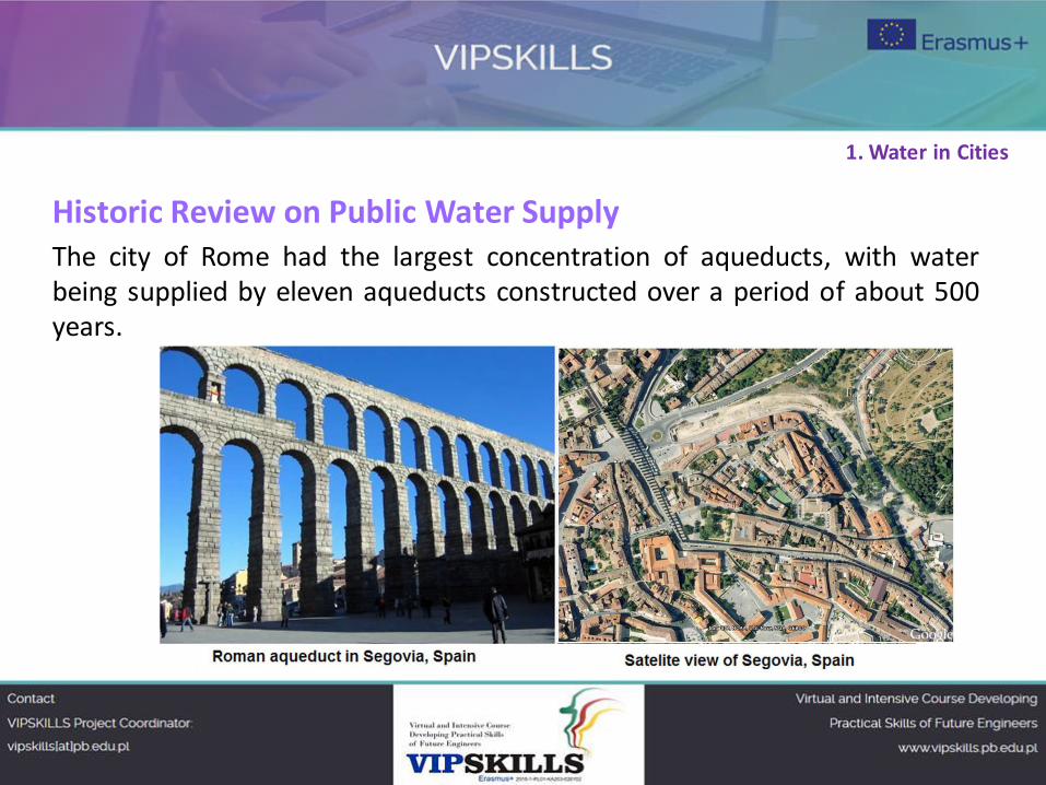
Historic Review on Public Water Supply
The city of Rome had the largest concentration of aqueducts, with water
being supplied by eleven aqueducts constructed over a period of about 500
years.
1. Water in Cities
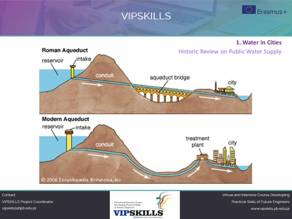
Historic Review on Public Water Supply
They served potable water and supplied the numerous baths and fountains in
the city, as well as finally being emptied into the sewers, where the once-used
gray water performed their last function in removing waste matter.
In addition to aqueducts, the Romans built many more channels excavated in
the ground, usually with a clay lining (leats). They could serve industrial sites
such as gold mines, lead and tin mines, forges, water-mills and thermae
(public baths).
1. Water in Cities
Historic Review on Public Water Supply
1. Water in Cities
2. Domestic water distribution systems
Water distribution systems provide ways to supply water throughout
buildings at pressure sufficient to operate plumbing fixtures.
Smaller buildings may be served simply by the pressure available in water
mains (or pressure tanks fed by pumped wells). This is called upfeed
distribution.
For taller buildings, several other options are available:
- Downfeed. Pumps raise the water to storage tanks at the top of a building,
and water then drops down to the plumbing fixtures.
- Pumped upfeed. Pumps supply the additional pressure needed.
- Hydropneumatic feed. Pumps force water into sealed tanks, compressing
the air within the tanks to maintain the needed water pressure.
2. Domestic water distribution systems
Determination of domestic water system load
The required water capacity of a building depends on the coincidental peak load demand (CPLD)
of all load categories, based on an assumed time of day in the heavy demand season.
For example, the highest CPLD for an office building is when it is fully occupied, plumbing facilities
are in heavy use, and air conditioning is near its peak.
The highest CPLD for an apartment building would be around dinner time in the summer, when
most people are home taking showers, washing, and preparing meals.
Domestic water system loads may be grouped into the following categories:
• Plumbing facilities • Laundry
• Food service – preparation, refrigeration,
washing, dining, etc. • Exterior – lawn and plant irrigation, fountains, etc.
• Research and process – laboratory
equipment, commercial or industrial
processes, computer equipment
• Pools – swimming pools, whirlpools, therapeutic pools
• Heating and cooling systems • Fire protection (if combined with the domestic system)
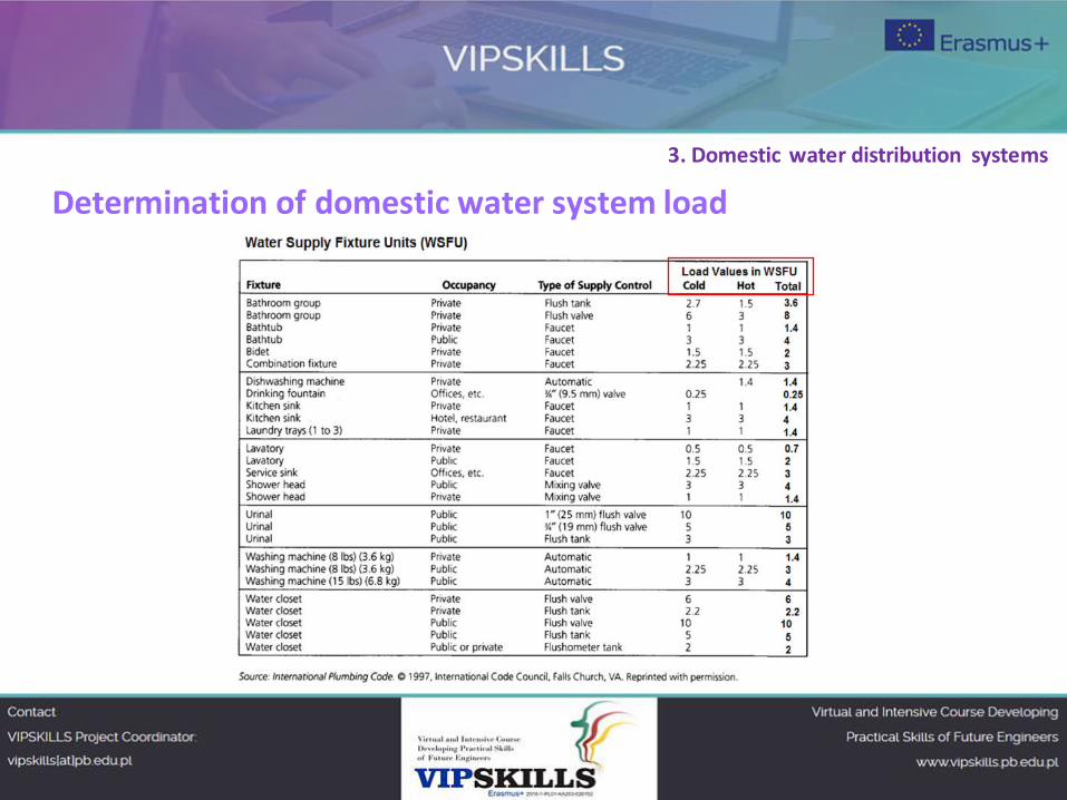
Determination of domestic water system load
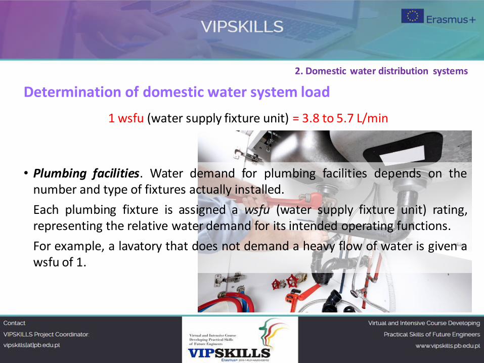
1 wsfu (water supply fixture unit) = 3.8 to 5.7 L/min
• Plumbing facilities. Water demand for plumbing facilities depends on the
number and type of fixtures actually installed.
Each plumbing fixture is assigned a wsfu (water supply fixture unit) rating,
representing the relative water demand for its intended operating functions.
For example, a lavatory that does not demand a heavy flow of water is given a
wsfu of 1.
2. Domestic water distribution systems
Determination of domestic water system load
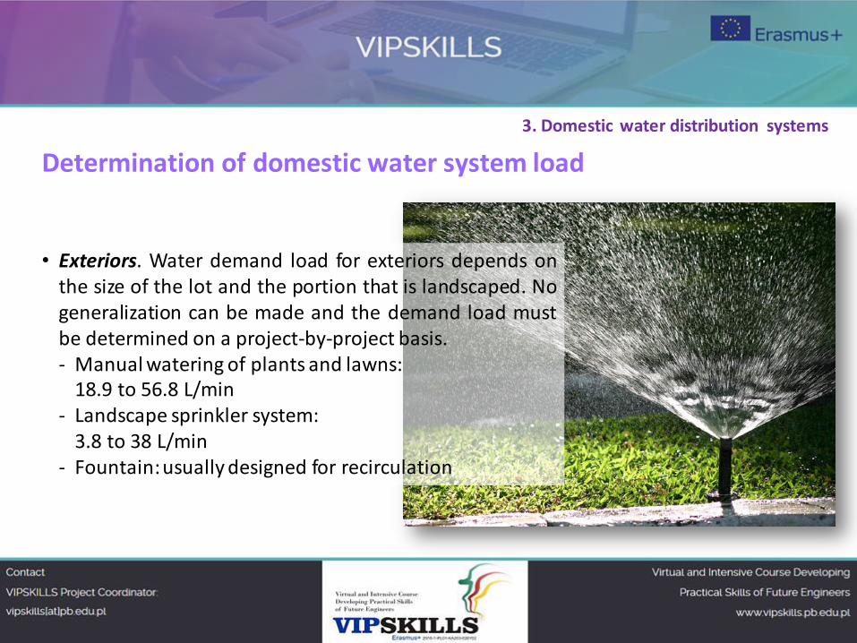
• Exteriors. Water demand load for exteriors depends on
the size of the lot and the portion that is landscaped. No
generalization can be made and the demand load must
be determined on a project-by-project basis.
‐ Manual watering of plants and lawns:
18.9 to 56.8 L/min
- Landscape sprinkler system:
3.8 to 38 L/min
- Fountain: usually designed for recirculation
3. Domestic water distribution systems
Determination of domestic water system load
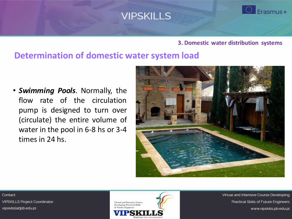
• Swimming Pools. Normally, the
flow rate of the circulation
pump is designed to turn over
(circulate) the entire volume of
water in the pool in 6-8 hs or 3-4
times in 24 hs.
3. Domestic water distribution systems
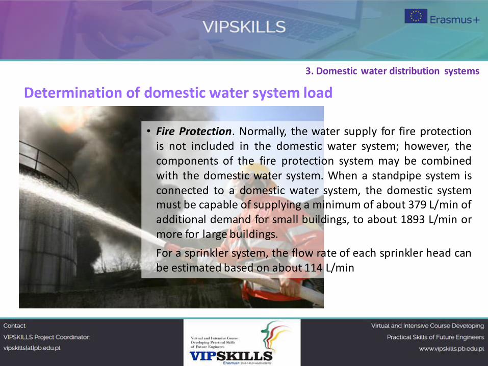
• Fire Protection. Normally, the water supply for fire protection
is not included in the domestic water system; however, the
components of the fire protection system may be combined
with the domestic water system. When a standpipe system is
connected to a domestic water system, the domestic system
must be capable of supplying a minimum of about 379 L/min of
additional demand for small buildings, to about 1893 L/min or
more for large buildings.
For a sprinkler system, the flow rate of each sprinkler head can
be estimated based on about 114 L/min
Determination of domestic water system load
3. Domestic water distribution systems
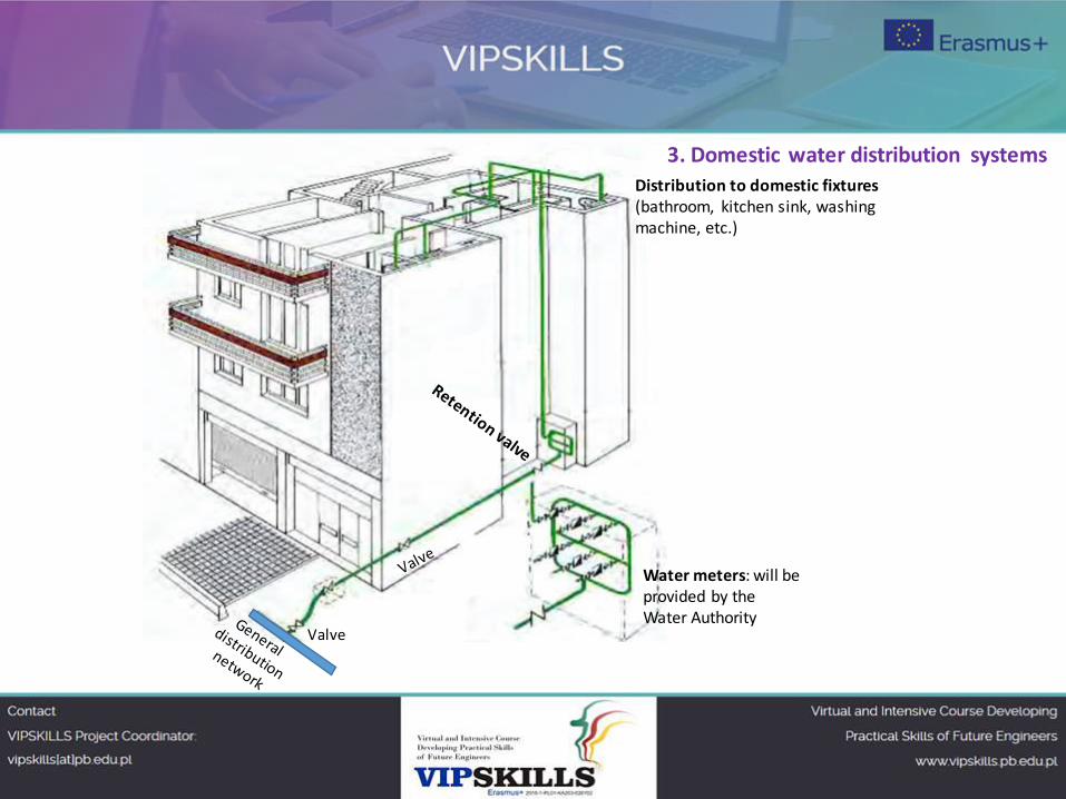
Valve
Water meters: will be
provided by the
Water Authority
3. Domestic water distribution systems
Distribution to domestic fixtures
(bathroom, kitchen sink, washing
machine, etc.)
Determination of domestic water system load
3. Domestic water distribution systems
Sizing of Water Pipes
A water system must be maintained with positive pressure to establish a flow in the
distribution system and through the plumbing fixtures or equipment.
Furthermore, positive water pressure prevents water from being contaminated by
external sources, since at a positive pressure, water tends to leak out of the pipe.
Water pressure should be sufficient to overcome any pressure loss due to friction,
differences in elevation, and flow pressure at outlets or equipment.
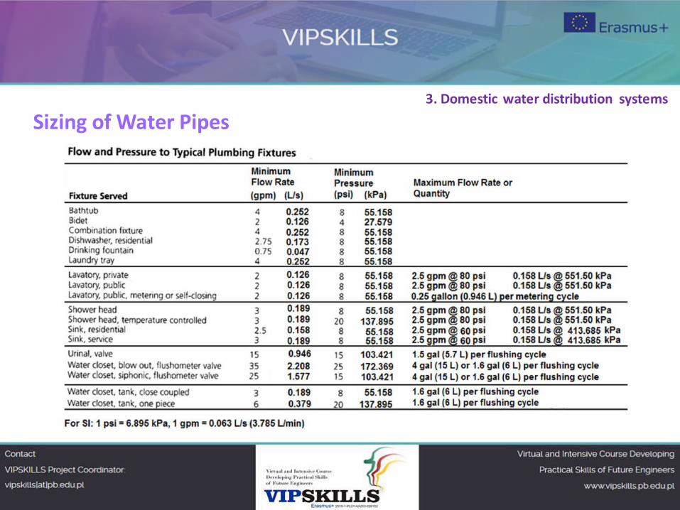
Minimum Flow Pressure for Fixture or Equipment
‐ Every plumbing fixture or connection that uses water must have the proper pressure to
maintain the required flow.
‐ Minimum fixture pressures vary from 28 to 138 kPa for fixtures.
‐ Because the pressure in street main is usually about 345 kPa, it is possible to assure the
minimum fixture pressure, provided that the water does not have to be lifted to too
great a height and not too much pressure is lost by friction in distribution piping.
3. Domestic water distribution systems
Sizing of Water Pipes 3. Domestic water distribution systems
Sizing of Water Pipes
Excessive friction results from piping that:
- Is too long in developed length (actual distance of water flow)
- That interposes too many fittings (such as elbows and tees),
- Is too small in diameter
The pressure losses in an upfeed system served by street main pressure are as follows:
Minimum fixture flow pressure A
(for the highest, most remote fixture from street)
Pressure loss due to height B
Pressure loss due to friction in piping C
Pressure loss by flow through water meter D
-----------------------------------------------------------------------------------
Total required street main pressure: E = A + B + C + D
3. Domestic water distribution systems
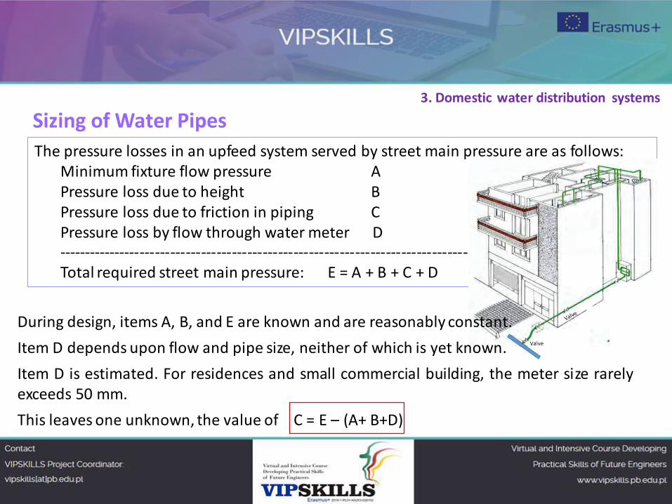
The pressure losses in an upfeed system served by street main pressure are as follows:
Minimum fixture flow pressure A
Pressure loss due to height B
Pressure loss due to friction in piping C
Pressure loss by flow through water meter D
-----------------------------------------------------------------------------------
Total required street main pressure: E = A + B + C + D
Sizing of Water Pipes 3. Domestic water distribution systems
During design, items A, B, and E are known and are reasonably constant.
Item D depends upon flow and pipe size, neither of which is yet known.
Item D is estimated. For residences and small commercial building, the meter size rarely
exceeds 50 mm.
This leaves one unknown, the value of C = E – (A+ B+D)
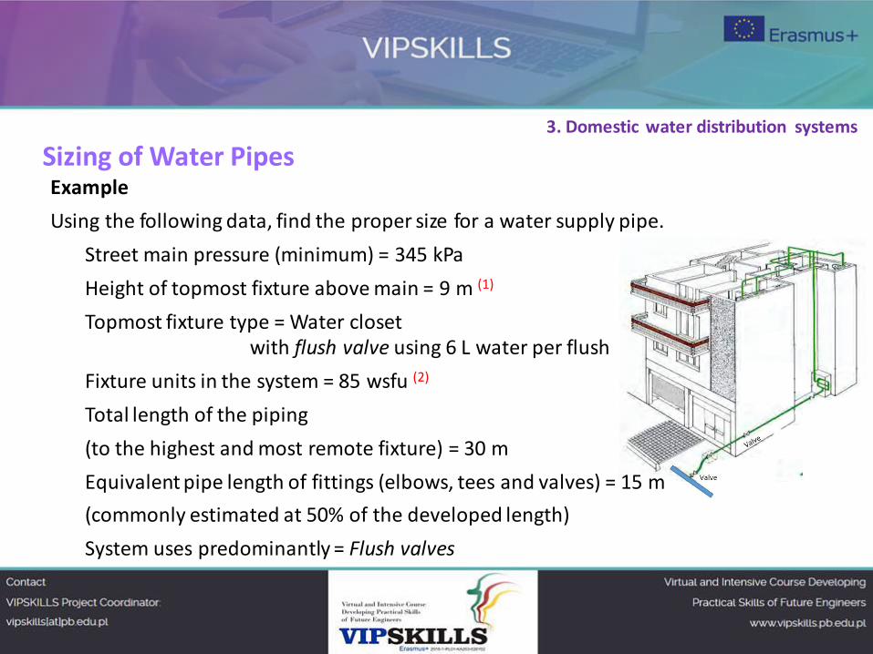
Example
Using the following data, find the proper size for a water supply pipe.
Street main pressure (minimum) = 345 kPa
Height of topmost fixture above main = 9 m (1)
Topmost fixture type = Water closet
with flush valve using 6 L water per flush
Fixture units in the system = 85 wsfu (2)
Total length of the piping
(to the highest and most remote fixture) = 30 m
Equivalent pipe length of fittings (elbows, tees and valves) = 15 m
(commonly estimated at 50% of the developed length)
System uses predominantly = Flush valves
Sizing of Water Pipes 3. Domestic water distribution systems
Example
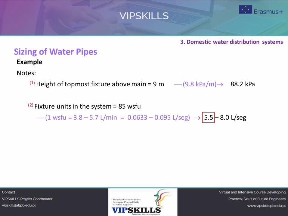
Notes:
(1) Height of topmost fixture above main = 9 m (9.8 kPa/m) 88.2 kPa
(2) Fixture units in the system = 85 wsfu
(1 wsfu = 3.8 – 5.7 L/min = 0.0633 – 0.095 L/seg) 5.5 – 8.0 L/seg
Sizing of Water Pipes 3. Domestic water distribution systems
Sizing of Water Pipes
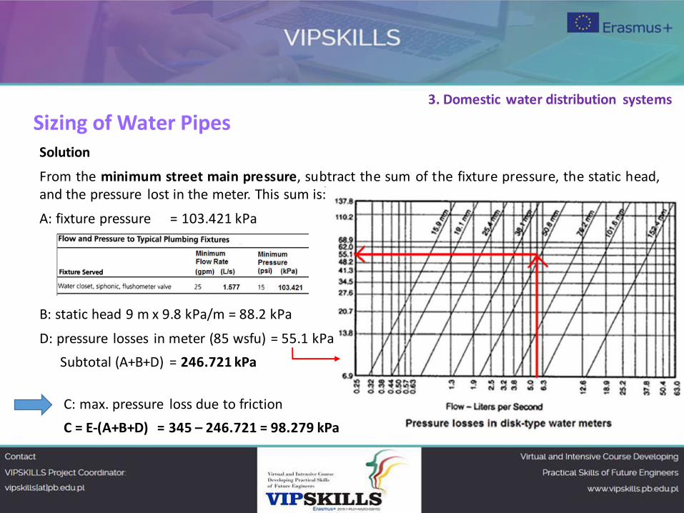
Solution
From the minimum street main pressure, subtract the sum of the fixture pressure, the static head,
and the pressure lost in the meter. This sum is:
A: fixture pressure = 103.421 kPa
B: static head 9 m x 9.8 kPa/m = 88.2 kPa
D: pressure losses in meter (85 wsfu) = 55.1 kPa
Subtotal (A+B+D) = 246.721 kPa
C: max. pressure loss due to friction
C = E-(A+B+D) = 345 – 246.721 = 98.279 kPa
3. Domestic water distribution systems
Sizing of Water Pipes
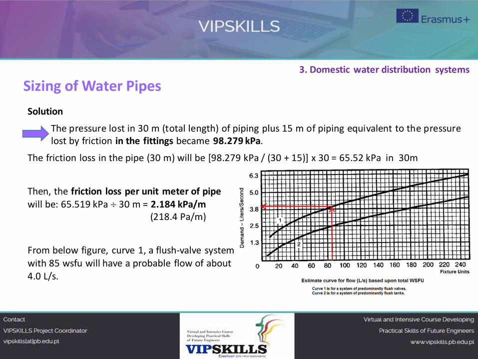
Solution
The pressure lost in 30 m (total length) of piping plus 15 m of piping equivalent to the pressure
lost by friction in the fittings became 98.279 kPa.
The friction loss in the pipe (30 m) will be [98.279 kPa / (30 + 15)] x 30 = 65.52 kPa in 30m
Then, the friction loss per unit meter of pipe
will be: 65.519 kPa 30 m = 2.184 kPa/m
(218.4 Pa/m)
From below figure, curve 1, a flush-valve system
with 85 wsfu will have a probable flow of about
4.0 L/s.
3. Domestic water distribution systems
Sizing of Water Pipes
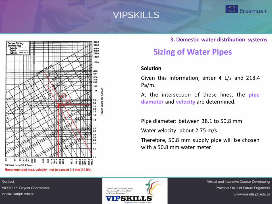
Solution
Given this information, enter 4 L/s and 218.4
Pa/m.
At the intersection of these lines, the pipe
diameter and velocity are determined.
Pipe diameter: between 38.1 to 50.8 mm
Water velocity: about 2.75 m/s
Therefore, 50.8 mm supply pipe will be chosen
with a 50.8 mm water meter.
3. Domestic water distribution systems
HOT-WATER SYSTEM
Design considerations for water distribution systems
Piping Material
Thermal Insulation
Preventing Backflow
Vacuum breaker
Shock Absorption
Plumbing Fixtures
Fixture units
Bibliography
3. Domestic water distribution systems
Next
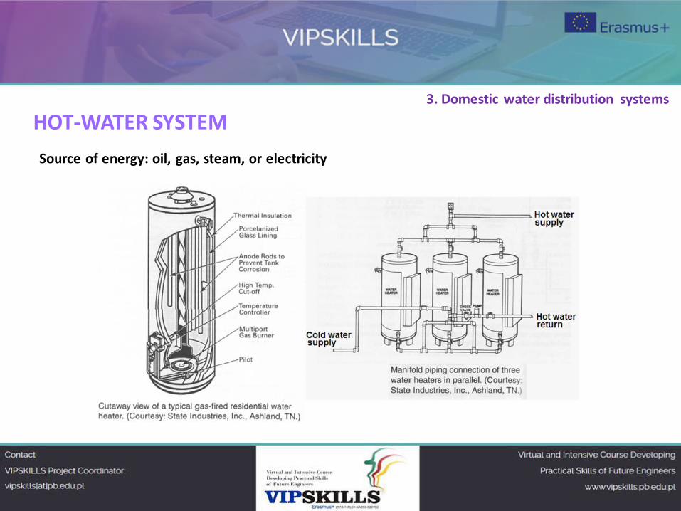
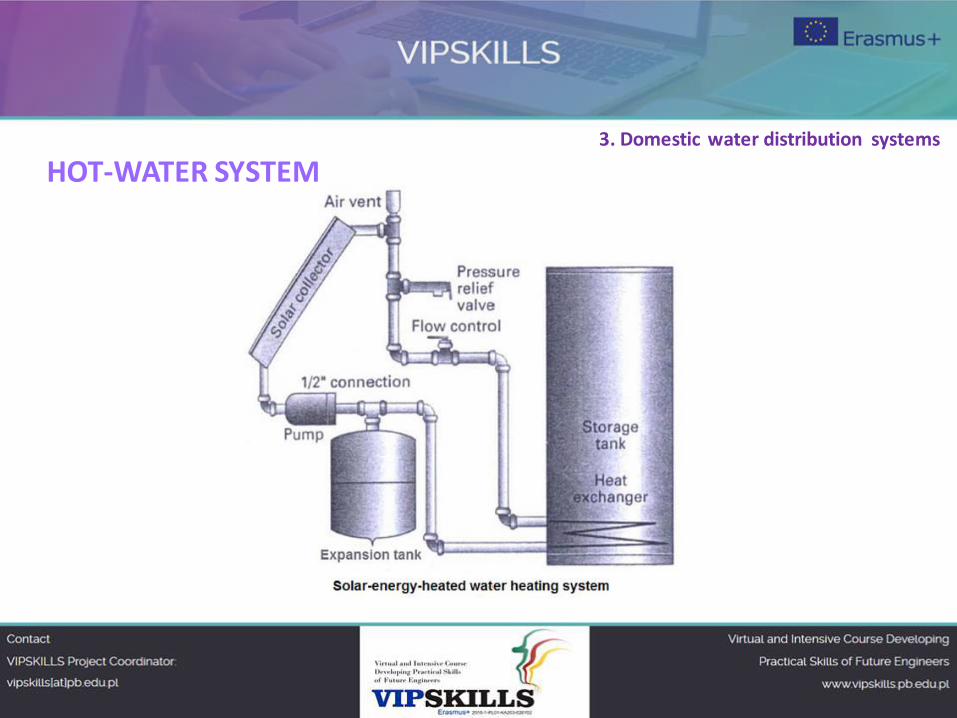
HOT-WATER SYSTEM
Source of energy: oil, gas, steam, or electricity
3. Domestic water distribution systems
HOT-WATER SYSTEM 3. Domestic water distribution systems
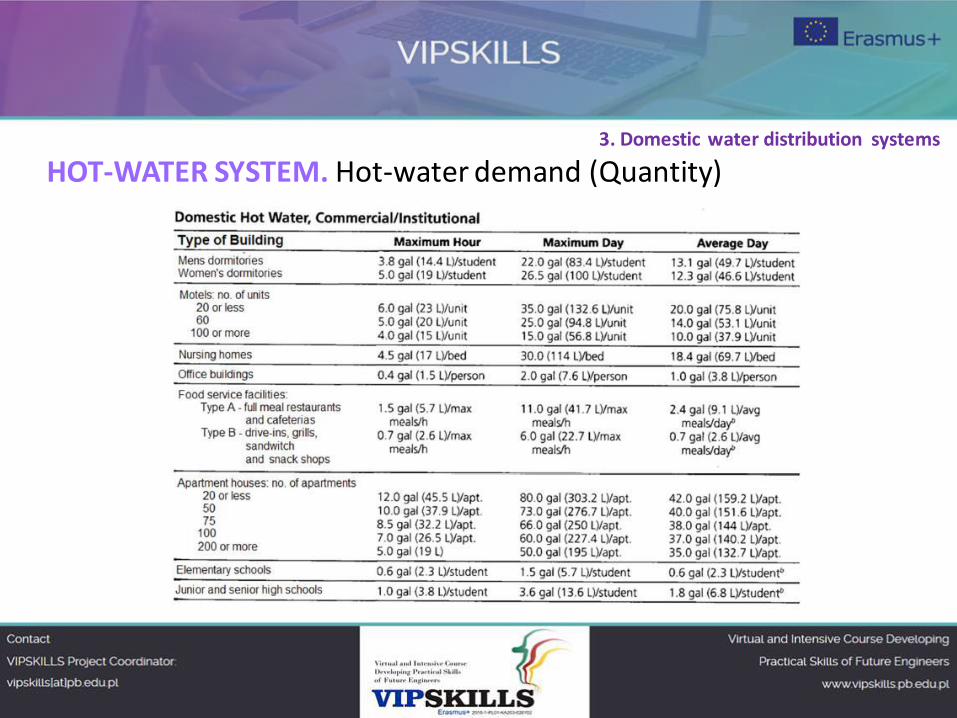
HOT-WATER SYSTEM. Hot-water demand (Quantity)
3. Domestic water distribution systems
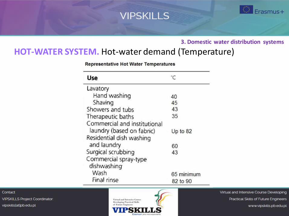
HOT-WATER SYSTEM. Hot-water demand (Temperature)
3. Domestic water distribution systems
Design considerations for water distribution systems.
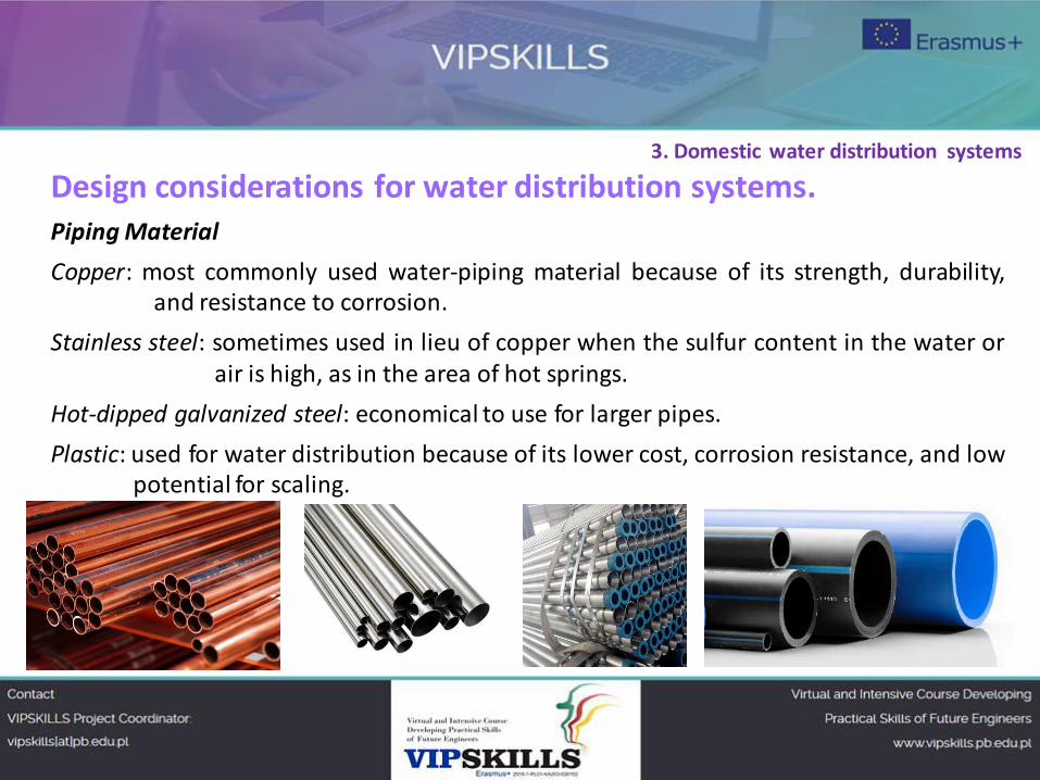
Piping Material
Copper: most commonly used water-piping material because of its strength, durability,
and resistance to corrosion.
Stainless steel: sometimes used in lieu of copper when the sulfur content in the water or
air is high, as in the area of hot springs.
Hot-dipped galvanized steel: economical to use for larger pipes.
Plastic: used for water distribution because of its lower cost, corrosion resistance, and low
potential for scaling.
3. Domestic water distribution systems
Design considerations for water distribution systems.
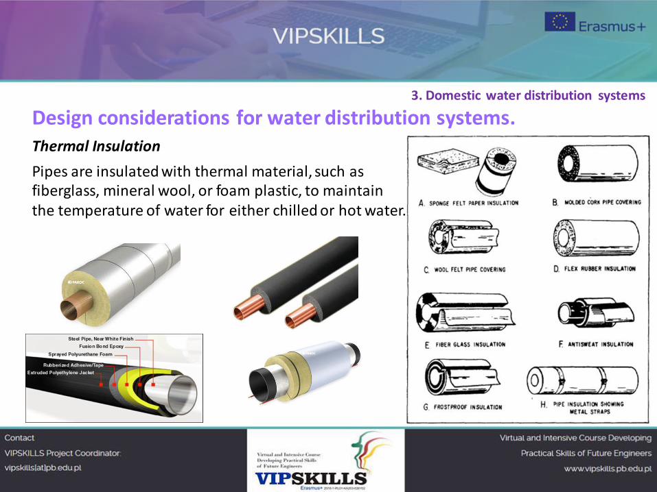
Thermal Insulation
Pipes are insulated with thermal material, such as
fiberglass, mineral wool, or foam plastic, to maintain
the temperature of water for either chilled or hot water.
3. Domestic water distribution systems
Design considerations for water distribution systems.
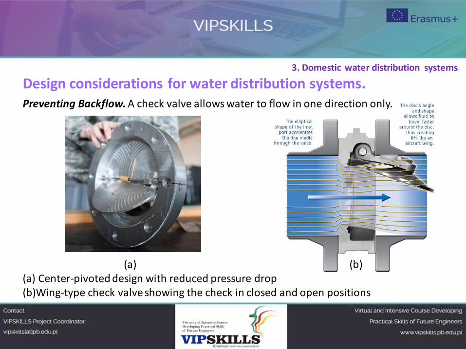
Preventing Backflow. A check valve allows water to flow in one direction only.
(a) (b)
(a) Center-pivoted design with reduced pressure drop
(b)Wing-type check valve showing the check in closed and open positions
3. Domestic water distribution systems
Design considerations for water distribution systems.
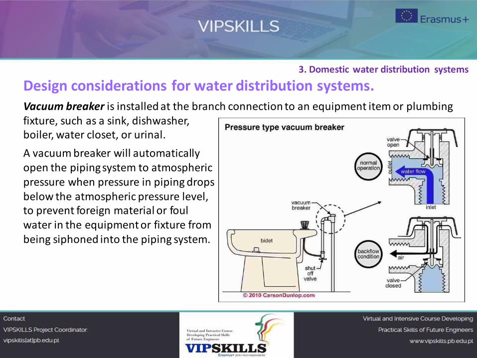
Vacuum breaker is installed at the branch connection to an equipment item or plumbing
fixture, such as a sink, dishwasher,
boiler, water closet, or urinal.
A vacuum breaker will automatically
open the piping system to atmospheric
pressure when pressure in piping drops
below the atmospheric pressure level,
to prevent foreign material or foul
water in the equipment or fixture from
being siphoned into the piping system.
3. Domestic water distribution systems
Design considerations for water distribution systems.
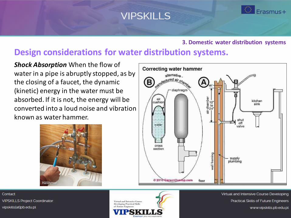
Shock Absorption When the flow of
water in a pipe is abruptly stopped, as by
the closing of a faucet, the dynamic
(kinetic) energy in the water must be
absorbed. If it is not, the energy will be
converted into a loud noise and vibration
known as water hammer.
3. Domestic water distribution systems
Water
closets
Urinals
Lavatories
Sinks Drinking
fountains
Bathtubs (BT)
Showers
Bidets
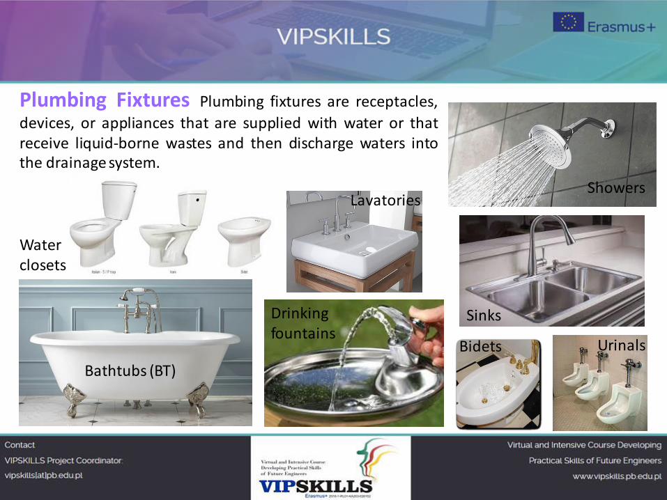
Plumbing Fixtures Plumbing fixtures are receptacles,
devices, or appliances that are supplied with water or that
receive liquid-borne wastes and then discharge waters into
the drainage system.
Fixture units
The water supply fixture unit (wsfu):
The wsfu is a measure of the probable hydraulic demand on the water supply by various
types of plumbing fixtures.
The wsfu depends on the rate of supply, the duration of a single operation, and the
frequency of operation of the fixture.
1 wsfu: A 1/2 in. (12.7 mm) residential type lavatory faucet is rated for 1 wsfu which is
equivalent to about 1 to 1.5 GPM (5.7 L/min) flow rate.
3. Domestic water distribution systems
Bibliography ARE1024 – Building Equipment and System Design. School of Architecture and Architectural
Engineering, Hanyang University, ERICA Campus. Chapter 9. Plumbing Equipment and Systems.
http://aesl.hanyang.ac.kr/class/are1024/PDF-ENG/ARE1024(ENG)-CH09.pdf
Domestic Hot Water Systems. Continuing Education from the American Society of Plumbing Engineers.
CEU 221. March 2015.
https://www.aspe.org/sites/default/files/webfm/ContinuingEd/CEU_221_Mar15.pdf
Water Supply and Drainage for Buildings. September 19-21, 2007/ Brno, Czech Republic. CIB W062
2007. 33rd International Symposium.
https://www.irbnet.de/daten/iconda/CIB6832.pdf
Spanish Legislation
Código Técnico de la Edificación. Ministerio de la Vivienda. Marzo 2006
(RD 314/2006 de 17 de marzo)
RITE + Instrucciones Técnicas Complementarias. RD 1027/2007 20 de julio
(BOE nº 207, 29 de agosto 2007)

María Fátima Moreno Pérez
University of Cordoba
The presentation is available on license
Creative Commons Attribution-ShareAlike 4.0
International

Related Documents