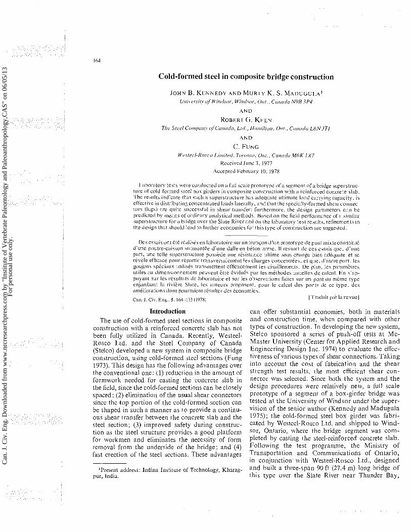
Cold-formed steel in composite bridge construction JOHN B. KENNEDY AND MUR-I-Y K. S. MADUGULA' U/ii~,er.sity of' Wirrtlsor., Wiirtl.sor,Otrr.. Ctrtrcrrlo NYB 3P.l AND ROBERT G. KEEN 7'lre Strd Conrprriry r~fCtrirtrtlo. Lttl., Hoii~ilton, 011t.. Ctrrrtrdtr L8N37'1 AND C. FUNC Wrstcrl-Rosco L.itiri!ctl,Toroilto, Out., C(rtrot1tr IM~K 1x7 Received June 3, 1977 Accepted Feb~uary 10. 1978 L:~bomtory tests were conducted on 21 full scale prototype of a segment ofa bridge superstruc- ture of cold-formed steel box girders in composite construction with a reinforced concrete slab. The results indicate that such :I superstructure has adeql~ate ~~ltimate load carrying capacity, is effective in distributing concentrated loads latel-ally, antl that the specially-formed shear-connec- tors (lugs) are quite successful in shear transfer; furthermore, the tlesign parameters can be predictctl by means of ordinary analytical (methods. Based on the field performance of n similar supe~.structure for a bvidge over the Slate River antl on the laboratory test results, refinements in the tlesign that should lead to fill-ther economies for this type ofconstr~~ction are suggested. Des essais ont ete rCalises en laboratoire surun tronson d'un prototype tle punt mixteconstitw5 cl'une poutre-caisson surmontee d'une clulle en beton mne. I1 ressort tle ces essais que. d'une pal-t. m e telle superstwcture posskcle m e resistance ultime sous charge bien adequate et se rkvele efficace pour repartir t~xnsversalement les charges concentl-ees, et que, d'autre part. les goujons speciaux utilises transmettent efficacement les cisnillements. De pl~rs, les pwarnktres utile5 XI clir~ierision~ie~iient peuvent 611-e Cvalu6s par les methodes usuelles de calcul. En s'ap- pclyant sur les ~lsultats cle Idxwatoire et sur les observations faites sur un pont du meme type en.jambant la rivii.1-e Slate, les auteurs proposent, pour le calcul des ponts de ce type, des ameliorations dont pourraient resulter des economies. Can. J. Civ. Eng.. 5. 164-173 (1978) [T~xduit pal. la r e v u e ] Introduction The use of cold-formed steel sections in composite construction with a reinforced concrete slab has not been fully utilized in Canada. Recently, Westeel- Rosco Ltd. and the Steel Company of Canada (Stelco) developed a new system in composite bridge construction, using cold-formed steel sections (Fung 1973). This design has the following advantages over the conventional one: (1) reduction in the amount of formwork needed for casting the concrete slab in the field, since the cold-formed sections can be closely spaced; (2) elimination of the usual shear connectors since the top portion of the cold-formed section can be shaped in such a manner as to provide a continu- ous shear transfer between the concrete slab and the steel section; (3) improved safety during construc- tion as the steel structure provides a good platform for workmen and eliminates the necessity of form removal from the underside of the bridge; and (4) fast erection of the steel sections. These advantages 'Present address: Indian Institute of Technology, Kharag- pur, India. can offer substantial econon~ies,both in materials and constructioil time, when compared with other types of construction. In developing the new system, Stelco sponsored a series of push-off tests at Mc- Master University (Center for Applied Research and Engineering Design Inc. 1974) t o evaluate the effec- tiveness of various types of shear connections. Taking into account the cost of fabrication and the shear strength test results, the most efficient shear con- nector was selected. Since both the system and the design procedures were relatively new, a full scale prototype of a segment of a box-girder bridge was tested at the University of Windsor under the super- vision of the senior author (Kennedy and Madugula 1975); the cold-formed steel box girder was fabri- cated by Westeel-Rosco Ltd. and shipped to Wind- sor, Ontario, where the bridge segment was com- pleted by casting the steel-reinforced concrete slab. Following the test programme, the Ministry of Transportation and Con~nlunications of Ontario, in conjunction with Westeel-Rosco Ltd., designed and built a three-span 90 ft (27.4 m) long bridge of this type over the Slate River near Thunder Bay, Can. J. Civ. Eng. Downloaded from www.nrcresearchpress.com by "Institute of Vertebrate Paleontology and Paleoanthropology,CAS" on 06/05/13 For personal use only.

Welcome message from author
This document is posted to help you gain knowledge. Please leave a comment to let me know what you think about it! Share it to your friends and learn new things together.
Transcript
Cold-formed steel in composite bridge construction
JOHN B. K E N N E D Y A N D MUR-I-Y K. S. M A D U G U L A ' U/ii~,er.sity of' Wirrtlsor., Wiirtl.sor, Otrr.. Ctrtrcrrlo NYB 3P.l
AND
ROBERT G . KEEN 7'lre S t rd Conrprriry r~fCtrirtrtlo. Lttl., Hoii~ilton, 0 1 1 t . . Ctrrrtrdtr L8N37'1
AND
C . FUNC Wrstcrl-Rosco L.itiri!ctl, Toroilto, Out. , C(rtrot1tr I M ~ K 1x7
Received June 3 , 1977
Accepted F e b ~ u a r y 10. 1978
L:~bomtory tests were conducted on 21 full scale prototype of a segment o f a bridge superstruc- ture of cold-formed steel box girders in composite construction with a reinforced concrete slab. The results indicate that such :I superstructure has adeql~ate ~ ~ l t i m a t e load carrying capacity, is effective in distributing concentrated loads latel-ally, antl that the specially-formed shear-connec- tors (lugs) are quite successful in shear transfer; furthermore, the tlesign parameters can be predictctl by means of ordinary analytical (methods. Based on the field performance of n similar supe~.structure for a bvidge over the Slate River antl on the laboratory test results, refinements in the tlesign that should lead to fill-ther economies for this type ofcons t r~~ct ion are suggested.
Des essais ont ete rCalises en laboratoire surun tronson d'un prototype tle punt mixteconstitw5 cl'une poutre-caisson surmontee d'une clulle en beton m n e . I1 ressort tle ces essais que. d 'une pal-t. m e telle superstwcture posskcle m e resistance ultime sous charge bien adequate et se rkvele efficace pour repartir t~xnsversalement les charges concentl-ees, e t que, d'autre part. les goujons speciaux utilises transmettent efficacement les cisnillements. De pl~rs, les pwarnktres utile5 XI clir~ierision~ie~iient peuvent 611-e Cvalu6s par les methodes usuelles d e calcul. En s'ap- pclyant sur les ~ l s u l t a t s cle Idxwatoire et sur les observations faites sur un pont du meme type en.jambant la rivii.1-e Slate, les auteurs proposent, pour le calcul des ponts de ce type, des ameliorations dont pourraient resulter des economies.
Can. J. Civ. Eng.. 5. 164-173 (1978) [T~xdui t pal. la revue]
Introduction The use of cold-formed steel sections in composite
construction with a reinforced concrete slab has not been fully utilized in Canada. Recently, Westeel- Rosco Ltd. and the Steel Company of Canada (Stelco) developed a new system in composite bridge construction, using cold-formed steel sections (Fung 1973). This design has the following advantages over the conventional one: (1) reduction in the amount of formwork needed for casting the concrete slab in the field, since the cold-formed sections can be closely spaced; (2) elimination of the usual shear connectors since the top portion of the cold-formed section can be shaped in such a manner as to provide a continu- ous shear transfer between the concrete slab and the steel section; (3) improved safety during construc- tion as the steel structure provides a good platform for workmen and eliminates the necessity of form removal from the underside of the bridge; and (4) fast erection of the steel sections. These advantages
'Present address: Indian Institute of Technology, Kharag- pur, India.
can offer substantial econon~ies, both in materials and constructioil time, when compared with other types of construction. In developing the new system, Stelco sponsored a series of push-off tests at Mc- Master University (Center for Applied Research and Engineering Design Inc. 1974) t o evaluate the effec- tiveness of various types of shear connections. Taking into account the cost of fabrication and the shear strength test results, the most efficient shear con- nector was selected. Since both the system and the design procedures were relatively new, a full scale prototype of a segment of a box-girder bridge was tested at the University of Windsor under the super- vision of the senior author (Kennedy and Madugula 1975); the cold-formed steel box girder was fabri- cated by Westeel-Rosco Ltd. and shipped to Wind- sor, Ontario, where the bridge segment was com- pleted by casting the steel-reinforced concrete slab. Following the test programme, the Ministry of Transportation and Con~nlunications of Ontario, in conjunction with Westeel-Rosco Ltd., designed and built a three-span 90 ft (27.4 m) long bridge of this type over the Slate River near Thunder Bay,
Can
. J. C
iv. E
ng. D
ownl
oade
d fr
om w
ww
.nrc
rese
arch
pres
s.co
m b
y "I
nstit
ute
of V
erte
brat
e Pa
leon
tolo
gy a
nd P
aleo
anth
ropo
logy
,CA
S" o
n 06
/05/
13Fo
r pe
rson
al u
se o
nly.
K E N N E D Y ET r\L
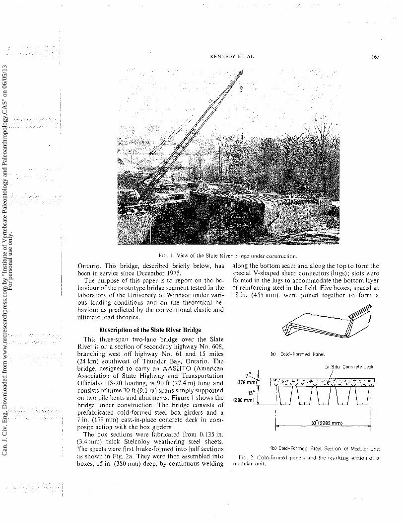
FIG. I . View of the Slate River bridgc ~ ~ n d e r construction.
Ontario. This bridge, described briefly below, has been in service since December 1975.
The purpose of this paper is to report on the be- haviour of the prototype bridge segment tested in the laboratory of the University of Windsor under vari- ous loading conditions and oil the theoretical be- haviour as predicted by the conveiitioiial elastic and ultimate load theories.
Description of the Slate River Bridge This three-span two-lane bridge over the Slate
River is on a section of secondary highway No. 608, braiiching west off highway No. 61 and 15 miles (24 k111) southwest of Thunder Bay, Ontario. The bridge, designed to carry an AASHTO (American Association of State Highway and Transportation Officials) HS-20 loading, is 90 ft (27.4 ni) long and consists of three 30 ft (9.1 in) spans simply supported on two pile bents and abutments. Figure 1 shows the bridge under constructioii. The bridge consists of prefabricated cold-formed steel box girders and a 7 in. (179 mni) cast-in-place concrete deck i11 conl- posite action with the box girders.
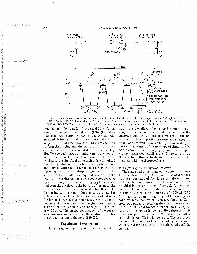
The box sectioiis were fabricated from 0.135 in. (3.4 inm) thick Stelcoloy weathering steel sheets. The sheets were first brake-formed into half sections as shown i11 Fig. 2a. They were then assembled into boxes, 15 in. (380 mm) deep, by coiitinuous welding
along the bottom seam and along the t o p t o form the special V-shaped shear connectors (lugs); slots were formed in the lugs to accommodate the bottom layer of reinforcing steel in the field. Five boxes, spaced at 18 in. (455 itiiii), were joined together t o form a
(0) Cold- Formed Panel
In Situ Concrete Deck
I I
C 90"(2285 mm) -I (b) Cold-Formed Steel Section of Modular Unit
FIG. 2. Cold-formctl panels and the resulting section of a modular ~mit .
Can
. J. C
iv. E
ng. D
ownl
oade
d fr
om w
ww
.nrc
rese
arch
pres
s.co
m b
y "I
nstit
ute
of V
erte
brat
e Pa
leon
tolo
gy a
nd P
aleo
anth
ropo
logy
,CA
S" o
n 06
/05/
13Fo
r pe
rson
al u
se o
nly.
166 C A N . J . CIV. ENG. VOL. 5, 1978
Special Concrete
Steel Section
FIG. 3. Dimensions of coniposite s t r ~ ~ c t ~ ~ r e and location of strain and dellection gauges. Legend:@longitudinal con- crete strain g a ~ ~ g e s ; ~ , ~ l o n g i t ~ l d i n a l steel strain ga~~ges;@end-slip gauges;aniid-span deflection gauges. Note:Thickness of cold-formed section = 0.138 in. (3.5 m m ) ; all dimensions indicated are i n the inches (millinietres).
modular unit, 90 in. (2.28 IN) wide and 30 ft (9.1 n ~ ) long; a 20-gauge galvanized steel (CSA (Canadian Standards Association) G40.8, Grade A) pan was attached between the shear connectors along the length of the unit except for 2 ft (0.61 m) at each end to form the diaphragms; the pan produced a hollow core and served as permanent deck formwork (Fig. 2b). Twelve such modular units were fabricated by Weststeel-Rosco Ltd. in their Toronto plant and trucked to the site. At the site each unit was hoisted into place (resting on rubber bearings) by a light crane and aligned with each other in such a way that re- inforcing steels could be dropped into the slots in the shear lugs. Four units were required to make up the width of the bridge and these were connected together by field bolting the mid-span bridging plates, which had been shop-welded to the bottom of the units; the upper edges of the units were welded together in the field using 2 in. (51 mm) long fillet welds at 3 ft (0.92 m) centres. After placing the longitudinal rein- forcing steel over the transverse steel a 7 in. (179 mm) concrete slab was cast; the specified compressive strength of the concrete was 4000 psi (27.6 MPa) after 28 days. The on-site construction of the super- structure was simple and fast; the contract price for the bridge was approxin~ately $129 000.
Experimental Investigation The experimental investigation was intended to
study: (I) the effect of construction preload (i.e. weight of the concrete slab) on the behaviour of the unshored cold-formed steel box girder; (2) the be- haviour of the composite structure under eccentric wheel loads as well as under heavy shear loading to test the effectiveness of the new type of shear transfer mechanism, i.e. shear lugs (Fig. 3), and to investigate any premature web buckling; and (3) the comparison of the actual ultimate load-carrying capacity of the structure with the theoretical one.
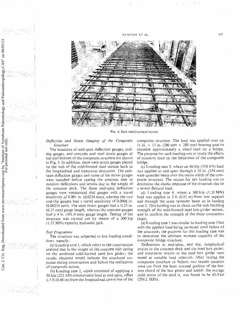
Description of the Composite Structure The shape and dimensions of the composite struc-
ture are shown in Fig. 3. The reinforcement for the slab deck consisted of four layers of deformed bars, with the bottom transverse steel placed in notches provided in the top portion of the cold-formed steel section. The layout of the slab reinforcement is shown in Fig. 4. Air-entrained concrete of 4000 psi (27.6 MPa) nominal strength was supplied by a ready-mix concrete manufacturer i n Windsor, Ontario. Con- crete was placed directly on the special pan welded on top of the cold-formed steel section (Fig. 3) re- sulting in the box girder being hollow throughout its length except for a distance of 2 ft (0.61 m) at either end, which was filled with concrete. The reinforced concrete slab deck and the control cylinders were water-cured for 21 days and then air-cured until the test day.
Can
. J. C
iv. E
ng. D
ownl
oade
d fr
om w
ww
.nrc
rese
arch
pres
s.co
m b
y "I
nstit
ute
of V
erte
brat
e Pa
leon
tolo
gy a
nd P
aleo
anth
ropo
logy
,CA
S" o
n 06
/05/
13Fo
r pe
rson
al u
se o
nly.
K E N N E D Y E l ' AL
FIG. 4. Slab reinforcement layout
Dejectio~z and Strain Gauging of the Cornyosite Strvctwe
The locations of mid-span deflection gauges, end- slip gauges, and concrete and steel strain gauges a t top and bottom of the composite structure are shown in Fig. 3. In addition, there were strain gauges placed on the web of the cold-formed steel section both in the longitudinal and transverse directions. The mid- span deflection gauges and some of the strain gauges were installed before casting the concrete slab to monitor deflections and strains due to the weight of the concrete deck. The three mid-span deflection gauges were mechanical dial gauges with a travel sensitivity of 0.001 in. (0.0254 mm), whereas the two end-slip gauges had a travel sensitivity of 0.0001 in. (0.00254 mm). The steel strain gauges had a 0.25 in. (6.35 mm) gauge length, whereas the concrete gauges had a 4 in. (101.6 mm) gauge length. Testing of the structure was carried out by means of a 300 kip (1.33 MN) capacity hydraulic jack.
Test Progm?ztne The structure was subjected to five loading condi-
tions, namely: (a) Loading case 1 , which refers to the construction
preload due to the weight of the concrete slab acting on the unshored cold-formed steel box girder; the results obtained would indicate the structural res- ponse during construction and before the realization of composite action.
(b) Loading case 2, which consisted of applying a 50 kip (222 kN) concentrated load at mid-span, offset 1.5 ft (0.46 m) from the longitudinal centre line of the
composite structure. The load was applied over an I 1 in. x 11 in. (280 mnl x 280 nim) bearing area t o simulate approximately a wheel load on a bridge. The purpose for such loading was to study the effects of eccentric load on the beliaviour of the conlposite bridge.
(c) Loading case 3, where an 80 kip (356 kN) load was applied at mid-span through a 10 in. (254 mm) wide spreader beam over the entire width of the com- posite structure. The reason for this loading was t o determine the elastic response of the structure due to a severe flexural load.
(d) Loading case 4, where a 300 kip (1.33 MN) load was applied at 3 ft (0.91 m) from one support and through the same spreader beam as in loading case 3. This loading was to check on the web buckling strength of the cold-formed steel box-girder section, and to confirm the strength of the shear connectors (lugs).
(e) Loading case 5 was similar to loading case 3 but with the applied load being increased until failure of the structure; the purpose for this loading case was to determine the ultimate moment capacity of the composite bridge structure.
Deflections at mid-span, end slip, longitudinal strains in the concrete deck and the steel box girder, and transverse stralns in the steel box girder were noted at s ~ ~ i t a b l e load intervals. After testing the composite structure to failure, two tensile coupons were cut from the least stressed portion of the bot- tom chord of the box girder and tested: the average yield stress of the steel o, was found t o be 43.4 ksi (299.2 MPa).
Can
. J. C
iv. E
ng. D
ownl
oade
d fr
om w
ww
.nrc
rese
arch
pres
s.co
m b
y "I
nstit
ute
of V
erte
brat
e Pa
leon
tolo
gy a
nd P
aleo
anth
ropo
logy
,CA
S" o
n 06
/05/
13Fo
r pe
rson
al u
se o
nly.
168 C A N . J . CIV. ENG. V O L . 5 . 1978
Theoretical Analysis The geometric and mechanical properties of the
cold-formed steel section and the composite section were calculated in the usual manner; the values for the positions of the neutral axes, y,, and y,,, moments of inertia, 1, and I,, and section moduli, S,, S,,, and S,,, are given in Table 1.
Elastic Analysis The deflection at mid-span, S,, of an unshored
cold-formed steel box girder of span L due to the weight of the concrete deck, I \ . , , and the weight of the concrete, H,,, forining the end diaphragms of length h can be deduced from
in which E, is the modulus of elasticity of the steel. The tensile and compressive strains E, and E, at the extreme bottom and top fibres, respectively, of the cold-formed steel section subjected to a bending moment M are
in which c!, is the depth of the steel section. The corre- sponding strains for a composite bridge section be- coine
For a concentrated load P at mid-span and eccen- trically applied at a distance c from the longitudinal centre line of the composite structure, the total de- flection at centre of the loaded and unloaded cells of the cross section can be estimated as (6,, + S.,) and (6, - 6,), respectively, where
[4] 6, = deflection due to bending = ~ L ~ / 4 8 ~ , 1 ,
and
[5] 6, = deflection due to twisting = Be
Assuming that the twisting is equally shared by all the cells of the cross section, the angle of twist 0 is calculated from
[6 1 0 = (PeL ij; ds/t)/24A2G
in which G = shear inodulus of steel, A = area formed by the centre line of one cell, and ds and t are the element of length of the cell and its thickness, respectively.
Yield and Ultimate Analyses If oy is the yield stress of the steel, then the yield
inoinent that can be developed by the composite sec- tion is My = oySc,. For a dead load bending moment M , at mid-span, the yield load at centre is estimated from
TABLE I . Properties of the steel, concrete, and composite sections
Property Value
Corrcr.etc sectiorr
22.3 in.' (14 x lo4 mnlz) 15 in. (380 nun)
6.66 in. (1 70 mm) 748 in.4 (3 1 1 x lo6 111111~)
I 12.5 i11.3(1 .84 x lo6 IIIIII~) 29 x loG psi (200 GPa)
4550 psi (3 1 . 4 M Pa) 4900 psi (33.7 MPa)
150 Ib/ft3 (2 .4 Mg/m3) 4.24 x lo6 psi (29.2 GPa)
6 . 84 60.6 i n . ( 1 . 54m) 7 . 1 in. (181 mm)
8.9 in. (225 mm) 15.5 in. (393 mm) 6 . 6 in. (168 nun)
3348 in.' (1.39 x lo9 mm') 216.4 (3.55 x lo6 111m3) 502.8 (8.24 x lo6 n1m3)
N o r r : Notation is delined in t l ~ c Appcndis. 'Cornit6 Europeen du Beton - Federation In~e rnn t iona l e de la Precon-
t~- ; l in te (1970). D a y of rcstinp was the 51st day a f ~ e r castina. tArneric.ln Concrctc lnstiiute (1971).
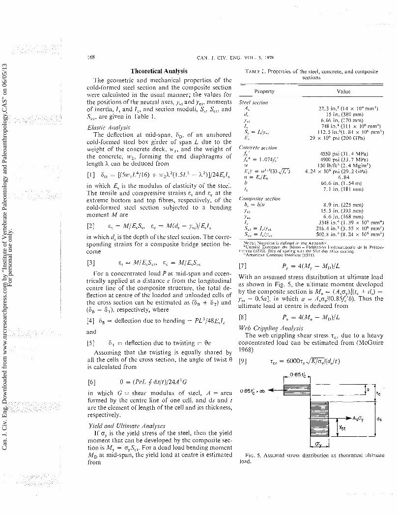
With an assunled stress distribution at ultimate load as shown in Fig. 5, the ultimate moment developed by the composite section is M,, = (Asoy)[(tc + c!,) - y,, - 0.5a], in which a = Aso,/(0.85f,'b). Thus the ultimate load at centre is deduced from
Web Cril)pling A ~ ~ ~ l y s i s The web crippling shear stress .rcr due to a heavy
concentrated load can be estimated from (McGuire L968)
FIG, 5. Assumed stress distribution a t theoretical ultimate load.
Can
. J. C
iv. E
ng. D
ownl
oade
d fr
om w
ww
.nrc
rese
arch
pres
s.co
m b
y "I
nstit
ute
of V
erte
brat
e Pa
leon
tolo
gy a
nd P
aleo
anth
ropo
logy
,CA
S" o
n 06
/05/
13Fo
r pe
rson
al u
se o
nly.
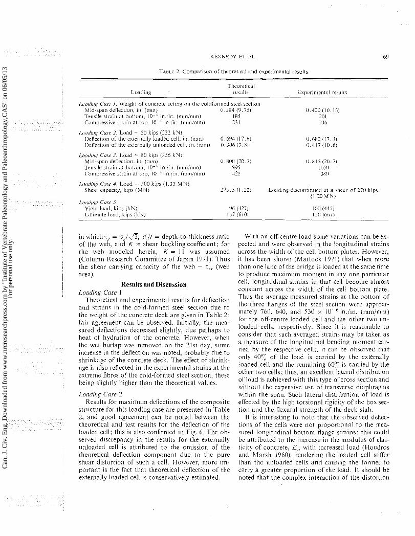
Tlicorctical Loading ~ C S L I ~ ts Experimcntal r c s ~ ~ l t s
Lo(rt1irrg Cnsc I. Weight of concrcte acting on thc colclformecl stccl scctiol~ Mid-span deflection, in. (nim) 0.384 (9.75) 0 . 4 0 0 (10.16) Tensile strain at hottom, lo-' in./in. (mni/rnm) 185 20 1 Compressive strain at top. 10~-(' in./in. (nim/mm) 23 1 236
f.O(/di/lg Cnsc 2 . Load = 50 kips (222 kN) Deflection of thc externally loaded ccll, in. (mm) 0.694 (17.6) Dcflcction of the externally unloaded cell, in. (mm) 0.336 (7 .8)
Lorrtlirlg CNSC 3. Load = SO kips (356 k N ) Mid-span deflection, in. (nim) 0 .800 (20.3) Tcnsile strain a t bottom, lo-' in./in. (mmimm) 995 Comprcssive strain at top, lo-" in./in. (rnm/mm) 42s
Loarlitig Crrrr 4 . Load = 300 kips (1 .33 M N ) Shear capacity, kips ( M N ) 273.5 (1.22) Loading discontin~lctl at a s l~car of 170 kips
(1.10 M N ) Loclrlillg crrsc 5
Yiclcl load, kips (kN) 06 (427) I 00 (445 ) Ultiliiate load, kips (kN) 137 (610) 150 (667)
in which T, = o,/,B, clJt = depth-to-thickness ratio of the web, and K = shear buckling coefficient; for the web modeled herein, K = 11 was assun~ed (Column Research Conlnlittee of Japan 1971). Thus the shear carrying capacity of the web = T,, (web area).
Results and Disc~ission Loadilirlg Case 1
Theoretical and experimental results for deflection and strains in the cold-formed steel section due to the weight of the concrete deck are given in Table 2 ; fair agreement can be observed. Initially, the mea- sured deflections decreased slightly, due perhaps to heat of hydration of the concrete. However, when the wet burlap was removed on the 21st day, some increase in the deflection was noted, probably due to shrinkage of the concrete deck. The effect of shrink- age is also reflected in the experimental strains at the extreme fibres of the cold-formed steel section, these being slightly higher than the theoretical values.
Loadiling Ccrse 2 Results for maxiniuni deflections of the composite
structure for this loading case are presented in Table 2, and good agreement can be noted between the theoretical and test results for the deflection of the loaded cell; this is also confirmed in Fig. 6. The ob- served discrepancy in the results for the externally unloaded cell is attributed to the omission of the theoretical deflection component due to the pure shear distortion of such a cell. However, more im- portant is the fact that theoretical deflection of the externally loaded cell is conservatively estimated.
With an off-centre load some variations can be ex- pected and were observed in the longit~~dinal strains across the width of the cell bottom plates. However, it has been shown (Mattock 1971) that when more than one lane of the'bridgc is loadeh a t the same time to produce maximum moment in any one particular cell, longitudinal strains in that cell become almost constant across tlie width of the cell bottom plate. Thus the average measured strains at the bottom of the three flanges of tlie steel section were approsi- luately 760. 640, and 530 x lo-' iin./in. (mm/mm) for the off-centre loaded cell and the other two un- loaded cells, respectively. Since i t is reasonable t o consider that such averaged strains may be taken as a measure of the longitudinal bending moment car- I ied by the respective cells, ~t can be observed that only 40'5 of tlic load is carried by the externally loaded cell and the remaining 60'; is carried by the other two cells: thus. an excellent lateral distribution of load is achieved with this type ofcross section and without the expensive use of transverse diaphragms within tlie span. Such lateral distribution of load is effected by the high torsional rigidity of the box sec- tion and the flexural strength of the deck slab.
It is interesting to note that the observed deflec- tions of the cells were not proportional to the mea- sured longitudinal bottom flange strains; this could be attributed to the increase in the ~iiodulus of elas- ticity of concrete, Ec, with increased load (Houdros and Marsh 196O), rendering the loaded cell stiffer than the unloaded cells and causing the former t o carry a greater proportion of the load. It should be noted that the con~plex interaction of the distortion
Can
. J. C
iv. E
ng. D
ownl
oade
d fr
om w
ww
.nrc
rese
arch
pres
s.co
m b
y "I
nstit
ute
of V
erte
brat
e Pa
leon
tolo
gy a
nd P
aleo
anth
ropo
logy
,CA
S" o
n 06
/05/
13Fo
r pe
rson
al u
se o
nly.

170 C A N . J . CIV. ENG. VOL. 5. 1978
Fic. 6. Comparison of thcorctical arid csperimental rcsults for dellection (loading case 2).
of the cross section and torsion in lnulticell box gir- ders with separated cells can be predicted by the folded plate theory (Mattock 1971). However, for this type of cross-sectional construction, it is simpler to analyze the cross section by first making an esti- mate of the portion of the loading that tends to de- form the most severely loaded cell and then assuming that this cell responds independently of the remain- der of the cross section. Warping stresses in the lon- gitudinal direction can be assumed to be small. tie- sults also confirm that distortion stresses from trans- verse flexure undergo reversal, especially near the junction of the steel box girder and the concrete deck when subjected to this type of loading. If the poten- tial number of cycles of such stress reversal is high, then the possibility of fatigue should be investigated.
Loatlitig Case 3 A conlparison of theoretical and experilnental re-
sults for this loading is shown in Table 2. Good agreenlent is noted between the theoretical and ex- perimental deflection a t centre of span. The dis- crepancy between the theoretical and experimental
strains, of approximately 1 can be attributed mainly to the transverse or local deformation of the three cells of the box girder when subjected to con- centrated load; due t o Poisson's effect, such defor- mation would augn~ent the longitudinal tensile stresses in the bottom flange of t h e cold-formed sec- tion and simultaneously reduce the longitudinal com- pressive stress in the top of the concrete deck; the stresses due to local deformation can be readily esti- mated (American Institute of Steel Construction 1963). Local stability of the thin plate elements o f the cells was not critical.
Loatlitig Case 4 Table 2 also gives a comparison between the theo-
retical and experimental results for the shear force carried by the web for this loading; the agreement is close. Moreover, from the observations of the end slip it was found that no slip occurred; this verifies the integrity of the bond between the concrete deck and the cold-formed steel section and that the shear lugs (part of the cold-formed steel box girder) had the required shear transfer capacity.
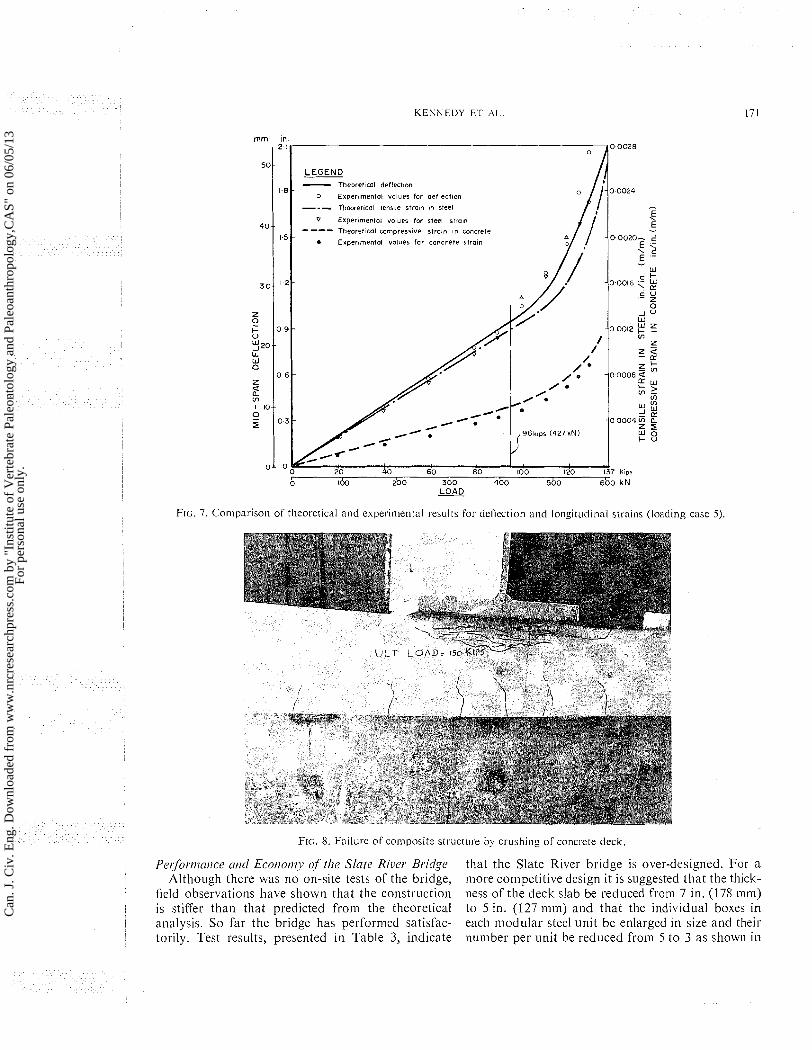
Loatlitig Case 5 - Figure 7 presents results for mid-span deflection,
tensile strain at the bottom of the cold-formed steel section, and the comp~-essive strain at the top of the concrete deck for the con~posite structure subjected to this loading. It can be observed that the test re- sults can be well predicted by the theoretical analysis. It appears that the bottonl fibre of the cold-formed steel section began to yield at a load of 100 kips (445 kN), which compares well w t h the predicted load of 96 kips (427 kN). Further increase in the applied load resulted in extensive yielding of the steel section at mid-span, thereby raising the neutral axis toward the concrete deck. Eventually this led t o secondary crushing of the concrete (Fig. 8) at a final collapse load of 150 kips (667 kN). However, prior to this load, deflections had already increased con- siderably at a load of 135 kips (600 kN), which is close to the predicted ultimate load of 137 kips (610 ItN). Slight buckling of the web was also observed a t advanced stages of loadlng, and this became critical at the collapse load; see Fig. 9. This oncoming in- stability was also verified by the strain readings from the transverse strain gauges on the web of the cold- formed steel box-girder section.
It should also be mentioned that the strains at the reentrant corners of the cold-formed steel box- girder section were measured by a number of suitably located strain gauges; the strains appeared to be rela- tively insignificant, due mainly t o the proximity of these corners to the neutral axis of the section of the composite structure.
Can
. J. C
iv. E
ng. D
ownl
oade
d fr
om w
ww
.nrc
rese
arch
pres
s.co
m b
y "I
nstit
ute
of V
erte
brat
e Pa
leon
tolo
gy a
nd P
aleo
anth
ropo
logy
,CA
S" o
n 06
/05/
13Fo
r pe
rson
al u
se o
nly.
K E N N E D Y E T Al.
LEGEND - Theoret~cal deflectmn
0 Expernmental values for def lectm --- Thewettcal tensile straln In sleel
V ex perm en to^ volues tor steel srror - --- Theoret~cal cornpresswe strojn In concrete
* Expermental volues for concrete slroln
W -00012 p 5
$00 3bo 400 500 6bo kN
FIG. 7. Comparison of theoretical and cxpcrimentnl results for detlection and longiti~clinal strains (loading case 5).
FIG. 8. Failure of composite s t r ~ ~ c t i ~ r e by c r~~sh ing of concrete deck.
Pet;fomntice atd Ecotiot~y of the Slate River Bridge that the Slate River bridge is over-designed. For a Although there was no on-site tests of the bridge, more competitive design it is suggested that the thick-
field observations have shown that the construction ness of the deck slab be reduced fro111 7 in. (178 mni) is stiffer than that predicted from the theoretical to 5 in. (127 n m ) and that the individual boxes in analysis. So far the bridge has performed satisfac- each modular steel unit be enlarged in size and their torily. Test results, presented in Table 3, indicate number per unit be reduced from 5 t o 3 as shown in
Can
. J. C
iv. E
ng. D
ownl
oade
d fr
om w
ww
.nrc
rese
arch
pres
s.co
m b
y "I
nstit
ute
of V
erte
brat
e Pa
leon
tolo
gy a
nd P
aleo
anth
ropo
logy
,CA
S" o
n 06
/05/
13Fo
r pe
rson
al u
se o
nly.
172 CAN. J . CIV. ENG. VOL. 5. 1978
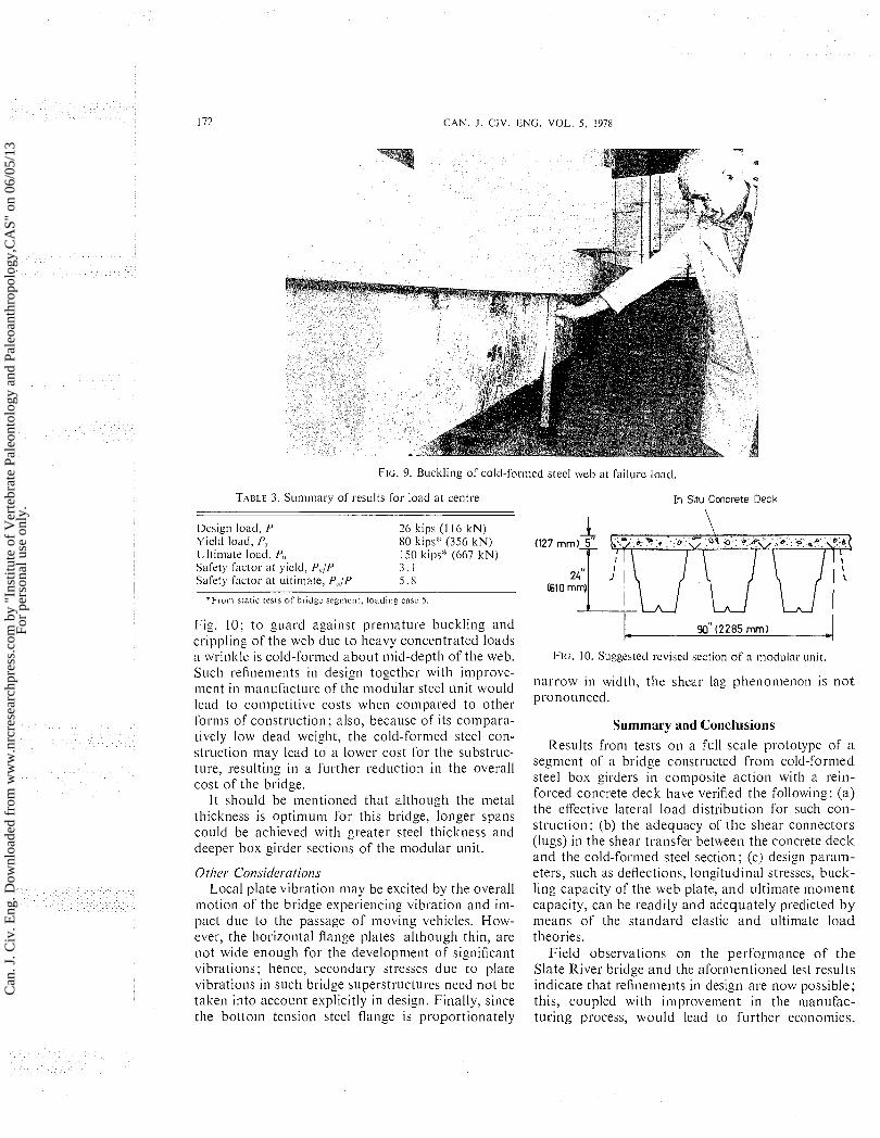
FIG. 9. Buckling of cold-formcd stecl web at failurc load.
TABLE 3. Su~nmauy of~.csi~lts for load at centre In Situ Concrete Deck
I \ Dcsign load, P 26 kips (I I6 kN) Yicld load, P? SO kips* (356 kN) Ultimate load, P,, 150 kips" (667 kN) Safety factor at yield, P,/P 3 . 1 Safety factor at i~ltiniate, P,,/P 5 . 8
*From slatic tests or bridge segment, loadiny: case 5
Fig. 10; to guard against premature buckling and crippling of the web due to heavy concentrated loads ;1 wrinkle is cold-formed about mid-de~ th of the web. FIG. 10. Suggested revised section of a modular unit.
Such refinements in design together with improve- ~iient in manufacture of the modular steel unit would narrow in width, the shear lag phenomenon is no t
lead to competitive costs when compared to other pronounced.
forms of construction; also, because of its compara- tively low dead weight, the cold-formed steel con- struction may lead to a lower cost for tlie substruc- ture, resulting in a further reduction in the overall cost of tlie bridge.
It should be mentioned that although the nietal thickness is optimuni for this bridge, longer spans could be achieved with greater steel thickness and deeper box girder sections of the modular unit.
Other Consir/erations Local plate vibration may be excited by the overall
motion of the bridge experiencing vibration and im- pact due to the passage of moving vehicles. How- ever, the horizontal flange plates although thin, are not wide enough for the development of significant vibrations; hence, secondary stresses due to plate vibrations in such bridge superstructures need not be taken into account explicitly in design. Finally, since the bottom tension steel flange is proportionately
Summary aud Conclusions Results from tests on a full scale prototype of a
segment of a bridge constructed from cold-formed steel box girders in coniposite action with a rein- forced concrete deck have verified the following: (a) the effective lateral load distribution for such con- struction; (b) the adequacy of the shear connectors (lugs) in the shear transfer between the concrete deck and the cold-formed steel section; (c) design param- eters, such as deflections, longitudinal stresses, buck- ling capacity of tlie web plate, and ultimate moment capacity, can be readily and adequately predicted by means of the standard elastic and ultimate load theories.
Field observations on the perforniance of the Slate River bridge and the aformentioned test results indicate that refinements in design are now possible; this, coupled with improvement in the nianufac- tiiring process, would lead to further econonlies.
Can
. J. C
iv. E
ng. D
ownl
oade
d fr
om w
ww
.nrc
rese
arch
pres
s.co
m b
y "I
nstit
ute
of V
erte
brat
e Pa
leon
tolo
gy a
nd P
aleo
anth
ropo
logy
,CA
S" o
n 06
/05/
13Fo
r pe
rson
al u
se o
nly.
K E N N E D Y ET AL.
Bearing in mind its inherent advantages, this type of construction has a real potential for short (and even medium) span bridges located in remote areas.
Acknowledgements The authors wish to thank the Steel Company of
Canada and Westeel-Rosco Ltd. for permission t o publish some of the experimental data reported herein.
A M E R I C A N CONCREIE I N S T I ~ I ~ U ~ I ~ E . 1971. Building code re- quirements for reinforced concrete. ACI 318-71.
AMERICAN I N S T ~ ~ I ~ U T E OF STEEL CONSTRUCT~ON. 1963. Design manual for orthotropic steel plate deck bridges.
CENTRE FOR APPLIED RESEARCH A N D E N G ~ N E E R ~ N C DESIGN INC., McMnster University. 1974. Phase I of tests of short span bridge components. Report to Steel Co. of Canada. Hxmilton, Ont.
COLUMN RESEARCH COMMIT-.I-EE OF JAPAN. 1971. Handbook of stl-uctufi11 stability. Corono Publishing Co. Ltd., Tokyo, Japan. pp. 3-21, 3-22.
COMITE E U R O P ~ E N DU Bi-[.ON - F ~ ? I ~ ~ R A T ~ O N INTER- NTZ.I.IONALE DE LA PRECONT.RAINTE. 1970. International re- commendations for the design and constl.uction of concrete s t~uc ture , principles and recommendations.
FUNG. C. 1973. Composite steel deck for short span bridge. Westeel-Rosco Limited Report. Toronto, Ont.
HOUDROS, G. . and MARSH, J . G. 1960. Load distribution in composite girder-slab systems. ASCE Jourml of the Struc- tural Division, 86(ST1 I ) , pp. 79-109.
KENNEDY. J . B., and MADUGULA, M. K. S . 1975. Casting anti testing of a composite beam of cold-formed steel profile and reinforced concrete slab. Industrial Research Institute of the University of Windsor, Report 8-41. Windsor. Ont.
M,z-r- roc^. A. H . 1971. Development ofdesign criteria for com- posite box girder bridges. Proceedings of the International Conference on Developments in Bridge Design and Construc- tion, University College, Cardiff. U.K.
MCGUIRE, W. 1968. Steel structures. Prentice-Hall, Inc., Englewood Cliffs. NJ. p. 767.
Appendix-Notation The following symbols are used in this paper.
A = area formed by the centre line of one cell of the box-girder cross section
n = depth of concrete stress block As = cross-sectional area of cold-formed steel
section of the box girder b = width of reinforced concrete deck 0, = b / ~ = equivalent width of steel slab
(1, = depth of cold-formed steel section Ec = modulus of elasticity of concrete E, = modulus of elasticity of steel e = eccentricity of concentrated load from
longitudinal centre line of structure fc = compressive strength of concrete on the
day of testing .fCr = 28-day compressive strength of concrete G = shear modulus of steel
= moment of inertia of composite section about its centroidal axis
= moment of inertia of cold-formed steel section about its centroidal axis
= critical elastic shear buckling coefficient = effective span of structure = dead load bending moment a t mid-span = ultimate moment carrying capacity = yield moment = modular ratio, Es/Ec = ultimate (yield) load at centre of span = section niodulus of coniposite section in
compression (tension) = section nlodulus of cold-formed steel
section in tension = thickness of cold-formed steel section
(concrete deck) = concentrated load i n kips (1 kip =
4.45 kN) = unit mass of concrete = distance of the extreme fibre in compres-
sion (tension) from the centroidal axis of the composite section
= distance of the extreme fibre in tension from the centroidal axis of the cold- formed steel section
= deflection due t o bending (twist) = tensile (compressive) strain due to bend-
ing = angle of twist a t mid-span, in radians = width of end diaphragm = Poisson's ratio for steel = yield stress of steel = critical web-buckling stress in shear = oy/ = yield stress in shear
Can
. J. C
iv. E
ng. D
ownl
oade
d fr
om w
ww
.nrc
rese
arch
pres
s.co
m b
y "I
nstit
ute
of V
erte
brat
e Pa
leon
tolo
gy a
nd P
aleo
anth
ropo
logy
,CA
S" o
n 06
/05/
13Fo
r pe
rson
al u
se o
nly.
Related Documents