1 Introduction We developeda mobile earthstationwhichincludes a modem usingmultiple blockcodedmodulation(MBCM) fortransmittingimagesinmobilesatellitecommunica- tions. This earth station adopts an unequal error protection technologywitherrorprotectionlevels correspondingto theimportanceofthedatabittransmitted. Asinthe environment of the mobile satellite communication, where thesignal-to-noiseratio ofreceived signalsconstantly fluctuates,itisexpected to enhancethereliabilityof communication [1] .In experimentsforcodemodulation technology using the Engineering Test Satellite VIII, the bit errorratewasmeasured asbasicperformanceand the performance of the multiple blockcodedmodulationina non-linearregionwerealsoevaluatedsinceperformance degradation due to non-linearity ofthe high power amplifierthroughpowerlimitationinthesatellitelink often occurred. Additionally, an earth station was mounted onavehicleandanimagetransmittingexperiment was performed during vehicle running. In this paper, the results of these experiments are described. 2 Image transmitting earth station using multiple block coded modulation Table 1shows specifications of the developedmodem in theimagetransmitting earth station.Numbersof multiple bundled symbols of multiple block coded modulation are 2, 4 and 6, that are selectable by a switch. A larger multiplenumber has ahigher error endurancefor the important bit. Other conventional modulation methods such asBPSK,QPSK and 8PSK can beselected for comparisonpurpose. MPEG4schemeisusedforimage codec.Ithas three protection levels (unequalerror protection)fortransmitted data corresponding to its importance. For example, whentransmitting images by IP packetsignals, threepiecesofinformationsuchasthe packet address informationinthe header of the frame, the headerof theimagesignal, andpart of imagedataare transmittedwitherrorprotectionof 17/750, 17/125and 102/125respectivelywhentheyaremultipleblockcoded withmultiplenumber 6. Thesecodingrates providethe minimumsquared Euclidean distance of 24.6, 24.0 and 4.0. The quality of total transmission data is enhanced by giving higherror endurance tothe frame header andthe image headerthathave strongerimpacton the quality of transmission. Multiplecodedmodulationis characterized byrealizingtheabovedifferent error protections usinga single coded modulation and demodulation scheme. Figure 1 shows a picture of the modulationanddemodulation. The radio-frequency componentofthe earth station has equivalent isotropically radiatedpower (EIRP) of 20dBW andfigureofmerit(G/T)of-15dBK. A flatantenna (phasedarray type) is usedfor the mobile earthstationin 41 3 Mobile Satellite Communication SystemExperiments CodedModulationTechniqueExperiment Shinichi TAIRAandHuan-Bang LI A mobileearth station usingthemultipleblockcoded modulation techniquehasbeen developedfor videoimage transmission. The performance evaluationtests for this earthstation were conductedvia the satellite communicationlink. Among the obtainedmeasurement results, thebiterrorrateperformancethroughthesatellitelinkisalmostthesameasthatofthe computer simulationresults, andthe degradationof the performance due tothe non-linearity of the satellite linkis very small. These results showthat the multiple codedmodulationtechnique is suitable for the satellite communications. Table1 Maincharacteristics of theMODEMpart Modulation :MBCM (k =2, 4, 6), BPSK, QPSK, 8PSK Information bit rate :65.8 kbps - 1579.2 kbps Error correcting code : Outer code :Reed-Solomon coding (204, 188) Inner Code :Convolutional coding (rate=1/2)/Viterbi decoding Block frame length :7500 symbols (Header :360 symbols, Data :7140 symbols) Band pass filter :Raised cosine filter (roll-off=0.3 ) Tx/Rx IF signal frequency :140 MHz band

Welcome message from author
This document is posted to help you gain knowledge. Please leave a comment to let me know what you think about it! Share it to your friends and learn new things together.
Transcript
1 Introduction
We developed a mobile earth station which includes a modem using multiple block coded modulation (MBCM) for transmitting images in mobile satellite communica-tions. This earth station adopts an unequal error protection technology with error protection levels corresponding to the importance of the data bit transmitted. As in the environment of the mobile satellite communication, where the signal-to-noise ratio of received signals constantly fluctuates, it is expected to enhance the reliability of communication[1]. In experiments for code modulation technology using the Engineering Test Satellite VIII, the bit error rate was measured as basic performance and the performance of the multiple block coded modulation in a non-linear region were also evaluated since performance degradation due to non-linearity of the high power amplifier through power limitation in the satellite link often occurred. Additionally, an earth station was mounted on a vehicle and an image transmitting experiment was performed during vehicle running. In this paper, the results of these experiments are described.
2 Image transmitting earth station using multiple block coded modulation
Table 1 shows specifications of the developed modem in the image transmitting earth station. Numbers of multiple bundled symbols of multiple block coded modulation are 2, 4 and 6, that are selectable by a switch. A larger multiple number has a higher error endurance for the important bit. Other conventional modulation methods
such as BPSK, QPSK and 8PSK can be selected for comparison purpose. MPEG4 scheme is used for image codec. It has three protection levels (unequal error protection) for transmitted data corresponding to its importance. For example, when transmitting images by IP packet signals, three pieces of information such as the packet address information in the header of the frame, the header of the image signal, and part of image data are transmitted with error protection of 17/750, 17/125 and 102/125 respectively when they are multiple block coded with multiple number 6. These coding rates provide the minimum squared Euclidean distance of 24.6, 24.0 and 4.0. The quality of total transmission data is enhanced by giving high error endurance to the frame header and the image header that have stronger impact on the quality of transmission. Multiple coded modulation is characterized by realizing the above different error protections using a single coded modulation and demodulation scheme. Figure 1 shows a picture of the modulation and demodulation. The radio-frequency component of the earth station has equivalent isotropically radiated power (EIRP) of 20 dBW and figure of merit (G/T) of -15 dBK. A flat antenna (phased array type) is used for the mobile earth station in
41
3 Mobile Satellite Communication System Experiments
Coded Modulation Technique Experiment
Shinichi TAIRA and Huan-Bang LI
A mobile earth station using the multiple block coded modulation technique has been developed for video image transmission. The performance evaluation tests for this earth station were conducted via the satellite communication link. Among the obtained measurement results, the bit error rate performance through the satellite link is almost the same as that of the computer simulation results, and the degradation of the performance due to the non-linearity of the satellite link is very small. These results show that the multiple coded modulation technique is suitable for the satellite communications.
Table 1 Main characteristics of the MODEM partModulation: MBCM (k =2, 4, 6), BPSK, QPSK, 8PSKInformation bit rate: 65.8 kbps - 1579.2 kbpsError correcting code: Outer code: Reed-Solomon coding (204, 188) Inner Code: Convolutional coding (rate=1/2)/Viterbi decodingBlock frame length: 7500 symbols (Header: 360 symbols, Data: 7140 symbols)Band pass filter: Raised cosine filter(roll-off=0.3)Tx/Rx IF signal frequency: 140 MHz band
Title:J2014E-3-2.ec9 Page:41 Date: 2014/12/02 Tue 16:08:02

this experiment because it can be easily mounted on a vehicle[2]. Table 2 shows major specifications of the antenna. The antenna gain shown in Table 2 is the value when the satellite elevation angle is 45 degrees. For tracking the satellite, we have the open loop method to be controlled by the position and the direction information from the vehicle, and the closed loop method for tracking the satellite by searching the maximum level of the signals through antenna’s own beam scanning. The continuously variable phase shifter that can shift phase continuously is adopted in order to reduce quantization error. The tracking speed is 30 degrees at maximum per second. It is an adequate speed for satellite tracking during normal vehicle driving unless a rapid change in direction occurs. Figure 2 shows the antenna with the radome removed. 18 antenna elements are arranged in circular symmetry manner. The satellite has no regenerative repeating function for this modulation method. The experiment was performed by setting the bent pipe mode to the satellite.
3 Basic transmission experiment
3.1 Bit error rateBit error rate (BER) that is a basic performance of a
digital modem was obtained[3]. Figure 3 shows measure-ment results with the block coding multiple number of 6 and symbol rate of 1200 ksps. In figure 3, L1, L2 and L3 have the coded rate 17/750, 17/125 and 102/125 respectively. The performance of BPSK is also obtained for comparison. The calculated BER of BPSK are analytical results. The calculated BER of block coded modulation are results of computer simulation[4]. Degradation of the measured value from the calculated value is as small as within 0.5 dB. This almost corresponds to the performance of the folding measurement using a translator at the frequency of 140 MHz band that is the input/output frequency of the modem of the earth station. It was confirmed that there was little performance degradation by passing through the satellite.
42 Journal of the National Institute of Information and Communications Technology Vol. 61 No. 1 (2014)
3 Mobile Satellite Communication System Experiments
Fig. 3 BER performance
Fig. 1 Photo of MODEM part
Table 2 Main characteristics of the antenna partAntenna element: Two-layer self-diplexing antenna Upper layer: Circular patch (Tx), Lower layer: Ring patch (Rx)Number of antenna elements: 18Phase shifter: Continuously variable type using double balanced mixersSize: φ440×H117 mm Weight: 18.7 kgFrequency : 2655.5~2658.0 MHz (Tx) : 2500.5~2503.0 MHz (Rx)Polarization: Left hand circular polarizationGain: 12.3 dBi (Tx), 14.5 dBi (Rx)EIRP: 26.3 dBW G/T: -12.3 dB/KTracking method: Closed loop or Open loopTracking speed: 30 degrees/second at maximum
Fig. 2 Photo of antenna part
Title:J2014E-3-2.ec9 Page:42 Date: 2014/12/02 Tue 16:08:03

3.2 BER performances through non-linear linkThe geostationary satellite is located at 36,000 km
above the equator. The distance from the earth station to the satellite is large. In satellite link, high power amplifier output for transmitting signals is often used near the saturation level. It is important to understand the transmission performance when the input/output charac-teristics are in the non-linear condition. (1) Test via translatorAs a pre-evaluation of an experiment using a satellite,
RF signal test was performed using a translator equipped at an S-band base station. In the test, the output of the modem was connected to the S-band base station, the transmission output signal with 2.6 GHz band of the high power amplifier at the S-band base station was input to the translator to transform it into receiving frequency of 2.5 GHz band. Then, it was input to the low noise amplifier of receiving system, 140 MHz band IF signals after frequency conversion were demodulated and the BER performance were obtained. The non-linearity of the link in this test was resulted from the non-linearity of the S-band base station’s high power amplifier. Figure 4 shows obtained non-linearity characteristics. In Figure 4, the horizontal axis indicates the output power of the modulator, i.e. the input power to the S-band base station and the vertical axis indicates the input power to the demodulator, i.e. the output power of the S-band base station. The operation point P1 with the input power value of -13.5 dBm to the S-band becomes 1 dB gain compression (1 dBGCP) whose value is compressed by 1 dB from the output of linear characteristics indicated by the straight line. The input power value to the S-band base station is changed based on this point P1. The BER was measured at three points including the operating point P1, P1+4 dB with the power input 4 dB larger than the input power at
the operating point P1, and P1-6 dB with the power input 6 dB smaller than the input power at the operating point P1. Figure 5 shows the BER performance of the multiple block coded method and the BER performance of 8PSK. As shown in Fig. 5, in the case of 8PSK, for example, when the BER is 1.0 × 10⁻⁴, P1+4 dB operating in the non-linear region has approximately 2 dB degradation compared to P1-6 dB operating in the linear region. Meanwhile, if the multiple block coded modulation is used, there is little performance degradation due to the effect of non-linearity. Therefore, it is reasonable to conclude that multiple block coded modualtion is more robust against the non-linearity.(2) Experiment via the satellite link[5]
Figure 6 shows input/output characteristics via the ETS-VIII. As with Fig 4, the horizontal axis in Fig. 6 indicates the output power of the modulator, i.e. the input power value to the S-band base station and the vertical axis
43
3-2 Coded Modulation Technique Experiment
Fig. 6 Non-linearity characteristics of S-band satellite linkFig. 4 Non-linearity characteristics for power amplifier of S-band
earth station
Fig. 5 BER performance via translator of S-band earth station
Title:J2014E-3-2.ec9 Page:43 Date: 2014/12/05 Fri 14:46:51

indicates the input power to the demodulator, i.e. the output power of the S-band base station. The operation point P1 with the input power value of -16.7 dBm to the S-band base station becomes 1 dB gain compression point. Input power to the high power amplifier is changed based on the point P1. Due to the operational radiated power limit of the satellite, P1+1.5 dB is the largest output in the experiment that is an input 1.5 dB larger than the operating point P1. At this time, the earth station operates in the linear region. The major cause of non-linearity is due to the effect of non-linearity of the high power amplifier of the satellite. Figure 7 shows the BER performance of multiple block
coded modulation. The BER of 8PSK are also shown for comparison. As shown in Fig. 7, at the maximum output, degradation is observed in 8PSK due to non-linearity of satellite link. In multiple block coded modulation, until BER approaches approximately 1.0 × 10⁻⁶, the result is almost as same as that of the linear region. The multiple block coded modulation is robust against non-linearity of link. It is appropriate for the satellite link.
4 Image transmission experiment
An image transmission experiment was performed during driving by mounting the earth station on a vehicle and setting the symbol rate to 1200 ksps. The total ratio between the received signal power and the noise power density (C/No) was approximately 72.5 dBHz when the mobile earth station vehicle is in static condition. If the satellite is in line-of-sight, the minimum value of C/No
value during driving was approximately 71 dBHz. The BER performance during image transmission was not measured. However, the minimum value of the ratio between the received power per 1 bit and the noise power density (Eb/No) is approximately 9.5 dBHz in the case of 102/125 with largest coding rate. The BER at this Eb/No is estimated to be 1 × 10⁻⁷. The developed modem has the normal mode in which the transmission data is categorized depending on importance and the test mode in which data is sorted randomly without specially categorizing them. If the transmission data is output by test mode, transmission of images was not completed during driving and images could not be regenerated at the receiving side. Meanwhile, in the normal mode where the transmission data was categorized depending on importance, images could be regenerated with little error. Figure 8 shows the transmission image and the received image in the experiment. It can be seen that the damage rate of images was approximately 2.5%. Error is observed slightly at the upper part of Fig. 8(b).
44 Journal of the National Institute of Information and Communications Technology Vol. 61 No. 1 (2014)
3 Mobile Satellite Communication System Experiments
(a)Transmitted image
Fig. 8 Image data transmission test
(b)Received image
Fig. 7 BER performance via satellite
Title:J2014E-3-2.ec9 Page:44 Date: 2014/12/04 Thu 18:11:39
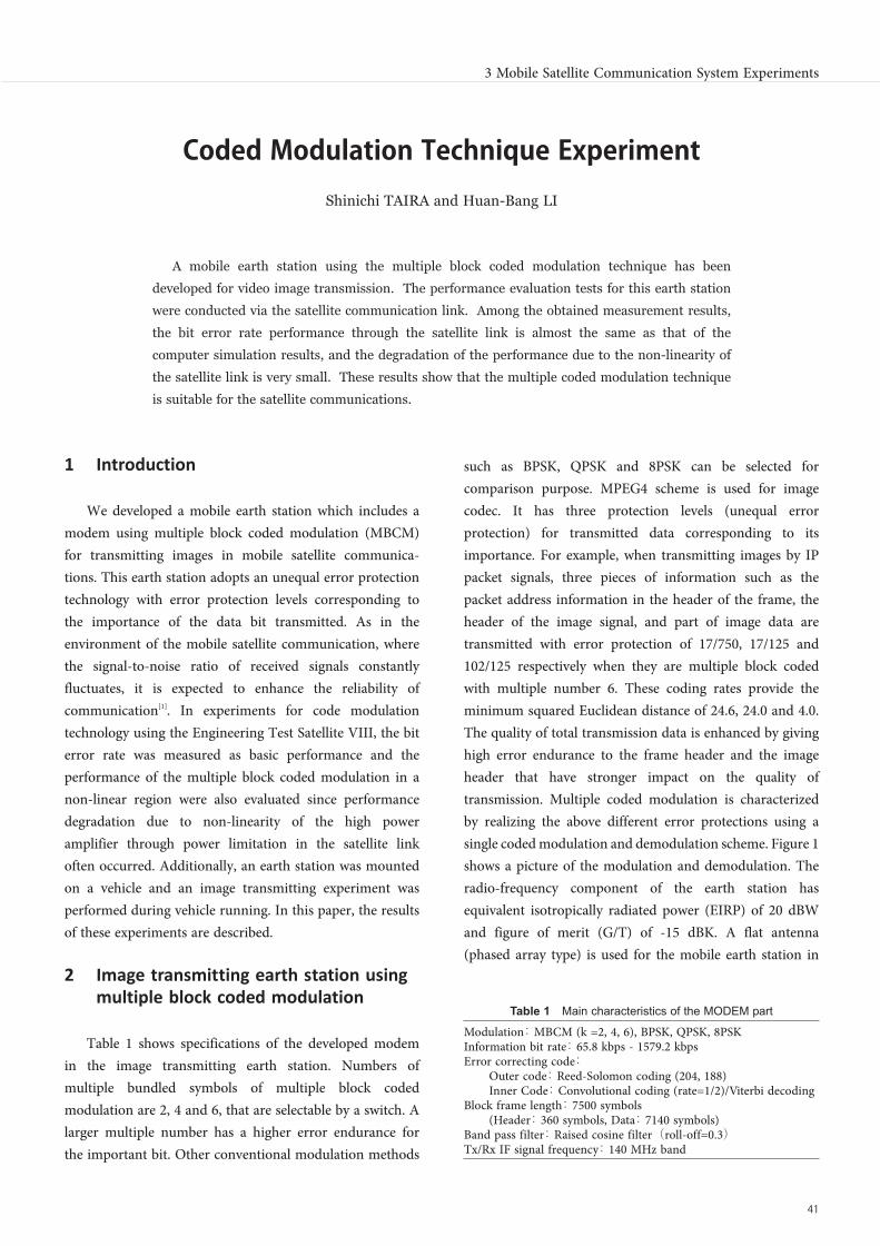
6 Conclusion
The image transmission earth station was developed for mobile satellite communication and experiments to evaluate its performance were conducted in satellite link using the ETS-VIII. This earth station uses the multiple block coded modulation in communication. The measured BER performance is as close as within 0.5 dB compared to that of computer simulation results. Little performance degradation was observed in the satellite link. The BER performance was also obtained in the non-linear region of the satellite link. Almost the same BER performance was obtained in the non-linear region as that in the linear region. Further, the earth station was mounted on a vehicle and image transmission tests were performed during driving. It was confirmed that image transmission with little error can be realized by coding the transmission data depending on their importance. From these test results using an actual geostationary satellite, the multiple block coded modulation is verified suitable for mobile satellite communication link.
Acknowledgments
We express our appreciation to many people who engaged in development of the Engineering Test Satellite VIII. Especially, we express our heartfelt thanks to Mitsugu OKAWA, Senior Researcher who participated in the development of the modem and Hiroshi WATANABE who was in charge of conducting experiments.
References 1 H.-B. Li and M. Ohkawa, “A Modem Developed for Unequal Error Protection Using Multiple Block-Coded Modulation,” 21st International Communications Satellite Systems Conference, AIAA-2003-2241, April, 2003
2 A. Miura, Y. Fujino, S. Taira, N. Obata, M. Tanaka, T. Ojima, and K. Sakauchi, “S-band Active Array Antenna with Analog Phased Shifters using Double Balanced Mixers for Mobile SATCOM Vehicles,” IEEE Trans. Antenna and Propagation, Vol. 53, No. 8, Aug. 2005.
3 H. Watanabe, S. Yamamoto, and S. Taira, “Measurement of Coded Modulation with Unequal Error Protection using ETS-VIII,” IEICE General Conference 2008, March 2008.(in Japanese)
4 H.-B. Li and M. Ohkawa, “Coded Modulation Equipment with Unequal Error Protection,” Journal of the Communications Research Laboratory, Vol. 50, Nos. 3/4, pp. 219-224, Sept./Dec. 2003.
5 H. Watanabe, S. Yamamoto, and S. Taira, “Nonlinear Transmission Performance of Block Coded Modulation using ETS-VIII Earth Station,” IEICE Society Conference 2008, Sept. 2008.(in Japanese)
45
3-2 Coded Modulation Technique Experiment
Huan-Bang LI, Dr. Eng.Senior Researcher, Dependable Wireless Laboratory, Wireless Network Research InstituteMobile Satellite Communication, Coded Modulation, Ultra Wide Band (UWB)
Shinichi TAIRAAssociate Director, Space Communication Systems Laboratory, Wireless Network Research InstituteMobile Satellite Commnication, Switching System
Title:J2014E-3-2.ec9 Page:45 Date: 2014/12/02 Tue 16:08:06
Related Documents
![Trellis-Coded Modulation [TCM]](https://static.cupdf.com/doc/110x72/618ad19974abd138231352ca/trellis-coded-modulation-tcm.jpg)