Diesel Mechanic: Module PDF - Mining Qualifications Authority - All rights reserved. Created : 01 February 2003 Revised : March 2015 Owner : Learnership Department First Published : March 2003 Revision No: 002 TRG 9 Page 1 of 78 DIESEL MECHANIC CODE: PDF MAINTAIN FUEL SYSTEMS

Welcome message from author
This document is posted to help you gain knowledge. Please leave a comment to let me know what you think about it! Share it to your friends and learn new things together.
Transcript

Diesel Mechanic: Module PDF
- Mining Qualifications Authority - All rights reserved.
Created : 01 February 2003
Revised : March 2015
Owner : Learnership Department
First Published : March 2003
Revision No: 002
TRG 9
Page 1 of 78
DIESEL MECHANIC
CODE: PDF
MAINTAIN FUEL SYSTEMS

Diesel Mechanic: Module PDF
- Mining Qualifications Authority - All rights reserved.
Created : 01 February 2003
Revised : March 2015
Owner : Learnership Department
First Published : March 2003
Revision No: 002
TRG 9
Page 2 of 78
INDEX
The following elements are contained in this learning guide:
TOPIC PAGE NUMBER
Index 2
Objective 3
Source reference 4
Dictionary 6
The fuel system 7
The fuel lift pump 8-11
Fuel filters 11-18
Fuel injector pumps 18-31
Timing the engine 32-35
Remove an injector pump 36-37
Replace the injector pump 38-40
Fuel injectors 41-49
Bleeding a fuel system 50-52
Fault finding a fuel system 53-54
Common Rail diesel fuel system 56-58
High pressure fuel pump 59
Fuel metering control valve 60-62
High pressure regulator valve 62
High pressure accumulator (common rail) 63
Fuel rail pressure sensor 64-68
Fuel injectors 69-72
Engine management closed loop control functions 73
Fuel system diagnosis 74-75
SELF TEST 76-77

Diesel Mechanic: Module PDF
- Mining Qualifications Authority - All rights reserved.
Created : 01 February 2003
Revised : March 2015
Owner : Learnership Department
First Published : March 2003
Revision No: 002
TRG 9
Page 3 of 78
1. MODULE OBJECTIVE
To enable the learner to maintain the fuel system of a diesel engine.
2. LEARNING OBJECTIVES
On completion of this module the learner must be able to:
2.1 State the function of the various components in the fuel system.
2.2 Do fault finding on a diesel engine fuel system.
2.3 Maintain the fuel system of a diesel engine.
3. ASSESSMENT AND EVALUATION CRITERIA
3.1 A theory and practical test will be set at the end of the module and must be
completed without using references.
3.2 The learner will be required to correctly state
(a) the function of the various components of a diesel engine fuel system, and
(b) the symptoms of the various faults that may occur in a diesel engine.
3.3 The learner will be required to do a complete maintenance of a diesel engine fuel system to the following standards.
(a) The gauze filter on the fuel pump must not be damaged.

Diesel Mechanic: Module PDF
- Mining Qualifications Authority - All rights reserved.
Created : 01 February 2003
Revised : March 2015
Owner : Learnership Department
First Published : March 2003
Revision No: 002
TRG 9
Page 4 of 78
(b) There must not be any oil leaks at the fuel lift and the injector pump.
(c) There must not be any fuel leaks at the fuel lift and injector pumps or the fuel filters and the injectors.
(d) There must not be any damage to any fasteners or bleed screws.
(e) All the fasteners must be tightened to the correct specifications.
(f) There must not be any damage to fuel pipes or fittings.
(g) Precautions must be taken to prevent dirt from entering the fuel system at any
point.
(h) The engine must start, attain maximum revolutions and be able to idle.
(i) There must be no symptoms of faulty equipment in the fuel system.
3.4 All safety procedures must be adhered to.
4. ADDITIONAL RESOURCES
4.1 A demonstration by a competent person e.g. a Training Officer.
4.2 Workshop manual for the diesel engine.
4.3 Audio-visual aids (if available).
COPYRIGHT
All rights reserved. No part of this document may be quoted or reproduced without the
prior written permission of the Mining Qualifications Authority.

Diesel Mechanic: Module PDF
- Mining Qualifications Authority - All rights reserved.
Created : 01 February 2003
Revised : March 2015
Owner : Learnership Department
First Published : March 2003
Revision No: 002
TRG 9
Page 5 of 78
HAZARD IDENTIFICATION AND CONTROL (HIAC) FORM
MAINTAIN FUEL SYSTEMS
STEPS IN OPERATION /
PROCESS
POTENTIAL ACCIDENT /
INCIDENT
CONTROLS (BY
RESPONSIBLE PERSON)
1. Use hand tools
2. Test injectors and
bleed the fuel system
Using damaged tools or wrong tools for the job can cause injury and damage to equipment.
Diesel fuel can be detrimental to health if it comes into contact with eyes and skin.
Always use the correct tool for the job.
Ensure tools are in good condition.
Use tools correctly.
Wear appropriate PPE where necessary.
Always take good care of tools. Maintain, clean and store it properly.
Exercise care to prevent fuel spray from coming into contact with eyes or hands.
NOTE:Before doing the practical work contained in this module, the learner must study
the content of the above HIAC form again and then sign the statement below.
The above risks, which will be encountered in this module, are fully understood and
will be controlled during the practical work.
Signature of Learner:……………………………………….
Signature of Training Officer:…………………………………
Date:…………………………..
Diesel Mechanic: Module PDF
- Mining Qualifications Authority - All rights reserved.
Created : 01 February 2003
Revised : March 2015
Owner : Learnership Department
First Published : March 2003
Revision No: 002
TRG 9
Page 6 of 78
DICTIONARY
APP- Accelerator pedal position sensor B+ - Battery positive CKP- Crankshaft position sensor DPF- Diesel particulate filter DTC- Diagnostic trouble code EDC- Electronic diesel control ECM- Electronic control module ECT- Engine coolant temperature sensor HP - High pressure MIL- Malfunction indicator light PWM- Pulse with modulation

Diesel Mechanic: Module PDF
- Mining Qualifications Authority - All rights reserved.
Created : 01 February 2003
Revised : March 2015
Owner : Learnership Department
First Published : March 2003
Revision No: 002
TRG 9
Page 7 of 78
THE FUEL SYSTEM
Introduction
Module PDS illustrated that the fuel is injected into the cylinder in the form of a fine spray, at
the end of the compression stroke just before the piston is at top dead centre.
The method by which it is done is explained in this module
Types of fuel systems
In the first system the fuel oil is fed into the injection pump by a fuel lift pump (Fig. 1).
The fuel lift pump "lifts" the fuel from the tank through the filter into the injector pump.
The injector pump conveys the fuel in measured quantities, and at the appropriate times, to the injector atomisers.
Fig. 1

Diesel Mechanic: Module PDF
- Mining Qualifications Authority - All rights reserved.
Created : 01 February 2003
Revised : March 2015
Owner : Learnership Department
First Published : March 2003
Revision No: 002
TRG 9
Page 8 of 78
a. This second system is basically the same as the first except that there is no fuel lift
pump and the fuel tank is placed higher than the filter and injector pump (Fig. 2), and
the fuel is gravity fed to the injector pump.
THE FUEL LIFT PUMP
Operating principle
The lift pump is of the diaphragm type. It is normally fitted on the camshaft side of the engine and is driven by an eccentric on the engine camshaft
(Fig. 3 next page).
Fuel Tank
Fuel Tank
Fig. 2

Diesel Mechanic: Module PDF
- Mining Qualifications Authority - All rights reserved.
Created : 01 February 2003
Revised : March 2015
Owner : Learnership Department
First Published : March 2003
Revision No: 002
TRG 9
Page 9 of 78
Fig. 3

Diesel Mechanic: Module PDF
- Mining Qualifications Authority - All rights reserved.
Created : 01 February 2003
Revised : March 2015
Owner : Learnership Department
First Published : March 2003
Revision No: 002
TRG 9
Page 10 of 78
When the eccentric on the camshaft rotates, it lifts the rocker arm which in turn pulls down the diaphragm which creates a vacuum in the pump chamber. This causes the fuel to flow from the tank into the pump chamber.
During the return stroke the spring forces the diaphragm upwards and pushes the fuel through the valve into the injector pump.
A hand priming lever is fitted in order to prime the fuel system if the supply of fuel from the tank fails at any time. This will be discussed in detail later in this module.
Test a fuel lift pump
Disconnect the pipe that runs from the lift pump to the injector pump.
Operate the hand priming lever. A spurt of fuel should be emitted from the outlet port of the pump every time that the hand priming lever is depressed.
NB: If the hand lever cannot be depressed, rotate the engine one revolution in order to
turn the eccentric on the camshaft from its maximum lift position
Service a fuel lift pump
Stop and isolate the engine.
Shut off the fuel supply to the pump.
Clean the outside of the pump and surrounding area thoroughly.
Disconnect all the fuel pipes from the lift pump.
Remove the securing nuts and washers.
Withdraw the pump.
Remove the gauze strainer.

Diesel Mechanic: Module PDF
- Mining Qualifications Authority - All rights reserved.
Created : 01 February 2003
Revised : March 2015
Owner : Learnership Department
First Published : March 2003
Revision No: 002
TRG 9
Page 11 of 78
Clean and replace the strainer.
Replace the pump and reconnect the fuel pipes.
Restore the fuel supply to the pump and check that there are no fuel or oil leaks at the pump.
NB: For further details refer to the workshop manual for the engine in your training
centre.
DO THE PRACTICE BEFORE CONTINUING WITH THE REST OF THE MODULE.
PRACTICE
If the engine in your training centre is fitted with a lift pump, do the following:
(a) Test the lift pump.
(b) Remove, service and replace the pump.
Ask your Training Officer to check your work and if it is correct, to sign below and then go on
to the next section.
LEARNER TRAINING OFFICER
DATE:………………………..
SIGNED:……………………..
DATE:…………………………
SIGNED:……………………….

Diesel Mechanic: Module PDF
- Mining Qualifications Authority - All rights reserved.
Created : 01 February 2003
Revised : March 2015
Owner : Learnership Department
First Published : March 2003
Revision No: 002
TRG 9
Page 12 of 78
FUEL FILTERS
The fuel pump and injector components of a diesel engine are machined to very close tolerances and are very expensive. Consequently, they must be protected from damage and wear caused by contaminants in the fuel.
Contaminants that could be present in diesel fuel are dirt, bacteria, water and rust.
These contaminants are removed with the aid of fuel filters mounted in the fuel system.
Types of filters
The filtering material and the construction of the filter are the same as for air and oil filters
and are available with replaceable cartridge or "spin-on" canisters.
A fuel system can have
up to three filters, namely a primary, a secondary, and a final stage, or
more commonly, two filters (a primary and final stage), or
one single filter which combines the water separator and the filter element,
NB: Different combinations of filters are used in different vehicles. It is,
therefore, important that you acquaint yourself with the system used on
the vehicle you work on.
Filter elements
3.1 Primary filter elements consist of saturating paper pleated to provide a larger filtering area
(Fig. 4(a)),
(Fig. 4(b)). or packed into a metal container (next page)

Diesel Mechanic: Module PDF
- Mining Qualifications Authority - All rights reserved.
Created : 01 February 2003
Revised : March 2015
Owner : Learnership Department
First Published : March 2003
Revision No: 002
TRG 9
Page 13 of 78
3.3 Secondary filter elements can be either of high grade saturating paper (Fig. 5(a)), or of
resin impregnated paper pleated to provide a larger filtering area (Fig. 5(b)).
Fig.5a Fig. 5b
Fig. 4a Fig. 4b

Diesel Mechanic: Module PDF
- Mining Qualifications Authority - All rights reserved.
Created : 01 February 2003
Revised : March 2015
Owner : Learnership Department
First Published : March 2003
Revision No: 002
TRG 9
Page 14 of 78
3.4 The single filter or combination filter/water trap (final stage) shown in Fig. 6 incorporates
an element of resin impregnated paper similar to that shown in Fig. 4(b).
Fig. 6

Diesel Mechanic: Module PDF
- Mining Qualifications Authority - All rights reserved.
Created : 01 February 2003
Revised : March 2015
Owner : Learnership Department
First Published : March 2003
Revision No: 002
TRG 9
Page 15 of 78
Service a fuel filter
The drain plug must be loosened and the water drained off daily. This can be done while the
engine is running. However, it is recommended that it be drained during the daily service
whilst the engine is stopped.
Replace a fuel filter element
Refer to Fig. 7
Stop and isolate the engine.
Shut off the fuel supply to the filter
Fig. 7
Loosen bolt to
remove filter element
Vent screw
Filter element
Water trap
Water drain
plug

Diesel Mechanic: Module PDF
- Mining Qualifications Authority - All rights reserved.
Created : 01 February 2003
Revised : March 2015
Owner : Learnership Department
First Published : March 2003
Revision No: 002
TRG 9
Page 16 of 78
Clean the outside of the filter and surrounding area thoroughly.
Drain the filter.
Open the filter housing and remove the old cartridge element.
Wipe the inside of the housing clean with a clean linen cloth.
Install the new cartridge, taking care that it is the right way up.
Replace the drain plug and close the drain cock. See Fig. 7.
Turn on the fuel.
Refill the filter housing with clean fuel.
Replace the cover gasket if it shows any signs of damage.
Fit the gasket and tighten the cover.
Purge the filter; i.e. bleed off any air, which may be present in it.
Start and run the engine and check the filter for leaks.
Wipe up any spilt fuel.
Replace a srew-on canister fuel filter
Stop and isolate the engine.
Shut off the fuel supply.
Clean the outside of the filter and surrounding area.

Diesel Mechanic: Module PDF
- Mining Qualifications Authority - All rights reserved.
Created : 01 February 2003
Revised : March 2015
Owner : Learnership Department
First Published : March 2003
Revision No: 002
TRG 9
Page 17 of 78
Unscrew the canister.
Wipe the face of the filter seat with a clean linen cloth.
Make sure the gasket fit securely to the seat (Fig. 8).
Fill the canister with clean fuel.
Screw the canister onto the seat.
Turn on the fuel and purge the filter.
Start and run the engine and check the filter for leaks.
Wipe up any spilt fuel.
NB: Refer to workshop manual if necessary
DO THE PRACTICE BELOW BEFORE CONTINUING WITH THE REST OF THE MODULE.
Rubber gasket
Screw on filter
Fig. 8

Diesel Mechanic: Module PDF
- Mining Qualifications Authority - All rights reserved.
Created : 01 February 2003
Revised : March 2015
Owner : Learnership Department
First Published : March 2003
Revision No: 002
TRG 9
Page 18 of 78
PRACTICE
Replace the fuel filters of a diesel engine.
Ask your Training Officer to check your work and if it is correct, to sign below and then go on
to the next section.
LEARNER TRAINING OFFICER
DATE:………………………..
SIGNED:……………………..
DATE:…………………………
SIGNED:……………………….
FUEL INJECTOR PUMPS
Operating principle
The most important unit in the fuel system of a diesel engine is the injector pump. It delivers identical quantities of fuel oil to the injector of each cylinder.
The fuel oil is sprayed into the cylinder at a higher pressure than the compression pressure.
Fig. 9 illustrates the basic principle of a fuel pump and an injector.

Diesel Mechanic: Module PDF
- Mining Qualifications Authority - All rights reserved.
Created : 01 February 2003
Revised : March 2015
Owner : Learnership Department
First Published : March 2003
Revision No: 002
TRG 9
Page 19 of 78
The two types of injector pumps commonly used in the mining industry namely the multiple
plunger pump and the distributor pump, are described below
Types of fuel injector pumps
Multiple plungerpump.
This unit has a plunger pump for each cylinder. (See Fig. 10 next page and the display board). The plungers are operated by a camshaft.
Fig. 9

Diesel Mechanic: Module PDF
- Mining Qualifications Authority - All rights reserved.
Created : 01 February 2003
Revised : March 2015
Owner : Learnership Department
First Published : March 2003
Revision No: 002
TRG 9
Page 20 of 78
The quantity of fuel that is delivered to each piston is regulated by the helical groove in the plunger (Fig. 11 next page).
Plunger
Camshaft
Fig. 10

Diesel Mechanic: Module PDF
- Mining Qualifications Authority - All rights reserved.
Created : 01 February 2003
Revised : March 2015
Owner : Learnership Department
First Published : March 2003
Revision No: 002
TRG 9
Page 21 of 78
The plungers can be rotated by means of a rack and pinion to increase or decrease the quantity of fuel supplied to the cylinders. This in turn increases or decreases the speed of the engine (Fig. 12).
Fig. 12
Fig.11

Diesel Mechanic: Module PDF
- Mining Qualifications Authority - All rights reserved.
Created : 01 February 2003
Revised : March 2015
Owner : Learnership Department
First Published : March 2003
Revision No: 002
TRG 9
Page 22 of 78
The unit is equipped with a governor to control the maximum and idling speeds of the engine.
A delivery valve is housed in the discharged union at the top of each pump assembly
(Fig. 13 next page).
This valve acts basically as a non-return valve. At the end of the delivery stroke, the fuel pressure is suddenly reduced so that the delivery valve is closed at once by the influence of its spring. This action instantaneously terminates the fuel spray into the cylinder, thereby eliminating any tendency of the fuel to dribble.

Diesel Mechanic: Module PDF
- Mining Qualifications Authority - All rights reserved.
Created : 01 February 2003
Revised : March 2015
Owner : Learnership Department
First Published : March 2003
Revision No: 002
TRG 9
Page 23 of 78
Distributorpump.
In the distributor type injector pump, the fuel is pumped by a single element regardless of the number of engine cylinders.
The fuel charges are distributed in the correct firing order by a rotary distributor integrated with the pump. (See Fig. 14 next page and the display board).
Fig. 13

Diesel Mechanic: Module PDF
- Mining Qualifications Authority - All rights reserved.
Created : 01 February 2003
Revised : March 2015
Owner : Learnership Department
First Published : March 2003
Revision No: 002
TRG 9
Page 24 of 78
The pressure of the fuel entering the pump is raised to an intermediate level by the transfer pump.
This transfer pressure is controlled by the metering valve (see Fig. 15) which is operated by the engine throttle. The valve regulates the quantity of fuel that flows into the pumping section from where it is pumped into the injector. Thus the valve controls the speed of the engine.
Fig. 14

Diesel Mechanic: Module PDF
- Mining Qualifications Authority - All rights reserved.
Created : 01 February 2003
Revised : March 2015
Owner : Learnership Department
First Published : March 2003
Revision No: 002
TRG 9
Page 25 of 78
When the rotor turns, the fuel subjected to transfer pressure flows in through a port in the head and through another in the rotor, down the central passage and into the space between the plungers, forcing them apart. This is the inlet stroke (Fig. 15).
When rotation continues, the inlet port is closed. When the radial distribution port in the rotor comes in line with an outlet port in the head, the plungers are forced together by the cams and the fuel is expelled into one of the injectors. This is called the injection stroke .
Fig. 15

Diesel Mechanic: Module PDF
- Mining Qualifications Authority - All rights reserved.
Created : 01 February 2003
Revised : March 2015
Owner : Learnership Department
First Published : March 2003
Revision No: 002
TRG 9
Page 26 of 78
Fuel pump timing
The injection of the fuel must be timed accurately so that its commencement corresponds with the position of the piston when the latter is approaching the end of its compression stroke.
Usually the manufacturer's marks engraved on the pump coupling represent the position at which the No.1 plunger of the fuel pump commences to deliver its fuel (Fig. 16) . These are called the pump timing marks.
NB: The No. 1 plunger of the pump is the one that supplies the fuel to the No. 1 piston. In general, this piston is the one situated in the front of the engine on the opposite end to the flywheel. You will have to refer to your workshop manual to determine which is the No. 1 piston of the engine.
Fig. 16

Diesel Mechanic: Module PDF
- Mining Qualifications Authority - All rights reserved.
Created : 01 February 2003
Revised : March 2015
Owner : Learnership Department
First Published : March 2003
Revision No: 002
TRG 9
Page 27 of 78
If no timing marks are found on the fuel pump, there are three methods that can be used to
determine or check the timing marks.
(a)The concave method
For this method sufficient fuel must be supplied to the pump. To carry out this method:
Set the control levers at the fully open position.
Disconnect the pipe union of the No. 1 plunger.
Wipe off the surplus fuel with a clean finger so as to leave a concave surface on the fuel remaining in the pump delivery passage. Do not use a cloth.
Slowly turn the pump's shaft in the correct direction of rotation (this is indicated on the pump) until the concave surface suddenly flattens. This indicated that the plunger is just commencing to deliver fuel.
This method is suitable for use with both types of pumps.
(b)Spill timing method
This method can be used only with the multiple plunger type.
A device consisting of a standard injector pipe assembly, shaped as shown in Fig. 17 on the
next page, and with the open end cut at an acute angle, is used in this method.

Diesel Mechanic: Module PDF
- Mining Qualifications Authority - All rights reserved.
Created : 01 February 2003
Revised : March 2015
Owner : Learnership Department
First Published : March 2003
Revision No: 002
TRG 9
Page 28 of 78
Remove the standard union and the delivery valve of the No. 1 plunger.
Screw the spill pipe onto the union of the No. 1 plunger on the pump.
Connect a lift pump onto the pump inlet.
Move the control lever to the fully open position.
Turn the pump shaft in the correct direction while the lift pump is operated, until the fuel flows out of the spill pipe (Fig. 18).
Fig 17
Spill pipe
Cut at a
angle

Diesel Mechanic: Module PDF
- Mining Qualifications Authority - All rights reserved.
Created : 01 February 2003
Revised : March 2015
Owner : Learnership Department
First Published : March 2003
Revision No: 002
TRG 9
Page 29 of 78
3. Refit the union and
screw on the spill pipe
shown in fig. 17
2. Remove the delivery
valve and spring
1. Unscrew the union
Fig. 18

Diesel Mechanic: Module PDF
- Mining Qualifications Authority - All rights reserved.
Created : 01 February 2003
Revised : March 2015
Owner : Learnership Department
First Published : March 2003
Revision No: 002
TRG 9
Page 30 of 78
Slowly continue to turn the pump shaft until the flow of fuel is gradually reduced and finally stops.
This is the exact moment of commencement of fuel injection.
Check the pump timing marks.
Injector tester method
This method can be used only with the distributor pump.
Remove the pump from the engine.
Fill the tester (shown in Fig. 19) with clean fuel oil.
Fig. 19
Connect injector
for testing
Reservoir for
diesel fuel
Pressure gauge

Diesel Mechanic: Module PDF
- Mining Qualifications Authority - All rights reserved.
Created : 01 February 2003
Revised : March 2015
Owner : Learnership Department
First Published : March 2003
Revision No: 002
TRG 9
Page 31 of 78
Expel the air from the pump by operating the hand lever until the fuel, which issues from the outlet pipe, is free from bubbles.
Connect the No. 1 injector outlet connection on the pump to the outlet pipe of the tester.
Turn the pump by hand until it locks. This is the exact moment of commencement of fuel injection.
Check the pump timing marks.
DO THE PRACTICE BEFORE CONTINUING WITH THE REST OF THE MODULE
PRACTICE
Determine and check the timing marks of fuel injector pumps in the following ways:
(a) The multiple plunger pump by applying the "concave" and "spill" timing methods.
(b) The distributor pump by applying the "concave" and "injector tester" method.

Diesel Mechanic: Module PDF
- Mining Qualifications Authority - All rights reserved.
Created : 01 February 2003
Revised : March 2015
Owner : Learnership Department
First Published : March 2003
Revision No: 002
TRG 9
Page 32 of 78
Ask your Training Officer to check your work and if it is correct, to sign below and then go on
to the next section.
LEARNER TRAINING OFFICER
DATE:………………………..
SIGNED:……………………..
DATE:…………………………
SIGNED:……………………….
Usually manufacturers engrave marks on the flywheel rim to represent the top dead centre
(TDC) of the No. 1 piston. This can be the TDC at either the exhaust stroke or the
compression stroke.
To ensure that the No. 1 piston is at the TDC on its compression stroke, remove the tappet
cover and do the following:
Turn the engine in the correct direction (clockwise) until the valves of the No. 1 piston are in a "rocking position". This is the position where the exhaust valve will start to close and immediately after it has closed, the inlet valve will start to open. (Fig. 20).

Diesel Mechanic: Module PDF
- Mining Qualifications Authority - All rights reserved.
Created : 01 February 2003
Revised : March 2015
Owner : Learnership Department
First Published : March 2003
Revision No: 002
TRG 9
Page 33 of 78
Check that the TDC mark on the crank pulleyl lines up with the marker (Fig. 21). If you turn the engine backwards from this position, the exhaust valve will start to open. If you turn it forward the inlet valve will start to open.
Intake valve start to open and
exhaust valve start to close
Cam follower
Valve return spring
Valve
Fig. 20

Diesel Mechanic: Module PDF
- Mining Qualifications Authority - All rights reserved.
Created : 01 February 2003
Revised : March 2015
Owner : Learnership Department
First Published : March 2003
Revision No: 002
TRG 9
Page 34 of 78
Turn the flywheel in the same direction as before through another 360 (one complete turn) until the TDC marks lines up with the marker again. Now the No. 1 piston is at the TDC on the compression stroke.
Injection commences from 10 - 30 before TDC. This is usually marked INJ (INJECT) on the flywheel rim.
Now turn the flywheel backwards until the INJ mark lines up with the marker.
NB: If the timing of the engine is set correctly, the pump timing marks must also
line up in this position.
Replace the tappet cover.
NB: For further details refer to the workshop manual.
Fig. 21

Diesel Mechanic: Module PDF
- Mining Qualifications Authority - All rights reserved.
Created : 01 February 2003
Revised : March 2015
Owner : Learnership Department
First Published : March 2003
Revision No: 002
TRG 9
Page 35 of 78
DO THE PRACTICE BELOW BEFORE CONTINUING WITH THE REST OF THE MODULE.
PRACTICE
Line up the INJ (INJECT) marks on the compression stroke of the diesel engine.
Ask your Training Officer to check your work and if it is correct, to sign below and then go on
to the next section.
LEARNER TRAINING OFFICER
DATE:………………………..
SIGNED:……………………..
DATE:…………………………
SIGNED:……………………….

Diesel Mechanic: Module PDF
- Mining Qualifications Authority - All rights reserved.
Created : 01 February 2003
Revised : March 2015
Owner : Learnership Department
First Published : March 2003
Revision No: 002
TRG 9
Page 36 of 78
Remove an injector pump
Stop and isolate the engine.
Clean the outside of the pump and the surrounding area.
Ensure that the No. 1 piston is on the compression stroke.
Turn the engine so that the INJ mark on the flywheel lines up with the marker.
Check if the pump timing marks are lined up.
Remove all the pipes between the injector pump and all the injectors.
NB: Blank off all the pipe ends, the ports on the injectors and the injector pump
with plastic caps to prevent dirt entering.
(Fig. 22)
Remove the fuel pipes between the filter and injector pump.
Disconnect the accelerator and "stop" levers.
Fig. 22 Plastic caps on all fuel
openings

Diesel Mechanic: Module PDF
- Mining Qualifications Authority - All rights reserved.
Created : 01 February 2003
Revised : March 2015
Owner : Learnership Department
First Published : March 2003
Revision No: 002
TRG 9
Page 37 of 78
Remove the pump securing nuts and washers.
Remove the pump.
For further details refer to the workshop manual.
DO THE PRACTICE ON THE NEXT PAGE BEFORE CONTINUING WITH THE REST OF
THE MODULE
PRACTICE
Remove the injector pump from a diesel engine.
Ask your Training Officer to check your work and if it is correct, to sign below and then go on
to the next section.
LEARNER TRAINING OFFICER
DATE:………………………..
SIGNED:……………………..
DATE:…………………………
SIGNED:……………………….

Diesel Mechanic: Module PDF
- Mining Qualifications Authority - All rights reserved.
Created : 01 February 2003
Revised : March 2015
Owner : Learnership Department
First Published : March 2003
Revision No: 002
TRG 9
Page 38 of 78
Replace the injector pump
Line up the engine marks. The INJ must be on the compression stroke (Fig. 23).
Line up the pump timing marks. If there are no timing marks on the pump you can determine the timing position by applying any of the methods described previously in these notes. The method you use is obviously dependent on the type of pump you are working with.
Fit the pump to the engine.
Fig. 23 Injection take place
between 10 and 15
degree

Diesel Mechanic: Module PDF
- Mining Qualifications Authority - All rights reserved.
Created : 01 February 2003
Revised : March 2015
Owner : Learnership Department
First Published : March 2003
Revision No: 002
TRG 9
Page 39 of 78
NB: The engine drive should be connected to the pump shaft at the latter's
coupling or splines, without altering the positions of the crankshaft or pump
shaft. The fuel injection timing will be correct if this is done.
Replace and tighten the securing bolts and nuts of the pump.
Replace all the fuel pipes.
Replace the tappet cover.
Replace the accelerator and "stop" linkage.
NB: For further details refer to the workshop manual.
DO THE PRACTICE ON THE NEXT PAGE BEFORE CONTINUING WITH THE REST OF
THE MODULE.

Diesel Mechanic: Module PDF
- Mining Qualifications Authority - All rights reserved.
Created : 01 February 2003
Revised : March 2015
Owner : Learnership Department
First Published : March 2003
Revision No: 002
TRG 9
Page 40 of 78
PRACTICE
Replace the injector pump of a diesel engine.
Ask your Training Officer to check your work and if it is correct, to sign below and then go on
to the next section.
LEARNER TRAINING OFFICER
DATE:………………………..
SIGNED:……………………..
DATE:…………………………
SIGNED:……………………….

Diesel Mechanic: Module PDF
- Mining Qualifications Authority - All rights reserved.
Created : 01 February 2003
Revised : March 2015
Owner : Learnership Department
First Published : March 2003
Revision No: 002
TRG 9
Page 41 of 78
FUEL INJECTORS
Construction and operation
An injector consists of a rigid metal piece. In this metal piece is a needle valve, nozzle and control spring (Fig. 24).
1. Leak off port 7. Fuel Gallery 13. Needle Valve
2. Leak off cap 8. Tapered needle shoulder 14. One of 3 feed holes
3. Injector Spring 9. Nozzle Body 15. Supply Hole
4. Lower spring plate 10. Spray Holes 16. Spindle
5. Clamping Flange 11. Nozzle Tip 17. Inlet Port 6. Nozzle Holder 12. Needle and Nozzle seat 18. Spring cap adjustment nut
Fig. 24

Diesel Mechanic: Module PDF
- Mining Qualifications Authority - All rights reserved.
Created : 01 February 2003
Revised : March 2015
Owner : Learnership Department
First Published : March 2003
Revision No: 002
TRG 9
Page 42 of 78
The fuel enters the injector through the supply pipe and fills the fuel channel.
As pressure builds up in the pump it tends to lift the valve off its seat. The valve is held against the seat by the compression spring in the injector head. When the pressure of the fuel overcomes the tension of the spring, the valve is lifted from its seat and the fuel is injected into the cylinder. This reduces the pressure of the fuel and the valve returns to its seat.
The fuel, which escapes past the valve is returned to the tank and is used to lubricate the parts. This also eliminates the possibility of air entering the system.
The tension of the spring can be adjusted in the injector head.
The injectors supply the required amount of fuel received from the injector pump to the cylinder in the form of a spray. The fuel is thus burnt as efficiently as possible.
The form of the spray varies with the different types of nozzle used in the injector. The name of the injector is taken from the type of nozzle used. There are basically three types of nozzles used, namely,
- pintle type nozzles (Fig. 25).
- multi-hole nozzles (Fig. 26).
- single hole nozzles (Fig. 27).

Diesel Mechanic: Module PDF
- Mining Qualifications Authority - All rights reserved.
Created : 01 February 2003
Revised : March 2015
Owner : Learnership Department
First Published : March 2003
Revision No: 002
TRG 9
Page 43 of 78
Fig. 25
Fig. 26 Fig. 27
Diesel Mechanic: Module PDF
- Mining Qualifications Authority - All rights reserved.
Created : 01 February 2003
Revised : March 2015
Owner : Learnership Department
First Published : March 2003
Revision No: 002
TRG 9
Page 44 of 78
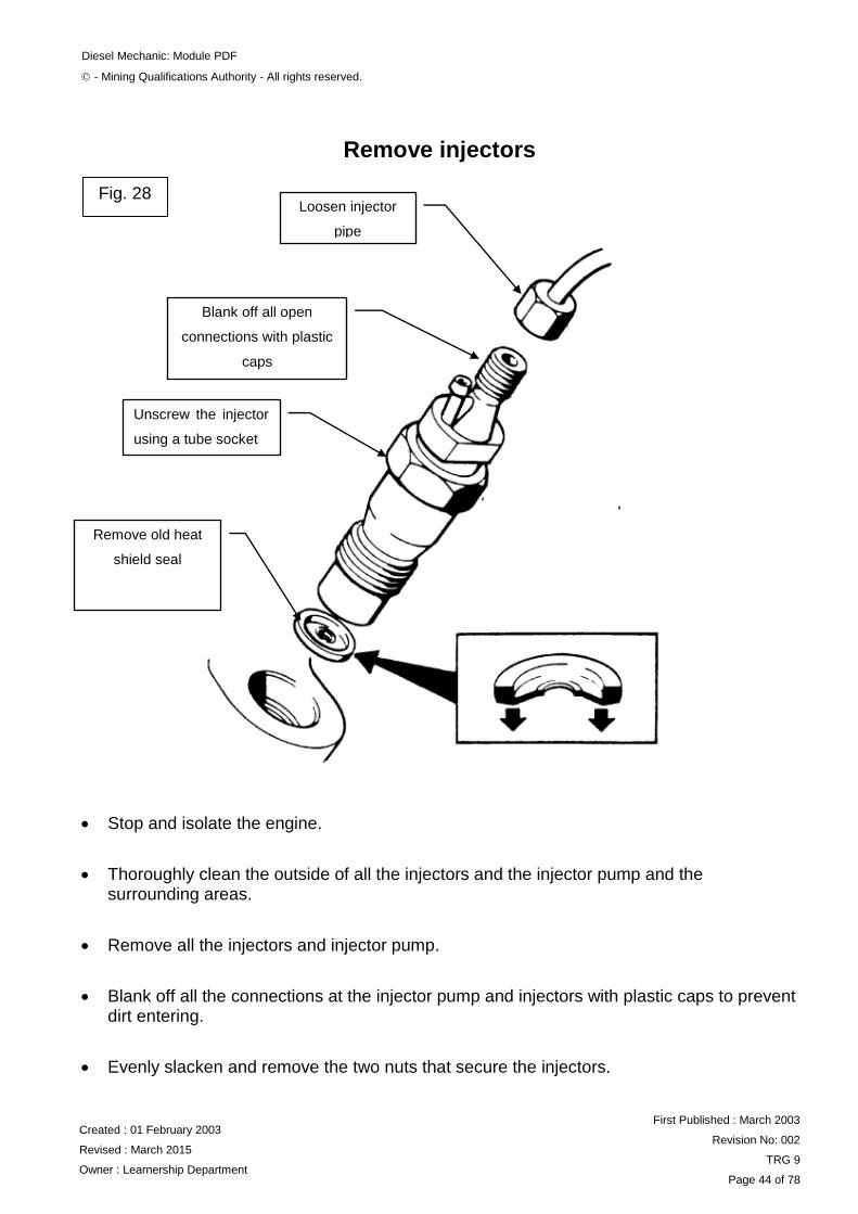
Remove injectors
Stop and isolate the engine.
Thoroughly clean the outside of all the injectors and the injector pump and the surrounding areas.
Remove all the injectors and injector pump.
Blank off all the connections at the injector pump and injectors with plastic caps to prevent dirt entering.
Evenly slacken and remove the two nuts that secure the injectors.
Remove old heat
shield seal
Blank off all open
connections with plastic
caps
Unscrew the injector
using a tube socket
Loosen injector
pipe
Fig. 28

Diesel Mechanic: Module PDF
- Mining Qualifications Authority - All rights reserved.
Created : 01 February 2003
Revised : March 2015
Owner : Learnership Department
First Published : March 2003
Revision No: 002
TRG 9
Page 45 of 78
Gently and evenly prise the injectors out of position.
Remove the injectors and cover their nozzles with protective caps.
Remove the copper washer in the injector port.
Clean the ports and blank them off with a piece of cloth to prevent dirt entering.
DO THE PRACTICE BEFORE CONTINUING WITH THE REST OF THE MODULE.
PRACTICE
Remove all the injectors from a diesel engine.
Ask your Training Officer to check your work and if it is correct, to sign below and then go on
to the next section.
LEARNER TRAINING OFFICER
DATE:………………………..
SIGNED:……………………..
DATE:…………………………
SIGNED:……………………….
Test injectors
3.1 The following is one method that may be used to test an injector:
Remove the injectors and then re-connect them to the fuel supply pipes.
Position the injector nozzles away from the engine.

Diesel Mechanic: Module PDF
- Mining Qualifications Authority - All rights reserved.
Created : 01 February 2003
Revised : March 2015
Owner : Learnership Department
First Published : March 2003
Revision No: 002
TRG 9
Page 46 of 78
Bleed the air from the supply pipes, and examine the sprays from the injectors while the engine is turned by the starter motor or by hand cranking.
3.2 The more general method of testing an injector is to make use of a lever-operated
injector tester (pump) shown in Fig. 29.
FIG. 29
Fill the container with clean fuel oil.
Expel the air from the test pump by operating the hand lever until the fuel that is free from air bubbles, issues from the outlet pipe.
Mount the injector on the pump (Fig. 30).
Fig. 29
Connect injector
for testing
Reservoir for
diesel fuel
Pressure gauge

Diesel Mechanic: Module PDF
- Mining Qualifications Authority - All rights reserved.
Created : 01 February 2003
Revised : March 2015
Owner : Learnership Department
First Published : March 2003
Revision No: 002
TRG 9
Page 47 of 78
Check the pressure at which the needle valve opens.
Compare this pressure with the specified setting pressure.
Examine the spray of the injector by pumping at about 60 strokes per minute. The correct spray should appear as a fine mist without distortion and without visible streaks of unvaporised fuel.
Check that the nozzle tip is still dry on completion of the fuel injection.
If the injector does not operate satisfactorily on testing, it should be replaced.
NB: Care must always be exercised to prevent the fuel spray coming into
contact with your hands or eyes.
DO THE PRACTICE BELOW BEFORE CONTINUING WITH THE REST OF THE MODULE.
PRACTICE
Test the three types of injectors on an injector tester and record your findings on a piece of
paper.
Ask your Training Officer to check your work and if it is correct, to sign below and then go on
to the next section.
LEARNER TRAINING OFFICER
DATE:………………………..
SIGNED:……………………..
DATE:…………………………
SIGNED:……………………….

Diesel Mechanic: Module PDF
- Mining Qualifications Authority - All rights reserved.
Created : 01 February 2003
Revised : March 2015
Owner : Learnership Department
First Published : March 2003
Revision No: 002
TRG 9
Page 48 of 78
Replace injectors
Remove the cloth in the injector ports.
Place new copper washers into the recess in the injector ports.
Remove the plastic caps from the injectors.
Place the injectors into their ports. Ensure that the pipe connections are facing the correct direction.
Screw on all the injectors’ retaining nuts and "finger tighten” them.
Tighten all the retaining nuts to ±8Nm.
Install a new heat
shield seal
Remove all plastic caps
from fuel ports
Tighten the injector
using a tube socket
Tighten injector
pipe
Fig. 30

Diesel Mechanic: Module PDF
- Mining Qualifications Authority - All rights reserved.
Created : 01 February 2003
Revised : March 2015
Owner : Learnership Department
First Published : March 2003
Revision No: 002
TRG 9
Page 49 of 78
Tighten the nuts to the torque specified in the workshop manual.
Remove the plastic caps from the injector pipe connections and on the injector pump.
Replace the injector pipes. All the pipes are set for their respective positions. No attempt should be made, therefore, to bend any of the pipes in order to fit them.
Replace the fuel overflow pipe on the top of the injectors.
DO THE PRACTICE BELOW BEFORE CONTINUING WITH THE REST OF THE MODULE.
PRACTICE
Replace the fuel injectors of a diesel engine.
Ask your Training Officer to check your work and if it is correct, to sign below and then go on
to the next section.
LEARNER TRAINING OFFICER
DATE:………………………..
SIGNED:……………………..
DATE:…………………………
SIGNED:……………………….

Diesel Mechanic: Module PDF
- Mining Qualifications Authority - All rights reserved.
Created : 01 February 2003
Revised : March 2015
Owner : Learnership Department
First Published : March 2003
Revision No: 002
TRG 9
Page 50 of 78
BLEEDING A FUEL SYSTEM
Procedure to bleed a fuel system
Slacken the air vent screw (A) at the front side of the governor control cover.
Slacken one of the two hydraulic head locking screws (B).
B- Supply fuel
connection
D- Injector pump
pipe unions
A- Governor
control air vent
screw
C- Secondary fuel
filter
Fuel lift pump with
priming lever
Fig. 31

Diesel Mechanic: Module PDF
- Mining Qualifications Authority - All rights reserved.
Created : 01 February 2003
Revised : March 2015
Owner : Learnership Department
First Published : March 2003
Revision No: 002
TRG 9
Page 51 of 78
NB: If the pump is installed in such a position that one head locking screw is
higher than the other, the screw at the higher level must be slackened.
Unscrew by two or three turns, the vent plug (C) at the top of the filter cover. (This is not the return pipe to the tank).
Operate the priming lever on the feed pump or the separate hand primer. When fuel, which is free of air bubbles, issues from each venting point, tighten the screws in the following order:
- Filter cover vent screw (C)
- Head locking screw (B)
- Governor vent screw (A)
Slacken the pipe union nut (D) at the pump inlet. Operate the priming device and retighten the union nut when the fuel issuing from around the threads is free from air bubbles.
Slacken the unions at the injector ends of two of the high-pressure pipes.
Set the accelerator at the fully open position and ensure that the control is in the "run" position.
Turn the engine until the fuel oil, which must be free of air bubbles, issues from both injector pipes.
Tighten the unions on the injector pipes. The engine is now ready for starting and running.
Start the engine and check that it can attain the maximum RPM that it will handle.

Diesel Mechanic: Module PDF
- Mining Qualifications Authority - All rights reserved.
Created : 01 February 2003
Revised : March 2015
Owner : Learnership Department
First Published : March 2003
Revision No: 002
TRG 9
Page 52 of 78
DO THE PRACTICE BELOW BEFORE CONTINUING WITH THE REST OF THE MODULE
PRACTICE
Practice bleeding the fuel system of a diesel engine, starting the engine,
and running it at half the idling speed and at the maximum prescribed RPM.
Ask your Training Officer to check your work and if it is correct, to sign below and then go on
to the next section.
LEARNER TRAINING OFFICER
DATE:………………………..
SIGNED:……………………..
DATE:…………………………
SIGNED:……………………….

Diesel Mechanic: Module PDF
- Mining Qualifications Authority - All rights reserved.
Created : 01 February 2003
Revised : March 2015
Owner : Learnership Department
First Published : March 2003
Revision No: 002
TRG 9
Page 53 of 78
FAULT FINDING A FUEL SYSTEM
Symptoms of faulty injectors
Engine will not start or is difficult to start.
Lack of power.
The engine misfires.
Excessive fuel consumption.
Black exhaust smoke.
Knock in the engine.
Erratic running.
Vibration.
The engine overheats
Symptoms of a faulty fuel lift pump
Engine will not start or is difficult to start.
Lack of power.
The engine misfires.
Knock in the engine.
Erratic running.
The symptoms of a blocked fuel filter
Engine will not start of is difficult to start.
Lack of power.
The engine misfires.
Erratic running.
The engine starts and stops.
The symptoms of a faulty injector pump
Engine will not start or is difficult to start.
Lack of power.
The engine misfires.
Excessive fuel consumption.
Black exhaust smoke.
Erratic running.
Vibration.
The engine overheats.

Diesel Mechanic: Module PDF
- Mining Qualifications Authority - All rights reserved.
Created : 01 February 2003
Revised : March 2015
Owner : Learnership Department
First Published : March 2003
Revision No: 002
TRG 9
Page 54 of 78
The symptoms of incorrect injection pump timing
Engine will not start or is difficult to start.
Lack of power.
The engine misfires.
Excessive fuel consumption.
Black exhaust smoke.
Blue/white exhaust smoke
Knock in the engine.
The engine overheats.
The symptoms of air in the fuel system
Engine will not start or is difficult to start.
Lack of power.
The engine misfires.
Erratic running.
The engine stops and starts.
NB: (a) It is essential to use a systematic approach when doing faultfinding.
Your Training Officer will demonstrate this to you.
(b) Working on a diesel engine simulator will greatly assist you to develop
systematic fault finding skills.
Ask your Training Officer to check your work and if it is correct, to sign below.
LEARNER TRAINING OFFICER
DATE:………………………..
SIGNED:……………………..
DATE:…………………………
SIGNED:……………………….

Diesel Mechanic: Module PDF
- Mining Qualifications Authority - All rights reserved.
Created : 01 February 2003
Revised : March 2015
Owner : Learnership Department
First Published : March 2003
Revision No: 002
TRG 9
Page 55 of 78
THE FOLLOWING PART OF THIS MODULE CONTAINS
WORK ON EXTREMELY HI PRESSURE. DIESEL
INJECTION TO ANY PART OF YOUR BODY CAN BE
DANGEROUS.

Diesel Mechanic: Module PDF
- Mining Qualifications Authority - All rights reserved.
Created : 01 February 2003
Revised : March 2015
Owner : Learnership Department
First Published : March 2003
Revision No: 002
TRG 9
Page 56 of 78
COMMON RAIL DIESEL FUEL SYSTEM
Advantages of common rail:
• Fuel pressure available on demand.
• Higher injection pressures and finer atomization of fuel.
• Injection pressure created independent of engine speed.
• Multiple injections per cylinder combustion are possible.
Benefits of common rail:
• Reduction of overall exhaust emissions.
• Reduction of particulate emissions.
• Reduction of noise emissions.
• Improved fuel efficiency.
• Higher performance.
Fig. 32

Diesel Mechanic: Module PDF
- Mining Qualifications Authority - All rights reserved.
Created : 01 February 2003
Revised : March 2015
Owner : Learnership Department
First Published : March 2003
Revision No: 002
TRG 9
Page 57 of 78
Examples of typical common rail system maximum fuel
pressures:
Bosch:
Generation 1: up to 1350 Bar (19845 psi). Unijet
Generation 2: up to 1600 Bar (23520 psi) EDC 16
Generation 3: up to 2000 Bar + (29400 psi)
Denso:
1 st generation: up to 1450 Bar (21315 psi) ECD-U2P
2 nd generation: 1800 Bar + (26460 psi) HP3/HP4
Delphi
Multec: up to 2000 Bar
Direct acting diesel common rail system: up to 2000 Bar
Various systems differ in design, components layout and specific functions.
However, all operate in a similar way.
The fuel system can be divided into three basic circuits
• Low pressure supply circuit
• High pressure delivery circuit
• Fuel leak back and return

Diesel Mechanic: Module PDF
- Mining Qualifications Authority - All rights reserved.
Created : 01 February 2003
Revised : March 2015
Owner : Learnership Department
First Published : March 2003
Revision No: 002
TRG 9
Page 58 of 78
Components overview (example: Bosch EDC 16)
Fig. 33

Diesel Mechanic: Module PDF
- Mining Qualifications Authority - All rights reserved.
Created : 01 February 2003
Revised : March 2015
Owner : Learnership Department
First Published : March 2003
Revision No: 002
TRG 9
Page 59 of 78
Basic function
To ensure that enough fuel is delivered at sufficient pressure across the engine’s entire
operating range. This includes delivery of sufficient fuel for a rapid engine start and
pressure increase in the rail.
High pressure fuel pump
Fig. 34
Diesel Mechanic: Module PDF
- Mining Qualifications Authority - All rights reserved.
Created : 01 February 2003
Revised : March 2015
Owner : Learnership Department
First Published : March 2003
Revision No: 002
TRG 9
Page 60 of 78
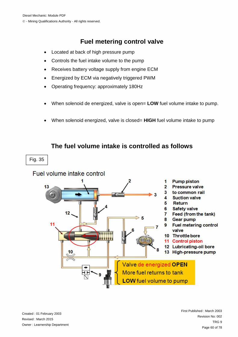
Fuel metering control valve
Located at back of high pressure pump
Controls the fuel intake volume to the pump
Receives battery voltage supply from engine ECM
Energized by ECM via negatively triggered PWM
Operating frequency: approximately 180Hz
When solenoid de energized, valve is open= LOW fuel volume intake to pump.
When solenoid energized, valve is closed= HIGH fuel volume intake to pump
The fuel volume intake is controlled as follows
Fig. 35

Diesel Mechanic: Module PDF
- Mining Qualifications Authority - All rights reserved.
Created : 01 February 2003
Revised : March 2015
Owner : Learnership Department
First Published : March 2003
Revision No: 002
TRG 9
Page 61 of 78
Advantages of fuel intake volume regulation
• Only the required volume of fuel is supplied to the common rail from
the high pressure pump.
• Reduced fuel flow around system results in lower fuel return flow
temperature.
• Reduced parasitic load on engine from high pressure pump contributes
towards further reductions in exhaust emissions.
Fig. 37
Fig. 36

Diesel Mechanic: Module PDF
- Mining Qualifications Authority - All rights reserved.
Created : 01 February 2003
Revised : March 2015
Owner : Learnership Department
First Published : March 2003
Revision No: 002
TRG 9
Page 62 of 78
Fuel metering control valve failure symptoms and diagnosis
Solenoid circuit monitored by engine ECM.
If an open or short circuit is detected:
Engine stops or will not start.
DTC stored and MIL illuminated.
Mechanical failure of the metering control valve does not necessarily prevent the
engine from starting
Mechanical faults can cause DTC’s relating to positive or negative rail pressure
deviations.
High pressure regulator valve
System variant.
Fitted to back of HP pump.
Controls high pressure fuel delivery to common rail.
Excess fuel returns to tank
Fig. 38

Diesel Mechanic: Module PDF
- Mining Qualifications Authority - All rights reserved.
Created : 01 February 2003
Revised : March 2015
Owner : Learnership Department
First Published : March 2003
Revision No: 002
TRG 9
Page 63 of 78
High pressure accumulator (common rail)
Fuel is supplied to the common rail at high pressure from the high pressure pump.
The rail stores the fuel and distributes it to the individual injectors.
It also damps pressure vibrations caused by the high pressure pump and injection
processes.
Typical volume of fuel held in common rail: 16 – 20cm³.
Typical fuel rail pressure with engine idling and at running temperature:
approximately between 300 – 400 Bar (4410 – 5880 psi)
Typical maximum possible fuel rail pressure:
approximately between 1600 – 2000 Bar (23520 – 28400 psi)
Due to the extremely high working fuel pressures in the common rail fuel
system, NEVER slacken fuel or injector pipes or try to disconnect
components of the fuel system whilst the engine is running and high
pressure is present in the system!
Typical maximum possible fuel rail pressure:
approximately between 1600 – 2000 Bar (23520 – 28400 psi)
Fig. 39

Diesel Mechanic: Module PDF
- Mining Qualifications Authority - All rights reserved.
Created : 01 February 2003
Revised : March 2015
Owner : Learnership Department
First Published : March 2003
Revision No: 002
TRG 9
Page 64 of 78
Fuel rail pressure sensor
Monitors the fuel pressure in the common rail.
Typically a piezo resistive type sensor.
Three wires:
5 Volt supply from engine ECM.
Sensor ground via engine ECM.
Linear signal voltage output to ECM.
Signal utilization:
To enable the engine ECM to determine the fuel rail pressure
Used by the ECM as part of the calculation for the % duty cycle applied
to the rail pressure control solenoid and fuel metering solenoid.
The resistive value of the sensor creates a change in the voltage on the
signal wire relative to the fuel rail pressure.
Fig. 40
Fig. 41
Diesel Mechanic: Module PDF
- Mining Qualifications Authority - All rights reserved.
Created : 01 February 2003
Revised : March 2015
Owner : Learnership Department
First Published : March 2003
Revision No: 002
TRG 9
Page 65 of 78
Typical signal voltages from rail pressure sensor:
(Example figures Bosch EDC16)
Engine stationary: approximately 0.5 volts.
Engine idling: approximately 1.32 volts.
Snap acceleration: approximately 3.77 volts +
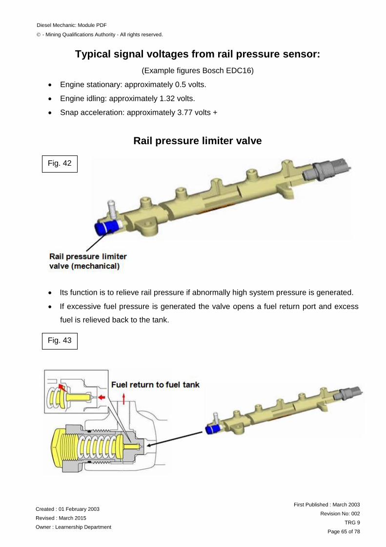
Rail pressure limiter valve
Its function is to relieve rail pressure if abnormally high system pressure is generated.
If excessive fuel pressure is generated the valve opens a fuel return port and excess
fuel is relieved back to the tank.
Fig. 43
Fig. 42

Diesel Mechanic: Module PDF
- Mining Qualifications Authority - All rights reserved.
Created : 01 February 2003
Revised : March 2015
Owner : Learnership Department
First Published : March 2003
Revision No: 002
TRG 9
Page 66 of 78
Example operating pressure of rail pressure:
limiter valve (Denso HP3 system):
valve opens at 230 MPa (2300 Bar)
valve closes at 50 MPa (500 Bar)
Fuel rail pressure control valve solenoid
A rail pressure control valve solenoid is fitted to the common rail on
some systems
The valve controls fuel pressure by opening and closing a return port in the rail.
Excess fuel returns to the fuel tank via the fuel return.
Receives battery voltage supply from engine ECM
Energized by engine ECM via a negatively triggered PWM.
Operating frequency: approximately 1000Hz
Used in conjunction with fuel metering solenoid, the rail pressure solenoid
provides more accurate and faster control of pressure, particularly when
reducing rail pressure during overrun.
Fig. 44

Diesel Mechanic: Module PDF
- Mining Qualifications Authority - All rights reserved.
Created : 01 February 2003
Revised : March 2015
Owner : Learnership Department
First Published : March 2003
Revision No: 002
TRG 9
Page 67 of 78
Fig. 45

Diesel Mechanic: Module PDF
- Mining Qualifications Authority - All rights reserved.
Created : 01 February 2003
Revised : March 2015
Owner : Learnership Department
First Published : March 2003
Revision No: 002
TRG 9
Page 68 of 78
Rail pressure control valve failure symptoms and diagnosis
Most likely consequence:
Engine stops or will not start.
Solenoid circuit monitored by engine ECM - Open or short circuit detected:
DTC stored and MIL illuminated.
(Engine stops or will not start).
Mechanical failure:
Valve stuck open = Low rail pressure
Engine stops or will not start
Valve stuck closed = High rail pressure
Engine stops or will not start
A minimum amount of fuel rail pressure is required to enable the engine to start:
approximately between 200 - 300 Bar
Testing rail pressure control valve
Multi-meter:
Test internal resistance of valve solenoid winding.
Typical value: approximately 3.6 Ohms.
Diagnostic scan tool:
DTC’s and monitoring of rail pressure values.
Oscilloscope:
Test supply voltage and earth switching signal from engine ECM.
Test stability of waveform.

Diesel Mechanic: Module PDF
- Mining Qualifications Authority - All rights reserved.
Created : 01 February 2003
Revised : March 2015
Owner : Learnership Department
First Published : March 2003
Revision No: 002
TRG 9
Page 69 of 78
Fuel injectors
The fuel injectors are controlled by either a solenoid or piezo actuator.
They are energized sequentially by the engine ECM.
The ECM simultaneously switches a live voltage supply and an earth for
each injector.
Multiple injection processes per cylinder combustion are possible.
Operation of fuel injectors
Fuel pressure is supplied to the injector needle seat area and also to a small chamber
above the injector piston via a calibrated inlet port.
Fig. 46

Diesel Mechanic: Module PDF
- Mining Qualifications Authority - All rights reserved.
Created : 01 February 2003
Revised : March 2015
Owner : Learnership Department
First Published : March 2003
Revision No: 002
TRG 9
Page 70 of 78
When the solenoid is energized, the injector valve opens
Fuel pressure is relieved above the injector piston and returns to the fuel tank via the
injector leak back (return) ports.
This creates a pressure difference above and below the injector piston.
Fig. 47
Fig. 48

Diesel Mechanic: Module PDF
- Mining Qualifications Authority - All rights reserved.
Created : 01 February 2003
Revised : March 2015
Owner : Learnership Department
First Published : March 2003
Revision No: 002
TRG 9
Page 71 of 78
Fuel pressure below the injector needle lifts the needle.
Fuel is now injected into the cylinder.
Maximum stroke of solenoid valve: approximately 50 micrometers (0.05 mm).
Piezo injector
Fig. 49

Diesel Mechanic: Module PDF
- Mining Qualifications Authority - All rights reserved.
Created : 01 February 2003
Revised : March 2015
Owner : Learnership Department
First Published : March 2003
Revision No: 002
TRG 9
Page 72 of 78
Primary advantage:
Quicker response time (up to four times faster than solenoid controlled injector).
Features
Piezo stack has several hundred wafer thin slices of Piezo crystal material
When voltage is applied, the piezo stack expands and opens the injector valve
Mechanical principle of operation is similar to the solenoid injector.
Injector codes
Most injectors have a code that must be programmed into the engine ECM.
The code relates to the calibrated flow rate of the injector.
It enables the ECM to correct the injection quantity to compensate for manufacturing
tolerances.
Fig. 50

Diesel Mechanic: Module PDF
- Mining Qualifications Authority - All rights reserved.
Created : 01 February 2003
Revised : March 2015
Owner : Learnership Department
First Published : March 2003
Revision No: 002
TRG 9
Page 73 of 78
Engine management closed loop control functions
Fig. 51
Fig. 52

Diesel Mechanic: Module PDF
- Mining Qualifications Authority - All rights reserved.
Created : 01 February 2003
Revised : March 2015
Owner : Learnership Department
First Published : March 2003
Revision No: 002
TRG 9
Page 74 of 78
Fuel system diagnosis
Common rail diesel fuel systems operate on a closed loop basis.
The system carries out a great many complex calculations to precisely
control fuel quantity and injection timing.
A range of tools and test equipment is commercially available to assist
with diagnosis of the system.
The following is a brief overview to highlight some of the basic tests that
can be carried out to diagnose faults with the system.
Basics first!
Sufficient diesel in the fuel tank?
Fuel contamination (eg from petrol).
Fuel leaks and damage to components.
Battery state of charge?
Adequate low pressure fuel supply from fuel tank?
Does engine start or crank and try to start?
Is white smoke emitted from exhaust during engine cranking?

Diesel Mechanic: Module PDF
- Mining Qualifications Authority - All rights reserved.
Created : 01 February 2003
Revised : March 2015
Owner : Learnership Department
First Published : March 2003
Revision No: 002
TRG 9
Page 75 of 78
(not always easy to see but indicates some fuel is entering cylinders).
Are any DTC’s stored in fault memory of engine ECM?
Is the system capable of generating sufficient fuel pressure?
Typical minimum ‘manufacturer specified’ value during engine cranking:
approximately between 200 – 300 Bar
Injector leak back test
There should not normally be any fuel collected in receptacles during
engine cranking.
Example of acceptable leak back value with engine idling: approximately 20ml
per injector over a 2 minute period.
(Always refer to manufacturer data for exact specifications)
DO THE SELF-TEST ON THE NEXT PAGE BEFORE ATTEMPTING THE ASSESSMENT
FOR THE MODULE
Fig. 53

Diesel Mechanic: Module PDF
- Mining Qualifications Authority - All rights reserved.
Created : 01 February 2003
Revised : March 2015
Owner : Learnership Department
First Published : March 2003
Revision No: 002
TRG 9
Page 76 of 78
SELF TEST
Answer the questions below without referring to your notes.
1. What are the symptoms of faulty injectors?
(i) _____________________________________________________________
(ii) _____________________________________________________________
(iii) _____________________________________________________________
(iv) _____________________________________________________________
(v) _____________________________________________________________
(vi) _____________________________________________________________
(vii) _____________________________________________________________
(viii) _____________________________________________________________
(ix) _____________________________________________________________
2. What are the symptoms of a faulty fuel lift pump?
(i) _____________________________________________________________
(ii) _____________________________________________________________
(iii) _____________________________________________________________
(iv) _____________________________________________________________
(v) _____________________________________________________________
3. What are the symptoms of a blocked fuel filter?
(i) _____________________________________________________________
(ii) _____________________________________________________________
(iii) _____________________________________________________________
(iv) _____________________________________________________________
(v) _____________________________________________________________
4. What are the symptoms of a faulty injection pump?
(i) _____________________________________________________________
(ii) _____________________________________________________________
(iii) _____________________________________________________________
(iv) _____________________________________________________________
(v) _____________________________________________________________

Diesel Mechanic: Module PDF
- Mining Qualifications Authority - All rights reserved.
Created : 01 February 2003
Revised : March 2015
Owner : Learnership Department
First Published : March 2003
Revision No: 002
TRG 9
Page 77 of 78
(vi) _____________________________________________________________
(vii) _____________________________________________________________
(viii) _____________________________________________________________
5. What are the symptoms of incorrect injection pump timing?
(i) _____________________________________________________________
(ii) _____________________________________________________________
(iii) _____________________________________________________________
(iv) _____________________________________________________________
(v) _____________________________________________________________
(vi) _____________________________________________________________
(vii) _____________________________________________________________
(viii) _____________________________________________________________
6. What are the symptoms of air in the fuel system?
(i) _____________________________________________________________
(ii) _____________________________________________________________
(iii) _____________________________________________________________
(iv) _____________________________________________________________
(v) _____________________________________________________________
Check your answers against the notes. If they are not correct, study the notes again and re-
do the test.
Ask your Training Officer to check your work and if it is correct, to sign below.
LEARNER TRAINING OFFICER
DATE:………………………..
SIGNED:……………………..
DATE:…………………………
SIGNED:……………………….

Diesel Mechanic: Module PDF
- Mining Qualifications Authority - All rights reserved.
Created : 01 February 2003
Revised : March 2015
Owner : Learnership Department
First Published : March 2003
Revision No: 002
TRG 9
Page 78 of 78
REMEMBER ALWAYS WORK SAFE
Once you have passed all the Self Tests, you are now at liberty to request a Formative
Assessment from your Assessor.
You have now completed Module PDF.
If you feel ready, ask for the assessment for the module.
Related Documents


