Code of Practice for the Reduction of Chlorofluorocarbon Emissions from Canadian Environmental Protection Act Code of Practice EPS URN1 March 1991

Welcome message from author
This document is posted to help you gain knowledge. Please leave a comment to let me know what you think about it! Share it to your friends and learn new things together.
Transcript

-)
Code of Practice for the Reduction of Chlorofluorocarbon Emissions from
Canadian Environmental Protection Act
I i Code of Practice EPS URN1 March 1991
Abstract
iii
This Code is intended to cover all refrigeration systems within residential, commercial, and industrial refrigeration; heat pumps; and air conditioning, including mobile air conditioning.
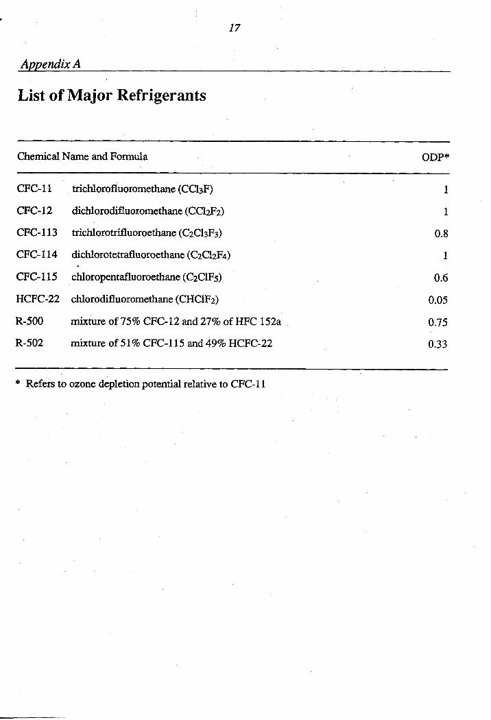
This Code of Practice is published tofU@ll the responsibilities of the Minister of Environment for the formulation of environmental codes of practice as required under Section 8 of the Canadian Environmental Protection Act. The main purpose of this Code is to provide guidelines for the reduction of atmospheric emissions of chlorofluorocarbons (CFCs) used in refrigeration and air conditioning applications. To the extent possible, this Code can also be used to reduce emissions of hydrofluorocarbons (HFCs) and hydrochlorofuorocarbons (HCFCs). A list of major refrigerants is shown in Appendix A.
The establishment of this Code is part of the action program that Environment Canada has undertaken aimed at reducing CFC emissions by major CFC user industries.
1
-1
I

. V
Table of Contents
Abstract . . . . . . . . . . . . . . . . . . . . . . . . . . . . . iii Acknowledgments . . . . . . . . . . . . . . . . . . . . . . . vii
Section I Commercial/Industrial Systems . . . . . . . . . . . . . . . . 1 1.1 Design . . . . . . . . . . . . . . . . . . . . . . . . . . 1 1.1.1 Compressors . . . . . . . . . . . . . . . . . . . . . . . 1 1.1.2 Condensers and Evaporators . . . . . . . . . . . . . . . 2 1.1.3 Pipelines and Connections . . . . . . . . . . . . . . . . 2 1.1.4 Valves . . . . . . . . . . . . . . . . . . . . . . . . . . 3 1.1.5 ReliefDevices . . . . . . . . . . . . . . . . . . . . . . 3 1.1.6 AirPurgers . . . . . . . . . . . . . . . . . . . . . . . . 3 1.1.7 Pump-down Capability . . . . . . . . . . . . . . . . . . 3 1.1.8 OilDraining . . . . . . . . . . . . . . . . . . . . . . . 4 1.1.9 Leak Detection and Warning . . . . . . . . . . . . . . . 4 1.2 Manufacture . . . . . . . . . . . . . . . . . . . . . . . 4 1.2.1 Triple Evacuation Procedures . . . . . . . . . . . . . . 4 1.2.2 HoldingCharges . . . . . . . . . . . . . . . . . . . . . 4 1.2.3 Cleanliness of Systems . . . . . . . . . . . . . . . . . . 4 1.2.4 LeakTesting . . . . . . . . . . . . . . . . . . . . . . . 4 1.2.5 Discharge/Evacuation . . . . . . . . . . . . . . . . . . 4
1.3 Installation and Servicing . . . . . . . . . . . . . . . . 5 1.3.1 Installation of Fquipment . . . . . . . . . . . . . . . . 5 1.3.2 General Routine Servicing of Equipment . . . . . . . . 5 1.3.3 Cleaning and mushing a Contaminated
System After a Hermetic or Semi-hermetic Compressor Failure or Motor Bum Out . . . . . . . . . 6
1.3.4 Service Records . . . . . . . . . . . . . . . . . . . . . 7 1.4 Advicetousers . . . . . . . . . . . . . . . . . . . . . 7 1.5 Recovery. Reuse. and Disposal of Refrigerants . . . . . 7 1.5.1 Manufacture . . . . . . . . . . . . . . . . . . . . . . . 7 1.5.2 Installation and Servicing . . . . . . . . . . . . . . . . 7 1.5.3 Disposal of Used Refrigerant . . . . . . . . . . . . . . 8 1.6 Handling and Storage of Refrigerants . . . . . . . . . . 8 1.6.1 Storage . . . . . . . . . . . . . . . . . . . . . . . . . . 8 1.6.2 Use . . . . . . . . . . . . . . . . . . . . . . . . . . . . 8 1.6.3 Refrigerant Transfer Between Containers . . . . . . . . 9 1.6.4 Records . . . . . . . . . . . . . . . . . . . . . . . . . . 9 1.7 Disposal of Equipment Containing CFCs . . . . . . . . 9 1.8 Training of Personnel . . . . . . . . . . . . . . . . . . 10
1.2.6 Sign . . . . . . . . . . . . . . . . . . . . . . . . . . . 4

vi
Section 2 Residential Systems . . . . . . . . . . . . . . . . . . . . . . 11 2.1 Design . . . . . . . . . . . . . . . . . . . . . . . . . . 11 2.1.1 Compressor . . . . . . . . . . . . . . . . . . . . . . . 11 2.1.2 Condensers . . . . . . . . . . . . . . . . . . . . . . . . 11 2.1.3 Tubing and Connections . . . . . . . . . . . . . . . . . 11 2.2 Manufacture . . . . . . . . . . . . . . . . . . . . . . . 11 2.2.1 Triple Evacuation Procedures . . . . . . . . . . . . . . 11 2.2.2 Cleanliness of Systems . . . . . . . . . . . . . . . . . . 11 2.2.3 LeakTesting . . . . . . . . . . . . . . . . . . . . . . . 11 2.2.4 Sign . . . . . . . . . . . . . . . . . . . . . . . . . . . 11 2.3 Installation and Servicing . . . . . . . . . . . . . . . . 12 2.3.1 InstallationofUnit . . . . . . . . . . . . . . . . . . . . 12 2.3.2 General Routine Servicing . . . . . . . . . . . . . . . . 12 2.4 Recovery. Reuse. and Disposal of Refrigerant . . . . . . 12 2.4.1 Manufacture . . . . . . . . . . . . . . . . . . . . . . . 12 2.4.2 Installation and Servicing . . . . . . . . . . . . . . . . 12 2.4.3 Disposal of Used Refrigerant . . . . . . . . . . . . . . 13 2.5 Disposal of Appliances Containing CFCs . . . . . . . . 13 2.6 TrahhgofPersonnel . . . . . . . . . . . . . . . . . . 13
Section 3 Mobile Air Conditioners . . . . . . . . . . . . . . . . . . . . 14 3.1 Design . . . . . . . . . . . . . . . . . . . . . . . . . . 14 3.2 Manufacture . . . . . . . . . . . . . . . . . . . . . . . 14 3.2.1 Cleanliness of Systems . . . . . . . . . . . . . . . . . . 14 3.2.2 LeakTesting . . . . . . . . . . . . . . . . . . . . . . . 14 3.2.3 Discharge/Evacuation . . . . . . . . . . . . . . . . . . 14 3.3 Servicing . . . . . . . . . . . . . . . . . . . . . . . . . 14 3.3.1 Procedures . . . . . . . . . . . . . . . . . . . . . . . . 14 3.3.2 Container Size Restriction . . . . . . . . . . . . . . . . 14 3.3.3 Non-reusable Refrigerant . . . . . . . . . . . . . . . . 14 3.3.4 Records . . . . . . . . . . . . . . . . . . . . . . . . . . 15
Slated for Wrecking . . . . . . . . . . . . . . . . . . . 15 3.5 TrahhgofPersonnel . . . . . . . . . . . . . . . . . . 15
3.4 Disposal of Refrigerant in Automobiles
Appendix A List of Major Refrigerants . . . . . . . . . . . . . . . . . . 17
Appendix B Society of Automotive Engineers Proposed Standards . . . 19
i

vii
Acknowledgments ->
This Code is based mainly on a similar document published by the Commission of European Communities (Report EUR 9509 EN). Development was also guided by the Refrigerants Order of the National Swedish Environmental Protection Board (draft; October, 1988) and the Action Guidelines of the Heating, Refrigerating and Air Conditioning Institute of Canada. The Code also reflects inputfrom a broad section of Canadian industrial and governmental bodies.
Environment Canada wishes to thunk all those who participated in the preparation of the Code, in particular Dr. Leon R u c k of Peat Marwick Stevenson & Kellogg.
I
\) Section I
Commercial/Industrial Systems
1.1 Design
This section deals with the design of refrigeration and air conditioning systems and their components, and identifies possible sources of inadvertent loss of CFCs to the atmosphere.
The appreciation and application of established technology in both the design and construction of refrigeration systems constitutes a good foundation for the prevention of refrigerant leakage.
1.1.1 Compressors Leaks associated with compressors are generally not related to the design of the compressor but to the associated equipment fitted to it, e.g., gauge and cut-out connections, oil retum, oil drain, oil level sight glass, relief valve, and connecting pipework.
1.1.1.1 Gland Seakr (Open Drive). Damaged gland seals on compressors are a frequent source of refrigerant leakage. Damage may be caused by oil contamination or lubrication breakdown. Moisture within the system combines with the refrigerant to form a weak acid solution leading to oil breakdown, component corrosion, and sludge formation. A clean, dry system, therefore, is an essential prerequisite for prolonged gland seal effectiveness. Adequate drying of h e refrigerdnt system, straining and fdtration of solids in the system together with fdtration of oil in the compressor, should be provided to ensure
that the necessary level of cleanliness is maintained (see also 1.2.3).
The gland housing should be designed to avoid the draining away of oil during shut-down periods. Lack of lubrication can cause the mating faces to dry out and adhere together. Subsequent starting up causes tearing or cracking of the seal faces which produces a leakage path.
On large systems it may prove economical to provide a separate oil pump to lubricate the gland prior to starting the compressor. During long shut-down periods it will be necessary to run the pump weekly. On systems without a separate oil pump the compressor should be run weekly. If this is not possible the gland should be inspected and lubricated before starting the system.
)
1.1.1.2 Vibration. Vibration often causes leaks and some improvement will be achieved by mounting the unit on adequate solid foundations and, if required, anti-vibration mountings can be used. Where feasible, vibration eliminators should be included in the suction and discharge lines in the proximity of the compressor and in the correct plane of flexing to minimize leaks (see also 1.1.3.4).
Adequate support of pipeline connections to the compressor should be provided to avoid unacceptable stresses which could lead to leakage.
1.1.1.3 Where feasible, gauges and cut-outs should be adequately isolated to minimize

2
I
the chance of CFC loss during servicing or replacement.
1.1.1.4 Isolating valves should be fitted on both the suction and discharge sides of the compressor to " i z e discharge of CFC during service work (see also 1.1.4).
1.1.2 Condensers and Evaporators Properly designed and manufactured condensers and evaporators have few leakage problems. However, the following points require appropriate action:
I.I.2.1 Excessive vibration from compressors or other equipment can cause tube failure. To " i z e this effect, antivibration mountings and vibration eliminators should be used where feasible (see 1.1.1.2).
1.1.23 Excessive water velocity through the &bes of shell and tube units can cause vibration or erosion failures and should be avoided.
1.1.2.3 Water conditions vary widely and consideration should always be given to water treatment and fitration to avoid corrosion or erosion failures. Careful selection of the tube materials can also " i z e corrosion. For non-ferrous tubes sacrificial iron anodes should be used to reduce corrosion pitting.
I.I.2.4 Reduced or suspended water flow can lead to serious corrosion problems. Facilities for flushing and a regular inspection procedure should be provided. Sacrificial iron anodes are ineffective unless there is water flowing through the tubes.
1.1.3 Pipelines and Connections I .I .3.1 AU pipelines should be designed so that the number of joints is kept to a "Um.
1.1.3.2 To increase resistance to pressure, temperature, and vibrational stresses, welding or brazing should be adopted wherever practical for joining pipelines, in preference to flared or screwed connections.
1.1.3.3 Where flanged joints are used, gaskets, jointing materials and joint design should be selected to withstand the pressures and temperatures involved together with the effects of exposure to the refrigerant/oil mixture. Welding or brazing should be used to join the flange to the pipeline instead of threaded connections where the joint is made on the thread.
1.1.3.4 Pipelines should be supported against vibration stresses by being adequately clamped to solid fixtures. Suitable vibration eliminators and expansion bends should be used. For lines too large for vibration eliminators (>7.5 cm O.D.) trombone bends or sprung hangers should be used. Gauges, high pressure and low pressure shut-off, and oil safety switches should be connected to the main system via flexible hoses so as to absorb vibrations.
1.1.3.5 Efficient strainers and filters should be included in the piping system to minimize the chance of damage to the gland faces and other working parts of compressors or liquid refrigerant pumps by oil-bome particles of dirt or metal (see also 1.1.1.1). Damage can also be caused to motor windings and compressor parts of hermetic and semihermetic compressors.
1 .I .3.6 Driers of an adequate size should be included to minimize moisture in the system. The inclusion of a moisture indicating

liquid-line sight glass in conjunction with the drier is strongly recommended.
1.1.3.7 Every effort should be made to ensure cleanliness of pipeline interiors during assembly or site erection. Nitrogen should be used as an anti-oxidation blanket during welding or brazing. Pipework should be blown out with nitrogen or air to remove welding, brazing, or cutting debris. Oxygen should not be used for this purpose on any account.
1.1.4 Valves 1.1.4.1 Except when ball valves are involved, valves with retained or captive spindles and facilities for tightening or replacement of the gland packing/diaphragm under line pressure should be used.
I +
1.1.4.2 Capped valves which retain any leakage from the spindle gland should be used for all service stop valves. Valves which are to be used regularly as part of the operation of the system should be fitted with hand wheels and be subject to periodic leak testing.
1 .I A 3 Valves with welded, brazed, or flanged connections should be used instead of flared or screwed types for sizes greater than 18 mm O.D. (see also 1.1.3.2).
1.1.4.4 An adequate number of valves should be included to allow isolation of vessels and equipment to minimize the risk of refrigerant loss during servicing. Any piping or segment of installation between two shutoff valves should be protected by a pressure-relief valve.
1.1.5 Relief Devices 1.1.5.1 Pressure-relief Valves. Certain designs of pressure-relief valves fail to reseat after having relieved excess pressure.
3
Therefore, a dual relief valve should be used to facilitate repair or replacement without impairing protection of the system.
1.1.5.2 Designs should allow an adequate margin between the normal working pressure of the system and the relief value setting. Unnecessary operation of pressure-relief valves will then be avoided.
1 .I .6 Air Purgers Centrifugal units using CFC-11 which operate at sub-atmospheric pressure where air can leak in, should be fitted with air purge units.
1.1.7 Pump-down Capability 1.1.7.1 All systems fitted with thermostatic expansion valves or similar devices should incorporate a fully protected and isolable liquid receiver, or a condenser and receiver combination of sufficient capacity to hold the complete refrigerant charge to facilitate pumping down during servicing or repairs. Auxiliary receivers should be installed if required. Units using capillary expansion control, however, need not necessarily be fitted with a liquid receiver.
1.1.7.2 Guideline 1.1.7.1 does not necessarily apply to systems containing a shell and tube condenser if the condenser shell is large enough to contain the entire refrigerant charge, is fully isolable, and is protected by a pressure-relief valve.
2.1.7.3 Guideline 1.1.7.1 does not necessarily apply when the evaporator and/or liquid accumulator/separator can contain the entire charge, is fully isolable and is protected by a pressure-relief valve.
1.1.7.4 Large systems should incorporate a separate pump-down condensing unit and receiver.

4
3
'I
1.1.7.5 Parallel systems should be designed with the necessary crossover connections and storage facilities to allow transfer of the refkigerant prior to service or repair operations.
1.1.7.6 Compressors and major items of equipment should be fitted with suitable valves to allow the connection of a pump-down unit for the removal of refrigerant prior to service or repair operations.
1.1.8 Oil Draining Since CFCs are soluble in compressor lubricating oils, compressor crankcases should be pumped down to atmospheric pressure prior to oil removal. Refrigerant in solution should be further reduced by crankcase oil heaters.
1.1.9 Leak Detection and Warning Design should incorporate devices and systems which warn operators that refrigerant is leaking out of the installation whether it is at rest or in operation.
1.2 Manufacture
13.1 Triple Evacuation Procedures One of the main areas where reduction of CFC emissions during manufacture can be made is in restricting the use of the triple evacuation technique. This involves a vacuum being placed on the equipment and an amount of CFC-12 being introduced to absorb moisture. The CFC-12 is then r e l e ~ e d after a period of time. This is repeated twice and during the final phase the refrigerant charge is introduced. It is recommended that receivers or other safe technology be used to contain the CFC- 12 that has been used for triple evacuation techniques. If this is not possible, an
altemative to triple evacuation, such as deep vacuum evacuation, should be employed.
1.2.2 Holding Charges Only nitrogen or dry air should be used when shipping with a holding charge.
12.3 Cleanliness of Systems
Irrespective of the type of compressor being used, the system should be absolutely clean to reduce the risk of contamination of refrigerant and the need for subsequent recharging. All key personnel involved should be conversant with refrigerant technology and familiar with all aspects of the manufacturing process.
s
12.4 Leak Testing CFC-12 should not be used as a trace gas and alternatives such as sulphur hexafluoride and helium should be used. After leak testing all pressure should be released and, except in the case of helium testing, the system purged with an inert gas prior to any subsequent welding or brazing operations. Consideration should also be given to bubble testing with soap and water, or by water immersion. An electronic leak detection device can also be used.
12.5 DischargelEvacuation Discharge/evacuation valves should be fitted to compressors to assist in the servicing and maintenance of the installation, with removal of CFC to suitable containers.
1.2.6 Sign The type and quantity of refrigerant used should be stamped or clearly displayed on a plate mounted on all major components of the equipment. For packaged units, one indicator plate is sufficient.

5
1.3 Installation and Servicing
1.3.1 Installation of Equipment Recommendations on the design of pipework and on the methods of connection can be found in Section 1.1.
During the siting and fixing in position of the major components and also during a thorough examination on completion of the system, the installation technician should ensure that:
1.3.1,I all pipework and fittings are thoroughly examined for cleanliness prior to fitting into position;
1.3.13 no metal filhgs are left in cut pipework since these can cause damage to shaft seals, compressor bearings, and windings in hermetic and semi-hennetic compressors;
1.3.1.3 great care is taken when making flare connections; a suitable lubricant should be used between the back of the flare and the nut, to avoid tearing the flare while tightening the nut;
1.3.1.4 with flanged connections, only the correct type and grade of gasket material is used which is suitable for use with CFCs and oil;
1.3.1.5 after pipework has been fixed in position, dry nitrogen is blown through the system to remove oxygen prior to brazing or soldering of joints using silver solder or “silfoss”; dry nitrogen should also be allowed to bleed continuously through the system at minimal pressure during the brazing operation to eliminate oxidation which can be a common cause of choked driers, dirty oil, and compressor failure;
1.3.1.6 all mechanical joints have been double checked for tightness before any trace gas is introduced into the system;
1.3.1.7 the complete system should be pressurized with dry nitrogen and leak tested using the soap bubble method or an electronic leak detection device; and
1.3.1.8 whenever evacuating the system, deep evacuation should be used, if triple evacuation of the system must be undertaken, HCFC-22 should be used in place of CFC-12 as an absorber during the first two stages to minimize the possibility of emitting CFC-12 to the atmosphere. (NB: as a trace gas, a smaller quantity of HCFC-22 is required than of CFC-12).
1.3.2 General Routine Servicing of Equipment
1.3.2.1 All service technicians should be instructed not to use refrigerant gas for the purpose of cleaning debris and dirt from air cooled condenser fins and similar equipment.
1
1.3.2.2 Service technicians should be instructed on the importance of putting back and tightening:
valve stem glands;
caps over gauge points; and
service valve caps.
These items should be thoroughly leak tested after service.
1.3.2.3 On finding a system short of refrigerant and before topping up, service technicians should be instructed to take great care in examining the following for oil traces: flare joints, brazed joints, compressor gaskets, control bellows, and (if applicable) shaft seals. 1
6
The low pressure side of a system should be given a positive pressure before leak testing the evaporator, heat exchanger, thermostatic expansion valve, or solenoid valve. If the system is of the hot gas type, this can be achieved by reversing the cycle. If the system has electric defrost, the compressor should be switched off and the defrost cycle initiated without pumping down the system, taking care not to allow excessive pressure to build up on the low pressure gauges or liquid refiigerant to migrate to the compressor.
3
1.3.2.4 The belts on open belt driven condensing sets should be thoroughly checked for wear and damage, as wom or damaged belts, misalignment, or over-tensioning can cause compressor shaft seal and front end bearing failure.
I .3.2.5 Having located a leak, that part of the system should be isolated to minimize the loss of CFC. The repair can then be undertaken and under no circumstances must the total charge be discharged to the atmosphere. If isolation is not possible, the charge should be pumped back into the system receiver or into a suitable container.
1
I.3.2.6 Prior to charging the system, the connecting lines should be lightly purged or evacuated. Purge gas may be collected using appropriate technologies.
I .3.3 Cleaning and Flushing a Contaminated System Afrer a Hermetic or Semi-hermetic Compressor Failure or Motor Burn Out
I.3.3.1 Isolate as many parts of the system as possible.
1.3.3.2 Remove contaminated refrigerant to suitable empty dump tanks. On small systems most refrigerants can be discharged
J either:
into a suitable empty container, which has been previously cooled in a freezer; or
by using an open condensing unit to pump the refrigerant out.
In both cases great care should be taken not to overfill the container, and refrigerant gases should not be mixed in the same container. (see Section 1.5 - Recovery, Reuse, and Disposal of Refrigerants).
1.3.3.3 When the system is empty, the component parts should be removed and capped off and, where possible, taken to the service company’s workshop for cleaning. The cleaning should be carried out with a non-CFC cleaning agent.
1.3.3.4 After the cleaning operation is complete, the major component parts should be reassembled in the system with the new compressor.
1.3.3.5 The system should be deep evacuated to 500 p or less and the discharge from the vacuum pump taken through a condenser to recover the CFC vapour in a container that can be sealed off after use. The vacuum should then be broken with a mixture of dry nitrogen and HCFC-22. However, if the major consideration is bringing the system back into service without delay because of the nature of the installation (e.g., blood bank, plasma freezing, operating theatre equipment), or if there is good assurance that the flush gases will be carefully collected, triple evacuation may be used. Between the second and third stages of triple evacuation, while there is a zero pressure in the system, new dryers, etc. should be installed and the system again pressurized with the dry nitrogen and HCFC-22 mixture and a thorough leak test carried out before the system is finally recharged with refrigerant.
7
1.3.4 Service Records An up-to-date record of servicing act- rities should be kept close to the equipment and be made available for inspection. Charging and discharging of refrigerant should be documented.
1.4 Advice to Users
1.4.1 All users should regularly inspect the system for traces of oil, which could indicate the existence of leaks. If systems equipped with open type compressors are turned off for any length of time, they should be run once a week for at least half an hour to ensure that mechanical seal faces, bearings, etc. have a continuous oil film on their surfaces. Such a procedure could prevent seal failure from occurring after a long period of shutdown.
1.4.2 All users should monitor the operation of their installation weekly and call for the service technician as soon as any abnormal condition is found. Apart from the likelihood of minimizing loss of CFCs to the atmosphere, they may also save themselves the cost of an expensive repair or replacement.
1.4.3 All users should enter into a routine maintenance agreement for their system with a reputable service contractor.
1.5 Recovery, Reuse, and Disposal of Refrigerants
The venting of CFCs to atmosphere during manufacturing, installation, or servicing operations should be kept to a minimum by recovery and reuse of refrigerant.
1.5.1 Manufacture Refrigerant is used in performance testing of units or systems in both development and
production operations. Receivers or dump j tanks should be used for the subsequent reuse of such refrigerant.
1.5.2 Installation and Servicing
Manufacturers fit receivers or dump tanks to larger capacity refrigeration and air conditioning equipment to facilitate reuse of the refrigerant charge following servicing operations or modifications during the commissioning of equipment.
In smaller capacity equipment it is not always feasible to fit receivers and provide pump-down capability for technical and economic reasons. In such cases refrigerant containers are often used as temporary receivers, for reuse of all or part of the refrigerant charge. Hazards arise in the use of refrigerant containers in this way and consideration must be given to the following:
1.5.2.1 A CFC refrigerant container is a pressure vessel designed for the transportation of a non-corrosive liquified gas. Neither the designed maximum working pressure nor the designed carrying capacity should be exceeded in any filling operation, however temporary.
Refrigerant/oil mixtures have a lower density than refrigerant alone, and for this reason the carrying capacity of refrigerant containers will be reduced for refrigerant/oil mixtures, compared to pure refrigerants.
1.5.2.2 If contaminated refrigerant is decanted into a refrigerant container, corrosion may occur. An intemal examination by a competent technician should be carried out on such containers at the earliest opportunity to determine whether the container is fit for continued service under design conditions.
8
1 A2.3 If a refrigerant container belonging to a third party (e.g., a refrigerant manufacturer), is to be used as a temporary receiver, the peqnission of the owner of the container should be obtained in advance. Where permission is granted, the owner should be given the opportunity to carry out his own internal inspection for corrosion and contamination immediately after use.
1.5.2.4 To avoid the danger of mixing different refrigerant grades, the receiving container should have been used previously only for the refrigerant grade which is being transferred.
1.5.2.5 When containers specifically designed for containment, temporary storage, and transport of spent refrigerant become available and approved by organizations that set standards, such containers should be used.
1.5.3 Disposal of Used Refrigerant Refrigerant removed from working equipment may be:
1
recycled by the service organization or owner;
recycled by an outside agency; or
destroyed.
1.5.3.1 A service organization or equipment owner/operator who recycles a refrigerant using his own equipment should ensure that the equipment is intended for the type of refrigerant being processed and will clean the refrigerant to meet prescribed specifications.
1.5.3.2 An extemal agency that recycles used refrigerants should ensure that the equipment it uses is functioning properly and
the recycled refrigerant meets the required specifications.
1.5.3.3 If facilities are available, refrigerant that cannot be reused should be destroyed.
1.6 Handling and Storage of Refrigerants
Losses of refrigerant to the atmosphere can occur during the handling and storage of refrigerant containers. Recommended good practice is as follows:
1.6.1 Storage 1.6.1.1 Refrigerant containers should be stored in a cool place, away from fire risk, and sources of direct heat.
1.6.1.2 Containers should not be dropped. Careful handling will prevent mechanical damage to the container and its valve.
1.6.1.3 When not in use, container valves should be closed, the valve outlet cover nut screwed on, and the valve protection cover replaced.
1.6.2 Use 1.6.2.1 The pipework connecting a container to a refrigerating system should be leak tested before fully opening the container valve. This can be done by partially opening and then closing the container valve to pressurize the connecting pipework.
1.6.2.2 Refrigerant transferred to a sealed system should be metered by either weight or volume using weigh scales or a volumetric charging device.
1.6.2.3 Charging lines should be as short as possible to avoid losses during disconnection at the end of the transfer. Care must be
9
taken to prevent refrigerant liquid from being trapped between closed valves.
1.6.2.4 Refrigerant containers should not be connected to a system at a higher pressure, or to hydraulic legs, where the pressure i? sufficient to cause a back flow of refrigerant into the container. For similar reasons refrigerant containers should not be connected to systems or other containers at a higher temperature.
Containers can become overfilled by a back flow of refrigerant which may result in the development of hydraulic pressure sufficient to burst the container, a subsequent danger in containers full of liquid. To prevent this condition, check valves should be inserted at appropriate locations in the discharge piping.
I
I
1.6.2.5 Refrigerant containers should not be manifolded together if there is a possibility of temperature differences existing between them since this will result in refrigerant transfer and the danger of overfilling the coldest container. Where containers are manifolded together, care should be taken that all containers are the same height to avoid gravity transfer between containers.
1.6.3 Refrigerant Transfer Between
1.6.3.1 When refrigerant is to be transferred from one container to another, it should be carried out in a way that is safe and will minimize chances of release. A pump should be used to establish a pressure difference between the containers. Heating of the discharging container under controlled conditions is possible. Under no circumstances should refrigerant be vented to the atmosphere from the receiving container in order to cool this container. The receiving container may be cooled in a refrigerator or a cold storage area.
Containers
Direct heating of refrigerant containers by flames, radiant heaters, or direct contact heaters, to increase the rate of discharge of refrigerant during transfer or use operations, is not recommended. Heating containers using indirect forms of heating (e.g., controlled temperature air flow), should only be permitted where the control system is designed to “fail-safe”.
1.6.32 In filling refrigerant containers, the maximum carrying capacity is a function of the internal volume of the container and the liquid density of the refrigerant at a reference temperature.
I .6.4 Records Up to date records should be kept detailing transfer quantities by CFC type between various containers and refrigerant systems. Accurate records of the contents of refrigerant storage containers (type, quantity, transfer in, transfer out) should also be kept.
1.7 Disposal of Equipment Containing CFCs
1.7.1 As soon as the decision to retire equipment containing CFCs has been taken, the owner should arrange for the full pump down of the equipment under the same conditions as if the equipment was going to be serviced (see Section 1.5, Recovery, Reuse, and Disposal of Refrigerants). The equipment should be flushed with nitrogen and the flush gas collected in appropriate containers before the equipment is open to the atmosphere.
I.7.2 Before the equipment is being removed for disposal, the owner or his representative should show proof that guideline 1.7.1 has been satisfied by presenting a copy of the completed work order.

1.7.3 Before a building containing equipment which used CFC is wrecked, the owner or his representative should show proof that guideline 1.7.1 has been followed.
1.8 Training of Personnel
Chlorofluorocarbons are expensive and although personnel have been trained to minimize waste, existing requirements make it more essential for additional training to " i z e emissions. Such a training course should have a syllabus containing the following:
IO
Introduction.
Ozone issue.
Detailed examination of CFC emissions sources within the Refrigeration and Air Conditioning Industry.
Required actions by the manufacturers of refrigeration and air conditioning.
Required actions by contractors and service personnel in the Refrigeration and Air Conditioning Industry.

11
\ Section 2
Residential Systems
The general principles which underlie Section 1 -Commercial/Industrial Systems are also applicable to residential systems.
2.1 Design
2.1.1 Compressor 2.1.1.1 The compressor should be mounted on the unit's frame in such a way as to prevent vibration. Stress on connecting tubing should be avoided.
2.1.1.2 Isolating valves should be provided to permit compressor removal and replacement without losing the entire CFC charge.
2.1.2 Condensers Condensers and evaporator coils should be designed and mounted in a way that will prevent vibrations.
2.1.3 Tubing and Connections 2.1.3.1 All tubing should be designed so that joints are kept to a mini".
2.1.3.2 Welding should be adopted in preference to flared connections for refrigerator tubing.
2.2 Manufacture
2.2.1 Triple Evacuation Procedures One of the main areas where reduction of CFC emissions during manufacture can be made is in restricting the use of the triple evacuation technique. This involves a vacuum being placed on the equipment and
an amount of CFC-12 (refrigerators and freezers) being introduced to absorb moisture. The CFC-12 is then released after a period of time. This is repeated twice and during the final phase the refrigerant charge is introduced. It is recommended that receivers or other available safe technology should be used to contain the CFC-12 that has been used for triple evacuation techniques. If this is not possible, an altemative flushing medium such as HCFC-22 should be employed.
2.2.2 Cleanliness of Systems Irrespective of the type of compressor being used, the system should be absolutely clean to reduce the risk of contamination of refrigerant and the need for subsequent recharging. All key personnel involved should be conversant with refrigerant technology and familiar with all aspects of the manufacturing process.
2.2.3 Leak Testing CFC-12 should not be used as a trace gas and altematives such as sulphur hexafluoride and helium should be used. After leak testing aSl pressure should be released and, except in the case of helium testing, the system purged with an inert gas prior to any subsequent welding or brazing operations. Consideration should also be given to bubble testing with soap and water, or by water immersion.
2.2.4 Sign The type and quantity of refrigerant used should be stamped or clearly displayed on a plate mounted on the unit.
12
2.3 Installation and Servicing
23.1 InstulWon of Unit Delivery personnel and users should be instructed as to the proper location and installation procedures:
handling;
- ventilation; and
levelling.
2.3.2 General Routine Servicing 2.3.2.1 Only qualified personnel should be employed in the servicing of residential refngeration units. See subsection on training.
2.3.2.2 When fiiing leaks and replacing components, that part of the system should be isolated to minimize the CFC loss. The repair can then be undertaken and under no circumstances must the total charge be discharged to the atmosphere. If isolation is not possible, the charge should be pumped back into the system receiver or a suitable container.
2.4 Recovery, Reuse, and Disposal of Refrigerant
The venting of CFCs to atmosphere during manufacturing, installation, or servicing operations should be kept to a minimum by recovery and reuse of refrigerant.
2.4.1 Manufacture Refrigerant is used in performance testing of units or systems in both development and production operations. Receivers or dump tanks should be used for the subsequent reuse of such refrigerant.
2.4.2 Installation and Servicing In smaller capacity equipment it is not always feasible to fit receivers and provide pump-down capability for technical and economic reasons. In such cases refrigerant containers may be used as temporary receivers, for reuse of a l l or part of the refrigerant charge.
Hazards arise in the use of refrigerant containers in this way and consideration must be given to the following:
2.4.2.1 A CFC refrigerant container is a pressure vessel designed for the transportation of a non corrosive liquified gas. Neither the designed maximum working pressure nor the designed carrying capacity should be exceeded in any filling operation, however temporary.
RefYigerant/oil mixtures have a lower density than refrigerant alone, and for this reason the carrying capacity of refrigerant containers will be reduced for refrigerant/oil mixtures, compared to pure refrigerants.
2.4.2.2 If contaminated refrigerant is decanted into a refrigerant container, corrosion may occur. An intemal examination by a competent technician should be carried out on such containers at the earliest opportunity to determine whether the container is fit for continued service under design conditions.
2.4.2.3 If a refrigerant container belonging to a third party (e.g., a refrigerant manufacturer), is to be used as a temporary receiver, the permission of the owner of the container should be obtained in advance. Where permission is granted, the owner should be given the opportunity to carry out his own intemal inspection for corrosion and contamination immediately after use.

13
2.4.2.4 To avoid the danger of mixing different refrigerant grades, the receiving container should have been used previously only for the refrigerant grade which is being transferred.
2.4.2.5 When containers specifically designed for containment, temporary storage, and transport of spent refrigerant become available and approved by standard setting bodies, such containers should be used.
2.4.3 Disposal of Used Refigerant Refrigerant removed from working equipment may be:
recycled by the service organization;
recycled by an outside agency; or
destroyed.
2.4.3.1 A service organization that recycles a refrigerant using its own equipment should ensure that the equipment is intended for the type of refrigerant being processed and will clean the refrigerant to meet prescribed specifications.
2.4.3.2 An extemal agency that recycles used refrigerants should ensure that the equipment it uses is functioning properly and the recycled refrigerant meets the prescribed specifications.
2.5 Disposal of Appliances Containing CFCs
Private and public refuse collectors should isolate appliances containing CFCs that are presented to them for disposal. These appliances should be handled with care and brought to a pre-assigned site for the application of guidelines 2.4.2 and 2.4.3.
2.6 Training of Personnel
Chlorofluorocarbons are expensive and although personnel have been trained to minimize waste, existing requirements make it more essential for additional training to minimize emissions. Such a training course should have a syllabus containing the following:
Introduction.
Ozone issue.
Detailed examination of CFC emission sources within the Refrigeration and Air Conditioning Industry.
Required actions by the manufacturers of refrigeration and airconditioning equipment.
Required actions by contractors and service personnel in the Refrigeration and Air Conditioning Industry.
2.4.3.3 If facilities are available, refrigerant that cannot be reused should be destroyed.

14
Section 3 1
0
Mobile Air Conditioners
The basic principles which underlie Sections 1 and 2 can also be translated to mobile air conditioning.
3. I Design
Manufacturer should ensure that the design of mobile air conditioners includes a series of proven features that will minimize CFC loss to the atmosphere, such as:
anti-vibration mountings;
heavy-duty clamps; and
mini” permeability hoses.
3.2 Manufacture
3.2.1 Cleanliness of Systems The system should be absolutely clean to reduce the risk of contamination of refrigerant and the need for subsequent recharging. All key personnel involved should be conversant with refrigerant technology and familiar with all aspects of the manufacturing process.
32.2 Leak Testing CFC-12 should not be used as a trace gas and alternatives such as sulphur hexafluoride and helium should be used. After leak testing all pressure should be released and, except in the case of helium testing, the system purged with an inert gas prior to any subsequent welding or brazing operations. Consideration should also be given to bubble testing with soap and water, or by water immersion.
32.3 DischargelEvacuation Discharge/evacuation valves should be fitted to compressors to assist in the servicing and maintenance of the installation, with removal of CFC to suitable containers.
3.3 Sewicing
3.3.1 Procedures Venting CFCs to atmosphere during servicing operations should be “ k e d by recovery and re-use of refrigerant.
The following standards from the Society of Automotive Engineers should be observed in servicing mobile air conditioning equipment.
SAE Standard J1989 “Recommended Service Procedure for the Containment of R-12”;
S A E Standard J1990 “Extraction and Recycle Equipment for Mobile Automotive Air Conditioning Systems”; and
SAE Standard J1991 “Standard of Purity for use in Mobile Air Conditioning Systems”.
3.3.2 Container Size Restriction No refrigerant will be sold in containers of 450 g or less.
3.3.3 Non-reusable Refrigerant If facilities are available, refrigerant which cannot be reused should be destroyed.

3.3.4 Records Active service organizations should maintain up-todate records of receipts, shipments, inventory levels, and accidental venting of resrigerant (new, used, and recycled) by type.
3.4 Disposal of Reftigerant in Automobiles Slated for Wrecking
Before an air conditioned car is wrecked it is essential that all the CFC contained in the air conditioning system be removed, stored, and disposed of as previously described. This will be done either:
by the trade-in dealer;
by the wrecker; or
at a pre-assigned CFC local removal centre.
If the car is first brought to a trade-in dealer, the dealer should remove the CFCs. Similarly, the wrecker should remove the CFCs if the car is brought directly to E wrecker. In either case, the wrecker or the
dealer may use a qualified outside agency to remove the CFCs.
3.5 Training of Personnel
Chlorofluorocarbons are expensive and although personnel have been trained to " i z e waste, existing requirements make it more essential for additional training to " i z e emissions. Such a training course should have a syllabus containing the following:
Introduction.
Ozone issues.
Detailed examination of CFC emission sources in mobile a i r conditioning and refrigeration equipment.
Required actions by the manufacturers of mobile air conditioning. Required actions by mobile air conditioning service personnel.
17
Appendix A
List of Major Refrigerants 3
Chemical Name and Formula ODP*
CFC-11
CFC- 12
CFC-113
CFC-114
CFC- 1 1 5
HCFC-22
R-500
R-502 \
trichlorofluoromethane (CC13F)
dichlorodifluoromethane (CC12F2)
trichlorotrifluoroethane (C2C13F3)
dichlorotetrafluoroethane (C2C12F4)
chloropentafluoroethane (C2ClF5)
chlorodinuoromethane (CHClF2)
mixture of 75% CFC-12 and 27% of HFC 152a
mixture of 51% CFC-115 and 49% HCFC-22
1
1
0.8
1
0.6
0.05
0.75
0.33
1 * Refers to ozone depletion potential relative to CFC-11
19
) Appendix B*
Society of Automotive Engineers Recommended Standards
A 51989 Recommended Service Procedure for the Containment of R-12.
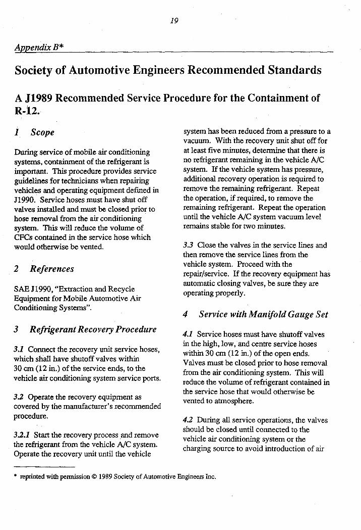
I Scope
During service of mobile air conditioning systems, containment of the refrigerant is important. This procedure provides service guidelines for technicians when repairing vehicles and operating equipment defined in J1990. Service hoses must have shut off valves installed and must be closed prior to hose removal from the air conditioning system. This will reduce the volume of CFCs contained in the service hose which would otherwise be vented.
2 References
S A E J1990, “Extraction and Recycle Equipment for Mobile Automotive Air Conditioning Systems”.
3 Refrigerant Recovery Procedure
3.1 Connect the recovery unit service hoses, which shall have shutoff valves within 30 cm (12 in.) of the service ends, to the vehicle air conditioning system service ports.
3 3 Operate the recovery equipment as covered by the manufacturer’s recommended procedure.
3.2.1 Start the recovery process and remove the refrigerant from the vehicle A/C system. Operate the recovery unit until the vehicle <
system has been reduced from a pressure to a vacuum. With the recovery unit shut off for at least five minutes, determine that there is no refrigerant remaining in the vehicle A/C system. If the vehicle system has pressure, additional recovery operation is required to remove the remaining refrigerant. Repeat the operation, if required, to remove the remaining refrigerant. Repeat the operation until the vehicle A/C system vacuum level remains stable for two minutes.
3.3 Close the valves in the service lines and then remove the service lines from the vehicle system. Proceed with the repair/service. If the recovery equipment has automatic closing valves, be sure they are operating properly.
4 Service with Manifold Gauge Set
4.1 Service hoses must have shutoff valves in the high, low, and centre service hoses within 30 cm (12 in.) of the open ends. Valves must be closed prior to hose removal from the air conditioning system. This will reduce the volume of refrigerant contained in the service hose that would otherwise be vented to atmosphere.
4.2 During all service operations, the valves should be closed until connected to the vehicle air conditioning system or the charging source to avoid introduction of air
* reprinted with permission 0 1989 Society of Automotive Engineers Inc.

20 4
and to contain the refrigerant rather than vent open to atmosphere.
4.3 When the manifold gauge set is disconnected from the air conditioning system or when the centre hose is moved to another device which cannot accept refrigerant pressure, the gauge set hoses should f i t be attached to the reclaim equipment to recover the refrigerant from the hoses.
5 Recycled Refrigerant Checking Procedures
5.1 To determine if the recycled refrigerant container has excess non-condensable gases (air) the container must be stored at a temperature of 18.3' C (65' C) or above for a period of time (12 hours) protected from direct sun.
5.2 Install a calibrated pressure gauge, with 1 psig (0.07 kg) divisions, to the container and determine the container pressure.
5.3 With a calibrated thermometer, measure the air temperature within 10 cm (4 in.) of the container surface.
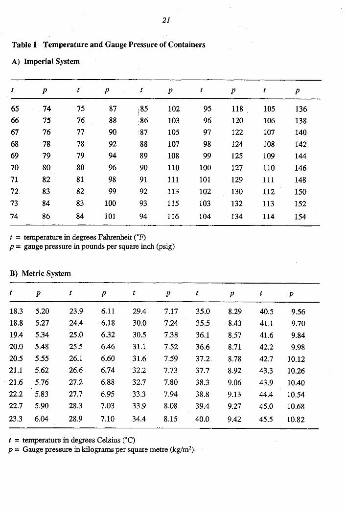
5.4 Compare the observed container pressure and air temperature to determine if the container exceeds the pressure limits found in Table 1, e.g., air temperature 21" C (70" F) pressure must not exceed 5.62 kg/cm2 (80 psig).
5.5 If the container pressure is less than the Table 1 value and has been recycled, limits of non-condensable gases (air) have not been exceeded and the refrigerant may be used.
21
Table 1 Temperature and Gauge Pressure of Containers
A) Imperial System
t P t P t P t P t P ~
65 74 75 87 ~ 85 102 95 118 105 136 66 67 68 69 70 71 72 73
74
75 76 78 79 80 82 83 84
86
76 77 78 79 80 81 82 83
84
88 90 92 94 96 98 99
100
101
86 103 87 105 88 107 89 108 90 110 91 111 92 113
93 115
94 116
96 120 97 122 98 1 24 99 125
100 127 101 129 102 130 103 132
104 134
106 107 108 109 110 111 112 113
114
138 140 142 144 146 148 150 152
154
t = temperature in degrees Fahrenheit (OF) p = gauge pressure in pounds per square inch (psig)
B) Metric System
t P t P t P t P t P
18.3 5.20 23.9 6.1 1 29.4 7.17 35.0 8.29 40.5 18.8 5.27 24.4 6.18 30.0 7.24 35.5 8.43 41.1 19.4 5.34 25.0 6.32 30.5 7.38 36.1 8.57 41.6 20.0 5.48 25.5 6.46 31.1 7.52 36.6 8.71 42.2 20.5 5.55 26.1 6.60 31.6 7.59 37.2 8.78 42.7 21.1 5.62 26.6 6.74 32.2 7.73 37.7 8.92 43.3 21.6 5.76 27.2 6.88 32.7 7.80 38.3 9.06 43.9 22.2 5.83 27.7 6.95 33.3 7.94 38.8 9.13 44.4 22.7 5.90 28.3 7.03 33.9 8.08 39.4 9.27 45.0
23.3 6.04 28.9 7.10 34.4 8.15 40.0 9.42 45.5
9.56 9.70 9.84 9.98
10.12 10.26 10.40 10.54 10.68
10.82
t = temperature in degrees Celsius ("C) p = Gauge pressure in kilograms per square metre (kg/m2)

22
I
5.6 If the container pressure is greater than the range and the container contains recycled material, slowly vent from the top of the container a small amount of vapour into the recycle equipment, until the pressure is less than the pressure shown in Table 1.
5.7 If the container still exceeds the pressure shown in Table 1, the entire contents of the container shall be recycled.
6 Containers for Storage of Recycled Refrigerant:
6.1 Recycled refrigerant should not be salvaged or stored in disposable refrigerant containers. This is the type of container in which virgin refrigerant containers is sold. Use only DOT CFR Title 49 or UL, approved storage containers for recycled refrigerant.
6.2 Any container of recycled refrigerant that has been stored or transferred must be checked prior to use, as defined in Section 5.
7 Transfer of Recycled Refrigerant:
7.1 When extemal portable containers are used for transfer, the container must be
evacuated to at least 27 inches of vacuum (75 mm Hg absolute pressure) prior to transfer of the recycled refrigerant. External portable containers must meet DOT and UL standards.
7.2 To prevent on-site overfilling when transferring to extemal containers, the safe filling level must be controlled by weight and must not exceed 60% of container gross weight rating.
8 Disposal of EmptylNear Empty Contain ers:
8.1 Since all the refrigerant may not be removed from disposable refrigerant containers during normal system charging procedures, emptylnear empty container contents should be reclaimed prior to disposal of the container.
8.2 Attach the container to the recovery unit and remove the remaining refrigerant. When the container has been reduced from a pressure to a vacuum, the container valve can be closed. The container should be marked empty and is ready for disposal.
23
B J1990 Extraction and Recycle Equipment for Mobile Automotive Air Conditioning Systems.
Fore word
Due to the CFCs damaging effect on the ozone layer, recycle of CFC- 12 (R- 12) used in mobile air conditioning systems is required to replace system venting during normal service operations. Establishing recycle specifications for R-12 will assure that system operation with recycled R-12 will provide the same level of performance as new refrigerant.
Extensive field testing with the EPA and the auto industry indicate that R-12 can be reused, provided that the refrigerant is cleaned to specification in SAE 51991. The purpose of this document is to establish the specific mini” equipment specifications required for recycled R-12 for use in mobile automotive air conditioning systems.
I Scope
The purpose of this document is to provide equipment specifications for CFC- 12 (R- 12), recycling and/or recovery, and recharging systems. This information applies to equipment used to service automobiles, light trucks and other vehicles with similar CFC-12 systems. Systems used on mobile vehicles for refrigerated cargo that have hermetically-sealed systems are not covered in this document.
2 References
SAE J5 1, Automotive Air-conditioning Hose
UL 1963 Section 40 Tests Service Hoses for Refrigerant- 12 (Underwriters Laboratories)
Pressure Relief Device Standard Part 1 - Cylinders for Compressed Gases, GA Pamphlet S-1.1
3 Specification and General Description
3.1 The equipment must be able to extract and process R-12 from mobile air conditioning systems to purity levels specified in SAE 51991.
3.2 The equipment shall be suitable for use in an automotive service garage environment as defined in 7.8.
3.3 The equipment must be certified by Underwriters Laboratories or an equivalent certifying laboratory.
4 Refrigeration Recycle Equipment Requirements
4.1 Moisture and Acid The equipment shall incorporate a desiccant package that must be replaced before saturated with moisture and whose acid capacity is at least 5% (percent) by weight of total system dry desiccant.
4.1 .I The equipment shall be provided with a moisture detection means that will reliably indicate when moisture in the R-12 exceeds the allowable level and requires the filter/dryer replacement.
SAE J1991, Standard of Purity for Use in Mobile Air-Conditioning Systems
4
* 24
4.2 Filter The equipment shall incorporate an in-line filter that will trap particles of 15 pn spherical diameter or greater.
4.3 Non-condensable Gas 4.3.1 If the equipment has a self-contained recovery tank, a device is required to alert the operator that the noncondensable level has been exceeded.
4.3.2 Transfer of Recycled Refigerant. Recycled refrigerant for recharging and transfer shall be taken from the liquid phase only.
5 Safety Requirements
5.1 The equipment must comply with applicable federal, state and local requirements on equipment related to the handling of R-12 material. Safety precautions or notices related to the safe operation of the equipment shall be prominently displayed on the equipment and should also state “Caution Should be Operated by Qualified Personnel”.
6 Operating Instructions
6.1 The equipment manufacturer must provide operating instructions, necessary maintenance procedures, and source information for replacement parts and repair.
6.2 The equipment must prominently display the manufacturer’s name, address, and any items that require maintenance or replacement that affect the proper operation of the equipment. Operation manuals must cover information for complete maintenance of the equipment to assure proper operation.
7 Functional Description 7.1 The equipment must be capable of ensuing recovery of the R-12 from the system being serviced, by reducing the system to a vacuum.
7.2 To prevent overcharge, the equipment must have a shutoff device and mechanical pressure-relief valve to protect the tank used to store the recycled refrigerant.
7.3 Portable refflable tanks or containers used in conjunction with this equipment must meet applicable DOT (or Underwriters laboratories a)) standards and be adaptable to existing refrigerant service and charging equipment.
7.4 During the recovery and/or recycle, the equipment must provide overfill protection to assure that during f i g or transfer, the tank or storage container cannot exceed 80% of volume at 21 “C (70°F) its maximum rating as defined by DOT standards, CFR Title 49 Part/Section 173.304 and American Society of Mechanical Engineers.
7.4.1 Additional Storage Tank
7.4.1.1 The cylinder valve shall comply with the standard for cylinder valves, UL 1769.
Requirements
7.4.1.2 The pressure-relief device shall comply with the Pressure Relief Device Standard Part 1 - Cylinden for Compressed Gases, CGA Pamphlet S - 1.1.
7.4.1.3 The tank assembly shall be marked to indicate the first retest date, which shall be five years after date of manufacture. The marking shall indicate that retest must be performed every subsequent five years. The marking shall be in letters at least 0.6 cm (1/4 in.) high.

25
7.5 Au flexible hoses must meet SAE J51 or UL 1963 Section 40.
7.6 Service hoses must have shutoff devices located within 30 cm (12 in.) of the connection point to the system being serviced to " i z e introduction of noncondensable gases into the recovery equipment and the release of the refrigerant when being disconnected.
7.7 The equipment must be able to separate the lubricant from recovered refrigerant and accurately indicate in 28 g (1.0 oz.) units.
7.8 The equipment must be compatible with a leak detector that may be present in the system.
8 Testing
This test procedure and the requirements are used for evaluation of the equipment for its ability to clean the contaminated'R-12 refrigerant.
8.1 The equipment shall clean the contaminated R-12 refrigerant to the minimum purity level as defined in SAE 51991 when tested in accordance with the following conditions:
8.2 For test validation, the equipment is to be operated according to the manufacturers' instructions.
8.3 The equipment must be pre-conditioned with 13.6 kg (30 lb) of the standard contaminated R-12 at an ambient of 21°C (70°F) before starting the test cycle. Sample amounts are not to exceed 1.13 kg (2.5 lb) with sample amounts to be repeated every five minutes. The sample method fixture, defined in Figure 1, shall be operated at 24'C (75°F).
8.4 Contaminated R-I2 Samples: 8.4.1 Standard contaminated R-12 refrigerant shall consist of liquid R-12 with 100 ppm (by weight) moisture at 21°C (70°F) and 45 000 ppm (by weight) mineral oil 525 suspension viscosity nominal and 770 ppm (by weight) of noncondensable gases (air).
8.4.2 High moisture contaminated sample shall consist of R-12 vapour with 1 000 ppm (by weight) moisture.
8.4.3 High, oil-contaminated sample shall consist of R-12 with 200 000 ppm (by weight) mineral oil 525 suspension viscosity nominal.
8.5 Testcycle 8.5.1 After preconditioning as stated in 8.3 the test cycle is started processing the following contaminated samples through the equipment: ,
8.5.1.1 13.6 kg (30 pounds) of standard contaminated R-12.
1
8.5.13 1 kg (2.2 pounds) of high, oil-contaminated R-12.
8.5.1.3 4.5 kg (10 pounds) of standard contaminated R-12.
8.5.1.4 1 kg (2.2 pounds) of high, moisture-contaminated R- 12.
8.6 Equipment Operating Ambient 8.6.1 The R-12 is to be cleaned to the mini" purity level, as noted in SAE J1991, with the equipment operating in a stable ambient of 10,21 and 49°C (50,70 and 120" F) and processing the samples as defined in 8.5.

26
8.7 Sample Analysis 8.7. I The processed contaminated samples shall be analyzed according to the following procedure:
8.8 Quantitative Determination of
8.8.1 The cleaned sample of R-12 is to be subjected to a quantitative determination of the moisture content by Karl Fischer titration.
Mokture
8.8.2 The apparatus employed is a Karl Fischer coulometer, an automated instrument for precise determination of small amounts of water. The weighed sample of liquid R-12 is introduced directly into the analyte of the Karl Fischer coulometer. A coulemeuic titration by the instrument is conducted and the results are calculated and displayed as parts per million moisture weight.
8.9 Determination of Percent Oil 8.9.1 A weighed, 100-mL sample of the liquid R-12 is placed in a pre-weighed graduated Goetz phosphorus tube of 100-mL nominal capacity. The sample and containing tube is maintained in ambient air at a minimurn temperature of 32'C (90°F)
above the expected boiling point of the refrigerant. When 85 mL of the sample has evaporated, the tube is then immersed in a refrigerated brine bath at a temperature of 1O'C (50°F) above the boiling point of the sample for 30 min. The residual sample, if any, is allowed to reach room temperature. The tube is reweighed and the percent of oil is calculated.
8.10 Non-condensable Gas 8.10.1 The sample is to be analyzed using gas chromatography to determine the noncondensable gas content. The cleaned refrigerant is to be sampled in the liquid phase through a closed loop or by an airtight syringe into the injector.
8.11 Sample Requirements 8.11.1 The sample shall be tested as defined in 8.7,8.8,8.9, and 8.10 at ambient temperatures of 10,21, and 49°C (50,70, and 120°F) as defined in 8.6.1.
9 Date of Effectiveness
This recommended practice will become a standard after one year.
C J1991 Standard of Purity for Used in Mobile Air Conditioning Systems
Foreword
Due to the CFCs damaging effect on the ozone layer, recycle of CFC-12 (R-12) used in mobile air conditioning systems is required to reduce system venting during normal,service operations. Establishing recycle specifications for R- 12 will assure that system operation with recycled R- 12 will provide the same level of performance as new refrigerant.
Extensive field testing with the EPA and the auto industry indicate, that reuse of R-12 removed from mobile air conditioning systems can be considered, if recycled R- 12 removed from the refrigerant is cleaned to a specific standard. The purpose of this standard is to establish the specific minimum levels of R-12 purity required for recycled R-12 removed from mobile air conditioning systems.

* ppm - parts per million
27
I Scope
This information applies to refrigerant used to service automobiles, light trucks, and other vehicles with similar CFC-12 systems. Systems used on mobile vehicles for refrigerated cargo that have hermetically-sealed, rigid pipe are not covered in this document.
2 References
SAE J1989, Recommended Service Procedure for the Containment of R-12
SAE J1990, Extraction and Recycle Equipment for Mobile Automotive Air-Conditioning Systems
ARI Standard 700-88
3 Purity Specification
The refrigerant in this document shall have been directly removed from, and intended to be returned to, a mobile air-conditioning system. The contaminants in this recycled refrigerant 12 shall be limited to moisture, refrigerant oil, and noncondensable gases, which shall not exceed the following levels:
3.1 Moisture 15 ppm* by weight.
3.2 Refrigerant Oil 4000 ppm by weight.
3.3 Nora-condensable Gas 330 ppm by weight.
4 Refrigeration Recycle Equipment Used in Direct Mobile Air-Conditioning Service Operatio ns R equiremen t
4.1 The equipment shall meet SAE J1990, which covers additional moisture, acid, and filter requirements.
4.2 The equipment shall have a label indicating that it is certified to meet this document.
5 Purity Specification of Recycled R-12 Refrigerant Supplied in Containers from Other Recycle Sources
Purity specification of recycled R- 12 refrigerant supplied in containers from other recycle sources, for service of mobile air-conditioning systems, shall meet ARI
Standard 700-88 (Air Conditioning and Refrigeration Institute).
6 Operation of the Recycle Equipment
This shall be done @ accordance with SAE 51989.
J
Related Documents