arXiv:1104.1121v2 [cond-mat.mtrl-sci] 24 Sep 2012 Nonlinear effects for island coarsening and stabilization during strained film heteroepitaxy Champika G. Gamage and Zhi-Feng Huang Department of Physics and Astronomy, Wayne State University, Detroit, Michigan 48201, USA (Dated: January 19, 2014) Nonlinear evolution of three-dimensional strained islands or quantum dots in heteroepitaxial thin films is studied via a continuum elasticity model and the development of a nonlinear dynamic equation governing the film morphological profile. All three regimes of island array evolution are identified and examined, including a film instability regime at early stage, a nonlinear coarsening regime at intermediate times, and the crossover to a saturated asymptotic state, with detailed behavior depending on film-substrate misfit strains but not qualitatively on finite system sizes. The phenomenon of island stabilization and saturation, which corresponds to the formation of steady but non-ordered arrays of strained quantum dots, occurs at later time for smaller misfit strain. It is found to be controlled by the strength of film-substrate wetting interaction which would constrain the valley-to-peak mass transport and hence the growth of island height, and also determined by the effect of elastic interaction between surface islands and the high-order strain energy of individual islands at late evolution stage. The results are compared to previous experimental and theoretical studies on quantum dots coarsening and saturation. PACS numbers: 81.15.Aa, 68.55.-a, 68.65.Hb I. INTRODUCTION The formation of surface nanostructures such as islands or quantum dots during heteroepitaxy of strained films has attracted continuing great interest, due to its importance in both fundamental understanding of material growth and its wide range of applications particularly for optoelectronic nano devices 1–3 . One of the underlying mechanisms of island formation has been attributed to the occurrence of morphological instability of the strained film (i.e., the Asaro-Tiller-Grinfeld instability 4 ), for which the competition between the stabilization effect of film surface energy and the destabilization effect of system elastic energy due to film-substrate misfit strain plays a key role. This involves the procedure of stress release in the film via surface mass transport driven by local energy gradient and consequently the formation of coherent nonplanar surface structures like nanoscale islands 5,6 . Compared to other formation mechanisms such as thermally activated nucleation, a main feature here is the continuous, nucleationless nature of the film instability and the subsequent island growth that starts from rough surface 7–9 . It results in more regular and correlated arrays of self assembled quantum dots that are appealing for a variety of applications. The onset of this type of quantum dots or strained islands formation has been well understood, as studied via detailed instability analysis for both single-component 5,6 and alloy strained films 10–13 as well as multilayers/superlattices 14,15 . Such film instability, showing as surface ripples and cell-like undulations which are the precursor of coherent island formation, has been observed in experiments of semiconductor heteroepitaxial films such as SiGe 7,8 . On the other hand, the subsequent nonlinear evolution of these strained dots that are well beyond the initial linear stability stage, is more complicated and much less understood. A typical phenomenon is the coarsening of quantum dot islands, showing as the increase of average island size during film evolution and the shrinking of small dots. Such scenario has been observed in experiments of Ge/Si(001) 16–19 , SiGe/Si(001) 20 , and InAs/GaAs(001) 21 , although with different mechanisms and behavior of coarsening reported. For the example of Ge-Si systems that have been extensively studied, nonlinear island coarsening rate that deviates from classical results of Ostwald ripening has been found; however, it was associated with different mechanisms of island morphology evolution in different experiments, such as the effect of island shape transition accompanying the coarsening process 16–18 or a contrasting kinetic picture that incorporates elastic interactions but not island shape transition 20 . Also, the slowing 16 or suppression 19 of coarsening process at late stage and the resulting saturated, stabilized quantum dot arrays 17,19,22 have been observed in some experiments, but not others 20 . The corresponding theoretical/computational study on nonlinear island evolution is also far from conclusive. Most efforts are based on continuum approaches including continuum elasticity theory 23–35 and phase field methods 37,38 , in addition to other modeling techniques that incorporate crystalline details, such as kinetic Monte Carlo method with elastic interaction 39–41 and the recently developed phase-field-crystal (PFC) model and the associated amplitude equation formalism 42–45 . For continuum elasticity modeling, which is the current main avenue for studying strained island coarsening due to the large length and time scales involved, much recent focus has been put on the derivation and simulation of nonlinear evolution equations through approximating the system elasticity and the dynamics of film morphology via perturbation methods. Two limits of system configuration were addressed in early studies of such

Welcome message from author
This document is posted to help you gain knowledge. Please leave a comment to let me know what you think about it! Share it to your friends and learn new things together.
Transcript
arX
iv:1
104.
1121
v2 [
cond
-mat
.mtr
l-sc
i] 2
4 Se
p 20
12
Nonlinear effects for island coarsening and stabilization during strained film
heteroepitaxy
Champika G. Gamage and Zhi-Feng HuangDepartment of Physics and Astronomy, Wayne State University, Detroit, Michigan 48201, USA
(Dated: January 19, 2014)
Nonlinear evolution of three-dimensional strained islands or quantum dots in heteroepitaxial thinfilms is studied via a continuum elasticity model and the development of a nonlinear dynamicequation governing the film morphological profile. All three regimes of island array evolution areidentified and examined, including a film instability regime at early stage, a nonlinear coarseningregime at intermediate times, and the crossover to a saturated asymptotic state, with detailedbehavior depending on film-substrate misfit strains but not qualitatively on finite system sizes. Thephenomenon of island stabilization and saturation, which corresponds to the formation of steadybut non-ordered arrays of strained quantum dots, occurs at later time for smaller misfit strain. It isfound to be controlled by the strength of film-substrate wetting interaction which would constrainthe valley-to-peak mass transport and hence the growth of island height, and also determined by theeffect of elastic interaction between surface islands and the high-order strain energy of individualislands at late evolution stage. The results are compared to previous experimental and theoreticalstudies on quantum dots coarsening and saturation.
PACS numbers: 81.15.Aa, 68.55.-a, 68.65.Hb
I. INTRODUCTION
The formation of surface nanostructures such as islands or quantum dots during heteroepitaxy of strained filmshas attracted continuing great interest, due to its importance in both fundamental understanding of material growthand its wide range of applications particularly for optoelectronic nano devices1–3. One of the underlying mechanismsof island formation has been attributed to the occurrence of morphological instability of the strained film (i.e., theAsaro-Tiller-Grinfeld instability4), for which the competition between the stabilization effect of film surface energyand the destabilization effect of system elastic energy due to film-substrate misfit strain plays a key role. Thisinvolves the procedure of stress release in the film via surface mass transport driven by local energy gradient andconsequently the formation of coherent nonplanar surface structures like nanoscale islands5,6. Compared to otherformation mechanisms such as thermally activated nucleation, a main feature here is the continuous, nucleationlessnature of the film instability and the subsequent island growth that starts from rough surface7–9. It results in moreregular and correlated arrays of self assembled quantum dots that are appealing for a variety of applications.The onset of this type of quantum dots or strained islands formation has been well understood, as studied via detailed
instability analysis for both single-component5,6 and alloy strained films10–13 as well as multilayers/superlattices14,15.Such film instability, showing as surface ripples and cell-like undulations which are the precursor of coherent islandformation, has been observed in experiments of semiconductor heteroepitaxial films such as SiGe7,8. On the otherhand, the subsequent nonlinear evolution of these strained dots that are well beyond the initial linear stability stage,is more complicated and much less understood. A typical phenomenon is the coarsening of quantum dot islands,showing as the increase of average island size during film evolution and the shrinking of small dots. Such scenariohas been observed in experiments of Ge/Si(001)16–19, SiGe/Si(001)20, and InAs/GaAs(001)21, although with differentmechanisms and behavior of coarsening reported. For the example of Ge-Si systems that have been extensively studied,nonlinear island coarsening rate that deviates from classical results of Ostwald ripening has been found; however, itwas associated with different mechanisms of island morphology evolution in different experiments, such as the effectof island shape transition accompanying the coarsening process16–18 or a contrasting kinetic picture that incorporateselastic interactions but not island shape transition20. Also, the slowing16 or suppression19 of coarsening process atlate stage and the resulting saturated, stabilized quantum dot arrays17,19,22 have been observed in some experiments,but not others20.The corresponding theoretical/computational study on nonlinear island evolution is also far from conclusive. Most
efforts are based on continuum approaches including continuum elasticity theory23–35 and phase field methods37,38,in addition to other modeling techniques that incorporate crystalline details, such as kinetic Monte Carlo methodwith elastic interaction39–41 and the recently developed phase-field-crystal (PFC) model and the associated amplitudeequation formalism42–45. For continuum elasticity modeling, which is the current main avenue for studying strainedisland coarsening due to the large length and time scales involved, much recent focus has been put on the derivationand simulation of nonlinear evolution equations through approximating the system elasticity and the dynamics of filmmorphology via perturbation methods. Two limits of system configuration were addressed in early studies of such
2
approach, including the limit of perfectly rigid substrate24,30 and the case of infinitely thick strained film28. Morerecently, similar approximation has been applied to heteroepitaxial systems consisting of a strained thin film grown onan elastic substrate as configured in most experiments. The corresponding reduced nonlinear evolution equations havebeen derived and simulated, based on the long-wave or small-slope approximation of film surface profile31,34,35 or theassumption of small surface gradient33. Some physical mechanisms in thin film growth have also been incorporated,such as the wetting effect between the strained film and the underlying substrate. These approaches are more efficientfor large scale simulations, as compared to directly solving the full system elasticity problem and the correspondingfull dynamic equation of morphological profile, which instead is of high computational cost and hence usually involveslimited system size, island number, and evolution time particularly for three-dimensional (3D) systems.Despite the success of these theoretical approaches in describing properties of quantum dot formation and film
morphology, some behavior of film nonlinear evolution, particularly the process of island coarsening vs. saturation, isstill not well understood, with inconsistent results given in different studies26,29,32–36. For the case of film annealingas examined in most simulations, coarsening of strained island arrays has been reproduced, although with differentcoarsening rate found in different approaches29,34,35. One of the main difference in these work is the result forasymptotic and steady state of the film morphology. Stable arrays of quantum dots that persist after the coarseningstage have been obtained in both studies of the reduced nonlinear evolution equation33,36 and the direct solution ofthe full elasticity problem26,32, consistent with the observation in some Si-Ge experiments17,19,22. However, as in someother experiments20 such scenario of the suppression or cessation of island coarsening was not found in other modelingprocesses29,34, and recent nonlinear analysis of a system evolution equation suggested that a regular quantum dotarray would be unstable as a result of subcritical bifurcation34. Note that in many previous studies the saturationof coarsening islands has been attributed to the effect of surface energy anisotropy26,32,36, although the saturationphenomenon has also been observed in recent simulation without such anisotropy effect33. These discrepancies inmodeling results could probably be related to different types of approximation and various ways of small variableexpansion and truncation involved in the approaches, and/or the difficulty in simulating large enough system size andlong enough evolution time required for experimental comparison.In this paper we focus on the nonlinear evolution of strained quantum dot islands grown epitaxially on an elastic
substrate, based on a continuum elasticity model and the development of a systematic approach for approximatelysolving the film-substrate elastic state via a perturbation analysis in Fourier space. Results up to second- and third-order perturbation of surface morphology are presented, and our approach can be readily extended to incorporatehigher-order solutions. We can then derive a new nonlinear evolution equation governing the dynamics of strained filmmorphology, which allows us to systematically examine the detailed behavior of island evolution at large enough spatialand temporal scales. This nonlinear equation, with the incorporation of the wetting effect and also a second-ordertruncation in the elastic solution, is applied to the study of the coarsening and saturating process in post-deposited,annealing films. Our focus is on systems of small misfit strains, which correspond to large enough length scale of theresulting surface structure as compared to the scale of crystalline lattice. (This is based on recent studies43 showingthat continuum approaches, such as the continuum elasticity theory developed here, can well describe the films inweak strain limit, but not for large misfit stress which would lead to qualitatively different behavior of surface islandsdue to the effects of discrete lattice structure.) The whole series of island evolution can be reproduced in our numericalsimulations, including three characteristic regimes: the development of morphological instability and island formationat early times, nonlinear coarsening of islands at intermediate stage, and the slowing of such coarsening processwhich leads to a saturated state of steady quantum dot arrays. We also investigate the mechanisms underlying thephenomenon of island stabilization and saturation, based on the study of wetting effect on the constraint of surfacemass transport between island valleys and peaks, and also on a detailed examination of strain relaxation process viastudying the temporal evolution and spatial distribution of elastic energy density at the film surface. We identify anew factor responsible for suppressing the island growth and coarsening, which is attributed to the effect of high-orderelastic energy of individual islands and the elastic interaction between them.
II. MODEL
Assume that a strained film of spatially varying height h(x, y, t) is deposited epitaxially on a semi-infinite elasticsubstrate that occupies the region z < 0. The misfit strain in the film with respect to the substrate is given byǫ = (af − as)/as, where af and as are the lattice spacings of the film and the substrate respectively. For suchcoherent, dislocation-free system, the evolution of the film surface morphological profile h(x, y, t) is governed by
∂h
∂t= Γh
√g∇2
s
δFδh
+ v, (1)
3
where Γh is the kinetic coefficient determined by surface diffusion, ∇2s is the surface Laplacian, v is the deposition
rate, and g = 1 + |∇h|2. Here the effect of film-substrate interdiffusion is neglected. The total free energy functional
F consists of two parts, including the elastic energy Fel =∫ h
−∞d3rE where E represents the strain energy density,
and the surface free energy Fs =∫
d2rγs(h)√g where γs is the thickness-dependent, isotropic surface tension with
the effect of wetting interaction between the film and substrate incorporated. The dynamic equation (1) can then berewritten as6,31,34
∂h
∂t= Γh
√g∇2
s
[
γκ+W (h) + Ef]
+ v, (2)
where κ is the mean surface curvature, γ is the surface energy density, Ef gives the film elastic energy density at thesurface z = h, and the wetting potential W can be approximated via a phenomenological glued-layer wetting model34
W (h) = −w
(
h
hml
)
−αw
e−h/hml . (3)
Here w gives the strength of the film-substrate wetting interaction, hml is the characteristic wetting-layer thicknessthat is usually of few monolayers, and the exponent αw (> 0) gives the singularity of the potential W in the limit ofh → 0 that emulates the persistence of the wetting layer during film evolution34.The formulation of elasticity for this film-substrate system has been well established6. In isotropic, linear elasticity
theory (i.e., with harmonic approximation), the elastic energy density is given by E = 12σijuij , where i, j = x, y, z,
and uij is the linear elastic strain tensor defined by uij = (∂jui + ∂iuj)/2 (with ui the displacement field). FromHooke’s law for isotropic elastic system, the stress tensor σij in the strained film is expressed by
σij = 2µ
[
ν
1− 2νδijukk + uij −
1 + ν
1− 2νǫδij
]
, (4)
where µ is the shear modulus and ν is the Poisson ratio. The stress tensor in the substrate is also given by Eq. (4)with ǫ = 0. Here for simplicity we have assumed equal elastic constants in the film and substrate, which correspondsto the situation in most experimental systems where the difference of elastic constants between film and substratematerials is not significant.Since the elastic relaxation occurs at a time scale of orders of magnitude faster than that of the atomic diffusion
process and the associated system morphological evolution, it is usually assumed that the mechanical equilibriumcondition ∂jσij = 0 is always satisfied in both film and substrate. Using Eq. (4) we can obtain Navier’s equations inthe whole film-substrate system
(1− 2ν)∂2j ui + ∂i∂juj = 0. (5)
The corresponding boundary condition on the top film surface is given by
σfijnj = 0 at z = h(x, y, t), (6)
due to the neglecting of external pressure on the free surface, while the boundary conditions at the film-substrateinterface is determined by the continuity of stress and displacement fields:
σfijnj = σs
ijnj and ufi = us
i at z = 0. (7)
Here nj is the unit vector normal to the film surface or the film-substrate interface, and the subscripts “f ” and “s”refer to the film and substrate phases, respectively. Also, inside the substrate region which is far away from the filmwe have
usi , u
sij → 0 for z → −∞. (8)
III. PERTURBATION ANALYSIS AND NONLINEAR EVOLUTION EQUATION
To solve this elasticity problem, we adopt a perturbation analysis in Fourier space based on the expansion of thesmall vertical variation of film surface profile. More specifically, given the Fourier transform of the film morphologicalprofile
h = h+∑
q
h(q, t)ei(qxx+qyy), (9)
4
where h = h0+vt is the average film thickness at any time t (with h0 the initial film thickness), the Fourier components
of the displacement field ui(q), stress tensor σij(q) (i, j = x, y, z), and film elastic energy density Ef are expanded in
the order of surface perturbation h(q), i.e.,
ui = ui +∑
qui(q)e
i(qxx+qyy), ui = u(1)i + u
(2)i + u
(3)i + · · · ,
σij = σij +∑
qσij(q)e
i(qxx+qyy), σij = σ(1)ij + σ
(2)ij + σ
(3)ij + · · · , (10)
Ef = Ef +∑
qEf (q)ei(qxx+qyy), Ef = E(1)f + E(2)f + E(3)f + · · · .
For the 0th-order base state with planar, uniformly strained film, the elasticity solutions are given by6: ufi = 0
(i = x, y) and ufz = uf
zzz for the displacement fields, the strain tensor ufij = 0 except for uf
zz = ǫ(1 + ν)/(1 − ν), the
stress tensor σfij = 0 except for σf
xx = σfyy = −2µu0
zz, and the 0th-order elastic energy density Ef = Eǫ2/(1−ν) (where
E is the Young’s modulus). For the substrate, the corresponding base state is stress-free, with usi = us
ij = σsij = 0.
The elastic properties at higher orders can be obtained by substituting the expansions (9) and (10) into Eqs. (5)–(8).In Fourier space the Navier’s equations (5) can be rewritten as
(1 − 2ν)(∂2z − q2)u
(ξ)j + iqj
[
iqxu(ξ)x + iqyu
(ξ)y + ∂z u
(ξ)z
]
= 0, for j = x, y, (11)
(1 − 2ν)(∂2z − q2)u(ξ)
z + ∂z
[
iqxu(ξ)x + iqyu
(ξ)y + ∂zu
(ξ)z
]
= 0, (12)
for ξth order expansion (ξ = 1, 2, 3, ...). The corresponding general solutions have the same format as that obtainedin Ref. 6 for 1st order equations, which read
u(ξ)fi =
α(ξ)x
α(ξ)y
α(ξ)z
cosh(qz) +
β(ξ)x
β(ξ)y
β(ξ)z
sinh(qz)−
C(ξ)iqx/qC(ξ)iqy/q
D(ξ)
z sinh(qz)−
D(ξ)iqx/qD(ξ)iqy/q
C(ξ)
z cosh(qz) (13)
for the film, and
u(ξ)si =
α(ξ)x
α(ξ)y
α(ξ)z
eqz −
iqx/qiqy/q1
B(ξ)zeqz (14)
for the substrate after using the boundary conditions (7) and (8) at the film-substrate interface and inside the
substrate. The coefficients α(ξ)i , β
(ξ)i , C(ξ), D(ξ), and B(ξ) in Eqs. (13) and (14) are determined via the expansion of
boundary conditions (6)–(7) in orders of perturbation h. Note that the 1st order solution has been known with theuse of linearized boundary conditions6,10, with the perturbed elastic energy density being given by
E(1)f = −2E(1 + ν)
1− νǫ2qh(q). (15)
For the 2nd order expansion of the boundary conditions, at the top surface of the film, z = h, Eq. (6) can bewritten as
−∑
q′
i(qx − q′x)σ(1)fjx (q′)h(q− q
′)−∑
q′
i(qy − q′y)σ(1)fjy (q′)h(q− q
′) + σ(2)fjz (q) = 0, (16)
while the continuity of stress at the film-substrate interface z = 0 (i.e., Eq. (7)) yields
σ(2)fjz (q) = σ
(2)sjz (q), (17)
with j = x, y, z. Substituting Eqs. (13) and (14) to these boundary conditions (16) and (17), the second ordercoefficients of the solution can be obtained as follows:
qα(2)z = qβ(2)
z = −e−qh
[
a(2)1 qx + b
(2)1 qy
2µq(1− 2ν + qh)− c
(2)1
2µ(2− 2ν + qh)
]
,
iqxα(2)x + iqyα
(2)y = iqxβ
(2)x + iqyβ
(2)y = e−qh
[
a(2)1 qx + b
(2)1 qy
2µq(qh− 2 + 2ν) +
c(2)1
2µ(1 − 2ν + qh)
]
,
C(2) = D(2) = B(2) = e−qh
[
−a(2)1 qx + b
(2)1 qy
2µq+
c(2)1
2µ
]
, (18)
5
where
a(2)1 qx + b
(2)1 qy =
∑
q′
h(q− q′)h(q′)
{
2Eǫ
q′(1− ν)
[
qx(qx − q′x)(q′2x + νq′2y ) + qy(qy − q′y)(q
′2y + νq′2x )
]
+2Eǫq′xq
′
y
q′[
qx(qy − q′y) + qy(qx − q′x)]
}
, (19)
and
c(2)1 =
∑
q′
h(q− q′)h(q′)
Eǫ
1 − ν
[
q′x(qx − q′x) + q′y(qy − q′y)]
. (20)
Based on the above solution, we can determine the second order elastic energy density, i.e.,
E(2)f =∑
q′
[
1 + ν
2Eσ(1)fij (q′)σ
(1)fij (q− q
′)− ν
2Eσ(1)fll (q)σ
(1)fll (q− q
′)
]
+Eǫ
1− ν
[
(1 − ν)a(2)1 qx + b
(2)1 qy
µq− (1− 2ν)
c(2)1
2µ
]
, (21)
where the expressions of 1st-order stress tensor σ(1)fij at the top surface are given in the appendix [see Eqs. (A.11)–
(A.16)]. The 2nd-order stress tensor can be also calculated, with results shown in Eqs. (A.5)–(A.10) of the appendix.We then derive the nonlinear evolution equation for film surface morphology from Eq. (2), using the results of
perturbed elastic energy density given in Eqs. (15) and (21). All the terms in the dynamic equation (2) are expanded
up to second order of surface perturbation h, except for W (h) for which the full nonlinear wetting potential form
Eq. (3) is used. For the surface energy term γκ, noting that the surface curvature κ = −∇ · [∇h/√
1 + |∇h|2],we have γκ ∼ −γ∇2h + O(h3) and hence only need to keep the linear order term in the 2nd-order approximationconsidered here. To further simplify the calculation, we choose a length scale l = γ/E0 and a time scale τ = l4/γΓh,where the characteristic strain energy density E0 = 2Eǫ20(1+ ν)/(1− ν) with ǫ0 a reference misfit value. The resulting
nondimensional dynamic equation for the perturbed surface profile h(q, t) is given by
∂h
∂t= (−q4 + ǫ∗2q3)h− q2Wq − ǫ∗2
∑
q′
h(q′)h(q− q′)Λ(q,q′), (22)
where Wq is the Fourier transform of the rescaled wetting potential W (h)/E0, ǫ∗ = ǫ/ǫ0, and
Λ(q,q′) = q2[
(1− ν)[q′ · (q − q
′)]2
q′|q− q′| − q′ · (q− q
′) + νq′|q− q′|]
+2q
q′{
qx(qx − q′x)(q′2x + νq′2y ) + qy(qy − q′y)(q
′2y + νq′2x ) + (1− ν)q′xq
′
y
[
qx(qy − q′y) + qy(qx − q′x)]}
. (23)
In Eq. (22), the first term of the right-hand-side is the combination of the surface energy contribution and the 1st order
elastic energy density E(1)f , consistent with the previous linear-order results6,31,34. The last term is from the 2nd-orderperturbation result of the elastic energy density, i.e., Eq. (21) for E(2)f . It would be straightforward, although withmore complicated processes, to extend the above approach to incorporate higher-order contributions, based on theperturbed analysis of system elasticity given in Eqs. (9)–(14). That is, to obtain the nth-order elastic results, we canfirst express the nth-order expansion of the boundary conditions in terms of ξth-order (ξ = 1, 2, ..., n − 1, n) stresstensors [similar to the expression in Eq. (16)], and use it to calculate the nth-order solution of the displacement fieldgiven in Eq. (13); The corresponding film elastic properties can then be derived, particularly the nth-order elastic
energy density E(n)f at the film surface which can be expressed as a function of ξth-order (ξ = 1, 2, ..., n− 1) elasticquantities that are already known. We have applied this recursive method to third-order calculations, with resultsof elastic energy density E(3)f shown in the appendix. The corresponding higher-order evolution equation can beobtained via adding term −q2E(3)f to Eq. (22).
IV. LINEAR STABILITY ANALYSIS
In the following studies of film evolution and strained island dynamics, we focus on Eq. (22) with 2nd-order elasticproperties. Here we first perform a linear stability analysis of Eq. (22) to determine the conditions of morphological
6
instability of the system; such conditions are needed for the nonlinear calculations given in Sec. V and Sec. VI.
Following the standard procedure, we assume an exponential growth h = h0 exp(σht) at early time, and apply it to
the linearized evolution equation of h. The characteristic equation for the perturbation growth rate σh is then givenby
σh = −q4 + q3ǫ∗2 − q2a, (24)
where a = (w∗/h∗
ml)(x + αw)x−αw−1e−x, x = h/hml, w
∗ = w/E0, and h∗
ml = hml/l. From the above dispersion
relation we can identify the condition for the occurrence of film morphological instability, which is given by ǫ∗4 ≥ 4aor equivalently,
exxαw+1
x+ αw≥ 4w∗
ǫ∗4h∗
ml
. (25)
The corresponding characteristic wave number of film instability (for the fastest instability growth mode) can bewritten as
qmax =3
8
[
ǫ∗2 +
√
ǫ∗4 − 32
9a
]
. (26)
Eq. (25) is used to identify the parameters in our numerical simulations shown below, for which the initial filminstability and hence the appearance of nonplanar surface morphology or islands are required. Note that for givenfilm conditions such as misfit strain ǫ and wetting parameters, Eq. (25) indicates that due to the film-substratewetting effect (with αw > 0), the morphological instability and surface nanostructures will develop only for thickenough films, with the critical thickness hc determined by Eq. (25), i.e., excxαw+1
c /(xc + αw) = 4w∗/ǫ∗4h∗
ml (wherexc = hc/hml); the value of hc increases with smaller film-substrate misfit strain. Also, the characteristic size (orwavelength λ = 2π/qmax) of surface structures at the initial stage will decrease with the increasing average filmthickness h, as can be obtained from Eq. (26).
V. EFFECTS OF WETTING POTENTIAL
To validate our model system and the nonlinear dynamic equation (22) derived above, we first examine the effect ofwetting potential on film evolution and compare it to the well-known results of cusp formation obtained from previousfull elasticity calculations23,25. Since Eq. (22) is already presented in Fourier space, in our numerical simulations wedirectly use the spectral method with periodic boundary conditions along the lateral x and y directions, and alsoan exponential propagation algorithm for time integration46. This allows us to use large enough time steps (up to∆t = 1 in most results shown below, except for the study of groove/cusp formation for which ∆t = 0.01 is used).For rescaling parameters that are associated with the nondimensional equation (22), the reference misfit ǫ0 = 3% ischosen, and thus the length scale can be estimated as l ≃ 5.5 nm if using the material parameters of Ge/Si system.For simplicity, in this work we focus on the case of nongrowing films with deposition rate v = 0 and simulate theannealing process of film evolution.As found first by Yang and Srolovitz23 and later in various numerical studies of 2D25,28 and 3D30,33 systems via
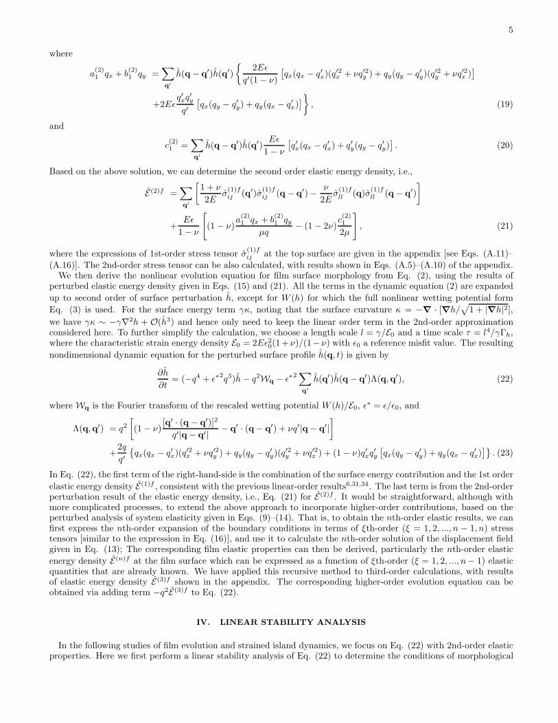
solving either the full elasticity problem or the reduced nonlinear evolution equations, deep grooves or cusps will formin stressed solid systems without the incorporation of wetting effect. This is well reproduced in our numerical resultsof Eq. (22), as shown in Fig. 1 for 3% misfit films with ν = 1/3 and initial film thickness h0 = 0. Two types ofinitial conditions are used: (1) a small random disturbance of a planar film of thickness h0, with results of a 128× 128system presented in Fig. 1 (a) and (b), and (2) a weakly perturbed film with doubly-periodic sinusoidal surface profileh = h0+A0[cos(qx0x)+cos(qy0y)], as given in panels (c) and (d) of Fig. 1 for a λx0×λy0 system (where λx0 = 2π/qx0and λy0 = 2π/qy0). For condition (2) the initial perturbed amplitude is set as A0 = 0.01, and a perturbed wavevector
qx0 = qy0 = 3/4√2 is chosen, corresponding to the wave number of the most linearly unstable mode determined by
Eq. (26). In both cases the formation of singular cusps or deep grooves and their rapid growth have been foundduring the film evolution, as evidenced by the 3D morphological profiles given in Fig. 1 (a) and (c), and also fromthe results of time-evolving 2D cross-section profiles shown in (b) and (d) which are consistent with the previous 2Dresults of Spencer and Meiron25 and Xiang and E28.To incorporate the wetting effect, in our calculations we use a pseudospectral method; that is, we first evaluate
the wetting potential W (h) from Eq. (3) in real space and then obtain its Fourier component Wq as used in thedynamic equation (22). As expected, the cusp/groove singularity is completely suppressed by the film-substrate
7
0.0 0.2 0.4 0.6 0.8 1.0
-1.0
-0.8
-0.6
-0.4
-0.2
0.0
0.2
h(x
,y=
Ly/
2)
x/ x
t=34.35
t=34.15
t=33.6
t=30
20 40 60 80 100 120-1.0
-0.8
-0.6
-0.4
-0.2
0.0
0.2
h(x
=6
5,y
)
y
t=45
t=46.5
t=46.77
t=46.85
50
55
60
65
60
65
70
-1.0
-0.6
-0.2
0.2
y
x
h
(c)
(a) (b)
(d)
FIG. 1: Surface morphologies of 3% strained films, as obtained from numerical simulations without the wetting effect. Thesimulations start either from small random initial perturbation of a planar film [(a) and (b)] or from a doubly-periodic surfaceprofile with wavevector qx0 = qy0 = 3/4
√2 and amplitude A0 = 0.01 [(c) and (d)]. Both 3D morphologies, (a) at t = 46.77
for a portion of a 128 × 128 system and (c) at t = 34.35 for system size λx0 × λy0, and also time evolution of 2D cross-sectionprofiles are shown.
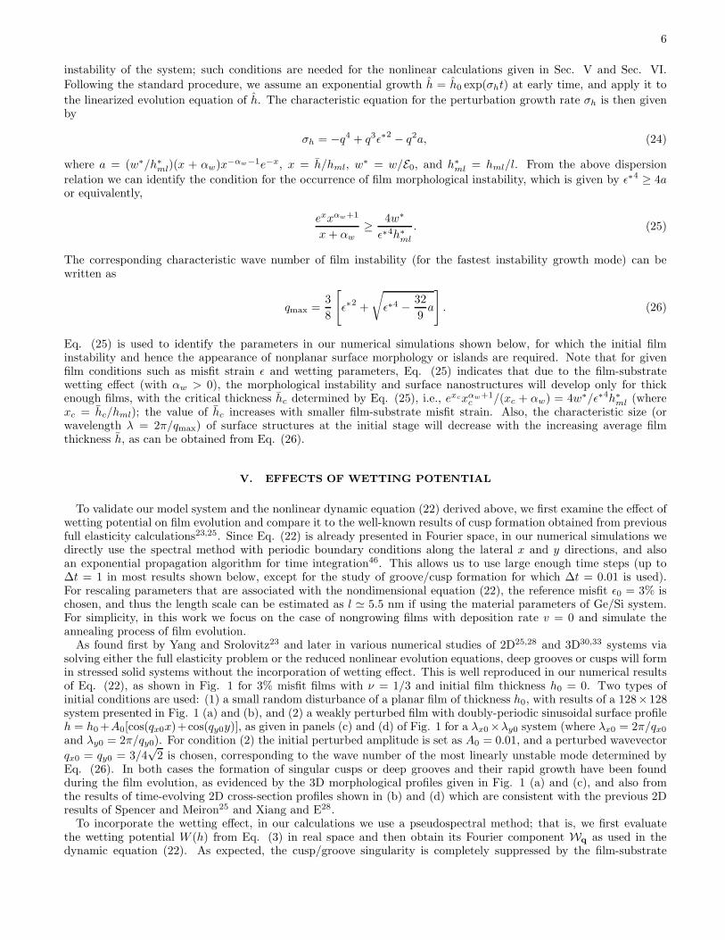
wetting interaction, and arrays of strained islands or quantum dots will form and grow. This has been verified byour numerical results shown in Fig. 2, where we have used the parameters of ǫ = 3%, h0 = 0.41, h∗
ml = 0.3, αw = 2,w∗ = 0.08 or 0.2, and simulation time step ∆t = 1. However, another type of growth instability would occur whenthe strength of wetting interaction is not strong enough (e.g., w∗ = 0.08 in Fig. 2), showing as the rapid increase ofisland heights beyond initial time stage and then the blow-up of numerical solution at late times. Such instabilitywith unbound growth of island height is absent for stronger wetting effect, such as the effect of w∗ = 0.2 shown inFig. 2(a) which gives the stabilization and saturation of island evolution. This can be understood from the factthat the wetting interaction tends to prevent the depletion of the film-substrate wetting layer and hence suppress themass transport from the valley of an island to its top, leading to the constraint of island height as a result of massconservation. Such effect would increase with the strength of wetting interaction, as can be seen from the results given
8
10 20 30 40 50 60 70 80 900.0
0.2
0.4
0.6
0.8
1.0
1.2
h(x,
y-L y/2
)
x
w*=0.08t=330
w*=0.2t=10000
(b)
1 10 100 10000.4
0.5
0.6
0.7
0.8
0.9
1
1.1
100
120
0
1
100
120
M
axim
um h
eigh
t hm
ax
Time t
w*=0.2
w*=0.08
(a)
xy
h
FIG. 2: Time evolution of 3% strained films with different wetting strength w∗ = 0.08 and 0.2. (a) Evolution of maximumsurface height, with a 3D island morphology for w∗ = 0.08 at t = 330 shown in the inset; (b) 2D cross-section profiles aty = Ly/2 for w∗ = 0.08 at t = 330 and w∗ = 0.2 at t = 10000.
in Fig. 2(b): thicker film layers between surface islands and shallower valleys are found for larger wetting strengthw∗, as a result of stronger suppression on the valley-to-peak diffusion process.
VI. RESULTS OF NONLINEAR EVOLUTION
To examine the detailed evolution of strained film morphology more systematically, we have conducted numericalsimulations of the full dynamic equation (22) for different small film-substrate misfit strains ǫ = 2%, 2.5%, and 3%(in such weak strain limit the continuum elasticity approach can be well applied, as shown in most recent studies43).The parameters for the wetting potential are chosen as h∗
ml = 0.3, αw = 2, and w∗ = 0.2, with all other parametersthe same as those given in Sec. V. In our simulations we have used 3 different system sizes Lx×Ly for each parameterset, including the lateral dimensions of 128× 128, 256× 256, and 512× 512, to examine any possible artifacts of finitesize effects. A numerical grid spacing ∆x = ∆y = 1 is adopted, and the integration time step is chosen as ∆t = 1.The quantitative results given below have been averaged over 20 independent runs for system sizes 128 × 128 and256× 256, and 10 runs for 512× 512. Also, each simulation starts with a rescaled initial film thickness of h0 = 0.67for misfit strain ǫ = 2%, h0 = 0.5 for ǫ = 2.5%, and h0 = 0.41 for ǫ = 3%, all of which are within the correspondinginstability parameter region for each misfit as determined by Eq. (25).Typical simulation results of film evolution and the formation and dynamics of quantum dot arrays are illustrated
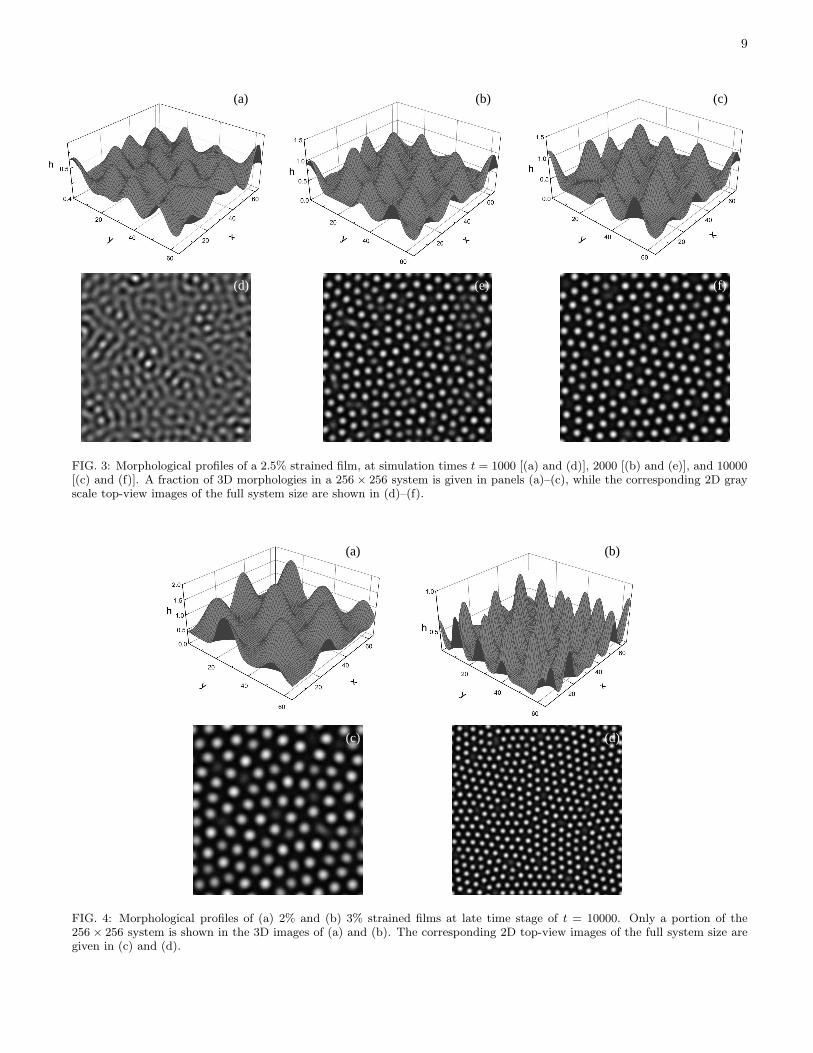
in Fig. 3, for 2.5% mismatch between the film and substrate. At the beginning stage surface undulations occur due tofilm morphological instability determined in Eq. (25), leading to the formation of strained surface islands or quantumdots as shown in Fig. 3(a). Note that at different surface locations, islands will form and grow gradually at differentrates due to the nonlinear effects of elastic interaction. Island coarsening occurs at the next stage, showing as thegrowth of some quantum dots at the expense of other shrinking ones and hence the decrease of island density on thefilm surface. This can be seen more clearly in the corresponding 2D top-view images of Figs. 3(d)–(f), which givethe comparison of island distribution between times t = 1000, 2000, and 104. Such coarsening process becomes muchslower as time increases, and the system would approach an asymptotic state with steady arrays of strained quantumdots. As expected, this late-time state of film surface structures highly depends on the value of film-substrate misfitstrain, with an increase of island density and a decrease of island spacing for larger misfits. This has been confirmedin our results of 2% and 3% films given in Fig. 4, as compared to the 2.5% film shown in Figs. 3(c) and 3(f). In oursimulations no long-range spatial order can be found for quantum dot arrays, even at the late-time stage, agreeingwith the observation of most experimental and theoretical studies.To quantify the above results, we have analyzed the film surface morphology through various time-dependent
parameters, including the structure factor of surface height, its moments, the maximum height of surface profile, and
9
(d)
(a) (b)
(e) (f)
(c)
FIG. 3: Morphological profiles of a 2.5% strained film, at simulation times t = 1000 [(a) and (d)], 2000 [(b) and (e)], and 10000[(c) and (f)]. A fraction of 3D morphologies in a 256× 256 system is given in panels (a)–(c), while the corresponding 2D grayscale top-view images of the full system size are shown in (d)–(f).
(c) (d)
(b)(a)
FIG. 4: Morphological profiles of (a) 2% and (b) 3% strained films at late time stage of t = 10000. Only a portion of the256× 256 system is shown in the 3D images of (a) and (b). The corresponding 2D top-view images of the full system size aregiven in (c) and (d).
10
0.0 0.2 0.4 0.6 0.8-5
0
5
10
15
20
25
30
35
S
truct
ure
Fact
or S
q
Wave number q
t=2000
t=6000
t=10000(a)
0.0 0.2 0.4 0.6 0.8
0
2
4
6
8
Stru
ctur
e fa
ctor
Sq
Wave number q
t=2000
t=6000
t=10000(b)
0.0 0.2 0.4 0.6 0.8
0.0
0.5
1.0
1.5
2.0
2.5
3.0
Stru
ctur
e fa
ctor
Sq
Wave number q
t=2000
t=6000
t=10000(c)
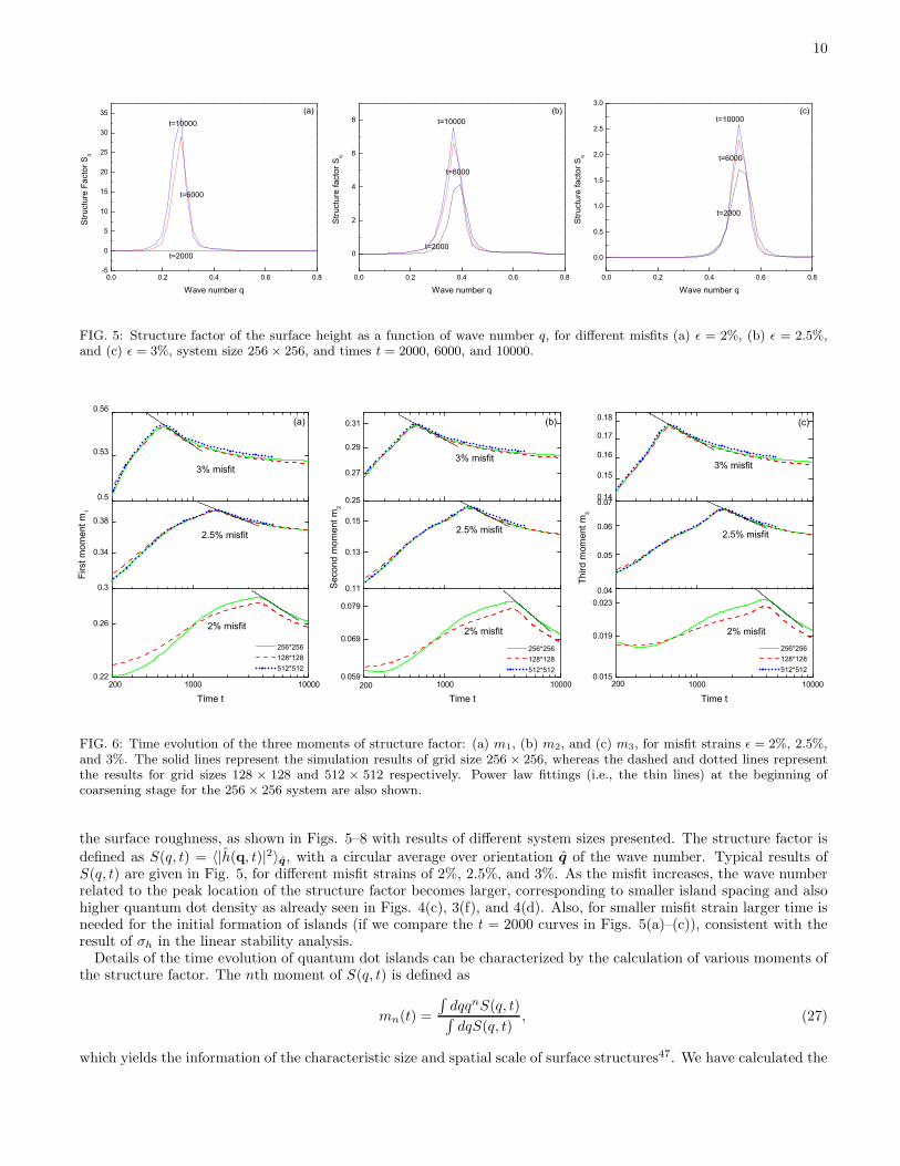
FIG. 5: Structure factor of the surface height as a function of wave number q, for different misfits (a) ǫ = 2%, (b) ǫ = 2.5%,and (c) ǫ = 3%, system size 256× 256, and times t = 2000, 6000, and 10000.
1000 100000.22
0.26
0.3
0.34
0.38
0.5
0.53
0.56
Time t
2% misfit
200
Firs
t mom
ent m
1
2.5% misfit
256*256 128*128 512*512
3% misfit
(a)
1000 100000.059
0.069
0.079
0.11
0.13
0.15
0.25
0.27
0.29
0.31
200
Time t
2% misfit
Sec
ond
mom
ent m
2
2.5% misfit
256*256 128*128 512*512
3% misfit
(b)
1000 100000.015
0.019
0.0230.04
0.05
0.06
0.070.14
0.15
0.16
0.17
0.18
200
Time t
2% misfit
Third
mom
ent m
3
2.5% misfit
256*256 128*128 512*512
3% misfit
(c)
FIG. 6: Time evolution of the three moments of structure factor: (a) m1, (b) m2, and (c) m3, for misfit strains ǫ = 2%, 2.5%,and 3%. The solid lines represent the simulation results of grid size 256 × 256, whereas the dashed and dotted lines representthe results for grid sizes 128 × 128 and 512 × 512 respectively. Power law fittings (i.e., the thin lines) at the beginning ofcoarsening stage for the 256× 256 system are also shown.
the surface roughness, as shown in Figs. 5–8 with results of different system sizes presented. The structure factor is
defined as S(q, t) = 〈|h(q, t)|2〉q, with a circular average over orientation q of the wave number. Typical results ofS(q, t) are given in Fig. 5, for different misfit strains of 2%, 2.5%, and 3%. As the misfit increases, the wave numberrelated to the peak location of the structure factor becomes larger, corresponding to smaller island spacing and alsohigher quantum dot density as already seen in Figs. 4(c), 3(f), and 4(d). Also, for smaller misfit strain larger time isneeded for the initial formation of islands (if we compare the t = 2000 curves in Figs. 5(a)–(c)), consistent with theresult of σh in the linear stability analysis.Details of the time evolution of quantum dot islands can be characterized by the calculation of various moments of
the structure factor. The nth moment of S(q, t) is defined as
mn(t) =
∫
dqqnS(q, t)∫
dqS(q, t), (27)
which yields the information of the characteristic size and spatial scale of surface structures47. We have calculated the
11
200 1000 1800 2600 3400 4200 50001E-3
0.01
0.1
1
10
Max
imum
stru
ctur
e fa
ctor
Sm
ax
Time t
2% misfit (256*256)
2.5% misfit (256*256)
2.5% misfit (512*512)
3% misfit (512*512)
3% misfit (256*256)
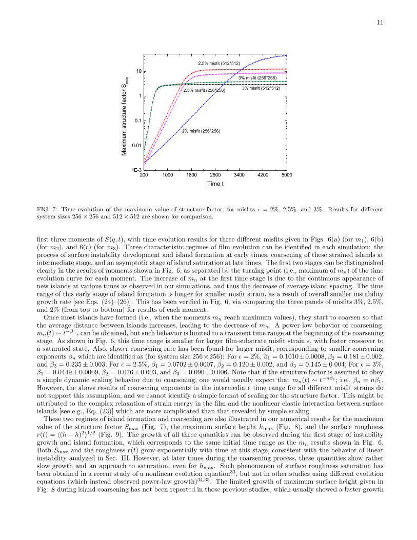
FIG. 7: Time evolution of the maximum value of structure factor, for misfits ǫ = 2%, 2.5%, and 3%. Results for differentsystem sizes 256× 256 and 512× 512 are shown for comparison.
first three moments of S(q, t), with time evolution results for three different misfits given in Figs. 6(a) (for m1), 6(b)(for m2), and 6(c) (for m3). Three characteristic regimes of film evolution can be identified in each simulation: theprocess of surface instability development and island formation at early times, coarsening of these strained islands atintermediate stage, and an asymptotic stage of island saturation at late times. The first two stages can be distinguishedclearly in the results of moments shown in Fig. 6, as separated by the turning point (i.e., maximum of mn) of the timeevolution curve for each moment. The increase of mn at the first time stage is due to the continuous appearance ofnew islands at various times as observed in our simulations, and thus the decrease of average island spacing. The timerange of this early stage of island formation is longer for smaller misfit strain, as a result of overall smaller instabilitygrowth rate [see Eqs. (24)–(26)]. This has been verified in Fig. 6, via comparing the three panels of misfits 3%, 2.5%,and 2% (from top to bottom) for results of each moment.Once most islands have formed (i.e., when the moments mn reach maximum values), they start to coarsen so that
the average distance between islands increases, leading to the decrease of mn. A power-law behavior of coarsening,mn(t) ∼ t−βn , can be obtained, but such behavior is limited to a transient time range at the beginning of the coarseningstage. As shown in Fig. 6, this time range is smaller for larger film-substrate misfit strain ǫ, with faster crossover toa saturated state. Also, slower coarsening rate has been found for larger misfit, corresponding to smaller coarseningexponents βn which are identified as (for system size 256×256): For ǫ = 2%, β1 = 0.1010±0.0008, β2 = 0.181±0.002,and β3 = 0.235± 0.003; For ǫ = 2.5%, β1 = 0.0702± 0.0007, β2 = 0.120± 0.002, and β3 = 0.145± 0.004; For ǫ = 3%,β1 = 0.0449± 0.0009, β2 = 0.076± 0.003, and β3 = 0.090± 0.006. Note that if the structure factor is assumed to obeya simple dynamic scaling behavior due to coarsening, one would usually expect that mn(t) ∼ t−nβ1 ; i.e., βn = nβ1.However, the above results of coarsening exponents in the intermediate time range for all different misfit strains donot support this assumption, and we cannot identify a simple format of scaling for the structure factor. This might beattributed to the complex relaxation of strain energy in the film and the nonlinear elastic interaction between surfaceislands [see e.g., Eq. (23)] which are more complicated than that revealed by simple scaling.These two regimes of island formation and coarsening are also illustrated in our numerical results for the maximum
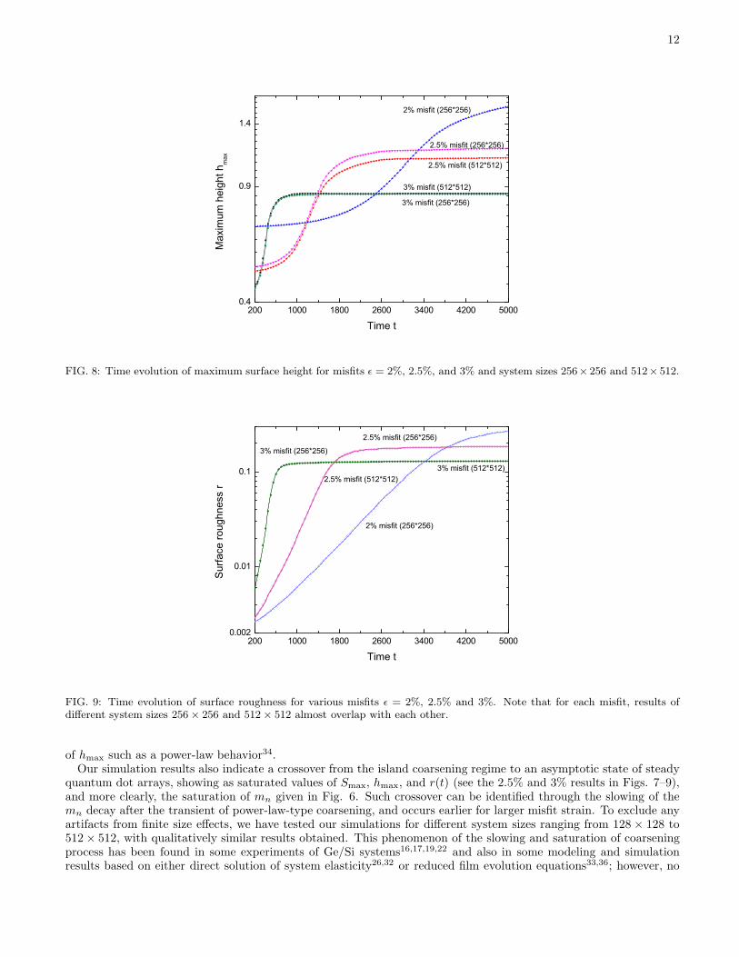
value of the structure factor Smax (Fig. 7), the maximum surface height hmax (Fig. 8), and the surface roughnessr(t) = 〈(h − h)2〉1/2 (Fig. 9). The growth of all three quantities can be observed during the first stage of instabilitygrowth and island formation, which corresponds to the same initial time range as the mn results shown in Fig. 6.Both Smax and the roughness r(t) grow exponentially with time at this stage, consistent with the behavior of linearinstability analyzed in Sec. III. However, at later times during the coarsening process, these quantities show ratherslow growth and an approach to saturation, even for hmax. Such phenomenon of surface roughness saturation hasbeen obtained in a recent study of a nonlinear evolution equation33, but not in other studies using different evolutionequations (which instead observed power-law growth)34,35. The limited growth of maximum surface height given inFig. 8 during island coarsening has not been reported in those previous studies, which usually showed a faster growth
12
200 1000 1800 2600 3400 4200 50000.4
0.9
1.4
Max
imum
hei
ght h
max
Time t
3% misfit (256*256)
3% misfit (512*512)
2.5% misfit (512*512)
2.5% misfit (256*256)
2% misfit (256*256)
FIG. 8: Time evolution of maximum surface height for misfits ǫ = 2%, 2.5%, and 3% and system sizes 256× 256 and 512× 512.
200 1000 1800 2600 3400 4200 50000.002
0.01
0.1
Sur
face
roug
hnes
s r
Time t
2% misfit (256*256)
2.5% misfit (256*256)
2.5% misfit (512*512)3% misfit (512*512)
3% misfit (256*256)
FIG. 9: Time evolution of surface roughness for various misfits ǫ = 2%, 2.5% and 3%. Note that for each misfit, results ofdifferent system sizes 256× 256 and 512× 512 almost overlap with each other.
of hmax such as a power-law behavior34.Our simulation results also indicate a crossover from the island coarsening regime to an asymptotic state of steady
quantum dot arrays, showing as saturated values of Smax, hmax, and r(t) (see the 2.5% and 3% results in Figs. 7–9),and more clearly, the saturation of mn given in Fig. 6. Such crossover can be identified through the slowing of themn decay after the transient of power-law-type coarsening, and occurs earlier for larger misfit strain. To exclude anyartifacts from finite size effects, we have tested our simulations for different system sizes ranging from 128 × 128 to512× 512, with qualitatively similar results obtained. This phenomenon of the slowing and saturation of coarseningprocess has been found in some experiments of Ge/Si systems16,17,19,22 and also in some modeling and simulationresults based on either direct solution of system elasticity26,32 or reduced film evolution equations33,36; however, no
13
-0.018
-0.017
-0.016
µ (x
=L
x/2, y
)
20 40 60 80 100 120y
-0.1
-0.05
0
0.05
εf (x=
Lx/2
, y)
70009000
t=10000
t=10000
5000
t=5000
t=7000t=9000
(a)
(b)
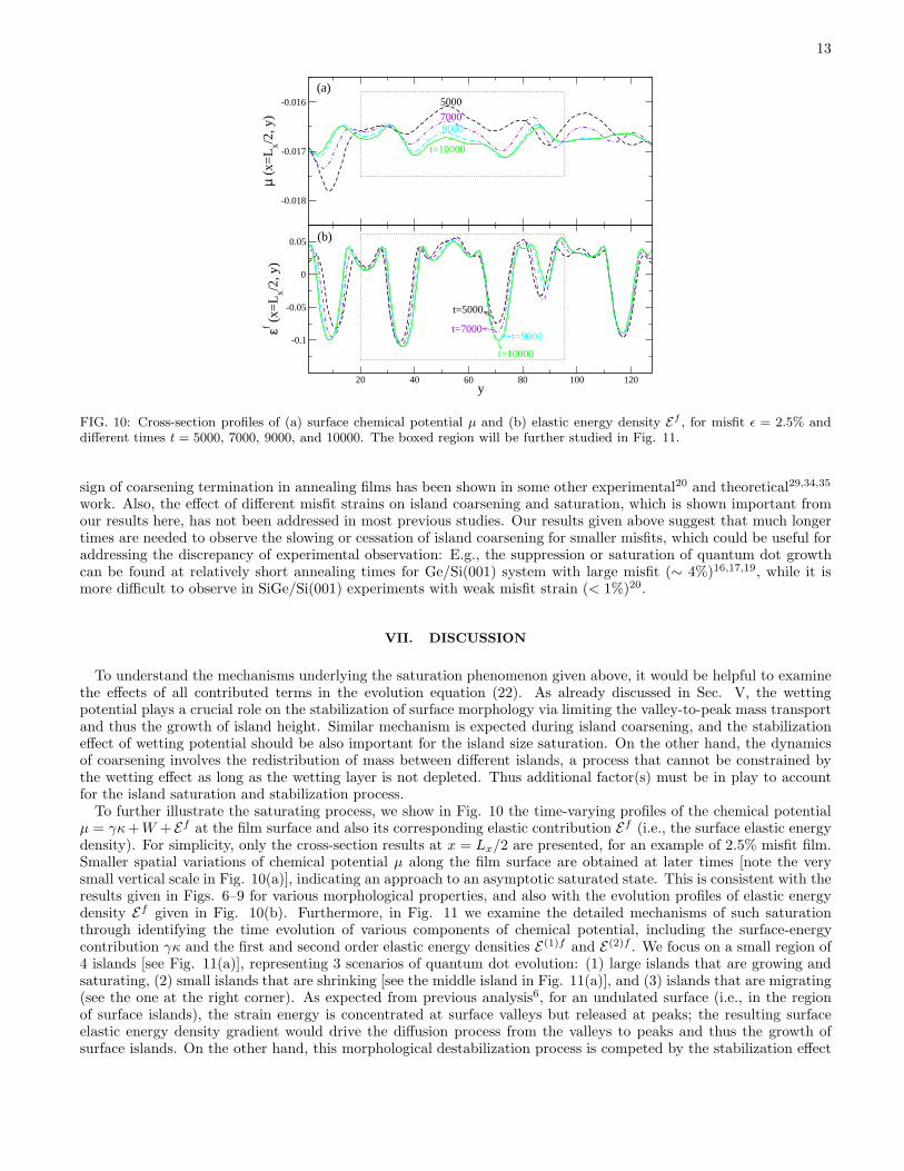
FIG. 10: Cross-section profiles of (a) surface chemical potential µ and (b) elastic energy density Ef , for misfit ǫ = 2.5% anddifferent times t = 5000, 7000, 9000, and 10000. The boxed region will be further studied in Fig. 11.
sign of coarsening termination in annealing films has been shown in some other experimental20 and theoretical29,34,35
work. Also, the effect of different misfit strains on island coarsening and saturation, which is shown important fromour results here, has not been addressed in most previous studies. Our results given above suggest that much longertimes are needed to observe the slowing or cessation of island coarsening for smaller misfits, which could be useful foraddressing the discrepancy of experimental observation: E.g., the suppression or saturation of quantum dot growthcan be found at relatively short annealing times for Ge/Si(001) system with large misfit (∼ 4%)16,17,19, while it ismore difficult to observe in SiGe/Si(001) experiments with weak misfit strain (< 1%)20.
VII. DISCUSSION
To understand the mechanisms underlying the saturation phenomenon given above, it would be helpful to examinethe effects of all contributed terms in the evolution equation (22). As already discussed in Sec. V, the wettingpotential plays a crucial role on the stabilization of surface morphology via limiting the valley-to-peak mass transportand thus the growth of island height. Similar mechanism is expected during island coarsening, and the stabilizationeffect of wetting potential should be also important for the island size saturation. On the other hand, the dynamicsof coarsening involves the redistribution of mass between different islands, a process that cannot be constrained bythe wetting effect as long as the wetting layer is not depleted. Thus additional factor(s) must be in play to accountfor the island saturation and stabilization process.To further illustrate the saturating process, we show in Fig. 10 the time-varying profiles of the chemical potential
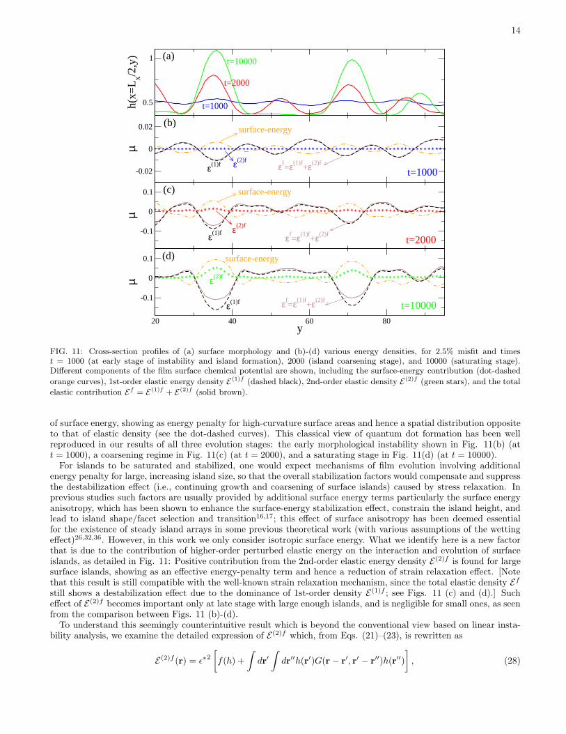
µ = γκ+W + Ef at the film surface and also its corresponding elastic contribution Ef (i.e., the surface elastic energydensity). For simplicity, only the cross-section results at x = Lx/2 are presented, for an example of 2.5% misfit film.Smaller spatial variations of chemical potential µ along the film surface are obtained at later times [note the verysmall vertical scale in Fig. 10(a)], indicating an approach to an asymptotic saturated state. This is consistent with theresults given in Figs. 6–9 for various morphological properties, and also with the evolution profiles of elastic energydensity Ef given in Fig. 10(b). Furthermore, in Fig. 11 we examine the detailed mechanisms of such saturationthrough identifying the time evolution of various components of chemical potential, including the surface-energycontribution γκ and the first and second order elastic energy densities E(1)f and E(2)f . We focus on a small region of4 islands [see Fig. 11(a)], representing 3 scenarios of quantum dot evolution: (1) large islands that are growing andsaturating, (2) small islands that are shrinking [see the middle island in Fig. 11(a)], and (3) islands that are migrating(see the one at the right corner). As expected from previous analysis6, for an undulated surface (i.e., in the regionof surface islands), the strain energy is concentrated at surface valleys but released at peaks; the resulting surfaceelastic energy density gradient would drive the diffusion process from the valleys to peaks and thus the growth ofsurface islands. On the other hand, this morphological destabilization process is competed by the stabilization effect
14
-0.02
0
0.02µ
-0.1
0
0.1
µ
20 40 60 80y
-0.1
0
0.1
µ
0.5
1
h(x=
Lx/2
,y)
t=2000
ε(2)f
ε(2)f
t=10000
t=1000
t=1000
t=10000
t=2000
ε(2)f
ε(1)f
ε(1)f
ε(1)f εf=ε(1)f
+ε(2)f
εf=ε(1)f
+ε(2)f
εf=ε(1)f
+ε(2)f
surface-energy
surface-energy
surface-energy
(a)
(b)
(c)
(d)
FIG. 11: Cross-section profiles of (a) surface morphology and (b)-(d) various energy densities, for 2.5% misfit and timest = 1000 (at early stage of instability and island formation), 2000 (island coarsening stage), and 10000 (saturating stage).Different components of the film surface chemical potential are shown, including the surface-energy contribution (dot-dashed
orange curves), 1st-order elastic energy density E (1)f (dashed black), 2nd-order elastic density E (2)f (green stars), and the total
elastic contribution Ef = E (1)f + E (2)f (solid brown).
of surface energy, showing as energy penalty for high-curvature surface areas and hence a spatial distribution oppositeto that of elastic density (see the dot-dashed curves). This classical view of quantum dot formation has been wellreproduced in our results of all three evolution stages: the early morphological instability shown in Fig. 11(b) (att = 1000), a coarsening regime in Fig. 11(c) (at t = 2000), and a saturating stage in Fig. 11(d) (at t = 10000).For islands to be saturated and stabilized, one would expect mechanisms of film evolution involving additional
energy penalty for large, increasing island size, so that the overall stabilization factors would compensate and suppressthe destabilization effect (i.e., continuing growth and coarsening of surface islands) caused by stress relaxation. Inprevious studies such factors are usually provided by additional surface energy terms particularly the surface energyanisotropy, which has been shown to enhance the surface-energy stabilization effect, constrain the island height, andlead to island shape/facet selection and transition16,17; this effect of surface anisotropy has been deemed essentialfor the existence of steady island arrays in some previous theoretical work (with various assumptions of the wettingeffect)26,32,36. However, in this work we only consider isotropic surface energy. What we identify here is a new factorthat is due to the contribution of higher-order perturbed elastic energy on the interaction and evolution of surfaceislands, as detailed in Fig. 11: Positive contribution from the 2nd-order elastic energy density E(2)f is found for largesurface islands, showing as an effective energy-penalty term and hence a reduction of strain relaxation effect. [Notethat this result is still compatible with the well-known strain relaxation mechanism, since the total elastic density Ef
still shows a destabilization effect due to the dominance of 1st-order density E(1)f ; see Figs. 11 (c) and (d).] Sucheffect of E(2)f becomes important only at late stage with large enough islands, and is negligible for small ones, as seenfrom the comparison between Figs. 11 (b)-(d).To understand this seemingly counterintuitive result which is beyond the conventional view based on linear insta-
bility analysis, we examine the detailed expression of E(2)f which, from Eqs. (21)–(23), is rewritten as
E(2)f (r) = ǫ∗2[
f(h) +
∫
dr′∫
dr′′h(r′)G(r − r′, r′ − r
′′)h(r′′)
]
, (28)
15
where
f(h) = |∇h|2 + ν(
E(1)f/ǫ∗2)2
+ (1− ν)
3∑
i=1
g2i (h), (29)
with gi(h) (i = 1, 2, 3) the Fourier transform of q2xh/q, q2yh/q, and
√2qxqyh/q respectively, and
G(r− r′, r′ − r
′′) =∑
q,q′
eiq·(r−r′)+iq′
·(r′−r′′)
× 2
qq′{
qx(qx − q′x)(q′2x + νq′2y ) + qy(qy − q′y)(q
′2y + νq′2x ) + (1− ν)q′xq
′
y
[
qx(qy − q′y) + qy(qx − q′x)]}
. (30)
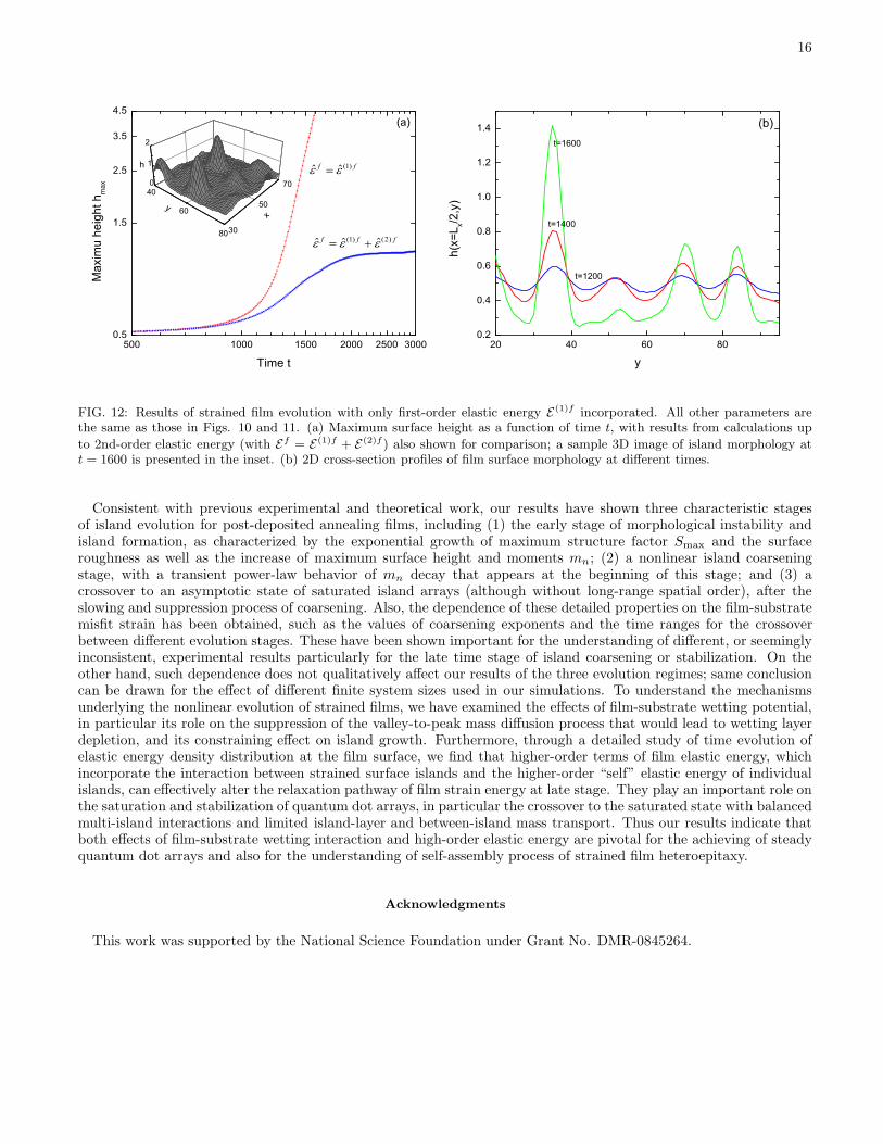
In Eq. (28), the first part f(h) is always positive, analogous to the “self” elastic energy of a given surface profile thatserves as a energy penalty to suppress its coarsening; the 2nd part represents the correlation between surface heightsand thus the elastic interaction between surface islands. Within each island region (particularly near the peak), themagnitudes of both parts increase with the island size as verified in our numerical calculations.If these 2nd-order elastic contributions are absent or not strong enough, the elastic energy relaxation would increas-
ingly dominate over the surface-energy stabilization effect, driving the continuing island growth even in the presence ofthe wetting potential. This can be illustrated clearly from our numerical results given in Fig. 12, where the same filmevolution equation (22) is simulated, but with only first-order elastic energy E(1)f incorporated. All other parametersremain unchanged, including the same wetting potential approximation Eq. (3). The maximum surface height isfound to increase monotonically with time [see Fig. 12 (a)], without any slowing or saturation process observed, aresult that is consistent with previous work34. Time evolution of the corresponding 2D cross-section surface profilesis given in Fig. 12 (b), from which two main features of surface dynamics can be identified: (1) Large mass transportfrom film layers to islands is observed, leading to much thinner film layers between surface islands as compared to theresult shown in Fig. 11 (a) which incorporates the 2nd-order elastic energy effects. Although the wetting potentialstill has the effect of preserving the wetting layer in-between surface islands and then limiting the diffusion processfrom the depleted wetting layer to the peaks, here such effect becomes relatively weaker as time evolves due to theincreasing dominance of the destabilization effect of 1st-order elastic energy and the absence of “self” energy penaltyterm f(h) for large islands. (2) Mass transport between islands continues to occur, which corresponds to islandmigration or coarsening process and is actually a secondary effect compared to (1). This process cannot be preventedby the wetting effect, and can be controlled only by the higher-order elastic energy terms describing island interactionand correlation [see Eq. (28)]. Thus at late times the island heights increase rapidly, resulting in the formation ofsurface islands with large aspect ratio between height and width as shown in Fig. 12. The perturbation method usedhere is no longer valid for such high islands, and the simulations will ultimately blow up. This is qualitatively differentfrom the results given above with the incorporation of 2nd-order elastic energy, where islands with well constrainedaspect ratio are obtained which also shows the applicability of the perturbation method developed here.All these results indicate that the nonlinearities given by the higher-order strain energy of individual islands and
the elastic interaction between islands can affect the pathway of film strain relaxation at late evolution times, slowdown the decrease of total elastic energy via their increasing positive energy contribution for large islands, andthus effectively reduce the effect of stress relaxation as the surface instability driving force. Such reduction leadsto relatively stronger role played by the surface energy and the wetting potential at later times [see the comparisonbetween Figs. 11 (c) and (d), and between Figs. 11 (a) and 12 (b)], limiting the mass transport between film layersand islands and hence suppressing the island growth and coarsening.
VIII. CONCLUSIONS
We have investigated the nonlinear dynamic processes governing the formation, coarsening, and stabilization ofstrained quantum dot islands on the surface of heteroepitaxial films, through the development of a nonlinear evolutionequation for film morphology. Our study is based on a continuum elasticity model that incorporates the film-substratewetting effect and importantly, on the construction of a perturbation method in Fourier space for determining thesystem elastic properties. In addition to a linear stability analysis which yields the conditions of film morphologicalinstability, we have performed large scale numerical calculations of the dynamic equation derived to study the detailedbehavior of film evolution. We focus on effects of small misfit strains which correspond to relatively large length scaleof surface nanostructures, and analyze the evolution of strained surface islands/dots using a variety of characteristicsof film morphology, including the structure factor of surface height, its first three moments, the maximum height ofsurface profile, and the surface roughness.
16
20 40 60 800.2
0.4
0.6
0.8
1.0
1.2
1.4
h(x=
L x/2,y
)
y
t=1600
t=1400
t=1200
(b)
40
60
80
0
1
2
30
50
70
500 1000 1500 2000 2500 30000.5
1.5
2.5
3.5
4.5
Time t
Max
imu
heig
ht h
max
ff )1(
fff )2()1(
(a)
xy
h
FIG. 12: Results of strained film evolution with only first-order elastic energy E (1)f incorporated. All other parameters arethe same as those in Figs. 10 and 11. (a) Maximum surface height as a function of time t, with results from calculations up
to 2nd-order elastic energy (with Ef = E (1)f + E (2)f ) also shown for comparison; a sample 3D image of island morphology att = 1600 is presented in the inset. (b) 2D cross-section profiles of film surface morphology at different times.
Consistent with previous experimental and theoretical work, our results have shown three characteristic stagesof island evolution for post-deposited annealing films, including (1) the early stage of morphological instability andisland formation, as characterized by the exponential growth of maximum structure factor Smax and the surfaceroughness as well as the increase of maximum surface height and moments mn; (2) a nonlinear island coarseningstage, with a transient power-law behavior of mn decay that appears at the beginning of this stage; and (3) acrossover to an asymptotic state of saturated island arrays (although without long-range spatial order), after theslowing and suppression process of coarsening. Also, the dependence of these detailed properties on the film-substratemisfit strain has been obtained, such as the values of coarsening exponents and the time ranges for the crossoverbetween different evolution stages. These have been shown important for the understanding of different, or seeminglyinconsistent, experimental results particularly for the late time stage of island coarsening or stabilization. On theother hand, such dependence does not qualitatively affect our results of the three evolution regimes; same conclusioncan be drawn for the effect of different finite system sizes used in our simulations. To understand the mechanismsunderlying the nonlinear evolution of strained films, we have examined the effects of film-substrate wetting potential,in particular its role on the suppression of the valley-to-peak mass diffusion process that would lead to wetting layerdepletion, and its constraining effect on island growth. Furthermore, through a detailed study of time evolution ofelastic energy density distribution at the film surface, we find that higher-order terms of film elastic energy, whichincorporate the interaction between strained surface islands and the higher-order “self” elastic energy of individualislands, can effectively alter the relaxation pathway of film strain energy at late stage. They play an important role onthe saturation and stabilization of quantum dot arrays, in particular the crossover to the saturated state with balancedmulti-island interactions and limited island-layer and between-island mass transport. Thus our results indicate thatboth effects of film-substrate wetting interaction and high-order elastic energy are pivotal for the achieving of steadyquantum dot arrays and also for the understanding of self-assembly process of strained film heteroepitaxy.
Acknowledgments
This work was supported by the National Science Foundation under Grant No. DMR-0845264.
17
Appendix: Third order perturbation results of film elasticity
As described in Sec. III, our perturbation approach developed here for solving the system elasticity problem canbe extended to obtain higher order results through a recursive procedure. We have calculated the elastic propertiesof this heteroepitaxial system up to third order, with results presented in this appendix. The 3rd-order perturbedelastic energy density is given by
E(3)f =Eǫ
1− ν
[
(1− ν)a(3)1 qx + b
(3)1 qy
µq− (1− 2ν)
c(3)1
2µ
]
+∑
q′
{
1 + ν
2E
[
σ(1)fij (q′)σ
(2)fij (q − q
′) + σ(2)fij (q′)σ
(1)fij (q− q
′)]
− ν
2E
[
σ(1)fll (q′)σ
(2)fll (q− q
′) + σ(2)fll (q′)σ
(1)fll (q− q
′)]}
, (A.1)
where
a(3)1 =
∑
q′
[
(qx − q′x)σ(2)fxx (q′) + (qy − q′y)σ
(2)fxy (q′)
]
h(q− q′), (A.2)
b(3)1 =
∑
q′
[
(qx − q′x)σ(2)fxy (q′) + (qy − q′y)σ
(2)fyy (q′)
]
h(q− q′), (A.3)
c(3)1 =
∑
q′
i[
(qx − q′x)σ(2)fxz (q′) + (qy − q′y)σ
(2)fyz (q′)
]
h(q− q′). (A.4)
Based on the perturbation solutions of the system elasticity, we have obtained the first and second order results forelastic stress tensors at the film surface, which are used to calculate the perturbed elastic energy density given above.In second order we have
σ(2)fxx (q) = − Eǫ
1− ν
∑
q′
{
4qx(qx − q′x)
q3q′(νq′2y + q′2x )(q
2 + νq2y) + 4ν(qy − q′y)q
3y
q3q′(q′2y + νq′2x )
+4(1− ν)q′xq
′
y
q3q′[
qx(qy − q′y) + qy(qx − q′x)]
(q2x + νq2)− 1
q2[
q′x(qx − q′x) + q′y(qy − q′y)]
(2νq2y + q2x)
+4(1− ν)qxqyq
′
xq′
y
q3q′[
qy(qy − q′y)− qx(qx − q′x)]
}
h(q′)h(q− q′), (A.5)
σ(2)fyy (q) = − Eǫ
1− ν
∑
q′
{
4qy(qy − q′y)
q3q′(νq′2x + q′2y )(q2 + νq2x) + 4ν
(qx − q′x)q3x
q3q′(q′2x + νq′2y )
+4(1− ν)q′xq
′
y
q3q′[
qx(qy − q′y) + qy(qx − q′x)]
(q2y + νq2)− 1
q2[
q′x(qx − q′x) + q′y(qy − q′y)]
(2νq2x + q2y)
−4(1− ν)qxqyq
′
xq′
y
q3q′[
qy(qy − q′y)− qx(qx − q′x)]
}
h(q′)h(q− q′), (A.6)
σ(2)fzz (q) =
Eǫ
(1− ν)(3− 2ν)
∑
q′
[
q′x(qx − q′x) + q′y(qy − q′y)]
h(q′)h(q− q′), (A.7)
σ(2)fxy (q) = Eǫ
∑
q′
{
−4qxqyq′q3
[(
qx(qx − q′x)(q′2x + νq′2y ) + qy(qy − q′y)(q
′2y + νq′2x )
)
+(1− ν)q′xq′
y
(
qx(qy − q′y) + qy(qx − q′x))]
+(1− 2ν)
(1 − ν)
qxqyq2
[
q′x(qx − q′x) + q′y(qy − q′y)]
− 4
(1− ν)
q2yq3q′
[
qy(qx − q′x)(q′2x + νq′2y )− qx(qy − q′y)(q
′2y + νq′2x )
+(1− ν)q′xq′
y
(
qy(qy − q′y)− qx(qx − q′x))]}
h(q′)h(q − q′), (A.8)
18
σ(2)fxz (q) =
2Eǫ
1− ν
∑
q′
iqxq2q′
{
qx(qx − q′x)(q′2x + νq′2y ) + qy(qy − q′y)(q
′2y + νq′2x )
+(1− ν)q′xq′
y
[
qx(qy − q′y) + qy(qx − q′x)]
−q2yqx
[
(qx − q′x)(q′2x + νq′2y ) + (1− ν)(qy − q′y)q
′
xq′
y
]
+(1− ν)qy(qx − q′x)q′
xq′
y + qy(qy − q′y)(q′2y + νq′2x )
}
h(q′)h(q− q′), (A.9)
σ(2)fyz (q) =
2Eǫ
1− ν
∑
q′
iqyq2q′
{
qx(qx − q′x)(q′2x + νq′2y ) + qy(qy − q′y)(q
′2y + νq′2x )
+(1− ν)q′xq′
y
[
qx(qy − q′y) + qy(qx − q′x)]
− q2xqy
[
(qy − q′y)(q′2y + νq′2x ) + (1 − ν)(qx − q′x)q
′
xq′
y
]
+(1− ν)qx(qy − q′y)q′
xq′
y + qx(qx − q′x)(q′2x + νq2y)
}
h(q′)h(q− q′), (A.10)
while the results for first order perturbation are given by
σ(1)fxx (q) =
2Eǫ
q(1− ν)(q2x + νq2y)h(q), (A.11)
σ(1)fyy (q) =
2Eǫ
q(1− ν)(q2y + νq2x)h(q), (A.12)
σ(1)fzz (q) = 0, (A.13)
σ(1)fxy (q) = 2Eǫ
qxqyq
h(q), (A.14)
σ(1)fxz (q) = − Eǫ
1− νiqxh(q), (A.15)
σ(1)fyz (q) = − Eǫ
1− νiqyh(q). (A.16)
1 J. Stangl, V. Holy, and G. Bauer, Rev. Mod. Phys. 76, 725 (2004).2 S. Kiravittaya, A. Rastelli, and O. G. Schmidt, Rep. Prog. Phys. 72, 046502 (2009).3 I. Berbezier and A. Ronda, Surf. Sci. Rep. 64, 47 (2009).4 R. J. Asaro and W. A. Tiller, Metall. Trans. 3, 1789 (1972); M. A. Grinfeld, Sov. Phys. Dokl. 31, 831 (1986).5 D. J. Srolovitz, Acta Metall. 37, 621 (1989).6 B. J. Spencer, P. W. Voorhees, and S. H. Davis, Phys. Rev. Lett. 67, 3696 (1991); J. Appl. Phys. 73, 4955 (1993).7 P. Sutter and M. G. Lagally, Phys. Rev. Lett. 84, 4637 (2000).8 R. M. Tromp, F. M. Ross, and M. C. Reuter, Phys. Rev. Lett. 84, 4641 (2000).9 J. Tersoff, B. J. Spencer, A. Rastelli, and H. von Kanel, Phys. Rev. Lett. 89, 196104 (2002).
10 J. E. Guyer and P. W. Voorhees, Phys. Rev. Lett. 74, 4031 (1995).11 B. J. Spencer, P. W. Voorhees, and J. Tersoff, Phys. Rev. B 64, 235318 (2001).12 Z.-F. Huang and R. C. Desai, Phys. Rev. B 65, 205419 (2002); 65, 195421 (2002).13 R. C. Desai, H. K. Kim, A. Chatterji, D. Ngai, S. Chen, and N. Yang, Phys. Rev. B 81, 235301 (2010).14 L. E. Shilkrot, D. J. Srolovitz, and J. Tersoff, Phys. Rev. B 62, 8397 (2000); 67, 249901(E) (2003).15 Z.-F. Huang and R. C. Desai, Phys. Rev. B 67, 075416 (2003); Z.-F. Huang, D. Kandel, and R. C. Desai, Appl. Phys. Lett.
82, 4705 (2003).16 F. M. Ross, J. Tersoff, and R. M. Tromp, Phys. Rev. Lett. 80, 984 (1998).17 G. Medeiros-Ribeiro, T. I. Kamins, D. A. A. Ohlberg, and R. S. Williams, Phys. Rev. B 58, 3533 (1998).18 A. Rastelli, M. Stoffel, J. Tersoff, G. S. Kar, and O. G. Schmidt, Phys. Rev. Lett. 95, 026103 (2005).19 M. R. McKay, J. A. Venables, and J. Drucker, Phys. Rev. Lett. 101, 216104 (2008).20 J. A. Floro, M. B. Sinclair, E. Chason, L. B. Freund, R. D. Twesten, R. Q. Hwang, and G. A. Lucadamo, Phys. Rev. Lett.
84, 701 (2000).21 T. J. Krzyzewski and T. S. Jones, J. Appl. Phys. 96, 668 (2004).22 W. Dorsch, H. P. Strunk, H. Wawra, G. Wagner, J. Groenen, and R. Carles, Appl. Phys. Lett. 72, 179 (1998).23 W. H. Yang and D. J. Srolovitz, Phys. Rev. Lett. 71, 1593 (1993).24 B. J. Spencer, S. H. Davis, and P. W. Voorhees, Phys. Rev. B, 47, 9760 (1993).25 B. J. Spencer and D. I. Meiron, Acta Metall. Mater. 42, 3629 (1994).
19
26 C.-H. Chiu, Appl. Phys. Lett. 75, 3473 (1999); C.-H. Chiu and Z. Huang, J. Appl. Phys. 101, 113540 (2007).27 F. Liu, A. H. Li, and M. G. Lagally, Phys. Rev. Lett. 87, 126103 (2001).28 Y. Xiang and W. E, J. Appl. Phys. 91, 9414 (2002).29 P. Liu, Y. W. Zhang, and C. Lu, Phys. Rev. B 68, 035402 (2003).30 A. A. Golovin, S. H. Davis, and P. W. Voorhees, Phys. Rev. E 68, 056203 (2003).31 W. T. Tekalign and B. J. Spencer, J. Appl. Phys. 96, 5505 (2004); 102, 073503 (2007).32 H. R. Eisenberg and D. Kandel, Phys. Rev. B, 71, 115423 (2005).33 Y. Pang and R. Huang, Phys. Rev. B 74, 075413 (2006).34 M. S. Levine, A. A. Golovin, S. H. Davis, and P. W. Voorhees, Phys. Rev. B 75, 205312 (2007).35 J.-N. Aqua, T. Frisch, and A. Verga, Phys. Rev. B 76, 165319 (2007); Phys. Rev. E 81, 021605 (2010).36 J.-N. Aqua and T. Frisch, Phys. Rev. B 82, 085322 (2010).37 J. Muller and M. Grant, Phys. Rev. Lett. 82, 1736 (1999).38 K. Kassner, C. Misbah, J. Muller, J. Kappey, and P. Kohlert, Phys. Rev. E 63, 036117 (2001).39 G. Nandipati and J. G. Amar, Phys. Rev. B 73, 045409 (2006).40 T. P. Schulze and P. Smereka, J. Mech. Phys. Solids 57, 521 (2009).41 X. B. Niu, G. B. Stringfellow, and F. Liu, Phys. Rev. Lett. 107, 076101 (2011).42 K. R. Elder, M. Katakowski, M. Haataja, and M. Grant, Phys. Rev. Lett. 88, 245701 (2002).43 Z.-F. Huang and K. R. Elder, Phys. Rev. Lett. 101, 158701 (2008); Phys. Rev. B 81, 165421 (2010).44 K.-A. Wu and P. W. Voorhees, Phys. Rev. B 80, 125408 (2009).45 K. R. Elder, Z.-F. Huang, and N. Provatas, Phys. Rev. E 81, 011602 (2010); K. R. Elder and Z.-F. Huang, J. Phys.: Condens.
Matter 22, 364103 (2010); Z.-F. Huang, K. R. Elder, and N. Provatas, Phys. Rev. E 82, 021605 (2010).46 M. C. Cross, D. I. Meiron, and Y. Tu, Chaos 4, 607 (1994).47 C. Sagui and R. C. Desai, Phys. Rev. E, 49, 2225 (1994).
Related Documents


![Strained -Sn on InSb(001) · InSb, is likewise a heteroepitaxial strained system. The use of InSb as a template for high quality crystals is well established [18{20]. It induces a](https://static.cupdf.com/doc/110x72/5f63835e50764f10ad37eb67/strained-sn-on-insb001-insb-is-likewise-a-heteroepitaxial-strained-system-the.jpg)