® Coarse Bubble Aeration System INSTALLATION, OPERATION AND MAINTENANCE MANUAL

Welcome message from author
This document is posted to help you gain knowledge. Please leave a comment to let me know what you think about it! Share it to your friends and learn new things together.
Transcript

®
Coarse Bubble Aeration System
INSTALLATION, OPERATION ANDMAINTENANCE MANUAL
TABLE OF CONTENTS
Page No.
INTRODUCTION.............................................. ii
INSTALLATION AND START-UPReceiving and Site Storage................................ 1Physical Inventory............................................... 1FIXED HEADER..................................................1
Dropleg Installation .........................................1Manifold Installation ........................................2Header Installation ..........................................6
Header Installation Without Manifold .........6Header Installation With Manifold ..............9
REMOVABLE HEADER....................................11Dropleg Installation........................................11Header Installation ........................................12
Diffuser Installation and Leveling ......................15Aeration System Start-up Procedure ................16
Installation Inspection ...................................16Leak, Level and Uniform Air Distribution ......16
Removable Header Hoist Lifting Instructions....18
Page No.
PLANT OPERATIONPrinciples ...........................................................21Diffuser Operating Air Flow Range ...................22Mixing.................................................................22Diffuser Fouling..................................................22
PREVENTATIVE MAINTENANCEPower Failures and Loss of Air Supply .............23Visual Inspection................................................23Air Main Inspection ............................................23Aeration System Troubleshooting Guide ..........24
YEARLY MAINTENANCE AND CLEANINGMaintenance Schedule......................................27Lubrication Schedule.........................................27Cleaning.............................................................27
LONG TERM STORAGE PROCEDURES...............................................29
i®

ii ®
INTRODUCTION
This manual covers the Installation, Start-up,Plant Operation, Maintenance and Repair ofSANITAIRE Coarse Bubble Aeration Systems.
This manual is used for SANITAIRE Fixed andRemovable Header Coarse Bubble AerationSystems. The format and text of this manualhave not been edited for specific projects orspecification requirements.
Distinct sections are included for the installationof both system types. The installing Contractorshould follow the instructions for the suppliedsystem.
Before beginning the installation process, theinstalling Contractor should make sure theSanitaire Erection “E” drawings are in theirpossession. The “E” drawings have the requiredcomponent part number designations and areessential for proper installation.Submittal “S” drawings do not contain thedetailed information necessary to install theequipment properly. DO NOT use “S” drawingsto lay out or install the equipment.
The Safety Alert Symbol meansATTENTION! BECOME ALERT! YOURSAFETY IS INVOLVED!
! CAUTIONThis symbol and signal word indicate apotentially hazardous situation which,if not avoided, MAY result in minor ormoderate injury. This symbol MAYalso be used to alert against unsafepractices.
CAUTIONThis signal word indicates a situationwhich if not avoided, MAY result inproduct or property damage.
The precautions listed in this manual are not all-inclusive. If a procedure, method, tool or part isnot specifically recommended, you must satisfyyourself that it is safe for you and others, and thatthe system will not be damaged or made unsafeas a result of your decision.
!
© Copyright Sanitaire 1999
This material may not be copied, reproduced or stored in an electronic retrieval system without prior written approval from Sanitaire.

INSTALLATION AND START-UP
RECEIVING AND SITE STORAGE
The equipment is delivered by flat bed trailertrucks. Before the arrival of the truck, select adry, level area to temporarily store the equipment.
The aeration headers, manifolds and droplegsare shipped in maximum lengths of 41'-0". Thediffusers, supports, support hardware andancillary equipment are packed in boxes, ifpossible, according to item and size and shippedto the jobsite on pallets. The diffusers areshipped in cardboard boxes on wooden pallets.The diffusers should not be removed from theoriginal packaging until final installation on theheaders.
Unload the piping system components using aforklift or crane with a minimum 2000 lb. liftingcapacity. Care must be taken during handling toavoid damage, particularly to the flanged endsand diffuser connectors. Nylon straps should beused to lift the piping off the truck. All equipmentshould be stored on blocks in a level position toavoid damage before installation.
DO NOT stack shipping units.
DO NOT store the units where snow removal orother heavy equipment could cause damage.
PHYSICAL INVENTORY
Sanitaire provides shipping lists for all componentsused for the SANITAIRE Coarse Bubble AerationSystem as part of the project I, O & M manual.In addition, each shipment has a packing listof all items delivered.
Before installation, take a physical inventory of allcomponents (by comparing the shipping andpacking lists) and immediately report any missingor damaged items to the Sanitaire ProductionDepartment.
FIXED HEADER
CAUTIONCompletely read the followinginstructions and review all SanitaireErection “E” drawings beforebeginning installation.
Definitions
� DROPLEG - The pipe that connects theairmain to the manifold.
� MANIFOLD - The pipe that connects thedropleg to the headers. There are nodiffusers on this pipe.
� HEADER - The pipe that connects themanifolds to the diffusers. The diffuserconnectors and diffusers are mounted on thispipe.
� DIFFUSER - The device attached to theheader that distributes the air to the liquid.
Dropleg Installation (Fixed Header)
CAUTIONBefore installing the upper droplegsection, all dirt and debris must beremoved from the air main. The airblowers are normally used for thisoperation. The air filtration equipmentshould be installed and operatingbefore blowing out the air main.Blowers may require a minimum backpressure when operating. Be sure tofollow the blower manufacturer'srequirements.
If dropleg supports are not installed,the air main must be capable ofsupporting the full weight of the upperstainless steel portion of the droplegduring system installation. If the airmain is not capable of supporting thefull weight of the upper stainless steelportion of the dropleg during systeminstallation, temporary droplegsupports must be installed to preventdamage to the air main.
1®

INSTALLATION AND START-UP
1. Locate the proper dropleg. All droplegs havea part number marked on the piece. Thispart number also appears on the Erectiondrawings for identification. Remove theprotective plastic or wooden end plugs fromthe dropleg.
2. Using the Erection drawings, locate thedropleg connection point and mark thecenterline location of the dropleg on the tankfloor. Before connecting the upper portion ofthe dropleg to the air main, install anydropleg wall supports which may be required.
3. Attach the upper portion of the dropleg to theair main.
NOTEWhen the upper dropleg is installedproperly, it should be vertical with itscenterline location as shown on theErection drawings.
4. Use the installed stainless steel upperdropleg and the Erection drawings to locateand lay out the centerline of the manifold orheader. All components of the system arereferenced from the dropleg location.
NOTEThe manifold centerline may be locateddirectly under the dropleg or offset from it.Review the Erection drawings beforemanifold or header layout. If the systemdoes not have a manifold, proceed to theHeader Installation section.
Manifold Installation (Fixed Header)
Use the Erection drawings and shipping lists tolocate all manifold anchors and supports.
Sanitaire manufactures two types of manifoldassemblies. They are the in-line manifoldand the raised manifold. The manifold installationprocedure covers both types.
The in-line manifold attaches to the headers withflanges or clamp couplings. Either the centerlineor invert elevations of the manifold and headersare the same.
The raised manifold attaches to the headers withan adjustable support connection and clampcoupling. See Figure 1. The centerline elevationof the raised manifold is approximately 2'-0"higher than the centerline of the air header.
Figure 1. Adjustable Support Connection
1. The manifold layout centerline should bealready established by the dropleginstallation. Using the Erection drawings,mark the locations of the manifold supports.These locations are indexed from thecenterline of the dropleg.
2. Following the Erection drawings, mark themanifold anchor locations at the specificsupport locations.
NOTEAnchor spacings, sizes and embedmentsvary according to pipe size and supportdesign. Be sure to accurately follow theanchor bolt settings and size informationshown on the Erection drawings. Followthe anchor manufacturer’s edge distanceguidelines at sumps, construction jointsand expansion joints.
3. Locate the proper manifold sections andlower them into the tank. Remove theprotective end plugs and orient the pieces inthe correct position. All sections have a partnumber marked on the piece. This partnumber also appears on the Erectiondrawings for identification. Before installingthe anchors, lay the manifold section next tothe anchor layout to check for possibleinterference with manifold connections.
413-1
2 ®
INSTALLATION AND START-UP
NOTEIf interference does occur, the supportscan be relocated providing the maximumsupport spacing does not exceed 17'-6".
CAUTIONSanitaire supplies stainless steel materials only. The use of carbonsteel anchors, hardware or supportmaterials on SANITAIRE equipmentis not acceptable. Installationof non-stainless materials will causeequipment failure.
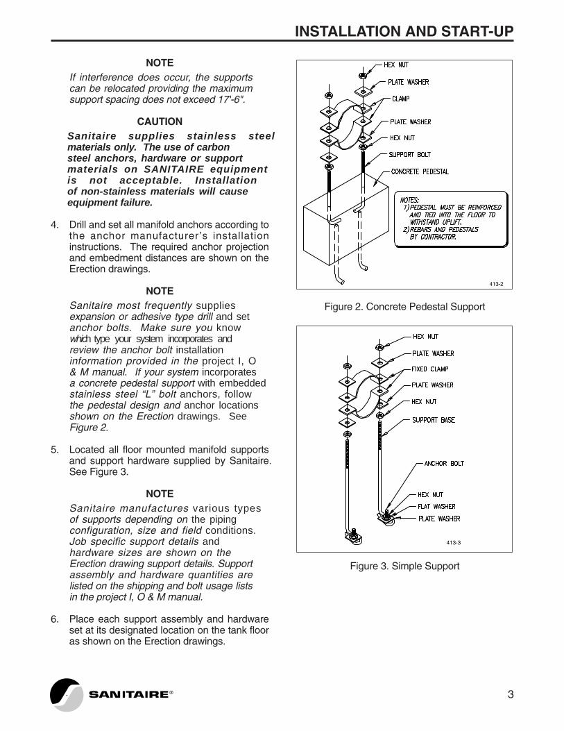
4. Drill and set all manifold anchors according tothe anchor manufacturer ’s installationinstructions. The required anchor projectionand embedment distances are shown on theErection drawings.
NOTESanitaire most frequently suppliesexpansion or adhesive type drill and setanchor bolts. Make sure you knowwhich type your system incorporates andreview the anchor bolt installationinformation provided in the project I, O& M manual. If your system incorporatesa concrete pedestal support with embeddedstainless steel “L” bolt anchors, followthe pedestal design and anchor locationsshown on the Erection drawings. SeeFigure 2.
5. Located all floor mounted manifold supportsand support hardware supplied by Sanitaire.See Figure 3.
NOTESanitaire manufactures various typesof supports depending on the pipingconfiguration, size and field conditions.Job specific support details andhardware sizes are shown on theErection drawing support details. Supportassembly and hardware quantities arelisted on the shipping and bolt usage listsin the project I, O & M manual.
6. Place each support assembly and hardwareset at its designated location on the tank flooras shown on the Erection drawings.
Figure 2. Concrete Pedestal Support
Figure 3. Simple Support
413-3
413-2
3®

INSTALLATION AND START-UP
4 ®
7. Place the support bases on the anchor bolts.Secure the support base to the anchor boltswith the stainless steel washers and nutsprovided by Sanitaire. Tighten the anchorbolts to the torque values listed in the anchor manufacturer ’s installationinstructions. Rod type bases must havea plate washer installed on the anchor boltabove the support base before installationof the anchor flat washer and nut.
CAUTIONFailure to properly torque expansionanchor bolts at installation reducestheir load carrying capacity. Normalbuoyant loads on the piping may thencause support assembly failure withresultant piping damage.
NOTE For rod type support bases with diagonalstruts, mount the strut on the supportbase above the plate washer beforeplacement of the anchor bolt flat washerand nut.
8. Install the lower pipe support verticaladjusting nuts, washers and bottom bandclamp or crosstree. Using a laser levelingsystem, adjust the lower support assembly tothe correct elevation. If a band clampsupport is used, the elevation of the clampflange is the same as the manifold centerlineelevation shown on the Erection drawings. Ifa crosstree style support is used, thecrosstree elevation is the manifold centerlineelevation shown on the Erection drawingsminus one half the outside diameter of thepipe.
9. Place the stainless steel manifold piping onthe support bottom band clamp or crosstreeper the Erection drawings. Install the pieceat the dropleg connection first and work awayfrom the dropleg location. The clampcoupling for the dropleg to manifold
connection should be temporarily installed atthis time. See Figure 4. Installationinstructions for the clamp coupling areincluded in the project I, O & M manual.
Figure 4. Clamp Coupling
NOTEThe following must be considered whensetting the manifold pieces on thesupport bases:
A) Manifold piping flanges should be nocloser than six inches to a support assembly.
B) SANITAIRE Fixed Header Coarse BubbleAeration Systems normally have a fixedsupport at some point in the system. Thefixed support may be floor or wall mounted.See Figures 5 and 6. If your system has afloor mounted frame or pedestal fixedsupport, be sure the fixing clip that is weldedto the invert of the pipe mates up with thefixing link of the support base. If your systemhas a wall or floor mounted “T” bracket fixedsupport, make sure that the welded fin on themanifold is close enough to mate with themounted “T” bracket. Do not mount the “T”bracket until the manifold leveling procedureis completed.
413-4

INSTALLATION AND START-UP
Figure 5. Floor Mount Fixed Support
Figure 6. Wall Mount Fixed Support
10. Assemble all manifold joints. Sanitaireprovides two types of manifold joints;flanged and expansion. Make sure allgaskets and O-rings are in place.
NOTEAssemble, but do not fully tighten thejoints until all necessary piping rotationfor leveling purposes is complete.
11. Loosely install the top band clamp or “U” bolton the proper support bases. Use the correctquantity, size and type of hardware on eachsupport. Refer to the bolt usage list andErection drawing support details.
413-6
413-5
5®
12. Check all manifold sections for level. Start atthe dropleg and adjust the piping heights asrequired using the BOTTOM verticaladjusting nuts. The manifold section whichconnects to the dropleg must be rotated asrequired so that any inclusive headerconnection ports are level horizontally for in-line manifolds or plumb vertically forraised manifolds. Install and tighten theTOP nuts on the band clamps or crosstreesONLY on the support closest to the dropleg.
NOTE If your system has “U” bolt type supports,tighten the bottom nuts on the “U” boltonly until light contact is made betweenthe “U” bolt and manifold. Lock the “U”bolt in place by tightening the top nut.
13. Wall or floor mounted “T” bracket fixedsupports, if supplied with your system, mustbe mounted now before continuing with therest of the installation. Their installation isaccomplished as follows:
A) Locate the “T” bracket as shown on theErection drawings.
B) Set the “T” bracket on the tank wall orfloor to match up with the fin welded on themanifold.
C) Mark the required anchor bolt locations.
D) Drill and set the anchors according to theanchor manufacturer ’s installationinstructions. The required anchor projectionand embedment distances are shown on theErection drawings.
NOTEA manifold section which connects to the“T” bracket may need to be removed inorder to drill the anchor bolt holes. Placethe manifold section back on the supportstands when the anchors are set.
E) Secure the “T” bracket to the wall or floorusing the anchor hardware. Tighten theanchor bolts to the torque values listed inthe anchor manufacturer’s installationinstructions.
INSTALLATION AND START-UP
CAUTIONFailure to properly torque expansionanchor bolts at installation reducestheir load carrying capacity. Normalbuoyant loads on the piping may thencause support assembly failure withresultant piping damage.
F) Install the connecting hardware betweenthe fixing fin and the “T” bracket.
14. If your system has a floor mounted frame orpedestal fixing support, install the fixing linksand draw the hardware down tight. See theErection drawings for fixed support details.
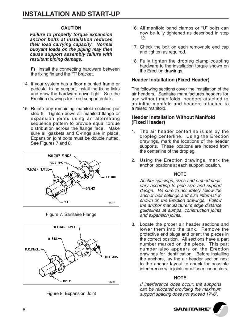
15. Rotate any remaining manifold sections perstep 9. Tighten down all manifold flange orexpansion joints using an alternatingsequence pattern to provide equal torquedistribution across the flange face. Makesure all gaskets and O-rings are in place.Expansion joint bolts must be double nutted.See Figures 7 and 8.
Figure 7. Sanitaire Flange
Figure 8. Expansion Joint
413-8
413-7
16. All manifold band clamps or “U” bolts cannow be fully tightened as described in step12.
17. Check the bolt on each removable end capand tighten as required.
18. Fully tighten the dropleg clamp couplinghardware to the installation torque shown onthe Erection drawings.
Header Installation (Fixed Header)
The following sections cover the installation of theair headers. Sanitaire manufactures headers foruse without manifolds, headers attached toan inline manifold and headers attached toa raised manifold.
Header Installation Without Manifold (Fixed Header)
1. The air header centerline is set by thedropleg centerline. Using the Erectiondrawings, mark the locations of the headersupports. These locations are indexed fromthe centerline of the dropleg.
2. Using the Erection drawings, mark theanchor locations at each support location.
NOTE Anchor spacings, sizes and embedmentsvary according to pipe size and supportdesign. Be sure to accurately follow theanchor bolt settings and size informationshown on the Erection drawings. Followthe anchor manufacturer’s edge distanceguidelines at sumps, construction jointsand expansion joints.
3. Locate the proper air header sections andlower them into the tank. Remove theprotective end plugs and orient the pieces inthe correct position. All sections have a partnumber marked on the piece. This partnumber also appears on the Erectiondrawings for identification. Before installingthe anchors, lay the air header section nextto the anchor layout to check for possibleinterference with joints or diffuser connectors.
NOTEIf interference does occur, the supportscan be relocated providing the maximumsupport spacing does not exceed 17'-6".
6 ®

INSTALLATION AND START-UP
CAUTIONSanitaire supplies stainlesssteel materials only. The use of carbonsteel anchors, hardware or supportmaterials on SANITAIRE equipmentis not acceptable. Installationof non-stainless materials will causeequipment failure.
4. Drill and set all header anchors according tothe anchor manufacturer ’s installationinstructions. The required anchor projectionand embedment distances are shown on theErection drawings.
NOTESanitaire most frequently suppliesexpansion or adhesive type drill and setanchor bolts. Make sure you knowwhich type your systemincorporates and review the anchor boltinstallation information provided in theproject I, O & M manual. If your systemincorporates a concrete pedestal supportwith embedded stainless steel “L” boltanchors, follow the pedestal design andanchor locations shown on the Erectiondrawings. Refer to Figure 2.
5. Locate all floor mounted header supports andsupport hardware supplied by Sanitaire.Refer to Figure 3.
NOTESanitaire manufactures various typesof supports depending on the pipingconfiguration, size and field conditions.Job specific support details andhardware sizes are shown on theErection drawing support details.Support assembly and hardwarequantities are listed on the shipping andbolt usage lists in the project I, O & Mmanual.
6. Place each support assembly and hardwareset at its designated location on the tank flooras shown on the Erection drawings.
7. Place the support bases on the anchor bolts.Secure the support base to the anchor boltswith the stainless steel washers and nutsprovided by Sanitaire. Tighten the
anchor bolts to the torque valueslisted in the anchor manufacturer ’sinstallation instructions. Rod type basesmust have a plate washer installed on theanchor bolt above the support base beforeinstallation of the anchor flat washer and nut.
CAUTIONFailure to properly torque expansionanchor bolts at installation reducestheir load carrying capacity. Normalbuoyant loads on the piping may thencause support assembly failure withresultant piping damage.
NOTEFor rod type support bases with diagonalstruts, mount the strut on the supportbase above the plate washer beforeplacement of the anchor bolt flat washerand nut.
8. Install the lower pipe support verticaladjusting nuts, washers and bottom bandclamp or crosstree. Using a laser levelingsystem, adjust the lower support assembly tothe correct elevation. If a band clampsupport is used, the elevation of the clampflange is the same as the header centerlineelevation shown on the Erection drawings. Ifa crosstree style support is used, thecrosstree elevation is the header centerlineelevation shown on the Erection drawingsminus one half the outside diameter of thepipe.
9. Place the stainless steel header piping on thesupport bottom band clamp or crosstree perthe Erection drawings. Install the piece at thedropleg connection first and work out fromthere. The clamp coupling for the dropleg /header connection should be temporarilyinstalled at this time. Refer to Figure 4.Installation instructions for the clamp couplingare included in the project I, O & M manual.
NOTEThe following must be considered whensetting the header pieces on the supportbases:
A) Header pipe flanges and diffuserconnectors should be no closer than sixinches to a support assembly.
7®

INSTALLATION AND START-UP
B) SANITAIRE Fixed Header Coarse BubbleAeration Systems have a fixed support atsome point in the system. The fixed supportmay be floor or wall mounted. Refer toFigures 5 and 6. If your system has a floormounted frame or pedestal fixed support,make sure the fixing clip that is welded to theinvert of the pipe mates up with the fixing linkof the support base. If your system has awall or floor mounted “T” bracket fixedsupport , make sure that the welded fin onthe header is close enough to mate with themounted “T” bracket. Do not mount the “T”bracket until the header leveling procedure iscompleted.
10. Assemble all header joints. Sanitaireprovides two types of header joints;flanged and expansion. Make sure all gaskets and O-rings are in place.
NOTEAssemble, but do not fully tighten thejoints until all necessary piping rotationfor leveling purposes is complete.
11. Loosely install the top band clamp or “U” bolton the proper support bases. Use the correctquantity, size and type of hardware on eachsupport. Refer to the bolt usage list andErection drawing support details.
12. Install and level the SANITAIRE diffusers.Refer to the Diffuser Installation and Levelingsection.
13. Check all header pipe sections and diffusersagain for level. Start at the dropleg andadjust the piping heights as required usingthe BOTTOM vertical adjusting nuts. Installand tighten the TOP nuts on the clamps orcrosstrees ONLY on the support closest tothe dropleg.
NOTEIf your system has “U” bolt type supports,tighten the bottom nuts on the “U” boltonly until light contact is made betweenthe “U” bolt and manifold. Lock the “U”bolt in place by tightening the top nut.
14. Wall or floor mounted “T” bracket fixedsupports, if supplied with your system, mustbe mounted now before continuing with therest of the installation. Their installation isaccomplished as follows:
A) Locate the “T” bracket as shown on theErection drawings.
B) Set the “T” bracket on the tank wall orfloor to match up with the fin welded on theheader.
C) Mark the required anchor bolt locations.
D) Drill and set the anchors according to theanchor manufacturer ’s installationinstructions. The required anchor projectionand embedment distances are shown on theErection drawings.
NOTEA header section may need to beremoved in order to drill the anchor boltholes. Place the header section back onthe support stands when the drilling iscomplete. Reassemble the removedheader section.
E) Secure the “T” bracket to the wall or floorusing the anchor hardware. Tighten theanchor bolts to the torque values listed inthe anchor manufacturer’s installationinstructions.
CAUTIONFailure to properly torque expansionanchor bolts at installation reducestheir load carrying capacity. Normalbuoyant loads on the piping may thencause support assembly failure withresultant piping damage.
F) Install the connecting hardware betweenthe fixing fin and the “T” bracket.
15. If your system has a floor mounted frame orpedestal fixing support, install the fixing linksand draw the hardware down tight. See theErection drawings for fixed support details.
8 ®

INSTALLATION AND START-UP
16. Tighten down all header flange or expansionjoints using an alternating sequence patternto provide equal torque distribution acrossthe flange face. Make sure all gaskets andO-rings are in place. Expansion joint boltsmust be double nutted. Refer to Figures 7and 8.
17. All header support band clamps or “U” boltscan now be fully tightened as described instep 13.
18. Fully tighten the dropleg clamp couplinghardware to the installation torque shown onthe Erection drawings.
19. Check the bolt on each removable end capand tighten as required. See Figure 9.
Figure 9. Removable End Cap
20. Proceed to the Aeration System Start-upProcedure section.
Header Installation With Manifold (FixedHeader)
1. The air header centerlines are set by themanifold connection centerlines. Using theErection drawings, mark the locations of theheader supports. These locations areindexed from the centerline of the manifold.
2. Using the Erection drawings, mark theanchor locations at each support location.
413-9
NOTEAnchor spacings, sizes and embedmentsvary according to pipe size and supportdesign. Be sure to accurately follow theanchor bolt settings and size informationshown on the Erection drawings. Followthe anchor manufacturer’s edge distanceguidelines at sumps, construction jointsand expansion joints.
3. Locate the proper air header sections andlower them into the tank. Remove theprotective end plugs and orient the pieces inthe correct position. All sections have a partnumber marked on the piece. This partnumber also appears on the Erectiondrawings for identification. Before installingthe anchors, lay the air header section nextto the anchor layout to check for possibleinterference with joints or diffuser connectors.
NOTEIf interference does occur, the supportscan be relocated providing the maximumsupport spacing does not exceed 17'-6".
CAUTIONSanitaire supplies stainless steel materials only. The use of carbonsteel anchors, hardware or supportmaterials on SANITAIRE equipmentis not acceptable. Installationof non-stainless materials will causeequipment failure.
4. Drill and set all header anchors according tothe anchor manufacturer ’s installationinstructions. The required anchor projectionand embedment distances are shown on theErection drawings.
NOTESanitaire most frequently suppliesexpansion or adhesive type drill and setanchor bolts. Make sure you knowwhich type your system incorporates and review the anchor boltinstallation information provided in theproject I, O & M manual. If your systemincorporates a concrete pedestal supportwith embedded stainless steel “L” boltanchors, follow the pedestal design andanchor locations shown on the Erectiondrawings. Refer to Figure 2.
9®
INSTALLATION AND START-UP
5. Locate all floor mounted header supports andsupport hardware supplied by Sanitaire.Refer to Figure 3.
NOTESanitaire manufactures various typesof supports depending on the pipingconfiguration, size and field conditions.Job specific support details and hardware sizes are shown on theErection drawing support details.Support assembly and hardwarequantities are listed on the shipping andbolt usage lists in the project I, O & Mmanual.
6. Place each support assembly and hardwareset at its designated location on the tank flooras shown on the Erection drawings.
7. Place the support bases on the anchor bolts.Secure the support base to the anchor boltswith the stainless steel washers and nutsprovided by Sanitaire. Tighten the anchorbolts to the torque values listed inthe anchor manufacturer ’s installationinstructions. Rod type bases must havea plate washer installed on the anchorbolt above the support base beforeinstallation of the anchor flat washer and nut.
CAUTIONFailure to properly torque expansionanchor bolts at installation reducestheir load carrying capacity. Normalbuoyant loads on the piping may thencause support assembly failure withresultant piping damage.
NOTEFor rod type support bases with diagonalstruts, mount the strut on the supportbase above the plate washer beforeplacement of the anchor bolt flat washerand nut.
8. Install the lower pipe support verticaladjusting nuts, washers and bottom bandclamp or crosstree. Using a laser levelingsystem, adjust the lower support assembly tothe correct elevation. If a band clampsupport is used, the elevation of the clampflange is the same as the header centerline
elevation shown on the Erection drawings. Ifa cross-tree style support is used, thecrosstree elevation is the header centerlineelevation shown on the Erection drawingsminus one half the outside diameter of thepipe.
9. Place the stainless steel header piping on thesupport bottom band clamp or crosstree perthe Erection drawings. Install the piece at themanifold connection first and work out fromthere. The flange, clamp coupling oradjustable support connection tie bars andclamp coupling for the manifold / headerconnection should be temporarily installed atthis time. This connection may have to beadjusted for header assembly levelingpurposes. Refer to Figures 1 and 4. Makesure all gaskets and O-rings are in place.Installation instructions for the clamp couplingare included in the project I, O & M manual.
NOTEIn the case where adjustable supportconnection tie bars are used as the solesupport for installation of the first headersection, level the header and tighten thetie bar hardware before proceeding to thenext header section.
NOTEThe following must be considered whensetting the header pieces on the supportbases:
A) Header pipe flanges and diffuserconnectors should be no closer than sixinches to a support assembly.
B) Headers with expansion joints must havea fixed support at some point on the header.Make sure the fixing clip that is welded to theinvert of the pipe mates up with the fixing linkof the support base.
10. Assemble all header joints. Sanitaireprovides two types of header joints;flanged and expansion. Make sure all gasketsand O-rings are in place.
NOTE Assemble, but do not fully tighten thejoints until all necessary piping rotationfor leveling purposes is complete.
10 ®
INSTALLATION AND START-UP
11. Loosely install the top band clamp or “U” bolton the proper support bases. Use the correctquantity, size and type of hardware on eachsupport. Refer to the bolt usage list andErection drawing support details.
12. Install and level the SANITAIRE diffusers.Refer to the Diffuser Installation and Levelingsection.
13. Check all header pipe sections and diffusersagain for level. Start at the manifoldconnection and adjust the header pipingheights as required using the BOTTOMvertical adjusting nuts on the support clampsor crosstrees. Install and tighten the TOPnuts on the clamps or crosstrees ONLY onthe support closest to the manifoldconnection. Tighten the adjustable supportand clamp coupling hardware (if applicable).
NOTEIf your system has “U” bolt type supports,tighten the bottom nuts on the “U” boltonly until light contact is made betweenthe “U” bolt and the manifold. Lock the“U” bolt in place by tightening the top nut.
14. If your system has a floor mounted frame orpedestal fixing support, install the fixing linksand draw the hardware down tight. See theErection drawings for fixed support details.
15. Tighten down all header flange or expansionjoints using an alternating sequence patternto provide equal torque distribution acrossthe flange face. Make sure all gaskets andO-rings are in place. Expansion joint boltsmust be double nutted. Refer to Figures 7and 8.
16. All header support band clamps or “U” boltscan now be fully tightened as described instep 13.
17. Check the bolt on each removable end capand tighten as required. Refer to Figure 9.
18. Proceed to the Aeration System Start-upProcedure section.
REMOVABLE HEADER
CAUTIONCompletely read the followinginstructions and review all SanitaireErection “E” drawings beforebeginning installation.
Definitions
� DROPLEG - The pipe that connects theairmain to the header.
� HEADER - The pipe that connects the droplegto the diffusers. The diffuser connectors anddiffusers are mounted on this pipe.
� DIFFUSER - The device attached to theheader that distributes the air to the liquid.
Dropleg Installation (Removable Header)
CAUTIONBefore installing the upper droplegsection, all dirt and debris must beremoved from the air main. The airblowers are normally used for thisoperation. The air filtration equipmentshould be installed and operatingbefore blowing out the air main.Blowers may require a minimum backpressure when operating. Be sure tofollow the blower manufacturer ’srequirements.
The air main must be capable of supporting thefull weight of the removable header assembly.
NOTESome removable header assemblies maybe small enough that the dropleg andheader can be bolted together, attachedto the airmain and leveled beforeinstalling the supports. After locating theproper dropleg and header section, seeHeader Installation steps 10-12.Complete the installation starting withDropleg Installation step 1 below.
1. Locate the proper dropleg. All droplegs havea part number marked on the piece. Thispart number also appears on the Erectiondrawings for identification. Remove theprotective plastic or wooden end plugs fromthe dropleg.
11®

INSTALLATION AND START-UP
2. Attach the upper portion of the dropleg to theair main.
NOTESanitaire supplies two bolt quickdisconnect dropleg follower and adapterflanges and two bolts for use with waterbody butterfly valves. See Figure 10.Hardware for mounting the adapter flangeand wafer body butterfly valve to the airmain flange connection is by others.Sanitaire supplies four bolt quickdisconnect follower flanges for use withlug type butterfly valves. All hardware formounting the lug body butterfly valveis by others. Job specific connectioninformation is shown on the Erectiondrawing details.
Figure 10. Two Bolt Quick Disconnect
NOTEWhen the upper dropleg is installedproperly, it should be vertical with itscenterline location as shown on theErection drawings.
3. Use the installed stainless steel upperdropleg and the Erection drawings to locateand layout the centerline of the header. Allcomponents of the system are referencedfrom the dropleg location.
413-10
Header Installation (Removable Header)
1. The air header centerline is set by thedropleg centerline. Using the Erectiondrawings, mark the locations of the headersupports. These locations are indexed fromthe centerline of the dropleg.
2. Using the Erection drawings, mark theanchor locations at each support location.
NOTEAnchor spacings, sizes and embedmentsvary according to pipe size and supportdesign. Be sure to accurately follow theanchor bolt settings and size informationshown on the Erection drawings. Followthe anchor manufacturer’s edge distanceguidelines at sumps, construction jointsand expansion joints.
3. Locate the proper air header sections andlower them into the tank. Remove theprotective end plugs and orient the pieces inthe correct position. All sections have a partnumber marked on the piece. This partnumber also appears on the Erectiondrawings for identification. Before installingthe anchors, lay the air header section nextto the anchor layout to check for possibleinterference with joints or diffuser connectors.
NOTEIf interference does occur, the supportscan be relocated providing the maximumsupport spacing does not exceed 17'-6”.
CAUTIONSanitaire supplies stainlesssteel materials only. The use of carbonsteel anchors, hardware or supportmaterials on SANITAIRE equipmentis not acceptable. Installationof non-stainless materials will causeequipment failure.
4. Drill and set all header anchors according tothe anchor manufacturer ’s installationinstructions. The required anchor projectionand embedment distances are shown on theErection drawings.
12 ®
INSTALLATION AND START-UP
NOTESanitaire most frequently suppliesexpansion or adhesive type drill and setanchor bolts. Make sure you knowwhich type your systemincorporates and review the anchor boltinstallation information provided in theproject I, O & M manual. If your systemincorporates a concrete pedestal supportwith embedded stainless steel “L” boltanchors, follow the pedestal design andanchor locations shown on the Erectiondrawings. Refer to Figure 2.
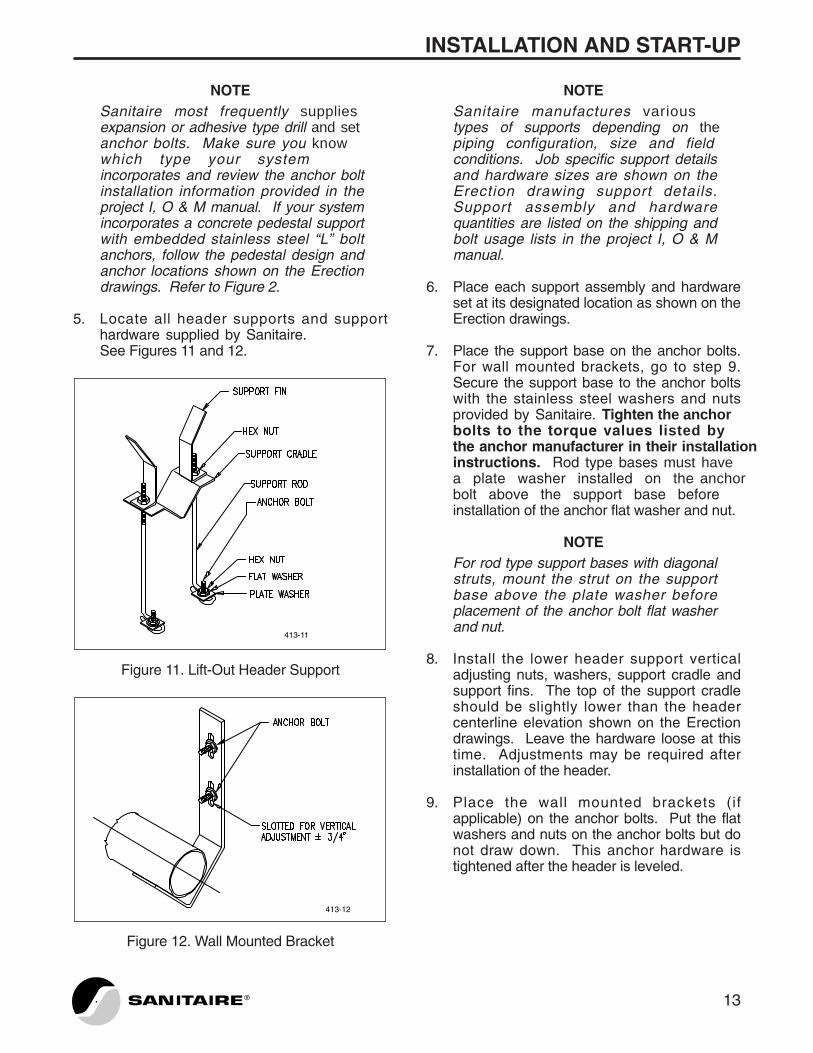
5. Locate all header supports and supporthardware supplied by Sanitaire.See Figures 11 and 12.
Figure 11. Lift-Out Header Support
Figure 12. Wall Mounted Bracket
413-12
413-11
NOTESanitaire manufactures varioustypes of supports depending on thepiping configuration, size and fieldconditions. Job specific support detailsand hardware sizes are shown on theErection drawing support details.Support assembly and hardwarequantities are listed on the shipping andbolt usage lists in the project I, O & Mmanual.
6. Place each support assembly and hardwareset at its designated location as shown on theErection drawings.
7. Place the support base on the anchor bolts.For wall mounted brackets, go to step 9.Secure the support base to the anchor boltswith the stainless steel washers and nutsprovided by Sanitaire. Tighten the anchorbolts to the torque values listed bythe anchor manufacturer in their installationinstructions. Rod type bases must havea plate washer installed on the anchorbolt above the support base before installation of the anchor flat washer and nut.
NOTEFor rod type support bases with diagonalstruts, mount the strut on the supportbase above the plate washer beforeplacement of the anchor bolt flat washerand nut.
8. Install the lower header support verticaladjusting nuts, washers, support cradle andsupport fins. The top of the support cradleshould be slightly lower than the headercenterline elevation shown on the Erectiondrawings. Leave the hardware loose at thistime. Adjustments may be required afterinstallation of the header.
9. Place the wall mounted brackets (ifapplicable) on the anchor bolts. Put the flatwashers and nuts on the anchor bolts but donot draw down. This anchor hardware istightened after the header is leveled.
13®
INSTALLATION AND START-UP
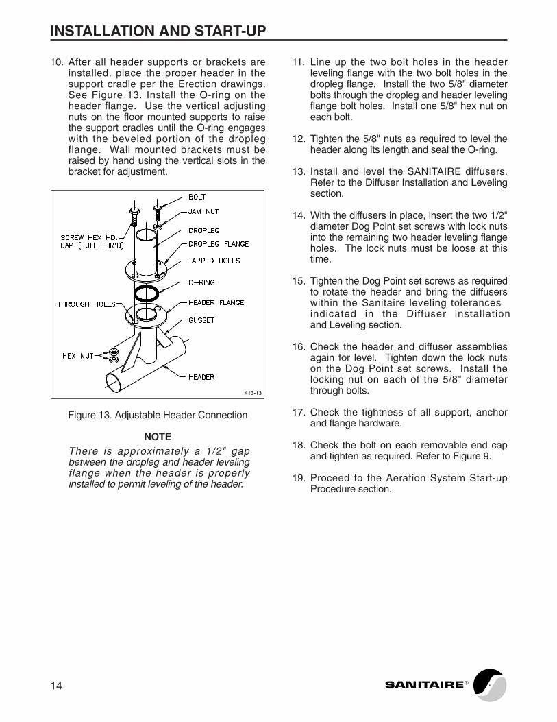
10. After all header supports or brackets areinstalled, place the proper header in thesupport cradle per the Erection drawings.See Figure 13. Install the O-ring on theheader flange. Use the vertical adjustingnuts on the floor mounted supports to raisethe support cradles until the O-ring engageswith the beveled portion of the droplegflange. Wall mounted brackets must beraised by hand using the vertical slots in thebracket for adjustment.
Figure 13. Adjustable Header Connection
NOTEThere is approximately a 1/2" gapbetween the dropleg and header levelingflange when the header is properlyinstalled to permit leveling of the header.
413-13
11. Line up the two bolt holes in the headerleveling flange with the two bolt holes in thedropleg flange. Install the two 5/8" diameterbolts through the dropleg and header levelingflange bolt holes. Install one 5/8" hex nut oneach bolt.
12. Tighten the 5/8" nuts as required to level theheader along its length and seal the O-ring.
13. Install and level the SANITAIRE diffusers.Refer to the Diffuser Installation and Levelingsection.
14. With the diffusers in place, insert the two 1/2"diameter Dog Point set screws with lock nutsinto the remaining two header leveling flangeholes. The lock nuts must be loose at thistime.
15. Tighten the Dog Point set screws as requiredto rotate the header and bring the diffuserswithin the Sanitaire leveling tolerancesindicated in the Diffuser installationand Leveling section.
16. Check the header and diffuser assembliesagain for level. Tighten down the lock nutson the Dog Point set screws. Install thelocking nut on each of the 5/8" diameterthrough bolts.
17. Check the tightness of all support, anchorand flange hardware.
18. Check the bolt on each removable end capand tighten as required. Refer to Figure 9.
19. Proceed to the Aeration System Start-upProcedure section.
14 ®

INSTALLATION AND START-UP
DIFFUSER INSTALLATION AND LEVELING
1. SANITAIRE coarse bubble stainless steel D-24 and D-12 diffusers are manufacturedwith 3/4" dia. NPT male connectors. SeeFigure 14. Various process applicationsrequire smaller diameter orifices to provideenough back pressure to evenly distributethe air flow throughout the system. Sanitairehas developed the following color codedfactory installed orifice inserts:
COLOR DIAMETER
Black 5/16"White 3/8"Gold 7/16"Green 1/2"Red 9/16"Yellow 5/8"
NOTEThe 3/4" diameter orifice requires noinsert. Check the equipment data sheetsand shipping list in the project I, O & Mmanual to insure that the correct insertshave been installed.
Figure 14. Diffuser Installation
413-14
2. See the Erection drawings for proper diffuserinstallation location. The number (1 or 2) ofdiffusers per connector varies from system tosystem depending on the process andavailable air rates. Threaded plugs aresupplied for single diffuser installations.
3. A commercial thread compound such asNEVER-SEEZ, manufactured by Never-SeezCompound Corporation in Broadview, Illinois,or equal must be applied to the male diffuserconnector threads before diffuser installation.Sanitaire does not supply any threadcompound.
CAUTIONFailure to use a thread lubricant willcause the stainless steel threads togall or strip.
NOTEIf diffusers are removed following theinitial installation, thread compound mustbe applied upon reinstallation.
4. The diffusers should be screwed on by handas far as possible. Wrench tighten thestainless steel D-24 and D-12 diffusers untilthe “V” shaped bottom deflector is pointeddirectly toward the floor. Make at least onecomplete turn after hand tightening to insureproper thread engagement.
5. After the diffusers are installed, the diffusersshould be leveled as close as possible to acommon horizontal plane. This can beaccomplished by rotating the header pipe atthe joint. Following this initial leveling, returnto the appropriate header installation sectionfor your system.
NOTESanitaire 's fabrication tolerancesallow ± 3/8" variation in elevationfrom diffuser to diffuser along a header'slength as measured at the threadeddiffuser connection. Angular variationsof the threaded connection may causethe outboard ends of the diffuser tovary by an additional ± 3/8" for a totalrange of outboard diffuser tip elevationvariation of ± 3/4". For proper airdistribution, the diffuser levels should beadjusted around an average elevation forall the diffusers in an assembly.
15®
®
INSTALLATION AND START-UP
AERATION SYSTEM START-UP PROCEDURE
Installation Inspection
Once the aeration system is installed, perform afinal in-tank inspection. Look for such items asloose nuts or bolts, missing or improperly placedhardware, missing diffusers or plugs and non-connected joints.
Pay particular attention to the following:
� All hardware including anchor bolts MUST bestainless steel. This can be confirmed using amagnet. Stainless steel is not magnetic.
CAUTIONSanitaire supplies stainlesssteel materials only. The use ofcarbon steel anchors, hardware orsupport materials on SANITAIREequipment is not acceptable.Installation of non-stainless materialswill cause equipment failure.
� The stainless steel diffusers (D-24 or D-12)must be oriented with the “V” shaped bottomdeflector pointing downward.
� All expansion joint bolts (if applicable) MUSTbe double nutted.
� Make sure all “U” bolt and crosstree supports(if applicable) have double nut systems perthe Erection drawings.
� Anchor bolts must be properly tightened to thetorque values listed in the anchormanufacturer’s installation instructions.
� For removable header systems, the droplegand leveling flange through bolts MUST havedouble nut systems per the Erection drawings.
Make any repairs or adjustments required basedon the above inspection before continuing thestart-up procedure.
Leak, Level And Uniform Air Distribution
NOTEThe following leak and level start-upprocedure must be performed on allsystems. It should be completed before
any contractual requirement forinstallation inspection by Sanitaireauthorized service personnel is fulfilled.
1. Fill the tank with potable water or planteffluent to a point approximately 2" above thebase elevation header sections that havediffusers mounted to them.
CAUTIONWater should be introduced to thebasin at a rate and direction so that noabnormal stresses are imposed on theaeration pipe network that could causedamage.
2. Turn the air on at a rate of approximately50% of the design flow.
A) Observe the headers for leaking joints orendcaps and note their location.
B) Observe the diffuser connection at theheader for leaks. Excessive mounding of airat this location indicates that the diffuser isnot properly tightened.
C) Observe the uniformity of air distributionthroughout the aeration system. Note thelocations of excessively high or low airdischarge.
3. If there are leaks or non-uniform airdischarge, turn the air off. Lower the water toa wading level (if necessary) and proceed asbelow. Turn the air on and off as neededduring this adjusting stage to check yourrepairs. If there are no problems, go to step 4.
! CAUTIONFollow all laws and appropriate safetyregulation and practices when enteringwastewater treatment tanks. Someinstallations may be defined asconfined spaces or contain harmful ordeadly gasses. Proper safetyprecautions must be followed at alltimes.
! CAUTIONWhen repairing pipe joints, turn off theair supply to the assembly beingworked on.
16
INSTALLATION AND START-UP
A) Repair the leaks at the joints, removableend caps or diffuser connectors. Simpletightening usually solves the problem.
NOTELeaking at flanged or expansion joints isgenerally due to one of the followingconditions:
� The expansion joint O-ring is pinched or out of place.
� The joint is missing the proper gasketor hardware.
� The joint is not tight.
B) Check isolated non-discharging diffusersfor plugging or debris. Clean out as required.
C) Raise or level any sections of the headerfrom which air is not discharging ordischarging at a noticeably lower rate. Thiscan be done by adjusting the headerelevation a small amount and checking thedischarge by turning the air on. Continueadjusting if required.
NOTEIf the problem header section height isfixed by its attachment to the dropleg andcannot be raised, downstream headersections must be lowered in order tobalance the system.
D) Lower any section of the header fromwhich air is discharging at a noticeably higherrate as described in C above.
NOTEWhether to raise or lower pipe sections inan attempt to attain proper air distributionis a matter of judgment. The higher theair rate becomes, the more even the airdistribution appears as the diffuserorifices balance the system. At a normaldesign air flow rate, it is difficult to detecta section of header that is one or twoinches out of level. The water in the tankcan be used as a benchmark to achievethe proper degree of levelness in thesystem by draining the water down to thetop of the diffusers.
4. Once the headers and diffusers are level andleak free, add water past any elevatedheader or manifold sections. Turn the air onand check for joint or removable endcapleaks. Tighten or repair as necessary.
5. With the air on, use a soap solution to checkfor leaks at clamp couplings or flanged jointswhich are not submerged. Tighten or repairas necessary.
The system is ready to be placed in operation. Ifrequired by contract, contact Sanitaireto arrange for installation inspection by Sanitaireauthorized service personnel.
See the Long Term Storage Procedures section ifthe system is not placed in operation immediately.
17®
REMOVABLE HEADER HOIST LIFTINGINSTRUCTIONS
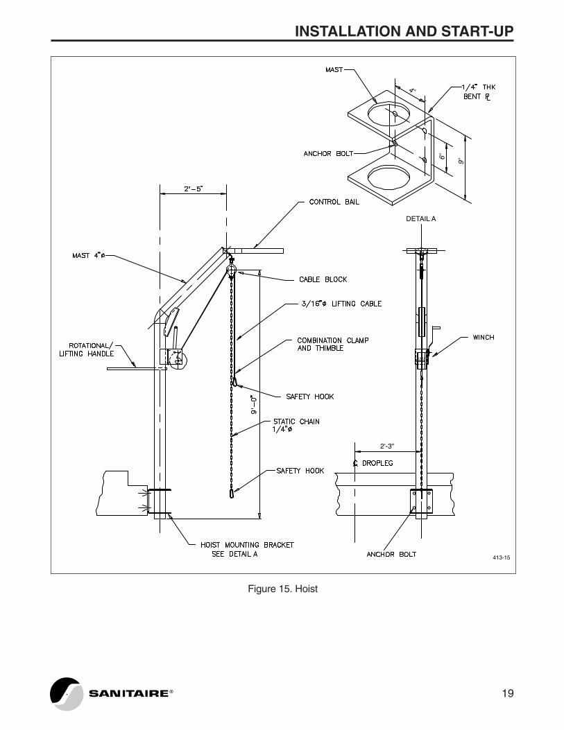
The following instructions are for the standardSANITAIRE manual bent mast socket mounted orportable wheel based hoist. See Figure 15. Seethe Erection drawings and project I, O & Mmanual for any other hoist type. Beforebeginning the removal of the aeration assembly,check the Erection drawings for the type andlocation of submerged supports. Knowing thetype of header supports used may be of usewhen directing the assembly in and out of thetank.
1. Locate the Sanitaire supplied hoisthoist. Position the hoist at the drop to beremoved. Insert the hoist into the mountingsocket at the tank or anchor the portablehoist to the anchor assembly mount on theopposite side of the walkway.
2. Position the lifting cable and static line overthe dropleg lifting eye. The rotational/liftinghandle on the mast can be used to swing themast and cable into position. Attach thelifting cable safety hook to the lifting eye.
3. Use the manual winch to put slight tension onthe lifting cable. This removes the deadloadof the aeration assembly from the droplegconnection.
! CAUTIONSupply air to the aeration assemblymust be turned off beforedisconnecting any piping connections.
Disconnect the dropleg at the connection to theair main or butterfly isolation valve as applicable.
! CAUTIONReduce wastewater velocities beforeattempting removal of the assembly.The channel should be taken out ofservice or flow diverted to reduce thevelocity. High wastewater velocitiescan cause the aeration assembly to bepushed downstream after dropleg
disconnection. This makes removingthe assembly difficult and dangerous.Injuries to operating personnel ordamage to the aeration assembly mayoccur.
4. Using the manual winch, raise the dropleg toa point where the lifting lug is visible andaccessible at the top of the tank. Feed thetop end of the dropleg up through the mastcontrol bail as the dropleg is raised. Attachthe safety hook on the static chain to thelifting lug. DO NOT disconnect the liftingcable. Use the winch to release the tensionon the lifting cable. Continue until theassembly is supported entirely by the staticchain. Disconnect the lifting cable at thelifting eye and reconnect to the second holein the lifting lug where the static chain isattached.
5. Raise the dropleg to a point where thediffusers are approximately 1'-6" above thetop of the tank or handrail.
NOTEThe procedure in item 4 must berepeated for longer droplegs that havemore than one lifting lug on the dropleg.
6. The rotational / lifting handle on the mast canbe used to swing the assembly over the tankdeck.
7. Perform inspection, cleaning and repairs asrequired.
8. Reverse steps 1 through 6 to reinstall theaeration assembly.
CAUTIONThe supports can damage the headerand diffusers upon reinstallation if theassembly is not placed carefully andproperly.
9. After the aeration assembly or assembliesare reinstalled and reconnected to the airmain, turn on the supply air. Return thechannel to its normal service conditions.
10. Clean and store the hoist.
INSTALLATION AND START-UP
18 ®
6''
9''
4''
DETAIL A
2'-3''
413-15
INSTALLATION AND START-UP
19®
Figure 15. Hoist
PLANT OPERATION
21®
PRINCIPLES
SANITAIRE Coarse Bubble Aeration Systemscan be used in various wastewater treatmentprocesses.
Grit Removal
The coarse bubble aeration system passescompressed air through the diffusers whichinduces a spiral roll velocity pattern perpendicularto the wastewater flow through the tank. Thelighter organics are kept in suspension fortreatment downstream. The heavier grit particlesdrop to the bottom where they can be removed.The air rate and tank configuration affect the typeof particles removed.
Equalization And Preaeration
The coarse bubble aeration system usescompressed air to mix the raw influentwastewater on a batch type process to preventhydraulic and organic shock loadings on thetreatment system. This also can control odor andprevent septic conditions.
Activated Sludge Treatment
The removal of carbonaceous BOD, thecoagulation of non-settleable colloidal solids, andthe stabilization of organic matter areaccomplished biologically using a variety ofmicroorganisms (principally bacteria) in theactivated sludge process. The microorganismsconvert the colloidal and dissolved carbonaceousorganic matter into various gasses and cell tissuethrough synthesis.
Aerobic systems require the presence ofmolecular oxygen to maximize the conversion ofthe organic matter through a complex series ofBiochemical Oxidation and Reduction Reactions.
Oxygen needed by the microorganisms istransferred to the mixed liquor by aeration. Thecoarse bubble aeration system takes
compressed air and passes it through the diffuserelement forming coarse bubbles that passthrough the mixed liquor. Diffusion makes theoxygen in the compressed air accessible to themicroorganisms.
Anoxic Zones
The coarse bubble aeration system supplies onlyenough compressed air to mix the wastewater.This mixing function is more typically performedby mechanical mixers.
Post Aeration
The coarse bubble aeration system usescompressed air to supply oxygen to the treatedwastewater effluent to meet discharge permitD.O. concentrations.
Sludge Holding And Storage
The coarse bubble aeration system usescompressed air to supply oxygen to the sludgefor mixing, odor control and prevention of septicconditions.
Aerobic Digesters
The coarse bubble aeration system usescompressed air to supply oxygen to the sludge sothat oxidation reactions occur which destroy thebiologically degradable organic components ofthe sludge. This destruction also reduces thesludge mass and volume.
REFERENCES
1. “Design Manual - Fine Pore AerationSystems.” EPA/625/1-89/023, U.S. EPA,CERI, Cincinnati, Ohio (1989).
2. “Design of Municipal Wastewater TreatmentPlants, Vol. I and II.” WEF Manual ofPractice No. 8, Water EnvironmentFederation, Alexandria, VA and ASCEManual and Report on Engineering PracticeNo. 76, American Society of Civil Engineers,New York, NY, (1992).

PLANT OPERATION
DIFFUSER OPERATING AIR FLOWRANGE
Flow Per Diffuser:
SIZE MIN MAXD-24 5 Scfm 40 Scfm
(8.5 Nm3/hr) (68 Nm3/hr)D-12 3 Scfm 12 Scfm
(5.1 Nm3/hr) (20.4 Nm3/hr)
NOTEThe above listed air flow rates aregeneral design standards. Actual projectdesign values may vary.
1. Do not operate below the minimum air flowrequirements. Poor distribution and solidssettling may occur.
2. Turning off air to the diffusers may allowmixed liquor to enter the pipe network if airleaks exist in the piping system. A higherthan normal air flow and pressure may berequired to clear the diffusers and pipenetwork at start-up.
General notes regarding air flow range
● The most common D-24 diffuser designaverage air flow range is 15 - 30 Scfm/diffuser(25.5 - 51 Nm3/hr/diffuser).
● The coarse bubble system oxygen transferefficiency is not dependent on air flow perdiffuser rates. The efficiency is a function ofsubmergence and diffuser placement.
● It may be necessary to operate at a higher airflow rate than design in order to meet theactual oxygen demand.
● Mixing requirements must be consideredwhen operating below the common designaverage air flow range above.
MIXING
The generally accepted activated sludge plantcoarse bubble mixing air rate standard is 20Scfm/KCF (0.02 Nm3/min./m3). The air requiredfor digesters is typically 20 - 40 Scfm/KCF (0.02-0.04 Nm3/min./m3). The air required to mix achannel is 3-5 Scfm/linear foot (16.5-28Nm3/hr/linear meter) of channel.
DIFFUSER FOULING
SANITAIRE stainless steel coarse bubblediffusers rarely become plugged and normallyrequire no maintenance or cleaning.
An accumulation of a stringy rope-like massaround the diffuser, usually near the connectionto the header, may occur but normally does notaffect the performance of the stainless steeldiffuser.
When the blower is inoperative, waterbornesolids can enter the stainless steel diffuser if theblower check valve or system leak allows the airpressure to drop below the hydraulic head. If thiscondition is repeated frequently, these solidscould agglomerate in the piping system throughthe diffuser and result in orifice plugging.
Diffusers removed for inspection should bereplaced as described in the installationinstructions.
22 ®
PREVENTATIVE MAINTENANCE
23®
POWER FAILURES AND LOSS OF AIRSUPPLY
The results of a power failure or loss of air supplyare as follows:
� Solids settle on the piping assembly, diffuserand tank floor.
� Mixed liquor may enter the pipe networkthrough the stainless steel diffuser or pipingleaks.
There is no adverse effect in the short term. Thelong term effect may be fouling or plugging withinthe piping assembly.
When the air supply is restored, the air pressurebuilds and the flow is reduced until sufficientliquid and solids are pushed out of the stainlesssteel diffuser system to allow air to be releasedthrough the diffusers.
This may require shutting off adjacent assembliesor turning on additional blowers to increase theair flow rate to force solids out of the piping. Thisis generally the case for long term intermittentlyused aeration systems.
VISUAL INSPECTION
Visually inspect the aeration basin surfacepattern. The air flow should be, for the most part,evenly distributed over the aeration assembly.
Large boiling in an isolated area indicates afailure in the submerged pipe system.
Visual inspection is an ongoing preventativemaintenance step that can be done whileperforming regular tasks such as taking samplesand dissolved oxygen readings.
AIR MAIN INSPECTION
Air main leaks are easily identified and usuallyare caused by loose joints or degraded gaskets.These types of leaks should be repaired quicklyin order to prevent loss of system efficiency.

STAINLESS STEEL AERATION SYSTEM TROUBLESHOOTING GUIDE
PROBLEM CAUSE CORRECTIVE ACTION
VISUAL INSPECTION
Poor air distribution The air rate is too low. Increase the air supplied.
The equipment is not level. Level the headers and diffusers. See the installationinstructions.
The diffuser orifice or Drain the tank, inspect the headers are plugged with equipment and clean as necessary.solids. (This is normally caused by extended periods of shutdown in high solids concentrationwastes.)
The equipment is installed Install the correctly sized orifice.without or with inadequately sized diffuser orifices. This is indicated by low diffuser air release upstream of headers or at pipe reducer locations.
Air discharging from air Loose joints, degraded Repair or replace as required.main gaskets or air main piping.
“Mounding” or excessive air Piping leak, leaking seals or Drain the tank. Inspect therelease in an isolated location missing diffusers. equipment and repair or
replace as required.
PREVENTATIVE MAINTENANCE
24 ®

STAINLESS STEEL AERATION SYSTEM TROUBLESHOOTING GUIDE
PROBLEM CAUSE CORRECTIVE ACTION
OPERATIONAL PROBLEMS
Excessive blower discharge The blower filters are dirty. Replace or clean the filters.pressure
Excessive valve throttling Open the valves.towards closed position.
The aeration equipment Clean the aeration equipment.is plugged.
Excessive solids are settling The air supply is inadequate Increase the air rate.under the aeration equipment to keep solids in suspension. on the tank floor.
The solids are too large and Suggest adding or improvingof too high a specific gravity the grit handling equipment.to be kept in suspension.
The tank contents appear The solids concentration is Decrease the solids concentration highly viscous (like wet too high for mixing by and/or augment mixing with cement) and air escapes diffused aeration. mechanical mixers.at surface intermittently in very large exploding bubbles.
Inadequate dissolved oxygen Too little air is supplied. Increase the air rate.concentration where the mixed liquor has “black” color and is highly odorous.
PREVENTATIVE MAINTENANCE
25®
YEARLY MAINTENANCEAND CLEANING
27®
MAINTENANCE SCHEDULE
Sanitaire recommends the following maintenanceschedule be observed at least once per year:
1. Drain down each tank.
2. Remove the excess settled solids, if any, thathave accumulated.
3. Clean the diffusers and piping assemblies asrequired.
4. Inspect the support hardware to ensure allcomponents are intact and tight.
5. Inspect the gaskets and O-rings fordeterioration or leakage. Replace asrequired.
6. Inspect the bolted connections to make sureall components are tight.
NOTEFor items 4-6, refer to the InstallationInstructions.
LUBRICATION SCHEDULE
Since there are no moving parts on SANITAIRECoarse Bubble Aeration Systems, a formallubrication schedule is not required.
The 3/4" dia. male diffuser connector requireslubrication at the time of initial installation andfollowing removal for repairs or cleaning.Lubricate in accordance with the InstallationInstructions.
CLEANING
SANITAIRE diffusers rarely become plugged andnormally require no maintenance or cleaning.There are no moving parts requiring preventativemaintenance.
If the aeration pattern indicates an inspection isrequired, as evidenced by uneven air distribution,the tank should be dewatered to expose theheader assembly. The suspect diffusers shouldbe removed from the header for inspection of theorifices.
If foreign material is present in the diffuserconnector and orifice, it should be removed. Theheader should also be inspected and cleaned if itis found to contain solid material.
Units installed in high viscosity solutions, such asaerobic digesters, should be inspected annuallyfor deposition of solids. If deposits are found, thediffusers should be removed from the header.The diffusers and headers should then be flushedwith clean high pressure water.
An accumulation of a stringy rope-like massaround the diffuser, usually near the connectionto the header, may occur but normally does notaffect the performance of the stainless steeldiffuser. Remove any accumulated material.
The 3/4" dia. male diffuser connector on diffusersremoved for cleaning or repair should always belubricated before reinstallation. See theInstallation Instructions.

LONG TERM STORAGE PROCEDURES
The procedure below was developed to protectthe piping and diffusers from environmentaldamage.
NOTEIt must be understood that Sanitaireassumes no responsibility for damage orcleaning requirements as a result oflong term storage.
For use when the aeration system is not in use,air is not available and flooding is undesirable.
1. Drain the tank dry and clean out solids anddebris.
NOTEThe floor drains should remain open toprevent water from standing in the pipesystem and tank. Equipment flooded byoverflows or misdirected sewage flowswill probably require cleaning beforebeing placed in service.
CAUTIONStanding water allowed to freezearound the pipe may crush the pipe.
2. Before bringing the system on line, check allhardware for tightness. Check the gasketsand O-ring seals for deterioration or leakage.Replace as required.
29®

NOTES
30 ®

Related Documents