4 Oilfield Review Coalbed Methane: Clean Energy for the World Coalbed methane can be found almost anywhere there is coal. Considered a dangerous nuisance in the mining industry, it has potential as an abundant clean energy supply to help replace other diminishing hydrocarbon reserves. Recent developments in technologies and methodologies are playing a large part in harnessing this unconventional resource. Some of these are adaptations of those used in conventional oil and gas operations, but others are new applications designed specifically to address coal’s unique properties. Ahmed Al-Jubori Sean Johnston Calgary, Alberta, Canada Chuck Boyer Stephen W. Lambert Pittsburgh, Pennsylvania, USA Oscar A. Bustos Sugar Land, Texas, USA Jack C. Pashin Geological Survey of Alabama Tuscaloosa, Alabama, USA Andy Wray Denver, Colorado, USA Oilfield Review Summer 2009: 21, no. 2. Copyright © 2009 Schlumberger. For help in preparation of this article, thanks to Drazenko Boskovic, Calgary; Peter Clark, The University of Alabama, Tuscaloosa; Rick Lewis, Oklahoma City, Oklahoma, USA; and Kevin England, Doug Pipchuk, Prachur Sah, Steven Segal and Felix Soepyan, Sugar Land. CBMA, CemNET, ClearFRAC, CoalFRAC, ECLIPSE, ECS, FMI, LiteCRETE, Litho-Density, Multi Express, OSC, PeriScope, Petrel, PowerDrive and ThorFRAC are marks of Schlumberger. Z-Pinnate is a mark of CDX Gas LLC. When humans discovered rocks that could pro- vide warmth and fuel cooking fires, coal was likely viewed as a gift from the gods. Extracting coalbed methane (CBM) from underground coal seams may not have the same significance to modern man, but this source for natural gas certainly seems like a gift to a world in need of clean energy supplies. Because today’s oil and gas industry recognizes the value of this unconventional resource, CBM exploration and development, once uniquely North American, are now under way on a global scale. 1. Coal Bed Methane, http://www.australianminesatlas.gov. au/aimr/commodity/coal_bed_methane.jsp (accessed February 22, 2009). 2. Global Overview of CMM Opportunities, Coalbed Methane Outreach Program, US Environmental Protection Agency, September 2008, http://www. methanetomarkets.org/resources/coalmines/docs/ overviewfull.pdf (accessed March 1, 2009). 3. Coalbed Methane Proved Reserves and Production, US DOE Energy Information Administration, http://tonto.eia. doe.gov/dnav/ng/ng_enr_cbm_a_EPG0_r52_Bcf_a.htm (accessed March 1, 2009). 4. For more on coalbed methane: Ayoub J, Colson L, Hinkel J, Johnston D and Levine J: “Learning to Produce Coalbed Methane,” Oilfield Review 3, no. 1 (January 1991): 27–40. Anderson J, Simpson M, Basinski P, Beaton A, Boyer C, Bulat D, Ray S, Reinheimer D, Schlachter G, Colson L, Olsen T, John Z, Khan R, Low N, Ryan B and Schoderbek D: “Producing Natural Gas from Coal,” Oilfield Review 15, no. 3 (Autumn 2003): 8–31. 5. BP Statistical Review of World Energy, June 2008, http://www.bp.com/liveassets/bp_internet/globalbp/ globalbp_uk_english/reports_and_publications/ statistical_energy_review_2008/STAGING/local_assets/ downloads/pdf/statistical_review_of_world_energy_full_ review_2008.pdf (accessed February 13, 2009).

Welcome message from author
This document is posted to help you gain knowledge. Please leave a comment to let me know what you think about it! Share it to your friends and learn new things together.
Transcript
4 Oilfield Review
Coalbed Methane: Clean Energy for the World
Coalbed methane can be found almost anywhere there is coal. Considered
a dangerous nuisance in the mining industry, it has potential as an abundant
clean energy supply to help replace other diminishing hydrocarbon reserves.
Recent developments in technologies and methodologies are playing a large part
in harnessing this unconventional resource. Some of these are adaptations of
those used in conventional oil and gas operations, but others are new applications
designed specifically to address coal’s unique properties.
Ahmed Al-JuboriSean JohnstonCalgary, Alberta, Canada
Chuck BoyerStephen W. LambertPittsburgh, Pennsylvania, USA
Oscar A. Bustos Sugar Land, Texas, USA
Jack C. PashinGeological Survey of AlabamaTuscaloosa, Alabama, USA
Andy WrayDenver, Colorado, USA
Oilfield Review Summer 2009: 21, no. 2. Copyright © 2009 Schlumberger.For help in preparation of this article, thanks to Drazenko Boskovic, Calgary; Peter Clark, The University of Alabama, Tuscaloosa; Rick Lewis, Oklahoma City, Oklahoma, USA; and Kevin England, Doug Pipchuk, Prachur Sah, Steven Segal and Felix Soepyan, Sugar Land. CBMA, CemNET, ClearFRAC, CoalFRAC, ECLIPSE, ECS, FMI, LiteCRETE, Litho-Density, Multi Express, OSC, PeriScope, Petrel, PowerDrive and ThorFRAC are marks of Schlumberger.Z-Pinnate is a mark of CDX Gas LLC.
When humans discovered rocks that could pro-vide warmth and fuel cooking fires, coal was likely viewed as a gift from the gods. Extracting coalbed methane (CBM) from underground coal seams may not have the same significance to modern man, but this source for natural gas
certainly seems like a gift to a world in need of clean energy supplies. Because today’s oil and gas industry recognizes the value of this unconventional resource, CBM exploration and development, once uniquely North American, are now under way on a global scale.
Oilfield ReviewSpring 09CBM Fig. OpenerORSprng09-CBM Fig. Opener
1. Coal Bed Methane, http://www.australianminesatlas.gov.au/aimr/commodity/coal_bed_methane.jsp (accessed February 22, 2009).
2. Global Overview of CMM Opportunities, Coalbed Methane Outreach Program, US Environmental Protection Agency, September 2008, http://www.methanetomarkets.org/resources/coalmines/docs/overviewfull.pdf (accessed March 1, 2009).
3. Coalbed Methane Proved Reserves and Production, US DOE Energy Information Administration, http://tonto.eia.doe.gov/dnav/ng/ng_enr_cbm_a_EPG0_r52_Bcf_a.htm (accessed March 1, 2009).
4. For more on coalbed methane: Ayoub J, Colson L, Hinkel J, Johnston D and Levine J: “Learning to Produce Coalbed Methane,” Oilfield Review 3, no. 1 (January 1991): 27–40.
Anderson J, Simpson M, Basinski P, Beaton A, Boyer C, Bulat D, Ray S, Reinheimer D, Schlachter G, Colson L, Olsen T, John Z, Khan R, Low N, Ryan B and Schoderbek D: “Producing Natural Gas from Coal,” Oilfield Review 15, no. 3 (Autumn 2003): 8–31.
5. BP Statistical Review of World Energy, June 2008, http://www.bp.com/liveassets/bp_internet/globalbp/globalbp_uk_english/reports_and_publications/statistical_energy_review_2008/STAGING/local_assets/downloads/pdf/statistical_review_of_world_energy_full_review_2008.pdf (accessed February 13, 2009).
25612schD3R1.indd 4 7/29/09 12:48 AM
Summer 2009 5
In recent years, CBM projects have rapidly proliferated. Australia had no CBM production in 1995, but in 2008, 4 billion m3 [141 Bcf] was extracted from its extensive underground coal reserves.1 China had in excess of 1.4 million m3 [49 Bcf] of CBM production in 2006.2 These amounts are small compared with US production in 2007—61 billion m3 [2.15 Tcf], more than 10% of the US domestic natural gas supply.3 However, all this production is significant because it comes from an energy resource that was barely utilized before 1985. Acceptance of this unconventional resource as an alternative natural gas supply is evidenced by the level of investment capital being expended worldwide.
Driven largely by tax incentives, the natural gas industry in the USA began developing CBM resources in the 1980s.4 Since then, improve-ments in technologies and methodologies for CBM evaluation, drilling and production have been introduced, mostly through adaptations of those already in use for traditional oil and gas reservoirs. Other developments came in response to coal’s unique reservoir characteristics.
Evaluating the potential for CBM production relies heavily on laboratory core analysis and reservoir characterization. Field-level evaluation has evolved considerably since the early days of CBM development when models were adaptations of mining-industry techniques. Today, factors required to economically produce natural gas from coal seams are better understood. As new basins are explored, this understanding continues to evolve. In addition, data from tools developed expressly for shallow wells and low-density reservoirs are improving reservoir modeling.
Modeling and evaluation are not the only areas of progress in CBM development. Complex lateral wells with multiple horizontal sections were unheard of a few decades ago, even for conventional oil and gas wells, but these are becoming common-place in CBM drilling programs. Completion techniques have been developed that cause less damage to the production mechanisms of coal seams, such as that occurring during cementing operations. Stimulation fluids have been engi-neered specifically to enhance CBM production.
This article contains a brief overview of the current state of CBM production and describes recent developments in drilling, completing, evaluating and producing these unconventional reservoirs. Operators in a number of coal-bearing regions are seeing results from these advances, and this article presents example applications from Australia, Canada and the USA.
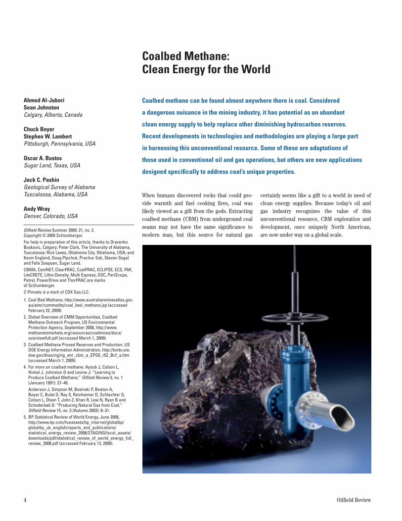
Global ViewThe largest proven recoverable coal reserves, according to the latest published data, are in the USA (28.6%), followed by Russia (18.5%), China (13.5%), Australia (9.0%) and India (6.7%).5 Shallow coal deposits in many areas, such as in the UK and in some other European nations, have been extensively mined, yet deep coal seams beyond the reach of mining operations present opportunities for development. Even with little minable coal remaining, the UK still ranks sixth worldwide in estimated CBM reserves (above). The nations with the largest coal depos-its, however, are receiving the majority of the investment capital, which for the industry was estimated at US $12 billion in 2008.
> CBM reserves and activity. Major CBM reserves (dark blue) are found in Russia, the USA (Alaska alone has an estimated 1,037 Tcf), China, Australia, Canada, the UK, India, Ukraine and Kazakhstan. Of the 69 countries with the majority of coal reserves, 61% have recorded some form of CBM activity—investigation, testing or production. (US DOE, reference 3, and BP Statistical Review, reference 5.)
Oilfield ReviewSpring 09CBM Fig. 1ORSprng09-CBM Fig. 1
CBM activity,past or present
Alaska1,037 Tcf
Canada699 Tcf
USA minus Alaska711 Tcf
UK102 Tcf
Ukraine42 Tcf
Russia1,730 Tcf
Kazakhstan23 Tcf
India71 Tcf
Australia1,037 Tcf
China1,307 Tcf
25612schD3R1.indd 5 7/29/09 12:49 AM
6 Oilfield Review
China’s government, recognizing the value of this resource, named CBM development as one of 16 major projects in its current “Five-Year Plan.” Production targets are 10 billion m3 [353 Bcf] by 2010, 30 billion m3 [1.059 Tcf] by 2015 and 50 billion m3 [1.765 Tcf] by 2020.6
The USA has a mature CBM industry that draws from 10 major producing basins. Most of the lower 48 states have been explored for CBM potential, but Alaska’s resources, estimated to be in excess of 30 trillion m3 [1,000 Tcf], have not been aggressively investigated.7
Australia is second only to the USA in CBM production. Commercial production commenced in the mid 1990s on a small scale, but by 2008, 4 billion m3 of CBM was produced, an increase of 39% over the previous year.8
India has substantial coal reserves and most are suitable for CBM development. Deep coal deposits, not accessible by conventional mining operations, also offer CBM development opportu-nities. In 1997, India’s government formulated a CBM policy and allotted a number of blocks for exploration. Commercial production of CBM began in 2007.9
The sleeping giant in regard to CBM is Russia: Depending on the source, resource estimates range from 17 to 80 trillion m3 [600 to 2,825 Tcf]. As of early 2009, only a few wells had been drilled to evaluate the potential for commercial produc-tion. This situation may be changing, however, as a result of political and market forces. Natural gas produced in the western half of the country is sold to Europe. CBM resources concentrated in central Siberia could be tapped for heavy
industry in central Russia, freeing more gas to be sold to the West.
There are some inherent challenges to pro-ducing CBM from any basin. These include economical, geological, logistical and operational issues. One of the primary considerations is deal-ing with produced water.
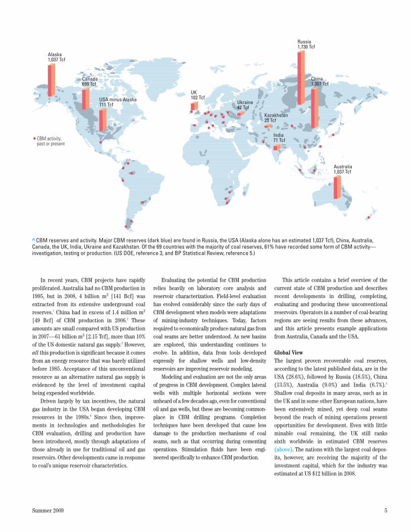
Desorption, Coalification and DewateringCBM reservoirs are different from conventional reservoirs in a number of ways, but the primary differences are water production and gas-storage mechanism. Hydrocarbon-storage capacity in most oil and gas reservoirs is related to porosity because gas is trapped and stored in the pore systems of the matrix. Coals have moderate intrinsic porosity, yet they can store up to six times more gas than an equivalent volume of sandstone at a similar pressure. Gas-storage capacity is determined primarily by a coal’s rank. Higher-rank coals—bituminous and anthra-cite—have the greatest potential for methane storage (below).10 However, high gas-storage capacity is not required for successful commer-cial operations.
Methane is generated in low-rank coals by microbial activity and in higher-rank coals during thermal maturation of their organic compounds. Once generated, the methane is adsorbed, or bound by weak intermolecular attractions—van der Waals forces—to the organic materials that make up the coal. Storage capacity in coal is related to the pressure and adsorbed gas content commonly described by the Langmuir sorption iso-therm measured from crushed coal samples.11 Large volumes of stored gas are possible because
the internal surface area of the microporosity where the gas is adsorbed is very large (next page, top right).
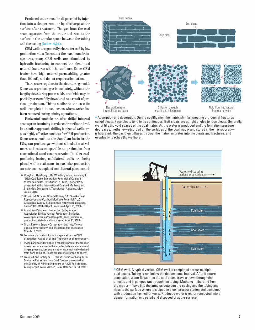
Small amounts of methane are also found in void spaces created when coal shrinks after depo-sition. Shrinkage occurs during coalification—the process of transforming organic-rich peat into coal through biological processes and the appli-cation of heat and pressure. During coalification, water is driven off, the matrix volume decreases and orthogonal fractures, or cleats, form. Primary cleats (face cleats) are generally perpendicular to secondary cleats (butt cleats). Face cleats are often continuous and provide connectivity, whereas butt cleats are noncontinuous and often end at face cleats. The extent of the cleating net-work can be estimated by analyzing conventional cores or by interpreting borehole images, such as those from the FMI microimager tool.
The spatial separation and geometries of the cleats are significant because this natural frac-ture system is the principal mechanism for permeability. Postdepositional fracturing caused by tectonic stresses may enhance the bulk permeability, or conversely, excessive tectonic activity may lead to a reduction in permeability.
Production of CBM normally involves dewa-tering the formation to lower the reservoir pressure. Lowering the pressure allows the for-mation of free gas, which raises the gas permeability of the coal and facilitates the migra-tion of gas into the wellbore.12 The lower pressure liberates methane adsorbed on the coal face, which then flows to the wellbore through the fracture system.
> Storage capacity, coal rank and methane generation. Gas-storage capacity is a function of coal rank and pressure, and as coal matures the sorptive capacity increases (left). Of the coal ranks, anthracite (green) has the greatest storage capacity, followed by various grades of bituminous coals (red, orange and yellow). Methane is generated from coal by microbial activity (biogenesis) and by heat (right). The methane is adsorbed on the surface of the organic materials that form the coal. Biogenetic processes cease as these materials are transformed to higher-rank coal and are exposed to more heat. Biogenesis can reoccur if fluid movement brings in new microorganisms to feed on the coal.
Oilfield ReviewSpring 09CBM Fig. 2ORSprng09-CBM Fig. 2
Thermally derivedmethane
Biogenic methane,nitrogen and
carbon dioxide
Incr
easi
ng g
as g
ener
atio
n
Increasing coal rank
Lignite Sub-bituminous Bituminous Anthracite Graphite
1,000
Adso
rbed
gas
con
tent
, scf
/ton
(dry
, ash
-free
) 1,200
800
600
400
200
00 200 400 600 800 1,000
Pressure, psia
AnthraciteMedium-volatile bituminousHigh-volatile bituminous AHigh-volatile bituminous B
25612schD3R1.indd 6 7/29/09 12:49 AM
Summer 2009 7
Produced water must be disposed of by injec-tion into a deeper zone or by discharge at the surface after treatment. The gas from the coal seam separates from the water and rises to the surface in the annular space between the tubing and the casing (below right).
CBM wells are generally characterized by low production rates. To contact the maximum drain-age area, many CBM wells are stimulated by hydraulic fracturing to connect the cleats and natural fractures with the wellbore. Some CBM basins have high natural permeability, greater than 100 mD, and do not require stimulation.
There are exceptions to the dewatering model. Some wells produce gas immediately, without the lengthy dewatering process. Mature fields may be partially or even fully dewatered as a result of pre-vious production. This is similar to the case for wells completed in coal seams where water has been removed during mining operations.
Horizontal boreholes are often drilled into coal seams prior to mining to reduce the methane level. In a similar approach, drilling horizontal wells cre-ates highly effective conduits for CBM production. Some areas, such as the San Juan basin in the USA, can produce gas without stimulation at vol-umes and rates comparable to production from conventional sandstone reservoirs. In other coal-producing basins, multilateral wells are being placed within coal seams to maximize production. An extreme example of multilateral placement is
6. Honglin L, Guizhong L, Bo W, Yibing W and Yanxiang L: “High Coal Rank Exploration Potential of Coalbed Methane and Its Distribution in China,” paper 0705, presented at the International Coalbed Methane and Shale Gas Symposium, Tuscaloosa, Alabama, May 23–24, 2007.
7. Flores RM, Stricker GD and Kinney SA: “Alaska Coal Resources and Coalbed Methane Potential,” U.S. Geological Survey Bulletin 2198, http://pubs.usgs.gov/bul/b2198/B2198-508.pdf (accessed April 15, 2009).
8. Australian Petroleum Production & Exploration Association Limited Annual Production Statistics, www.appea.com.au/content/pdfs_docs_xls/annual_production_statistics.xls (accessed April 21, 2009).
9. Great Eastern Energy Corporation Ltd, http://www. geecl.com/overview-and-milestone.htm (accessed March 10, 2009).
10. For more on coal rank and its applications to CBM production: Ayoub et al and Anderson et al, reference 4.
11. Irving Langmuir developed a model to predict the fraction of solid surface covered by an adsorbate as a function of its gas pressure. Langmuir isotherms, empirically derived from core samples, relate pressure to storage capacity.
12. Trevits A and Finfinger GL: “Case Studies of Long-Term Methane Extraction from Coal,” paper presented at the Society of Mining Engineers of AIME Fall Meeting, Albuquerque, New Mexico, USA, October 16–18, 1985.
> Adsorption and desorption. During coalification the matrix shrinks, creating orthogonal fractures called cleats. Face cleats tend to be continuous. Butt cleats are at right angles to face cleats. Generally, water fills the void spaces of the coal matrix. As the water is produced and the formation pressure decreases, methane—adsorbed on the surfaces of the coal matrix and stored in the micropores—is liberated. The gas then diffuses through the matrix, migrates into the cleats and fractures, and eventually reaches the wellbore.
Oilfield ReviewSpring 09CBM Fig. 3ORSprng09-CBM Fig. 3
Desorption frominternal coal surfaces
Coal matrix
Face cleat
Butt cleat
Fluid flow into naturalfracture network
Diffusion throughmatrix and micropores
> CBM well. A typical vertical CBM well is completed across multiple coal seams. Tubing is run below the deepest coal interval. After fracture stimulation, water flows from the coal seam, travels down through the annulus and is pumped out through the tubing. Methane—liberated from the matrix—flows into the annulus between the casing and the tubing and rises to the surface where it is piped to a compressor station and combined with production from other wells. Produced water is either reinjected into a deeper formation or treated and disposed of at the surface.
Coal seam
Coal seam
Coal seam
Gas to pipeline
Water to disposal atsurface or by reinjection
Oilfield ReviewSpring 09CBM Fig. 4ORSprng09-CBM Fig. 4
25612schD3R1.indd 7 8/26/09 9:28 PM
8 Oilfield Review
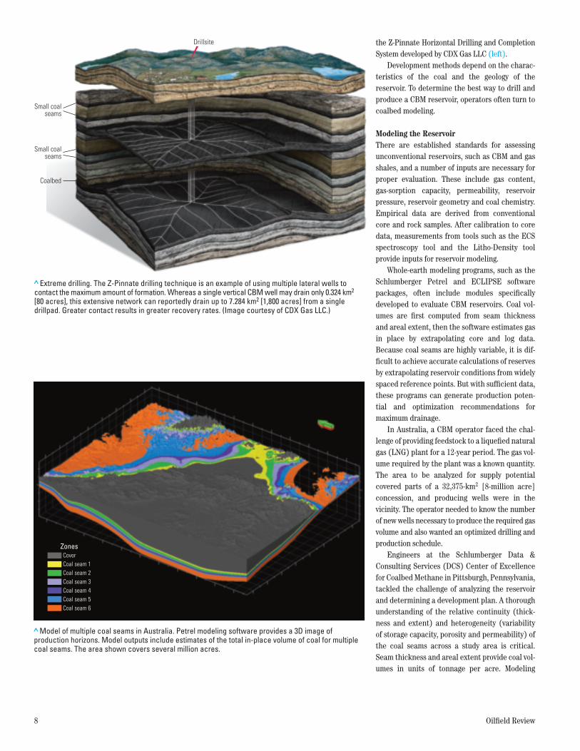
the Z-Pinnate Horizontal Drilling and Completion System developed by CDX Gas LLC (left).
Development methods depend on the charac-teristics of the coal and the geology of the reservoir. To determine the best way to drill and produce a CBM reservoir, operators often turn to coalbed modeling.
Modeling the ReservoirThere are established standards for assessing unconventional reservoirs, such as CBM and gas shales, and a number of inputs are necessary for proper evaluation. These include gas content, gas-sorption capacity, permeability, reservoir pressure, reservoir geometry and coal chemistry. Empirical data are derived from conventional core and rock samples. After calibration to core data, measurements from tools such as the ECS spectroscopy tool and the Litho-Density tool provide inputs for reservoir modeling.
Whole-earth modeling programs, such as the Schlumberger Petrel and ECLIPSE software packages, often include modules specifically developed to evaluate CBM reservoirs. Coal vol-umes are first computed from seam thickness and areal extent, then the software estimates gas in place by extrapolating core and log data. Because coal seams are highly variable, it is dif-ficult to achieve accurate calculations of reserves by extrapolating reservoir conditions from widely spaced reference points. But with sufficient data, these programs can generate production poten-tial and optimization recommendations for maximum drainage.
In Australia, a CBM operator faced the chal-lenge of providing feedstock to a liquefied natural gas (LNG) plant for a 12-year period. The gas vol-ume required by the plant was a known quantity. The area to be analyzed for supply potential covered parts of a 32,375-km2 [8-million acre] concession, and producing wells were in the vicinity. The operator needed to know the number of new wells necessary to produce the required gas volume and also wanted an optimized drilling and production schedule.
Engineers at the Schlumberger Data & Consulting Services (DCS) Center of Excellence for Coalbed Methane in Pittsburgh, Pennsylvania, tackled the challenge of analyzing the reservoir and determining a development plan. A thorough understanding of the relative continuity (thick-ness and extent) and heterogeneity (variability of storage capacity, porosity and permeability) of the coal seams across a study area is critical. Seam thickness and areal extent provide coal vol-umes in units of tonnage per acre. Modeling
> Extreme drilling. The Z-Pinnate drilling technique is an example of using multiple lateral wells to contact the maximum amount of formation. Whereas a single vertical CBM well may drain only 0.324 km2 [80 acres], this extensive network can reportedly drain up to 7.284 km2 [1,800 acres] from a single drillpad. Greater contact results in greater recovery rates. (Image courtesy of CDX Gas LLC.)
Oilfield ReviewSpring 09CBM Fig. 5ORSprng09-CBM Fig. 5
Small coalseams
Small coalseams
Coalbed
Drillsite
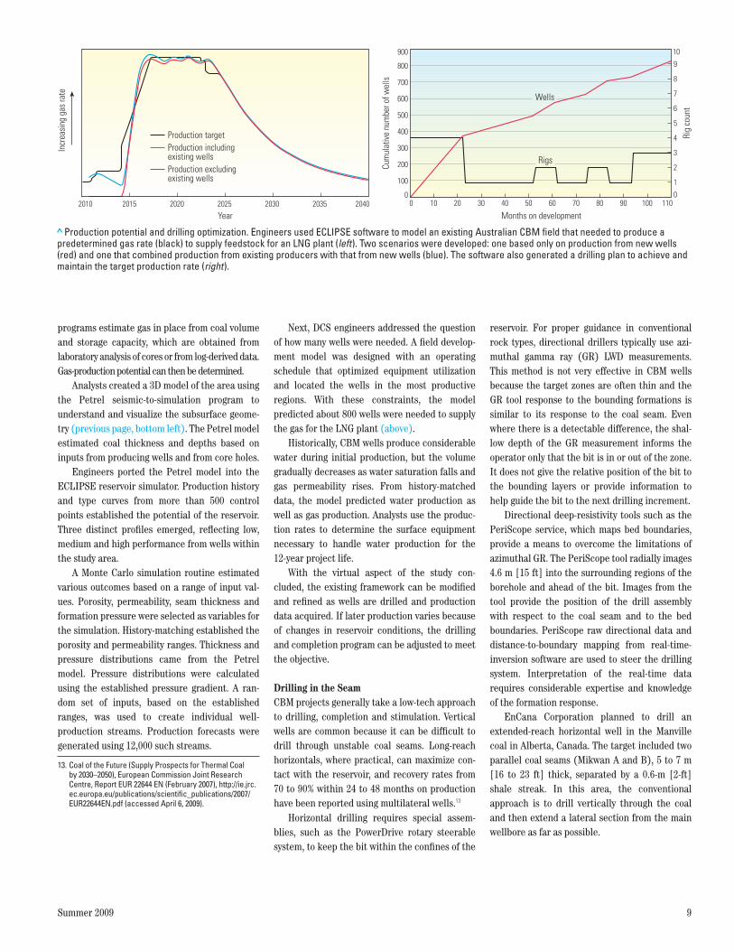
>Model of multiple coal seams in Australia. Petrel modeling software provides a 3D image of production horizons. Model outputs include estimates of the total in-place volume of coal for multiple coal seams. The area shown covers several million acres.
Oilfield ReviewSpring 09CBM Fig. 6ORSprng09-CBM Fig. 6
Coal seam 1Coal seam 2Coal seam 3Coal seam 4Coal seam 5Coal seam 6
CoverZones
25612schD3R1.indd 8 7/29/09 12:49 AM
Summer 2009 9
13. Coal of the Future (Supply Prospects for Thermal Coal by 2030–2050), European Commission Joint Research Centre, Report EUR 22644 EN (February 2007), http://ie.jrc.ec.europa.eu/publications/scientific_publications/2007/EUR22644EN.pdf (accessed April 6, 2009).
programs estimate gas in place from coal volume and storage capacity, which are obtained from laboratory analysis of cores or from log-derived data. Gas-production potential can then be determined.
Analysts created a 3D model of the area using the Petrel seismic-to-simulation program to understand and visualize the subsurface geome-try (previous page, bottom left). The Petrel model estimated coal thickness and depths based on inputs from producing wells and from core holes.
Engineers ported the Petrel model into the ECLIPSE reservoir simulator. Production history and type curves from more than 500 control points established the potential of the reservoir. Three distinct profiles emerged, reflecting low, medium and high performance from wells within the study area.
A Monte Carlo simulation routine estimated various outcomes based on a range of input val-ues. Porosity, permeability, seam thickness and formation pressure were selected as variables for the simulation. History-matching established the porosity and permeability ranges. Thickness and pressure distributions came from the Petrel model. Pressure distributions were calculated using the established pressure gradient. A ran-dom set of inputs, based on the established ranges, was used to create individual well- production streams. Production forecasts were generated using 12,000 such streams.
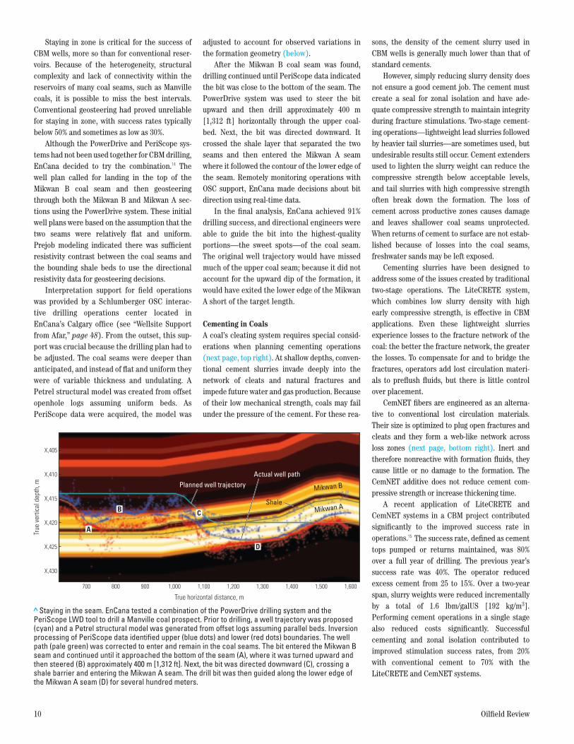
Next, DCS engineers addressed the question of how many wells were needed. A field develop-ment model was designed with an operating schedule that optimized equipment utilization and located the wells in the most productive regions. With these constraints, the model predicted about 800 wells were needed to supply the gas for the LNG plant (above).
Historically, CBM wells produce considerable water during initial production, but the volume gradually decreases as water saturation falls and gas permeability rises. From history-matched data, the model predicted water production as well as gas production. Analysts use the produc-tion rates to determine the surface equipment necessary to handle water production for the 12-year project life.
With the virtual aspect of the study con-cluded, the existing framework can be modified and refined as wells are drilled and production data acquired. If later production varies because of changes in reservoir conditions, the drilling and completion program can be adjusted to meet the objective.
Drilling in the SeamCBM projects generally take a low-tech approach to drilling, completion and stimulation. Vertical wells are common because it can be difficult to drill through unstable coal seams. Long-reach horizontals, where practical, can maximize con-tact with the reservoir, and recovery rates from 70 to 90% within 24 to 48 months on production have been reported using multilateral wells.13
Horizontal drilling requires special assem-blies, such as the PowerDrive rotary steerable system, to keep the bit within the confines of the
reservoir. For proper guidance in conventional rock types, directional drillers typically use azi-muthal gamma ray (GR) LWD measurements. This method is not very effective in CBM wells because the target zones are often thin and the GR tool response to the bounding formations is similar to its response to the coal seam. Even where there is a detectable difference, the shal-low depth of the GR measurement informs the operator only that the bit is in or out of the zone. It does not give the relative position of the bit to the bounding layers or provide information to help guide the bit to the next drilling increment.
Directional deep-resistivity tools such as the PeriScope service, which maps bed boundaries, provide a means to overcome the limitations of azimuthal GR. The PeriScope tool radially images 4.6 m [15 ft] into the surrounding regions of the borehole and ahead of the bit. Images from the tool provide the position of the drill assembly with respect to the coal seam and to the bed boundaries. PeriScope raw directional data and distance-to-boundary mapping from real-time-inversion software are used to steer the drilling system. Interpretation of the real-time data requires considerable expertise and knowledge of the formation response.
EnCana Corporation planned to drill an extended-reach horizontal well in the Manville coal in Alberta, Canada. The target included two parallel coal seams (Mikwan A and B), 5 to 7 m [16 to 23 ft] thick, separated by a 0.6-m [2-ft] shale streak. In this area, the conventional approach is to drill vertically through the coal and then extend a lateral section from the main wellbore as far as possible.
> Production potential and drilling optimization. Engineers used ECLIPSE software to model an existing Australian CBM field that needed to produce a predetermined gas rate (black) to supply feedstock for an LNG plant (left). Two scenarios were developed: one based only on production from new wells (red) and one that combined production from existing producers with that from new wells (blue). The software also generated a drilling plan to achieve and maintain the target production rate (right).
Rig
coun
t
10
9
8
7
6
5
4
3
2
1
0
Cum
ulat
ive
num
ber o
f wel
ls
900
800
700
600
500
400
300
200
100
00 10 20 30 40 50 60 70 80 90 100 110
Months on development
Rigs
Wells
Production excludingexisting wells
Production includingexisting wells
Production target
Incr
easi
ng g
as ra
te
2010 2015 2020 2025 2030 2035 2040
Year
Oilfield ReviewSpring 09CBM Fig. 7ORSprng09-CBM Fig. 7
25612schD3R1.indd 9 7/29/09 12:49 AM
10 Oilfield Review
Staying in zone is critical for the success of CBM wells, more so than for conventional reser-voirs. Because of the heterogeneity, structural complexity and lack of connectivity within the reservoirs of many coal seams, such as Manville coals, it is possible to miss the best intervals. Conventional geosteering had proved unreliable for staying in zone, with success rates typically below 50% and sometimes as low as 30%.
Although the PowerDrive and PeriScope sys-tems had not been used together for CBM drilling, EnCana decided to try the combination.14 The well plan called for landing in the top of the Mikwan B coal seam and then geosteering through both the Mikwan B and Mikwan A sec-tions using the PowerDrive system. These initial well plans were based on the assumption that the two seams were relatively flat and uniform. Prejob modeling indicated there was sufficient resistivity contrast between the coal seams and the bounding shale beds to use the directional resistivity data for geosteering decisions.
Interpretation support for field operations was provided by a Schlumberger OSC interac-tive drilling operations center located in EnCana’s Calgary office (see “Wellsite Support from Afar,” page 48). From the outset, this sup-port was crucial because the drilling plan had to be adjusted. The coal seams were deeper than anticipated, and instead of flat and uniform they were of variable thickness and undulating. A Petrel structural model was created from offset openhole logs assuming uniform beds. As PeriScope data were acquired, the model was
adjusted to account for observed variations in the formation geometry (below).
After the Mikwan B coal seam was found, drilling continued until PeriScope data indicated the bit was close to the bottom of the seam. The PowerDrive system was used to steer the bit upward and then drill approximately 400 m [1,312 ft] horizontally through the upper coal-bed. Next, the bit was directed downward. It crossed the shale layer that separated the two seams and then entered the Mikwan A seam where it followed the contour of the lower edge of the seam. Remotely monitoring operations with OSC support, EnCana made decisions about bit direction using real-time data.
In the final analysis, EnCana achieved 91% drilling success, and directional engineers were able to guide the bit into the highest-quality portions—the sweet spots—of the coal seam. The original well trajectory would have missed much of the upper coal seam; because it did not account for the upward dip of the formation, it would have exited the lower edge of the Mikwan A short of the target length.
Cementing in CoalsA coal’s cleating system requires special consid-erations when planning cementing operations (next page, top right). At shallow depths, conven-tional cement slurries invade deeply into the network of cleats and natural fractures and impede future water and gas production. Because of their low mechanical strength, coals may fail under the pressure of the cement. For these rea-
sons, the density of the cement slurry used in CBM wells is generally much lower than that of standard cements.
However, simply reducing slurry density does not ensure a good cement job. The cement must create a seal for zonal isolation and have ade-quate compressive strength to maintain integrity during fracture stimulations. Two-stage cement-ing operations—lightweight lead slurries followed by heavier tail slurries—are sometimes used, but undesirable results still occur. Cement extenders used to lighten the slurry weight can reduce the compressive strength below acceptable levels, and tail slurries with high compressive strength often break down the formation. The loss of cement across productive zones causes damage and leaves shallower coal seams unprotected. When returns of cement to surface are not estab-lished because of losses into the coal seams, freshwater sands may be left exposed.
Cementing slurries have been designed to address some of the issues created by traditional two-stage operations. The LiteCRETE system, which combines low slurry density with high early compressive strength, is effective in CBM applications. Even these lightweight slurries experience losses to the fracture network of the coal: the better the fracture network, the greater the losses. To compensate for and to bridge the fractures, operators add lost circulation materi-als to preflush fluids, but there is little control over placement.
CemNET fibers are engineered as an alterna-tive to conventional lost circulation materials. Their size is optimized to plug open fractures and cleats and they form a web-like network across loss zones (next page, bottom right). Inert and therefore nonreactive with formation fluids, they cause little or no damage to the formation. The CemNET additive does not reduce cement com-pressive strength or increase thickening time.
A recent application of LiteCRETE and CemNET systems in a CBM project contributed significantly to the improved success rate in operations.15 The success rate, defined as cement tops pumped or returns maintained, was 80% over a full year of drilling. The previous year’s success rate was 40%. The operator reduced excess cement from 25 to 15%. Over a two-year span, slurry weights were reduced incrementally by a total of 1.6 lbm/galUS [192 kg/m3]. Performing cement operations in a single stage also reduced costs significantly. Successful cementing and zonal isolation contributed to improved stimulation success rates, from 20% with conventional cement to 70% with the LiteCRETE and CemNET systems.
> Staying in the seam. EnCana tested a combination of the PowerDrive drilling system and the PeriScope LWD tool to drill a Manville coal prospect. Prior to drilling, a well trajectory was proposed (cyan) and a Petrel structural model was generated from offset logs assuming parallel beds. Inversion processing of PeriScope data identified upper (blue dots) and lower (red dots) boundaries. The well path (pale green) was corrected to enter and remain in the coal seams. The bit entered the Mikwan B seam and continued until it approached the bottom of the seam (A), where it was turned upward and then steered (B) approximately 400 m [1,312 ft]. Next, the bit was directed downward (C), crossing a shale barrier and entering the Mikwan A seam. The drill bit was then guided along the lower edge of the Mikwan A seam (D) for several hundred meters.
Shale
A
B C
D
True
ver
tical
dep
th, m
700 800 900 1,000 1,100 1,200 1,300 1,400 1,500 1,600
X,405
X,410
X,415
X,420
X,425
X,430
True horizontal distance, m
Mikwan A
Mikwan BPlanned well trajectoryActual well path
Oilfield ReviewSpring 09CBM Fig. 8ORSprng09-CBM Fig. 8
25612schD3R1.indd 10 8/26/09 9:29 PM
Summer 2009 11
Fracture Stimulation for CBM ReservoirsFracture stimulation is widely used for accessing CBM reserves. Connecting the naturally occur-ring fracture network to the wellbore provides a conduit through which water and gas are pro-duced. Propped hydraulic fracturing of coalbeds has been successful in stimulating production, but the wells have generally underperformed those producing from fracture-stimulated sand-stone reservoirs.16
Coal has physical characteristics that are different from those of conventional rocks. Its higher Poisson’s ratio results in higher fracture gradients, often higher than those in bounding layers. The softness of coal makes fracture propa-gation difficult. Cleating systems lead to complex fracture networks. In highly fractured coals with low Young’s modulus, complex networks are cre-ated. Thus, limited fracture lengths are achieved even with high treating pressures. Fluid leakoff associated with gel-base systems can cause swell-ing and damage to the coals.
The high degree of heterogeneity in coals found within a basin may produce inconsistent results. Coal variability from basin to basin also affects the ultimate stimulation results. Trial-and-error is not usually the most cost-effective method for optimizing a stimulation program, but it is sometimes the only way.
For CBM development, fracture stimulations fall into three primary categories: polymer-base gel systems, slickwater systems and foamed or energized systems (nitrogen or carbon dioxide). Crosslinked gel systems may lead to formation damage if the gel does not break, irreversibly plugging cleats. Slickwater systems require very high pumping rates because the fluid has poor proppant-carrying capabilities. Foamed systems give good results and reduce the potential for damage caused by interactions between the coal and the fracture fluids. However, danger of forma-tion damage persists even with foamed systems. For example, the surfactants used with these sys-tems can negatively impact the coal’s natural wettability and reduce the rate of dewatering.
To address these issues, Schlumberger designed the solids-free, polymer-free CoalFRAC fluids, a modification of the ClearFRAC stimula-tion fluids. One of the key benefits of CoalFRAC fluids over other fluids is the use of additives that meet environmental water-quality standards. This is an important feature because coalbeds are often located in proximity to freshwater aquifers.
CoalFRAC fluids are most often used with nitrified foam systems. Minimizing the liquid-
phase fluids used in stimulation reduces the volume of liquids introduced into the formation that must then be recovered to initiate methane desorption from the coal. Nitrogen is chemically nonreactive, cost-effective and readily available. It is an excellent medium to initiate and propa-gate the hydraulic fracture, control leakoff and transport proppants. By energizing the reservoir, the nitrogen hastens cleanup of fracture fluids and assists in the dewatering phase.
14. Christiaansen E, Bourgeois D, MacDonald C, Longmuir K, Natras T and McIlreath I: ”Proactive Geosteering with Directional Deep Resistivity and Rotary Steerable Tool in Thin Coalbed Methane (CBM) Reservoirs,” paper AADE-07-NTCE-13, presented at the AADE National Technical Conference and Exhibition, Houston, April 10–12, 2007.
15. Sayers AC, Boyer CM, Frenzel TJ and Rodgers RA: “Technologies Key to Deep CBM Success,” The American Oil & Gas Reporter 47, no. 3 (March 2004): 79–85.
16. Olsen TN, Brenize G and Frenzel T: “Improvement Processes for Coalbed Natural Gas Completion and Stimulation,” paper SPE 84122, presented at the SPE Annual Technical Conference and Exhibition, Denver, October 5–8, 2003.
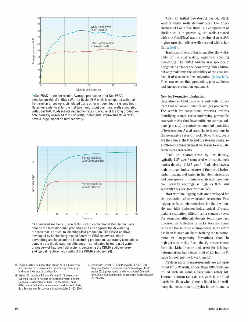
> CemNET fibers. Cement in coal cleats impedes the production of water and gas into the wellbore and can negatively affect fracture stimulation (left). CemNET fibers (inset) form a mat-like barrier in the near-wellbore region to stop the flow of cement into the cleats (right). The fibers do not decrease the compressive strength of the cement after setting and can be added to the preflush or to the cement slurry. Adding CemNET fibers directly to the slurry facilitates proper placement in the coal seams where the potential for fluid loss is greatest.
Oilfield ReviewSpring 09CBM Fig. 11ORSprng09-CBM Fig. 11
Cement flow through coal cleats CemNET barrier
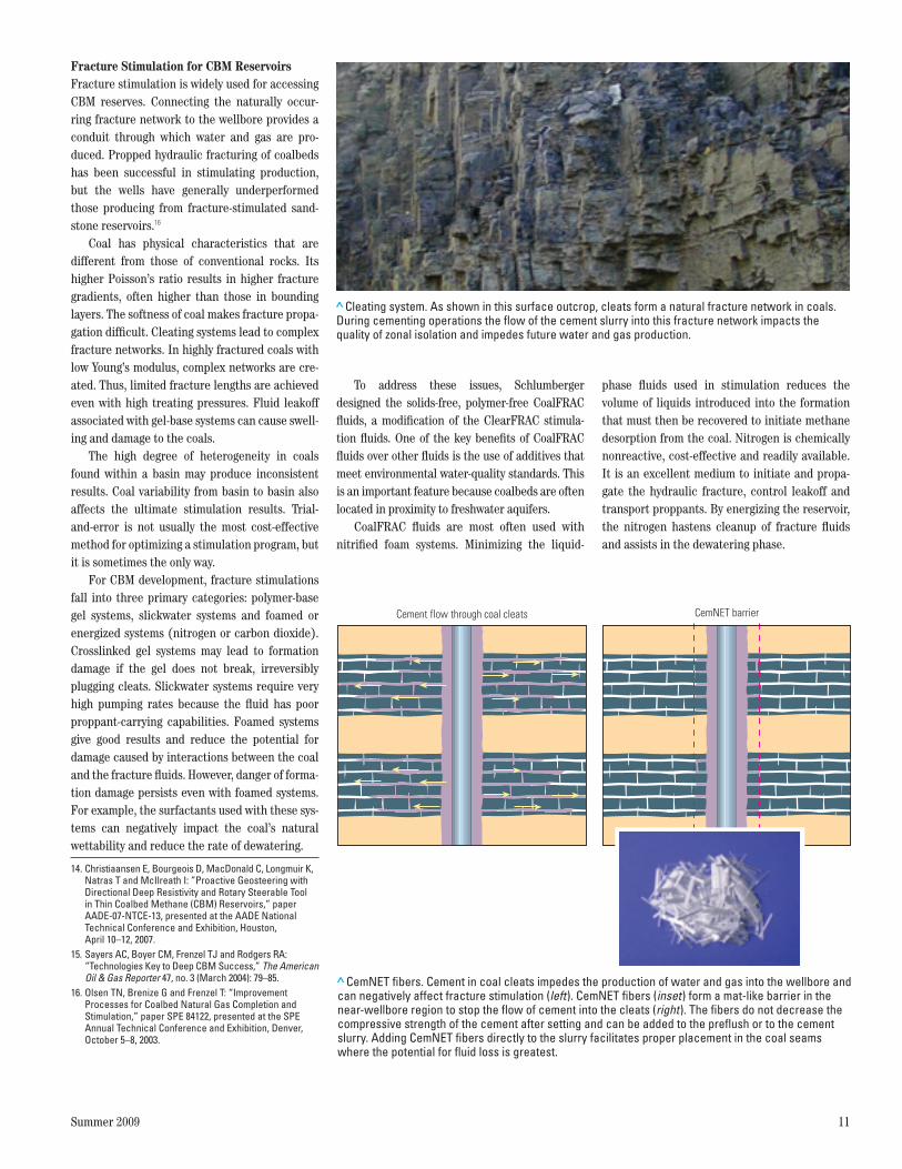
> Cleating system. As shown in this surface outcrop, cleats form a natural fracture network in coals. During cementing operations the flow of the cement slurry into this fracture network impacts the quality of zonal isolation and impedes future water and gas production.
25612schD3R1.indd 11 7/29/09 12:49 AM
12 Oilfield Review
17. The photoelectric absorption factor, Pe, is a property of the rock matrix. It is useful for determining mineralogy and as an indicator of coal quality.
18. Arthur JD, Langhus BG and Vonfeldt C: “Current and Evolving Issues Pertaining to Produced Water and the Ongoing Development of Coal Bed Methane,” paper 0814, presented at the International Coalbed and Shale Gas Symposium, Tuscaloosa, Alabama, May 21–22, 2008.
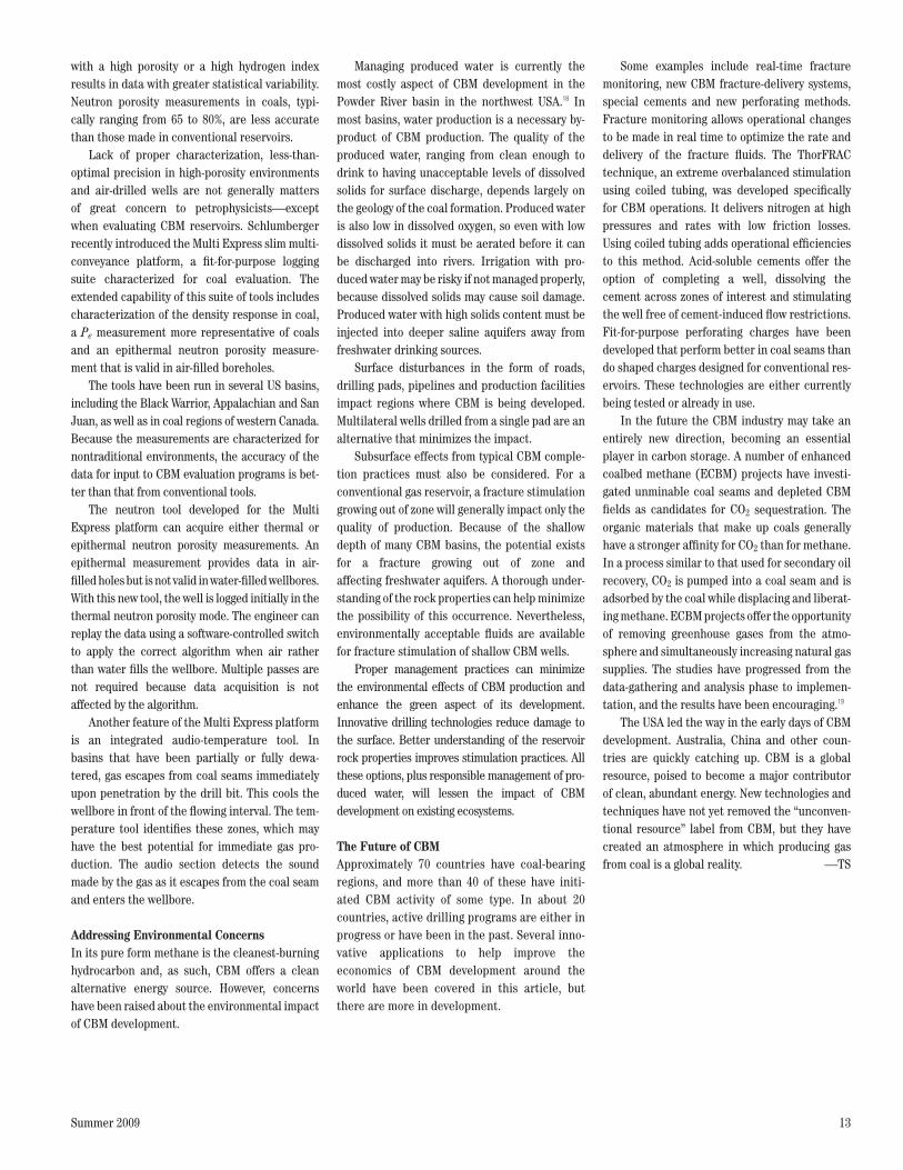
> CoalFRAC treatment results. Average production after CoalFRAC stimulations (blue) in Black Warrior basin CBM wells is compared with that from similar offset wells stimulated using other nitrogen foam systems (red). Rates were identical for the first two months, but over time, wells stimulated with CoalFRAC fluids maintained higher rates. Because of the long production time normally observed for CBM wells, incremental improvements in rates have a large impact on total recovery.
Aver
age
gas
rate
, Mcf
/d
100
80
60
40
20
0
10
30
50
70
90
Months on production0 10 20 30 40
Wells treated withCoalFRAC fluid
Offset wells treatedwith other fluids
Oilfield ReviewSpring 09CBM Fig. 12ORSprng09-CBM Fig. 12
After an initial dewatering period, Black Warrior basin wells demonstrated the effec-tiveness of CoalFRAC fluid. In a comparison of similar wells in proximity, the wells treated with the CoalFRAC system produced at a 38% higher rate than offset wells treated with other fluids (left).
Traditional fracture fluids can alter the wetta-bility of the coal matrix, negatively affecting dewatering. The CBMA additive was specifically designed to enhance the dewatering. This additive not only maintains the wettability of the coal sur-face, it also reduces fines migration (below left). Fines can reduce fluid production, plug wellbores and damage production equipment.
New for Formation EvaluationEvaluation of CBM reservoirs and wells differs from that of conventional oil and gas producers. The search for conventional reserves involves identifying source rocks underlying permeable reservoir rocks that have sufficient storage vol-ume (porosity) to contain commercial quantities of hydrocarbon. A seal traps the hydrocarbons in the permeable reservoir rock. By contrast, coals are the source, the trap and the storage media, so a different approach must be taken to evaluate them as gas reservoirs.
Coals are characterized by low density, typically 1.25 g/cm3 compared with sandstone’s matrix density of 2.65 g/cm3. Coals also have a high hydrogen index because of their solid hydro-carbon matrix and water in the cleat structures and pore spaces. Bituminous coals may have neu-tron porosity readings as high as 80%, and generally they are greater than 65%.
Most wireline logging tools are developed for the evaluation of conventional reservoirs. Few logging tools are characterized for the low den-sity and high hydrogen index typical of coals, making evaluation difficult using standard tools. For example, although density tools have less precision in high-density rocks because count rates are low in these environments, more effort has been focused on characterizing the measure-ment in low-porosity formations than in high-porosity rocks. Also, the Pe measurement from the Litho-Density tool, used for lithology determination, has a lower limit of 1.0, but the Pe value for coal may be lower than 0.2.17
Neutron porosity measurements are not opti-mized for CBM wells, either. Many CBM wells are drilled with air using a percussion rotary bit. Thermal neutron tools do not work in air-filled boreholes. Even when there is liquid in the well-bore, the measurement physics in environments
> Engineered solutions. Surfactants used in conventional stimulation fluids change the formation-fluid properties and can degrade the dewatering process that is critical to initiating CBM production. The CBMA additive, developed by Schlumberger specifically for CBM reservoirs, aids in dewatering and helps control fines during production. Laboratory simulations demonstrate the dewatering efficiency—as indicated by increased water drainage—of fracture fluid systems containing the CBMA additive (green) and typical fracture fluids without the CBMA additive (red).
5
Wat
er d
rain
age
Time, min0 10 20 30 40
Stimulation fluidswith CBMA additive
Stimulation fluidswith no additive
15 25 35 45 50
Oilfield ReviewSpring 09CBM Fig. 13ORSprng09-CBM Fig. 13
19. Byrer CW, Litynski JT and Plasynski SI: “U.S. DOE Regional Carbon Sequestration Partnerships Effort,” paper 0722, presented at the International Coalbed and Shale Gas Symposium, Tuscaloosa, Alabama, May 23–24, 2007.
25612schD3R1.indd 12 8/31/09 11:52 AM
Summer 2009 13
with a high porosity or a high hydrogen index results in data with greater statistical variability. Neutron porosity measurements in coals, typi-cally ranging from 65 to 80%, are less accurate than those made in conventional reservoirs.
Lack of proper characterization, less-than-optimal precision in high-porosity environments and air-drilled wells are not generally matters of great concern to petrophysicists—except when evaluating CBM reservoirs. Schlumberger recently introduced the Multi Express slim multi-conveyance platform, a fit-for-purpose logging suite characterized for coal evaluation. The extended capability of this suite of tools includes characterization of the density response in coal, a Pe measurement more representative of coals and an epithermal neutron porosity measure-ment that is valid in air-filled boreholes.
The tools have been run in several US basins, including the Black Warrior, Appalachian and San Juan, as well as in coal regions of western Canada. Because the measurements are characterized for nontraditional environments, the accuracy of the data for input to CBM evaluation programs is bet-ter than that from conventional tools.
The neutron tool developed for the Multi Express platform can acquire either thermal or epithermal neutron porosity measurements. An epithermal measurement provides data in air-filled holes but is not valid in water-filled wellbores. With this new tool, the well is logged initially in the thermal neutron porosity mode. The engineer can replay the data using a software-controlled switch to apply the correct algorithm when air rather than water fills the wellbore. Multiple passes are not required because data acquisition is not affected by the algorithm.
Another feature of the Multi Express platform is an integrated audio-temperature tool. In basins that have been partially or fully dewa-tered, gas escapes from coal seams immediately upon penetration by the drill bit. This cools the wellbore in front of the flowing interval. The tem-perature tool identifies these zones, which may have the best potential for immediate gas pro-duction. The audio section detects the sound made by the gas as it escapes from the coal seam and enters the wellbore.
Addressing Environmental ConcernsIn its pure form methane is the cleanest-burning hydrocarbon and, as such, CBM offers a clean alternative energy source. However, concerns have been raised about the environmental impact of CBM development.
Managing produced water is currently the most costly aspect of CBM development in the Powder River basin in the northwest USA.18 In most basins, water production is a necessary by-product of CBM production. The quality of the produced water, ranging from clean enough to drink to having unacceptable levels of dissolved solids for surface discharge, depends largely on the geology of the coal formation. Produced water is also low in dissolved oxygen, so even with low dissolved solids it must be aerated before it can be discharged into rivers. Irrigation with pro-duced water may be risky if not managed properly, because dissolved solids may cause soil damage. Produced water with high solids content must be injected into deeper saline aquifers away from freshwater drinking sources.
Surface disturbances in the form of roads, drilling pads, pipelines and production facilities impact regions where CBM is being developed. Multilateral wells drilled from a single pad are an alternative that minimizes the impact.
Subsurface effects from typical CBM comple-tion practices must also be considered. For a conventional gas reservoir, a fracture stimulation growing out of zone will generally impact only the quality of production. Because of the shallow depth of many CBM basins, the potential exists for a fracture growing out of zone and affecting freshwater aquifers. A thorough under-standing of the rock properties can help minimize the possibility of this occurrence. Nevertheless, environmentally acceptable fluids are available for fracture stimulation of shallow CBM wells.
Proper management practices can minimize the environmental effects of CBM production and enhance the green aspect of its development. Innovative drilling technologies reduce damage to the surface. Better understanding of the reservoir rock properties improves stimulation practices. All these options, plus responsible management of pro-duced water, will lessen the impact of CBM development on existing ecosystems.
The Future of CBMApproximately 70 countries have coal-bearing regions, and more than 40 of these have initi-ated CBM activity of some type. In about 20 countries, active drilling programs are either in progress or have been in the past. Several inno-vative applications to help improve the economics of CBM development around the world have been covered in this article, but there are more in development.
Some examples include real-time fracture monitoring, new CBM fracture-delivery systems, special cements and new perforating methods. Fracture monitoring allows operational changes to be made in real time to optimize the rate and delivery of the fracture fluids. The ThorFRAC technique, an extreme overbalanced stimulation using coiled tubing, was developed specifically for CBM operations. It delivers nitrogen at high pressures and rates with low friction losses. Using coiled tubing adds operational efficiencies to this method. Acid-soluble cements offer the option of completing a well, dissolving the cement across zones of interest and stimulating the well free of cement-induced flow restrictions. Fit-for-purpose perforating charges have been developed that perform better in coal seams than do shaped charges designed for conventional res-ervoirs. These technologies are either currently being tested or already in use.
In the future the CBM industry may take an entirely new direction, becoming an essential player in carbon storage. A number of enhanced coalbed methane (ECBM) projects have investi-gated unminable coal seams and depleted CBM fields as candidates for CO2 sequestration. The organic materials that make up coals generally have a stronger affinity for CO2 than for methane. In a process similar to that used for secondary oil recovery, CO2 is pumped into a coal seam and is adsorbed by the coal while displacing and liberat-ing methane. ECBM projects offer the opportunity of removing greenhouse gases from the atmo-sphere and simultaneously increasing natural gas supplies. The studies have progressed from the data-gathering and analysis phase to implemen-tation, and the results have been encouraging.19
The USA led the way in the early days of CBM development. Australia, China and other coun-tries are quickly catching up. CBM is a global resource, poised to become a major contributor of clean, abundant energy. New technologies and techniques have not yet removed the “unconven-tional resource” label from CBM, but they have created an atmosphere in which producing gas from coal is a global reality. —TS
25612schD3R1.indd 13 8/26/09 9:37 PM
Related Documents