Coal Without Carbon An Investment Plan for Federal Action EXPERT REPORTS ON RESEARCH, DEVELOPMENT, AND DEMONSTRATION FOR AFFORDABLE CARBON CAPTURE AND SEQUESTRATION SEPTEMBER, 2009 A Clean Air Task Force Report Funded by the Doris Duke Charitable Foundation

Welcome message from author
This document is posted to help you gain knowledge. Please leave a comment to let me know what you think about it! Share it to your friends and learn new things together.
Transcript
Coal Without CarbonAn Investment Plan for Federal Action
ExpErt rEports on rEsEarCh, DEvElopmEnt, anD DEmonstration for afforDablE Carbon CapturE anD sEquEstration
sEptEmbEr, 2009
a Clean air task force report funded by the Doris Duke Charitable foundation

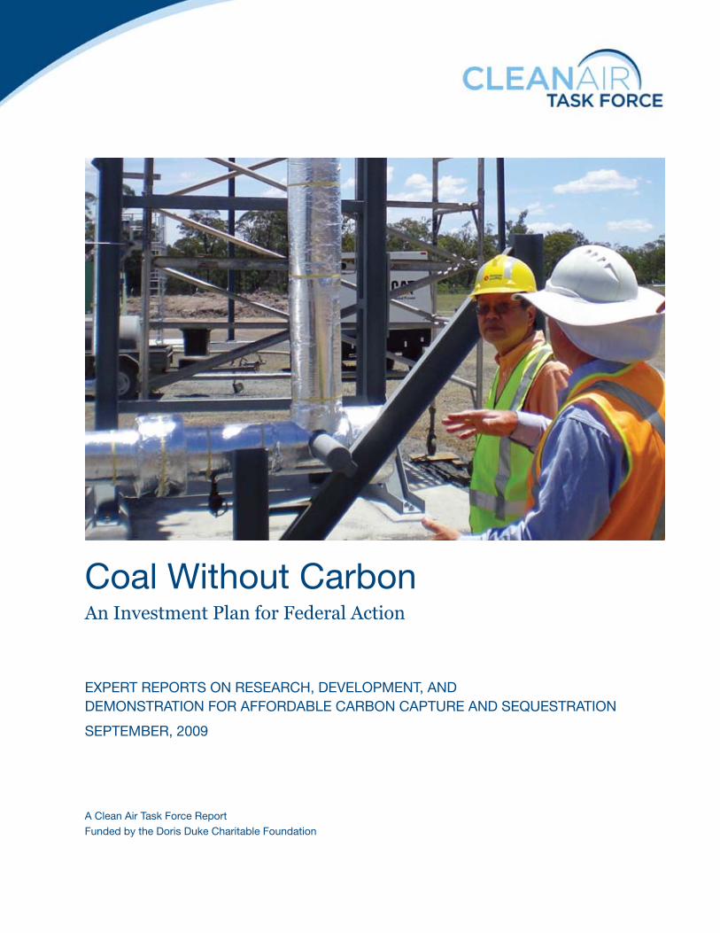
Cover image: Synthesis gas production well at Carbon energy Ltd., underground coal gasification site in Queensland, australia, November, 2008. image by mike Fowler, Clean air Task Force.
Clean air task force is a nonprofit organization dedicated to reducing atmospheric pollution through research, advocacy, and private sector collaboration.
MAIN OFFICE
18 tremont street
suite 530
boston, ma 02108
617.624.0234
www.catf.us
OthEr lOCAtIONs
beijing, China
brunswick, mE
Carbondale, il
Columbus, oh
Washington, DC
Study Participants
Chapter Authors
Kelly Fennerty
Director, Commercial Transactions,
Summit Power Group Inc., Seattle, WA
Dr. S. Julio Friedmann
Director, Carbon Management Program,
Lawrence Livermore National Laboratory,
Livermore, CA
Mike Fowler
Climate Technology Innovation Coordinator,
Clean Air Task Force, Boston, MA
Dr. Alan Hattan
Ralph Landau Professor of
Chemical Engineering Practice,
Massachusetts Institute of Technology,
Cambridge, MA
Dr. Howard Herzog
Principal Research Engineer,
Laboratory for Energy and the Environment,
Massachusetts Institute of Technology,
Cambridge, MA
Dr. Jerry Meldon
Associate Professor of Biological and Chemical
Engineering, Tufts University, Medford, MA
Dr. Robin Newmark
Deputy Program Director,
Energy and Environmental Security Directorate,
Lawrence Livermore National Laboratory,
Livermore, CA
Eric Redman
President, Summit Power Group Inc.,
Seattle, WA
John Thompson
Director, Coal Transition Project,
Clean Air Task Force, Carbondale, IL
Study Advisory Committee Members
Tom Bechtel
Former Director, National Energy Technology
Laboratory, New Bern, NC
Dr. Howard Herzog
Principal Research Engineer,
Laboratory for Energy and the Environment,
Massachusetts Institute of Technology,
Cambridge, MA
Eric Redman
President, Summit Power Group, Inc.,
Seattle, WA
Dr. Ed Rubin
Alumni Professor of Environmental Engineering
and Science, Carnegie Mellon University,
Pittsburgh, PA
Advisory committee members did not approve
or endorse this report and individual members
may have different views on one or all matters
addressed herein.
Clean Air Task Force Project Team
Joe Chaisson, Mike Fowler, John Thompson,
and Kurt Waltzer
Editing Team
Ashley Pettus and Marika Tatsutani
Table of Contents
Executive Summary i
Introduction – The Imperative for De-Carbonized Coal v
John Thompson, Clean Air Task Force
Mike Fowler, Clean Air Task Force
Glossary of Acronym Definitions viii
Chapter 1 1
Accelerating Development of Underground Coal Gasification:
Priorities and Challenges for U.S. Research and Development
Julio Friedmann, Lawrence Livermore National Laboratory
Chapter 2 17
Mobilizing Next Generation Coal Gasification Technology
for Carbon Capture and Sequestration
Eric Redman, Summit Power Group, Inc.
Kelly Fennerty, Summit Power Group, Inc.
Mike Fowler, Clean Air Task Force
Chapter 3 37
An RD&D “Pipeline” for Advanced Post-Combustion
CO2 Capture Technologies
Howard Herzog, Massachusetts Institute of Technology
Alan Hatton, Massachusetts Institute of Technology
Jerry Meldon, Tufts University
Chapter 4 59
Commercial Deployment of Geologic Carbon Sequestration:
Technical Components of an Accelerated U.S. Program
Julio Friedmann, Lawrence Livermore National Laboratory
Robin Newmark, Lawrence Livermore National Laboratory

acknowledgements
this study has benefitted greatly from comments and suggestions by advisory committee members and chapter review-
ers. individual chapter drafts were widely reviewed. for example the underground coal gasification chapter was reviewed
by a majority of current practitioners throughout the world. however, the expert authors are responsible for the contents
of their chapters.
advisory committee members were not asked to approve or endorse this study and individual members may have
differing views on many subjects addressed here.
this work was supported by a generous grant from the Doris Duke Charitable foundation. the foundation’s vision
and leadership on climate technology innovation is gratefully acknowledged.
Publication design by Legge graphics, Boston, ma
CoaL wiThouT CarBoN: exeCuTive Summary i
T here is widespread agreement
that technologies for carbon
capture and sequestration (CCS)
from coal fired power plants are
an essential tool to mitigate global
climate change. While current technology can do
the job,more efficient and less expensive CCS-
related technologieswould be highly beneficial.
This study examines several technologies for
CCS that are not currently receiving adequate
development support but that could — in the right
policyenvironment—providethekindofsignifi-
cantcostreductions(andsignificantimprovements
inefficiency)thatcouldgreatlyacceleratebroad,
economically attractive CCS deployment.1 Several
gasification technologies that “enable” CCS by
reducing overall energy systems costs and improv-
ing efficiency alsoplay aprominent role in this
report.Themostsignificantofthesemaybegas-
ificationofcoaldirectlyinwetseamsdeepunder-
groundsothatagaseousfuelcanbeextracted.
Clean Air Task Force selected these technology
areas (though not the technologies themselves)
andsolicitedreportsfromexpertsineachfieldto
explore how these technologiesmight fit into a
broader CCS deployment strategy. Each expert
was asked to develop a research, development, and
demonstration (RD&D) “road map” that could
efficientlymoveeachtechnologyfromthelabora-
tory into the commercial mainstream. Because the
chapter authors are either technical experts or
commercial players and are not, for the most part,
energypolicyexperts,subsequentworkwilltrans-
late their RD&D recommendations into action-
able policy proposals.
The heart of this report consists of four chapters
on advanced coal and CCS technologies:
nUndergroundcoalgasification(UCG),written
by Julio Friedmann at Lawrence Livermore
National Laboratory;
nNextgenerationcoalgasification(surface-based
gasification) led by Eric Redman at Summit
Power Group;
nAdvancedtechnologiesforpost-combustioncap-
ture (PCC) of CO2, led by Howard Herzog at
Massachusetts Institute of Technology; and
n RD&D to speed commercialization of geologi-
cal CO2 sequestration (GCS), led by Julio
Friedmann.
Each chapter has been written as much for
otherexpertsinthefieldasforpolicymakers.Still,
an effort has been made to make the information
accessible. Summaries of each chapter and its
RD&D recommendations are included below.
Underground Coal Gasification
Undergroundcoalgasification(UCG)isapromis-
ing technology in which coal is converted into a
gas deep within a coal seam by the controlled in-
jectionofairoroxygen(andsometimessteam).
Experiencehasshownthattheresultinggashas
lesssulfur,nitrogen,andashthanthegasifiedcoal
and contains high levels of hydrogen, which makes
it well-suited for use as fuel for a power plant
designed for low CO2 emissions. The gas is brought
to the surface in wells similar to the wells used to
producenaturalgas.SpecificadvantagesofUCG
include:
n UCG has the potential to enable electricity gen-
eration from coal, with CO2 capture, at costs
that are far lower than IGCC and conventional
coal with similar levels of capture. This is large-
ly due to the relatively low costs of producing
and cleaning the gas.
n UCG offers the potential to reduce the lifecycle
environmental impacts of coal use by avoiding
damaging mining and coal transportation
activities.
nUCGwillworkwellwithlower-gradecoals,mak-
ing it attractive in places like India where coal
exeCuTive Summary
1
other potentially important
CCs technologies, such
as direct capture of car-
bon dioxide from ambient
air, are outside the scope
of this report.
i i CoaL wiThouT CarBoN: exeCuTive Summary
quality is generally poor and use of CCS may be
constrained by the high costs of imported coal.
n Resources suitable for UCG are found in many
areas of the world where coal utilization is large
and growing (for example, the Powder River
Basin in Wyoming, the Illinois Basin of the Mid-
west United States, China, and India).
Commercial interest in UCG has been growing
in recent years, with several pilot projects operat-
ing or under development around the world, es-
pecially in China, Australia and South Africa.
Additional projects are on the drawing board in
the United States (especially in Wyoming) and in
Canada. These projects are primarily based on
knowledge developed in early research programs
in the United States and the former Soviet Union
and it is clear that substantial improvements in
project siting and operation can be achieved. Such
improvements are likely to reduce UCG costs and
more effectively address the environmental risks
sometimes associated with UCG (in particular,
groundwater contamination resulting from im-
proper operation). At the same time, the potential
benefitsofUCGforCCSarenotparticularlywell
understoodatpresentduetolimitedexperience.
The potential advantages of UCG technology,
the environmental risks of improper operation,
and nascent commercial activity all warrant real
federal investment in building new knowledge
about UCG. Today, however, federal investment
inUCGRD&Disessentiallynonexistent.There-
fore, to build knowledge for effectively deploying
UCG, we recommend a four year, $122 million
RD&D effort, led by the federal government in
conjunction with commercial enterprises. Impor-
tant facets of this effort, which are detailed in
Chapter 1, include:
n Improved fundamental understanding of UCG
processes and interactions with the subsurface
environment, including simulation technology,
monitoringtechnology,andfit-for-purposeCO2
capture and sequestration technology.
nDevelopmentofatargetedUCGfieldprogram,
which would include:
l Technical support for and collaboration with
early commercial projects;
l Funding and management of a dedicated
domesticstate-of-the-artUCGresearchand
training facility; and,
l Support for and collaboration with interna-
tionalfieldactivities.
n Rapid development of human capital on UCG,
including university programs, technical work-
shops,andproject-basedexperience.
Next Generation Coal Gasification
Currentgasificationsystemssuchasthoseusedin
theintegratedgasificationcombinedcycle(IGCC)
power plants in Polk County, Florida and Wabash,
Indiana offer some advantages for CCS over con-
ventional coal combustion power plants. These
gasificationsystemsalsofacesomechallengesto
deployment, however, especially capital costs and
internalpowerrequirements.Fortunately,gasifi-
cation technologies have been the subject of con-
siderable R&D over the past several decades, and
a number of promising new technologies have been
developed which could — with early deployment
support—leadtosignificantreductions incost,
andimprovementsinefficiency,overtheexisting
technologies.
Chapter2ofthisstudyexaminesahandfulof
theseadvancedor“nextgeneration”gasification
technologies. Included in the review are:
n Bluegas from Great Point Energy (a method for
catalyticcoalgasificationandproductionofsub-
stitute natural gas — SNG);
n The Calderon Process from Energy Indepen-
dence of America Corporation (a gasification
process based on coking and blast furnace tech-
nology in the steel industry);
nThe Viresco Process (based on hydrogasifi-
cation);
nHighTemperatureHydrogasificatonfromTher-
moGenHague(atechnologybasedongasifica-
tion using very high temperature steam);
nHydroMaxfromAlchemix(amoltenbathgas-
ificationtechnology);
nWileyProcessfromSynGasCo(anon-catalytic
syngas reforming technology);
nZe-gen Process (a molten bath gasification
technology).
Demonstratingthesetechnologiesatsufficient
scale to provide a basis for further, fully commer-
cial deployment, has been a great challenge to
technology developers working in this area. Ac-
cordingly, our key recommendation for this class
of technologies generally is a “first commercial
CoaL wiThouT CarBoN: exeCuTive Summary i i i
projectfund”thatwouldhavethefollowinggen-
eral attributes:
nThe fund would be a public-private partner-
ship with a strong technology assessment
capability.
nThefundwouldprovidekeystonefinancing,par-
ticularlydebtsupport, forriskyfirstcommer-
cial-scaleprojects.
nThefundwouldbeself-sustainingfollowingan
initial public investment, by spreading risk
across an investment portfolio, participating in
upside gains for successful technologies, and
engaging private sector participation with tai-
lored investment products.
We envision an initial federal investment of
several billion dollars for this fund, with details to
be determined during program implementation.
In addition, our review suggests a need for con-
tinuedandexpandedfederalR&Dingasification
technologiesatsub-commercialscale.Wethere-
forerecommendafive-year,$250millionexpan-
sion of federal gasification R&D, which would
include provision of process analysis and modeling
support to technology developers and construction
of one or more shared user facilities for testing
newgasificationtechnologies.
Advanced Post-Combustion Capture
TechnologyforremovalofCO2fromtheexhaust
stack of a coal power plant is available today and
it will be a critical technology for reducing emis-
sionsfromthemassiveexistinginstalledbaseof
coal power plants worldwide, especially in China
where many plants are relatively new and can’t be
expected to retire any time soon. In fact, post-
combustion capture (PCC) may offer one of the
fastest ways to reduce global CO2 emissions, be-
cause of the size and relative uniformity of the
large and rapidly growing coal power generation
emissions pool. It is also clear that absent ap-
plicationofPCCtomostoftherapidlyexpanding
coalpowerplant “fleet”, itwillbe impossible to
meetmid-centuryCO2reductiontargets.Unfor-
tunately, today’s post-combustion capture tech-
nologies have not yet been deployed at full scale
oncoalpowerplants,astheresultingsignificant
reductions in generation output and coal consump-
tion per unit of electricity generated — which
substantiallyincreasepowercosts—aresignificant
hurdles to deployment.
There are a number of advanced technologies
that could significantly reduce the “efficiency
penalty”ofPCC.Asdetailed inChapter3,these
include:
n Advanced amine solvents and solvent systems
n Amines immobilized within solid sorbents
n Polymeric membrane absorbents
n Metal organic frameworks
n Structuredfluidabsorbents(CO2hydrates,liq-
uid crystals, and ionic liquids)
n Non-thermal solvent regeneration methods,
including electrical and electrochemical ap-
proaches
Inorder toexplore thesenovelapproachesat
laboratory scale while also demonstrating viable
technologiesatsub-commercialandcommercial
scale,werecommendestablishinganRD&D“pipe-
line”mechanism thatwould have the following
attributes:
n An initial survey of performance characteristics
oftheUScoalpowerfleet
nAn8-10yearfundingtimeframe,commencing
immediately
nFundingfor50exploratoryresearcheffortsat
laboratory scale (roughly $1 million each)
nFundingfor30proofofconcepteffortsfortech-
nologies that meet screening criteria (roughly
$10millioneach)
nFundingfor15pilotsplants(roughly$50mil-
lion each) for viable technologies
nFundingforfivecommercial-scaledemonstra-
tions, including some of today’s leading tech-
nologies and more advanced technologies that
have come up through the pipeline (roughly
$750millionperproject)
The total expenditure for this effortwouldbe
roughly $6 billion.
Deployment of Geological Sequestration
Geological sequestration of CO2 (GCS) in saline
aquifersisneitherthemostexpensivenorthemost
energy intensive part of an integrated CCS process
(far from it), but it is the aspect currently subject
to the highest levels of regulatory and public scru-
tiny and the aspect of CCS most dependent on
site-specificcharacterizationsof long-termenvi-
ronmentalprocesses.Althoughearly-moverinte-
iv CoaL wiThouT CarBoN: exeCuTive Summary
grated CCS projects will look to commercial en-
hanced oil recovery (EOR) operations for seques-
tration, the ultimate capacity of that resource will
be limited. Therefore robust technical knowledge
and decision-making frameworks for geological
sequestration — especially in saline formations
— should be accessible to many diverse stakehold-
ers (including the general public, regulators, inves-
tors, and other parties to commercial transactions)
prior to widespread deployment. As a market for
CO2 sequestration emerges and the GCS industry
matures, private companies will likely take on
much of the technology development burden. In
the near term, however, a targeted public technol-
ogy development program will reduce the risk and
cost of GCS commercialization.
In order to accelerate dissemination of the re-
quired“learningbydoing”werecommendatar-
geted RD&D program for geological CO2 seques-
tration that has the following components:
n A comprehensive research and development
program focused on the most pressing issues
that relate to risk and cost reduction, includ-
ing:
l Hazard assessment/risk management
(groundwater protection, geomechanics, well
bores);
lMonitoringandverification(noveltools,in-
tegration, lab work);
l Applied science and technology (advanced
simulators, basic science).
nA field demonstration program where field
knowledge and iteration can improve the speed
of learning and reduce the cycle time for devel-
opment including:
l Enhanced U.S. program — Seven projects in-
jecting between 1 million and 5 million tons
of CO2 per year, including some projects em-
phasizing integration with upstream
processes;
l ExperimentaltestbedtosupportrapidR&D
— A dedicated domestic facility where repeat-
ed, iterative experiments areused tobuild
core knowledge.
n A program of international cooperation focused
on accelerating knowledge development and
technology transfer to rapidly developing coun-
tries such as China and India including:
l Field program — US involvement in eight in-
ternational projects over a range of econom-
ic and geologic conditions;
lNon-technicalwork—Participateinknowl-
edge sharing efforts related to permitting re-
quirements, regulatory structure, subsurface
ownership and access, and long-term
liability;
l Geologic assessments — Partner with other
key nations and provide staff, sponsorship,
and knowledge in support of regional and
national geological assessments.
The total expenditure for implementing these
recommendations is estimated at $3.2 billion over
four years. ■
CoaL wiThouT CarBoN: iNTroduCTioN v
G lobal warming is already occur-
ring.SincethestartoftheIndus-
trialRevolution,morethan1,500
billion tons of the greenhouse gas
carbondioxide (CO2)havebeen
released by human activity. CO2 concentrations
in the atmosphere have now reached 385 parts per
million(ppmv)—a35percentincreaseoverpre-
industrial levels. During the same period, these
emissions have already increased global tempera-
turebyabout0.8oC.Becausecarbondioxidehas
such a long atmospheric lifetime, global tempera-
tures could rise an additional 1.8oC due to the CO2
already released if emissions stopped completely
today.1 And for each ton of CO2 emitted today,
close to half a ton could still be airborne one thou-
sand years from now, contributing to damaging
temperature increases that last for millennia
(Mathews and Caldeira, 2008; Solomon et al,
2009).Givenourbestprojections,theimpactsof
sustained, elevated global temperature on human
society could potentially be greater than recorded
recessions, depressions, or global wars.2
Coal is a major source of CO2. It accounts for
more than40percentofall energysystemCO2
emissions worldwide. And because it is relatively
cheap and abundant, especially in industrialized
areas of the world, it is unrealistic to think that
coalwill“goaway.”Chinahasrecentlybeenbuild-
ing new coal power plants at an astounding rate,
adding as much capacity in the past several years
astheentireU.S.coalpowerfleet(justover300
GW3),whichtooksixtyyears tobuild(Cohenet
al, 2009). India is also poised to develop large
amounts of new coal generation capacity. The
International Energy Agency currently projects
1
further temperature
increases due to past
Co2 emissions may occur
due to the climatic inertia
of the oceans, on-going
efforts to reduce emis-
sions of toxic aerosol
compounds (which mask
the effects of global warm-
ing), and slow feedback
cycles in the climate
system (for example, ice
mass and vegetation
pattern changes). see, for
example, ramanathan and
feng (2008) and hansen
et al (2008).
2
the stern review (2006)
likens the impacts of
warming scenarios less
extreme than are currently
forecast by some models
to the depression and
world wars of the early
20th century. but unlike
sustained temperature
increases, those were
relatively brief events.
3
one gigawatt (GW)
is one billion watts.
4
to be accomplished
by direct removal and
sequestration of atmo-
spheric Co2.
iNTroduCTioN: CoaL wiThouT CarBoN
thatworldcoalcapacitywillnearlydoubleby2030,
an increase of 1,310GW—ofwhichChina and
India will account for 883 GW and 241 GW re-
spectively(IEA,2008). Ifthisgenerationexpansion
occurs with conventional coal technology, world
CO2 emissions will grow by about 12.6 billion
metric tons annually by 2030, or roughly twice
today’s CO2 emissions from all U.S. sources (IEA,
2008).
Against this backdrop of rising CO2 emissions
from coal, science is suggesting that CO2 reduc-
tions may need to occur faster and deeper than
firstthought.Asrecentlyasafewyearsago,ag-
gressivetargetsof50percentreductioninglobal
CO2emissionsbymid-centuryweresuggestedto
avoid the worst impacts of climate change. But
with more thinking about warming feedbacks, the
role of the oceans in temperature control and
carboncycling,andaerosolmasking,a100percent
reduction — or even net negative emissions4 — by
mid-centurymayberequired.MathewsandCal-
deira — two leading climate scientists — put it this
wayinthetitletoa2008paper:“Stabilizingclimate
requires near-zeroemissions”(emphasisadded).
No one technology can achieve all the reductions
needed to avert the worst impacts of climate
change.Energyefficiency,renewableenergy,and
nuclear power are essential for deep CO2 emissions
reductions, but cannot do the whole job. To meet
even modest CO2 emissions reduction targets, a
recent study suggests that CO2 emissions from
energysystemsmustdecreasebyalmost10percent
peryear for thenextseveraldecades(Anderson
andBows,2008).Thisreductionrategreatlyex-
ceeds the one-time, short-lived CO2 emissions
reductions due to the collapse of the former So-
the imperative for low-Carbon CoalJOhN thOMpsON anD MIkE FOwlEr, ClEan air task forCE
vi CoaL wiThouT CarBoN: iNTroduCTioN
vietUnion’s economy, the25-yearbuildofnew
nuclear power plants in France, or the United
Kingdom’s“dashtogas”powerinthe1990s(An-
derson and Bows, 2008; also Stern, 2006). No
single technology or policy is capable of achieving
such“modest”reductions,muchlesstheemerging
target of zeroing out global CO2 emissions by
2050.
Carbon capture and sequestration (CCS) tech-
nologies hold special promise for reducing CO2
emissions from coal and other fossil fuels. CCS
technologies separate CO2 before it can be emitted,
and inject the CO2 deep underground, where it
cannotaffecttheclimate.Almostwithoutexcep-
tion, no credible technical body has found that
adequate CO2 emissions reductions are possible
withoutwidespreaduseofCCS(CATF,2008).But
scale-upofthistechnologytothelevelneededto
help solve global warming faces several chal-
lenges. CCS is technically feasible today and de-
ployment potential is vast: the Intergovernmental
Panel onClimate Change (2005) has estimated
thatcapacityexiststogeologicallysequesterhun-
dreds of years of global CO2 emissions. Only a
handfuloflarge-scaleCCSsystemsareoperating
today, however. Components of an electric power
generation system with CCS have not yet been
integrated and operated at large scale. And CCS
is costly, like many other CO2 emissions mitigation
options. Applying CCS to a new pulverized coal
power plant today might increase the costs of
electricitygenerationby80percentwhilerequir-
ingasmuchas40percentmorecoalfuelcompared
to operation without CCS. For power plants based
ongasificationtechnologytheseincreasesareless
pronounced but still significant (DOE/NETL,
2007).Lessthanaquarterofthesecostsarefor
underground CO2 sequestration. Most costs are
for equipment to separate and compress CO2 at
the power plant itself.
This report describes a research, development,
and demonstration (RD&D) path to significant
CCS technology improvements and associated cost
reductions.(SeeBoxI.1forageneraldescription
of RD&D terminology). Three chapters address
CO2 capture and enabling technology: under-
ground coal gasification, advanced surface coal
gasificationandadvancedpost-combustionCO2
capture. The fourth chapter addresses geologic
carbon sequestration. These technology areas
were selected because they could lower the cost
and accelerate widespread deployment of CCS and
because they are not being adequately or suffi-
cientlyaddressedbyexistingRD&Dprogramsin
the United States or elsewhere.
Energy technology innovation is a complex
process involving diverse participants, large invest-
ments, and long time horizons (CSPO/CATF,
2009).Andincreasingly, this innovationsystem
is truly international, with participants, technol-
ogy, and policy developed and shaped with global
feedbacks.5 Thus, any effective RD&D program
must link with relevant researchers and capabili-
ties in other countries conducting related technol-
ogy RD&D such as China, Australia, and Japan to
facilitate rapid, cost-effective and widespread
deployment of CCS technology. This is especially
important given that the majority of CCS deploy-
ment must occur in countries like China and India
to have any hope of meeting mid-century CO2
emissionreductiontargets.Tobesuccessful,ex-
ecution of this report’s RD&D recommendations
must be conducted in real and effective coopera-
tion with other key countries.
Clean Air Task Force hopes that this report
serves as a guide for action to reduce costs of CCS
technologies. Along the way we have greatly ben-
efitedfromtheexpertiseandeffortsofmanywhose
input is not acknowledged directly in this report.
This work was supported by a generous grant
from the Doris Duke Charitable Foundation.
The Foundation’s vision and leadership on climate
technology innovation is gratefully acknowl-
edged. ■
5
China huaneng Group
and Duke Energy in the
u.s. are collaborating on
several areas of energy
technology innovation, for
example, huaneng Group
has post-combustion
capture experience devel-
oped in partnership with
australia’s Commonwealth
scientific and industrial
research organisation
(Csiro).
CoaL wiThouT CarBoN: iNTroduCTioN vi i
references
anderson, kevin, and alice bows. 2008. “reframing the Climate Change Challenge in light of post-2000 Emission trends.” philosophical transactions of the royal society a., published online, doi: 10.1098.
Clean air task force. 2008. “the role of Carbon Capture and storage technology in attaining Global Climate stability targets: a literature review”. available at http://www.catf.us/.
Cohen, armond, mike fowler, and kurt Waltzer, 2009, “nowGen”: Getting real about Coal Carbon Capture and sequestration, Electricity Journal, 22(4), may, 2009, doi:/10.1016/j.tej.2009.03.016
Consortium for science, policy, and outcomes and Clean air task force. 2009. innovation policy for Climate Change: a report to the nation. available at http://www.catf.us/.
DoE/nEtl. 2007. Cost and performance baseline for fossil En-ergy plants, august 1, 2007 revision of may 2007 report, volume 1: p.226.
hansen, James, makiko sato, pushker kharecha, David beerling, robert berner, valerie masson-Delmotte, mark pagani, maureen raymo, Dana l. roywer and James C. Zachos. 2008. “target atmospheric Co2: Where should humanity aim?” the open atmospheric science Journal, 2: 217-231.
Box I.1
Description of Research, Development, Demonstration, and Commercialization research, often subdivided in basic (or fundamental) research and applied research, aims to generate
and validate new scientific and technical knowledge — whether in physics, in chemical engineering, or in
organizational behavior. Development refers to a broad swath of activities that turn knowledge into ap-
plications. Generally speaking, development differs from research in being a matter of synthesis — envi-
sioning and creating something new — rather than analysis in search of understanding. Design and de-
velopment, the core activities of technical practice and hence the source of much technological innovation,
apply knowledge in forms such as technical analysis based on mathematical models and methods. these
can be used, for instance, to predict how pCC processes will scale up to larger sizes and for estimating
their energy consumption. over the past several decades, computer-based modeling and simulation have
complemented and sometimes substituted for costly and time-consuming testing of prototypes. Demon-
stration is a particular type of development activity intended to narrow or resolve both technical and
business uncertainties, as by validating design parameters and providing a sound basis for cost estimates.
Demonstration has considerable importance for some energy-climate innovations, notably carbon capture
and storage. (accounting and budgeting conventions normally treat demonstration as a form of r&D.)
Commercialization, finally, marks the introduction into economic transactions of goods or services em-
bodying whatever is novel in an innovation. Commercialization does not imply widespread adoption, which,
if it does occur, may still take decades. the definitions of r&D used by the national science foundation
in compiling its survey-based estimates have become widely accepted; they appear for instance, on pp.
4-9 of science and Engineering indicators 2008, vol. 1 (arlington, va: national science board/national
science foundation, January 2008). ■
intergovernmental panel on Climate change. 2005. ipCC special report on Carbon Dioxide Capture and storage. Cambridge, uk: Cambridge university press.
iEa. 2008. World Energy outlook 2008. paris: Development Center of the oECD.
matthews, h. Damon, and ken Caldeira. 2008. “stabilizing Climate requires near-zero Emissions.” Geophysical research letters, 35, l04705, doi: 10.1029/2007Gl032388.
ramanthan, v., and Y. feng. 2008. “on avoiding Dangerous an-thropogenic interference with the Climate system: formidable Challenges ahead.” proceedings of the natural academy of sciences, 106(38): 14245-14250.
solomon, susan, Glan-kasper plattner, reto knuttl, and pierre friedlingstein. 2008. “irreversible Climate Change due to Car-bon Dioxide Emissions.” proceedings of the national academy of sciences, 106(6): 1704-1709.
stern, nicholas, et al. 2006. the Economics of Climate Change. new York: Cambridge university press.
Source: Excerpted from CSPO/CATF (2009).
vi i i CoaL wiThouT CarBoN: gLoSSary oF aCroNym deFiNiTioNS
GlossaryofAcronymDefinitions
aa aqueous ammonia
aCEsa american Clean Energy and security act
aEri alberta Energy research institute
aGtsr advanced Gas turbine systems research
arra american recovery and reinvestment act
asu air separation unit
bGl british Gas/lurgi
bp british petroleum
Cap Chilled ammonia process
Catf Clean air task force
CCGt Combined Cycle Gas turbine
CCpi Clean Coal power initiative
CCs Carbon Capture and sequestration
CCtDp u.s. Clean Coal technology Demonstration program
CE-CErt College of Engineering – Center for Environmental research and technology at university of California, riverside
CmG Control moment Gyros
Co2 Carbon Dioxide
CraDa Cooperative research and Development agreement
Crip Controlled retracting injection point
Csiro Commonwealth scientific and industrial research organization
Cslf Carbon sequestration leadership forum
Cspo Consortium for science, policy, and outcomes
Cumt Chinese university of mining technology
DmE Dimethyl Ether
DoE Department of Energy (us)
ECust East China university of science and technology
EiaC Energy independence of america Corporation
Eor Enhanced oil recovery
Epa Environmental protection agency
Epri Electric power research institute
ErDa Energy research and Development administration
Ert Electrical resistance tomography
fErC federal Energy regulatory Committee
G8 Group of 8 industrialized nations
GCCsi Global CCs institute
GCs Geologic Co2 sequestration
GE General Electric
GhGt-9 9th international Conference on Greenhouse Gas Control technologies
Gri Gas research institute
GW Gigawatt
hthG high temperature hydrogasification
iEa international Energy agency
iGCC integrated Gasification Combined Cycle
iit indian institute of technology
insar interference synthetic aperture radar
ipCC intergovernmental panel on Climate Change
kbr kellogg, brown, and root
lanl los alamos national laboratory
lbnl lawrence berkeley national laboratory
llnl lawrence livermore national laboratory
ltGi louisiana Gasification technology, inc.
m&v monitoring and verification
mDEa methyldiethanolamine
mEa monoethanolamine
mhi mitsubishi heavy industries
mit massachusetts institute of technology
mof metal organic framework
nEtl national Energy technology laboratory
onGC oil and natural Gas Company of india
opEC organization of petroleum Exporting Countries
opiC overseas private investment Corporation
pCC post-Combustion Capture
pDu process Development unit
pnnl pacific northwest national laboratory
pph pounds per hour
ppmv parts per million by volume
psDf power systems Development facility
pZ piperazine
r&D research and Development
ram reliability, availability, and maintainability
rD&D research, Development, and Demonstration
rmi "rocky mountain 1" uCG project
rZCs reactor Zone Carbon sequestration
sCpC super-critical, pulverized Coal
sEs synthesis Energy systems
snG substitute natural Gas
thf tetrahydrofuran
tpd tons per Day
tpri thermal power research institute (China)
triG transport reactor integrated Gasifier
uCG underground Coal Gasification
voC volatile organic Compounds
vsp vertical seismic profiling
Wri World resources institute
Zif Zeolitic inidazolate frameworks
CoaL wiThouT CarBoN: aCCeLeraTiNg deveLoPmeNT oF uNdergrouNd CoaL gaSiFiCaTioN 1
ChaPTer 1
accelerating Development of underground Coal Gasification: Priorities and Challenges for U.S. Research and Development
Dr. s. JulIO FrIEDMANNlaWrEnCE livErmorE national laboratorY
2 CoaL wiThouT CarBoN: aCCeLeraTiNg deveLoPmeNT oF uNdergrouNd CoaL gaSiFiCaTioN
ChaPTer 1 iNTroduCTioN
In recent years, the search for solutions to
the world’s energy-climate predicament
hasledtogrowinginterestin“cleancoal”
technologies.Undergroundcoalgasifica-
tion or UCG offers a promising method of
increasing the availability of coal as an energy
resource, while substantially reducing the pollution
and greenhouse gas emissions associated with coal
use.Throughaprocessofpartial oxidationand
reaction with high temperature steam, UCG con-
verts coal below ground (in-situ) into a synthesis
gasor“syngas”,whichinturnprovidesapotential
source of power for electricity or a feedstock for
the production of chemicals, liquid fuels, hydrogen
and synthetic natural gas.
While research into UCG peaked in the United
Statesinthe1970sand80s(largelyinresponse
to the OPEC oil embargo and rising oil prices), the
technology has gained new attention over the past
decade as concerns over global warming and en-
ergysecurityhaveintensified.Withworldwidecoal
consumption currently at 27 percent of total en-
ergyuseandprojected to increasebynearly50
percentoverthenext20years(USDOE,2009),
theneedforcost-effective,near-termmeasuresto
mitigate coal’s environmental impact has become
urgent. UCG not only allows for control of pollut-
ants,suchassulfur,nitrousoxides,andmercury
emissions,inamannersimilartosurfacegasifiers;
it is also potentially the lowest cost path to carbon
capture and storage (CCS) for coal (NorthBridge
Group, 2009). The well infrastructure for UCG
offers possibilities for geologic CO2 storage that
may reduce some of the capital and operating
expensesassociatedwithabovegroundgasifica-
tion. At the same time, UCG has the potential to
increase recoverable coal reserves in the United
Statesby300to400percentbyenablinggasifica-
tion of otherwise unmineable deep or thin coal
seams in diverse geological settings.
The enormous potential of UCG to meet rising
energy demand in a CO2 constrained world war-
rantsahigh-priority effortby theUnitedStates
government to speed commercialization of UCG on a large scale. Recent trials of UCG in a number
of countries suggest that while the technology is close to commercial readiness, a number of key hurdles remain. Better predictive science is needed to assure stakeholders of the technology’s safety, reliability and repeatability in a range of settings. Operators of the few commercial facilities currentlyinexistencehavenotyetcompiledanddisseminated a comprehensive body of techno-logical information, nor have they attempted carbon management — steps that are necessary for the wide deployment of UCG.
This chapter describes the components of a US program that would enable UCG to advance from anexperimentaltechnologytoawidelyavailableenergy resource over the next five to ten years.Five critical objectives for research and develop-ment are addressed:
1. Filling the Gaps in UCG Technology — by addressing persistent technical questions through improvements in basic science re-search, simulation techniques, monitoring and verificationmethods,andmoduledesign
2. Advancing Carbon Capture and Sequestra-
tion (CCS) — by pursuing research into CCS pathwaysinthecontextofUCG
3. Ensuring Environmental Management — by improving control of environmental risks associated with UCG
4. Increasing Human Capital — by addressing the shortage of UCG expertise in the USthroughexpansionofacademicandpracticaltraining
5. Establishing a Targeted Field Program — by funding a number of pilot projects, creating one state-of-the art facility for training andtesting, and directly engaging with interna-tional initiatives
The discussion identifiesmany of the lessonslearnedfromspecifictrialsaroundtheworldandcharts a course for the development of a UCG industry in the United States, based on close col-laboration between federal efforts and nascent commercial enterprises — both those at home and
abroad.
CoaL wiThouT CarBoN: aCCeLeraTiNg deveLoPmeNT oF uNdergrouNd CoaL gaSiFiCaTioN 3
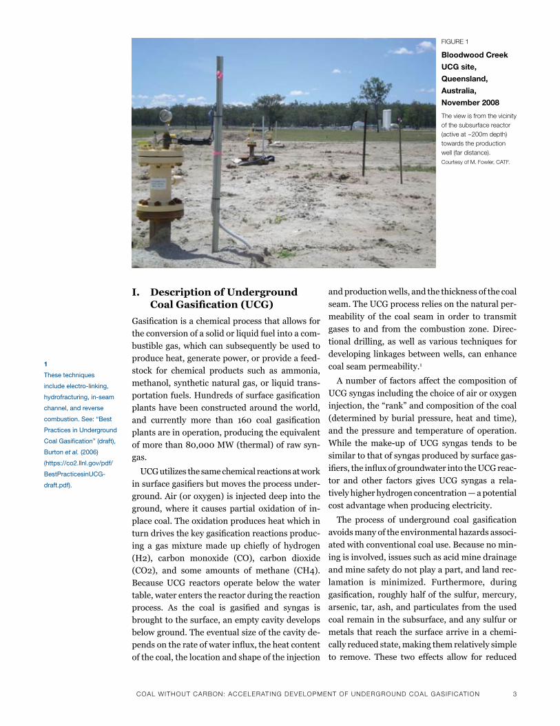
I. Description of Underground Coal Gasification (UCG)
Gasificationisachemicalprocessthatallowsfor
the conversion of a solid or liquid fuel into a com-
bustible gas, which can subsequently be used to
produce heat, generate power, or provide a feed-
stock for chemical products such as ammonia,
methanol, synthetic natural gas, or liquid trans-
portationfuels.Hundredsofsurfacegasification
plants have been constructed around the world,
and currently more than 160 coal gasification
plants are in operation, producing the equivalent
ofmorethan80,000MW(thermal)ofrawsyn-
gas.
UCG utilizes the same chemical reactions at work
insurfacegasifiersbutmovestheprocessunder-
ground.Air(oroxygen)isinjecteddeepintothe
ground,where it causes partial oxidation of in-
placecoal.Theoxidationproducesheatwhichin
turndrivesthekeygasificationreactionsproduc-
ing a gasmixturemade up chiefly of hydrogen
(H2), carbon monoxide (CO), carbon dioxide
(CO2), and some amounts of methane (CH4).
Because UCG reactors operate below the water
table, water enters the reactor during the reaction
process. As the coal is gasified and syngas is
brought to the surface, an empty cavity develops
below ground. The eventual size of the cavity de-
pendsontherateofwaterinflux,theheatcontent
of the coal, the location and shape of the injection
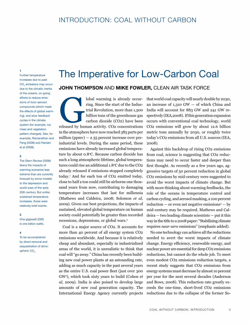
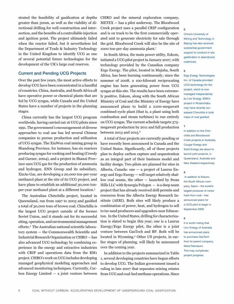
Figure 1
Bloodwood Creek
uCG site,
Queensland,
Australia,
November 2008
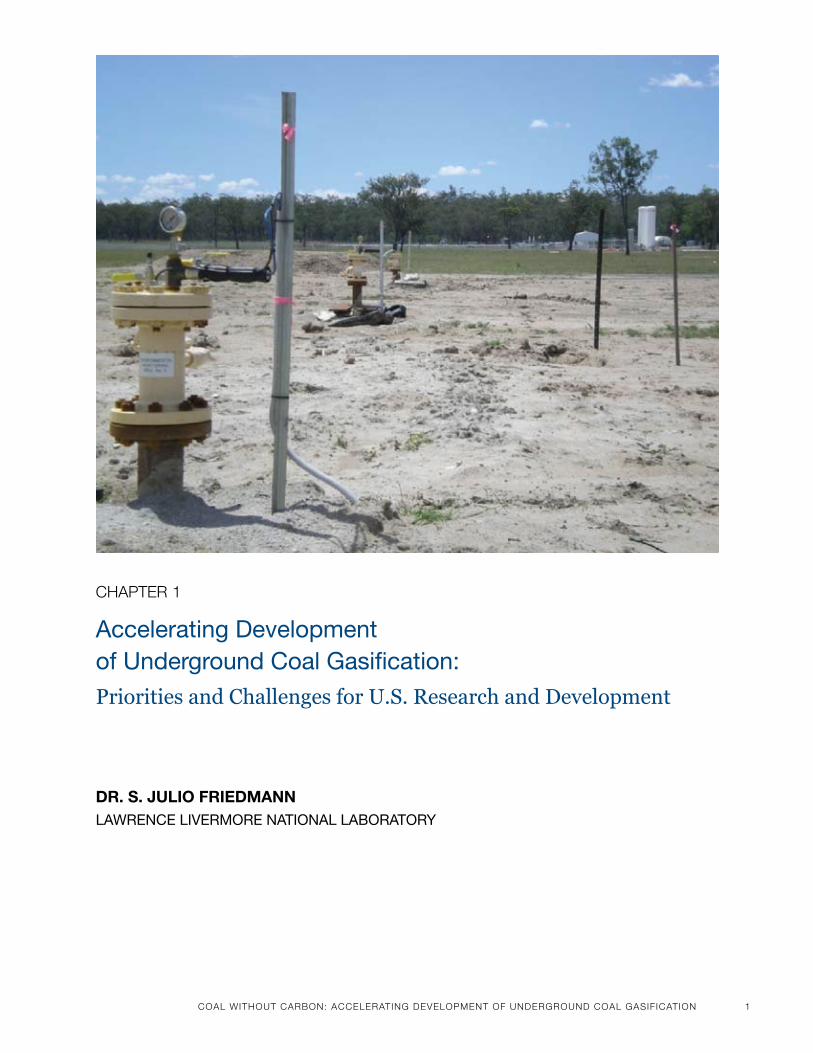
The view is from the vicinity of the subsurface reactor (active at ~200m depth) towards the production well (far distance). Courtesy of m. Fowler, CaTF.
and production wells, and the thickness of the coal
seam. The UCG process relies on the natural per-
meability of the coal seam in order to transmit
gases to and from the combustion zone. Direc-
tional drilling, as well as various techniques for
developing linkages between wells, can enhance
coal seam permeability.1
A number of factors affect the composition of
UCGsyngasincludingthechoiceofairoroxygen
injection,the“rank”andcompositionofthecoal
(determined by burial pressure, heat and time),
and the pressure and temperature of operation.
While the make-up of UCG syngas tends to be
similar to that of syngas produced by surface gas-
ifiers,theinfluxofgroundwaterintotheUCGreac-
tor and other factors gives UCG syngas a rela-
tively higher hydrogen concentration — a potential
cost advantage when producing electricity.
The process of underground coal gasification
avoids many of the environmental hazards associ-
ated with conventional coal use. Because no min-
ing is involved, issues such as acid mine drainage
and mine safety do not play a part, and land rec-
lamation is minimized. Furthermore, during
gasification,roughlyhalfof thesulfur,mercury,
arsenic, tar, ash, and particulates from the used
coal remain in the subsurface, and any sulfur or
metals that reach the surface arrive in a chemi-
cally reduced state, making them relatively simple
to remove. These two effects allow for reduced
1
these techniques
include electro-linking,
hydrofracturing, in-seam
channel, and reverse
combustion. see: “best
practices in underground
Coal Gasification” (draft),
burton et al. (2006)
(https://co2.llnl.gov/pdf/
bestpracticesinuCG-
draft.pdf).
4 CoaL wiThouT CarBoN: aCCeLeraTiNg deveLoPmeNT oF uNdergrouNd CoaL gaSiFiCaTioN
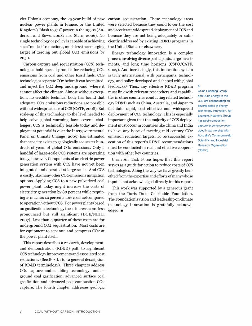
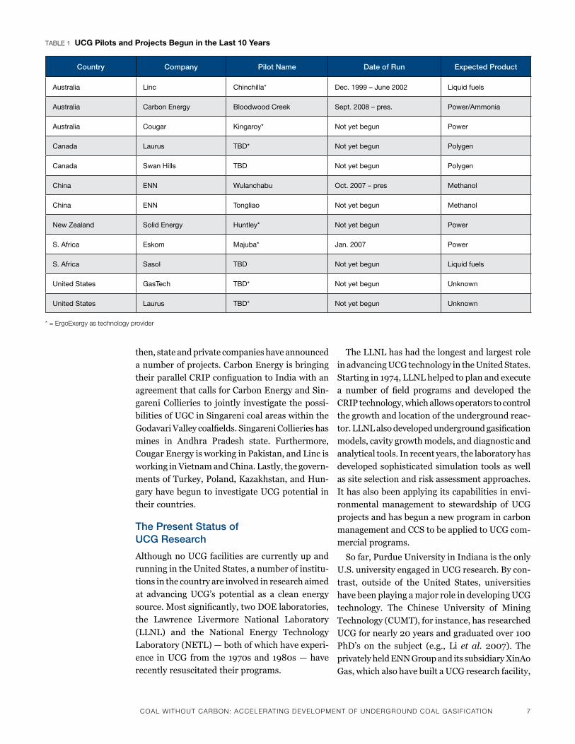
Figure 2
schematic Diagram
Of A uCG reactor
Note that the reactor is below the water table and that water flows into the cavity.
Courtesy of ergoexergy
emissions of criteria pollutants. Additionally, becausetheprocesswaterforgasificationcomesprimarily from the subsurface — and, in the most recent project sites, from saline formations at depth — less surface and shallow groundwater is required for power or fuel production. Finally, UCG may allow for the removal of CO2 from the syngas before use by means of established technologies atsignificantlyreducedcost.2
Alongside these advantages, UCG presents a unique set of engineering and environmental chal-lenges — most notably, the problems of surface subsidence (or caving) and groundwater con-tamination — that will be addressed in some detail below.Thediscussionturnsfirst toanoverviewof UCG history in order to highlight past progress and setbacks in the technology’s evolution and to clarify the current status of efforts aimed at ad-
vancing UCG’s commercial viability.
II. The Evolution of UCG Technology
Overthepastcentury,morethan50attemptsat
underground coal gasification have taken place
around the world, under diverse ecological and
economic conditions and yielding varying levels
of success. In 1868, a German scientist, Sir William
Siemens,publishedthefirstpaperproposingthe
idea of gasifying coal underground, but it was
Soviet scientists who pioneered the application of
UCG on a large scale. Lenin, and later Stalin,
promoted the technology as a boon for socialist
society because it would eliminate the need for
hard mining labor. In 1928, the USSR launched a
national research and development program in
UCG, and by the 1950s the government had
achievedcommercial-scaleproductionofsyngas.
Thefirstdesigninvolvedanundergroundgasifica-
tion chamber built into the coal that required
2
Examples of gas removal
technologies include sel-
exol and rectisol.
underground workers, but later designs relied on
boreholes linked by either vertical wells and
reverse-combustionlinkingordirectionalunder-
ground drilling. The UCG site at Angren, Uzbeki-
stan proved most effective, and continues to have
capacity to produce up to 18 billion cubic feet of
syngas a year, providing fuel for boilers that gen-
erate electricity at the Angren power station.
The Soviets demonstrated that UCG could oper-
ate successfully in coals in a wide variety of geo-
logic settings and in the complex and changing
conditions created by a burning coal seam and
collapsing cavity (Gregg, et al., 1976). Yet despite
the apparent success of the technology, Soviet UCG
productionpeakedinthemid-1960sandsteeply
declinedafterthe1970sforreasonsthatremain
unclear. One possibility is that the discovery of
extensivenaturalgasdepositsinSiberiasiphoned
off support for investment in UCG. UCG may also
have become less economically competitive relative
to natural gas. There is also some evidence that
Soviet UCG technology delivered disappointing
yields and that the government ignored the recom-
mendationsoftheirowntechnicalexperts,making
minimal use of diagnostics and modeling (Burton,
et.al.,2006).
As the Soviet UCG program slowed, efforts to
apply the technology in the United States intensi-
fied.Between 1974 and 1989, theUnitedStates
was the site of major research and deployment
efforts in many areas of renewable and fossil en-
ergy, including UCG. The impact of the OPEC oil
embargo and rising oil prices increased federal
support for UCG research and development. Over
a15-yearperiod,theU.S.conducted33UCGpilot
projects located in Wyoming, Texas, Alabama,
West Virginia and Washington; the Department
of Energy (DOE) sponsored much of the research,

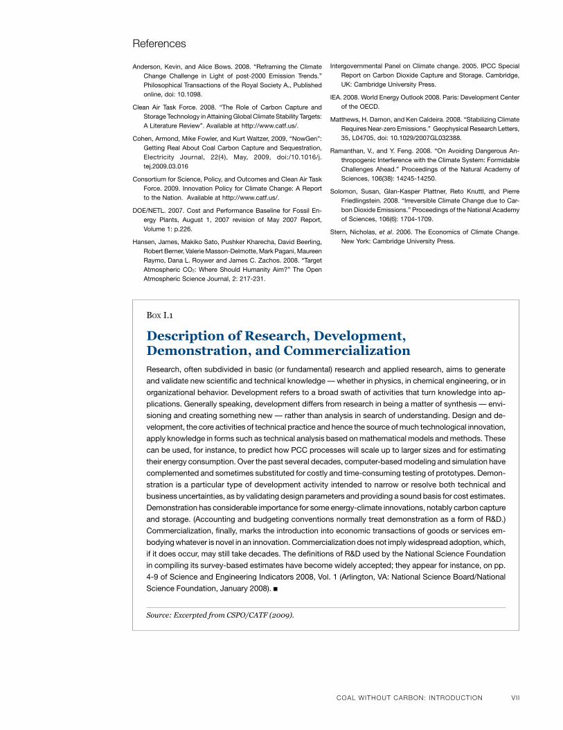
CoaL wiThouT CarBoN: aCCeLeraTiNg deveLoPmeNT oF uNdergrouNd CoaL gaSiFiCaTioN 5
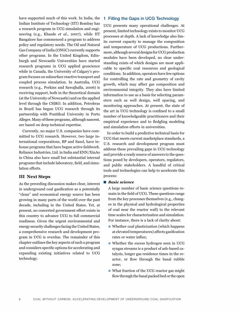
Prior test sites
Announced/planned
CentraliaCentralia
Sites of note
Hoe CreekHoe CreekRM1RM1
ChinchillaChinchilla
AngrenAngren
MajubaMajuba
WulanchabuWulanchabu
Prior test sitesPrior test sites
Announced/planned
CentraliaCentralia
Sites of note
Hoe CreekHoe CreekRM1RM1
ChinchillaChinchilla
AngrenAngren
MajubaMajuba
WulanchabuWulanchabu
investingasmuchas$200millionintoday’sterms
and the Lawrence Livermore National Laboratory
was involved in at least half of the pilots.
The U.S. experiments in UCG succeeded in
validatingin-situgasificationasaprocessforre-
coveringandconvertinglow-rankcoals,thickand
thin seams, as well as seams that were flat or
steeply dipping. The projects also yielded a num-
ber of technological advances — the most impor-
tantofwhichwastheintroductionof“controlled
retractinginjectionpoint”technologyor“CRIP.”
CRIPallowsforincreasedcontroloverthegasifi-
cation progress by enabling retraction of the injec-
tion point once the coal near the gasification
cavity has been used up.3 Other key technical
developmentsincludedworkon“reversecombus-
tionlinking”(amethodforincreasingcoalseam
permability)and“cleancavity”siteclosuremeth-
ods.
The U.S. project sites also revealed evidence of
some of the operational problems and environ-
mental risks associated with UCG. Tests run in
HoeCreek,Wyominginthelate1970s,forinstance,
revealedthatwaterinfluxduringthegasification
process lowered the quality of the resulting gas;
attempts to decreasewater influx by increasing
the operating pressure in the burn zone led to a
significantamountofgasloss.Moresignificantly,
theHoeCreektestsresultedinsignificantamounts
of organic contaminants entering the groundwater,
largely because the reactor was too shallow, was
poorly operated, was not adequately separated
fromadjacentaquifersbyastronggeologic“roof”,
and was designed as a first-of-a-kind experi-
ment.
These discoveries informed the most successful
UCGventureintheUnitedStatesduringthe1980s:
the“RockyMountain1”projectorRMIwascon-
ducted in Carbon County, Wyoming, and jointly
organized by the U.S. DOE, the Electric Power
Research Institute (EPRI), the Gas Research In-
stitute (GRI), Amoco Production Company, and
UnionPacificResources.Theprojecttestedboth
deviatedCRIPandextendedlinkedwellprocess
configurations over many weeks of continuous
operation. It also incorporated environmental
protection into planning and operational proce-
dures.Theproject’sorganizersinvestedsignificant
time and effort in site selection, characterization,
process management, and post-project process
and environmental evaluation.4 A commercial
follow-onprojectatthesite,intendedtoproduce
ammonia from UCG syngas, won a first-round
award inDOE’s “clean coal” program.Unfortu-
nately, the project never got off the ground, because
after the 1986 drop in oil process, US support for
UCG development effectively ended. The technol-
ogy developments from RM1 have nevertheless
provided a valuable basis for future commercial
activity.
During the 1990s, European efforts at UCG
ledtoasuccessful—thoughshort-lived—trialin
northeastern Spain. The tests run at the “El
Tremedal”siteintheProvinceofTerueldemon-
3
in the “Crip” process,
directional drilling is
used to create a channel
connecting the production
well to the injection well.
a gasification cavity forms
at the end of the injection
well in the horizontal
section of the coal seam.
once the coal in the cavity
area is expended the in-
jection point is withdrawn
(usually by burning a
section of the liner) and
a new gasifi-cation cavity
is initiated (burton, et al.,
2006).
4
Dozens of academic
papers and reports were
written describing the
work at rm1 and its
implications for the
science and technology
of uCG (e.g., thorsness
& britten, 1989; metzger,
1988; Cena, 1988; boyson
et al., 1990; Daly et al.,
1989). in 2008-2009,
the rm1 results served
as a template for Carbon
Energy in demonstrating
an advance Crip configur-
ation at their bloodwood
Creek site near Dalby in
queensland, australia.
Figure 3
locations of
prior, Current,
and pending
uCG pilot sites
majuba, Bloodwood Creek, and wulanchabu are active. The base map shows sequestration resource prospectivity.
(Bradshaw and dance, 2004)
6 CoaL wiThouT CarBoN: aCCeLeraTiNg deveLoPmeNT oF uNdergrouNd CoaL gaSiFiCaTioN
strated the feasibility of gasification at depths
greaterthan500m,aswellastheviabilityofdi-
rectional drilling for well construction and inter-
section,andthebenefitsofacontrollableinjection
and ignition point. The project ultimately failed
when the reactor failed, but it nevertheless led
the Department of Trade & Industry Technology
in the United Kingdom to identify UCG as one
of several potential future technologies for the
development of the UK’s large coal reserves.
Current and Pending UCG Projects
Over the past few years, the most active efforts to
develop UCG have been concentrated in a handful
of countries. China, Australia, and South Africa all
have operative power or chemical plants that are
fed by UCG syngas, while Canada and the United
States have a number of projects in the planning
stages.
China currently has the largest UCG program
worldwide, having carried out 16 UCG pilots since
1991. The government’s encouragement of diverse
approaches to coal use has led several Chinese
companies to pursue production and utilization
of UCG syngas. The XinWen coal mining group in
ShandongProvince,forinstance,hassixreactors
producing syngas for cooking and heating (Creedy
andGarner,2004),andaprojectinShanxiProv-
ince uses UCG gas for the production of ammonia
and hydrogen. ENN Group and its subsidiary,
XinAoGas,aredevelopinga20,000ton-per-year
methanol plant at the site of its UCG project, and
haveplanstoestablishanadditional30,000ton-
per-yearmethanolplantatadifferentlocation.5
The Australian Chinchilla project, located in
Queensland,ranfrom1997to2003andgasified
atotalof30,000tonsofbrowncoal.Chinchillais
the largest UCG project outside of the former
Soviet Union, and it stands out for its successful
siting, operation, and environmental management
efforts.6TheAustraliannationalscientificlabora-
torysystem—theCommonwealthScientificand
Industrial Research Organization or CSIRO — has
alsoadvancedUCGtechnologybycombiningex-
perience in theenergyandextractive industries
with CRIP and operations data from the RM1
project. CSIRO’s work on UCG includes developing
managed geophysical modeling approaches and
advanced monitoring techniques. Currently, Car-
bon Energy Limited — a joint venture between
5
China’s university of
mining and technology in
beijing has also received
substantial government
support to conduct in-situ
gasification in abandoned
coalmines.
6
Ergo Exergy technologies
inc. of Canada provided
uCG technology for the
project, which is now
managed independently
by linc Energy. Enn’s
project in Wulanchabu
may have recently sur-
passed Chinchilla in total
mass of coal gasified.
7
in addition to the Chin-
chilla and bloodwood
Creek projects in australia,
Cougar Energy and
solid Energy are about to
launch pilot projects, in
queensland, australia and
new Zealand respectively.
8
in addition to Eskom,
the south african com-
pany, sasol – the world’s
largest producer of motor
fuels from coal – has
announced plans for
a uCG pilot to begin in
september 2009.
9
it is worth noting that
linc Energy of australia
has announced plans
to purchase Gastech
from its parent company,
Wold petroleum.
this may complicate
project progress.
CSIRO and the mineral exploration company,
METEX — has a pilot underway. The Bloodwood
CreekprojectusesaparallelCRIPconfiguration
andisontracktobethefirstcommerciallyoper-
ated unit to generate electricity for sale through
the grid. Bloodwood Creek will also be the site of
1000ton-per-dayammoniaplant.7
In South Africa, the main power utility, Eskom,
initiatedaUCGpilotprojectinJanuary2007,with
technology provided by the Canadian company
ErgoExergy.Thepilot,locatedinMajuba,South
Africa, has been burning continuously; since the
summer of 2008, a 100-kilowatt reciprocating
engine has been generating power from UCG
syngasatthissite.Theresultshavebeenextreme-
ly positive. Eskom, along with the South African
Ministry of Coal and the Ministry of Energy have
announced plans to build a 2100-megawatt
combined-cycleplant(thatis,aplantusingboth
combustion and steam turbines) to run entirely
onUCGsyngas.Thecurrentscheduletargets375-
megawattproductionby2011andfullproduction
between2013and2015.8
A total of four projects are currently pending or
have recently been announced in Canada and the
UnitedStates.Significantly,allof theseprojects
plan to deploy carbon capture and sequestration
as an integral part of their business model and
facility design. Two pilots are planned for sites in
Alberta, Canada: one — a project of Laurus En-
ergyandErgoExergy—willtargetrelativelyshal-
low coal seams, the other — launched by Swan
Hills LLC with Synergia Polygen — is a deep seam
project that has already received drill permits and
resources from the Alberta Energy Research In-
stitute (AERI). Both sites will likely produce a
combination of power, heat, and hydrogen to sell
to tar sand producers and upgraders near Edmon-
ton. In the United States, drilling for characteriza-
tion is slated to begin this year; one is a Laurus
Energy/Ergo Exergy pilot, the other is a joint
venture between GasTech and BP. Both will be
located in Wyoming.9 Other US projects, in ear-
lier stages of planning, will likely be announced
over the coming year.
In addition to the projects summarized in Table
1, several developing countries have begun efforts
to develop UCG. The Indian government issued a
rulinginlate2007thatseparatesminingestates
fromUCGandcoal-bedmethaneoperations.Since
CoaL wiThouT CarBoN: aCCeLeraTiNg deveLoPmeNT oF uNdergrouNd CoaL gaSiFiCaTioN 7
then, state and private companies have announced
a number of projects. Carbon Energy is bringing
theirparallelCRIPconfiguationtoIndiawithan
agreement that calls for Carbon Energy and Sin-
gareni Collieries to jointly investigate the possi-
bilities of UGC in Singareni coal areas within the
GodavariValleycoalfields.SingareniCollierieshas
mines in Andhra Pradesh state. Furthermore,
Cougar Energy is working in Pakistan, and Linc is
working in Vietnam and China. Lastly, the govern-
ments of Turkey, Poland, Kazakhstan, and Hun-
gary have begun to investigate UCG potential in
their countries.
The Present Status of UCG Research
Although no UCG facilities are currently up and
running in the United States, a number of institu-
tions in the country are involved in research aimed
at advancing UCG’s potential as a clean energy
source.Mostsignificantly,twoDOElaboratories,
the Lawrence Livermore National Laboratory
(LLNL) and the National Energy Technology
Laboratory(NETL)—bothofwhichhaveexperi-
ence inUCG from the 1970sand1980s—have
recently resuscitated their programs.
Country Company Pilot Name Date of Run Expected Product
australia linc Chinchilla* Dec. 1999 – June 2002 liquid fuels
australia Carbon Energy bloodwood Creek sept. 2008 – pres. power/ammonia
australia Cougar kingaroy* not yet begun power
Canada laurus tbD* not yet begun polygen
Canada swan hills tbD not yet begun polygen
China Enn Wulanchabu oct. 2007 – pres methanol
China Enn tongliao not yet begun methanol
new Zealand solid Energy huntley* not yet begun power
s. africa Eskom majuba* Jan. 2007 power
s. africa sasol tbD not yet begun liquid fuels
united states Gastech tbD* not yet begun unknown
united states laurus tbD* not yet begun unknown
* = ErgoExergy as technology provider
The LLNL has had the longest and largest role
in advancing UCG technology in the United States.
Startingin1974,LLNLhelpedtoplanandexecute
a number of field programs and developed the
CRIP technology, which allows operators to control
the growth and location of the underground reac-
tor.LLNLalsodevelopedundergroundgasification
models, cavity growth models, and diagnostic and
analytical tools. In recent years, the laboratory has
developed sophisticated simulation tools as well
as site selection and risk assessment approaches.
It has also been applying its capabilities in envi-
ronmental management to stewardship of UCG
projects and has begun a new program in carbon
management and CCS to be applied to UCG com-
mercial programs.
So far, Purdue University in Indiana is the only
U.S. university engaged in UCG research. By con-
trast, outside of the United States, universities
have been playing a major role in developing UCG
technology. The Chinese University of Mining
Technology (CUMT), for instance, has researched
UCGfornearly20yearsandgraduatedover100
PhD’s on the subject (e.g., Li et al. 2007). The
privately held ENN Group and its subsidiary XinAo
Gas, which also have built a UCG research facility,
TaBLe 1 uCG pilots and projects Begun in the last 10 Years
* = ergoexergy as technology provider
8 CoaL wiThouT CarBoN: aCCeLeraTiNg deveLoPmeNT oF uNdergrouNd CoaL gaSiFiCaTioN
have supported much of this work. In India, the
Indian Institute of Technology (IIT) Bombay has
a research program in UCG simulation and engi-
neering (e.g., Khasde et al., 2007), while IIT
Bangalore has commenced a program to address
policy and regulatory needs. The Oil and Natural
Gas Company of India (ONGC) currently supports
other programs. In the United Kingdom, Edin-
burgh and Newcastle Universities have started
research programs in UCG applied geoscience
while in Canada, the University of Calgary’s pro-
gram focuses on subsurface reactive transport and
coupled process simulation. In Australia, UCG
research (e.g.,PerkinsandSawajhalla,2006) is
receiving support, both in the theoretical domain
(at the University of Newcastle) and on the applied
level through the CSIRO. In addition, Petrobras
in Brazil has begun UCG research through its
partnership with Pontifical University in Porto
Allegre. Many of these programs, although nascent,
arebasedondeeptechnicalexpertise.
Currently, no major U.S. companies have com-
mitted to UCG research. However, two large in-
ternationalcorporations,BPandSasol,havein-
houseprogramsthathavebegunactivefieldwork.
Reliance Industries, Ltd. in India and ENN/XinAo
in China also have small but substantial internal
programsthatincludelaboratory,field,andsimu-
lation efforts.
III Next Steps
As the preceding discussion makes clear, interest
inundergroundcoalgasificationasapotentially
“clean” and economical energy source has been
growing in many parts of the world over the past
decade, including in the United States. Yet, at
present,noconcertedgovernmenteffortexistsin
this country to advance UCG to full commercial
readiness. Given the urgent environmental and
energy security challenges facing the United States,
a comprehensive research and development pro-
gram in UCG is overdue. The remainder of this
chapter outlines the key aspects of such a program
andconsidersspecificoptionsforacceleratingand
expanding existing initiatives related to UCG
technology.
1 Filling the Gaps in UCG Technology
UCG presents many operational challenges. At
present,limitedtechnologyexiststomonitorUCG
processes at depth. A lack of knowledge also lim-
its current capacity to manage the composition
and temperature of UCG productions. Further-
more, although several designs for UCG production
modules have been developed, no clear under-
standingexistsofwhichdesignsaremostappli-
cable to specific coal resources and geological
conditions. In addition, operators have few options
for controlling the rate and geometry of cavity
growth, which may affect gas composition and
environmental integrity. They also have limited
information to use as a basis for selecting param-
eters such as well design, well spacing, and
monitoring approaches. At present, the state of
theartinUCGtechnologyisconfinedtoasmall
number of knowledgeable practitioners and their
empirical experience and to fledgling modeling
and simulation efforts in universities.
In order to build a predictive technical basis for
UCG that meets current marketplace standards, a
U.S. research and development program must
address these prevailing gaps in UCG technology
and provide a ready source of answers to the ques-
tions posed by developers, operators, regulators,
and public stakeholders. A handful of critical
tools and technologies can help to accelerate this
process:
n Basic science
A large number of basic science questions re-
maininthefieldofUCG.Thesequestionsrange
from the key processes themselves (e.g., chang-
es in the physical and hydrological properties
of coal near the reactor wall) to the relevant
time scales for characterization and simulation.
For instance, there is a lack of clarity about:
l Whether coal plasticization (which happens
atelevatedtemperatures)affectsgasification
ratesorwaterinflux;
lWhether theexcesshydrogenseen inUCG
syngasstreamsisaproductofash-basedca-
talysis, longer gas residence times in the re-
actor, or flow through the basal rubble
zone;
l What fraction of the UCG reactor gas might
flowthroughthebasalpackedbedortheopen
CoaL wiThouT CarBoN: aCCeLeraTiNg deveLoPmeNT oF uNdergrouNd CoaL gaSiFiCaTioN 9
channel, and what change in conditions might
alter that effect;
l Where in the cavity pyrolysis products form,
at what rate they form, at what rate they are
consumed in the reactor, the full spectrum
of effects that could lead to their migration
into groundwater, and how changing UCG
operations might reduce their abundance or
mobility.
A new program aimed at investigating the basic
scienceofUCGwouldhelpfill theseholes in
knowledge and open up new cost saving and
efficiencymeasuresinthefuture.Manypoten-
tial research institutions could take part in
answering these questions, including the na-
tional laboratories and various universities.
Because the questions are complex and the
time-scales for investigation are likely to be
long, sustained funding is required. Annual
formal exchanges among all researchers in-
volved in the program will be necessary to
ensure the sharing of knowledge and insights.
(During the 1970s and 1980s, annual UCG
conferences brought scientists and engineers
together,helping tocreatea“goldenage” for
the technology.) Thus, funds should be allo-
cated to ensure conference participation and
allow for publication of research results. Fi-
nally, a web site must be established to archive
existing information andmake both old and
newscientificinformationavailabletoawide
audience.
n Advanced simulation
UCG simulators in current use have limited
capabilities. They are often only one-dimen-
sional and can neither match the products of
priorfieldprojects,noraccuratelypredictthe
natural fluctuations associated with syngas
production. Although sophisticated models
combininggasificationeffectswithgeophysical
and hydrological effects in multiple dimensions
doexist,theyarenotwidelyused,andtheystill
require manual parameterizations between
modules and across scales. Improved three-
dimensional “coupled simulators” — that is,
simulatorslinkinggasification,hydrology,and
geomechanics — are needed to:
l Simulate the evacuation of coal and cavity
growth;
l Simulate cavity collapse and subsidence;
l Simulategroundwaterinfluxasafunction
of reactor pressure;
l Simulate UCG modules at scale;
l Predict changes in syngas composition giv-
en different pressures and temperatures of
operation;
l Provide insight into environmental concerns
during and after operation.
Many currently available simulators may ad-
dress some or part of these concerns, but they
are located across different industries and re-
search institutions. Moreover, many of them
arefit toadifferentpurpose (e.g.,predicting
tunnel collapse) and have not been applied to
UCG problems. Thus, a substantial effort is
neededtointegratethebestfeaturesofexisting
simulation models, to develop new simulation
tools, and, in turn, to validate these technolo-
giesusingrecordsfrompriorfieldtestsandnew
field experiments. This initiativewill require
collaboration between research labs, universi-
ties and private companies — each of which will
contribute different elements to the process of
improving UCG simulation techniques. Ideally,
a working group would be established to share
initial results and compare approaches. New
sets of simulators will then need to be bench-
markedagainstfieldtests.
n Monitoring and
verification technology
Monitoring is necessary to identify key UCG
processes, to provide engineering process con-
trol, and to detect hazards and failures in the
subsurface. Most UCG monitoring took place
over 20 years ago. Advanced approaches to
geophysical and geochemical monitoring have
notyetbeenappliedintheUCGcontext.Such
techniques include the use of micro seismic
networks (detectors near the surface that
monitor small vibrations in and around the
gasification cavity), “InSAR” (a type of radar
that uses the interference of radio waves to
measure small surface deformations), cross-
well or time-lapse seismic evaluations, and
micro-gravimetricorelectricalsurveys.Inad-
dition, UCG has special operational and process
attributes that both require and make possible
new monitoring approaches.
10 CoaL wiThouT CarBoN: aCCeLeraTiNg deveLoPmeNT oF uNdergrouNd CoaL gaSiFiCaTioN
A U.S. program on UCG monitoring technol-
ogy should thus have the following objectives:
l To identify and select potentially useful tools
and approaches such as micro seismic, In-
SAR, and electrical surveys
l To advance simulation of monitoring in the
contextofUCG,both forhypotheticalrock
bodiesandfield-focusedsites
l Toensurevalidationinthefield
l To reduce uncertainty
l To develop novel, fit-for-purposemonitor-
ing approaches
This program will need to build on prior tools
and approaches developed for underground
mining,oil andgasexplorationanddevelop-
ment, and data integration. Like a simulation
development program, it would begin by using
existingtoolsanddatasetsfrompreviousfield
programs and from industrial analogs (e.g.,
long-wallmining),anditwouldendinapplied
field programs. These field programswould
initially be aimed at understanding the full
range of viable tools and approaches, but their
ultimate aim would be to reduce the cost and
enhance the performance of monitoring.
Many U.S. research institutions have skill sets
applicable to these challenges, including the
DOE national laboratories and universities.
Yet, to date, none of these institutions has an
active program aimed at researching the spe-
cific thermal, mechanical, hydrological, and
chemical signatures of UCG operations. Simi-
larly,manycompanieshaveexpertiseappropri-
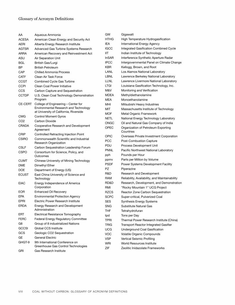
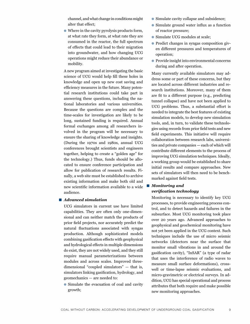
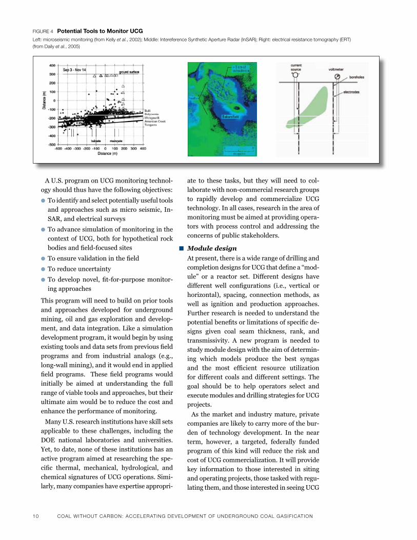
Figure 4 potential tools to Monitor uCGLeft: microseismic monitoring (from Kelly et al., 2002); middle: intereference Synthetic aperture radar (inSar); right: electrical resistance tomography (erT) (from daily et al., 2005)
ate to these tasks, but they will need to col-laboratewithnon-commercialresearchgroupsto rapidly develop and commercialize UCG technology. In all cases, research in the area of monitoring must be aimed at providing opera-tors with process control and addressing the concerns of public stakeholders.
n Module design
At present, there is a wide range of drilling and completiondesignsforUCGthatdefinea“mod-ule” or a reactor set. Different designs havedifferent well configurations (i.e., vertical orhorizontal), spacing, connection methods, as well as ignition and production approaches. Further research is needed to understand the potentialbenefitsorlimitationsofspecificde-signs given coal seam thickness, rank, and transmissivity. A new program is needed to study module design with the aim of determin-ing which models produce the best syngas and the most efficient resource utilization for different coals and different settings. The goal should be to help operators select and executemodulesanddrillingstrategiesforUCGprojects.
As the market and industry mature, private companies are likely to carry more of the bur-den of technology development. In the near term, however, a targeted, federally funded program of this kind will reduce the risk and cost of UCG commercialization. It will provide key information to those interested in siting and operating projects, those tasked with regu-
lating them, and those interested in seeing UCG
CoaL wiThouT CarBoN: aCCeLeraTiNg deveLoPmeNT oF uNdergrouNd CoaL gaSiFiCaTioN 11
proceed with the highest possible environmen-
tal standards.
2. Advancing Carbon Management
During the heyday of U.S.-basedUCG research
anddevelopment in the1970sand1980s, there
was not yet a broad recognition of the need to
reduce CO2 emissions. Yet, in recent years, the
potential for UCG to provide a pathway for captur-
ing and sequestering CO2 has played a major role
in driving the resurgence of interest in the technol-
ogy. A targeted research program is urgently
needed to determine the possibilities for carbon
abatement associated with the production and use
of UCG syngas. The program should focus on three
key areas.
n Conventional geological
sequestration
The technology exists today to separate CO2
from UCG syngas and to store that CO2 in
geological formations. However, there has not
yet been a focused investigation into how op-
erators might apply these technologies to-
gether.Anewresearchinitiativeshouldexam-
ine the potential synergies between UCG and
conventional CCS in regions of interest and
begin mapping UCG and sequestration re-
sources. In addition, engineering and cost
studies should be carried out to determine the
commercial viability of UCG with CCS systems
in many potential applications.
n Reactor zone carbon sequestration
UCG creates large voids in the subsurface by
gasifying, fracturing, spalling, and evacuating
coal. These voids may offer a sequestration
resource through an approach known as reactor
zone carbon sequestration (RZCS). RZCS could
provide a closed loop for a wide range of engi-
neering applications, such as synthetic natural
gasorcoal-to-liquidsproduction.Atpresent,
however, many geological, geochemical and
geomechanical questions remain unanswered,
stalling deployment of this approach.
An accelerated research program is needed to
examine the key chemical and physical pro-
cesses involved in RZCS and to determine its
commercial viability. There is currently a high
level of uncertainty about the degree of char-
acterization required before contemplating
reactor zone storage and about the likely fate
and transport of CO2 in this setting. Because
the process of UCG causes profound changes
in the coal and associated host rocks (as a result
of exposure to heat, collapse, and reactive
chemical agents), it is unclear how CO2 might
behave in this altered environment. Thus, a
sustained,multi-prongedresearcheffortshould
aim to:
l Develop advanced coupled simulators link-
ing RZCS and UCG processes;
l Initiate laboratory work to understand the
physical, chemical, mechanical, and thermal
transients associated with UCG and RZCS;
l Develop a technical roadmap for testing
RZCS;
l Reduce RZCS to a practice in site operation
aimed at minimizing contaminant produc-
tion and transport.
n Fit-for-purpose capture technology
Most of the carbon capture technologies devel-
oped thus far have been geared toward deploy-
ment in surface facilities such as power plants.
To date, little attention has been paid to how
UCG operating conditions might present ad-
ditional opportunities and challenges for car-
bon capture. There is thus a pressing need for
studies to determine how carbon capture costs
might be reduced through the application of
fit-for-purpose UCG capture technologies.
These technologies could be applied in the reac-
torzone(e.g.,enhancedwater-gasshift),inthe
wellbore (e.g., downhole separation mem-
branes), or at the surface (e.g., enhanced pres-
sure swing adsorption). Researchers should
seek to understand the conditions under which
UCG operations could improve the cost, per-
formance, or risk profile for carbon capture.
Studies should focus on:
l Integrated engineering — i.e. looking at the
potential upsides and downsides of carbon
capture engineering for UCG
lDown-hole engineering to reduce carbon
production
lDown-holeengineeringtoenhancesubsur-
facewater-gasshift
l Surface facility design for UCG syngas pro-
duction swings
Relative to conventional CCS technologies
(i.e. surface capture and geological CO2 disposal),
12 CoaL wiThouT CarBoN: aCCeLeraTiNg deveLoPmeNT oF uNdergrouNd CoaL gaSiFiCaTioN
CCS applied to UCG remains in an early discovery
phase. For this reason, a research program aimed
at advancing carbon management in UCG should
draw on the technological insights of other CCS
programs, but proceed independently of those
programs so as not to distort public perceptions
of the readiness of CCS technology generally. UCG
presents many unique challenges and opportuni-
ties for carbon capture that warrant a distinct
research enterprise.
3. Ensuring Environmental Management
One of the attractions of UCG is its potential to
recoup the energy content of coal without the
practice of mining. While the elimination of min-
ing hasmany potential environmental benefits,
in-situconversionandgasificationpresentsanew
set of environmental concerns. Any substantial
deployment of UCG in the United States must
proceed with a high level environmental integrity
and focus on the protection of natural resources.
Research should begin by addressing the two most
critical environmental hazards likely to confront
potential UCG operators: ground water contamina-
tion and subsidence.
n Groundwater protection
While past UCG research and development
programs in the United States left a legacy of
many technical successes, two pilots — Hoe
Creek 2 and the William’s Carbon County proj-
ect — resulted in environmental problems. At
Hoe Creek 2, the problems stemmed from poor
siting and operation of the UCG module; at
Carbon County, the issues arose from drilling
errors and fracturing of the formation during
restoration. In both cases, the result was
groundwater contamination. Problems relating
to project siting, management, and operations
can be readily addressed; however, the record
of environmental problems with UCG poses a
challenge to future operators, who will have to
overcome permitting and public acceptance
hurdles.
An accelerated research program should thus
focus on developing improved practices for site
selection, site operation, and project steward-
ship. The key components of such an effort
would include:
l Application of conventional simulators to
contaminant fate and transport
l Laboratory work to understand the genera-
tion of potential contaminants
l Study of current practices in groundwater
protection that are relevant to UCG
l Standardization of procedures aimed at min-
imizing contaminant production and trans-
port (e.g., operational pressure tolerances)
in site operation
l Incorporation of lessons from prior and
current research into standard operating
practice
n Subsidence control
UCG allows for coal to be evacuated from the
subsurface as a gas. This creates voids in the
subsurface that could potentially result in sur-
face deformation. At present, most of the avail-
ableexpertiseontheproblemofsubsidenceis
found in the coal mining industry, which fo-
cusesonundergroundoperationswithin200
meters of the surface.While experiencewith
subsidenceinthecontextoflong-wallmining
is analogous to UCG in many respects, ques-
tions remain regarding industrial practice in
long-wallminemanagementwhenfullaccess
to the subsurface is limited. Moreover, it is not
yet clear what the public perception will be or
what regulatory requirements will result, when
these practices are applied in the context of
UCG.
Research is needed to accelerate the develop-
ment of techniques aimed at managing and
reducingsurfacesubsidenceinthecontextof
UCG. Several key elements of this effort in-
clude:
l Applying conventional simulators to shallow
geomechanics, in particular on discrete fail-
ure and fracture
l Conducting laboratory work to understand
data requirements for accurate simulation
and data collection needs
l Studying current practice in related indus-
tries (e.g., coal mining), with a particular fo-
cus on long-wall and room-and-pillar
mining
l Studying potential impacts of subsidence
on groundwater, including impacts on
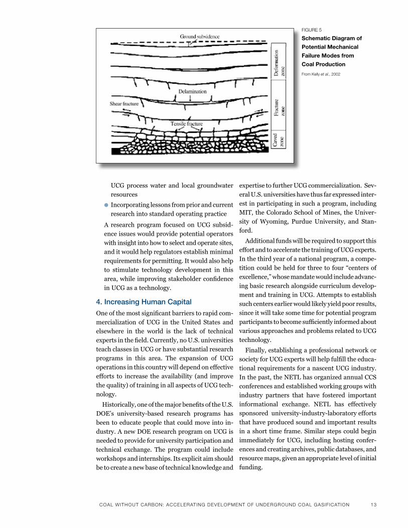
CoaL wiThouT CarBoN: aCCeLeraTiNg deveLoPmeNT oF uNdergrouNd CoaL gaSiFiCaTioN 13
UCG process water and local groundwater
resources
l Incorporating lessons from prior and current
research into standard operating practice
A research program focused on UCG subsid-
ence issues would provide potential operators
with insight into how to select and operate sites,
and it would help regulators establish minimal
requirements for permitting. It would also help
to stimulate technology development in this
area,whileimprovingstakeholderconfidence
in UCG as a technology.
4. Increasing Human Capital
Oneofthemostsignificantbarrierstorapidcom-
mercialization of UCG in the United States and
elsewhere in the world is the lack of technical
expertsinthefield.Currently,noU.S.universities
teach classes in UCG or have substantial research
programs in this area. The expansion of UCG
operations in this country will depend on effective
efforts to increase the availability (and improve
the quality) of training in all aspects of UCG tech-
nology.
Historically,oneofthemajorbenefitsoftheU.S.
DOE’s university-based research programs has
been to educate people that could move into in-
dustry. A new DOE research program on UCG is
needed to provide for university participation and
technical exchange. The program could include
workshopsandinternships.Itsexplicitaimshould
be to create a new base of technical knowledge and
Figure 5
schematic Diagram of
potential Mechanical
Failure Modes from
Coal production
From Kelly et al., 2002
expertisetofurtherUCGcommercialization.Sev-
eralU.S.universitieshavethusfarexpressedinter-
est in participating in such a program, including
MIT, the Colorado School of Mines, the Univer-
sity of Wyoming, Purdue University, and Stan-
ford.
Additional funds will be required to support this
effortandtoacceleratethetrainingofUCGexperts.
In the third year of a national program, a compe-
titioncouldbeheldforthreetofour“centersof
excellence,”whosemandatewouldincludeadvanc-
ing basic research alongside curriculum develop-
ment and training in UCG. Attempts to establish
such centers earlier would likely yield poor results,
since it will take some time for potential program
participantstobecomesufficientlyinformedabout
various approaches and problems related to UCG
technology.
Finally, establishing a professional network or
societyforUCGexpertswillhelpfulfilltheeduca-
tional requirements for a nascent UCG industry.
In the past, the NETL has organized annual CCS
conferences and established working groups with
industry partners that have fostered important
informational exchange. NETL has effectively
sponsoreduniversity-industry-laboratoryefforts
that have produced sound and important results
in a short time frame. Similar steps could begin
immediately for UCG, including hosting confer-
ences and creating archives, public databases, and
resource maps, given an appropriate level of initial
funding.
14 CoaL wiThouT CarBoN: aCCeLeraTiNg deveLoPmeNT oF uNdergrouNd CoaL gaSiFiCaTioN
5 Establishing a Targeted Field Program
While much of the advanced development work
in UCG will proceed in a laboratory setting, a good
portion of it will require close coordination with
field programs both in the United States and
abroad, in order to validate simulations and ap-
proaches.AnewU.S.fieldprogramforUCGwill
be critical for advancing many aspects of the tech-
nology and for fostering new technical discoveries.
A targeted field program should include three
critical components:
n Support for, and collaboration with,
commercial UCG pilots
Commercial UCG projects in the United States
representanimmediateopportunitytorefine
andtestexistingapproachesforUCGsiteselec-
tion, operation, andmonitoring. AU.S. field
program should select a number of pilot proj-
ects—fromtwotofive—forpotentialfunding
and help to provide the appropriate infrastruc-
ture. These projects would provide a basis for
understanding near-term commercial and
regulatory challenges and for filling gaps in
knowledge and developing tools for UCG, while
protecting a number of public interests. These
domestic commercial UCG projects should be
treated in a manner that is conceptually akin
to the rest of the U.S. clean coal program. The
government could provide support for such
projectsthroughgrants,incentives,taxbenefits,
and/or loan guarantees. The projects would
alsorepresentasignificantopportunitytole-
verage public investments in technology, with
resultantenvironmentalbenefitsandlong-term
commercial advantages.
n Formation of a state-of-the-art
UCG facility for research and
training purposes
A federally-funded domestic state-of-the-art
UCG facility would allow for (1) rapid learning
throughexperimentationand(2)thedevelop-
mentandtestingofadvancedscientificmeth-
ods, simulations, and monitoring platforms.
n Support for and collaboration with
international field activities
IdeallyaU.S.-basedUCGprogramwouldprog-
ress in parallel with an international effort.
Opportunities for technology sharing with for-
eign UCG entities will likely improve the tech-
nical products in the United States and acceler-
ate learning. This is especially true of field
programs. Both China and South Africa have
launchedactivefieldpilotprojectsinadvance
of large-scale commercialization. Australia,
India, Canada, and New Zealand are accelerat-
ing pilots to test for commercialization. The
United States should work toward explicit
agreements with other countries aimed at pro-
viding technology assistance and basic R&D
support in exchange for access tofieldpilots
and their data. This objective could be achieved
through bilateral agreements or through um-
brella partnerships, along the lines of the Car-
bon Sequestration Leadership Forum. Coop-
erativeinternationalfieldprojectswillincrease
the pace of R&D, save money overall, and allow
participating countries and others with a na-
scent interest in UCG (such as, Poland, Turkey,
and Brazil) to quickly advance their own pro-
grams using the best available technology. Is-
sues associated with visas and access will need
to be managed effectively in order to streamline
the transfer of knowledge and technology.
IV. Draft Budget Requirements
Belowarepreliminarybudgetestimatesforafour-
year federal UCG program that will focus on the
R & D objectives discussed above. The numbers
are intended to provide a framework for discussion
and planning; decisions about important details
— such as how much emphasis is placed on inter-
national relative to domestic projects, how many
entities (universities, private enterprises, na-
tional laboratories) will participate, and how much
basicscienceworkisneeded—willinfluencethe
distribution of funds between different program
components and total annual costs.
YEAR1 $10-12M
YEAR2 $12-20M
YEAR3 $27.5-37.5M
YEAR 4 $52.5M minimum
CoaL wiThouT CarBoN: aCCeLeraTiNg deveLoPmeNT oF uNdergrouNd CoaL gaSiFiCaTioN 15
A possible breakdown of spending during the
firstandfourthyearoftheprogramcouldproceed
as follows:
YEAR 1 (total draft budget = $11M)
Environmental Protection $ 2.5M
CarbonManagement $ 2.0M
Conventional CCS $ 0.5M
RZCS $ 0.5M
Fit-for-purpose $ 1.0M
Technologydevelopment $ 3.0M
Simulation $ 1.2M
Monitoring $ 0.8M
Basic Science $ 1.0M
Field Program
International $ 3.0M
Othersupport $ 0.5M
YEAR 4 (total draft budget = $52.5M)
EnvironmentalProtection $4.0M
Carbon Management $ 4.5M
Conventional CCS $ 1.5M
RZCS $ 1.0M
Fit-for-purpose $ 2.0M
Technologydevelopment $7.0M
Simulation $ 2.0M
Monitoring $ 2.0M
Basic Science $ 3.0M
Field Program $ 9.5M
International $ 7.5M
US pilots $ 17.0M
US collaboratives $ 5.0M
Othersupport $ 7.0M
Centers of Excellence $ 4.0M
Training $ 2.5M
Conference and exchanges $ 0.5M
ConclusionUCG holds the promise of transforming the use of
coal as an energy resource, with positive conse-
quences for the natural environment and energy
costs. UCG has a history of success producing
syngas for multiple purposes in sites around the
world. In recent years, interest in the technology
has grown as a result of global climate concerns;
the underground well infrastructure used in UCG
offers the potential for CO2 capture and sequestra-
tion.
Yet,inorderforUCGtofulfillitsenvironmental
and economic potential it will need to be deployed
on a large scale in North America and overseas.
Near-term government support is urgently re-
quired to produce a reliable base of technical
knowledgeandexpertisethatwillensureacom-
mercially-viableUCGindustryintheUnitedStates.
This preceding discussion has outlined the essen-
tialcomponentsofU.S.-basedresearchanddevel-
opment program aimed at addressing the unre-
solved problems and unanswered questions in
UCG technology and speeding advancement to-
ward full commercialization. In addition to im-
proving basic science understanding, this program
will support progress in simulation and monitor-
ing techniques and module design. It will also
address those aspects of UCG that are less likely
to receive private-sector investment — specifi-
cally, environmental management, CO2 capture
andsequestration,anduniversity-basedtraining.
Each of these areas of research and development
willbenefitfromclosecollaborationwithnascent
commercial enterprises in the U.S. and cooperation
with international projects and research facilities.
The resulting technological advances will ulti-
matelybe testedandrefined in thecontextofa
federallyfundedtargetedfieldprogramthatwill
serve as critical a data source for commercial
UCG projects going forward.
Note: It is possible for much recommended
federally funded R&D to begin immediately. This
would include the research on development of
simulation tools and experimental programs.
Moreover,somecommercialfieldprojectsinNorth
America or overseas could serve as possible loca-
tions to develop and test novel monitoring, simu-
lation, drilling, or environmental protection
technologies, tools, and approaches. This model
would follow the Weyburn CCS project, wherein
scientific and technical investigations benefited
from access to the surface and subsurface at a
commercial CCS project site. The costs for these
initial efforts would be relatively low, and they
would provide a platform to determine the role,
viability,andfeaturesofaUSgovernment-spon-
soredfieldprogram.■

16 CoaL wiThouT CarBoN: aCCeLeraTiNg deveLoPmeNT oF uNdergrouNd CoaL gaSiFiCaTioN
recent reports on uCgbelow is a list of several reports that may be useful to decision makers in considering current practice and understanding with re-spect to uCG technology.
best practices in underground Coal Gasification (draft), burton et al., 2006 (https://co2.llnl.gov/pdf/bestpracticesinuCG-draft.pdf)
underground Coal Gasification, in, the urgency of sustainable Coal, national Coal Council 2008, (http://www.nationalcoal-council.org/Documents/urgency_of_sustainable_Coal.pdf)
underground Coal Gasification technical summary stephens Dr, thorsness Cb, hill rW, thompson Ds, 1983
review of Environmental issues of underground Coal Gasification, sury et al., 2004 (http://www.berr.gov.uk/files/file20034.pdf)
status report on underground Coal Gasification: office of the principle scientific advisor (india) 2007 (http://psa.gov.in/writereaddata/11913281701_ucg.pdf)
Clean Energy from underground Coal Gasification in China, Creedy Dp, Garner k, 2004, (http://www.berr.gov.uk/files/file20060.pdf)
Detailed Evaluation of process and Environmental Data from the rocky mountain 1 underground Coal Gasification field test, Gas research institute, Gri-97/0331, 1998
the international Energy agency’s Clean Coal program (http://www.iea-coal.org.uk) is in the process of publishing a report on uCG that should be released later this year. the draft report is available at http://www.iea-coal.org.uk/site/ieacoal/publica-tions/draft-reports.
Key references Citedboyson JE, Covell Jr, sullivan s, 1990, rocky mountain 1 under-
ground Coal Gasification test, hanna, Wyoming - results from venting, flushing and Cooling of the rocky mountain 1 uCG Cavities. final topical report, Western resources institute report Wri-90-r026
burton, E, friedmann, sJ, upadhye, r, 2006, best practices in underground Coal Gasification (draft), lawrence livermore national laboratory report uCrl-tr-225331-Draft, 119 p.
Cena rJ, britten Ja, thorsness Cb, 1988, resource recovery and Cavity Growth During rocky mountain 1 field test, lawrence livermore national laboratory report uCrl-98643
Creedy Dp, Garner k, 2004, Clean Energy from underground Coal Gasification in China, Dti Cleaner Coal technology transfer programme, report no. Coal r250 Dti/pub urn 03/1611, february 2004.
Daly JD, Craig r, schmit fr, 1989, role of hydrogeology in rocky mountain 1 underground Coal Gasification test, hanna basin, Wyoming, aapG bulletin, v.79
metzger G, britten Ja, 1988 Data acquisition system and instru-mentation for the rocky mountain 1 Coal Gasification test, lawrence livermore national laboratory report uCrl-98640.
northbridge Group, 2009, Early Deployment program for Clean Coal and nuclear technologies, analysis prepared for the na-tional Commission on Energy policy, available at http://www.catf.us/powersector/.
khadse a, qayyumi m, mahajani s, aghalayam p, 2007, “reactor model for underground coal gasification channel, Energy – the international Journal
li Y, liang x, liang J, 2007, an overview of the Chinese uCG program, Data science Journal, v.6, aug 11, s460-s466
national Coal Council, 2008, Chapter 6: underground Coal Gasifi-cation, in, the urgency of sustainable Coal, national Coal Council annual report, library of Congress Catalog # 2008928663, pp. 131-142
perkins G, sahajwalla v, 2006, a numerical study of the Effects of operating Conditions and Coal properties on Cavity Growth in underground Coal Gasification, Energy and fuels, v. 20, 596-608
stephens Dr, thorsness Cb, hill rW, thompson Ds, 1983, un-derground Coal Gasification technical summary, lawrence livermore national laboratory report uCrl-88339-preprint, presented aiChE annual Conf., 1983, Denver, Colorado
sury m and 9 others, 2004, review of Environmental issues of underground Coal Gasification, report no. Coal r272 Dti/pub urn 04/1880, november 2004
thorsness Cb, britten Ja, 1989, analysis of materila and Energy balances for the rocky mountain 1 uCG field test,, lawrence livermore national laboratory report uCrl-101619.
us DoE, 2009, annual Energy outlook with projections to 2030, Energy information agency, Washington, D.C.
Working Group on uCG, 2007, status report on underground Coal Gasification, report psa/2007/1, office of the principle scien-tific advisor, new Delhi, india.
CoaL wiThouT CarBoN: moBiLiziNg NexT geNeraTioN CoaL gaSiFiCaTioN TeChNoLogy For CarBoN CaPTure aNd SeQueSTraTioN 17
ChaPTer 2
mobilizing next Generation Coal Gasification technology for Carbon Capture and sequestration
ErIC rEDMAN prEsiDEnt, summit poWEr Group, inC.
kEllY FENNErtY DirECtor, CommErCial transaCtions,
summit poWEr Group, inC.
MIkE FOwlEr ClimatE tEChnoloGY innovation CoorDinator
ClEan air task forCE
18 CoaL wiThouT CarBoN: moBiLiziNg NexT geNeraTioN CoaL gaSiFiCaTioN TeChNoLogy For CarBoN CaPTure aNd SeQueSTraTioN CoaL wiThouT CarBoN: moBiLiziNg NexT geNeraTioN CoaL gaSiFiCaTioN TeChNoLogy For CarBoN CaPTure aNd SeQueSTraTioN 19
Coal gasification converts coal feed-
stock to a gas that can be used to
produce chemicals, fuels or power.
It is a critical climate change mitiga-
tion technology that can be applied
to produce power from coal with CCS and many
studiessuggestthatcoalgasificationwithCCSmay
thelowestcost“aboveground”low-carbonform
ofnewcoalpowerproduction(MIT,2007;DOE/
NETL,2007).Historiccoalgasificationresearch,
development and demonstration (RD&D) pro-
grams have produced several commercial tech-
nologiesandpromisingpre-commercialtechnolo-
gies,someofwhichareprofiledinthischapter.In
comparison with today’s commercially available
coalgasificationtechnologies,advancedcoalgas-
ificationtechnologiescanpotentiallylowercosts,
improvecoalconversionefficiency,offerflexible
conversion products (syngas, methane or hydro-
gen) and increase fuel flexibility. In turn, these
benefitscouldaccelerateadoptionoflow-carbon
coal power technology.
Coal gasification technology has evolved in
various commercial applications for more than a
century,witha“surge”ofdomesticR&Dsupport
inthe1970sinresponsetotheoilembargocrisis.
Looking forward to a climate constrained world,
coalgasification’sprimarypurposeisshiftingfrom
traditional chemical and liquid fuel industry ap-
plications to low-carbon power and natural gas
production. This recent shift in the public impor-
tanceofcoalgasificationneedstobeaddressedby
anevolvedpublicRD&Dprogramthatfullyreflects
amajorshiftinthetechnology’spurpose.Anex-
panded and adequately funded federal advanced
coal gasificationRD&Dprogram is nowneeded
to accelerate commercialization of advanced coal
gasificationtechnologytohelpsocietyaddresskey
climate challenges.
Gasifyingcoalisinmanywayslikerefiningcrude
oil: It is amethod for transforming energy-rich
raw material into more valuable (and cleaner)
fuelsandotherproducts.Gasificationtechnologies
may offer several advantages over coal combustion
for power generation, including improved effi-
ciency, potential for lower-cost CO2 removal,
substantially lower air pollution emissions, re-
duced volumes of dangerous solid waste and re-
duced water consumption. While these advan-
tages would be quite valuable to society, use of
coalgasificationtoproducepowerisnotyetfully
competitive with coal combustion. And in the
United States, the historic availability of abundant
low-cost oil and natural gas feedstocks in the
petrochemical industries has constrained broad
application of coal gasification technology. In
contrast, there has been an “explosion” of coal
gasificationapplicationsinChina’schemicalsin-
dustry over the past decade where natural gas feed
stocksareexpensiveandscarce.
Asaresult,therehasbeenlimitedmarket“pull”
towards commercial demonstration and deploy-
mentofgasificationtechnologiesforpowerpro-
duction. At the same time, there has been limited
“push”intheformofgovernmentfundingtomove
these technologies out of the R&D world and into
commercial operation, with funding for pioneering
commercial demonstration plants limited to early
entrant technologies. If the United States is to
realizethepotentialadvantagesthatgasification
technologies could provide, it must create both a
market“pull”andagovernment“push.”Thiscan
be done by programs that place an effective price
on CO2 emissions or otherwise reward CCS and
throughcarefullycraftedfundingeffortsto“push”
potentiallymorebeneficialtechnologiesintothe
commercialarena.Thisisespeciallytruefor“ad-
vanced”or“breakthrough”gasificationtechnolo-
gies that may offer even greater advantages than
their predecessors.
The chapter discusses several advanced coal
gasificationtechnologies,whicharerepresentative
of a broader universe of advanced gasification
technologies that offer considerable commercial
ChaPTer 2 iNTroduCTioN
Coal without Carbon: Mobilizing next generation Coal gasifiCation teChnology for Carbon Capture anD sequestration 19
and environmental promise in a carbon-con-
strained world. This chapter reviews each technol-
ogy in the context of coal gasification and carbon
capture generally, discusses some of the chal-
lenges faced by this class of technologies on the
path to commercialization, and concludes with
recommendations for government support in this
area. The details of our review follow. In brief, our
recommendations are:
1. The existing RD&D “pipeline” for advanced
gasification technologies should be expanded
significantly. This expansion should include:
l Increased support for fundamental gasifica-
tion research and pre-commercial gasifica-
tion R&D efforts
l An expanded process for systematically
interacting with technology developers to
identify and meet development needs that
would not be addressed by the private
sector and that are critical for scaling up
to commercial applications (examples in-
clude process engineering and feasibility
analyses)
l Construction of one or more shared user fa-
cilities for advanced gasification systems
development
2. Carefully structured public-sector financial
support should be provided to allow construc-
tion of initial commercial-scale projects for
strong technologies despite risk aversion in
commercial credit markets. This “first com-
mercial project” fund, which would be struc-
tured as a semi-autonomous corporate agent
of the federal government, would:
l Offer loans, loan guarantees, and insurance
products to help riskier technologies bridge
the “Valley of Death” to commercialization
l Sustain its operations through fees for its ser-
vices as well as returns on equity invested in
projects (or other arrangements with tech-
nology developers)
l Support private-sector investment through
the creation of privately owned funds and
other investment approaches
BackgroundThis chapter profiles seven technologies that differ
significantly from coal gasification systems cur-
rently available in the marketplace. Commercial
gasification systems include gasifiers originally
developed by the chemical and refining industries
(for example, the Texaco — now GE — technology,
the Shell coal gasification system and the E-Gas
technology of ConocoPhillips), all of which em-
phasize reaction of coal with oxygen and steam at
high temperature (above 2,000oF) and moderate
or higher pressure (above 400 psi) in entrained
flow configurations (where the gasification occurs
rapidly as the coal and steam-oxygen mixture
moves freely through a reaction chamber). (Box
2.1 includes a basic description of coal gasification
processes.) Despite general success, with dozens
of these gasifiers around the world generating
synthesis gas for commercial uses, important chal-
lenges have become evident:
nCurrent systems are very capital-intensive; they
require large pressure vessels made of special-
ty materials and lined with refractory or water
wall membranes for thermal protection.
nCurrent systems typically have large internal
power requirements because they use air sepa-
ration units (ASUs) to generate the oxygen re-
quired for the gasification reactions.
n Current systems would benefit from improved
feed flexibility and the ability to mix feedstocks
or use low carbon feedstocks.
n Current systems would benefit from improved
efficiency.
n Current systems would benefit from improved
reliability, availability, and maintainability
(“RAM”).
These challenges have contributed to limiting
the deployment of gasification technologies in the
power sector. Despite this, the major gasification
technology providers have participated in com-
mercial-scale coal gasification power generation
projects (called integrated gasification combined
cycle or “IGCC”) in the past fifteen years. GE’s
gasification technology is in use at TECO Energy’s
Polk County IGCC plant in Florida; ConocoPhil-
lips’s E-Gas technology is in use at the Wabash
River IGCC plant in Indiana; Shell’s coal gasifica-
tion technology is in use at the Nuon IGCC plant
in the Netherlands; and Prenflo’s gasification
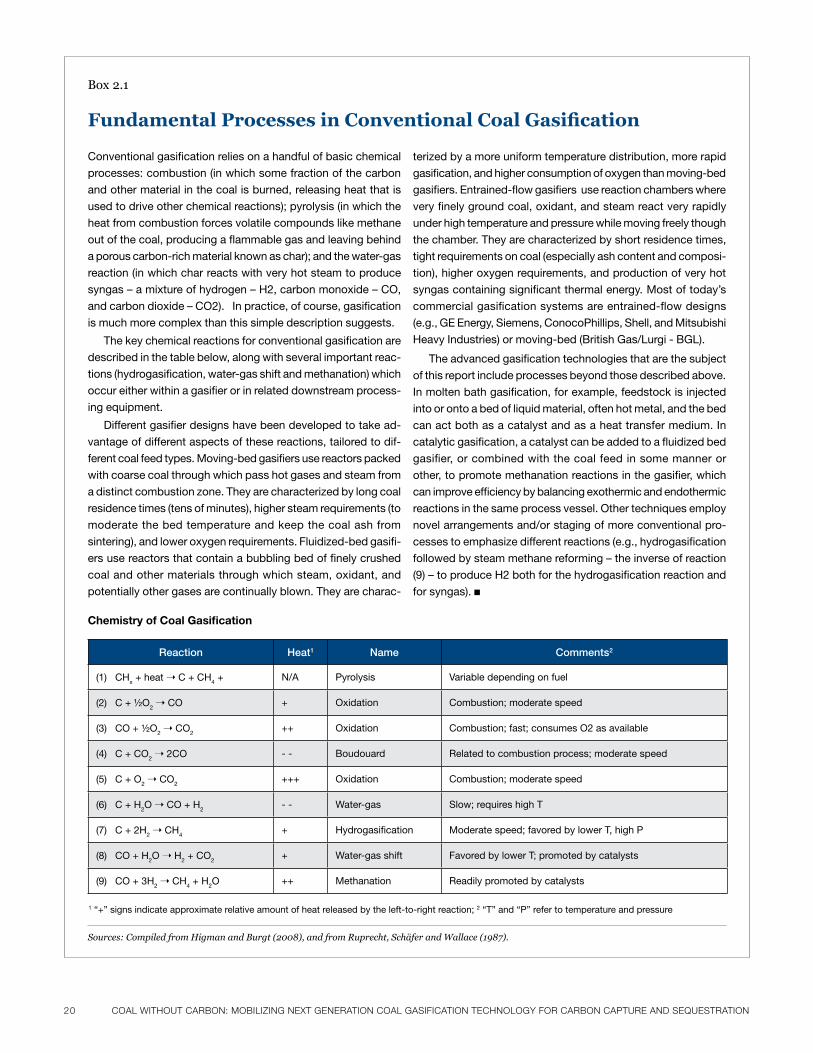
20 CoaL wiThouT CarBoN: moBiLiziNg NexT geNeraTioN CoaL gaSiFiCaTioN TeChNoLogy For CarBoN CaPTure aNd SeQueSTraTioN CoaL wiThouT CarBoN: moBiLiziNg NexT geNeraTioN CoaL gaSiFiCaTioN TeChNoLogy For CarBoN CaPTure aNd SeQueSTraTioN 21
Chemistry of Coal Gasification
Reaction Heat1 Name Comments2
(1) Chx + heat ➝ C + Ch4 + n/a pyrolysis variable depending on fuel
(2) C + ½o2 ➝ Co + oxidation Combustion; moderate speed
(3) Co + ½o2 ➝ Co2++ oxidation Combustion; fast; consumes o2 as available
(4) C + Co2 ➝ 2Co - - boudouard related to combustion process; moderate speed
(5) C + o2 ➝ Co2+++ oxidation Combustion; moderate speed
(6) C + h2o ➝ Co + h2- - Water-gas slow; requires high t
(7) C + 2h2 ➝ Ch4+ hydrogasification moderate speed; favored by lower t, high p
(8) Co + h2o ➝ h2 + Co2+ Water-gas shift favored by lower t; promoted by catalysts
(9) Co + 3h2 ➝ Ch4 + h2o ++ methanation readily promoted by catalysts
1 “+” signs indicate approximate relative amount of heat released by the left-to-right reaction; 2 “t” and “p” refer to temperature and pressure
Box2.1
Fundamental Processes in Conventional Coal Gasification
Sources: Compiled from Higman and Burgt (2008), and from Ruprecht, Schäfer and Wallace (1987).
Conventional gasification relies on a handful of basic chemical
processes: combustion (in which some fraction of the carbon
and other material in the coal is burned, releasing heat that is
used to drive other chemical reactions); pyrolysis (in which the
heat from combustion forces volatile compounds like methane
out of the coal, producing a flammable gas and leaving behind
a porous carbon-rich material known as char); and the water-gas
reaction (in which char reacts with very hot steam to produce
syngas – a mixture of hydrogen – h2, carbon monoxide – Co,
and carbon dioxide – Co2). in practice, of course, gasification
is much more complex than this simple description suggests.
the key chemical reactions for conventional gasification are
described in the table below, along with several important reac-
tions (hydrogasification, water-gas shift and methanation) which
occur either within a gasifier or in related downstream process-
ing equipment.
Different gasifier designs have been developed to take ad-
vantage of different aspects of these reactions, tailored to dif-
ferent coal feed types. moving-bed gasifiers use reactors packed
with coarse coal through which pass hot gases and steam from
a distinct combustion zone. they are characterized by long coal
residence times (tens of minutes), higher steam requirements (to
moderate the bed temperature and keep the coal ash from
sintering), and lower oxygen requirements. fluidized-bed gasifi-
ers use reactors that contain a bubbling bed of finely crushed
coal and other materials through which steam, oxidant, and
potentially other gases are continually blown. they are charac-
terized by a more uniform temperature distribution, more rapid
gasification, and higher consumption of oxygen than moving-bed
gasifiers. Entrained-flow gasifiers use reaction chambers where
very finely ground coal, oxidant, and steam react very rapidly
under high temperature and pressure while moving freely though
the chamber. they are characterized by short residence times,
tight requirements on coal (especially ash content and composi-
tion), higher oxygen requirements, and production of very hot
syngas containing significant thermal energy. most of today’s
commercial gasification systems are entrained-flow designs
(e.g., GE Energy, siemens, Conocophillips, shell, and mitsubishi
heavy industries) or moving-bed (british Gas/lurgi - bGl).
the advanced gasification technologies that are the subject
of this report include processes beyond those described above.
in molten bath gasification, for example, feedstock is injected
into or onto a bed of liquid material, often hot metal, and the bed
can act both as a catalyst and as a heat transfer medium. in
catalytic gasification, a catalyst can be added to a fluidized bed
gasifier, or combined with the coal feed in some manner or
other, to promote methanation reactions in the gasifier, which
can improve efficiency by balancing exothermic and endothermic
reactions in the same process vessel. other techniques employ
novel arrangements and/or staging of more conventional pro-
cesses to emphasize different reactions (e.g., hydrogasification
followed by steam methane reforming – the inverse of reaction
(9) – to produce h2 both for the hydrogasification reaction and
for syngas). ■
CoaL wiThouT CarBoN: moBiLiziNg NexT geNeraTioN CoaL gaSiFiCaTioN TeChNoLogy For CarBoN CaPTure aNd SeQueSTraTioN 21
technology is in use at the Puertollano IGCC plant
in Spain. A new IGCC plant based on GE’s technol-
ogy is also under construction in Indiana. There
are other IGCC installations as well, using heavy
liquidhydrocarbonfeedstocks(e.g.,theGE-based
IGCCsystemsattheSarluxandISABrefineriesin
ItalyandtheShell-basedIGCCsystemattheAGIP
SannazzarorefineryinItaly),andsignificantnon-
IGCC gasification installations (including the
DakotaGasificationCompany’ssubstitutenatural
gas production facility in Beulah, North Dakota,
whichusesLurgi gasifiers).Kellogg,Brownand
Root’stransportreactorintegratedgasifier(KBR’s
TRIG),whichhasundergoneextensivedevelop-
ment at the DOE/EPRI/Southern Co.-funded
Power Systems Development Facility in Alabama,
may also soon move into the commercial market
with an IGCC project in Kemper County, Missis-
sippithatincludesintegratedCCS.(Box2.2pro-
videsashorthistoryofgasificationtechnology.)
Recently several additional technologies offering
potentialincrementalimprovementsoverexisting
gasification technology for some feedstocks or
applications have entered the marketplace. These
technologies include the Siemens, East China
University (ECUST) and Chinese Thermal Power
ResearchInstitute(TPRI)entrainedflowoxygen-
blowngasifiersandtheMitsubishiHeavyIndus-
tries (MHI) gasifier (which can be operated in
eitheran“air-blown”or“oxygen-blown”configu-
ration).SeveraloftheSiemensgasifiershavebeen
soldforcommercialuseinnon-powerapplications,
and several power projects based on the Siemens
technologyareunderdevelopment(Siemens,2007
and2008).A250MWIGCCprojectusingtheMHI
coalgasificationtechnologyhasbeenoperatingfor
about a year in Nakoso, Japan (Clean Coal Power,
2008).TheLurgiseriesoffixed-bedsteam-oxygen
gasifiers, which has been deployed successfully
around the world for many years, has also been
improved and upgraded (Envirotherm, 2003).
Although these improved technologies are impor-
tant, they suffer some of the same cost and per-
formance hurdles as their predecessors in the role
of power production.
Incontrast,theadvancedgasificationtechnolo-
gies addressed in this chapter may offer poten-
tially significant advantages in terms of system
cost, performance (including reliability and feed-
stock flexibility) and simplicity, among other
virtues. As a result, these technologies — none of
which have been developed at commercial scale
—couldprovide a step-change improvement in
thecostandperformanceofcoalgasificationsys-
temsand could thus accelerate andexpand low
carbon power production from coal and other
carbonaceous feed stocks.
Thetechnologiesprofiledinthischapterare:
■ Bluegas from GreatPoint Energy — a method
for producing substitute natural gas directly
from coal and other carbonaceous materials us-
inga singlefluidizedbedgasifierwithanen-
trained catalyst
■ Calderon Process from Energy Independence of
America Corporation — a method for produc-
ingdualstreamsofcleansynthesisgas(or“syn-
gas”) — one hydrogen-rich, one carbon
monoxide-rich—fromstagedpyrolysisofcoal
and other carbonaceous material followed by
air-blownslagginggasificationofchar
■Viresco Process (formerly the CE-CERT pro-
cess) from Viresco Energy — a method for pro-
ducing syngas for chemicals production and
powergenerationusingthermally-forcedsteam
hydrogasificationofmoist carbonaceous fuels
coupled with steam methane reforming
■ HTHG from ThermoGen Hague — a process for
producingsubstitutenaturalgasfromlow-rank
coalusingveryhightemperaturesteamgasifi-
cationwithoutsignificantoxygen
■HydroMaxfromAlchemix—amethodforpro-
ducing synthesis gas from coal and other car-
bonaceous materials using molten bath
technology adapted from the metal smelting
industry
■ Wiley Process from SynGasCo — a method for
producing synthesis gas from coal and other fu-
elsusingpyrolysis,gasification,andnon-cata-
lytic syngas reforming at moderate temperature
andlowpressurewithouttheadditionofexter-
naloxygen
■Ze-gen—amethodofproducingsynthesisgas
from organic waste and other carbonaceous ma-
terialsusingliquidmetalgasificationtechnolo-
gy drawn from the steel industry
Thereareadditionaladvancedgasificationtech-
nologies that could offer advantages similar to the
technologies noted above. These include NC12
(formerlyTexasSyngas,amoltenbathgasification
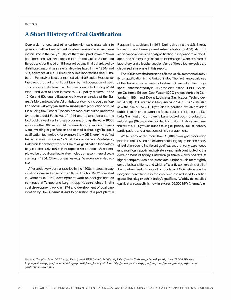
22 CoaL wiThouT CarBoN: moBiLiziNg NexT geNeraTioN CoaL gaSiFiCaTioN TeChNoLogy For CarBoN CaPTure aNd SeQueSTraTioN CoaL wiThouT CarBoN: moBiLiziNg NexT geNeraTioN CoaL gaSiFiCaTioN TeChNoLogy For CarBoN CaPTure aNd SeQueSTraTioN 23
Box2.2
A Short History of Coal Gasification
Conversion of coal and other carbon-rich solid materials into
gaseous fuel has been around for a long time and was first com-
mercialized in the early 1900s. at that time, production of ‘town
gas’ from coal was widespread in both the united states and
Europe and continued until the practice was finally displaced by
distributed natural gas several decades later. in the 1920s and
30s, scientists at u.s. bureau of mines laboratories near pitts-
burgh, pennsylvania experimented with the bergius process for
the direct production of liquid fuels by hydrogenation of coal.
this process fueled much of Germany’s war effort during World
War ii and was of keen interest to u.s. policy makers. in the
1940s and 50s coal utilization work was expanded at the bu-
reau’s morgantown, West virginia laboratory to include gasifica-
tion of coal with oxygen and the subsequent production of liquid
fuels using the fischer-tropsch process. authorized under the
synthetic liquid fuels act of 1944 and its amendments, the
total public investment in these programs through the early 1950s
was more than $80 million. at the same time, private companies
were investing in gasification and related technology: texaco’s
gasification technology, for example (now GE Energy), was first
tested at small scale in 1946 at the company’s montebello,
California laboratory; work on shell’s oil gasification technology
began in the early 1950s in Europe; in south africa, sasol em-
ployed lurgi coal gasification technology on a commercial scale
starting in 1954. other companies (e.g., Winkler) were also ac-
tive.
after a relatively dormant period in the 1960s, interest in gas-
ification increased again in the 1970s. the first iGCC operated
in Germany in 1969, development work on coal gasification
continued at texaco and lurgi, krupp koppers joined shell’s
coal development work in 1974 and development of coal gas-
ification by Dow Chemical lead to operation of a pilot plant in
plaquemine, louisiana in 1978. During this time the u.s. Energy
research and Development administration (ErDa) also put
significant emphasis on coal gasification in response to oil short-
ages, and numerous gasification technologies were explored at
laboratory and pilot plant scale. many of those technologies are
discussed elsewhere in this report.
the 1980s saw the beginning of large-scale commercial activ-
ity on gasification in the united states the first large-scale use
of the texaco gasifier was by Eastman Chemical at their king-
sport, tennessee facility in 1983; the joint texaco – Epri – south-
ern California Edison ‘Cool Water’ iGCC project started in Cali-
fornia in 1984; and Dow’s louisiana Gasification technology,
inc. (lGti) iGCC started in plaquemine in 1987. the 1980s also
saw the rise of the u.s. synfuels Corporation, which provided
public investment in synthetic fuels projects (including the Da-
kota Gasification Company’s lurgi-based coal-to-substitute
natural gas (snG) production facility in north Dakota) and saw
the fall of u.s. synfuels due to falling oil prices, lack of industry
participation, and allegations of mismanagement.
While many of the more than 10,000 town gas production
plants in the u.s. left an environmental legacy of tar and heavy
oil pollution due to inefficient gasification, that early experience
(and significant public and private investment) contributed to the
development of today’s modern gasifiers which operate at
higher temperatures and pressures, under much more tightly
controlled conditions, and which efficiently convert almost all of
their carbon feed into useful products and Co2. Generally the
inorganic constituents in the coal feed are reduced to vitrified
(glass-like) slag or ash in today’s gasifiers. Worldwide installed
gasification capacity is now in excess 56,000 mW (thermal). ■
Sources: Compiled from DOE (2007), Sasol (2001), EPRI (2007), Raloff (1985), Gasification Technology Council (2008). Also US DOE Website:
http://fossil.energy.gov/aboutus/history/syntheticfuels_history.html and http://www.fossil.energy.gov/programs/powersystems/gasification/
gasificationpioneer.html
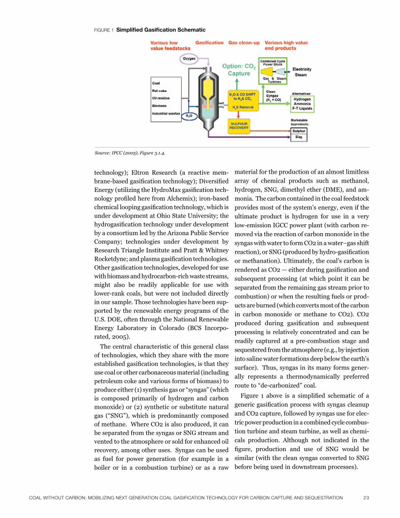
CoaL wiThouT CarBoN: moBiLiziNg NexT geNeraTioN CoaL gaSiFiCaTioN TeChNoLogy For CarBoN CaPTure aNd SeQueSTraTioN 23
technology); Eltron Research (a reactive mem-brane-basedgasificationtechnology);DiversifiedEnergy(utilizingtheHydroMaxgasificationtech-nologyprofiledherefromAlchemix);iron-basedchemicalloopinggasificationtechnology,whichisunder development at Ohio State University; the hydrogasificationtechnologyunderdevelopmentby a consortium led by the Arizona Public Service Company; technologies under development by Research Triangle Institute and Pratt & Whitney Rocketdyne;andplasmagasificationtechnologies.Othergasificationtechnologies,developedforusewithbiomassandhydrocarbon-richwastestreams,might also be readily applicable for use with lower-rankcoals,butwerenot includeddirectlyin our sample. Those technologies have been sup-ported by the renewable energy programs of the U.S. DOE, often through the National Renewable Energy Laboratory in Colorado (BCS Incorpo-rated,2005).
The central characteristic of this general class of technologies, which they share with the more establishedgasificationtechnologies,isthattheyuse coal or other carbonaceous material (including petroleum coke and various forms of biomass) to produceeither(1)synthesisgasor“syngas”(whichis composed primarily of hydrogen and carbon monoxide)or(2)syntheticorsubstitutenaturalgas (“SNG”),which is predominantly composedof methane. Where CO2 is also produced, it can be separated from the syngas or SNG stream and vented to the atmosphere or sold for enhanced oil recovery, among other uses. Syngas can be used as fuel for power generation (for example in a
boiler or in a combustion turbine) or as a raw
material for the production of an almost limitless
array of chemical products such as methanol,
hydrogen, SNG, dimethyl ether (DME), and am-
monia. The carbon contained in the coal feedstock
provides most of the system’s energy, even if the
ultimate product is hydrogen for use in a very
low-emissionIGCCpowerplant(withcarbonre-
movedviathereactionofcarbonmonoxideinthe
syngas with water to form CO2 in a water–gas shift
reaction),orSNG(producedbyhydro-gasification
or methanation). Ultimately, the coal’s carbon is
renderedasCO2—eitherduringgasificationand
subsequent processing (at which point it can be
separated from the remaining gas stream prior to
combustion) or when the resulting fuels or prod-
ucts are burned (which converts most of the carbon
in carbon monoxide or methane to CO2). CO2
produced during gasification and subsequent
processing is relatively concentrated and can be
readily captured at a pre-combustion stage and
sequestered from the atmosphere (e.g., by injection
into saline water formations deep below the earth’s
surface). Thus, syngas in its many forms gener-
ally represents a thermodynamically preferred
routeto“de-carbonized”coal.
Figure 1 above is a simplified schematic of a
genericgasificationprocesswithsyngascleanup
and CO2 capture, followed by syngas use for elec-
tric power production in a combined cycle combus-
tion turbine and steam turbine, as well as chemi-
cals production. Although not indicated in the
figure, production and use of SNG would be
similar (with the clean syngas converted to SNG
before being used in downstream processes).
Source: IPCC (2005), Figure 3.1.4.
Figure 1 simplified Gasification schematic
24 CoaL wiThouT CarBoN: moBiLiziNg NexT geNeraTioN CoaL gaSiFiCaTioN TeChNoLogy For CarBoN CaPTure aNd SeQueSTraTioN CoaL wiThouT CarBoN: moBiLiziNg NexT geNeraTioN CoaL gaSiFiCaTioN TeChNoLogy For CarBoN CaPTure aNd SeQueSTraTioN 25
Carbon Management
The technologies discussed in this chapter range
from “gasification only” processes to complete
coal-to-energysystemsconcepts.Mosthavebeen
under development for many years. As noted
above, the imperative of addressing climate change
requires that commercial application of these
gasification technologies include clear and fully
developed plans for capturing and processing CO2
for sequestration. It is also critical that technology
developersaddresstheintegrationoftheirgasifi-
cation technologies with systems that produce
electricity, natural gas, or other products. In ad-
dition, technology development must include
considerable detail regarding the integration of
carbon capture, processing, and compression as
part of such energy systems. In short, carbon
managementisnotsomethingto“getreal”about
only at some point “down the road”—rather it
should be fully integrated into the process of com-
mercializing these next generation gasification
technologies.Thisviewisreflectedinourrecom-
mendations, which are discussed below.
The Review ProcessInterviews and Surveys
Sevendifferentadvancedgasificationtechnologies
areprofiledinthischapter.Thesearenottheonly
suchtechnologiesinexistence.Rather,theywere
identifiedinsomemanner—eitherthroughthe
personal knowledge of the report authors, via
referencesfromthegasificationfield,orinindus-
try publication or conferences — as having the
potentialtooffersignificantadvantagesoncecom-
mercialized. Although the companies that are
currently developing and nurturing these tech-
nologies face myriad challenges — including seri-
ouscapitalconstraintsthathavebeenexacerbated
by current economic conditions — only one of the
companies we originally approached ultimately
chose not to participate.
The content and recommendations presented
here should be understood in light of the process
usedtodevelopthisreport.Ouraimistobriefly
describe each technology and provide a qualitative
understanding of the RD&D (and other) needs
confronted by this class of technologies in attempt-
ing to reach commercialization. The report authors
researched each technology using publicly avail-
able information and considered historical funding (if any) from DOE. The report authors then devel-oped a questionnaire intended to focus on the development, historical public funding, and cur-rent RD&D needs of each technology, among other data items. A telephone interview with each of the company participants covered these issues in greater detail. These interviews ranged in length and scope, but all followed the general framework of the questionnaire.
Following the interview, all of the companies chose to complete the questionnaire themselves recognizing that it would form the basis for the content in this report. The reasons for this prefer-ence varied, but included concerns about confi-dentiality and the protection of intellectual prop-erty. Similarly, the content of this report neces-sarily has been limited by the simple fact that none of these companies yet knows precisely what a fully developed commercial plant would look like (although some know more than others).
One point emerged clearly from our dialogue with these companies: all of them have strong opinions,experiences,andevidenceaboutwhatisneeded to push their technologies from develop-ment to actual commercialization. Each of the companies we interviewed reviewed this report priortopublication,buttheaccuracyofspecificinformation about individual technologies has not otherwisebeenverified.Aninternaladvisorygroupofexperttechnicalreviewersdidprovideaformof objective peer review. In this way, the report aims to present an accurate overall picture of the stateoftheseadvancedgasificationtechnologiesgenerally, while compiling and synthesizing infor-mation about their RD&D needs as voiced by the companies involved and by expert technical re-viewers. This report should not, however, be construed as providing an independent technical assessmentorevaluationofanyspecifictechnol-ogy— or for thatmatter of any specific claimsregarding a particular technology. Rather, it is intended to provide a roadmap to move this im-
portant suite of technologies forward.
Advanced Gasification ProcessesShortprofilesofthesevenselectedadvancedgas-
ification technologiesare includedbelow.These
profilesarebasedoninformationprovidedbythe
technology development companies during our
CoaL wiThouT CarBoN: moBiLiziNg NexT geNeraTioN CoaL gaSiFiCaTioN TeChNoLogy For CarBoN CaPTure aNd SeQueSTraTioN 25
review process and from various publically avail-
able sources.
Bluegas from GreatPoint Energy
the bluegas process from Greatpoint Energy – called “hy-
dromethanation” – uses a fluidized bed reactor to produce
substitute natural gas (snG, predominantly methane) di-
rectly from carbonaceous material using an integrated set
of thermally-balanced, catalyst-promoted gasification and
methanation reactions. overall thermal efficiency of the
single-step process is expected to be much higher than
more conventional snG production which relies on separate
processing steps for gasification, water-gas shift, and
methanation. Conventional means are available to separate
from the produced methane, Co2, sulfur, and other impuri-
ties, resulting in pipeline quality natural gas. Greatpoint
reports that coal (including power river basin sub-bitumi-
nous), petcoke, and biomass can be used with the pro-
cess.
DoE invested significant resources into the study of
catalytic gasification in the 1970s and 1980s, including
construction of bench-scale reactors in conjunction with
Exxon research and Development. Greatpoint leased a 1-3
ton-per-day (tpd) flex-fuel gasifier at the Gas technology
institute in illinois to perform testing on a range of feed-
stocks. these tests validated the performance character-
istics of the hydromethanation process. since 2003 Great-
point has worked with continued public sponsorship (e.g.,
modest funding from the alberta Energy resources institute
and the massachusetts technology Collaborative) and
private investment (from venture capital firms such as klein-
er perkins and companies such as aEs, Dow Chemical,
peabody Energy, and suncor Energy) and has refined the
technology to produce a commercial process that includes
an improved catalyst recycle system, higher efficiency,
lower capital cost and reduced Co2 footprint. a blueGas
demonstration facility for testing a wide range of feedstocks
has recently entered commercial operation in somerset,
massachusetts, and the company reports that external
technical review indicates the process is ready for scale-up
to commercial application. plans are in place for a com-
mercial demonstration project in China with a large power
company and Greatpoint is investigating other opportunities
in north america.
HydroMax from Alchemix
the hydromax process under commercialization by alche-
mix Corporation uses a molten bath technology adapted
from the metal smelting industry to produce low pressure,
high temperature, moderate-btu syngas from carbonaceous
feeds including high-moisture, low-cost fuels like biomass,
lignite and powder river basin sub-bituminous coal. the
company reports that cold gas efficiency of the gasification
process can be as high as 84 percent for some high-btu
fuels when the company’s proprietary “chemical quench”
(reaction of char and Co2 to produce carbon monoxide) is
used.1 the syngas produced by the process can be cleaned
by conventional processes and used for production of hy-
drogen, substitute natural gas, or chemicals (e.g., methanol).
in the process the molten bath acts as both a heat transfer
medium and an oxygen carrier, splitting water molecules to
produce hydrogen and to convert carbon to carbon mon-
oxide gas. When materials such as petcoke are processed,
metals recovery (e.g., nickel and vanadium) can be signifi-
cant.
the hydromax process has been developed since 2000
by a team including alchemix, pittsburgh mineral and En-
vironmental technology, Commonwealth scientific and
industrial research organization (Csiro, australia’s na-
tional labs), Diversified Energy, and others. the process has
been tested in a 0.3 meter diameter pilot scale bath smelt-
er at Csiro. to complete detailed design for a first com-
mercial plant, a concept for a 1.0 meter diameter pre-com-
mercial demonstration plant has been developed. much
larger bath smelters (e.g., 8 meter diameter) are already in
use in the metal smelting industry. alchemix reports that the
gasification and downstream processing have been mod-
eled using aspen-plus and factsage. recently the technol-
ogy has received two small business innovation research
awards from the DoE’s national Energy technology labo-
ratory (nEtl). in 2005 it was a finalist for a platts Global
Energy award.
Calderon Process from Energy Independence of America Corporation
the Calderon process under commercialization by Energy
independence of america Corporation (EiaC) uses a se-
quence of pyrolysis reactors and hot char gasifiers to pro-
duce two distinct syngas streams — a hydrogen-rich stream
from the pyrolysis reactions and a low-btu stream from the
char gasifiers — with the former suited to methanol or
other chemicals production and the latter suited to power
generation in a combined cycle gas turbine (CCGt). the
technology has grown out of coking and blast furnace ex-
perience in the steel industry. Crushed, run-of-mine coal is
fed without pre-treatment into a horizontal pyrolysis reactor
with small amounts of oxygen followed directly by gasifica-
tion of the hot, porous char in a vertical air-blown slagging
gasifier. the company reports that any type of coal can be
used, and multiple configurations are possible (e.g., electric
power, liquids, snG). EiaC has developed a proprietary
sorbent-based hot gas clean-up technology for use with
their process, and is involved in development of a process
to convert unseparated nitrogen and Co2 in combustion
flue gas into fertilizer.
a pDu with capacity of 10 tons per hour (tph) was oper-
ated (at reduced throughput to conserve funding) in the late
1980s and early 1990s in alliance, ohio, and EiaC reports
that the pyrolysis, char gasification, and solids handling
aspects of the technology were demonstrated there, as was
the proprietary hot-gas cleanup system. Development of
the Calderon process was facilitated by moderate funding
1
There are many measures
of efficiency. in power gen-
eration applications the
overall efficiency of an inte-
grated process, or its in-
verse – the heat rate – is
often used when compar-
ing technologies. overall
efficiency values between
30 percent and 60 percent
are common in different
power generation settings,
with values quoted with
reference either to “hhv” –
higher heating value, repre-
senting all of the heat en-
ergy contained in the fuel
– or “Lhv” – lower heating
value, consisting of hhv
less the heat energy re-
quired to vaporize any
water produced as a result
of fuel combustion. when
gasification systems are
discussed in isolation
often only the “cold gas effi-
ciency” is quoted. Cold gas
efficiency represents the
chemical efficiency of the
gasification process itself
(amount of energy in the
product gas vs. amount of
energy in the feedstock),
and is not directly compa-
rable with overall efficiency
measures because it ex-
cludes the energy inputs to
the gasification process (for
example, steam and com-
pressed, purified oxygen)
and other internal energy
demands (for example,
gas cleanup equipment).
26 CoaL wiThouT CarBoN: moBiLiziNg NexT geNeraTioN CoaL gaSiFiCaTioN TeChNoLogy For CarBoN CaPTure aNd SeQueSTraTioN CoaL wiThouT CarBoN: moBiLiziNg NexT geNeraTioN CoaL gaSiFiCaTioN TeChNoLogy For CarBoN CaPTure aNd SeQueSTraTioN 27
from the federal government and the state of ohio. the
process has been evaluated on a confidential basis by
bechtel Corporation and other commercial entities, and a
conceptual design for a 640 mWe (net) commercial power
plant has been developed.
Wiley Process from SynGasCo
the Wiley process developed by thermal Conversions, inc.
and commercialized by synGasCo utilizes a two-step py-
rolysis and gasification/non-catalytic steam reformation
process at low pressure and moderate temperature to
produce a moderate-btu syngas without the need to supply
external oxygen or air. fuel (especially pet coke or coal) is
fed dry, and steam from an external source is added to
sustain the reactions. syngas is cleaned with a cyclone ash
removal system, a proprietary “ion-water” technology that
results in solid byproduct containing sulfur, mercury, and
other contaminants, and a moisture condensation system.
the company reports that the system has an overall cold
gas efficiency of 70 percent after accounting for syngas
used to produce process heat and steam.
the Wiley process has been developed without public
funds. a pilot plant with 175 tpd design capacity was con-
structed in 2007 in Denver and is now operating as a test
facility at the university of toledo. the unit has used pet-
coke, powder river basin coal, ohio coal, woodchips, and
rice hulls, and can use other moist carbonaceous feedstock.
syngas produced from the process is used to offset natural
gas used in the university’s boiler systems, and technical
evaluation of the process is ongoing, including work by the
university of toledo and DoE-funded work by tss Consul-
tants on behalf of the City of Gridley, California. Commercial
plans for the process include re-powering of smaller, lower-
efficiency boilers in the u.s. coal power fleet.
Ze-gen Process
Ze-gen, inc. has developed a system for gasifying organic
wastes using a molten iron bath produced within a channel
induction furnace of the type commonly used by the steel
industry. feedstock and oxygen are introduced into the
molten bath using submerged lances and moderate-btu
syngas is produced at low pressure. the company reports
that standard syngas cleanup (e.g., particulate removal) can
be used if necessary.
Ze-gen’s technology was developed with minimal pub-
lic support by integrating existing commercial technologies
into a new technology platform, and a large-scale demon-
stration facility is operating in massachusetts. the com-
pany plans to develop this technology into small modules
(250 million btu/hr) that can be used to provide syngas to
existing industrial consumers of natural gas and fuel oil, or
alternatively can be used to provide gas for blending in
natural gas pipeline systems. the economics of the process
represent a synergy between production of energy and
reduced tipping fees for waste management.
Ze-Gen reports that they are evaluating a number of
improvements to their demonstrated process, including
mechanisms to obviate the need for submerged lances and
substitution of a copper bath for an iron bath to reduce
energy requirements. Ze-Gen currently is focusing on bio-
mass and industrial waste stream fuel inputs to produce
syngas for power generation or other uses.
Viresco Process from Viresco Energy
the viresco process couples moderate temperature, mod-
erate pressure steam hydrogasification in a wet slurry fed
reactor with downstream steam methane reformation to
produce syngas with a composition suitable for chemicals
production (e.g., methanol), electricity, or other uses. hy-
drogen for the hydrogasification reactions is extracted from
syngas following reformation, and no external source of
oxygen or hydrogen is used (except during startup). solids
are recycled within the process to increase heat transfer for
the (endothermic) gasification reactions, with a fraction of
the recycled solids combusted along with excess hydrogen
to raise steam for internal power requirements. the com-
pany reports that feed can be any carbonaceous material,
with blends of sub-bituminous coal and wood receiving
recent attention.
Developed since 2003 by the College of Engineering
— Center for Environmental research and technology at
the university of California, riverside (CE-CErt) — using
funding provided by viresco Energy and the City of river-
side, the viresco process has been simulated using aspEn-
plus by DoE under a CraDa. an independent review of the
technology by nEtl (including detailed heat and mass bal-
ances and financial calculations) will be published soon,
and suggests that the viresco process offers an opportu-
nity for increased efficiencies and reduced capital costs
over partial oxidation gasification for certain configurations.
a 2 pound per hour (pph) bench scale kiln reactor and
several batch and drop-down reactors have been used to
test the basic process and to acquire data, as has a fluidized
bed reactor at the Energy & Environmental research Center
at the university of north Dakota. a 10 pph pDu concept
is under development, and a 20 tpd pilot plant is proposed
for alton, utah.
HTHG Process from ThermoGen Hague
thermoGen hague’s high temperature hydrogasification
(hthG) process uses very high temperature steam raised
in a hydrogen-fired furnace to convert carbonaceous feeds,
especially reactive material like power river basin sub-bi-
tuminous coal, into hydrogen-rich syngas followed by hy-
drogasification to produce substitute natural gas. in one of
its configurations, the process uses two moderate-pressure,
moderate-temperature reactors in series, with hydrogen
provided to the second (hydrogasification) reactor (and a
boiler for raising steam) from shifted syngas produced in
the first reactor. Coal is pulverized and is fed dry into the
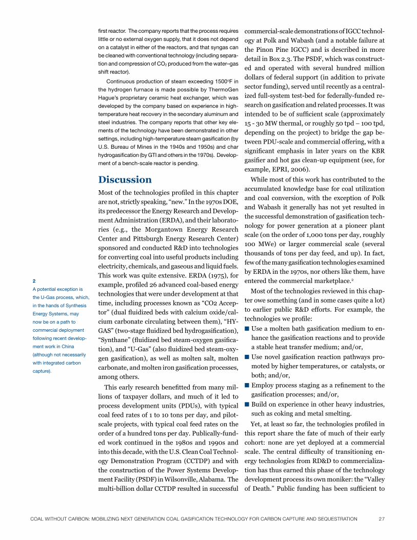
CoaL wiThouT CarBoN: moBiLiziNg NexT geNeraTioN CoaL gaSiFiCaTioN TeChNoLogy For CarBoN CaPTure aNd SeQueSTraTioN 27
first reactor. the company reports that the process requires
little or no external oxygen supply, that it does not depend
on a catalyst in either of the reactors, and that syngas can
be cleaned with conventional technology (including separa-
tion and compression of Co2 produced from the water–gas
shift reactor).
Continuous production of steam exceeding 1500of in
the hydrogen furnace is made possible by thermoGen
hague’s proprietary ceramic heat exchanger, which was
developed by the company based on experience in high-
temperature heat recovery in the secondary aluminum and
steel industries. the company reports that other key ele-
ments of the technology have been demonstrated in other
settings, including high-temperature steam gasification (by
u.s. bureau of mines in the 1940s and 1950s) and char
hydrogasification (by Gti and others in the 1970s). Develop-
ment of a bench-scale reactor is pending.
DiscussionMostofthetechnologiesprofiledinthischapter
arenot,strictlyspeaking,“new.”Inthe1970sDOE,
its predecessor the Energy Research and Develop-
ment Administration (ERDA), and their laborato-
ries (e.g., the Morgantown Energy Research
Center and Pittsburgh Energy Research Center)
sponsored and conducted R&D into technologies
for converting coal into useful products including
electricity, chemicals, and gaseous and liquid fuels.
Thisworkwasquiteextensive.ERDA(1975),for
example,profiled26advancedcoal-basedenergy
technologies that were under development at that
time,includingprocessesknownas“CO2Accep-
tor”(dualfluidizedbedswithcalciumoxide/cal-
ciumcarbonatecirculatingbetweenthem),“HY-
GAS”(two-stagefluidizedbedhydrogasification),
“Synthane”(fluidizedbedsteam-oxygengasifica-
tion),and“U-Gas”(alsofluidizedbedsteam-oxy-
gengasification), aswell asmolten salt,molten
carbonate,andmoltenirongasificationprocesses,
among others.
Thisearlyresearchbenefittedfrommanymil-
lions of taxpayer dollars, andmuch of it led to
process development units (PDUs), with typical
coalfeedratesof1to10tonsperday,andpilot-
scale projects, with typical coal feed rates on the
orderofahundredtonsperday.Publically-fund-
edwork continued in the 1980s and 1990s and
into this decade, with the U.S. Clean Coal Technol-
ogy Demonstration Program (CCTDP) and with
the construction of the Power Systems Develop-
ment Facility (PSDF) in Wilsonville, Alabama. The
multi-billiondollarCCTDPresultedinsuccessful
commercial-scaledemonstrationsofIGCCtechnol-
ogy at Polk and Wabash (and a notable failure at
the Pinon Pine IGCC) and is described in more
detailinBox2.3.ThePSDF,whichwasconstruct-
ed and operated with several hundred million
dollars of federal support (in addition to private
sector funding), served until recently as a central-
izedfull-systemtest-bedforfederally-fundedre-
searchongasificationandrelatedprocesses.Itwas
intendedtobeofsufficientscale(approximately
15-30MWthermal,orroughly50tpd–100tpd,
depending on the project) to bridge the gap be-
tweenPDU-scaleandcommercialoffering,witha
significant emphasis in later years on the KBR
gasifierandhotgasclean-upequipment(see,for
example,EPRI,2006).
While most of this work has contributed to the
accumulated knowledge base for coal utilization
and coal conversion,with the exceptionofPolk
and Wabash it generally has not yet resulted in
thesuccessfuldemonstrationofgasificationtech-
nology for power generation at a pioneer plant
scale(ontheorderof1,000tonsperday,roughly
100 MWe) or larger commercial scale (several
thousands of tons per day feed, and up). In fact,
fewofthemanygasificationtechnologiesexamined
byERDAinthe1970s,norotherslikethem,have
entered the commercial marketplace.2
Most of the technologies reviewed in this chap-
ter owe something (and in some cases quite a lot)
to earlier public R&D efforts. For example, the
technologiesweprofile:
■Useamoltenbathgasificationmediumtoen-
hancethegasificationreactionsandtoprovide
a stable heat transfer medium; and/or,
■Usenovelgasificationreactionpathwayspro-
moted by higher temperatures, or catalysts, or
both; and/or,
■Employprocessstagingasarefinementtothe
gasificationprocesses;and/or,
■Buildonexperienceinotherheavyindustries,
such as coking and metal smelting.
Yet,atleastsofar,thetechnologiesprofiledin
this report share the fate of much of their early
cohort: none are yet deployed at a commercial
scale. The central difficulty of transitioning en-
ergy technologies from RD&D to commercializa-
tion has thus earned this phase of the technology
developmentprocessitsownmoniker:the“Valley
ofDeath.”Public fundinghasbeen sufficient to
2
a potential exception is
the u-Gas process, which,
in the hands of synthesis
Energy systems, may
now be on a path to
commercial deployment
following recent develop-
ment work in China
(although not necessarily
with integrated carbon
capture).
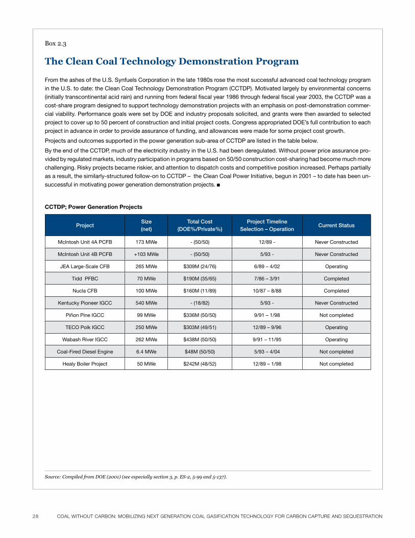
28 CoaL wiThouT CarBoN: moBiLiziNg NexT geNeraTioN CoaL gaSiFiCaTioN TeChNoLogy For CarBoN CaPTure aNd SeQueSTraTioN CoaL wiThouT CarBoN: moBiLiziNg NexT geNeraTioN CoaL gaSiFiCaTioN TeChNoLogy For CarBoN CaPTure aNd SeQueSTraTioN 29
from the ashes of the u.s. synfuels Corporation in the late 1980s rose the most successful advanced coal technology program
in the u.s. to date: the Clean Coal technology Demonstration program (CCtDp). motivated largely by environmental concerns
(initially transcontinental acid rain) and running from federal fiscal year 1986 through federal fiscal year 2003, the CCtDp was a
cost-share program designed to support technology demonstration projects with an emphasis on post-demonstration commer-
cial viability. performance goals were set by DoE and industry proposals solicited, and grants were then awarded to selected
project to cover up to 50 percent of construction and initial project costs. Congress appropriated DoE’s full contribution to each
project in advance in order to provide assurance of funding, and allowances were made for some project cost growth.
projects and outcomes supported in the power generation sub-area of CCtDp are listed in the table below.
by the end of the CCtDp, much of the electricity industry in the u.s. had been deregulated. Without power price assurance pro-
vided by regulated markets, industry participation in programs based on 50/50 construction cost-sharing had become much more
challenging. risky projects became riskier, and attention to dispatch costs and competitive position increased. perhaps partially
as a result, the similarly-structured follow-on to CCtDp – the Clean Coal power initiative, begun in 2001 – to date has been un-
successful in motivating power generation demonstration projects. ■
Box2.3
The Clean Coal Technology Demonstration Program
CCtDp; power Generation projects
ProjectSize(net)
Total Cost (DOE%/Private%)
Project TimelineSelection – Operation
Current Status
mcintosh unit 4a pCfb 173 mWe - (50/50) 12/89 - never Constructed
mcintosh unit 4b pCfb +103 mWe - (50/50) 5/93 - never Constructed
JEa large-scale Cfb 265 mWe $309m (24/76) 6/89 – 4/02 operating
tidd pfbC 70 mWe $190m (35/65) 7/86 – 3/91 Completed
nucla Cfb 100 mWe $160m (11/89) 10/87 – 8/88 Completed
kentucky pioneer iGCC 540 mWe - (18/82) 5/93 - never Constructed
piñon pine iGCC 99 mWe $336m (50/50) 9/91 – 1/98 not completed
tECo polk iGCC 250 mWe $303m (49/51) 12/89 – 9/96 operating
Wabash river iGCC 262 mWe $438m (50/50) 9/91 – 11/95 operating
Coal-fired Diesel Engine 6.4 mWe $48m (50/50) 5/93 – 4/04 not completed
healy boiler project 50 mWe $242m (48/52) 12/89 – 1/98 not completed
Source: Compiled from DOE (2001) (see especially section 3, p. ES-2, 5-99 and 5-137).
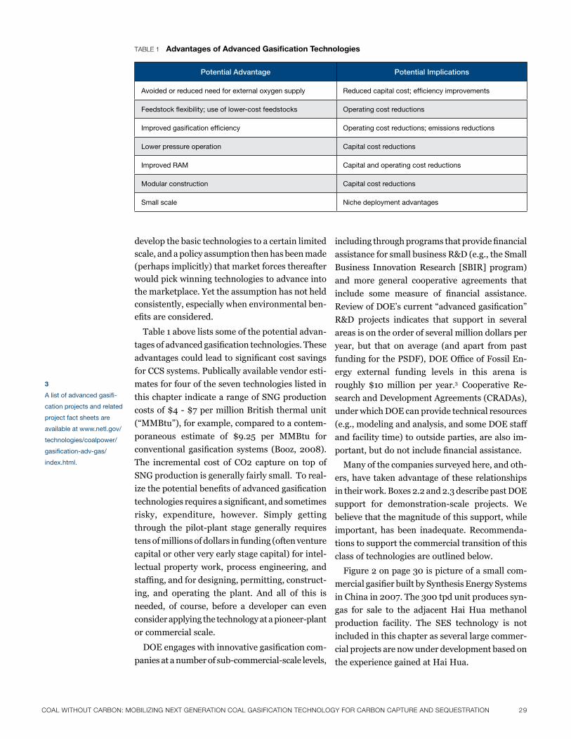
CoaL wiThouT CarBoN: moBiLiziNg NexT geNeraTioN CoaL gaSiFiCaTioN TeChNoLogy For CarBoN CaPTure aNd SeQueSTraTioN 29
develop the basic technologies to a certain limited
scale, and a policy assumption then has been made
(perhaps implicitly) that market forces thereafter
would pick winning technologies to advance into
the marketplace. Yet the assumption has not held
consistently, especially when environmental ben-
efitsareconsidered.
Table 1 above lists some of the potential advan-
tagesofadvancedgasificationtechnologies.These
advantagescouldleadtosignificantcostsavings
for CCS systems. Publically available vendor esti-
mates for four of the seven technologies listed in
this chapter indicate a range of SNG production
costsof$4-$7permillionBritishthermalunit
(“MMBtu”),forexample,comparedtoacontem-
poraneous estimate of $9.25 per MMBtu for
conventional gasification systems (Booz, 2008).
The incremental cost of CO2 capture on top of
SNG production is generally fairly small. To real-
izethepotentialbenefitsofadvancedgasification
technologiesrequiresasignificant,andsometimes
risky, expenditure, however. Simply getting
through the pilot-plant stage generally requires
tens of millions of dollars in funding (often venture
capital or other very early stage capital) for intel-
lectual property work, process engineering, and
staffing,andfordesigning,permitting,construct-
ing, and operating the plant. And all of this is
needed, of course, before a developer can even
considerapplyingthetechnologyatapioneer-plant
or commercial scale.
DOEengageswithinnovativegasificationcom-
paniesatanumberofsub-commercial-scalelevels,
includingthroughprogramsthatprovidefinancial
assistance for small business R&D (e.g., the Small
Business Innovation Research [SBIR] program)
and more general cooperative agreements that
include some measure of financial assistance.
ReviewofDOE’scurrent“advancedgasification”
R&D projects indicates that support in several
areas is on the order of several million dollars per
year, but that on average (and apart from past
fundingforthePSDF),DOEOfficeofFossilEn-
ergy external funding levels in this arena is
roughly $10million per year.3 Cooperative Re-
search and Development Agreements (CRADAs),
under which DOE can provide technical resources
(e.g., modeling and analysis, and some DOE staff
and facility time) to outside parties, are also im-
portant,butdonotincludefinancialassistance.
Many of the companies surveyed here, and oth-
ers, have taken advantage of these relationships
intheirwork.Boxes2.2and2.3describepastDOE
support for demonstration-scale projects. We
believe that the magnitude of this support, while
important, has been inadequate. Recommenda-
tions to support the commercial transition of this
class of technologies are outlined below.
Figure2onpage30ispictureofasmallcom-
mercialgasifierbuiltbySynthesisEnergySystems
inChinain2007.The300tpdunitproducessyn-
gas for sale to the adjacent Hai Hua methanol
production facility. The SES technology is not
included in this chapter as several large commer-
cial projects are now under development based on
theexperiencegainedatHaiHua.
3
a list of advanced gasifi-
cation projects and related
project fact sheets are
available at www.netl.gov/
technologies/coalpower/
gasification-adv-gas/
index.html.
Potential Advantage Potential Implications
avoided or reduced need for external oxygen supply reduced capital cost; efficiency improvements
feedstock flexibility; use of lower-cost feedstocks operating cost reductions
improved gasification efficiency operating cost reductions; emissions reductions
lower pressure operation Capital cost reductions
improved ram Capital and operating cost reductions
modular construction Capital cost reductions
small scale niche deployment advantages
TaBLe 1 Advantages of Advanced Gasification technologies
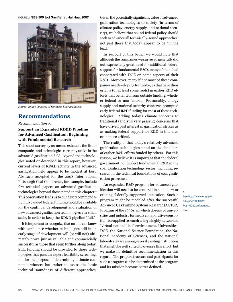
30 CoaL wiThouT CarBoN: moBiLiziNg NexT geNeraTioN CoaL gaSiFiCaTioN TeChNoLogy For CarBoN CaPTure aNd SeQueSTraTioN CoaL wiThouT CarBoN: moBiLiziNg NexT geNeraTioN CoaL gaSiFiCaTioN TeChNoLogy For CarBoN CaPTure aNd SeQueSTraTioN 31
RecommendationsRecommendation #1
Support an Expanded RD&D Pipeline
for Advanced Gasification, Beginning
with Fundamental Research
Thisshortsurveybynomeansexhauststhelistof
companies and technologies currently active in the
advancedgasificationfield.Beyondthetechnolo-
gies noted or described in this report, however,
current levels of RD&D activity in the advanced
gasification field appear to be modest at best.
Abstracts accepted for the 2008 International
PittsburghCoalConference,forexample,include
few technical papers on advanced gasification
technologies beyond those noted in this chapter.4
Thisobservationleadsustoourfirstrecommenda-
tion:Expandedfederalfundingshouldbeavailable
for the continual development and evaluation of
newadvancedgasificationtechnologiesatasmall
scale,inordertokeeptheRD&Dpipeline“full.”
It is important to recognize that no one can know
withconfidencewhether technologies still inan
early stage of development will (or will not) ulti-
mately prove just as valuable and commercially
successful as those that seem further along today.
Still, funding should be provided to those tech-
nologiesthatpassanexpertfeasibilityscreening,
not for the purpose of determining ultimate eco-
nomic winners but rather to assess the basic
technical soundness of different approaches.
Figure 2 sEs 300 tpd Gasifier at hai hua, 2007 Giventhepotentiallysignificantvalueofadvanced
gasification technologies to society (in terms of
climate policy, energy supply, and national secu-
rity), we believe that sound federal policy should
seektoadvancealltechnically-soundapproaches,
not just those that today appear to be “in the
lead.”
In support of this belief, we would note that
although the companies we surveyed generally did
notexpressanygreatneedforadditionalfederal
support for fundamental R&D, many of them had
cooperated with DOE on some aspects of their
R&D. Moreover, many if not most of these com-
panies are developing technologies that have their
origins (or at least some roots) in earlier R&D ef-
fortsthatbenefitedfromoutsidefunding,wheth-
er federal or non-federal. Presumably, energy
supply and national security concerns prompted
early federal R&D funding for most of these tech-
nologies. Adding today’s climate concerns to
traditional (and still very present) concerns that
havedrivenpastinterestingasificationstrikesus
as making federal support for R&D in this area
even more critical.
The reality is that today’s relatively advanced
gasificationtechnologiesstandontheshoulders
of earlier R&D efforts funded by others. For this
reason, we believe it is important that the federal
government not neglect fundamental R&D in the
coalgasificationtechnologysector,includingre-
searchinthetechnicalfoundationsofcoalgasifi-
cation processes.
AnexpandedR&Dprogramforadvancedgas-
ificationwillneedtobecenteredinsomenewor
existing federally-supported institution. Such a
program might be modeled after the successful
Advanced Gas Turbine Systems Research (AGTSR)
Programofthe1990s,inwhichdozensofuniver-
sities and industry formed a collaborative consor-
tium for applied research using a highly networked
“virtualnational lab”environment.Universities,
DOE, the National Science Foundation, the Na-
tional Academy of Sciences, and the national
laboratoriesareamongseveralexistinginstitutions
that might be well suited to oversee this effort, but
we make no definitive recommendation in this
regard. The proper structure and participants for
such a program can be determined as the program
anditsmissionbecomebetterdefined.
Source: Image Courtesy of Synthesis Energy Systems
4
see http://www.engr.pitt.
edu/pcc/2008%20
past%20Conferences.
html.
CoaL wiThouT CarBoN: moBiLiziNg NexT geNeraTioN CoaL gaSiFiCaTioN TeChNoLogy For CarBoN CaPTure aNd SeQueSTraTioN 31
Our review also indicates that many technology
developers have not thoroughly evaluated the
actual engineering implications (for example,
detailed energy and material balances), economics,
and CO2 implications (not to mention other envi-
ronmentalimpacts)ofactualcommercialconfigu-
rations based on their technology. Rather, they
havenecessarily and appropriately focusedfirst
on the core science, particularly the chemistry of
their processes, and on reducing that science to
practice. Conducting additional analyses is costly
for small companies, and therefore difficult to
justify, especially for commercial configurations
thatmight seem superfluous during early-stage
evaluations. Yet these analyses are indispensable
for assessing the potential advantages and applica-
tions of these technologies and their associated
costs, and for moving these technologies to mar-
ket.
Given the critical need for this information, and
the low cost of producing it (relative to overall U.S.
energy program budgets) we recommend generous
support for process engineering and related
analyses — perhaps hosted within an organization
such as NETL — for all technology development
firmswillingtoengageinsuchevaluations.Provid-
ing assistance with standardized modeling tools
would constitute a critical component of this sup-
port, because it would enable developers to know
and objectively state the relative efficiency and
economics of their technology. While existing
programs at DOE provide some of this support
through CRADAs, funding for these programs
couldbeexpanded.
Finally, shared demonstration units may be one
way to increase the cost-effectiveness of public
RD&D spending while also eliminating redundan-
cies in plant buildup for technologies that incor-
porate similar plant components. The existing
PSDF in Alabama represented a step in this direc-
tion. Its initial use focused on both pressurized
fluid bed combustion and gasification system
technology, but in recent years its use has gener-
allyfocusedontheTRIGgasifierandonthede-
velopment of downstream processing equipment
(e.g.,hotgasfilters).5 Activity at the facility is cur-
rently being refocused as it becomes home to DOE’s
new National Carbon Capture Center, however,
and the mission of the PSDF is moving away from
gasificationresearch.6Priortothisshift,expand-
edfull-systemtest-bedcapacitybeyondthePSDF
likely would have been required in order to provide
timely,flexibleaccessforsmallertechnologyfirms
astheymovefromthebench-scaleproof-of-con-
ceptstagetodevelopingpilot-scaleoperatingunits,
andthenontopre-commercialsystemvalidation.
With PSDF’s mission changing, this need is even
more critical.
Anexpandedprogramofthetypedescribedhere
mightrequirefundingofroughly50milliondollars
per year for aperiodof 5 to 10 years, over and
abovecurrentexpendituresbyDOE.Asmallfrac-
tionofthissupportwouldaugmentexistingcapac-
ity for assessments and engineering assistance
(perhaps $5 million per year for DOE staff and
contractor services), while the majority of the ad-
ditional funding would support construction and
operation of one or more shared user facilities for
advancedgasificationsystemsdevelopment.
Recommendation #2
Establish a Self-Sustaining
“First Commercial Projects” Fund
Without a doubt, the most critical problem facing
newtechnologiesisthis:Withfewexceptions,and
regardless of the other impediments to commercial
deployment they may face, companies can’t de-
velop their first commercial-scale projects en-
tirely with equity investment or debt from private
sources. Public sector dollars and venture capital
investments may have funded technology develop-
mentfromlaboratory-throughpilot-scaledevelop-
ment. Private equity and project finance debt
capital markets historically have been available to
fund projects and manufacturing facilities once
technologies are commercially proven. But few, if
any, promising technologies in the gasification
sector that have been proven at pilot scale are able
tosecurefinancingforcommercial-scaledeploy-
ment. Venture capital and private equity firms
typically make smaller investments and/or require
higher returns than individual energy projects
typically generate, while strategic investment by
large corporations can be hindered by competition
for markets and/or competing funding priorities.
And debt, simply put, generally isn’t available for
riskycommercial-scaleprojectsofanysort.(Box
2.4 provides a brief introduction to the concepts
andterminologyofprojectfinance.)
5
see “project accomplish-
ments” for psDf on the
DoE web site at: http://
fossil.energy.gov/fred/
factsheet.
6
see, for example, south-
ern Company (2007) and
southern Company (2009).
32 CoaL wiThouT CarBoN: moBiLiziNg NexT geNeraTioN CoaL gaSiFiCaTioN TeChNoLogy For CarBoN CaPTure aNd SeQueSTraTioN CoaL wiThouT CarBoN: moBiLiziNg NexT geNeraTioN CoaL gaSiFiCaTioN TeChNoLogy For CarBoN CaPTure aNd SeQueSTraTioN 33
First commercial projects are not necessarily at
maximumscale;oftentheytaketheformofsmall
commercialprojects(e.g.,100MWe)thatcanbe
scaled up at some later point. But even minimum
sizefirstcommercial-scaleprojectsareoftentoo
large to be financed with equity alone (even in
pre-financialcrisistimes).Alltheseminimum-size
firstcommercialprojectswillrequireatleastsome
debt, and in most cases substantial amounts of
debt. Even before the current financial crisis,
limitedornon-recourseprojectdebt isbasically
not available for first commercial projects that
involve new technology and most of the companies
donothaveadequatebalancesheetstoback-stop
theinherentfirst-moverrisks.
This need for project debt, and the fact that it is
unavailable, creates the well-known “Valley of
Death”problemfortechnologiesforwhichcom-
mercial-scaledemonstrationrequiresafacilitythat
is sufficiently large to (1) achieve evenminimal
economies of scale and (2) provide adequate en-
gineering and economic data upon which to base
subsequent, fully commercial projects. This prob-
lemdoesnotconfronttechnologieswherethefirst
commercialprojectcanbebuiltata sufficiently
small scale so as not to require any debt. Advanced
gasificationtechnologies,however,almostuniver-
sally need proving out at sizes that require hun-
dreds of millions of dollars (or more) of capital.
Norisittheproblemofgenerallackoffinancing
for all large projects (proven technology or not)
since the recentfinancial crisis developed. The
“first commercialproject”problem is specific to
newtechnologies(whetherinvolvinggasification
or other processes) where the minimum commer-
cial-scaleprojectistoobigtobebuiltwithequity
alone.
Equity investors can be persuaded to take risks,
based on their own due diligence. They have the
opportunity to participate in upside gains if the
new technology is successful. Lenders generally
cannot be persuaded to take any of the risks that
equity investors take — or indeed any risks at all
that they can avoid. The reason, of course, is that
lenders do not participate in any upside gains even
if a project is wildly successful. All the lenders get,
at best, is a return of the principal amount of their
loan, plus the agreed rate of interest. They are in
the business of earning predictably safe, if modest,
returns.Theydonottakeriskonfirstcommercial
projects.
Mostoftheadvancedgasificationtechnologies
we surveyed will need funding from some other
source than equity investors to build their first
commercial projects. One solution, of course, is to
gainaccesstodebtfinancingbyhavingsomethird-
party entity guarantee the lenders that the debt
will be repaid regardless of the project’s perfor-
mance. Such a guarantee can come from the eq-
uity investors themselves, but in that case the
guaranteed amount is really contingent equity from
an investor’s standpoint. This means that the
projectremainsessentially100percentequityfi-
nanced, from the equity investor’s point of view.
In terms of impacts on project costs, this means
theprojectisnotgaininganyrealcostbenefitfrom
using debt as part of its capital structure.
The federal government in recent years has
enacted its own loan guarantee program for vari-
ous energy technology projects. The program also
effectively allows a direct federal loan in some
circumstances.7 There is a risk, however, that the
federal loan guarantee program could be swallowed
up(orexhausted)bynuclearpowerandrenewable
energy projects alone,8 (although several legislative
initiatives have been proposed that would create
a stand-alone clean energy bank to oversee the
loan guarantee program and add a substantial
focusonfirstcommercializationforabroadarray
ofenergytechnologies).Loanguaranteesforfirst
commercialization and government support for
enabling private equity investment need to be
available—insignificantandreliableincrements
—fornovelcoalgasificationtechnology,notjust
for gasificationprojects that rely on established
technologies and that are already capable of gain-
ing performance guarantees from creditworthy
vendors and manufacturers.
We strongly recommend, as a start, that the
federal loan guarantee program (for commercial
projects)beavailabletoadvancedcoalgasification
technologies at the development stages typical of
the companies and technologies we have surveyed
here. Without that availability — particularly dur-
ingthecurrentfinancialcrisis,but(asnotedabove)
even independent of that crisis — it will be very
difficult,ifnotimpossible,forthesetechnologies
to achieve full commercial deployment. In other
7
under the existing federal
loan guarantee program,
the federal financing
bank can issue direct
loans for up to eighty
percent of project costs
at an applicant’s request.
see 10 C.f.r. 609.2.
8
While the loan guarantee
programs of Epact2005
are essentially technology-
neutral, allocation de-
pends on the federal ap-
propriations process. in
2009, more than 20 billion
dollars were allocated to
nuclear technologies, and
more than 18 billion dol-
lars for renewables, energy
efficiency, and distributed
generation. Coal programs
were allocated 8 billion
dollars.
CoaL wiThouT CarBoN: moBiLiziNg NexT geNeraTioN CoaL gaSiFiCaTioN TeChNoLogy For CarBoN CaPTure aNd SeQueSTraTioN 33
innovation in energy systems requires construction of large
initial projects, and hence “lumpy” investments of hundreds of
millions of dollars or more. like their later counterparts, these
initial projects are generally constructed with some combination
of equity investment (that is, money supplied by individuals and/
or organizations who then own part of the project or the com-
pany developing it) and debt (that is, money that must be repaid
in one way or another). Equity can come from individual invest-
ment groups or from large publically-traded corporations, and
debt is generally provided either directly to the sponsoring com-
pany (for example, through general corporate borrowing or sales
of corporate bonds) or by syndicates of commercial banks pro-
viding financing for development of individual projects. acquir-
ing this financing in the necessary quantities has proven to be a
significant challenge for new technologies, since equity investors
stand to gain if the project is successful, but lose if the project
is not, and loans must be repaid at an agreed interest rate in any
case.
a special type of debt known as “non-recourse” or “limited re-
course” financing has been used extensively for project develop-
ment in the oil and gas industry and has become increasingly
common in the u.s. electricity industry as a result of deregula-
tion. in these arrangements, which are currently the norm for
independent power producers and for snG manufacturing
proposals, new projects are established as special-purpose
companies whose assets are roughly limited to a single project
under development. the project sponsors contribute some
equity (perhaps 20 percent of the project costs), and commercial
banks provide the balance, with recourse in the event of a default
on the loans available only through the assets of the project itself.
project revenues are used to pay principal and interest on the
loan and operating costs.1
Box2.4
Project Finance
this type of project lending does not require the participation of
a large, willing corporate sponsor, but it is far riskier than corpo-
rate lending, since lenders only have one asset, rather than an
entire company’s earnings potential to rely upon. as a result
limited recourse financing is attractive to smaller innovative or-
ganizations and yet difficult in practice to use. in fact, the project
finance debt market is extraordinarily conservative on three dif-
ferent fronts:
■ first, project finance lenders will avoid any meaningful con-
struction risk. they thus often request a full fixed-price turn-
key construction contract from a credit-worthy firm with cash
penalties for delays and performance shortfalls. lenders also
request a major study from an experienced engineering firm
regarding feasibility and constructability of the project. Ex-
perience has shown that these turnkey contracts and un-
equivocal studies are difficult to achieve for a first-of-a-kind
energy plant.
■ second, project finance lenders will avoid any meaningful
technology risk. lenders often have balked at loan requests
for natural gas fired combined cycle generation plants until
the particular turbine model has a demonstrated multi-year
successful operating history in similar applications, for ex-
ample. this hurdle is a serious obstacle for the maiden voy-
age of a particular gasification technology.
■ third, project finance lenders prefer long-term fixed price
contracts for the output of the facility executed with invest-
ment-grade rated customers. thus new projects not only
have to prove the technology to the lender but to potential
“offtake” third parties, who themselves may be hesitant to
enter into any definitive commitment for a first commercial
project. ■
1
more information on loan financing can be found in standard and poor’s (2008).
34 CoaL wiThouT CarBoN: moBiLiziNg NexT geNeraTioN CoaL gaSiFiCaTioN TeChNoLogy For CarBoN CaPTure aNd SeQueSTraTioN CoaL wiThouT CarBoN: moBiLiziNg NexT geNeraTioN CoaL gaSiFiCaTioN TeChNoLogy For CarBoN CaPTure aNd SeQueSTraTioN 35
words,whateverbenefits these technologiescan
bring to society in terms of climate policy, energy
supply, and national security will not be realized
unless the “Valley of Death” problem for new
technologies can be overcome.
The federal loan guarantee program, however,
requireslarge,riskyadvanceexpendituresforap-
plicants. Even where federal appropriations cover
hefty credit subsidy costs, applicants must still
expendmillionsofdollarsinpreliminaryengineer-
ing, site selection, offtake development, and so on
— even to be able to apply. A program designed
to encourage technology innovation would do well
to include some form of bridge mechanism from
thepilot-scaleplanttothefirstcommercialplant,
even before the Valley of Death. This might be
accomplishedviaamoreflexibleloanguarantee
solicitation for very small commercial projects
(where taxpayer risk is smaller)orotherbridge
mechanisms.
Federal loan guarantees are only one possible
tool for helping new technologies reach the com-
mercialdeploymentstageincaseswhereevenfirst
commercial projects must be built on a large scale.
Additional policy support, such as price support
for certain products, cash credits for CO2 captured,
investment and production tax credits, direct
grants, and other mechanisms may all be appropri-
ate and useful in certain instances. These forms
ofsupportcanperhapsbetiedtogoal-basedso-
licitations, similar to earlier CCTDP solicitations.
An even broader approach, however, could make
theunique“firstcommercialprojectproblem”even
more tractable. Since the same problem faces all
newtechnologies(notjustadvancedcoalgasifica-
tion technologies) where the first commercial
project is too large to be built with equity alone,
solutionsneednotbeconfinedtoadvancedcoal
gasificationtechnologies.
As a general premise of energy technology
policy, we believe that the discipline imposed by
private equity and debt financing generally is
necessary for the fruitful development of success-
ful technologies (and for the elimination of un-
competitive ones). As a result, public funds gener-
ally should not be used for technology development
when private funds are available. In the case of
the technologies discussed in this report, however,
thepotential publicbenefits of the technologies
(primarilythepotentialforlower-costCO2reduc-
tions from fossil-fueled power generation) are
likelytoberealizedasprivate-sectorreturnson
investment only following a period of some years
(perhaps even as much as a decade) under a na-
tional climatepolicy thatputsa “price”onCO2
emissions. Under these circumstances, where the
potential returns on investment are some distance
off,butthepublicneedandpotentialbenefitare
much more immediate, substitution of public funds
for private resources is essential — provided that
publicinvestmentdoesnotsacrificethediscipline
of capital market forces.
Tothisend,theconceptofa“FirstCommercial
ProjectFund”or“CleanTechnologyAcceleration
Fund”hasbeenasubjectofstudyintheprivate
financialsectorforsomeyears.Suchafundcould
offer targeted financial support (whether in the
form of direct investment, a tranche of project
debt,aloanguarantee,orother)thatwouldsuffice
toenablefirstcommercialprojectsinvolvingnew
technologies to be built at the necessary scale.
Such a fund obviously would need to attract inves-
tors. It also would need a strong technology as-
sessment capability to assure that it provided
support only to new technologies that are likely to
become commercially successful with the fund’s
help — not to technologies that have failed to at-
tract investment precisely because their odds of
achieving commercial success are too low. And,
especially in the current financial environment,
such a fund will bemore effective as a public-
private partnership.
Again, we make no recommendation as to the
institutional“home”forsuchafund.Variousop-
tions have been proposed. DOE or other institu-
tions already mentioned might make appropriate
homes. Alternatively, the federal government could
establish a new corporate agent — perhaps pat-
terned after the Overseas Private Investment
Corporation(OPIC),whichprovidesfinancialsup-
port (e.g., insurance, loan guarantees, and direct
loans, and support for the creation of privately
owned and managed investment funds) in response
to the critical shortfall of private equity capital in
developing countries.9 Applying a similar model,
a new U.S. corporation would stimulate the cre-
ation of domestically oriented, privately-owned
and managed investment funds focused on provid-
ing critical equity capital that is otherwise unavail-
able forfirstcommercialprojects.Regardlessof
9
opiC typically provides
debt (10–12 year maturi-
ties) to funds while earning
a profit participation com-
ponent. the low-cost
loans provided by opiC
are backed by the full faith
and credit of the u.s.
government and are sold
to u.s.-eligible institutional
investors. for background
on opiC see foreign
assistance act of 1961,
section 231 et seq., as
amended, available at
http://www.opic.gov/.
CoaL wiThouT CarBoN: moBiLiziNg NexT geNeraTioN CoaL gaSiFiCaTioN TeChNoLogy For CarBoN CaPTure aNd SeQueSTraTioN 35
institutional form, a “first commercial project
fund”wouldhaveseveralimportantfeatures:
■Asapublic-privatepartnership,thefundshould
includeseniorgovernmentofficialsaswell as
representativesfromtheprivatefinancial,tech-
nology, and energy policy communities. Feder-
aldollarsshould“leverage”privatedollars,not
take their place, because federal dollars will go
much further if they stimulate the availability
of private dollars. An independent board should
manage the fund according to transparent in-
vestment criteria.
■ To avoid waste, the fund must have a technol-
ogy assessment capability and must focus on
providingonlythe“keystone”necessarytocom-
pletean“arch”ofprivateequityandcapitalmar-
ketdebtforfirstcommercialprojects.Thereason
for this is twofold: First, this approach will make
the federal dollars go further. Second, it will
help weed out technologies that cannot reason-
ablybeexpectedtoattractsufficientcapitalto
achieve commercial deployment even with the
addition of federal support.
■ In return for whatever assistance it provides,
the fund should have the capability and oppor-
tunitytoshareinanyresultingupsidetotheex-
tent possible. The reasons for this are threefold.
First, because taxpayers (ultimately) are the
ones funding the effort, they are entitled to some
form of return on the investment (just as pri-
vate-sectorapplicantsrequiretheassistanceto
make money themselves). Second, government
funding should never replace funding that is
available in the private sector, nor should it be
a cheap alternative to available private sector
funding. Requiring some upside provides some
assurance against either situation. Third, the
fund’s investments inevitably will involve some
risk, which should be coupled with the possibil-
ityofsomerewardtoenablethefundtobeself-
sustaining on a portfolio basis. The upside could
be in the form of equity (project or corporate),
profit-sharingorotherformofagreement(al-
though issues of taxation will require careful
consideration). Ultimately the fund should be
financiallyself-sustainingasreturnsoninvest-
ments revolve to allow for continuing re-
investment.
SummaryIn summary, we make two recommendations.
First, there is a need to ensure that improved
technologies continue to pass through the develop-
ment pipeline as years pass and as our ability to
address carbon emissions becomes all the more
critical.Thismeansexpandedsupportforfunda-
mental research and a substantial public role in
providing the process engineering support, assess-
ments, and hardware development that are
needed as these technologies move through the
pipeline (or are discarded in favor of stronger
candidates). Second, and most importantly, we
recommendthatafirstprojectcommercialization
fund be established to help worthy technologies
bridge the Valley of Death.
Implementing each of these recommendations
will require at least a modest level of public fund-
ing.Weestimatethecostofexpandingtheexisting
RD&D pipeline (our first recommendation) at
roughly$50millionperyearoverandabovecur-
rentfundinglevels.Thepubliccostofafirstcom-
mercial project fund (our second recommendation)
would depend on the details of its structure and
implementation but would likely be serveral billion
dollars.Inanyevent,giventhatthecoalextraction
and transportation industries have much to lose
as a low-carbon future unfolds, and given that
advanced coal utilization technologies will be
needed if coal is to be compatible with that future,
those industries and the coal utility industry would
seem to be a logical source for funding advanced
coal utilization technology. This support might be
provided voluntarily, perhaps in the form of pri-
vate-sectorequityordebtassuranceforinnovative
projects. Or it might be involuntary, perhaps in
theformofalevyusedtofundadvancedgasifica-
tion RD&D and commercialization programs.10 ■
referencesbCs incorporated. 2005. biomass r&D activities. prepared for us
DoE for the federal technical advisory Committee on bio-mass.
booz allen hamilton. 2008. “the Case for synthetic natural Gas.” presented to the september 2008 international pittsburgh Coal Conference, pittsburgh, usa.
Childress, Jim. 2008. “Gasification industry overview: addressing the Dash to Gas.” presented to the Gasification technologies Council, tulsa, oklahoma, usa.
10
there will, of course, be
limits to what can be ac-
complished even with
significant federal funding.
as one anonymous re-
viewer of an early draft of
this report noted: it has
been my personal experi-
ence with inventor/devel-
oper led organizations that
many of them falter be-
cause of internal clashes
between the inventor and
those who are needed to
grow the developing orga-
nization to commercial
demonstration and viabil-
ity. these transitions are
painful and often involve
the transition from intui-
tive/empirical develop-
ment to predictive design
– a transition that taxes
the skills and patience of
many inventor-owners of
the companies promoting
these technologies. this
transitional gap has prov-
en to be difficult for gov-
ernment support to bridge.

36 CoaL wiThouT CarBoN: moBiLiziNg NexT geNeraTioN CoaL gaSiFiCaTioN TeChNoLogy For CarBoN CaPTure aNd SeQueSTraTioN
Clean Coal power r&D Company, ltd., and mitsubishi heavy in-dustries, ltd. 2008. “first Year operation results of CCp’s nakoso 250mW air-blown iGCC Demonstration plant”. pre-sented at the october 2008 Gasification technologies Confer-ence in Washington D.C., usa.
Envirotherm Gmbh. 2003. “operating results of the bGl Gasifier at schwarze pumpe.” presented at the october 2003 Gasifica-tion technologies Conference in Washington D.C., usa.
Epri. 2006. “power systems Development facility: test results 2006.” palo alto, Ca, 1012240.
Epri. 2007. “integrated Gasification Combined Cycle (iGCC) Design Considerations for high availability.” volume 1: lessons from Existing operations. palo alto, Ca.
ErDa. 1975. “Energy from Coal: a state-of-the-art review.” pre-pared for the u.s. Department of Energy by tetra tech, inc.: arlington, va, usa.
Great northern power Development Company and allied syngas Company. 2008. “south heart snG project.” presented at the october 2008 Gasification technologies Conference, Washing-ton D.C., usa.
higman, Christopher and maarten van der burgt. 2008. Gasification. 2 ed. burlington, ma: Gulf professional publishing.
intergovernmental panel on Climate change. 2005. ipCC special report on Carbon Dioxide Capture and storage. Cambridge, uk: Cambridge university press.
mit. 2007. “the future of Coal: an interdisciplinary mit study.” Cambridge, ma: massachusetts institute of technology.
raloff, Janet. 1985. “Washington Deals synfuels a big blow”. science news.128(6): 87 ,
ruprecht, peter, Wolfgang schafer, and paul Wallace. 1988. “a Computer model of Entrained Coal Gasification.”fuel, 67(6): 739-742.
sasol. 2001. “sasol: Continued value addition to Coal through Gasification technology.” presented at the 2001 Gasification technologies Conference, san francisco, Ca, usa.
siemens power Generation. 2007. “siemens to supply Environ-mentally friendly Coal Gasification technology to China.” press release, 19 January 2007.
siemens power Generation. 2008. “siemens Gasification technol-ogy for Canada’s first low-Co2 power plant –Eco-friendly Coal-based power Generation” press release, 18 august 2008.
southern Company services. 2007. “update on Gasification test-ing at the power systems Development facility.” presented at the June 2007 32nd international technical Conference on Coal utilization & fuel systems.
southern Company services. 2009. “southern Company to oper-ate Department of Energy’s national Carbon Capture Center.” press release. 27 may 2009.
standard and poor’s. 2008. a Guide to the loan market. new York, nY: standard and poor’s.
us DoE/nEtl. 2001. Clean Coal technology Demonstration pro-gram: 2001 program update.
us DoE/nEtl. 2007. Cost and performance baseline for fossil Energy plants, august 1, 2007 revision of may 2007 report, volume 1.
us DoE Website. 2009. “pioneering Gasification plants”. us De-partment of Energy, at http://www.fossil.energy.gov/programs/powersystems/gasification/gasificationpioneer.html
us DoE Website. 2009. “the Early Days of Coal research”. us Department of Energy, at http://fossil.energy.gov/aboutus/his-tory/syntheticfuels_history.html
CoaL wiThouT CarBoN: aN rd&d “PiPeLiNe” For advaNCed PoST-ComBuSTioN Co2 CaPTure TeChNoLogieS 37
ChaPTer 3
an rD&D “pipeline” for advanced post-Combustion Co2
Capture technologies
hOwArD hErzOG massaChusEtts institutE of tEChnoloGY
AlAN hAttANmassaChusEtts institutE of tEChnoloGY
JErrY MElDONtufts univErsitY
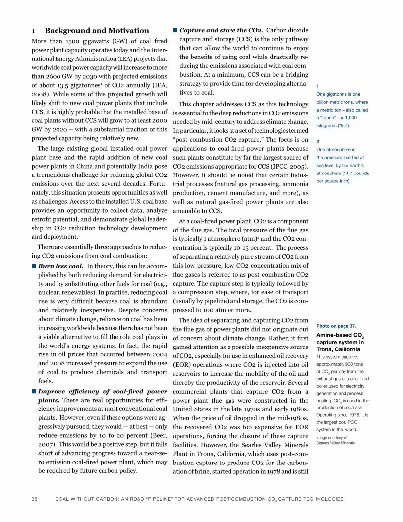
38 CoaL wiThouT CarBoN: aN rd&d “PiPeLiNe” For advaNCed PoST-ComBuSTioN Co2 CaPTure TeChNoLogieS
1 Background and MotivationMore than 1500 gigawatts (GW) of coal firedpower plant capacity operates today and the Inter-national Energy Administration (IEA) projects that worldwide coal power capacity will increase to more than2600GWby2030withprojectedemissionsof about 13.5 gigatonnes1 of CO2 annually (IEA, 2008).Whilesomeof thisprojectedgrowthwilllikely shift to new coal power plants that include CCS, it is highly probable that the installed base of coalplantswithoutCCSwillgrowtoatleast2000GWby2020–withasubstantialfractionofthisprojected capacity being relatively new.
The large existing global installed coal powerplant base and the rapid addition of new coal power plants in China and potentially India pose a tremendous challenge for reducing global CO2 emissions over thenext several decades. Fortu-nately, this situation presents opportunities as well as challenges. Access to the installed U.S. coal base provides an opportunity to collect data, analyze retrofitpotential,anddemonstrategloballeader-ship in CO2 reduction technology development and deployment.
There are essentially three approaches to reduc-
ing CO2 emissions from coal combustion:
n Burn less coal. In theory, this can be accom-plished by both reducing demand for electrici-ty and by substituting other fuels for coal (e.g., nuclear, renewables). In practice, reducing coal use is very difficult because coal is abundantand relatively inexpensive. Despite concernsabout climate change, reliance on coal has been increasing worldwide because there has not been aviablealternativetofilltherolecoalplaysinthe world’s energy systems. In fact, the rapid rise inoil prices that occurredbetween2004and2008increasedpressuretoexpandtheuseof coal to produce chemicals and transport
fuels.
n Improve efficiency of coal-fired power
plants. There are real opportunities for effi-ciency improvements at most conventional coal plants. However, even if these options were ag-gressively pursued, they would — at best — only reduce emissions by 10 to 20 percent (Beer,2007).Thiswouldbeapositivestep,butitfallsshortofadvancingprogresstowardanear-ze-roemissioncoal-firedpowerplant,whichmay
be required by future carbon policy.
n Capture and store the CO2.Carbondioxide
capture and storage (CCS) is the only pathway
that can allow the world to continue to enjoy
thebenefitsofusingcoalwhiledrasticallyre-
ducing the emissions associated with coal com-
bustion. At a minimum, CCS can be a bridging
strategy to provide time for developing alterna-
tives to coal.
This chapter addresses CCS as this technology
is essential to the deep reductions in CO2 emissions
neededbymid-centurytoaddressclimatechange.
In particular, it looks at a set of technologies termed
“post-combustionCO2capture.”Thefocusison
applications to coal-fired power plants because
such plants constitute by far the largest source of
CO2emissionsappropriateforCCS(IPCC,2005).
However, it should be noted that certain indus-
trial processes (natural gas processing, ammonia
production, cement manufacture, and more), as
well as natural gas-fired power plants are also
amenable to CCS.
Atacoal-firedpowerplant,CO2isacomponent
ofthefluegas.Thetotalpressureofthefluegas
is typically 1 atmosphere (atm)2 and the CO2 con-
centrationistypically10-15percent.Theprocess
of separating a relatively pure stream of CO2 from
thislow-pressure,low-CO2-concentrationmixof
fluegasesisreferredtoaspost-combustionCO2
capture. The capture step is typically followed by
a compression step, where, for ease of transport
(usually by pipeline) and storage, the CO2 is com-
pressedto100atmormore.
The idea of separating and capturing CO2 from
thefluegasofpowerplantsdidnotoriginateout
ofconcernaboutclimatechange.Rather, itfirst
gainedattentionasapossibleinexpensivesource
of CO2, especially for use in enhanced oil recovery
(EOR) operations where CO2 is injected into oil
reservoirs to increase the mobility of the oil and
thereby the productivity of the reservoir. Several
commercial plants that capture CO2 from a
power plant flue gas were constructed in the
UnitedStates inthe late1970sandearly1980s.
Whenthepriceofoildroppedinthemid-1980s,
the recovered CO2 was too expensive for EOR
operations, forcing the closure of these capture
facilities. However, the Searles Valley Minerals
PlantinTrona,California,whichusespost-com-
bustion capture to produce CO2 for the carbon-
ation of brine, started operation in 1978 and is still
1
one gigatonne is one
billion metric tons, where
a metric ton – also called
a “tonne” – is 1,000
kilograms (“kg”).
2
one atmosphere is
the pressure exerted at
sea level by the Earth’s
atmosphere (14.7 pounds
per square inch).
photo on page 37.
Amine-based CO2 capture system in trona, California This system captures
approximately 900 tons
of Co2 per day from the
exhaust gas of a coal-fired
boiler used for electricity
generation and process
heating. Co2 is used in the
production of soda ash.
operating since 1978, it is
the largest coal PCC
system in the world.
image courtesy of Searles valley minerals
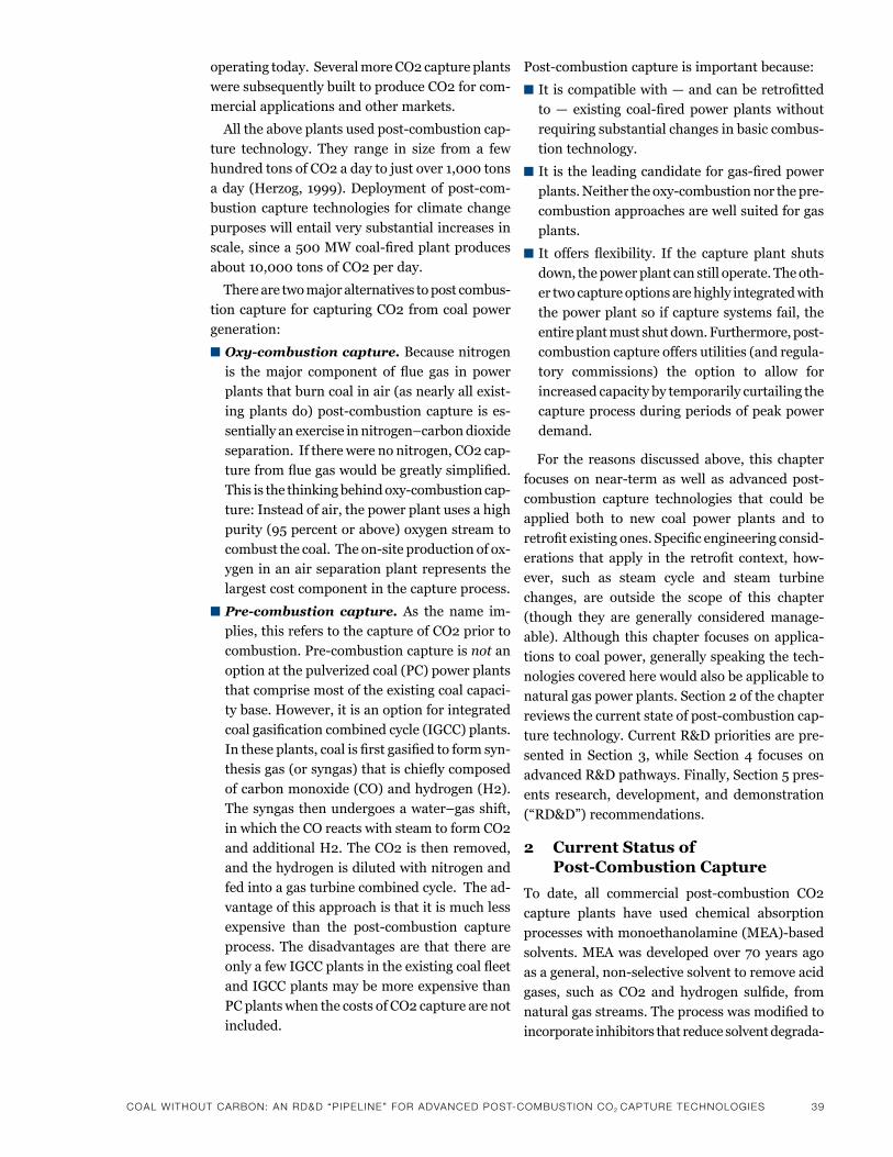
CoaL wiThouT CarBoN: aN rd&d “PiPeLiNe” For advaNCed PoST-ComBuSTioN Co2 CaPTure TeChNoLogieS 39
operating today. Several more CO2 capture plants
were subsequently built to produce CO2 for com-
mercial applications and other markets.
Alltheaboveplantsusedpost-combustioncap-
ture technology. They range in size from a few
hundredtonsofCO2adaytojustover1,000tons
aday (Herzog, 1999).Deploymentofpost-com-
bustion capture technologies for climate change
purposes will entail very substantial increases in
scale,sincea500MWcoal-firedplantproduces
about10,000tonsofCO2perday.
There are two major alternatives to post combus-
tion capture for capturing CO2 from coal power
generation:
n Oxy-combustion capture. Because nitrogen
is themajor component of flue gas in power
plantsthatburncoalinair(asnearlyallexist-
ingplantsdo)post-combustioncapture ises-
sentiallyanexerciseinnitrogen–carbondioxide
separation. If there were no nitrogen, CO2 cap-
turefromfluegaswouldbegreatlysimplified.
Thisisthethinkingbehindoxy-combustioncap-
ture: Instead of air, the power plant uses a high
purity(95percentorabove)oxygenstreamto
combustthecoal.Theon-siteproductionofox-
ygen in an air separation plant represents the
largest cost component in the capture process.
n Pre-combustion capture. As the name im-
plies, this refers to the capture of CO2 prior to
combustion.Pre-combustioncaptureisnot an
option at the pulverized coal (PC) power plants
thatcomprisemostoftheexistingcoalcapaci-
ty base. However, it is an option for integrated
coalgasificationcombinedcycle(IGCC)plants.
Intheseplants,coalisfirstgasifiedtoformsyn-
thesisgas(orsyngas)thatischieflycomposed
ofcarbonmonoxide(CO)andhydrogen(H2).
The syngas then undergoes a water–gas shift,
in which the CO reacts with steam to form CO2
and additional H2. The CO2 is then removed,
and the hydrogen is diluted with nitrogen and
fed into a gas turbine combined cycle. The ad-
vantage of this approach is that it is much less
expensive than the post-combustion capture
process. The disadvantages are that there are
onlyafewIGCCplantsintheexistingcoalfleet
andIGCCplantsmaybemoreexpensivethan
PC plants when the costs of CO2 capture are not
included.
Post-combustioncaptureisimportantbecause:
nItiscompatiblewith—andcanberetrofitted
to— existing coal-firedpower plantswithout
requiring substantial changes in basic combus-
tion technology.
nItistheleadingcandidateforgas-firedpower
plants.Neithertheoxy-combustionnorthepre-
combustion approaches are well suited for gas
plants.
nIt offers flexibility. If the capture plant shuts
down, the power plant can still operate. The oth-
er two capture options are highly integrated with
the power plant so if capture systems fail, the
entireplantmustshutdown.Furthermore,post-
combustion capture offers utilities (and regula-
tory commissions) the option to allow for
increased capacity by temporarily curtailing the
capture process during periods of peak power
demand.
For the reasons discussed above, this chapter
focuses onnear-termaswell as advancedpost-
combustion capture technologies that could be
applied both to new coal power plants and to
retrofitexistingones.Specificengineeringconsid-
erations that apply in the retrofit context, how-
ever, such as steam cycle and steam turbine
changes, are outside the scope of this chapter
(though they are generally considered manage-
able). Although this chapter focuses on applica-
tions to coal power, generally speaking the tech-
nologies covered here would also be applicable to
natural gas power plants. Section 2 of the chapter
reviewsthecurrentstateofpost-combustioncap-
ture technology. Current R&D priorities are pre-
sented in Section 3, while Section 4 focuses on
advanced R&D pathways. Finally, Section 5 pres-
ents research, development, and demonstration
(“RD&D”)recommendations.
2 Current Status of Post-Combustion Capture
To date, all commercial post-combustion CO2
capture plants have used chemical absorption
processeswithmonoethanolamine(MEA)-based
solvents.MEAwasdevelopedover70yearsago
asageneral,non-selectivesolventtoremoveacid
gases, such as CO2 and hydrogen sulfide, from
naturalgasstreams.Theprocesswasmodifiedto
incorporate inhibitors that reduce solvent degrada-
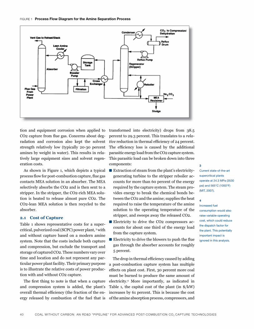
40 CoaL wiThouT CarBoN: aN rd&d “PiPeLiNe” For advaNCed PoST-ComBuSTioN Co2 CaPTure TeChNoLogieS
tion and equipment corrosion when applied to
CO2capturefromfluegas.Concernsaboutdeg-
radation and corrosion also kept the solvent
strength relatively low (typically 20-30 percent
amines by weight in water). This results in rela-
tively large equipment sizes and solvent regen-
eration costs.
As shown in Figure 1, which depicts a typical
processflowforpost-combustioncapture,fluegas
contacts MEA solution in an absorber. The MEA
selectively absorbs the CO2 and is then sent to a
stripper.Inthestripper,theCO2-richMEAsolu-
tion is heated to release almost pure CO2. The
CO2-leanMEA solution is then recycled to the
absorber.
2.1 Cost of Capture
Table 1 shows representative costs for a super-
critical, pulverized coal (SCPC) power plant, 3 with
and without capture based on a modern amine
system. Note that the costs include both capture
andcompression,butexcludethetransportand
storage of captured CO2. These numbers vary over
time and location and do not represent any par-
ticular power plant facility. Their primary purpose
is to illustrate the relative costs of power produc-
tion with and without CO2 capture.
Thefirst thing tonote is thatwhena capture
and compression system is added, the plant’s
overallthermalefficiency(thefractionoftheen-
ergy released by combustion of the fuel that is
transformed into electricity) drops from 38.5
percent to 29.3 percent. This translates to a rela-
tivereductioninthermalefficiencyof24percent.
The efficiency loss is caused by the additional
parasitic energy load from the CO2 capture system.
This parasitic load can be broken down into three
components:
nExtractionofsteamfromtheplant’selectricity-
generating turbine to the stripper reboiler ac-
countsformorethan60percentoftheenergy
required by the capture system. The steam pro-
vides energy to break the chemical bonds be-
tween the CO2 and the amine; supplies the heat
required to raise the temperature of the amine
solution to the operating temperature of the
stripper, and sweeps away the released CO2.
n Electricity to drive the CO2 compressors ac-
counts for about one third of the energy load
from the capture system.
nElectricitytodrivetheblowerstopushtheflue
gas through the absorber accounts for roughly
5 percent.
Thedropinthermalefficiencycausedbyadding
a post-combustion capture system hasmultiple
effectsonplantcost.First,30percentmorecoal
must be burned to produce the same amount of
electricity.4 More importantly, as indicated in
Table 1, the capital cost of the plant (in $/kW)
increases by 61 percent. This is because the cost
of the amine absorption process, compressors, and
Figure 1 process Flow Diagram for the Amine separation process
3
Current state-of-the-art
supercritical plants
operate at 24.3 mpa (3530
psi) and 565°C (1050°f)
(mit, 2007).
4
increased fuel
consumption would also
raise variable operating
cost, which could reduce
the dispatch factor for
the plant. this potentially
important impact is
ignored in this analysis.
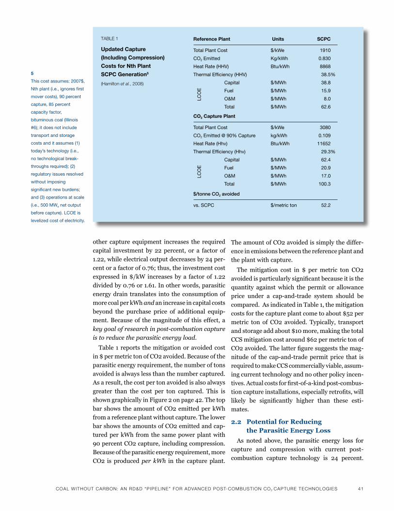
CoaL wiThouT CarBoN: aN rd&d “PiPeLiNe” For advaNCed PoST-ComBuSTioN Co2 CaPTure TeChNoLogieS 41
other capture equipment increases the required
capital investment by 22 percent, or a factor of
1.22, while electrical output decreases by 24 per-
centorafactorof0.76;thus,theinvestmentcost
expressed in$/kW increasesbya factorof 1.22
dividedby0.76or1.61.Inotherwords,parasitic
energy drain translates into the consumption of
more coal per kWh and an increase in capital costs
beyond the purchase price of additional equip-
ment. Because of the magnitude of this effect, a
key goal of research in post-combustion capture
is to reduce the parasitic energy load.
Table 1 reports the mitigation or avoided cost
in $ per metric ton of CO2 avoided. Because of the
parasitic energy requirement, the number of tons
avoided is always less than the number captured.
As a result, the cost per ton avoided is also always
greater than the cost per ton captured. This is
shown graphically in Figure 2 on page 42. The top
bar shows the amount of CO2 emitted per kWh
from a reference plant without capture. The lower
bar shows the amounts of CO2 emitted and cap-
tured per kWh from the same power plant with
90percentCO2capture,includingcompression.
Because of the parasitic energy requirement, more
CO2 is produced per kWh in the capture plant.
The amount of CO2 avoided is simply the differ-
ence in emissions between the reference plant and
the plant with capture.
The mitigation cost in $ per metric ton CO2
avoidedisparticularlysignificantbecauseitisthe
quantity against which the permit or allowance
price under a cap-and-trade system should be
compared. As indicated in Table 1, the mitigation
costs for the capture plant come to about $52 per
metric ton of CO2 avoided. Typically, transport
andstorageaddabout$10more,makingthetotal
CCS mitigation cost around $62 per metric ton of
CO2avoided.Thelatterfiguresuggeststhemag-
nitudeof the cap-and-tradepermitprice that is
required to make CCS commercially viable, assum-
ing current technology and no other policy incen-
tives.Actualcostsforfirst-of-a-kindpost-combus-
tioncaptureinstallations,especiallyretrofits,will
likely be significantly higher than these esti-
mates.
2.2 Potential for Reducing the Parasitic Energy Loss
As noted above, the parasitic energy loss for
capture and compression with current post-
combustion capture technology is 24 percent.
5
this cost assumes: 2007$,
nth plant (i.e., ignores first
mover costs), 90 percent
capture, 85 percent
capacity factor,
bituminous coal (illinois
#6); it does not include
transport and storage
costs and it assumes (1)
today’s technology (i.e.,
no technological break-
throughs required); (2)
regulatory issues resolved
without imposing
significant new burdens;
and (3) operations at scale
(i.e., 500 mWe net output
before capture). lCoE is
levelized cost of electricity.
reference plant units sCpC
total plant Cost $/kWe 1910
Co2 Emitted kg/kWh 0.830
heat rate (hhv) btu/kWh 8868
thermal Efficiency (hhv) 38.5%
Capital $/mWh 38.8
fuel $/mWh 15.9
o&m $/mWh 8.0
total $/mWh 62.6
CO2 Capture plant
total plant Cost $/kWe 3080
Co2 Emitted @ 90% Capture kg/kWh 0.109
heat rate (hhv) btu/kWh 11652
thermal Efficiency (hhv) 29.3%
Capital $/mWh 62.4
fuel $/mWh 20.9
o&m $/mWh 17.0
total $/mWh 100.3
$/tonne CO2 avoided
vs. sCpC $/metric ton 52.2
TaBLe 1
updated Capture
(Including Compression)
Costs for Nth plant
sCpC Generation5
(hamilton et al., 2008)
lCo
ElC
oE
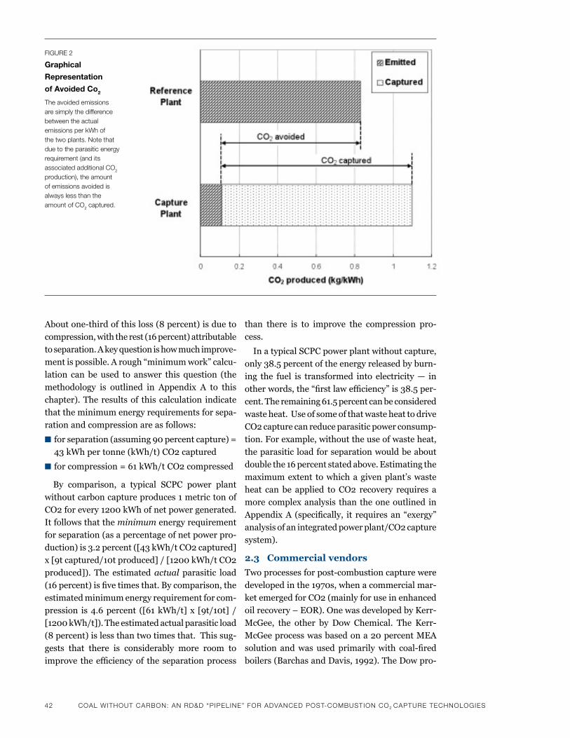
42 CoaL wiThouT CarBoN: aN rd&d “PiPeLiNe” For advaNCed PoST-ComBuSTioN Co2 CaPTure TeChNoLogieS
Aboutone-thirdofthisloss(8percent)isdueto
compression, with the rest (16 percent) attributable
to separation. A key question is how much improve-
mentispossible.Arough“minimumwork”calcu-
lation can be used to answer this question (the
methodology is outlined in Appendix A to this
chapter). The results of this calculation indicate
that the minimum energy requirements for sepa-
ration and compression are as follows:
n forseparation(assuming90percentcapture)=
43 kWh per tonne (kWh/t) CO2 captured
n for compression = 61 kWh/t CO2 compressed
By comparison, a typical SCPC power plant
without carbon capture produces 1 metric ton of
CO2forevery1200kWhofnetpowergenerated.
It follows that the minimum energy requirement
for separation (as a percentage of net power pro-
duction) is 3.2 percent ([43 kWh/t CO2 captured]
x[9tcaptured/10tproduced]/[1200kWh/tCO2
produced]). The estimated actual parasitic load
(16percent)isfivetimesthat.Bycomparison,the
estimated minimum energy requirement for com-
pression is4.6percent ([61kWh/t]x [9t/10t] /
[1200kWh/t]).Theestimatedactualparasiticload
(8 percent) is less than two times that. This sug-
gests that there is considerably more room to
improve theefficiencyof theseparationprocess
than there is to improve the compression pro-
cess.
In a typical SCPC power plant without capture,
only 38.5 percent of the energy released by burn-
ing the fuel is transformed into electricity — in
otherwords,the“firstlawefficiency”is38.5per-
cent. The remaining 61.5 percent can be considered
waste heat. Use of some of that waste heat to drive
CO2 capture can reduce parasitic power consump-
tion.Forexample,withouttheuseofwasteheat,
the parasitic load for separation would be about
double the 16 percent stated above. Estimating the
maximumextent towhichagivenplant’swaste
heat can be applied to CO2 recovery requires a
morecomplexanalysis thantheoneoutlined in
AppendixA (specifically, it requiresan“exergy”
analysis of an integrated power plant/CO2 capture
system).
2.3 Commercial vendors
Twoprocessesforpost-combustioncapturewere
developedinthe1970s,whenacommercialmar-
ket emerged for CO2 (mainly for use in enhanced
oilrecovery–EOR).OnewasdevelopedbyKerr-
McGee, the other by Dow Chemical. The Kerr-
McGeeprocesswasbasedona20percentMEA
solution andwas used primarilywith coal-fired
boilers (Barchas and Davis, 1992). The Dow pro-
Figure 2
Graphical
representation
of Avoided Co2
The avoided emissions are simply the difference between the actual emissions per kwh of the two plants. Note that due to the parasitic energy requirement (and its associated additional Co2 production), the amount of emissions avoided is always less than the amount of Co2 captured.
CoaL wiThouT CarBoN: aN rd&d “PiPeLiNe” For advaNCed PoST-ComBuSTioN Co2 CaPTure TeChNoLogieS 43
cess used a 30 percent MEA solution and was
applied primarily on natural gas plants (Sander
and Mariz, 1992). Today, the Dow technology
(ECONAMINE FG) is licensed by Fluor and the
Kerr-McGee technology by ABB/Lummus. Sev-
eral installations worldwide use these technolo-
gies.
Several other vendors also offer commercial
amine processes:
n MHI in Japan has developed a process named
KM-CDRthatisbasedontheproprietarysol-
ventKS-1(thesolventprobablyinvolvesahin-
dered amine). TheKM-CDR process is being
offeredcommerciallyforgas-firedplants(with
anofferingforcoal-firedplantsunderdevelop-
ment). MHI claims their process is the most en-
ergyefficientofcurrentcommercialofferings.
Fourcommercialunitsforgas-firedplantshave
been built with this technology, with four more
underconstruction.PilotscaletestsoftheKM-
CDR process are currently being conducted on
coal-firedfluegas(Kishimotoet al.,2008).
n HTC Purenergy is offering a process package.
It is based on research done at the Internation-
al Test Centre at the University of Regina to de-
velop a mixed amine solvent. One way the
company is attempting to lower costs is by of-
feringmodularunitsthatcanbepre-fabricat-
ed. HTC Purenergy has a unique marketing
strategy that involvesfinancing, constructing,
and managing the capture process. The compa-
ny also offers an option in which they (HTC)
own and operate the process.
n Aker Clean Carbon in Norway also offers a
commercialpackage.Named“JustCatch”,de-
velopment of this process was initiated by Aker
Clean Carbon AS with support from a larger in-
dustrial consortium (Sanden et al.,2006).The
aim was to develop and verify an amine based
technologyinacostefficientmanner.Prelimi-
nary results for this process are based on a set
of feasible technology improvements where the
further engineering design is performed with
the principal goal of facilitating cost-effective
solutions, minimizing technical and economic
risks, and developing confidence in cost
estimation.
n Cansolv is offering a CO2 capture process based
on a recently developed amine system that uses
aproprietarysolventnamedAbsorbentDC101™
(Cansolv,2008).Thesolventisbasedontertia-
ry amines and probably includes a promoter to
yieldsufficientabsorptionratestobeusedfor
low-pressure flue gas streams (Hakka and
Ouimet, 2006).Withtheuseofoxidationin-
hibitorsthisprocesscanbeappliedtooxidizing
environments and in environments with limit-
edconcentrationsofoxidizedsulfur.Theclaim
is that this process can also simultaneously re-
move other acidic contaminants and particulate
material,suchasoxidesofsulfurandnitrogen
(SOx,andNOx).Twodemonstrationplantsus-
ing the Cansolv CO2 capture system have been
built. One is in Montreal, Canada and captures
CO2fromthefluegasofanaturalgasfiredboil-
er; the other is in Virginia and captures CO2
fromfluegasofacoalfiredboiler.Nocommer-
cial plants have yet been built.
3 Current R&D Thrusts
Figure 3 on page 44 outlines the various technol-
ogypathwaystopost-combustioncapture.Most
of these pathways are discussed in this section;
theexploratorytechnologiesarereviewedinSec-
tion 4.
3.1 Absorption
Inabsorption(or“scrubbing”),fluegascomesin
contactwithaliquid“absorbent”(orsolvent)that
has been selected because CO2 dissolves in it more
readily than nitrogen — i.e., it is selective for CO2.
The process takes place in tall columns (towers)
knownasscrubbers,inwhichturbulentflowpro-
motes rapid CO2 transfer from gas to liquid. Dif-
ferences in density make it easy to separate the
emerging gas and liquid.
To recover the captured CO2 the loaded solvent
ispumpedtoa“stripper”inwhichitisexposedto
a hotter gas that is free of CO2 — typically steam.
Heating the solvent causes desorption of the CO2
(and traces of nitrogen). The stripped liquid is
pumped back to the scrubber, while the steam/
CO2mixtureiscooledtocondensethesteam.This
leaveshigh-purityCO2suitableforcompression,
transport, and sequestration.
The capital costs of scrubbing decrease as the
ratesofCO2absorption/stripping(“masstrans-
fer”) increase. This is mainly because smaller
absorbers and strippers, with correspondingly
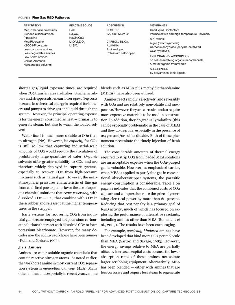
44 CoaL wiThouT CarBoN: aN rd&d “PiPeLiNe” For advaNCed PoST-ComBuSTioN Co2 CaPTure TeChNoLogieS
shorter gas/liquid exposure times, are required
when CO2 transfer rates are higher. Smaller scrub-
bers and strippers also mean lower operating costs
because less electrical energy is required for blow-
ers and pumps to drive gas and liquid through the
system.However,theprincipaloperatingexpense
is for the energy consumed as heat — primarily to
generate steam, but also to warm the loaded sol-
vent.
Water itself is much more soluble to CO2 than
to nitrogen (N2). However, its capacity for CO2
is still so low that capturing industrial-scale
amounts of CO2 would require the circulation of
prohibitively large quantities of water. Organic
solvents offer greater solubility to CO2 and are
therefore widely deployed in capture systems,
especially to recover CO2 from high-pressure
mixturessuchasnaturalgas.However,thenear-
atmospheric pressures characteristic of flue gas
fromcoal-firedpowerplantsfavortheuseofaque-
ous chemical solutions that react reversibly with
dissolved CO2 — i.e., that combine with CO2 in
the scrubber and release it at the higher tempera-
tures in the stripper.
Early systems for recovering CO2 from indus-
trial gas streams employed hot potassium carbon-
ate solutions that react with dissolved CO2 to form
potassium bicarbonate. However, for many de-
cades now the additives of choice have been amines
(Kohl and Nielsen, 1997).
3.1.1 Amines
Aminesarewater-solubleorganicchemicalsthat
contain reactive nitrogen atoms. As noted earlier,
the workhorse amine in most current CO2 separa-
tion systems is monoethanolamine (MEA). Many
other amines and, especially in recent years, amine
blends such as MEA plus methyldiethanolamine
(MDEA), have also been utilized.
Amines react rapidly, selectively, and reversibly
withCO2andarerelativelynonvolatileandinex-
pensive. However, they are corrosive and so require
moreexpensivematerialstobeusedinconstruc-
tion. In addition, they do gradually volatilize (this
can be especially problematic in the case of MEA)
and they do degrade, especially in the presence of
oxygenand/orsulfurdioxide.Bothofthesephe-
nomena necessitate the timely injection of fresh
solution.
The considerable amounts of thermal energy
required to strip CO2 from loaded MEA solutions
areanacceptableexpensewhentheCO2-purged
gas is valuable. However, as emphasized earlier,
whenMEAisappliedtopurifyfluegasinconven-
tional absorber/stripper systems, the parasitic
energy consumption is considerable. Table 1 on
page 41 indicates that the combined costs of CO2
capture and compression raise the price of gener-
atingelectricalpowerbymore than60percent.
Reducing that cost penalty is a primary goal of
R&Dactivity,muchofwhichhasfocusedonex-
ploring the performance of alternative reactants,
including amines other than MEA (Bonenfant et
al.,2003).Theresultshavebeenencouraging.
Forexample,sterically hindered amines have
been developed that bind more CO2 per molecule
than MEA (Sartori and Savage, 1983). However,
the energy savings relative to MEA are partially
offset by increased capital costs because the lower
absorption rates of these amines necessitate
larger scrubbing equipment. Alternatively, MEA
has been blended — either with amines that are
less corrosive and require less steam to regenerate
absorption
mea, other alkanolaminesblended alkanolaminespiperazinemea/piperazinek2Co3/piperazineless corrosive aminesless degradable amineslow ∆hrxn aminesChilled ammonianonaqueous solvents
rEaCtivE soliDs
Caona2Co3
naoh/Caoli2o/li2Zro3 li4sio4
aDsorption
ZEolitEs5a, 13x, mCm-41
Carbon, siliCa, aluminaamine-doped potassium salt-doped
Figure 3 Flue Gas r&D pathways
mEmbranEs
Gas/liquid Contactorspermselective and high-temperature polymers
bioloGiCalalgae (photosynthesis)Carbonic anhydrase (enzyme-catalyzedCo2 hydrolysis)
ExploratorY aDsorption on self-assembling organic nanochannels,& metal/organic frameworks
absorption by polyamines, ionic liquids
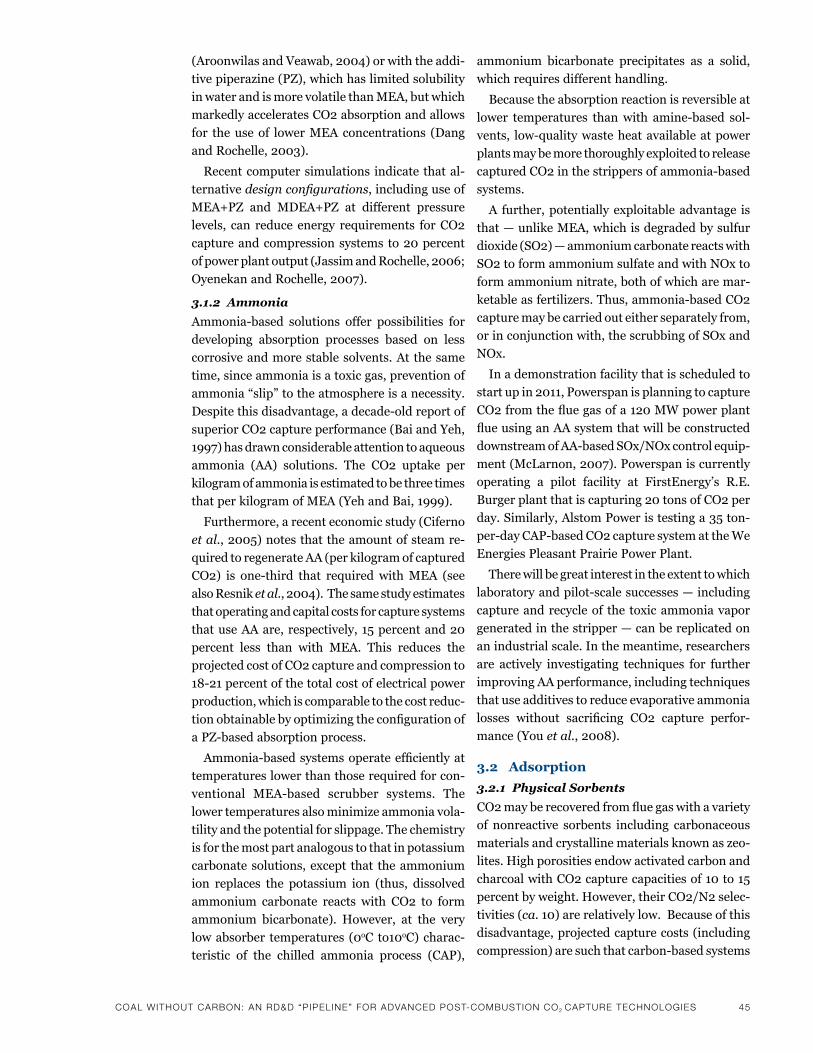
CoaL wiThouT CarBoN: aN rd&d “PiPeLiNe” For advaNCed PoST-ComBuSTioN Co2 CaPTure TeChNoLogieS 45
(AroonwilasandVeawab,2004)orwiththeaddi-
tive piperazine (PZ), which has limited solubility
in water and is more volatile than MEA, but which
markedly accelerates CO2 absorption and allows
for the use of lower MEA concentrations (Dang
andRochelle,2003).
Recent computer simulations indicate that al-
ternative design configurations, including use of
MEA+PZ and MDEA+PZ at different pressure
levels, can reduce energy requirements for CO2
captureandcompressionsystemsto20percent
ofpowerplantoutput(JassimandRochelle,2006;
OyenekanandRochelle,2007).
3.1.2 Ammonia
Ammonia-based solutions offer possibilities for
developing absorption processes based on less
corrosive and more stable solvents. At the same
time,sinceammoniaisatoxicgas,preventionof
ammonia“slip”totheatmosphereisanecessity.
Despitethisdisadvantage,adecade-oldreportof
superior CO2 capture performance (Bai and Yeh,
1997) has drawn considerable attention to aqueous
ammonia (AA) solutions. The CO2 uptake per
kilogram of ammonia is estimated to be three times
that per kilogram of MEA (Yeh and Bai, 1999).
Furthermore, a recent economic study (Ciferno
et al.,2005)notesthattheamountofsteamre-
quired to regenerate AA (per kilogram of captured
CO2) is one-third that requiredwithMEA (see
also Resnik et al.,2004).Thesamestudyestimates
that operating and capital costs for capture systems
thatuseAAare,respectively,15percentand20
percent less than with MEA. This reduces the
projected cost of CO2 capture and compression to
18-21percentofthetotalcostofelectricalpower
production, which is comparable to the cost reduc-
tionobtainablebyoptimizingtheconfigurationof
aPZ-basedabsorptionprocess.
Ammonia-basedsystemsoperateefficientlyat
temperatures lower than those required for con-
ventional MEA-based scrubber systems. The
lower temperatures also minimize ammonia vola-
tility and the potential for slippage. The chemistry
is for the most part analogous to that in potassium
carbonatesolutions,except that theammonium
ion replaces the potassium ion (thus, dissolved
ammonium carbonate reacts with CO2 to form
ammonium bicarbonate). However, at the very
lowabsorber temperatures (0oCto10oC) charac-
teristic of the chilled ammonia process (CAP),
ammonium bicarbonate precipitates as a solid,
which requires different handling.
Because the absorption reaction is reversible at
lower temperatures thanwith amine-based sol-
vents, low-qualitywasteheatavailableatpower
plantsmaybemorethoroughlyexploitedtorelease
capturedCO2inthestrippersofammonia-based
systems.
Afurther,potentiallyexploitableadvantage is
that — unlike MEA, which is degraded by sulfur
dioxide(SO2)—ammoniumcarbonatereactswith
SO2toformammoniumsulfateandwithNOxto
form ammonium nitrate, both of which are mar-
ketableasfertilizers.Thus,ammonia-basedCO2
capture may be carried out either separately from,
orinconjunctionwith,thescrubbingofSOxand
NOx.
In a demonstration facility that is scheduled to
startupin2011,Powerspanisplanningtocapture
CO2fromthefluegasofa120MWpowerplant
flueusinganAAsystemthatwillbeconstructed
downstreamofAA-basedSOx/NOxcontrolequip-
ment(McLarnon,2007).Powerspaniscurrently
operating a pilot facility at FirstEnergy’s R.E.
Burgerplantthatiscapturing20tonsofCO2per
day.Similarly,AlstomPoweristestinga35ton-
per-dayCAP-basedCO2capturesystemattheWe
Energies Pleasant Prairie Power Plant.
Therewillbegreatinterestintheextenttowhich
laboratoryandpilot-scalesuccesses—including
captureandrecycleof the toxicammoniavapor
generated in the stripper — can be replicated on
an industrial scale. In the meantime, researchers
are actively investigating techniques for further
improving AA performance, including techniques
that use additives to reduce evaporative ammonia
losses without sacrificing CO2 capture perfor-
mance (You et al.,2008).
3.2 Adsorption
3.2.1 Physical Sorbents
CO2mayberecoveredfromfluegaswithavariety
of nonreactive sorbents including carbonaceous
materials and crystalline materials known as zeo-
lites. High porosities endow activated carbon and
charcoalwithCO2capturecapacitiesof10to15
percent by weight. However, their CO2/N2 selec-
tivities (ca.10)arerelativelylow.Becauseofthis
disadvantage, projected capture costs (including
compression)aresuchthatcarbon-basedsystems
46 CoaL wiThouT CarBoN: aN rd&d “PiPeLiNe” For advaNCed PoST-ComBuSTioN Co2 CaPTure TeChNoLogieS
become practical only when the required CO2
purityisatmost90percent(Radoszet al.,2008).
Zeolitic materials, on the other hand, offer CO2/
N2selectivitiesfivetotentimesgreaterthanthose
of carbonaceous materials. However, their CO2
capacities are two to three times lower (Konduru
et al.,2007;Merelet al.,2008).Moreover,zeolite
performance is impaired when water vapor is
present.
To be competitive with liquid solvents, solid
sorbents must be less sensitive to steam and offer
substantially greater capacities and selectivities
for CO2 than currently available physical sorbents
(Ho et al., in press).
3.2.2 Chemical Sorbents
Whenheated to850oC, limestone — or calcium
carbonate (CaCO3) — releases CO2 (calcines) and
therebytransformstocalciumoxide(CaO).CaO
willrecombinewithCO2at650oC. These reactions
have a long history of service in industrial pro-
cesses. Limestone is also widely employed to
capturefluegasSO2.However, it losescapacity
over time, especially if it is deployed to capture
both CO2 and SO2, and requires frequent replace-
ment (Rodriguez et al.,2008).
The CaO/CaCO3 system nonetheless remains
attractive because of its high CO2 capture capac-
ity and long track record. Furthermore, it offers
possibilities for power plant configurations that
(a) maximize the benefits of feeding otherwise
prohibitively expensive oxygen rather than air
(therebyobviatingtheneedforpost-combustion
CO2/N2separation),(b)exploittheavailabilityof
high-levelheat,and(c)improveenergyefficiency
by generating steam from heat released in the
carbonation reaction (Manovic and Anthony,
2008;Romeoet al.,2008).Consequently,CaO/
CaCO3-basedCO2captureisthefocusofcontinu-
ing intensive research activity.
Alkalimetal-based sorbents also captureCO2
— primarily via reactions that transform metal
carbonatesintobicarbonates,withsteamasaco-
reactant (similar to when CO2 reacts with aqueous
carbonatesolutions).Highlyporoussodium-based
sorbentsoperateefficientlyinthesametempera-
ture range as aqueous amines (25oC-120oC), but
have considerably lower CO2 capture capacity (Lee
et al.,2008).Lithium-basedsorbentsthatfunction
bestat400oC-500oC offer higher CO2 capacities
(Venegas et al., 2007; Ochoa-Fernandez et al.,
2008).Thelong-termstabilityandperformance
of alkalimetal-based sorbentsunderactualflue
gas conditions remains to be established.
An increasingly active area of research involves
CO2 capture by amines immobilized within porous
sorbents. In fact, a practical system of this type
has been deployed for CO2 capture in a space
mission life support system (Satyapal et al.,2001).
A variety of amines, sorbent supports, and im-
mobilizing techniques have been tested (Gray et
al.,2005;Knowleset al.,2006;Hickset al.,2008;
Yue et al.,2008)andtheresultshavebeenquite
promising. Several amine-derived sorbents ex-
hibit high CO2 uptake/release capacity and stabil-
ity in the 50oC–120oC range. Furthermore, the
absence of large quantities of circulating water
should make thermal energy requirements for CO2
release appreciably lower than for amine-based
absorption/stripping. As noted above regarding
alkalimetal-basedsorbents,commercialviability
requires that these sorbents can be shown to oper-
atestablyforextendedperiodsoftimeunderac-
tualfluegasconditions.
3.3 Membrane-Based Separation
A third mature technology under consideration
forCO2captureismembrane-basedseparation.
Membranes, which generally consist of thin poly-
mericfilms,owetheirselectivitiestotherelative
rates at which chemical species permeate. Differ-
ences in permeation rates are generally due (in the
case of porous membranes) to the relative sizes of
the permeating molecules or (in the case of dense
membranes) their solubilities and/or diffusion
coefficients (i.e., mobilities) in the membrane
material. Because permeation rates vary inversely
with membrane thickness, membranes are made
to be as thin as possible without compromising
mechanical strength (which is frequently provided
bynon-selective,poroussupportlayers).
As is true of membrane-based filtration and
desaltingofwater,membrane-basedgassepara-
tion is a well-established, mature technology.
Many large plants are operating worldwide to
recoveroxygenand/ornitrogenfromair,CO2from
natural gas, and hydrogen from a variety of process
streams. As is the case with absorption and adsorp-
tion, economic considerations dictate that mem-
brane systems recoverCO2 fromfluegas selec-
tively.
CoaL wiThouT CarBoN: aN rd&d “PiPeLiNe” For advaNCed PoST-ComBuSTioN Co2 CaPTure TeChNoLogieS 47
Membrane permeation is generally pressure-
driven: The feed gas is either compressed, and/or
the permeate channel operates under vacuum,
and/or a sweep gas is employed. Due to the low
partialpressureofCO2inthefluegas,thiscon-
stitutes amajor challenge formembrane-based
capture systems compared to systems that make
use of liquid absorbents or solid adsorbents that
are thermally regenerated (i.e., heated to strip
away the captured CO2).
3.3.1 Polymeric Membranes
Recently, Favre and coworkers (Bounaeur et al.,
2006;Favre,2007)andWileyandcoworkers(Ho
et al.,2006,2008)publishedtheresultsofexten-
sivecalculationsthatexplorethedependenceof
CO2 capture costs on membrane selectivity, per-
meability,andunitprice.Mostsignificantly,their
results indicate that for membranes to be com-
petitivewithamine-basedabsorptionforcapturing
CO2 fromflue gases, theirCO2/N2 selectivities
(i.e., permeability ratios) must be in the 200
range.
Withrareexception,theselectivitiesofavailable
polymers fall well below that. While many have
selectivitiesof50to60,theytendtobelessperme-
able—i.e.,theirfluxesarelow(PowellandQiao,
2006). Once again, cost effectiveness may be
achievable only when separation is promoted by
aCO2-selectivechemicalreaction.
Hoandcoworkers(ZouandHo,2006;Huang
et al.,2008)havedemonstratedthatbyvirtueof
their reversible reactions with CO2, amines can
raise the CO2/N2 selectivity of polymeric mem-
branesto170whilealsoboostingCO2fluxes.If
these encouraging results can be sustained for
extendedperiodsofoperation,suchsystemswill
merit serious consideration as candidates for CO2
captureatcoal-firedpowerplants.
3.4 Membrane Absorption
An alternative approach to CO2 capture is to use
porous membranes as platforms for absorption
and stripping. In this approach, which has at-
tracted considerable interest, membranes serve
primarily to separate gas and liquid. CO2 and N2
eachtransfereasilythroughnonselective,gas-filled
membrane pores. Selectivity is provided by the
liquid, which, as usual, is typically an aqueous
amine solution (deMontigny et al., 2006; Shi-
mada et al.,2006).Oneadvantageofmembrane
absorbers is that, unlike conventional absorbers,
there are no inherent restrictions on gas and liquid
flowrates.
The performance of membrane absorbers, when
measured in terms of mass transfer rates per unit
modulevolume, canexceed thoseof absorption
and stripping in conventional columns. Further-
more, modularity makes membrane systems easy
toreplaceorexpand.However,economiesofscale
do not apply to modular systems, whereas they do
favor traditional, large absorption and stripping
columns.
3.5 Biomimetic Approaches
In addition to absorption, adsorption, and mem-
brane-based systems, awide variety of newap-
proaches are under development. Some that have
shown promise take their cues from living systems
that have evolved highly efficient systems for
capturing and/or converting CO2.
Forexample,severalstudieshaveexploredthe
use of the enzyme carbonic anhydrase, which is
themost efficient catalyst of CO2 reactionwith
water,topromoteCO2scrubbingfromfluegases
(Bond et al., 2001). By immobilizing carbonic
anhydrase in a bioreactor, Bhattacharya et al.
(2004)quadrupledtherateofCO2absorptionin
water.
Microalgae systems, which have long been under
investigation for CO2 capture from air (Cheng et
al.,2006),areespeciallyattractivebecausethey
consume CO2 in photosynthesis. This obviates the
need for CO2 compression and sequestration.
Furthermore, the algae biomass can serve as ani-
malfeedorasaneffectivelycarbon-neutral fuel
(Skjanes et al.,2007).
3.6 Other Approaches
Another approach that has been proposed is to
coolthefluegastolowtemperaturessothatthe
CO2 is separated as dry ice (Younes et al.,2006).
After the initial paper outlining this concept, no
further information has been forthcoming.
4 Advanced R&D Pathways
Current technologies for recovering and separating
CO2 and other compounds from gas streams are
relatively mature. As discussed in the previous
section,thesetechnologiescanbebroadlyclassified
into three categories: absorption, adsorption, and
48 CoaL wiThouT CarBoN: aN rd&d “PiPeLiNe” For advaNCed PoST-ComBuSTioN Co2 CaPTure TeChNoLogieS
membrane processes. In almost all absorption and
adsorption processes, the separation step entails
physical and/or chemical interactions that form
newmolecularcomplexes.Thisstepmustthenbe
reversed through significant increases in tem-
perature. The need to heat and subsequently cool
large volumes of sorbents to prepare them for the
next sorption cycle is wasteful both thermody-
namically (because it involves unnecessary heating
and cooling of inert materials) and dynamically (a
large thermal mass of inert materials limits heat
transfer rates, which leads to larger required equip-
ment sizes).
While the performance of currently available
technologies can be expected to improve with
further R&D, new concepts and materials could
providesignificantbreakthroughs in theperfor-
mance and costs of capture systems. Advanced
R&D pathways seek to eliminate or at least mini-
mize large thermal swings through a greater reli-
ance on structured materials; possibly stimuli-
responsive, entropic (e.g., shape selective) rather
than enthalpic interactions between the sorbate
and the separation media; and through the ap-
plication of stimuli (e.g., an electric field) to
modify the separation environment in order to
release the captured solute. Some of these promis-
ing new approaches are reviewed in this section.
4.1 Solid Adsorbents
The traditional use of carbonaceous materials for
CO2 adsorption is limited by low CO2/N2 selec-
tivities and while the more structured zeolites have
significantly higher selectivities, they have sig-
nificantly lower capacities. In addition, their
performance is impaired when water vapor is
present. Advanced research in the development of
new adsorbent materials indicates some promising
approaches that may overcome many of the limi-
tations of the currently available adsorbents. Some
of these approaches are discussed here.
4.1.1 Metal-Organic Frameworks
Metal organic frameworks (MOFs) are porous
crystallinesolidmaterialswithwell-definedcavi-
ties that resemble those of zeolites (Millward and
Yaghi,2005;Bourellyet al.,2005;Muelleret al.,
2006).Theycanbetunedtovarythecavitysize,
accessibility, and interactions with molecules
contained within the cavity. MOFs are open struc-
tures with high capacities for gaseous species and
have good diffusional properties. They may not
always be sufficiently stable for the conditions
underwhichtheywouldneedtobeappliedinflue
gas treatment, however. More recently, nano-
systems researchers at UCLA (Banerjee et al.,
2008;Wanget al.,2008)havesynthesizedand
screenedalargenumberofzeolitic-typematerials
known as zeolitic imidazolate frameworks (ZIFs).
A few of the ZIFs have been shown to have good
chemical and thermal stability in water and in a
number of different organic solvents, an advantage
overtraditionalsilicon-basedzeolites,whoseper-
formance can be degraded in the presence of steam,
for instance. ZIFs have high CO2 capacities and
selectivity against CO and N2 is good. As there is
agreatdealofflexibilityinthekindsofZIFstruc-
tures that can be synthesized, it is likely that new
materials with even better adsorption selectivity
and capacity can be developed in this way.
4.1.2 Functionalized Fibrous Matrices
The need for both high capacity and fast diffu-
sional response in adsorbents can be addressed
byusingchemicallymodifiedfibrousmaterialsto
show adsorptive selectivity and capacity for CO2.
Li et al.(2008a,b)attachedpolyethylenimineto
glassfibermatricesthroughappropriatecoupling
chemistry to develop an adsorbent with high CO2
capacity that (1) worked more effectively in a hu-
mid environment and (2) could be completely
regenerated at high temperature without loss of
performance.
4.1.3 Poly (Ionic Liquids)
A new class of solid adsorbents based on the po-
lymerization of ionic liquids (these are discussed
below) has been reported by Tang et al.(2005a,b).
Thesepolymersexhibitedenhancedsorptionca-
pacity and rates relative to those observed for the
room temperature ionic liquids. Researchers have
inferred from these results that the mechanism
for CO2 capture with this new class of polymers
is bulk absorption rather than surface adsorption.
Bara et al.(2008)showedsimilarenhancedselec-
tivity in polymerized ionic liquid gas separation
membranes.
4.2 Structured Fluid Absorbents
4.2.1 CO2 Hydrates
Spencer (1999) and others have suggested that
CO2 hydrates be exploited for carbon capture.
This approach involves CO2 being incorporated
CoaL wiThouT CarBoN: aN rd&d “PiPeLiNe” For advaNCed PoST-ComBuSTioN Co2 CaPTure TeChNoLogieS 49
in the cages, or clathrates, formed by water mol-
ecules under high pressure (7-20 atm) and low
temperatures (0°C-4°C), asdictatedby thermo-
dynamic constraints on the formation of these
hydrates. The concept was not to use the water
hydrates as a recyclable absorption medium, al-
though it is conceivable to do so, but rather to
directly sequester the hydrate slurry. Based on
more recent reports that tetrahydrofuran (THF)
reduces the incipient equilibrium hydrate forma-
tion conditions, a process has been described that
involves three hydrate stages coupled with a
membrane-based gas separation process. This
process could operate at a substantially lower
pressure than is required in the absence of THF
(Linga et al.,2007,2008).Compressioncostswere
estimated to be reduced from 75 percent of the
powerproducedforatypical500MWpowerplant,
to 53 percent. This work is important because of
its use of additives to enhance and expand the
range of application of water clathrates, and be-
cause it points to possible new approaches for the
design of suitable absorbents under more general
conditions.
4.2.2 Liquid Crystals
While it is appealing to rely on the physical host-
ing of the solute in structured cavities like those
provided by CO2 hydrates, the reliance on water
as the clathrating agent restricts the accessible
range of operating conditions for such processes.
Andalthoughthisrangecanbeexpandedwiththe
use of additives such as THF, other structured
materials, such as liquid crystals, provide poten-
tiallymoreflexiblestimuli-responsivesorbentsfor
gas sorption purposes. This is because their op-
erational temperature ranges can be tuned to be
compatible with a given process. Liquid crystals
constitute an unusual state of matter: They can
exhibit ordered, crystalline-like structures with
liquid-like properties over certain temperature
ranges,butaboveawell-definedtransitiontem-
perature they convert to more traditional liquid
phases. The restructuring of this phase can be
achieved by a slight drop in temperature, or by the
applicationofasuitableelectricormagneticfield.
Asanexample,Chenet al.(1993,2000)andHsuie
et al. (1994) measured the physical absorption of
CO2 infilmsofa liquidcrystal exposed topure
CO2 over the temperature range spanning the
solidtoliquidphasetransition.Theirexperimen-
tal results showed that the amount of CO2 absorbed
bytheliquidcrystallinephaseissignificantlyless
than that absorbed in the isotropic liquid. The
liquid crystals can be ordered dramatically by very
smallchangesintemperature(1°C)or,inprinciple,
bytheapplicationofastrongelectricfieldacross
theliquidcrystalfilm.Furthermore,theabilityto
reverse their physical sorption and desorption of
CO2withverysmallexternalperturbationsshowed
a stimulus-responsive CO2 separation. The gas
solubility in conventional liquid crystals, however,
isunacceptablylowforCO2separationfromflue
gases, although it is comparable to the capacities
exhibitedbywaterclathrates.Note,however,that
none of the work done to date on liquid crystals
has focused on using these systems for separation
purposes. Thus there is ample scope for enhancing
CO2 capacities through appropriate design of the
molecules. Means for enhancing CO2 sorption
capacities in liquid crystal systems are required;
developing such means through advanced materi-
als R&D will require a strongly interdisciplinary
approach that draws on synthetic chemistry,
physical characterization, and molecular model-
ing.
4.2.3 Ionic Liquids
Another area of research that has demonstrated
significant potential and is currently drawing a
great deal of interest involves ionic liquids. Ionic
liquids are organic salts with melting points usu-
allynearroomtemperature—thatis,below100°C.
An unexpectedly large solubility of CO2 gas in
ionicliquidswasfirstreportedbyBlanchardet al.
(1999) (see also Anthony et al.,2002).Sincethen,
therehasbeengrowinginterestinexploringand
understanding the solubility of various gases in
ionic liquids (Wu et al., 2004;Anderson et al.,
2007). Recently, it has been reported that CO2
absorption and desorption rates in poly (ionic
liquids) are much faster than those in ionic liquids
and that the absorption/desorption is completely
reversible (Anderson et al., 2007; Tang et al.,
2005a,b). The gas absorption capacity of ionic
liquids, both in monomeric and polymeric materi-
als, depends on the chemical and molecular struc-
ture of the ionic liquids, especially the anions (Tang
et al.,2005a). In general, ionic liquids are char-
acterizedbyextremelylowvaporpressures,wide
liquidranges,non-flammability,thermalstability,
tunable polarity, good electrolytic properties, and
50 CoaL wiThouT CarBoN: aN rd&d “PiPeLiNe” For advaNCed PoST-ComBuSTioN Co2 CaPTure TeChNoLogieS
easy recycling (Cadena et al.,2004).Theseattri-
butes make them attractive candidate sorbents for
CO2captureandseparationfromthepost-com-
bustionfluegasofcoal-firedpowerplants.How-
ever, desorption of CO2 in ionic liquid media and
regeneration of the sorbent require significant
thermal energy (Trilla et al.,2008).Inaddition,
the viscosity of ionic liquids is relatively high —
about five-fold higher than that of a traditional
aqueous solution of MEA (Meidersma et al.,2007)
— and increases with CO2 loading. This leads to
an additional energy penalty in pumping the sor-
bent.
4.3 Non-Thermal Regeneration Methods
4.3.1 Electrical Swing Adsorption
Adsorption processes with activated carbon, zeo-
lites, and other mesoporous adsorbents are gener-
ally carried out in thermal swing operations where
the adsorption occurs at a given temperature and
the desorption and sorbent regeneration is
achieved at a significantly higher temperature.
Again, the thermal load adds to the efficiency
losses associated with these capture processes. To
overcome these thermal requirements, an isother-
mal electrical swing adsorption process has been
proposed (Judkins and Burchell, 1999a,b; Burchell
et al.,2002).Specifically,thisprocessuseselectri-
cally conductive adsorption media so that when a
power supply is applied, a current passes through
thematrix.Thisresults in thedesorptionof the
adsorbed component. It has been claimed that this
desorption is not caused by resistive heating of the
matrix,butratherresultsfromadirectelectrical
effectonsorbate-sorbentinteractions.However,
nospecificmechanismshavebeenadvancedfor
such interactions.
A similar process has been proposed for an
electro-desorption compressor (Pfister et al.,
2003),inwhichthesorbateisadsorbedatalow
pressure, anddesorbed at a significantlyhigher
pressure; again, it is claimed that the desorption
reactionisessentiallynon-thermal.Whilemuch
progress has been made in identifying sorbents
with appropriate electrical properties, it is still not
clear what the mechanisms for the enhanced des-
orption processes are. Advanced research should
focus on understanding these mechanisms and,
oncetheyareunderstood,onexploitingthemto
design more effective adsorbents, with possibly
more controlled stimuli-responsive properties.
Molecular modeling could play a large role in this
endeavor.
4.3.2 Electrochemical Methods
The electrochemical separation and concentration
ofCO2fromadilutegasmixturehasbeendem-
onstrated using a benzoquinone as the carrier
within a suitable solvent phase (either an organic
solvent or an ionic liquid) (Scovazzo et al.,2003).
Specifically,CO2isabletobindefficientlytothe
benzoquinone in its reduced or charged state, but
is released readilywhen the carrier is oxidized.
This appears to be a promising approach for the
post-combustioncaptureofCO2sinceitdoesnot
requiresignificantheatingandsubsequentcooling
toregeneratethesorbentandprepareforthenext
sorption cycle. In addition, there is ample oppor-
tunity for the development of new materials and
processesbasedonsuchredoxapproaches.The
redox-active carriers must be able to undergo
reductionandoxidationinboththepresenceand
absenceofthesorbate,andmustexhibitthedesired
selectivity and capacity for CO2 in the reduced
state,withasignificantreductionincapacitywhen
thecarrierisoxidized.Thereactionkineticsshould
be sufficiently rapid that the reaction does not
limit the overall sorption/desorption processes.
4.4 Summary and Conclusions
Advanced R&D on selective CO2 capture is re-
quired to develop new aids to separation that have
high capacity and selectivity for CO2 under the
operatingconditionstypicaloffluegasemissions.
One avenue of research will be the continued de-
velopment of specialized adsorbentswith finely
controlled structures, such as uniform,well-de-
finedcavitiesandpores,asarefoundwithMOFs
and ZIFs. These specialized adsorbents can provide
high selectivities and capacities for CO2 in flue
gases,while stillbeingsufficiently robust to the
presence of other components, such as water vapor.
The functionalization of adsorbent surfaces (e.g.,
fibrousmatrices,etc.)toprovidedesiredsepara-
tions capability and rates is also a target of op-
portunity for advanced R&D.
At the same time, liquid phase absorbents such
as ionic liquids will continue to be an active area
of research, with the continuing goal of optimizing
their physical as well as chemical properties. An-
CoaL wiThouT CarBoN: aN rd&d “PiPeLiNe” For advaNCed PoST-ComBuSTioN Co2 CaPTure TeChNoLogieS 51
other research area that deserves attention is the
developmentofnon-thermalmethods(e.g.,electric
swing adsorption, electrochemical methods) for
regenerating liquid or solid sorbents. Such meth-
ods will require the development of new separation
media that are more finely-tuned in their re-
sponses to externally-applied stimuli. These re-
quirements pose stimulating challenges for efforts
to (1) synthesize new materials — most likely
aided by detailed molecular modeling of sorbate/
sorbent interactions — and (2) develop new inte-
grative module designs that enable these new
materials to be effectively implemented in a process
environment.
5 RD&D Recommendations
A few key points emerge from the above review of
post-combustioncapturetechnologies:
nIntheory,therearemanyapproachestopost-
combustion capture.
n The state of development of these approaches
varies widely.
n If one had to deploy the technology today, the
only real option is a chemical absorption pro-
cess (e.g., scrubbing with amines or ammonia).
In offering RD&D recommendations, it is im-
portant to articulate program goals. For CCS in
general(andpost-combustioncaptureinparticu-
lar) program goals should include advancing both
near-term solutions (which can help develop a
commercial technology market in which CCS is
part of the response to legislative mandates or
carboncosts)andlonger-term,improvedsolutions
(which can enable deeper reductions at lower cost).
In somediscussions, thenear-termand longer-
term solutions are considered at opposite ends of
the RD&D spectrum, and both have strong pro-
ponents today. However, the reality going forward
is that a robust CCS RD&D program must respond
to shorter-term needs while also anticipating
longer-term needs. That means creating and
maintaining an RD&D pipeline that begins with
basic research and ends with commercial demon-
strations for worthy technologies.
Since strong arguments can be made for empha-
sizing either short- or long-term scenarios, we
recommendthattheviewpointsexpressedonboth
sides be considered in putting together a research
portfolio.Thisincludesactivitiesaimedat“tech-
nologyreadiness”(i.e.,ensuringthatthetechnol-
ogycanprovideasignificantamountofemissions
reduction) as well as activities aimed at achieving
significant cost reductions (through high-risk,
high-reward projects). In otherwords, it is es-
sential to develop a portfolio approach to
post-combustion capture RD&D.
To provide a solid basis for developing this
portfolio R&D approach, we recommend that a
national statistical database be assembled that
describesthosefeaturesoftheexistingU.S.coal
fleet that are most relevant for assessing post-
combustion capture technology. This database
might draw on data currently provided to the U.S.
Environmental Protection Agency (US EPA), the
U.S. Department of Energy (US DOE), the Fed-
eral Energy Regulatory Commission (FERC), and
other organizations. It should include, at a mini-
mum, a statistical representation of the current
coalfleetintermsoffluegastemperature,mois-
ture,CO2,oxygenandsulfurdioxideconcentra-
tions, steam cycle and steam turbine parameters,
as well as metrics for (1) the physical space avail-
ableat theplantsite for retrofitequipmentand
(2)localelectricalsystemreservemarginorexcess
capacity. This information would feed into the
portfolio approach, which we envision as a research
pipeline.
For convenience, we divide the pipeline into four
sections:
n Exploratory research will feed the pipeline.
Many of the technologies described in the pre-
vious section fall in this category. Since many
of these technologies can be characterized as
high-risk,high-reward,alargenumberofproj-
ects should be underway in this part of the pipe-
line,butthefundsexpendedperprojectshould
below.Movingalongthepipeline,wewouldex-
pect the number of projects to decline, but the
RD&D investment for each project to rise.
n Proof of concept researchconstitutesthenext
stage of the pipeline. Technologies that look
promising, based on their performance in the
exploratoryresearchphase,willbeexpectedto
proceed to proof of concept. The goal at this
stage is to understand whether the technology
under consideration is appropriate for the task
ofpost-combustioncapture.Activitiesmayin-
clude laboratory work to synthesize materials,
measure basic properties, and analyze behavior
in realistic environments (such as those found
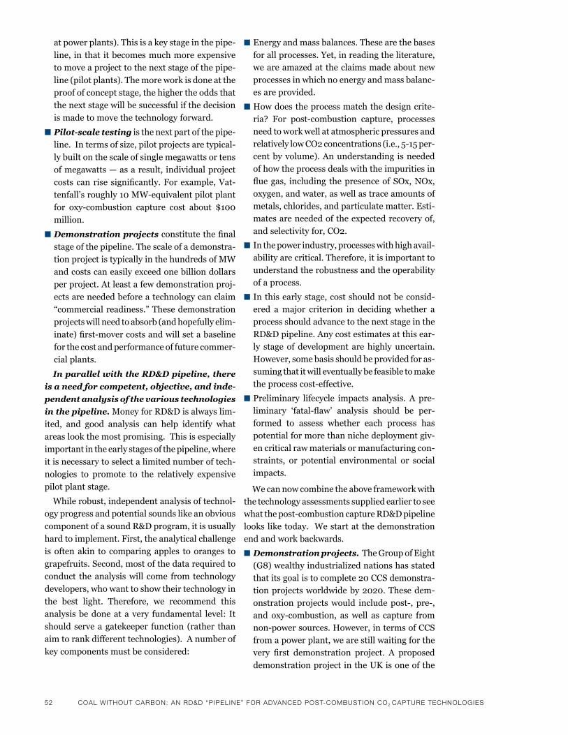
52 CoaL wiThouT CarBoN: aN rd&d “PiPeLiNe” For advaNCed PoST-ComBuSTioN Co2 CaPTure TeChNoLogieS
at power plants). This is a key stage in the pipe-
line, inthat itbecomesmuchmoreexpensive
tomoveaprojecttothenextstageofthepipe-
line (pilot plants). The more work is done at the
proof of concept stage, the higher the odds that
thenextstagewillbesuccessfulifthedecision
is made to move the technology forward.
n Pilot-scale testingisthenextpartofthepipe-
line. In terms of size, pilot projects are typical-
ly built on the scale of single megawatts or tens
of megawatts — as a result, individual project
costscanrise significantly.Forexample,Vat-
tenfall’sroughly10MW-equivalentpilotplant
for oxy-combustion capture cost about $100
million.
n Demonstration projectsconstitutethefinal
stage of the pipeline. The scale of a demonstra-
tion project is typically in the hundreds of MW
andcostscaneasilyexceedonebilliondollars
per project. At least a few demonstration proj-
ects are needed before a technology can claim
“commercialreadiness.”Thesedemonstration
projects will need to absorb (and hopefully elim-
inate)first-movercostsandwillsetabaseline
for the cost and performance of future commer-
cial plants.
In parallel with the RD&D pipeline, there
is a need for competent, objective, and inde-
pendent analysis of the various technologies
in the pipeline. Money for RD&D is always lim-
ited, and good analysis can help identify what
areas look the most promising. This is especially
important in the early stages of the pipeline, where
it is necessary to select a limited number of tech-
nologies to promote to the relatively expensive
pilot plant stage.
While robust, independent analysis of technol-
ogy progress and potential sounds like an obvious
component of a sound R&D program, it is usually
hard to implement. First, the analytical challenge
is often akin to comparing apples to oranges to
grapefruits. Second, most of the data required to
conduct the analysis will come from technology
developers, who want to show their technology in
the best light. Therefore, we recommend this
analysis be done at a very fundamental level: It
should serve a gatekeeper function (rather than
aim to rank different technologies). A number of
key components must be considered:
n Energy and mass balances. These are the bases for all processes. Yet, in reading the literature, we are amazed at the claims made about new processes in which no energy and mass balanc-es are provided.
n How does the process match the design crite-ria? For post-combustion capture, processesneed to work well at atmospheric pressures and relativelylowCO2concentrations(i.e.,5-15per-cent by volume). An understanding is needed of how the process deals with the impurities in fluegas, including thepresenceofSOx,NOx,oxygen,andwater,aswellastraceamountsofmetals, chlorides, and particulate matter. Esti-matesareneededoftheexpectedrecoveryof,and selectivity for, CO2.
n In the power industry, processes with high avail-ability are critical. Therefore, it is important to understand the robustness and the operability of a process.
n In this early stage, cost should not be consid-ered a major criterion in deciding whether a processshouldadvancetothenextstageintheRD&D pipeline. Any cost estimates at this ear-ly stage of development are highly uncertain. However, some basis should be provided for as-suming that it will eventually be feasible to make theprocesscost-effective.
n Preliminary lifecycle impacts analysis. A pre-liminary ‘fatal-flaw’ analysis should be per-formed to assess whether each process has potential for more than niche deployment giv-en critical raw materials or manufacturing con-straints, or potential environmental or social impacts.
We can now combine the above framework with the technology assessments supplied earlier to see whatthepost-combustioncaptureRD&Dpipelinelooks like today. We start at the demonstration end and work backwards.
n Demonstration projects. The Group of Eight (G8) wealthy industrialized nations has stated thatitsgoalistocomplete20CCSdemonstra-tionprojectsworldwideby2020.Thesedem-onstrationprojectswould includepost-, pre-,and oxy-combustion, aswell as capture fromnon-powersources.However,intermsofCCSfrom a power plant, we are still waiting for the very first demonstration project. A proposed
demonstration project in the UK is one of the
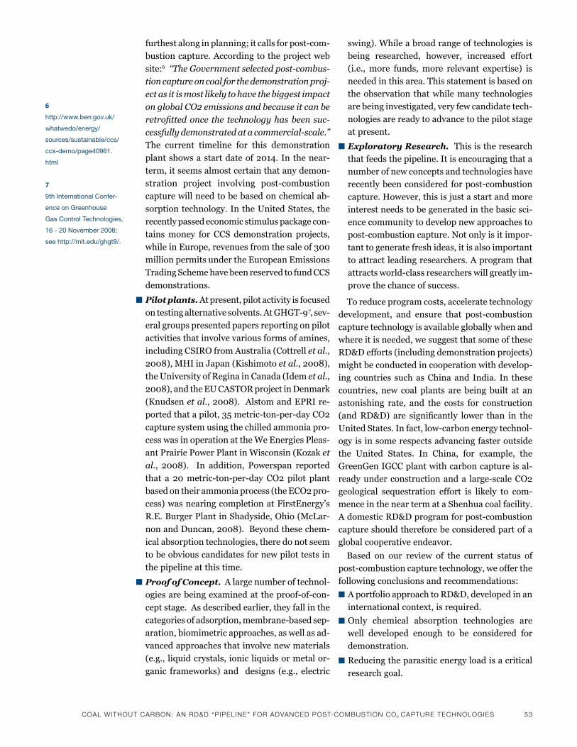
CoaL wiThouT CarBoN: aN rd&d “PiPeLiNe” For advaNCed PoST-ComBuSTioN Co2 CaPTure TeChNoLogieS 53
furthestalonginplanning;itcallsforpost-com-
bustion capture. According to the project web
site:6 “The Government selected post-combus-
tion capture on coal for the demonstration proj-
ect as it is most likely to have the biggest impact
on global CO2 emissions and because it can be
retrofitted once the technology has been suc-
cessfully demonstrated at a commercial-scale.”
The current timeline for this demonstration
plantshowsastartdateof2014.Inthenear-
term, it seems almost certain that any demon-
stration project involving post-combustion
capture will need to be based on chemical ab-
sorption technology. In the United States, the
recently passed economic stimulus package con-
tains money for CCS demonstration projects,
whileinEurope,revenuesfromthesaleof300
million permits under the European Emissions
Trading Scheme have been reserved to fund CCS
demonstrations.
n Pilot plants. At present, pilot activity is focused
ontestingalternativesolvents.AtGHGT-97, sev-
eral groups presented papers reporting on pilot
activities that involve various forms of amines,
including CSIRO from Australia (Cottrell et al.,
2008),MHIinJapan(Kishimotoet al.,2008),
the University of Regina in Canada (Idem et al.,
2008),andtheEUCASTORprojectinDenmark
(Knudsen et al.,2008).AlstomandEPRIre-
portedthatapilot,35metric-ton-per-dayCO2
capture system using the chilled ammonia pro-
cess was in operation at the We Energies Pleas-
ant Prairie Power Plant in Wisconsin (Kozak et
al., 2008). In addition, Powerspan reported
that a 20metric-ton-per-day CO2 pilot plant
based on their ammonia process (the ECO2 pro-
cess) was nearing completion at FirstEnergy’s
R.E. Burger Plant in Shadyside, Ohio (McLar-
nonandDuncan,2008).Beyondthesechem-
ical absorption technologies, there do not seem
to be obvious candidates for new pilot tests in
the pipeline at this time.
n Proof of Concept. A large number of technol-
ogiesarebeingexaminedattheproof-of-con-
cept stage. As described earlier, they fall in the
categoriesofadsorption,membrane-basedsep-
aration, biomimetric approaches, as well as ad-
vanced approaches that involve new materials
(e.g., liquid crystals, ionic liquids or metal or-
ganic frameworks) and designs (e.g., electric
swing). While a broad range of technologies is being researched, however, increased effort (i.e., more funds, more relevant expertise) isneeded in this area. This statement is based on the observation that while many technologies are being investigated, very few candidate tech-nologies are ready to advance to the pilot stage at present.
n Exploratory Research. This is the research that feeds the pipeline. It is encouraging that a number of new concepts and technologies have recentlybeenconsideredforpost-combustioncapture. However, this is just a start and more interest needs to be generated in the basic sci-ence community to develop new approaches to post-combustioncapture.Notonlyisitimpor-tant to generate fresh ideas, it is also important to attract leading researchers. A program that attractsworld-classresearcherswillgreatlyim-prove the chance of success.
To reduce program costs, accelerate technology development, and ensure that post-combustioncapture technology is available globally when and where it is needed, we suggest that some of these RD&D efforts (including demonstration projects) might be conducted in cooperation with develop-ing countries such as China and India. In these countries, new coal plants are being built at an astonishing rate, and the costs for construction (andRD&D) are significantly lower than in theUnitedStates.Infact,low-carbonenergytechnol-ogy is in some respects advancing faster outside the United States. In China, for example, theGreenGen IGCC plant with carbon capture is al-readyunderconstructionanda large-scaleCO2geological sequestration effort is likely to com-mence in the near term at a Shenhua coal facility. AdomesticRD&Dprogramforpost-combustioncapture should therefore be considered part of a global cooperative endeavor.
Based on our review of the current status of post-combustioncapturetechnology,weofferthefollowing conclusions and recommendations:
n A portfolio approach to RD&D, developed in an internationalcontext,isrequired.
n Only chemical absorption technologies are well developed enough to be considered for demonstration.
n Reducing the parasitic energy load is a critical
research goal.
6
http://www.berr.gov.uk/
whatwedo/energy/
sources/sustainable/ccs/
ccs-demo/page40961.
html
7
9th international Confer-
ence on Greenhouse
Gas Control technologies,
16 - 20 november 2008;
see http://mit.edu/ghgt9/.
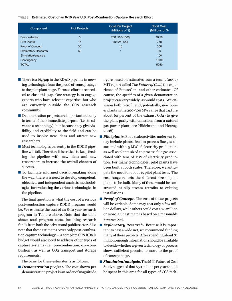
54 CoaL wiThouT CarBoN: aN rd&d “PiPeLiNe” For advaNCed PoST-ComBuSTioN Co2 CaPTure TeChNoLogieS
n There is a big gap in the RD&D pipeline in mov-ingtechnologiesfromtheproof-of-conceptstageto the pilot plant stage. Focused efforts are need-ed to close this gap. One strategy is to engage expertswhohave relevant expertise,butwhoare currently outside the CCS research community.
n Demonstration projects are important not only in terms of their immediate purpose (i.e., to ad-vance a technology), but because they give vis-ibility and credibility to the field and can be used to inspire new ideas and attract new researchers.
n Most technologies currently in the RD&D pipe-line will fail. Therefore it is critical to keep feed-ing the pipeline with new ideas and new researchers to increase the overall chances of success.
nTo facilitate informed decision-making alongthe way, there is a need to develop competent, objective, and independent analysis methodol-ogies for evaluating the various technologies in the pipeline.
Thefinalquestioniswhatthecostofaseriouspost-combustioncaptureRD&Dprogramwouldbe.Weestimatethecostofan8-10yearresearchprogram in Table 2 above. Note that the table shows total program costs, including research funds from both the private and public sector. Also notethattheseestimatescoveronlypost-combus-tion capture technology — a complete CCS RD&D budget would also need to address other types of capturesystems(i.e.,pre-combustion,oxy-com-bustion), as well as CO2 transport and storage requirements.
The basis for these estimates is as follows:
n Demonstration project. The cost shown per demonstration project is an order of magnitude
figurebasedonestimatesfromarecent(2007)
MIT report called The Future of Coal,theexpe-
rience of FutureGen, and other estimates. Of
course, thespecificsofagivendemonstration
project can vary widely, as would costs. We en-
visionbothretrofitand,potentially,newpow-
erplantsinthe200-300MWrangethatcapture
about60percentof theexhaustCO2(togive
the plant parity with emissions from a natural
gas power plant; see Hildebrand and Herzog,
2008).
n Pilot plants.Pilot-scaleactivitiesunderwayto-
dayincludeplantssizedtoprocessfluegasas-
sociatedwith1-5MWofelectricityproduction,
aswellasplantssizedtoprocessfluegasasso-
ciated with tens of MW of electricity produc-
tion. For many technologies, pilot plants have
been built at both scales. Therefore, we antici-
pate the need for about 15 pilot plant tests. The
cost range reflects the different size of pilot
plants to be built. Many of these would be con-
structed as slip stream retrofits to existing
installations.
n Proof of Concept. The cost of these projects
will be variable: Some may cost only a few mil-
liondollars,whileotherscouldcost$20million
or more. Our estimate is based on a reasonable
average cost.
n Exploratory Research. Because it is impor-
tant to cast a wide net, we recommend funding
many of these projects. After spending about $1
million, enough information should be available
to decide whether a given technology or process
showssufficientpromisetomovetotheproof
of concept stage.
n Simulation/analysis. The MIT Future of Coal
Studysuggestedthat$50millionperyearshould
be spent in this area for all types of CCS tech-
TaBLe 2 Estimated Cost of an 8-10 Year u.s. post-Combustion Capture research Effort
Component # of ProjectsCost Per Project
(Millions of $)Total Cost
(Millions of $)
Demonstration
pilot plants
proof of Concept
Exploratory research
simulation/analysis
Contingency
TOTAL
5
15
30
50
750 (500-1000)
50 (25-100)
10
1
3750
750
300
50
100
1000
5950
CoaL wiThouT CarBoN: aN rd&d “PiPeLiNe” For advaNCed PoST-ComBuSTioN Co2 CaPTure TeChNoLogieS 55
nology.Wescaledthisestimatedowntoreflect
the level of fundingneeded for post-combus-
tion capture technologies only.
n Contingency. Because of uncertainty in these
estimates (and in terms of future prices), we
haveincludeda20percentcontingency.■
referencesanderson, J.l., J.k Dixon and J.f. brennecke, “solubility of Co2,
Ch4, C2h6, C2h4, o2, and n2 in 1-hexyl-3-methylpyridinium bis(trifluoromethylsulfonyl)imide: Comparison to other ionic liquids,” acc. Chem. res, 40:11, 1208, (2007).
anthony, J.l., E.J. maginn and J.f. brennecke, “solubilities and thermodynamic properties of gases in the ionic liquid 1-n-butyl-3-methylimidazolium hexafluorophosphate,” J. phys. Chem. b, 106:29, 7315, (2002).
aroonwilas, a. and a. veawab, “Characterization and comparison of the Co2 absorption performance into single and blended alkanolamines in a packed column,” ind. Eng. Chem. res, 43:9, 2228, (2004).
bai, h. and a.C. Yeh, “removal of Co2 greenhouse gas by am-monia scrubbing,” ind. Eng. Chem. res, 36:6, 2490, (1997).
banerjee, r., a. phan, b. Wang, C. knobler, h. furukawa, m. o’keeffe and o.m. Yaghi, “high-throughput synthesis of zeolitic imidazolate frameworks and application to Co2 capture,” sci-ence, 319:5865, 939, (2008).
bara, J.E., C.J. Gabriel, E.s. hatakeyama, t.k. Carlisle, s. lessmann, r.D. noble and D.l. Gin, “improving Co2 selectivity in polym-erized room-temperature ionic liquid gas separation membranes through incorporation of polar substituents,” J. membr. sci, 321:1, 3, (2008).
barchas, r. and r. Davis, “the kerr-mcGee/abb lummus Crest technology for the recovery of Co2 from stack Gases,” En-ergy Convers. mgmt, 33:5-8, 333-340, (1992).
beer, J.m., “high efficiency electric power generation: the environ-mental role,” progress in Energy and Combustion science, 33:2, 107, (2007).
bhattacharya, s., a. nayak, m. shiavone and s.k. bhattacharya, “solubilization and concentration of carbon dioxide: novel spray reators with immobilized carbonic anhydrase,” biotech. bioeng., 86:1, 37 (2004).
blanchard, l.a., D. hancu, E.J. beckman and J.f. brennecke, “Green processing using ionic liquids and Co2,” nature, 399:6731, 28, (1999).
bond, G.m., J. stringer, D.k. brandvold, f.a. simsek, m.-G. med-ina and G. Egeland, “Development of integrated system for biomimetic Co2 sequestration using the enzyme carbonic anhydrase,” Energy & fuels, 15:2, 309, (2001).
bonenfant, D., mimeault, m. and r. hausler, “Determination of the structural features of distinct amines important for the absorp-tion of Co2 and regeneration in aqueous solution,” ind. Eng. Chem. res, 42:14, 3179, (2003).
bourrelly, s., p.l. llewellyn, C. serre, f. millange, t. loiseau and G. ferey, “Different adsorption behaviors of methane and carbon dioxide in the isotypic nanoporous metal terephthalates mil-53 and mil-47,” J. am. Chem. soc, 127:39, 13519, (2005).
burchell, t.D., r.r. Judkins and k.a Wilson, “Device for separating Co2 from fossil-fueled power plant emissions,” us patent 6,357,716, (2002).
Cansolv, “Cansolv technologies, inc.” retrieved october 5, 2008, from http://www.cansolv.com/ (2008).
Cesar, C., J.l. anthony, J.k. shah, t.i. morrow, J.f. brennecke and E.J. maginn, “Why is Co2 so soluble in imidazolium-based ionic liquids?,” J. am. Chem. soc, 126:16, 5300, (2004).
Chen, D.s., h.G. hsiue, J.D. schultze, b.h. song and J. springer, “Gas sorption properties and molecular-states of a liquid-crystal,” molecular Crystals and liquid Crystals science and technology section a-molecular Crystals and liquid Crystals, 237, 85, (1993).
Chen, G.h. and J. springer, “sorption and diffusion of gases in liquid crystalline substances,” molecular Crystals and liquid Crystals, 339, 31-44, (2000).
Cheng, l., l. Zhang, h. Chen and C. Gao, “Carbon dioxide re-moval from air by microalgae cultured in a membrane-photo-bioreactor,” sep. & purif. tech, 50:3, 324, (2006).
Ciferno, J.p., p. Dipietro and t. tarka, “an economic scoping study for Co2 capture using aqueous ammonia,” final report, na-tional Energy technology laboratory, us Department of En-ergy, pittsburgh, pa, (2005).
Cottrell, a.J., J.m. mcGregor, J. Jansen, Y. artanto, n. Dave, s. morgan, p. pearson, m.i. attalla, l.t. Wardhaugh, h. Yua, a. allport and p.h.m. feron, “post-combustion capture r&D and pilot plant operation in australia,” proceedings of the 9th inter-national Conference on Greenhouse Gas Control technologies, in press, (2008).
Dang, h. and G.t. rochelle, “Carbon Dioxide absorption rate and solubility in mEa/pZ/h2o,” sep. sci. tech, 38:2, 337, (2003).
Demontigny, D., p. tontiwachwuthikul and a. Chakma, “using polypropylene and polytetrafluoroethylene membranes in a membrane contact for Co2 absorption,” J. memb. sci, 277:1-2, 99, (2006).
Eia (Energy information administration), Emissions of Greenhouse Gases report, us Department of Energy report, DoE/Eia-0573(2006), (2007).
Gray, m.l., Y. soong, k.J. Champagne, h. pennline, J.p. baltrus, r.W. stevens Jr., r. khatri, s.s.C. Chuang and t. filburn, “improved immobilized carbon dioxide sorbents,” fuel proc. tech, 86:14-15, 1449, (2005).
hakka, l. E. and m. a. ouimet, “method for recovery of Co2 from gas streams”, united states patent and trademark office grantedppatent, Cansolv technologies inc. (2006).
hamilton, m.r., h.J. herzog and J.E. parsons, “project financing of new coal power plants with carbon capture and sequestra-tion,” proceedings of the 9th international Conference on Greenhouse Gas Control, in press, (2008).
herzog, h. J., “an introduction to Co2 separation and Capture technologies,” Energy laboratory Working paper, (1999). see http://sequestration.mit.edu/pdf/introduction_to_capture.pdf
hicks, J.C., J.h. Drese, D.J. fauth, m.l. Gray, G. qi and C.W. Jones, “Designing adsorbents for Co2 capture from flue gas – hyper-branched aminosalicas capable of capturing Co2 reversibly,” J. am. Chem. soc, 130:10, 2902, (2008).
hildebrand, a.n. and h.J. herzog, “optimization of carbon capture percentage for technical and economic impact of near-term CCs implementation at coal-fired power plants,” proceedings of the 9th international Conference on Greenhouse Gas Control, in press, (2008).
ho, m.Y., G. leamon, G.W. allinson and D.E. Wiley, “Economics of Co2 and mixed gas geosequestration of flue gas using gas separation membranes,” ind. Eng. Chem. res, 45:8, 2546, (2006).

56 CoaL wiThouT CarBoN: aN rd&d “PiPeLiNe” For advaNCed PoST-ComBuSTioN Co2 CaPTure TeChNoLogieS
ho, m.Y., G.W. allinson and D.E. Wiley, “reducing the cost of Co2 capture from flue gases using membrane technology,” ind. Eng. Chem. res, 47:5, 1562, (2008).
ho, m.Y., G.W. allinson and D.E. Wiley, “reducing the cost of Co2 capture from flue gases using pressure swing adsorption,” ind. Eng. Chem. res, 47:14, 4883, (2008).
hsiue, G.h., D.s. Chen, and C.J. hsieh, “Gas sorption properties in a smectic liquid-crystal,” molecular Crystals and liquid Crystals science and technology section a-molecular Crystals and liquid Crystals, 241, 187, (1994).
huang, J., J. Zou and W.s.W. ho, “Carbon dioxide capture using a Co2-selective facilitated transport membrane,” ind. Eng. Chem. res, 47:4, 1267, (2006).
idem, r., D. Gelowitz, and p. tontiwachwuthikul, “Evaluation of the performance of various amine based solvents in an optimized multipurpose technology development pilot plant”, proceedings of the 9th international Conference on Greenhouse Gas Control technologies, in press, (2008).
intergovernmental panel on Climate Change (ipCC) special report, Carbon Dioxide Capture and storage, new York: Cambridge university press (2005).
international Energy organization (iEa), World Energy outlook 2008, appendix a.
Jassim, m.s. and G.t. rochelle, “innovative absorber/stripper configurations for Co2 capture by aqueous monoethanolamine,” ind. Eng. Chem. res, 45:8, 2465, (2006).
Judkins, r. and t. burchell, “Gas separation device based on electrical swing adsorption,” us patent 5,972,077, (1999).
Judkins, r. and t. burchell, “Electrical swing adsorption gas stor-age and delivery system,” us patent 5,912,424, (1999).
kishimoto, s., t. hirata, m. iijima, t. ohishi, k. higaki and r. mitch-ell, “Current status of mhi’s Co2 recovery technology and optimization of Co2 recovery plant with a pC fired power plant,” proceedings of the 9th international Conference on Greenhouse Gas Control technologies, in press, (2008).
knowles, G.p., s.W. Delaney and a.l. Chaffee, “Diethylenetriamine[propyl(silyl)]-functionalized (Dt) mesopo-rous silicas as Co2 adsorbents,” ind. Eng. Chem, 45:8, 2626, (2006).
knudsen, J.n., J.n. Jensen, p-J vilhelmsen and o. biede, “Experi-ence with Co2 capture from coal flue gas in pilot-scale: testing of different amine solvents,” proceedings of the 9th interna-tional Conference on Greenhouse Gas Control technologies, in press, (2008).
kohl, a.l. and r.b. nielsen, Gas purification, 5th ed., Gulf publish-ing Co., houston, tx. (1997).
konduru, n., p. lindner and n.m. assaf-anid, “Curbing the green-house effect by carbon dioxide adsorption with zeolite 13x,” aiChE Jl, 53:12, 3137, (2007).
kozak, f., a. petig, E. morris, r. rhudy and D. thimsen, “Chilled ammonia process for Co2 capture,” proceedings of the 9th international Conference on Greenhouse Gas Control tech-nologies, in press, (2008).
lee, J.b., C.k. ryu, J.-i. back, J.h. lee, t.h. Eom and s.h. kim, “sodium-based dry regenerable sorbent for carbon dioxide capture from power plant flue gas,” ind. Eng. Chem. res, 47:13, 4465, (2008).
li, p., b. Ge, s. Zhan, s. Chen, q. Zhang, and Y. Zhao, “Co2 cap-ture by polyethylenimine -modified fibrous adsorbent,” langmuir, 24:13, 6567, (2008).
li, p., s. Zhan, s. Chen, q. Zhang, J. pan, and b. Ge, “preparation and adsorption properties of polyethylenimine containing fibrous adsorbent for carbon dioxide capture,” J. appl. polym. sci, 108:6, 3851, (2008).
linga, p., a. adeyemo, and p. Englezos, “medium-pressure clathrate hydrate/membrane hybrid process for postcombustion capture of carbon dioxide,” Environ. sci. technol, 42:1, 315, (2007).
linga, p., r. rajnish kumar, J.a. ripmeester and p. Enlezos, “hydrate processes for Co2 capture and scale up using a new appara-tus” in proceedings of the 6th international Conference on Gas hydrates (iCGh 2008), vancouver, british Columbia,, July 6-10, (2008).
manovic, v. and E.J. anthony, “thermal activation of Cao-based sorbent and self-reactivation during Co2 capture looping cy-cles,” Environ. sci. tech, 42:11, 4170, (2008).
mclarnon, C.r., “ammonia based Co2 capture with multi-pollutant control technology,” presented at international Conference on air quality vi, arlington, va. (2007).
mclarnon, C.r. and J.l. Duncan, “testing of ammonia based Co2 capture with multi-pollutant control technology,” proceedings of the 9th international Conference on Greenhouse Gas Control technologies, in press, (2008).
meidersma, G.W., l.m. Galan sanchez, a.r. hansmeier and a.b. de haan, “application of task-specific ionic liquids for intensi-fied separations,” monatshefte fuer Chemie, 138:11, 1125, (2007).
merel, J., m. Clausse and f. meunier, “Experimental investigation on Co2 post-combustion capture by indirect thermal swing adsorption using 13x and 5a zeolites,” ind. Eng. Chem. res, 47:1, 209, (2008).
millward, a.r. and o.m. Yaghi, “metal-organic frameworks with exceptionally high capacity for storage of carbon dioxide at room temperature” J. am. Chem. soc, 127:51, 17998, (2005).
mit (massachusetts institute of technology), the future of Coal in a Carbon Constrained World, http://mit.edu/coal, (2007).
mueller, u., m. schubert, f. teich, h. puetter, k. schierle-arndt and J. pastre, “metal-organic frameworks - prospective industrial applications,” J. materials Chem, 16, 626, (2006).
ochoa-fernandez, E., m. ronning, x. Yu, t. Grande and D. Chen “Compositional effects of nanocrystalline lithium zironate on its Co2 capture properties,” ind. Eng. Chem. res, 47:2, 434, (2008).
oyenekan, b.a. and G.t. rochelle, “alternative stripper configura-tions for Co2 capture by aqueous amines,” aiChE Jl, 53:12, 3144, (2007).
pfister, D., C. byrd, and h. Davidson, “Electro-desorption compres-sor,” us patent 6,502,419, (2003).
powell, C.E. and G.G. qiao, “polymeric Co2/n2 gas separation membranes for the capture of carbon dioxide from power plant flue gases,” J. memb. sci, 279:1-2, 1, (2006).
radosz, m., x. hu, k. krutkramelis and Y. shen, “flue-gas carbon capture on carbonaceous sorbents: towards a low-cost multi-functional carbon filter for ‘green’ energy producers,” ind. Eng. Chem. res, 47:10, 3783, (2008).
resnik, k.p., J.t. Yeh and h.E. pennline, “aqua ammonia process for simultaneous removal of Co2, so2 and nox,” int. J. Envi-ror. tech. mgt, 4:1-2, 89, (2004).
rodriguez, n., m. alonso, G. Grasa and J.C. abanades, “heat requirements in a calciner of CaCo3 integrated in a Co2 cap-ture using Cao,” Chem. Eng. Jl, 138:1-3, 148, (2008).

CoaL wiThouT CarBoN: aN rd&d “PiPeLiNe” For advaNCed PoST-ComBuSTioN Co2 CaPTure TeChNoLogieS 57
romeo, l.m., J.C. abanades, J.m. Escosa, J. pano, a. Gimenez, a. sanchez-biezma and J.C. ballesteros, “oxyfuel carbonation/calination cycles for low cost Co2 capture in existing power plants,” Energy Conv. mgmt, in press, (2008).
sanden, k., t. ursin1, a-h. haaland, h.a. haugen, “Co2 capture from gas power plants – Just Catchtm potential cost reduc-tions,” proceedings of the 8th international Conference on Greenhouse Gas Control technologies, trondheim, norway, o. bolland, h. f. svendsen, p. Zweigel and J. Gale. (eds.), El-sevier (2006).
sander, m.t. and C.l. mariz, “the fluor Daniel Econamine fG process: past experience and present day focus,” Energy Convers. mgmt, 33:5-8, 341, (1992).
sartori, G. and D.W. savage, “sterically hindered amines for o2 removal from gases,” ind. Eng. Chem. fundam, 22:2, 239, (1983).
satyapal, s., t.p. filburn, J. trela, and J. strange, “performance and properties of a solid amine absorbent for carbon dioxide removal in space life support applications,” Energy fuels, 15:2, 250, (2001).
scovazzo, p., J. pshusta, D. Dubois, C. koval and r.D. noble, “Electrochemical separation and concentration of <1% carbon dioxide from nitrogen,” J. Electrochem. soc, 150:5, D91, (2003).
shimada, k., i.n. seekkuarachchi and h. kumazawa, “absorption of Co2 into aqueous solutions of sterically hindered methyl aminoethanol using a hydrophobic microroporous hollow fiber contained contactor,” Chem. Eng. Comm, 193:1, 38, (2006).
skjanes, k., p. lindblad and J. muller, “bioCo2 – a multidisciplinary, biological approach using solar energy to capture Co2 while producing h2 and high value products,” biotech. bioeng., 24, 405, (2007).
spencer, D.f. “integration of an advanced Co2 separation process with methods for disposing of Co2 in oceans and terrestrial deep aquifers,” in Greenhouse Gas Control technologies, p. riemer, b. Elisasson and a. Wokaun, Elsevier: pp 89-94, (1999).
tang, J., h. tang, W. sun, m. radosz and Y. shen, “poly(ionic liquid)s as new materials for Co2 absorption” J. polym. sci. part a: polym. Chem, 43:22, 5477, (2005a).
tang, J., h. tang, W. sun, h. plancher, m. radosz and Y. shen, “poly(ionic liquid)s: a new material with enhanced and fast Co2 absorption,” Chem. Commun, 26, 3325, (2005b).
trilla, m., r. pleixats, t. parella, C. blanc, p. Dieudonné, Y. Guari and m.W.C. man, “ionic liquid crystals based on mesitylene-containing bis- and trisimidazolium salts,” langmuir, 24:1, 259, (2008).
venegas, m.J., E. fregoso-israel, r. Esamilla and h. pfeiffer, “ki-netic and reaction mechanism of Co2 sorption on li4sio4: study of the particle size effect,” ind. Eng. Chem. res, 46:8, 2407, (2007).
Wang, b., a.p. Cote, h. furukawa, m.o. o’keeffe and o.m. Yaghi, “Colossal cages in zeolitic imidazolate frameworks as selective carbon dioxide reservoirs,” nature, 453, 207, (2008).
Wu, W., b. han, h. Gao, Z. liu, t. Jiang and J. huang, “Desulfuriza-tion of flue gas: so2 absorption by an ionic liquid,” angewandte Chemie-international Edition, 43:18, 2415, (2004).
Yeh, a.C. and h. bai, “Comparison of ammonia and monoetha-nolamine solvents to reduce Co2 greenhouse gas emissions,” sci. total Environ, 228:2-3, 121, (1999).
You, J.k., h. park, s.h. Yang, W.h. hong, W. shin, J.k. kang, k.b. Yi and J.-n. kim, “influence of additives including amine and hydroxyl groups on aqueous ammonia absorbent for Co2 capture,” J. phys. Chem. b, 112:14, 4323, (2008).
Younes, m., D. Clodic and a. bill, “test results of Co2 capture by anti-sublimation: Capture efficiency and energy consumption for boiler plants,” proceedings of the 8th international Confer-ence on Greenhouse Gas Control technologies, trondheim, norway, o. bolland, h. f. svendsen, p. Zweigel and J. Gale. (eds.), Elsevier (2006).
Yue, m.b., l.b. sun, Y. Cao, Y. Wang, Z.J. Wang, and J.h. Zhu, “Efficient Co2 capture derived from as-synthesized mCm-41 modified with amine,” Chem. Eur. J, 14:11, 3442, (2008).
Zou, J. and W.s.W. ho, “Co2-selective polymeric membranes containing amines in cross-linked polyvinylalchol,” J. memb. sci, 286:1-2, 301, (2008).
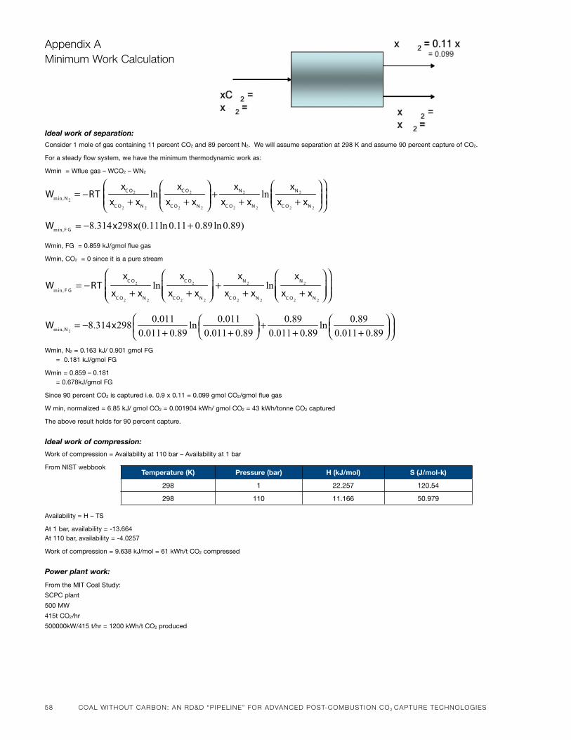
58 CoaL wiThouT CarBoN: aN rd&d “PiPeLiNe” For advaNCed PoST-ComBuSTioN Co2 CaPTure TeChNoLogieS
appendix a minimum work Calculation
Ideal work of separation:
Consider 1 mole of gas containing 11 percent Co2 and 89 percent n2. We will assume separation at 298 k and assume 90 percent capture of Co2.
for a steady flow system, we have the minimum thermodynamic work as:
Wmin = Wflue gas – WCo2 – Wn2
Wmin, fG = 0.859 kJ/gmol flue gas
Wmin, Co2 = 0 since it is a pure stream
Wmin, n2 = 0.163 kJ/ 0.901 gmol fG = 0.181 kJ/gmol fG
Wmin = 0.859 – 0.181 = 0.678kJ/gmol fG
since 90 percent Co2 is captured i.e. 0.9 x 0.11 = 0.099 gmol Co2/gmol flue gas
W min, normalized = 6.85 kJ/ gmol Co2 = 0.001904 kWh/ gmol Co2 = 43 kWh/tonne Co2 captured
the above result holds for 90 percent capture.
Ideal work of compression:
Work of compression = availability at 110 bar – availability at 1 bar
from nist webbook
availability = h – ts
at 1 bar, availability = -13.664at 110 bar, availability = -4.0257
Work of compression = 9.638 kJ/mol = 61 kWh/t Co2 compressed
Power plant work:
from the mit Coal study:
sCpC plant
500 mW
415t Co2/hr
500000kW/415 t/hr = 1200 kWh/t Co2 produced
Wmin, F G
= −RTx
C O2
xC O2
+ xN 2
lnx
C O2
xC O2
+ xN 2
+x
N 2
xC O2
+ xN 2
lnx
N 2
xC O2
+ xN 2
min, 8.314 298 (0.11ln 0.11 0.89ln 0.89)F GW x x= − +
2min,
0.011 0.011 0.89 0.898.314 298 ln ln
0.011 0.89 0.011 0.89 0.011 0.89 0.011 0.89NW x = − + + + + +
2 2 2 2
2
2 2 2 2 2 2 2 2
min, ln lnC O C O N N
N
C O N C O N C O N C O N
x x x xW RT
x x x x x x x x
= − + + + + +
temperature (k) pressure (bar) h (kJ/mol) s (J/mol-k)
298 1 22.257 120.54
298 110 11.166 50.979

CoaL wiThouT CarBoN: CommerCiaL dePLoymeNT oF geoLogiC CarBoN SeQueSTraTioN 59
ChaPTer 4
Commercial Deployment of Geologic Carbon sequestration: Technical Components of an Accelerated U.S. Program
Drs. s. JulIO FrIEDMANN anD rOBIN l. NEwMArklaWrEnCE livErmorE national laboratorY
60 CoaL wiThouT CarBoN: CommerCiaL dePLoymeNT oF geoLogiC CarBoN SeQueSTraTioN
ChaPTer 4 iNTroduCTioN
C arbon capture and sequestration
(CCS) provides a promising pathway
for achieving swift, dramatic, and
sustained reductions in global
greenhouse gas emissions. CCS in-
volves capturing and separating CO2 from indus-
trial and power plant flue streams, and then
compressing and transporting it at high concentra-
tions for storage underground. Geologic carbon
sequestration (GCS) refers to the portion of the
process in which the captured CO2 is injected into
suitable deep geological formations, where it re-
mains indefinitely.While CCS can be used in a
numberofcontexts(i.e.,naturalgasandbiomass
power generation, petroleum refining, biofuels
production, cement making, and chemical manu-
facturing), it is primarily considered as a means
ofreducingCO2emissionsfromcoal-firedpower
generation.
Over the past decade, CCS has been gaining
ground as an important component within a com-
prehensive response to climate change. Several
institutions, including the Intergovernmental
Panel on Climate Change (IPCC), the Interna-
tional Energy Agency (IEA), the U.S. Department
of Energy (DOE), the Massachusetts Institute of
Technology (MIT), and the Electric Power Re-
search Institute (EPRI), have recently carried out
studiesexaminingthetechnicalviabilityandabate-
ment potential of CCS.1Theirfindingshaveledto
a number of key conclusions:
n First, without CCS, the cost of achieving atmo-
spheric stabilization for a range of scenarios will
increase50-80percent.
nSecondly,itisextremelyunlikelythatstabiliza-
tionbelow550partspermillion(ppm)canbe
achieved without CCS.
n Thirdly, CCS is technically sound and feasible
basedonanalogous,long-livedindustrialpro-
cesses, as well as a handful of successful proj-
ects in different parts of the world.
With respect to geologic carbon sequestration
(GCS) in particular, the current literature finds
that:
1
a full list of recent pub-
lished reports on CCs and
GCs, including relevant
web links, is available at
the end of this document.
2
one gigatonne equals
1 billion metric tons.
n GCS resources are widespread globally — in-
cluding in key OECD and developing countries
—suchthatthecapacitylikelyexiststoseques-
ter tens to thousands of gigatonnes2 of CO2.
n Over time, the costs of GCS are likely to decrease
and the safety and effectiveness of GCS are like-
ly to increase.
For these and other reasons, CCS features
prominently in the American Recovery and Rein-
vestmentActof2009(economicstimuluspackage
adopted earlier this year in the United States), and
the proposed American Clean Energy and Secu-
rity Act (ACESA) recently adopted by the U.S.
House of Representatives. It has been a theme in
recent discussions between President Obama and
the governments of Canada and China.
Yet, if CCS is to play a meaningful role in achiev-
ing atmospheric stabilization, the United States
will likely need to increase dramatically the num-
berofGCSprojectsinoperationby2030.Dooley
et al.(2008)estimatethattostabilizegreenhouse
gasconcentrationsat550ppm,worldwidedeploy-
ment must jump from 5 million tons per year
(today) to260million tonsperyearwithin just
eleven years. Stabilization at more stringent cli-
matetargets—450ppmorbelow—couldrequire
gigatonne-scaleCCSdeploymentby2020,accord-
ing to the U.S. Climate Change Science Program
(2007). In the United States alone, the Energy
Information Administration’s (EIA recent analysis
of ACESA estimates that as much as 69 GW of coal
with CCS would be deployed by implementation
oftheACESAproposal-whichcouldmeanwell
over100largeGCSprojects(EIA,2009).
In order to reach these targets, the United States
must launch an accelerated research and develop-
ment program aimed at readying GCS technology
for broad commercialization. The issue is not
whether saline formation sequestration is possible
or safe or effective today – plenty is known based
onothergeologicalexpertise,particularly inthe
oil industry and based on enhanced oil recovery
(EOR) practices, to establish the core discipline
– but rather whether the level of predictive capac-
photo on page 59.
Denbury resourses
Green CO2 pipeline
under Construction
in louisiana in Early
2009.
The pipeline will connect new industrial and natural sources of Co2 near the gulf of mexico to eor fields in Texas. image courtesy of denbury resources, inc.
CoaL wiThouT CarBoN: CommerCiaL dePLoymeNT oF geoLogiC CarBoN SeQueSTraTioN 61
ityintheindustryisadequateforefficientcase-by-case decision-making. There appears to benear-consensus among leaders in sequestrationefforts that an enhanced technical capability is needed for efficient regulatory and commercialtransactions, and that the only way to develop that capabilityisthroughiterativestudyofcommercial-scale injections of CO2. While industrial analogs such as EOR and acid gas disposal provide a solid base of experience upon which to develop firstdemonstration and early commercial GCS projects (especially in preferred and well circumscribed geological settings) a deeper predictive under-standing of the geophysics, geochemistry, and geomechanics of sequestration is required to more effectivelyandefficientlyassessprojectrisksandinform stakeholder participation.
With the increases in programmatic budget, strong leadership within the DOE, and the addition of ARRA (stimulus) projects and funds, the current DOEOfficeofFossilEnergyprogram inGCS isvery active. Much of this activity is based on years of research road mapping and stakeholder buy in (DOE-NETL,2009),andmuchisaimedatanswer-ing key questions from a set of stakeholders and iswellconfiguredtosucceed.Thisactivityhasalsocreated opportunities to gather new knowledge, science, and information and to test new technol-ogy. It is vitally important that the United States seize these opportunities and that these programs have sufficient funds and clarity of mission toachieve the goals. A goal of this document is to help strengthen that mission and provide additional thoughts as to how those goals might be achieved.
This document identifies the critical researchtopics and technical concerns that should form the focus of a GCS program in the United States. The
core areas addressed include:
n Research and Development:
l Hazard assessment/risk management
(groundwater protection, geomechanics,
well bores)
lMonitoring and verification (novel tools,
integration, lab work)
l Applied science and technology (advanced
simulators, experimental test-bed, basic
science)
n Demonstration/Field Program:
l Enhanced U.S. program
l Integrated projects
n International Collaboration:
l Field program
lNon-technicalwork
l Geologic assessments
The discussion begins with an overview of GCS,
including an overview summary of the history
of geological carbon storage and the current state
of research and deployment efforts.
I. Description of Geological Carbon Sequestration
Geological carbon sequestration involves the injec-
tion and long-term storage of large volumes of
CO2 in deep geological formations (Figure 1, page
62). The most promising reservoirs are porous
and permeable rock bodies, generally at depths
of roughly 1 kilometer, where pressure and tem-
perature conditions enable CO2 to enter a super-
critical phase in which its viscosity and density are
similar to that of oil. A number of geological res-
ervoirs appear to have the potential to store many
hundreds to thousands of gigatonnes of CO2. The
most important units are saline formations. These
contain brine in their pore volumes (salinities
greaterthan10,000ppm)andarewidelydistrib-
uted geographically. The CO2 sequestration capac-
ity of saline formations in North America has been
estimatedatbetween1,300and3,000gigatonnes
(DOENETL,2008).
Mature oil and gas fields, which have some
combination of water and hydrocarbons in their
porevolumes,alsoserveaspotential sequestra-
tion sites. In some cases, economic gains can be
achieved through the use of captured CO2 for EOR
or enhanced gas recovery. Substantial use of CO2
in EOR applications already occurs in the United
States, withmore than 60million tons of CO2
injected annually from natural and anthropo-
genicsources.Basedon100-plusyearsofoiland
gasexplorationandexploitation,aswellasexpe-
rience with water management and hazardous
waste disposal, both saline formations and mature
oilandgasfieldsarewellunderstoodintermsof
their porosity, permeability, physics, and basic
chemistry.
Because of their large storage potential and
broad distribution, saline formations are likely to
provide the predominant locale for geological
sequestration. However, initial projects will prob-
ablyoccurinmatureoilandgasfieldsaspartof
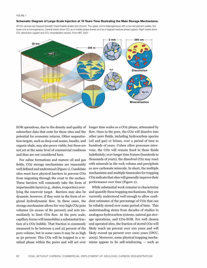
62 CoaL wiThouT CarBoN: CommerCiaL dePLoymeNT oF geoLogiC CarBoN SeQueSTraTioN
EOR operations, due to the density and quality of
subsurfacedatathatexistforthesesitesandthe
potential for economic returns. Other sequestra-
tion targets, such as deep coal seams, basalts, and
organic shale, may also prove viable; but these are
not yet at the same level of commercial readiness
and thus are not considered here.
For saline formations and mature oil and gas
fields, CO2 storagemechanisms are reasonably
welldefinedandunderstood(Figure1).Candidate
sites must have physical barriers to prevent CO2
from migrating through the crust to the surface.
These barriers will commonly take the form of
impermeable layers (e.g., shales, evaporites) over-
lying the reservoir target. Barriers may also be
dynamic,however,iftheyexistintheformofre-
gional hydrodynamic flow. In these cases, the
storage mechanism allows for very high CO2 pore
volumes (in excess of 80 percent) and acts im-
mediately to limit CO2 flow. At the pore scale,
capillary forces will immobilize a substantial frac-
tion of a CO2 bubble. That fraction is commonly
measured to be between 5 and 25 percent of the
pore volume, but in some cases it may be as high
as50percent.ThisCO2willbetrappedinare-
sidual phase within the pores and will act over
longer time scales as a CO2 plume, attenuated by
flow.Onceinthepore,theCO2willdissolveinto
otherporefluids,includinghydrocarbonspecies
(oil and gas) or brines, over a period of tens to
hundreds of years. Unless other processes inter-
vene, the CO2 will remain fixed in these fluids
indefinitely;overlongertimeframes(hundredsto
thousands of years), the dissolved CO2 may react
with minerals in the rock volume and precipitate
as new carbonate minerals. In short, the multiple
mechanisms and multiple timescales for trapping
CO2 indicate that sites will generally improve their
performance over time (Figure 2).
While substantial work remains to characterize
and quantify these trapping mechanisms, they are
currentlyunderstoodwellenoughtoallowconfi-
dent estimates of the percentage of CO2 that can
be reliably stored over some period of time. This
understanding stems from decades of studies in
analogous hydrocarbon systems, natural gas stor-
age operations, and CO2-EOR. Forwell chosen
and operated sites, the fraction of stored CO2 will
likely reach 99 percent over 100 years andwill
likelyexceed99percentover1000years(IPCC,
2005).Moreover,somephysicaltrappingmecha-
nisms appear to be self-reinforcing — such as
Figure 1
schematic Diagram of large-scale Injection at 10 Years time Illustrating the Main storage Mechanisms.
all Co2 plumes are trapped beneath impermeable shales (not shown). The upper unit is heterogeneous with a low net percent usable, the lower unit is homogeneous. Central insets show Co2 as a mobile phase (lower) and as a trapped residual phase (upper). right insets show Co2 dissolution (upper) and Co2 mineralization (lower). From miT, 2007
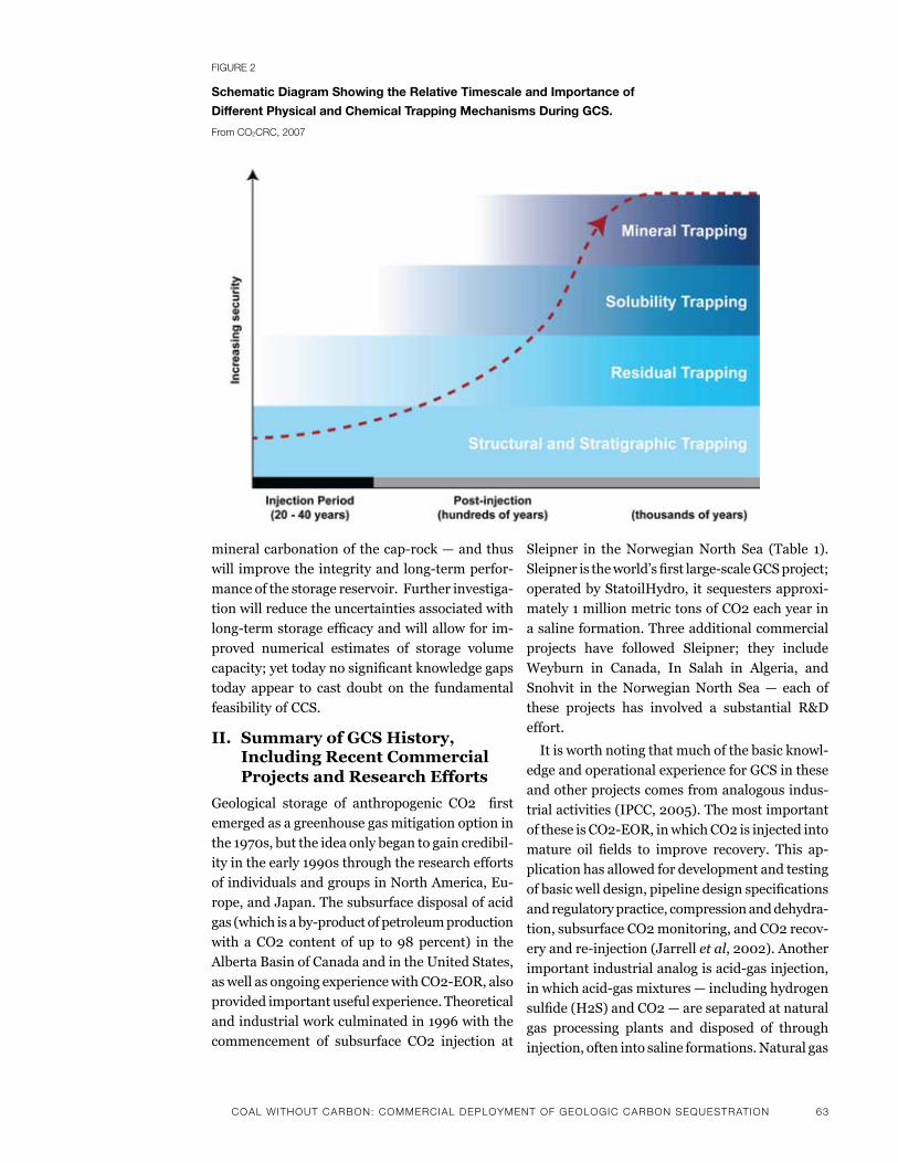
CoaL wiThouT CarBoN: CommerCiaL dePLoymeNT oF geoLogiC CarBoN SeQueSTraTioN 63
mineralcarbonationofthecap-rock—andthus
will improvetheintegrityandlong-termperfor-
mance of the storage reservoir. Further investiga-
tion will reduce the uncertainties associated with
long-termstorageefficacyandwillallowforim-
proved numerical estimates of storage volume
capacity;yettodaynosignificantknowledgegaps
today appear to cast doubt on the fundamental
feasibility of CCS.
II. Summary of GCS History, Including Recent Commercial Projects and Research Efforts
Geological storage of anthropogenic CO2 first
emerged as a greenhouse gas mitigation option in
the1970s,buttheideaonlybegantogaincredibil-
ityintheearly1990sthroughtheresearchefforts
of individuals and groups in North America, Eu-
rope, and Japan. The subsurface disposal of acid
gas(whichisaby-productofpetroleumproduction
with a CO2 content of up to 98 percent) in the
Alberta Basin of Canada and in the United States,
aswellasongoingexperiencewithCO2-EOR,also
providedimportantusefulexperience.Theoretical
and industrial work culminated in 1996 with the
commencement of subsurface CO2 injection at
Sleipner in the Norwegian North Sea (Table 1).
Sleipneristheworld’sfirstlarge-scaleGCSproject;
operatedbyStatoilHydro,itsequestersapproxi-
mately 1 million metric tons of CO2 each year in
a saline formation. Three additional commercial
projects have followed Sleipner; they include
Weyburn in Canada, In Salah in Algeria, and
Snohvit in the Norwegian North Sea — each of
these projects has involved a substantial R&D
effort.
It is worth noting that much of the basic knowl-
edgeandoperationalexperienceforGCSinthese
and other projects comes from analogous indus-
trialactivities(IPCC,2005).Themostimportant
oftheseisCO2-EOR,inwhichCO2isinjectedinto
mature oil fields to improve recovery. This ap-
plication has allowed for development and testing
ofbasicwelldesign,pipelinedesignspecifications
and regulatory practice, compression and dehydra-
tion, subsurface CO2 monitoring, and CO2 recov-
eryandre-injection(Jarrellet al,2002).Another
importantindustrialanalogisacid-gasinjection,
inwhichacid-gasmixtures—includinghydrogen
sulfide(H2S)andCO2—areseparatedatnatural
gas processing plants and disposed of through
injection, often into saline formations. Natural gas
Figure 2
schematic Diagram showing the relative timescale and Importance of
Different physical and Chemical trapping Mechanisms During GCs.
From Co2CrC, 2007
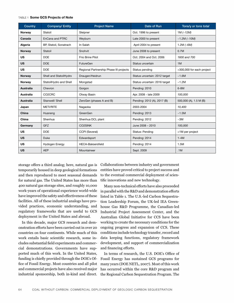
64 CoaL wiThouT CarBoN: CommerCiaL dePLoymeNT oF geoLogiC CarBoN SeQueSTraTioN
storage offers a third analog; here, natural gas is
temporarily housed in deep geological formations
and then reproduced to meet seasonal demands
for natural gas. The United States has more than
400naturalgasstoragesites,androughly10,000
work-yearsofoperationalexperienceworld-wide
have improved the safety and effectiveness of these
facilities. All of these industrial analogs have pro-
vided practices, economic understanding, and
regulatory frameworks that are useful to GCS
deployment in the United States and abroad.
In this decade, major GCS research and dem-
onstrationeffortshavebeencarriedoutinover20
countries on four continents. While much of this
work entails basic scientific research, some in-
cludessubstantialfieldexperimentsandcommer-
cial demonstrations. Governments have sup-
ported much of this work. In the United States,
fundingischieflyprovidedthroughtheDOE’sOf-
ficeofFossilEnergy.Mostcountriesandallpilot
and commercial projects have also received major
industrial sponsorship, both in-kind and direct.
Collaborations between industry and government
entities have proved critical to project success and
to the eventual commercial deployment of scien-
tificinnovationsandnewtechnology.
Manynon-technicaleffortshavealsoproceeded
in parallel with the R&D and demonstration efforts
listedinTable1.TheU.S.-ledCarbonSequestra-
tionLeadershipForum, theUK-led IEAGreen-
house Gas R&D Programme, the Canadian-led
Industrial Project Assessment Center, and the
Australian Global Initiative for CCS have been
working to create the necessary conditions for the
ongoing progress and expansion of CCS. These
conditions include technology transfer, record and
data keeping functions, regulatory framework
development, and support of commercialization
andfinancingefforts.
Intermsofresearch, theU.S.DOE’sOfficeof
Fossil Energy has sustained GCS programs for
manyyears(DOENETL,2007).Mostofthiswork
has occurred within the core R&D program and
the Regional Carbon Sequestration Program. The
TaBLe 1 some GCs projects of Note
Country Company/ Entity Project Name Date of Run Tons/y or tons total
Norway statoil sleipner oct. 1996 to present 1m (~12M)
Canada EnCana and ptrC Weyburn late 2000 to present ~1.2m (~10M)
Algeria bp, statoil, sonatrach in salah april 2004 to present 1.2m (~6M)
Norway statoil snohvit June 2008 to present 0.7m
us DoE frio brine pilot oct. 2004 and oct. 2006 1600 and 700
us DoE futureGen status uncertain 1m
us DoE regional partnership phase iii projects status pending >300,000 for each project
Norway shell and statoilhydro Draugen/heidrun status uncertain: 2012 target ~1.6m
Norway statoilhydro and shell mongstad status uncertain: 2016 target ~1.2m
Australia Chevron Gorgon pending: 2010 6-8m
Australia Co2CrC otway basin apr. 2008 - late 2009 100,000
Australia stanwell/ shell ZeroGen (phases a and b) pending: 2012 (a), 2017 (b) 500,000 (a), 1.5 m (b)
Japan mEti/ritE nagaoka 2003-2004 10,400
China huaneng GreenGen pending: 2013 ~1.5m
China shenhua shenhua DCl plant pending: 2012 ~3m
Germany GfZ Co2sink June 2008 – 2010 100,000
us DoE CCpi (several) status: pending >1m per project
us Duke Edwardsport pending: 2014 1-4m
us hydogen Energy hECa-baksersfield pending: 2014 1.5m
us aEp mountaineer sept. 2009 .1m
CoaL wiThouT CarBoN: CommerCiaL dePLoymeNT oF geoLogiC CarBoN SeQueSTraTioN 65
DOE’s National Laboratories — including Law-
rence Berkeley National Laboratory (LBNL),
Lawrence Livermore National Laboratory (LLNL),
LosAlamosNationalLaboratory(LANL),Pacific
Northwest National Laboratory (PNNL), and Na-
tional Energy Technology Laboratory (NETL) —
haveplayedsignificantresearchroles.Theirwork
hasincludedthedevelopmentofsimulators,field
monitoring approaches and equipment, site char-
acterization approaches, and preliminary risk
qualifications and assessment methodologies.
Several research universities have collaborated
with the national laboratories in these efforts —
most notably MIT, Stanford, and the University
ofTexas.TheUniversityofUtah,MontanaState,
the Colorado School of Mines, and a number of
others, have also participated on a smaller scale.
Sofar,over$400million3 has been spent under
this national program over the past decade.
Major overseas research programs have also
workedwithandexchangedtechnicalinformation
both with each other and with U.S. research enti-
ties. In particular, Canada, Norway, and Australia
have had active large-scale research programs,
basedprimarilyinuniversities,“centersofexcel-
lence,”andstate-sponsoredresearchinstitutions
(e.g., geological surveys). Other countries, notably
Germany, Japan, China, and France, have also had
substantial, long-livedprograms.Theworkcon-
ducted within these programs has ranged from
basic science, such as, simulation and laboratory
experiments,tofielddemonstrations(seeabove).
Many institutions have published major works
on CCS in recent years, ranging from technical
reviews to guidelines for operators intended to
help in the drafting of regulatory protocols. Some
ofthekeydocumentsreleasedoverthepastfive
years are listed at the end of this document. The
listisstillincompletebutshouldsufficetoreflect
the depth, breadth, and scale of effort within the
CCS research community.
III. Moving GCS Forward
1. Target Areas for U.S. Research and Development
As a market for CO2 sequestration emerges and
the GCS industry matures, it is likely that private
companies will take on much of the technology
development burden themselves. In the near term,
however, a targeted technology development pro-
gram will reduce the risk and cost of GCS com-
mercialization. This program should address the
most pressing concerns and provide key informa-
tion to (1) those interested in siting and operating
projects, (2) those tasked with regulating those
projects, and (3) those interested in seeing GCS
proceed with the highest possible environmental
standards.
The research program outlined below describes
the most pressing areas of focus for GCS research
and development going forward. Progress in these
areas will help enable rapid commercialization in
the United States. The program we outline dis-
cusses both key technical needs in the current
contextofGCSdeploymenteffortsandemergent
areas of concern outside the scope of older research
programs. The key topics include hazard assess-
mentandmanagement,monitoringandverifica-
tion technology, and applied science and technol-
ogydevelopment.Aswillbediscussedinthenext
section (Demonstration Projects), these program
elementsmustbe investigated in the context of
large-scaleinjectionprojects.
Importantly, much of the R&D needed to ad-
vance GCS can be done in parallel with early de-
ploymentefforts,whichcanprovideatest-bedfor
key investigations or may even be required to ad-
dress important deployment challenges. Similarly,
much of the work will focus on sequestration in
saline formations. In part, this is to help establish
anewGCSindustrythatdealschieflywithsaline
formations rather than oil and gas fields. The
relative weight of research and the timing of re-
search efforts is such that components of this
program may be able to move right away (e.g.,
research needs in the areas of monitoring and
verificationorcombiningEORwithsequestration
are relatively modest and could be addressed
fairly quickly). Other areas of research may require
larger commitments of time and money to address
the full spectrum of important challenges (e.g.,
hazard management or project integration). None-
theless, both the R&D and deployment components
of the recommended technical agenda can be
launched quickly in many places in the United
States and overseas.
n Hazard Assessment and
Risk Management
Themost up-to-date research on GCS, com-
binedwithexperiencefromindustrialanalogs,
3
Does not include funding
from the american re-
covery and reinvestment
act of 2009
66 CoaL wiThouT CarBoN: CommerCiaL dePLoymeNT oF geoLogiC CarBoN SeQueSTraTioN
suggests that the knowledge and technological
capabilitycurrentlyexisttocarryoutGCSproj-
ectssafelyandeffectively(Friedmann,2007).
However,becauseofalackofsustainedexperi-
ence with GCS operations, as well as a lack of
comprehensive science programs at existing
demonstration projects, there is not yet a suf-
ficiently deep understanding of GCS-related
risks under a variety of geologic conditions to
enablewide-scalecommercialuse.Inorderto
achieve widespread deployment of GCS, poten-
tial operators must understand their liability
exposure, insurers must be able to manage
commercial risk, and public stakeholders and
regulators must be able to guarantee environ-
mental protections. A comprehensive research
effort is thus urgently needed to investigate and
assess potential hazards associated with GCS.
Recently, the DOE and NETL have announced
a new multi-lab cooperative called the Na-
tionalRiskAssessmentProgramaimedexplic-
itly at research and development on this and
relatedtopic.Theywillcoverfiveriskareas,in-
cluding methodological approaches, simulation
and modeling, and these three critical topics:
l Groundwater protection (EPA, 2008).
Underground drinking water is vulnerable
to unintended leakage of CO2 out of the in-
jection zone. The U.S. Environmental Pro-
tection Agency (EPA) is currently drafting
rules for regulating underground CO2 with
specific regard to groundwater protection.
Potential concerns include the mobilization
and transport of metals and/or volatile or-
ganic carbon compounds (VOCs), the intru-
sion of brine into drinking water, and
dramatic changes in local or regional
hydrology.
An accelerated research program is need-
edtodefinebestpracticesforsitecharacter-
ization, site operation, and project stewardship
based explicitly on groundwater concerns.
This initiative should include several com-
ponents:
� Laboratory studies of real and synthetic
aquifers to understand the rate and con-
centrations,duration,andextentofmobi-
lizedmetalsandVOCsfromrock-brine-CO2
interactions
� Aneffortaimedatrapid,low-cost,non-in-
vasive monitoring of shallow groundwater
resources
� Simulation of CO2 migration into local and
regional aquifers in order better to under-
stand and constrain potential consequenc-
es of leakage
� Investigation into current, alternate, and
novel mitigation tools and approaches for
unexpectedseveregroundwatercontami-
nation and degradation
l Geo-mechanical risks. GCS differs most
dramatically from industrial analogs, such
asoilandgasexploration,intermsoftheim-
pactofCO2injectionongeo-mechanicalcon-
ditions. In CO2-EOR, for example, CO2 is
injected but oil is produced, and thus reser-
voir pressure is held more or less constant.
By contrast, the injection of CO2 into a sa-
line formation creates a pressure gradient
that will grow over the lifetime of the proj-
ect—perhaps60years.Todate,littlework
has focused on the geo-mechanical conse-
quencesof large-scale injections, andeven
less work has been undertaken on the range
of potential approaches to the management
of sustained large-volume injection. Since
this problem lies squarely outside of conven-
tional oil and gas recovery practice, a sub-
stantial R&D program is warranted. This
program should aim to achieve the following
objectives:
� Development of practices for fault map-
ping during siting and early project oper-
ation at the injection site
� Development of current and novel ap-
proachestodefiningthethresholdforpo-
tential mechanical failure in the shallow
crust (upper 5 kilometers)
� Field- and simulation-based studies into
fault reactivation, including induced seis-
micity and associated ground shaking
� Laboratory and simulation studies looking
atcoupledgeo-mechanicalandhydrologi-
caleffects,suchasfault-fluidmigration
� Field, laboratory, and simulation studies
ofmechanicallyinducedwell-borefailure
CoaL wiThouT CarBoN: CommerCiaL dePLoymeNT oF geoLogiC CarBoN SeQueSTraTioN 67
l Wellbore integrity. Wells represent the likeliest failure points for a CO2 storage site. When rock has been penetrated by a well, the natural trapping mechanisms of the crust will not function. In addition, the history of sub-surface industrial activities has repeatedly demonstrated that wells have the potential to fail even where the crust remains intact. Wellsarevulnerablebecausetheyexistex-clusivelytobringfluidsfromdeepintheearthup to the surface quickly.
Fortunately,thisisalsoanareawhereex-isting industrial analogs will prove useful. Many industries have successfully deployed wells in large CO2 injection projects, and a greatdealofexperienceexistsrecompletingand closing damaged or failed CO2 wells (Aines et al., 2008; Lewicki et al., 2007).Nevertheless,thespecificoperationalneedsof GCS will require additional knowledge and technology that the oil and gas industry have had no incentive to develop.
Thus, another focus of an accelerated GCS research program should be the development of technical approaches to the management andreductionofwell-borehazards.Thisini-tiative should include several components:
� Laboratoryanalysisofwell-borematerialssuch as cements, casing, plugs, and rocks, as well as the interfaces between these materials
� Development of high-fidelity well-bore simulation tools for the purpose of CO2 injection
� Development of current and novel ap-proaches to characterizing the well-boreenvironment
� Enhancementofexistingtoolstolocatelostand abandoned wells at the surface
� Development of new practice and technol-ogiestoimprovetheperformanceofexist-ing and new well bores
An accelerated research program focusing on these issues will give industry and regu-lators the technical information needed to make decisions about project permitting and operations. It will also help inform potential project stakeholders and the general public about the potential risks and consequences associatedwithlarge-scaleCO2injection.
n Monitoring and Verification (M&V)
Successful deployment of GCS will require a
combination of technology, regulation, and
public acceptance. Thus, a critical role exists
formonitoringandverification(M&V).Inthe
contextofGCS,M&Vrefersspecificallyto(1)
monitoring the injection of CO2 into the sub-
surface reservoir and its subsequent move-
ments, and (2) verifying the location and con-
tainment of the injected CO2 over time. This
information enables project developers to en-
sure that there are no threats to human health
and environmental systems — a basic condition
for obtaining permits for sequestration proj-
ects. By providing an accurate accounting of
stored CO2, M&V also provides a critical means
of recognizing sequestration activities in the
contextof emissions reductionpolicies (such
asacap-and-tradesystemforgreenhousegas
emissions) and for supporting such activities
throughfinancialmechanisms(suchasaprice
on CO2 emissions).
Some of the M&V challenges for GCS include
the use of various techniques that are sensitive
tosomesubsetoffluidandrockpropertiesin
ordertomonitorandquantifydetailsoffluid
movement and interactions.Thisdifficulty is
compounded by (1) the fact that the initial
characterization of rock and fluid properties
will necessarily have less detail than is desired,
and (2) by the dynamic conditions under which
the reservoir properties themselves change
during the process of injection and plume mi-
gration.
M&V activities should logically take place
throughout the duration of a GCS project. Dur-
ing assessment and planning, related activities
include site characterization, simulation and
forward modeling, and array design and plan-
ning. Baseline monitoring establishes the refer-
ence conditions against which to compare
changes during the injection process. Opera-
tional monitoring is necessary during injection
inordertoverifyperformanceagainstexpecta-
tions.Closeoutandpost-injectionmonitoring
may include both surface and subsurface com-
ponents; there may also be a need for addi-
tionaleffortsfocusedalonghigh-riskzones.
M&V measurements must be repeatable and
stable; the techniques used must prove both
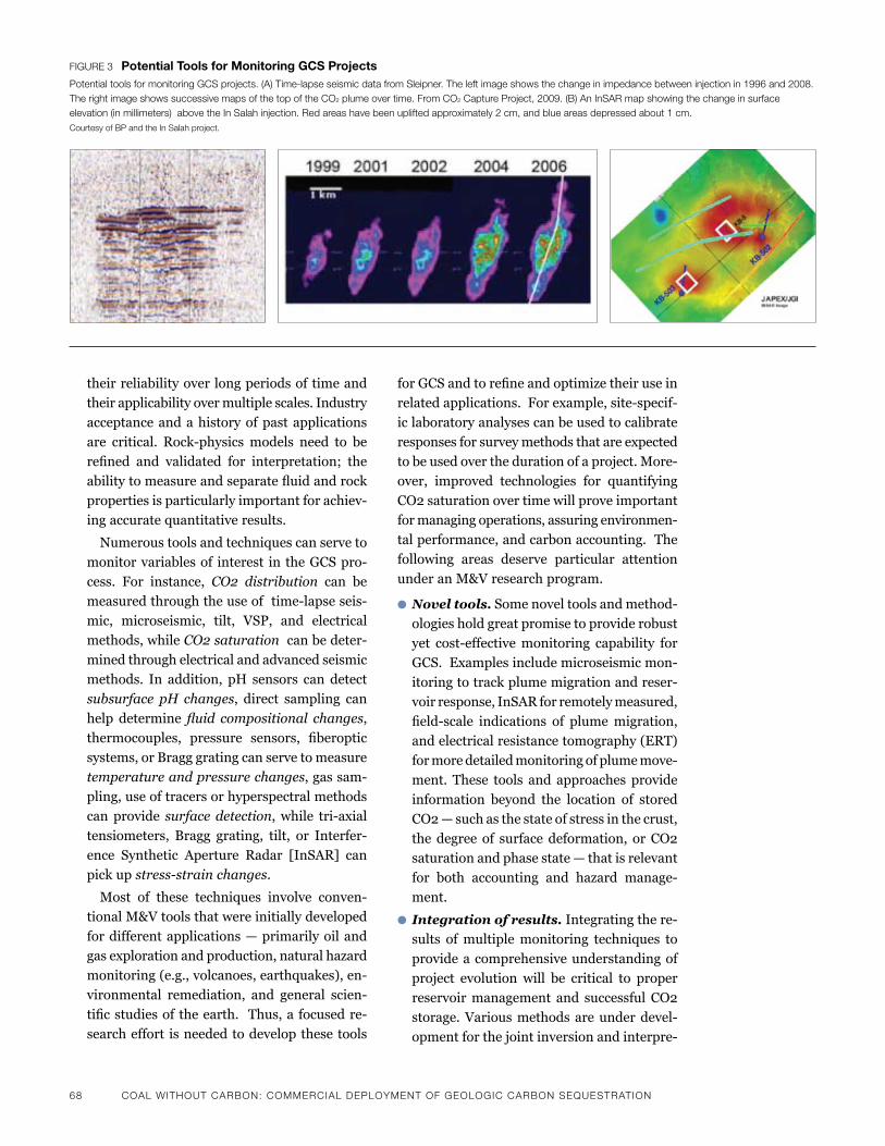
68 CoaL wiThouT CarBoN: CommerCiaL dePLoymeNT oF geoLogiC CarBoN SeQueSTraTioN
their reliability over long periods of time and
their applicability over multiple scales. Industry
acceptance and a history of past applications
are critical. Rock-physics models need to be
refined and validated for interpretation; the
abilitytomeasureandseparatefluidandrock
properties is particularly important for achiev-
ing accurate quantitative results.
Numerous tools and techniques can serve to
monitor variables of interest in the GCS pro-
cess. For instance, CO2 distribution can be
measuredthroughtheuseoftime-lapseseis-
mic, microseismic, tilt, VSP, and electrical
methods, while CO2 saturation can be deter-
mined through electrical and advanced seismic
methods. In addition, pH sensors can detect
subsurface pH changes, direct sampling can
help determine fluid compositional changes,
thermocouples, pressure sensors, fiberoptic
systems, or Bragg grating can serve to measure
temperature and pressure changes, gas sam-
pling, use of tracers or hyperspectral methods
can provide surface detection,while tri-axial
tensiometers, Bragg grating, tilt, or Interfer-
ence Synthetic Aperture Radar [InSAR] can
pick up stress-strain changes.
Most of these techniques involve conven-
tional M&V tools that were initially developed
for different applications — primarily oil and
gasexplorationandproduction,naturalhazard
monitoring (e.g., volcanoes, earthquakes), en-
vironmental remediation, and general scien-
tificstudiesof theearth. Thus,a focusedre-
search effort is needed to develop these tools
Figure 3 potential tools for Monitoring GCs projectsPotential tools for monitoring gCS projects. (a) Time-lapse seismic data from Sleipner. The left image shows the change in impedance between injection in 1996 and 2008. The right image shows successive maps of the top of the Co2 plume over time. From Co2 Capture Project, 2009. (B) an inSar map showing the change in surface elevation (in millimeters) above the in Salah injection. red areas have been uplifted approximately 2 cm, and blue areas depressed about 1 cm. Courtesy of BP and the in Salah project.
forGCSandtorefineandoptimizetheirusein
relatedapplications.Forexample,site-specif-
ic laboratory analyses can be used to calibrate
responsesforsurveymethodsthatareexpected
to be used over the duration of a project. More-
over, improved technologies for quantifying
CO2 saturation over time will prove important
for managing operations, assuring environmen-
tal performance, and carbon accounting. The
following areas deserve particular attention
under an M&V research program.
l Novel tools. Some novel tools and method-
ologies hold great promise to provide robust
yet cost-effectivemonitoring capability for
GCS.Examplesincludemicroseismicmon-
itoring to track plume migration and reser-
voir response, InSAR for remotely measured,
field-scale indications of plumemigration,
and electrical resistance tomography (ERT)
for more detailed monitoring of plume move-
ment. These tools and approaches provide
information beyond the location of stored
CO2 — such as the state of stress in the crust,
the degree of surface deformation, or CO2
saturation and phase state — that is relevant
for both accounting and hazard manage-
ment.
l Integration of results. Integrating the re-
sults of multiple monitoring techniques to
provide a comprehensive understanding of
project evolution will be critical to proper
reservoir management and successful CO2
storage. Various methods are under devel-
opment for the joint inversion and interpre-
CoaL wiThouT CarBoN: CommerCiaL dePLoymeNT oF geoLogiC CarBoN SeQueSTraTioN 69
tation of such results. The optimal method
will be one that can invert highly disparate
datasets—incorporatingboth“hard”data,
suchasindividualmeasurements,and“soft-
er”datathathavegreateruncertainty—and
include some estimate of the robustness of
each.Oneapproach,knownasMonte-Carlo
Markov Chain analysis (e.g., Ramirez et al.,
2008),usesstochasticmethodstocompare
known measurements and information with
new measurements in order to quantify the
likelihood of a given outcome. This approach
identifiesandranksalternativeexplanations
that are consistent with all available data
based on their probability. Other approach-
es (e.g., sequential Markov Chain, conven-
tional multivariate inversions, etc.) also have
merit and could apply in appropriate cir-
cumstances.
An accelerated research program will lead
to improved calibration of conventional
methods and increase familiarity and com-
mercialexperiencewiththesetools foruse
in GCS. Through integration, such a program
willalsoimprovequantificationandresolu-
tion of CO2 distribution and state in the
subsurface.
l Laboratory calibration of site data.Site-
specificdataonthedistributionofkeyrock
andfluidpropertiesarecritical,particularly
underdifferentfluidsaturationandcompo-
sition conditions. These include:
� Porosity,permeability,lithology,andstruc-
ture
� Liquid, gas, water content and ratio, oil,
etc.
� State of stress
� Fluid redistribution and change of state
� Fracture creation/opening/closure
Thespecificgeophysical,geochemical,orgeo-mechanicalresponsetoCO2injectioniscorrelatedtopetro-physicalandrockchem-ical attributes that are site controlled and site dependent in key ways. A robust M&V pro-gram should have a laboratory component tointerpretandde-convolvethecomplexsig-natures of surface and subsurface monitor-ing. Importantly, these studies add critical quantitative constraints to the determination ofrockandfluidproperties.Assuch,theyof-
fer a basis for scaling local results to nation-
al practices and for developing international
standards in M&V.
n Applied Science and
Technology Development
GCS presents many operational challenges. Presently, the technology for monitoring and simulating GCS processes at depth remains limited and incomplete. Despite the knowledge base built from analog industries, there is no widely available practice for managing GCS operations. A great many potential designs for GCS injectionandproject configurationhavebeen proposed, but these stem largely from analog industries and thus may not always be appropriate. A new saline storage industry will likely face technical challenges specific to itsoperations that can’t be immediately addressed bydrawinguponexperiencefromtheoilandgas industries. For instance, GCS will require well design geared toward low-permeabilityrocks, which oil and gas producers generally avoid.
GCS deployment — on the scale of gigatonnes CO2injectedperyearworldwideor100mega-tons injected per year in the United States — will demand a high level of due diligence, process control, and environmental credentials. To move GCS toward this level of readiness quickly, a technology development program must focus on providing insight into the prob-lems described above and on answering the key questions of developers, operators, regulators, and public stakeholders. A handful of critical technologies can play a major role in accelerat-ing R&D progress and addressing stakeholder concerns:
l Advanced simulation. In general, the sim-ulationofmulti-phasefluidflow inporousmedia is fairly advanced. However, GCS pres-ents a set of physical and chemical process-es that present-day simulators are poor atrepresenting. These include mechanical re-sponses to large subsurface pressure tran-sients and the dissolution and precipitation of a large number of mineral species. Because
these physical and chemical processes affect
thelocalandregionalpermeabilityfield,flow
path, and retention, new computational tools
are needed to help operators and regulators
70 CoaL wiThouT CarBoN: CommerCiaL dePLoymeNT oF geoLogiC CarBoN SeQueSTraTioN
predict the performance of proposed and ac-
tive projects.
While many simulators are available to ad-
dress some or part of these concerns, they
existacrossarangeofindustriesandinsti-
tutions.Manyofthemarefittoadifferent
purpose — such as , oil production or ground-
waterclean-up—andhavenotbeenapplied
to GCS problems. Thus, a focused effort is
needed to couple existingmodels, develop
new simulation tools, and validate these
tools andmodels using prior field-test re-
cordsandnewfieldprogramopportunities.
The program should aim to develop simula-
tors that:
� Are fully three dimensional
� Couple hydrological, reactive chemical, and
geo-mechanicalprocesses
� Cansimulatemultiplewell-injectioncon-
figurations
� Have adequate CO2 equations of state
� Can represent heterogeneities and com-
plexitiesinthesubsurface
� Can accurately predict the fate and trans-
port of CO2 over long time scales
� Can provide insight into environmental
concerns during and after operation
A small number of U.S. research institu-
tions have demonstrated capability in this
area. In particular, some of the national lab-
oratories (such as, Lawrence Livermore Na-
tional Laboratory, Lawrence Berkeley
NationalLaboratory,andPacificNorthwest
National Laboratory) and a few universities
(Stanford, Princeton, and the University of
Texas) have made substantial progress in
GCS simulation. In addition, a few compa-
nieshaveexpertiseappropriate to the task
(Schlumberger, CMG) and have begun col-
laborating with non-industrial research
groups to pursue rapid development and
commercialization.
A U.S. effort to improve GCS simulation
wouldbenefitfromjointprogramsinvolving
laboratoryexperiments,codedevelopment,
andfieldvalidation.Suchaninitiativewould
pair initial modification and coupling of
existingmoduleswithafocusedlaboratory
experimentalprogramtohelp testandpa-
rameterize simulators. Subsequent efforts
would test and validate models with public-
ly available data sets from prior tests.
An important goal of this work would be
to develop a common set of accepted com-
putational platforms that all potential oper-
ators and regulators would agree are suitably
accurate and robust for the purposes of in-
jection design, monitoring validation, and
plume migration prediction. Similar com-
monframeworksandstandardsexisttoob-
tain air permits and injection permits for
class I wells. Ideally, a working group would
be established to share initial results and
compare approaches. Finally, sets of simu-
lators would be supported for prediction and
verification,withfieldprojectsproceedingin
the private sector in the United States or
abroad.
l Experimental test-bed. In the oil and gas
industries, companies develop technology at
field sites, where experiments can be con-
ducted at scale. Major advances in logging,
improved and enhanced oil recovery, reser-
voir characterization, and novel production
strategies (e.g., horizontal drilling) have been
achieved in this setting. The GCS communi-
ty currently lacks this type of test bed, and
without a climate or carbon policy (and the
commercial drivers that would be created by
such a policy) a full industrial program for
GCS may be many years away. Given this
context,afacilitydevotedtoGCSfieldexper-
iments would prove enormously useful in
accelerating the process of technology devel-
opment and testing, as well as in answering
basic science questions.
A new program could be launched in either
a“green-field”site(i.e.afieldwherenopri-
or subsurface work has taken place) or a
“brown-field”site(i.e.asitepreviouslyused
foroilexploration,EORorCO2injection).
What is important is that the site have the
following attributes:
� Regular and repeated access to the sub-
surface
�Well-understoodgeologyandgeophysics
� Multiple types of reservoir geology in one
locale at multiple depths
CoaL wiThouT CarBoN: CommerCiaL dePLoymeNT oF geoLogiC CarBoN SeQueSTraTioN 71
�Multiplewellsformonitoringandopera-
tions
� Access to large volumes of CO2 for con-
ductingexperimentsatreasonablecost
� Ability to ramp up quickly
� A dedicated staff for maintenance of safe-
ty and operational needs
� Propershieldingfromindemnification
Somefieldexperimentprogramshavemet
many of these criteria — for instance, the
DOE’s Frio Brine Pilot, Germany’s CO2SINK
project site, and Australia’s Otway Basin.
However, most of these cases have been
individual projects rather than sustained
field efforts aimed at technology develop-
ment.Overthelastfiveyears,proposalsfor
this type of dedicated research program have
emerged but have not yet achieved priority
status. Such an initiative deserves urgent
attention in order to move GCS toward
widespread commercial deployment. At a
minimum,oneexperimentalfieldfacilityis
needed in the United States, and two could
potentiallybedevelopedover thenextfive
years.
l Basic science. While many aspects of GCS
are well understood, a substantial number of
basic science questions remain. These range
from questions about rates of mineral disso-
lution and precipitation, to questions about
the way pressure waves from multiple injec-
tions interact across faults. Although most of
these issues are not critical to the safe de-
ployment and commercial success of GCS,
they represent a realm of investigation that
could yield improvements in operations, haz-
ard management, and site performance.
Some of the relevant areas of inquiry that re-
main unaddressed include:
� Questions of fundamental processes, such
as cement carbonation and imbibition
rates
� Characterizationandquantificationofun-
certainty
� Typical accuracy required for successful
characterization
� Concerns related to monitoring, such as
acousticandelectricalpropertiesofCO2-
brine-rocksystems,amongothers
� Improved understanding of unconvention-
al CCS resources, such as basalts, salt
domes, organic shales, and offshore geo-
logical storage
A new program aimed at investigating a set of
basic science questions would begin to remedy this
lack of understanding and help open the door to
new cost saving and efficiencymeasures in the
future. Many research institutions could poten-
tially take part in this effort, including several
national laboratories and universities. Because the
questions are complex and the time scales for
investigation are likely to be long, sustained fund-
ing is required. Similarly, the lack of near-term
urgency means that a substantial proposal and
reviewprocesseswouldbejustifiedtoensurethe
highestlevelofscientificinquiry.TheDOE’sOffice
of Science has laid out a fairly clear and ambitious
basic science agenda in support of GCS in their
2007document(seeabove).
2. Demonstration Projects in a Range of Geological Settings
Largefielddemonstrationprojectsarethesingle
most important component of any U.S. or global
research program. For GCS to be effective as a
means of reducing CO2 emissions from large
fossil-energypoint sources,many largeprojects
must be deployed worldwide. Such projects are
critical because many of the fundamental pro-
cesses and key geological thresholds can only be
detected and understood at scale (Friedmann,
2006).Inparticular,geo-mechanicaleffects,the
long-termbehaviorofCO2,andthefar-fieldeffects
of displacement cannot be studied at pilot scales.
Demonstration projects can begin to be deployed
today in parallel with other R&D efforts. In fact,
theR&Dprogramdescribedabovewouldbenefit
greatly fromopenaccess to large-scaleprojects,
wherefieldknowledgeanditerationcanimprove
the speed of learning and reduce the cycle time for
development. This is currently the model of sci-
entific and technical effort being applied at the
Weyburn project in Canada and the In Salah,
project in Algeria, and it is being considerd for
FutureGen, the Clean Coal Power Intiative (CCPI),
and other new DOE projects.
Ultimately,fieldprogramsservetodemonstrate
economics, performance, and environmental
management; they also lead to technical discover-
72 CoaL wiThouT CarBoN: CommerCiaL dePLoymeNT oF geoLogiC CarBoN SeQueSTraTioN
ies and can help validate existing knowledge,
simulation tools, and approaches. There are three
ways a domestic GCS R&D program could engage
infieldefforts:(1)targetedU.S.GCSdemonstra-
tion projects, (2) integrated GCS/CCS projects at
scale, and (3) international GCS collaboratives.
Thefirsttwoapproachesarediscussedinthissec-
tion; the third is included within the subsequent
discussion on international collaboration.
n Targeted U.S. Field Program for GCS
DOE has recognized the need for large field
projects to address key technical questions
relevant for GCS deployment. At present, DOE
has accelerated the deployment of large proj-
ects in its Phase III partnership efforts. These
programs,ifproperlyexecuted,havethepoten-
tial to address key technical questions and
providebeneficial insights forGCSoperation
and regulation.
Meanwhile, regional partnerships are pro-
ceeding on an individual basis; yet, so far, the
results have been uneven. This is due in part to
a lack of adequate funding for scientific and
technicalmissions.Insomecases,insufficient
clarity and the lack of a mandate regarding
technical expectations for scientific efforts in
Phase III projects also hinders the ability to
deliver on national programmatic needs.
At a minimum, a U.S. GCS field program
requires:
� Threelarge-scaleprojects(sequesteringap-
proximately1milliontonsperyear),start-
ed within three years in a range of geological
settings and with CO2 injection sustained
forfive years, and followedby two years
post-injectionstudyandintegration
� Sixlarge-scaleprojectswithinsixyearsin
a range of geological settings
A preferred program schedule and scale would
entail:
� Twolarge-scaleprojectswithintwoyears
in different geological settings
� Sevenlarge-scaleprojectswithinfouryears
in a range of geological settings; at least
two of these on a scale greater than 5 mil-
lion tons per year
Program goals include:
� A set of protocols every two years that in-
tegrates lessons learned from the projects
with respect to site characterization, GCS
projectdesign,monitoringandverification,
basic operations, and closure
� Formal recommendations to state, region-
al, and federal regulatory bodies concern-
ing lessons learned, preferred practices,
and hazard assessment and management
� Empirical and site-specific geological,
geochemical, geophysical, and hydrologi-
cal data and information for continued
study and analysis
To accelerate safe and effective GCS deploy-
ment, efforts should focus on sites that can be
characterized and started swiftly and safely. In
addition,thetechnicalcomponentofthesefield
demonstration programs should ensure ade-
quate delivery of empirical information that
will inform for operational and regulatory pro-
cedures going forward.
n Integrated GCS/CCS Projects
Many researchers and technical experts cur-
rentlyworkinginthefieldofGCS(i.e.within
the DOE’s Fossil Energy division, the U.S Cli-
mate Change Technology Program, MIT, and
elsewhere) have remarked on the need for large
integrated capture and storage projects at
commercial-scalepowerplants.Suchprojects
are critical to provide engineering and eco-
nomic bases for decision making, to demon-
strate and develop integrated capture and
storage facilities, and to provide early knowl-
edge and empirical information to develop
industrial practices and standards. Several
programs in theDOEOfficeofFossilEnergy
(FutureGen, CCPI) have this focus. In addition,
there have been recent legislative attempts
(such as the bill introduced by Congressman
Rick Boucher to promote demonstration proj-
ects, that was later incorporated into the pro-
posedACESA)toexpandandaccelerateproj-
ects with these objectives in mind.
Integrated capture and storage projects pro-
videasourceofexperiencewiththecostand
performance issues that arise in coordinating
theinjectionprocesswithindustrialCO2off-
take needs. Some of these integrated projects
should be carried out in conjunction with the
fielddemonstrationsdiscussedabove,butem-
CoaL wiThouT CarBoN: CommerCiaL dePLoymeNT oF geoLogiC CarBoN SeQueSTraTioN 73
phasis on integration and demonstration
should be augmented by the research and de-
velopment needs of each individual part of the
process. Projects of this type require new funds
as well as strong management and direction to
ensure that the key deliverables (e.g., opera-
tional practices for sequestration well design,
injection, and monitoring) are brought into the
public realm.
This is of crucial importance to harvest the
opportunities provided by the natural field
laboratories created by these large and compli-
cated projects. Since such projects entail inte-
grating the engineering and economics of
complexsurfaceandsubsurfacefacilities,their
sponsoring entities need to communicate clear
expectationstothecommercialoperatorsand
technical investigators. Ultimately, these efforts
will enhance the prospects for commercial
deployment of GCS by improving industrial
practice and providing clarity to key stakehold-
ers regarding the performance and operating
needs of injection programs.
n International Collaboration
Many countries (as well as the European
Union) have begun large-scaleGCS projects.
These include integrated capture and seques-
tration projects, such as, ZeroGen, and projects
that inject pure streams of byproduct CO2 (e.g.,
Snohvit, Shenhua). In many cases, the projects
provide a platform for rapid technical develop-
mentand scientific investigationat relatively
low cost. They also open potential pathways for
U.S.technology-basedcommercedevelopment.
Furthermore, GCS projects may foster technol-
ogy transfer and collaboration that can help
facilitatedialogueinotherclimate-relatedareas
(for instance, with China, India, and Brazil) or
potentially address other energy security con-
cerns(e.g.,Poland,Turkey).Inthesecontexts,
the United States should greatly expand its
current international programs and consider
new avenues for collaboration and technical
discovery.
l International Cooperation on Field
Programs. Field programs offer the most
immediate venues for collaboration. They re-
quire basic geological data and information;
they also require locations where tools can
be deployed and approaches tested at mini-
mal cost. DOE should seek to engage and
support U.S. scientists, investigators, and
companies in field campaigns world wide.
Bilateral agreements or umbrella partner-
ships, such as the Carbon Sequestration Lead-
ership Forum, could help to facilitate this
effort.Specificrecommendationsforinter-
national field programs include at a
minimum:
�MajorU.S.involvementinthreelarge-scale
internationalprojects(approximately1mil-
lion tons CO2 injected per year) within the
firstyear
�MajorU.S. involvementwitheight large-
scaleprojectsworldwidewithinfiveyears
� Selection to cover a range of geological set-
tings and host-country economic condi-
tions
It would be preferable to have:
� MajorU.S.involvementinfivelarge-scale
international projects (each injecting ap-
proximately1milliontonsperyear)with-
inthefirstyear
� MajorU.S. involvementwitheight large-
scaleprojectsworldwidewithinfiveyears,
includingfiveinkeydevelopingcountries
(e,g,, India, China, Brazil, Indonesia)
� Selection to cover a range of geologies
(Note: Selection could be made through a
combinationofopensolicitationandexec-
utive decision and should be driven by op-
portunity, technical parameters, and public
benefit.)
l International Cooperation on Non-tech-
nical Issues. The commercial deployment
of GCS in the United States will also depend
onanumberofnon-technicalissues.These
include permitting requirements, regulatory
structure, subsurface ownership and access,
andlong-termliability.Othernationshave
already begun work in these areas, and in
some instances, they have begun to codify
decisions and technical constraints. While
someofforeignexampleswillnottranslate
readilytotheU.S.context(e.g.,Crownown-
ership), others will prove applicable.
At present several mechanisms exist
through which the United States can engage
74 CoaL wiThouT CarBoN: CommerCiaL dePLoymeNT oF geoLogiC CarBoN SeQueSTraTioN
GCS issues internationally. They include the
policy working group of the DOE’s Carbon
Sequestration Leadership Forum (CSLF)
(http://www.cslforum.org/), the IEA’s work-
ing groups and forums, various internation-
al conferences and workshops, and the Asia
PacificPartnershipco-sponsoredbytheU.S.
State Department and the DOE. The poten-
tial exists to expand all of these efforts
throughexistingchannelsandbyinvesting
additionalresources.Twoexamplesareuse-
ful to consider here.
� Australia’s Global CCS Institute. Re-
cently, Prime Minister Rudd of Australia
announced the creation of the Global CCS
Institute (GCCSI), amulti-national body
ofexpertswithamissiontofacilitatethe
commercial deployment of CCS in many
countries. The government of Australia has
committedover$100millionperyearfor
fiveyearsandtheInstituteisbeginningto
hire staff and clarify its charter (See: http://
www.zeroemissionplatform.eu/website/
docs/GA3/ZEP%202008%20GA%20-%20
Hartwell%20Australian%20insights.pdf).
The government of the United States be-
came a founding member of the GCCSI on
July 14th and is considering its range of
commitments in terms of time, staff, and
money. Yet, this initiative presents a clear
opportunity to increase knowledge and to
create and improve deployment protocols
world-wide,therebybothacceleratingthe
commercialization of CCS and increasing
the U.S. share of global markets for this
technology.
� World Resources Institute CCS Guide-
lines for China. Under the Asia Pacific
Partnership, the World Resources Institute
(WRI)haslaunchedasetofU.S.-Chinaex-
changes and study tours with the goal of
accelerating the development of CCS guide-
lines in China. WRI has directly partnered
with Tsinghua University and many key
Chinese organizations, increasing the
chance that guidelines will evolve organi-
callytoservethatcountry’sspecificpolicy,
economic, and environmental needs. The
WRIeffortcouldbeexpandedthroughthe
DOE and U.S. State Department to include
more training and technology transfer as
well as high-level summit meetings be-
tween critical U.S. and Chinese stake-
holders.
l Support for International Geological
Assessment. The current state of knowledge
about GCS resources greatly limits the speed
of deployment and market penetration in the
UnitedStatesandworld-wide.Sofar,only
two countries (the United States and Austra-
lia) and one Canadian province (Alberta) have
carried out necessary geological mapping in
any level of detail. It appears that key coun-
tries and regions — in particular, India, Chi-
na,andEasternEurope)lacktheknow-how
andsponsorshiptoexecutesimilarstudies.
Some countries, notably Australia, have be-
gun to sponsor geological assessment work
in other countries in the hopes of improving
trade relationships and accelerating CCS
deployment.
Under one potential model for engagement,
theUnitedStateswouldpartnerbi-laterally
with other key nations and provide staff,
sponsorship, and knowledge in support of
regional and national geological assessments.
The United States could also spearhead an
effort to get the G8 or OECD nations to con-
tribute to a general fund dedicated to this as-
sessment task.
IV. Draft Budget Requirements
Ultimately, program costs will reflect program
goals. They will also depend on program design,
the number of participants, and the way in which
tasks are completed and executed. A detailed
roadmap will shed more light on likely program
expenditures,aswilldecisionsregardingspecific
program goals, the degree of emphasis on inter-
nationalvs.domesticprojects,andtheextentof
focusonbasicscientificwork.Wepresentsome
preliminary budget estimates below, in order to
help bound the discussion in terms of reasonable
technical requirements. It is important to note that
thesenumbersreflectonlytheGCScomponent;
costsforcarboncaptureexperiments,plantdesign
anddemonstration, and large-scale capital con-
struction are not included in these estimates and
will need to be considered and assessed indepen-
dently.
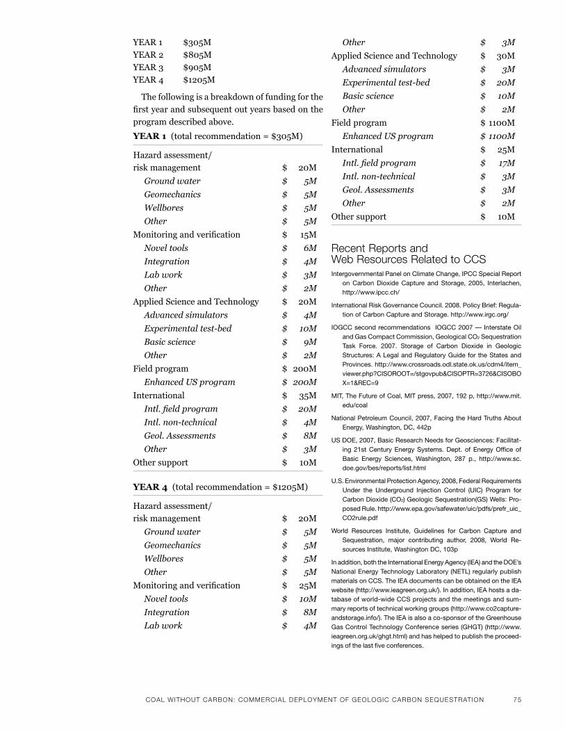
CoaL wiThouT CarBoN: CommerCiaL dePLoymeNT oF geoLogiC CarBoN SeQueSTraTioN 75
YEAR1 $305M
YEAR2 $805M
YEAR3 $905M
YEAR4 $1205M
The following is a breakdown of funding for the
firstyearandsubsequentoutyearsbasedonthe
program described above.
YEAR 1(totalrecommendation=$305M)
Hazard assessment/
riskmanagement $ 20M
Ground water $ 5M
Geomechanics $ 5M
Wellbores $ 5M
Other $ 5M
Monitoringandverification $ 15M
Novel tools $ 6M
Integration $ 4M
Lab work $ 3M
Other $ 2M
AppliedScienceandTechnology $ 20M
Advanced simulators $ 4M
Experimental test-bed $ 10M
Basic science $ 9M
Other $ 2M
Fieldprogram $ 200M
Enhanced US program $ 200M
International $ 35M
Intl. field program $ 20M
Intl. non-technical $ 4M
Geol. Assessments $ 8M
Other $ 3M
Othersupport $ 10M
YEAR 4(totalrecommendation=$1205M)
Hazard assessment/
riskmanagement $ 20M
Ground water $ 5M
Geomechanics $ 5M
Wellbores $ 5M
Other $ 5M
Monitoringandverification $ 25M
Novel tools $ 10M
Integration $ 8M
Lab work $ 4M
Other $ 3M
AppliedScienceandTechnology $ 30M
Advanced simulators $ 3M
Experimental test-bed $ 20M
Basic science $ 10M
Other $ 2M
Fieldprogram $1100M
Enhanced US program $ 1100M
International $ 25M
Intl. field program $ 17M
Intl. non-technical $ 3M
Geol. Assessments $ 3M
Other $ 2M
Othersupport $ 10M
recent reports and web resources related to CCSintergovernmental panel on Climate Change, ipCC special report
on Carbon Dioxide Capture and storage, 2005, interlachen, http://www.ipcc.ch/
international risk Governance Council. 2008. policy brief: regula-tion of Carbon Capture and storage. http://www.irgc.org/
ioGCC second recommendations ioGCC 2007 — interstate oil and Gas Compact Commission, Geological Co2 sequestration task force. 2007. storage of Carbon Dioxide in Geologic structures: a legal and regulatory Guide for the states and provinces. http://www.crossroads.odl.state.ok.us/cdm4/item_viewer.php?Cisoroot=/stgovpub&Cisoptr=3726&Cisobox=1&rEC=9
mit, the future of Coal, mit press, 2007, 192 p, http://www.mit.edu/coal
national petroleum Council, 2007, facing the hard truths about Energy, Washington, DC, 442p
us DoE, 2007, basic research needs for Geosciences: facilitat-ing 21st Century Energy systems. Dept. of Energy office of basic Energy sciences, Washington, 287 p., http://www.sc.doe.gov/bes/reports/list.html
u.s. Environmental protection agency, 2008, federal requirements under the underground injection Control (uiC) program for Carbon Dioxide (Co2) Geologic sequestration(Gs) Wells: pro-posed rule. http://www.epa.gov/safewater/uic/pdfs/prefr_uic_Co2rule.pdf
World resources institute, Guidelines for Carbon Capture and sequestration, major contributing author, 2008, World re-sources institute, Washington DC, 103p
in addition, both the international Energy agency (iEa) and the DoE’s national Energy technology laboratory (nEtl) regularly publish materials on CCs. the iEa documents can be obtained on the iEa website (http://www.ieagreen.org.uk/). in addition, iEa hosts a da-tabase of world-wide CCs projects and the meetings and sum-mary reports of technical working groups (http://www.co2capture-andstorage.info/). the iEa is also a co-sponsor of the Greenhouse Gas Control technology Conference series (GhGt) (http://www.ieagreen.org.uk/ghgt.html) and has helped to publish the proceed-ings of the last five conferences.

76 CoaL wiThouT CarBoN: CommerCiaL dePLoymeNT oF geoLogiC CarBoN SeQueSTraTioN
nEtl has also published numerous roadmaps, atlases, guide-lines, and technical reports on CCs. much of this literature is avail-able through the nEtl website (http://www.netl.doe.gov/technolo-gies/carbon_seq/refshelf/refshelf.html) and through the office of fossil Energy. key documents include the annual technology road-map (http://www.netl.doe.gov/technologies/carbon_seq/refshelf/project%20portfolio/2007/2007roadmap.pdf) and two atlases of Co2 sequestration for north america (early 2007 (http://www.netl.doe.gov/technologies/carbon_seq/refshelf/atlas/index.html) and late 2008 (http://www.netl.doe.gov/technologies/carbon_seq/ref-shelf/atlas/atlasii.pdf). nEtl has also hosted an annual conference on CCs (www.carbonsq.com) and publishes the proceedings through Exchangemonitor (http://www.exchangemonitor.com/). finally, nEtl co-sponsored GhGt-9 with the iEa in 2008.
Key references Citedaines rD, leach mJ, Weisgraber th, simpson mD friedmann sJ,
bruton CJ, 2008 quantifying the potential exposure hazard due to energetic releases of Co2 from failed sequestration wells, 9th Greenhouse Gas technology Conference, Washington, DC
Co2 Capture project 2009, a technical basis for Carbon Dioxide storage (C. Cooper, Ed.), http://www.co2captureproject.org/co2_storage_technical_book.html
Dooley JJ, rt Dahowski, and Cl Davidson. 2009 "Comparing Existing pipeline networks with the potential scale of future u.s. Co2 pipeline networks." Energy procedia, volume 1, issue 1, february 2009, pages 1595-1602. GhGt9 procedia doi:10.1016/j.egypro.2009.01.209
DoE nEtl, 2008, u.s. Department of Energy, national Energy technology
laboratory, Carbon sequestration atlas of the united states and Canada, http://www.netl.doe.gov/technologies/carbon_seq/refshelf/atlasii/atlasii.pdf
DoE nEtl, 2007, Carbon sequestration technology roadmap and program plan. u.s. Department of Energy, morgantown, Wv http://www.netl.doe.gov/technologies/carbon_seq/refshelf/project%20portfolio/2007/2007roadmap.pdf
Energy information administration, 2009, annual Energy outlook 2009, report number DoE/Eia-0383, www.eia.doe.gov/oiaf/aeo,
friedmann, s.J., 2006, the scientific case for large Co2 storage projects worldwide: Where they should go, what they should look like, and how much they should cost, 8th Greenhouse Gas technology Conference, trondjheim, norway, poster session ii
friedmann, sJ 2007, operational protocols for geologic carbon storage: facility life-cycle and the new hazard characterization approach, 6th annual nEtl conference on Carbon Capture and sequestration, pittsburgh, pa Exchangemonitor, oral 034
Jarrell, pm, CE fox, mh stein, sl Webb, practical aspects of Co2 flooding. monograph 22. society of petroleum Engineers, richardson, tx, usa., 2002
lewicki, J.l., birkholzer, J. and tsang, C-f. (2007) natural and in-dustrial analogues for leakage of Co2 from storage reservoirs: identification of features, events, and processes and lessons learned: Environ. Geology, v. 52, p. 457-467.
ramirez, a, friedmann, s.J., foxall, W.a., kirkendall, b., Dyer, k., 2006, subsurface imaging of Co2 plumes using multiple data types and bayesian inference, 8th Greenhouse Gas technol-ogy Conference, trondjheim, norway, poster session ii
also, Links to:national petroleum Council document: http://www.npchardtruth-
sreport.org/
Wri document: http://www.wri.org/publication/ccs-guidelines


Related Documents


