1 2-4-2013 Coal to Desired Fuels and Chemicals Maohong Fan SER Professor in the Department of Chem. & Petroleum Eng. UNIVERSITY OF WYOMING [email protected] Phone: (307) 766 5633

Welcome message from author
This document is posted to help you gain knowledge. Please leave a comment to let me know what you think about it! Share it to your friends and learn new things together.
Transcript

1
2-4-2013
Coal to Desired Fuels and Chemicals
Maohong Fan
SER Professor in the Department of Chem. & Petroleum Eng.UNIVERSITY OF WYOMING
[email protected]: (307) 766 5633
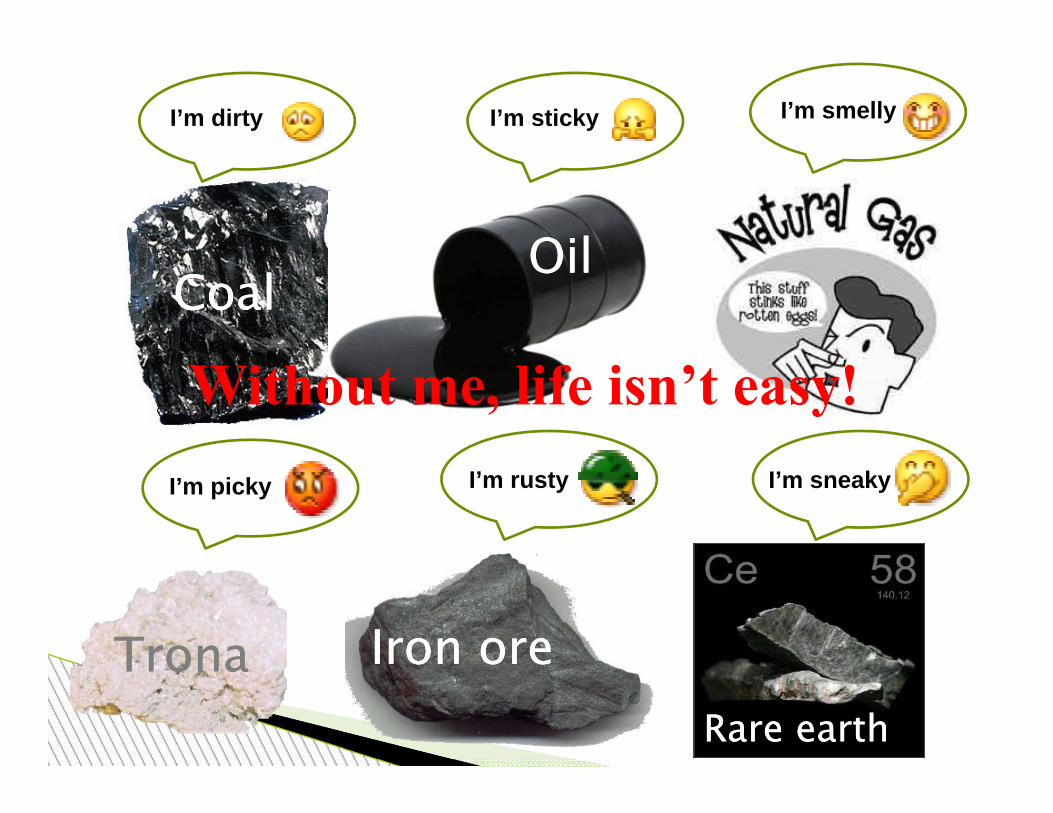
CoalCoalOilOil
TronaTrona Iron oreIron oreRare earthRare earth
I’m dirty I’m sticky I’m smelly
I’m picky I’m sneakyI’m rusty
Without me, life isn’t easy!

Maohong Fan’s Research Group

UW’s Clean Coal Technology Development Map
High‐value carbon based materials
Catalytic pyrolysis mode in the same
reactor
Catalytic gasification mode in the same
reactor
Cleaning & separating CO + CO2obtained with 1st
choice of feed gases
Catalytic CO coupling (converting the CO
obtained with 1st choice of feed gases)
Dried coal impregnated with catalysts
1st choice of feed gases: CO2 +
limited O2
Separation(note: One of the
objectives is to minimize CH4 production in
pyrolyis and gasification modes)
Light tar separation(into naphthalene, 1‐naphthaleneacetic acid, anthracene, phenol, diesel
H2OChar/coke
CO+CO2
CO2
CO2 + small amout of CH4
Synthesis conversion(converting the CO & H2obtained with 2nd choice
of feed gases) 2nd choice of feed gases: CO2
+ CH4 (natural gas)limited O2 + H2O
IGCC Electric Power
Synthetic ammonia
Synthesis of methanol
F‐T synthesis
Oxalic acid
Ethanol
Ethylene glycol
higheralcohols
Urea
Olefins
Gasoline
DME
Jet/Diesel
Chemicals
Polyester
COH2
Feed gases: CO2 + limited O2
H2:CO≈2 + near zero CH4
CO2
CO + zero H2 + zero CH4
Catalytic Coal Pyrolysis and Gasification◦ Na-Fe based
Syngas to liquids◦ Ethylene glycol
Environmental management◦ CO2
Three Sample Projects to Be Presented

Why catalyst?◦ Increase gasification or carbon conversion
rate/kinetics ◦ Decrease gasification temperature Improve energy efficiency Increase life span of gasifier
◦ Change the composition of syngas Obtain desired CO:H2 ratio Decrease CH4 concentration in syngas
Sample Project 1- Catalytic Coal Gasification
7
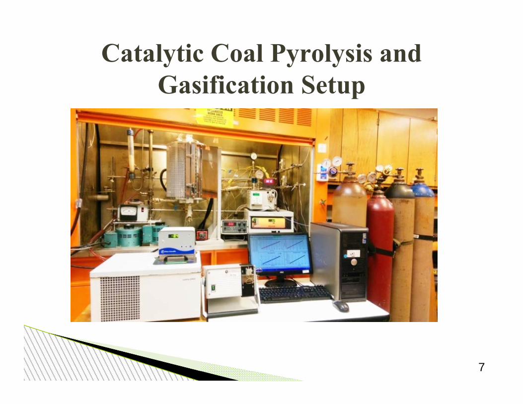
Catalytic Coal Pyrolysis and Gasification Setup
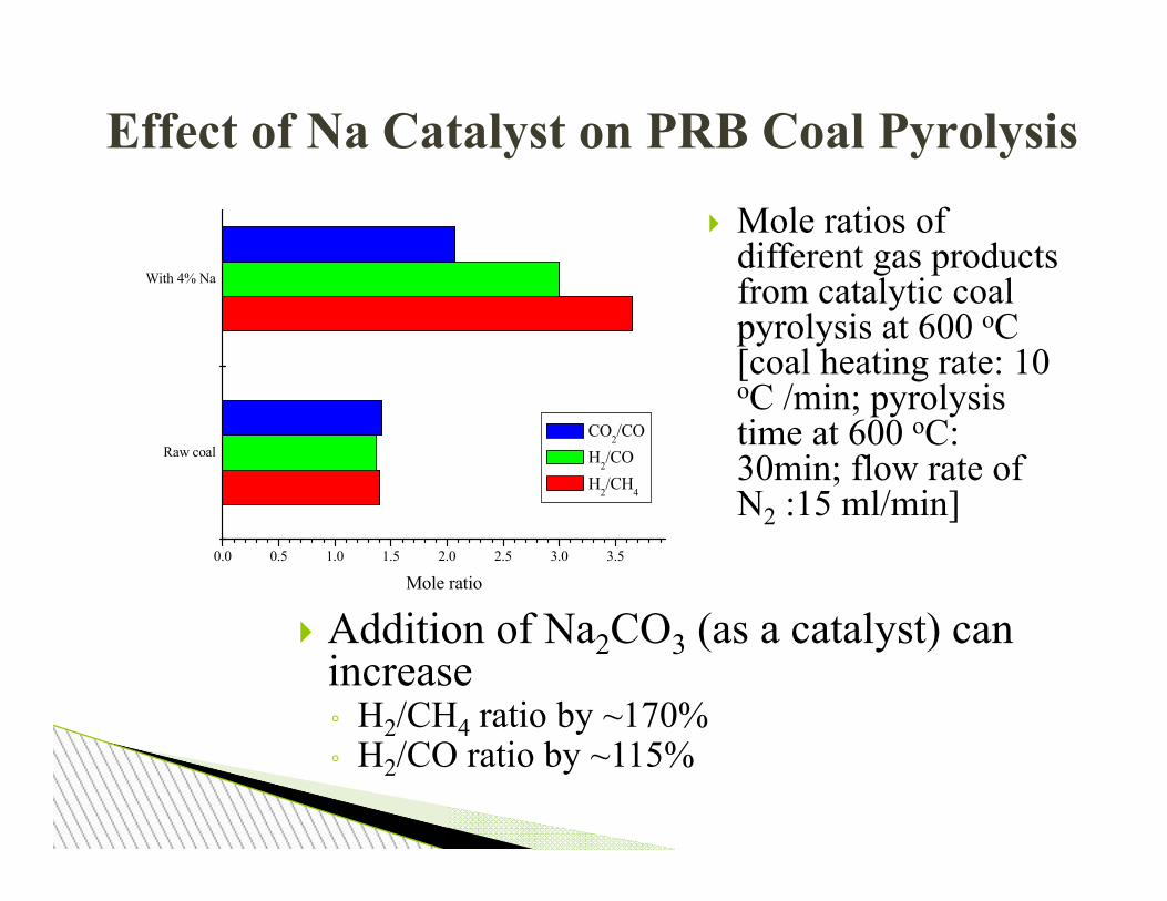
Effect of Na Catalyst on PRB Coal Pyrolysis
Addition of Na2CO3 (as a catalyst) can increase ◦ H2/CH4 ratio by ~170%◦ H2/CO ratio by ~115%
Raw coal
With 4% Na
0.0 0.5 1.0 1.5 2.0 2.5 3.0 3.5
Mole ratio
CO2/CO H2/CO H2/CH4
Mole ratios of different gas products from catalytic coal pyrolysis at 600 oC[coal heating rate: 10oC /min; pyrolysis time at 600 oC: 30min; flow rate of N2 :15 ml/min]
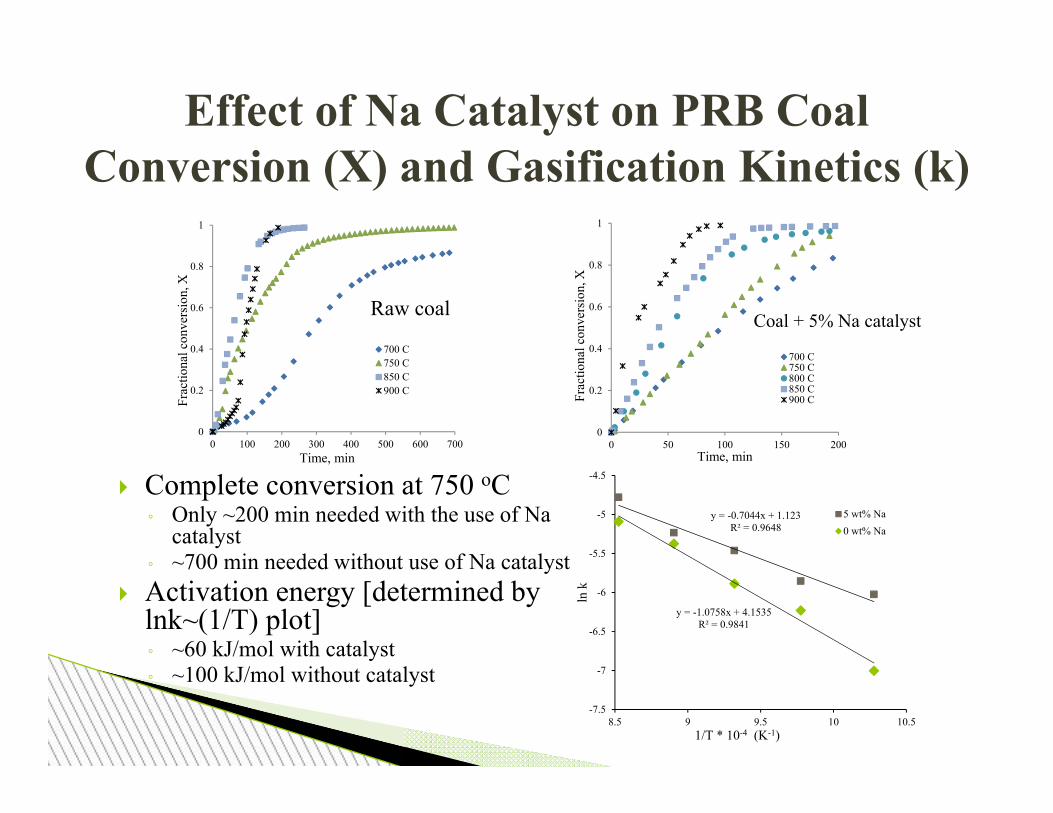
Effect of Na Catalyst on PRB Coal Conversion (X) and Gasification Kinetics (k)
0
0.2
0.4
0.6
0.8
1
0 100 200 300 400 500 600 700
Frac
tiona
l con
vers
ion,
X
Time, min
700 C750 C850 C900 C
0
0.2
0.4
0.6
0.8
1
0 50 100 150 200
Frac
tiona
l con
vers
ion,
X
Time, min
700 C750 C800 C850 C900 C
y = -0.7044x + 1.123R² = 0.9648
y = -1.0758x + 4.1535R² = 0.9841
-7.5
-7
-6.5
-6
-5.5
-5
-4.5
8.5 9 9.5 10 10.5
ln k
1/T * 10-4 (K-1)
5 wt% Na0 wt% Na
Raw coal Coal + 5% Na catalyst
Complete conversion at 750 oC◦ Only ~200 min needed with the use of Na
catalyst◦ ~700 min needed without use of Na catalyst
Activation energy [determined by lnk~(1/T) plot]◦ ~60 kJ/mol with catalyst◦ ~100 kJ/mol without catalyst

Effect of Composite Catalyst on CO Concentration in Syngas
Test conditions◦ Mass of DAF coal: 5 g◦ H2O flow rate: 180 ml/min◦ N2 flow rate: 4.1 ml/min◦ #1:1%-Fe+3%-Na◦ #2: 2%-Fe+2%-Na◦ #3: 3%-Fe+1%-Na
Observations◦ Increase in temperature →
significant increase in CO ◦ Increase in Fe in composite
catalyst → considerable decrease in CO
Molar yield of CO per mole of carbon in the char vs. different loadings of Fe and temperatures
10

Effect of a Composite Catalyst’s Composition and Temperature on H2 Concentration in Syngas with Steam
Gasification
Composite catalyst can take the advantage of two individual catalysts and overcome their challenges
Molar yields of H2 per mole of carbon ◦ 3% Fe loading leads to the increase in
H2 production by 35% at 700 oC.
2015/8/19
1
2
3
4
700
750
800
850
900
% Fe loading
T(°C)
1.1 1.2 1.3 1.4 1.5 1.6
mol
H2/
mol
C
Test conditions- Mass of coal: 5 g; #1: 1%-Fe+3%-Na; #2: 2%-Fe+2%-Na; #3: 3%-Fe+1%-Na: #4: 4%-Fe+0%-Na.
Molar yield of H2 per mole of carbon in the char vs. different loadings of Fe and temperatures

Effect of Na Catalyst on Carbon Conversion with CO2 Gasification
Test conditions◦ Gasification Temperature: 700
oC◦ Mass of DAF coal: 5 g◦ CO2 flow rate: 180 ml/min◦ N2 flow rate: 4.1 ml/min
Observations◦ Addition of trona can
significantly accelerate carbon conversion X (mole fraction) or coal gasification rate
◦ Gasifying the same amount of coal with catalyst needs less time a smaller gasifier
12

Effect of Catalyst on CO2 Gasification (continued)
2015/8/19
Test conditions – Gasification temperature: 700 oC; mass of coal: 5 g; CO2 flow rate: 180 ml/min; N2 flow rate: 4.1 ml/min.
Pure CO could be obtained
1,200 min is needed for gasifying the coal without presence of catalyst.
Only 300 min is needed for gasifying the coal with the presence of catalyst.

The Mechanism of PRB Coal Gasification with Fe Catalyst: Mössbauer spectroscopy data
During pyrolysis iron oxides are reduced to metallic iron Fe0, Fe3C and higher coordination iron Fen+
After steam introduction Fe3C is oxidized to Fe0
and Fe(O) The catalytic mechanism on oxidized iron layer:Fe + H2O → Fe(O) +H2Fe(O) + C → C(O) + FeC(O) → CO3Fe(O)+H2O → Fe3O4 +H2Fe3O4 +CO→ 3Fe(O)+CO2CO2 + C ↔2 CO
97.5
98.0
98.5
99.0
99.5
100.0
-12 -8 -4 0 4 8 12
Abs
orpt
ion
(%)
Velocity (mm/s)
3% Fe in raw coal, 20oC
Fe2O3,multiple coordinations
90.0
92.0
94.0
96.0
98.0
100.0
-12 -8 -4 0 4 8 12
Abs
orpt
ion
(%)
Velocity (mm/s)
3% Fe coal afterpyrolysis at 800oC
Fe0
Fe3Ccementite
Fen+
90.0
92.0
94.0
96.0
98.0
100.0
-12 -8 -4 0 4 8 12
Abs
orpt
ion
(%)
Velocity (mm/s)
3% Fe coal after pyrolysisat 800C + 10 min H2O
Fe0
Fe3O4
Fen+
np-Fe-ox
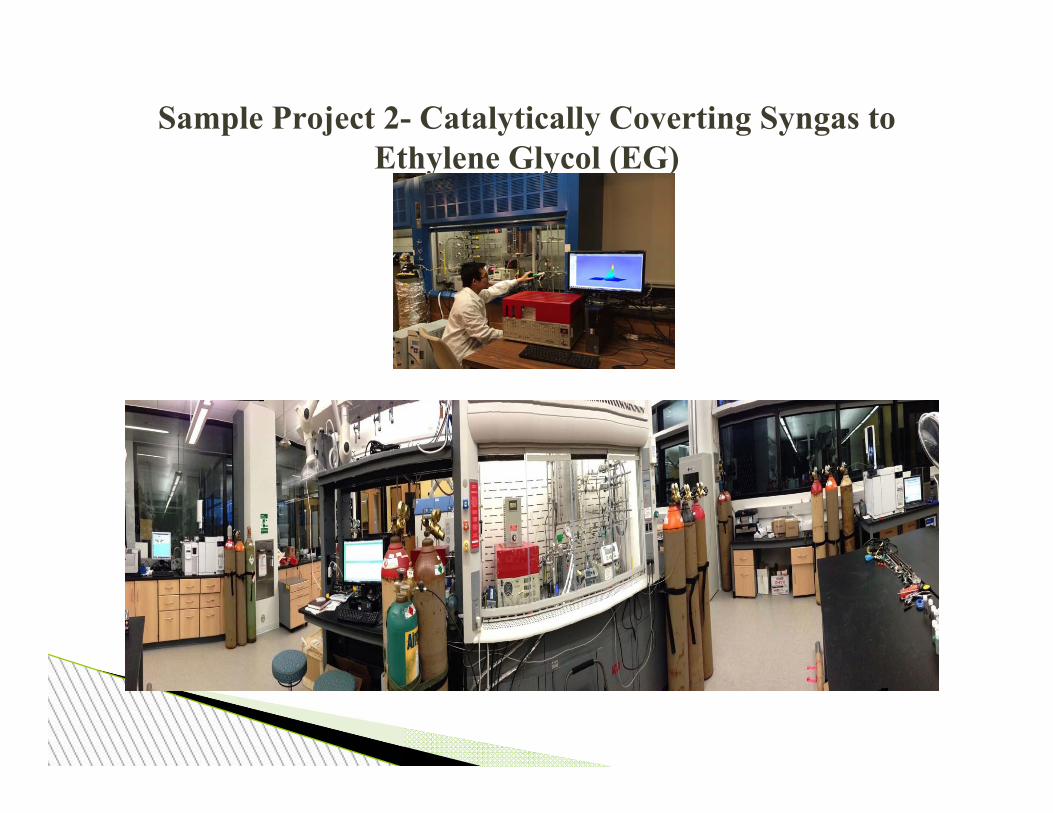
Sample Project 2- Catalytically Coverting Syngas to Ethylene Glycol (EG)

16
Syngas to ethylene glycol
Disadvantages of methyl nitrite:• Highly flammable • Highly explosive • Toxic • Being controlled in the US
Advantages of ethyl nitrite:• Less flammable • Non-explosive • Less toxic • Transportation allowed
2CO + 2CH3ONO (COOCH3)2 + 2NOMethyl nitrite (MN)
2NO + 0.5O2 N2O3
N2O3 + 2CH3OH 2CH3ONO + 2H2OMethyl nitrite (MN)
Dimethyl Oxalate (DMO)
(COOCH3)2 + 4H2 (CH2OH)2 + 2CH3OHDimethyl Oxalate (DMO) Ethylene glycol (EG)
Methyl nitritetoEthylene glycol
2CO + 2CH3CH2ONO (COOCH3CH2)2 + 2NOEthyl nitrite (EN)
2NO + 0.5O2 N2O3
N2O3 + 2CH3CH2OH 2CH3CH2ONO + 2H2OEthyl nitrite (EN)
Diethyl Oxalate (DEO)
(COOCH3CH2)2 + 4H2 (CH2OH)2 + 2CH3CH2OHDiethyl Oxalate (DEO) Ethylene glycol (EG)
Ethyl nitritetoEthylene glycol

UW DEO synthesis catalyst ◦ 0.1% DEO production catalyst prepared at UW can perform better
than 1% that prepared with conventional method.◦ Cost-effectiveness of UW catalyst is 9 times or 900% better than that
of conventional ones.
1st Step of Syngas to EG: (CO +EN) → DEO
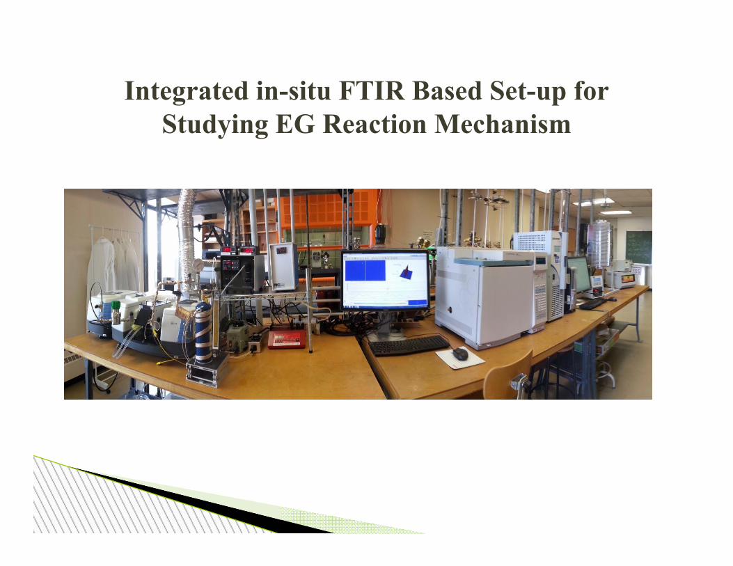
Integrated in-situ FTIR Based Set-up for Studying EG Reaction Mechanism

19
Without promoter
With a promoter (0.8 wt-%)
In-Situ FTIR Observation of DEO Synthesis with and without Uses of a Promoter
140 oC;1 atm; CO: EN;1.4 :1.
CO
EN
DEO
CO
DEO
EN

2nd Step of Syngas to EG: DMO→EG
• UW’s AC based catalysts achieve higher DMO conversion and EG + MG (methyl glycolate) selectivity in lower temperature range ( < 200 oC)
• UW’s 20Cu-AS30-AC is the best catalyst – 100% CO conversion– 90% EG + MG
2015/8/19

Sample Project 3- New CO2 Capture Technologies
• Sorption based CO2 capture technology – Advantages
• Easy in operation • Applicable to gases with a wide range of CO2
concentrations– Absorption: for pre-combustion CO2 capture – Adsorption: for flue gas with low CO2 concentration
– Shortcoming• Slow CO2 desorption rates (especially for absorption based
technology) → high desorption energy consumption– the largest obstacle for reducing overall CO2 capture cost since
about 70% of overall CCS capital is spent on CO2 desorption step
• What to do? Using catalysis

Catalytic CO2 Captureset-up
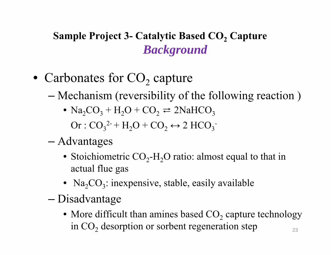
• Carbonates for CO2 capture – Mechanism (reversibility of the following reaction )
• Na2CO3 + H2O + CO2 ⇄ 2NaHCO3
Or : CO32- + H2O + CO2 ↔ 2 HCO3
-
– Advantages • Stoichiometric CO2-H2O ratio: almost equal to that in
actual flue gas• Na2CO3: inexpensive, stable, easily available
– Disadvantage• More difficult than amines based CO2 capture technology
in CO2 desorption or sorbent regeneration step 23
Sample Project 3- Catalytic Based CO2 Capture Background

Catalytic Based CO2 Capture - InorganicCO2 Desorption Rate Constants (k) with and without Uses of a Catalyst
• Test Conditions– Mass of spent CO2 sorbent
(NaHCO3):50-100 mg– NaHCO3/Catalyst (called NHF)– N2 flow rate: 100 mL/min
• Observations– Rate constants [k (min-1)] increased
significantly at the same temperature due to use of the catalyst (e.g., kpure-
NaHCO3 = 0.005 min-1, while k 90%
wt.%NHF = 0.19 min-1, k 50% wt.%NHF = 0.20 min-1, k 10% wt.%NHF = 0.06 min-1
at 100 oC ) • CO2 desorbs much faster due to use of
catalyst• Reduce operating and capital costs
Sample Temperature (°C)
m k(min-1)
R2
Pure NaHCO3
100 0.9 0.005 0.9992120 1.0 0.02 1.0000140 1.2 0.06 0.9991150 1.2 0.13 0.9991160 1.2 0.29 0.9999
90 wt.% NHF
100 0.7 0.19 0.9996110 0.6 0.25 0.9994120 0.4 0.49 0.9995130 0.4 0.89 0.9990140 0.3 1.32 0.9975
50 wt.% NHF
100 0.6 0.20 0.9989110 0.4 0.32 0.9989120 0.1 0.46 0.9994130 0.1 0.59 0.9997140 0.1 0.84 0.9995
20 wt.% NHF
100 0.5 0.06 0.9997110 0.5 0.13 0.9998120 0.5 0.23 0.9998130 0.5 0.35 0.9998140 0.5 0.50 0.9998
24
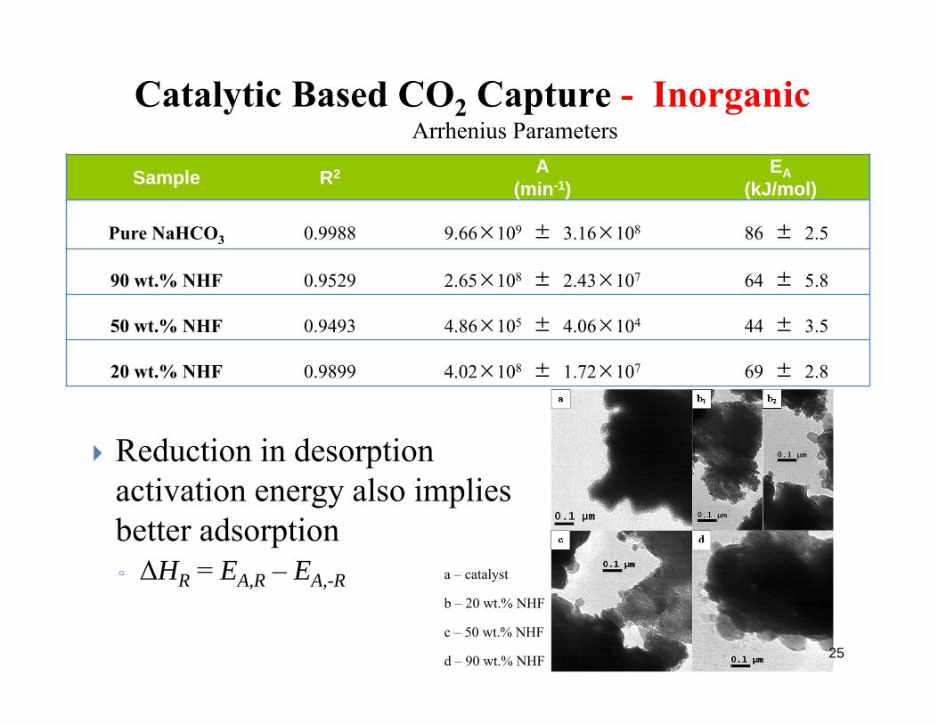
Sample R2 A(min-1)
EA(kJ/mol)
Pure NaHCO3 0.9988 9.66×10⁹ ± 3.16×10⁸ 86 ± 2.5
90 wt.% NHF 0.9529 2.65×10⁸ ± 2.43×10⁷ 64 ± 5.8
50 wt.% NHF 0.9493 4.86×10⁵ ± 4.06×10⁴ 44 ± 3.5
20 wt.% NHF 0.9899 4.02×10⁸ ± 1.72×10⁷ 69 ± 2.8
Catalytic Based CO2 Capture - InorganicArrhenius Parameters
a – catalyst
b – 20 wt.% NHF
c – 50 wt.% NHF
d – 90 wt.% NHF
Reduction in desorption activation energy also implies better adsorption◦ ΔHR = EA,R – EA,-R
25
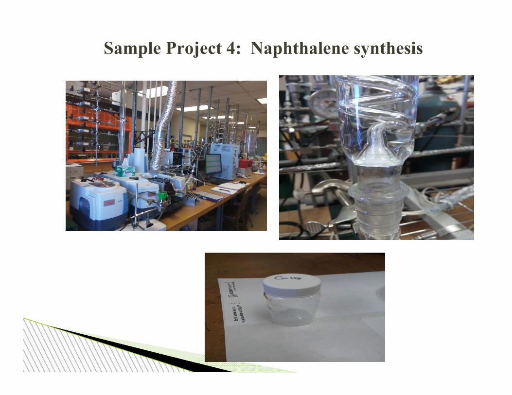
Sample Project 4: Naphthalene synthesis
Thanks to
Related Documents