Prepared by: GAI Consultants, Inc. Murrysville Office 4200 Triangle Lane Export, Pennsylvania 15632-1358 Prepared for: Richmond Power & Light 2000 U.S. 27 South P.O. Box 908 Richmond, Indiana 47374 Coal Combustion Residuals Unit Factor of Safety Assessment Richmond Power & Light Whitewater Valley Station Surface Impoundment Wayne County, Indiana GAI Project Number: C151119.07 April 2018

Welcome message from author
This document is posted to help you gain knowledge. Please leave a comment to let me know what you think about it! Share it to your friends and learn new things together.
Transcript

Prepared by: GAI Consultants, Inc.Murrysville Office
4200 Triangle Lane
Export, Pennsylvania 15632-1358
Prepared for: Richmond Power & Light2000 U.S. 27 South
P.O. Box 908
Richmond, Indiana 47374
Coal Combustion Residuals Unit Factor of Safety Assessment
Richmond Power & Light
Whitewater Valley Station Surface Impoundment
Wayne County, Indiana
GAI Project Number: C151119.07
April 2018
Coal Combustion Residuals Unit Factor of Safety Assessment Richmond Power and Light Whitewater Valley Station, Wayne County, Indiana
Page i
C151119.07/ April 2018
Table of Contents
Certification/Statement of Professional Opinion ................................................................................. ii
1.0 Introduction ........................................................................................................................... 2
2.0 Purpose ................................................................................................................................. 2
3.0 Factor of Safety Assessment Requirements .............................................................................. 2
4.0 Factor of Safety Assessment ................................................................................................... 2
4.1 Long-Term Maximum Storage Pool Loading Condition .................................................... 3
4.2 Maximum Surcharge Pool Loading Conditions ................................................................ 3
4.3 Seismic Factor of Safety ............................................................................................... 3
4.4 Liquefaction Factor of Safety ........................................................................................ 3
5.0 Conclusion ............................................................................................................................. 4
6.0 References ............................................................................................................................. 4
Appendix A Calculations
© 2018 GAI Consultants
Coal Combustion Residuals Unit Factor of Safety Assessment Richmond Power and Light Whitewater Valley Station, Wayne County, Indiana
Page ii
C151119.07/ April 2018
Certification/Statement of Professional Opinion
The Factor of Safety Assessment (Assessment) for the Whitewater Valley Power Station (Station) was prepared by GAI Consultants, Inc. (GAI). The Assessment may contain findings and determinations
that are based on certain information that, other than for information GAI originally prepared, GAI has relied on, but not independently verified. This Certification/Statement of Professional Opinion is
therefore limited to the information available to GAI at the time the Assessment was written. On the
basis of and subject to the foregoing, it is my professional opinion as a Professional Engineer licensed in the State of Indiana that the Assessment has been prepared in accordance with good and accepted
engineering practices as exercised by other engineers practicing in the same discipline(s), under similar circumstances, at the same time, and in the same locale. It is my professional opinion that the
Assessment was prepared consistent with the requirements of § 257.73(e)(1) of the United States
Environmental Protection Agency’s “Standards for the Disposal of Coal Combustion Residuals in Landfills and Surface Impoundments,” published in the Federal Register on April 17, 2015 with an
effective date of October 19, 2015 (40 CFR 257 Subpart D), and meeting the provisions of the “Extension of Compliance Deadlines for Certain Inactive Surface Impoundments: Response to Partial
Vacatur,” effective October 4, 2016.
The use of the words “certification” and/or “certify” in this document shall be interpreted and
construed as a Statement of Professional Opinion and is not and shall not be interpreted or construed
as a guarantee, warranty or legal opinion.
GAI Consultants, Inc.
Charles F. Straley, P.E.
Senior Engineering Manager
Date _________________

Coal Combustion Residuals Unit Factor of Safety Assessment Richmond Power and Light Whitewater Valley Station, Wayne County, Indiana
Page 1
C151119.07/ April 2018
Acronyms Assessment Coal Combustion Residuals Factor of Safety Assessment
CCR Coal Combustion Residuals
CCR Rule “Standards for the Disposal of Coal Combustion Residuals in Landfills and Surface Impoundments” 40 CFR 257 Subpart D (2015)
CFR Code of Federal Regulations
EPA United States Environmental Protection Agency
GAI GAI Consultants, Inc.
Impoundment Surface Impoundment
IN Indiana
RP&L Richmond Power & Light
Station Whitewater Valley Power Station
USGS United States Geological Survey
Coal Combustion Residuals Unit Factor of Safety Assessment Richmond Power and Light Whitewater Valley Station, Wayne County, Indiana
Page 2
C151119.07/ April 2018
1.0 Introduction The Whitewater Valley Power Station (Station) is owned by Richmond Power & Light (RP&L) and is
located in Richmond, Indiana (IN). The station includes a Surface Impoundment (Impoundment),
which is used for the long term storage of coal combustion residuals (CCR).
The Impoundment is located on RP&L property at the Whitewater Valley Power Station in Wayne
County, Indiana (coordinates 39° 48' 12.9" North and 84° 53' 54.8" West). The Impoundment is located in the northwestern corner of the property.
The Impoundment is currently inactive and is regulated as an existing CCR surface impoundment under the United States Environmental Protection Agency’s (EPA’s) “Standards for the Disposal of Coal
Combustion Residuals in Landfills and Surface Impoundments” [40 CFR 257 Subpart D] published in
the Federal Register on April 17, 2015 with an effective date of October 19, 2015 (CCR Rule), and meeting the provisions of the “Extension of Compliance Deadlines for Certain Inactive Surface
Impoundments: Response to Partial Vacatur,” effective October 4, 2016.
2.0 Purpose This Factor of Safety Assessment is prepared pursuant to § 257.73(e)(1) of the CCR Rule [40 CFR § 257.73(e)(1)].
3.0 Factor of Safety Assessment Requirements In accordance with § 257.73(e)(1), a CCR surface impoundment owner or operator “must conduct initial and periodic safety factor assessments for each CCR unit and document whether the calculated
factors of safety for each CCR unit achieve the minimum safety factors…for the critical cross section of
the embankment.”
§ 257.73(e)(1) requires that safety assessments be conducted for the following conditions of the
impoundment and that the safety factor assessments be supported by appropriate engineering calculations:
� The calculated static factor of safety under the long-term, maximum storage pool loading condition must equal or exceed 1.50;
� The calculated static factor of safety under the maximum surcharge pool loading condition must equal or exceed 1.40;
� The calculated seismic factor of safety must equal or exceed 1.00; and
� For dikes constructed of soils that are susceptible to liquefaction, the calculated liquefaction
factor of safety must equal or exceed 1.20.
This Assessment will document the factors of safety for the Impoundment as required by the CCR
Rule.
4.0 Factor of Safety Assessment The material underlying the Impoundment, comprising the embankment foundation, is discussed in the
History of Construction (GAI Consultants, 2018a). The current configuration of the Impoundment is
that it is filled with CCR material and generally graded to drain and not impound water. Thus, pooling of water within the Impoundment will be temporary. The critical sections for the stability analyses are
located along the west embankment of the Impoundment due to their height and slope steepness. Under the maximum pool from the 1,000-year design storm event (GAI Consultants, 2018b), the
critical sections are not adjacent to ponded water, and do not overtop.

Coal Combustion Residuals Unit Factor of Safety Assessment Richmond Power and Light Whitewater Valley Station, Wayne County, Indiana
Page 3
C151119.07/ April 2018
The critical section with the lowest factors of safety against sliding was located at the SW Corner of the Impoundment. The minimum factors of safety against sliding calculated for each condition are
summarized in Table 1.
Table 1
Calculated Factors of Safety
Factor of Safety Condition
Minimum Target Factor of
Safety Calculated Factor of Safety
Long-term, maximum storage pool loading
1.50 1.57
Maximum surcharge pool loading 1.40 1.57
Seismic factor of safety 1.00 1.31
Liquefaction factor of safety 1.20 >1.20
Calculations are included in Appendix A.
4.1 Long-Term Maximum Storage Pool Loading Condition
Pursuant to the CCR Rule, the maximum storage pool loading is “the maximum water level that can be
maintained that will result in full development of a steady-state seepage condition.” Additionally, “the maximum storage pool loading needs to consider a pool elevation in the CCR unit that is equivalent to
the lowest elevation of the invert of the spillway, i.e., the lowest overflow point of the perimeter of the
embankment.”
Since no long term pool is developed, the calculated static factors of safety for the long-term,
maximum storage pool loading condition is based on the existing topographic conditions with a phreatic surface set to the measured groundwater level.
The calculated factor of safety is 1.57 for the embankment is greater than the minimum of 1.50 required by the CCR Rule.
4.2 Maximum Surcharge Pool Loading Conditions
Since pooling within the Impoundment will be temporary, and the topographic configuration of the Impoundment precludes pooling near the critical section, the calculated static factors of safety for the
maximum surcharge pool loading condition is equivalent to that under long-term maximum storage pool loading condition. The calculated static factor of safety is greater than the minimum of 1.40
required by the CCR Rule.
4.3 Seismic Factor of Safety
The seismic factor of safety is calculated with a seismic loading event with a 2 percent probability of
exceedance in 50 years, based on the United States Geological Survey (USGS) seismic hazard maps. A
peak ground acceleration of 0.075g (acceleration of gravity) was used in the analysis. The calculated factor of safety is 1.31 is greater than the minimum of 1.00 required by the CCR Rule.
4.4 Liquefaction Factor of Safety
Based on the soils of the Geotechnical Report (GAI Consultants, August 2016), the Impoundment
embankments are generally composed of sandy lean clay. In order for liquefaction to occur, the embankment material would need to be saturated. The long term groundwater level is located below

Coal Combustion Residuals Unit Factor of Safety Assessment Richmond Power and Light Whitewater Valley Station, Wayne County, Indiana
Page 4
C151119.07/ April 2018
the base of the embankment; therefore, the embankment material should not be subject to liquefaction.
GAI, however, performed a liquefaction analysis to determine if the soils in the embankment are susceptible to liquefaction. The calculated liquefaction safety factors exceeded the minimum of 1.20
stated in the CCR Rule. The calculations are included in Appendix A.
5.0 Conclusion Based on the analyses conducted for the conditions outlined in the CCR Rule, the Whitewater Valley Station Surface Impoundment meets or exceeds the required factors of safety.
6.0 References GAI Consultants. Geotechnical Summary Report. August 2016.
GAI Consultants. Groundwater Characterization Report. September 2016.
GAI Consultants. 2018a. History of Construction. April 2018.
GAI Consultants. 2018b. Inflow Design Flood Control System Plan. April 2018.

Coal Combustion Residuals Unit Factor of Safety Assessment Whitewater Valley Power Station
C151119.07/ April 2018
APPENDIX A
Calculations

Z:\Energy\2015\C151119.07 - RPL Impound Closure Spt\Working Docs\Task 4 - April 2018 items\CCR Factor of Safety
Assessment\WWVS-Deep-Seated-Stability-CCR Factor of Safety 2018 Calc.docx
SUBJECT: RP-L WHITEWATER VALLEY STATION – SURFACE IMPOUNDMENT
_______CCR FACTOR OF SAFETY - DEEP-SEATED STABILITY ANALYSES
BY CAG DATE 4/5/2018 PROJ. NO. C151119.07 CHKD. BY CFS DATE 4/9/2018 SHEET NO. 1 OF 17
OBJECTIVE: Evaluate deep-seated rotational failure surfaces under static and seismic conditions for the existing dike of the
Surface Impoundment at the Richmond Power and Light (RP-L) Whitewater Valley Station located in Richmond, Wayne County, Indiana. The analyses will be performed using simplified Bishop’s method.
METHODOLOGY:
Stability will be evaluated under both static and seismic conditions using two-dimensional limit equilibrium analysis with the design software Slope/W by GeoStudio 2016, version 8.16.1.13452. The target factors of
safety for static and seismic conditions are outlined in the United States Environmental Protection Agency’s
“Standards for the Disposal of Coal Combustion Residuals in Landfills and Surface Impoundments,” published in the Federal Register on April 17, 2015 with an effective date of October 19, 2015. (CCR Rule),
§257.73(e)(1) (Reference 1).
REFERENCES: 1. United States Environmental Protection Agency, 2015. 40 CFR Parts 257 and 261 Hazardous and Solid
Waste Management System; Disposal of Coal Combustion Residuals from Electric Utilities; Final Rule. April 17, 2015.
2. U.S. Geological Society. Earthquake Hazards Program. Lower 48 Maps and Data. Web. 2 Apr. 2018 3. U.S. Department of Transportation Federal Administration, Publication No. FHWA NHI-06-088, Soils and
Foundations Reference Manual Volume I, December 2006.
4. “Geotechnical Summary Report” Whitewater Valley Station, GAI Consultants, August 2016
BACKGROUND:
RP-L is proposing the closure of the Surface Impoundment located at the Whitewater Valley Station in Wayne County, Indiana. The closure will be achieved by leaving the majority of the CCR material in place.
The analysis will analyze the stability of the existing conditions of the west dike. A static and seismic analysis will
be performed to determine if the existing conditions of the west dike achieve the minimum target factors of safety
Values. Target factors of safety values are outlined in §257.73(e)(1) of Reference 1. The static analysis will be the calculated static factor of safety under the long-term, maximum storage pool loading condition. The
seismic analysis will be the calculated seismic factor of safety. The calculated static factor of safety under the maximum surcharge pool loading condition was not included in this calculation since the impoundment does
not have water impounding capabilities.
ANALYSIS: Long-term static and seismic stability analyses were performed along the west dike of the Surface
Impoundment to evaluate the stability of the existing conditions of the dike. Three (3) cross-sections were selected to represent the critical and typical case slope conditions. Location of these sections are shown as
Attachment 1, Figure 1. Additionally, detailed information regarding the cross section geometry of each
section is included in the slope stability software output presented as Attachment 3.
The soil parameters used in the slope stability analyses are summarized in Attachment 2. The material properties selected for the in-place CCR material were obtained from laboratory testing performed on in-situ
Z:\Energy\2015\C151119.07 - RPL Impound Closure Spt\Working Docs\Task 4 - April 2018 items\CCR Factor of Safety
Assessment\WWVS-Deep-Seated-Stability-CCR Factor of Safety 2018 Calc.docx
SUBJECT: RP-L WHITEWATER VALLEY STATION – SURFACE IMPOUNDMENT
_______CCR FACTOR OF SAFETY - DEEP-SEATED STABILITY ANALYSES
BY CAG DATE 4/5/2018 PROJ. NO. C151119.07 CHKD. BY CFS DATE 4/9/2018 SHEET NO. 2 OF 17
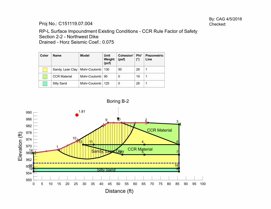
samples obtained from the Surface Impoundment in September, 2015. The material properties used to
represent the in-place dike soils were also obtained from sampling completed during September, 2015. Phi angles were based on relationships between plasticity index and phi. Values for cohesion were determined
using the information presented in Reference 4. The analysis was completed using drained parameters for CCR material and the dike soils. The piezometric surface used in the analysis is based on the groundwater elevation
shown on the potentiometric surface readings conducted in September, 2016.
Based on the data subsurface investigation, CCR material was encountered below soil fill in the borings drilled in the vicinity of the impoundment dike. This indicates that the impoundment may have been increased in size
in the past by raising the impoundment dike by placing soil fill, at least partially, on top of previously placed CCR material.
The CCR material exhibited the weakest strength of the materials present in the dike. The dike was modeled with a conservative amount of CCR. While the model shows the CCR material being near the surface at parts
of the dike, GAI does not expect CCR material to be present within the first few feet of the slope of the dike.
Seismic Conditions – The existing facility is located in Wayne County, which is an area of low to moderate
seismic activity and risk. The peak horizontal ground acceleration at the proposed site (using a 2 percent probability of exceedance in 50 years) is approximately 0.075g. This acceleration was estimated using the
2014 USGS “Two-percent probability of exceedance in 50 years map of ground acceleration” data, which is
included here as Attachment 4 (Reference 2).
SUMMARY:
Stability analyses performed for the existing dike are summarized in Attachment 3. Static and seismic
conditions were evaluated using simplified Bishop method which is an equilibrium method that considers both shear and normal interslice forces and satisfies both moment and force equilibrium. A large number of deep-
seated failure surfaces were generated and the most critical failure surface for each analysis section was isolated to determine the minimum factor of safety. Seismic analyses were performed for each static stability
analysis and these included a seismic coefficient equal to 0.075g.
The following table summarizes the results of static and seismic slope stability analyses considering drained
conditions for CCR material and dike soils.
Section Condition Analyzed
Minimum
Target Factor
of Safety
Calculated
Factor of Safety Drained
Conditions
Section 2-2 NW Corner
Static 1.50 2.18
Seismic 1.00 1.81
Section 3-3
Mid Alignment
Static 1.50 1.62
Seismic 1.00 1.38
Section 4-4
SW Corner
Static 1.50 1.57
Seismic 1.00 1.31

Z:\Energy\2015\C151119.07 - RPL Impound Closure Spt\Working Docs\Task 4 - April 2018 items\CCR Factor of Safety
Assessment\WWVS-Deep-Seated-Stability-CCR Factor of Safety 2018 Calc.docx
SUBJECT: RP-L WHITEWATER VALLEY STATION – SURFACE IMPOUNDMENT
_______CCR FACTOR OF SAFETY - DEEP-SEATED STABILITY ANALYSES
BY CAG DATE 4/5/2018 PROJ. NO. C151119.07 CHKD. BY CFS DATE 4/9/2018 SHEET NO. 3 OF 17
As shown in the summary table above and in the SLOPE/W software output presented in Attachment 3, the
resulting minimum factors of safety calculated for static and seismic conditions for the existing geometry of the dike are equal to or greater than the target values of 1.50 and 1.00, respectively.

Z:\Energy\2015\C151119.07 - RPL Impound Closure Spt\Working Docs\Task 4 - April 2018 items\CCR Factor of Safety Assessment\WWVS-Deep-Seated-Stability-CCR Factor of Safety 2018.docx
ATTACHMENT 1
SLOPE STABILITY CROSS-SECTIONS

ELEVATION
ELE
VA
TIO
N
ELEVATION
ELE
VA
TIO
N
ELEVATION
ELE
VA
TIO
N
ELEVATION
EL
EV
AT
IO
N
Mur
rysv
ille
| 42
00 T
riang
le L
ane,
Exp
ort,
PA
156
32-1
358
gaiconsultants
C15
1119
-07-
004-
C-D
1-00
1
SH
EE
T N
O.:
NO
.:D
ATE
:D
WN
:C
HK
:A
PV
:D
ES
CR
IPTI
ON
:
RE
VIS
ION
RE
CO
RD
OF
GA
I FIL
E N
UM
BE
R:
GAI DRAWING NUMBER:
ALT
./CLI
EN
T D
RA
WIN
G N
UM
BE
R:
© 2018 GAI Consultants, Inc.
SCALE:
DR
AW
ING
TIT
LE
PR
OJE
CT
ISSUE DATE:
APPROVED BY:CHECKED BY:DRAWN BY:
CLI
EN
T
ISS
UIN
G O
FFIC
E:
RE
VIS
ION
DWG TYPE:
RIC
HM
ON
D, I
ND
IAN
A
RIC
HM
ON
D P
OW
ER
AN
D L
IGH
T
SLODOJD
CIVIL AS SHOWN 04/02/2018
11
D1-001
RIC
HM
ON
D, I
ND
IAN
A 4
7374
FIG
UR
E 1
- S
LOP
E C
RO
SS
SE
CTI
ON
S A
ND
PLA
N V
IEW
CC
R R
ULE
CO
MP
LIA
NC
E-R
P&
L
WH
ITE
WA
TER
VA
LLE
Y S
TATI
ON
WA
YN
E C
OU
NTY
NORTH
AutoCAD SHX Text
COAL PILE
AutoCAD SHX Text
P-4 POND
AutoCAD SHX Text
A-4 POND
AutoCAD SHX Text
A-3 POND
AutoCAD SHX Text
A-2 POND
AutoCAD SHX Text
A-1 POND
AutoCAD SHX Text
DIESEL TANK
AutoCAD SHX Text
PUMP HOUSE
AutoCAD SHX Text
COOLING TOWERS
AutoCAD SHX Text
COOLING TOWERS
AutoCAD SHX Text
WATER PRECIPITATOR BUILDING
AutoCAD SHX Text
EXISTING DRAINAGE SWALE
AutoCAD SHX Text
4
AutoCAD SHX Text
4
AutoCAD SHX Text
3
AutoCAD SHX Text
3
AutoCAD SHX Text
APPROXIMATE LIMIT OF ASH
AutoCAD SHX Text
2
AutoCAD SHX Text
2
AutoCAD SHX Text
1
AutoCAD SHX Text
1
AutoCAD SHX Text
EXISTING GROUND
AutoCAD SHX Text
EXISTING GROUND
AutoCAD SHX Text
EXISTING GROUND
AutoCAD SHX Text
EXISTING GROUND
AutoCAD SHX Text
This drawing was produced with computer aided drafting technology and is supported by electronic drawing files. Do not revise this drawing via manual drafting methods.
AutoCAD SHX Text
GAI CAD FILE PATH: Z:\Energy\2015\C151119.07 - RPL Impound Closure Spt\CAD\Production Drawings\C151119-07-004-C-D1-001.dwg PLOTTED ON: 4/2/2018 12:48:43 PM PLOTTED BY: Jeremy Slodowick PLOT FILE: GAI.stb
AutoCAD SHX Text
0
AutoCAD SHX Text
80
AutoCAD SHX Text
160
AutoCAD SHX Text
80
AutoCAD SHX Text
SCALE: 1" = 80'
AutoCAD SHX Text
REFERENCE: 2012 INDIANA STATEWIDE IMAGERY AND LIDAR PROGRAM 1-FOOT PIXEL RESOLUTION ORTHOIMAGERY; AND 2-FOOT CONTOUR INTERVALS LINES DEVELOPED FROM 1.5 METER NPS BARE EARTH LIDAR. SURVEY PROVIDED BY BEALS-MOORE & ASSOCIATES,INC. DATED JANUARY 17TH 2016
AutoCAD SHX Text
PLAN VIEW
AutoCAD SHX Text
0
AutoCAD SHX Text
SCALE: 1" = 20'
AutoCAD SHX Text
20
AutoCAD SHX Text
40
AutoCAD SHX Text
20
AutoCAD SHX Text
SECTION 4
AutoCAD SHX Text
0
AutoCAD SHX Text
SCALE: 1" = 20'
AutoCAD SHX Text
20
AutoCAD SHX Text
40
AutoCAD SHX Text
20
AutoCAD SHX Text
SECTION 3
AutoCAD SHX Text
TP-2
AutoCAD SHX Text
TP-11
AutoCAD SHX Text
B-3
AutoCAD SHX Text
B-1
AutoCAD SHX Text
APPROXIMATE LIMIT OF ASH SURVEYED TEST PIT LOCATION APPROXIMATE TEST PIT LOCATION SURVEYED BORING LOCATION APPROXIMATE BORING LOCATION
AutoCAD SHX Text
LEGEND:
AutoCAD SHX Text
NOTE: 1.TP-12 AND TP-13 ARE LOCATED IN THE TP-12 AND TP-13 ARE LOCATED IN THE SOLAR FIELD SOUTH OF THE COAL PILE. 2.SECTION # CORRESPONDS TO BORING # SECTION # CORRESPONDS TO BORING # AND THERE IS NO SECTION 1, 2, OR 4.
AutoCAD SHX Text
0
AutoCAD SHX Text
SCALE: 1" = 20'
AutoCAD SHX Text
20
AutoCAD SHX Text
40
AutoCAD SHX Text
20
AutoCAD SHX Text
SECTION 2
AutoCAD SHX Text
0
AutoCAD SHX Text
SCALE: 1" = 20'
AutoCAD SHX Text
20
AutoCAD SHX Text
40
AutoCAD SHX Text
20
AutoCAD SHX Text
SECTION 1

Z:\Energy\2015\C151119.07 - RPL Impound Closure Spt\Working Docs\Task 4 - April 2018 items\CCR Factor of Safety Assessment\WWVS-Deep-Seated-Stability-CCR Factor of Safety 2018.docx
ATTACHMENT 2
SOIL PARAMETERS

By: CAG 4/05/2018 Checked: CFS 4/10/2018
Z:\Energy\2015\C151119.07 - RPL Impound Closure Spt\Working Docs\Task 4 - April 2018 items\CCR Factor of Safety Assessment\Summary Stability Analysis Design Parameters.docx
Summary Stability Analysis Design Parameters
RP&L Whitewater Valley Station
Surface Impoundment Closure
Material Total Unit
Weight
(pcf)
Drained Shear Strength
Cohesion
(psf)
Friction Angle
(deg)
Sandy Lean Clay 130.0 50.0 28.0
Silty Sand 125.0 0.0 28.0
CCR Material 90.0 0.0 19.0
Z:\Energy\2015\C151119.07 - RPL Impound Closure Spt\Working Docs\Task 4 - April 2018 items\CCR Factor of Safety Assessment\WWVS-Deep-Seated-Stability-CCR Factor of Safety 2018.docx
ATTACHMENT 3
SLOPE STABILITY ANALYSIS RESULTS

1
23
4
5
6
7
8
9
1011
12
13
14
1516
17
18
Sandy, Lean ClayCCR Material
CCR Material
Silty Sand
2.18
Distance (ft)
0 5 10 15 20 25 30 35 40 45 50 55 60 65 70 75 80 85 90 95 100
Ele
va
tio
n (
ft)
950
954
958
962
966
970
974
978
982
986
990
Proj No.: C151119.07.004
RP-L Surface Impoundment Existing Conditions - CCR Rule Factor of SafetySection 2-2 - Northwest DikeDrained - Horz Seismic Coef.: 0
Color Name Model Unit
Weight
(pcf)
Cohesion'
(psf)
Phi'
(°)
Piezometric
Line
Sandy, Lean Clay Mohr-Coulomb 130 50 28 1
CCR Material Mohr-Coulomb 90 0 19 1
Silty Sand Mohr-Coulomb 125 0 28 1
Boring B-2
By: CAG 4/5/2018
Checked:
garavca
Text Box
CFS 4/10/2018
1
23
4
5
6
7
8
9
1011
12
13
14
1516
17
18
Sandy, Lean ClayCCR Material
CCR Material
Silty Sand
1.81
Distance (ft)
0 5 10 15 20 25 30 35 40 45 50 55 60 65 70 75 80 85 90 95 100
Ele
va
tio
n (
ft)
950
954
958
962
966
970
974
978
982
986
990
Proj No.: C151119.07.004
RP-L Surface Impoundment Existing Conditions - CCR Rule Factor of SafetySection 2-2 - Northwest DikeDrained - Horz Seismic Coef.: 0.075
Color Name Model Unit
Weight
(pcf)
Cohesion'
(psf)
Phi'
(°)
Piezometric
Line
Sandy, Lean Clay Mohr-Coulomb 130 50 28 1
CCR Material Mohr-Coulomb 90 0 19 1
Silty Sand Mohr-Coulomb 125 0 28 1
Boring B-2
By: CAG 4/5/2018
Checked:
garavca
Text Box
CFS 4/10/2018

1
23
4
5
6
78 9
10
1112
13
14
15
16
17
18
19
20
Sandy, Lean Clay
Silty Sand
CCR MaterialSandy, Lean Clay
CCR Material
1.62
Distance (ft)
0 5 10 15 20 25 30 35 40 45 50 55 60 65 70 75 80 85 90 95 100
Ele
va
tio
n (
ft)
950
954
958
962
966
970
974
978
982
986
990
Proj No.: C151119.07.004
RP-L Surface Impoundment Existing Conditions - CCR Rule Factor of SafetySection 3-3 - Center West DikeDrained - Horz Seismic Coef.: 0
Color Name Model Unit
Weight
(pcf)
Cohesion'
(psf)
Phi'
(°)
Piezometric
Line
Sandy, Lean Clay Mohr-Coulomb 130 50 28 1
CCR Material Mohr-Coulomb 90 0 19 1
Silty Sand Mohr-Coulomb 125 0 28 1
Boring B-3
By: CAG 4/5/2018
Checked:
garavca
Text Box
CFS 4/10/2018

1
23
4
5
6
78 9
10
1112
13
14
15
16
17
18
19
20
Sandy, Lean Clay
Silty Sand
CCR MaterialSandy, Lean Clay
CCR Material
1.38
Distance (ft)
0 5 10 15 20 25 30 35 40 45 50 55 60 65 70 75 80 85 90 95 100
Ele
va
tio
n (
ft)
950
954
958
962
966
970
974
978
982
986
990
Proj No.: C151119.07.004
RP-L Surface Impoundment Existing Conditions - CCR Rule Factor of SafetySection 3-3 - Center West DikeDrained - Horz Seismic Coef.: 0.075
Color Name Model Unit
Weight
(pcf)
Cohesion'
(psf)
Phi'
(°)
Piezometric
Line
Sandy, Lean Clay Mohr-Coulomb 130 50 28 1
CCR Material Mohr-Coulomb 90 0 19 1
Silty Sand Mohr-Coulomb 125 0 28 1
Boring B-3
By: CAG 4/5/2018
Checked:
garavca
Text Box
CFS 4/10/2018

1
23
4
5
6
7
8 9
10
11
12
13
14
15
16
17
Sandy, Lean Clay
Silty Sand
CCR Material
CCR Material
1.57
Distance (ft)
0 5 10 15 20 25 30 35 40 45 50 55 60 65 70 75 80 85 90 95 100
Ele
va
tio
n (
ft)
950
954
958
962
966
970
974
978
982
986
990
Proj No.: C151119.07.004
RP-L Surface Impoundment Existing Conditions - CCR Rule Factor of SafetySection 4-4 - Southwest DikeDrained - Horz Seismic Coef.: 0
Color Name Model Unit
Weight
(pcf)
Cohesion'
(psf)
Phi'
(°)
Piezometric
Line
Sandy, Lean Clay Mohr-Coulomb 130 50 28 1
CCR Material Mohr-Coulomb 90 0 19 1
Silty Sand Mohr-Coulomb 125 0 28 1
Boring B-5
By: CAG 4/5/2018
Checked:
garavca
Text Box
CFS 4/10/2018

1
23
4
5
6
7
8 9
10
11
12
13
14
15
16
17
Sandy, Lean Clay
Silty Sand
CCR Material
CCR Material
1.31
Distance (ft)
0 5 10 15 20 25 30 35 40 45 50 55 60 65 70 75 80 85 90 95 100
Ele
va
tio
n (
ft)
950
954
958
962
966
970
974
978
982
986
990
Proj No.: C151119.07.004
RP-L Surface Impoundment Existing Conditions - CCR Rule Factor of SafetySection 4-4 - Southwest DikeDrained - Horz Seismic Coef.: 0.075
Color Name Model Unit
Weight
(pcf)
Cohesion'
(psf)
Phi'
(°)
Piezometric
Line
Sandy, Lean Clay Mohr-Coulomb 130 50 28 1
CCR Material Mohr-Coulomb 90 0 19 1
Silty Sand Mohr-Coulomb 125 0 28 1
Boring B-5
By: CAG 4/5/2018
Checked:
garavca
Text Box
CFS 4/10/2018

Z:\Energy\2015\C151119.07 - RPL Impound Closure Spt\Working Docs\Task 4 - April 2018 items\CCR Factor of Safety Assessment\WWVS-Deep-Seated-Stability-CCR Factor of Safety 2018.docx
ATTACHMENT 4
USGS EARTHQUAKE GROUND ACCELERATION

Two-percent probability of exceedance in 50 years map of peak ground acceleration
0 500 1,000 KILOMETERS
0 500 1,000 MILES
70°80°90°100°110°120°
45°
40°
35°
30°
25°
Areas where suspected nontectonic
earthquakes have been deleted
0.8
0.4
0.3
0.2
0.14
0.1
0.06
0.04
0.02
0
EXPLANATION
Peak acceleration, expressed as
a fraction of standard gravity (g)
muraoti
Text Box
muraoti
Callout
Approximate site location. Range 0.06g-0.1g. Use 0.1g

-85.550 39.800 8.27883E-02 -85.500 39.800 8.18046E-02 -85.450 39.800 8.08038E-02 -85.400 39.800 7.98088E-02 -85.350 39.800 7.89001E-02 -85.300 39.800 7.79980E-02 -85.250 39.800 7.72036E-02 -85.200 39.800 7.64153E-02 -85.150 39.800 7.57786E-02 -85.100 39.800 7.51463E-02 -85.050 39.800 7.46980E-02 -85.000 39.800 7.42521E-02 -84.950 39.800 7.40163E-02 -84.900 39.800 7.37816E-02 -84.850 39.800 7.37577E-02 -84.800 39.800 7.37337E-02 -84.750 39.800 7.39373E-02 -84.700 39.800 7.41425E-02 -84.650 39.800 7.45271E-02 -84.600 39.800 7.49135E-02 -84.550 39.800 7.53995E-02 -84.500 39.800 7.58887E-02 -84.450 39.800 7.63389E-02 -84.400 39.800 7.67926E-02 -84.350 39.800 7.71080E-02 -84.300 39.800 7.74258E-02 -84.250 39.800 7.74466E-02 -84.200 39.800 7.74676E-02 -84.150 39.800 7.71305E-02 -84.100 39.800 7.67923E-02 -84.050 39.800 7.61055E-02
1
muraoti
Text Box
First two columns represent approximate coordinates of the Surface impoundment. Last column presents the peak ground acceleration (2% chance of exceedance in 50 years. Use 0.075g in seismic analysis.
Richmond Power and Light
Whitewater Valley Station
Surface Impoundment
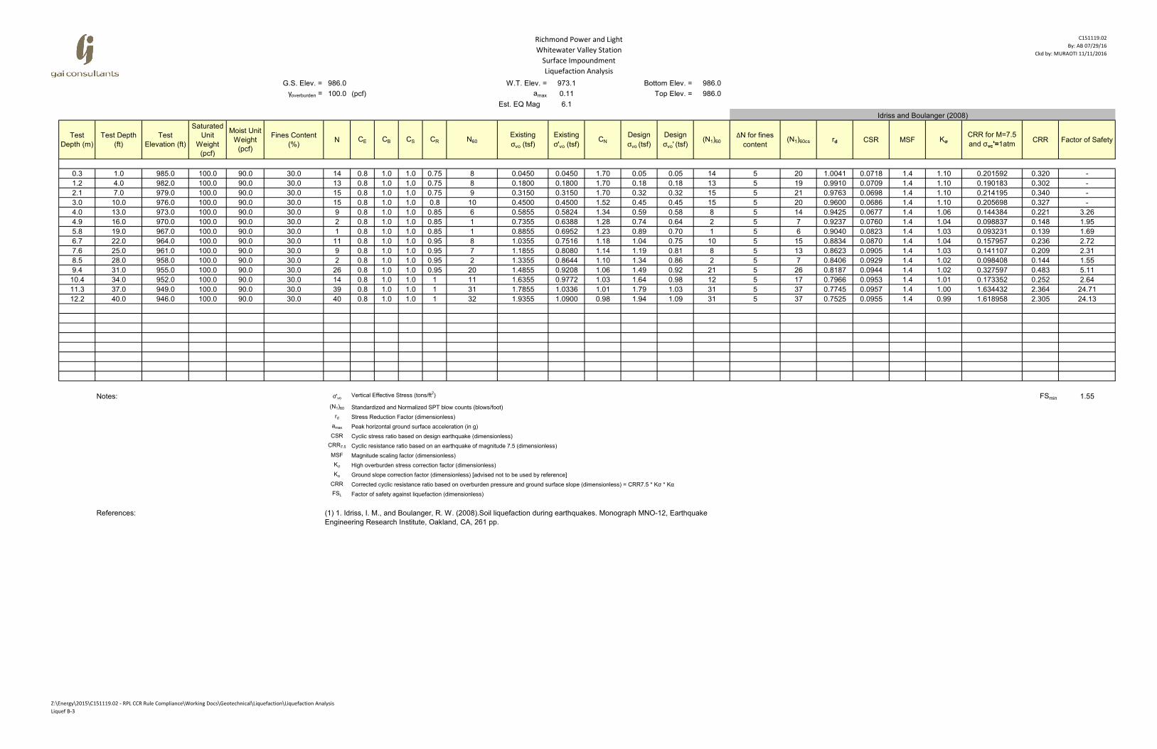
Liquefaction Analysis
C151119.02
By: AB 07/29/16
Ckd by: MURAOTI 11/11/2016
G.S. Elev. = 986.0 W.T. Elev. = 976.9 Bottom Elev. = 986.0
γoverburden = 100.0 (pcf) amax 0.11 Top Elev. = 986.0
Est. EQ Mag 6.1
Test
Depth (m)
Test Depth
(ft)
Test
Elevation (ft)
Saturated
Unit
Weight
(pcf)
Moist Unit
Weight
(pcf)
Fines Content
(%)N CE CB CS CR N60
Existing
σvo (tsf)
Existing
σ'vo (tsf)CN
Design
σvo (tsf)
Design
σvo' (tsf)(N1)60
ΔN for fines
content(N1)60cs rd CSR MSF Kσ
CRR for M=7.5
and σvc'=1atmCRR Factor of Safety
0.3 1.0 985.0 100.0 90.0 30.0 4 0.8 1.0 1.0 0.75 2 0.0450 0.0450 1.70 0.05 0.05 4 5 9 1.0041 0.0718 1.4 1.10 0.114221 0.181 -
1.2 4.0 982.0 100.0 90.0 30.0 8 0.8 1.0 1.0 0.75 5 0.1800 0.1800 1.70 0.18 0.18 8 5 14 0.9910 0.0709 1.4 1.10 0.144107 0.229 -
2.1 7.0 979.0 100.0 90.0 30.0 10 0.8 1.0 1.0 0.75 6 0.3150 0.3150 1.70 0.32 0.32 10 5 16 0.9763 0.0698 1.4 1.10 0.160925 0.256 -
3.0 10.0 976.0 100.0 90.0 30.0 12 0.8 1.0 1.0 0.8 8 0.4545 0.4264 1.56 0.45 0.43 12 5 17 0.9600 0.0732 1.4 1.10 0.177558 0.282 3.85
4.0 13.0 973.0 100.0 90.0 30.0 21 0.8 1.0 1.0 0.85 14 0.6045 0.4828 1.47 0.60 0.48 21 5 26 0.9425 0.0844 1.4 1.10 0.326326 0.518 6.14
4.9 16.0 970.0 100.0 90.0 30.0 30 0.8 1.0 1.0 0.85 20 0.7545 0.5392 1.39 0.75 0.54 28 5 34 0.9237 0.0924 1.4 1.10 0.867819 1.378 14.91
5.8 19.0 967.0 100.0 90.0 30.0 18 0.8 1.0 1.0 0.85 12 0.9045 0.5956 1.32 0.90 0.60 16 5 22 0.9040 0.0982 1.4 1.08 0.226653 0.353 3.60
6.7 22.0 964.0 100.0 90.0 30.0 16 0.8 1.0 1.0 0.95 12 1.0545 0.6520 1.27 1.05 0.65 15 5 21 0.8834 0.1022 1.4 1.06 0.215361 0.331 3.24
7.6 25.0 961.0 100.0 90.0 30.0 16 0.8 1.0 1.0 0.95 12 1.2045 0.7084 1.21 1.20 0.71 15 5 20 0.8623 0.1048 1.4 1.05 0.207403 0.315 3.00
8.5 28.0 958.0 100.0 90.0 30.0 16 0.8 1.0 1.0 0.95 12 1.3545 0.7648 1.17 1.35 0.76 14 5 20 0.8406 0.1064 1.4 1.04 0.200761 0.302 2.83
9.4 31.0 955.0 100.0 90.0 30.0 19 0.8 1.0 1.0 0.95 14 1.5045 0.8212 1.13 1.50 0.82 16 5 22 0.8187 0.1072 1.4 1.03 0.227763 0.340 3.17
Notes: σ'voVertical Effective Stress (tons/ft
2) FSmin 2.83
(N1)60 Standardized and Normalized SPT blow counts (blows/foot)
rd Stress Reduction Factor (dimensionless)
amax Peak horizontal ground surface acceleration (in g)
CSR Cyclic stress ratio based on design earthquake (dimensionless)
CRR7.5 Cyclic resistance ratio based on an earthquake of magnitude 7.5 (dimensionless)
MSF Magnitude scaling factor (dimensionless)
Kσ High overburden stress correction factor (dimensionless)
Kα Ground slope correction factor (dimensionless) [advised not to be used by reference]
CRR Corrected cyclic resistance ratio based on overburden pressure and ground surface slope (dimensionless) = CRR7.5 * Kσ * Kα
FSL Factor of safety against liquefaction (dimensionless)
References:
Idriss and Boulanger (2008)
(1) 1. Idriss, I. M., and Boulanger, R. W. (2008).Soil liquefaction during earthquakes. Monograph MNO-12, Earthquake
Engineering Research Institute, Oakland, CA, 261 pp.
Z:\Energy\2015\C151119.02 - RPL CCR Rule Compliance\Working Docs\Geotechnical\Liquefaction\Liquefaction Analysis
Liquef B-1

Richmond Power and Light
Whitewater Valley Station
Surface impoundment
Liquefaction Analysis
C151119.02
By: AB 07/29/16
Ckd by:MURAOTI 11/11/2016
G.S. Elev. = 986.0 W.T. Elev. = 976.0 Bottom Elev. = 986.0
γoverburden = 100.0 (pcf) amax 0.11 Top Elev. = 986.0
Est. EQ Mag 6.1
Test
Depth (m)
Test Depth
(ft)
Test
Elevation (ft)
Saturated
Unit
Weight
(pcf)
Moist Unit
Weight
(pcf)
Fines Content
(%)N CE CB CS CR N60
Existing
σvo (tsf)
Existing
σ'vo (tsf)CN
Design
σvo (tsf)
Design
σvo' (tsf)(N1)60
ΔN for fines
content(N1)60cs rd CSR MSF Kσ
CRR for M=7.5
and σvc'=1atmCRR Factor of Safety
0.3 1.0 985.0 100.0 90.0 30.0 16 0.8 1.0 1.0 0.75 10 0.0450 0.0450 1.70 0.05 0.05 16 5 22 1.0041 0.0718 1.4 1.10 0.228300 0.363 -
1.2 4.0 982.0 100.0 90.0 30.0 15 0.8 1.0 1.0 0.75 9 0.1800 0.1800 1.70 0.18 0.18 15 5 21 0.9910 0.0709 1.4 1.10 0.214195 0.340 -
2.1 7.0 979.0 100.0 90.0 30.0 15 0.8 1.0 1.0 0.75 9 0.3150 0.3150 1.70 0.32 0.32 15 5 21 0.9763 0.0698 1.4 1.10 0.214195 0.340 -
3.0 10.0 976.0 100.0 90.0 30.0 13 0.8 1.0 1.0 0.8 8 0.4500 0.4500 1.52 0.45 0.45 13 5 18 0.9600 0.0686 1.4 1.10 0.184074 0.292 4.26
4.0 13.0 973.0 100.0 90.0 30.0 15 0.8 1.0 1.0 0.85 10 0.6000 0.5064 1.44 0.60 0.51 15 5 20 0.9425 0.0798 1.4 1.10 0.205979 0.326 4.08
5.8 19.0 967.0 100.0 90.0 30.0 15 0.8 1.0 1.0 0.85 10 0.9000 0.6192 1.30 0.90 0.62 13 5 19 0.9040 0.0939 1.4 1.07 0.190035 0.292 3.11
6.7 22.0 964.0 100.0 90.0 30.0 11 0.8 1.0 1.0 0.95 8 1.0500 0.6756 1.24 1.05 0.68 10 5 16 0.8834 0.0982 1.4 1.05 0.162611 0.246 2.51
7.6 25.0 961.0 100.0 90.0 30.0 11 0.8 1.0 1.0 0.95 8 1.2000 0.7320 1.19 1.20 0.73 10 5 15 0.8623 0.1011 1.4 1.04 0.159075 0.239 2.36
8.5 28.0 958.0 100.0 90.0 30.0 19 0.8 1.0 1.0 0.95 14 1.3500 0.7884 1.15 1.35 0.79 17 5 22 0.8406 0.1029 1.4 1.04 0.232770 0.349 3.40
9.4 31.0 955.0 100.0 90.0 30.0 21 0.8 1.0 1.0 0.95 16 1.5000 0.8448 1.11 1.50 0.84 18 5 23 0.8187 0.1039 1.4 1.03 0.251264 0.374 3.60
10.4 34.0 952.0 100.0 90.0 30.0 29 0.8 1.0 1.0 1 23 1.6500 0.9012 1.08 1.65 0.90 25 5 30 0.7966 0.1043 1.4 1.03 0.506784 0.753 7.22
11.3 37.0 949.0 100.0 90.0 30.0 12 0.8 1.0 1.0 1 10 1.8000 0.9576 1.04 1.80 0.96 10 5 15 0.7745 0.1041 1.4 1.01 0.159416 0.232 2.23
12.2 40.0 946.0 100.0 90.0 30.0 11 0.8 1.0 1.0 1 9 1.9500 1.0140 1.01 1.95 1.01 9 5 14 0.7525 0.1035 1.4 1.00 0.150274 0.218 2.10
Notes: σ'voVertical Effective Stress (tons/ft
2) FSmin 2.10
(N1)60 Standardized and Normalized SPT blow counts (blows/foot)
rd Stress Reduction Factor (dimensionless)
amax Peak horizontal ground surface acceleration (in g)
CSR Cyclic stress ratio based on design earthquake (dimensionless)
CRR7.5 Cyclic resistance ratio based on an earthquake of magnitude 7.5 (dimensionless)
MSF Magnitude scaling factor (dimensionless)
Kσ High overburden stress correction factor (dimensionless)
Kα Ground slope correction factor (dimensionless) [advised not to be used by reference]
CRR Corrected cyclic resistance ratio based on overburden pressure and ground surface slope (dimensionless) = CRR7.5 * Kσ * Kα
FSL Factor of safety against liquefaction (dimensionless)
References:
Idriss and Boulanger (2008)
(1) 1. Idriss, I. M., and Boulanger, R. W. (2008).Soil liquefaction during earthquakes. Monograph MNO-12, Earthquake
Engineering Research Institute, Oakland, CA, 261 pp.
Z:\Energy\2015\C151119.02 - RPL CCR Rule Compliance\Working Docs\Geotechnical\Liquefaction\Liquefaction Analysis
Liquef B-2
Richmond Power and Light
Whitewater Valley Station
Surface Impoundment
Liquefaction Analysis
C151119.02
By: AB 07/29/16
Ckd by: MURAOTI 11/11/2016
G.S. Elev. = 986.0 W.T. Elev. = 973.1 Bottom Elev. = 986.0
γoverburden = 100.0 (pcf) amax 0.11 Top Elev. = 986.0
Est. EQ Mag 6.1
Test
Depth (m)
Test Depth
(ft)
Test
Elevation (ft)
Saturated
Unit
Weight
(pcf)
Moist Unit
Weight
(pcf)
Fines Content
(%)N CE CB CS CR N60
Existing
σvo (tsf)
Existing
σ'vo (tsf)CN
Design
σvo (tsf)
Design
σvo' (tsf)(N1)60
ΔN for fines
content(N1)60cs rd CSR MSF Kσ
CRR for M=7.5
and σvc'=1atmCRR Factor of Safety
0.3 1.0 985.0 100.0 90.0 30.0 14 0.8 1.0 1.0 0.75 8 0.0450 0.0450 1.70 0.05 0.05 14 5 20 1.0041 0.0718 1.4 1.10 0.201592 0.320 -
1.2 4.0 982.0 100.0 90.0 30.0 13 0.8 1.0 1.0 0.75 8 0.1800 0.1800 1.70 0.18 0.18 13 5 19 0.9910 0.0709 1.4 1.10 0.190183 0.302 -
2.1 7.0 979.0 100.0 90.0 30.0 15 0.8 1.0 1.0 0.75 9 0.3150 0.3150 1.70 0.32 0.32 15 5 21 0.9763 0.0698 1.4 1.10 0.214195 0.340 -
3.0 10.0 976.0 100.0 90.0 30.0 15 0.8 1.0 1.0 0.8 10 0.4500 0.4500 1.52 0.45 0.45 15 5 20 0.9600 0.0686 1.4 1.10 0.205698 0.327 -
4.0 13.0 973.0 100.0 90.0 30.0 9 0.8 1.0 1.0 0.85 6 0.5855 0.5824 1.34 0.59 0.58 8 5 14 0.9425 0.0677 1.4 1.06 0.144384 0.221 3.26
4.9 16.0 970.0 100.0 90.0 30.0 2 0.8 1.0 1.0 0.85 1 0.7355 0.6388 1.28 0.74 0.64 2 5 7 0.9237 0.0760 1.4 1.04 0.098837 0.148 1.95
5.8 19.0 967.0 100.0 90.0 30.0 1 0.8 1.0 1.0 0.85 1 0.8855 0.6952 1.23 0.89 0.70 1 5 6 0.9040 0.0823 1.4 1.03 0.093231 0.139 1.69
6.7 22.0 964.0 100.0 90.0 30.0 11 0.8 1.0 1.0 0.95 8 1.0355 0.7516 1.18 1.04 0.75 10 5 15 0.8834 0.0870 1.4 1.04 0.157957 0.236 2.72
7.6 25.0 961.0 100.0 90.0 30.0 9 0.8 1.0 1.0 0.95 7 1.1855 0.8080 1.14 1.19 0.81 8 5 13 0.8623 0.0905 1.4 1.03 0.141107 0.209 2.31
8.5 28.0 958.0 100.0 90.0 30.0 2 0.8 1.0 1.0 0.95 2 1.3355 0.8644 1.10 1.34 0.86 2 5 7 0.8406 0.0929 1.4 1.02 0.098408 0.144 1.55
9.4 31.0 955.0 100.0 90.0 30.0 26 0.8 1.0 1.0 0.95 20 1.4855 0.9208 1.06 1.49 0.92 21 5 26 0.8187 0.0944 1.4 1.02 0.327597 0.483 5.11
10.4 34.0 952.0 100.0 90.0 30.0 14 0.8 1.0 1.0 1 11 1.6355 0.9772 1.03 1.64 0.98 12 5 17 0.7966 0.0953 1.4 1.01 0.173352 0.252 2.64
11.3 37.0 949.0 100.0 90.0 30.0 39 0.8 1.0 1.0 1 31 1.7855 1.0336 1.01 1.79 1.03 31 5 37 0.7745 0.0957 1.4 1.00 1.634432 2.364 24.71
12.2 40.0 946.0 100.0 90.0 30.0 40 0.8 1.0 1.0 1 32 1.9355 1.0900 0.98 1.94 1.09 31 5 37 0.7525 0.0955 1.4 0.99 1.618958 2.305 24.13
Notes: σ'voVertical Effective Stress (tons/ft
2) FSmin 1.55
(N1)60 Standardized and Normalized SPT blow counts (blows/foot)
rd Stress Reduction Factor (dimensionless)
amax Peak horizontal ground surface acceleration (in g)
CSR Cyclic stress ratio based on design earthquake (dimensionless)
CRR7.5 Cyclic resistance ratio based on an earthquake of magnitude 7.5 (dimensionless)
MSF Magnitude scaling factor (dimensionless)
Kσ High overburden stress correction factor (dimensionless)
Kα Ground slope correction factor (dimensionless) [advised not to be used by reference]
CRR Corrected cyclic resistance ratio based on overburden pressure and ground surface slope (dimensionless) = CRR7.5 * Kσ * Kα
FSL Factor of safety against liquefaction (dimensionless)
References:
Idriss and Boulanger (2008)
(1) 1. Idriss, I. M., and Boulanger, R. W. (2008).Soil liquefaction during earthquakes. Monograph MNO-12, Earthquake
Engineering Research Institute, Oakland, CA, 261 pp.
Z:\Energy\2015\C151119.02 - RPL CCR Rule Compliance\Working Docs\Geotechnical\Liquefaction\Liquefaction Analysis
Liquef B-3

Richmond Power and Light
Whitewater Valley Station
Surface Impoundment
Liquefaction Analysis
C151119.02
By: AB 07/29/16
Ckd by:MURAOTI 11/11/2016
G.S. Elev. = 972.0 W.T. Elev. = 962.0 Bottom Elev. = 972.0
γoverburden = 100.0 (pcf) amax 0.11 Top Elev. = 972.0
Est. EQ Mag 6.1
Test
Depth (m)
Test Depth
(ft)
Test
Elevation (ft)
Saturated
Unit
Weight
(pcf)
Moist Unit
Weight
(pcf)
Fines Content
(%)N CE CB CS CR N60
Existing
σvo (tsf)
Existing
σ'vo (tsf)CN
Design
σvo (tsf)
Design
σvo' (tsf)(N1)60
ΔN for fines
content(N1)60cs rd CSR MSF Kσ
CRR for M=7.5
and σvc'=1atmCRR Factor of Safety
0.3 1.0 971.0 100.0 90.0 30.0 7 1.3 1.0 1.0 0.75 7 0.0450 0.0450 1.70 0.05 0.05 12 5 17 1.0041 0.0718 1.4 1.10 0.173581 0.276 -
1.1 3.5 968.5 100.0 90.0 30.0 13 1.3 1.0 1.0 0.75 13 0.1575 0.1575 1.70 0.16 0.16 22 5 27 0.9933 0.0710 1.4 1.10 0.343521 0.545 -
1.8 6.0 966.0 100.0 90.0 30.0 18 1.3 1.0 1.0 0.75 18 0.2700 0.2700 1.70 0.27 0.27 30 5 35 0.9814 0.0702 1.4 1.10 1.155283 1.835 -
2.6 8.5 963.5 100.0 90.0 30.0 11 1.3 1.0 1.0 0.75 11 0.3825 0.3825 1.65 0.38 0.38 18 5 23 0.9683 0.0692 1.4 1.10 0.250849 0.398 -
3.4 11.0 961.0 100.0 90.0 30.0 10 1.3 1.0 1.0 0.8 10 0.5000 0.4688 1.49 0.50 0.47 16 5 21 0.9543 0.0728 1.4 1.10 0.217125 0.345 4.74
4.1 13.5 958.5 100.0 90.0 30.0 33 1.3 1.0 1.0 0.85 36 0.6250 0.5158 1.42 0.63 0.52 52 5 57 0.9394 0.0814 1.4 1.10 2.000000 3.176 39.02
Notes: σ'voVertical Effective Stress (tons/ft
2) FSmin 4.74
(N1)60 Standardized and Normalized SPT blow counts (blows/foot)
rd Stress Reduction Factor (dimensionless)
amax Peak horizontal ground surface acceleration (in g)
CSR Cyclic stress ratio based on design earthquake (dimensionless)
CRR7.5 Cyclic resistance ratio based on an earthquake of magnitude 7.5 (dimensionless)
MSF Magnitude scaling factor (dimensionless)
Kσ High overburden stress correction factor (dimensionless)
Kα Ground slope correction factor (dimensionless) [advised not to be used by reference]
CRR Corrected cyclic resistance ratio based on overburden pressure and ground surface slope (dimensionless) = CRR7.5 * Kσ * Kα
FSL Factor of safety against liquefaction (dimensionless)
References:
Idriss and Boulanger (2008)
(1) 1. Idriss, I. M., and Boulanger, R. W. (2008).Soil liquefaction during earthquakes. Monograph MNO-12, Earthquake
Engineering Research Institute, Oakland, CA, 261 pp.
Z:\Energy\2015\C151119.02 - RPL CCR Rule Compliance\Working Docs\Geotechnical\Liquefaction\Liquefaction Analysis
Liquef B-4
Richmond Power and Light
Whitewater Valley Station
Surface Impoundment
Liquefaction Analysis
C151119.02
By: AB 07/29/16
Ckd by:MURAOTI 11/11/2016
G.S. Elev. = 986.0 W.T. Elev. = 976.0 Bottom Elev. = 986.0
γoverburden = 100.0 (pcf) amax 0.11 Top Elev. = 986.0
Est. EQ Mag 6.1
Test
Depth (m)
Test Depth
(ft)
Test
Elevation (ft)
Saturated
Unit
Weight
(pcf)
Moist Unit
Weight
(pcf)
Fines Content
(%)N CE CB CS CR N60
Existing
σvo (tsf)
Existing
σ'vo (tsf)CN
Design
σvo (tsf)
Design
σvo' (tsf)(N1)60 α β (N1)60cs
ΔN for fines
content(N1)60cs rd CSR MSF Kσ
CRR for M=7.5
and σvc'=1atmCRR Factor of Safety
0.3 1.0 985.0 100.0 90.0 30.0 17 0.8 1.0 1.0 0.75 10 0.0450 0.0450 1.70 0.05 0.05 17 5 1.1 24 5 23 1.0041 0.0718 1.4 1.10 0.244294 0.388 -
1.2 4.0 982.0 100.0 90.0 30.0 16 0.8 1.0 1.0 0.75 10 0.1800 0.1800 1.70 0.18 0.18 16 5 1.1 23 5 22 0.9910 0.0709 1.4 1.10 0.228300 0.363 -
2.1 7.0 979.0 100.0 90.0 30.0 7 0.8 1.0 1.0 0.75 4 0.3150 0.3150 1.70 0.32 0.32 7 5 1.1 13 5 13 0.9763 0.0698 1.4 1.10 0.136231 0.216 -
3.0 10.0 976.0 100.0 90.0 30.0 8 0.8 1.0 1.0 0.8 5 0.4500 0.4500 1.52 0.45 0.45 8 5 1.1 13 5 13 0.9600 0.0686 1.4 1.09 0.141289 0.222 3.23
4.0 13.0 973.0 100.0 90.0 30.0 12 0.8 1.0 1.0 0.85 8 0.6000 0.5064 1.44 0.60 0.51 12 5 1.1 18 5 17 0.9425 0.0798 1.4 1.09 0.174673 0.274 3.43
4.9 16.0 970.0 100.0 90.0 30.0 12 0.8 1.0 1.0 0.85 8 0.7500 0.5628 1.36 0.75 0.56 11 5 1.1 17 5 16 0.9237 0.0880 1.4 1.07 0.169062 0.262 2.97
5.8 19.0 967.0 100.0 90.0 30.0 15 0.8 1.0 1.0 0.85 10 0.9000 0.6192 1.30 0.90 0.62 13 5 1.1 19 5 19 0.9040 0.0939 1.4 1.07 0.190035 0.292 3.11
6.7 22.0 964.0 100.0 90.0 30.0 15 0.8 1.0 1.0 0.95 11 1.0500 0.6756 1.24 1.05 0.68 14 5 1.1 20 5 20 0.8834 0.0982 1.4 1.06 0.200346 0.306 3.11
7.6 25.0 961.0 100.0 90.0 30.0 17 0.8 1.0 1.0 0.95 13 1.2000 0.7320 1.19 1.20 0.73 15 5 1.1 22 5 21 0.8623 0.1011 1.4 1.05 0.215925 0.327 3.23
8.5 28.0 958.0 100.0 90.0 30.0 4 0.8 1.0 1.0 0.95 3 1.3500 0.7884 1.15 1.35 0.79 3 5 1.1 9 5 9 0.8406 0.1029 1.4 1.02 0.110285 0.163 1.58
Notes: σ'voVertical Effective Stress (tons/ft
2) FSmin 1.58
(N1)60 Standardized and Normalized SPT blow counts (blows/foot)
rd Stress Reduction Factor (dimensionless)
amax Peak horizontal ground surface acceleration (in g)
CSR Cyclic stress ratio based on design earthquake (dimensionless)
CRR7.5 Cyclic resistance ratio based on an earthquake of magnitude 7.5 (dimensionless)
MSF Magnitude scaling factor (dimensionless)
Kσ High overburden stress correction factor (dimensionless)
Kα Ground slope correction factor (dimensionless) [advised not to be used by reference]
CRR Corrected cyclic resistance ratio based on overburden pressure and ground surface slope (dimensionless) = CRR7.5 * Kσ * Kα
FSL Factor of safety against liquefaction (dimensionless)
References:
Idriss and Boulanger (2008)
(1) 1. Idriss, I. M., and Boulanger, R. W. (2008).Soil liquefaction during earthquakes. Monograph MNO-12, Earthquake Engineering
Research Institute, Oakland, CA, 261 pp.
Z:\Energy\2015\C151119.02 - RPL CCR Rule Compliance\Working Docs\Geotechnical\Liquefaction\Liquefaction Analysis
Liquef B-5

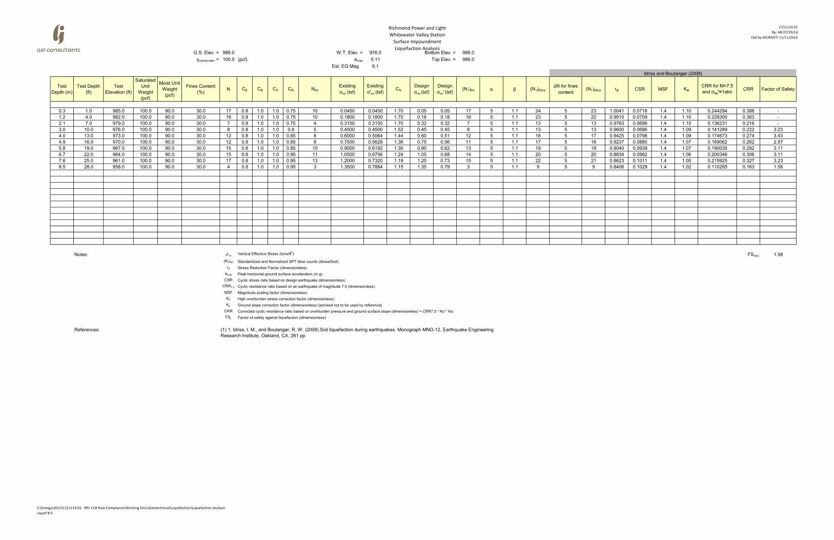
Richmond Power and Light
Whitewater Valley Station
Surface Impoundment
Liquefaction Analysis
C151119.02
By: AB 07/29/16
Ckd by: MURAOTI 11/11/2016
G.S. Elev. = 982.0 W.T. Elev. = 967.3 Bottom Elev. = 982.0
γoverburden = 100.0 (pcf) amax 0.11 Top Elev. = 982.0
Est. EQ Mag 6.1
Test
Depth (m)
Test Depth
(ft)
Test
Elevation (ft)
Saturated
Unit
Weight
(pcf)
Moist Unit
Weight
(pcf)
Fines Content
(%)N CE CB CS CR N60
Existing
σvo (tsf)
Existing
σ'vo (tsf)CN
Design
σvo (tsf)
Design
σvo' (tsf)(N1)60 α β (N1)60cs
ΔN for fines
content(N1)60cs rd CSR MSF Kσ
CRR for M=7.5
and σvc'=1atmCRR Factor of Safety
0.3 1.0 981.0 100.0 90.0 30.0 1 0.8 1.0 1.0 0.75 1 0.0450 0.0450 1.70 0.05 0.05 1 5 1.1 6 5 6 1.0041 0.0718 1.4 1.10 0.094370 0.150 -
1.2 4.0 978.0 100.0 90.0 30.0 4 0.8 1.0 1.0 0.75 2 0.1800 0.1800 1.70 0.18 0.18 4 5 1.1 9 5 9 0.9910 0.0709 1.4 1.10 0.114221 0.181 -
2.1 7.0 975.0 100.0 90.0 30.0 2 0.8 1.0 1.0 0.75 1 0.3150 0.3150 1.70 0.32 0.32 2 5 1.1 7 5 7 0.9763 0.0698 1.4 1.10 0.100745 0.160 -
3.0 10.0 972.0 100.0 90.0 30.0 1 0.8 1.0 1.0 0.80 1 0.4500 0.4500 1.52 0.45 0.45 1 5 1.1 6 5 6 0.9600 0.0686 1.4 1.07 0.094094 0.145 -
4.0 13.0 969.0 100.0 90.0 30.0 1 0.8 1.0 1.0 0.85 1 0.5850 0.5850 1.34 0.59 0.59 1 5 1.1 6 5 6 0.9425 0.0674 1.4 1.05 0.093688 0.141 -
4.9 16.0 966.0 100.0 90.0 30.0 1 0.8 1.0 1.0 0.85 1 0.7265 0.6859 1.23 0.73 0.69 1 5 1.1 6 5 6 0.9237 0.0700 1.4 1.03 0.093265 0.139 1.99
5.8 19.0 963.0 100.0 90.0 30.0 1 0.8 1.0 1.0 0.85 1 0.8765 0.7423 1.19 0.88 0.74 1 5 1.1 6 5 6 0.9040 0.0763 1.4 1.03 0.093067 0.138 1.81
6.7 22.0 960.0 100.0 90.0 30.0 3 0.8 1.0 1.0 0.95 2 1.0265 0.7987 1.14 1.03 0.80 3 5 1.1 8 5 8 0.8834 0.0812 1.4 1.02 0.104395 0.154 1.90
8.5 28.0 954.0 100.0 90.0 30.0 14 0.8 1.0 1.0 0.95 11 1.3265 0.9115 1.07 1.33 0.91 11 5 1.1 17 5 17 0.8406 0.0875 1.4 1.02 0.171577 0.252 2.88
9.4 31.0 951.0 100.0 90.0 30.0 20 0.8 1.0 1.0 0.95 15 1.4765 0.9679 1.04 1.48 0.97 16 5 1.1 22.1 5 21 0.8187 0.0893 1.4 1.01 0.220734 0.322 3.60
10.4 34.0 948.0 100.0 90.0 30.0 20 0.8 1.0 1.0 1.00 16 1.6265 1.0243 1.01 1.63 1.02 16 5 1.1 22.5 5 22 0.7966 0.0904 1.4 1.00 0.225900 0.327 3.61
11.3 37.0 945.0 100.0 90.0 30.0 22 0.8 1.0 1.0 1.00 18 1.7765 1.0807 0.98 1.78 1.08 17 5 1.1 24 5 23 0.7745 0.0910 1.4 0.99 0.243634 0.350 3.84
12.2 40.0 942.0 100.0 90.0 30.0 25 0.8 1.0 1.0 1.00 20 1.9265 1.1371 0.96 1.93 1.14 19 5 1.1 26 5 25 0.7525 0.0912 1.4 0.99 0.279282 0.397 4.36
Notes: σ'voVertical Effective Stress (tons/ft
2) FSmin 1.81
(N1)60 Standardized and Normalized SPT blow counts (blows/foot)
rd Stress Reduction Factor (dimensionless)
amax Peak horizontal ground surface acceleration (in g)
CSR Cyclic stress ratio based on design earthquake (dimensionless)
CRR7.5 Cyclic resistance ratio based on an earthquake of magnitude 7.5 (dimensionless)
MSF Magnitude scaling factor (dimensionless)
Kσ High overburden stress correction factor (dimensionless)
Kα Ground slope correction factor (dimensionless) [advised not to be used by reference]
CRR Corrected cyclic resistance ratio based on overburden pressure and ground surface slope (dimensionless) = CRR7.5 * Kσ * Kα
FSL Factor of safety against liquefaction (dimensionless)
References:
Idriss and Boulanger (2008)
(1) 1. Idriss, I. M., and Boulanger, R. W. (2008).Soil liquefaction during earthquakes. Monograph MNO-12, Earthquake Engineering
Research Institute, Oakland, CA, 261 pp.
Z:\Energy\2015\C151119.02 - RPL CCR Rule Compliance\Working Docs\Geotechnical\Liquefaction\Liquefaction Analysis
Liquef B-6

Richmond Power and Light
Whitewater Valley Station
Surface Impoundment
Liquefaction Analysis
C151119.02
By: AB 07/29/16
Ckd by: MURAOTI 11/11/2016
G.S. Elev. = 984.0 W.T. Elev. = 978.3 Bottom Elev. = 984.0
γoverburden = 100.0 (pcf) amax 0.11 Top Elev. = 984.0
Est. EQ Mag 6.1
Test
Depth (m)
Test Depth
(ft)
Test
Elevation (ft)
Saturated
Unit
Weight
(pcf)
Moist Unit
Weight
(pcf)
Fines Content
(%)N CE CB CS CR N60
Existing
σvo (tsf)
Existing
σ'vo (tsf)CN
Design
σvo (tsf)
Design
σvo' (tsf)(N1)60 α β (N1)60cs
ΔN for fines
content(N1)60cs rd CSR MSF Kσ
CRR for M=7.5
and σvc'=1atmCRR Factor of Safety
0.3 1.0 983.0 100.0 90.0 30.0 4 0.8 1.0 1.0 0.75 2 0.0450 0.0450 1.70 0.05 0.05 4 5 1.1 9 5 9 1.0041 0.0718 1.4 1.10 0.114221 0.181 -
1.2 4.0 980.0 100.0 90.0 30.0 2 0.8 1.0 1.0 0.75 1 0.1800 0.1800 1.70 0.18 0.18 2 5 1.1 7 5 7 0.9910 0.0709 1.4 1.10 0.100745 0.160 -
2.1 7.0 977.0 100.0 90.0 30.0 0 0.8 1.0 1.0 0.75 0 0.3215 0.2809 1.70 0.32 0.28 0 5 1.1 5 5 5 0.9763 0.0799 1.4 1.10 0.088250 0.140 1.75
3.0 10.0 974.0 100.0 90.0 30.0 0 0.8 1.0 1.0 0.8 0 0.4715 0.3373 1.70 0.47 0.34 0 5 1.1 5 5 5 0.9600 0.0959 1.4 1.09 0.088250 0.138 1.44
4.0 13.0 971.0 100.0 90.0 30.0 10 0.8 1.0 1.0 0.85 7 0.6215 0.3937 1.63 0.62 0.39 11 5 1.1 17 5 16 0.9425 0.1064 1.4 1.10 0.168687 0.268 2.52
5.8 19.0 965.0 100.0 90.0 30.0 3 0.8 1.0 1.0 0.85 2 0.9215 0.5065 1.44 0.92 0.51 3 5 1.1 8 5 8 0.9040 0.1176 1.4 1.06 0.106502 0.163 1.39
6.7 22.0 962.0 100.0 90.0 30.0 13 0.8 1.0 1.0 0.95 10 1.0715 0.5629 1.36 1.07 0.56 13 5 1.1 20 5 19 0.8834 0.1202 1.4 1.08 0.192300 0.299 2.49
7.6 25.0 959.0 100.0 90.0 30.0 12 0.8 1.0 1.0 0.95 9 1.2215 0.6193 1.30 1.22 0.62 12 5 1.1 18 5 17 0.8623 0.1216 1.4 1.06 0.175860 0.270 2.22
8.5 28.0 956.0 100.0 90.0 30.0 17 0.8 1.0 1.0 0.95 13 1.3715 0.6757 1.24 1.37 0.68 16 5 1.1 22.4 5 21 0.8406 0.1220 1.4 1.06 0.224560 0.344 2.82
9.4 31.0 953.0 100.0 90.0 30.0 22 0.8 1.0 1.0 0.95 17 1.5215 0.7321 1.19 1.52 0.73 20 5 1.1 27 5 25 0.8187 0.1216 1.4 1.06 0.298075 0.455 3.74
10.4 34.0 950.0 100.0 90.0 30.0 25 0.8 1.0 1.0 1 20 1.6715 0.7885 1.15 1.67 0.79 23 5 1.1 30 5 28 0.7966 0.1207 1.4 1.05 0.399670 0.607 5.03
11.3 37.0 947.0 100.0 90.0 30.0 15 0.8 1.0 1.0 1 12 1.8215 0.8449 1.11 1.82 0.84 13 5 1.1 19 5 19 0.7745 0.1194 1.4 1.03 0.191047 0.283 2.37
12.2 40.0 944.0 100.0 90.0 30.0 37 0.8 1.0 1.0 1 30 1.9715 0.9013 1.08 1.97 0.90 32 5 1.1 40 5 37 0.7525 0.1177 1.4 1.04 1.851274 2.785 23.67
Notes: σ'voVertical Effective Stress (tons/ft
2) FSmin 1.39
(N1)60 Standardized and Normalized SPT blow counts (blows/foot)
rd Stress Reduction Factor (dimensionless)
amax Peak horizontal ground surface acceleration (in g)
CSR Cyclic stress ratio based on design earthquake (dimensionless)
CRR7.5 Cyclic resistance ratio based on an earthquake of magnitude 7.5 (dimensionless)
MSF Magnitude scaling factor (dimensionless)
Kσ High overburden stress correction factor (dimensionless)
Kα Ground slope correction factor (dimensionless) [advised not to be used by reference]
CRR Corrected cyclic resistance ratio based on overburden pressure and ground surface slope (dimensionless) = CRR7.5 * Kσ * Kα
FSL Factor of safety against liquefaction (dimensionless)
References:
Idriss and Boulanger (2008)
(1) 1. Idriss, I. M., and Boulanger, R. W. (2008).Soil liquefaction during earthquakes. Monograph MNO-12, Earthquake Engineering
Research Institute, Oakland, CA, 261 pp.
Z:\Energy\2015\C151119.02 - RPL CCR Rule Compliance\Working Docs\Geotechnical\Liquefaction\Liquefaction Analysis
Liquef B-7

Richmond Power and Light
Whitewater Valley Station
Surface Impoundment
Liquefaction Analysis
C151119.02
By: AB 07/29/16
Ckd by: MURAOTI 11/11/2016
G.S. Elev. = 984.0 W.T. Elev. = 975.6 Bottom Elev. = 984.0
γoverburden = 100.0 (pcf) amax 0.11 Top Elev. = 984.0
Est. EQ Mag 6.1
Test
Depth (m)
Test Depth
(ft)
Test
Elevation (ft)
Saturated
Unit
Weight
(pcf)
Moist Unit
Weight
(pcf)
Fines Content
(%)N CE CB CS CR N60
Existing
σvo (tsf)
Existing
σ'vo (tsf)CN
Design
σvo (tsf)
Design
σvo' (tsf)(N1)60
ΔN for fines
content(N1)60cs rd CSR MSF Kσ
CRR for M=7.5
and σvc'=1atmCRR Factor of Safety
0.3 1.0 983.0 100.0 90.0 30.0 2.00 0.80 1.0 1.0 0.75 1 0.0450 0.0450 1.70 0.05 0.05 2 5 7 1.0041 0.072 1.4 1.10 0.10 0.160 -
1.2 4.0 980.0 100.0 90.0 30.0 0.00 0.80 1.0 1.0 0.75 0 0.1800 0.1800 1.70 0.18 0.18 0 5 5 0.9910 0.071 1.4 1.10 0.09 0.140 -
2.1 7.0 977.0 100.0 90.0 30.0 0.00 0.80 1.0 1.0 0.75 0 0.3150 0.3150 1.70 0.32 0.32 0 5 5 0.9763 0.070 1.4 1.09 0.09 0.139 -
3.0 10.0 974.0 100.0 90.0 30.0 0.00 0.80 1.0 1.0 0.80 0 0.4580 0.4081 1.60 0.46 0.41 0 5 5 0.9600 0.077 1.4 1.07 0.09 0.137 1.77
4.9 16.0 968.0 100.0 90.0 30.0 0.00 0.80 1.0 1.0 0.85 0 0.7580 0.5209 1.42 0.76 0.52 0 5 5 0.9237 0.096 1.4 1.05 0.09 0.134 1.40
5.8 19.0 965.0 100.0 90.0 30.0 6.00 0.80 1.0 1.0 0.85 4 0.9080 0.5773 1.34 0.91 0.58 5 5 11 0.9040 0.102 1.4 1.06 0.12 0.189 1.86
6.7 22.0 962.0 100.0 90.0 30.0 7.00 0.80 1.0 1.0 0.95 5 1.0580 0.6337 1.28 1.06 0.63 7 5 12 0.8834 0.105 1.4 1.05 0.13 0.203 1.92
7.6 25.0 959.0 100.0 90.0 30.0 5.00 0.80 1.0 1.0 0.95 4 1.2080 0.6901 1.23 1.21 0.69 5 5 10 0.8623 0.108 1.4 1.04 0.12 0.177 1.64
8.5 28.0 956.0 100.0 90.0 30.0 7.00 0.80 1.0 1.0 0.95 5 1.3580 0.7465 1.18 1.36 0.75 6 5 12 0.8406 0.109 1.4 1.03 0.13 0.194 1.77
9.4 31.0 953.0 100.0 90.0 30.0 30.00 0.80 1.0 1.0 0.95 23 1.5080 0.8029 1.14 1.51 0.80 26 5 31 0.8187 0.110 1.4 1.06 0.59 0.892 8.11
10.4 34.0 950.0 100.0 90.0 30.0 30.00 0.80 1.0 1.0 1.00 24 1.6580 0.8593 1.10 1.66 0.86 26 5 32 0.7966 0.110 1.4 1.04 0.63 0.943 8.58
11.3 37.0 947.0 100.0 90.0 30.0 37.00 0.80 1.0 1.0 1.00 30 1.8080 0.9157 1.07 1.81 0.92 32 5 37 0.7745 0.109 1.4 1.04 1.74 2.603 23.81
12.2 40.0 944.0 100.0 90.0 30.0 38.00 0.80 1.0 1.0 1.00 30 1.9580 0.9721 1.04 1.96 0.97 32 5 37 0.7525 0.108 1.4 1.02 1.69 2.495 23.02
Notes: σ'voVertical Effective Stress (tons/ft
2) FSmin 1.40
(N1)60 Standardized and Normalized SPT blow counts (blows/foot)
rd Stress Reduction Factor (dimensionless)
amax Peak horizontal ground surface acceleration (in g)
CSR Cyclic stress ratio based on design earthquake (dimensionless)
CRR7.5 Cyclic resistance ratio based on an earthquake of magnitude 7.5 (dimensionless)
MSF Magnitude scaling factor (dimensionless)
Kσ High overburden stress correction factor (dimensionless)
Kα Ground slope correction factor (dimensionless) [advised not to be used by reference]
CRR Corrected cyclic resistance ratio based on overburden pressure and ground surface slope (dimensionless) = CRR7.5 * Kσ * Kα
FSL Factor of safety against liquefaction (dimensionless)
References:
Idriss and Boulanger (2008)
(1) 1. Idriss, I. M., and Boulanger, R. W. (2008).Soil liquefaction during earthquakes. Monograph MNO-12, Earthquake
Engineering Research Institute, Oakland, CA, 261 pp.
Z:\Energy\2015\C151119.02 - RPL CCR Rule Compliance\Working Docs\Geotechnical\Liquefaction\Liquefaction Analysis
Liquef B-8

Richmond Power and Light
Whitewater Valley Station
Surface Impoundment
Liquefaction Analysis
C151119.02
By: AB 07/29/16
Ckd by: MURAOTI 11/11/2016
G.S. Elev. = 984.0 W.T. Elev. = 975.1 Bottom Elev. = 984.0
γoverburden = 100.0 (pcf) amax 0.11 Top Elev. = 984.0
Est. EQ Mag 6.1
Test
Depth (m)
Test Depth
(ft)
Test
Elevation (ft)
Saturated
Unit
Weight
(pcf)
Moist Unit
Weight
(pcf)
Fines Content
(%)N CE CB CS CR N60
Existing
σvo (tsf)
Existing
σ'vo (tsf)CN
Design
σvo (tsf)
Design
σvo' (tsf)(N1)60
ΔN for fines
content(N1)60cs rd CSR MSF Kσ
CRR for M=7.5
and σvc'=1atmCRR Factor of Safety
0.3 1.0 983.0 100.0 90.0 30.0 2.00 0.80 1.0 1.0 0.75 1 0.0450 0.0450 1.70 0.05 0.05 2 5 7 1.0041 0.072 1.4 1.10 0.10 0.160 -
1.2 4.0 980.0 100.0 90.0 30.0 0.00 0.80 1.0 1.0 0.75 0 0.1800 0.1800 1.70 0.18 0.18 0 5 5 0.9910 0.071 1.4 1.10 0.09 0.140 -
3.0 10.0 974.0 100.0 90.0 30.0 0.00 0.80 1.0 1.0 0.80 0 0.4555 0.4212 1.57 0.46 0.42 0 5 5 0.9600 0.074 1.4 1.07 0.09 0.136 1.84
4.0 13.0 971.0 100.0 90.0 30.0 0.00 0.80 1.0 1.0 0.85 0 0.6055 0.4776 1.48 0.61 0.48 0 5 5 0.9425 0.085 1.4 1.06 0.09 0.135 1.58
5.8 19.0 965.0 100.0 90.0 30.0 9.00 0.80 1.0 1.0 0.85 6 0.9055 0.5904 1.33 0.91 0.59 8 5 14 0.9040 0.099 1.4 1.06 0.14 0.220 2.22
6.7 22.0 962.0 100.0 90.0 30.0 11.00 0.80 1.0 1.0 0.95 8 1.0555 0.6468 1.27 1.06 0.65 11 5 16 0.8834 0.103 1.4 1.05 0.16 0.251 2.43
7.6 25.0 959.0 100.0 90.0 30.0 32.00 0.80 1.0 1.0 0.95 24 1.2055 0.7032 1.22 1.21 0.70 30 5 35 0.8623 0.106 1.4 1.10 1.11 1.760 16.7
Notes: σ'voVertical Effective Stress (tons/ft
2) FSmin 1.58
(N1)60 Standardized and Normalized SPT blow counts (blows/foot)
rd Stress Reduction Factor (dimensionless)
amax Peak horizontal ground surface acceleration (in g)
CSR Cyclic stress ratio based on design earthquake (dimensionless)
CRR7.5 Cyclic resistance ratio based on an earthquake of magnitude 7.5 (dimensionless)
MSF Magnitude scaling factor (dimensionless)
Kσ High overburden stress correction factor (dimensionless)
Kα Ground slope correction factor (dimensionless) [advised not to be used by reference]
CRR Corrected cyclic resistance ratio based on overburden pressure and ground surface slope (dimensionless) = CRR7.5 * Kσ * Kα
FSL Factor of safety against liquefaction (dimensionless)
References:
Idriss and Boulanger (2008)
(1) 1. Idriss, I. M., and Boulanger, R. W. (2008).Soil liquefaction during earthquakes. Monograph MNO-12, Earthquake
Engineering Research Institute, Oakland, CA, 261 pp.
Z:\Energy\2015\C151119.02 - RPL CCR Rule Compliance\Working Docs\Geotechnical\Liquefaction\Liquefaction Analysis
Liquef B-9

Richmond Power and Light
Whitewater Valley Station
Surface Impoundment
Liquefaction Analysis
C151119.02
By: AB 07/29/16
Ckd by:MURAOTI 11/11/2016
G.S. Elev. = 996.0 W.T. Elev. = 979.0 Bottom Elev. = 996.0
γoverburden = 100.0 (pcf) amax 0.11 Top Elev. = 996.0
Est. EQ Mag 6.1
Test
Depth (m)
Test Depth
(ft)
Test
Elevation (ft)
Saturated
Unit
Weight
(pcf)
Moist Unit
Weight
(pcf)
Fines Content
(%)N CE CB CS CR N60
Existing
σvo (tsf)
Existing
σ'vo (tsf)CN
Design
σvo (tsf)
Design
σvo' (tsf)(N1)60 α β (N1)60cs
ΔN for fines
content(N1)60cs rd CSR MSF Kσ
CRR for M=7.5
and σvc'=1atmCRR Factor of Safety
0.3 1.0 995.0 100.0 90.0 30.0 5.00 0.80 1.0 1.0 0.75 3 0.0450 0.0450 1.70 0.05 0.05 5 5 1.1 10 5 10 1.0041 0.072 1.4 1.10 0.12 0.193 -
1.2 4.0 992.0 100.0 90.0 30.0 23.00 0.80 1.0 1.0 0.75 14 0.1800 0.1800 1.70 0.18 0.18 23 5 1.1 31 5 29 0.9910 0.071 1.4 1.10 0.42 0.667 -
2.1 7.0 989.0 100.0 90.0 30.0 6.00 0.80 1.0 1.0 0.75 4 0.3150 0.3150 1.70 0.32 0.32 6 5 1.1 11 5 11 0.9763 0.070 1.4 1.10 0.13 0.204 -
3.0 10.0 986.0 100.0 90.0 30.0 4.00 0.80 1.0 1.0 0.80 3 0.4500 0.4500 1.52 0.45 0.45 4 5 1.1 9 5 9 0.9600 0.069 1.4 1.08 0.11 0.175 -
4.0 13.0 983.0 100.0 90.0 30.0 3.00 0.80 1.0 1.0 0.85 2 0.5850 0.5850 1.34 0.59 0.59 3 5 1.1 8 5 8 0.9425 0.067 1.4 1.05 0.11 0.159 -
4.9 16.0 980.0 100.0 90.0 30.0 1.00 0.80 1.0 1.0 0.85 1 0.7200 0.7200 1.20 0.72 0.72 1 5 1.1 6 5 6 0.9237 0.066 1.4 1.03 0.09 0.138 -
5.8 19.0 977.0 100.0 90.0 30.0 1.00 0.80 1.0 1.0 0.85 1 0.8650 0.8026 1.14 0.87 0.80 1 5 1.1 6 5 6 0.9040 0.070 1.4 1.02 0.09 0.137 1.96
7.6 25.0 971.0 100.0 90.0 30.0 1.00 0.80 1.0 1.0 0.95 1 1.1650 0.9154 1.07 1.17 0.92 1 5 1.1 6 5 6 0.8623 0.078 1.4 1.01 0.09 0.136 1.73
8.5 28.0 968.0 100.0 90.0 30.0 1.00 0.80 1.0 1.0 0.95 1 1.3150 0.9718 1.04 1.32 0.97 1 5 1.1 5.6 5 6 0.8406 0.081 1.4 1.01 0.09 0.135 1.66
9.4 31.0 965.0 100.0 90.0 30.0 1.00 0.80 1.0 1.0 0.95 1 1.4650 1.0282 1.01 1.47 1.03 1 5 1.1 6 5 6 0.8187 0.083 1.4 1.00 0.09 0.134 1.61
10.4 34.0 962.0 100.0 90.0 30.0 4.00 0.80 1.0 1.0 1.00 3 1.6150 1.0846 0.98 1.62 1.08 3 5 1.1 8 5 9 0.7966 0.085 1.4 1.00 0.11 0.155 1.83
11.3 37.0 959.0 100.0 90.0 30.0 16.00 0.80 1.0 1.0 1.00 13 1.7650 1.1410 0.96 1.77 1.14 12 5 1.1 18 5 18 0.7745 0.086 1.4 0.99 0.18 0.257 3.00
12.2 40.0 956.0 100.0 90.0 30.0 20.00 0.80 1.0 1.0 1.00 16 1.9150 1.1974 0.93 1.92 1.20 15 5 1.1 21 5 20 0.7525 0.086 1.4 0.98 0.21 0.297 3.45
Notes: σ'voVertical Effective Stress (tons/ft
2) FSmin 1.61
(N1)60 Standardized and Normalized SPT blow counts (blows/foot)
rd Stress Reduction Factor (dimensionless)
amax Peak horizontal ground surface acceleration (in g)
CSR Cyclic stress ratio based on design earthquake (dimensionless)
CRR7.5 Cyclic resistance ratio based on an earthquake of magnitude 7.5 (dimensionless)
MSF Magnitude scaling factor (dimensionless)
Kσ High overburden stress correction factor (dimensionless)
Kα Ground slope correction factor (dimensionless) [advised not to be used by reference]
CRR Corrected cyclic resistance ratio based on overburden pressure and ground surface slope (dimensionless) = CRR7.5 * Kσ * Kα
FSL Factor of safety against liquefaction (dimensionless)
References:
Idriss and Boulanger (2008)
(1) 1. Idriss, I. M., and Boulanger, R. W. (2008).Soil liquefaction during earthquakes. Monograph MNO-12, Earthquake Engineering
Research Institute, Oakland, CA, 261 pp.
Z:\Energy\2015\C151119.02 - RPL CCR Rule Compliance\Working Docs\Geotechnical\Liquefaction\Liquefaction Analysis
Liquef B-10

Richmond Power and Light
Whitewater Valley Station
Surface Impoundment
Liquefaction Analysis
C151119.02
By: AB 07/29/16
Ckd by:MUROATI 11/11/2016
G.S. Elev. = 986.0 W.T. Elev. = 969.4 Bottom Elev. = 986.0
γoverburden = 100.0 (pcf) amax 0.11 Top Elev. = 986.0
Est. EQ Mag 6.1
Test
Depth (m)
Test Depth
(ft)
Test
Elevation (ft)
Saturated
Unit
Weight
(pcf)
Moist Unit
Weight
(pcf)
Fines Content
(%)N CE CB CS CR N60
Existing
σvo (tsf)
Existing
σ'vo (tsf)CN
Design
σvo (tsf)
Design
σvo' (tsf)(N1)60 α β (N1)60cs
ΔN for fines
content(N1)60cs rd CSR MSF Kσ
CRR for M=7.5
and σvc'=1atmCRR Factor of Safety
0.3 1.0 985.0 100.0 90.0 30.0 5.00 0.80 1.00 1.00 0.75 3 0.0450 0.0450 1.70 0.05 0.05 5 5 1.1 10 5 10 1.0041 0.072 1.4 1.10 0.12 0.193 -
1.2 4.0 982.0 100.0 90.0 30.0 10.00 0.80 1.00 1.00 0.75 6 0.1800 0.1800 1.70 0.18 0.18 10 5 1.1 16 5 16 0.9910 0.071 1.4 1.10 0.16 0.256 -
2.1 7.0 979.0 100.0 90.0 30.0 2.00 0.80 1.00 1.00 0.75 1 0.3150 0.3150 1.70 0.32 0.32 2 5 1.1 7 5 7 0.9763 0.070 1.4 1.10 0.10 0.160 -
3.0 10.0 976.0 100.0 90.0 30.0 0.00 0.80 1.00 1.00 0.80 0 0.4500 0.4500 1.52 0.45 0.45 0 5 1.1 5 5 5 0.9600 0.069 1.4 1.06 0.09 0.136 -
4.0 13.0 973.0 100.0 90.0 30.0 0.00 0.80 1.00 1.00 0.85 0 0.5850 0.5850 1.34 0.59 0.59 0 5 1.1 5 5 5 0.9425 0.067 1.4 1.04 0.09 0.133 -
4.9 16.0 970.0 100.0 90.0 30.0 0.00 0.80 1.00 1.00 0.85 0 0.7200 0.7200 1.20 0.72 0.72 0 5 1.1 5 5 5 0.9237 0.066 1.4 1.03 0.09 0.131 -
5.8 19.0 967.0 100.0 90.0 30.0 0.00 0.80 1.00 1.00 0.85 0 0.8670 0.7921 1.15 0.87 0.79 0 5 1.1 5 5 5 0.9040 0.071 1.4 1.02 0.09 0.130 1.84
6.7 22.0 964.0 100.0 90.0 30.0 8.00 0.80 1.00 1.00 0.95 6 1.0170 0.8485 1.11 1.02 0.85 7 5 1.1 12 5 12 0.8834 0.076 1.4 1.02 0.13 0.196 2.59
7.6 25.0 961.0 100.0 90.0 30.0 21.00 0.80 1.00 1.00 0.95 16 1.1670 0.9049 1.07 1.17 0.90 17 5 1.1 23.6 5 23 0.8623 0.080 1.4 1.02 0.24 0.355 4.47
8.5 28.0 958.0 100.0 90.0 30.0 21.00 0.80 1.00 1.00 0.95 16 1.3170 0.9613 1.04 1.32 0.96 17 5 1.1 23 5 22 0.8406 0.082 1.4 1.01 0.23 0.340 4.13
9.4 31.0 955.0 100.0 90.0 30.0 24.00 0.80 1.00 1.00 0.95 18 1.4670 1.0177 1.01 1.47 1.02 18 5 1.1 25 5 24 0.8187 0.084 1.4 1.00 0.26 0.384 4.55
10.4 34.0 952.0 100.0 90.0 30.0 17.00 0.80 1.00 1.00 1.00 14 1.6170 1.0741 0.99 1.62 1.07 13 5 1.1 19 5 19 0.7966 0.086 1.4 1.00 0.19 0.276 3.22
11.3 37.0 949.0 100.0 90.0 30.0 15.00 0.80 1.00 1.00 1.00 12 1.7670 1.1305 0.96 1.77 1.13 12 5 1.1 17 5 17 0.7745 0.087 1.4 0.99 0.17 0.247 2.86
12.2 40.0 946.0 100.0 90.0 30.0 18.00 0.80 1.00 1.00 1.00 14 1.9170 1.1869 0.94 1.92 1.19 14 5 1.1 20 5 19 0.7525 0.087 1.4 0.98 0.19 0.274 3.15
Notes: σ'voVertical Effective Stress (tons/ft
2) FSmin 1.84
(N1)60 Standardized and Normalized SPT blow counts (blows/foot)
rd Stress Reduction Factor (dimensionless)
amax Peak horizontal ground surface acceleration (in g)
CSR Cyclic stress ratio based on design earthquake (dimensionless)
CRR7.5 Cyclic resistance ratio based on an earthquake of magnitude 7.5 (dimensionless)
MSF Magnitude scaling factor (dimensionless)
Kσ High overburden stress correction factor (dimensionless)
Kα Ground slope correction factor (dimensionless) [advised not to be used by reference]
CRR Corrected cyclic resistance ratio based on overburden pressure and ground surface slope (dimensionless) = CRR7.5 * Kσ * Kα
FSL Factor of safety against liquefaction (dimensionless)
References:
Idriss and Boulanger (2008)
(1) 1. Idriss, I. M., and Boulanger, R. W. (2008).Soil liquefaction during earthquakes. Monograph MNO-12, Earthquake Engineering
Research Institute, Oakland, CA, 261 pp.
Z:\Energy\2015\C151119.02 - RPL CCR Rule Compliance\Working Docs\Geotechnical\Liquefaction\Liquefaction Analysis
Liquef B-11

Richmond Power and Light
Whitewater Valley Station
Surface Impoundment
Liquefaction Analysis
C151119.02
By: AB 07/29/16
Ckd by:MURAOTI 11/11/2016
G.S. Elev. = 986.0 W.T. Elev. = 979.8 Bottom Elev. = 986.0
γoverburden = 100.0 (pcf) amax 0.11 Top Elev. = 986.0
Est. EQ Mag 6.1
Test
Depth (m)
Test Depth
(ft)
Test
Elevation (ft)
Saturated
Unit
Weight
(pcf)
Moist Unit
Weight
(pcf)
Fines Content
(%)N CE CB CS CR N60
Existing
σvo (tsf)
Existing
σ'vo (tsf)CN
Design
σvo (tsf)
Design
σvo' (tsf)(N1)60 α β (N1)60cs
ΔN for fines
content(N1)60cs rd CSR MSF Kσ
CRR for M=7.5
and σvc'=1atmCRR Factor of Safety
0.3 1.0 985.0 100.0 90.0 30.0 22.00 0.80 1.0 1.0 0.75 13 0.0450 0.0450 1.70 0.05 0.05 22 5 1.1 29 5 28 1.0041 0.072 1.4 1.10 0.38 0.597 -
1.2 4.0 982.0 100.0 90.0 30.0 9.00 0.80 1.0 1.0 0.75 5 0.1800 0.1800 1.70 0.18 0.18 9 5 1.1 15 5 15 0.9910 0.071 1.4 1.10 0.15 0.242 -
2.1 7.0 979.0 100.0 90.0 30.0 8.00 0.80 1.0 1.0 0.75 5 0.3190 0.2940 1.70 0.32 0.29 8 5 1.1 14 5 14 0.9763 0.076 1.4 1.10 0.14 0.229 3.02
3.0 10.0 976.0 100.0 90.0 30.0 4.00 0.80 1.0 1.0 0.80 3 0.4690 0.3504 1.70 0.47 0.35 4 5 1.1 9 5 10 0.9600 0.092 1.4 1.10 0.12 0.184 2.01
4.0 13.0 973.0 100.0 90.0 30.0 5.00 0.80 1.0 1.0 0.85 3 0.6190 0.4068 1.60 0.62 0.41 5 5 1.1 11 5 11 0.9425 0.103 1.4 1.09 0.12 0.195 1.90
4.9 16.0 970.0 100.0 90.0 30.0 5.00 0.80 1.0 1.0 0.85 3 0.7690 0.4632 1.50 0.77 0.46 5 5 1.1 10 5 10 0.9237 0.110 1.4 1.08 0.12 0.188 1.72
5.8 19.0 967.0 100.0 90.0 30.0 10.00 0.80 1.0 1.0 0.85 7 0.9190 0.5196 1.42 0.92 0.52 10 5 1.1 15 5 15 0.9040 0.114 1.4 1.08 0.16 0.243 2.12
6.7 22.0 964.0 100.0 90.0 30.0 7.00 0.80 1.0 1.0 0.95 5 1.0690 0.5760 1.35 1.07 0.58 7 5 1.1 13 5 13 0.8834 0.117 1.4 1.06 0.14 0.209 1.78
7.6 25.0 961.0 100.0 90.0 30.0 15.00 0.80 1.0 1.0 0.95 11 1.2190 0.6324 1.28 1.22 0.63 15 5 1.1 20.8 5 20 0.8623 0.119 1.4 1.07 0.21 0.317 2.67
8.5 28.0 958.0 100.0 90.0 30.0 27.00 0.80 1.0 1.0 0.95 21 1.3690 0.6888 1.23 1.37 0.69 25 5 1.1 32 5 31 0.8406 0.119 1.4 1.09 0.53 0.826 6.92
9.4 31.0 955.0 100.0 90.0 30.0 45.00 0.80 1.0 1.0 0.95 34 1.5190 0.7452 1.18 1.52 0.75 40 5 1.1 49 5 46 0.8187 0.119 1.4 1.10 2.00 3.171 26.58
10.4 34.0 952.0 100.0 90.0 30.0 15.00 0.80 1.0 1.0 1.00 12 1.6690 0.8016 1.14 1.67 0.80 14 5 1.1 20 5 19 0.7966 0.119 1.4 1.03 0.19 0.291 2.45
11.3 37.0 949.0 100.0 90.0 30.0 18.00 0.80 1.0 1.0 1.00 14 1.8190 0.8580 1.10 1.82 0.86 16 5 1.1 22 5 21 0.7745 0.117 1.4 1.03 0.22 0.329 2.80
12.2 40.0 946.0 100.0 90.0 30.0 18.00 0.80 1.0 1.0 1.00 14 1.9690 0.9144 1.07 1.97 0.91 15 5 1.1 22 5 21 0.7525 0.116 1.4 1.02 0.22 0.316 2.73
Notes: σ'voVertical Effective Stress (tons/ft
2) FSmin 1.72
(N1)60 Standardized and Normalized SPT blow counts (blows/foot)
rd Stress Reduction Factor (dimensionless)
amax Peak horizontal ground surface acceleration (in g)
CSR Cyclic stress ratio based on design earthquake (dimensionless)
CRR7.5 Cyclic resistance ratio based on an earthquake of magnitude 7.5 (dimensionless)
MSF Magnitude scaling factor (dimensionless)
Kσ High overburden stress correction factor (dimensionless)
Kα Ground slope correction factor (dimensionless) [advised not to be used by reference]
CRR Corrected cyclic resistance ratio based on overburden pressure and ground surface slope (dimensionless) = CRR7.5 * Kσ * Kα
FSL Factor of safety against liquefaction (dimensionless)
References:
Idriss and Boulanger (2008)
(1) 1. Idriss, I. M., and Boulanger, R. W. (2008).Soil liquefaction during earthquakes. Monograph MNO-12, Earthquake Engineering
Research Institute, Oakland, CA, 261 pp.
Z:\Energy\2015\C151119.02 - RPL CCR Rule Compliance\Working Docs\Geotechnical\Liquefaction\Liquefaction Analysis
Liquef B-12
Related Documents