Co-ordinated Voltage Control of DFIG Wind Turbines in Uninterrupted Operation during Grid Faults Anca D. Hansen*, Wind Energy Department, Risø National Laboratory, Roskilde, Denmark Gabriele Michalke, Department of Renewable Energies, University of Technology Darmstadt, Germany Poul Sørensen and Torsten Lund, Wind Energy Department, Risø National Laboratory, Roskilde, Denmark Florin Iov, Institute of Energy Technology, Aalborg University, Aalborg, Denmark Emphasis in this article is on the design of a co-ordinated voltage control strategy for doubly fed induction generator (DFIG) wind turbines that enhances their capability to provide grid support during grid faults. In contrast to its very good performance in normal operation, the DFIG wind turbine concept is quite sensitive to grid faults and requires special power converter protection.The fault ride-through and grid support capabilities of the DFIG address therefore primarily the design of DFIG wind turbine control with special focus on power converter protection and voltage control issues. A voltage control strategy is designed and implemented in this article, based on the idea that both converters of the DFIG (i.e. rotor-side converter and grid-side converter) participate in the grid voltage control in a co-ordinated manner. By default the grid voltage is controlled by the rotor-side con- verter as long as it is not blocked by the protection system, otherwise the grid-side converter takes over the voltage control. Moreover, the article presents a DFIG wind farm model equipped with a grid fault protection system and the described co-ordinated voltage control. The whole DFIG wind farm model is implemented in the power system simulation toolbox PowerFactory DIgSILENT. The DFIG wind farm ride-through capability and con- tribution to voltage control in the power system are assessed and discussed by means of simulations with the use of a transmission power system generic model developed and delivered by the Danish Transmission System Operator Energinet.dk.The simulation results show how a DFIG wind farm equipped with voltage control can help a nearby active stall wind farm to ride through a grid fault, without implementation of any additional ride- through control strategy in the active stall wind farm. Copyright © 2006 John Wiley & Sons, Ltd. Received 24 April 2006; Revised 6 June 2006; Accepted 29 June 2006 WIND ENERGY Wind Energ. 2007; 10:51–68 Published online 10 August 2006 in Wiley Interscience (www.interscience.wiley.com) DOI: 10.1002/we.207 Copyright © 2006 John Wiley & Sons, Ltd. Research Article *Correspondence to: A. D. Hansen, Wind Energy Department, Risø National Laboratory, DK-4000 Roskilde, Denmark. E-mail: [email protected] Contract/grant sponsor: Danish Energy Agency, contract/grant number: ENS-1363/04-0008 Introduction Up to 5–6 years ago, most grid codes did not require wind turbines to support the power system during a grid disturbance—wind turbines were only required to be disconnected from the grid when an abnormal grid voltage was detected. With the increased capacity of wind power in the power system over the years, a sudden high loss of power during grid faults, due to wind turbine disconnection, could generate control problems of frequency and voltage in the system, and as worst case a system collapse. Key words: voltage control; power system; DFIG; power converter; wind farm; grid faults

Welcome message from author
This document is posted to help you gain knowledge. Please leave a comment to let me know what you think about it! Share it to your friends and learn new things together.
Transcript

Co-ordinated Voltage Control ofDFIG Wind Turbines in UninterruptedOperation during Grid FaultsAnca D. Hansen*, Wind Energy Department, Risø National Laboratory, Roskilde, DenmarkGabriele Michalke, Department of Renewable Energies, University of Technology Darmstadt, GermanyPoul Sørensen and Torsten Lund, Wind Energy Department, Risø National Laboratory, Roskilde, DenmarkFlorin Iov, Institute of Energy Technology, Aalborg University, Aalborg, Denmark
Emphasis in this article is on the design of a co-ordinated voltage control strategy fordoubly fed induction generator (DFIG) wind turbines that enhances their capability toprovide grid support during grid faults. In contrast to its very good performance in normaloperation, the DFIG wind turbine concept is quite sensitive to grid faults and requires specialpower converter protection.The fault ride-through and grid support capabilities of the DFIGaddress therefore primarily the design of DFIG wind turbine control with special focus onpower converter protection and voltage control issues. A voltage control strategy isdesigned and implemented in this article, based on the idea that both converters of theDFIG (i.e.rotor-side converter and grid-side converter) participate in the grid voltage controlin a co-ordinated manner. By default the grid voltage is controlled by the rotor-side con-verter as long as it is not blocked by the protection system, otherwise the grid-side convertertakes over the voltage control. Moreover, the article presents a DFIG wind farm modelequipped with a grid fault protection system and the described co-ordinated voltagecontrol. The whole DFIG wind farm model is implemented in the power system simulationtoolbox PowerFactory DIgSILENT. The DFIG wind farm ride-through capability and con-tribution to voltage control in the power system are assessed and discussed by means ofsimulations with the use of a transmission power system generic model developed anddelivered by the Danish Transmission System Operator Energinet.dk. The simulation resultsshow how a DFIG wind farm equipped with voltage control can help a nearby active stallwind farm to ride through a grid fault, without implementation of any additional ride-through control strategy in the active stall wind farm. Copyright © 2006 John Wiley & Sons,Ltd.
Received 24 April 2006; Revised 6 June 2006; Accepted 29 June 2006
WIND ENERGYWind Energ. 2007; 10:51–68Published online 10 August 2006 in Wiley Interscience (www.interscience.wiley.com) DOI: 10.1002/we.207
Copyright © 2006 John Wiley & Sons, Ltd.
Research Article
* Correspondence to: A. D. Hansen, Wind Energy Department, Risø National Laboratory, DK-4000 Roskilde, Denmark.E-mail: [email protected]/grant sponsor: Danish Energy Agency, contract/grant number: ENS-1363/04-0008
IntroductionUp to 5–6 years ago, most grid codes did not require wind turbines to support the power system during a griddisturbance—wind turbines were only required to be disconnected from the grid when an abnormal grid voltagewas detected. With the increased capacity of wind power in the power system over the years, a sudden highloss of power during grid faults, due to wind turbine disconnection, could generate control problems of frequency and voltage in the system, and as worst case a system collapse.
Key words: voltage control;power system; DFIG;power converter;wind farm; grid faults
The increased penetration of wind energy into the power system over the last decade has therefore led toserious concern about its influence on the dynamic behaviour of the power system. It has resulted in the powersystem operators revising the grid codes in several countries, such as in Denmark and Germany.1,2 Basically,for wind power, these grid codes require an operational behaviour more similar to that of conventional gener-ation capacity, and more responsibility in network operation. An overview of existing grid connection codesis given in References 3 and 4. These regulations are determined for wind farms connected to the transmis-sion grid, but they are applied to both onshore and offshore farms. The attention in these requirements is drawnto both the wind turbine fault ride-through capability and the wind turbine grid support capability, i.e. theircapability to assist the power system by supplying ancillary services. The ancillary services represent a numberof services required by the power system operators, such as voltage control, in order to secure safe and reli-able grid operation. Fault ride-through capability addresses primarily the design of the wind turbine controllerin such a way that the wind turbine is able to remain connected to the network during grid faults (e.g. short-circuit faults).
The effect of wind farm integration in the power system depends on both the power system design to whichthe wind farms are connected and the wind farm control ability to fulfil the grid requirements. This abilitydepends of course on the wind turbine/wind farm technology. This fact has challenged different wind turbinemanufactures and initiated important research activity regarding the ability of different wind turbine conceptsto comply with high-power system operator requirements. There is presently much research activity world-wide, involving model simulation studies to understand the impact of system disturbances on wind turbinesand consequently on the power system itself.5,6
The presence of power electronics inside modern wind turbines provides enlarged potential control capabil-ities, and therefore the main trend of wind turbine/wind farm concepts continues without doubt to be variablespeed operation where the grid connection is partly or entirely through power electronic interfaces. One impor-tant advantage of variable speed wind turbines is the ability to control independently their active and reactivepower and thus to assist the power system. Two variable speed wind turbine concepts have a substantial dom-inance in the market today.7 One of them is the variable speed wind turbine concept with partial-scale powerconverter, known as the doubly fed induction generator (DFIG) concept. The other is the variable speed windturbine concept with full-scale power converter and synchronous generator. These two variable speed windturbine concepts compete against each other on the market with their more or less weak and strong features.
Nowadays the most widely used generator type for units above 1MW is the doubly fed induction machine.7
The main advantage of the DFIG concept is that only a percentage of the power produced in the generator hasto pass through the power converter. Typically this is only 20%–30%—compared with full power (100%) fora synchronous generator-based wind turbine concept—and thus it has a substantial cost advantage comparedwith the conversion of full power. The control performance of the DFIG is excellent under normal grid con-ditions, allowing active and reactive power changes in the range of few milliseconds owing to the presence ofpower electronics. However, since the stator in a DFIG is directly connected to the grid, and the rotor inter-faces through a partial-scale power converter, this concept is more sensitive to grid disturbances comparedwith the full-scale power converter concept. The DFIG concept requires therefore advanced protection systemsunder grid faults. Without such protection a DFIG wind turbine is not able to stay grid connected during a gridfault, as high transient currents can damage the power converter device.
This article addresses the design and implementation of DFIG wind turbine control and protection that enableboth ride-through operation and voltage recovery assistance by the wind turbine during a fault. The objectiveis to enhance the DFIG wind turbine capability for uninterrupted operation during grid faults.
A co-ordinated voltage control of the DFIG wind turbine for uninterrupted operation during a fault is imple-mented. It is based on a strategy whereby both DFIG converters, i.e. rotor-side converter (RSC) and grid-sideconverter (GSC), are used in a co-ordinated manner. The idea is that the RSC is used as the default reactivepower source, while the GSC is used as a supplementary reactive power source when the protection system istriggered and, as a result, the RSC is blocked.
The article is organized as follows. First the system configuration of DFIG-based wind turbines is brieflypresented. The power converter control is then explained, with focus on the issues regarding the fault ride-
52 A. D. Hansen et al.
Copyright © 2006 John Wiley & Sons, Ltd. Wind Energ 2007; 10:51–68DOI: 10.1002/we

through and voltage control capability of the DFIG wind turbine. An aggregated model of a large offshore 160MW DFIG wind farm connected to a power transmission system generic model, developed by the DanishTransmission System Operator Energinet.dk, is described and investigated. The interaction between the genericpower system model and the DFIG wind farm during a grid fault is assessed through simulations in the simulation toolbox PowerFactory DIgSILENT. The analyses focus on the DFIG wind farm capability to ridethrough and provide grid support. The turbine parameters used for the simulation are not linked to a specificmanufacturer but are representative for the turbine and generator type.
System Configuration of DFIG Variable Speed Wind TurbineAs a mainstream configuration for large wind turbines, DFIG wind turbines are required to remain grid con-nected during grid faults so that they can contribute to the stability of the power transmission system. Thisraises problems in terms of generator/converter protection and control. In the case of grid faults the control-lability of a DFIG variable speed wind turbine embraces both the wind turbine control for preventing over-speeding of the wind turbine and the control and protection of the power converter during and after the gridfaults.
To obtain a realistic response of a DFIG wind turbine, the main electrical components as well as mechani-cal parts and the controllers have to be considered in the model. The applied DFIG wind turbine model is thesame as that described in References 8 and 9 and is therefore only described very briefly here. It is also assumedthat the generator breaker is closed all the time, since the purpose of the present investigation is to enable theturbines to ride through extensive transient faults and thus protect themselves without disconnection.
Figure 1 shows a block diagram of the main components of a DFIG-based wind turbine:
• drive train and aerodynamics;• pitch angle control system;• doubly fed induction generator (DFIG) system, including converters;• power converter protection (crowbar);• power converter control (during normal operation or fault operation).
Drive Train and AerodynamicsIn stability analysis, when the system response to heavy disturbances is analysed, the drive train system mustbe approximated by at least a two-mass model.5 The idea of using a two-mass mechanical model is to get a
Co-ordinated Voltage Control of DFIG Wind Turbines 53
Copyright © 2006 John Wiley & Sons, Ltd. Wind Energ 2007; 10:51–68DOI: 10.1002/we
Crowbar
DFIG
~=
~ ~ ~
Power converter controlPitch angle control
refQrefP
θ
Control mode selection:• normal operation• fault operation
~=
Rotor sideconverter
Grid sideconverter
Fault detection
Drive trainGear box
Figure 1. Control block diagram of a DFIG wind turbine

more accurate response from the wind turbine during grid faults and to have a more accurate prediction of theimpact on the power system.
The mechanical model considered in the present article is therefore a two-mass mechanical model, con-nected by a flexible shaft characterized by a stiffness k and a damping c, as described in Reference 8. The stiff-ness and damping components are modelled on the low-speed shaft, while the high-speed shaft is assumedstiff. Moreover, an ideal gear with the exchange ratio 1 :ngear is included. One mass represents the turbine inertiaJrot, while the other mass is equivalent to the generator inertia Jgen. The motion equations on the low- and high-speed shafts of the turbine are
where Tmec = Tshaft/ngear. The aerodynamic torque from the rotor acts on one end of the drive train, while themechanical torque from the generator side acts on the other end of the drive train. The result of this is torsionof the shaft. In steady state, all torques are in equilibrium, i.e. Taero = Tshaft and Tmec = Tel.
During grid faults the electrical torque is significantly reduced and therefore the drive train system acts likea torsion spring that gets untwisted. Owing to the torsion spring characteristic of the drive train, both themechanical torque and the aerodynamical torque, and thus the generator speed, start to oscillate with the so-called free–free frequency. In the case of a grid fault the drive train model can thus be reduced to a singleeigenfrequency represented by an equivalent inertia Jeq determined by
The frequency of the drive train oscillations during the grid fault can be estimated according to
As these torsional oscillations may influence the converter operation during the grid disturbance and also ashort while after the disturbance, their modelling by using at least a two-mass model for the drive train systemis essential. Furthermore, these torsional oscillations can even be excited and become undamped at a fast con-verter control.5
A simplified aerodynamic model is sufficient to illustrate the effect of the speed and pitch angle changes onthe aerodynamic power during a grid fault. This simplified aerodynamic model is typically based on a two-dimensional aerodynamic torque coefficient Cq table8 provided by a standard aerodynamic program.
In dynamic impact studies, wind speed is usually assumed to be constant during the observed time framesand therefore no concrete wind speed models are described here.
Pitch Angle ControlThe pitch angle control is realised by a PI controller using a servomechanism model with limitation of boththe pitch angle and its rate of change, as illustrated in Figure 2. A gain-scheduling control of the pitch angleis implemented in order to compensate for the non-linear aerodynamic characteristics.8
The rate-of-change limitation is very important during grid faults, because it decides how fast the aerody-namic power can be reduced in order to prevent overspeeding during faults. In this work the pitch rate limitis set to the typical value of 10degs−1.
Note that the pitch angle control, illustrated in Figure 2, prevents overspeeding both in normal operationsand during grid faults, owing to the fact that the pitch angle controls the generator speed directly. The dynamicstability of the generator is increased by the pitch angle control. In the case of overspeeding, the aerodynamicpower is automatically reduced, while the speed is controlled to its rated value. This means that there is noneed to design another pitch control solution additional to the existing one, sketched in Figure 2, in order to
fk
Josc
eq
= 1
2p
JJ n J
J n Jeq
rot gear gen
rot gear gen
=+
2
2
J T T
J T Trot rot aero shaft
gen gen mec el
˙
˙ww
= −= −
54 A. D. Hansen et al.
Copyright © 2006 John Wiley & Sons, Ltd. Wind Energ 2007; 10:51–68DOI: 10.1002/we

improve the dynamic stability during grid faults. This is, for example, the case in References 10 and 11, wherethe reduction of aerodynamic power and the prevention of overspeeding during grid faults are realized byimplementation of an additional pitch control solution.
Doubly Fed Induction Generator (DFIG) SystemThe principles of the DFIG have been discussed in a variety of publications12–14 and are therefore only sum-marized here. A DFIG system is essentially a wound rotor induction generator with slip rings, with the statordirectly connected to the grid and with the rotor interfaced through a back-to-back partial-scale power converter. The converter consists of two conventional voltage source converters (rotor-side converter and grid-side converter) and a common DC bus, as illustrated in Figure 1.
The DFIG is doubly fed, meaning that the voltage on the stator is applied from the grid and the voltage onthe rotor is induced by the power converter. This system allows variable speed operation over a large butrestricted range depending on the converter size. The voltage source converter supplies the rotor windings withvariable voltage and frequency. In addition to the DFIG’s ability to feed the rotor with power of variable fre-quency, a distinct aspect of the DFIG is that it has a fast current control. This means that the DFIG controlcan, within limits, hold the electrical power constant in spite of fluctuating wind, thus temporarily storing therapid fluctuations in power as kinetic energy.
The use of the partial-scale converter to the generator rotor makes this concept on one hand attractive froman economic point of view. On the other hand, this converter arrangement requires an advanced protectionsystem, as it is very sensitive to disturbances on the grid. Without such protection, high transient currentsinduced in the rotor can damage the power converter device.
The level of detail required for the stability model of a DFIG is still subject to discussions.5,15 It is gener-ally accepted that stator flux derivatives can be neglected. The DFIG model in PowerFactory DIgSILENT isa standard built-in model whose detailing level can be chosen depending on the study propose.
Fault Detection and Converter ProtectionThe control performance of the DFIG is very good under normal grid conditions, allowing active and reactivepower changes in the range of a few line periods. The concern with the DFIG is usually the fact that large dis-turbances lead to large fault currents in the stator due to the stator’s direct connection to the grid. Because ofthe magnetic coupling between stator and rotor and the laws of flux conservation, the stator disturbance isfurther transmitted to the rotor. High voltages are thus induced in the rotor windings that in turn cause exces-sive currents in the rotor as well. High stator currents may be advantageous for the co-ordination of the pro-tection in the grid. They guarantee that the fault current level is high enough to trip circuit breakers in thefaulty part of the grid and thus disconnect the turbine. However, as the stator is directly connected to the grid,the converter has only partial control over the generator during grid faults. It reaches its limits quickly and asa consequence loses the control of the generator. The results are both high rotor currents and voltages duringgrid faults. Furthermore, the surge following a fault includes a ‘rush’ of power from the rotor terminals towardsthe converter. As the grid voltage drops at the fault moment, the grid-side converter is not able to transfer thepower from the rotor-side converter further to the grid; instead, the additional energy goes into charging theDC bus capacitor and thus the DC bus voltage rises rapidly.
Co-ordinated Voltage Control of DFIG Wind Turbines 55
Copyright © 2006 John Wiley & Sons, Ltd. Wind Energ 2007; 10:51–68DOI: 10.1002/we
+
-refωPI
θref∆ω
GainschedullingKPI
+ θ
ω-
τ Anglelim
Rate lim
Figure 2. Pitch angle control

A suitable protection system for the DFIG converter is therefore necessary to break the high currents andthe uncontrollable energy flow through the rotor-side converter to the DC link and thus to minimize the effectsof possible abnormal operating conditions.
The protection system monitors different signals such as the rotor current and the DC link voltage; when atleast one of the monitored signals exceeds its respective relay settings, the protection is activated. A simpleprotection method is to short circuit the rotor through a device called a crowbar and disable the rotor convertercontrol. The crowbar protection is specific to doubly fed induction generators and, as illustrated in Figure 1,is an external rotor impedance. It is coupled via the slip rings to the generator rotor instead of to the converterand has a rotor current-limiting function. When the crowbar is triggered and the rotor is short circuited overthe crowbar impedance, the DFIG behaves as a squirrel cage induction generator (SCIG) with an increasedrotor resistance. In this case, as the rotor-side converter is deactivated and bypassed, the controllability of activeand reactive power gets lost during fault detection. This implies that the magnetization of the generator, whichin normal operation is done over the rotor circuit by the rotor-side converter, must in the case of a fault bedone over the stator.
Since the grid-side converter is not directly coupled to the generator windings, there is no need to disablethis converter too. The grid-side converter can therefore be used as a STATCOM to produce reactive power(limited, however, by its rating) during faults.
Note that the connection of the external impedance improves the torque characteristic and thus the dynamicstability of the induction generator during grid faults.5 The pull-out torque of the generator is moved into therange of higher speeds.
In PowerFactory DIgSILENT implementation the crowbar protection is an integral part of the doubly fedinduction generator model. To represent the operation of the crowbar, the model deactivates the RSC upondetection of a rotor current magnitude above the current protection limit. By this procedure the RSC controllersare deactivated and the rotor windings of the DFIG are short circuited over the crowbar. The crowbar protec-tion can be removed after a predefined time or according to additional criteria such as the grid voltage magnitude.
Power Converter ControlThe power converter control contains the electrical control of the power converters and of the doubly fed induc-tion generator. Power converter control is essential for the DFIG behaviour both in normal operation and duringfault conditions.
Power converters are usually controlled utilizing vector control techniques.13 Briefly, vector control allowsdecoupled control of both active and reactive power. The idea is to use a rotating reference frame based on anAC flux or voltage and then to project currents on this rotating frame. Such projections are usually referred toas the d and q components of their respective currents. With a suitable choice of reference frames the AC cur-rents appear as DC quantities in the steady state. For flux-based rotating frames, changes in the q componentwill lead to active power changes, while changes in the d component will lead to reactive power changes. Involtage-based rotating frames (and thus 90° ahead of flux-based frames) the effect is the opposite.
The power converter is a standard built-in model in the PowerFactory library. Its control is not a standardmodel in the PowerFactory library and therefore it has to be implemented as a user-written model in thedynamic simulation language of PowerFactory. In the present investigation the converter control is modelledon a generic level, as illustrated in Figure 3, without focusing on any particular design of a manufacturer. Therotor-side converter (RSC) operates in the stator flux reference frame, while the grid-side converter (GSC)operates in the stator voltage reference frame. The q-axis current of the RSC is used to control the active power,while the d-axis current is used for reactive power control. The d-axis current of the GSC is used to controlthe DC link voltage to a constant level, while the q-axis current is used for reactive power control.
As illustrated in Figure 3, both RSC and GSC are controlled by a two-stage controller. The first stage con-sists of very fast current controllers regulating the rotor currents to reference values that are specified by aslower power controller (second stage).
56 A. D. Hansen et al.
Copyright © 2006 John Wiley & Sons, Ltd. Wind Energ 2007; 10:51–68DOI: 10.1002/we

The reference signals Pgridref , Qgrid
ref and QGSCref for the second-stage controllers of the converters (see Figure 3)
are defined depending on which operational mode (normal or fault operational mode) the wind turbine isworking in. The reference signal Udc is set to a constant value irrespective of the wind turbine operationalmode, but strictly dependent on the size of the converter, the stator/rotor voltage ratio and the modulation factorof the power converter.
In this article, attention is mainly drawn to the fault ride-through capability and the voltage control of theDFIG during grid faults. This control is built on as an extension of the control structure of the DFIG duringnormal operation. The DFIG control during normal operation is therefore briefly presented first, then detailsregarding the implemented converter’s control and protection during fault operation mode are discussed.
Normal OperationThe DFIG control and its performance in normal operation have been discussed in a variety of publications.8,13,14
In normal operation the aim of the rotor-side converter is to control independently the active and reactivepower on the grid, while the grid-side converter has to maintain the DC link capacitor voltage at a set valueregardless of the magnitude and direction of the rotor power and to guarantee converter operation with unitypower factor (zero reactive power). The reference signals for the second-stage controllers in the case of normaloperation are illustrated in Figure 4. The reference Pgrid
ref for the active power is given by the maximum powertracking point (MPT) look-up table as function of the optimal generator speed.8,9
The reference Qgridref for the reactive power of the rotor-side converter can be set to a certain value or to zero
according to whether or not the DFIG is required to contribute with reactive power. In normal operation thereactive power reference for the grid-side converter, QGSC
ref , is usually set to zero. This means that the grid-sideconverter exchanges with the grid only active power, and therefore the transmission of reactive power fromthe DFIG to the grid is done only through the stator in normal operation.
Uninterrupted Operation during Grid FaultThe technical specifications defined by the power system operator require that the wind turbines remain con-nected to the grid during a grid fault. The wind turbines have to behave as active components16 and thus supportthe grid during the fault. The voltage grid support capacity of a DFIG depends on the quantity of reactive powerinjection but also on the line characteristic from the generator to the connection point with the power system.
Co-ordinated Voltage Control of DFIG Wind Turbines 57
Copyright © 2006 John Wiley & Sons, Ltd. Wind Energ 2007; 10:51–68DOI: 10.1002/we
ACDC AC
DC
RSC GSC
Power converter
PI PI
PI PI PI PI
PI PI
RSCqrefI RSC
drefI GSCqrefIGSC
drefI
RSCdI
RSCqI GSC
dI
GSCqI
dcUGSCQ
refdcU
GSCrefQ
gridP
gridQ
gridrefP grid
refQ
mq mqmdmd
First stage (current)
Second stage (power)
Figure 3. Power converter control scheme

At a severe grid fault, if the generator is not tripped, the DFIG wind turbine has to continue its operationwith a short-circuited generator, trying to sustain grid connection. Overspeeding of the wind turbine is pre-vented by the pitch control. The rotor-side converter is blocked at the moment when the crowbar is triggeredby either an overcurrent in the rotor circuit or an overvoltage in the DC link. In such a situation the DFIG gridsupport capability is strongly reduced. Its capability to control independently the active and reactive power islost when it is actually most needed, namely during and shortly after the fault.
In general, different possible voltage control strategies exist for regulating voltage at the terminals of theDFIG. The voltage can in principle be controlled by either the rotor-side converter17 or the grid-side converter18
or by both of them.5 There is limited information in the literature about the latter voltage control method. Theattention in this article is therefore drawn to the voltage control strategy where the reactive power contribu-tion is performed by both converters in a co-ordinated manner. The idea is that the rotor-side converter is usedas the default reactive power source, while the grid-side converter is used as a supplementary reactive powersource during the blocking of the rotor-side converter.
During a grid fault the tasks of the rotor-side and grid-side converters can be changed depending on whetherthe protection system (i.e. crowbar) is triggered or not. In the case of less severe grid faults or reactive powerunbalance in the system, and when the crowbar is not triggered, the rotor-side converter and the grid-side con-verter have the same tasks as in normal operation. In such situations the rotor-side converter is not blockedand therefore can still independently supply active and reactive power to the grid. On the other hand, in thecase of a severe fault, when the crowbar is triggered, the rotor-side converter is blocked, its controllability islost and therefore its task to support the grid with reactive power is taken over by the grid-side converter. Thegrid-side converter does not block at a grid fault but continues its operation as a STATCOM as long as therotor-side converter is blocked. When the crowbar is removed, the rotor-side converter starts to operate andthe grid-side converter is set again to be reactive neutral.
The fault ride-through and the voltage control strategy of the DFIG are implemented as extensions of thenormal operation control structure, as illustrated in Figures 5 and 6. Thus an additional third control stage isadded to the normal operation control structure consisting of two control stages (i.e. current and power controlstages). This third (voltage) control stage, as illustrated in Figure 5, provides the reference signals for thesecond-stage controllers in the case of fault operation. This control stage contains three additional controllers,namely a damping controller, a rotor-side converter (RSC) voltage controller and a grid-side converter (GSC)reactive power boosting. It has as its task to improve the controllability of the DFIG for grid voltage supportin uninterrupted operation during a grid fault. Similarly to the first and second control stages, the third controlstage is also implemented as a user-written model in the dynamic simulation language of PowerFactory.
The damping controller and the RSC voltage controller provide the active power Pgridref and reactive power
Qgridref references for the rotor-side converter respectively, while the GSC reactive power boosting defines the
reactive power reference for the grid-side converter.
58 A. D. Hansen et al.
Copyright © 2006 John Wiley & Sons, Ltd. Wind Energ 2007; 10:51–68DOI: 10.1002/we
PI PI PI PI
RSCqrefI RSC
drefI GSCqrefIGSC
drefI
dcU GSCQ
refdcU
GSCrefQ
gridP
gridQ
gridrefP grid
refQ
Second stage (power)
Maximum powertracking point
0=gridrefQ
0=GSCrefQ
genωor
0≠gridrefQ
Figure 4. Definition of reference signals for power converter control in the case of normal operation

The damping controller has as its task to damp the torsional excitations that are excited in the drive trainowing to the grid fault. Different control schemes can be applied to damp these oscillations. In this work thedamping controller of Reference 5 is adopted. As illustrated in Figure 6, the PI damping controller producesthe active power reference signal Pgrid
ref for the rotor-side converter control based on the deviation between theactual generator speed and its reference. The speed reference is defined by the optimal speed curve at theincoming wind. The damping controller is tuned to actively damp the torsional oscillations excited at a gridfault in the drive train system. Reference 19 shows that absence or insufficient tuning of this PI controller maylead to self-excitation of the drive train system and to a risk of tripping as protection against vibrations in themechanical construction.
The pitch control is not able to damp the torsional oscillations because of several delay mechanisms in thepitch.20 The pitch control damps the slow frequency variations in the generator speed, while a damping con-troller has to damp the fast oscillations in the generator speed.
The RSC voltage controller provides the reactive power reference signal Qgridref for the rotor-side converter
when the protection system is not triggered.21 As illustrated in Figure 6, the RSC voltage controller controlsthe grid voltage at the point of common coupling as long as the rotor-side converter is not blocked.
As illustrated in Figure 5, a reactive power boosting added to the cascaded control loops of the grid-sideconverter generates a reactive power reference signal QGSC
ref for the reactive power control loop of the grid-sideconverter. The implemented reactive power boosting provides a zero reactive power reference when the rotor-side converter is active and a maximum reactive power of the grid-side converter (1pu) as reference valuewhen the rotor-side converter is blocked. This means that the grid-side converter contributes with its maximumreactive power capacity for grid support under severe grid faults.
When such supplementary reactive power control by the grid-side converter is applied, a co-ordinationcontrol between the rotor-side and grid-side converters is needed. During the grid fault, some of the controllershave to be disabled, while others are enabled. Controller start-up must be treated with some care to avoid discontinuities and to minimize the loads on the wind turbine. Such discontinuities could eventually lead to
Co-ordinated Voltage Control of DFIG Wind Turbines 59
Copyright © 2006 John Wiley & Sons, Ltd. Wind Energ 2007; 10:51–68DOI: 10.1002/we
GSCrefQgrid
refP gridrefQ
RSCvoltage controller
Dampingcontroller
co-ordination GSC reactivepower boosting
PI PI PI PI
RSCqrefI RSC
drefI GSCqrefIGSC
drefI
dcUGSCQ
refdcU
gridP
gridQ
Second stage (power)
Third stage (voltage)
Figure 5. Definition of reference signals for power converter control in the case of uninterrupted operation during a grid fault
Wind speed
refω
ω
gridrefP
-+
gridrefacU ,
gridacU
gridrefQ+
-
Damping controller RSC voltage controller
PIPIOptimalspeed
Figure 6. Damping controller and RSC voltage controller
prolonged transients and, implicitly, to subsequent operations of the crowbar protection. The controller start-up of the rotor-side converter is, for example, realized in this work by introducing a minor feedback loop,which prevents the integrator action of the controller from adopting an inappropriate state during blocking ofthe controller.
Aggregated DFIG Wind Farm ModelIn the present work an aggregated model of a large offshore wind farm consisting of 80 DFIG wind turbines,each of 2MW rated power, is implemented.
Aggregated modelling of large wind farms is commonly used to facilitate the investigation of the impact ofa large wind farm on the dynamics of the power system to which it is connected. This type of modelling isoften used in system studies where the concern is not the individual wind turbines but the impact of the entirefarm on the power system. The advantage of an aggregated model is that it eliminates the need to develop adetailed model of the wind farm with tens or hundreds of wind turbines and their interconnections. It reducesboth the complexity of the system and the computation time substantially.
This article uses the aggregation approach presented in Reference 15. The accuracy of this approach isdemonstrated and validated with the help of some simulations, where an aggregated wind farm model and adetailed wind farm model consisting of many single turbines are compared, showing good accordance in powersystem studies.
The idea of the aggregation is to represent an entire large wind farm in voltage stability investigations byone equivalent lumped wind turbine with rescaled power capacity. According to Reference 22, the mutual inter-action between converter control systems of the wind turbines equipped with DFIGs can be neglected.
PowerFactory DIgSILENT offers a built-in aggregation technique for the electrical system (i.e. generator,power converter, transformer, capacitor, inductance) of the wind turbine:15 for example, the generator and thetransformers can be modelled directly by a certain number of parallel machines or transformers respectively,while the other electrical components (power converter, capacitance, inductance) and control can be upscaledaccordingly to the increased power flow. The mechanical part of the wind farm aggregated model, namely theshaft model, the aerodynamics and the pitch system, is modelled as for one individual wind turbine. Themechanical power used as input to the aggregated generator is then the mechanical output from one turbinemultiplied by the number of turbines in the wind farm.
Studied Power System ModelIn the following, attention is drawn to studies regarding the fault ride-through capability and voltage gridsupport features of large DFIG wind farms connected to a realistic power transmission system model. Thesestudies require a realistic enhanced power transmission system model characterized by the voltage and the frequency, which are not fixed to their respective rated values but may be subject to fluctuations when thetransmission system is subjected to disturbances. Such a realistic model for the power transmission system isusually not easily disposable, and if it is, it contains a large amount of detailed confidential data, which makesit inappropriate for publication of the studies. The Danish Transmission System Operator Energinet.dk has fortunately noted this aspect and therefore developed a small test model for the power transmission system,23
especially for educational and research purposes. This small test model is a generic simplified model of a powertransmission grid, but it is still a fairly realistic model to investigate the response of a transmission systemwith grid-connected wind turbines to grid faults. It is implemented in the simulation tool PowerFactoryDIgSILENT and produces a realistic output when the response of a whole wind farm has to be evaluated. Thetest model for the power transmission system in its original form, as described in Reference 23, is used in thepresent article as a basis for extension. The outline of the extended test model is presented in Figure 7.
The grid model contains busbars with voltages from 0.7 to 400kV, four conventional power plants with theircontrol, several consumption centres, a lumped equivalent for local wind turbines and a model for a 165MW
60 A. D. Hansen et al.
Copyright © 2006 John Wiley & Sons, Ltd. Wind Energ 2007; 10:51–68DOI: 10.1002/we

offshore wind farm connected through a sea cable to the transmission grid of 135kV. The conventional powerplants are synchronous generators with primary voltage control. The model can be easily extended with fre-quency controllers, but as the focus in the present article is on voltage stability issues, the frequency stabilityin the system is assured only by large generator inertia. The on-land local wind turbines are fixed speed, stall-controlled wind turbines equipped with no-load compensated induction generators. The 165MW offshore windfarm is modelled as active stall-controlled wind turbines with induction generators, similar to the Danish off-shore wind farm at Nysted. The offshore wind farm is modelled with a one-machine approach based on theaggregation technique. The wind turbine symbol in Figure 7 denotes the wind turbine model, containing modelsfor the drive train system with constant mechanical torque, generator, transformer and the control respectively,as described in detail in Reference 23.
The local wind turbines illustrated in Figure 7 are old land-based wind turbines without any ride-throughcontrol implemented and are therefore disconnected from the system by the protection system to avoid over-speeding in the case of a grid fault. As required in Reference 1, large wind farms connected to the transmis-sion system have to be able to withstand grid faults without being disconnected in cases where the clearanceof the fault does not isolate the wind farm. This is normally the case when the grid fault happens in the trans-mission system. In contrast to the local wind turbines, the active stall offshore wind farm illustrated in Figure7 is equipped with a fault ride-through capability control. In the case of a severe voltage drop the active powerproduction is reduced to avoid uncontrolled overspeeding. The mechanical power of the rotor is directly rampeddown to 20% of the rated mechanical power to comply with the Danish grid code. The reduction of the activepower production implies that the reactive power absorption is reduced too. Such power reduction control hasa positive effect, contributing to a better stabilization of the wind farm. It is a kind of passive reactive powercontrol, as it does not participate actively in the voltage control of the system.
The test model described in Reference 23 is extended in this article by adding a new offshore wind farmmade up exclusively of DFIG wind turbines—see Figure 7. The new wind farm consists of 80 identical 2MWDFIG wind turbines. It is connected to the transmission system at a 135kV busbar through an offshore line,similarly to the active stall offshore wind farm. The new wind farm is modelled based on the mentioned
Co-ordinated Voltage Control of DFIG Wind Turbines 61
Copyright © 2006 John Wiley & Sons, Ltd. Wind Energ 2007; 10:51–68DOI: 10.1002/we
LL
L
400 kV
Lin
e 1
Lin
e 2
Lin
e 4
Lin
e 3
Off
shor
e li
ne
Off
shor
e li
ne
Active stallwind farm
DFIGwind farm
Localwind turbines
400 kV
135 kV135 kV
135 kV
135 kV
WFTWFT
New added wind farmfor the simulation example
SG SG
SG
SG
Simulatedfault event
Figure 7. Simplified grid structure of the transmission network model

aggregation technique, namely by one equivalent lumped wind turbine with rescaled power capacity. It is alsoequipped with the co-ordinated voltage control, described in the article.
Simulation ExamplesIn this section, different studies are carried out in order to illustrate and evaluate the interaction between thelarge DFIG wind farm and the realistic power transmission system model during grid faults. It is assumed thatthe DFIG wind farm operates at its rated capacity, as this is worst for the voltage stability.
In each simulation a severe three-phase short-circuit grid fault is considered to occur in the transmissiongrid at the end of line 4 close to the wind farms—see Figure 7. The grid fault lasts for 100ms and gets clearedby permanent isolation (tripping the relays) of the faulty line (line 4 in Figure 7). Note that, by tripping line4, the power system becomes weaker (higher impendance) and some components (e.g. line 3) are fully loaded.At the moment of the grid fault it is assumed that the on-land wind turbines are disconnected from the systemby their protection system. The frequency stability in the grid at the moment of on-land wind turbine discon-nections is assured by large generator inertia.
Two sets of application studies are illustrated. The first set has as focus the effect of the damping controlleron the DFIG wind turbine performance during the grid fault. The second set illustrates how the DFIG windfarm provides voltage grid support and how the DFIG voltage control affects the performance of the activestall wind farm located in the vicinity.
Damping Controller EffectFigure 8 illustrates the effect of the damping controller on the DFIG wind turbine performance during the gridfault. The generator speed and the mechanical torque of the equivalent DFIG wind turbine are illustrated forthe situations with and without the damping controller respectively.
Note that without the damping controller the torsional oscillations excited by the grid fault are only slightlydamped still 10 s after the grid fault incident. It is clearly visible that the oscillations are quickly damped overa few seconds when the damping controller is used. Furthermore, the amplitude of the mechanical torque oscil-lations is much smaller when using the damping controller. Moreover, in contrast to the case when no dampingcontroller is used, the mechanical torque crosses only once through zero when the damping controller is used,and therefore the mechanical stress of the drive train is substantially reduced in this case. Hence the presenceof the damping controller is very important for minimizing the grid fault effect on both the mechanical andthe electrical side of the turbine.
DFIG Voltage Control EffectThe following simulations illustrate the effect of the DFIG co-ordinated voltage control on both the powersystem voltage stability and the performance of a nearby active stall wind farm during the grid fault.
The voltage drop occurs at the grid fault instant. Immediately after the fault, when the rotor current magni-tude is above the current protection limitation, the crowbar protection system of the DFIG is triggered, therotor is short circuited, the rotor-side converter is blocked and the grid-side converter operates as a STATCOM.When the fault is cleared and the DFIG wind farm terminal voltage recovers to a certain value, the crowbarprotection is disabled, the rotor-side converter starts to control the grid voltage and the grid-side converter isagain set to be reactive neutral. The damping controller is assumed enabled during this simulation set.
Figure 9 illustrates the voltage, active power and reactive power of the wind farm at the wind farm termi-nal (WFT) for two situations.
1. The DFIG is not equipped with voltage control capability—the turbine maintains a power factor of unity.2. The DFIG is equipped with voltage control capability.
62 A. D. Hansen et al.
Copyright © 2006 John Wiley & Sons, Ltd. Wind Energ 2007; 10:51–68DOI: 10.1002/we

As expected, the influence of voltage control is visible both during the fault, when the grid-side converteroperates as a STATCOM and supplies reactive power, and after disconnection of the crowbar, when the rotor-side converter controls the voltage. When no voltage control is enabled, the grid voltage oscillates and stabi-lizes to a higher voltage level after the fault is cleared. This can be explained both by the reactive power surplusexistent in the system as a result of the on-land wind turbine disconnections and by the fact that, as a resultof the fault clearance (tripping line 4), the transport of active power from the wind farms to the grid is donethrough a higher-resistance transmission line. Figure 9 shows that the existing reactive power surplus in thesystem is absorbed by the DFIG when the voltage control is enabled. Note that the DFIG voltage control re-establishes the grid voltage to 1pu very quickly without any fluctuations. No significant effect of the voltagecontrol appears on the active power production. However, there is a slight improvement in active power whenvoltage control is used. The small ‘drops’ in the power, visible in both cases just after the fault is cleared, correspond to the damped torsional oscillations in the generator speed. The damping controller damps the torsional oscillations appearing in the drive train and in the generator speed, due to the grid fault, within a fewseconds. The initial level of the active power is reached after a few more seconds.
The next simulation is basically the same as that illustrated in Figure 9, but this time the active stall windfarm is not equipped with fault ride-through control, i.e. its power reduction control is disabled. The simula-tion results are shown in Figure 10.
The fact that the active stall wind farm, located in the vicinity of the DFIG wind farm, has no fault ride-through control enabled this time has, as expected, a negative influence on the voltage stability in the grid. Inthe case of no voltage control for the DFIG wind farm, the grid voltage oscillates for a longer time than in the
Co-ordinated Voltage Control of DFIG Wind Turbines 63
Copyright © 2006 John Wiley & Sons, Ltd. Wind Energ 2007; 10:51–68DOI: 10.1002/we
10.007.505.002.500.00
3.0E+4
2.0E+4
1.0E+4
0.0E+0
-1.0E+4
10.007.505.002.500.00
1.150
1.120
1.090
1.060
1.030
1.000
DIg
SIL
EN
T
Gen
erat
or s
peed
[pu
]
Without damping controller With damping controller
Mec
hani
calt
orqu
e [
Nm
]
[sec]
[sec]
Figure 8. Damping controller effect

previous example before stabilizing again to a higher voltage level. This behaviour reflects that the active stallwind farm does not have any power reduction control during the fault. The oscillations in the drive train ofthe active stall wind turbine due to the grid fault are transferred uncontrolled to the generator speed and thegrid voltage. However, the DFIG wind farm equipped with voltage control manages again to re-establish thevoltage rapidly by controlling the reactive power supply.
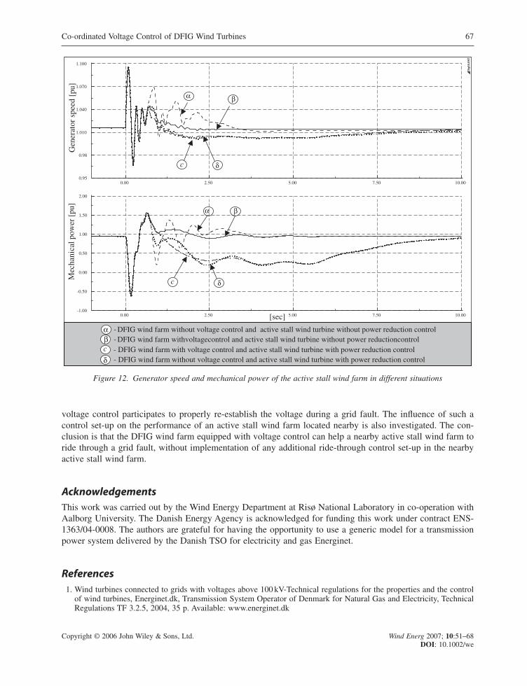
In Figures 9 and 10, attention was focused on the performance of the DFIG wind farm during a grid faultwhen it is or is not equipped with voltage control. One question in mind now is how the DFIG wind farmvoltage control influences the performance of a nearby active stall wind farm during a grid fault, located asillustrated in Figure 7. The next two figures therefore contain only information concerning the active stall windfarm during the grid fault, namely the active and the reactive power at the wind farm terminal (Figure 11) andthe generator speed and the mechanical power of the active stall wind turbines (Figure 12).
Both Figures 11 and 12 illustrate the simulation results for the active stall wind farm from the followingfour different control scenerios:
(a) DFIG wind farm without voltage control and active stall wind farm without power reduction control;(b) DFIG wind farm with voltage control and active stall wind farm without power reduction control;(c) DFIG wind farm with voltage control and active stall wind farm with power reduction control;(d) DFIG wind farm without voltage control and active stall wind farm with power reduction control.
64 A. D. Hansen et al.
Copyright © 2006 John Wiley & Sons, Ltd. Wind Energ 2007; 10:51–68DOI: 10.1002/we
5.003.752.501.250.00
190.0
150.0
110.0
70.00
30.00
-10.00
5.003.752.501.250.00
1.500
1.200
0.90
0.60
0.30
-0.000
5.003.752.501.250.00
150.0
100.0
50.00
0.00
-50.00
-100.0
DIg
SIL
EN
T
Vol
tage
in W
FT [
pu]
Act
ive
pow
er in
WFT
[M
W]
Rea
ctiv
e po
wer
in W
FT [
Mva
r]
[sec]
1 2
1
1
2
2
1 - DFIG wind farm without voltage control
- DFIG wind farm with voltage control2
Figure 9. DFIG wind farm terminal (WFT) with and without co-ordinated voltage control

The following observations can be made.
• The voltage control of the DFIG wind farm (cases (b) and (c)) has a damping effect on the active stall windfarm, no matter whether this has or does not have power reduction control.
• The active power, the generator speed and the mechanical power are almost identical during the grid fault,no matter which case is simulated. The fact that the mechanical power is unchanged in this period meansthat the drive train system is equally stressed in all four cases.
• The worst case for the active stall wind farm is clearly case (a), when the DFIG wind farm has no voltagecontrol and the active stall wind farm has no power reduction control.
• The best case for the active stall wind farm is clearly case (b), when the DFIG wind farm is equipped withvoltage control and the power reduction control of the active stall wind farm is not enabled. Note that thewind farm is not subjected to torsional oscillations and there is no loss of active power production. The influ-ence of the DFIG voltage control on the active stall wind farm is thus even better when the latter does nothave any special control implemented to ride through a grid fault.
The overall conclusion from Figures 11 and 12 is that the DFIG wind farm equipped with voltage controlcan help a nearby active stall wind farm through a grid fault, without any need to implement an additionalride-through control strategy in the active stall wind farm.
Co-ordinated Voltage Control of DFIG Wind Turbines 65
Copyright © 2006 John Wiley & Sons, Ltd. Wind Energ 2007; 10:51–68DOI: 10.1002/we
5.003.752.501.250.00
190.0
150.0
110.0
70.00
30.00
-10.00
5.003.752.501.250.00
1.500
1.200
0.90
0.60
0.30
-0.000
5.003.752.501.250.00
150.0
100.0
50.00
0.00
-50.00
-100.0
DIg
SIL
EN
T
Vol
tage
in
WFT
[pu
]A
ctiv
e po
wer
in W
FT [
MW
]R
eact
ive
pow
er in
WFT
[M
var]
[sec]
1 2
1
1
2
2
1 - DFIG wind farm without voltage control
- DFIG wind farm with voltage control2
Figure 10. DFIG wind farm terminal (WFT) with and without co-ordinated voltage control when the power reductioncontrol of the active stall wind farm is disabled

ConclusionsThis article presents a simulation model for DFIG wind turbines equipped with co-ordinated voltage controlto enable uninterrupted operation during a grid fault. The idea of this strategy is that both DFIG convertersparticipate in the voltage control in a co-ordinated manner. By default the grid voltage is controlled by therotor-side converter as long as this is not blocked by the protection device (i.e. crowbar), otherwise the grid-side converter takes over the control of the voltage. Issues on moderlling and control of a DFIG wind turbine,with focus on the converter protection under grid fault operation, are discussed and illustrated.
The controllability of the DFIG during grid faults is enhanced by the design of a proper co-ordination ofthree additional controllers, namely a damping controller, a rotor-side converter voltage controller and a grid-side converter reactive power boosting. The damping controller is tuned to actively damp the torsional oscil-lations excited at a grid fault in the drive train system. The absence of such a controller during a grid faultmay lead to self-excitation of the drive train system and to high mechanical stress of the drive train.
An aggregated model of a large offshore wind farm consisting of 80 DFIG wind turbines, each of 2MWrated power, is implemented in order to illustrate how the DFIG wind farm contributes with reactive powerand thus helps to re-establish the voltage in the case of a grid fault. The DFIG wind farm fault ride-throughcapability and its contribution to voltage control are assessed and evaluated by means of simulations with theuse of a generic but realistic transmission power system model delivered by the Danish Transmission SystemOperator Energinet.dk. The simulation results illustrate how the DFIG wind farm equipped with the presented
66 A. D. Hansen et al.
Copyright © 2006 John Wiley & Sons, Ltd. Wind Energ 2007; 10:51–68DOI: 10.1002/we
10.007.505.002.500.00
300.00
200.00
100.00
0.00
-100.00
10.007.505.002.500.00
300.00
200.00
100.00
0.00
-100.00
-200.00
DIg
SIL
EN
T
Act
ive
pow
er i
n W
FT [
MW
]R
eact
ive
pow
er
in W
FT
[M
var]
[sec]
α β
c δ
α β
c δ
α - DFIG wind farm without voltage control and active stall wind turbine without power reduction controlβ - DFIG wind farm with voltage control and active stall wind turbine without power reduction controlc - DFIG wind farm with voltage control and active stall wind turbine with power reduction controlδ - DFIG wind farm without voltage control and active stall wind turbine with power reduction control
Figure 11. Active and reactive power of the active stall wind farm in different situations
voltage control participates to properly re-establish the voltage during a grid fault. The influence of such acontrol set-up on the performance of an active stall wind farm located nearby is also investigated. The con-clusion is that the DFIG wind farm equipped with voltage control can help a nearby active stall wind farm toride through a grid fault, without implementation of any additional ride-through control set-up in the nearbyactive stall wind farm.
AcknowledgementsThis work was carried out by the Wind Energy Department at Risø National Laboratory in co-operation withAalborg University. The Danish Energy Agency is acknowledged for funding this work under contract ENS-1363/04-0008. The authors are grateful for having the opportunity to use a generic model for a transmissionpower system delivered by the Danish TSO for electricity and gas Energinet.
References1. Wind turbines connected to grids with voltages above 100 kV-Technical regulations for the properties and the control
of wind turbines, Energinet.dk, Transmission System Operator of Denmark for Natural Gas and Electricity, TechnicalRegulations TF 3.2.5, 2004, 35 p. Available: www.energinet.dk
Co-ordinated Voltage Control of DFIG Wind Turbines 67
Copyright © 2006 John Wiley & Sons, Ltd. Wind Energ 2007; 10:51–68DOI: 10.1002/we
10.007.505.002.500.00
1.100
1.070
1.040
1.010
0.98
0.95
10.007.505.002.500.00
2.00
1.50
1.00
0.50
0.00
-0.50
-1.00
DIg
SIL
EN
T
Gen
erat
or s
peed
[pu
]M
echa
nica
l pow
er [
pu]
[sec]
α β
c δ
α β
c δ
α - DFIG wind farm without voltage control and active stall wind turbine without power reduction controlβc - DFIG wind farm with voltage control and active stall wind turbine with power reduction controlδ - DFIG wind farm without voltage control and active stall wind turbine with power reduction control
- DFIG wind farm withvoltagecontrol and active stall wind turbine without power reductioncontrol
Figure 12. Generator speed and mechanical power of the active stall wind farm in different situations

2. E.ON. Netzanschlussregeln Hoch- und Hoechstspannung. 2003. Report ENENARHS 2006, April 2006, 46 pages.www.eon-netz.com
3. Jauch C, Sørensen P, Bak-Jensen B. International review of grid connection requirements for wind turbines. Nordicwind Power Conference, 6 pp, 2004.
4. Bolik SM. Grid requirements challenges for wind turbines. Fourth International Workshop on Large-scale Integrationof Wind Power and Transmission Networks for Offshore Wind Farms, Billund, 6 pp, 2003.
5. Akhmatov V. Analysis of dynamic behavior of electric power systems with large amount of wind power. PhD Thesis,Ørsted DTU, 2003.
6. Sørensen P, Hansen AD, Christensen P, Meritz M, Bech J, Bak-Jensen B, Nielsen H. Simulation and verification oftransient events in large wind power installations. Risø-R-1331(EN), 2003.
7. Hansen AD, Iov F, Blaabjerg F, Hansen LH. Review of contemporary wind turbine concepts and their market pene-tration. Wind Engineering 2004; 28: 247–263.
8. Hansen AD, Jauch C, Sørensen P, Iov F, Blaabjerg F. Dynamic wind turbine models in power system simulation toolDIgSILENT. Risø-R-1400(EN), 2003.
9. Hansen AD, Sørensen P, Iov F, Blaabjerg F. Centralised power control of wind farm with doubly-fed induction gener-ators. Renewable Energy 2006; 31: 935–951.
10. Holdsworth L, Charalambous I, Ekanayake JB, Jenkins N. Power system fault ride through capabilities of inductiongenerator based wind turbines. Wind Engineering 2004; 28: 399–412.
11. Sun T, Chen Z, Blaabjerg F. Transient stability of DFIG wind turbines at an external short-circuit fault. Wind Energy2005; 8: 345–360.
12. Heier S. Grid Integration of Wind Energy Conversion Systems. John Wiley & Sons, Ltd, Chichester UK, 1998.13. Leonhard W. Control of Electrical Drives. Springer: New York, NY, 2001.14. Pena R, Clare JC, Asher GM. Doubly-fed induction generator using back-to-back converters and its application to vari-
able speed wind-energy generation. IEE Proceedings on Electronic Power Application 1996; 143: 231–241.15. Poeller M. Achilles S. Aggregated wind park models for analyzing power system dynamics. Fourth International Work-
shop on Large-scale Integration of Wind Power and Transmission Networks for Offshore Wind Farms, Billund, 10 pp,2003.
16. Sørensen P, Bak-Jensen B, Kristiasen J, Hansen AD, Janosi L, Bech J. Power plant characteristics of wind farms. WindPower for the 21st Century. Proceedings of International Conference, Kassel, 6 pp, 2000.
17. Eping C, Stenzel J, Poeller M, Mueller H. Impact of large scale wind power on power system stability. Fifth Interna-tional Workshop on Large-scale Integration of Wind Power and Transmission Networks for Offshore Wind Farms,Glasgow, 9 pp, 2005.
18. Kayikci M, Anaya-Lara O, Milanovic JV, Jenkins N. Strategies for DFIG voltage control during transient operation.CIRED, 18th International Conference on Electricity Distribution, Turin, 5 pp, 2005.
19. Akhmatov V. Variable-speed wind turbines with doubly-fed induction generators. Part II: Power system stability. WindEngineering 2002; 26: 171–188.
20. Akhmatov V. Variable-speed wind turbines with doubly-fed induction generators. Part IV: Uninterrupted operation fea-tures at grid faults with converter control coordination. Wind Engineering 2003; 27: 519–529.
21. Akhmatov V. Variable speed wind turbines with doubly-fed induction generators. Part III: Model with back-to-backconverters, Wind Engineering 2003; 27: 79–91.
22. Akhmatov V. An aggregated model of a large wind farm with variable-speed wind turbines equipped with doubly-fedinduction generators. Wind Engineering 2004; 28: 479–488.
23. Akhmatov V. A small test model for the transmission grid with a large offshore wind farm for education and researchat Technical University of Denmark. Wind Engineering in press.
68 A. D. Hansen et al.
Copyright © 2006 John Wiley & Sons, Ltd. Wind Energ 2007; 10:51–68DOI: 10.1002/we
Related Documents