c.o. Bmwner Engineering DU. CONSUI I INC CI 01 rCIiNI CAI 1 NCINI.IIIINC 215 - 530 Raven Woods Drive North Vancouver, British Columbia Canada V7G 2T5 Tel(604) 980-6189 F.:Ix (604) 980-6186 email: cobrawnerë'shawcablo.corn Review Report Plan de Déposition - Parc à Résidus Osisko Canadian Malartic Project November 2008

Welcome message from author
This document is posted to help you gain knowledge. Please leave a comment to let me know what you think about it! Share it to your friends and learn new things together.
Transcript
c.o. Bmwner Engineering DU.
C O N S U I I I N C CI 01 rCIiNI CAI 1 NCINI.IIIINC
215 - 530 Raven Woods DriveNorth Vancouver, British Columbia Canada V7G 2T5Tel (604) 980-6189 F.:Ix (604) 980-6186email: cobrawnerë'shawcablo.corn
Review Report
Plan de Déposition - Parc à Résidus
Osisko Canadian Malartic Project
November 2008
peran01
Tampon

Table of Contents
1.0 Introduction2.0 Design Concept by Golder3.0 Confirmation ofDesign Concept4.0 Further Geotechnical and Design Considerations
4.1 Tailings Properties4.2 Stability of the Tailings Pile4.3 Waste Rock Dike4.4 Influence ofClimate
5.0 Review
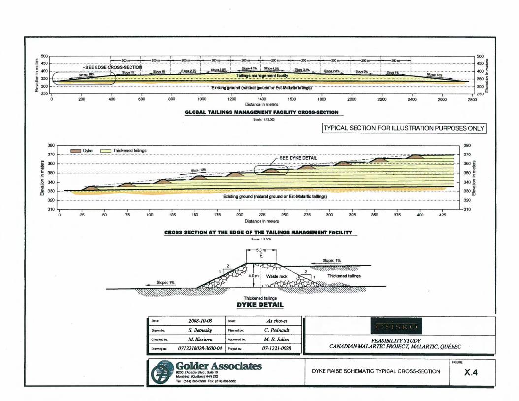
List of FiguresGeneral Aerial ViewFinal Modelled Configuration of the Tailings AreaWatershed locationsDike raise Schematic Typical Cross-section
Page
112233333
XlX2X3X4
c.o. Brawner Engineering lID.
eONSUlllNC C~OlFCIINICAI rNCINrEIIINC
215 - 530 Raven Woods DriveNorth Vancouver, Brilish Columbia Canada V7G 2T5Tel (604) 980-6189 Fax(604) 980-6186email: [email protected]
Osisko Exploration2140 Rue St. MathieuMontreal, QuebecH3H 2J4
Attn: Paul Johnson, Ing.Manager, Mining
November 24, 2008
Re - Peer Review - Canadian Malartic ProjectPlan de Déposition - Parc à Résidus
Dear ML Johnson.
1.0 Introduction
Further to your request 1have reviewed the report "Plan de Déposition, Parc àRésidus de la Mine Canadian Malartic, Revision 1," by Golder Associates. 1wasalso provided with four figures from an earlier Golder Report - figures X-1, X-2,X-3 and X-4, which are attached.
2.0 Design Concept by Golder
The preliminary plan envisions depositing tailings thickened to 68% solids. At thisthickness the tailings flow to a steeper angle than typical tailings.
To develop an overall downstream slope of 10% it is proposed to constructintermediate dikes of waste rock. See figure X-4. The waste rock dikes of nonacid- generating waste rock will be 4 metres high with a 5.Cm wide berm.Thickened tailings will be deposited from several different discharge locations,
Collection and diversion ditches for the overflow water and seepage will bedeveloped outside the lowest waste rock dikes.
1
The design has been developed using Walace Software from the WruffwareCompany as weil as the Surpac program as a visualization tool. The topographyand volumes have been provided by Osisko. The surface topography is based ona grid of 20 x 20m. The height of the waste rack retaining dikes will be 4m.
The waste rock dump will be raised in advance of the tailings pile. The tailingstorage will encroach on the original tailings pond and sedimentation basin. Atthis time no geotechnical evaluation to assess the shear strength, stability orconsolidation characteristics has been performed to assess foundation conditionsfor the proposed tailings storage. This is required.
Water displaced by the tailings storage will be deposited in the new polishingpond. Water freed from the tailings and run-off water will be collected in a systemof collector ditches. A peripheral ditch will be constructed and will drain into thepolishing pond.
On mine c1osure, the surface of the exposed tailings will be progressivelycovered with Sm of mine waste rock from the waste dump.
3.0 Confirmation of Design Hypothesis
During active mining the following stages can be carried out to confirm the designhypothesis:
- Develop a test program on site at the start-up of the plant to verify thehypothesis of development - slopes, density in place, performance ofthe deposition system and other parameters as weil as developing themodel to reality. The verification is usually done by perforrninq detailedfield surveys to compare the results with the modal. Necessaryadjustments are then made to the model and the performance of sitedrainage can be verified if required.
- The stability of the entire pile must be verified to conform to thenumerical model and the hypotheses that have been used in thepreliminary design.
4.0 Further Geotechnical and Design Considerations
There are several important design and construction issues that need to beaddressed to confirm the proposed design model. These include the following:
4.1 Tailings Properties
a) Determination of the gradation and engineering properties of the tailings.Engineering properties to include moisture-density relationship, shearstrength and consolidation characteristics.
b) Permeability and drainage characteristics. Consideration of dump underdrainage. Will the tailings flow into voids of the waste rock pile?
2
c) Surface slope angle of the tailings for various flow rates.d) Trafficability for various types of construction equipment.
4.2 Stability of the tailings pile
a) Adequacy of the old tailings pond and sedimentation ponds asfoundations.
b) Seismic stability - earthquake and blasting.
4.3 Waste rock dike
a) Compatibility of tailing gradation with dike rock gradation. Require a filtercloth?
b) Constructability - equipment and procedure.
4.4 Influence of Climate
a) Summer conditions - heavy rainfall, high winds (dust)b) Winter conditions - frost heave, spring thaw effects.
5.0 Review
When the design reaches a final draft 1would be available to provide a reportreview.
C. O. Brawner, P. Eng.FCAE, FEIC, FCIM
3
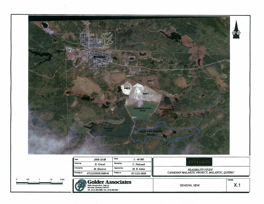
Ost.: 2008-10-08 8al1o:
Drown~ R. Gravel PIom.ltJv;
Choekodly; M Kissiova App<.......~
DICIWlngro.: 071221OO28-36fXJ..01 Projodm.;
1 : 40000
C. Pednauù
M. R. Julien
07-1221-0028
~
( l' , l " l -, ( )
FEASIBIU1YSTUDYCANADIANMALARTIC PROJECT, MALART/C, QUÉBEC
o 0,5 1.5 21cm
Golder Associates1l2OO.r_BMI. SuIe 10Monlréol (Québec) t«N 212Tel.: (514)383-OllllO Fax; (514)383-5332
GENERAL VIEW
FIGUIlE
X.1

Dolo:
Dr....,~
2008-1oœS. Betnesky
SCIlle'
p-~
1:25000
C.Pednau/l( ) -, 1 ~ l-. ( )
Chockod ~ M. Kissiova 1 Appoovod bf'
Illll'Mng",: 0712210028-3(j()().02 1 PIOJOd'"
M. R.Julien
07-1221-0028FEASIBILI1YSroDY
CANADJANMALARTIC PROJECT, MALARTIC, QUÉBEC
1 ! ! ! ! 1Il 25D 50D 750 1 DOD 125Dm
Golder Associatesll2OO, rAcadie BIvd••SUIe10l.Iontréel (Québec) H4N mToI.: (514)~ Fax: (514)=-=
FINAL MODELLED CONFIGURATIONOFTHE TAIUNGSAREA
FIlllH:
X.2

1 Watershed identification
Watershed Iimits
712,000 mE. 713,000 mE.
Ma/artic River
0010: 2oo8·1D-Œ Sœlo:
OIawnl7)': S. Betnesky Plomodlly:
Choc:kodlJf: M. Kissiova AppIovedlJf:
DIl.wi"CI lll : 0712210028-3600-03 PtoJOdro ,
714.000 mE.
1 :30000
C. Pednauù
M.R.Julien
07-1221-{)(}28
715.000 mE. 716.000 mE.
( ) ~, l '-, l-, ( )
FEASIBlLI1YSroDYCANADlAN MALARTIC PROJECT, MALART/C, QUÉBEC
o 250 500 750 1000 1250 1500m1 ! ! ! ! ! !
Golder Associaœsll2OO, rAcadle BMI.,&lie tOMonlréal (Quêbeo) f«N 2l'ZTel .: (514)~ FOJC (514)~
WATERSHED LOCATIONS
FIGURl:
X.3
500 500
.§! 450 r.::::::~~ t ~.~ + ~.~ + ~.~ } ~.~ .l ~~..·· : · ~·~· ..··..·I··· ..·..~·':'. · · · 1-- ··~·~ .J ~~ l............................................ 450 Al~ 400 .. . . r ~.E.~..~OO~.~~;S.x:~~.?~ SbpO'25 I.~ ..J.. Slp~a .. 1.... a_cft 1~H" ....I ..§H>!.~a. J.. 6~ J...SbpOa- l...~.ft.' L................. ................... ....... 400 ~
!:: L~:::~ : :: : ~ ~~~..:7: : : : : : : : : : : : : : : : ~: :~: : : : : : : : : : : : : : : : : :~ : : : : :~ : : : : : : ::: : : : : : : : : :: : : : : : :: : : : : : : : : : : :~~:~:;~i:~;:~~:~~::;~~~;: : : : : : : : : : : :;: : : : : : : : : : : : : : : : : : : : : : : : : : :~: : : : ;: :~ : : : : : : : : : : : : ~ : : : : : : : : : :.~ : : :~~:~ ::::: :: ::::::: :: jw w
250 250o ~ 400 ~ ~ 1~ 1~ 1400 1500 1~ 2~ 2~ 2400 2500 ~OO
Distance ln melers
GLOBAL TAILINGS MANAGIlMIlNT .ACILITT CROS8-SIlCnONSuie: 1:12.000
IlYPICAL SECTION FOR ILLUSTRATION PURPOSES ONLY 1
380
370_----J/ SEE DYKEDETAIL
, ::::: .::.::..:: ~.~ -_ .~.-:-........- .._... - -- -ç--
- -- ------ --
c::::J Thickened lailngs.. .. . ... . . . . . ... .... . . . .. . . .. . .. . ... . . . . . . . ... . . . . . . .... .. . . . .. .... .. ... .. . . . .. . . . . .. .. . . . . . . ... . . .. . . u ..- - - -
.........................................................................................................................~!~~.~~~.!~.~~~ .~.~~~.~~.~~~~!'1.~.~ .~~I~J.. .320
330
340
aio l seo •, ., ., , ",,', , .s, , aso ', ~, ., seo
1 1 W1 1 3201 i 11 310
~ 360
~.s.§
!
o 25 50 75 100 125 150 175 200 225 250 275 300 325 350 375 400 425
Dislance in melers
CROSS SIlCTION AT THil IlDGIl O' THil TAILINGS MANAGIlMIlNT .ACILITT
Dole; 2008-10-œ Selo":
1lI-bv: S. Betnesky PllImDdbv:
Chocl<od bv: M. Kissiova Applovadbv:
Dtowlng nl : 0712210028-3«J0.04 Plolid R) :
As shown
C. Pednauù
M. R.JuJien
07-1221-0028
( ) '-. 1 ' , kt)
FEAS/B/Ll1YSroDYCANADIANMAlARTIC PROJECT, MALART/C, QUÉBEC
Golder AssociatesIl2OO.r_ BMl.•SUIe10,",onkée! (QUébec) H4N:mTeI.:(~ICl~ Fax:.I~tC)~
FIGUIE
DYKE RAISESCHEMATIC TYPICAL CROSS-SECTION X.4
Related Documents


