Welcome to CNC Training programme.

Welcome message from author
This document is posted to help you gain knowledge. Please leave a comment to let me know what you think about it! Share it to your friends and learn new things together.
Transcript
Welcome to
CNC Training programme.

Why CNC?• Fast change in product technology requires
that the manufacturing resources be more flexible and adaptable quick changeover.
• Productivity improvement without hampering quality.

Advantages of CNC machines• Higher flexibility.
• Increase in productivity.
• Consistency in quality.
• Higher accuracy.
• Reliability in operation.
• Reduction in nonproductive time.
• Reduction in manpower.
• Shorter cycle time.
• Reduction in material handling.

Advantages of CNC machines• Reduced lead time.
• Reduction in material handling.
• Lesser floor space.
• More operational safety.

Step by step development in CNC machines
• Vertical machining centre with three axes for multiple machining operation with manual tool change.
• Vertical machining centre with auto tool change.
• Horizontal machining centre with auto tool changer.
• Addition of 4th axis (Rotary table) making it possible to work on four sides.

Step by step development in CNC machines
• Addition of automatic twin pallet changer on VTC and HMC to eliminate machine idle time during component loading and unloading.
• Introduction of feature like tool life monitoring, sister tool replacement,tool breakage detection,etc.
• Provision of spindle mounted probe for measuring critical dimensions before taking final cuts.

Step by step development in CNC machines
• Increased tool magazines capacity (from 20 tools to 90 tools) to accommodate no. of operations.
• Provision of direct numerical control feature to upload and download part program.
• Faster tool change time.(1.5 to 6sec.)• Higher spindle speeds (10,000-20,000rpm)
for very high material removal rate in soft materials like aluminum.

Step by step development in CNC machines
• Higher rapid travel rates to minimize positioning time.(60,000 mm/min)
• Development of universal machining centres that have vertical and horizontal spindles which can be rotated to obtain a vertical or horizontal configuration. This can machine all five sides of component in single setup.
FMS
• FMS is a manufacturing system which consists of one or more CNC machines connected by an automated material handling system and all are operated under the control of central computer along with auxiliary subsystems like component load/unload station,automatic tool handling system ,tool presetter,component measuring equipment ,wash station etc..

FMS
C N C m ach inesM ach in ing cetres.Tu rn ing cen tres .
G ear cu tting m ach ines
M ateria l handling sys tem sR obot
R ail gu ided veh ic lesA u tom atic gu ided veh ic les .
A uxillary equ ipm en tsP allet s tore
Load/un load s tationTool s tore
C en tral com pu terS chedu ling sof tw areS im u lation sof tw are
D N C sof tw are.
F M S

END

INTRODUCTIONCOMPONENTS OF NC SYSTEMSCLASSIFICATION OF NC MACHINESCONSRUCTIONAL DETAILS

Definition:-
Numerical control
A system in which the actions are controlled by direct insertion of numerical data at some point. The system must automatically interpret at least some portion of this data.

General Classification :-
1) N.C. Machines
2) C.N.C. Machines
3) D.N.C. Machines
N.C. MachinesIt gives position of the workpiece relative to
cutting tool.
The instructions to the NC Machines are fed
through an external medium ie through paper
tape or magnetic tape.
For minor change in the design new tape has to
be prepared for new program.
C.N.C. MachinesThe part program can be input through controller unit.Part program once inserted can be used again.Part program can be edited & optimised at machine tool itselfThe input information can be reduced to great extent with the special use of sub program.The part program can be proved on control itselfbefore actual running of the machine.Various cutting tools can be used.

D.N.C. MachinesIt is a manufacturing system in which large no. of machines are controlled by computer through direct connection. All the machines are linked to main frame computer which sends the information to individual machine as & when required.

Components of numerical control system
• 1) Program of instruction
• 2) Machine control unit
• 3) Machine tool

Program of instruction:- It is a detailed step by step set of directions which tell machine tool what to do & in what sequence.
Machine control Unit:- It is the unit which stores, converts the logical data inside the system
Machine tool:- It is the unit which actually does the movements which are fed through program.

Classification of Numerical control system:- Based on Feedback control1) Open loop control system:- Machine tool in which there is no provision to compare the actual provision of the cutting tool or work piece with the input command or value.
No feedback is given for the actual displacement of machine slide.


2)Closed loop control system:- In a closed loop control system the actual output from the system i.e. actual displacement of the machine slide is compared with the input signal.It consists of two types of feedbacks i) Velocity feedback:-measures & monitors speed of motorii) positional feedback:- measures & monitors position of machine slide.


Classification based on Control system features1) Point to point control system:- There is no machining operation carried out when tool travels from one program point to other program point.2) Straight line control system:- It is an extension of point to point control system where machining operation can be done along a straight line.3) Continuous path system:- It generates a continuously controlled motion of the tool & work piece along different coordinate axis.


Methods of listing the coordinate axis of points
1) Absolute coordinate system:- In this system coordinates are always referred with the reference to the same datum.
2) Incremental coordinate system:-In this system coordinates are calculated with reference to previous point.

Constructional details of the C.N.C. control system
1) Machine Elements2) Guide ways3) Feed drives4) Spindle & spindle bearings5) Measuring system

Machine structure :- It is the load carrying & supporting member of the machine tool.
All the motors, drive mechanism & other functional assemblies are aligned & rigidly fixed to the machine structure.
The machine element is designed to take static load, dynamic load, thermal load.


Guide ways :-It controls the direction or line of action of the carriage or table on which a tool or a work is held.
It absorbs all the static & dynamic forces.
The quality of the work produced depends not only on the accuracy of the relative movement of the tool w.r.t. work piece but also on the geometric accuracies & kinematic accuracies of the guide ways.


Guide ways are of two types:-1) Friction guide ways:- These guide ways operate under the condition of sliding friction. They do not have constant coefficient of friction, it varies with the sliding velocities.It is having good damping capacity.2) Antifriction linear motion guide ways:- These guide ways use rolling element in between moving & stationary element of the machine.It is having good load carrying capacity.Other types of guide waysI) Hydrostatic guide waysII) Aerostatic guide ways


Feed Drives:- It gives motion to the slide as per motion commands.
The feed drive consists of a) Servomotor :- It provides excellent speed regulation, high torque & high efficiency.
b) Mechanical Transmission system:- It is required to convert rotary motion to linear motion (Re- circulating ball screw- nut system or rack & pinion system) &To transmit torque (Gear box or timing belt)

Spindle & Spindle bearings :- It takes high torsional load, radial deflections, thrust force.Various types of spindle bearings area) Hydrodynamic bearings:-Hydrodynamic bearings are journal bearings with thin film of oil between the spindle & journal. The pressure is developed by rotation of the spindle.b) Hydrostatic bearings:- The spindle is supported in the bearings by relatively thick film of oil supplied under pressure. c) Antifriction bearings:- These are suitable for high speeds & high loads. Common example is Ball bearings & Taper roller bearings.


Measuring System :-Measuring system is employed on each controlled axis to monitor the movement & compare the position of of the slide/ spindle with the desired position.Measuring system used fora) Monitoring the position of the slide on the slide wayb) Measuring the speed of the spindle.
It is done with the help of Rotary Encoder ORwith the linear scale.


Good Practices while operating C.N.C. machines1) Do not use heavy depth of cut2) Use only specified taper tool mentioned in the manual3) Always take dry run for new program proving4) Do not use feed, speed specified on the insert5) Tool length should be entered correctly.6) Always use single block proving for any change in the program.

END
Contents • What is mean by CNC program ?• Coordinate measuring systems.• Dimensioning system.• CNC programming formats.• G-CODES (Preparatory functions.)• M-CODES (Miscellaneous Functions)• Canned Cycles.• Subprogram/Subroutine.• Preparation required before doing program.• Example of one program.• Precautionary measures while doing and executing
CNC Program.
CNC program
• Set of instructions fed to the machine control in the form of numerical codes written in particular sequence.

Example of CNC program.
N10/ (Core drill dia 55)
N20 T1 M6 ;
N30 G0 G90 G54 X200. Y150. ;
N40 G0 G43 H01 Z100. ;
N50 G98 G81 Z-25 R5 F40 ;
N60 G80 G91G28 X0. Y0. Z0. ;
System of coordinates.
• It is used in preparation of part program for introducing the position of machining.
• It consists of 3 axis ( X,Y&Z)
• There are two types of system of coordinates.– M/C coordinate system (G53).– Workpiece coordinate system (G54-G59).

System of coordinates.M/C coordinate system.
• M/c actually moves in its own system of coordinates called ‘M/C CODINATE SYSTM’.and reference point w.r.t.which it moves called as ‘M/C ZERO’
• Generally m/c coordinate system has machining zone on -ve direction from m/c zero point.

System of coordinates.M/C coordinate system.

System of coordinates.M/C coordinate system.

System of coordinates.W/P coordinate system.
• To make machining easy temporary reference point is taken in m/c coordinate system this point is called as ‘WORK ZERO’.
• Distances of this temp. point in X,Y&Z direction from m/c zero called as ‘ZERO OFFSET’

System of coordinates.W/P coordinate system.
• Generally this point should be such that all dimensions on part drawing would be from that point.
• For e.g. Locating pin center.

System of coordinates.W/P coordinate system.

System of dimensioning
G90 (Absolute Dimensioning)
• It is the most common method of dimensioning our drawings used for part production on CNC machines.
• In this system all dimensions are taken from a single point called as ‘DATUM POINT’ or ‘ORIGIN’.
• This is denoted by preparatory function G90.

System of dimensioning
G90 (Absolute Dimensioning)
ADVANTAGES:
• If hole no. 2 is put in wrong If hole no. 2 is put in wrong location hole no.3 would location hole no.3 would not be affected.not be affected.
• Generally our drawings are Generally our drawings are dimensioned in absolute dimensioned in absolute method so it becomes very method so it becomes very to find out the co-ordinates .to find out the co-ordinates .
50.0
100.0
150.0
150.0
50.0
100.0
1
2
3

System of dimensioning
G91 (Incremental Dimensioning)
• It is very rarely used.
• Generally it is used for machining of complicated pockets.
• In this system measurement is from hole to hole
• This is denoted by preparatory function G90.

System of dimensioningG91 (Incremental Dimensioning)
• If hole no. 2 is put in If hole no. 2 is put in wrong location next all wrong location next all holes will be incorrectly holes will be incorrectly positioned.positioned.
• For doing programming in For doing programming in incremental mode incremental mode tremendous calculations tremendous calculations are required.are required.
• It benefits while doing It benefits while doing subprogramssubprograms
50.0
1
2
3
50.0
50.0
50.0 50.0 50.0

System of dimensioningExample of G90 & G91
G90
N10 G71 ;
N20 G90 ;
N30 G00 X100. Y100. ;
N40 X150. Y100. ;
N50 X150. Y150. ;
N60 X100. Y150. ;
N70 X100. Y100. ;
N80 M30
100.0
150.0
100.0
150.0
X
Y
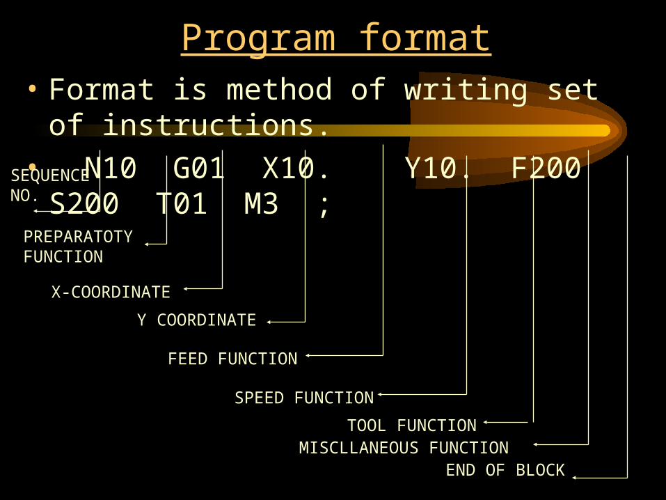
Program format• Format is method of writing set of instructions.
• N10 G01 X10. Y10. F200 S200 T01 M3 ;SEQUENCENO.
PREPARATOTYFUNCTION
X-COORDINATE
Y COORDINATE
FEED FUNCTION
SPEED FUNCTION
TOOL FUNCTIONMISCLLANEOUS FUNCTION
END OF BLOCK

Types of programming formats
Fixed b lock form at Tab sequentia l form at W ord address form at
Prog ram m ing form ats

A) Fixed block format
• Instructions are always given in same sequence.
• All instructions must be given in every block including the instructions which remain unchanged from previous block.
• Address letters are not required while writing instructions.

15 60 15
40
(0,0)
2 HOLES Ø10
+Y
-Y
+X-X
A) Fixed block format• N X Y F S
• 001 15.00 -20.00 200 500 ;
• 002 75.00 -20.00 200 500 ;
B) Tab sequential format
• This is same as that of fixed block format only difference is that each word is separated by TAB character.
• No need to repeat same instructions in previous block.
• Address letters are not required.
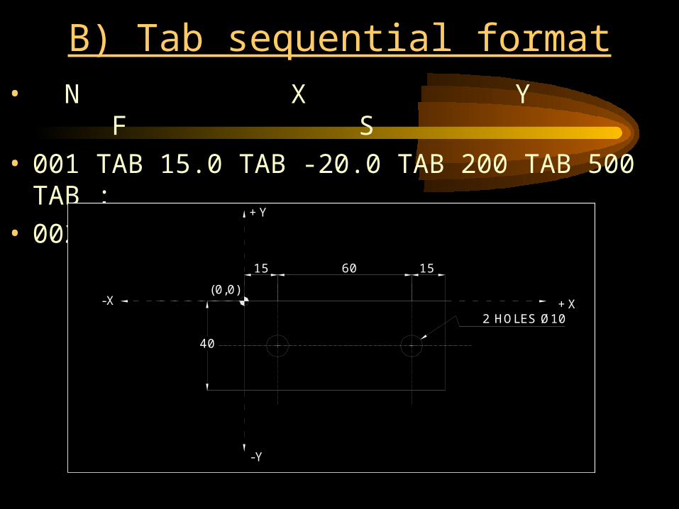
B) Tab sequential format• N X Y F S• 001 TAB 15.0 TAB -20.0 TAB 200 TAB 500 TAB ;• 002 TAB 75.00 TAB ;
15 60 15
40
(0,0)
2 HOLES Ø10
+Y
-Y
+X-X

C) Word address format
• ADDRESS : Any word from A to Z can be used as address. For e.g. G
• WORD : Address followed by any no. e.g G01
• BLOCK : One more or words together form a block e.g. N001 G01 Z10.0 EOB.
• If word remain unchanged not necessary to repeat in next block.

C) Word address format
• N001 X15.0 Y20.0 F200 S500 ;• N002 X75.0;
15 60 15
40
(0,0)
2 HOLES Ø10
+Y
-Y
+X-X

Functions & Addresses
SR NO. FUNCTION ADDRESS
1 Program number O
2 Sequence number N
3 Preparatory functions G
4 Dimension word X,Y,ZA,B,C,U,V,W
RI,J,K
5 Feed function F
6 Spindle speed function S
7 Tool function T
8 Miscellaneous function MB
9 Offset number D,H
10 Dwell P,X
11 Program number designation P
FUNCTIONS AND ADDRESSES

G codes
• G-Codes are also called as “Preparatory functions” as they take active part in part program execution.
• They are always programmed at the start of block.
• They decides type of machine movement ,type of interpolation,type of dimension etc.

Modal : Which remain active until another G code of same group is programmed.Blockwise active : Gcode which remain active only in that particular block in which it is programmed.
Modal B lockwise active.
G codes
Type of G codes


G00 (Rapid positioning)
• Position data command programmed after G00 is traversed at maximum possible feedrate along a straight line set by machine tool manufacturer.
• G00 can be programmed as G or G0.
• G00 is modal and canceled with G01 or G02 or G03.
• On graphic screen G00 appears as a dotted line.

G00 (Rapid positioning)
• Example :
15 60
(0,0)
+Y
-Y
+X-X
12
20
To move from point 1 to point 2 command data is given asG00 X75 Y-20 ;

G01 (Linear interpolation)
• Position data command programmed after G01 is executed at programmed feedrate along a straight line.
• Movement being made along straight line joining start point and end point.
• G01 is modal and canceled with G00 , G02 or G03.
• On graphic screen G01 appears as continuos line.

G01(Linear interpolation).
• Example :
15 60
(0,0)
+Y
-Y
+X-X
12
20
To move from point 1 to point 2 command data is given asG01 X75 Y-20 F20 ;
End of block
Programmed feed rate
Position data
Movement at set feedrate.

G02/G03 (Circular interpolation)
• Position data given after G02 or G03 is executed along a circular path at the set feed rate.
• The code G02 refers to the circular interpolation in a clockwise direction.
• The code G03 refers to the circular interpolation in a Anticlockwise direction.

G02/G03 (Circular interpolation)
• When we write code G02 ,We have to feed information regarding
-Start point
-End point
-Radius of arc or Circle center point.

Example of G02/G03 with radius.
G02N10 G01 X40. Y40. ;
N20 G02 X80. Y80. R40 ;
G03N10 G01 X80. Y80. ;
N20 G03 X40. Y40. R40 ;
(40,40)
(80,80) (80,80)
(40,40)
GO2G03

G02/G03 - Circular interpolation with circle center point
• Here instead of giving radius of circle we have to mention center point of circle in form of parameters called I,J&K.– Where ‘I’ --- Distance between starting point of cutter to
the center of arc in ‘X’ direction.– ‘J’--- Distance between starting point of cutter to the center
of arc in ‘Y’ direction.– ‘K’ --- Distance between starting point of cutter to the
center of arc in ‘Z’ direction.
• Values of I,J&K are always incremental.

Example of G02/G03 with interpolation parameters..
G02N10 G01 X40. Y40. ;
N20 G02 X80. Y80. I40 J0 ; (40,40)
(80,80)
GO2

G04 (Dwell)
• It is used to program dwell time in sec.
• Dwell time value is programmed by means of letter X.
• For e.g. N10 G04 X2 ;– Means spindle will take dwell of 2 sec. While
executing this line.
• It is blockwise active.
• No other function can be programmed in a block in which G04 is programmed.

Cutter radius compensation
• To accommodate difference in programmed diameter of cutter and actual diameter of cutter ,cutter compensation concept is used.
• While writing part program it is necessary to mention that whether cutter compensation is required in left direction or right direction.

Cutter radius compensation
• Following 3 G-codes are used for cutter radius compensation.– G41 Compensation applied to shift the cutter path to
left.– G42 Compensation applied to shift the cutter path to
right.– G40 To cancel cutter Compensation.
• Direction of shift is decided by looking in direction of cut.

Cutter radius compensation
• Advantages :1.Different dia. of cutters can be used without
changing part program.
2.By using cutter radius compensation job of programmer becomes simplified because part program can be developed assuming zero cutter radius and on actual dimensions of part drawing.

Cutter radius compensation G41/G42
G41G42
Cutter centerline
Cutter centerline

Cutter radius compensationExample
35.0
35.080.0
95.0
X
R15.0
G70 (Inch unit system)
• It is used to represent inch unit system
• for e.g. N10 G70 G0 X4. ;– It indicates that X axis will move by 4”.
• For e.g N10 G70 G95 F0.02 ;– It indicates that tool will move at the feed rate
of 0.02 inch/rev
• This is an modal G code.

G71 (Metric unit system)
• It is used to represent metric unit system
• for e.g. N10 G71 G0 X4. ;– It indicates that X axis will move by 4mm.
• For e.g N10 G71 G95 F0.02 ;– It indicates that tool will move at the feed rate
of 0.02 mm/rev
• This is an modal G code.

G94 (feed /min)
• When code G94 is programmed CNC assumes that feed rate value entered under address F is in mm/min or inch/min.
• for e.g. N10 G94 F100 ;– It means that tool moves at the rate of
100mm/min or 100 inch/min depends upon G70/G71.
• This is an modal G code.

G95 (feed /rev)
• When code G95 is programmed CNC assumes that feed rate value entered under address F is in mm/rev or inch/rev.
• for e.g. N10 G94 F0.2 ;– It means that tool moves at the rate of 0.2
mm/rev or inch/rev depends upon G70/G71.
• This is an modal G code.

MISCLLANEOUS FUNCTIONS (M CODES) :
• Miscellaneous function word is used to specify certain miscellaneous functions which do not relate to dimensional movements of the machine.
• For e.g. Spindle start , Spindle stop etc.


Canned cycle :
• Canned cycle or fixed cycle may be defined as a set of instructions inbuilt or stored in the system memory to perform fixed sequence of operations.
• Canned cycle can be brought into action with single command and as such reduce programming time and efforts.

Canned cycle :
• Canned cycles are used for repetitive and commonly used machining operations .
• Canned cycles are stored under G code address.
• G81 to G89 are reserved for canned cycles and G80 for cancellation of canned cycle.

Canned cycle operation sequence

Drilling cycle (G81) :
POINT R
POINT 'Z'
INITIAL LEVEL
POINT 'Z'
POINT R
G81(G98) G81(G99)
POINT 'R' LEVELw/p
w/p

Format for Drilling cycle (G81) :
• X_ Y_ Hole position data.
• Z_ Position of bottom of hole from Z zero..
• R_ Position of point ‘R’ level from Z zero.
• F_ Cutting feed rate.
Format : G81 X_ Y_ Z_ R_ F_

Operation sequence for Drilling cycle (G81) :
• Tool is positioned to X&Y axes.
• Rapid traverse is performed upto point ‘R’.
• Drilling is performed from point ‘R’ to point ‘Z’.
• Tool is then retracted in rapid traverse upto point ‘R’ or upto initial level depends upon G99/G98.

Drilling cycle (G81) :
• IMPORTANT POINTS :
1.Before specifying G81 use a miscellaneous function (M CODE) to rotate the spindle.
2.Specify ‘R’ in block that perform drilling .If it is specified in block that does not performed drilling it can be stored as MODAL data.
3.Do not specify G codes from G00 To G03 together with G81 otherwise G81 is canceled.

Counter boring cycle (G82) :
POINT R
POINT 'Z'
INITIAL LEVEL
POINT 'Z'
POINT R POINT 'R' LEVELw/p
w/p
P P
G82(G98) G82(G99)

Format for Counter boring cycle (G82) :
• X_ Y_ Hole position data.
• Z_ Position of bottom of hole from Z zero.
• R_ Position of R point level from Z zero.
• P_ Dwell time at the bottom of hole.
• F_ Cutting feed rate.
Format : G82 X_ Y_ Z_ R_ P_ F_

Operation sequence for counter boring cycle (G82) :
• Tool is positioned to X&Y axes.• Rapid traverse is performed upto point ‘R’.• Drilling is performed from point ‘R’ to point ‘Z’.• Tool remains idle at the bottom over the period
mentioned in ‘P’.• Tool is then retracted in rapid traverse upto point
‘R’ or upto initial level depends upon G99/G98.

Counter boring cycle (G82) :
• IMPORTANT POINTS :
1.Before specifying G82 use a miscellaneous function (M CODE) to rotate the spindle.
2.Specify ‘R’ in block that perform drilling .If it is specified in block that does not performed drilling it can be stored as MODAL data.
3.Do not specify G codes from G00 To G03 together with G82 otherwise G82 is canceled.

Peck drilling cycle (G83) :
w/p
R
Z=0
q
d
d
Initial level
R
d
d
q
Z=0
Initial level
G83(G98) G83(G99)

Format for Peck drilling cycle (G83) :
• X_ Y_ Hole position data.
• Z_ Position of bottom of hole from Z zero .
• R_ Position of point ‘R’ level from Z zero.
• Q_ Every cut in value(Always incremental).
• F_ Cutting feed rate..
Format : G83 X_ Y_ Z_ Q_ R_ F_

Operation sequence for peck drilling cycle (G83) :
• Tool is positioned to X&Y axes.• Rapid traverse is performed upto point ‘R’.• Drilling is done from point R up to depth Q.• Tool is then retracted to point R in rapid .• Tool again travel in rapid traverse just above first
drilling depth. • Again drilling is performed up to depth Q.• Process is repeated still it achieves total drilling depth..

Peck drilling cycle (G83) :
• IMPORTANT POINTS :
1.Before specifying G83 use a miscellaneous function (M CODE) to rotate the spindle.
2.Specify ‘R’ in block that perform drilling .If it is specified in block that does not performed drilling it can be stored as MODAL data.
3.Do not specify G codes from G00 To G03 together with G83 otherwise G83 is canceled.
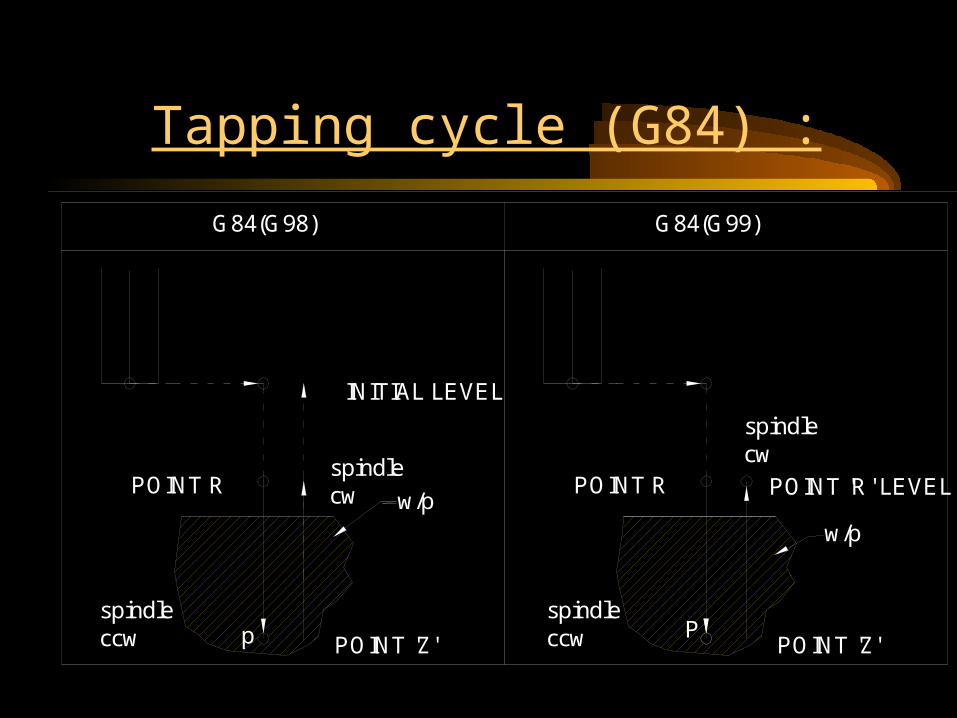
Tapping cycle (G84) :
POINT R
POINT 'Z'
INITIAL LEVEL
POINT 'Z'
POINT R
G84(G98) G84(G99)
POINT 'R' LEVELw/p
w/p
p Pspindleccw
spindleccw
spindlecw
spindlecw

Format for tapping cycle (G84) :
• X_ Y_ Hole position data.
• Z_ Position of bottom of hole from Z zero.
• R_ Position of R point level from Z zero.
• P_ Dwell time.
• F_ Cutting feed rate.
Format : G84 X_ Y_ Z_ P_ R_ F_

Operation sequence for tapping cycle (G84) :
• Tool is positioned to X&Y axes.
• Rapid traverse is performed upto point ‘R’.
• Tapping is performed from point ‘R’ to point ‘Z’ in CW direction.
• Tool remains idle at the bottom over the period mentioned in ‘P’.
• Tool is then retracted in feed in CCW direction up to point R.
• Tool is then traverse in rapid up to initial level depends upon G99/G98.

Tapping cycle (G84) :
• IMPORTANT POINTS :
1.Before specifying G84 use a miscellaneous function (M CODE) to rotate the spindle.
2.Specify ‘R’ in block that perform drilling .If it is specified in block that does not performed drilling it can be stored as MODAL data.
3.Do not specify G codes from G00 To G03 together with G84 otherwise G84 is canceled.

Boring cycle (G85) :
POINT R
POINT 'Z'
INITIAL LEVEL
POINT 'Z'
POINT R POINT 'R' LEVELw/p
w/p
G85(G98) G85(G99)

Format for boring cycle (G85) :
• X_ Y_ Hole position data.
• Z_ Position of bottom of hole from Z zero.
• R_ Position of point ‘R’ level from Z zero .
• F_ Cutting feed rate.
Format : G85 X_ Y_ Z_ R_ F_

Operation sequence for boring cycle (G85) :
• Tool is positioned to X&Y axes.
• Rapid traverse is performed upto point ‘R’.
• Boring is performed from point ‘R’ to point ‘Z’.
• Tool is then retracted in feed up to point R.
• Tool is then traverse in rapid up to initial level depends upon G98/G99.

Boring cycle (G85) :
• IMPORTANT POINTS :
1.Before specifying G85 use a miscellaneous function (M CODE) to rotate the spindle.
2.Specify ‘R’ in block that perform drilling .If it is specified in block that does not performed drilling it can be stored as MODAL data.
3.Do not specify G codes from G00 To G03 together with G85 otherwise G85 is canceled.

Boring cycle (G86) :
POINT R
POINT 'Z'
INITIAL LEVEL
POINT 'Z'
POINT R POINT 'R' LEVELw/p
w/p
spindlestop
spindlestop
spindlecw
spindlecw
G86(G98) G86(G99)

Format for boring cycle (G86) :
• X_ Y_ Hole position data.
• Z_ Position of bottom of hole from Z zero .
• R_ Position of point ‘R’ level from Z zero.
• F_ Cutting feed rate.
Format : G86 X_ Y_ Z_ R_ F_

Operation sequence for boring cycle (G86) :
• Tool is positioned to X&Y axes.
• Rapid traverse is performed upto point ‘R’.
• Boring is performed from point ‘R’ to point ‘Z’.
• Spindle stops at the bottom of hole.
• Tool is then retracted in rapid traverse upto point ‘R’ or upto point ‘Z’ depends upon G99/G98.

Boring cycle (G86) :
• IMPORTANT POINTS :
1.Before specifying G86 use a miscellaneous function (M CODE) to rotate the spindle.
2.Specify ‘R’ in block that perform drilling .If it is specified in block that does not performed drilling it can be stored as MODAL data.
3.Do not specify G codes from G00 To G03 together with G86 otherwise G86 is canceled.

Back boring cycle (G87) :
G87(G98) G87(G99)
NOT USEDPOINT R
spindle cw
spindle cw
P
q
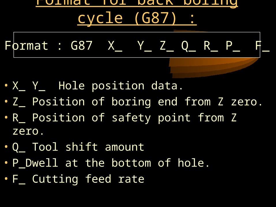
Format for back boring cycle (G87) :
• X_ Y_ Hole position data.
• Z_ Position of boring end from Z zero.
• R_ Position of safety point from Z zero.
• Q_ Tool shift amount
• P_Dwell at the bottom of hole.
• F_ Cutting feed rate
Format : G87 X_ Y_ Z_ Q_ R_ P_ F_

Operation sequence for back boring cycle (G87) :
• Tool is positioned to X&Y axes.• Spindle is stopped and aligned.• Tool is moved in direction opposite to tool tip by an amount
equal to Q.• Rapid traverse is performed up to point R. • Again tool is shifted in direction of tool tip by an amount equal
to Q and spindle starts rotating in CW direction.• Boring is performed up to point Z.
• At point Z spindle gets stopped and aligned.
• Again tool shifts opposite to tool tip by an amount equal to Q.
• Tool returned to initial level in rapid.

Back boring cycle (G87) :
• IMPORTANT POINTS :
1.Before specifying G87 use a miscellaneous function (M CODE) to rotate the spindle.
2.Specify ‘R’ in block that perform drilling .If it is specified in block that does not performed drilling it can be stored as MODAL data.
3. Value of Q should be always positive..
4.Do not specify G codes from G00 To G03 together with G87 otherwise G87 is canceled.

Boring cycle (G88) :
POINT R
POINT 'Z'
INITIAL LEVEL
POINT 'Z'
POINT R POINT 'R' LEVELw/p
w/p
spindle stop
p
spindlestop
p
spindlecw
spindlecw
G88(G98) G88(G99)

Format for boring cycle (G88) :
• X_ Y_ Hole position data.
• Z_ Distance from point R to the bottom of hole.
• R_ Distance from initial level to point ‘R’ level.
• P_Dwell time at the bottom of hole.
• F_ Cutting feed rate
Format : G88 X_ Y_ Z_R_ P_ F_

Operation sequence for boring cycle (G88) :
• Tool is positioned to X&Y axes.• Rapid traverse is performed upto point ‘R’.• Boring is performed from point ‘R’ to point ‘Z’.• Tool remains idle at the bottom over the period
mentioned in ‘P’.• Tool is then retracted in feed up to point R.• Too traverse in rapid up to initial level depends upon
G98/G99.

Boring cycle (G88) :
• IMPORTANT POINTS :
1.Before specifying G88 use a miscellaneous function (M CODE) to rotate the spindle.
2.Specify ‘R’ in block that perform drilling .If it is specified in block that does not performed drilling it can be stored as MODAL data.
3.Do not specify G codes from G00 To G03 together with G88 otherwise G88 is canceled.

Boring cycle (G89) :
POINT R
POINT 'Z'
INITIAL LEVEL
POINT 'Z'
POINT R
G89(G98) G89(G99)
POINT 'R' LEVELw/p
w/p
P P

Format for boring cycle (G89) :
• X_ Y_ Hole position data.
• Z_ Position of bottom of hole from Z zero.
• R_Position of point ‘R’ level from Z zero.
• P_ Dwell at the bottom of hole.
• F_ Cutting feed rate
Format : G89 X_ Y_ Z_ R_ P_ F_

Operation sequence for boring cycle (G89) :
• Tool is positioned to X&Y axes.• Rapid traverse is performed upto point ‘R’.• Boring is performed from point ‘R’ to point ‘Z’.• Tool remains idle at the bottom over the period
mentioned in ‘P’.• Tool is then retraced in feed up to point R.• Tool is then retracted in rapid traverse upto initial
point depends upon G98/G99.

Boring cycle (G89) :
• IMPORTANT POINTS :
1.Before specifying G89 use a miscellaneous function (M CODE) to rotate the spindle.
2.Specify ‘R’ in block that perform drilling .If it is specified in block that does not performed drilling it can be stored as MODAL data.
4.Do not specify G codes from G00 To G03 together with G89 otherwise G89 is canceled.

CANNED CYCLE SUMMARYCANNED CYCLE SUMMARY
G CODE Drilling(- Z
direction)
Operation at the
bottom ofhole
Retraction
(+ Zdirection)
Application
G73 Intermittentfeed
--- Rapidtraverse
High speedpeck drillingcycle.
G74 feed Spindle cw feed Left handtapping cycle.
G76 feed Orientedspindlestop
Rapidtraverse
Fine boringcycle
G81 feed --- Rapidtraverse
Drilling cycle
G82 feed dwell Rapidtraverse
Counter boringcycle
G83 Intermittentfeed
--- Rapidtraverse
Peck drillingcycle.
G84 feed Spindleccw
feed Tapping cycle
G85 feed --- feed Boring cycleG86 feed Spindle
stopRapidtraverse
Boring cycle
G87 feed Spindlestop
Manual/Rapidtraverse
Back boringcycle
G88 feed Dwell-Spindlestop
Manual/Rapidtraverse
Boring cycle
G89 feed Dwell-Spindlestop
feed Boring cycle

SUBROUTINES• Also called as SUBPROGRAM.
• These are powerful time saving technique.
• Subroutines provides the capability of programming certain fixed sequence or frequently repeated patterns.
• Subroutines are in fact independent programs with all feature of usual part program.
• Subroutines are stored in memory under separate program no.

SUBROUTINES• Whenever particular feature is required
within the program, associated subroutine is called for execution.
• Subroutine may called any time and any no.of times.
• After execution of subroutine the control returns to main program .
• To describe and use a subroutine following information is required in form of code and symbol.

SUBROUTINES• For e.g.
– Start of subroutine.– End of subroutine.– A means of calling subroutine.
– For start we will use letter ‘L’ followed by any no. for e.g. ‘L001’
– For end we will use a word as ‘M17’.– For calling subroutine any where in main
program by giving just subroutine no. preceded by letter ‘L’.
–

Example of subroutine.
N10 G91 ;
N20 G01 Z-8. F300 ;
N30 G01 X40. ;
N40 G01 Y40. ;
N50 G01 X-40. ;
N60 G01 Y-40. ;
N70 G00 Z8. ;
N80 G90 ;
N90 M17 ;
X
Y
50.0
50.0
90.0
90.0
50.0
(120,120)
(200,200)

Introducing subroutine in main program
N10 G90 G71 G94 S500 M03 ;
N20 G00 X50. Y50. ;
N30 G00 Z5 M08 ;
N40 L101 ;
N50 G00 X120. Y120. ;
N60 L101;
N70 G00 X200. Y200. ;
N80 L101 ;
N90 G00 X0. Y0. Z20. M09
N100 M30 ;
X
Y
50.0
50.0
90.0
90.0
50.0
(120,120)
(200,200)

What programmer has to do ?
• Study the drawing thoroughly.
• Identify type of material to be machined.
• Know the specification and functions of machine to be used.
• Decide the dimension mode (mm or inches)
• Decide the coordinate system .
• Identify the plane of cutting.
• Know the cutting parameters for job/tool combinations.
What programmer has to do ?
• Know the federate programming.
• Check required toolings.
• Establish sequence of machining operations.
• Identify whether use of any special feature like subroutines is required or not.

Part Program Example.OPERATIONS TOOLS
• Bore dia 60H7 Core Drill dia 55B. Bar
dia 59.5 B. Bar dia 60
• Drilling dia 10 HSS Drill dia 10
• Tapping M12X1.75HSS Drill dia 10.8 Tap M12 STD.
• Tapping M10X1.5 HSS Drill dia 8.5 Tap M10 STD.

Part Program Example.
O100
N10 G71 G94;
N20/ (Core drill dia 55)N30 T1 M6 ;
N40 G0 G90 G54 X200. Y150. ;
N50 G0 G43 H01 Z100. ;
N60 S300 F30 M3 ;
N60 G98 G81 Z-25 R5 F40 ;
N70 G80 G91G28 X0. Y0. Z0. ;
N80/ (Semifinish Boring bar dia 59.5)
N90 T2 M6 ;
N100 G0 G90 G54 X200. Y150. ;
N110 G0 G43 H02 Z100. ;
N120 S800 F80 M3;
N120 G98 G85 Z-25 R5 F40 ;
N130 G80 G91G28 X0. Y0. Z0. ;

Part Program Example.N130/ (Finish bore dia 60)N140 T3 M6 ;
N150 G0 G90 G54 X200. Y150. ;
N160 G0 G43 H03 Z100. ;
N170 S1000 F80 M3 ;
N180 G98 G76 Z-25 R5 Q0.5 F40 ;
N190 G80 G91G28 X0. Y0. Z0. ;
N200/ (Drilling dia 10)N210 T4 M6 ;
N220 G0 G90 G54 X100. Y255. ;
N230 G0 G43 H04 Z100. ;
N240 S400 F40 M3 ;
N250 G99 G81 Z-25 R5 F40 ;
N260 G98 X275. Y50. ;
N270 G80 G91 G28 X0. Y0. Z0. ;

Part Program Example.N260/ (Drill dia 10.25 for M12
tapping)N270 T5 M6 ;
N280 G0 G90 G54 X380. Y255. ;
N290 G0 G43 H05 Z100. ;
N300 S400 40 M3 ;
N310 G98 G81 Z-25 R5 F40 ;
N320 G80 G91G28 X0. Y0. Z0. ;
N320/ (Tap M12)N330 T6 M6 ;
N340 G0 G90 G94 G54 X380. Y255. ;
N350 G0 G43 H06 Z100. ;
N360 M29 S100
N370 G98 G84 Z-25 R5 F175 ;
N380 G80 G91 G28 X0. Y0. Z0. ;

Part Program Example
N390/ (Drill dia 8.5 for M10 tapping)
N400 T7 M6 ;
N410 G0 G90 G54 X150. Y150. ;
N420 G0 G43 H07 Z100. ;
N430 S500 F50 M3 ;
N430 G99 G81 Z-25 R5 F40 ;
N440 X250. ;
N450 X200. Y200. ;
N460 G98 Y100. ;
N470 G80 G91G28 X0. Y0. Z0. ;
Part Program Example
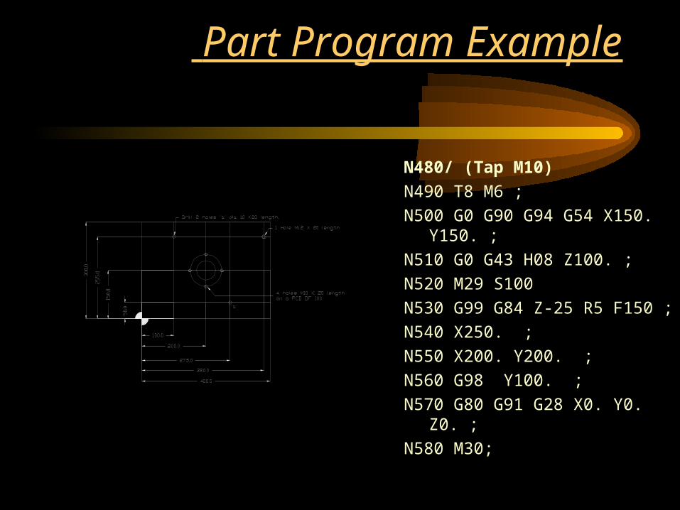
N480/ (Tap M10)
N490 T8 M6 ;
N500 G0 G90 G94 G54 X150. Y150. ;
N510 G0 G43 H08 Z100. ;
N520 M29 S100
N530 G99 G84 Z-25 R5 F150 ;
N540 X250. ;
N550 X200. Y200. ;
N560 G98 Y100. ;
N570 G80 G91 G28 X0. Y0. Z0. ;
N580 M30;

Symbols of good program.
• Easily understood .
• Minimum air cutting.
• Avoid repetition of tools.
• Should be simple and short.
• Considered future tooling changes feasibility.
• Should not hamper m/c tool life.

Precautions while doing or executing CNC PROGRAM.
• Always add point ( . ) at the end of each coordinate value of axes. For e.g. X200. , Y 50.
• While replacing any tool from m/c check always tool offset and feed correctly.
• Always run first program in single block and without component.
• After using canned cycle & interpolation cycle , cancel it with respective G code like G80 & G40 respectively.

END
Related Documents