CNC PILOT 640 The Contouring Control for Lathes and Turning-Milling Machines For Gen 3 drives Information for the Machine Tool Builder 06/2021

Welcome message from author
This document is posted to help you gain knowledge. Please leave a comment to let me know what you think about it! Share it to your friends and learn new things together.
Transcript

CNC PILOT 640The Contouring Control forLathes and Turning-MillingMachines
For Gen 3 drives
Information for theMachine Tool Builder
06/2021

Contouring control with drive system from HEIDENHAINGeneral information
CNC PILOT 640 • Contouring control for lathes and turning-milling machines• Suitable for horizontal and vertical lathes as well as vertical
boring and turning mills• Axes: max. 24 control loops (22 control loops with functional
safety (FS)), max. 8 NC axes per channel, max. 6 spindles in theoverall system
• Up to three channels for asynchronous multi-slide machining• Up to 3 principal axes (X, Z, and Y), B axis, closed-loop spindle
and counter spindle, C1/C2 axis, and driven tools• 5-axis simultaneous machining (X, Z, Y, B, and C axes)• Up to 3 programmable auxiliary axes (U, V, W) for control of
steady rest, tailstock, and counter spindle• The position of a parallel secondary axis can be shown
combined with its principal axis• For operation with HEIDENHAIN inverter systems and ideally
with HEIDENHAIN motors• Fully digital with HSCI interface and EnDat interface• 24-inch, 19-inch, or 15.6-inch multi-touch display• CFR CompactFlash memory card (CFast)• Programming of turning, drilling, and milling operations with
smart.Turn, according to DIN, or via cycles• TURN PLUS: automated smart.Turn program generation• ICP free contour programming for turning and milling contours• For simple tool holders (multifix), turrets, or magazines
CNC PILOT 640with 24-inch multi-touch display
CNC PILOT 640 with 15.6-inch multi-touch display
System test Controls, power modules, motors, and encoders fromHEIDENHAIN are usually integrated as components into completesystems. In such cases, comprehensive testing of the completesystem is required, irrespective of the specifications of theindividual devices.
Parts subject towear
Controls from HEIDENHAIN contain parts subject to wear, such asa backup battery and fan.
Standards Standards (ISO, EN, etc.) apply only where explicitly stated in thebrochure.
Note Intel, Intel Xeon, Core, and Celeron are registered trademarks ofIntel Corporation.
Validity The features and specifications described here apply to thefollowing control and NC software versions:
CNC PILOT 640 with NC software versions688946-08 (export license required) 688947-08 (no export license required)
This brochure supersedes all previous editions, which therebybecome invalid. Subject to change without notice.
Requirements Some of these specifications require particular machineconfigurations. Please also note that, for some functions, a specialPLC program must be created by the manufacturer.
Functional safety(FS)
If standard components and FS components (FS = FunctionalSafety) are not explicitly differentiated, then the information forboth versions apply (e.g. TE 725T, TE 725T FS).
2
Contents
Contouring control with drive system from HEIDENHAIN 2
Overview tables 4
HSCI control components 16
Accessories 26
Cable overview 39
Technical description 46
Data transfer and communication 71
Mounting information 74
Key dimensions 76
General information 96
Subject index 98
Please note the page references in the tables with thespecifications.
Using thisbrochure
This brochure is purely a decision-making aid for selectingHEIDENHAIN components. Additional documentation isrequired for project development (see "Technical documentation",Page 96).
3

Overview tablesComponents
Control systems 24-inch design 19-inch design 15.6-inch design Page
For operatingpanel
MC 366(1920 x 1080 pixels)
MC 8532(1280 x 1024 pixels)
MC 8420T(1366 x 768 pixels)
Main computer
For electricalcabinet
MC 306 -
16
Multi-touch display BF 360(1920 x 1080 pixels)
BF 860(1280 x 1024 pixels)
21
Keyboard unit TE 725TTE 725T FSTE 745T
TE 745T TE 725TTE 725T FS
22
IntegratedMachine operating panel
PLB 6001, PLB 600x FS (HSCI adapter for OEM machine operating panel) 26
Storage medium CFR memory card 18
NC software license On SIK component 18
PL 6000 consisting of PLB 62xx basic module (system PL) or PLB 61xx(expansion PL) and I/O modules
24PLC inputs/outputs1)
With HSCIinterface
On UEC2) and UMC3)
CMA-H for analog axes/spindles in the HSCI systemAdditional modules1)
Modules for fieldbus systems
27
Inverter systems2) Compact inverters and modular inverters
Connecting cables ✓ 39
1) May be necessary depending on the configuration2) For more information, refer to the Inverter Systems for Gen 3 Drives brochure3) For more information, refer to the Inverter Systems UV 1xx, UVR 1xx, UM 1xx, UEC 1xx, UE 2xx, UR 2xx brochure
Please note: The MC main computer does not have any PLC inputs/outputs. Therefore one PL 6000, one UEC, or one UMC isnecessary for each control. They feature safety-relevant inputs/outputs as well as the connections for touch probes.
4
Accessories
Accessory CNC PILOT 640 Page
Electronic handwheels • HR 510, HR 510 FS portable handwheel, or• HR 520, HR 520 FS portable handwheel with display, or• HR 550 FS portable wireless handwheel with display, or• HR 130 panel-mounted handwheel
28
Workpiece touch probes1) • TS 260 touch trigger probe with cable connection, or• TS 460 touch trigger probe with radio and infrared transmission, or• TS 750 touch trigger probe with cable connection• TS 150 touch trigger probe with cable connection• TS 740 touch trigger probe with infrared transmission
Tool touch probes1) With cuboid probe contact as accessory• TT 160 touch trigger probe, or• TT 460 touch trigger probe with radio or infrared transmission
Programming station2) DataPilot CP 640Control software for PCs for programming, archiving, and training• Full version with single user license or network license• Demo version (free of charge)
Auxiliary axis control PNC 610 33
Industrial PC ITC 860: additional operating station with touchscreen and integrated keyboardIPC 306/IPC 6641: industrial PC for WindowsIPC 6490/IPC 8420: industrial PC for PNC 610
31
Snap-on keys For controls and handwheels 35
1) For more information, refer to the Touch Probes brochure2) For more information, refer to the Programming Station for Turning Controls brochure
Software tools CNC PILOT 640 Page
PLCdesign1) PLC development software 67
TNCremo2), TNCremoPlus2)3) Data transfer software (TNCremoPlus with “live” screen) 72
ConfigDesign1) Software for configuring the machine parameters 63
TNCkeygen1) Software for enabling SIK options for a limited time, and for single-day access to theOEM area
18
TNCscope1) Software for data recording 64
TNCopt1) Software for putting digital control loops into service 64
IOconfig1) Software for configuring PLC I/O and fieldbus components 25
TeleService1)3) Software for remote diagnostics, monitoring, and operation 64
RemoTools SDK1) Function library for developing customized applications for communication withHEIDENHAIN controls
73
TNCtest1) Software for creation and execution of acceptance tests 65
TNCanalyzer1) Software for the analysis and evaluation of service files 65
1) Available to registered customers for download from the Internet2) Available to all customers (without registration) for download from the Internet3) Software release module required
5

Specifications
Specification CNC PILOT 640 Page
Axes Max. 24 control loops (22 control loops with functional safety (FS)),max. 8 NC axes per channel, max. 6 spindles in the overall system
Axes Up to 6 closed-loop linear axesX, Z, U, V, W: StandardY: Option
B axis Option
C1/C2 axis Option
Synchronized axes ✓
PLC axes ✓
52
Spindles Up to 6 controlled spindles:Main spindleCounter spindleDriven tool
54
55
Speed Max. 60 000 rpm (with option 49 max. 120 000 rpm) for motors with one polepair
54
Operating mode switchover ✓ 54
Position-controlled spindle ✓ 54
Oriented spindle stop ✓ 54
Gear shifting ✓ 54
NC program memory 7.7 GB 16
Input resolution and display step
Linear axes X axis: 0.5 µm (diameter 1 µm)U,V, W, Y, Z axes: 1 µm
Rotary axes B, C1/C2 axis: 0.001°
52
Functional safety (FS) With FS components, SPLC, and SKERN
For applications with up to • SIL 2 according to EN 61 508• Category 3, PL d as per EN ISO 13 849-1:2008
48
Interpolation
Straight line In 2 axes (maximum: ±100 m); in 3 main axes with software option 70
Circular In 2 axes (max. radius: 999 m); additional linear interpolation of the third axiswith software option 55 or 70
C1/C2 axis Interpolation of the linear axes X and Z with the C1/C2 axis (software option 55)
B axis 5-axis interpolation between the X, Z, Y, B, and C axis (software option 54)
Multichannel machining Up to three channels for asynchronous multi-slide machining (software option153)
53
Axis feedback control
With following error ✓
With feedforward ✓
57
With jerk limiting ✓ 52
Maximum feed rate60000 rpm . Screw pitch [mm]
No. of motor pole pairs
at fPWM = 5000 Hz
52
Constant surface speed ✓
6
Specification CNC PILOT 640 Page
Input mm/min or mm/revolution
Cycle times of main computer MC 57
Block processing 1.5 ms
Cycle times of controller unit CC/UEC/UMC 57
Path interpolation 3 ms
Fine interpolation Single-speed: 0.2 ms Double-speed: 0.1 ms (software option 49)
Position controller Single-speed: 0.2 ms Double-speed: 0.1 ms (software option 49)
Speed controller Single-speed: 0.2 ms Double-speed: 0.1 ms (software option 49)
Current controller fPWM 3.333 kHz4 kHz5 kHz6.666 kHz (software option 49)8 kHz (software option 49)10 kHz (software option 49)13.333 kHz (software option 49)16 kHz (software option 49)
TINT
150 µs 125 µs 100 µs75 µs (software option 49)62.5 µs (software option 49)50 µs (software option 49)37.5 µs (software option 49)31.25 µs (software option 49)
57
Permissible temperature range Operation:In electrical cabinet: 5 °C to 40 °C In operating panel: 0 °C to 50 °C Storage: –20 to 60 °C
7

Interfacing to the machine
Interfacing to the machine CNC PILOT 640 Page
Error compensation ✓ 62
Linear axis error ✓ 62
Nonlinear axis error ✓ 62
Backlash ✓ 62
Reversal spikes during circularmovement
✓ 62
Hysteresis ✓ 62
Thermal expansion ✓ 62
Static friction ✓ 62
Sliding friction ✓ 62
Integrated PLC ✓ 66
Program format Statement list 66
Program input at the control ✓ 66
Program input via PC ✓ 66
Symbolic PLC-NC interface ✓ 66
PLC memory 4 GB 66
PLC cycle time 9 ms to 30 ms (adjustable) 66
PLC inputs/outputs For the maximum configuration of the PLC system, see Page 47 24
PLC inputs, DC 24 V Via PL, UEC, UMC 24
PLC outputs, DC 24 V Via PL, UEC, UMC 24
Analog inputs ±10 V Via PL 24
Inputs for PT 100 thermistors Via PL 24
Analog outputs ±10 V Via PL 24
PLC functions ✓ 66
PLC soft keys ✓ 67
PLC positioning ✓ 67
PLC basic program ✓ 69
Integration of applications 68
High-level language programming Use of the Python programming language in conjunction with the PLC(software option 46)
68
User interfaces can be custom-designed
Creation of individualized user interfaces by the machine manufacturer with thePython programming language. Programs up to a memory limit of 10 MB are enabledin standard mode. More can be enabled via software option 46.
68
8
Interfacing to the machine CNC PILOT 640 Page
Commissioning anddiagnostic aids
63
TNCdiag Software for the analysis of status and diagnostic information of digital drive systems 63
TNCopt Software for putting digital control loops into service 64
ConfigDesign Software for creating the machine configuration 63
Integrated oscilloscope ✓ 63
Trace function ✓ 64
API DATA function ✓ 64
Table function ✓ 64
OLM (online monitor) ✓ 64
Log ✓ 64
TNCscope ✓ 64
Bus diagnostics ✓ 64
Data interfaces ✓
Ethernet 2 x 1000BASE-T 71
USB Rear: USB 3.0Front: may vary based on the component description
71
Protocols 71
Standard data transmission ✓ 71
Blockwise data transfer ✓ 71
LSV2 ✓ 71
9

Functions for the user
Function
Sta
nd
ard
Op
tio
nCNC PILOT 640
Configuration ✓
✓
0-655+0-670+0-654+0-694+0-6132+0-6
Basic version: X and Z axis, main spindle Driven tool and auxiliary axes (U, V, W)C axis and driven toolY axisB axisParallel axes U, V, W (display function and compensation)Counter spindleDigital current and speed control
Operating modes
Manual operation ✓
✓
11
Manual slide movement through axis-direction keys, an intermediate switch, or electronichandwheelsGraphical support for entering and running cycles without storage of the machining steps, indirect alternation with manual machine operationThread reworking (thread repair) in a second workpiece setup
Teach-in mode 8 Sequential arrangement of canned cycles, with each cycle being run immediately after input orgraphically simulated and subsequently saved
Program run✓
98
All are possible in single-block and full-sequence modesDIN PLUS programssmart.Turn programsCycle programs
Setup functions ✓✓✓✓✓✓
171717
Workpiece datum settingDefinition of tool-change positionDefinition of protection zoneDefinition of machine dimensionsManual programsTool measurement by touching the workpieceTool measurement with a TT tool touch probeTool measurement with an optical gaugeWorkpiece measurement with a TS workpiece touch probe
Programming
Cycle Programming 88888888
8+558+558+55
8+558+558+55
888
8+9
Turning cycles for simple or complex contours, and contours described with ICPContour-parallel turning cyclesRecessing cycles for simple or complex contours, and contours described with ICPRepetitions with recessing cyclesRecess turning cycles for simple or complex contours, and contours described with ICPUndercut and parting cyclesEngraving cyclesThreading cycles for single or multi-start longitudinal, taper, or API threads, and threads withvariable pitchCycles for axial and radial drilling, pecking, and tapping operations with the C axisThread milling with the C axisAxial and radial milling cycles for slots, figures, single surfaces, and centric polygon surfaces,and for complex contours described with ICP for machining with the C axisHelical slot milling (multi-start) with the C axisDeburring of ICP contoursLinear and circular patterns for drilling, boring, and milling operations with the C axisContext-sensitive help graphicsTransfer of cutting values from the technology databaseUse of DIN macros in cycle programsConversion of cycle programs to smart.Turn programs
10
Function
Sta
nd
ard
Op
tio
n
CNC PILOT 640
Interactive ContourProgramming (ICP)
8/98/98/98/98/98/98/98/98/9+55
9+70
8/9+55+70+1328/9+42
Contour definition with linear and circular contour elementsImmediate display of entered contour elementsCalculation of missing coordinates, intersections, etc.Graphical display of all solutions for selection by the user if more than one solution is possibleChamfers, rounding arcs, and undercuts available as form elementsInput of form elements immediately during contour creation or through later superimpositionChanges to existing contours can be programmedMachining attributes available for individual contour elementsC-axis machining on face and lateral surface:– Description of individual holes and hole patterns (only in smart.Turn)– Description of figures and figure patterns for milling (only in smart.Turn)– Creation of freely definable milling contoursY-axis machining on the XY and ZY planes (only in smart.Turn):– Description of individual holes and hole patterns– Description of figures and figure patterns for milling– Creation of freely definable milling contoursProgramming of the rear face for full-surface machining with the C and Y axes
DXF import: Import of contours for lathe and milling operations
smart.Turnprogramming
✓
9
99999999+55/70
9+559+55/70
999999
The basis is the "unit," which is the complete description of a machining block (geometry,technology, and cycle data)Dialog boxes divided into overview and detail formsFast navigation between the forms and the input groups via the "smart" keysContext-sensitive help graphicsStart unit with global settingsTransfer of global values from the start unitTransfer of cutting values from the technology databaseUnits for all turning and recessing operations for simple contours and ICP contoursUnits for boring, drilling, and milling operations with the C or Y axis for holes, milling contours,and drilling and milling patterns that are simple or that have been programmed with ICPActivating/deactivating special units for the C axis; subprograms and section repeatsVerification graphics for the workpiece blank and finished part, as well as for C- and Y-axiscontoursTurret assignment and other setup information in the smart.Turn programParallel programmingParallel simulationTrochoidal millingHobbingMultiple plungingBatch Mode (automatic execution of multiple different main programs)
TURN PLUS 63 Automatic smart.Turn program generation with– Automatic tool selection– Automatic turret assignment– Automatic calculation of cutting data– Automatic generation of machining sequence in all working planes, also for C-axis machining(with option 55) and Y-axis machining (with option 70) – Automatic cutting limitation through chucking equipment– Automatic generation of work blocks for rechucking for turning with counter spindles– Automatic generation of work blocks for rear-face machining (with option 132)
11
FunctionS
tan
dar
d
Op
tio
n
CNC PILOT 640
DIN PLUSprogramming
✓✓✓✓
✓
✓✓
✓✓
✓✓
✓✓
5570
131/132132
8/9
9
Programming in DIN 66025 formatExpanded command format (IF ... THEN ... ELSE ...)Simplified geometry programming (calculation of missing data)Powerful fixed cycles for area clearance, recessing, recess turning, and thread machiningPowerful fixed cycles for drilling and milling with the C axisPowerful fixed cycles for drilling and milling with the Y axisSubprogramsTechnology functions for full-surface machining:– Moving to a fixed stop– Parting control– Spindle synchronization– Converting and mirroring– Mechatronic tailstockProgramming with variablesContour description with ICPProgram verification graphics for workpiece blank and finished partTurret assignment and other setup information in the DIN PLUS programConversion of smart.Turn units into DIN PLUS command sequencesParallel programmingParallel simulation
Simulation ✓✓
✓
✓
✓✓
✓✓✓
55
54
132
Graphical simulation of the cycle process, or of the cycle, smart.Turn, or DIN PLUS programDepiction of the tool paths as pencil-trace or cutting-path graphics; special identification of therapid traverse pathsMachining simulation (2D material-removal graphics)Side or face view, or 2D view of cylindrical surface for verification of C-axis machiningDisplay of programmed contoursView of the tilted plane (B-axis machining)View of front face and YZ plane for verification of Y-axis machiningThree-dimensional rendering of the workpiece blank and finished partSimulation of mirrored contours for rear-face machiningShifting and magnifying functionsBlock scan in the simulationIncluding for complex multi-channel machining operations
Program-rungraphics
✓ Graphical depiction of the current machining operation
B-axis machining✓
54
549+54
Machining with the B axisTilting the working planeRotating the machining position of the toolSimultaneous turning
Eccentric machining 135135
Cycles for eccentric turning and for the manufacture of oval and polygonal contoursSuperimpositioning of traversing movements of the X and Y axes synchronously to therotational motion of the spindle
Machining timeanalysis
✓✓✓
Calculation of machining times and idle timesConsideration of the switching commands triggered by the CNCRepresentation of time per individual cycle or per tool change
Monitoringfunctions
151155
Load Monitoring: detect tool wear and tool breakage during machiningComponent Monitoring: monitor for the overloading and wear of machine components
12
Function
Sta
nd
ard
Op
tio
n
CNC PILOT 640
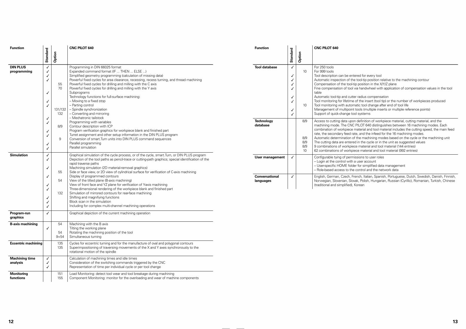
Tool database ✓
✓✓✓✓
✓✓
✓✓
10
10
For 250 toolsFor 999 toolsTool description can be entered for every toolAutomatic inspection of the tool-tip position relative to the machining contourCompensation of the tool-tip position in the X/Y/Z planeFine compensation of tool via handwheel with application of compensation values in the tooltableAutomatic tool-tip and cutter radius compensationTool monitoring for lifetime of the insert (tool tip) or the number of workpieces producedTool monitoring with automatic tool change after end of tool lifeManagement of multipoint tools (multiple inserts or multiple reference points)Support of quick-change tool systems
Technologydatabase
8/9
8/98/98/910
Access to cutting data upon definition of workpiece material, cutting material, and themachining mode. The CNC PILOT 640 distinguishes between 16 machining modes. Eachcombination of workpiece material and tool material includes the cutting speed, the main feedrate, the secondary feed rate, and the infeed for the 16 machining modes.Automatic determination of the machining modes based on the cycle or the machining unitThe cutting data are entered in the cycle or in the unit as suggested values9 combinations of workpiece material and tool material (144 entries)62 combinations of workpiece material and tool material (992 entries)
User management ✓ Configurable tying of permissions to user roles– Login at the control with a user account– User-specific HOME folder for simplified data management– Role-based access to the control and the network data
Conversationallanguages
✓ English, German, Czech, French, Italian, Spanish, Portuguese, Dutch, Swedish, Danish, Finnish,Norwegian, Slovenian, Slovak, Polish, Hungarian, Russian (Cyrillic), Romanian, Turkish, Chinese(traditional and simplified), Korean
13

Software options
Optionnumber
Option Startingwith NC-Software688946-688947-
ID Comment Page
0 Additional Axis 1 01 354540-01 Additional control loop 1 20
1 Additional Axis 2 01 353904-01 Additional control loop 2 20
2 Additional Axis 3 01 353905-01 Additional control loop 3 20
3 Additional Axis 4 01 367867-01 Additional control loop 4 20
4 Additional Axis 5 01 367868-01 Additional control loop 5 20
5 Additional Axis 6 01 370291-01 Additional control loop 6 20
6 Additional Axis 7 01 370292-01 Additional control loop 7 20
7 Additional Axis 8 03 370293-01 Additional control loop 8 20
8 Teach-in 01 632226-01 Cycle programming• Contour description with ICP• Cycle programming• Technology database with 9 combinations of
workpiece materials and tool materials
9 smart.Turn 01 632227-01 smart.Turn• Contour description with ICP• Programming with smart.Turn• Technology database with 9 combinations of
workpiece materials and tool materials
10 Tools andTechnology
01 632228-01 Tools and technology• Tool database expanded to 999 entries• Technology database expanded to 62 combinations of
workpiece materials and tool materials• Tool life monitoring with exchange tools
11 Thread Recutting 01 632229-01 Threads• Thread recutting• Handwheel superimposition during thread cutting
17 Touch ProbeFunctions
01 632230-01 Tool measurement and workpiece measurement• Determining tool-setting dimensions with a tool touch
probe• Determining tool-setting dimensions with an optical
gauge• Automatic workpiece measurement with a workpiece
touch probe
18 HEIDENHAIN DNC 01 526451-01 Communication with external PC applications over COMcomponent
73
24 Gantry Axes 01 634621-01 Gantry axes in master-slave torque control 53
42 DXF Import 01 632231-01 DXF import: Import of DXF contours
46 Python OEMProcess
01 579650-01 Python application on the control 68
49 Double-Speed Axes 01 632223-01 Short control-loop cycle times for direct drives 58
54 B-Axis Machining 01 825742-01 B axis: Tilting the working plane, rotating the machiningposition of the tool
53
55 C-Axis Machining 01 633944-01 C-axis machining 54
63 TURN PLUS 01 825743-01 TURN PLUS automatic generation of smart.Turnprograms
14
Optionnumber
Option Startingwith NC-Software688946-688947-
ID Comment Page
70 Y-Axis Machining 01 661881-01 Y-axis machining
77 4 Additional Axes 03 634613-01 4 additional control loops 20
78 8 Additional Axes 03 634614-01 8 additional control loops 20
94 Parallel Axes 01 679676-01 Support of parallel axes (U, V, W)Combined display of principal axes and secondary axes
101 - 130 OEM option 01 579651-01 to579651-30
Options of the machine manufacturer
131 SpindleSynchronism
01 806270-01 Synchronization (of two or more spindles) 55
132 Counter Spindle 01 806275-01 Counter spindle (spindle synchronism, rear-facemachining)
54
133 Remote DesktopManager
04 894423-01 Display and operation of external computer units(e.g., a Windows PC)
73
135 SynchronizingFunctions
03 1085731-01 Expanded synchronization of axes and spindles 53
137 State Reporting 06 1232242-01 State Reporting Interface (SRI): Provision of operatingconditions
64
143 Load Adapt. Control 01 800545-01 LAC: Load-dependent adaptation of control parameters 62
151 Load Monitoring 03 1111843-01 Monitoring of the tool load 61
153 Multichannel 05 1217032-01 Multi-channel capability: up to three channels forasynchronous multi-slide machining
53
155 ComponentMonitoring
07 1226833-01 Monitoring for component overloading and wear 61
160 Integrated FS: Basic 07 1249928-01 Enables functional safety and four safe control loops 48
161 Integrated FS: Full 07 1249929-01 Enables functional safety and maximum number of safecontrol loops
48
162 Add. FS Ctrl. Loop 1 07 1249930-01 Additional control loop 1 48
163 Add. FS Ctrl. Loop 2 07 1249931-01 Additional control loop 2 48
164 Add. FS Ctrl. Loop 3 07 1249932-01 Additional control loop 3 48
165 Add. FS Ctrl. Loop 4 07 1249933-01 Additional control loop 4 48
166 Add. FS Ctrl. Loop 5 07 1249934-01 Additional control loop 5 48
169 Add. FS Full 08 1319091-01 Enabling of all FS axis options or control loops. Options160 and 162 to 166 must already be set.
48
15

HSCI control componentsMain computer
Main computer The MC main computers feature the following:• Processor• RAM• Gbit HSCI interface to the controller unit and to other
control components• HDL2 interface to the BF monitor
(with electrical cabinet versions)• 4 x USB 3.0 interface, e.g., to the TE 7x5T (FS) operating panel
To be ordered separately and installed in the main computer by theOEM:• CFR memory card with the NC software• The System Identification Key (SIK) component for the
enabling of control loops and software options
The following HSCI components are required for operation of theCNC PILOT 640:• MC main computer• Controller unit• PLB 62xx PLC I/O unit (system PL; integrated in UxC)• TE 725T or TE 725T FS, or TE 745T keyboard unit with an
integrated machine operating panel
Interfaces For use by end users, the MC is equipped with the USB 3.0 andEthernet interfaces. Connection to PROFIBUS DP or PROFINET IOis possible either via additional modules or by means of acombined PROFIBUS DP / PROFINET IO module.
Export version Because the complete NC software is on the storage medium,no export version is required for the main computer itself. Onlythe easily replaceable storage medium and SIK component areavailable as export versions.
Gen 3 labels The different Gen 3 labels identify how control components can bedeployed.
Gen 3 ready: These components can be used in systems withGen 3 drives (UVR 3xx, UM 3xx, CC 3xx) and in systems with a1xx inverter system (UVR 1xx, UE 2xx, UR 2xx, CC 61xx).
Gen 3 exclusive: These components can be used only in systemswith Gen 3 drives (UVR 3xx, UM 3xx, CC 3xx).
16
Versions Various versions of the MC main computer are available:• Installation into the operating panel:
The MC 8420T (15.6-inch), MC 8532 (19-inch), and MC 366(24-inch), together with the BF monitor, make up a single unitand are installed directly into the operating panel. With theexception of the power supply line, only one HSCI connectingcable to the electrical cabinet is needed
• Installation in the electrical cabinet:The MC 306 are installed in the electrical cabinet. The operatingpanel requires HSCI, USB, and HDL2 cables as control lines
The MC 8420T and MC 8532 main computers are supportedstarting with NC software 68894x-05. The MC 306 and MC 366main computers are supported starting with NC software68894x-08. Earlier software versions do not run on these maincomputers.
MC 306
MC 8420T with main computerinstalled on the back MC 8532 with main computer
installed on the backMC 366 with main computer installed on theback
Installationtype
Storage medium
Processor RAM Power consumption*)
Mass ID
MC 8532 Operatingpanel
CFR Intel Core i7-3,1.7 GHz, dual-core
4 GB ≈ 75 W ≈ 7.5 kg 1189190-xx
MC 306 Electricalcabinet
CFR Intel Xeon E3,2.1 GHz, quad-core
8 GB ≈ 65 W ≈ 4.0 kg 1180045-xx
MC8420T
Operatingpanel
CFR Intel Celeron 10471.4 GHz, dual-core
4 GB ≈ 43 W ≈ 6.7 kg 1213689-xx
MC 366 Operatingpanel
CFR Intel Core i7-3,1.7 GHz, dual-core
8 GB ≈ 75 W ≈ 7.5 kg 1246689-xx
*) Test conditions: Windows 7 (64-bit) operating system, 100 % processor loading, no load on interfaces, nofieldbus module
Software options Software options allow the performance of the CNC PILOT 640to be adapted to one’s actual needs at a later time. The softwareoptions are described on page 14. They are enabled by enteringkeywords based on the SIK number and are saved in the SIKcomponent. Please provide the SIK number when ordering newoptions.
17

Storage medium The storage medium is a CFR (CompactFlash Removable)compact flash memory card. It contains the NC software andis used to store NC and PLC programs. The storage mediumis removable and must be ordered separately from the maincomputer.
This CFR uses the fast SATA protocol (CFast) for significantlyshorter access times. This CFR is compatible with the MC unitsdescribed in the Main computers section.
CFR CompactFlash, 30 GBFree PLC memory space ≈ 4 GBFree NC memory space ≈ 7.7 GBExport license required(NC-SW 688946-08)
ID 1075088-08
Export license not required(NC SW 688947-08)
ID 1075088-58
CFR CompactFlash
SIK component The SIK component contains the NC software license forenabling control loops and software options. It gives the maincomputer an unambiguous ID code—the SIK number. The SIKcomponent is ordered and shipped separately. It must be insertedinto a slot provided for it in the MC main computer.
The SIK component with the NC software license exists indifferent versions based on the enabled control loops and softwareoptions. Additional control loops can be enabled later by entering akeyword. HEIDENHAIN provides the keyword, which is based onthe SIK number.
When ordering, please provide the SIK number of your control.When the keywords are entered in the control, they are saved inthe SIK component, thereby enabling and activating the softwareoptions. Should servicing become necessary, the SIK componentmust be inserted into the replacement control in order to enable allof the required software options.
SIK component
Master keyword(general key)
For putting the CNC PILOT 640 into service, there is a masterkeyword that enables all software options once for 90 days. Afterthis period, the software options can be activated only with thecorrect keywords. The general key is activated via a soft key.
TNCkeygen(accessory)
TNCkeygen is a collection of PC software tools for generatingenabling keys for HEIDENHAIN controls for a limited period oftime.
With the OEM Key Generator, you can generate enabling keysfor software options by entering the SIK number, the softwareoption to be enabled, the enabling period, and an OEM-specificpassword. This activation is limited to a period of 10 to 90 days.Each software option can be enabled only once; this is performedindependently of the master keyword.
The OEM daily key generator generates an enabling key for theprotected OEM area, thus granting the user access on the day it isgenerated.
18
NC softwarelicense andenabling ofcontrol loopsbased on the CC
There are always three control loops enabled in the basic version.The controller unit must be designed for the correspondingnumber of activated control loops. Maximum numbers:
• UEC 3x4: 4 control loops• UEC 3x4: 5 control loops• CC 302: 2 control loops• CC 308: 8 control loops• CC 310: 10 control loops
You can find the usual SIK combinations in the following table.Other versions are available upon request.
SIK with software license and enabling for
Controlloops
Included options
SIK
• smart.Turn (option 9) ID 686002-01ID 686002-51*)
3
• Teach-in (option 8)• smart.Turn (option 9)• Thread Recutting (option 11)• C-Axis Machining (option 55)
ID 686002-10ID 686002-60*)
4 • smart.Turn (option 9)• C-Axis Machining (option 55)
ID 686002-03ID 686002-53*)
5 • smart.Turn (option 9)• C-Axis Machining (option 55)
ID 686002-04ID 686002-54*)
5 • smart.Turn (option 9)• C-Axis Machining (option 55)• Y-Axis Machining (option 70)
ID 686002-62
6 • smart.Turn (option 9)• C-Axis Machining (option 55)• Y-Axis Machining (option 70)
ID 686002-05ID 686002-55*)
6 • smart.Turn (option 9)• C-Axis Machining (option 55)• Counter Spindle (option 132)
ID 686002-63
7 • smart.Turn (option 9)• C-Axis Machining (option 55)• Y-Axis Machining (option 70)• Counter Spindle (option 132)
ID 686002-64
*) Export version
19

Enabling furthercontrol loops
Further control loops can be enabled either as groups orindividually. The combination of control-loop groups and individualcontrol loops makes it possible to enable any number of controlloops. No more than 24 control loops (22 control loops withfunctional safety (FS)) are possible.
Control-loop groups Software option
4 additional control loops 77 ID 634613-01
8 additional control loops 78 ID 634614-01
Individual control loops Software option
1st additional control loop 0 ID 354540-01
2nd additional control loop 1 ID 353904-01
3rd additional control loop 2 ID 353905-01
4th additional control loop 3 ID 367867-01
5th additional control loop 4 ID 367868-01
6th additional control loop 5 ID 370291-01
7th additional control loop 6 ID 370292-01
8th additional control loop 7 ID 370293-01
20
19-inch display and keyboard
BF 860 monitor • Supply voltage: DC 24 V/≈ 65 W• 19-inch; 1280 x 1024 pixels• HDL2 interface to the MC in the electrical cabinet• Integrated USB hub with 4 USB ports on the rear• Display for multitouch operation
Via touchscreen operation• Soft-key row switchover• Screen layout• Operating mode switchover
BF 860 ID 1244875-xxMass ≈ 7.5 kg
BF 860
TE 745T • Suitable for MC 8532 or BF 860 (19-inch design)• Numeric keypad• ASCII keyboard• Spindle-speed, feed-rate, and rapid-traverse override
potentiometers• Three holes for additional keys or keylock switches• Touchpad and navigation keys• Electronic handwheel• USB interface to the MC main computer• USB port with cover cap
Integrated machine operating panel with:• Supply voltage: DC 24 V/≈ 4 W• 36 exchangeable snap-on keys with LED status via PLC• Operating elements: keys preassigned by the PLC basic
program: Control voltage on1); NC start1); NC stop1); emergencystop; axis direction keys; rapid traverse key; spindle start; spindlestop; jog spindle; spindle change key; feed rate stop• Connection for HR handwheel (due to the internal connector
layout, no additional handwheels can be connected)• HSCI interface• 8 free PLC inputs and 8 free PLC outputs
1) Illuminated keys, addressable via PLC
TE 745T ID 801306-xxMass ≈ 4.5 kg
TE 745T
21

Keyboard suitable for 15.6-inch and 24-inch display
TE 725T,TE 725T FS
• Suitable for MC 8420T• Numeric keypad• ASCII keyboard• Spindle-speed and feed-rate override potentiometers• Two holes for additional keys or keylock switches• USB interface to the MC main computer• USB port with cover cap
Integrated machine operating panel with:• Supply voltage: DC 24 V / ≈ 4 W• 36 exchangeable snap-on keys with LED status via PLC• Operating elements: keys preassigned by the PLC basic
program: Control voltage on1); NC start1); NC stop1); emergencystop; axis direction keys; rapid traverse key; spindle start; spindlestop; jog spindle; spindle change key; feed rate stop• Connection for HR handwheel• HSCI interface• TE 725T: 8 free PLC inputs and 8 free PLC outputs• TE 725T FS: 4 free FS inputs and 8 free PLC outputs; additional
dual-channel FS inputs for emergency stop and permissivebuttons of the HR handwheel
1) Keys illuminated, addressable via PLC
TE 725T ID 1264436-xxTE 725T FS ID 1211940-xxMass ≈ 3.1 kg
TE 725T, TE 725T FS
22
24-inch display
BF 360 monitor • Supply voltage: DC 24 V/≈ 35 W• 24-inch; 1920 x 1024 pixels• HDL2 interface to the MC in the electrical cabinet• Integrated USB hub with 4 USB ports on the rear• Display for multi-touch operation
Via touchscreen operation:• Soft-key row switchover• Screen layout• Operating mode switchover
BF 360 ID 1275079-xxMass ≈ 9.5 kg
BF 360
23

PL 6000 PLC input/output systems with HSCI
PL 6000 The PLC inputs and outputs are available via external modularPL 6000 PLC input/output systems. They consist of a basicmodule and one or more input/output modules. A total maximumof 1000 inputs/outputs is supported. The PL 6000 units areconnected to the MC main computer via the HSCI interface. ThePL 6000 units are configured with the IOconfig PC software.
PLB 62xx
Basic modules Basic modules with an HSCI interface exist for 4, 6, 8, and10 modules. Fastening is performed on standard NS 35 rails(DIN 46227 or EN 50022).
Supply voltage DC 24 VPower consumption1) ≈ 48 W at DC 24 V NC
≈ 21 W at DC 24 V PLCMass ≈ 0.36 kg (bare)1) PLB 6xxx completely filled, incl. TS, TT
System PL withEnDat support
• Required once for each control system (except with UxC)• Connections for TS and TT touch probes• TS and TT touch probes with EnDat interface are supported• Without FS: 12 free inputs, 7 free outputs
With FS: 6 free FS inputs, 2 free FS outputs• Functional safety (FS) is enabled via
SIK options 160 to 166• Slots are equipped with cover strips
PLB 6204 For 4 I/O modules ID 1129809-xxPLB 6206 For 6 I/O modules ID 1129812-xxPLB 6208 For 8 I/O modules ID 1129813-xxPLB 6210 For 10 I/O modules ID 1278136-xx
PLB 6204 FS For 4 I/O modules ID 1223032-xxPLB 6206 FS For 6 I/O modules ID 1223033-xxPLB 6208 FS For 8 I/O modules ID 1223034-xxPLB 6210 FS For 10 I/O modules ID 1290089-xx
24
Expansion PL For connection to the system PL to increase the number ofPLC inputs/outputs
PLB 6104 For 4 I/O modules ID 1129799-xxPLB 6106 For 6 I/O modules ID 1129803-xxPLB 6108 For 8 I/O modules ID 1129804-xx
PLB 6104 FS For 4 I/O modules ID 1129796-xxPLB 6106 FS For 6 I/O modules ID 1129806-xxPLB 6108 FS For 8 I/O modules ID 1129807-xx
Up to seven PLB 6xxx modules can be connected to the control.
I/O modules There are I/O modules with digital and analog inputs and outputs.
PLD-H 16-08-00 I/O module with 16 digital inputs and 8 digital outputs
ID 594243-xx
PLD-H 08-16-00 I/O module with 8 digital inputs and 16 digital outputs
ID 650891-xx
PLD-H 08-04-00 FS I/O module with 8 digital FS inputs and 4 digital FS outputs
ID 598905-xx
PLD-H 04-08-00 FS I/O module with 4 digital FS inputs and 8 digital FS outputs
ID 727219-xx
PLD-H 04-04-00HSLS FS
I/O module with 4 digital FS inputs and 4 high-side/low-side FS outputs
ID 746706-xx
Total current Outputs 0 to 7: ≤ 2 A per output (≤ 8 A simultaneously)Power output Max. 200 WMass ≈ 0.2 kg
PLA-H 08-04-04 Analog module for PL 6xxx with• 8 analog inputs, ±10 V• 4 analog outputs, ±10 V• 4 analog inputs for PT 100 thermistors
ID 675572-xx
Mass ≈ 0.2 kg
I/O module foraxis release
Axis-release module for external safety. In combination with thePLB 620x without FS
PAE-H 08-00-01 I/O module for enabling 8 axis groups ID 1203881-xx
IOconfig(accessory)
PC software for configuring HSCI and PROFIBUS components
25

AccessoriesHSCI adapter for OEM machine operating panel
PLB 600x The PLB 600x HSCI adapter is required in order to connect anOEM-specific machine operating panel to the CNC PILOT 640.
• HSCI interface• Connection for HR handwheel• Inputs and outputs for keys and key illumination
PLB 6001: Terminals for 72 PLC inputs / 40 PLC outputsPLB 6001 FS: Terminals for 36 FS inputs / 40 PLC outputsPLB 6002 FS: Terminals for 4 FS inputs, 64 PLC inputs, and
40 PLC outputs• Screw fastening or top-hat-rail mounting• Configuration of the PLC inputs/outputs with the IOconfig PC
software
PLB 6001 ID 668792-xxPLB 6001 FS ID 722083-xxPLB 6002 FS ID 1137000-xxMass ≈ 1.2 kg
PLB 6001
26
Additional modules
Module for analogaxes
Digital drive designs sometimes also require analog axes orspindles. The additional module CMA-H 04-04-00 (ControllerModule Analog—HSCI) makes it possible to integrate analog drivesystems in an HSCI system.
The CMA-H is integrated into the HSCI control system via a sloton the underside of the CC or UEC. Every controller unit has slotsfor two boards. The CMA-H does not increase the total numberof available axes: every analog axis used reduces the number ofavailable digital control loops by one. Analog control loops alsoneed to be enabled on the SIK. The analog control-loop outputscan be accessed only via the NC, not via the PLC.
Additional module for analog axes/spindles:• Expansion board for the CC or UEC controller units• 4 analog outputs, ±10 V for axes/spindle• Spring-type plug-in terminals
CMA-H 04-04-00 ID 688721-xxCMA-H 04-04-00
Fieldbus systems An expansion board can be used to provide the CNC PILOT640 with a PROFIBUS or PROFINET interface at any time. Themodules are integrated into the control system through a slot onthe MC. This makes the connection to an appropriate fieldbussystem as a master possible. As of version 3.0, the interface isconfigured with IOconfig.
PROFIBUS DPmodule
• Expansion board for the MC main computer• Connection for 9-pin D-sub connector (female) to X121
MC 85x2, MC 366, MC 8420T ID 828539-xxMC 306 ID 1279074-xx
PROFIBUS DP module
PROFINET IOmodule
• Expansion board for the MC main computer• RJ45 connection at X621 and X622
MC 85x2, MC 366 and MC 8420T ID 828541-xxMC 306 ID 1279077-xx
PROFINET IO module
CombinedPROFIBUS DP/PROFINET IOmodule
• Expansion board for the MC main computer• RJ45 connection at X621 (PROFINET IO) and M12 connector at
X121 (PROFIBUS DP)• Additionally connectable terminating resistor for PROFIBUS DP
with front LED
MC 85x2, MC 366, and MC 8420T ID 1160940-xxMC 306 ID 1233765-xx
Combined module
27

Electronic handwheels
Overview Support for electronic handwheels is standard on the CNC PILOT640:• HR 550 FS wireless handwheel, or• Portable handwheel HR 510, HR 510 FS or HR 520, HR 520 FS
or• HR 130 panel-mounted handwheel
It is possible to operate more than one handwheel on a CNCPILOT 640:• One handwheel on the handwheel input of the main computer
(consider the interfaces of the given main computer)• One handwheel each on HSCI machine operating panels or
PLB 6001 or PLB 600x FS HSCI adapters (for the maximumnumber possible, see Page 47)
The mixed operation of handwheels with and without display isnot possible. Handwheels with functional safety (FS) are short-circuit-proof due to special permissive-button logic.
HR 510 Portable electronic handwheel with:• Keys for actual-position capture and the selection of five axes• Keys for traverse direction and three preset feed rates• Three keys for machine functions (see below)• Emergency stop button and two permissive buttons (24 V)• Magnetic holding pads
All keys are designed as snap-on keys and can be replaced withother symbols (see Overview for the HR 510 in Snap-on keys forthe HR).
Keys Withoutdetent
With detent
NC start/stop,spindle start(for basic PLCprogram)
ID 1119971-xx ID 1120313-xx
FCT A, FCT B,FCT C
ID 1099897-xx –
HR 510
Spindle right/left/stop
ID 1184691-xx –
NC start/stop,spindle start(for basic PLCprogram)
ID 1120311-xx ID 1161281-xx
FCT A, FCT B,FCT C
– ID 1120314-xx
HR 510 FS
Spindle start,FCT B, NC start
– ID 1119974-xx
Mass ≈ 0.6 kg
HR 510
28
HR 520 Portable electronic handwheel with:• Display for operating mode, actual position value, programmed
feed rate and spindle speed, error messages• Override potentiometers for feed rate and spindle speed• Selection of axes via keys or soft keys• Actual position capture• NC start/stop• Spindle on/off• Keys for continuous traverse of the axes• Soft keys for machine functions of the machine manufacturer• Emergency stop button
Withoutdetent
With detent
HR 520 ID 670302-xx ID 670303-xx
HR 520 FS ID 670304-xx ID 670305-xx
Mass ≈ 1 kgHR 520
Holder for HR 520 For attaching to a machine ID 591065-xx
HR 550 FS Electronic handwheel with wireless transmission. Display,operating elements, and functions are like those of the HR 520
In addition:• Functional safety (FS)• Radio transmission range of up to 20 m (depending on
environment)
HR 550 FS Without detent ID 1200495-xxWith detent ID 1183021-xx
Replacementbattery
For HR 550 FS ID 623166-xx
HR 550 FS with HRA 551 FS
HRA 551 FS Handwheel holder for HR 550 FS• For docking the HR 550 FS onto the machine• Integrated battery charger for HR 550 FS• Connections to the control and the machine• Integrated transceiver• HR 550 FS magnetically held to front of HRA 551 FS
HRA 551 FS ID 1119052-xxMass ≈ 1.0 kg
For more information, see the HR 550 FS Product Informationdocument.
29

Connecting cables HR 510 HR 510 FS HR 520 HR 520 FS HR 550 FSwithHRA 551 FS
– – ✓ ✓ – ID 312879-01Connecting cable(spiral cable) to HR (3 m) ✓ ✓ – – – ID1117852-03
– – ✓ ✓ – ID 296687-xxConnecting cable withmetal armor
✓ ✓ – – – ID 1117855-xx
– – ✓ ✓ ✓ (max. 2 m) ID 296467-xxConnecting cablewithout metal armor
✓ ✓ – – – ID 1117853-xx
HR adapter cable toMC, straightconnector
✓ ✓ ✓ ✓ ✓1) ID 1161072-xx
HR adapter cable toMC, angled connector(1 m)
✓ ✓ ✓ ✓ ✓1) ID 1218563-01
Extension cable toadapter cable
✓ ✓ ✓ ✓ ✓1) ID 281429-xx
Adapter cable for HRAto MC
– – – – ✓2) ID 749368-xx
Extension cable toadapter cable
– – – – ✓2) ID 749369-xx
Adapter connector forhandwheels withoutfunctional safety
✓ – ✓ – – ID 271958-03
Adapter connectorfor handwheels withfunctional safety
– ✓ – ✓ ✓ ID 271958-05
1) For maximum cable lengths of 20 m between the MB and HRA 551 FS2) For maximum cable lengths of 50 m between the MB and HRA 551 FS
See also Cable overview on Page 45.
HR 130 Panel-mounted handwheel with ergonomic control knob. It is attached to the TE 7x5T either directly or via an extensioncable.
HR 130 Without detent ID 540940-03With detent ID 540940-01
Mass ≈ 0.7 kg
HR 130
30
Industrial PCs/ITC
Additionaloperating stationwith touchscreen
The additional ITC operating station (Industrial Thin Client)from HEIDENHAIN is a convenient solution for the additional,decentralized operation of the machine or of machine units suchas tool changing stations. The remote operation strategy, which istailored to the CNC PILOT 640, makes it very easy to connect theITC over a standard Ethernet connection with a cable length of upto 100 m.
Connecting an ITC is very easy: as soon as the CNC PILOT 640identifies an ITC, it provides it with a current operating system.After the ITC has been started, the complete content of the mainscreen is mirrored to the ITC's screen. As a result of this plug-and-play principle, no configuration by the machine manufactureris necessary. With the standard configuration of the Ethernetinterface at X116, the CNC PILOT 640 integrates the ITC into thesystem fully self-sufficiently.
The ITC 860 and the separately orderable keyboard unit togetherform a complete, second operating station.
ITC 860 ID number ID 1174935-xxMass ≈ 8.2 kgInstallation type Operating panelDisplay 19-inch touchscreen
(1280 x 1024 pixels)Processor Intel Atom E3845
1.9 GHzRAM 2 GBPower consumption ≈ 50 W ITC 860
31

IPC 306 / IPC 6641for Windows
With the help of the IPC 306 and IPC 6641 industrial PC, you canstart and remotely operate Windows-based applications throughthe user interface of the CNC PILOT 640. The user interface isdisplayed on the control screen. Option 133 is required for this.
Since Windows runs on the industrial PC, it does not influencethe NC machining process. The IPC is connected to the NC maincomputer via Ethernet. No second screen is necessary, since theWindows applications are displayed on the screen of the CNCPILOT 640 via remote accesses.
Along with the industrial PC, a separately orderable hard disk isrequired for operation. Windows 8 or 10 can be installed on theempty data carrier as the operating system.
IPC 306 ID number ID 1179966-xxInstallation type Electrical cabinetMass ≈ 5.0 kgRAM 8 GB RAMProcessor Intel Xeon,
2.1 GHz, quad-corePower consumption 65 W
SSDR hard disk ID number ID 1282884-51Storage capacity ≈ 240 GB
With 8 GB of RAM ID 1039543-01IPC 6641With 16 GB of RAM ID 1039543-02Mass ≈ 4.0 kgInstallation type Electrical cabinetProcessor Intel Core i7/3,
2.1 GHz, quad-corePower consumption 75 W
HDR hard disk ID number ID 1074770-51Storage capacity ≈ 320 GB
IPC 306
IPC 6641
32
Control of auxiliary axes
PNC 610 The PNC 610 auxiliary axis control is designed for controlling PLCaxes independently of the CNC PILOT 640. The PNC 610 doesnot have an NC channel and thus cannot perform interpolatingNC movements. With the IPC auxiliary computer, SIK, and CFRstorage medium, the PNC 610 is a separate HSCl system, whichcan be expanded with HEIDENHAIN inverters. The standardPNC 610 permits enabling of six PLC axes. Software option 46(Python OEM Process) is enabled in the standard version. The PLCbasic program contains a Python interface for pallet managementthat is adaptable by the machine manufacturer.
The system’s design is identical to that of the CNC PILOT 640.All relevant HEIDENHAIN tools and a basic program can be used.The position information can be transmitted over PROFIBUS DP(optional), PROFINET IO (optional), or TCP/IP (integrated, system isnot capable of real-time), regardless of the platform.
Auxiliary computer The IPC auxiliary computer features the following:• Processor• RAM memory• HSCl interface to the CC controller unit or to the UxC and to
other control components• USB 3.0 interface
The following components must be ordered separately by theOEM and installed in the auxiliary computer:• CFR CompactFlash memory card with the NC software• System ldentification Key component (SIK) for enabling software
options
The following HSCI components are required for operating thePNC 610:• IPC auxiliary computer• Controller unit• PLB 62xx PLC I/O unit
(system PL; integrated into UxC)
Interfaces USB 3.0 and Ethernet are available to the user on the MC. Theconnection to PROFINET IO or PROFIBUS DP is possible via anadditional module.
Design IPC 6490 ID number ID 1039541-xxInstallation type Electrical cabinetMass ≈ 2.3 kgPower consumption 48 WRAM 2 GBProcessor Intel Celeron Dual Core, 1.4 GHz
IPC 8420 ID number ID 1249510-xxInstallation type Operating panelMass ≈ 6.7 kgPower consumption 48 WDisplay 15.6-inch touchscreen (1366 x 768 pixels)RAM 2 GBProcessor Intel Celeron Dual Core, 1.4 GHz
Export version Because the complete NC software is saved on the CFRCompactFlash storage medium, no export version is required forthe main computer itself. The NC software of the PNC 610 needsno export license.
33

Software options
The performance of the PNC 610 can also be adapted to the actualrequirements at a later time through software options. Softwareoptions are enabled and saved in the SIK component through theentry of keywords based on the SIK number. Please provide theSIK number when ordering new options.
Optionnumber
Option ID Remark Page
18 HEIDENHAIN DNC 526451-01 Communication with external PC applicationsover COM component
24 Gantry Axes 634621-01 Gantry axes in master-slave torque control 53
135 SynchronizingFunctions
1085731-01 Expanded synchronization of axes and spindles
143 Load Adapt. Control 800545-01 LAC: load-dependent adaptation of controlparameters
62
160 Integrated FS: Basic 1249928-01 Enables functional safety and four safe controlloops
48
161 Integrated FS: Full 1249929-01 Enables functional safety and maximumnumber of safe control loops ( 10)
48
162 Add. FS Ctrl. Loop 1 1249930-01 Additional control loop 1 48
163 Add. FS Ctrl. Loop 2 1249931-01 Additional control loop 2 48
164 Add. FS Ctrl. Loop 3 1249932-01 Additional control loop 3 48
165 Add. FS Ctrl. Loop 4 1249933-01 Additional control loop 4 48
166 Add. FS Ctrl. Loop 5 1249934-01 Additional control loop 5 48
169 Add. FS Full 1319091-01 Enabling of all FS axis options or remainingcontrol loops Options 160 and 162 to 166 mustalready be set.
48
Storage medium The storage medium is a CFR (CompactFlash Removable)compact flash memory card. This contains the NC softwareand must be ordered separately from the main computer. TheNC software is based on the HEIDENHAIN HEROS 5 operatingsystem.
CFR CompactFlash, 30 GB ID 1102057-59No export license requiredNC software 817591-09Free PLC memory space 4 GBFree NC memory space 7.7 GB
SIK component The SIK component holds the NC software license for enablingsoftware options. It gives the main computer an unambiguousID code—the SIK number. The SIK component is ordered andshipped separately. It must be inserted into a special slot in theIPC auxiliary computer. The SIK component of the PNC can enablesix axes. The enabling of up to the maximum number of ten axesmust be performed via the UMC compact inverter.
SIK component for PNC 610 ID 617763-53
34
Snap-on keys for handwheels
Snap-on keys The snap-on keys make it easy to replace the key symbols,thus allowing the HR handwheel can be adapted to differentrequirements. The snap-on keys are available in packs of five keys.
Overview for HR 520, HR 520 FS, and HR 550 FS
Axis keys
Machinefunctions
Spindlefunctions
Other keys
Gray
Orange
Black
Black
Black
Black
Black
Black Black
Black
Black
Red
Green
Red
Red
Green
Gray
Green Green
Red
Green
35

Overview for HR 510 and HR 510 FS
Axis keysOrange
Gray
Other keys
Green
Green
Red Orange
Gray
Black
Black
Machinefunctions
Black Black Black
Spindlefunctions
Green Red
Red
36
Snap-on keys for the control
Snap-on keys The snap-on keys make it easy to replace the key symbols, thusallowing the keyboard to be adapted to different requirements. Thesnap-on keys are available in packs of five keys.
Overview of control keys
Machinefunctions
Gray
KeysOrange
Green Black
Black
Black
Black
Red
37

Other keys
Spindlefunctions
Green
Green
Black
Black
Black
Black
Gray
Orange
Red
Red
Green
Red
Red
Special keys Snap-on keys can also be made with special key symbols forspecial applications. The laser labeling differs in appearance fromthe labeling of the standard keys. If you need keys for specialapplications, please consult your contact person at HEIDENHAIN.
38
Cable overviewControl system with CC or UEC (MC in electrical cabinet)
1161
508-
xxm
ax. 2
0m
PL
620x
(FS
)
PL
610x
(FS
)
CC
3xx
UE
C 3
xx
X40
xx
X14
1...X
144
X50
0A
MC
30
6
X25
0
X50
0
X50
2A
X50
2
X50
2
X50
2
X50
0
X50
0B
X50
2BX50
1
07.0
5.20
21
BF
360
TE
725
T (
FS)
TE
745
T
BF
860
TE
745
T1
)
3)
3)
1)
X43
xx1
)1
)2
)
4)
4)
4)
4)
1)
2)
3)
4)
HS
CI (
Gb
it)
1257
765-
xx
D-s
ub
, 25-
pin
Min
i I/O
Op
tio
n 1
Op
tio
n 2
CC
s w
ith
2n
d c
on
tro
ller
bo
ard
Cab
le in
clu
ded
wit
h t
he
CC
For
the
enco
der
co
nn
ecti
on
s, s
ee t
he
bro
chu
re
"Cab
les
and
Co
nn
ecto
rs"
(ID
120
6103
-xx)
US
B 2
.0 (
3547
70-x
x)
US
B 1
.1 (
6247
75-x
x)
HS
CI t
ota
l len
gth
70
m
39

Control system with CC or UEC (MC in operating panel)X
501
X50
2
US
B 2
.0 3
5477
0-xx
X50
0
US
B 1
.1 6
2477
5-xx
max
. 5m
max
. 20m
TE
725
T F
S (
15.6
“) /
TE
745
T (
19“)
MC
842
0T (1
5.6“
)M
C 8
532
(19“
)M
C 3
66 (2
4“)
PL
610x
(FS
)X
502
CC
3xx
UE
C 3
xx
X40
xx
X50
0A
X50
2A
X50
0B
X50
2B
1)
3)
3)
1)
X43
xx1
)1
)
D-s
ub
, 25-
pin
Min
i I/O
07.0
5.20
21
1)
2)
3)
HS
CI (
Gb
it)
1257
765-
xx
2)
CC
s w
ith
2n
d c
on
tro
ller
bo
ard
Cab
le in
clu
ded
wit
h t
he
CC
For
the
enco
der
co
nn
ecti
on
s, s
ee t
he
bro
chu
re
"Cab
les
and
Co
nn
ecto
rs"
(ID
120
6103
-xx)
HS
CI t
ota
l len
gth
70
m
40
Encoders
X40
xx*
X43
xx*
X50
0A
X50
2A
X50
0B*
X50
2B*
max
. 55m
max
. 30m
7359
61-x
x
RC
N x
x10
/ En
Dat
22
RC
N x
x80
/ En
Dat
02
max
. 10
0m
max
. 10
0m
max
. 30m
max
. 20m
max
. 30m
RC
N x
x10
/ En
Dat
22
1083
369-
xx
6m
m
1119
910-
xx
4.5
mm
7542
32-x
x (L
S x
87, L
F x8
5)
max
. 9m
5587
27-x
x
5096
67-x
x53
3631
-xx
max
. 9m
max
. 55m
max
. 30m
max
. 75m
1036
785-
xx
4.5
mm
1036
814-
xx
6m
m
1245
592-
xx
4.5
mm
1245
572-
xx
6m
m
7580
82-x
x
max
. 20m
7296
81-x
x
4.5
mm
1036
361-
xx
6m
m11
3310
4-xx
6
mm
max
. 5m
7296
81-x
x
4.5
mm
1036
361-
xx
6m
m11
3311
9-xx
8
mm
1036
537-
xx
4.5
mm
1036
547-
xx
6m
m11
3310
4-xx
8
mm
max
. 5m
1036
537-
xx
4.5
mm
1036
547-
xx
6m
m11
3311
9-xx
8
mm
1036
521-
xx
6m
m
1036
521-
xx
6m
m
1036
537-
xx
4.5
mm
1036
547-
xx
6m
m
7296
81-x
x
4.5
mm
1036
361-
xx
6m
m
max
. 20m
7296
81-x
x
4.5
mm
1036
361-
xx
6m
m
max
. 5m
max
. 5m
1119
394-
xx
4.5
mm
1245
843-
xx
4.5
mm
1036
521-
xx
6m
m11
3099
4-xx
8
mm
1036
372-
xx
6m
m74
5894
-xx
8
mm
1036
537-
xx
4.5
mm
1036
547-
xx
6m
m
1036
372-
xx
6m
m74
5894
-xx
8
mm
1036
537-
xx
4.5
mm
1036
547-
xx
6m
m
1130
994-
xx
8m
m74
5894
-xx
8
mm
1036
537-
xx
4.5
mm
1036
547-
xx
6m
m
max
. 10
0m
max
. 10
0m
max
. 55m
max
. 10
0m
LC 2
11LC
x15
/ E
nD
at 2
2
max
. 30m
LC 2
11LC
x15
/ E
nD
at 2
2
LC 2
81LC
x85
/ E
nD
at 0
2
UE
C 3
xx
CC
3xx
5096
67-x
x64
3450
-xx
max
. 20m
55m
3101
28-x
x 36
0645
-xx
max
. 9m
max
. 20m
max
. 55m
max
. 20m
max
. 30m
max
. 55m
03.0
5.20
21
1245
639-
xx
6m
m
1245
639-
xx
6m
m
1264
917-
A5
(0.5
m)
7458
94-x
x
8m
m
1 V
PP
1 V
PP
*CC
s w
ith
2n
d c
on
tro
ller
bo
ard
Vo
ltag
e co
ntr
olle
r 5
V36
8210
-02
Vo
ltag
e co
ntr
olle
r 5
V36
8210
-02
Ad
apte
r K
TY
KT
Y/P
T 1
00
036
7770
-02
Encoder inputs (Mini I/O)
Encoder inputs (D-sub 25-pin)
on
ly U
p =
12
V
41

Inverter system
UM
3xx
UM
3xx
UM
3xx
UM
3xx
UM
3xx
UP
3xx
CM
H3x
xU
VR
3xx
L1 L
2 L3
KD
R 3
xx
CC
3xx
UM
3xx
UM
3xx
UM
3xx
UM
3xx
UV
R 3
xx
L1 L
2 L3
KD
R 3
xx
CC
3xx
UM
3xx
UM
3xx
UM
3xx
UM
3xx
UM
3xx
UP
3xx
CM
H3x
xU
VR
3xx
L1 L
2 L3
KD
R 3
xx
18.1
2.20
19
CC
3xx
Line
filt
erE
pcos
xx
A
ID 1
2653
51-x
x
For
pow
er c
able
s to
the
mot
or, s
ee
“HE
IDE
NH
AIN
Mot
ors”
bro
chur
e.
DC
-link
and
24
V s
uppl
y co
nduc
tor-b
ar c
onne
ctio
n (in
clud
ed in
del
iver
y)
SIE
ME
NS
S
itor
gS o
r gR
lin
e fu
se
Opt
iona
l ov
ervo
ltage
pro
tect
or
ID 1
2653
51-x
x
SIE
ME
NS
S
itor
gS o
r gR
lin
e fu
seO
ptio
nal
over
volta
ge p
rote
ctor
Line
filt
er E
pcos
xx
A
DC
-link
and
24
V s
uppl
y co
nduc
tor-b
ar c
onne
ctio
n (in
clud
ed in
del
iver
y)
Line
filt
erE
pcos
xx
A
ID 1
2653
51-x
x
For
pow
er c
able
s to
the
mot
or, s
ee
“HE
IDE
NH
AIN
Mot
ors”
bro
chur
e.
DC
-link
and
24
V s
uppl
y co
nduc
tor-b
ar c
onne
ctio
n (in
clud
ed in
del
iver
y)
SIE
ME
NS
S
itor
gS o
r gR
lin
e fu
se
Opt
iona
l ov
ervo
ltage
pro
tect
or
For
max
imum
leng
ths,
see
“I
nver
ter
Syst
ems
GE
N3”
Te
chni
cal M
anua
l.
42
Inverters (multi-row)
UM
3xx
UM
3xx
UM
3xx
UP
3xx
CM
H3x
xU
VR
3xx
L1 L
2 L3
KD
R 3
xx
18.1
2.20
19
CC
3xx
UM
3xx
UM
3xx
UM
3xx
ID 1
2746
03-x
x
ID 1
2789
10-x
xLi
ne f
ilter
Epc
os
xxA
ID 1
2653
51-x
x
For
pow
er c
able
s to
the
mot
or, s
ee
“HE
IDE
NH
AIN
Mot
ors”
bro
chur
e.
DC
-link
and
24
V s
uppl
y co
nduc
tor-b
ar c
onne
ctio
n (in
clud
ed in
del
iver
y)
SIE
ME
NS
S
itor
gS o
r gR
lin
e fu
se
Opt
iona
l ov
ervo
ltage
pro
tect
or
For
max
imum
leng
ths,
see
“G
en 3
Driv
es”
Tech
nica
l Man
ual.
RD
BU
43

UEC 3xx (FS)
CM
H3x
xU
M 3
xxC
C30
2R
M33
0U
EC
3xx
L1 L
2 L3
26.0
8.20
20
PW
310
ID 1
2653
51-x
xID
125
7765
-xx
ID 1
2577
65-x
x
DC
-link
and
24
V s
uppl
y co
nduc
tor-b
ar c
onne
ctio
n
For
pow
er c
able
s to
the
mot
or, s
ee
“HE
IDE
NH
AIN
Mot
ors”
bro
chur
e.
SIE
ME
NS
S
itor
gS o
r gR
lin
e fu
se
For
max
imum
leng
ths,
see
“G
en 3
Driv
es”
Tech
nica
l Man
ual.
44
Accessories
03.0
5.20
21
X23
X29
MB
3xx
/7xx
TE
3xx
/7xx
PLB
600
x
MC
85x
2M
C 3
66
VL
2814
29-x
x50
m
2966
87-x
x
2964
67-x
x
HR
130
5409
40-0
1
-0
3
HR
510
1119
971-
xx11
2031
3-xx
1099
897-
xx11
8469
1-xx
HR
510
FS
1119
974-
xx11
2031
1-xx
1120
314-
xx11
6128
1-xx
1117
852-
03
1117
853-
xx
1117
855-
xx
3128
79-0
1 H
R 5
2067
0302
-xx
6703
03-x
x
2964
67-x
x
1161
072-
xx20
m
max
. 2m
7493
68-x
x
50m
7493
69-x
x
1161
072-
xx
1218
563-
01
1218
563-
01
6887
21-x
x
CC
3xx
/6xx
xU
EC
11x
UM
C 1
1x
CM
A-H
04-
04-0
0
HR
520
FS
67
0304
-xx
6703
05-x
x
HR
550
FS
120
0495
-xx
1183
021-
xx
HR
A 5
51 F
S11
1905
2-xx
2719
58-0
3-0
5
VL:
Ext
ensi
on
cab
le
–
Fo
r se
par
atio
n p
oin
ts w
ith
co
nn
ecti
ng
cab
le
–
Fo
r ex
ten
din
g e
xist
ing
co
nn
ecti
ng
cab
le
anal
og
axe
s
- Fo
r an
ove
rvie
w o
f to
uch
pro
bes
, see
th
e b
roch
ure
"To
uch
Pro
bes
fo
r M
ach
ine
Too
ls"
(ID
111
3984
-xx)
- F
or
the
tou
ch p
rob
e co
nn
ecti
on
s, s
ee t
he
bro
chu
re
"C
able
s an
d C
on
nec
tors
" (I
D 1
2061
03-x
x)
Op
erat
ing
pan
el M
Cs,
e.g
.:
45

Technical descriptionDigital control design
Uniformly digital In the uniformly digital control design from HEIDENHAIN, all ofthe components are connected with each other via purely digitalinterfaces. A high degree of availability for the entire system, fromthe main computer to the encoder, is thereby achieved, with thesystem being diagnosable and immune to noise. The outstandingcharacteristics of the uniformly digital design from HEIDENHAINguarantee very high accuracy and surface finish quality, combinedwith high traversing speeds.
Connection of the components:• Control components via HSCI (HEIDENHAIN Serial Controller
Interface), the HEIDENHAIN real-time protocol for GigabitEthernet• Encoders via the EnDat 2.2 bi-directional interface from
HEIDENHAIN• Power modules via digital optical fiber cables
HSCI HSCI, the HEIDENHAIN Serial Controller Interface, connects themain computer, controller(s), and other control components. Theconnection between two HSCI components is also referred to asan HSCI segment. HSCI communication in Gen 3 control systemsis based on Gigabit Ethernet hardware. All HSCI components andHSCI cables must therefore be Gigabit-capable. A special interfacecomponent developed by HEIDENHAIN enables short cycle timesfor data transfer.
Main advantages of the control design with HSCI:• Hardware platform for a flexible and scalable control system (e.g.,
decentralized axis systems) • High noise immunity due to digital communication between
components• Hardware basis for implementing “functional safety”• Simple wiring (commissioning, configuration)• Inverter connection via digital optical fiber cables• Long line lengths in the overall system• High number of possible control loops• High number of PLC inputs/outputs• Decentralized arrangement of the controller units
CC or UEC controller units, up to nine PL 6000 PLC I/O modules,and machine operating panels (e.g., MB 72x from HEIDENHAIN)can be connected to the serial HSCI bus of the MC maincomputer. The HR handwheel is connected directly to themachine operating panel. The combination of monitor and maincomputer is especially advantageous if the computer is housedin the operating panel. Besides the power supply, all that is thenrequired is an HSCI line to the controller unit in the electricalcabinet.
Maximum cable lengths for HSCI:• For one HSCI segment: 70 m• For up to 12 HSCI slaves: 290 m (total of HSCI segments)• For up to 13 HSCI slaves (maximum configuration): 180 m (total of
HSCI segments)
46
The maximum permissible number of individual HSCI participants is listed below:
Gbit HSCI component Maximum number in thecontrol system
MC, IPC HSCI master 1
CC, UEC HSCI slave 51)
UVR HSCI slave 4
MB, PLB 600x HSCI slave 2
PLB 6xxx(integrated in UEC 3xx (FS))
HSCI slave 7
PLB 6xxx FS(integrated in UEC 3xx FS)
HSCI slave 2
HR 5
PLD-H xx-xx-xx FS In PLB 6xxx FS 102)
PLD-H xx-xx-xx, PLA-H xx-xx-xx
In PLB 6xxx (FS) 252)
PAE-H xx-xx-xx In PLB 62xx 13)
UEC 3xx for external safety HSCI slave (PAE module integrated) 13)
1) Controller motherboards distributed to CC or UEC as desired. Increased to five units as of NCK software 597110-15(for more information on the NCK software, see the Technical Manual of the respective control).
2) Maximum total of 1000 inputs/outputs3) Only in systems without integrated functional safety (FS)
47

Control systems with integrated functional safety (FS)
Basic principle With controls with integrated functional safety (FS) fromHEIDENHAIN, Safety Integrity Level 2 (SIL 2) as per thestandard EN 61508 and Performance Level “d”Category 3 asper EN ISO 13849-1 can be attained. In these standards, theassessment of safety-related systems is based on, among otherthings, the failure probabilities of integrated components andsubsystems. This modular approach aids the manufacturers ofsafety-related machines in implementing their systems, since theycan then build upon prequalified subsystems. This design is takeninto account for the CNC PILOT 640 control, as well as for safety-related position encoders. Two redundant, mutually independentsafety channels form the basis of the controls with functionalsafety (FS). All safety-relevant signals are captured, processed, andoutput via two channels. Errors are detected through a reciprocaldata comparison of the two channels’ states. Consequently, theoccurrence of a single error in the control does not cause a loss insafety functionality.
Design The safety-related controls from HEIDENHAIN have a dual-channeldesign with mutual monitoring. The SPLC (safety-related PLCprogram) and SKERN (safety kernel software) software processesare the basis of the two redundant systems. The two softwareprocesses run on the MC main computer (CPU) and CC controllerunit components. The dual-channel configuration through MC andCC is continued in the I/O systems PLB 6xxx FS and TE 725T FS.This means that all safety-relevant signals (e.g., permissive buttonsand keys, door contacts, emergency stop button) are captured viatwo channels, and are evaluated independently of each other bythe MC and CC. The MC and CC use separate channels to alsoaddress the power modules, and to stop the motors in the eventof an error.
Components In systems with functional safety, certain hardware componentsassume safety-relevant tasks. In systems with FS, only safety-relevant components are permitted to be used that, including theirvariant from HEIDENHAIN, are approved for this.
Control components with functional safety FS can be recognizedbased on the addition of “FS” after the type designation,e.g., TE 725T FS.
For a current list of the components approved for functional safety(FS), refer to Functional safety (FS) supplement to the TechnicalManual (ID 1177599).
MB and TE An MB machine operating panel with functional safety (FS) isindispensable for systems with FS. Only on such a machineoperating panel do all keys have a dual-channel design. Axes canbe moved without additional permissive keys.
PLB In systems with functional safety (FS), a combination of hardware(FS and standard) is possible, but a PLB 62xx FS is mandatory.
HR In systems with functional safety (FS), FS handwheels arerequired because they are the only ones equipped with therequired cross-circuit-proof permissive buttons.
48
Safety functions Safety functions integrated into hardware and software:• Safe stop reactions (SS0, SS1, and SS2)• Safe torque off (STO)• Safe operating stop (SOS)• Safely limited speed (SLS)• Safely limited position (SLP)• Safe brake control (SBC)• Safe operating modes
– Operating mode 1: Automated or production mode– Operating mode 2: Set-up mode– Operating mode 3: Manual intervention– Operating mode 4: Advanced manual intervention, process
monitoring
Please note: Full functionality is not yet available for all machinetypes with functional safety (FS). Before planning a machine withfunctional safety (FS), please determine whether the currentscope of features is sufficient for your machine design.
Activationof functionalsafety (FS)
The following requirements are absolutely necessary:• At least one PLB 62xx FS must be present in the system• Safety-relevant control components in FS design
(e.g. , TE 725T FS, HR 550 FS)• Safety-related SPLC program• Configuration of safe machine parameters• Wiring of the machine for systems with functional safety (FS)
Functional safety (FS) can be scaled via the software options160-166 and 169 (see Page 14). Only the number of safe drivesystems actually needed must be enabled.
For every active drive that is assigned to a safe axis group, a safecontrol loop must be enabled. The control will otherwise displayan error message.
For moreinformation
For details, see the Functional Safety FS Technical Manual. Yourcontact person at HEIDENHAIN will be glad to answer anyquestions concerning controls with functional safety (FS).
49

Control systems with external safety
Basic principle In control systems without integrated functional safety (FS), nointegrated safety functions, such as safe operating modes, safespeed monitoring, or safe operating stop, are available. Suchfunctions must be implemented entirely with the help of externalsafety components.
Control systems without integrated functional safety (FS) solelysupport the realization of the safety functions STO (safe torqueoff: dual-channel interruption of the motor power supply) and SBC(safe brake control: dual-channel triggering of the motor holdingbrakes). The dual-channel redundancy of the functions must berealized by the OEM through appropriate wiring.
Design In control systems with external safety, a special PL modulefor the dual-channel triggering of STO and SBC is absolutelynecessary. This module is the PAE-H 08-00-01, with which up toeight axis groups can be individually controlled.
50
Operating system
HEROS 5 The CNC PILOT 640 and PNC 610 work with the real-time capableHEROS 5 operating system (HEIDENHAIN Realtime OperatingSystem). This future-oriented operating system contains thefollowing powerful functions as part of its standard repertoire:
Network– Network: management of network settings– Remote Desktop Manager: management of remote
applications– Printer: management of printers– Shares: management of network shares– VNC: virtual network computing serverSafety– Portscan (OEM): port scanner– Firewall: protection against undesired network access– SELinux: protection against unauthorized changes to system
files– Sandbox: running applications in separated environmentsSystem– Backup/Restore: function for backing-up and restoring the
software on the control– HELogging: evaluation and creation of log files– Perf2: system monitor– User administration: define users with different roles and
access permissionsTools– Web browser: Firefox®*)
– Document Viewer: display PDF, TXT, XLS, and JPEG files– File Manager: file explorer for managing files and memory
media– Gnumeric: spreadsheet calculations– Leafpad: text editor for creating notes– Ristretto: display of image files– Orage Calendar: simple calendar function– Screenshot: creation of screendumps– Totem: media player for playing audio and video files
Useradministration
The improper operation of a control often leads to unplannedmachine downtime and costly scrap. The user administrationfeature can significantly improve process reliability throughthe systematic avoidance of improper operation. Through theconfigurable linkage of rights with user roles, access can betailored to the activities of the respective user.
• Logging on to the control with a user account• User-specific HOME folder for simplified data management• Role-based access to the control and network data
*) Firefox is a registered trademark of the Mozilla Foundation
51

Axes
Overview The CNC PILOT 640 is a contouring control for CNC lathes andis ideal both for horizontal and vertical lathes as well as verticalboring and turning mills. The CNC PILOT 640 supports latheswith main and counter spindle, C axis or positionable spindle,and driven tools, as well as machines with Y and B axes. In multi-channel machining, different machining steps can be carried outsimultaneously using several slides.
Display andprogramming
Feed rate in• mm/min• mm/revolution• Feed rate override: 0 % to 150 %• Maximum feed rate at fPWM = 5000 Hz:
60000 rpm . Screw pitch [mm]No. of motor pole pairs
Traverse range –99 999.9999 to +99 999.9999 [mm]The machine manufacturer defines the traverse range. The usercan set additional limits to the traverse range if he wishes toreduce the working space (software limit switch). A protectionzone for the spindle (Z–) can also be specified.
Tool carriers The CNC PILOT 640 supports quick change tool posts (multifix),tool turrets, and tool magazines. The tool carriers can be located infront of or behind the workpiece.
52
Synchronizedaxes
Synchronized axes move in synchronism and are programmedwith the same axis designation.
With HEIDENHAIN controls, parallel axis systems (gantry axes),such as on portal-type machines or tilting tables, can be movedsynchronously to each other through high-accuracy and dynamicposition control.
In the case of gantry axes, multiple gantry slave axes can beassigned to a single master axis. They may also be distributed tomultiple controller units.
B Axis(softwareoption 54)
With a B axis it is possible to drill, bore, and mill in oblique planes.Programming, as usual, can be done in the main plane.
Moreover, by tilting the B axis and rotating the tool you can bringit into positions that enable you, for example, to use a single toolto machine in the longitudinal and transverse directions on themain and counter spindles. The number of required tools and toolchanges can thus be reduced.
Torque Control(software option 24)
Torque control is used on machines with mechanically coupledmotors, for which• a defined distribution of drive torque is desired,
or• parts of the controlled system show a backlash effect that can
be eliminated by “tensioning” the motors (e.g. toothed racks).
For torque control, the master and slave must be on the samecontroller motherboard. Depending on the controller unit beingused, up to five slave axes can thereby be configured for eachmaster.
Real-timecoupling function(softwareoption 135)
The real-time coupling function (Synchronizing Functions) allowsthe cyclic calculation of a position offset for an axis from the actualand nominal values of any other axes in the system. This enablesyou to realize complex simultaneous movements of several NCor PLC axes. The mutual dependence of the axes is defined inmathematical formulas.
PLC axes Axes can be defined as PLC axes. Programming is performedthrough M functions or OEM cycles. The PLC axes are positionedindependently of the NC axes and are therefore designated asasynchronous axes.
Multi-ChannelCapability(softwareoption 153)
Multi-channel machining provides up to three channels forasynchronous multi-slide machining, This is regardless of whetherseveral slides simultaneously machine one workpiece or multipleworkpieces in the workspace. Furthermore, with multi-channelmachining the controlling of loading systems through a freemachining channel is possible.
53

Spindle and counter spindle
Overview The CNC PILOT 640 contouring control operates in conjunctionwith the HEIDENHAIN inverter systems with field-oriented control.As an alternative, an analog nominal speed value can be output.
For machines featuring a higher level of automation, you canposition the spindle or counter spindle, or switch to C-axisoperation.
Controller unit With the CC controller units and the UEC/UMC inverters, afundamental PWM frequency can be set for each output. In thiscase, every output can have its own fundamental PWM frequency(e.g., with the CC 306: X551 = 4 kHz, X552 = 5 kHz, etc.).
Possible fundamental frequencies are 3.33 kHz, 4 kHz, or 5 kHz.
With software option 49 (Double Speed Axes), this frequencycan be increased to up to 16 kHz for fast-turning spindles (e.g.,HF spindles).
Display andprogramming
Spindle speed:• Constant shaft speed: 1 to 99 999 rpm• Constant surface speed: 1 to 9 999 m/min
Spindlepositioning
Input resolution and display step: 0.001°
Speed limiting • The CNC PILOT 640 monitors the actual speed.• Speed limiting can be adjusted via parameter and in the
tool/spindle/feed-rate menu (TSF menu).
Spindle override 50 % to 150 %
Maximum spindlespeed
The maximum spindle speed is calculated as follows:
nmax = f 60000 rpmNPP 5000 Hz
PWM ..
fPWM = PWM frequency in HzNPP = Number of pole pairs
Gear ranges A specific parameter set can be defined for each gear range.The gears are switched via the PLC. Up to 10 gear ranges aresupported.
Operating modeswitchover
For controlling the spindle, different parameter sets can be savedfor closed-loop control (e.g., for wye or delta connections). You canswitch between the parameter sets in the PLC.
Position-controlled spindle
The position of the spindle is monitored by the control.
Encoder HEIDENHAIN rotary encoder with sinusoidal voltage signals (1 VPP)or EnDat interface.
C-Axis Machining(softwareoption 55)
For milling, drilling, and boring cycles, either the spindle or counterspindle is switched to C-axis operation, or a separate C-axis drive isactivated.
Input resolution and display step: 0.001°
Counter Spindle(softwareoption 132)
The Counter Spindle option is necessary in order to work with acounter spindle. The Spindle Synchronism option is included in theCounter Spindle option.
54
Driven tools
Overview The driven tool is used for drilling and tapping holes as well as formilling in M19 or C-axis operation. Programs for the driven tool canbe input in manual operation, via cycles with smart.Turn, or in theDIN editor.
Display andprogramming
Speed of the driven tool:• Constant shaft speed: 1 to 99 999 rpm• Constant surface speed: 1 to 9 999 m/min
Speed limiting • The CNC PILOT 640 monitors the actual speed.• Speed limiting can be adjusted via parameter and in the
tool/spindle/feed-rate menu (TSF menu).
SpindleSynchronism(softwareoption 131)
The Spindle Synchronism option is necessary for specialoperations with a driven tool (e.g. polygonal turning.) This option isincluded in the Counter Spindle option.
55

Encoders
Overview For speed and position control of the axes and spindle,HEIDENHAIN offers both incremental and absolute encoders.
Incrementalencoders
Incremental encoders have as their measuring standard a gratingconsisting of alternating lines and spaces. Relative movementbetween the scanning head and the scale causes the output ofsinusoidal scanning signals. The measured value is calculated bycounting the signals.
Reference mark After the machine has been switched on, the relationship betweenthe measured value and the machine position must be establishedby traversing the reference marks. For encoders with distance-coded reference marks, the maximum travel until automaticreference mark storage for linear encoders is only 20 mm or80 mm, depending on the model, or 10° or 20° for angle encoders.
Evaluation ofreference marks
The routine for traversing the reference marks can also be startedfor specific axes via the PLC during operation (reactivation ofparked axes).
Output signals Incremental encoders with sinusoidal output signals with ~ 1 VPP
levels are suitable for connection to HEIDENHAIN numericalcontrols.
Absoluteencoders
With absolute encoders, the position information is containedin several coded tracks. Thus, an absolute reference is availableimmediately after switch-on. A reference-mark traverse is notnecessary. Additional incremental signals are output for highlydynamic control loops.
EnDat interface The CNC PILOT 640 features the serial EnDat 2.2 interface(includes EnDat 2.1) for the connection of absolute encoders.
Note: The EnDat interface on HEIDENHAIN encoders differs inits pin assignment from the interface on Siemens motors withintegrated absolute ECN/EQN rotary encoders. Special adaptercables are available.
Encoder inputs Incremental and absolute linear, angle, or rotary encoders fromHEIDENHAIN can be connected to all position encoder inputs ofthe controller unit.
Incremental and absolute rotary encoders from HEIDENHAIN canbe connected to all speed encoder inputs of the controller unit.
Input frequency1)Inputs Signal level/Interface1)
Position Speed
Incremental signals ~1 VPP
EnDat 2.133 kHz/350 kHz 350 kHz
Absolute position values EnDat 2.1EnDat 2.2
– –
1) Switchable
56
Digital servo control
Integrated inverter Position controllers, speed controllers, current controllers, andinverters are integrated into the CNC PILOT 640. HEIDENHAINsynchronous or asynchronous motors are connected to theCNC PILOT 640.
Axis feedbackcontrol
The CNC PILOT 640 can control axes with servo lag orfeedforward control. During roughing operations at high speeds,for example, you can switch to velocity semi-feedforward controlvia an OEM cycle in order to machine faster at reduced accuracy.
Operation withservo lag
The term “servo lag” denotes the distance between themomentary nominal position and the actual position of the axis.The velocity is calculated as follows:
v = Velocitykv = Position loop gain
v = kv · sa
sa = Servo lag
Operation withfeedforwardcontrol
Feedforward means that a given velocity and acceleration areadapted to the machine. Together with the values calculated fromthe servo lag, this given velocity and acceleration becomes thenominal value. A much lower servo lag thereby manifests itself (inthe range of only a few microns).
Compensation oftorque ripples
The torque of synchronous, torque, and linear motors is subjectto periodic oscillations, one cause of which can be permanentmagnets. The amplitude of this torque ripple depends on themotor design and, under certain circumstances, can have an effecton the workpiece surface. During initial configuration of the axeswith TNCopt, this “torque ripple” can be compensated for bymeans of the Torque Ripple Compensation (TRC) function of theCC or UEC.
Control loop cycletimes
The cycle time for path interpolation is defined as the timeinterval during which interpolation points on the path arecalculated. The cycle time for fine interpolation is defined as thetime interval during which interpolation points are calculated thatlie within the interpolation points calculated for path interpolation.The cycle time for the position controller is defined as the timeinterval during which the actual position value is compared to thecalculated nominal position value. The cycle time for the speedcontroller is defined as the time interval in which the actual speedvalue is compared to the calculated nominal speed value. Thecycle time for the current controller is defined as the time intervalduring which the actual value of the electrical current is comparedto the calculated nominal value of the electrical current.
CC/UEC/UMC
Path interpolation 3 ms
Fine interpolation 0.2 ms/0.1 ms1) at fPWM = 5000 Hz
Position controller 0.2 ms/0.1 ms1) at fPWM = 5000 Hz
Speed controller 0.2 ms/0.1 ms1) at fPWM = 5000 Hz
Current controller 0.1 ms at fPWM = 5000 Hz
1) Double speed (with software option 49)
Axis clamping The control loop can be opened through the PLC in order to clampspecific axes.
57

Double speedcontrol loops(software option 49)
Double-speed control loops permit higher PWM frequencies andshorter cycle times for the speed controller. This enables improvedcurrent control for spindles and higher controller performance forlinear and torque motors.
Crossover PositionFilter (CPF)
To increase the stability of the position control loop in systemswith resonances, the position signal from the position encoder,which is filtered through a low-pass filter, is combined with theposition signal from the motor speed encoder, which is filteredthrough a high-pass filter. This signal combination is made availableto the position controller as the actual position value. The possibleposition controller gain (kV factor) is increased significantly by this.The filter separation frequency is set specifically for each axis viamachine parameters. The CPF can be used only in dual-encodersystems; i.e., on motors with a speed encoder and positionencoder.
58
Fast machining
Look-ahead The CNC PILOT 640 calculates the geometry ahead of time inorder to adjust the feed rate. In this way, directional changes aredetected in time to accelerate or decelerate the appropriate NCaxes.
Jerk The derivative of acceleration is referred to as jerk. A linear changein acceleration causes a jerk step. Such motion sequences maycause the machine to oscillate.
Jerk limiting To prevent machine oscillations, the jerk is limited in order to attainoptimum path control.
Smoothed jerk The jerk is smoothed by nominal position value filters. TheCNC PILOT 640 therefore mills smooth surfaces at the highestpossible feed rate and yet keeps the contour accurate. Thepermitted tolerance is programmed by the user via a cycle. Specialfilters for HSC machining (HSC filters) can suppress machine-specific natural frequencies. The desired accuracy along with veryhigh surface quality are attained.
AdvancedDynamicPrediction (ADP)
The Advanced Dynamic Prediction (ADP) function enhancesthe conventional look-ahead of the permissible maximum feedrate profile, thereby enabling optimized motion control for cleansurface finishes and perfect contours. The strengths of ADP areevident, for example, during bidirectional finish milling throughsymmetrical feed behavior on the forward and reverse paths, aswell as through particularly smooth feed rate curves on parallelmilling paths. NC programs that are generated on CAM systemshave a negative effect on the machining process due to variousfactors such as short, step-like contours; coarse chord tolerances;and heavily rounded end-point coordinates. Through an improvedresponse to such factors and the exact adherence to dynamicmachine parameters, ADP not only improves the surface quality ofthe workpiece but also optimizes the machining time.
59

Monitoring functions
Description During operation, the control monitors the following details*):• Amplitude of the encoder signals• Edge separation of the encoder signals• Absolute position from encoders with distance-coded reference
marks• Current position (following error monitoring)• Actual distance traversed (movement monitoring)• Position deviation at standstill• Nominal speed value• Checksum of safety-related functions• Supply voltage• Voltage of the backup battery• Operating temperature of the MC and CPU• Run time of the PLC program• Motor current / motor temperature• Temperature of the power module• DC-link voltage
With EnDat 2.2 encoders:• The CRC checksum of the position value• EnDat alarm Error1→ EnDat status alarm register (0xEE)• EnDat alarm Error2• Edge speed of 5 µs• Transmission of the absolute position value on the time grid
In the event of hazardous errors, an emergency stop messageis sent to the external electronics via the control-is-ready output,and the axes are brought to a stop. The correct connection ofthe CNC PILOT 640 in the machine’s emergency stop loop ischecked when the control system is switched on. In the event ofan error, the control displays a message in plain language.
*) No safety functions
60
Context-sensitivehelp
A context-sensitive help function is available to the user via theInfo key or the Info softkey or via the ERR key. In the event of anerror message, the control displays the cause of the error andthe possibilities for fixing it. The machine manufacturer can alsoimplement this user support for PLC error messages.
Load Monitoring (softwareoption 151)
This option monitors the load that occurs during machiningprocesses in order to detect the wear or breakage of tools. Byperforming a reference operation for each machining step, thenominal load on the motors is determined. The actual motor loadis then continuously compared to the nominal load. Up to fourmotors can be monitored per machining step. In the event oftool wear or breakage, two definable limit values trigger errorreactions.
Tool wear If the load and/or load integral exceed the limit values for tool wear,the CNC PILOT 640 designates the current tool as worn. Withactive tool life monitoring, the tool will automatically be replacedby a defined replacement tool the next time it is called.
Tool breakage If the load exceeds the limit value for tool breakage, the CNCPILOT 640 immediately stops machining (cycle stop).
Meaningful error messages are issued if the limit values areexceeded. Furthermore, the CNC PILOT 640 can display the loadvalues numerically and graphically in a separate window.
ComponentMonitoring(softwareoption 155)
The overloading of machine components is often the cause ofexpensive machine damage and unplanned production downtime.Component monitoring keeps the user informed about the currentload on the spindle bearings and reacts upon exceedance of thespecified limit values (e.g., with an NC stop).
61

Error compensation
Overview The CNC PILOT 640 automatically compensates for mechanicalerrors of the machine.
Linear error Linear error can be compensated over the entire travel range foreach axis.
Nonlinear error The CNC PILOT 640 can compensate for ball-screw pitch errorsand sag errors simultaneously. The compensation values arestored in a table. Nonlinear axis-error compensation also makes itpossible to compensate for position-dependent backlash.
Backlash The play between table movement and rotary encoder movementduring direction changes can be compensated for in lengthmeasurements by the spindle and rotary encoder. This backlash isoutside the controlled system.
Hysteresis The hysteresis between the table movement and motormovement is also compensated for in direct lengthmeasurements. In this case, the hysteresis is within the controlledsystem.
Reversal spikes In circular movements, reversal spikes can occur at quadranttransitions due to mechanical influences. The CNC PILOT 640 cancompensate for these reversal spikes.
Static friction At very low feed rates, high static friction can cause the slide tostop and start repeatedly for short periods. This is commonlyknown as stick-slip. The CNC PILOT 640 can compensate for thisproblematic behavior.
Sliding friction Sliding friction is compensated for by the speed controller of theCNC PILOT 640.
Thermalexpansion
To compensate for thermal expansion, the machine’s expansionbehavior must be known.
The temperature is measured via thermistors connected to theanalog inputs of the CNC PILOT 640. The PLC evaluates thetemperature information and passes a compensation value to theNC.
Load AdaptiveControl (LAC,softwareoption 143)
With LAC (software option 143), you can dynamically adjustcontroller parameters based on the load or friction.
In order to optimize changed control behavior at differing loads,adaptive feedforward controls can exploit data on acceleration,holding torque, static friction, and friction.
62
Initial setup and diagnostic aids
Overview The CNC PILOT 640 provides comprehensive internalcommissioning and diagnostic aids. It also includes highly effectivePC software for diagnostics, optimization, and remote control.
ConfigDesign(accessory)
PC software for configuring the machine parameters• Stand-alone machine-parameter editor for the control; all
supporting information, additional data, and input limits areshown for the parameters• Configuration of machine parameters• Comparison of parameters from different controls• Importing of service files: easy testing of machine parameters in
the field• Rule-based creation and management of machine configurations
for multiple controls (together with PLCdesign)
TNCdiag The HEIDENHAIN TNCdiag application evaluates the status anddiagnostic information of HEIDENHAIN components (with anemphasis on the drive systems) and graphically images the data:• Status and diagnostic information about the HEIDENHAIN
components (drive electronics, encoders, input/output devices,etc.) connected to the control• History of the recorded data• Replaces DriveDiag for Gen 3 drives
TNCdiag comes in a PC version for the analysis of service files andin a control version for the display of live data.
Oscilloscope The CNC PILOT 640 features an integrated oscilloscope. Both X/tand X/Y graphs are possible. The following characteristic curvescan be recorded and stored in six channels:• Actual value and nominal value of the axis feed rate• Contouring feed rate• Nominal and actual position• Following error of the position controller• Content of PLC operands• Encoder signal (0°–A) and (90°–B)• Difference between position and speed encoder• Nominal velocity value• Integral-action component of the nominal current value• Torque-determining nominal current value
Logic signals Simultaneous graphical representation of the logic states of up to16 operands (markers, words, inputs, outputs, counters, timers)• Marker (M)• Input (I)• Output (O)• Timer (T)• Counter (C)• IpoLogic (X)
63

TNCopt(accessory)
PC software for commissioning digital control loops.Functions (among others):• Initial setup of the current controller• (Automatic) initial setup of the velocity controller• (Automatic) optimization of sliding-friction compensation• (Automatic) optimization of compensation for reversal spikes• (Automatic) optimization of the kV factor• Circular interpolation test, contour test
Online Monitor(OLM)
The online monitor is a component of the CNC PILOT 640 andis called with a code number. It supports commissioning anddiagnosis of control components through the following:• Display of control-internal variables for axes and channels• Display of controller-internal variables (if a CC is present)• Display of hardware signal states• Various trace functions• Activation of spindle commands• Enabling of control-internal debug outputs
TNCscope(accessory)
PC software for transferring the oscilloscope files to a PC. With TNCscope you can record and save up to 16 channelssimultaneously.
API DATA With the API DATA function, the control displays the states orcontents of the symbolic API markers and API double words.
Table function The current conditions of the markers, words, inputs, outputs,counters, and timers are displayed in tables. The conditions can bechanged through the keyboard.
Trace function The current content of the operands and the accumulators isshown in the statement list in each line in hexadecimal or decimalcode. The active lines of the statement list are marked.
Log For the purpose of error diagnostics, all error messages andkeystrokes are recorded in a log. The entries can be read using thePLCdesign or TNCremo software for PCs.
TeleService(accessory)
PC software for remote diagnostics, remote monitoring, andremote operation of the control. For more information, please askfor the Remote Diagnosis with TeleService Technical Informationsheet.
Single station license ID 340449-xx
Bus diagnosis In Diagnosis mode, the structure of the connected bus systems aswell as the details of the connected components can be shown inan intuitive manner.
State Reporting(software option 137)
With the State Reporting Interface (SRI) software option,HEIDENHAIN offers an interface for the simple provision ofmachine operating states for a higher-level machine data orproduction data acquisition system (MDA/PDA).
64
TNCtest Acceptance tests on machine tools with external or integratedfunctional safety (FS) must be conducted reproducibly andverifiably.
The TNCtest and TestDesign program package can be usedto plan and perform acceptance tests for machine tools withHEIDENHAIN controls. The acceptance tests are planned withTestDesign and run with TNCtest.
The TNCtest programs are designed to provide support duringacceptance testing, provide required information, and performautomatic configurations, as well as record data and evaluate thedata semiautomatically. A tester must evaluate manually whethera test case passed or failed.
TNCanalyzer The TNCanalyzer application from HEIDENHAIN provides forsimple and intuitive evaluation of service files and log files.
Function:• Loading of service and log files• Analysis of temporal sequences and static states• Filters and search functions• Data export (HELogger, CSV, and JSON formats)• Definition of application-specific analysis profiles• Preconfigured analysis profiles• Graphical display of signals via TNCscope• Interaction with other tools that are intended for the display of
special sections of the service file
65

Integrated PLC
Overview The PLC program is created by the machine manufacturer eitherat the control or with the PLC development software PLCdesign(accessory). Machine-specific functions are activated andmonitored via the PLC inputs/outputs. The number of PLC inputs/outputs required depends on the complexity of the machine.
PLC inputs/outputs
PLC I/Os are available via the external PL 6000 or UxC 3xx. ThePLC I/Os and the PROFINET IO or PROFIBUS DP-capable I/Osystem must be configured with the IOconfig PC software.
PLC programming Format Statement list
Memory 4 GB
Cycle time 9 ms to 30 ms (adjustable)
Commandset
• Bit, byte, and word commands• Logical operations• Arithmetic commands• Comparisons• Bracketed terms• Jump commands• Subprograms• Stack operations• Submit programs• Timers• Counters• Comments• PLC modules• Strings
Encryption ofPLC data
The encrypted PLC partition (PLCE:) provides the machinemanufacturer with a tool for preventing third parties from viewingor changing files. The files on the PLCE partition can be read onlyby the control itself or by using the correct OEM keyword. Thisensures that proprietary know-how and special customer-specificsolutions cannot be copied or changed.
The machine manufacturer can also determine the size of theencrypted partition. This is not determined until the machinemanufacturer creates the PLCE partition. Another advantageis that, in spite of the encryption, the data can backed up fromthe control to a separate data medium (USB drive, network,e. g., through TNCremo) and later restored. You need not enterthe password, but the data cannot be read until the keyword issupplied.
66
PLC window The CNC PILOT 640 can display PLC error messages in the dialogline during operation.
PLC soft keys The machine manufacturer can display his own PLC soft keys inthe vertical soft-key row on the screen.
PLC positioning All closed-loop axes can also be positioned via the PLC.PLC positioning of the NC axes cannot be superimposed onNC positioning.
PLC axes Axes can be defined as PLC axes. They are programmedby means of M functions or OEM cycles. The PLC axes arepositioned independently of the NC axes.
PLCdesign(accessory)
PC software for PLC program development. The PC programPLCdesign can be used for easy creation of PLC programs.Extensive examples of PLC programs are included.
Functions:• Easy-to-use text editor• Menu-guided operation• Programming of symbolic operands• Modular programming techniques• “Compiling” and “linking” of PLC source files• Operand commenting, creation of the documentation file• Comprehensive help system• Data transfer between the PC and control• Creation of PLC soft keys
67

Python OEMProcess (software option 46)
The Python OEM Process software option gives the machinemanufacturer a powerful tool for using a high-level, object-orientedprogramming language in the control (PLC). Python is an easy-to-learn script language supporting all necessary high-level languageelements.
Python OEM Process can be used universally for machinefunctions and complex calculations, as well as to display specialuser interfaces. User-specific or machine-specific solutions can beefficiently implemented. Numerous libraries on the basis of Pythonand GTK are available, regardless of whether you want to createspecial algorithms for special functions, or separate solutions suchas an interface for machine maintenance software.
The applications you create can be included via the PLC in thefamiliar PLC windows, or they can be displayed in separate freewindows that can be expanded to the control’s full screen size.
Simple Python scripts (e.g., for display masks) can also beexecuted without enabling the Python OEM Process softwareoption (software option 46). Reserved for this function are 10 MBof dedicated memory. For more information, refer to the Python inHEIDENHAIN Controls Technical Manual.
68
PLC basicprogram
The PLC basic program serves as the basis for the adaptation ofthe control to the requirements of the respective machine model.It can be downloaded from the Internet. These essential functionsare covered by the PLC basic program:
General information • Vertical PLC soft-key row• Support for various screen formats• Display and management of PLC error messages• Hydraulic control• Work envelope protection• Chuck protection• Chuck (inner and outer chucking for compression and tension
fixtures)• Control of the coolant system (internal, external, air)• Handling of M functions• Chip conveyor• PLC support for handwheels• PLC log• Diagnostic screen (Python)• Python example applications• Status display is modifiable by the user in the dashboard area
(Python widget)• Tailstock (coupled Z axis) with quill
System • 3 channels for multi-slide machining• 5-axis machining milling/turning with B axis
Axes • Control of analog and digital axes• Axes with clamping mode, central drive, and Hirth grid• Synchronized axes• Reference run, reference end position• Feed rate control• Axis lubrication• Temperature compensation
Spindles • Control of analog and digital spindles (S1 to S5)• Spindle synchronism for main and counter spindles (S1/S4)• Torque reduction for workpiece transfer (SI/S4)• Oriented spindle stop• Spindles with clamping mode• Gear switching via M functions• C-axis operation of spindles (S1/S4)• C-axis operation via separate motor
Tool changers • Manual tool changer• Tool change with multifix• Positioning of the tool turret with three-phase AC motor• Tool changer with revolver system (five types, multi-channel)• Tool changer with B axis, tool gripper, tool shuttle, and n tool
magazines• Service functions for the tool changer (multi-channel)
Safety functions
• Functional safety (FS)• Emergency stop test (EN 13849-1)• Brake test (EN 13849-1)• Repeated switch-on test
69

Interfacing to the machine
OEM cycles The machine manufacturer has the possibility of creating his ownUNITS for programming in smart.Turn (menus, texts, dialogs, andevaluations). These UNITS can be called by a menu item in theUNIT menu.
With the CNC PILOT 640 you can create your own manufacturercycles (OEM G functions). The range G500 to G590 is intended forthese G functions. They can be called via the G-function menu andintegrated directly into the NC program.
In addition to the OEM G functions, PLC G functions (G602 toG699) can also be defined. The PLC G functions are processeddirectly in the PLC.
Toolmanagement
With integral PLC, the tool changer is moved either via proximityswitch or as a controlled axis. Complete tool management withtool life monitoring and replacement tool monitoring is carried outby the CNC PILOT 640.
Tool calibration With the TT tool touch probe systems (accessory), tools canbe measured and inspected. Standard cycles for automatictool measurement are available in the control. The controlcalculates the probing feed rate and the optimal spindle speed.The measured data are stored in a tool table.
Touch-probe configuration
All touch-probe data can be configured conveniently through atable. All HEIDENHAIN touch probe systems are preconfiguredand can be selected through a drop-down menu.
Magazinemanagement
The magazine management provides several functions for variousmagazine types:
• Loading and unloading of tools in chain-type magazines• Loading and unloading between magazine and spindle• Support for manual tools in manual magazines• Support for block search in tool magazines
70
Data transfer and communicationData interfaces
Overview The CNC PILOT 640 is connected to PCs, networks, and otherdata storage devices via data interfaces.
Ethernet The CNC PILOT 640 can be interconnected via the Ethernetinterface. For connection to a data network, the control features a1000BASE-T (twisted pair Ethernet) connection.
Maximum transmission distance: Unshielded: 100 m Shielded: 400 m
Protocol The CNC PILOT 640 communicates using the TCP/IP protocol.
Networkconnection
• NFS file server• Windows networks (SMB)
Data transmissionspeed
Approx. 400 to 800 Mbit/s (depending on the file type andnetwork utilization)
Protocols The CNC PILOT 640 can transfer data using various protocols.
Standard datatransmission
The data is transferred character by character. The number of databits, stop bits, the handshake, and character parity must be set bythe user.
Blockwise datatransfer
The data is transferred blockwise. A block check character (BCC) isused for data backup. This method improves data security.
LSV2 Bidirectional transfer of commands and data as per DIN 66019.The data is divided into telegrams (blocks) and transmitted.
USB The CNC PILOT 640 features USB interfaces for connectingstandard USB devices such as a mouse, disk drive, etc. The MCunits have four USB 3.0 interfaces. One of them leads to the TE,where a cover cap protects it from contamination. More USB 2.0ports are in the integrated USB hub on the rear of the BF. The USBports are rated for a maximum of 0.5 A.
USB cables Cable length of up to 5 m ID 354770-xxCable length of 6 m to 30 m with integratedamplifier; limited to USB 1.1
ID 624775-xx
71

Software for datatransfer
We recommend using HEIDENHAIN software to transfer filesbetween the CNC PILOT 640 and a PC.
TNCremo(accessory)
This PC software package supports the user in transmitting datafrom the PC to the control. This software implements blockwisedata transfer with block check characters (BCC).
Functions:• Data transfer (including blockwise)• Remote control (only serial)• File management and data backup of the control• Reading out the log• Print-out of screen contents• Text editor• Managing more than one machine
TNCremoPlus(accessory)
In addition to the features already familiar from TNCremo,TNCremoPlus can also transfer the current content of the control’sscreen to the PC (live screen). This makes it very simple tomonitor the machine.
Additional functions:• Interrogation of control information (NC uptime, machine
uptime, machine running time, spindle running time, pendingerrors, data from the data servers—e.g., symbolic PLCoperands)• Overwriting of specific tool data based on values from a tool
presetter
TNCremoPlus ID 340447-xx
72
Connected Machining
Overview Connected Machining makes uniformly digital job managementpossible in networked manufacturing. You also profit from:• Easy data usage• Time-saving procedures• Transparent processes
Remote DesktopManager (software option 133)
Remote control and display of external computers over anEthernet connection (e.g., Windows PC). The information isdisplayed on the control’s screen. Remote Desktop Managerallows you to access important applications, such as CAD/CAMapplications or job management, from the control.
Remote Desktop Manager ID 894423-xx
HEIDENHAINDNC (software option 18)
The development environments on Windows operating systemsare particularly well suited as flexible platforms for applicationdevelopment in order to handle the increasingly complexrequirements of the machine’s environment.
The flexibility of the PC software and the large selection ofready-to-use software components and standard tools in thedevelopment environment enable you to develop PC applicationsof great use to your customers in a very short time, for example:• Error reporting systems that, for example, send the customer
a text message to his cell phone reporting problems on thecurrently running machining process • Standard or customer-specific PC software that decidedly
increases process reliability and equipment availability• Software solutions controlling the processes of manufacturing
systems• Information exchange with job management software
The HEIDENHAIN DNC software interface is an attractivecommunication platform for this purpose. It provides all the dataand configuration capabilities needed for these processes so thatan external PC application can evaluate data from the control and,if required, influence the manufacturing process.
RemoTools SDK(accessory)
To enable you to use HEIDENHAIN DNC effectively, HEIDENHAINoffers the RemoTools SDK development package. It contains theCOM component and the ActiveX control for integration of theDNC functions in development environments.
RemoTools SDK ID 340442-xx
For more information, refer to the HEIDENHAIN DNC brochure.
73

Mounting informationClearances and mounting
Proper minimumclearance
When mounting the control components, please observe proper minimum clearances and space requirements,as well as the length and position of the connecting cables.
Installation in an electrical cabinet Installation in an operating panel
Air out
Air in
Leave space for air circulation and servicing
1520
Leave space for air circulation and servicing
74
Mountingand electricalinstallation
Observe the following points during mounting and electricalconnection:• National regulations for low-voltage installations at the operating
site of the machine or components• National regulations regarding interference and noise immunity
at the operating site of the machine or components• National regulations regarding electrical safety and operating
conditions at the operating site of the machine or components• Specifications for the installation position• Specifications of the Technical Manual
Degrees ofprotection
The following components fulfill the requirements for IP54 (dustprotection and splash-proof protection):• Display unit (when properly installed)• Keyboard unit (when properly installed)• Machine operating panel (when properly installed)• Handwheel
All electric and electronic control components must be installedin an environment (e.g., electrical cabinet, housing) with anIP54 rating (dust and splash-proof protection) in order to fulfillthe requirements of pollution degree 2. All components of theOEM operating panel must also have an IP54 rating, just like theHEIDENHAIN operating panel components.
Electromagneticcompatibility
Protect your equipment from interference by observing the rulesand recommendations specified in the Technical Manual.
Intended place ofoperation
This unit fulfills the requirements of EN 50370-1 and is intendedfor operation in industrially zoned areas.
Likely sources of interference
Interference is produced by capacitive and inductive coupling intoelectrical conductors or into device connections, caused by, e. g.:• Strong magnetic fields from transformers or electric motors• Relays, contactors, and solenoid valves• High-frequency equipment, pulse equipment, and stray
magnetic fields from switch-mode power supplies• Power lines and leads to the above equipment
Protectivemeasures
• Ensure that the MC, CC, and signal lines are at least 20 cmaway from interfering devices• Minimum distance of 10 cm between MC, CC, and signal lines
to cables carrying interfering signals (in metal cable ducts, agrounded separation wall suffices for decoupling)• Shielding according to EN 50178• Use equipotential bonding lines in accordance with the
grounding diagram (comply with the Technical Manual of yourcontrol).• Use only genuine HEIDENHAIN cables and connecting
elements
Installationelevation
The maximum elevation for installation of HEIDENHAIN controlcomponents (MC, CC, PLB, MB, TE, BF, IPC, etc.) is 3000 mabove sea level.
75

Key dimensionsMain computer
MC 306, IPC 306
410
380
234 25
89
6.5
13
300
15
74.5+0.5
24.75
396+
2
76
IPC 6641
77

IPC 6490
170±0.2
300±0.3
21.5
30
4.8
30
78
MC 8532
25.5
±1
20.9
±1
1–0.
5
31.4
+2
87.4
+2
3
12±1
12±1
Front panel openingMounting surfaceSpace for air circulation
79

MC 8420T, IPC 8420
9.5±
0.5
12±0.5
399±125.5±1
1+0.
5
23+
2
70+
5
15
20
20
9.5±
0.5
252±
1
3
19±
1
R55.5
1
12±0.5
277.5±193±1
Front panel openingMounting surfaceSpace for air circulation
80
MC 366
365
138 156
600
590+1
57+2
52
15
20
1.5 - 6
Z
Z3:1
355+
1
91+2
7
13
R 10
R 5 (4x
)
15
51
12
=====
Front panel openingMounting surfaceSpace for air circulationHolding clamp (6x), each with two M4 setscrews with hexagon socket and cone point (Md = 0.4 – 0.5 Nm)O-ring cord, EPDM
81

Display and keyboard
BF 860, ITC 860
12 1.4
1–0.510
90°
384±
0.2
376
12
476
176.2 190.5
12
232
104.
5
400
476±0.2
500 28
71.5+2
3
===
Front panel openingMounting surfaceSpace for air circulation
82
BF 360
365
267 156.8
600
590+1
43.5+2
53.5
15
20
1.5 - 6
Z
Z3:1
355+
1
77.5+2
7
13
R 10
R 5 (4x
)
15
79.5
12
=====
Front panel openingMounting surfaceSpace for air circulationHolding clamp (6x), each with two M4 setscrews with hexagon socket and cone point (Md = 0.4 – 0.5 Nm)O-ring cord, EPDM
83

TE 745T
Front panel openingMounting surface
84
TE 725T, TE 725T FS
426±0.212
8
132.5
X
Y
Y3:1
113.
5
450±0.3
426±0.25.5
15x45°
258±
0.2 26
1+1
437+1
258±
0.2
22.6±1
38.4±1
46.7±2
1.4
5.4
2 5
.5
7
.9
90°
274±
0.3
Front panel openingMounting surface
85

PLB 6001, PLB 600x FS
86
PLC inputs and outputs
PL 6000 (PLB 62xx, PLB 61xx)
Clearance for air circulation
87

Electronic handwheels
HR 510, HR 510 FS
278
46
3
76.5
296
HR 520, HR 520 FS
88
Holder for HR 520, HR 520 FS
HR 550 FS
69.3
70.3
73.5
72
89

HRA 551 FS
4
48.6
68.6
122
120
116
320
324x
5.5
6 12180
83±0.2
192±0.2
204
210
90
HR 130
91

Adapter cable for handwheels (straight)
X1 X2
Mounting opening for wall thickness S = 4 or more
Mounting opening up to wall thickness S = 4
HR/HRA adapter cable to MC (straight connector)
92
Adapter cable for handwheels (angled)
36
X1 X2
Mounting opening
Adapter cable for HR/HRA to MC (angled connector)
93

Interface accessories
Line-drop compensator for encoders with EnDat interface
Connection to KTY
USB extension cable with hubs
Ordering length
94
KTY adapter connector
Leave space for connecting cable!
95

General informationDocumentation
Technicaldocumentation
Technical Manuals(PDF format on HESIS-Web including Filebase)• CNC PILOT 640 ID 1090006• PNC 610 ID 1191125• 1xx Inverter Systems ID 208962• Gen 3 Drives ID 1252650• Functional Safety (FS) ID 749363• Functional Safety (FS) Supplement to the Technical Manual ID 1177599• Python in HEIDENHAIN Controls ID 757807
Userdocumentation
User's Manuals• CNC PILOT 640 ID 1079662-xx• smart.Turn and DIN (ISO) Programming ID 1118606-xx
General• TNCremo Integrated help• TNCremoPlus Integrated help• IOconfig Integrated help• PLCdesign Integrated help
Otherdocumentation
Brochures• CNC PILOT 640 ID 895949-xx• Functions of the CNC PILOT 640 ID 1224137-xx• Touch Probes ID 1113984-xx• Gen 3 Drives 527ID 1303180-xx• Motors ID 208893-xx• RemoTools SDK virtualTNC ID 628968-xx• Programming Station for Lathe Controls ID 826688-xx
Product Information documents• HR 550 FS 527ID 636227-xx
Product Overviews• Remote Diagnosis with TeleService ID 348236-xx
DVDs• Touch Probes ID 344353-xx• Programming Station: DataPilot CP 640, MP 620 (Demo Version) ID 1230525-xx• Programming Station: DataPilot CP 640, MP 620 (Single Station
License)ID 1230536-xx
• Programming Station: DataPilot CP 640, MP 620 (NetworkLicense for 14 Stations)
ID 1230537-xx
• Programming Station: DataPilot CP 640, MP 620 (NetworkLicense for 20 Stations)
ID 1230538-xx
Safetyparameters
For HEIDENHAIN products (such as control components,encoders, or motors), the safety characteristics (such as failurerates or statements on fault exclusion) are available on product-specific request from your HEIDENHAIN contact person.
Basic circuitdiagram
More information on basic circuit diagrams can be requested fromyour HEIDENHAIN contact person.
96
Service and training
Technical support HEIDENHAIN offers the machine manufacturer technical supportto optimize the adaptation of the control to the machine, includingon-site support.
Exchange control In the event of a malfunction, HEIDENHAIN guarantees thetimely shipment of an exchange control (usually within 24 hours inEurope).
Helpline Our customer service technicians are available for questionsregarding adaption or in the event of malfunctions:
NC support(initial configuration/optimization, field service/troubleshooting)
+49 8669 31-3101 E-mail: [email protected]
PLC/Python programmingFunctional safety (FS)
+49 8669 31-3102E-mail: [email protected]
NC/Cycle programming and kinematics +49 8669 31-3103 E-mail: [email protected]
Encoders / machine calibration +49 8669 31-3104 E-mail: [email protected]
Application programming +49 8669 31-3106 E-mail: [email protected]
If you have questions about repairs, spare parts, or exchange units,please contact our Service department:
Customer service, Germany +49 8669 31-3121 E-mail: [email protected]
Customer service, international
+49 8669 31-3123E-mail: [email protected]
Machinecalibration
On request, HEIDENHAIN engineers will calibrate your machine’sgeometry (e.g., with a KGM grid encoder).
Technical courses HEIDENHAIN provides technical customer training in the followingsubjects:• NC programming• PLC programming• TNC optimization• TNC servicing• Encoder servicing• Special training for specific customers
For more information on dates or registration:
+49 8669 31-3049Technical training courses inGermany
E-mail: [email protected]
Technical training coursesoutside of Germany
www.heidenhain.comEN Service & Support Technical training
97

Subject index
AAbsolute encoders.............................. 56Accessories........................................... 5Additional modules.............................. 27Advanced Dynamic Prediction (ADP).... 59API DATA............................................ 64Axes................................................... 52Axis clamping...................................... 57Axis feedback control.......................... 57
BBacklash.............................................. 62Basic modules..................................... 24B Axis................................................. 53BF 360.......................................... 23, 83BF 860.......................................... 21, 82Bus diagnosis...................................... 64
CCable overview................................... 39C-Axis Machining (software option 55).. 54CMA-H 04-04-00................................. 27Combined PROFIBUS DP/PROFINET IOmodule................................................ 27Compensation of torque ripples........... 57Component Monitoring....................... 61Components......................................... 4ConfigDesign...................................... 63Connected Machining.......................... 73Connecting cables............................... 30Context-sensitive help......................... 61Control loop cycle times...................... 57Control systems with external safety... 50Control systems with integratedfunctional safety (FS)........................... 48Counter Spindle (software option 132).. 54Crossover Position Filter (CPF)............. 58
DData interfaces.................................... 71Degrees of protection......................... 75Digital control design........................... 46Digital servo control............................ 57Display................................................ 21Display step.......................................... 6DNC applications................................. 73Double speed control loops................. 58Driven tools......................................... 55
EEA module for axis release.................. 25Electromagnetic compatibility.............. 75Electronic handwheels........................ 28Encoder inputs.................................... 56EnDat 2.2............................................ 46Error compensation............................. 62Ethernet.............................................. 71Expansion PL...................................... 25Export version..................................... 16
FFeedforward control............................ 57Fieldbus systems................................ 27Functions for the user......................... 10
GGantry axes......................................... 53Gear ranges........................................ 54
HHEROS 5............................................ 51HR 130......................................... 30, 91HR 510............................................... 28HR 510, HR 510 FS............................. 88HR 510 FS........................................... 28HR 520............................................... 29HR 520, HR 520 FS............................ 88HR 520 FS.......................................... 29HR 550 FS.................................... 29, 89HRA 551 FS.................................. 29, 90HSCI................................................... 46HSCI adapter....................................... 26HSCI control components.................... 16Hysteresis........................................... 62
II/O modules........................................ 25Incremental encoders.......................... 56Industrial PCs/ITC................................ 31Initial setup and diagnostic aids............ 63Input resolution..................................... 6Installation elevation............................ 75Integrated inverter............................... 57Integrated PLC.................................... 66Interfacing to the machine..................... 8Inverter system................................... 42IOconfig.............................................. 25IPC 306......................................... 32, 76IPC 6490............................................. 78IPC 6641............................................. 77IPC 6641............................................. 32ITC 860............................................... 82
JJerk..................................................... 59Jerk limiting........................................ 59
LLinear error......................................... 62Load Adaptive Control (LAC)................ 62Load Monitoring.................................. 61Log..................................................... 64Look-ahead.......................................... 59
MMain computer................................... 16Master keyword.................................. 18Maximum spindle speed..................... 54MC 306........................................ 17, 76
MC 366........................................ 17, 81MC 8420 T......................................... 17MC 8532...................................... 17, 79Module for analog axes....................... 27Monitoring functions........................... 60Mounting and electrical installation....... 75Multi-Channel Capability...................... 53
NNonlinear error.................................... 62
OOnline Monitor.................................... 64Operating system................................ 51Oscilloscope........................................ 63
PPAE-H 08-00-01................................... 25PL 6000........................................ 24, 87PLA-H 08-04-04................................... 25PLB 6001, PLB 600x FS...................... 86PLB 600x............................................ 26PLB 6104............................................ 25PLB 6104 FS....................................... 25PLB 6106............................................ 25PLB 6106 FS....................................... 25PLB 6108............................................ 25PLB 6108 FS....................................... 25PLB 6204 EnDat................................. 24PLB 6204 FS EnDat............................ 24PLB 6206 EnDat................................. 24PLB 6206 FS EnDat............................ 24PLB 6208 EnDat................................. 24PLB 6208 FS EnDat............................ 24PLB 6210 EnDat.................................. 24PLB 6210 FS EnDat............................. 24PLC axes...................................... 53, 67PLC basic program.............................. 69PLCdesign........................................... 67PLC encryption................................... 66PLC inputs/outputs.............................. 66PLC positioning................................... 67PLC programming............................... 66PLC soft keys...................................... 67PLC window....................................... 67PLD-H 04-04-00 FS.............................. 25PLD-H 04-08-00 FS.............................. 25PLD-H 08-04-00 FS.............................. 25PLD-H 08-16-00................................... 25PLD-H 16-08-00................................... 25PNC 610............................................. 33Position-controlled spindle................... 54PROFIBUS DP module........................ 27PROFINET IO module.......................... 27Proper minimum clearance.................. 74Python OEM Process.......................... 68
RReal-time coupling function.................. 53Remote Desktop Manager.................. 73RemoTools SDK.................................. 73
98
Reversal spikes................................... 62
SServo lag............................................. 57SIK component................................... 18Sliding friction..................................... 62Smoothed jerk.................................... 59Snap-on keys................................. 35, 37Software options................................. 14Software tools....................................... 5Specifications........................................ 6Spindle and counter spindle................. 54Spindle override.................................. 54Spindle Synchronism........................... 55State Reporting................................... 64Static friction....................................... 62Storage medium................................. 18Synchronized axes............................... 53System PL with EnDat support............ 24
TTable function...................................... 64TE 725 T....................................... 22, 85TE 725 T FS........................................ 22TE 745T........................................ 21, 84TeleService.......................................... 64Thermal expansion.............................. 62TNCanalyzer........................................ 65TNCdiag.............................................. 63TNCkeygen......................................... 18TNCopt............................................... 64TNCremo............................................ 72TNCremoPlus...................................... 72TNCscope........................................... 64TNCtest.............................................. 65Tool carriers......................................... 52Torque Control..................................... 53Trace function...................................... 64Traverse range..................................... 52
UUSB.................................................... 71User administration............................. 51User management.............................. 13
99

NZ Llama ENGINEERING Ltd5012 Wellington, New Zealand E-mail: [email protected]
PH MACHINEBANKS' CORPORATIONQuezon City, Philippines 1113 E-mail: [email protected]
PL APS02-384 Warszawa, Poland www.heidenhain.pl
PT FARRESA ELECTRÓNICA, LDA.4470 - 177 Maia, Portugal www.farresa.pt
RO HEIDENHAIN Reprezentanta RomaniaBrasov, 500407, Romania www.heidenhain.ro
RS Serbia BG
RU GERTNER Service119002 Moscow, Russian Federation www.heidenhain.ru
SE HEIDENHAIN Scandinavia AB12739 Skärholmen, Sweden www.heidenhain.se
SG HEIDENHAIN PACIFIC PTE LTDSingapore 408593 www.heidenhain.com.sg
SK KOPRETINA TN s.r.o.91101 Trencin, Slovakia www.kopretina.sk
SL NAVO d.o.o.2000 Maribor, Slovenia www.heidenhain.si
TH HEIDENHAIN (THAILAND) LTDBangkok 10250, Thailand www.heidenhain.co.th
TR T&M Mühendislik San. ve Tic. LTD. STI·.
34775 Y. Dudullu – Ümraniye-Istanbul, Turkey www.heidenhain.com.tr
TW HEIDENHAIN CO., LTD.Taichung 40768, Taiwan www.heidenhain.com.tw
UA GERTNER Service 02094 Kiev, Ukraine www.heidenhain.ua
US HEIDENHAIN CORPORATIONSchaumburg, IL 60173-5337, USA www.heidenhain.us
VN AMS Co. LtdHCM City, VietnamE-mail: [email protected]
ZA MAFEMA SALES SERVICES C.C.Kyalami 1684, South Africa www.heidenhain.co.za
DK Denmark SE
ES FARRESA ELECTRONICA S.A.08028 Barcelona, Spain www.farresa.es
FI HEIDENHAIN Scandinavia AB01740 Vantaa, Finland www.heidenhain.fi
FR HEIDENHAIN FRANCE sarl92310 Sèvres, France www.heidenhain.fr
GB HEIDENHAIN (G.B.) LimitedBurgess Hill RH15 9RD, United Kingdom www.heidenhain.co.uk
GR MB Milionis Vassilis17341 Athens, Greece www.heidenhain.gr
HR Croatia SL
HU HEIDENHAIN Kereskedelmi Képviselet1239 Budapest, Hungary www.heidenhain.hu
ID PT Servitama Era ToolsindoJakarta 13930, Indonesia E-mail: [email protected]
IL NEUMO VARGUS MARKETING LTD.Holon, 5885948, Israel E-mail: [email protected]
IN HEIDENHAIN Optics & Electronics India Private LimitedChetpet, Chennai 600 031, India www.heidenhain.in
IT HEIDENHAIN ITALIANA S.r.l.20128 Milano, Italy www.heidenhain.it
JP HEIDENHAIN K.K.Tokyo 102-0083, Japan www.heidenhain.co.jp
KR HEIDENHAIN Korea Ltd.Anyang-si, Gyeonggi-do, 14087 South Korea www.heidenhain.co.kr
MX HEIDENHAIN CORPORATION MEXICO20290 Aguascalientes, AGS., Mexico E-mail: [email protected]
MY ISOSERVE SDN. BHD.43200 Balakong, Selangor E-mail: [email protected]
NL HEIDENHAIN NEDERLAND B.V.6716 BM Ede, Netherlands www.heidenhain.nl
NO HEIDENHAIN Scandinavia AB7300 Orkanger, Norway www.heidenhain.no
AR NAKASE SRL.B1653AOX Villa Ballester, Argentina www.heidenhain.com.ar
AT HEIDENHAIN Techn. Büro Österreich83301 Traunreut, Germany www.heidenhain.de
AU FCR MOTION TECHNOLOGY PTY LTDRavenhall Victoria 3023, Australia E-mail: [email protected]
BE HEIDENHAIN NV1760 Roosdaal, Belgium www.heidenhain.be
BG ESD Bulgaria Ltd.Sofia 1172, Bulgaria www.esd.bg
BR HEIDENHAIN Brasil Ltda.04763-070 – São Paulo – SP, Brazil www.heidenhain.com.br
BY GERTNER Service220026 Minsk, Belarus www.heidenhain.by
CA HEIDENHAIN CORPORATIONMississauga, OntarioL5T2N2, Canada www.heidenhain.com
CH HEIDENHAIN (SCHWEIZ) AG8603 Schwerzenbach, Switzerland www.heidenhain.ch
CN DR. JOHANNES HEIDENHAIN (CHINA) Co., Ltd.Beijing 101312, China www.heidenhain.com.cn
CZ HEIDENHAIN s.r.o.102 00 Praha 10, Czech Republic www.heidenhain.cz
DE HEIDENHAIN Vertrieb Deutschland83301 Traunreut, Deutschland 08669 31-3132 08669 32-3132E-Mail: [email protected]
HEIDENHAIN Technisches Büro Nord12681 Berlin, Deutschland 030 54705-240
HEIDENHAIN Technisches Büro Mitte07751 Jena, Deutschland 03641 4728-250
HEIDENHAIN Technisches Büro West44379 Dortmund, Deutschland 0231 618083-0
HEIDENHAIN Technisches Büro Südwest70771 Leinfelden-Echterdingen, Deutschland 0711 993395-0
HEIDENHAIN Technisches Büro Südost83301 Traunreut, Deutschland 08669 31-1337
Vollständige und weitere Adressen siehe www.heidenhain.de For complete and further addresses see www.heidenhain.com
896094-26 · 06/2021 · H · Printed in Germany
Related Documents