Thin Client Configuration IM5 Commissioning PCU Basic Software (for PCU 50 V2) IM6 Commissioning NCU Operating System NCU sl IM7 Commissioning PCU Basic Software (for PCU 50.3) IM8 SINUMERIK 840D sl/840Di sl SINUMERIK 840D/810D CNC Part 5 (Basesoftware) Commissioning Manual 07/2006 Edition

Welcome message from author
This document is posted to help you gain knowledge. Please leave a comment to let me know what you think about it! Share it to your friends and learn new things together.
Transcript
Thin Client Configuration
IM5
Commissioning PCU Basic Software (for PCU 50 V2)
IM6
Commissioning NCU Operating System NCU sl
IM7
Commissioning PCU Basic Software (for PCU 50.3)
IM8
SINUMERIK 840D sl/840Di sl SINUMERIK 840D/810D
CNC Part 5 (Basesoftware)
Commissioning Manual
07/2006 Edition
SINUMERIK® Documentation
Edition Order No. Comment 08/2005 6FC5397-2CP10-0BA0 A 01/2006 6FC5397-2CP10-1BA0 C 07/2006 ll6FC5397-2CP10-2BA0 lC
Registered trademarks
All designations with the trademark symbol ® are registered trademarks of Siemens AG. Other designations in this documentation may be trademarks whose use by third parties for their own purposes may infringe the rights of the owner.
Disclaimer
We have conscientiously checked the contents of this manual to ensure that they coincide with the hardware and software described. Nonetheless, differences might exist and therefore we cannot guarantee that they are completely identical. The information contained in this document is, however, reviewed regularly and any necessary changes will be included in the next edition.
Copyright © Siemens AG 1995 – 2006 Order No.: 6FC5397-2CP10-2BA0 Siemens AG, 2006. Subject to change without prior notice
Printing history Brief details of this edition and previous editions are listed below. The status of each version is indicated by the code in the "Comment" column. Status code in the "Comment" column: A .... New documentation B .... Unrevised reprint with new order number C .... Revised edition with new status
07/2006 Preface
© Siemens AG, 2006. All rights reserved SINUMERIK 840D sl/840Di sl/840D/810D Commissioning Basic Software (IAM2) – 07/2006 Edition iii
Preface
SINUMERIK documentation The SINUMERIK documentation is organized in 3 parts:
• General documentation • User documentation • Manufacturer/service documentation An overview of publications, which is updated on a monthly basis and provides information about the language versions available, can be found on the Internet at: http://www.siemens.com/motioncontrol Follow the menu items "Support" "Technical Documentation" "Overview of Publications". The Internet version of DOConCD (DOConWEB) is available at: http://www.automation.siemens.com/doconweb Information on the range of training courses and FAQs (frequently asked questions) are available on the Internet at: http://www.siemens.com/motioncontrol under menu item "Support"
Target group This documentation is intended for service personnel. The plant/product is installed, connected, and ready to start. For the subsequent steps, e.g. testing the cabling/wiring, power on, function test, the commissioning manual must contain all required information or at least references to it.
Usage Based on the commissioning manual, the intended target group can test and commission the product/system correctly without any danger. Utilization phase: Setup and commissioning phase
Standard version This documentation describes the functionality of the standard version. Extensions or changes made by the machine manufacturer are documented by the machine manufacturer. Other functions not described in this documentation might be executable in the control. This does not, however, represent an obligation to supply such functions with a new control or when servicing.
Preface 07/2006
© Siemens AG, 2006. All rights reserved iv SINUMERIK 840D sl/840Di sl/840D/810D Commissioning Basic Software (IAM2) – 07/2006 Edition
Further, for the sake of simplicity, this documentation does not contain all detailed information about all types of the product and cannot cover every conceivable case of installation, operation, or maintenance.
Technical support If you have any technical questions, please contact our hotline:
Europe / Africa Asia / Australia America Phone +49 180 5050 222 +86 1064 719 990 +1 423 262 2522 Fax +49 180 5050 223 +86 1064 747 474 +1 423 262 2289 Internet http://www.siemens.com/automation/support-request E-Mail mailto:[email protected]
Note
Country telephone numbers for technical support are provided under the following Internet address: http://www.siemens.com/automation/service&support
Questions about the manual If you have any queries (suggestions, corrections) in relation to this documentation, please fax or e-mail us:
Fax +49 9131 98 63315 E-Mail mailto:[email protected]
A fax form is available at the end of this document.
SINUMERIK Internet address http://www.siemens.com/sinumerik
EC declaration of conformity The EC Declaration of Conformity for the EMC Directive can be found on the Internet at: http://www.ad.siemens.com/csinfo or ordered with order number 15257461 or obtained from the relevant branch office of the A&D MC Division of Siemens AG.
07/2006 Preface
© Siemens AG, 2006. All rights reserved SINUMERIK 840D sl/840Di sl/840D/810D Commissioning Basic Software (IAM2) – 07/2006 Edition v
Safety guidelines This manual contains notices you have to observe in order to ensure your personal safety, as well as to prevent damage to property. The notices referring to your personal safety are highlighted in the manual by a safety alert symbol, notices referring only to property damage have no safety alert symbol. These notices shown below are graded according to the degree of danger.
! Danger
indicates that death or severe personal injury will result if proper precautions are not taken.
! Warning
indicates that death or severe personal injury may result if proper precautions are not taken.
! Caution
with a safety alert symbol, indicates that minor personal injury can result if proper precautions are not taken.
Caution
without a safety alert symbol, indicates that property damage can result if proper precautions are not taken.
Notice
indicates that an unintended result or situation can occur if the corresponding information is not taken into account. If more than one degree of danger is present, the warning notice representing the highest degree of danger will be used. A notice warning of injury to persons with a safety alert symbol may also include a warning relating to property damage.
Qualified personnel The device/system may only be set up and operated in conjunction with this documentation. Commissioning and operation of a device/system may only be performedby qualified personnel. Within the context of the safety notes in this documentation qualified persons are defined as persons who are authorized to commission, ground, and label devices, systems, and circuits in accordance with established safety practices and standards.
Preface 07/2006
© Siemens AG, 2006. All rights reserved vi SINUMERIK 840D sl/840Di sl/840D/810D Commissioning Basic Software (IAM2) – 07/2006 Edition
Prescribed usage Note the following:
! Warning
This device may only be used for the applications described in the catalog or the technical description and only in connection with devices or components from other manufacturers which have been approved or recommended by Siemens. Correct, reliable operation of the product required proper transport, storage, positioning and assembly, as well as careful operation and maintenance.
Notes The following notes with special significance are used in this documentation:
Note
This symbol always appears in this documentation where further, explanatory information is provided.
Ordering data option
In this documentation you will find the symbol shown on the left with a reference to an ordering data option. The described function can only run if the control contains the designated option.
07/2006 Thin Client Configuration (IM5) Contents
© Siemens AG, 2006. All rights reserved SINUMERIK 810D/840D/840D sl/840Di sl (IAM2) – 07/2006 Edition IM5/i
SINUMERIK 810D/840D SINUMERIK 840Di sl/840D sl
CNC Part 5 (Basic Software)
Thin Client Configuration (IM5)
Commissioning Manual
Valid for Controller SINUMERIK 810D powerline / 810DE powerline SINUMERIK 840D powerline / 840DE powerline SINUMERIK 840Di sl / 840DiE sl SINUMERIK 840D sl / 840DE sl
Software Version PCU Basesoftware 8.0 NCU operating system 2.0
Thin Client Configuration (IM5) 07/2006 Contents
© Siemens AG, 2006. All rights reserved IM5/ii SINUMERIK 810D/840D/840D sl/840Di sl (IAM2) – 07/2006 Edition
Contents
1 Introduction............................................................................................................................. IM5/1-5
1.1 Description of TCU and HT 8 ................................................................................................ IM5/1-6
1.2 Requirements for operating the HT 8..................................................................................... IM5/1-7
1.3 Requirements for operating the TCU ..................................................................................... IM5/1-7
1.4 Supplementary conditions for operating the TCU .................................................................. IM5/1-8
1.5 Licensing Provisions .............................................................................................................. IM5/1-9
2 Configuring the System........................................................................................................ IM5/2-11
2.1 Factory default settings........................................................................................................ IM5/2-14 2.1.1 Preconfiguration of the TCU.............................................................................................. IM5/2-14 2.1.2 Preconfiguration of the NCU ............................................................................................. IM5/2-14 2.1.3 Preconfiguration of the PCU ............................................................................................. IM5/2-16
2.2 File structure on PCUs and NCUs ....................................................................................... IM5/2-17
2.3 Configuring the IP addresses of network stations ................................................................ IM5/2-21 2.3.1 Setting the IP address of the PCU under Windows XP..................................................... IM5/2-22 2.3.2 Deactivating Services ....................................................................................................... IM5/2-24 2.3.3 Declaring the PCUs .......................................................................................................... IM5/2-25 2.3.4 Setting the IP address of the PCU 50.3 ............................................................................ IM5/2-26 2.3.5 Setting the IP address of the PCU 50 V2.......................................................................... IM5/2-27 2.3.6 Installing the 'PCU Basesoftware Thin Client' ................................................................... IM5/2-28
2.4 Configuring the System Network.......................................................................................... IM5/2-30 2.4.1 Configuring the TCU and MCP ......................................................................................... IM5/2-30 2.4.2 Activating Direct Keys ....................................................................................................... IM5/2-32
2.5 Configuring the HT 8 in the system network ........................................................................ IM5/2-33 2.5.1 Connecting the HT 8 (solution line)................................................................................... IM5/2-33 2.5.2 Connecting the HT 8 (powerline) ...................................................................................... IM5/2-35 2.5.3 Display/skip the inscriptions of the traversinge keys ......................................................... IM5/2-36
2.6 Operating with an S7 CPU................................................................................................... IM5/2-39 2.6.1 Operating the HT 8 with an S7 CPU via PROFIBUS ........................................................ IM5/2-39
2.7 Configuring system network with 'Settings system network' ................................................ IM5/2-40
2.8 Making changes after commissioning .................................................................................. IM5/2-46
2.9 Disabling switch-over between TCUs via PLC n .................................................................. IM5/2-48
3 Configuring Network Operation (SINUMERIK powerline)............................................. IM5/3-51
3.1 Configurations without connecting the PCU to a company network..................................... IM5/3-54 3.1.1 1:(1:1) without company network ...................................................................................... IM5/3-54 3.1.2 1:(1:n) without company network ...................................................................................... IM5/3-55 3.1.3 1:(m:1) without company network ..................................................................................... IM5/3-56 3.1.4 t:(1:1) without company network ....................................................................................... IM5/3-58
07/2006 Thin Client Configuration (IM5) Contents
© Siemens AG, 2006. All rights reserved SINUMERIK 810D/840D/840D sl/840Di sl (IAM2) – 07/2006 Edition IM5/iii
3.1.5 Connecting the programming device to the system network............................................. IM5/3-60 3.1.6 t:(1:n) without company network ....................................................................................... IM5/3-61
3.2 Configurations with PCU connected to a company network................................................. IM5/3-62 3.2.1 1:(1:1) with company network ........................................................................................... IM5/3-62 3.2.2 1:(1:n) with company network ........................................................................................... IM5/3-65 3.2.3 1:(m:1) with company network .......................................................................................... IM5/3-68 3.2.4 t:(1:1) with company network ............................................................................................ IM5/3-71 3.2.5 t:(1:n) with company network ............................................................................................ IM5/3-74
4 Configuring Network Operation (SINUMERIK solution line) ........................................ IM5/4-77
4.1 Permissible Network Topologies.......................................................................................... IM5/4-78
4.2 Networks without connection to the company network ........................................................ IM5/4-79 4.2.1 Configuration 1: NCU and TCU......................................................................................... IM5/4-79 4.2.2 Configuration 2: NCU and PCU 50.3 with a direct OP ...................................................... IM5/4-80
4.3 Networks with NCU connection to the company network..................................................... IM5/4-81 4.3.1 Configuration 3: NCU and TCU......................................................................................... IM5/4-81 4.3.2 Configuration 4: NCU and PCU 50.3 with a direct OP ...................................................... IM5/4-82 4.3.3 Configuration 5: PCU with TCU on NCU........................................................................... IM5/4-83 4.3.4 Connecting the programming device to the NCU.............................................................. IM5/4-84
5 Diagnostics............................................................................................................................ IM5/5-85
5.1 Booting of the TCU .............................................................................................................. IM5/5-86 5.1.1 Messages during booting .................................................................................................. IM5/5-86 5.1.2 Faults during booting ........................................................................................................ IM5/5-86
5.2 Special key combinations..................................................................................................... IM5/5-89
A Appendix...............................................................................................................................IM5/A-91
A.1 License Text of General Public License (gpl.txt).................................................................. IM5/A-91
A.2 License text (lgpl.txt)........................................................................................................... IM5/A-96
A.3 BSD license (bsd.txt) ......................................................................................................... IM5/A-105
A.4 License Winpcap.dll (bsd_style.txt) ................................................................................. IM5/A-105
A.5 License zlib-License (zlib.txt)........................................................................................... IM5/A-106
B Abbreviations .....................................................................................................................IM5/B-107
B.1 List of abbreviations/acronyms .......................................................................................... IM5/B-107
I Index ...................................................................................................................................... IM5/I-109

Thin Client Configuration (IM5) 07/2006 Contents
© Siemens AG, 2006. All rights reserved IM5/iv SINUMERIK 810D/840D/840D sl/840Di sl (IAM2) – 07/2006 Edition
07/2006 Thin Client Configuration (IM5) 1 Introduction
© Siemens AG, 2006. All rights reserved SINUMERIK 810D/840D/840D sl/840Di sl (IAM2) – 07/2006 Edition IM5/1-5
1 Introduction
1.1 Description of TCU and HT 8...................................................... IM5/1-6
1.2 Requirements for operating the HT 8 ......................................... IM5/1-7
1.3 Requirements for operating the TCU.......................................... IM5/1-7
1.4 Supplementary conditions for operating the TCU....................... IM5/1-8
1.5 Licensing provisions ................................................................... IM5/1-9
1
Thin Client Configuration (IM5) 07/2006 1 Introduction
© Siemens AG, 2006. All rights reserved IM5/1-6 SINUMERIK 810D/840D/840D sl/840Di sl (IAM2) – 07/2006 Edition
1.1 Description of TCU and HT 8
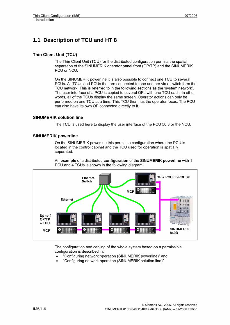
Thin Client Unit (TCU) The Thin Client Unit (TCU) for the distributed configuration permits the spatial separation of the SINUMERIK operator panel front (OP/TP) and the SINUMERIK PCU or NCU. On the SINUMERIK powerline it is also possible to connect one TCU to several PCUs. All TCUs and PCUs that are connected to one another via a switch form the TCU network. This is referred to in the following sections as the ‘system network’. The user interface of a PCU is copied to several OPs with one TCU each. In other words, all of the TCUs display the same screen. Operator actions can only be performed on one TCU at a time. This TCU then has the operator focus. The PCU can also have its own OP connected directly to it.
SINUMERIK solution line The TCU is used here to display the user interface of the PCU 50.3 or the NCU.
SINUMERIK powerline On the SINUMERIK powerline this permits a configuration where the PCU is located in the control cabinet and the TCU used for operation is spatially separated. An example of a distributed configuration of the SINUMERIK powerline with 1 PCU and 4 TCUs is shown in the following diagram:
Ethernet-Switch
OP + PCU 50/PCU 70
Up to 4 OP/TP + TCU
Ethernet
MCP SINUMERIK 840D
MCP
The configuration and cabling of the whole system based on a permissible configuration is described in: • “Configuring network operation (SINUMERIK powerline)” and • “Configuring network operation (SINUMERIK solution line)”
07/2006 Thin Client Configuration (IM5) 1 Introduction
© Siemens AG, 2006. All rights reserved SINUMERIK 810D/840D/840D sl/840Di sl (IAM2) – 07/2006 Edition IM5/1-7
Handheld Terminal (HT 8) The mobile SINUMERIK HAT 8 handheld terminal combines the functions of an operating panel and a machine control panel. It is therefore ideal for visualization, operation, teach-in, and programming at the machine: - Manipulators/robots - Machine tools - Production machines
The HT 8 does not have its own user interface software on board; it works on the thin client principle. An HAT 8 is a “mobile TCU” with an integrated machine control panel and it behaves like a stationary TCU. The 7.5 TFT color display provides touch operation. It also has membrane key for traversing the axes, for numeric input, for cursor control, and for machine control panel functions like start and stop.
1.2 Requirements for operating the HT 8 To operate the HT 8, the following requirements must be met: • The HT 8 is operated using a PCU 50.3 on a SINUMERIK powerline control
unit. • PCU 50.3 with Basesoftware ≥ V08.00.00.01 and HMI Advanced V07.02.00 • No more than four HT8 handheld units can be connected or, in mixed
operation, no more than four nodes, consisting of TCU and HT8: See “Configuring network operation (SINUMERIK powerline)”
For the rest of the procedure for installing the HT 8: See “Configuring HT 8 on the system network”
1.3 Requirements for operating the TCU To operate a TCU on a PCU the following requirements must be met: • PCU 50 V2 ≥ 1.2 GHz with Windows XP and BIOS Version ≥ 02.03.09 • PCU Basesoftware ≥ 07.05.00.00 on a PCU 50 V2 • If HMI Advanced is used on a PCU 50 V2: Version ≥ 06.04.21 • A second Ethernet card if the PCU 50 V2 is also to be used for connecting the
TCU to a company network. • If the PCU is to be operated without an operator panel front, monitors and an
additional keyboard will also be required for: - Initial installation of the software required for TCU operation (only on PCU
50 V2) - Diagnostics when booting the PCU - If required, installation of a replacement hard drive (alternatively, the hard
drive can also be prepared externally).
Thin Client Configuration (IM5) 07/2006 1 Introduction
© Siemens AG, 2006. All rights reserved IM5/1-8 SINUMERIK 810D/840D/840D sl/840Di sl (IAM2) – 07/2006 Edition
• PCU Basesoftware ≥ 08.00.00.00 on a PCU 50.3 • If HMI Advanced is used on a PCU 50.3: Version ≥ 07.01.00 To operate a TCU on an NCU the following requirements must be met: • NCU Basesoftware ≥ 01.03 • PCU Basesoftware ≥ 08.00.00.00 on a PCU 50.3 with HMI Advanced • HMI Version ≥ 07.01.00 • An additional external keyboard is required for uppercase/lowercase letters.
1.4 Supplementary conditions for operating the TCU
To operate a TCU on a PCU 50 V2/PCU 50.3 The following supplementary conditions apply: • No more than four TCUs may be active at any one time on a PCU
(SINUMERIK powerline). • All OPs must have the same screen resolution: This encompasses both an OP
connected directly to the PCU 50 V2 and the OPs on the TCUs. • If PCU applications requiring the properties of hardware support to implement
graphic output (e.g., OpenGL or DirectX) are to be visualized via the TCU, the hardware support for graphic output must be disabled on the PCU.
• The depth-of-color selection is limited to a 16-bit setting. • If a PC keyboard is connected to the TCU, it cannot be guaranteed that all
special keys, e.g., multimedia keys, will be transferred to the software on the PCU.
• You must use PLC block FB9 for automatic switchover of a machine control panel when changing the focus. To do this, FB9 must be parameterized and called accordingly by the PLC user program. (see /FB1/ Description of functions Basic machine, Basic PLC program (P3)). The automatic switchover of the machine control panels used when changing the focus can only be performed in conjunction with HMI Advanced on SINUMERIK powerline.
• Machine control panels connected via a PROFIBUS network are not supported for switchover.
• Disabling the switchover between TCUs with HMI Advanced: This function is supported by the PLC program and can only be used on the SINUMERIK powerline and SINUMERIK solution line if HMI Advanced is active (see “Disabling the switchover between TCUs via PLC”).
• Veto Mode is only available if HMI Advanced is active. • Peripheral memory media connected to the TCU via USB can only be used
with HMI Advanced version 07.01.00 and above. • CF cards cannot be used on the TCU.
07/2006 Thin Client Configuration (IM5) 1 Introduction
© Siemens AG, 2006. All rights reserved SINUMERIK 810D/840D/840D sl/840Di sl (IAM2) – 07/2006 Edition IM5/1-9
To operate a TCU on an NCU on the SINUMERIK solution line: The following supplementary conditions apply: • No more than one TCU may be active on an NCU. • No more than one NCU may be operated on the system network. See
“Configuring network operation (SINUMERIK solution line)” for information on integrating a PCU into the system network.
• When changing the focus, it is not possible to perform a switchover of the machine control panels.
• The OPs on the TCUs, which are operated in parallel on an HMI (on an NCU or on a PCU), must have identical screen diagonals.
• CF cards cannot be used on the TCU.
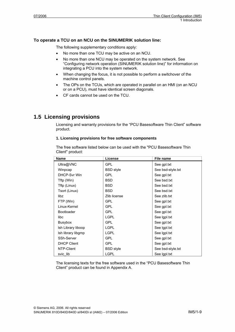
1.5 Licensing provisions Licensing and warranty provisions for the “PCU Basesoftware Thin Client” software product. 1. Licensing provisions for free software components The free software listed below can be used with the "PCU Basesoftware Thin Client" product:
Name License File name Ultra@VNC Winpcap DHCP-Svr Win Tftp (Win) Tftp (Linux) Tsort (Linux) libz FTP (Win) Linux-Kernel Bootloader libc Busybox lsh Library liboop lsh library libgmp SSh-Server DHCP Client NTP-Client svic_lib
GPL BSD style GPL BSD BSD BSD Zlib license GPL GPL GPL LGPL GPL LGPL LGPL GPL GPL BSD style LGPL
See gpl.txt See bsd-style.txt See gpl.txt See bsd.txt See bsd.txt See bsd.txt See zlib.txt See gpl.txt See gpl.txt See gpl.txt See lgpl.txt See gpl.txt See lgpl.txt See lgpl.txt See gpl.txt See gpl.txt See bsd-style.txt See lgpl.txt
The licensing texts for the free software used in the “PCU Basesoftware Thin Client” product can be found in Appendix A.
Thin Client Configuration (IM5) 07/2006 1 Introduction
© Siemens AG, 2006. All rights reserved IM5/1-10 SINUMERIK 810D/840D/840D sl/840Di sl (IAM2) – 07/2006 Edition
These programs have been developed by third parties. If you wish to use free software as well as the program sequence provided by Siemens, please contact the originators or other copyright holders for this software in order to apply for usage rights (in observance of the appropriate licensing conditions). You can obtain the source text for the free software, along with the associated licensing texts and copyright endorsements, from your SIEMENS sales representative for up to three years after purchasing this product. 2. General conditions on the licensing of software products for automation engineering This software is protected by national and international copyright laws and agreements. It is an offense to reproduce or sell this software, in whole or in part, without the necessary authorization. Such offenses are punishable in both criminal and civil courts and can result in severe penalties and/or claims for compensation. Please read the licensing provisions for this software before installing or using it. If you received this software on a CD marked “Trial Version” or with software for which you have a license, the software may only be used for test and validation purposes, in accordance with the enclosed Trial License conditions. In this respect, programs, software, libraries, etc., must be installed on your computer. We strongly recommend, therefore, that these programs are installed on a stand-alone computer or on a computer, which is not used in the production process or for storing important data, due to the risk of existing files being changed or overwritten. We can accept no responsibility for damage and/or loss of data resulting from the installation of this software, or from non-observance of this warning. All other use of this software is only permitted if you have purchased a valid license from Siemens. If you do not possess a valid license, which can be proved by presentation of the relevant Certificate of License/Software Product Certificate, please terminate this installation and contact Siemens immediately, in order to avoid any claims for compensation. 3. Warranty provisions for free software The free software contained in this product, which is not part of the program sequence provided by Siemens, is used at your own risk, i.e., no warranty claims may be made against Siemens. Siemens does not offer technical support for this product if you are using it in conjunction with modified software. The licensing conditions listed contain notes regarding the warranties offered by the originators or copyright holders of the free software. Siemens will also accept no warranty claims if a product defect is or could be the result of modifications made to the programs or their configurations by you.
07/2006 Thin Client Configuration (IM5) 2 Configuring the System
© Siemens AG, 2006. All rights reserved SINUMERIK 810D/840D/840D sl/840Di sl (IAM2) – 07/2006 Edition IM5/2-11
2 Configuring the System
2.1 Factory default settings............................................................. IM5/2-14 2.1.1 Preconfiguration of the TCU .................................................. IM5/2-14 2.1.2 Preconfiguration of the NCU.................................................. IM5/2-14 2.1.3 Preconfiguration of the PCU.................................................. IM5/2-16
2.2 File structure on PCUs and NCUs........................................... IM5/2-17
2.3 Configuring the IP addresses of network stations .................... IM5/2-21 2.3.1 Setting the IP address of the PCU under Windows XP......... IM5/2-22 2.3.2 Deactivating Services ............................................................ IM5/2-24 2.3.3 Declaring the PCUs ............................................................... IM5/2-25 2.3.4 Setting the IP address of the PCU 50.3................................. IM5/2-26 2.3.5 Setting the IP address of the PCU 50 V2 .............................. IM5/2-27 2.3.6 Installing the 'PCU Basesoftware Thin Client' ....................... IM5/2-28
2.4 Configuring the System Network .............................................. IM5/2-30 2.4.1 Configuring the TCU and MCP.............................................. IM5/2-30 2.4.2 Activating Direct Keys............................................................ IM5/2-32
2.5 Configuring the HT 8 in the system network............................. IM5/2-33 2.5.1 Connecting the HT 8 (solution line) ....................................... IM5/2-33 2.5.2 Connecting the HT 8 (powerline) ........................................... IM5/2-35 2.5.3 Display/skip the inscriptions of the traversinge keys ............. IM5/2-36
2.6 Operating with an S7 CPU........................................................ IM5/2-39 2.6.1 Operating the HT 8 with an S7 CPU via PROFIBUS............. IM5/2-39
2.7 Configuring system network with 'Settings system network' .... IM5/2-40
2.8 Making changes after commissioning ...................................... IM5/2-46
2.9 Disabling switch-over between TCUs via PLC n ...................... IM5/2-48
2
Thin Client Configuration (IM5) 07/2006 2 Configuring the System
© Siemens AG, 2006. All rights reserved IM5/2-12 SINUMERIK 810D/840D/840D sl/840Di sl (IAM2) – 07/2006 Edition
Overview This chapter describes the procedure for installing the TCU. Depending on the configuration of your system and the number of TCUs, PCUs, and NCUs, there may be some special aspects of installation. So before you start the installation you should not only read this chapter but also refer to the relevant section in chapter "Configuring network operation" for the SINUMERIK powerline or the SINUMERIK solution line.
Commissioning of SINUMERIK powerline Perform the following steps to operate the TCU on the PCU 50 V2:
1. Configure the PCUs on the system network
– Set the IP address of the PCU on the system network – Install the "PCU Basesoftware Thin Client" – Deactivate the DHCP server: If more than one PCU – Declare the PCUs
2. Configure the system network
– Assign names to the TCUs – Set the addresses of the machine control panels – Connect the programming device to the system network
3. Additional information and further steps:
– Make changes after installation – File structure on the PCU – Disable switchover between TCUs via PLC: Only with HMI Advanced – In the event of a service call: Connect the programming device
07/2006 Thin Client Configuration (IM5) 2 Configuring the System
© Siemens AG, 2006. All rights reserved SINUMERIK 810D/840D/840D sl/840Di sl (IAM2) – 07/2006 Edition IM5/2-13
Installing the SINUMERIK solution line Perform the following steps to operate the TCU on the PCU 50.3:
1. PCU on the system network: IP address is preset
– Change the IP address of the PCU: If more than two PCUs – Deactivate the DHCP server: If more than two PCUs or one NCU – Declare the PCUs
2. Configure the system network
– TCU on the system network: IP address is assigned automatically – Assign a name to the TCU – Connect the programming device to the system network
3. Additional information and further steps:
– File structure on the PCU – Disable switchover between TCUs via PLC: Only with HMI Advanced
Perform the following steps to operate the TCU on the NCU:
1. NCU on the system network: IP address is preset
(declare the PCUs on the NCU if required under the path: /user/common/tcu/ftp_tcus/tcux/config)
2. TCU on the system network: IP address is assigned automatically
3. Configure the system network: Assign a name to the TCU
4. In the event of a service call: Connect the programming device
Thin Client Configuration (IM5) 07/2006 2 Configuring the System
© Siemens AG, 2006. All rights reserved IM5/2-14 SINUMERIK 810D/840D/840D sl/840Di sl (IAM2) – 07/2006 Edition
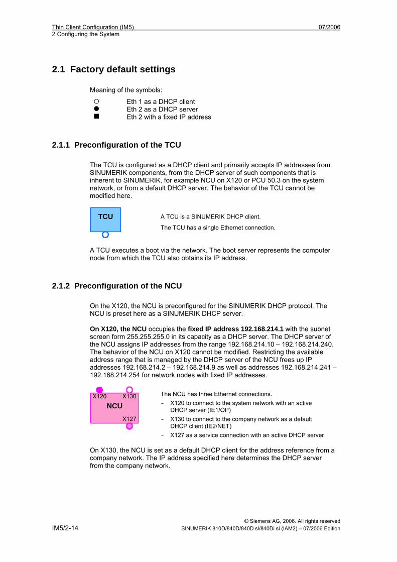
2.1 Factory default settings Meaning of the symbols:
Eth 1 as a DHCP client Eth 2 as a DHCP server Eth 2 with a fixed IP address
2.1.1 Preconfiguration of the TCU The TCU is configured as a DHCP client and primarily accepts IP addresses from SINUMERIK components, from the DHCP server of such components that is inherent to SINUMERIK, for example NCU on X120 or PCU 50.3 on the system network, or from a default DHCP server. The behavior of the TCU cannot be modified here. TCU
A TCU is a SINUMERIK DHCP client. The TCU has a single Ethernet connection.
A TCU executes a boot via the network. The boot server represents the computer node from which the TCU also obtains its IP address.
2.1.2 Preconfiguration of the NCU On the X120, the NCU is preconfigured for the SINUMERIK DHCP protocol. The NCU is preset here as a SINUMERIK DHCP server. On X120, the NCU occupies the fixed IP address 192.168.214.1 with the subnet screen form 255.255.255.0 in its capacity as a DHCP server. The DHCP server of the NCU assigns IP addresses from the range 192.168.214.10 – 192.168.214.240. The behavior of the NCU on X120 cannot be modified. Restricting the available address range that is managed by the DHCP server of the NCU frees up IP addresses 192.168.214.2 – 192.168.214.9 as well as addresses 192.168.214.241 – 192.168.214.254 for network nodes with fixed IP addresses.
NCU X120 X130
X127
The NCU has three Ethernet connections. - X120 to connect to the system network with an active
DHCP server (IE1/OP) - X130 to connect to the company network as a default
DHCP client (IE2/NET) - X127 as a service connection with an active DHCP server
On X130, the NCU is set as a default DHCP client for the address reference from a company network. The IP address specified here determines the DHCP server from the company network.
07/2006 Thin Client Configuration (IM5) 2 Configuring the System
© Siemens AG, 2006. All rights reserved SINUMERIK 810D/840D/840D sl/840Di sl (IAM2) – 07/2006 Edition IM5/2-15
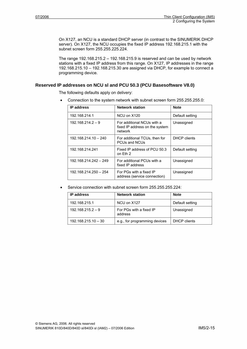
On X127, an NCU is a standard DHCP server (in contrast to the SINUMERIK DHCP server). On X127, the NCU occupies the fixed IP address 192.168.215.1 with the subnet screen form 255.255.225.224. The range 192.168.215.2 – 192.168.215.9 is reserved and can be used by network stations with a fixed IP address from this range. On X127, IP addresses in the range 192.168.215.10 – 192.168.215.30 are assigned via DHCP, for example to connect a programming device.
Reserved IP addresses on NCU sl and PCU 50.3 (PCU Basesoftware V8.0) The following defaults apply on delivery:
• Connection to the system network with subnet screen form 255.255.255.0:
IP address Network station Note
192.168.214.1 NCU on X120 Default setting
192.168.214.2 – 9 For additional NCUs with a fixed IP address on the system network
Unassigned
192.168.214.10 – 240 For additional TCUs, then for PCUs and NCUs
DHCP clients
192.168.214.241 Fixed IP address of PCU 50.3 on Eth 2
Default setting
192.168.214.242 – 249 For additional PCUs with a fixed IP address
Unassigned
192.168.214.250 – 254 For PGs with a fixed IP address (service connection)
Unassigned
• Service connection with subnet screen form 255.255.255.224:
IP address Network station Note
192.168.215.1 NCU on X127 Default setting
192.168.215.2 – 9 For PGs with a fixed IP address
Unassigned
192.168.215.10 – 30 e.g., for programming devices DHCP clients
Thin Client Configuration (IM5) 07/2006 2 Configuring the System
© Siemens AG, 2006. All rights reserved IM5/2-16 SINUMERIK 810D/840D/840D sl/840Di sl (IAM2) – 07/2006 Edition
2.1.3 Preconfiguration of the PCU
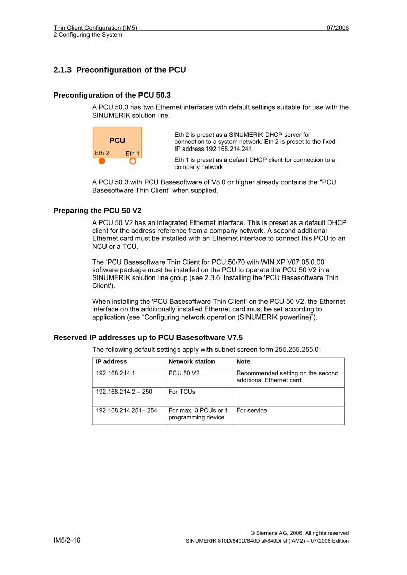
Preconfiguration of the PCU 50.3 A PCU 50.3 has two Ethernet interfaces with default settings suitable for use with the SINUMERIK solution line.
PCU Eth 2 Eth 1
- Eth 2 is preset as a SINUMERIK DHCP server for connection to a system network. Eth 2 is preset to the fixed IP address 192.168.214.241.
- Eth 1 is preset as a default DHCP client for connection to a company network.
A PCU 50.3 with PCU Basesoftware of V8.0 or higher already contains the "PCU Basesoftware Thin Client" when supplied.
Preparing the PCU 50 V2 A PCU 50 V2 has an integrated Ethernet interface. This is preset as a default DHCP client for the address reference from a company network. A second additional Ethernet card must be installed with an Ethernet interface to connect this PCU to an NCU or a TCU. The ‘PCU Basesoftware Thin Client for PCU 50/70 with WIN XP V07.05.0.00’ software package must be installed on the PCU to operate the PCU 50 V2 in a SINUMERIK solution line group (see 2.3.6 Installing the 'PCU Basesoftware Thin Client'). When installing the 'PCU Basesoftware Thin Client' on the PCU 50 V2, the Ethernet interface on the additionally installed Ethernet card must be set according to application (see “Configuring network operation (SINUMERIK powerline)”).
Reserved IP addresses up to PCU Basesoftware V7.5 The following default settings apply with subnet screen form 255.255.255.0:
IP address Network station Note 192.168.214.1 PCU 50 V2 Recommended setting on the second
additional Ethernet card
192.168.214.2 – 250 For TCUs
192.168.214.251– 254 For max. 3 PCUs or 1 programming device
For service
07/2006 Thin Client Configuration (IM5) 2 Configuring the System
© Siemens AG, 2006. All rights reserved SINUMERIK 810D/840D/840D sl/840Di sl (IAM2) – 07/2006 Edition IM5/2-17
2.2 File structure on PCUs and NCUs
Creating the file structure After allocating the TCU name during the initial boot, the system automatically creates a file structure in the PCU for each TCU. Under normal circumstances, you will not have to change this file structure. This section discusses the file structure and the information it contains. Subsequent modification of the settings might be necessary, for example, if you want to change the settings when you have completed installation.
Installation path on the NCU The file structure is created on the NCU under /user/common/tcu.
Installation path on the PCU The installation path for the file structure on the PCU is E:\TCU\SERVICES. Here, programs are stored in subdirectory BIN and the configuration files of "PCU Basesoftware Thin Client" in subdirectory ETC. The file structure is also created on the PCU in directory F:\TCU\SERVICES (without the configuration files in the ETC subdirectories). You can make changes to the configuration here, i.e., you can copy the configuration files containing the sections you want to change from drive E:\ to F:\ and make your changes there. We do not recommend making a complete copy of the configuration files.
Note
Use directory E:\TCU\SERVICES "read-only". Only change the configuration files under path: F:\TCU\SERVICES.
Explanation of the file structure A file structure is created for each TCU under the specified TCU name, for example directory “TCUx”. In directory FTP_TCUS, a file is automatically created with the MAC address of the TCU as its file name to identify each TCU. The sole content of the file is the assigned TCU name, for example "TCUx". A file with the name "6" is automatically generated in subdirectory COMMON\TCU\MCPADDR. The name of this file specifies the MPI address of the machine control panel (MCP) assigned to the TCU. In this case, the default address “6”. If you want to use another MPI address you must rename the file accordingly. If it is possible to switch the TCU over to several different PCUs in a system network, enter those PCUs in the config file in subdirectory common\tcu (see "Declaring PCUs“).
Thin Client Configuration (IM5) 07/2006 2 Configuring the System
© Siemens AG, 2006. All rights reserved IM5/2-18 SINUMERIK 810D/840D/840D sl/840Di sl (IAM2) – 07/2006 Edition
To manage an OP connected directly to the PCU, directory FTP_TCUS contains a directory called "PCU" with the same file structure as that of the TCUs by default.
Storage path The directories and files are located: → On the PCU under F:\TCU\SERVICES → On the NCU under /user/common/tcu. File: TCU.INI (response during focus-change time intervals) Entry: In file TCU.INI, the response to focus change can be set in the TCUs. The following setting options are available: [VNCServer] # VETO MODE # VetoMode enabled: # VNC server notifies the HMI regie before another # panel gets the focus. # VetoMode disabled: # Focus timeout mode enabled (implicitly; see FOCUS TIMEOUT) # (0=DISABLE, 1=ENABLE) VetoMode=1 # FOCUS TIMEOUT # Guaranteed time period (in sec) a panel can hold the # focus at least before another panel can get the focus. # The time period starts from the moment the panel has # gained the focus. FocusTimeout=10 # ALARMBOXTIMEOUT # specifies the time period (in sec) the messagebox is shown # (i.e. is operable) in the case of VetoMode=1; no meaning # else AlarmBoxTimeOut=5 VetoMode = 1 When focus is requested by another OP the user with the focus can prevent the focus from changing by acknowledging an alarm (alarm 120011), i.e., the user can keep the operator focus with this veto right. The alarm can be acknowledged during a time interval defined in "AlarmBoxTimeOut". If no action is performed during this time, the focus changes to the requesting TCU. VetoMode = 0 The time interval set in "FocusTimeout" has a disabling effect and will only allow a focus change to take place again when it has expired.
07/2006 Thin Client Configuration (IM5) 2 Configuring the System
© Siemens AG, 2006. All rights reserved SINUMERIK 810D/840D/840D sl/840Di sl (IAM2) – 07/2006 Edition IM5/2-19
Directory FTP_TCUS The content of directory FTP_TCUS is generated automatically. You must insert the files marked bold if you change the configuration. TCUx common tcu mcpaddr 6 (Empty file named after the address of the MCP
for this OP (this TCU); default setting is “6”, so this file is called “6”, which corresponds to the default machine control panel address on the MPI.)
config (List of all PCUs and NCUs available on the system network to which this TCU can connect; see "Declaring PCUs".)
system MACADDR ("TCUx") (file name is the MAC address of the TCUx)
TCU_HWS\ETC\ File: TCU_HWS.CONF # IP address of the PCU on
the system network Entry: interface 192.168.214.1 # IP address of the PCU on
the system network Entry: pcu_name "main operator
panel" # Identifier of the PCU, as displayed for this PCU in the selection/switching dialog on the TCU. # Max. length: 40 characters; Default: no name (="")
NETKIT-TFTPD\ETC\ File: NETKIT-TFTPD.CONF Entry: interface 192.168.214.1 # IP address of the PCU
on the system network.
BETAFTPD\ETC\ File: BETAFTPD.CONF Entry: interface 192.168.214.1 # IP address of the PCU
on the system network.
Thin Client Configuration (IM5) 07/2006 2 Configuring the System
© Siemens AG, 2006. All rights reserved IM5/2-20 SINUMERIK 810D/840D/840D sl/840Di sl (IAM2) – 07/2006 Edition
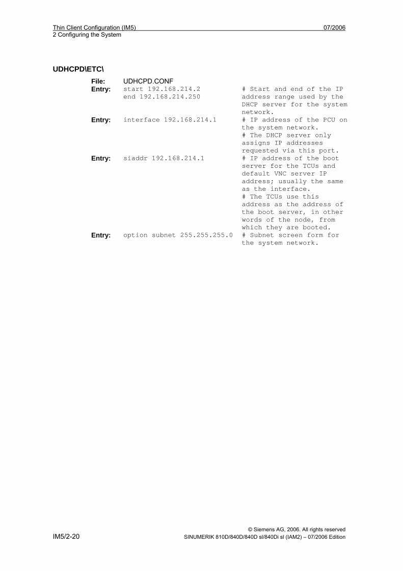
UDHCPD\ETC\ File: UDHCPD.CONF Entry: start 192.168.214.2
end 192.168.214.250 # Start and end of the IP address range used by the DHCP server for the system network.
Entry: interface 192.168.214.1 # IP address of the PCU on the system network. # The DHCP server only assigns IP addresses requested via this port.
Entry: siaddr 192.168.214.1 # IP address of the boot server for the TCUs and default VNC server IP address; usually the same as the interface. # The TCUs use this address as the address of the boot server, in other words of the node, from which they are booted.
Entry: option subnet 255.255.255.0 # Subnet screen form for the system network.
07/2006 Thin Client Configuration (IM5) 2 Configuring the System
© Siemens AG, 2006. All rights reserved SINUMERIK 810D/840D/840D sl/840Di sl (IAM2) – 07/2006 Edition IM5/2-21
2.3 Configuring the IP addresses of network stations
Connecting the NCU on the system network (X120) On X120, the NCU is preset as required. No settings are necessary here.
Determining the IP address of the NCU on the company network (X130) On X130, the NCU is set to the address reference via DHCP. If the company network has a DHCP server no further settings are required. There are three ways of determining the address that the NCU obtained on the company network.
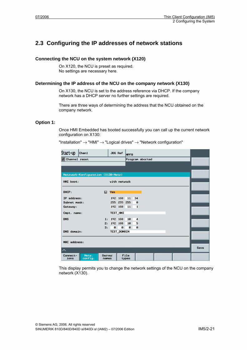
Option 1: Once HMI Embedded has booted successfully you can call up the current network configuration on X130:
"Installation" → "HMI" → "Logical drives" → "Network configuration"
This display permits you to change the network settings of the NCU on the company network (X130).
Thin Client Configuration (IM5) 07/2006 2 Configuring the System
© Siemens AG, 2006. All rights reserved IM5/2-22 SINUMERIK 810D/840D/840D sl/840Di sl (IAM2) – 07/2006 Edition
Option 2: If the NCU boots in switch position 8, it indicates the IP address on X130 on the 7-segment display.
Option 3: Once the NCU has booted successfully, open a service shell on the TCU and execute the following command to obtain the desired information: SC SHOW IP
Changing the IP address:
If the company network has no available DHCP server or if this cannot be used, you are given the option to set a fixed address for the NCU on X130 (in accordance with the addresses already used on the company network). Example:
The following command results in an IP address 157.163.245.105 with a subnet screen form 255.255.255.0. SC SET IP 157.163.245.105 255.255.255.0 -X130
Further information on the service commands can be found in: /IM7/ Commissioning the NCU sl or if you execute the sc help command.
2.3.1 Setting the IP address of the PCU under Windows XP
Operator input sequence steps 1. Select the following on the PCU in Windows service mode: "Start" "Settings"
"Network Connections". The "Network Connections" window opens.
2. Double-click the interface you want to parameterize, Ethernet 2, which is to be used for connecting the TCU or system network.
The "Ethernet 2 (System Network) Properties" window opens.
3. On the "General" tab card, select "Internet Protocol (TCP/IP)" and click the "Properties" button.
07/2006 Thin Client Configuration (IM5) 2 Configuring the System
© Siemens AG, 2006. All rights reserved SINUMERIK 810D/840D/840D sl/840Di sl (IAM2) – 07/2006 Edition IM5/2-23
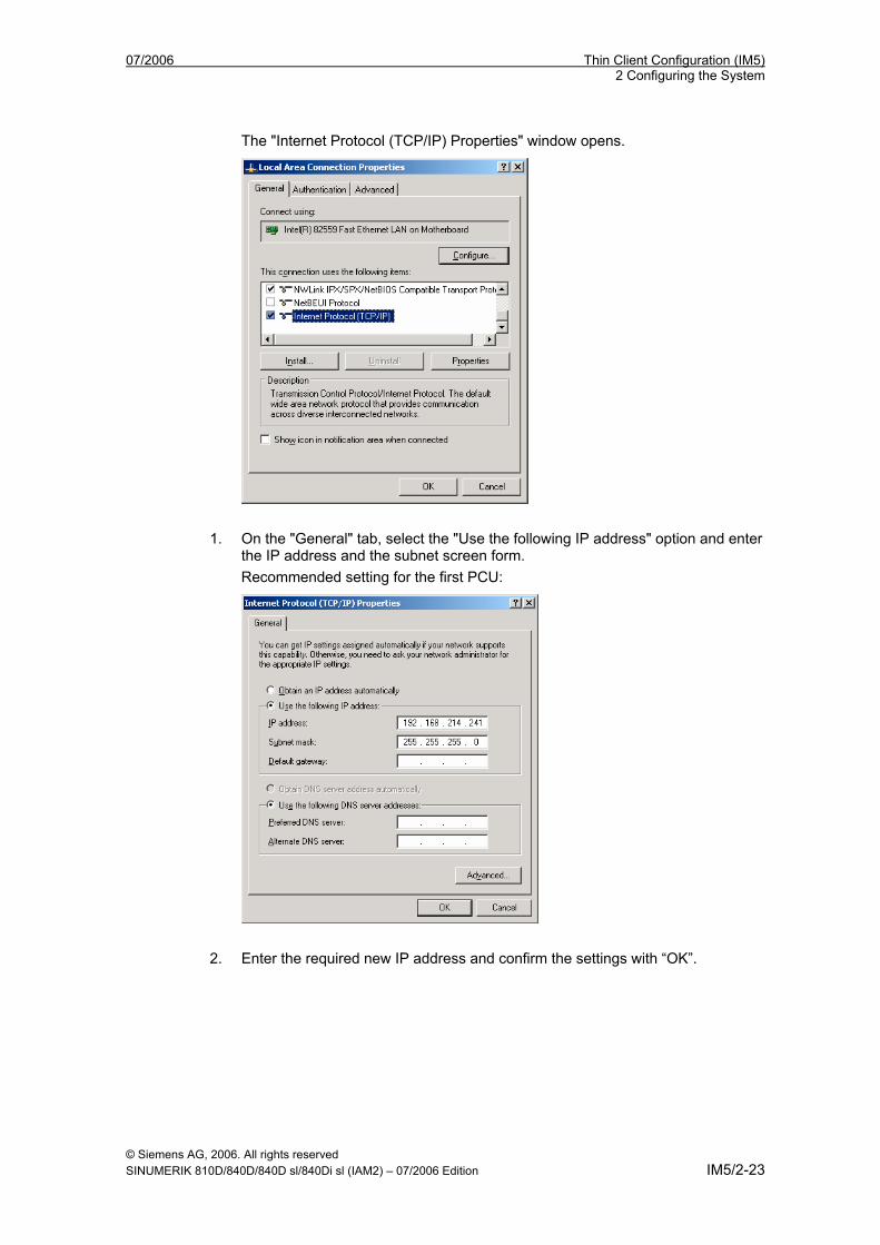
The "Internet Protocol (TCP/IP) Properties" window opens.
1. On the "General" tab, select the "Use the following IP address" option and enter
the IP address and the subnet screen form. Recommended setting for the first PCU:
2. Enter the required new IP address and confirm the settings with “OK”.
Thin Client Configuration (IM5) 07/2006 2 Configuring the System
© Siemens AG, 2006. All rights reserved IM5/2-24 SINUMERIK 810D/840D/840D sl/840Di sl (IAM2) – 07/2006 Edition
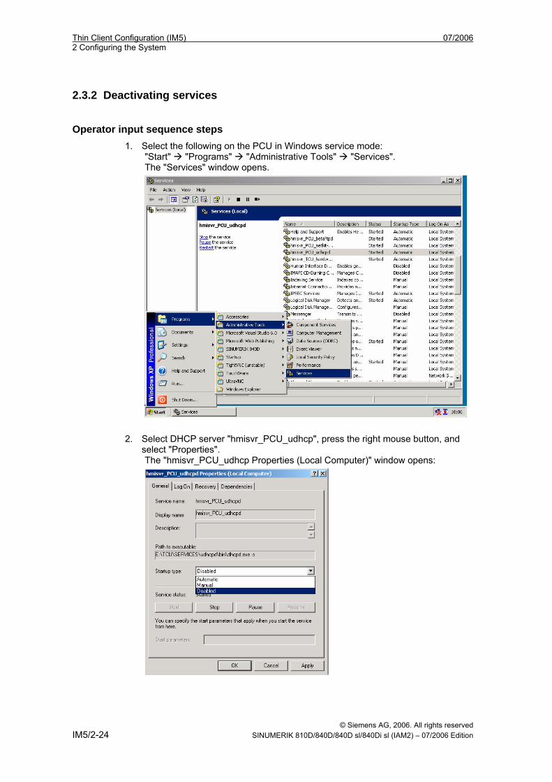
2.3.2 Deactivating services
Operator input sequence steps 1. Select the following on the PCU in Windows service mode:
"Start" "Programs" "Administrative Tools" "Services". The "Services" window opens.
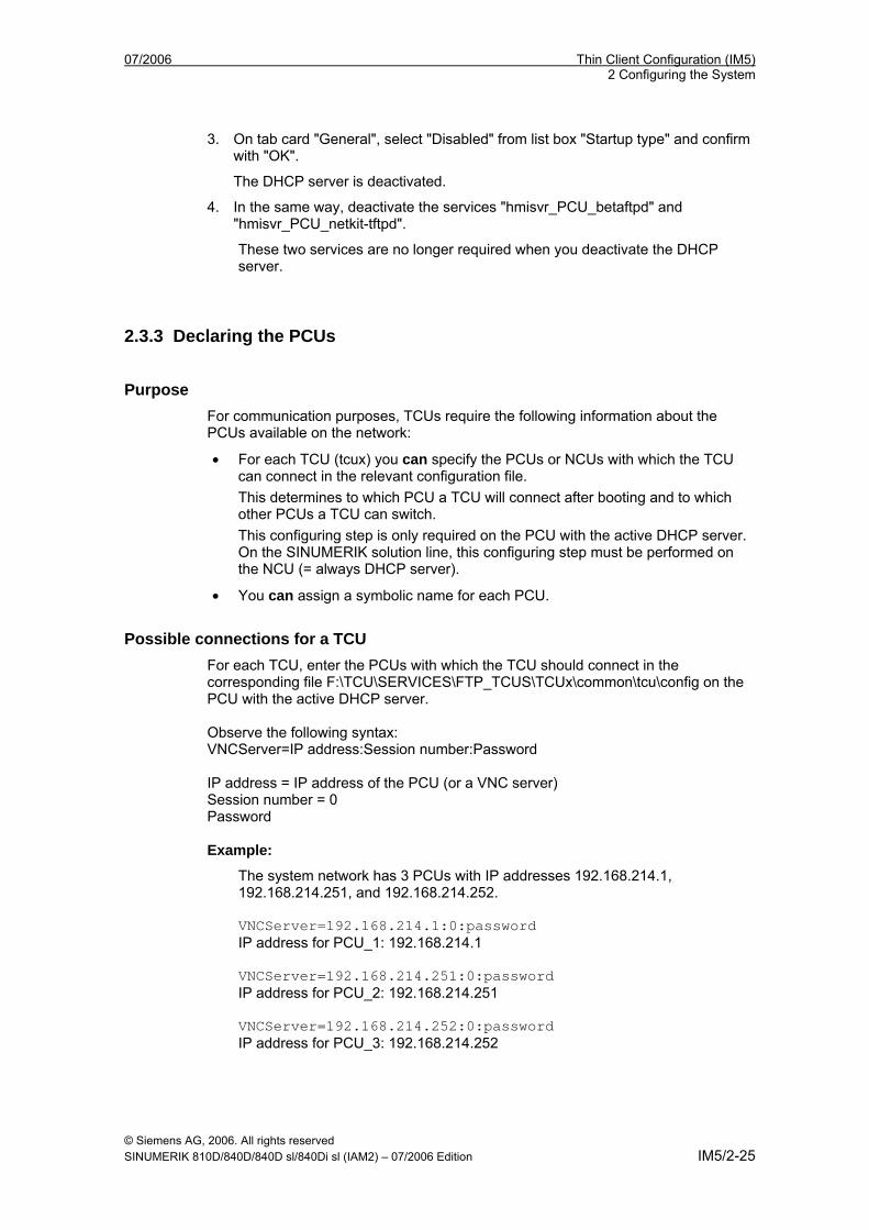
2. Select DHCP server "hmisvr_PCU_udhcp", press the right mouse button, and select "Properties". The "hmisvr_PCU_udhcp Properties (Local Computer)" window opens:
07/2006 Thin Client Configuration (IM5) 2 Configuring the System
© Siemens AG, 2006. All rights reserved SINUMERIK 810D/840D/840D sl/840Di sl (IAM2) – 07/2006 Edition IM5/2-25
3. On tab card "General", select "Disabled" from list box "Startup type" and confirm with "OK".
The DHCP server is deactivated.
4. In the same way, deactivate the services "hmisvr_PCU_betaftpd" and "hmisvr_PCU_netkit-tftpd".
These two services are no longer required when you deactivate the DHCP server.
2.3.3 Declaring the PCUs
Purpose For communication purposes, TCUs require the following information about the PCUs available on the network:
• For each TCU (tcux) you can specify the PCUs or NCUs with which the TCU can connect in the relevant configuration file. This determines to which PCU a TCU will connect after booting and to which other PCUs a TCU can switch. This configuring step is only required on the PCU with the active DHCP server. On the SINUMERIK solution line, this configuring step must be performed on the NCU (= always DHCP server).
• You can assign a symbolic name for each PCU.
Possible connections for a TCU For each TCU, enter the PCUs with which the TCU should connect in the corresponding file F:\TCU\SERVICES\FTP_TCUS\TCUx\common\tcu\config on the PCU with the active DHCP server. Observe the following syntax: VNCServer=IP address:Session number:Password IP address = IP address of the PCU (or a VNC server) Session number = 0 Password Example:
The system network has 3 PCUs with IP addresses 192.168.214.1, 192.168.214.251, and 192.168.214.252. VNCServer=192.168.214.1:0:password IP address for PCU_1: 192.168.214.1 VNCServer=192.168.214.251:0:password IP address for PCU_2: 192.168.214.251 VNCServer=192.168.214.252:0:password IP address for PCU_3: 192.168.214.252
Thin Client Configuration (IM5) 07/2006 2 Configuring the System
© Siemens AG, 2006. All rights reserved IM5/2-26 SINUMERIK 810D/840D/840D sl/840Di sl (IAM2) – 07/2006 Edition
Note:
The TCU connects to the first PCU listed in the config file when it boots. In the case of the “config” file, when switching a TCU between multiple PCUs, it is important to ensure that the file name is written in lowercase letters.
Assigning names to the PCU On every PCU on the system network, enter a name for the PCU in file F:\TCU\SERVICES\TCU_HWS\ETC\TCU_HWS.CONF. Example:
The PCU is to be called "PCU_1". pcu_name "PCU_1"
The PCUs are displayed with this name in the selection menu of the "VNC-Starter" window on the TCU as soon as the user presses key combination "Recall" + "Menu select" to switchover the TCU. If you do not enter a name for the PCU, the IP address of the PCU appears in the "VNC Starter" window instead of the name.
2.3.4 Setting the IP address of the PCU 50.3 Valid for: SINUMERIK solution line
Note
The IP address 192.168.214.241 is set as a factory default for every PCU 50.3 on the system network. You must only perform the steps described below if you wish to change this default setting.
The IP address must be changed if there are more than 2 PCUs on the network or if the IP address of the NCU has been changed on X120. If changes to the IP address are necessary (in the range 192.168.214.242 – 192.168.214.249) these must be carried out on the PCU before it is connected to the system network.
Procedure → See section "Setting the IP address of the PCU in Windows XP" In the case of a PCU that is being used as a DHCP server, the default IP address 192.168.214.241 should be kept.

07/2006 Thin Client Configuration (IM5) 2 Configuring the System
© Siemens AG, 2006. All rights reserved SINUMERIK 810D/840D/840D sl/840Di sl (IAM2) – 07/2006 Edition IM5/2-27
Deactivating the DHCP server On a PCU 50.3, the DHCP server should be deactivated in the following cases:
• The PCU 50.3 is operated together with an NCU on the system network: The DHCP servers must be deactivated on all PCUs.
• More than one PCU 50.3 is operated on the system network: If an NCU is also operated, the DHCP servers must be deactivated on all PCUs. If no NCU is present, the DHCP servers must be deactivated on all PCUs apart from one. The PCU 50.3 with the active DHCP server should be that with the IP address 192.168.214.241.
Procedure → See “Deactivating services”
2.3.5 Setting the IP address of the PCU 50 V2 Valid for: SINUMERIK powerline You must define a fixed network address for each PCU 50 V2 on the system network.
Note
Before you start installation carefully consider what you will require each IP address for and observe the following:
• Recommended address range in the following table.
• The IP addresses of the PCUs must be different whereas the subnet masks must be identical.
• The installation of the ‘PCU Basesoftware Thin Client’ runs automatically if you have set the fixed IP address 192.168.214.1 with the subnet screen form 255.255.255.0 for the PCU 50 V2.
Example:
The system network has 3 PCU 50 V2 that require their IP addresses (for the second additional Ethernet card) to be set.
Address range for the TCUs: 192.168.214.2 – 250
PCU_1: 192.168.214.1 with subnet screen form 255.255.255.0
PCU_2: 192.168.214.251 with subnet screen form 255.255.255.0
PCU_3: 192.168.214.252 with subnet screen form 255.255.255.0 (see "Installing the PCU Basesoftware Thin Client").
Free IP addresses, e.g., to connect a PG: 192.168.214.253 – 254. Procedure → See "Setting the IP address of the PCU under Windows XP"
Thin Client Configuration (IM5) 07/2006 2 Configuring the System
© Siemens AG, 2006. All rights reserved IM5/2-28 SINUMERIK 810D/840D/840D sl/840Di sl (IAM2) – 07/2006 Edition
Deactivating the DHCP server If more than one PCU is operated on the system network, the DHCP server must only be active on a single PCU. Select the PCU with the recommended IP address 192.168.214.1 as appropriate and deactivate the DHCP server on all other PCUs. You must deactivate the DHCP service after you have installed the "PCU Basesoftware Thin Client" and before you next boot the PCU to prevent several DHCP servers running concurrently on the system network. Procedure → See “Deactivating services”
2.3.6 Installing the 'PCU Basesoftware Thin Client' Valid for: SINUMERIK powerline The ‘PCU Basesoftware Thin Client’ must be installed on each PCU 50 V2 on the system network.
1. Install the "PCU Basesoftware Thin Client" (see /IM6/ Installing PCU Basesoftware, “Installing the software”).
Result: - Installation is started. - The installation of the ‘PCU Basesoftware Thin Client’ runs automatically if
you have set the fixed IP address 192.168.214.1 with the subnet screen form 255.255.255.0 for the PCU 50 V2.
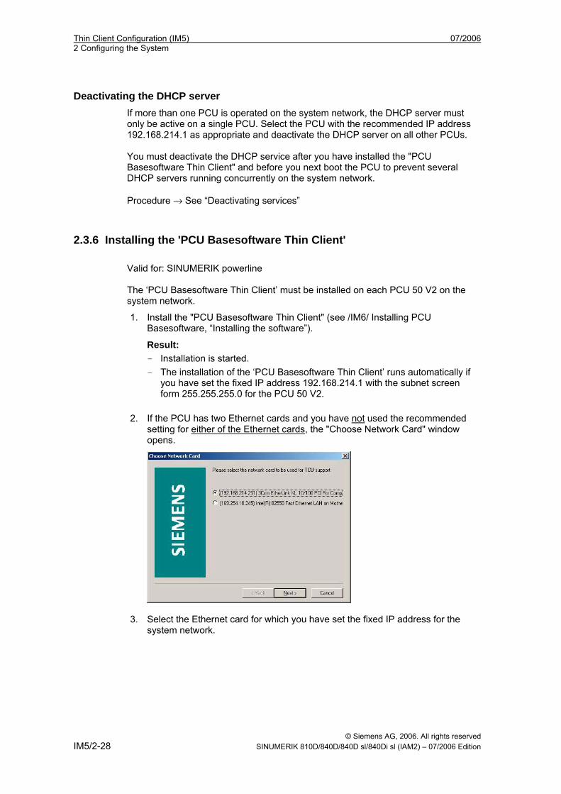
2. If the PCU has two Ethernet cards and you have not used the recommended
setting for either of the Ethernet cards, the "Choose Network Card" window opens.
3. Select the Ethernet card for which you have set the fixed IP address for the system network.
07/2006 Thin Client Configuration (IM5) 2 Configuring the System
© Siemens AG, 2006. All rights reserved SINUMERIK 810D/840D/840D sl/840Di sl (IAM2) – 07/2006 Edition IM5/2-29
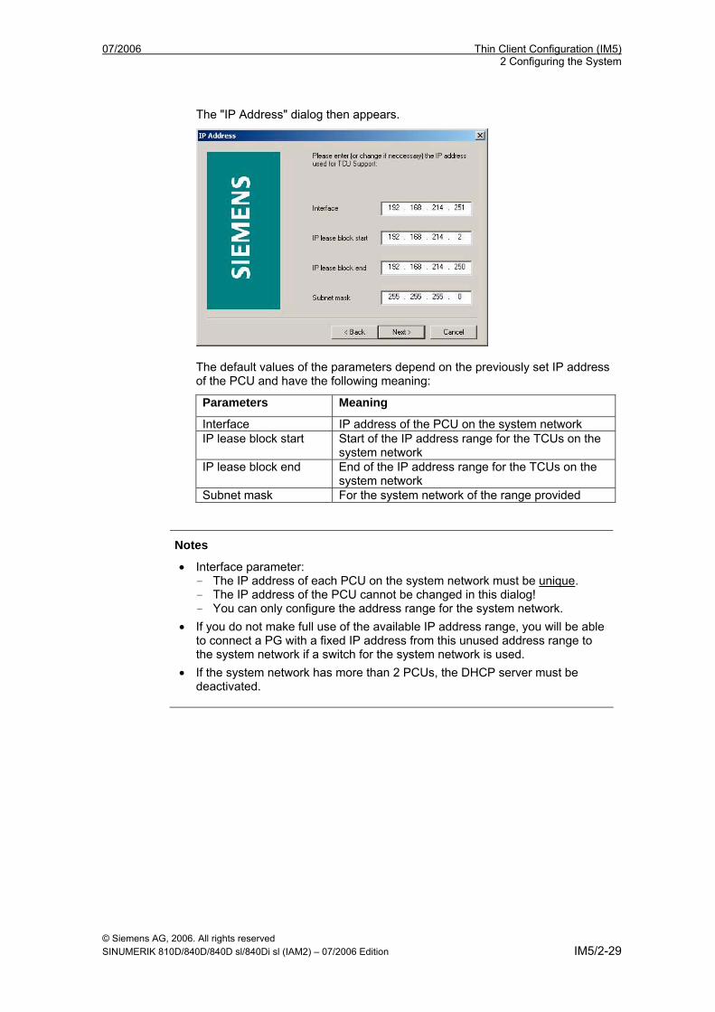
The "IP Address" dialog then appears.
The default values of the parameters depend on the previously set IP address of the PCU and have the following meaning:
Parameters Meaning
Interface IP address of the PCU on the system network IP lease block start Start of the IP address range for the TCUs on the
system network IP lease block end End of the IP address range for the TCUs on the
system network Subnet mask For the system network of the range provided
Notes
• Interface parameter: - The IP address of each PCU on the system network must be unique. - The IP address of the PCU cannot be changed in this dialog! - You can only configure the address range for the system network.
• If you do not make full use of the available IP address range, you will be able to connect a PG with a fixed IP address from this unused address range to the system network if a switch for the system network is used.
• If the system network has more than 2 PCUs, the DHCP server must be deactivated.
Thin Client Configuration (IM5) 07/2006 2 Configuring the System
© Siemens AG, 2006. All rights reserved IM5/2-30 SINUMERIK 810D/840D/840D sl/840Di sl (IAM2) – 07/2006 Edition
2.4 Configuring the System Network
2.4.1 Configuring the TCU and MCP Valid for: PCU Basesoftware as of V8.0 SP2 for powerline and solution line
Assign a name to the TCU Each TCU is declared in the system network:
1. Restart the TCU and the PCU with the active DHCP server so that the new settings are applied. After switch-on, the dialog box "Unknown/New TCU" opens on the TCU.
2. Select "New". The prompt "Please enter name of this TCU: TCU1" appears.
3. Change the proposed name if applicable and accept the entry using the <Input> key.
4. For an HT 8, confirm the "DIP..." name proposed by the system or adapt the name. You can select any other characters. Accept the entry using the <Input> key.
5. Follow the instructions: Press the <MENU SELECT> key or <F10>. Then you will receive the following input prompt:
TCU settings
MCP address: __
TCU Index: __
Enable direct keys: No
Ethernet connection: • For an Ethernet connection, the IP address of the MCP must be in the
range between 192.168.214.192 and 192.168.214.223. For the HT 8, the range between 192.168.214.1 and 192.168.214.191 is permitted.
• The TCU index is used to evaluate the direct keys. The values can range between 1 - 255. For an HT 8, the TCU index has no function.
• Direct keys can only be activated by appropriate devices. For an HT 8, if the traversing keys are activated as direct keys, the traversing keys are deactivated and vice versa.
MPI connection: For an MPI connection, the MPI address of the Machine Control Panel must be specified for "MCP Address". The two entries under "TCU Index" and "Enable Direct Keys" are not relevant.
07/2006 Thin Client Configuration (IM5) 2 Configuring the System
© Siemens AG, 2006. All rights reserved SINUMERIK 810D/840D/840D sl/840Di sl (IAM2) – 07/2006 Edition IM5/2-31
Making settings without an MCP via the MPI (not applicable to the HT 8) If a PCU or a TCU has no Machine Control Panel (MCP), you must set one of the two following options:
• MCP address = 0 or no entry After the change of focus, there is no switch-over of the machine control panel; the previously active MCP remains active.
• MCP address = 255 If the operator focus is transferred to this PCU or TCU, the previous machine control panel is deactivated and there is no active machine control panel from this point onwards.
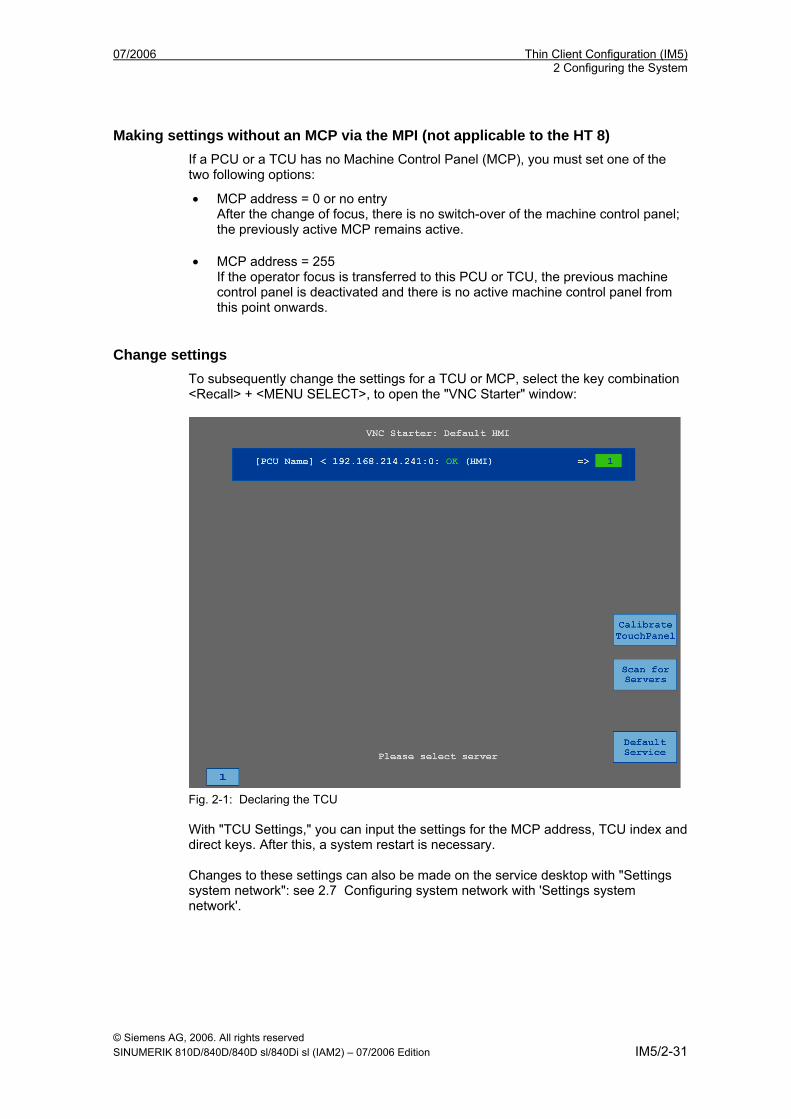
Change settings To subsequently change the settings for a TCU or MCP, select the key combination <Recall> + <MENU SELECT>, to open the "VNC Starter" window:
Fig. 2-1: Declaring the TCU With "TCU Settings," you can input the settings for the MCP address, TCU index and direct keys. After this, a system restart is necessary. Changes to these settings can also be made on the service desktop with "Settings system network": see 2.7 Configuring system network with 'Settings system network'.
Thin Client Configuration (IM5) 07/2006 2 Configuring the System
© Siemens AG, 2006. All rights reserved IM5/2-32 SINUMERIK 810D/840D/840D sl/840Di sl (IAM2) – 07/2006 Edition
Connecting a replacement TCU If a TCU is faulty and has to be replaced, you should proceed as follows:
1. Connect the new TCU.
The new TCU lists the TCUs on the system network along with their status “active” or “inactive”.
2. Select the name previously assigned to the faulty TCU from the “Unknown/New TCU” dialog. As a result, the new TCU is recognized on the network and acquires all of the configuration settings from the TCU that has been replaced.
2.4.2 Activating direct keys Valid for: PCU Basesoftware as of V8.0 SP2 only for solution line
Direct keys The signals from pressing the direct keys are sent directly to the PLC without delay. In the PLC, the keys appear as 16 digital inputs.
Definition: operator station The term operator station designates a unit that consists of an OP/TP, a TCU or PCU and a machine control panel (MCP), that are connected to each other via Ethernet. All TCUs and PCU 50.3 can be used along with OP/TP with "integrated TCU", e.g.: OP 08T, OP 015T, TP 015AT.
References For further information about the interface, please refer to: Function manual basic machine (P3 sl) PLC basic program solution line
07/2006 Thin Client Configuration (IM5) 2 Configuring the System
© Siemens AG, 2006. All rights reserved SINUMERIK 810D/840D/840D sl/840Di sl (IAM2) – 07/2006 Edition IM5/2-33
2.5 Configuring the HT 8 in the system network
2.5.1 Connecting the HT 8 (solution line)
Requirements for the HT 8 Two configurations are possible for SINUMERIK solution line: • HT 8 directly to NCU without PCU • HT 8 with NCU and PCU: Only one DHCP server may be active.
(See Subsection 2.3.2 Deactivating services). General sequence: • Switch the NCU on. • Connect HT8 up to a connection module • The name for the HT 8 is adopted by the DIP switch • Select address of machine control panel • Calibrate touch panel
Connect the HT8 up to an NCU The setting of the DIP switch from the terminal module is adopted. The response corresponds to a stationary MCP; the MAC address is no longer needed. The settings of the DIP switch from 192 - 223 correspond to the addresses 1 - 32 in the PLC.
Caution
The EMER STOP circuit is controlled via the EMER STOP button when the HT 8 is connected. If the connecting cable of the HT 8 is disconnected from the terminal box Basic PN, the EMER STOP circuit is interrupted. This leads to a reliable machine stop or an EMER STOP of the system to be monitored. The EMER STOP lines of the HT 8 are not monitored, but are placed directly on the EMER STOP circuit. For overriding the EMER STOP circuit when connecting or disconnecting the HT 8, there is a button or key switch.
Calibrating touch panel The calibration is automatically started after switching on. Follow the instructions on the screen and press the three calibration points one after the other. This completes the calibration.
Note
The calibration process on the HT 8 can also be alternatively started with the <U> key.
Thin Client Configuration (IM5) 07/2006 2 Configuring the System
© Siemens AG, 2006. All rights reserved IM5/2-34 SINUMERIK 810D/840D/840D sl/840Di sl (IAM2) – 07/2006 Edition
Assigning names for HT 8 You define a name for each HT 8 on the system network.
1. After the HT 8 is calibrated, the dialogue box "New TCU" opens. The setting of the DIP switch is detected and adopted as the name for the HT 8. The following message is output for this: "New TCU 'DIP 8' registered."
2. Follow the instructions: Press the <MENU SELECT> key or <F10>. Then you will receive the following input prompt:
TCU settings
MCP address: __
TCU Index: __
Enable direct keys: No
Select HT 8 mode No
The selection can be made with the cursor keypad on the HT 8.
For an HT 8, if the traversing keys are activated as direct keys, the traversing keys are deactivated and vice versa.
Select HT 8 mode The default setting for an HT 8 is that "individual" is deselected with "No", i.e. the "auto" mode is activated for automatic detection in the system network. The HT 8 is automatically detected based on its name "DIP_".
If "individual" is activated with "Yes", the HT 8 is identified by its MAC address on the system network.
HT 8 operated with the handwheel An HT 8 with a handwheel responds like an MCP 483C IE with a handwheel. The handwheel pulses are sent from the MCP image to the NCK.
Caution
The increments per revolution for a handwheel on a mobile HT 8 amount to 50 increments/revolution; for a stationary unit, it is 100 increments/revolution.
A different length of the traverse path results from this difference.
Additional information can be found in: Function manual basic machine (P3 sl) PLC basic program solution line /BHsl/ Equipment Manual Operator Components solution line
07/2006 Thin Client Configuration (IM5) 2 Configuring the System
© Siemens AG, 2006. All rights reserved SINUMERIK 810D/840D/840D sl/840Di sl (IAM2) – 07/2006 Edition IM5/2-35
2.5.2 Connecting the HT 8 (powerline)
Requirements for HT 8 with SINUMERIK powerline To start up the HT 8, 50.3 HMI-Advanced ≥ V07.02.00.00 must already have been installed on the PCU. A USB keyboard is also needed. General sequence: • Start the PCU in the service mode • Activate HT 8 on the PCU • Connect HT8 up to a connection module • The name for the HT 8 is adopted by the DIP switch • Select address of the MCP • Calibrate touch panel
Activating MSTT function Drivers are needed on the PCU to transfer the MCP signals by Ethernet. These are activated in the REGIE.INI file using the "HT8TCU" program. Start the program from "Start" → "Programs" → "SINUMERIK 840D" → "Tools" → "HT8TCU" and change the button over to "Enabled". The HT 8 is then connected e.g. to a SINUMERIK connection module basic PN. The DIP switch for setting the addresses of the machine control panel is integrated in the connection module. Other possible connections for the HT 8: See /BH/, Operator Components Equipment Manual for powerline
Assigning names for HT 8 You define a name for each HT 8 on the system network. Confirm the "DIP..." name proposed by the system or adapt the name. You can select any other characters. Accept the entry using the <Input> key.
Selecting address of Machine Control Panel (MCP) A system will propose an address depending on the DIP switch setting: Confirm this by pressing <Input> or enter another address. The range of addresses for the machine control panel is restricted to the values 1 to 15.
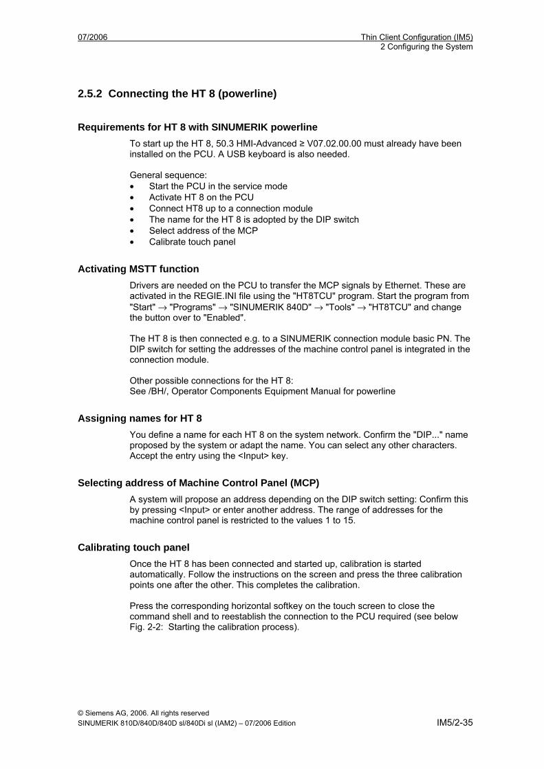
Calibrating touch panel Once the HT 8 has been connected and started up, calibration is started automatically. Follow the instructions on the screen and press the three calibration points one after the other. This completes the calibration. Press the corresponding horizontal softkey on the touch screen to close the command shell and to reestablish the connection to the PCU required (see below Fig. 2-2: Starting the calibration process).
Thin Client Configuration (IM5) 07/2006 2 Configuring the System
© Siemens AG, 2006. All rights reserved IM5/2-36 SINUMERIK 810D/840D/840D sl/840Di sl (IAM2) – 07/2006 Edition
The directory structure for the HT 8 is then set up on the PCU 50.3 just as it is for a TCU.
Example: F:\TCU\SERVICES\FTP_TCUS\DIP8\common\tcu\mcpaddr To perform another calibration during operations, press the keys <Recall> + <MENU SELECT> to start the command shell:
The vertical "Calibrate TouchPanel" softkey starts calibration.
Fig. 2-2: Starting the calibration process
2.5.3 Display/skip the inscriptions of the traversing keys
Requirement In order to display or skip the inscriptions of the traversing keys, the HT 8 must have operator focus.
Setting parameters for MSTT signals of HT 8 in the PLC HT 8-relevant modules in the PLC program are FB 1 for HT 8/PLC communication and FC 26 for NCK/PLC communication.
You will find a description of the PLC functions in: Function Manual Basic Machine, (P3 pl) PLC Basic Program powerline
07/2006 Thin Client Configuration (IM5) 2 Configuring the System
© Siemens AG, 2006. All rights reserved SINUMERIK 810D/840D/840D sl/840Di sl (IAM2) – 07/2006 Edition IM5/2-37
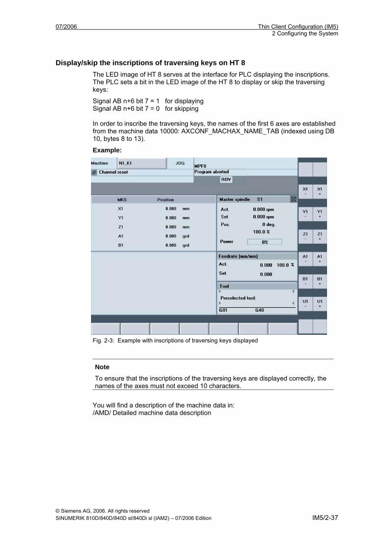
Display/skip the inscriptions of traversing keys on HT 8 The LED image of HT 8 serves at the interface for PLC displaying the inscriptions. The PLC sets a bit in the LED image of the HT 8 to display or skip the traversing keys:
Signal AB n+6 bit 7 = 1 for displaying Signal AB n+6 bit 7 = 0 for skipping In order to inscribe the traversing keys, the names of the first 6 axes are established from the machine data 10000: AXCONF_MACHAX_NAME_TAB (indexed using DB 10, bytes 8 to 13).
Example:
Fig. 2-3: Example with inscriptions of traversing keys displayed
Note
To ensure that the inscriptions of the traversing keys are displayed correctly, the names of the axes must not exceed 10 characters.
You will find a description of the machine data in: /AMD/ Detailed machine data description
Thin Client Configuration (IM5) 07/2006 2 Configuring the System
© Siemens AG, 2006. All rights reserved IM5/2-38 SINUMERIK 810D/840D/840D sl/840Di sl (IAM2) – 07/2006 Edition
Acknowledging display/skipping by HMI on PLC The HMI reports to the PLC whether the traversing keys are displayed or skipped. This is done using bit 7 in byte 72 of data block 10:
Displayed: DB10.DBX72.7 = 1 Skipped: DB10.DBX72.7 = 0
User keys The user keys (the 2 keys at the top and bottom) can be assigned in any way. Customized keys, which can be used to trigger a wide range of machine functions, are evaluated directly by the PLC program.
07/2006 Thin Client Configuration (IM5) 2 Configuring the System
© Siemens AG, 2006. All rights reserved SINUMERIK 810D/840D/840D sl/840Di sl (IAM2) – 07/2006 Edition IM5/2-39
2.6 Operating with an S7 CPU
2.6.1 Operating the HT 8 with an S7 CPU via PROFIBUS
Requirements To operate an HT 8 with an S7 CPU via PROFIBUS, the following supplementary conditions apply: • The PCU 50.3 with HMI Advanced ≥ V07.02.00.00 is connected via MPI or
BTSS to the S7-CPU. • MPP483 is connected via PROFIBUS to the S7 CPU.
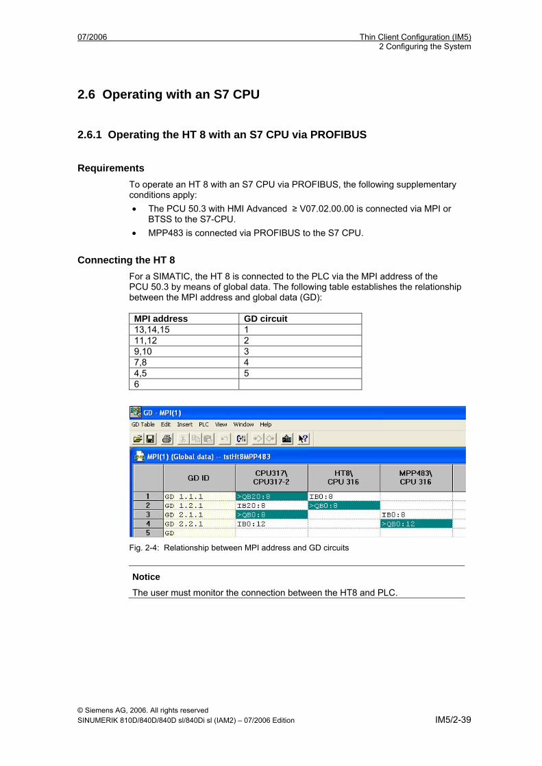
Connecting the HT 8 For a SIMATIC, the HT 8 is connected to the PLC via the MPI address of the PCU 50.3 by means of global data. The following table establishes the relationship between the MPI address and global data (GD): MPI address GD circuit 13,14,15 1 11,12 2 9,10 3 7,8 4 4,5 5 6
Fig. 2-4: Relationship between MPI address and GD circuits
Notice
The user must monitor the connection between the HT8 and PLC.
Thin Client Configuration (IM5) 07/2006 2 Configuring the System
© Siemens AG, 2006. All rights reserved IM5/2-40 SINUMERIK 810D/840D/840D sl/840Di sl (IAM2) – 07/2006 Edition
2.7 Configuring system network with 'Settings system network' Valid for: PCU 50.3 with Basesoftware from V8.0 SP1
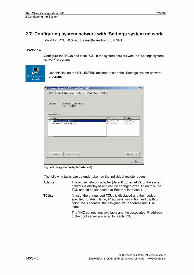
Overview Configure the TCUs and local PCU in the system network with the 'Settings system network' program.
Use this link on the SINUMERIK desktop to start the "Settings system network" program:
Fig. 2-5: Register "Adapter" (default)
The following tasks can be undertaken on the individual register pages:
Adapter: The active network adapter (default: Ethernet 2) for the system network is displayed and can be changed over. To do this, the TCU should be connected to Ethernet interface 1.
TCUs:
A list of the announced TCUs is displayed and their codes specified: Status, Name, IP address, resolution and depth of color, MAC address, the assigned MCP address and TCU index.
The VNC connections available and the associated IP address of the boot server are listed for each TCU.
07/2006 Thin Client Configuration (IM5) 2 Configuring the System
© Siemens AG, 2006. All rights reserved SINUMERIK 810D/840D/840D sl/840Di sl (IAM2) – 07/2006 Edition IM5/2-41
TCU support: The services needed to operate a TCU can be started, stopped and activated or deactivated.
TCU mode: Configuration of "Veto mode", resolution adjustment and the waiting times during booting (see Section 2.8 Making changes after commissioning).
DHCP settings: Configuration of the DHCP service: The IP address band and the boot server (TFTP) are defined.
PCU: The MCP address and PCU index are assigned to the PCU here.
Information on operation:
The data belonging to a TCU is reloaded in the display by pressing “Refresh view”.
Press “Apply” to accept the changed settings.
Select "Discard changes" to discard the changes.
Press “Exit” to exit the program (the dialog).
Register "Adapter" The status in which PCU is supplied is the default: Ethernet 2 for system network. The following statuses can be displayed:
The connection is selected and active. The connection is selected and not active because e.g. the TCU is not switched
on. The connection is not selected and cannot be accessed because e.g. no
network cables are plugged in.
If the user selects another adapter, acceptance of the new adapter must be confirmed by pressing “Apply”. The corresponding input is then transferred to the configuration files. The associated services are restarted and the result displayed.
Register "TCUs" The TCU can assume the following states:
The TCU is switched on and there is configuration data on the PCU. The TCU is switched on and there is no configuration data on the PCU. The TCU is switched off and there is configuration data on the PCU.
When a new name is entered for a TCU, the configuration data on the PCU is adapted accordingly. Press "Apply" to trigger a restart of all the TCUs and therefore to modify the configuration data.
Thin Client Configuration (IM5) 07/2006 2 Configuring the System
© Siemens AG, 2006. All rights reserved IM5/2-42 SINUMERIK 810D/840D/840D sl/840Di sl (IAM2) – 07/2006 Edition
The following configuration data of a TCU are selected here: • Rename Rename TCU • Remove: Delete inactive TCU • Reboot: Restart active TCU • DCK enable: Activate direct keys
(see Subsection 2.4.2 Activating Direct Keys IM5/2-32 • Assign MCP: Assign MCP identifier • Assign Index: Assign index identifier • VNC connections: Edit, delete, add VNC connection
"TCU support" register A standard configuration or the manual configuration can be selected from the "TCU support“ register page:
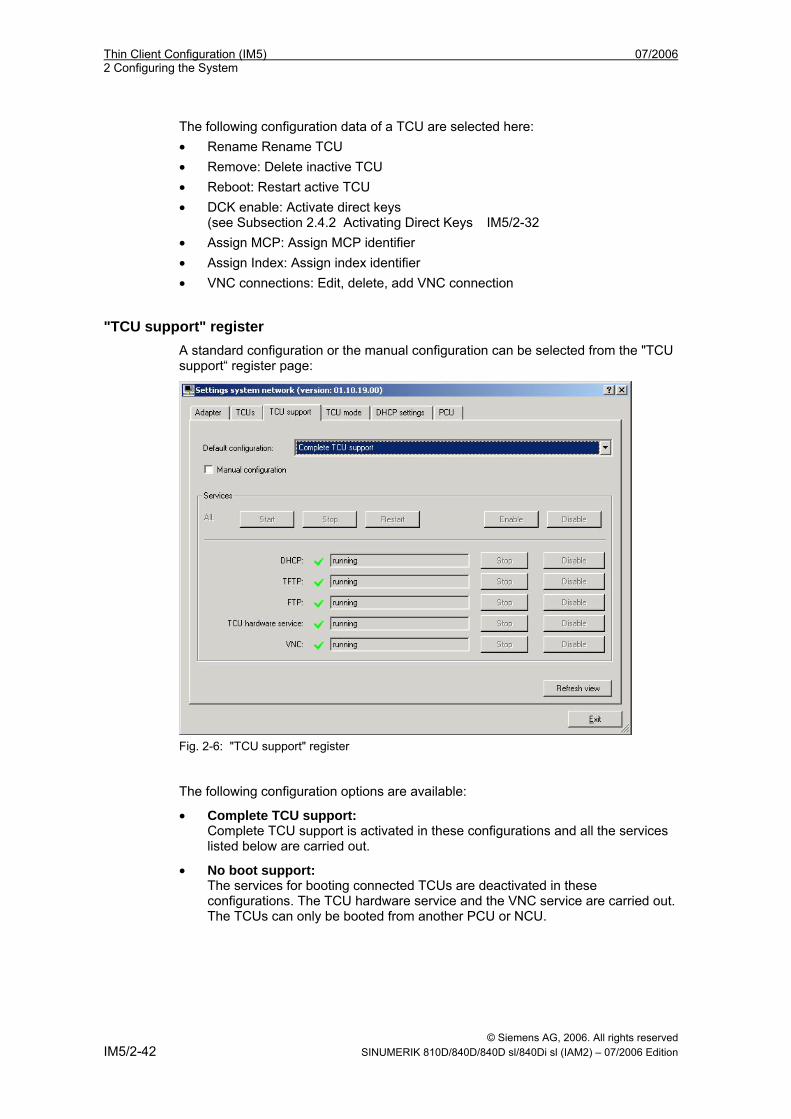
Fig. 2-6: "TCU support" register The following configuration options are available:
• Complete TCU support: Complete TCU support is activated in these configurations and all the services listed below are carried out.
• No boot support: The services for booting connected TCUs are deactivated in these configurations. The TCU hardware service and the VNC service are carried out. The TCUs can only be booted from another PCU or NCU.
07/2006 Thin Client Configuration (IM5) 2 Configuring the System
© Siemens AG, 2006. All rights reserved SINUMERIK 810D/840D/840D sl/840Di sl (IAM2) – 07/2006 Edition IM5/2-43
• Boot support runtime and configuration only (TFTP/FTP): DHCP services are deactivated in this configuration. The remaining services are carried out. The IP addresses of the connected TCUs must come from another PCU or NCU. Booting is however carried out from this PCU. To do this, the PCU or NCU supplying the IP addresses must use this PCU as the "boot server“.
• Boot support IP addresses only (DHCP): TFTP and FTP services are deactivated in this configuration. The remaining services are carried out.
The PCU provides the TCUs with IP addresses but the TCU must be booted by another PCU or NCU. A corresponding boot server must be specified for this purpose on the "DHCP settings" register page.
• Manual Configuration: With the manual configuration, each service can be started or stopped and activated or deactivated individually. The current status of the corresponding service is displayed in the status line.
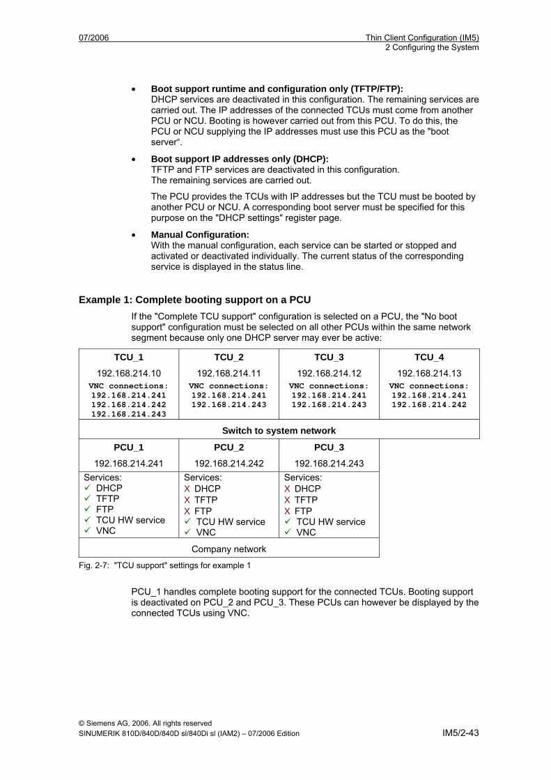
Example 1: Complete booting support on a PCU If the "Complete TCU support" configuration is selected on a PCU, the "No boot support" configuration must be selected on all other PCUs within the same network segment because only one DHCP server may ever be active:
TCU_1
192.168.214.10
TCU_2
192.168.214.11
TCU_3
192.168.214.12
TCU_4
192.168.214.13 VNC connections: 192.168.214.241 192.168.214.242 192.168.214.243
VNC connections: 192.168.214.241 192.168.214.243
VNC connections: 192.168.214.241 192.168.214.243
VNC connections: 192.168.214.241 192.168.214.242
Switch to system network
PCU_1
192.168.214.241
PCU_2
192.168.214.242
PCU_3
192.168.214.243 Services:
DHCP TFTP FTP TCU HW service VNC
Services: X DHCP X TFTP X FTP
TCU HW service VNC
Services: X DHCP X TFTP X FTP
TCU HW service VNC
Company network
Fig. 2-7: "TCU support" settings for example 1
PCU_1 handles complete booting support for the connected TCUs. Booting support is deactivated on PCU_2 and PCU_3. These PCUs can however be displayed by the connected TCUs using VNC.
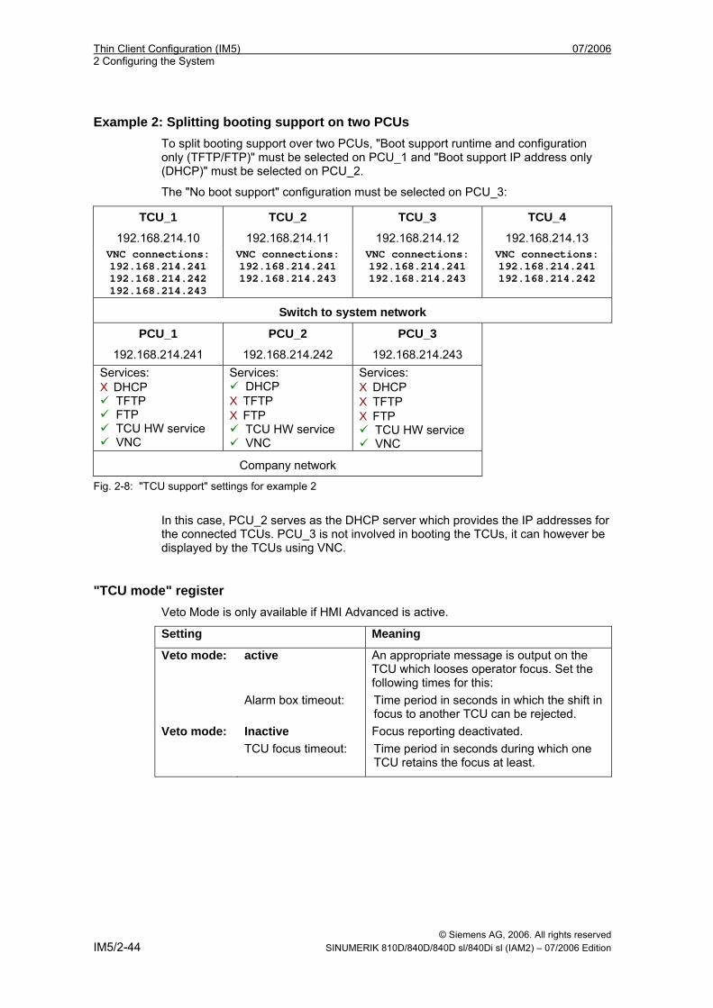
Thin Client Configuration (IM5) 07/2006 2 Configuring the System
© Siemens AG, 2006. All rights reserved IM5/2-44 SINUMERIK 810D/840D/840D sl/840Di sl (IAM2) – 07/2006 Edition
Example 2: Splitting booting support on two PCUs To split booting support over two PCUs, "Boot support runtime and configuration only (TFTP/FTP)" must be selected on PCU_1 and "Boot support IP address only (DHCP)" must be selected on PCU_2.
The "No boot support" configuration must be selected on PCU_3:
TCU_1
192.168.214.10
TCU_2
192.168.214.11
TCU_3
192.168.214.12
TCU_4
192.168.214.13 VNC connections: 192.168.214.241 192.168.214.242 192.168.214.243
VNC connections: 192.168.214.241 192.168.214.243
VNC connections: 192.168.214.241 192.168.214.243
VNC connections: 192.168.214.241 192.168.214.242
Switch to system network
PCU_1
192.168.214.241
PCU_2
192.168.214.242
PCU_3
192.168.214.243 Services: X DHCP
TFTP FTP TCU HW service VNC
Services: DHCP
X TFTP X FTP
TCU HW service VNC
Services: X DHCP X TFTP X FTP
TCU HW service VNC
Company network
Fig. 2-8: "TCU support" settings for example 2
In this case, PCU_2 serves as the DHCP server which provides the IP addresses for the connected TCUs. PCU_3 is not involved in booting the TCUs, it can however be displayed by the TCUs using VNC.
"TCU mode" register Veto Mode is only available if HMI Advanced is active.
Setting Meaning
Veto mode: active Alarm box timeout:
An appropriate message is output on the TCU which looses operator focus. Set the following times for this: Time period in seconds in which the shift in focus to another TCU can be rejected.
Veto mode: Inactive TCU focus timeout:
Focus reporting deactivated. Time period in seconds during which one TCU retains the focus at least.
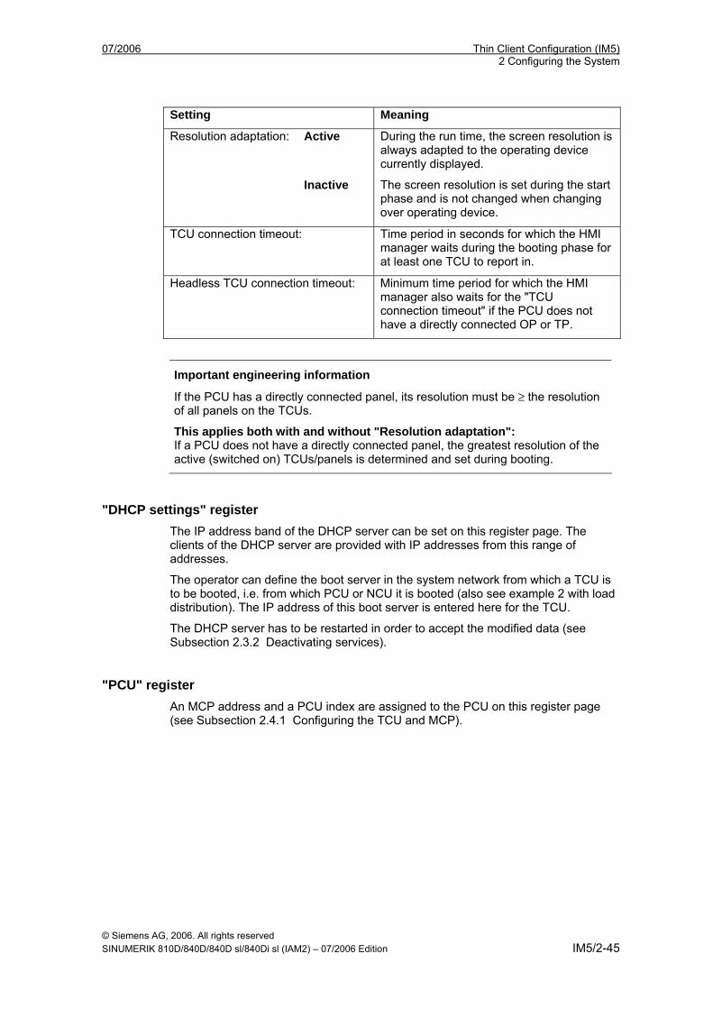
07/2006 Thin Client Configuration (IM5) 2 Configuring the System
© Siemens AG, 2006. All rights reserved SINUMERIK 810D/840D/840D sl/840Di sl (IAM2) – 07/2006 Edition IM5/2-45
Setting Meaning
Resolution adaptation: Active During the run time, the screen resolution is always adapted to the operating device currently displayed.
Inactive The screen resolution is set during the start phase and is not changed when changing over operating device.
TCU connection timeout:
Time period in seconds for which the HMI manager waits during the booting phase for at least one TCU to report in.
Headless TCU connection timeout: Minimum time period for which the HMI manager also waits for the "TCU connection timeout" if the PCU does not have a directly connected OP or TP.
Important engineering information
If the PCU has a directly connected panel, its resolution must be ≥ the resolution of all panels on the TCUs.
This applies both with and without "Resolution adaptation": If a PCU does not have a directly connected panel, the greatest resolution of the active (switched on) TCUs/panels is determined and set during booting.
"DHCP settings" register The IP address band of the DHCP server can be set on this register page. The clients of the DHCP server are provided with IP addresses from this range of addresses.
The operator can define the boot server in the system network from which a TCU is to be booted, i.e. from which PCU or NCU it is booted (also see example 2 with load distribution). The IP address of this boot server is entered here for the TCU.
The DHCP server has to be restarted in order to accept the modified data (see Subsection 2.3.2 Deactivating services).
"PCU" register An MCP address and a PCU index are assigned to the PCU on this register page (see Subsection 2.4.1 Configuring the TCU and MCP).
Thin Client Configuration (IM5) 07/2006 2 Configuring the System
© Siemens AG, 2006. All rights reserved IM5/2-46 SINUMERIK 810D/840D/840D sl/840Di sl (IAM2) – 07/2006 Edition
2.8 Making changes after commissioning
Overview If you want to change any settings you have made after completing installation of the TCU, you must make those changes directly in the configuration files (see Section 2.2 File structure on PCUs and NCUs).
Changing the IP address of the PCU Example: The fixed IP address of the PCU should be 167.142.117.8 with subnet screen form 255.255.255.0. File: F:\TCU\SERVICES\TCU_HWS\ETC\TCU_HWS.CONF Entry: interface 167.142.117.8 File: F:\TCU\SERVICES\NETKIT-TFTPD\ETC\NETKIT-TFTPD.CONF Entry: interface 167.142.117.8 File: F:\TCU\SERVICES\BETAFTPD\ETC\BETAFTPD.CONF Entry: interface 167.142.117.8 File: F:\TCU\SERVICES\UDHCPD\ETC\UDHCPD.CONF Entry: interface 167.142.117.8 Entry: start 167.142.117.9 Entry: end 167.142.117.250 Entry: siaddr 167.142.117.8 Entry: option subnet 255.255.255.0 The IP address for ‘interface’ must be the same as the server IP address ‘siaddr’!
Changing the address range of TCUs Example: The address range for the TCUs should be 167.142.117.9 through 167.142.117.250. File: F:\TCU\SERVICES\UDHCPD\ETC\UDHCPD.CONF Entry: start 167.142.117.9 Entry: end 167.142.117.250
Changing the address of the MCP See "Setting the address of the MCP"
Changing the name of the TCU • Delete directory F:\TCU\SERVICES\FTP_TCUS\TCUx from the file structure on
every PCU on the system network (see “Assigning names to the TCUs”). • Alternatively: Open file MACADDR and change the name of the TCU in the file.
Next adapt the directory name TCUx.
07/2006 Thin Client Configuration (IM5) 2 Configuring the System
© Siemens AG, 2006. All rights reserved SINUMERIK 810D/840D/840D sl/840Di sl (IAM2) – 07/2006 Edition IM5/2-47
Declaring PCUs subsequently See "Declaring PCUs"
Removing a TCU from the system network Delete directory F:\TCU\SERVICES\FTP_TCUS\TCUx and the file with the MAC address from the file structure on every PCU on the system network.
Removing a PCU from the system network Delete the entry for the PCU in file F:\TCU\SERVICES\FTP_TCUS\TCUx\common\tcu\config on the PCU with the active DHCP server for each TCU.
Booting the PCU on the SINUMERIK desktop (“Headless” operation) When booting, the PCU waits until it connects to a TCU or an OP. This delay on the PCU (so-called “Headless” operation) can be set in the file tcu.ini. The system waits until the maximum possible number of TCUs that connected in the last session have re-connected before displaying the time window to press key <3>. This timeout is the time interval, which is set in the default parameter file or in the user-specific parameter file TCU.INI via “TCUConnectTimeout” (see 2.2 File structure on PCUs and NCUs). In the case of a “headless PCU”, if no TCU has connected to the PCU once this time has elapsed, the system continues to wait until at least one TCU has connected. The timeout here is the time interval, which is set in the default parameter file or in the user-specific parameter file tcu.ini via “HeadlessTCUConnectTimeout”. [TCU_HWSService] # TCU CONNECT TIMEOUT # Guaranteed time period (in sec) the HMI manager waits for # TCUs recognized as connected TCUs by the TCU_HWS service. TCUConnectTimeout=30 # TCU CONNECT TIMEOUT FOR HEADLESS STARTUP # Guaranteed time period (in sec) the HMI manager waits for # TCUs recognized as connected TCUs by the TCU_HWS service, # if a PCU panel doesn't exist and no TCUs are connected # till now. This time period is effective additionally to # the time period TCUConnectTimeout. HeadlessTCUConnectTimeout=30
Note
The SINUMERIK desktop can also be launched by pressing key <3> within 3 seconds of the version details of the PCU Basesoftware appearing in the background when booting.
Thin Client Configuration (IM5) 07/2006 2 Configuring the System
© Siemens AG, 2006. All rights reserved IM5/2-48 SINUMERIK 810D/840D/840D sl/840Di sl (IAM2) – 07/2006 Edition
2.9 Disabling switch-over between TCUs via PLC n When using HMI Advanced, the TCU switchover disable offers the option of dynamically disabling the switchover from one TCU to the next when the system is running by means of the PLC. For the duration of the disable, a user authorization request to change user authorizations between TCUs will be ignored by the system and rejected. The rejected user authorization request leads to a message being output in the user response line of the HMI, in the form of a checkback signal for the requester. The message disappears after five seconds.
HMI/PLC data interface The “switchover disable” function is always active in HMI Advanced and does not have to be switched on explicitly. The function is controlled by a data bit DBX in the PLC. The HMI transfers the active OP to the PLC, thus forming the basis of the control function in the PLC. The control bits and control information for this function are stored in the m:n data interface of the PLC. In terms of m:n, this function can be operated separately for the currently overridden HMIs in both m:n online interfaces (DB19.DBW120 ff for HMI1 and DB19.DBW130 ff for HMI2). If a system is not running an m:n, only the first m:n online interface is used for this function. Switchover disable is controlled by a TCU_SHIFT_LOCK bit, managed by the user, on each HMI in the PLC. The bit address for the first HMI is DB19.DBB126.6 and DB19.DBB136.6 for the second HMI. The PLC m:n online interface is expanded so that byte DB19.DBB118 is still added to the first interface and byte DB19.DBB119 to the second. These bytes acquire the index of the active TCU (of the active OP) for the appropriate HMI. The byte is called TCU_INDEX. The appropriate HMI uses the TCU index configured for the active TCU to describe the TCU_INDEX byte (see “Configuring”). The TCU_SHIFT_LOCK bit is monitored by the appropriate HMI. A value = 1 triggers the switchover disable; switchover is enabled if the value returns to 0. The TCU_SHIFT_LOCK bit can be set, for example, to the PLC by the user pressing a key or it can be managed by the PLC user program according to its own logic. The TCU_SHIFT_LOCK bit is managed in the PLC exclusively by the user; the HMI only accesses this bit in read-only mode. The HMI assigns the configured index of the TCU or PCU whose OP currently possesses user authorization in the shadow grouping to the TCU_INDEX field. If no OP is active, a value of 0 is entered in TCU_INDEX. If no TCU index is configured for the active TCU (active OP), the value 255 = undefined is presented as the TCU index. This means that the values 0 and 255 may not be configured as the TCU index.
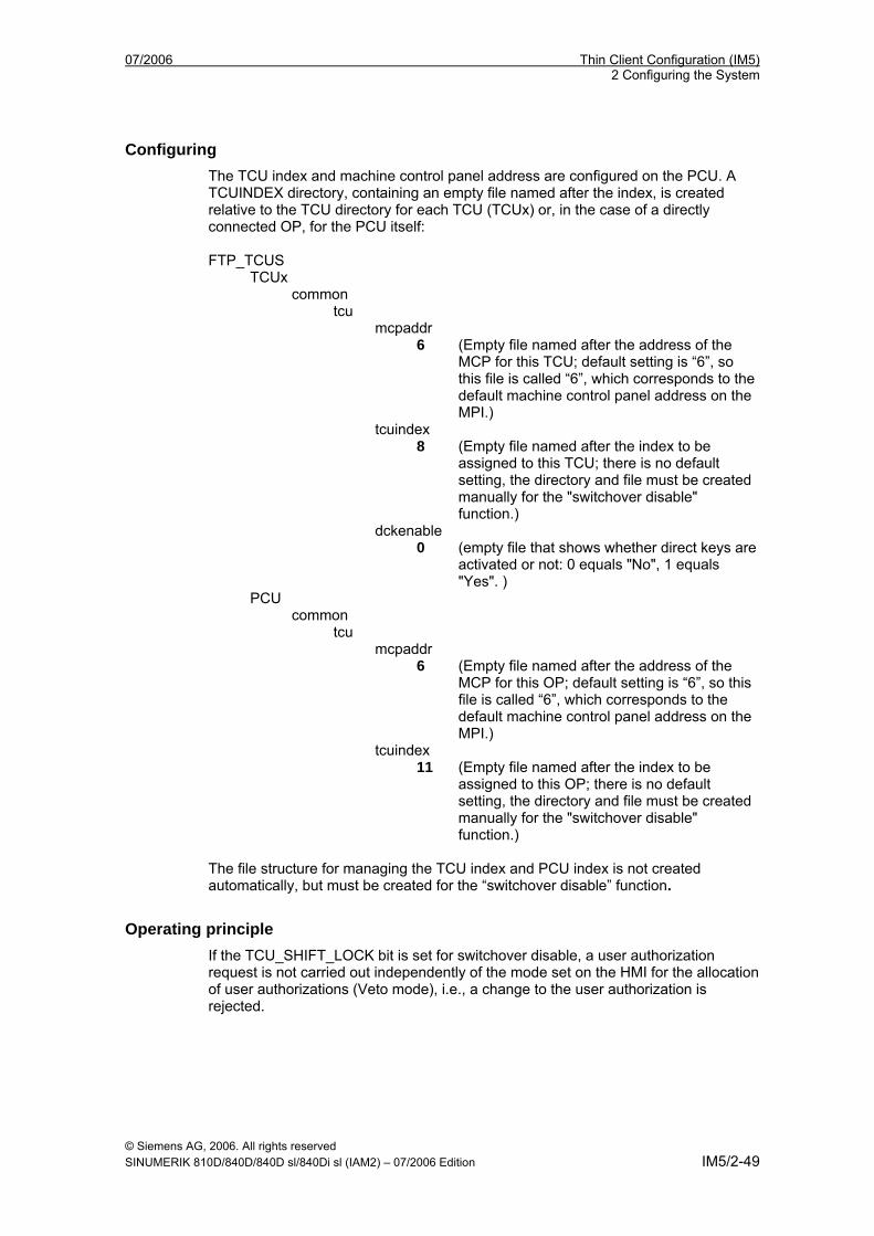
07/2006 Thin Client Configuration (IM5) 2 Configuring the System
© Siemens AG, 2006. All rights reserved SINUMERIK 810D/840D/840D sl/840Di sl (IAM2) – 07/2006 Edition IM5/2-49
Configuring The TCU index and machine control panel address are configured on the PCU. A TCUINDEX directory, containing an empty file named after the index, is created relative to the TCU directory for each TCU (TCUx) or, in the case of a directly connected OP, for the PCU itself: FTP_TCUS TCUx common tcu mcpaddr 6 (Empty file named after the address of the
MCP for this TCU; default setting is “6”, so this file is called “6”, which corresponds to the default machine control panel address on the MPI.)
tcuindex 8 (Empty file named after the index to be
assigned to this TCU; there is no default setting, the directory and file must be created manually for the "switchover disable" function.)
dckenable 0 (empty file that shows whether direct keys are
activated or not: 0 equals "No", 1 equals "Yes". )
PCU common tcu mcpaddr 6 (Empty file named after the address of the
MCP for this OP; default setting is “6”, so this file is called “6”, which corresponds to the default machine control panel address on the MPI.)
tcuindex 11 (Empty file named after the index to be
assigned to this OP; there is no default setting, the directory and file must be created manually for the "switchover disable" function.)
The file structure for managing the TCU index and PCU index is not created automatically, but must be created for the “switchover disable” function.
Operating principle If the TCU_SHIFT_LOCK bit is set for switchover disable, a user authorization request is not carried out independently of the mode set on the HMI for the allocation of user authorizations (Veto mode), i.e., a change to the user authorization is rejected.
Thin Client Configuration (IM5) 07/2006 2 Configuring the System
© Siemens AG, 2006. All rights reserved IM5/2-50 SINUMERIK 810D/840D/840D sl/840Di sl (IAM2) – 07/2006 Edition
This message appears on all OPs, for approximately 5 seconds: "No switchover: Switchover disable set in current PLC“, while operations on the OP with the user authorization can still be carried out unaffected.
Note
The switchover disable only relates to changing the user authorization on the OPs on a PCU in a network. Active switching from one OP to another PCU is not prevented.
Special points to be noted • Even if switchover disable is set, the TCU_INDEX field value may change in the
PLC. This is the case if:
− The OP in possession of the user authorization is actively switched to another PCU. Depending on whether another TCU takes on the user authorization or no TCU is currently active, either the index of the TCU (as when user authorizations are switched over) or the PCU itself (if its directly connected OP becomes active) is entered.
This may also be the value 255, if no TCU index is available for the OP. 0 is entered if an OP is no longer available in the shadow grouping.
− An m:n switchover is in progress. The HMI of the incoming PCU deactivates the HMI, which is active on it. An OP from the shadow grouping of the new (incoming) PCU must receive the user authorization. The TCU index of this OP is entered in the TCU_INDEX field.
− A PCU is disconnected from a NCK/PLC in the context of m:n. No HMI and, therefore, no OP with operator focus is then available on the exited NCK/PLC. This is signaled independently of a switchover disable by entering the value 0 into the TCU_INDEX field.
• If a TCU is actively switched over to another PCU, it can be deactivated there, i.e., it does not obtain the user authorization, if a switchover disable is set for the destination PCU.
• With an m:n PCU switchover, i.e., the PCU is switched to another NCK and, therefore, to another PLC, the PCU takes on the switchover disable settings of that PLC.
• The m:n interlock options on the PLC side have priority over the TCU switchover disable, so that a set TCU switchover disable cannot prevent an m:n switchover. If necessary, the m:n interference options should be synchronized here with those for the TCU in the PLC. It may, for example, be practical to set or remove the m:n displacement disable simultaneously with the TCU switchover disable.
07/2006 Thin Client Configuration (IM5) 3 Configuring Network Operation
© Siemens AG, 2006. All rights reserved SINUMERIK 810D/840D/840D sl/840Di sl (IAM2) – 07/2006 Edition IM5/3-51
3 Configuring Network Operation (SINUMERIK powerline)
3.1 Configurations without connecting the PCU to a company network ..................................................................... IM5/3-54 3.1.1 1:(1:1) without company network........................................... IM5/3-54 3.1.2 1:(1:n) without company network........................................... IM5/3-55 3.1.3 1:(m:1) without company network.......................................... IM5/3-56 3.1.4 t:(1:1) without company network............................................ IM5/3-58 3.1.5 Connecting the programming device to the system network ...................................................................... IM5/3-60 3.1.6 t:(1:n) without company network............................................ IM5/3-61
3.2 Configurations with PCU connected to a company network .... IM5/3-62 3.2.1 1:(1:1) with company network................................................ IM5/3-62 3.2.2 1:(1:n) with company network................................................ IM5/3-65 3.2.3 1:(m:1) with company network............................................... IM5/3-68 3.2.4 t:(1:1) with company network................................................. IM5/3-71 3.2.5 t:(1:n) with company network................................................. IM5/3-74
3

Thin Client Configuration (IM5) 07/2006 3 Configuring Network Operation
© Siemens AG, 2006. All rights reserved IM5/3-52 SINUMERIK 810D/840D/840D sl/840Di sl (IAM2) – 07/2006 Edition
07/2006 Thin Client Configuration (IM5) 3 Configuring Network Operation
© Siemens AG, 2006. All rights reserved SINUMERIK 810D/840D/840D sl/840Di sl (IAM2) – 07/2006 Edition IM5/3-53
Overview The various configurations for operating a TCU on a PCU are described in this chapter. Included in this description are m:n configurations of control unit management for the SINUMERIK powerline, which can provide the basis for operation with the TCU. The m:n functionality is configured on the PCUs for each relevant HMI in the usual way. No changes result from operation with the TCU. The individual configurations are designated as follows: t:(m:n) t = Number of TCUs on a system network m = Number of PCUs or active HMIs on them on a system network n = Number of NCUs The brackets express how the PCUs are operated on the NCUs. The expression (m:1) means that there are m PCUs each of which is assigned its own NCU. Consequently (m:n) means that m PCUs can be connected via n NCUs according to the rules of control unit management. The integrated Ethernet interface is used for operation without a company network. An additional integrated Ethernet interface is used with the system network to operate the TCU in the event of connection to a company network. Colors and symbols:
Integrated Ethernet interface of the PCU 50 V2 (DHCP client)
Additional Ethernet interface of the PCU 50 V2 (DHCP server)
Additional Ethernet interface with a fixed IP address Green connection Uncrossed Ethernet cable Gray connection Crossed Ethernet cable (crossover) Only the hardware required to connect the components (cable, switch) is listed under "Hardware requirements". As it is of no relevance to the configuration options whether an MCP is linked to a TCU with its OP, the MCP is not represented in the figures. Nor is it of any relevance to this description whether a separate OP is connected directly to a PCU or not. Consequently, such a scenario can also be disregarded.
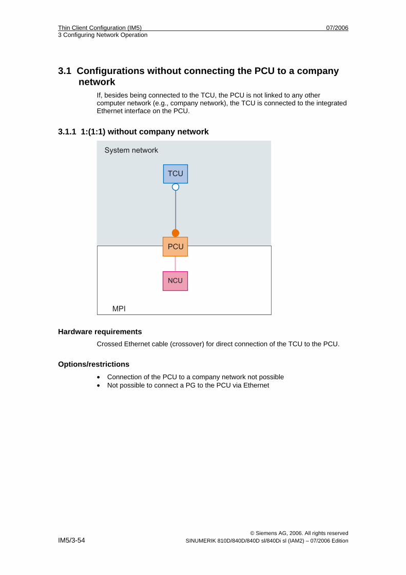
Thin Client Configuration (IM5) 07/2006 3 Configuring Network Operation
© Siemens AG, 2006. All rights reserved IM5/3-54 SINUMERIK 810D/840D/840D sl/840Di sl (IAM2) – 07/2006 Edition
3.1 Configurations without connecting the PCU to a company network
If, besides being connected to the TCU, the PCU is not linked to any other computer network (e.g., company network), the TCU is connected to the integrated Ethernet interface on the PCU.
3.1.1 1:(1:1) without company network
Hardware requirements Crossed Ethernet cable (crossover) for direct connection of the TCU to the PCU.
Options/restrictions • Connection of the PCU to a company network not possible • Not possible to connect a PG to the PCU via Ethernet
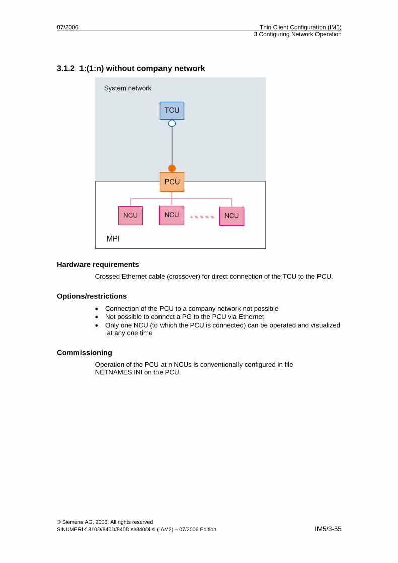
07/2006 Thin Client Configuration (IM5) 3 Configuring Network Operation
© Siemens AG, 2006. All rights reserved SINUMERIK 810D/840D/840D sl/840Di sl (IAM2) – 07/2006 Edition IM5/3-55
3.1.2 1:(1:n) without company network
Hardware requirements Crossed Ethernet cable (crossover) for direct connection of the TCU to the PCU.
Options/restrictions • Connection of the PCU to a company network not possible • Not possible to connect a PG to the PCU via Ethernet • Only one NCU (to which the PCU is connected) can be operated and visualized
at any one time
Commissioning Operation of the PCU at n NCUs is conventionally configured in file NETNAMES.INI on the PCU.
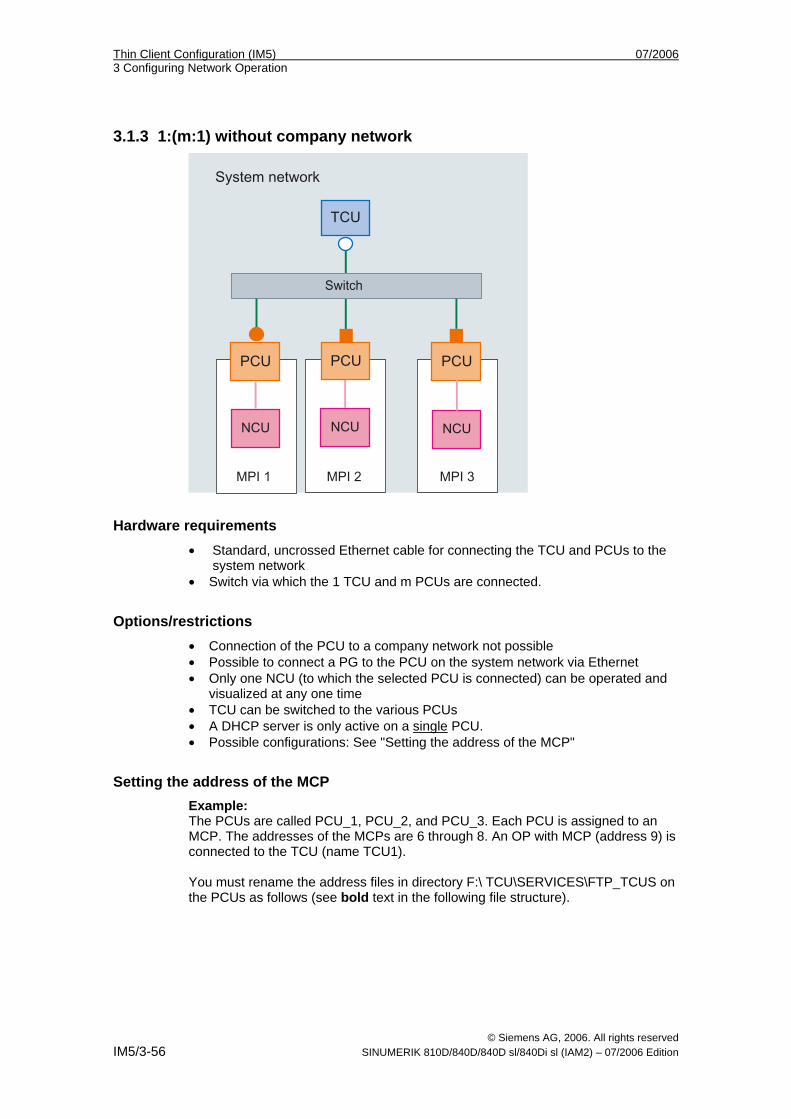
Thin Client Configuration (IM5) 07/2006 3 Configuring Network Operation
© Siemens AG, 2006. All rights reserved IM5/3-56 SINUMERIK 810D/840D/840D sl/840Di sl (IAM2) – 07/2006 Edition
3.1.3 1:(m:1) without company network
Hardware requirements • Standard, uncrossed Ethernet cable for connecting the TCU and PCUs to the
system network • Switch via which the 1 TCU and m PCUs are connected.
Options/restrictions • Connection of the PCU to a company network not possible • Possible to connect a PG to the PCU on the system network via Ethernet • Only one NCU (to which the selected PCU is connected) can be operated and
visualized at any one time • TCU can be switched to the various PCUs • A DHCP server is only active on a single PCU. • Possible configurations: See "Setting the address of the MCP"
Setting the address of the MCP
Example: The PCUs are called PCU_1, PCU_2, and PCU_3. Each PCU is assigned to an MCP. The addresses of the MCPs are 6 through 8. An OP with MCP (address 9) is connected to the TCU (name TCU1). You must rename the address files in directory F:\ TCU\SERVICES\FTP_TCUS on the PCUs as follows (see bold text in the following file structure).
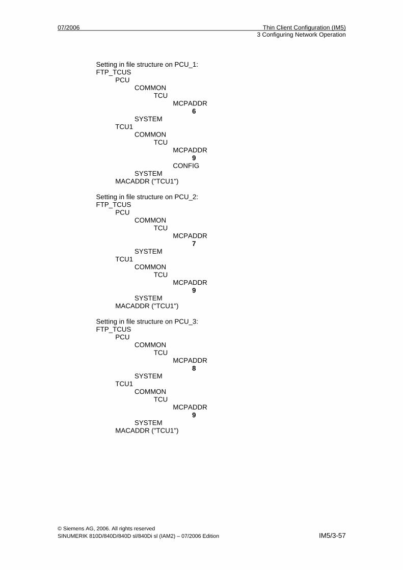
07/2006 Thin Client Configuration (IM5) 3 Configuring Network Operation
© Siemens AG, 2006. All rights reserved SINUMERIK 810D/840D/840D sl/840Di sl (IAM2) – 07/2006 Edition IM5/3-57
Setting in file structure on PCU_1: FTP_TCUS PCU COMMON TCU MCPADDR 6 SYSTEM TCU1 COMMON TCU MCPADDR 9 CONFIG SYSTEM MACADDR ("TCU1") Setting in file structure on PCU_2: FTP_TCUS PCU COMMON TCU MCPADDR 7 SYSTEM TCU1 COMMON TCU MCPADDR 9 SYSTEM MACADDR ("TCU1") Setting in file structure on PCU_3: FTP_TCUS PCU COMMON TCU MCPADDR 8 SYSTEM TCU1 COMMON TCU MCPADDR 9 SYSTEM MACADDR ("TCU1")
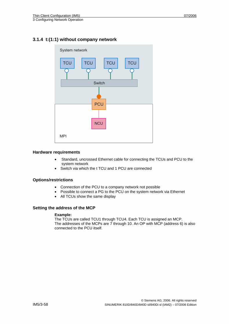
Thin Client Configuration (IM5) 07/2006 3 Configuring Network Operation
© Siemens AG, 2006. All rights reserved IM5/3-58 SINUMERIK 810D/840D/840D sl/840Di sl (IAM2) – 07/2006 Edition
3.1.4 t:(1:1) without company network
Hardware requirements • Standard, uncrossed Ethernet cable for connecting the TCUs and PCU to the
system network • Switch via which the t TCU and 1 PCU are connected
Options/restrictions • Connection of the PCU to a company network not possible • Possible to connect a PG to the PCU on the system network via Ethernet • All TCUs show the same display
Setting the address of the MCP Example: The TCUs are called TCU1 through TCU4. Each TCU is assigned an MCP. The addresses of the MCPs are 7 through 10. An OP with MCP (address 6) is also connected to the PCU itself.
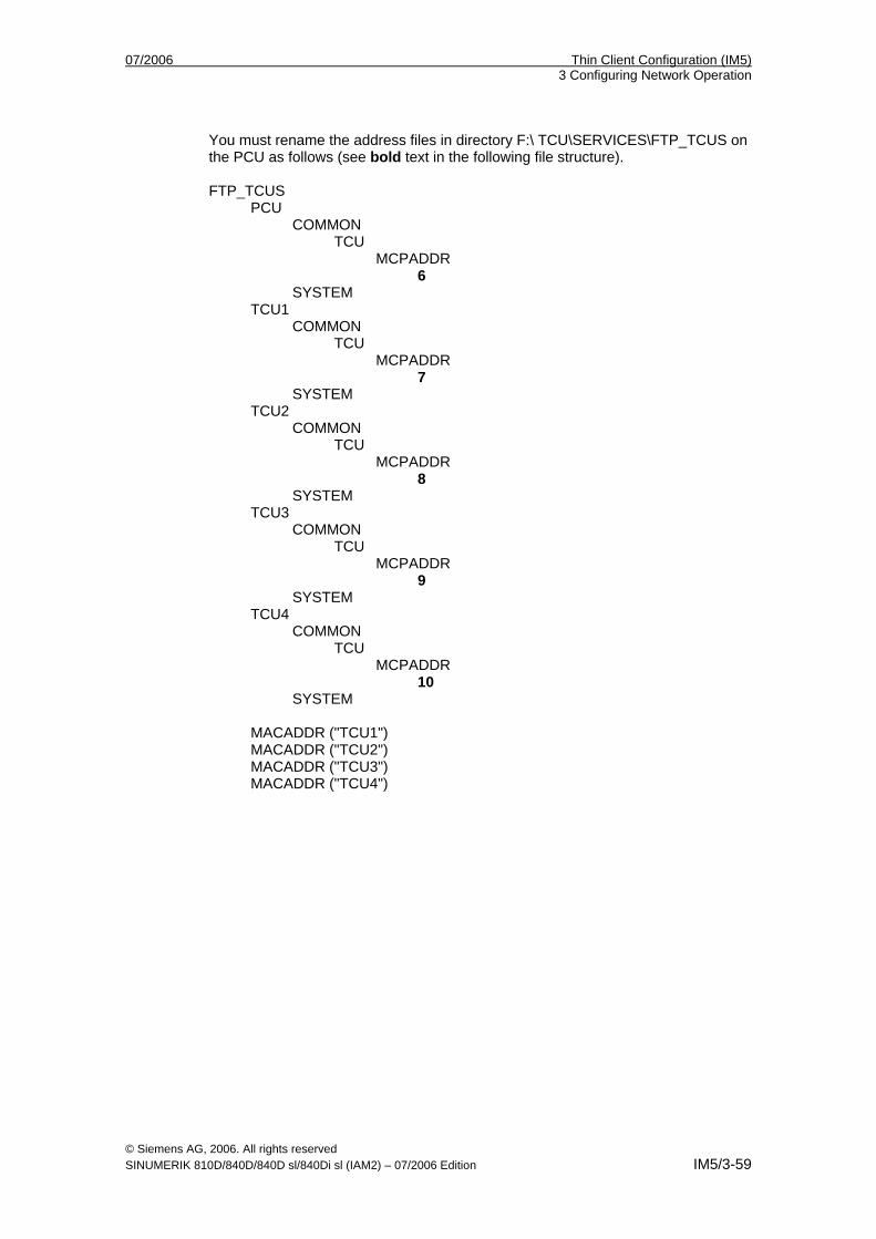
07/2006 Thin Client Configuration (IM5) 3 Configuring Network Operation
© Siemens AG, 2006. All rights reserved SINUMERIK 810D/840D/840D sl/840Di sl (IAM2) – 07/2006 Edition IM5/3-59
You must rename the address files in directory F:\ TCU\SERVICES\FTP_TCUS on the PCU as follows (see bold text in the following file structure). FTP_TCUS PCU COMMON TCU MCPADDR 6 SYSTEM TCU1 COMMON TCU MCPADDR 7 SYSTEM TCU2 COMMON TCU MCPADDR 8 SYSTEM TCU3 COMMON TCU MCPADDR 9 SYSTEM TCU4 COMMON TCU MCPADDR 10 SYSTEM MACADDR ("TCU1") MACADDR ("TCU2") MACADDR ("TCU3") MACADDR ("TCU4")
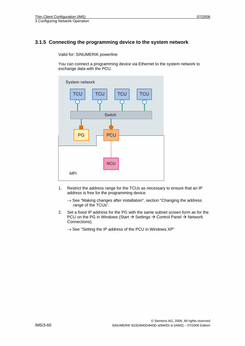
Thin Client Configuration (IM5) 07/2006 3 Configuring Network Operation
© Siemens AG, 2006. All rights reserved IM5/3-60 SINUMERIK 810D/840D/840D sl/840Di sl (IAM2) – 07/2006 Edition
3.1.5 Connecting the programming device to the system network Valid for: SINUMERIK powerline You can connect a programming device via Ethernet to the system network to exchange data with the PCU.
1. Restrict the address range for the TCUs as necessary to ensure that an IP
address is free for the programming device.
→ See “Making changes after installation”, section “Changing the address range of the TCUs”.
2. Set a fixed IP address for the PG with the same subnet screen form as for the PCU on the PG in Windows (Start Settings Control Panel Network Connections).
→ See "Setting the IP address of the PCU in Windows XP"
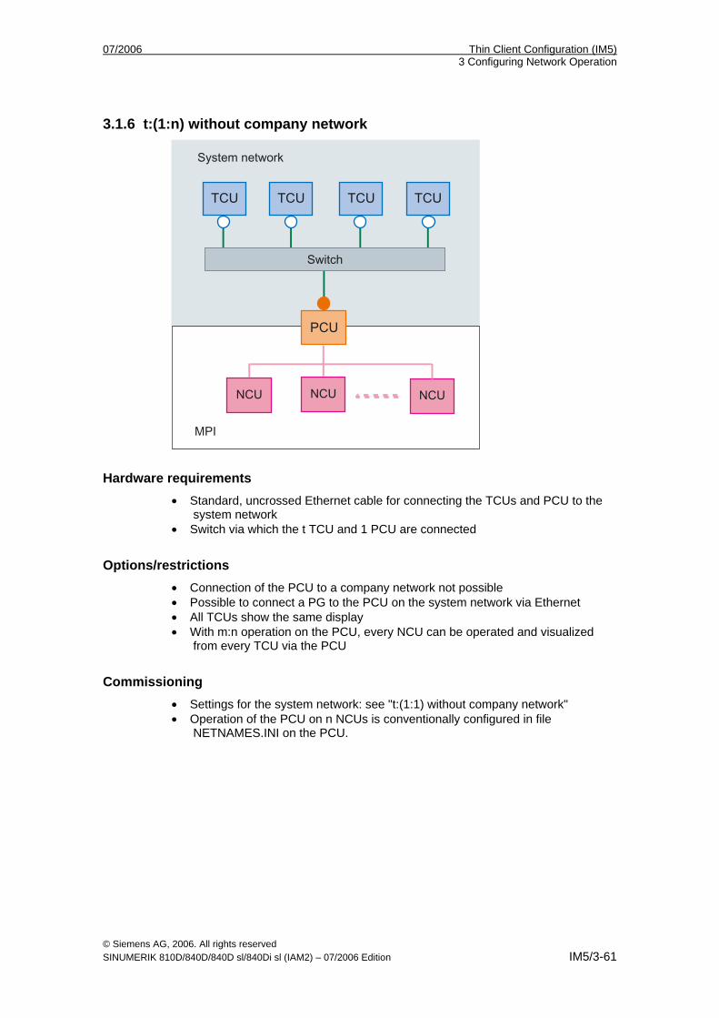
07/2006 Thin Client Configuration (IM5) 3 Configuring Network Operation
© Siemens AG, 2006. All rights reserved SINUMERIK 810D/840D/840D sl/840Di sl (IAM2) – 07/2006 Edition IM5/3-61
3.1.6 t:(1:n) without company network
Hardware requirements • Standard, uncrossed Ethernet cable for connecting the TCUs and PCU to the
system network • Switch via which the t TCU and 1 PCU are connected
Options/restrictions • Connection of the PCU to a company network not possible • Possible to connect a PG to the PCU on the system network via Ethernet • All TCUs show the same display • With m:n operation on the PCU, every NCU can be operated and visualized
from every TCU via the PCU
Commissioning • Settings for the system network: see "t:(1:1) without company network" • Operation of the PCU on n NCUs is conventionally configured in file
NETNAMES.INI on the PCU.
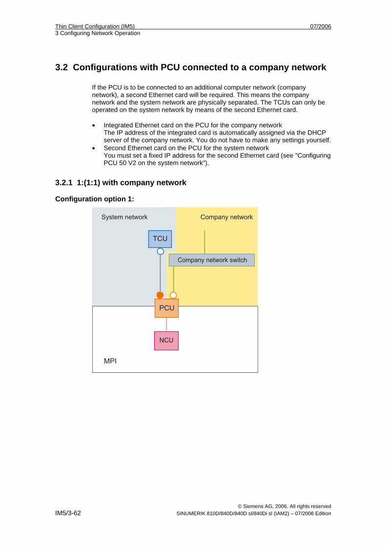
Thin Client Configuration (IM5) 07/2006 3 Configuring Network Operation
© Siemens AG, 2006. All rights reserved IM5/3-62 SINUMERIK 810D/840D/840D sl/840Di sl (IAM2) – 07/2006 Edition
3.2 Configurations with PCU connected to a company network If the PCU is to be connected to an additional computer network (company network), a second Ethernet card will be required. This means the company network and the system network are physically separated. The TCUs can only be operated on the system network by means of the second Ethernet card. • Integrated Ethernet card on the PCU for the company network
The IP address of the integrated card is automatically assigned via the DHCP server of the company network. You do not have to make any settings yourself.
• Second Ethernet card on the PCU for the system network You must set a fixed IP address for the second Ethernet card (see "Configuring PCU 50 V2 on the system network").
3.2.1 1:(1:1) with company network
Configuration option 1:
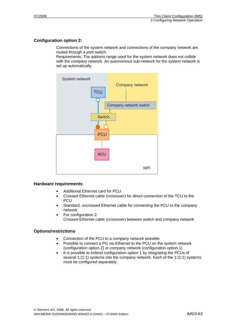
07/2006 Thin Client Configuration (IM5) 3 Configuring Network Operation
© Siemens AG, 2006. All rights reserved SINUMERIK 810D/840D/840D sl/840Di sl (IAM2) – 07/2006 Edition IM5/3-63
Configuration option 2: Connections of the system network and connections of the company network are routed through a joint switch. Requirements: The address range used for the system network does not collide with the company network. An autonomous sub-network for the system network is set up automatically.
Hardware requirements • Additional Ethernet card for PCU • Crossed Ethernet cable (crossover) for direct connection of the TCU to the
PCU • Standard, uncrossed Ethernet cable for connecting the PCU to the company
network • For configuration 2:
Crossed Ethernet cable (crossover) between switch and company network
Options/restrictions • Connection of the PCU to a company network possible • Possible to connect a PG via Ethernet to the PCU on the system network
(configuration option 2) or company network (configuration option 1) • It is possible to extend configuration option 1 by integrating the PCUs of
several 1:(1:1) systems into the company network. Each of the 1:(1:1) systems must be configured separately.
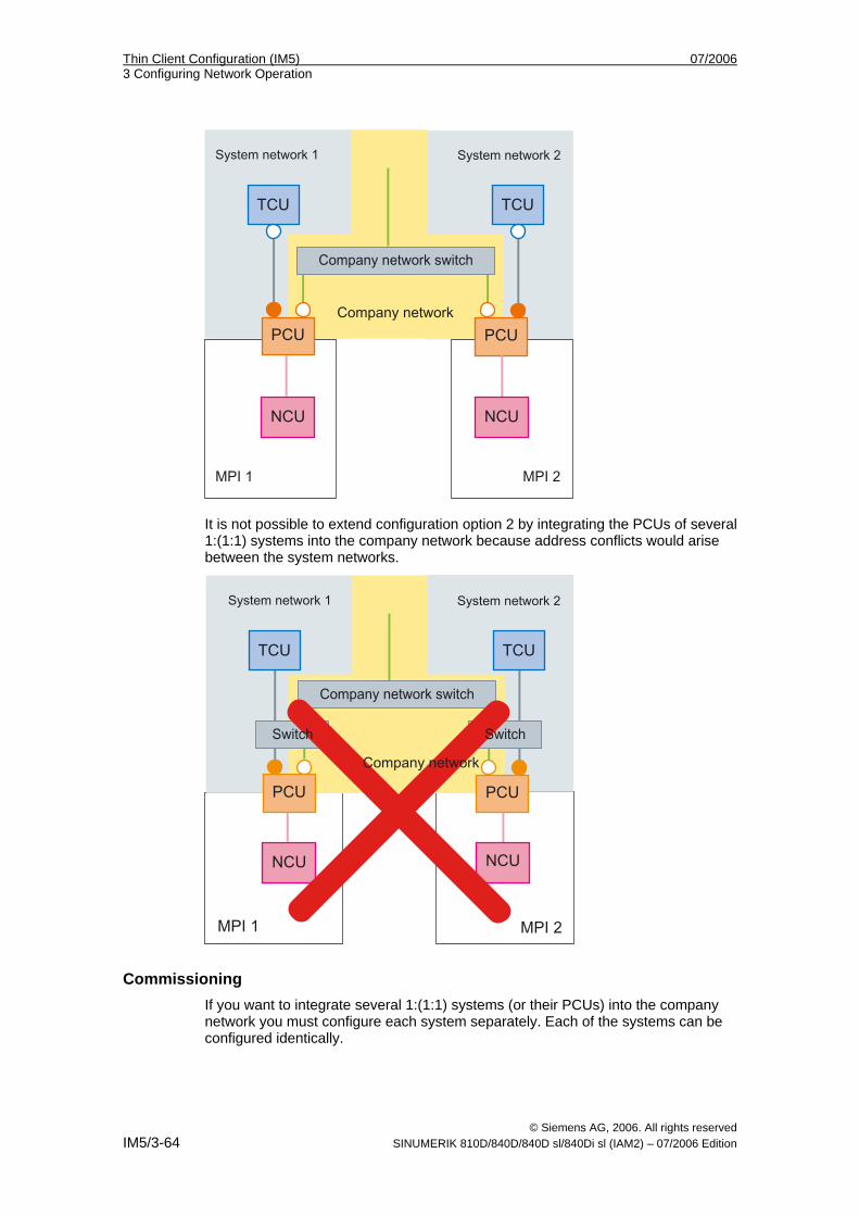
Thin Client Configuration (IM5) 07/2006 3 Configuring Network Operation
© Siemens AG, 2006. All rights reserved IM5/3-64 SINUMERIK 810D/840D/840D sl/840Di sl (IAM2) – 07/2006 Edition
It is not possible to extend configuration option 2 by integrating the PCUs of several 1:(1:1) systems into the company network because address conflicts would arise between the system networks.
Commissioning If you want to integrate several 1:(1:1) systems (or their PCUs) into the company network you must configure each system separately. Each of the systems can be configured identically.
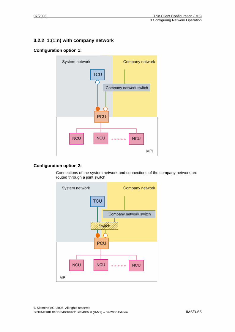
07/2006 Thin Client Configuration (IM5) 3 Configuring Network Operation
© Siemens AG, 2006. All rights reserved SINUMERIK 810D/840D/840D sl/840Di sl (IAM2) – 07/2006 Edition IM5/3-65
3.2.2 1:(1:n) with company network
Configuration option 1:
Configuration option 2: Connections of the system network and connections of the company network are routed through a joint switch.
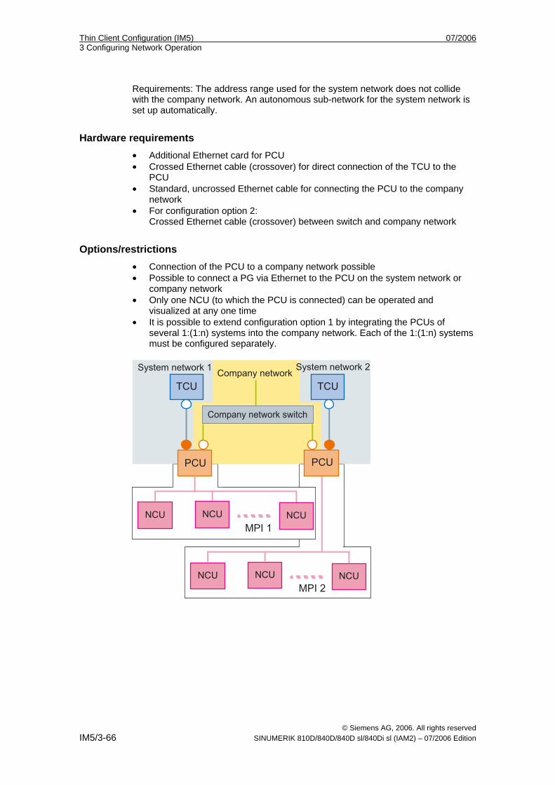
Thin Client Configuration (IM5) 07/2006 3 Configuring Network Operation
© Siemens AG, 2006. All rights reserved IM5/3-66 SINUMERIK 810D/840D/840D sl/840Di sl (IAM2) – 07/2006 Edition
Requirements: The address range used for the system network does not collide with the company network. An autonomous sub-network for the system network is set up automatically.
Hardware requirements • Additional Ethernet card for PCU • Crossed Ethernet cable (crossover) for direct connection of the TCU to the
PCU • Standard, uncrossed Ethernet cable for connecting the PCU to the company
network • For configuration option 2:
Crossed Ethernet cable (crossover) between switch and company network
Options/restrictions • Connection of the PCU to a company network possible • Possible to connect a PG via Ethernet to the PCU on the system network or
company network • Only one NCU (to which the PCU is connected) can be operated and
visualized at any one time • It is possible to extend configuration option 1 by integrating the PCUs of
several 1:(1:n) systems into the company network. Each of the 1:(1:n) systems must be configured separately.
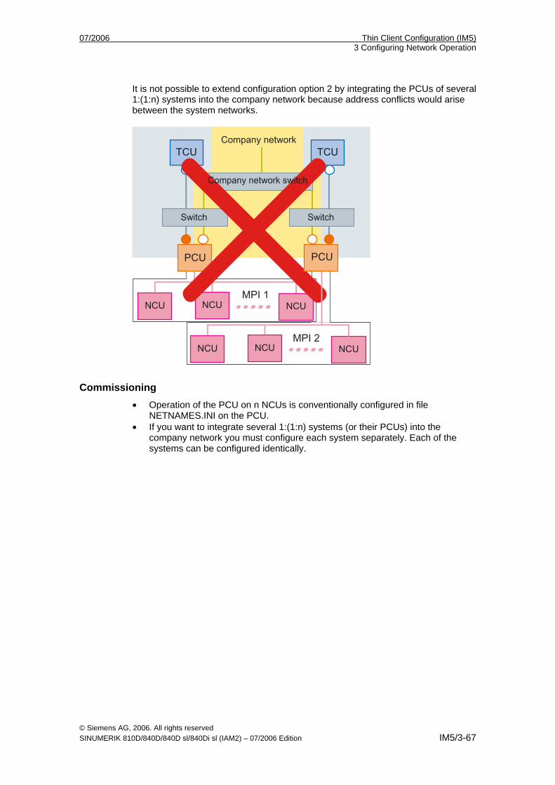
07/2006 Thin Client Configuration (IM5) 3 Configuring Network Operation
© Siemens AG, 2006. All rights reserved SINUMERIK 810D/840D/840D sl/840Di sl (IAM2) – 07/2006 Edition IM5/3-67
It is not possible to extend configuration option 2 by integrating the PCUs of several 1:(1:n) systems into the company network because address conflicts would arise between the system networks.
Commissioning • Operation of the PCU on n NCUs is conventionally configured in file
NETNAMES.INI on the PCU. • If you want to integrate several 1:(1:n) systems (or their PCUs) into the
company network you must configure each system separately. Each of the systems can be configured identically.
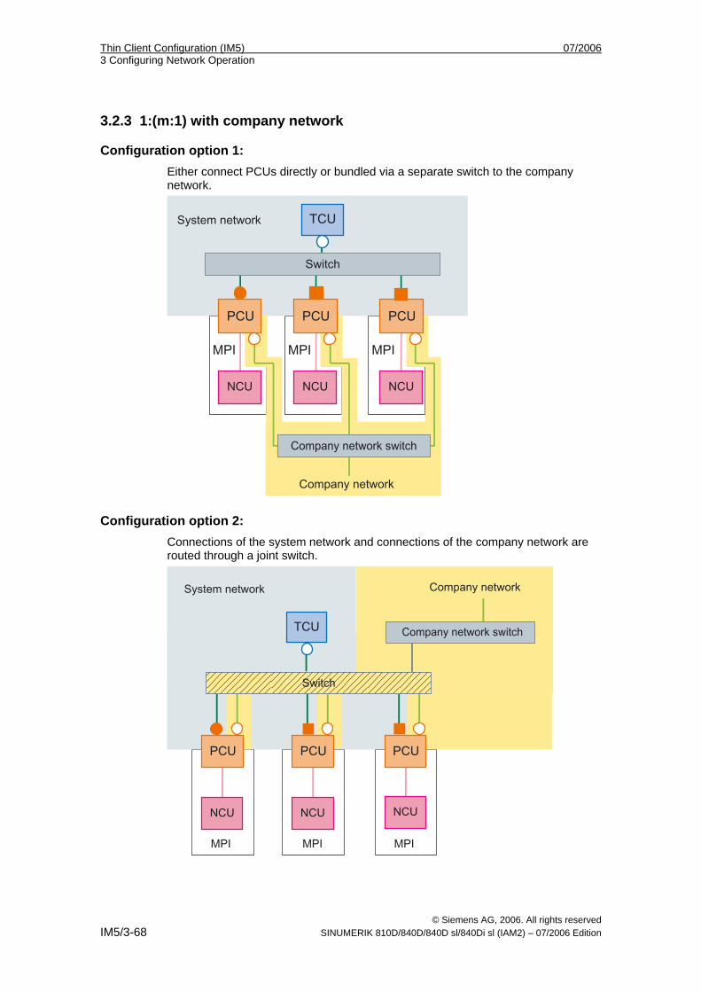
Thin Client Configuration (IM5) 07/2006 3 Configuring Network Operation
© Siemens AG, 2006. All rights reserved IM5/3-68 SINUMERIK 810D/840D/840D sl/840Di sl (IAM2) – 07/2006 Edition
3.2.3 1:(m:1) with company network
Configuration option 1: Either connect PCUs directly or bundled via a separate switch to the company network.
Configuration option 2: Connections of the system network and connections of the company network are routed through a joint switch.
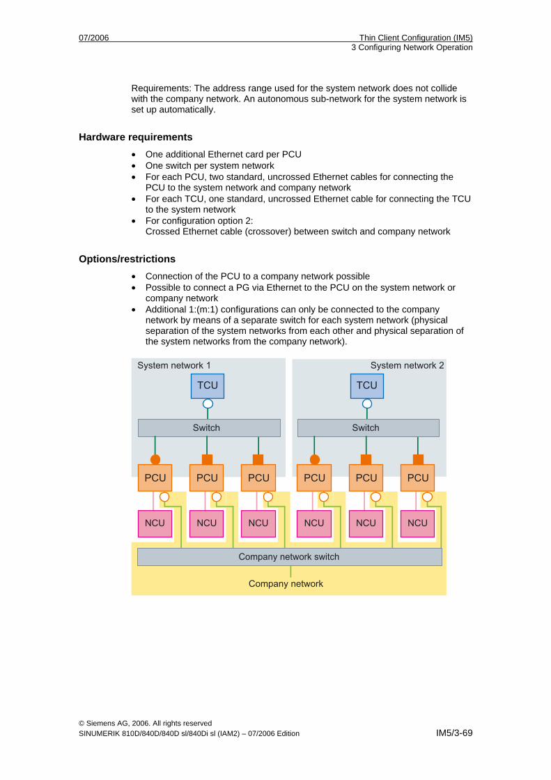
07/2006 Thin Client Configuration (IM5) 3 Configuring Network Operation
© Siemens AG, 2006. All rights reserved SINUMERIK 810D/840D/840D sl/840Di sl (IAM2) – 07/2006 Edition IM5/3-69
Requirements: The address range used for the system network does not collide with the company network. An autonomous sub-network for the system network is set up automatically.
Hardware requirements • One additional Ethernet card per PCU • One switch per system network • For each PCU, two standard, uncrossed Ethernet cables for connecting the
PCU to the system network and company network • For each TCU, one standard, uncrossed Ethernet cable for connecting the TCU
to the system network • For configuration option 2:
Crossed Ethernet cable (crossover) between switch and company network
Options/restrictions • Connection of the PCU to a company network possible • Possible to connect a PG via Ethernet to the PCU on the system network or
company network • Additional 1:(m:1) configurations can only be connected to the company
network by means of a separate switch for each system network (physical separation of the system networks from each other and physical separation of the system networks from the company network).
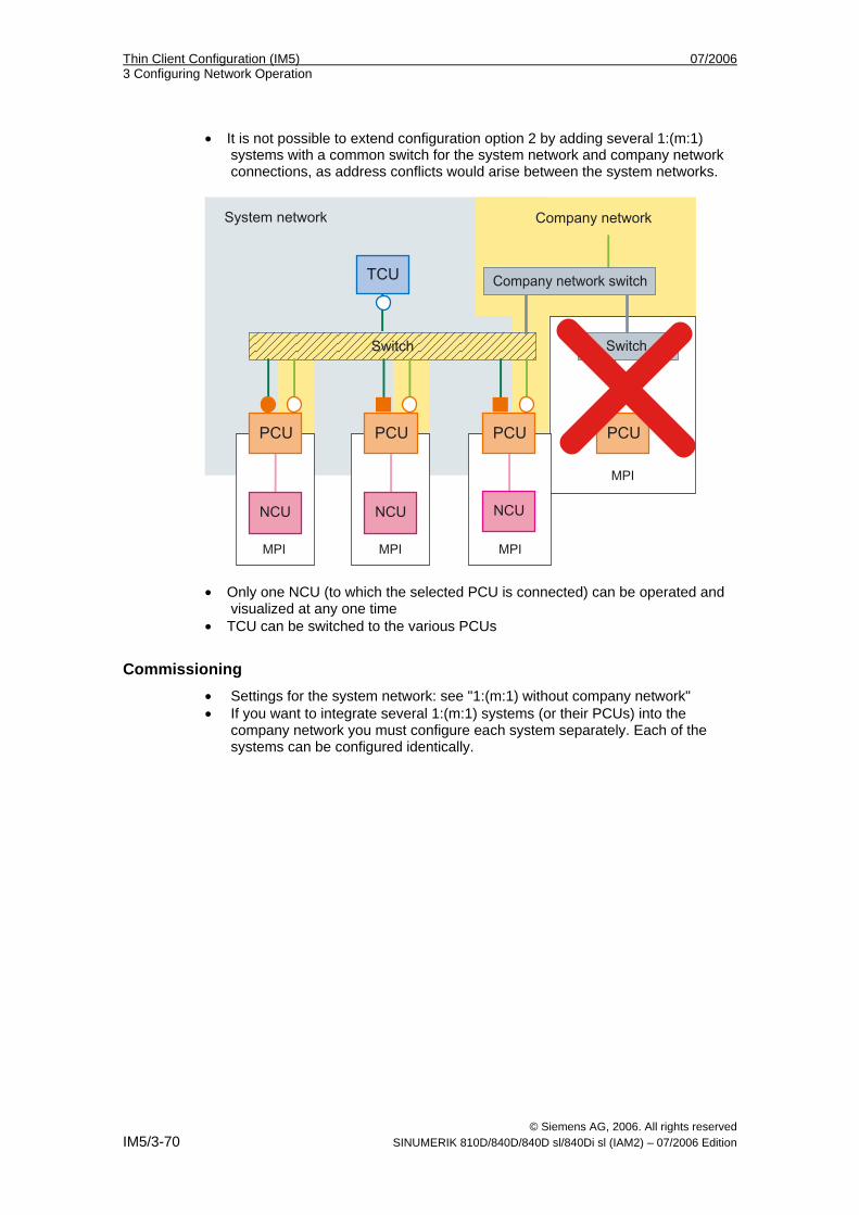
Thin Client Configuration (IM5) 07/2006 3 Configuring Network Operation
© Siemens AG, 2006. All rights reserved IM5/3-70 SINUMERIK 810D/840D/840D sl/840Di sl (IAM2) – 07/2006 Edition
• It is not possible to extend configuration option 2 by adding several 1:(m:1) systems with a common switch for the system network and company network connections, as address conflicts would arise between the system networks.
• Only one NCU (to which the selected PCU is connected) can be operated and
visualized at any one time • TCU can be switched to the various PCUs
Commissioning • Settings for the system network: see "1:(m:1) without company network" • If you want to integrate several 1:(m:1) systems (or their PCUs) into the
company network you must configure each system separately. Each of the systems can be configured identically.
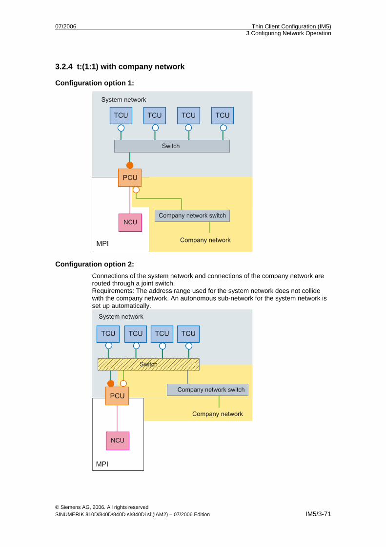
07/2006 Thin Client Configuration (IM5) 3 Configuring Network Operation
© Siemens AG, 2006. All rights reserved SINUMERIK 810D/840D/840D sl/840Di sl (IAM2) – 07/2006 Edition IM5/3-71
3.2.4 t:(1:1) with company network
Configuration option 1:
Configuration option 2: Connections of the system network and connections of the company network are routed through a joint switch. Requirements: The address range used for the system network does not collide with the company network. An autonomous sub-network for the system network is set up automatically.
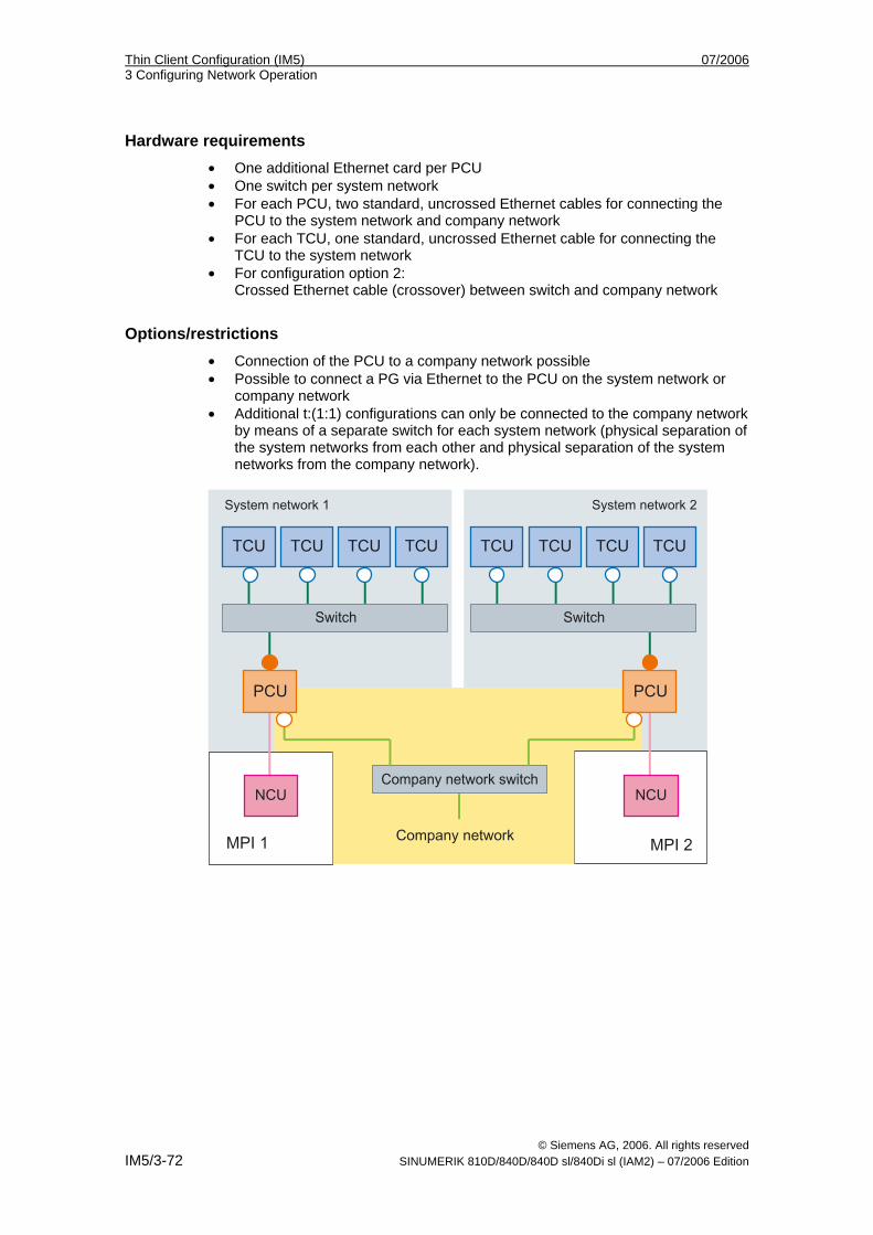
Thin Client Configuration (IM5) 07/2006 3 Configuring Network Operation
© Siemens AG, 2006. All rights reserved IM5/3-72 SINUMERIK 810D/840D/840D sl/840Di sl (IAM2) – 07/2006 Edition
Hardware requirements • One additional Ethernet card per PCU • One switch per system network • For each PCU, two standard, uncrossed Ethernet cables for connecting the
PCU to the system network and company network • For each TCU, one standard, uncrossed Ethernet cable for connecting the
TCU to the system network • For configuration option 2:
Crossed Ethernet cable (crossover) between switch and company network
Options/restrictions • Connection of the PCU to a company network possible • Possible to connect a PG via Ethernet to the PCU on the system network or
company network • Additional t:(1:1) configurations can only be connected to the company network
by means of a separate switch for each system network (physical separation of the system networks from each other and physical separation of the system networks from the company network).
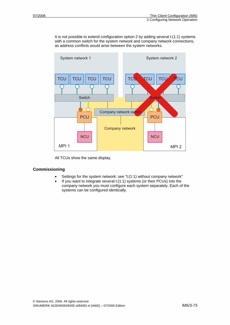
07/2006 Thin Client Configuration (IM5) 3 Configuring Network Operation
© Siemens AG, 2006. All rights reserved SINUMERIK 810D/840D/840D sl/840Di sl (IAM2) – 07/2006 Edition IM5/3-73
It is not possible to extend configuration option 2 by adding several t:(1:1) systems with a common switch for the system network and company network connections, as address conflicts would arise between the system networks.
All TCUs show the same display.
Commissioning • Settings for the system network: see "t:(1:1) without company network" • If you want to integrate several t:(1:1) systems (or their PCUs) into the
company network you must configure each system separately. Each of the systems can be configured identically.
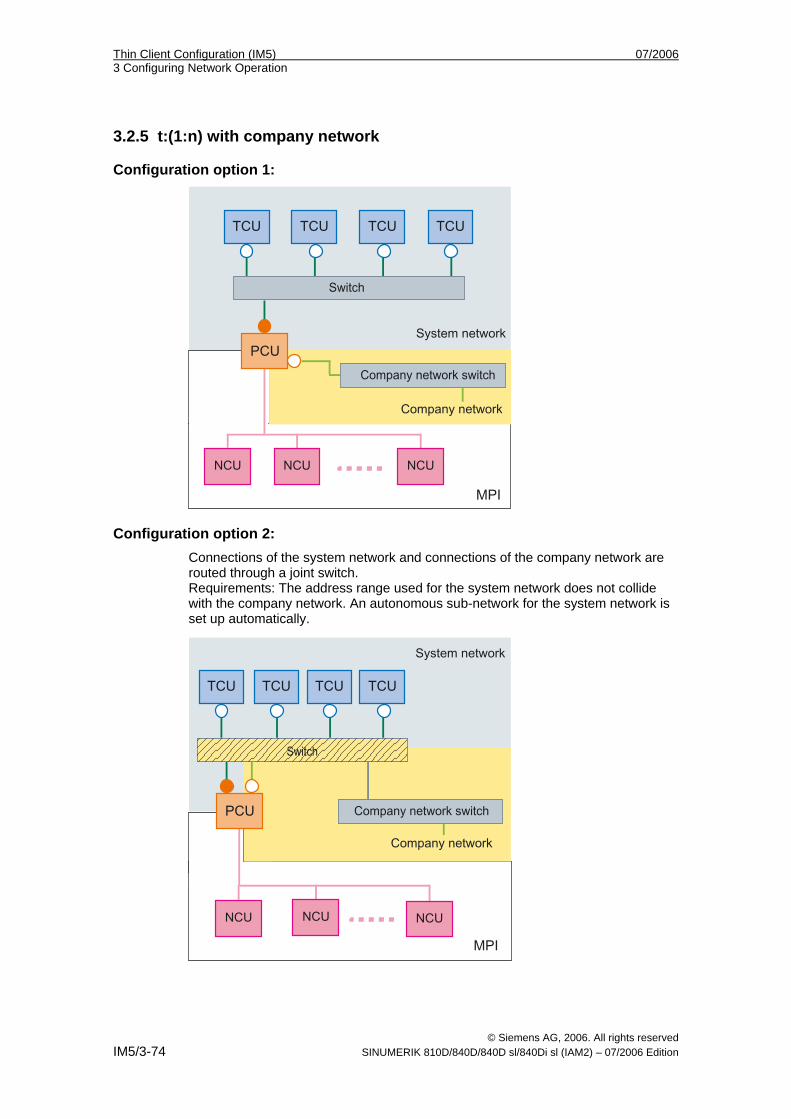
Thin Client Configuration (IM5) 07/2006 3 Configuring Network Operation
© Siemens AG, 2006. All rights reserved IM5/3-74 SINUMERIK 810D/840D/840D sl/840Di sl (IAM2) – 07/2006 Edition
3.2.5 t:(1:n) with company network
Configuration option 1:
Configuration option 2: Connections of the system network and connections of the company network are routed through a joint switch. Requirements: The address range used for the system network does not collide with the company network. An autonomous sub-network for the system network is set up automatically.
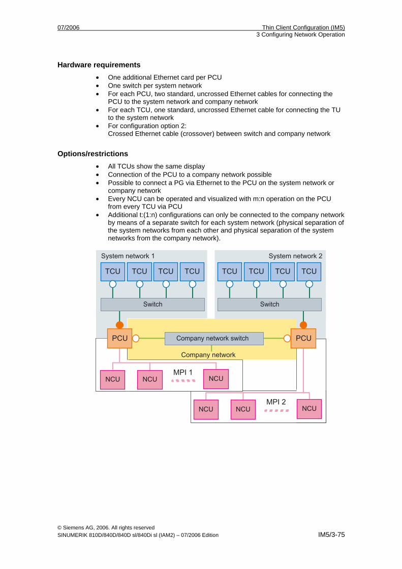
07/2006 Thin Client Configuration (IM5) 3 Configuring Network Operation
© Siemens AG, 2006. All rights reserved SINUMERIK 810D/840D/840D sl/840Di sl (IAM2) – 07/2006 Edition IM5/3-75
Hardware requirements • One additional Ethernet card per PCU • One switch per system network • For each PCU, two standard, uncrossed Ethernet cables for connecting the
PCU to the system network and company network • For each TCU, one standard, uncrossed Ethernet cable for connecting the TU
to the system network • For configuration option 2:
Crossed Ethernet cable (crossover) between switch and company network
Options/restrictions • All TCUs show the same display • Connection of the PCU to a company network possible • Possible to connect a PG via Ethernet to the PCU on the system network or
company network • Every NCU can be operated and visualized with m:n operation on the PCU
from every TCU via PCU • Additional t:(1:n) configurations can only be connected to the company network
by means of a separate switch for each system network (physical separation of the system networks from each other and physical separation of the system networks from the company network).
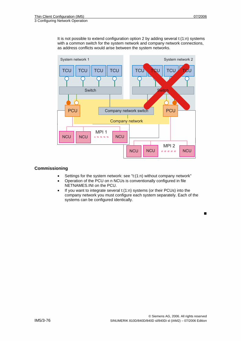
Thin Client Configuration (IM5) 07/2006 3 Configuring Network Operation
© Siemens AG, 2006. All rights reserved IM5/3-76 SINUMERIK 810D/840D/840D sl/840Di sl (IAM2) – 07/2006 Edition
It is not possible to extend configuration option 2 by adding several t:(1:n) systems with a common switch for the system network and company network connections, as address conflicts would arise between the system networks.
Commissioning • Settings for the system network: see "t:(1:n) without company network" • Operation of the PCU on n NCUs is conventionally configured in file
NETNAMES.INI on the PCU. • If you want to integrate several t:(1:n) systems (or their PCUs) into the
company network you must configure each system separately. Each of the systems can be configured identically.
07/2006 Thin Client Configuration (IM5) 4 Configuring Network Operation
© Siemens AG, 2006. All rights reserved SINUMERIK 810D/840D/840D sl/840Di sl (IAM2) – 07/2006 Edition IM5/4-77
4 Configuring Network Operation (SINUMERIK solution line)
4.1 Permissible Network Topologies .............................................. IM5/4-78
4.2 Networks without connection to the company network............. IM5/4-79 4.2.1 Configuration 1: NCU and TCU ............................................. IM5/4-79 4.2.2 Configuration 2: NCU and PCU 50.3 with a direct OP .......... IM5/4-80
4.3 Networks with NCU connection to the company network......... IM5/4-81 4.3.1 Configuration 3: NCU and TCU ............................................. IM5/4-81 4.3.2 Configuration 4: NCU and PCU 50.3 with a direct OP .......... IM5/4-82 4.3.3 Configuration 5: PCU with TCU on NCU ............................... IM5/4-83 4.3.4 Connecting the programming device to the NCU.................. IM5/4-84
4
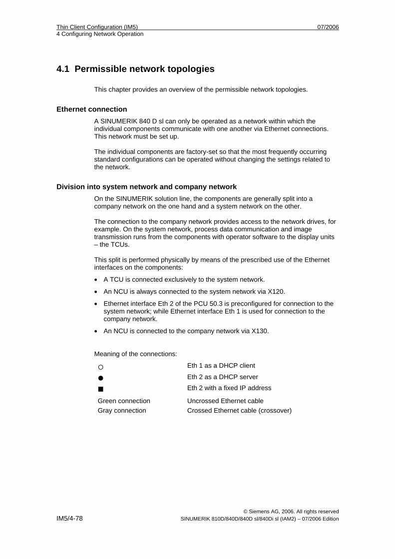
Thin Client Configuration (IM5) 07/2006 4 Configuring Network Operation
© Siemens AG, 2006. All rights reserved IM5/4-78 SINUMERIK 810D/840D/840D sl/840Di sl (IAM2) – 07/2006 Edition
4.1 Permissible network topologies This chapter provides an overview of the permissible network topologies.
Ethernet connection A SINUMERIK 840 D sl can only be operated as a network within which the individual components communicate with one another via Ethernet connections. This network must be set up. The individual components are factory-set so that the most frequently occurring standard configurations can be operated without changing the settings related to the network.
Division into system network and company network On the SINUMERIK solution line, the components are generally split into a company network on the one hand and a system network on the other. The connection to the company network provides access to the network drives, for example. On the system network, process data communication and image transmission runs from the components with operator software to the display units – the TCUs. This split is performed physically by means of the prescribed use of the Ethernet interfaces on the components:
• A TCU is connected exclusively to the system network.
• An NCU is always connected to the system network via X120.
• Ethernet interface Eth 2 of the PCU 50.3 is preconfigured for connection to the system network; while Ethernet interface Eth 1 is used for connection to the company network.
• An NCU is connected to the company network via X130. Meaning of the connections:
Eth 1 as a DHCP client
Eth 2 as a DHCP server
Eth 2 with a fixed IP address
Green connection Uncrossed Ethernet cable
Gray connection Crossed Ethernet cable (crossover)
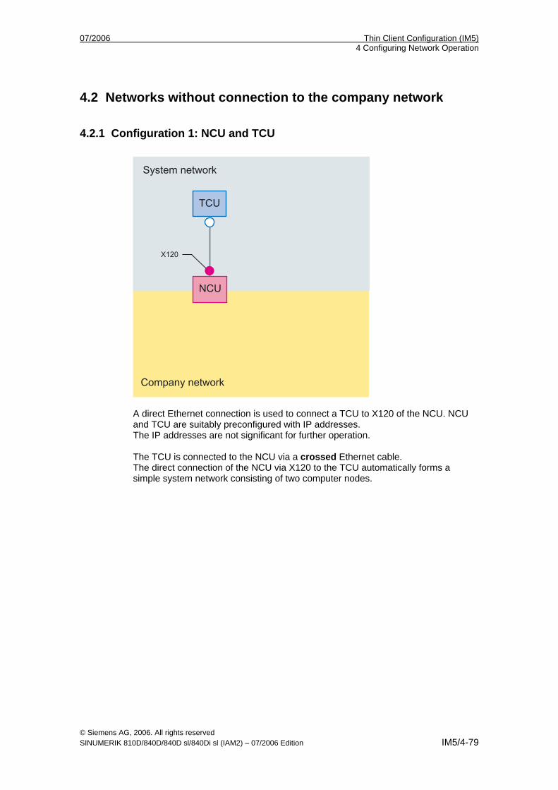
07/2006 Thin Client Configuration (IM5) 4 Configuring Network Operation
© Siemens AG, 2006. All rights reserved SINUMERIK 810D/840D/840D sl/840Di sl (IAM2) – 07/2006 Edition IM5/4-79
4.2 Networks without connection to the company network
4.2.1 Configuration 1: NCU and TCU
A direct Ethernet connection is used to connect a TCU to X120 of the NCU. NCU and TCU are suitably preconfigured with IP addresses. The IP addresses are not significant for further operation. The TCU is connected to the NCU via a crossed Ethernet cable. The direct connection of the NCU via X120 to the TCU automatically forms a simple system network consisting of two computer nodes.
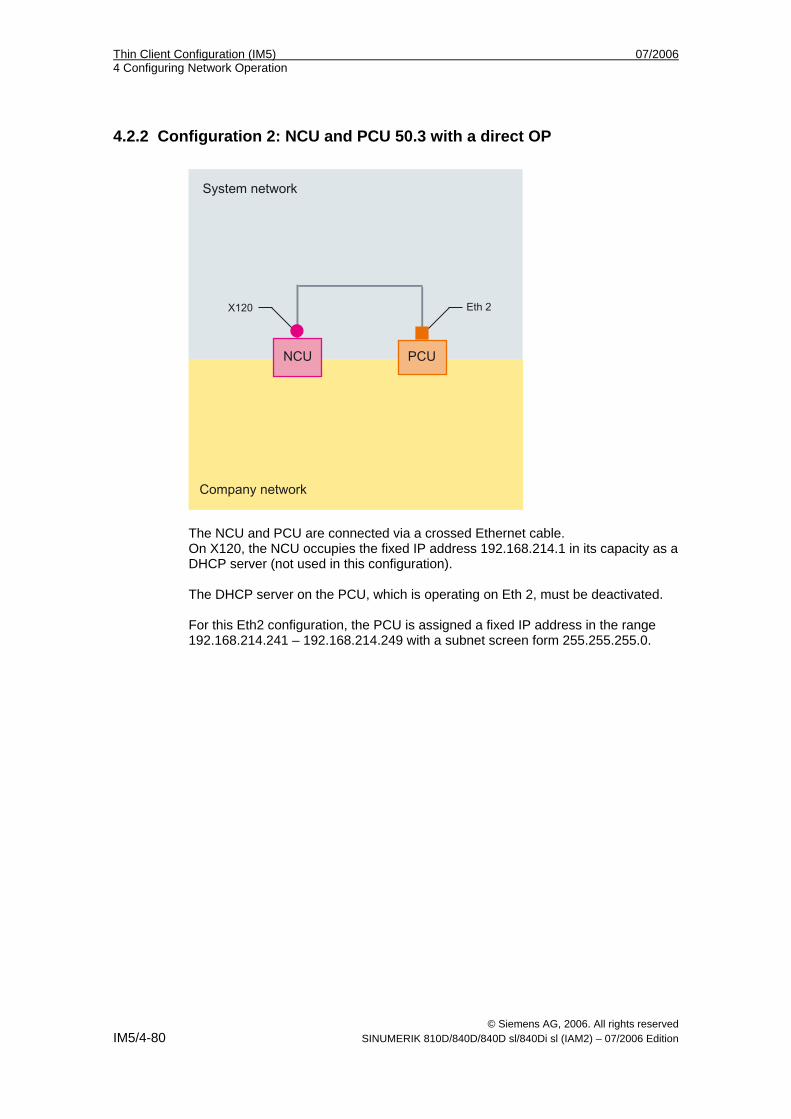
Thin Client Configuration (IM5) 07/2006 4 Configuring Network Operation
© Siemens AG, 2006. All rights reserved IM5/4-80 SINUMERIK 810D/840D/840D sl/840Di sl (IAM2) – 07/2006 Edition
4.2.2 Configuration 2: NCU and PCU 50.3 with a direct OP
The NCU and PCU are connected via a crossed Ethernet cable. On X120, the NCU occupies the fixed IP address 192.168.214.1 in its capacity as a DHCP server (not used in this configuration). The DHCP server on the PCU, which is operating on Eth 2, must be deactivated. For this Eth2 configuration, the PCU is assigned a fixed IP address in the range 192.168.214.241 – 192.168.214.249 with a subnet screen form 255.255.255.0.
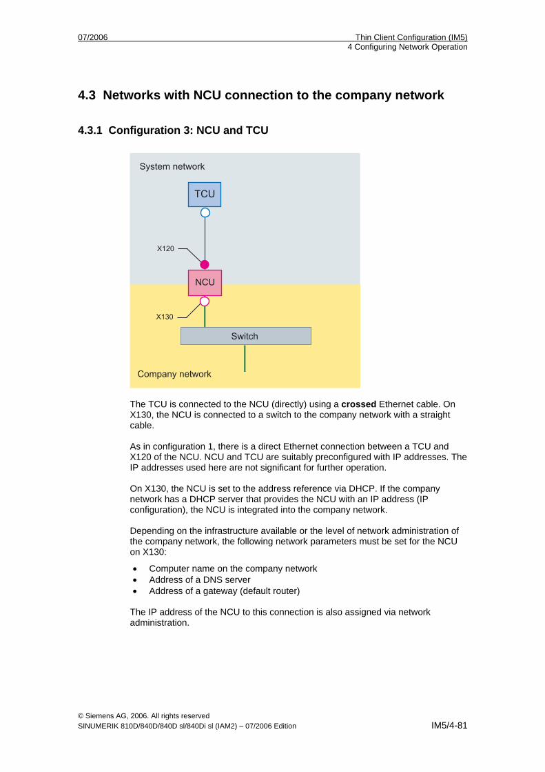
07/2006 Thin Client Configuration (IM5) 4 Configuring Network Operation
© Siemens AG, 2006. All rights reserved SINUMERIK 810D/840D/840D sl/840Di sl (IAM2) – 07/2006 Edition IM5/4-81
4.3 Networks with NCU connection to the company network
4.3.1 Configuration 3: NCU and TCU
The TCU is connected to the NCU (directly) using a crossed Ethernet cable. On X130, the NCU is connected to a switch to the company network with a straight cable. As in configuration 1, there is a direct Ethernet connection between a TCU and X120 of the NCU. NCU and TCU are suitably preconfigured with IP addresses. The IP addresses used here are not significant for further operation. On X130, the NCU is set to the address reference via DHCP. If the company network has a DHCP server that provides the NCU with an IP address (IP configuration), the NCU is integrated into the company network. Depending on the infrastructure available or the level of network administration of the company network, the following network parameters must be set for the NCU on X130:
• Computer name on the company network • Address of a DNS server • Address of a gateway (default router)
The IP address of the NCU to this connection is also assigned via network administration.
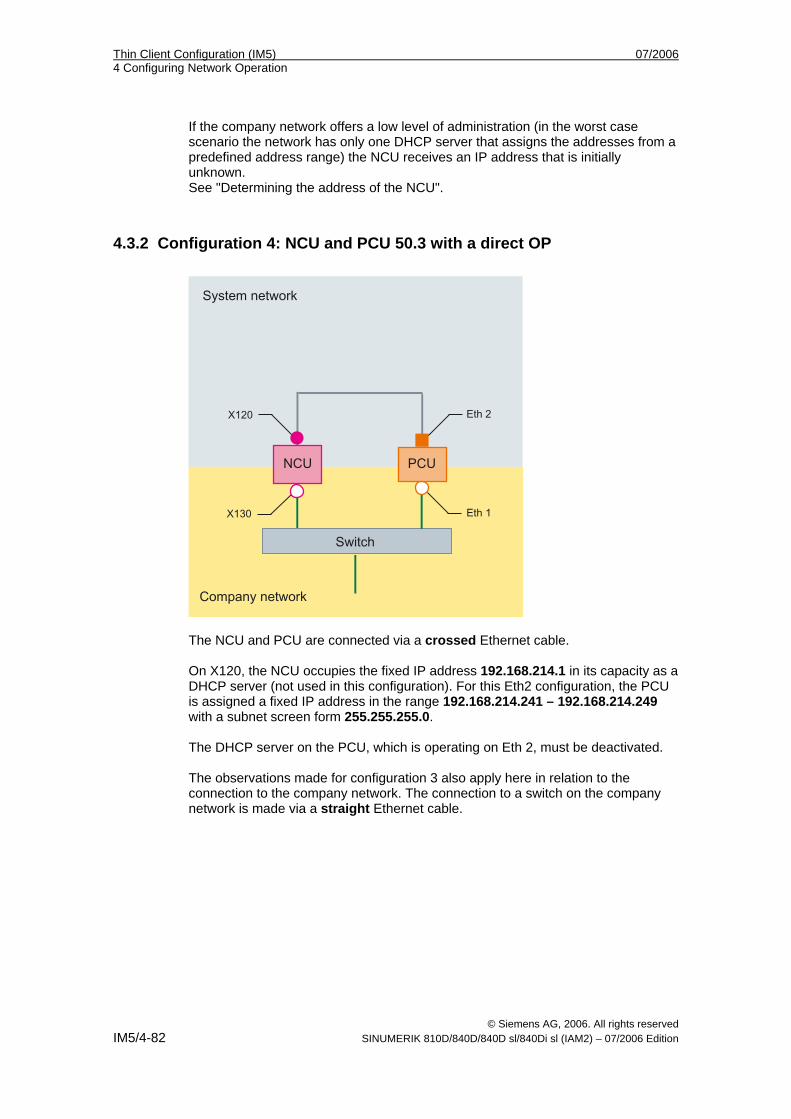
Thin Client Configuration (IM5) 07/2006 4 Configuring Network Operation
© Siemens AG, 2006. All rights reserved IM5/4-82 SINUMERIK 810D/840D/840D sl/840Di sl (IAM2) – 07/2006 Edition
If the company network offers a low level of administration (in the worst case scenario the network has only one DHCP server that assigns the addresses from a predefined address range) the NCU receives an IP address that is initially unknown. See "Determining the address of the NCU".
4.3.2 Configuration 4: NCU and PCU 50.3 with a direct OP
The NCU and PCU are connected via a crossed Ethernet cable. On X120, the NCU occupies the fixed IP address 192.168.214.1 in its capacity as a DHCP server (not used in this configuration). For this Eth2 configuration, the PCU is assigned a fixed IP address in the range 192.168.214.241 – 192.168.214.249 with a subnet screen form 255.255.255.0. The DHCP server on the PCU, which is operating on Eth 2, must be deactivated. The observations made for configuration 3 also apply here in relation to the connection to the company network. The connection to a switch on the company network is made via a straight Ethernet cable.
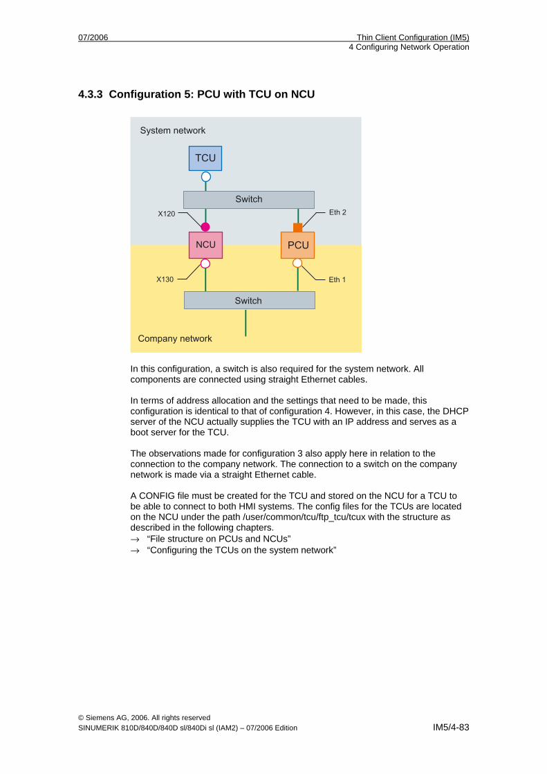
07/2006 Thin Client Configuration (IM5) 4 Configuring Network Operation
© Siemens AG, 2006. All rights reserved SINUMERIK 810D/840D/840D sl/840Di sl (IAM2) – 07/2006 Edition IM5/4-83
4.3.3 Configuration 5: PCU with TCU on NCU
In this configuration, a switch is also required for the system network. All components are connected using straight Ethernet cables. In terms of address allocation and the settings that need to be made, this configuration is identical to that of configuration 4. However, in this case, the DHCP server of the NCU actually supplies the TCU with an IP address and serves as a boot server for the TCU. The observations made for configuration 3 also apply here in relation to the connection to the company network. The connection to a switch on the company network is made via a straight Ethernet cable. A CONFIG file must be created for the TCU and stored on the NCU for a TCU to be able to connect to both HMI systems. The config files for the TCUs are located on the NCU under the path /user/common/tcu/ftp_tcu/tcux with the structure as described in the following chapters. → “File structure on PCUs and NCUs” → “Configuring the TCUs on the system network”
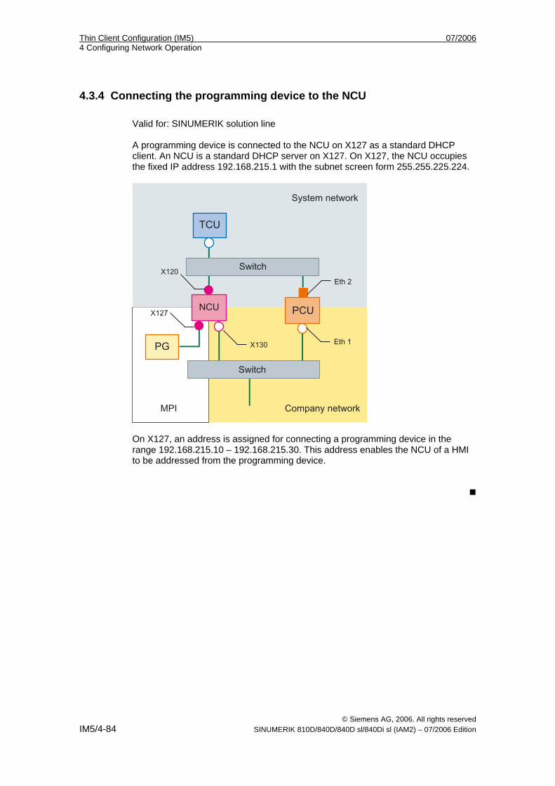
Thin Client Configuration (IM5) 07/2006 4 Configuring Network Operation
© Siemens AG, 2006. All rights reserved IM5/4-84 SINUMERIK 810D/840D/840D sl/840Di sl (IAM2) – 07/2006 Edition
4.3.4 Connecting the programming device to the NCU Valid for: SINUMERIK solution line A programming device is connected to the NCU on X127 as a standard DHCP client. An NCU is a standard DHCP server on X127. On X127, the NCU occupies the fixed IP address 192.168.215.1 with the subnet screen form 255.255.225.224.
On X127, an address is assigned for connecting a programming device in the range 192.168.215.10 – 192.168.215.30. This address enables the NCU of a HMI to be addressed from the programming device.
07/2006 Thin Client Configuration (IM5) 5 Diagnostics
© Siemens AG, 2006. All rights reserved SINUMERIK 810D/840D/840D sl/840Di sl (IAM2) – 07/2006 Edition IM5/5-85
5 Diagnostics
5.1 Booting of the TCU .................................................................. IM5/5-86 5.1.1 Messages during booting ..................................................... IM5/5-86 5.1.2 Faults during booting ............................................................ IM5/5-86
5.2 Special key combinations ........................................................ IM5/5-89
5
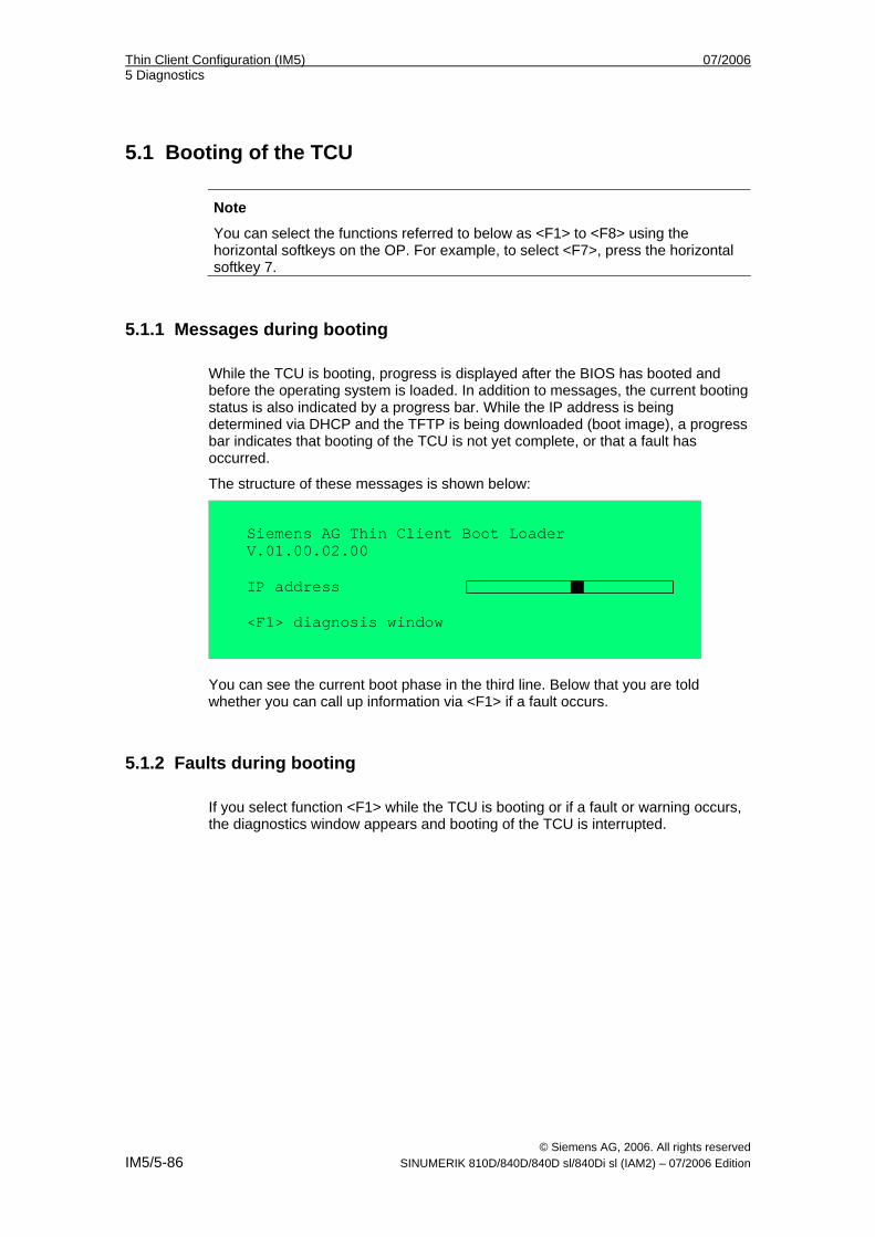
Thin Client Configuration (IM5) 07/2006 5 Diagnostics
© Siemens AG, 2006. All rights reserved IM5/5-86 SINUMERIK 810D/840D/840D sl/840Di sl (IAM2) – 07/2006 Edition
5.1 Booting of the TCU
Note
You can select the functions referred to below as <F1> to <F8> using the horizontal softkeys on the OP. For example, to select <F7>, press the horizontal softkey 7.
5.1.1 Messages during booting While the TCU is booting, progress is displayed after the BIOS has booted and before the operating system is loaded. In addition to messages, the current booting status is also indicated by a progress bar. While the IP address is being determined via DHCP and the TFTP is being downloaded (boot image), a progress bar indicates that booting of the TCU is not yet complete, or that a fault has occurred.
The structure of these messages is shown below:
Siemens AG Thin Client Boot Loader V.01.00.02.00
IP address
<F1> diagnosis window
You can see the current boot phase in the third line. Below that you are told whether you can call up information via <F1> if a fault occurs.
5.1.2 Faults during booting If you select function <F1> while the TCU is booting or if a fault or warning occurs, the diagnostics window appears and booting of the TCU is interrupted.
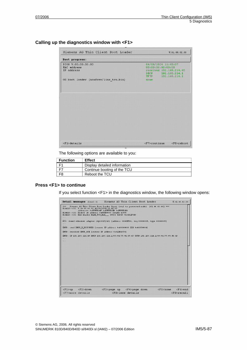
07/2006 Thin Client Configuration (IM5) 5 Diagnostics
© Siemens AG, 2006. All rights reserved SINUMERIK 810D/840D/840D sl/840Di sl (IAM2) – 07/2006 Edition IM5/5-87
Calling up the diagnostics window with <F1>
The following options are available to you:
Function Effect F1 Display detailed information F7 Continue booting of the TCU F8 Reboot the TCU
Press <F1> to continue If you select function <F1> in the diagnostics window, the following window opens:
Thin Client Configuration (IM5) 07/2006 5 Diagnostics
© Siemens AG, 2006. All rights reserved IM5/5-88 SINUMERIK 810D/840D/840D sl/840Di sl (IAM2) – 07/2006 Edition
The following options are available to you:
Function Effect F1 to F6 Navigate within the window
(Alternatively, you can also use the corresponding keys on the OP.)
F7 Display more information F8 Display less information F9 Return to diagnostics window
Press <F7> to continue If you select function <F7> in the diagnostics window, booting of the TCU continues: If booting is not yet complete, you can interrupt the boot procedure again with <F1>.
The diagnostics window is displayed automatically in the event of a fault:
The following options are available to you: Function Effect F1 Display detailed information F8 Reboot the TCU If the diagnostics window is already active and a warning message appears, it is displayed inside the window.
07/2006 Thin Client Configuration (IM5) 5 Diagnostics
© Siemens AG, 2006. All rights reserved SINUMERIK 810D/840D/840D sl/840Di sl (IAM2) – 07/2006 Edition IM5/5-89
The following options are available to you: Function Effect F1 Display detailed information
5.2 Special key combinations
Notice
These operator input sequence steps must only be carried out by qualified personnel.
You can operate the HMI Advanced software on the OP of the TCU in exactly the same way as you do on the OP connected directly to the PCU. All keys have the same functions as on the directly connected OP. The following differences apply:
Requesting the operator focus
On a TCU that has no operator focus, the first key that is pressed serves exclusively to request the operator focus, i.e., this key is not evaluated by HMI Advanced. The settings for the right to veto are stored in file F:\TCU\SERVICES\TCU.INI and only take effect if HMI Advanced is installed on the PCU.
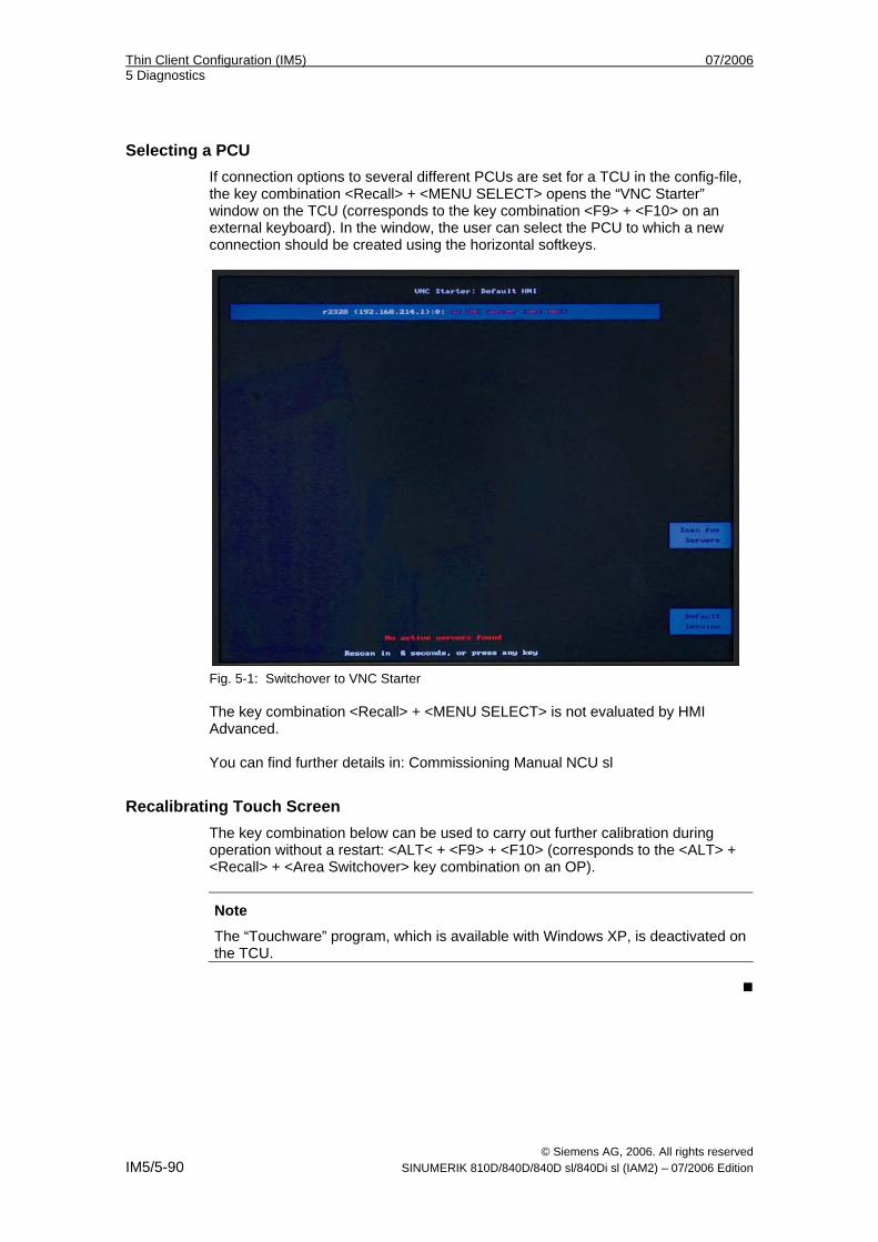
Thin Client Configuration (IM5) 07/2006 5 Diagnostics
© Siemens AG, 2006. All rights reserved IM5/5-90 SINUMERIK 810D/840D/840D sl/840Di sl (IAM2) – 07/2006 Edition
Selecting a PCU
If connection options to several different PCUs are set for a TCU in the config-file, the key combination <Recall> + <MENU SELECT> opens the “VNC Starter” window on the TCU (corresponds to the key combination <F9> + <F10> on an external keyboard). In the window, the user can select the PCU to which a new connection should be created using the horizontal softkeys.
Fig. 5-1: Switchover to VNC Starter The key combination <Recall> + <MENU SELECT> is not evaluated by HMI Advanced. You can find further details in: Commissioning Manual NCU sl
Recalibrating Touch Screen The key combination below can be used to carry out further calibration during operation without a restart: <ALT< + <F9> + <F10> (corresponds to the <ALT> + <Recall> + <Area Switchover> key combination on an OP).
Note
The “Touchware” program, which is available with Windows XP, is deactivated on the TCU.
07/2006 A Appendix
© Siemens AG, 2006. All rights reserved SINUMERIK 810D/840D/840D sl/840Di sl (IAM2) – 07/2006 Edition IM5/A-91
A Appendix
A.1 License Text of General Public License (gpl.txt) GNU GENERAL PUBLIC LICENSE Version 2, June 1991 Copyright (C) 1989, 1991 Free Software Foundation, Inc. 59 Temple Place, Suite 330, Boston, MA 02111-1307 USA Everyone is permitted to copy and distribute verbatim copies of this license document, but changing it is not allowed. Preamble The licenses for most software are designed to take away your freedom to share and change it. By contrast, the GNU General Public License is intended to guarantee your freedom to share and change free software--to make sure the software is free for all its users. This General Public License applies to most of the Free Software Foundation's software and to any other program whose authors commit to using it. (Some other Free Software Foundation software is covered by the GNU Library General Public License instead.) You can apply it to your programs, too. When we speak of free software, we are referring to freedom, not price. Our General Public Licenses are designed to make sure that you have the freedom to distribute copies of free software (and charge for this service if you wish), that you receive source code or can get it if you want it, that you can change the software or use pieces of it in new free programs; and that you know you can do these things. To protect your rights, we need to make restrictions that forbid anyone to deny you these rights or to ask you to surrender the rights. These restrictions translate to certain responsibilities for you if you distribute copies of the software, or if you modify it. For example, if you distribute copies of such a program, whether gratis or for a fee, you must give the recipients all the rights that you have. You must make sure that they, too, receive or can get the source code. And you must show them these terms so they know their rights. We protect your rights with two steps: (1) copyright the software, and (2) offer you this license which gives you legal permission to copy, distribute and/or modify the software. Also, for each author's protection and ours, we want to make certain that everyone understands that there is no warranty for this free software. If the software is modified by someone else and passed on, we want its recipients to know that what they have is not the original, so that any problems introduced by others will not reflect on the original authors' reputations.
A
A Appendix 07/2006
© Siemens AG, 2006. All rights reserved IM5/A-92 SINUMERIK 810D/840D/840D sl/840Di sl (IAM2) – 07/2006 Edition
Finally, any free program is threatened constantly by software patents. We wish to avoid the danger that redistributors of a free program will individually obtain patent licenses, in effect making the program proprietary. To prevent this, we have made it clear that any patent must be licensed for everyone's free use or not licensed at all. The precise terms and conditions for copying, distribution and modification follow: GNU GENERAL PUBLIC LICENSE TERMS AND CONDITIONS FOR COPYING, DISTRIBUTION AND MODIFICATION 0. This License applies to any program or other work which contains a notice placed by the copyright holder saying it may be distributed under the terms of this General Public License. The "Program", below, refers to any such program or work, and a "work based on the Program" means either the Program or any derivative work under copyright law: that is to say, a work containing the Program or a portion of it, either verbatim or with modifications and/or translated into another language. (Hereinafter, translation is included without limitation in the term "modification".) Each licensee is addressed as "you". Activities other than copying, distribution and modification are not covered by this License; they are outside its scope. The act of running the Program is not restricted, and the output from the Program is covered only if its contents constitute a work based on the Program (independent of having been made by running the Program). Whether that is true depends on what the Program does. 1. You may copy and distribute verbatim copies of the Program's source code as you receive it, in any medium, provided that you conspicuously and appropriately publish on each copy an appropriate copyright notice and disclaimer of warranty; keep intact all the notices that refer to this License and to the absence of any warranty; and give any other recipients of the Program a copy of this License along with the Program. You may charge a fee for the physical act of transferring a copy, and you may at your option offer warranty protection in exchange for a fee. 2. You may modify your copy or copies of the Program or any portion of it, thus forming a work based on the Program, and copy and distribute such modifications or work under the terms of Section 1 above, provided that you also meet all of these conditions: a) You must cause the modified files to carry prominent notices stating that you changed the files and the date of any change. b) You must cause any work that you distribute or publish, that in whole or in part contains or is derived from the Program or any part thereof, to be licensed as a whole at no charge to all third parties under the terms of this License. c) If the modified program normally reads commands interactively when run, you must cause it, when started running for such interactive use in the most ordinary way, to print or display an announcement including an appropriate copyright notice and a notice that there is no warranty (or else, saying that you provide a warranty) and that users may redistribute the program under these conditions, and telling the user how to view a copy of this License. (Exception: if the Program itself is interactive but does not normally print such an announcement, your work based on the Program is not required to print an announcement.) These requirements apply to the modified work as a whole. If identifiable sections of that work are not derived from the Program, and can be reasonably considered independent and separate works in themselves, then this License, and its terms, do not apply to those sections when you distribute them as separate works.
07/2006 A Appendix
© Siemens AG, 2006. All rights reserved SINUMERIK 810D/840D/840D sl/840Di sl (IAM2) – 07/2006 Edition IM5/A-93
But when you distribute the same sections as part of a whole which is a work based on the Program, the distribution of the whole must be on the terms of this License, whose permissions for other licensees extend to the entire whole, and thus to each and every part regardless of who wrote it. Thus, it is not the intent of this section to claim rights or contest your rights to work written entirely by you; rather, the intent is to exercise the right to control the distribution of derivative or collective works based on the Program. In addition, mere aggregation of another work not based on the Program with the Program (or with a work based on the Program) on a volume of a storage or distribution medium does not bring the other work under the scope of this License. 3. You may copy and distribute the Program (or a work based on it, under Section 2) in object code or executable form under the terms of Sections 1 and 2 above provided that you also do one of the following: a) Accompany it with the complete corresponding machine-readable source code, which must be distributed under the terms of Sections 1 and 2 above on a medium customarily used for software interchange; or, b) party, for a charge no more than your cost of physically performing source distribution, a complete machine-readable copy of the corresponding source code, to be distributed under the terms of Sections 1 and 2 above on a medium customarily used for software interchange; or, c) Accompany it with the information you received as to the offer to distribute corresponding source code. (This alternative is allowed only for non-commercial distribution and only if you received the program in object code or executable form with such an offer, in accord with Subsection b above.) The source code for a work means the preferred form of the work for making modifications to it. For an executable work, complete source code means all the source code for all modules it contains, plus any associated interface definition files, plus the scripts used to control compilation and installation of the executable. However, as a special exception, the source code distributed need not include anything that is normally distributed (in either source or binary form) with the major components (compiler, kernel, and so on) of the operating system on which the executable runs, unless that component itself accompanies the executable. If distribution of executable or object code is made by offering access to copy from a designated place, then offering equivalent access to copy the source code from the same place counts as distribution of the source code, even though third parties are not compelled to copy the source along with the object code. 4. You may not copy, modify, sublicense, or distribute the Program except as expressly provided under this License. Any attempt otherwise to copy, modify, sublicense or distribute the Program is void, and will automatically terminate your rights under this License. However, parties who have received copies, or rights, from you under this License will not have their licenses terminated so long as such parties remain in full compliance. 5. You are not required to accept this License, since you have not signed it. However, nothing else grants you permission to modify or distribute the Program or its derivative works. These actions are prohibited by law if you do not accept this License. Therefore, by modifying or distributing the Program (or any work based on the Program), you indicate your acceptance of this License to do so, and all its terms and conditions for copying, distributing or modifying the Program or works based on it.
A Appendix 07/2006
© Siemens AG, 2006. All rights reserved IM5/A-94 SINUMERIK 810D/840D/840D sl/840Di sl (IAM2) – 07/2006 Edition
6. Each time you redistribute the Program (or any work based on the Program), the recipient automatically receives a license from the original licensor to copy, distribute or modify the Program subject to these terms and conditions. You may not impose any further restrictions on the recipients' exercise of the rights granted herein. You are not responsible for enforcing compliance by third parties to this License. 7. If, as a consequence of a court judgment or allegation of patent infringement or for any other reason (not limited to patent issues), conditions are imposed on you (whether by court order, agreement or otherwise) that contradict the conditions of this License, they do not excuse you from the conditions of this License. If you cannot distribute so as to satisfy simultaneously your obligations under this License and any other pertinent obligations, then as a consequence you may not distribute the Program at all. For example, if a patent license would not permit royalty free redistribution of the Program by all those who receive copies directly or indirectly through you, then the only way you could satisfy both it and this License would be to refrain entirely from distribution of the Program. If any portion of this section is held invalid or unenforceable under any particular circumstance, the balance of the section is intended to apply and the section as a whole is intended to apply in other circumstances. It is not the purpose of this section to induce you to infringe any patents or other property right claims or to contest validity of any such claims; this section has the sole purpose of protecting the integrity of the free software distribution system, which is implemented by public license practices. Many people have made generous contributions to the wide range of software distributed through that system in reliance on consistent application of that system; it is up to the author/donor to decide if he or she is willing to distribute software through any other system and a licensee cannot impose that choice. This section is intended to make thoroughly clear what is believed to be a consequence of the rest of this License. 8. If the distribution and/or use of the Program is restricted in certain countries either by patents or by copyrighted interfaces, the original copyright holder who places the Program under this License may add an explicit geographical distribution limitation excluding those countries, so that distribution is permitted only in or among countries not thus excluded. In such case, this License incorporates the limitation as if written in the body of this License. 9. The Free Software Foundation may publish revised and/or new versions of the General Public License from time to time. Such new versions will be similar in spirit to the present version, but may differ in detail to address new problems or concerns. Each version is given a distinguishing version number. If the Program specifies a version number of this License which applies to it and "any later version", you have the option of following the terms and conditions either of that version or of any later version published by the Free Software Foundation. If the Program does not specify a version number of this License, you may choose any version ever published by the Free Software Foundation. 10. If you wish to incorporate parts of the Program into other free programs whose distribution conditions are different, write to the author to ask for permission. For software which is copyrighted by the Free Software Foundation, write to the Free Software Foundation; we sometimes make exceptions for this. Our decision will be guided by the two goals of preserving the free status of all derivatives of our free software and of promoting the sharing and reuse of software generally.
07/2006 A Appendix
© Siemens AG, 2006. All rights reserved SINUMERIK 810D/840D/840D sl/840Di sl (IAM2) – 07/2006 Edition IM5/A-95
NO WARRANTY 11. BECAUSE THE PROGRAM IS LICENSED FREE OF CHARGE, THERE IS NO WARRANTY FOR THE PROGRAM, TO THE EXTENT PERMITTED BY APPLICABLE LAW. EXCEPT WHEN OTHERWISE STATED IN WRITING, THE COPYRIGHT HOLDERS AND/OR OTHER PARTIES PROVIDE THE PROGRAM "AS IS" WITHOUT WARRANTY OF ANY KIND, EITHER EXPRESSED OR IMPLIED, INCLUDING, BUT NOT LIMITED TO, THE IMPLIED WARRANTIES OF MERCHANTABILITY AND FITNESS FOR A PARTICULAR PURPOSE. THE ENTIRE RISK AS TO THE QUALITY AND PERFORMANCE OF THE PROGRAM IS WITH YOU. SHOULD THE PROGRAM PROVE DEFECTIVE, YOU ASSUME THE COST OF ALL NECESSARY SERVICING, REPAIR OR CORRECTION. 12. IN NO EVENT UNLESS REQUIRED BY APPLICABLE LAW OR AGREED TO IN WRITING WILL ANY COPYRIGHT HOLDER, OR ANY OTHER PARTY WHO MAY MODIFY AND/OR REDISTRIBUTE THE PROGRAM AS PERMITTED ABOVE, BE LIABLE TO YOU FOR DAMAGES, INCLUDING ANY GENERAL, SPECIAL, INCIDENTAL OR CONSEQUENTIAL DAMAGES ARISING OUT OF THE USE OR INABILITY TO USE THE PROGRAM (INCLUDING BUT NOT LIMITED TO LOSS OF DATA OR DATA BEING RENDERED INACCURATE OR LOSSES SUSTAINED BY YOU OR THIRD PARTIES OR A FAILURE OF THE PROGRAM TO OPERATE WITH ANY OTHER PROGRAMS), EVEN IF SUCH HOLDER OR OTHER PARTY HAS BEEN ADVISED OF THE POSSIBILITY OF SUCH DAMAGES. END OF TERMS AND CONDITIONS How to Apply These Terms to Your New Programs If you develop a new program, and you want it to be of the greatest possible use to the public, the best way to achieve this is to make it free software which everyone can redistribute and change under these terms. To do so, attach the following notices to the program. It is safest to attach them to the start of each source file to most effectively convey the exclusion of warranty; and each file should have at least the "copyright" line and a pointer to where the full notice is found. one line to give the program's name and a brief idea of what it does. Copyright (C) This program is free software; you can redistribute it and/or modify it under the terms of the GNU General Public License as published by the Free Software Foundation; either version 2 of the License, or (at your option) any later version. This program is distributed in the hope that it will be useful, but WITHOUT ANY WARRANTY; without even the implied warranty of MERCHANTABILITY or FITNESS FOR A PARTICULAR PURPOSE. See the GNU General Public License for more details. You should have received a copy of the GNU General Public License along with this program; if not, write to the Free Software Foundation, Inc., 59 Temple Place, Suite 330, Boston, MA 02111-1307 USA Also add information on how to contact you by electronic and paper mail. If the program is interactive, make it output a short notice like this when it starts in an interactive mode: Gnomovision version 69, Copyright (C) year, name of author. Gnomovision comes with ABSOLUTELY NO WARRANTY; for details type `show w'. This is free software, and you are welcome to redistribute it under certain conditions; type `show c' for details. The hypothetical commands `show w' and `show c' should show the appropriate parts of the General Public License.
A Appendix 07/2006
© Siemens AG, 2006. All rights reserved IM5/A-96 SINUMERIK 810D/840D/840D sl/840Di sl (IAM2) – 07/2006 Edition
Of course, the commands you use may be called something other than `show w' and `show c'; they could even be mouse-clicks or menu items--whatever suits your program. You should also get your employer (if you work as a programmer) or your school, if any, to sign a "copyright disclaimer" for the program, if necessary. Here is a sample; alter the names: Yoyodyne, Inc., hereby disclaims all copyright interest in the program `Gnomovision' (which makes passes at compilers) written by James Hacker. signature of Ty Coon, 1 April 1989 Ty Coon, President of Vice This General Public License does not permit incorporating your program into proprietary programs. If your program is a subroutine library, you may consider it more useful to permit linking proprietary applications with the library. If this is what you want to do, use the GNU Library General Public License instead of this License.
A.2 License text (lgpl.txt) GNU LESSER GENERAL PUBLIC LICENSE Version 2.1, February 1999 Copyright (C) 1989, 1999 Free Software Foundation, Inc. 59 Temple Place, Suite 330, Boston, MA 02111-1307 USA Everyone is permitted to copy and distribute verbatim copies of this license document, but changing it is not allowed. [This is the first released version of the Lesser GPL. It also counts as the successor of the GNU Library Public License, version 2, hence the version number 2.1.] Preamble The licenses for most software are designed to take away your freedom to share and change it. By contrast, the GNU General Public Licenses are intended to guarantee your freedom to share and change free software--to make sure the software is free for all its users. This license, the Lesser General Public License, applies to some specially designated software packages--typically libraries--of the Free Software Foundation and other authors who decide to use it. You can use it too, but we suggest you first think carefully about whether this license or the ordinary General Public License is the better strategy to use in any particular case, based on the explanations below. When we speak of free software, we are referring to freedom of use, not price. Our General Public Licenses are designed to make sure that you have the freedom to distribute copies of free software (and charge for this service if you wish); that you receive source code or can get it if you want it; that you can change the software and use pieces of it in new free programs; and that you are informed that you can do these things.
07/2006 A Appendix
© Siemens AG, 2006. All rights reserved SINUMERIK 810D/840D/840D sl/840Di sl (IAM2) – 07/2006 Edition IM5/A-97
To protect your rights, we need to make restrictions that forbid distributors to deny you these rights or to ask you to surrender these rights. These restrictions translate to certain responsibilities for you if you distribute copies of the library or if you modify it. For example, if you distribute copies of the library, whether gratis or for a fee, you must give the recipients all the rights that we gave you. You must make sure that they, too, receive or can get the source code. If you link other code with the library, you must provide complete object files to the recipients, so that they can relink them with the library after making changes to the library and recompiling it. And you must show them these terms so they know their rights. We protect your rights with a two-step method: (1) we copyright the library, and (2) we offer you this license, which gives you legal permission to copy, distribute and/or modify the library. To protect each distributor, we want to make it very clear that there is no warranty for the free library. Also, if the library is modified by someone else and passed on, the recipients should know that what they have is not the original version, so that the original author's reputation will not be affected by problems that might be introduced by others. Finally, software patents pose a constant threat to the existence of any free program. We wish to make sure that a company cannot effectively restrict the users of a free program by obtaining a restrictive license from a patent holder. Therefore, we insist that any patent license obtained for a version of the library must be consistent with the full freedom of use specified in this license. Most GNU software, including some libraries, is covered by the ordinary GNU General Public License. This license, the GNU Lesser General Public License, applies to certain designated libraries, and is quite different from the ordinary General Public License. We use this license for certain libraries in order to permit linking those libraries into non-free programs. When a program is linked with a library, whether statically or using a shared library, the combination of the two is legally speaking a combined work, a derivative of the original library. The ordinary General Public License therefore permits such linking only if the entire combination fits its criteria of freedom. The Lesser General Public License permits more lax criteria for linking other code with the library. We call this license the "Lesser" General Public License because it does less to protect the user's freedom than the ordinary General Public License. It also provides other free software developers Less of an advantage over competing non-free programs. These disadvantages are the reason we use the ordinary General Public License for many libraries. However, the Lesser license provides advantages in certain special circumstances. For example, on rare occasions, there may be a special need to encourage the widest possible use of a certain library, so that it becomes a de-facto standard. To achieve this, non-free programs must be allowed to use the library. A more frequent case is that a free library does the same job as widely used non-free libraries. In this case, there is little to gain by limiting the free library to free software only, so we use the Lesser General Public License.
A Appendix 07/2006
© Siemens AG, 2006. All rights reserved IM5/A-98 SINUMERIK 810D/840D/840D sl/840Di sl (IAM2) – 07/2006 Edition
In other cases, permission to use a particular library in non-free programs enables a greater number of people to use a large body of free software. For example, permission to use the GNU C Library in non-free programs enables many more people to use the whole GNU operating system, as well as its variant, the GNU/Linux operating system. Although the Lesser General Public License is Less protective of the users' freedom, it does ensure that the user of a program that is linked with the Library has the freedom and the wherewithal to run that program using a modified version of the Library. The precise terms and conditions for copying, distribution and modification follow. Pay close attention to the difference between a "work based on the library" and a "work that uses the library". The former contains code derived from the library, whereas the latter must be combined with the library in order to run. GNU LESSER GENERAL PUBLIC LICENSE TERMS AND CONDITIONS FOR COPYING, DISTRIBUTION AND MODIFICATION 0. This License Agreement applies to any software library or other program which contains a notice placed by the copyright holder or other authorized party saying it may be distributed under the terms of this Lesser General Public License (also called "this License"). Each licensee is addressed as "you". A "library" means a collection of software functions and/or data prepared so as to be conveniently linked with application programs (which use some of those functions and data) to form executables. The "Library", below, refers to any such software library or work which has been distributed under these terms. A "work based on the Library" means either the Library or any derivative work under copyright law: that is to say, a work containing the Library or a portion of it, either verbatim or with modifications and/or translated straightforwardly into another language. (Hereinafter, translation is included without limitation in the term "modification".) "Source code" for a work means the preferred form of the work for making modifications to it. For a library, complete source code means all the source code for all modules it contains, plus any associated interface definition files, plus the scripts used to control compilation and installation of the library. Activities other than copying, distribution and modification are not covered by this License; they are outside its scope. The act of running a program using the Library is not restricted, and output from such a program is covered only if its contents constitute a work based on the Library (independent of the use of the Library in a tool for writing it). Whether that is true depends on what the Library does and what the program that uses the Library does. 1. You may copy and distribute verbatim copies of the Library's complete source code as you receive it, in any medium, provided that you conspicuously and appropriately publish on each copy an appropriate copyright notice and disclaimer of warranty; keep intact all the notices that refer to this License and to the absence of any warranty; and distribute a copy of this License along with the Library.
07/2006 A Appendix
© Siemens AG, 2006. All rights reserved SINUMERIK 810D/840D/840D sl/840Di sl (IAM2) – 07/2006 Edition IM5/A-99
You may charge a fee for the physical act of transferring a copy, and you may at your option offer warranty protection in exchange for a fee. 2. You may modify your copy or copies of the Library or any portion of it, thus forming a work based on the Library, and copy and distribute such modifications or work under the terms of Section 1 above, provided that you also meet all of these conditions: a) The modified work must itself be a software library. b) You must cause the files modified to carry prominent notices stating that you changed the files and the date of any change. c) You must cause the whole of the work to be licensed at no charge to all third parties under the terms of this License. d) If a facility in the modified Library refers to a function or a table of data to be supplied by an application program that uses the facility, other than as an argument passed when the facility is invoked, then you must make a good faith effort to ensure that, in the event an application does not supply such function or table, the facility still operates, and performs whatever part of its purpose remains meaningful. (For example, a function in a library to compute square roots has a purpose that is entirely well-defined independent of the application. Therefore, Subsection 2d requires that any application-supplied function or table used by this function must be optional: if the application does not supply it, the square root function must still compute square roots.) These requirements apply to the modified work as a whole. If identifiable sections of that work are not derived from the Library, and can be reasonably considered independent and separate works in themselves, then this License, and its terms, do not apply to those sections when you distribute them as separate works. But when you distribute the same sections as part of a whole which is a work based on the Library, the distribution of the whole must be on the terms of this License, whose permissions for other licensees extend to the entire whole, and thus to each and every part regardless of who wrote it. Thus, it is not the intent of this section to claim rights or contest your rights to work written entirely by you; rather, the intent is to exercise the right to control the distribution of derivative or collective works based on the Library. In addition, mere aggregation of another work not based on the Library with the Library (or with a work based on the Library) on a volume of a storage or distribution medium does not bring the other work under the scope of this License. 3. You may opt to apply the terms of the ordinary GNU General Public License instead of this License to a given copy of the Library. To do this, you must alter all the notices that refer to this License, so that they refer to the ordinary GNU General Public License, version 2, instead of to this License. (If a newer version than version 2 of the ordinary GNU General Public License has appeared, then you can specify that version instead if you wish.) Do not make any other change in these notices.
A Appendix 07/2006
© Siemens AG, 2006. All rights reserved IM5/A-100 SINUMERIK 810D/840D/840D sl/840Di sl (IAM2) – 07/2006 Edition
Once this change is made in a given copy, it is irreversible for that copy, so the ordinary GNU General Public License applies to all subsequent copies and derivative works made from that copy. This option is useful when you wish to copy part of the code of the Library into a program that is not a library. 4. You may copy and distribute the Library (or a portion or derivative of it, under Section 2) in object code or executable form under the terms of Sections 1 and 2 above provided that you accompany it with the complete corresponding machine-readable source code, which must be distributed under the terms of Sections 1 and 2 above on a medium customarily used for software interchange. If distribution of object code is made by offering access to copy from a designated place, then offering equivalent access to copy the source code from the same place satisfies the requirement to distribute the source code, even though third parties are not compelled to copy the source along with the object code. 5. A program that contains no derivative of any portion of the Library, but is designed to work with the Library by being compiled or linked with it, is called a "work that uses the Library". Such a work, in isolation, is not a derivative work of the Library, and therefore falls outside the scope of this License. However, linking a "work that uses the Library" with the Library creates an executable that is a derivative of the Library (because it contains portions of the Library), rather than a "work that uses the library". The executable is therefore covered by this License. Section 6 states terms for distribution of such executables. When a "work that uses the Library" uses material from a header file that is part of the Library, the object code for the work may be a derivative work of the Library even though the source code is not. Whether this is true is especially significant if the work can be linked without the Library, or if the work is itself a library. The threshold for this to be true is not precisely defined by law. If such an object file uses only numerical parameters, data structure layouts and accessors, and small macros and small inline functions (ten lines or less in length), then the use of the object file is unrestricted, regardless of whether it is legally a derivative work. (Executables containing this object code plus portions of the Library will still fall under Section 6.) Otherwise, if the work is a derivative of the Library, you may distribute the object code for the work under the terms of Section 6. Any executables containing that work also fall under Section 6, whether or not they are linked directly with the Library itself. 6. As an exception to the Sections above, you may also combine or link a "work that uses the Library" with the Library to produce a work containing portions of the Library, and distribute that work under terms of your choice, provided that the terms permit modification of the work for the customer's own use and reverse engineering for debugging such modifications. You must give prominent notice with each copy of the work that the Library is used in it and that the Library and its use are covered by this License. You must supply a copy of this License.
07/2006 A Appendix
© Siemens AG, 2006. All rights reserved SINUMERIK 810D/840D/840D sl/840Di sl (IAM2) – 07/2006 Edition IM5/A-101
If the work during execution displays copyright notices, you must include the copyright notice for the Library among them, as well as a reference directing the user to the copy of this License. Also, you must do one of these things: a) Accompany the work with the complete corresponding machine-readable source code for the Library including whatever changes were used in the work (which must be distributed under Sections 1 and 2 above); and, if the work is an executable linked with the Library, with the complete machine-readable "work that uses the Library", as object code and/or source code, so that the user can modify the Library and then relink to produce a modified executable containing the modified Library. (It is understood that the user who changes the contents of definitions files in the Library will not necessarily be able to recompile the application to use the modified definitions.) b) Use a suitable shared library mechanism for linking with the Library. A suitable mechanism is one that (1) uses at run time a copy of the library already present on the user's computer system, rather than copying library functions into the executable, and (2) will operate properly with a modified version of the library, if the user installs one, as long as the modified version is interface-compatible with the version that the work was made with. c) Accompany the work with a written offer, valid for at least three years, to give the same user the materials specified in Subsection 6a, above, for a charge no more than the cost of performing this distribution. d) If distribution of the work is made by offering access to copy from a designated place, offer equivalent access to copy the above specified materials from the same place. e) Verify that the user has already received a copy of these materials or that you have already sent this user a copy. For an executable, the required form of the "work that uses the Library" must include any data and utility programs needed for reproducing the executable from it. However, as a special exception, the materials to be distributed need not include anything that is normally distributed (in either source or binary form) with the major components (compiler, kernel, and so on) of the operating system on which the executable runs, unless that component itself accompanies the executable. It may happen that this requirement contradicts the license restrictions of other proprietary libraries that do not normally accompany the operating system. Such a contradiction means you cannot use both them and the Library together in an executable that you distribute. 7. You may place library facilities that are a work based on the Library side-by-side in a single library together with other library facilities not covered by this License, and distribute such a combined library, provided that the separate distribution of the work based on the Library and of the other library facilities is otherwise permitted, and provided that you do these two things:
A Appendix 07/2006
© Siemens AG, 2006. All rights reserved IM5/A-102 SINUMERIK 810D/840D/840D sl/840Di sl (IAM2) – 07/2006 Edition
a) Accompany the combined library with a copy of the same work based on the Library, uncombined with any other library facilities. This must be distributed under the terms of the Sections above. b) Give prominent notice with the combined library of the fact that part of it is a work based on the Library, and explaining where to find the accompanying uncombined form of the same work. 8. You may not copy, modify, sublicense, link with, or distribute the Library except as expressly provided under this License. Any attempt otherwise to copy, modify, sublicense, link with, or distribute the Library is void, and will automatically terminate your rights under this License. However, parties who have received copies, or rights, from you under this License will not have their licenses terminated so long as such parties remain in full compliance. 9. You are not required to accept this License, since you have not signed it. However, nothing else grants you permission to modify or distribute the Library or its derivative works. These actions are prohibited by law if you do not accept this License. Therefore, by modifying or distributing the Library (or any work based on the Library), you indicate your acceptance of this License to do so, and all its terms and conditions for copying, distributing or modifying the Library or works based on it. 10. Each time you redistribute the Library (or any work based on the Library), the recipient automatically receives a license from the original licensor to copy, distribute, link with or modify the Library subject to these terms and conditions. You may not impose any further restrictions on the recipients' exercise of the rights granted herein. You are not responsible for enforcing compliance by third parties with this License. 11. If, as a consequence of a court judgment or allegation of patent infringement or for any other reason (not limited to patent issues), conditions are imposed on you (whether by court order, agreement or otherwise) that contradict the conditions of this License, they do not excuse you from the conditions of this License. If you cannot distribute so as to satisfy simultaneously your obligations under this License and any other pertinent obligations, then as a consequence you may not distribute the Library at all. For example, if a patent license would not permit royalty-free redistribution of the Library by all those who receive copies directly or indirectly through you, then the only way you could satisfy both it and this License would be to refrain entirely from distribution of the Library. If any portion of this section is held invalid or unenforceable under any particular circumstance, the balance of the section is intended to apply, and the section as a whole is intended to apply in other circumstances. It is not the purpose of this section to induce you to infringe any patents or other property right claims or to contest validity of any such claims; this section has the sole purpose of protecting the integrity of the free software distribution system which is implemented by public license practices. Many people have made generous contributions to the wide range of software distributed through that system in reliance on consistent application of that system; it is up to the author/donor to decide if he or she is willing to distribute software through any other system and a licensee cannot impose that choice.
07/2006 A Appendix
© Siemens AG, 2006. All rights reserved SINUMERIK 810D/840D/840D sl/840Di sl (IAM2) – 07/2006 Edition IM5/A-103
This section is intended to make thoroughly clear what is believed to be a consequence of the rest of this License. 12. If the distribution and/or use of the Library is restricted in certain countries either by patents or by copyrighted interfaces, the original copyright holder who places the Library under this License may add an explicit geographical distribution limitation excluding those countries, so that distribution is permitted only in or among countries not thus excluded. In such case, this License incorporates the limitation as if written in the body of this License. 13. The Free Software Foundation may publish revised and/or new versions of the Lesser General Public License from time to time. Such new versions will be similar in spirit to the present version, but may differ in detail to address new problems or concerns. Each version is given a distinguishing version number. If the Library specifies a version number of this License which applies to it and "any later version", you have the option of following the terms and conditions either of that version or of any later version published by the Free Software Foundation. If the Library does not specify a license version number, you may choose any version ever published by the Free Software Foundation. 14. If you wish to incorporate parts of the Library into other free programs whose distribution conditions are incompatible with these, write to the author to ask for permission. For software which is copyrighted by the Free Software Foundation, write to the Free Software Foundation; we sometimes make exceptions for this. Our decision will be guided by the two goals of preserving the free status of all derivatives of our free software and of promoting the sharing and reuse of software generally. NO WARRANTY 15. BECAUSE THE LIBRARY IS LICENSED FREE OF CHARGE, THERE IS NO WARRANTY FOR THE LIBRARY, TO THE EXTENT PERMITTED BY APPLICABLE LAW. EXCEPT WHEN OTHERWISE STATED IN WRITING THE COPYRIGHT HOLDERS AND/OR OTHER PARTIES PROVIDE THE LIBRARY "AS IS" WITHOUT WARRANTY OF ANY KIND, EITHER EXPRESSED OR IMPLIED, INCLUDING, BUT NOT LIMITED TO, THE IMPLIED WARRANTIES OF MERCHANTABILITY AND FITNESS FOR A PARTICULAR PURPOSE. THE ENTIRE RISK AS TO THE QUALITY AND PERFORMANCE OF THE LIBRARY IS WITH YOU. SHOULD THE LIBRARY PROVE DEFECTIVE, YOU ASSUME THE COST OF ALL NECESSARY SERVICING, REPAIR OR CORRECTION. 16. IN NO EVENT UNLESS REQUIRED BY APPLICABLE LAW OR AGREED TO IN WRITING WILL ANY COPYRIGHT HOLDER, OR ANY OTHER PARTY WHO MAY MODIFY AND/OR REDISTRIBUTE THE LIBRARY AS PERMITTED ABOVE, BE LIABLE TO YOU FOR DAMAGES, INCLUDING ANY GENERAL, SPECIAL, INCIDENTAL OR CONSEQUENTIAL DAMAGES ARISING OUT OF THE USE OR INABILITY TO USE THE LIBRARY (INCLUDING BUT NOT LIMITED TO LOSS OF DATA OR DATA BEING RENDERED INACCURATE OR LOSSES SUSTAINED BY YOU OR THIRD PARTIES OR A FAILURE OF THE LIBRARY TO OPERATE WITH ANY OTHER SOFTWARE), EVEN IF SUCH HOLDER OR OTHER PARTY HAS BEEN ADVISED OF THE POSSIBILITY OF SUCH DAMAGES.
A Appendix 07/2006
© Siemens AG, 2006. All rights reserved IM5/A-104 SINUMERIK 810D/840D/840D sl/840Di sl (IAM2) – 07/2006 Edition
END OF TERMS AND CONDITIONS How to apply these terms to your new libraries If you develop a new library, and you want it to be of the greatest possible use to the public, we recommend making it free software that everyone can redistribute and change. You can do so by permitting redistribution under these terms (or, alternatively, under the terms of the ordinary General Public License). To apply these terms, attach the following notices to the library. It is safest to attach them to the start of each source file to most effectively convey the exclusion of warranty; and each file should have at least the "copyright" line and a pointer to where the full notice is found. <one line to give the library's name and a brief idea of what it does.> Copyright (C) <year> <name of author> This library is free software; you can redistribute it and/or modify it under the terms of the GNU Lesser General Public License as published by the Free Software Foundation; either version 2 of the License, or (at your option) any later version. This library is distributed in the hope that it will be useful, but WITHOUT ANY WARRANTY; without even the implied warranty of MERCHANTABILITY or FITNESS FOR A PARTICULAR PURPOSE. See the GNU Lesser General Public License for more details. You should have received a copy of the GNU Lesser General Public License along with this library; if not, write to the Free Software Foundation, Inc., 59 Temple Place, Suite 330, Boston, MA 02111-1307 USA Also add information on how to contact you by electronic and paper mail. You should also get your employer (if you work as a programmer) or your school, if any, to sign a "copyright disclaimer" for the library, if necessary. Here is a sample; alter the names: Yoyodyne, Inc., hereby disclaims all copyright interest in the library `Frob' (a library for tweaking knobs) written by James Random Hacker. <signature of Ty Coon>, 1 April 1990 Ty Coon, President of Vice That's all there is to it!
07/2006 A Appendix
© Siemens AG, 2006. All rights reserved SINUMERIK 810D/840D/840D sl/840Di sl (IAM2) – 07/2006 Edition IM5/A-105
A.3 BSD license (bsd.txt) /* * Copyright (c) 1988, 1989, 1991, 1994, 1995, 1996, 1997 * The Regents of the University of California. All rights reserved. * * Redistribution and use in source and binary forms, with or without * modification, are permitted provided that: (1) source code distributions * retain the above copyright notice and this paragraph in its entirety, (2) * distributions including binary code include the above copyright notice and * this paragraph in its entirety in the documentation or other materials * provided with the distribution, and (3) all advertising materials mentioning * features or use of this software display the following acknowledgement: * ``This product includes software developed by the University of California, * Lawrence Berkeley Laboratory and its contributors.'' Neither the name of * the University nor the names of its contributors may be used to endorse * or promote products derived from this software without specific prior * written permission. * THIS SOFTWARE IS PROVIDED ``AS IS'' AND WITHOUT ANY EXPRESS OR IMPLIED * WARRANTIES, INCLUDING, WITHOUT LIMITATION, THE IMPLIED WARRANTIES OF * MERCHANTABILITY AND FITNESS FOR A PARTICULAR PURPOSE. */
A.4 License Winpcap.dll (bsd_style.txt) Copyright (c) 1999 - 2004 NetGroup, Politecnico di Torino (Italy). All rights reserved. Redistribution and use in source and binary forms, with or without modification, are permitted provided that the following conditions are met: 1. Redistributions of source code must retain the above copyright notice, this list of conditions and the following disclaimer. 2. Redistributions in binary form must reproduce the above copyright notice, this list of conditions and the following disclaimer in the documentation and/or other materials provided with the distribution. 3. Neither the name of the Politecnico di Torino nor the names of its contributors may be used to endorse or promote products derived from this software without specific prior written permission. THIS SOFTWARE IS PROVIDED BY THE COPYRIGHT HOLDERS AND CONTRIBUTORS "AS IS" AND ANY EXPRESS OR IMPLIED WARRANTIES, INCLUDING, BUT NOT LIMITED TO, THE IMPLIED WARRANTIES OF MERCHANTABILITY AND FITNESS FOR A PARTICULAR PURPOSE ARE DISCLAIMED. IN NO EVENT SHALL THE COPYRIGHT OWNER OR CONTRIBUTORS BE LIABLE FOR ANY DIRECT, INDIRECT, INCIDENTAL, SPECIAL, EXEMPLARY, OR CONSEQUENTIAL DAMAGES (INCLUDING, BUT NOT LIMITED TO, PROCUREMENT OF SUBSTITUTE GOODS OR SERVICES;
A Appendix 07/2006
© Siemens AG, 2006. All rights reserved IM5/A-106 SINUMERIK 810D/840D/840D sl/840Di sl (IAM2) – 07/2006 Edition
LOSS OF USE, DATA, OR PROFITS; OR BUSINESS INTERRUPTION) HOWEVER CAUSED AND ON ANY THEORY OF LIABILITY, WHETHER IN CONTRACT, STRICT LIABILITY, OR TORT (INCLUDING NEGLIGENCE OR OTHERWISE) ARISING IN ANY WAY OUT OF THE USE OF THIS SOFTWARE, EVEN IF ADVISED OF THE POSSIBILITY OF SUCH DAMAGE. This product includes software developed by the University of California, Lawrence Berkeley Laboratory (http://www-nrg.ee.lbl.gov/) and its contributors.
A.5 License zlib-License (zlib.txt) /* zlib.h -- interface of the 'zlib' general purpose compression library version 1.2.1, November 17th, 2003 Copyright (C) 1995-2003 Jean-loup Gailly and Mark Adler This software is provided 'as-is', without any express or implied warranty. In no event will the authors be held liable for any damages arising from the use of this software. Permission is granted to anyone to use this software for any purpose, including commercial applications, and to alter it and redistribute it freely, subject to the following restrictions: 1. The origin of this software must not be misrepresented; you must not claim that you wrote the original software. If you use this software in a product, an acknowledgment in the product documentation would be appreciated but is not required. 2. Altered source versions must be plainly marked as such, and must not be misrepresented as being the original software. 3. This notice may not be removed or altered from any source distribution.
07/2006 B Abbreviations
© Siemens AG, 2006. All rights reserved SINUMERIK 810D/840D/840D sl/840Di sl (IAM2) – 07/2006 Edition IM5/B-107
B Abbreviations
B.1 List of abbreviations/acronyms
CF Compact Flash: Memory card
CNC Computerized Numerical Control
DCK Direct Control Keys
DHCP Dynamic Host Configuration Protocol: Dynamic assignment of an IP address and other configuration parameters on a computer in a network
DNS Domain Name System: Conversion of domain names into IP addresses
GUD Global User Data
HMI Human Machine Interface
IRT Isochronous Realtime (Ethernet)
MCP Machine Control Panel
MPI Multi-Point Interface
MUI Multilanguage User Interface
NCK Numerical Control Kernel
NCU Numerical Control Unit: NCK hardware unit
NRT Non-Realtime (Ethernet)
NTFS New Technology File System
NTP Network Time Protocol: Standard for synchronizing clocks in the entire network
NTPD NTP Daemon: Utility that runs in the background and does not have to be started by the user.
PCU PC Unit: Computer unit
PG Programming device
PLC Programmable Logic Controller
PROFIBUS Process Field Bus: Standard for the fieldbus communication in automation systems
RAM Random Access Memory: Program memory which can be read and written into
RDY Ready
B
B Abbreviations 07/2006
© Siemens AG, 2006. All rights reserved IM5/B-108 SINUMERIK 810D/840D/840D sl/840Di sl (IAM2) – 07/2006 Edition
TCU Thin Client Unit
UDP User Datagram Protocol: NTP is mostly processed via UDP.
USB Universal Serial Bus
USV Uninterruptible power supply (UPS)
UTC Universal Time, Coordinated
VNC Virtual Network Computing
07/2006 Thin Client Configuration (IM5) I Index
© Siemens AG, 2006. All rights reserved SINUMERIK 810D/840D/840D sl/840Di sl (IAM2) – 07/2006 Edition IM5/I-109
I Index
A
Adapter -> Ethernet interface ....... IM5/2-41 Address
TCU............IM5/2-46, IM5/3-56, IM5/3-58 Axis traversing keys ...................... IM5/2-36
B
Boot server .................................... IM5/4-83
C
Calibrating touch panel HT 8............................ IM5/2-33, IM5/2-35
Calibrating Touch Panel TCU............................................ IM5/5-90
CF card............................................ IM5/1-8 Commissioning
Changes..................................... IM5/2-46 Company network ......................... IM5/3-62 CONFIG file ................................... IM5/2-25 Configuration files.......................... IM5/2-17 Configuring system network .......... IM5/2-40 Configuring the system network .... IM5/2-30 Connecting the PG ........ IM5/3-60, IM5/4-84 Connection module ....................... IM5/2-35
D
Deactivating the DHCP server ...... IM5/2-24 Depth of color ................................. IM5/1-8 DHCP client ................................... IM5/2-14 DHCP server ................. IM5/2-14, IM5/2-45 DIP switch...................................... IM5/2-35 Direct keys (DCK).......................... IM5/2-32
E
Ethernet card ................................. IM5/3-62 Ethernet connection....................... IM5/4-78 Ethernet interface........................... IM5/4-78
F
Factory defaults ............................. IM5/2-14 Faults during booting .................... IM5/5-86 File structure .................................. IM5/2-17 Focus change ................................ IM5/2-18
H
HMI Advanced ...................IM5/1-7, IM5/1-8 HMI Manager ................................. IM5/2-45 HT 8
Activate driver ............................. IM5/2-35 Handheld Terminal ....................... IM5/1-7 Issue names ............................... IM5/2-35 Operation ...................................... IM5/1-7
I
Installation NCU ............................................ IM5/2-13 PCU 50 V2 ................................. IM5/2-12 PCU 50.3 ................................... IM5/2-13
Installation path NCU ............................................ IM5/2-17 PCU ............................................ IM5/2-17
IP address Changing ................................... IM5/2-46 NCU ............................................ IM5/2-21 PCU 50 V2.................................. IM5/2-27 PCU 50.3 .................................... IM5/2-26 PG...............................IM5/3-60, IM5/4-84 Setting ........................IM5/2-22, IM5/2-39
I
Thin Client Configuration (IM5) 07/2006 I Index
© Siemens AG, 2006. All rights reserved IM5/I-110 SINUMERIK 810D/840D/840D sl/840Di sl (IAM2) – 07/2006 Edition
K
Key combination............................ IM5/5-89
M
m (Number of PCUs)..................... IM5/3-53 MCP
Address ...................... IM5/3-56, IM5/3-58 MPI address ............................... IM5/2-17
Messages during booting .............. IM5/5-86 Multimedia keys............................... IM5/1-8
N
n (Number of NCUs)...................... IM5/3-53 Name TCU..................................... IM5/2-30 NETNAMES.INI ............................ IM5/3-55 Network structure .......................... IM5/4-78 Network topology........................... IM5/3-53
O
Operator focus................. IM5/1-6, IM5/5-89
P
Parameter setting for traversing keys ............................................... IM5/2-36 PCU
Assign index............... IM5/2-45, IM5/2-49 Declaring .................................... IM5/2-25 Deletion from the network .......... IM5/2-47 Installing base software.............. IM5/2-28 Selection .................................... IM5/5-90
PROFIBUS .................................... IM5/2-39
R
Requirements of TCU...................... IM5/1-7
S
Screen diagonals............................. IM5/1-9
Screen resolution............................. IM5/1-8 Settings system network................ IM5/2-40 SINUMERIK Desktop .................... IM5/2-47 SINUMERIK DHCP server............. IM5/2-14 SINUMERIK DHCP client .............. IM5/2-14 Subnet screen form........................ IM5/2-22 Supplementary conditions ............... IM5/1-8 Switchover disable ........IM5/2-39, IM5/2-48
T
t (Number of TCUs)........................ IM5/3-53 TCU
Assign name............................... IM5/2-30 Assigning index...........IM5/2-41, IM5/2-49 Boot ............................................ IM5/5-86 Changing the name .................... IM5/2-46 Connection timeout..................... IM5/2-45 Deletion from the system
Network ................................... IM5/2-47 MAC address ............................. IM5/2-17 Settings....................................... IM5/2-30 Thin Client Unit ............................. IM5/1-6
TCU Center → Settings system network .......................................... IM5/2-40 TCU diagnostics............................. IM5/5-86 TCU replacement........................... IM5/2-32 Traversing keys
Inscription ................................... IM5/2-37
U
USB interface................................... IM5/1-8 User keys ....................................... IM5/2-38
V
Veto right..........................IM5/1-8, IM5/2-44 VNC server ....................IM5/2-18, IM5/2-25 VNC starter ....................IM5/2-26, IM5/5-90
08/2005 Commissioning PCU Basic Software (IM6) Contents
SINUMERIK 840D/840Di/810D
CNC Part 5 (Basic Software)
Commissioning PCU Basic Software (IM6)
Valid for PLC SINUMERIK 840D powerline / 840DE powerline SINUMERIK 840Di powerline / 840DiE powerline SINUMERIK 810D powerline / 810DE powerline Software Software version PCU basic software 7.5
© Siemens AG, 2005. All rights reserved SINUMERIK 840D sl/840D/840Di/810D Commissioning Basic Software (IAM2) – 08/2005 Edition IM6/i

Commissioning PCU Basic Software (IM6) 08/2005 Contents
© Siemens AG, 2005. All rights reserved IM6/ii SINUMERIK 840D sl/840D/840Di/810D Commissioning Basic Software (IAM2) – 08/2005 Edition
08/2005 Commissioning PCU Basic Software (IM6) Contents
© Siemens AG, 2005. All rights reserved SINUMERIK 840D sl/840D/840Di/810D Commissioning Basic Software (IAM2) – 08/2005 Edition IM6/iii
Contents
1 Commissioning a System ...................................................................................................... IM6/1-5
1.1 Delivery condition of the PCU ................................................................................................ IM6/1-6 1.1.1 Hardware ............................................................................................................................ IM6/1-6 1.1.2 Partitioning the hard disk..................................................................................................... IM6/1-7 1.1.3 Supplied software on the PCU............................................................................................ IM6/1-8 1.1.4 BIOS delivery settings....................................................................................................... IM6/1-10 1.1.5 Installing and activating software ...................................................................................... IM6/1-13
1.2 PCMCIA interface software.................................................................................................. IM6/1-14
1.3 Boot manager ...................................................................................................................... IM6/1-16 1.3.1 Powering up the system.................................................................................................... IM6/1-16 1.3.2 Booting for first commissioning ......................................................................................... IM6/1-17 1.3.3 Checking for boot viruses.................................................................................................. IM6/1-18 1.3.4 Starting booting using an HMI application......................................................................... IM6/1-19 1.3.5 Starting booting using the HMI desktop ............................................................................ IM6/1-20 1.3.6 Storage location of HMI boot screen................................................................................. IM6/1-21 1.3.7 Displaying an in-house boot screen or desktop background image .................................. IM6/1-22
1.4 Configuring HMI operators ................................................................................................... IM6/1-23
2 Configuring a System........................................................................................................... IM6/2-25
2.1 Service menu functions (DOS function) ............................................................................... IM6/2-26 2.1.1 Service menu .................................................................................................................... IM6/2-26 2.1.2 Setting the original SINUMERIK HMI environment ........................................................... IM6/2-29 2.1.3 Setting the current SINUMERIK HMI environment............................................................ IM6/2-30 2.1.4 Starting DOS shell ............................................................................................................ IM6/2-32 2.1.5 Starting the SINUMERIK desktop ..................................................................................... IM6/2-33 2.1.6 Checking the hard disk ..................................................................................................... IM6/2-34 2.1.7 Checking the PCU basic software version ........................................................................ IM6/2-35
2.2 SINUMERIK desktop functions (Windows) .......................................................................... IM6/2-35 2.2.1 Saving HMI desktop settings............................................................................................. IM6/2-35 2.2.2 Installing system software or an update............................................................................ IM6/2-36 2.2.3 Setting the original SINUMERIK HMI environment ........................................................... IM6/2-37 2.2.4 Setting the current SINUMERIK HMI environment............................................................ IM6/2-38 2.2.5 HMI Explorer functions...................................................................................................... IM6/2-38 2.2.6 Error analysis .................................................................................................................... IM6/2-38 2.2.7 Starting OEM programs .................................................................................................... IM6/2-40
2.3 PCU 50/70 with SITOP UPS module ................................................................................... IM6/2-41 2.3.1 Starting and configuring the SITOP monitor...................................................................... IM6/2-42 2.3.2 Configuration of SITOP UPS module................................................................................ IM6/2-43 2.3.3 Configuration for exiting the HMI....................................................................................... IM6/2-45
3 Installing Software and Network Operation........................................................................ IM6/3-47
3.1 Installing software and software update............................................................................... IM6/3-49 3.1.1 Installing an upgrade or Service Pack............................................................................... IM6/3-49 3.1.2 “Silently” installing an upgrade or Service Pack ................................................................ IM6/3-50 3.1.3 Installation with FAT16 data file structure ......................................................................... IM6/3-52 3.1.4 Installation with FAT32 data file structure ......................................................................... IM6/3-54 3.1.5 Installation via a network connection ................................................................................ IM6/3-55
Commissioning PCU Basic Software (IM6) 08/2005 Contents
© Siemens AG, 2005. All rights reserved IM6/iv SINUMERIK 840D sl/840D/840Di/810D Commissioning Basic Software (IAM2) – 08/2005 Edition
3.2 Settings for network drives................................................................................................... IM6/3-60 3.2.1 PG/PC requirements......................................................................................................... IM6/3-60 3.2.2 Network operation with Windows NT/XP .......................................................................... IM6/3-61 3.2.3 Settings via the PCU Service menu .................................................................................. IM6/3-61
3.3 Network operation with the SINUMERIK desktop ................................................................ IM6/3-67 3.3.1 Installing SIMATIC STEP7 for SINUMERIK hardware ...................................................... IM6/3-69 3.3.2 Authorizing SIMATIC STEP7 via the Service menu.......................................................... IM6/3-71 3.3.3 Authorizing SIMATIC STEP7 via the SINUMERIK desktop .............................................. IM6/3-72
4 Backing Up and Restoring Data .......................................................................................... IM6/4-73
4.1 Backing up/restoring data with an Ethernet connection ....................................................... IM6/4-75 4.1.1 Backing up the PCU hard disk to the PG/PC hard disk..................................................... IM6/4-75 4.1.2 Restoring the PCU hard disk from the PG/PC hard disk................................................... IM6/4-79 4.1.3 Commissioning the replacement hard disk ....................................................................... IM6/4-85
4.2 Backing up and restoring PCU partitions locally .................................................................. IM6/4-87 4.2.1 Backing up partitions......................................................................................................... IM6/4-89 4.2.2 Restoring partitions ........................................................................................................... IM6/4-92 4.2.3 Restoring partition E: (Windows) on the PCU ................................................................... IM6/4-94 4.2.4 Deleting the backup image................................................................................................ IM6/4-96 4.2.5 Defining an emergency backup image.............................................................................. IM6/4-98 4.2.6 Restoring the emergency backup on partition E: ............................................................ IM6/4-100
4.3 Backing up/restoring data with a TCU configuration .......................................................... IM6/4-102
I Index ...................................................................................................................................... IM6/I-105
I.1 Subject index ....................................................................................................................... IM6/I-105
I.2 Index of commands and identifiers ...................................................................................... IM6/I-107
08/2005 Commissioning PCU Basic Software (IM6) 1 Commissioning a System
1
1 Commissioning a System
1.1 Delivery condition of the PCU ........................................................................... 1-6 1.1.1 Hardware......................................................................................................................1-6 1.1.2 Partitioning the hard disk..............................................................................................1-7 1.1.3 Supplied software on the PCU .....................................................................................1-8 1.1.4 BIOS delivery settings ................................................................................................1-10 1.1.5 Installing and activating software................................................................................1-13
1.2 PCMCIA interface software............................................................................. 1-14
1.3 Boot manager.................................................................................................. 1-16 1.3.1 Powering up the system .............................................................................................1-16 1.3.2 Booting for first commissioning...................................................................................1-17 1.3.3 Checking for boot viruses...........................................................................................1-18 1.3.4 Starting booting using an HMI application ..................................................................1-19 1.3.5 Starting booting using the HMI desktop......................................................................1-20 1.3.6 Storage location of HMI boot screen ..........................................................................1-21 1.3.7 Displaying an in-house boot screen or desktop background image ...........................1-22
1.4 Configuring HMI operators .............................................................................. 1-23
© Siemens AG, 2005. All rights reserved SINUMERIK 840D sl/840D/840Di/810D Commissioning Basic Software (IAM2) – 08/2005 Edition IM6/1-5
Commissioning PCU Basic Software (IM6) 08/2005 1 Commissioning a System
1.1 Delivery condition of the PCU
1.1.1 Hardware
Hardware HMI software is based on a computing unit linked to an Operation Panel OP… The computing unit on which the HMI (human machine interface) software runs is called a “PCU”.
PCU properties Depending on the PCU model, either Windows NT 4.0 or Windows XP may be installed on the PCU hard disk. In the case of PCU models that allow for both of these options, the desired operating system has to be predefined using the appropriate order number.
Note
Details of how to replace PCU and OP/TP components can also be found in the Operator Components Manual. Please refer to the latest /BU/NC 60 ordering information catalog for available component combinations.
References: /BH/, Operator Components Manual
In-system communication In-system communication between the PCU and NCU/PLC takes place via the operator panel front interface, OPI (1.5 Mbaud) or MPI (187.5 kbaud).
Hard-disk memory space
The following memory space is available on the PCU50/70 hard disk: Drive D: 1.8 GB reserved for local backups Drive F: 3 GB reserved for operator data (programs, applications,
languages, data, etc.) besides the 5-language HMI Advanced that is installed
High memory map in drive F: can lead to a local partition backup becoming so large that it can no longer be saved locally on drive D:. In this case, the GHOST image (hard-disk backup) must be stored on an external device.
© Siemens AG, 2005. All rights reserved IM6/1-6 SINUMERIK 840D sl/840D/840Di/810D Commissioning Basic Software (IAM2) – 08/2005 Edition
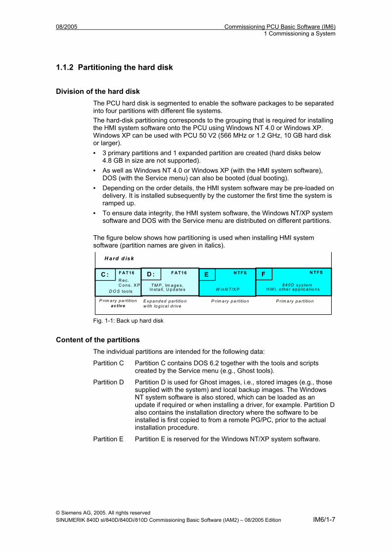
08/2005 Commissioning PCU Basic Software (IM6) 1 Commissioning a System
1.1.2 Partitioning the hard disk
Division of the hard disk The PCU hard disk is segmented to enable the software packages to be separated into four partitions with different file systems. The hard-disk partitioning corresponds to the grouping that is required for installing the HMI system software onto the PCU using Windows NT 4.0 or Windows XP. Windows XP can be used with PCU 50 V2 (566 MHz or 1.2 GHz, 10 GB hard disk or larger). • 3 primary partitions and 1 expanded partition are created (hard disks below
4.8 GB in size are not supported). • As well as Windows NT 4.0 or Windows XP (with the HMI system software),
DOS (with the Service menu) can also be booted (dual booting). • Depending on the order details, the HMI system software may be pre-loaded on
delivery. It is installed subsequently by the customer the first time the system is ramped up.
• To ensure data integrity, the HMI system software, the Windows NT/XP system software and DOS with the Service menu are distributed on different partitions.
The figure below shows how partitioning is used when installing HMI system software (partition names are given in italics).
P rim ary pa rtition P rim a ry pa rtition E xpanded pa rtitio n w ith lo g ica l d rive
C : F A T16
D O S too ls
E N TFS
W inN T /X P
F N TFS
840D sys tem H M I, o the r ap p lic a t io ns
D : F A T16
TM P , Im age s, Insta ll, U pda te s
H a rd d is k
R ec . C ons. X P
P rim ary pa rtition ac tive
Fig. 1-1: Back up hard disk
Content of the partitions The individual partitions are intended for the following data:
Partition C Partition C contains DOS 6.2 together with the tools and scripts created by the Service menu (e.g., Ghost tools).
Partition D Partition D is used for Ghost images, i.e., stored images (e.g., those supplied with the system) and local backup images. The Windows NT system software is also stored, which can be loaded as an update if required or when installing a driver, for example. Partition D also contains the installation directory where the software to be installed is first copied to from a remote PG/PC, prior to the actual installation procedure.
Partition E Partition E is reserved for the Windows NT/XP system software.
© Siemens AG, 2005. All rights reserved SINUMERIK 840D sl/840D/840Di/810D Commissioning Basic Software (IAM2) – 08/2005 Edition IM6/1-7
Commissioning PCU Basic Software (IM6) 08/2005 1 Commissioning a System
Partition F Partition F is intended for installing operator programs: Applications such as HMI system software (incl. data storage and temporary data), STEP7, OEM applications for HMI, or customer-specific applications should only be installed here.
Note
We strongly recommend that you install all applications in Partition F only. The size of the given partitions depends on the size of the hard disk and the Windows system.
1.1.3 Supplied software on the PCU The software installed on delivery of the PCU includes the components below, among others:
MS Windows NT 4.0 SP6a MS Windows XP Professional SP2
Internet Explorer V 5.5 SP2 (+ Security Update)
V 6.0
MS-DOS SW 6.21 SW 6.21
MPI driver V 05.08 V 6.02
USB V 4.2 V 5.64 SR4
Norton Ghost (default setting) V 6.01 V 7.5 (incl. Ghost Explorer)
Symantec Ghost Symantec Ghost Walker
V 7.5 V 7.5.0.335
V 7.5 V 7.5.0.335
Documentation for all Ghost tools is supplied on the PCU’s hard disk under path C:\TOOLS.
Note
Notes on using the PCU basic software can be found in file C:\Siemensd.rtf.
The versions of the Service menu (and Windows NT) system components contained in the PCU basic software can be found in file C:\BaseVers.txt.
The PCU basic software can be extended using HMI system software for operating Siemens SINUMERIK or OEM software for specific requirements. The Service menu, which is part of the PCU basic software, is used to perform the extension.
© Siemens AG, 2005. All rights reserved IM6/1-8 SINUMERIK 840D sl/840D/840Di/810D Commissioning Basic Software (IAM2) – 08/2005 Edition
08/2005 Commissioning PCU Basic Software (IM6) 1 Commissioning a System
System settings For reasons of security, Windows XP is preset as follows when updating to SP2:
• The Autorun function is deactivated. • Automatic Windows Update is deactivated. • Monitoring and alerts for antivirus software and automatic update are
deactivated. • Links used to call up Internet Explorer from the desktop and the Start menu
are removed. • Remote Procedure Call (RPC) is possible for calls that are not connected.
Changes to Windows services Other default settings:
Windows services: Start-up type: Computer Browser Manual (Not started) Error Reporting Service Disabled Portable Media Serial Number Manual (Not started) SSDP Discovery Service Disabled Universal Plug and Play Host Disabled Web Client Manual (Not started) Wireless Zero Configuration Manual (Not started)
Firewall settings Firewall settings are activated on the on-board Ethernet network card. The firewall settings are also activated if an additional Ethernet card is installed. The firewall settings for the second network card are not deactivated until the “PCU basic software Thin Client" is installed.
Service menu The Service menu is implemented using DOS. The Service menu is used to start a software install/update, which is then performed by Windows NT/XP (following a reboot). Data backup functions (Backup/Restore) are also carried out using the Service menu. The Boot Manager can be used to select between ramping up a SINUMERIK system and the Service menu.
ServiceCenter If a configuration contains one or more TCUs, data backup/restoration cannot be carried out with service programs on the DOS level. This is why the SINUMERIK desktop (Windows NT/XP) provides a link to the “ServiceCenter” program (see Section 4.3).
© Siemens AG, 2005. All rights reserved SINUMERIK 840D sl/840D/840Di/810D Commissioning Basic Software (IAM2) – 08/2005 Edition IM6/1-9
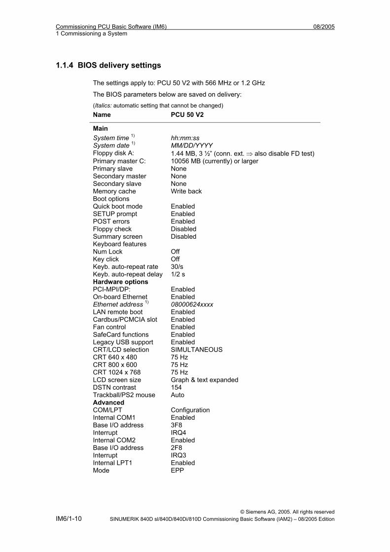
Commissioning PCU Basic Software (IM6) 08/2005 1 Commissioning a System
1.1.4 BIOS delivery settings The settings apply to: PCU 50 V2 with 566 MHz or 1.2 GHz
The BIOS parameters below are saved on delivery: (Italics: automatic setting that cannot be changed) Name PCU 50 V2
Main
System time 1) hh:mm:ss System date 1) MM/DD/YYYY Floppy disk A: 1.44 MB, 3 ½” (conn. ext. ⇒ also disable FD test) Primary master C: 10056 MB (currently) or larger Primary slave None Secondary master None Secondary slave None Memory cache Write back Boot options Quick boot mode Enabled SETUP prompt Enabled POST errors Enabled Floppy check Disabled Summary screen Disabled Keyboard features Num Lock Off Key click Off Keyb. auto-repeat rate 30/s Keyb. auto-repeat delay 1/2 s Hardware options PCI-MPI/DP: Enabled On-board Ethernet Enabled Ethernet address 1) 08000624xxxx LAN remote boot Enabled Cardbus/PCMCIA slot Enabled Fan control Enabled SafeCard functions Enabled Legacy USB support Enabled CRT/LCD selection SIMULTANEOUS CRT 640 x 480 75 Hz CRT 800 x 600 75 Hz CRT 1024 x 768 75 Hz LCD screen size Graph & text expanded DSTN contrast 154 Trackball/PS2 mouse Auto Advanced COM/LPT Configuration Internal COM1 Enabled Base I/O address 3F8 Interrupt IRQ4 Internal COM2 Enabled Base I/O address 2F8 Interrupt IRQ3 Internal LPT1 Enabled Mode EPP
© Siemens AG, 2005. All rights reserved IM6/1-10 SINUMERIK 840D sl/840D/840Di/810D Commissioning Basic Software (IAM2) – 08/2005 Edition
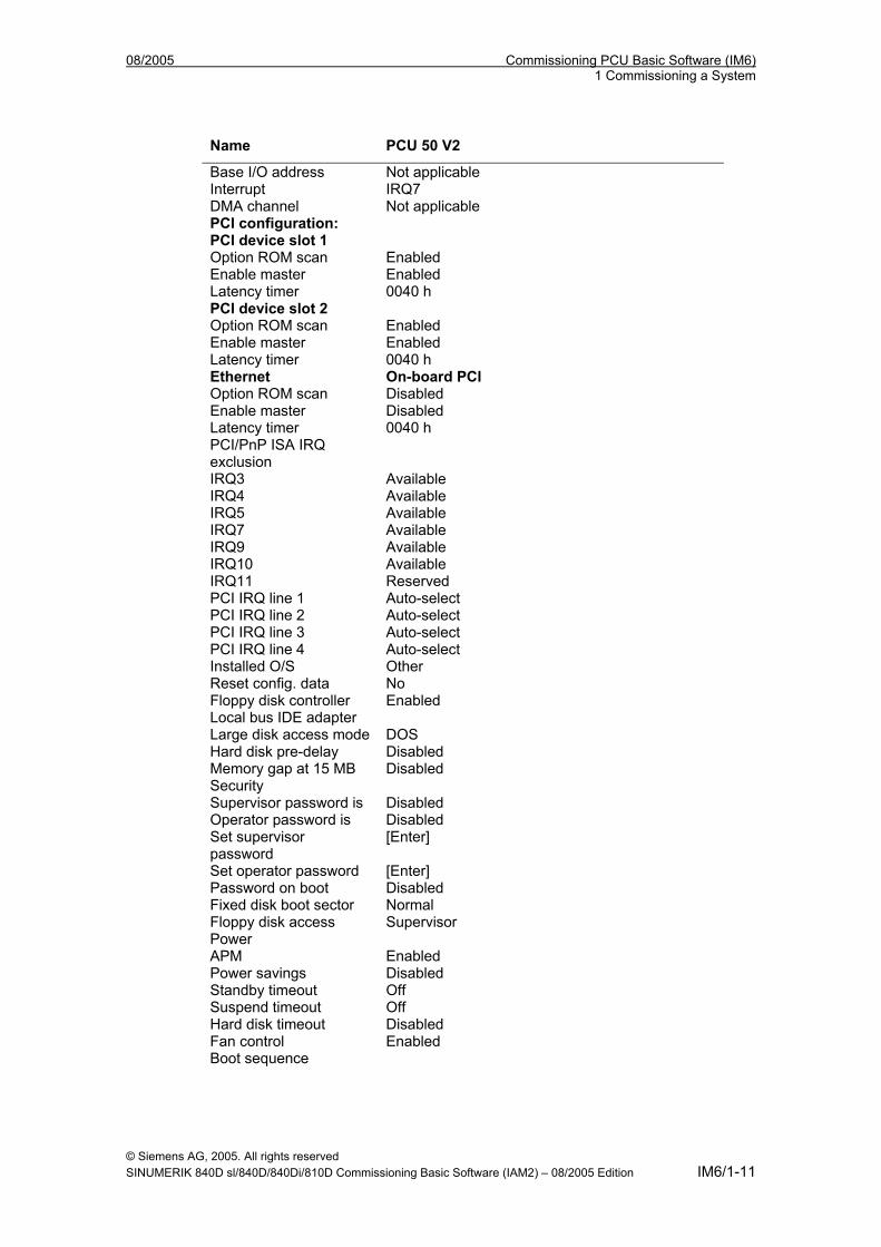
08/2005 Commissioning PCU Basic Software (IM6) 1 Commissioning a System
Name PCU 50 V2
Base I/O address Not applicable Interrupt IRQ7 DMA channel Not applicable PCI configuration: PCI device slot 1 Option ROM scan Enabled Enable master Enabled Latency timer 0040 h PCI device slot 2 Option ROM scan Enabled Enable master Enabled Latency timer 0040 h Ethernet On-board PCI Option ROM scan Disabled Enable master Disabled Latency timer 0040 h PCI/PnP ISA IRQ exclusion
IRQ3 Available IRQ4 Available IRQ5 Available IRQ7 Available IRQ9 Available IRQ10 Available IRQ11 Reserved PCI IRQ line 1 Auto-select PCI IRQ line 2 Auto-select PCI IRQ line 3 Auto-select PCI IRQ line 4 Auto-select Installed O/S Other Reset config. data No Floppy disk controller Enabled Local bus IDE adapter Large disk access mode DOS Hard disk pre-delay Disabled Memory gap at 15 MB Disabled Security Supervisor password is Disabled Operator password is Disabled Set supervisor password
[Enter]
Set operator password [Enter] Password on boot Disabled Fixed disk boot sector Normal Floppy disk access Supervisor Power APM Enabled Power savings Disabled Standby timeout Off Suspend timeout Off Hard disk timeout Disabled Fan control Enabled Boot sequence
© Siemens AG, 2005. All rights reserved SINUMERIK 840D sl/840D/840Di/810D Commissioning Basic Software (IAM2) – 08/2005 Edition IM6/1-11
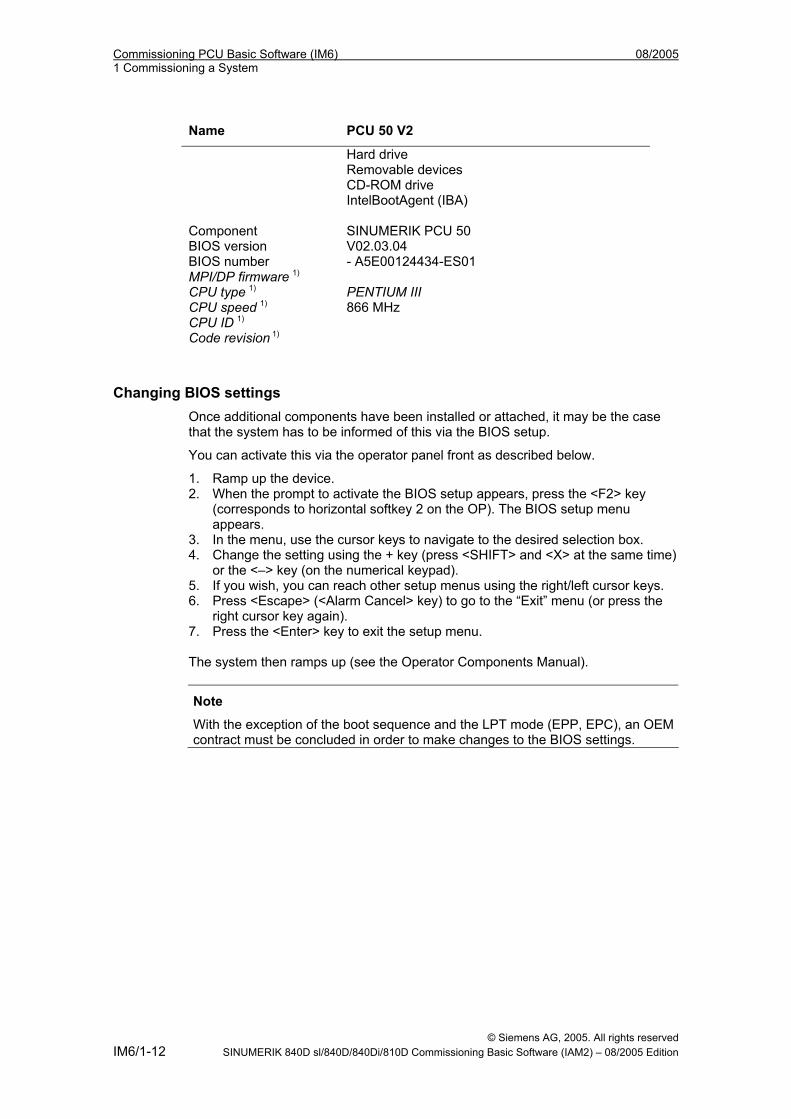
Commissioning PCU Basic Software (IM6) 08/2005 1 Commissioning a System
Name PCU 50 V2
Hard drive Removable devices CD-ROM drive IntelBootAgent (IBA) Component SINUMERIK PCU 50 BIOS version V02.03.04 BIOS number - A5E00124434-ES01 MPI/DP firmware 1) CPU type 1) PENTIUM III CPU speed 1) 866 MHz CPU ID 1) Code revision 1)
Changing BIOS settings Once additional components have been installed or attached, it may be the case that the system has to be informed of this via the BIOS setup.
You can activate this via the operator panel front as described below.
1. Ramp up the device. 2. When the prompt to activate the BIOS setup appears, press the <F2> key
(corresponds to horizontal softkey 2 on the OP). The BIOS setup menu appears.
3. In the menu, use the cursor keys to navigate to the desired selection box. 4. Change the setting using the + key (press <SHIFT> and <X> at the same time)
or the <–> key (on the numerical keypad). 5. If you wish, you can reach other setup menus using the right/left cursor keys. 6. Press <Escape> (<Alarm Cancel> key) to go to the “Exit” menu (or press the
right cursor key again). 7. Press the <Enter> key to exit the setup menu. The system then ramps up (see the Operator Components Manual).
Note
With the exception of the boot sequence and the LPT mode (EPP, EPC), an OEM contract must be concluded in order to make changes to the BIOS settings.
© Siemens AG, 2005. All rights reserved IM6/1-12 SINUMERIK 840D sl/840D/840Di/810D Commissioning Basic Software (IAM2) – 08/2005 Edition
08/2005 Commissioning PCU Basic Software (IM6) 1 Commissioning a System
1.1.5 Installing and activating software Windows NT or Windows XP is preinstalled on the PCU. The "PCU basic software" is comprised of the Windows system together with the service tools described below.
Service menu (under DOS) The Service menu is used to install software and back up data. • Transferring/extending HMI system software • Installing HMI system software via a network • Saving data on a hard disk (Backup/Restore). The Service menu is activated during booting and is described in the “Service menu functions” section.
SINUMERIK desktop The Windows area is intended for the service function, which can use the Windows features to commission the controller. • Installing HMI system software via a network • Installing additional software (e.g., installing additional languages) • Changing INI files/HW configuration (e.g., installing drivers) • Setting the HMI software runtime environment • Activating the SIMATIC STEP7 license key disk • Performing system checks (e.g., version check, disk check, etc.) • Installing and parameterizing UPS software Calling up the SINUMERIK desktop 1. Via DOS Service menu: menu item 4, then 1 or: 2. When the version display appears on the bottom right of the screen during
booting, press key "3". 3. Enter the password. 4. Select the first menu, "SINUMERIK desktop”, and confirm your selection with
the Enter key. The SINUMERIK desktop appears on the screen (see the “SINUMERIK desktop functions” section).
© Siemens AG, 2005. All rights reserved SINUMERIK 840D sl/840D/840Di/810D Commissioning Basic Software (IAM2) – 08/2005 Edition IM6/1-13
Commissioning PCU Basic Software (IM6) 08/2005 1 Commissioning a System
1.2 PCMCIA interface software The PCU 50/70 has an interface for PCMCIA components. Provision of the interface software varies for Windows NT and Windows XP.
PCMCIA interface software for Windows NT CardWare V6.0 software for Windows NT (single license) is available to allow memories/devices to be used in conjunction with this interface. Delivery The software is supplied on CD together with a readme
file (in English). Requirements Windows NT 4.0 with Service Pack 6 is required. Installation Establish a connection between the PCU 50/70 and the
CD drive as described in "Setting up access to external drives/computers". Start SETUP.EXE on the CD. Follow the operator prompting in InstallShield.
Restrictions The current restrictions can be found in PRODIS.
Usable media
Before removing a flash card, you should ensure that it is switched to "Slot Power Off". Once the CardWare V6.0 software is installed, the PCMCIA interface is ready to operate the following components (plug and play): • PCMCIA network card 3Com Megahertz 589E • PCMCIA card Xiron RealPort Ethernet 10/100 + Modem56 REM56G - 100 • PCMCIA flash card Toshiba TH6SS160402A (40 MB) • SanDisk 32 MB flash disk PCMCIA/PC CARD ATA • Callunacard 1040 MB Type III hard disk drive The manufacturers of the CardWare V6.0 software run a PC card knowledge base on their Website, where you can find other PCMCIA components that are supported.
Notes on use Before removing a flash card, you should ensure that it is switched to "Slot Power Off". This software is not intended for use with SINUCOPY, which did not form part of testing. After ramping up Windows NT 4.0, CardWare takes around 30 seconds to become active. This does not affect the booting of PCU 50/70 with HMI Advanced. CardWare V6.0 is not intended for use with Windows 2000.
© Siemens AG, 2005. All rights reserved IM6/1-14 SINUMERIK 840D sl/840D/840Di/810D Commissioning Basic Software (IAM2) – 08/2005 Edition
08/2005 Commissioning PCU Basic Software (IM6) 1 Commissioning a System
Address of the software supplier: APSoft Sonnenstrasse 26b 85622 Feldkirchen, Germany Internet: www.tssc.de Phone: +49 (0)89 900 479 0 Fax: +49 (0)89 900 479 11
PCMCIA interface software for Windows XP Standard PCMCIA applications are supported directly by Windows XP.
© Siemens AG, 2005. All rights reserved SINUMERIK 840D sl/840D/840Di/810D Commissioning Basic Software (IAM2) – 08/2005 Edition IM6/1-15
Commissioning PCU Basic Software (IM6) 08/2005 1 Commissioning a System
1.3 Boot manager
1.3.1 Powering up the system
Requirements Before connecting the PCU to the power supply, unlock the hard disk and connect an operator panel front and the keyboard and display/monitor peripherals. With the PCU 50/70 power supply switched off, insert the peripherals’ connecting cables into the corresponding sockets on the interface side of the PCU. Once the peripherals have been connected, the device is ready. Information about how to adjust and set your interface and the required connecting lead can be found in the Operator Guide that goes with the peripheral.
Connecting the power supply The PCU 50/PCU70 is supplied with 24 V DC. References: /BH/, Operator Components Manual
Switching on and switching off There is no power switch available, meaning that the power supply is switched on and off by inserting or removing the power-supply connector.
Note
When connecting peripherals, please make sure that the components are suitable for industrial use.
! Caution
When inserting or removing peripheral connections (keyboard, mouse, printer, etc.), the peripherals and the PCU must be disconnected from the power supply. Otherwise, they can become damaged. This does not apply to USB connections.
© Siemens AG, 2005. All rights reserved IM6/1-16 SINUMERIK 840D sl/840D/840Di/810D Commissioning Basic Software (IAM2) – 08/2005 Edition
08/2005 Commissioning PCU Basic Software (IM6) 1 Commissioning a System
1.3.2 Booting for first commissioning
Boot manager When booting the PCU, you can select the SINUMERIK system or the Service menu from the Boot Manager menu.
• SINUMERIK: SINUMERIK system This takes you to the beginning of the HMI system software or (for service purposes) to the SINUMERIK desktop (Windows XP).
• [hidden menu entry]: Service menu The Service menu under DOS is used to transfer software to be installed (e.g., if no network is available) and data backup.
• [hidden menu entry]: Recovery console (Windows XP) Details on this can be found in the original MS literature, under "Starting Windows Recovery Console".
First commissioning On first commissioning, the software that was ordered and loaded onto the hard disk (SINUMERIK products, possibly including HMI Advanced software) is installed as follows under Windows NT/XP: Welcome to SINUMERIK These SINUMERIK products will be installed now: <product 1> <product 2> <product 3> ... Install NOW Install at NEXT REBOOT CANCEL Installing
Scope of command buttons The command buttons can be selected using the Tab key and activated using the Enter key: Install NOW All the products displayed are installed one after another in the sequence in which they are listed. If a reboot is required to activate the installation, it is executed immediately after installation of the corresponding program. The system may, therefore, be rebooted several times until all products are installed. Install at NEXT REBOOT The screen above is displayed again the next time the system is rebooted. Nothing is installed immediately.
© Siemens AG, 2005. All rights reserved SINUMERIK 840D sl/840D/840Di/810D Commissioning Basic Software (IAM2) – 08/2005 Edition IM6/1-17
Commissioning PCU Basic Software (IM6) 08/2005 1 Commissioning a System
CANCEL Installing Nothing is installed and the screen is not displayed again the next time the system is rebooted. Later, other installations can then only be performed explicitly in Windows mode by activating the setup.exe programs directly from the Setup directories. If you want to install individual products at a later stage, activate the HMI Explorer via the SINUMERIK desktop. Then, in the HMI Explorer, select the product to be installed under the “Install” menu item (see also the “SINUMERIK desktop” section).
Errors during booting The following errors can occur during booting:
• Hard disk is still locked Remedy: Unlock hard disk
• PCU 50 does not ramp up, Remedy: See /BH/, Operator Components Manual
1.3.3 Checking for boot viruses
SYSLOCK V2 The SYSLOCK program is used to detect basic boot sector and partition table viruses. The fact that all viruses of this type have to be installed in a memory area just below the 640 KB limit for technical reasons is utilized to full advantage. These viruses then manipulate the BIOS so that it reduces the available memory and displays it as 639 KB, for example. The SYSLOCK driver uses this characteristic to detect a virus infection. In this way, both previously defined viruses and those not yet identified by the usual virus scanners can be detected. The main advantage of SYSLOCK when compared to conventional antivirus protection products is that the antivirus protection software does not have to be updated regularly. On the other hand, this means that the SYSLOCK driver cannot identify individual viruses or disinfect a system affected by a virus. This requires a full virus scanner product (e.g., Trend OfficeScan from Trend Micro, Inc.).
© Siemens AG, 2005. All rights reserved IM6/1-18 SINUMERIK 840D sl/840D/840Di/810D Commissioning Basic Software (IAM2) – 08/2005 Edition
08/2005 Commissioning PCU Basic Software (IM6) 1 Commissioning a System
Virus alarm If the program detects that the size of the main memory has changed since the first initialization, a virus alarm and the following system responses are triggered: • The program is paused for 30 seconds • A message is displayed on the screen • A message is logged in the file C:\SYSLOCK.LOG This file only exists if a virus
alarm was recorded the last time SYSLOCK was started. If a virus message is output, the system must be checked and disinfected using a full virus scanner. The conventional procedure should be used for disinfecting boot viruses: 1. Start the system from a clean, i.e., virus-free, boot diskette. 2. Open the virus scanner and disinfect the system. Once the system has been successfully disinfected, SYSLOCK.EXE automatically recognizes it as being "clean".
1.3.4 Starting booting using an HMI application Valid for: PCU 50 with PCU basic software WinNT 4.0 V07.03.04 or higher If an HMI application, e.g., HMI Advanced, is to be started following booting, the settings and functionality differ from those that apply if the Windows desktop is to be started.
Starting an HMI application on booting When the HMI application is exited, Windows NT shuts down completely. Keystroke sequences and function keys that were pressed simultaneously are then filtered. The keystroke sequences and functions that were pressed simultaneously and are to be filtered, can be configured in file E:\WinNT.40\System.ini. Filtering keystroke sequences: Section: MMC103Keyb Key: SeqAct Value: <bit mask>
(= keystroke sequences to be filtered, specified in accordance with the comment in E:\WinNT.40\System.ini)
Init value: 262143 Filtering function keys that were pressed simultaneously: Section: MMC103Keyb Key: ConcurrentKeyMask Value: <bit mask>
(= function keys to be filtered, specified in accordance with the comment in E:\WinNT.40\System.ini)
Init value: 255
© Siemens AG, 2005. All rights reserved SINUMERIK 840D sl/840D/840Di/810D Commissioning Basic Software (IAM2) – 08/2005 Edition IM6/1-19
Commissioning PCU Basic Software (IM6) 08/2005 1 Commissioning a System
Windows Explorer runs in the background and its settings (browser functionality, taskbar, start menu, etc.) prevents the Windows platform being accessed unintentionally.
Starting HMI desktop after booting Programs can be started at the same time as the HMI application and are started automatically by Windows when the HMI desktop is opened. This start in parallel to the HMI application can be configured. Programs in Windows Startup directories in E:\WinNT.40\Profiles: Key: HKLM\SOFTWARE\Siemens\SINUMERIK\Basic software\
<version>\HMI Manager Value: StartSINHMIStartupDirsPrograms (DWORD) Data: 1 (the programs are started) or
0 (the programs are NOT started) Init data: 0 Default data: 0 (if entry is not available/readable): Programs in the registry entries “HKCU\Software\Microsoft\Windows\CurrentVersion\Run” and “HKLM\Software\Microsoft\Windows\CurrentVersion\Run”: Key: HKLM\SOFTWARE\Siemens\SINUMERIK\Basic software\
<version>\HMI Manager Value: StartSINHMIRunPrograms (DWORD) Data: 1 (the programs are started) or
0 (the programs are NOT started) Init data: 0 Default data: 0 (if entry is not available/readable)
1.3.5 Starting booting using the HMI desktop Valid for: PCU 50 with PCU basic software WinNT 4.0 V07.03.04 or higher When an HMI application started from the HMI desktop is exited, you are returned to the HMI desktop. The keystroke sequences and function keys that are pressed simultaneously are filtered as a function of the configuration in file E:\WinNT.40\System.ini. Filtering keystroke sequences: Section: MMC103Keyb Key: KeySequencesEnable Value: 1 (= filtering of keystroke sequences specified in the SeqAct key) or
0 (= NO filtering) Init value: 0 Default value: 0 (if entry is not available/readable): Key: SeqAct Value: <bit mask>
(= keystroke sequences to be filtered, specified in accordance with the comment in E:\WinNT.40\System.ini)
Init value: 262143
© Siemens AG, 2005. All rights reserved IM6/1-20 SINUMERIK 840D sl/840D/840Di/810D Commissioning Basic Software (IAM2) – 08/2005 Edition
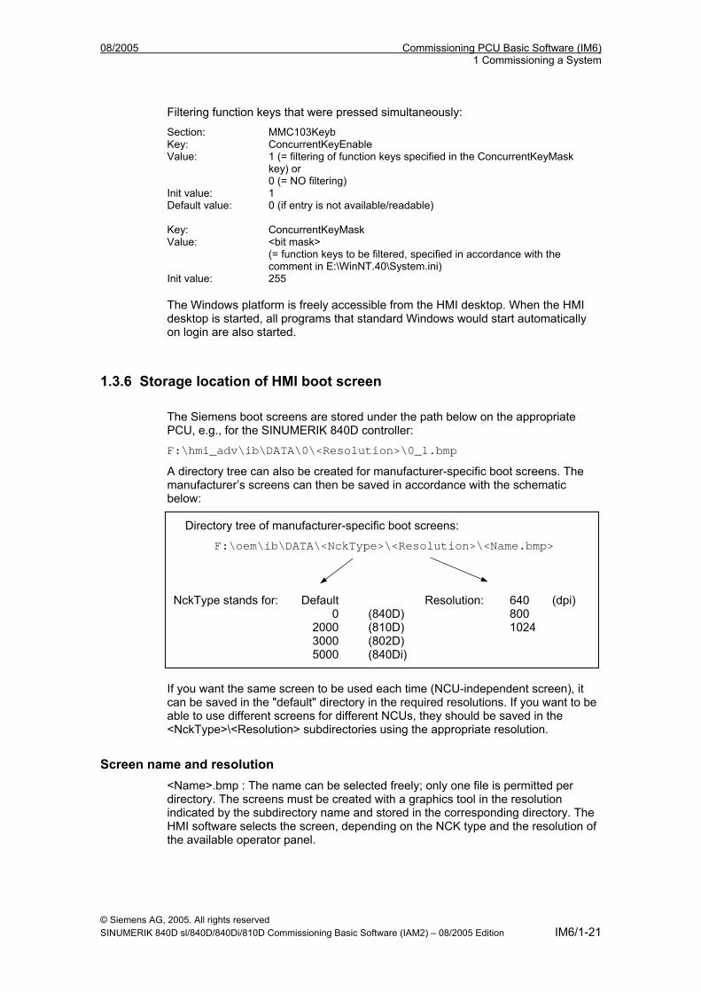
08/2005 Commissioning PCU Basic Software (IM6) 1 Commissioning a System
Filtering function keys that were pressed simultaneously: Section: MMC103Keyb Key: ConcurrentKeyEnable Value: 1 (= filtering of function keys specified in the ConcurrentKeyMask
key) or 0 (= NO filtering)
Init value: 1 Default value: 0 (if entry is not available/readable) Key: ConcurrentKeyMask Value: <bit mask>
(= function keys to be filtered, specified in accordance with the comment in E:\WinNT.40\System.ini)
Init value: 255 The Windows platform is freely accessible from the HMI desktop. When the HMI desktop is started, all programs that standard Windows would start automatically on login are also started.
1.3.6 Storage location of HMI boot screen The Siemens boot screens are stored under the path below on the appropriate PCU, e.g., for the SINUMERIK 840D controller:
F:\hmi_adv\ib\DATA\0\<Resolution>\0_1.bmp
A directory tree can also be created for manufacturer-specific boot screens. The manufacturer’s screens can then be saved in accordance with the schematic below:
Directory tree of manufacturer-specific boot screens:
F:\oem\ib\DATA\<NckType>\<Resolution>\<Name.bmp> NckType stands for: Default Resolution: 640 (dpi) 0 (840D) 800 2000 (810D) 1024 3000 (802D) 5000 (840Di)
If you want the same screen to be used each time (NCU-independent screen), it can be saved in the "default" directory in the required resolutions. If you want to be able to use different screens for different NCUs, they should be saved in the <NckType>\<Resolution> subdirectories using the appropriate resolution.
Screen name and resolution <Name>.bmp : The name can be selected freely; only one file is permitted per directory. The screens must be created with a graphics tool in the resolution indicated by the subdirectory name and stored in the corresponding directory. The HMI software selects the screen, depending on the NCK type and the resolution of the available operator panel.
© Siemens AG, 2005. All rights reserved SINUMERIK 840D sl/840D/840Di/810D Commissioning Basic Software (IAM2) – 08/2005 Edition IM6/1-21
Commissioning PCU Basic Software (IM6) 08/2005 1 Commissioning a System
1.3.7 Displaying an in-house boot screen or desktop background image Valid for: PCU 50 with PCU basic software WinNT 4.0 V06.02.01 or higher
Displaying an in-house boot screen Set up a directory containing several boot screens (for different panel resolutions). This directory should be segmented into subdirectories 640, 800 and 1024, which each contain a boot screen of the appropriate resolution. A directory containing default boot screens can also be set up, likewise divided into subdirectories 640, 800 and 1024. The default boot screen stored there for a particular resolution is displayed if no boot screen (including one with a lower resolution) is found in the booting-screen directory described above. If no default boot screen (including one with a lower resolution) is found, a general default boot screen is displayed, which is part of the PCU basic software. The paths of the directories mentioned must be set in the registry: Directory containing boot screens: Key: HKLM\SOFTWARE\Siemens\SINUMERIK\Basic software\
<version>\HMI Manager Value: BackgroundBitmapDir (STRING) Data: "<path>" (e.g., “E:\WinNT.40\System32\AppStartupBitmaps\1000\1”)
or “(None)” (= NO in-house boot screens) Init data: “(None)” Default data: “(None)” (if entry is not available/readable) Directory containing default boot screens: Key: HKLM\SOFTWARE\Siemens\SINUMERIK\Basic software\
<version>\HMI Manager Value: DefaultBackgroundBitmapDir (STRING) Data: “<path>” (e.g., “E:\WinNT.40\System32\DefStartupBitmaps”) or
“(None)” (= NO default boot screens) Init data: “(None)” Default data: “(None)” (if entry is not available/readable)
Changing the desktop background image The background pattern and image on the Windows desktop must be set in the registry as shown below (instead of via the Control Panel [Settings -> Control Panel -> Display -> Background]): Background pattern: Key: HKLM\SOFTWARE\Siemens\SINUMERIK\Basic software\
<version>\HMI desktop Value: Pattern (STRING) Data: “<bit code>” (e.g., “0 80 114 32 0 5 39 2”,
see HKCU\Control Panel\Patterns) “(None)” (= NO background pattern)
Init data: Background pattern previously set via the Control Panel Default data: “(None)” (if entry is not available/readable) Background image: Key: HKLM\SOFTWARE\Siemens\SINUMERIK\Basic
© Siemens AG, 2005. All rights reserved IM6/1-22 SINUMERIK 840D sl/840D/840Di/810D Commissioning Basic Software (IAM2) – 08/2005 Edition
08/2005 Commissioning PCU Basic Software (IM6) 1 Commissioning a System
software\<version>\HMI desktop Value: Bitmap (STRING) Data: “<path>” (e.g., “E:\WinNT.40\System32\Desktop.bmp”) or
“(StartupBitmap)” (the current boot screen is also the background image) or “(None)” (= NO background image)
Init data: Background image previously set via the Control Panel Default data: “(None)” (if entry is not available/readable)
Note
An attempt to set the Windows desktop background (as in standard Windows) via the Control Panel does not affect the desktop background display, but only the boot screen display.
1.4 Configuring HMI operators
Use You can configure the nominated Windows operator under which the HMI system software is always started (= HMI operator). The local Windows operator is the default HMI operator “audoperator”. Any other Windows operator can also become the HMI operator (instead of “audoperator”) if they are set up as a local Windows operator or a domain operator and possess administrator rights. The registry entries below must be made in order to register as an HMI operator:
Reference Default Key HKLM\SOFTWARE\Siemens\SINUMERIK\Basic software\<version>\
HMI Manager Operator Entry HMIOperatorName (STRING) audoperator Domain Entry HMIOperatorDomainName (STRING) local
For the HMIOperatorDomainName you should enter: for a domain operator: "<domainname>" for a local operator: "(local)" If the operator logs in as the (currently registered) HMI operator, the HMI system software starts automatically on booting. If the operator logs in as the HMI operator as another Windows operator, they are taken to the SINUMERIK desktop.
© Siemens AG, 2005. All rights reserved SINUMERIK 840D sl/840D/840Di/810D Commissioning Basic Software (IAM2) – 08/2005 Edition IM6/1-23
Commissioning PCU Basic Software (IM6) 08/2005 1 Commissioning a System
Auto logon The operator does not usually have to log on explicitly, as the system is configured in such a way that the operator is logged on as the HMI operator automatically. Should the operator wish to log on as another Windows operator, they have to hold down the Shift key on the PS2 keyboard or an external USB keyboard (not possible on the OP keyboard) once the boot screen has appeared. The Windows logon screen then appears and the operator has to enter the name and password of the desired Windows operator.
■
© Siemens AG, 2005. All rights reserved IM6/1-24 SINUMERIK 840D sl/840D/840Di/810D Commissioning Basic Software (IAM2) – 08/2005 Edition
08/2005 Commissioning PCU Basic Software (IM6) 2 Configuring a System
22 Configuring a System
2.1 Service menu functions (DOS function) ................................................ IM6/2-26 2.1.1 Service menu...................................................................................... IM6/2-26 2.1.2 Setting the original SINUMERIK HMI environment ............................ IM6/2-29 2.1.3 Setting the current SINUMERIK HMI environment............................. IM6/2-30 2.1.4 Starting DOS shell .............................................................................. IM6/2-32 2.1.5 Starting the SINUMERIK desktop....................................................... IM6/2-33 2.1.6 Checking the hard disk ....................................................................... IM6/2-34 2.1.7 Checking the PCU basic software version ......................................... IM6/2-35
2.2 SINUMERIK desktop functions (Windows) ........................................... IM6/2-35 2.2.1 Saving HMI desktop settings .............................................................. IM6/2-35 2.2.2 Installing system software or an update ............................................. IM6/2-36 2.2.3 Setting the original SINUMERIK HMI environment ............................ IM6/2-37 2.2.4 Setting the current SINUMERIK HMI environment............................. IM6/2-38 2.2.5 HMI Explorer functions ....................................................................... IM6/2-38 2.2.6 Error analysis...................................................................................... IM6/2-38 2.2.7 Starting OEM programs...................................................................... IM6/2-40
2.3 PCU 50/70 with SITOP UPS module..................................................... IM6/2-41 2.3.1 Starting and configuring the SITOP monitor....................................... IM6/2-42 2.3.2 Configuration of SITOP UPS module ................................................. IM6/2-43 2.3.3 Configuration for exiting the HMI........................................................ IM6/2-45
© Siemens AG, 2005. All rights reserved SINUMERIK 840D sl/840D/840Di/810D Commissioning Basic Software (IAM2) – 08/2005 Edition IM6/2-25
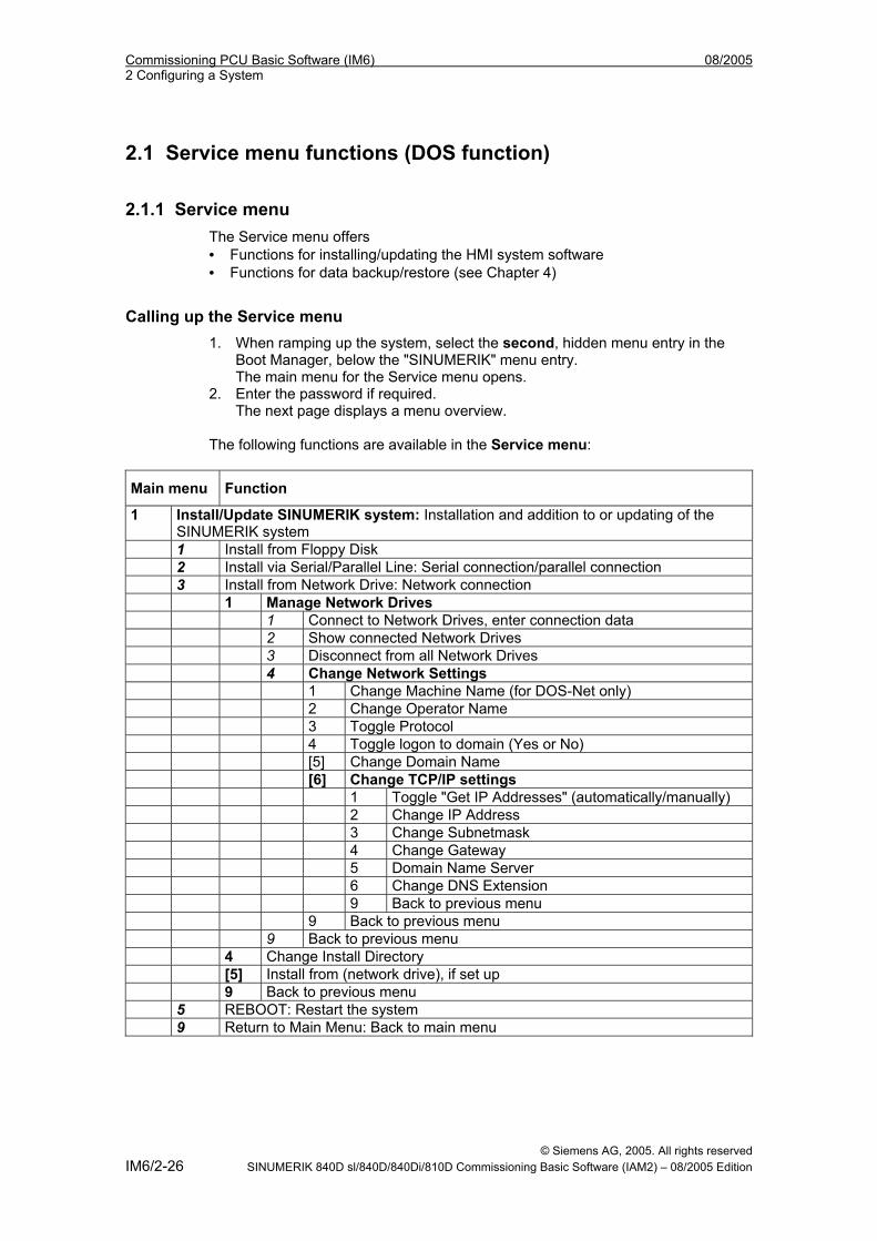
Commissioning PCU Basic Software (IM6) 08/2005 2 Configuring a System
2.1 Service menu functions (DOS function)
2.1.1 Service menu The Service menu offers • Functions for installing/updating the HMI system software • Functions for data backup/restore (see Chapter 4)
Calling up the Service menu 1. When ramping up the system, select the second, hidden menu entry in the
Boot Manager, below the "SINUMERIK" menu entry. The main menu for the Service menu opens.
2. Enter the password if required. The next page displays a menu overview.
The following functions are available in the Service menu:
Main menu Function
1 Install/Update SINUMERIK system: Installation and addition to or updating of the SINUMERIK system
1 Install from Floppy Disk 2 Install via Serial/Parallel Line: Serial connection/parallel connection 3 Install from Network Drive: Network connection 1 Manage Network Drives 1 Connect to Network Drives, enter connection data 2 Show connected Network Drives 3 Disconnect from all Network Drives 4 Change Network Settings 1 Change Machine Name (for DOS-Net only) 2 Change Operator Name 3 Toggle Protocol 4 Toggle logon to domain (Yes or No) [5] Change Domain Name [6] Change TCP/IP settings 1 Toggle "Get IP Addresses" (automatically/manually) 2 Change IP Address 3 Change Subnetmask 4 Change Gateway 5 Domain Name Server 6 Change DNS Extension 9 Back to previous menu 9 Back to previous menu 9 Back to previous menu 4 Change Install Directory [5] Install from (network drive), if set up 9 Back to previous menu 5 REBOOT: Restart the system 9 Return to Main Menu: Back to main menu
© Siemens AG, 2005. All rights reserved IM6/2-26 SINUMERIK 840D sl/840D/840Di/810D Commissioning Basic Software (IAM2) – 08/2005 Edition
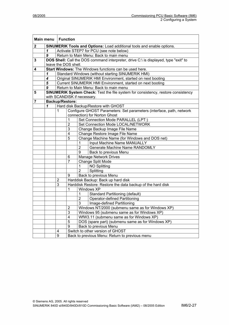
08/2005 Commissioning PCU Basic Software (IM6) 2 Configuring a System
Main menu Function
2 SINUMERIK Tools and Options: Load additional tools and enable options. 1 Activate STEP7 for PCU (see note below) 9 Return to Main Menu: Back to main menu 3 DOS Shell: Call the DOS command interpreter, drive C:\ is displayed, type "exit" to
leave the DOS shell. 4 Start Windows: The Windows functions can be used here. 1 Standard Windows (without starting SINUMERIK HMI) 4 Original SINUMERIK HMI Environment, started on next booting 5 Current SINUMERIK HMI Environment, started on next booting 9 Return to Main Menu: Back to main menu 5 SINUMERIK System Check: Test the file system for consistency, restore consistency
with SCANDISK if necessary. 7 Backup/Restore: 1 Hard disk Backup/Restore with GHOST 1 Configure GHOST Parameters: Set parameters (interface, path, network
connection) for Norton Ghost 1 Set Connection Mode PARALLEL (LPT:) 2 Set Connection Mode LOCAL/NETWORK 3 Change Backup Image File Name 4 Change Restore Image File Name 5 Change Machine Name (for Windows and DOS net) 1 Input Machine Name MANUALLY 2 Generate Machine Name RANDOMLY 9 Back to previous Menu 6 Manage Network Drives 7 Change Split Mode 1 NO Splitting 2 Splitting 9 Back to previous Menu 2 Harddisk Backup: Back up hard disk 3 Harddisk Restore: Restore the data backup of the hard disk 1 Windows XP 1 Standard Partitioning (default) 2 Operator-defined Partitioning 3 Image-defined Partitioning 2 Windows NT/2000 (submenu same as for Windows XP) 3 Windows 95 (submenu same as for Windows XP) 4 WfW3.11 (submenu same as for Windows XP) 5 DOS (spare part) (submenu same as for Windows XP) 9 Back to previous Menu 4 Switch to other version of GHOST 9 Back to previous Menu: Return to previous menu
© Siemens AG, 2005. All rights reserved SINUMERIK 840D sl/840D/840Di/810D Commissioning Basic Software (IAM2) – 08/2005 Edition IM6/2-27
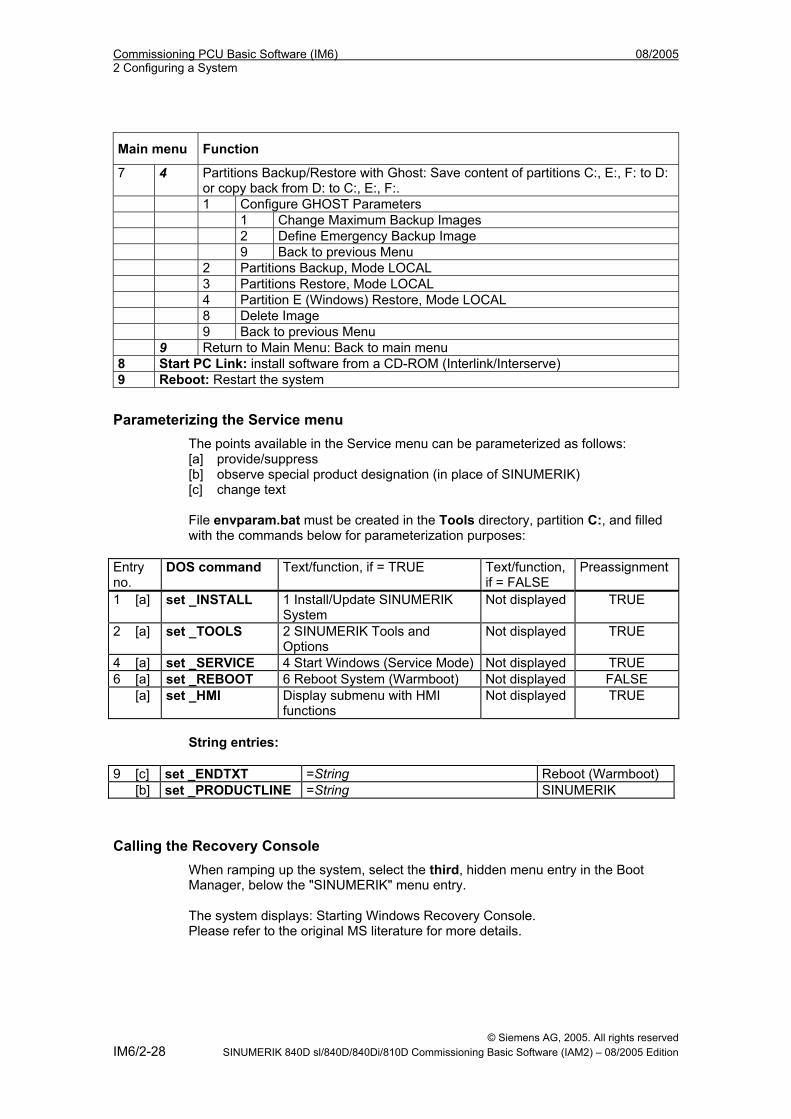
Commissioning PCU Basic Software (IM6) 08/2005 2 Configuring a System
Main menu Function
7 4 Partitions Backup/Restore with Ghost: Save content of partitions C:, E:, F: to D: or copy back from D: to C:, E:, F:.
1 Configure GHOST Parameters 1 Change Maximum Backup Images 2 Define Emergency Backup Image 9 Back to previous Menu 2 Partitions Backup, Mode LOCAL 3 Partitions Restore, Mode LOCAL 4 Partition E (Windows) Restore, Mode LOCAL 8 Delete Image 9 Back to previous Menu 9 Return to Main Menu: Back to main menu 8 Start PC Link: install software from a CD-ROM (Interlink/Interserve) 9 Reboot: Restart the system
Parameterizing the Service menu The points available in the Service menu can be parameterized as follows: [a] provide/suppress [b] observe special product designation (in place of SINUMERIK) [c] change text File envparam.bat must be created in the Tools directory, partition C:, and filled with the commands below for parameterization purposes:
Entry no.
DOS command Text/function, if = TRUE Text/function, if = FALSE
Preassignment
1 [a] set _INSTALL 1 Install/Update SINUMERIK System
Not displayed TRUE
2 [a] set _TOOLS 2 SINUMERIK Tools and Options
Not displayed TRUE
4 [a] set _SERVICE 4 Start Windows (Service Mode) Not displayed TRUE 6 [a] set _REBOOT 6 Reboot System (Warmboot) Not displayed FALSE [a] set _HMI Display submenu with HMI
functions Not displayed TRUE
String entries:
9 [c] set _ENDTXT =String Reboot (Warmboot) [b] set _PRODUCTLINE =String SINUMERIK
Calling the Recovery Console When ramping up the system, select the third, hidden menu entry in the Boot Manager, below the "SINUMERIK" menu entry. The system displays: Starting Windows Recovery Console. Please refer to the original MS literature for more details.
© Siemens AG, 2005. All rights reserved IM6/2-28 SINUMERIK 840D sl/840D/840Di/810D Commissioning Basic Software (IAM2) – 08/2005 Edition
08/2005 Commissioning PCU Basic Software (IM6) 2 Configuring a System
2.1.2 Setting the original SINUMERIK HMI environment The HMI environment is set to its original delivery condition. The content of the following directories is saved prior to this: - ADD_ON - OPERATOR - OEM The directories are then cleared.
Operation While the PCU is ramping up (after switching the controller off and then on again) 1. Select the Service menu [hidden menu entry] in the Boot Manager The following menu is displayed: PLEASE SELECT 1 Install/Update SINUMERIK System 2 SINUMERIK Tools and Options 3 DOS Shell 4 Start Windows (Service Mode) 5 SINUMERIK System Check 7 Backup/Restore 8 Start PC Link 9 Reboot (Warmboot) Your Choice [1, 2, 3, 4, 5, 7, 8, 9]? 2. Select option 4 The following menu is displayed: PLEASE SELECT 1 Standard Windows (without starting SINUMERIK HMI) 4 Original SINUMERIK HMI environment 5 Current SINUMERIK HMI environment 9 Return to Main Menu Your Choice [1, 4, 5, 9]?
Setting the environment 3. Select option 4 The system will ask you to enter the password: passwd:
© Siemens AG, 2005. All rights reserved SINUMERIK 840D sl/840D/840Di/810D Commissioning Basic Software (IAM2) – 08/2005 Edition IM6/2-29
Commissioning PCU Basic Software (IM6) 08/2005 2 Configuring a System
4. Enter one of the passwords for authorization levels 0 – 2. - System - Manufacturer - Service
Booting The system will then reboot automatically. The function is actually executed next time Windows is ramped up, before the HMI system software is started.
Note
The HMI environment can also be set to its original delivery condition by starting the “Original SINUMERIK HMI Environ” function from the SINUMERIK desktop.
2.1.3 Setting the current SINUMERIK HMI environment The original HMI environment setting is undone, that is, the contents of the saved directories are reloaded.
Operation While the PCU is ramping up (after switching the controller off and then on again) 1. Select the Service menu [hidden menu entry] in the Boot Manager The following menu is displayed: PLEASE SELECT 1 Install/Update SINUMERIK System 2 SINUMERIK Tools and Options 3 DOS Shell 4 Start Windows (Service Mode) 5 SINUMERIK System Check 7 Backup/Restore 8 Start PC Link 9 Reboot (Warmboot) Your Choice [1, 2, 3, 4, 5, 7, 8, 9]? 2. Select option 4
© Siemens AG, 2005. All rights reserved IM6/2-30 SINUMERIK 840D sl/840D/840Di/810D Commissioning Basic Software (IAM2) – 08/2005 Edition
08/2005 Commissioning PCU Basic Software (IM6) 2 Configuring a System
The following menu is displayed: PLEASE SELECT 1 Standard Windows (without starting SINUMERIK HMI) 4 Original SINUMERIK HMI environment 5 Current SINUMERIK HMI environment 9 Return to Main Menu Your Choice [1, 4, 5, 9]?
Setting the environment 3. Select option 5 The system will ask you to enter the password: passwd: 4. Enter one of the passwords for authorization levels 0 – 2. - System - Manufacturer - Service
Booting The system will then reboot automatically. The function is actually executed next time Windows is ramped up, before the HMI software is started.
Note
The original HMI environment setting can also be undone by starting the “Current SINUMERIK HMI Environ” function from the SINUMERIK desktop.
© Siemens AG, 2005. All rights reserved SINUMERIK 840D sl/840D/840Di/810D Commissioning Basic Software (IAM2) – 08/2005 Edition IM6/2-31
Commissioning PCU Basic Software (IM6) 08/2005 2 Configuring a System
2.1.4 Starting DOS shell
Operation While the PCU is ramping up (after switching the controller off and then on again) 1. Select the Service menu [hidden menu entry] in the Boot Manager The following menu is displayed: PLEASE SELECT 1 Install/Update SINUMERIK System 2 SINUMERIK Tools and Options 3 DOS Shell 4 Start Windows (Service Mode) 5 SINUMERIK System Check 7 Backup/Restore 8 Start PC Link 9 Reboot (Warmboot) Your Choice [1, 2, 3, 4, 5, 7, 8, 9]?
Starting DOS shell 2. Select option 3 The system will ask you to enter the password: passwd: 3. Enter one of the passwords for authorization levels 0 – 2. - System - Manufacturer - Service You are now in the DOS shell.
Exiting DOS shell To leave the DOS shell, type exit.
© Siemens AG, 2005. All rights reserved IM6/2-32 SINUMERIK 840D sl/840D/840Di/810D Commissioning Basic Software (IAM2) – 08/2005 Edition
08/2005 Commissioning PCU Basic Software (IM6) 2 Configuring a System
2.1.5 Starting the SINUMERIK desktop On the next booting, the SINUMERIK desktop (Windows) will start instead of the HMI system software.
Operation While the PCU is ramping up (after switching the controller off and then on again) 1. Select the Service menu [hidden menu entry] in the Boot Manager The following menu is displayed: PLEASE SELECT 1 Install/Update SINUMERIK System 2 SINUMERIK Tools and Options 3 DOS Shell 4 Start Windows (Service Mode) 5 SINUMERIK System Check 7 Backup/Restore 8 Start PC Link 9 Reboot (Warmboot) Your Choice [1, 2, 3, 4, 5, 7, 8, 9]?
Starting DOS shell 2. Select option 4 The following menu appears: PLEASE SELECT 1 Standard Windows (without starting SINUMERIK HMI) 4 Original SINUMERIK HMI environment 5 Current SINUMERIK HMI environment 9 Return to Main Menu Your Choice [1, 4, 5, 9]?
Starting the SINUMERIK desktop 3. Select option 1
Booting The system will then reboot automatically. The SINUMERIK desktop (Windows) is started instead of the HMI system software.
© Siemens AG, 2005. All rights reserved SINUMERIK 840D sl/840D/840Di/810D Commissioning Basic Software (IAM2) – 08/2005 Edition IM6/2-33
Commissioning PCU Basic Software (IM6) 08/2005 2 Configuring a System
Note
The SINUMERIK desktop can also be started by pressing key “3” (within a 3-second time window) when the PCU basic software version data appears on the background image during booting.
2.1.6 Checking the hard disk All partitions (C:, D:, E:, F:) on the hard disk are checked.
Operation While the PCU is ramping up (after switching the controller off and then on again) 1. Select the Service menu [hidden menu entry] in the Boot Manager The following menu is displayed: PLEASE SELECT 1 Install/Update SINUMERIK System 2 SINUMERIK Tools and Options 3 DOS Shell 4 Start Windows (Service Mode) 5 SINUMERIK System Check 7 Backup/Restore 8 Start PC Link 9 Reboot (Warmboot) Your Choice [1, 2, 3, 4, 5, 7, 8, 9]?
Checking the hard disk 2. Select option 5
Booting The system will then reboot automatically. The function is actually executed next time Windows NT/XP is ramped up, before the HMI system software is started.
Note
The hard disk can also be checked on the SINUMERIK desktop by starting the function "Check SINUMERIK System".
© Siemens AG, 2005. All rights reserved IM6/2-34 SINUMERIK 840D sl/840D/840Di/810D Commissioning Basic Software (IAM2) – 08/2005 Edition
08/2005 Commissioning PCU Basic Software (IM6) 2 Configuring a System
2.1.7 Checking the PCU basic software version The versions of the Service menu system components contained in the PCU basic software and those of Windows NT/XP are listed in file C:\BaseVers.txt. Alternatively, HMI Explorer can be activated on the SINUMERIK desktop.
Operation 1. Proceed as described in the “Starting DOS shell” section. 2. Enter: type BaseVers.txt
The version information is listed. To leave the DOS shell, type exit.
Result The PCU basic software version is displayed on the bottom right of the boot screen.
2.2 SINUMERIK desktop functions (Windows)
2.2.1 Saving HMI desktop settings Valid for: PCU 50 with PCU basic software WinNT 4.0 V06.01.07 or higher
Default setting Settings made on the HMI desktop (e.g., arrangement of icons on the HMI desktop) are not saved as standard when logging off. In other words, a service engineer should not find that any changes have been made to the HMI desktop, which could have been caused by another service engineer during a previous session.
Saving settings This behavior can be changed by making an entry in the registry. This registry entry determines whether the following settings are saved or not: • Moving and deleting of icons • Positions of open windows • Size and position of the taskbar Links on the HMI desktop are always saved, irrespective of the registry entry.
© Siemens AG, 2005. All rights reserved SINUMERIK 840D sl/840D/840Di/810D Commissioning Basic Software (IAM2) – 08/2005 Edition IM6/2-35
Commissioning PCU Basic Software (IM6) 08/2005 2 Configuring a System
Note
Application windows, which are still open prior to logging off, should be closed before exiting the HMI desktop if “Saving settings” is active. Otherwise, they would appear for a short period (via an Explorer running in the background) when the system is rebooted (directly before the HMI application is started), which could have a disruptive effect.
Saving the HMI desktop settings: Key: HKLM\SOFTWARE\Siemens\SINUMERIK\Basic software\ <version>\HMI
Manager Value: SaveSINDesktopSettings (DWORD) Data: 1 (HMI desktop settings are saved) or
0 (HMI desktop settings are NOT saved) Init data: - Value is not created by the basic software - Default data: (If entry is not available/readable): 0 The key is effective for all HMI and other operators.
2.2.2 Installing system software or an update
Installation path System software or a software update can be installed using the SINUMERIK desktop, as well as the Service menu (DOS). This mostly affects installation/update packages, which have been transferred to the PCU via the Windows network. Installation can be performed in two ways:
• The installation/update process can be started from the SINUMERIK desktop directly by executing the installation/update package.
• The installation/update package is stored in directory D:\INSTALL. The installation/update process is started automatically during booting when the PCU is next booted. Only when the installation or update process is completed does normal boot manager continue and, if necessary, HMI software started.
Automatic execution Several installation directories can be set to enable a operator setup to be executed automatically. Installation directories are the “Install” subdirectories, which are listed in the SetupDirs section of the E:\Windows\System32\HMIServe.ini parameters file. The "D:\Install" installation directory is preset there. The key names contained within a section of the E:\Windows\System32\HMIServe.ini parameters file must be unique.
© Siemens AG, 2005. All rights reserved IM6/2-36 SINUMERIK 840D sl/840D/840Di/810D Commissioning Basic Software (IAM2) – 08/2005 Edition
08/2005 Commissioning PCU Basic Software (IM6) 2 Configuring a System
Note
Prior to automatic execution of setups from the installation directories (e.g., D:\Install), a checkback screen is always displayed and must be acknowledged manually. Remedy: A value can be configured in the registry to set whether the checkback screen should be displayed or not. Path in the registry: ‘HKLM\SOFTWARE\Siemens\SINUMERIK\Basic software\ <version>\HMI Manager\ShowInstallStartDialog’ ShowInstallStartDialog = 0: Screen is not displayed (default setting) = 1: Screen is displayed
The installation directories are evaluated in the sequence described in the parameters file. If the parameters file is missing or if it does not contain a “SetupDirs” section, the preset "D:\Install” installation directory is considered instead. If the “SetupDirs” section does contain installation directories, but not “D:\Install”, the “D:\Install” directory is not considered within the context of the set installation directories. When executing a setup using OpFile, whether or not the setup requires a reboot once it has been completed is taken into account and displayed via a corresponding OpFile entry. If a corresponding entry exists, a reboot is triggered. If there is a chain of setups to be executed one after the other, the reboot is performed once the final setup is complete.
Note
Installing the HMI system software or an update using the Service menu (DOS) is described in Section 3.3.
2.2.3 Setting the original SINUMERIK HMI environment The "Original SINUMERIK HMI Environ" function is available as a script file on the SINUMERIK desktop. The original delivery condition is set up, i.e., the contents of the directories below are saved, when this function is executed:
- F:\ADD_ON - F:\OPERATOR - F:\OEM - C:\RUNOEM
The directories are then cleared.
© Siemens AG, 2005. All rights reserved SINUMERIK 840D sl/840D/840Di/810D Commissioning Basic Software (IAM2) – 08/2005 Edition IM6/2-37
Commissioning PCU Basic Software (IM6) 08/2005 2 Configuring a System
Note
The function can also be triggered from the Service menu (DOS). It is then executed during the Windows NT booting (before the HMI system software is started), without displaying the SINUMERIK desktop.
2.2.4 Setting the current SINUMERIK HMI environment The "Current SINUMERIK HMI Environ" function is available as a script file on the SINUMERIK desktop. When this function is executed, restoration of the original settings is canceled, i.e., the saved directory contents are copied back.
Note
The function can also be triggered from the Service menu (DOS). It is then executed during the Windows booting (before the HMI system software is started), without displaying the SINUMERIK desktop.
2.2.5 HMI Explorer functions There is (sometimes) an option to start and uninstall individual HMI applications from the HMI Explorer.
Displaying component information The component information of a product is displayed in the Component dialog box. Selecting the “Component” option in the Export Settings allows component information to be printed or saved. The current internal version is displayed in the Info dialog box; the internal versions of the Release, Service Pack and Hotfix are displayed in the History dialog box. This information is also saved and printed if the Info and History tabs are selected in the Export Settings.
2.2.6 Error analysis
Checking the hard disk The "Check SINUMERIK System" function is available as a script file on the SINUMERIK desktop. All partitions (C:, D:, E:, F:) on the hard disk are checked when this function is executed.
Note
The function can also be triggered from the Service menu (DOS). It is then executed during the Windows booting (before the HMI system software is started), without displaying the SINUMERIK desktop.
© Siemens AG, 2005. All rights reserved IM6/2-38 SINUMERIK 840D sl/840D/840Di/810D Commissioning Basic Software (IAM2) – 08/2005 Edition
08/2005 Commissioning PCU Basic Software (IM6) 2 Configuring a System
Generating dump information Windows NT/XP is configured such that if a system crash (blue screen) occurs, Windows generates a dump containing current system information. The dump is stored in the file D:\Memory.dmp.
Checking versions of the HMI system software The “HMI Explorer” Windows program is available on the SINUMERIK desktop. When this program is called, detailed version information relating to the HMI system software applications installed and to Windows NT/XP is displayed.
Log file Whenever the system is ramped up, information is written to a block in the file D:\$$Base.log, which contains the date, time and nature of administrative interventions. Information about the booting, controlled by the HMI Manager, can be displayed on the screen and written to log file D:\$$Base.log. Output is controlled via registry values: • The type of information to be output is set via registry value
“HKLM\SOFTWARE\Siemens\SINUMERIK\Basic software\<version>\HMI Manager\InfoLevel”:
InfoLevel (DWORD) = 1: Mandatory information is output (default setting) = 2: Mandatory and supplementary information is output = 3: Mandatory, supplementary and trace information is output
(InfoLevel <= 0 treated as InfoLevel == 1, InfoLevel > 3 treated as Info Level == 3)
• Whether the information is also to be displayed on the screen (as well as being output to the log file) is set via registry value “HKLM\SOFTWARE\Siemens\SINUMERIK\Basic software\<version>\HMI Manager\ShowInfo”:
ShowInfo (DWORD) = 0: Only mandatory information is displayed, not supplementary or trace
information = 1: Mandatory, supplementary and trace information is displayed
(default setting)
© Siemens AG, 2005. All rights reserved SINUMERIK 840D sl/840D/840Di/810D Commissioning Basic Software (IAM2) – 08/2005 Edition IM6/2-39
Commissioning PCU Basic Software (IM6) 08/2005 2 Configuring a System
2.2.7 Starting OEM programs You can start OEM programs directly before starting the HMI system software. This requires these programs (or links to them) to be stored in subdirectories of the directory C:\RunOEM.
Starting OEM programs The subdirectories are executed in the order listed. The programs within a subdirectory are started in the chronological order in which they were placed in the subdirectory. • Programs in the C:\RunOEM\SeqOnce subdirectory are started once and
sequentially, i.e., a program is not started until the previously started program is completed.
• Programs in the C:\RunOEM\Seq subdirectory are started sequentially
whenever the system is ramped up, i.e., a program is not started until the previously started program is completed.
• Programs in the C:\RunOEM\ParOnce subdirectory are started once and
simultaneously. They run in parallel with the HMI system software. • Programs in the C:\RunOEM\Par subdirectory are started simultaneously
whenever the system is ramped up. They run in parallel with the HMI system software.
Not only program files, but also other types of file can be stored in the subdirectories, which are then opened in accordance with their file type. For example, ".txt" files are opened using Notepad, ".htm" files are opened using Internet Explorer.
Information about the current software version The SIEMENSD or SIEMENSE documents on the SINUMERIK desktop contain explanations, notes and supplementary conditions relating to the currently loaded PCU basic software.
© Siemens AG, 2005. All rights reserved IM6/2-40 SINUMERIK 840D sl/840D/840Di/810D Commissioning Basic Software (IAM2) – 08/2005 Edition
08/2005 Commissioning PCU Basic Software (IM6) 2 Configuring a System
2.3 PCU 50/70 with SITOP UPS module
Application If the supply voltage to the PCU 50/70 dips, the SITOP UPS modules below could maintain operation for a limited period if a backup battery is being used, allowing the HMI to be properly shut down before the battery is exhausted: 6EP1931-2DC31 6 A module with serial interface or 6EP1931-2EC31 15 A module with serial interface or 6EP1931-2DC41 6 A module with USB interface or 6EP1931-2EC41 15 A module with USB interface
Note
The UPS modules with USB interfaces can only be used on a PCU 50 with WinXP PCU basic software.
Requirements • PCU 50, V2 or higher • Windows XP PCU basic software, V07.03.02 or higher or
Windows NT 4.0 PCU basic software, V 07.03.04 or higher for serial interfaces • Windows XP PCU basic software, V07.04.00 or higher for USB interfaces • HMI Advanced, V06.03.14 or higher • SITOP software, V2.5.2.4 or higher is installed:
SITOP software is available for download from: http://www.ad.siemens.com/sitop
• SITOP monitor/configuration program is installed: To enable this, the SITOP software must be copied to the E:\SITOP directory set up on the PCU 50. This directory already contains PCU 50 tools required for shutdown on the SITOP UPS. If this directory does not exist in an older version of the PCU basic software, it must be created so that it will be compatible for any subsequent updating of the PCU basic software.
• UPS USB driver for Windows XP is installed: Installation is described in the relevant SITOP documentation. The documentation is part of the SITOP software download package.
• The SITOP UPS hardware is connected.
Note
The "SITOP UPS" function has been tested in the standard configuration of HMI Advanced. When installing add-on or OEM software components, the shutdown procedure of the complete system has to be checked by the operator.
© Siemens AG, 2005. All rights reserved SINUMERIK 840D sl/840D/840Di/810D Commissioning Basic Software (IAM2) – 08/2005 Edition IM6/2-41
Commissioning PCU Basic Software (IM6) 08/2005 2 Configuring a System
2.3.1 Starting and configuring the SITOP monitor 1. The SITOP monitor has to be started by Windows automatically during
booting. A new value has to be entered for the SITOP monitor under the key below in the Windows registry:
[HKEY_LOCAL_MACHINE\SOFTWARE\Microsoft\Windows\CurrentVersion\Run] ValueName: SITOP ValueType: REG_SZ Value Data: E:\SITOP\SITOP_DC_UPS.exe
2. An XP script file, sitop.reg, is located in the E:\SITOP directory. The required
key is entered into the XP registry automatically if this file is executed. 3. The SITOP monitor is started automatically once the PCU 50 is restarted. The
next installation step is to configure the monitor.
Notice
The SITOP monitor must not be started via the Windows Autostart directory.
General settings The following settings must be made in the SITOP-monitor configuration dialog box:
Parameterization of the interface: COM2 for a module with a serial interface USB for a module with a USB interface
•
• Parameterization of the change action: The monitoring window display must be deselected, as this function can lead to sporadic faults on the HMI operator interface.
Parameterization of the SITOP monitor Enter the path of the program that ensures that HMI Advanced and the PCU shut down properly in the event of a power failure into the parameter area of the buffer. E:\SITOP\Shutdown.bat Alternatively, the following settings should be used for XP 07.03 or NT 07.03.04 PCU basic software:
Path for XP: E:\Windows\system32\hmiexit.exe Path for NT 4.0: E:\WINNT.40\System32\hmiexit.exe
© Siemens AG, 2005. All rights reserved IM6/2-42 SINUMERIK 840D sl/840D/840Di/810D Commissioning Basic Software (IAM2) – 08/2005 Edition
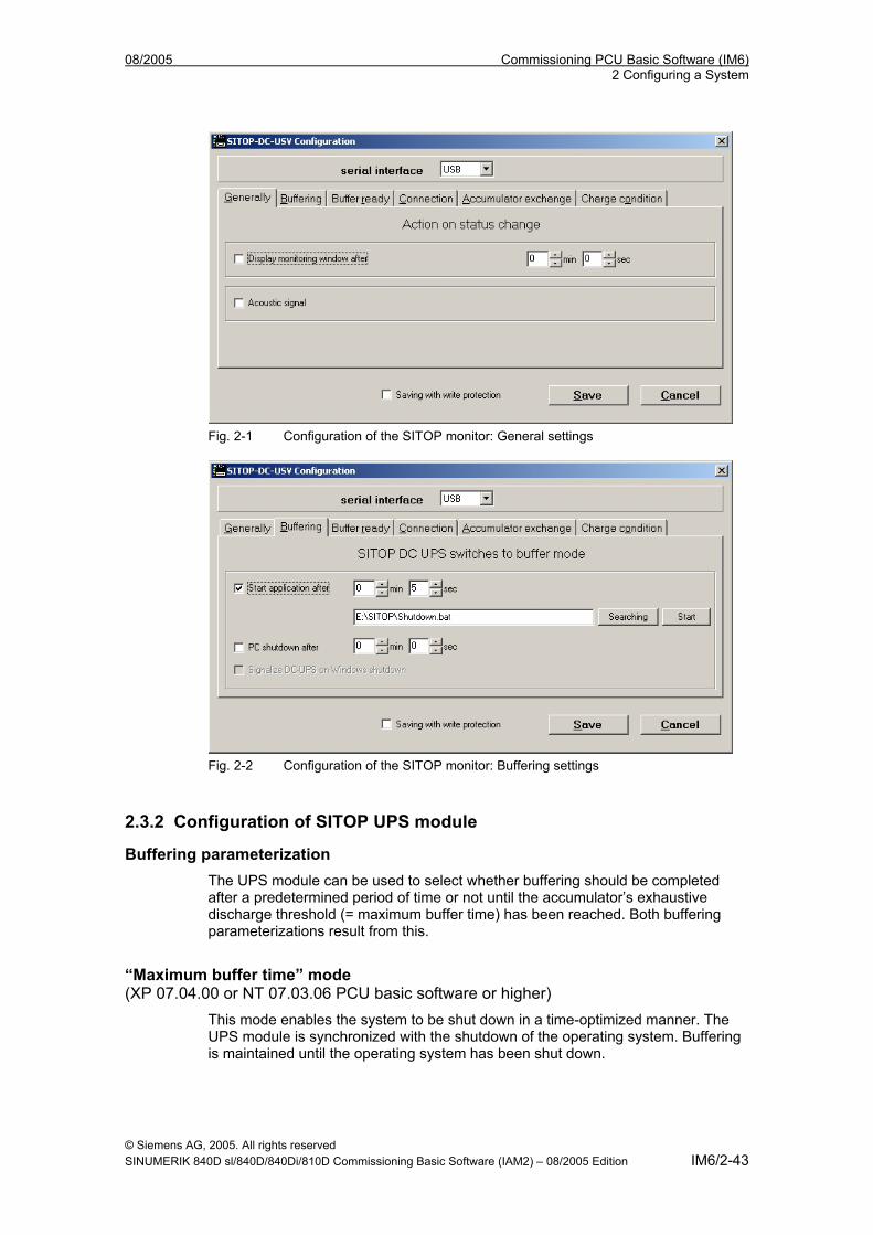
08/2005 Commissioning PCU Basic Software (IM6) 2 Configuring a System
Fig. 2-1 Configuration of the SITOP monitor: General settings
Fig. 2-2 Configuration of the SITOP monitor: Buffering settings
2.3.2 Configuration of SITOP UPS module
Buffering parameterization The UPS module can be used to select whether buffering should be completed after a predetermined period of time or not until the accumulator’s exhaustive discharge threshold (= maximum buffer time) has been reached. Both buffering parameterizations result from this.
“Maximum buffer time” mode (XP 07.04.00 or NT 07.03.06 PCU basic software or higher)
This mode enables the system to be shut down in a time-optimized manner. The UPS module is synchronized with the shutdown of the operating system. Buffering is maintained until the operating system has been shut down.
© Siemens AG, 2005. All rights reserved SINUMERIK 840D sl/840D/840Di/810D Commissioning Basic Software (IAM2) – 08/2005 Edition IM6/2-43
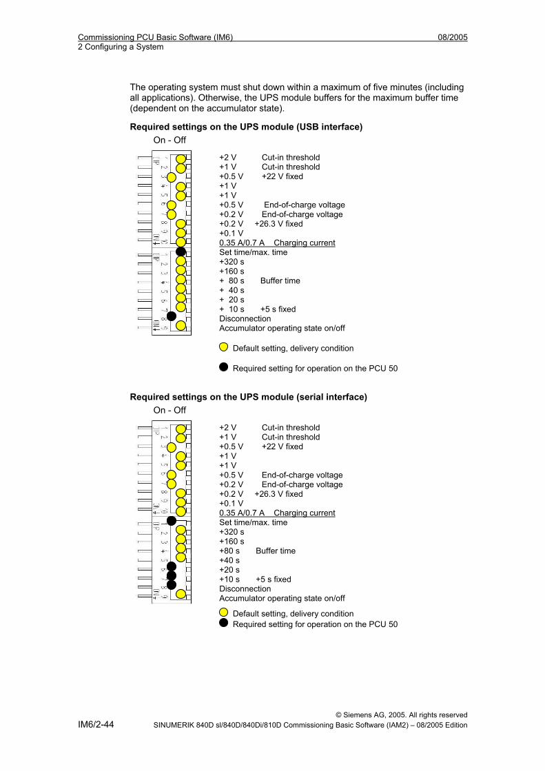
Commissioning PCU Basic Software (IM6) 08/2005 2 Configuring a System
The operating system must shut down within a maximum of five minutes (including all applications). Otherwise, the UPS module buffers for the maximum buffer time dependent on the accumulator state). (
Required settings on the UPS module (USB interface)
On - Off
+2 V Cut-in threshold +1 V Cut-in threshold +0.5 V +22 V fixed +1 V +1 V +0.5 V End-of-charge voltage +0.2 V End-of-charge voltage +0.2 V +26.3 V fixed +0.1 V 0.35 A/0.7 A Charging current Set time/max. time +320 s +160 s + 80 s Buffer time + 40 s + 20 s + 10 s +5 s fixed Disconnection Accumulator operating state on/off
Default setting, delivery condition
Required setting for operation on the PCU 50
Required settings on the UPS module (serial interface)
On - Off
+2 V Cut-in threshold +1 V Cut-in threshold +0.5 V +22 V fixed +1 V +1 V +0.5 V End-of-charge voltage +0.2 V End-of-charge voltage +0.2 V +26.3 V fixed +0.1 V 0.35 A/0.7 A Charging current Set time/max. time +320 s +160 s +80 s Buffer time +40 s +20 s +10 s +5 s fixed Disconnection A
ccumulator operating state on/off
Default setting, delivery condition Required setting for operation on the PCU 50
© Siemens AG, 2005. All rights reserved IM6/2-44 SINUMERIK 840D sl/840D/840Di/810D Commissioning Basic Software (IAM2) – 08/2005 Edition
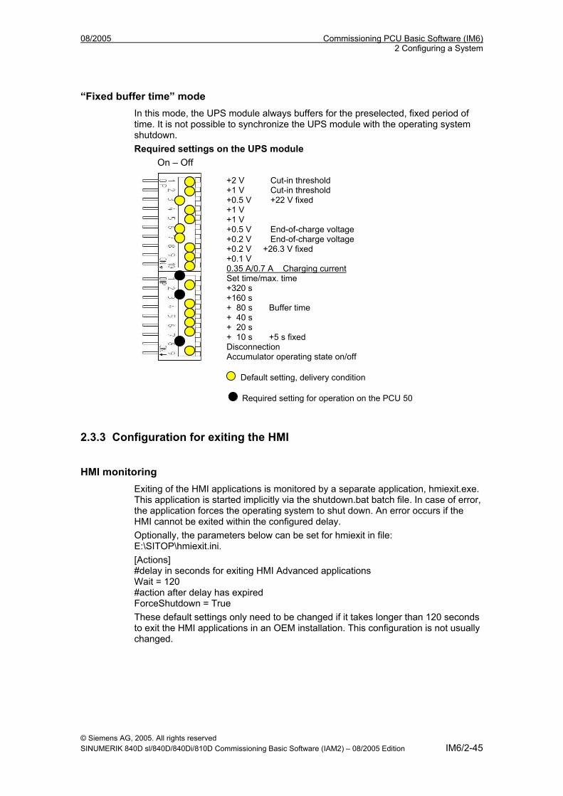
08/2005 Commissioning PCU Basic Software (IM6) 2 Configuring a System
“Fixed buffer time” mode In this mode, the UPS module always buffers for the preselected, fixed period of time. It is not possible to synchronize the UPS module with the operating system shutdown. Required settings on the UPS module
On – Off
+2 V Cut-in threshold +1 V Cut-in threshold +0.5 V +22 V fixed +1 V +1 V +0.5 V End-of-charge voltage +0.2 V End-of-charge voltage +0.2 V +26.3 V fixed +0.1 V 0.35 A/0.7 A Charging current Set time/max. time +320 s +160 s + 80 s Buffer time + 40 s + 20 s + 10 s +5 s fixed Disconnection Accumulator operating state on/off
Default setting, delivery condition
Required setting for operation on the PCU 50
2.3.3 Configuration for exiting the HMI
HMI monitoring Exiting of the HMI applications is monitored by a separate application, hmiexit.exe. This application is started implicitly via the shutdown.bat batch file. In case of error, the application forces the operating system to shut down. An error occurs if the HMI cannot be exited within the configured delay. Optionally, the parameters below can be set for hmiexit in file: E:\SITOP\hmiexit.ini. [Actions] #delay in seconds for exiting HMI Advanced applications Wait = 120 #action after delay has expired ForceShutdown = True These default settings only need to be changed if it takes longer than 120 seconds to exit the HMI applications in an OEM installation. This configuration is not usually changed.
© Siemens AG, 2005. All rights reserved SINUMERIK 840D sl/840D/840Di/810D Commissioning Basic Software (IAM2) – 08/2005 Edition IM6/2-45
Commissioning PCU Basic Software (IM6) 08/2005 2 Configuring a System
Configuring the EXIT button During production, the option to shut down the HMI via the EXIT button in the operating area menu should be disabled, as this function cannot be synchronized with the UPS module. The EXIT button is disabled by entering ExitButton=False in the Regie.ini file.
Hibernate The operating system’s hibernate mode is suspended when operating the UPS, as the USB interface always has to be active for the UPS module.
References: //For more notes, please see the product descriptions using the corresponding order numbers.
© Siemens AG, 2005. All rights reserved IM6/2-46 SINUMERIK 840D sl/840D/840Di/810D Commissioning Basic Software (IAM2) – 08/2005 Edition
08/2005 Commissioning PCU Basic Software (IM6) 3 Installing Software and Network Operation
33 Installing Software and Network Operation
3.1 Installing software and software update ................................................ IM6/3-49 3.1.1 Installing an upgrade or Service Pack................................................ IM6/3-49 3.1.2 “Silently” installing an upgrade or Service Pack ................................. IM6/3-50 3.1.3 Installation with FAT16 data file structure .......................................... IM6/3-52 3.1.4 Installation with FAT32 data file structure .......................................... IM6/3-54 3.1.5 Installation via a network connection.................................................. IM6/3-55
3.2 Settings for network drives .................................................................... IM6/3-60 3.2.1 PG/PC requirements .......................................................................... IM6/3-60 3.2.2 Network operation with Windows NT/XP............................................ IM6/3-61 3.2.3 Settings via the PCU Service menu ................................................... IM6/3-61
3.3 Network operation with the SINUMERIK desktop ................................. IM6/3-67 3.3.1 Installing SIMATIC STEP7 for SINUMERIK hardware....................... IM6/3-69 3.3.2 Authorizing SIMATIC STEP7 via the Service menu........................... IM6/3-71 3.3.3 Authorizing SIMATIC STEP7 via the SINUMERIK desktop ............... IM6/3-72
© Siemens AG, 2005. All rights reserved SINUMERIK 840D sl/840D/840Di/810D Commissioning Basic Software (IAM2) – 08/2005 Edition IM6/3-47
Commissioning PCU Basic Software (IM6) 08/2005 3 Installing Software and Network Operation
Overview This chapter describes how to install or update additional software based on the preinstalled WinNT/WinXP PCU basic software. The description below is based on the delivery condition of the hardware and software components. The Service menu and the SINUMERIK desktop are both important tools.
© Siemens AG, 2005. All rights reserved IM6/3-48 SINUMERIK 840D sl/840D/840Di/810D Commissioning Basic Software (IAM2) – 08/2005 Edition
08/2005 Commissioning PCU Basic Software (IM6) 3 Installing Software and Network Operation
3.1 Installing software and software update Valid for: PCU 50 with PCU basic software WinNT 4.0 V06.03.06 or higher and V07.03.05 or higher
3.1.1 Installing an upgrade or Service Pack Upgrades and Service Packs for the WinNT 4.0 PCU basic software are provided in two ways: • Setup directory: All files required for the installation, including Setup.exe, cab files, Setup.ini,
etc., are stored together in one directory. The installation is started by starting Setup.exe.
• Self-extracting setup: First, when started, Setup.exe extracts itself to a temporary setup directory
and then starts the installation by starting Setup.exe, which is stored there. Upgrades and Service Packs can be processed in two ways, irrespective of how they are provided: • Independent setup: The entire installation is controlled by the setup itself. In particular, setup is
responsible for executing any necessary reboots during and/or after installation.
The behavior of the setup is controlled via the Setup.ini control file. This is
contained in the (temporary) setup directory as standard. The control parameters are set for interactive installation as standard.
When setup finds the control file in the (temporary) setup directory, it is evaluated.
• Subsetup of a frame setup:
Setup is started from a frame setup and, as such, does not have full control over the installation procedure. Instead, it reports state changes and results, such as success/failure, completion, cancellation, or any necessary reboots during and/or after installation, to the frame setup. The frame setup is then responsible for carrying out the appropriate measures. The behavior of the setup is controlled via the OpFile.txt control file. This is contained in the (temporary) setup directory as standard. The control parameters are set for silent installation as standard. Setup only evaluates the control file when call parameter -OF is entered when the file is called, e.g., Setup.exe -OF:.\OpFile.txt. In this case, the control file can be stored in any directory.
Note
There must not be any blank between -OF: and .\OpFile.txt.
© Siemens AG, 2005. All rights reserved SINUMERIK 840D sl/840D/840Di/810D Commissioning Basic Software (IAM2) – 08/2005 Edition IM6/3-49
Commissioning PCU Basic Software (IM6) 08/2005 3 Installing Software and Network Operation
The -OF call parameter lets setup know that it is running as the subsetup of a frame setup. In this case, before setup is completed, it stores information about other measures to be carried out by the frame setup in the result parameters of the control file, e.g.:
[RESULTS] SetupSucceeded=1 RebootRequested=1 The frame setup is then responsible for carrying out the reboot.
Note
When calling a setup with call parameter -OF from the command line, the operator is responsible for any necessary measures to be carried out after completion, e.g., a reboot.
3.1.2 “Silently” installing an upgrade or Service Pack Valid for: PCU 50 with PCU basic software WinNT 4.0 upgrade V06.02.01
Independent or self-extracting setup The relevant control parameters in the Setup.ini control file of the Setup.exe setup are already set for “silent” installation as standard, i.e.: [Startup] ShowOperatorDlg = no: No operator dialog boxes, such as welcome or license dialog boxes, are displayed. ShowRebootDlg = no: The end dialog box (Reboot yes/no) is not displayed. Nevertheless, when these control parameters are set in this way, a dialog box appears during the installation process to ask whether the MPI needs to be reinstalled if the same MPI version is found. The only way to prevent this dialog box appearing is to use the NagsAway.exe tool to poll it and acknowledge it automatically as soon as it appears. NagsAway.exe should be started before Setup.exe is called. It requires the NagsAway.ini configuration file, which is stored in the same directory as NagsAway.exe and contains the following: [General] Interval=100 [1] WindowCaption=... checking installed MPI version ControlCaption=&Yes WinSubCheck=0 CtlSubCheck=0
© Siemens AG, 2005. All rights reserved IM6/3-50 SINUMERIK 840D sl/840D/840Di/810D Commissioning Basic Software (IAM2) – 08/2005 Edition
08/2005 Commissioning PCU Basic Software (IM6) 3 Installing Software and Network Operation
Valid for: PCU 50 with PCU basic software WinNT 4.0 upgrade V06.03.06 and PCU 50 with PCU basic software WinNT 4.0 upgrade V07.03.05
Independent setup The control parameters in the Setup.ini file of the Setup.exe setup are set for interactive installation. For "silent" installation, the following settings must be made: [Startup] ShowOperatorDlg = no: No operator dialog boxes, such as welcome or license dialog boxes, are displayed. ShowRebootDlg = no: The end dialog box (Reboot yes/no) is not displayed.
Self-extracting setup The only way to prevent the end dialog box (Reboot yes/no) appearing is to use the NagsAway.exe tool to poll it and acknowledge it automatically as soon as it appears. NagsAway.exe should be started before Setup.exe is called. It requires the NagsAway.ini configuration file, which is stored in the same directory as NagsAway.exe and contains the following: [General] Interval=100 [1] WindowCaption=Setup Complete ControlCaption=Yes, I want to restart my computer now. WinSubCheck=0 CtlSubCheck=0 [2] WindowCaption=Setup Complete ControlCaption=Finish WinSubCheck=0 CtlSubCheck=0
Subsetup of a frame setup The OpFile.txt control file is also stored in the setup directory along with Setup.exe. The relevant control parameter in the OpFile.txt control file of the setup directory is already set for silent installation as standard: [SETUPREQUESTS] SetupMode = Batch Assuming that Setup.exe is stored in the directory with path <setuppath>, start setup using: <setuppath>\Setup.exe –OF:<setuppath>\OpFile.txt
Note
There must not be any blank between -OF: and .\OpFile.txt.
© Siemens AG, 2005. All rights reserved SINUMERIK 840D sl/840D/840Di/810D Commissioning Basic Software (IAM2) – 08/2005 Edition IM6/3-51
Commissioning PCU Basic Software (IM6) 08/2005 3 Installing Software and Network Operation
Self-extracting setup Control file OpFile.txt is among the installation files extracted by Setup.exe. The relevant control parameter in the OpFile.txt control file is already set for silent installation as standard, i.e.: [SETUPREQUESTS] SetupMode = Batch Assuming that Setup.exe is stored in the directory with path <setuppath>, start the self-extracting setup using: <setuppath>\Setup.exe –s –a –OF:.\OpFile.txt
3.1.3 Installation with FAT16 data file structure
Requirements You will need a PC or a PG with a CD-ROM drive. INTERSVR is used on the external PG/PC to transfer the software to the PCU. It can only be operated under DOS/Win3.11/Win95/Win98 if the PG/PC has a hard disk partition with a FAT16 data file structure (not FAT32!).
Transfer This function transfers the HMI software to be installed to D:\INSTALL. The actual installation is carried out by Windows NT on the next booting, provided the software includes an exe file, e.g., "setup.exe". The parallel (not serial) interface for the HMI software installation must be used for the transfer.
! Important
Prior to the installation process, ensure that hard-disk partition D has sufficient free memory space.
Operation 1. Switch off the PCU. 2. Using the parallel connecting cable (PC-Link cable, LapLink cable), connect
the parallel port LPT on the PG/PC to port LPT on the PCU.
Transmission mode PC/PG PCU Parallel LPT1 LPT (25-pin)
3. Copy the HMI Advanced directory from the CD to drive C:\ on your PG/PC’s
hard disk and rename it "MMC2". If there is insufficient memory space available on drive C:\ or it does not have a FAT16 data file structure, you can also use another local hard disk drive (e.g., D:\). The software cannot be installed directly from the CD.
© Siemens AG, 2005. All rights reserved IM6/3-52 SINUMERIK 840D sl/840D/840Di/810D Commissioning Basic Software (IAM2) – 08/2005 Edition
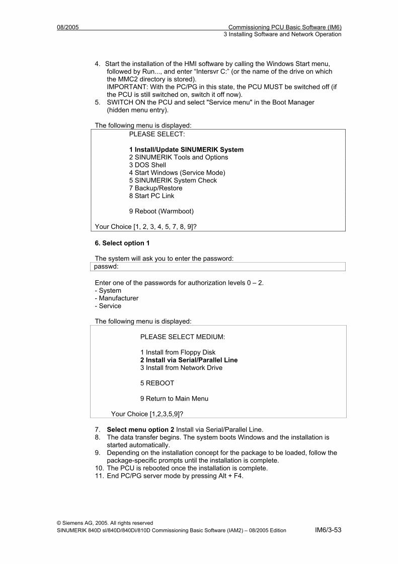
08/2005 Commissioning PCU Basic Software (IM6) 3 Installing Software and Network Operation
4. Start the installation of the HMI software by calling the Windows Start menu, followed by Run..., and enter “Intersvr C:” (or the name of the drive on which the MMC2 directory is stored). IMPORTANT: With the PC/PG in this state, the PCU MUST be switched off (if the PCU is still switched on, switch it off now).
5. SWITCH ON the PCU and select "Service menu" in the Boot Manager (hidden menu entry).
The following menu is displayed: PLEASE SELECT: 1 Install/Update SINUMERIK System 2 SINUMERIK Tools and Options 3 DOS Shell 4 Start Windows (Service Mode) 5 SINUMERIK System Check 7 Backup/Restore 8 Start PC Link 9 Reboot (Warmboot) Your Choice [1, 2, 3, 4, 5, 7, 8, 9]? 6. Select option 1 The system will ask you to enter the password:
passwd: Enter one of the passwords for authorization levels 0 – 2. - System - Manufacturer - Service The following menu is displayed:
PLEASE SELECT MEDIUM: 1 Install from Floppy Disk 2 Install via Serial/Parallel Line 3 Install from Network Drive 5 REBOOT 9 Return to Main Menu
Your Choice [1,2,3,5,9]?
7. Select menu option 2 Install via Serial/Parallel Line. 8. The data transfer begins. The system boots Windows and the installation is
started automatically. 9. Depending on the installation concept for the package to be loaded, follow the
package-specific prompts until the installation is complete. 10. The PCU is rebooted once the installation is complete. 11. End PC/PG server mode by pressing Alt + F4.
© Siemens AG, 2005. All rights reserved SINUMERIK 840D sl/840D/840Di/810D Commissioning Basic Software (IAM2) – 08/2005 Edition IM6/3-53
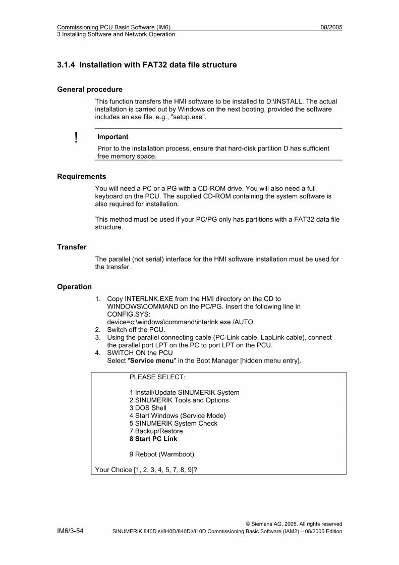
Commissioning PCU Basic Software (IM6) 08/2005 3 Installing Software and Network Operation
3.1.4 Installation with FAT32 data file structure
General procedure This function transfers the HMI software to be installed to D:\INSTALL. The actual installation is carried out by Windows on the next booting, provided the software includes an exe file, e.g., "setup.exe".
! Important
Prior to the installation process, ensure that hard-disk partition D has sufficient free memory space.
Requirements You will need a PC or a PG with a CD-ROM drive. You will also need a full keyboard on the PCU. The supplied CD-ROM containing the system software is also required for installation. This method must be used if your PC/PG only has partitions with a FAT32 data file structure.
Transfer The parallel (not serial) interface for the HMI software installation must be used for the transfer.
Operation 1. Copy INTERLNK.EXE from the HMI directory on the CD to
WINDOWS\COMMAND on the PC/PG. Insert the following line in CONFIG.SYS: device=c:\windows\command\interlnk.exe /AUTO
2. Switch off the PCU. 3. Using the parallel connecting cable (PC-Link cable, LapLink cable), connect
the parallel port LPT on the PC to port LPT on the PCU. 4. SWITCH ON the PCU
Select "Service menu" in the Boot Manager [hidden menu entry]. PLEASE SELECT: 1 Install/Update SINUMERIK System 2 SINUMERIK Tools and Options 3 DOS Shell 4 Start Windows (Service Mode) 5 SINUMERIK System Check 7 Backup/Restore 8 Start PC Link 9 Reboot (Warmboot) Your Choice [1, 2, 3, 4, 5, 7, 8, 9]?
© Siemens AG, 2005. All rights reserved IM6/3-54 SINUMERIK 840D sl/840D/840Di/810D Commissioning Basic Software (IAM2) – 08/2005 Edition
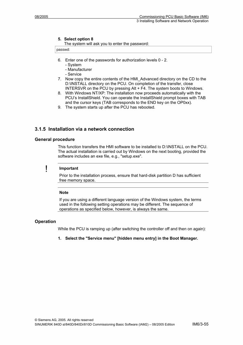
08/2005 Commissioning PCU Basic Software (IM6) 3 Installing Software and Network Operation
5. Select option 8 The system will ask you to enter the password:
passwd:
6. Enter one of the passwords for authorization levels 0 - 2.
- System - Manufacturer - Service
7. Now copy the entire contents of the HMI_Advanced directory on the CD to the D:\INSTALL directory on the PCU. On completion of the transfer, close INTERSVR on the PCU by pressing Alt + F4. The system boots to Windows.
8. With Windows NT/XP: The installation now proceeds automatically with the PCU’s InstallShield. You can operate the InstallShield prompt boxes with TAB and the cursor keys (TAB corresponds to the END key on the OP0xx).
9. The system starts up after the PCU has rebooted.
3.1.5 Installation via a network connection
General procedure This function transfers the HMI software to be installed to D:\INSTALL on the PCU. The actual installation is carried out by Windows on the next booting, provided the software includes an exe file, e.g., "setup.exe".
! Important
Prior to the installation process, ensure that hard-disk partition D has sufficient free memory space.
Note
If you are using a different language version of the Windows system, the terms used in the following setting operations may be different. The sequence of operations as specified below, however, is always the same.
Operation While the PCU is ramping up (after switching the controller off and then on again): 1. Select the "Service menu" [hidden menu entry] in the Boot Manager.
© Siemens AG, 2005. All rights reserved SINUMERIK 840D sl/840D/840Di/810D Commissioning Basic Software (IAM2) – 08/2005 Edition IM6/3-55
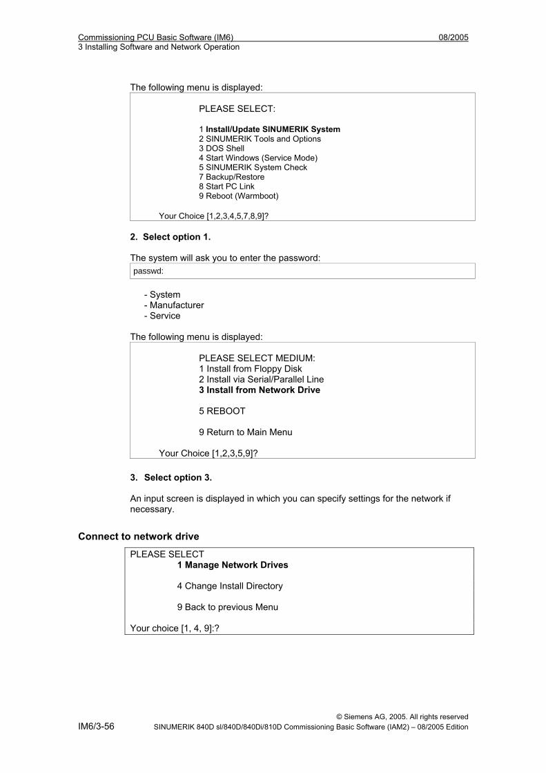
Commissioning PCU Basic Software (IM6) 08/2005 3 Installing Software and Network Operation
The following menu is displayed: PLEASE SELECT: 1 Install/Update SINUMERIK System 2 SINUMERIK Tools and Options 3 DOS Shell 4 Start Windows (Service Mode) 5 SINUMERIK System Check 7 Backup/Restore 8 Start PC Link 9 Reboot (Warmboot)
Your Choice [1,2,3,4,5,7,8,9]? 2. Select option 1. The system will ask you to enter the password: passwd:
- System
- Manufacturer - Service The following menu is displayed:
PLEASE SELECT MEDIUM: 1 Install from Floppy Disk 2 Install via Serial/Parallel Line 3 Install from Network Drive 5 REBOOT 9 Return to Main Menu
Your Choice [1,2,3,5,9]?
3. Select option 3. An input screen is displayed in which you can specify settings for the network if necessary.
Connect to network drive
PLEASE SELECT 1 Manage Network Drives 4 Change Install Directory 9 Back to previous Menu Your choice [1, 4, 9]:?
© Siemens AG, 2005. All rights reserved IM6/3-56 SINUMERIK 840D sl/840D/840Di/810D Commissioning Basic Software (IAM2) – 08/2005 Edition
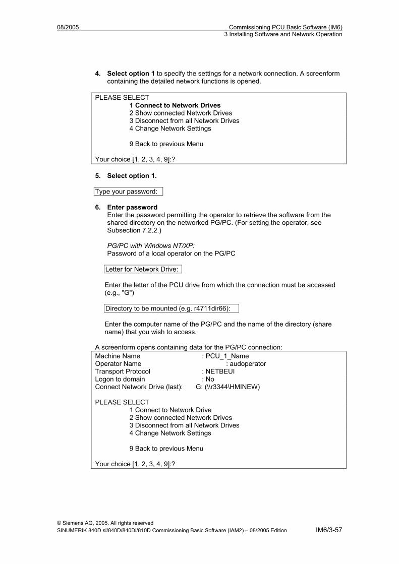
08/2005 Commissioning PCU Basic Software (IM6) 3 Installing Software and Network Operation
4. Select option 1 to specify the settings for a network connection. A screenform containing the detailed network functions is opened.
PLEASE SELECT 1 Connect to Network Drives 2 Show connected Network Drives 3 Disconnect from all Network Drives 4 Change Network Settings 9 Back to previous Menu Your choice [1, 2, 3, 4, 9]:? 5. Select option 1.
Type your password: 6. Enter password
Enter the password permitting the operator to retrieve the software from the shared directory on the networked PG/PC. (For setting the operator, see Subsection 7.2.2.) PG/PC with Windows NT/XP: Password of a local operator on the PG/PC
Letter for Network Drive:
Enter the letter of the PCU drive from which the connection must be accessed (e.g., "G")
Directory to be mounted (e.g. r4711dir66):
Enter the computer name of the PG/PC and the name of the directory (share name) that you wish to access.
A screenform opens containing data for the PG/PC connection: Machine Name : PCU_1_Name Operator Name : audoperator Transport Protocol : NETBEUI Logon to domain : No Connect Network Drive (last): G: (\\r3344\HMINEW) PLEASE SELECT 1 Connect to Network Drive 2 Show connected Network Drives 3 Disconnect from all Network Drives 4 Change Network Settings 9 Back to previous Menu Your choice [1, 2, 3, 4, 9]:?
© Siemens AG, 2005. All rights reserved SINUMERIK 840D sl/840D/840Di/810D Commissioning Basic Software (IAM2) – 08/2005 Edition IM6/3-57
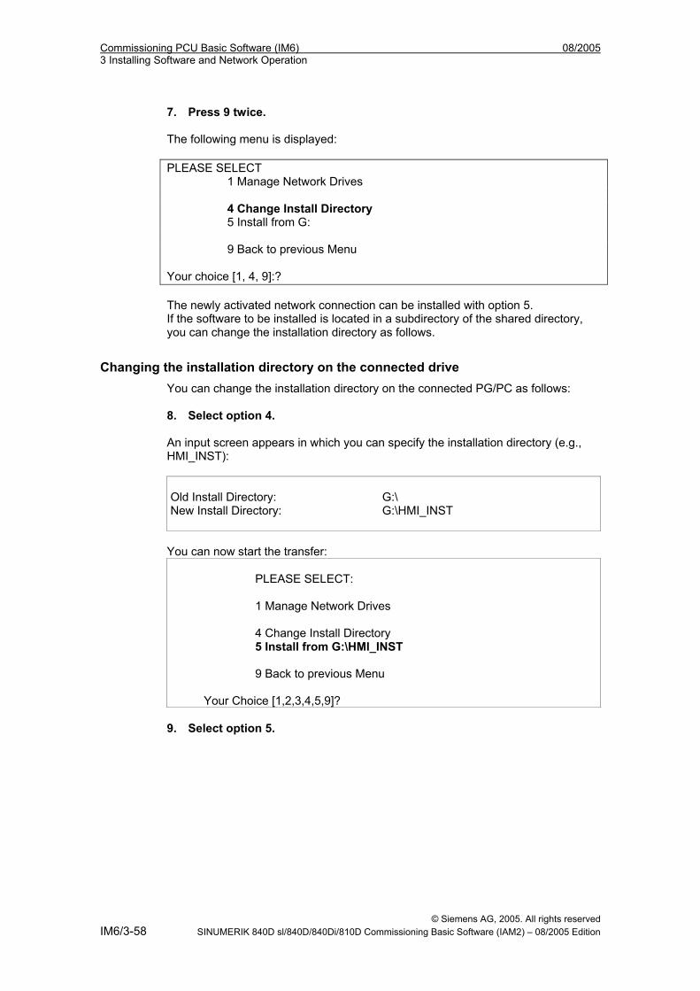
Commissioning PCU Basic Software (IM6) 08/2005 3 Installing Software and Network Operation
7. Press 9 twice. The following menu is displayed: PLEASE SELECT 1 Manage Network Drives 4 Change Install Directory 5 Install from G: 9 Back to previous Menu Your choice [1, 4, 9]:? The newly activated network connection can be installed with option 5. If the software to be installed is located in a subdirectory of the shared directory, you can change the installation directory as follows.
Changing the installation directory on the connected drive You can change the installation directory on the connected PG/PC as follows: 8. Select option 4. An input screen appears in which you can specify the installation directory (e.g., HMI_INST):
Old Install Directory: G:\ New Install Directory: G:\HMI_INST
You can now start the transfer:
PLEASE SELECT: 1 Manage Network Drives 4 Change Install Directory 5 Install from G:\HMI_INST 9 Back to previous Menu
Your Choice [1,2,3,4,5,9]? 9. Select option 5.
© Siemens AG, 2005. All rights reserved IM6/3-58 SINUMERIK 840D sl/840D/840Di/810D Commissioning Basic Software (IAM2) – 08/2005 Edition
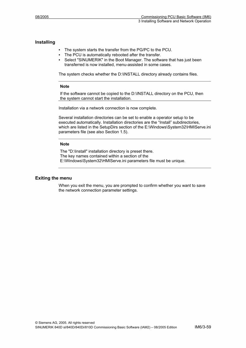
08/2005 Commissioning PCU Basic Software (IM6) 3 Installing Software and Network Operation
Installing • The system starts the transfer from the PG/PC to the PCU. • The PCU is automatically rebooted after the transfer. • Select "SINUMERIK" in the Boot Manager. The software that has just been
transferred is now installed, menu-assisted in some cases.
The system checks whether the D:\INSTALL directory already contains files.
Note
If the software cannot be copied to the D:\INSTALL directory on the PCU, then the system cannot start the installation.
Installation via a network connection is now complete. Several installation directories can be set to enable a operator setup to be executed automatically. Installation directories are the “Install” subdirectories, which are listed in the SetupDirs section of the E:\Windows\System32\HMIServe.ini parameters file (see also Section 1.5).
Note
The "D:\Install" installation directory is preset there. The key names contained within a section of the E:\Windows\System32\HMIServe.ini parameters file must be unique.
Exiting the menu When you exit the menu, you are prompted to confirm whether you want to save the network connection parameter settings.
© Siemens AG, 2005. All rights reserved SINUMERIK 840D sl/840D/840Di/810D Commissioning Basic Software (IAM2) – 08/2005 Edition IM6/3-59
Commissioning PCU Basic Software (IM6) 08/2005 3 Installing Software and Network Operation
3.2 Settings for network drives Correctly established network connections are absolutely essential to the network drive functions described below. Therefore, a general overview of network connections is provided here.
3.2.1 PG/PC requirements • Setting NETBEUI (Windows XP only)
Follow the instructions in the MS Knowledge Base article Q301041 • Determine the computer name of the
PG/PC with WIN NT via the Control Panel: Start→Settings→Control Panel→"Network" icon→Identification tab→ "Computer name", e.g.: r3344
• Determine the computer name of the PG/PC with WIN XP • Via the Control Panel:
Start→Settings→Control Panel→"System" icon→Computer Name tab, "Change" command button, e.g.: r3344
• Set shared directory Give shared access to the directory in which the software to be installed is stored. PC/PG with Windows NT4: On the desktop, click the directory to which shared access is to be given. File → Properties, Sharing tab Assign share name: (e.g., HMINEW). Comment: any Operator limit: any “Permissions” command button: Enter permission (e.g., Operator1 [local operator] or "anyone" with access type: "read"). PG/PC with Windows XP: Select the directory to be shared and click the right mouse key. Click "Sharing and Security…". Select the "Sharing" tab, activate "Share this folder" and assign a share name and comment if required. Click the "Permissions" command button to set the access rights for operators and then click "OK" to leave the Permissions window and the Share window.
• Connect cable Cable for point-to-point connection on the Ethernet port Ethernet cable of type "Converted Twisted Pair cable".
© Siemens AG, 2005. All rights reserved IM6/3-60 SINUMERIK 840D sl/840D/840Di/810D Commissioning Basic Software (IAM2) – 08/2005 Edition
08/2005 Commissioning PCU Basic Software (IM6) 3 Installing Software and Network Operation
3.2.2 Network operation with Windows NT/XP The PCU 50 contains a network port as standard. The network port is preinstalled such that, for TCP/IP communication to take place, only the PCU’s IP address needs to be entered and use of DHCP server needs to be selected once the Ethernet cable has been inserted.
Note
If no fixed Internet address is set for the Ethernet on-board and no DHCP server is available on the network, a so-called APIPA address is assigned under Windows XP. Boot manager is extended by at least one minute (this is system-related and not an error on the part of the HMI Manager).
NFS client The NFS client from "Windows Services for UNIX" is installed on E:\SFU\NFSCLIENT.
Entering the IP address The IP address is entered under Start → Settings → Control Panel → Network, in the Protocols tab on which the TCP/IP Protocol properties are selected.
PCU 50/70 ID If it is not already the case, the PCU computer name now has to be made unique in the network. You can enter the desired ID under Start → Settings → Control Panel → Network on the "Identification" tab.
3.2.3 Settings via the PCU Service menu Some of the Service menu functions below use network drives as a source or target when installing software or backing up or restoring systems. When necessary, the Manage Network Drives menu is provided in certain places on the operating menu so that the required settings can be made. You reach this menu as follows, for example: Main menu (Service menu) → 1 Install/Update SINUMERIK System → Enter password 3 Install from Network Drive → 1 Manage Network Drives
© Siemens AG, 2005. All rights reserved SINUMERIK 840D sl/840D/840Di/810D Commissioning Basic Software (IAM2) – 08/2005 Edition IM6/3-61

Commissioning PCU Basic Software (IM6) 08/2005 3 Installing Software and Network Operation
You can then choose from the following network management functions: 1 Connect to Network Drives 2 Show connected Network Drives 3 Disconnect from all Network Drives 4 Change Network Settings 9 Back to previous menu The following submenus are available for the individual menu items:
1 Connect to Network Drives
Type your passwd: Enter the password permitting the operator to retrieve data (e.g., software) from or write data (e.g., PCU images) to the shared directory using the networked PG/PC. PG/PC with Windows NT/XP: Password for a local operator of the PG/PC PG/PC with Windows 95/98: Any operator name, password identical to the password for directory sharing (if specified). Letter for Network Drive: Enter the letter of the PCU drive from which the connection must be accessed (e.g., "G"). Directory to be mounted (e.g., \\r3344\HMINEW): Enter the computer name of the PG/PC and the name of the directory (share name) that you wish to access. A screenform opens containing data for the PG/PC connection: Machine Name : PCU_1_Name Operator Name : audoperator Transport Protocol : NETBEUI Logon to domain : No Connect Network Drive (last): G: (\\r3344\HMINEW) PLEASE SELECT 1 Connect to Network Drive 2 Show connected Network Drives 3 Disconnect from all Network Drives 4 Change Network Settings 9 Back to previous Menu Your choice [1, 2, 3, 4, 9]:?
© Siemens AG, 2005. All rights reserved IM6/3-62 SINUMERIK 840D sl/840D/840Di/810D Commissioning Basic Software (IAM2) – 08/2005 Edition
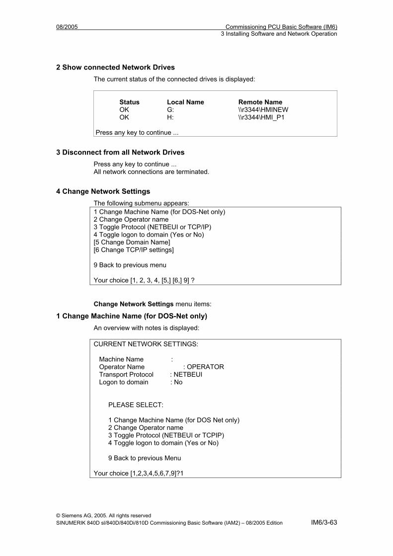
08/2005 Commissioning PCU Basic Software (IM6) 3 Installing Software and Network Operation
2 Show connected Network Drives The current status of the connected drives is displayed: Status Local Name Remote Name OK G: \\r3344\HMINEW OK H: \\r3344\HMI_P1 Press any key to continue ...
3 Disconnect from all Network Drives Press any key to continue ... All network connections are terminated.
4 Change Network Settings The following submenu appears: 1 Change Machine Name (for DOS-Net only) 2 Change Operator name 3 Toggle Protocol (NETBEUI or TCP/IP) 4 Toggle logon to domain (Yes or No) [5 Change Domain Name] [6 Change TCP/IP settings] 9 Back to previous menu Your choice [1, 2, 3, 4, [5,] [6,] 9] ? Change Network Settings menu items:
1 Change Machine Name (for DOS-Net only) An overview with notes is displayed: CURRENT NETWORK SETTINGS: Machine Name : Operator Name : OPERATOR Transport Protocol : NETBEUI Logon to domain : No PLEASE SELECT: 1 Change Machine Name (for DOS Net only) 2 Change Operator name 3 Toggle Protocol (NETBEUI or TCPIP) 4 Toggle logon to domain (Yes or No) 9 Back to previous Menu Your choice [1,2,3,4,5,6,7,9]?1
© Siemens AG, 2005. All rights reserved SINUMERIK 840D sl/840D/840Di/810D Commissioning Basic Software (IAM2) – 08/2005 Edition IM6/3-63
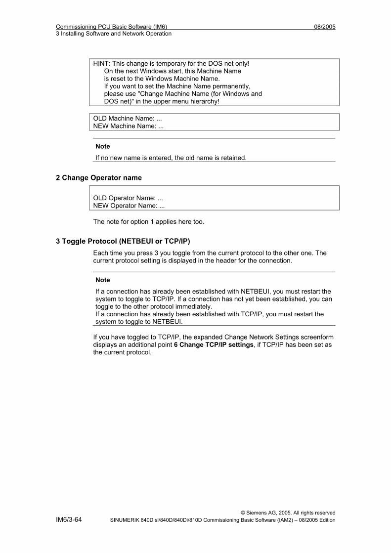
Commissioning PCU Basic Software (IM6) 08/2005 3 Installing Software and Network Operation
HINT: This change is temporary for the DOS net only! On the next Windows start, this Machine Name is reset to the Windows Machine Name. If you want to set the Machine Name permanently, please use "Change Machine Name (for Windows and DOS net)" in the upper menu hierarchy! OLD Machine Name: ... NEW Machine Name: ...
Note
If no new name is entered, the old name is retained.
2 Change Operator name
OLD Operator Name: ... NEW Operator Name: ... The note for option 1 applies here too.
3 Toggle Protocol (NETBEUI or TCP/IP) Each time you press 3 you toggle from the current protocol to the other one. The current protocol setting is displayed in the header for the connection.
Note
If a connection has already been established with NETBEUI, you must restart the system to toggle to TCP/IP. If a connection has not yet been established, you can toggle to the other protocol immediately. If a connection has already been established with TCP/IP, you must restart the system to toggle to NETBEUI.
If you have toggled to TCP/IP, the expanded Change Network Settings screenform displays an additional point 6 Change TCP/IP settings, if TCP/IP has been set as the current protocol.
© Siemens AG, 2005. All rights reserved IM6/3-64 SINUMERIK 840D sl/840D/840Di/810D Commissioning Basic Software (IAM2) – 08/2005 Edition
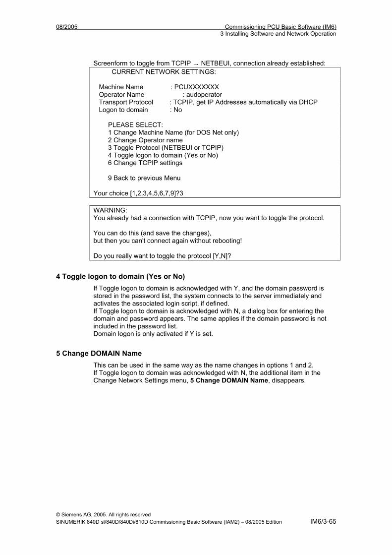
08/2005 Commissioning PCU Basic Software (IM6) 3 Installing Software and Network Operation
Screenform to toggle from TCPIP → NETBEUI, connection already established: CURRENT NETWORK SETTINGS: Machine Name : PCUXXXXXXX Operator Name : audoperator Transport Protocol : TCPIP, get IP Addresses automatically via DHCP Logon to domain : No PLEASE SELECT: 1 Change Machine Name (for DOS Net only) 2 Change Operator name 3 Toggle Protocol (NETBEUI or TCPIP) 4 Toggle logon to domain (Yes or No) 6 Change TCPIP settings 9 Back to previous Menu Your choice [1,2,3,4,5,6,7,9]?3 WARNING: You already had a connection with TCPIP, now you want to toggle the protocol. You can do this (and save the changes), but then you can't connect again without rebooting! Do you really want to toggle the protocol [Y,N]?
4 Toggle logon to domain (Yes or No) If Toggle logon to domain is acknowledged with Y, and the domain password is stored in the password list, the system connects to the server immediately and activates the associated login script, if defined. If Toggle logon to domain is acknowledged with N, a dialog box for entering the domain and password appears. The same applies if the domain password is not included in the password list. Domain logon is only activated if Y is set.
5 Change DOMAIN Name This can be used in the same way as the name changes in options 1 and 2. If Toggle logon to domain was acknowledged with N, the additional item in the Change Network Settings menu, 5 Change DOMAIN Name, disappears.
© Siemens AG, 2005. All rights reserved SINUMERIK 840D sl/840D/840Di/810D Commissioning Basic Software (IAM2) – 08/2005 Edition IM6/3-65
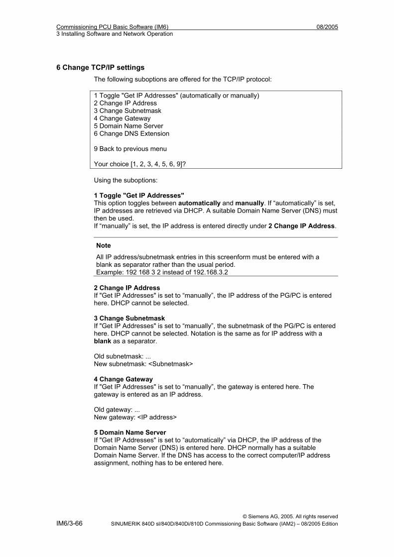
Commissioning PCU Basic Software (IM6) 08/2005 3 Installing Software and Network Operation
6 Change TCP/IP settings The following suboptions are offered for the TCP/IP protocol: 1 Toggle "Get IP Addresses" (automatically or manually) 2 Change IP Address 3 Change Subnetmask 4 Change Gateway 5 Domain Name Server 6 Change DNS Extension 9 Back to previous menu Your choice [1, 2, 3, 4, 5, 6, 9]? Using the suboptions: 1 Toggle "Get IP Addresses" This option toggles between automatically and manually. If “automatically” is set, IP addresses are retrieved via DHCP. A suitable Domain Name Server (DNS) must then be used. If “manually” is set, the IP address is entered directly under 2 Change IP Address.
Note
All IP address/subnetmask entries in this screenform must be entered with a blank as separator rather than the usual period. Example: 192 168 3 2 instead of 192.168.3.2
2 Change IP Address If "Get IP Addresses" is set to “manually”, the IP address of the PG/PC is entered here. DHCP cannot be selected. 3 Change Subnetmask If "Get IP Addresses" is set to “manually”, the subnetmask of the PG/PC is entered here. DHCP cannot be selected. Notation is the same as for IP address with a blank as a separator. Old subnetmask: ... New subnetmask: <Subnetmask> 4 Change Gateway If "Get IP Addresses" is set to “manually”, the gateway is entered here. The gateway is entered as an IP address. Old gateway: ... New gateway: <IP address> 5 Domain Name Server If "Get IP Addresses" is set to “automatically” via DHCP, the IP address of the Domain Name Server (DNS) is entered here. DHCP normally has a suitable Domain Name Server. If the DNS has access to the correct computer/IP address assignment, nothing has to be entered here.
© Siemens AG, 2005. All rights reserved IM6/3-66 SINUMERIK 840D sl/840D/840Di/810D Commissioning Basic Software (IAM2) – 08/2005 Edition
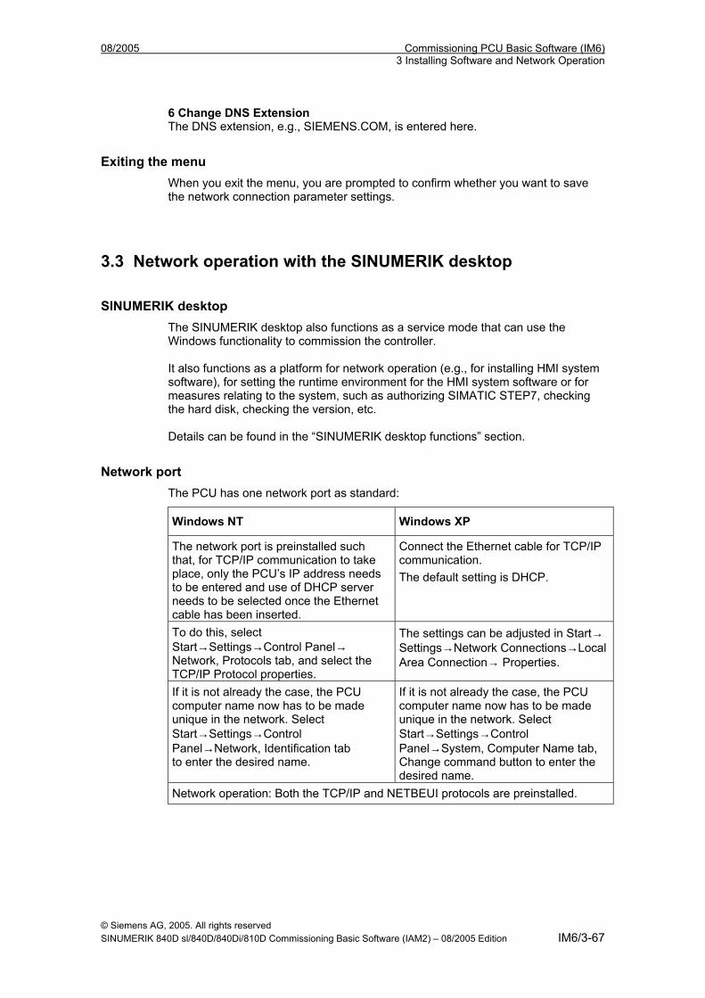
08/2005 Commissioning PCU Basic Software (IM6) 3 Installing Software and Network Operation
6 Change DNS Extension The DNS extension, e.g., SIEMENS.COM, is entered here.
Exiting the menu When you exit the menu, you are prompted to confirm whether you want to save the network connection parameter settings.
3.3 Network operation with the SINUMERIK desktop
SINUMERIK desktop The SINUMERIK desktop also functions as a service mode that can use the Windows functionality to commission the controller. It also functions as a platform for network operation (e.g., for installing HMI system software), for setting the runtime environment for the HMI system software or for measures relating to the system, such as authorizing SIMATIC STEP7, checking the hard disk, checking the version, etc. Details can be found in the “SINUMERIK desktop functions” section.
Network port The PCU has one network port as standard:
Windows NT Windows XP
The network port is preinstalled such that, for TCP/IP communication to take place, only the PCU’s IP address needs to be entered and use of DHCP server needs to be selected once the Ethernet cable has been inserted.
Connect the Ethernet cable for TCP/IP communication. The default setting is DHCP.
To do this, select Start→Settings→Control Panel→ Network, Protocols tab, and select the TCP/IP Protocol properties.
The settings can be adjusted in Start→ Settings→Network Connections→Local Area Connection→ Properties.
If it is not already the case, the PCU computer name now has to be made unique in the network. Select Start→Settings→Control Panel→Network, Identification tab to enter the desired name.
If it is not already the case, the PCU computer name now has to be made unique in the network. Select Start→Settings→Control Panel→System, Computer Name tab, Change command button to enter the desired name.
Network operation: Both the TCP/IP and NETBEUI protocols are preinstalled.
© Siemens AG, 2005. All rights reserved SINUMERIK 840D sl/840D/840Di/810D Commissioning Basic Software (IAM2) – 08/2005 Edition IM6/3-67
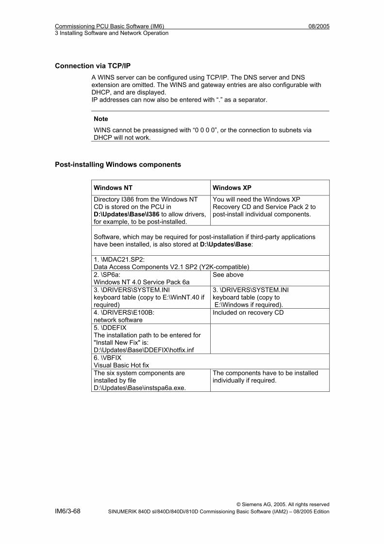
Commissioning PCU Basic Software (IM6) 08/2005 3 Installing Software and Network Operation
Connection via TCP/IP
A WINS server can be configured using TCP/IP. The DNS server and DNS extension are omitted. The WINS and gateway entries are also configurable with DHCP, and are displayed. IP addresses can now also be entered with “.” as a separator.
Note
WINS cannot be preassigned with “0 0 0 0”, or the connection to subnets via DHCP will not work.
Post-installing Windows components
Windows NT Windows XP
Directory I386 from the Windows NT CD is stored on the PCU in D:\Updates\Base\I386 to allow drivers, for example, to be post-installed.
You will need the Windows XP Recovery CD and Service Pack 2 to post-install individual components.
Software, which may be required for post-installation if third-party applications have been installed, is also stored at D:\Updates\Base: 1. \MDAC21.SP2: Data Access Components V2.1 SP2 (Y2K-compatible) 2. \SP6a: Windows NT 4.0 Service Pack 6a
See above
3. \DRIVERS\SYSTEM.INI keyboard table (copy to E:\WinNT.40 if required)
3. \DRIVERS\SYSTEM.INI keyboard table (copy to E:\Windows if required).
4. \DRIVERS\E100B: network software
Included on recovery CD
5. \DDEFIX The installation path to be entered for "Install New Fix" is: D:\Updates\Base\DDEFIX\hotfix.inf
6. \VBFIX Visual Basic Hot fix The six system components are installed by file D:\Updates\Base\instspa6a.exe.
The components have to be installed individually if required.
© Siemens AG, 2005. All rights reserved IM6/3-68 SINUMERIK 840D sl/840D/840Di/810D Commissioning Basic Software (IAM2) – 08/2005 Edition
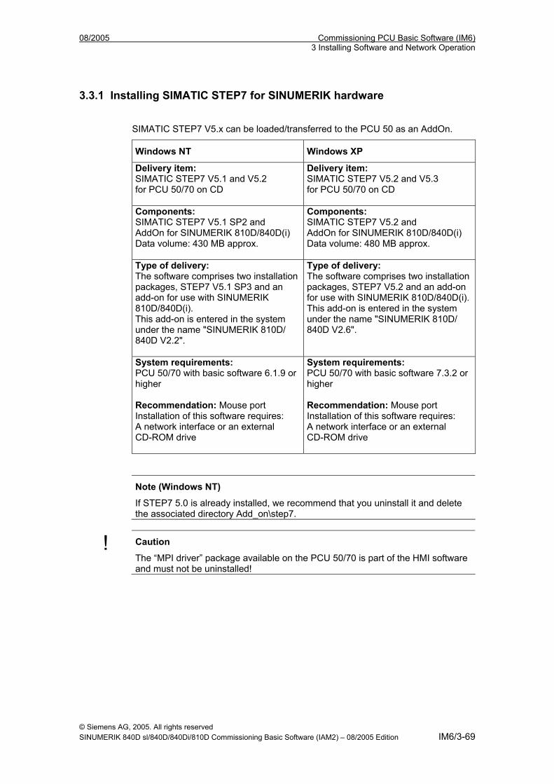
08/2005 Commissioning PCU Basic Software (IM6) 3 Installing Software and Network Operation
3.3.1 Installing SIMATIC STEP7 for SINUMERIK hardware
SIMATIC STEP7 V5.x can be loaded/transferred to the PCU 50 as an AddOn.
Windows NT Windows XP
Delivery item: SIMATIC STEP7 V5.1 and V5.2 for PCU 50/70 on CD
Delivery item: SIMATIC STEP7 V5.2 and V5.3 for PCU 50/70 on CD
Components: SIMATIC STEP7 V5.1 SP2 and AddOn for SINUMERIK 810D/840D(i) Data volume: 430 MB approx.
Components: SIMATIC STEP7 V5.2 and AddOn for SINUMERIK 810D/840D(i) Data volume: 480 MB approx.
Type of delivery: The software comprises two installation packages, STEP7 V5.1 SP3 and an add-on for use with SINUMERIK 810D/840D(i). This add-on is entered in the system under the name "SINUMERIK 810D/ 840D V2.2".
Type of delivery: The software comprises two installation packages, STEP7 V5.2 and an add-on for use with SINUMERIK 810D/840D(i). This add-on is entered in the system under the name "SINUMERIK 810D/ 840D V2.6".
System requirements: PCU 50/70 with basic software 6.1.9 or higher Recommendation: Mouse port Installation of this software requires: A network interface or an external CD-ROM drive
System requirements: PCU 50/70 with basic software 7.3.2 or higher Recommendation: Mouse port Installation of this software requires: A network interface or an external CD-ROM drive
Note (Windows NT)
If STEP7 5.0 is already installed, we recommend that you uninstall it and delete the associated directory Add_on\step7.
! Caution
The “MPI driver” package available on the PCU 50/70 is part of the HMI software and must not be uninstalled!
© Siemens AG, 2005. All rights reserved SINUMERIK 840D sl/840D/840Di/810D Commissioning Basic Software (IAM2) – 08/2005 Edition IM6/3-69
Commissioning PCU Basic Software (IM6) 08/2005 3 Installing Software and Network Operation
Operation in Windows NT This procedure also applies to HMI Advanced with WinNT 4.0. You must follow the installation sequence described here! 1. Booting the PCU 50 in the Windows NT desktop (using Service menu
option 4, then 1). 2. Create access to the STEP7 CD (via a network or an external CD-ROM drive). 3. Switch to the STEP7_V5.1 directory on the CD and call SETUP.EXE. The
installation proceeds with operator prompting. You will be prompted to enter the ID number (see CD label). The installation directory on partition F: can be used.
Press "Skip" to acknowledge the prompt for the license key disk. On completion of this setup there is no need to boot the PCU 50.
4. Switch to the SINUMERIK_Add_on directory on the CD and call SETUP.EXE. The installation proceeds with operator prompting. On completion of this setup you must boot the PCU 50. Booting to the Windows NT desktop again.
5. Call the "STEP7 Authorizing" desktop icon. STEP7 is now authorized and can be started from the HMI Advanced software
(second menu bar in the area menu, protected to protection level 3). The following entries are made automatically in F:\Add_on\oemframe.ini:
[s7tgtopx] ; with HMI Advanced: eliminate minimize/maximize buttons ; of the STEP7 window WindowStyle_Off=196608 ; with HMI Advanced: switch to previous task when STEP7 is terminated nSwitchToTaskAfterTermination= -2
6. These entries may also need to be modified in OEM configurations. If STEP7 V5.1 is installed on the controller and V5.0 has to be installed at a later date, directory: F:\mmc2\step7\dat has to be completely deleted after V5.1 is uninstalled and before V5.0 is installed.
Operation in Windows XP Operation is the same as for Windows NT, but a STEP7 software version ≥ 5.2 must be installed. STEP7 must not be installed on partitions D: or E:. If warning message "WARNING: Application rngofrm didn´t post InitComplete" appears in HMI Advanced on the first booting after installing STEP7, the PCU 50 has to be rebooted.
© Siemens AG, 2005. All rights reserved IM6/3-70 SINUMERIK 840D sl/840D/840Di/810D Commissioning Basic Software (IAM2) – 08/2005 Edition
08/2005 Commissioning PCU Basic Software (IM6) 3 Installing Software and Network Operation
3.3.2 Authorizing SIMATIC STEP7 via the Service menu
Requirements The SIMATIC STEP7 V5.x software for SINUMERIK hardware is already installed. STEP7 V5.0 and STEP7 V5.2 can be authorized.
Operation While the PCU is ramping up (after switching the controller off and then on again): 1. Select the Service menu [hidden menu entry] in the Boot Manager The following menu is displayed: PLEASE SELECT 1 Install/Update SINUMERIK System 2 SINUMERIK Tools and Options 3 DOS Shell 4 Start Windows (Service Mode) 5 SINUMERIK System Check 7 Backup/Restore 8 Start PC Link 9 Reboot (Warmboot) Your Choice [1, 2, 3, 4, 5, 7, 8, 9]? 2. Select option 2 The system will ask you to enter the password: passwd: 3. Enter one of the passwords for authorization levels 0 – 2. - System - Manufacturer - Service The following menu is displayed: PLEASE SELECT 1 Activate Step7 for PCU 9 Return to Main Menu Your Choice [1, 9] ?
© Siemens AG, 2005. All rights reserved SINUMERIK 840D sl/840D/840Di/810D Commissioning Basic Software (IAM2) – 08/2005 Edition IM6/3-71
Commissioning PCU Basic Software (IM6) 08/2005 3 Installing Software and Network Operation
Authorizing 4. Select option 1
Booting The system will then reboot automatically. The actual authorization takes place next time Windows NT/XP is ramped up, before the HMI system software is started.
Note
The authorization can also be checked on the SINUMERIK desktop by starting the "STEP7 Authorizing" function.
3.3.3 Authorizing SIMATIC STEP7 via the SINUMERIK desktop The "STEP7 Authorizing" function is available as a script file on the SINUMERIK desktop. This function authorizes the SIMATIC STEP7 software if it has been installed previously.
Note
The function can also be triggered from the Service menu (DOS). It is then executed during the Windows booting (before the HMI system software is started), without displaying the SINUMERIK desktop.
© Siemens AG, 2005. All rights reserved IM6/3-72 SINUMERIK 840D sl/840D/840Di/810D Commissioning Basic Software (IAM2) – 08/2005 Edition
08/2005 Commissioning PCU Basic Software (IM6) 4 Backing Up and Restoring Data
44 Backing Up and Restoring Data
4.1 Backing up/restoring data with an Ethernet connection ........................ IM6/4-75 4.1.1 Backing up the PCU hard disk to the PG/PC hard disk ..................... IM6/4-75 4.1.2 Restoring the PCU hard disk from the PG/PC hard disk.................... IM6/4-79 4.1.3 Commissioning the replacement hard disk ........................................ IM6/4-85
4.2 Backing up and restoring PCU partitions locally ................................... IM6/4-87 4.2.1 Backing up partitions .......................................................................... IM6/4-89 4.2.2 Restoring partitions............................................................................. IM6/4-92 4.2.3 Restoring partition E: (Windows) on the PCU .................................... IM6/4-94 4.2.4 Deleting the backup image ................................................................. IM6/4-96 4.2.5 Defining an emergency backup image ............................................... IM6/4-98 4.2.6 Restoring the emergency backup on partition E: ............................. IM6/4-100
4.3 Backing up/restoring data with a TCU configuration ........................... IM6/4-102
© Siemens AG, 2005. All rights reserved SINUMERIK 840D sl/840D/840Di/810D Commissioning Basic Software (IAM2) – 08/2005 Edition IM6/4-73
Commissioning PCU Basic Software (IM6) 08/2005 4 Backing Up and Restoring Data
Application The entire contents of hard disks can be saved as a disk image using the Norton Ghost utility. These disk images can be stored on various data carriers and the data restored to the hard disk at a later date. PCU replacement hard disks and complete PCU hard disks are supplied by the plant with Norton Ghost already installed. Norton Ghost is used in some of the backup and restore procedures described below. More information is available on the Internet at www.ghost.com.
© Siemens AG, 2005. All rights reserved IM6/4-74 SINUMERIK 840D sl/840D/840Di/810D Commissioning Basic Software (IAM2) – 08/2005 Edition
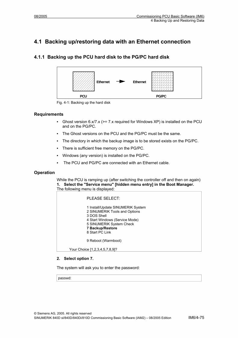
08/2005 Commissioning PCU Basic Software (IM6) 4 Backing Up and Restoring Data
4.1 Backing up/restoring data with an Ethernet connection
4.1.1 Backing up the PCU hard disk to the PG/PC hard disk
PCU PG/PC
Ethernet Ethernet
Fig. 4-1: Backing up the hard disk
Requirements • Ghost version 6.x/7.x (>= 7.x required for Windows XP) is installed on the PCU
and on the PG/PC.
• The Ghost versions on the PCU and the PG/PC must be the same.
• The directory in which the backup image is to be stored exists on the PG/PC.
• There is sufficient free memory on the PG/PC.
• Windows (any version) is installed on the PG/PC.
• The PCU and PG/PC are connected with an Ethernet cable.
Operation While the PCU is ramping up (after switching the controller off and then on again) 1. Select the "Service menu" [hidden menu entry] in the Boot Manager. The following menu is displayed:
PLEASE SELECT: 1 Install/Update SINUMERIK System 2 SINUMERIK Tools and Options 3 DOS Shell 4 Start Windows (Service Mode) 5 SINUMERIK System Check 7 Backup/Restore 8 Start PC Link 9 Reboot (Warmboot)
Your Choice [1,2,3,4,5,7,8,9]? 2. Select option 7. The system will ask you to enter the password: passwd:
© Siemens AG, 2005. All rights reserved SINUMERIK 840D sl/840D/840Di/810D Commissioning Basic Software (IAM2) – 08/2005 Edition IM6/4-75
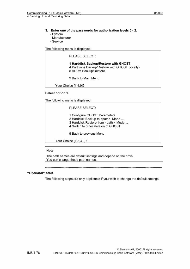
Commissioning PCU Basic Software (IM6) 08/2005 4 Backing Up and Restoring Data
3. Enter one of the passwords for authorization levels 0 - 2. - System - Manufacturer - Service The following menu is displayed:
PLEASE SELECT: 1 Harddisk Backup/Restore with GHOST 4 Partitions Backup/Restore with GHOST (locally) 5 ADDM Backup/Restore 9 Back to Main Menu
Your Choice [1,4,9]? Select option 1. The following menu is displayed:
PLEASE SELECT: 1 Configure GHOST Parameters 2 Harddisk Backup to <path>, Mode ... 3 Harddisk Restore from <path>, Mode ... 4 Switch to other Version of GHOST 9 Back to previous Menu
Your Choice [1,2,3,9]?
Note
The path names are default settings and depend on the drive. You can change these path names.
--------------------------------------------------------------------------------------------------------------
"Optional" start The following steps are only applicable if you wish to change the default settings.
© Siemens AG, 2005. All rights reserved IM6/4-76 SINUMERIK 840D sl/840D/840Di/810D Commissioning Basic Software (IAM2) – 08/2005 Edition
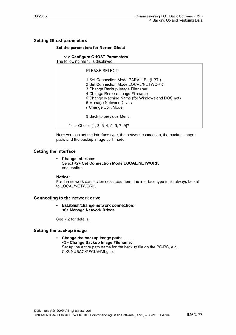
08/2005 Commissioning PCU Basic Software (IM6) 4 Backing Up and Restoring Data
Setting Ghost parameters Set the parameters for Norton Ghost
<1> Configure GHOST Parameters
The following menu is displayed: PLEASE SELECT: 1 Set Connection Mode PARALLEL (LPT:) 2 Set Connection Mode LOCAL/NETWORK 3 Change Backup Image Filename 4 Change Restore Image Filename 5 Change Machine Name (for Windows and DOS net) 6 Manage Network Drives 7 Change Split Mode 9 Back to previous Menu
Your Choice [1, 2, 3, 4, 5, 6, 7, 9]? Here you can set the interface type, the network connection, the backup image path, and the backup image split mode.
Setting the interface • Change interface:
Select <2> Set Connection Mode LOCAL/NETWORK and confirm.
Notice: For the network connection described here, the interface type must always be set to LOCAL/NETWORK.
Connecting to the network drive • Establish/change network connection:
<6> Manage Network Drives See 7.2 for details.
Setting the backup image • Change the backup image path:
<3> Change Backup Image Filename: Set up the entire path name for the backup file on the PG/PC, e.g., C:\SINUBACK\PCU\HMI.gho.
© Siemens AG, 2005. All rights reserved SINUMERIK 840D sl/840D/840Di/810D Commissioning Basic Software (IAM2) – 08/2005 Edition IM6/4-77
Commissioning PCU Basic Software (IM6) 08/2005 4 Backing Up and Restoring Data
Splitting the backup image • Backup image split mode:
<7> Change Split Mode Choose whether you wish to split the backup image into portions and, if so, enter the split size (max. split size: 2048 MB; default split size: 640 MB). The names of the split files are assigned as follows: <name>.gho <name>.001 <name>.002 <name>. ...
Exiting the menu • Return to the previous menu:
< 9 > Back to previous Menu Prompt: Save GHOST parameters? Answer Yes.
"Optional" end -------------------------------------------------------------------------------------------------------------- The following steps are always applicable.
Backing up the hard disk You can now start the transfer: Back up the hard disk
< 2 > Harddisk Backup to <pathname>, Mode LOCAL/NETWORK Selecting this option opens the following menu if local partition data backups are available: (See Backing up/restoring partitions).
PLEASE SELECT: 1 Backup WITHOUT Local Images 2 Backup WITH Local Images
Your Choice [1,2]? If you do NOT want to back up local partition data (substantial reduction in transfer time and memory), select: Option 1 "Backup WITHOUT Local Images", otherwise select option 2 "Backup WITH Local Images".
* A message window then opens:
You are prompted to check whether a connection exists between the PCU and the PG/PC. The target path for the directory on the PG/PC in which the backup image is to be stored is displayed. You are prompted to check whether this directory exists on the PG/PC.
© Siemens AG, 2005. All rights reserved IM6/4-78 SINUMERIK 840D sl/840D/840Di/810D Commissioning Basic Software (IAM2) – 08/2005 Edition
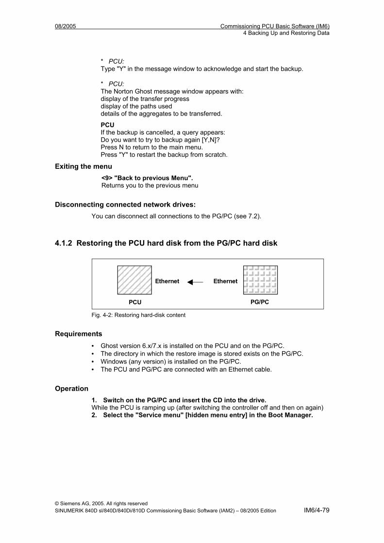
08/2005 Commissioning PCU Basic Software (IM6) 4 Backing Up and Restoring Data
* PCU: Type "Y" in the message window to acknowledge and start the backup.
* PCU: The Norton Ghost message window appears with: display of the transfer progress display of the paths used details of the aggregates to be transferred.
PCU If the backup is cancelled, a query appears: Do you want to try to backup again [Y,N]? Press N to return to the main menu. Press "Y" to restart the backup from scratch.
Exiting the menu <9> "Back to previous Menu". Returns you to the previous menu
Disconnecting connected network drives: You can disconnect all connections to the PG/PC (see 7.2).
4.1.2 Restoring the PCU hard disk from the PG/PC hard disk
PCU PG/PC
Ethernet Ethernet
Fig. 4-2: Restoring hard-disk content
Requirements • Ghost version 6.x/7.x is installed on the PCU and on the PG/PC. • The directory in which the restore image is stored exists on the PG/PC. • Windows (any version) is installed on the PG/PC. • The PCU and PG/PC are connected with an Ethernet cable.
Operation 1. Switch on the PG/PC and insert the CD into the drive. While the PCU is ramping up (after switching the controller off and then on again) 2. Select the "Service menu" [hidden menu entry] in the Boot Manager.
© Siemens AG, 2005. All rights reserved SINUMERIK 840D sl/840D/840Di/810D Commissioning Basic Software (IAM2) – 08/2005 Edition IM6/4-79
Commissioning PCU Basic Software (IM6) 08/2005 4 Backing Up and Restoring Data
The following menu is displayed: PLEASE SELECT: 1 Install/Update SINUMERIK System 2 SINUMERIK Tools and Options 3 DOS Shell 4 Start Windows (Service Mode) 5 SINUMERIK System Check 7 Backup/Restore 8 Start PC Link 9 Reboot (Warmboot)
Your Choice [1,2,3,4,5,7,8,9]?
3. Select option 7. The system will ask you to enter the password: passwd:
4. Enter one of the passwords for authorization levels 0 - 2.
- System - Manufacturer - Service
The following menu is displayed: PLEASE SELECT: 1 Harddisk Backup/Restore with Ghost 4 Partitions Backup/Restore with Ghost 5 ADDM Backup/Restore 9 Return to Main Menu
Your Choice [1, 4, 5, 9]? 5. Select option 1. The following menu is displayed:
PLEASE SELECT: 1 Configure GHOST Parameters 2 Harddisk Backup to <path>, Mode ... 3 Harddisk Restore from <path>, Mode ... 4 Switch to other Version of GHOST 9 Back to previous Menu
Your Choice [1, 2, 3, 4, 9]?
© Siemens AG, 2005. All rights reserved IM6/4-80 SINUMERIK 840D sl/840D/840Di/810D Commissioning Basic Software (IAM2) – 08/2005 Edition
08/2005 Commissioning PCU Basic Software (IM6) 4 Backing Up and Restoring Data
Note
The path names are default settings and depend on the drive. You can change these path names.
--------------------------------------------------------------------------------------------------------------
"Optional" start The following steps are only applicable if you wish to change the default settings.
Setting Ghost parameters 6. Set the parameters for Norton Ghost < 1 >Configure GHOST Parameters The following menu is displayed:
PLEASE SELECT: 1 Set Connection Mode PARALLEL (LPT:) 2 Set Connection Mode LOCAL/NETWORK 3 Change Backup Image Filename 4 Change Restore Image Filename 5 Change Machine Name (for Windows and DOS net) 6 Manage Network Drives [See 7.2] 7 Change Split Mode 9 Back to previous Menu
Your Choice [1, 2, 3, 4, 5, 6, 7, 9]? Here you can set the interface type, the network connection, the backup image path, and the restore image path.
Setting the interface 6.1 Change interface:
Select <2> Set Connection Mode LOCAL
and confirm.
! Important
For the network connection described here the interface type must always be set to LOCAL/NETWORK.
Connecting to the network drive 6.2 Establish/change network connection
<6> Manage Network Drives
© Siemens AG, 2005. All rights reserved SINUMERIK 840D sl/840D/840Di/810D Commissioning Basic Software (IAM2) – 08/2005 Edition IM6/4-81
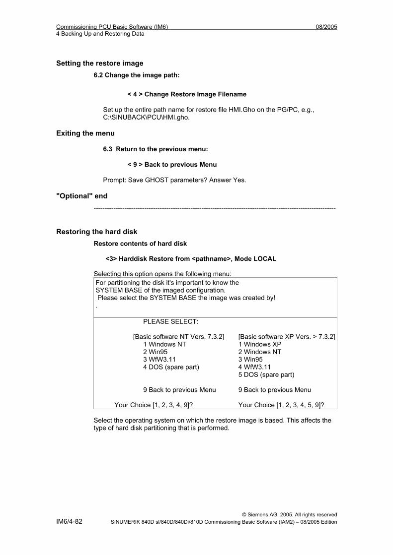
Commissioning PCU Basic Software (IM6) 08/2005 4 Backing Up and Restoring Data
Setting the restore image 6.2 Change the image path:
< 4 > Change Restore Image Filename
Set up the entire path name for restore file HMI.Gho on the PG/PC, e.g., C:\SINUBACK\PCU\HMI.gho.
Exiting the menu
6.3 Return to the previous menu:
< 9 > Back to previous Menu
Prompt: Save GHOST parameters? Answer Yes.
"Optional" end --------------------------------------------------------------------------------------------------------------
Restoring the hard disk Restore contents of hard disk
<3> Harddisk Restore from <pathname>, Mode LOCAL Selecting this option opens the following menu: For partitioning the disk it's important to know the SYSTEM BASE of the imaged configuration. Please select the SYSTEM BASE the image was created by! .
PLEASE SELECT: [Basic software NT Vers. 7.3.2] [Basic software XP Vers. > 7.3.2] 1 Windows NT 1 Windows XP 2 Win95 2 Windows NT 3 WfW3.11 3 Win95 4 DOS (spare part) 4 WfW3.11 5 DOS (spare part) 9 Back to previous Menu 9 Back to previous Menu
Your Choice [1, 2, 3, 4, 9]? Your Choice [1, 2, 3, 4, 5, 9]? Select the operating system on which the restore image is based. This affects the type of hard disk partitioning that is performed.
© Siemens AG, 2005. All rights reserved IM6/4-82 SINUMERIK 840D sl/840D/840Di/810D Commissioning Basic Software (IAM2) – 08/2005 Edition
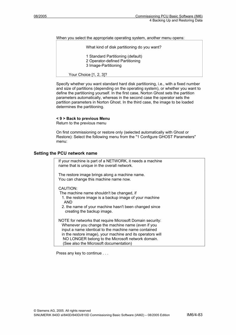
08/2005 Commissioning PCU Basic Software (IM6) 4 Backing Up and Restoring Data
When you select the appropriate operating system, another menu opens: What kind of disk partitioning do you want? 1 Standard Partitioning (default) 2 Operator-defined Partitioning 3 Image-Partitioning
Your Choice [1, 2, 3]? Specify whether you want standard hard disk partitioning, i.e., with a fixed number and size of partitions (depending on the operating system), or whether you want to define the partitioning yourself. In the first case, Norton Ghost sets the partition parameters automatically, whereas in the second case the operator sets the partition parameters in Norton Ghost. In the third case, the image to be loaded determines the partitioning.
< 9 > Back to previous Menu Return to the previous menu On first commissioning or restore only (selected automatically with Ghost or Restore): Select the following menu from the "1 Configure GHOST Parameters" menu:
Setting the PCU network name
If your machine is part of a NETWORK, it needs a machine name that is unique in the overall network. The restore image brings along a machine name. You can change this machine name now. CAUTION: The machine name shouldn't be changed, if 1. the restore image is a backup image of your machine AND 2. the name of your machine hasn't been changed since creating the backup image. NOTE for networks that require Microsoft Domain security: Whenever you change the machine name (even if you input a name identical to the machine name contained in the restore image), your machine and its operators will NO LONGER belong to the Microsoft network domain. (See also the Microsoft documentation) Press any key to continue . . .
© Siemens AG, 2005. All rights reserved SINUMERIK 840D sl/840D/840Di/810D Commissioning Basic Software (IAM2) – 08/2005 Edition IM6/4-83
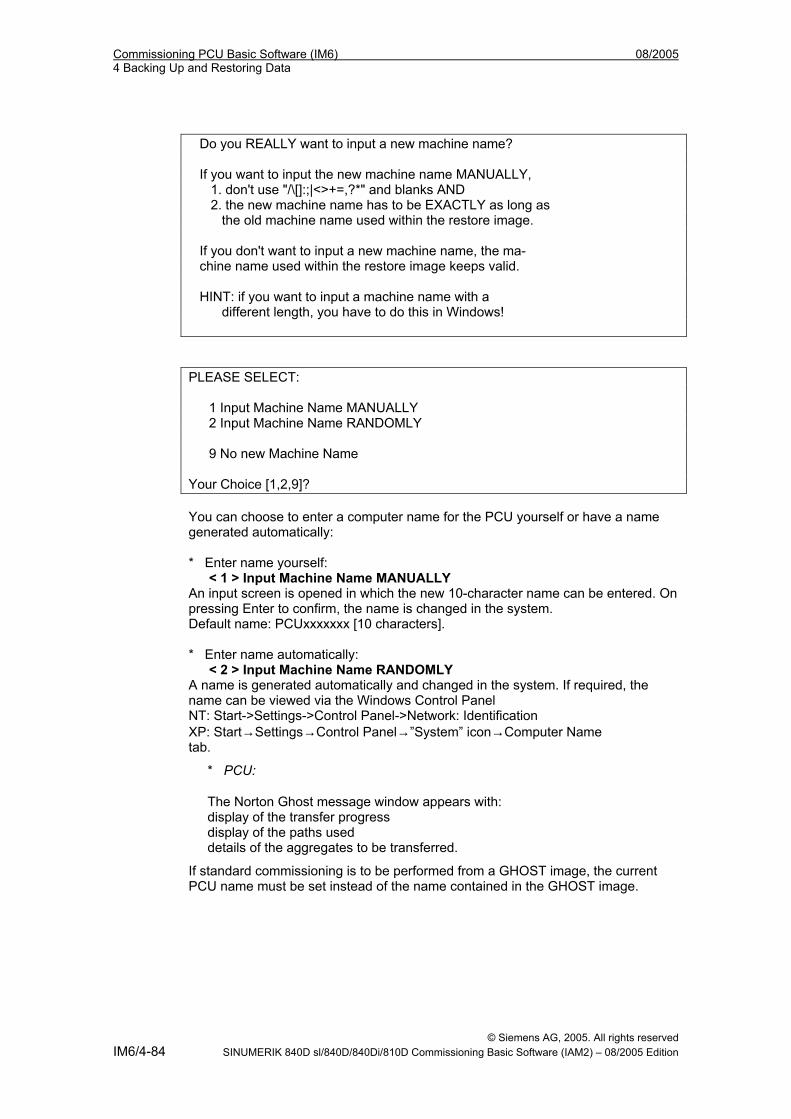
Commissioning PCU Basic Software (IM6) 08/2005 4 Backing Up and Restoring Data
Do you REALLY want to input a new machine name? If you want to input the new machine name MANUALLY, 1. don't use "/\[]:;|<>+=,?*" and blanks AND 2. the new machine name has to be EXACTLY as long as the old machine name used within the restore image. If you don't want to input a new machine name, the ma- chine name used within the restore image keeps valid. HINT: if you want to input a machine name with a different length, you have to do this in Windows! PLEASE SELECT: 1 Input Machine Name MANUALLY 2 Input Machine Name RANDOMLY 9 No new Machine Name Your Choice [1,2,9]? You can choose to enter a computer name for the PCU yourself or have a name generated automatically: * Enter name yourself: < 1 > Input Machine Name MANUALLY An input screen is opened in which the new 10-character name can be entered. On pressing Enter to confirm, the name is changed in the system. Default name: PCUxxxxxxx [10 characters]. * Enter name automatically: < 2 > Input Machine Name RANDOMLY A name is generated automatically and changed in the system. If required, the name can be viewed via the Windows Control Panel NT: Start->Settings->Control Panel->Network: Identification XP: Start→Settings→Control Panel→”System” icon→Computer Name tab.
* PCU:
The Norton Ghost message window appears with: display of the transfer progress display of the paths used details of the aggregates to be transferred.
If standard commissioning is to be performed from a GHOST image, the current PCU name must be set instead of the name contained in the GHOST image.
© Siemens AG, 2005. All rights reserved IM6/4-84 SINUMERIK 840D sl/840D/840Di/810D Commissioning Basic Software (IAM2) – 08/2005 Edition
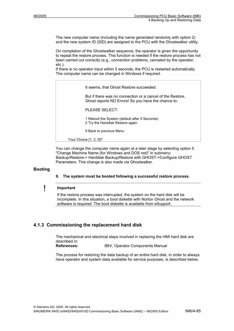
08/2005 Commissioning PCU Basic Software (IM6) 4 Backing Up and Restoring Data
The new computer name (including the name generated randomly with option 2) and the new system ID (SID) are assigned to the PCU with the Ghostwalker utility. On completion of the Ghostwalker sequence, the operator is given the opportunity to repeat the restore process. This function is needed if the restore process has not been carried out correctly (e.g., connection problems, canceled by the operator, etc.). If there is no operator input within 5 seconds, the PCU is restarted automatically. The computer name can be changed in Windows if required.
It seems, that Ghost Restore succeeded. But if there was no connection or a cancel of the Restore, Ghost reports NO Errors! So you have the chance to: PLEASE SELECT: 1 Reboot the System (default after 5 Seconds) 2 Try the Harddisk Restore again 9 Back to previous Menu
Your Choice [1, 2, 9]? You can change the computer name again at a later stage by selecting option 5 "Change Machine Name (for Windows and DOS net)" in submenu Backup/Restore-> Harddisk Backup/Restore with GHOST->Configure GHOST Parameters. This change is also made via Ghostwalker.
Booting 8. The system must be booted following a successful restore process.
! Important
If the restore process was interrupted, the system on the hard disk will be incomplete. In this situation, a boot diskette with Norton Ghost and the network software is required. The boot diskette is available from eSupport.
4.1.3 Commissioning the replacement hard disk The mechanical and electrical steps involved in replacing the HMI hard disk are described in: References: /BH/, Operator Components Manual The process for restoring the data backup of an entire hard disk, in order to always have operator and system data available for service purposes, is described below.
© Siemens AG, 2005. All rights reserved SINUMERIK 840D sl/840D/840Di/810D Commissioning Basic Software (IAM2) – 08/2005 Edition IM6/4-85
Commissioning PCU Basic Software (IM6) 08/2005 4 Backing Up and Restoring Data
Norton Ghost The entire contents of hard disks can be saved as a disk image file using the Norton Ghost utility. This disk image file can be stored on various data carriers and the data restored to the hard disk at a later date. PCUs and replacement hard disks are supplied by the plant with Norton Ghost already installed.
Note
Recommendation: Archive the hard disk backup (hard disk image), including the Norton Ghost utility, on CD.
Restoring data backup Requirements: • Ghost is installed on the PG. • A new replacement hard disk has been obtained. • The HMI is connected to the PC/PG with a parallel cable. • The Windows 3.x or Windows 95 operating system is installed on the PG and a
CD drive is available. ÉÉÉ
1. Install the new replacement hard disk in the PCU or install the new HMI (see instructions supplied with the hard disk) – Click the hard disk into place – Plug in the connecting cable from the hard disk to the PCU – Secure the hard disk with the 4 knurled-head screws – Release the transport lock: Turn towards "operating" until it engages. References: /BH/, Operator Components Manual
Note
The replacement hard disk does not contain a Windows NT operating system or HMI system software.
2. Switch on the PG and insert the CD in the drive. 3. Switch the controller off and then on and select the Service menu in the Boot
Manager. Select menu "4: Backup/Restore". 4. Select: 7 Backup/Restore 5. Enter password. 6. Select menu 1 "Hard disk Backup/Restore with Ghost" 7. Set parameters for Norton Ghost:
– <1> Configure Ghost parameters: – <3> Harddisk Restore from <pathname>, Mode PARALLEL * If this menu is selected, a message window appears: You are prompted to check whether a connection exists between the HMI and the PG/PC. The HMI image file to which the restore process is to be loaded is created.
© Siemens AG, 2005. All rights reserved IM6/4-86 SINUMERIK 840D sl/840D/840Di/810D Commissioning Basic Software (IAM2) – 08/2005 Edition
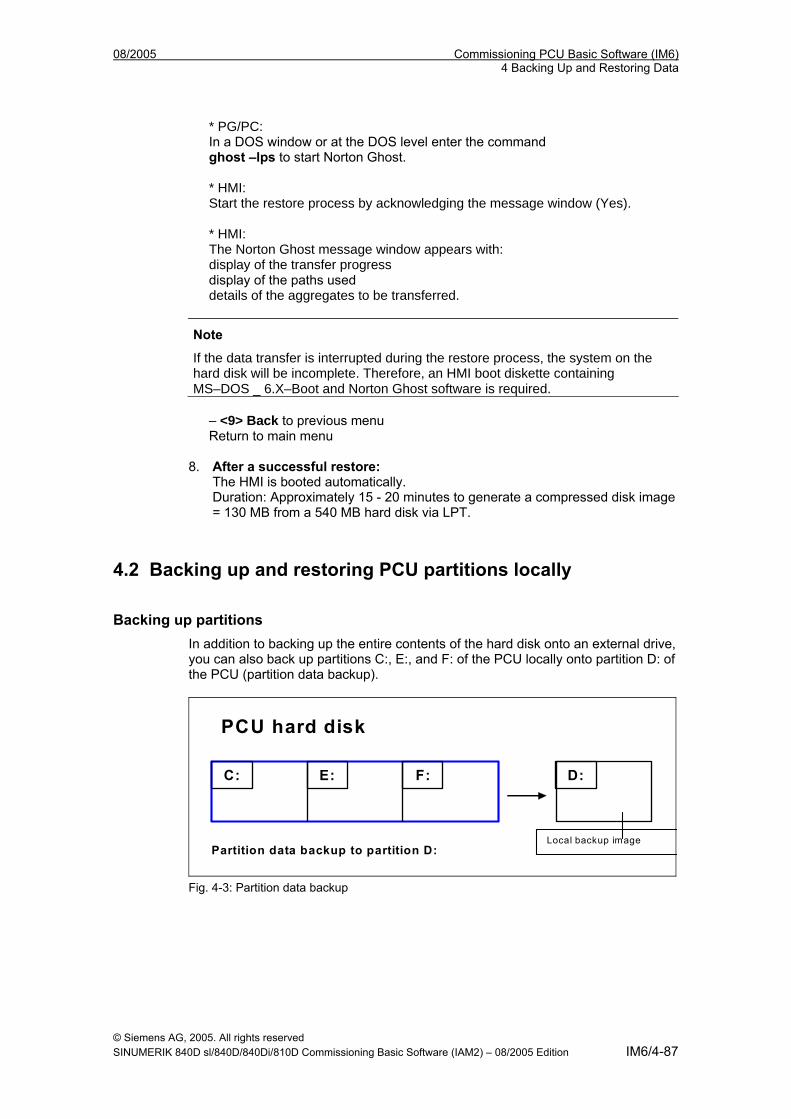
08/2005 Commissioning PCU Basic Software (IM6) 4 Backing Up and Restoring Data
* PG/PC: In a DOS window or at the DOS level enter the command ghost –lps to start Norton Ghost. * HMI: Start the restore process by acknowledging the message window (Yes). * HMI: The Norton Ghost message window appears with: display of the transfer progress display of the paths used details of the aggregates to be transferred.
Note
If the data transfer is interrupted during the restore process, the system on the hard disk will be incomplete. Therefore, an HMI boot diskette containing MS–DOS _ 6.X–Boot and Norton Ghost software is required.
– <9> Back to previous menu Return to main menu
8. After a successful restore:
The HMI is booted automatically. Duration: Approximately 15 - 20 minutes to generate a compressed disk image = 130 MB from a 540 MB hard disk via LPT.
4.2 Backing up and restoring PCU partitions locally
Backing up partitions In addition to backing up the entire contents of the hard disk onto an external drive, you can also back up partitions C:, E:, and F: of the PCU locally onto partition D: of the PCU (partition data backup).
PCU hard disk
C: F: D: E:
Partition data backup to partition D: Local backup image
Fig. 4-3: Partition data backup
© Siemens AG, 2005. All rights reserved SINUMERIK 840D sl/840D/840Di/810D Commissioning Basic Software (IAM2) – 08/2005 Edition IM6/4-87
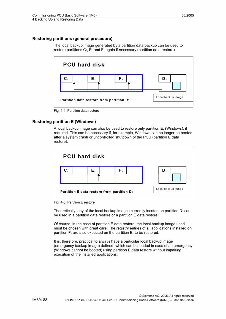
Commissioning PCU Basic Software (IM6) 08/2005 4 Backing Up and Restoring Data
Restoring partitions (general procedure) The local backup image generated by a partition data backup can be used to restore partitions C:, E: and F: again if necessary (partition data restore).
PCU hard disk
C:
F: D: E:
Partition data restore from partition D: Local backup image
Fig. 4-4: Partition data restore
Restoring partition E (Windows) A local backup image can also be used to restore only partition E: (Windows), if required. This can be necessary if, for example, Windows can no longer be booted after a system crash or uncontrolled shutdown of the PCU (partition E data restore).
PCU hard disk
C:
F: D: E:
Partition E data restore from partition D: Local backup image
Fig. 4-5: Partition E restore Theoretically, any of the local backup images currently located on partition D: can be used in a partition data restore or a partition E data restore. Of course, in the case of partition E data restore, the local backup image used must be chosen with great care: The registry entries of all applications installed on partition F: are also expected on the partition E: to be restored. It is, therefore, practical to always have a particular local backup image (emergency backup image) defined, which can be loaded in case of an emergency (Windows cannot be booted) using partition E data restore without impairing execution of the installed applications.
© Siemens AG, 2005. All rights reserved IM6/4-88 SINUMERIK 840D sl/840D/840Di/810D Commissioning Basic Software (IAM2) – 08/2005 Edition
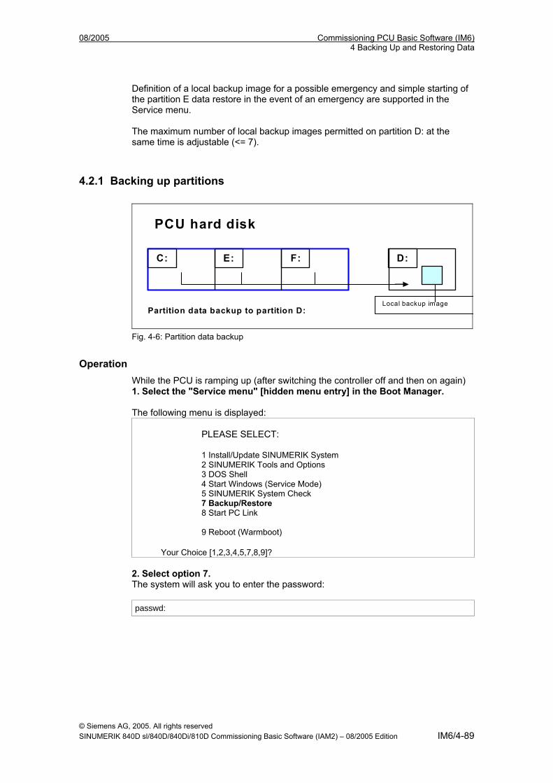
08/2005 Commissioning PCU Basic Software (IM6) 4 Backing Up and Restoring Data
Definition of a local backup image for a possible emergency and simple starting of the partition E data restore in the event of an emergency are supported in the Service menu. The maximum number of local backup images permitted on partition D: at the same time is adjustable (<= 7).
4.2.1 Backing up partitions
PCU hard disk
C:
F: D: E:
Partition data backup to partition D: Local backup image
Fig. 4-6: Partition data backup
Operation While the PCU is ramping up (after switching the controller off and then on again) 1. Select the "Service menu" [hidden menu entry] in the Boot Manager. The following menu is displayed:
PLEASE SELECT: 1 Install/Update SINUMERIK System 2 SINUMERIK Tools and Options 3 DOS Shell 4 Start Windows (Service Mode) 5 SINUMERIK System Check 7 Backup/Restore 8 Start PC Link 9 Reboot (Warmboot)
Your Choice [1,2,3,4,5,7,8,9]? 2. Select option 7. The system will ask you to enter the password: passwd:
© Siemens AG, 2005. All rights reserved SINUMERIK 840D sl/840D/840Di/810D Commissioning Basic Software (IAM2) – 08/2005 Edition IM6/4-89
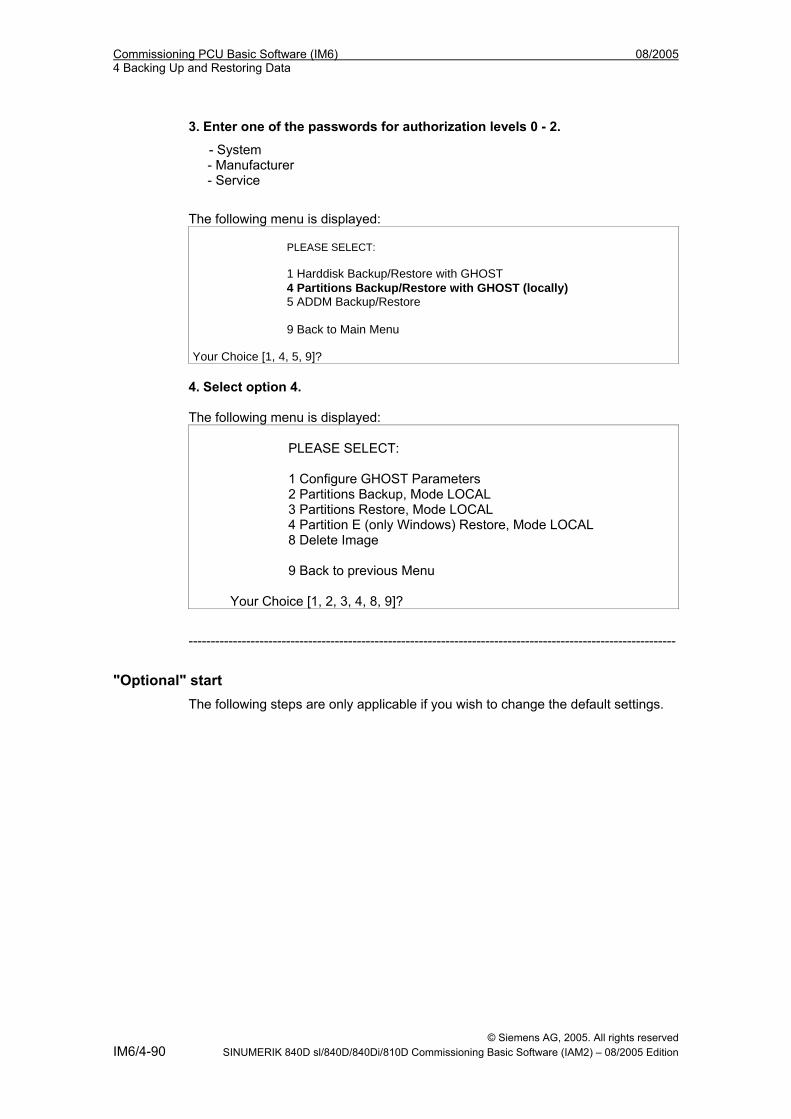
Commissioning PCU Basic Software (IM6) 08/2005 4 Backing Up and Restoring Data
3. Enter one of the passwords for authorization levels 0 - 2.
- System - Manufacturer - Service
The following menu is displayed: PLEASE SELECT: 1 Harddisk Backup/Restore with GHOST 4 Partitions Backup/Restore with GHOST (locally) 5 ADDM Backup/Restore 9 Back to Main Menu Your Choice [1, 4, 5, 9]?
4. Select option 4. The following menu is displayed:
PLEASE SELECT: 1 Configure GHOST Parameters 2 Partitions Backup, Mode LOCAL 3 Partitions Restore, Mode LOCAL 4 Partition E (only Windows) Restore, Mode LOCAL 8 Delete Image 9 Back to previous Menu
Your Choice [1, 2, 3, 4, 8, 9]?
--------------------------------------------------------------------------------------------------------------
"Optional" start The following steps are only applicable if you wish to change the default settings.
© Siemens AG, 2005. All rights reserved IM6/4-90 SINUMERIK 840D sl/840D/840Di/810D Commissioning Basic Software (IAM2) – 08/2005 Edition
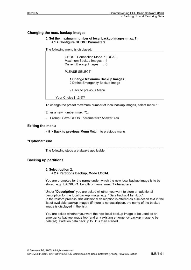
08/2005 Commissioning PCU Basic Software (IM6) 4 Backing Up and Restoring Data
Changing the max. backup images 5. Set the maximum number of local backup images (max. 7)
< 1 > Configure GHOST Parameters: The following menu is displayed:
GHOST Connection Mode : LOCAL Maximum Backup Images : 1 Current Backup Images : 0 PLEASE SELECT: 1 Change Maximum Backup Images 2 Define Emergency Backup Image 9 Back to previous Menu
Your Choice [1,2,9]? To change the preset maximum number of local backup images, select menu 1: Enter a new number (max. 7).
- Prompt: Save GHOST parameters? Answer Yes.
Exiting the menu < 9 > Back to previous Menu Return to previous menu
"Optional" end -------------------------------------------------------------------------------------------------------------- The following steps are always applicable.
Backing up partitions 6. Select option 2.
< 2 > Partitions Backup, Mode LOCAL You are prompted for the name under which the new local backup image is to be stored, e.g., BACKUP1. Length of name: max. 7 characters. Under "Description" you are asked whether you want to store an additional description for the local backup image, e.g., "Data backup1 by Hugo". In the restore process, this additional description is offered as a selection text in the list of available backup images (if there is no description, the name of the backup image is displayed in the list). You are asked whether you want the new local backup image to be used as an emergency backup image too (and any existing emergency backup image to be deleted). Partition data backup to D: is then started.
© Siemens AG, 2005. All rights reserved SINUMERIK 840D sl/840D/840Di/810D Commissioning Basic Software (IAM2) – 08/2005 Edition IM6/4-91
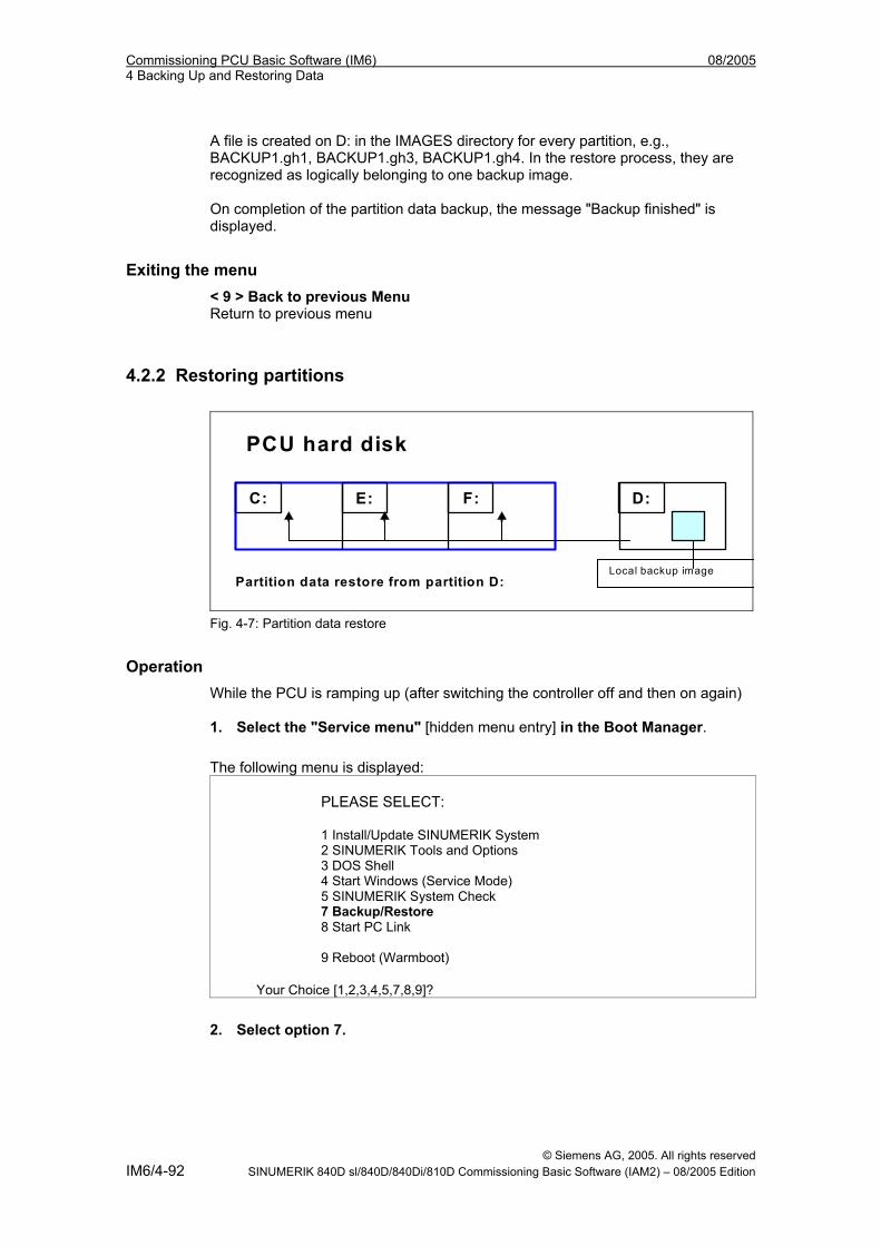
Commissioning PCU Basic Software (IM6) 08/2005 4 Backing Up and Restoring Data
A file is created on D: in the IMAGES directory for every partition, e.g., BACKUP1.gh1, BACKUP1.gh3, BACKUP1.gh4. In the restore process, they are recognized as logically belonging to one backup image. On completion of the partition data backup, the message "Backup finished" is displayed.
Exiting the menu < 9 > Back to previous Menu Return to previous menu
4.2.2 Restoring partitions
PCU hard disk
C:
F: D: E:
Partition data restore from partition D: Local backup image
Fig. 4-7: Partition data restore
Operation While the PCU is ramping up (after switching the controller off and then on again) 1. Select the "Service menu" [hidden menu entry] in the Boot Manager.
The following menu is displayed:
PLEASE SELECT: 1 Install/Update SINUMERIK System 2 SINUMERIK Tools and Options 3 DOS Shell 4 Start Windows (Service Mode) 5 SINUMERIK System Check 7 Backup/Restore 8 Start PC Link 9 Reboot (Warmboot)
Your Choice [1,2,3,4,5,7,8,9]?
2. Select option 7.
© Siemens AG, 2005. All rights reserved IM6/4-92 SINUMERIK 840D sl/840D/840Di/810D Commissioning Basic Software (IAM2) – 08/2005 Edition
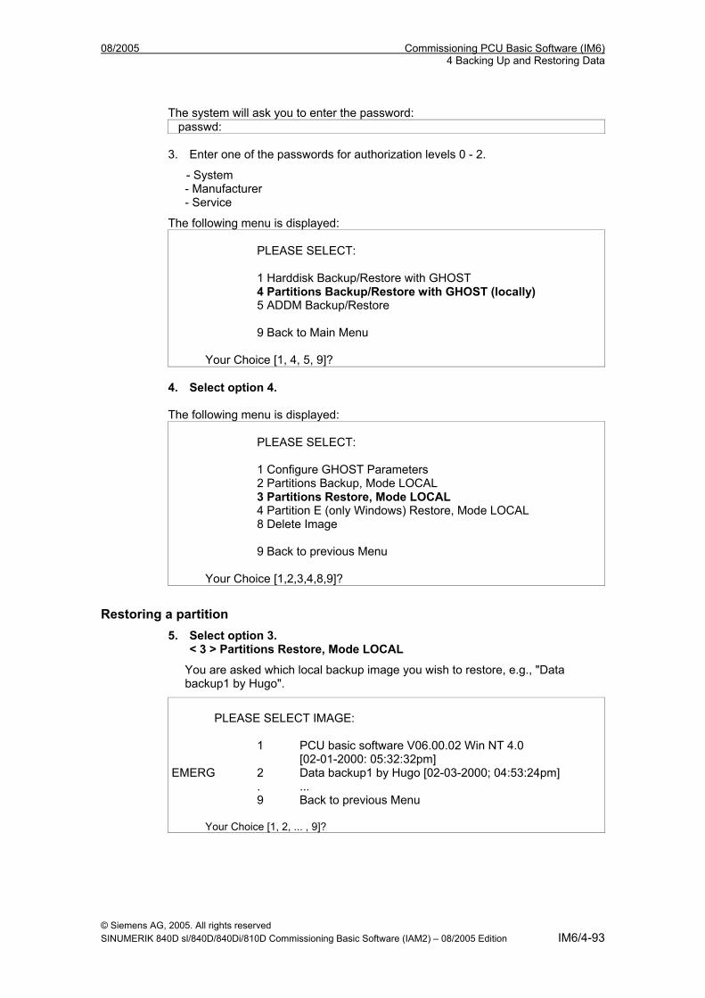
08/2005 Commissioning PCU Basic Software (IM6) 4 Backing Up and Restoring Data
The system will ask you to enter the password: passwd:
3. Enter one of the passwords for authorization levels 0 - 2.
- System - Manufacturer - Service
The following menu is displayed: PLEASE SELECT: 1 Harddisk Backup/Restore with GHOST 4 Partitions Backup/Restore with GHOST (locally) 5 ADDM Backup/Restore 9 Back to Main Menu
Your Choice [1, 4, 5, 9]? 4. Select option 4. The following menu is displayed:
PLEASE SELECT: 1 Configure GHOST Parameters 2 Partitions Backup, Mode LOCAL 3 Partitions Restore, Mode LOCAL 4 Partition E (only Windows) Restore, Mode LOCAL 8 Delete Image 9 Back to previous Menu
Your Choice [1,2,3,4,8,9]?
Restoring a partition 5. Select option 3.
< 3 > Partitions Restore, Mode LOCAL
You are asked which local backup image you wish to restore, e.g., "Data backup1 by Hugo".
PLEASE SELECT IMAGE: 1 PCU basic software V06.00.02 Win NT 4.0 [02-01-2000: 05:32:32pm] EMERG 2 Data backup1 by Hugo [02-03-2000; 04:53:24pm] . ...
9 Back to previous Menu
Your Choice [1, 2, ... , 9]?
© Siemens AG, 2005. All rights reserved SINUMERIK 840D sl/840D/840Di/810D Commissioning Basic Software (IAM2) – 08/2005 Edition IM6/4-93
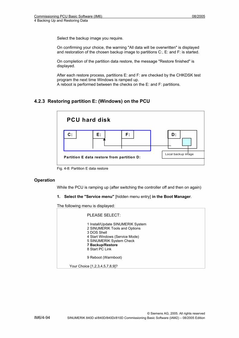
Commissioning PCU Basic Software (IM6) 08/2005 4 Backing Up and Restoring Data
Select the backup image you require. On confirming your choice, the warning "All data will be overwritten" is displayed and restoration of the chosen backup image to partitions C:, E: and F: is started. On completion of the partition data restore, the message "Restore finished" is displayed. After each restore process, partitions E: and F: are checked by the CHKDSK test program the next time Windows is ramped up. A reboot is performed between the checks on the E: and F: partitions.
4.2.3 Restoring partition E: (Windows) on the PCU
PCU hard disk
C:
F: D: E:
Partition E data restore from partition D: Local backup image
Fig. 4-8: Partition E data restore
Operation While the PCU is ramping up (after switching the controller off and then on again) 1. Select the "Service menu" [hidden menu entry] in the Boot Manager. The following menu is displayed:
PLEASE SELECT: 1 Install/Update SINUMERIK System 2 SINUMERIK Tools and Options 3 DOS Shell 4 Start Windows (Service Mode) 5 SINUMERIK System Check 7 Backup/Restore 8 Start PC Link 9 Reboot (Warmboot)
Your Choice [1,2,3,4,5,7,8,9]?
© Siemens AG, 2005. All rights reserved IM6/4-94 SINUMERIK 840D sl/840D/840Di/810D Commissioning Basic Software (IAM2) – 08/2005 Edition
08/2005 Commissioning PCU Basic Software (IM6) 4 Backing Up and Restoring Data
2. Select option 7. The system will ask you to enter the password: passwd:
3. Enter one of the passwords for authorization levels 0 - 2.
- System - Manufacturer - Service
The following menu is displayed:
PLEASE SELECT: 1 Harddisk Backup/Restore with GHOST 4 Partitions Backup/Restore with GHOST (locally) 5 ADDM Backup/Restore 9 Back to Main Menu
Your Choice [1, 4, 5, 9]? 4. Select option 4. The following menu is displayed:
PLEASE SELECT: 1 Configure GHOST Parameters 2 Partitions Backup, Mode LOCAL 3 Partitions Restore, Mode LOCAL 4 Partition E (only Windows) Restore, Mode LOCAL 8 Delete Image 9 Back to previous Menu
Your Choice [1,2,3,4,8,9]?
Restoring partition E 5. Select option 4.
< 4 > Partition E (only Windows) Restore, Mode LOCAL You are asked which local backup image’s partition E: (Windows partition) you wish to restore, e.g., "Data backup1 by Hugo".
© Siemens AG, 2005. All rights reserved SINUMERIK 840D sl/840D/840Di/810D Commissioning Basic Software (IAM2) – 08/2005 Edition IM6/4-95
Commissioning PCU Basic Software (IM6) 08/2005 4 Backing Up and Restoring Data
PLEASE SELECT: - as for Restoring a partition
Select the backup image you require: On confirming your choice, the warning: “The Windows partition will be overwritten” is displayed and the restore process for partition E: is started. On completion of the partition E data restore, the message "Restore finished" is displayed. Partition E: is checked by the CHKDSK test program the next time WinNT is ramped up.
4.2.4 Deleting the backup image
Operation While the PCU is ramping up (after switching the controller off and then on again) 1. Select the "Service menu" [hidden menu entry] in the Boot Manager. The following menu is displayed:
PLEASE SELECT: 1 Install/Update SINUMERIK System 2 SINUMERIK Tools and Options 3 DOS Shell 4 Start Windows (Service Mode) 5 SINUMERIK System Check 7 Backup/Restore 8 Start PC Link 9 Reboot (Warmboot)
Your Choice [1, 2, 3, 4, 5, 7, 8, 9]? 2. Select option 7. The system will ask you to enter the password: passwd:
© Siemens AG, 2005. All rights reserved IM6/4-96 SINUMERIK 840D sl/840D/840Di/810D Commissioning Basic Software (IAM2) – 08/2005 Edition
08/2005 Commissioning PCU Basic Software (IM6) 4 Backing Up and Restoring Data
3. Enter one of the passwords for authorization levels 0 - 2.
- System - Manufacturer - Service
The following menu is displayed: PLEASE SELECT: 1 Harddisk Backup/Restore with GHOST 4 Partitions Backup/Restore with GHOST (locally) 5 ADDM Backup/Restore 9 Back to Main Menu
Your Choice [1, 4, 5, 9]? 4. Select option 4. The following menu is displayed:
PLEASE SELECT: 1 Configure GHOST Parameters 2 Partitions Backup, Mode LOCAL 3 Partitions Restore, Mode LOCAL 4 Partition E (only Windows) Restore, Mode LOCAL 8 Delete Image 9 Back to previous Menu
Your Choice [1, 2, 3, 4, 8, 9]?
Deleting the backup image 5. Select option 8.
< 8 > Delete Image From the list of available backup images, select the one you wish to delete. The system asks you whether you really want to delete the image. Confirm with "Y" to delete the backup image.
Exiting the menu < 9 > Back to previous Menu Return to previous menu
© Siemens AG, 2005. All rights reserved SINUMERIK 840D sl/840D/840Di/810D Commissioning Basic Software (IAM2) – 08/2005 Edition IM6/4-97
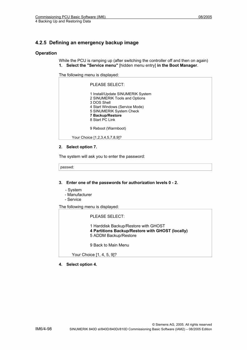
Commissioning PCU Basic Software (IM6) 08/2005 4 Backing Up and Restoring Data
4.2.5 Defining an emergency backup image
Operation While the PCU is ramping up (after switching the controller off and then on again) 1. Select the "Service menu" [hidden menu entry] in the Boot Manager. The following menu is displayed:
PLEASE SELECT: 1 Install/Update SINUMERIK System 2 SINUMERIK Tools and Options 3 DOS Shell 4 Start Windows (Service Mode) 5 SINUMERIK System Check 7 Backup/Restore 8 Start PC Link 9 Reboot (Warmboot)
Your Choice [1,2,3,4,5,7,8,9]? 2. Select option 7. The system will ask you to enter the password: passwd:
3. Enter one of the passwords for authorization levels 0 - 2.
- System - Manufacturer - Service
The following menu is displayed: PLEASE SELECT: 1 Harddisk Backup/Restore with GHOST 4 Partitions Backup/Restore with GHOST (locally) 5 ADDM Backup/Restore 9 Back to Main Menu
Your Choice [1, 4, 5, 9]? 4. Select option 4.
© Siemens AG, 2005. All rights reserved IM6/4-98 SINUMERIK 840D sl/840D/840Di/810D Commissioning Basic Software (IAM2) – 08/2005 Edition
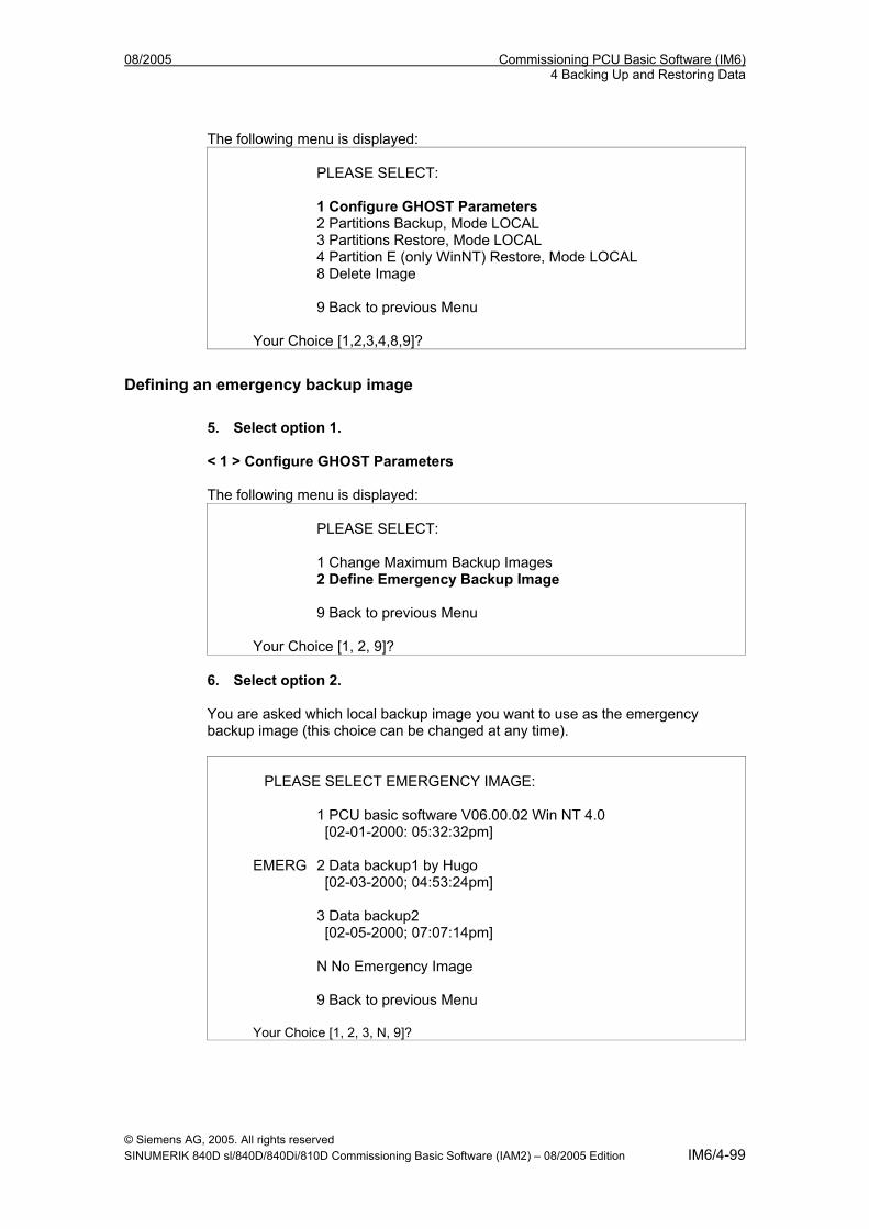
08/2005 Commissioning PCU Basic Software (IM6) 4 Backing Up and Restoring Data
The following menu is displayed: PLEASE SELECT: 1 Configure GHOST Parameters 2 Partitions Backup, Mode LOCAL 3 Partitions Restore, Mode LOCAL 4 Partition E (only WinNT) Restore, Mode LOCAL 8 Delete Image 9 Back to previous Menu
Your Choice [1,2,3,4,8,9]?
Defining an emergency backup image 5. Select option 1. < 1 > Configure GHOST Parameters The following menu is displayed:
PLEASE SELECT: 1 Change Maximum Backup Images 2 Define Emergency Backup Image 9 Back to previous Menu
Your Choice [1, 2, 9]? 6. Select option 2. You are asked which local backup image you want to use as the emergency backup image (this choice can be changed at any time).
PLEASE SELECT EMERGENCY IMAGE: 1 PCU basic software V06.00.02 Win NT 4.0 [02-01-2000: 05:32:32pm] EMERG 2 Data backup1 by Hugo [02-03-2000; 04:53:24pm] 3 Data backup2 [02-05-2000; 07:07:14pm] N No Emergency Image 9 Back to previous Menu Your Choice [1, 2, 3, N, 9]?
© Siemens AG, 2005. All rights reserved SINUMERIK 840D sl/840D/840Di/810D Commissioning Basic Software (IAM2) – 08/2005 Edition IM6/4-99
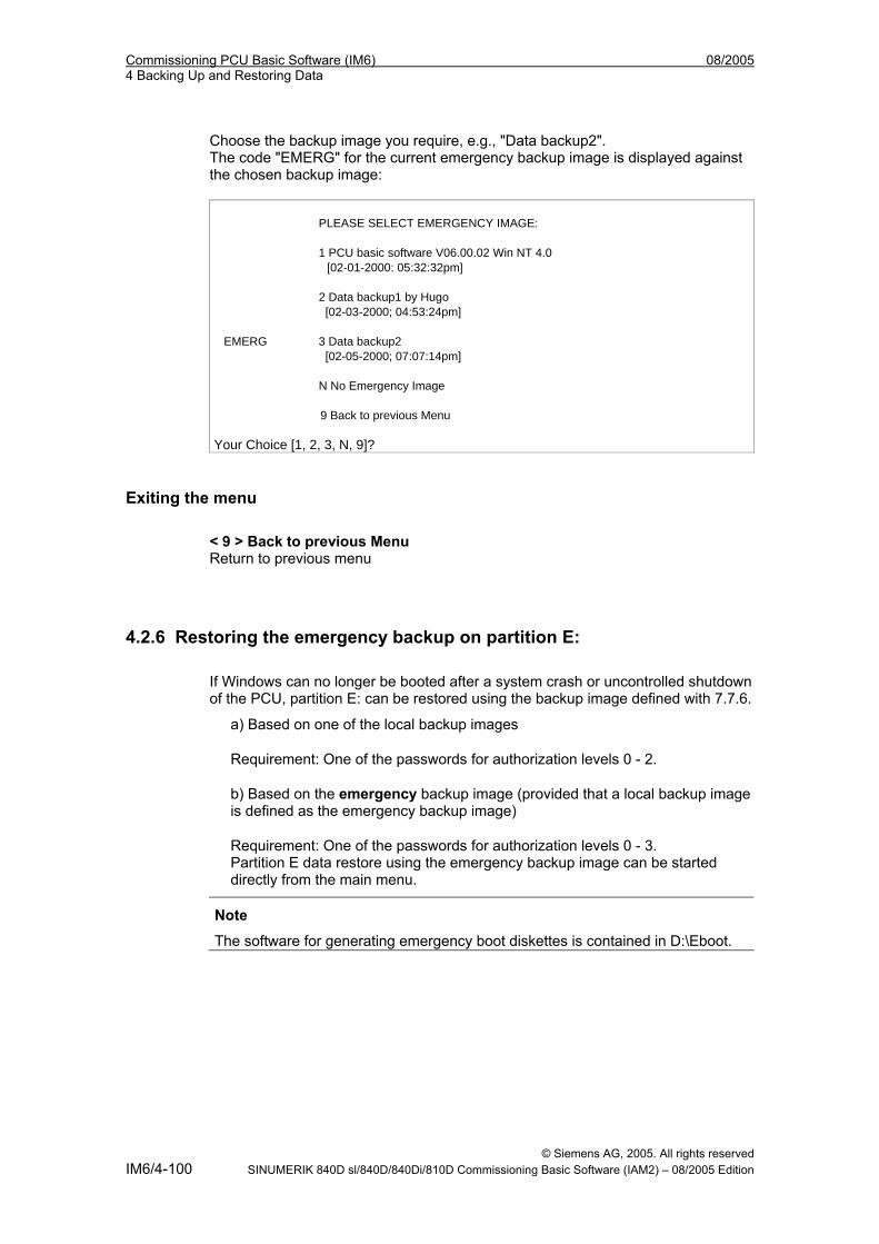
Commissioning PCU Basic Software (IM6) 08/2005 4 Backing Up and Restoring Data
Choose the backup image you require, e.g., "Data backup2". The code "EMERG" for the current emergency backup image is displayed against the chosen backup image: PLEASE SELECT EMERGENCY IMAGE: 1 PCU basic software V06.00.02 Win NT 4.0 [02-01-2000: 05:32:32pm] 2 Data backup1 by Hugo [02-03-2000; 04:53:24pm] EMERG 3 Data backup2 [02-05-2000; 07:07:14pm] N No Emergency Image 9 Back to previous Menu Your Choice [1, 2, 3, N, 9]?
Exiting the menu < 9 > Back to previous Menu Return to previous menu
4.2.6 Restoring the emergency backup on partition E: If Windows can no longer be booted after a system crash or uncontrolled shutdown of the PCU, partition E: can be restored using the backup image defined with 7.7.6.
a) Based on one of the local backup images
Requirement: One of the passwords for authorization levels 0 - 2.
b) Based on the emergency backup image (provided that a local backup image is defined as the emergency backup image)
Requirement: One of the passwords for authorization levels 0 - 3. Partition E data restore using the emergency backup image can be started directly from the main menu.
Note
The software for generating emergency boot diskettes is contained in D:\Eboot.
© Siemens AG, 2005. All rights reserved IM6/4-100 SINUMERIK 840D sl/840D/840Di/810D Commissioning Basic Software (IAM2) – 08/2005 Edition
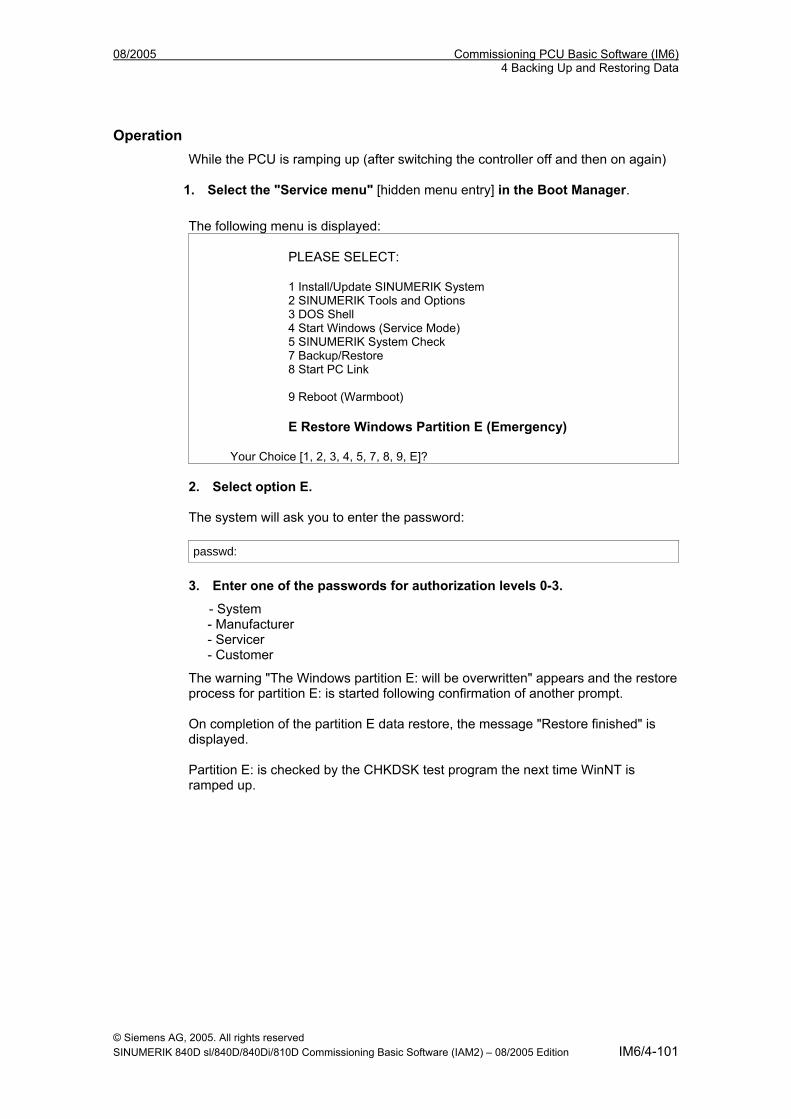
08/2005 Commissioning PCU Basic Software (IM6) 4 Backing Up and Restoring Data
Operation While the PCU is ramping up (after switching the controller off and then on again)
1. Select the "Service menu" [hidden menu entry] in the Boot Manager.
The following menu is displayed: PLEASE SELECT: 1 Install/Update SINUMERIK System 2 SINUMERIK Tools and Options 3 DOS Shell 4 Start Windows (Service Mode) 5 SINUMERIK System Check 7 Backup/Restore 8 Start PC Link 9 Reboot (Warmboot) E Restore Windows Partition E (Emergency)
Your Choice [1, 2, 3, 4, 5, 7, 8, 9, E]? 2. Select option E. The system will ask you to enter the password: passwd:
3. Enter one of the passwords for authorization levels 0-3.
- System - Manufacturer - Servicer - Customer
The warning "The Windows partition E: will be overwritten" appears and the restore process for partition E: is started following confirmation of another prompt. On completion of the partition E data restore, the message "Restore finished" is displayed. Partition E: is checked by the CHKDSK test program the next time WinNT is ramped up.
© Siemens AG, 2005. All rights reserved SINUMERIK 840D sl/840D/840Di/810D Commissioning Basic Software (IAM2) – 08/2005 Edition IM6/4-101
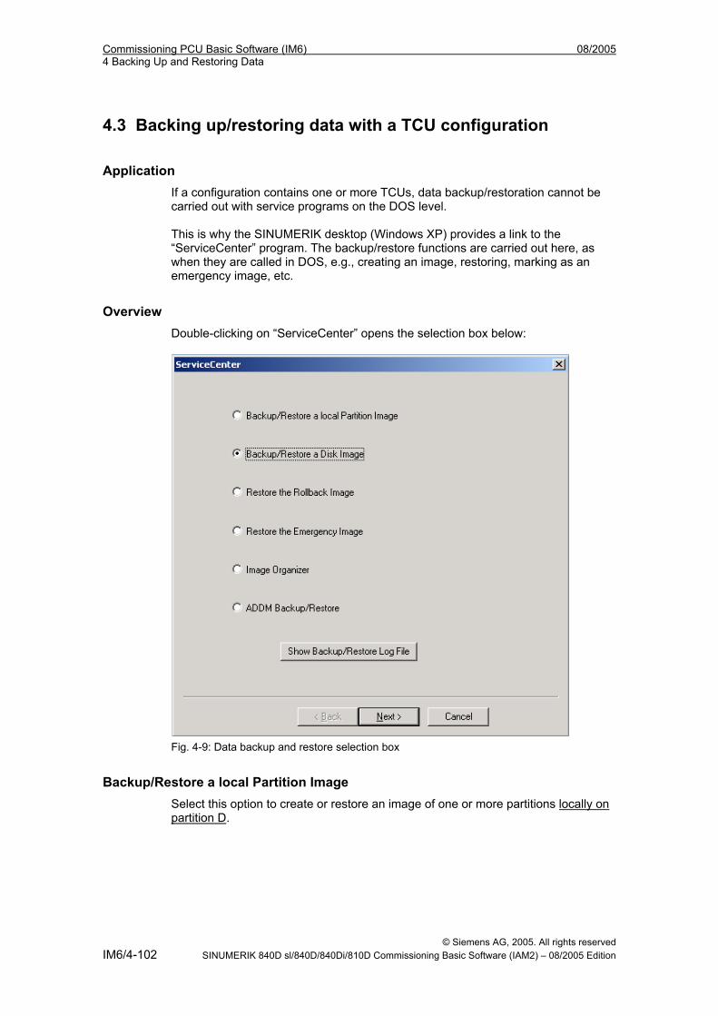
Commissioning PCU Basic Software (IM6) 08/2005 4 Backing Up and Restoring Data
4.3 Backing up/restoring data with a TCU configuration
Application If a configuration contains one or more TCUs, data backup/restoration cannot be carried out with service programs on the DOS level. This is why the SINUMERIK desktop (Windows XP) provides a link to the “ServiceCenter” program. The backup/restore functions are carried out here, as when they are called in DOS, e.g., creating an image, restoring, marking as an emergency image, etc.
Overview Double-clicking on “ServiceCenter” opens the selection box below:
Fig. 4-9: Data backup and restore selection box
Backup/Restore a local Partition Image Select this option to create or restore an image of one or more partitions locally on partition D.
© Siemens AG, 2005. All rights reserved IM6/4-102 SINUMERIK 840D sl/840D/840Di/810D Commissioning Basic Software (IAM2) – 08/2005 Edition
08/2005 Commissioning PCU Basic Software (IM6) 4 Backing Up and Restoring Data
“Next >” opens the next selection box, where you can select partitions C, E or F individually. If you wish to save the backup and restore it later, we recommend that you create a complete image (C, E and F). The size of every partition is displayed before you start the backup process. In order to retain suitable data packets for archiving on a CD-ROM, for example, you can also define the desired sizes under “Options”.
Backup/Restore a Disk Image Select this option to create or restore an image of one or more partitions on a network drive. “Next >” opens the next selection box: If you have already established a network connection with access to a shared drive, select “Net Share” and enter the drive name and the file name.
• You can reset the communication parameters under "Change Network Settings".
• Under “Options”, select either one backup file or several data packets and define the appropriate sizes.
A connection is established using the “Ghost Cast Client” Ghost software (with a 1:1 connection, for example). To implement this, licensed Ghost software must be installed on the target drive.
Fig. 4-10: Network drive selection box
© Siemens AG, 2005. All rights reserved SINUMERIK 840D sl/840D/840Di/810D Commissioning Basic Software (IAM2) – 08/2005 Edition IM6/4-103
Commissioning PCU Basic Software (IM6) 08/2005 4 Backing Up and Restoring Data
Restore the Rollback Image Select this option to restore a rollback image (the most recently backed up/newest image of partitions C, E and F).
Restore the Emergency Image Select this option to restore the emergency image of one or more partitions. This image is intended for use when the system can no longer be booted after a system crash or uncontrolled shutdown and, therefore, comprises partitions C and E. This image must not impair the execution of installed applications, i.e., the registry entries for all applications installed on F: must be included in the image. Use the “Image Organizer” function to mark the emergency image.
Image Organizer Select this option to mark out one image contained in the displayed list as the emergency image, or to delete an existing image.
ADDM Backup/Restore Select this option to create or restore an image of the ADDM (A & D data management) software on partition D or on a network drive.
Show Backup/Restore Log File This option opens file bacres.txt, which contains a log of all backup records.
Outputting the log file (Service menu “Actionlog” function) The log file can be read out from the booting menu. A booting menu is displayed whenever a crash event occurs (PLC bit DB19, byte0, bit6). The bit is set and canceled by the PLC on the operator interface (as is key disable, screen blanking, etc.). The function is executed as described in /IM4/.
© Siemens AG, 2005. All rights reserved IM6/4-104 SINUMERIK 840D sl/840D/840Di/810D Commissioning Basic Software (IAM2) – 08/2005 Edition
08/2005 Commissioning PCU Basic Software (IM6) I Index
I Index
II.1 Subject index
A
Action log..................................... IM6/4-104 Antivirus protection........................ IM6/1-18
B
Boot screen Replacing................................... IM6/1-22 Storage location......................... IM6/1-21
Backing up partitions ..... IM6/4-87, IM6/4-89 Backing up/restoring data.............. IM6/4-75 Backup battery............................... IM6/2-41 Backup/restore ............................ IM6/4-102 BIOS settings................................. IM6/1-12 BIOS setup .....................................IM6/1-10 Booting .......................... IM6/1-16, IM6/1-17 Boot Manager ................................ IM6/1-16 Boot virus check ............................ IM6/1-18 Buffer time ..................................... IM6/2-44
C
Checking for boot viruses.............. IM6/1-18 Configuring HMI operators ............ IM6/1-23 Connection
Ethernet ..................................... IM6/4-75 Parallel....................................... IM6/4-75
D
DHCP server ................................. IM6/3-61 Disk image................................... IM6/4-102 DNS server .................................... IM6/3-68
E
Emergency backup image............. IM6/4-98 Emergency image ....................... IM6/4-102 Errors............................................. IM6/1-18 Ethernet
Connection ................................ IM6/4-75 Port ............................................ IM6/3-61
F
First commissioning ....................... IM6/1-17
H
Hard disk Partitioning ................................... IM6/1-7 Replacement.............................. IM6/4-85 Replacing ................................... IM6/4-85
HMI Explorer .................................. IM6/2-38 HMI Manager ................................. IM6/3-61 HMI monitoring............................... IM6/2-45
I
Installation path.............................. IM6/2-36 Installing HMI software .................. IM6/3-54 IP address...................................... IM6/3-61
L
Log file .........................IM6/2-39, IM6/4-104
N
Network drives ............................... IM6/3-61 Network operation.......................... IM6/3-67 NFS client ...................................... IM6/3-61
P
Partition image ............................. IM6/4-102 PCMCIA interface .......................... IM6/1-14 PCU
Delivery condition......................... IM6/1-6 Installing basic software............. IM6/1-13 Interfaces ................................... IM6/1-14
PCU computer name ..................... IM6/3-61 PCU network name........................ IM6/4-83 Post-installing Windows
components ............................... IM6/3-68
© Siemens AG, 2005. All rights reserved SINUMERIK 840D sl/840D/840Di/810D Commissioning Basic Software (IAM2) – 08/2005 Edition IM6/I-105
Commissioning PCU Basic Software (IM6) 08/2005 I Index
R
Recovery CD ................................. IM6/3-68 Recovery Console ......... IM6/1-17, IM6/2-28 Restoring partitions ....... IM6/4-92, IM6/4-94 Rollback image............................ IM6/4-102
S
Service menu Functions ................................... IM6/2-26 Parameterizing .......................... IM6/2-28 Settings...................................... IM6/3-61
ServiceCenter.............................. IM6/4-102 SIMATIC STEP7
Authorizing................................. IM6/3-71 Installing .................................... IM6/3-69
SINUMERIK desktop Calling up................................... IM6/1-13 Functions ................................... IM6/2-35 Network operation ..................... IM6/3-67
SITOP monitor Configuring ................................ IM6/2-42 Parameterizing .......................... IM6/2-42
Software Components ................................ IM6/1-8 Installing .................................... IM6/2-36 Update ....................................... IM6/3-49
Starting OEM programs................. IM6/2-40
System Powering up ............................... IM6/1-16
T
TCP/IP Communication .......................... IM6/3-61 Settings ...................................... IM6/3-66
U
UPS module (SITOP).....IM6/2-41, IM6/2-43 USB interface................................. IM6/2-41
V
Version Checking PCU ........................... IM6/2-35 SW components...........IM6/1-8, IM6/2-38
W
WINS server................................... IM6/3-68
© Siemens AG, 2005. All rights reserved IM6/I-106 SINUMERIK 840D sl/840D/840Di/810D Commissioning Basic Software (IAM2) – 08/2005 Edition
08/2005 Commissioning PCU Basic Software (IM6) I Index
I.2 Index of commands and identifiers
A
ADDM (A&D data management) IM6/4-104
C
Change DNS Extension ................ IM6/2-26 Change Domain Name.................. IM6/2-26 Change Gateway........................... IM6/2-26 Change IP Address ....................... IM6/2-26 Change Machine Name ................ IM6/2-26 Change Network Settings.............. IM6/2-26 Change Subnetmask..................... IM6/2-26 Change TCP/IP settings................ IM6/2-26 Change Operator Name................ IM6/2-26 Connect to Network Drives............ IM6/2-26
D
Disconnect from all Network Drives ........................................ IM6/2-26
Domain Name Server.................... IM6/2-26
I
Install from Floppy Disk ................ IM6/2-26
M
Manage Network Drives ................ IM6/2-26
S
SYSLOCK...................................... IM6/1-18
T
Toggle Protocol.............................. IM6/2-26
■
© Siemens AG, 2005. All rights reserved SINUMERIK 840D sl/840D/840Di/810D Commissioning Basic Software (IAM2) – 08/2005 Edition IM6/I-107
Commissioning PCU Basic Software (IM6) 08/2005 I Index
© Siemens AG, 2005. All rights reserved IM6/I-108 SINUMERIK 840D sl/840D/840Di/810D Commissioning Basic Software (IAM2) – 08/2005 Edition
Commissioning a System 1
Configuring network operation
2Backing up and Restoring Data
3
Service Commands 4
Appendix A
List of abbreviations B
SINUMERIK 840D sl
CNC Part 5 (Basesoftware)NCU operating system
Commissioning manual
07/2006 6FC5397-2CP10-2BA0
Valid for: SINUMERIK 840D sl/840DE sl control system Software version NCU 2.0

Safety Guidelines This manual contains notices you have to observe in order to ensure your personal safety, as well as to prevent damage to property. The notices referring to your personal safety are highlighted in the manual by a safety alert symbol, notices referring only to property damage have no safety alert symbol. These notices shown below are graded according to the degree of danger.
Danger
indicates that death or severe personal injury will result if proper precautions are not taken.
Warning
indicates that death or severe personal injury may result if proper precautions are not taken.
Caution
with a safety alert symbol, indicates that minor personal injury can result if proper precautions are not taken.
Caution
without a safety alert symbol, indicates that property damage can result if proper precautions are not taken.
Notice
indicates that an unintended result or situation can occur if the corresponding information is not taken into account.
If more than one degree of danger is present, the warning notice representing the highest degree of danger will be used. A notice warning of injury to persons with a safety alert symbol may also include a warning relating to property damage.
Qualified Personnel The device/system may only be set up and used in conjunction with this documentation. Commissioning and operation of a device/system may only be performed by qualified personnel. Within the context of the safety notes in this documentation qualified persons are defined as persons who are authorized to commission, ground and label devices, systems and circuits in accordance with established safety practices and standards.
Prescribed Usage Note the following:
Warning
This device may only be used for the applications described in the catalog or the technical description and only in connection with devices or components from other manufacturers which have been approved or recommended by Siemens. Correct, reliable operation of the product requires proper transport, storage, positioning and assembly as well as careful operation and maintenance.
Trademarks All names identified by ® are registered trademarks of the Siemens AG. The remaining trademarks in this publication may be trademarks whose use by third parties for their own purposes could violate the rights of the owner.
Disclaimer of Liability We have reviewed the contents of this publication to ensure consistency with the hardware and software described. Since variance cannot be precluded entirely, we cannot guarantee full consistency. However, the information in this publication is reviewed regularly and any necessary corrections are included in subsequent editions.
Siemens AG Automation and Drives Postfach 48 48 90437 NÜRNBERG GERMANY
Order No.: 6FC5397-2CP10-2BA0 Edition 08/2006
Copyright © Siemens AG 2005, 2006. Technical data subject to change
NCU operating system Commissioning manual, 07/2006, 6FC5397-2CP10-2BA0 iii
Table of contents 1 Commissioning a System ....................................................................................................................... 1-1
1.1 Delivery condition of the system ................................................................................................ 1-1 1.2 System booting .......................................................................................................................... 1-2 1.3 Displays during system booting ................................................................................................. 1-3 1.4 Meaning of switch positions ....................................................................................................... 1-5
2 Configuring network operation ................................................................................................................ 2-1 2.1 Ethernet interfaces of the NCU.................................................................................................. 2-1 2.2 Structure of the file 'basasys.ini'................................................................................................. 2-1 2.2.1 Section [ExternalInterface]......................................................................................................... 2-2 2.2.2 Section [LinuxBase] ................................................................................................................... 2-4
3 Backing up and Restoring Data .............................................................................................................. 3-1 3.1 Applications................................................................................................................................ 3-1 3.2 Creating a service system for the NCU ..................................................................................... 3-2 3.3 Service system........................................................................................................................... 3-3 3.3.1 Storing data on a service system............................................................................................... 3-3 3.3.2 Restoring data from the service system .................................................................................... 3-5 3.4 Network drive ............................................................................................................................. 3-6 3.4.1 Backing up data onto a network drive........................................................................................ 3-6 3.4.2 Restoring data from the network drive....................................................................................... 3-8
4 Service Commands ................................................................................................................................ 4-1 4.1 Using service commands........................................................................................................... 4-1 4.2 Syntax for the Actions ................................................................................................................ 4-2 4.3 Generic elements....................................................................................................................... 4-3 4.4 Description of the actions........................................................................................................... 4-5 4.4.1 Help............................................................................................................................................ 4-5 4.4.2 Check-cf ..................................................................................................................................... 4-6 4.4.3 Connect...................................................................................................................................... 4-6 4.4.4 Disconnect ................................................................................................................................. 4-8 4.4.5 Enable, disable .......................................................................................................................... 4-8 4.4.6 Restart........................................................................................................................................ 4-9 4.4.7 Restore....................................................................................................................................... 4-9 4.4.8 Save ......................................................................................................................................... 4-10 4.4.9 Show ........................................................................................................................................ 4-11 4.4.10 Start, Stop ................................................................................................................................ 4-13 4.4.11 Service tools WinSCP and PuTTY........................................................................................... 4-14
Table of contents
NCU operating system iv Commissioning manual, 07/2006, 6FC5397-2CP10-2BA0
A Appendix.................................................................................................................................................A-1 A.1 Example: File basesys.ini...........................................................................................................A-1 A.2 Example: Configuration with fixed IP address ...........................................................................A-3 A.3 Licenses for WinSCP and PuTTY..............................................................................................A-4 A.3.1 GNU License..............................................................................................................................A-4 A.3.2 PuTTY Licence.........................................................................................................................A-10
B List of abbreviations................................................................................................................................B-1 B.1 Abbreviations .............................................................................................................................B-1
Glossary ..................................................................................................................................... Glossary-1 Index................................................................................................................................................ Index-1
NCU operating system Commissioning manual, 07/2006, 6FC5397-2CP10-2BA0 1-1
Commissioning a System 11.1 Delivery condition of the system
Directories on the CF card When the NCU is in operation, the following directories are available on the CF card (this is a selection and not an exhaustive list):
Directory Use /siemens Reserved for Siemens system software /addon Reserved for Siemens add-on software /oem Additional software and configurations of the machine manufacturer /user • Storage of user data
• Configuration of the HMI • Data that appears on the user interface when the machine is started
up /system Linux operating system /user/system/etc File basesys.ini (modifications possible) /user/common/tcu TCU configuration data /var/log/messages System log file (same as event.log under Windows)
Priorities Files in the directory under /user always have priority over files with the same name in the directory /oem → /addon → /siemens.
Caution Suitable editors for Linux In most Linux system files, lines may only be ended with LF, and not with CRLF as in Windows. Bear this in mind when selecting an editor. The editor of the internal HMI under "Start-up” is suitable. In the Linux operating system, the UNIX Editor vi is available. Note that the Linux operating system is case-sensitive.
Commissioning a System 1.2 System booting
NCU operating system 1-2 Commissioning manual, 07/2006, 6FC5397-2CP10-2BA0
Preset users The following users are already set up on the operating system of the NCU:
Users Password operator operator1 operator2 operator3
--- --- --- ---
Key switch position 0 Key switch position 1 Key switch position 2 Key switch position 3
user CUSTOMER Operators, users service EVENING Service personnel manufact SUNRISE Machine manufacturer
See also Using service commands (Page 4-1)
1.2 System booting
Sequence To ensure unproblematic booting of the NCU, the CF card must be inserted. When the NCU is booting up, visual information on the current operating system is provided using the following displays: • The RDY-LED flashes slowly yellow when the CF card is accessed. • During booting, the seven-segment display outputs different codes that signalize, for
example, when the BIOS is started, when the CF card is accessed, etc. When the booting has been completed successfully, the following is displayed: • The PLC LED lights up green. • The seven-segment display shows "6." with a flashing dot. • The RDY-LED and all other LEDs are not illuminated.
Performing a reset operation The reset button is located behind the blanking plate of the NCU. A reset operation resets the entire system and requires a system restart. This is comparable to a "Power On reset" except that the 24V power supply does not have to be switched off.
Commissioning a System 1.3 Displays during system booting
NCU operating system Commissioning manual, 07/2006, 6FC5397-2CP10-2BA0 1-3
Booting for servicing purposes For service or diagnosis purposes, the NCU can be booted from a service system, the Emergency Boot System.
See also Creating a service system for the NCU (Page 3-2)
1.3 Displays during system booting
States of the RDY LED Of the LEDs on the front of the NCU, only the RDY LED and its status is important when booting up the NCU.
BIOS power-up
RDY LED: yellow Other LEDs: All yellow, set by PLC/option module Significance: No boot device was found: Code 1F or Code FF. Cause: The CF card is defective or not bootable, or it does not contain
any system software.
Downloading of operating system
RDY LED: Slowly flashing red (0.5Hz) Other LEDs: Set by PLC/option module Significance: Loading the operating system involves three phases, which
are displayed on the seven-segment display.
Booting up the kernel
RDY LED: Slowly flashing yellow (0.5Hz) Other LEDs: Set by PLC/option module Seven-segment display: 1 Significance: Phase 2: Driver initialization
Commissioning a System 1.3 Displays during system booting
NCU operating system 1-4 Commissioning manual, 07/2006, 6FC5397-2CP10-2BA0
Booting up the basic system
RDY LED: Slowly flashing yellow/green (0.5Hz) Other LEDs: Set by PLC/option module Significance: Phase 3: Initialization of the basic system
NRK/NCK outputs
RDY LED: Off (If fault status: red)
Other LEDs: Set by PLC/option module Significance: After the basic system, the NRK/NCK takes over the LED and
7-segment display.
System fault
RDY LED: Rapidly flashing red (2Hz) Other LEDs: Set by PLC/option module Significance: An error has occurred.
The system is stopped.
RDY LED: Rapidly flashing red/yellow (2Hz) Other LEDs: Set by PLC/option module Significance: An error has occurred.
The system has continued running - although with restricted functions.
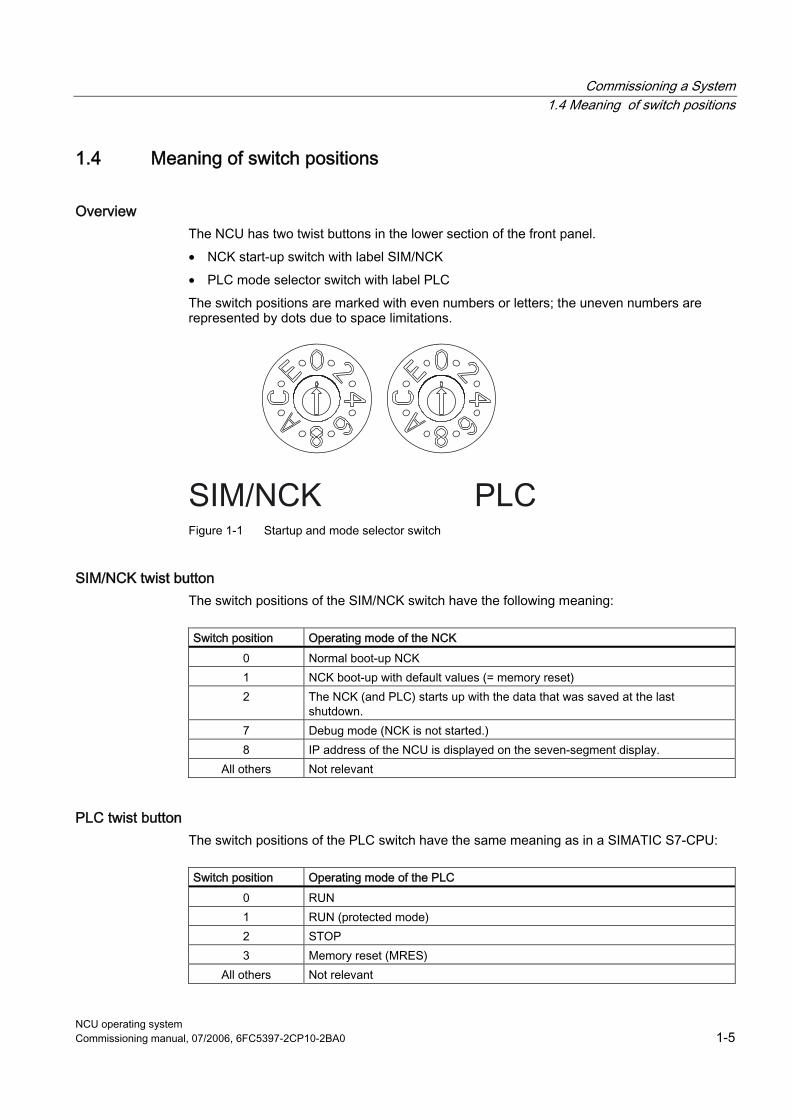
Commissioning a System 1.4 Meaning of switch positions
NCU operating system Commissioning manual, 07/2006, 6FC5397-2CP10-2BA0 1-5
1.4 Meaning of switch positions
Overview The NCU has two twist buttons in the lower section of the front panel. • NCK start-up switch with label SIM/NCK • PLC mode selector switch with label PLC The switch positions are marked with even numbers or letters; the uneven numbers are represented by dots due to space limitations.
Figure 1-1 Startup and mode selector switch
SIM/NCK twist button The switch positions of the SIM/NCK switch have the following meaning:
Switch position Operating mode of the NCK
0 Normal boot-up NCK 1 NCK boot-up with default values (= memory reset) 2 The NCK (and PLC) starts up with the data that was saved at the last
shutdown. 7 Debug mode (NCK is not started.) 8 IP address of the NCU is displayed on the seven-segment display.
All others Not relevant
PLC twist button The switch positions of the PLC switch have the same meaning as in a SIMATIC S7-CPU:
Switch position Operating mode of the PLC
0 RUN 1 RUN (protected mode) 2 STOP 3 Memory reset (MRES)
All others Not relevant
Commissioning a System 1.4 Meaning of switch positions
NCU operating system 1-6 Commissioning manual, 07/2006, 6FC5397-2CP10-2BA0
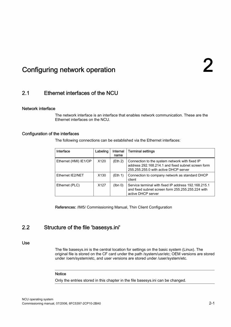
NCU operating system Commissioning manual, 07/2006, 6FC5397-2CP10-2BA0 2-1
Configuring network operation 22.1 Ethernet interfaces of the NCU
Network interface The network interface is an interface that enables network communication. These are the Ethernet interfaces on the NCU.
Configuration of the interfaces The following connections can be established via the Ethernet interfaces:
Interface Labeling Internal
name Terminal settings
Ethernet (HMI) IE1/OP X120 (Eth 2) Connection to the system network with fixed IP address 292.168.214.1 and fixed subnet screen form 255.255.255.0 with active DHCP server
Ethernet IE2/NET X130 (Eth 1) Connection to company network as standard DHCP client
Ethernet (PLC) X127 (Ibn 0) Service terminal with fixed IP address 192.168.215.1 and fixed subnet screen form 255.255.255.224 with active DHCP server
References: /IM5/ Commissioning Manual, Thin Client Configuration
2.2 Structure of the file 'basesys.ini'
Use The file basesys.ini is the central location for settings on the basic system (Linux). The original file is stored on the CF card under the path /system/usr/etc; OEM versions are stored under /oem/system/etc, and user versions are stored under /user/system/etc.
Notice Only the entries stored in this chapter in the file basesys.ini can be changed.
Configuring network operation 2.2 Structure of the file 'basesys.ini'
NCU operating system 2-2 Commissioning manual, 07/2006, 6FC5397-2CP10-2BA0
Structure The file basesys.ini has the same theoretical structure as the Windows-ini files. Comments are introduced by ';' or '#' at the beginning of the line, and span the width of the line. Empty lines are also handled as comments. The sections that start with a "[NAME]" line, as in Windows, are ignored by the basic system itself, but are sometimes used by the HMI. Variable definitions are written in the form "NAME=VALUE". Blanks are permitted around the '=' character. The value may also be enclosed in double quotation marks, but this is optional.
See also Example: File basesys.ini (Page A-1)
2.2.1 Section [ExternalInterface]
Description In this section, the parameters and settings for the external Ethernet interface are defined. For an NCU7x0, this is X130 (Eth1). If the external interface is in DHCP mode, i.e. the value of ExternalIP is empty or not defined, then all parameters listed here, with the exception of 'DHCPClientID', are accepted by the DHCP server as long as the server provides a value for the parameter.
ExternalIP If ExternalIP is not empty, the fixed IP address specified there is used on the company network interface. The ExternalNetMask then also needs to be set, as well as the gateway, name servers, host name and domain if required. If ExternalIP is not set or is empty, a DHCP client is started on the interface.
Value: IP address Default: Empty
ExternalNetMask ExternalNetMask must be set together with ExternalIP, in order to define the size of the network.
Value: Subnet Mask Default: Empty
Configuring network operation 2.2 Structure of the file 'basesys.ini'
NCU operating system Commissioning manual, 07/2006, 6FC5397-2CP10-2BA0 2-3
Gateway If the value of Gateway is not empty, the host specified there is used as the default gateway, which means that all IP packages that cannot be directly assigned are sent here for routing. If no gateway is specified, only the networks that are directly connected are accessible.
Value: IP address Default: Empty
Nameservers If DNS name servers are specified here, these are used for resolution of symbolic host names. In most positions at which an IP address is expected, a server name can also be used. The name server setting is also sent to your DHCP client (TCU, PG) via the DHCP server of the NCU, so that this can also work with symbolic names.
Value: List of IP addresses (separated by a blank) Default: Empty
Timeservers Here you can quote a list of NTP servers (UDP/123) which can be used by the NTPD on the NCU for reasons of time synchronization.
Value: List of IP addresses (separated by a blank) Default: Empty
Domain These variables can be used to configure the DNS domain. Currently, the only practical effect is that names in this domain can be resolved without qualification. (e.g.: if the domain is "test.local", instead of the name "rechner1.test.local", you can also write "rechner1".)
Value: Name Default: Empty
Host name Here you can define a name for the local host. This manually assigned name has priority above all other names.
Configuring network operation 2.2 Structure of the file 'basesys.ini'
NCU operating system 2-4 Commissioning manual, 07/2006, 6FC5397-2CP10-2BA0
The host name is determined in the following order: • Host name from the basesys.ini, if set • A name received from the DHCP server (if DHCP client mode and a name have been
supplied), the result of a reverse DNS lookup, i.e. which name belongs to the IP received (if nameservers are defined)
• A default name ("NONAME_...")
Value: Name Default: Empty
DHCPClientID With these variables, you can influence which ClientID the DHCP client presents to its server. This ID can be used by the server to assign certain parameters to the client, for example a static IP address. Usually, the MAC address of the Ethernet interface is used for this purpose. This is also the default setting. Alternatively, you can also use the host name ("@NAME"), which must then be defined in the basesys.ini, in order to be recognized before the DHCP request. It is also possible to use an arbitrary string for ClientID.
Value: @MAC, @NAME, or any string Default: @MAC
EnableCoreDumps If this variable is set as equal to 1, a log file for processes is created and stored under /var/tmp. The protocol file contains a memory print of the process that has crashed or that has terminated.
Value: Empty, 0 or 1 Default: 0
2.2.2 Section [LinuxBase]
Timezone The time zone set here is used by the system to convert UTC time into local time. The time zone is also sent to all applications via the environment variable TZ, and is taken into account by the libc function localtime(). The time zone influences all time entries in the basic system, particularly for the command 'date', for ls -l, and in the system log file (on the CF card under /var/log/messages).
Configuring network operation 2.2 Structure of the file 'basesys.ini'
NCU operating system Commissioning manual, 07/2006, 6FC5397-2CP10-2BA0 2-5
Value: Time zone description Default: UTC
Some selected time zone descriptions are listed in the comments of the supplied example file basesys.ini:
Europe: WET0WEST,M3.5.0,M10.5.0
CET-1CEST,M3.5.0,M10.5.0 EET-2EEST,M3.5.0,M10.5.0
USA: EST5EDT,M4.1.0,M10.5.0 CST6CDT,M4.1.0,M10.5.0 MST7MDT,M4.1.0,M10.5.0 PST8PDT,M4.1.0,M10.5.0
China: CST-8 Japan: JST-9
Synchronizing the time We must differentiate between two cases: • If there is an external NTP server to act as a time server (entered in the basesys.ini file or
via DHCP), then the PLC clock is synchronized via the Linux clock. • If there is no external time server, the PLC clock will be the master for the Linux clock:
DisableNTPTimeSync If this variable is set to 1, the time synchronization server NTPD will not be started and no more time synchronizations will be executed.
Value: 0 or 1 Default: 0
DisablePLCTimeSync If this variable is set to 1, no synchronization of the systems time with the PLC time (in both directions) will be executed.
Value: 0 or 1 Default: 0

Configuring network operation 2.2 Structure of the file 'basesys.ini'
NCU operating system 2-6 Commissioning manual, 07/2006, 6FC5397-2CP10-2BA0
NCU operating system Commissioning manual, 07/2006, 6FC5397-2CP10-2BA0 3-1
Backing up and Restoring Data 33.1 Applications
Overview To back up and restore the CF card data, proceed as follows: • Create a service system • Back up onto a service system • Restore from the service system As an alternative to backing up the data on a service system: • Back up onto a network drive • Restore from the network drive To call a service shell, depending on the configuration, the following possibilities are available:
(I) Configuration of NCU with TCU: the service shell is called under Linux. (II) Configuration of NCU with PCU50.3 or programming device (PD): the service shell can be called under Linux or alternatively also under Windows
via WinSCP. References: Commissioning Manual, Thin Client Configuration
VNC (Virtual Network Computing) Virtual Network Computing is a software that displays the screen contents of a remote computer, with a running VNC server, on a local computer, with a running VNC viewer, and in return sends keyboard and mouse movements of the local computer to the remote computer.
Backing up and Restoring Data 3.2 Creating a service system for the NCU
NCU operating system 3-2 Commissioning manual, 07/2006, 6FC5397-2CP10-2BA0
3.2 Creating a service system for the NCU
Purpose In case servicing is needed, create a portable "Emergency Boot System" (EBS) on a USB memory. Thus you can start the booting of the NCU from the service system in order to carry out various service tasks, such as data backup or updates, in a service shell. Two partitions are created on the service system: • a Linux partition that is invisible under Windows. • an FAT32 partition for DOS or Windows applications. The FAT32 partition can be addressed using the path /data, and can be read and written to under Linux and also from a Windows system.
Scope of delivery To create a service system on a USB storage medium with 512 MB storage capacity, the following files are included on CD: • an executable file installdisk.exe • an image file linuxbase-512M.img • a file with the newest information siemensd.txt
Recommendation: Preferably, the SIMATIC PC USB-FlashDrive with 512 MB storage capacity should be used.
Note To create the service system, you need administrator rights. All data already on the USB storage medium will be deleted. The transfer is optimized for USB 2.0; therefore, the transmission to the USB storage medium takes longer when using USB 1.1 than USB 2.0
Proceed as follows To create a service system on a USB storage medium: 1. Copy the service system onto a local hard disk of your programming device (PD) or PC. 2. Connect a 512MB USB storage medium to the USB interface of the PG/PC. 3. Determine in Windows Explorer which drive letter the USB storage medium was
assigned, e.g. H: 4. Open a DOS shell and change to the directory in which the files for the service system
are stored.
Backing up and Restoring Data 3.3 Service system
NCU operating system Commissioning manual, 07/2006, 6FC5397-2CP10-2BA0 3-3
5. In the DOS shell, enter the following command: installdisk – –verbose – –blocksize 1m linuxbase-512M.img h: Result: The image is transferred to the USB storage medium; a partition for Linux and a FAT32 partition for Windows systems are created.
6. Disconnect the USB storage medium and connect it again. Result: After this has been completed successfully, you will have a bootable service system on the USB storage medium.
3.3 Service system
3.3.1 Storing data on a service system
Proceed as follows To back up the complete system: 1. Connect the service system to a USB interface (X125 or X135) of the NCU and press the
reset button. Alternatively, you can switch the NCU off, connect the service system, and switch the NCU on again. Result: The NCU boots from the service system and the main menu is displayed:
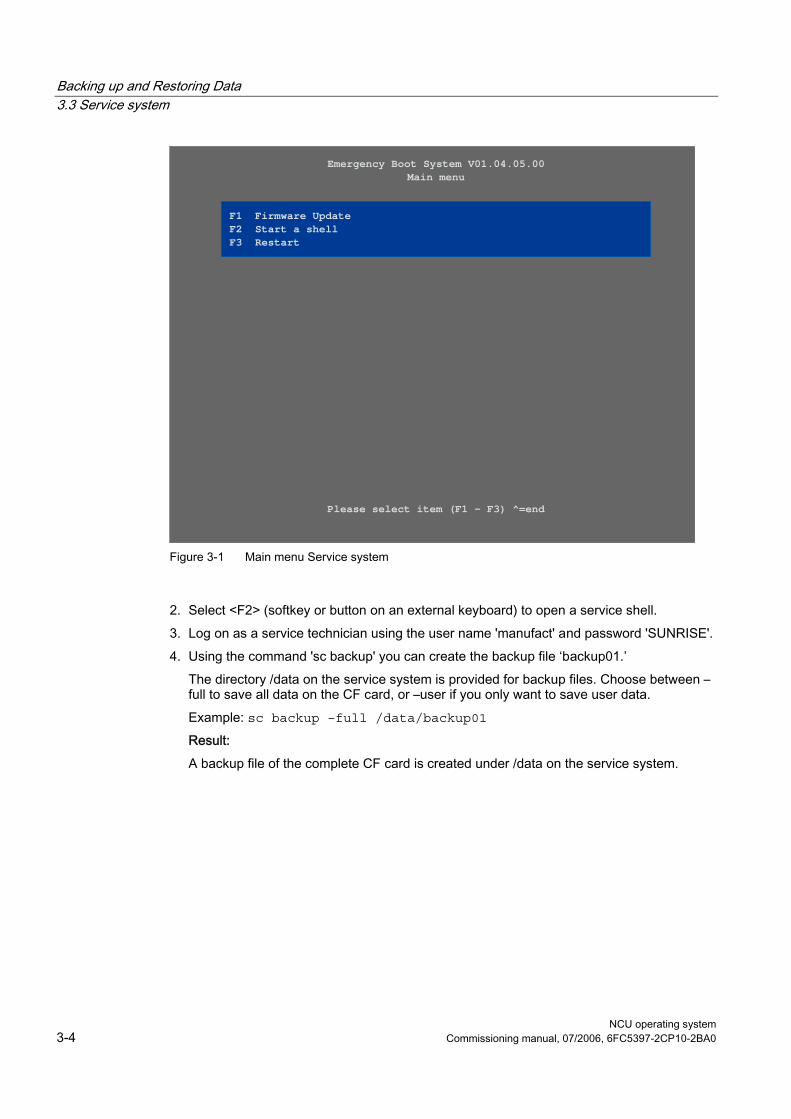
Backing up and Restoring Data 3.3 Service system
NCU operating system 3-4 Commissioning manual, 07/2006, 6FC5397-2CP10-2BA0
Emergency Boot System V01.04.05.00Main menu
Please select item (F1 - F3) ^=end
F1 Firmware UpdateF2 Start a shellF3 Restart
Figure 3-1 Main menu Service system
2. Select <F2> (softkey or button on an external keyboard) to open a service shell. 3. Log on as a service technician using the user name 'manufact' and password 'SUNRISE'. 4. Using the command 'sc backup' you can create the backup file ‘backup01.’
The directory /data on the service system is provided for backup files. Choose between –full to save all data on the CF card, or –user if you only want to save user data. Example: sc backup –full /data/backup01 Result: A backup file of the complete CF card is created under /data on the service system.
Backing up and Restoring Data 3.3 Service system
NCU operating system Commissioning manual, 07/2006, 6FC5397-2CP10-2BA0 3-5
3.3.2 Restoring data from the service system
Proceed as follows To restore the complete system: 1. Connect the service system to a USB interface (X125 or X135) of the NCU and press the
reset button. Alternatively, you can switch the NCU off, connect the service system, and switch the NCU on again. Result: The NCU boots from the service system and the main menu is displayed.
2. Select <F2> (softkey or button on an external keyboard) to open a service shell. 3. Log on as a service technician using the user name 'manufact' and password 'SUNRISE'. 4. With the command ‘sc restore’ you can write the backup file ‘backup01’ from the service
system back to the CF card in the NCU. Example: sc restore /data/backup01 Result: The system state stored in the file ‘backup01’ is restored on the NCU.
Note If access to the system data on the CF card is not possible because the CF card is defective or empty, you can only log in as user 'admin' with the password 'SUNRISE' and no longer as the user 'manufact'.
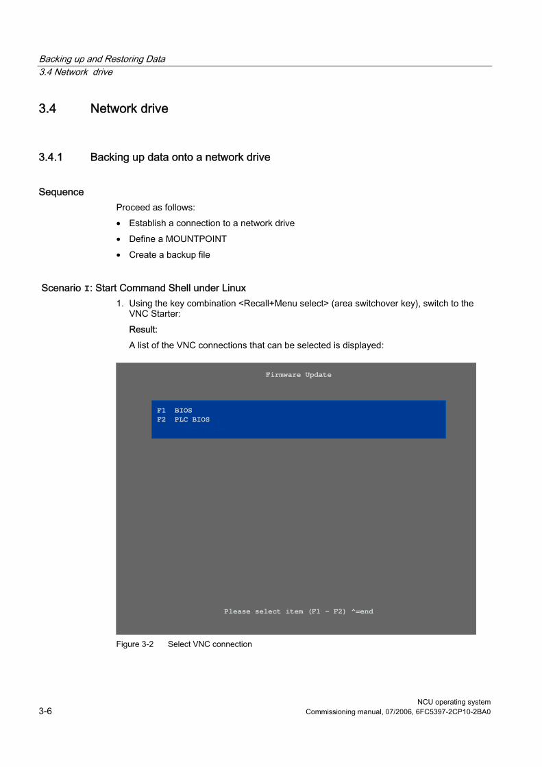
Backing up and Restoring Data 3.4 Network drive
NCU operating system 3-6 Commissioning manual, 07/2006, 6FC5397-2CP10-2BA0
3.4 Network drive
3.4.1 Backing up data onto a network drive
Sequence Proceed as follows: • Establish a connection to a network drive • Define a MOUNTPOINT • Create a backup file
Scenario I: Start Command Shell under Linux 1. Using the key combination <Recall+Menu select> (area switchover key), switch to the
VNC Starter: Result: A list of the VNC connections that can be selected is displayed:
Firmware Update
Please select item (F1 - F2) ^=end
F1 BIOSF2 PLC BIOSF3 FPGA- ControlerF3 FPGA- Controler
Figure 3-2 Select VNC connection
Backing up and Restoring Data 3.4 Network drive
NCU operating system Commissioning manual, 07/2006, 6FC5397-2CP10-2BA0 3-7
2. Start a service shell by using the assigned softkey to select 'Session 4'. In 'Session 5', the log console is output.
3. Log on as a service technician using the user name 'manufact' and password 'SUNRISE'. 4. Create a new 'backup' directory under /tmp on the CF card, which you will then use as
MOUNTPOINT . Example: mkdir /tmp/backup
5. Use the command 'sc connect' to connect the network drive: sc connect //username%password@server/share /tmp/backup Please enter here the user name and the password for the network drive that is to be connected to.
6. Using the command 'sc save', create the backup file 'backup01'. Choose between –full to save all data to the CF card, or –user, if you only want to save user data in the directory /user. Example: sc save –full /tmp/backup/backup01 Result: A backup file of the complete CF card is created under the specified path on the network drive.
Scenario II: Start the Command Shell with WinSCP on the PD: 1. Start WinSCP and enter the following data in the log-on window:
– Host name of the NCU or IP address – Use name 'manufact' with password 'SUNRISE'.
2. Select in the menu "Commands" → "Open Terminal". 3. Execute the data backup using the commands described in steps 4 to 6 from scenario I.
See also Connect (Page 4-6) Save (Page 4-10)
Backing up and Restoring Data 3.4 Network drive
NCU operating system 3-8 Commissioning manual, 07/2006, 6FC5397-2CP10-2BA0
3.4.2 Restoring data from the network drive
Sequence Proceed as follows: • Stop all subsystems • Establish a connection to a network drive • Define a MOUNTPOINT • Restore the data • Start all subsystems again
Scenario I: Start Command Shell under Linux 1. Before you can restore backup files, you need to stop the subsystems, e.g. NCK:
Using the key combination <Recall + Menu select> (area switchover key), switch to VNC Starter: A list of VNC connections that can be selected is displayed.
2. Start a service shell by using the assigned softkey to select 'Session 4'. In 'Session 5', the log console is output.
3. Log on as a service technician using the user name 'manufact' and password 'SUNRISE'. sc stop all
4. Use the command 'sc connect' to connect the network drive: sc connect //username%password@server/share /tmp/backup
5. Please enter here the user name and the password for the network drive that is to be connected to. (For further details on the syntax, please see Section "Service commands"). To completely restore the system (system data and user data), enter the following: sc restore –full backup01 Result: The whole system is overwritten by the backup data..
6. To restore user data only, enter the following command: sc restore –user backup01 Result: The user data are written back again. All subsystems are then restarted: sc start all Result: The system state stored in the file ‘backup01’ is restored on the NCU.
Backing up and Restoring Data 3.4 Network drive
NCU operating system Commissioning manual, 07/2006, 6FC5397-2CP10-2BA0 3-9
Scenario II: Start the Command Shell with WinSCP on the PD: 1. Start WinSCP and enter the following data in the log-on window:
– Host name of the NCU or IP address – Use name 'manufact' with password 'SUNRISE'.
2. Select in the menu "Commands" → "Open Terminal". 3. To restore the data, enter the corresponding commands as described under steps 3 to 5
in scenario I.
See also Connect (Page 4-6)

Backing up and Restoring Data 3.4 Network drive
NCU operating system 3-10 Commissioning manual, 07/2006, 6FC5397-2CP10-2BA0
NCU operating system Commissioning manual, 07/2006, 6FC5397-2CP10-2BA0 4-1
Service Commands 44.1 Using service commands
Overview The service command 'sc' is a tool used for performing a range of service tasks on a SINUMERIK NCU. The required action is written in the command line after the 'sc', e.g.: sc help This action produces a list of all actions with a short description. After the action, further parameters or options can follow. 'sc' is available in both the NCU basic system and the service system (mostly in the form of a USB memory.) However, some actions are only useful in one of the two systems (NCU/Service). This is noted for each action.
See also: The most important terms and abbreviations are explained in the glossary.
Privilege levels The 'sc' command can execute its actions using more privileges than are normally granted to the calling user. For example, starting or stopping subsystems requires root privileges, but 'sc' allows every user who belongs to the ‘service’ group to do this. Each action of 'sc' is assigned an “privilege level”. This is a user group to which the user must belong in order to execute the action. As the groups are hierarchically nested, members of “higher” groups can also use the action in question. For example, the group 'manufact' is above 'service', which means that members of the group 'manufact' can call all actions that require the privilege level 'service'. The privilege level that the caller requires is noted for each individual action. The possible levels are (in ascending order): • none • operator • user • service • manufact
Service Commands 4.2 Syntax for the Actions
NCU operating system 4-2 Commissioning manual, 07/2006, 6FC5397-2CP10-2BA0
Example: An action with the privilege level 'user' can also always be executed by members of the groups 'service' and 'manufact'. Actions with privilege level ‘none’ can be called by all users. If a user does not have the required privileges, the following error message is output: Action 'ACTION' needs at least GROUP privilege level.
4.2 Syntax for the Actions
Description 'sc' in the command line is essentially not case-sensitive. The following entries are therefore interpreted as identical: sc help show SC help SHOW sc HeLp sHoW In some cases, however, upper/lower case can make a difference, for example in file or user names. This is avoided wherever possible. The conventions used are as follows: • Names completely in upper case represent objects to be used depending on the
situation. Example: sc help ACTION In this case, ACTION is to be replaced by the action for which you want a description. If written in lower case, however, the entry should be entered as specified.
• Square brackets indicate optional entries. Example: sc help [ACTION] In this case the specification of an action is optional, which means that you can enter an action, but do not have to. Square brackets may also be nested: ... [USERNAME[/DOMAIN]] ... In this case, USERNAME and DOMAIN are both optional, but you can only enter a DOMAIN if you have also entered the USERNAME.
• Alternatives are separated with '|'. Example: sc start all|system|SUBSYSTEM This means that any of the following commands applies: sc start all sc start system sc start SUBSYSTEM In the latter case, SUBSYSTEM in upper case can be replaced by a concrete subsystem name.
Service Commands 4.3 Generic elements
NCU operating system Commissioning manual, 07/2006, 6FC5397-2CP10-2BA0 4-3
• As a shortened form, alternatives can also be written in square brackets: sc save [-full|-user] ... Here you can use the option "-full" or "-user", or none at all.
• Options that begin with '-' can always be entered in any order. For example, the notation could be interpreted to mean that "-force" must come after "-full" or "-user", but this is not necessarily the case: sc save [-full|-user] [-force] FILENAME
4.3 Generic elements
Overview This section describes the syntax elements that are used by several actions.
Permitted interface designations The names of network interfaces are used by "sc show ip", "sc set ip" and "sc enable DHCPSvr", for example. As the input of an interface is optional, it is always introduced by a '−' character. The '−' is followed by the actual name. In most cases, multiple names are possible for the same interface. Accepted names are:
System network port: "X120", "eth2", "tcu", "internal" Company network port: "X130", "eth1", "factory", "extern IBN port: "X127", "ibn0", "pg"
Permitted subsystem designations Subsystem names are entered when using "sc enable" and "sc start", for example. In most cases, the name of the subsystem is simply the name of the corresponding CFS, without the path and without the extension ".cfs". For example, for the CFS /siemens/sinumerik/nck.cfs, the relevant subsystem name is simply "nck". It is also possible to use absolute paths (beginning with /) in a subsystem name. In the example above, you could also use "/siemens/sinumerik/nck" as a subsystem name. The difference between names with and without a specified path is that without the path, all CFS with this name are included, but if the path is specified, only this exact CFS is meant.
Subsystem A subsystem is a CFS that not only contains a collection of files, but also executes a program, for example, at runtime. To do this, the CFS contains a script that is used to control the starting and stopping of this program.
Service Commands 4.3 Generic elements
NCU operating system 4-4 Commissioning manual, 07/2006, 6FC5397-2CP10-2BA0
For this reason, only administrators are permitted to set up NFS file systems, and NFS is usually only implemented in uniformly administrated environments. Exported file systems on the server are addressed directly on the server via their path.
CFS (Compressed File System) A CFS (file extension ".cfs") is a compressed file system, similar to a zip file. It contains files and subdirectories that look like normal files on the controller at runtime. Files and directories contained in a CFS cannot be changed. They are decompressed at runtime as required.
NFS (Network File System) NFS is the most common protocol for remote file systems in the world of Unix, and is also available for Windows. NFS is closely based on the Unix privilege model – each time a file is accessed, a UID and GID are supplied which the server then uses to decide whether the operation is permitted. The server relies on the client to provide the correct IDs.
Remote File System A file system that is contacted over the network. The files are physically located on another computer in the network (the "server"), but appear locally the same as all other files. Operations performed on these files are sent via the network to the server, instead of being executed directly on a local storage medium (such as a hard drive or CF card). As a server usually exports more than one file system, a name for the required file system must also be entered in addition to the name of the server.
SMB (Server Message Block) SMB is the underlying protocol of MS Windows file systems (also known as drives, releases, shares, etc.). SMB connections are always active in the context of a specific user, who must be known to the server. Exported file systems have a name (release name), by which they can be addressed. The client does not need to know the concrete path on the server.
Service Commands 4.4 Description of the actions
NCU operating system Commissioning manual, 07/2006, 6FC5397-2CP10-2BA0 4-5
4.4 Description of the actions
4.4.1 Help
Description
Syntax: sc help [Action] Alternative names: -h, --help Privilege level: none
The call of "sc help" without any additional action outputs a list of possible actions with a short description. If you enter an additional action, you receive a more detailed description for this action. Examples: sc help All actions: help [ACTION] Print help about a specific or list all actions restart Reboot the machine enable hmi|nck|SUBSYSTEM... enable DHCPSvr -INTERFACE Enable HMI, NCK, or any other subsystem [...] sc help enable enable hmi|nck|SUBSYSTEM... DHCPSvr -INTERFACE Enable subsystem(s), like 'hmi', 'nck', and so on. A subsystem name is the name of the CFS containing it, without the '.cfs' extension. This enables all CFSes with that name, but you can also use a full path (e.g., /siemens/sinumerik/nck) to enable just a specific CFS. Another form is to enable the DHCP server on a network interface, for example 'enable DHCPSvr -X120'.
Service Commands 4.4 Description of the actions
NCU operating system 4-6 Commissioning manual, 07/2006, 6FC5397-2CP10-2BA0
4.4.2 Check-cf
Description
Syntax: sc check-df Alternative names: checkcf Privilege level: user
With this action, the CF card is checked reading to see whether it contains defective sectors. If errors occur, this is noted in the file /var/log/messages.
4.4.3 Connect
Description
Syntax: sc connect [-ro] SERVER:/PATH [MOUNTPOINT] sc connect [-ro] [-public] //[USERNAME[/DOMAIN] [%PASSWORD]@]SERVER/SHARE [MOUNTPOINT]
Alternative names: mount Privilege level: none
This action makes a remote file system on a server available on the controller. This is enabled by linking the remote file system to a local directory, known as the "MOUNTPOINT". The files offered by the server are then visible under this directory.
Notice Note that when entering this command, the password appears on the screen in plain text according to the specified syntax. For path names, use the slash “/” and not the backslash “\”.
Supported file systems Two types of remote file system are supported: Windows SMB and Unix NFS. These two systems have completely different characteristics, particularly in terms of user administration: • In Windows SMB, you connect to the server as a particular user that the server must
recognize. Via this connection, you then access the files as this user, independently of which local user triggers the action. This feature means that in SMB systems, you already have to enter a user name, if necessary its domain, and a password at the time of connection.
Service Commands 4.4 Description of the actions
NCU operating system Commissioning manual, 07/2006, 6FC5397-2CP10-2BA0 4-7
• In NFS servers, the connection itself does not require a particular user to be entered. Instead, for each file operation, the user who wants to carry out the operation must log on to the server. The server then decides whether or not to permit this. Users are entered using a user ID and group ID, not with names. The server must therefore recognize the corresponding IDs (or permit access for all users.) Another type of remote file system that is supported are USB memory devices exported from TCUs (USB Flash Drive). Since these are integrated using NFS, the entries for server and path are similar to those for NFS. However, the TCU names are administrated differently, and the USB memory devices have specific paths that do not physically exist.
Notation of the remote file system For SMB and NFS/TCU, the file system is entered using different notations:
SMB: //[USERNAME[/DOMAIN][%PASSWORD]@]SERVER/SHARE The fixed share is: //SERVER/SHARE The server name can of course also be a numeric IP address. SHARE is the name of the release on the server. Note that the character '$', which often occurs in this type of name, must be preceded by a backslash ('\') in the command line. Otherwise, the system tries to expand a variable. A user name can also be entered in front of the server name, separated with a '@' character. If necessary, the user name can also be extended by adding '/' followed by the Windows domain to which it belongs. The password belonging to this user is normally queried interactively, so that it is not visible on the screen. ´ For some applications, however, it may be necessary to write the password on the command line. (For example, programs started from WinSCP cannot read from the keyboard.) In this case, you can append an additional '%' character, followed by the password. If this contains any special characters that are interpreted by the shell (<, >, &, ;, ", ', $, (, ), |), you should shield these by preceding them with a backslash. Commas in SMB passwords cannot be interpreted.
NFS: SERVER:/PATH In NFS, entering the user is not required, which just leaves the two components SERVER and PATH. As before, SERVER is the name of the file server. In contrast to SMB, PATH is a path name that exists on the server, and not an arbitrarily assigned name. The command "sc show drives SERVER" shows the file systems offered by a particular server in the correct notation. For SMB, if required, the user name etc. still need to be added. After the entry of the remote file system, you can also specify the required directory ('MOUNTPOINT') in which the remote files will become visible locally. This should be an empty directory to which you have write access. If MOUNTPOINT is omitted, 'sc' itself generates a suitable directory. The name is /tmp/drvNN (numbered consecutively), and is displayed when the connection is successful. The option "-ro" connects the remote file system in read-only mode, which means that you can only read and do not have write access. This can be useful if you want to exclude changes that originate from the controller, or if the server only allows read-only connections. As explained above, an SMB file system is connected as the specified user. To prevent a third user from executing file operations on the controller in the name of the connected user,
Service Commands 4.4 Description of the actions
NCU operating system 4-8 Commissioning manual, 07/2006, 6FC5397-2CP10-2BA0
the local directory can normally only be accessed by the latter (and all members of the same group). However, if you do want to make the remote directory available to further local users, you can use the option "-public" to make the MOUNTPOINT belong to the "operator" group, and this access is therefore guaranteed.
4.4.4 Disconnect
Description
Syntax: sc disconnect MOUNTPOINT sc disconnect all
Alternative names: umount, unmount Privilege level: user
The action "disconnect" terminates the connection to a remote file system previously connected using "connect“. If the MOUNTPOINT has been automatically created by 'sc', the corresponding directory is also deleted again. The variant "sc disconnect -all" can be used to remove all existing SMB and NFS file systems.
4.4.5 Enable, disable
Description
Syntax: sc enable hmi|nck|SUBSYSTEM ... sc enable DHCPSvr -INTERFACE sc disable hmi|nck|SUBSYSTEM ... sc disable DHCPSvr -INTERFACE
Alternative names: --- Privilege level: service
The 'enable' action switches on the specified subsystems such that these are also activated when a subsystem is started. Similarly, 'Disable' switches off subsystems. These subsystems are then not loaded again at the next restart. "hmi", "nck", or any other subsystem names, can be used for the subsystems. You can also switch several subsystems on/off using an 'Enable'/'Disable' command.
Service Commands 4.4 Description of the actions
NCU operating system Commissioning manual, 07/2006, 6FC5397-2CP10-2BA0 4-9
Specific subsystems The name 'DHCPSvr' is a special case. This does not switch a normal subsystem on or off, but specifies whether or not a DHCP server should be started on a network interface. The interface is entered in the standard form. The actions 'enable' and 'disable' function by changing certain variables in the file /user/system/etc/basesys.ini. In subsystems, this variable is 'DisableSubsystems', in DHCPSvr 'DisableDHCPD<INTERFACE>'.
4.4.6 Restart
Description
Syntax: sc restart Alternative names: reboot Privilege level: service
The action "sc restart" triggers a controlled shut down of the machine (stops all subsystems and the basic system), and then initiates a restart. The effect is the same as the 'reboot' command in the basic system, which can only be executed by 'root'.
4.4.7 Restore
Description
Syntax: sc restore [-full|-addon|-addon+|-oem|-oem+|-user] [-force] [-nodelete] [-update] [-restart] FILENAME
Alternative names: --- Privilege level: user
A backup created using "sc save" can be restored to the controller using "sc restore".
Operating principle As for "sc save", a restore is only possible from the service system or if subsystems are stopped. If “sc restore" reports an error, for example that the restore will cause running subsystems to crash, you can use the option "-force" to force the operation – just as for “sc save”. Normally, "sc restore" deletes the whole destination area before the backup is restored (complete CF card for full backup, /user in user data backups). This means that no files are subsequently available that were not included in the backup.
Service Commands 4.4 Description of the actions
NCU operating system 4-10 Commissioning manual, 07/2006, 6FC5397-2CP10-2BA0
Options If no further options are specified, the archive should represent a full backup and this should be restored in full. The status of all files is therefore the same after the "restore" as it was at the time of the backup. • The -full option additionally forces the partition and the file system to be recreated on the
CF card. This is only possible from a service system, however. -full is necessary if the partition table and/or file system is missing or damaged.
• However, if you want to restore the backup files without losing any files that have been created in the meantime, you can use the option "-nodelete" to prevent these from being deleted. "-nodelete" is not executed together with "-full", as when the file system is recreated, all files are essentially deleted.
• The options -addon, -oem, -user, -addon+ and -oem+ also allow you to unpack only parts of an archive.
• The -update option is used for loading software updates supplied by Siemens. The -restart option can also be useful with -update. If user-defined system files are changed when loading an archive, a restart or reinitialization is necessary. In such cases, "sc restore" outputs a message to that effect at the end of the operation. The -restart option causes the required action to be performed automatically.
4.4.8 Save
Description
Syntax: sc save [-full|-addon|-addon+|-oem|-oem+|-user] [-force] [-update] FILENAME
Alternative names: backup Privilege level: user
The call of "sc help" without any additional action outputs a list of possible actions with a short description. If you enter an additional action, you receive a more detailed description for this action. The action "Save" or “Backup” creates a backup of the CF card in FILENAME. If the action is used from a service system, the backup receives the files of the underlying controller, not of the service system itself.
Options The options are used for selecting which directories of the file system are to be written to the archive: • full: Full backup (default setting), all files of the controller incl. Boot Loader • addon: only /addon directory • oem: only /oem directory • user: only /user directory (user data) • addon+: /addon, /oem and /user • oem+: /oem and /user
Service Commands 4.4 Description of the actions
NCU operating system Commissioning manual, 07/2006, 6FC5397-2CP10-2BA0 4-11
If "sc save" is used directly on the controller and the subsystems are running, this may lead to inconsistencies between saved files, because they can still change during the backup process. Therefore, in this case “sc save" normally ends in an error message to inform you that subsystems are still running. If you want to create a backup anyway, you can use the option "-force". "sc save" still issues a warning, but the process continues. If "sc save" is started from the service system, no subsystems of the controller are running and "-force" is not necessary. Example: sc save -user /tmp/drv01/backup.tgz
4.4.9 Show
Description
Syntax: sc show ip [-INTERFACE] sc show drives SERVER
Alternative names: ---- Privilege level: none
Under the action 'show', various displays are grouped together showing the status of the system in the form of subactions. As these are barely related to each other, they are handled separately.
show ip
Syntax: sc show ip [-INTERFACE] Privilege level: none
This command displays the IP address data of network interfaces. You have the option to enter a specific interface. If no particular interface is specified, the data for all existing interfaces is displayed, as well as the Default Gateway. Example: sc show ip X120 (eth0): configured: (default) current : IP=192.168.214.1 Netmask=255.255.255.0 MAC=08:00:06:73:28:76 X130 (eth1): configured: DHCP current : IP=157.163.247.201 Netmask=255.255.254.0 MAC=08:00:06:73:28:77
Service Commands 4.4 Description of the actions
NCU operating system 4-12 Commissioning manual, 07/2006, 6FC5397-2CP10-2BA0
X127 (ibn0): current : IP=192.168.215.249 Netmask=255.255.255.248 MAC=08:00:06:73:28:78 Default gateway: 157.163.246.1 (via eth1) The following data is displayed for each interface: • Name: the names of the connection socket (X1xx), together with the name used by the
operating system in brackets (ethN or ibnN). • "configured": The IP address configured in the basesys.ini (variables
ExternalIP/ExternalNetMask for X130, InternalIP/Internal-NetMask for X120), or "(default)" if nothing is configured in the basesys.ini, or "DHCP" if the address was sourced via DHCP.
• "current": The current IP address together with the network screen form and MAC address of the interface.
When all interfaces are displayed, the Default Gateway is also output, i.e. the address of a router to which all packages are sent that cannot reach their destination directly via a local interface. The Default Gateway is therefore a piece of data that applies to all interfaces and of which there is only one instance. However, there is one interface via which it must be possible to address the Default Gateway. This is displayed in brackets after the address.
show drives
Syntax: sc show drives SERVER Privilege level: none
"sc show drives" shows the available remote file systems for a particular server. The server name SERVER can be an NFS server, an SMB server or "TCU", which represents any USB media that are connected to a TCU. For details of possible server names and entering a user name (often required for SMB), see the description of the "sc connect" command. Examples: sc show drives someuser/somedomain@somepc # Windows-Server Password: ******* //somepc/C$ //somepc/D$ //somepc/images sc show drives someserver # NFS-Server someserver:/export/home1 someserver:/export/home2 sc show drives TCU # TCU USB-Medien TCU1:/dev0-0 TCU2:/dev0-0 All the available remote file systems of the relevant server are listed, in the notation that is expected by "sc connect".
Service Commands 4.4 Description of the actions
NCU operating system Commissioning manual, 07/2006, 6FC5397-2CP10-2BA0 4-13
SMB shared drives on Windows servers always begin with "//", followed by the server name and the name of the shared drive. In NFS file systems, the server name is always first, followed by a colon and then the export path. USB memory devices on TCUs are a special form of NFS, and therefore also have the same notation as NFS file systems. The specified path does not exist physically on the TCU, but is converted there to USB by the NFS server. Connection to SMB servers usually requires the entry of a user name (with domain, if applicable) and a password.
4.4.10 Start, Stop
Description
Syntax: sc start all|system|SUBSYSTEM sc start all|system|SUBSYSTEM
Alternative names: --- Privilege level: service
These two actions start or stop individual or all subsystems. Since these actions have a direct influence on the runtime behavior, they are only available directly on the PLC, but not in the service system (with the exception of "sc stop system"). The subsystems of the underlying PLC do not run here, and can therefore not be controlled.
Note Only "all" and "system" function, but not arbitrary subsystems. Both of these actions have only been implemented to a restricted extent.
Subsystem names "hmi", "nck", or any other names, can be used for the subsystems. Multiple subsystems can also be specified in a row, which are then started and stopped in this order. "all" and "system" are special values for the subsystem: • "all" starts or stops all available subsystems. • "sc stop system" similarly stops all subsystems, but also the basic system with the PLC. • "start system" is identical to "start all" and exists mainly for reasons of symmetry.
Service Commands 4.4 Description of the actions
NCU operating system 4-14 Commissioning manual, 07/2006, 6FC5397-2CP10-2BA0
4.4.11 Service tools WinSCP and PuTTY
Use The programs WinSCP and PuTTY are freely-available open source programs for Windows. WinSCP is intended especially for transferring files from and to Linux systems, PuTTY for the remote operation of a command shell. WinSCP and PuTTY are included with the package ‘PCU Basesoftware Thin Client for PCU 50 V07.05.00.00 and higher'. With a PCU 50.3, this package is pre-installed. When installing HMI Advanced on PG/PC, WinSCP is automatically installed, too. • WinSCP can be downloaded via the following link:
http://winscp.net/eng/download.php (Installation Package). WinSCP also offers a ”command shell” that is limited so that commands can be issued, but no callbacks can be answered.
• PuTTY, by contrast, offers a complete command shell. PuTTY web page: http://www.chiark.greenend.org.uk/~sgtatham/putty
With both programs, a service technician can log onto the NCU and carry out service tasks. The username ‘manufact’ with the password ‘SUNRISE’ is available for the Siemens service technician.
Starting WinSCP WinSCP is started from Windows after the service technician has logged onto the NCU with which they are connected with the corresponding privilege (e.g. as user ‘manufact’ with password ‘SUNRISE’). From the "Commands“ menu, select ”Open terminal” to open a command shell. There you can carry out the service commands in the usual way.
See also Applications (Page 3-1)
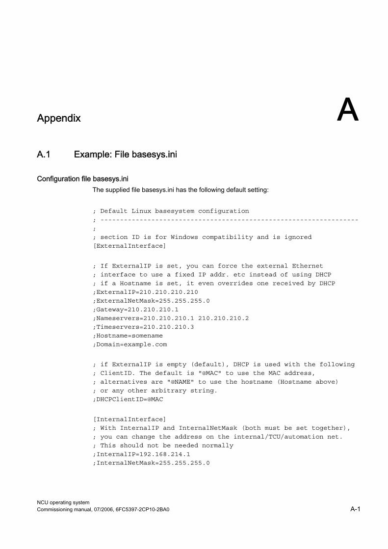
NCU operating system Commissioning manual, 07/2006, 6FC5397-2CP10-2BA0 A-1
Appendix AA.1 Example: File basesys.ini
Configuration file basesys.ini The supplied file basesys.ini has the following default setting: ; Default Linux basesystem configuration ; ------------------------------------------------------------------ ; ; section ID is for Windows compatibility and is ignored [ExternalInterface] ; If ExternalIP is set, you can force the external Ethernet ; interface to use a fixed IP addr. etc instead of using DHCP ; if a Hostname is set, it even overrides one received by DHCP ;ExternalIP=210.210.210.210 ;ExternalNetMask=255.255.255.0 ;Gateway=210.210.210.1 ;Nameservers=210.210.210.1 210.210.210.2 ;Timeservers=210.210.210.3 ;Hostname=somename ;Domain=example.com ; if ExternalIP is empty (default), DHCP is used with the following ; ClientID. The default is "@MAC" to use the MAC address, ; alternatives are "@NAME" to use the hostname (Hostname above) ; or any other arbitrary string. ;DHCPClientID=@MAC [InternalInterface] ; With InternalIP and InternalNetMask (both must be set together), ; you can change the address on the internal/TCU/automation net. ; This should not be needed normally ;InternalIP=192.168.214.1 ;InternalNetMask=255.255.255.0
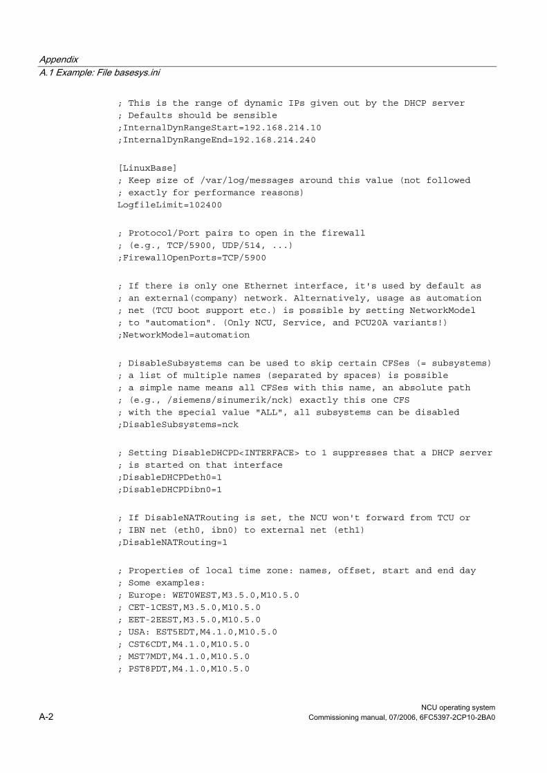
Appendix A.1 Example: File basesys.ini
NCU operating system A-2 Commissioning manual, 07/2006, 6FC5397-2CP10-2BA0
; This is the range of dynamic IPs given out by the DHCP server ; Defaults should be sensible ;InternalDynRangeStart=192.168.214.10 ;InternalDynRangeEnd=192.168.214.240 [LinuxBase] ; Keep size of /var/log/messages around this value (not followed ; exactly for performance reasons) LogfileLimit=102400 ; Protocol/Port pairs to open in the firewall ; (e.g., TCP/5900, UDP/514, ...) ;FirewallOpenPorts=TCP/5900 ; If there is only one Ethernet interface, it's used by default as ; an external(company) network. Alternatively, usage as automation ; net (TCU boot support etc.) is possible by setting NetworkModel ; to "automation". (Only NCU, Service, and PCU20A variants!) ;NetworkModel=automation ; DisableSubsystems can be used to skip certain CFSes (= subsystems) ; a list of multiple names (separated by spaces) is possible ; a simple name means all CFSes with this name, an absolute path ; (e.g., /siemens/sinumerik/nck) exactly this one CFS ; with the special value "ALL", all subsystems can be disabled ;DisableSubsystems=nck ; Setting DisableDHCPD<INTERFACE> to 1 suppresses that a DHCP server ; is started on that interface ;DisableDHCPDeth0=1 ;DisableDHCPDibn0=1 ; If DisableNATRouting is set, the NCU won't forward from TCU or ; IBN net (eth0, ibn0) to external net (eth1) ;DisableNATRouting=1 ; Properties of local time zone: names, offset, start and end day ; Some examples: ; Europe: WET0WEST,M3.5.0,M10.5.0 ; CET-1CEST,M3.5.0,M10.5.0 ; EET-2EEST,M3.5.0,M10.5.0 ; USA: EST5EDT,M4.1.0,M10.5.0 ; CST6CDT,M4.1.0,M10.5.0 ; MST7MDT,M4.1.0,M10.5.0 ; PST8PDT,M4.1.0,M10.5.0
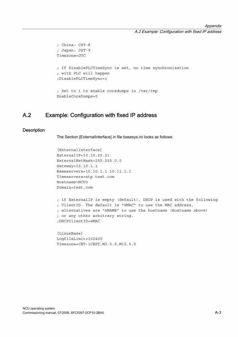
Appendix A.2 Example: Configuration with fixed IP address
NCU operating system Commissioning manual, 07/2006, 6FC5397-2CP10-2BA0 A-3
; China: CST-8 ; Japan: JST-9 Timezone=UTC ; If DisablePLCTimeSync is set, no time synchronization ; with PLC will happen ;DisablePLCTimeSync=1 ; Set to 1 to enable coredumps in /var/tmp EnableCoreDumps=0
A.2 Example: Configuration with fixed IP address
Description The Section [ExternalInterface] in file basesys.ini looks as follows: [ExternalInterface] ExternalIP=10.10.20.21 ExternalNetMask=255.255.0.0 Gateway=10.10.1.1 Nameservers=10.10.1.1 10.11.1.1 Timeservers=ntp.test.com Hostname=NCU3 Domain=test.com ; if ExternalIP is empty (default), DHCP is used with the following ; ClientID. The default is "@MAC" to use the MAC address, ; alternatives are "@NAME" to use the hostname (Hostname above) ; or any other arbitrary string. ;DHCPClientID=@MAC [LinuxBase] LogfileLimit=102400 Timezone=CET-1CEST,M3.5.0,M10.5.0
Appendix A.3 Licenses for WinSCP and PuTTY
NCU operating system A-4 Commissioning manual, 07/2006, 6FC5397-2CP10-2BA0
A.3 Licenses for WinSCP and PuTTY
Copyright of license texts
WinSCP: Copyright © 2000-2005 Martin Přikryl. The application is protected by GNU General Public Licence. Part of the code of this software comes from program PuTTY 0.58 © 1997-2005 Simon Tatham. License agreements for using PuTTY are part of WinSCP license agreement.
PuTTYgen and Pageant applications distributed with WinSCP installation package are © 1997-2005 Simon Tatham. PuTTYgen and Pageant applications distributed with WinSCP installation package are © 1997-2005 Simon Tatham.
A.3.1 GNU License
GNU General Public License GNU GENERAL PUBLIC LICENSE Version 2, June 1991 Copyright (C) 1989, 1991 Free Software Foundation, Inc. 51 Franklin Street, Fifth Floor, Boston, MA 02110-1301, USA Everyone is permitted to copy and distribute verbatim copies of this license document, but changing it is not allowed.
Preamble The licenses for most software are designed to take away your freedom to share and change it. By contrast, the GNU General Public License is intended to guarantee your freedom to share and change free software--to make sure the software is free for all its users. This General Public License applies to most of the Free Software Foundation's software and to any other program whose authors commit to using it. (Some other Free Software Foundation software is covered by the GNU Lesser General Public License instead.) You can apply it to your programs, too. When we speak of free software, we are referring to freedom, not price. Our General Public Licenses are designed to make sure that you have the freedom to distribute copies of free software (and charge for this service if you wish), that you receive source code or can get it if you want it, that you can change the software or use pieces of it in new free programs; and that you know you can do these things. To protect your rights, we need to make restrictions that forbid anyone to deny you these rights or to ask you to surrender the rights. These restrictions translate to certain responsibilities for you if you distribute copies of the software, or if you modify it.
Appendix A.3 Licenses for WinSCP and PuTTY
NCU operating system Commissioning manual, 07/2006, 6FC5397-2CP10-2BA0 A-5
For example, if you distribute copies of such a program, whether free of charge or for a fee, you must give the recipients all the rights that you have. You must make sure that they, too, receive or can get the source code. And you must show them these terms so they know their rights. We protect your rights with two steps: (1) copyright the software, and (2) offer you this license which gives you legal permission to copy, distribute and/or modify the software. Also, for each author's protection and ours, we want to make certain that everyone understands that there is no warranty for this free software. If the software is modified by someone else and passed on, we want its recipients to know that what they have is not the original, so that any problems introduced by others will not reflect on the original authors' reputations. Finally, any free program is threatened constantly by software patents. We wish to avoid the danger that redistributors of a free program will individually obtain patent licenses, in effect making the program proprietary. To prevent this, we have made it clear that any patent must be licensed for everyone's free use or not licensed at all. The precise terms and conditions for copying, distribution and modification follow:
TERMS AND CONDITIONS FOR COPYING, DISTRIBUTION AND MODIFICATION 0. This License applies to any program or other work which contains a notice placed by the copyright holder saying it may be distributed under the terms of this General Public License. The "Program", below, refers to any such program or work, and a "work based on the Program" means either the Program or any derivative work under copyright law: that is to say, a work containing the Program or a portion of it, either verbatim or with modifications and/or translated into another language. (Hereinafter, translation is included without limitation in the term "modification".) Each licensee is addressed as "you". Activities other than copying, distribution and modification are not covered by this License; they are outside its scope. The act of running the Program is not restricted, and the output from the Program is covered only if its contents constitute a work based on the Program (independent of having been made by running the Program). Whether that is true depends on what the Program does. 1. You may copy and distribute verbatim copies of the Program's source code as you receive it, in any medium, provided that you conspicuously and appropriately publish on each copy an appropriate copyright notice and disclaimer of warranty; keep intact all the notices that refer to this License and to the absence of any warranty; and give any other recipients of the Program a copy of this License along with the Program. You may charge a fee for the physical act of transferring a copy, and you may at your option offer warranty protection in exchange for a fee. 2. You may modify your copy or copies of the program or any portion of it, thus forming a work based on the program, and copy and distribute such modifications or work under the terms of Section 1 above, provided that you also meet all of these conditions: You must cause the modified files to carry prominent notices stating that you changed the files and the date of any change.
Appendix A.3 Licenses for WinSCP and PuTTY
NCU operating system A-6 Commissioning manual, 07/2006, 6FC5397-2CP10-2BA0
You must cause any work that you distribute or publish, that in whole or in part contains or is derived from the Program or any part thereof, to be licensed as a whole at no charge to all third parties under the terms of this License. If the modified program normally reads commands interactively when run, you must cause it, when started running for such interactive use in the most ordinary way, to print or display an announcement including an appropriate copyright notice and a notice that there is no warranty (or else, saying that you provide a warranty) and that users may redistribute the program under these conditions, and telling the user how to view a copy of this License. (Exception: if the Program itself is interactive but does not normally print such an announcement, your work based on the Program is not required to print an announcement.) These requirements apply to the modified work as a whole. If identifiable sections of that work are not derived from the Program, and can be reasonably considered independent and separate works in themselves, then this License, and its terms, do not apply to those sections when you distribute them as separate works. But when you distribute the same sections as part of a whole which is a work based on the Program, the distribution of the whole must be on the terms of this License, whose permissions for other licensees extend to the entire whole, and thus to each and every part regardless of who wrote it. Thus, it is not the intent of this section to claim rights or contest your rights to work written entirely by you; rather, the intent is to exercise the right to control the distribution of derivative or collective works based on the Program. In addition, mere aggregation of another work not based on the Program with the Program (or with a work based on the Program) on a volume of a storage or distribution medium does not bring the other work under the scope of this License. 3. You may copy and distribute the Program (or a work based on it, under Section 2) in object code or executable form under the terms of Sections 1 and 2 above provided that you also do one of the following: Accompany it with the complete corresponding machine-readable source code, which must be distributed under the terms of Sections 1 and 2 above on a medium customarily used for software interchange; or, Accompany it with a written offer, valid for at least three years, to give any third party, for a charge no more than your cost of physically performing source distribution, a complete machine-readable copy of the corresponding source code, to be distributed under the terms of Sections 1 and 2 above on a medium customarily used for software interchange; or, Accompany it with the information you received as to the offer to distribute corresponding source code. (This alternative is allowed only for noncommercial distribution and only if you received the program in object code or executable form with such an offer, in accord with Subsection b above.) The source code for a work means the preferred form of the work for making modifications to it. For an executable work, complete source code means all the source code for all modules it contains, plus any associated interface definition files, plus the scripts used to control compilation and installation of the executable. However, as a special exception, the source code distributed need not include anything that is normally distributed (in either source or binary form) with the major components (compiler, kernel, and so on) of the operating system on which the executable runs, unless that component itself accompanies the executable.
Appendix A.3 Licenses for WinSCP and PuTTY
NCU operating system Commissioning manual, 07/2006, 6FC5397-2CP10-2BA0 A-7
If distribution of executable or object code is made by offering access to copy from a designated place, then offering equivalent access to copy the source code from the same place counts as distribution of the source code, even though third parties are not compelled to copy the source along with the object code. 4. You may not copy, modify, sublicense, or distribute the Program except as expressly provided under this License. Any attempt otherwise to copy, modify, sublicense or distribute the Program is void, and will automatically terminate your rights under this License. However, parties who have received copies, or rights, from you under this License will not have their licenses terminated so long as such parties remain in full compliance. 5. You are not required to accept this License, since you have not signed it. However, nothing else grants you permission to modify or distribute the Program or its derivative works. These actions are prohibited by law if you do not accept this License. Therefore, by modifying or distributing the Program (or any work based on the Program), you indicate your acceptance of this License to do so, and all its terms and conditions for copying, distributing or modifying the Program or works based on it. 6. Each time you redistribute the Program (or any work based on the Program), the recipient automatically receives a license from the original licensor to copy, distribute or modify the Program subject to these terms and conditions. You may not impose any further restrictions on the recipients' exercise of the rights granted herein. You are not responsible for enforcing compliance by third parties to this License. 7. If, as a consequence of a court judgment or allegation of patent infringement or for any other reason (not limited to patent issues), conditions are imposed on you (whether by court order, agreement or otherwise) that contradict the conditions of this License, they do not excuse you from the conditions of this License. If you cannot distribute so as to satisfy simultaneously your obligations under this License and any other pertinent obligations, then as a consequence you may not distribute the Program at all. For example, if a patent license would not permit royalty-free redistribution of the Program by all those who receive copies directly or indirectly through you, then the only way you could satisfy both it and this License would be to refrain entirely from distribution of the Program. If any portion of this section is held invalid or unenforceable under any particular circumstance, the balance of the section is intended to apply and the section as a whole is intended to apply in other circumstances. It is not the purpose of this section to induce you to infringe any patents or other property right claims or to contest validity of any such claims; this section has the sole purpose of protecting the integrity of the free software distribution system, which is implemented by public license practices. Many people have made generous contributions to the wide range of software distributed through that system in reliance on consistent application of that system; it is up to the author/donor to decide if he or she is willing to distribute software through any other system and a licensee cannot impose that choice. This section is intended to make thoroughly clear what is believed to be a consequence of the rest of this License. 8. If the distribution and/or use of the Program is restricted in certain countries either by patents or by copyrighted interfaces, the original copyright holder who places the Program under this License may add an explicit geographical distribution limitation excluding those countries, so that distribution is permitted only in or among countries not thus excluded. In such case, this License incorporates the limitation as if written in the body of this License.
Appendix A.3 Licenses for WinSCP and PuTTY
NCU operating system A-8 Commissioning manual, 07/2006, 6FC5397-2CP10-2BA0
9. The Free Software Foundation may publish revised and/or new versions of the General Public License from time to time. Such new versions will be similar in spirit to the present version, but may differ in detail to address new problems or concerns. Each version is given a distinguishing version number. If the Program specifies a version number of this License which applies to it and "any later version", you have the option of following the terms and conditions either of that version or of any later version published by the Free Software Foundation. If the Program does not specify a version number of this License, you may choose any version ever published by the Free Software Foundation. 10. If you wish to incorporate parts of the Program into other free programs whose distribution conditions are different, write to the author to ask for permission. For software which is copyrighted by the Free Software Foundation, write to the Free Software Foundation; we sometimes make exceptions for this. Our decision will be guided by the two goals of preserving the free status of all derivatives of our free software and of promoting the sharing and reuse of software generally.
NO WARRANTY 11. BECAUSE THE PROGRAM IS LICENSED FREE OF CHARGE, THERE IS NO WARRANTY FOR THE PROGRAM, TO THE EXTENT PERMITTED BY APPLICABLE LAW. EXCEPT WHEN OTHERWISE STATED IN WRITING THE COPYRIGHT HOLDERS AND/OR OTHER PARTIES PROVIDE THE PROGRAM "AS IS" WITHOUT WARRANTY OF ANY KIND, EITHER EXPRESSED OR IMPLIED, INCLUDING, BUT NOT LIMITED TO, THE IMPLIED WARRANTIES OF MERCHANTABILITY AND FITNESS FOR A PARTICULAR PURPOSE. THE ENTIRE RISK AS TO THE QUALITY AND PERFORMANCE OF THE PROGRAM IS WITH YOU. SHOULD THE PROGRAM PROVE DEFECTIVE, YOU ASSUME THE COST OF ALL NECESSARY SERVICING, REPAIR OR CORRECTION. 12. IN NO EVENT UNLESS REQUIRED BY APPLICABLE LAW OR AGREED TO IN WRITING WILL ANY COPYRIGHT HOLDER, OR ANY OTHER PARTY WHO MAY MODIFY AND/OR REDISTRIBUTE THE PROGRAM AS PERMITTED ABOVE, BE LIABLE TO YOU FOR DAMAGES, INCLUDING ANY GENERAL, SPECIAL, INCIDENTAL OR CONSEQUENTIAL DAMAGES ARISING OUT OF THE USE OR INABILITY TO USE THE PROGRAM (INCLUDING BUT NOT LIMITED TO LOSS OF DATA OR DATA BEING RENDERED INACCURATE OR LOSSES SUSTAINED BY YOU OR THIRD PARTIES OR A FAILURE OF THE PROGRAM TO OPERATE WITH ANY OTHER PROGRAMS), EVEN IF SUCH HOLDER OR OTHER PARTY HAS BEEN ADVISED OF THE POSSIBILITY OF SUCH DAMAGES.
END OF TERMS AND CONDITIONS
How to Apply These Terms to Your New Programs If you develop a new program, and you want it to be of the greatest possible use to the public, the best way to achieve this is to make it free software which everyone can redistribute and change under these terms. To do so, attach the following notices to the program. It is safest to attach them to the start of each source file to most effectively convey the exclusion of warranty; and each file should have at least the "copyright" line and a
Appendix A.3 Licenses for WinSCP and PuTTY
NCU operating system Commissioning manual, 07/2006, 6FC5397-2CP10-2BA0 A-9
pointer to where the full notice is found. one line to give the program's name and an idea of what it does. Copyright (C) yyyy name of author This program is free software; you can redistribute it and/or modify it under the terms of the GNU General Public License as published by the Free Software Foundation; either version 2 of the License, or (at your option) any later version. This program is distributed in the hope that it will be useful, but WITHOUT ANY WARRANTY; without even the implied warranty of MERCHANTABILITY or FITNESS FOR A PARTICULAR PURPOSE. See the GNU General Public License for more details. You should have received a copy of the GNU General Public License along with this program; if not, write to the Free Software Foundation, Inc., 51 Franklin Street, Fifth Floor, Boston, MA 02110-1301, USA. Also add information on how to contact you by electronic and paper mail. If the program is interactive, make it output a short notice like this when it starts in an interactive mode: Gnomovision version 69, Copyright (C) year name of author Gnomovision comes with ABSOLUTELY NO WARRANTY; for details type 'show w'. This is free software, and you are welcome to redistribute it under certain conditions; type 'show c' for details. The hypothetical commands `show w' and 'show c' should show the appropriate parts of the General Public License. Of course, the commands you use may be called something other than 'show w' and 'show c'; they could even be mouse-clicks or menu items -- whatever suits your program. You should also get your employer (if you work as a programmer) or your school, if any, to sign a "copyright disclaimer" for the program, if necessary. Here is a sample; alter the names: Yoyodyne, Inc., hereby disclaims all copyright interest in the program 'Gnomovision'(which makes passes at compilers) written by James Hacker. signature of Ty Coon, 1 April 1989 Ty Coon, President of Vice This General Public License does not permit incorporating your program into proprietary programs. If your program is a subroutine library, you may consider it more useful to permit linking proprietary applications with the library. If this is what you want to do, use the GNU Lesser General Public License instead of this License. Updated: $Date: 2005/06/07 16:30:55 $ $Author: novalis $
Appendix A.3 Licenses for WinSCP and PuTTY
NCU operating system A-10 Commissioning manual, 07/2006, 6FC5397-2CP10-2BA0
A.3.2 PuTTY Licence
PuTTY Licence The PuTTY executables and source code are distributed under the MIT licence, which is similar in effect to the BSD licence. (This licence is Open Source certified and complies with the Debian Free Software Guidelines.) The precise licence text, as given in the file LICENCE in the source distribution, is as follows: PuTTY is copyright 1997-2005 Simon Tatham. Portions copyright Robert de Bath, Joris van Rantwijk, Delian Delchev, Andreas Schultz, Jeroen Massar, Wez Furlong, Nicolas Barry, Justin Bradford, Ben Harris, Malcolm Smith, Ahmad Khalifa, Markus Kuhn, and CORE SDI S.A. Permission is hereby granted, free of charge, to any person obtaining a copy of this software and associated documentation files (the "Software"), to deal in the Software without restriction, including without limitation the rights to use, copy, modify, merge, publish, distribute, sublicense, and/or sell copies of the Software, and to permit persons to whom the Software is furnished to do so, subject to the following conditions: The above copyright notice and this permission notice shall be included in all copies or substantial portions of the Software. THE SOFTWARE IS PROVIDED "AS IS", WITHOUT WARRANTY OF ANY KIND, EXPRESS OR IMPLIED, INCLUDING BUT NOT LIMITED TO THE WARRANTIES OF MERCHANTABILITY, FITNESS FOR A PARTICULAR PURPOSE AND NONINFRINGEMENT. IN NO EVENT SHALL SIMON TATHAM BE LIABLE FOR ANY CLAIM, DAMAGES OR OTHER LIABILITY, WHETHER IN AN ACTION OF CONTRACT, TORT OR OTHERWISE, ARISING FROM, OUT OF OR IN CONNECTION WITH THE SOFTWARE OR THE USE OR OTHER DEALINGS IN THE SOFTWARE. In particular, anybody (even companies) can use PuTTY without restriction (even for commercial purposes) and owe nothing to me or anybody else. Also, apart from having to maintain the copyright notice and the licence text in derivative products, anybody (even companies) can adapt the PuTTY source code into their own programs and products (even commercial products) and owe nothing to me or anybody else. And, of course, there is no warranty and if PuTTY causes you damage you're on your own, so don't use it if you're unhappy with that. In particular, note that the MIT licence is compatible with the GNU GPL. So if you want to incorporate PuTTY or pieces of PuTTY into a GPL program, there's no problem with that.
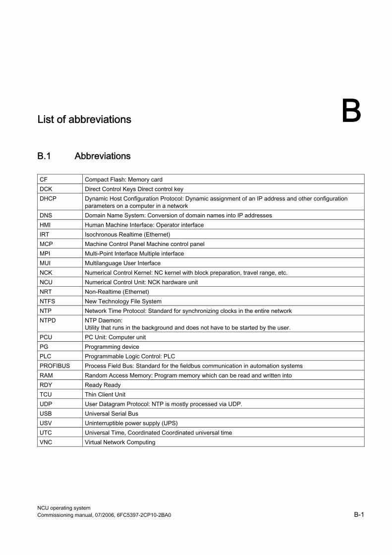
NCU operating system Commissioning manual, 07/2006, 6FC5397-2CP10-2BA0 B-1
List of abbreviations BB.1 Abbreviations CF Compact Flash: Memory card DCK Direct Control Keys Direct control key DHCP Dynamic Host Configuration Protocol: Dynamic assignment of an IP address and other configuration
parameters on a computer in a network DNS Domain Name System: Conversion of domain names into IP addresses HMI Human Machine Interface: Operator interface IRT Isochronous Realtime (Ethernet) MCP Machine Control Panel Machine control panel MPI Multi-Point Interface Multiple interface MUI Multilanguage User Interface NCK Numerical Control Kernel: NC kernel with block preparation, travel range, etc. NCU Numerical Control Unit: NCK hardware unit NRT Non-Realtime (Ethernet) NTFS New Technology File System NTP Network Time Protocol: Standard for synchronizing clocks in the entire network NTPD NTP Daemon:
Utility that runs in the background and does not have to be started by the user. PCU PC Unit: Computer unit PG Programming device PLC Programmable Logic Control: PLC PROFIBUS Process Field Bus: Standard for the fieldbus communication in automation systems RAM Random Access Memory: Program memory which can be read and written into RDY Ready Ready TCU Thin Client Unit UDP User Datagram Protocol: NTP is mostly processed via UDP. USB Universal Serial Bus USV Uninterruptible power supply (UPS) UTC Universal Time, Coordinated Coordinated universal time VNC Virtual Network Computing

List of abbreviations B.1 Abbreviations
NCU operating system B-2 Commissioning manual, 07/2006, 6FC5397-2CP10-2BA0
NCU operating system Commissioning manual, 07/2006, 6FC5397-2CP10-2BA0 Glossary-1
Glossary
CFS (Compressed File System) A CFS (file extension ".cfs") is a compressed file system, similar to a zip file. It contains files and subdirectories that look like normal files on the controller at runtime. Files and directories contained in a CFS cannot be changed. They are decompressed at runtime as required.
Network interface The network interface is an interface that enables network communication. These are the Ethernet interfaces on the NCU.
NFS (Network File System) NFS is the most common protocol for remote file systems in the world of Unix, and is also available for Windows. NFS is closely based on the Unix privilege model – each time a file is accessed, a UID and GID are supplied which the server then uses to decide whether the operation is permitted. The server relies on the client to provide the correct IDs.
Remote File System A file system that is contacted over the network. The files are physically located on another computer in the network (the "server"), but appear locally the same as all other files. Operations performed on these files are sent via the network to the server, instead of being executed directly on a local storage medium (such as a hard drive or CF card). As a server usually exports more than one file system, a name for the required file system must also be entered in addition to the name of the server.
SMB (Server Message Block) SMB is the underlying protocol of MS Windows file systems (also known as drives, releases, shares, etc.). SMB connections are always active in the context of a specific user, who must be known to the server. Exported file systems have a name (release name), by which they can be addressed. The client does not need to know the concrete path on the server.
Subsystem A subsystem is a CFS that not only contains a collection of files, but also executes a program, for example, at runtime. To do this, the CFS contains a script that is used to control the starting and stopping of this program. For this reason, only administrators are permitted to set up NFS file systems, and NFS is usually only implemented in uniformly administrated environments. Exported file systems on the server are addressed directly on the server via their path.
Glossary
NCU operating system Glossary-2 Commissioning manual, 07/2006, 6FC5397-2CP10-2BA0
VNC (Virtual Network Computing) Virtual Network Computing is a software that displays the screen contents of a remote computer, with a running VNC server, on a local computer, with a running VNC viewer, and in return sends keyboard and mouse movements of the local computer to the remote computer.
NCU operating system Commissioning manual, 07/2006, 6FC5397-2CP10-2BA0 Index-1
Index
A Access privilege, 1-1 Applications, 3-1
B BIOS power-up, 1-3
C CF card, 3-6 CFS (Compressed File System), 4-4 Coding switches, 1-5 Command
Backup Save, 4-10 Check-cf, 4-6 Connect, 4-6 Disable, 4-8 Disconnect, 4-8 Enable, 4-8 Help, 4-5 Reboot, 4-9 Restart, 4-9 Restore, 4-9 Save, 4-10 Show, 4-11 Start, Stop, 4-13
D data
Backing up, 3-6 Restoring, 3-8
DHCPClientID, 2-4 Directory structure, 1-1 DisableNTPTimeSync, 2-5 DisablePLCTimeSync, 2-5 Domain, 2-3 Downloading of operating system, 1-3
E Emergency Boot System, 3-2 EnableCoreDumps, 2-4 Ethernet interfaces, 2-1 ExternalIP, 2-2 ExternalNetMask, 2-2
G Gateway, 2-3
H Host name, 2-3
I Interfaces
Ethernet, 4-3 NCU, 2-1
L LED, 1-3
N Nameservers, 2-3 NCK start-up switch, 1-5 NCU booting, 1-2 Network interface, 2-1 NFS (Network File System), 4-4
P PLC mode selector switch, 1-5 Privilege, 4-1
Index
NCU operating system Index-2 Commissioning manual, 07/2006, 6FC5397-2CP10-2BA0
R Remote File System, 4-4 Reset
Button, 1-2 Execute, 1-2
S Section
[ExternalInterface], 2-2 [LinuxBase], 2-4
Service command Application, 4-1 privileges, 4-1 Syntax, 4-2
Service system Backing up data, 3-3 Creating for the NCU, 3-2 Restoring data, 3-5
Service Tool WinSCP, 4-14 SMB (Server Message Block), 4-4 Subsystem, 4-3
Designation, 4-3 Synchronizing the time, 2-5 System
Diagnostics, 1-3 Log file, 1-1, 2-4 Start-up, 1-3
System fault, 1-4
T Time zone, 2-4 Timeservers, 2-3
U User group, 4-1 Users (default setting), 1-2
V VNC (Virtual Network Computing), 3-1
W WinSCP, 4-14
Commissioning a system 1
Configuring the system 2
Install software and updates 3
Backing up and restoring data
4
Service and diagnostics 5
List of Abbreviations A
SINUMERIK 810D/840D SINUMERIK 840D sl/840Di sl CNC Part 5 (Basesoftware)PCU-Basesoftware (IM8)
Commissioning manual
07/2006 6FC5397-2CP10-2BA0
Valid for: Controller SINUMERIK 810D/810DE SINUMERIK 840D/840DE SINUMERIK 840Di sl/840DiE sl SINUMERIK 840D sl/840DE sl Software Version PCU Basesoftware 8.0
Safety Guidelines This manual contains notices you have to observe in order to ensure your personal safety, as well as to prevent damage to property. The notices referring to your personal safety are highlighted in the manual by a safety alert symbol, notices referring only to property damage have no safety alert symbol. These notices shown below are graded according to the degree of danger.
Danger
indicates that death or severe personal injury will result if proper precautions are not taken.
Warning
indicates that death or severe personal injury may result if proper precautions are not taken.
Caution
with a safety alert symbol, indicates that minor personal injury can result if proper precautions are not taken.
Caution
without a safety alert symbol, indicates that property damage can result if proper precautions are not taken.
Notice
indicates that an unintended result or situation can occur if the corresponding information is not taken into account.
If more than one degree of danger is present, the warning notice representing the highest degree of danger will be used. A notice warning of injury to persons with a safety alert symbol may also include a warning relating to property damage.
Qualified Personnel The device/system may only be set up and used in conjunction with this documentation. Commissioning and operation of a device/system may only be performed by qualified personnel. Within the context of the safety notes in this documentation qualified persons are defined as persons who are authorized to commission, ground and label devices, systems and circuits in accordance with established safety practices and standards.
Prescribed Usage Note the following:
Warning
This device may only be used for the applications described in the catalog or the technical description and only in connection with devices or components from other manufacturers which have been approved or recommended by Siemens. Correct, reliable operation of the product requires proper transport, storage, positioning and assembly as well as careful operation and maintenance.
Trademarks All names identified by ® are registered trademarks of the Siemens AG. The remaining trademarks in this publication may be trademarks whose use by third parties for their own purposes could violate the rights of the owner.
Disclaimer of Liability We have reviewed the contents of this publication to ensure consistency with the hardware and software described. Since variance cannot be precluded entirely, we cannot guarantee full consistency. However, the information in this publication is reviewed regularly and any necessary corrections are included in subsequent editions.
Siemens AG Automation and Drives Postfach 48 48 90437 NÜRNBERG GERMANY
Order No.: 6FC5397-2CP10-2BA0 Edition 08/2006
Copyright © Siemens AG 2005, 2006. Technical data subject to change
PCU-Basesoftware (IM8) Commissioning manual, 07/2006, 6FC5397-2CP10-2BA0 iii
Table of contents 1 Commissioning a system........................................................................................................................ 1-1
1.1 Delivery condition of the system ................................................................................................ 1-1 1.1.1 Hard disk partitions .................................................................................................................... 1-2 1.1.2 System settings.......................................................................................................................... 1-3 1.2 User administration .................................................................................................................... 1-5 1.2.1 Which users are set up? ............................................................................................................ 1-5 1.2.2 Change service user .................................................................................................................. 1-6 1.2.3 Global user settings ................................................................................................................... 1-7 1.2.4 Specific user settings ............................................................................................................... 1-10 1.3 Boot up behavior of the PCU ................................................................................................... 1-11 1.3.1 Boot up of the PCU: no HMI program installed........................................................................ 1-11 1.3.2 Boot up of the PCU: HMI program already installed................................................................ 1-12 1.4 BIOS settings ........................................................................................................................... 1-13
2 Configuring the system ........................................................................................................................... 2-1 2.1 System features ......................................................................................................................... 2-1 2.2 Configuring the customized operator interface .......................................................................... 2-2 2.2.1 Switching the language for the Windows system ...................................................................... 2-2 2.2.2 Storage location of HMI boot screen ......................................................................................... 2-4 2.2.3 Displaying your own boot screen............................................................................................... 2-4 2.2.4 Changing the background of the service desktop...................................................................... 2-5 2.3 User-specific settings during boot up......................................................................................... 2-6 2.3.1 Starting an HMI program during boot up ................................................................................... 2-6 2.3.2 Starting service des ktop during boot up .................................................................................... 2-7 2.3.3 Starting OEM programs ............................................................................................................. 2-9 2.4 PCU 50.3 with SITOP UPS module......................................................................................... 2-10 2.4.1 Starting and configuring the SITOP monitor ............................................................................ 2-11 2.4.2 Configuration of the SITOP UPS module ................................................................................ 2-12 2.4.3 Configuration for exiting the HMI ............................................................................................. 2-15
3 Install software and updates ................................................................................................................... 3-1 3.1 Installing SINUMERIK products ................................................................................................. 3-1 3.2 Installation via service desktop .................................................................................................. 3-1 3.3 Installing and authorizing SIMATIC STEP 7 .............................................................................. 3-4 3.4 Installing additional languages under Windows XP (DVD)........................................................ 3-5
4 Backing up and restoring data ................................................................................................................ 4-1 4.1 Backing up and restoring data ................................................................................................... 4-1 4.1.1 Starting ServiceCenter Backup Restore .................................................................................... 4-1 4.1.2 Starting applications in service mode ........................................................................................ 4-4 4.1.3 Select service task ..................................................................................................................... 4-5 4.1.4 Backup/restore local partitions................................................................................................... 4-6
Table of contents
PCU-Basesoftware (IM8) iv Commissioning manual, 07/2006, 6FC5397-2CP10-2BA0
4.1.5 Backing up/restoring the hard disk............................................................................................. 4-7 4.1.6 Restoring system data from "Emergency Image" ...................................................................... 4-8 4.2 Saving the HMI Advanced environment..................................................................................... 4-9 4.3 Creating the service system for PCU....................................................................................... 4-10 4.4 Connecting a PG/PC to the PCU in the system network ......................................................... 4-11 4.4.1 Requirements........................................................................................................................... 4-11 4.4.2 Procedure................................................................................................................................. 4-14 4.5 Commissioning the replacement hard disk .............................................................................. 4-18
5 Service and diagnostics.......................................................................................................................... 5-1 5.1 PCU Hardware Diagnostics ....................................................................................................... 5-1 5.2 Enabling/disabling error log during boot up ............................................................................... 5-2
A List of Abbreviations ...............................................................................................................................A-1 A.1 Abbreviations .............................................................................................................................A-1
Index................................................................................................................................................ Index-1
PCU-Basesoftware (IM8) Commissioning manual, 07/2006, 6FC5397-2CP10-2BA0 1-1
Commissioning a system 11.1 Delivery condition of the system
Overview The high-performance SINUMERIK PCU 50.3 has onboard interfaces for communicating via Ethernet, MPI and PROFIBUS DP. The integrated free slots remain free for other tasks. The PCU 50.3 is equipped with the Windows XP ProEmbSys operating system and for data backup tasks with the Symantec Ghost software. Interfaces: • Four USB ports (USB 2.0) offer points where a keyboard, mouse and other peripheral
devices can be connected. • For CF cards, there is a covered slot. • For use with SINUMERIK 840D/840D sl:
Two internal PCI slots are available for specific expansions. • For use with SINUMERIK 840Di sl:
A PCI slot is already equipped with the MCI2 board and can be equipped with the optional MCI board extension.
Two 7-segment displays and two LEDs are integrated for diagnostic purposes. They indicate the current operating status and display the BIOS error codes during boot up. References: Equipment manual "Operating Components"
Supplied software on the PCU The software installed on delivery of the PCU includes the components below, among others:
MS Windows XP Professional SP2 Internet Explorer V 6.0 MPI driver V 6.03 Symantec Ghost (default setting) V 8.2 (incl. Ghost Explorer) TCU Support (is already installed and available on the hard disk under D:\Updates, if it must be re-installed.)
V 8.0
Documentation for all Ghost tools is supplied on the PCU’s hard disk under E:\TOOLS.
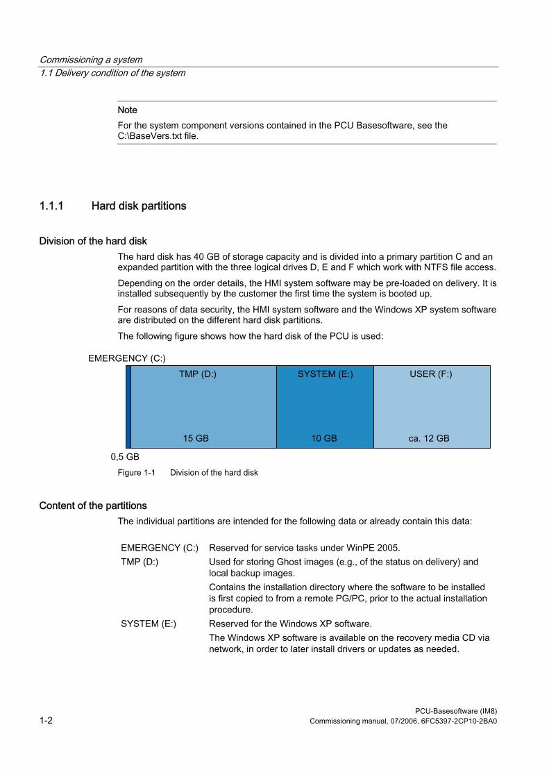
Commissioning a system 1.1 Delivery condition of the system
PCU-Basesoftware (IM8) 1-2 Commissioning manual, 07/2006, 6FC5397-2CP10-2BA0
Note For the system component versions contained in the PCU Basesoftware, see the C:\BaseVers.txt file.
1.1.1 Hard disk partitions
Division of the hard disk The hard disk has 40 GB of storage capacity and is divided into a primary partition C and an expanded partition with the three logical drives D, E and F which work with NTFS file access. Depending on the order details, the HMI system software may be pre-loaded on delivery. It is installed subsequently by the customer the first time the system is booted up. For reasons of data security, the HMI system software and the Windows XP system software are distributed on the different hard disk partitions. The following figure shows how the hard disk of the PCU is used:
Figure 1-1 Division of the hard disk
Content of the partitions The individual partitions are intended for the following data or already contain this data:
EMERGENCY (C:) Reserved for service tasks under WinPE 2005. TMP (D:) Used for storing Ghost images (e.g., of the status on delivery) and
local backup images. Contains the installation directory where the software to be installed is first copied to from a remote PG/PC, prior to the actual installation procedure.
SYSTEM (E:) Reserved for the Windows XP software. The Windows XP software is available on the recovery media CD via network, in order to later install drivers or updates as needed.
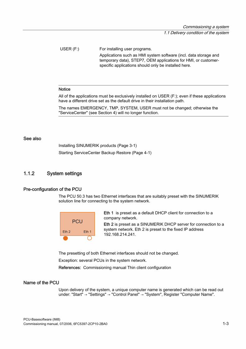
Commissioning a system 1.1 Delivery condition of the system
PCU-Basesoftware (IM8) Commissioning manual, 07/2006, 6FC5397-2CP10-2BA0 1-3
USER (F:) For installing user programs. Applications such as HMI system software (incl. data storage and temporary data), STEP7, OEM applications for HMI, or customer-specific applications should only be installed here.
Notice All of the applications must be exclusively installed on USER (F:); even if these applications have a different drive set as the default drive in their installation path. The names EMERGENCY, TMP, SYSTEM, USER must not be changed; otherwise the "ServiceCenter" (see Section 4) will no longer function.
See also Installing SINUMERIK products (Page 3-1) Starting ServiceCenter Backup Restore (Page 4-1)
1.1.2 System settings
Pre-configuration of the PCU The PCU 50.3 has two Ethernet interfaces that are suitably preset with the SINUMERIK solution line for connecting to the system network.
Eth 1 is preset as a default DHCP client for connection to a company network. Eth 2 is preset as a SINUMERIK DHCP server for connection to a system network. Eth 2 is preset to the fixed IP address 192.168.214.241.
The presetting of both Ethernet interfaces should not be changed. Exception: several PCUs in the system network. References: Commissioning manual Thin client configuration
Name of the PCU Upon delivery of the system, a unique computer name is generated which can be read out under: "Start" → "Settings" → "Control Panel" → "System", Register "Computer Name".
Commissioning a system 1.1 Delivery condition of the system
PCU-Basesoftware (IM8) 1-4 Commissioning manual, 07/2006, 6FC5397-2CP10-2BA0
Configuration of the operating system For safety reasons, Windows XP has been preset as follows: • The Autorun function is deactivated. • Automatic Windows Update is deactivated. • Monitoring and alerts for antivirus software and automatic update are deactivated. • Links used to call up Internet Explorer from the service desktop and the start menu are
removed. • Remote Procedure Call (RPC) is possible for calls that are not connected. • The firewall settings are activated on the network card Eth 1 and deactivated on Eth 2.
Changes to Windows services Other default settings:
Windows services: Start-up type: Computer Browser Manual (Not started) Error Reporting Service Disabled Portable Media Serial Number Manual (Not started) SSDP Discovery Service Disabled Universal Plug and Play Host Disabled Web Client Manual (Not started) Wireless Zero Configuration Manual (Not started)
Preset users Upon delivery of the system, the following users are defined at the factory:
User name Password User type Windows user group operator operator HMI Users Operator auduser SUNRISE Service user System administrator siemens ***** --- System administrator
Starting ServiceCenter Using this link on the service desktop, you can start the service center users. In service center users, the boot up behavior of the PCU is globally set for all users or individual users.
Commissioning a system 1.2 User administration
PCU-Basesoftware (IM8) Commissioning manual, 07/2006, 6FC5397-2CP10-2BA0 1-5
1.2 User administration
1.2.1 Which users are set up?
Overview The users are managed in the "ServiceCenter Users", so that the commissioner/service user no longer has to make corresponding settings directly in the registry. The preset users are: • The "auduser".
The "auduser" is a service user type of user and belongs to the system administrators' user group. The system administrators have the user rights of a local administrator.
• The "operator" The "operator" is an HMI user type of user and belongs to the operators' user group. The operators have limited user rights.
For the HMI user and service user, individual settings can be configured for boot up, the HMI program and service.
Notice In the PCU Basesoftware version 8.0 SP2, only one service user ("auduser" is the default) and only one HMI user with the fixed name of "operator" are supported.
Users Each user is from one user type and belongs to one user group.
User type A user can be assigned to the following user types:
User types Task card HMI Users • Boot up of the PCU
• Operating the HMI program Service user • Service tasks
• Boot up of the PCU • Operating the HMI program
The user types are implemented under Windows in user groups with various user rights.
Commissioning a system 1.2 User administration
PCU-Basesoftware (IM8) 1-6 Commissioning manual, 07/2006, 6FC5397-2CP10-2BA0
User group The user types are implemented via the following Windows user groups:
User group Name of the group (Windows) User rights Operator operator.group Restricted System administrators Administrators local administrator
Service Desktop The service desktop provides the service user with a Windows desktop, which is expanded by tools and functions for service tasks, such as manage users, install software, save/restore data, check system integrity, etc.
1.2.2 Change service user
Overview Any other Windows user can also become the service user (instead of “auduser”) if they are set up as a local Windows administrator or a domain user and possess local administrator rights.
Change service user The service user is identified in the registry by two entries: User name and user type. The default user name is "auduser", the user type for the service user is "2". In order to change the service user, the user who wants to be the new service user must log into Windows with local administrator rights. Only this user has sufficient user rights to make the entries in his user-specific branch of the registry. The service user is registered by the following registry entries:
Reference Default Key HKLM\SOFTWARE\Siemens\SINUMERIK\Basesoftware\<version>\HMIManager HMIUserName Entry <user name> (STRING) auduser HMIUserDomainName Entry <domain name> (STRING) (local)
Reference Default Key HKCU\SOFTWARE\Siemens\SINUMERIK\Basesoftware\HMIManager UserType Entry 2 (DWORD)
The following name must be entered under "HMIUserDomainName": • for a local administrator: (local) • for a domain operator: <domain name>
Commissioning a system 1.2 User administration
PCU-Basesoftware (IM8) Commissioning manual, 07/2006, 6FC5397-2CP10-2BA0 1-7
1.2.3 Global user settings
Principle of passing on In the "ServiceCenter Users", set the following responses under "Users" → "Global Settings": • Boot up behavior of the PCU • Start the HMI program • Behavior in service mode The settings that are made for users under "Global Settings" are passed on to individual users. The passed on settings can still be specifically adapted for the respective user. To do this, the user must log in using his password.
Figure 1-2 Global user settings
Startup:
Selection Effect Bitmap folder: - None - Directory with boot screens Default bitmap folder: F:\hmi_adv\ib\DATA\default Directory containing default boot screens Installing: "yes" (default) Installation privilege exists during boot up "no" No installation privilege
Commissioning a system 1.2 User administration
PCU-Basesoftware (IM8) 1-8 Commissioning manual, 07/2006, 6FC5397-2CP10-2BA0
Selection Effect Install veto dialog: "no" (default) For pending installation during the boot
up: No prompting, the installation begins immediately.
"yes" For pending installation during the boot up: Prompt asking whether to install.
HMI program:
Selection Effect Start: "yes" (default) The HMI program is started. "no" The HMI program is not started. File: F:\hmi_adv\reg_cmd.exe
(default) Directory of the HMI program
Task bar autohide: "no" (default) HMI program: Hide start task bar "yes" HMI program: Show start task bar Task bar on top: "no" (default) HMI program: Start task bar in the
background "yes" HMI program: Start task bar on top
Service:
Selection Effect Intro dialog: "yes" (default) Display service intro dialog "no" Do not display service intro dialog Logon dialog: "yes" (default) Display service logon dialog "no" Do not display service logon dialog Default password map: "yes" (default) The password is not case-sensitive. "no" The password must be entered exactly as
specified. Bitmaps folder: - None - Directory with background screens for the
service desktop Default bitmap folder: - None - Directory with default background screens for
the service desktop Task bar autohide: "no" (default) Service Desktop: Hide start task bar "yes" Service Desktop: Show start task bar Task bar on top: "no" (default) Service Desktop: Start task bar on top "yes" Service Desktop: Start task bar in the
background
Note If you press the "Reboot" button, the system immediately reboots (without prior prompting). Use "Exit" to end the ServiceCenter Users.
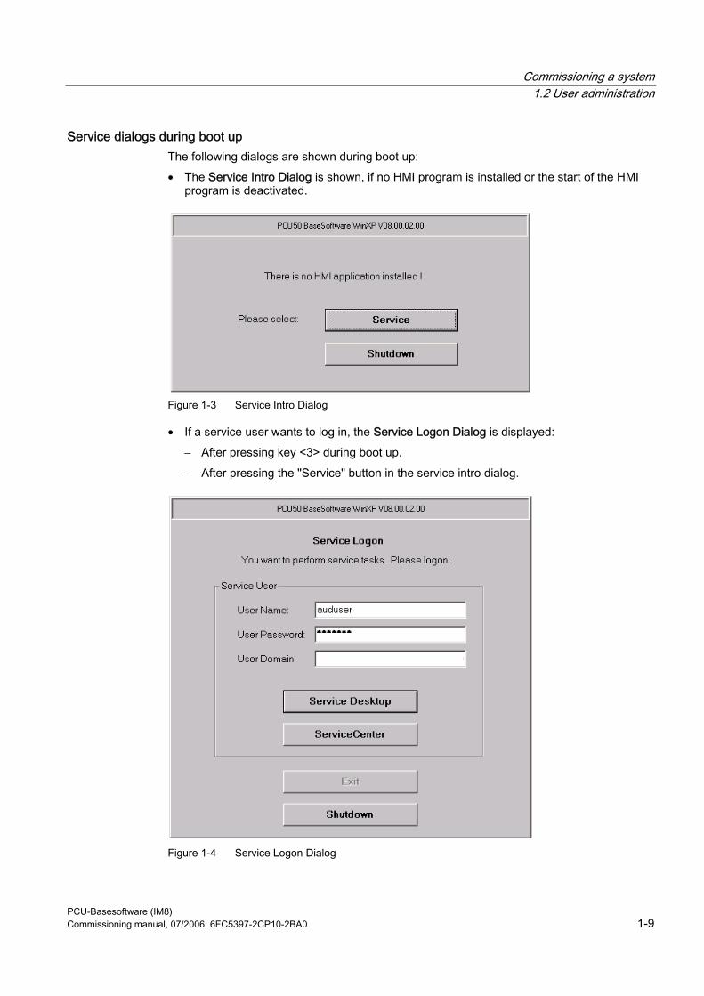
Commissioning a system 1.2 User administration
PCU-Basesoftware (IM8) Commissioning manual, 07/2006, 6FC5397-2CP10-2BA0 1-9
Service dialogs during boot up The following dialogs are shown during boot up: • The Service Intro Dialog is shown, if no HMI program is installed or the start of the HMI
program is deactivated.
Figure 1-3 Service Intro Dialog
• If a service user wants to log in, the Service Logon Dialog is displayed: – After pressing key <3> during boot up. – After pressing the "Service" button in the service intro dialog.
Figure 1-4 Service Logon Dialog
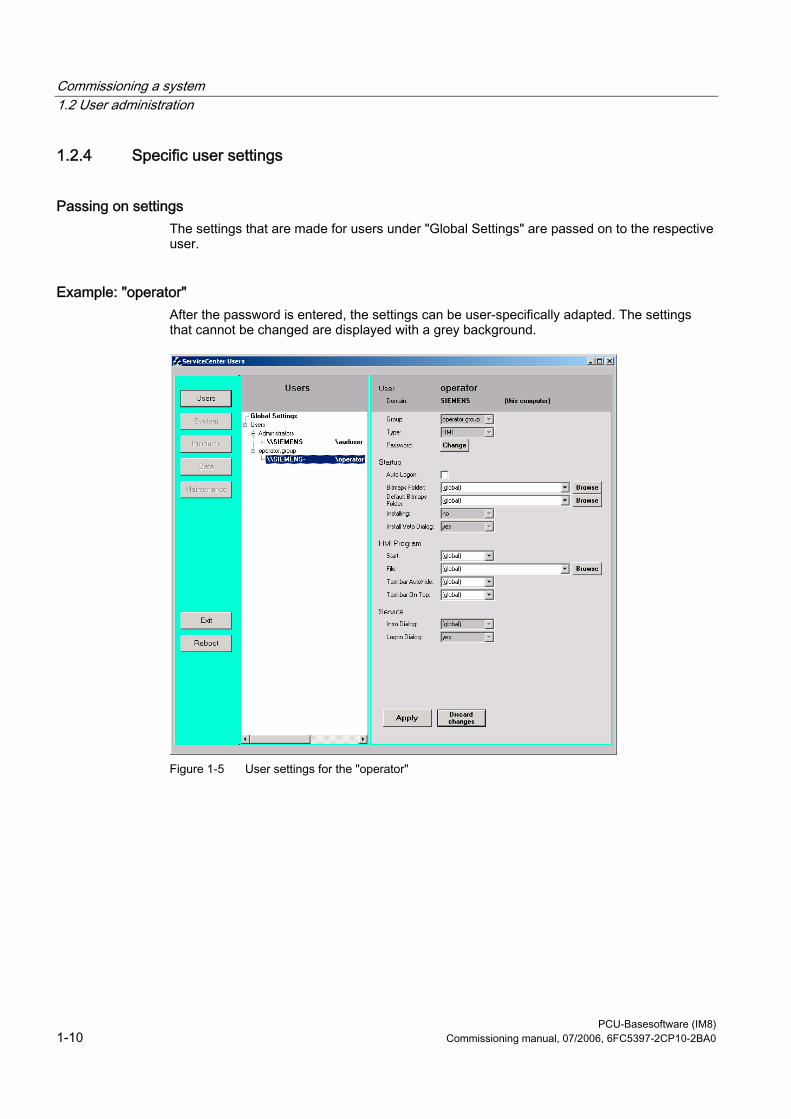
Commissioning a system 1.2 User administration
PCU-Basesoftware (IM8) 1-10 Commissioning manual, 07/2006, 6FC5397-2CP10-2BA0
1.2.4 Specific user settings
Passing on settings The settings that are made for users under "Global Settings" are passed on to the respective user.
Example: "operator" After the password is entered, the settings can be user-specifically adapted. The settings that cannot be changed are displayed with a grey background.
Figure 1-5 User settings for the "operator"
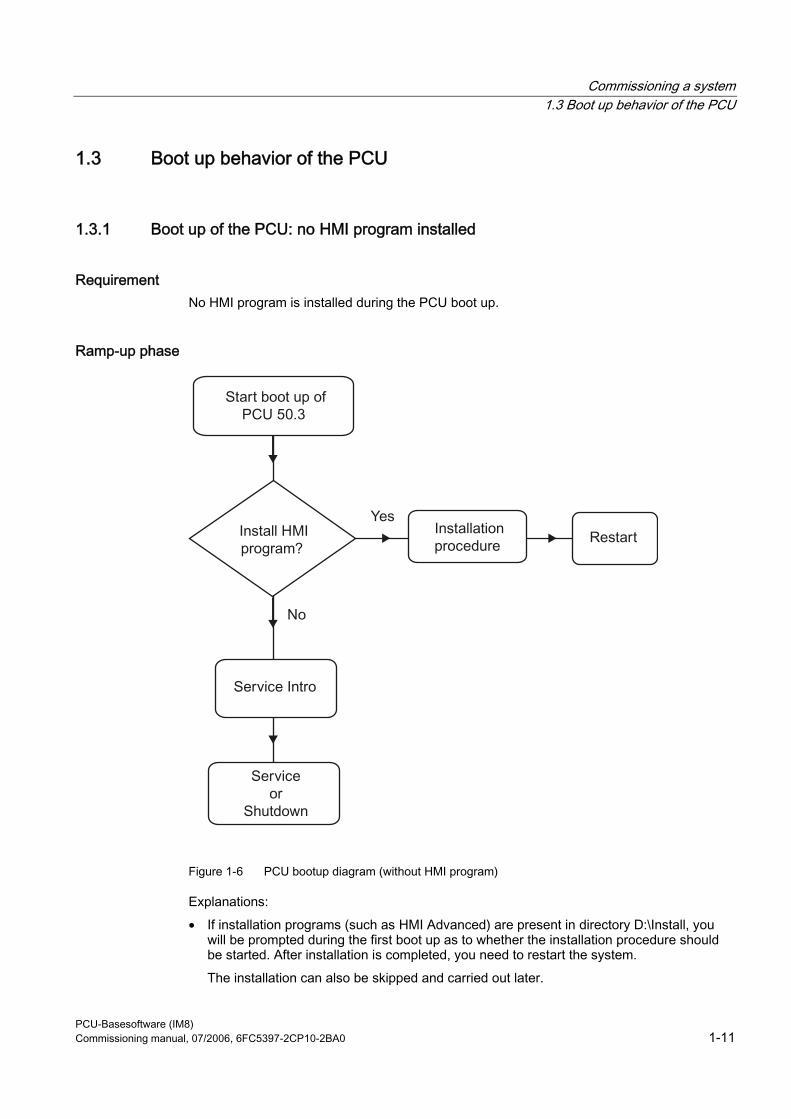
Commissioning a system 1.3 Boot up behavior of the PCU
PCU-Basesoftware (IM8) Commissioning manual, 07/2006, 6FC5397-2CP10-2BA0 1-11
1.3 Boot up behavior of the PCU
1.3.1 Boot up of the PCU: no HMI program installed
Requirement No HMI program is installed during the PCU boot up.
Ramp-up phase
Figure 1-6 PCU bootup diagram (without HMI program)
Explanations: • If installation programs (such as HMI Advanced) are present in directory D:\Install, you
will be prompted during the first boot up as to whether the installation procedure should be started. After installation is completed, you need to restart the system. The installation can also be skipped and carried out later.
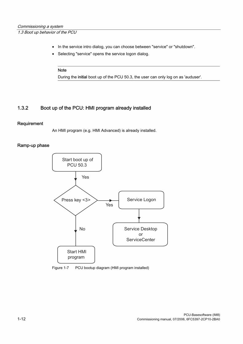
Commissioning a system 1.3 Boot up behavior of the PCU
PCU-Basesoftware (IM8) 1-12 Commissioning manual, 07/2006, 6FC5397-2CP10-2BA0
• In the service intro dialog, you can choose between "service" or "shutdown". • Selecting "service" opens the service logon dialog.
Note During the initial boot up of the PCU 50.3, the user can only log on as 'auduser'.
1.3.2 Boot up of the PCU: HMI program already installed
Requirement An HMI program (e.g. HMI Advanced) is already installed.
Ramp-up phase
Figure 1-7 PCU bootup diagram (HMI program installed)
Commissioning a system 1.4 BIOS settings
PCU-Basesoftware (IM8) Commissioning manual, 07/2006, 6FC5397-2CP10-2BA0 1-13
Explanations: • If the HMI program is already installed, the PCU boots up and the HMI program is started
(default). • During the boot up, there is a time interval for pressing key <3> when the version
information appears on the lower right of the background screen. The service logon dialog then opens.
• After logging in as a service user, you can either start the "service desktop" in order to carry out additional service tasks, or you can start the "ServiceCenter Users" in order to set the boot up behavior for the individual users.
1.4 BIOS settings
Overview The BIOS of the PCU 50.3 is preset in such a way that no changes are required. The date and time can be set under Windows or the HMI operator interface.
Notice Your device configuration is preset for working with the software supplied with the unit. You should only change the preset values if you have modified your device in any way, or if a fault occurs when the unit is powered up.
Starting BIOS setup 1. Start the BIOS SETUP as follows:
Reset the device (warm or cold restart). After the first boot up, the following message appears: Press < F2 > to enter SETUP or <ESC> to show boot menu
2. Press the F2 key as long as the BIOS prompt appears on the screen.
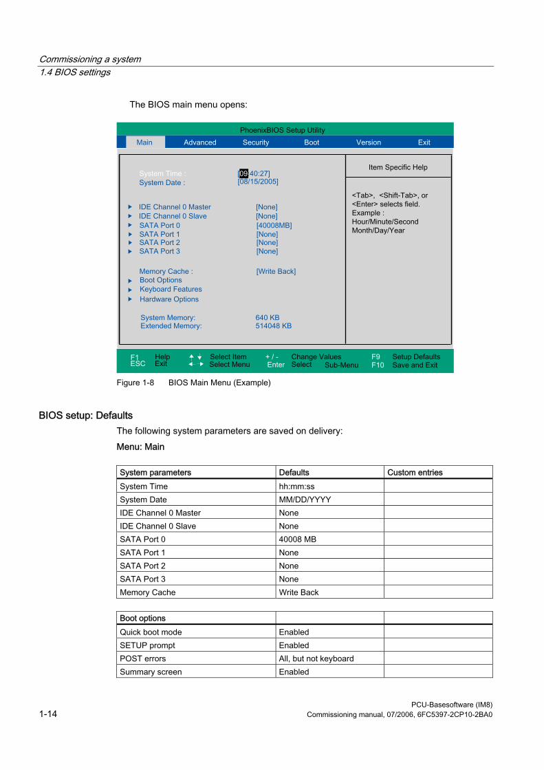
Commissioning a system 1.4 BIOS settings
PCU-Basesoftware (IM8) 1-14 Commissioning manual, 07/2006, 6FC5397-2CP10-2BA0
The BIOS main menu opens:
Figure 1-8 BIOS Main Menu (Example)
BIOS setup: Defaults The following system parameters are saved on delivery: Menu: Main
System parameters Defaults Custom entries System Time hh:mm:ss System Date MM/DD/YYYY IDE Channel 0 Master None IDE Channel 0 Slave None SATA Port 0 40008 MB SATA Port 1 None SATA Port 2 None SATA Port 3 None Memory Cache Write Back
Boot options Quick boot mode Enabled SETUP prompt Enabled POST errors All, but not keyboard Summary screen Enabled
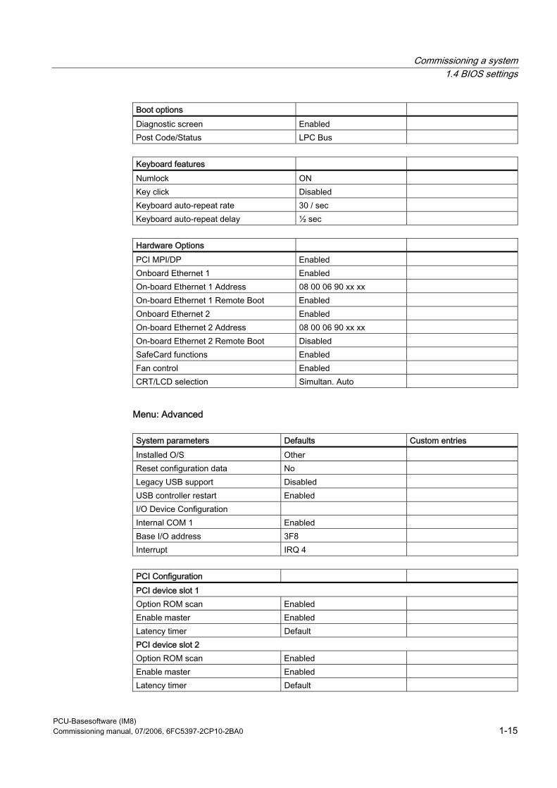
Commissioning a system 1.4 BIOS settings
PCU-Basesoftware (IM8) Commissioning manual, 07/2006, 6FC5397-2CP10-2BA0 1-15
Boot options Diagnostic screen Enabled Post Code/Status LPC Bus
Keyboard features Numlock ON Key click Disabled Keyboard auto-repeat rate 30 / sec Keyboard auto-repeat delay ½ sec
Hardware Options PCI MPI/DP Enabled Onboard Ethernet 1 Enabled On-board Ethernet 1 Address 08 00 06 90 xx xx On-board Ethernet 1 Remote Boot Enabled Onboard Ethernet 2 Enabled On-board Ethernet 2 Address 08 00 06 90 xx xx On-board Ethernet 2 Remote Boot Disabled SafeCard functions Enabled Fan control Enabled CRT/LCD selection Simultan. Auto
Menu: Advanced
System parameters Defaults Custom entries Installed O/S Other Reset configuration data No Legacy USB support Disabled USB controller restart Enabled I/O Device Configuration Internal COM 1 Enabled Base I/O address 3F8 Interrupt IRQ 4
PCI Configuration PCI device slot 1 Option ROM scan Enabled Enable master Enabled Latency timer Default PCI device slot 2 Option ROM scan Enabled Enable master Enabled Latency timer Default
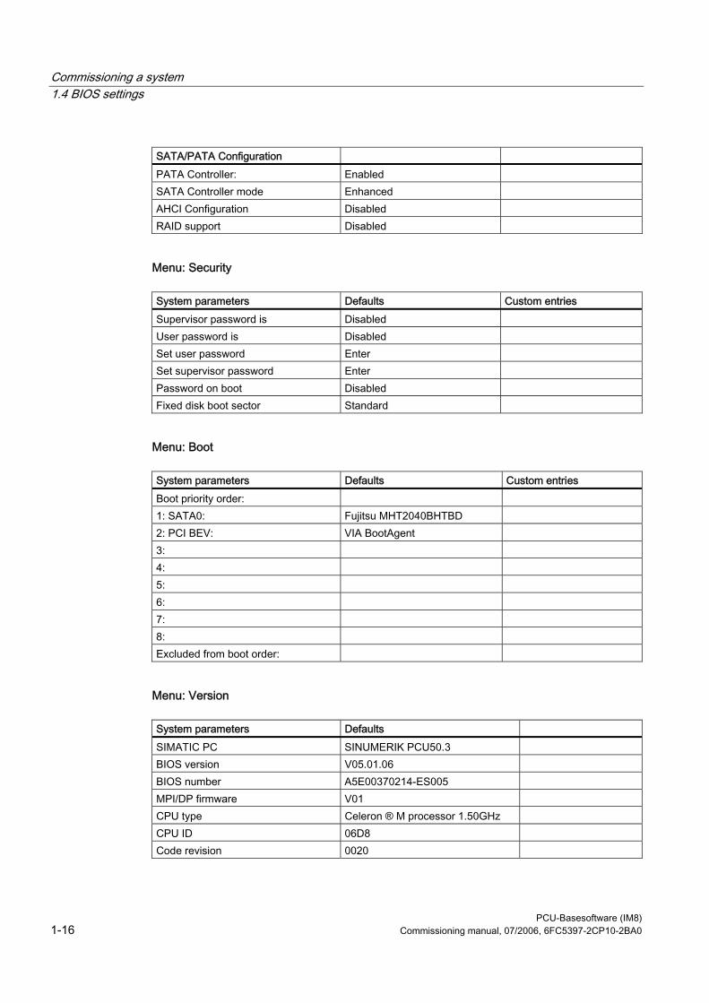
Commissioning a system 1.4 BIOS settings
PCU-Basesoftware (IM8) 1-16 Commissioning manual, 07/2006, 6FC5397-2CP10-2BA0
SATA/PATA Configuration PATA Controller: Enabled SATA Controller mode Enhanced AHCI Configuration Disabled RAID support Disabled
Menu: Security
System parameters Defaults Custom entries Supervisor password is Disabled User password is Disabled Set user password Enter Set supervisor password Enter Password on boot Disabled Fixed disk boot sector Standard
Menu: Boot
System parameters Defaults Custom entries Boot priority order: 1: SATA0: Fujitsu MHT2040BHTBD 2: PCI BEV: VIA BootAgent 3: 4: 5: 6: 7: 8: Excluded from boot order:
Menu: Version
System parameters Defaults SIMATIC PC SINUMERIK PCU50.3 BIOS version V05.01.06 BIOS number A5E00370214-ES005 MPI/DP firmware V01 CPU type Celeron ® M processor 1.50GHz CPU ID 06D8 Code revision 0020
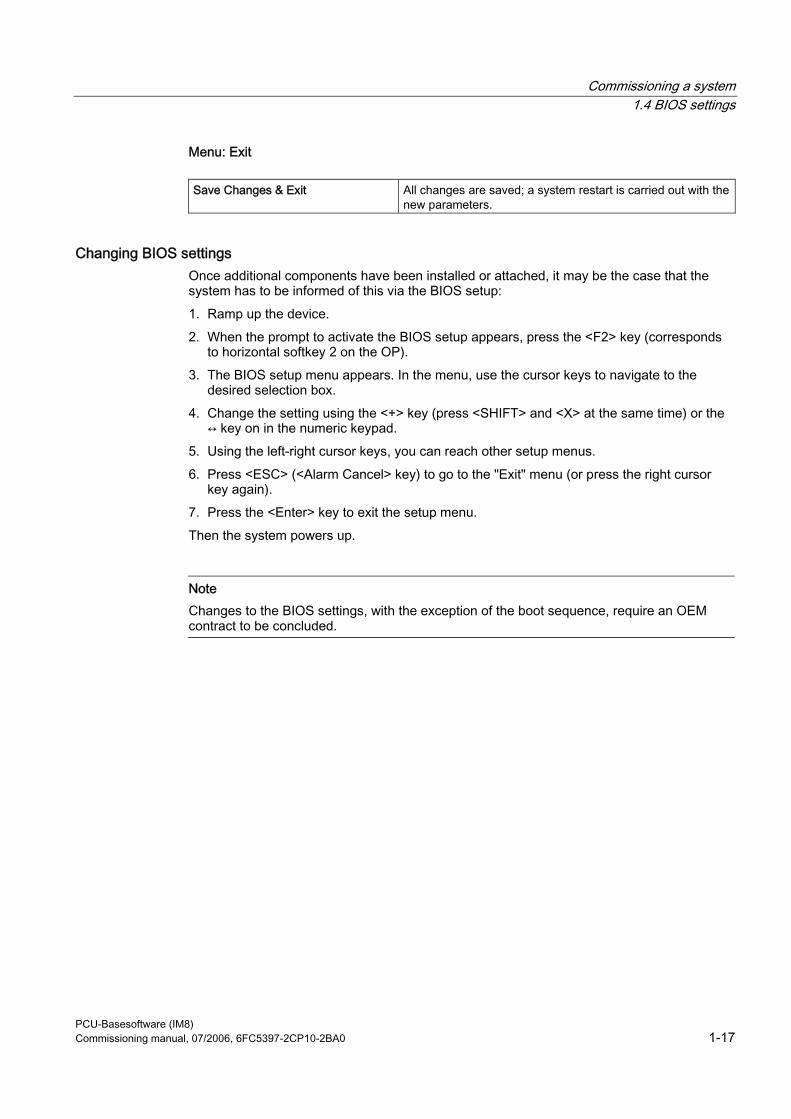
Commissioning a system 1.4 BIOS settings
PCU-Basesoftware (IM8) Commissioning manual, 07/2006, 6FC5397-2CP10-2BA0 1-17
Menu: Exit
Save Changes & Exit All changes are saved; a system restart is carried out with the new parameters.
Changing BIOS settings Once additional components have been installed or attached, it may be the case that the system has to be informed of this via the BIOS setup: 1. Ramp up the device. 2. When the prompt to activate the BIOS setup appears, press the <F2> key (corresponds
to horizontal softkey 2 on the OP). 3. The BIOS setup menu appears. In the menu, use the cursor keys to navigate to the
desired selection box. 4. Change the setting using the <+> key (press <SHIFT> and <X> at the same time) or the
↔ key on in the numeric keypad. 5. Using the left-right cursor keys, you can reach other setup menus. 6. Press <ESC> (<Alarm Cancel> key) to go to the "Exit" menu (or press the right cursor
key again). 7. Press the <Enter> key to exit the setup menu. Then the system powers up.
Note Changes to the BIOS settings, with the exception of the boot sequence, require an OEM contract to be concluded.
Commissioning a system 1.4 BIOS settings
PCU-Basesoftware (IM8) 1-18 Commissioning manual, 07/2006, 6FC5397-2CP10-2BA0
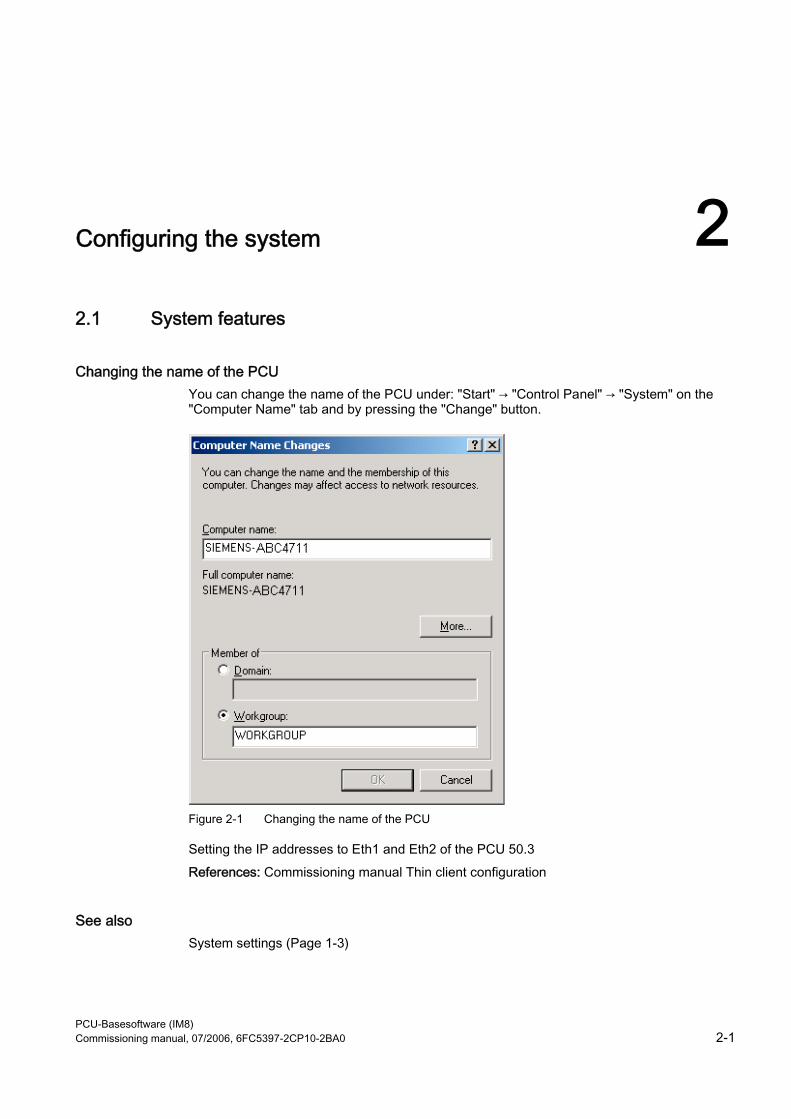
PCU-Basesoftware (IM8) Commissioning manual, 07/2006, 6FC5397-2CP10-2BA0 2-1
Configuring the system 22.1 System features
Changing the name of the PCU You can change the name of the PCU under: "Start" → "Control Panel" → "System" on the "Computer Name" tab and by pressing the "Change" button.
Figure 2-1 Changing the name of the PCU
Setting the IP addresses to Eth1 and Eth2 of the PCU 50.3 References: Commissioning manual Thin client configuration
See also System settings (Page 1-3)
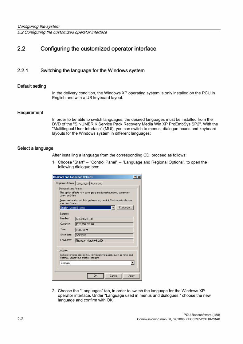
Configuring the system 2.2 Configuring the customized operator interface
PCU-Basesoftware (IM8) 2-2 Commissioning manual, 07/2006, 6FC5397-2CP10-2BA0
2.2 Configuring the customized operator interface
2.2.1 Switching the language for the Windows system
Default setting In the delivery condition, the Windows XP operating system is only installed on the PCU in English and with a US keyboard layout.
Requirement In order to be able to switch languages, the desired languages must be installed from the DVD of the "SINUMERIK Service Pack Recovery Media Win XP ProEmbSys SP2". With the "Multilingual User Interface" (MUI), you can switch to menus, dialogue boxes and keyboard layouts for the Windows system in different languages:
Select a language After installing a language from the corresponding CD, proceed as follows: 1. Choose "Start" → "Control Panel" → "Language and Regional Options", to open the
following dialogue box:
2. Choose the "Languages" tab, in order to switch the language for the Windows XP operator interface. Under "Language used in menus and dialogues," choose the new language and confirm with OK.
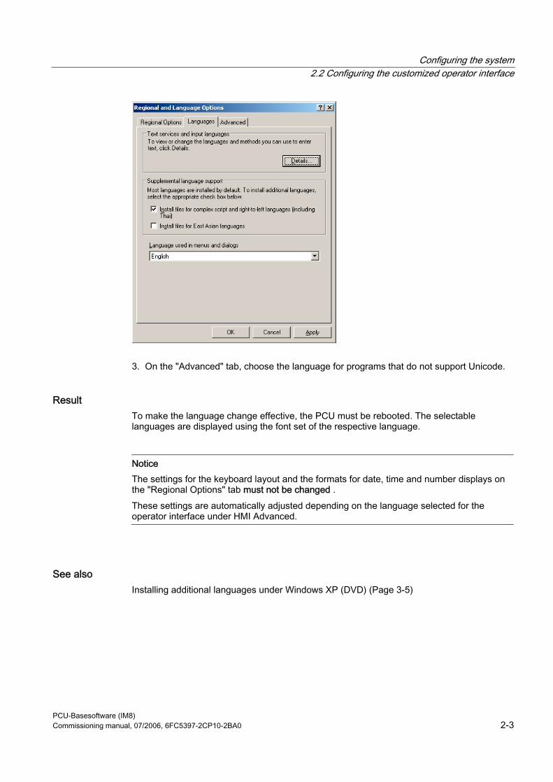
Configuring the system 2.2 Configuring the customized operator interface
PCU-Basesoftware (IM8) Commissioning manual, 07/2006, 6FC5397-2CP10-2BA0 2-3
3. On the "Advanced" tab, choose the language for programs that do not support Unicode.
Result To make the language change effective, the PCU must be rebooted. The selectable languages are displayed using the font set of the respective language.
Notice The settings for the keyboard layout and the formats for date, time and number displays on the "Regional Options" tab must not be changed . These settings are automatically adjusted depending on the language selected for the operator interface under HMI Advanced.
See also Installing additional languages under Windows XP (DVD) (Page 3-5)
Configuring the system 2.2 Configuring the customized operator interface
PCU-Basesoftware (IM8) 2-4 Commissioning manual, 07/2006, 6FC5397-2CP10-2BA0
2.2.2 Storage location of HMI boot screen
Default setting The Siemens boot screens are stored under the path below on the appropriate PCU, e.g., for the SINUMERIK 840D sl controller: F:\hmi_adv\ib\DATA\10700\0\<Resolution>\10700_0.bmp A directory tree can also be created for manufacturer-specific boot screens. The manufacturer’s screens can then be saved in accordance with the schematic below: Directory tree of manufacturer-specific boot screens: F:\oem\ib\DATA\<NckType>\<Resolution>\<Name>.bmp
<NckType> stands for:
0 840D 2000 810D
10700 840D sl 15000 840Di sl
<Resolution>: 640 or 800 or 1024 dpi If you want the same screen to be used each time (NCU-independent screen), it can be saved in the "default" directory in the required resolutions. If you want to be able to use different screens for different NCUs, they should be saved in the <NckType>\<Resolution> subdirectories using the appropriate resolution.
Screen name and resolution <Name>.bmp: The name can be selected freely; only one file is permitted per directory. The screens must be created with a graphics tool in the resolution indicated by the subdirectory name and stored in the corresponding directory. The HMI software selects the screen, depending on the NCK type and the resolution of the available operator panel.
2.2.3 Displaying your own boot screen
Requirements Set up a directory containing several boot screens (for different panel resolutions). This directory should be segmented into subdirectories 640, 800 and 1024, which each contain a boot screen of the appropriate resolution. A directory containing boot screens can also be set up, likewise divided into subdirectories 640, 800 and 1024. The boot screen stored there for a particular resolution is displayed if no boot screen (including one with a lower resolution) is found in the booting-screen directory described above. If no boot screen (including one with a lower resolution) is found, a general boot screen is displayed, which is part of the PCU basic software.
Configuring the system 2.2 Configuring the customized operator interface
PCU-Basesoftware (IM8) Commissioning manual, 07/2006, 6FC5397-2CP10-2BA0 2-5
Directories The directories can be user-specifically set in ServiceCenter Users under: • Startup: Bitmaps folder • Startup: Default bitmap folder
2.2.4 Changing the background of the service desktop
Overview A background pattern for the service desktop is not set via the "Control Panel" (system control), but in the registry: • Background pattern:
Key: HKLM\SOFTWARE\Siemens\SINUMERIK\Basic software\ <version>\HMI
desktop Value: Pattern (STRING) Date: <bit code>” (e.g., “0 80 114 32 0 5 39 2”, see HKCU\Control Panel\Patterns)
“(None)” (= NO background pattern) Init data: Background pattern previously set via the Control Panel Default data: “(None)” (if entry is not available/readable)
• Background image:
A background screen for the service desktop is not user-specifically set via the "Control Panel" (system control), but in the ServiceCenter Users under "Service: Bitmap Folders" or "Service: Default Bitmap Folders".
Note An attempt to set the service desktop background (as in standard Windows) via the Control Panel does not affect the service desktop background display, but only the boot screen display.
Configuring the system 2.3 User -specific settings during boot up
PCU-Basesoftware (IM8) 2-6 Commissioning manual, 07/2006, 6FC5397-2CP10-2BA0
2.3 User-specific settings during boot up
Overview If an HMI program, e.g., HMI Advanced, is to be started following booting, the settings and functionality differ from those that apply if the service desktop is to be started.
2.3.1 Starting an HMI program during boot up
Filtering keys During boot up of an HMI program, keystroke sequences and pressed function keys are simultaneously filtered. The keystroke sequences and functions that were pressed simultaneously and are to be filtered can be configured in file E:\Windows\System.ini. Filtering keystroke sequences:
Section: MMC103Keyb Key: SeqAct Value: <bit mask>
(= keystroke sequences to be filtered, specified in accordance with the comment in E:\Windows\System.ini)
Init value: 262143
Filtering function keys that were pressed simultaneously:
Section: MMC103Keyb Key: ConcurrentKeyMask Value: <bit mask>
(= function keys to be filtered, specified in accordance with the comment in E:\Windows\System.ini)
Init value: 255
Starting additional programs Programs can also be started at the same time as the HMI program and are started automatically by Windows when the service desktop is opened. This start in parallel to the HMI program can be configured. If the programs to be started are located in the Windows directories of E:\Documents and Settings, the following registry entry must be set:
Key: HKLM\SOFTWARE\Siemens\SINUMERIK\Basic software\ <version>\HMI
Manager Value: StartSINHMIStartupDirsPrograms (DWORD) Date: 1 (the programs are started) or
0 (the programs are NOT started)
Configuring the system 2.3 User -specific settings during boot up
PCU-Basesoftware (IM8) Commissioning manual, 07/2006, 6FC5397-2CP10-2BA0 2-7
Init data: 0 Default data: 0 (if entry is not available/readable)
If the programs to be started are set in the registry entries 'HKCU\Software\Microsoft\Windows\CurrentVersion\Run' and 'HKLM\Software\Microsoft\Windows\CurrentVersion\Run', the following registry entry must be set:
Key: HKLM\SOFTWARE\Siemens\SINUMERIK\Basic software\ <version>\HMI
Manager Value: StartSINHMIRunPrograms (DWORD) Date: 1 (the programs are started) or
0 (the programs are NOT started) Init data: 0 Default data: 0 (if entry is not available/readable)
Executing an HMI program While the HMI program is being executed, Windows Explorer runs in the background and its settings (disabled browser functionality, taskbar, start menu, ...) prevent the Windows platform being accessed unintentionally. The behavior of the taskbar can be user-specifically set in the ServiceCenter Users under "HMI program" using "Taskbar Autohide" and "Taskbar On Top".
Ending an HMI program When the HMI program is ended, Windows XP shuts down completely.
2.3.2 Starting service des ktop during boot up
Filtering keys The keystroke sequences and function keys that are pressed simultaneously are filtered as a function of the configuration in file: E:\Windows\System.ini Filtering keystroke sequences:
Section: MMC103Keyb Key: KeySequencesEnable Value: 1 (= filtering of keystroke sequences specified in the SeqAct key) or
0 (= NO filtering) Init value: 0 Default value: 0 (if entry is not available/readable):
Configuring the system 2.3 User -specific settings during boot up
PCU-Basesoftware (IM8) 2-8 Commissioning manual, 07/2006, 6FC5397-2CP10-2BA0
Key: SeqAct Value: <bit mask> (= keystroke sequences to be filtered, specified in accordance
with the comment in E:\Windows\System.ini) Init value: 262143
Filtering function keys that were pressed simultaneously:
Section: MMC103Keyb Key: ConcurrentKeyEnable Value: 1 (= filtering of function keys specified in the ConcurrentKeyMask key) or
0 (= NO filtering) Init value: 1 Default value: 0 (if entry is not available/readable)
Key: ConcurrentKeyMask Value: <bit mask> (= function keys to be filtered, specified in accordance with the
comment in E:\Windows\System.ini) Init value: 255
Starting the service desktop The Windows platform is freely accessible via the service desktop. When the service desktop is started, all of the programs that would automatically be started by Windows (standard version) during log-in are also started.
Executing an HMI program The HMI program can also be started from the service desktop.
Ending an HMI program When an HMI program started from the service desktop is exited, you are returned to the service desktop.
Saving the service desktop (default) The settings on the service desktop (e.g. arrangement of the links on the service desktop) are not saved when you log off. A service technician should always find the same starting condition on the service desktop, not the settings from a previous session.
Saving the settings of the service Desktop This behavior can be changed by making an entry in the registry. The following settings can be saved via this registry entry: • Positions of open windows • Size and position of the task bar • Moving and deleting links
Configuring the system 2.3 User -specific settings during boot up
PCU-Basesoftware (IM8) Commissioning manual, 07/2006, 6FC5397-2CP10-2BA0 2-9
Key: HKLM\SOFTWARE\Siemens\SINUMERIK\Basic software\ <version>\HMI Manager
Value: SaveSINDesktopSettings (DWORD) Date: 1 (the settings are saved) or
0 (the settings are NOT saved) Init data: - Value is not created by the basic software - Default data: 0 (if entry is not available/readable)
The key is effective for all service users and other users. Links on the service desktop are always saved, irrespective of the registry entry.
Note Application windows that are still open before logging out, must be closed by the setting "Save settings" before exiting the service desktop. Otherwise, these application windows will briefly be displayed and then closed again during a restart immediately before the HMI program starts.
2.3.3 Starting OEM programs
Overview You can start OEM programs directly before starting the HMI system software. This requires these programs (or their links) to be stored in subdirectories of the directory C:\RunOEM.
Starting sequence The subdirectories are executed in the order listed. The programs within a subdirectory are started in the chronological order in which they were placed in the subdirectory. • Programs in the C:\RunOEM\SeqOnce subdirectory are started once and sequentially,
i.e., a program is not started until the previously started program is completed. • Programs in the C:\RunOEM\Seq subdirectory are started sequentially whenever the
system is ramped up, i.e., a program is not started until the previously started program is completed.
• Programs in the C:\RunOEM\ParOnce subdirectory are started once and simultaneously. They run parallel with the HMI system software.
• Programs in the C:\RunOEM\Par subdirectory are started simultaneously whenever the system is ramped up. They run parallel with the HMI system software.
Not only program files, but also other types of file can be stored in the subdirectories, which are then opened in accordance with their file type. For example, ".txt" files are opened using Notepad, ".htm" files are opened using Internet Explorer.
Configuring the system 2.4 PCU 50.3 with SITOP UPS module
PCU-Basesoftware (IM8) 2-10 Commissioning manual, 07/2006, 6FC5397-2CP10-2BA0
2.4 PCU 50.3 with SITOP UPS module
Application (Version 2.6.0.1) If the supply voltage at the PCU dips, the SITOP UPS modules below could maintain operation for a limited period if a backup battery is being used, allowing the PCU to be properly shut down before the battery is exhausted:
Identifier Order number (MLFB) SITOP POWER DC UPS module 15 (USB interface) 6EP1931-2EC41
Requirements • PCU basic software WinXP V08.00.00 of higher for USB port • HMI Advanced 07.01.00 or higher • SITOP software, V2.5.2.4 or higher is installed:
SITOP software is available for download from: http://www.ad.siemens.de/sitop • SITOP monitor/configuration program is installed:
To enable this, the SITOP software must be copied to the E:\SITOP directory set up on the PCU. This directory already contains PCU tools required for shutdown on the SITOP UPS. If this directory does not exist in an older version of the PCU basic software, it must be created so that it will be compatible for any subsequent updating of the PCU basic software.
• UPS USB driver for Windows XP is installed: Installation is described in the relevant SITOP documentation. The documentation is part of the SITOP software download package.
• The SITOP UPS hardware is connected.
Test environment The "SITOP UPS" function has been tested in the standard configuration of HMI Advanced. When installing add-on or OEM software components, the shutdown procedure of the complete system has to be checked by the operator.
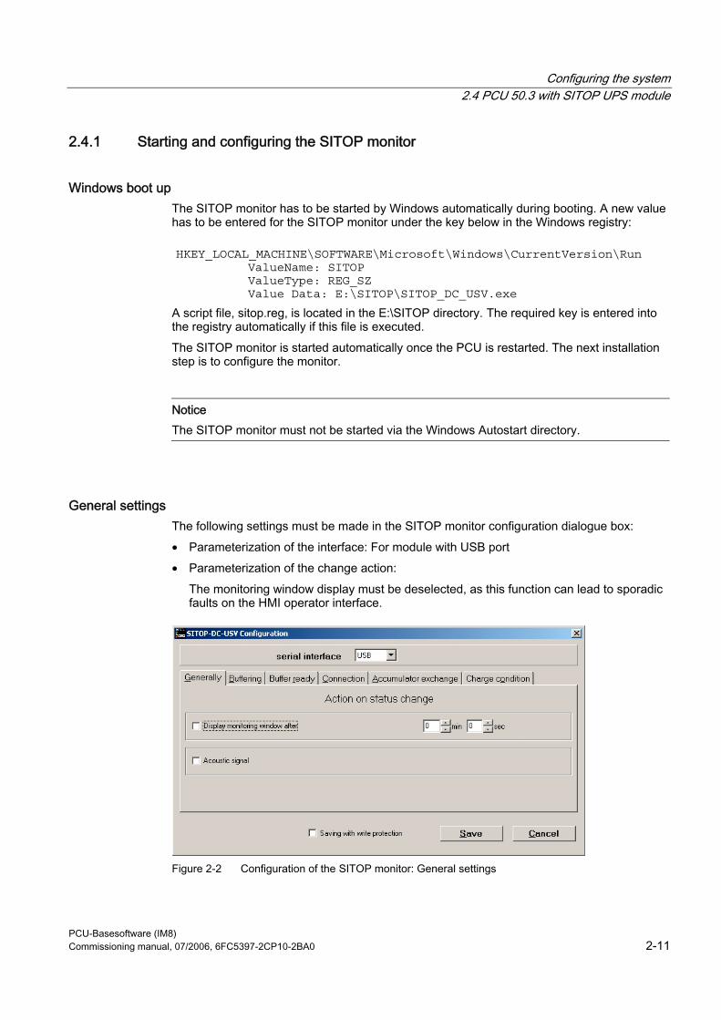
Configuring the system 2.4 PCU 50.3 with SITOP UPS module
PCU-Basesoftware (IM8) Commissioning manual, 07/2006, 6FC5397-2CP10-2BA0 2-11
2.4.1 Starting and configuring the SITOP monitor
Windows boot up The SITOP monitor has to be started by Windows automatically during booting. A new value has to be entered for the SITOP monitor under the key below in the Windows registry:
HKEY_LOCAL_MACHINE\SOFTWARE\Microsoft\Windows\CurrentVersion\Run ValueName: SITOP
ValueType: REG_SZ Value Data: E:\SITOP\SITOP_DC_USV.exe
A script file, sitop.reg, is located in the E:\SITOP directory. The required key is entered into the registry automatically if this file is executed. The SITOP monitor is started automatically once the PCU is restarted. The next installation step is to configure the monitor.
Notice The SITOP monitor must not be started via the Windows Autostart directory.
General settings The following settings must be made in the SITOP monitor configuration dialogue box: • Parameterization of the interface: For module with USB port • Parameterization of the change action:
The monitoring window display must be deselected, as this function can lead to sporadic faults on the HMI operator interface.
Figure 2-2 Configuration of the SITOP monitor: General settings
Configuring the system 2.4 PCU 50.3 with SITOP UPS module
PCU-Basesoftware (IM8) 2-12 Commissioning manual, 07/2006, 6FC5397-2CP10-2BA0
Parameterization of the SITOP monitor Enter the path of the program that ensures that HMI Advanced and the PCU shut down properly in the event of a power failure into the parameter area of the buffer. E:\SITOP\Shutdown.bat
Figure 2-3 Configuration of the SITOP monitor: Buffering settings
Alternatively, the following setting can be used: E:\Windows\system32\hmiexit.exe
2.4.2 Configuration of the SITOP UPS module
Buffering parameterization The UPS module can be used to select whether buffering should be completed after a predetermined period of time or not until the accumulator’s lowest discharge threshold (= maximum buffer time) has been reached. Both buffering parameterizations result from this.
"Maximum buffer time" mode (PCU basic software XP 08.00.00 or higher) This mode enables the system to be shut down in a time-optimized manner. The UPS module is synchronized with the shutdown of the operating system. Buffering is maintained until the operating system has been shut down. The operating system must shut down within a maximum of five minutes (including all applications). Otherwise, the UPS module buffers for the maximum buffer time (dependent on the accumulator state).
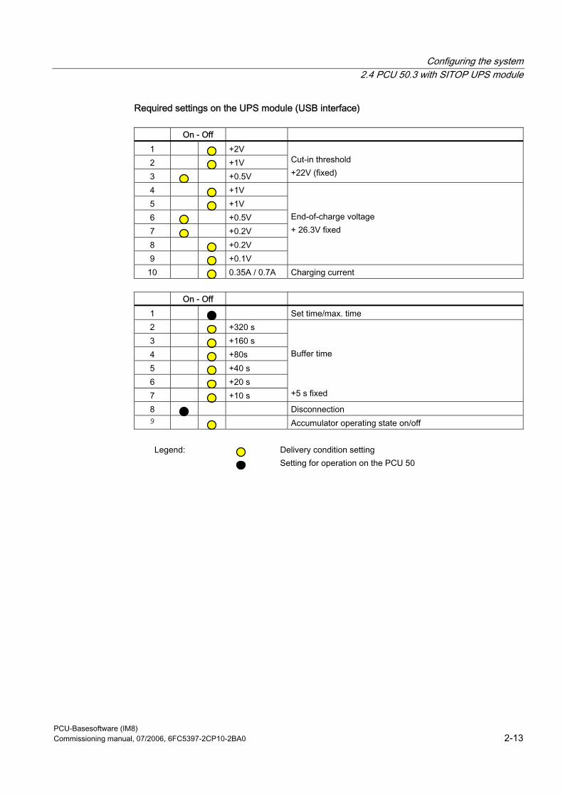
Configuring the system 2.4 PCU 50.3 with SITOP UPS module
PCU-Basesoftware (IM8) Commissioning manual, 07/2006, 6FC5397-2CP10-2BA0 2-13
Required settings on the UPS module (USB interface)
On - Off 1 +2V 2 +1V 3 +0.5V
Cut-in threshold +22V (fixed)
4 +1V 5 +1V 6 +0.5V 7 +0.2V 8 +0.2V 9 +0.1V
End-of-charge voltage + 26.3V fixed
10 0.35A / 0.7A Charging current
On - Off 1 Set time/max. time 2 +320 s 3 +160 s 4 +80s 5 +40 s 6 +20 s 7 +10 s
Buffer time +5 s fixed
8 Disconnection 9 Accumulator operating state on/off
Legend: Delivery condition setting
Setting for operation on the PCU 50
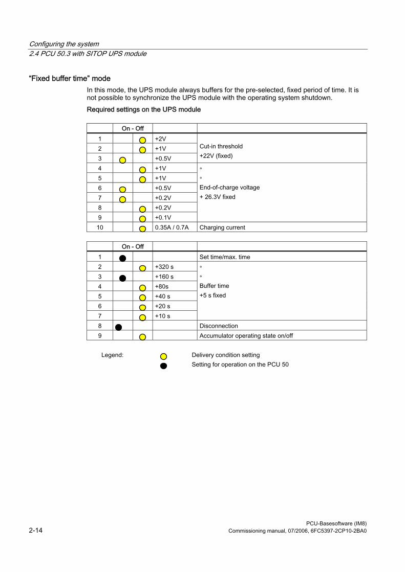
Configuring the system 2.4 PCU 50.3 with SITOP UPS module
PCU-Basesoftware (IM8) 2-14 Commissioning manual, 07/2006, 6FC5397-2CP10-2BA0
“Fixed buffer time” mode In this mode, the UPS module always buffers for the pre-selected, fixed period of time. It is not possible to synchronize the UPS module with the operating system shutdown. Required settings on the UPS module
On - Off
1 +2V 2 +1V 3 +0.5V
Cut-in threshold +22V (fixed)
4 +1V 5 +1V 6 +0.5V 7 +0.2V 8 +0.2V 9 +0.1V
∘ ∘ End-of-charge voltage + 26.3V fixed
10 0.35A / 0.7A Charging current
On - Off 1 Set time/max. time 2 +320 s 3 +160 s 4 +80s 5 +40 s 6 +20 s 7 +10 s
∘ ∘ Buffer time +5 s fixed
8 Disconnection 9 Accumulator operating state on/off
Legend: Delivery condition setting
Setting for operation on the PCU 50
Configuring the system 2.4 PCU 50.3 with SITOP UPS module
PCU-Basesoftware (IM8) Commissioning manual, 07/2006, 6FC5397-2CP10-2BA0 2-15
2.4.3 Configuration for exiting the HMI
HMI monitoring Exiting of the HMI advanced is monitored by a separate application, hmiexit.exe. This application is started implicitly via the shutdown.bat batch file. In case of error, the application forces the operating system to shut down. An error occurs if the HMI cannot be exited within the configured delay. Optionally, the parameters below can be set for hmiexit in file: E:\SITOP\hmiexit.ini. [Actions] #Waiting time in seconds for closing HMI Advanced applications Wait = 120 # Action on expiration of the waiting time ForceShutdown = True These default settings only need to be changed if it takes longer than 120 seconds to exit the HMI applications in an OEM installation. This configuration is not usually changed.
Configuring the EXIT button During production, the option to shut down the HMI via the EXIT button in the operating area menu should be disabled, as this function cannot be synchronized with the UPS module. The EXIT button is disabled by entering ExitButton=False in the Regie.ini file.
Hibernate The operating system’s hibernate mode is suspended when operating the UPS, as the USB interface always has to be active for the UPS module.
Note More information can be found in the product descriptions with the corresponding order number.

Configuring the system 2.4 PCU 50.3 with SITOP UPS module
PCU-Basesoftware (IM8) 2-16 Commissioning manual, 07/2006, 6FC5397-2CP10-2BA0
PCU-Basesoftware (IM8) Commissioning manual, 07/2006, 6FC5397-2CP10-2BA0 3-1
Install software and updates 33.1 Installing SINUMERIK products
Overview This chapter describes how to install additional software on the basis of the pre-installed PCE basic software or how to carry out an update. The description below is based on the delivery condition of the hardware and software components. The service desktop is used for the following tasks: • Installing HMI system software • Setting the running environment of the HMI system software • Checking the hard disk or version • Authorization for SIMATIC STEP 7
3.2 Installation via service desktop
Installing additional software The service desktop makes it possible to install system software or a software update. This mostly affects installation/update packages that are to be installed via the Windows network. Installation can be performed in two ways: • The installation/update package is stored in directory D:\INSTALL. When booting the
PCU the next time, the installation/update process is automatically started while booting. Only when the installation or update process is completed does normal boot manager continue and, if necessary, HMI software started.
• The installation/update process can be started from the service desktop directly by executing the installation/update package.
Using installation directories Several installation directories can be set to enable an operator setup to be executed automatically. Installation directories include the subdirectory D:\Install and the directories listed in the [SetupDirs] section of the E:\Windows\System32\HMIServe.ini parameters file. The "D:\Install" installation directory is preset there.
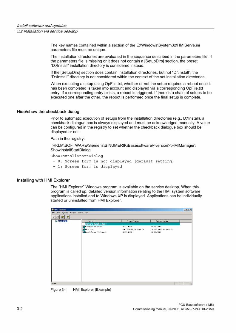
Install software and updates 3.2 Installation via service desktop
PCU-Basesoftware (IM8) 3-2 Commissioning manual, 07/2006, 6FC5397-2CP10-2BA0
The key names contained within a section of the E:\Windows\System32\HMIServe.ini parameters file must be unique. The installation directories are evaluated in the sequence described in the parameters file. If the parameters file is missing or it does not contain a [SetupDirs] section, the preset "D:\Install” installation directory is considered instead. If the [SetupDirs] section does contain installation directories, but not “D:\Install”, the “D:\Install” directory is not considered within the context of the set installation directories. When executing a setup using OpFile.txt, whether or not the setup requires a reboot once it has been completed is taken into account and displayed via a corresponding OpFile.txt entry. If a corresponding entry exists, a reboot is triggered. If there is a chain of setups to be executed one after the other, the reboot is performed once the final setup is complete.
Hide/show the checkback dialog Prior to automatic execution of setups from the installation directories (e.g., D:\Install), a checkback dialogue box is always displayed and must be acknowledged manually. A value can be configured in the registry to set whether the checkback dialogue box should be displayed or not. Path in the registry: 'HKLM\SOFTWARE\Siemens\SINUMERIK\Basesoftware\<version>\HMIManager\ ShowInstallStartDialog' ShowInstallStartDialog = 0: Screen form is not displayed (default setting) = 1: Screen form is displayed
Installing with HMI Explorer The “HMI Explorer” Windows program is available on the service desktop. When this program is called up, detailed version information relating to the HMI system software applications installed and to Windows XP is displayed. Applications can be individually started or uninstalled from HMI Explorer.
Figure 3-1 HMI Explorer (Example)
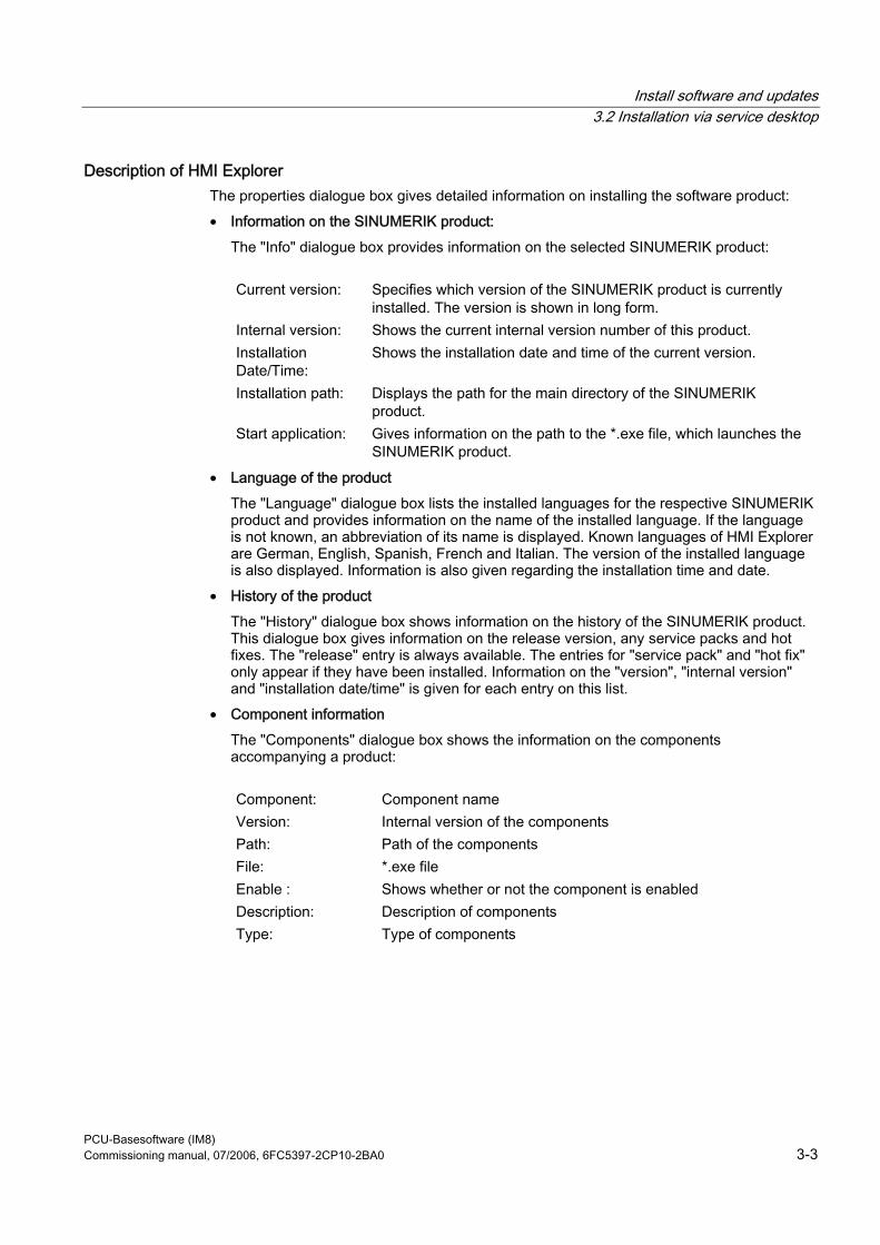
Install software and updates 3.2 Installation via service desktop
PCU-Basesoftware (IM8) Commissioning manual, 07/2006, 6FC5397-2CP10-2BA0 3-3
Description of HMI Explorer The properties dialogue box gives detailed information on installing the software product: • Information on the SINUMERIK product:
The "Info" dialogue box provides information on the selected SINUMERIK product:
Current version: Specifies which version of the SINUMERIK product is currently installed. The version is shown in long form.
Internal version: Shows the current internal version number of this product. Installation Date/Time:
Shows the installation date and time of the current version.
Installation path: Displays the path for the main directory of the SINUMERIK product.
Start application: Gives information on the path to the *.exe file, which launches the SINUMERIK product.
• Language of the product The "Language" dialogue box lists the installed languages for the respective SINUMERIK product and provides information on the name of the installed language. If the language is not known, an abbreviation of its name is displayed. Known languages of HMI Explorer are German, English, Spanish, French and Italian. The version of the installed language is also displayed. Information is also given regarding the installation time and date.
• History of the product The "History" dialogue box shows information on the history of the SINUMERIK product. This dialogue box gives information on the release version, any service packs and hot fixes. The "release" entry is always available. The entries for "service pack" and "hot fix" only appear if they have been installed. Information on the "version", "internal version" and "installation date/time" is given for each entry on this list.
• Component information The "Components" dialogue box shows the information on the components accompanying a product:
Component: Component name Version: Internal version of the components Path: Path of the components File: *.exe file Enable : Shows whether or not the component is enabled Description: Description of components Type: Type of components
Install software and updates 3.3 Installing and authorizing SIMATIC STEP 7
PCU-Basesoftware (IM8) 3-4 Commissioning manual, 07/2006, 6FC5397-2CP10-2BA0
Figure 3-2 "Components" Dialogue Box (Example)
3.3 Installing and authorizing SIMATIC STEP 7
Overview SIMATIC STEP 7 V5.3 SP2 can also be installed on the PCU.
Delivery item: SIMATIC STEP 7 V5.3 SP2 Components: SIMATIC STEP 7 V5.3 SP2 and
Add-on for SINUMERIK 810D/840D/840D sl/840Di sl Type of delivery: 2 installation CDs System requirements: PCU basic software V8.0 or higher
A network connection or a connection to a CD-ROM drive is required. Recommendation: Mouse port
Note The “MPI driver” package available on the PCU is part of the HMI software and must not be uninstalled!
Install software and updates 3.4 Installing additional languages under Windows XP (DVD)
PCU-Basesoftware (IM8) Commissioning manual, 07/2006, 6FC5397-2CP10-2BA0 3-5
Installation under Windows XP You must follow the installation sequence described here! 1. Booting up the PCU in the service desktop. 2. Access CD 1 (via network or external CD-ROM drive) call up SETUP.EXE in the root
directory there. 3. The installation proceeds with operator prompting. The installation directory for STEP 7
should be changed to F:\... where directory in F: can be freely selected. 4. The prompt for "Transfer license keys" must be answered with "No, transfer the license
keys later." The licensing is done after the installation of SINUMERIK AddOn. Once installation is complete, the PC will need to be rebooted. During boot up, select the service desktop again.
5. Switch to the SINUMERIK_Add_on directory on CD 2 and call up SETUP.EXE there. The installation proceeds with operator prompting. Once installation is complete, the PC will need to be rebooted. During boot up, select the service desktop again.
6. Start the link "STEP7 authorizing" on the service desktop. This authorizes STEP 7 and starting can now be done from the HMI Advanced operator interface (STEP 7 appears as its own operating area on the expansion bar of the area menu, protected with protection level 3). The following entries are made automatically in F:\Add_on\oemframe.ini: [s7tgtopx] ; with HMI Advanced: eliminate minimize/maximize buttons ; of the Step7 window WindowStyle_Off=196608 ; with HMI Advanced: switch to previous task when Step7 is terminated nSwitchToTaskAfterTermination= -2 These entries may also need to be modified in OEM configurations.
3.4 Installing additional languages under Windows XP (DVD)
Use Use the SINUMERIK service pack recovery Media WIN XP ProEmbSys SP2 to: • Subsequently install Windows components • Re-establish the delivery condition of the PCU without HMI Advanced • To install other languages for Windows XP
Install software and updates 3.4 Installing additional languages under Windows XP (DVD)
PCU-Basesoftware (IM8) 3-6 Commissioning manual, 07/2006, 6FC5397-2CP10-2BA0
Contents of the DVD There are the following directories on the DVD:
Contents Contents 1_WIN_Components Windows XP ProEmbSys SP2
Windows XP ProEmbSys operating system, incl. SP2 for post-installation of software components that are no longer located on the PCU.
2_XP_Base Symantec Ghost Image for PCU 50.3 and EBOOT • Ghost image of the delivery condition of the PCU base
software Windows XP for PCU 50.3 without HMI Advanced and other application software.
• Ghost image for creating an "Emergency Boot System" (identical to the directory D:\EBOOT on the PCU)
3_MUI_1 Chinese (simplified) Traditional Chinese Japanese Korean Romanian Slovakian
4_MUI_2 Danish German French Dutch Italian Spanish Swedish
5_MUI_3 Brazilian Portuguese Finnish Polish Russian Czech Turkish Hungarian
EULA TERMS Certificate of authenticity
Contained Not contained
Install software and updates 3.4 Installing additional languages under Windows XP (DVD)
PCU-Basesoftware (IM8) Commissioning manual, 07/2006, 6FC5397-2CP10-2BA0 3-7
Installing languages To install additional languages, proceed as follows: 1. If no DVD drive is directly connected via a USB port, the DVD can be accessed via a
network to a released DVD disk drive via "Explorer" → "Tools" → "Map Network Drive". The letter G should be selected as the drive letter.
2. Select the directory with the appropriate language, the program "MUISETUP.EXE" starts. After accepting the licensing conditions, you can start the installation procedure with "Continue". A list of all of the pre-installed languages and the languages available on the DVD is displayed.
3. Now the desired languages can be installed/uninstalled by inserting or deleting a check mark in front of the language.
4. Other settings include: – Choice of language version for the standard user/new user – The language for programs without Unicode support must be set to "English (US)". – The font set must also be set to "English (US)".
5. After confirming with "OK," the installation begins. Many languages (e.g. Chinese) require system files that are also located on the DVD. If the installation drive is other than the recommended "G:" the "Windows XP Professional Service Pack 2 CD" or the "Windows XP Professional CD" may be required. The path name must then be changed accordingly.
6. After successful installation, a reboot may be requested depending on the language.
Note • The choice can only be made from among the languages that were previously
installed on the PCU. • The new language of Windows XP only goes into effect if the user logs in again after
the changeover or the PCU is turned off and then on again. • The language of the HMI Advanced operator interface is independent of this. It is set
independently of this under "Start-up" → "HMI" → "Change Language".
Install software and updates 3.4 Installing additional languages under Windows XP (DVD)
PCU-Basesoftware (IM8) 3-8 Commissioning manual, 07/2006, 6FC5397-2CP10-2BA0
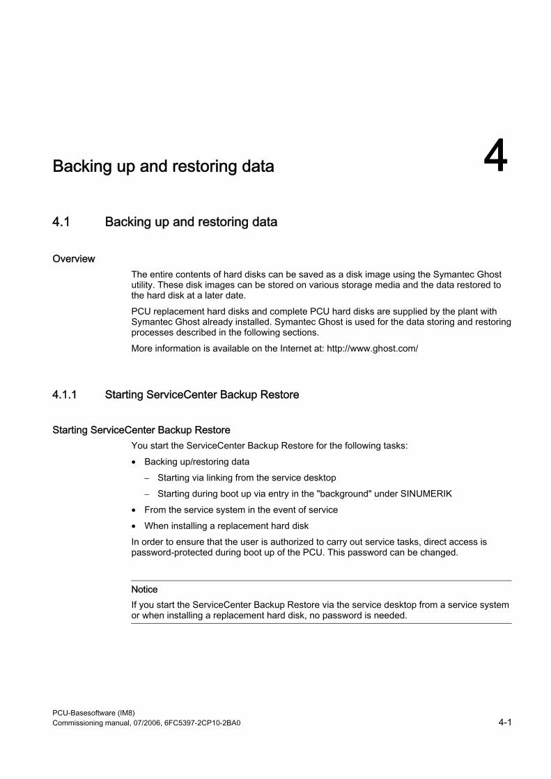
PCU-Basesoftware (IM8) Commissioning manual, 07/2006, 6FC5397-2CP10-2BA0 4-1
Backing up and restoring data 44.1 Backing up and restoring data
Overview The entire contents of hard disks can be saved as a disk image using the Symantec Ghost utility. These disk images can be stored on various storage media and the data restored to the hard disk at a later date. PCU replacement hard disks and complete PCU hard disks are supplied by the plant with Symantec Ghost already installed. Symantec Ghost is used for the data storing and restoring processes described in the following sections. More information is available on the Internet at: http://www.ghost.com/
4.1.1 Starting ServiceCenter Backup Restore
Starting ServiceCenter Backup Restore You start the ServiceCenter Backup Restore for the following tasks: • Backing up/restoring data
– Starting via linking from the service desktop – Starting during boot up via entry in the "background" under SINUMERIK
• From the service system in the event of service • When installing a replacement hard disk In order to ensure that the user is authorized to carry out service tasks, direct access is password-protected during boot up of the PCU. This password can be changed.
Notice If you start the ServiceCenter Backup Restore via the service desktop from a service system or when installing a replacement hard disk, no password is needed.
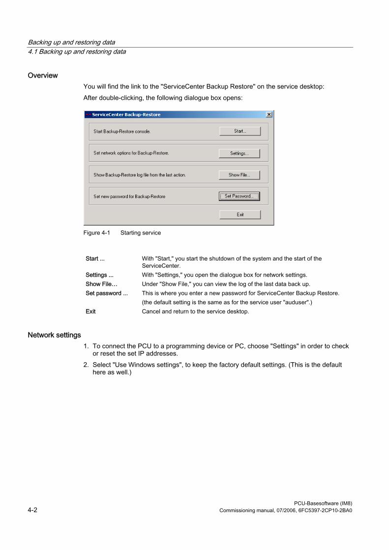
Backing up and restoring data 4.1 Backing up and restoring data
PCU-Basesoftware (IM8) 4-2 Commissioning manual, 07/2006, 6FC5397-2CP10-2BA0
Overview You will find the link to the "ServiceCenter Backup Restore" on the service desktop: After double-clicking, the following dialogue box opens:
Figure 4-1 Starting service
Start ... With "Start," you start the shutdown of the system and the start of the
ServiceCenter. Settings ... With "Settings," you open the dialogue box for network settings. Show File… Under "Show File," you can view the log of the last data back up. Set password ... This is where you enter a new password for ServiceCenter Backup Restore.
(the default setting is the same as for the service user "auduser".) Exit Cancel and return to the service desktop.
Network settings 1. To connect the PCU to a programming device or PC, choose "Settings" in order to check
or reset the set IP addresses. 2. Select "Use Windows settings", to keep the factory default settings. (This is the default
here as well.)
Backing up and restoring data 4.1 Backing up and restoring data
PCU-Basesoftware (IM8) Commissioning manual, 07/2006, 6FC5397-2CP10-2BA0 4-3
Figure 4-2 Network Settings
3. Select "Use the following settings", to set a new configuration: – With "Obtain an IP address automatically (DHCP)," you receive an automatically
assigned IP address from your DHCP server. – With "Use the following IP address," you enter an IP address in the range of
192.168.214.250 – 254 using subnet screen form 255.255.255.0.
Note Changes to the network settings that you make here only become effective after you reboot the PCU. If you make changes to the network settings from service desktop, they are immediately adopted.
See also System settings (Page 1-3) Other details for setting the IP address: References: Commissioning manual Thin client configuration
Backing up and restoring data 4.1 Backing up and restoring data
PCU-Basesoftware (IM8) 4-4 Commissioning manual, 07/2006, 6FC5397-2CP10-2BA0
4.1.2 Starting applications in service mode
Starting other applications If other applications are to be started in service mode, enter them with their complete path in the [OEMRun] section in the file WINBOM.INI:
How Do I Starting the "notepad" program. [OEMRunOnce] "Start WinVnc", "x:\I386\system32\StartWinVnc.exe" "Check Password","x:\I386\system32\CheckPEPwd.exe" [OEMRun] "Start Backup/Restore", "x:\I386\system32\GhostOrder.exe" "notepad","e:\windows\notepad.exe" All other entries must not be changed.
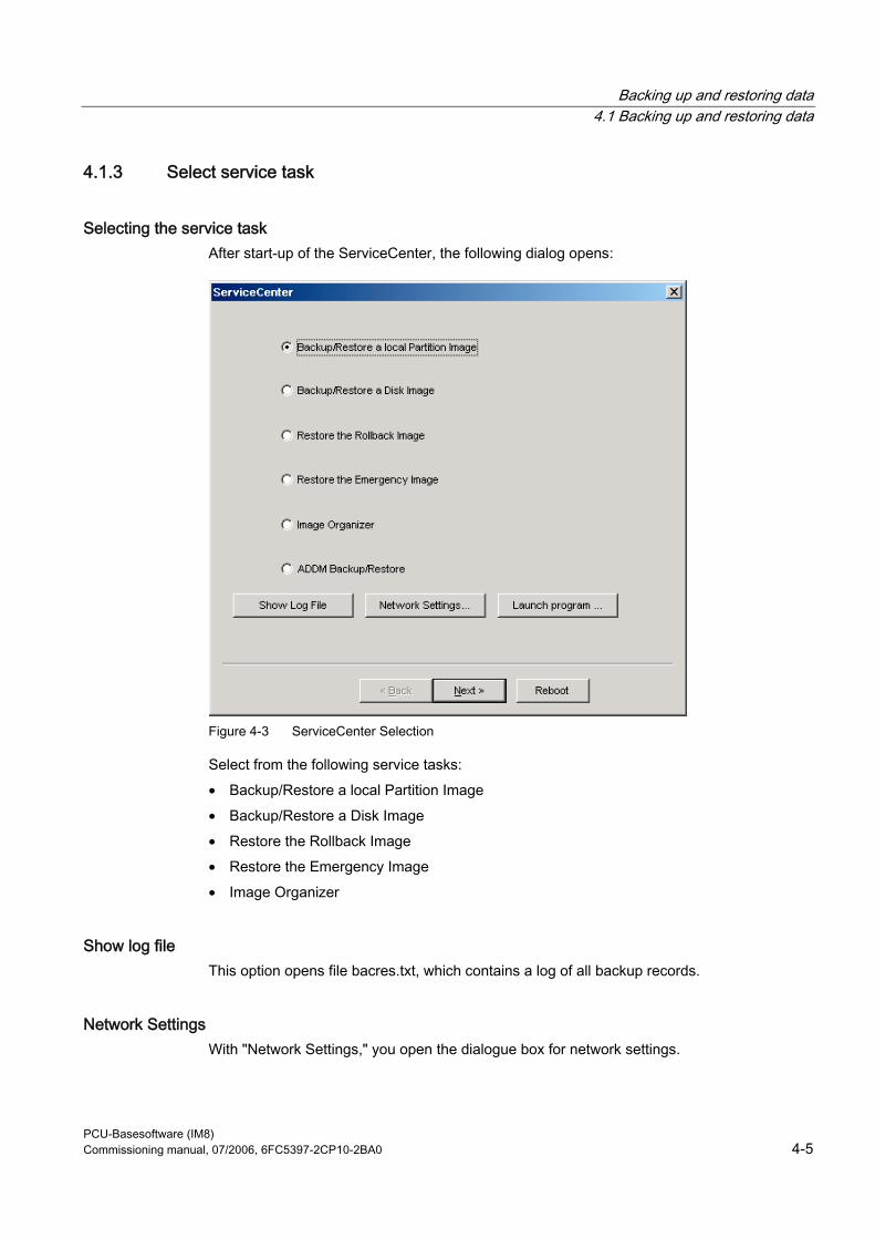
Backing up and restoring data 4.1 Backing up and restoring data
PCU-Basesoftware (IM8) Commissioning manual, 07/2006, 6FC5397-2CP10-2BA0 4-5
4.1.3 Select service task
Selecting the service task After start-up of the ServiceCenter, the following dialog opens:
Figure 4-3 ServiceCenter Selection
Select from the following service tasks: • Backup/Restore a local Partition Image • Backup/Restore a Disk Image • Restore the Rollback Image • Restore the Emergency Image • Image Organizer
Show log file This option opens file bacres.txt, which contains a log of all backup records.
Network Settings With "Network Settings," you open the dialogue box for network settings.
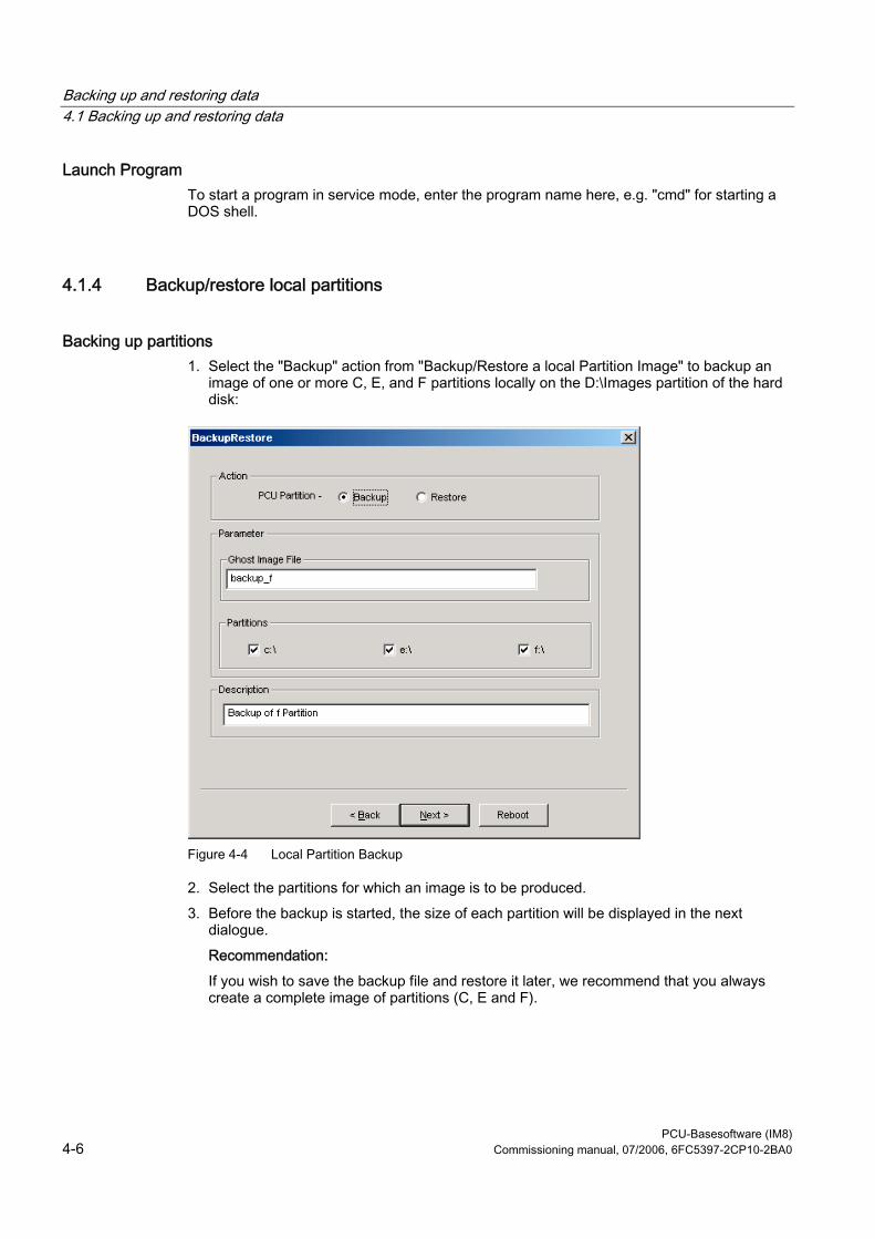
Backing up and restoring data 4.1 Backing up and restoring data
PCU-Basesoftware (IM8) 4-6 Commissioning manual, 07/2006, 6FC5397-2CP10-2BA0
Launch Program To start a program in service mode, enter the program name here, e.g. "cmd" for starting a DOS shell.
4.1.4 Backup/restore local partitions
Backing up partitions 1. Select the "Backup" action from "Backup/Restore a local Partition Image" to backup an
image of one or more C, E, and F partitions locally on the D:\Images partition of the hard disk:
Figure 4-4 Local Partition Backup
2. Select the partitions for which an image is to be produced. 3. Before the backup is started, the size of each partition will be displayed in the next
dialogue. Recommendation: If you wish to save the backup file and restore it later, we recommend that you always create a complete image of partitions (C, E and F).
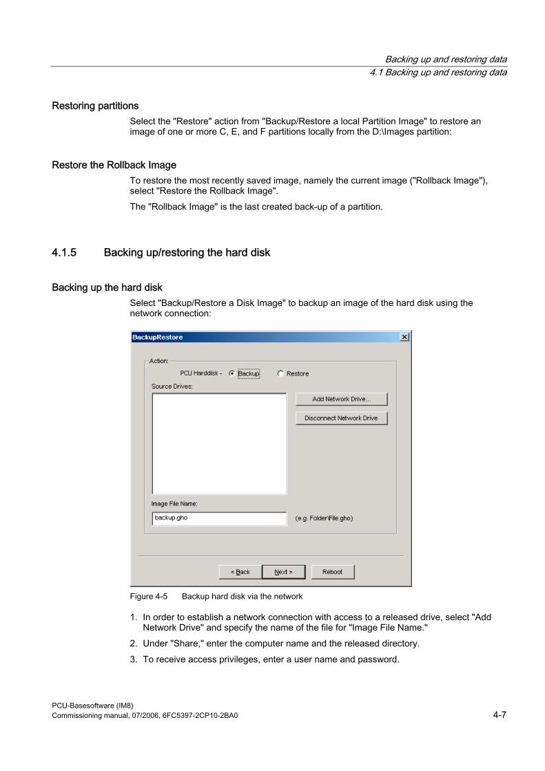
Backing up and restoring data 4.1 Backing up and restoring data
PCU-Basesoftware (IM8) Commissioning manual, 07/2006, 6FC5397-2CP10-2BA0 4-7
Restoring partitions Select the "Restore" action from "Backup/Restore a local Partition Image" to restore an image of one or more C, E, and F partitions locally from the D:\Images partition:
Restore the Rollback Image To restore the most recently saved image, namely the current image ("Rollback Image"), select "Restore the Rollback Image". The "Rollback Image" is the last created back-up of a partition.
4.1.5 Backing up/restoring the hard disk
Backing up the hard disk Select "Backup/Restore a Disk Image" to backup an image of the hard disk using the network connection:
Figure 4-5 Backup hard disk via the network
1. In order to establish a network connection with access to a released drive, select "Add Network Drive" and specify the name of the file for "Image File Name."
2. Under "Share," enter the computer name and the released directory. 3. To receive access privileges, enter a user name and password.
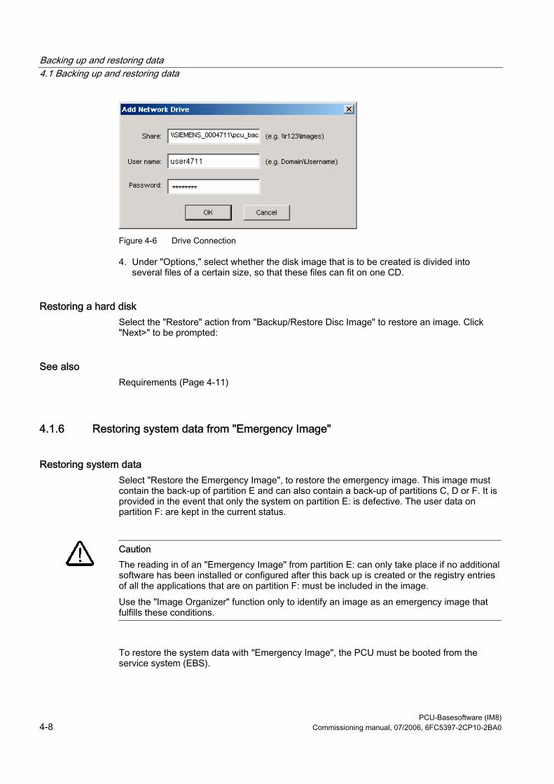
Backing up and restoring data 4.1 Backing up and restoring data
PCU-Basesoftware (IM8) 4-8 Commissioning manual, 07/2006, 6FC5397-2CP10-2BA0
Figure 4-6 Drive Connection
4. Under "Options," select whether the disk image that is to be created is divided into several files of a certain size, so that these files can fit on one CD.
Restoring a hard disk Select the "Restore" action from "Backup/Restore Disc Image" to restore an image. Click "Next>" to be prompted:
See also Requirements (Page 4-11)
4.1.6 Restoring system data from "Emergency Image"
Restoring system data Select "Restore the Emergency Image", to restore the emergency image. This image must contain the back-up of partition E and can also contain a back-up of partitions C, D or F. It is provided in the event that only the system on partition E: is defective. The user data on partition F: are kept in the current status.
Caution The reading in of an "Emergency Image" from partition E: can only take place if no additional software has been installed or configured after this back up is created or the registry entries of all the applications that are on partition F: must be included in the image. Use the "Image Organizer" function only to identify an image as an emergency image that fulfills these conditions.
To restore the system data with "Emergency Image", the PCU must be booted from the service system (EBS).
Backing up and restoring data 4.2 Saving the HMI Advanced environment
PCU-Basesoftware (IM8) Commissioning manual, 07/2006, 6FC5397-2CP10-2BA0 4-9
Manage images Select “Image Organizer” to mark out one image contained in the displayed list as the emergency image, or to delete an existing image.
See also Creating the service system for PCU (Page 4-10)
4.2 Saving the HMI Advanced environment
Setting the original SINUMERIK HMI environment The "Original SINUMERIK HMI Environ" function is available as a script file on the service desktop. The original delivery condition is set up, i.e., the contents of the directories below are saved, when this function is executed: • C:\RUNOEM • F:\ADD_ON • F:\OEM • F:\USER Then the directories are cleared.
Setting the current SINUMERIK HMI environment The "Current SINUMERIK HMI Environ" function is available as a script file on the service desktop. When this function is executed, restoration of the original settings is canceled, i.e., the saved directory contents are copied back.
Backing up and restoring data 4.3 Creating the service system for PCU
PCU-Basesoftware (IM8) 4-10 Commissioning manual, 07/2006, 6FC5397-2CP10-2BA0
4.3 Creating the service system for PCU
Use In case servicing is needed, create a portable service system as an "Emergency Boot System" (EBS) on a USB memory store on the basis of WinPE. Recommendation: Preferably, the SIMATIC PC USB-FlashDrive with 512 MB storage capacity should be used.
Creating a service system The Ghost image is available on the hard disk under D:\Eboot in order to create the service system for a PCU 50.3 on a USB memory store. Please proceed as follows: 1. Start the PCU 50.3 in the service mode. 2. Plug a USB memory store with at least 256 MB into one of the four USB ports of the PCU
50.3. 3. Launch Ghost32.exe in directory E:\Tools 4. Select Ghost: Local → Disk → From Image. As the source, select D:\Eboot\eboot.gho and
as the destination select the USB memory store (recognizable by its storage capacity). Results: After successfully transferring eboot.gho to the USB memory store, the service system for the PCU is ready to use.
Using the same procedure, create a service system on a PG/PC. For this, the Symantec Ghost program must be installed on the PG/PC.
Booting up the service system 1. Plug the EBS into one of the rear USB ports of the PCU 50.3. 2. Press the <ALARM CANCEL> key on the operator panel or the <ESC> key on an
external keyboard while the BIOS of the PCU 50 is booting up in order to display the "Boot Menu".
3. Select the entry "USB-HDD: XXX " from the list of available media. Results: The PCU boots up from the service system and the ServiceCenter starts.
4. First select "Start" to start the ServiceCenter and then "Backup/Restore Disk Image", to restore the hard disk using the disk image.
Backing up and restoring data 4.4 Connecting a PG/PC to the PCU in the system network
PCU-Basesoftware (IM8) Commissioning manual, 07/2006, 6FC5397-2CP10-2BA0 4-11
Notice During booting: • The boot-up of the PCU from the EBS via the front USB interface of a directly
connected OP is also possible but it is considerably slower (=USB V1.1; rear USB 2.0).
• It is not possible to boot up the PCU from the EBS via the USB interface of a TCU. • It is not possible to save network settings on the EBS. • The EBS is not capable of functioning if a DVI monitor is connected directly to the DVI
interface of the PCU 50.3. VGA mode is only possible via a DVI → VGA adapter.
See also Backing up/restoring the hard disk (Page 4-7)
4.4 Connecting a PG/PC to the PCU in the system network
Applications For the following applications, you need a connection in the system network between the PCU and a PG/PC: • To store a backup image from the hard disk of a PCU 50 on a PG/PC. • To restore a PCU 50 hard disk via the CD-ROM drive of a PG/PC. • To commission a replacement hard disk.
4.4.1 Requirements
Overview The following figures show the typical connection options in the system network: • PCU to "Eth 2" with service PG/PC, directly, using a crossed Ethernet cable • PCU to "Eth 2" with service PG/PC, via a switch, using an un-crossed Ethernet cable If you want to connect the service PG/PC via a company network (Eth 1), contact your network service center.
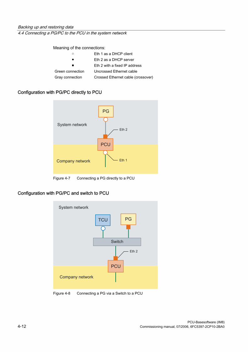
Backing up and restoring data 4.4 Connecting a PG/PC to the PCU in the system network
PCU-Basesoftware (IM8) 4-12 Commissioning manual, 07/2006, 6FC5397-2CP10-2BA0
Meaning of the connections: ○ Eth 1 as a DHCP client ● Eth 2 as a DHCP server ■ Eth 2 with a fixed IP address
Green connection Gray connection
Uncrossed Ethernet cable Crossed Ethernet cable (crossover)
Configuration with PG/PC directly to PCU
Figure 4-7 Connecting a PG directly to a PCU
Configuration with PG/PC and switch to PCU
Figure 4-8 Connecting a PG via a Switch to a PCU
Backing up and restoring data 4.4 Connecting a PG/PC to the PCU in the system network
PCU-Basesoftware (IM8) Commissioning manual, 07/2006, 6FC5397-2CP10-2BA0 4-13
Note If a PCU is switched off and on again without its own OP/TP including TCU, and if the PCU boot-up is supposed to take place from the service system (EBS), an external VGA monitor and keyboard are needed in order to operate the PCU.
Basic procedure On the PG/PC with Windows XP: • Connecting a PG/PC to a PCU 50.3 as per one of the configurations in the figures above. • The network protocol used is: TCP/IP.
TCP/IP is already pre-configured in the basic PCU software. • Setting up IP addresses on the same subnetwork. • Releasing a directory on the PG/PC for network access. On the PCU under WinPE: • Start the ServiceCenter under WinPE on the PCU 50.3. • Establish a network connection to the released directory of the PG/PC. • Using the "Backup" function, a ghost image of the PCU hard disk is saved in the released
directory of the PG/PC in the event of a need for service. • With the "Restore" function, the hard disk of the PCU 50.3 is restored from a ghost image
in the released directory of the PG/PC.
See also Backing up/restoring the hard disk (Page 4-7)
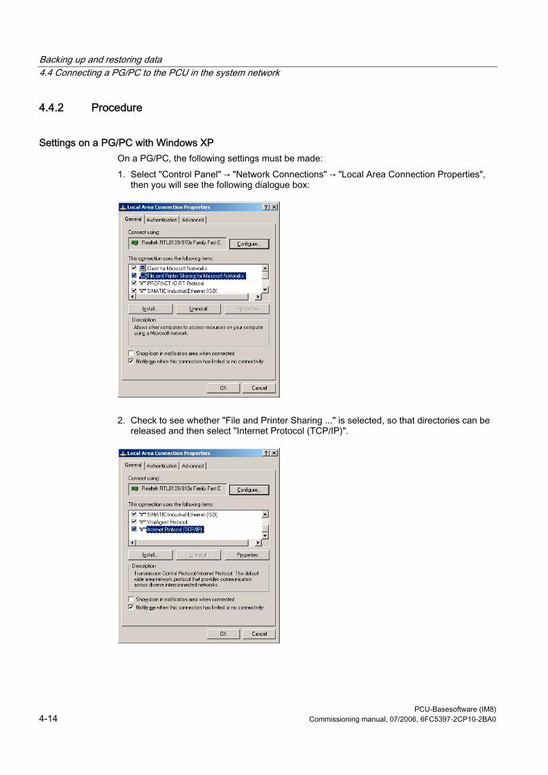
Backing up and restoring data 4.4 Connecting a PG/PC to the PCU in the system network
PCU-Basesoftware (IM8) 4-14 Commissioning manual, 07/2006, 6FC5397-2CP10-2BA0
4.4.2 Procedure
Settings on a PG/PC with Windows XP On a PG/PC, the following settings must be made: 1. Select "Control Panel" → "Network Connections" → "Local Area Connection Properties",
then you will see the following dialogue box:
2. Check to see whether "File and Printer Sharing ..." is selected, so that directories can be released and then select "Internet Protocol (TCP/IP)".
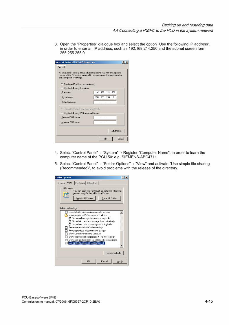
Backing up and restoring data 4.4 Connecting a PG/PC to the PCU in the system network
PCU-Basesoftware (IM8) Commissioning manual, 07/2006, 6FC5397-2CP10-2BA0 4-15
3. Open the "Properties" dialogue box and select the option "Use the following IP address", in order to enter an IP address, such as 192.168.214.250 and the subnet screen form 255.255.255.0.
4. Select "Control Panel" → "System" → Register "Computer Name", in order to learn the computer name of the PCU 50: e.g. SIEMENS-ABC4711
5. Select "Control Panel" → "Folder Options" → "View" and activate "Use simple file sharing (Recommended)", to avoid problems with the release of the directory.
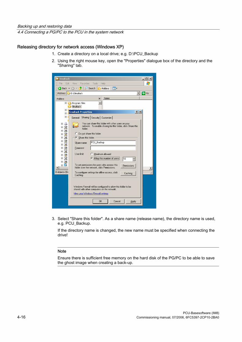
Backing up and restoring data 4.4 Connecting a PG/PC to the PCU in the system network
PCU-Basesoftware (IM8) 4-16 Commissioning manual, 07/2006, 6FC5397-2CP10-2BA0
Releasing directory for network access (Windows XP) 1. Create a directory on a local drive; e.g. D:\PCU_Backup 2. Using the right mouse key, open the "Properties" dialogue box of the directory and the
"Sharing" tab.
3. Select "Share this folder". As a share name (release name), the directory name is used, e.g. PCU_Backup. If the directory name is changed, the new name must be specified when connecting the drive!
Note Ensure there is sufficient free memory on the hard disk of the PG/PC to be able to save the ghost image when creating a back-up.
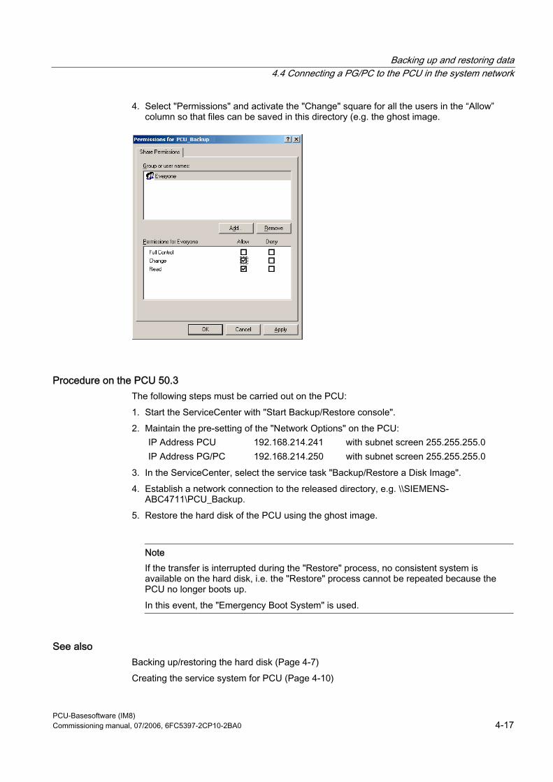
Backing up and restoring data 4.4 Connecting a PG/PC to the PCU in the system network
PCU-Basesoftware (IM8) Commissioning manual, 07/2006, 6FC5397-2CP10-2BA0 4-17
4. Select "Permissions" and activate the "Change" square for all the users in the “Allow” column so that files can be saved in this directory (e.g. the ghost image.
Procedure on the PCU 50.3 The following steps must be carried out on the PCU: 1. Start the ServiceCenter with "Start Backup/Restore console". 2. Maintain the pre-setting of the "Network Options" on the PCU:
IP Address PCU 192.168.214.241 with subnet screen 255.255.255.0 IP Address PG/PC 192.168.214.250 with subnet screen 255.255.255.0
3. In the ServiceCenter, select the service task "Backup/Restore a Disk Image". 4. Establish a network connection to the released directory, e.g. \\SIEMENS-
ABC4711\PCU_Backup. 5. Restore the hard disk of the PCU using the ghost image.
Note If the transfer is interrupted during the "Restore" process, no consistent system is available on the hard disk, i.e. the "Restore" process cannot be repeated because the PCU no longer boots up. In this event, the "Emergency Boot System" is used.
See also Backing up/restoring the hard disk (Page 4-7) Creating the service system for PCU (Page 4-10)
Backing up and restoring data 4.5 Commissioning the replacement hard disk
PCU-Basesoftware (IM8) 4-18 Commissioning manual, 07/2006, 6FC5397-2CP10-2BA0
4.5 Commissioning the replacement hard disk
Overview The mechanical and electrical steps involved in replacing the PCU 50.3 hard disk are described in: References: Equipment manual "Operating Components"
Note The replacement hard disk is delivered without the Windows operating system and without HMI system software. The ServiceCenter incl. Symantec Ghost is installed at the factory on each PCU and on the replacement hard disk.
Creating a hard disk backup (disk image) The entire contents of hard disks can be saved as a disk image file using the Symantec Ghost utility. This "disk image" can be stored on various types of media for later restoration of the hard disk, e.g. on CD-ROM or a network drive.
Commissioning the replacement hard disk After installing the replacement hard disk, the Ethernet interfaces of the PCU are preset in the following manner: • Ethernet 1 (Company Network) as a standard DHCP client • Ethernet 2 (System Network) as a SINUMERIK DHCP server with the fixed IP address
192.168.214.241 and subnet screen 255.255.255.0 To commission the hard disk, proceed as follows: 1. Connect a PG/PC as per the recommended configurations. 2. Start the ServiceCenter and select "Restore Disk Image".
Note If the transfer is interrupted during the "Restore" process, no consistent system is available on the hard disk, i.e. the "Restore" process cannot be repeated because the PCU no longer boots up. In this event, the "Emergency Boot System" is used.
Backing up and restoring data 4.5 Commissioning the replacement hard disk
PCU-Basesoftware (IM8) Commissioning manual, 07/2006, 6FC5397-2CP10-2BA0 4-19
See also Requirements (Page 4-11) Backing up/restoring the hard disk (Page 4-7) Creating the service system for PCU (Page 4-10)

Backing up and restoring data 4.5 Commissioning the replacement hard disk
PCU-Basesoftware (IM8) 4-20 Commissioning manual, 07/2006, 6FC5397-2CP10-2BA0
PCU-Basesoftware (IM8) Commissioning manual, 07/2006, 6FC5397-2CP10-2BA0 5-1
Service and diagnostics 55.1 PCU Hardware Diagnostics
Purpose The PCU hardware supports the diagnostics of important system components via an integrated "safecard", which is designated as a Safecard-On-Motherboard (SOM). These diagnostic functions are only evaluated by systems with HMI Advanced. The fault statuses of the hardware are reported in the form of alarms via the operator interface of HMI Advanced. This allows for visualization of the data in HMI Advanced and external evaluation.
Monitored Parameters The following physical parameters of the PCU 50.3 hardware are monitored: • CPU temperature • Housing temperature • I/O chip temperature • Speed of the two housing fans • S.M.A.R.T - status of the hard disk
Logging errors without HMI Advanced The PCU hardware monitor logs all hardware errors in the Windows event log so that the errors can be output even for a PCU without HMI Base installed. The alarms are output in the log under "Control Panel" → "Administrative Tools" → "Event Viewer".
Note The PLC interface of HMI Advanced is located in DB 10 of the PLC program and is supplied by the PCU hardware monitor in the event of a failure.
Service and diagnostics 5.2 Enabling/disabling error log during boot up
PCU-Basesoftware (IM8) 5-2 Commissioning manual, 07/2006, 6FC5397-2CP10-2BA0
See also Commissioning the replacement hard disk (Page 4-18) Description of the alarms: Diagnostics Manual SINUMERIK Replacement part description: Manual for Operating Components, Chapter PCU 50.3 Replacement Parts
5.2 Enabling/disabling error log during boot up
Application Each time the system is booted up, information is written to a block in the file D:\$$Base.log, which contains the date, time and nature of administrative interventions. Information about the booting controlled by the HMI Manager, can be displayed on the screen and written to log file D:\$$Base.log.
Output in log file The output is controlled by registry values: • Type of information
The type of information to be output is set via registry value “HKLM\SOFTWARE\Siemens\SINUMERIK\Basic software\<version>\HMI Manager\InfoLevel”: InfoLevel (DWORD)
= 1: Mandatory information is output (default setting) = 2: Mandatory and supplementary information is output = 3: Mandatory, supplementary and trace information is output
(InfoLevel <= 0 is treated as InfoLevel == 1; InfoLevel <= 3 is treated as InfoLevel == 3)
• Outputting information to the screen
Whether the information is also to be displayed on the screen (as well as being output to the log file) is set via registry value 'HKLM\SOFTWARE\Siemens\SINUMERIK\Basic software\<version>\HMI Manager\ShowInfo': ShowInfo (DWORD)
= 0: Displays the mandatory information,
no display of the supplemental and trace information = 1: Mandatory, supplementary and trace information is displayed (default)
PCU-Basesoftware (IM8) Commissioning manual, 07/2006, 6FC5397-2CP10-2BA0 A-1
List of Abbreviations AA.1 Abbreviations CF Compact Flash: Memory card DCK Direct Control Keys Direct control key DHCP Dynamic Host Configuration Protocol: Dynamic assignment of an IP address and other configuration
parameters on a computer in a network DNS Domain Name System: Conversion of domain names into IP addresses HMI Human Machine Interface: Operator interface IRT Isochronous Realtime (Ethernet) MCP Machine Control Panel Machine control panel MPI Multi-Point Interface Multiple interface MUI Multilanguage User Interface NCK Numerical Control Kernel: NC kernel with block preparation, travel range, etc. NCU Numerical Control Unit: NCK hardware unit NRT Non-Realtime (Ethernet) NTFS New Technology File System NTP Network Time Protocol: Standard for synchronizing clocks in the entire network NTPD NTP Daemon:
Utility that runs in the background and does not have to be started by the user. PCU PC Unit: Computer unit PG Programming device PLC Programmable Logic Control: PLC PROFIBUS Process Field Bus: Standard for the fieldbus communication in automation systems RAM Random Access Memory: Program memory which can be read and written into RDY Ready Ready TCU Thin Client Unit UDP User Datagram Protocol: NTP is mostly processed via UDP. USB Universal Serial Bus USV Uninterruptible power supply (UPS) UTC Universal Time, Coordinated Coordinated universal time VNC Virtual Network Computing

List of Abbreviations A.1 Abbreviations
PCU-Basesoftware (IM8) A-2 Commissioning manual, 07/2006, 6FC5397-2CP10-2BA0
PCU-Basesoftware (IM8) Commissioning manual, 07/2006, 6FC5397-2CP10-2BA0 Index-1
Index
A Activating the firewall, 1-4
B Backup time, 2-12 Backup/Restore
Disc image, 4-7 Partition image, 4-6 Rollback image, 4-7
BIOS Changing default setting, 1-17 Start setup, 1-13 System parameters, 1-14
Boot screen replace, 2-4 Storage location, 2-4
C Configuring the operator interface, 2-2
E Emergency boot system, 4-10 Emergency image, 4-8, 4-14 Enabling the log, 5-2 Error log, 5-2
H HMI monitoring, 2-15
I Installing SIMATIC STEP 7, 3-4
M Mains-fed operation, 3-1
Multilingual User Interface (MUI), 3-5
N Network settings, 4-2 NTFS file system, 1-2
P Partitioning the hard disk, 1-2 PCU
Change name, 2-1 Checking the hard disk, 5-1 Delivery condition, 1-1 IP address, 2-1
PCU name default setting, 1-3 PG in the system network, 4-11
R Recovery Media, 3-5 Replacement hard disk, 4-18 Restoring data, 4-1 Restoring system data, 4-8, 4-14
S Save data, 4-1 Saving the HMI environment, 4-9 Select language (MUI), 2-2 Service Desktop
Background, 2-5 install, 3-1 starting, 4-2
Service system for PCU, 4-10 Service tasks, 4-5 SITOP Monitor
Configure, 2-11 Parameterizing, 2-12
Software Components, 1-3 install, 3-1
Starting OEM programs, 2-9
Index
PCU-Basesoftware (IM8) Index-2 Commissioning manual, 07/2006, 6FC5397-2CP10-2BA0
Starting ServiceCenter, 4-2 System settings, 1-1, 1-4
U UPS module (SITOP), 2-10 USB memory, 4-10 User group, 1-6 User presetting, 1-4 User type, 1-5
V Version software components, 1-3
W Windows language (MUI), 2-2
To Siemens AG
Suggestions Corrections
A&D MC MS Postfach 3180
For Publication/Manual: SINUMERIK 840D sl/840Di sl
SINUMERIK 840D/810D
91050 ERLANGEN, GERMANY Tel.: +49 (0)180 5050 - 222 [Hotline] Fax: +49 (0) 9131 98 - 63315 [Documentation] E-mail: [email protected]
CNC Part 5 (Basesoftware) Manufacturer / Service Documentation
From
Name:
Commissioning Manual Order No.: 6FC5397-2CP10-2BA0 Edition: 07/2006
Address of your company/department
Address:
ZIP code: ____________ City:
Phone: __________ /
Fax: ________ /
Should you come across any printing errors when reading this publication, please notify us on this sheet. Ebenso dankbar sind wir für Anregungen und Verbesserungen.
Suggestions and/or corrections

Related Documents