Shanghai Hensley Enterprise Co., Ltd 上海海世利实业有限公司 CN860 Manual Operation Single Knife Slitter Operation, Maintenance & Spare Parts Manual Co. Name: Machine Serial No.: S/N Please ensure all employees operating this machine have read this Manual with attention drawn to all cautionary and important notes prior to operating machine

Welcome message from author
This document is posted to help you gain knowledge. Please leave a comment to let me know what you think about it! Share it to your friends and learn new things together.
Transcript

Shanghai Hensley Enterprise Co., Ltd
上海海世利实业有限公司
CN860Manual Operation
Single Knife Slitter
Operation, Maintenance& Spare Parts Manual
Co. Name:
Machine Serial No.: S/N
Please ensure all employees operating this machine have read this Manual with attentiondrawn to all cautionary and important notes prior to operating machine

IMPORTANT NOTE
SSSIIINNNGGGLLLEEE KKKNNNIIIFFFEEESSSLLLIIITTTTTTIIINNNGGG
The principle on which this type of slitting is based, dependson the knife being able to displace the roll width being slit.
Materials which are too dense or have been wound tootightly may be unsuitable to slit by this method.
In this case either the roll must be rewound to a lessertension or the material cut on a machine known as aslit/rewinder.
Knife parameters are crucial in successful Single KnifeSlitting (Refer Knife Selection Section 9.1 in Manual)
As widths being slit increase so must the secondary or backbevel on the knife in order to balance the forces and achievea straight cut.
Failure to pay attention to choosing a knife with the correctbevel will result in the knife chipping or in an extreme caseshatter.

IMPORTANT NOTICECONSULT YOUR ELECTRICIAN REGARDING YOUR POWER SUPPLY
WE RECOMMEND YOUR ELECTRICIAN HARD WIRES MACHINE.IF A RESIDUAL CURRENT DEVICE (RCD) IS FITTED TO YOUR
SINGLE PHASE POWER OUTLET IT WILL CAUSE INVERTOR (VSD)TO OVERLOAD WHEN USING STANDARD LEAD & PLUG.
TO AVOID UNNECESSARY PROBLEMS OCCURRING, PLEASEENSURE YOU TAKE THE FOLLOWING STEPS BEFORECOMMISSIONING AND SETTING UP YOUR MACHINE.
1. Read your manual BEFORE trying to operate machine.
2. Unpack the machine, lay out the components and check for transportdamage.
3. Check contents against your Packing Slip.
4. Report any damage or missing components.
5. Assemble the machine in accordance with instructions in the Manual.CHECK ALL BOLTS FOR TIGHTNESS.
6. Follow the instructions in the Manual to...
• Level the machine.• Connect electrical power.
8. Ensure that you understand the principles andfunctions of the machine BEFORE you attempt tooperate the machine.


CN860 Operation, Maintenance & Spare Parts Manual 1
______________________________________________________________________________________________________________________________________________________________________________ ___________________
1 SPECIFICATION Javelin CN860 Manual Single Knife Slitter
DESCRIPTION CN860
POWER REQUIREMENTS: Single Phase 240 Volts (with Invertor fitted)
MACHINEDIMENSIONS:
LENGTH: 2500 mm (98”)
DEPTH:
HEIGHT:
WEIGHT:
1100 mm (43”)
1650 mm (65”)
450 Kg (990lbs)-(fully Optioned)
CAPACITYLOG ROLL:
WIDTH: 1630 mm (64’”)
OUTSIDE DIAMETER:
CORE INSIDE DIAMETER:
∅305 mm (∅12”)
∅76.2 mm (∅3” )∅51 mm (∅2” ) (OPTIONAL)∅25.4 mm (∅1” ) (OPTIONAL)
MOTOR:CHUCK/MANDREL DRIVE:
Connected to:INVERTOR (V S DRIVE):
KNIFE DRIVE:
1.5kw (2HP), AC, 6 pole motor
1.5kw (2HP)/Single Phase( converts power to 3 Phase (SP IN 3PH OUT)
Free rotating knife with Knife Brake
CHUCK: 3 pin chuck
KNIFE: OUTSIDE DIAMETER:
BORE:
THICKNESS:
∅330 mm (∅13” )
∅25.4 mm (∅1” )
3mm (1/8” )
INDEXING UNIT: Rack & Pinion System with carriage position lock.
Electronic Digital Read Out Screen) (OPTIONAL).(if fitted displays width to be cut)
ROTATING MANDRELS:EXPANDING SECTION WITH
INTERNAL JAWS:
ROTATING MANDRELS
Accepts 1630 (64”) wide rollson ∅76.2 mm (∅3”) I/D cores
To accept 76mm (3”) I/D coresTo accept 25.4mm (1”) I/D cores (OPTIONAL)To accept 51mm (2”) I/D cores (OPTIONAL)

CN860 Operation, Maintenance & Spare Parts Manual 2
______________________________________________________________________________________________________________________________________________________________________________ ___________________
2. INSTALLATION
2.1 SHIPPING AND UNPACKING
Use forklift with at least 500Kg (1000lbs) capacity and move the machine to the area of finallocation. Remove packing case and carefully remove shrink film protective covering. Unloadaccessories and lay them down on the floor for ease of identification during reassembly. Checkmachine and accessories and report any damages/omissions immediately.
2.2 SPACE REQUIREMENTS
In addition to machine floor plan, room should be provided around the machine to allow for
• Ease of service• Loading of material onto mandrel• For stacking of raw & finished materials
See Fig. 2.2 for suggested layout. A relatively flat & solid floor with at least 200 Kg/m2
(366lbs/yd2) load capacity is required.
Fig. 2.2 CN860 footprint
SAFETY MEASURES:
• Non slip surface around machine• Hazard tape around designated area
• Good safe housekeeping around machine.
Loading Area for MandrelMachine Floor Plan
Operator Working Area
2010mm (6’2”)2800mm (9’2”)
4800mm (15’4”)
600mm (2’)

CN860 Operation, Maintenance & Spare Parts Manual 3
______________________________________________________________________________________________________________________________________________________________________________ ___________________
2.3 ASSEMBLING & LEVELLING MACHINE
1. With a forklift, remove machine from floor of packing case.2. Lower the machine on to rubber strips supplied (to prevent vibration).
2.4 CONNECTING TO ELECTRICAL SUPPLY
IMPORTANT NOTE: Only use a qualified industrial Electrician to connect power tomachine.
Refer to machine specifications/schematics for electricity supply machine wired to.
NOTE: CONSULT YOUR ELECTRICIAN REGARDING YOUR POWER SUPPLYWE RECOMMEND YOUR ELECTRICIAN HARD WIRES MACHINE.
IF A RESIDUAL CURRENT DEVICE (RCD) IS FITTED TO YOUR SINGLE PHASE POWER OUTLET ITWILL CAUSE INVERTOR (VSD) TO OVERLOAD WHEN USING STANDARD LEAD & PLUG.
2.5 CONNECTING TO PNEUMATIC SUPPLY (if Venturi Spray System fitted)
1. At least 224 litres per minute (8 cfm) compressor at 600 – 700 kpa (80 ~ 90 psi) linepressure is required.
2. Fitting to suit customer’s compressed air line is required (see Fig 2.5)
Note: To ensure trouble free performance, air supply to machine MUST BE clean, dry and freeof oil.
Pneumatic connection is located on Right Handside (chuck end) of machine. Connection onlyfitted when Venturi Spray System optionincluded.Note: Connection is ¼” Gas thread
Fig. 2.5
RUBBER STRIPS:Place under machine base front andbackUsed to minimise vibration.

CN860 Operation, Maintenance & Spare Parts Manual 4
______________________________________________________________________________________________________________________________________________________________________________ ___________________
2.6 SET UP MACHINE IN PREPARATION FOR SLITTING
1. Connect machine to a power point (See section 2.4 Connect to Electric supply).2. Connect compressed air line to machine (if Venturi Spray fitted).3. Fit mandrel and lock it in position and raise RH mandrel support.4. Select appropriate knife (refer to the operator reference sheets or knife selection guide
(Section 4.6)) and fit on to spindle taking note of the following:• Clean the locating surfaces of knife spindle, backing plates, and knife.• Slide first (inner) backing plate, knife then second backing plate (outer) onto the
spindle. Ensure knife and BOTH backing plates are located on the dowel pins oneither side of spindle. (see Fig 2.6.1)
• Do up the cap screw until finger tight and then tighten spindle cap screw with thespanner and hex key supplied.
• NOTE: The knife is engraved and must be positioned on the spindle with “TOP”uppermost and the two lines pointing to the mandrel.
6. Set knife forward stop:• Bring knife edge gently against mandrel using hand lever.• Adjust knife forward stop (black knob –see photo) (see Fig 2.6.2) until knife is about
2mm off mandrel.7. The machine is now ready for use.8. Test lubricant system (if fitted). Fill water bottle and add a good quality car wash-n-wax
solution. Dilute 1:50.
NOTE : 1) Setting the knife too far forward will prematurely damage the mandrel sleeve.2) Setting the knife too far back will prevent it cutting through the core.
Ensure knife and BOTHbacking plates are locatedon the dowel pins on eitherside of spindle beforetightening.
Knife Fwd Stop
Fig 2.6.2
WARNING:Failure to set fwd stop correctlycan result in damage to the knife
Backing plates should bemarked for position eitherside of knife to ensure kniferuns true
Knives should be engraved for easyidentification for: Correct location on knife spindle Bevel type Sharp or Rounded edgeNOTE:Knife in picture is double bevel – singlebevel knives – knife must be placed onspindle with main/primary bevel facingAWAY from chuck to enabledisplacement of material during slittingprocess
Fig 2.6.1

CN860 Operation, Maintenance & Spare Parts Manual 5
______________________________________________________________________________________________________________________________________________________________________________ ___________________
3. MACHINE FUNCTIONS
3.1 CHUCK SPINDLE DRIVE
The mandrel is driven by a 1.5 kw (2HP) 6 pole motor and fitted with 1.5kw (2HP) SinglePhase inverter (VSD).
3.2 CHUCK SPINDLE
The main spindle is located within the face plate or chuck and drives the mandrel. It is mountedin a sealed bearing and bolted to the mainframe.
3.3 ROTATING MANDREL with EXPANSION SECTION (76mm/3”)
The mandrel (with expansion section to grip I/D of 76mm (3”) cores rotates with the chuckspindle. It is held in place in the chuck spindle by two opposing screws. It can be removed fromthe machine by sliding it out after loosening the 2 lock screws which lock into dimples in themandrel. The mandrel is fitted with PE sleeves to protect the knife edge from the steelmandrel. Log roll is gripped by turning the ‘T’ handle anti-clockwise (CAUTION: ensurehandle is removed before starting machine) to expand the internal jaws. (see Fig 3.3)
Expanding Section of Mandrel
Chuck
PE sleeve
T Handle NOTE:Excessive force tightening exp jaws with
T Handle may cause damage to jaws
Fig 3.3 Rotating Expanding Mandrel
Mandrel Locating Screws
Metal Carriage stop bracketEnsure this bracket is notremoved as this can causedamage to machine
WARNING: DO NOT LEAVE MANDREL UNSUPPORTED IF A HEAVY LOG ROLL ISLOADED AS DAMAGE TO THE MANDREL MAY OCCUR

CN860 Operation, Maintenance & Spare Parts Manual 6
______________________________________________________________________________________________________________________________________________________________________________ ___________________
3.4 ROTATING MANDREL for 25.4mm (1”) I/D CORES(OPTIONAL)
The mandrel rotates with the chuck spindle and is fitted with a PE sleeve along the fullslitting length to protect the knife edge. A special chuck plate is fitted with pin holders thatwill reach down to the 25.4mm/1” core together with an adjustable mandrel support bracket(movable) to prevent mandrel from flexing.
3.4.1 FITTING THE 25.4/1” MANDREL
1. Expand 76mm/3” internal jaws out to their full extent (A) so that pin (B) will slideunder the jaws.
2. Align dimples in mandrel (C) with cap screws located behind chuck (D)
3. Slide mandrel through chuck until pin contacts chuck body.
4. Raise mandrel support arm and fit nylon adapter (E).
5. Tighten cap screws evenly ensuring cap screw are located into dimples in mandrel.
6. Adjust forward knife stop to suit mandrel.
7. Fit metal carriage stop on front slide rails at chuck end of machine (F) to preventdamage from knife coming into contact with rotating chuck.
B
A
C
D
E
Ensure additional RED bracket (F) fittedand not removed when using 25.4mm(1”) mandrel as this will cause damageto machine
F

CN860 Operation, Maintenance & Spare Parts Manual 7
______________________________________________________________________________________________________________________________________________________________________________ ___________________
3.4.2 FITTING THE CHUCK PLATE (for 1”/25.4mm Mandrel)
1. Move knife carriage to R/Hand end of machine
2. Retract internal chuck Jaws (A) to their full extent
3. Slide chuck plate over mandrel to chuckCAUTION: Ensure plastic edge protector is fitted over knife edge during this process
4 Hold chuck over internal jaws squarely (F)
5 Expand jaws to grip inside of chuck and tighten firmly
6 Rotate chuck by hand to ensure it is running true (G)
3.4.3 FITTING MANDREL SUPPORT BRACKET (for 1”/25.4mm Mandrel)
1. Hook the support bracket pins (A) into the slot (B) in the rear carriage rail.
2. Lower the front of the support brackets onto the front rail and nip up knob ‘(C)
3. Set the support bracket as close as practical to the end of the log roll.4. After several cuts are made the slit rolls can be moved away and the support
bracket moved close to the end of the log roll again.
FG
Movable MandrelSupport Bracket
C
A
B
WARNING: DO NOT LEAVE MANDREL UNSUPPORTED IF A HEAVY LOG ROLL ISLOADED AS DAMAGE TO THE MANDREL MAY OCCUR
CN860 Operation, Maintenance & Spare Parts Manual 8
______________________________________________________________________________________________________________________________________________________________________________ ___________________
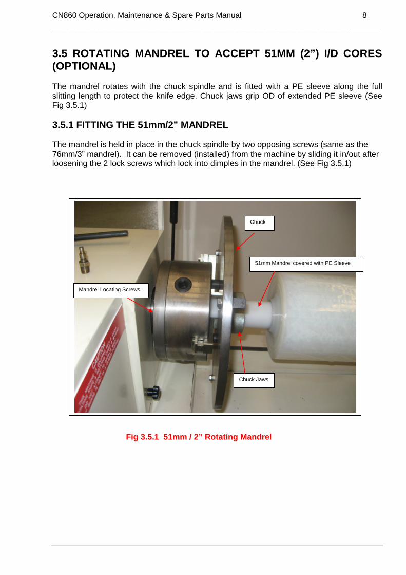
3.5 ROTATING MANDREL TO ACCEPT 51MM (2”) I/D CORES(OPTIONAL)
The mandrel rotates with the chuck spindle and is fitted with a PE sleeve along the fullslitting length to protect the knife edge. Chuck jaws grip OD of extended PE sleeve (SeeFig 3.5.1)
3.5.1 FITTING THE 51mm/2” MANDREL
The mandrel is held in place in the chuck spindle by two opposing screws (same as the76mm/3” mandrel). It can be removed (installed) from the machine by sliding it in/out afterloosening the 2 lock screws which lock into dimples in the mandrel. (See Fig 3.5.1)
Fig 3.5.1 51mm / 2” Rotating Mandrel
Mandrel Locating Screws
Chuck
Chuck Jaws
51mm Mandrel covered with PE Sleeve

CN860 Operation, Maintenance & Spare Parts Manual 9
______________________________________________________________________________________________________________________________________________________________________________ ___________________
3.6 CHUCK (3 PIN)
The chuck is a slotted face plate mounted on the front of the main spindle. It is fitted with a setof 3 push-in type pin holders for external gripping. When fitted with the rotating mandrel, it issupplied with a set of pin holders capable of gripping a range of log roll diameters from 76.2 ∼to 305 mm (3” ∼ 12 ”).
3.7 KNIVES
All knives should be engraved with the word TOP for correct location on knife spindle. Knife isalways mounted on the spindle with engraved marking to the top and with main/primary bevelfacing AWAY from chuck and supported by a backing plate** on each side and held in place bya cap screw. When properly set, runout must not exceed ±0.1 mm (0.004”)(4 thou). ReferSection 5.4 **Backing plate should also be engraved with TOP for correct positioning and alsoOUT to indicate which plate is place on the outside of knife.
Caution: Always use cut resistant gloves when handling knife
3.8 KNIFE SHARPENINGRefer Section 4.5 for bevel requirements to achieve good slitting results (See Fig 3.7)
3.9 KNIFE SPINDLE
The knife spindle in conjunction with backing plates holds the knife firmly to keep it within anacceptable runout both radially and axially. (See Fig 3.8)
Fig 3.8
Spindle
Inner Backing Plate
Knife
Knives should have 8° main(primary) bevel plus a . small11° bevel to strengthen outeredge of knifeAdd back bevel to reverse sideof knife to suit width to be cutNOTE: Main bevel shouldalways face away from chuck
small 11° bevel tostrengthen outer edge ofknife
Fig 3.7
NOTE: Protective strip (available from Javelin)placed over exposed knife edge duringmaintenance or when machine not in use.

CN860 Operation, Maintenance & Spare Parts Manual 10
______________________________________________________________________________________________________________________________________________________________________________ ___________________
3.10 KNIFE BRAKE
A knife brake is fitted to the spindle (see Fig. 3.10).The knob behind the knife pedestal should betightened just enough to slow down the knife rotationas it cuts through the material. This will help if there isa problem with double cutting or when slitting narrowwidths. Varying the amount of braking can be usefulwhen slitting all types of products
When slitting hot stamp foils the knife spindle brakeshould be tightened so that the knife is stationary untilit contacts the core. The knife must rotate when itcontacts the core, so that a new section of knife edgeis exposed, thus preventing a dull spot forming oncutting edge.
3.11 KNIFE LUBRICATION
The knife lubrication is used to keep heat down which resultsfrom friction between the knife and the material being slit,and to prevent adhesive build up on knife and slit roll.
3.11.1 STANDARD LUBRICATIONFoam Pads fitted either side of knife which can besaturated with lubricant from p0ump action bottle
3.11.2 VENTURI SYSTEM (OPTIONAL)
The system is fitted using a vacuum generator (Spray Nozzle).Compressed air flowing through the vacuum generatordraws water into the air stream to form a mist. The unitis located on top of the knife guard. Two plastic containersare located at rear of machine. One holds lubricantwhile the other collects residual oversprayAs a lubricant, add approximately 30ml of lubricantto 2 litres of water to the water container.We recommend the use of Javelin lubricant tominimise rust.
Note: The spray only operates when theknife is moved forward, off the rear stop
If problems arise see Section 6.1 for trouble shooting.
3.12 KNIFE PEDESTAL
The knife pedestal is mounted on the carriage plate. The indexing hand wheel (refer Fig 3.13)is used to move the knife along the bed of the machine. The hand lever (refer Fig 3.11) isused to move the knife towards the mandrel.
Fig 3.10
Knife BrakeAdjusting Knob
Plastic Containers
Spray Nozzle
Fig 3.11
HandLever

CN860 Operation, Maintenance & Spare Parts Manual 11
______________________________________________________________________________________________________________________________________________________________________________ ___________________
3.13 INDEXING
Indexing is achieved by traversing the knife carriage and reading off the indexing counter(when fitted). The knife pedestal traverses by hand wheel and rack and pinion. When theknife is moved forward off the reset switch, the counter resets to zero for the next index. (Reffig 3.13.1)An electronic counter (Optional) provides a digital display for the width of cut.
3.13.1 DIGITAL COUNTER (WIDTH DISPLAY) (when fitted)
The Digital Counter is connected to a rotary encoderand is graduated in .2mm (.008”) increments:
Electronic digital counter displayswidth to be slit
Fig. 3.12.1
Fig 3.13 Indexing Mechanism
Rotary Encoder
Indexing(traversing)Handwheel
CarriageLock
Rack
Index counter ‘’reset’’(to zero) switch
WARNING:DO NOT LEAVE TOOLS ON TRAY UNDER PEDESTAL AS DAMAGE TO ENCODER MAY RESULT

CN860 Operation, Maintenance & Spare Parts Manual 12
______________________________________________________________________________________________________________________________________________________________________________ ___________________
4. MACHINEOPERATION
4.1 OPERATOR SAFETY
PLEASE NOTE FOLLOWING BEFORE COMMENCING OPERATION:
Safety should be a constant concern of everyone around any type of machinery. Whilemore than normal precautions were taken in the manufacture of this machine,everyone connected with its operation should be made fully aware of the HighVoltages, High Speed Motion and Sharp, Rotating Automatically Actuated CuttingTools involved.
To prevent injury, the suggestions below should be followed:
1. KEEP CLEAR of cutting blade, rotating mandrel, chuck and material when themachine is in motion.
2. ENSURE all GUARDS in position & safety systems operational before starting themachine..
3. DO NOT place your hands between the knife and rolls when loading or unloading.ENSURE knife is in its furthest back position.
4. KEEP the area around the machine CLEAN and DRY proof surface or mats. Onlythe operator to work within area designated by hazard tape.
5. ENSURE main isolator is switched OFF before any maintenance is carried out.
6. USE suitable PROTECTIVE GLOVES when handling blades.
7. Ensure KNIFE IS REMOVED OR KNIFE EDGE COVERED with a flexible plasticcover when servicing or cleaning and when machine not in use.
8. Request ASSISTANCE when CHANGING knives or LOADING heavy material ontothe mandrel.
9. Ensure ALLoperators & maintenance personnel have read and understoodthis manual before operating or carrying out maintenance on this machine.
Ensure only qualified electricians work on the electrical components of themachine. Operators must not open the electrical cabinet, motor drive cabinet oroperator panel. In the case of an electrical malfunction qualified electricalpersonnel/contractor should be called.

CN860 Operation, Maintenance & Spare Parts Manual 13
______________________________________________________________________________________________________________________________________________________________________________ ___________________
4.2 PRINCIPLES OF SINGLE KNIFE SLITTING
Slitting by the single knife method is basically the ability of a circular knife todisplace the slit roll as it enters the log.
Single knife slitting is not a precise science. Slitting results are affected by anumber of factors including:
• the type of backing (i.e. Polyester/Cloth/Foam)• evenness of adhesive coating,• tension under which the log has been wound to• knife diameter• knife sharpness or dullness• air or room temperature
Materials which are too dense or have been wound too tightly may be unsuitable toslit by this method. In this case either the roll must be rewound to a lesser tensionor the material cut on a machine known as a slit/rewinder.
Knife parameters are crucial in successful Single Knife Slitting (Refer KnifeSelection Section 4.6)
As widths bering slit increase so must the secondary or back bevel on the knife inorder to balance the forces and achieve a straight cut.
CAUTION: Failure to pay attention to choosing a knife with the correctbevel can result in the knife chipping or in an extreme case shatter.
CAUTION~ always use cut resistant gloves when handling knives ~
CN860 Operation, Maintenance & Spare Parts Manual 14
______________________________________________________________________________________________________________________________________________________________________________ ___________________
4.3 PRINCIPLE OF OPERATION - SLITTING
The JAVELIN series CN860 is a Manually Operated Single Knife, lathe type slitting machinefor cutting log rolls of Fibreglass, rubber, adhesive tape, stamping foils & textiles.
The CN860 will accept a log roll up to ∅305 mm (∅12”) x 1630 mm (64”) & core diameter of∅76.2 mm (∅3”) is standard. Other mandrels from ∅1” diameter are available on request.
The log roll is slid onto a PE sleeve covered steel mandrel from the right hand end of themachine and secured internally by expanding jaws and externally by a 3 pin chuck.
The width of cut is checked by using the optional Digital Width Counter, or by manuallymeasuring with a tape measure.
When the machine is turned ON, the chuck spindle will rotate the log roll. By pulling the handlever forward manually, the knife will move forward making its first cut through to the core onwhich the material is wound. Upon completion of the cut, the hand lever is pushed all the wayback until the knife clears the diameter of the log ready for indexing to the left for the next cut.
Also refer to Sections 4.2 Slitting tolerances/4.3 Principles of single knife slitting
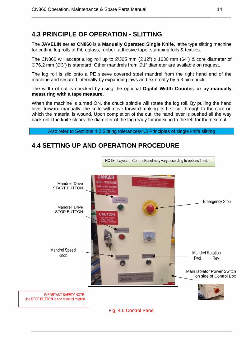
4.4 SETTING UP AND OPERATION PROCEDURE
to ON to shift brake calliper towardsREGULATOR 8 & PRESSURE GAUGE 9 can also beadjusted but will only be functional during actual rewinding.
Fig. 4.5 Control Panel
Mandrel RotationFwd Rev
Emergency Stop
Main Isolator Power Switchon side of Control Box
Mandrel DriveSTOP BUTTON
Mandrel DriveSTART BUTTON
Mandrel SpeedKnob
IMPORTANT SAFETY NOTE:Use STOP BUTTON to end mandrel rotation
.
NOTE: Layout of Control Panel may vary according to options fitted.

CN860 Operation, Maintenance & Spare Parts Manual 15
______________________________________________________________________________________________________________________________________________________________________________ ___________________
1. Check mandrel speed set to zero
2. Check emergency stop released
3. Press reset button
4. Load log roll onto mandrel and slide up to face of the chuck
5. Raise mandrel support arm
6. Secure log roll by inserting the T handle into the chuck and turning anti clockwise toexpand internal jaws (Do Not overtighten). When required push chuck pins into OD ofmaterial and tighten screws on back of chuck plate.
7. Ensure the end of the log roll is pushed up against the chuck face to prevent anydeflection during slitting.
8. Using the hand wheel traverse the knife carriage to the right hand end of log roll and towhere the first cut is to be made.
9. Press mandrel start button.
10. Turn mandrel speed dial to required RPM
11. Adjust brake to suit product to be slit.
12. Turn Venturi spray system to lubricate knife (if fitted)
13. Using hand wheel index knife to position where first cut is to be made while checkingdisplay digital width counter (if fitted) for accuracy.
14. Engage carriage lock (Ensure surface dry and clear or clamp may move during slittingresulting in a width error)
15. Pull hand lever forward with even pressure to make the cut until the knife cuts throughthe material and the core. The spray (if fitted) should operate as the knife comesforward.NOTE: If log roll rotation becomes uneven, stop cutting action briefly and then recommence witheven pulling action on handle with arm straight and standing back from machine a little more. (seeFig 4.5 below)
16. When the cut is completed, push the hand lever all the way back until the OD of the logroll is cleared and the digital counter (if fitted) is reset to zero.
17. Using the hand wheel move the knife to the next slitting position and repeat from No 14.
√
Photo 1 – Correct position - shows the correct arm position with theoperator back a little from the machine when pulling the cutting lever.Action should be an even action until the cut is complete.
Photo 2 – Incorrect position – shows the operator standing too closeand pulling the lever with a bent arm action. This will result in the knifedeveloping vibration particularly with larger diameter log rolls..
XFig 4.5

CN860 Operation, Maintenance & Spare Parts Manual 16
______________________________________________________________________________________________________________________________________________________________________________ ___________________
4.5 KNIFE SELECTION~ always use cut resistant gloves when handling knives ~
KNIFE BEVELSWhen slitting narrow widths only a primary bevel is requiredbut with wider widths a back bevel is needed to balance the forces on eitherside of the knife so that it will cut straight through the roll without deflecting
CAUTION: Knife may be damaged or shatter if insufficient back bevel on knifewhen slitting wide widths. Trying to slit a roll to a wide width from a tightly woundlog roll, using a knife with insufficient back bevel, risks chipping or shattering the knife.
Diagram No. Slitting range Knife requirements
1 Up to 22 mm (7/8”) No Back Bevel2 25.4 mm (1”) - 38 mm (1½”) 0.5 mm (1/64”) Back Bevel3 40 mm (1 5/8”) - 96mm (4”) 1.5 mm (1/16”) Back Bevel4 Over 100mm (4”) Equal Bevel both sides of knife5 Any width (very hard materials) Tightly wound denser rolls will require test slitting to determine
the best knife bevel & edge for product Additional angle onprimary bevel
Dense materials that will not displace Must be rewound to a lesser tension
THE ABOVE DIMENSIONS ARE A GUIDE ONLY AND WILL VARY ACCORDING TO THE DENSITY OF THE MATERIAL TO BE SLIT.
Diagram 1:Knife with noback bevel
Diagram 2:Knife with 0.5mm(1/64”)back bevel
Diagram 3:Knife with 1.5mm(1/16”)back bevel
Diagram 4:Knife with equalbevel both sides
Diagram 5:Knife with reinforcededge (No. 2 angle)(refer to manual fordetails)
NOTE: A rounded edge is preferred for most adhesive tapes. Some exceptions would be,for example, foam sealant & paper tapes which require a sharp edge. Too sharp anedge can result in edge breaking down (chipping). Edge should be slightlyrounded with Shielded oil stone to prevent this occurring.
NOTE: It is imperative records be kept for specific materials so the operator knows which knife to choose each time a particular product is tobe slit. Ref: Operator Reference Sheets in the Manual.
No. 1 angle
No. 2 angle1 - 2mm (1/16” - 3/32”)
**With interlined materials it may be necessary to glue end of log roll to prevent centre of roll moving out, also iftightly wound a Diagram 3 bevel may be required. (Ensure log roll is pushed up against chuck face or spacer roll)

CN860 Operation, Maintenance & Spare Parts Manual 17
______________________________________________________________________________________________________________________________________________________________________________ ___________________
4.6 KNIFE STORAGE
The knife is the most important item on your machine.Knives should be kept in a purpose built cabinet and knifeedge protected with protective strip.
~ always use approved protective gloves when handling knives~
Operators should read the guidelines for knife selection, preparation and maintenancecarefully.
4.7 ROUNDING KNIFE EDGE
Operator MUST wear cut proof gloves when performing this function.
Turn off power at main isolating switch and using a Shielded Oil Stone (see Fig 4.8) hold thestone flat against knife edge and slowly rotate the knife with the other gloved hand. This willhave the effect of dulling the sharp edge. Polish knife edge with Scotch Bright™
IMPORTANT NOTE
If knife is slightly chipped youwill need to return to supplierfor repair. .
Fig 4.8

CN860 Operation, Maintenance & Spare Parts Manual 18
______________________________________________________________________________________________________________________________________________________________________________ ___________________
4.8 OPERATOR REFERENCE SHEETS
CN860 Knife & Machine Settings
Date: Ref:
Customer Name :Product Description :
Manufactured By :Brand :
End Use/s :
Log Roll : Diameter WidthLength Core sizeMaterial thickness
Mandrel Speed:Width To Be Cut :
Density Of Material :Tolerance Required :
Weight of Log Roll :
Knife : Diameter ThicknessNo. of Backing Plates
Back Bevel : Size
Knife Braking : On OffKnife Edge : Rounded Sharp
Sprays : Off OnChuck Grip : Internal External
Support Plate To Prevent1st Roll From Collapsing : Yes No

CN860 Operation, Maintenance & Spare Parts Manual 19
______________________________________________________________________________________________________________________________________________________________________________ ___________________
5. PREVENTATIVE MAINTENANCE
5.1 GENERAL
Apart from daily cleaning & rust prevention control, the CN860 machine needs very littlemaintenance attention.
Keeping the machine clean & dry at the end of each shift is essential for preventing rust andcorrosion which leads eventually to expensive parts replacement (refer to Section 5.2).
Note: Always remove knife and backing plates at end of each day and keep clean and freefrom grit. Wipe with light oil or spray with kerosene & oil mixture
Indexing gear & rack teeth should be cleaned DAILY with brush and/or air gun.CAUTION: Wear Safety glasses if using air gun as grit may fly and cause injury to eye/s.
5.2 LUBRICATION & MAINTENANCE CHARTPART METHOD NO. OF
PLACESLUBRICANT
DAILYNOTE: Take care to keep area clean and dry where carriage lock clamp contacts body of machine
otherwise clamp will not hold and errors in indexing will occurCarriage Rails &Traversing Rack
Wipe with oil impregnated rag 2 Light machine oil orspray with kero/oilmixture
Polycarbonate Cover Wipe over with soft cloth soaked inmild detergent and water or windex.Do not use other type of cleaner(hydrocarbons) otherwisepolycarbonate will crack
1 Mild detergent mixedwith wateror WINDEX®window cleaner.
Safety CoverInterlock SafetySwitches
Check daily and report immediately ifnot working
SIX MONTHSMachine Level Level Spirit LevelMandrel/Chuck Check for straightness & running freely See ManualMandrel Sleeves Check for worn/Uneven surface VisualKnife Spindle Run Out Dial IndicatorKnives & Backing Plate Run Out Dial IndicatorKnife Brake Check holding knife when full engaged
Knife free when releasedCarriage Lock Check lock clamps securely. Adjust if
necessaryTraversing RackTeeth (See Fig 3.13.1)
Smear by hand full lengthof rack
Multi purpose grease
Chuck/Mandrel DriveBelt
Check belt tension
Knife Pivot Bearings Grease Gun 2 Multi purpose greaseBearing in MandrelSupport Arm
Grease Gun 1 Multi purpose grease
Foam Pads Replace when worn and will no longer absorb lubricant
Venturi LubricationSystem (if fitted)
Clear lubricant container and remove any sediment. Recommend Javelinlubricant to prevent rust build up on knife and prevent build-up of sediment inspray nozzle
CN860 Operation, Maintenance & Spare Parts Manual 20
______________________________________________________________________________________________________________________________________________________________________________ ___________________
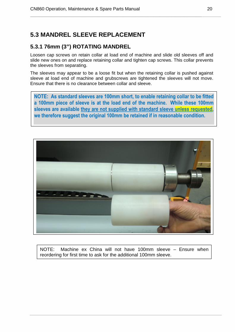
5.3 MANDREL SLEEVE REPLACEMENT
5.3.1 76mm (3”) ROTATING MANDREL
Loosen cap screws on retain collar at load end of machine and slide old sleeves off andslide new ones on and replace retaining collar and tighten cap screws. This collar preventsthe sleeves from separating.
The sleeves may appear to be a loose fit but when the retaining collar is pushed againstsleeve at load end of machine and grubscrews are tightened the sleeves will not move.Ensure that there is no clearance between collar and sleeve.
NOTE: As standard sleeves are 100mm short, to enable retaining collar to be fitteda 100mm piece of sleeve is at the load end of the machine. While these 100mmsleeves are available they are not supplied with standard sleeve unless requested,we therefore suggest the original 100mm be retained if in reasonable condition.
NOTE: Machine ex China will not have 100mm sleeve – Ensure whenreordering for first time to ask for the additional 100mm sleeve.

CN860 Operation, Maintenance & Spare Parts Manual 21
______________________________________________________________________________________________________________________________________________________________________________ ___________________
5.4 SLITTING TOLERANCES
a. CHECKING FOR BACKING PLATE RUNOUT:
Backing plates that have been dropped onto a hard surface may be out ofspecification and will need to be replaced.
i) Run a smooth flat file across the face of the backing plate and washer to ensurethere are no burrs.
ii) Check spindle face for burrs or grit.iii) Fit backing plate and washer and check for runout with dial indicator (See Note).iv) Runout should not be more than .08mm (.003”). If runout exceeds tolerance,
mark backing plate in 2 positions and one position on spindle with marking pen.v) Rotate backing plate to position 2 and re check if runout is excessive.
1
2
3
4
backing plate
spindle
b. CHECKING FOR KNIFE RUNOUT
Place dial indicator on knife face (1 at top-Picture A) and rotate knife to 2 (Picture B). A‘run out’ of not more than .08mm (.003”) is permissible.
2
NOTE: Checkbacking plate oninside by fittinglarge backingplate/small backingplate and nut, thenplacing dial vernieron edge of backingplate as shown inpicture.
DIAL INDICATOR
A B
NOTE:Backing plates maydiffer in appearance –principle is the same.

CN860 Operation, Maintenance & Spare Parts Manual 22
______________________________________________________________________________________________________________________________________________________________________________ ___________________
6. TROUBLE SHOOTING- MACHINE PROBLEMS
6.1 VENTURI SPRAY SYSTEM (WHEN FITTED)
PROBLEM/EFFECT REMEDIESSpray not working.
(N.B. spray starts whenknife is brought forward)
Check air supply Valve turned off Check Flow control open Move pedestal off rear stop
Air but not water. Check: …. Water pick-up tube is pushed into bottle Water bottle is full Flow valve adjustment Loose fitting or split tubes Air pressure of flow rate too high forcing water back into bottle
Felt Pads worn & notcontacting Knife
Replace Pads
6.2 ROTATING MANDRELS
PROBLEM/EFFECT CAUSE REMEDIESMandrel vibration(See Note Section 4.3item 16)
Core loose fit on mandrel -I/D oversized.
Log roll out of round.
Using 25.4mm (1”) mandrel
Use correct core size.
Slow mandrel speed.
Move 25.4mm/1” mandrel supportbracket closer to knife
Mandrel sleevesbecome worn tooquickly
Mandrel secured in place by2 cap screws behind chuckwhich lock into counter sunkholes in mandrel.
Tighten screws.
Mandrel becomesworn
Knife penetrating mandrelsleeve too deep
“Check mechanical knife stop setas per Manual with knife edge atleast 2mm from OD of sleeve
Strands protrudingfrom PE mandrelsleeve.
Knife cutting too deep intomandrel sleeve.
Adjust knife depth. Smoothsurface of sleeve with anglegrinder
6.3 KNIFE BRAKE
PROBLEM/EFFECT CAUSE REMEDIESBrake does not holdknife
Brake Pads worn Replace

CN860 Operation, Maintenance & Spare Parts Manual 23
______________________________________________________________________________________________________________________________________________________________________________ ___________________
6.4 DIGITAL INDEX COUNTER (WHEN FITTED)
6.5 MANDREL SUPPORT ARM
PROBLEM/EFFECT CAUSE REMEDIESMandrel vibratesSideways movementbetween mandrelsupport arm andmandrel supportbearings.
Bearings loose betweenmandrel support arm andmounting bracket.
Tighten bearing housings and orgrub screws in bearings ontosupport arm pivot shaft
Knife not slittingthrough core and/orknife cutting too farinto mandrel sleeve atone end of machine.
Mandrel support not alignedparallel to knife carriage.
• Raise mandrel support.• Traverse carriage to extreme
left.• Adjust forward knife stop so
that the knife just touchesmandrel.
• Traverse knife to the extremeright and move knife forward tomandrel.
• Loosen grub screws lockingmandrel support arm to pivotbearings and move arm side-ways so that knife touches themandrel sleeve fractionallyharder than at other end ofmachine (0.1mm or 0.004”).
• Lock grub screws and re-check.
PROBLEM/EFFECT CAUSE REMEDIESReads inaccurately Scale factor error
Loose WireEncoder wheel not contacting
rail
Encoder failure
Re-enter scale factor
Check wiringSpring broken or stretchedObstruction prevents wheelturningFit new Encoder(Encoder cannot be repaired)

CN860 Operation, Maintenance & Spare Parts Manual 24
______________________________________________________________________________________________________________________________________________________________________________ ___________________
6.6 KNIFE (OUT OF TOLERANCE)
PROBLEM/EFFECT CAUSE REMEDIESPoor quality slit rolls Knife spindle, backing plates
and knives must be cleanof all grit when puttingknife and backing platesonto spindle and locatedin same position eachtime. Knives and backingplates should be markedfor this purpose. Failureto do this will cause kniferun out.
Knife sharpened incorrectlyaltering the bevel angle.
Mount dial indicator on knife andlook for excessive run out.(Refer Section 5.5 of Manual)
Return knife to Javelin for bevelto be reground.
6.7 MANDREL
6.8 EXPANSION JAWS
6.9 KNIFE CUTTING HANDLE
PROBLEM/EFFECT CAUSE REMEDIESMandrel becomesloose
Two cap screws behindchuck become loose
Push mandrel firmly back intoplace (tap with rubber hammer)line up counter sunk holes inmandrel spindle (journal) with capscrew behind chuck – tighten capscrews.
PROBLEM/EFFECT CAUSE REMEDIESExpansion jaws willnot expand evenly
Weld on expansion jawsbreaks
Remove mandrel to access jaws– re weld or replace jaws
PROBLEM/EFFECT CAUSE REMEDIESHandle comes loose Caps screws come loose Remove knife then look for three
“phillip head” counter sunkscrews inside aluminium guard.Remove screws and the knifeguard should then come off.Tighten up the two cap screwsthat secure the handle (5mmAllen Key required)Reassemble as before.

CN860 Operation, Maintenance & Spare Parts Manual 25
______________________________________________________________________________________________________________________________________________________________________________ ___________________
7. TROUBLE SHOOTING- SLITTING PROBLEMS
7.1 SELF WOUND ADHESIVE TAPE
PROBLEM/EFFECT CAUSE REMEDIESDouble cutting causestape to tear whenbeing unwound
Knife running out oftolerance.
Worn mandrel sleeve.
Speed of knife entry too fast
Core diameter too loose onmandrel
Replace Knife.
Replace sleeve. Set knife stopcorrectly to avoid premature sleevedamage.
Slow down knife forward speed.
Specify correct inside diameter tocore manufacturer.
Slit roll “telescopes”after slitting
Tight and loose section in logdue to uneven adhesivecoating
Slit log separating tight and loosesections and rewind to acceptabletension
Self wound foil tapes,copper, aluminium,lead, tear when beingunwound after slitting
Knife edge roll over causingtape to tear when unwound.
Interline foil before slitting.
Adhesive smearing onsides of rolls. Tapesticks together andcannot be separated.
Knife edge unsuitable
Insufficient lubrication
Sometimes very sharp knife cancause this problem. Round off knifeedge
Check and adjust sprays
Soft adhesive coatedtapes such as Teflonfilm are left with steepridges on either sideof the slit roll.
No back bevel on knife Grind back bevel on knife tominimise problem.
Knife edge shatters Knife too sharp
Knife hits steel mandrel
Core is hard or thick
Round edge of knife to strengthen.
Adjust knife forward stop.
Reduce knife forward speed whencutting through core
Concave or convexrolls. Tape visuallypoor and not suitablefor resale.
Knife bevel unsuitable Refer Section 4.6

CN860 Operation, Maintenance & Spare Parts Manual 26
______________________________________________________________________________________________________________________________________________________________________________ ___________________
7.2 INTERLINED & NON ADHESIVE COATED MATERIALSEG VINYL USED IN SIGN INDUSTRY
PROBLEM/EFFECT CAUSE REMEDIESInside of roll movestowards end of log
Layers of vinyl or othersubstrate not bondedtogether as with self woundadhesive products.
Glue end of roll with Hot MeltGlueLog roll should be pushed againstchuck face or spacer roll.
Difficulty pulling knifethrough log roll
Film wound too tight. Checkback bevel on knife suitablefor width being cut
Rewind to lesser tension.Use knife with larger back bevel.
Log roll stops rotatingbefore cut iscompleted
Non adhesive Paper/Film/Foilslipping on the core
Use strong adhesive tape toanchor the leading edge ofpaper/film/foil to core.Reverse the direction of rotatingmandrel as this has effect oftightening the roll.
Knife pushes vinyl/filmaside and will not cutthrough core
Knife edge very blunt Resharpen knife
7.3 FABRICS/FIBREGLASS/FOAMS (WITHOUT PRESSURE SEHSITIVE ADHESIVE)
PROBLEM/EFFECT CAUSE REMEDIESPoor quality slit rolls Knife is dull Sharpen knife more frequently
Log roll loosely wound Rewind to tighter tension. Wraplog roll with stretch film.
Mandrel speed too slow Increase mandrel RPM as muchas possible.
Width of slit roll variesfrom outside to insideof roll
As product is not bondedtogether centre layers moveas knife penetrates roll.
Bond end of roll (at chuck end)with Hot Melt GlueUse roll support at r/hand end ofroll
7.4 HOT STAMP FOIL
NOTE: Log tension for narrow slit rolls up to 48mm should be tighterLog tension for wider rolls 72mm plus should be less tight
PROBLEM/EFFECT CAUSE REMEDIESEdge of knife shatters Foil wound too tight Rewind to softer tension
Insufficient knife brakefriction
Tighten brake so knife turnsonly when cutting through core.
Knife too sharp Slightly round cutting edge ofknife
Width of slit roll variesfrom outside to insideof roll
As product is not bondedtogether centre layers moveas knife penetrates roll.
Bond end of roll (at chuck end)with Hot Melt GlueLog roll should be pushed againstchuck face or spacer roll.
NOTE 1: When slitting large diameters of Hot Stamp Foil on a 25.4mm I/D core themandrel speed must be reduced. The knife brake must also be used to lock the knife at alltimes when slitting stamping foils. Knife should rotate only near the core.NOTE 2: Lubricant should not be used when slitting stamping foils.

CN860 Operation, Maintenance & Spare Parts Manual 27
______________________________________________________________________________________________________________________________________________________________________________ ___________________
8.0 SLITTING TECHNIQUES
8.1 DENSE MATERIALS (i.e. rubber, some fabrics and foam tapes):
1. Use a strong adhesive tape to anchor the leading edge of your rubber/fabric/foamsto the core onto which the product is to be rolled.
2. Roll up product as tightly as possible and use adhesive tape to hold outer edge inplace.
3. Wrap finished (log) roll tightly with stretch film.
4. This will help prevent slit rolls falling apart.
5. For heavy materials reduce mandrel speed to avoid vibration
6. For softer materials increased mandrel speed.
7. The leading edge of rubber on outside of wrap of log roll should run in the oppositedirection to mandrel/chuck rotation.
8. Adjust knife brake so that knife begins to rotate only as it enters the log roll.
8.2 FILM PROTECTION TAPE
1. Use knife with equal bevel on both sides for cut widths wider than 50mm.
2. Use small amount of knife brake
3. Keep mandrel speed between 1/3rd to half speed.
8.3 SLITTING INTERLINED MATERIALS
Any interlined material especially large diameters need to be glued with a hot melt glue atthe chuck end only, to prevent the centre of the log roll slipping away whilst it is being cut.
Note: When slitting copper, lead or aluminium foil whether or not coated with a pressuresensitive adhesive, an interlining paper is essential to achieve quality slit rolls.

CN860 Operation, Maintenance & Spare Parts Manual 28
______________________________________________________________________________________________________________________________________________________________________________ ___________________
9. MACHINE SPARE PARTS
9.1 SPARE PARTS SUMMARYPrices on Application
ITEM JAVELIN PART NO: DESCRIPTION
Knife Drive Assembly
1. 011 3332 050 Backing Plate for Knife
2. 081 4210 032 Lock Cap Screw
3. 226 0180 004 Knife Drive Chain
Chuck Assembly
4. 081 2110 024 Chuck Pins & Grub Screws (Set of 3)
5. 081 2110 022 Chuck Pin Holders, complete (Set of 3)
6. 228 0000 002 Chuck Drive Belt
Mandrels
7. 156 2048 000 Mandrel Sleeves (Ø 76mm (White) **Refer Note Section 5.4 of manual
8. 156 2051 000 Mandrel Sleeves (Ø 51mm (White)
9. 156 2024 000 Mandrel Sleeves (Ø 25.4mm (White)
10. 247 1350 505 Gas Strut 400 Newton 505
Spray (Venturi) System
11. 491 1005 100 Spray nozzle
12. 081 5000 000 Spray system complete
9.2 ACCESSORIES SUMMARY
ITEM JAVELIN PARTNO:
DESCRIPTION
Mandrel - Rotating*
1. 081 7410 000 1600mm (63”)x25.4mm (1”)
2. 081 7410 000 1600mm (63”)x51mm (2”)
Mandrels - Rotating (Expanding)*
3. 081 7220 000 1600mm (63”)x76mm (3”)
Roll Support Discs
4. 001 1076 305 3” I/D x 12” O/D
Used to support slit rolls of narrow width interlined tapes to preventthem unravelling during the slitting process.
Circular Knives (See Note 1)
5. 008 1330 030 330mm (13") OD x 3mm (1/8") x 1"ID
Note 1: All knives are ground with a primary bevel of 8° - ifsecondary or back bevel is required an extra charge is made.
6 699 9999 006 Knife Lubricant for Spray System (500ml)
Safety
7 699 9999 003 Cut resistant gloves
8. 001 1077 010 Shielded Oil Stone

CN860 Operation, Maintenance & Spare Parts Manual 29
______________________________________________________________________________________________________________________________________________________________________________ ___________________
Table of Contents
1 SPECIFICATION JAVELIN CN860 MANUAL SINGLE KNIFE SLITTER................................................ 1
2. INSTALLATION.................................................................................................................................................. 2
2.1 SHIPPING AND UNPACKING........................................................................................................................... 22.2 SPACE REQUIREMENTS................................................................................................................................... 22.3 ASSEMBLING & LEVELLING MACHINE ....................................................................................................... 32.4 CONNECTING TO ELECTRICAL SUPPLY...................................................................................................... 32.5 CONNECTING TO PNEUMATIC SUPPLY (IF VENTURI SPRAY SYSTEM FITTED) ..................................................... 32.6 SET UP MACHINE IN PREPARATION FOR SLITTING.................................................................................. 3
3. MACHINE FUNCTIONS .................................................................................................................................... 4
3.1 CHUCK SPINDLE DRIVE .................................................................................................................................. 53.2 CHUCK SPINDLE ............................................................................................................................................... 53.3 ROTATING MANDREL WITH EXPANSION SECTION (76MM/3”).................................................................. 53.4 ROTATING MANDREL FOR 25.4MM (1”) I/D CORES (OPTIONAL) ............................................................... 5
3.4.1 FITTING THE 25.4/1” MANDREL .............................................................................................................. 63.4.2 FITTING THE CHUCK PLATE (for 1”/25.4mm Mandrel)......................................................................... 73.4.3 FITTING MANDREL SUPPORT BRACKET (for 1”/25.4mm Mandrel)...................................................... 7
3.5 ROTATING MANDREL TO ACCEPT 51MM (2”) I/D CORES (OPTIONAL).................................................. 83.5.1 FITTING THE 51mm/2” MANDREL............................................................................................................ 8
3.6 CHUCK (3 PIN).................................................................................................................................................... 93.7 KNIVES................................................................................................................................................................ 93.8 KNIFE SHARPENING......................................................................................................................................... 93.9 KNIFE SPINDLE.................................................................................................................................................. 93.10 KNIFE BRAKE ................................................................................................................................................ 103.11 KNIFE LUBRICATION ................................................................................................................................... 10
3.11.1 STANDARD LUBRICATION .................................................................................................................... 103.11.2 VENTURI SYSTEM (OPTIONAL) ............................................................................................................ 10
3.12 KNIFE PEDESTAL .......................................................................................................................................... 103.13 INDEXING....................................................................................................................................................... 11
3.13.1 DIGITAL COUNTER (WIDTH DISPLAY) (when fitted) ......................................................................... 11
4. MACHINEOPERATION................................................................................................................................... 12
4.1 OPERATOR SAFETY........................................................................................................................................ 124.2 PRINCIPLES OF SINGLE KNIFE SLITTING .................................................................................................. 134.3 PRINCIPLE OF OPERATION - SLITTING ...................................................................................................... 144.4 SETTING UP AND OPERATION PROCEDURE............................................................................................. 144.5 KNIFE SELECTION .......................................................................................................................................... 164.6 KNIFE STORAGE.............................................................................................................................................. 174.7 ROUNDING KNIFE EDGE ............................................................................................................................... 174.8 OPERATOR REFERENCE SHEETS................................................................................................................. 18
5. PREVENTATIVE MAINTENANCE ............................................................................................................... 19
5.1 GENERAL.......................................................................................................................................................... 195.2 LUBRICATION & MAINTENANCE CHART ................................................................................................. 195.3 MANDREL SLEEVE REPLACEMENT............................................................................................................ 20
5.3.1 76mm (3”) ROTATING MANDREL............................................................................................................ 205.4 SLITTING TOLERANCES................................................................................................................................ 20
a. CHECKING FOR BACKING PLATE RUNOUT:............................................................................................ 21b. CHECKING FOR KNIFE RUNOUT ............................................................................................................... 21

CN860 Operation, Maintenance & Spare Parts Manual 30
______________________________________________________________________________________________________________________________________________________________________________ ___________________
6. TROUBLE SHOOTING- MACHINE PROBLEMS....................................................................................... 22
6.1 VENTURI SPRAY SYSTEM (WHEN FITTED) ............................................................................................... 226.2 ROTATING MANDRELS ................................................................................................................................. 226.3 KNIFE BRAKE .................................................................................................................................................. 226.4 DIGITAL INDEX COUNTER (WHEN FITTED).............................................................................................. 236.5 MANDREL SUPPORT ARM............................................................................................................................. 236.6 KNIFE (OUT OF TOLERANCE)....................................................................................................................... 246.7 MANDREL......................................................................................................................................................... 246.9 KNIFE CUTTING HANDLE ............................................................................................................................. 24
7. TROUBLE SHOOTING- SLITTING PROBLEMS ....................................................................................... 25
7.1 SELF WOUND ADHESIVE TAPE.................................................................................................................... 257.2 INTERLINED & NON ADHESIVE COATED MATERIALS........................................................................... 267.3 FABRICS/FIBREGLASS/FOAMS (WITHOUT PRESSURE SEHSITIVE ADHESIVE) ................................ 267.4 HOT STAMP FOIL............................................................................................................................................. 26
8.0 SLITTING TECHNIQUES............................................................................................................................. 27
8.1 DENSE MATERIALS (I.E. RUBBER, SOME FABRICS AND FOAM TAPES) ............................................................. 278.2 FILM PROTECTION TAPE............................................................................................................................... 278.3 SLITTING INTERLINED MATERIALS........................................................................................................... 27
9. MACHINE SPARE PARTS............................................................................................................................... 28
9.1 SPARE PARTS SUMMARY.............................................................................................................................. 289.2 ACCESSORIES SUMMARY............................................................................................................................. 28
Related Documents