CLASSIFICATION NOTES No. 20.1 DET NORSKE VERITAS Veritasveien 1, NO-1322 Høvik, Norway Tel.: +47 67 57 99 00 Fax: +47 67 57 99 11 STABILITY DOCUMENTATION FOR APPROVAL APRIL 2010

Welcome message from author
This document is posted to help you gain knowledge. Please leave a comment to let me know what you think about it! Share it to your friends and learn new things together.
Transcript

CLASSIFICATION NOTESNo. 20.1
DET NORSKE VERITASVeritasveien 1, NO-1322 Høvik, Norway Tel.: +47 67 57 99 00 Fax: +47 67 57 99 11
STABILITY DOCUMENTATION FOR APPROVAL
APRIL 2010

FOREWORDDET NORSKE VERITAS (DNV) is an autonomous and independent foundation with the objectives of safeguarding life, prop-erty and the environment, at sea and onshore. DNV undertakes classification, certification, and other verification and consultancyservices relating to quality of ships, offshore units and installations, and onshore industries worldwide, and carries out researchin relation to these functions.Classification NotesClassification Notes are publications that give practical information on classification of ships and other objects. Examples of de-sign solutions, calculation methods, specifications of test procedures, as well as acceptable repair methods for some componentsare given as interpretations of the more general rule requirements.All publications may be downloaded from the Society’s Web site http://webshop.dnv.com/global/.The Society reserves the exclusive right to interpret, decide equivalence or make exemptions to this Classification Note.
This issue of CN 20.1 replaces the April 2004 issue and is valid until superseded by a new revision or withdrawn.
Main changes— Reference to “Ships newbuildings” on the front page deleted to reflect 1.1.3 in the text— NPS document codes added— Provision for electronic versions of documentation added— Note with respect to mandatory use of IMO number included— References to obsolete classification note CN 20.2 have been replaced with references to IACS Recommendation No.31,
“Inclining test unified procedure”— Changed references to international regulations currently in force, i.e.:
— MARPOL Annex I (2006 Edition)— SOLAS 2009— IMO 2008 IS Code (Res.MSC.267(85))
— Updated some references to IACS and IMO guidance— IACS Rec.31— MSC/Circ.920— MSC/Circ.1142
— Added the DNV form “Notification on lightweight survey and inclining test” as Appendix A— Requirements for offshore units added— Added the term “Minimum required GM”— Deleted the (F) and (P) to align with current practice.
Comments may be sent by e-mail to [email protected] information about DNV and the Society's services is found at the Web site http://www.dnv.com
© Det Norske Veritas Computer Typesetting (Adobe FrameMaker) by Det Norske Veritas
If any person suffers loss or damage which is proved to have been caused by any negligent act or omission of Det Norske Veritas, then Det Norske Veritas shall pay compensation to such personfor his proved direct loss or damage. However, the compensation shall not exceed an amount equal to ten times the fee charged for the service in question, provided that the maximum compen-sation shall never exceed USD 2 million.In this provision "Det Norske Veritas" shall mean the Foundation Det Norske Veritas as well as all its subsidiaries, directors, officers, employees, agents and any other acting on behalf of DetNorske Veritas.
Classification Notes - No. 20.1, April 2010
Page 3
CONTENTS
1. INTRODUCTION .................................................... 51.1 Scope............................................................................51.2 General.........................................................................51.3 Documents submitted in electronic form.....................52. STABILITY DOCUMENTATION......................... 52.1 B050 - Preliminary stability manual (PSM) ................52.2 B100 - Inclining test and lightweight survey
procedure (ITP)............................................................82.3 B110 - Inclining test and lightweight survey
report (ITR, LWS) .......................................................92.4 B120 - Final stability manual (FSM)...........................92.5 B070 - Preliminary damage stability
calculation (PDS).........................................................92.6 B130 - Final damage stability calculation (FDS) ......102.7 B060 - Floodable lengths and subdivision
calculations of passenger ships (FSC) .......................102.8 Damage control information......................................102.9 B150 - Damage control plan (DCP) ..........................102.10 B160 - Damage control manual (DCM) ....................112.11 Z010 - General arrangement plan (GAP) ..................11
2.12 B010 - Lines plan and offset tables (LPO)................ 112.13 B020 - External watertight integrity plan or
freeboard plan (EWP)................................................ 112.14 B030 - Internal watertight integrity plan (IWP)........ 123. ADDITIONAL DOCUMENTATION FOR
CERTAIN SHIPS................................................... 123.1 Sea-going ships of 65 m in length and above
required to carry a loading manual............................ 123.2 New tankers designed as combination carriers ......... 133.3 Bulk carriers .............................................................. 133.4 Ships intended for the carriage of grain in bulk ........ 133.5 Ships designed to carry timber deck cargoes ............ 153.6 High speed crafts - B170 Stability in the non-
displacement mode.................................................... 16
APPENDIX ANOTIFICATION ON LIGHTWEIGHT SURVEY AND INCLINING TEST .................................................. 17
DET NORSKE VERITAS

Classification Notes - No. 20.1, April 2010
Page 4
DET NORSKE VERITAS
Classification Notes - No. 20.1, April 2010
Page 5
1. Introduction1.1 Scope
1.1.1 The purpose of this Classification Note (CN) is to pro-vide DNV’s clients with specification on minimum contents ofthe stability documentation required in connection with stabil-ity approval.The codes given for each of the document type (e.g. B050) re-fers to the DNV document code according to Rules for ShipsPt.0 Ch.3 and the documentation requirement list for new-buildings and conversions.
1.1.2 The information in this CN is made to suit various DNVstability rules and common IMO and IACS standards in thosecases where DNV is authorised to conduct statutory stabilityapprovals. This CN is not intended to cover statutory docu-mentation requirements that may be in excess of those stand-ards. One should therefore refer to the rules and regulations inquestion to verify the applicable information for the ship inquestion.
1.1.3 While this Classification Note has been written with ap-plication to newbuildings in mind it should also be used as faras practicable whenever all or parts of stability documentationfor existing ships is to be replaced.
1.1.4 This CN is not a substitute for the rules or regulations,but a means to help implementing them.
1.1.5 DNV stability rules allow that the class requirementsmay be considered complied with in some cases where a na-tional authority has carried out the approval. In these cases it isnevertheless recommended that the contents of this CN be im-plemented in that documentation as far as practicable.
1.1.6 DNV may accept layouts of stability documentationother than those presented in this CN, provided the basic con-tents are included.
1.1.7 According to the Society's rules, approved loadingcomputer systems (LCS) are accepted as supplementary toprinted stability documentation. The documentation require-ments for such systems are not within the scope of this CN. Forinformation on approval and certification of LCS softwareplease see CN 21.1.
1.2 General
1.2.1 General requirements for all documentation are out-lined in DNV's Rules for Classification of Ships, Pt.0 Ch.3Sec.1 E100.All documentation must include evidence of verification.
1.2.2 The stability documents should be legible, clear andeasy to use onboard.
1.2.3 The units in all stability documentation should be con-sistent.
1.2.4 Approval of preliminary stability documentation meanspreliminary stability approval. Short-term certificates requirepreliminary stability approval.
1.2.5 Approval of final stability documentation means finalstability approval. Full-term certificates require final stabilityapproval.
1.2.6 IMO has adopted certain mandatory documentation re-
quirements for tankers and bulk carriers. An excerpt fromthese requirements has been included in this CN.
1.3 Documents submitted in electronic formUnless otherwise agreed in accordance with Pt.1 Ch.1 Sec.3 Aof DNV Rules (eApproval), electronic versions of single draw-ings and booklets should be avoided, but may be accepted fortime critical approvals upon prior agreement.
2. Stability Documentation2.1 B050 - Preliminary stability manual (PSM)
2.1.1 The PSM should be submitted for approval as early aspossible to ensure valid approval at vessel delivery. The PSMcovers all vessels in a series and is to be submitted once.
2.1.2 For compliance with the intact stability criteria of the2008 IS Code (IMO Res.MSC.267(85)) only, the format ofIMO MSC/Circ.920 may be accepted for the stability manual.
2.1.3 The following are the general contents of the stabilitymanual. The manual should contain sufficient information toenable the master to operate the ship in compliance with thestability requirements applicable to the vessel. These contentsare to be adjusted in accordance with the applicable regula-tions. The stability manual should also include information onlongitudinal strength, if applicable for the relevant ship type.
Note:Sea-going ships of 65 m in length and above which are contract-ed for construction on or after 1998-07-01 are to be providedwith an approved loading manual based on the final light shipparticulars of the ship and which includes strength considerations(IACS UR S1). There are also additional requirements for bulkcarriers, ore carriers and combination carriers of 150 m in lengthand above (IACS UR S1A). The loading manual required forthese ships may be submitted for approval as the FSM providedthat it also contains the information set out below. See also sec-tion 3 of this CN for details.
---e-n-d---of---N-o-t-e---
Table of contentsTable of contents and index for each booklet forming part ofthe stability documentation.Main particularsThe vessel's identification, including the IMO number, maindimensions, maximum draught, maximum trim and service in-formation.
Guidance note:According to IMO MSC/Circ.1142 "all plans, manuals and otherdocuments required by the various IMO conventions to be car-ried on board ships constructed on or after 1 July 2005 should bemarked with the IMO ship identification number in a clearly leg-ible and unambiguous manner". For consistency it is recom-mended that new versions of such documents for older ships bemarked with the IMO number as well.
---e-n-d---of---G-u-i-d-a-n-c-e---n-o-t-e---
Applicable regulationsReference to the statutory regulations and class notations thatare basis for the approval and a brief list of the correspondingstability requirements.Stability modelSketch of volumes contributing to buoyancy in intact and dam-age stability calculations.Reference system and baseline
DET NORSKE VERITAS
Classification Notes - No. 20.1, April 2010
Page 6
These are to be clearly defined and are to be used consistentlythroughout the stability documentation.Preliminary lightship particularsBased on an estimate or sister vessel.Deadweight dataMasses and positions of centre of gravity of typical deadweightgroups/items to facilitate simplified calculation of loading con-ditions such as “consumables departure”, “consumables arriv-al” or standard cargo loads and so forth. Information on thetransverse centre of gravity TCG should be provided in orderto enable upright loading if it is expected that this value willnot be 0 due to the ship's design or load distribution.Tank dataTank plan and capacity tables with following information oneach tank:
— tank name/number— type— volume— centre of gravity— maximum free surface effect.
Sounding or ullage tables may be included for this purpose.Stowage planApplicable for carriage of containers or vehicles.Draught marksA sketch showing longitudinal position of draught marks, po-sition relative to the hydrostatic reference system and baseline.Information on the correlation between the draught marks andappendages such as azimuth thrusters is to be particularly em-phasised. Instructions on how to calculate from draught read-ings the corresponding draught to be used in tables forhydrostatic data, cross curves and minimum required GMT ormaximum allowable VCG curves, assuming no deflection ofhull girder are to be included.Hydrostatic dataThe hydrostatic data are to be presented on extreme draughtbasis in tabular form, from lightship draught to above maxi-mum draught with steps not exceeding 0.10 m.In cases where the vessel is expected to operate with trim, thehydrostatic data should cover the intended trim range. Alterna-tively, trim correction tables are to be included.As a minimum, the following hydrostatic should be presented:
— displacement moulded (m3)— displacement extreme (tonnes)— tonnes per centimetre immersion— moment to change trim one centimetre— vertical centre of buoyancy— longitudinal centre of buoyancy— longitudinal centre of flotation— transverse metacentre— longitudinal metacentre.
Cross curvesThe cross curves should be presented on an extreme draught ordisplacement basis in tabular form, from lightship draught toabove maximum draught for at least the following angles ofheel: 5, 10, 15, 20, 30 and 40 degrees. If the same curves arealso intended for use in connection with grain stability, thecurve for 12 degrees is to be included.In cases where the vessel is expected to operate with trim, thecross curves should cover the intended trim range and the trimvalues should correspond with those presented for the hydro-static particulars.The cross curves are to be calculated on a “free to trim” basis.
Guidance note:See also Sec.3 in the case of ships designed for carriage of timberdeck cargoes.
---e-n-d---of---G-u-i-d-a-n-c-e---n-o-t-e---
Water- and weathertight integrity Position of critical unprotected and weathertight openings con-sidered flooding points in intact- and damage stability calcula-tions as applicable.Instructions on closing appliances and location of signboards.Flooding angle curveFlooding angle curve representing the angle of flooding of crit-ical unprotected openings as a function of extreme draught ordisplacement from lightship draught to above maximumdraught.In cases where the vessel is expected to operate with trim, mul-tiple flooding angle curves covering the intended trim range isto be developed. The trim values are to correspond with thosepresented for hydrostatic particulars and cross curves.Minimum required GMT or maximum allowable VCG curvesThe draught reference point is to be same as for hydrostatic data.The minimum required GMT or maximum allowable VCGcurves may be presented on an extreme draught or displace-ment basis in tabular or curves form from lightship draught tomaximum draught.In cases where the vessel is intended to operate with trim, theminimum required GMT or maximum allowable VCG curvesare to cover the intended trim range. The trim values are to cor-respond with those presented for hydrostatic particulars andcross curves.The minimum required GMT or maximum allowable VCGcurves are to satisfy all intact and damage stability require-ments of the regulations applicable to the ship. The curves areto be presented as resulting curves. Separate curves for intactand damage stability are not to be included in the documenta-tion intended for use on board unless justified by multiplemodes of operation.Any limitations or conditions such as specific modes of opera-tion related to the application of the minimum required GMTor maximum allowable VCG curves are to be clearly stated onthe curves.If no minimum required GMT or maximum allowable VCGcurves have been calculated, the validity of the stability ap-proval will be limited to the presented loading conditions.
Note:See also Sec.3 in the case of ships designed for carriage of timberdeck cargoes.
---e-n-d---of---N-o-t-e---
Special loads/momentsSpecial loads and external heeling moments are to be presentedas required by the applicable rules, regulations and additionalclass notations, such as:
— high speed turning— wind heeling moment— passenger heeling moment— davit launching moment— towing heeling moment— crane heeling moment— entrapped water in pipes on deck, included in the loading
conditions— entrapped water on deck or other spaces included in the
loading conditions— water monitors heeling moment— ice beaching moment
DET NORSKE VERITAS
Classification Notes - No. 20.1, April 2010
Page 7
— ice accretion, included in the loading conditions.
Loading conditionsThe loading conditions should be preceded by a summary of allloading cases in a tabular form giving a brief overview of theloading conditions included in the document. This overviewshould consist of:
— total capacity of cargo, tanks and other items included ineach loading condition
— total displacement and corrected centre of gravity (VCG)— extreme draughts and total trim— corrected transverse metacentric height (GMT).
Except as otherwise specified by this CN or required by theregulations applicable for the ship, for the purpose of assessingin general whether the stability criteria are met, stability curvesusing the assumptions given by the applicable regulationsshould be drawn for the loading conditions intended by theowner in respect of the ship's operations.If the owner of the ship does not supply sufficiently detailed in-formation regarding such loading conditions, calculationsshould be made for the standard loading conditions, as follows:
— full load condition, departure (100% consumables)— full load condition, arrival (10% consumables)— ballast condition, departure (100% consumables)— ballast condition, arrival (10% consumables).
Guidance note:Standard loading conditions for certain types of ships are listedin the 2008 IS Code Part C Part 3.4.1.
---e-n-d---of---G-u-i-d-a-n-c-e---n-o-t-e---
If the loading conditions are based on the assumption that thereduction in stability due to consumption of fuel oil and freshwater is to be compensated by intake of water ballast duringthe voyage the calculations should be supplemented with addi-tional loading conditions demonstrating at what stage(s) of thevoyage water ballast is to be added. The free surface effectsshould be calculated to take account of the most onerous tran-sitory stage relating to such operations. Please note 2008 ISCode Part B Par. 3.1.5 in this respect.Special loads and external heeling moments such as ice load,crane load and entrapped water are to be applied to the present-ed loading conditions as may be required by the regulations ap-plicable to the ship.
Note:Some regulations require that the special loads or heeling mo-ments be applied to supplementary loading conditions assumingmaximum allowable VCG.
---e-n-d---of---N-o-t-e---
In addition to the regulatory conditions above loading condi-tions covering the intended range of service modes includingthose most unfavourable are to be presented.
Note:See also Sec.3 for more specific guidance on loading conditionsfor certain types of ships.
---e-n-d---of---N-o-t-e---
The presented loading conditions are to be within the limitcurves or satisfy the applicable requirements.As a minimum, the following information is to be presented foreach loading condition:
— individual masses with centre of gravity— free surface moments of slack tanks— total displacement and corrected centre of gravity— extreme draughts and total trim— propeller immersion, if applicable— corrected transverse metacentric height (GMT)— maximum allowable VCG or minimum required GMT— tabulated GZ - values and GZ - curves— values of applicable stability criteria if maximum allowa-
ble VCG curves have not been calculated.
Notes on stability
— general precautions against capsizing— instructions on checking the stability— use of free surface correction— use of cross curves— use of maximum allowable VCG curves.— stability limitations regarding loading of the vessel includ-
ing draught to prevent slamming, if applicable— instructions on emergency situations (storm/damage)— use of onboard computer in assessing the stability.
Worked example on stabilityA complete worked example on calculating and checking thestability of a loading condition.Blank stability formsBlank forms for calculating and checking the stability for actu-al loading conditions.Deadweight scaleConversion tablesFor vessels to which the DNV Offshore Standard apply, a Pre-liminary Stability Manual (B051, PSM) shall be prepared. Thecontents are to be the same as for B050, with the following ad-justments, as applicable. For self-elevating units and column-stabilized units required to have an Operation Manual, the be-low information should be included therein.Limit curves or maximum allowable VCG curves, general:
— The details of the calculations are to be documented in aseparate document, B040 Stability analysis.
— The draught reference point is to be same as for hydrostat-ic data.
— The limit curves may be presented on an extreme draughtor displacement basis in tabular or curves form from light-weight draught to maximum draught.
— In cases where the vessel is intended to operate with trim,the limit curves are to cover the trim range.
— The limit curves are to satisfy all stability requirements ofthe rules and regulations.
— Any limitation or conditions related to the application ofthe limit curves should be clearly stated on the curves.
Limit curves or maximum allowable VCG-curves, column-sta-bilised units
DET NORSKE VERITAS
Classification Notes - No. 20.1, April 2010
Page 8
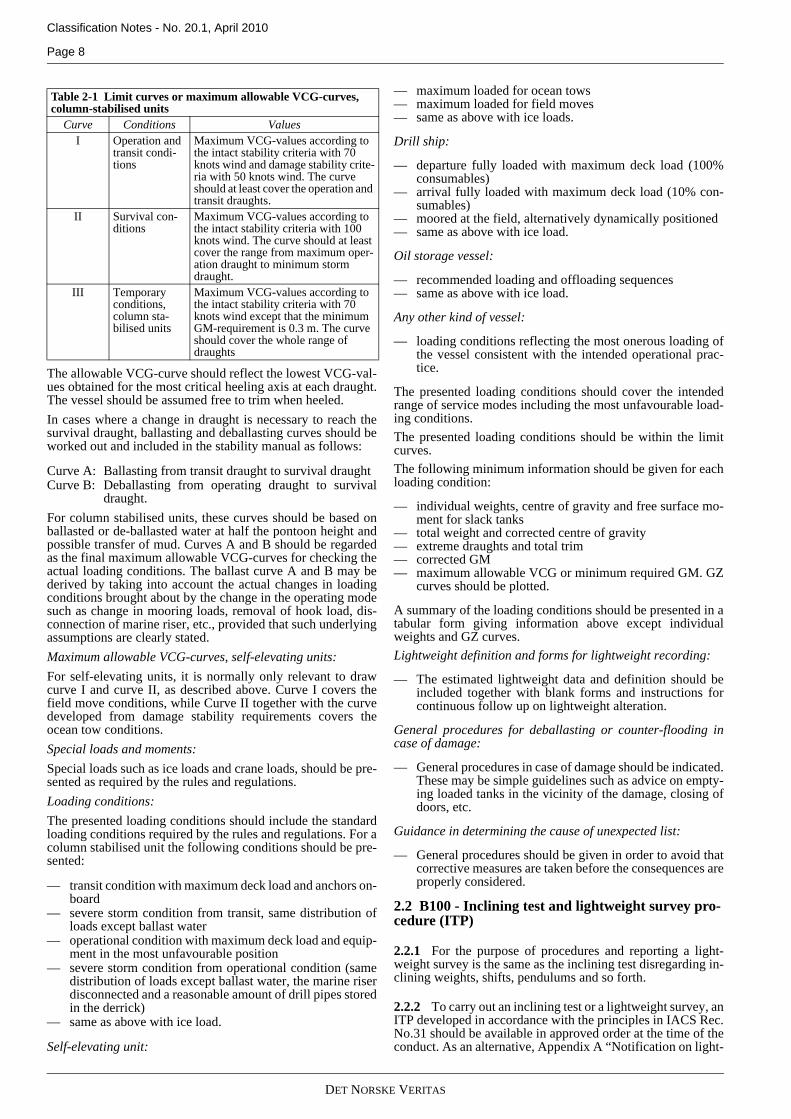
The allowable VCG-curve should reflect the lowest VCG-val-ues obtained for the most critical heeling axis at each draught.The vessel should be assumed free to trim when heeled.In cases where a change in draught is necessary to reach thesurvival draught, ballasting and deballasting curves should beworked out and included in the stability manual as follows:
Curve A: Ballasting from transit draught to survival draughtCurve B: Deballasting from operating draught to survival
draught.For column stabilised units, these curves should be based onballasted or de-ballasted water at half the pontoon height andpossible transfer of mud. Curves A and B should be regardedas the final maximum allowable VCG-curves for checking theactual loading conditions. The ballast curve A and B may bederived by taking into account the actual changes in loadingconditions brought about by the change in the operating modesuch as change in mooring loads, removal of hook load, dis-connection of marine riser, etc., provided that such underlyingassumptions are clearly stated.Maximum allowable VCG-curves, self-elevating units:For self-elevating units, it is normally only relevant to drawcurve I and curve II, as described above. Curve I covers thefield move conditions, while Curve II together with the curvedeveloped from damage stability requirements covers theocean tow conditions.Special loads and moments:Special loads such as ice loads and crane loads, should be pre-sented as required by the rules and regulations.Loading conditions:The presented loading conditions should include the standardloading conditions required by the rules and regulations. For acolumn stabilised unit the following conditions should be pre-sented:
— transit condition with maximum deck load and anchors on-board
— severe storm condition from transit, same distribution ofloads except ballast water
— operational condition with maximum deck load and equip-ment in the most unfavourable position
— severe storm condition from operational condition (samedistribution of loads except ballast water, the marine riserdisconnected and a reasonable amount of drill pipes storedin the derrick)
— same as above with ice load.
Self-elevating unit:
— maximum loaded for ocean tows— maximum loaded for field moves— same as above with ice loads.
Drill ship:
— departure fully loaded with maximum deck load (100%consumables)
— arrival fully loaded with maximum deck load (10% con-sumables)
— moored at the field, alternatively dynamically positioned— same as above with ice load.
Oil storage vessel:
— recommended loading and offloading sequences— same as above with ice load.
Any other kind of vessel:
— loading conditions reflecting the most onerous loading ofthe vessel consistent with the intended operational prac-tice.
The presented loading conditions should cover the intendedrange of service modes including the most unfavourable load-ing conditions.The presented loading conditions should be within the limitcurves. The following minimum information should be given for eachloading condition:
— individual weights, centre of gravity and free surface mo-ment for slack tanks
— total weight and corrected centre of gravity— extreme draughts and total trim— corrected GM— maximum allowable VCG or minimum required GM. GZ
curves should be plotted.
A summary of the loading conditions should be presented in atabular form giving information above except individualweights and GZ curves.Lightweight definition and forms for lightweight recording:
— The estimated lightweight data and definition should beincluded together with blank forms and instructions forcontinuous follow up on lightweight alteration.
General procedures for deballasting or counter-flooding incase of damage:
— General procedures in case of damage should be indicated.These may be simple guidelines such as advice on empty-ing loaded tanks in the vicinity of the damage, closing ofdoors, etc.
Guidance in determining the cause of unexpected list:
— General procedures should be given in order to avoid thatcorrective measures are taken before the consequences areproperly considered.
2.2 B100 - Inclining test and lightweight survey pro-cedure (ITP)
2.2.1 For the purpose of procedures and reporting a light-weight survey is the same as the inclining test disregarding in-clining weights, shifts, pendulums and so forth.
2.2.2 To carry out an inclining test or a lightweight survey, anITP developed in accordance with the principles in IACS Rec.No.31 should be available in approved order at the time of theconduct. As an alternative, Appendix A “Notification on light-
Table 2-1 Limit curves or maximum allowable VCG-curves, column-stabilised units
Curve Conditions ValuesI Operation and
transit condi-tions
Maximum VCG-values according to the intact stability criteria with 70 knots wind and damage stability crite-ria with 50 knots wind. The curve should at least cover the operation and transit draughts.
II Survival con-ditions
Maximum VCG-values according to the intact stability criteria with 100 knots wind. The curve should at least cover the range from maximum oper-ation draught to minimum storm draught.
III Temporary conditions, column sta-bilised units
Maximum VCG-values according to the intact stability criteria with 70 knots wind except that the minimum GM-requirement is 0.3 m. The curve should cover the whole range of draughts
DET NORSKE VERITAS

Classification Notes - No. 20.1, April 2010
Page 9
weight survey and inclining test” may be filled in and handedover to the DNV surveyor (ref. list in the form of cases forwhich this is accepted) before the conduct.
2.2.3 If the yard/owner wishes to determine the lightship par-ticulars based on a satisfactory lightweight survey and the in-clining test of a sister vessel, a lightweight survey procedure isto be submitted as the ITP instead.
2.2.4 Subject to statutory regulations and DNV Rules forShips, a lightweight survey may be accepted in lieu of an in-clining test for a series of sister vessels. This will also dependon:
— the type of vessel— the time span of building the series— whether the vessels are built for the same owner— if there are dissimilarities between the vessels— if the inclining test of the first vessel is approved.
Note:SOLAS 2009 Ch.II-1 Par.5-1 states that: "A weight survey shallbe carried out upon completion and the ship shall be inclinedwhenever in comparison with the data derived from the sistership, a deviation from the lightship displacement exceeding 1%for ships of 160 m or more in length and 2% for ships of 50 m orless in length and as determined by linear interpolation for inter-mediate lengths or a deviation from the lightship longitudinalcentre of gravity exceeding 0.5% of Ls is found".
---e-n-d---of---N-o-t-e---
2.2.5 The contents of the procedure are to be in accordancewith IACS Rec.No.31 or, as an alternative, Annex 1 of IMO2008 IS Code part B.
2.3 B110 - Inclining test and lightweight survey report (ITR, LWS)
2.3.1 An ITR/LWS prepared in accordance with IACSRec.31 should be submitted for approval as soon as possibleafter the inclining test or lightweight survey, to ensure approv-al before vessel delivery. It is to be forwarded to the attendingsurveyor for endorsement before being submitted for approval.
2.4 B120 - Final stability manual (FSM)
2.4.1 The FSM is basically the revision of the loading condi-tions from the PSM according to the approved lightship partic-ulars in the ITR, and any other comments as may have beengiven in connection with the preliminary approval.
2.4.2 The date and place of the inclining test or lightweightsurvey upon which the FSM is based is to be entered underlightship particulars and also the name of the organisation re-sponsible for the approval. Alternatively a stamped copy of theITR could be included, if available.
2.4.3 The mass and location of any permanent ballast or otherfixed weights not included in the results from the ITR/LWS isto be clearly specified in the FSM.
2.4.4 If the differences between lightship particulars for sistervessels are sufficiently small and within the accuracy and tol-erances of inclining tests and lightweight surveys, the lightshipparticulars of the first vessels in a series may be used for thesister vessel. Identical final stability documentation to that ofthe first vessel may then be accepted for the sister vessel. Thiswill normally be accepted if the difference in lightship mass iswithin 0.5% and the difference in LCG is within 0.5% of LBP.In such cases it is recommended that the lightweight data ap-proval letter is included in the FSM.
2.4.5 Upon approval of the FSM, the approval letter should bephysically attached to the FSM before taken onboard the ves-sel. That is to ensure that any limitations to the approval areclearly communicated to the Master.
2.5 B070 - Preliminary damage stability calculation (PDS)
2.5.1 Subject to appropriate class and statutory regulations adamage stability approval can be either general, based on ap-proval of minimum required GMT or maximum allowableVCG curves, specific, based on approval of specific loadingconditions representing the intended service of the vessel, or acombination.
2.5.2 The PDS should be submitted for approval as early aspossible, since such calculations often decide the limit curvesthat are to be used further in the PSM.
2.5.3 If the PDS is intended to provide maximum allowableVCG curves only, that is, they are independent of the lightshipparticulars, they may also be considered as the final damagestability calculations (FDC).
2.5.4 The presentation of the calculations depends on the cal-culation method, that is, whether the applicable regulations arebased on deterministic or probabilistic principles or a combi-nation of both. Information common for both methods
— reference to the applicable damage stability requirements— description and location of openings assumed watertight,
weathertight or unprotected in the calculations— description of the margin line or other immersion limits as
may be applicable— a list and sketches of cross-flooding systems, downflood-
ing openings and other devices assumed to correct list dueto flooding.
Deterministic methodThe following are the minimum contents of the PDS in the caseof deterministic calculations, such as for supply vessels, oiltankers under regulation 28 of MARPOL 73/78 Annex I (2006Edition) and the deterministic IMO 2000 HSC Code:
— a list of initial intact conditions is to be given if it is the in-tention to obtain an approval of specific loading conditionsonly
— initial intact conditions covering the intended range ofdraughts and trims if only minimum required GMT ormaximum allowable VCG curves are to be calculated
— assumed extent of damage and number of damaged com-partments
— a list and sketches of the calculated damage cases. the cal-culated damage cases are to be the most severe damagecases according to the applicable requirements
— a specification of the initial contents of damaged tanks, ifapplicable
— details on the damage stability calculations and the resultsfor each damage case:
i) equilibrium position (draught, trim and heel) afterdamage;
ii) the metacentric height (GMT);iii) particulars of the GZ curve in intermediate and final
stages of flooding, including maximum righting armand the corresponding heel angle, positive range, free-board to critical flooding points and the margin line, ifapplicable
iv) time required for equalisation, if applicable
DET NORSKE VERITAS

Classification Notes - No. 20.1, April 2010
Page 10
v) other critical factors, such as crowding of passengerson one side, launching of lifeboats, effect of wind andso forth, if required by the regulations.
— minimum required GMT or maximum allowable VCGcurves if applicable.
Probabilistic methodThe following are the minimum contents of the PDS in the caseof probabilistic calculations; such as for cargo ships under partB-1, chapter II-1 of SOLAS-74 and passenger ships underIMO resolution A.265(VIII):
— calculation of the required subdivision index R— initial intact conditions. (Deepest subdivision load line, par-
tial load line(s), light service draught, assumed trims, VCG)— a list and sketches of the calculated damage cases— tables showing, for each damage case:
i) the indices ‘p’, ’b’, ’h’, ’v’ and ‘s’ii) particulars of the GZ curve in intermediate and final
stages of flooding, including maximum righting armand the corresponding heel angle, positive range, free-board to critical flooding points and the margin line, ifapplicable
iii) time required for equalisation, if applicable
— minimum required GMT or maximum allowable VCGcurves.
Guidance note:For guidance on calculation of subdivision indices and minimumrequired GMT under part B-1 in chapter II-1 of SOLAS-2009 re-fer to “Explanatory notes to the SOLAS Ch.II-1 subdivision anddamage stability regulations”, IMO Res. MSC.281(85). Forguidance on calculation of subdivision indices under IMO Res.A.265(VIII) refer to “Explanatory notes to the regulations onsubdivision and stability of passenger ships as an equivalent topart B of Chapter II of the International Convention for the safetyof Life at Sea, 1960” as adopted by IMO in connection with IMORes. A.265(VIII).
---e-n-d---of---G-u-i-d-a-n-c-e---n-o-t-e---
2.6 B130 - Final damage stability calculation (FDS)
2.6.1 The FDS is the revised PDS according to the approvedlightship particulars after the inclining test or lightweight sur-vey, and any comments in connection with the preliminary ap-proval.
2.6.2 If the approved PDS is based on loading conditionsonly it may be considered as the final damage stability calcu-lations if the approved lightship particulars are not less favour-able than the estimates used in those calculations.
2.6.3 If the approved PDS is based on the probabilistic meth-od, a preliminary approved partial index Ai may be consideredto remain valid as final provided that, 1) differences in light-ship particulars result in minor deviations from the assumeddraught and trim in the light service conditions, and 2) the as-sumed watertight subdivision and watertight integrity has beenconfirmed unchanged.
2.7 B060 - Floodable lengths and subdivision calcu-lations of passenger ships (FSC)This document contains calculations according to SOLAS-74Ch.II-1 Part B Reg.4-7, and only applies to passenger vesselsconstructed before 1. January 2009. The FSC should be sub-mitted for approval together with the PDS.FSC for passenger ships should contain:
— calculations of permeability, criterion of service and factorof subdivision
— floodable- and permissible length curves.
Note:SOLAS-74 and common interpretations permit certain alterna-tives for detailed calculation of permeability etc. The use of suchalternative calculation methods is to be clarified with DNV in ad-vance of the submission.
---e-n-d---of---N-o-t-e---
2.8 Damage control information
2.8.1 The damage control information is intended to providethe ship's officers with clear information on the ship's water-tight subdivision and equipment related to maintaining the in-tegrity of the watertight boundaries so that in the event ofdamage to the ship causing flooding proper precautions can betaken to prevent progressive flooding through openings thereinand effective action can be taken quickly to mitigate and,where possible, recover the ship's loss of stability.
Guidance note:Damage control information should be prepared according toIMO MSC/Circ.919 (pre. 1. January 2009) or MSC/Circ.1245(after 1. January 2009).
---e-n-d---of---G-u-i-d-a-n-c-e---n-o-t-e---
2.8.2 The damage control information should consist of:
— damage control Plan (DCP)— damage control Manual (DCM).
2.8.3 The DCP and DCM should be clear and easy to under-stand. They should not include information that is not directlyrelevant to damage control, and should be provided in theworking language of the ship. If the languages used in the prep-aration of the plan and booklet is not one of the official lan-guages of the SOLAS Convention, a translation into one of theofficial languages should be included.
2.8.4 DCP and DCM are to be provided in printed form. Theuse of on-board computers with damage stability software de-veloped for the specific ship and familiar to properly trainedship's officers can provide a rapid means to supplement the in-formation in the planned booklet for effective damage controlbut can not be approved in lieu of the DCP and DCM.
2.9 B150 - Damage control plan (DCP)
2.9.1 The DCP should be of a scale adequate to show clearlythe required contents of the plan.
2.9.2 The DCP should include inboard profile, plan views ofeach deck and transverse sections to the extent necessary toshow the following:
a) The watertight boundaries of the ship.b) The locations and arrangements of all cross-flooding sys-
tems, blow-out plugs and any mechanical means to correctlist due to flooding, together with the locations of theirvalves and remote controls, if any.
c) The locations of all internal watertight closing appliances,including internal ramps or doors acting as extension ofthe collision bulkhead on ‘Ro-Ro ships’, their controls andthe locations of their local and remote controls, positionindicators and alarms.
d) The locations of those watertight closing appliances whichare not allowed to be opened during navigation, and of
DET NORSKE VERITAS

Classification Notes - No. 20.1, April 2010
Page 11
those watertight closing appliances which are allowed tobe opened during navigation.
e) Watertight doors in passenger ships that are allowed to re-main open during navigation in accordance with SOLAS2009 regulation II-1/13.
f) The location of all doors in the shell of the ship, positionindicators, leakage detection and surveillance devices.
g) The locations of all weathertight closing appliances in lo-cal subdivision boundaries above the bulkhead deck andon the lowest exposed weather decks, together with loca-tions of controls and position indicators, if applicable.
h) The location of all bilge and ballast pumps, their controlpositions and associated valves.
i) Any pipes, ducts or tunnels through which limited pro-gressive flooding has been accepted by the Administra-tion.
j) Reference to where to find detailed information for eachdamage case. This information is to be given in the DCM.Each damage case should therefore refer to the corre-sponding page number in the DCM.
Note:In the case of large passenger ships using a GAP as the basis fora DCP is not advisable as information tends to get lost in the largeamount of detail on such drawings.
---e-n-d---of---N-o-t-e---
2.10 B160 - Damage control manual (DCM)
2.10.1 The information listed in paragraph 2.9.2 should be re-peated in the damage control booklet. In addition the DCMshould include general instructions for controlling the effectsof damage, such as:
— immediately closing all watertight and weathertight clos-ing appliances
— establishing the locations and safety of persons on board,sounding tanks and compartments to ascertain the extentof damage and repeated soundings to determine rates offlooding
— cautionary advice regarding the cause of any list and ofliquid transfer operations to lessen list or trim, and the re-sulting effects of creating additional free surfaces and ofinitiating pumping operations to control the ingress of wa-ter.
2.10.2 The booklet should contain additional details to the in-formation shown on the DCP, such as the locations of allsounding devices, tank vents and overflows which do not ex-tend above the weather deck, pump capacities, piping dia-grams, instructions for operating cross-flooding systems,means of accessing and escaping from watertight compart-ments below the bulkhead deck for use by damage control par-ties, and alerting ship management and other organisations tostand by and to co-ordinate assistance, if required.
2.10.3 If applicable to the ship, locations of non-watertightopenings with non-automatic closing devices through whichprogressive flooding might occur should be indicated as wellas guidance on the possibility of non-structural bulkheads anddoors or other obstructions retarding the flow of entering sea-water to cause at least temporary conditions of unsymmetricalflooding.
2.10.4 An easily assimilated summary of the damage stabilitycalculations is to be presented for the required draughts at evenkeel, assuming the corresponding maximum allowable VCGas initial intact conditions. Additional guidance should be pro-vided to ensure that the ship's officers referring to that informa-
tion are aware that the results are included only to assist themin estimating the ship's relative survivability.
2.10.5 The guidance should identify criteria on which theanalyses were based and clearly indicate that the initial condi-tions of the ship's loading extents and locations of damage, per-meability, assumed for the analyses may have no correlationwith the actual damaged condition of the ship.
2.10.6 Simple, clear and concise guidance, such as damageconsequence diagrams, can provide the master with a rapidmeans to evaluate the consequence of damage to the ship andmay be attached to the DCM.
2.11 Z010 - General arrangement plan (GAP)
2.11.1 The GAP is to be submitted with the PSM or PDS andincludes names of compartments, frame numbers, frame spac-ing and so forth.
2.12 B010 - Lines plan and offset tables (LPO)
2.12.1 LPO is to be submitted with the PSM or PDS.
2.12.2 The following drawings are to be included:
— offset tables— body plan— profile (elevation)— lines plan (waterlines)— appendages, both positive and negative.
2.12.3 The following information is to be indicated:
— definition of base line and reference system— stations/frame spacing.
2.13 B020 - External watertight integrity plan or freeboard plan (EWP)
2.13.1 A EWP is to be submitted with the PSM or PDS. Theplan is to contain information on all external openings (airpipes, ventilators, hatches, doors and so forth.) of volumes af-fecting stability calculations.
2.13.2 The following information is to be shown on the plan:
— superstructures and deckhouses contributing to buoyancyin intact or damage stability calculations
— position of each opening (longitudinal, transverse and ver-tical)
— type of closing appliance (watertight, weathertight or un-protected)
— alarms, indicators, remote controls and signboards fittedfor each opening/closing appliance
— spaces that each opening leads to.
If the above information is shown on the freeboard plan or onthe Damage Control Plan, one of those drawings can be sub-mitted as the external watertight integrity plan.
2.13.3 B021 External watertight integrity plan for vessels, towhich the DNV Offshore Codes apply, should contain the fol-lowing information:
— position of opening (longitudinal, transverse and vertical)— type of closing appliance (watertight, weathertight or un-
protected)— alarms, indicators, remote controls and signboards fitted
for each opening or closing appliance— spaces that each opening leads to beach lines showing the
extent of the weathertight zone according to intact stability
DET NORSKE VERITAS

Classification Notes - No. 20.1, April 2010
Page 12
requirements and the water- and weathertight zones ac-cording to damage stability requirements should be indi-cated.
If the above information is shown on the freeboard plan, thatdrawing can be submitted as the external watertight integrityplan.
2.14 B030 - Internal watertight integrity plan (IWP)
2.14.1 The IWP is only required in connection with approvalof damage stability calculations and is to be submitted withPDS.
2.14.2 The plan is to contain items affecting damage stabilitycalculations, such as internal subdivision, possibility of pro-gressive flooding from one compartment to another throughinternal openings, pipes/tunnels or ventilation ducts and pipes,ducts, tunnels in the damage penetration zone specified in theapplicable damage assumptions.
2.14.3 The following information is to be shown on the plan:
— internal watertight boundaries (bulkheads, decks and tun-nels)
— internal openings in these boundaries such as: doors,hatches, stairways, ventilation ducts and so forth
— spaces each opening leads to (for ventilation ducts)— type of closing appliance (doors, hatches, valves and so
forth).— alarms, indicators, remote controls and signboards fitted
for each opening/closing appliance— marking of the damage penetration zone, as specified in
the applicable damage assumptions, on various waterlines/decks and cross sections
— pipes, ducts and tunnels in the marked damage penetrationzone and spaces where these lead
— design pressure heads for watertight bulkheads and decks— information on materials in piping if it is intended to use
heat sensitive materials.
2.14.4 For ships to which chapter II-1, part B-1, of SOLAS-74or SOLAS 2009 applies the damage penetration zone is to beconsistent with the depth of penetration’b’ and position of hor-izontal subdivision (factor ‘v’) used in the attained subdivisionindex calculations.
2.14.5 For ships where the watertight integrity is complex(e.g. passenger ships), the yard/approval unit should agree ona list of drawings showing all piping systems, including valves,with their exact location and with the subdivision limits includ-ed, according to the table below:
In addition, basic drawings should present the transverse pro-jection showing fore and abaft of each section of the shipwhere there are either transverse watertight bulkheads or stepsin the longitudinal subdivision limits. The deepest equilibriumwaterline for which contribution to the attained index A is ob-tained as well as the waterline corresponding to the calculatedresidual stability (GZ-range) should be indicated. The co-ordi-nates of the waterlines should be included. It is to be noted thatthe zone between the equilibrium/intermediate waterline andthe residual stability waterline may correspond to any anglebetween 1 to 16 degrees depending on the calculations. Thisresidual zone is intended to account for wave action.
2.14.6 For ships with less complex arrangements (such ascrude oil tankers), the Damage control plan (DCP) may be ac-cepted as the IWP provided that:
— the DCP includes the information required for the IWP;— the drawing is submitted together with the preliminary
damage stability calculations; and— the drawing is available for the internal watertight integri-
ty survey.
3. Additional Documentation for Certain ShipsThe following is an overview of documentation requirementsfor some mandatory ship type notations. They are also to be ap-plied in the case of statutory approvals of the same ship types.
3.1 Sea-going ships of 65 m in length and above required to carry a loading manualFor compliance with IACS UR S1all DNV-classed sea-goingships of 65 m in length or more contracted for construction onor after 1998-07-01 are to carry an approved loading manualcontaining the design loading and ballast conditions uponwhich the approval of the hull scantlings is based, subdividedinto departure and arrival conditions and ballast exchange atsea conditions, where applicable. In particular the followingloading conditions should be included.
3.1.1 General cargo ships, container ships, roll-on/roll-offand refrigerated carriers, ore carriers and bulk carriers:
— homogeneous loading conditions at maximum draught— ballast conditions— special loading conditions, e.g. container or light load con-
ditions at less than the maximum draught, heavy cargo,empty holds or non-homogeneous cargo conditions deckcargo conditions, etc., where applicable
— short voyage or harbour conditions, where applicable— docking condition afloat— loading and unloading transitory conditions, where appli-
cable.
3.1.2 Oil tankers:
— homogeneous loading conditions (excluding dry and cleanballast tanks) and ballast or part loaded conditions for bothdeparture and arrival.
— any specified non-uniform distribution of loading
Ventilation ducts Position and dimensions, closing valves if anyBallast lines A (deck-plan) drawing showing location of pipes
and valves. Fuel lines and overflowline
Transfer lines, valves normally closed opened only when the transfer takes place. Overflow lines have to be open and the piping has to be ar-ranged in such a way that the progressive flood-ing can not take place, i.e. are to be above the most severe waterline, residual stability.
Bilge lines Normally non-return valves at the end of the pipe.
Drainage Applicable from ro-ro decks, tender and bunker stations.
Grey water/black water
A drawing (deck plan and side projection as found necessary) showing the actual position of the pipes. Emergency shut-off valves to be in-cluded.
Air pipes Longitudinal projection and transverse sectionsFresh water Positions of pipes and location of valvesSprinkler/drencher
Sprinkler systems may be considered as closed while drencher systems are open.
DET NORSKE VERITAS

Classification Notes - No. 20.1, April 2010
Page 13
— mid-voyage conditions relating to tank cleaning or otheroperations where these differ significantly from the ballastconditions
— docking condition afloat— loading and unloading transitory conditions.
3.1.3 Chemical tankers:
— conditions as specified for oil tankers— conditions for high density or heated cargo and segregated
cargo where these are included in the approved cargo list.
3.1.4 Liquefied gas carriers:
— homogeneous loading conditions for all approved cargoesfor both arrival and departure
— ballast conditions for both arrival and departure— cargo condition where one or more tanks are empty or par-
tially filled or where more than one type of cargo havingsignificantly different densities is carried, for both arrivaland departure
— harbour condition for which an increased vapour pressurehas been approved
— docking condition afloat.
3.1.5 Combination carriers:
— conditions as specified in 3.3.1 and 3.3.2 above.
Details related to the presentation of strength calculations arenot within the scope of this CN. Please refer to the structuralrequirements for the ship in question and IACS UR S1 andS1A as may be applicable.
3.2 New tankers designed as combination carriers
3.2.1 This sub-section is intended for documentation re-quired for oil carriers with additional notation Bulk Carrier orTanker for Oil and its equivalents.
3.2.2 For oil tankers regulation 27 of MARPOL-73/78Annex I (2006 edition) requires that certain intact stability re-quirements included in that regulation be met through designmeasures alone. However, for combination carriers simple sup-plementary operational procedures may be allowed. Such sup-plementary operational procedures for liquid transfer meanswritten procedures made available to the master. To complywith the MARPOL Convention these procedures are to:
— be approved by or on behalf of the Flag State— indicate those cargo and ballast tanks which may, under
any specific condition of liquid transfer and possible rangeof cargo densities, be slack and still allow the stability cri-teria to be met. The slack tanks may vary during the liquidtransfer operations and be of any combination providedthey satisfy the criteria
— be readily understandable to the officer in charge of liquidtransfer operations
— provide for planned sequences of cargo and ballast transferoperations
— allow comparisons of attained and required stability usingstability performance criteria in graphical or tabular form;
— require no extensive mathematical calculations by the of-ficer-in-charge
— provide for corrective actions to be taken by the officer incharge in case of departure from recommended values andin case of emergency situations
— be prominently displayed in the approved trim and stabil-ity booklet and at the cargo/ballast transfer control stationand in any computer software by which stability calcula-tions are performed.
3.3 Bulk carriers
3.3.1 This sub-section is intended for documentation re-quired for mandatory ship type notation Bulk Carrier
3.3.2 Chapters VI and XII of SOLAS-74, as amended, con-tain certain additional requirements for information to be pre-sented in conjunction with the stability documentation. Thepurpose of these requirements is to enable the master to pre-vent excessive stresses in the ship's structure. Information onstatutory application to new and existing bulk carriers will befound in that Convention.
3.3.3 The ship is to be provided with a booklet, which shouldbe written in a language with which the ship's officers respon-sible for cargo operations are familiar. If this language is notEnglish, the ship should be provided with a booklet writtenalso in the English language.
3.3.4 The booklet should, as a minimum, include:
— stability data, as required by SOLAS 2009 regulation II-1/5, effectively the PSM and FSM
— ballasting and deballasting rates and capacities— maximum allowable load per unit surface area of the tank
top plating— maximum allowable load per hold— general loading and unloading instructions with regard to
the strength of the ship's structure including any limita-tions on the most adverse operating conditions duringloading, unloading, ballasting operations and the voyage
— any special restrictions such as limitations on the most ad-verse operating conditions imposed by the Administrationor organisation recognised by it, if applicable; and
— where strength calculations are required, maximum per-missible forces and moments on the ship's hull duringloading, unloading and the voyage
— identification of any restrictions imposed on the carriageof solid bulk cargoes having a density of 1,780 kg/m3 andabove in accordance with the requirements of regulationXII/8 of SOLAS-74, as amended.
For convenience it is recommended that the above informationbe included in the PSM and FSM
Note:See also IMO Res. A.862(20), “Code of practice for the safeloading and unloading of bulk carriers” (BLU Code).Regulation 10 of chapter XII of SOLAS-74 requires that all bulkcarriers of 150 m in length and upwards, regardless of their dateof construction, shall be fitted with a loading instrument capableof providing information on hull girder shear forces and bendingmoments. For information on DNV approval procedures for suchinstruments refer to CN 21.1
---e-n-d---of---N-o-t-e---
3.4 Ships intended for the carriage of grain in bulk
3.4.1 This sub-section is intended for documentation re-quired in those cases where DNV is authorised to carry out thestatutory approval of grain stability.
3.4.2 The final grain loading manual (B090, FGM) is basical-ly the revision of the loading conditions from the preliminarygrain loading manual (PGM, B040) according to the approvedlightship particulars in the ITR, and any other comments givenin connection with the preliminary approval.
DET NORSKE VERITAS

Classification Notes - No. 20.1, April 2010
Page 14
Guidance note:The date and place of the inclining test or lightweight survey isto be entered under lightship particulars and also the name of theorganisation responsible for the approval.
---e-n-d---of---G-u-i-d-a-n-c-e---n-o-t-e---
3.4.3 The following is the general contents of the grain load-ing manual. These contents are to be adjusted in accordancewith the applicable regulations.
Table of contentsA table of contents and index for each booklet forming part ofthe grain stability documentation is to be included.References to associated drawingsA list of references to associated drawings not included in thePGM such as grain fittings, hydrostatic tables and cross curves.Main particularsThe vessel's identification, including the IMO number, maindimensions, maximum draught, maximum trim and relevantservice information.Applicable regulations Reference to the regulations which are basis for the approvaland a brief list of the corresponding grain stability require-ments. It is to be clearly stated if calculations for “cargo holdsfilled, untrimmed” are included.Stability modelSketch of volumes contributing to buoyancy in the stabilitycalculations.Reference system and baselineThese are to be clearly defined and maintained throughout themanual.Preliminary lightship particularsBased on an estimate or a sister vessel.Deadweight dataMasses and position of gravity centre of typical deadweightgroups or items in order to facilitate simplified calculation ofloading conditions such as “consumables departure”, “con-sumables arrival” or standard cargo loads and so forth.Tank dataTank plan and capacity tables with following information oneach tank:
— tank name/number— type— volume— centre of gravity— maximum free surface effect.
Sounding or ullage tables may be included for this purpose.Draught marksA sketch showing longitudinal position of draught marks, po-sition relative to the hydrostatic reference system and baseline.Information on the correlation between the draught marks andappendages such as azimuth thrusters is to be particularly em-phasised. Instructions on how to calculate from draught read-ings the corresponding draught to be used in tables forhydrostatic data, cross curves and maximum allowable VCGcurves, assuming no deflection of hull girder are to be includ-ed.Hydrostatic dataThe hydrostatic particulars are to be presented on extremedraught basis in tabular form, from lightship draught to abovemaximum draught with steps not exceeding 0.10 m.
In cases where the vessel is expected to operate with trim, thehydrostatic data are to cover the intended trim range. Alterna-tively, trim correction tables are to be included.As a minimum, the following hydrostatic data are to be pre-sented:
— displacement moulded (m3)— displacement extreme (tonnes)— tonnes per centimetre immersion— moment to change trim one centimetre— vertical centre of buoyancy— longitudinal centre of buoyancy— longitudinal centre of flotation— transverse metacentre— longitudinal metacentre.
Cross curvesThe cross curves should be presented on an extreme draught ordisplacement basis in tabular form, from lightship draught toabove maximum draught for at least the following angles ofheel: 5, 10, 15, 20, 30 and 40 degrees. If the same curves arealso intended for use in connection with grain stability, thecurve for 12 degrees is also to be included.In cases where the vessel is expected to operate with trim, thecross curves are to cover the intended trim range and the trimvalues are to correspond with those presented for the hydro-static particulars.The cross curves are to be calculated on a “free to trim” basis.
Note:The values for heeling angles 12 and 40 degrees are an explicitSOLAS/International grain code requirement.
---e-n-d---of---N-o-t-e---
Watertight integrityPosition of critical unprotected openings considered down-flooding points for grain stability calculations.Flooding angle curveFlooding angle curve representing the angle of flooding of crit-ical unprotected openings as a function of extreme draught ordisplacement from lightship draught to above maximumdraught. In cases where the vessel is expected to operate with trim, mul-tiple flooding angle curves covering the intended trim rangeare to be developed.Minimum required GMT or maximum allowable VCG curvesThe draught reference point is to be the same as for hydrostaticdata.The curves may be presented on an extreme draught or dis-placement basis in tabular or curves form from lightshipdraught to maximum draught.In cases where the vessel is intended to operate with trim, thecurves are to cover the trim range.The curves are to satisfy all stability requirements of the appli-cable regulations.Any limitations or conditions related to the application of theminimum required GMT or maximum allowable VCG curvesare to be clearly stated on the curves.Grain loading informationThis should include:
— curves or tables of volumes, vertical centres of volumesand volumetric heeling moments for every compartment,filled or partly filled, or combination thereof, including theeffects of temporary fittings
DET NORSKE VERITAS

Classification Notes - No. 20.1, April 2010
Page 15
— tables of volumetric heeling moments for holds “filled,ends untrimmed”, if applicable
— curves or tables of maximum allowable heeling momentsor other information sufficient to allow the master to dem-onstrate compliance with the applicable requirements
— details of the scantlings of any temporary grain fittings,feeders, feeder holes and so forth, if assumed in the calcu-lations.
Note:It is a requirement of the International Grain Code that the heel-ing moment data for each cargo compartment is to be provided asvolumetric heeling moments in the grain loading informationrather than as actual grain heeling moments. Instructions on howto accomplish the required conversion are to be provided.The uppermost point on a curve of volumetric heeling momentversus either depth or grain ullage in a partly filled compartmentshould be based on the void in the filled condition shifted 25°. Inother words, the curve of volumetric heeling moments for thepartly filled condition should not be terminated at the point, atzero ullage, which represents the volumetric heeling momentbased on a 150 shift as that moment applies only to the filled con-dition. (IMO MSC/Circ.488)
---e-n-d---of---N-o-t-e---
Grain loading conditionsThe presented loading conditions are to include the standardloading conditions required by the applicable regulations suchas:
— full load conditions, departure (100% consumables) andarrival (10% consumables) with at least the followingstowage factors1.25, 1.53 and 1.81 m3/t (45, 55 and 65 ft3/t).
If, for reasons of carrying capacity, it is not practicable to carrycargoes with stowage factors less than a certain value this lim-itation is to be included in the “Grain loading instructions” be-low.Worst intermediate loading conditions are to be presented, ifnecessary.As a minimum, the following information is to be presented foreach loading condition:
— individual masses with centre of gravity— free surface moments for slack tanks— total displacement and corrected centre of gravity— extreme draughts and total trim— corrected metacentric height (GMT)— maximum allowable VCG or minimum required GMT— actual grain heeling moment— maximum allowable grain heeling moment— plotted GZ and grain heeling lever curves— values of applicable stability criteria.
A summary of the loading conditions is to be presented in atabular form giving information above except individual mass-es, GZ values and grain heeling lever curves.Grain loading instructionsThese should include:
— general precautions against capsizing— instructions on how to verify compliance with the grain
loading requirements— use of free surface correction— use of cross curves— use of limit curves— stability limitations regarding loading of the vessel, in-
cluding draught to prevent slamming, if applicable— instructions on emergency situations (storm/damage)— use of onboard computer in assessing the stability.
Worked example on grain stabilityA complete worked example on calculating and checking thestability of a grain loading condition.Blank grain stability formsBlank forms for calculating and checking the stability for actu-al grain loading conditions.Deadweight scaleConversion tablesGrain heeling moment calculation (B080)Underlying data related to calculation of grain heeling mo-ments such as:
— capacity plan giving general dimensions and size of com-partments.
— details of hatch covers and hatch coamings, dimensions ofdeck girders, hatch girders and hatch end beams
— copy of input and output from computer calculations in ad-dition to the drawings used in connection with the inputdata and any supporting calculation carried out.
The above information may be submitted separately, and neednot be included in the FGM.
3.5 Ships designed to carry timber deck cargoes
3.5.1 Supplementary stability information for ships designedto carry timber deck cargoes may be inserted in the PSM/FSM.If the buoyancy of the timber deck cargo is taken into consid-eration when calculating the ship’s stability all related calcula-tions should be kept in a separate section of the manual andshould be clearly marked to avoid confusion with other infor-mation.
3.5.2 The presentation in general is to be as for the PSM/FGM and PDC/FDC, but the following supplementary infor-mation is to be included:Stowage planDrawing showing the location and dimensions of the deck car-go assumed in the calculations.
Note:See also IMO Res. A.715(17), “Code of safe practice for shipscarrying timber deck cargoes” for general advice on stowing andsecuring of cargo.
---e-n-d---of---N-o-t-e---
Cross curvesAccount may be taken of the buoyancy of the timber deck car-go assuming that such cargo has a permeability of 25% of thevolume of the cargo. However, the buoyancy of only onestandard superstructure height of timber deck cargo is to beconsidered.Minimum required GMT or maximum allowable VCG curvesIf the buoyancy of the timber deck cargo has been taken intoaccount a second limiting curve based on this assumption is tobe included.Loading conditionsLoading conditions indicating the maximum amount of deckcargo having regard to the lightest stowage rate likely to be metin service are to be included. They should at least include:
— full load condition, departure (100% consumables), withthe ship loaded to its timber load line, if assigned
— full load condition, arrival (10% consumables).
In arrival conditions it is to be assumed that the mass of the
DET NORSKE VERITAS

Classification Notes - No. 20.1, April 2010
Page 16
deck cargo has increased by 10% due to water absorption.
Damage stabilityFor dry cargo ships to which damage stability requirements ap-ply separate PDC/FDC may be submitted covering the condi-tions with timber deck cargo. The calculation principles andthe presentation are basically as for ordinary dry cargo ships,but the buoyancy of the timber deck cargo may be taken intoaccount.
Note:See also IMO MSC/Circ.998 on IACS unified interpretation“Timber deck cargo in the context of damage stability require-ments” (UI SC161).
---e-n-d---of---N-o-t-e---
3.6 High speed crafts - B170 Stability in the non-dis-placement modeFor high speed crafts using foils, air cushions or other meansas the main hydrodynamic lift force at speed, the stability in thenon-displacement and transient mode should be documentedaccording to the IMO 2000 HSC Code Ch.2. Details should beagreed on in each separate case and may involve simulationsand/or model tests.
DET NORSKE VERITAS

Classification Notes - No. 20.1, April 2010
Page 17
Appendix ANOTIFICATION ON LIGHTWEIGHT SURVEY AND INCLINING TEST
This form and the enclosed checklist shall be completed by the person responsible for the execution and forwarded to the DNVstation not later than a week prior to the conduct as notification that an inclining test/lightweight survey is planned. The checklistis not subject to formal approval.In the following cases DNV approval of a detailed inclining test procedure is mandatory, and such a procedure shall be forwardedto the DNV station in reasonable time before the conduct (minimum one week):
— Inclining tests carried out by water transfer— Inclining tests for mobile offshore units— Use of alternative arrangements not covered by IACS Rec. No.31— If required by the Flag Administration
In general the standard procedures and quantitative recommendations set out in IACS Recommendation No. 31, ‘Inclining testunified procedure’ and chapter 7 of IMO resolution A.749(18)/chapter 8 of Res. MSC.267(85) shall be applied as the minimumstandard for ships classed with DNV. The purpose of this document is to assist in achieving a satisfactory accuracy in the deter-mination of the lightship weight and of the coordinates of its centre of gravity by assigning resources for the different tasks to becarried out. Guidance notesAny inclining test includes a lightweight survey. The section ‘Lightweight survey and general actions’ in this form is always tobe completed while the section ‘Inclining test actions’ is only completed if an inclining test is to be carried out. The expression‘test’ in this document refers to lightweight surveys and inclining tests alike.The column Ref refers to the specific standards in IACS Rec. No.31. The person(s) or institution(s) responsible for preparationand execution of each item is entered in the column Responsible for… The column OK is intended for checking out completeditems. N/A should be entered for items not relevant for the particular test in question.Where the lightweight survey and inclining test is performed to satisfy a statutory requirement, such equivalents may also besubject to acceptance of the Flag Administration.The responsibility of the DNV surveyor attending a lightweight survey/inclining test is to verify that the test is conducted ac-cording to the above standards and that all basic measurements and data are correctly taken and recorded. Upon completion ofthe test a test report and analysis including calculation of the light ship particulars is to be submitted to the attending surveyorfor verification and endorsement. The attending surveyor will then forward the endorsed report to the relevant DNV approvalcentre for review and approval. Reports sent directly to an approval centre will normally not be reviewed until an endorsed copyis available.
DET NORSKE VERITAS
Yard, Y/N or ship name DNV Id No.
Location Expected date and time for test
Person responsible for conduct Contact details (Telephone, email etc.)
DNV station Surveyor
This notification concerns (tick one)Inclining test and lightweight survey Lightweight survey only
Place Date Completed by (Signature)
DET NORSKE VERITAS

Classification Notes - No. 20.1, April 2010
Page 18
AnnexYARD'S CHECKLIST FOR PLANNING AND EXECUTION OF LIGHTWEIGHT SURVEY AND INCLINING TEST
LIGHTWEIGHT SURVEYS AND GENERAL ACTIONS
Estimated floating position and transverse metacentric height at time of survey
Draught [m] Trim [m] Heel [deg] GMt [m]
Weight estimates
Weight [tonnes] LCG [m] VCG [m]
Sum tanks to go off
Sum weights to go off (max 4% of lightweight)Sum weights to go on(max 2% of lightweight)Sum weights to relocate
Ref Action Responsible for preparation/execution
OK
2.1 2.7.2
Drawings and hydrostatic particulars valid (tolerance +/- 1% of LBP) for the anticipated trim will be available or will be provided by direct calculations
2.2.3 The ship will be as near to completion as possible and cleared of cargo residues, tools, scaffolding and garbage. (Surplus weights excluding tanks maximum 4% of lightweight and missing weights within 2% of lightweight)
2.7.3 Adequate, positive stability and acceptable stress levels will be ensured. (Initial metacentric height should be at least 0.20 m.)
2.2.3 Accumulations of ice, snow or rain water on inner and outer surfaces, including the underwater hull, will be removed
2.2.4 All bilge water and other extraneous standing liquids will be removed
2.2.5 All service tanks and machinery plant piping will be filled to operating levels
2.2.6 The number of people not participating in the test will be re-duced to a minimum
2.2.7 Spaces and tanks that will be entered will be made gas-free and safe for inspection
2.3.1 The number of tanks containing liquids will be kept to a min-imum
2.3.2 Tape measures and sounding tables for manual sounding of tanks will be available.
2.3.2 Measurements of densities of liquids in tanks will be taken
Manholes on tanks assumed empty will be opened for visual inspection
2.4.1 Mooring arrangement will ensure that the draft readings and inclining test results will not be affected
2.4.6 The ship’s gangway will be in the stowed position and any shore gangway will be removed during the draught readings and the inclining test
DET NORSKE VERITAS

Classification Notes - No. 20.1, April 2010
Page 19
2.4.6 As few cables, hoses, etc. as possible will be connected to shore
2.4.2 It will be ensured that the depth of water under the hull will be sufficient to keep the hull entirely free of the bottom
2.4.5 The scheduled time of day or location will ensure that tidal currents will not affect the results
2.4.7 The weather forecast will be checked to ensure that adverse wind, waves or other ambient conditions will not affect the re-sults
3.5.2 Weather conditions, i.e., wind speed and direction relative to the vessel, sea state, air and water temperatures, etc., during the test will be recorded
3.3.1 Draught and/or freeboard will be measured immediately be-fore and verified after the test (Forward/amidships/aft on both sides)
3.3.2 Draught marks and freeboard measurement locations are doc-umented or will be verified
3.3.5 Hydrometer will be available and will be checked for accuracy
3.3.5 Seawater density will be measured at suitable locations and depths (Average of forward/amidships/aft at two depths)
3.3.3 3.3.4
Boat and equipment for measuring draughts will be available
Communication equipment will be available
2.2.1 Lists ready for inventory of tank contents, weights to go off, weights to go on and weights to be relocated will be available
5.2 Test report will be forwarded to the attending DNV surveyor for verification of recorded data
5.3 Endorsed test report and attendance check list will be forward-ed to responsible DNV approval centre for approval.
To be carried out by the attending DNV surveyor
DET NORSKE VERITAS

Classification Notes - No. 20.1, April 2010
Page 20
INCLINING TEST ACTIONS
This section is only completed if an inclining experiment is to be carried out
Ref Action Responsible for preparation /execution
OK
2.7.2 It will be assured that abrupt changes in the water-plane will be avoided as the ship heels in the intended draught and trim
2.7.3 It will be verified that hull stress levels, including structure under heeling weights will be acceptable
2.2.2 All weights which may swing or shift will be secured in a known position
2.3.1 Nearly empty tanks and spaces that may generate large free surfac-es will be drained (no free surface correction)
2.3.3 Measures will be taken to avoid air pockets in tanks assumed com-pletely full.
2.3.3 Measures will be taken to prevent any unintended passage of water between tanks, including cross-flooding connections. Closed valves will be suitably markedConsumption/production of fuel, freshwater etc. will be kept at a minimum and will be monitored
2.5.3 An estimate of necessary heeling moments to obtain minimum an-gles will be prepared (+/- 1-4 degrees past upright for conventional ships)
2.5.5 If not certified earlier weighing of the inclining weights with veri-fied scales will be arranged (Minimum 4 solid weights, marked with identification)
2.7.1 It will be assured that the initial position is close to upright (+/- 0.5 degree) and that the ship will be heeled past upright in both direc-tions
3.4.1 3.4.2
Planned movement pattern will be in accordance with the standards (Minimum 8 shifts, 0.5 degrees between each, 4th shift to verify in-itial position). Changes in longitudinal or vertical position when shifting weights shall be avoided.
2.6.1 3.4.4
At least two pendulums with recording battens and oil trays to dampen pendulum oscillations will be provided.
2.6.1 3.4.3
Pendulums or U-tubes will be of sufficient length to obtained min-imum nominal deflection readings (minimum 4 meters and mini-mum 150 mm deflection past upright at maximum moment to both sides)
2.6.1 Pendulums will be placed in a protected location
2.6.1 2.6.2
Use of other measurement devices than pendulums has been ac-cepted by the Society in advance if other devices will be used (Min-imum 1 pendulum)U-tubes, if used, will be checked for air pockets and resonance in the water column
3.4.6 Readings will be plotted independently as heeling moments against tangents or angles of heel for each measuring device to verify con-sistency of results during the testTransverse metacentric height for ship as inclined will be calculat-ed independently for each measuring device using linear regression
3.4.7 Personnel will be instructed to remain on their assigned positions while inclination readings are being taken
3.4.7 Personnel will be assigned to check that all mooring lines, etc., re-main slack following each weight shiftThe final GM value will be calculated based on accumulated in-clining moments and angles using the least square method (linear regression) separately for each pendulum.The report will include information on particular weight items con-sidered part of the light ship. Amount and location of included or excluded permanent ballast to be clearly specified
DET NORSKE VERITAS
Related Documents