5505 WEST 123RD STREET • SAVAGE, MN 55378-1299 / PH: 952.895.6400 / WWW.CONTINENTALHYDRAULICS.COM MOTION CONTROL SOLUTIONS CONTINENTAL HYDRAULICS MOTION CONTROL SOLUTIONS CEM MODULES | SOFTWARE | TOOLS | ACCESSORIES BRAINS OF ELECTRONICS CONTROLLING THE BRAWN OF HYDRAULICS

Welcome message from author
This document is posted to help you gain knowledge. Please leave a comment to let me know what you think about it! Share it to your friends and learn new things together.
Transcript

5505 WEST 123RD STREET • SAVAGE, MN 55378-1299 / PH: 952.895.6400 / WWW.CONTINENTALHYDRAULICS.COM
MOTION CONTROL SOLUTIONS
CONTINENTAL HYDRAULICS
MOTIONCONTROLSOLUTIONSCEM MODULES | SOFTWARE | TOOLS | ACCESSORIES
BRAINS OF ELECTRONICS CONTROLLINGTHE BRAWN OF HYDRAULICS

2 WWW.CONTINENTALHYDRAULICS.COM - [email protected]
MOT
ION
CONT
ROL
SOLU
TION
S
MOTION CONTROL SOLUTIONS
TABLE OF CONTENTS
CEM-AC Single Channel Power Amplifier . . . . . . . . . . . . . . . . . . . . . . . . . . . . . . . . . . . . . . . . page 3DIN coil mounted to songle solenoid proportional flow or pressure valve
CEM-AA Dual Channel Power Amplifier . . . . . . . . . . . . . . . . . . . . . . . . . . . . . . . . . . . . . . . . . page 5Versatile amplifier with wide range of input signals
CEM-PA Closed Loop Pressure Amplifier . . . . . . . . . . . . . . . . . . . . . . . . . . . . . . . . . . . . . . . . page 8Single channel amplifier for PID closed loop control of Pressure | Force | Speed
CEM-SA Closed Loop Position Module . . . . . . . . . . . . . . . . . . . . . . . . . . . . . . . . . . . . . . . . . page 10Analog command and analog feedback
CEM-SD Closed Loop Position Module . . . . . . . . . . . . . . . . . . . . . . . . . . . . . . . . . . . . . . . . . page 12Analog Command and digital SSI feedback
CEM-MS Closed Loop Synchronization Module . . . . . . . . . . . . . . . . . . . . . . . . . . . . . . . . . . . . . page 14Position synchronization of two hydraulic cylinders
CEM-BPS Closed Loop ByPass Synchronization Module . . . . . . . . . . . . . . . . . . . . . . . . . . . . . . . . . page 16xxxxxxxxx
CEM-PID Closed Loop PID Module . . . . . . . . . . . . . . . . . . . . . . . . . . . . . . . . . . . . . . . . . . . page 18Versatile closed loop PID signal conditioner
VEA Valve Electrical Accessories . . . . . . . . . . . . . . . . . . . . . . . . . . . . . . . . . . . . . . . . . page 20Programming boxes, cables and adapters

[email protected] - WWW.CONTINENTALHYDRAULICS.COM 3
SINGLE CHANNEL POWER AMPLIFIERCEM-AC
SINGLE CHANNEL POWER AM
PLIFIER - CEM-AC
DIN Coil MountDESCRIPTIONThis power amplifer mounts directly to a single solenoid proportionalvalve coil with a DIN style connector, and will drive up to 2.5A. It issuitable to control current to either a proportional flow or pressurevalve coil.
A wide range of analog signals are accepted. There are two productchoices for input; one accepts voltage commands, the other acceptscurrent commands. These inputs are easily scaled to match systemrequirements. Two independent ramps are available for accelerationand deceleration control.
Min and Max output current are adjustable. Output characteristics canbe independently customized. The module is disabled if the coil outputsare shorted or open. If command current is outside of the proper range,the module is also disabled. PWM and Dither are user adjustable.
This module is easily adapted to a variety of system requirements. Allvariables are user adjusted with easy to use software on your MicrosoftWindows laptop. Control variables are stored in non-volatile memoryinternal to the module. All variables can be read by the laptop, andreproduced exactly on other modules.
TECHNICAL DATA
POWER SUPPLY vDC 12 to 30 (including ripple)
Consumption mA <100mA + solenoid
External Fuse A 3 (medium action)
ANALOG INPUTS Voltage vDC 0 to +10 (voltage version)
Impedance ohm 90k
Current mA 4 to 20 (current version)
Impedance ohm 390
Resolution % <0.1
Sample Time mS 1.0
SOLENOIDOUTPUTS
A 1.2 software selectable
A 2.5 software selectable
PWM Frequency Hz 60 to 2650
Dither Frequency Hz 60 to 400
Dither Amplitude % 0 to 30
Sample Time mS 0.17
ELECTRICALCONNECTION
Power and Signal M12 5 pin male key style A
Communication LIN bus
Ground via DIN coil pin
HOUSING Housing Attaches to DIN 43650 coil
Material Polyamide PA
Combustibility Class UL94 V1
Protection Class IP 65 (with gasket)
Working Temperature °C -20 to +60
Storage Temperature °C -20 to +70
Humidity % 95 (non condensing)
ELETCROMAGNETICCOMPATIBILITY
Emission EN 61000-6-2
Immunity EN 61000-6-3
Vibration Resistance IEC 60068-2-6

4 WWW.CONTINENTALHYDRAULICS.COM - [email protected]
SING
LE C
HANN
EL P
OWER
AM
PLIF
IER
- CEM
-AC
IDENTIFICATION CODE
CEM - AC - E0 - AE0 voltage input command
E1 current input command
FUNCTIONAL DIAGRAM
1
3
InputScaling
Control Program
DC
DC
+12 to 24v(Brown)
0v (Gnd)(Blue)
Sol AOutputCommand input(White)
2
4
5
Ramp OutputControl+
-
0 to +10vor
4 to 20 mA
Communication(Gray) Ground via DIN
plug
Command Return(Black)
CEM-AC-E0 (voltage input)CEM-AC-E1 (current input)
ucw
WIRING EXAMPLE
31
2
54
(communications)
12-30vDCGround
0 to 10vGround
programming
E0 - Voltage input
E1 - Current input
Power
Signal
31
2
54
(communications)
Power
Signal
12-30vDCGround
4-20 mAreturn
programming
DIMENSIONS
3.1"
1.3"
1.5"
DIN 43650 Form A
M12 5pin male
4 3
1 2
5
Face view ofconnector
on module

[email protected] - WWW.CONTINENTALHYDRAULICS.COM 5
DUAL CHANNEL POWER AM
PLIFIER - CEM-AA
DUAL CHANNEL POWER AMPLIFIERCEM-AA
DESCRIPTIONThis adaptable Open loop power amplifier is configurable to driveeither single or dual solenoid, or two independent proportional valvecoils up to 2.6A. A wide range of analog or digital signals are accepteddependent on the configuration. User may select either voltage,current or digital input mode. These inputs are easily scaled to matchsystem requirements.
The CEM-AA-B module has three selectable function modes:
Function mode AA for operating one single or dual solenoidProportional Control ValveFunction mode A-B for operating independently two single solenoidProportional Control ValvesFunction mode RA, this mode accepts 3 independent switch inputs,each which has independently adjustable speed and ramp controls.Inputs are additive, for up to 8 unique preset speed and ramp profiles.
This module is easily adapted to a variety of system requirements. Allvariables are user adjusted with easy to use CHI-PC software on yourMicrosoft Windows laptop. Control variables are stored in non-volatilememory internal to the module. All variables can be read by thelaptop, and reproduced exactly on other modules.
TECHNICAL DATA
POWER SUPPLY vDC 12 to 30 (including ripple)
Consumption mA 60 (depending on type of solenoid,2 solenoids are active)
External Fuse A 3 (medium action)
REFERENCE V 8 (maximum 25 mA)
ANALOG INPUTS Voltage V ± 10 / 0 to 10
Impedance ohm 90k
Current mA 4 − 20
Impedance ohm 390
Resolution % <0.01
Sample Time (process) mS 1.0
Sample Time (solenoid) mS 0.125
DIGITAL OUTPUTS V Logical 0 = <2
V Logical 1 = >12 (50 mA)
DIGITAL INPUTS V Logical 0 = <2
V Logical 1 = >10
Input Resistance ohm 25k
SOLENOIDOUTPUTS
Nominal PWM output mA 500 − 2600; broken wire monitoredand short circuit proof
PWM frequency Hz 61 − 2604; adjustable in steps
ELECTRICALCONNECTION
Power and Signal USB type B
Communication 4 x 4 pol. screw terminals
Ground PE: direct via DIN rail
HOUSING Housing Snap On Module EN 50022
Material Polyamide PA 6.6
Combustibility Class UL94 V0
INTERFACE USB type B
Virtual COM port driver (CHI-PC)
9600 to 57600 Baud (Default = 57600)
1 Stop bit, No parity, No handshake
WEIGHT kg 0.19
PROTECTION CLASS IP20
TEMPERATURERANGE °C -20 to 60
HUMIDITY % <95 (not condensing)
ELETCROMAGNETICCOMPATIBILITY
Emission EN 61000-6-2: 8/2005
Immunity EN 61000-6-4: 6/2007; A1:2011
Vibration Resistance IEC 60068-2-6 (category C)
6 WWW.CONTINENTALHYDRAULICS.COM - [email protected]
DUAL
CHA
NNEL
POW
ER A
MPL
IFIE
R - C
EM-A
A
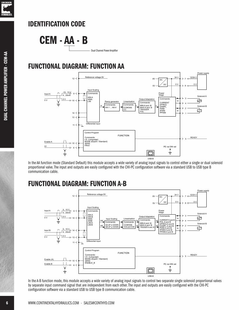
FUNCTIONAL DIAGRAM: FUNCTION AA
In the AA function mode (Standard Default) this module accepts a wide variety of analog input signals to control either a single or dual solenoidproportional valve. The input and outputs are easily configured with the CHI-PC configuration software via a standard USB to USB type Bcommunication cable.
In the A-B function mode, this module accepts a wide variety of analog input signals to control two separate single solenoid proportional valvesby separate input command signal that are independent from each other. The input and outputs are easily configured with the CHI-PCconfiguration software via a standard USB to USB type B communication cable.
FUNCTIONAL DIAGRAM: FUNCTION A-B
IDENTIFICATION CODE
CEM - AA - BDual Channel Power Amplifier

[email protected] - WWW.CONTINENTALHYDRAULICS.COM 7
1 DIN EN 50022 rail type fastening
2 USB interface, for setup
3 LEDs for output signals
99
120
Ready A B
1
3DUPLOMATIC
OLEODINAMICA
2
23
DUAL CHANNEL POWER AM
PLIFIER - CEM-AA
In the RA function mode, this module accepts 3 independent switch inputs to control either a single or dual solenoid proportional valve. Eachinput has independent adjustable speed and ramp controls. Inputs are additive for up to 8 unique preset speed and ramp profiles. The input andoutputs are easily configured with the CHI-PC configuration software via a standard USB to USB type B communication cable.
FUNCTIONAL DIAGRAM: FUNCTION RA
DIMENSIONS
8 WWW.CONTINENTALHYDRAULICS.COM - [email protected]
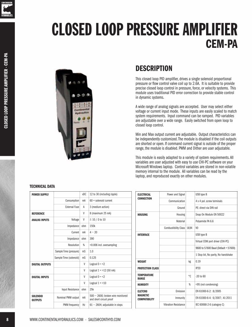
CLOSED LOOP PRESSURE AMPLIFIERCEM-PA
DESCRIPTIONThis closed loop PID amplifier, drives a single solenoid proportionalpressure or flow control valve coil up to 2.6A. It is suitable to provideprecise closed loop control in pressure, force, or velocity systems. Thismodule uses traditional PID error correction to provide stable controlin dynamic systems.
A wide range of analog signals are accepted. User may select eithervoltage or current input mode. These inputs are easily scaled to matchsystem requirements. Input command can be ramped. PID variablesare adjustable over a wide range. Easily switched from open loop toclosed loop control.
Min and Max output current are adjustable. Output characteristics canbe independently customized. The module is disabled if the coil outputsare shorted or open. If command current signal is outside of the properrange, the module is disabled. PWM and Dither are user adjustable.
This module is easily adapted to a variety of system requirements. Allvariables are user adjusted with easy to use CHI-PC software on yourMicrosoft Windows laptop. Control variables are stored in non-volatilememory internal to the module. All variables can be read by thelaptop, and reproduced exactly on other modules.
CLOS
ED L
OOP
PRES
SURE
AM
PLIF
IER
- CEM
-PA
TECHNICAL DATA
POWER SUPPLY vDC 12 to 30 (including ripple)
Consumption mA 60 + solenoid current
External Fuse A 3 (medium action)
REFERENCE V 8 (maximum 25 mA)
ANALOG INPUTS Voltage V ± 10 / 0 to 10
Impedance ohm 150k
Current mA 4 − 20
Impedance ohm 390
Resolution % <0.006 incl. oversampling
Sample Time (pressure) mS 1.0
Sample Time (solenoid) mS 0.125
DIGITAL OUTPUTS V Logical 0 = <2
V Logical 1 = >12 (50 mA)
DIGITAL INPUTS V Logical 0 = <2
V Logical 1 = >10
Input Resistance ohm 25k
SOLENOIDOUTPUTS
Nominal PWM output mA 500 − 2600; broken wire monitoredand short circuit proof
PWM frequency Hz 61 − 2604; adjustable in steps
ELECTRICALCONNECTION
Power and Signal USB type B
Communication 4 x 4 pol. screw terminals
Ground PE: direct via DIN rail
HOUSING Housing Snap On Module EN 50022
Material Polyamide PA 6.6
Combustibility Class UL94 V0
INTERFACE USB type B
Virtual COM port driver (CHI-PC)
9600 to 57600 Baud (Default = 57600)
1 Stop bit, No parity, No handshake
WEIGHT kg 0.19
PROTECTION CLASS IP20
TEMPERATURERANGE
°C -20 to 60
HUMIDITY % <95 (not condensing)
ELETCROMAGNETICCOMPATIBILITY
Emission EN 61000-6-2: 8/2005
Immunity EN 61000-6-4: 6/2007; A1:2011
Vibration Resistance IEC 60068-2-6 (category C)
[email protected] - WWW.CONTINENTALHYDRAULICS.COM 9
1 DIN EN 50022 rail type fastening
2 USB interface, for setup
3 LEDs for output signals
IDENTIFICATION CODE
FUNCTIONAL DIAGRAM
56START
15ENABLE
24 V input
24 V input
READY
4
3
2
Solenoid A
PE via DIN rail
10
90... 10V / 4... 20mA
Pressure command
Voltage reference output12
1
ia
0V
USB-B
DC
DC 0 V
24 V7
8
Internal Power
PELV
24 V
0 V
C:PC:I
commands:
C:D
Controller
Control Program
EOUT (Error Mode)SENS
MODE (Expert or Standard)
24 V outputcommands:
TS (Sample time)LG
Output
commands:MINMAXTRIGGER
SIGNAL:U
SIGNAL:W
Input Scaling
commands:
13
140... 10V / 4... 20mA
0VSIGNAL:X
Input Scaling
commands:
Pressure feedback
11
N_RANGE:XOFFSET:X
Differential input
e
w
A: UP
RAMPs
commands:
A: DOWN
WS
C:FFC:T1C:I_LIMC:I_ACT
x
-
Adaptation
SIGNAL:U
Power
commands:CURRENTDITHERPWM
IPWM
stage
PPWM
ACC
u
DIMENSIONS
CLOSED LOOP PRESSURE AMPLIFIER - CEM
-PA
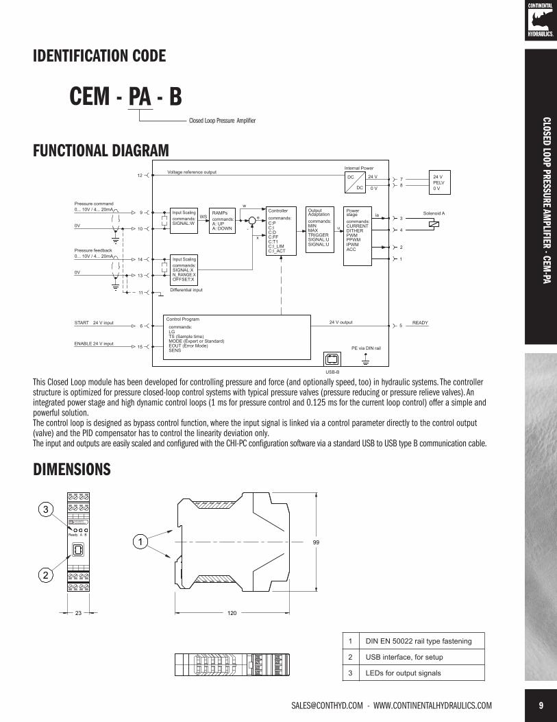
CEM - PA - BClosed Loop Pressure Amplifier
99
120
Ready A B
1
3DUPLOMATIC
OLEODINAMICA
2
23
This Closed Loop module has been developed for controlling pressure and force (and optionally speed, too) in hydraulic systems. The controllerstructure is optimized for pressure closed-loop control systems with typical pressure valves (pressure reducing or pressure relieve valves). Anintegrated power stage and high dynamic control loops (1 ms for pressure control and 0.125 ms for the current loop control) offer a simple andpowerful solution.The control loop is designed as bypass control function, where the input signal is linked via a control parameter directly to the control output(valve) and the PID compensator has to control the linearity deviation only. The input and outputs are easily scaled and configured with the CHI-PC configuration software via a standard USB to USB type B communication cable.

10 WWW.CONTINENTALHYDRAULICS.COM - [email protected]
CLOSED LOOP POSITION MODULECEM-SA
DESCRIPTIONThis closed loop position module has been developed for controlling hydraulicpositioning drives. Proportional valves with integrated or external electronics canbe controlled with the different output. Output is an analog signal of eithervoltage, 0 to ± 10V or current, 4-20mA, suitable for directly driving aproportional directional valve with on board electronics.
The internal profile generation is optimized for stoke-dependent deceleration orthe NC control mode. The controller and the controller settings are factory presetto typical requirements and can be optimized for the control behavior asrequired. The optimized control function offers a high degree of precisiontogether with high stability for hidraulic drives. The movement cycle is controlledvia the external position and speed inputs.
The high resolution of the analog signals ensures good positioning behavior. Awide range of analog signals are accepted. User may select either voltage orcurrent input mode. These inputs are easily scaled to match systemrequirements. Forward and Reverse “jog” inputs allow for manual load control. Auser definable window for “in position” triggers an output for communication tothe next machine function.
This module is easily adapted to a variety of system requirements. All variables areuser adjusted with easy to use CHI-PC software on your Microsoft Windows laptop.Control variables are stored in non-volatile memory internal to the module. Allvariables can be read by the laptop, and reproduced exactly on other modules.
CLOS
ED L
OOP
POSI
TION
MOD
ULE
- CEM
-SA
TECHNICAL DATA
POWER SUPPLY vDC 12 to 30 (including ripple)
Consumption W < 100
External Fuse A 1 (medium action)
REFERENCE V 8 (maximum 25 mA)
ANALOG INPUTS Voltage V 0 − 10
Impedance ohm 25k
Current mA 4 − 20
Impedance ohm 240
Resolution % 0.003 incl. oversampling (max res. 1 μm)
Sample Time (process) mS 1.0
Sample Time (solenoid) mS 0.125
DIGITAL OUTPUTS V Logical 0 = <2
V Logical 1 = >12 (50 mA)
DIGITAL INPUTS V Logical 0 = <2
V Logical 1 = >10
Input Resistance ohm 25k
ANALOG OUTPUTS Voltage V 2 x 0 − 10 differential output
Current mA 4 − 20; 390 Ω max load
Resolution % 0.006
ELECTRICALCONNECTION
Power and Signal USB type B
Communication 4 x 4 pol. screw terminals
Ground PE: direct via DIN rail
HOUSING Housing Snap On Module EN 50022
Material Polyamide PA 6.6
Combustibility Class UL94 V0
INTERFACE USB in RS 232C Emulation
9600 to 57600 Baud (Default = 57600)
1 Stop bit, No parity, echo mode
WEIGHT kg 0.17
PROTECTION CLASS IP20
TEMPERATURERANGE °C -20 to 60
HUMIDITY % <95 (not condensing)
ELETCROMAGNETICCOMPATIBILITY
Emission EN 61000-6-2: 8/2005
Immunity EN 61000-6-4: 6/2007; A1:2011
Vibration Resistance IEC 60068-2-6 (category C)
[email protected] - WWW.CONTINENTALHYDRAULICS.COM 11
1 DIN EN 50022 rail type fastening
2 USB interface, for setup
3 LEDs for output signals
SEEAVAILABLE
OUTPUT 16 -
15 +
12
±10 V
U
Output signals
voltage
current
IDENTIFICATION CODE
FUNCTIONAL DIAGRAM
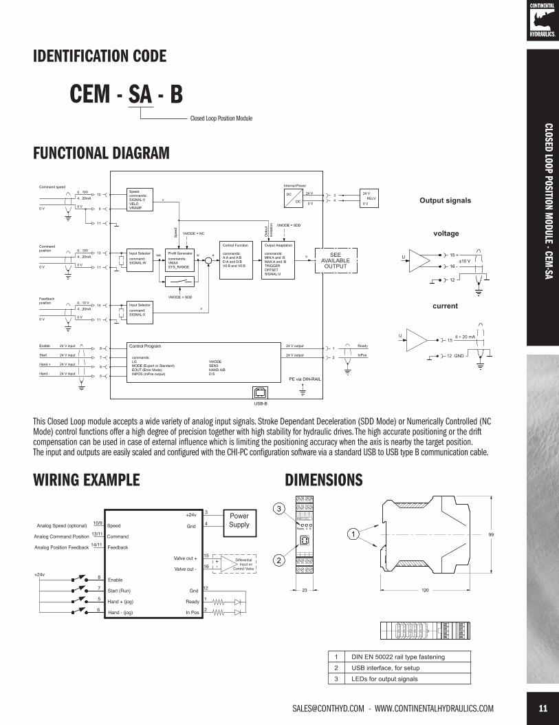
CEM - SA - BClosed Loop Position Module
This Closed Loop module accepts a wide variety of analog input signals. Stroke Dependant Deceleration (SDD Mode) or Numerically Controlled (NCMode) control functions offer a high degree of precision together with high stability for hydraulic drives. The high accurate positioning or the driftcompensation can be used in case of external influence which is limiting the positioning accuracy when the axis is nearby the target position. The input and outputs are easily scaled and configured with the CHI-PC configuration software via a standard USB to USB type B communication cable.
CLOSED LOOP POSITION MODULE - CEM
-SA
WIRING EXAMPLE
PowerSupply
15
16Differential Input on
Control Valve+-
3
4
12
1
2Ready
In Pos
5Start (Run)
Hand + (jog)6
7
8
Hand - (jog)
Analog Position Feedback
Analog Command Position
Analog Speed (optional)
+24v
14/11
13/11
10/9 Gnd
+24v
Gnd
Valve out +
Enable
Speed
Command
Feedback
Valve out -
DIMENSIONS
99
120
Ready A B
1
3DUPLOMATIC
OLEODINAMICA
2
23

12 WWW.CONTINENTALHYDRAULICS.COM - [email protected]
CLOS
ED L
OOP
POSI
TION
MOD
ULE
- CEM
-SD
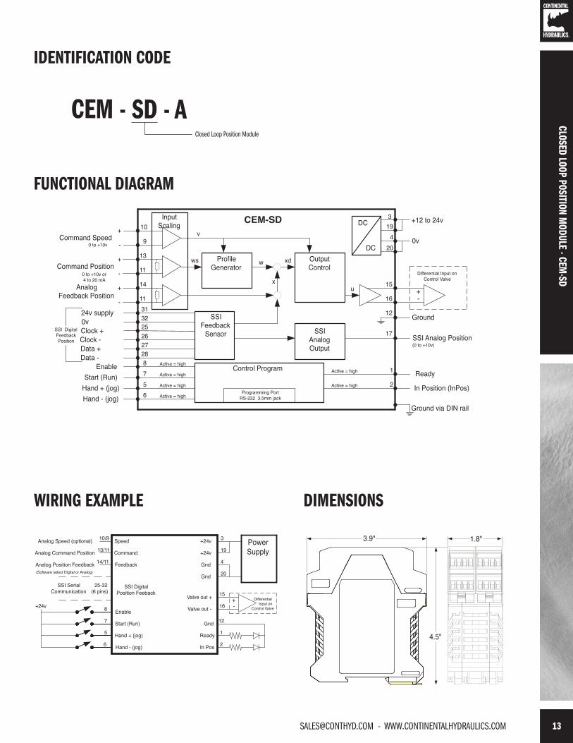
CLOSED LOOP POSITION MODULECEM-SD
Analog Command and SSI Digital FeedbackDESCRIPTIONThis closed loop position module is designed to quickly and accurately movehydraulic cylinder loads. Position and velocity commands are from analogsources. Cylinder position feedback is from a digital (SSI) source.
Stroke dependent deceleration is used to provide quick and repeatablepositioning. Internal ramp and velocity adjustments allow for easy system tuning.
A wide range of analog signals are accepted. User may select either voltageor current input mode. These inputs are easily scaled to match system requirements.
Forward and Reverse “jog” inputs allow for manual load control. A userdefinable window for “in position” triggers an output for communication to thenext machine function.
Output is an analog voltage, 0 to +10vdc, suitable for directly driving aproportional directional valve with on board electronics.
This module is easily adapted to a variety of system requirements. All variablesare user adjusted with easy to use software on your Microsoft Windows laptop.Control variables are stored in non-volatile memory internal to the module. Allvariables can be read by the laptop, and reproduced exactly on other modules.
TECHNICAL DATA
POWER SUPPLY vDC 12 to 30 (including ripple)
Consumption mA <100mA
External Fuse A 3 (medium action)
ANALOG INPUTS Voltage vDC 0 − 10
Impedance ohm 33k
Current mA 4 − 20
Impedance ohm 250
Resolution % 0.01
Sample Time mS 1.0
(Speed Input) Voltage vDC 0 − 10
(Speed Input) Impedance ohm 90K
SSI FEEDBACK RS-422 150k baud
Monitor vDC 0 to 10
mA 5 (max)
DIGITAL INPUTS V Logical 0 = <2
V Logical 1 = >10
Impedance ohm 25k
ELECTRICALCONNECTION
Programming Port RS-232 3.5mm Stero Jack
Power and Signal 8 strips with 4 screw terminals each
Ground via DIN Rail
DIGITAL OUTPUTS V Logical 0 = <2 (50mA max)
V Logical 1 = ~ Power Supply
ANALOG OUTPUTS Voltage vDC 0 to ± 10
Current mA 5 max
Resolution % 0.024
HOUSING Module Snaps to 35mm DIN rail EN 50022
Material Polyamide PA 6.6
Combustability Class UL94 V0
Protection Class IP 20
Working Temperature °C -20 to +60
Storage Temperature °C -20 to +70
Humidity % 95 (non condensing)
ELETCRO MAGNETICCOMPATIBILITY
Emission EN 61000-6-2
Immunity EN 61000-6-3
Vibration Resistance EIC 60068-2-6
[email protected] - WWW.CONTINENTALHYDRAULICS.COM 13
CLOSED LOOP POSITION MODULE - CEM
-SD
IDENTIFICATION CODE
FUNCTIONAL DIAGRAM
CEM - SD - AClosed Loop Position Module
WIRING EXAMPLE
PowerSupply
15
16Differential Input on
Control Valve+-
3
20
19
4
12
1
2Ready
In Pos
Gnd
5
SSI SerialCommunication
Start (Run)
Hand + (jog)6
7
8
Hand - (jog)
SSI DigitalPosition Feeback
25-32(6 pins)
Analog Position Feedback
Analog Command Position
Analog Speed (optional)
(Software select Digital or Analog)
+24v
14/11
13/11
10/9
Gnd
+24v
+24v
Gnd
Valve out +
Enable
Speed
Command
Feedback
Valve out -
DIMENSIONS
4.5"
3.9" 1.8"

14 WWW.CONTINENTALHYDRAULICS.COM - [email protected]
CLOSED LOOP SYNCHRONIZATION MODULECEM-MS
Two Axis ControlDESCRIPTIONThis closed loop position module is to be applied in pairs, each moduledriving a hydraulic cylinder for a system of synchronized motion. This pairof cylinders can quickly and accurately move hydraulic cylinder loads inunison. Position and velocity commands are from analog sources.Cylinder feedback is from an analog source.
Stroke dependent deceleration is used to provide quick and repeatablepositioning. Internal ramp and velocity adjustments allow for easy systemtuning.
A wide range of analog signals are accepted. User may select eithervoltage or current input mode. These inputs are easily scaled to matchsystem requirements.
Output is an analog voltage, 0 to +10vdc, suitable for directly driving aproportional directional valve with on board electronics.
This module is easily adapted to a variety of system requirements. Allvariables are user adjusted with easy to use software on your MicrosoftWindows laptop. Control variables are stored in non-volatile memoryinternal to the module. All variables can be read by the laptop, andreproduced exactly on other modules.
CLOS
ED L
OOP
SYNC
HRON
IZAT
ION
MOD
ULE
- CEM
-MS
TECHNICAL DATA
POWER SUPPLY vDC 12 to 30 (including ripple)
Consumption mA <100mA
External Fuse A 3 (medium action)
ANALOG INPUTS Voltage vDC 0 − 10
Impedance ohm 33k
Current mA 4 − 20
Impedance ohm 250
Resolution % 0.01
Sample Time mS 1.0
(Speed Input) Voltage vDC 0 − 10
(Speed Input) Impedance ohm 90K
DIGITAL OUTPUTS V Logical 0 = <2 (50mA max)
V Logical 1 = ~ Power Supply
DIGITAL INPUTS V Logical 0 = <2
V Logical 1 = >10
Impedance ohm 25k
ELECTRICALCONNECTION
Programming Port RS-232 3.5mm Stero Jack
Power and Signal 8 strips with 4 screw terminals each
Ground via DIN Rail
ANALOG OUTPUTS Voltage vDC 0 to ± 10
Current mA 5 max
Resolution % 0.024
HOUSING Module Snaps to 35mm DIN rail EN 50022
Material Polyamide PA 6.6
Combustability Class UL94 V0
Protection Class IP 20
Working Temperature °C -20 to +60
Storage Temperature °C -20 to +70
Humidity % 95 (non condensing)
ELETCRO MAGNETICCOMPATIBILITY
Emission EN 61000-6-2
Immunity EN 61000-6-3
Vibration Resistance EIC 60068-2-6

[email protected] - WWW.CONTINENTALHYDRAULICS.COM 15
IDENTIFICATION CODE
FUNCTIONAL DIAGRAM
CEM - MS - AClosed Loop Synchronization Module
WIRING EXAMPLE
5
7
10/9
8
13
14
6
10/9
13
14
6
5
7
8
Speed input (optional)
Position Command
Master position
Slave position
Master
Start/Run
Synch Active
Enable
Start/Run
Synch Active
Slave
Enable
15
16Differential Input on
Control Valve
+-
PowerSupply
3
4
+
-
15
16+-
PowerSupply
3
4
+
-
12
1
2
12
1
2Ready
In Pos
Gnd
Ready
In Pos
Gnd+24v
+24v
Differential Input on
Control Valve
LED
LED
DIMENSIONS
4.5"
3.9" 0.9"
CLOSED LOOP SYNCHRONIZATION MODULE - CEM
-MS

16 WWW.CONTINENTALHYDRAULICS.COM - [email protected]
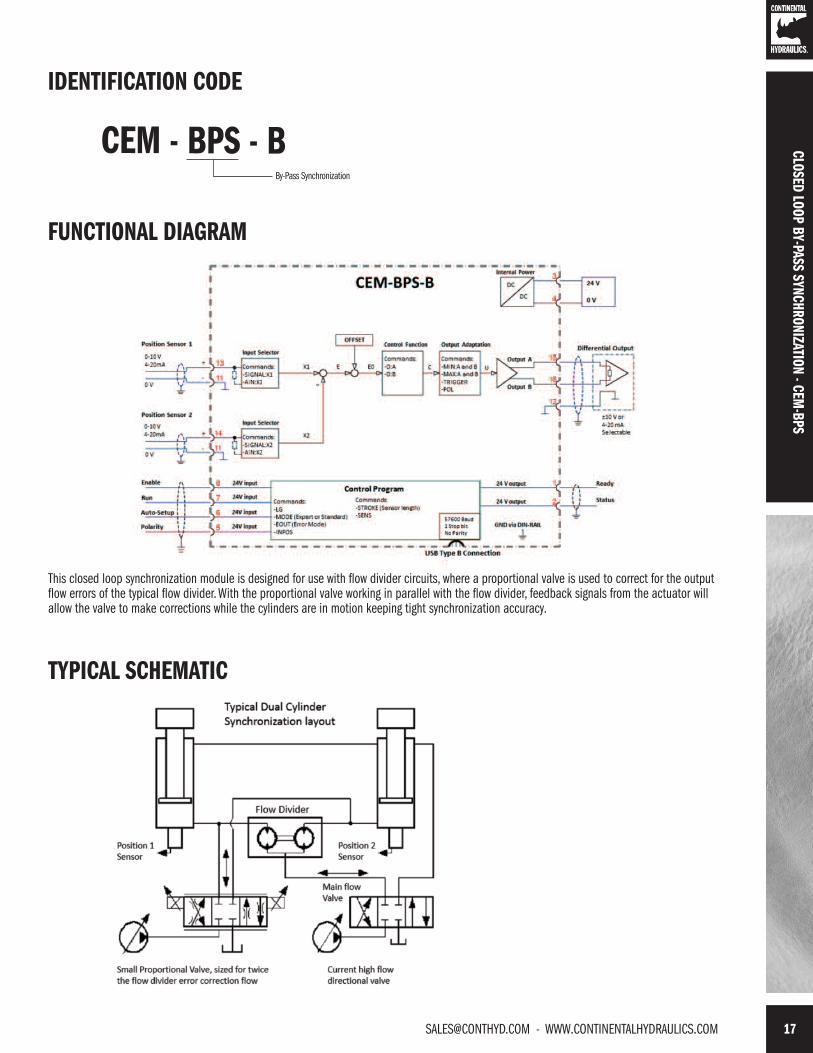
CLOSED LOOP BY-PASS SYNCHRONIZATIONCEM-BPS
DESCRIPTIONThis closed loop position module has been developed for controllinghydraulic synchronization systems. The typical synchronization accuracyis about 0.1% to 1% of the sensor length (depending on the hydraulicsystem). Proportional valve with integrated or external electronics canbe controlled with the differential output. Output is an analog signal ofeither voltage, 0 to +/- 10v or current 4-20mA.
This module is designed for use within a flow divider circuit. A flowdivider (valve or gear pump) will synchronize the axis but with limitedaccuracy. A proportional valve working in parallel to the flow divider iscompensating the flow error in one or both cylinders. This kind ofsynchronization control is ex-tremely stable and simple to use.
With the AUTO SETUP input feature, the offset error between bothsensors can be measured and compensated automatically.The internal profile generation is optimized for stroke-dependentdeceleration control mode. The controller and the controller settingscan be optimized for the control behavior as required.
This module is easily adapted to a variety of system requirements. Allvariables are user adjusted with easy to use CHI-PC software on yourMicrosoft Windows laptop. Control variables are stored in non-volatilememory internal to the module. All variables can be read by the laptop,and reproduced exactly on other modules.
CLOS
ED L
OOP
BY-P
ASS
SYNC
HRON
IZAT
ION
- CEM
-BPS
TECHNICAL DATA
POWER SUPPLY vDC 12 to 30 (including ripple)
Consumption W < 100
External Fuse A 1 (medium action)
REFERENCE V 8 (maximum 25 mA)
ANALOG INPUTS Voltage V 0 − 10
Impedance ohm 25k
Current mA 4 − 20
Impedance ohm 240
Resolution % 0.003 incl. oversampling (max res. 1 μm)
Sample Time (process) mS 1.0
Sample Time (solenoid) mS 0.125
DIGITAL OUTPUTS V Logical 0 = <2
V Logical 1 = >12 (50 mA)
DIGITAL INPUTS V Logical 0 = <2
V Logical 1 = >10
Input Resistance ohm 25k
ANALOG OUTPUTS Voltage V 2 x 0 − 10 differential output
Current mA 4 − 20; 390 Ω max load
Resolution % 0.006
ELECTRICALCONNECTION
Power and Signal USB type B
Communication 4 x 4 pol. screw terminals
Ground PE: direct via DIN rail
HOUSING Housing Snap On Module EN 50022
Material Polyamide PA 6.6
Combustibility Class UL94 V0
INTERFACE USB in RS 232C Emulation
9600 to 57600 Baud (Default = 57600)
1 Stop bit, No parity, echo mode
WEIGHT kg 0.17
PROTECTION CLASS IP20
TEMPERATURERANGE °C -20 to 60
HUMIDITY % <95 (not condensing)
ELETCROMAGNETICCOMPATIBILITY
Emission EN 61000-6-2: 8/2005
Immunity EN 61000-6-4: 6/2007; A1:2011
Vibration Resistance IEC 60068-2-6 (category C)
[email protected] - WWW.CONTINENTALHYDRAULICS.COM 17
IDENTIFICATION CODE
FUNCTIONAL DIAGRAM
CEM - BPS - BBy-Pass Synchronization
This closed loop synchronization module is designed for use with flow divider circuits, where a proportional valve is used to correct for the outputflow errors of the typical flow divider. With the proportional valve working in parallel with the flow divider, feedback signals from the actuator willallow the valve to make corrections while the cylinders are in motion keeping tight synchronization accuracy.
TYPICAL SCHEMATIC
CLOSED LOOP BY-PASS SYNCHRONIZATION - CEM-BPS

18 WWW.CONTINENTALHYDRAULICS.COM - [email protected]
CLOSED LOOP PID MODULECEM-PID
Universal PID Signal ConditionerDESCRIPTIONThis closed loop PID module compares command and feedbacksignals, and applies traditional PID gain settings to the error signal.This modified signal is provided as an analog voltage (0 to +/-10v)output. It may be used to drive proportional pressure or flow controlvalves with on board electronics, or as a command to another amplifiermodule. It is suitable to provide dynamic closed loop control inpressure, force, or velocity systems.
A wide range of analog signals are accepted. User may select eithervoltage or current input mode. These inputs are easily scaled to matchsystem requirements. Input command can be ramped. PID variablesare adjustable over a wide range. Easily switched from open loop toclosed loop control.
Output can be scaled to match the proportional valve being driven. Ifcommand current signal is outside of the proper range, the module isdisabled. Digital outputs inform the user of system errors.
This module is easily adapted to a variety of system requirements. Allvariables are user adjusted with easy to use software on your MicrosoftWindows laptop. Control variables are stored in non-volatile memoryinternal to the module. All variables can be read by the laptop, andreproduced exactly on other modules.
TECHNICAL DATA
POWER SUPPLY vDC 12 to 30 (including ripple)
Consumption mA <100mA
External Fuse A 3 (medium action)
ANALOG INPUTS Voltage vDC 0 − 10
Impedance ohm 33k
Current mA 4 − 20
Impedance ohm 250
Resolution % 0.012
Sample Time mS 1.0
Reference Voltage vDC 8 (maximum 10 mA)
DIGITAL INPUTS V Logical 0 = <2
V Logical 1 = >10
Impedance ohm 25k
DIGITAL OUTPUTS V Logical 0 = <2 (50mA max)
V Logical 1 = ~ Power Supply
ELECTRICALCONNECTION
Programming Port RS-232 3.5mm Stero Jack
Power and Signal 8 strips with 4 screw terminals each
Ground via DIN Rail
ANALOG OUTPUTS Voltage vDC 0 to ± 10
Current mA 5 max
Resolution % 0.024
HOUSING Module Snaps to 35mm DIN rail EN 50022
Material Polyamide PA 6.6
Combustability Class UL94 V0
Protection Class IP 20
Working Temperature °C -20 to +60
Storage Temperature °C -20 to +70
Humidity % 95 (non condensing)
ELETCRO MAGNETICCOMPATIBILITY
Emission EN 61000-6-2
Immunity EN 61000-6-3
Vibration Resistance EIC 60068-2-6
CLOS
ED L
OOP
PID
MOD
ULE
- CEM
-PID

[email protected] - WWW.CONTINENTALHYDRAULICS.COM 19
IDENTIFICATION CODE
FUNCTIONAL DIAGRAM
3
4
15
16
1 Ready
InputScaling
Control Program
DC
DC
+12 to 24v0v
Command Input
Parameter Group Selection
9
11
8
6
14
11
1211
8v (10 mA)
Ramp PID Control
OutputControl+
-0 to +10v
or4 to 20 mA
Enable
GroundReference output
Ground via DIN rail
Programming PortRS-232 3.5mm jack
CEM-PID
Feedback Input+
-
w
x
u
2 Error
+
Offset
75Ramp
Start (Run)Active = high
Active = high
Active = high
Active = high
Active = high
Active = high
Differential Input onControl Valve
+-
CEM - PID - AClosed Loop PID Module
WIRING EXAMPLE
RunEnable
FeedbackGnd
Command in+8v ref
Gnd
11
129
11
8
PressureTransducer
Potentiometer
5
14PowerSupply
1516
Differential Input on
Control Valve
+-
34
1112
ReadyError
Gnd+24v
Gnd
Valve out +Valve out -
Parameter Group SelectionRamp
6
7
LED
DIMENSIONS
4.5"
3.9" 0.9"
CLOSED LOOP PID MODULE - CEM
-PID

20 WWW.CONTINENTALHYDRAULICS.COM - [email protected]
VALVE ELECTRICAL ACCESSORIESFOR ELECTRO-HYDRAULIC PRODUCTS
DESCRIPTIONThese products are used to connect, configure and troubleshoot yourelectro hydraulic proportional products.
CHI electro hydraulic products are unique in the industry, as you needonly “One cable, and One software” to configure our full line of alldigital valves and control modules.
This easy to use software allows you precise and repeatable control ofthe electronic variables necessary to tune the motion profile of yourcontrol system.
All variables can be adjusted, saved and reproduced into othermodules. Variable names and ranges are consistent from one moduleto another, making your machine tuning job easier.
Product offerings include:
Programming Cable Programming Boxes Adapters Connectors and Cordsets Software
PROGRAMMING CABLESVEA-BUSB (USB to Type B USB) cable is necessary to configure all CEM “B series” Modules.
VEA-USB (USB to RS232 3.5 mm with Communication Chip) cable is necessary to configure all Digital Valves with On-Board Electronics alongwith the Programming Box and all “A series” CEM Modules.
VALV
E EL
ECTR
ICAL
ACC
ESSO
RIES
[email protected] - WWW.CONTINENTALHYDRAULICS.COM 21
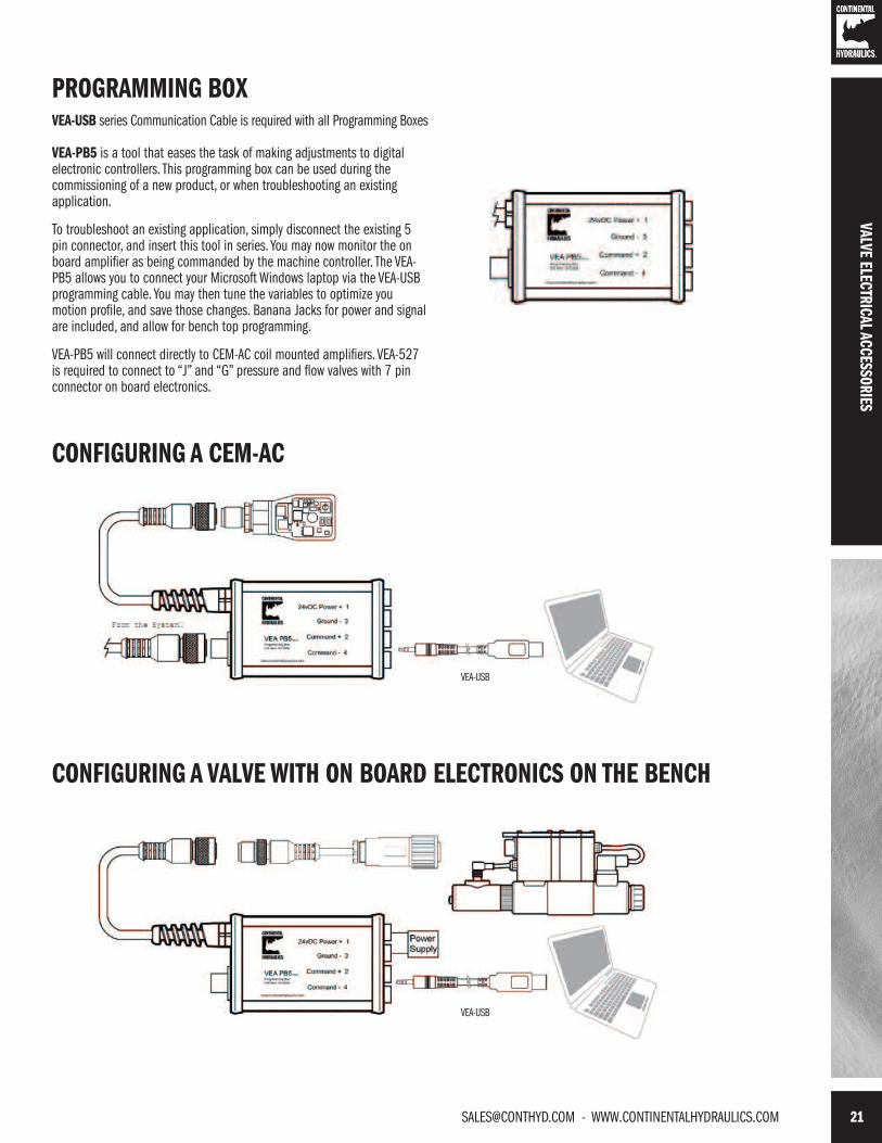
PROGRAMMING BOX VEA-USB series Communication Cable is required with all Programming Boxes
VEA-PB5 is a tool that eases the task of making adjustments to digitalelectronic controllers. This programming box can be used during thecommissioning of a new product, or when troubleshooting an existingapplication.
To troubleshoot an existing application, simply disconnect the existing 5pin connector, and insert this tool in series. You may now monitor the onboard amplifier as being commanded by the machine controller. The VEA-PB5 allows you to connect your Microsoft Windows laptop via the VEA-USBprogramming cable. You may then tune the variables to optimize youmotion profile, and save those changes. Banana Jacks for power and signalare included, and allow for bench top programming.
VEA-PB5 will connect directly to CEM-AC coil mounted amplifiers. VEA-527is required to connect to “J” and “G” pressure and flow valves with 7 pinconnector on board electronics.
CONFIGURING A CEM-AC
CONFIGURING A VALVE WITH ON BOARD ELECTRONICS ON THE BENCH
VALVE ELECTRICAL ACCESSORIES
VEA-USB
VEA-USB

22 WWW.CONTINENTALHYDRAULICS.COM - [email protected]
WARNING! Connecting the device will cut off the pin Fmonitor signal from the valve, in order to allow the LINbuscommunication. This behaviour can be managed via software.
FUNCTION DESCRIPTION24V PWR (24V powered)
Main power supply via 24V (pin A)green LED indicates the device is powered by 24 V source on pin A of the7-pin connector.
USB COM USB communicationred = [TX] transmissiongreen = [RX] receiving
USB PWR (USB powered)
USB supplyyellowindicates that the USB section is powered.
to the valve
VALV
E EL
ECTR
ICAL
ACC
ESSO
RIES
PROGRAMMING BOX
VEA-PB7 is a tool that eases the task of making adjustments to digitalelectronic controllers. This programming box can be used during thecommissioning of a new product, or when troubleshooting an existingapplication.
To troubleshoot an existing application, simply disconnect the existing 7pin connector, and insert this tool in series. You may now monitor the onboard amplifier as being commanded by the machine controller. The VEA-PB7 allows you to connect your Microsoft Windows laptop via VEA-USB, andchange variables as required.
VEA-PB7 will connect directly to any valves with 7 pin connector on boardelectronics.
CONFIGURING A VALVE WITH ON BOARD ELECTRONICS
BLOCK DIAGRAM

[email protected] - WWW.CONTINENTALHYDRAULICS.COM 23
VALVE ELECTRICAL ACCESSORIES
PROGRAMMING BOX CABLE ADAPTERVEA-527 is an adapter that allows the VEA-PB5 to connect to proportional valves with on board electronics. It has a male M12 5 pin jack, and afemale 7 pin plug to connect to the valve. Internally, Pin A is connected to Pin C to turn on “Enable”. Power, signal and communication pins arewired straight through.
VALVE CONNECTORS AND CORDSETS
VEA-3P5C is a molded shielded cordset that brings power and signal tothe CEM AC amplifier. It is a M12 female connector attached 5conductors of 24ga finely stranded copper, all wrapped in a foil shield.The shield drain is to be connected to frame ground at the control box.The cable is 5 meters long, and can be easily cut to length duringinstallation.
Electrical connectors and shielded cable assemblies connects themachine controller to the 7 pin on board electronics valve controller.Plastic VEA-3P7P and metal VEA-3P7M versions are offered.
VEA-3P7C cordset attaches a plastic connector body to a 3 meter longcable made of 7 individual 18 gauge copper conductors, all wrapped ina foil shield. The outer jacket is an oil resistant gray PVC. The controllerend of the cable is stripped and tagged with pin names.

24 WWW.CONTINENTALHYDRAULICS.COM - [email protected]
VALV
E EL
ECTR
ICAL
ACC
ESSO
RIES
SOFTWARECHI PC is a “free to download” application for your Microsoft Windows®laptop. This tool allows you configure and troubleshoot all of your CHIdigital electronics products. This easy to understand software can be usedin all three process steps: configure and tune the machine, storing thesevariables to permanent memory, and monitoring the machine duringoperation.
The configuration page allowsthe user to scale inputs,adjust ramp times, set closedloop control variables, andadjust outputs to match thevalve. Only those parametersthat apply to the connectedmodule appear on this screen
The oscilloscope featureallows the user to monitorinputs and outputs in realtime. Cursor control allows forprecise measurement ofvariables.


ABOUT CONTINENTAL HYDRAULICSRugged, durable, high-performance, efficient—the reason Continental Hydraulics’ products are used in some of the most challenging applications across the globe. With a commitment to quality customer
support and innovative engineering, Continental’s pumps, valves, power units, mobile and custom products deliver what the markets demand. Continental has been serving the food production, brick
and block, wood products, automotive and machine tool industries since 1962. Learn how our products survive some of the most harsh environments.
[email protected] WEST 123RD STREET • SAVAGE, MN 55378-1299 / PH: 952.895.6400 / FAX: 952.895.6444 / WWW.CONTINENTALHYDRAULICS.COM
FORM NO. 1013819. REV. 06/2016. © 2014 CONTINENTAL HYDRAULICS. ALL RIGHTS RESERVED. PRODUCT SPECIFICATIONS AND APPEARANCE ARE SUBJECT TO CHANGE WITHOUT NOTICE.
MOT
ION
CONT
ROL
SOLU
TION
S
Related Documents