CLUTCHES 1

Welcome message from author
This document is posted to help you gain knowledge. Please leave a comment to let me know what you think about it! Share it to your friends and learn new things together.
Transcript

CLUTCHES
1
Clutch
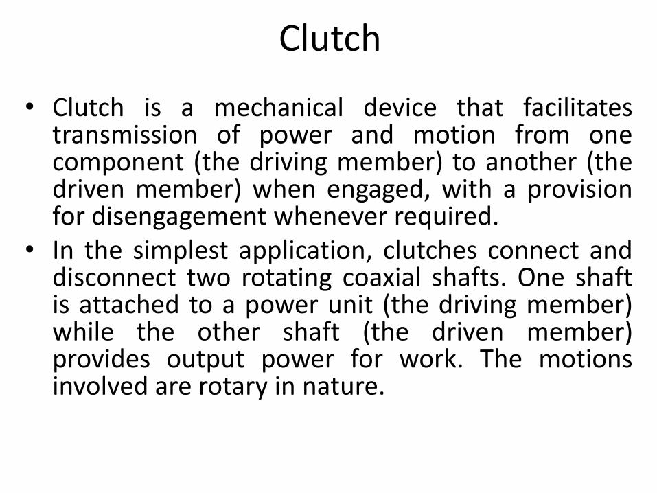
• Clutch is a mechanical device that facilitates transmission of power and motion from one component (the driving member) to another (the driven member) when engaged, with a provision for disengagement whenever required.
• In the simplest application, clutches connect and disconnect two rotating coaxial shafts. One shaft is attached to a power unit (the driving member) while the other shaft (the driven member) provides output power for work. The motions involved are rotary in nature.
Purpose
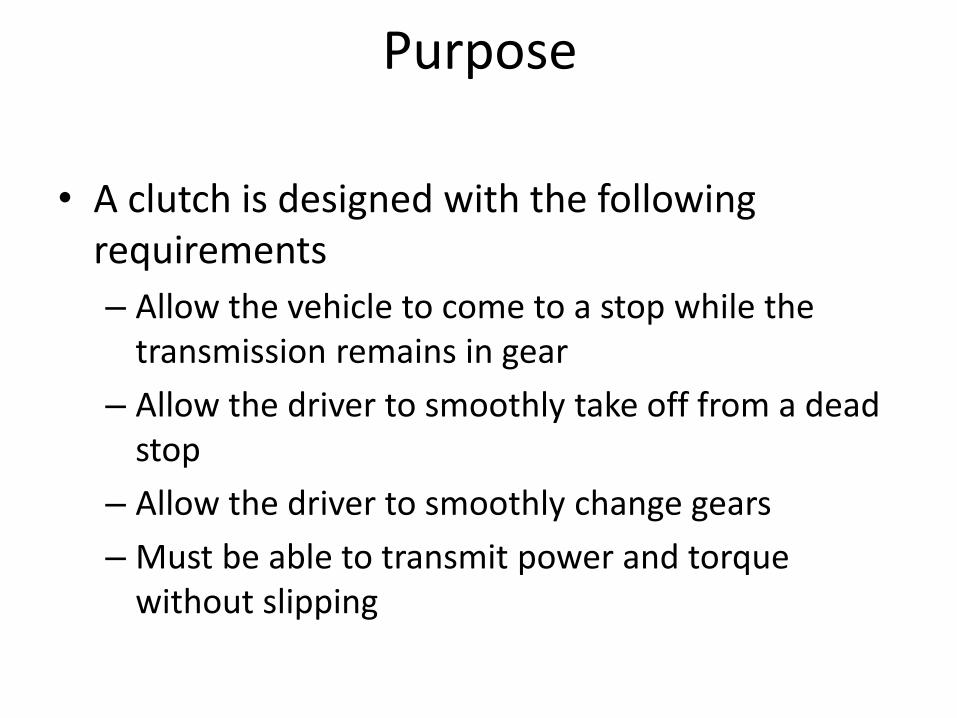
• A clutch is designed with the following requirements
– Allow the vehicle to come to a stop while the transmission remains in gear
– Allow the driver to smoothly take off from a dead stop
– Allow the driver to smoothly change gears
– Must be able to transmit power and torque without slipping
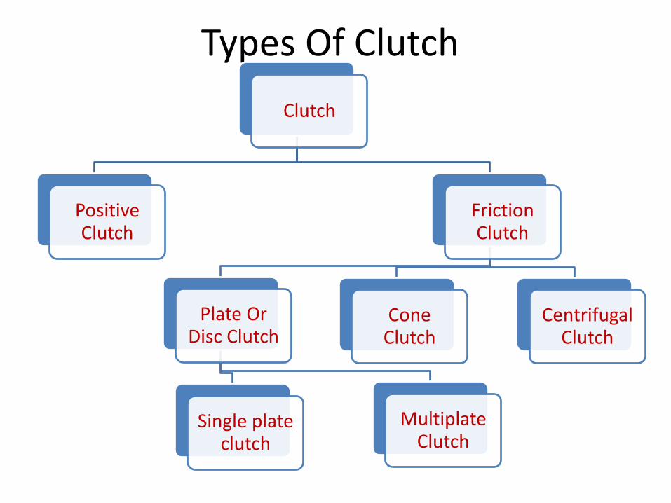
Types Of Clutch
Clutch
Positive Clutch
Friction Clutch
Plate Or Disc Clutch
Single plate clutch
Multiplate Clutch
Cone Clutch
Centrifugal Clutch
Types of Clutch
1. WET CLUTCH : Wet clutch is immersed in a cooling lubricating fluid which also keeps the surfaces clean and gives smoother performance and longer life. Wet clutches, however, tend to lose some energy to the liquid.
2. DRY CLUTCH : Dry clutch, as the name implies, is not bathed in fluid and runs dry.
Clutch terms
• Clutch disengaged (Clutch pedal pressed)
The clutch is disengaged when
– Starting the engine
– Shifting the gear
– Stopping the vehicle and
– Idling the engine
• Clutch engaged
– Clutch pedal is released
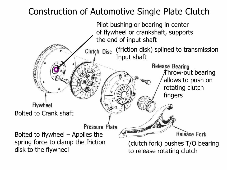
Bolted to Crank shaft
(friction disk) splined to transmission Input shaft
Throw-out bearing allows to push on rotating clutch fingers
Bolted to flywheel – Applies the spring force to clamp the friction disk to the flywheel
(clutch fork) pushes T/O bearing to release rotating clutch
Pilot bushing or bearing in center of flywheel or crankshaft, supports the end of input shaft
Construction of Automotive Single Plate Clutch
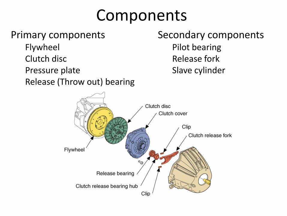
Components Primary components
Flywheel Clutch disc Pressure plate Release (Throw out) bearing
Secondary components Pilot bearing Release fork Slave cylinder
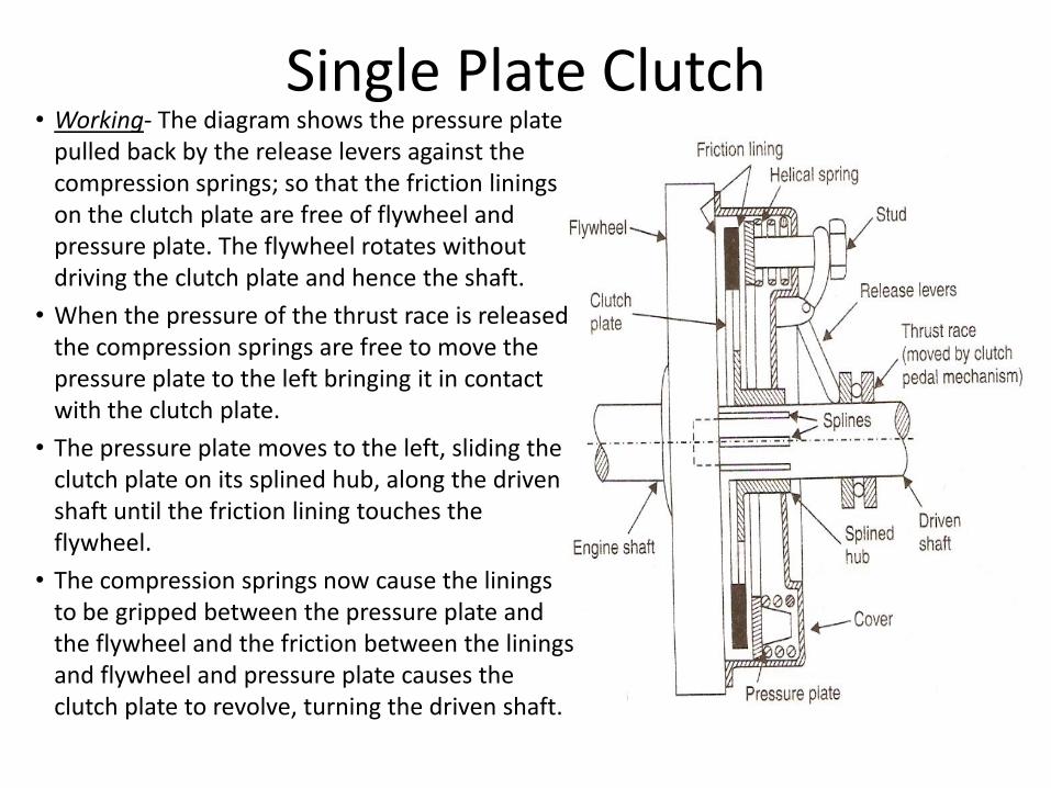
Single Plate Clutch • Working- The diagram shows the pressure plate
pulled back by the release levers against the compression springs; so that the friction linings on the clutch plate are free of flywheel and pressure plate. The flywheel rotates without driving the clutch plate and hence the shaft.
• When the pressure of the thrust race is released the compression springs are free to move the pressure plate to the left bringing it in contact with the clutch plate.
• The pressure plate moves to the left, sliding the clutch plate on its splined hub, along the driven shaft until the friction lining touches the flywheel.
• The compression springs now cause the linings to be gripped between the pressure plate and the flywheel and the friction between the linings and flywheel and pressure plate causes the clutch plate to revolve, turning the driven shaft.
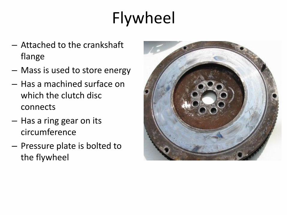
Flywheel
– Attached to the crankshaft flange
– Mass is used to store energy
– Has a machined surface on which the clutch disc connects
– Has a ring gear on its circumference
– Pressure plate is bolted to the flywheel
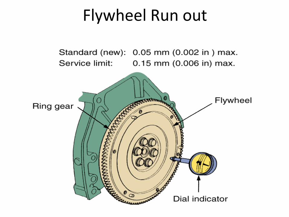
Flywheel Run out
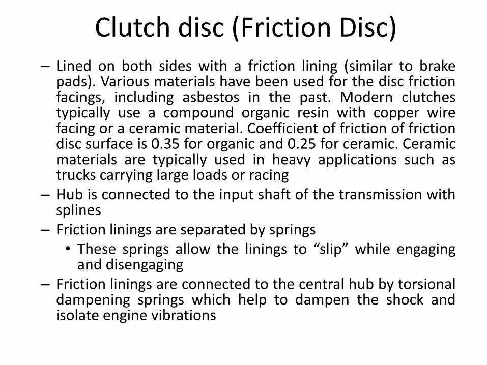
Clutch disc (Friction Disc) – Lined on both sides with a friction lining (similar to brake
pads). Various materials have been used for the disc friction facings, including asbestos in the past. Modern clutches typically use a compound organic resin with copper wire facing or a ceramic material. Coefficient of friction of friction disc surface is 0.35 for organic and 0.25 for ceramic. Ceramic materials are typically used in heavy applications such as trucks carrying large loads or racing
– Hub is connected to the input shaft of the transmission with splines
– Friction linings are separated by springs • These springs allow the linings to “slip” while engaging
and disengaging – Friction linings are connected to the central hub by torsional
dampening springs which help to dampen the shock and isolate engine vibrations
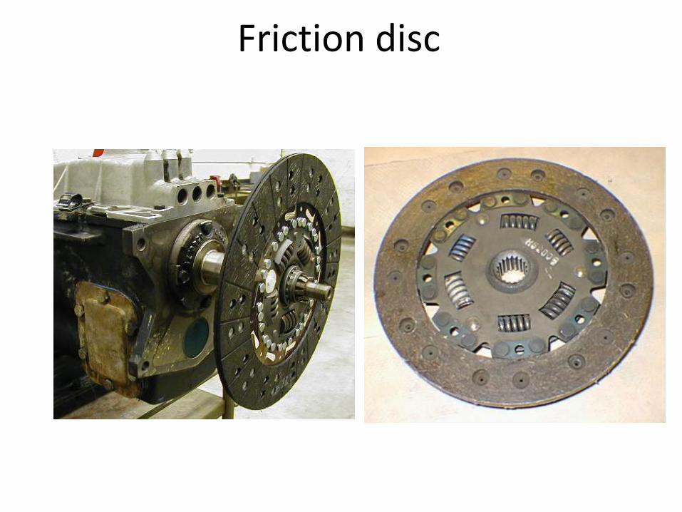
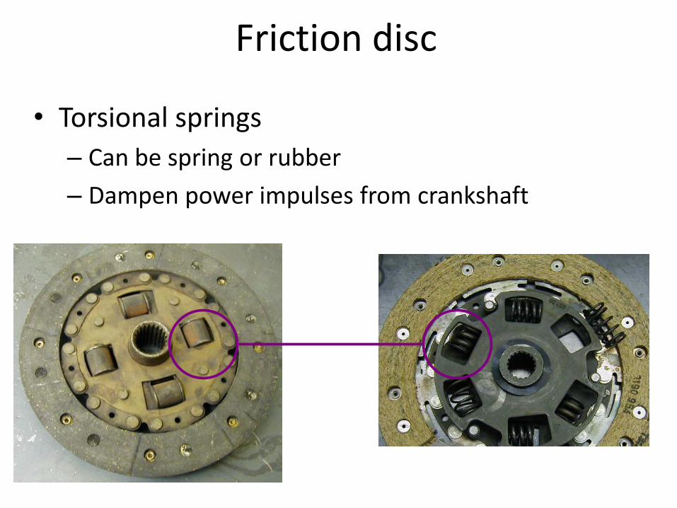
Friction disc
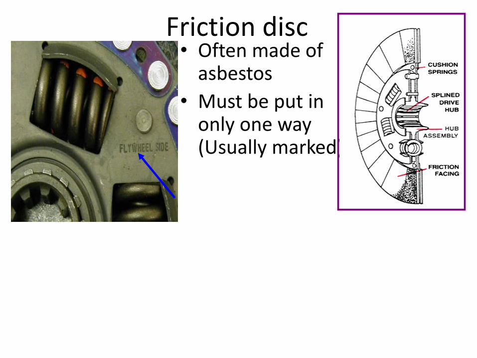
Friction disc • Often made of
asbestos
• Must be put in only one way (Usually marked)
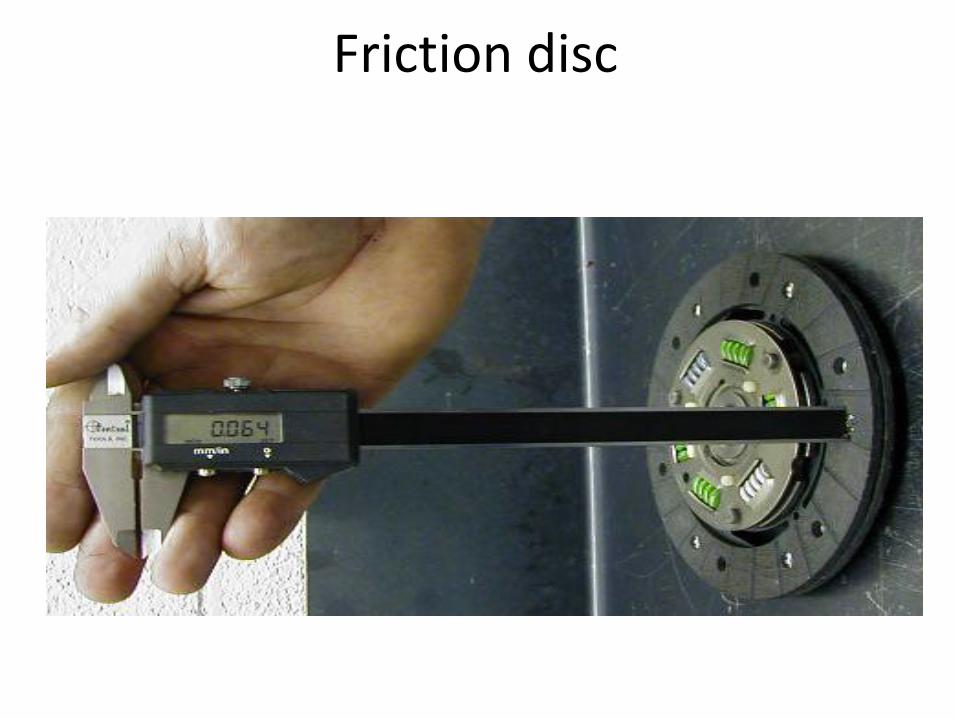
Friction disc
Friction disc
• Torsional springs
– Can be spring or rubber
– Dampen power impulses from crankshaft
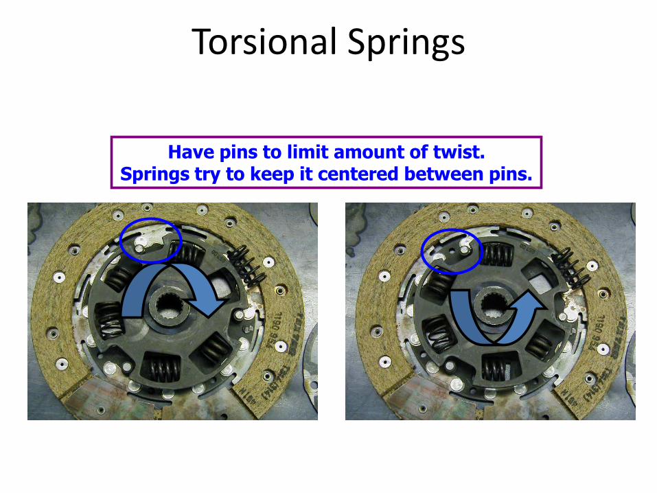
Torsional Springs
Have pins to limit amount of twist. Springs try to keep it centered between pins.
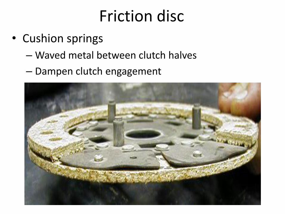
Friction disc • Cushion springs
– Waved metal between clutch halves
– Dampen clutch engagement
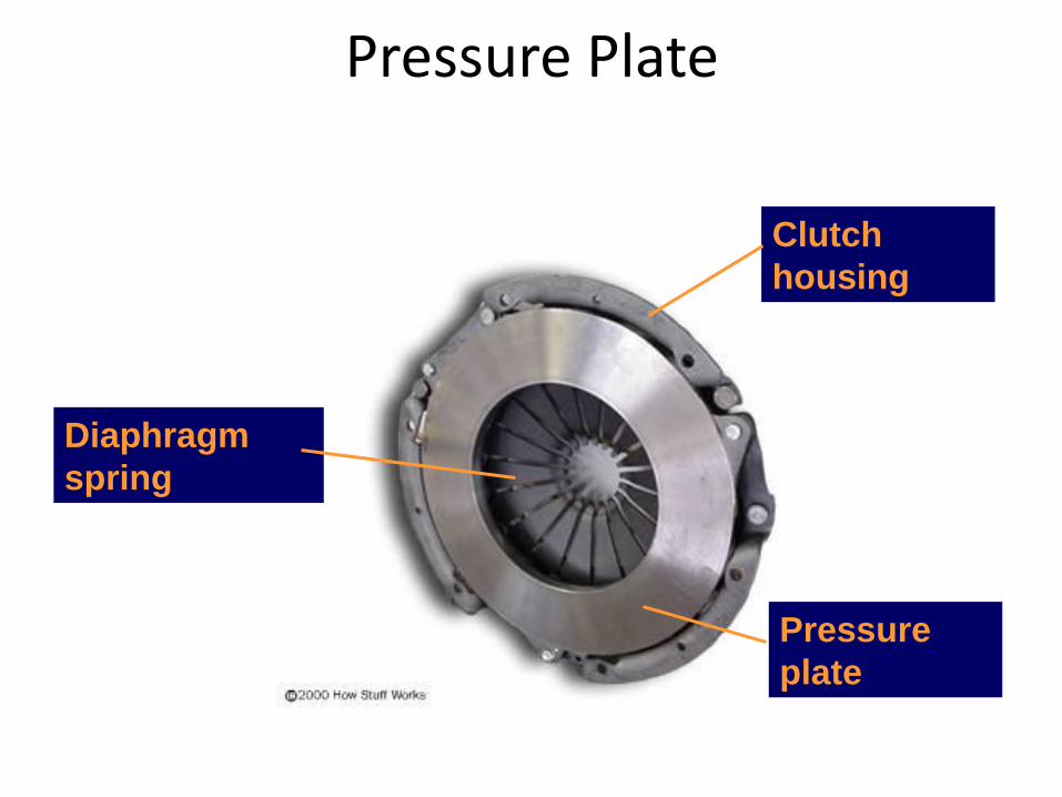
Pressure
plate
Diaphragm
spring
Clutch
housing
Pressure Plate
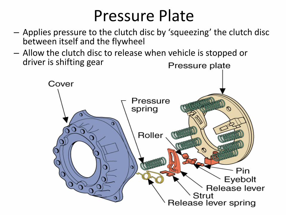
Pressure Plate – Applies pressure to the clutch disc by ‘squeezing’ the clutch disc
between itself and the flywheel – Allow the clutch disc to release when vehicle is stopped or
driver is shifting gear
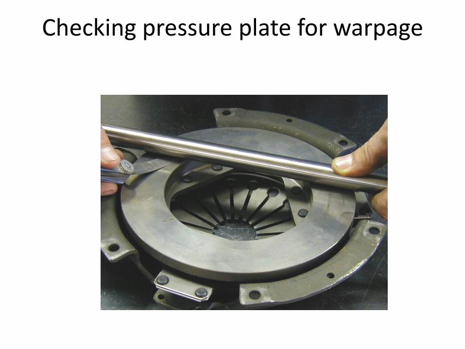
Checking pressure plate for warpage
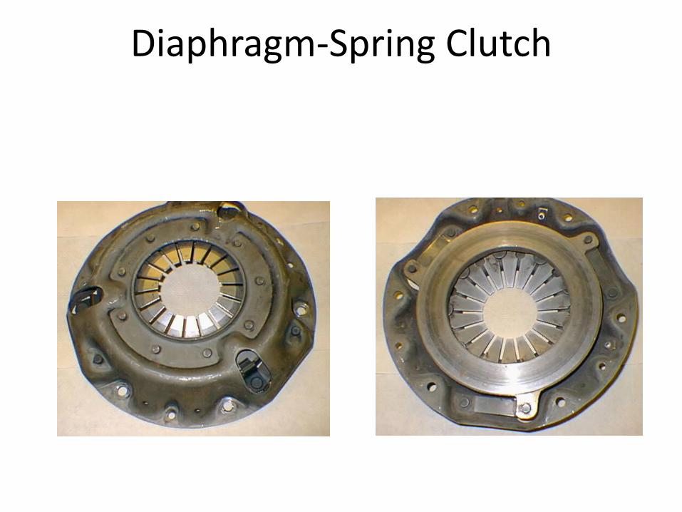
Diaphragm-Spring Clutch
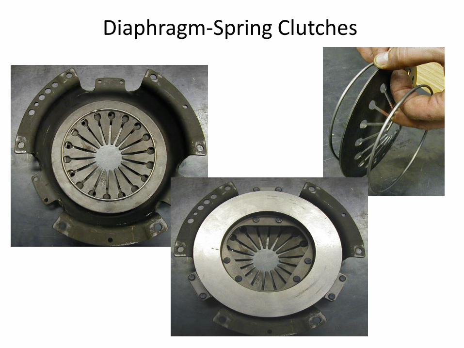
Diaphragm-Spring Clutches
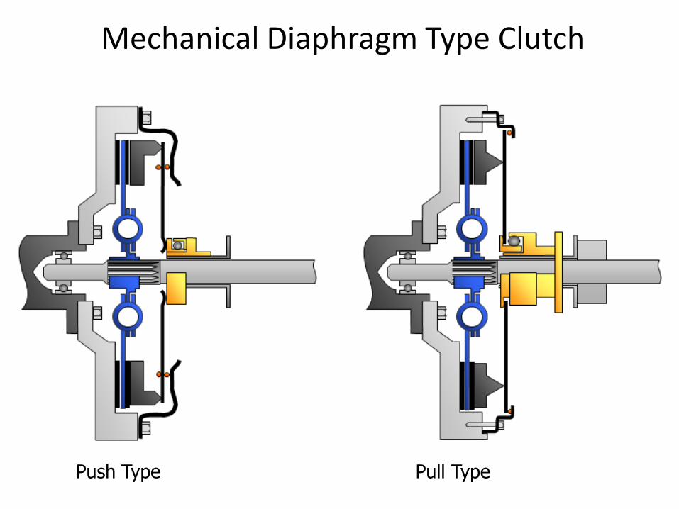
Mechanical Diaphragm Type Clutch
Push Type Pull Type
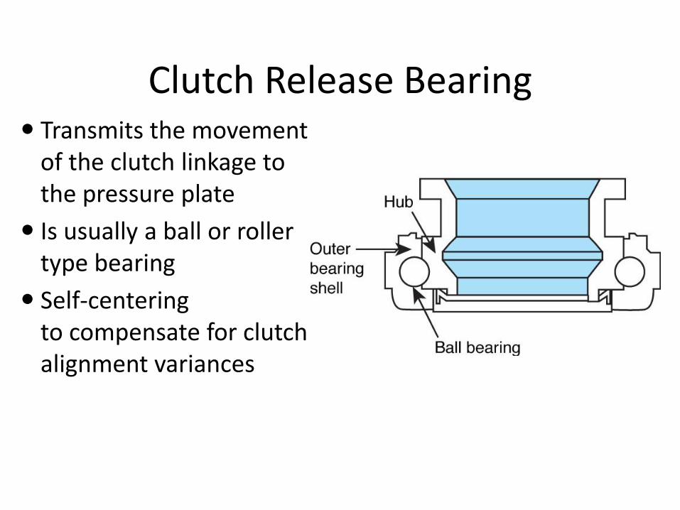
Clutch Release Bearing Transmits the movement
of the clutch linkage to the pressure plate
Is usually a ball or roller type bearing
Self-centering to compensate for clutch alignment variances
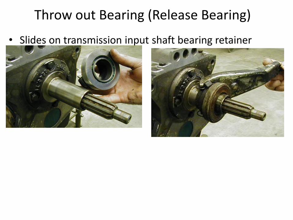
Throw out Bearing (Release Bearing)
• Slides on transmission input shaft bearing retainer
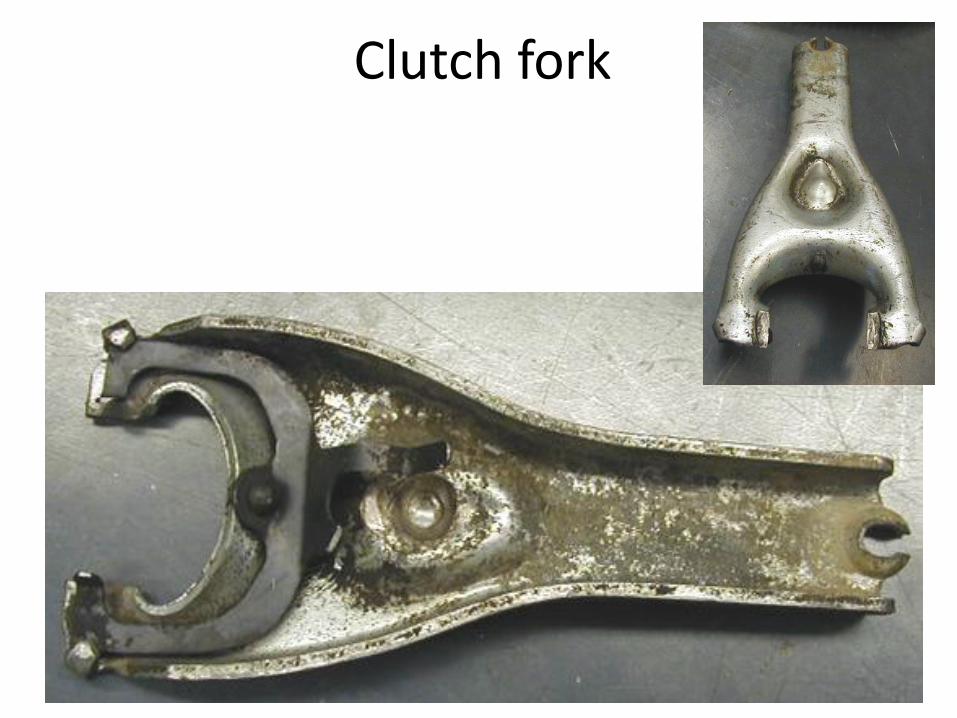
Clutch fork
27
Clutch Linkage
A clutch linkage mechanism uses levers and rods to transfer motion from the clutch pedal to the clutch fork. When the pedal is pressed, a pushrod pushes the bell crank and the bell crank reverses the forward movement of the clutch pedal. The other end of the bell crank is connected to the release rod. The release rod transfers bell crank movement to the clutch fork. It also provides a method of adjustment for the clutch.
Clutch Linkage
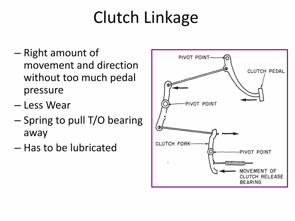
– Right amount of movement and direction without too much pedal pressure
– Less Wear
– Spring to pull T/O bearing away
– Has to be lubricated
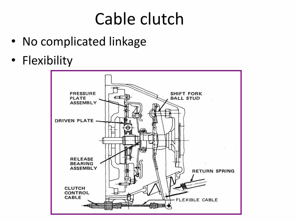
Cable clutch • No complicated linkage
• Flexibility
Cable clutch The clutch cable mechanism uses a steel cable inside a flexible housing to transfer pedal movement to the clutch fork. The cable is usually fastened to the upper end of the clutch pedal, with the other end of the cable connecting to the clutch fork. The cable housing is mounted in a stationary position. This allows the cable to slide inside the housing whenever the clutch pedal is moved. One end of the clutch cable housing has a threaded sleeve for clutch adjustment
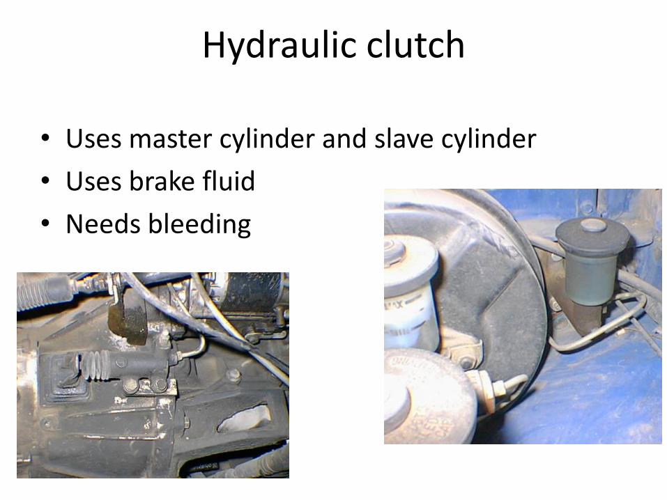
Hydraulic clutch
• Uses master cylinder and slave cylinder
• Uses brake fluid
• Needs bleeding
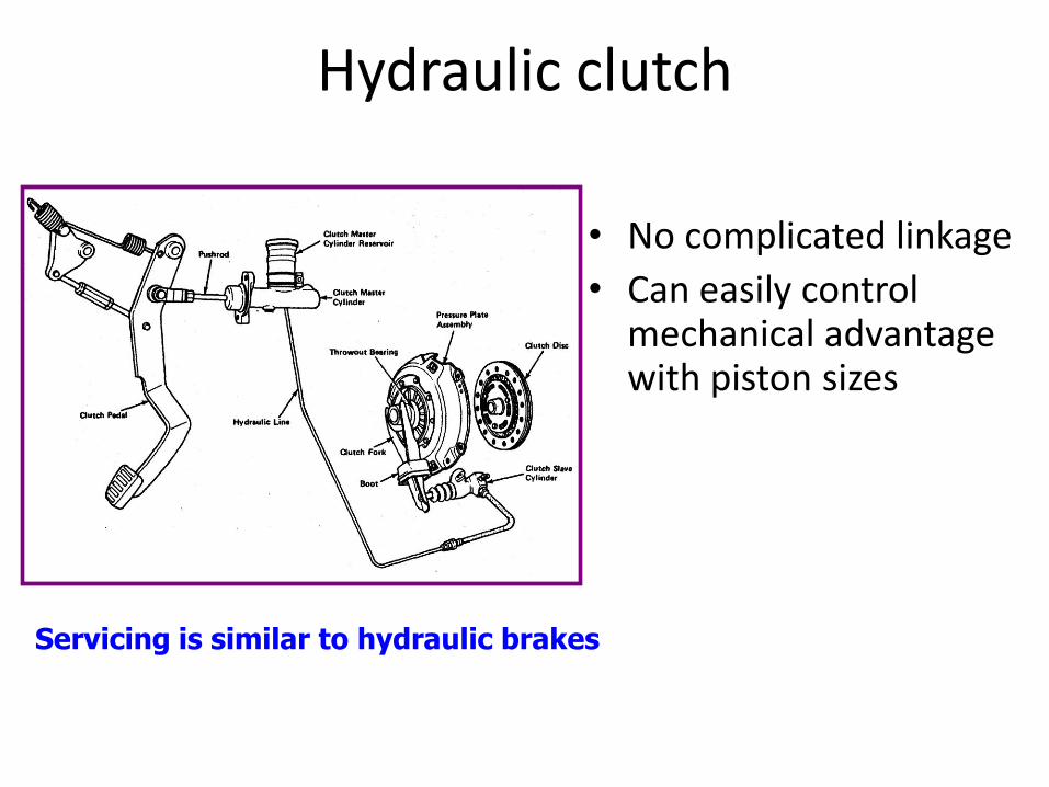
Hydraulic clutch
• No complicated linkage
• Can easily control mechanical advantage with piston sizes
Servicing is similar to hydraulic brakes
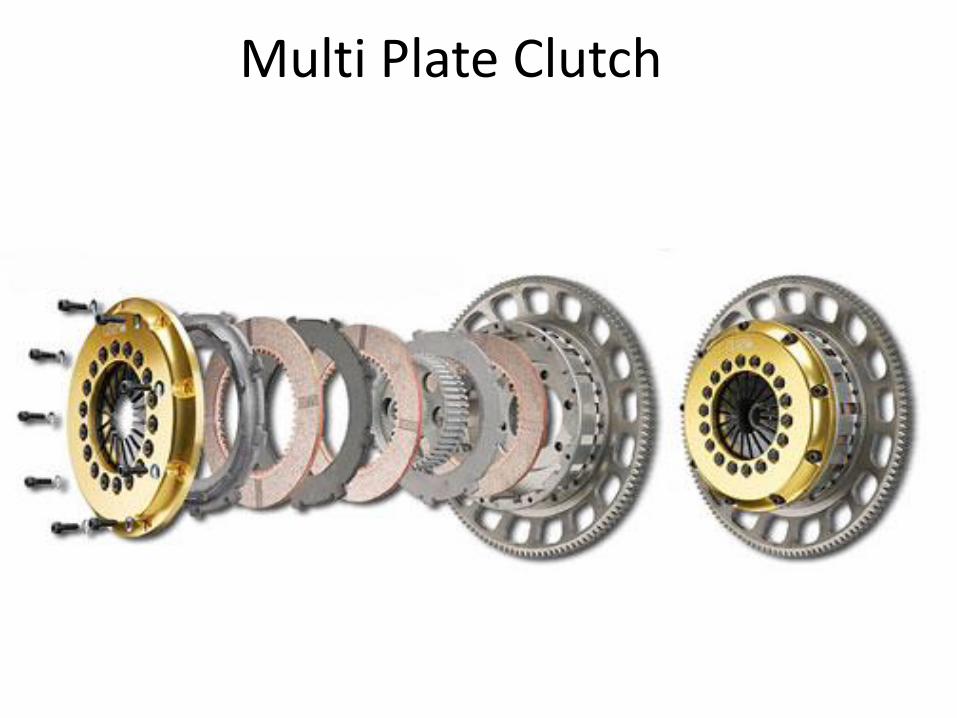
Multi Plate Clutch
• Multi plate clutch is used when – large torque is to be transmitted e.g. Heavy
vehicles and machine tools
– compact construction is required e.g. scooters and motor cycles
• When a great amount of torque is to be transmitted, instead of single plate a number of friction plates are employed. This increases the number of mating friction surfaces, hence it is called multiplate clutch.
• These clutches are used in heavy commercial vehicles, racing cars and motor cycles for transmitting high torque.
• In this friction rings are splined on their outer circumferences to mate with corresponding splines on the bore of the housing and are free to slide on the splines. The friction material therefore rotates with the housing and engine shafts.
• Discs or plates are free to slide on the splines on the driven shaft and rotate with it.
• The disc on the right can be moved to the right against a powerful spring which, when the actuating force is removed, presses the disc into contact with friction rings.
• Torque is therefore transmitted between the engine shaft and the driven shaft.
Multi Plate Clutch
Multi Plate Clutch

It consists of a flywheel and a cone mounted on driving and driven shafts respectively. The shape of the side of the flywheel facing the cone is as to accommodate the cone readily when the clutch is engaged. The surfaces of contact are lined with the friction lining (Asbestos, leather etc.). The cone can be disengaged from flywheel by mechanism which operates in the groove of the cone.
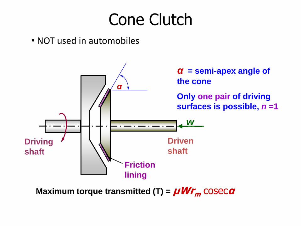
Cone Clutch
Driving
shaft
Driven
shaft
Friction
lining
α
Maximum torque transmitted (T) = μWrm cosecα
α = semi-apex angle of
the cone
Only one pair of driving
surfaces is possible, n =1
Cone Clutch
w
• NOT used in automobiles
• The only advantage of this clutch is that the normal force acting on the friction surfaces is greater than the axial force, as compared to the single plate clutch in which the normal force acting the friction surfaces is equal to the axial force.
• The cone clutch is practically obsolete, due to the following disadvantages. – If the cone angle is made smaller than 20°, the cones
tend to bind and it is difficult to disengage the clutch. – A small amount of wear on the cone surfaces results
in a considerable amount of the axial movement of the cone which is difficult to compensate
Cone Clutch
Driving
shaft
Driven
shaft
Friction
lining
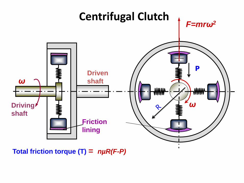
Total friction torque (T) = nµR(F-P)
F=mrω2
ω
ω
P
Centrifugal Clutch
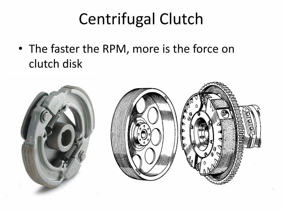
Centrifugal Clutch
• The faster the RPM, more is the force on clutch disk
Clutch Safety Switch
• Prevents from cranking with clutch engaged
Related Documents