6.1.1.5 Clutch disk friction material

Welcome message from author
This document is posted to help you gain knowledge. Please leave a comment to let me know what you think about it! Share it to your friends and learn new things together.
Transcript

6.1.1.5 Clutch disk friction material
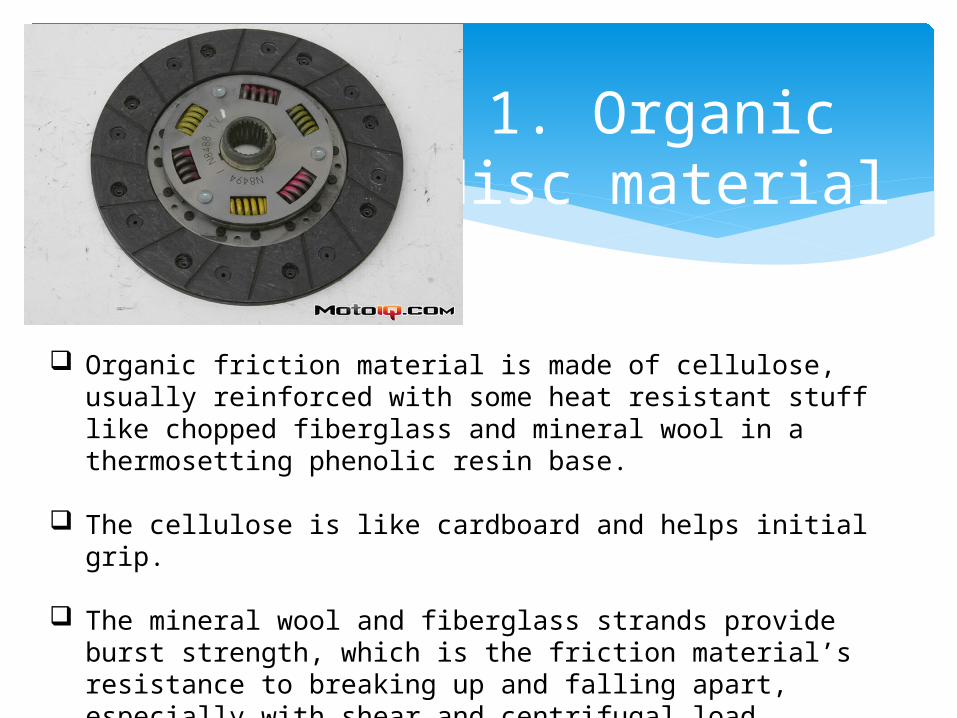
1. Organic disc material
Organic friction material is made of cellulose, usually reinforced with some heat resistant stuff like chopped fiberglass and mineral wool in a thermosetting phenolic resin base.
The cellulose is like cardboard and helps initial grip. The mineral wool and fiberglass strands provide burst
strength, which is the friction material’s resistance to breaking up and falling apart, especially with shear and centrifugal load.
2. Heavy duty (HD)
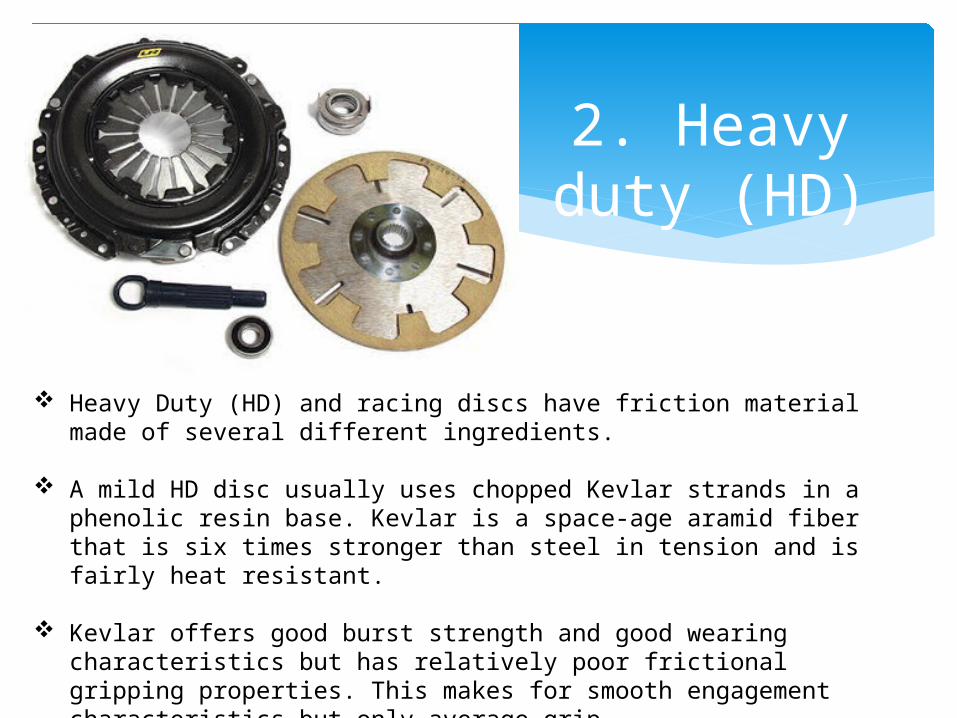
Heavy Duty (HD) and racing discs have friction material made of several different ingredients.
A mild HD disc usually uses chopped Kevlar strands in a phenolic resin base. Kevlar is a space-age aramid fiber that is six times stronger than steel in tension and is fairly heat resistant.
Kevlar offers good burst strength and good wearing characteristics but has relatively poor frictional gripping properties. This makes for smooth engagement characteristics but only average grip.
3. Semi-metallic disc
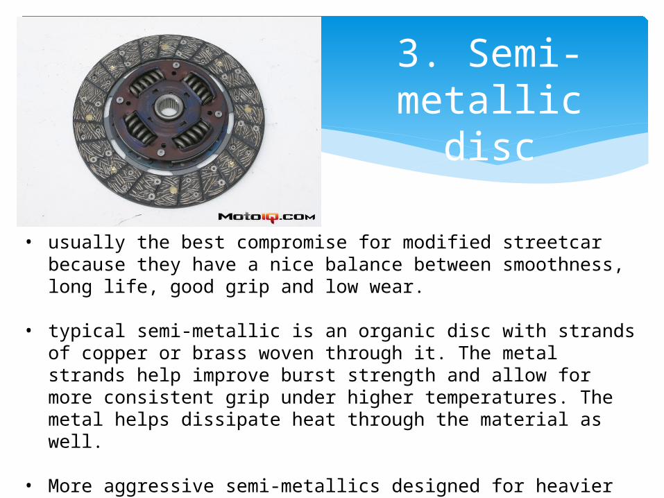
• usually the best compromise for modified streetcar because they have a nice balance between smoothness, long life, good grip and low wear.
• typical semi-metallic is an organic disc with strands of copper
or brass woven through it. The metal strands help improve burst strength and allow for more consistent grip under higher temperatures. The metal helps dissipate heat through the material as well.
• More aggressive semi-metallics designed for heavier abuse have powdered ceramics, copper, bronze, carbon or iron added to the organic based mixture to help improve grip at higher temperatures.
4.Copper ceramic disc
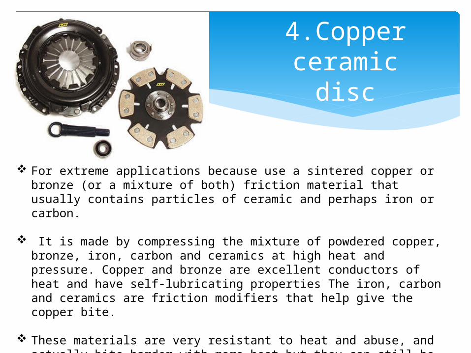
For extreme applications because use a sintered copper or bronze (or a mixture of both) friction material that usually contains particles of ceramic and perhaps iron or carbon.
It is made by compressing the mixture of powdered copper, bronze, iron, carbon and ceramics at high heat and pressure. Copper and bronze are excellent conductors of heat and have self-lubricating properties The iron, carbon and ceramics are friction modifiers that help give the copper bite.
These materials are very resistant to heat and abuse, and actually bite harder with more heat but they can still be overheated in extreme cases and the copper can smear and melt over the friction modifier particles ruining the disc.
5. Carbon - carbon
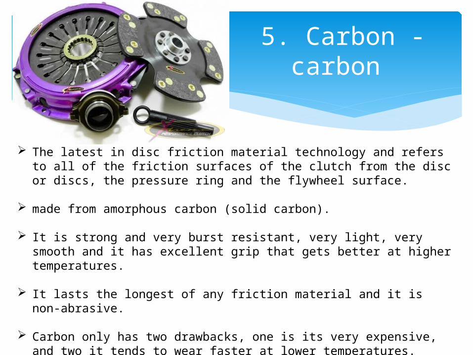
The latest in disc friction material technology and refers to all of the friction surfaces of the clutch from the disc or discs, the pressure ring and the flywheel surface.
made from amorphous carbon (solid carbon). It is strong and very burst resistant, very light, very smooth and it has
excellent grip that gets better at higher temperatures.
It lasts the longest of any friction material and it is non-abrasive.
Carbon only has two drawbacks, one is its very expensive, and two it tends to wear faster at lower temperatures.
A slightly cheaper alternative is carbon-steel.
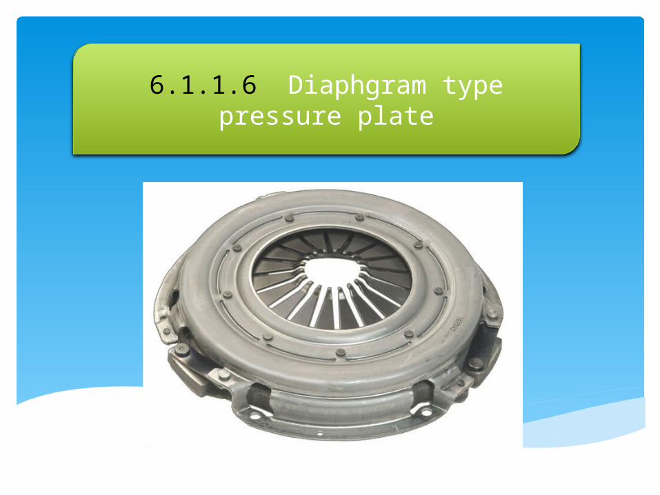
6.1.1.6 Diaphgram type pressure plate
Diaphragm Style pressure plate assemblies produce clamp load with pressure from a “Belleville spring”, commonly referred to as a diaphragm spring.
Created from heat-treated spring steel, the diaphragm spring is stamped into an oval one-piece concave shape with slits that separate the spring fingers.
In addition to the diaphragm spring, typical diaphragm assemblies are comprised of a pressure plate, pivot ring, drive straps, rivets, and a cover stamping.
• diaphragm assemblies actually increase the clamping force during the first half of service life before returning to the original clamp load.
• Diaphragm assemblies also require less pedal effort to disengage the system, and they contain fewer moving parts.
• pressure is applied against the tips of the diaphragm spring and they are pushed toward the flywheel. The opposite end (outside diameter) of the diaphragm pivots on a pivot ring away from the flywheel.
• The pressure plate is then pulled away from the flywheel by the use of diaphragm straps that connect the pressure plate to the cover stamping.

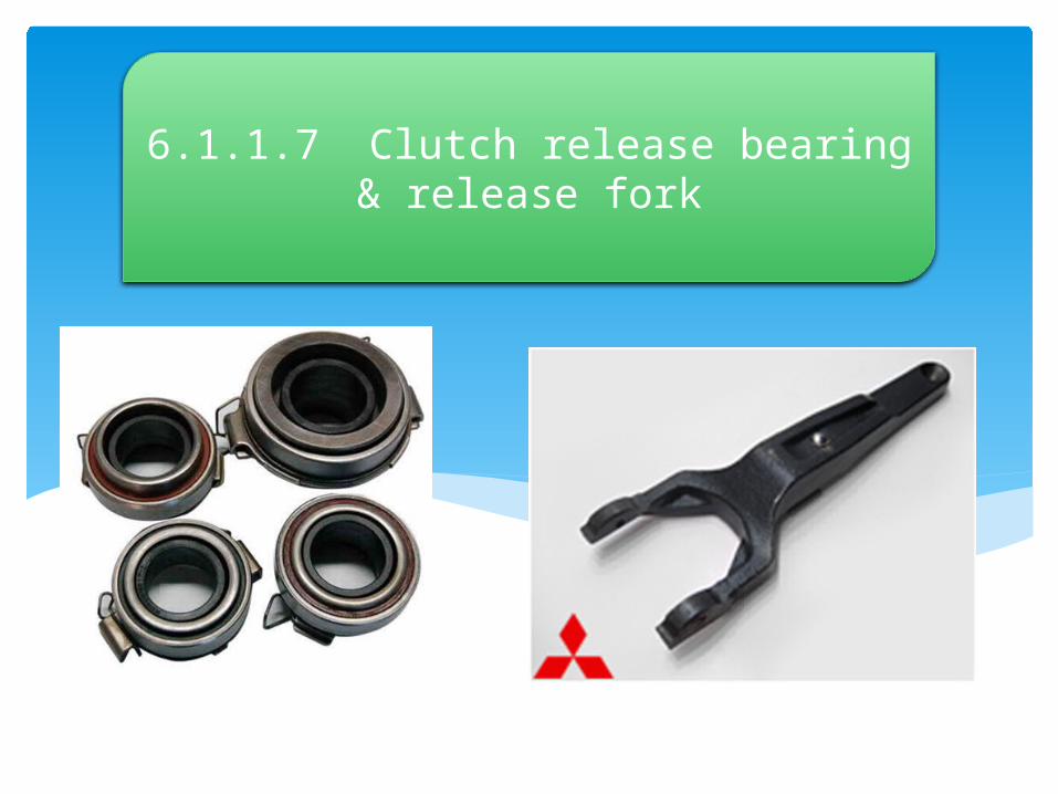
6.1.1.7 Clutch release bearing & release fork
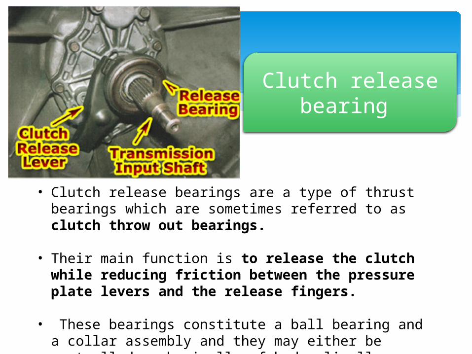
• Clutch release bearings are a type of thrust bearings which are sometimes referred to as clutch throw out bearings.
• Their main function is to release the clutch while reducing friction between the pressure plate levers and the release fingers.
• These bearings constitute a ball bearing and a collar assembly and they may either be controlled mechanically of hydraulically.
Clutch release bearing
Clutch release fork
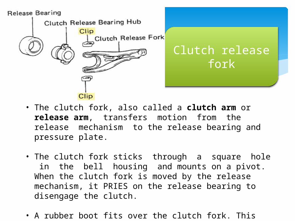
• The clutch fork, also called a clutch arm or release arm, transfers motion from the release mechanism to the release bearing and pressure plate.
• The clutch fork sticks through a square hole in the bell housing and mounts on a pivot. When the clutch fork is moved by the release mechanism, it PRIES on the release bearing to disengage the clutch.
• A rubber boot fits over the clutch fork. This boot is designed to keep road dirt, rocks, oil, water, and other debris from entering the clutch housing.

6.1.1.8 Clutch release mechanism

I. Linkage type clutch release mechanism
• consists of a bellcrank that pivots between the frame and the engine block. One side of the bell crank attaches to the clutch pedal, and the opposite side attaches to the adjustment rod for clutch release.
• The adjustment rod is inserted into the clutch fork and lengthened or shortened to achieve the proper release and gap between the clutch fingers and the bearing.
• the ratio between the release mechanism and the pedal effort is between three and four to one. Mechanical linkages provide the most flexibility in clutch adjustment.
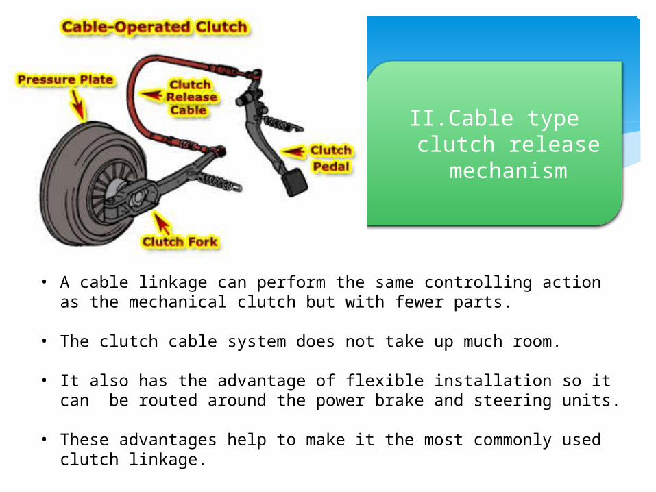
II. Cable type clutch release
mechanism
• A cable linkage can perform the same controlling action as the mechanical clutch but with fewer parts.
• The clutch cable system does not take up much room.
• It also has the advantage of flexible installation so it can be routed around the power brake and steering units.
• These advantages help to make it the most commonly used clutch linkage.

III.Hydraulic type clutch release mechanism
• In the hydraulic clutch linkage system, hydraulic pressure transmits motion from one sealed cylinder to another through a hydraulic line.
• Like the cable linkage assembly, the hydraulic linkage is compact and flexible.
• Hydraulic linkages allow the placement of the release fork anywhere that gives which gives more flexibility in body design
Related Documents