March 2005 N15368F VERITAS Cluster Server 4.1 User’s Guide Solaris

Welcome message from author
This document is posted to help you gain knowledge. Please leave a comment to let me know what you think about it! Share it to your friends and learn new things together.
Transcript

March 2005
N15368F
VERITAS Cluster Server 4.1
User’s Guide
Solaris
Disclaimer
The information contained in this publication is subject to change without notice. VERITAS Software Corporation makes no warranty of any kind with regard to this manual, including, but not limited to, the implied warranties of merchantability and fitness for a particular purpose. VERITAS Software Corporation shall not be liable for errors contained herein or for incidental or consequential damages in connection with the furnishing, performance, or use of this manual.
VERITAS Legal Notice
Copyright © 1998-2005 VERITAS Software Corporation. All rights reserved. VERITAS and the VERITAS Logo are trademarks or registered trademarks of VERITAS Software Corporation or its affiliates in the U.S. and other countries. Other names may be trademarks of their respective owners.
VERITAS Software Corporation350 Ellis StreetMountain View, CA 94043 USAPhone 650–527–8000 Fax 650–527–2901www.veritas.com
Third-Party Legal Notices
Apache Software
Version 2.0, January 2004
http://www.apache.org/licenses/
TERMS AND CONDITIONS FOR USE, REPRODUCTION, AND DISTRIBUTION
1. Definitions.
"License" shall mean the terms and conditions for use, reproduction, and distribution as defined by Sections 1 through 9 of this document.
"Licensor" shall mean the copyright owner or entity authorized by the copyright owner that is granting the License.
"Legal Entity" shall mean the union of the acting entity and all other entities that control, are controlled by, or are under common control with that entity. For the purposes of this definition, "control" means (i) the power, direct or indirect, to cause the direction or management of such entity, whether by contract or otherwise, or (ii) ownership of fifty percent (50%) or more of the outstanding shares, or (iii) beneficial ownership of such entity.
"You" (or "Your") shall mean an individual or Legal Entity exercising permissions granted by this License.
"Source" form shall mean the preferred form for making modifications, including but not limited to software source code, documentation source, and configuration files.
"Object" form shall mean any form resulting from mechanical transformation or translation of a Source form, including but not limited to compiled object code, generated documentation, and conversions to other media types.
"Work" shall mean the work of authorship, whether in Source or Object form, made available under the License, as indicated by a copyright notice that is included in or attached to the work.
"Derivative Works" shall mean any work, whether in Source or Object form, that is based on (or derived from) the Work and for which the editorial revisions, annotations, elaborations, or other modifications represent, as a whole, an original work of authorship. For the purposes of this License, Derivative Works shall not include works that remain separable from, or merely link (or bind by name) to the interfaces of, the Work and Derivative Works thereof.
"Contribution" shall mean any work of authorship, including the original version of the Work and any modifications or additions to that Work or Derivative Works thereof, that is intentionally submitted to Licensor for inclusion in the Work by the copyright owner or by an individual or Legal Entity authorized to submit on behalf of the copyright owner. For the purposes of this definition, "submitted" means any form of electronic, verbal, or written communication sent to the Licensor or its representatives, including but not limited to communication on electronic mailing lists, source
code control systems, and issue tracking systems that are managed by, or on behalf of, the Licensor for the purpose of discussing and improving the Work, but excluding communication that is conspicuously marked or otherwise designated in writing by the copyright owner as "Not a Contribution."
"Contributor" shall mean Licensor and any individual or Legal Entity on behalf of whom a Contribution has been received by Licensor and subsequently incorporated within the Work.
2. Grant of Copyright License. Subject to the terms and conditions of this License, each Contributor hereby grants to You a perpetual, worldwide, non-exclusive, no-charge, royalty-free, irrevocable copyright license to reproduce, prepare Derivative Works of, publicly display, publicly perform, sublicense, and distribute the Work and such Derivative Works in Source or Object form.
3. Grant of Patent License. Subject to the terms and conditions of this License, each Contributor hereby grants to You a perpetual, worldwide, non-exclusive, no-charge, royalty-free, irrevocable (except as stated in this section) patent license to make, have made, use, offer to sell, sell, import, and otherwise transfer the Work, where such license applies only to those patent claims licensable by such Contributor that are necessarily infringed by their Contribution(s) alone or by combination of their Contribution(s) with the Work to which such Contribution(s) was submitted. If You institute patent litigation against any entity (including a cross-claim or counterclaim in a lawsuit) alleging that the Work or a Contribution incorporated within the Work constitutes direct or contributory patent infringement, then any patent licenses granted to You under this License for that Work shall terminate as of the date such litigation is filed.
4. Redistribution. You may reproduce and distribute copies of the Work or Derivative Works thereof in any medium, with or without modifications, and in Source or Object form, provided that You meet the following conditions:
(a) You must give any other recipients of the Work or Derivative Works a copy of this License; and
(b) You must cause any modified files to carry prominent notices stating that You changed the files; and
(c) You must retain, in the Source form of any Derivative Works that You distribute, all copyright, patent, trademark, and attribution notices from the Source form of the Work, excluding those notices that do not pertain to any part of the Derivative Works; and
(d) If the Work includes a "NOTICE" text file as part of its distribution, then any Derivative Works that You distribute must include a readable copy of the attribution notices contained within such NOTICE file, excluding those notices that do not pertain to any part of the Derivative Works, in at least one of the following places: within a NOTICE text file distributed as part of the Derivative Works; within the Source form or documentation, if provided along with the Derivative Works; or, within a display generated by the Derivative Works, if and wherever such third-party notices normally appear. The contents of the NOTICE file are for informational purposes only and do not modify the License. You may add Your own attribution notices within Derivative Works that You distribute, alongside or as an addendum to the NOTICE text from the Work, provided that such additional attribution notices cannot be construed as modifying the License.
You may add Your own copyright statement to Your modifications and may provide additional or different license terms and conditions for use, reproduction, or distribution of Your modifications, or for any such Derivative Works as a whole, provided Your use, reproduction, and distribution of the Work otherwise complies with the conditions stated in this License.
5. Submission of Contributions. Unless You explicitly state otherwise, any Contribution intentionally submitted for inclusion in the Work by You to the Licensor shall be under the terms and conditions of this License, without any additional terms or conditions. Notwithstanding the above, nothing herein shall supersede or modify the terms of any separate license agreement you may have executed with Licensor regarding such Contributions.
6. Trademarks. This License does not grant permission to use the trade names, trademarks, service marks, or product names of the Licensor, except as required for reasonable and customary use in describing the origin of the Work and reproducing the content of the NOTICE file.
7. Disclaimer of Warranty. Unless required by applicable law or agreed to in writing, Licensor provides the Work (and each Contributor provides its Contributions) on an "AS IS" BASIS, WITHOUT WARRANTIES OR CONDITIONS OF ANY KIND, either express or implied, including, without limitation, any warranties or conditions of TITLE, NON-INFRINGEMENT, MERCHANTABILITY, or FITNESS FOR A PARTICULAR PURPOSE. You are solely responsible for determining the appropriateness of using or redistributing the Work and assume any risks associated with Your exercise of permissions under this License.
8. Limitation of Liability. In no event and under no legal theory, whether in tort (including negligence), contract, or otherwise, unless required by applicable law (such as deliberate and grossly negligent acts) or agreed to in writing, shall any Contributor be liable to You for damages, including any direct, indirect, special, incidental, or consequential damages of any character arising as a result of this License or out of the use or inability to use the Work (including but not limited to damages for loss of goodwill, work stoppage, computer failure or malfunction, or any and all other commercial damages or losses), even if such Contributor has been advised of the possibility of such damages.
9. Accepting Warranty or Additional Liability. While redistributing the Work or Derivative Works thereof, You may choose to offer, and charge a fee for, acceptance of support, warranty, indemnity, or other liability obligations and/or rights consistent with this License. However, in accepting such obligations, You may act only on Your own behalf and on Your sole responsibility, not on behalf of any other Contributor, and only if You agree to indemnify, defend, and hold each Contributor harmless for any liability incurred by, or claims asserted against, such Contributor by reason of your accepting any such warranty or additional liability.

Data Encryption Standard (DES)
Support for data encryption in VCS is based on the MIT Data Encryption Standard (DES) under the following copyright:
Copyright © 1990 Dennis Ferguson. All rights reserved.
Commercial use is permitted only if products that are derived from or include this software are made available for purchase and/or use in Canada. Otherwise, redistribution and use in source and binary forms are permitted.
Copyright 1985, 1986, 1987, 1988, 1990 by the Massachusetts Institute of Technology. All rights reserved.
Export of this software from the United States of America may require a specific license from the United States Government. It is the responsibility of any person or organization contemplating export to obtain such a license before exporting.
WITHIN THAT CONSTRAINT, permission to use, copy, modify, and distribute this software and its documentation for any purpose and without fee is hereby granted, provided that the above copyright notice appear in all copies and that both that copyright notice and this permission notice appear in supporting documentation, and that the name of M.I.T. not be used in advertising or publicity pertaining to distribution of the software without specific, written prior permission. M.I.T. makes no representations about the suitability of this software for any purpose. It is provided as is without express or implied warranty.
SNMP Software
SNMP support in VCS is based on CMU SNMP v2 under the following copyright:
Copyright 1989, 1991, 1992 by Carnegie Mellon University
All Rights Reserved
Permission to use, copy, modify, and distribute this software and its documentation for any purpose and without fee is hereby granted, provided that the above copyright notice appear in all copies and that both that copyright notice and this permission notice appear in supporting documentation, and that the name of CMU not be used in advertising or publicity pertaining to distribution of the software without specific, written prior permission.
CMU DISCLAIMS ALL WARRANTIES WITH REGARD TO THIS SOFTWARE, INCLUDING ALL IMPLIED WARRANTIES OF MERCHANTABILITY AND FITNESS, IN NO EVENT SHALL CMU BE LIABLE FOR ANY SPECIAL, INDIRECT OR CONSEQUENTIAL DAMAGES OR ANY DAMAGES WHATSOEVER RESULTING FROM LOSS OF USE, DATA OR PROFITS, WHETHER IN AN ACTION OF CONTRACT, NEGLIGENCE OR OTHER TORTIOUS ACTION, ARISING OUT OF OR IN CONNECTION WITH THE USE OR PERFORMANCE OF THIS SOFTWARE.
Contents
Preface . . . . . . . . . . . . . . . . . . . . . . . . . . . . . . . . . . . . . . . . . . . . . . . . . . . . . . . . . . . . . .xv
How This Guide is Organized . . . . . . . . . . . . . . . . . . . . . . . . . . . . . . . . . . . . . . . . . . . . . . .xv
Conventions . . . . . . . . . . . . . . . . . . . . . . . . . . . . . . . . . . . . . . . . . . . . . . . . . . . . . . . . . . . . xviii
Getting Help . . . . . . . . . . . . . . . . . . . . . . . . . . . . . . . . . . . . . . . . . . . . . . . . . . . . . . . . . . . . . xix
Documentation Feedback . . . . . . . . . . . . . . . . . . . . . . . . . . . . . . . . . . . . . . . . . . . . . . . . . . xix
Section I. Basic Clustering Concepts and Terminology
Chapter 1. Getting Acquainted with Clustering . . . . . . . . . . . . . . . . . . . . . . . . . . . . . .1
What is a Cluster? . . . . . . . . . . . . . . . . . . . . . . . . . . . . . . . . . . . . . . . . . . . . . . . . . . . . . . . . . . 1
Can My Application be Clustered? . . . . . . . . . . . . . . . . . . . . . . . . . . . . . . . . . . . . . . . . . . . . 3
Chapter 2. VCS Technical Concepts . . . . . . . . . . . . . . . . . . . . . . . . . . . . . . . . . . . . . . .7
What is a VCS Cluster? . . . . . . . . . . . . . . . . . . . . . . . . . . . . . . . . . . . . . . . . . . . . . . . . . . . . . . 7
Understanding Cluster Components . . . . . . . . . . . . . . . . . . . . . . . . . . . . . . . . . . . . . . . . . . 8
Putting the Pieces Together . . . . . . . . . . . . . . . . . . . . . . . . . . . . . . . . . . . . . . . . . . . . . . . . . 18
Other VCS Processes . . . . . . . . . . . . . . . . . . . . . . . . . . . . . . . . . . . . . . . . . . . . . . . . . . . . . . . 19
Chapter 3. Defining Cluster Topologies . . . . . . . . . . . . . . . . . . . . . . . . . . . . . . . . . . .21
Basic Failover Configurations . . . . . . . . . . . . . . . . . . . . . . . . . . . . . . . . . . . . . . . . . . . . . . . 21
Advanced Failover Configurations . . . . . . . . . . . . . . . . . . . . . . . . . . . . . . . . . . . . . . . . . . . 26
Cluster Topologies and Storage Configurations . . . . . . . . . . . . . . . . . . . . . . . . . . . . . . . . 30
v
Chapter 4. Configuration Concepts . . . . . . . . . . . . . . . . . . . . . . . . . . . . . . . . . . . . . . 35
The VCS Configuration Language . . . . . . . . . . . . . . . . . . . . . . . . . . . . . . . . . . . . . . . . . . . 36
The main.cf File . . . . . . . . . . . . . . . . . . . . . . . . . . . . . . . . . . . . . . . . . . . . . . . . . . . . . . . . . . . 36
The types.cf File . . . . . . . . . . . . . . . . . . . . . . . . . . . . . . . . . . . . . . . . . . . . . . . . . . . . . . . . . . . 41
Attributes . . . . . . . . . . . . . . . . . . . . . . . . . . . . . . . . . . . . . . . . . . . . . . . . . . . . . . . . . . . . . . . . 43
Keywords/Reserved Words . . . . . . . . . . . . . . . . . . . . . . . . . . . . . . . . . . . . . . . . . . . . . . . . 47
Managing the VCS Configuration File: The hacf Utility . . . . . . . . . . . . . . . . . . . . . . . . . 48
Section II. Administration-Putting VCS to Work
Chapter 5. Introducing the VCS User Privilege Model . . . . . . . . . . . . . . . . . . . . . . . 51
VCS User Privileges . . . . . . . . . . . . . . . . . . . . . . . . . . . . . . . . . . . . . . . . . . . . . . . . . . . . . . . 51
User Privileges for CLI and Cluster Shell Commands . . . . . . . . . . . . . . . . . . . . . . . . . . 55
User Privileges in Global Clusters . . . . . . . . . . . . . . . . . . . . . . . . . . . . . . . . . . . . . . . . . . . 55
Chapter 6. Administering the Cluster from the Command Line . . . . . . . . . . . . . . . . . . . . . . . . . . . . . . . . . . . . . . . . . . . . . . . 57
VCS Environment Variables . . . . . . . . . . . . . . . . . . . . . . . . . . . . . . . . . . . . . . . . . . . . . . . . 57
How VCS Identifies the Local System . . . . . . . . . . . . . . . . . . . . . . . . . . . . . . . . . . . . . . . . 59
Installing a VCS License . . . . . . . . . . . . . . . . . . . . . . . . . . . . . . . . . . . . . . . . . . . . . . . . . . . . 59
Starting VCS . . . . . . . . . . . . . . . . . . . . . . . . . . . . . . . . . . . . . . . . . . . . . . . . . . . . . . . . . . . . . . 60
Stopping VCS . . . . . . . . . . . . . . . . . . . . . . . . . . . . . . . . . . . . . . . . . . . . . . . . . . . . . . . . . . . . . 61
Logging On to VCS . . . . . . . . . . . . . . . . . . . . . . . . . . . . . . . . . . . . . . . . . . . . . . . . . . . . . . . . 63
Adding, Modifying, and Deleting Users . . . . . . . . . . . . . . . . . . . . . . . . . . . . . . . . . . . . . . 65
Querying VCS . . . . . . . . . . . . . . . . . . . . . . . . . . . . . . . . . . . . . . . . . . . . . . . . . . . . . . . . . . . . 69
Administering Service Groups . . . . . . . . . . . . . . . . . . . . . . . . . . . . . . . . . . . . . . . . . . . . . . 75
Administering Resources . . . . . . . . . . . . . . . . . . . . . . . . . . . . . . . . . . . . . . . . . . . . . . . . . . . 77
Administering Systems . . . . . . . . . . . . . . . . . . . . . . . . . . . . . . . . . . . . . . . . . . . . . . . . . . . . 78
Administering Clusters . . . . . . . . . . . . . . . . . . . . . . . . . . . . . . . . . . . . . . . . . . . . . . . . . . . . 79
Enabling and Disabling VERITAS Security Services . . . . . . . . . . . . . . . . . . . . . . . . . . . . 81
Encrypting Passwords . . . . . . . . . . . . . . . . . . . . . . . . . . . . . . . . . . . . . . . . . . . . . . . . . . . . . 83
vi VERITAS Cluster Server User’s Guide
Basic Configuration Operations . . . . . . . . . . . . . . . . . . . . . . . . . . . . . . . . . . . . . . . . . . . . . . 84
Backing Up and Restoring VCS Configuration Files . . . . . . . . . . . . . . . . . . . . . . . . . . . . 98
Using the -wait Option in Scripts . . . . . . . . . . . . . . . . . . . . . . . . . . . . . . . . . . . . . . . . . . . 106
Using VCS Simulator . . . . . . . . . . . . . . . . . . . . . . . . . . . . . . . . . . . . . . . . . . . . . . . . . . . . . . 107
Chapter 7. Administering the Cluster fromCluster Manager (Java Console) . . . . . . . . . . . . . . . . . . . . . . . . . . . . . . . . . . . . . . . .109
Disability Compliance . . . . . . . . . . . . . . . . . . . . . . . . . . . . . . . . . . . . . . . . . . . . . . . . . . . . . 109
Getting Started . . . . . . . . . . . . . . . . . . . . . . . . . . . . . . . . . . . . . . . . . . . . . . . . . . . . . . . . . . . 110
Reviewing Components of the Java Console . . . . . . . . . . . . . . . . . . . . . . . . . . . . . . . . . . 113
Icons in the Java Console . . . . . . . . . . . . . . . . . . . . . . . . . . . . . . . . . . . . . . . . . . . . . . . . . . 113
About Cluster Monitor . . . . . . . . . . . . . . . . . . . . . . . . . . . . . . . . . . . . . . . . . . . . . . . . . . . . 115
About Cluster Explorer . . . . . . . . . . . . . . . . . . . . . . . . . . . . . . . . . . . . . . . . . . . . . . . . . . . . 122
Accessing Additional Features of the Java Console . . . . . . . . . . . . . . . . . . . . . . . . . . . . 135
Administering Cluster Monitor . . . . . . . . . . . . . . . . . . . . . . . . . . . . . . . . . . . . . . . . . . . . . 145
Administering User Profiles . . . . . . . . . . . . . . . . . . . . . . . . . . . . . . . . . . . . . . . . . . . . . . . . 151
Administering Service Groups . . . . . . . . . . . . . . . . . . . . . . . . . . . . . . . . . . . . . . . . . . . . . . 154
Administering Resources . . . . . . . . . . . . . . . . . . . . . . . . . . . . . . . . . . . . . . . . . . . . . . . . . . 176
Importing Resource Types . . . . . . . . . . . . . . . . . . . . . . . . . . . . . . . . . . . . . . . . . . . . . . . . . 194
Administering Systems . . . . . . . . . . . . . . . . . . . . . . . . . . . . . . . . . . . . . . . . . . . . . . . . . . . . 195
Administering Clusters . . . . . . . . . . . . . . . . . . . . . . . . . . . . . . . . . . . . . . . . . . . . . . . . . . . . 199
Executing Commands . . . . . . . . . . . . . . . . . . . . . . . . . . . . . . . . . . . . . . . . . . . . . . . . . . . . . 202
Editing Attributes . . . . . . . . . . . . . . . . . . . . . . . . . . . . . . . . . . . . . . . . . . . . . . . . . . . . . . . . 203
Querying the Cluster Configuration . . . . . . . . . . . . . . . . . . . . . . . . . . . . . . . . . . . . . . . . . 205
Setting up VCS Event Notification Using Notifier Wizard . . . . . . . . . . . . . . . . . . . . . . 206
Administering Logs . . . . . . . . . . . . . . . . . . . . . . . . . . . . . . . . . . . . . . . . . . . . . . . . . . . . . . . 209
Administering VCS Simulator . . . . . . . . . . . . . . . . . . . . . . . . . . . . . . . . . . . . . . . . . . . . . . 214
Contents vii

Chapter 8. Administering the Cluster fromCluster Manager (Web Console) . . . . . . . . . . . . . . . . . . . . . . . . . . . . . . . . . . . . . . . . 215
Disability Compliance . . . . . . . . . . . . . . . . . . . . . . . . . . . . . . . . . . . . . . . . . . . . . . . . . . . . 215
Before Using the Web Console . . . . . . . . . . . . . . . . . . . . . . . . . . . . . . . . . . . . . . . . . . . . . 216
Web Console Layout . . . . . . . . . . . . . . . . . . . . . . . . . . . . . . . . . . . . . . . . . . . . . . . . . . . . . . 227
Navigating the Web Console . . . . . . . . . . . . . . . . . . . . . . . . . . . . . . . . . . . . . . . . . . . . . . . 228
Reviewing Web Console Views . . . . . . . . . . . . . . . . . . . . . . . . . . . . . . . . . . . . . . . . . . . . 229
Administering Users . . . . . . . . . . . . . . . . . . . . . . . . . . . . . . . . . . . . . . . . . . . . . . . . . . . . . . 251
Administering Cluster Configurations . . . . . . . . . . . . . . . . . . . . . . . . . . . . . . . . . . . . . . 254
Administering Service Groups . . . . . . . . . . . . . . . . . . . . . . . . . . . . . . . . . . . . . . . . . . . . . 255
Administering Resources . . . . . . . . . . . . . . . . . . . . . . . . . . . . . . . . . . . . . . . . . . . . . . . . . . 268
Administering Systems . . . . . . . . . . . . . . . . . . . . . . . . . . . . . . . . . . . . . . . . . . . . . . . . . . . 281
Editing Attributes . . . . . . . . . . . . . . . . . . . . . . . . . . . . . . . . . . . . . . . . . . . . . . . . . . . . . . . . 283
Querying the Cluster Configuration . . . . . . . . . . . . . . . . . . . . . . . . . . . . . . . . . . . . . . . . 284
Customizing the Web Console with myVCS . . . . . . . . . . . . . . . . . . . . . . . . . . . . . . . . . 285
Customizing the Log Display . . . . . . . . . . . . . . . . . . . . . . . . . . . . . . . . . . . . . . . . . . . . . . 287
Monitoring Alerts . . . . . . . . . . . . . . . . . . . . . . . . . . . . . . . . . . . . . . . . . . . . . . . . . . . . . . . . 288
Integrating the Web Console with VERITAS Traffic Director . . . . . . . . . . . . . . . . . . . 290
Chapter 9. Configuring Application and NFS Service Groups . . . . . . . . . . . . . . . 291
Configuring Application Service Groups Using the Application Wizard . . . . . . . . . 292
Configuring NFS Service Groups Using the NFS Wizard . . . . . . . . . . . . . . . . . . . . . . 304
Section III. VCS Operations
Chapter 10. VCS Communications, Membership,and I/O Fencing . . . . . . . . . . . . . . . . . . . . . . . . . . . . . . . . . . . . . . . . . . . . . . . . . . . . . 311
Intra-Node Communication . . . . . . . . . . . . . . . . . . . . . . . . . . . . . . . . . . . . . . . . . . . . . . . 311
Inter-Node Communication . . . . . . . . . . . . . . . . . . . . . . . . . . . . . . . . . . . . . . . . . . . . . . . 313
Cluster Membership . . . . . . . . . . . . . . . . . . . . . . . . . . . . . . . . . . . . . . . . . . . . . . . . . . . . . . 314
viii VERITAS Cluster Server User’s Guide
VCS I/O Fencing . . . . . . . . . . . . . . . . . . . . . . . . . . . . . . . . . . . . . . . . . . . . . . . . . . . . . . . . . 318
VCS Operation Without I/O Fencing . . . . . . . . . . . . . . . . . . . . . . . . . . . . . . . . . . . . . . . . 330
Chapter 11. Controlling VCS Behavior . . . . . . . . . . . . . . . . . . . . . . . . . . . . . . . . . . .343
VCS Behavior on Resource Faults . . . . . . . . . . . . . . . . . . . . . . . . . . . . . . . . . . . . . . . . . . . 343
Controlling VCS Behavior at the Service Group Level . . . . . . . . . . . . . . . . . . . . . . . . . 347
Controlling VCS Behavior at the Resource Level . . . . . . . . . . . . . . . . . . . . . . . . . . . . . . 351
How VCS Handles Resource Faults . . . . . . . . . . . . . . . . . . . . . . . . . . . . . . . . . . . . . . . . . 353
Disabling Resources . . . . . . . . . . . . . . . . . . . . . . . . . . . . . . . . . . . . . . . . . . . . . . . . . . . . . . . 360
Clearing Resources in the ADMIN_WAIT State . . . . . . . . . . . . . . . . . . . . . . . . . . . . . . . 363
Service Group Workload Management . . . . . . . . . . . . . . . . . . . . . . . . . . . . . . . . . . . . . . 364
Additional Considerations . . . . . . . . . . . . . . . . . . . . . . . . . . . . . . . . . . . . . . . . . . . . . . . . . 367
Sample Configurations Depicting Workload Management . . . . . . . . . . . . . . . . . . . . . 368
Chapter 12. The Role of Service Group Dependencies . . . . . . . . . . . . . . . . . . . . . .383
Why Configure a Service Group Dependency? . . . . . . . . . . . . . . . . . . . . . . . . . . . . . . . . 384
Categories of Service Group Dependencies . . . . . . . . . . . . . . . . . . . . . . . . . . . . . . . . . . . 385
Location of Dependency . . . . . . . . . . . . . . . . . . . . . . . . . . . . . . . . . . . . . . . . . . . . . . . . . . . 386
Type of Dependency . . . . . . . . . . . . . . . . . . . . . . . . . . . . . . . . . . . . . . . . . . . . . . . . . . . . . . 387
Service Group Dependency Configurations . . . . . . . . . . . . . . . . . . . . . . . . . . . . . . . . . . 389
Linking Service Groups (Online/Offline Dependencies) . . . . . . . . . . . . . . . . . . . . . . . 396
Automatic Actions for Service Group Dependencies . . . . . . . . . . . . . . . . . . . . . . . . . . . 397
Manual Operations for Service Group Dependencies . . . . . . . . . . . . . . . . . . . . . . . . . . 400
Dependency Limitations . . . . . . . . . . . . . . . . . . . . . . . . . . . . . . . . . . . . . . . . . . . . . . . . . . . 402
Dependencies in Failover and Parallel Service Groups . . . . . . . . . . . . . . . . . . . . . . . . . 403
Section IV. Administration–Beyond the Basics
Chapter 13. Notification . . . . . . . . . . . . . . . . . . . . . . . . . . . . . . . . . . . . . . . . . . . . . . .413
How Notification Works . . . . . . . . . . . . . . . . . . . . . . . . . . . . . . . . . . . . . . . . . . . . . . . . . . . 413
Notification Components . . . . . . . . . . . . . . . . . . . . . . . . . . . . . . . . . . . . . . . . . . . . . . . . . . 416
Contents ix
VCS Events and Traps . . . . . . . . . . . . . . . . . . . . . . . . . . . . . . . . . . . . . . . . . . . . . . . . . . . . 418
Monitoring Aggregate Events . . . . . . . . . . . . . . . . . . . . . . . . . . . . . . . . . . . . . . . . . . . . . . 426
Configuring Notification . . . . . . . . . . . . . . . . . . . . . . . . . . . . . . . . . . . . . . . . . . . . . . . . . . 427
Chapter 14. VCS Event Triggers . . . . . . . . . . . . . . . . . . . . . . . . . . . . . . . . . . . . . . . . 429
How Event Triggers Work . . . . . . . . . . . . . . . . . . . . . . . . . . . . . . . . . . . . . . . . . . . . . . . . . 429
Using Event Triggers . . . . . . . . . . . . . . . . . . . . . . . . . . . . . . . . . . . . . . . . . . . . . . . . . . . . . 429
List of Event Triggers . . . . . . . . . . . . . . . . . . . . . . . . . . . . . . . . . . . . . . . . . . . . . . . . . . . . . 430
Section V. Advanced Cluster Configurations
Chapter 15. Connecting Clusters–Introducing the Global Cluster Option . . . . . . 443
How VCS Global Clusters Work . . . . . . . . . . . . . . . . . . . . . . . . . . . . . . . . . . . . . . . . . . . . 444
VCS Global Clusters: The Building Blocks . . . . . . . . . . . . . . . . . . . . . . . . . . . . . . . . . . . 445
Before Configuring Global Clusters . . . . . . . . . . . . . . . . . . . . . . . . . . . . . . . . . . . . . . . . . 451
Setting Up a Global Cluster . . . . . . . . . . . . . . . . . . . . . . . . . . . . . . . . . . . . . . . . . . . . . . . . 453
Upgrading from VERITAS Global Cluster Manager . . . . . . . . . . . . . . . . . . . . . . . . . . . 463
Migrating a Service Group . . . . . . . . . . . . . . . . . . . . . . . . . . . . . . . . . . . . . . . . . . . . . . . . . 464
Simulating Global Clusters Using VCS Simulator . . . . . . . . . . . . . . . . . . . . . . . . . . . . . 465
Setting Up a Fire Drill . . . . . . . . . . . . . . . . . . . . . . . . . . . . . . . . . . . . . . . . . . . . . . . . . . . . . 466
Chapter 16. Administering Global Clustersfrom the Command Line . . . . . . . . . . . . . . . . . . . . . . . . . . . . . . . . . . . . . . . . . . . . . . 469
Global Querying . . . . . . . . . . . . . . . . . . . . . . . . . . . . . . . . . . . . . . . . . . . . . . . . . . . . . . . . . 469
Administering Service Groups . . . . . . . . . . . . . . . . . . . . . . . . . . . . . . . . . . . . . . . . . . . . . 475
Administering Resources . . . . . . . . . . . . . . . . . . . . . . . . . . . . . . . . . . . . . . . . . . . . . . . . . . 477
Administering Clusters . . . . . . . . . . . . . . . . . . . . . . . . . . . . . . . . . . . . . . . . . . . . . . . . . . . 477
Administering Heartbeats . . . . . . . . . . . . . . . . . . . . . . . . . . . . . . . . . . . . . . . . . . . . . . . . . 479
x VERITAS Cluster Server User’s Guide
Chapter 17. Administering Global Clustersfrom Cluster Manager (Java Console) . . . . . . . . . . . . . . . . . . . . . . . . . . . . . . . . . . . .481
Adding a Remote Cluster . . . . . . . . . . . . . . . . . . . . . . . . . . . . . . . . . . . . . . . . . . . . . . . . . . 482
Deleting a Remote Cluster . . . . . . . . . . . . . . . . . . . . . . . . . . . . . . . . . . . . . . . . . . . . . . . . . 487
Administering Global Service Groups . . . . . . . . . . . . . . . . . . . . . . . . . . . . . . . . . . . . . . . 491
Administering Global Heartbeats . . . . . . . . . . . . . . . . . . . . . . . . . . . . . . . . . . . . . . . . . . . 497
Chapter 18. Administering Global Clusters from Cluster Manager (Web Console) . . . . . . . . . . . . . . . . . . . . . . . . . . . . . . . . . . . . . . . .501
Adding a Remote Cluster . . . . . . . . . . . . . . . . . . . . . . . . . . . . . . . . . . . . . . . . . . . . . . . . . . 502
Deleting a Remote Cluster . . . . . . . . . . . . . . . . . . . . . . . . . . . . . . . . . . . . . . . . . . . . . . . . . 505
Administering Global Service Groups . . . . . . . . . . . . . . . . . . . . . . . . . . . . . . . . . . . . . . . 513
Administering Global Heartbeats . . . . . . . . . . . . . . . . . . . . . . . . . . . . . . . . . . . . . . . . . . . 521
Chapter 19. Setting Up Replicated Data Clusters . . . . . . . . . . . . . . . . . . . . . . . . . . .525
About Replicated Data Clusters . . . . . . . . . . . . . . . . . . . . . . . . . . . . . . . . . . . . . . . . . . . . . 525
How VCS Replicated Data Clusters Work . . . . . . . . . . . . . . . . . . . . . . . . . . . . . . . . . . . . 526
Setting up a Replicated Data Cluster Configuration . . . . . . . . . . . . . . . . . . . . . . . . . . . 527
Migrating a Service Group . . . . . . . . . . . . . . . . . . . . . . . . . . . . . . . . . . . . . . . . . . . . . . . . . 531
Setting Up a Fire Drill . . . . . . . . . . . . . . . . . . . . . . . . . . . . . . . . . . . . . . . . . . . . . . . . . . . . . 532
Chapter 20. Setting Up Campus Clusters . . . . . . . . . . . . . . . . . . . . . . . . . . . . . . . . .533
How VCS Campus Clusters Work . . . . . . . . . . . . . . . . . . . . . . . . . . . . . . . . . . . . . . . . . . 534
Setting Up a Campus Cluster Configuration . . . . . . . . . . . . . . . . . . . . . . . . . . . . . . . . . . 536
Section VI. Troubleshooting and Performance
Chapter 21. Predicting VCS Behavior Using VCS Simulator . . . . . . . . . . . . . . . . . . . . . . . . . . . . . . . . . . . . . . . . . . . . . . . . . .541
Installing VCS Simulator . . . . . . . . . . . . . . . . . . . . . . . . . . . . . . . . . . . . . . . . . . . . . . . . . . . 541
Administering VCS Simulator From the Java Console . . . . . . . . . . . . . . . . . . . . . . . . . 544
Administering VCS Simulator from the Command Line . . . . . . . . . . . . . . . . . . . . . . . 550
Contents xi

Chapter 22. VCS Performance Considerations . . . . . . . . . . . . . . . . . . . . . . . . . . . . 555
How Cluster Components Affect Performance . . . . . . . . . . . . . . . . . . . . . . . . . . . . . . . 555
Booting a Cluster System . . . . . . . . . . . . . . . . . . . . . . . . . . . . . . . . . . . . . . . . . . . . . . . . . . 558
Bringing a Resource Online . . . . . . . . . . . . . . . . . . . . . . . . . . . . . . . . . . . . . . . . . . . . . . . . 559
Taking a Resource Offline . . . . . . . . . . . . . . . . . . . . . . . . . . . . . . . . . . . . . . . . . . . . . . . . . 559
Bringing a Service Group Online . . . . . . . . . . . . . . . . . . . . . . . . . . . . . . . . . . . . . . . . . . . 559
Taking a Service Group Offline . . . . . . . . . . . . . . . . . . . . . . . . . . . . . . . . . . . . . . . . . . . . . 560
Detecting Resource Failure . . . . . . . . . . . . . . . . . . . . . . . . . . . . . . . . . . . . . . . . . . . . . . . . 560
Detecting System Failure . . . . . . . . . . . . . . . . . . . . . . . . . . . . . . . . . . . . . . . . . . . . . . . . . . 561
Detecting Network Link Failure . . . . . . . . . . . . . . . . . . . . . . . . . . . . . . . . . . . . . . . . . . . . 561
When a System Panics . . . . . . . . . . . . . . . . . . . . . . . . . . . . . . . . . . . . . . . . . . . . . . . . . . . . 562
Time Taken for a Service Group Switch . . . . . . . . . . . . . . . . . . . . . . . . . . . . . . . . . . . . . 563
Time Taken for a Service Group Failover . . . . . . . . . . . . . . . . . . . . . . . . . . . . . . . . . . . . 563
Scheduling Class and Priority Configuration . . . . . . . . . . . . . . . . . . . . . . . . . . . . . . . . . 564
CPU Binding of HAD . . . . . . . . . . . . . . . . . . . . . . . . . . . . . . . . . . . . . . . . . . . . . . . . . . . . . 566
Monitoring CPU Usage . . . . . . . . . . . . . . . . . . . . . . . . . . . . . . . . . . . . . . . . . . . . . . . . . . . 567
VCS Agent Statistics . . . . . . . . . . . . . . . . . . . . . . . . . . . . . . . . . . . . . . . . . . . . . . . . . . . . . . 568
Chapter 23. Troubleshooting and Recovery for VCS . . . . . . . . . . . . . . . . . . . . . . . 571
Logging . . . . . . . . . . . . . . . . . . . . . . . . . . . . . . . . . . . . . . . . . . . . . . . . . . . . . . . . . . . . . . . . . 571
Troubleshooting VCS Startup . . . . . . . . . . . . . . . . . . . . . . . . . . . . . . . . . . . . . . . . . . . . . . 575
Troubleshooting Service Groups . . . . . . . . . . . . . . . . . . . . . . . . . . . . . . . . . . . . . . . . . . . 576
Troubleshooting Resources . . . . . . . . . . . . . . . . . . . . . . . . . . . . . . . . . . . . . . . . . . . . . . . . 579
Troubleshooting Notification . . . . . . . . . . . . . . . . . . . . . . . . . . . . . . . . . . . . . . . . . . . . . . 581
Troubleshooting Cluster Manager (Web Console) . . . . . . . . . . . . . . . . . . . . . . . . . . . . . 582
Troubleshooting VCS Configuration Backup and Restore . . . . . . . . . . . . . . . . . . . . . . 587
Troubleshooting and Recovery for Global Clusters . . . . . . . . . . . . . . . . . . . . . . . . . . . . 588
Troubleshooting Licensing . . . . . . . . . . . . . . . . . . . . . . . . . . . . . . . . . . . . . . . . . . . . . . . . 591
xii VERITAS Cluster Server User’s Guide

Section VII. Appendixes
Appendix A. VCS User Privileges—Administration Matrices . . . . . . . . . . . . . . . . .597
Administration Matrices . . . . . . . . . . . . . . . . . . . . . . . . . . . . . . . . . . . . . . . . . . . . . . . . . . . 597
Appendix B. Configuring VCS in Zones . . . . . . . . . . . . . . . . . . . . . . . . . . . . . . . . . .609
Configuring a Zone in VCS . . . . . . . . . . . . . . . . . . . . . . . . . . . . . . . . . . . . . . . . . . . . . . . . 610
Verifying the Zone Configuration . . . . . . . . . . . . . . . . . . . . . . . . . . . . . . . . . . . . . . . . . . . 617
Maintenance Tasks . . . . . . . . . . . . . . . . . . . . . . . . . . . . . . . . . . . . . . . . . . . . . . . . . . . . . . . . 617
Appendix C. Cluster and System States . . . . . . . . . . . . . . . . . . . . . . . . . . . . . . . . . .621
Remote Cluster States . . . . . . . . . . . . . . . . . . . . . . . . . . . . . . . . . . . . . . . . . . . . . . . . . . . . . 621
System States . . . . . . . . . . . . . . . . . . . . . . . . . . . . . . . . . . . . . . . . . . . . . . . . . . . . . . . . . . . . 624
Appendix D. VCS Attributes . . . . . . . . . . . . . . . . . . . . . . . . . . . . . . . . . . . . . . . . . . . .627
Resource Attributes . . . . . . . . . . . . . . . . . . . . . . . . . . . . . . . . . . . . . . . . . . . . . . . . . . . . . . . 628
Resource Type Attributes . . . . . . . . . . . . . . . . . . . . . . . . . . . . . . . . . . . . . . . . . . . . . . . . . . 633
Service Group Attributes . . . . . . . . . . . . . . . . . . . . . . . . . . . . . . . . . . . . . . . . . . . . . . . . . . 640
System Attributes . . . . . . . . . . . . . . . . . . . . . . . . . . . . . . . . . . . . . . . . . . . . . . . . . . . . . . . . . 653
Cluster Attributes . . . . . . . . . . . . . . . . . . . . . . . . . . . . . . . . . . . . . . . . . . . . . . . . . . . . . . . . . 661
Heartbeat Attributes . . . . . . . . . . . . . . . . . . . . . . . . . . . . . . . . . . . . . . . . . . . . . . . . . . . . . . 667
Appendix E. Administering VERITAS Web Server . . . . . . . . . . . . . . . . . . . . . . . . . .669
Reviewing the Web Server Configuration . . . . . . . . . . . . . . . . . . . . . . . . . . . . . . . . . . . . 671
Configuring Ports for VRTSweb . . . . . . . . . . . . . . . . . . . . . . . . . . . . . . . . . . . . . . . . . . . . 672
Managing VRTSweb SSL Certificates . . . . . . . . . . . . . . . . . . . . . . . . . . . . . . . . . . . . . . . . 677
Configuring SMTP Notification for VRTSweb . . . . . . . . . . . . . . . . . . . . . . . . . . . . . . . . 680
Configuring VRTSweb Logging . . . . . . . . . . . . . . . . . . . . . . . . . . . . . . . . . . . . . . . . . . . . 686
Modifying the Maximum Heap Size for VRTSweb . . . . . . . . . . . . . . . . . . . . . . . . . . . . 690
Contents xiii

Appendix F. Accessibility and VCS . . . . . . . . . . . . . . . . . . . . . . . . . . . . . . . . . . . . . 691
Navigation and Keyboard Shortcuts . . . . . . . . . . . . . . . . . . . . . . . . . . . . . . . . . . . . . . . . 691
Support for Accessibility Settings . . . . . . . . . . . . . . . . . . . . . . . . . . . . . . . . . . . . . . . . . . . 692
Support for Assistive Technologies . . . . . . . . . . . . . . . . . . . . . . . . . . . . . . . . . . . . . . . . . 692
Glossary . . . . . . . . . . . . . . . . . . . . . . . . . . . . . . . . . . . . . . . . . . . . . . . . . . . . . . . . . . . 693
Index . . . . . . . . . . . . . . . . . . . . . . . . . . . . . . . . . . . . . . . . . . . . . . . . . . . . . . . . . . . . . . 699
xiv VERITAS Cluster Server User’s Guide

Preface
This guide provides information on how to use and configure VERITAS Cluster Server (VCS) version 4.1 on the Solaris operating system.
If this document is dated more than six months prior to the date you are installing the enterprise agent, contact VERITAS Technical Support to confirm you have the latest supported versions of the application and operating
How This Guide is Organized Chapter 1. “Getting Acquainted with Clustering” on page 1 introduces you to the basics of clustering software, including failover detection and storage considerations.
Chapter 2. “VCS Technical Concepts” on page 7 explains the building blocks of VCS and how they interact with one another in a cluster environment, and introduces the core VCS processes.
Chapter 3. “Defining Cluster Topologies” on page 21 describes the various configuration types, or topologies, including replicated data clusters and global clusters.
Chapter 4. “Configuration Concepts” on page 35 describes the VCS configuration language, including attributes, definitions, clauses, and dependencies. This chapter also includes a list of key and reserved words, and an overview of basic configuration concepts, such as the contents of the main.cf and types.cf configuration files.
Chapter 5. “Introducing the VCS User Privilege Model” on page 51 introduces the VCS user categories and their associated privileges.
Chapter 6. “Administering the Cluster from the Command Line” on page 57 provides instructions on how to perform administrative tasks from the command line.
Chapter 7. “Administering the Cluster from Cluster Manager (Java Console)” on page 109 describes the VCS Java graphical user interface and provides instructions on how to perform administrative tasks.
Chapter 8. “Administering the Cluster from Cluster Manager (Web Console)” on page 215 describes the VCS Web-based graphical user interface and provides instructions on how to perform administrative tasks.
xv
How This Guide is Organized
Chapter 9. “Configuring Application and NFS Service Groups” on page 299 describes the Application, and NFS wizards and provide instructions on how to use the wizards to create and modify the service groups.
Chapter 10. “VCS Communications, Membership, and I/O Fencing” on page 311 describes how the VCS engine, HAD, communicates with the various components of VCS. This chapter also explains how VCS behaves during failures in fenced and non-fenced environments.
Chapter 11. “Controlling VCS Behavior” on page 343 describes the default behavior of resource and service groups when they fail. This chapter also explains the latest load balancing mechanism and how VCS employs this functionality at the service group level.
Chapter 12. “The Role of Service Group Dependencies” on page 383 defines the role of service group dependencies and describes how to link service groups.
Chapter 13. “Notification” on page 413 explains how VCS uses SNMP and SMTP to notify administrators of important events, such as resource or system faults. This chapter also describes the notifier component, consisting of the VCS notifier process and the hanotify utility.
Chapter 14. “VCS Event Triggers” on page 429 describes how event triggers work and how they enable the administrator to take specific actions in response to particular events. This chapter also includes a description of each event trigger, including usage and location.
Chapter 15. “Connecting Clusters–Introducing the Global Cluster Option” on page 443 explains global clustering and presents key terms.
Chapter 16. “Administering Global Clusters from the Command Line” on page 469 provides instructions on how to perform administrative tasks on global clusters from the command line.
Chapter 17. “Administering Global Clusters from Cluster Manager (Java Console)” on page 481 provides instructions on how to perform administrative tasks on global clusters from Cluster Manager (Java Console).
Chapter 18. “Administering Global Clusters from Cluster Manager (Web Console)” on page 501 provides instructions on how to perform administrative tasks on global clusters from Cluster Manager (Web Console).
Chapter 19. “Setting Up Replicated Data Clusters” on page 525 describes how to set up a replicated data cluster configuration.
Chapter 20. “Setting Up Campus Clusters” on page 533 describes how to set up a campus cluster configuration.
Chapter 21. “Predicting VCS Behavior Using VCS Simulator” on page 541 introduces VCS Simulator and describes how to simulate cluster configurations.
xvi VERITAS Cluster Server User’s Guide
How This Guide is Organized
Chapter 22. “VCS Performance Considerations” on page 555 describes the impact of VCS on system performance.
Chapter 23. “Troubleshooting and Recovery for VCS” on page 571 explains VCS unified logging and defines the message format. This chapter also describes how to troubleshoot common problems in VCS.
Appendix A. “VCS User Privileges—Administration Matrices” on page 597 describes user privileges for VCS operations.
Appendix B. “Configuring VCS in Zones” on page 609 describes how to configure VCS service groups in Solaris zones.
Appendix C. “Cluster and System States” on page 621 describes the various cluster and system states and the order in which they transition from one state to another.
Appendix D. “VCS Attributes” on page 627 lists the VCS attributes for each cluster object, including service groups, resources, resource types, systems, and clusters.
Appendix E. “Administering VERITAS Web Server” on page 669 describes the VERITAS Web Server component VRTSweb and explains how to configure it. Cluster Manager (Web Console) uses VRTSweb.
Appendix F. “Accessibility and VCS” on page 691 describes VCS accessibility features and compliance.
Preface xvii
Conventions
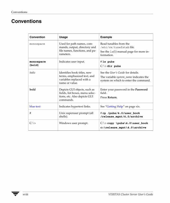
Conventions
Convention Usage Example
monospace Used for path names, commands, output, directory and file names, functions, and parameters.
Read tunables from the /etc/vx/tunefstab file.
See the ls(1) manual page for more in-formation.
monospace (bold)
Indicates user input. # ls pubs
C:\> dir pubs
italic Identifies book titles, new terms, emphasized text, and variables replaced with a name or value.
See the User’s Guide for details.
The variable system_name indicates the system on which to enter the command.
bold Depicts GUI objects, such as fields, list boxes, menu selections, etc. Also depicts GUI commands.
Enter your password in the Password field.
Press Return.
blue text Indicates hypertext links. See “Getting Help” on page xix.
# Unix superuser prompt (all shells).
# cp /pubs/4.0/user_book /release_mgnt/4.0/archive
C:\> Windows user prompt. C:\> copy \pubs\4.0\user_book
c:\release_mgnt\4.0\archive
xviii VERITAS Cluster Server User’s Guide

Getting Help
Getting Help
For technical assistance, visit http://support.veritas.com and select phone or email support. This site also provides access to resources such as TechNotes, product alerts, software downloads, hardware compatibility lists, and our customer email notification service. Use the Knowledge Base Search feature to access additional product information, including current and past releases of VERITAS documentation.
Additional Resources
For license information, software updates and sales contacts, visit https://my.veritas.com/productcenter/ContactVeritas.jsp. For information on purchasing product documentation, visit http://webstore.veritas.com.
Documentation Feedback Your feedback on product documentation is important to us. Send suggestions for improvements and reports on errors or omissions to [email protected]. Include the title and part number of the document (located in the lower left corner of the title page), and chapter and section titles of the text on which you are reporting. Our goal is to ensure customer satisfaction by providing effective, quality documentation. For assistance with topics other than documentation, visit http://support.veritas.com.
Preface xix

Documentation Feedback
xx VERITAS Cluster Server User’s Guide
Section I. Basic Clustering Concepts and Terminology
This section introduces basic clustering concepts and describes the building blocks of VCS. This information lays the groundwork for an understanding of cluster technology. The section also describes key configuration concepts required to set up a VCS cluster.
Section I includes the following chapters:
◆ Chapter 1. “Getting Acquainted with Clustering” on page 1
◆ Chapter 2. “VCS Technical Concepts” on page 7
◆ Chapter 3. “Defining Cluster Topologies” on page 21
◆ Chapter 4. “Configuration Concepts” on page 35


Getting Acquainted with Clustering
1 This chapter introduces clustering and describes the basics of application clustering using VERITAS Cluster Server™ (VCS).What is a Cluster? VERITAS Cluster Server (VCS) connects, or clusters, multiple, independent systems into a management framework for increased availability. Each system, or node, runs its own operating system and cooperates at the software level to form a cluster. VCS links commodity hardware with intelligent software to provide application failover and control. When a node or a monitored application fails, other nodes can take predefined actions to take over and bring up services elsewhere in the cluster.
Detecting Failure VCS can detect application failure and node failure among cluster members.
Detecting Application Failure
VCS is typically deployed to keep business-critical applications online and available to users. VCS provides a mechanism to detect failure of an application by issuing specific commands, tests, or scripts that monitor the overall health of an application. VCS also determines the health of underlying resources supporting the application, such as file systems and network interfaces.
Detecting Node Failure
One of the most difficult tasks in clustering is correctly discriminating between loss of a system and loss of communication between systems. VCS uses a redundant network heartbeat along with SCSI III-based membership coordination and data protection for detecting failure on a node and on fencing. For more information on detecting node failure and how VCS protects data, see “Cluster Control, Communications, and Membership” on page 15.
1
What is a Cluster?
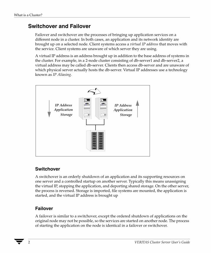
Switchover and Failover Failover and switchover are the processes of bringing up application services on a different node in a cluster. In both cases, an application and its network identity are brought up on a selected node. Client systems access a virtual IP address that moves with the service. Client systems are unaware of which server they are using.
A virtual IP address is an address brought up in addition to the base address of systems in the cluster. For example, in a 2-node cluster consisting of db-server1 and db-server2, a virtual address may be called db-server. Clients then access db-server and are unaware of which physical server actually hosts the db-server. Virtual IP addresses use a technology known as IP Aliasing.
IP Address Application
Storage
IP Address Application
Storage
Switchover
A switchover is an orderly shutdown of an application and its supporting resources on one server and a controlled startup on another server. Typically this means unassigning the virtual IP, stopping the application, and deporting shared storage. On the other server, the process is reversed. Storage is imported, file systems are mounted, the application is started, and the virtual IP address is brought up
Failover
A failover is similar to a switchover, except the ordered shutdown of applications on the original node may not be possible, so the services are started on another node. The process of starting the application on the node is identical in a failover or switchover.
2 VERITAS Cluster Server User’s Guide

Can My Application be Clustered?
Can My Application be Clustered? Most applications can be placed under cluster control provided the basic guidelines are met:
◆ Defined start, stop, and monitor procedures.
◆ Ability to restart in a known state.
◆ Ability to store required data on shared disks.
◆ Adherence to license requirements and host name dependencies.
Defined Start, Stop, and Monitor Procedures The application to be clustered must have defined procedures for starting, stopping, and monitoring.
Defined Start Procedure
The application must have a command to start it and all resources it may require, such as mounted file systems, IP addresses, etc. VCS brings up the required resources in a specific order, then brings up the application using the defined start procedure.
For example, to start an Oracle database, VCS first brings the required storage and file systems online, then the database instance. To start the instance, VCS must know which Oracle utility to call, such as sqlplus. To use this utility properly, VCS must also know the Oracle user, instance ID, Oracle home directory, and the pfile.
Defined Stop Procedure
An individual instance of the application must be capable of being stopped without affecting other instances. For example, killing all HTTPd processes on a Web server is unacceptable because it would also stop other Web servers. Instead, the application must have a defined procedure for stopping a single instance.
In many cases, a method to “clean up” after an application must also be identified. If VCS cannot stop an application cleanly, it may call for a more forceful method, like a kill signal. After a forced stop, the clean-up procedure may also be required for various process- and application-specific items left behind, such as shared memory segments or semaphores.
Chapter 1, Getting Acquainted with Clustering 3
Can My Application be Clustered?
Defined Monitor Procedure
The application must have a monitor procedure that determines if the specified application instance is healthy. The application must allow individual monitoring of unique instances.
For example, the monitor procedure for a Web server connects to the specified server and verifies that it is serving Web pages. In a database environment, the monitoring application can connect to the database server and perform SQL commands to verify read and write to the database. In both cases, end-to-end monitoring is a far more robust check of application health. The closer a test comes to matching what a user does, the better the test is in discovering problems. However, there is a tradeoff: end-to-end monitoring increases system load and may increase system response time. The level of monitoring should be carefully balanced between ensuring the application is up and minimizing monitor overhead.
Ability to Restart the Application in a Known State When the application is taken offline, it must close out all tasks, store data properly on shared disk, and exit. Stateful servers must not keep that state of clients in memory. States should be written to shared storage to ensure proper failover.
Commercial databases such as Oracle, Sybase, or SQL Server are perfect examples of well-written, crash-tolerant applications. On any client SQL request, the client is responsible for holding the request until it receives acknowledgement from the server. When the server receives a request, it is placed in a special redo log file. The data is confirmed as being written to stable disk storage before acknowledging the client. After a server crashes, the database recovers to the last-known committed state by mounting the data tables and applying the redo logs. This returns the database to the time of the crash. The client resubmits any outstanding client requests unacknowledged by the server, and all others are contained in the redo logs. Note the cooperation between the client application and the server. This must be factored in when assessing whether the application is cluster-compatible.
If an application cannot recover gracefully after a server crashes, it cannot run in a cluster environment. The takeover server cannot start up because of data corruption and other problems.
4 VERITAS Cluster Server User’s Guide
Can My Application be Clustered?
External Data Storage The application must be capable of storing all required data and configuration information on shared disks. The exception to this rule is a true shared nothing cluster, described in section “Shared Nothing Cluster” on page 32.
To meet this requirement, you may need specific setup options or soft links. For example, a product may only install in /usr/local. This would require linking /usr/local to a file system mounted from the shared storage device or mounting file system from the shared device on /usr/local.
The application must also store data to disk rather than maintaining it in memory. The takeover system must be capable of accessing all required information. This precludes the use of anything inside a single system inaccessible by the peer, such as NVRAM accelerator boards and other disk-caching mechanisms contained in a local host.
Licensing and Host Name Issues The application must be capable of running on all servers designated as potential hosts, which means strict adherence to licensing requirements and host name dependencies. Changing host names can lead to significant management issues when multiple systems have the same host name after an outage. Custom scripting to modify a system host name on failover is not recommended. It is better to configure applications and licensing to run properly on all hosts.
Chapter 1, Getting Acquainted with Clustering 5

Can My Application be Clustered?
6 VERITAS Cluster Server User’s Guide

VCS Technical Concepts
2 VERITAS Cluster Server (VCS) provides a framework for application management and availability. It enables you to monitor systems and application services, and to restart services on a different system when hardware or software fails. This chapter describes the various components of VCS and how they interact with one another.What is a VCS Cluster? A VCS cluster is composed of a set of systems that provide scalability and high availability for specified applications. VCS monitors and controls the applications in a cluster, and can restart or move them in response to a variety of hardware and software faults. A cluster consists of multiple systems connected with a dedicated communications infrastructure. This infrastructure enables cluster members to exchange information on the status of cluster resources.
Each cluster has a unique cluster ID. Systems in a cluster are connected by redundant cluster communication links. Clusters can have from 1 to 32 member systems, or nodes. Applications can be configured to run on specific nodes within the cluster. Nodes can be individual systems, or they can be created with domains or partitions on enterprise-class systems. Individual cluster nodes each run their own operating system and possess their own boot device. Each node must run the same operating system within a single VCS cluster.
Most applications in a cluster require access to shared application data for systems hosting the application. Nodes sharing storage access are eligible to run an application. Nodes without common storage cannot fail over an application that stores data to disk. See “Defining Cluster Topologies” on page 21 for details.
7
Understanding Cluster Components
Understanding Cluster Components
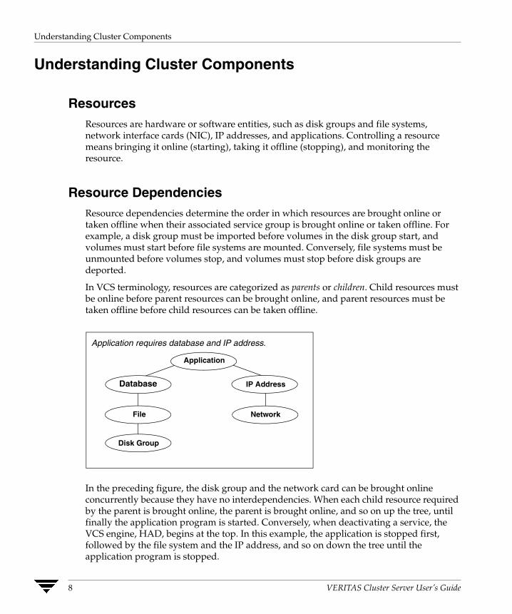
Resources Resources are hardware or software entities, such as disk groups and file systems, network interface cards (NIC), IP addresses, and applications. Controlling a resource means bringing it online (starting), taking it offline (stopping), and monitoring the resource.
Resource Dependencies Resource dependencies determine the order in which resources are brought online or taken offline when their associated service group is brought online or taken offline. For example, a disk group must be imported before volumes in the disk group start, and volumes must start before file systems are mounted. Conversely, file systems must be unmounted before volumes stop, and volumes must stop before disk groups are deported.
In VCS terminology, resources are categorized as parents or children. Child resources must be online before parent resources can be brought online, and parent resources must be taken offline before child resources can be taken offline.
Application
Database
File
Disk Group
IP Address
Network
Application requires database and IP address.
In the preceding figure, the disk group and the network card can be brought online concurrently because they have no interdependencies. When each child resource required by the parent is brought online, the parent is brought online, and so on up the tree, until finally the application program is started. Conversely, when deactivating a service, the VCS engine, HAD, begins at the top. In this example, the application is stopped first, followed by the file system and the IP address, and so on down the tree until the application program is stopped.
8 VERITAS Cluster Server User’s Guide
Understanding Cluster Components
Resource Categories Different types of resources require different levels of control. In VCS there are three categories of resources:
◆ On-Off. VCS starts and stops On-Off resources as required. For example, VCS imports a disk group when required, and deports it when it is no longer needed.
◆ On-Only. VCS starts On-Only resources, but does not stop them. For example, VCS requires NFS daemons to be running to export a file system. VCS starts the daemons if required, but does not stop them if the associated service group is taken offline.
◆ Persistent. These resources cannot be brought online or taken offline. For example, a network interface card cannot be started or stopped, but it is required to configure an IP address. A Persistent resource has an operation value of None. VCS monitors Persistent resources to ensure their status and operation. Failure of a Persistent resource triggers a service group failover.
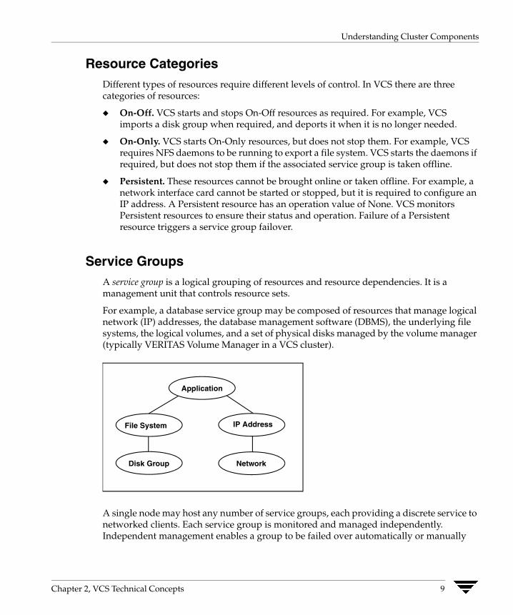
Service Groups A service group is a logical grouping of resources and resource dependencies. It is a management unit that controls resource sets.
For example, a database service group may be composed of resources that manage logical network (IP) addresses, the database management software (DBMS), the underlying file systems, the logical volumes, and a set of physical disks managed by the volume manager (typically VERITAS Volume Manager in a VCS cluster).
Application
Network
IP AddressFile System
Disk Group
A single node may host any number of service groups, each providing a discrete service to networked clients. Each service group is monitored and managed independently. Independent management enables a group to be failed over automatically or manually
Chapter 2, VCS Technical Concepts 9

Understanding Cluster Components
idled for administration or maintenance without necessarily affecting other service groups. If the server crashes, all service groups on that node must be failed over elsewhere.
VCS monitors each resource in a service group and, when a failure is detected, restarts that service group. This could mean restarting it locally or moving it to another node and then restarting it. The method is determined by the type of failure incurred. In the case of local restart, the entire service group may not need to be restarted. It could be that only a single resource within the group is restarted to restore the application service.
Administrative operations are performed on resources, including starting, stopping, restarting, and monitoring at the service group level. Service group operations initiate administrative operations for all resources within the group. For example, when a service group is brought online, all resources within the group are also brought online. When a failover occurs in VCS, resources never fail over individually–the entire service group fails over. If there is more than one group defined on a server, one group may fail over without affecting the other groups on the server.
Types of Service Groups VCS service groups fall in three main categories: failover, parallel, and hybrid.
Failover Service Groups
A failover service group runs on one system in the cluster at a time. Failover groups are used for most applications not designed to maintain data consistency when multiple copies are started, including most databases and NFS servers. VCS assures that a service group is online, partially online or in any state other than offline, such as attempting to go online or attempting to go offline.
Parallel Service Groups
A parallel service group runs simultaneously on more than one system in the cluster. It is more complex than a failover group, and requires an application that can be started safely on more than one system at a time, with no threat of data corruption.
Hybrid Service Groups
A hybrid service group is for replicated data clusters and is a combination of the two groups cited above. It behaves as a failover group within a system zone and a parallel group across system zones. It cannot fail over across system zones, and a switch operation on a hybrid group is allowed only if both systems are within the same system zone. If there are no systems within a zone to which a hybrid group can fail over, the nofailover
10 VERITAS Cluster Server User’s Guide
Understanding Cluster Components
trigger is invoked on the lowest numbered node. Hybrid service groups adhere to the same rules governing group dependencies as do parallel groups. See the “Categories of Service Group Dependencies” on page 385 for more information.
The ClusterService Group The ClusterService group is a special purpose service group, which contains resources required by VCS components. The group contains resources for Cluster Manager (Web Console), Notification, and the wide-area connector (WAC) process used in global clusters.
The ClusterService group can fail over to any node despite restrictions such as “frozen.” It is the first service group to come online and cannot be autodisabled. The group comes online on the first node that goes in the running state. The VCS engine discourages taking the group offline manually.
Chapter 2, VCS Technical Concepts 11
Understanding Cluster Components
Agents Agents are VCS processes that manage resources of predefined resource types according to commands received from the VCS engine, HAD. A system has one agent per resource type that monitors all resources of that type; for example, a single IP agent manages all IP resources.
When the agent is started, it obtains the necessary configuration information from VCS. It then periodically monitors the resources, and updates VCS with the resource status.
The agent provides the type-specific logic to control resources. The action required to bring a resource online or take it offline differs significantly for each resource type. VCS employs agents to handle this functional disparity between resource types. For example, bringing a disk group online requires importing the disk group, but bringing a database online requires starting the database manager process and issuing the appropriate startup commands.
VCS agents are multithreaded, meaning a single VCS agent monitors multiple resources of the same resource type on one host. For example, the IP agent monitors all IP resources. VCS monitors resources when they are online and offline to ensure they are not started on systems on which they are not supposed to run. For this reason, VCS starts the agent for any resource configured to run on a system when the cluster is started. If no resources of a particular type are configured, the agent is not started. For example, if there are no Oracle resources in your configuration, the Oracle agent is not started on the system.
The Agent Framework
VCS agents provide the capability to control a wide array of hardware and software resources. The agent abstraction makes it simple for a developer to support new and changing applications in the VCS control framework.
The VCS agent framework is a set of common, predefined functions compiled into each agent. These functions include the ability to connect to the VCS engine (HAD) and to understand common configuration attributes. The agent framework frees the developer from developing support functions required by the cluster, and instead focus on controlling a specific resource type. For more information on developing agents in C++, Perl, and shell scripts, see the VERITAS Cluster Server Agent Developer’s Guide.
12 VERITAS Cluster Server User’s Guide

Understanding Cluster Components
Agent Operations
Agents carry out specific operations on resources on behalf of the cluster engine. The functions an agent performs are entry points, code sections that carry out specific functions, such as online, offline, and monitor. Entry points can be compiled into the agent itself or can be implemented as individual Perl scripts. For details on any of the following entry points, see the VERITAS Cluster Server Agent Developer’s Guide.
◆ Online—Brings a specific resource ONLINE from an OFFLINE state.
◆ Offline—Takes a resource from an ONLINE state to an OFFLINE state.
◆ Monitor—Tests the status of a resource to determine if the resource is online or offline.
During initial node startup, the monitor entry point probes and determines the status of all resources on the system. The monitor entry point runs after every online and offline operation to verify the operation was successful.
The monitor entry point is also run periodically to verify that the resource remains in its correct state. Under normal circumstances, the monitor is run every 60 seconds when a resource is online, and every 300 seconds when a resource is expected to be offline.
◆ Clean—Cleans up after a resource fails to come online, fails to go offline, or fails while in an ONLINE state. The clean entry point is designed to “clean up” after an application, and ensures the host system is returned to a valid state. For example, the clean function may remove shared memory segments or IPC resources left behind by a database.
◆ Action—Performs actions that can be completed in a short time (typically, a few seconds), and which are outside the scope of traditional activities such as online and offline.
◆ Info—Retrieves specific information for an online resource.
The retrieved information is stored in the resource attribute ResourceInfo. This entry point is invoked periodically by the agent framework when the resource type attribute InfoInterval is set to a non-zero value. The InfoInterval attribute indicates the period after which the info entry point must be invoked. For example, the Mount agent may use this entry point to indicate the space available on the file system.
Chapter 2, VCS Technical Concepts 13

Understanding Cluster Components
Agent Classifications
Bundled Agents
Bundled agents are packaged with VCS. They include agents for Disk, Mount, IP, and various other resource types. See the VERITAS Bundled Agents Reference Guide for a complete list.
Enterprise Agents
Enterprise agents control third-party applications and are licensed separately. These include agents for Oracle, NetBackup, and Sybase. Each enterprise agent includes instructions on installing and configuring the agent. Contact your VERITAS sales representative for more information.
Custom Agents
Custom agents can be developed by you or by VERITAS consultants. Typically, agents are developed because the user requires control of an application that is not covered by current bundled or enterprise agents. See the VERITAS Cluster Server Agent Developer’s Guide for information on developing a custom agent, or contact VERITAS Enterprise Consulting Services.
14 VERITAS Cluster Server User’s Guide

Understanding Cluster Components
Cluster Control, Communications, and Membership Cluster communications ensure VCS is continuously aware of the status of each system’s service groups and resources. They also enable VCS to recognize which systems are active members of the cluster, which are joining or leaving the cluster, and which have failed.
High-Availability Daemon (HAD)
The high-availability daemon, or HAD, is the main VCS daemon running on each system. It is responsible for building the running cluster configuration from the configuration files, distributing the information when new nodes join the cluster, responding to operator input, and taking corrective action when something fails. It is typically known as the VCS engine. The engine uses agents to monitor and manage resources. Information about resource states is collected from the agents on the local system and forwarded to all cluster members. The local engine also receives information from the other cluster members to update its view of the cluster. HAD operates as a replicated state machine (RSM). This means HAD running on each node has a completely synchronized view of the resource status on each node. Each instance of HAD follows the same code path for corrective action, as required. The RSM is maintained through the use of a purpose-built communications package consisting of the protocols Low Latency Transport (LLT) and Group Membership Services/Atomic Broadcast (GAB).
Low Latency Transport (LLT)
VCS uses private network communications between cluster nodes for cluster maintenance. The Low Latency Transport functions as a high-performance, low-latency replacement for the IP stack, and is used for all cluster communications. VERITAS recommends two independent networks between all cluster nodes, which provide the required redundancy in the communication path and enable VCS to discriminate between a network failure and a system failure. LLT has two major functions.
◆ Traffic Distribution
LLT distributes (load balances) internode communication across all available private network links. This distribution means that all cluster communications are evenly distributed across all private network links (maximum eight) for performance and fault resilience. If a link fails, traffic is redirected to the remaining links.
◆ Heartbeat
LLT is responsible for sending and receiving heartbeat traffic over network links. This heartbeat is used by the Group Membership Services function of GAB to determine cluster membership.
Chapter 2, VCS Technical Concepts 15
Understanding Cluster Components
Group Membership Services/Atomic Broadcast (GAB)
The Group Membership Services/Atomic Broadcast protocol (GAB) is responsible for cluster membership and cluster communications.
◆ Cluster Membership
GAB maintains cluster membership by receiving input on the status of the heartbeat from each node via LLT. When a system no longer receives heartbeats from a peer, it marks the peer as DOWN and excludes the peer from the cluster. In most configurations, the I/O fencing module is used to prevent network partitions. See “Cluster Membership” on page 314 for more information.
◆ Cluster Communications
GAB’s second function is reliable cluster communications. GAB provides guaranteed delivery of point-to-point and broadcast messages to all nodes. The VCS engine uses a private IOCTL (provided by GAB) to tell GAB that it is alive.
I/O Fencing Module
The I/O fencing module implements a quorum-type functionality to ensure only one cluster survives a split of the private network. I/O fencing also provides the ability to perform SCSI-III persistent reservations on failover. The shared VERITAS Volume Manager disk groups offer complete protection against data corruption by nodes assumed to be excluded from cluster membership. See “VCS I/O Fencing” on page 318 for more information.
16 VERITAS Cluster Server User’s Guide

Understanding Cluster Components
Security Services VCS uses VERITAS Security Services (VxSS) to provide secure communication between cluster nodes and clients, including the Java and the Web consoles. VCS uses digital certificates for authentication and uses SSL to encrypt communication over the public network.
When running in secure mode, VCS uses platform-based authentication; VCS does not store user passwords. All VCS users are system and domain users and are configured using fully-qualified user names. For example, administrator@vcsdomain. VCS provides a single sign-on mechanism, so authenticated users need not sign on each time to connect to a cluster.
VCS requires a system to be configured as a root broker. Additionally, all nodes in the cluster must be configured as authentication brokers.
◆ A root broker serves as the main registration and certification authority; it has a self-signed certificate and can authenticate other brokers. VERITAS recommends configuring a system outside the cluster as the root broker.
◆ Authentication brokers reside one level below the root broker. Authentication brokers serve as intermediate registration and certification authorities. They can authenticate clients, such as users or services, but cannot authenticate other brokers. Authentication brokers have certificates signed by the root.
For secure communication, VCS components acquire credentials from the VxSS authentication broker configured on the local system. The acquired certificate is used during authentication and is presented to clients for the SSL handshake. VCS and its components specify the account name and the domain in the following format:
◆ HAD Account
name = _HA_VCS_(systemname)domain = HA_SERVICES@(fully_qualified_system_name)
◆ CmdServer
name = _CMDSERVER_VCS_(systemname)domain = HA_SERVICES@(fully_qualified_system_name)
For instructions on how to set up Security Services while setting up the cluster, see the VERITAS Cluster Server Installation Guide. For instructions on enabling and disabling Security Services manually, see “Enabling and Disabling VERITAS Security Services” on page 81.
Chapter 2, VCS Technical Concepts 17
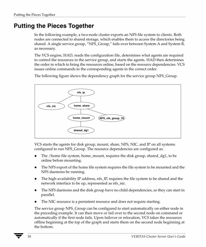
Putting the Pieces Together
Putting the Pieces Together In the following example, a two-node cluster exports an NFS file system to clients. Both nodes are connected to shared storage, which enables them to access the directories being shared. A single service group, “NFS_Group,” fails over between System A and System B, as necessary.
The VCS engine, HAD, reads the configuration file, determines what agents are required to control the resources in the service group, and starts the agents. HAD then determines the order in which to bring the resources online, based on the resource dependencies. VCS issues online commands to the corresponding agents in the correct order.
The following figure shows the dependency graph for the service group NFS_Group.
home_mount
shared_dg1
home_share
NFS_nfs_group_16
nfs_nic
nfs_ip
VCS starts the agents for disk group, mount, share, NFS, NIC, and IP on all systems configured to run NFS_Group. The resource dependencies are configured as:
◆ The /home file system, home_mount, requires the disk group, shared_dg1, to be online before mounting.
◆ The NFS export of the home file system requires the file system to be mounted and the NFS daemons be running.
◆ The high-availability IP address, nfs_IP, requires the file system to be shared and the network interface to be up, represented as nfs_nic.
◆ The NFS daemons and the disk group have no child dependencies, so they can start in parallel.
◆ The NIC resource is a persistent resource and does not require starting.
The service group NFS_Group can be configured to start automatically on either node in the preceding example. It can then move or fail over to the second node on command or automatically if the first node fails. Upon failover or relocation, VCS takes the resources offline beginning at the top of the graph and starts them on the second node beginning at the bottom.
18 VERITAS Cluster Server User’s Guide
Other VCS Processes
Other VCS Processes In addition to the processes and components previously cited in this chapter, there are several others that play a key role in VCS operations.
Command-Line Interface (CLI) The VCS command-line interface provides a comprehensive set of commands for managing and administering the cluster. For more information, see “Administering the Cluster from the Command Line” on page 57.
Cluster Manager (Java Console) A cross-platform Java-based graphical user interface that provides complete administration capabilities for your cluster. The console runs on any system inside or outside the cluster, on any operating system that supports Java. For more information, see “Administering the Cluster from Cluster Manager (Java Console)” on page 109.
Cluster Manager (Web Console) A Web-based graphical user interface for monitoring and administering the cluster. For more information, see “Administering the Cluster from Cluster Manager (Web Console)” on page 215.
The hacf Utility Verifies a configuration file. Can also be used by HAD to load a configuration file at run time. See “Managing the VCS Configuration File: The hacf Utility” on page 48 for more information about the utility.
The hashadow Process A process that monitors and, when required, restarts HAD.
Chapter 2, VCS Technical Concepts 19

Other VCS Processes
20 VERITAS Cluster Server User’s Guide
Defining Cluster Topologies
3 This chapter describes VCS failover configurations, including their advantages and limitations. It also provides information on potential storage and cluster configurations according to location of nodes, connections to storage, and connections to other nodes.Basic Failover Configurations This section describes basic failover configurations, including asymmetric, symmetric, and N-to-1.
21

Basic Failover Configurations
Asymmetric or Active/Passive Configuration In an asymmetric configuration, an application runs on a primary, or master, server. A dedicated redundant server is present to take over on any failure. The redundant server is not configured to perform any other functions. In the following illustration, a database application is moved, or failed over, from the master to the redundant server.
Before Failover After Failover
Application Application✗
Asymmetric Failover
This configuration is the simplest and most reliable. The redundant server is on stand-by with full performance capability. If other applications are running, they present no compatibility issues.
22 VERITAS Cluster Server User’s Guide

Basic Failover Configurations
Symmetric or Active/Active Configuration In a symmetric configuration, each server is configured to run a specific application or service and provide redundancy for its peer. In the example below, each server is running one application service group. When a failure occurs, the surviving server hosts both application groups.
Before Failover After Failover
Application1 ✗Application2 Application1
Application2
Symmetric Failover
Symmetric configurations appear more efficient in terms of hardware utilization. In the asymmetric example, the redundant server requires only as much processor power as its peer. On failover, performance remains the same. In the symmetric example, the redundant server requires not only enough processor power to run the existing application, but also enough to run the new application it takes over.
Further issues can arise in symmetric configurations when multiple applications running on the same system do not co-exist properly. Some applications work well with multiple copies started on the same system, but others fail. Issues can also arise when two applications with different I/O and memory requirements run on the same system.
Chapter 3, Defining Cluster Topologies 23
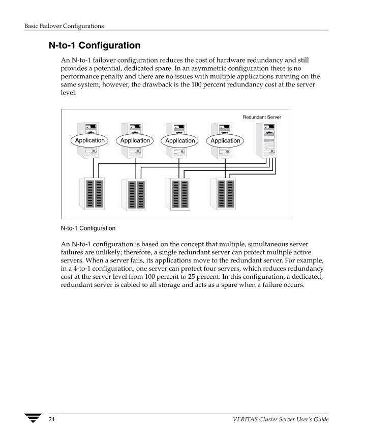
Basic Failover Configurations
N-to-1 Configuration An N-to-1 failover configuration reduces the cost of hardware redundancy and still provides a potential, dedicated spare. In an asymmetric configuration there is no performance penalty and there are no issues with multiple applications running on the same system; however, the drawback is the 100 percent redundancy cost at the server level.
Redundant Server
ApplicationApplicationApplicationApplication
N-to-1 Configuration
An N-to-1 configuration is based on the concept that multiple, simultaneous server failures are unlikely; therefore, a single redundant server can protect multiple active servers. When a server fails, its applications move to the redundant server. For example, in a 4-to-1 configuration, one server can protect four servers, which reduces redundancy cost at the server level from 100 percent to 25 percent. In this configuration, a dedicated, redundant server is cabled to all storage and acts as a spare when a failure occurs.
24 VERITAS Cluster Server User’s Guide
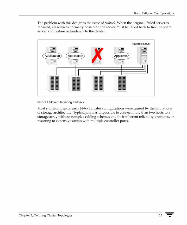
Basic Failover Configurations
The problem with this design is the issue of failback. When the original, failed server is repaired, all services normally hosted on the server must be failed back to free the spare server and restore redundancy to the cluster.
Redundant Server
ApplicationApplicationApplication ✗
N-to-1 Failover Requiring Failback
Most shortcomings of early N-to-1 cluster configurations were caused by the limitations of storage architecture. Typically, it was impossible to connect more than two hosts to a storage array without complex cabling schemes and their inherent reliability problems, or resorting to expensive arrays with multiple controller ports.
Chapter 3, Defining Cluster Topologies 25
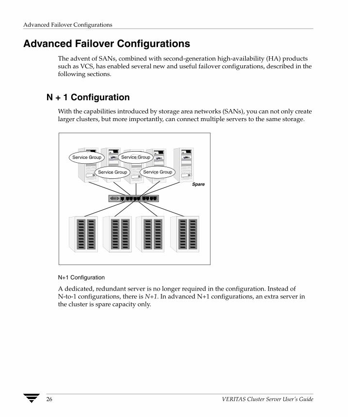
Advanced Failover Configurations
Advanced Failover Configurations The advent of SANs, combined with second-generation high-availability (HA) products such as VCS, has enabled several new and useful failover configurations, described in the following sections.
N + 1 Configuration With the capabilities introduced by storage area networks (SANs), you can not only create larger clusters, but more importantly, can connect multiple servers to the same storage.
Service Group
Service Group
Service Group
Service Group
Spare
N+1 Configuration
A dedicated, redundant server is no longer required in the configuration. Instead of N-to-1 configurations, there is N+1. In advanced N+1 configurations, an extra server in the cluster is spare capacity only.
26 VERITAS Cluster Server User’s Guide

Advanced Failover Configurations
When a server fails, the application service group restarts on the spare. After the server is repaired, it becomes the spare. This configuration eliminates the need for a second application failure to fail back the service group to the primary system. Any server can provide redundancy to any other server.
Service Group
Service Group
Service Group
Service Group
✗
N+1 Failover
Chapter 3, Defining Cluster Topologies 27

Advanced Failover Configurations
N-to-N Configuration An N-to-N configuration refers to multiple service groups running on multiple servers, with each service group capable of being failed over to different servers in the cluster. For example, consider a four-node cluster with each node supporting three critical database instances.
SG
SG
SG
SG
SG
SG
SG
SG
SG
SG
SG
SG
SG = Service Group
N-to-N Configuration
28 VERITAS Cluster Server User’s Guide
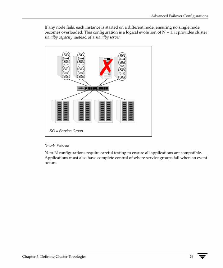
Advanced Failover Configurations
If any node fails, each instance is started on a different node, ensuring no single node becomes overloaded. This configuration is a logical evolution of N + 1: it provides cluster standby capacity instead of a standby server.
SG
SG
SG
SG
SG
SG
SG = Service Group
SG
SG
SG
SG
SG
SG
SG
SG
SG
SG
✗
N-to-N Failover
N-to-N configurations require careful testing to ensure all applications are compatible. Applications must also have complete control of where service groups fail when an event occurs.
Chapter 3, Defining Cluster Topologies 29

Cluster Topologies and Storage Configurations
Cluster Topologies and Storage Configurations This section describes commonly-used cluster topologies, along with the storage configuration used to support the topologies.
Basic Shared Storage Cluster In this configuration, a single cluster shares access to a storage device, typically over a SAN. An application can only be started on a node with access to the required storage. For example, in a multi-node cluster, any node designated to run a specific database instance must have access to the storage where the database’s tablespaces, redo logs, control files, etc., are stored. Shared disk architecture is also the easiest to implement and maintain. When a node or application fails, all data required to start on another node is stored on the shared disk.
Service Group
Service Group
Service Group
Service Group
Shared Disk Architecture for Basic Cluster
30 VERITAS Cluster Server User’s Guide

Cluster Topologies and Storage Configurations
Campus, or “Metropolitan,” Shared Storage ClusterIn a campus environment, VCS and VERITAS Volume Manager are used to create a cluster that spans multiple data centers or buildings. Instead of a single storage array, data is mirrored between arrays using VERITAS Volume Manager. This provides synchronized copies of data at both sites. This procedure is identical to mirroring between two arrays in a data center, only now it is spread over a distance. The requirements for a campus cluster are two independent network links for heartbeat, public network connectivity between buildings on same IP subnet, and two storage arrays, each providing highly available disks.
Campus Shared Storage Cluster
SG SG
SG
SG = Service Group
SG SG
SG
SGSG SGSG
SG
SGSG
SG
SG SG
Site A Site B
VERITAS Volume Manager
RAID 1 Mirror of
Reliable Disks
Chapter 3, Defining Cluster Topologies 31

Cluster Topologies and Storage Configurations
Shared Nothing Cluster Systems in shared nothing clusters do not share access to disks; they maintain separate copies of data. VCS shared nothing clusters typically have read-only data stored locally on both systems. For example, a pair of systems in a cluster that includes a critical Web server which provides access to a backend database. The Web server runs on local disks and does not require data sharing at the Web server level.
Shared Nothing Cluster
32 VERITAS Cluster Server User’s Guide
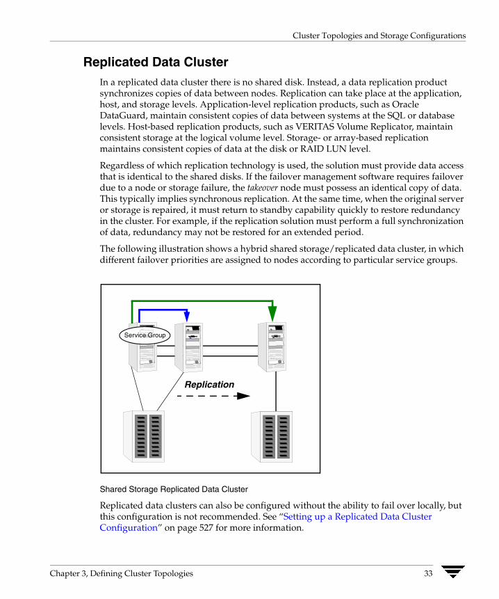
Cluster Topologies and Storage Configurations
Replicated Data Cluster In a replicated data cluster there is no shared disk. Instead, a data replication product synchronizes copies of data between nodes. Replication can take place at the application, host, and storage levels. Application-level replication products, such as Oracle DataGuard, maintain consistent copies of data between systems at the SQL or database levels. Host-based replication products, such as VERITAS Volume Replicator, maintain consistent storage at the logical volume level. Storage- or array-based replication maintains consistent copies of data at the disk or RAID LUN level.
Regardless of which replication technology is used, the solution must provide data access that is identical to the shared disks. If the failover management software requires failover due to a node or storage failure, the takeover node must possess an identical copy of data. This typically implies synchronous replication. At the same time, when the original server or storage is repaired, it must return to standby capability quickly to restore redundancy in the cluster. For example, if the replication solution must perform a full synchronization of data, redundancy may not be restored for an extended period.
The following illustration shows a hybrid shared storage/replicated data cluster, in which different failover priorities are assigned to nodes according to particular service groups.
Replication
Service Group
Shared Storage Replicated Data Cluster
Replicated data clusters can also be configured without the ability to fail over locally, but this configuration is not recommended. See “Setting up a Replicated Data Cluster Configuration” on page 527 for more information.
Chapter 3, Defining Cluster Topologies 33
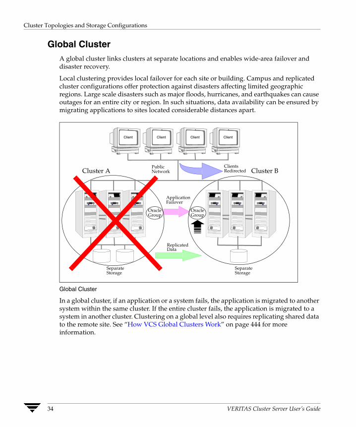
Cluster Topologies and Storage Configurations
Global ClusterA global cluster links clusters at separate locations and enables wide-area failover and disaster recovery.
Local clustering provides local failover for each site or building. Campus and replicated cluster configurations offer protection against disasters affecting limited geographic regions. Large scale disasters such as major floods, hurricanes, and earthquakes can cause outages for an entire city or region. In such situations, data availability can be ensured by migrating applications to sites located considerable distances apart.
Global Cluster
In a global cluster, if an application or a system fails, the application is migrated to another system within the same cluster. If the entire cluster fails, the application is migrated to a system in another cluster. Clustering on a global level also requires replicating shared data to the remote site. See “How VCS Global Clusters Work” on page 444 for more information.
PublicNetwork
SeparateStorage
SeparateStorage
Client Client Client Client
ReplicatedData
ClientsRedirected
ApplicationFailover
OracleGroup
OracleGroup
Cluster A Cluster B
34 VERITAS Cluster Server User’s Guide
Configuration Concepts
4 Configuring VCS means conveying to the VCS engine the definitions of the cluster, service groups, resources, and resource dependencies. VCS uses two configuration files in a default configuration:◆ The main.cf file defines the entire cluster.
◆ The types.cf file defines the resource types.
By default, both files reside in the directory /etc/VRTSvcs/conf/config. Additional files similar to types.cf may be present if agents have been added, such as Oracletypes.cf.
In a VCS cluster, the first system to be brought online reads the configuration file and creates an internal (in-memory) representation of the configuration. Systems brought online after the first system derive their information from systems running in the cluster. You must stop the cluster while you are modifying the files from the command line. Changes made by editing the configuration files take effect when the cluster is restarted. The node on which the changes were made should be the first node to be brought back online.
35
The VCS Configuration Language
The VCS Configuration Language The VCS configuration language specifies the makeup of service groups and their associated entities, such as resource types, resources, and attributes. These specifications are expressed in configuration files, whose names contain the suffix .cf. For example, the body of the configuration is in main.cf. Using an include statement, it references the file types.cf, which specifies resource types.
There are three ways to generate configuration files:
✔ Use Cluster Manager (Java Console).
✔ Use the command-line interface.
✔ If VCS is not running, use a text editor to create and modify the files.
The main.cf File The format of the main.cf file comprises include clauses and definitions for the cluster, systems, service groups, and resources. The main.cf file also includes service group and resource dependency clauses.
Include Clauses Include clauses incorporate additional configuration files into main.cf. These additional files typically contain type definitions, including the types.cf file. Other type definitions must be included as required. Typically, custom agents add type definitions in their own files. Most customers and VERITAS consultants do not modify the types.cf file, but instead create additional type files.
Cluster Definition This section of main.cf defines the attributes of the cluster, including the cluster name and the names of the cluster users.
36 VERITAS Cluster Server User’s Guide

The main.cf File
System Definition Each system designated as part of the cluster is listed in this section of main.cf. The names listed as system names must match the name returned by the command uname -a. System names are preceded with the keyword “system.” For any system to be used in a service group definition, it must be defined in this section. Each service group can be configured to run on a subset of systems defined in this section.
Service Group Definition Service group definitions in main.cf comprise the attributes of a particular service group. See “Service Group Attributes” on page 640 for a complete list. The following information describes two common service group attributes: SystemList and AutoStartList.
SystemList Attribute
The SystemList attribute designates all systems on which a service group can come online. By default, the order of systems in the list defines the priority of systems used in a failover. For example, the definition SystemList = { SystemA, SystemB, SystemC } configures SystemA to be the first choice on failover, followed by SystemB and then SystemC.
System priority may also be assigned explicitly in the SystemList attribute by assigning numeric values to each system name. For example: SystemList = { SystemA=0, SystemB=1, SystemC=2 }
If you assign numeric priority values, VCS assigns a priority to the system without a number by adding 1 to the priority of the preceding system. For example, if the SystemList is defined as SystemList = { SystemA, SystemB=2, SystemC }, VCS assigns the values SystemA = 0, SystemB = 2, SystemC = 3.
Note that a duplicate numeric priority value may be assigned when the following occurs:
SystemList = { SystemA, SystemB=0, SystemC }
The numeric values assigned are SystemA = 0, SystemB = 0, SystemC = 1.
To avoid the same priority number being assigned to more than one system, do not assign any numbers or assign different numbers to each system in SystemList.
AutoStartList Attribute
List of systems on which the service group will be started with VCS (usually at system boot). For example, if a system is a member of a failover service group’s AutoStartList attribute, and if the service group is not already running on another system in the cluster, the group is brought online when the system is started.
Chapter 4, Configuration Concepts 37
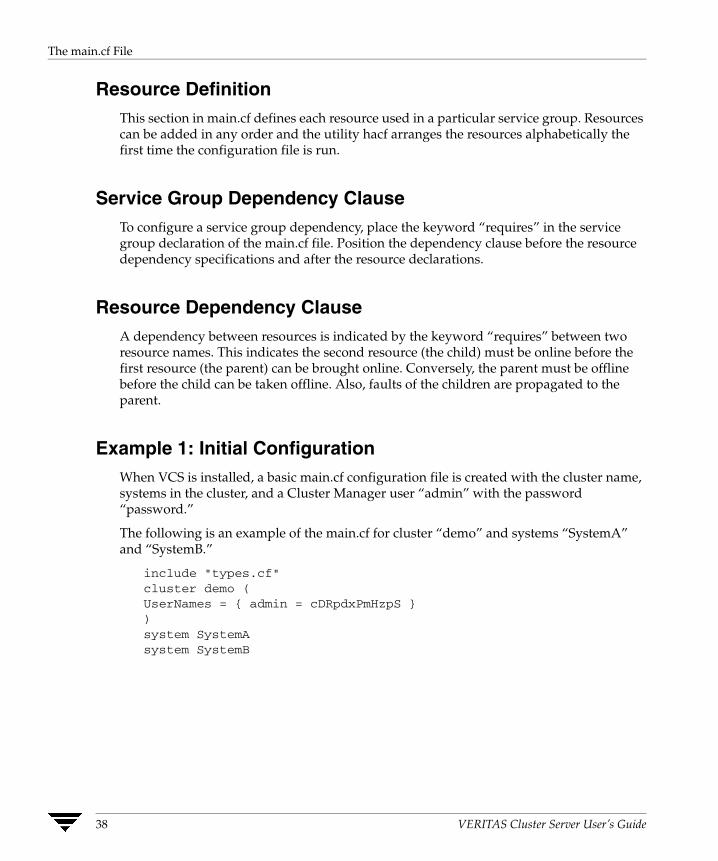
The main.cf File
Resource Definition This section in main.cf defines each resource used in a particular service group. Resources can be added in any order and the utility hacf arranges the resources alphabetically the first time the configuration file is run.
Service Group Dependency Clause To configure a service group dependency, place the keyword “requires” in the service group declaration of the main.cf file. Position the dependency clause before the resource dependency specifications and after the resource declarations.
Resource Dependency Clause A dependency between resources is indicated by the keyword “requires” between two resource names. This indicates the second resource (the child) must be online before the first resource (the parent) can be brought online. Conversely, the parent must be offline before the child can be taken offline. Also, faults of the children are propagated to the parent.
Example 1: Initial Configuration When VCS is installed, a basic main.cf configuration file is created with the cluster name, systems in the cluster, and a Cluster Manager user “admin” with the password “password.”
The following is an example of the main.cf for cluster “demo” and systems “SystemA” and “SystemB.”
include "types.cf"cluster demo (UserNames = { admin = cDRpdxPmHzpS })system SystemAsystem SystemB
38 VERITAS Cluster Server User’s Guide
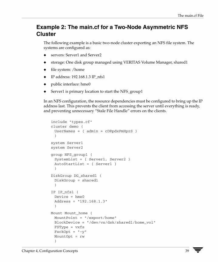
The main.cf File
Example 2: The main.cf for a Two-Node Asymmetric NFS Cluster
The following example is a basic two-node cluster exporting an NFS file system. The systems are configured as:
◆ servers: Server1 and Server2
◆ storage: One disk group managed using VERITAS Volume Manager, shared1
◆ file system: /home
◆ IP address: 192.168.1.3 IP_nfs1
◆ public interface: hme0
◆ Server1 is primary location to start the NFS_group1
In an NFS configuration, the resource dependencies must be configured to bring up the IP address last. This prevents the client from accessing the server until everything is ready,and preventing unnecessary “Stale File Handle” errors on the clients.
include "types.cf"cluster demo (UserNames = { admin = cDRpdxPmHpzS })
system Server1system Server2
group NFS_group1 (SystemList = { Server1, Server2 }AutoStartList = { Server1 })
DiskGroup DG_shared1 (DiskGroup = shared1)
IP IP_nfs1 (Device = hme0Address = "192.168.1.3")
Mount Mount_home (MountPoint = "/export/home"BlockDevice = "/dev/vx/dsk/shared1/home_vol"FSType = vxfsFsckOpt = "-y"MountOpt = rw)
Chapter 4, Configuration Concepts 39
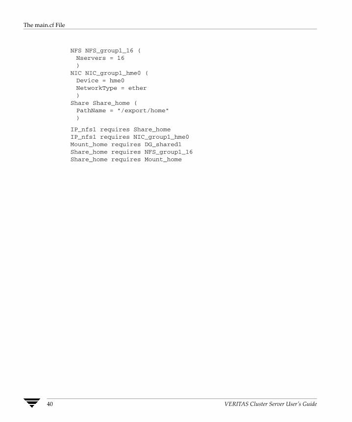
The main.cf File
NFS NFS_group1_16 (Nservers = 16)
NIC NIC_group1_hme0 (Device = hme0NetworkType = ether)
Share Share_home (PathName = "/export/home")
IP_nfs1 requires Share_homeIP_nfs1 requires NIC_group1_hme0Mount_home requires DG_shared1Share_home requires NFS_group1_16Share_home requires Mount_home
40 VERITAS Cluster Server User’s Guide
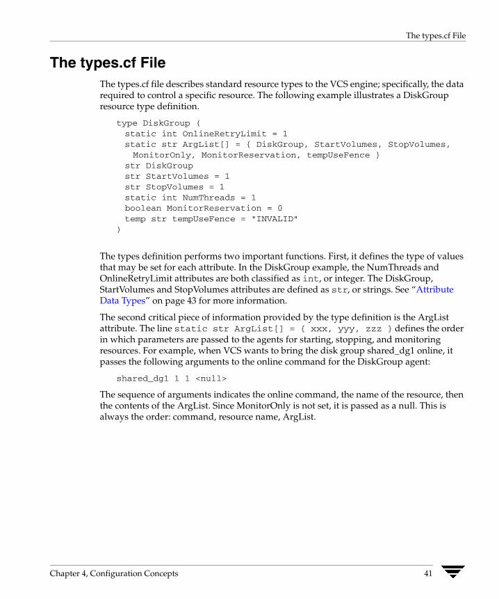
The types.cf File
The types.cf File The types.cf file describes standard resource types to the VCS engine; specifically, the data required to control a specific resource. The following example illustrates a DiskGroup resource type definition.
type DiskGroup (static int OnlineRetryLimit = 1static str ArgList[] = { DiskGroup, StartVolumes, StopVolumes,MonitorOnly, MonitorReservation, tempUseFence }
str DiskGroupstr StartVolumes = 1str StopVolumes = 1static int NumThreads = 1boolean MonitorReservation = 0temp str tempUseFence = "INVALID"
)
The types definition performs two important functions. First, it defines the type of values that may be set for each attribute. In the DiskGroup example, the NumThreads and OnlineRetryLimit attributes are both classified as int, or integer. The DiskGroup, StartVolumes and StopVolumes attributes are defined as str, or strings. See “Attribute Data Types” on page 43 for more information.
The second critical piece of information provided by the type definition is the ArgList attribute. The line static str ArgList[] = { xxx, yyy, zzz } defines the order in which parameters are passed to the agents for starting, stopping, and monitoring resources. For example, when VCS wants to bring the disk group shared_dg1 online, it passes the following arguments to the online command for the DiskGroup agent:
shared_dg1 1 1 <null>
The sequence of arguments indicates the online command, the name of the resource, then the contents of the ArgList. Since MonitorOnly is not set, it is passed as a null. This is always the order: command, resource name, ArgList.
Chapter 4, Configuration Concepts 41
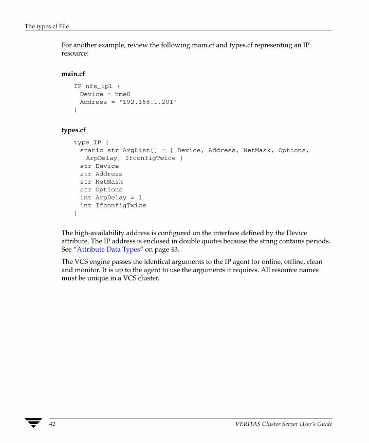
The types.cf File
For another example, review the following main.cf and types.cf representing an IP resource:
main.cf
IP nfs_ip1 (Device = hme0Address = "192.168.1.201"
)
types.cf
type IP (static str ArgList[] = { Device, Address, NetMask, Options,ArpDelay, IfconfigTwice }
str Devicestr Addressstr NetMaskstr Optionsint ArpDelay = 1int IfconfigTwice
)
The high-availability address is configured on the interface defined by the Device attribute. The IP address is enclosed in double quotes because the string contains periods. See “Attribute Data Types” on page 43.
The VCS engine passes the identical arguments to the IP agent for online, offline, clean and monitor. It is up to the agent to use the arguments it requires. All resource names must be unique in a VCS cluster.
42 VERITAS Cluster Server User’s Guide
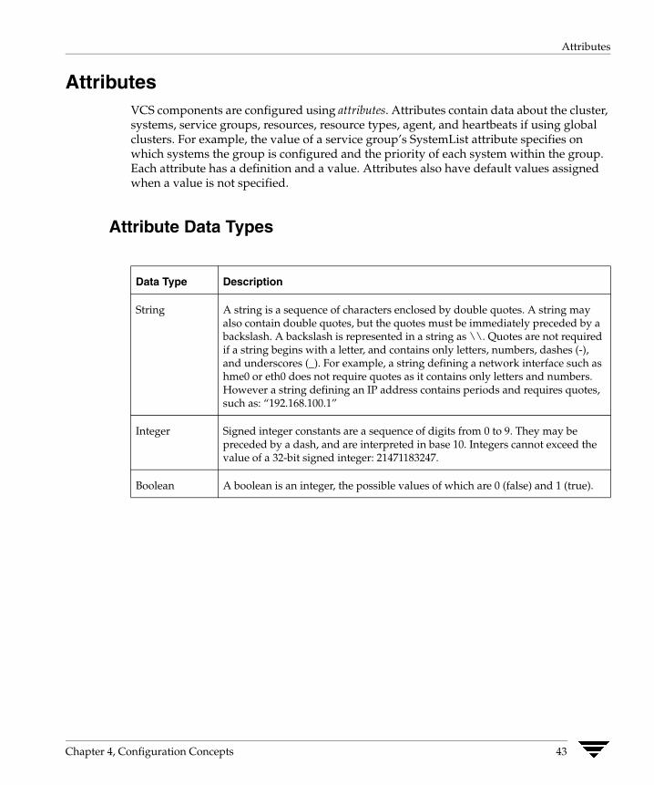
Attributes
Attributes VCS components are configured using attributes. Attributes contain data about the cluster, systems, service groups, resources, resource types, agent, and heartbeats if using global clusters. For example, the value of a service group’s SystemList attribute specifies on which systems the group is configured and the priority of each system within the group. Each attribute has a definition and a value. Attributes also have default values assigned when a value is not specified.
Attribute Data Types
Data Type Description
String A string is a sequence of characters enclosed by double quotes. A string may also contain double quotes, but the quotes must be immediately preceded by a backslash. A backslash is represented in a string as \\. Quotes are not required if a string begins with a letter, and contains only letters, numbers, dashes (-), and underscores (_). For example, a string defining a network interface such as hme0 or eth0 does not require quotes as it contains only letters and numbers. However a string defining an IP address contains periods and requires quotes, such as: “192.168.100.1”
Integer Signed integer constants are a sequence of digits from 0 to 9. They may be preceded by a dash, and are interpreted in base 10. Integers cannot exceed the value of a 32-bit signed integer: 21471183247.
Boolean A boolean is an integer, the possible values of which are 0 (false) and 1 (true).
Chapter 4, Configuration Concepts 43
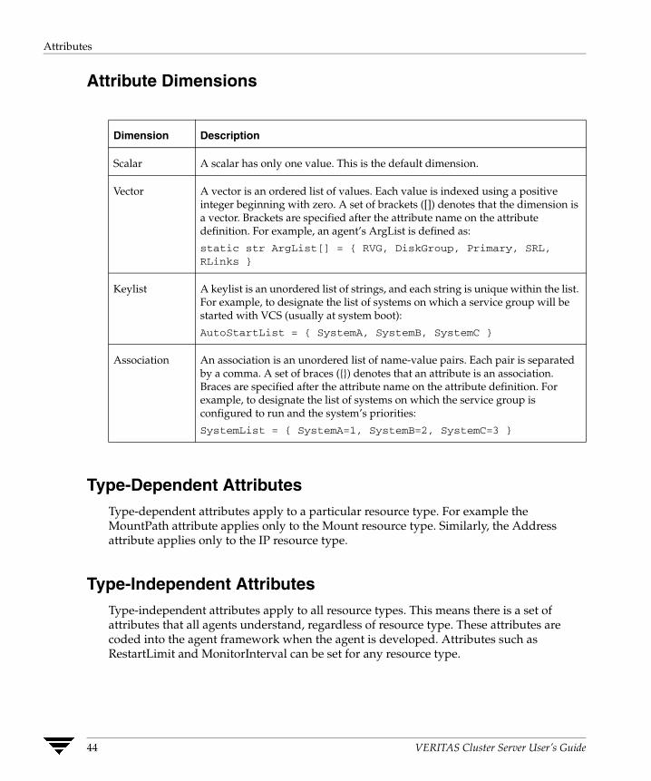
Attributes
Attribute Dimensions
Dimension Description
Scalar A scalar has only one value. This is the default dimension.
Vector A vector is an ordered list of values. Each value is indexed using a positive integer beginning with zero. A set of brackets ([]) denotes that the dimension is a vector. Brackets are specified after the attribute name on the attribute definition. For example, an agent’s ArgList is defined as:
static str ArgList[] = { RVG, DiskGroup, Primary, SRL, RLinks }
Keylist A keylist is an unordered list of strings, and each string is unique within the list. For example, to designate the list of systems on which a service group will be started with VCS (usually at system boot):
AutoStartList = { SystemA, SystemB, SystemC }
Association An association is an unordered list of name-value pairs. Each pair is separated by a comma. A set of braces ({}) denotes that an attribute is an association. Braces are specified after the attribute name on the attribute definition. For example, to designate the list of systems on which the service group is configured to run and the system’s priorities:
SystemList = { SystemA=1, SystemB=2, SystemC=3 }
Type-Dependent Attributes Type-dependent attributes apply to a particular resource type. For example the MountPath attribute applies only to the Mount resource type. Similarly, the Address attribute applies only to the IP resource type.
Type-Independent Attributes Type-independent attributes apply to all resource types. This means there is a set of attributes that all agents understand, regardless of resource type. These attributes are coded into the agent framework when the agent is developed. Attributes such as RestartLimit and MonitorInterval can be set for any resource type.
44 VERITAS Cluster Server User’s Guide
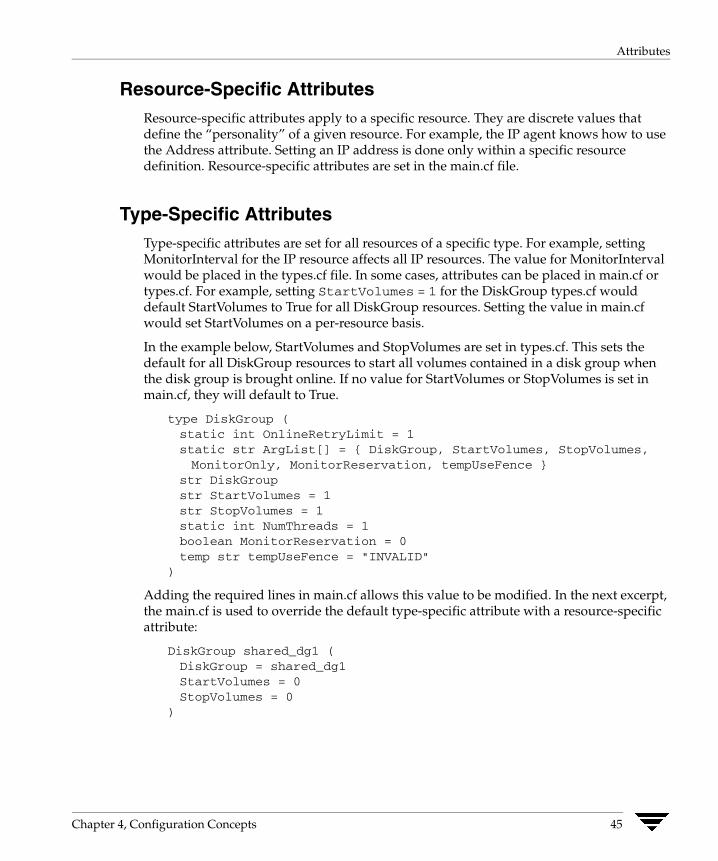
Attributes
Resource-Specific Attributes Resource-specific attributes apply to a specific resource. They are discrete values that define the “personality” of a given resource. For example, the IP agent knows how to use the Address attribute. Setting an IP address is done only within a specific resource definition. Resource-specific attributes are set in the main.cf file.
Type-Specific Attributes Type-specific attributes are set for all resources of a specific type. For example, setting MonitorInterval for the IP resource affects all IP resources. The value for MonitorInterval would be placed in the types.cf file. In some cases, attributes can be placed in main.cf or types.cf. For example, setting StartVolumes = 1 for the DiskGroup types.cf would default StartVolumes to True for all DiskGroup resources. Setting the value in main.cf would set StartVolumes on a per-resource basis.
In the example below, StartVolumes and StopVolumes are set in types.cf. This sets the default for all DiskGroup resources to start all volumes contained in a disk group when the disk group is brought online. If no value for StartVolumes or StopVolumes is set in main.cf, they will default to True.
type DiskGroup (static int OnlineRetryLimit = 1static str ArgList[] = { DiskGroup, StartVolumes, StopVolumes,MonitorOnly, MonitorReservation, tempUseFence }
str DiskGroupstr StartVolumes = 1str StopVolumes = 1static int NumThreads = 1boolean MonitorReservation = 0temp str tempUseFence = "INVALID"
)
Adding the required lines in main.cf allows this value to be modified. In the next excerpt, the main.cf is used to override the default type-specific attribute with a resource-specific attribute:
DiskGroup shared_dg1 (DiskGroup = shared_dg1StartVolumes = 0StopVolumes = 0
)
Chapter 4, Configuration Concepts 45
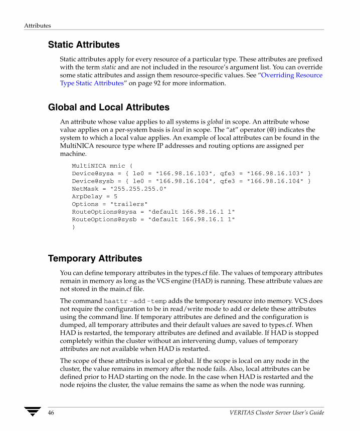
Attributes
Static Attributes Static attributes apply for every resource of a particular type. These attributes are prefixed with the term static and are not included in the resource’s argument list. You can override some static attributes and assign them resource-specific values. See “Overriding Resource Type Static Attributes” on page 92 for more information.
Global and Local Attributes An attribute whose value applies to all systems is global in scope. An attribute whose value applies on a per-system basis is local in scope. The “at” operator (@) indicates the system to which a local value applies. An example of local attributes can be found in the MultiNICA resource type where IP addresses and routing options are assigned per machine.
MultiNICA mnic (Device@sysa = { le0 = "166.98.16.103", qfe3 = "166.98.16.103" }Device@sysb = { le0 = "166.98.16.104", qfe3 = "166.98.16.104" }NetMask = "255.255.255.0"ArpDelay = 5Options = "trailers"RouteOptions@sysa = "default 166.98.16.1 1"RouteOptions@sysb = "default 166.98.16.1 1")
Temporary Attributes You can define temporary attributes in the types.cf file. The values of temporary attributes remain in memory as long as the VCS engine (HAD) is running. These attribute values are not stored in the main.cf file.
The command haattr -add -temp adds the temporary resource into memory. VCS does not require the configuration to be in read/write mode to add or delete these attributes using the command line. If temporary attributes are defined and the configuration is dumped, all temporary attributes and their default values are saved to types.cf. When HAD is restarted, the temporary attributes are defined and available. If HAD is stopped completely within the cluster without an intervening dump, values of temporary attributes are not available when HAD is restarted.
The scope of these attributes is local or global. If the scope is local on any node in the cluster, the value remains in memory after the node fails. Also, local attributes can be defined prior to HAD starting on the node. In the case when HAD is restarted and the node rejoins the cluster, the value remains the same as when the node was running.
46 VERITAS Cluster Server User’s Guide
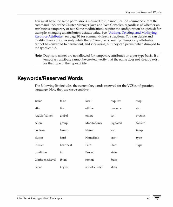
Keywords/Reserved Words
You must have the same permissions required to run modification commands from the command line, or the Cluster Manager Java and Web Consoles, regardless of whether an attribute is temporary or not. Some modifications require the configuration be opened; for example, changing an attribute’s default value. See “Adding, Deleting, and Modifying Resource Attributes” on page 93 for command-line instructions. You can define and modify these attributes only while the VCS engine is running. Temporary attributes cannot be converted to permanent, and vice-versa, but they can persist when dumped to the types.cf file.
Note Duplicate names are not allowed for temporary attributes on a per-type basis. If a temporary attribute cannot be created, verify that the name does not already exist for that type in the types.cf file.
Keywords/Reserved Words The following list includes the current keywords reserved for the VCS configuration language. Note they are case-sensitive.
action false local requires stop
after firm offline resource str
ArgListValues global online set system
before group MonitorOnly Signaled System
boolean Group Name soft temp
cluster hard NameRule start type
Cluster heartbeat Path Start Type
condition int Probed state
ConfidenceLevel IState remote State
event keylist remotecluster static
Chapter 4, Configuration Concepts 47
Managing the VCS Configuration File: The hacf Utility
Managing the VCS Configuration File: The hacf Utility The hacf utility translates the VCS configuration language into a syntax that can be read by the VCS engine. Specifically, hacf translates the contents of the main configuration file, main.cf, into commands for the VCS server.
Verifying a Configuration Use hacf to verify (check syntax of) the main.cf and the type definition file, types.cf. VCS does not execute if hacf detects errors in the configuration. No error message and a return value of zero indicates that the syntax is legal.
# hacf -verify config_directory
The variable config_directory refers to directories containing a main.cf file and any .cf files included in main.cf.
Loading a Configuration The hacf utility verifies the configuration before loading it into VCS. The configuration is not loaded under the following conditions:
◆ If main.cf or include files are missing.
◆ If syntax errors appear in the .cf files.
◆ If the configuration file is marked “stale.” A .stale file is created in the configuration directory when you indicate that you intend to change a running configuration. See “Setting the Configuration to Read/Write” on page 65 for details.
Dumping a Running Configuration A configuration is dumped (written to disk) when you indicate that you have finished changing it. The configuration is also dumped on a system when the system joins the VCS cluster. When VCS dumps a running configuration, it is always pretty-printed. VCS removes the .stale file following a successful dump. You can dump a configuration from the command line using the haconf -dump -makero command.
Multiple Versions of .cf Files When hacf creates a .cf file, it does not overwrite existing .cf files. A copy of the file remains in the directory, and its name includes a suffix of the date and time it was created, such as main.cf.03Dec2001.175904. In addition, the previous version of any .cf file is saved with the suffix .previous; for example, main.cf.previous.
48 VERITAS Cluster Server User’s Guide

Section II. Administration-Putting VCS to Work
This section introduces the VCS user privilege model and provides information on monitoring and administering VCS from the graphical-user interfaces and the command line. The section also describes how to configure Application and NFS service groups using configuration wizards.
Section II includes the following chapters:
◆ Chapter 5. “Introducing the VCS User Privilege Model” on page 51
◆ Chapter 6. “Administering the Cluster from the Command Line” on page 57
◆ Chapter 7. “Administering the Cluster from Cluster Manager (Java Console)” on page 109
◆ Chapter 8. “Administering the Cluster from Cluster Manager (Web Console)” on page 215
◆ Chapter 9. “Configuring Application and NFS Service Groups” on page 291

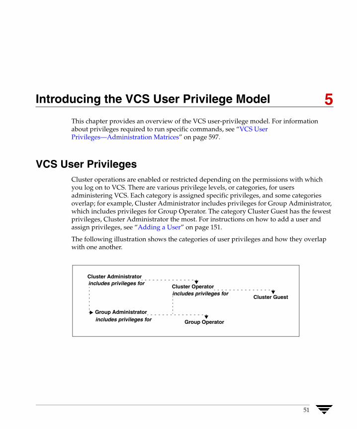
Introducing the VCS User Privilege Model
5 This chapter provides an overview of the VCS user-privilege model. For information about privileges required to run specific commands, see “VCS User Privileges—Administration Matrices” on page 597.VCS User Privileges Cluster operations are enabled or restricted depending on the permissions with which you log on to VCS. There are various privilege levels, or categories, for users administering VCS. Each category is assigned specific privileges, and some categories overlap; for example, Cluster Administrator includes privileges for Group Administrator, which includes privileges for Group Operator. The category Cluster Guest has the fewest privileges, Cluster Administrator the most. For instructions on how to add a user and assign privileges, see “Adding a User” on page 151.
The following illustration shows the categories of user privileges and how they overlap with one another.
Cluster Administrator
Cluster Operator includes privileges for
Cluster Guest includes privileges for
Group Administrator
Group Operator includes privileges for
51

VCS User Privileges
The following table lists the VCS user categories, with a summary of their associated privileges.
User Category Privileges
Cluster Administrator Users in this category are assigned full privileges, including making configuration read-write, creating and deleting groups, setting group dependencies, adding and deleting systems, and adding, modifying, and deleting users. All group and resource operations are allowed. Users with Cluster Administrator privileges can also change other users’ privileges and passwords.
Note Cluster Administrators can change their own and other users’ passwords only after changing the configuration to read/write mode.
Users in this category can create and delete resource types and execute remote commands from the Manager (Java Console) via Cluster Shell. Cluster Administrators are allowed access to Cluster Shell if designated in the value of the attribute HaCliUserLevel. For more information, see the description of the attribute under “Cluster Attributes” on page 661.
Cluster Operator In this category, all cluster-, group-, and resource-level operations are allowed, including modifying the user’s own password and bringing service groups online.
Note Users in this category can change their own passwords only if configuration is in read/write mode. Cluster Administrators can change the configuration to the read/write mode.
Users in this category cannot create service groups or execute remote commands via Cluster Shell. Additionally, users in this category can be assigned Group Administrator privileges for specific service groups.
Group Administrator Users in this category can perform all service group operations on specific groups, such as bringing groups and resources online, taking them offline, and creating or deleting resources. Additionally, users can establish resource dependencies and freeze or unfreeze service groups. Note that users in this category cannot create or delete service groups.
Group Operator Users in this category can bring service groups and resources online and take them offline. Users can also temporarily freeze or unfreeze service groups.
52 VERITAS Cluster Server User’s Guide
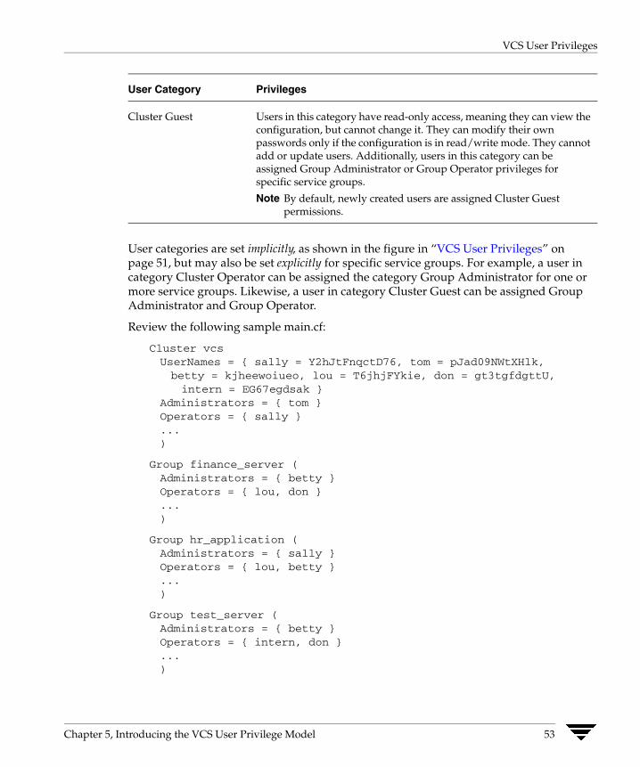
VCS User Privileges
User Category Privileges
Cluster Guest Users in this category have read-only access, meaning they can view the configuration, but cannot change it. They can modify their own passwords only if the configuration is in read/write mode. They cannot add or update users. Additionally, users in this category can be assigned Group Administrator or Group Operator privileges for specific service groups.
Note By default, newly created users are assigned Cluster Guest permissions.
User categories are set implicitly, as shown in the figure in “VCS User Privileges” on page 51, but may also be set explicitly for specific service groups. For example, a user in category Cluster Operator can be assigned the category Group Administrator for one or more service groups. Likewise, a user in category Cluster Guest can be assigned Group Administrator and Group Operator.
Review the following sample main.cf:
Cluster vcsUserNames = { sally = Y2hJtFnqctD76, tom = pJad09NWtXHlk,betty = kjheewoiueo, lou = T6jhjFYkie, don = gt3tgfdgttU,intern = EG67egdsak }
Administrators = { tom }Operators = { sally }...)
Group finance_server (Administrators = { betty }Operators = { lou, don }...)
Group hr_application (Administrators = { sally }Operators = { lou, betty }...)
Group test_server (Administrators = { betty }Operators = { intern, don }...)
Chapter 5, Introducing the VCS User Privilege Model 53

VCS User Privileges
◆ User tom is Cluster Administrator.
◆ User sally is Cluster Operator and Group Administrator for service group hr_application.
◆ User betty does not have Cluster Administrator or Cluster Operator privileges. However, she is Group Administrator for the service groups finance_server and test_server. She is also Group Operator for the service group hr_application.
◆ User lou has no privileges at the cluster level. However, he is Group Operator for the service groups finance_server and hr_application.
◆ User don does not have Cluster Administrator or Cluster Operator privileges. However, he is Group Operator for the service groups finance_server and test_server.
◆ User intern does not have Cluster Administrator or Cluster Operator privileges. However he or she is Group Operator for the service group test_server.
Category tom sally betty lou don intern
Cluster Administrator ✔ – – – – –
Cluster Operator ✔ ✔ – – – –
finance_server Admin. ✔ – ✔ – – –
finance_server Operator ✔ ✔ ✔ ✔ ✔ –
hr_application Admin. ✔ ✔ – – – –
hr_application Operator ✔ ✔ ✔ ✔ – –
test_server Admin. ✔ – ✔ – – –
test_server Operator ✔ ✔ ✔ – ✔ ✔
54 VERITAS Cluster Server User’s Guide
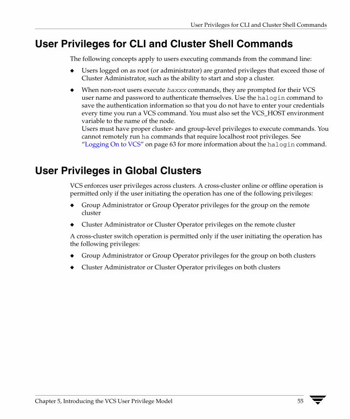
User Privileges for CLI and Cluster Shell Commands
User Privileges for CLI and Cluster Shell Commands The following concepts apply to users executing commands from the command line:
◆ Users logged on as root (or administrator) are granted privileges that exceed those of Cluster Administrator, such as the ability to start and stop a cluster.
◆ When non-root users execute haxxx commands, they are prompted for their VCS user name and password to authenticate themselves. Use the halogin command to save the authentication information so that you do not have to enter your credentials every time you run a VCS command. You must also set the VCS_HOST environment variable to the name of the node. Users must have proper cluster- and group-level privileges to execute commands. You cannot remotely run ha commands that require localhost root privileges. See “Logging On to VCS” on page 63 for more information about the halogin command.
User Privileges in Global Clusters VCS enforces user privileges across clusters. A cross-cluster online or offline operation is permitted only if the user initiating the operation has one of the following privileges:
◆ Group Administrator or Group Operator privileges for the group on the remote cluster
◆ Cluster Administrator or Cluster Operator privileges on the remote cluster
A cross-cluster switch operation is permitted only if the user initiating the operation has the following privileges:
◆ Group Administrator or Group Operator privileges for the group on both clusters
◆ Cluster Administrator or Cluster Operator privileges on both clusters
Chapter 5, Introducing the VCS User Privilege Model 55

User Privileges in Global Clusters
56 VERITAS Cluster Server User’s Guide

Administering the Cluster from the Command Line
6This chapter describes commonly used VCS commands. For more information about specific commands or their options, see their usage information or the man pages associated with the commands.
Most commands listed in this chapter can be entered from any system in the cluster only when VCS is running. The command to start VCS is typically invoked at system startup. For instructions, see “Starting VCS” on page 60.
VCS Environment Variables VCS environment variables can be defined in the file vcsenv, which is located at the path /opt/VRTSvcs/bin/. These variables are set for VCS when the hastart command is invoked.
Variable Definition and Default Value
VCS_CONF Root directory for VCS configuration files.
Default: /etc/VRTSvcs
Note If this variable is added or modified you must reboot the system to apply the changes.
VCS_DOMAIN The VxSS domain in which users are configured.
VCS_DOMAINTYPE Type of domain: unixpwd, NT, NIS, NIS+, or vx.
VCS_ENABLE_LDF Designates whether or not log data files (LDFs) are generated. If set to 1, LDFs are generated. If set to 0, they are not.
VCS_HOME Root directory for VCS executables.
Default: /opt/VRTSvcs
VCS_HOST VCS node on which ha commands will be run.
57
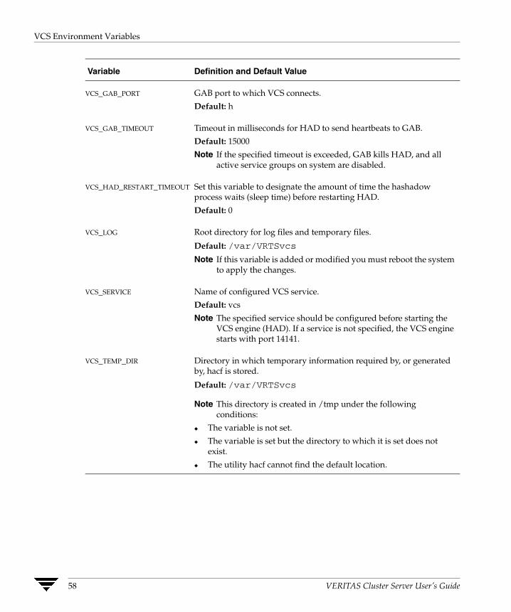
VCS Environment Variables
Variable Definition and Default Value
VCS_GAB_PORT GAB port to which VCS connects.
Default: h
VCS_GAB_TIMEOUT Timeout in milliseconds for HAD to send heartbeats to GAB.
Default: 15000
Note If the specified timeout is exceeded, GAB kills HAD, and all active service groups on system are disabled.
VCS_HAD_RESTART_TIMEOUT Set this variable to designate the amount of time the hashadow process waits (sleep time) before restarting HAD.
Default: 0
VCS_LOG Root directory for log files and temporary files.
Default: /var/VRTSvcs
Note If this variable is added or modified you must reboot the system to apply the changes.
VCS_SERVICE Name of configured VCS service.
Default: vcs
Note The specified service should be configured before starting the VCS engine (HAD). If a service is not specified, the VCS engine starts with port 14141.
VCS_TEMP_DIR Directory in which temporary information required by, or generated by, hacf is stored.
Default: /var/VRTSvcs
Note This directory is created in /tmp under the following conditions:
◆ The variable is not set.
◆ The variable is set but the directory to which it is set does not exist.
◆ The utility hacf cannot find the default location.
58 VERITAS Cluster Server User’s Guide
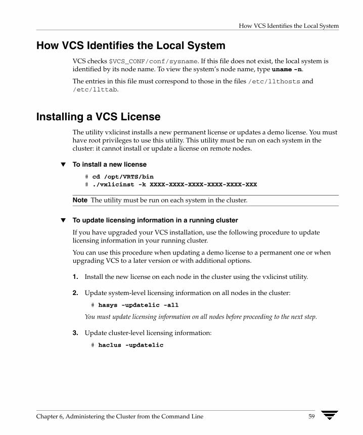
How VCS Identifies the Local System
How VCS Identifies the Local System VCS checks $VCS_CONF/conf/sysname. If this file does not exist, the local system is identified by its node name. To view the system’s node name, type uname -n.
The entries in this file must correspond to those in the files /etc/llthosts and /etc/llttab.
Installing a VCS License The utility vxlicinst installs a new permanent license or updates a demo license. You must have root privileges to use this utility. This utility must be run on each system in the cluster: it cannot install or update a license on remote nodes.
▼ To install a new license
# cd /opt/VRTS/bin# ./vxlicinst -k XXXX-XXXX-XXXX-XXXX-XXXX-XXX
Note The utility must be run on each system in the cluster.
▼ To update licensing information in a running cluster
If you have upgraded your VCS installation, use the following procedure to update licensing information in your running cluster.
You can use this procedure when updating a demo license to a permanent one or when upgrading VCS to a later version or with additional options.
1. Install the new license on each node in the cluster using the vxlicinst utility.
2. Update system-level licensing information on all nodes in the cluster:
# hasys -updatelic -all
You must update licensing information on all nodes before proceeding to the next step.
3. Update cluster-level licensing information:
# haclus -updatelic
Chapter 6, Administering the Cluster from the Command Line 59
Starting VCS
Starting VCS The command to start VCS is invoked from the file /etc/rc3.d/S99vcs or /sbin/rc3.d/S99vcs. When VCS is started, it checks the state of its local configuration file and registers with GAB for cluster membership. If the local configuration is valid, and if no other system is running VCS, it builds its state from the local configuration file and enters the RUNNING state.
▼ To start VCS
# hastart [-stale|-force]
The option -stale instructs the engine to treat the local configuration as stale even if it is valid. The option -force instructs the engine to treat a stale, but otherwise valid, local configuration as valid.
▼ To start VCS when all systems are in ADMIN_WAIT
Run the following command from any system in the cluster to force VCS to use the configuration file from the system specified by the variable system:
# hasys -force system
When VCS is started on a system, and when that system is the only one running,VCS retrieves the configuration from the local configuration directory $VCS_CONF/conf/config. If the configuration is valid, VCS performs a LOCAL_BUILD, and the system transitions to the state of RUNNING, its normal operational state. If the local configuration is missing, invalid, or designated “stale,” the system transitions to the STALE_ADMIN_WAIT state, and the VCS engine waits for manual intervention, or for VCS to be started on a system that has a valid configuration.
If VCS is started on a system when other systems are already running VCS, the engine processes exchange their operational states according to the following conventions:
◆ If a system running VCS is in the state of RUNNING, the system joining the cluster performs a REMOTE_BUILD from that system and transitions to the state of RUNNING.
◆ If a system running VCS is in the state of LOCAL_BUILD, the system joining the cluster waits for that system to transition to RUNNING. It then performs a REMOTE_BUILD from that system and transitions to the state of RUNNING.
◆ If all systems running VCS are in the state of STALE_ADMIN_WAIT, and if the local configuration file of the system joining the cluster is valid, the joining system performs a LOCAL_BUILD and transitions to RUNNING. The other systems then perform REMOTE_BUILDs from the new system and transition to RUNNING.
◆ If all systems running VCS are in the state of STALE_ADMIN_WAIT, and if the local configuration file of the system joining the cluster is invalid, then the joining system also transitions to STALE_ADMIN_WAIT.
60 VERITAS Cluster Server User’s Guide
Stopping VCS
See the appendix “Cluster and System States” for a complete list of VCS system states.
▼ To start VCS on a single node
Type the following command to start an instance of VCS that does not require the GAB and LLT packages. Do not use this command on a multisystem cluster.
# hastart -onenode
▼ To start VCS as a time-sharing process
# hastart -ts
Stopping VCS The hastop command stops HAD and related processes. This command includes the following options:
hastop -all [-force]hastop [-help]hastop -local [-force | -evacuate | -noautodisable]hastop -local [-force | -evacuate -noautodisable]hastop -sys system ... [-force | -evacuate | -noautodisable]hastop -sys system ... [-force | -evacuate -noautodisable]
The option -all stops HAD on all systems in the cluster and takes all service groups offline.
The option -help displays command usage.
The option -local stops HAD on the system on which you typed the command.
The option -force allows HAD to be stopped without taking service groups offline on the system.
The option -evacuate, when combined with -local or -sys, migrates the system’s active service groups to another system in the cluster, before the system is stopped.
The option -noautodisable ensures that service groups that can run on the node where the hastop command was issued are not autodisabled. This option can be used with -evacuate but not with -force.
The option -sys stops HAD on the system you specified.
Chapter 6, Administering the Cluster from the Command Line 61
Stopping VCS
Stopping VCS Without -force Option When VCS is stopped on a system without using the -force option to hastop, it enters the LEAVING state, and waits for all groups to go offline on the system. Use the output of the command hasys -display system to verify that the values of the SysState and the OnGrpCnt attributes are non-zero. VCS continues to wait for the service groups to go offline before it shuts down. See “Troubleshooting Resources” on page 579 for more information.
Stopping VCS with Options Other Than -force When VCS is stopped by options other than -force on a system with online service groups, the groups running on the system are taken offline and remain offline. This is indicated by VCS setting the attribute IntentOnline to 0. Using the option -force enables service groups to continue running while HAD is brought down and restarted (IntentOnline remains unchanged).
Additional Considerations for Stopping VCS ◆ If using the command reboot, behavior is controlled by the ShutdownTimeOut
parameter. After HAD exits, if GAB exits within the time designated in the ShutdownTimeout attribute, the remaining systems recognize this as a reboot and fail over service groups from the departed system. For systems running several applications, consider increasing the value in the ShutdownTimeout attribute.
◆ Stopping VCS on a system autodisables each service group that include the system in their SystemList attribute. (This does not apply to systems that are powered off.)
◆ If you use the -evacuate option, evacuation occurs before VCS is brought down.
62 VERITAS Cluster Server User’s Guide
Logging On to VCS
Logging On to VCS When non-root users execute haxxx commands, they are prompted for their VCS user name and password to authenticate themselves. Use the halogin command to save the authentication information so that you do not have to enter your credentials every time you run a VCS command.
In secure clusters, VCS assigns Guest privileges to all native users.
The command stores authentication information in the user’s home directory. In secure clusters, the command also sets up a trust relationship and retrieves a certificate from an authentication broker.
If you run the command for different hosts, VCS stores authentication information for each host.
▼ To log on to a cluster running in secure mode
1. Set the following environment variables:
◆ VCS_DOMAIN—Name of the VxSS domain to which the user belongs.
◆ VCS_DOMAINTYPE—Type of VxSS domain: unixpwd, nt, NIS, NIS+, or vx.
2. Define the node on which the VCS commands will be run. Set the VCS_HOST environment variable to the name of the node.
3. Log on to VCS:
# halogin vcsusername password
Note You do not need to run the halogin command if you are running VCS commands from the local host.
▼ To log on to a cluster not running in secure mode
1. Define the node on which the VCS commands will be run. Set the VCS_HOST environment variable to the name of the node.
2. Log on to VCS:
# halogin vcsusername password
Chapter 6, Administering the Cluster from the Command Line 63
Logging On to VCS
▼ To end a session for a host
# halogin -endsession hostname
▼ To end all sessions
# halogin -endallsessions
VCS will now prompt you for credentials every time you run a VCS command.
64 VERITAS Cluster Server User’s Guide

Adding, Modifying, and Deleting Users
Adding, Modifying, and Deleting Users ✔ The VCS configuration must be in read/write mode.
✔ You can add, modify, and delete users on any system in the cluster.
Note You must add users to the VCS configuration to monitor and administer VCS from the graphical user interface Cluster Manager.
User Management in Secure Mode ✔ If VCS is running in secure mode, you can add system or domain users to VCS and
assign them VCS privileges. By default, VCS assigns Guest privileges to native users. You must specify fully-qualified user names, in the format username@domain.
✔ You cannot assign or change passwords for users when VCS is running in secure mode.
Setting the Configuration to Read/Write The commands to add, modify, and delete a user must be executed only as root, and only if the VCS configuration is in read/write mode.
To set the mode to read/write, type the following command from any system in the cluster:
# haconf -makerw
This command also designates the configuration stale by creating the default file $VCS_CONF/conf/config/.stale on all systems running VCS.
Setting the Configuration to Read-Only When you have completed adding, modifying, and deleting users, reset the configuration to read-only:
# haconf -dump -makero
In addition to setting the configuration to read-only, this command writes, or “dumps,” the configuration to disk and removes the configuration’s designation of stale.
Chapter 6, Administering the Cluster from the Command Line 65

Adding, Modifying, and Deleting Users
Adding a User
1. Set the configuration to read/write mode:
# haconf -makerw
2. Add the user:
# hauser -add user [-priv <Administrator|Operator> [-group service_groups]]
3. Enter a password when prompted.
4. Reset the configuration to read-only:
# haconf -dump -makero
Note Users in the category Cluster Guest cannot add users.
▼ To add a user with Cluster Administrator access
# hauser -add user -priv Administrator
▼ To add a user with Cluster Operator access
# hauser -add user -priv Operator
▼ To add a user with Group Administrator access
# hauser -add user -priv Administrator -group service_groups
▼ To add a user with Group Operator access
# hauser -add user -priv Operator -group service_groups
Assigning and Removing User Privileges
▼ To assign privileges to an Administrator or Operator
# hauser -addpriv user Adminstrator|Operator[-group service_groups]
▼ To remove privileges from an Administrator or Operator
# hauser -delpriv user Adminstrator|Operator[-group service_groups]
66 VERITAS Cluster Server User’s Guide

Adding, Modifying, and Deleting Users
Modifying a User
1. Set the configuration to read/write mode:
# haconf -makerw
2. Modify the user:
# hauser -update user
3. Enter a new password when prompted.
4. Reset the configuration to read-only:
# haconf -dump -makero
Note Users in the category Cluster Guest cannot modify users.
Deleting a User
1. Set the configuration to read/write mode:
# haconf -makerw
2. For users with Administrator and Operator access, remove their privileges:
# hauser -delpriv user Adminstrator|Operator [-group service_groups]
3. Delete the user from the list of registered users:
# hauser -delete user
4. Reset the configuration to read-only:
# haconf -dump -makero
Chapter 6, Administering the Cluster from the Command Line 67
Adding, Modifying, and Deleting Users
Displaying a User
▼ To display a list of users
# hauser -list
▼ To display the privileges of all users
# hauser -display
▼ To display the privileges of a specific user
# hauser -display user
68 VERITAS Cluster Server User’s Guide
Querying VCS
Querying VCS VCS enables you to query various cluster objects, including resources, service groups, systems, resource types, agents, and clusters. You may enter query commands from any system in the cluster. Commands to display information on the VCS configuration or system states can be executed by all users: you do not need root privileges.
Querying Service Groups
▼ To display the state of a service group on a system
# hagrp -state [service_group] [-sys system]
▼ For a list of a service group’s resources
# hagrp -resources service_group
▼ For a list of a service group’s dependencies
# hagrp -dep [service_group]
▼ To display a service group on a system
# hagrp -display [service_group] [-sys system]
If service_group is not specified, information regarding all service groups is displayed.
▼ To display attributes of a system
# hagrp -display [service_group] [-attribute attribute][-sys system]
Note System names are case-sensitive.
Chapter 6, Administering the Cluster from the Command Line 69
Querying VCS
Querying Resources
▼ For a list of a resource’s dependencies
# hares -dep [resource]
▼ For information on a resource
# hares -display [resource]
If resource is not specified, information regarding all resources is displayed.
▼ To confirm an attribute’s values are the same on all systems
# hares -global resource attribute value ... | key... | {key value}...
▼ To display resources of a service group
# hares -display -group service_group
▼ To display resources of a resource type
# hares -display -type resource_type
▼ To display attributes of a system
# hares -display -sys system
Querying Resource Types
▼ For a list of resource types
# hatype -list
▼ For a list of all resources of a particular type
# hatype -resources resource_type
▼ For information about a resource type
# hatype -display resource_type
If resource_type is not specified, information regarding all types is displayed.
70 VERITAS Cluster Server User’s Guide

Querying VCS
Querying Agents
▼ For an agent’s run-time status
# haagent -display [agent]
If agent is not specified, information regarding all agents is displayed.
Run-Time Status Definition
Faults Indicates the number of agent faults and the time the faults began.
Messages Displays various messages regarding agent status.
Running Indicates the agent is operating.
Started Indicates the file is executed by the VCS engine (HAD).
Querying Systems
▼ For a list of systems in the cluster
# hasys -list
▼ For information about each system
# hasys -display [system]
Querying Clusters
▼ For the value of a specific cluster attribute
# haclus -value attribute
▼ For information about the cluster
# haclus -display
Chapter 6, Administering the Cluster from the Command Line 71
Querying VCS
Querying Status
▼ For the status of all service groups in the cluster, including resources
# hastatus
▼ For the status of a particular service group, including its resources
# hastatus [-sound] -group service_group [-group service_group]...
If you do not specify a service group, the status of all service groups is displayed. The -sound option enables a bell to ring each time a resource faults.
▼ For the status of cluster faults, including faulted service groups, resources, systems, links, and agents
# hastatus -summary
Note Unless executed with the -summary option, hastatus continues to produce output of online state transitions until you interrupt it with the command CTRL+C.
Querying Log Data Files (LDFs) Log data files (LDFs) contain data regarding messages written to a corresponding English language file. Typically, for each English file there is a corresponding LDF.
▼ To display the hamsg usage list
# hamsg -help
▼ To display the list of LDFs available on the current system
# hamsg -list
▼ To display general LDF data
# hamsg -info [-path path_name] LDF
The option -path specifies where hamsg looks for the specified LDF. If not specified, hamsg looks for files in the default directory /var/VRTSvcs/ldf.
72 VERITAS Cluster Server User’s Guide
Querying VCS
▼ To display specific LDF data
# hamsg [-any] [-tag A|B|C|D|E] [-otype VCS|RES|GRP|SYS|AGT][-oname object_name] [-msgid message_ID] [-path path_name]
[-lang language] LDF
The option -any specifies hamsg return messages matching any of the specified query options.
The option -tag specifies hamsg return messages matching the specified tag.
The option -otype specifies hamsg return messages matching the specified object type:
VCS = general VCS messages
RES = resource
GRP = service group
SYS = system
AGT = agent
The option -oname specifies hamsg return messages matching the specified object name.
The option -msgid specifies hamsg return messages matching the specified message ID.
The option -path specifies where hamsg looks for the specified LDF. If not specified, hamsg looks for files in the default directory /var/VRTSvcs/ldf.
The option -lang specifies the language in which to display messages. For example, the value "en" specifies English and "ja" specifies Japanese.
Chapter 6, Administering the Cluster from the Command Line 73
Querying VCS
Conditional Statements Some query commands include an option for conditional statements. Conditional statements take three forms:
Attribute=Value (the attribute equals the value)
Attribute!=Value (the attribute does not equal the value)
Attribute=~Value (the value is the prefix of the attribute, for example a query for the state of a resource = ~FAULTED returns all resources whose state begins with FAULTED.)
Multiple conditional statements can be used and imply AND logic.
Note You can only query attribute-value pairs displayed in the output of command hagrp -display, described in section “Querying Service Groups” on page 69.
▼ For a list of service groups whose values match a conditional statement
# hagrp -list [conditional_statement]
If no conditional statement is specified, all service groups in the cluster are listed.
▼ For a list of resources whose values match a conditional statement
# hares -list [conditional_statement]
If no conditional statement is specified, all resources in the cluster are listed.
▼ For a list of agents whose values match a conditional statement
# haagent -list [conditional_statement]
If no conditional statement is specified, all agents in the cluster are listed.
74 VERITAS Cluster Server User’s Guide
Administering Service Groups
Administering Service Groups
▼ To start a service group and bring its resources online
# hagrp -online service_group -sys system
▼ To start a service group on a system and bring online only the resources already online on another system
# hagrp -online service_group -sys system -checkpartialother_system
If the service group does not have resources online on the other system, the service group is brought online on the original system and the checkpartial option is ignored.
Note that the checkpartial option is used by the Preonline trigger during failover. When a service group configured with Preonline =1 fails over to another system (system 2), the only resources brought online on system 2 are those that were previously online on system 1 prior to failover.
▼ To stop a service group and take its resources offline
# hagrp -offline service_group -sys system
▼ To stop a service group only if all resources are probed on the system
# hagrp -offline [-ifprobed] service_group -sys system
▼ To switch a service group from one system to another
# hagrp -switch service_group -to system
A service group can be switched only if it is fully or partially online. The -switch option is not supported for switching parallel service groups and for switching hybrid service groups across system zones.
▼ To freeze a service group (disable onlining, offlining, and failover)
# hagrp -freeze service_group [-persistent]
The option -persistent enables the freeze to be “remembered” when the cluster is rebooted.
▼ To unfreeze a service group (reenable onlining, offlining, and failover)
# hagrp -unfreeze service_group [-persistent]
Chapter 6, Administering the Cluster from the Command Line 75

Administering Service Groups
▼ To enable a service group
# hagrp -enable service_group [-sys system]
A group can be brought online only if it is enabled.
▼ To disable a service group
# hagrp -disable service_group [-sys system]
A group cannot be brought online or switched if it is disabled.
▼ To enable all resources in a service group
# hagrp -enableresources service_group
▼ To disable all resources in a service group
# hagrp -disableresources service_group
Agents do not monitor group resources if resources are disabled.
▼ To clear faulted, non-persistent resources in a service group
# hagrp -clear service_group [-sys system]
Clearing a resource initiates the online process previously blocked while waiting for the resource to become clear.
◆ If system is specified, all faulted, non-persistent resources are cleared from that system only.
◆ If system is not specified, the service group is cleared on all systems in the group’s SystemList in which at least one non-persistent resource has faulted.
▼ To clear resources in ADMIN_WAIT state in a service group
# hagrp -clearadminwait [-fault] service_group -sys system
See “Clearing Resources in the ADMIN_WAIT State” on page 363 for more information.
76 VERITAS Cluster Server User’s Guide

Administering Resources
Administering Resources
▼ To bring a resource online
# hares -online resource -sys system
▼ To take a resource offline
# hares -offline [-ignoreparent] resource -sys system
The option -ignoreparent enables a resource to be taken offline even if its parent resources in the service group are online. This option does not work if taking the resources offline violates the group dependency.
▼ To take a resource offline and propagate the command to its children
# hares -offprop [-ignoreparent] resource -sys system
As in the above command, the option -ignoreparent enables a resource to be taken offline even if its parent resources in the service group are online. This option does not work if taking the resources offline violates the group dependency.
▼ To prompt a resource’s agent to immediately monitor the resource on a particular system
# hares -probe resource -sys system
Though the command may return immediately, the monitoring process may not be completed by the time the command returns.
▼ To clear a resource
Initiate a state change from RESOURCE_FAULTED to RESOURCE_OFFLINE:
# hares -clear resource [-sys system]
Clearing a resource initiates the online process previously blocked while waiting for the resource to become clear. If system is not specified, the fault is cleared on each system in the service group’s SystemList attribute. (For instructions, see “To clear faulted, non-persistent resources in a service group” on page 76.)
This command also clears the resource’s parents. Persistent resources whose static attribute Operations is defined as None cannot be cleared with this command and must be physically attended to, such as replacing a raw disk. The agent then updates the status automatically.
Chapter 6, Administering the Cluster from the Command Line 77
Administering Systems
Administering Systems
▼ To force a system to start while in ADMIN_WAIT
# hasys -force system
This command overwrites the configuration on systems running in the cluster. Before using it, verify that the current VCS configuration is valid.
▼ To modify a system’s attributes
# hasys -modify modify_options
Some attributes are internal to VCS and cannot be modified. For details on system attributes, see “The -modify Option” on page 84.
▼ To display the value of a system’s node ID as defined in the file /etc/llttab
# hasys -nodeid node_ID
▼ To freeze a system (prevent groups from being brought online or switched on the system)
# hasys -freeze [-persistent] [-evacuate] system
The option -persistent enables the freeze to be “remembered” when the cluster is rebooted. Note that the cluster configuration must be in read/write mode and must be saved to disk (dumped) to enable the freeze to be remembered.
The option -evacuate fails over the system’s active service groups to another system in the cluster before the freeze is enabled.
▼ To unfreeze a frozen system (reenable onlining and switching of service groups)
# hasys -unfreeze [-persistent] system
78 VERITAS Cluster Server User’s Guide
Administering Clusters
Administering Clusters
▼ To add a system to a cluster
This section provides an overview of tasks involved in adding a node to a cluster. For detailed instructions, see the VERITAS Cluster Server Installation Guide.
1. Make sure the system meets the hardware and software requirements for VCS. See the VERITAS Cluster Server Installation Guide for details.
2. Set up the private communication links from the new system.
3. Install VCS and require patches on the new system.
4. Add the VCS license key. See “Installing a VCS License” on page 59 for instructions.
5. Configure LLT and GAB to include the new system in the cluster membership.
6. Add the new system using the hasys -add command.
▼ To remove a node from a cluster
This section provides an overview of tasks involved in adding a node to a cluster. For detailed instructions, see the VERITAS Cluster Server Installation Guide.
1. Make a backup copy of the current configuration file, main.cf.
2. Switch or remove any VCS service groups from the node. The node cannot be removed as long as it runs service groups on which other service groups depend.
3. Stop VCS on the node.
# hastop -sys systemname
4. Delete the system from the SystemList of all service groups.
# hagrp -modify groupname SystemList -delete systemname
5. Delete the node from the cluster.
# hasys -delete systemname
6. Remove the entries for the node from the following files on each remaining node:
◆ /etc/gabtab
◆ /etc/llthosts
Chapter 6, Administering the Cluster from the Command Line 79
Administering Clusters
7. Unconfigure GAB and LLT on the node leaving the cluster.
8. Remove VCS and other packages from the node.
9. Remove GAB and LLT configuration files from the node.
▼ To modify a cluster attribute
# haclus [-help [-modify]]
80 VERITAS Cluster Server User’s Guide

Enabling and Disabling VERITAS Security Services
Enabling and Disabling VERITAS Security Services This section describes how to enable and disable VERITAS Security Services (VxSS). Do not edit the VCS configuration file main.cf to enable or disable VxSS.
▼ To enable VERITAS Security Services
1. Verify you have a VxSS root broker configured. See the VERITAS Cluster Server Installation Guide for instructions.
2. Run the installvcs command with the -security option.
# installvcs -security
The command prompts you to choose whether you want to enable or disable VxSS.
1) Enable VERITAS Security Services on a VCS Cluster2) Disable VERITAS Security Services on a VCS Cluster3) Install VERITAS Security Services Root Broker
Select the Security option you would like to perform [1-3,q]
3. Enter 1 and press Return.
The command retrieves information about VCS configuration files in the cluster and asks if you want to enable VERITAS Security Services in the cluster.
Cluster Name: vxsstestCluster ID Number: 233Systems: vcsqs3 vcsqs4Service Groups: groupA groupB
Would you like to enable VERITAS Security Services on this cluster?
4. Enter y and press Return.
5. The command creates the VxSS service group, creates VxSS credentials on each node in the cluster, establishes trust with the root broker, and restarts the cluster in secure mode. It also creates Web credentials for VCS users. Various messages indicate the status of the process.
6. Press Return to complete the process.
Chapter 6, Administering the Cluster from the Command Line 81

Enabling and Disabling VERITAS Security Services
▼ To disable VERITAS Security Services
1. Run the installvcs command with the -security option.
# installvcs -security
The command prompts you to choose whether you want to enable or disable VxSS.
1) Enable VERITAS Security Services on a VCS Cluster2) Disable VERITAS Security Services on a VCS Cluster3) Install VERITAS Security Services Root Broker
Select the Security option you would like to perform [1-3,q]
2. Enter 2 and press Return.
The command retrieves information about VCS configuration files in the cluster and asks if you want to disable VERITAS Security Services in the cluster.
Cluster Name: vxsstestCluster ID Number: 233Systems: vcsqs3 vcsqs4Service Groups: groupA groupB
Would you like to disable VERITAS Security Services on this cluster?
3. Enter y to disable VERITAS Security Services and press Return.
4. The command deletes the VxSS service group, stops VCS, disables VERITAS Security Services, and restarts the cluster.
5. Press Return to complete the process.
82 VERITAS Cluster Server User’s Guide

Encrypting Passwords
Encrypting Passwords Use the vcsencrypt utility to encrypt passwords when editing the VCS configuration file main.cf to add VCS users or when configuring agents that require user passwords.
Note Do not use the vcsencrypt utility when entering passwords from a configuration wizard or from the Java and Web consoles.
▼ To encrypt a password
1. Run the utility from the command line.
To encrypt a password for an agent configuration:
# vcsencrypt -agent
To encrypt a VCS user password:
# vcsencrypt -vcs
2. The utility prompts you to enter the password twice. Enter the password and press Return.
# Enter New Password:# Enter Again:
3. The utility encrypts the password and displays the encrypted password. Use the displayed password to edit the VCS configuration file main.cf.
Chapter 6, Administering the Cluster from the Command Line 83
Basic Configuration Operations
Basic Configuration Operations Commands listed in the following sections permanently affect the configuration of the cluster. If the cluster is brought down with the command hastop -all or made read-only, the main.cf file and other configuration files written to disk reflect the updates.
Specifying Values Preceded by a Dash (-) When specifying values in a command-line syntax, you must prefix values beginning with a dash (-) with a percentage sign (%). If a value begins with a percentage sign, you must prefix it with another percentage sign. (The initial percentage sign is stripped by HAD and does not appear in the configuration file.)
The -modify Option Most configuration changes are made using the -modify options of the commands haclus, hagrp, hares, hasys, and hatype. Specifically, the -modify option of these commands changes the attribute values stored in the VCS configuration file. By default, all attributes are global, meaning that the value of the attribute is the same for all systems.
Note VCS must be in read/write mode before you can change the configuration. For instructions, see “Setting the Configuration to Read/Write” on page 65.
84 VERITAS Cluster Server User’s Guide
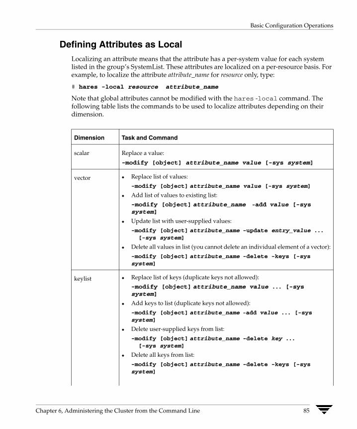
Basic Configuration Operations
Defining Attributes as Local Localizing an attribute means that the attribute has a per-system value for each system listed in the group’s SystemList. These attributes are localized on a per-resource basis. For example, to localize the attribute attribute_name for resource only, type:
# hares -local resource attribute_name
Note that global attributes cannot be modified with the hares -local command. The following table lists the commands to be used to localize attributes depending on their dimension.
Dimension Task and Command
scalar Replace a value:
-modify [object] attribute_name value [-sys system]
vector ◆ Replace list of values:
-modify [object] attribute_name value [-sys system]
◆ Add list of values to existing list:
-modify [object] attribute_name -add value [-sys system]
◆ Update list with user-supplied values:
-modify [object] attribute_name -update entry_value ... [-sys system]
◆ Delete all values in list (you cannot delete an individual element of a vector):
-modify [object] attribute_name -delete -keys [-sys system]
keylist ◆ Replace list of keys (duplicate keys not allowed):
-modify [object] attribute_name value ... [-sys system]
◆ Add keys to list (duplicate keys not allowed):
-modify [object] attribute_name -add value ... [-sys system]
◆ Delete user-supplied keys from list:
-modify [object] attribute_name -delete key ... [-sys system]
◆ Delete all keys from list:
-modify [object] attribute_name -delete -keys [-sys system]
Chapter 6, Administering the Cluster from the Command Line 85

Basic Configuration Operations
Dimension Task and Command
association ◆ Replace list of key-value pairs (duplicate keys not allowed):
-modify [object] attribute_name value ... [-sys system]
◆ Add user-supplied list of key-value pairs to existing list (duplicate keys not allowed):
-modify [object] attribute_name -add value ...[-sys system]
◆ Replace value of each key with user-supplied value:
-modify [object] attribute_name -update key value ... [-sys system]
◆ Delete a key-value pair identified by user-supplied key:
-modify [object] attribute_name -delete key ... [-sys system]
◆ Delete all key-value pairs from association:
-modify [object] attribute_name -delete -keys [-sys system]
Note If multiple values are specified and if one is invalid, VCS returns an error for the invalid value, but continues to process the others. In the following example, if sysb is part of the attribute SystemList, but sysa is not, sysb is deleted and an error message is sent to the log regarding sysa.
hagrp -modify group1 SystemList -delete sysa sysb [-sys system]
86 VERITAS Cluster Server User’s Guide

Basic Configuration Operations
Adding Service Groups
▼ To add a service group to your cluster
# hagrp -add service_group
The variable service_group must be unique among all service groups defined in the cluster.
This command initializes a service group that is ready to contain various resources. To employ the group properly, you must populate its SystemList attribute to define the systems on which the group may be brought online and taken offline. (A system list is an association of names and integers that represent priority values.)
Modifying Service Group Attributes
▼ To modify a service group attribute
# hagrp -modify service_group attribute value [-sys system]
The variable value represents:
system_name1 priority system_name2 priority2
If the attribute being modified has local scope, you must specify the system on which to modify the attribute, except when modifying the attribute on the system from which you run the command.
For example, to populate the system list of service group groupx with Systems A and B, type:
# hagrp -modify groupx SystemList -add SystemA 1 SystemB 2
Similarly, to populate the AutoStartList attribute of a service group, type:
# hagrp -modify groupx AutoStartList SystemA SystemB
You may also define a service group as parallel. To set the Parallel attribute to 1, type the following command. (Note that the default for this attribute is 0, which designates the service group as a failover group.):
# hagrp -modify groupx Parallel 1
This attribute cannot be modified if resources have already been added to the service group.
You can modify the attributes SystemList, AutoStartList, and Parallel only by using the command hagrp -modify. You cannot modify attributes created by the system, such as the state of the service group.
Chapter 6, Administering the Cluster from the Command Line 87
Basic Configuration Operations
Modifying the SystemList Attribute
When using the hagrp -modify command ot change a service group’s existing system list, you can use the options -modify, -add, -update, -delete, or -delete -keys.
For example, suppose you originally defined the SystemList of service group groupx as SystemA and SystemB. Then after the cluster was brought up you added a new system to the list:
# hagrp -modify groupx SystemList -add SystemC 3
You must take the service group offline on the system being modified.
When you add a system to a service group’s system list, the system must have been previously added to the cluster. When using the command line, you can use the hasys -add command.
When you delete a system from a service group’s system list, the service group must not be online on the system to be deleted.
If you attempt to change a service group’s existing system list using hagrp -modify without other options (such as -add or -update) the command fails.
88 VERITAS Cluster Server User’s Guide

Basic Configuration Operations
Adding Resources
▼ To add a resource
# hares -add resource resource_type service_group
This command creates a new resource, resource, which must be a unique name throughout the cluster, regardless of where it resides physically or in which service group it is placed. The resource type is resource_type, which must be defined in the configuration language. The resource belongs to the group service_group.
When new resources are created, all non-static attributes of the resource’s type, plus their default values, are copied to the new resource. Three attributes are also created by the system and added to the resource:
◆ Critical (default = 1). If the resource or any of its children faults while online, the entire service group is marked faulted and failover occurs.
◆ AutoStart (default = 1). If the resource is set to AutoStart, it is brought online in response to a service group command. All resources designated as AutoStart=1 must be online for the service group to be considered online. (This attribute is unrelated to AutoStart attributes for service groups.)
◆ Enabled. If the resource is set to Enabled, the agent for the resource’s type manages the resource. The default is 1 for resources defined in the configuration file main.cf, 0 for resources added on the command line.
Note Adding resources on the command line requires several steps, and the agent must be prevented from managing the resource until the steps are completed. For resources defined in the configuration file, the steps are completed before the agent is started.
Chapter 6, Administering the Cluster from the Command Line 89

Basic Configuration Operations
Modifying Resource Attributes
▼ To modify a new resource
# hares -modify resource attribute value# hares -modify <resource> <attr> <value>
[-sys <system>] [-wait [-time <waittime>]]
The variable value depends on the type of attribute being created.
▼ To set a new resource’s Enabled attribute to 1
# hares -modify resourceA Enabled 1
The agent managing the resource is started on a system when its Enabled attribute is set to 1 on that system. Specifically, the VCS engine begins to monitor the resource for faults. Agent monitoring is disabled if the Enabled attribute is reset to 0.
Additional Considerations for Modifying Attributes
Resource names must be unique throughout the cluster and you cannot modify resource attributes defined by the system, such as the resource state.
Linking Resources
▼ To specify a dependency relationship, or “link,” between two resources
# hares -link parent_resource child_resource
The variable parent_resource depends on child_resource being online before going online itself. Conversely, parent_resource go offline before child_resource goes offline.
For example, a NIC resource must be available before an IP resource can go online, so for resources IP1 of type IP and NIC1 of type NIC, specify the dependency as:
# hares -link IP1 NIC1
Additional Considerations for Linking Resources
A resource can have an unlimited number of parents and children. When linking resources, the parent cannot be a resource whose Operations attribute is equal to None or OnOnly. Specifically, these are resources that cannot be brought online or taken offline by an agent (None), or can only be brought online by an agent (OnOnly).
Loop cycles are automatically prohibited by the VCS engine. You cannot specify a resource link between resources of different service groups.
90 VERITAS Cluster Server User’s Guide

Basic Configuration Operations
Deleting and Unlinking Service Groups and Resources
▼ To delete a service group
# hagrp -delete service_group
▼ To unlink service groups
# hagrp -unlink parent_group child_group
▼ To delete a resource
# hares -delete resource
Note that deleting a resource won’t take offline the object being monitored by the resource. The object remains online, outside the control and monitoring of VCS.
▼ To unlink resources
# hares -unlink parent_resource child_resource
Note You can unlink service groups and resources at any time. You cannot delete a service group until all of its resources are deleted.
Chapter 6, Administering the Cluster from the Command Line 91

Basic Configuration Operations
Adding, Deleting, and Modifying Resource Types After creating a resource type, use the command haattr to add its attributes (see “Modifying Resource Attributes” on page 90). By default, resource type information is stored in the types.cf configuration file.
▼ To add a resource type
# hatype -add resource_type
▼ To delete a resource type
# hatype -delete resource_type
You must delete all resources of the type before deleting the resource type.
▼ To add or modify resource types in main.cf without shutting down VCS
# hatype -modify resource_type SourceFile "./resource_type.cf"
The information regarding resource_type is stored in the file config/resource_type.cf, and an include line for resource_type.cf is added to the main.cf file.
▼ To set the value of static resource type attributes
# hatype -modify ...
Overriding Resource Type Static Attributes You can override some resource type static attributes and assign them resource-specific values. When a static attribute is overriden and the configuration is saved, the main.cf file includes a line in the resource definition for the static attribute and its overriden value.
▼ To override a type’s static attribute
# hares -override resource_type
▼ To restore default settings to a type’s static attribute
# hares -undo_override resource_type
92 VERITAS Cluster Server User’s Guide
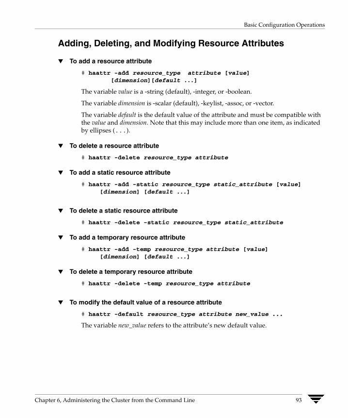
Basic Configuration Operations
Adding, Deleting, and Modifying Resource Attributes
▼ To add a resource attribute
# haattr -add resource_type attribute [value][dimension][default ...]
The variable value is a -string (default), -integer, or -boolean.
The variable dimension is -scalar (default), -keylist, -assoc, or -vector.
The variable default is the default value of the attribute and must be compatible with the value and dimension. Note that this may include more than one item, as indicated by ellipses (...).
▼ To delete a resource attribute
# haattr -delete resource_type attribute
▼ To add a static resource attribute
# haattr -add -static resource_type static_attribute [value][dimension] [default ...]
▼ To delete a static resource attribute
# haattr -delete -static resource_type static_attribute
▼ To add a temporary resource attribute
# haattr -add -temp resource_type attribute [value][dimension] [default ...]
▼ To delete a temporary resource attribute
# haattr -delete -temp resource_type attribute
▼ To modify the default value of a resource attribute
# haattr -default resource_type attribute new_value ...
The variable new_value refers to the attribute’s new default value.
Chapter 6, Administering the Cluster from the Command Line 93

Basic Configuration Operations
Starting and Stopping VCS Agents Manually
▼ To start and stop agents manually
# haagent -start agent -sys system# haagent -stop agent -sys system
Note Under normal conditions, VCS agents are started and stopped automatically.
After issuing the commands above, a message is displayed instructing the user to look for messages in the log file. The agent log is located at $VCS_HOME/log/agent_A.log. See “Logging” on page 571 for more information on log messages.
Initializing Resource Type Scheduling and Priority Attributes The following configuration shows how to initialize resource type scheduling and priority attributes through configuration files. The example shows attributes of a FileOnOff resource. (See “Resource Attributes” on page 628 for a description of each attribute cited below and its defaults.)
type FileOnOff (static str AgentClass = RT static str AgentPriority = 10 static str ScriptClass = RTstatic str ScriptPriority = 40 static str ArgList[] = { PathName } str PathName
)
94 VERITAS Cluster Server User’s Guide

Basic Configuration Operations
Setting Scheduling/Priority Attributes
▼ To update the AgentClass
# hatype -modify resource_type AgentClass value
For example, to set the AgentClass attribute of the FileOnOff resource to RealTime, type:
# hatype -modify FileOnOff AgentClass "RT"
▼ To update the AgentPriority
# hatype -modify resource_type AgentPriority value
For example, to set the AgentPriority attribute of the FileOnOff resource to 10, type:
# hatype -modify FileOnOff AgentPriority "10"
▼ To update the ScriptClass
# hatype -modify resource_type ScriptClass value
For example, to set the ScriptClass of the FileOnOff resource to RealTime, type:
# hatype -modify FileOnOff ScriptClass "RT"
▼ To update the ScriptPriority
# hatype -modify resource_type ScriptPriority value
For example, to set the ScriptClass of the FileOnOff resource to RealTime, type:
# hatype -modify FileOnOff ScriptPriority "40"
Note For attributes AgentClass and AgentPriority, changes are effective immediately. For ScriptClass and ScriptPriority, changes become effective for scripts fired after the execution of the hatype command.
Chapter 6, Administering the Cluster from the Command Line 95

Basic Configuration Operations
Initializing Cluster Attributes in the Configuration File You may assign values for cluster attributes while configuring the cluster. (See “Cluster Attributes” on page 661 for a description of each attribute cited below.)
Review the following sample configuration:
cluster vcs-india ( EngineClass = "RT" EnginePriority = "20" ProcessClass = "TS" ProcessPriority = "40"
)
Setting Cluster Attributes from the Command Line
▼ To update the EngineClass
# haclus -modify EngineClass value
For example, to set the EngineClass attribute to RealTime::
# haclus -modify EngineClass "RT"
▼ To update the EnginePriority
# haclus -modify EnginePriority value
For example, to set the EnginePriority to 20::
# haclus -modify EnginePriority "20"
▼ To update the ProcessClass
# haclus -modify ProcessClass value
For example, to set the ProcessClass to TimeSharing:
# haclus -modify ProcessClass "TS"
96 VERITAS Cluster Server User’s Guide

Basic Configuration Operations
▼ To update the ProcessPriority
# haclus -modify ProcessPriority value
For example, to set the ProcessPriority to 40:
# haclus -modify ProcessPriority "40"
Note For the attributes EngineClass and EnginePriority, changes are effective immediately. For ProcessClass and ProcessPriority changes become effective only for processes fired after the execution of the haclus command.
Chapter 6, Administering the Cluster from the Command Line 97
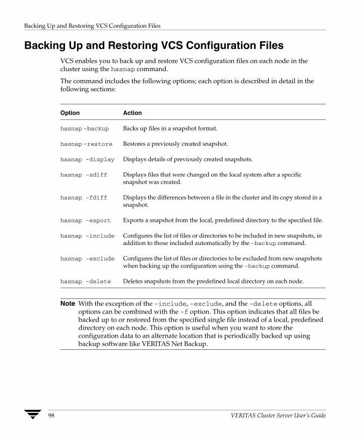
Backing Up and Restoring VCS Configuration Files
Backing Up and Restoring VCS Configuration Files VCS enables you to back up and restore VCS configuration files on each node in the cluster using the hasnap command.
The command includes the following options; each option is described in detail in the following sections:
Option Action
hasnap -backup Backs up files in a snapshot format.
hasnap -restore Restores a previously created snapshot.
hasnap -display Displays details of previously created snapshots.
hasnap -sdiff Displays files that were changed on the local system after a specific snapshot was created.
hasnap -fdiff Displays the differences between a file in the cluster and its copy stored in a snapshot.
hasnap -export Exports a snapshot from the local, predefined directory to the specified file.
hasnap -include Configures the list of files or directories to be included in new snapshots, in addition to those included automatically by the -backup command.
hasnap -exclude Configures the list of files or directories to be excluded from new snapshots when backing up the configuration using the -backup command.
hasnap -delete Deletes snapshots from the predefined local directory on each node.
Note With the exception of the -include, -exclude, and the -delete options, all options can be combined with the -f option. This option indicates that all files be backed up to or restored from the specified single file instead of a local, predefined directory on each node. This option is useful when you want to store the configuration data to an alternate location that is periodically backed up using backup software like VERITAS Net Backup.
98 VERITAS Cluster Server User’s Guide

Backing Up and Restoring VCS Configuration Files
hasnap -backup
The hasnap -backup command backs up files in a snapshot format. A snapshot is a collection of VCS configuration files backed up at a particular point in time, typically before making changes to the existing configuration. A snapshot also contains information such as the snapshot name, description, creation time, and file permisisons.
The command backs up a predefined list of VCS configuration files as well as a user-defined list. The predefined list includes all the *.cf files, custom agents, LLT and GAB configuration files, triggers, custom heartbeats, and action scripts. Please see the -include and -exclude commands to construct a user-defined list.
Syntax
hasnap -backup [-f filename] [-n] [-m description]
Options
-n: Runs the command in the non-interactive mode
-m: Specifies a description of the snapshot
Examples
The following command creates a backup of the configuration in the non-interactive mode and adds “Test Backup” as the backup description.
# hasnap -backup -n -m "Test Backup"
The following command creates a backup of the configuration files and saves it as /tmp/backup-2-2-2003 on the node where the command was run.
# hasnap -backup -f /tmp/backup-2-2-2003
Chapter 6, Administering the Cluster from the Command Line 99
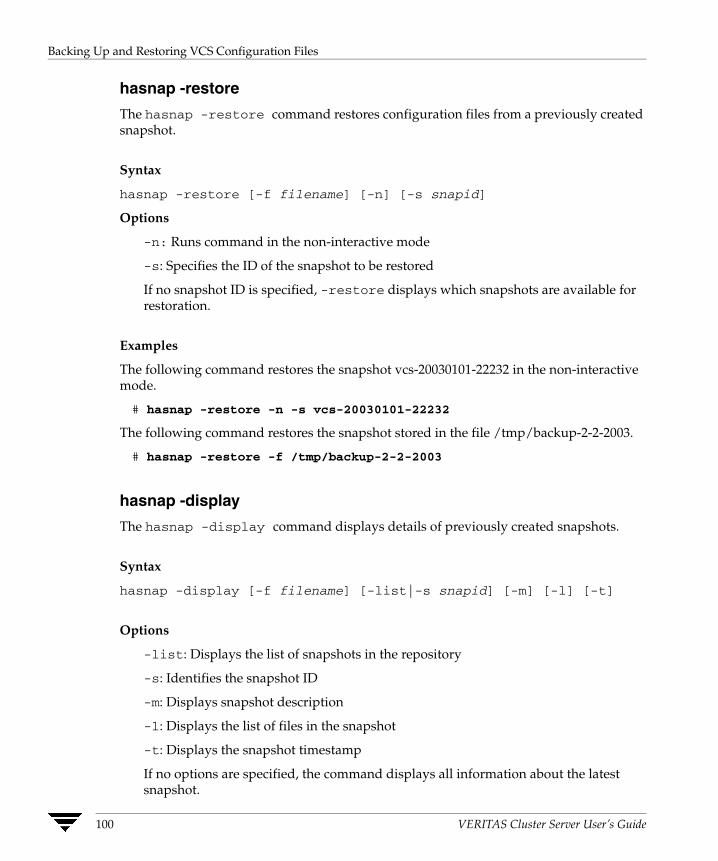
Backing Up and Restoring VCS Configuration Files
hasnap -restore
The hasnap -restore command restores configuration files from a previously created snapshot.
Syntax
hasnap -restore [-f filename] [-n] [-s snapid]
Options
-n: Runs command in the non-interactive mode
-s: Specifies the ID of the snapshot to be restored
If no snapshot ID is specified, -restore displays which snapshots are available for restoration.
Examples
The following command restores the snapshot vcs-20030101-22232 in the non-interactive mode.
# hasnap -restore -n -s vcs-20030101-22232
The following command restores the snapshot stored in the file /tmp/backup-2-2-2003.
# hasnap -restore -f /tmp/backup-2-2-2003
hasnap -display
The hasnap -display command displays details of previously created snapshots.
Syntax
hasnap -display [-f filename] [-list|-s snapid] [-m] [-l] [-t]
Options
-list: Displays the list of snapshots in the repository
-s: Identifies the snapshot ID
-m: Displays snapshot description
-l: Displays the list of files in the snapshot
-t: Displays the snapshot timestamp
If no options are specified, the command displays all information about the latest snapshot.
100 VERITAS Cluster Server User’s Guide
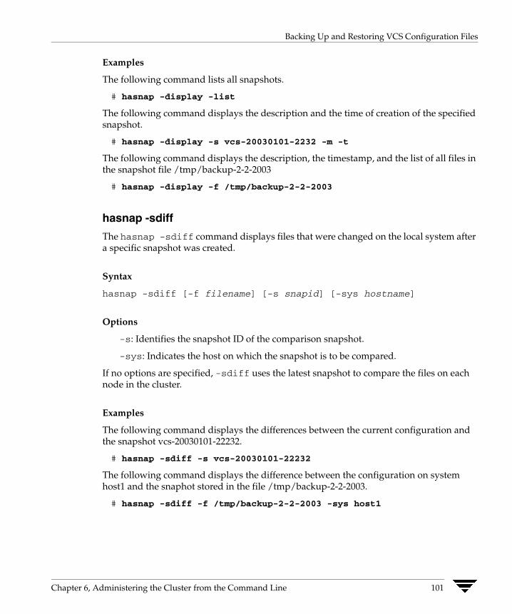
Backing Up and Restoring VCS Configuration Files
Examples
The following command lists all snapshots.
# hasnap -display -list
The following command displays the description and the time of creation of the specified snapshot.
# hasnap -display -s vcs-20030101-2232 -m -t
The following command displays the description, the timestamp, and the list of all files in the snapshot file /tmp/backup-2-2-2003
# hasnap -display -f /tmp/backup-2-2-2003
hasnap -sdiff
The hasnap -sdiff command displays files that were changed on the local system after a specific snapshot was created.
Syntax
hasnap -sdiff [-f filename] [-s snapid] [-sys hostname]
Options
-s: Identifies the snapshot ID of the comparison snapshot.
-sys: Indicates the host on which the snapshot is to be compared.
If no options are specified, -sdiff uses the latest snapshot to compare the files on each node in the cluster.
Examples
The following command displays the differences between the current configuration and the snapshot vcs-20030101-22232.
# hasnap -sdiff -s vcs-20030101-22232
The following command displays the difference between the configuration on system host1 and the snaphot stored in the file /tmp/backup-2-2-2003.
# hasnap -sdiff -f /tmp/backup-2-2-2003 -sys host1
Chapter 6, Administering the Cluster from the Command Line 101

Backing Up and Restoring VCS Configuration Files
hasnap -fdiff
The hasnap -fdiff command displays the differences between a file currently on the cluster and its copy stored in a previously created snapshot.
Syntax
hasnap -fdiff [-f filename] [-s snapid] [-sys hostname] file
Options
-s: Identifies the snaphot ID of the snapshot.
-sys: Indicates the host on which the specified file is to be compared.
file: Identifies the comparison file.
If no options are specified, -fdiff uses the latest snapshot to compare the file on each node in the cluster.
Examples
The following command displays the differences between the files /etc/VRTSvcs/conf/config/main.cf on host1 and its version in the last snapshot.
# hasnap -fdiff -sys host1 /etc/VRTSvcs/conf/config/main.cf
The following command displays the differences between the files /var/llttab on each node in the cluster and the version stored in the snapshot contained in the file /var/backup-2-2-2003.
# hasnap -fdiff -f /tmp/backup-2-2-2003 /etc/llttab
102 VERITAS Cluster Server User’s Guide
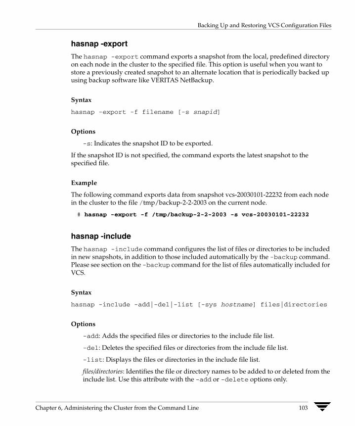
Backing Up and Restoring VCS Configuration Files
hasnap -export
The hasnap -export command exports a snapshot from the local, predefined directory on each node in the cluster to the specified file. This option is useful when you want to store a previously created snapshot to an alternate location that is periodically backed up using backup software like VERITAS NetBackup.
Syntax
hasnap -export -f filename [-s snapid]
Options
-s: Indicates the snapshot ID to be exported.
If the snapshot ID is not specified, the command exports the latest snapshot to the specified file.
Example
The following command exports data from snapshot vcs-20030101-22232 from each node in the cluster to the file /tmp/backup-2-2-2003 on the current node.
# hasnap -export -f /tmp/backup-2-2-2003 -s vcs-20030101-22232
hasnap -include
The hasnap -include command configures the list of files or directories to be included in new snapshots, in addition to those included automatically by the -backup command. Please see section on the -backup command for the list of files automatically included for VCS.
Syntax
hasnap -include -add|-del|-list [-sys hostname] files|directories
Options
-add: Adds the specified files or directories to the include file list.
-del: Deletes the specified files or directories from the include file list.
-list: Displays the files or directories in the include file list.
files/directories: Identifies the file or directory names to be added to or deleted from the include list. Use this attribute with the -add or -delete options only.
Chapter 6, Administering the Cluster from the Command Line 103

Backing Up and Restoring VCS Configuration Files
Examples
The following command displays the list of files or directories to be included in new snapshots on each node of the cluster.
# hasnap -include -list
The following command adds the file /opt/VRTSweb/conf/vrtsweb.xml to the include list on host1, which results in this file being included in the snapshot the next time the hasnap -backup command is run.
# hasnap -include -add /opt/VRTSweb/conf/vrtsweb.xml
The following command removes the file /opt/VRTSweb/conf/vrtsweb.xml from the include list on host1.
# hasnap -include -del -sys host1 /opt/VRTSweb/conf/vrtsweb.xml
hasnap -exclude
The hasnap -exclude command configures the list of files or directories that should not be included in new snapshots when backing up the configuration using the -backup command.
Syntax
hasnap -exclude -add|-del|-list [-sys hostname] files|directories
Options
-add: Adds the specified files or directories to the exclude file list.
-del: Deletes the specified files or directories from the exclude file list.
-list: Displays the files or directories in the exclude file list.
files/directories: Identifies the files or directories to be added to or deleted from the exclude list. Use this attribute with the -add or -delete options only.
Examples
The following command displays the exclude file list on each node in the cluster.
# hasnap -exclude -list
104 VERITAS Cluster Server User’s Guide

Backing Up and Restoring VCS Configuration Files
The following command adds the file /etc/VRTSvcs/conf/config/temp.cf to the exclude file list on host1, which results in this file being excluded from the snapshot the next time the hasnap -backup command is run.
# hasnap -exclude -add -sys host1 /etc/VRTSvcs/conf/config/temp.cf
The following command removes the file /etc/VRTSvcs/conf/config/temp.cf from the exclude list on host1.
# hasnap -exclude -del -sys host1 /etc/VRTSvcs/conf/config/temp.cf
hasnap -delete
The hasnap -delete command deletes previously created snapshots from the predefined local directory on each node.
Syntax
hasnap -delete [-s snapid]
Options
-s: Snapshot ID to be deleted.
If the snapshot ID is not specified, the command displays a list of snapshots available for deletion.
Example
The following command deletes snapshot vcs-20030101-22232 from the cluster.
# hasnap -delete -s vcs-20030101-22232
Chapter 6, Administering the Cluster from the Command Line 105
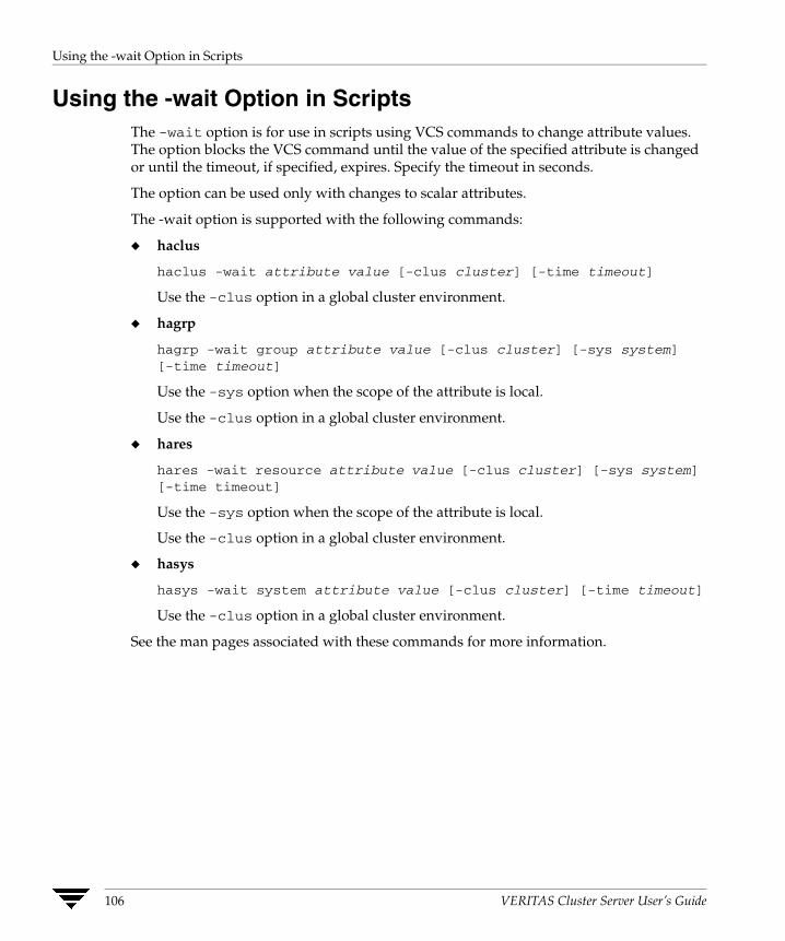
Using the -wait Option in Scripts
Using the -wait Option in Scripts The -wait option is for use in scripts using VCS commands to change attribute values. The option blocks the VCS command until the value of the specified attribute is changed or until the timeout, if specified, expires. Specify the timeout in seconds.
The option can be used only with changes to scalar attributes.
The -wait option is supported with the following commands:
◆ haclus
haclus -wait attribute value [-clus cluster] [-time timeout]
Use the -clus option in a global cluster environment.
◆ hagrp
hagrp -wait group attribute value [-clus cluster] [-sys system] [-time timeout]
Use the -sys option when the scope of the attribute is local.
Use the -clus option in a global cluster environment.
◆ hares
hares -wait resource attribute value [-clus cluster] [-sys system] [-time timeout]
Use the -sys option when the scope of the attribute is local.
Use the -clus option in a global cluster environment.
◆ hasys
hasys -wait system attribute value [-clus cluster] [-time timeout]
Use the -clus option in a global cluster environment.
See the man pages associated with these commands for more information.
106 VERITAS Cluster Server User’s Guide

Using VCS Simulator
Using VCS Simulator VCS Simulator is a tool to assist you in building and simulating cluster configurations. With VCS Simulator you can predict service group behavior during cluster or system faults, view state transitions, and designate and fine-tune various configuration parameters. This tool is especially useful when evaluating complex, multi-node configurations. It is convenient in that you can design a specific configuration without test clusters or changes to existing configurations.
With VCS Simulator, you can predict how VCS behaves in response to resource and system failures in configurations with several groups, resources, and dependencies without affecting your production systems. You can also fine-tune values for attributes governing the rules of failover, such as Load and Capacity in a simulated environment. VCS Simulator enables you to simulate various configurations and provides the information you need to make the right choices. It also enables simulating global clusters. For instructions, see “Predicting VCS Behavior Using VCS Simulator” on page 541.
Chapter 6, Administering the Cluster from the Command Line 107

Using VCS Simulator
108 VERITAS Cluster Server User’s Guide

Administering the Cluster from Cluster Manager (Java Console)
7Cluster Manager (Java Console) offers complete administration capabilities for your cluster. Use the different views in the Java Console to monitor clusters and VCS objects, including service groups, systems, resources, and resource types. Many of the operations supported by the Java Console are also supported by the command line interface and Cluster Manager (Web Console). See the VERITAS Cluster Server Installation Guide for instructions on how to install Cluster Manager (Java Console).
Disability Compliance Cluster Manager (Java Console) for VCS provides disabled individuals access to and use of information and data that is comparable to the access and use provided to non-disabled individuals, including:
◆ Alternate keyboard sequences for specific operations (see matrix in appendix “Accessibility and VCS” on page 691).
◆ High-contrast display settings.
◆ Support of third-party accessibility tools. Note that VERITAS has not tested screen readers for languages other than English.
◆ Text-only display of frequently viewed windows.
109
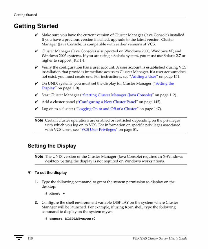
Getting Started
Getting Started ✔ Make sure you have the current version of Cluster Manager (Java Console) installed.
If you have a previous version installed, upgrade to the latest version. Cluster Manager (Java Console) is compatible with earlier versions of VCS.
✔ Cluster Manager (Java Console) is supported on Windows 2000, Windows XP, and Windows 2003 systems. If you are using a Solaris system, you must use Solaris 2.7 or higher to support JRE 1.4.
✔ Verify the configuration has a user account. A user account is established during VCS installation that provides immediate access to Cluster Manager. If a user account does not exist, you must create one. For instructions, see “Adding a User” on page 151.
✔ On UNIX systems, you must set the display for Cluster Manager (“Setting the Display” on page 110).
✔ Start Cluster Manager (“Starting Cluster Manager (Java Console)” on page 112).
✔ Add a cluster panel (“Configuring a New Cluster Panel” on page 145).
✔ Log on to a cluster (“Logging On to and Off of a Cluster” on page 147).
Note Certain cluster operations are enabled or restricted depending on the privileges with which you log on to VCS. For information on specific privileges associated with VCS users, see “VCS User Privileges” on page 51.
Setting the Display
Note The UNIX version of the Cluster Manager (Java Console) requires an X-Windows desktop. Setting the display is not required on Windows workstations.
▼ To set the display
1. Type the following command to grant the system permission to display on the desktop:
# xhost +
2. Configure the shell environment variable DISPLAY on the system where Cluster Manager will be launched. For example, if using Korn shell, type the following command to display on the system myws:
# export DISPLAY=myws:0
110 VERITAS Cluster Server User’s Guide
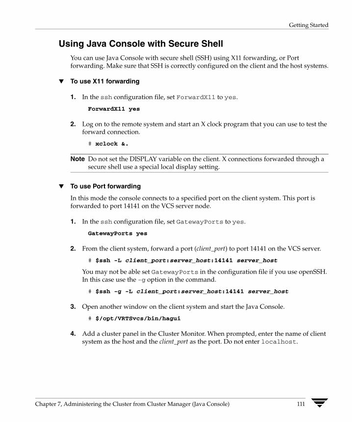
Getting Started
Using Java Console with Secure Shell You can use Java Console with secure shell (SSH) using X11 forwarding, or Port forwarding. Make sure that SSH is correctly configured on the client and the host systems.
▼ To use X11 forwarding
1. In the ssh configuration file, set ForwardX11 to yes.
ForwardX11 yes
2. Log on to the remote system and start an X clock program that you can use to test the forward connection.
# xclock &.
Note Do not set the DISPLAY variable on the client. X connections forwarded through a secure shell use a special local display setting.
▼ To use Port forwarding
In this mode the console connects to a specified port on the client system. This port is forwarded to port 14141 on the VCS server node.
1. In the ssh configuration file, set GatewayPorts to yes.
GatewayPorts yes
2. From the client system, forward a port (client_port) to port 14141 on the VCS server.
# $ssh -L client_port:server_host:14141 server_host
You may not be able set GatewayPorts in the configuration file if you use openSSH. In this case use the -g option in the command.
# $ssh -g -L client_port:server_host:14141 server_host
3. Open another window on the client system and start the Java Console.
# $/opt/VRTSvcs/bin/hagui
4. Add a cluster panel in the Cluster Monitor. When prompted, enter the name of client system as the host and the client_port as the port. Do not enter localhost.
Chapter 7, Administering the Cluster from Cluster Manager (Java Console) 111

Getting Started
Starting Cluster Manager (Java Console)
▼ To start the Java Console on Windows systems
Double-click the VERITAS Cluster Manager (Java Console) icon on the desktop.
▼ To start the Java Console on UNIX systems
After establishing a user account and setting the display, type the following command to start Cluster Manager:
# /opt/VRTSvcs/bin/hagui
The command hagui will not work across firewalls unless all outgoing server ports are open.
112 VERITAS Cluster Server User’s Guide
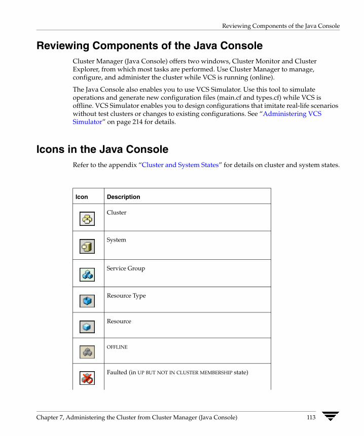
Reviewing Components of the Java Console
Reviewing Components of the Java Console Cluster Manager (Java Console) offers two windows, Cluster Monitor and Cluster Explorer, from which most tasks are performed. Use Cluster Manager to manage, configure, and administer the cluster while VCS is running (online).
The Java Console also enables you to use VCS Simulator. Use this tool to simulate operations and generate new configuration files (main.cf and types.cf) while VCS is offline. VCS Simulator enables you to design configurations that imitate real-life scenarios without test clusters or changes to existing configurations. See “Administering VCS Simulator” on page 214 for details.
Icons in the Java Console Refer to the appendix “Cluster and System States” for details on cluster and system states.
Icon Description
Cluster
System
Service Group
Resource Type
Resource
OFFLINE
Faulted (in UP BUT NOT IN CLUSTER MEMBERSHIP state)
Chapter 7, Administering the Cluster from Cluster Manager (Java Console) 113
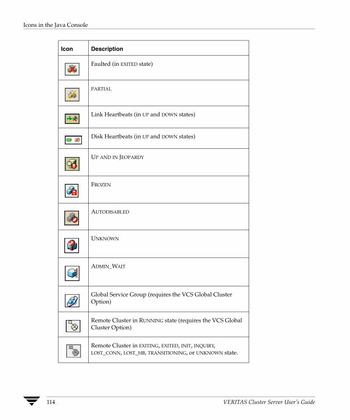
Icons in the Java Console
Icon Description
Faulted (in EXITED state)
PARTIAL
Link Heartbeats (in UP and DOWN states)
Disk Heartbeats (in UP and DOWN states)
UP AND IN JEOPARDY
FROZEN
AUTODISABLED
UNKNOWN
ADMIN_WAIT
Global Service Group (requires the VCS Global Cluster Option)
Remote Cluster in RUNNING state (requires the VCS Global Cluster Option)
Remote Cluster in EXITING, EXITED, INIT, INQUIRY, LOST_CONN, LOST_HB, TRANSITIONING, or UNKNOWN state.
114 VERITAS Cluster Server User’s Guide

About Cluster Monitor
About Cluster Monitor After starting Cluster Manager, the first window that appears is Cluster Monitor. This window includes one or more panels displaying general information about actual or simulated clusters. Use Cluster Monitor to log on to and off of a cluster, view summary information on various VCS objects, customize the display, use VCS Simulator, and exit Cluster Manager.
Chapter 7, Administering the Cluster from Cluster Manager (Java Console) 115
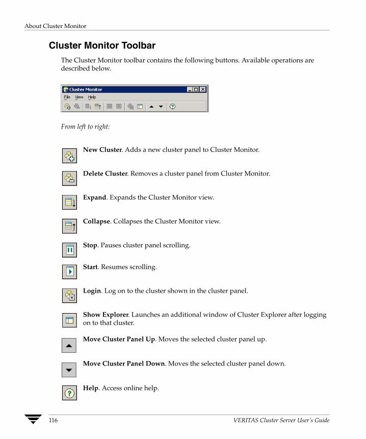
About Cluster Monitor
Cluster Monitor Toolbar The Cluster Monitor toolbar contains the following buttons. Available operations are described below.
From left to right:
New Cluster. Adds a new cluster panel to Cluster Monitor.
Delete Cluster. Removes a cluster panel from Cluster Monitor.
Expand. Expands the Cluster Monitor view.
Collapse. Collapses the Cluster Monitor view.
Stop. Pauses cluster panel scrolling.
Start. Resumes scrolling.
Login. Log on to the cluster shown in the cluster panel.
Show Explorer. Launches an additional window of Cluster Explorer after logging on to that cluster.
Move Cluster Panel Up. Moves the selected cluster panel up.
Move Cluster Panel Down. Moves the selected cluster panel down.
Help. Access online help.
116 VERITAS Cluster Server User’s Guide

About Cluster Monitor
Cluster Monitor Panels To administer a cluster, add a cluster panel or reconfigure an existing cluster panel in Cluster Monitor. Each panel summarizes the status of the connection and components of a cluster.
Monitoring the Cluster Connection with Cluster Monitor The right pane of a panel in Cluster Monitor displays the status of the connection to a cluster. An inactive panel will appear grey until the user logs on and connects to the cluster. To alter the connection to a cluster, right-click a panel to access a menu.
◆ The menu on an active panel enables you to log off a cluster.
◆ The menu on an inactive panel enables you to log on to a cluster, configure the cluster, and delete the cluster from Cluster Monitor.
Menus are enabled when the Cluster Monitor display appears in the default expanded view. If you activate a menu on a collapsed scrolling view of Cluster Monitor, the scrolling stops while accessing the menu.
If the system to which the console is connected goes down, a message notifies you that the connection to the cluster is lost. Cluster Monitor tries to connect to another system in the cluster according to the number of Failover retries set in the Connectivity Configuration dialog box. The panels flash until Cluster Monitor is successfully connected to a different system. If the failover is unsuccessful, a message notifies you of the failure and the panels turn grey.
Chapter 7, Administering the Cluster from Cluster Manager (Java Console) 117
About Cluster Monitor
Monitoring VCS Objects with Cluster Monitor Cluster Monitor summarizes the state of various objects in a cluster and provides access to in-depth information about these objects in Cluster Explorer. The right pane of a Cluster Monitor panel displays the connection status (online, offline, up, or down) of service groups, systems, and heartbeats. The left pane of a Cluster Monitor panel displays three icons representing service groups, systems, and heartbeats. The colors of the icons indicate the state of the cluster; for example:
◆ A flashing red slash indicates Cluster Manager failed to connect to the cluster and will attempt to connect to another system in the cluster.
◆ A flashing yellow slash indicates Cluster Manager is experiencing problems with the connection to the cluster.
Pointing to an icon accesses the icon’s ScreenTip, which provides additional information on the specific VCS object.
To review detailed information about VCS objects in Cluster Explorer, Logs, and Command Center, right-click a panel to access a menu. Menus are enabled when the Cluster Monitor display appears in the default expanded view. If you activate a menu on a collapsed scrolling view of Cluster Monitor, the scrolling stops while accessing the menu.
118 VERITAS Cluster Server User’s Guide
About Cluster Monitor
Expanding and Collapsing the Cluster Monitor Display Cluster Monitor supports two views: expanded (default) and collapsed. The expanded view shows all cluster panels. The collapsed view shows one cluster panel at a time as the panels scroll upward.
Operations enabled for the expanded view of cluster panels, such as viewing menus, are also enabled on the collapsed view after the panels stop scrolling.
▼ To collapse the Cluster Monitor view
On the View menu, click Collapse.
or
Click Collapse on the Cluster Monitor toolbar.
▼ To expand the Cluster Monitor view
On the View menu, click Expand.
or
Click Expand on the Cluster Monitor toolbar.
▼ To pause a scrolling cluster panel
Click the cluster panel.
or
Click Stop on the Cluster Monitor toolbar.
Chapter 7, Administering the Cluster from Cluster Manager (Java Console) 119

About Cluster Monitor
Customizing the Cluster Manager Display
1. From Cluster Monitor, click Preferences on the File menu. If you are using a Windowssystem, proceed to step 2. Otherwise, proceed to step 3.
2. In the Look & Feel tab (for Windows systems):
a. Click Native (Windows or Motif) look & feel or Java (Metal) look & feel.
b. Click Apply.
3. In the Appearance tab:
a. Click the color (applies to Java (Metal) look & feel).
b. Click an icon size.
c. Select the Show Tooltips check box to enable ToolTips.
120 VERITAS Cluster Server User’s Guide

About Cluster Monitor
d. Select the Remove Cluster Manager colors check box to alter the standard color scheme.
e. Click Apply.
4. In the Sound tab:
a. Select the Enable Sound check box to associate sound with specific events.
b. Click an event from the Events configuration tree.
c. Click a sound from the Sounds list box.
d. To test the selected sound, click Play.
e. Click Apply.
f. Repeat step 4a through step 4e to enable sound for other events.
Note This tab requires a properly configured sound card.
5. After you have made your final selection, click OK.
Chapter 7, Administering the Cluster from Cluster Manager (Java Console) 121
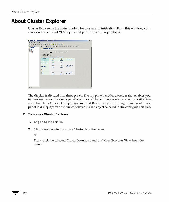
About Cluster Explorer
About Cluster Explorer Cluster Explorer is the main window for cluster administration. From this window, you can view the status of VCS objects and perform various operations.
The display is divided into three panes. The top pane includes a toolbar that enables you to perform frequently used operations quickly. The left pane contains a configuration tree with three tabs: Service Groups, Systems, and Resource Types. The right pane contains a panel that displays various views relevant to the object selected in the configuration tree.
▼ To access Cluster Explorer
1. Log on to the cluster.
2. Click anywhere in the active Cluster Monitor panel.
or
Right-click the selected Cluster Monitor panel and click Explorer View from the menu.
122 VERITAS Cluster Server User’s Guide

About Cluster Explorer
Cluster Explorer Toolbar The Cluster Explorer toolbar contains 18 buttons. Available operations are described below. Note: Some buttons may be disabled depending on the type of cluster (local or global) and the privileges with which you logged on to the cluster.
From left to right:
Open Configuration. Modifies a read-only configuration to a read-write file. This enables you to modify the configuration.
Save Configuration. Writes the configuration to disk.
Save and Close Configuration. Writes the configuration to disk as a read-only file.
Add Service Group. Displays the Add Service Group dialog box.
Add Resource. Displays the Add Resource dialog box.
Add System. Displays the Add System dialog box.
Manage systems for a Service Group. Displays the System Manager dialog box.
Online Service Group. Displays the Online Service Group dialog box.
Offline Service Group. Displays the Offline Service Group dialog box.
Show Command Center. Enables you to perform many of the same VCS operations available from the command line.
Show Shell Command Window. Enables you to launch a non-interactive shell command on cluster systems, and to view the results on a per-system basis.
Chapter 7, Administering the Cluster from Cluster Manager (Java Console) 123
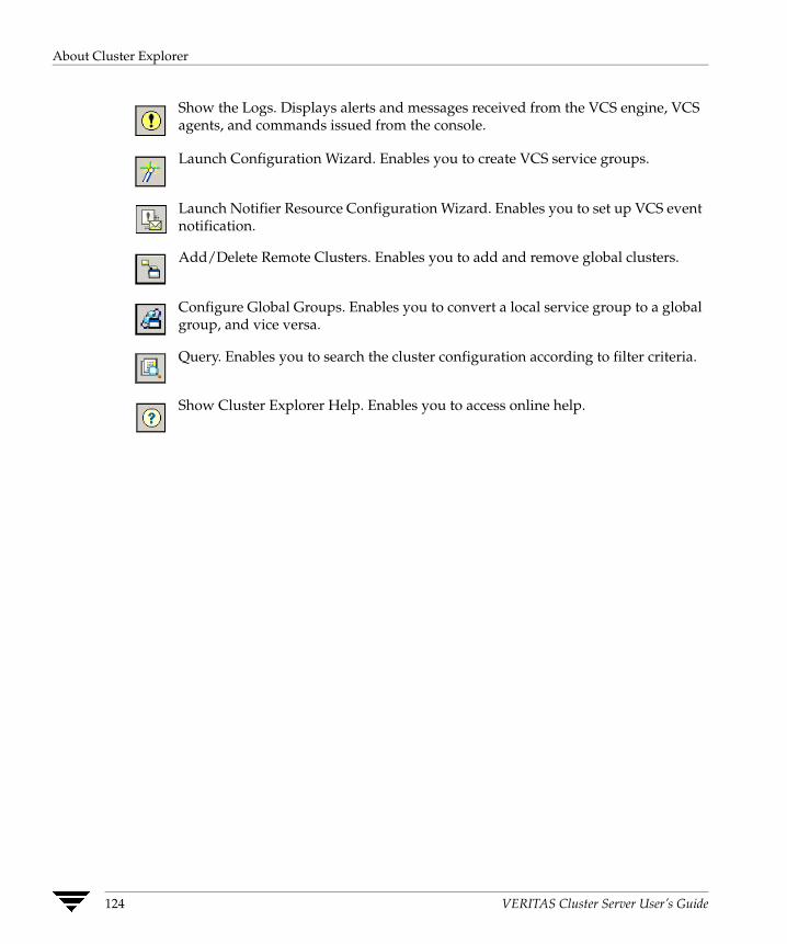
About Cluster Explorer
Show the Logs. Displays alerts and messages received from the VCS engine, VCS agents, and commands issued from the console.
Launch Configuration Wizard. Enables you to create VCS service groups.
Launch Notifier Resource Configuration Wizard. Enables you to set up VCS event notification.
Add/Delete Remote Clusters. Enables you to add and remove global clusters.
Configure Global Groups. Enables you to convert a local service group to a global group, and vice versa.
Query. Enables you to search the cluster configuration according to filter criteria.
Show Cluster Explorer Help. Enables you to access online help.
124 VERITAS Cluster Server User’s Guide
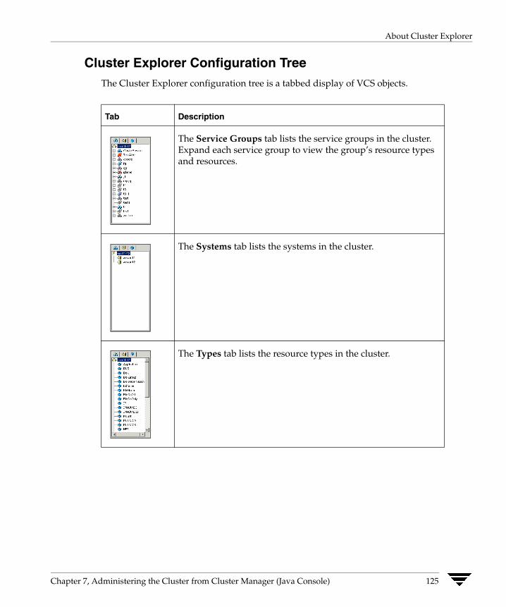
About Cluster Explorer
Cluster Explorer Configuration Tree The Cluster Explorer configuration tree is a tabbed display of VCS objects.
Tab Description
The Service Groups tab lists the service groups in the cluster. Expand each service group to view the group’s resource types and resources.
The Systems tab lists the systems in the cluster.
The Types tab lists the resource types in the cluster.
Chapter 7, Administering the Cluster from Cluster Manager (Java Console) 125
About Cluster Explorer
Cluster Explorer View Panel The right pane of the Cluster Explorer includes a view panel that provides detailed information about the object selected in the configuration tree. The information is presented in tabular or graphical format. Use the tabs in the view panel to access a particular view. The console enables you to “tear off” each view to appear in a separate window.
◆ Click any object in the configuration tree to access the Status View and Properties View.
◆ Click a cluster in the configuration tree to access the Service Group View, System Connectivity View, and Remote Cluster Status View (for global clusters only).
◆ Click a service group in the configuration tree to access the Resource View.
▼ To create a tear-off view
On the View menu, click Tear Off, and click the appropriate view from the menu.
or
Right-click the object in the configuration tree, click View, and click the appropriate view from the menu.
126 VERITAS Cluster Server User’s Guide

About Cluster Explorer
Status View The Status View summarizes the state of the object selected in the configuration tree. Use this view to monitor the overall status of a cluster, system, service group, resource type, and resource.
For example, if a service group is selected in the configuration tree, the Status View displays the state of the service group and its resources on member systems. It also displays the last five critical or error logs. Point to an icon in the status table to open a ScreenTip about the relevant VCS object.
For global clusters, this view displays the state of the remote clusters. For global groups, this view shows the status of the groups on both local and remote clusters.
▼ To access the Status View
1. From Cluster Explorer, click an object in the configuration tree.
2. In the view panel, click the Status tab.
Chapter 7, Administering the Cluster from Cluster Manager (Java Console) 127
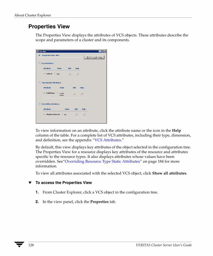
About Cluster Explorer
Properties View The Properties View displays the attributes of VCS objects. These attributes describe the scope and parameters of a cluster and its components.
To view information on an attribute, click the attribute name or the icon in the Help column of the table. For a complete list of VCS attributes, including their type, dimension, and definition, see the appendix “VCS Attributes.”
By default, this view displays key attributes of the object selected in the configuration tree. The Properties View for a resource displays key attributes of the resource and attributes specific to the resource types. It also displays attributes whose values have been overridden. See“Overriding Resource Type Static Attributes” on page 184 for more information.
To view all attributes associated with the selected VCS object, click Show all attributes.
▼ To access the Properties View
1. From Cluster Explorer, click a VCS object in the configuration tree.
2. In the view panel, click the Properties tab.
128 VERITAS Cluster Server User’s Guide

About Cluster Explorer
Service Group View The Service Group View displays the service groups and their dependencies in a cluster. Use the graph and ScreenTips in this view to monitor, create, and disconnect dependencies. To view the ScreenTips, point to a group icon for information on the type and state of the group on the cluster systems, and the type of dependency between the service groups.
The line between two service groups represents a dependency, or parent-child relationship. In VCS, parent service groups depend on child service groups. A service group can function as a parent and a child. (See “Categories of Service Group Dependencies” for more information.)
The color of the link between service groups indicates different types of dependencies.
◆ A blue link indicates a soft dependency.
◆ A red link indicates a firm dependency.
◆ A green link indicates a hard dependency typically used with VVR in disaster recovery configurations.
▼ To access the Service Group View
1. From Cluster Explorer, click a cluster in the configuration tree.
2. In the view panel, click the Service Groups tab.
Chapter 7, Administering the Cluster from Cluster Manager (Java Console) 129
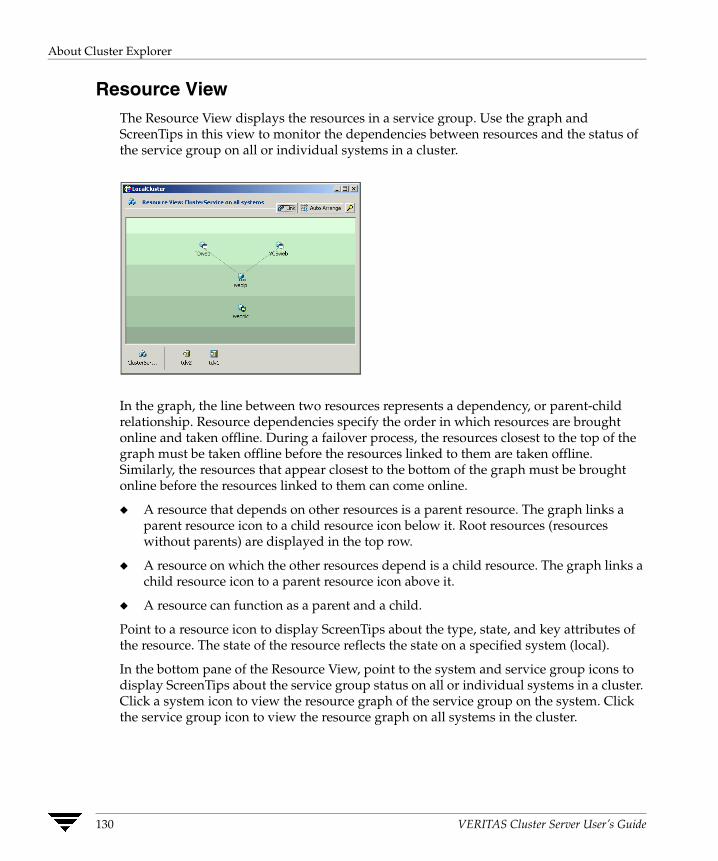
About Cluster Explorer
Resource View The Resource View displays the resources in a service group. Use the graph and ScreenTips in this view to monitor the dependencies between resources and the status of the service group on all or individual systems in a cluster.
In the graph, the line between two resources represents a dependency, or parent-child relationship. Resource dependencies specify the order in which resources are brought online and taken offline. During a failover process, the resources closest to the top of the graph must be taken offline before the resources linked to them are taken offline. Similarly, the resources that appear closest to the bottom of the graph must be brought online before the resources linked to them can come online.
◆ A resource that depends on other resources is a parent resource. The graph links a parent resource icon to a child resource icon below it. Root resources (resources without parents) are displayed in the top row.
◆ A resource on which the other resources depend is a child resource. The graph links a child resource icon to a parent resource icon above it.
◆ A resource can function as a parent and a child.
Point to a resource icon to display ScreenTips about the type, state, and key attributes of the resource. The state of the resource reflects the state on a specified system (local).
In the bottom pane of the Resource View, point to the system and service group icons to display ScreenTips about the service group status on all or individual systems in a cluster. Click a system icon to view the resource graph of the service group on the system. Click the service group icon to view the resource graph on all systems in the cluster.
130 VERITAS Cluster Server User’s Guide

About Cluster Explorer
▼ To access the Resource View
1. From Cluster Explorer, click the service groups tab in the configuration tree.
2. Click a service group in the configuration tree.
3. In the view panel, click the Resources tab.
Moving and Linking Icons in Group and Resource Views The Link and Auto Arrange buttons are available in the top right corner of the Service Group or Resource View:
Click Link to set or disable the link mode for the Service Group and Resource Views. Note: There are alternative ways to set up dependency links without using the Link button.
The link mode enables you to create a dependency link by clicking on the parent icon, dragging the yellow line to the icon that will serve as the child, and then clicking the child icon. Use the Esc key to delete the yellow dependency line connecting the parent and child during the process of linking the two icons.
If the Link mode is not activated, click and drag an icon along a horizontal plane to move the icon. Click Auto Arrange to reset the appearance of the graph. The view resets the arrangement of icons after the addition or deletion of a resource, service group, or dependency link. Changes in the Resource and Service Group Views will be maintained after the user logs off and logs on to the Java Console at a later time.
Chapter 7, Administering the Cluster from Cluster Manager (Java Console) 131
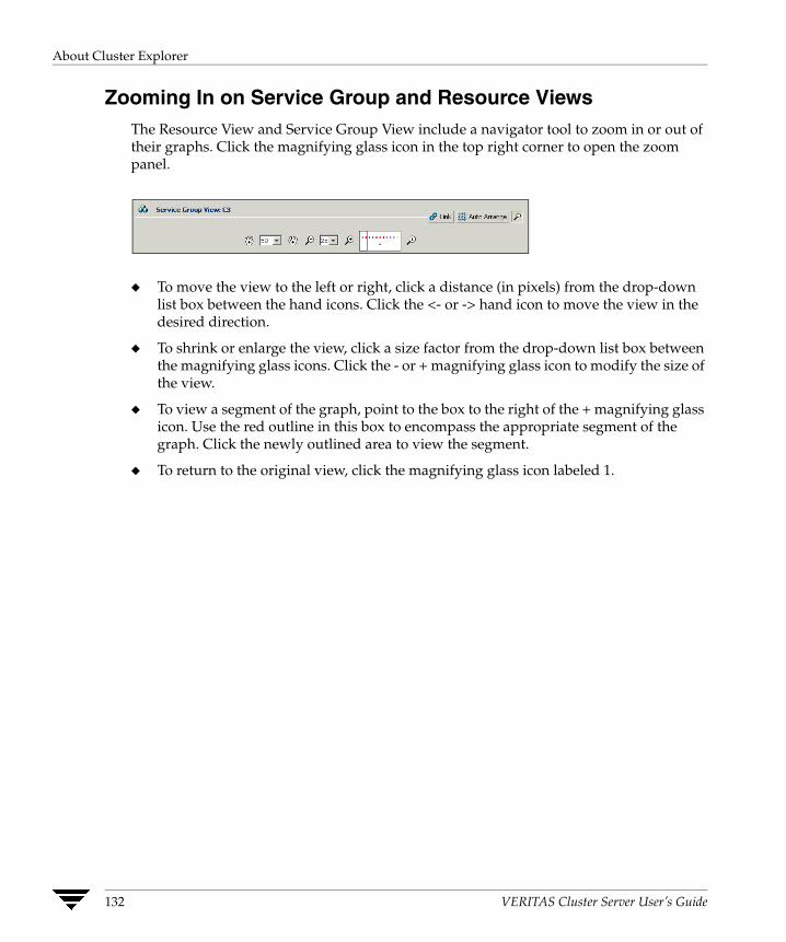
About Cluster Explorer
Zooming In on Service Group and Resource Views The Resource View and Service Group View include a navigator tool to zoom in or out of their graphs. Click the magnifying glass icon in the top right corner to open the zoom panel.
◆ To move the view to the left or right, click a distance (in pixels) from the drop-down list box between the hand icons. Click the <- or -> hand icon to move the view in the desired direction.
◆ To shrink or enlarge the view, click a size factor from the drop-down list box between the magnifying glass icons. Click the - or + magnifying glass icon to modify the size of the view.
◆ To view a segment of the graph, point to the box to the right of the + magnifying glass icon. Use the red outline in this box to encompass the appropriate segment of the graph. Click the newly outlined area to view the segment.
◆ To return to the original view, click the magnifying glass icon labeled 1.
132 VERITAS Cluster Server User’s Guide
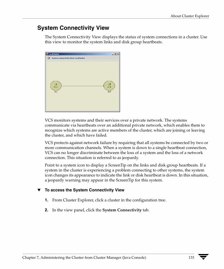
About Cluster Explorer
System Connectivity View The System Connectivity View displays the status of system connections in a cluster. Use this view to monitor the system links and disk group heartbeats.
VCS monitors systems and their services over a private network. The systems communicate via heartbeats over an additional private network, which enables them to recognize which systems are active members of the cluster, which are joining or leaving the cluster, and which have failed.
VCS protects against network failure by requiring that all systems be connected by two or more communication channels. When a system is down to a single heartbeat connection, VCS can no longer discriminate between the loss of a system and the loss of a network connection. This situation is referred to as jeopardy.
Point to a system icon to display a ScreenTip on the links and disk group heartbeats. If a system in the cluster is experiencing a problem connecting to other systems, the system icon changes its appearance to indicate the link or disk heartbeat is down. In this situation, a jeopardy warning may appear in the ScreenTip for this system.
▼ To access the System Connectivity View
1. From Cluster Explorer, click a cluster in the configuration tree.
2. In the view panel, click the System Connectivity tab.
Chapter 7, Administering the Cluster from Cluster Manager (Java Console) 133
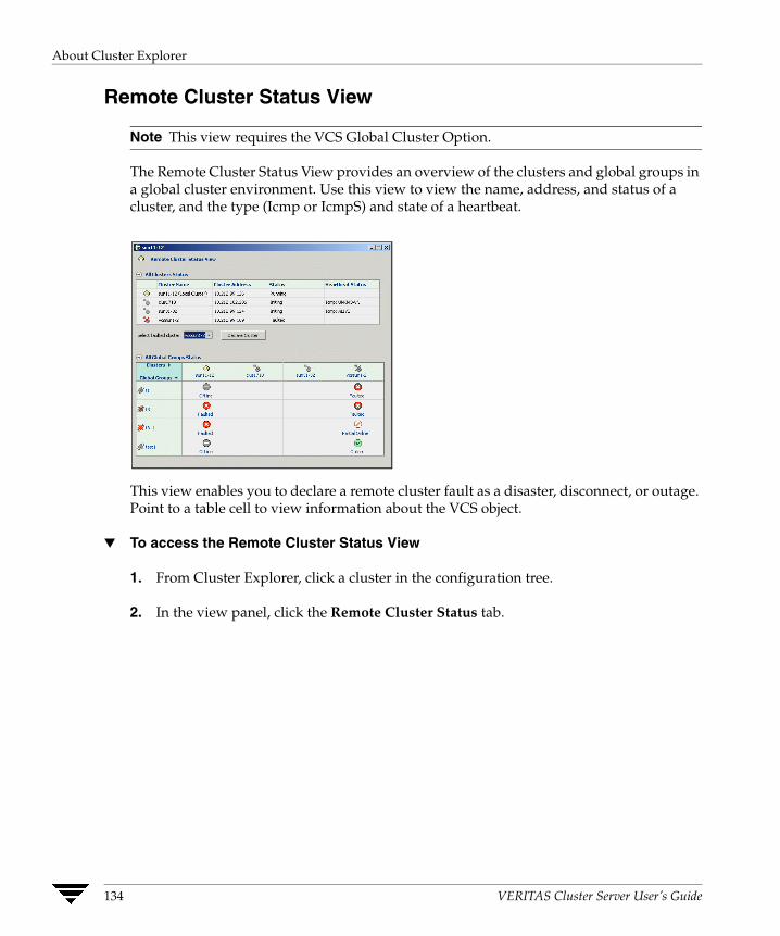
About Cluster Explorer
Remote Cluster Status View
Note This view requires the VCS Global Cluster Option.
The Remote Cluster Status View provides an overview of the clusters and global groups in a global cluster environment. Use this view to view the name, address, and status of a cluster, and the type (Icmp or IcmpS) and state of a heartbeat.
This view enables you to declare a remote cluster fault as a disaster, disconnect, or outage. Point to a table cell to view information about the VCS object.
▼ To access the Remote Cluster Status View
1. From Cluster Explorer, click a cluster in the configuration tree.
2. In the view panel, click the Remote Cluster Status tab.
134 VERITAS Cluster Server User’s Guide

Accessing Additional Features of the Java Console
Accessing Additional Features of the Java Console Use Cluster Manager to access the Template View, System Manager, User Manager, Cluster Shell, Command Center, Configuration Wizard, Notifier Resource Configuration Wizard, Query Module, and Logs.
Template View The Template View displays the service group templates available in VCS. Templates are predefined service groups that define the resources, resource attributes, and dependencies within the service group. Use this view to add service groups to the cluster configuration, and copy the resources within a service group template to existing service groups.
In this window, the left pane displays the templates available on the system to which Cluster Manager is connected. The right pane displays the selected template’s resource dependency graph.
Template files conform to the VCS configuration language and contain the extension .tf. These files reside in the VCS configuration directory.
▼ To access the Template View
From Cluster Explorer, click Templates on the Tools menu.
Chapter 7, Administering the Cluster from Cluster Manager (Java Console) 135
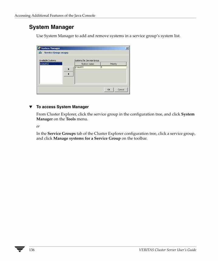
Accessing Additional Features of the Java Console
System Manager Use System Manager to add and remove systems in a service group’s system list.
▼ To access System Manager
From Cluster Explorer, click the service group in the configuration tree, and click System Manager on the Tools menu.
or
In the Service Groups tab of the Cluster Explorer configuration tree, click a service group, and click Manage systems for a Service Group on the toolbar.
136 VERITAS Cluster Server User’s Guide
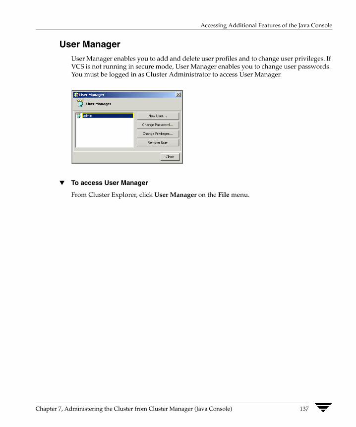
Accessing Additional Features of the Java Console
User Manager User Manager enables you to add and delete user profiles and to change user privileges. If VCS is not running in secure mode, User Manager enables you to change user passwords. You must be logged in as Cluster Administrator to access User Manager.
▼ To access User Manager
From Cluster Explorer, click User Manager on the File menu.
Chapter 7, Administering the Cluster from Cluster Manager (Java Console) 137

Accessing Additional Features of the Java Console
Cluster Shell Cluster Shell enables you to run a non-interactive shell command on one or more cluster systems, and to view the results for each system. Do not use Cluster Shell to run commands that require user input.
The left pane of the window displays a list of the systems in the cluster. The right pane displays the time the command was issued, the system on which it was issued, and the output from the command as generated on the system’s command line or console. The bottom pane provides a field to enter the command.
The following conditions must be met to access and run commands from this window:
◆ Set the cluster attribute HacliUserLevel to CLUSTERADMIN.
If HacliUserLevel was modified while Cluster Explorer was open, close and restart Cluster Explorer before using Cluster Shell. For more information, see the appendix “VCS Attributes” on page 627.
◆ Set the user account with Cluster Administrator privileges.
▼ To access Cluster Shell
From Cluster Explorer, click Cluster Shell on the Tools menu.
or
On the Cluster Explorer toolbar, click Show Shell Command Window.
138 VERITAS Cluster Server User’s Guide
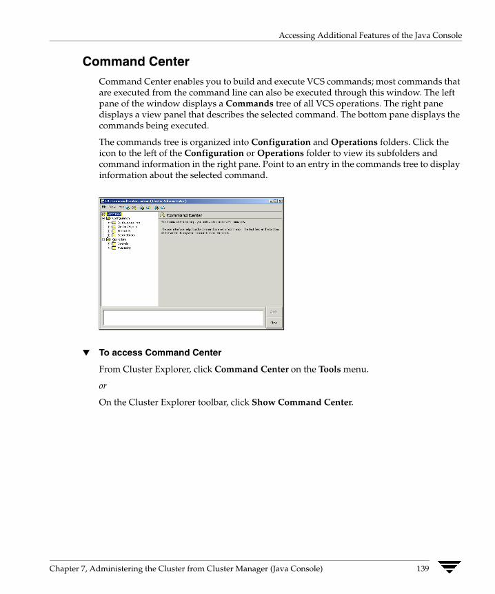
Accessing Additional Features of the Java Console
Command Center Command Center enables you to build and execute VCS commands; most commands that are executed from the command line can also be executed through this window. The left pane of the window displays a Commands tree of all VCS operations. The right pane displays a view panel that describes the selected command. The bottom pane displays the commands being executed.
The commands tree is organized into Configuration and Operations folders. Click the icon to the left of the Configuration or Operations folder to view its subfolders and command information in the right pane. Point to an entry in the commands tree to display information about the selected command.
▼ To access Command Center
From Cluster Explorer, click Command Center on the Tools menu.
or
On the Cluster Explorer toolbar, click Show Command Center.
Chapter 7, Administering the Cluster from Cluster Manager (Java Console) 139
Accessing Additional Features of the Java Console
Configuration Wizard Use Configuration Wizard to create and assign service groups to systems in a cluster.
▼ To access Configuration Wizard
From Cluster Explorer, click Configuration Wizard on the Tools menu.
or
On the Cluster Explorer toolbar, click Launch Configuration Wizard.
Notifier Resource Configuration Wizard VCS provides a method for notifying an administrator of important events such as a resource or system fault. VCS includes a “notifier” component, which consists of the notifier daemon and the hanotify utility. This wizard enables you to configure the notifier component as a resource of type NotifierMngr as part of the ClusterService group.
▼ To access Notifier Resource Configuration Wizard
From Cluster Explorer, click Notifier Wizard on the Tools menu.
or
On the Cluster Explorer toolbar, click Launch Notifier Resource Configuration Wizard.
140 VERITAS Cluster Server User’s Guide

Accessing Additional Features of the Java Console
Cluster Query Use Cluster Query to run SQL-like queries from Cluster Explorer. VCS objects that can be queried include service groups, systems, resources, and resource types. Some queries can be customized, including searching for the system’s online group count and specific resource attributes.
▼ To access the Query dialog box
From Cluster Explorer, click Query on the Tools menu.
or
In the Cluster Explorer toolbar, click Query.
Chapter 7, Administering the Cluster from Cluster Manager (Java Console) 141

Accessing Additional Features of the Java Console
Logs The Logs dialog box displays the log messages generated by the VCS engine, VCS agents, and commands issued from Cluster Manager to the cluster. Use this dialog box to monitor and take actions on alerts on faulted global clusters and failed service group failover attempts.
Note To ensure the time stamps for engine log messages are accurate, make sure to set the time zone of the system running the Java Console to the same time zone as the system running the VCS engine.
✔ Click the VCS Logs tab to view the log type, time, and details of an event. Each message presents an icon in the first column of the table to indicate the message type. Use this window to customize the display of messages by setting filter criteria.
✔ Click the Agent Logs tab to display logs according to system, resource type, and resource filter criteria. Use this tab to view the log type, time, and details of an agent event.
142 VERITAS Cluster Server User’s Guide
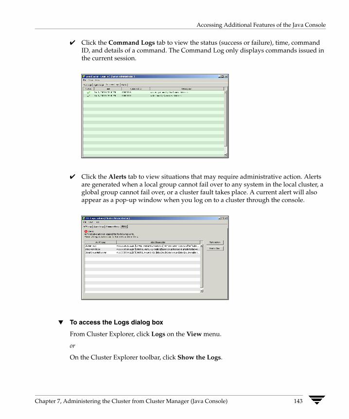
Accessing Additional Features of the Java Console
✔ Click the Command Logs tab to view the status (success or failure), time, command ID, and details of a command. The Command Log only displays commands issued in the current session.
✔ Click the Alerts tab to view situations that may require administrative action. Alerts are generated when a local group cannot fail over to any system in the local cluster, a global group cannot fail over, or a cluster fault takes place. A current alert will also appear as a pop-up window when you log on to a cluster through the console.
▼ To access the Logs dialog box
From Cluster Explorer, click Logs on the View menu.
or
On the Cluster Explorer toolbar, click Show the Logs.
Chapter 7, Administering the Cluster from Cluster Manager (Java Console) 143
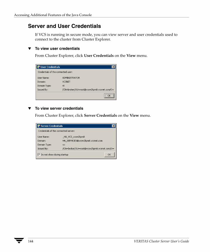
Accessing Additional Features of the Java Console
Server and User Credentials If VCS is running in secure mode, you can view server and user credentials used to connect to the cluster from Cluster Explorer.
▼ To view user credentials
From Cluster Explorer, click User Credentials on the View menu.
▼ To view server credentials
From Cluster Explorer, click Server Credentials on the View menu.
144 VERITAS Cluster Server User’s Guide
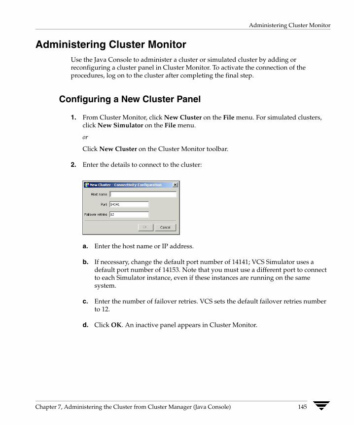
Administering Cluster Monitor
Administering Cluster Monitor Use the Java Console to administer a cluster or simulated cluster by adding or reconfiguring a cluster panel in Cluster Monitor. To activate the connection of the procedures, log on to the cluster after completing the final step.
Configuring a New Cluster Panel
1. From Cluster Monitor, click New Cluster on the File menu. For simulated clusters, click New Simulator on the File menu.
or
Click New Cluster on the Cluster Monitor toolbar.
2. Enter the details to connect to the cluster:
a. Enter the host name or IP address.
b. If necessary, change the default port number of 14141; VCS Simulator uses a default port number of 14153. Note that you must use a different port to connect to each Simulator instance, even if these instances are running on the same system.
c. Enter the number of failover retries. VCS sets the default failover retries number to 12.
d. Click OK. An inactive panel appears in Cluster Monitor.
Chapter 7, Administering the Cluster from Cluster Manager (Java Console) 145

Administering Cluster Monitor
Modifying a Cluster Panel Configuration
1. If Cluster Monitor is in the default expanded state, proceed to step 2. If Cluster Monitor is in the collapsed state:
On the View menu, click Expand.
or
On the View menu, click Stop when an active panel appears as the view panel.
2. Right-click the cluster panel. If the panel is inactive, proceed to step 4.
3. On the menu, click Logout. The cluster panel becomes inactive.
4. Right-click the inactive panel, and click Configure.
5. Edit the details to connect to the cluster:
a. Enter the host name.
b. Enter the port number and the number of failover retries. VCS sets the default port number to 14141 and failover retries number to 12; VCS Simulator uses a default port number of 14153.
c. For simulated panels, click the platform for the configuration.
d. Click OK.
146 VERITAS Cluster Server User’s Guide
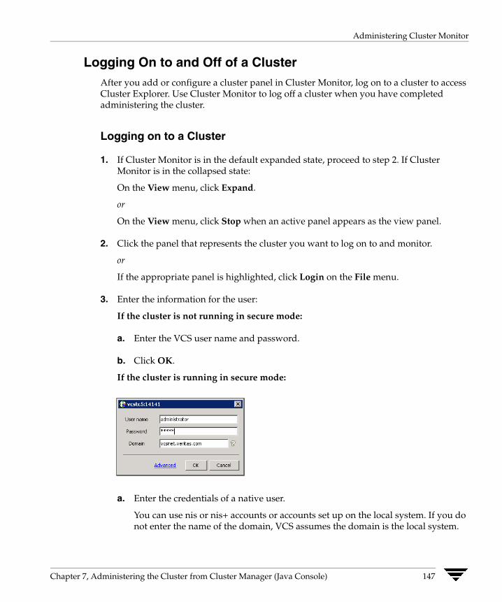
Administering Cluster Monitor
Logging On to and Off of a Cluster After you add or configure a cluster panel in Cluster Monitor, log on to a cluster to access Cluster Explorer. Use Cluster Monitor to log off a cluster when you have completed administering the cluster.
Logging on to a Cluster
1. If Cluster Monitor is in the default expanded state, proceed to step 2. If Cluster Monitor is in the collapsed state:
On the View menu, click Expand.
or
On the View menu, click Stop when an active panel appears as the view panel.
2. Click the panel that represents the cluster you want to log on to and monitor.
or
If the appropriate panel is highlighted, click Login on the File menu.
3. Enter the information for the user:
If the cluster is not running in secure mode:
a. Enter the VCS user name and password.
b. Click OK.
If the cluster is running in secure mode:
a. Enter the credentials of a native user.
You can use nis or nis+ accounts or accounts set up on the local system. If you do not enter the name of the domain, VCS assumes the domain is the local system.
Chapter 7, Administering the Cluster from Cluster Manager (Java Console) 147
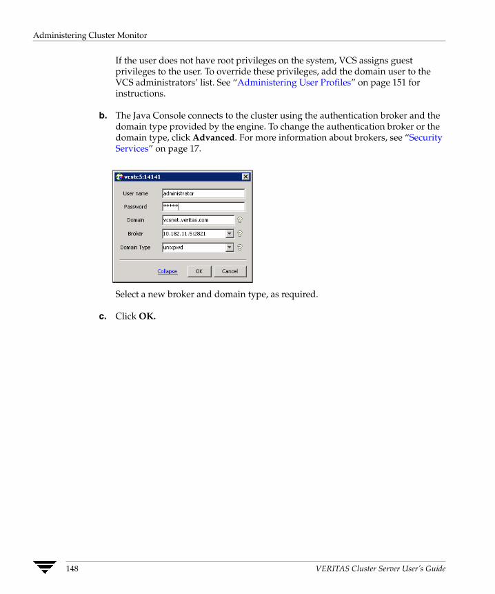
Administering Cluster Monitor
If the user does not have root privileges on the system, VCS assigns guest privileges to the user. To override these privileges, add the domain user to the VCS administrators’ list. See “Administering User Profiles” on page 151 for instructions.
b. The Java Console connects to the cluster using the authentication broker and the domain type provided by the engine. To change the authentication broker or the domain type, click Advanced. For more information about brokers, see “Security Services” on page 17.
Select a new broker and domain type, as required.
c. Click OK.
148 VERITAS Cluster Server User’s Guide

Administering Cluster Monitor
d. The Server Credentials dialog box displays the credentials of the cluster service to which the console is connected.
To disable this dialog box from being displayed every time you connect to the cluster, select the Do not show during startup check box
e. Click OK to connect to the cluster.
The animated display shows various objects, such as service groups and resources, being transferred from the server to the console.
Cluster Explorer is launched automatically upon initial logon, and the icons in the cluster panel change color to indicate an active panel.
Chapter 7, Administering the Cluster from Cluster Manager (Java Console) 149
Administering Cluster Monitor
Logging off of a Cluster
1. If Cluster Monitor is in the default expanded state, proceed to step 2. If Cluster Monitor is in the collapsed state:
On the View menu, click Expand.
or
On the View menu, click Stop when an active panel appears as the view panel.
2. Right-click the active panel, and click Logout.
or
If the appropriate panel is highlighted, click Logout on the File menu.
Cluster Explorer closes and the Cluster Monitor panel becomes inactive. You may be prompted to save the configuration if any commands were executed on the cluster.
▼ To log off from Cluster Explorer
Click Log Out on the File menu.
150 VERITAS Cluster Server User’s Guide

Administering User Profiles
Administering User Profiles The Java Console enables a user with Cluster Administrator privileges to add, modify, and delete user profiles. The icon next to each user name in the User Manager dialog box indicates privileges for each user. Administrator and Operator privileges are separated into the cluster and group levels. For more information, see “VCS User Privileges” on page 51.
Adding a User
1. From Cluster Explorer, click User Manager on the File menu.
2. In the User Manager dialog box, click New User.
3. In the Add User dialog box:
a. Enter the name of the user.
b. If the cluster is not running in secure mode, enter a password for the user and confirm it.
c. Select the appropriate check boxes to grant privileges to the user. To grant Group Administrator or Group Operator privileges, proceed to step 3d. Otherwise, proceed to step 3f.
d. Click Select Groups.
e. Click the groups for which you want to grant privileges to the user and click the right arrow to move the groups to the Selected Groups box.
f. Click OK to exit the Add User dialog box, then click OK again to exit the Add Group dialog box.
Chapter 7, Administering the Cluster from Cluster Manager (Java Console) 151
Administering User Profiles
4. Click Close.
Deleting a User
1. From Cluster Explorer, click User Manager on the File menu.
2. In the User Manager dialog box, click the user name.
3. Click Remove User.
4. Click Yes.
Changing a User Password A user with Administrator, Operator, or Guest privileges can change his or her own password. You must be logged on as Cluster Administrator to access User Manager.
Note This module is not available if the cluster is running in secure mode.
▼ To change a password as an Administrator
1. From Cluster Explorer, click User Manager on the File menu.
2. Click the user name.
3. Click Change Password.
4. In the Change Password dialog box:
a. Enter the new password.
b. Reenter the password in the Confirm Password field.
c. Click OK.
152 VERITAS Cluster Server User’s Guide

Administering User Profiles
▼ To change a password as an Operator or Guest
1. From Cluster Explorer, click Change Password on the File menu.
2. In the Change Password dialog box:
a. Enter the new password.
b. Reenter the password in the Confirm Password field.
c. Click OK.
Note Before changing the password, make sure the configuration is in the read-writemode. Cluster administrators can change the configuration to the read-write mode.
Changing a User Privilege
1. From Cluster Explorer, click User Manager on the File menu.
2. Click the user name.
3. Click Change Privileges and enter the details for user privileges:
a. Select the appropriate check boxes to grant privileges to the user. To grant Group Administrator or Group Operator privileges, proceed to step 4b. Otherwise, proceed to step 4d.
b. Click Select Groups.
c. Click the groups for which you want to grant privileges to the user, then click the right arrow to move the groups to the Selected Groups box.
d. Click OK in the Change Privileges dialog box, then click Close in the User Manager dialog box.
Chapter 7, Administering the Cluster from Cluster Manager (Java Console) 153
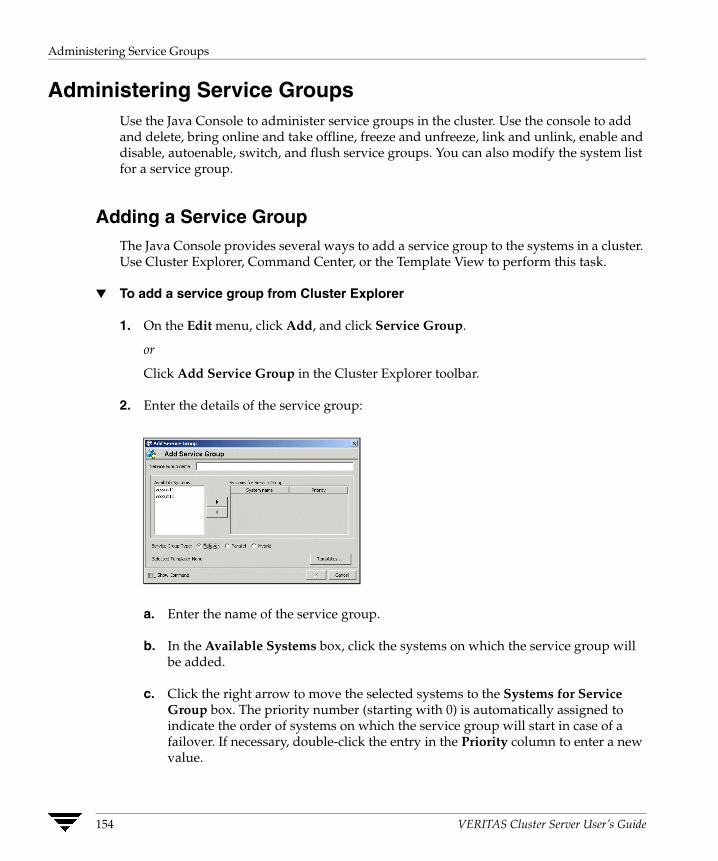
Administering Service Groups
Administering Service Groups Use the Java Console to administer service groups in the cluster. Use the console to add and delete, bring online and take offline, freeze and unfreeze, link and unlink, enable and disable, autoenable, switch, and flush service groups. You can also modify the system list for a service group.
Adding a Service Group The Java Console provides several ways to add a service group to the systems in a cluster. Use Cluster Explorer, Command Center, or the Template View to perform this task.
▼ To add a service group from Cluster Explorer
1. On the Edit menu, click Add, and click Service Group.
or
Click Add Service Group in the Cluster Explorer toolbar.
2. Enter the details of the service group:
a. Enter the name of the service group.
b. In the Available Systems box, click the systems on which the service group will be added.
c. Click the right arrow to move the selected systems to the Systems for Service Group box. The priority number (starting with 0) is automatically assigned to indicate the order of systems on which the service group will start in case of a failover. If necessary, double-click the entry in the Priority column to enter a new value.
154 VERITAS Cluster Server User’s Guide

Administering Service Groups
d. To add a new service group based on a template, click Templates. Otherwise, proceed to step 2g. (Alternative method to add a new service group based on a template: From Cluster Explorer, click Templates on the Tools menu. Right-click the Template View panel, and click Add as Service Group from the menu.)
e. Click the appropriate template name, then click OK.
f. Click the appropriate service group type. A failover service group runs on only one system at a time; a parallel service group runs concurrently on multiple systems.
g. Click Show Command in the bottom left corner if you want to view the command associated with the service group. Click Hide Command to close the view of the command.
h. Click OK.
Chapter 7, Administering the Cluster from Cluster Manager (Java Console) 155
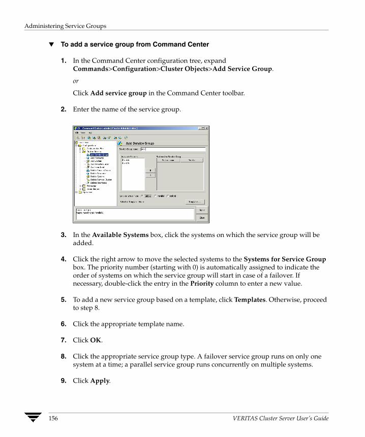
Administering Service Groups
▼ To add a service group from Command Center
1. In the Command Center configuration tree, expand Commands>Configuration>Cluster Objects>Add Service Group.
or
Click Add service group in the Command Center toolbar.
2. Enter the name of the service group.
3. In the Available Systems box, click the systems on which the service group will be added.
4. Click the right arrow to move the selected systems to the Systems for Service Group box. The priority number (starting with 0) is automatically assigned to indicate the order of systems on which the service group will start in case of a failover. If necessary, double-click the entry in the Priority column to enter a new value.
5. To add a new service group based on a template, click Templates. Otherwise, proceed to step 8.
6. Click the appropriate template name.
7. Click OK.
8. Click the appropriate service group type. A failover service group runs on only one system at a time; a parallel service group runs concurrently on multiple systems.
9. Click Apply.
156 VERITAS Cluster Server User’s Guide
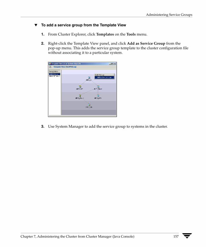
Administering Service Groups
▼ To add a service group from the Template View
1. From Cluster Explorer, click Templates on the Tools menu.
2. Right-click the Template View panel, and click Add as Service Group from the pop-up menu. This adds the service group template to the cluster configuration file without associating it to a particular system.
3. Use System Manager to add the service group to systems in the cluster.
Chapter 7, Administering the Cluster from Cluster Manager (Java Console) 157

Administering Service Groups
Deleting a Service Group Delete a service group from Cluster Explorer or Command Center.
Note You cannot delete service groups with dependencies. To delete a linked service group, you must first delete the link.
▼ To delete a service group from Cluster Explorer
1. In the Service Groups tab of the configuration tree, right-click the service group.
or
Click a cluster in the configuration tree, click the Service Groups tab, and right-click the service group icon in the view panel.
2. Click Delete from the menu.
3. Click Yes.
▼ To delete a service group from Command Center
1. In the Command Center configuration tree, expand Commands>Configuration>Cluster Objects>Delete Service Group.
2. Click the service group.
3. Click Apply.
158 VERITAS Cluster Server User’s Guide
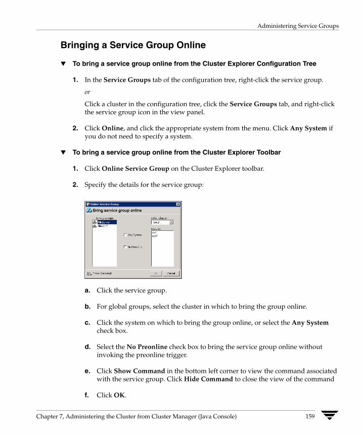
Administering Service Groups
Bringing a Service Group Online
▼ To bring a service group online from the Cluster Explorer Configuration Tree
1. In the Service Groups tab of the configuration tree, right-click the service group.
or
Click a cluster in the configuration tree, click the Service Groups tab, and right-click the service group icon in the view panel.
2. Click Online, and click the appropriate system from the menu. Click Any System if you do not need to specify a system.
▼ To bring a service group online from the Cluster Explorer Toolbar
1. Click Online Service Group on the Cluster Explorer toolbar.
2. Specify the details for the service group:
a. Click the service group.
b. For global groups, select the cluster in which to bring the group online.
c. Click the system on which to bring the group online, or select the Any System check box.
d. Select the No Preonline check box to bring the service group online without invoking the preonline trigger.
e. Click Show Command in the bottom left corner to view the command associated with the service group. Click Hide Command to close the view of the command
f. Click OK.
Chapter 7, Administering the Cluster from Cluster Manager (Java Console) 159
Administering Service Groups
▼ To bring a service group online from Command Center
1. In the Command Center configuration tree, expand Commands>Operations>Controls>Online Service Group.
or
Click Bring service group online in the Command Center toolbar.
2. Click the service group.
3. For global groups, select the cluster in which to bring the group online.
4. Click the system on which to bring the group online, or select the Any System check box.
5. Click Apply.
160 VERITAS Cluster Server User’s Guide
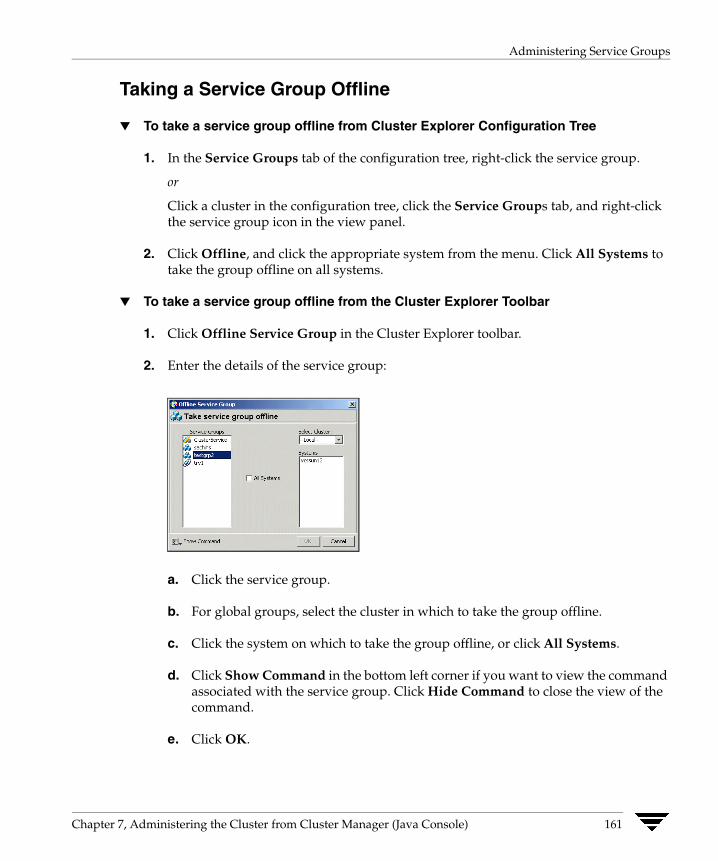
Administering Service Groups
Taking a Service Group Offline
▼ To take a service group offline from Cluster Explorer Configuration Tree
1. In the Service Groups tab of the configuration tree, right-click the service group.
or
Click a cluster in the configuration tree, click the Service Groups tab, and right-click the service group icon in the view panel.
2. Click Offline, and click the appropriate system from the menu. Click All Systems to take the group offline on all systems.
▼ To take a service group offline from the Cluster Explorer Toolbar
1. Click Offline Service Group in the Cluster Explorer toolbar.
2. Enter the details of the service group:
a. Click the service group.
b. For global groups, select the cluster in which to take the group offline.
c. Click the system on which to take the group offline, or click All Systems.
d. Click Show Command in the bottom left corner if you want to view the command associated with the service group. Click Hide Command to close the view of the command.
e. Click OK.
Chapter 7, Administering the Cluster from Cluster Manager (Java Console) 161
Administering Service Groups
▼ To take a service group offline from Command Center
1. In the Command Center configuration tree, expand Commands>Operations>Controls>Offline Service Group.
or
Click Take service group offline in the Command Center toolbar.
2. Click the service group.
3. For global groups, select the cluster in which to take the group offline.
4. Click the system on which to take the group offline, or click the All Systems check box.
5. Click Apply.
162 VERITAS Cluster Server User’s Guide
Administering Service Groups
Switching a Service Group The process of switching a service group involves taking it offline on its current system and bringing it online on another system.
▼ To switch a service group from Cluster Explorer
1. In the Service Groups tab of the configuration tree, right-click the service group.
or
Click the cluster in the configuration tree, click the Service Groups tab, and right-click the service group icon in the view panel.
2. Click Switch To, and click the appropriate system from the menu.
▼ To switch a service group from Command Center
1. In the Command Center configuration tree, expand Commands>Operations>Controls>Switch Service Group.
2. Click the service group.
3. For global groups, select the cluster in which to switch the service group.
4. Click the system on which to bring the group online, or select the Any System check box.
5. Click Apply.
Chapter 7, Administering the Cluster from Cluster Manager (Java Console) 163

Administering Service Groups
Freezing a Service Group Freeze a service group to prevent it from failing over to another system. This freezing process stops all online and offline procedures on the service group.
▼ To freeze a service group from Cluster Explorer
1. In the Service Groups tab of the configuration tree, right-click the service group.
or
Click the cluster in the configuration tree, click the Service Groups tab, and right-click the service group icon in the view panel.
2. Click Freeze, and click Temporary or Persistent from the menu. The persistent option maintains the frozen state after a reboot if the user saves this change to the configuration.
▼ To freeze a service group from Command Center
1. In the Command Center configuration tree, expand Commands>Operations>Availability>Freeze Service Group.
2. Click the service group.
3. Select the persistent check box if necessary. The persistent option maintains the frozen state after a reboot if the user saves this change to the configuration.
4. Click Apply.
164 VERITAS Cluster Server User’s Guide

Administering Service Groups
Unfreezing a Service Group Unfreeze a frozen service group to perform online or offline operations on the service group.
▼ To unfreeze a service group from Cluster Explorer
1. In the Service Groups tab of the configuration tree, right-click the service group.
or
Click the cluster in the configuration tree, click the Service Groups tab, and right-click the service group icon in the view panel.
2. Click Unfreeze.
▼ To unfreeze a service group from Command Center
1. In the Command Center configuration tree, expand Commands>Operations>Availability>Unfreeze Service Group.
2. Click the service group.
3. Click Apply.
Chapter 7, Administering the Cluster from Cluster Manager (Java Console) 165

Administering Service Groups
Enabling a Service Group Enable a service group before bringing it online. A service group that was manually disabled during a maintenance procedure on a system may need to be brought online after the procedure is completed.
▼ To enable a service group from Cluster Explorer
1. In the Service Groups tab of the configuration tree, right-click the service group.
or
Click the cluster in the configuration tree, click the Service Groups tab, and right-click the service group icon in the view panel.
2. Click Enable, and click the appropriate system from the menu. Click all to enable the group on all systems.
▼ To enable a service group from Command Center
1. In the Command Center configuration tree, expand Commands>Operations>Availability>Enable Service Group.
2. Click the service group.
3. Select the Per System check box to enable the group on a specific system instead of all systems.
4. Click Apply.
166 VERITAS Cluster Server User’s Guide
Administering Service Groups
Disabling a Service Group Disable a service group to prevent it from coming online. This process temporarily stops VCS from monitoring a service group on a system undergoing maintenance operations.
▼ To disable a service group from Cluster Explorer
1. In the Service Groups tab of the configuration tree, right-click the service group.
or
Click the cluster in the configuration tree, click the Service Groups tab, and right-click the service group icon in the view panel.
2. Click Disable, and click the appropriate system in the menu. Click all to disable the group on all systems.
▼ To disable a service group from Command Center
1. In the Command Center configuration tree, expand Commands>Operations>Availability>Disable Service Group.
2. Click the service group.
3. Select the Per System check box to disable the group on a specific system instead of all systems.
4. Click Apply.
Chapter 7, Administering the Cluster from Cluster Manager (Java Console) 167

Administering Service Groups
Autoenabling a Service Group A service group is autodisabled until VCS probes all resources and checks that they are ready to bring online. Autoenable a service group in situations where the VCS engine is not running on one of the systems in the cluster, and you must override the disabled state of the service group to enable the group on another system in the cluster.
▼ To autoenable a service group from Cluster Explorer
1. In the Service Groups tab of the configuration tree, right-click the service group.
or
Click the cluster in the configuration tree, click the Service Groups tab, and right-click the service group icon in the view panel.
2. Click Autoenable, and click the appropriate system from the menu.
▼ To autoenable a service group from Command Center
1. In the Command Center configuration tree, expand Commands>Operations>Availability>Autoenable Service Group.
2. Click the service group.
3. Click the system on which to autoenable the group.
4. Click Apply.
168 VERITAS Cluster Server User’s Guide
Administering Service Groups
Flushing a Service Group As a service group is brought online or taken offline, the resources within the group are brought online and taken offline. If the online or offline operation hangs on a particular resource, flush the service group to halt the operation on the resources waiting to go online or offline. Flushing a service group typically leaves the cluster in a partial state. After completing this process, resolve the issue with the particular resource (if necessary) and proceed with starting or stopping the service group.
▼ To flush a service group from Cluster Explorer
1. In the Service Groups tab of the configuration tree, right-click the service group.
or
Click the cluster in the configuration tree, click the Service Groups tab, and right-click the service group icon in the view panel.
2. Click Flush, and click the appropriate system from the menu.
▼ To flush a service group from Command Center
1. In the Command Center configuration tree, expand Commands>Operations>Availability>Flush Service Group.
2. Click the service group.
3. Click the system on which to flush the service group.
4. Click Apply.
Chapter 7, Administering the Cluster from Cluster Manager (Java Console) 169
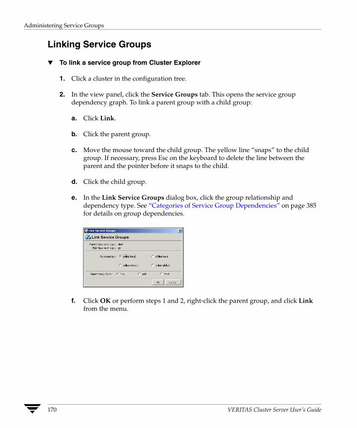
Administering Service Groups
Linking Service Groups
▼ To link a service group from Cluster Explorer
1. Click a cluster in the configuration tree.
2. In the view panel, click the Service Groups tab. This opens the service group dependency graph. To link a parent group with a child group:
a. Click Link.
b. Click the parent group.
c. Move the mouse toward the child group. The yellow line “snaps” to the child group. If necessary, press Esc on the keyboard to delete the line between the parent and the pointer before it snaps to the child.
d. Click the child group.
e. In the Link Service Groups dialog box, click the group relationship and dependency type. See “Categories of Service Group Dependencies” on page 385 for details on group dependencies.
f. Click OK or perform steps 1 and 2, right-click the parent group, and click Link from the menu.
170 VERITAS Cluster Server User’s Guide

Administering Service Groups
g. Click the child group, relationship, and dependency type. See “Categories of Service Group Dependencies” on page 385 for details on group dependencies.
h. Click OK.
▼ To link a service group from Command Center
1. In the Command Center configuration tree, expand Commands>Configuration>Dependencies>Link Service Groups.
2. Click the parent resource group in the Service Groups box. After selecting the parent group, the potential groups that can serve as child groups are displayed in the Child Service Groups box.
3. Click a child service group.
4. Click the group relationship and dependency type. See Chapter 13 for details on group dependencies.
5. Click Apply.
Chapter 7, Administering the Cluster from Cluster Manager (Java Console) 171

Administering Service Groups
Unlinking Service Groups
▼ To delete a service group dependency from Cluster Explorer
1. Click a cluster in the configuration tree.
2. In the view panel, click the Service Groups tab.
3. In the Service Group View, right-click the link between the service groups.
4. Click Unlink from the menu.
5. Click Yes.
▼ To delete a service group dependency from Command Center
1. In the Command Center configuration tree, expand Commands>Configuration>Dependencies>Unlink Service Groups.
2. Click the parent resource group in the Service Groups box. After selecting the parent group, the corresponding child groups are displayed in the Child Service Groups box.
3. Click the child service group.
4. Click Apply.
172 VERITAS Cluster Server User’s Guide
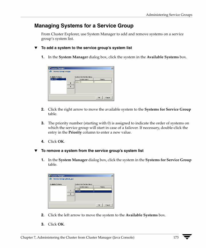
Administering Service Groups
Managing Systems for a Service Group From Cluster Explorer, use System Manager to add and remove systems on a service group’s system list.
▼ To add a system to the service group’s system list
1. In the System Manager dialog box, click the system in the Available Systems box.
2. Click the right arrow to move the available system to the Systems for Service Group table.
3. The priority number (starting with 0) is assigned to indicate the order of systems on which the service group will start in case of a failover. If necessary, double-click the entry in the Priority column to enter a new value.
4. Click OK.
▼ To remove a system from the service group’s system list
1. In the System Manager dialog box, click the system in the Systems for Service Group table.
2. Click the left arrow to move the system to the Available Systems box.
3. Click OK.
Chapter 7, Administering the Cluster from Cluster Manager (Java Console) 173

Administering Service Groups
Creating Service Groups with the Configuration Wizard This section describes how to create service groups using the Configuration Wizard.
Note VCS also provides wizards to create service groups for applications and NFS shares. See the chapter “Configuring Application and NFS Service Groups” on page 291 for more information about these wizards.
▼ To create a service group using the configuration wizard
1. Open the Configuration Wizard. From Cluster Explorer, click Configuration Wizard on the Tools menu.
2. Read the information on the Welcome screen and click Next.
3. Specify the name and target systems for the service group:
a. Enter the name of the group.
b. Click the target systems in the Available Systems box.
c. Click the right arrow to move the systems to the Systems for Service Group table. To remove a system from the table, click the system and click the left arrow.
d. The priority number (starting with 0) is automatically assigned to indicate the order of systems on which the service group will start in case of a failover. If necessary, double-click the entry in the Priority column to enter a new value.
e. Click the service group type.
4. Click Next.
174 VERITAS Cluster Server User’s Guide
Administering Service Groups
5. Click Next again to configure the service group with a template and proceed to step 7. Click Finish to add an empty service group to the selected cluster systems and configure it at a later time.
6. Click the template on which to base the new service group. The Templates box lists the templates available on the system to which Cluster Manager is connected. The resource dependency graph of the templates, the number of resources, and the resource types are also displayed.
7. Click Next. If a window notifies you that the name of the service group or resource within the service group is already in use, proceed to step 9. Otherwise, proceed to step 10.
8. Click Next to apply all of the new names listed in the table to resolve the name clash.
or
Modify the clashing names by entering text in the field next to the Apply button, clicking the location of the text for each name from the Correction drop-down list box, clicking Apply, and clicking Next.
9. Click Next to create the service group. A progress indicator displays the status.
10. After the service group is successfully created, click Next to edit attributes using the wizard and proceed to step 12. Click Finish to edit attributes at a later time using Cluster Explorer.
11. Review the attributes associated with the resources of the service group. If necessary, proceed to step 13 to modify the default values of the attributes. Otherwise, proceed to step 14 to accept the default values and complete the configuration.
12. Modify the values of the attributes (if necessary).
a. Click the resource.
b. Click the attribute to be modified.
c. Click the Edit icon at the end of the table row.
d. In the Edit Attribute dialog box, enter the attribute values.
e. Click OK.
f. Repeat the procedure for each resource and attribute.
13. Click Finish.
Chapter 7, Administering the Cluster from Cluster Manager (Java Console) 175

Administering Resources
Administering Resources Use the Java Console to administer resources in the cluster. Use the console to add and delete, bring online and take offline, probe, enable and disable, clear, and link and unlink resources. You can also import resource types to the configuration.
Adding a Resource The Java Console provides several ways to add a resource to a service group. Use Cluster Explorer or Command Center to perform this task.
▼ To add a resource from Cluster Explorer
1. On the Edit menu, click Add, and click Resource.
or
Click Add Resource in the Cluster Explorer toolbar.
2. Enter the details of the resource:
a. Enter the name of the resource.
b. Click the resource type.
c. Edit resource attributes according to your configuration. The Java Console also enables you to edit attributes after adding the resource.
d. Select the Critical and Enabled check boxes, if applicable. The Critical option is selected by default.
176 VERITAS Cluster Server User’s Guide
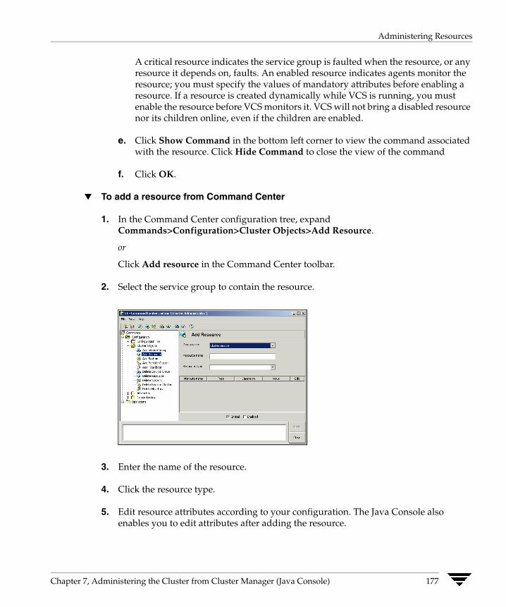
Administering Resources
A critical resource indicates the service group is faulted when the resource, or any resource it depends on, faults. An enabled resource indicates agents monitor the resource; you must specify the values of mandatory attributes before enabling a resource. If a resource is created dynamically while VCS is running, you must enable the resource before VCS monitors it. VCS will not bring a disabled resource nor its children online, even if the children are enabled.
e. Click Show Command in the bottom left corner to view the command associated with the resource. Click Hide Command to close the view of the command
f. Click OK.
▼ To add a resource from Command Center
1. In the Command Center configuration tree, expand Commands>Configuration>Cluster Objects>Add Resource.
or
Click Add resource in the Command Center toolbar.
2. Select the service group to contain the resource.
3. Enter the name of the resource.
4. Click the resource type.
5. Edit resource attributes according to your configuration. The Java Console also enables you to edit attributes after adding the resource.
Chapter 7, Administering the Cluster from Cluster Manager (Java Console) 177

Administering Resources
6. Select the Critical and Enabled check boxes, if applicable. The Critical option is selected by default.
A critical resource indicates the service group is faulted when the resource, or any resource it depends on, faults. An enabled resource indicates agents monitor the resource; you must specify the values of mandatory attributes before enabling a resource. If a resource is created dynamically while VCS is running, you must enable the resource before VCS monitors it. VCS will not bring a disabled resource nor its children online, even if the children are enabled.
7. Click Apply.
▼ To add a resource from the Template View
1. From Cluster Explorer, click Templates on the Tools menu.
2. In the left pane of the Template View, click the template from which to add resources to your configuration.
3. In the resource graph, right-click the resource to be added to your configuration.
4. Click Copy, and click Self from the menu to copy the resource. Click Copy, and click Self and Child Nodes from the menu to copy the resource with its dependent resources.
5. In the Service Groups tab of the Cluster Explorer configuration tree, click the service group to which to add the resources.
6. In the Cluster Explorer view panel, click the Resources tab.
7. Right-click the Resource View panel and click Paste from the menu. After the resources are added to the service group, edit the attributes to configure the resources.
178 VERITAS Cluster Server User’s Guide

Administering Resources
Deleting a Resource
▼ To delete a resource from Cluster Explorer
1. In the Service Groups tab of the configuration tree, right-click the resource.
or
Click a service group in the configuration tree, click the Resources tab, and right-click the resource icon in the view panel.
2. Click Delete from the menu.
3. Click Yes.
▼ To delete a resource from Command Center
1. In the Command Center configuration tree, expand Commands>Configuration>Cluster Objects>Delete Resource.
2. Click the resource.
3. Click Apply.
Chapter 7, Administering the Cluster from Cluster Manager (Java Console) 179

Administering Resources
Bringing a Resource Online
▼ To bring a resource online from Cluster Explorer
1. In the Service Groups tab of the configuration tree, right-click the resource.
or
Click a service group in the configuration tree, click the Resources tab, and right-click the resource icon in the view panel.
2. Click Online, and click the appropriate system from the menu.
▼ To bring a resource online from Command Center
1. In the Command Center configuration tree, expand Commands>Operations>Controls>Online Resource.
2. Click a resource.
3. Click a system on which to bring the resource online.
4. Click Apply.
180 VERITAS Cluster Server User’s Guide

Administering Resources
Taking a Resource Offline
▼ To take a resource offline from Cluster Explorer
1. In the Service Groups tab of the configuration tree, right-click the resource.
or
Click a service group in the configuration tree, click the Resources tab, and right-click the resource icon in the view panel.
2. Click Offline, and click the appropriate system from the menu.
▼ To take a resource offline from Command Center
1. In the Command Center configuration tree, expand Commands>Operations>Controls>Offline Resource.
2. Click a resource.
3. Click a system on which to take the resource offline.
4. If necessary, select the ignoreparent check box to take a selected child resource offline, regardless of the state of the parent resource. This option is only available through Command Center.
5. Click Apply.
Chapter 7, Administering the Cluster from Cluster Manager (Java Console) 181

Administering Resources
Taking a Resource Offline and Propagating the Command Use the Offline Propagate (OffProp) feature to propagate the offline state of a parent resource. This command signals that resources dependent on the parent resource should also be taken offline.
Use the Offline Propagate (OffProp) “ignoreparent” feature to take a selected resource offline, regardless of the state of the parent resource. This command propagates the offline state of the selected resource to the child resources. The “ignoreparent” option is only available in Command Center.
▼ To take a parent resource and its child resources offline from Cluster Explorer
1. In the Resources tab of the configuration tree, right-click the resource.
2. Click Offline Prop, and click the appropriate system from the menu.
▼ To take a parent resource and its child resources offline from Command Center
1. In the Command Center configuration tree, expand Commands>Operations>Controls>OffProp Resource.
2. Click the resource.
3. Click the system on which to offline the resource and its child resources.
4. Click Apply.
▼ To take child resources offline from Command Center while ignoring the state of the parent resource
1. In the Command Center configuration tree, expand Commands>Operations>Controls>OffProp Resource.
2. Click the resource.
3. Click the system on which to offline the resource and its child resources.
4. Select the ignoreparent check box.
5. Click Apply.
182 VERITAS Cluster Server User’s Guide

Administering Resources
Probing a Resource Probe a resource to check that it is configured and ready to bring online.
▼ To probe a resource from Cluster Explorer
1. In the Service Groups tab of the configuration tree, right-click the resource.
2. Click Probe, and click the appropriate system from the menu.
▼ To probe a resource from Command Center
1. In the Command Center configuration tree, expand Commands>Operations>Controls>Probe Resource.
2. Click the resource.
3. Click the system on which to probe the resource.
4. Click Apply.
Chapter 7, Administering the Cluster from Cluster Manager (Java Console) 183

Administering Resources
Overriding Resource Type Static Attributes You can override some resource type static attributes and assign them resource-specific values. When a static attribute is overridden and the configuration is saved, the main.cf file includes a line in the resource definition for the static attribute and its overridden value.
▼ To override a resource type’s static attribute
1. Right-click the resource in the Service Groups tab of the configuration tree or in the Resources tab of the view panel.
2. Click Override Attributes.
3. Select the attributes to override.
4. Click OK.
The selected attributes appear in the Overridden Attributes table in the Properties view for the resource.
5. To modify the default value of an overridden attribute, click the icon in the Edit column of the attribute.
▼ To restore default settings to a type’s static attribute
1. Right-click the resource in the Service Groups tab of the configuration tree or in the Resources tab of the view panel.
2. Click Remove Attribute Overrides.
3. Select the overridden attributes to be restored to their default settings.
4. Click OK.
184 VERITAS Cluster Server User’s Guide

Administering Resources
Enabling Resources in a Service Group Enable resources in a service group to bring the disabled resources online. A resource may have been manually disabled to temporarily stop VCS from monitoring the resource. You must specify the values of mandatory attributes before enabling a resource.
▼ To enable an individual resource in a service group
1. From Cluster Explorer, click the Service Groups tab of the configuration tree.
2. Right-click a disabled resource in the configuration tree, and click Enabled from the menu.
▼ To enable all resources in a service group from Cluster Explorer
1. From Cluster Explorer, click the Service Groups tab in the configuration tree.
2. Right-click the service group.
3. Click Enable Resources.
▼ To enable all resources in a service group from Command Center
1. In the Command Center configuration tree, expand Commands>Operations>Availability>Enable Resources for Service Group.
2. Click the service group.
3. Click Apply.
Chapter 7, Administering the Cluster from Cluster Manager (Java Console) 185
Administering Resources
Disabling Resources in a Service Group Disable resources in a service group to prevent them from coming online. This disabling process is useful when you want VCS to temporarily “ignore” resources (rather than delete them) while the service group is still online.
▼ To disable an individual resource in a service group
1. From Cluster Explorer, click the Service Groups tab in the Cluster Explorer configuration tree.
2. Right-click a resource in the configuration tree. An enabled resource will display a check mark next to the Enabled option that appears in the menu.
3. Click Enabled from the menu to clear this option.
▼ To disable all resources in a service group from Cluster Explorer
1. From Cluster Explorer, click the Service Groups tab in the configuration tree.
2. Right-click the service group and click Disable Resources.
▼ To disable all resources in a service group from Command Center
1. In the Command Center configuration tree, expand Commands>Operations>Availability>Disable Resources for Service Group.
2. Click the service group.
3. Click Apply.
186 VERITAS Cluster Server User’s Guide
Administering Resources
Clearing a Resource Clear a resource to remove a fault and make the resource available to go online. A resource fault can occur in a variety of situations, such as a power failure or a faulty configuration.
▼ To clear a resource from Cluster Explorer
1. In the Service Groups tab of the configuration tree, right-click the resource.
2. Click Clear, and click the system from the menu. Click Auto instead of a specific system to clear the fault on all systems where the fault occurred.
▼ To clear a resource from Command Center
1. In the Command Center configuration tree, expand Commands>Operations>Availability>Clear Resource.
2. Click the resource. To clear the fault on all systems listed in the Systems box, proceed to step 5. To clear the fault on a specific system, proceed to step 3.
3. Select the Per System check box.
4. Click the system on which to clear the resource.
5. Click Apply.
Chapter 7, Administering the Cluster from Cluster Manager (Java Console) 187

Administering Resources
Linking Resources Use Cluster Explorer or Command Center to link resources in a service group.
▼ To link resources from Cluster Explorer
1. In the configuration tree, click the Service Groups tab.
2. Click the service group to which the resources belong.
3. In the view panel, click the Resources tab. This opens the resource dependency graph. To link a parent resource with a child resource:
a. Click Link.
b. Click the parent resource.
c. Move the mouse towards the child resource. The yellow line “snaps” to the child resource. If necessary, press Esc to delete the line between the parent and the pointer before it snaps to the child.
d. Click the child resource.
e. In the Confirmation dialog box, click Yes.
or
Right-click the parent resource, and click Link from the menu. In the Link dialog box, click the resource that will serve as the child. Click OK.
f. Click OK.
188 VERITAS Cluster Server User’s Guide

Administering Resources
▼ To link resources from Command Center
1. In the Command Center configuration tree, expand Commands>Configuration>Dependencies>Link Resources.
2. Click the service group to contain the linked resources.
3. Click the parent resource in the Service Group Resources box. After selecting the parent resource, the potential resources that can serve as child resources are displayed in the Child Resources box.
4. Click a child resource.
5. Click Apply.
Chapter 7, Administering the Cluster from Cluster Manager (Java Console) 189
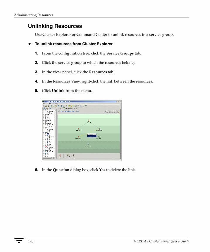
Administering Resources
Unlinking Resources Use Cluster Explorer or Command Center to unlink resources in a service group.
▼ To unlink resources from Cluster Explorer
1. From the configuration tree, click the Service Groups tab.
2. Click the service group to which the resources belong.
3. In the view panel, click the Resources tab.
4. In the Resources View, right-click the link between the resources.
5. Click Unlink from the menu.
6. In the Question dialog box, click Yes to delete the link.
190 VERITAS Cluster Server User’s Guide

Administering Resources
▼ To unlink resources from Command Center
1. In the Command Center configuration tree, expand Commands>Configuration>Dependencies>Unlink Resources.
2. Click the service group that contains the linked resources.
3. Click the parent resource in the Service Group Resources box. After selecting the parent resource, the corresponding child resources are displayed in the Child Resources box.
4. Click the child resource.
5. Click Apply.
Chapter 7, Administering the Cluster from Cluster Manager (Java Console) 191
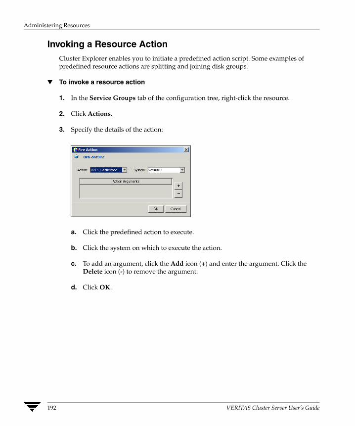
Administering Resources
Invoking a Resource Action Cluster Explorer enables you to initiate a predefined action script. Some examples of predefined resource actions are splitting and joining disk groups.
▼ To invoke a resource action
1. In the Service Groups tab of the configuration tree, right-click the resource.
2. Click Actions.
3. Specify the details of the action:
a. Click the predefined action to execute.
b. Click the system on which to execute the action.
c. To add an argument, click the Add icon (+) and enter the argument. Click the Delete icon (-) to remove the argument.
d. Click OK.
192 VERITAS Cluster Server User’s Guide
Administering Resources
Refreshing the ResourceInfo Attribute Refresh the ResourceInfo attribute to view the latest values for that attribute.
▼ To refresh the ResourceInfo attribute
1. In the Service Groups tab of the configuration tree, right-click the resource.
2. Click Refresh ResourceInfo, and click the system on which to refresh the attribute value.
Clearing the ResourceInfo Attribute Clear the ResourceInfo attribute to reset all the parameters in this attribute.
▼ To clear the parameters of the ResourceInfo attribute
1. In the Service Groups tab of the configuration tree, right-click the resource.
2. Click Clear ResourceInfo, and click the system on which to reset the attribute value.
Chapter 7, Administering the Cluster from Cluster Manager (Java Console) 193
Importing Resource Types
Importing Resource Types The Java Console enables you import resource types to your configuration (main.cf). For example, use this procedure to import the types.cf for enterprise agents to your configuration. You cannot import resource types that already exist in your configuration.
▼ To import a resource type from Cluster Explorer
1. On the File menu, click Import Types.
2. In the Import Types dialog box:
a. Click the file from which to import the resource type. The dialog box displays the files on the system that Cluster Manager is connected to.
b. Click Import.
194 VERITAS Cluster Server User’s Guide

Administering Systems
Administering Systems Use the Java Console to administer systems in the cluster. Use the console to add, delete, freeze, and unfreeze systems.
Adding a System Cluster Explorer and Command Center enable you to add a system to the cluster. A system must have an entry in the LLTTab configuration file before it can be added to the cluster.
▼ To add a system from Cluster Explorer
1. On the Edit menu, click Add, and click System.
or
Click Add System on the Cluster Explorer toolbar.
2. Enter the name of the system.
3. Click Show Command in the bottom left corner to view the command associated with the system. Click Hide Command to close the view of the command.
4. Click OK.
▼ To add a system from Command Center
1. Click Add System in the Command Center toolbar.
or
In the Command Center configuration tree, expand Commands>Configuration>Cluster Objects>Add System.
2. Enter the name of the system.
3. Click Apply.
Chapter 7, Administering the Cluster from Cluster Manager (Java Console) 195

Administering Systems
Deleting a System
▼ To delete a system from Command Center
1. In the Command Center configuration tree, expand Commands>Configuration>Cluster Objects>Delete System.
2. Click the system.
3. Click Apply.
196 VERITAS Cluster Server User’s Guide
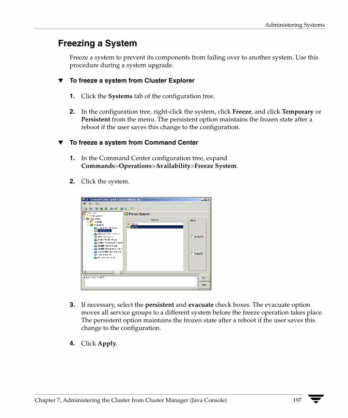
Administering Systems
Freezing a System Freeze a system to prevent its components from failing over to another system. Use this procedure during a system upgrade.
▼ To freeze a system from Cluster Explorer
1. Click the Systems tab of the configuration tree.
2. In the configuration tree, right-click the system, click Freeze, and click Temporary or Persistent from the menu. The persistent option maintains the frozen state after a reboot if the user saves this change to the configuration.
▼ To freeze a system from Command Center
1. In the Command Center configuration tree, expand Commands>Operations>Availability>Freeze System.
2. Click the system.
3. If necessary, select the persistent and evacuate check boxes. The evacuate option moves all service groups to a different system before the freeze operation takes place. The persistent option maintains the frozen state after a reboot if the user saves this change to the configuration.
4. Click Apply.
Chapter 7, Administering the Cluster from Cluster Manager (Java Console) 197

Administering Systems
Unfreezing a System Unfreeze a frozen system to perform online and offline operations on the system.
▼ To unfreeze a system from Cluster Explorer
1. Click the Systems tab of the configuration tree.
2. In the configuration tree, right-click the system and click Unfreeze.
▼ To unfreeze a system from Command Center
1. In the Command Center configuration tree, expand Commands>Operations>Availability>Unfreeze System.
2. Click the system.
3. Click Apply.
198 VERITAS Cluster Server User’s Guide
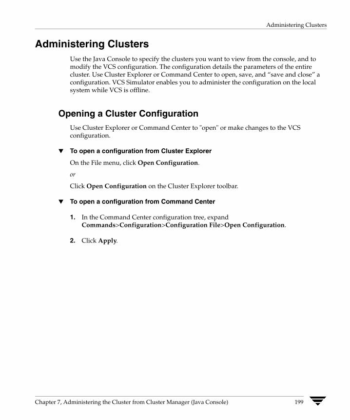
Administering Clusters
Administering Clusters Use the Java Console to specify the clusters you want to view from the console, and to modify the VCS configuration. The configuration details the parameters of the entire cluster. Use Cluster Explorer or Command Center to open, save, and “save and close” a configuration. VCS Simulator enables you to administer the configuration on the local system while VCS is offline.
Opening a Cluster Configuration Use Cluster Explorer or Command Center to "open" or make changes to the VCS configuration.
▼ To open a configuration from Cluster Explorer
On the File menu, click Open Configuration.
or
Click Open Configuration on the Cluster Explorer toolbar.
▼ To open a configuration from Command Center
1. In the Command Center configuration tree, expand Commands>Configuration>Configuration File>Open Configuration.
2. Click Apply.
Chapter 7, Administering the Cluster from Cluster Manager (Java Console) 199

Administering Clusters
Saving a Cluster Configuration After updating the VCS configuration, use Cluster Explorer or Command Center to save the latest configuration to disk while maintaining the configuration state in read-write mode.
▼ To save a configuration from Cluster Explorer
On the File menu, click Save Configuration.
or
Click Save Configuration on the Cluster Explorer toolbar.
▼ To save a configuration from Command Center
1. In the Command Center configuration tree, expand Commands>Configuration>Configuration File>Save Configuration.
2. Click Apply.
200 VERITAS Cluster Server User’s Guide
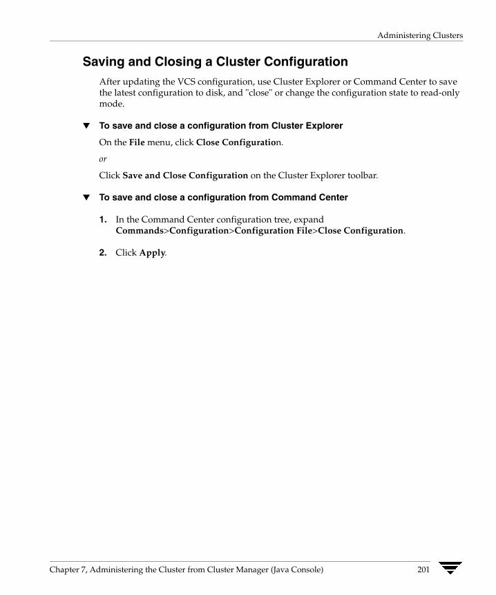
Administering Clusters
Saving and Closing a Cluster Configuration After updating the VCS configuration, use Cluster Explorer or Command Center to save the latest configuration to disk, and "close" or change the configuration state to read-only mode.
▼ To save and close a configuration from Cluster Explorer
On the File menu, click Close Configuration.
or
Click Save and Close Configuration on the Cluster Explorer toolbar.
▼ To save and close a configuration from Command Center
1. In the Command Center configuration tree, expand Commands>Configuration>Configuration File>Close Configuration.
2. Click Apply.
Chapter 7, Administering the Cluster from Cluster Manager (Java Console) 201
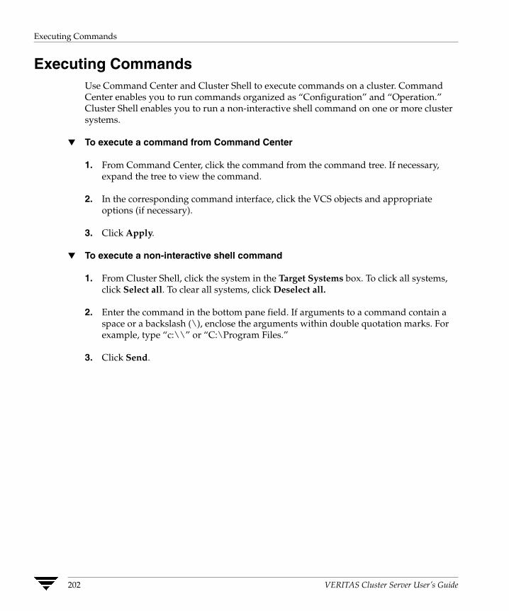
Executing Commands
Executing Commands Use Command Center and Cluster Shell to execute commands on a cluster. Command Center enables you to run commands organized as “Configuration” and “Operation.” Cluster Shell enables you to run a non-interactive shell command on one or more cluster systems.
▼ To execute a command from Command Center
1. From Command Center, click the command from the command tree. If necessary, expand the tree to view the command.
2. In the corresponding command interface, click the VCS objects and appropriate options (if necessary).
3. Click Apply.
▼ To execute a non-interactive shell command
1. From Cluster Shell, click the system in the Target Systems box. To click all systems, click Select all. To clear all systems, click Deselect all.
2. Enter the command in the bottom pane field. If arguments to a command contain a space or a backslash (\), enclose the arguments within double quotation marks. For example, type “c:\\” or “C:\Program Files.”
3. Click Send.
202 VERITAS Cluster Server User’s Guide
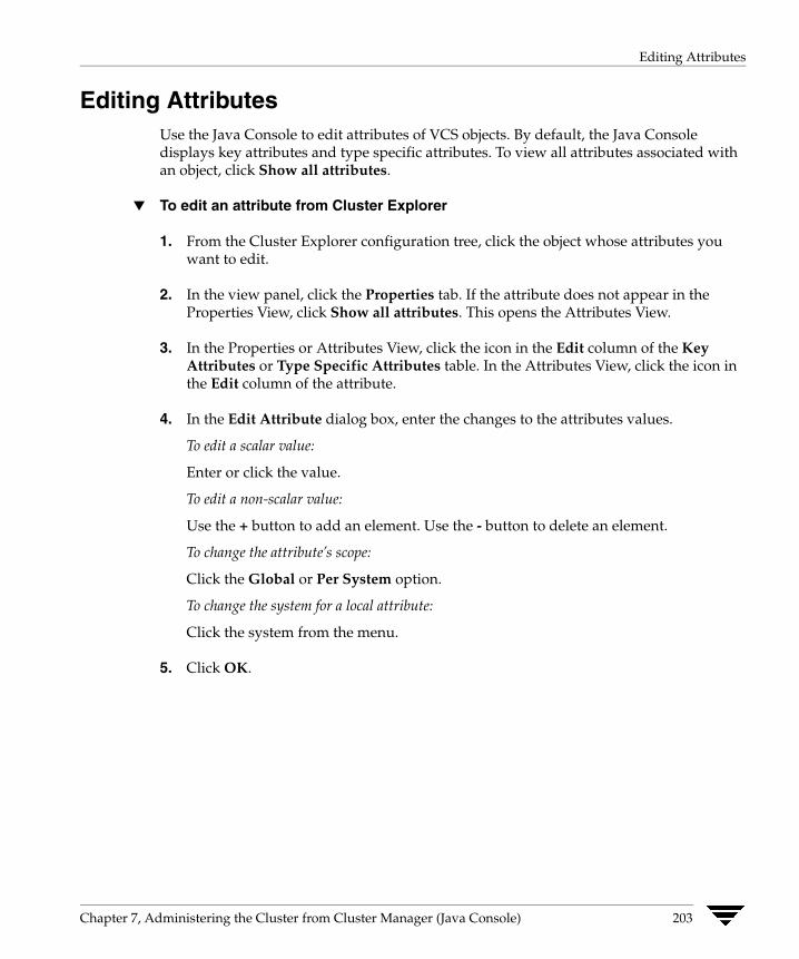
Editing Attributes
Editing Attributes Use the Java Console to edit attributes of VCS objects. By default, the Java Console displays key attributes and type specific attributes. To view all attributes associated with an object, click Show all attributes.
▼ To edit an attribute from Cluster Explorer
1. From the Cluster Explorer configuration tree, click the object whose attributes you want to edit.
2. In the view panel, click the Properties tab. If the attribute does not appear in the Properties View, click Show all attributes. This opens the Attributes View.
3. In the Properties or Attributes View, click the icon in the Edit column of the Key Attributes or Type Specific Attributes table. In the Attributes View, click the icon in the Edit column of the attribute.
4. In the Edit Attribute dialog box, enter the changes to the attributes values.
To edit a scalar value:
Enter or click the value.
To edit a non-scalar value:
Use the + button to add an element. Use the - button to delete an element.
To change the attribute’s scope:
Click the Global or Per System option.
To change the system for a local attribute:
Click the system from the menu.
5. Click OK.
Chapter 7, Administering the Cluster from Cluster Manager (Java Console) 203
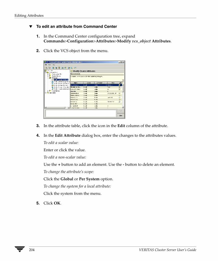
Editing Attributes
▼ To edit an attribute from Command Center
1. In the Command Center configuration tree, expand Commands>Configuration>Attributes>Modify vcs_object Attributes.
2. Click the VCS object from the menu.
3. In the attribute table, click the icon in the Edit column of the attribute.
4. In the Edit Attribute dialog box, enter the changes to the attributes values.
To edit a scalar value:
Enter or click the value.
To edit a non-scalar value:
Use the + button to add an element. Use the - button to delete an element.
To change the attribute’s scope:
Click the Global or Per System option.
To change the system for a local attribute:
Click the system from the menu.
5. Click OK.
204 VERITAS Cluster Server User’s Guide

Querying the Cluster Configuration
Querying the Cluster Configuration
1. From Cluster Explorer, click Query on the Tools menu.
or
On the Cluster Explorer toolbar, click Query.
2. Enter the details of the query:
a. Click the VCS object to search.
b. Depending on the selected object, click the specific entity to search.
c. Click the appropriate phrase or symbol between the search item and value.
d. Click the appropriate value for the specified query. Certain queries allow the user to enter specific filter information:
Click System, click Online Group Count, click <, and type the required value in the blank field.
or
Click Resource, click [provide attribute name] and type in the name of an attribute, click = or contains, and type the appropriate value of the attribute in the blank field. For example, click Resource, click [provide attribute name] and type in pathname, click contains, and type c:\temp in the blank field.
e. To use additional queries, click + as many times as necessary to select the appropriate options. Click - to reduce the number of queries.
f. Click AND or OR for each filter selection.
g. Click Search. The results appear in tabular format at the bottom of the dialog box. To search a new item, click Reset to reset the dialog box to its original blank state.
Chapter 7, Administering the Cluster from Cluster Manager (Java Console) 205
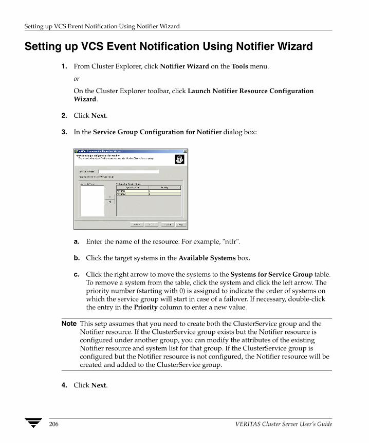
Setting up VCS Event Notification Using Notifier Wizard
Setting up VCS Event Notification Using Notifier Wizard
1. From Cluster Explorer, click Notifier Wizard on the Tools menu.
or
On the Cluster Explorer toolbar, click Launch Notifier Resource Configuration Wizard.
2. Click Next.
3. In the Service Group Configuration for Notifier dialog box:
a. Enter the name of the resource. For example, "ntfr".
b. Click the target systems in the Available Systems box.
c. Click the right arrow to move the systems to the Systems for Service Group table. To remove a system from the table, click the system and click the left arrow. The priority number (starting with 0) is assigned to indicate the order of systems on which the service group will start in case of a failover. If necessary, double-click the entry in the Priority column to enter a new value.
Note This setp assumes that you need to create both the ClusterService group and the Notifier resource. If the ClusterService group exists but the Notifier resource is configured under another group, you can modify the attributes of the existing Notifier resource and system list for that group. If the ClusterService group is configured but the Notifier resource is not configured, the Notifier resource will be created and added to the ClusterService group.
4. Click Next.
206 VERITAS Cluster Server User’s Guide
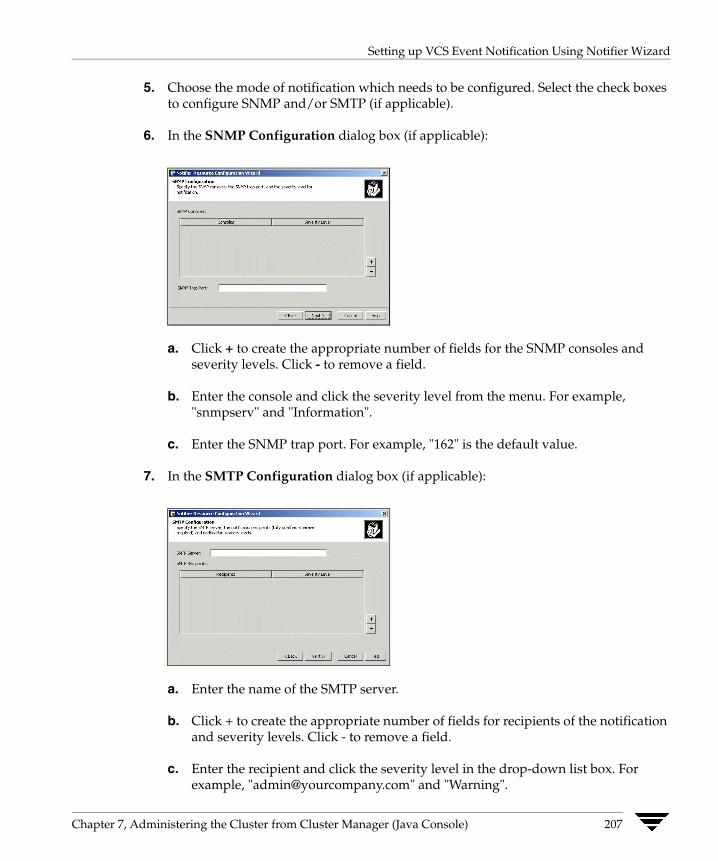
Setting up VCS Event Notification Using Notifier Wizard
5. Choose the mode of notification which needs to be configured. Select the check boxes to configure SNMP and/or SMTP (if applicable).
6. In the SNMP Configuration dialog box (if applicable):
a. Click + to create the appropriate number of fields for the SNMP consoles and severity levels. Click - to remove a field.
b. Enter the console and click the severity level from the menu. For example, "snmpserv" and "Information".
c. Enter the SNMP trap port. For example, "162" is the default value.
7. In the SMTP Configuration dialog box (if applicable):
a. Enter the name of the SMTP server.
b. Click + to create the appropriate number of fields for recipients of the notification and severity levels. Click - to remove a field.
c. Enter the recipient and click the severity level in the drop-down list box. For example, "[email protected]" and "Warning".
Chapter 7, Administering the Cluster from Cluster Manager (Java Console) 207
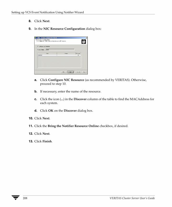
Setting up VCS Event Notification Using Notifier Wizard
8. Click Next.
9. In the NIC Resource Configuration dialog box:
a. Click Configure NIC Resource (as recommended by VERITAS). Otherwise, proceed to step 10.
b. If necessary, enter the name of the resource.
c. Click the icon (...) in the Discover column of the table to find the MACAddress for each system.
d. Click OK on the Discover dialog box.
10. Click Next.
11. Click the Bring the Notifier Resource Online checkbox, if desired.
12. Click Next.
13. Click Finish.
208 VERITAS Cluster Server User’s Guide
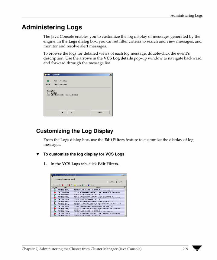
Administering Logs
Administering Logs The Java Console enables you to customize the log display of messages generated by the engine. In the Logs dialog box, you can set filter criteria to search and view messages, and monitor and resolve alert messages.
To browse the logs for detailed views of each log message, double-click the event’s description. Use the arrows in the VCS Log details pop-up window to navigate backward and forward through the message list.
Customizing the Log Display From the Logs dialog box, use the Edit Filters feature to customize the display of log messages.
▼ To customize the log display for VCS Logs
1. In the VCS Logs tab, click Edit Filters.
Chapter 7, Administering the Cluster from Cluster Manager (Java Console) 209

Administering Logs
2. Enter the filter criteria:
a. Click the types of logs to appear on the message display.
b. From the Logs of list, select the category of log messages to display.
c. From the Named menu, select the name of the selected object or component. Toview all the messages for the selected category, click All.
d. In the Logs from last field, enter the numerical value and select the time unit.
e. To search log messages, enter the search string. Select the Whole String check box, if required.
f. Click OK.
210 VERITAS Cluster Server User’s Guide
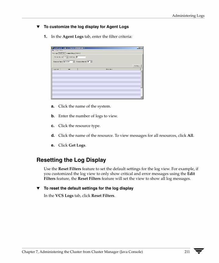
Administering Logs
▼ To customize the log display for Agent Logs
1. In the Agent Logs tab, enter the filter criteria:
a. Click the name of the system.
b. Enter the number of logs to view.
c. Click the resource type.
d. Click the name of the resource. To view messages for all resources, click All.
e. Click Get Logs.
Resetting the Log Display Use the Reset Filters feature to set the default settings for the log view. For example, if you customized the log view to only show critical and error messages using the Edit Filters feature, the Reset Filters feature will set the view to show all log messages.
▼ To reset the default settings for the log display
In the VCS Logs tab, click Reset Filters.
Chapter 7, Administering the Cluster from Cluster Manager (Java Console) 211

Administering Logs
Monitoring Alerts The Java Console sends automatic alerts that require administrative action and are displayed on the Alerts tab of the Logs dialog box. Use this tab to take action on the alert or delete the alert.
▼ To take action on an alert
1. In the Alert tab or dialog box, click the alert to take action on.
2. Click Take Action.
3. Enter the required information to resolve the alert.
If the alert warns that a local group cannot fail over to any system in the local cluster, the user cannot take action.
If the alert warns that a global group cannot fail over, the action involves bringing the group online on another system in the global cluster environment.
If the alert warns that a global cluster is faulted, the action involves declaring the cluster as a disaster, disconnect, or outage, and determining the service groups to fail over to another cluster.
4. Click OK.
212 VERITAS Cluster Server User’s Guide
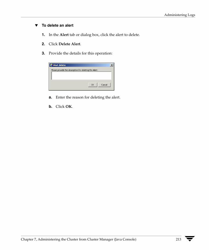
Administering Logs
▼ To delete an alert
1. In the Alert tab or dialog box, click the alert to delete.
2. Click Delete Alert.
3. Provide the details for this operation:
a. Enter the reason for deleting the alert.
b. Click OK.
Chapter 7, Administering the Cluster from Cluster Manager (Java Console) 213
Administering VCS Simulator
Administering VCS Simulator VCS Simulator enables you to view state transitions, experiment with configuration parameters, and predict how service groups will behave during cluster or system faults. Use this tool to create and save configurations in an OFFLINE state.
Through the Java Console, VCS Simulator enables you to configure a simulated cluster panel, bring a system in an unknown state into an online state, simulate power loss for running systems, simulate resource faults, and save the configuration while VCS is offline.
For global clusters, you can simulate the process of generating and clearing cluster faults.
You can run multiple simulated clusters on a system by using different port numbers for each cluster. The Java Console provides the same views and features that are available for online configurations
See “Predicting VCS Behavior Using VCS Simulator” on page 541 for more information.
214 VERITAS Cluster Server User’s Guide
Administering the Cluster from Cluster Manager (Web Console)
8Cluster Manager (Web Console) offers web-based administration capabilities for your cluster. Use the Web Console to monitor clusters and cluster objects, including service groups, systems, resources, and resource types. Many of the operations supported by the Web Console are also supported by the command line interface and Cluster Manager (Java Console).
The Web Console uses a Web Server component called VRTSweb. See the appendix “Administering VERITAS Web Server” on page 669 for more information about VRTSweb.
Disability Compliance Cluster Manager (Web Console) for VCS provides disabled individuals access to and use of information and data that is comparable to the access and use provided to non-disabled individuals, including:
◆ Alternate keyboard sequences for specific operations (see matrix in appendix “Accessibility and VCS”).
◆ High-contrast display settings.
◆ Support of third-party accessibility tools.
◆ Text-only display of frequently viewed windows.
215

Before Using the Web Console
Before Using the Web Console ✔ By default, the Web Console requires three exclusive ports: 8181, 8443 and 14300.
Verify that no other applications are bound to these ports. If this is not possible, review “Configuring Ports for VRTSweb” on page 672.
✔ You can configure the Web Console in the cluster or outside of the cluster. See “Setting up the Web Console: Inside or Outside the Cluster” on page 217.
✔ Review the ClusterService service group configuration to verify that the group is online. For more information, see “Configuring the Web Console Manually” on page 217.
✔ Install the Internet Explorer (5.0, 5.5, or 6.0) or Netscape (6.2 or 7.0) browser on the system from which you will monitor and administer the cluster. The console requires the Java plug-in enabled on the client browser. If the Java plug-in is not already enabled on Netscape, you must download the plug-in from Netscape and configure it according to the instructions on the site.
✔ On Solaris systems, verify the Web Console is running on Solaris 2.7 or higher systems.
✔ To run the Web Console from a .Net client, change the IE security level for the zone to Medium-Low.
✔ Verify that cookies are enabled for the browser.
216 VERITAS Cluster Server User’s Guide

Before Using the Web Console
Setting up the Web Console: Inside or Outside the Cluster VCS enables you to set up the Web Console within a clustered environment or on a standalone server.
◆ If you configure the Web Console while installing VCS, the console is installed on all systems in the cluster. The console is configured under the ClusterService group; this group can fail over to another system in the cluster, making the console highly available. VCS controls the starting and stopping of the Web Console.
◆ If you do not configure the Web Console while installing VCS, you can install it on a standalone server by manually installing the VRTSweb, VRTSjre, and VRTSvcsw packages. After installing the packages, use the /opt/VRTSweb/bin/startApp vcs command to start the console and the /opt/VRTSweb/bin/stopApp vcs command to stop the console.
This setup outside the cluster does not provide high availability for the console. You must have administrative privileges on the system to start and stop the Web Console.
Configuring the Web Console Manually The resources required for Cluster Manager (Web Console) are configured in the ClusterService group. You must create and configure the ClusterService service group manually if you did not enable the Cluster Manager (Web Console) option while installing VCS.
▼ To configure the Web Console
1. Create a service group called ClusterService.
2. Add a resource of type NIC to the service group. Name the resource csgnic. Set the value of the Device attribute to the name of the NIC. Configure other attributes, if desired.
3. Add a resource of type IP to the service group. Name the resource webip. Configure the following attributes for the resource:
◆ Address: A virtual IP address assigned to VCS Cluster Manager (Web Console.) The Web Console is accessed using this IP address.
◆ Device: The name of the public network card on the system from which the Web Console will run. Device is defined as a local attribute for each system in the cluster.
◆ NetMask: The subnet to which the virtual IP address belongs.
◆ Critical: Set this attribute to True to make webip a critical resource.
Chapter 8, Administering the Cluster from Cluster Manager (Web Console) 217

Before Using the Web Console
4. Link the NIC and IP resources, making the IP resource the parent resource.
5. Add a resource of type VRTSWebApp to the service group. Name the resource VCSweb. Configure the following attributes for the resource:
◆ Appname: Set to vcs.
◆ InstallDir: Set to /opt/VRTSweb/VERITAS.
◆ TimeForOnline: Set to 5.
◆ Critical: Set to False.
6. Link the VCSweb and webip resources, making VCSweb the parent resource.
7. Enable both resources.
8. Bring the ClusterService service group online.
218 VERITAS Cluster Server User’s Guide

Before Using the Web Console
Sample Configuration
group ClusterService (SystemList = { vcssol5, vcssol6 }AutoStartList = { vcssol5, vcssol6 }OnlineRetryLimit = 3
)
IP webip (Address = "162.39.9.85"NetMask = "255.255.255.0"Device = "qfe0"
)
VRTSWebApp VCSweb (AppName = "vcs"InstallDir = "/opt/VRTSweb/VERITAS"TimeForOnline = 5Critical = 0
)
VCSweb requires webipVCSweb requires csgnic
Chapter 8, Administering the Cluster from Cluster Manager (Web Console) 219

Before Using the Web Console
Java Plug-in Requirements for the Console The console requires the Java Plug-in enabled on the client browser (Internet Explorer or Netscape).
▼ To confirm the Java Plug-in is enabled on IE
1. From the Tools menu on IE, click Internet Options.
2. In the Advanced tab, verify the JIT compiler for virtual machine enabled check box is selected under Microsoft VM.
VERITAS recommends using Microsoft VM on IE instead of any available Java (Sun) Plug-in. If the IE 6.0 browser does not provide a Microsoft VM option on the Advanced tab, you must download the Java Plug-in from http://java.sun.com/products/plugin/index-1.4.html. You can install any version prior to 1.4.2 on the client. VERITAS recommends using version 1.4.1_x.
If the IE 5.5 or 6.0 browser stops responding or “hangs” after logging on to a cluster through the Web Console, verify the type of Java Plug-in used by the browser on the Advanced tab described above.
▼ To disable a Java (Sun) Plug-in on IE
1. Clear the Use Java 2 v1.4.2_x for <applet> check box under Java (Sun) on the Advanced tab.
2. Select the JIT compiler for virtual machine enabled check box under Microsoft VM and click OK. If Microsoft VM is not an available option, check that the system is running only one Java Runtime Environment. If multiple JREs are installed on the client, uninstall the earlier versions and keep the latest version. VERITAS recommends using JRE 1.4.1.
If the Java Plug-in is not enabled on Netscape 6.2. or 7.0, you must download the Plug-in from the Netscape Web site (http://wp.netscape.com/plugins/jvm.html) and configure it according to the instructions on the site. Use any Java Plug-in prior to version 1.4.2_x.
220 VERITAS Cluster Server User’s Guide

Before Using the Web Console
Connecting to the Web Console The method of accessing the Web Console depends on the location of the console. You must use a valid VCS user name and password to log on to a cluster.
◆ If the console is set up inside the cluster, use the following URL to access the console:
http://virtual_IP:8181/vcs/index.html
The variable virtual_IP is the virtual IP address configured for the webip resource in the ClusterService service group, and the number 8181 is the default VERITAS Web port.
◆ If the console is set up outside the cluster, use the following URL to access the console:
http://system_alias:8181/vcs/index.html
The variable system_alias is either the name or IP address of the system on which the console is configured, and the number 8181 is the default VERITAS Web port.
Note Certain cluster operations are enabled or restricted depending on the privileges with which you log on to VCS. For information about the specific privileges associated with VCS users, see the appendix “VCS User Privileges—Administration Matrices” on page 597.
Chapter 8, Administering the Cluster from Cluster Manager (Web Console) 221
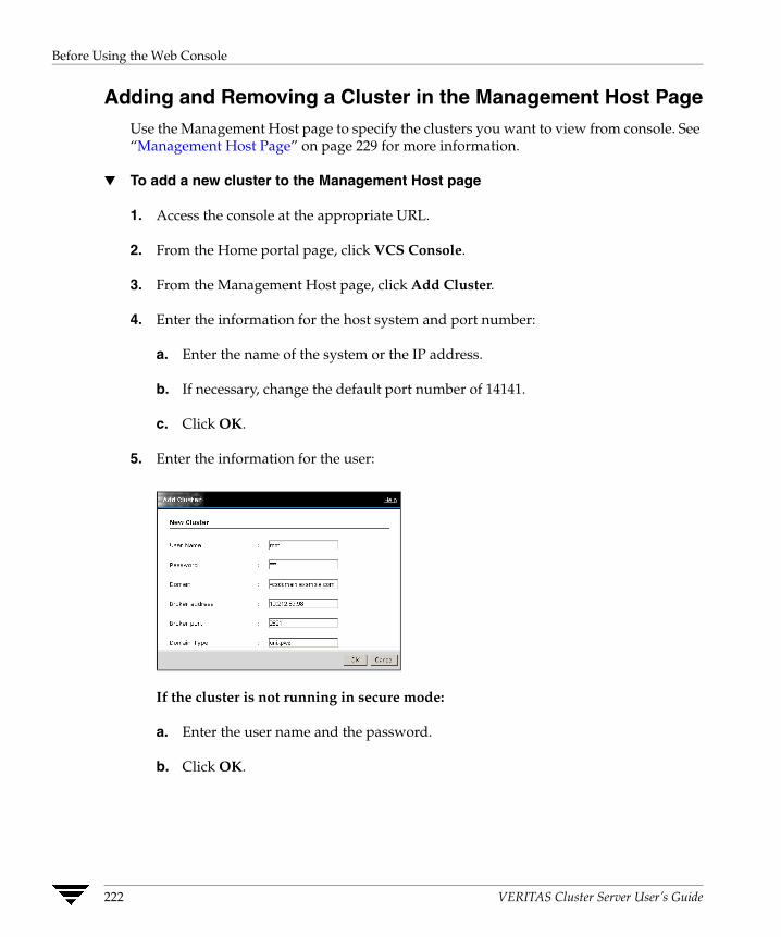
Before Using the Web Console
Adding and Removing a Cluster in the Management Host Page Use the Management Host page to specify the clusters you want to view from console. See “Management Host Page” on page 229 for more information.
▼ To add a new cluster to the Management Host page
1. Access the console at the appropriate URL.
2. From the Home portal page, click VCS Console.
3. From the Management Host page, click Add Cluster.
4. Enter the information for the host system and port number:
a. Enter the name of the system or the IP address.
b. If necessary, change the default port number of 14141.
c. Click OK.
5. Enter the information for the user:
If the cluster is not running in secure mode:
a. Enter the user name and the password.
b. Click OK.
222 VERITAS Cluster Server User’s Guide
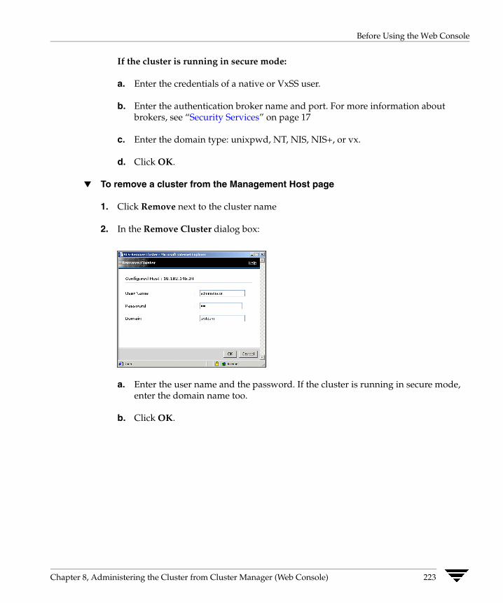
Before Using the Web Console
If the cluster is running in secure mode:
a. Enter the credentials of a native or VxSS user.
b. Enter the authentication broker name and port. For more information about brokers, see “Security Services” on page 17
c. Enter the domain type: unixpwd, NT, NIS, NIS+, or vx.
d. Click OK.
▼ To remove a cluster from the Management Host page
1. Click Remove next to the cluster name
2. In the Remove Cluster dialog box:
a. Enter the user name and the password. If the cluster is running in secure mode, enter the domain name too.
b. Click OK.
Chapter 8, Administering the Cluster from Cluster Manager (Web Console) 223

Before Using the Web Console
Logging In to and Out of the Web Console You must have a valid user name and password to use the console.
▼ To log in to the console
1. Click the appropriate cluster name listed on the Management Host page.
2. Enter the VCS user name and password. If the cluster is running in secure mode, enter the domain name too.
3. The console connects to the cluster using the authentication broker and the domain type provided by the engine. To change the authentication broker or the domain type, click Advanced. For more information about brokers, see “Security Services” on page 17.
4. Click Login.
▼ To log out of a cluster
1. Click Logout in the top right corner of any view if you are viewing a particular cluster.
or
Click Logout next to the cluster name on the Management Host page.
2. Clear the Save Configuration check box if you do not want to save the latest configuration.
3. Click Yes.
▼ To log out of all clusters
1. Click Logout All in the top right corner of the Management Host page.
2. Clear the Save Configuration check box if you do not want to save the latest configurations for all clusters you are logged on to through the Web Console.
3. Click Yes.
224 VERITAS Cluster Server User’s Guide

Before Using the Web Console
Using the Single Sign-On Feature in Secure Clusters To enable the single sign-on mechanism, you must create a proxy user on an authentication broker and configure the proxy user in the Web console.
Prerequisites
✔ All authentication brokers in the cluster must point to a single root broker.
✔ If the root broker is not part of the cluster, all authentication brokers must have a trust relationship between them.
Creating a Proxy User
Run the following command on an authentication broker node to create a proxy user:
# vssat addprpl --pdrtype ab --domain HA_SERVICES --prplname proxyusername --password <password> --prpltype service --can_proxy
◆ <proxyusername>—The name of the user.
◆ <password>—The password associated with the proxy user.
◆ The --can_proxy option specifies that the user can act as a proxy for another user.
Configuring the Proxy Users in the Web Console
1. Access the Web Console.
2. Click the cluster in which you want to configure the proxy user.
3. Enter the VCS user name, password, and domain.
4. Click Login.
5. In the left pane, click User Management.
6. In the VCS Users page, click Proxy User Details.
Chapter 8, Administering the Cluster from Cluster Manager (Web Console) 225
Before Using the Web Console
7. In the Proxy User Details dialog box, specify the details of the proxy user created in “Creating a Proxy User” on page 225.
a. Enter the name of the proxy user.
b. Enter the password for the proxy user.
c. Enter the fully qualified host name of the authentication broker node on which you created the proxy user.
d. Enter the IP address for the authentication broker node.
e. Enter the port number used to connect to the authentication broker node. Default is 2821.
f. Click OK.
8. Click Close Window.
Additional Considerations for Configuring Proxy Users
◆ If the ClusterService service group fails over, you must configure the proxy user on the new node. The proxy user must be configured once on each node in the cluster.
◆ You need not reconfigure the proxy user if the node hosting the ClusterService group is restarted.
Using Help The Web Console provides context-sensitive online help in a separate browser for the various views in the console. Use the Contents, Index, and Search features in the help system to locate the information you need.
▼ To access online help
Click Help in the top right corner of any view.
To avoid launching extraneous browser windows, do not close the online help until the content is fully loaded into the help browser.
226 VERITAS Cluster Server User’s Guide
Web Console Layout
Web Console Layout The Web Console provides a tri-pane view of cluster configurations:
◆ Use the links in the left pane to initiate operations, view certain pages in the console, or connect to the VERITAS Software Technical Services Web Site.
◆ Use the links, buttons, and breadcrumb trail along the top portion of the console to access specific pages and online help, create a customized view of the console using myVCS, and search the console using Cluster Query.
◆ Use the information displayed in the content pane to monitor the status of the cluster configuration. The content pane provides additional icons, links, and buttons to access specific information.
Chapter 8, Administering the Cluster from Cluster Manager (Web Console) 227
Navigating the Web Console
Navigating the Web Console The Web Console provides easy access to a cluster and its components through various methods of navigation. Use links, trails, or buttons to access a particular page or dialog box.
Using Information Links The Web Console links some of its information to additional pages in the console. For example, the Systems page displays information about online, faulted, and partial service groups on each system. These group names link to their respective pages. Links are provided throughout the tri-pane layout of the console.
Using Navigation Trails The Web Console follows a top down navigation approach. The top left corner of each content pane page displays a “breadcrumb trail” indicating the page’s position in the navigation hierarchy. The components of the trail are links to ascendant pages in the hierarchy. For example, if you are on a Resource page, the navigation trail shows Home -> Cluster -> Service Groups -> Service Group -> Resource.
◆ Click Home to view the cluster host name and logon status.
◆ Click the cluster name to view general information about the cluster.
◆ Click Service Groups to view information about service groups.
◆ Click the service group name to view information about the particular service group.
Using Navigation Buttons The top pane of the console provides buttons that link to other pages in the console. For example, click Systems to view the Systems page.
228 VERITAS Cluster Server User’s Guide

Reviewing Web Console Views
Reviewing Web Console Views A Cluster Manager (Web Console) “view” is an HTML page that displays information about the cluster or its objects. For example, the System page displays detailed information about a system in the cluster.
Management Host Page The Web Console Management Host page appears after you access the console at the appropriate URL. Use this page to configure the list of clusters that you want to log in to and view through the Web Console. You can view the host name, port number, cluster platform, and VCS version number for each cluster you are currently logged on to.
Note Review the Java Plug-in requirements for the browser to ensure you can view the console properly after logging in to a cluster.
▼ To view this page
Log on to the console.
or
After logging on to the cluster, click Home in the top right corner of any page.
Chapter 8, Administering the Cluster from Cluster Manager (Web Console) 229

Reviewing Web Console Views
Cluster Summary Page The Cluster Summary page appears after you log on to the Web Console and connect to a cluster.
View from VCS
View from Global Cluster Option
From the left pane of the console:
◆ Click the Configuration links to modify the VCS configuration using the Open Configuration and Save Configuration links, and to add and delete service groups.
◆ Click the Related links to manage users, set console preferences, and view resource types.
◆ For global clusters, click the Global Clusters links to add and delete clusters, create global service groups, and view heartbeat information.
230 VERITAS Cluster Server User’s Guide
Reviewing Web Console Views
From the top pane of the console:
◆ Click the links in the top right corner to access the Management Host page, create a customized view of the console using myVCS, search the console using Query, log off of the console, and launch online help.
◆ Click the buttons along the top of the content pane to access the Cluster Summary page, Groups page, Systems page, and Logs page.
From the right content pane:
◆ View the online and offline status of service groups, the running and faulted status of systems, notification of pending alerts, and recent log messages. Click the icon in the Service Groups box to display additional information on all service groups. Click the icon in the Systems box to display additional information on all systems. Click the icon in the Recent Critical/Error Messages box, to display the ten most recent log messages.
◆ Click the All Attributes link to display cluster attributes and their current values.
◆ Click the Alert notification that appears when the cluster has pending alert messages that may require administrative action; some alerts are specific to global clusters.
◆ For global clusters, use the Remote Clusters box to view the name, status, and IP address of each remote cluster.
▼ To view this page
Select a cluster on the Management Host page.
or
After logging on to a cluster, click the Cluster Summary button along the top of the content pane.
Chapter 8, Administering the Cluster from Cluster Manager (Web Console) 231

Reviewing Web Console Views
VCS Users Page The Users page displays the configured cluster users and their privileges.
◆ Use the VCS Users table to change passwords and privileges, and delete users.
◆ Use the links in the left pane to add users, change passwords, open and save the configuration, and access information on resource types.
Note You cannot change user passwords if the cluster is running in secure mode.
▼ To view this page
After logging on to a cluster, click User Management in the left pane of any page.
232 VERITAS Cluster Server User’s Guide

Reviewing Web Console Views
Preferences Page The Preferences page enables you to select the appropriate refresh mode to refresh the data automatically or manually, or to disable the update notification. The refresh mode icon in the top left corner of most views alters its appearance according to the mode selected; you can also click the icon to change the modes.
The Web Console supports the following refresh modes:
◆ Notify Only. Informs you of the need to manually refresh the page. When an update takes place, the Refresh icon appears in place of the Update icon. Click the icon to refresh the page.
◆ Auto Update. Automatically updates the page when the data displayed is no longer current.
◆ Disabled. Disables update notification. Click the browser’s Refresh button to refresh the page and retrieve current information.
The Update icon next to the Refresh Mode icon indicates the need to refresh the page when the information displayed is no longer current. The color of the Update icon indicates the state of the information on the page.
◆ A green icon indicates that the information on the page is current.
◆ A blinking orange icon indicates that the information on the page is outdated and must be refreshed.
◆ A blue icon indicates the Web Console is connecting to the server.
◆ A red icon indicates the Web Console is disconnected from the server.
◆ A gray icon indicates update notification is disabled.
▼ To view this page
From the Cluster Summary page, click Preferences in the left pane.
Chapter 8, Administering the Cluster from Cluster Manager (Web Console) 233
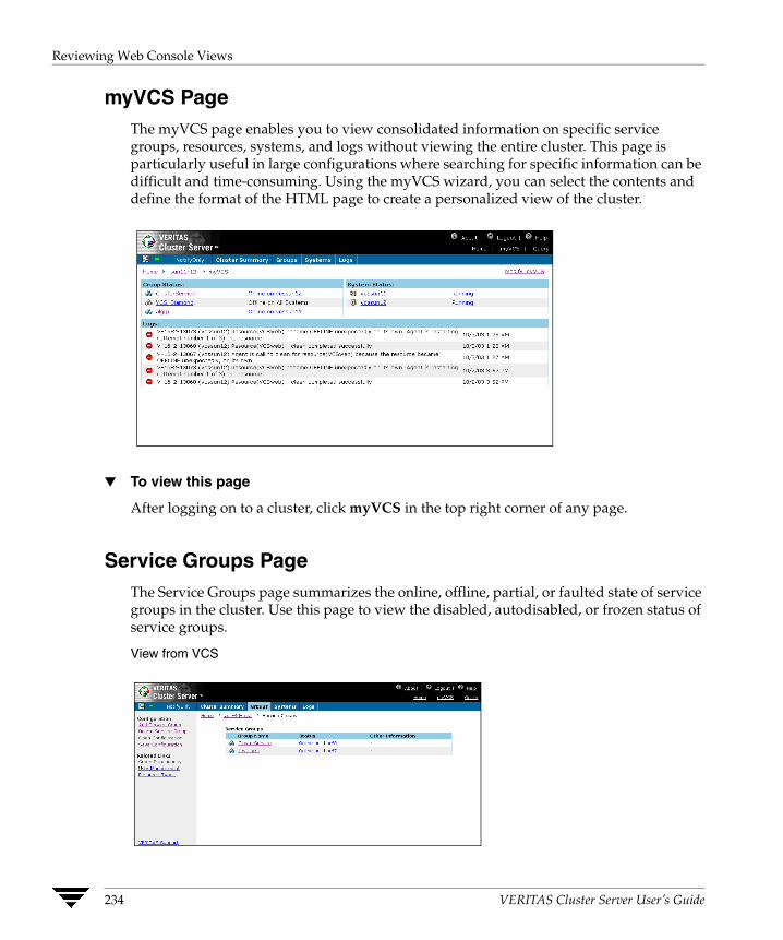
Reviewing Web Console Views
myVCS Page The myVCS page enables you to view consolidated information on specific service groups, resources, systems, and logs without viewing the entire cluster. This page is particularly useful in large configurations where searching for specific information can be difficult and time-consuming. Using the myVCS wizard, you can select the contents and define the format of the HTML page to create a personalized view of the cluster.
▼ To view this page
After logging on to a cluster, click myVCS in the top right corner of any page.
Service Groups Page The Service Groups page summarizes the online, offline, partial, or faulted state of service groups in the cluster. Use this page to view the disabled, autodisabled, or frozen status of service groups.
View from VCS
234 VERITAS Cluster Server User’s Guide
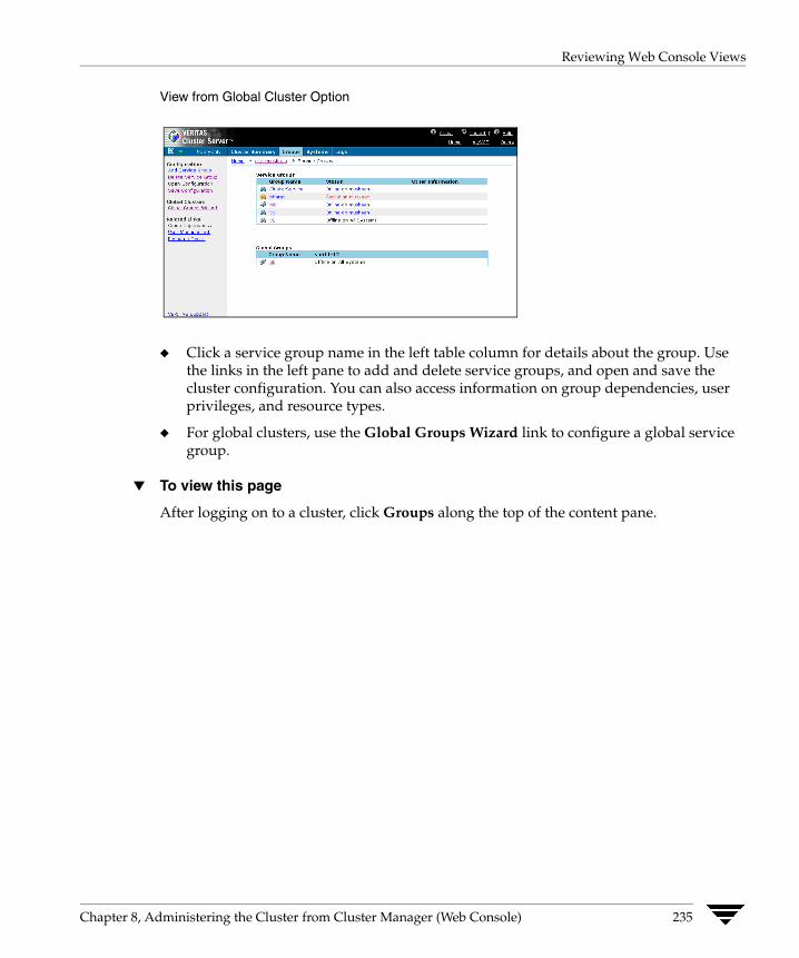
Reviewing Web Console Views
View from Global Cluster Option
◆ Click a service group name in the left table column for details about the group. Use the links in the left pane to add and delete service groups, and open and save the cluster configuration. You can also access information on group dependencies, user privileges, and resource types.
◆ For global clusters, use the Global Groups Wizard link to configure a global service group.
▼ To view this page
After logging on to a cluster, click Groups along the top of the content pane.
Chapter 8, Administering the Cluster from Cluster Manager (Web Console) 235
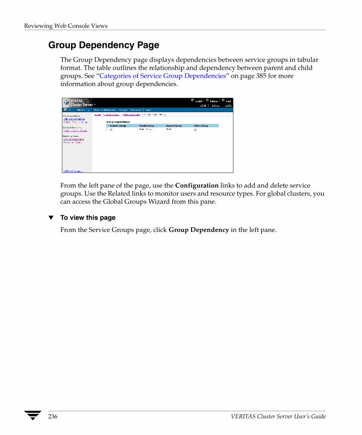
Reviewing Web Console Views
Group Dependency Page The Group Dependency page displays dependencies between service groups in tabular format. The table outlines the relationship and dependency between parent and child groups. See “Categories of Service Group Dependencies” on page 385 for more information about group dependencies.
From the left pane of the page, use the Configuration links to add and delete service groups. Use the Related links to monitor users and resource types. For global clusters, you can access the Global Groups Wizard from this pane.
▼ To view this page
From the Service Groups page, click Group Dependency in the left pane.
236 VERITAS Cluster Server User’s Guide

Reviewing Web Console Views
Systems Page The Systems page displays the status of systems in the cluster and lists the online, faulted, and partial service groups on the systems. The value of the UpDownState attribute is displayed in brackets when the system is UP BUT NOT IN CLUSTER MEMBERSHIP.
◆ Click a service group or system name link for details about the group or system.
◆ Use the links in the left pane to access information on system heartbeats, user privileges, and resource types.
▼ To view this page
After logging on to a cluster, click Systems along the top of the content pane.
Chapter 8, Administering the Cluster from Cluster Manager (Web Console) 237
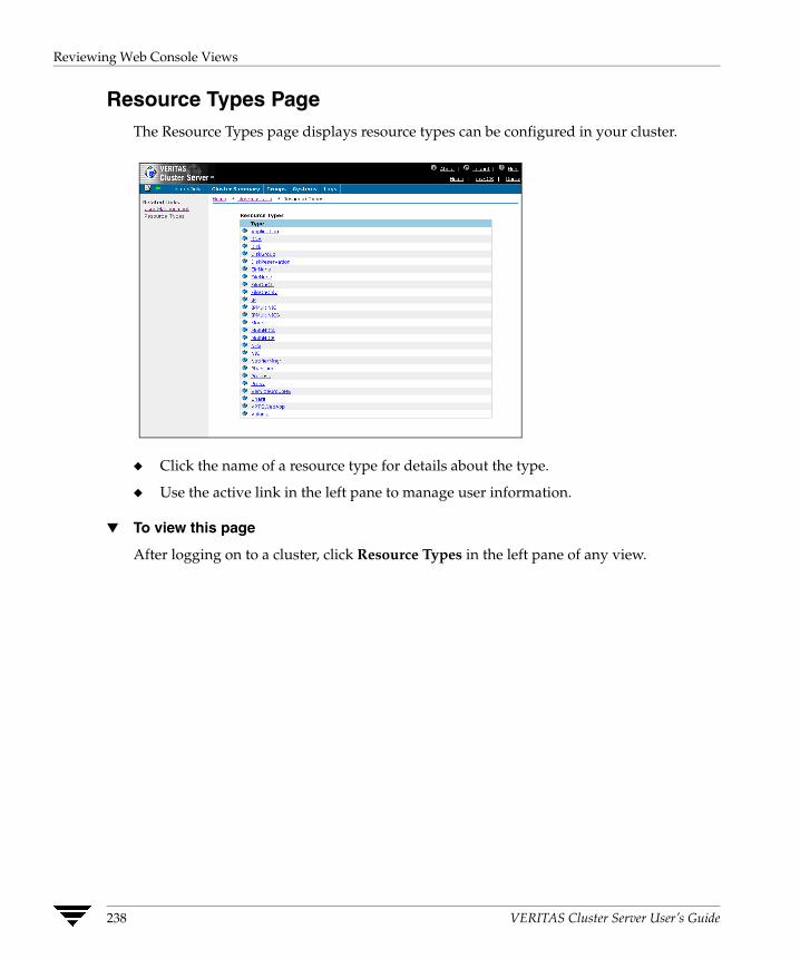
Reviewing Web Console Views
Resource Types Page The Resource Types page displays resource types can be configured in your cluster.
◆ Click the name of a resource type for details about the type.
◆ Use the active link in the left pane to manage user information.
▼ To view this page
After logging on to a cluster, click Resource Types in the left pane of any view.
238 VERITAS Cluster Server User’s Guide
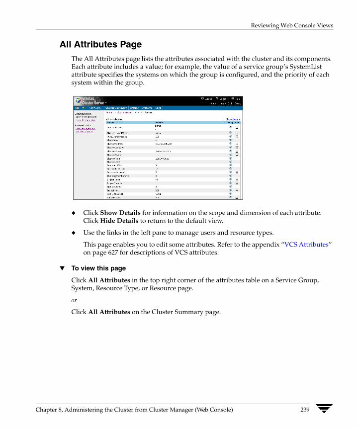
Reviewing Web Console Views
All Attributes Page The All Attributes page lists the attributes associated with the cluster and its components. Each attribute includes a value; for example, the value of a service group’s SystemList attribute specifies the systems on which the group is configured, and the priority of each system within the group.
◆ Click Show Details for information on the scope and dimension of each attribute. Click Hide Details to return to the default view.
◆ Use the links in the left pane to manage users and resource types.
This page enables you to edit some attributes. Refer to the appendix “VCS Attributes” on page 627 for descriptions of VCS attributes.
▼ To view this page
Click All Attributes in the top right corner of the attributes table on a Service Group, System, Resource Type, or Resource page.
or
Click All Attributes on the Cluster Summary page.
Chapter 8, Administering the Cluster from Cluster Manager (Web Console) 239
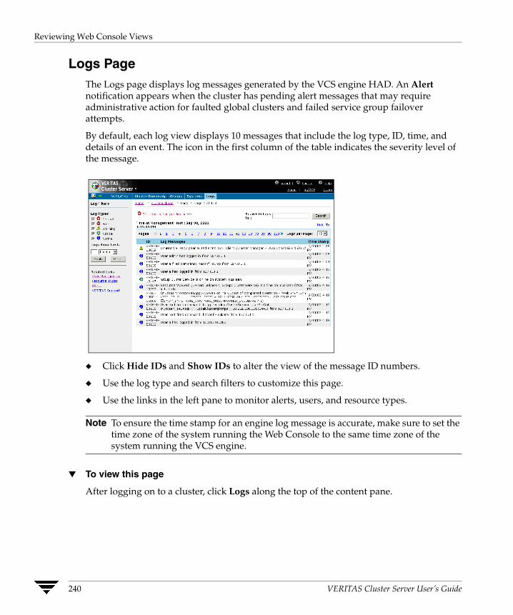
Reviewing Web Console Views
Logs Page The Logs page displays log messages generated by the VCS engine HAD. An Alertnotification appears when the cluster has pending alert messages that may require administrative action for faulted global clusters and failed service group failover attempts.
By default, each log view displays 10 messages that include the log type, ID, time, and details of an event. The icon in the first column of the table indicates the severity level of the message.
◆ Click Hide IDs and Show IDs to alter the view of the message ID numbers.
◆ Use the log type and search filters to customize this page.
◆ Use the links in the left pane to monitor alerts, users, and resource types.
Note To ensure the time stamp for an engine log message is accurate, make sure to set the time zone of the system running the Web Console to the same time zone of the system running the VCS engine.
▼ To view this page
After logging on to a cluster, click Logs along the top of the content pane.
240 VERITAS Cluster Server User’s Guide
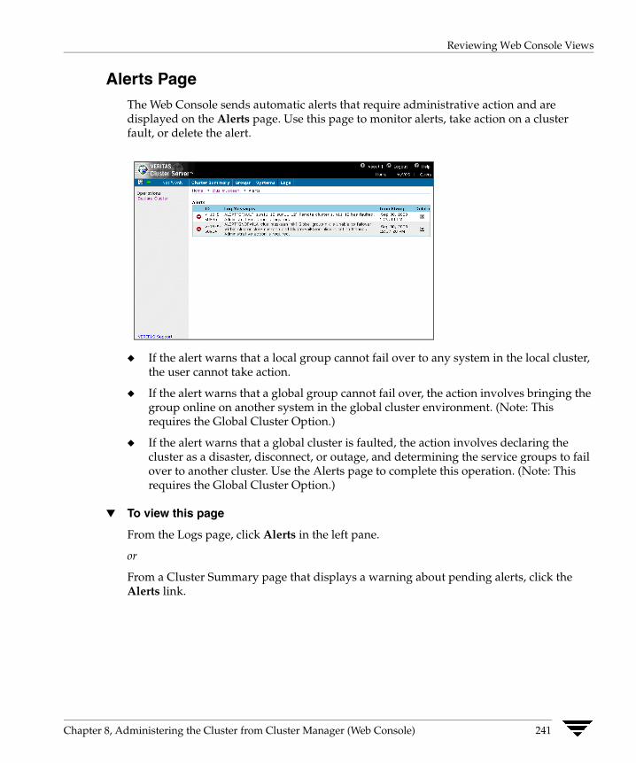
Reviewing Web Console Views
Alerts Page The Web Console sends automatic alerts that require administrative action and are displayed on the Alerts page. Use this page to monitor alerts, take action on a cluster fault, or delete the alert.
◆ If the alert warns that a local group cannot fail over to any system in the local cluster, the user cannot take action.
◆ If the alert warns that a global group cannot fail over, the action involves bringing the group online on another system in the global cluster environment. (Note: This requires the Global Cluster Option.)
◆ If the alert warns that a global cluster is faulted, the action involves declaring the cluster as a disaster, disconnect, or outage, and determining the service groups to fail over to another cluster. Use the Alerts page to complete this operation. (Note: This requires the Global Cluster Option.)
▼ To view this page
From the Logs page, click Alerts in the left pane.
or
From a Cluster Summary page that displays a warning about pending alerts, click the Alerts link.
Chapter 8, Administering the Cluster from Cluster Manager (Web Console) 241

Reviewing Web Console Views
Service Group Page The Service Group page displays information about the status, attributes, member systems, configured resources, and log messages of a specific group. A service group is a self-contained set of resources that VCS manages as a single unit. During a failover process, VCS fails over the entire service group rather than individual resources.
View from VCS
View from Global Cluster Option
◆ Click a resource name to access details on that resource. Use the Graph and Text links above the resource list to view the dependencies between the resources in the service group.
242 VERITAS Cluster Server User’s Guide

Reviewing Web Console Views
◆ Click a system name to access details on that system. For the entire selection of attributes associated with the service group, click All Attributes above the Important Attributes table.
◆ For users running the VERITAS Cluster Server Traffic Director Web Console, click Traffic Director in the top right corner of the content pane to access that console.
◆ Use the links in the left pane to execute group operations, add and delete resources, open and save configurations, and manage users, resource types, and group dependencies.
◆ For global clusters, use the Global Groups Wizard link to configure a global service group.
▼ To view this page
Click the name of a service group from the Service Groups page.
Chapter 8, Administering the Cluster from Cluster Manager (Web Console) 243

Reviewing Web Console Views
System Page The System page displays the system state and major attributes of a specific system. Use this page to review the status of service groups configured on the system and relevant log messages.
◆ Click a service group name to access details on that group. For the entire selection of attributes associated with the system, click All Attributes.
◆ Use the links in the left pane to freeze and unfreeze systems, and to manage users and resource types.
▼ To view this page
Click the name of a system from the Systems page.
244 VERITAS Cluster Server User’s Guide

Reviewing Web Console Views
System Heartbeats Page The System Heartbeats page displays the name and state of a system, and status of the link and disk heartbeats.
Use the links in the left pane to manage users and resource types.
▼ To view this page
From the Systems page, click System Heartbeats in the left pane.
Chapter 8, Administering the Cluster from Cluster Manager (Web Console) 245

Reviewing Web Console Views
Resource Type Page The Resource Type page displays the specified resource type and its major attributes.
◆ For the entire selection of attributes associated with the resource type, click All Attributes.
◆ Use the Configuration links in the left pane to open and save the cluster configuration.
◆ Use the Related Links to manage users and resource types.
▼ To view this page
Click the name of the resource type from the Resource Types page.
246 VERITAS Cluster Server User’s Guide
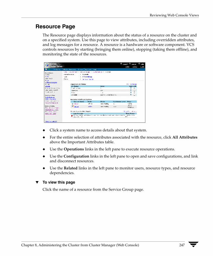
Reviewing Web Console Views
Resource Page The Resource page displays information about the status of a resource on the cluster and on a specified system. Use this page to view attributes, including overridden attributes, and log messages for a resource. A resource is a hardware or software component. VCS controls resources by starting (bringing them online), stopping (taking them offline), and monitoring the state of the resources.
◆ Click a system name to access details about that system.
◆ For the entire selection of attributes associated with the resource, click All Attributes above the Important Attributes table.
◆ Use the Operations links in the left pane to execute resource operations.
◆ Use the Configuration links in the left pane to open and save configurations, and link and disconnect resources.
◆ Use the Related links in the left pane to monitor users, resource types, and resource dependencies.
▼ To view this page
Click the name of a resource from the Service Group page.
Chapter 8, Administering the Cluster from Cluster Manager (Web Console) 247
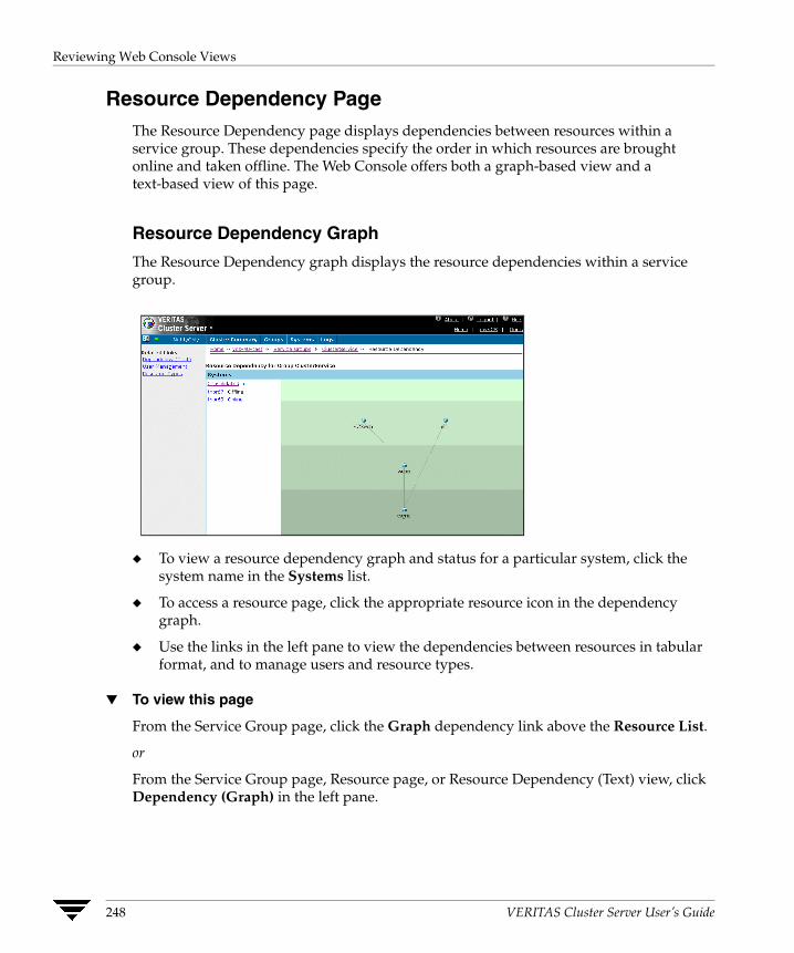
Reviewing Web Console Views
Resource Dependency Page The Resource Dependency page displays dependencies between resources within a service group. These dependencies specify the order in which resources are brought online and taken offline. The Web Console offers both a graph-based view and a text-based view of this page.
Resource Dependency Graph
The Resource Dependency graph displays the resource dependencies within a service group.
◆ To view a resource dependency graph and status for a particular system, click the system name in the Systems list.
◆ To access a resource page, click the appropriate resource icon in the dependency graph.
◆ Use the links in the left pane to view the dependencies between resources in tabular format, and to manage users and resource types.
▼ To view this page
From the Service Group page, click the Graph dependency link above the Resource List.
or
From the Service Group page, Resource page, or Resource Dependency (Text) view, click Dependency (Graph) in the left pane.
248 VERITAS Cluster Server User’s Guide
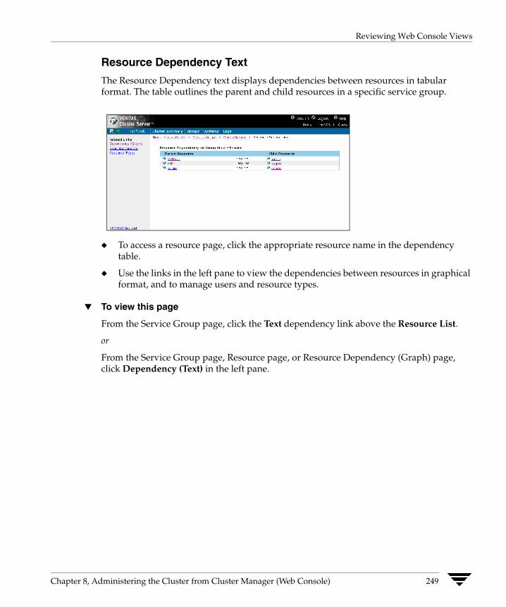
Reviewing Web Console Views
Resource Dependency Text
The Resource Dependency text displays dependencies between resources in tabular format. The table outlines the parent and child resources in a specific service group.
◆ To access a resource page, click the appropriate resource name in the dependency table.
◆ Use the links in the left pane to view the dependencies between resources in graphical format, and to manage users and resource types.
▼ To view this page
From the Service Group page, click the Text dependency link above the Resource List.
or
From the Service Group page, Resource page, or Resource Dependency (Graph) page, click Dependency (Text) in the left pane.
Chapter 8, Administering the Cluster from Cluster Manager (Web Console) 249
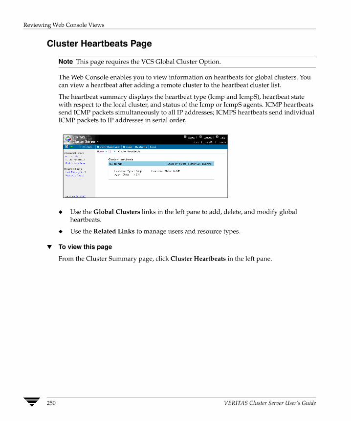
Reviewing Web Console Views
Cluster Heartbeats Page
Note This page requires the VCS Global Cluster Option.
The Web Console enables you to view information on heartbeats for global clusters. You can view a heartbeat after adding a remote cluster to the heartbeat cluster list.
The heartbeat summary displays the heartbeat type (Icmp and IcmpS), heartbeat state with respect to the local cluster, and status of the Icmp or IcmpS agents. ICMP heartbeats send ICMP packets simultaneously to all IP addresses; ICMPS heartbeats send individual ICMP packets to IP addresses in serial order.
◆ Use the Global Clusters links in the left pane to add, delete, and modify global heartbeats.
◆ Use the Related Links to manage users and resource types.
▼ To view this page
From the Cluster Summary page, click Cluster Heartbeats in the left pane.
250 VERITAS Cluster Server User’s Guide
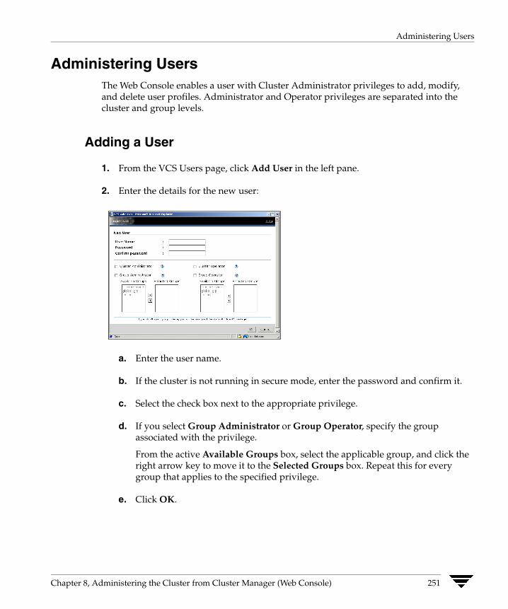
Administering Users
Administering Users The Web Console enables a user with Cluster Administrator privileges to add, modify, and delete user profiles. Administrator and Operator privileges are separated into the cluster and group levels.
Adding a User
1. From the VCS Users page, click Add User in the left pane.
2. Enter the details for the new user:
a. Enter the user name.
b. If the cluster is not running in secure mode, enter the password and confirm it.
c. Select the check box next to the appropriate privilege.
d. If you select Group Administrator or Group Operator, specify the group associated with the privilege.
From the active Available Groups box, select the applicable group, and click the right arrow key to move it to the Selected Groups box. Repeat this for every group that applies to the specified privilege.
e. Click OK.
Chapter 8, Administering the Cluster from Cluster Manager (Web Console) 251
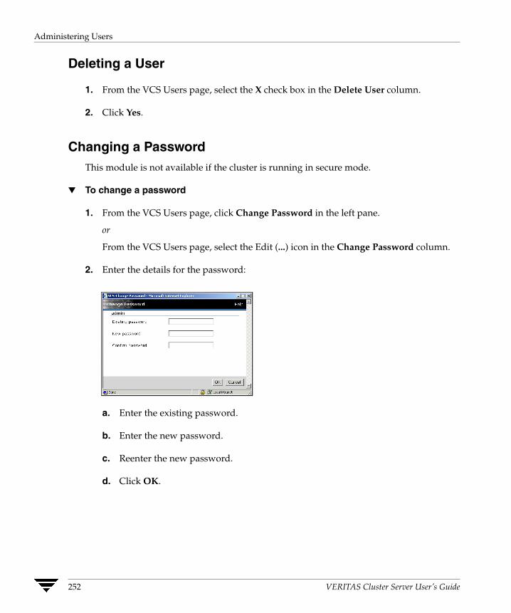
Administering Users
Deleting a User
1. From the VCS Users page, select the X check box in the Delete User column.
2. Click Yes.
Changing a Password This module is not available if the cluster is running in secure mode.
▼ To change a password
1. From the VCS Users page, click Change Password in the left pane.
or
From the VCS Users page, select the Edit (...) icon in the Change Password column.
2. Enter the details for the password:
a. Enter the existing password.
b. Enter the new password.
c. Reenter the new password.
d. Click OK.
252 VERITAS Cluster Server User’s Guide
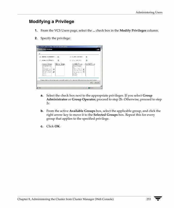
Administering Users
Modifying a Privilege
1. From the VCS Users page, select the ... check box in the Modify Privileges column.
2. Specify the privilege:
a. Select the check box next to the appropriate privileges. If you select Group Administrator or Group Operator, proceed to step 2b. Otherwise, proceed to step 2c.
b. From the active Available Groups box, select the applicable group, and click the right arrow key to move it to the Selected Groups box. Repeat this for every group that applies to the specified privilege.
c. Click OK.
Chapter 8, Administering the Cluster from Cluster Manager (Web Console) 253
Administering Cluster Configurations
Administering Cluster Configurations The Web Console enables you to modify the parameters of the VCS configuration. After opening the configuration, you can save it to disk.
Opening the Configuration Modify a read-only configuration file to a read-write file by opening the configuration from most pages in the Web Console.
▼ To open a configuration
1. On a page (such as the Cluster Summary page) that includes Configuration links in the left pane, click Open Configuration.
2. Click OK.
Saving the Configuration After updating the VCS configuration, use the Cluster Summary page to save your latest configuration to disk.
▼ To save the configuration
1. On a page (such as the Cluster Summary page) that includes Configuration links in the left pane, click Save Configuration.
2. Select the check box to prevent any write operations to the configuration file.
3. Click OK.
254 VERITAS Cluster Server User’s Guide
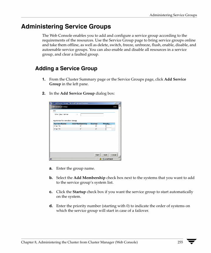
Administering Service Groups
Administering Service Groups The Web Console enables you to add and configure a service group according to the requirements of the resources. Use the Service Group page to bring service groups online and take them offline, as well as delete, switch, freeze, unfreeze, flush, enable, disable, and autoenable service groups. You can also enable and disable all resources in a service group, and clear a faulted group.
Adding a Service Group
1. From the Cluster Summary page or the Service Groups page, click Add Service Group in the left pane.
2. In the Add Service Group dialog box:
a. Enter the group name.
b. Select the Add Membership check box next to the systems that you want to add to the service group’s system list.
c. Click the Startup check box if you want the service group to start automatically on the system.
d. Enter the priority number (starting with 0) to indicate the order of systems on which the service group will start in case of a failover.
Chapter 8, Administering the Cluster from Cluster Manager (Web Console) 255
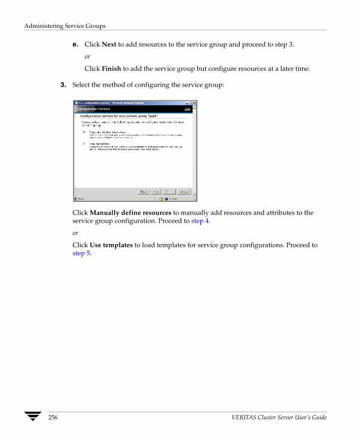
Administering Service Groups
e. Click Next to add resources to the service group and proceed to step 3.
or
Click Finish to add the service group but configure resources at a later time.
3. Select the method of configuring the service group:
Click Manually define resources to manually add resources and attributes to the service group configuration. Proceed to step 4.
or
Click Use templates to load templates for service group configurations. Proceed to step 5.
256 VERITAS Cluster Server User’s Guide

Administering Service Groups
4. If you manually define resources and attributes:
a. Enter the resource name.
b. Select the resource type.
c. If necessary, clear the Critical or Enabled check boxes; these options are selected by default. A critical resource indicates the service group is faulted when the resource, or any resource it depends on, faults. An enabled resource indicates agents monitor the resource. If a resource is created dynamically while VCS is running, you must enable the resource before VCS monitors it. VCS will not bring a disabled resource nor its children online, even if the children are enabled.
d. Click the edit icon (...) to edit an attribute for the selected resource type. After editing the attribute, click Save in the Edit Attribute dialog box to return to the Add Resource dialog box.
e. Click New Resource to save the resource to the resource list in the left pane of the dialog box. Make changes to the attributes of the other resources in the group by clicking the resource name in the resource list.
f. Click Finish.
Chapter 8, Administering the Cluster from Cluster Manager (Web Console) 257

Administering Service Groups
5. If you configure the service group using a template:
a. Select the appropriate service group template.
b. Click Next.
258 VERITAS Cluster Server User’s Guide
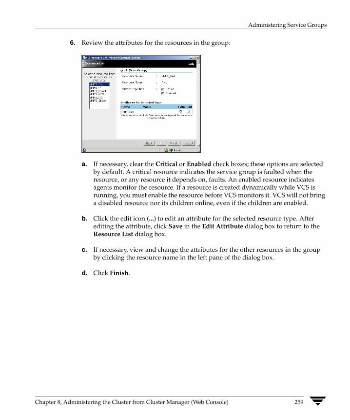
Administering Service Groups
6. Review the attributes for the resources in the group:
a. If necessary, clear the Critical or Enabled check boxes; these options are selected by default. A critical resource indicates the service group is faulted when the resource, or any resource it depends on, faults. An enabled resource indicates agents monitor the resource. If a resource is created dynamically while VCS is running, you must enable the resource before VCS monitors it. VCS will not bring a disabled resource nor its children online, even if the children are enabled.
b. Click the edit icon (...) to edit an attribute for the selected resource type. After editing the attribute, click Save in the Edit Attribute dialog box to return to the Resource List dialog box.
c. If necessary, view and change the attributes for the other resources in the group by clicking the resource name in the left pane of the dialog box.
d. Click Finish.
Chapter 8, Administering the Cluster from Cluster Manager (Web Console) 259
Administering Service Groups
Deleting a Service Group
1. From the Cluster Summary page or Service Groups page, click Delete Service Group in the left pane.
2. In the Delete Service Group dialog box:
a. Select the group to remove it from the cluster.
b. Click OK.
Bringing a Service Group Online
1. From the Service Group page, click Online in the left pane.
2. In the Online Group dialog box:
a. Select the system on which to bring the service group online, or click Anywhere.
b. To run a PreOnline script, select the Run preonline script check box. This user-defined script checks for external conditions before bringing a group online.
c. Click OK.
Taking a Service Group Offline
1. From the Service Group page, click Offline in the left pane.
2. In the Offline Group dialog box:
a. For parallel groups, select the system on which to take the service group offline, or click All Systems.
b. Click OK.
260 VERITAS Cluster Server User’s Guide

Administering Service Groups
Switching a Service Group The process of switching a service group involves taking it offline on its current system and bringing it online on another system.
▼ To switch a service group
1. From the Service Group page, click Switch in the left pane.
2. In the Switch Group dialog box:
a. Select the system to switch the service group to.
b. Click OK.
Freezing a Service Group Freeze a service group to prevent it from failing over to another system. This freezing procedure stops all online and offline operations on the service group.
▼ To freeze a service group
1. From the Service Group page, click Freeze in the left pane.
2. In the Freeze Group dialog box:
a. If necessary, choose Persistent to enable the service group to retain its frozen state when the cluster is rebooted.
b. Click OK.
Chapter 8, Administering the Cluster from Cluster Manager (Web Console) 261

Administering Service Groups
Unfreezing a Service Group Unfreeze a frozen service group to perform online or offline operations on the service group.
▼ To unfreeze a service group
1. From the Service Group page, click Unfreeze in the left pane.
2. In the Unfreeze Group dialog box, click OK.
Flushing a Service Group As a service group is brought online or taken offline, the resources within the group are brought online and taken offline. If the online or offline operation hangs on a particular resource, flush the service group to halt the operation on the resources waiting to go online or offline. Flushing a service group resets the internal engine variables to their default values and typically leaves the cluster in a partial state. After completing this process, resolve the issue with the particular resource (if necessary) and proceed with starting or stopping the service group.
▼ To flush a service group
1. From the Service Group page, click Flush in the left pane.
2. In the Flush Group dialog box:
a. Click the system on which to flush the service group.
b. Click OK.
262 VERITAS Cluster Server User’s Guide
Administering Service Groups
Enabling a Service Group Enable a service group to bring a disabled service group online. A service group that was manually disabled during a maintenance procedure on a system may need to be brought online after the procedure is completed.
▼ To enable a service group
1. From the Service Group page, click Enable in the left pane.
2. In the Enable Group dialog box:
a. Select the system on which to enable the service group. To enable the service group on all systems, click All Systems.
b. Click OK.
Disabling a Service Group Disable a service group to prevent it from coming online. This disabling process is useful to temporarily stop VCS from monitoring a service group on a system undergoing maintenance operations.
▼ To disable a service group
1. From the Service Group page, click Disable in the left pane.
2. In the Disable Group dialog box:
a. Select the system on which to disable the service group. To disable the service group on all systems, click All Systems.
b. Click OK.
Chapter 8, Administering the Cluster from Cluster Manager (Web Console) 263
Administering Service Groups
Autoenabling a Service Group A service group is autodisabled until VCS probes all resources and checks that they are ready to bring online. Autoenable a service group in situations where the VCS engine is not running on one of the systems in the cluster and you need to override the disabled state of the service group to be able to enable it on another system in the cluster.
▼ To autoenable a service group
1. From the Service Group page, click Autoenable in the left pane.
2. In the Autoenable Group dialog box:
a. Select the system on which to enable the service group.
b. Click OK.
264 VERITAS Cluster Server User’s Guide
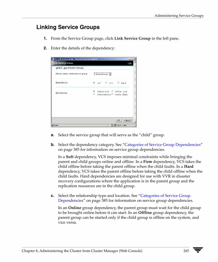
Administering Service Groups
Linking Service Groups
1. From the Service Group page, click Link Service Group in the left pane.
2. Enter the details of the dependency:
a. Select the service group that will serve as the “child” group.
b. Select the dependency category. See “Categories of Service Group Dependencies” on page 385 for information on service group dependencies.
In a Soft dependency, VCS imposes minimal constraints while bringing the parent and child groups online and offline. In a Firm dependency, VCS takes the child offline before taking the parent offline when the child faults. In a Hard dependency, VCS takes the parent offline before taking the child offline when the child faults. Hard dependencies are designed for use with VVR in disaster recovery configurations where the application is in the parent group and the replication resources are in the child group.
c. Select the relationship type and location. See “Categories of Service Group Dependencies” on page 385 for information on service group dependencies.
In an Online group dependency, the parent group must wait for the child group to be brought online before it can start. In an Offline group dependency, the parent group can be started only if the child group is offline on the system, and vice versa.
Chapter 8, Administering the Cluster from Cluster Manager (Web Console) 265

Administering Service Groups
In a Local dependency, an instance of the parent group depends on an instance of the child group being online or offline on the same system, depending on the category of group dependency. In a Global dependency, an instance of the parent group depends on one or more instances of the child group being online on any system. In a Remote dependency, an instance of the parent group depends on one or more instances of the child group being online on any system other than the system on which the parent is online.
d. Click OK.
Unlinking Service Groups
1. From the Service Group page, click Unlink Service Group in the left pane.
2. In the Unlink Service Group dialog box:
a. Select the name of the service group to disconnect from the dependency.
b. Click OK.
266 VERITAS Cluster Server User’s Guide
Administering Service Groups
Managing Systems for a Service Group Use the Web console to add and remove systems on a service group’s system list.
▼ To modify the SystemList for a service group
1. From the Service Group page, click Modify SystemList in the left pane.
2. In the Modify SystemList dialog box:
a. Select the systems that will host the service group.
b. Select the Startup check box if you want the service group to automatically start on the system.
c. Assign a priority number (starting with 0) to indicate the order of systems on which the service group will start in case of a failover.
d. Click OK.
Clearing a Faulted Service Group Clear a service group to remove the resource faults within the group. This operation makes the group available to be brought online. A resource fault in a group may occur in several situations, such as a power failure or faulty configuration.
▼ To clear a faulted service group
1. From the Service Group page, click Clear Fault in the left pane.
2. In the Clear Faulted Group dialog box:
a. Select the system on which to clear the service group. To clear the group on all systems, click All Systems.
b. Click OK.
Chapter 8, Administering the Cluster from Cluster Manager (Web Console) 267

Administering Resources
Administering Resources The Web Console enables you to perform several operations through the Resource page. Use this page to bring resources online and take them offline, take parent and child resources offline, clear or probe resources, refresh the ResourceInfo attribute, invoke the action entry point, enable and disable individual resources, and create and remove resource dependencies.
Links for enabling and disabling all resources in a group, and adding and deleting them, are available from the Service Group page.
Bringing a Resource Online
1. From the Resource page, click Online in the left pane.
2. In the Online Resource dialog box:
a. Select the system on which to bring the resource online.
b. Click OK.
Taking a Resource Offline
1. From the Resource page, click Offline in the left pane.
2. In the Offline Resource dialog box:
a. Select the system on which to take the resource offline.
b. Click OK.
268 VERITAS Cluster Server User’s Guide
Administering Resources
Taking a Resource Offline and Propagating the Command This command signals that resources dependent on the parent resource should also be taken offline. Use the Offline Propagate feature to propagate the offline state of a parent resource. This link is disabled if any of the following conditions exist:
✔ The user does not have administrator or operator privileges.
✔ The resource does not depend on any other resource.
✔ An online resource depends on this resource.
✔ The resource is not online.
▼ To take a parent resource and all of its child resources offline
1. From the Resource page, click Offline Propagate in the left pane.
2. In the Offline Propagate Resource dialog box:
a. Select the system on which to take the resource and all of its child resources offline.
b. Click OK.
Chapter 8, Administering the Cluster from Cluster Manager (Web Console) 269
Administering Resources
Overriding Resource Type Static Attributes You can override some resource type static attributes and assign them resource-specific values. When a static attribute is overridden and the configuration is saved, the main.cf file includes a line in the resource definition for the static attribute and its overridden value.
▼ To override a resource type’s static attribute
1. From the Resource page, click Override Attribute in the left pane.
2. Select the attribute to override.
3. Click OK.
The selected attributes appear in the Overridden Attributes table.
4. To modify the default value of an overridden attribute, click the icon in the Edit column of the attribute.
▼ To restore default settings to a type’s static attribute
1. From the Resource page, click Remove Attribute Overrides in the left pane.
2. Select the overridden attribute to be restored to their default settings.
3. Click OK.
270 VERITAS Cluster Server User’s Guide
Administering Resources
Clearing a Faulted Resource Clear a resource to remove a fault and make the resource available to go online. A resource fault can occur in several situations, such as a power failure or a faulty configuration.
▼ To clear a faulted resource
1. From the Resource page, click Clear Fault in the left pane.
2. In the Clear Resource dialog box:
a. Select the system on which to clear the resource. To clear the resource on all systems, click All Systems.
b. Click OK.
Probing a Resource Probe a resource to check that it is configured and ready to bring online.
1. From the Resource page, click Probe in the left pane.
2. In the Probe Resource dialog box:
a. Select the system on which to probe the resource.
b. Click OK.
Chapter 8, Administering the Cluster from Cluster Manager (Web Console) 271
Administering Resources
Enabling a Resource Enable a resource in a service group to bring a disabled resource online. A resource may have been manually disabled to temporarily stop VCS from monitoring the resource.
▼ To enable a resource
1. From the Resource page, click Enable in the left pane.
2. In the Enable Resource dialog box, click OK.
Disabling a Resource Disable a resource in a service group to prevent it from coming online. This disabling process is useful when you want VCS to temporarily “ignore” a resource (rather than delete it) while the service group is still online.
▼ To disable a resource
1. From the Resource page, click Disable in the left pane.
2. In the Disable Resource dialog box, click OK.
272 VERITAS Cluster Server User’s Guide
Administering Resources
Enabling All Resources in a Service Group Enable resources in a service group to bring disabled resources online. Resources may have been manually disabled to temporarily stop VCS from monitoring the resource.
The EnableResources feature is not available if any of the following conditions exist:
✔ The user does not have the privileges to perform this operation.
✔ The service group does not have any resources.
✔ All resources in the group are already enabled.
▼ To enable all resources in a service group:
1. From the Service Group page, click Enable Resources in the left pane.
2. In the Enable All Resources dialog box, click OK.
Chapter 8, Administering the Cluster from Cluster Manager (Web Console) 273
Administering Resources
Disabling All Resources in a Service Group Disable resources in a service group to prevent them from coming online. This disabling process is useful when you want VCS to temporarily “ignore” resources (rather than delete them) while the service group is still online.
The DisableResources feature is not available if any of the following conditions exist:
✔ The user does not have the privileges to perform this operation.
✔ The service group does not have any resources.
✔ All resources in the group are already disabled.
▼ To disable all resources in a service group
1. From the Service Group page, click Disable Resources in the left pane.
2. In the Disable All Resources dialog box, click OK.
274 VERITAS Cluster Server User’s Guide
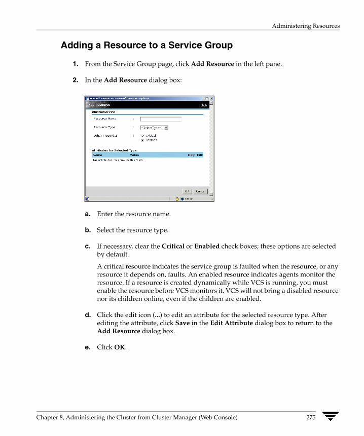
Administering Resources
Adding a Resource to a Service Group
1. From the Service Group page, click Add Resource in the left pane.
2. In the Add Resource dialog box:
a. Enter the resource name.
b. Select the resource type.
c. If necessary, clear the Critical or Enabled check boxes; these options are selected by default.
A critical resource indicates the service group is faulted when the resource, or any resource it depends on, faults. An enabled resource indicates agents monitor the resource. If a resource is created dynamically while VCS is running, you must enable the resource before VCS monitors it. VCS will not bring a disabled resource nor its children online, even if the children are enabled.
d. Click the edit icon (...) to edit an attribute for the selected resource type. After editing the attribute, click Save in the Edit Attribute dialog box to return to the Add Resource dialog box.
e. Click OK.
Chapter 8, Administering the Cluster from Cluster Manager (Web Console) 275

Administering Resources
Deleting a Resource in a Service Group Delete a resource from the Service Group page or the Resource page.
▼ From the Service Group page
1. Click Delete Resource in the left pane.
2. In the Delete Resource dialog box:
a. Select the resource you want to delete from the group.
b. Click OK.
▼ From the Resource page
Click Delete this Resource in the left pane.
276 VERITAS Cluster Server User’s Guide

Administering Resources
Linking Resources Link resources from the Resource Dependency page or the Resource page.
▼ From the Resource Dependency page
1. Click Link Resource in the left pane.
2. In the Link Resource dialog box:
a. Select the "parent" resource.
b. Select the "child" resource.
c. Click OK.
▼ From the Resource page
1. Click Link Resource in the left pane.
2. In the Link Resource dialog box:
a. Select the "child" resource.
b. Click OK.
Chapter 8, Administering the Cluster from Cluster Manager (Web Console) 277
Administering Resources
Unlinking Resources Unlink resources from the Resource Dependency page or the Resource page.
▼ From the Resource Dependency page
1. Click Unlink Resource in the left pane.
2. In the Unlink Resource dialog box:
a. Select the “parent” resource.
b. Select the “child” resource.
c. Click OK.
▼ From the Resource page
1. Click Unlink Resource in the left pane.
2. In the Unlink Resource dialog box:
a. Select the resource to unlink from the “parent” resource.
b. Click OK.
278 VERITAS Cluster Server User’s Guide

Administering Resources
Invoking a Resource Action Use the Invoke Action link to initiate a predefined “action” script, such as splitting and joining disk groups.
▼ To invoke a resource action
1. From the Resource page, click Invoke Action.
2. In the Invoke Action dialog box:
a. Select the predefined action to execute. Some examples of preset actions are displayed on the menu above.
b. Select the system on which to execute the action.
c. Enter an action argument and click Add. Click the Delete icon (x) to delete the argument.
d. Click OK.
Chapter 8, Administering the Cluster from Cluster Manager (Web Console) 279

Administering Resources
Refreshing the ResourceInfo Attribute Refresh the ResourceInfo attribute to view the latest values for that attribute. Some examples of this operation include viewing the current amount of space available on the file system for a mount resource, or viewing the latest RVG link status for a replication resource.
▼ To refresh the ResourceInfo attribute
1. From the Resource page, click Refresh ResourceInfo in the left pane.
2. In the Refresh ResourceInfo dialog box:.
a. Select the system on which to refresh the attribute value.
b. Click OK.
3. From the Resource page, click All Attributes above the Important Attributes table to view the latest information on the ResourceInfo attribute.
Clearing the ResourceInfo Attribute Clear the ResourceInfo attribute to reset all the parameters in this attribute to their default value.
▼ To clear the ResourceInfo attribute
1. From the Resource page, click Clear ResourceInfo in the left pane.
2. In the Clear ResourceInfo dialog box:
a. Select the system on which to reset the parameters of the ResourceInfo attribute.
b. Click OK.
3. From the Resource page, click All Attributes above the Important Attributes table to verify the information on the ResourceInfo attribute.
280 VERITAS Cluster Server User’s Guide
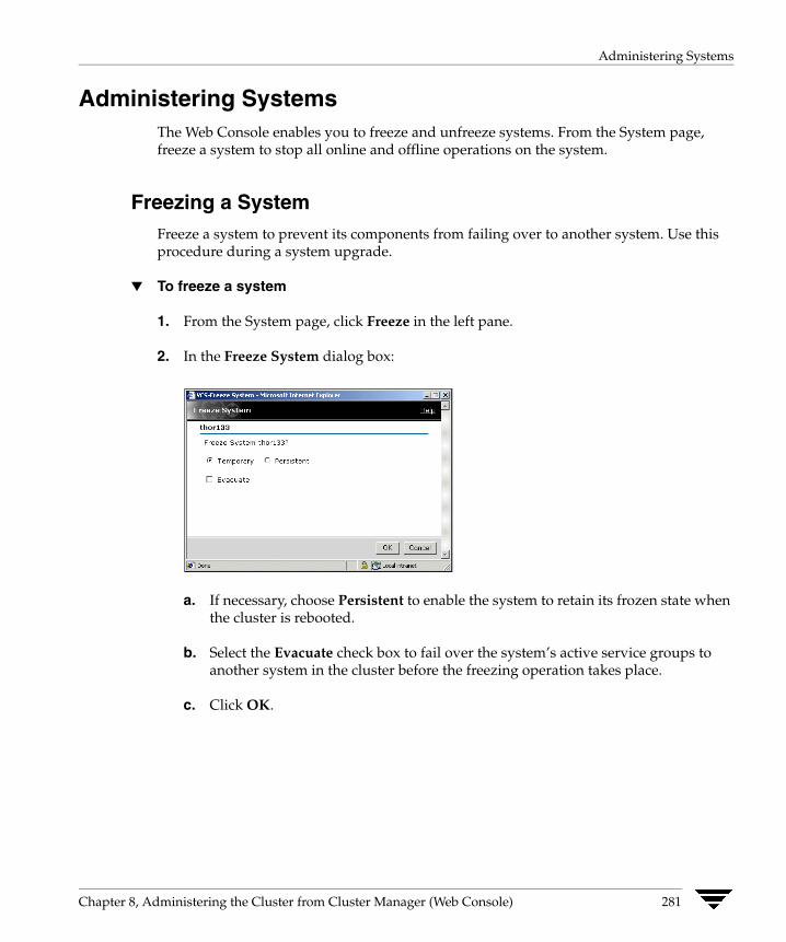
Administering Systems
Administering Systems The Web Console enables you to freeze and unfreeze systems. From the System page, freeze a system to stop all online and offline operations on the system.
Freezing a System Freeze a system to prevent its components from failing over to another system. Use this procedure during a system upgrade.
▼ To freeze a system
1. From the System page, click Freeze in the left pane.
2. In the Freeze System dialog box:
a. If necessary, choose Persistent to enable the system to retain its frozen state when the cluster is rebooted.
b. Select the Evacuate check box to fail over the system’s active service groups to another system in the cluster before the freezing operation takes place.
c. Click OK.
Chapter 8, Administering the Cluster from Cluster Manager (Web Console) 281
Administering Systems
Unfreezing a System Unfreeze a frozen system to perform online or offline operations on the system.
▼ To unfreeze a system
1. From the System page, click Unfreeze in the left pane.
2. In the Unfreeze System dialog box, Click OK.
282 VERITAS Cluster Server User’s Guide

Editing Attributes
Editing Attributes The Web Console enables you to edit attributes of certain cluster objects, including service groups, systems, resources, and resource types. Make sure the configuration is open (in read/write mode) before editing attributes. By default, the console displays key attributes. To view the entire list of attributes associated with a cluster object, click All Attributes.
Changes to certain attributes, such as a webip attribute, may involve taking the service group offline, modifying the configuration file, and bringing the group online. (VERITAS recommends using the command line to edit attributes that are specific to the Web Console.)
Note VERITAS does not recommend editing the value of the UserStrGlobal attribute for the ClusterService group. The VCS Web Console uses this attribute for cross-product navigation.
▼ To edit an attribute
1. Navigate to the page containing the attributes you want to edit. For example, to edit system attributes, go to the System page.
2. In the Important Attributes table, click the edit icon (...) for the attribute.
or
Click All Attributes above the Important Attributes table, and click the edit icon (...) for the attribute you want to modify.
or
Click All Attributes on the Cluster Summary page, and click the edit icon (...) for the attribute you want to modify.
3. Enter the new value for the attribute:
a. For a scalar value, enter the value.
For an association value, enter the key and the associated value. Click add after entering each key-value pair.
For a keylist or a vector, enter value. Click Add after entering each value.
b. Click OK
Chapter 8, Administering the Cluster from Cluster Manager (Web Console) 283
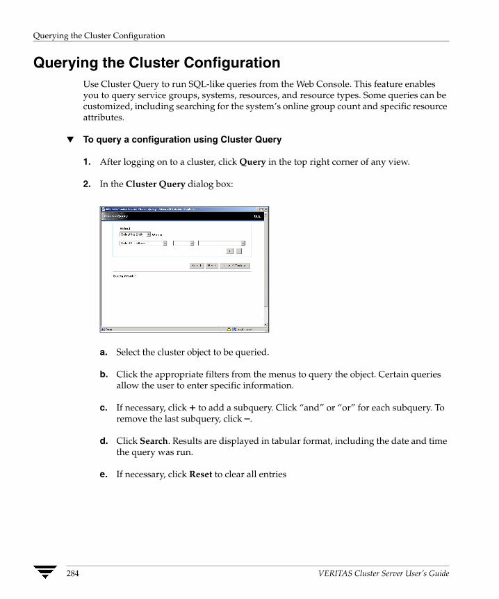
Querying the Cluster Configuration
Querying the Cluster Configuration Use Cluster Query to run SQL-like queries from the Web Console. This feature enables you to query service groups, systems, resources, and resource types. Some queries can be customized, including searching for the system’s online group count and specific resource attributes.
▼ To query a configuration using Cluster Query
1. After logging on to a cluster, click Query in the top right corner of any view.
2. In the Cluster Query dialog box:
a. Select the cluster object to be queried.
b. Click the appropriate filters from the menus to query the object. Certain queries allow the user to enter specific information.
c. If necessary, click + to add a subquery. Click “and” or “or” for each subquery. To remove the last subquery, click –.
d. Click Search. Results are displayed in tabular format, including the date and time the query was run.
e. If necessary, click Reset to clear all entries
284 VERITAS Cluster Server User’s Guide

Customizing the Web Console with myVCS
Customizing the Web Console with myVCS Use the myVCS wizard to customize a view of the cluster configuration. After the myVCS page is created, use the Configure myVCS wizard to modify the page.
Creating myVCS
1. After logging into a cluster, click myVCS in the top right corner of any page.
2. In the Welcome screen, click Next.
3. In the Select layout for myVCS dialog box:
a. Select the appropriate template.
b. Click Next.
4. In the Select groups for myVCS dialog box:
a. Select the appropriate service groups to appear in the view.
b. Click Next.
5. In the Select systems for myVCS dialog box:
a. Select the appropriate systems to appear in the view.
b. Click Next.
Chapter 8, Administering the Cluster from Cluster Manager (Web Console) 285

Customizing the Web Console with myVCS
6. Before finalizing the myVCS page:
a. Select the check box to make the “myVCS” view the default page in the Web Console instead of the Cluster Summary page.
b. Click Next.
7. Click Close Window. The customized myVCS view is displayed in the console.
Modifying myVCS From the myVCS page, click Modify myVCS and follow the instructions in “Creating myVCS” on page 285.
286 VERITAS Cluster Server User’s Guide
Customizing the Log Display
Customizing the Log Display The Web Console enables you to customize the log display of messages generated by the VCS engine, HAD. In the Logs page, you can set filter criteria to search and view messages.
▼ To view logs with a specific string
1. Enter the string in the search field.
2. Click Search.
▼ To reset the default view of all messages
Click Clear Search.
▼ To change the number of logs displayed on a page
Select the appropriate number from the Logs per Page menu.
▼ To view logs of a specific type
1. From the left pane, select the check box next to each log type that you want to view on the page.
2. Enter the amount of time (hours, days, or months) that you want the logs to span.
3. Click Apply.
▼ To set the default filter settings for the log view
From the left pane, click Reset.
The Reset feature does not reset default settings for user preferences. This applies to the number of log messages viewed per page.
Chapter 8, Administering the Cluster from Cluster Manager (Web Console) 287

Monitoring Alerts
Monitoring Alerts Alerts are generated when a local group cannot fail over to any system in the local cluster, a global group cannot fail over, or a cluster fault takes place. A current alert will also appear as a pop-up window when you log on to a cluster through the console.
▼ To declare a cluster as a disaster, disconnect, or outage
1. From the Alerts page, click Declare Cluster.
2. Enter the required information to resolve the alert:
a. Select the cluster to declare.
b. Select or change the cluster declaration as disaster, disconnect, or outage.
c. Click No if you do not want to switch all the global groups from the selected cluster to the local cluster.
d. Click OK.
288 VERITAS Cluster Server User’s Guide

Monitoring Alerts
▼ To delete an alert
1. From the Alerts page, click the X icon in the Delete column of the Alerts table.
2. Provide the details for this operation:
a. Enter the reason for deleting the alert.
b. Click OK.
Chapter 8, Administering the Cluster from Cluster Manager (Web Console) 289
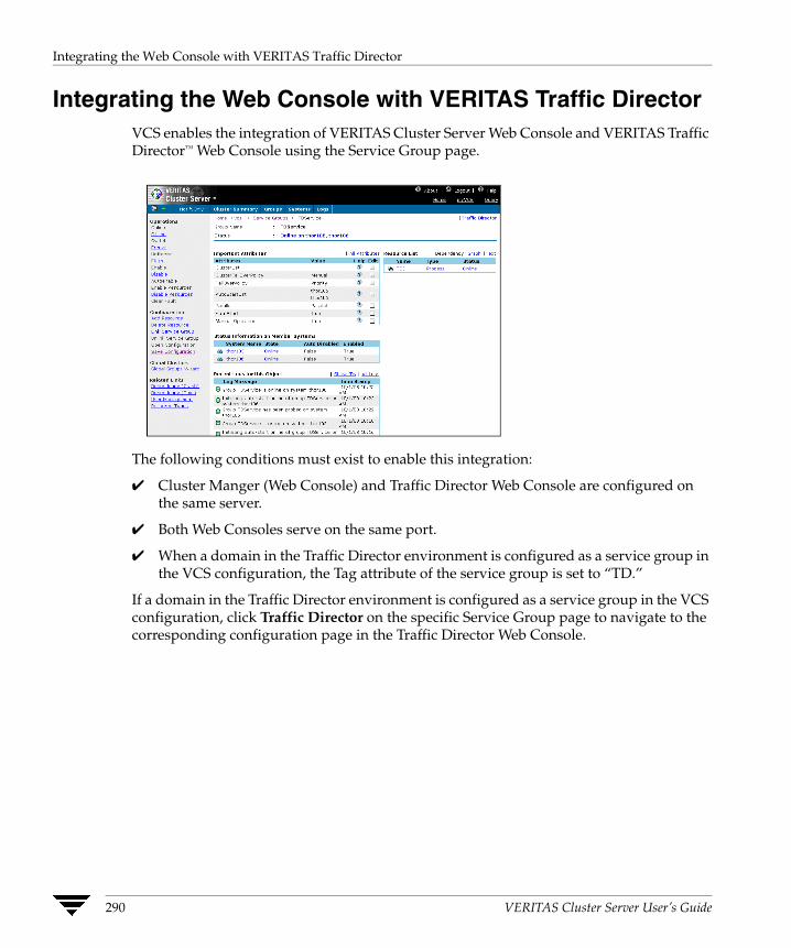
Integrating the Web Console with VERITAS Traffic Director
Integrating the Web Console with VERITAS Traffic Director VCS enables the integration of VERITAS Cluster Server Web Console and VERITAS Traffic Director™ Web Console using the Service Group page.
The following conditions must exist to enable this integration:
✔ Cluster Manger (Web Console) and Traffic Director Web Console are configured on the same server.
✔ Both Web Consoles serve on the same port.
✔ When a domain in the Traffic Director environment is configured as a service group in the VCS configuration, the Tag attribute of the service group is set to “TD.”
If a domain in the Traffic Director environment is configured as a service group in the VCS configuration, click Traffic Director on the specific Service Group page to navigate to the corresponding configuration page in the Traffic Director Web Console.
290 VERITAS Cluster Server User’s Guide
Configuring Application and NFS Service Groups
9VCS provides the following configuration wizards for specific service groups:
◆ Application Configuration Wizard
Creates and modifies Application service groups, which provide high availability for applications in a VCS cluster. The wizard creates service groups for applications running in local and global zones. See “Configuring Application Service Groups Using the Application Wizard” on page 292.
◆ NFS Configuration Wizard
Creates and modifies NFS service groups, which provide high availability for fileshares in a VCS cluster. See “Configuring NFS Service Groups Using the NFS Wizard” on page 304.
This chapter describes the Application and NFS wizards and how to use them to create and modify the service groups.
291
Configuring Application Service Groups Using the Application Wizard
Configuring Application Service Groups Using the Application Wizard
Before running the wizard, review the resource types and the attribute descriptions of the Application, Mount, NIC, and IP agents in the VERITAS Cluster Server Bundled Agents Reference Guide.
Prerequisites ✔ Make sure that the applications are not configured in any other service group.
✔ Verify the directories on which the applications depend reside on shared disks and are mounted.
✔ If the application runs in a zone, make sure the zone is started.
✔ Verify the mount points on which the applications depend are not configured in any other service group.
✔ Verify the virtual IP addresses on which applications depend are up. Verify the IP addresses are not configured in any other service group.
✔ Make sure the executable files required to start, stop, monitor, and clean (optional) the application reside on all nodes participating in the service group. If the application runs in a non-global zone, the executable files must reside in the non-global zone.
◆ StartProgram: The executable, created locally on each node, that starts the application.
◆ StopProgram: The executable, created locally on each node, that stops the application.
◆ CleanProgram: The executable, created locally on each node, that forcibly stops the application.
◆ You can monitor the application in the following ways:
◆ Specify the program that will monitor the application.
◆ Specify a list of processes to be monitored and cleaned.
◆ Specify a list of pid files that contain the process ID of the processes to be monitored and cleaned. These files are application-generated files. Each PID file contains one PID which will be monitored.
◆ All or some of the above.
292 VERITAS Cluster Server User’s Guide

Configuring Application Service Groups Using the Application Wizard
Running the Application Wizard
1. Start the Application wizard from a node in the cluster:
# hawizard application
2. Read the information on the Welcome screen and click Next.
3. On the Wizard Options dialog box, select to create a new service group or modify an existing group.
If you chose to modify an existing service group, select the service group.
In the Modify Application Service Group mode, you can add, modify, or delete applications in the service group. You can also modify the configuration of the Mount, IP and NIC resources if the service group is offline.
Click Next.
4. Specify the service group name and the system list.
a. Enter a name for the service group.
b. In the Available Cluster Systems box, select the systems on which to configure the service group and click the right-arrow icon to move the systems to the service group’s system list.
To remove a system from the service group’s system list, select the system in the Systems in Priority Order box and click the button with the left-arrow icon.
c. To change a system’s priority in the service group’s system list, select the system in the Systems in Priority Order box and click the buttons with the up and down arrow icons. The system at the top of the list has the highest priority while the system at the bottom of the list has the lowest priority.
Chapter 9, Configuring Application and NFS Service Groups 293

Configuring Application Service Groups Using the Application Wizard
d. Click Next.
If the cluster does not have zones configured, proceed to step 7 on page 296. If the cluster has zones configured, proceed to the next step.
5. Configure the zone in which the application runs.
a. Select the zone in which the application runs. If the zone does not appear in the list, click Discover Zones.
b. If the application depends on an IP address, select the Are applications accessible over the network? check box.
Select an ethernet card for the IP address associated with the application on each system. Click Discover NIC, if required.
c. Click Next.
If you chose a global zone for the application, proceed to step 7 on page 296. If you chose a non-global zone for the application, proceed to the next step.
294 VERITAS Cluster Server User’s Guide

Configuring Application Service Groups Using the Application Wizard
6. If you chose to configure a resource for a non-global zone, configure the Mount resources for the zone and the application.
a. Select the check boxes next to the mount points required for the application and for the non-global zones. Click Discover Mounts to discover mounts, if required.
b. Specify the Mount and Fsck options, if applicable. The agent uses these options when bringing the resource online.
c. If using the vxfs file system, you can select the SnapUmount check box to take the MountPoint snapshot offline when the resource is taken offline.
d. Select the Create mount points on all systems if they do not exist check box, if desired.
e. Click Next.
Chapter 9, Configuring Application and NFS Service Groups 295

Configuring Application Service Groups Using the Application Wizard
7. Select to create or modify applications.
To create an application:
a. Choose the Create Application option.
b. Enter the name of the application.
c. Click Next.
To modify an application:
a. Choose the Modify Application option.
b. Select the application.
c. To delete the application, click Delete Application. To modify the application, click Next.
Note Choose the Configure Application Dependency option only after you have finished with adding, modifying, or deleting applications.
296 VERITAS Cluster Server User’s Guide

Configuring Application Service Groups Using the Application Wizard
8. Specify information about the executables used to start, stop, and clean the application.
a. Specify the locations of the Start, Stop, and Clean (optional) programs along with their parameters. You must specify values for the Start and Stop programs.
b. Select the user in whose context the programs will run. Click Discover Users if some users were added after starting the wizard.
c. Click Next.
Chapter 9, Configuring Application and NFS Service Groups 297
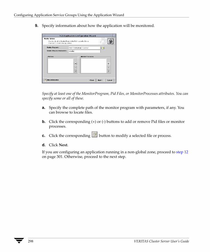
Configuring Application Service Groups Using the Application Wizard
9. Specify information about how the application will be monitored.
Specify at least one of the MonitorProgram, Pid Files, or MonitorProcesses attributes. You can specify some or all of these.
a. Specify the complete path of the monitor program with parameters, if any. You can browse to locate files.
b. Click the corresponding (+) or (-) buttons to add or remove Pid files or monitor processes.
c. Click the corresponding button to modify a selected file or process.
d. Click Next.
If you are configuring an application running in a non-global zone, proceed to step 12 on page 301. Otherwise, proceed to the next step.
298 VERITAS Cluster Server User’s Guide
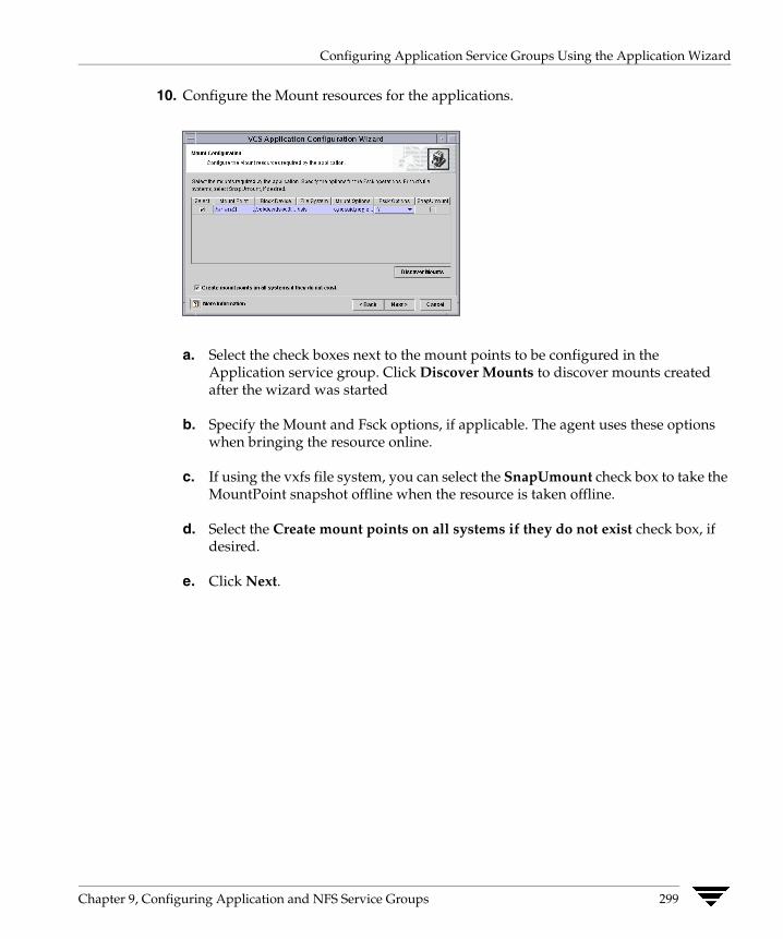
Configuring Application Service Groups Using the Application Wizard
10. Configure the Mount resources for the applications.
a. Select the check boxes next to the mount points to be configured in the Application service group. Click Discover Mounts to discover mounts created after the wizard was started
b. Specify the Mount and Fsck options, if applicable. The agent uses these options when bringing the resource online.
c. If using the vxfs file system, you can select the SnapUmount check box to take the MountPoint snapshot offline when the resource is taken offline.
d. Select the Create mount points on all systems if they do not exist check box, if desired.
e. Click Next.
Chapter 9, Configuring Application and NFS Service Groups 299
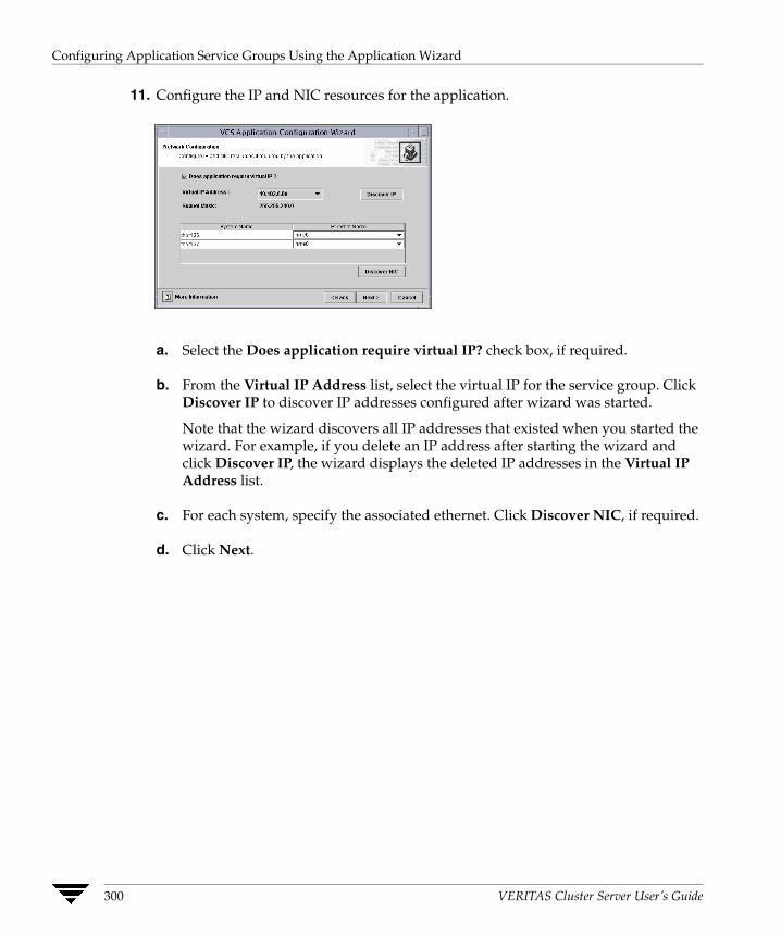
Configuring Application Service Groups Using the Application Wizard
11. Configure the IP and NIC resources for the application.
a. Select the Does application require virtual IP? check box, if required.
b. From the Virtual IP Address list, select the virtual IP for the service group. Click Discover IP to discover IP addresses configured after wizard was started.
Note that the wizard discovers all IP addresses that existed when you started the wizard. For example, if you delete an IP address after starting the wizard and click Discover IP, the wizard displays the deleted IP addresses in the Virtual IP Address list.
c. For each system, specify the associated ethernet. Click Discover NIC, if required.
d. Click Next.
300 VERITAS Cluster Server User’s Guide

Configuring Application Service Groups Using the Application Wizard
12. Specify whether you want to configure more applications in the service group.
If you want to add more applications to the service group, select the Configure more applications check box.
Click Next.
Note If you choose to configure more applications, the wizard displays the Application Options dialog box. See step 7 on page 296 for instructions on how to configure applications.
Chapter 9, Configuring Application and NFS Service Groups 301
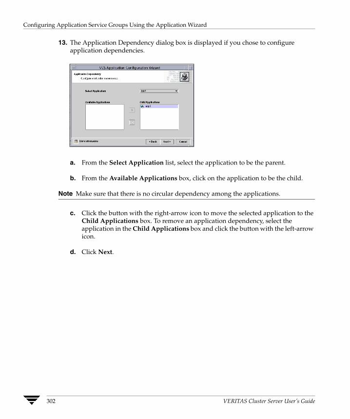
Configuring Application Service Groups Using the Application Wizard
13. The Application Dependency dialog box is displayed if you chose to configure application dependencies.
a. From the Select Application list, select the application to be the parent.
b. From the Available Applications box, click on the application to be the child.
Note Make sure that there is no circular dependency among the applications.
c. Click the button with the right-arrow icon to move the selected application to the Child Applications box. To remove an application dependency, select the application in the Child Applications box and click the button with the left-arrow icon.
d. Click Next.
302 VERITAS Cluster Server User’s Guide

Configuring Application Service Groups Using the Application Wizard
14. Review your configuration and change resource names, if desired.
The left pane lists the configured resources. Click on a resource to view its attributes and their configured values in the Attributes box.
To edit a resource name, select the resource name and click on it. Press Enter after editing each name. Note that when modifying service groups, you can change names of newly created resources only, which appear in black.
Click Next. The wizard starts running commands to create (or modify) the service group.
15. On the Completing the Application Configuration Wizard dialog box, select the check box to bring the service group online on the local system.
Click Close.
Chapter 9, Configuring Application and NFS Service Groups 303
Configuring NFS Service Groups Using the NFS Wizard
Configuring NFS Service Groups Using the NFS Wizard This NFS Configuration wizard enables you to create an NFS service group, which provides high availability for fileshares. Before running the wizard, review the resource type and the attribute descriptions of the NFS, Share, Mount, NIC, and IP agents in the VERITAS Cluster Server Bundled Agents Reference Guide.
The wizard supports the following configurations:
◆ Multiple Share Paths
◆ Single Virtual IP
Prerequisites ✔ Verify the paths to be shared are exported.
✔ Verify the paths to be shared are mounted and are not configured in any other service group.
✔ Verify the virtual IP to be configured is up and is not configured in any other service group.
✔ Disable the Service Management Facility (SMF) for NFS daemons for the NFS agent to work on Solaris 10.
You must disable SMF for nsd and mountd before bringing the NFS agent online. To do so:
svccfg delete -f svc:/network/nfs/server:default
304 VERITAS Cluster Server User’s Guide
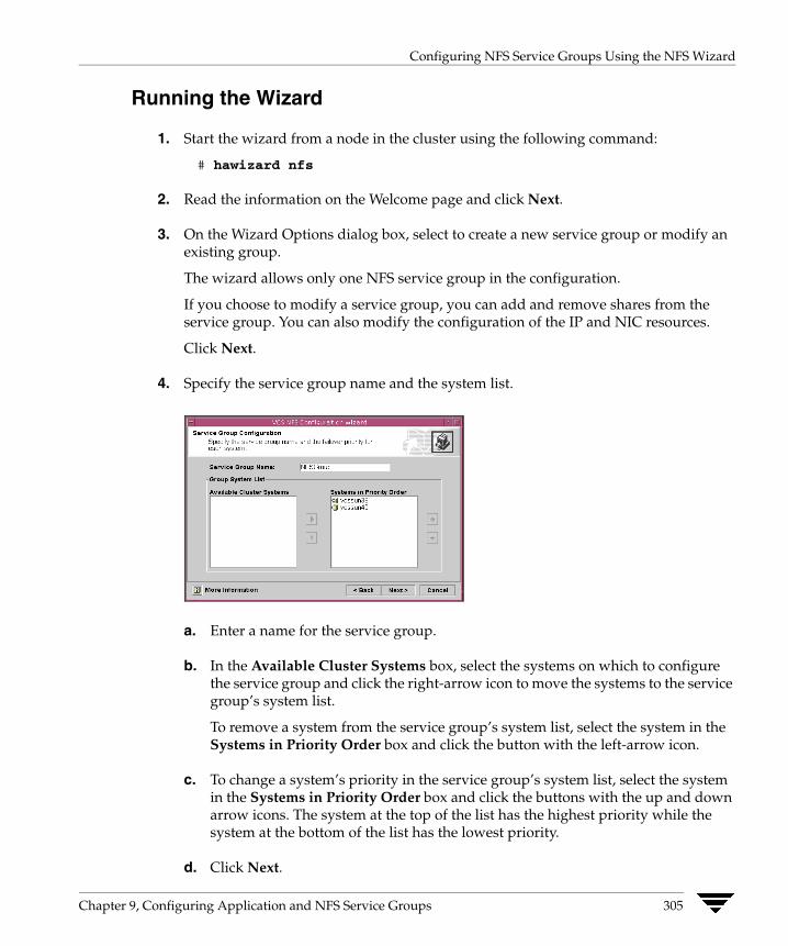
Configuring NFS Service Groups Using the NFS Wizard
Running the Wizard
1. Start the wizard from a node in the cluster using the following command:
# hawizard nfs
2. Read the information on the Welcome page and click Next.
3. On the Wizard Options dialog box, select to create a new service group or modify an existing group.
The wizard allows only one NFS service group in the configuration.
If you choose to modify a service group, you can add and remove shares from the service group. You can also modify the configuration of the IP and NIC resources.
Click Next.
4. Specify the service group name and the system list.
a. Enter a name for the service group.
b. In the Available Cluster Systems box, select the systems on which to configure the service group and click the right-arrow icon to move the systems to the service group’s system list.
To remove a system from the service group’s system list, select the system in the Systems in Priority Order box and click the button with the left-arrow icon.
c. To change a system’s priority in the service group’s system list, select the system in the Systems in Priority Order box and click the buttons with the up and down arrow icons. The system at the top of the list has the highest priority while the system at the bottom of the list has the lowest priority.
d. Click Next.
Chapter 9, Configuring Application and NFS Service Groups 305
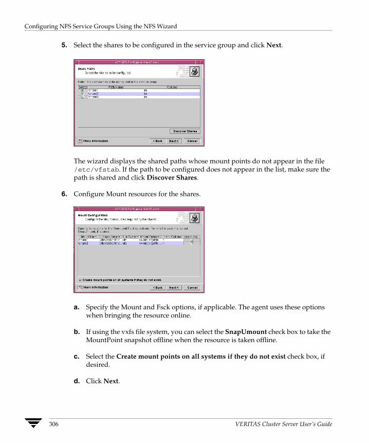
Configuring NFS Service Groups Using the NFS Wizard
5. Select the shares to be configured in the service group and click Next.
The wizard displays the shared paths whose mount points do not appear in the file /etc/vfstab. If the path to be configured does not appear in the list, make sure the path is shared and click Discover Shares.
6. Configure Mount resources for the shares.
a. Specify the Mount and Fsck options, if applicable. The agent uses these options when bringing the resource online.
b. If using the vxfs file system, you can select the SnapUmount check box to take the MountPoint snapshot offline when the resource is taken offline.
c. Select the Create mount points on all systems if they do not exist check box, if desired.
d. Click Next.
306 VERITAS Cluster Server User’s Guide
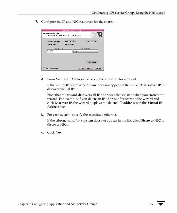
Configuring NFS Service Groups Using the NFS Wizard
7. Configure the IP and NIC resources for the shares.
a. From Virtual IP Address list, select the virtual IP for a mount.
If the virtual IP address for a share does not appear in the list, click Discover IP to discover virtual IPs.
Note that the wizard discovers all IP addresses that existed when you started the wizard. For example, if you delete an IP address after starting the wizard and click Discover IP, the wizard displays the deleted IP addresses in the Virtual IP Address list.
b. For each system, specify the associated ethernet.
If the ethernet card for a system does not appear in the list, click Discover NIC to discover NICs.
c. Click Next.
Chapter 9, Configuring Application and NFS Service Groups 307
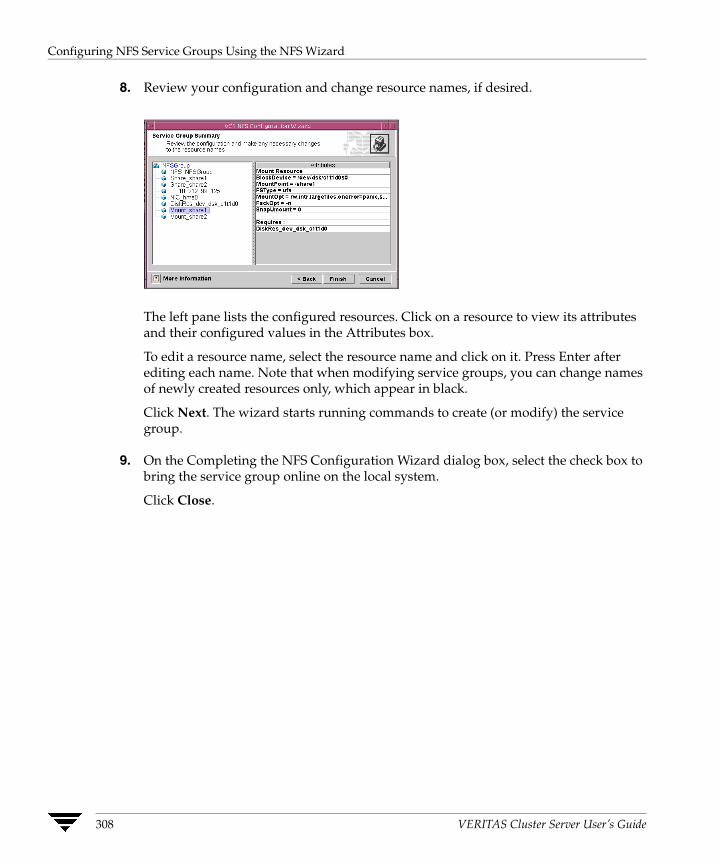
Configuring NFS Service Groups Using the NFS Wizard
8. Review your configuration and change resource names, if desired.
The left pane lists the configured resources. Click on a resource to view its attributes and their configured values in the Attributes box.
To edit a resource name, select the resource name and click on it. Press Enter after editing each name. Note that when modifying service groups, you can change names of newly created resources only, which appear in black.
Click Next. The wizard starts running commands to create (or modify) the service group.
9. On the Completing the NFS Configuration Wizard dialog box, select the check box to bring the service group online on the local system.
Click Close.
308 VERITAS Cluster Server User’s Guide
Section III. VCS Operations
This section provides information on inter-node and intra-node VCS communication. It describes how VCS maintains node memberships and uses I/O fencing to maintain data integrity. The section also describes resource and system failures and the role of service group dependencies and workload management.
Section III includes the following chapters:
◆ Chapter 10. “VCS Communications, Membership, and I/O Fencing” on page 311
◆ Chapter 11. “Controlling VCS Behavior” on page 343
◆ Chapter 12. “The Role of Service Group Dependencies” on page 383

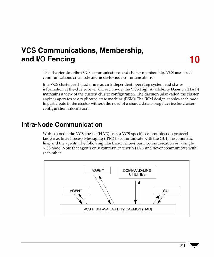
VCS Communications, Membership, and I/O Fencing
10This chapter describes VCS communications and cluster membership. VCS uses local communications on a node and node-to-node communications.
In a VCS cluster, each node runs as an independent operating system and shares information at the cluster level. On each node, the VCS High Availability Daemon (HAD) maintains a view of the current cluster configuration. The daemon (also called the cluster engine) operates as a replicated state machine (RSM). The RSM design enables each node to participate in the cluster without the need of a shared data storage device for cluster configuration information.
Intra-Node Communication Within a node, the VCS engine (HAD) uses a VCS-specific communication protocol known as Inter Process Messaging (IPM) to communicate with the GUI, the command line, and the agents. The following illustration shows basic communication on a single VCS node. Note that agents only communicate with HAD and never communicate with each other.
AGENT COMMAND-LINE UTILITIES
VCS HIGH AVAILABILITY DAEMON (HAD)
AGENT GUI
311
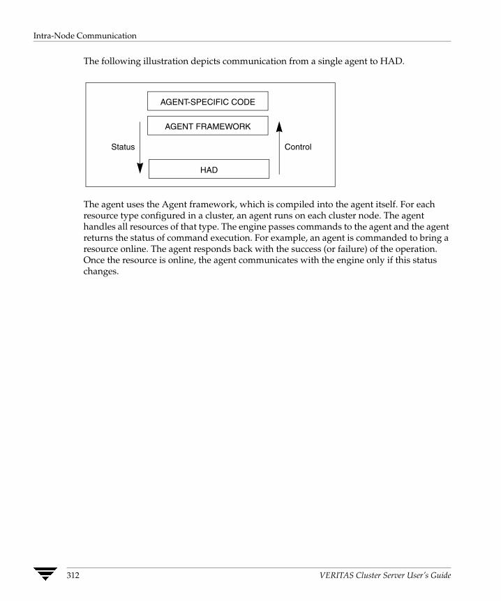
Intra-Node Communication
The following illustration depicts communication from a single agent to HAD.
Control Status
AGENT-SPECIFIC CODE
AGENT FRAMEWORK
HAD
The agent uses the Agent framework, which is compiled into the agent itself. For each resource type configured in a cluster, an agent runs on each cluster node. The agent handles all resources of that type. The engine passes commands to the agent and the agent returns the status of command execution. For example, an agent is commanded to bring a resource online. The agent responds back with the success (or failure) of the operation. Once the resource is online, the agent communicates with the engine only if this status changes.
312 VERITAS Cluster Server User’s Guide

Inter-Node Communication
Inter-Node Communication VCS uses the cluster interconnect for network communications between cluster nodes. The nodes communicate using the capabilities provided by LLT and GAB.
The LLT module is designed to function as a high performance, low latency replacement for the IP stack and is used for all cluster communications. LLT provides the communications backbone for GAB. LLT distributes, or load balances inter-node communication across up to eight interconnect links. When a link fails, traffic is redirected to remaining links.
The Group Membership Services /Atomic Broadcast module is responsible for reliable cluster communications. GAB provides guaranteed delivery of point-to-point and broadcast messages to all nodes. The Atomic Broadcast functionality is used by HAD to ensure that all systems within the cluster receive all configuration change messages, or are rolled back to the previous state, much like a database atomic commit. If a failure occurs while transmitting a broadcast message, GAB's atomicity ensures that, upon recovery, all systems have the same information. The VCS engine uses a private IOCTL (provided by GAB) to tell GAB that it is alive.
The following diagram illustrates the overall communications paths.
User
Kernel
Space
Space
AGENTAGENT
HAD
GAB
LLT
User
Kernel
Space
Space
AGENTAGENT
HAD
GAB
LLT
Chapter 10, VCS Communications, Membership, and I/O Fencing 313

Cluster Membership
Cluster Membership Cluster membership implies that the cluster must accurately determine which nodes are active in the cluster at any given time. In order to take corrective action on node failure, surviving nodes must agree on when a node has departed. This membership needs to be accurate and must be coordinated among active members. This becomes critical considering nodes can be added, rebooted, powered off, faulted, and so on. VCS uses its cluster membership capability to dynamically track the overall cluster topology. Cluster membership is maintained through the use of heartbeats.
LLT is responsible for sending and receiving heartbeat traffic over network links. Each node sends heartbeat packets on all configured LLT interfaces. By using an LLT ARP response, each node sends a single packet that tells all other nodes it is alive, as well as the communications information necessary for other nodes to send unicast messages back to the broadcaster.
LLT can be configured to designate specific links as high priority and others as low priority. High priority links are used for cluster communications (GAB) as well as heartbeat. Low priority links only carry heartbeat unless there is a failure of all configured high priority links. At this time, LLT switches cluster communications to the first available low priority link. Traffic reverts to high priority links as soon as they are available.
AGENTAGENT
HAD
GAB
LLT
AGENTAGENT
HAD
GAB
LLT
AGENTAGENT
HAD
GAB
LLT
AGENTAGENT
HAD
GAB
LLT
Broadcast heartbeat on every interface every 0.5 second
Each LLT module tracks heartbeat status from each peer on each public interface
LLT forwards heartbeat status of each node to GAB
LLT passes the status of the heartbeat to the Group Membership Services function of GAB. When LLT on a system no longer receives heartbeat messages from a peer on any configured LLT interface for a predefined time, LLT informs of the heartbeat loss for that system. GAB receives input on the status of heartbeat from all nodes and makes membership determination based on this information. When LLT informs GAB of a heartbeat loss, GAB marks the peer as DOWN and excludes the peer from the cluster. In most configurations, the I/O fencing module is utilized to ensure there was not a partition
314 VERITAS Cluster Server User’s Guide

Cluster Membership
or split of the cluster interconnect. Once the new membership is determined, GAB informs processes on the remaining nodes that the cluster membership has changed. VCS then carries out failover actions to recover.
Understanding Split-brain and the Need for I/O Fencing When VCS detects node failure, it attempts to take corrective action, which is determined by the cluster configuration. If the failing node hosted a service group, and one of the remaining nodes is designated in the group's SystemList, then VCS fails the service group over and imports shared storage to another node in the cluster. If the mechanism used to detect node failure breaks down, the symptoms appear identical to those of a failed node.
For example, in a four-node cluster, if a system fails, it stops sending heartbeat over the private interconnect. The remaining nodes then take corrective action. If the cluster interconnect fails, other nodes determine that their peer has departed and attempt to take corrective action. This may result in data corruption because both nodes attempt to take control of data storage in an uncoordinated manner.
✗ ✗
Node 1 Node 2 Node 3 Node 4
Node failure and loss of cluster interconnect result in no heartbeats being received from node 4.
This situation can also arise in other scenarios. If a system were so busy as to appear hung, it would be declared dead. This can also happen if the hardware supports a break and resume function. Dropping the system to prom (system controller) level with a break and a subsequent resume means the system could be declared as dead and the cluster reformed. The system could then return and start writing to the shared storage.
Chapter 10, VCS Communications, Membership, and I/O Fencing 315
Cluster Membership
Preventing Split-brain This section describes the strategies that could be used to prevent split-brain.
Coordinated Cluster Membership (Membership Arbitration)
When cluster nodes lose heartbeat from another node, the surviving nodes can:
◆ Assume the departed node is down; this presents data integrity risks.
◆ Take positive steps to ensure that the remaining nodes are the only surviving cluster members. This is known as membership arbitration.
Membership arbitration ensures that on any change in cluster membership, the surviving members determine if they are still allowed to remain running. In many designs, this is implemented with a quorum architecture.
A cluster using the quorum architecture requires at least 51% of available nodes to be alive. For example, in a 4 node cluster, if one node separates from the cluster due to an interconnect fault, the separated node is not capable of surviving. When the node receives notification that the cluster membership has changed, it determines that it is no longer in a membership with at least 51% of configured systems, and shuts down by calling a kernel panic.
Quorum is usually implemented with more than just systems in the quorum count. Using disk devices as members lends greater design flexibility. During a cluster membership change, remaining nodes attempt to gain exclusive control of any disk devices designated as quorum disks.
Membership arbitration is designed to ensure departed members must really be down. However, a membership arbitration scheme by itself is inadequate for complete data protection.
◆ A node can hang, and on return to processing, perform a write before determining it should not be a part of a running cluster.
◆ The same situation can exist if a node is dropped to the system controller/prom level and subsequently resumed. Other systems assume the node has departed, and perform a membership arbitration to ensure they have an exclusive cluster. When the node comes back it may write before determining the cluster membership has changed to exclude it.
In both cases, the concept of membership arbitration/quorum can leave a potential data corruption hole open. If a node can write before determining it should no longer be in the cluster, and panic, it would result in silent data corruption.
What is needed to augment any membership arbitration design is a complete data protection mechanism to block access to disks from any node that is not part of the active cluster.
316 VERITAS Cluster Server User’s Guide

Cluster Membership
Data Protection Mechanism
A data protection mechanism in a cluster is a method to block access to the disk for any node that should not be currently accessing the storage. Typically this is implemented with a SCSI reserve mechanism. In the past, many vendors implemented data protection using the SCSI-II Reserve/Release mechanism.
SCSI-II reservations have several limitations in a cluster environment where storage technology has evolved from SCSI-attached arrays to fiber channel SAN.
◆ SCSI-II reservations are designed to allow one active host to reserve a drive, thereby blocking access from any other initiator. This design was adequate when simple JBOD and early arrays had one path to disk, and were shared by two hosts. SCSI-II cannot support multiple paths to disk from a host (such as VERITAS Dynamic Multi Pathing) or more than one host being active at a time with a reservation in place.
◆ SCSI-II reservations can be cleared with a SCSI bus reset. Any device can reset the bus and clear the reservation. It is the responsibility of the reserving host to reclaim the reservation if it is cleared. Problems arise in more complicated environments, such as SAN-attached environments where multiple systems could potentially reset a reservation and open up a significant data corruption hole for a system to write data.
Chapter 10, VCS Communications, Membership, and I/O Fencing 317
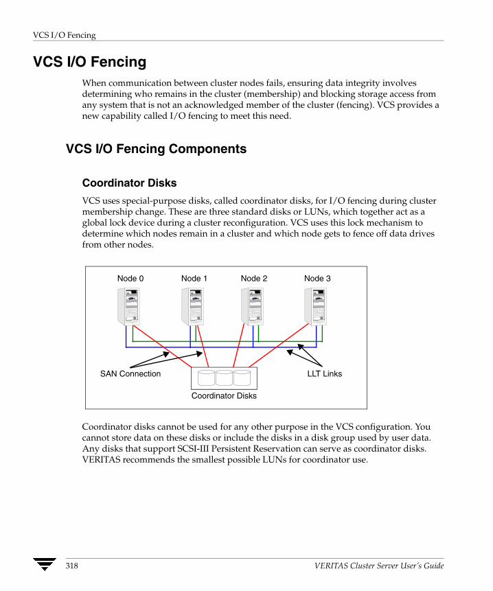
VCS I/O Fencing
VCS I/O Fencing When communication between cluster nodes fails, ensuring data integrity involves determining who remains in the cluster (membership) and blocking storage access from any system that is not an acknowledged member of the cluster (fencing). VCS provides a new capability called I/O fencing to meet this need.
VCS I/O Fencing Components
Coordinator Disks
VCS uses special-purpose disks, called coordinator disks, for I/O fencing during cluster membership change. These are three standard disks or LUNs, which together act as a global lock device during a cluster reconfiguration. VCS uses this lock mechanism to determine which nodes remain in a cluster and which node gets to fence off data drives from other nodes.
Node 0
SAN Connection LLT Links
Node 1 Node 2 Node 3
Coordinator Disks
Coordinator disks cannot be used for any other purpose in the VCS configuration. You cannot store data on these disks or include the disks in a disk group used by user data. Any disks that support SCSI-III Persistent Reservation can serve as coordinator disks. VERITAS recommends the smallest possible LUNs for coordinator use.
318 VERITAS Cluster Server User’s Guide
VCS I/O Fencing
Fencing Module
Each system in the cluster runs a kernel module called vxfen, or the fencing module. This module works to maintain tight control on cluster membership. It is responsible for the following actions:
◆ Registering with the coordinator disks during normal operation.
◆ Racing for control of the coordinator disks during membership changes.
SCSI-III Persistent Reservations
VCS I/O fencing uses SCSI-III Persistent Reservation (SCSI-III PR), which is an enhancement to the SCSI specification. SCSI-III PR resolves the issues of using SCSI reservations in a modern clustered SAN environment. It supports multiple nodes accessing a device and blocking access to other nodes. SCSI-III PR ensures persistent reservations across SCSI bus resets. It also supports multiple paths from a host to a disk.
SCSI-III PR uses a concept of registration and reservation. Systems wishing to participate register a key with a SCSI-III device. Multiple systems registering a key form a membership. Registered systems can then establish a reservation, which is typically set to Write Exclusive Registrants Only (WERO). This means that only registered systems can write.
SCSI-III PR technology makes blocking write access as simple as removing a registration from a device. If node A wishes to block node B, it removes node B’s registration by issuing a "preempt and abort" command. Only registered members can “eject” the registration of other members. Once a node is ejected, it cannot eject other nodes. This makes the process of ejecting final and "atomic."
The SCSI-III PR specification simply describes the method to control access to disks with the registration and reservation mechanism. The method to determine who can register with a disk and when a registered member should eject another node is implementation-specific.
Data Disks
Data disks are standard disk devices used for data storage. These can be physical disks or RAID Logical Units (LUNs). These disks must support SCSI-III PR. Data disks are incorporated in standard disk groups managed using VERITAS Volume Manager.
The VCS DiskGroup agent is responsible for fencing failover disk groups and Cluster Volume Manager (CVM) handles any shared CVM disk groups.
Chapter 10, VCS Communications, Membership, and I/O Fencing 319

VCS I/O Fencing
I/O Fencing Operational Concepts I/O fencing performs two important functions in a VCS cluster: membership arbitration and data protection.
Membership Arbitration
I/O fencing uses the fencing module and coordinator disks for membership control in a VCS cluster. With fencing, when a membership change occurs, members of any surviving cluster race for exclusive control of the coordinator disks to lock out any other potential cluster. This ensures that only one cluster is allowed to survive a membership arbitration in the event of an interconnect failure.
Let us take the example of a two-node cluster. If node 0 loses heartbeat from node 1, node 1 attempts to gain exclusive control of the coordinator disks. Node 0 makes no assumptions that node 1 is down, and races to gain control of the coordinator disks. Each node attempts to eject the opposite cluster from membership on the coordinator disks. The node that ejects the opposite member and gains control over a majority of the coordinator disks wins the race. The other node loses and must shut down.
The following illustration depicts the sequence in which these operations take place.
AGENTAGENT
HAD
GAB
LLT
1. GAB delivers
2. HAD sends IOCTL
membership to
to fencing module
I/O FENCE 3. Fencing module responds when I/O fence completes
clients.
First, on node 0, LLT times out the heartbeat from node 1 (16 seconds by default), GAB is informed of a heartbeat failure. GAB then determines that a membership change is occurring. After the “GAB Stable Timeout” (5 seconds), GAB delivers the membership change to all registered clients. In this case, HAD and I/O fence.
HAD receives the membership change and requests the fencing module to arbitrate in case of a split-brain scenario and waits for the race to complete.
The registration function of SCSI-III PR handles races. During normal startup, every cluster member registers a unique key with the coordinator disks. To win a race for the coordinator disks, a node has to eject the registration key of the node in question from a majority of the coordinator disks.
320 VERITAS Cluster Server User’s Guide
VCS I/O Fencing
If the I/O fencing module gains control of the coordinator disks, it informs HAD of success. If the fencing module is unsuccessful, the node panics and reboots.
Data Protection
Simple membership arbitration does not guarantee data protection. If a node is hung or suspended and comes back to life, it could cause data corruption before GAB and the fencing module determine the node was supposed to be dead. VCS takes care of this situation by providing full SCSI-III PR based data protection at the data disk level.
Failover Disk Groups
With fencing activated, the VCS DiskGroup agent imports shared storage using SCSI-III registration, and a WERO reservation. This means only the registered node can write. When taking over a disk group in a failover, the existing registration is ejected and the storage is imported.
Cluster Volume Manager Disk Groups
Shared disk groups managed using Cluster Volume Manager (CVM) are fenced by CVM during the import process. The CVM module on each node registers with data disks as they are imported. After registering with data disks, the master node sets a reservation on the disks in the WERO mode.
If a membership change occurs, the fencing module races to gain control over the coordinator disks. If successful, it informs the CVM module of the membership change. The CVM module then uses multiple kernel threads to eject departed members from all shared data drives in parallel. Once this operation complete, the fencing module passes the cluster reconfiguration information to higher software layers like the Cluster File System.
Chapter 10, VCS Communications, Membership, and I/O Fencing 321
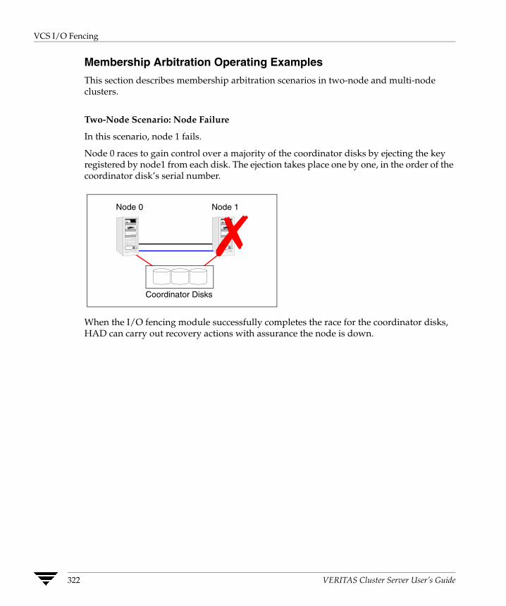
VCS I/O Fencing
Membership Arbitration Operating Examples
This section describes membership arbitration scenarios in two-node and multi-node clusters.
Two-Node Scenario: Node Failure
In this scenario, node 1 fails.
Node 0 races to gain control over a majority of the coordinator disks by ejecting the key registered by node1 from each disk. The ejection takes place one by one, in the order of the coordinator disk’s serial number.
Node 1
✗ Coordinator Disks
Node 0
When the I/O fencing module successfully completes the race for the coordinator disks, HAD can carry out recovery actions with assurance the node is down.
322 VERITAS Cluster Server User’s Guide
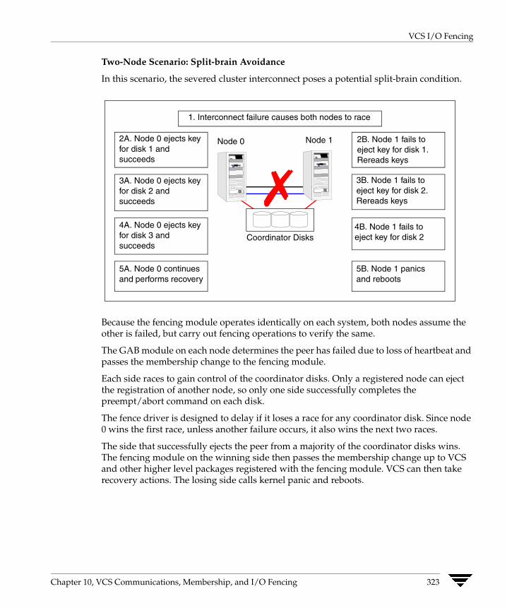
VCS I/O Fencing
Two-Node Scenario: Split-brain Avoidance
In this scenario, the severed cluster interconnect poses a potential split-brain condition.
2A. Node 0 ejects key for disk 1 and succeeds
Node 0
✗ Node 1
Coordinator Disks
3A. Node 0 ejects key for disk 2 and succeeds
4A. Node 0 ejects key for disk 3 and succeeds
5A. Node 0 continues and performs recovery
2B. Node 1 fails to eject key for disk 1. Rereads keys
3B. Node 1 fails to eject key for disk 2. Rereads keys
4B. Node 1 fails to eject key for disk 2
5B. Node 1 panics and reboots
1. Interconnect failure causes both nodes to race
Because the fencing module operates identically on each system, both nodes assume the other is failed, but carry out fencing operations to verify the same.
The GAB module on each node determines the peer has failed due to loss of heartbeat and passes the membership change to the fencing module.
Each side races to gain control of the coordinator disks. Only a registered node can eject the registration of another node, so only one side successfully completes the preempt/abort command on each disk.
The fence driver is designed to delay if it loses a race for any coordinator disk. Since node 0 wins the first race, unless another failure occurs, it also wins the next two races.
The side that successfully ejects the peer from a majority of the coordinator disks wins. The fencing module on the winning side then passes the membership change up to VCS and other higher level packages registered with the fencing module. VCS can then take recovery actions. The losing side calls kernel panic and reboots.
Chapter 10, VCS Communications, Membership, and I/O Fencing 323
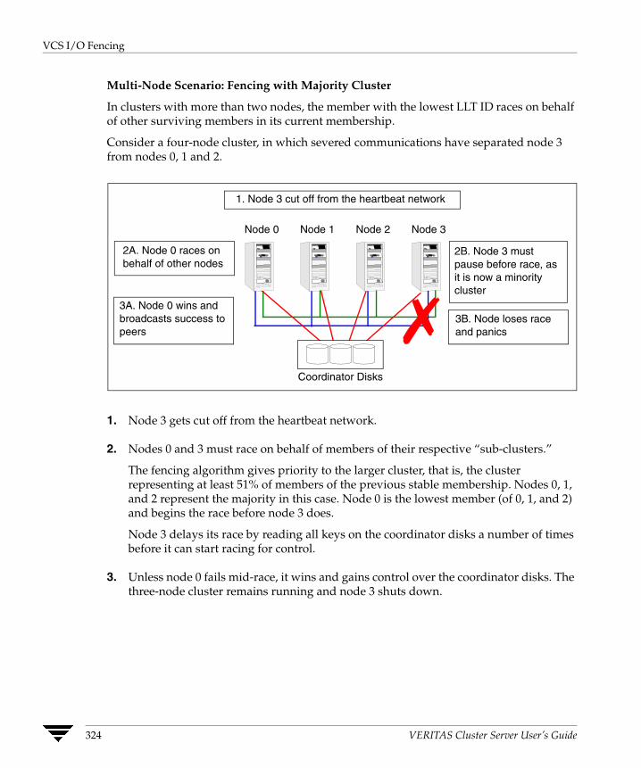
VCS I/O Fencing
Multi-Node Scenario: Fencing with Majority Cluster
In clusters with more than two nodes, the member with the lowest LLT ID races on behalf of other surviving members in its current membership.
Consider a four-node cluster, in which severed communications have separated node 3 from nodes 0, 1 and 2.
2A. Node 0 races on behalf of other nodes
1. Node 3 cut off from the heartbeat network
2B. Node 3 must pause before race, as it is now a minority cluster
3B. Node loses race and panics
3A. Node 0 wins and broadcasts success to peers
Coordinator Disks
Node 0 Node 1 Node 2 Node 3
✗ 1. Node 3 gets cut off from the heartbeat network.
2. Nodes 0 and 3 must race on behalf of members of their respective “sub-clusters.”
The fencing algorithm gives priority to the larger cluster, that is, the cluster representing at least 51% of members of the previous stable membership. Nodes 0, 1, and 2 represent the majority in this case. Node 0 is the lowest member (of 0, 1, and 2) and begins the race before node 3 does.
Node 3 delays its race by reading all keys on the coordinator disks a number of times before it can start racing for control.
3. Unless node 0 fails mid-race, it wins and gains control over the coordinator disks. The three-node cluster remains running and node 3 shuts down.
324 VERITAS Cluster Server User’s Guide

VCS I/O Fencing
Multi-Node Scenario: Fencing with Equal Sub-Clusters
In this scenario, each side has half the nodes, that is, there are two minority clusters.
2A. Node 0 pauses before racing for other nodes
2B. Node 2 pauses before racing for other nodes
3B. Node 2 loses race and panics
3A. Node 0 wins and broadcasts success to peers
Coordinator Disks
✗ 4. Node 3 times out and panics
1. Cluster separates into two sub-clusters
Node 0 Node 1 Node 2 Node 3
1. The interconnect failure leads to nodes 0 and 1 being separated from nodes 2 and 3. The cluster splits into two sub-clusters of the same size.
2. Both clusters wait for the same amount of time and begin racing. In this situation, either side can win control of the first coordinator disk. In this example, node 0 wins the first disk. Node 2 then delays by rereading the coordinator disks after losing the first race. Consequently, node 0 gains control over all three coordinator disks.
3. After winning the race, node 0 broadcast its success to its peers. On the losing side, node 2 panics because it has lost the race. The remaining members of the losing side time out waiting for a success message and panic.
Chapter 10, VCS Communications, Membership, and I/O Fencing 325
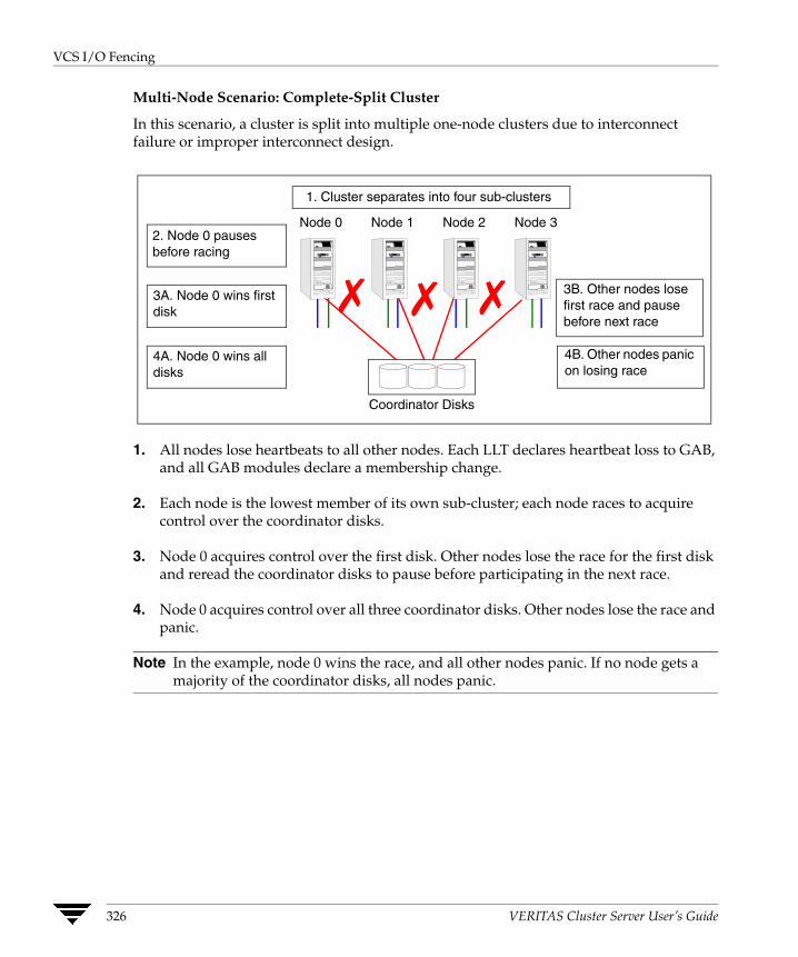
VCS I/O Fencing
Multi-Node Scenario: Complete-Split Cluster
In this scenario, a cluster is split into multiple one-node clusters due to interconnect failure or improper interconnect design.
2. Node 0 pauses before racing
3B. Other nodes lose first race and pause before next race
3A. Node 0 wins first disk
Coordinator Disks
✗ 4B. Other nodes panic on losing race
✗ ✗ 4A. Node 0 wins all disks
1. Cluster separates into four sub-clusters
Node 0 Node 1 Node 2 Node 3
1. All nodes lose heartbeats to all other nodes. Each LLT declares heartbeat loss to GAB, and all GAB modules declare a membership change.
2. Each node is the lowest member of its own sub-cluster; each node races to acquire control over the coordinator disks.
3. Node 0 acquires control over the first disk. Other nodes lose the race for the first disk and reread the coordinator disks to pause before participating in the next race.
4. Node 0 acquires control over all three coordinator disks. Other nodes lose the race and panic.
Note In the example, node 0 wins the race, and all other nodes panic. If no node gets a majority of the coordinator disks, all nodes panic.
326 VERITAS Cluster Server User’s Guide

VCS I/O Fencing
I/O Fencing Startup The startup sequence of I/O fencing is designed to prevent pre-existing network problems from affecting cluster membership. The startup sequence ensures that all members can access the coordinator disks and determine if a node should be allowed to join a cluster.
The startup sequence algorithm is as follows:
1. Determine which disks are to be used as coordinator disks.
a. Read the file /etc/vxfendg to determine the name of the VERITAS Volume Manager disk group containing the coordinator disks. See the VCS Installation Guide for information on creating the coordinator disk group.
b. Use Volume Manager tools to determine the disks in the disk group and the paths available to these disks.
c. Populate the file /etc/vxfentab with this information.
2. Start the fencing driver.
a. The fencing driver first reads the serial numbers of the coordinator disks from the file /etc/vxfentab and builds an in-memory list of these drives.
b. The driver then determines if it is the first node to start fencing. If other members are up and operating on GAB port B, it asks for a configuration snapshot from a running member. This is done to verify members in the cluster see the same coordinator disks. Otherwise, the fencing driver enters an error state.
3. Determine if a network partition exists.
a. Determine if any node has registered keys on the coordinator disks.
b. If any keys are present, verify the corresponding member can be seen in the current GAB membership. If the member cannot be seen, the fencing driver assumes the node starting up has been fenced out of the cluster due to a network partition. The fencing driver prints a warning to the console and the system log about a pre-existing network partition and does not start.
c. If the owners of the coordinator disks can be seen, or if no keys are seen on disk, the fencing driver proceeds.
4. Register keys with each coordinator disk in sequence.
Chapter 10, VCS Communications, Membership, and I/O Fencing 327
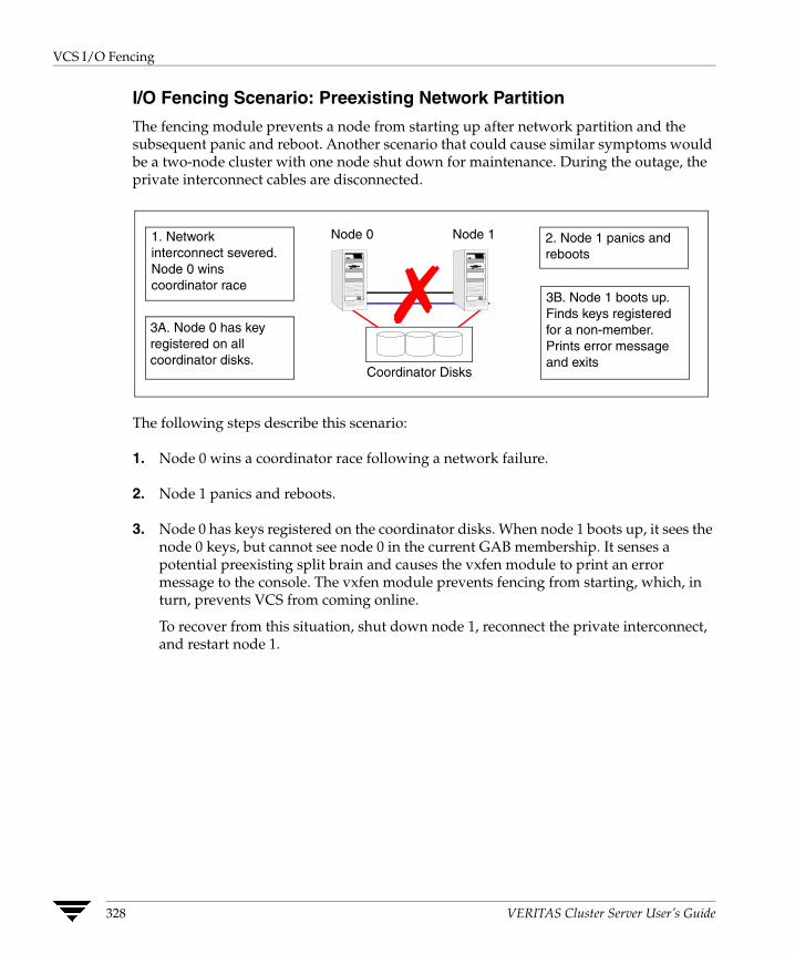
VCS I/O Fencing
I/O Fencing Scenario: Preexisting Network Partition
The fencing module prevents a node from starting up after network partition and the subsequent panic and reboot. Another scenario that could cause similar symptoms would be a two-node cluster with one node shut down for maintenance. During the outage, the private interconnect cables are disconnected.
3B. Node 1 boots up. Finds keys registered for a non-member. Prints error message and exits
3A. Node 0 has key registered on all coordinator disks.
✗ Coordinator Disks
1. Network interconnect severed. Node 0 wins coordinator race
2. Node 1 panics and reboots
Node 0 Node 1
The following steps describe this scenario:
1. Node 0 wins a coordinator race following a network failure.
2. Node 1 panics and reboots.
3. Node 0 has keys registered on the coordinator disks. When node 1 boots up, it sees the node 0 keys, but cannot see node 0 in the current GAB membership. It senses a potential preexisting split brain and causes the vxfen module to print an error message to the console. The vxfen module prevents fencing from starting, which, in turn, prevents VCS from coming online.
To recover from this situation, shut down node 1, reconnect the private interconnect, and restart node 1.
328 VERITAS Cluster Server User’s Guide
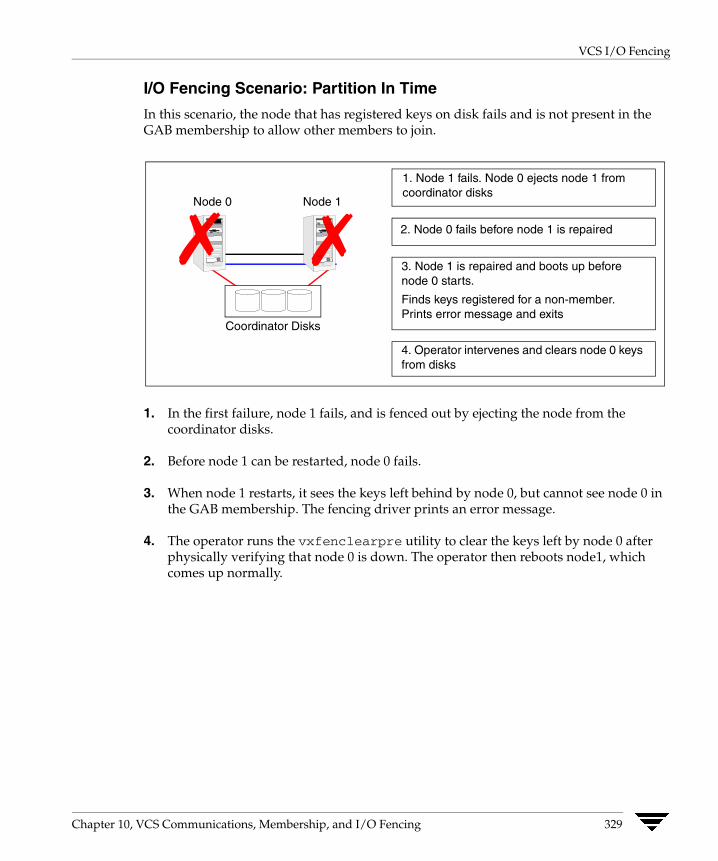
VCS I/O Fencing
I/O Fencing Scenario: Partition In Time
In this scenario, the node that has registered keys on disk fails and is not present in the GAB membership to allow other members to join.
3. Node 1 is repaired and boots up before node 0 starts.
Finds keys registered for a non-member. Prints error message and exits
2. Node 0 fails before node 1 is repaired
1. Node 1 fails. Node 0 ejects node 1 from coordinator disks
4. Operator intervenes and clears node 0 keys from disks
Coordinator Disks
Node 0 Node 1
✗✗
1. In the first failure, node 1 fails, and is fenced out by ejecting the node from the coordinator disks.
2. Before node 1 can be restarted, node 0 fails.
3. When node 1 restarts, it sees the keys left behind by node 0, but cannot see node 0 in the GAB membership. The fencing driver prints an error message.
4. The operator runs the vxfenclearpre utility to clear the keys left by node 0 after physically verifying that node 0 is down. The operator then reboots node1, which comes up normally.
Chapter 10, VCS Communications, Membership, and I/O Fencing 329
VCS Operation Without I/O Fencing
VCS Operation Without I/O Fencing This section describes the operation of VCS in clusters without SCSI-III PR storage.
VCS provides many methods to maintain cluster membership. These methods include LLT, low priority links and disk heartbeat. In all heartbeat configurations, VCS determines that a system has faulted when all heartbeats fail.
The traditional VCS design assumed that for all heartbeats to fail at the same time, a system must be dead. To handle situations where two or more heartbeat connections are not available at time of failure, VCS has a special membership condition known as jeopardy, which is explained in section “Jeopardy” on page 331.
Non-fencing Cluster Membership VCS membership operates differently when fencing is disabled with the “UseFence=None” directive or when I/O fencing is not available for membership arbitration.
Reliable Vs. Unreliable Communication Notification
LLT informs GAB if communication to a peer is reliable or unreliable. A peer connection is said to be reliable if more than one network link exists between them. If multiple links fail simultaneously, there is a higher possibility that the node has failed.
For the reliable designation to have meaning, it is critical that the networks used fail independently. LLT supports multiple independent links between systems. Using different interfaces and connecting infrastructure decreases the chance of two links failing at the same time, thereby increasing overall reliability. Nodes with a single connection to the cluster are placed in a special membership called a jeopardy membership.
330 VERITAS Cluster Server User’s Guide
VCS Operation Without I/O Fencing
Low Priority Link
LLT can be configured to use a low priority network link as a backup to normal heartbeat channels. Low priority links are typically configured on the public or administrative network.
The low priority link is not used for cluster membership traffic until it is the only remaining link. During normal operation, the low priority link carries only LLT heartbeat traffic. The frequency of heartbeats is reduced to 50% of normal to reduce network overhead. When the low priority link is the only remaining network link, LLT switches all cluster status traffic over as well. When a configured private link is repaired, LLT switches cluster status traffic back to the high priority link.
Disk Heartbeats (GABDISK) Disk heartbeats improve cluster resiliency by allowing a heartbeat to be placed on a physical disk shared by all systems in the cluster. It uses two small, dedicated regions of a physical disk. It has the following limitations:
◆ The cluster size is limited to 8 nodes
◆ Disk heartbeat channels cannot carry cluster state. Cluster status can only be transmitted on Network heartbeat connections.
With disk heartbeating configured, each system in the cluster periodically writes to and reads from specific regions on a dedicated shared disk. Because disk heartbeats do not support cluster communication, a failure of private network links leaves only a disk heartbeat link between one system and the remaining nodes in the cluster. This causes the system to have a special jeopardy status. See the next section for information on how VCS handles nodes in jeopardy.
Jeopardy VCS without I/O fencing requires a minimum of two heartbeat-capable channels between cluster nodes to provide adequate protection against network failure. When a node is down to a single heartbeat connection, VCS can no longer reliably discriminate between loss of a system and loss of the last network connection. It must then handle communication loss on a single network differently than on multiple network. This handling is called jeopardy.
GAB makes intelligent choices on cluster membership based on information about reliable and unreliable links provided by LLT. It also verifies the presence or absence of a functional disk heartbeat.
Chapter 10, VCS Communications, Membership, and I/O Fencing 331
VCS Operation Without I/O Fencing
If a system's heartbeats are lost simultaneously across all channels, VCS determines that the system has failed. The services running on that system are then restarted on another system. However, if the node had only one heartbeat (that is, the node was in jeopardy), VCS does not restart the applications on a new node. This action of disabling failover is a safety mechanism to prevent data corruption. A system can be placed in a jeopardy membership on two conditions:
◆ One network heartbeat and no disk heartbeat
In this situation, the node is a member of the regular membership and the jeopardy membership. VCS continues to operate as a single cluster except that failover due to system failure is disabled. Even after the last network connection is lost, VCS continues to operate as partitioned clusters on each side of the failure.
◆ A disk heartbeat and no network heartbeat
In this situation, the node is excluded from regular membership because the disk heartbeat cannot carry cluster status. The node is placed in a jeopardy membership. VCS prevents any actions taken on service groups that were running on the departed system. Reconnecting the network without stopping VCS and GAB may result in one or more systems stopping and restarting HAD and associated service groups.
332 VERITAS Cluster Server User’s Guide
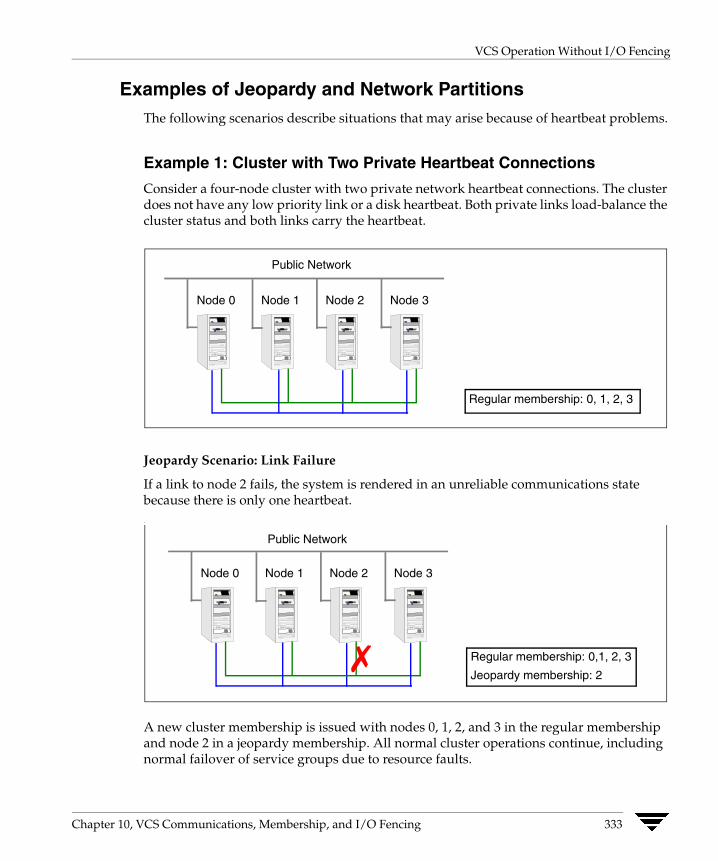
VCS Operation Without I/O Fencing
Examples of Jeopardy and Network Partitions The following scenarios describe situations that may arise because of heartbeat problems.
Example 1: Cluster with Two Private Heartbeat Connections
Consider a four-node cluster with two private network heartbeat connections. The cluster does not have any low priority link or a disk heartbeat. Both private links load-balance the cluster status and both links carry the heartbeat.
Public Network
Node 0 Node 1 Node 2 Node 3
Regular membership: 0, 1, 2, 3
Jeopardy Scenario: Link Failure
If a link to node 2 fails, the system is rendered in an unreliable communications state because there is only one heartbeat. .
Node 0 Node 1 Node 2 Node 3
✗
Public Network
Regular membership: 0,1, 2, 3
Jeopardy membership: 2
A new cluster membership is issued with nodes 0, 1, 2, and 3 in the regular membership and node 2 in a jeopardy membership. All normal cluster operations continue, including normal failover of service groups due to resource faults.
Chapter 10, VCS Communications, Membership, and I/O Fencing 333
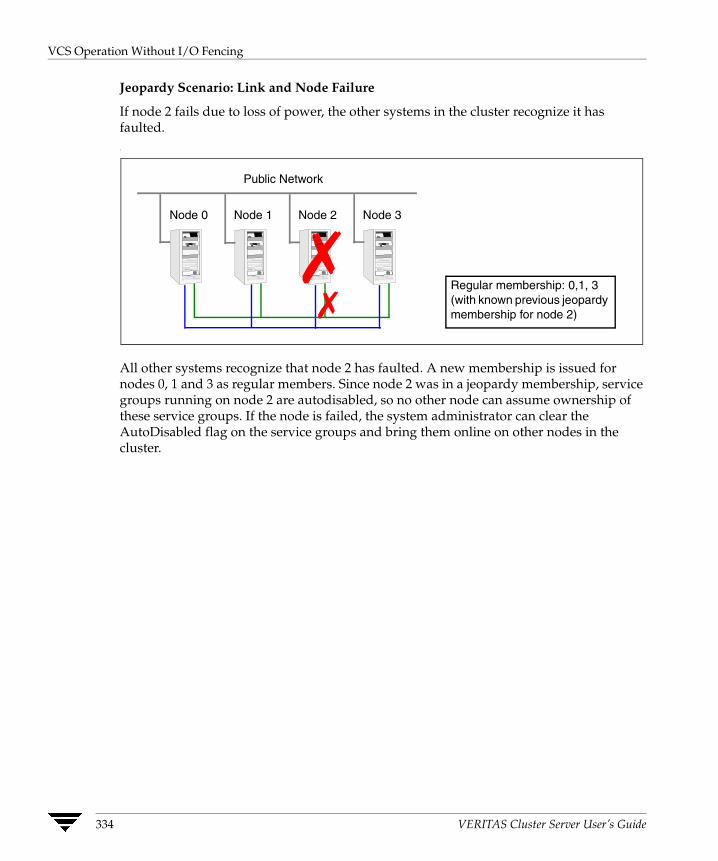
VCS Operation Without I/O Fencing
Jeopardy Scenario: Link and Node Failure
If node 2 fails due to loss of power, the other systems in the cluster recognize it has faulted. .
Public Network
Node 0 Node 1 Node 2 Node 3
✗ ✗
Regular membership: 0,1, 3 (with known previous jeopardy membership for node 2)
All other systems recognize that node 2 has faulted. A new membership is issued for nodes 0, 1 and 3 as regular members. Since node 2 was in a jeopardy membership, service groups running on node 2 are autodisabled, so no other node can assume ownership of these service groups. If the node is failed, the system administrator can clear the AutoDisabled flag on the service groups and bring them online on other nodes in the cluster.
334 VERITAS Cluster Server User’s Guide
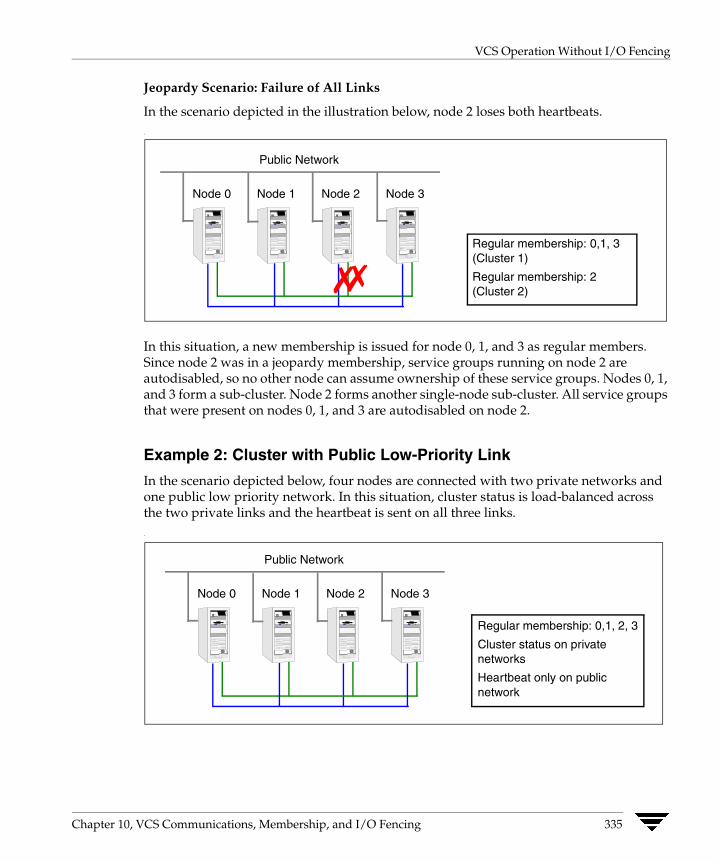
VCS Operation Without I/O Fencing
Jeopardy Scenario: Failure of All Links
In the scenario depicted in the illustration below, node 2 loses both heartbeats. .
Node 0 Node 1 Node 2 Node 3
Public Network
✗✗ Regular membership: 0,1, 3 (Cluster 1)
Regular membership: 2 (Cluster 2)
In this situation, a new membership is issued for node 0, 1, and 3 as regular members. Since node 2 was in a jeopardy membership, service groups running on node 2 are autodisabled, so no other node can assume ownership of these service groups. Nodes 0, 1, and 3 form a sub-cluster. Node 2 forms another single-node sub-cluster. All service groups that were present on nodes 0, 1, and 3 are autodisabled on node 2.
Example 2: Cluster with Public Low-Priority Link
In the scenario depicted below, four nodes are connected with two private networks and one public low priority network. In this situation, cluster status is load-balanced across the two private links and the heartbeat is sent on all three links. .
Node 0 Node 1 Node 2 Node 3
Public Network
Regular membership: 0,1, 2, 3
Cluster status on private networks
Heartbeat only on public network
Chapter 10, VCS Communications, Membership, and I/O Fencing 335
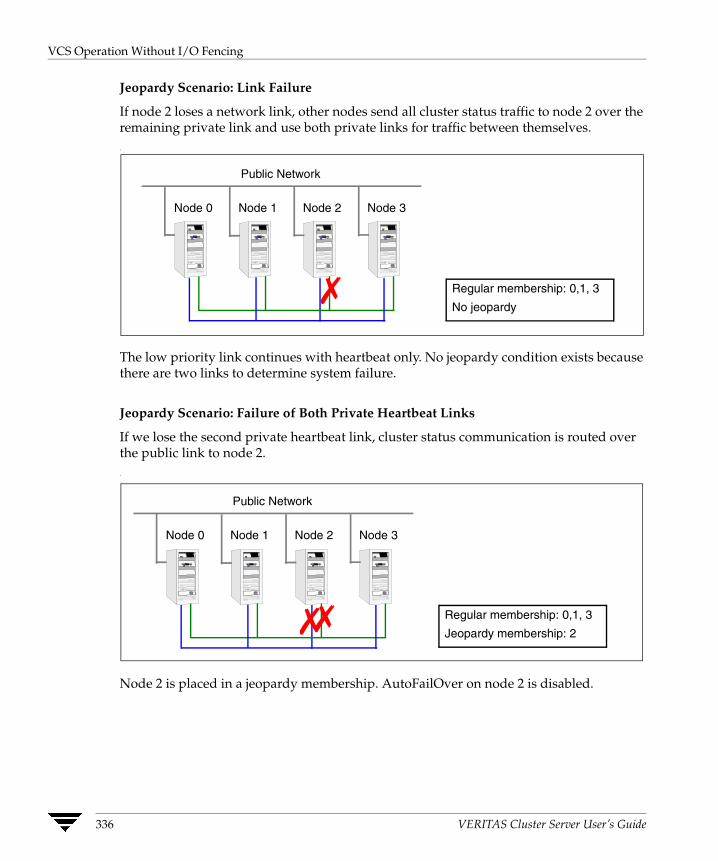
VCS Operation Without I/O Fencing
Jeopardy Scenario: Link Failure
If node 2 loses a network link, other nodes send all cluster status traffic to node 2 over the remaining private link and use both private links for traffic between themselves. .
Node 0 Node 1 Node 2 Node 3
Public Network
✗ Regular membership: 0,1, 3
No jeopardy
The low priority link continues with heartbeat only. No jeopardy condition exists because there are two links to determine system failure.
Jeopardy Scenario: Failure of Both Private Heartbeat Links
If we lose the second private heartbeat link, cluster status communication is routed over the public link to node 2. .
Node 0 Node 1 Node 2 Node 3
Public Network
✗✗ Regular membership: 0,1, 3
Jeopardy membership: 2
Node 2 is placed in a jeopardy membership. AutoFailOver on node 2 is disabled.
336 VERITAS Cluster Server User’s Guide
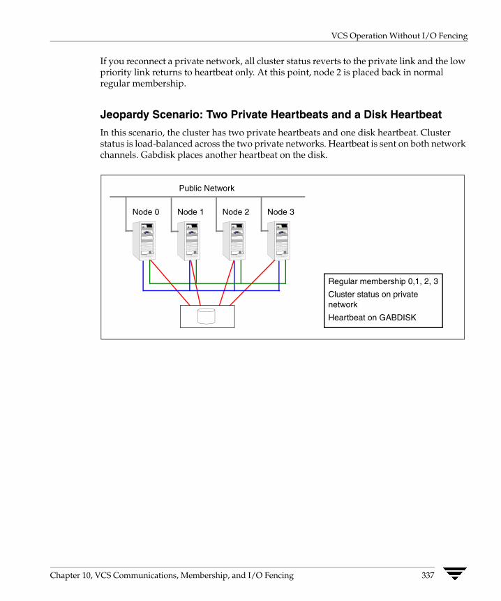
VCS Operation Without I/O Fencing
If you reconnect a private network, all cluster status reverts to the private link and the low priority link returns to heartbeat only. At this point, node 2 is placed back in normal regular membership.
Jeopardy Scenario: Two Private Heartbeats and a Disk Heartbeat
In this scenario, the cluster has two private heartbeats and one disk heartbeat. Cluster status is load-balanced across the two private networks. Heartbeat is sent on both network channels. Gabdisk places another heartbeat on the disk.
Node 0 Node 1 Node 2 Node 3
Public Network
Regular membership 0,1, 2, 3
Cluster status on private network
Heartbeat on GABDISK
Chapter 10, VCS Communications, Membership, and I/O Fencing 337

VCS Operation Without I/O Fencing
.On loss of a private heartbeat link, all cluster status shifts to the remaining private link. There is no jeopardy at this point because two heartbeats are still available to discriminate system failure.
Node 0 Node 1 Node 2 Node 3
Public Network
✗ Regular membership 0,1, 2, 3 (No jeopardy)
Cluster status on private network
Heartbeat on GABDISK
On loss of the second heartbeat, the cluster splits into mini clusters since no cluster status channel is available.
Node 0 Node 1 Node 2 Node 3
Public Network
✗✗ Regular membership cluster 0,1, 3.Special Jeopardy 2
Regular membership cluster 2. Special Jeopardy 0,1, 3
All opposite groups auto-disabled
Since heartbeats continue to write to disk, systems on each side of the break autodisable service groups running on the opposite side. Reconnecting a private link will cause HAD to recycle.
338 VERITAS Cluster Server User’s Guide

VCS Operation Without I/O Fencing
Pre-existing Network Partitions A pre-existing network partition refers to failures in communication channels that occur while the systems are down. Regardless of whether the cause is scheduled maintenance or system failure, VCS cannot respond to failures when systems are down. This leaves VCS without I/O fencing vulnerable to network partitioning when the systems are booted. VCS seeding is designed to help prevent this situation in clusters without I/O fencing
VCS Seeding To protect your cluster from a pre-existing network partition, VCS employs the concept of a seed. Systems can be seeded automatically or manually. Note that only systems that have been seeded can run VCS.
By default, when a system comes up, it is not seeded. When the last system in a cluster is booted, the cluster seeds and starts VCS on all systems. Systems can then be brought down and restarted in any combination. Seeding is automatic as long as at least one instance of VCS is running in the cluster.
Automatic seeding occurs in one of two ways:
◆ When an unseeded system communicates with a seeded system.
◆ When all systems in the cluster are unseeded and able to communicate with each other.
VCS requires that you declare the number of systems that will participate in the cluster.
Seeding control is established via the /etc/gabtab file. GAB is started with the command /sbin/gabconfig -c -n X. The variable X represents number of nodes in the cluster.
To start a cluster with less than all nodes, first verify the nodes not to be in the cluster are down, then start GAB using the command /sbin/gabconfig -c -x. This manually seeds the cluster and allows VCS to start on all connected systems.
During initial startup, VCS autodisables a service group until all resources are probed for the group on all systems in the SystemList that have GAB running. This protects against a situation where enough systems are running LLT and GAB to seed the cluster, but not all systems have HAD running.
Chapter 10, VCS Communications, Membership, and I/O Fencing 339

VCS Operation Without I/O Fencing
Using the Quorum Flag to Prevent Split-brain If you do not use I/O fencing, you can use the quorum flag to prevent split-brain in situations where the cluster splits with an unequal number of nodes in each sub-cluster.
In the event of a link failure, when a new cluster membership is created, GAB checks the number of systems in the new membership. If the number of systems is less than half the previous membership and if the quorum flag is set, VCS panics all nodes in the sub-cluster, thereby preventing split-brain.
Behavior Scenarios with the Quorum Flag Enabled
◆ If a 7-node cluster splits into two sub-clusters of 4 and 3 nodes respectively, the 3-node cluster panics.
◆ If a 4-node cluster splits into two sub-clusters of 2 nodes each, a split-brain condition occurs even if the quorum flag is set.
◆ If a 4-node cluster splits into four single-node sub-clusters, all sub-clusters panic.
Enabling and Disabling the Quorum Flag
Use the gabconfig command to enable and disable the quorum flag. You can add or remove the quorum flag from the file /etc/gabtab manually. Your settings take effect on system reboot.
✔ You must set this flag on all nodes in the cluster.
✔ Do not set this flag if you use I/O fencing (UseFence=SCSI3) in the cluster.
▼ To set (enable) the Quorum flag
1. Run the gabconfig command with the -q option:
gabconfig -q
2. Verify that the -q flag appears in the file /etc/gabtab.
▼ To disable the Quorum flag
1. Run the gabconfig command with the -d option:
gabconfig -d
2. Verify that the -q flag does not appear in the file /etc/gabtab.
340 VERITAS Cluster Server User’s Guide
VCS Operation Without I/O Fencing
▼ To verfiy changes to the GAB configuration
gabconfig -l
Chapter 10, VCS Communications, Membership, and I/O Fencing 341
VCS Operation Without I/O Fencing
Network Partitions and the UNIX Boot Monitor Most UNIX systems provide a console-abort sequence that enables you to halt and continue the processor. Continuing operations after the processor has stopped may corrupt data and is therefore unsupported by VCS.
When a system is halted with the abort sequence, it stops producing heartbeats. The other systems in the cluster consider the system failed and take over its services. If the system is later enabled with another console sequence, it continues writing to shared storage as before, even though its applications have been restarted on other systems.
VERITAS recommends disabling the console-abort sequence or creating an alias to force the “go” command to perform a reboot on systems not running I/O fencing.
Reconnecting the Private Network When a final network connection is lost in clusters not running I/O fencing, the systems on each side of the network partition segregate into sub-clusters.
Reconnecting a private network after a cluster has been segregated causes HAD to stop and restart. There are several rules that determine which systems will be affected.
◆ On a two-node cluster, the system with the lowest LLT host ID stays running and the higher stops and restarts HAD.
◆ In a multi-node cluster, the largest running group stays running. The smaller groups stop and restart HAD.
◆ On a multi-node cluster splitting into two equal size clusters, the cluster with the lowest node number stays running and the other cluster stops and restarts HAD.
342 VERITAS Cluster Server User’s Guide
Controlling VCS Behavior
11 VCS provides an enhanced set of options to configure service groups. These options allow greater flexibility and control when service groups fail over in response to resource faults.VCS Behavior on Resource Faults A resource is considered faulted in the following situations:
◆ When the resource state changes unexpectedly. For example, an online resource going offline.
◆ When a required state change does not occur. For example, a resource failing to go online or offline when commanded to do so.
In many situations, VCS agents take predefined actions to correct the issue before reporting resource failure to the engine. For example, the agent may try to bring a resource online several times before declaring a fault.
Cleaning Resources When a resource faults, VCS takes automated actions to “clean up” the faulted resource. The Clean function makes sure the resource is completely shut down before bringing it online on another node. This prevents concurrency violations.
Fault Propagation When a resource faults, VCS takes all resources dependent on the faulted resource offline. The fault is thus propagated in the service group
343
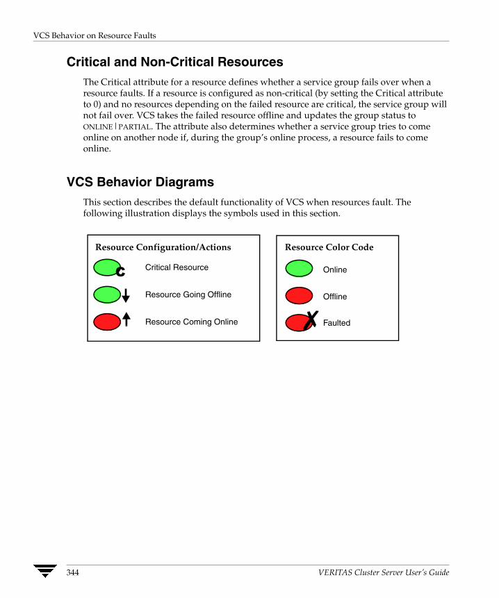
VCS Behavior on Resource Faults
Critical and Non-Critical Resources The Critical attribute for a resource defines whether a service group fails over when a resource faults. If a resource is configured as non-critical (by setting the Critical attribute to 0) and no resources depending on the failed resource are critical, the service group will not fail over. VCS takes the failed resource offline and updates the group status to ONLINE|PARTIAL. The attribute also determines whether a service group tries to come online on another node if, during the group’s online process, a resource fails to come online.
VCS Behavior Diagrams This section describes the default functionality of VCS when resources fault. The following illustration displays the symbols used in this section.
Resource Configuration/Actions Resource Color Code
C
✗
Critical Resource
Resource Going Offline
Resource Coming Online
Online
Offline
Faulted
344 VERITAS Cluster Server User’s Guide
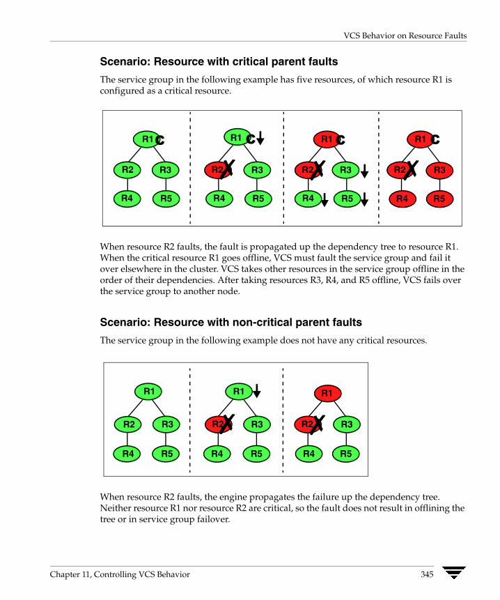
VCS Behavior on Resource Faults
Scenario: Resource with critical parent faults
The service group in the following example has five resources, of which resource R1 is configured as a critical resource.
C
✗ R1 R1 R1 C
R2 R3
R4 R5
R2
R4 R5 R4 R5
R3 R3R2✗ R2✗ R3
R4 R5
C R1 C
When resource R2 faults, the fault is propagated up the dependency tree to resource R1. When the critical resource R1 goes offline, VCS must fault the service group and fail it over elsewhere in the cluster. VCS takes other resources in the service group offline in the order of their dependencies. After taking resources R3, R4, and R5 offline, VCS fails over the service group to another node.
Scenario: Resource with non-critical parent faults
The service group in the following example does not have any critical resources.
R1
R2 R3
R4 R5
R1
R3R2✗ R2✗ R3
R5 R5R4 R4
R1
When resource R2 faults, the engine propagates the failure up the dependency tree. Neither resource R1 nor resource R2 are critical, so the fault does not result in offlining the tree or in service group failover.
Chapter 11, Controlling VCS Behavior 345

VCS Behavior on Resource Faults
Scenario: Resource with critical parent fails to come online
In the following example, when a command is issued to bring the service group online, resource R2 fails to come online.
R1 C
R2 R3
R4 R5
R1 C
R2✗ R3
R4 R5
R2✗ R1 C R1 C
R2 R3✗ R4 R5R5R4
R3
VCS calls the Clean function for resource R2 and propagates the fault up the dependency tree. Resource R1 is set to critical, so the service group is taken offline and failed over to another node in the cluster.
346 VERITAS Cluster Server User’s Guide

Controlling VCS Behavior at the Service Group Level
Controlling VCS Behavior at the Service Group Level This section describes how you can configure service group attributes to modify VCS behavior in response to resource faults.
Controlling Failover on Service Group or System Faults The AutoFailOver attribute configures service group behavior in response to service group and system faults.
◆ If the AutoFailOver attribute is set to 1, the service group fails over when a system or a service group faults, provided a suitable system exists for failover.
◆ If the AutoFailOver attribute is set to 0, the service group does not fail over when a system or service group faults. If a fault occurs in a service group, the group is taken offline, depending on whether any of its resources are configured as critical. If a system faults, the service group is not failed over to another system.
Freezing Service Groups Freezing a service group prevents VCS from taking any action when the service group or a system faults. Freezing a service group prevents dependent resources from going offline when a resource faults. It also prevents the Clean function from being called on a resource fault.
You can freeze a service group when performing operations on its resources from outside VCS control. This prevents VCS from taking actions on resources while your operations are on. For example, freeze a database group when using database controls to stop and start a database.
Chapter 11, Controlling VCS Behavior 347
Controlling VCS Behavior at the Service Group Level
Controlling Clean Behavior on Resource Faults The ManageFaults attribute specifies whether VCS calls the Clean entry point when a resource faults. ManageFaults is a service group attribute; you can configure each service group to operate as desired.
◆ If the ManageFaults attribute is set to ALL, VCS calls the Clean entry point when a resource faults.
◆ If the ManageFaults attribute is set to NONE, VCS takes no action on a resource fault; it “hangs” the service group until administrative action can be taken. VCS marks the resource state as ADMIN_WAIT and does not fail over the service group until the resource fault is removed and the ADMIN_WAIT state is cleared.
VCS calls the resadminwait trigger when a resource enters the ADMIN_WAIT state due to a resource fault if the ManageFaults attribute is set to NONE. You can customize this trigger to provide notification about the fault. See “resadminwait Event Trigger” on page 436 for more information.
Controlling Fault Propagation The FaultPropagation attribute defines whether a resource fault is propagated up the resource dependency tree. It also defines whether a resource fault causes a service group failover.
◆ If the FaultPropagation attribute is set to 1 (default), a resource fault is propagated up the dependency tree. If a resource in the path is critical, the service group is taken offline and failed over, provided the AutoFailOver attribute is set to 1.
◆ If the FaultPropagation is set to 0, resource faults are contained at the resource level. VCS does not take the dependency tree offline, thus preventing failover. If the resources in the service group remain online, the service group remains in the PARTIAL|FAULTED state. If all resources are offline or faulted, the service group remains in the OFFLINE| FAULTED state.
When a resource faults, VCS fires the resfault trigger and sends an SNMP trap. The trigger is called on the system where the resource faulted and includes the name of the faulted resource. See “resfault Event Trigger” on page 436 for more information.
348 VERITAS Cluster Server User’s Guide

Controlling VCS Behavior at the Service Group Level
Customized Behavior Diagrams The illustrations in this section depict how the ManageFaults and FaultPropagation attributes change VCS behavior when handling resource faults The following illustration depicts the legends used in the section.
Resource Color Code
Online
Offline
Faulted✗
Online | Admin_Wait
Offline | Admin_WaitW
W
Scenario: Resource with a critical parent and ManageFaults=NONE
The service group in the following example has five resources. The ManageFaults attribute is set to NONE for resource R2.
R1 C
R2 R3
R4 R5
R5 R3R2
R4 R5
R1C
W
If resource R2 fails, the resource is marked as ONLINE|ADMIN_WAIT. The Clean entry point is not called for the resource. VCS does not take any other resource offline.
Chapter 11, Controlling VCS Behavior 349

Controlling VCS Behavior at the Service Group Level
Scenario: Resource with a critical parent and FaultPropagation=0
In the following example, the FaultPropagation attribute is set to 0.
R1 C
R2 R3
R4 R5
R1C
R2✗ R3
R4 R5
When resource R2 faults, the Clean entry point is called and the resource is marked as faulted. The fault is not propagated up the tree, and the group is not taken offline.
350 VERITAS Cluster Server User’s Guide
Controlling VCS Behavior at the Resource Level
Controlling VCS Behavior at the Resource Level This section describes how you can control VCS behavior at the resource level. Note that a resource is not considered faulted until the agent framework declares the fault to the VCS engine.
Resource Type Attributes The following attributes affect how the VCS agent framework reacts to problems with individual resources before informing the fault to the VCS engine.
RestartLimit Attribute
The RestartLimit attribute defines whether VCS attempts to restart a failed resource before informing the engine of the fault.
If the RestartLimit attribute is set to a non-zero value, the agent attempts to restart the resource before declaring the resource as faulted. When restarting a failed resource, the agent framework calls the Clean entry point before calling the Online entry point. However, setting the ManageFaults attribute to NONE prevents the Clean entry point from being called and prevents the Online entry point from being retried.
OnlineRetryLimit Attribute
The OnlineRetryLimit attribute specifies the number of times the Online entry point is retried if the initial attempt to bring a resource online is unsuccessful.
When the OnlineRetryLimit set to a non-zero value, the agent framework calls the Clean entry point before rerunning the Online entry point. Setting the ManageFaults attribute to NONE prevents the Clean entry point from being called and also prevents the Online operation from being retried.
ConfInterval Attribute
The ConfInterval attribute defines how long a resource must remain online without encountering problems before previous problem counters are cleared. The attribute controls when VCS clears the RestartCount, ToleranceCount and CurrentMonitorTimeoutCount values.
Chapter 11, Controlling VCS Behavior 351
Controlling VCS Behavior at the Resource Level
ToleranceLimit Attribute
The ToleranceLimit attribute defines the number of times the Monitor routine should return an offline status before declaring a resource offline. This attribute is typically used when a resource is busy and appears to be offline. Setting the attribute to a non-zero value instructs VCS to allow multiple failing monitor cycles with the expectation that the resource will eventually respond. Setting a non-zero ToleranceLimit also extends the time required to respond to an actual fault.
FaultOnMonitorTimeouts Attribute
The FaultOnMonitorTimeouts attribute defines whether VCS interprets a Monitor entry point timeout as a resource fault.
If the attribute is set to 0, VCS does not treat Monitor timeouts as a resource faults. If the attribute is set to 1, VCS interprets the timeout as a resource fault and the agent calls the Clean entry point to shut the resource down.
By default, the FaultOnMonitorTimeouts attribute is set to 4. This means that the Monitor entry point must time out four times in a row before the resource is marked faulted.
352 VERITAS Cluster Server User’s Guide

How VCS Handles Resource Faults
How VCS Handles Resource Faults This section describes the process VCS uses to determine the course of action when a resource faults.
VCS Behavior When an Online Resource Faults In the following example, a resource in an online state is reported as being offline without being commanded by the agent to go offline.
◆ VCS first verifies the Monitor routine completes successfully in the required time. If it does, VCS examines the exit code returned by the Monitor routine. If the Monitor routine does not complete in the required time, VCS looks at the FaultOnMonitorTimeouts (FOMT) attribute.
◆ If FOMT=0, the resource will not fault when the Monitor routine times out. VCS considers the resource online and monitors the resource periodically, depending on the monitor interval.
If FOMT=1 or more, VCS compares the CurrentMonitorTimeoutCount (CMTC) with the FOMT value. If the monitor timeout count is not used up, CMTC is incremented and VCS monitors the resource in the next cycle.
◆ If FOMT= CMTC, this means that the available monitor timeout count is exhausted and VCS must now take corrective action.
◆ If the ManageFaults attribute is set to NONE, VCS marks the resource as ONLINE|ADMIN_WAIT and fires the resadminwait trigger. If the ManageFaults attribute is set to ALL, the resource enters a GOING OFFLINE WAIT state. VCS invokes the Clean entry point with the reason Monitor Hung.
◆ If the Clean entry point is successful (that is, Clean exit code = 0), VCS examines the value of the RestartLimit attribute. If Clean fails (exit code = 1), the resource remains online with the state UNABLE TO OFFLINE. VCS fires the resnotoff trigger and monitors the resource again.
◆ If the Monitor routine does not time out, it returns the status of the resource as being online or offline.
◆ If the ToleranceLimit (TL) attribute is set to a non-zero value, the Monitor cycle returns offline (exit code = 100) for a number of times specified by the ToleranceLimit and increments the ToleranceCount (TC). When the ToleranceCount equals the ToleranceLimit (TC = TL), the agent declares the resource as faulted.
Chapter 11, Controlling VCS Behavior 353
How VCS Handles Resource Faults
◆ If the Monitor routine returns online (exit code = 110) during a monitor cycle, the agent takes no further action. The ToleranceCount attribute is reset to 0 when the resource is online for a period of time specified by the ConfInterval attribute.
If the resource is detected as being offline a number of times specified by the ToleranceLimit before the ToleranceCount is reset (TC = TL), the resource is considered failed.
◆ After the agent determines the resource is not online, VCS checks the Frozen attribute for the service group. If the service group is frozen, VCS declares the resource faulted and calls the resfault trigger. No further action is taken.
◆ If the service group is not frozen, VCS checks the ManageFaults attribute. If ManageFaults=NONE, VCS marks the resource state as ONLINE|ADMIN_WAIT and calls the resadminwait trigger. If ManageFaults=ALL, VCS calls the Clean entry point with the CleanReason set to Unexpected Offline.
◆ If the Clean entry point fails (exit code = 1) the resource remains online with the state UNABLE TO OFFLINE. VCS fires the resnotoff trigger and monitors the resource again. The resource enters a cycle of alternating Monitor and Clean entry points until the Clean entry point succeeds or a user intervenes.
◆ If the Clean entry point is successful, VCS examines the value of the RestartLimit (RL) attribute. If the attribute is set to a non-zero value, VCS increments the RestartCount (RC) attribute and invokes the Online entry point. This continues till the value of the RestartLimit equals that of the RestartCount. At this point, VCS attempts to monitor the resource.
◆ If the Monitor returns an online status, VCS considers the resource online and resumes periodic monitoring. If the monitor returns an offline status, the resource is faulted and VCS takes actions based on the service group configuration.
354 VERITAS Cluster Server User’s Guide

How VCS Handles Resource Faults
Flowchart
RC=RC+1
100
Monitor Timeout?
Monitor Exit Code
TL>TC?
Group Frozen?
NO
Manage Faults
NO
NO
All
Clean.
Clean
RL>RC?
Resource Unable to Offline. resnotoff
Resource online. TC not cleared
TC =
A
Resource fails. Call Restart Trigger
YES
NONE
Monitor Resource
B
Monitor Exit Code
100
110
FOMT> CMTC
CMTC =
110
CMTC + 1
Resource Online | Admin_Wait. resadminwaitTrigger
NO
YES
YES
Manage Faults
NONE Resource Online | Admin_Wait. resadminwait Trigger
Resource Going Offline Wait
ALL
Clean Success?
YES YES
Resource Unable to Offline.
Resource CMTC
Resource Online
Clean.
“Monitor Hung”
resnotoff Trigger
YES
Trigger
YES
Unexpected Offline
Success?
NO
TC + 1
NO
online. not cleared
NO
Chapter 11, Controlling VCS Behavior 355
How VCS Handles Resource Faults
VCS Behavior When a Resource Fails to Come Online In the following example, the agent framework invokes the Online entry point for an offline resource. The resource state changes to WAITING TO ONLINE.
◆ If the Online entry point times out, VCS examines the value of the ManageFaults attribute.
◆ If ManageFaults is set to NONE, the resource state changes to OFFLINE|ADMIN_WAIT.
If ManageFaults is set to ALL, VCS calls the Clean entry point with the CleanReason set to Online Hung.
◆ If the Online entry point does not time out, VCS invokes the Monitor entry point. The Monitor routine returns an exit code of 110 if the resource is online. Otherwise, the Monitor routine returns an exit code of 100.
◆ VCS examines the value of the OnlineWaitLimit (OWL) attribute. This attribute defines how many monitor cycles can return an offline status before the agent framework declares the resource faulted. Each successive Monitor cycle increments the OnlineWaitCount (OWC) attribute. When OWL= OWC (or if OWL= 0), VCS determines the resource has faulted.
◆ VCS then examines the value of the ManageFaults attribute. If the ManageFaults is set to NONE, the resource state changes to OFFLINE|ADMIN_WAIT.
If the ManageFaults is set to ALL, VCS calls the Clean entry point with the CleanReason set to Online Ineffective.
◆ If the Clean entry point is not successful (exit code = 1), the agent monitors the resource. It determines the resource is offline, and calls the Clean entry point with the Clean Reason set to Online Ineffective. This cycle continues till the Clean entry point is successful, after which VCS resets the OnlineWaitCount value.
◆ If the OnlineRetryLimit (ORL) is set to a non-zero value, VCS increments the OnlineRetryCount (ORC) and invokes the Online entry point. This starts the cycle all over again. If ORL = ORC, or if ORL = 0, VCS assumes that the Online operation has failed and declares the resource as faulted.
356 VERITAS Cluster Server User’s Guide

How VCS Handles Resource Faults
Flowchart
100
Resource Offline
Monitor Exit Code
Manage Faults
NO
ORL >
NONE
B
ORC=
110
ORC+1
NO
Manage Faults
Resource Offline | Admin_Wait resadminwait Trigger
ALL
YES
Online. Resource Waiting to Online
A
Online Timeout?
Resource Online
OWL> OWC?
Clean. “Online Ineffective”
ORC?
ALL
Clean. “Online Hung”
OWC = OWC+1
YES
YES
NONE Resource Offline | Admin_Wait resadminwait Trigger
NONE
Reset OWC
Clean Success?
NO
NO
YES
Chapter 11, Controlling VCS Behavior 357

How VCS Handles Resource Faults
VCS Behavior After a Resource is Declared Faulted After a resource is declared faulted, VCS fires the resfault trigger and examines the value of the FaultPropagation attribute.
◆ If FaultPropagation is set to 0, VCS does not take other resources offline, and changes the group state to OFFLINE|FAULTED or PARTIAL|FAULTED. The service group does not fail over.
If FaultPropagation is set to 1, VCS takes all resources in the dependent path of the faulted resource offline, up to the top of the tree.
◆ VCS then examines if any resource in the dependent path is critical. If no resources are critical, the service group is left in its OFFLINE|FAULTED or PARTIAL|FAULTED state. If a resource in the path is critical, VCS takes the all resources in the service group offline in preparation of a failover.
◆ If the AutoFailOver attribute is set to 0, the service group is not failed over; it remains in a faulted state. If AutoFailOver is set to 1, VCS examines if any systems in the service group’s SystemList are possible candidates for failover. If no suitable systems exist, the group remains faulted and VCS calls the nofailover trigger. If eligible systems are available, VCS examines the FailOverPolicy to determine the most suitable system to which to fail over the service group.
Note If FailOverPolicy is set to Load, a NoFailover situation may occur because of restrictions placed on service groups and systems by Service Group Workload Management.
358 VERITAS Cluster Server User’s Guide
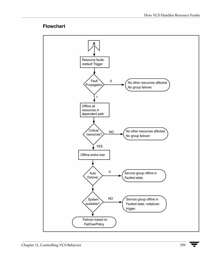
How VCS Handles Resource Faults
Flowchart
No other resources affected. No group failover.
YES
A
Resource faults. resfault Trigger
Fault Propagation
0
1
Offline all resources in dependent path
Critical resources?
NO
Offline entire tree
Auto Failover
System
No other resources affected. No group failover.
Service group offline in Faulted state.
0
available?
NO Service group offline in Faulted state. nofailover trigger.
Failover based on FailOverPolicy
Chapter 11, Controlling VCS Behavior 359
Disabling Resources
Disabling Resources Disabling a resource means that the resource is no longer monitored by a VCS agent, and that the resource cannot be brought online or taken offline. The agent starts monitoring the resource after the resource is enabled. The resource attribute Enabled determines whether a resource is enabled or disabled. (See “Resource Attributes” on page 628 for details.) A persistent resource can be disabled when all its parents are offline. A non-persistent resource can be disabled when the resource is in an OFFLINE state.
When to Disable a Resource Typically, resources are disabled when one or more resources in the service group encounter problems and disabling the resource is required to keep the service group online or to bring it online.
Note Disabling a resource is not an option when the entire service group requires disabling. In that case, set the service group attribute Enabled to 0.
▼ To disable a resource
To disable the resource when VCS is running:
# hares -modify resource_name Enabled 0
To have the resource disabled initially when VCS is started, set the resource’s Enabled attribute to 0 in main.cf.
Limitations When VCS is running, there are certain prerequisites to be met before the resource is disabled successfully.
✔ An online non-persistent resource cannot be disabled. It must be in a clean OFFLINE state. (The state must be OFFLINE and IState must be NOT WAITING.)
✔ If it is a persistent resource and the state is ONLINE on some of the systems, all dependent resources (parents) must be in clean OFFLINE state. (The state must be OFFLINE and IState must be NOT WAITING)
Therefore, before disabling the resource you may be required to take it offline (if it is non-persistent) and take other resources offline in the service group.
360 VERITAS Cluster Server User’s Guide
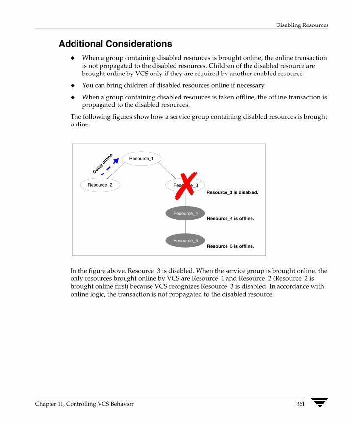
Disabling Resources
Additional Considerations ◆ When a group containing disabled resources is brought online, the online transaction
is not propagated to the disabled resources. Children of the disabled resource are brought online by VCS only if they are required by another enabled resource.
◆ You can bring children of disabled resources online if necessary.
◆ When a group containing disabled resources is taken offline, the offline transaction is propagated to the disabled resources.
The following figures show how a service group containing disabled resources is brought online.
Resource_1
Resource_3
Resource_3 is disabled.
Resource_2
Resource_4
Resource_5
Going
online
Resource_4 is offline.
Resource_5 is offline.
✗
In the figure above, Resource_3 is disabled. When the service group is brought online, the only resources brought online by VCS are Resource_1 and Resource_2 (Resource_2 is brought online first) because VCS recognizes Resource_3 is disabled. In accordance with online logic, the transaction is not propagated to the disabled resource.
Chapter 11, Controlling VCS Behavior 361

Disabling Resources
In the figure below, Resource_2 is disabled. When the service group is brought online, resources 1, 3, 4 are also brought online (Resource_4 is brought online first). Note Resource_3, the child of the disabled resource, is brought online because Resource_1 is enabled and is dependent on it.
Resource_1 Resource_2
Resource_2 is disabled.
Resource_3
Resource_4 Go
ing
on
line
✗
How Disabled Resources Affect Group States When a service group is brought online containing non-persistent, disabled resources whose AutoStart attributes are set to 1, the group state is PARTIAL, even though enabled resources with Autostart=1 are online. This is because the disabled resource is considered for the group state.
To have the group in the ONLINE state when enabled resources with AutoStart set to 1 are in ONLINE state, set the AutoStart attribute to 0 for the disabled, non-persistent resources.
362 VERITAS Cluster Server User’s Guide

Clearing Resources in the ADMIN_WAIT State
Clearing Resources in the ADMIN_WAIT State When VCS sets a resource in the ADMIN_WAIT state, it invokes the resadminwait trigger according to the reason the resource entered the state. For more information about the trigger, see “resadminwait Event Trigger” on page 436.
▼ To clear a resource
1. Take the necessary actions outside VCS to bring all resources into the required state.
2. Verify that resources are in the required state by issuing the command:
# hagrp -clearadminwait group -sys system
This command clears the ADMIN_WAIT state for all resources. If VCS continues to detect resources that are not in the required state, it resets the resources to the ADMIN_WAIT state.
3. If resources continue in the ADMIN_WAIT state, repeat step 1 and step 2, or issue the following command to stop VCS from setting the resource to the ADMIN_WAIT state:
# hagrp -clearadminwait -fault group -sys system
This command has the following results:
◆ If the resadminwait trigger was called for reasons 0 or 1, the resource state is set as ONLINE|UNABLE_TO_OFFLINE.
◆ If the resadminwait trigger was called for reasons 2, 3, or 4, the resource state is set as FAULTED. Please note that when resources are set as FAULTED for these reasons, the clean entry point is not called. Verify that resources in ADMIN-WAIT are in clean, OFFLINE state prior to invoking this command.
Note When a service group has a resource in the ADMIN_WAIT state, the following service group operations cannot be performed on the resource: online, offline, switch, and flush. Also, you cannot use the hastop command when resources are in the ADMIN_WAIT state. When this occurs, you must issue the hastop command with -force option only.
Chapter 11, Controlling VCS Behavior 363
Service Group Workload Management
Service Group Workload Management Service Group Workload Management is a load-balancing mechanism that determines which system hosts an application during startup, or after an application or server fault.
With Service Group Workload Management, you can statically associate system capacity and service group load within the main configuration file, main.cf. This is particularly useful when managing multiple service groups and systems. VCS also maintains the functionality of dynamic system load, which can be used when service groups deviate heavily from their static load. Dynamic load is specified at the system level, meaning you can specify the load regardless of which service group is loading the system. This helps account for system load contributed by an application outside VCS of control.
Deciding Startup and Failover Locations Service Group Workload Management provides tools for making intelligent decisions about startup and failover locations, based on system capacity and resource availability. This feature is enabled when the service group attribute FailOverPolicy is set to Load. This attribute governs how VCS calculates the target system for failover. There are three possible values for FailOverPolicy: Priority, RoundRobin, and Load.
◆ Priority
The Priority failover policy is ideal for simple two-node clusters or small clusters with few service groups. With FailOverPolicy set to Priority, the system with the lowest priority is selected as the failover target. Priority is set in the SystemList attribute implicitly via ordering, such as SystemList = {SystemA, SystemB} or explicitly, such as SystemList = {SystemA=0, SystemB=1}. Priority is the default behavior.
◆ RoundRobin
The RoundRobin failover policy selects the system running the fewest service groups as the failover target. This is ideal for large clusters running many service groups with similar server load characteristics (for example, similar databases or applications).
◆ Load
The Load failover policy comprises the following components:
◆ System capacity and service group load, represented by the attributes Capacity and Load respectively.
◆ System limits and service group prerequisites, represented by the attributes Limits and Prerequisites, respectively.
364 VERITAS Cluster Server User’s Guide

Service Group Workload Management
System Capacity and Service Group Load The system attribute Capacity sets a fixed load-handling capacity for servers. Define this attribute based on system requirements. The service group attribute Load sets a fixed demand for service groups. Define this attribute based on application requirements.
When a service group is brought online, its load is subtracted from the system’s capacity to determine available capacity, which is maintained in the attribute AvailableCapacity.
When a failover occurs, HAD determines which system has the highest available capacity and starts the service group on that system. During a failover involving multiple service groups, failover decisions are made serially to facilitate a proper load-based choice.
System capacity is a soft restriction; in some situations, value of the Capacity attribute could be less than zero. During some operations, including cascading failures, the value of the AvailableCapacity attribute could be negative.
Static Load versus Dynamic Load
Dynamic load is an integral component of the Service Group Workload Management framework. Typically, HAD sets remaining capacity with the function:
AvailableCapacity = Capacity - (sum of Load values of all online service groups)
If the DynamicLoad attribute is defined, its value overrides the calculated Load values with the function:
AvailableCapacity = Capacity - DynamicLoad
This enables better control of system loading values than estimated service group loading (static load). However, this requires setting up and maintaining a load estimation package outside VCS. It also requires modifying the configuration file main.cf manually.
Note that the DynamicLoad (specified with hasys -load) is subtracted from the Capacity as an integer and not a percentage value. For example, if a system’s capacity is 200 and the load estimation package determines the server is 80 percent loaded, it must inform VCS that the DynamicLoad value is 160 (not 80).
Overload Warning
Overload warning provides the notification component of the Load policy. When a server sustains the preset load level (set by the attribute LoadWarningLevel) for a preset time (set by the attribute LoadTimeThreshold), the loadwarning trigger is invoked. For a full description of event management with triggers, see “VCS Event Triggers” on page 429. For details on the attributes cited above, see “System Attributes” on page 653.
Chapter 11, Controlling VCS Behavior 365
Service Group Workload Management
The loadwarning trigger is a user-defined script or application designed to carry out specific actions. It is invoked once, when system load exceeds the LoadWarningLevel for the LoadTimeThreshold. It is not invoked again until the LoadTimeCounter, which determines how many seconds system load has been above LoadWarningLevel, is reset.
Limits and Prerequisites System limits and service group prerequisites strengthen the Load policy.
Limits is a system attribute and designates which resources are available on a system, including shared memory segments and semaphores.
Prerequisites is a service group attribute and helps manage application requirements. For example, a database may require three shared memory segments and 10 semaphores. VCS Load policy determines which systems meet the application criteria and then selects the least-loaded system.
If the prerequisites defined for a service group are not met on a system, the service group cannot be brought online on the system.
When configuring these attributes, define the service group’s prerequisites first, then the corresponding system limits. Each system can have a different limit and there is no cap on the number of group prerequisites and system limits. Service group prerequisites and system limits can appear in any order.
You can also use these attributes to configure the cluster as N-to-1 or N-to-N. For example, to ensure that only one service group can be online on a system at a time, add the following entries to the definition of each group and system:
Prerequisites = { GroupWeight = 1 }Limits = { GroupWeight = 1 }
System limits and group prerequisites work independently of FailOverPolicy. Prerequisites determine the eligible systems on which a service group can be started. When a list of systems is created, HAD then follows the configured FailOverPolicy.
Using Capacity and Limits When selecting a node as a failover target, VCS selects the system that meets the service group’s prerequisites and has the highest available capacity. If multiple systems meet the prerequisites and have the same available capacity, VCS selects the system appearing lexically first in the SystemList.
Systems having an available capacity of less than the percentage set by the LoadWarningLevel attribute, and those remaining at that load for longer than the time specified by the LoadTimeThreshold attribute invoke the loadwarning trigger.
366 VERITAS Cluster Server User’s Guide
Additional Considerations
Additional Considerations VCS provides the option of creating zones for systems in a cluster to further fine-tune application failover decisions. It also provides options to identify a suitable system to host a service group when the cluster starts.
System Zones The SystemZones attribute enables you to create a subset of systems to use in an initial failover decision. This feature allows fine-tuning of application failover decisions, and yet retains the flexibility to fail over anywhere in the cluster.
If the attribute is configured, a service group tries to stay within its zone before choosing a host in another zone. For example, in a three-tier application infrastructure with Web, application, and database servers, you could create two system zones: one each for the application and the database. In the event of a failover, a service group in the application zone will try to fail over to another node within the zone. If no nodes are available in the application zone, the group will fail over to the database zone, based on the configured load and limits.
In this configuration, excess capacity and limits on the database backend are kept in reserve to handle the larger load of a database failover. The application servers handle the load of service groups in the application zone. During a cascading failure, the excess capacity in the cluster is available to all service groups.
Load-Based AutoStart VCS provides a method to determine where a service group comes online when the cluster starts. Setting the AutoStartPolicy to Load instructs the VCS engine, HAD, to determine the best system on which to start the groups. VCS places service groups in an AutoStart queue for load-based startup as soon as the groups probe all running systems. VCS creates a subset of systems that meet all prerequisites and then chooses the system with the highest AvailableCapacity.
You can use AutoStartPolicy = Load and SystemZones to establish a list of preferred systems on which to initially run a group.
Chapter 11, Controlling VCS Behavior 367

Sample Configurations Depicting Workload Management
Sample Configurations Depicting Workload Management This section lists some sample configurations that use the concepts described in this chapter.
System and Service Group Definitions The main.cf in this example shows various Service Group Workload Management attributes in a system definition and a service group definition. For more information regarding the attributes cited below, see the appendix “VCS Attributes.”
include "types.cf"cluster SGWM-demo ()
system LargeServer1 (Capacity = 200Limits = { ShrMemSeg=20, Semaphores=10, Processors=12 }LoadWarningLevel = 90LoadTimeThreshold = 600)
group G1 (SystemList = { LargeServer1, LargeServer2, MedServer1,
MedServer2 }SystemZones = { LargeServer1=0, LargeServer2=0,
MedServer1=1, MedServer2=1 }AutoStartPolicy = LoadAutoStartList = { MedServer1, MedServer2 }FailOverPolicy = LoadLoad = 100Prerequisites = { ShrMemSeg=10, Semaphores=5, Processors=6 })
368 VERITAS Cluster Server User’s Guide
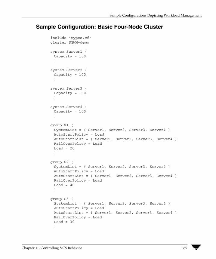
Sample Configurations Depicting Workload Management
Sample Configuration: Basic Four-Node Cluster
include "types.cf"cluster SGWM-demo
system Server1 (Capacity = 100)
system Server2 (Capacity = 100)
system Server3 (Capacity = 100)
system Server4 (Capacity = 100)
group G1 (SystemList = { Server1, Server2, Server3, Server4 }AutoStartPolicy = LoadAutoStartList = { Server1, Server2, Server3, Server4 }FailOverPolicy = LoadLoad = 20)
group G2 (SystemList = { Server1, Server2, Server3, Server4 }AutoStartPolicy = LoadAutoStartList = { Server1, Server2, Server3, Server4 }FailOverPolicy = LoadLoad = 40)
group G3 (SystemList = { Server1, Server2, Server3, Server4 }AutoStartPolicy = LoadAutoStartList = { Server1, Server2, Server3, Server4 }FailOverPolicy = LoadLoad = 30)
Chapter 11, Controlling VCS Behavior 369

Sample Configurations Depicting Workload Management
group G4 (SystemList = { Server1, Server2, Server3, Server4 }AutoStartPolicy = LoadAutoStartList = { Server1, Server2, Server3, Server4 }FailOverPolicy = LoadLoad = 10)
group G5 (SystemList = { Server1, Server2, Server3, Server4 }AutoStartPolicy = LoadAutoStartList = { Server1, Server2, Server3, Server4 }FailOverPolicy = LoadLoad = 50)
group G6 (SystemList = { Server1, Server2, Server3, Server4 }AutoStartPolicy = LoadAutoStartList = { Server1, Server2, Server3, Server4 }FailOverPolicy = LoadLoad = 30)
group G7 (SystemList = { Server1, Server2, Server3, Server4 }AutoStartPolicy = LoadAutoStartList = { Server1, Server2, Server3, Server4 }FailOverPolicy = LoadLoad = 20)
group G8 (SystemList = { Server1, Server2, Server3, Server4 }AutoStartPolicy = LoadAutoStartList = { Server1, Server2, Server3, Server4 }FailOverPolicy = LoadLoad = 40)
370 VERITAS Cluster Server User’s Guide

Sample Configurations Depicting Workload Management
AutoStart Operation
In this configuration, assume that groups probe in the same order they are described, G1 through G8. Group G1 chooses the system with the highest AvailableCapacity value. All systems have the same available capacity, so G1 starts on Server1 because this server is lexically first. Groups G2 through G4 follow on Server2 through Server4. With the startup decisions made for the initial four groups, the cluster configuration resembles:
Server AvailableCapacity Online Groups
Server1 80 G1
Server2 60 G2
Server3 70 G3
Server4 90 G4
As the next groups come online, group G5 starts on Server4 because this server has the highest AvailableCapacity value. Group G6 then starts on Server1 with AvailableCapacity of 80. Group G7 comes online on Server3 with AvailableCapacity of 70 and G8 comes online on Server2 with AvailableCapacity of 60.
The cluster configuration now resembles:
Server AvailableCapacity Online Groups
Server1 50 G1 and G6
Server2 20 G2 and G8
Server3 50 G3 and G7
Server4 40 G4 and G5
In this configuration, Server2 fires the loadwarning trigger after 600 seconds because it is at the default LoadWarningLevel of 80 percent.
Chapter 11, Controlling VCS Behavior 371
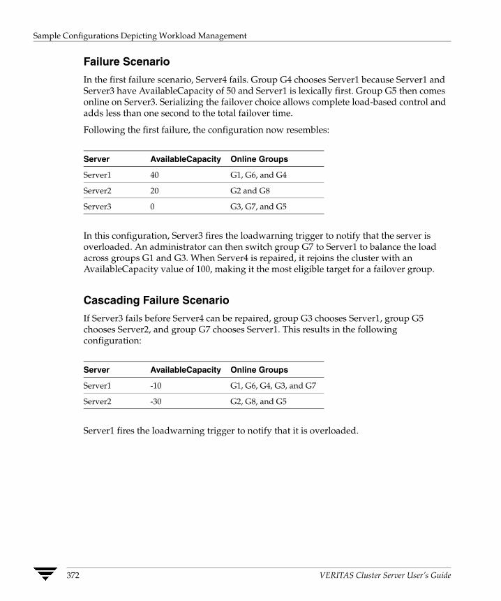
Sample Configurations Depicting Workload Management
Failure Scenario
In the first failure scenario, Server4 fails. Group G4 chooses Server1 because Server1 and Server3 have AvailableCapacity of 50 and Server1 is lexically first. Group G5 then comes online on Server3. Serializing the failover choice allows complete load-based control and adds less than one second to the total failover time.
Following the first failure, the configuration now resembles:
Server AvailableCapacity Online Groups
Server1 40 G1, G6, and G4
Server2 20 G2 and G8
Server3 0 G3, G7, and G5
In this configuration, Server3 fires the loadwarning trigger to notify that the server is overloaded. An administrator can then switch group G7 to Server1 to balance the load across groups G1 and G3. When Server4 is repaired, it rejoins the cluster with an AvailableCapacity value of 100, making it the most eligible target for a failover group.
Cascading Failure Scenario
If Server3 fails before Server4 can be repaired, group G3 chooses Server1, group G5 chooses Server2, and group G7 chooses Server1. This results in the following configuration:
Server AvailableCapacity Online Groups
Server1 -10 G1, G6, G4, G3, and G7
Server2 -30 G2, G8, and G5
Server1 fires the loadwarning trigger to notify that it is overloaded.
372 VERITAS Cluster Server User’s Guide
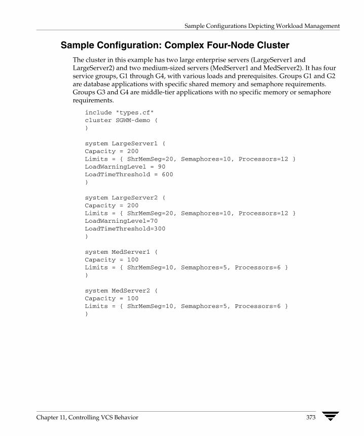
Sample Configurations Depicting Workload Management
Sample Configuration: Complex Four-Node Cluster The cluster in this example has two large enterprise servers (LargeServer1 and LargeServer2) and two medium-sized servers (MedServer1 and MedServer2). It has four service groups, G1 through G4, with various loads and prerequisites. Groups G1 and G2 are database applications with specific shared memory and semaphore requirements. Groups G3 and G4 are middle-tier applications with no specific memory or semaphore requirements.
include "types.cf"cluster SGWM-demo ()
system LargeServer1 (Capacity = 200Limits = { ShrMemSeg=20, Semaphores=10, Processors=12 }LoadWarningLevel = 90LoadTimeThreshold = 600)
system LargeServer2 (Capacity = 200Limits = { ShrMemSeg=20, Semaphores=10, Processors=12 }LoadWarningLevel=70LoadTimeThreshold=300)
system MedServer1 (Capacity = 100Limits = { ShrMemSeg=10, Semaphores=5, Processors=6 })
system MedServer2 (Capacity = 100Limits = { ShrMemSeg=10, Semaphores=5, Processors=6 })
Chapter 11, Controlling VCS Behavior 373
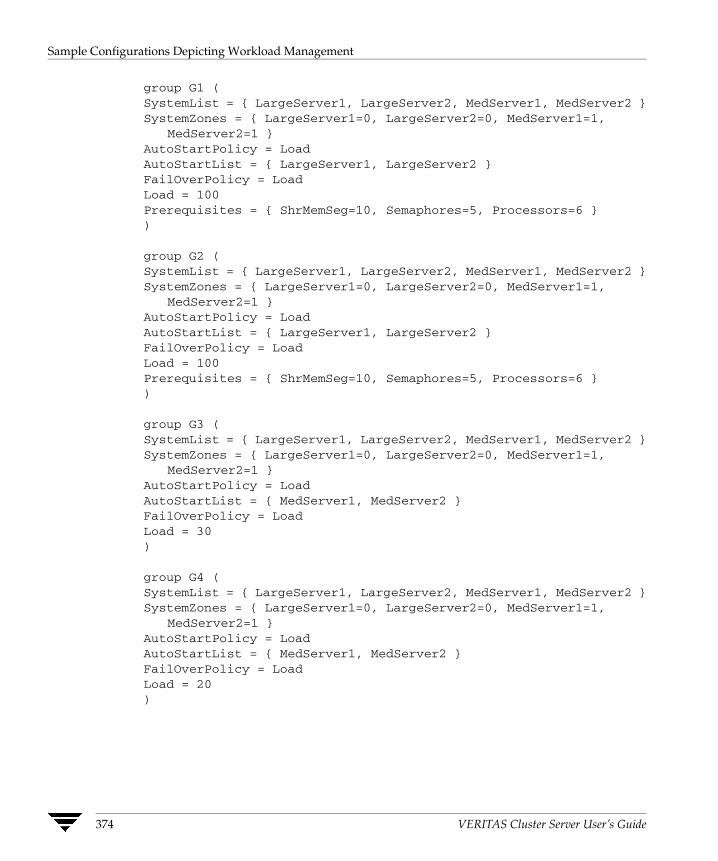
Sample Configurations Depicting Workload Management
group G1 (SystemList = { LargeServer1, LargeServer2, MedServer1, MedServer2 }SystemZones = { LargeServer1=0, LargeServer2=0, MedServer1=1,
MedServer2=1 }AutoStartPolicy = LoadAutoStartList = { LargeServer1, LargeServer2 }FailOverPolicy = LoadLoad = 100Prerequisites = { ShrMemSeg=10, Semaphores=5, Processors=6 })
group G2 (SystemList = { LargeServer1, LargeServer2, MedServer1, MedServer2 }SystemZones = { LargeServer1=0, LargeServer2=0, MedServer1=1,
MedServer2=1 }AutoStartPolicy = LoadAutoStartList = { LargeServer1, LargeServer2 }FailOverPolicy = LoadLoad = 100Prerequisites = { ShrMemSeg=10, Semaphores=5, Processors=6 })
group G3 (SystemList = { LargeServer1, LargeServer2, MedServer1, MedServer2 }SystemZones = { LargeServer1=0, LargeServer2=0, MedServer1=1,
MedServer2=1 }AutoStartPolicy = LoadAutoStartList = { MedServer1, MedServer2 }FailOverPolicy = LoadLoad = 30)
group G4 (SystemList = { LargeServer1, LargeServer2, MedServer1, MedServer2 }SystemZones = { LargeServer1=0, LargeServer2=0, MedServer1=1,
MedServer2=1 }AutoStartPolicy = LoadAutoStartList = { MedServer1, MedServer2 }FailOverPolicy = LoadLoad = 20)
374 VERITAS Cluster Server User’s Guide

Sample Configurations Depicting Workload Management
AutoStart Operation
In this configuration, the AutoStart sequence resembles:
G1—LargeServer1
G2—LargeServer2
G3—MedServer1
G4—MedServer2
All groups begin a probe sequence when the cluster starts. Groups G1 and G2 have an AutoStartList of LargeServer1 and LargeServer2. When these groups probe, they are queued to go online on one of these servers, based on highest AvailableCapacity value. If G1 probes first, it chooses LargeServer1 because LargeServer1 and LargeServer2 both have an AvailableCapacity of 200, but LargeServer1 is lexically first. Groups G3 and G4 use the same algorithm to determine their servers.
Normal Operation
The configuration resembles:
Server AvailableCapacity CurrentLimits Online Groups
LargeServer1 100 ShrMemSeg=10 G1
Semaphores=5
Processors=6
LargeServer2 100 ShrMemSeg=10 G2
Semaphores=5
Processors=6
MedServer1 70 ShrMemSeg=10 G3
Semaphores=5
Processors=6
MedServer2 80 ShrMemSeg=10 G4
Semaphores=5
Processors=6
Chapter 11, Controlling VCS Behavior 375

Sample Configurations Depicting Workload Management
Failure Scenario
In this scenario, if LargeServer2 fails, VCS scans all available systems in group G2’s SystemList that are in the same SystemZone and creates a subset of systems that meet the group’s prerequisites. In this case, LargeServer1 meets all required Limits. Group G2 is brought online on LargeServer1. This results in the following configuration:
Server AvailableCapacity CurrentLimits Online Groups
LargeServer1 0 ShrMemSeg=0 G1, G2
Semaphores=0
Processors=0
MedServer1 70 ShrMemSeg=10 G3
Semaphores=5
Processors=6
MedServer2 80 ShrMemSeg=10 G4
Semaphores=5
Processors=6
After 10 minutes (LoadTimeThreshold = 600) VCS fires the loadwarning trigger on LargeServer1 because the LoadWarningLevel exceeds 90 percent.
Cascading Failure Scenario
In this scenario, another system failure can be tolerated because each system has sufficient Limits to accommodate the service group running on its peer. If MedServer1 fails, its groups can fail over to MedServer2.
If LargeServer1 fails, the failover of the two groups running on it is serialized. The first group lexically, G1, chooses MedServer2 because the server meets the required Limits and has AvailableCapacity value. Group G2 chooses MedServer1 because it is the only remaining system that meets the required Limits.
376 VERITAS Cluster Server User’s Guide
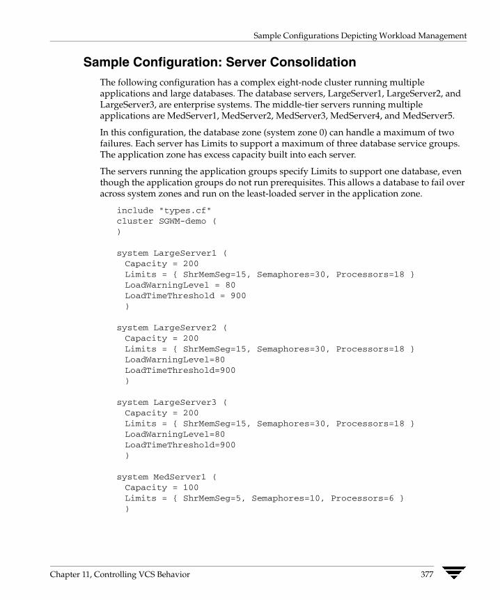
Sample Configurations Depicting Workload Management
Sample Configuration: Server Consolidation The following configuration has a complex eight-node cluster running multiple applications and large databases. The database servers, LargeServer1, LargeServer2, and LargeServer3, are enterprise systems. The middle-tier servers running multiple applications are MedServer1, MedServer2, MedServer3, MedServer4, and MedServer5.
In this configuration, the database zone (system zone 0) can handle a maximum of two failures. Each server has Limits to support a maximum of three database service groups. The application zone has excess capacity built into each server.
The servers running the application groups specify Limits to support one database, even though the application groups do not run prerequisites. This allows a database to fail over across system zones and run on the least-loaded server in the application zone.
include "types.cf"cluster SGWM-demo ()
system LargeServer1 (Capacity = 200Limits = { ShrMemSeg=15, Semaphores=30, Processors=18 }LoadWarningLevel = 80LoadTimeThreshold = 900)
system LargeServer2 (Capacity = 200Limits = { ShrMemSeg=15, Semaphores=30, Processors=18 }LoadWarningLevel=80LoadTimeThreshold=900)
system LargeServer3 (Capacity = 200Limits = { ShrMemSeg=15, Semaphores=30, Processors=18 }LoadWarningLevel=80LoadTimeThreshold=900)
system MedServer1 (Capacity = 100Limits = { ShrMemSeg=5, Semaphores=10, Processors=6 })
Chapter 11, Controlling VCS Behavior 377
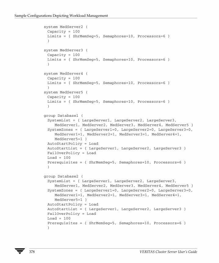
Sample Configurations Depicting Workload Management
system MedServer2 (Capacity = 100Limits = { ShrMemSeg=5, Semaphores=10, Processors=6 })
system MedServer3 (Capacity = 100Limits = { ShrMemSeg=5, Semaphores=10, Processors=6 })
system MedServer4 (Capacity = 100Limits = { ShrMemSeg=5, Semaphores=10, Processors=6 })
system MedServer5 (Capacity = 100Limits = { ShrMemSeg=5, Semaphores=10, Processors=6 })
group Database1 (SystemList = { LargeServer1, LargeServer2, LargeServer3,
MedServer1, MedServer2, MedServer3, MedServer4, MedServer5 }SystemZones = { LargeServer1=0, LargeServer2=0, LargeServer3=0,
MedServer1=1, MedServer2=1, MedServer3=1, MedServer4=1,MedServer5=1 }
AutoStartPolicy = LoadAutoStartList = { LargeServer1, LargeServer2, LargeServer3 }FailOverPolicy = LoadLoad = 100Prerequisites = { ShrMemSeg=5, Semaphores=10, Processors=6 })
group Database2 (SystemList = { LargeServer1, LargeServer2, LargeServer3,
MedServer1, MedServer2, MedServer3, MedServer4, MedServer5 }SystemZones = { LargeServer1=0, LargeServer2=0, LargeServer3=0,
MedServer1=1, MedServer2=1, MedServer3=1, MedServer4=1,MedServer5=1 }
AutoStartPolicy = LoadAutoStartList = { LargeServer1, LargeServer2, LargeServer3 }FailOverPolicy = LoadLoad = 100Prerequisites = { ShrMemSeg=5, Semaphores=10, Processors=6 })
378 VERITAS Cluster Server User’s Guide
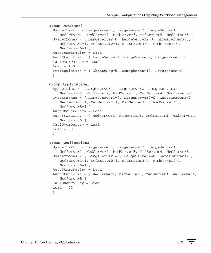
Sample Configurations Depicting Workload Management
group Database3 (SystemList = { LargeServer1, LargeServer2, LargeServer3,
MedServer1, MedServer2, MedServer3, MedServer4, MedServer5 }SystemZones = { LargeServer=0, LargeServer2=0, LargeServer3=0,
MedServer1=1, MedServer2=1, MedServer3=1, MedServer4=1,MedServer5=1 }
AutoStartPolicy = LoadAutoStartList = { LargeServer1, LargeServer2, LargeServer3 }FailOverPolicy = LoadLoad = 100Prerequisites = { ShrMemSeg=5, Semaphores=10, Processors=6 })
group Application1 (SystemList = { LargeServer1, LargeServer2, LargeServer3,
MedServer1, MedServer2, MedServer3, MedServer4, MedServer5 }SystemZones = { LargeServer1=0, LargeServer2=0, LargeServer3=0,
MedServer1=1, MedServer2=1, MedServer3=1, MedServer4=1,MedServer5=1 }
AutoStartPolicy = LoadAutoStartList = { MedServer1, MedServer2, MedServer3, MedServer4,
MedServer5 }FailOverPolicy = LoadLoad = 50)
group Application2 (SystemList = { LargeServer1, LargeServer2, LargeServer3,
MedServer1, MedServer2, MedServer3, MedServer4, MedServer5 }SystemZones = { LargeServer1=0, LargeServer2=0, LargeServer3=0,
MedServer1=1, MedServer2=1, MedServer3=1, MedServer4=1,MedServer5=1 }
AutoStartPolicy = LoadAutoStartList = { MedServer1, MedServer2, MedServer3, MedServer4,
MedServer5 }FailOverPolicy = LoadLoad = 50)
Chapter 11, Controlling VCS Behavior 379

Sample Configurations Depicting Workload Management
group Application3 (SystemList = { LargeServer1, LargeServer2, LargeServer3,
MedServer1, MedServer2, MedServer3, MedServer4, MedServer5 }SystemZones = { LargeServer1=0, LargeServer2=0, LargeServer3=0,
MedServer1=1, MedServer2=1, MedServer3=1, MedServer4=1,MedServer5=1 }
AutoStartPolicy = LoadAutoStartList = { MedServer1, MedServer2, MedServer3, MedServer4,
MedServer5 }FailOverPolicy = LoadLoad = 50)
group Application4 (SystemList = { LargeServer1, LargeServer2, LargeServer3,
MedServer1, MedServer2, MedServer3, MedServer4, MedServer5 }SystemZones = { LargeServer1=0, LargeServer2=0, LargeServer3=0,
MedServer1=1, MedServer2=1, MedServer3=1, MedServer4=1,MedServer5=1 }
AutoStartPolicy = LoadAutoStartList = { MedServer1, MedServer2, MedServer3, MedServer4,
MedServer5 }FailOverPolicy = LoadLoad = 50)
group Application5 (SystemList = { LargeServer1, LargeServer2, LargeServer3,
MedServer1, MedServer2, MedServer3, MedServer4, MedServer5 }SystemZones = { LargeServer1=0, LargeServer2=0, LargeServer3=0,
MedServer1=1, MedServer2=1, MedServer3=1, MedServer4=1,MedServer5=1 }
AutoStartPolicy = LoadAutoStartList = { MedServer1, MedServer2, MedServer3, MedServer4,
MedServer5 }FailOverPolicy = LoadLoad = 50)
380 VERITAS Cluster Server User’s Guide
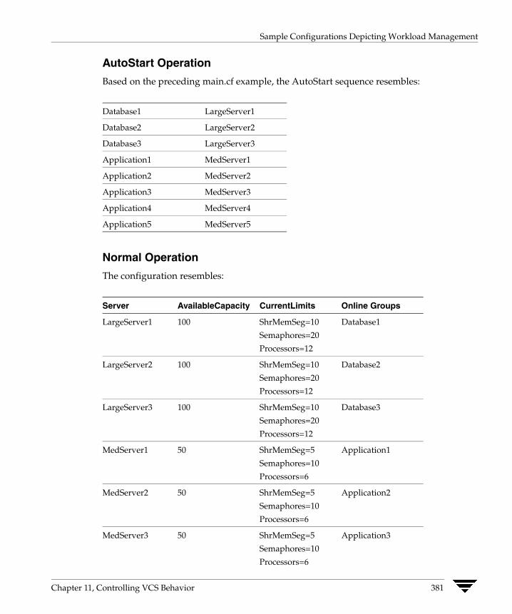
Sample Configurations Depicting Workload Management
AutoStart Operation
Based on the preceding main.cf example, the AutoStart sequence resembles:
Database1 LargeServer1
Database2 LargeServer2
Database3 LargeServer3
Application1 MedServer1
Application2 MedServer2
Application3 MedServer3
Application4 MedServer4
Application5 MedServer5
Normal Operation
The configuration resembles:
Server AvailableCapacity CurrentLimits Online Groups
LargeServer1 100 ShrMemSeg=10 Database1
Semaphores=20
Processors=12
LargeServer2 100 ShrMemSeg=10 Database2
Semaphores=20
Processors=12
LargeServer3 100 ShrMemSeg=10 Database3
Semaphores=20
Processors=12
MedServer1 50 ShrMemSeg=5 Application1
Semaphores=10
Processors=6
MedServer2 50 ShrMemSeg=5 Application2
Semaphores=10
Processors=6
MedServer3 50 ShrMemSeg=5 Application3
Semaphores=10
Processors=6
Chapter 11, Controlling VCS Behavior 381
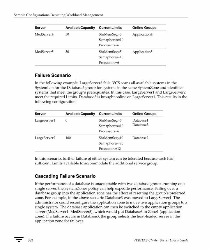
Sample Configurations Depicting Workload Management
Server AvailableCapacity CurrentLimits Online Groups
MedServer4 50 ShrMemSeg=5 Application4
Semaphores=10
Processors=6
MedServer5 50 ShrMemSeg=5 Application5
Semaphores=10
Processors=6
Failure Scenario
In the following example, LargeServer3 fails. VCS scans all available systems in the SystemList for the Database3 group for systems in the same SystemZone and identifies systems that meet the group’s prerequisites. In this case, LargeServer1 and LargeServer2 meet the required Limits. Database3 is brought online on LargeServer1. This results in the following configuration:
Server AvailableCapacity CurrentLimits Online Groups
LargeServer1 0 ShrMemSeg=5 Database1
Semaphores=10 Database3
Processors=6
LargeServer2 100 ShrMemSeg=10 Database2
Semaphores=20
Processors=12
In this scenario, further failure of either system can be tolerated because each has sufficient Limits available to accommodate the additional service group.
Cascading Failure Scenario
If the performance of a database is unacceptable with two database groups running on a single server, the SystemZones policy can help expedite performance. Failing over a database group into the application zone has the effect of resetting the group’s preferred zone. For example, in the above scenario Database3 was moved to LargeServer1. The administrator could reconfigure the application zone to move two application groups to a single system. The database application can then be switched to the empty application server (MedServer1–MedServer5), which would put Database3 in Zone1 (application zone). If a failure occurs in Database3, the group selects the least-loaded server in the application zone for failover.
382 VERITAS Cluster Server User’s Guide

The Role of Service Group Dependencies
12 A service group dependency provides a mechanism by which two service groups can be linked by a dependency rule. In a service group dependency:◆ A service group that depends on other service groups is a parent group.
◆ A service group on which other service groups depend is a child group.
◆ A service group can function as both parent and child.
Parent and child service groups are linked by a rule. This link defines the behavior of the groups when one of them faults. A link can be configured according to the following criteria:
◆ The category of the dependency, such as online or offline (described in “Categories of Service Group Dependencies” on page 385).
◆ The location of the dependency, such as local, global, or remote (described in “Location of Dependency” on page 386).
◆ The type of dependency, such as soft, firm, or hard (described in “Type of Dependency” on page 387).
Each service group dependency can be associated with a category, location, and type. For example, you could have an online local soft dependency. Note that all combinations of category, location, and dependency type are not supported.
Based on the type of link, VCS brings the parent/child service group online or takes it offline when one of the linked service groups faults.The link also controls the location where VCS brings a group online following events such as a resource fault, automatic group start, system shutdown, etc.
383

Why Configure a Service Group Dependency?
Why Configure a Service Group Dependency? While defining a cluster configuration, typically a service group and an application have a one-to-one relationship. For example, a service group hosts an application, or an application is contained within a service group. In a distributed computing environment there may be multiple applications running within a cluster, and one application may depend on another. For example, a database server may have several database applications depending on its services. In such situations, it is imperative that a dependency rule be specified for how groups are brought online and taken offline.
For example, you can define a rule that requires a database server (a child group) to be online before any or all database applications (parent group) can be brought online. You can also define a rule that requires database applications to fail over when the database server faults.
Note Configuring service group dependencies adds complexity to your configuration. We strongly recommend evaluating various scenarios before implementing group dependencies in your environment. In general, an application and its resources should be contained within a single service group. Group dependency helps leverage failover scenarios when multiple applications are configured in a cluster.
384 VERITAS Cluster Server User’s Guide
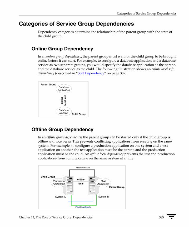
Categories of Service Group Dependencies
Categories of Service Group Dependencies Dependency categories determine the relationship of the parent group with the state of the child group.
Online Group Dependency In an online group dependency, the parent group must wait for the child group to be brought online before it can start. For example, to configure a database application and a database service as two separate groups, you would specify the database application as the parent, and the database service as the child. The following illustration shows an online local soft dependency (described in “Soft Dependency” on page 387).
Database Application
Parent Group
Child Group
Database Service
on
line
loca
l so
ft
Offline Group Dependency In an offline group dependency, the parent group can be started only if the child group is offline and vice versa. This prevents conflicting applications from running on the same system. For example, to configure a production application on one system and a test application on another, the test application must be the parent, and the production application must be the child. An offline local dependency prevents the test and production applications from coming online on the same system at a time.
System A System B
Public Network
Private Networks
offline
local Production Application
Test Application
Child Group
Parent Group
Chapter 12, The Role of Service Group Dependencies 385

Location of Dependency
Location of Dependency The location of the dependency determines the relative location of parent and child groups. In the following examples, parent and child groups can be failover or parallel, as described in “Service Groups” on page 9.
Local Dependency In a local dependency, an instance of the parent group depends on an instance of the child group being online or offline on the same system. For example, in an online local dependency, a child group must be online on a system before the parent group can come online on the same system.
Global Dependency In a global dependency an instance of the parent group depends on one or more instances of the child group being online on any system. In an online global dependency, the child group must be online somewhere in the cluster before the parent group can come online.
Remote Dependency In a remote dependency an instance of parent group depends on one or more instances of the child group being online on any system other than the system on which the parent is online. For example, for the parent to come online on System A, the child must be online on any system in the cluster except System A.
386 VERITAS Cluster Server User’s Guide

Type of Dependency
Type of Dependency The type of dependency defines the rigidity of the link between parent and child groups. There are three dependency types: soft, firm and hard.
Soft Dependency In a soft dependency, VCS imposes minimal constraints while onlining parent/child groups. The only constraint is that child group must be online prior to the parent group being brought online; the location of the dependency determines where the child group must be online. For example, in an online local soft dependency, an instance of the child group must be online on the same system before the parent group can come online.
Soft dependency provides the following enhanced flexibility:
◆ If the child group faults, VCS does not immediately take the parent offline. If the child group cannot fail over, the parent remains online.
◆ When both groups are online, the child group can be taken offline while the parent is online and vice versa (the parent group can be taken offline while the child is online).
◆ To link a parent and child group, the child group is not required to be online if the parent is online. However, if the child group is also online, the parent and child may not be linked in such a way that their online states conflict with the type of link between parent and child.
The location of the link (local, global, or remote) designates whether or not a parent group will fail over after a fault and failover of the child group.
Firm Dependency Firm dependency means VCS imposes more constraints when onlining parent/child groups. The child group must be online prior to the parent group being brought online; the location of the dependency determines where the child group must be online. In addition to the constraints imposed by soft dependency, firm dependency also includes the following constraints:
◆ If the child group faults, the parent is taken offline. If the child cannot fail over, the parent remains offline. However, if the child group faults and the parent group is frozen, the parent remains in its original state.
◆ The child group cannot be taken offline while the parent group is online. However, the parent group can be taken offline while the child is online.
◆ To link a parent and child group with firm dependency, the parent group must be offline or the parent and child group must be online in such a way that their online states do not conflict with the type of link between parent and child.
Chapter 12, The Role of Service Group Dependencies 387
Type of Dependency
Both soft and firm dependencies allow that if the parent group faults, the child group does not. The parent group may or may not fail over, depending on the link constraints and locations (such as online local versus online global). See “Service Group Dependency Configurations” on page 389 for more information.
Hard Dependency A hard dependency imposes maximum constraints on linked service groups and providesa closer relationship between parent and child groups. In a hard dependency, the child and the parent groups fail over to the same system together when either the child or theparent faults.
The following restrictions apply when configuring a hard dependency:
◆ Only online local hard dependencies are supported.
◆ Only a single-level, parent-child relationship can be configured as a hard dependency.
◆ Bringing the child group online does not automatically bring the parent online.
◆ Taking the parent group offline does not automatically take the child offline.
◆ Bringing the parent online is prohibited if the child is offline.
388 VERITAS Cluster Server User’s Guide

Service Group Dependency Configurations
Service Group Dependency Configurations This section describes the dependency configurations and the actions performed by parent and child groups according to dependency type and location. This section also includes a list of frequently asked questions (FAQs) regarding each dependency.
See “Dependencies in Failover and Parallel Service Groups” on page 403 for detailed information about group dependencies in different types of service groups.
Online Local Dependency In an online local dependency, a child group must be online on a system before a parent service group can come online on the same system.
Online Local Failover System for Child Group No Failover System for Child Group
Child Fails Soft ◆ Child faults.
◆ Child fails over to available system.
◆ Parent fails over to same system as child.
◆ Child faults.
◆ No failover for parent.
◆ Parent continues to run on original system.
Firm ◆ Child faults.
◆ Parent taken offline.
◆ Child fails over and starts.
◆ Parent starts on system with child.
◆ Child faults.
◆ Parent taken offline.
◆ Both groups die.
Hard ◆ Child faults.
◆ Parent is taken offline.
◆ Child fails over to available system.
◆ Parent starts on same system as child.
◆ Child faults.
◆ Parent is taken offline.
Chapter 12, The Role of Service Group Dependencies 389
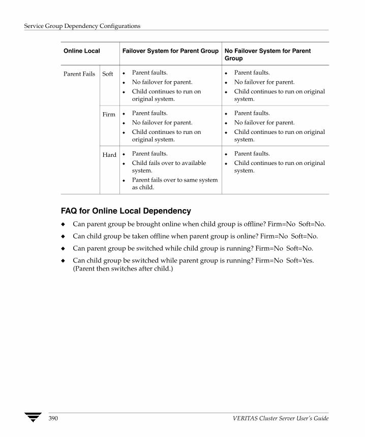
Service Group Dependency Configurations
Online Local Failover System for Parent Group No Failover System for Parent Group
Parent Fails Soft ◆ Parent faults.
◆ No failover for parent.
◆ Child continues to run on original system.
◆ Parent faults.
◆ No failover for parent.
◆ Child continues to run on original system.
Firm ◆ Parent faults.
◆ No failover for parent.
◆ Child continues to run on original system.
◆ Parent faults.
◆ No failover for parent.
◆ Child continues to run on original system.
Hard ◆ Parent faults.
◆ Child fails over to available system.
◆ Parent fails over to same system as child.
◆ Parent faults.
◆ Child continues to run on original system.
FAQ for Online Local Dependency
◆ Can parent group be brought online when child group is offline? Firm=No Soft=No.
◆ Can child group be taken offline when parent group is online? Firm=No Soft=No.
◆ Can parent group be switched while child group is running? Firm=No Soft=No.
◆ Can child group be switched while parent group is running? Firm=No Soft=Yes. (Parent then switches after child.)
390 VERITAS Cluster Server User’s Guide
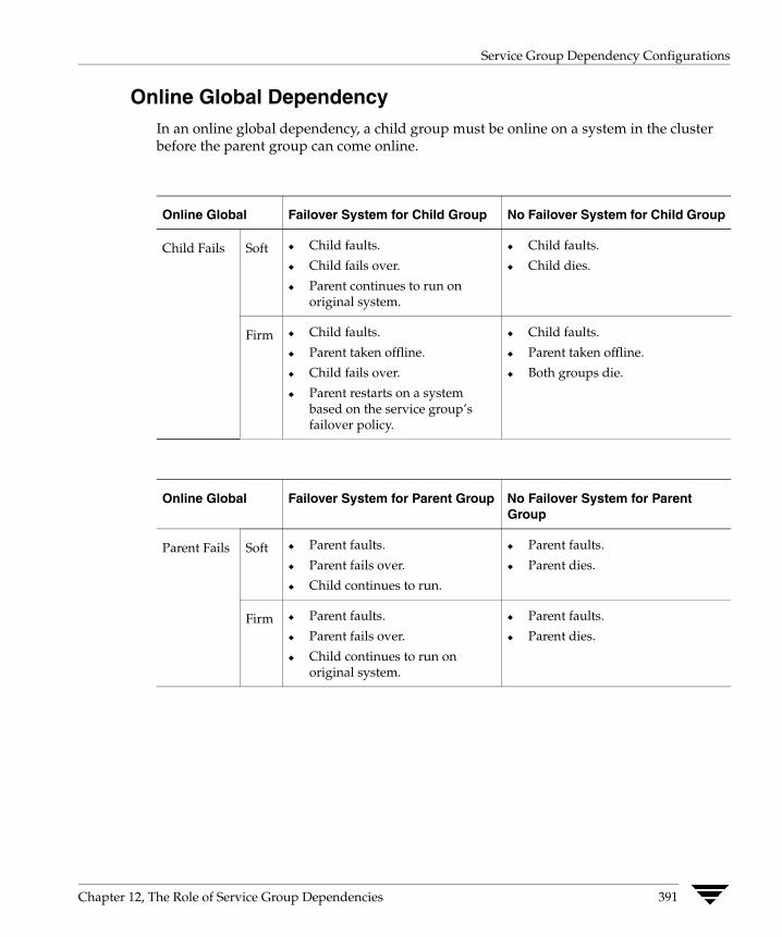
Service Group Dependency Configurations
Online Global Dependency In an online global dependency, a child group must be online on a system in the cluster before the parent group can come online.
Online Global Failover System for Child Group No Failover System for Child Group
Child Fails Soft ◆ Child faults.
◆ Child fails over.
◆ Parent continues to run on original system.
◆ Child faults.
◆ Child dies.
Firm ◆ Child faults.
◆ Parent taken offline.
◆ Child fails over.
◆ Parent restarts on a system based on the service group’s failover policy.
◆ Child faults.
◆ Parent taken offline.
◆ Both groups die.
Online Global Failover System for Parent Group No Failover System for Parent Group
Parent Fails Soft ◆ Parent faults.
◆ Parent fails over.
◆ Child continues to run.
◆ Parent faults.
◆ Parent dies.
Firm ◆ Parent faults.
◆ Parent fails over.
◆ Child continues to run on original system.
◆ Parent faults.
◆ Parent dies.
Chapter 12, The Role of Service Group Dependencies 391
Service Group Dependency Configurations
FAQ for Online Global Dependency
◆ Can parent group be brought online when child group is offline?
Soft=No Firm=No Hard=No.
◆ Can child group be taken offline when parent group is online?
Soft=Yes Firm=No Hard= No.
◆ Can parent group be switched while child group is running?
Soft=Yes Firm=Yes Hard=Yes.
◆ Can child group be switched while parent group is running?
Soft=Yes Firm=No Hard=No.
392 VERITAS Cluster Server User’s Guide
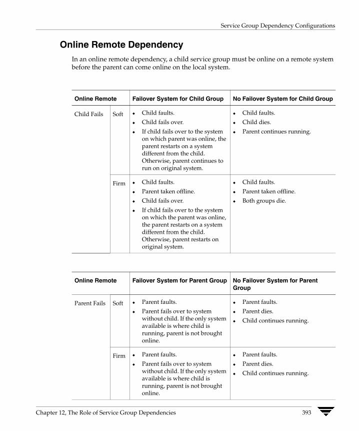
Service Group Dependency Configurations
Online Remote Dependency In an online remote dependency, a child service group must be online on a remote system before the parent can come online on the local system.
Online Remote Failover System for Child Group No Failover System for Child Group
Child Fails Soft ◆ Child faults.
◆ Child fails over.
◆ If child fails over to the system on which parent was online, the parent restarts on a system different from the child. Otherwise, parent continues to run on original system.
◆ Child faults.
◆ Child dies.
◆ Parent continues running.
Firm ◆ Child faults.
◆ Parent taken offline.
◆ Child fails over.
◆ If child fails over to the system on which the parent was online, the parent restarts on a system different from the child. Otherwise, parent restarts on original system.
◆ Child faults.
◆ Parent taken offline.
◆ Both groups die.
Online Remote Failover System for Parent Group No Failover System for Parent Group
Parent Fails Soft ◆ Parent faults.
◆ Parent fails over to system without child. If the only system available is where child is running, parent is not brought online.
◆ Parent faults.
◆ Parent dies.
◆ Child continues running.
Firm ◆ Parent faults.
◆ Parent fails over to system without child. If the only system available is where child is running, parent is not brought online.
◆ Parent faults.
◆ Parent dies.
◆ Child continues running.
Chapter 12, The Role of Service Group Dependencies 393
Service Group Dependency Configurations
FAQ for Online Remote Dependency
◆ Can parent group be brought online when child group is offline? Firm=No Soft=No.
◆ Can child group be taken offline when parent group is online? Firm=No Soft=Yes.
◆ Can parent group be switched while child group is running? Firm=Yes, but not to system on which child is running. Soft=Yes, but not to system on which child is running.
◆ Can child group be switched while parent group is running? Firm=No Soft=Yes, but not to system on which parent is running.
394 VERITAS Cluster Server User’s Guide
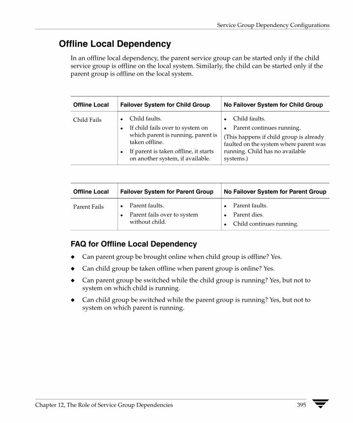
Service Group Dependency Configurations
Offline Local Dependency In an offline local dependency, the parent service group can be started only if the child service group is offline on the local system. Similarly, the child can be started only if the parent group is offline on the local system.
Offline Local Failover System for Child Group No Failover System for Child Group
Child Fails ◆ Child faults.
◆ If child fails over to system on which parent is running, parent is taken offline.
◆ If parent is taken offline, it starts on another system, if available.
◆ Child faults.
◆ Parent continues running.
(This happens if child group is already faulted on the system where parent was running. Child has no available systems.)
Offline Local Failover System for Parent Group No Failover System for Parent Group
Parent Fails ◆ Parent faults.
◆ Parent fails over to system without child.
◆ Parent faults.
◆ Parent dies.
◆ Child continues running.
FAQ for Offline Local Dependency
◆ Can parent group be brought online when child group is offline? Yes.
◆ Can child group be taken offline when parent group is online? Yes.
◆ Can parent group be switched while the child group is running? Yes, but not to system on which child is running.
◆ Can child group be switched while the parent group is running? Yes, but not to system on which parent is running.
Chapter 12, The Role of Service Group Dependencies 395
Linking Service Groups (Online/Offline Dependencies)
Linking Service Groups (Online/Offline Dependencies) You can link service groups from the command line or from the Java and Web consoles. This section describes the hagrp -link command.
Note that a configuration may require that a certain service group be running before another service group can be brought online. For example, a group containing resources of a database service must be running before the database application is brought online.
To link service groups:
# hagrp -link parent_group child_group gd_categorygd_location gd_type
The variable parent_group is the name of a service group.
The variable child_group is the name of a service group.
The variable gd_category is the category of group dependency (online/offline).
The variable gd_location is the boundary of parent_group-child_group link (local/global/remote).
The optional variable gd_type is the type of group dependency (soft/firm/hard).
Note While configuring group dependencies, if dependency type (soft/firm/hard) is omitted, the group dependency defaults to firm.
Configuring Service Group Dependencies To configure a service group dependency, place the requires clause in the service group declaration within the VCS configuration file, before the resource dependency specifications, and after the resource declarations. For example:
◆ To configure groupx and groupy as an online local firm dependency:
group groupx (...group definition...)...resource declarations...requires group groupy online local firm...resource dependencies...
◆ To configure groupx and groupy as an online global soft dependency:
group groupx (...group definition...)...resource declarations...requires group groupy online global soft...resource dependencies...
396 VERITAS Cluster Server User’s Guide
Automatic Actions for Service Group Dependencies
Automatic Actions for Service Group Dependencies
Automatic Online If a service group is configured to start automatically on a system, it is brought online only if the group’s dependency requirements are met. This implies that in an online local dependency, parent groups are brought online only after all child groups are brought online.
AutoRestart If a persistent resource on a service group (GROUP_1 in this example) faults, the service group is automatically failed over to another system in the cluster under the following conditions:
◆ The AutoFailOver attribute is set.
◆ There is another system in the cluster to which GROUP_1 can fail over.
If neither of the above conditions is met (the AutoFailOver attribute is not set or other systems in the cluster are unavailable), GROUP_1 remains offline and faulted, even after the faulted resource becomes online.
Setting the AutoRestart attribute enables a service group to be brought back online without manual intervention. In the above example, setting the AutoRestart attribute for GROUP_1 would enable VCS to bring the group back online, after the resource came online on the system where the resource faulted.
Or, if GROUP_1 could not fail over to another system because none was available, setting the AutoRestart attribute would enable VCS to bring the group back online on the first available system after the group’s faulted resource came online on that system.
For example, NIC is a persistent resource. In some cases, when a system boots and VCS starts, VCS probes all resources on the system. It is possible that when VCS probes the NIC resource, the resource may not yet be online because the networking is not up and fully operational. When this occurs, VCS will mark the NIC resource as faulted, and will not bring the service group online. However, when the NIC resource becomes online and if AutoRestart is enabled, the service group is brought online.
Chapter 12, The Role of Service Group Dependencies 397

Automatic Actions for Service Group Dependencies
Automatic Failover A failover occurs when a service group faults and is migrated to another system or when a system crashes. For service groups with dependencies, the following actions occur during failover
1. The service group is taken offline along with any of its parent service groups that have an online firm or hard dependency (online local firm, online global firm, online remote firm, or online local hard).
2. A failover target is chosen from the SystemList of the service group based on the failover policy and the restrictions brought by the service group dependencies.
If the faulted service group is also the parent service group in a service group dependency relationship, the service group dependency has an impact on the choice of a target system. For example, if the faulted service group has an online local (firm or soft) dependency with a child service group that is online only on that system, no failover targets are available.
3. If there are no other systems the service group can fail over to, the child service group and the parents that were taken offline remain offline. Note that for soft dependencies, when child group faults and cannot fail over, the parent group remains online.
4. If there is a failover target, then VCS takes any child service group with an online local hard dependency offline.
5. VCS then checks if there are any conflicting parent service groups that are already online on the target system. These service groups can be parent service groups that are linked with an offline local dependency or online remote soft dependency. In either case, the parent service group is taken offline to enable the child service group to start on that system.
6. If there is any child service group with an online local hard dependency, first the child service group and then the service group that initiated the failover are brought online.
7. After the service group is brought online successfully on the target system, VCS takes any parent service groups offline that have an online local soft dependency to the failed-over child.
8. Finally, VCS selects a failover target for any parent service groups that may have been taken offline during steps 1, 5, or 7 and brings the parent service group online on an available system.
9. If there are no target systems available to fail over the parent service group that has been taken offline, the parent service group remains offline.
398 VERITAS Cluster Server User’s Guide
Manual Operations for Service Group Dependencies
Manual Operations for Service Group Dependencies You can manually bring a service group online, take it offline, or fail it over using the hagrp -online, -offline, and -switch commands.
Manual Online Basic rules governing how to manually bring a service group online also apply to service groups with dependencies. Additionally, the following rules apply for service groups configured with dependencies. For example:
◆ For online dependencies, a parent group cannot be brought online manually if the child is not online.
◆ For online local dependencies, a parent group cannot be brought online manually on any system other than the system on which the child is online.
◆ For online remote dependencies, a parent group cannot be brought online manually on the system on which the child is online.
◆ For offline local dependencies, a parent group cannot be brought online manually on the system on which the child is online.
Typically, bringing a child group online manually is never rejected, except under the following circumstances:
◆ For online local dependencies, if parent is online, a child group online is rejected for any system other than the system where parent is online.
◆ For online remote dependencies, if parent is online, a child group online is rejected for the system where parent is online.
◆ For offline local dependencies, if parent is online, a child group online is rejected for the system where parent is online.
The following examples describe situations where bringing a parallel child group online is accepted:
◆ For a parallel child group linked online local with failover/parallel parent, multiple instances of child group online are acceptable.
◆ For a parallel child group linked online remote with failover parent, multiple instances of child group online are acceptable, as long as child group does not go online on the system where parent is online.
◆ For a parallel child group linked offline local with failover/parallel parent, multiple instances of child group online are acceptable, as long as child group does not go online on the system where parent is online.
Chapter 12, The Role of Service Group Dependencies 399

Manual Operations for Service Group Dependencies
Manual Offline Basic rules governing how to manually take a service group offline also apply to service groups with dependencies. Additionally, VCS rejects manual offlining if the procedure violates existing group dependencies. Typically, firm dependencies are more restrictive to offlining a child group while parent group is online. Rules for manual offlining include:
◆ Parent group offline is never rejected.
◆ For all soft dependencies, child group can be offlined regardless of the state of parent group.
◆ For all firm dependencies, if parent group is online, child group offline is rejected.
◆ For the online local hard dependency, if parent group is online, child group offline is rejected.
Manual Switch Switching a service group implies manually taking a service group offline on one system, and manually bringing it back online on another system. Basic rules governing how to manually switch a service group also apply to service group dependencies. Additionally, VCS rejects manual switch if the group does not comply with manual offline or manual online rules described above.
400 VERITAS Cluster Server User’s Guide
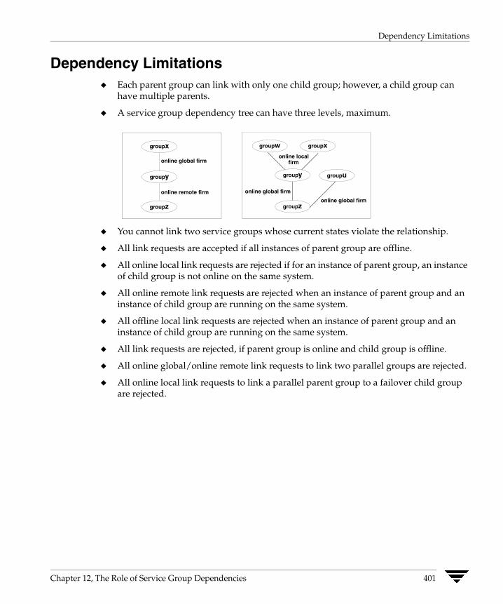
Dependency Limitations
Dependency Limitations ◆ Each parent group can link with only one child group; however, a child group can
have multiple parents.
◆ A service group dependency tree can have three levels, maximum.
online global firm
groupy
groupx
groupz
online remote firm
groupw groupx
groupy
groupz
groupu
online local firm
online global firm
online global firm
◆ You cannot link two service groups whose current states violate the relationship.
◆ All link requests are accepted if all instances of parent group are offline.
◆ All online local link requests are rejected if for an instance of parent group, an instance of child group is not online on the same system.
◆ All online remote link requests are rejected when an instance of parent group and an instance of child group are running on the same system.
◆ All offline local link requests are rejected when an instance of parent group and an instance of child group are running on the same system.
◆ All link requests are rejected, if parent group is online and child group is offline.
◆ All online global/online remote link requests to link two parallel groups are rejected.
◆ All online local link requests to link a parallel parent group to a failover child group are rejected.
Chapter 12, The Role of Service Group Dependencies 401
Dependencies in Failover and Parallel Service Groups
Dependencies in Failover and Parallel Service Groups In the following sections the term “instance” applies to parallel groups only. If a parallel group is online on three systems, an instance of the group is online on each system. For failover groups, only one instance of a group is online at any time.
The following information describes situations in which a child group faults in all service group dependencies with failover and parallel groups.
Failover Parent/Failover Child online local soft Failover parent group soft depends on failover child group being online on the same system.
Parent can be brought online on a system, for example, System A, only if the child is online on System A.
✔ If the child faults, the parent is not taken offline. After the child successfully fails over to another system, for example, System B, VCS migrates the parent to System B. If the child cannot fail over, the parent remains online on System A.
✔ If parent faults on System A, child remains online on System A. Parent cannot fail over anywhere.
online local firm Failover parent group firm depends on failover child group being online on the same system.
Parent can be brought online on a system, for example, System A, only if the child is online on System A.
✔ If the child faults, the parent is taken offline on System A. When a child successfully fails over to another system, for example System B, VCS migrates the parent to System B. If child cannot fail over, parent remains offline.
✔ If parent faults on System A, child remains online on System A. Parent cannot fail over anywhere.
402 VERITAS Cluster Server User’s Guide
Dependencies in Failover and Parallel Service Groups
online local hard Failover parent group firm depends on failover child group being online on the same system.
Parent can be brought online on a system, for example, System A, only if the child is online on System A.
✔ If the child faults, the parent is taken offline on System A. When a child successfully fails over to another system, for example System B, VCS migrates the parent to System B. If child cannot fail over, parent remains offline.
✔ If parent faults on System A, child is taken offline on System A. When child successfully fails over to System B, VCS migrates the parent to System B. If child cannot fail over, child continues to run on System A.
online global soft Failover parent group soft depends on failover child group being online anywhere in the cluster. Parent can be brought online as long as a child group is running somewhere in the cluster.
✔ If the child faults, the parent remains online when the child faults and fails over. The parent also remains online when the child faults and cannot fail over.
✔ If parent faults on System A, child remains online on System A. Parent fails over to next-available system. If no system is available, the parent remains offline.
online global firm Failover parent group firm depends on failover child group being online anywhere in the cluster.
Parent can be brought online as long as a child group is running somewhere in the cluster. For example, the parent group is online on System A, and the child group is online on System B.
✔ If the child faults on System B, the parent group on System A is taken offline. When the child successfully fails over to another system, for example, System C, the parent group is brought online on a suitable system. If child group cannot fail over, parent group remains offline.
✔ If parent faults on System A, child remains online on System A. Parent fails over to next-available system. If no system is available, the parent remains offline.
Chapter 12, The Role of Service Group Dependencies 403
Dependencies in Failover and Parallel Service Groups
online remote soft Failover parent group soft depends on failover child group being online on any other system in the cluster.
Parent can be brought online on any system other than the system on which the child is online. For example if child group is online on System B, the parent group can be online on System A.
✔ If the child faults on System B, the parent remains online on System A unless VCS selects System A as the target system on which to bring the child group online. In that case, the parent is taken offline. After the child successfully fails over to System A, VCS brings the parent online on another system, for example System B. If the child faults on System A, the parent remains online on System B unless VCS selects System B as the target system.
online remote firm Failover parent group firm depends on failover child group being online on any other system in the cluster.
Parent can be brought online on any system other than the system on which the child is online. For example if child group is online on System A, the parent group can be online on System B.
✔ If the child faults on System A, the parent is taken offline on System B. After the child successfully fails over to another system, VCS brings the parent online on a system other than B where the child is also offline. If no other system is available and if the child is offline on System B, the parent is restarted on System B.
✔ If the parent faults on System A, the child remains online on System B. The parent on System A fails over to a system other than A or B. If no system is available, the parent remains offline.
offline local Failover parent group depends on failover child group being offline on the same system and vice versa.
Parent can be brought online on any system as long as the child is not online on the system, and vice versa. For example, if child group is online on System B, the parent can be brought online on System A.
✔ If the child faults on System B, and if VCS selects System A as the target on which to bring the child online, the parent on System A is taken offline and the child is brought online. However, if child selects System C as the target, parent remains online on System A.
✔ If parent faults, child remains online. If there is no other system to which parent can fail over, parent remains offline.
404 VERITAS Cluster Server User’s Guide

Dependencies in Failover and Parallel Service Groups
Failover Parent/Parallel Child online local soft Failover parent group soft depends on an instance of the child group being online on the same system.
Failover group can be brought online on any system, for example System A, only if an instance of the child group is online on System A.
✔ If an instance of the child group on System A faults, the parent cannot migrate until the child has successfully failed over. After the child fails over to another system, for example, System B, the parent migrates to System B. If the instance of child cannot fail over, the parent may continue to run on System A.
Consider a configuration in which instances of the child group are online on Systems A and B and the parent group is online on System A.
✔ If the child faults, the parent group fails over to System B.
✔ If the parent faults, it fails over to System B. The child on System A remains online. The parent group now depends on the instance of the child group on System B.
online local firm (default) Failover parent group firm depends on an instance of the child group being online on the same system.
Failoverparent group can be brought online on any system, for example, System A, only if an instance of the child group is online on System A.
✔ If the instance of the child group on System A faults, the parent is taken offline. After the child has successfully failed over to another system, for example System B, the parent then fails over to System B.
Consider a configuration in which multiple instances of the child group are online on Systems A and B and the parent group is online on System A.
✔ If the parent faults, it fails over to System B. The child on System A remains online. The parent group now depends on the instance of the child group on System B.
online global soft Failover parent group soft depends on all online instances of the child remain online.
Failover group can be brought online anywhere as long as one or more instances of the child group are online somewhere in the cluster.
✔ If one or more instances of the child group fault, the parent remains online.
Consider that multiple instances of the child group are online on Systems A and B, and the parent group is online on System A.
✔ If parent faults, it fails over to System B. Both instances of the child group remain online, and the parent group maintains its dependency on the instances.
Chapter 12, The Role of Service Group Dependencies 405

Dependencies in Failover and Parallel Service Groups
online global firm Failover parent group firm depends on all instances of the child group being online anywhere in the cluster.
Failover group can be brought online anywhere as long as all instances of the child group are online somewhere in the cluster. For example, if two instances of the child are online on Systems A and B, and the parent is online on System A, if an instance of the child group faults, the parent is taken offline on System A. After the child has successfully failed over to System C, VCS fails over the parent group to another system. If the instance of the child group cannot fail over, the parent may not be brought online.
Consider that multiple instances of the child group are online on Systems A and B, and the parent group is online on System A.
✔ If parent faults, it fails over to System B. Both instances of the child group remain online, and the parent group maintains its dependency on the instances.
online remote soft Failover parent group soft depends on all instances of the child group being online on another system in the cluster.
Parent can be brought online on any system other than the system on which the child is online. For example if child group is online on Systems A and C, the parent group can be online on System B.
✔ If the child faults on System A, the parent remains online on System B unless VCS selects System B as the target system. After the child successfully fails over to System B, VCS brings the parent online on another system, for example, System D.
✔ If parent group faults on System B, both instances of the child group remain online. The parent group fails over to System D and maintains its dependency on both instances of the child group.
online remote firm Failover parent group firm depends on all instances of the child group being online on another system in the cluster.
Failover group can be brought online anywhere as long as all instances of the child group are online on another system. For example, if a child group is online on System A and System C, the parent group can be online on System B. When the child group on System A faults, the parent is taken offline. After the child has successfully failed over to System B, VCS brings the parent online on another system, for example, System D. If the child group fails over to System D, the parent group is restarted on System B.
Note System D is selected as an example only. The parent may be restarted on Systems A, B, or D, depending on the value of the FailOverPolicy attribute for the parent group and the system on which the child group is online.
✔ If parent group faults on System B, both instances of the child group remain online. The parent group fails over to System D and maintains its dependency on both instances of the child group.
406 VERITAS Cluster Server User’s Guide

Dependencies in Failover and Parallel Service Groups
offline local Failover parent group depends on no instances of the child group being online on the same system, and vice versa.
Failover group can be brought online anywhere as long as any instances of the child group are not online on that system, and vice versa. For example, if the child group is online on Systems B and C, the parent group can be brought online on SystemA. If the child group faults on System C, and if VCS selects System A as the target on which to bring the child group online, the parent group on System A is taken offline and the child is brought online. However, if the child group selects System D as the target, the parent group remains online on System A.
✔ If the parent group faults, the child group remains online. If there is no other system to which the parent can fail over, the parent remains offline.
Parallel Parent/Failover Child online global soft All instances of parent group soft depend on failover group.
All instances of the parent group can be online anywhere as long as the child is online somewhere in the cluster. An instance of the parent group does not fault if an instance of the child group faults.
online global firm All instances of parent group firm depend on failover group.
All instances of the parent group can be online anywhere as long as the child is online on another system. For example, the child group is online on System A, the parent group is online on Systems A and B.
✔ If the child faults, all instances of the parent group are taken offline on Systems A and B. After the child has successfully failed over to System B, VCS fails over all instances of the parent group on Systems A and B to other systems. If there are no available systems, the parent group instance is restarted on the same system.
✔ If an instance of the parent group on System A faults, the child group remains online, and the parent group fails over to System C.
online remote soft All instances of parent group soft depend on failover group on any other system.
An instance of the parent group can be online anywhere as long as the child is online on another system. For example, the child group is online on System A, the parent group can be online on System B and System C.
✔ If the child group faults and VCS selects System B as the target on which to bring the child online, the instance of the parent group running on System B is taken offline. After the child has successfully failed over to System B, VCS brings online the failed parent instance to another system, for example, System D.
Chapter 12, The Role of Service Group Dependencies 407
Dependencies in Failover and Parallel Service Groups
However, if the child group failed over to System D, the parent remains online. (If parent group on System B faults, it fails over to System D. The child group remains online on System A.)
online remote firm (default) All instances of parent group firm depend on failover group on any other system.
An instance of the parent group can be online anywhere as long as the child is online on another system. For example, if the child group is online on System A, the parent group can be online on System B and System C.
✔ If the child faults, all instances of the parent group are taken offline on System B and System C. After the child has successfully failed over to System C, VCS fails over all instances of the parent group on Systems A and B to other systems where the child is also offline. If there are no available systems and if the child is offline on the same system on which the parent was taken offline, the parent is restarted on the same system.
offline local All instances of the parent group depend on the child group being offline on that system and vice versa.
An instance of the parent group can be brought online anywhere as long as the child is not online on the system, and vice versa. For example, if the child group is online on System A, the parent group can be online on System B and System C.
✔ If the child faults on System A, and if VCS selects System B as the target on which to bring the child online, the parent on System B is taken offline first. However, if the child fails over to System D, the parent group remains online on Systems B and C.
✔ If the parent group faults on System B, the child group remains online on System A and the parent group fails over to System D.
408 VERITAS Cluster Server User’s Guide
Dependencies in Failover and Parallel Service Groups
Parallel Parent/Parallel Child online local soft An instance of the parent group soft depends on an instance of the child group on the same system.
An instance of a parent group can be brought online on a system, for example, System A, only if an instance of a child group is online on System A. For example, two instances of the parent are online on System A and System B, and each instance depends on an instance of the child being online on the same system.
✔ If the instance of the child group on System A faults, the child group fails over to System C. After the child fails over to another system, VCS migrates the instance of the parent group to System C. If the child cannot fail over, the parent remains online. Other instances of the parent group are unaffected.
✔ If an instance of the parent group on System B faults, it can fail over to System C only if an instance of the child group is running on System C and no instance of the parent group is running on System C.
online local firm An instance of the parent group firm depends on an instance of the child group on the same system.
An instance of a parent group can be brought online on a system, for example, System A, only if an instance of a child group is online on System A. For example, two instances of the parent are online on System A and System B, and each instance depends on an instance of the child being online on the same system.
✔ If an instance of the child group on System A faults, the instance of the parent group on System A is taken offline. After the child fails over to another system, for example, System C, VCS brings an instance of the parent group online on System C. Other instances of the parent group are unaffected.
✔ If an instance of the parent group on System B faults, it can fail over to System C only if an instance of the child group is running on System C and no instance of the parent group is running on System C.
offline local An instance of a parent group depends on an instance of a child group being offline on the same system and vice versa.
An instance of a parent group can be brought online provided that an instance of the child is not online on the same system and vice versa. For example, if the child group is online on System C and System D, the parent can be online on System A and System B.
✔ If the child on System C faults and VCS selects System A as the target on which to bring the child group online, the instance of the parent on System A is taken offline first.
✔ When an instance of a child group or parent group faults, it has no effect on the other running instances.
Chapter 12, The Role of Service Group Dependencies 409

Dependencies in Failover and Parallel Service Groups
410 VERITAS Cluster Server User’s Guide
Section IV. Administration–Beyond the Basics
This section describes the advanced VCS functionality of notification and event triggers.
Section IV includes the following chapters:
◆ Chapter 13. “Notification” on page 413
◆ Chapter 14. “VCS Event Triggers” on page 429

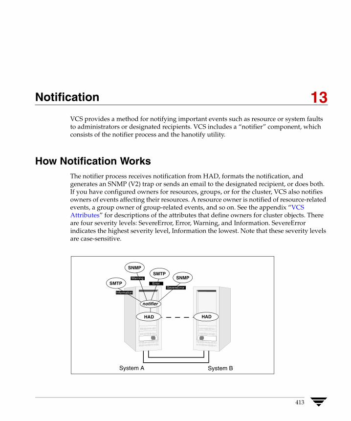
Notification
13 VCS provides a method for notifying important events such as resource or system faults to administrators or designated recipients. VCS includes a “notifier” component, which consists of the notifier process and the hanotify utility.How Notification Works The notifier process receives notification from HAD, formats the notification, and generates an SNMP (V2) trap or sends an email to the designated recipient, or does both. If you have configured owners for resources, groups, or for the cluster, VCS also notifies owners of events affecting their resources. A resource owner is notified of resource-related events, a group owner of group-related events, and so on. See the appendix “VCS Attributes” for descriptions of the attributes that define owners for cluster objects. There are four severity levels: SevereError, Error, Warning, and Information. SevereError indicates the highest severity level, Information the lowest. Note that these severity levels are case-sensitive.
HAD
System A System B
notifier
HAD
SNMP
SNMP SMTP
SMTP Warning
Error
Information
SevereError
413
How Notification Works
SNMP traps sent by VCS are forwarded to the SNMP console. Typically, traps are predefined for events such as service group or resource faults. You can use the hanotify utility to send additional traps.
Event Messages and Severity Levels When the VCS engine, HAD, starts up, it is initially configured to queue all messages as Information, the lowest severity level. However, when notifier connects to VCS, the severity communicated by notifier to HAD is one of the following, depending on which is the lowest:
◆ lowest severity for SNMP options
◆ lowest severity for SMTP options
If notifier is started from the command line without specifying a severity level for the SNMP console or SMTP recipients, notifier communicates the default severity level Warning to HAD. If notifier is configured under VCS control, severity must be specified. See the description of the NotifierMngr agent in the VERITAS Cluster Server Bundled Agents Reference Guide.
For example, if the following severities are specified for notifier:
◆ Warning for email recipient 1
◆ Error for email recipient 2
◆ SevereError for SNMP console
Notifier communicates the minimum severity, Warning, to HAD, which then queues all messages labelled severity level Warning and greater.
Notifier ensures the recipient gets only the messages that he or she has been designated to receive (according to the specified severity level). However, until notifier communicates the specifications to HAD, HAD stores all messages, because it does not know the severity the user has specified. This prevents messages from being lost between the time HAD stores them and notifier communicates the specifications to HAD.
414 VERITAS Cluster Server User’s Guide
How Notification Works
Persistent and Replicated Message Queue VCS includes a sophisticated mechanism for maintaining event messages that ensures messages are not lost. On each node, VCS queues messages to be sent to the notifier process. This queue is guaranteed persistent as long as VCS is running and the contents of this queue remain the same on each node. Therefore, if the group with notifier configured as a resource fails on one of the nodes, notifier is failed over to another node in the cluster. Because the message queue is guaranteed to be consistent and replicated across nodes, notifier can resume message delivery from where it left off after it fails over to the new node.
How HAD Deletes Messages The VCS engine, HAD, stores messages to be sent to notifier. These messages are deleted by HAD under the following conditions:
◆ The message has been in the queue for one hour and notifier is unable to deliver the message to the recipient. (This also means, that until notifier connects to HAD, messages are stored permanently in the queue until one of the following conditions are met.)
or
◆ The message queue is full and to make room for the latest message, the earliest message is deleted.
or
◆ VCS receives a message acknowledgement from notifier when notifier has delivered the message to at least one designated recipient. For example, if two SNMP consoles and two email recipients are designated, and notifier can send the message to only one email recipient because the other three were configured incorrectly, notifier sends an acknowledgement to VCS, regardless that the message reached only one of the four recipients. Error messages are also printed to the log files when delivery errors occur.
Chapter 13, Notification 415
Notification Components
Notification Components This section describes the notifier process and the hanotify utility.
The Notifier Process The notifier process configures how messages are received from VCS and how they are delivered to SNMP consoles and SMTP servers. Using notifier, you can specify notification based on the severity level of the events generating the messages. You can also specify the size of the VCS message queue, which is 30 by default. You can change this value by modifying the MessageQueue attribute. See the VCS Bundled Agents Reference Guide for more information about this attribute.
When started from the command line, notifier is a process that VCS does not control. For best results, use the NotifierMngr agent bundled with VCS to configure notifier as part of a highly available service group, which can then be monitored, brought online, and taken offline. For information on how to configure NotifierMngr, see the VERITAS Cluster Server Bundled Agents Reference Guide. Note that notifier must be configured in a failover group, not parallel, because only one instance of notifier runs in the entire cluster. Also note that notifier does not respond to SNMP get or set requests; notifier is a trap generator only.
Notifier enables you to specify configurations for the SNMP manager and SMTP server, including machine names, ports, community IDs, and recipients’ email addresses. You can specify more than one manager or server, and the severity level of messages sent to each.
Example of notifier Command
# notifier -s m=north -s m=south,p=2000,l=Error,c=your_company-t m=north,e="abc@your_company.com",l=SevereError
In this example, notifier:
◆ Sends all level SNMP traps to north at the default SNMP port and community value public.
◆ Sends Warning traps to north.
◆ Sends Error and SevereError traps to south at port 2000 and community value your_company.
◆ Sends SevereError email messages to north as SMTP server at default port and to email recipient abc@your_company.com.
416 VERITAS Cluster Server User’s Guide
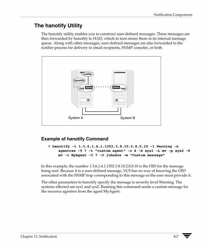
Notification Components
The hanotify Utility The hanotify utility enables you to construct user-defined messages. These messages are then forwarded by hanotify to HAD, which in turn stores them in its internal message queue. Along with other messages, user-defined messages are also forwarded to the notifier process for delivery to email recipients, SNMP consoles, or both.
System A System B
notifier
had had
hanotify
Queue Queue
Example of hanotify Command
# hanotify -i 1.3.6.1.4.1.1302.3.8.10.2.8.0.10 -l Warning -n agentres -T 7 -t "custom agent" -o 4 -S sys1 -L mv -p sys2 -Pmv -c MyAgent -C 7 -O johndoe -m "Custom message"
In this example, the number 1.3.6.1.4.1.1302.3.8.10.2.8.0.10 is the OID for the message being sent. Because it is a user-defined message, VCS has no way of knowing the OID associated with the SNMP trap corresponding to this message so the user must provide it.
The other parameters to hanotify specify the message is severity level Warning. The systems affected are sys1 and sys2. Running this command sends a custom message for the resource agentres from the agent MyAgent.
Chapter 13, Notification 417
VCS Events and Traps
VCS Events and Traps The tables below specify which events generate traps, email notification, or both. Note that SevereError indicates the highest severity level, Information the lowest. Traps specific to global clusters are ranked from Critical, the highest severity, to Normal, the lowest.
Clusters
Event Severity Level Description
Remote cluster has faulted.
(Global Cluster Option)
Error The trap for this event includes information on how to take over the global service groups running on the remote cluster before the cluster faulted.
Heartbeat is down. Error The connector on the local cluster lost its heartbeat connection to the remote cluster.
Remote cluster is in RUNNING state.
(Global Cluster Option)
Information Local cluster has complete snapshot of the remote cluster, indicating the remote cluster is in the RUNNING state.
Heartbeat is “alive.”
(Global Cluster Option)
Information Self-explanatory.
User has logged on to VCS. Information A user log on has been recognized because a user logged on via Cluster Manager, or because a haxxx command was invoked.
Agents
Event Severity Level Description
Agent is faulted. Warning The agent has faulted on one node in the cluster.
Agent is restarting Information VCS is restarting the agent.
418 VERITAS Cluster Server User’s Guide
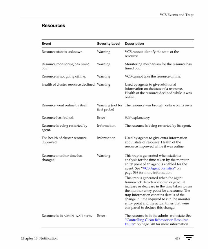
VCS Events and Traps
Resources
Event Severity Level Description
Resource state is unknown.
Resource monitoring has timed out.
Resource is not going offline.
Health of cluster resource declined.
Resource went online by itself.
Resource has faulted.
Resource is being restarted by agent.
The health of cluster resource improved.
Resource monitor time has changed.
Warning
Warning
Warning
Warning
Warning (not for first probe)
Error
Information
Information
Warning
VCS cannot identify the state of the resource.
Monitoring mechanism for the resource has timed out.
VCS cannot take the resource offline.
Used by agents to give additional information on the state of a resource. Health of the resource declined while it was online.
The resource was brought online on its own.
Self-explanatory.
The resource is being restarted by its agent.
Used by agents to give extra information about state of resource. Health of the resource improved while it was online.
This trap is generated when statistics analysis for the time taken by the monitor entry point of an agent is enabled for the agent. See “VCS Agent Statistics” on page 568 for more information.
This trap is generated when the agent framework detects a sudden or gradual increase or decrease in the time taken to run the monitor entry point for a resource. The trap information contains details of the change in time required to run the monitor entry point and the actual times that were compared to deduce this change.
Resource is in ADMIN_WAIT state. Error The resource is in the admin_wait state. See “Controlling Clean Behavior on Resource Faults” on page 348 for more information.
Chapter 13, Notification 419

VCS Events and Traps
Systems
Event Severity Level Description
VCS is being restarted by hashadow.
VCS is in jeopardy.
VCS is up on the first node in the cluster.
VCS has faulted.
A node running VCS has joined cluster.
VCS has exited manually.
CPU usage exceeded threshold on the system.
Warning
Warning
Information
SevereError
Information
Information
Warning
Self-explanatory.
One node running VCS is in jeopardy.
Self-explanatory.
Self-explanatory.
Self-explanatory.
VCS has exited gracefully from one node on which it was previously running.
The system’s CPU usage continuously exceeded the value set in the Notify threshold for a duration greater than the Notify time limit. See “Bringing a Resource Online” on page 559 for more information.
420 VERITAS Cluster Server User’s Guide

VCS Events and Traps
Service Groups
Event Severity Level Description
Service group has faulted.
Service group concurrency violation.
Service group has faulted and cannot be failed over anywhere.
Service group is online
Service group is offline.
Service group is autodisabled.
Service group is restarting.
Service group is being switched.
Service group restarting in response to persistent resource going online.
The global service group is online/partial on multiple clusters.
(Global Cluster Option)
Attributes for global service groups are mismatched.
(Global Cluster Option)
Error
SevereError
SevereError
Information
Information
Information
Information
Information
Information
SevereError
Error
Self-explanatory.
A failover service group has become online on more than one node in the cluster.
Specified service group has faulted on all nodes where group could be brought online, and there are no nodes to which the group can fail over.
Self-explanatory.
Self-explanatory.
VCS has autodisabled the specified group because one node exited the cluster.
Self-explanatory.
The service group is being taken offline on one node and being brought online on another.
Self-explanatory.
A concurrency violation occurred for the global service group.
The attributes ClusterList, AutoFailOver, and Parallel are mismatched for the same global service group on different clusters.
Chapter 13, Notification 421
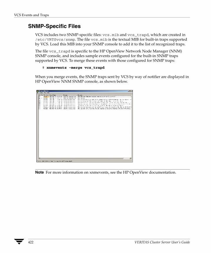
VCS Events and Traps
SNMP-Specific Files VCS includes two SNMP-specific files: vcs.mib and vcs_trapd, which are created in /etc/VRTSvcs/snmp. The file vcs.mib is the textual MIB for built-in traps supported by VCS. Load this MIB into your SNMP console to add it to the list of recognized traps.
The file vcs_trapd is specific to the HP OpenView Network Node Manager (NNM) SNMP console, and includes sample events configured for the built-in SNMP traps supported by VCS. To merge these events with those configured for SNMP traps:
# xnmevents -merge vcs_trapd
When you merge events, the SNMP traps sent by VCS by way of notifier are displayed in HP OpenView NNM SNMP console, as shown below.
Note For more information on xnmevents, see the HP OpenView documentation.
422 VERITAS Cluster Server User’s Guide
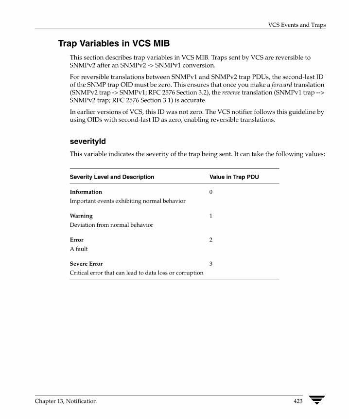
VCS Events and Traps
Trap Variables in VCS MIB This section describes trap variables in VCS MIB. Traps sent by VCS are reversible to SNMPv2 after an SNMPv2 -> SNMPv1 conversion.
For reversible translations between SNMPv1 and SNMPv2 trap PDUs, the second-last ID of the SNMP trap OID must be zero. This ensures that once you make a forward translation (SNMPv2 trap -> SNMPv1; RFC 2576 Section 3.2), the reverse translation (SNMPv1 trap --> SNMPv2 trap; RFC 2576 Section 3.1) is accurate.
In earlier versions of VCS, this ID was not zero. The VCS notifier follows this guideline by using OIDs with second-last ID as zero, enabling reversible translations.
severityId
This variable indicates the severity of the trap being sent. It can take the following values:
Severity Level and Description Value in Trap PDU
Information
Important events exhibiting normal behavior
Warning
Deviation from normal behavior
Error
A fault
Severe Error
Critical error that can lead to data loss or corruption
0
1
2
3
Chapter 13, Notification 423
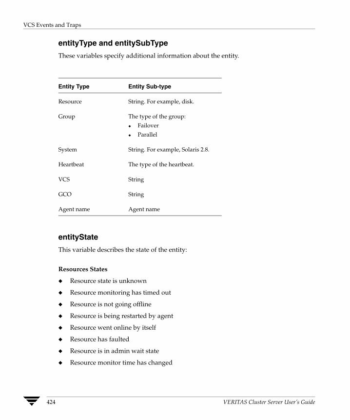
VCS Events and Traps
entityType and entitySubType
These variables specify additional information about the entity.
Entity Type Entity Sub-type
Resource
Group
System
Heartbeat
VCS
GCO
Agent name
String. For example, disk.
The type of the group:
◆ Failover
◆ Parallel
String. For example, Solaris 2.8.
The type of the heartbeat.
String
String
Agent name
entityState
This variable describes the state of the entity:
Resources States
◆ Resource state is unknown
◆ Resource monitoring has timed out
◆ Resource is not going offline
◆ Resource is being restarted by agent
◆ Resource went online by itself
◆ Resource has faulted
◆ Resource is in admin wait state
◆ Resource monitor time has changed
424 VERITAS Cluster Server User’s Guide
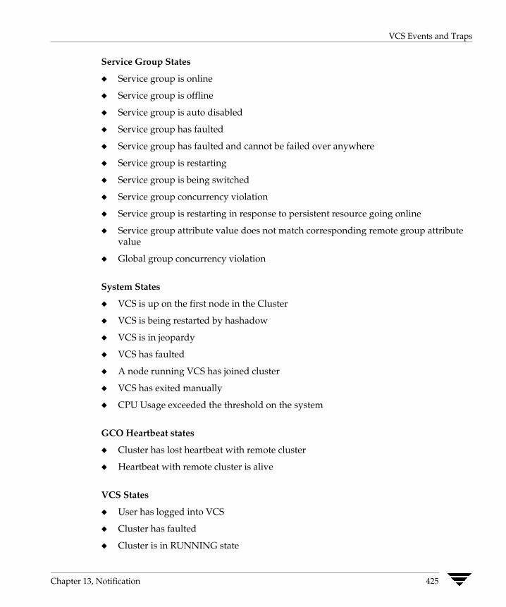
VCS Events and Traps
Service Group States
◆ Service group is online
◆ Service group is offline
◆ Service group is auto disabled
◆ Service group has faulted
◆ Service group has faulted and cannot be failed over anywhere
◆ Service group is restarting
◆ Service group is being switched
◆ Service group concurrency violation
◆ Service group is restarting in response to persistent resource going online
◆ Service group attribute value does not match corresponding remote group attribute value
◆ Global group concurrency violation
System States
◆ VCS is up on the first node in the Cluster
◆ VCS is being restarted by hashadow
◆ VCS is in jeopardy
◆ VCS has faulted
◆ A node running VCS has joined cluster
◆ VCS has exited manually
◆ CPU Usage exceeded the threshold on the system
GCO Heartbeat states
◆ Cluster has lost heartbeat with remote cluster
◆ Heartbeat with remote cluster is alive
VCS States
◆ User has logged into VCS
◆ Cluster has faulted
◆ Cluster is in RUNNING state
Chapter 13, Notification 425

Monitoring Aggregate Events
Agent States
◆ Agent is restarting
◆ Agent has faulted
Monitoring Aggregate Events This section describes how you can detect aggregate events by monitoring individual notifications.
Detecting Service Group Failover
VCS does not send any explicit traps when a failover occurs in response to a service group fault. When a service group faults, VCS generates the following notifications if the AutoFailOver attribute for the service group is set to 1:
◆ Service Group Fault for the node on which the service group was online and faulted
◆ Service Group Offline for the node on which the service group faulted
◆ Service Group Online for the node to which the service group failed over.
Detecting Service Group Switch
When a service group is switched, VCS sends notification to indicate the following events:
◆ Service group is being switched
◆ Service Group Offline for the node from which the service group is switched
◆ Service Group Online for the node to which the service group was switched. This notification is sent after VCS completes the service group switch operation.
Note You must configure appropriate severity for the notifier to receive these notifications. Specifically, to receive the notifications described above, the minimum acceptable severity level is Information.
426 VERITAS Cluster Server User’s Guide

Configuring Notification
Configuring Notification Configuring notification involves creating a resource for the Notifier Manager (NotifierMgr) agent in the ClusterService group. See the VERITAS Cluster Server Bundled Agents Reference Guide for more information about the agent.
VCS provides several methods for configuring notification:
◆ Manually editing the main.cf file.
◆ Using the Notifier wizard. See “Setting up VCS Event Notification Using Notifier Wizard” on page 206 for instructions.
Chapter 13, Notification 427

Configuring Notification
428 VERITAS Cluster Server User’s Guide
VCS Event Triggers
14 This chapter describes how event triggers work and how they enable the administrator to take specific actions in response to particular events.How Event Triggers Work VCS determines if the event is enabled and invokes hatrigger, a high-level Perl script located at $VCS_HOME/bin/hatrigger.
VCS also passes the name of the event trigger and the parameters specific to the event. For example, when a service group becomes online on a system, VCS invokeshatrigger -postonline system service_group. Note that VCS does not wait for hatrigger or the event trigger to complete execution. After calling the triggers, VCScontinues normal operations.
Event triggers are invoked by event names, for example violation denotes a concurrency violation.
Event triggers are invoked on the system where the event occurred, with the following exceptions:
◆ The sysoffline and nofailover event triggers are invoked from the lowest-numbered system in RUNNING state.
◆ The violation event trigger is invoked from all systems on which the service group was brought partially or fully online.
Using Event Triggers VCS provides a sample Perl script in $VCS_HOME/bin/sample_triggers for each event trigger. These scripts can be customized according to your requirements: you may write your own Perl scripts.
Note You must move the triggers to $VCS_HOME/bin/triggers to use them.
429

List of Event Triggers
List of Event Triggers The information in the following sections describes the various event triggers, including their usage, parameters, and location.
cpuusage Event Trigger
Usage - cpuusage triggertype system cpu_usage
The variable triggertype represents whether trigger is custom (triggertype=0) or internal (triggertype=1).
If 0, the trigger is invoked from /opt/VRTSvcs/bin/triggers/cpuusage
If 1, the system reboots by invoking the trigger from /opt/VRTSvcs/bin/internal_triggers/cpuusage
The variable system represents the name of the system.
The variable cpu_usage represents the percentage of CPU utilization on the system.
Description This trigger is invoked on the system where CPU usage has exceeded the usage configured in the ActionThreshold value of the system’s CPUUsageMonitoring attribute. For details, see “Bringing a Resource Online” on page 559.
This event trigger is configurable.
To enable this trigger, set following values in the system’s CPUUsageMonitoring attribute:
Enabled = 1
ActionTimeLimit = Non-zero value representing time in seconds.
ActionThreshold = Non-zero value representing CPU percentage utilization.
Action = CUSTOM, trigger is invoked from /opt/VRTSvcs/bin/triggers/cpuusage.
REBOOT, trigger is invoked from /opt/VRTSvcs/bin/internal_triggers/cpuusage and system reboots.
The trigger is invoked when the system’s CPU usage exceeds the value in ActionThreshold for a duration longer than configured in ActionTimeLimit, provided the trigger was not invoked previously on the system within the last five minutes.
To disable the trigger set one of the following values in CPUUsageMonitoring system attribute to 0 for the system:
ActionTimeLimit = 0
ActionThreshold = 0
430 VERITAS Cluster Server User’s Guide
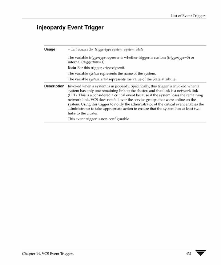
List of Event Triggers
injeopardy Event Trigger
Usage - injeopardy triggertype system system_state
The variable triggertype represents whether trigger is custom (triggertype=0) or internal (triggertype=1).
Note For this trigger, triggertype=0.
The variable system represents the name of the system.
The variable system_state represents the value of the State attribute.
Description Invoked when a system is in jeopardy. Specifically, this trigger is invoked when a system has only one remaining link to the cluster, and that link is a network link (LLT). This is a considered a critical event because if the system loses the remaining network link, VCS does not fail over the service groups that were online on the system. Using this trigger to notify the administrator of the critical event enables the administrator to take appropriate action to ensure that the system has at least two links to the cluster.
This event trigger is non-configurable.
Chapter 14, VCS Event Triggers 431

List of Event Triggers
loadwarning Event Trigger
Usage - loadwarning triggertype system available_capacity
The variable triggertype represents whether trigger is custom (triggertype=0) or internal (triggertype=1).
Note For this trigger, triggertype=0.
The variable system represents the name of the system.
The variable available_capacity represents the system’s AvailableCapacity attribute. (AvailableCapacity=Capacity-sum of Load for system’s online groups.)
Description Invoked when a system becomes overloaded because the load of the system’s online groups exceeds the system’s LoadWarningLevel attribute for an interval exceeding the LoadTimeThreshold attribute. For example, say the Capacity is 150, the LoadWarningLevel is 80, and the LoadTimeThreshold is 300. Also, the sum of the Load attribute for all online groups on the system is 135. Because the LoadWarningLevel is 80, safe load is 0.80*150=120. Actual system load is 135. If system load stays above 120 for more than 300 seconds, the LoadWarningLevel trigger is invoked.
Using this trigger to notify the administrator of the critical event enables him or her to switch some service groups to another system, ensuring that no one system is overloaded.
This event trigger is non-configurable.
432 VERITAS Cluster Server User’s Guide

List of Event Triggers
multinicb Event Trigger
Usage -multinicb_postchange triggertype resource-name device-name previous-state current-state monitor_heartbeat
The variable triggertype represents whether trigger is custom (triggertype=0) or internal (triggertype=1).
Note For this trigger, triggertype=0.
The variable resource-name represents the MultiNICB resource that invoked this trigger.
The variable device-name represents the network interface device for which the trigger is called.
The variable previous-state represents the state of the device before the change. The value 1 indicates that the device is up; 0 indicates it is down.
The variable current-state represents the state of the device after the change.
The variable monitor-heartbeat is an integer count, which is incremented in every monitor cycle. The value 0 indicates that the monitor routine is called for first time
Description Invoked when a network device configured under the MultiNICB agent changes its state. The trigger is also always called in the first monitor cycle.
VCS provides a sample trigger script for your reference. You can customize the sample script according to your requirements.
nofailover Event Trigger
Usage - nofailover triggertype system service_group
The variable triggertype represents whether trigger is custom (triggertype=0) or internal (triggertype=1).
Note For this trigger, triggertype=0.
The variable system represents the name of the last system on which an attempt was made to online the service group.
The variable service_group represents the name of the service group.
Description Called from the lowest-numbered system in RUNNING state when a service group cannot fail over.
This event trigger is non-configurable.
Chapter 14, VCS Event Triggers 433

List of Event Triggers
postoffline Event Trigger
Usage - postoffline triggertype system service_group
The variable triggertype represents whether trigger is custom (triggertype=0) or internal (triggertype=1).
Note For this trigger, triggertype=0.
The variable system represents the name of the system.
The variable service_group represents the name of the service group that went offline.
Description This event trigger is invoked on the system where the group went offline from a partial or fully online state. This trigger is invoked when the group faults, or is taken offline manually.
This event trigger is non-configurable.
postonline Event Trigger
Usage - postonline triggertype system service_group
The variable triggertype represents whether trigger is custom (triggertype=0) or internal (triggertype=1).
Note For this trigger, triggertype=0.
The variable system represents the name of the system.
The variable service_group represents the name of the service group that went online.
Description This event trigger is invoked on the system where the group went online from a partial or fully offline state.
This event trigger is non-configurable.
434 VERITAS Cluster Server User’s Guide

List of Event Triggers
preonline Event Trigger
Usage - preonline triggertype system service_group whyonlining [system_where_group_faulted]
The variable triggertype represents whether trigger is custom (triggertype=0) or internal (triggertype=1).
Note For this trigger, triggertype=0.
The variable system represents the name of the system.
The variable service_group represents the name of the service group on which the hagrp command was issued or the fault occurred.
The variable whyonlining represents two values:
FAULT indicates that the group was brought online in response to a group failover or switch.
MANUAL indicates that group was brought online manually on the system represented by the variable system.
The variable system_where_group_faulted is optional. This variable is set when the engine invokes the trigger during a failover or switch. It represents the name of the system on which the group has faulted or from where it is switching.
Description Indicates that HAD should not online a service group in response to an hagrp -online command or a fault. It should instead call a user-defined script that checks for external conditions before bringing the group online.
Note If it is OK to bring the group online, it is then the responsibility of the PreOnline event trigger to bring the group online using the format: hagrp -online -nopre service_group -sys system
If the trigger does not exist, VCS continues to bring the group online.
If you do want to bring the group online, define the trigger to take no action.
This event trigger is configurable.
◆ To enable this trigger, specify PreOnline=1 within the group definition, or use:
hagrp -modify service_group PreOnline 1
◆ To disable the trigger, specify PreOnline=0 within the group definition, or use:
hagrp -modify service_group PreOnline 0
Chapter 14, VCS Event Triggers 435

List of Event Triggers
resadminwait Event Trigger
Usage - resadminwait system resource adminwait_reason
The variable system represents the name of the system.
The variable resource represents the name of the faulted resource.
The variable adminwait_reason represents the reason the resource entered the ADMIN_WAIT state. Values range from 0-5:
0 = The offline entry point did not complete within the expected time.
1 = The offline entry point was ineffective.
2 = The online entry point did not complete within the expected time.
3 = The online entry point was ineffective.
4 = The resource was taken offline unexpectedly.
5 = The monitor entry point consistently failed to complete within the expected time.
Description Invoked when a resource enters ADMIN_WAIT state. A resource enters this state when the ManageFaults attribute for the service group is set to NONE and one of the reasons cited above has occurred.
Note When VCS sets a resource in the ADMIN_WAIT state, it invokes the ResAdminWait trigger according to the reason the resource entered the state. See “Clearing Resources in the ADMIN_WAIT State” on page 363 for instructions on clearing resources in this state.
This event trigger is non-configurable.
resfault Event Trigger
Usage - resfault triggertype system resource previous_state
The variable triggertype represents whether trigger is custom (triggertype=0) or internal (triggertype=1).
Note For this trigger, triggertype=0.
The variable system represents the name of the system.
The variable resource represents the name of the faulted resource.
The variable previous_state represents the resource’s previous state.
Description Invoked on the system where a resource has faulted. Note that when a resource is faulted, resources within the upward path of the faulted resource are also brought down.
This event trigger is non-configurable.
436 VERITAS Cluster Server User’s Guide
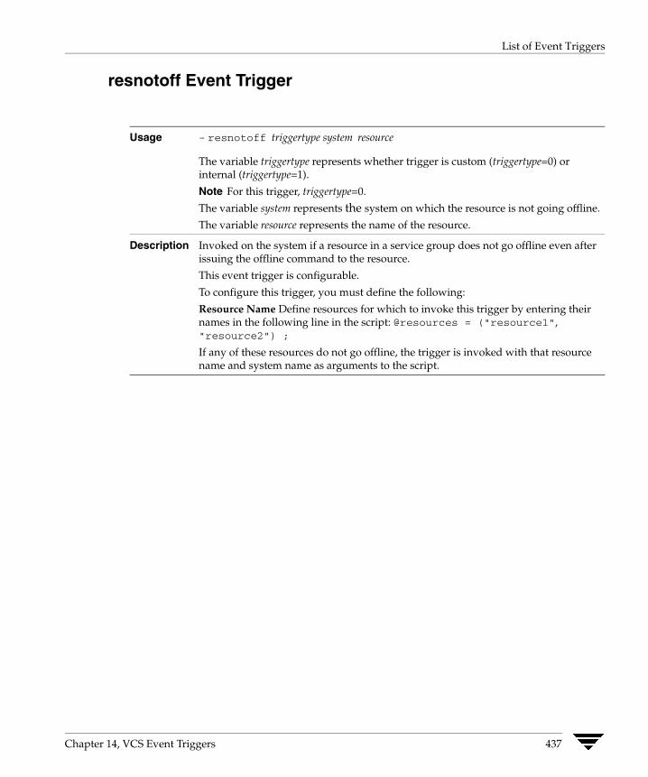
List of Event Triggers
resnotoff Event Trigger
Usage - resnotoff triggertype system resource
The variable triggertype represents whether trigger is custom (triggertype=0) or internal (triggertype=1).
Note For this trigger, triggertype=0.
The variable system represents the system on which the resource is not going offline.
The variable resource represents the name of the resource.
Description Invoked on the system if a resource in a service group does not go offline even after issuing the offline command to the resource.
This event trigger is configurable.
To configure this trigger, you must define the following:
Resource Name Define resources for which to invoke this trigger by entering their names in the following line in the script: @resources = ("resource1", "resource2") ;
If any of these resources do not go offline, the trigger is invoked with that resource name and system name as arguments to the script.
Chapter 14, VCS Event Triggers 437
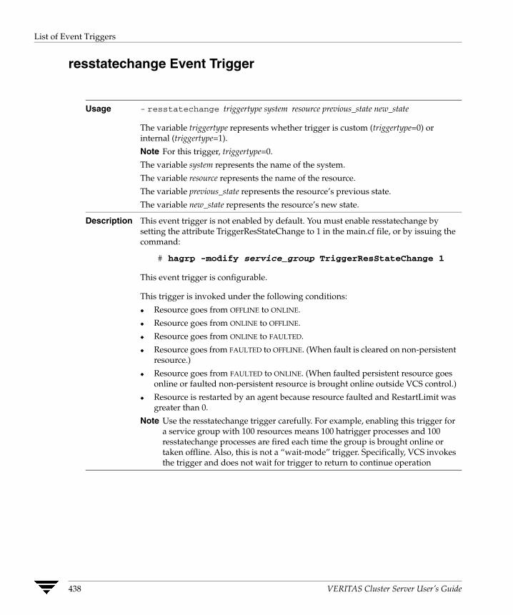
List of Event Triggers
resstatechange Event Trigger
Usage - resstatechange triggertype system resource previous_state new_state
The variable triggertype represents whether trigger is custom (triggertype=0) or internal (triggertype=1).
Note For this trigger, triggertype=0.
The variable system represents the name of the system.
The variable resource represents the name of the resource.
The variable previous_state represents the resource’s previous state.
The variable new_state represents the resource’s new state.
Description This event trigger is not enabled by default. You must enable resstatechange by setting the attribute TriggerResStateChange to 1 in the main.cf file, or by issuing the command:
# hagrp -modify service_group TriggerResStateChange 1
This event trigger is configurable.
This trigger is invoked under the following conditions:
◆ Resource goes from OFFLINE to ONLINE.
◆ Resource goes from ONLINE to OFFLINE.
◆ Resource goes from ONLINE to FAULTED.
◆ Resource goes from FAULTED to OFFLINE. (When fault is cleared on non-persistent resource.)
◆ Resource goes from FAULTED to ONLINE. (When faulted persistent resource goes online or faulted non-persistent resource is brought online outside VCS control.)
◆ Resource is restarted by an agent because resource faulted and RestartLimit was greater than 0.
Note Use the resstatechange trigger carefully. For example, enabling this trigger for a service group with 100 resources means 100 hatrigger processes and 100 resstatechange processes are fired each time the group is brought online or taken offline. Also, this is not a “wait-mode” trigger. Specifically, VCS invokes the trigger and does not wait for trigger to return to continue operation
438 VERITAS Cluster Server User’s Guide
List of Event Triggers
sysoffline Event Trigger
Usage - sysoffline system system_state
The variable system represents the name of the system.
The variable system_state represents the value of the State attribute. See “System States” on page 624 for more information.
Description Called from the lowest-numbered system in RUNNING state when a system leaves the cluster.
This event trigger is non-configurable.
unable_to_restart_had Event Trigger
Usage -unable_to_restart_had
This trigger has no arguments.
Description This event trigger is invoked by hashadow when hashadow cannot restart HAD on a system. If HAD fails to restart after six attempts, hashadow invokes the trigger on the system.
The default behavior of the trigger is to reboot the system. However, service groups previously running on the system are autodisabled when hashadow fails to restart HAD. Before theseservice groups can be brought online elsewhere in the cluster, you must autoenable them on the system. To do so, customize the unable_to_restart_had trigger to remotely execute the following command from any node in the cluster where VCS isrunning:
hagrp -autoenable service_group -sys system
For example, if hashadow fails to restart HAD on system1, and if group1 and group2 were online on that system, a trigger customized in this manner would autoenable group1 and group2 on system1 before rebooting. Autoenabling group1 and group2 on system1 enables these two service groups to come online on another system when the trigger reboots system1.
This event trigger is non-configurable.
Chapter 14, VCS Event Triggers 439
List of Event Triggers
violation Event Trigger
Usage - violation system service_group
The variable system represents the name of the system.
The variable service_group represents the name of the service group that was fully or partially online.
Description This trigger is invoked only on the system that caused the concurrency violation. Specifically, it takes the service group offline on the system where the trigger was invoked. Note that this trigger applies to failover groups only. The default trigger takes the service group offline on the system that caused the concurrency violation.
This event trigger is non-configurable.
440 VERITAS Cluster Server User’s Guide

Section V. Advanced Cluster Configurations
This section describes the advanced cluster configurations, including the VCS Global Cluster Option, which can be used to link clusters to provide wide-area failover and disaster recovery. It also describes how to administer and troubleshoot global clusters. The section also describes how you can set up replicated data clusters and campus clusters.
Section V includes the following chapters:
◆ Chapter 15. “Connecting Clusters–Introducing the Global Cluster Option” on page443
◆ Chapter 16. “Administering Global Clusters from the Command Line” on page 469
◆ Chapter 17. “Administering Global Clusters from Cluster Manager (Java Console)” on page 481
◆ Chapter 18. “Administering Global Clusters from Cluster Manager (Web Console)” on page 501
◆ Chapter 19. “Setting Up Replicated Data Clusters” on page 525
◆ Chapter 20. “Setting Up Campus Clusters” on page 533

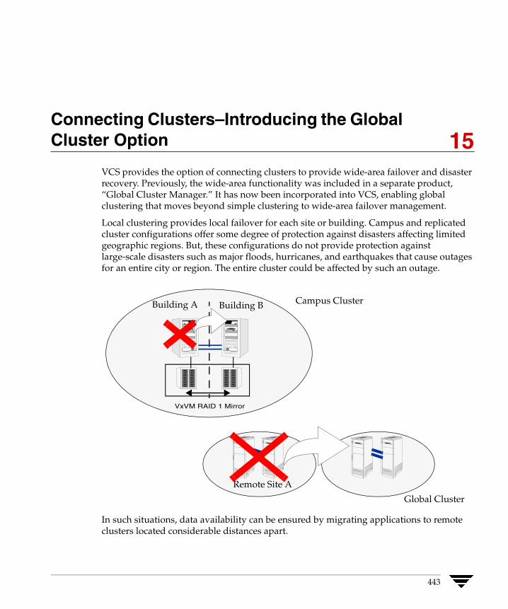
Connecting Clusters–Introducing the Global Cluster Option
15VCS provides the option of connecting clusters to provide wide-area failover and disaster recovery. Previously, the wide-area functionality was included in a separate product, “Global Cluster Manager.” It has now been incorporated into VCS, enabling global clustering that moves beyond simple clustering to wide-area failover management.
Local clustering provides local failover for each site or building. Campus and replicated cluster configurations offer some degree of protection against disasters affecting limited geographic regions. But, these configurations do not provide protection against large-scale disasters such as major floods, hurricanes, and earthquakes that cause outages for an entire city or region. The entire cluster could be affected by such an outage.
Remote Site A
Building B
Global Cluster
VxVM RAID 1 Mirror
Campus ClusterBuilding A
In such situations, data availability can be ensured by migrating applications to remote clusters located considerable distances apart.
443
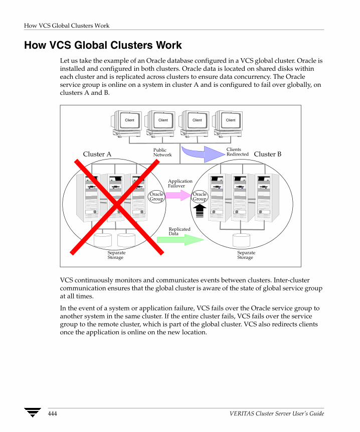
How VCS Global Clusters Work
How VCS Global Clusters WorkLet us take the example of an Oracle database configured in a VCS global cluster. Oracle is installed and configured in both clusters. Oracle data is located on shared disks within each cluster and is replicated across clusters to ensure data concurrency. The Oracle service group is online on a system in cluster A and is configured to fail over globally, on clusters A and B.
VCS continuously monitors and communicates events between clusters. Inter-cluster communication ensures that the global cluster is aware of the state of global service group at all times.
In the event of a system or application failure, VCS fails over the Oracle service group to another system in the same cluster. If the entire cluster fails, VCS fails over the service group to the remote cluster, which is part of the global cluster. VCS also redirects clients once the application is online on the new location.
PublicNetwork
SeparateStorage
SeparateStorage
Client Client Client Client
ReplicatedData
ClientsRedirected
ApplicationFailover
OracleGroup
OracleGroup
Cluster A Cluster B
444 VERITAS Cluster Server User’s Guide
VCS Global Clusters: The Building Blocks
VCS Global Clusters: The Building Blocks VCS extends clustering concepts to wide-area high availability and disaster recovery. It is enabled by the following:
◆ Visualization of Remote Cluster Objects
◆ Global Service Groups
◆ Global Cluster Management
◆ Serialization–The Authority Attribute
◆ Resiliency and “Right of Way”
◆ VCS Framework
◆ The Steward Process: Handling Split-brain in Two-Cluster Global Clusters
Visualization of Remote Cluster Objects VCS enables you to visualize remote cluster objects using the VCS command-line, the Java Console, and the Web Console.
You can define remote clusters in your configuration file, main.cf. The Remote Cluster Configuration wizard provides an easy interface to do so. The wizard updates the main.cf files of all connected clusters with the required configuration changes. See “Adding a Remote Cluster” on page 482 for more information.
Global Service Groups A global service group is a regular VCS group with additional properties to enable wide-area failover. The global service group attribute ClusterList defines the list of clusters to which the group can fail over. The service group must be configured on all participating clusters and must have the same name on each cluster. The Global Group Configuration wizard provides an easy interface to configure global groups. See “Administering Global Service Groups” on page 491 for more information.
Replication during cross-cluster failover is managed by VCS agents, as described in “VCS Framework” on page 448. You can configure a resource of type DNS to perform a canonical name update, if cross-cluster failover spans subnets. See “DNS Agent” on page 448 for more information.
Chapter 15, Connecting Clusters–Introducing the Global Cluster Option 445

VCS Global Clusters: The Building Blocks
Global Cluster Management VCS enables you to perform operations (online, offline, switch) on global service groups from any system in any cluster using the VCS command-line interface, the Java Console, or the Web Console. See “User Privileges in Global Clusters” on page 55 for information about the privileges required for global operations.
You can bring service groups online or switch them to any system in any cluster. If you do not specify a target system, VCS uses the FailOverPolicy to determine the system. “Deciding Startup and Failover Locations” on page 364 for more information.
Management of remote cluster objects is aided by inter-cluster communication enabled by the wide-area connector (wac) process.
Wide-Area Connector Process
The wide-area connector (wac) is a failover Application resource that ensures communication between clusters.
wac Process
HADHAD HADHAD HAD HAD
Application Group
wac Process
Application Group
Application Group
Application Group
Application Group
Application Group
Cluster 1 Cluster 2
The wac process runs on one system in each cluster and connects with peers in remote clusters. It receives and transmits information about the status of the cluster, service groups, and systems. This communication enables VCS to create a consolidated view of the status of all the clusters configured as part of the global cluster. The process also manages wide-area heartbeating to determine the health of remote clusters. The process also transmits commands between clusters and returns the result to the originating cluster.
446 VERITAS Cluster Server User’s Guide

VCS Global Clusters: The Building Blocks
Wide-Area Heartbeats
The wide-area Heartbeat agent manages the inter-cluster heartbeat. Heartbeats are used to monitor the health of remote clusters. For a list of attributes associated with the agent, see “Heartbeat Attributes” on page 667. You can change the default values of the heartbeat agents using the hahb -modify command.
Sample Configuration
Heartbeat Icmp (ClusterList = {C1, C2}AYAInterval@C1 = 20AYAInterval@C1 = 30Arguments@c1 = "X.X.X.X XX.XX.XX.XX" Arguments@c2 = "Y.Y.Y.Y YY.YY.YY.YY"
)
Serialization–The Authority Attribute VCS ensures that multi-cluster service group operations are conducted serially to avoid timing problems and to ensure smooth performance. The Authority attribute prevents a service group from coming online in multiple clusters at the same time. Authority is a persistent service group attribute and it designates which cluster has the right to bring a global service group online. The attribute cannot be modified at runtime.
A two-phase commit process prevents timing issues. If two administrators simultaneously try to bring a service group online in a two-cluster global group, one command is honored, and the other is rejected.
The attribute prevents bringing a service group online in a cluster that does not have the authority to do so. If the cluster holding authority is down, you can enforce a takeover by using the command hagrp -online -force service_group. This command enables you to fail over an application to another cluster when a disaster occurs.
Note A cluster assuming authority for a group does not guarantee the group will be brought online on the cluster. The attribute merely specifies the right to attempt bringing the service group online in the cluster. The presence of Authority does not override group settings like frozen, autodisabled, non-probed, and so on, that prevent service groups from going online.
You must seed authority if it is not “held” on any cluster.
Offline operations on global groups can originate from any cluster and do not require a change of authority to do so, because taking a group offline does not necessarily indicate an intention to perform a cross-cluster failover.
Chapter 15, Connecting Clusters–Introducing the Global Cluster Option 447
VCS Global Clusters: The Building Blocks
Authority and AutoStart
The attributes Authority and AutoStart work together to avoid potential concurrency violations in multi-cluster configurations.
If the AutoStartList attribute is set, and if a group’s Authority attribute is set to 1, HAD waits for the wac process to connect to the peer. If the connection fails, it means the peer is down and the AutoStart process proceeds. If the connection succeeds, HAD waits for the remote snapshot. If the peer is holding the authority for the group and the remote group is online (because of takeover), the local cluster does not bring the group online and relinquishes authority.
If the Authority attribute is set to 0, AutoStart is not invoked.
Resiliency and “Right of Way” VCS global clusters maintain resiliency using the wide-area connector process and the ClusterService group. The wide-area connector process runs as long as there is at least one surviving node in a cluster.
The wide-area connector, its alias, and notifier are components of the ClusterService group, described in “The ClusterService Group” on page 11.
VCS Framework VCS agents now manage external objects that are part of wide-area failover. These objects include replication, DNS updates, and so on. These agents provide a robust framework for specifying attributes and restarts, and can be brought online upon fail over.
New Entry Points
New entry points, action and info, allow for detailed management of cluster and replication-related objects. See the VERITAS Cluster Server Bundled Agents Reference Guide and the VERITAS Cluster Server Agent Developer’s Guide for more information.
DNS Agent
The DNS agent updates the canonical name-mapping in the domain name server after a wide-area failover. See the VERITAS Cluster Server Bundled Agents Reference Guide for more information about the agent.
448 VERITAS Cluster Server User’s Guide

VCS Global Clusters: The Building Blocks
RVG Agent
The RVG agent manages the Replicated Volume Group (RVG). Specifically, it brings the RVG online, monitors read-write access to the RVG, and takes the RVG offline. Use this agent when using VVR for replication.
RVGPrimary agent
The RVGPrimary agent attempts to migrate or take over a Secondary to a Primary following an application failover. The agent has no actions associated with the offline and monitor routines.
RVGSnapshot Agent
The RVGSnapshot agent, used in fire drill service groups, takes space-optimized snapshots so that applications can be mounted at secondary sites during a fire drill operation.
Note See the VERITAS Cluster Server Agents for VERITAS Volume Replicator Configuration Guide for more information about the RVG, RVGPrimary, and RVGSnapshot agents.
Chapter 15, Connecting Clusters–Introducing the Global Cluster Option 449

VCS Global Clusters: The Building Blocks
The Steward Process: Handling Split-brain in Two-Cluster Global Clusters
Failure of all heartbeats between any two clusters in a global cluster indicates one of the following:
◆ The remote cluster is faulted.
◆ All communication links between the two clusters are broken.
In global clusters with more than three clusters, VCS queries the connected clusters to confirm that the remote cluster is truly down. This mechanism is called inquiry.
In a two-cluster setup, VCS uses the Steward process to minimize chances of a wide-area split-brain. The process runs as a standalone binary on a system outside of the global cluster configuration.
Cluster A Cluster B
Steward
When all communication links between any two clusters are lost, each cluster contacts the Steward with an inquiry message. The Steward sends an ICMP ping to the cluster in question and responds with a negative inquiry if the cluster is running or with positive inquiry if the cluster is down. The Steward can also be used configurations with more than two clusters. See “Configuring the Steward Process (Optional)” on page 460 for more information.
A Steward is effective only if there are independent paths from each cluster to the host running the Steward. If there is only one path between the two clusters, you must prevent split-brain by confirming manually via telephone or some messaging system with administrators at the remote site if a failure has occurred. By default, VCS global clusters fail over an application across cluster boundaries with administrator confirmation. You can configure automatic failover by setting the ClusterFailOverPolicy attribute to Auto.
If you start a service group on a remote cluster while the service group is running on the primary cluster, data corruption does not occur because the clusters use replicated data. Instead, divergent data sets result, which must be merged manually once the split-brain is resolved. VCS does not automatically take a service group offline after an inter-cluster split-brain is reconnected.
450 VERITAS Cluster Server User’s Guide
Before Configuring Global Clusters
Before Configuring Global Clusters This section describes the prerequisites for configuring global clusters.
Cluster Setup
You must have at least two clusters to set up a global cluster. Every cluster must have the VCS Global Cluster Option license installed. A cluster can be part of one global cluster. VCS supports a maximum of four clusters participating in a global cluster.
Clusters must be running on the same platform; the operating system versions can be different. Clusters must be using the same VCS version.
Cluster names must be unique within each global cluster; system and resource names need not be unique across clusters. Service group names need not be unique across clusters; however, global service groups must have identical names.
Every cluster must have a valid virtual IP address, which is tied to the cluster. Define this IP address in the cluster’s ClusterAddress attribute. This address is normally configured as part of the initial VCS installation. The IP address must have a DNS entry.
Configured Applications
Applications to be configured as global groups must be configured to represent each other in their respective clusters. The multiple application groups of a global group must have the same name in each cluster. The individual resources of the groups can be different. For example, one group might have a MultiNIC resource or more Mount-type resources. Clients redirected to the remote cluster in case of a wide-area failover must be presented with the same application they saw in the primary cluster.
However, the resources that make up a global group must represent the same application from the point of the client as its peer global group in the other cluster. Clients redirected to a remote cluster should not be aware that a cross-cluster failover occurred, except for some downtime while the administrator initiates or confirms the failover.
Wide-Area Heartbeats
There must be at least one wide-area heartbeat going from each cluster to every other cluster. VCS starts communicating with a cluster only after the heartbeat reports that the cluster is alive. VCS uses the ICMP ping by default, the infrastructure for which is bundled with the product. VCS configures the ICMP heartbeat if you use Cluster Manager (Java Console) to set up your global cluster. Other heartbeats must be configured manually.
Chapter 15, Connecting Clusters–Introducing the Global Cluster Option 451
Before Configuring Global Clusters
ClusterService Group
The ClusterService group must be configured the wac, NIC, and IP resources. It is configured automatically when VCS is installed or upgraded, or by the GCO configuration wizard. The service group may contain additional resources for Cluster Manager (Web Console) and notification, if these components are configured.
If you entered a Global Cluster Option license during the VCS install or upgrade, the ClusterService group, including the wide-area connector process, is automatically configured.
If you add the license after VCS is operational, you must run the GCO Configuration wizard. For instructions, see “Running the GCO Configuration Wizard” on page 454.
Replication Setup
VCS global clusters are also used in case of disaster recovery, so you must set up real-time data replication between clusters. You can use VCS agents for supported replication solutions to manage the replication. If your configuration uses VERITAS Volume Replicator, you must add the VTRSvcsr package to all systems.
452 VERITAS Cluster Server User’s Guide

Setting Up a Global Cluster
Setting Up a Global Cluster This section describes the steps for planning, configuring, and testing a global cluster. It describes an example of converting a single instance Oracle database configured for local high availability in a VCS cluster to a highly available, disaster-protected infrastructure using a second cluster. The solution uses VERITAS Volume Replicator to replicate changed data real-time.
In this example, a single-instance Oracle database is configured as a VCS service group (appgroup) on a two-node cluster. The service group configuration looks like:
Note Before beginning the process, review the prerequisites listed in the section “Before Configuring Global Clusters” on page 451 and make sure your configuration is ready for a global cluster application.
The process involves the following steps:
◆ Preparing the Application for the Global Environment
◆ Running the GCO Configuration Wizard
◆ Configuring Replication
◆ Linking the Application and Replication Service Groups
◆ Configuring the Second Cluster
◆ Linking Clusters
◆ Configuring the Steward Process (Optional)
◆ Creating the Global Service Group
Chapter 15, Connecting Clusters–Introducing the Global Cluster Option 453
Setting Up a Global Cluster
Preparing the Application for the Global Environment Install the application (Oracle in this example) in the second cluster. Make sure the installation is identical with the one in the first cluster.
Set up replication between the shared disk groups in both clusters. If your configuration uses VVR, the process involves grouping the shared data volumes in the first cluster into a Replicated Volume Group (RVG), and creating the VVR Secondary on hosts in the new cluster, located in your remote site.
Running the GCO Configuration Wizard If you are upgrading from a single-cluster setup to a multi-cluster setup, run the GCO Configuration wizard to create or update the ClusterService group. The wizard verifies your configuration and validates it for a global cluster setup. You must have the GCO license installed on all nodes in the cluster. For more information, see “Installing a VCS License” on page 59.
▼ To run the GCO Configuration wizard
1. Start the GCO Configuration wizard.
# sh /opt/VRTSvcs/bin/gcoconfig
2. The wizard discovers the NIC devices on the local system and prompts you to enter the device to be used for the global cluster. Specify the name of the device and press Enter.
3. If you do not have NIC resources in your configuration, the wizard asks you whether the specified NIC will be the public NIC used by all systems. Enter y if it is the public NIC; otherwise enter n. If you entered n, the wizard prompts you to enter the names of NICs on all systems.
4. Enter the virtual IP to be used for the global cluster.
5. If you do not have IP resources in your configuration, the wizard prompts you for the netmask associated with the virtual IP. The wizard detects the netmask; you can accept the suggested value or enter another value.
6. The wizard starts running commands to create or update the ClusterService group. Various messages indicate the status of these commands. After running these commands, the wizard brings the ClusterService group online.
454 VERITAS Cluster Server User’s Guide

Setting Up a Global Cluster
Configuring Replication VCS supports several replication solutions for global clustering. Please contact your VERITAS sales representative for the solutions supported by VCS. This section describes how to set up replication using VERITAS Volume Replicator (VVR.)
Adding the RVG Resources
1. Create a new service group, say appgroup_rep.
2. Copy the DiskGroup resource from the appgroup to the new group.
3. Configure new resources of type IP and NIC in the appgroup_rep service group. The IP resource monitors the virtual IP that VVR uses for replication.
4. Configure a new resource of type RVG in the new (appgroup_rep) service group.
The RVG agent ships with the VVR software. If the RVG resource type is not defined in your configuration, import it, as instructed below.
a. On the File menu, click Import Types.
b. In the Import Types dialog box, click the file from which to import the resource type. By default, the RVG resource type is located at the path /etc/VRTSvcs/conf/VVRTypes.cf.
c. Click Import.
5. Configure the following attributes of the RVG resource:
◆ RVG—The name of the RVG.
◆ DiskGroup—The name of the diskgroup containing the RVG.
◆ Primary—Whether this is the Primary.
◆ SRL—The SRL associated with the RVG.
◆ RLinks—Names of Rlinks associated with the RVG. You can retrieve Rlink names by using the vxprint -l command.
Note The RVG resource starts, stops, and monitors the RVG in its current state and does not promote or demote VVR when you want to change the direction of replication. That task is managed by the RVGPrimary agent
Chapter 15, Connecting Clusters–Introducing the Global Cluster Option 455
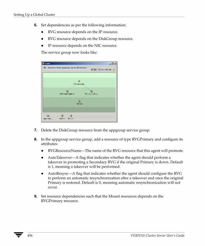
Setting Up a Global Cluster
6. Set dependencies as per the following information:
◆ RVG resource depends on the IP resource.
◆ RVG resource depends on the DiskGroup resource.
◆ IP resource depends on the NIC resource.
The service group now looks like:
7. Delete the DiskGroup resource from the appgroup service group.
8. In the appgroup service group, add a resource of type RVGPrimary and configure its attributes:
◆ RVGResourceName—The name of the RVG resource that this agent will promote.
◆ AutoTakeover—A flag that indicates whether the agent should perform a takeover in promoting a Secondary RVG if the original Primary is down. Default is 1, meaning a takeover will be performed.
◆ AutoResync—A flag that indicates whether the agent should configure the RVG to perform an automatic resynchronization after a takeover and once the original Primary is restored. Default is 0, meaning automatic resynchronization will not occur.
9. Set resource dependencies such that the Mount resources depends on the RVGPrimary resource.
456 VERITAS Cluster Server User’s Guide
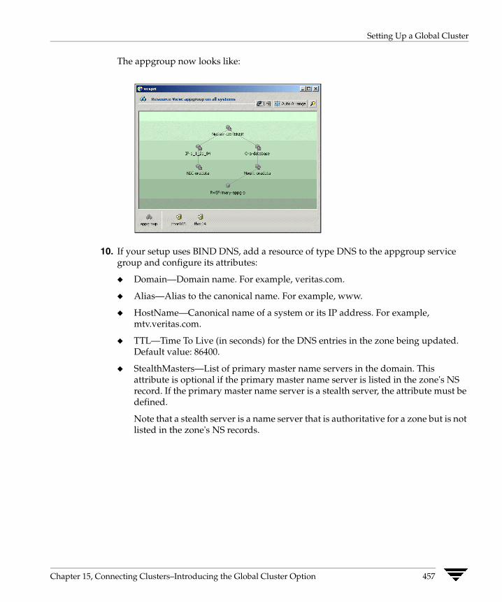
Setting Up a Global Cluster
The appgroup now looks like:
10. If your setup uses BIND DNS, add a resource of type DNS to the appgroup service group and configure its attributes:
◆ Domain—Domain name. For example, veritas.com.
◆ Alias—Alias to the canonical name. For example, www.
◆ HostName—Canonical name of a system or its IP address. For example, mtv.veritas.com.
◆ TTL—Time To Live (in seconds) for the DNS entries in the zone being updated. Default value: 86400.
◆ StealthMasters—List of primary master name servers in the domain. This attribute is optional if the primary master name server is listed in the zone's NS record. If the primary master name server is a stealth server, the attribute must be defined.
Note that a stealth server is a name server that is authoritative for a zone but is not listed in the zone's NS records.
Chapter 15, Connecting Clusters–Introducing the Global Cluster Option 457

Setting Up a Global Cluster
Linking the Application and Replication Service Groups Set an online local hard group dependency from appgroup to appgroup_rep to ensure that the service groups fail over and switch together.
▼ To link the service groups
1. In the Cluster Explorer configuration tree, click the cluster name.
2. In the view panel, click the Service Groups tab. This opens the service group dependency graph.
3. Click Link.
4. Click the parent group, appgroup, and move the mouse toward the child group, appgroup_rep.
5. Click the child group appgroup_rep.
6. In the Link Service Groups dialog box, click the online local relationship and the firm dependency type and click OK.
Configuring the Second Cluster
1. Run the GCO Configuration wizard in the second cluster. For instructions, see “Running the GCO Configuration Wizard” on page 454.
2. Create a configuration that is similar to the one in the first cluster. You can do this by either using Cluster Manager (Java Console) to copy and paste resources from the primary cluster, or by copying the configuration of the appgroup and appgroup_rep groups from the main.cf file in the primary cluster to the secondary cluster.
3. Make appropriate changes to the configuration. For example, you must modify the SystemList attribute to reflect the systems in the secondary cluster.
Note Make sure that the name of the service group (appgroup) is identical in both clusters.
It is a VVR best practice to use the same disk group and RVG name on both sites. This means that just the RLinks attribute needs to be modified to reflect the name of the secondary’s RLink.
458 VERITAS Cluster Server User’s Guide

Setting Up a Global Cluster
If the volume names are the same on both sides, the Mount resources will mount the same block devices, and the same Oracle instance will start at the secondary in case of a failover.
Linking Clusters Once the VCS and VVR infrastructure has been set up at both sites, you must link the two clusters. The Remote Cluster Configuration wizard provides an easy interface to link clusters.
Before linking clusters, verify the virtual IP address for the ClusterAddress attribute for each cluster is set. Use the same IP address as the one assigned to the IP resource in the ClusterService group.
If you are adding a stand-alone cluster to an existing global cluster environment, run the wizard from a cluster in the global cluster environment. Otherwise, run the wizard from any cluster. From Cluster Explorer, click Edit>Add/Delete Remote Cluster. For instructions on running the wizard, see “Adding a Remote Cluster” on page 482.
▼ To configure an additional heartbeat between the clusters (optional)
1. On Cluster Explorer’s Edit menu, click Configure Heartbeats.
2. In the Heartbeat configuration dialog box, enter the name of the heartbeat and select the check box next to the name of the cluster.
3. Click the icon in the Configure column to open the Heartbeat Settings dialog box.
4. Specify the value of the Arguments attribute and various timeout and interval fields. Click + to add an argument value; click - to delete it.
Note If you specify IP addresses in the Arguments attribute, make sure the IP addresses have DNS entries.
5. Click OK.
6. Click OK in the Heartbeat configuration dialog box.
Now, you can monitor the state of both clusters from the Java Console:
Chapter 15, Connecting Clusters–Introducing the Global Cluster Option 459
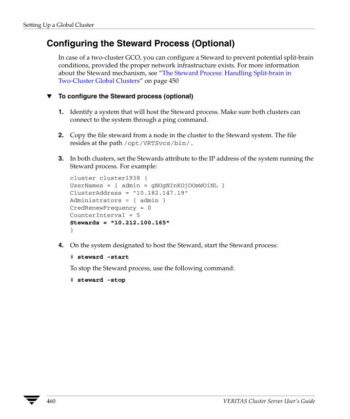
Setting Up a Global Cluster
Configuring the Steward Process (Optional) In case of a two-cluster GCO, you can configure a Steward to prevent potential split-brain conditions, provided the proper network infrastructure exists. For more information about the Steward mechanism, see “The Steward Process: Handling Split-brain in Two-Cluster Global Clusters” on page 450
▼ To configure the Steward process (optional)
1. Identify a system that will host the Steward process. Make sure both clusters can connect to the system through a ping command.
2. Copy the file steward from a node in the cluster to the Steward system. The file resides at the path /opt/VRTSvcs/bin/.
3. In both clusters, set the Stewards attribute to the IP address of the system running the Steward process. For example:
cluster cluster1938 (UserNames = { admin = gNOgNInKOjOOmWOiNL }ClusterAddress = "10.182.147.19"Administrators = { admin }CredRenewFrequency = 0CounterInterval = 5Stewards = "10.212.100.165"}
4. On the system designated to host the Steward, start the Steward process:
# steward -start
To stop the Steward process, use the following command:
# steward -stop
460 VERITAS Cluster Server User’s Guide

Setting Up a Global Cluster
Creating the Global Service Group Configure the Oracle service group, appgroup, as a global group by running the Global Group Configuration wizard.
▼ To create the global service group
1. From Cluster Explorer, click Configure Global Groups on the Edit menu.
2. Review the information required for the Global Group Configuration Wizard and click Next.
3. Enter the details of the service group to modify (appgroup):
a. Click the name of the service group.
b. From the Available Clusters box, click the clusters on which the group can come online. The local cluster is not listed as it is implicitly defined to be part of the ClusterList. Click the right arrow to move the cluster name to the ClusterList box.
c. Select the policy for cluster failover:
◆ Manual prevents a group from automatically failing over to another cluster.
◆ Auto enables a group to automatically fail over to another cluster if it is unable to fail over within the cluster, or if the entire cluster faults.
◆ Connected enables a group to automatically fail over to another cluster if it is unable to fail over within the cluster.
d. Click Next.
4. Enter or review the connection details for each cluster:
a. Click the Configure icon to review the remote cluster information for each cluster.
b. Enter the IP address of the remote cluster, the IP address of a cluster system, or the host name of a cluster system.
c. Enter the user name and the password for the remote cluster.
d. Click OK.
e. Click Next.
5. Click Finish.
Chapter 15, Connecting Clusters–Introducing the Global Cluster Option 461
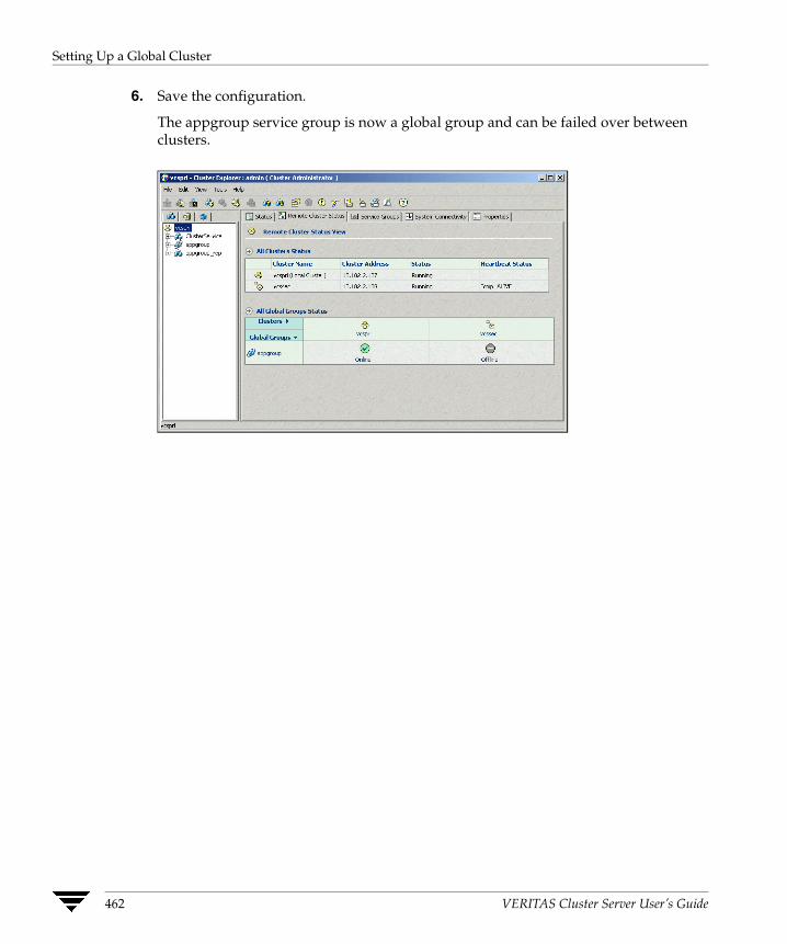
Setting Up a Global Cluster
6. Save the configuration.
The appgroup service group is now a global group and can be failed over between clusters.
462 VERITAS Cluster Server User’s Guide
Upgrading from VERITAS Global Cluster Manager
Upgrading from VERITAS Global Cluster Manager If you have a VERITAS Global Cluster Manager setup, follow the instructions below to upgrade:
1. Install VCS in your cluster. See the VERITAS Cluster Server Installation Guide for more information.
2. Install the GCO license on all nodes in the cluster. See “Installing a VCS License” on page 59 for instructions.
3. Run the GCO Configuration wizard to configure the wide-area connector resource. See “Running the GCO Configuration Wizard” on page 454 for instructions.
Chapter 15, Connecting Clusters–Introducing the Global Cluster Option 463
Migrating a Service Group
Migrating a Service Group In the global cluster setup, consider a case where the primary cluster suffers a failure. The Oracle service group cannot fail over in the local cluster and must fail over globally, to a node in another cluster.
In this situation, VCS sends an alert indicating that the group cannot fail over anywhere in the local cluster.
An administrator can take action by bringing the group online in the remote cluster.
The RVGPrimary agent ensures that VVR volumes are made writable and the DNS agent ensures that name services are resolved to the remote site. The application can be started at the remote site.
Switching the Service Group Before switching the application to the primary site, you must resynchronize any changed data from the active Secondary site since the failover. This can be done manually through VVR or by running a VCS action from the RVGPrimary resource.
▼ To switch the service group
1. In the Service Groups tab of the configuration tree, right-click the resource.
2. Click Actions.
3. Specify the details of the action:
a. From the Action list, choose fbsync.
b. Click the system on which to execute the action.
c. Click OK.
This begins a fast-failback of the replicated data set. You can monitor the value of the ResourceInfo attribute for the RVG resource to determine when the resynchronization has completed.
4. Once the resynchronization completes, switch the service group to the primary cluster.
a. In the Service Groups tab of the Cluster Explorer configuration tree, right-click the service group.
b. Click Switch To, and click Remote switch.
464 VERITAS Cluster Server User’s Guide
Simulating Global Clusters Using VCS Simulator
c. In the Switch global group dialog box, click the cluster to switch the group. Click the specific system, or click Any System, and click OK.
Declaring the Type of Failure If a disaster disables all processing power in your primary data center, heartbeats from the failover site to the primary data center fail. VCS sends an alert signalling cluster failure. If you choose to take action on this failure, VCS prompts you to declare the type of failure.
You can choose one of the following options to declare the failure:
◆ Disaster, implying permanent loss of the primary data center
◆ Outage, implying the primary may return to its current form in some time
◆ Disconnect, implying a split-brain condition; both clusters are up, but the link between them is broken
◆ Replica, implying that data on the takeover target has been made consistent from a backup source and that the RVGPrimary can initiate a takeover when the service group is brought online. This option applies to VVR environments only.
You can select the groups to be failed over to the local cluster, in which case VCS brings the selected groups online on a node based on the group’s FailOverPolicy attribute. It also marks the groups as being OFFLINE in the other cluster. If you do not select any service groups to fail over, VCS takes no action except implicitly marking the service groups as offline in the failed cluster.
Simulating Global Clusters Using VCS Simulator VCS Simulator enables you to simulate a global cluster environment without affecting your production systems. For more information, see “Predicting VCS Behavior Using VCS Simulator” on page 541.
Chapter 15, Connecting Clusters–Introducing the Global Cluster Option 465
Setting Up a Fire Drill
Setting Up a Fire Drill The Disaster Recovery Fire Drill procedure tests the fault-readiness of a configuration by mimicking a failover from the primary site to the secondary site. This procedure is done without stopping the application at the primary site and disrupting user access.
The initial steps to create a fire drill service group on the secondary site that closely follows the configuration of the original application service group and contains a point-in-time copy of the production data in the Replicated Volume Group (RVG). Bringing the fire drill service group online on the secondary site demonstrates the ability of the application service group to fail over and come online at the secondary site, should the need arise. Fire drill service groups do not interact with outside clients or with other instances of resources, so they can safely come online even when the application service group is online. You must conduct a fire drill only at the secondary site; do not bring the fire drill service group online on the node hosting the original application.
Note You can conduct fire drills only on regular VxVM volumes; volume sets (vset) are not supported.
Configuring the Fire Drill Service Group Use the RVG Secondary Fire Drill Wizard to set up the fire drill configuration.
The wizard performs the following specific tasks:
✔ Prepares all data volumes with FMR 4.0 technology, which enables space-optimized snapshots.
✔ Creates a Cache object to store changed blocks during the fire drill, which minimizes disk space and disk spindles required to perform the fire drill.
✔ Configures a VCS service group that resembles the real application group.
✔ Schedules the fire drill and the notification of results.
▼ To run the wizard
1. Start the RVG Secondary Fire Drill wizard on the VVR secondary site, where the service group is not online:
# fdsetup
2. Read the information on the Welcome screen and press the Enter key.
3. The wizard identifies the global service groups. Enter the name of the service group for the fire drill.
466 VERITAS Cluster Server User’s Guide
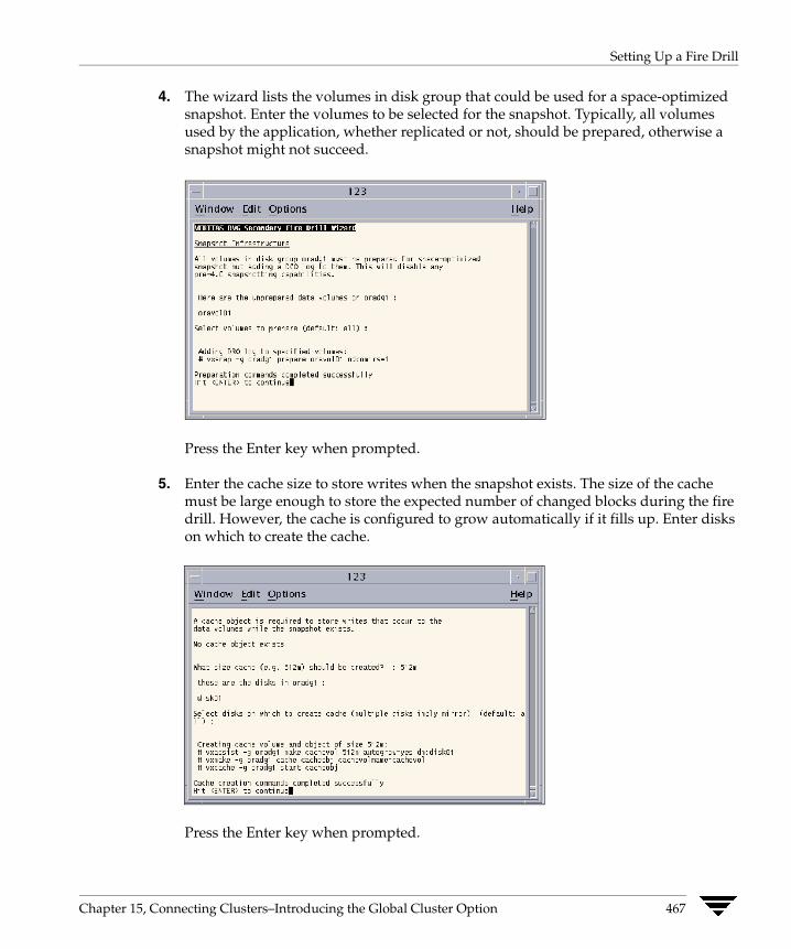
Setting Up a Fire Drill
4. The wizard lists the volumes in disk group that could be used for a space-optimized snapshot. Enter the volumes to be selected for the snapshot. Typically, all volumes used by the application, whether replicated or not, should be prepared, otherwise a snapshot might not succeed.
Press the Enter key when prompted.
5. Enter the cache size to store writes when the snapshot exists. The size of the cache must be large enough to store the expected number of changed blocks during the fire drill. However, the cache is configured to grow automatically if it fills up. Enter disks on which to create the cache.
Press the Enter key when prompted.
Chapter 15, Connecting Clusters–Introducing the Global Cluster Option 467
Setting Up a Fire Drill
6. The wizard starts running commands to create the fire drill setup. Press the Enter key when prompted.
The wizard creates the application group with its associated resources. It also creates a fire drill group with resources for the application (Oracle, for example), the Mount, and the RVGSnapshot types.
The application resources in both service groups define the same application, the same database in this example. The wizard sets the FireDrill attribute for the application resource to 1 to prevent the agent from reporting a concurrency violation when the actual application instance and the fire drill service group are online at the same time.
Verifying a Successful Fire Drill Bring the fire drill service group online on a node that does not have the application running. Verify that the fire drill service group comes online. This action validates that your disaster recovery solution is configured correctly and the production service group will fail over to the secondary site in the event of an actual failure (disaster) at the primary site.
If the fire drill service group does not come online, review the VCS Engine log to troubleshoot the issues so that corrective action can be taken as necessary in the production service group. You can also view the fire drill log, located at /tmp/fd-servicegroup.
Caution Remember to take the fire drill offline once its functioning has been validated. Failing to take the fire drill offline could cause failures in your environment. For example, if the application service group were to fail over to the node hosting the fire drill service group, there would be resource conflicts, resulting in both service groups faulting.
Scheduling a Fire Drill Schedule the fire drill for the service group by adding the file /opt/VRTSvcs/bin/fdsched to your crontab. You can make fire drills highly available by adding the file to every node in the cluster.
The scheduler runs the command hagrp -online firedrill_group -any at periodic intervals.
468 VERITAS Cluster Server User’s Guide

Administering Global Clusters from the Command Line
16This chapter describes the operations you can perform on global clusters from the command line.
Global Querying VCS enables you to query global cluster objects, including service groups, resources, systems, resource types, agents, and clusters. You may enter query commands from any system in the cluster. Commands to display information on the global cluster configuration or system states can be executed by all users; you do not need root privileges.
Note Only global service groups may be queried.
Querying Global Cluster Service Groups
▼ To display service group attribute values across clusters
# hagrp -value service_group attribute [system] [-clus cluster | -localclus]
The option -clus displays the attribute value on the cluster designated by the variable cluster; the option -localclus specifies the local cluster.
If the attribute has local scope, you must specify the system name, except when querying the attribute on the system from which you run the command.
469
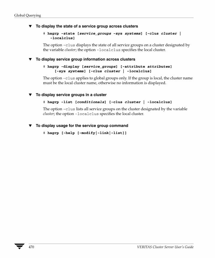
Global Querying
▼ To display the state of a service group across clusters
# hagrp -state [service_groups -sys systems] [-clus cluster | -localclus]
The option -clus displays the state of all service groups on a cluster designated by the variable cluster; the option -localclus specifies the local cluster.
▼ To display service group information across clusters
# hagrp -display [service_groups] [-attribute attributes][-sys systems] [-clus cluster | -localclus]
The option -clus applies to global groups only. If the group is local, the cluster name must be the local cluster name, otherwise no information is displayed.
▼ To display service groups in a cluster
# hagrp -list [conditionals] [-clus cluster | -localclus]
The option -clus lists all service groups on the cluster designated by the variable cluster; the option -localclus specifies the local cluster.
▼ To display usage for the service group command
# hagrp [-help [-modify|-link|-list]]
470 VERITAS Cluster Server User’s Guide
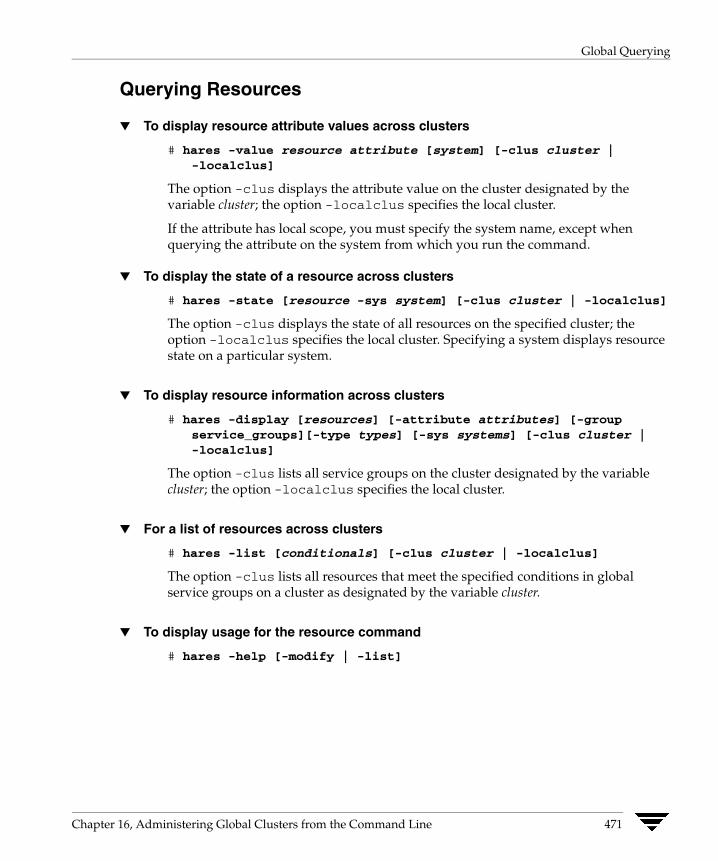
Global Querying
Querying Resources
▼ To display resource attribute values across clusters
# hares -value resource attribute [system] [-clus cluster |-localclus]
The option -clus displays the attribute value on the cluster designated by the variable cluster; the option -localclus specifies the local cluster.
If the attribute has local scope, you must specify the system name, except when querying the attribute on the system from which you run the command.
▼ To display the state of a resource across clusters
# hares -state [resource -sys system] [-clus cluster | -localclus]
The option -clus displays the state of all resources on the specified cluster; the option -localclus specifies the local cluster. Specifying a system displays resource state on a particular system.
▼ To display resource information across clusters
# hares -display [resources] [-attribute attributes] [-group service_groups][-type types] [-sys systems] [-clus cluster | -localclus]
The option -clus lists all service groups on the cluster designated by the variable cluster; the option -localclus specifies the local cluster.
▼ For a list of resources across clusters
# hares -list [conditionals] [-clus cluster | -localclus]
The option -clus lists all resources that meet the specified conditions in global service groups on a cluster as designated by the variable cluster.
▼ To display usage for the resource command
# hares -help [-modify | -list]
Chapter 16, Administering Global Clusters from the Command Line 471
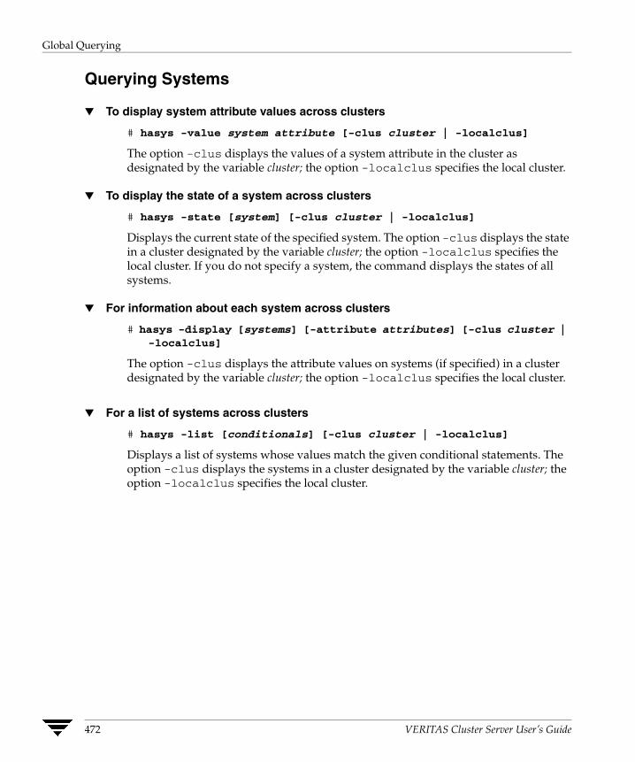
Global Querying
Querying Systems
▼ To display system attribute values across clusters
# hasys -value system attribute [-clus cluster | -localclus]
The option -clus displays the values of a system attribute in the cluster as designated by the variable cluster; the option -localclus specifies the local cluster.
▼ To display the state of a system across clusters
# hasys -state [system] [-clus cluster | -localclus]
Displays the current state of the specified system. The option -clus displays the state in a cluster designated by the variable cluster; the option -localclus specifies the local cluster. If you do not specify a system, the command displays the states of all systems.
▼ For information about each system across clusters
# hasys -display [systems] [-attribute attributes] [-clus cluster | -localclus]
The option -clus displays the attribute values on systems (if specified) in a cluster designated by the variable cluster; the option -localclus specifies the local cluster.
▼ For a list of systems across clusters
# hasys -list [conditionals] [-clus cluster | -localclus]
Displays a list of systems whose values match the given conditional statements. The option -clus displays the systems in a cluster designated by the variable cluster; the option -localclus specifies the local cluster.
472 VERITAS Cluster Server User’s Guide

Global Querying
Querying Clusters
▼ For the value of a specific cluster attribute on a specific cluster
# haclus -value attribute [cluster] [-localclus]
The attribute must be specified in this command. If you do not specify the cluster name, the command displays the attribute value on the local cluster.
▼ To display the state of a local or remote cluster as seen from the local cluster
# haclus -state [cluster] [-localclus]
The variable cluster represents the cluster. If a cluster is not specified, the state of the local cluster and the state of all remote cluster objects as seen by the local cluster are displayed.
▼ For information on the state of a local or remote cluster as seen from the local cluster
# haclus -display [cluster] [-localclus]
If a cluster is not specified, information on the local cluster is displayed.
▼ For a list of local and remote clusters
# haclus -list [conditionals]
Lists the clusters that meet the specified conditions, beginning with the local cluster.
▼ To display usage for the cluster command
# haclus [-help [-modify]]
▼ To display the status of a faulted cluster
# haclus -status cluster
Displays the status on the specified faulted cluster. If no cluster is specified, the command displays the status on all faulted clusters. It lists the service groups that were not in the OFFLINE or the FAULTED state before the fault occurred. It also suggests corrective action for the listed clusters and service groups.
Chapter 16, Administering Global Clusters from the Command Line 473
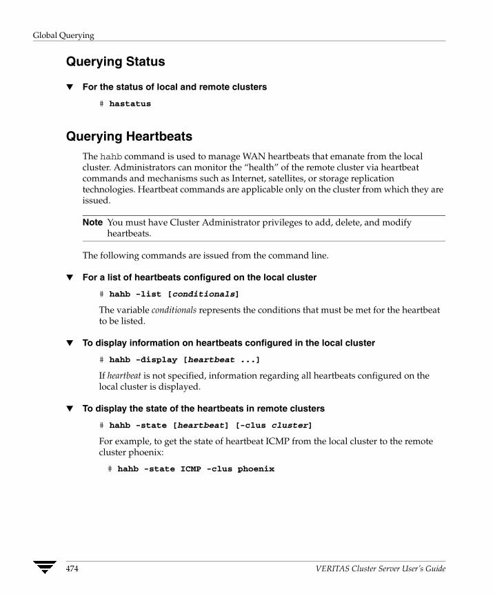
Global Querying
Querying Status
▼ For the status of local and remote clusters
# hastatus
Querying Heartbeats The hahb command is used to manage WAN heartbeats that emanate from the local cluster. Administrators can monitor the “health” of the remote cluster via heartbeat commands and mechanisms such as Internet, satellites, or storage replication technologies. Heartbeat commands are applicable only on the cluster from which they are issued.
Note You must have Cluster Administrator privileges to add, delete, and modify heartbeats.
The following commands are issued from the command line.
▼ For a list of heartbeats configured on the local cluster
# hahb -list [conditionals]
The variable conditionals represents the conditions that must be met for the heartbeat to be listed.
▼ To display information on heartbeats configured in the local cluster
# hahb -display [heartbeat ...]
If heartbeat is not specified, information regarding all heartbeats configured on the local cluster is displayed.
▼ To display the state of the heartbeats in remote clusters
# hahb -state [heartbeat] [-clus cluster]
For example, to get the state of heartbeat ICMP from the local cluster to the remote cluster phoenix:
# hahb -state ICMP -clus phoenix
474 VERITAS Cluster Server User’s Guide
Administering Service Groups
▼ To display an attribute value of a configured heartbeat
# hahb -value heartbeat attribute [-clus cluster]
The -value option provides the value of a single attribute for a specific heartbeat. The cluster name must be specified for cluster-specific attribute values, but not for global.
For example, to display the value of the ClusterList attribute for heartbeat ICMP:
# hahb -value ICMP ClusterList
Note that ClusterList is a global attribute.
▼ To display usage for the command hahb
# hahb [-help [-modify]]
If the -modify option is specified, the usage for the hahb -modify option is displayed.
Administering Service Groups Operations for the VCS global clusters option are enabled or restricted depending on the permissions with which you log on. The privileges associated with each user category are enforced for cross-cluster, service group operations. See “User Privileges in Global Clusters” on page 55 for more information.
▼ To bring a service group online across clusters for the first time
# hagrp -online -force
▼ To bring a service group online across clusters
# hagrp -online service_group -sys system [-clus cluster | -localclus]
The option -clus brings the service group online on the system designated in the cluster. If a system is not specified, the service group is brought online on any node within the cluster. The option -locaclus brings the service group online in the local cluster.
Chapter 16, Administering Global Clusters from the Command Line 475

Administering Service Groups
▼ To bring a service group online “anywhere”
# hagrp -online [-force] service_group -any [-clus cluster | -localclus]
The option -any specifies that HAD brings a failover group online on the optimal system, based on the requirements of service group workload management and existing group dependencies. If bringing a parallel group online, HAD brings the group online on each system designated in the SystemList attribute.
▼ To take a service group offline across clusters
# hagrp -offline [-force] [-ifprobed] service_group -sys system[-clus cluster -localclus]
The option -clus takes offline the service group on the system designated in the cluster.
▼ To take a service group offline “anywhere”
# hagrp -offline [-ifprobed] service_group -any [-clus cluster |-localclus]
The option -any specifies that HAD takes a failover group offline on the system on which it is online. For a parallel group, HAD takes the group offline on each system on which the group is online. HAD adheres to the existing group dependencies when taking groups offline.
▼ To switch a service group across clusters
# hagrp -switch service_group -to system [-clus cluster -localclus]
The option -clus identifies the cluster to which the service group will be switched. The service group is brought online on the system specified by the -to system argument. If a system is not specified, the service group may be switched to any node within the specified cluster.
▼ To switch a service group “anywhere”
# hagrp -switch service_group -clus cluster
The option -clus identifies the cluster to which the service group will be switched. HAD then selects the target system on which to switch the service group.
476 VERITAS Cluster Server User’s Guide
Administering Resources
Administering Resources
▼ To take action on a resource across clusters
# hares -action resource token [-actionargs arg1 ...] [-sys system] [-clus cluster |-localclus]
The option -clus implies resources on the cluster. If the designated system is not part of the local cluster, an error is displayed. If the -sys option is not used, it implies resources on the local node.
▼ To invoke the info entry point across clusters
# hares -refreshinfo resource [-sys system] [-clus cluster -localclus]
Causes the Info entry point to update the value of the ResourceInfo resource level attribute for the specified resource if the resource is online. If no system or remote cluster is specified, the Info entry point runs on local system(s) where the resource is online.
▼ To display usage for the resource command
To display usage for the command hares and its various options:
# hares [-help [-modify |-list]]
Administering Clusters
▼ To add a remote cluster object
# haclus -add cluster ip
The variable cluster represents the cluster. This command does not apply to the local cluster.
▼ To delete a remote cluster object
# haclus -delete cluster
The variable cluster represents the cluster.
Chapter 16, Administering Global Clusters from the Command Line 477
Administering Clusters
▼ To modify an attribute of a local or remote cluster object
# haclus -modify attribute value [-clus cluster]...
The variable cluster represents the cluster.
▼ To declare the state of a cluster after a disaster
# haclus -declare disconnet/outage/disaster/replica -clus cluster [-failover]
The variable cluster represents the remote cluster.
Changing the Cluster Name This section describes how to change the ClusterName in a global cluster configuration. The instructions describe how to rename VCSPriCluster to VCSPriCluster2 in a two-cluster configuration, comprising clusters VCSPriCluster and VCSSecCluster configured with the global group AppGroup.
Before changing the cluster name, make sure the cluster is not part of any ClusterList, in the wide-area Heartbeat agent and in global service groups.
▼ To change the name of a cluster
1. Run the following commands from cluster VCSPriCluster:
# hagrp -offline ClusterService -any# hagrp -modify AppGroup ClusterList -delete VCSPriCluster# haclus -modify ClusterName VCSPriCluster2# hagrp -modify AppGroup ClusterList -add VCSPriCluster2 0
2. Run the following commands from cluster VCSSecCluster:
# hagrp -offline ClusterService -any# hagrp -modify appgrp ClusterList -delete VCSPriCluster# hahb -modify Icmp ClusterList -delete VCSPriCluster# haclus -delete VCSPriCluster# haclus -add VCSPriCluster2 your_ip_address# hahb -modify Icmp ClusterList -add VCSPriCluster2# hahb -modify Icmp Arguments your_ip_address -clus
VCSPriCluster2# hagrp -modify AppGroup ClusterList -add VCSPriCluster2 0# hagrp -online ClusterService -any
3. Run the following command from the cluster renamed to VCSPriCluster2:
# hagrp -online ClusterService -any
478 VERITAS Cluster Server User’s Guide

Administering Heartbeats
Administering Heartbeats
▼ To create a heartbeat
# hahb -add heartbeat
For example, type the following command to add a new heartbeat called ICMP1. This represents a heartbeat sent from the local cluster and immediately forks off the specified agent process on the local cluster.
# hahb -add ICMP1
▼ To modify a heartbeat
# hahb -modify heartbeat attribute value ... [-clus cluster]
If the attribute is local, that is, it has a separate value for each remote cluster in the ClusterList attribute, the option -clus cluster must be specified. Use -delete -keys to clear the value of any list attributes.
For example, type the following command to modify the ClusterList attribute and specify targets “phoenix” and “houston” for the newly created heartbeat:
# hahb -modify ICMP ClusterList phoenix houston
To modify the Arguments attribute for target phoenix:
# hahb -modify ICMP Arguments phoenix.veritas.com-clus phoenix
▼ To delete a heartbeat
# hahb -delete heartbeat
▼ To change the scope of an attribute to cluster-specific
# hahb -local heartbeat attribute
For example, type the following command to change the scope of the attribute AYAInterval from global to cluster-specific:
# hahb -local ICMP AYAInterval
▼ To change the scope of an attribute to global
# hahb -global heartbeat attribute value ... | key ... | key value ...
For example, type the following command to change the scope of the attribute AYAInterval from cluster-specific to cluster-generic:
# hahb -global ICMP AYAInterval 60
Chapter 16, Administering Global Clusters from the Command Line 479

Administering Heartbeats
480 VERITAS Cluster Server User’s Guide
Administering Global Clustersfrom Cluster Manager (Java Console)
17The Global Cluster Option is required to manage global clustering for wide-area disaster recovery from the Java Console. The process of creating a global cluster environment involves creating a common service group for specified clusters, making sure all the service groups are capable of being brought online in the specified clusters, connecting the standalone clusters, and converting the service group that is common to all the clusters to a global service group. Use the console to add and delete remote clusters, create global service groups, and manage cluster heartbeats.
Creating a global cluster environment requires the following conditions:
✔ All service groups are properly configured and able to come online.
✔ The service group that will serve as the global group has the same unique name across all applicable clusters.
✔ The clusters must use the same version of VCS.
✔ The clusters must use the same operating system.
✔ The clusters are standalone and do not already belong to a global cluster environment.
Through the Java Console, you can simulate the process of generating and clearing global cluster faults in an OFFLINE state. Use VCS Simulator to complete these operations; refer to “Administering VCS Simulator” on page 214 for information on this tool.
Note Cluster Manager (Java Console) provides disabled individuals access to and use of information and data that is comparable to the access and use provided to non-disabled individuals. Refer to the appendix “Accessibility and VCS” for more information.
481
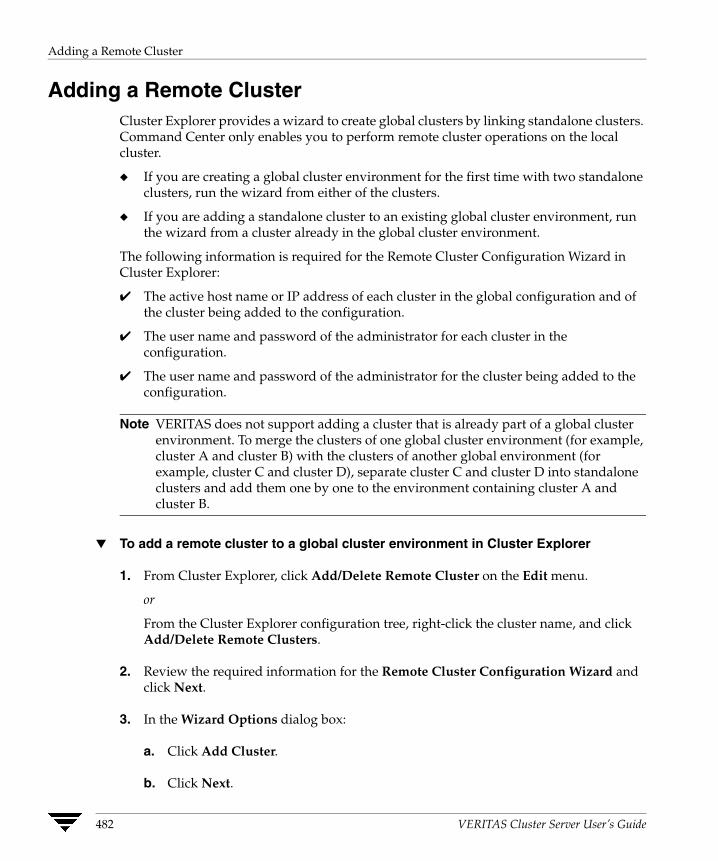
Adding a Remote Cluster
Adding a Remote Cluster Cluster Explorer provides a wizard to create global clusters by linking standalone clusters. Command Center only enables you to perform remote cluster operations on the local cluster.
◆ If you are creating a global cluster environment for the first time with two standalone clusters, run the wizard from either of the clusters.
◆ If you are adding a standalone cluster to an existing global cluster environment, run the wizard from a cluster already in the global cluster environment.
The following information is required for the Remote Cluster Configuration Wizard in Cluster Explorer:
✔ The active host name or IP address of each cluster in the global configuration and of the cluster being added to the configuration.
✔ The user name and password of the administrator for each cluster in the configuration.
✔ The user name and password of the administrator for the cluster being added to the configuration.
Note VERITAS does not support adding a cluster that is already part of a global cluster environment. To merge the clusters of one global cluster environment (for example, cluster A and cluster B) with the clusters of another global environment (for example, cluster C and cluster D), separate cluster C and cluster D into standalone clusters and add them one by one to the environment containing cluster A and cluster B.
▼ To add a remote cluster to a global cluster environment in Cluster Explorer
1. From Cluster Explorer, click Add/Delete Remote Cluster on the Edit menu.
or
From the Cluster Explorer configuration tree, right-click the cluster name, and click Add/Delete Remote Clusters.
2. Review the required information for the Remote Cluster Configuration Wizard and click Next.
3. In the Wizard Options dialog box:
a. Click Add Cluster.
b. Click Next.
482 VERITAS Cluster Server User’s Guide
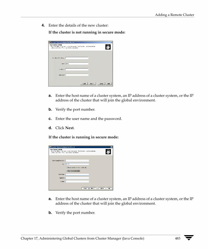
Adding a Remote Cluster
4. Enter the details of the new cluster:
If the cluster is not running in secure mode:
a. Enter the host name of a cluster system, an IP address of a cluster system, or the IP address of the cluster that will join the global environment.
b. Verify the port number.
c. Enter the user name and the password.
d. Click Next.
If the cluster is running in secure mode:
a. Enter the host name of a cluster system, an IP address of a cluster system, or the IP address of the cluster that will join the global environment.
b. Verify the port number.
Chapter 17, Administering Global Clusters from Cluster Manager (Java Console) 483

Adding a Remote Cluster
c. Choose to connect to the remote cluster with the credentials used for the current cluster connection or enter new credentials, including the user name, password, and the domain.
If you have connected to the remote cluster using the wizard earlier, you can use the credentials from the previous connection.
d. Click Next.
5. Enter the details of the existing remote clusters; this information on administrator rights enables the wizard to connect to all the clusters and make changes to the configuration:
6. Click the Configure icon. The Remote cluster information dialog box is displayed.
If the cluster is not running in secure mode:
a. Enter the host name of a cluster system, an IP address of a cluster system, or the IP address of the cluster that will join the global environment.
b. Verify the port number.
c. Enter the user name.
484 VERITAS Cluster Server User’s Guide

Adding a Remote Cluster
d. Enter the password.
e. Click OK.
f. Repeat step 5a through 5e for each cluster in the global environment.
If the cluster is running in secure mode:
a. Enter the host name of a cluster system, an IP address of a cluster system, or the IP address of the cluster that will join the global environment.
b. Verify the port number.
c. Choose to connect to the remote cluster with the credentials used for the current cluster connection or enter new credentials, including the user name, password, and the domain.
d. Click OK.
7. Click Next.
8. Click Finish. After running the wizard, the configurations on all the relevant clusters are opened and changed; the wizard does not close the configurations.
Chapter 17, Administering Global Clusters from Cluster Manager (Java Console) 485
Adding a Remote Cluster
▼ To add a remote cluster to a global cluster environment in Command Center
Note Command Center enables you to perform operations on the local cluster; this does not affect the overall global cluster configuration.
1. Click Commands>Configuration>Cluster Objects>Add Remote Cluster.
2. Enter the name of the cluster.
3. Enter the IP address of the cluster.
4. Click Apply.
486 VERITAS Cluster Server User’s Guide
Deleting a Remote Cluster
Deleting a Remote Cluster The Remote Cluster Configuration Wizard enables you to delete a remote cluster. This operation involves the following tasks:
◆ Taking the wac resource in the ClusterService group offline on the cluster that will be removed from the global environment. For example, to delete cluster C2 from a global environment containing C1 and C2, log on to C2 and take the wac resource offline.
◆ Removing the name of the specified cluster (C2) from the cluster lists of the other global groups using the Global Group Configuration Wizard. Note that the Remote Cluster Configuration Wizard in Cluster Explorer updates the cluster lists for heartbeats. Log on to the local cluster (C1) to complete this task before using the Global Group Configuration Wizard.
◆ Deleting the cluster (C2) from the local cluster (C1) through the Remote Cluster Configuration Wizard.
Note You cannot delete a remote cluster if the cluster is part of a cluster list for global service groups or global heartbeats, or if the cluster is in the RUNNING, BUILD, INQUIRY, EXITING, or TRANSITIONING states.
▼ To take the wac resource offline
1. From Cluster Monitor, log on to the cluster that will be deleted from the global cluster environment.
2. In the Service Groups tab of the Cluster Explorer configuration tree, right-click the wac resource under the Application type in the ClusterService group.
or
Click a service group in the configuration tree, click the Resources tab, and right-click the wac resource in the view panel.
3. Click Offline, and click the appropriate system from the menu.
Chapter 17, Administering Global Clusters from Cluster Manager (Java Console) 487
Deleting a Remote Cluster
▼ To remove a cluster from a cluster list for a global group
1. From Cluster Explorer, click Configure Global Groups on the Edit menu.
2. Click Next.
3. Enter the details of the service group to modify:
a. Click the name of the service group.
b. For global to local cluster conversion, click the left arrow to move the cluster name from the cluster list back to the Available Clusters box.
c. Click Next.
4. Enter or review the connection details for each cluster. Click the Configure icon to review the remote cluster information for each cluster.
If the cluster is not running in secure mode:
a. Enter the IP address of the remote cluster, the IP address of a cluster system, or the host name of a cluster system.
b. Verify the port number.
c. Enter the user name.
d. Enter the password.
e. Click OK.
If the cluster is running in secure mode:
a. Enter the IP address of the remote cluster, the IP address of a cluster system, or the host name of a cluster system.
b. Verify the port number.
c. Choose to connect to the remote cluster using the connected cluster’s credentials or enter new credentials, including the user name, password, and the domain.
d. Click OK.
5. Click Next.
488 VERITAS Cluster Server User’s Guide
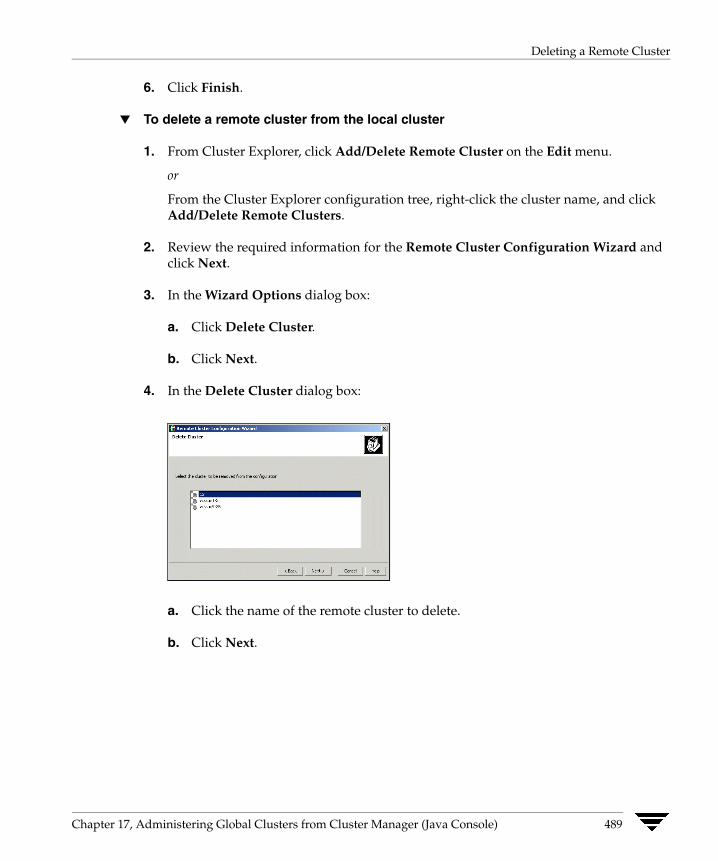
Deleting a Remote Cluster
6. Click Finish.
▼ To delete a remote cluster from the local cluster
1. From Cluster Explorer, click Add/Delete Remote Cluster on the Edit menu.
or
From the Cluster Explorer configuration tree, right-click the cluster name, and click Add/Delete Remote Clusters.
2. Review the required information for the Remote Cluster Configuration Wizard and click Next.
3. In the Wizard Options dialog box:
a. Click Delete Cluster.
b. Click Next.
4. In the Delete Cluster dialog box:
a. Click the name of the remote cluster to delete.
b. Click Next.
Chapter 17, Administering Global Clusters from Cluster Manager (Java Console) 489

Deleting a Remote Cluster
5. Review the connection details for each cluster. Click the Configure icon to review the remote cluster information for each cluster.
If the cluster is not running in secure mode:
a. Enter the IP address of the remote cluster, the IP address of a cluster system, or the host name of a cluster system.
b. Verify the port number.
c. Enter the user name.
d. Enter the password.
e. Click OK.
If the cluster is running in secure mode:
a. Enter the IP address of the remote cluster, the IP address of a cluster system, or the host name of a cluster system.
b. Verify the port number.
c. Choose to connect to the remote cluster with the credentials used for the current cluster connection or enter new credentials, including the user name, password, and the domain.
If you have connected to the remote cluster using the wizard earlier, you can use the credentials from the previous connection.
d. Click OK.
6. Click Finish.
490 VERITAS Cluster Server User’s Guide

Administering Global Service Groups
Administering Global Service Groups After connecting clusters in a global cluster environment, use the Global Group Configuration Wizard to convert a local service group that is common to the global clusters to a global group. This wizard also enables you to convert global groups into local groups.
Administering global groups requires the following conditions:
✔ A group that will serve as the global group must have the same name across all applicable clusters.
✔ You must know the user name and password for the administrator for each cluster in the configuration.
Use Cluster Explorer to bring a global group online and take a global group offline on a remote cluster.
Converting Local and Global Groups
1. From Cluster Explorer, click Configure Global Groups on the Edit menu.
or
From the Cluster Explorer configuration tree, right-click the service group, click Configure As Global or Make Local, and proceed to step 3b.
2. Review the information required for the Global Group Configuration Wizard and click Next.
Chapter 17, Administering Global Clusters from Cluster Manager (Java Console) 491

Administering Global Service Groups
3. Enter the details of the service group to modify:
a. Click the name of the service group that will be converted from a local group to a global group, or vice versa.
b. From the Available Clusters box, click the clusters on which the group can come online. Click the right arrow to move the cluster name to the Clusters for Service Group box; for global to local cluster conversion, click the left arrow to move the cluster name back to the Available Clusters box. A priority number (starting with 0) indicates the cluster in which the group will attempt to come online. If necessary, double-click the entry in the Priority column to enter a new value.
c. Select the policy for cluster failover:
◆ Manual prevents a group from automatically failing over to another cluster.
◆ Auto enables a group to automatically fail over to another cluster if it is unable to fail over within the cluster, or if the entire cluster faults.
◆ Connected enables a group to automatically fail over to another cluster if it is unable to fail over within the cluster.
d. Click Next.
492 VERITAS Cluster Server User’s Guide

Administering Global Service Groups
4. Enter or review the connection details for each cluster:
Click the Configure icon to review the remote cluster information for each cluster.
If the cluster is not running in secure mode:
a. Enter the IP address of the remote cluster, the IP address of a cluster system, or the host name of a cluster system.
b. Verify the port number.
c. Enter the user name and password.
d. Click OK.
Repeat these steps for each cluster in the global environment.
If the cluster is running in secure mode:
a. Enter the IP address of the remote cluster, the IP address of a cluster system, or the host name of a cluster system.
b. Verify the port number.
c. Choose to connect to the remote cluster with the credentials used for the current cluster connection, or enter new credentials, including the user name, password, and the domain.
If you have connected to the remote cluster using the wizard earlier, you can use the credentials from the previous connection.
d. Click OK.
Repeat these steps for each cluster in the global environment.
Chapter 17, Administering Global Clusters from Cluster Manager (Java Console) 493
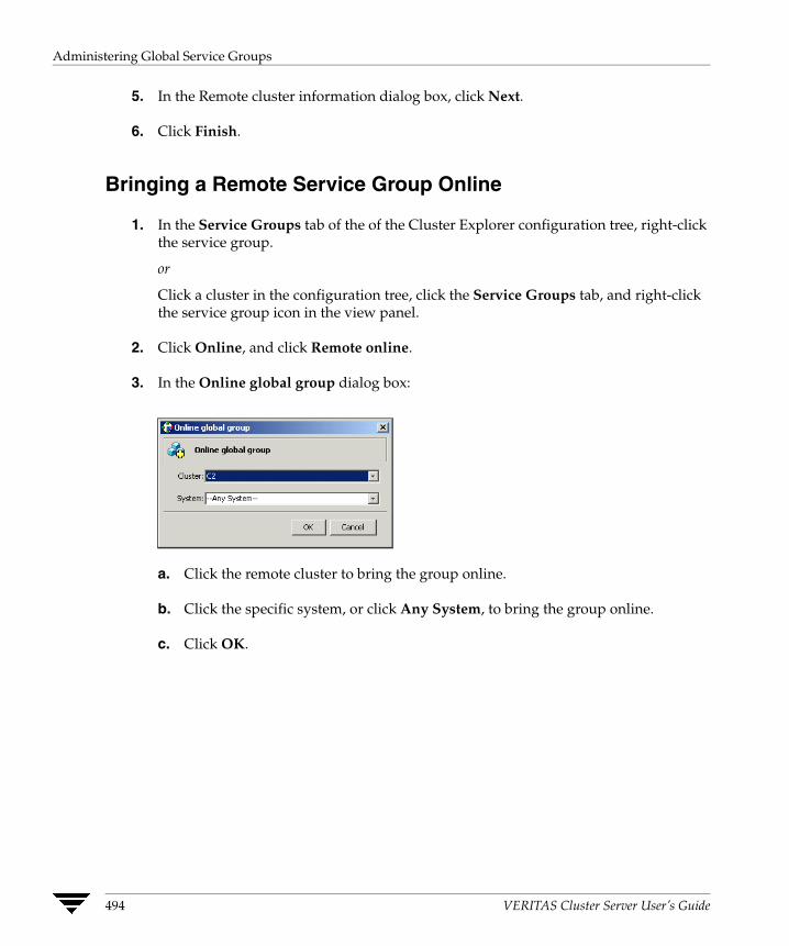
Administering Global Service Groups
5. In the Remote cluster information dialog box, click Next.
6. Click Finish.
Bringing a Remote Service Group Online
1. In the Service Groups tab of the of the Cluster Explorer configuration tree, right-click the service group.
or
Click a cluster in the configuration tree, click the Service Groups tab, and right-click the service group icon in the view panel.
2. Click Online, and click Remote online.
3. In the Online global group dialog box:
a. Click the remote cluster to bring the group online.
b. Click the specific system, or click Any System, to bring the group online.
c. Click OK.
494 VERITAS Cluster Server User’s Guide
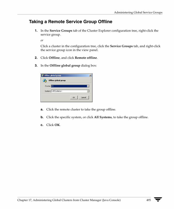
Administering Global Service Groups
Taking a Remote Service Group Offline
1. In the Service Groups tab of the Cluster Explorer configuration tree, right-click the service group.
or
Click a cluster in the configuration tree, click the Service Groups tab, and right-click the service group icon in the view panel.
2. Click Offline, and click Remote offline.
3. In the Offline global group dialog box:
a. Click the remote cluster to take the group offline.
b. Click the specific system, or click All Systems, to take the group offline.
c. Click OK.
Chapter 17, Administering Global Clusters from Cluster Manager (Java Console) 495
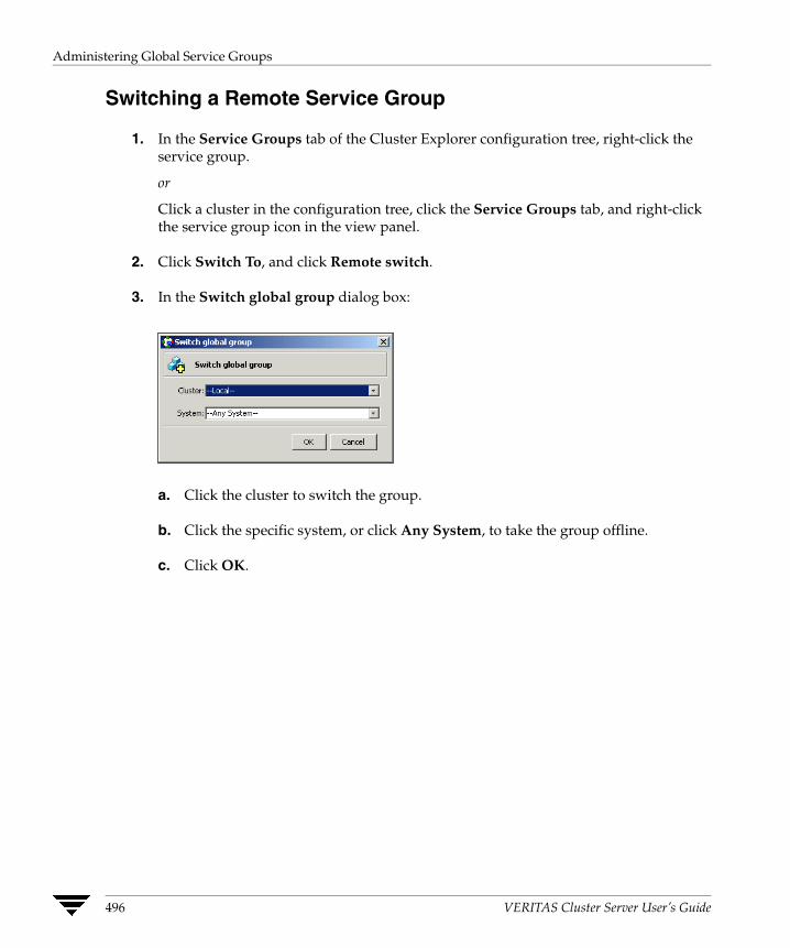
Administering Global Service Groups
Switching a Remote Service Group
1. In the Service Groups tab of the Cluster Explorer configuration tree, right-click the service group.
or
Click a cluster in the configuration tree, click the Service Groups tab, and right-click the service group icon in the view panel.
2. Click Switch To, and click Remote switch.
3. In the Switch global group dialog box:
a. Click the cluster to switch the group.
b. Click the specific system, or click Any System, to take the group offline.
c. Click OK.
496 VERITAS Cluster Server User’s Guide
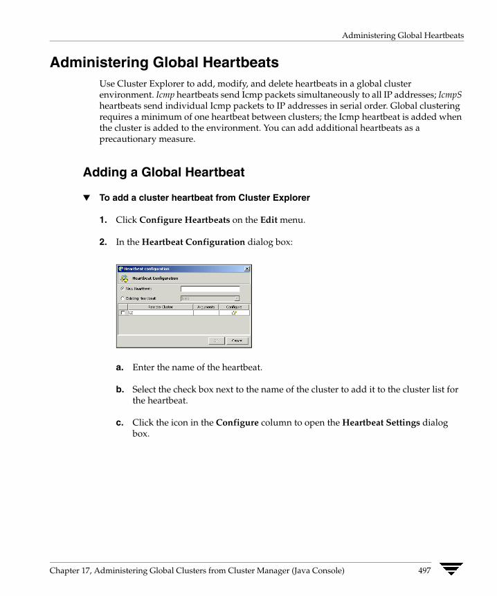
Administering Global Heartbeats
Administering Global Heartbeats Use Cluster Explorer to add, modify, and delete heartbeats in a global cluster environment. Icmp heartbeats send Icmp packets simultaneously to all IP addresses; IcmpS heartbeats send individual Icmp packets to IP addresses in serial order. Global clustering requires a minimum of one heartbeat between clusters; the Icmp heartbeat is added when the cluster is added to the environment. You can add additional heartbeats as a precautionary measure.
Adding a Global Heartbeat
▼ To add a cluster heartbeat from Cluster Explorer
1. Click Configure Heartbeats on the Edit menu.
2. In the Heartbeat Configuration dialog box:
a. Enter the name of the heartbeat.
b. Select the check box next to the name of the cluster to add it to the cluster list for the heartbeat.
c. Click the icon in the Configure column to open the Heartbeat Settings dialog box.
Chapter 17, Administering Global Clusters from Cluster Manager (Java Console) 497

Administering Global Heartbeats
d. Specify the value of the Arguments attribute and various timeout and interval fields. Click + to add an argument value; click - to delete it.
e. Click OK.
f. Click OK on the Heartbeat configuration dialog box.
▼ To add a cluster heartbeat from Command Center
1. Click Commands>Configuration>Cluster Objects>Add Heartbeat.
2. Enter the name of the heartbeat.
3. Click Apply.
498 VERITAS Cluster Server User’s Guide
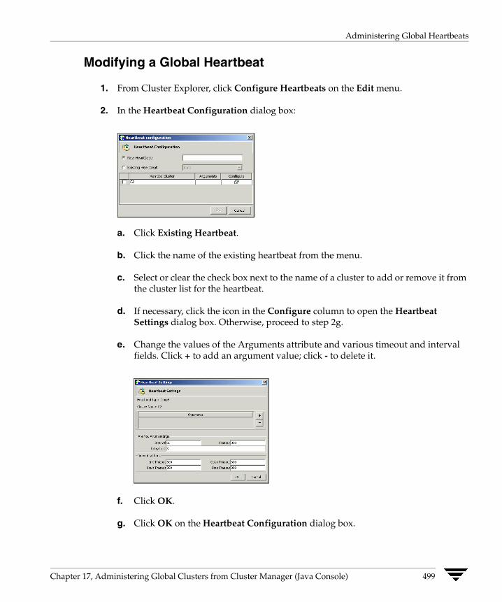
Administering Global Heartbeats
Modifying a Global Heartbeat
1. From Cluster Explorer, click Configure Heartbeats on the Edit menu.
2. In the Heartbeat Configuration dialog box:
a. Click Existing Heartbeat.
b. Click the name of the existing heartbeat from the menu.
c. Select or clear the check box next to the name of a cluster to add or remove it from the cluster list for the heartbeat.
d. If necessary, click the icon in the Configure column to open the Heartbeat Settings dialog box. Otherwise, proceed to step 2g.
e. Change the values of the Arguments attribute and various timeout and intervalfields. Click + to add an argument value; click - to delete it.
f. Click OK.
g. Click OK on the Heartbeat Configuration dialog box.
Chapter 17, Administering Global Clusters from Cluster Manager (Java Console) 499

Administering Global Heartbeats
Deleting a Global Heartbeat
Note You cannot delete the last heartbeat between global clusters.
▼ To delete a cluster heartbeat from Command Center
1. Click Commands>Configuration>Cluster Objects>Delete Heartbeat.
2. Click the heartbeat to delete.
3. Click Apply.
500 VERITAS Cluster Server User’s Guide

Administering Global Clusters from Cluster Manager (Web Console)
18The Global Cluster Option is required to manage global clustering for wide-area disaster recovery from the Web console. The process of creating a global cluster environment involves creating a common service group for specified clusters, making sure all the service groups are capable of being brought online in the specified clusters, connecting the standalone clusters, and converting the service group that is common to all the clusters to a global service group. Use the console to add and delete remote clusters, create global service groups, and manage cluster heartbeats.
Creating a global cluster environment requires the following conditions:
✔ All service groups are properly configured and able to come online.
✔ The service group that will serve as the global group has the same unique name across all applicable clusters.
✔ The clusters must use the same version of VCS.
✔ The clusters must use the same operating system.
✔ The clusters are standalone and do not already belong to a global cluster environment.
Note Cluster Manager (Web Console) provides disabled individuals access to and use of information and data that is comparable to the access and use provided to non-disabled individuals. Refer to the appendix “Accessibility and VCS” for more information.
501
Adding a Remote Cluster
Adding a Remote Cluster Use this procedure to create global clusters by linking standalone clusters.
✔ If you are creating a global cluster environment for the first time with two standalone clusters, run the operation from either of the clusters.
✔ If you are adding a standalone cluster to an existing global cluster environment, run the operation from a cluster already in the global cluster environment.
The following information is required for this procedure:
✔ The IP address of the cluster, the IP address of a system in the cluster, or the name of a system in the cluster being added to the configuration.
✔ The user name and password of the administrator for the cluster being added to the configuration.
VERITAS does not support adding a cluster that is already part of a global cluster environment. To merge the clusters of one global cluster environment (for example, cluster A and cluster B) with the clusters of another global environment (for example, cluster C and cluster D), separate cluster C and cluster D into standalone clusters and add them one by one to the environment containing cluster A and cluster B.
▼ To add a remote cluster to a global environment
1. From the Cluster Summary page, click Add Remote Cluster in the left pane.
502 VERITAS Cluster Server User’s Guide
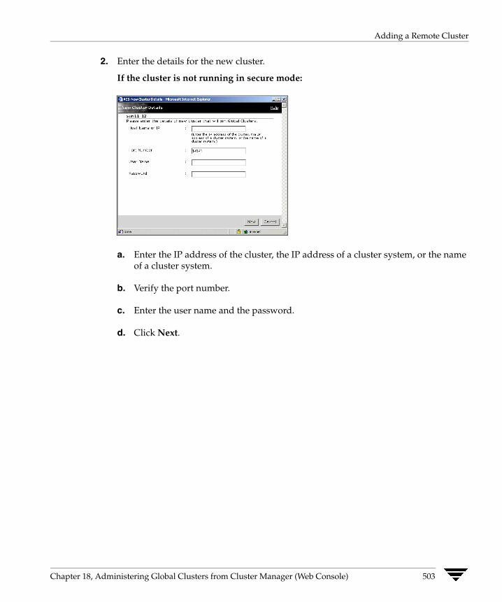
Adding a Remote Cluster
2. Enter the details for the new cluster.
If the cluster is not running in secure mode:
a. Enter the IP address of the cluster, the IP address of a cluster system, or the name of a cluster system.
b. Verify the port number.
c. Enter the user name and the password.
d. Click Next.
Chapter 18, Administering Global Clusters from Cluster Manager (Web Console) 503
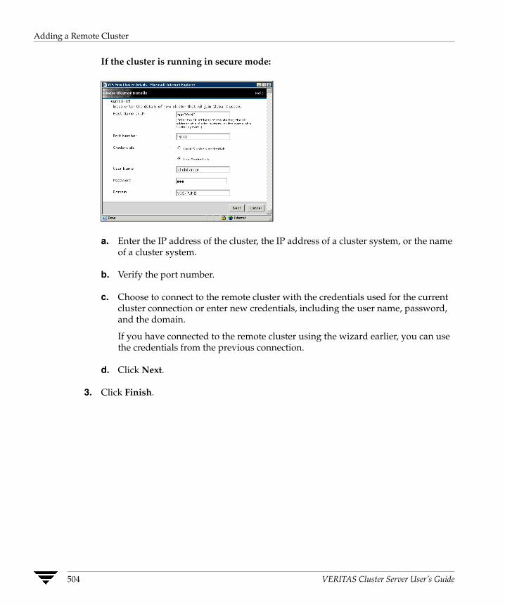
Adding a Remote Cluster
If the cluster is running in secure mode:
a. Enter the IP address of the cluster, the IP address of a cluster system, or the name of a cluster system.
b. Verify the port number.
c. Choose to connect to the remote cluster with the credentials used for the current cluster connection or enter new credentials, including the user name, password, and the domain.
If you have connected to the remote cluster using the wizard earlier, you can use the credentials from the previous connection.
d. Click Next.
3. Click Finish.
504 VERITAS Cluster Server User’s Guide
Deleting a Remote Cluster
Deleting a Remote Cluster The Web Console enables you to delete a remote cluster. This operation involves the following tasks:
✔ Taking the wac resource in the ClusterService group offline in the cluster that will be removed from the global environment. For example, to delete cluster C2 from a global environment containing C1 and C2, log on to C2 and take the wac resource offline.
✔ Removing the name of the specified cluster (C2) from the cluster lists of the other global groups; the Web Console updates the cluster lists for heartbeats. Log on to the local cluster (C1) to complete this task using the Global Groups Wizard.
✔ Removing the cluster (C2) from the local cluster (C1) using the Cluster Summary page on the local cluster (C1).
Note You cannot delete a remote cluster if the cluster is part of a cluster list for global service groups or global heartbeats, or if the cluster is in the RUNNING, BUILD, INQUIRY, EXITING, or TRANSITIONING states.
Taking the wac Resource Offline
1. From the Resource page for wac, click Offline in the left pane.
2. In the Offline Resource dialog box:
a. Select the system to take the resource offline.
b. Click OK.
Chapter 18, Administering Global Clusters from Cluster Manager (Web Console) 505

Deleting a Remote Cluster
Removing a Cluster from a Cluster List for a Global Group
1. From the Cluster Summary, Service Groups, or Service Group page, click Global Groups Wizard in the left pane.
2. In the Global Group Configuration dialog box:
a. Select the global group.
b. For global to local cluster conversion, select the cluster to delete in the Current ClusterList box.
c. Click the left arrow to move the cluster name from the current cluster list back to the Available Clusters box.
d. Select the policy for cluster failover:
◆ Manual prevents a group from automatically failing over to another cluster.
◆ Auto enables a group to automatically fail over to another cluster if it is unable to fail over within the cluster, or if the entire cluster faults.
◆ Connected enables a group to automatically fail over to another cluster if it is unable to fail over within the cluster.
e. Click Next.
506 VERITAS Cluster Server User’s Guide
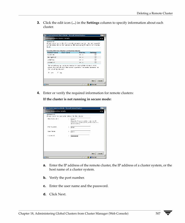
Deleting a Remote Cluster
3. Click the edit icon (...) in the Settings column to specify information about each cluster.
4. Enter or verify the required information for remote clusters:
If the cluster is not running in secure mode:
a. Enter the IP address of the remote cluster, the IP address of a cluster system, or the host name of a cluster system.
b. Verify the port number.
c. Enter the user name and the password.
d. Click Next.
Chapter 18, Administering Global Clusters from Cluster Manager (Web Console) 507
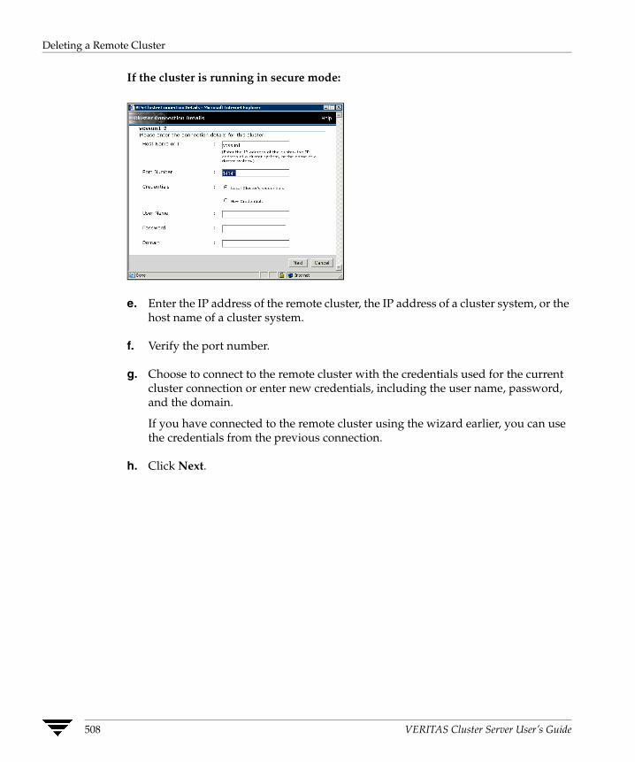
Deleting a Remote Cluster
If the cluster is running in secure mode:
e. Enter the IP address of the remote cluster, the IP address of a cluster system, or the host name of a cluster system.
f. Verify the port number.
g. Choose to connect to the remote cluster with the credentials used for the current cluster connection or enter new credentials, including the user name, password, and the domain.
If you have connected to the remote cluster using the wizard earlier, you can use the credentials from the previous connection.
h. Click Next.
508 VERITAS Cluster Server User’s Guide
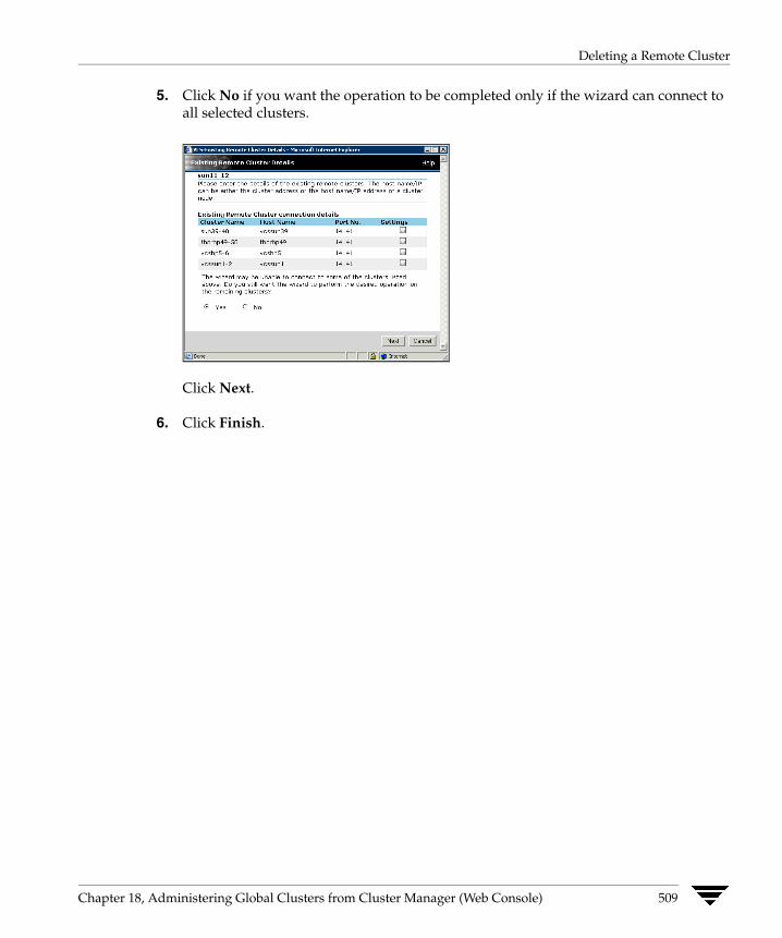
Deleting a Remote Cluster
5. Click No if you want the operation to be completed only if the wizard can connect to all selected clusters.
Click Next.
6. Click Finish.
Chapter 18, Administering Global Clusters from Cluster Manager (Web Console) 509

Deleting a Remote Cluster
Removing a Remote Cluster from the Local Cluster
1. From the Cluster Summary page, click Delete Remote Cluster in the left pane.
2. In the Remove Cluster dialog box, select the cluster to delete and click Next.
3. Click the edit icon (...) in the Settings column to specify information about each cluster.
4. Enter or verify the required information for remote clusters:
If the cluster is not running in secure mode:
a. Enter the IP address of the remote cluster, the IP address of a cluster system, or the host name of a cluster system.
b. Verify the port number.
510 VERITAS Cluster Server User’s Guide
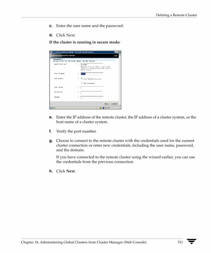
Deleting a Remote Cluster
c. Enter the user name and the password.
d. Click Next.
If the cluster is running in secure mode:
e. Enter the IP address of the remote cluster, the IP address of a cluster system, or the host name of a cluster system.
f. Verify the port number.
g. Choose to connect to the remote cluster with the credentials used for the current cluster connection or enter new credentials, including the user name, password, and the domain.
If you have connected to the remote cluster using the wizard earlier, you can use the credentials from the previous connection.
h. Click Next.
Chapter 18, Administering Global Clusters from Cluster Manager (Web Console) 511

Deleting a Remote Cluster
5. Click No if you want the operation to be completed only if the wizard can connect to all selected clusters.
6. Click Next.
7. Click Finish.
512 VERITAS Cluster Server User’s Guide
Administering Global Service Groups
Administering Global Service Groups After connecting clusters in a global cluster environment, use the Global Group Configuration Wizard to convert a local service group that is common to the global clusters to a global group. This wizard also enables you to convert global groups into local groups.
Administering global groups requires the following conditions:
✔ A group that will serve as the global group must have the same name across all applicable clusters.
✔ You must know the user name and password for the administrator for each cluster in the configuration.
Use the Web Console to bring a global group online and take a global group offline on a remote cluster.
Chapter 18, Administering Global Clusters from Cluster Manager (Web Console) 513
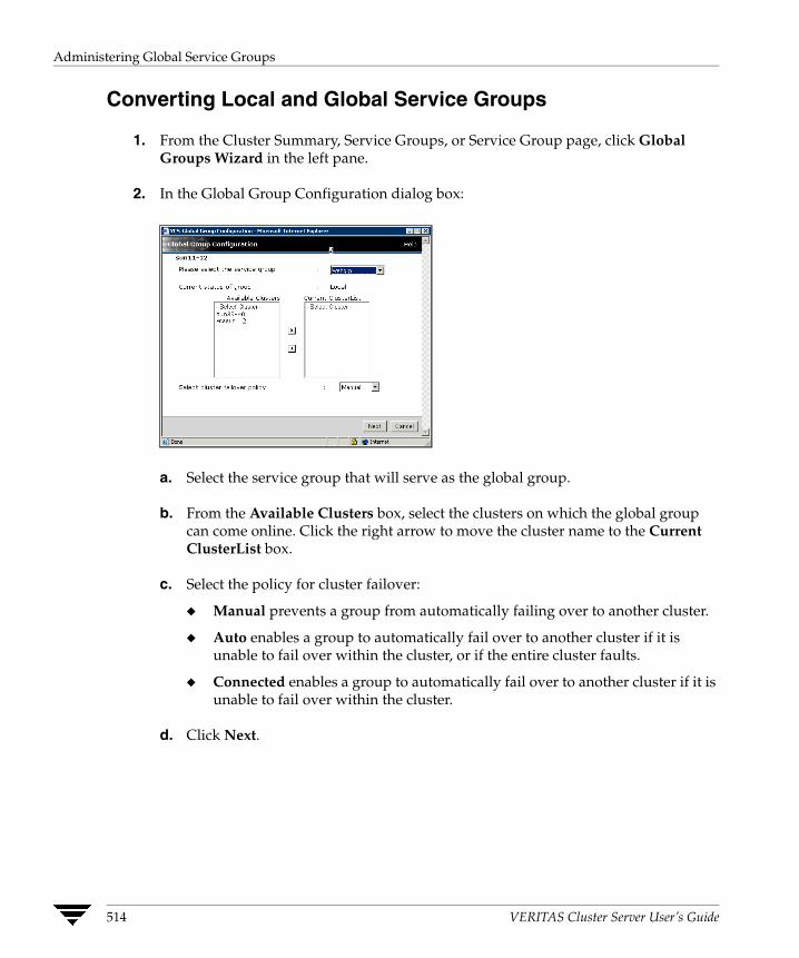
Administering Global Service Groups
Converting Local and Global Service Groups
1. From the Cluster Summary, Service Groups, or Service Group page, click Global Groups Wizard in the left pane.
2. In the Global Group Configuration dialog box:
a. Select the service group that will serve as the global group.
b. From the Available Clusters box, select the clusters on which the global group can come online. Click the right arrow to move the cluster name to the Current ClusterList box.
c. Select the policy for cluster failover:
◆ Manual prevents a group from automatically failing over to another cluster.
◆ Auto enables a group to automatically fail over to another cluster if it is unable to fail over within the cluster, or if the entire cluster faults.
◆ Connected enables a group to automatically fail over to another cluster if it is unable to fail over within the cluster.
d. Click Next.
514 VERITAS Cluster Server User’s Guide

Administering Global Service Groups
3. Click the edit icon (...) in the Settings column to specify information about the remote cluster.
4. Enter or verify the required information for the remote cluster:
If the cluster is not running in secure mode:
a. Enter the IP address of the remote cluster, the IP address of a cluster system, or the host name of a cluster system.
b. Verify the port number.
c. Enter the priority number (starting with 0) for the cluster on which the global group will attempt to come online.
d. Enter the user name and the password.
Chapter 18, Administering Global Clusters from Cluster Manager (Web Console) 515
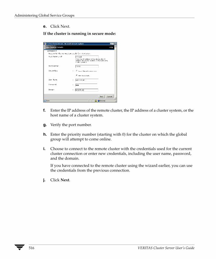
Administering Global Service Groups
e. Click Next.
If the cluster is running in secure mode:
f. Enter the IP address of the remote cluster, the IP address of a cluster system, or the host name of a cluster system.
g. Verify the port number.
h. Enter the priority number (starting with 0) for the cluster on which the global group will attempt to come online.
i. Choose to connect to the remote cluster with the credentials used for the current cluster connection or enter new credentials, including the user name, password, and the domain.
If you have connected to the remote cluster using the wizard earlier, you can use the credentials from the previous connection.
j. Click Next.
516 VERITAS Cluster Server User’s Guide
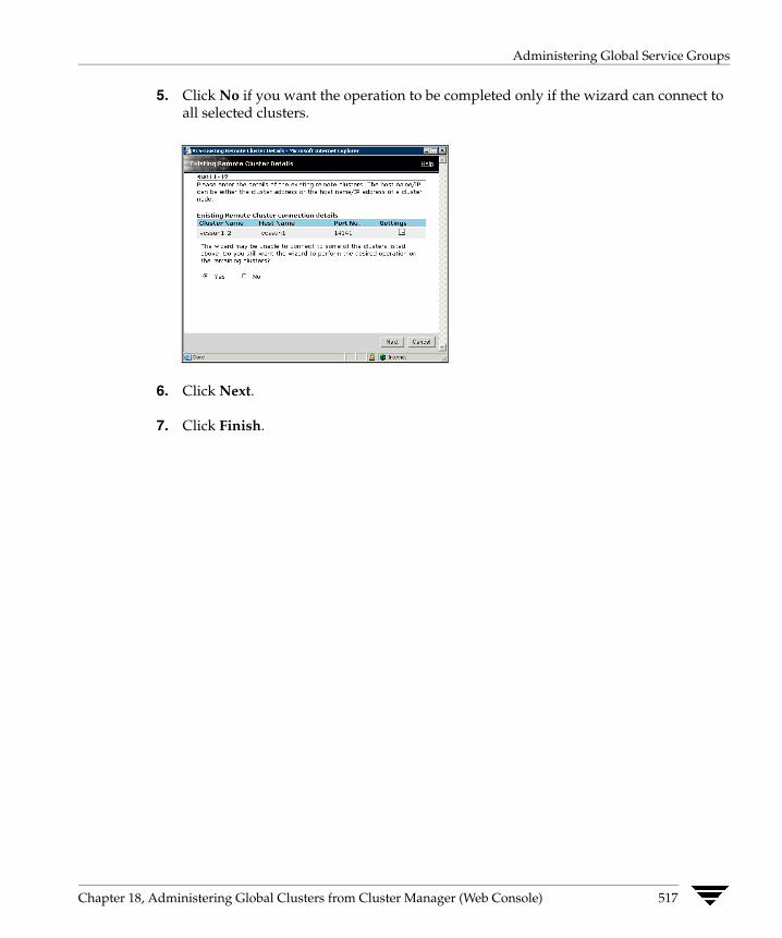
Administering Global Service Groups
5. Click No if you want the operation to be completed only if the wizard can connect to all selected clusters.
6. Click Next.
7. Click Finish.
Chapter 18, Administering Global Clusters from Cluster Manager (Web Console) 517

Administering Global Service Groups
Bringing a Remote Service Group Online
1. From the Service Group page, click Online in the left pane.
2. In the Online Group dialog box:
a. Select the cluster in which to bring the service group online, or click Anywhere.
b. Select the system on which to bring the service group online, or click Anywhere.
c. To run a PreOnline script, select the Run preonline script check box. This user-defined script checks for external conditions before bringing a group online.
d. Click OK.
518 VERITAS Cluster Server User’s Guide
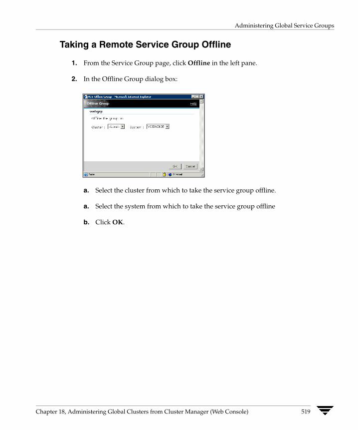
Administering Global Service Groups
Taking a Remote Service Group Offline
1. From the Service Group page, click Offline in the left pane.
2. In the Offline Group dialog box:
a. Select the cluster from which to take the service group offline.
a. Select the system from which to take the service group offline
b. Click OK.
Chapter 18, Administering Global Clusters from Cluster Manager (Web Console) 519

Administering Global Service Groups
Switching a Service Group The process of switching a service group involves taking it offline on its current system and bringing it online on another system.
1. From the Service Group page, click Switch in the left pane.
2. In the Switch Group dialog box:
a. Select the cluster to switch the service group to, or click Anywhere.
b. Select the system to switch the service group to, or click Anywhere.
c. Click OK.
520 VERITAS Cluster Server User’s Guide

Administering Global Heartbeats
Administering Global Heartbeats Use the Cluster Heartbeats page to add, delete, and configure heartbeats in a global cluster environment. Global clustering requires a minimum of one heartbeat between clusters; you can add additional heartbeats as a precautionary measure.
Adding a Global Heartbeat
1. From the Cluster Heartbeats page, click Add Heartbeat in the left pane.
2. In the Add Heartbeat dialog box:
a. Enter the name of the heartbeat.
b. Clear the check box next to the cluster name if you do not want that cluster added to the cluster list for the heartbeat.
Chapter 18, Administering Global Clusters from Cluster Manager (Web Console) 521
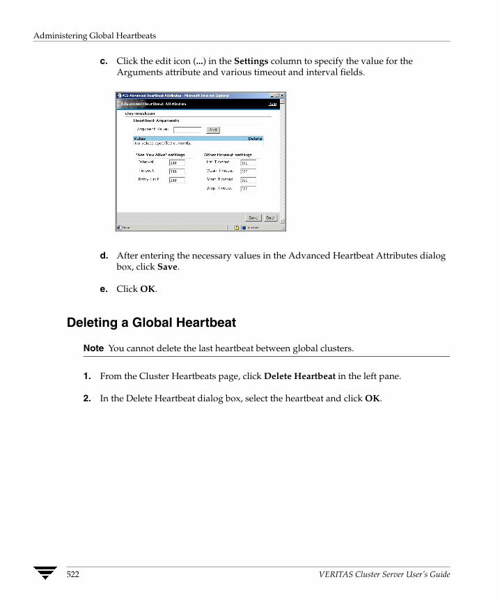
Administering Global Heartbeats
c. Click the edit icon (...) in the Settings column to specify the value for the Arguments attribute and various timeout and interval fields.
d. After entering the necessary values in the Advanced Heartbeat Attributes dialog box, click Save.
e. Click OK.
Deleting a Global Heartbeat
Note You cannot delete the last heartbeat between global clusters.
1. From the Cluster Heartbeats page, click Delete Heartbeat in the left pane.
2. In the Delete Heartbeat dialog box, select the heartbeat and click OK.
522 VERITAS Cluster Server User’s Guide
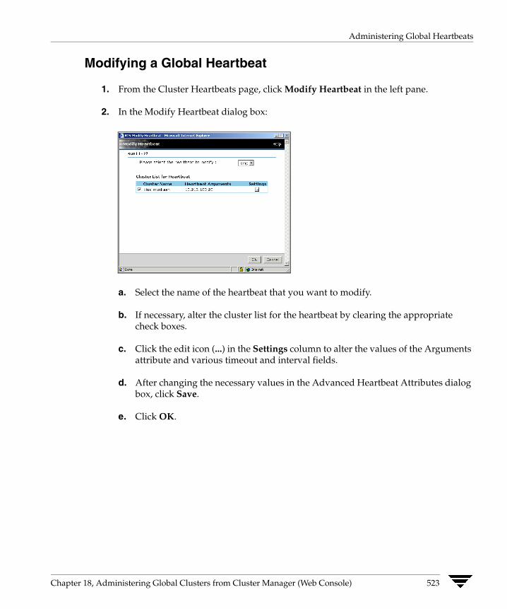
Administering Global Heartbeats
Modifying a Global Heartbeat
1. From the Cluster Heartbeats page, click Modify Heartbeat in the left pane.
2. In the Modify Heartbeat dialog box:
a. Select the name of the heartbeat that you want to modify.
b. If necessary, alter the cluster list for the heartbeat by clearing the appropriate check boxes.
c. Click the edit icon (...) in the Settings column to alter the values of the Arguments attribute and various timeout and interval fields.
d. After changing the necessary values in the Advanced Heartbeat Attributes dialog box, click Save.
e. Click OK.
Chapter 18, Administering Global Clusters from Cluster Manager (Web Console) 523

Administering Global Heartbeats
524 VERITAS Cluster Server User’s Guide

Setting Up Replicated Data Clusters
19 The Replicated Data Cluster (RDC) configuration provides both local high availability and disaster recovery functionality in a single VCS cluster.This chapter describes how to setup RDC in a VCS environment using VERITAS Volume Replicator (VVR.)
About Replicated Data Clusters A Replicated Data Cluster (RDC) uses data replication to assure data access to nodes. An RDC exists within a single VCS cluster. In an RDC configuration, if an application or a system fails, the application is failed over to another system within the current primary site. If the entire primary site fails, the application is migrated to a system in the remote secondary site (which then becomes the new primary).
For VVR replication to occur, the disk groups containing the Replicated Volume Group (RVG) must be imported at the primary and secondary sites. The replication service group must be online at both sites simultaneously, and must be configured as a hybrid VCS service group.
The application service group is configured as a failover service group. The application service group must be configured with an online local hard dependency on the replication service group.
Note VVR supports multiple replication secondary targets for any given primary. However, RDC for VCS supports only one replication secondary for a primary.
An RDC configuration is appropriate in situations where dual dedicated LLT links are available between the primary site and the disaster recovery secondary site but lacks shared storage or SAN interconnect between the primary and secondary data centers. In an RDC, data replication technology is employed to provide node access to data in a remote site.
Note You must use dual dedicated LLT links between the replicated nodes.
525
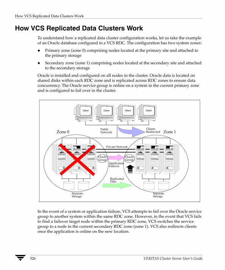
How VCS Replicated Data Clusters Work
How VCS Replicated Data Clusters WorkTo understand how a replicated data cluster configuration works, let us take the example of an Oracle database configured in a VCS RDC. The configuration has two system zones:
◆ Primary zone (zone 0) comprising nodes located at the primary site and attached to the primary storage
◆ Secondary zone (zone 1) comprising nodes located at the secondary site and attached to the secondary storage
Oracle is installed and configured on all nodes in the cluster. Oracle data is located on shared disks within each RDC zone and is replicated across RDC zones to ensure data concurrency. The Oracle service group is online on a system in the current primary zone and is configured to fail over in the cluster.
In the event of a system or application failure, VCS attempts to fail over the Oracle service group to another system within the same RDC zone. However, in the event that VCS fails to find a failover target node within the primary RDC zone, VCS switches the service group to a node in the current secondary RDC zone (zone 1). VCS also redirects clients once the application is online on the new location.
PublicNetwork
SeparateStorage
SeparateStorage
Client Client Client Client
ReplicatedData
ClientsRedirected
ApplicationFailover
OracleGroup
OracleGroup
Zone 0 Zone 1
Private Network
526 VERITAS Cluster Server User’s Guide

Setting up a Replicated Data Cluster Configuration
Setting up a Replicated Data Cluster Configuration This section describes the steps for planning, configuring, testing, and using the VCS RDC configuration to provide a robust and easy-to-manage disaster recovery protection for your applications. It describes an example of converting a single instance Oracle database configured for local high availability in a VCS cluster to a disaster-protected RDC infrastructure. The solution uses VERITAS Volume Replicator to replicate changed data.
The following illustration depicts a typical RDC configuration:
RVGPrimary
Lanman
IP
Application Group
NIC
Application
MountV
online local hard dependency
IP
NIC
RVG
DiskGroup
Replication Group
In this example, a single-instance Oracle database is configured as a VCS service group (oragroup) on a four-node cluster, with two nodes in the primary RDC system zone and two in the secondary RDC system zone. In the event of a failure on the primary node, VCS fails over Oracle to the second node in the primary zone.
The process involves the following steps:
◆ Setting Up Replication
◆ Configuring the Service Groups
◆ Configuring the Service Group Dependencies
Chapter 19, Setting Up Replicated Data Clusters 527

Setting up a Replicated Data Cluster Configuration
Setting Up Replication VERITAS Volume Replicator (VVR) technology is a license-enabled feature of VERITAS Volume Manager (VxVM), so you can convert VxVM-managed volumes into replicated volumes managed using VVR. In this example, the process involves grouping the Oracle data volumes into a Replicated Volume Group (RVG), and creating the VVR Secondary on hosts in another VCS cluster, located in your DR site.
When setting up VVR, it is a best practice to use the same DiskGroup and RVG name on both sites. This means that just the RLinks attribute needs to be modified to reflect the name of the secondary RLink. If the volume names are the same on both zones, the Mount resources will mount the same block devices, and the same Oracle instance will start on the secondary in case of a failover.
Configuring the Service Groups
▼ To configure the replication group
1. Create a hybrid service group (oragrp_rep) for replication. You can use the VvrRvgGroup template to create the service group. For more information about hybrid service groups, see “Types of Service Groups” on page 10.
2. Copy the DiskGroup resource from the application to the new group. Configure the resource to point to the disk group that contains the RVG.
3. Configure new resources of type IP and NIC.
4. Configure a new resource of type RVG in the service group. The RVG agent ships with the VVR software. If the RVG resource type is not defined in your configuration, import it, as instructed below.
a. On the File menu, click Import Types.
b. In the Import Types dialog box, Click the file from which to import the resource type. By default, the RVG resource type is located at the path /etc/VRTSvcs/conf/VVRTypes.cf.
c. Click Import.
528 VERITAS Cluster Server User’s Guide

Setting up a Replicated Data Cluster Configuration
5. Configure the following attributes of the RVG resource:
◆ RVG—The name of the RVG.
◆ DiskGroup—The name of the diskgroup containing the RVG.
◆ Primary—Whether this is the Primary.
◆ SRL—The name of the SRL volume associated with the RVG.
◆ RLinks—Names of Rlinks associated with the RVG. You can retrieve Rlink names by using the vxprint -l command.
Note The RVG resource starts, stops, and monitors the RVG in its current state and does not promote or demote VVR when you want to change the direction of replication. The RVGPrimary agent manages that task.
6. Set resource dependencies as per the following information:
◆ RVG resource depends on the IP resource
◆ RVG resource depends on the DiskGroup resource
◆ IP resource depends on the NIC resource
7. Set the SystemZones attribute of the child group, oragrp_rep, such that all nodes in the primary RDC zone are in system zone 0 and all nodes in the secondary RDC zone are in system zone 1.
▼ To configure the application service group
1. In the original Oracle service group (oragroup), delete the DiskGroup resource.
2. Add an RVGPrimary resource and configure its attributes.
Set the value of the RvgResourceName attribute to the name of the RVG type resource that will be promoted and demoted by the RVGPrimary agent.
Set the AutoTakeover and AutoResync attributes from their defaults as desired. See “RVGPrimary agent” on page 449 for more information about the agent.
3. Set resource dependencies such that all Mount resources depend on the RVGPrimary resource. If there are a lot of Mount resources, you can set the TypeDependencies attribute for the group to denote that the Mount resource type depends on the RVGPRimary resource type.
Chapter 19, Setting Up Replicated Data Clusters 529
Setting up a Replicated Data Cluster Configuration
4. Set the SystemZones attribute of the Oracle service group such that all nodes in the primary RDC zone are in system zone 0 and all nodes in the secondary RDC zone are in zone 1. The SystemZones attribute of both the parent and the child group must be identical.
5. If your setup uses BIND DNS, add a resource of type DNS to the oragroup service group. Set the Hostname attribute to the canonical name of the host or virtual IP address that the application uses on that cluster. This ensures DNS updates to the site when the group is brought online. A DNS resource would be necessary only if the nodes in the primary and the secondary RDC zones are in different IP subnets.
Configuring the Service Group Dependencies Set an online local hard group dependency from application service group to the replication service group to ensure that the service groups fail over and switch together.
1. In the Cluster Explorer configuration tree, select the cluster name.
2. In the view panel, click the Service Groups tab. This opens the service group dependency graph.
3. Click Link.
4. Click the parent group oragroup and move the mouse toward the child group, oragroup_rep.
5. Click the child group oragroup_rep.
6. On the Link Service Groups dialog box, click the online local relationship and the hard dependency type and click OK.
530 VERITAS Cluster Server User’s Guide

Migrating a Service Group
Migrating a Service Group In the RDC set up for the Oracle database, consider a case where the primary RDC zone suffers a total failure of the shared storage. In this situation, none of the nodes in the primary zone see any device.
The Oracle service group cannot fail over locally within the primary RDC zone, because the shared volumes cannot be mounted on any node. So, the service group must fail over, to a node in the current secondary RDC zone.
The RVGPrimary agent ensures that VVR volumes are made writable and the DNS agent ensures that name services are resolved to the DR site. The application can be started at the DR site and run there until the problem with the local storage is corrected.
If the storage problem is corrected, you can switch the application to the primary site using VCS.
Switching the Service Group Before switching the application back to the original primary RDC zone, you must resynchronize any changed data from the active DR site since the failover. This can be done manually through VVR or by running a VCS action from the RVGPrimary resource.
1. In the Service Groups tab of the configuration tree, right-click the resource.
2. Click Actions.
3. Specify the details of the action:
a. From the Action list, choose fast-failback.
b. Click the system on which to execute the action.
c. Click OK.
Chapter 19, Setting Up Replicated Data Clusters 531
Setting Up a Fire Drill
This begins a fast-failback of the replicated data set. You can monitor the value of the ResourceInfo attribute for the RVG resource to determine when the resynchronization has completed.
4. Once the resynchronization completes, switch the service group to the primary cluster.
a. In the Service Groups tab of the of the Cluster Explorer configuration tree, right-click the service group.
b. Click Switch To and select the system in the primary RDC zone to switch to and click OK.
Setting Up a Fire Drill You can use fire drills to test the configuration's fault readiness by mimicking a failover without stopping the application in the primary data center. See “Setting Up a Fire Drill” on page 466 for instructions.
532 VERITAS Cluster Server User’s Guide

Setting Up Campus Clusters
20 The Campus Cluster configuration provides local high availability and disaster recovery functionality in a single VCS cluster. This configuration uses mirroring to duplicate data at different sites. There is no host or array replication involvedVCS supports campus clusters employing cluster disk groups mirrored with VERITAS Volume Manager.
533

How VCS Campus Clusters Work
How VCS Campus Clusters Work Let us take the example of an Oracle database configured in a VCS campus cluster. Oracle is installed and configured in the cluster. Oracle data is located on shared disks.
VCS is configured on two nodes: node 1 is located at site A and node 2 at site B. The shared data is located on mirrored volumes on a cluster disk group configured using VERITAS Volume Manager.
◆ For each plex at site A, there is a plex at site B
◆ Single VCS cluster spanning multiple locations
◆ One disk group with the same number of disks at each site
◆ Logical volumes managed and mirrored using VM
◆ No host or array replication involved
Site B
VxVM RAID 1 Mirror
Campus Cluster Site A
Node 1 Node 2
The disk group is configured in VCS as a resource of type DiskGroup and is mounted using the Volume resource type. A resource of type CampusCluster monitors the paths to the disk group.
VCS continuously monitors and communicates events between cluster nodes. In the event of a system or application failure, VCS attempts to fail over the Oracle service group to another system in the cluster. VCS ensures that the disk group is imported by the node hosting the Oracle service group. If the original system comes up again, the VCS CampusCluster agent initiates a fast mirror resync (FMR) to synchronize data at both sites.
534 VERITAS Cluster Server User’s Guide
How VCS Campus Clusters Work
Takeover
In case of an outage at site A, VCS imports the disk group at site B and fails the service group over to the node at site B. The disk group is imported with all devices at the failed site marked as NODEVICE.
Fast-failback
Fast-failback provides the ability to resynchronize changed regions after a takeover if the original side returns in its original form, with minimal downtime.
When site A comes up again, the Volume Manager Dual Multi-pathing Daemon (DMP) detects the disks at site A and adds them to the disk group.
In this scenario, the CampusCluster agent performs a fast resynchronization of the original disks.
Link Failure
If a link between a node and its shared storage breaks, the node loses access to the remote disks but no takeover occurs. A power outage at the remote site could cause this situation.
Because the host has its ID stamped on the disks, when the disks return, the CampusCluster agent initiates a fast mirror resync.
Split-brain
Split-brain occurs when all heartbeat links between the hosts are cut and each side mistakenly thinks the other side is down. To minimize the effects of split-brain, make sure the LLT and heartbeat links are robust and do not fail at the same time.
Minimize risks by running heartbeat traffic and I/O traffic over same physical medium using technologies like DWDM. So if heartbeats are disrupted, the I/O communication is disrupted too. Each site interprets the situation as a takeover or as link failure.
Note that you cannot use SCSI III fencing in a two-site campus cluster. You must have an additional site to distribute the coordinator disks.
Chapter 20, Setting Up Campus Clusters 535
Setting Up a Campus Cluster Configuration
Setting Up a Campus Cluster Configuration This section provides an overview of the steps involved in setting up a campus cluster.
Prerequisites ✔ Verify VERITAS Volume Manager 4.1 is installed with the FMR license.
✔ You must have a single VCS cluster with at least one node in each of two sites, where the sites are separated by a physical distance of no more than 80 kilometers. they must share data and have a private heartbeat network.
✔ All volumes that have data required by the application must be evenly mirrored. Each site must have at least one plex of all volumes hosting application data, including the FMR Log volume.
✔ VERITAS recommends that you disable the Volume Manager Relocation Daemon to prevent plex relocation when the remote site suffers an outage.
✔ VERITAS recommends that you distinguish the physical location of each disk either by controller number or enclosure name. For example, controller 2 manages local devices and controller 3 manages remote devices. Differentiation by controller number avoids the need to scan all disks; differentiation by enclosure might help in disk placement.
Instructions
1. Set up the physical infrastructure. Verify each node is has access to the local storage arrays and to remote storage arrays.
2. Install Volume Manager and VCS on the cluster nodes.
3. Create a cluster disk group with disks from both sites.
4. Create one or more mirrored volumes in the disk group; do not create a mirror between two disks at the same physical location, such as in the same array.
5. Verify the disk group can be manually deported and imported on each node in the cluster.
6. Configure the disk group in VCS.
7. Configure the application and other related resources.
536 VERITAS Cluster Server User’s Guide
Setting Up a Campus Cluster Configuration
8. Add a resource of type CampusCluster to the service group. Create resource dependencies such that the DiskGroup resource depends on the CampusCluster resource.
9. Configure the CampusCluster resource.
Set the DiskGroup attribute to the same name as the DiskGroup attribute of the resource which depends on it.
If different controllers connect to the different sites, localize the RemoteCtlr attribute and set the attribute to the name of the controller that manages the remote disks from the point of view of the host. For instance, if controller c2 is connected to remote disks from standpoint of host vcs_a, then
# hares -local campus RemoteCtlr# hares -modify campus RemoteCtlr c2 -sys vcs_a
10. Bring the service group online.
Chapter 20, Setting Up Campus Clusters 537

Setting Up a Campus Cluster Configuration
538 VERITAS Cluster Server User’s Guide

Section VI. Troubleshooting and Performance
This section provides helpful troubleshooting and recovery tips for VCS. The section describes VCS Simulator, a tool that can be used to simulate VCS configurations and test VCS behavior on standalone systems. It also explains VCS performance considerations and the impact on cluster configurations.
Section VI includes the following chapters:
◆ Chapter 21. “Predicting VCS Behavior Using VCS Simulator” on page 541
◆ Chapter 22. “VCS Performance Considerations” on page 555
◆ Chapter 23. “Troubleshooting and Recovery for VCS” on page 571

Predicting VCS Behavior Using VCS Simulator
21VCS Simulator enables you to simulate and test cluster configurations. Use VCS Simulator to view and modify service group and resource configurations and test failover behavior. VCS Simulator can be run on a standalone system and does not require any additional hardware.
VCS Simulator runs an identical version of the VCS High Availability Daemon (HAD) as in a cluster, ensuring that failover decisions are identical to those in an actual cluster. VCS Simulator enables testing and tuning of multiple values governing the rules of failover, such as SystemList, Limits and Prerequisites, and Load and Capacity.
You can test configurations from different operating systems using VCS Simulator. For example, you can run VCS Simulator on a Windows system and test VCS configurations for Windows, Linux, and Solaris clusters. VCS Simulator also enables creating and testing global clusters.
You can administer VCS Simulator from the Java Console or from the command line.
Installing VCS Simulator
Note VERITAS also provides a Simulator Demo, which is available as a download from http://www.veritas.com. Do not install the Simulator Demo on systems running Cluster Manager (Java Console) or the Simulator version packaged with VCS.
▼ To install VCS Simulator on UNIX systems
1. Insert the VCS installation disc into a drive.
2. Navigate to the pkgs directory and locate the package VRTScssim.
3. Install the VRTScssim package using the pkgadd command.
To use Cluster Manager with Simulator, you must also install the VRTScscm package.
541
Installing VCS Simulator
▼ To install VCS Simulator on Windows systems
1. Insert the VCS installation disc into a drive.
2. From Windows Explorer, navigate to the path of the Simulator installer file, located at windows\WindowsInstallers\WindowsSimulator\EN\.
3. Double-click the installer file.
4. Read the information in the Welcome screen and click Next.
5. In the Destination Folders dialog box, click Next to accepted the suggested installation path or click Change to choose a different location.
6. In the Ready to Install the Program dialog box, click Back to make changes to your selections or click Install to proceed with the installation.
7. In the Installshield Wizard Completed dialog box, click Finish.
542 VERITAS Cluster Server User’s Guide
Installing VCS Simulator
Reviewing the Installation VCS Simulator installs Cluster Manager (Java Console) and Simulator binaries on the system. The Simulator installation creates the following directories:
Directory Contents
attrpool Information about attributes associated with VCS objects.
bin VCS Simulator binaries.
default_clus Files for the default cluster configuration.
sample_clus A sample cluster configuration, which serves as a template for each new cluster configuration.
templates Various templates used by the Java Console.
types The types.cf files for all supported platforms.
Additionally, VCS Simulator installs directories for various cluster configurations.
VCS Simulator creates a directory for every new simulated cluster and copies the contents of the sample_clus directory. Simulator also creates a logs directory within each cluster directory for logs associated with the cluster.
Simulator Ports VCS Simulator uses the following ports:
◆ Ports 15550 through 15558 to connect to the various cluster configurations.
◆ Ports 15560 through 15563 for the wide area connector (WAC) process.
Set the WAC port to -1 to disable WAC simulation.
Chapter 21, Predicting VCS Behavior Using VCS Simulator 543

Administering VCS Simulator From the Java Console
Administering VCS Simulator From the Java Console The Simulator Console enables you to start, stop, and manage simulated clusters.
The console provides two views:
◆ Cluster View—Lists all simulated cluster.
◆ Global View—Lists global clusters.
Through the Java Console, VCS Simulator enables you to configure a simulated cluster panel, bring a system in an unknown state into an online state, simulate power loss for running systems, simulate resource faults, and save the configuration while VCS is offline. For global clusters, you can simulate the process of generating and clearing cluster faults.
You can run multiple simulated clusters on a system by using different port numbers for each cluster.
The Java Console provides the same views and features that are available for online configurations. See “Administering the Cluster from Cluster Manager (Java Console)” on page 109 for more information.
544 VERITAS Cluster Server User’s Guide

Administering VCS Simulator From the Java Console
Starting VCS Simulator from the Java Console
▼ To start VCS Simulator from the Java Console (Windows)
Click Start > Programs > VERITAS > VCS Simulator - Java Console.
▼ To start VCS Simulator from the Java Console (UNIX)
1. Type the following command to grant the system permission to display on the desktop:
# xhost +
2. Configure the shell environment variable DISPLAY on the system where Cluster Manager will be launched. For example, if using Korn shell, type the following command to display on the system myws:
# export DISPLAY=myws:0
3. Run the following command:
# /opt/VRTSvcs/bin/hasimgui
Chapter 21, Predicting VCS Behavior Using VCS Simulator 545
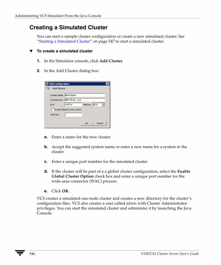
Administering VCS Simulator From the Java Console
Creating a Simulated Cluster You can start a sample cluster configuration or create a new simulated cluster. See “Starting a Simulated Cluster” on page 547 to start a simulated cluster.
▼ To create a simulated cluster
1. In the Simulator console, click Add Cluster.
2. In the Add Cluster dialog box:
a. Enter a name for the new cluster.
b. Accept the suggested system name or enter a new name for a system in the cluster.
c. Enter a unique port number for the simulated cluster.
d. If the cluster will be part of a a global cluster configuration, select the Enable Global Cluster Option check box and enter a unique port number for the wide-area connector (WAC) process.
e. Click OK.
VCS creates a simulated one-node cluster and creates a new directory for the cluster’s configuration files. VCS also creates a user called admin with Cluster Administrator privileges. You can start the simulated cluster and administer it by launching the Java Console.
546 VERITAS Cluster Server User’s Guide
Administering VCS Simulator From the Java Console
Starting a Simulated Cluster
1. In the Simulator console, select the cluster.
2. Click Start Cluster.
3. After the cluster starts, click Launch Console to administer the cluster.
4. Enter a valid user name and password to log on to the cluster.
Note VCS Simulator does not validate passwords; you can log on to a simulated cluster by just entering a valid VCS user name. If you use the default configuration, enter admin for the user name.
The animated display shows various objects, such as service groups and resources, being transferred from the server to the console.
Cluster Explorer is launched upon initial logon, and the icons in the cluster panel change color to indicate an active panel.
Verifying a Simulated Cluster Configuration
1. In the Simulator console, select the cluster.
2. Click Verify Configuration.
Simulating a Global Cluster Configuration
1. Create the simulated clusters for the global configuration. See “Creating a Simulated Cluster” on page 546 for instructions.
Note Select the Enable Global Cluster Option check box and enter a unique port number for the wide-area connector (WAC) process.
2. In the Simulator console, click Make Global.
Chapter 21, Predicting VCS Behavior Using VCS Simulator 547

Administering VCS Simulator From the Java Console
3. In the Make Global Configuration dialog box:
a. Select an existing global cluster or enter the name for a new global cluster.
b. From the Available Clusters list, select the clusters to add to the global cluster and click the right arrow. The clusters move to the Configured Clusters list.
c. Click OK.
Bringing a System Online
1. From Cluster Explorer, click the Systems tab of the configuration tree.
2. Right-click the system in an unknown state, and click Up.
Powering Off a System
1. From Cluster Explorer, click the Systems tab of the configuration tree.
2. Right-click the online system, and click Power Off.
Saving the Offline Configuration
1. From Cluster Explorer, click Save Configuration As from the File menu.
2. Enter the path location.
3. Click OK.
548 VERITAS Cluster Server User’s Guide
Administering VCS Simulator From the Java Console
Simulating a Resource Fault
1. From Cluster Explorer, click the Service Groups tab of the configuration tree.
2. Right-click an online resource, click Fault Resource, and click the system name.
Simulating Cluster Faults in Global Clusters Use VCS Simulator to imitate the process of generating and clearing cluster faults. See “Monitoring Alerts” on page 212 for information on declaring cluster faults.
▼ To generate a cluster fault
1. From Cluster Explorer, click the cluster in the configuration tree.
2. Right-click the cluster, click Fault Cluster, and click the cluster name.
▼ To clear a cluster fault
1. From Cluster Explorer, click the cluster in the configuration tree.
2. Right-click the cluster, click Clear Cluster Fault, and click the cluster name.
Chapter 21, Predicting VCS Behavior Using VCS Simulator 549

Administering VCS Simulator from the Command Line
Administering VCS Simulator from the Command Line The functionality of the VCS Simulator command line interface mimics that of standard ha commands. Start VCS Simulator before creating or administering simulated clusters.
Starting VCS Simulator From the Command Line
▼ To start VCS Simulator from the command line (UNIX)
1. To simulate a cluster running a particular operating system, copy the types.cf. file for the operating system from the types directory to /opt/VRTSsim/default_clus/conf/config/.
For example, if the cluster to be simulated runs on the AIX platform, copy the file types.cf.aix.
2. Add custom type definitions to the file, if required, and rename the file to types.cf.
3. If you have a main.cf file to run in the simulated cluster, copy it to /opt/VRTSsim/default_clus/conf/config/.
4. Start VCS Simulator:
# sim_dir/hasim -start system_name
The variable system_name represents a system name, as defined in the configuration file main.cf. This command starts Simulator on port 14153.
For example, to start the default cluster:
# sim_dir/hasim -start sys1
Note that the default configuration includes system sys1.
5. Add systems to the configuration, if desired:
# sim_dir/hasim -sys -add system_name# sim_dir/hasim -up system_name
6. Verify the states of each node in the cluster:
# sim_dir/hasim -sys -state
Use the command line or the Java Console to manage the simulated cluster.
Note For instructions on simulating a global cluster environment, see“To simulate global clusters from the command line” on page 552.
550 VERITAS Cluster Server User’s Guide
Administering VCS Simulator from the Command Line
▼ To start VCS Simulator from the command line (Windows)
VCS Simulator installs platform-specific types.cf files at the path %VCS_SIMULATOR_HOME%\types\. The variable %VCS_SIMULATOR_HOME% represents the Simulator installation directory, typically C:\Program Files\VERITAS\VCS Simulator\.
1. To simulate a cluster running a particular operating system, copy the types.cf. file for the operating system from the types directory to %VCS_SIMULATOR_HOME%\default_clus\conf\config\.
For example, if the cluster to be simulated runs on the AIX platform, copy the file types.cf.aix.
2. Add custom type definitions to the file, if required, and rename the file to types.cf.
3. If you have a main.cf file to run in the simulated cluster, copy it to %VCS_SIMULATOR_HOME%\default_clus\conf\config\.
4. Start VCS Simulator:
%VCS_SIMULATOR_HOME%\bin> hasim -start system_name
The variable system_name represents a system name, as defined in the configuration file main.cf.
This command starts Simulator on port 14153.
5. Add systems to the configuration, if desired:
%VCS_SIMULATOR_HOME%\bin> hasim -sys -add system_name%VCS_SIMULATOR_HOME%\bin> hasim -up system_name
6. Verify the state of each node in the cluster:
%VCS_SIMULATOR_HOME%\bin> hasim -sys -state
Note For instructions on simulating a global cluster environment, see “To simulate global clusters from the command line” on page 552.
Chapter 21, Predicting VCS Behavior Using VCS Simulator 551

Administering VCS Simulator from the Command Line
▼ To simulate global clusters from the command line
1. Install VCS Simulator in a directory (sim_dir) on your system. For instructions, see “Installing VCS Simulator” on page 541.
2. Set up the clusters on your system. Run the following command to add a cluster:
# sim_dir/hasim -setupclus clustername -simport port_no -wacport port_no
Note Do not use default_clus as the cluster name when simulating a global cluster.
VCS Simulator copies the sample configurations to the path sim_dir/clustername and creates a system named clustername_sys1.
For example, to add cluster clus_a using ports 15555 and 15575, run the following command:
# sim_dir/hasim -setupclus clus_a -simport 15555 -wacport 15575
Similarly, add the second cluster:
# sim_dir/hasim -setupclus clus_b -simport 15556 -wacport 15576
Note To create multiple clusters without simulating a global cluster environment, specify -1 for the wacport.
3. Start the simulated clusters:
# sim_dir/hasim -start clustername_sys1 -clus clustername
4. Set the following environment variables to access VCS Simulator from the command line:
◆ VCS_SIM_PORT=port_number
◆ VCS_SIM_WAC_PORT=wacport
Note that you must set these variables for each simulated cluster, otherwise Simulator always connects default_clus, the default cluster.
You can use the Java Console to link the clusters and to configure global service groups. See “Administering the Cluster from Cluster Manager (Java Console)” on page 109 for more information.
You can also edit the configuration file main.cf manually to create the global cluster configuration.
552 VERITAS Cluster Server User’s Guide
Administering VCS Simulator from the Command Line
Administering Simulated Clusters from the Command Line The functionality of VCS Simulator commands mimic that of standard ha commands.
Command Description
hasim -start system_name Starts VCS Simulator. The variable system_name represents the system that will transition from the LOCAL_BUILD state to RUNNING.
hasim -setupclus clustername -simport port_no [-wacport port_no] [-sys systemname]
Creates a simulated cluster and associates the specified ports with the cluster.
hasim -start clustername_sys1 [-clus clustername] [-disablel10n]
Starts VCS Simulator on the cluster specified by clustername.
If you start VCS Simulator with the -disablel10n option, the simulated cluster does not accept localized values for attributes. Use this option when simulating a UNIX configuration on a Windows system to prevent potential corruption when importing the simulated configuration to a UNIX cluster.
hasim -stop Stops the simulation process.
hasim -poweroff system_name
Gracefully shuts down the system.
hasim -up system_name Brings the system up.
hasim -fault system_name resource_name
Faults the specified resource on the specified system.
hasim -online system_name resource_name
Brings specified resource online. This command is useful if you have simulated a fault of a persistent resource and want to now simulate the fix.
hasim -faultcluster clustername
Simulates a cluster fault.
hasim -clearcluster clustername
Clears a simulated cluster fault.
hasim -getsimconfig cluster_name
Retrieves information about VCS Simulator ports.
Chapter 21, Predicting VCS Behavior Using VCS Simulator 553
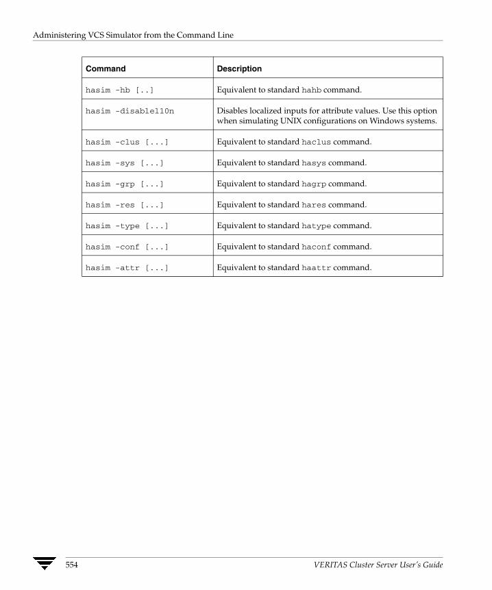
Administering VCS Simulator from the Command Line
Command Description
hasim -hb [..] Equivalent to standard hahb command.
hasim -disablel10n Disables localized inputs for attribute values. Use this option when simulating UNIX configurations on Windows systems.
hasim -clus [...] Equivalent to standard haclus command.
hasim -sys [...] Equivalent to standard hasys command.
hasim -grp [...] Equivalent to standard hagrp command.
hasim -res [...] Equivalent to standard hares command.
hasim -type [...] Equivalent to standard hatype command.
hasim -conf [...] Equivalent to standard haconf command.
hasim -attr [...] Equivalent to standard haattr command.
554 VERITAS Cluster Server User’s Guide
VCS Performance Considerations
22 This chapter describes factors that affect VCS operations, such as bringing a resource or service group online, taking them offline, and failing service groups over to a different system.How Cluster Components Affect Performance VCS and its agents run on the same systems as the applications. Therefore, VCS attempts to minimize its impact on overall system performance. The three main components of clustering that have an impact on performance include the kernel; specifically, GAB and LLT, the VCS engine (HAD), and the VCS agents. For details on attributes or commands mentioned in the following sections, see the chapter on administering VCS from the command line and the appendix on VCS attributes.
Kernel Components (GAB and LLT) Typically, overhead of VCS kernel components is minimal. Kernel components provide heartbeat and atomic information exchange among cluster systems. By default, each system in the cluster sends two small heartbeat packets per second to other systems in the cluster. Heartbeat packets are sent over all network links configured in the /etc/llttab configuration file. System-to-system communication is load-balanced across all private network links. If a link fails, VCS continues to use all remaining links. Typically, network links are private and do not increase traffic on the public network or LAN. You can configure a public network (LAN) link as low-priority, which by default generates a small (approximately 64-byte) broadcast packet per second from each system, and which will carry data only when all private network links have failed.
555
How Cluster Components Affect Performance
The VCS Engine “HAD” The VCS engine, HAD, runs as a daemon process. By default it runs as a high-priority process, which ensures it sends heartbeats to kernel components and responds quickly to failures.
VCS “sits” in a loop waiting for messages from agents, ha commands, the graphical user interfaces, and the other systems. Under normal conditions, the number of messages processed by HAD is few. They mainly include heartbeat messages from agents and update messages from the global counter. VCS may exchange additional messages when an event occurs, but typically overhead is nominal even during events. Note that this depends on the type of event; for example, a resource fault may invoke offlining a group on one system and onlining on another system, but a system fault invokes failing over all online service groups on the faulted system.
To continuously monitor VCS status, use the VCS graphical user interfaces or the command hastatus. Both methods maintain connection to VCS and register for events, and are more efficient compared to running commands like hastatus -summary or hasys in a loop.
The number of clients connected to VCS can affect performance if several events occur simultaneously. For example, if five GUI processes are connected to VCS, VCS sends state updates to all five. Maintaining fewer client connections to VCS reduces this overhead.
The Impact of Agents The VCS agent processes have the most impact on system performance. Each agent process has two components: the agent framework and the agent entry points. The agent framework provides common functionality, such as communication with the HAD, multithreading for multiple resources, scheduling threads, and invoking entry points. Agent entry points implement agent-specific functionality. Follow the performance guidelines below when configuring agents.
Monitoring Resource Type and Agent Configuration
By default, VCS monitors each resource every 60 seconds. You can change this by modifying the MonitorInterval attribute for the resource type. You may consider reducing monitor frequency for non-critical or resources with expensive monitor operations. Note that reducing monitor frequency also means that VCS may take longer to detect a resource fault.
By default, VCS also monitors offline resources. This ensures that if someone brings the resource online outside of VCS control, VCS detects it and flags a concurrency violation for failover groups. To reduce the monitoring frequency of offline resources, modify the OfflineMonitorInterval attribute for the resource type.
556 VERITAS Cluster Server User’s Guide

How Cluster Components Affect Performance
The VCS agent framework uses multithreading to allow multiple resource operations to run in parallel for the same type of resources. For example, a single Mount agent handles all mount resources. The number of agent threads for most resource types is 10 by default. To change the default, modify the NumThreads attribute for the resource type. The maximum value of the NumThreads attribute is 20.
Continuing with this example, the Mount agent schedules the monitor entry point for all mount resources, based on the MonitorInterval or OfflineMonitorInterval attributes. If the number of mount resources is more than NumThreads, the monitor operation for some mount resources may be required to wait to execute the monitor entry point until the thread becomes free.
Additional considerations for modifying the NumThreads attribute include:
◆ If you have only one or two resources of a given type, you can set NumThreads to a lower value.
◆ If you have many resources of a given type, evaluate the time it takes for the monitor entry point to execute and the available CPU power for monitoring. For example, if you have 50 mount points, you may want to increase NumThreads to get the ideal performance for the Mount agent without affecting overall system performance.
You can also adjust how often VCS monitors various entry points by modifying their associated attributes. The attributes MonitorTimeout, OnlineTimeOut, and OfflineTimeout indicate the maximum time (in seconds) within which the monitor, online, and offline entry points must complete or else be terminated. The default for the MonitorTimeout attribute is 60 seconds. The defaults for the OnlineTimeout and OfflineTimeout attributes is 300 seconds. For best results, VERITAS recommends measuring the time it takes to bring a resource online, take it offline, and monitor before modifying the defaults. Issue an online or offline command to measure the time it takes for each action. To measure how long it takes to monitor a resource, fault the resource and issue a probe, or bring the resource online outside of VCS control and issue a probe.
Agents typically run with normal priority. When you develop agents, consider the following:
◆ If you write a custom agent, write the monitor entry point using C or C++. If you write a script-based monitor, VCS must invoke a new process each time with the monitor. This can be costly if you have many resources of that type.
◆ If monitoring the resources is proving costly, you can divide it into cursory, or shallow monitoring, and the more extensive deep (or in-depth) monitoring. Whether to use shallow or deep monitoring depends on your configuration requirements.
Chapter 22, VCS Performance Considerations 557

Booting a Cluster System
Additional Considerations for Agents
Properly configure the attribute SystemList for your service group. For example, if you know that a service group can go online on sysa and sysb only, do not include other systems in the SystemList. This saves additional agent processes and monitoring overhead.
The VCS Graphical User Interfaces The VCS graphical user interfaces, Cluster Manager (Java Console) and Cluster Manager (Web Console) maintain a persistent connection to HAD, from which they receive regular updates regarding cluster status. For best results, run the Java and Web Consoles on a system outside the cluster to avoid impact on node performance.
Booting a Cluster System When a cluster system boots, the kernel drivers and VCS process start in a particular order. If it is the first system in the cluster, VCS reads the cluster configuration file main.cf and builds an “in-memory” configuration database. This is the LOCAL_BUILD state. After building the configuration database, the system transitions into the RUNNING mode. If another system joins the cluster while the first system is in the LOCAL_BUILD state, it must wait until the first system transitions into RUNNING mode. The time it takes to build the configuration depends on the number of service groups in the configuration and their dependencies, and the number of resources per group and resource dependencies. VCS creates an object for each system, service group, type, and resource. Typically, the number of systems, service groups and types are few, so the number of resources and resource dependencies determine how long it takes to build the configuration database and get VCS into RUNNING mode. If a system joins a cluster in which at least one system is in RUNNING mode, it builds the configuration from the lowest-numbered system in that mode.
Note Onlining service groups as part of AutoStart occurs after VCS transitions to RUNNING mode.
558 VERITAS Cluster Server User’s Guide
Bringing a Resource Online
Bringing a Resource Online The online entry point of an agent brings the resource online. This entry point may return before the resource is fully online. The subsequent monitor determines if the resource is online, then reports that information to VCS. The time it takes to bring a resource online equals the time for the resource to go online, plus the time for the subsequent monitor to execute and report to VCS.
Most resources are online when the online entry point finishes. The agent schedules the monitor immediately after the entry point finishes, so the first monitor detects the resource as online. However, for some resources, such as a database server, recovery can take longer. In this case, the time it takes to bring a resource online depends on the amount of data to recover. It may take multiple monitor intervals before a database server is reported online. When this occurs, it is important to have the correct values configured for the OnlineTimeout and OnlineWaitLimit attributes of the database server resource type.
Taking a Resource Offline Similar to the online entry point, the offline entry point takes the resource offline and may return before the resource is actually offline. Subsequent monitoring confirms whether the resource is offline. The time it takes to offline a resource equals the time it takes for the resource to go offline, plus the duration of subsequent monitoring and reporting to VCS that the resource is offline. Most resources are typically offline when the offline entry point finishes. The agent schedules the monitor immediately after the offline entry point finishes, so the first monitor detects the resource as offline.
Bringing a Service Group Online The time it takes to bring a service group online depends on the number of resources in the service group, the service group dependency structure, and the time to bring the group’s resources online. For example, if service group G1 has three resources, R1, R2, and R3 (where R1 depends on R2 and R2 depends on R3), VCS first onlines R3. When R3 is online, VCS onlines R2. When R2 is online, VCS onlines R1. The time it takes to online G1 equals the time it takes to bring all resources online. However, if R1 depends on both R2 and R3, but there was no dependency between them, the online operation of R2 and R3 is started in parallel. When both are online, R1 is brought online. The time it takes to online the group is Max (the time to online R2 and R3), plus the time to online R1. Typically, broader service group trees allow more parallel operations and can be brought online faster. More complex service group trees do not allow much parallelism and serializes the group online operation.
Chapter 22, VCS Performance Considerations 559

Taking a Service Group Offline
Taking a Service Group Offline Service group offlining works from the top down, as opposed to onlining, which works from the bottom up. The time it takes to offline a service group depends on the number of resources in the service group and the time to offline the group’s resources. For example, if service group G1 has three resources, R1, R2, and R3, VCS first offlines R1. When R1 is offline, VCS offlines R2. When R2 is offline, VCS offlines R3. The time it takes to offline G1 equals the time it takes for all resources to go offline.
Detecting Resource Failure The time it takes to detect a resource fault or failure depends on the MonitorInterval attribute for the resource type. When a resource faults, the next monitor detects it. The agent may not declare the resource as faulted if the ToleranceLimit attribute is set to non-zero. If the monitor entry point reports offline more often than the number set in ToleranceLimit, the resource is declared faulted. However, if the resource remains online for the interval designated in the ConfInterval attribute, previous reports of offline are not counted against ToleranceLimit.
When the agent determines that the resource is faulted, it calls the clean entry point (if implemented) to verify that the resource is completely offline. The monitor followingclean verifies the offline. The agent then tries to restart the resource according to the number set in the RestartLimit attribute (if the value of the attribute is non-zero) before it gives up and informs HAD that the resource is faulted. However, if the resource remainsonline for the interval designated in ConfInterval, earlier attempts to restart are not counted against RestartLimit.
In most cases, ToleranceLimit is 0. The time it takes to detect a resource failure is the time it takes the agent monitor to detect failure, plus the time to clean up the resource if the clean entry point is implemented. Therefore, the time it takes to detect failure depends on the MonitorInterval, the efficiency of the monitor and clean (if implemented) entry points, and the ToleranceLimit (if set).
In some cases, the failed resource may hang and may also cause the monitor to hang. For example, if the database server is hung and the monitor tries to query, the monitor will also hang. If the monitor entry point is hung, the agent eventually kills the thread running the entry point. By default, the agent times out the monitor entry point after 60 seconds. This can be adjusted by changing the MonitorTimeout attribute. The agent retriesmonitor after the MonitorInterval. If the monitor entry point times out consecutively for the number of times designated in the attribute FaultOnMonitorTimeouts, the agent treats the resource as faulted. The agent calls clean, if implemented. The default value ofFaultOnMonitorTimeouts is 4, and can be changed according to the type. A high value of this parameter delays detection of a fault if the resource is hung. If the resource is hung
560 VERITAS Cluster Server User’s Guide
Detecting System Failure
and causes the monitor entry point to hang, the time to detect it depends on MonitorTimeout, FaultOnMonitorTimeouts, and the efficiency of monitor and clean (if implemented).
Detecting System Failure When a system crashes or is powered off, it stops sending heartbeats to other systems in the cluster. By default, other systems in the cluster wait 21 seconds before declaring it dead. The time of 21 seconds derives from 16 seconds default timeout value for LLT peer inactive timeout, plus 5 seconds default value for GAB stable timeout. The default peer inactive timeout is 16 seconds, and can be modified in the /etc/llttab file. For example, to specify 12 seconds:
set-timer peerinact:1200
Note After modifying the peer inactive timeout, you must unconfigure, then restart LLT before the change is implemented. To unconfigure LLT, type lltconfig -u. To restart LLT, type lltconfig -c.
GAB stable timeout can be changed by specifying:
gabconfig -t timeout_value_milliseconds
Though this can be done, we do not recommend changing the values of the LLT peer inactive timeout and GAB stable timeout.
If a system reboots, it becomes unavailable until the reboot is complete. The reboot process kills all processes, including HAD. When the VCS process is killed, other systems in the cluster mark all service groups that can go online on the rebooted system as autodisabled. The AutoDisabled flag is cleared when the system goes offline. As long as the system goes offline within the interval specified in the ShutdownTimeout value, VCS treats this as a system reboot. The ShutdownTimeout default value of 120 can be changed by modifying the attribute. See “System Attributes” on page 653 for details.
Detecting Network Link Failure If a system loses a network link to the cluster, other systems stop receiving heartbeats over the links from that system. As mentioned above, LLT detects this and waits for 16 seconds before declaring the system lost a link.
Chapter 22, VCS Performance Considerations 561

When a System Panics
When a System Panics There are several instances in which GAB will intentionally panic a system, including if it detects an internal protocol error or discovers an LLT node-ID conflict. Three other instances are described below.
Client Process Failure If a client process fails to heartbeat to GAB, the process is killed. If the process hangs in the kernel and cannot be killed, GAB halts the system. If the -k option is used in the gabconfig command, GAB tries to kill the client process until successful, which may have an impact on the entire cluster. If the -b option is used in gabconfig, GAB does not try to kill the client process. Instead, it panics the system when the client process fails to heartbeat. This option cannot be turned off once set.
HAD heartbeats with GAB at regular intervals. The heartbeat timeout is specified by HAD when it registers with GAB; the default is 15 seconds. If HAD gets stuck within the kernel and cannot heartbeat with GAB within the specified timeout, GAB tries to kill HAD by sending a SIGABRT signal. If it does not succeed, GAB sends a SIGKILL and closes the port. This is an indication to other nodes that HAD on this node has been killed. Should HAD recover from its stuck state, it first processes pending signals. Here it will receive the SIGKILL first and get killed.
After sending a SIGKILL, GAB waits for a specific amount of time for HAD to get killed. If HAD survives beyond this time limit, GAB panics the system. This time limit is a kernel tunable parameter, gab_isolate_time and is configurable. The minimum value for this timer is 16 seconds and maximum is 4 minutes.
Network Failure If a network partition occurs, a cluster can “split” into two or more separate sub-clusters. When two clusters join as one, VCS designates that one system be ejected. GAB prints diagnostic messages and sends iofence messages to the system being ejected. The system receiving the iofence messages tries to kill the client process. The -k option applied here. If the -j option is used in gabconfig, the system is halted when the iofence message is received.
Quick Reopen If a system leaves cluster and tries to join the cluster before the new cluster is configured (default is five seconds), the system is sent an iofence message with reason set to “quick reopen.” When the system receives the message, it tries to kill the client process.
562 VERITAS Cluster Server User’s Guide

Time Taken for a Service Group Switch
Time Taken for a Service Group Switch The time it takes to switch a service group equals the time to offline a service group on the source system, plus the time to bring the service group online on the target system.
Time Taken for a Service Group Failover The time it takes to fail over a service group when a resource faults equals
◆ the time it takes to detect the resource fault
◆ the time it takes to offline the service group on source system
◆ the time it takes for the VCS policy module to select target system
◆ the time it takes to bring the service group online on target system
The time it takes to fail over a service group when a system faults equals
◆ the time it takes to detect system fault
◆ the time it takes to offline the service group on source system
◆ the time it takes for the VCS policy module to select target system
◆ the time it takes to bring the service group online on target system
The time it takes the VCS policy module to determine the target system is negligible incomparison to the other factors.
If you have a firm group dependency and the child group faults, VCS offlines all immediate and non-immediate parent groups before bringing the child group online on the target system. Therefore, the time it takes a parent group to be brought online also depends on the time it takes the child group to be brought online.
Chapter 22, VCS Performance Considerations 563
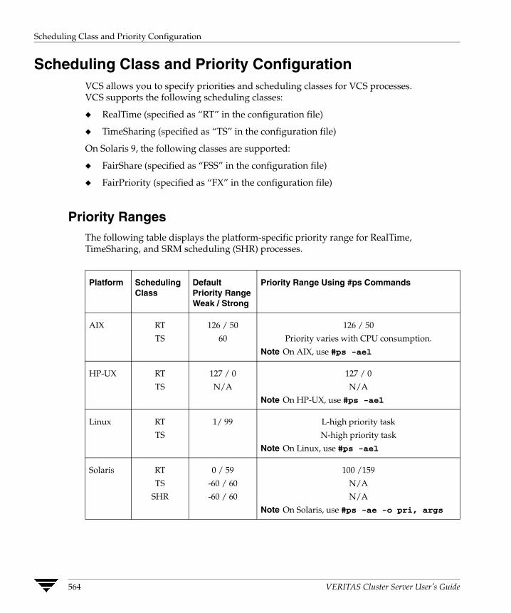
Scheduling Class and Priority Configuration
Scheduling Class and Priority Configuration VCS allows you to specify priorities and scheduling classes for VCS processes. VCS supports the following scheduling classes:
◆ RealTime (specified as “RT” in the configuration file)
◆ TimeSharing (specified as “TS” in the configuration file)
On Solaris 9, the following classes are supported:
◆ FairShare (specified as “FSS” in the configuration file)
◆ FairPriority (specified as “FX” in the configuration file)
Priority Ranges The following table displays the platform-specific priority range for RealTime, TimeSharing, and SRM scheduling (SHR) processes.
Platform Scheduling Class
Default Priority Range Weak / Strong
Priority Range Using #ps Commands
AIX RT
TS
126 / 50
60
126 / 50
Priority varies with CPU consumption.
Note On AIX, use #ps -ael
HP-UX RT
TS
127 / 0
N/A
127 / 0
N/A
Note On HP-UX, use #ps -ael
Linux RT
TS
1/ 99 L-high priority task
N-high priority task
Note On Linux, use #ps -ael
Solaris RT
TS
SHR
0 / 59
-60 / 60
-60 / 60
100 /159
N/A
N/A
Note On Solaris, use #ps -ae -o pri, args
564 VERITAS Cluster Server User’s Guide

Scheduling Class and Priority Configuration
Default Scheduling Classes and Priorities The following table lists the default class and priority values used by VCS. The class and priority of trigger processes are determined by the attributes ProcessClass (default = TS) and ProcessPriority (default = ""). Both attributes can be modified according to the class and priority at which the trigger processes run.
Process Default Scheduling
Class
Default Priority (AIX)
Default Priority (HP-UX)
Default Priority (Linux)
Default Priority (Solaris)
Engine RT 52 (Strongest + 2)
2 (Strongest + 2)
Min: 0
Max: 99
57 (Strongest - 2)
Process created by engine
TS 0 N/A 0 60 (Strongest)
Agent TS 0 N/A 0 0
Script TS 0 N/A 0 0
Note For standard configurations, VERITAS recommends using the default values for scheduling unless specific configuration requirements dictate otherwise.
Note that the default priority value is platform-specific. When priority is set to "" (empty string), VCS converts the priority to a value specific to the platform on which the system is running. For TS, the default priority equals the strongest priority supported by the TimeSharing class. For RT, the default priority equals two less than the strongest priority supported by the RealTime class. So, if the strongest priority supported by the RealTime class is 59, the default priority for the RT class is 57. For SHR (on Solaris only), the default priority is the strongest priority support by the SHR class.
Chapter 22, VCS Performance Considerations 565

CPU Binding of HAD
CPU Binding of HAD In certain situations, the operating system may assign a higher priority interrupt thread to the CPU on which HAD is running, thereby interrupting HAD. In this scenario, HAD will be interrupted and pinned to the same CPU and will not be able to function until the interrupt handler completes its operation.
To overcome this issue, VCS provides the option of running HAD on a specific processor and masks off all interrupts on that processor set. You can configure HAD to run on a specific processor by setting the CPUBinding attribute.
The attribute is specified in the following format:
CPUBinding = {BindTo = binding, CPUNumber = number}
The variable binding can take the following values:
◆ NONE indicates that CPU binding will not be used
◆ ANY indicates that HAD will bind to any available CPU
◆ CPUNUM indicates that HAD will bind to CPU specified in the CPUNumber attribute
The variable number specifies the number of the CPU.
566 VERITAS Cluster Server User’s Guide

Monitoring CPU Usage
Monitoring CPU Usage VCS includes a system attribute, CPUUsageMonitoring, which monitors CPU usage on a specific system and notifies the administrator when usage has been exceeded.
The default values for this attribute are: Enabled = 0, NotifyThreshold = 0, NotifyTimeLimit = 0, ActionThreshold = 0, ActionTimeLimit = 0, Action = NONE.
The values for ActionTimeLimit and NotifyTimeLimit represent the time in seconds. The values for ActionThreshold and NotifyThreshold represent the threshold in terms of CPU percentage utilization.
If Enabled is set to 1, HAD monitors the usage and updates CPUUsage attribute. If Enabled is set to 0 (default), HAD does not monitor the usage.
If the system’s CPU usage continuously exceeds the value set in NotifyThreshold for a duration greater than the value set in NotifyTimeLimit, HAD sends notification via an SNMP trap or SMTP message.
If the CPU usage continuously exceeds the value set in NotifyThreshold for a duration greater than the value set in NotifyTimeLimit, subsequent notifications are sent after five minutes to avoid sending notifications too frequently (if the NotifyTimeLimit value is set to a value less than five minutes). In this case, notification is sent after the first interval of NotifyTimeLimit. As CPU usage continues to exceed the threshold value, notifications are sent after five minutes. If the values of NotifyThreshold or NotifyTimeLimit are set to 0, no notification is sent.
If system’s CPU usage exceeds the value set in ActionThreshold continuously for a duration greater than the value set in ActionTimeLimit, the specified action is taken. If the CPU usage continuously exceeds the ActionThreshold for a duration greater than the value set in ActionTimeLimit, subsequent action is taken after five minutes to avoid taking action too frequently (if the ActionTimeLimit value is set to less than five minutes). In this case action is taken after the first interval of ActionTimeLimit. As CPU usage continues to exceed the threshold value, action is taken after five minutes. If the values of ActionThreshold or ActionTimeLimit are set to 0, no action is taken. Actions can have one of the following values:
NONE: No action will be taken and the message is logged in the VCS engine log.
REBOOT: System is rebooted.
CUSTOM: The cpuusage trigger is invoked.
Chapter 22, VCS Performance Considerations 567

VCS Agent Statistics
VCS Agent Statistics You can configure VCS to track the time taken for monitoring resources. You can use these statistics to configure the MonitorTimeout attribute. You can also detect potential problems with resources and systems on which resources are online by analyzing the trends in the time taken by the resource's monitor cycle. Note that VCS keeps track of monitor cycle times for online resources only.
VCS calculates the time taken for a monitor cycle to complete and computes an average of monitor times after a specific number of monitor cycles and stores the average in a resource-level attribute.
VCS also tracks increasing trends in the monitor cycle times and sends notifications about sudden and gradual increases in monitor times.
VCS uses the following parameters to compute the average monitor time and to detect increasing trends in monitor cycle times:
◆ Frequency: The number of monitor cycles after which the monitor time average is computed and sent to the VCS engine.
For example, if Frequency is set to 10, VCS computes the average monitor time after every 10 monitor cycles.
◆ ExpectedValue: The expected monitor time (in milliseconds) for a resource.
VCS sends a notification if the actual monitor time exceeds the expected monitor time by the ValueThreshold. So, if you set this attribute to 5000 for a FileOnOff resource, and if ValueThreshold is set to 40%, VCS will send a notification only when the monitor cycle for the FileOnOff resource exceeds the expected time by over 40%, that is 7000 milliseconds.
◆ ValueThreshold: The maximum permissible deviation (in percent) from the expected monitor time. When the time for a monitor cycle exceeds this limit, VCS sends a notification about the sudden increase or decrease in monitor time.
For example, a value of 100 means that VCS sends a notification if the actual monitor time deviates from the expected time by over 100%.
VCS sends these notifications conservatively. If 12 consecutive monitor cycles exceed the threshold limit, VCS sends a notification for the first spike, and then a collective notification for the next 10 consecutive spikes.
◆ AvgThreshold: The threshold value (in percent) for increase in the average monitor cycle time for a resource.
VCS maintains a running average of the time taken by the monitor cycles of a resource. The first such computed running average is used as a benchmark average. If the current running average for a resource differs from the benchmark average by more than this threshold value, VCS regards this as a sign of gradual increase or decrease in monitor cycle times and sends a notification about it for the resource.
568 VERITAS Cluster Server User’s Guide
VCS Agent Statistics
Whenever such an event occurs, VCS resets the internally maintained benchmark average to this new average. VCS sends notifications regardless of whether the deviation is an increase or decrease in the monitor cycle time.
For example, a value of 25 means that if the actual average monitor time is 25% more than the benchmark monitor time average, VCS sends a notification.
Tracking Monitor Cycle Times VCS marks sudden changes in monitor times by comparing the time taken for each monitor cycle with the ExpectedValue. If this difference exceeds the ValueThreshold, VCS sends a notification about the sudden change in monitor time. Note that VCS sends this notification only if monitor time increases.
VCS marks gradual changes in monitor times by comparing the benchmark average and the moving average of monitor cycle times. VCS computes the benchmark average after a certain number of monitor cycles and computes the moving average after every monitor cycle. If the current moving average exceeds the benchmark average by more than the AvgThreshold, VCS sends a notification about this gradual change in the monitor cycle time.
VCS Attributes Enabling Agent Statistics This section describes the attributes that enable VCS agent statistics.
MonitorStatsParam
MonitorStatsParam is a resource type-level attribute, which stores the required parameter values for calculating monitor time statistics.
static str MonitorStatsParam = { Frequency = 10, ExpectedValue= 3000, ValueThreshold = 100, AvgThreshold = 40 }
◆ Frequency: Defines the number of monitor cycles after which the average monitor cycle time should be computed and sent to the engine. If configured, the value for this attribute must be between 1 and 30. It is set to 0 by default.
◆ ExpectedValue: The expected monitor time in milliseconds for all resources of this type. Default=3000.
◆ ValueThreshold: The acceptable percentage difference between the expected monitor cycle time (ExpectedValue) and the actual monitor cycle time. Default=100.
◆ AvgThreshold: The acceptable percentage difference between the benchmark average and the moving average of monitor cycle times. Default=40.
Chapter 22, VCS Performance Considerations 569

VCS Agent Statistics
MonitorTimeStats
Stores the average time taken by a number of monitor cycles specified by the Frequency attribute along with a timestamp value of when the average was computed.
str MonitorTimeStats{} = { Avg = "0", TS = "" }
This attribute is updated periodically after a number of monitor cycles specified by the Frequency attribute. If Frequency is set to 10, the attribute stores the average of 10 monitor cycle times and is updated after every 10 monitor cycles.
The default value for this attribute is 0.
ComputeStats
A flag that specifies whether VCS keeps track of the monitor times for the resource.
bool ComputeStats = 0
The value 0 indicates that VCS will not keep track of the time taken by the monitor routine for the resource. The value 1 indicates that VCS keeps track of the monitor time for the resource.
The default value for this attribute is 0.
570 VERITAS Cluster Server User’s Guide
Troubleshooting and Recovery for VCS
23 This chapter explains VCS unified logging and defines the message format. This chapter also describes how to troubleshoot common problems in Cluster Manager and bundled agents.Logging VCS generates two error message logs: the engine log and the agent log. Log file names are appended by letters. Letter A indicates the first log file, B the second, C the third, and so on.
The engine log is located at /var/VRTSvcs/log/engine_A.log. The format of engine log messages is:
Timestamp (Year/MM/DD) | Mnemonic | Severity | UMI| Message Text
◆ Timestamp: the date and time the message was generated.
◆ Mnemonic: the string ID that represents the product (for example, VCS).
◆ Severity: levels include CRITICAL, ERROR, WARNING, NOTICE, and INFO (most to least severe, respectively).
◆ UMI: a unique message ID.
◆ Message Text: the actual message generated by VCS.
A typical engine log resembles:
2003/02/10 16:08:09 VCS INFO V-16-1-10077 received newcluster membership.
571
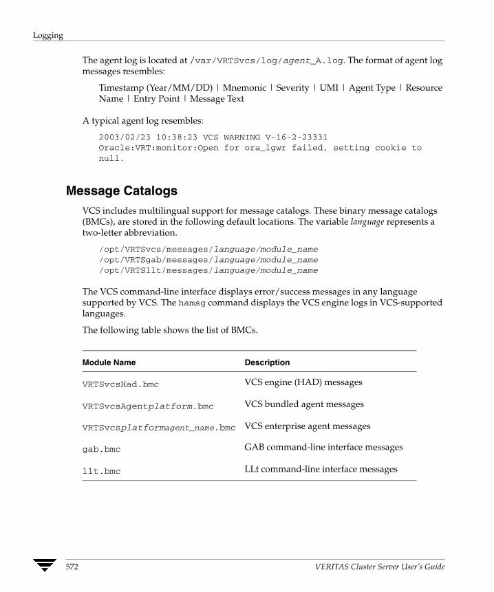
Logging
The agent log is located at /var/VRTSvcs/log/agent_A.log. The format of agent log messages resembles:
Timestamp (Year/MM/DD) | Mnemonic | Severity | UMI | Agent Type | Resource Name | Entry Point | Message Text
A typical agent log resembles:
2003/02/23 10:38:23 VCS WARNING V-16-2-23331 Oracle:VRT:monitor:Open for ora_lgwr failed, setting cookie tonull.
Message Catalogs VCS includes multilingual support for message catalogs. These binary message catalogs (BMCs), are stored in the following default locations. The variable language represents a two-letter abbreviation.
/opt/VRTSvcs/messages/language/module_name/opt/VRTSgab/messages/language/module_name/opt/VRTSllt/messages/language/module_name
The VCS command-line interface displays error/success messages in any language supported by VCS. The hamsg command displays the VCS engine logs in VCS-supported languages.
The following table shows the list of BMCs.
Module Name Description
VRTSvcsHad.bmc
VRTSvcsAgentplatform.bmc
VRTSvcsplatformagent_name.bmc
gab.bmc
llt.bmc
VCS engine (HAD) messages
VCS bundled agent messages
VCS enterprise agent messages
GAB command-line interface messages
LLt command-line interface messages
572 VERITAS Cluster Server User’s Guide
Logging
Preonline IP Check You can enable a preonline check of a failover IP address to protect against network partitioning. The check pings a service group’s configured IP address to verify it is not already in use. If it is, the service group is not brought online. A second check verifies the system is connected to its public and private networks. If the system receives no response from a broadcast ping to the public network and a check of the private networks, it determines the system is isolated and does not bring the service group online.
▼ To enable the preonline IP check
1. Move the preonline trigger script from the sample triggers directory into the triggers directory:
# cp /opt/VRTSvcs/bin/sample_triggers/preonline_ipc/opt/VRTSvcs/bin/triggers/preonline
2. Change the file permissions to make it executable.
Network Partitions and the UNIX Boot Monitor Most UNIX systems provide a console-abort sequence that enables you to halt and continue the processor. Continuing operations after the processor has stopped may corrupt data and is therefore unsupported by VCS. Specifically, when a system is halted with the abort sequence it stops producing heartbeats. The other systems in the cluster then consider the system failed and take over its services. If the system is later enabled with another console sequence, it continues writing to shared storage as before, even though its applications have been restarted on other systems where available.
If a write operation was pending when the console-abort sequence was processed, the write occurs when the processing sequence resumes. Halting a system by this method appears to all other nodes as a complete system fault because all heartbeats disappear simultaneously. Another node takes over services for the missing node. When the resume occurs, it takes several seconds before the return of a formerly missing heartbeat causes a system panic. During this time, the write waiting on the stopped node occurs, leading to data corruption.
VERITAS recommends rebooting the system if it was halted using the console-abort sequence.
Chapter 23, Troubleshooting and Recovery for VCS 573
Logging
HAD Diagnostics When the VCS engine HAD core dumps, the core is written to the directory /var/VRTSvcs/diag/had. When HAD starts, it renames this directory to had.timestamp, where timestamp represents the time at which the directory was renamed.
When HAD core dumps, review the contents of the /var/VRTSvcs/diag/had directory. See the following logs for more information:
◆ Operating system console log
◆ Engine log
◆ hashadow log
VCS runs the script /opt/VRTSvcs/bin/vcs_diag to collect diagnostic information when HAD and GAB encounter heartbeat problems. The diagnostic information is stored in the /var/VRTSvcs/diag/had directory.
574 VERITAS Cluster Server User’s Guide

Troubleshooting VCS Startup
Troubleshooting VCS Startup
This section includes error messages associated with starting VCS (shown in bold text), and provides descriptions of each error and the recommended action.
“VCS:10622 local configuration missing”
“VCS:10623 local configuration invalid”
“VCS:10624 local configuration stale”
The local configuration is invalid.
Recommended Action: Start the VCS engine, HAD, on another system that has a valid configuration file. The system with the configuration error “pulls” the valid configuration from the other system.
Another method is to correct the configuration file on the local system and force VCS to reread the configuration file. If the file appears valid, verify that is not an earlier version. It is possible that VCS marked the configuration stale by creating a .stale file because the last VCS shutdown was not graceful. The .stale file is created in the directory /etc/VRTSvcs/conf/config.
Type the following commands to verify the configuration and force VCS to reread the configuration file:
# cd /etc/VRTSvcs/conf/config# hacf -verify .# hasys -force system
“VCS:11032 registration failed. Exiting”
GAB was not registered or has become unregistered.
Recommended Action: GAB is registered by the gabconfig command in the file /etc/gabtab. Verify that the file exists and that it contains the command gabconfig -c.
GAB can become unregistered if LLT is set up incorrectly. Verify that the file is correct in /etc/llttab. If the LLT configuration is incorrect, make the appropriate changes and reboot.
“Waiting for cluster membership.”
This indicates that GAB may not be seeded. If this is the case, the command gabconfig -a does not show any members, and the following messages may appear on the console or in the event log.
GAB: Port a registration waiting for seed port membershipGAB: Port h registration waiting for seed port membership
Chapter 23, Troubleshooting and Recovery for VCS 575

Troubleshooting Service Groups
Troubleshooting Service Groups This section cites the most common problems associated with bringing service groups online and taking them offline. Bold text provides a description of the problem. Recommended action is also included, where applicable.
System is not in RUNNING state.
Recommended Action: Type hasys -display system to verify the system is running. See “System States” on page 624 for more information on system states.
Service group not configured to run on the system.
The SystemList attribute of the group may not contain the name of the system.
Recommended Action: Use the output of the command hagrp -display service_group to verify the system name.
Service group not configured to autostart.
If the service group is not starting automatically on the system, the group may not be configured to AutoStart, or may not be configured to AutoStart on that particular system.
Recommended Action: Use the output of the command hagrp -display service_group to verify the values of the AutoStart and AutoStartList attributes.
Service group is frozen.
Recommended Action: Use the output of the command hagrp -display service_group to verify the value of the Frozen and TFrozen attributes. Use the command hagrp -unfreeze to thaw the group. Note that VCS will not take a frozen service group offline.
Failover service group is online on another system.
The group is a failover group and is online or partially online on another system.
Recommended Action: Use the output of the command hagrp -display service_group to verify the value of the State attribute. Use the command hagrp -offline to offline the group on another system.
A critical resource faulted.
Output of the command hagrp -display service_group indicates that the service group has faulted.
Recommended Action: Use the command hares -clear to clear the fault.
576 VERITAS Cluster Server User’s Guide
Troubleshooting Service Groups
Service group autodisabled.
When VCS does not know the status of a service group on a particular system, it autodisables the service group on that system. Autodisabling occurs under the following conditions:
◆ When the VCS engine, HAD, is not running on the system.
◆ When all resources within the service group are not probed on the system.
◆ When a particular system is visible through disk heartbeat only.
Under these conditions, all service groups that include the system in their SystemList attribute are autodisabled. This does not apply to systems that are powered off.
Recommended Action: Use the output of the command hagrp -display service_group to verify the value of the AutoDisabled attribute.
Caution: To bring a group online manually after VCS has autodisabled the group, make sure that the group is not fully or partially active on any system that has the AutoDisabled attribute set to 1 by VCS. Specifically, verify that all resources that may be corrupted by being active on multiple systems are brought down on the designated systems. Then, clear the AutoDisabled attribute for each system:
# hagrp -autoenable service_group -sys system
Service group is waiting for the resource to be brought online/taken offline.
Recommended Action: Review the IState attribute of all resources in the service group to locate which resource is waiting to go online (or which is waiting to be taken offline). Use the hastatus command to help identify the resource. See the engine and agent logs in /var/VRTSvcs/log for information on why the resource is unable to be brought online or be taken offline.
To clear this state, make sure all resources waiting to go online/offline do not bring themselves online/offline. Use the command hagrp -flush to clear the internal state of VCS. You can now bring the service group online or take it offline on another system.
Service group is waiting for a dependency to be met.
Recommended Action: To see which dependencies have not been met, type hagrp -dep service_group to view service group dependencies, or hares -dep resource to view resource dependencies.
Chapter 23, Troubleshooting and Recovery for VCS 577
Troubleshooting Service Groups
Service group not fully probed.
This occurs if the agent processes have not monitored each resource in the service group. When the VCS engine, HAD, starts, it immediately “probes” to find the initial state of all of resources. (It cannot probe if the agent is not returning a value.) A service group must be probed on all systems included in the SystemList attribute before VCS attempts to bring the group online as part of AutoStart. This ensures that even if the service group was online prior to VCS being brought up, VCS will not inadvertently bring the service group online on another system.
Recommended Action: Use the output of hagrp -display service_group to see the value of the ProbesPending attribute for the system’s service group. (It should be zero.) To determine which resources are not probed, verify the local Probed attribute for each resource on the specified system. Zero means waiting for probe result, 1 means probed, and 2 means VCS not booted. See the engine and agent logs for information.
578 VERITAS Cluster Server User’s Guide
Troubleshooting Resources
Troubleshooting Resources This section cites the most common problems associated with bringing resources online and taking them offline. Bold text provides a description of the problem. Recommended action is also included, where applicable.
Service group brought online due to failover.
VCS attempts to bring resources online that were already online on the failed system, or were in the process of going online. Each parent resource must wait for its child resources to be brought online before starting.
Recommended Action: Verify that the child resources are online.
Waiting for service group states.
The state of the service group prevents VCS from bringing the resource online.
Recommended Action: See the appendix “Cluster and System States” for more information on states.
Waiting for child resources.
One or more child resources of parent resource are offline.
Recommended Action: Bring the child resources online first.
Waiting for parent resources.
One or more parent resources are online.
Recommended Action: Take the parent resources offline first.
Waiting for resource to respond.
The resource is waiting to come online or go offline, as indicated. VCS directed the agent to run an online entry point for the resource.
Recommended Action: Verify the resource’s IState attribute. See the engine and agent logs in /var/VRTSvcs/engine_A.log and /var/VRTSvcs/agent_A.log for information on why the resource cannot be brought online.
Agent not running.
The resource’s agent process is not running.
Recommended Action: Use hastatus -summary to see if the agent is listed as faulted. Restart the agent:
# haagent -start resource_type -sys system
Chapter 23, Troubleshooting and Recovery for VCS 579

Troubleshooting Resources
Invalid agent argument list.
The scripts are receiving incorrect arguments.
Recommended Action: Verify that the arguments to the scripts are correct. Use the output of hares -display resource to see the value of the ArgListValues attribute. If the ArgList attribute was dynamically changed, stop the agent and restart it.
To stop the agent:
# haagent -stop resource_type -sys system
To restart the agent:
# haagent -start resource_type -sys system
The Monitor entry point of the disk group agent returns ONLINE even if the disk group is disabled.
This is expected agent behavior. VCS assumes that data is being read from or written to the volumes and does not declare the resource as offline. This prevents potential data corruption that could be caused by the disk group being imported on two hosts.
You can deport a disabled disk group when all I/O operations are completed or when all volumes are closed. You can then reimport the disk group to the same system. Reimporting a disabled disk group may require a system reboot.
Note A disk group is disabled if data including the kernel log, configuration copies, or headers in the private region of a significant number of disks is invalid. Volumes can perform read-write operations if no changes are required to the private regions of the disks.
580 VERITAS Cluster Server User’s Guide
Troubleshooting Notification
Troubleshooting Notification Occasionally you may encounter problems when using VCS notification. This section cites the most common problems and the recommended actions. Bold text provides a description of the problem.
Notifier is configured but traps are not seen on SNMP console.
Recommended Action: Verify the version of SNMP traps supported by the console: VCS notifier sends SNMP v2.0 traps. If you are using HP OpenView Network Node Manager as the SNMP, verify events for VCS are configured using xnmevents. You may also try restarting the OpenView daemon (ovw) if, after merging VCS events in vcs_trapd, the events are not listed in the OpenView Network Node Manager Event configuration.
By default, notifier assumes the community string is public. If your SNMP console was configured with a different community, reconfigure it according to the notifier configuration. See the VERITAS Cluster Server Bundled Agents Reference Guide for more information on NotifierMngr.
Chapter 23, Troubleshooting and Recovery for VCS 581

Troubleshooting Cluster Manager (Web Console)
Troubleshooting Cluster Manager (Web Console) Occasionally you may encounter problems when using Cluster Manager (Web Console). This section cites the most common problems and the recommended actions. Bold text provides a description of the problem, and in some cases actual error messages.
Unable to log on.
Recommended Action: Verify the user name exists and that the password is correct for the user name. Then verify your browser is Java, Javascript, and cookies enabled.
Unable to view Cluster Manager on a browser using the Virtual IP/port number in URL (http://[virtual_ip:port_number]/vcs).
Recommended Action: Verify that the ClusterService service group, which has the IP and VRTSWebApp resources configured on it, is not offline or faulted on any node. If it is, use the command line to bring the group back online on at least one node.
Unable to view Cluster Manager on a browser using the HostName/port_number in URL (http://[host_name:port_number]/vcs.
Recommended Action: Verify that the host is running and that the ClusterService group is online on the host. If the host is down, access Cluster Manager (Web Console) using the URL http://virtual_IP:port_number/vcs. The cause of the failover should be apparent on Cluster Manager. Use Cluster Manager to administer nodes that are up and running in cluster.
Unable to bring the VCSweb resource online in the ClusterService group.
You cannot access the Web Console unless the VCSweb resource in the ClusterService group is online. The Web Console runs inside the VERITAS Web server (VRTSweb). VCSweb may fail to come online if the Web server cannot start because of one of the following reasons:
✔ Unsupported OS version or missing OS patches related to Java Runtime Environment 1.4 (JRE): VRTSweb uses JRE 1.4, which requires the installation of several Solaris patches to function properly. JRE 1.4 works on Solaris 2.7 or later versions. You can find information about these patches and instructions for downloading them at http://java.sun.com/j2se/1.4/download.html.
Recommended Action: Apply the patches (only for Solaris 2.7 and later versions) and try to bring the VCSweb resource online again.
582 VERITAS Cluster Server User’s Guide

Troubleshooting Cluster Manager (Web Console)
✔ Web server port unavailable: By default, the Web server binds itself to ports 8181, 8443, and 14300. If these ports are being used by another application, the Web server will fail to start.
To determine if this is the reason, review the last few lines of the log file /var/VRTSweb/log/_start0.0.log. If the output resembles the example below, the Web server port is already taken by another application:
5/28/03 8:13:35 PM PDT VRTSWEB INFO V-12-1-1041 Exception encountered
LifecycleException: Protocol handler initialization failed:java.net.BindException: Address already in use: JVM_Bind:8181
at org.apache.coyote.tomcat4.CoyoteConnector.initialize(CoyoteConnector.java:1119)
at org.apache.catalina.startup.Embedded.start(Embedded.java:999)at vrts.tomcat.server.VRTSweb.initServer(VRTSweb.java:2567)at vrts.tomcat.server.VRTSweb.commandStartServer(VRTSweb.java:385)
at vrts.tomcat.server.command.start.StartCommand.execute(StartCommand.java:59)
at sun.reflect.NativeMethodAccessorImpl.invoke0(Native Method)at sun.reflect.NativeMethodAccessorImpl.invoke(NativeMethodAccessorImpl.java:39)
at sun.reflect.DelegatingMethodAccessorImpl.invoke(DelegatingMethodAccessorImpl.java:25)
at java.lang.reflect.Method.invoke(Method.java:324)at vrts.tomcat.bootstrap.Main.main(Main.java:243)
Recommended Action: If you cannot make this port available for VRTSweb, see “Configuring Ports for VRTSweb” on page 672 for instructions on how to change the value of the Web server port.
Chapter 23, Troubleshooting and Recovery for VCS 583
Troubleshooting Cluster Manager (Web Console)
✔ Web server IP address unavailable: By default, the Web server binds itself to all IP addresses on the machine for the default ports 8181 and 8443. If you configure a specific IP address for the port, verify this IP address is available on the machine before the Web server starts. The Web server will fail to start if this IP address is not present on the machine.
To determine if this is the reason, review the last few lines of the two log files /var/VRTSweb/log/_start0.0.log and /var/VRTSweb/log/_command0.0.log. If the output resembles the example below, the IP address is not available:
5/28/03 8:20:16 PM PDT VRTSWEB INFO V-12-1-1041 Exception encountered
LifecycleException: Protocol handler initialization failed:java.net.BindException: Cannot assign requested address: JVM_Bind:8181
at org.apache.coyote.tomcat4.CoyoteConnector.initialize(CoyoteConnector.java:1119)
at org.apache.catalina.startup.Embedded.start(Embedded.java:999)at vrts.tomcat.server.VRTSweb.initServer(VRTSweb.java:2567)at vrts.tomcat.server.VRTSweb.commandStartServer(VRTSweb.java:385)
at vrts.tomcat.server.command.start.StartCommand.execute(StartCommand.java:59)
at sun.reflect.NativeMethodAccessorImpl.invoke0(Native Method)at sun.reflect.NativeMethodAccessorImpl.invoke(NativeMethodAccessorImpl.java:39)
at sun.reflect.DelegatingMethodAccessorImpl.invoke(DelegatingMethodAccessorImpl.java:25)
at java.lang.reflect.Method.invoke(Method.java:324)at vrts.tomcat.bootstrap.Main.main(Main.java:243)LifecycleException: Protocol handler initialization failed:java.net.BindException: Cannot assign requested address: JVM_Bind:8181
at org.apache.coyote.tomcat4.CoyoteConnector.initialize(CoyoteConnector.java:1119)
at org.apache.catalina.startup.Embedded.start(Embedded.java:999)at vrts.tomcat.server.VRTSweb.initServer(VRTSweb.java:2567)at vrts.tomcat.server.VRTSweb.commandStartServer(VRTSweb.java:385)
at vrts.tomcat.server.command.start.StartCommand.execute(StartCommand.java:59)
at sun.reflect.NativeMethodAccessorImpl.invoke0(Native Method)at sun.reflect.NativeMethodAccessorImpl.invoke(NativeMethodAccessorImpl.java:39)at sun.reflect.DelegatingMethodAccessorImpl.invoke
584 VERITAS Cluster Server User’s Guide
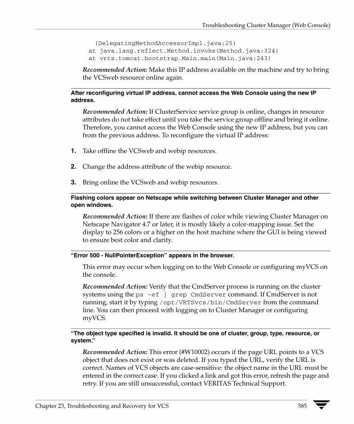
Troubleshooting Cluster Manager (Web Console)
(DelegatingMethodAccessorImpl.java:25)at java.lang.reflect.Method.invoke(Method.java:324)at vrts.tomcat.bootstrap.Main.main(Main.java:243)
Recommended Action: Make this IP address available on the machine and try to bring the VCSweb resource online again.
After reconfiguring virtual IP address, cannot access the Web Console using the new IP address.
Recommended Action: If ClusterService service group is online, changes in resource attributes do not take effect until you take the service group offline and bring it online. Therefore, you cannot access the Web Console using the new IP address, but you can from the previous address. To reconfigure the virtual IP address:
1. Take offline the VCSweb and webip resources.
2. Change the address attribute of the webip resource.
3. Bring online the VCSweb and webip resources.
Flashing colors appear on Netscape while switching between Cluster Manager and other open windows.
Recommended Action: If there are flashes of color while viewing Cluster Manager on Netscape Navigator 4.7 or later, it is mostly likely a color-mapping issue. Set the display to 256 colors or a higher on the host machine where the GUI is being viewed to ensure best color and clarity.
“Error 500 - NullPointerException” appears in the browser.
This error may occur when logging on to the Web Console or configuring myVCS on the console.
Recommended Action: Verify that the CmdServer process is running on the cluster systems using the ps -ef | grep CmdServer command. If CmdServer is not running, start it by typing /opt/VRTSvcs/bin/CmdServer from the command line. You can then proceed with logging on to Cluster Manager or configuring myVCS.
“The object type specified is invalid. It should be one of cluster, group, type, resource, or system.”
Recommended Action: This error (#W10002) occurs if the page URL points to a VCS object that does not exist or was deleted. If you typed the URL, verify the URL is correct. Names of VCS objects are case-sensitive: the object name in the URL must be entered in the correct case. If you clicked a link and got this error, refresh the page and retry. If you are still unsuccessful, contact VERITAS Technical Support.
Chapter 23, Troubleshooting and Recovery for VCS 585

Troubleshooting Cluster Manager (Web Console)
“The specified group does not exist or has been deleted.”
Recommended Action: This error (#W10003) indicates the service group whose information you tried to access does not exist, or was deleted. If you typed the URL, verify the URL is correct. If you clicked a link to get information about the service group, verify the service group exists. Refresh the display to get current information.
“The specified system does not exist or has been deleted.”
Recommended Action: This error (#W10004) indicates the system whose information you tried to access does not exist, or was deleted. If you typed the URL, verify the URL is correct. If you clicked a link to get information about the system, verify the system exists. Refresh the display to get current information.
“The specified resource type does not exist or has been deleted.”
Recommended Action: This error (#W10005) indicates the resource type whose information you tried to access does not exist, or was deleted. If you typed the URL, verify the URL is correct. If you clicked a link to get information about the resource type, verify the resource type exists. Refresh the display to get current information.
“The specified resource does not exist or has been deleted.”
Recommended Action: This error (#W10007) indicates the resource whose information you tried to access does not exist, or was deleted. If you typed the URL, verify the URL is correct. If you clicked a link to get information about the resource type, verify the resource exists. Refresh the display to get current information.
“Retrieving data from the VCS engine. Please try after some time.”
Recommended Action: This error (#R10001) indicates a “snapshot” of the VCS engine, HAD, is being taken. Wait a few moments then retry the operation.
“Could not log on to the VCS engine.”
Recommended Action: This error (#R10002) indicates Cluster Manger (Web Console) could not connect to the VCS engine. Wait a few moments then retry the operation.
“Cannot monitor VCS QuickStart.”
Recommended Action: This error ( R10005) indicates you tried to connect to a cluster configured by VCS QuickStart. Cluster Manager (Web Console) cannot connect to VCS QuickStart. Use the VCS QuickStart Web graphical user interface instead.
“The user could not be authenticated at this time. This could be because a snapshot of the VCS Server is being taken currently.”
Recommended Action: This error (#H10001) indicates a snapshot of the VCS engine is being taken. Wait a few moments then retry the operation.
586 VERITAS Cluster Server User’s Guide

Troubleshooting VCS Configuration Backup and Restore
“The URL you specified can be accessed only if you are logged on.”
Recommended Action: This error (#G10001) indicates you tried to access a page that requires authentication. Log on to VCS and retry the operation.
Troubleshooting VCS Configuration Backup and Restore This section cites the problem you may encounter when using the hasnap command to backup and restore VCS configuration files.
Error connecting to remote nodes in the cluster.
The hasnap command is a distributed command in the sense that it tries to backup and restore files from all cluster nodes in a single session. It needs to establish connection with all cluster nodes from the node where the command is executed. The connection may fail for one of the following reasons:
◆ The hasnap command retrieves the list of cluster nodes from the llthosts configuration file. However, the node names in this file may not always be DNS resolvable, in which case the command cannot establish connection with the remote nodes.
Recommended Action:. For each node in the cluster, map the VCS node names to the actual DNS-resolvable names using the hasnap configuration file /opt/VRTSvcs/cutil/conf/vcsmappings.properties.
◆ The hasnap command uses the VCS Command Server Daemon running on the remote nodes to establish connection. The connection fails if the Daemon is not running on the remote node.
Recommended Action: Verify the VCS Command Server Daemon is running on all cluster nodes. Start it by running the following command:
# /opt/VRTSvcs/bin/CmdServer
◆ The remote node might be currently down or unreachable.
Recommended Action: Run the hasnap command again after the bringing the remote node online.
Chapter 23, Troubleshooting and Recovery for VCS 587
Troubleshooting and Recovery for Global Clusters
Troubleshooting and Recovery for Global Clusters This section describes the concept of disaster declaration and provides troubleshooting tips for configurations using global clusters.
Disaster Declaration When a cluster in a global cluster transitions to the FAULTED state because it can no longer be contacted, failover executions depend on whether the cause was due to a split-brain, temporary outage, or a permanent disaster at the remote cluster.
If you choose to take action on the failure of a cluster in a global cluster, VCS prompts you to declare the type of failure.
◆ Disaster, implying permanent loss of the primary data center
◆ Outage, implying the primary may return to its current form in some time
◆ Disconnect, implying a split-brain condition; both clusters are up, but the link between them is broken
◆ Replica, implying that data on the takeover target has been made consistent from a backup source and that the RVGPrimary can initiate a takeover when the service group is brought online. This option applies to VVR environments only.
You can select the groups to be failed over to the local cluster, in which case VCS brings the selected groups online on a node based on the group’s FailOverPolicy attribute. It also marks the groups as being offline in the other cluster. If you do not select any service groups to fail over, VCS takes no action except implicitly marking the service groups as offline on the downed cluster.
Lost Heartbeats and the Inquiry Mechanism The loss of internal and all external heartbeats between any two clusters indicates that the remote cluster is faulted, or that all communication links between the two clusters are broken (a wide-area split-brain).
VCS queries clusters to confirm the remote cluster to which heartbeats have been lost is truly down. This mechanism is referred to as inquiry. If in a two-cluster configuration a connector loses all heartbeats to the other connector, it must consider the remote cluster faulted. If there are more than two clusters and a connector loses all heartbeats to a second cluster, it queries the remaining connectors before declaring the cluster faulted. If the other connectors view the cluster as running, the querying connector transitions the cluster to the UNKNOWN state, a process that minimizes false cluster faults. If all connectors report that the cluster is faulted, the querying connector also considers it faulted and transitions the remote cluster state to FAULTED.
588 VERITAS Cluster Server User’s Guide
Troubleshooting and Recovery for Global Clusters
VCS Alerts VCS alerts are identified by the alert ID, which is comprised of the following elements:
◆ alert_type—The type of the alert, described in “Types of Alerts.”
◆ cluster—The cluster on which the alert was generated
◆ system—The system on which this alert was generated
◆ object—The name of the VCS object for which this alert was generated. This could be a cluster or a service group.
Alerts are generated in the following format:
alert_type-cluster-system-object
For example:
GNOFAILA-Cluster1-oracle_grp
This is an alert of type GNOFAILA generated on cluster Cluster1 for the service group oracle_grp.
Types of Alerts
VCS generates the following types of alerts.
◆ CFAULT—Indicates that a cluster has faulted
◆ GNOFAILA—Indicates that a global group is unable to fail over within the cluster where it was online. This alert is displayed if the ClusterFailOverPolicy attribute is set to Manual and the wide-area connector (wac) is properly configured and running at the time of the fault.
◆ GNOFAIL—Indicates that a global group is unable to fail over to any system within the cluster or in a remote cluster.
Some reasons why a global group may not be able to fail over to a remote cluster:
◆ The ClusterFailOverPolicy is set to either Auto or Connected and VCS is unable to determine a valid remote cluster to which to automatically fail the group over.
◆ The ClusterFailOverPolicy attribute is set to Connected and the cluster in which the group has faulted cannot communicate with one ore more remote clusters in the group's ClusterList.
◆ The wide-area connector (wac) is not online or is incorrectly configured in the cluster in which the group has faulted
Chapter 23, Troubleshooting and Recovery for VCS 589
Troubleshooting and Recovery for Global Clusters
Managing Alerts
Alerts require user intervention. You can respond to an alert in the following ways:
◆ If the reason for the alert can be ignored, use the Alerts dialog box in the Java or Web consoles or the haalert command to delete the alert. You must provide a comment as to why you are deleting the alert; VCS logs the comment to engine log.
◆ Take an action on administrative alerts that have actions associated with them.You can do so using the Java or Web consoles. See “Actions Associated with Alerts” for more information.
◆ VCS deletes or negates some alerts when a negating event for the alert occurs. See “Negating Events” for more information.
An administrative alert will continue to live if none of the above actions are performed and the VCS engine (HAD) is running on at least one node in the cluster. If HAD is not running on any node in the cluster, the administrative alert is lost.
Actions Associated with Alerts
This section describes the actions you can perform from the Java and the Web consoles on the following types of alerts:
◆ CFAULT—When the alert is presented, clicking Take Action guides you through the process of failing over the global groups that were online in the cluster before the cluster faulted.
◆ GNOFAILA—When the alert is presented, clicking Take Action guides you through the process of failing over the global group to a remote cluster on which the group is configured to run.
◆ GNOFAIL—There are no associated actions provided by the consoles for this alert
Negating Events
VCS deletes a CFAULT alert when the faulted cluster goes back to the running state
VCS deletes the GNOFAILA and GNOFAIL alerts in response to the following events:
◆ The faulted group's state changes from FAULTED to ONLINE.
◆ The group's fault is cleared.
◆ The group is deleted from the cluster where alert was generated.
590 VERITAS Cluster Server User’s Guide

Troubleshooting Licensing
Troubleshooting Licensing This section cites problems you may encounter with VCS licensing. It provides instructions on how to validate license keys and lists the error messages associated with licensing.
Validating License Keys The installvcs script handles most license key validations. However, if you install a VCS key outside of installvcs (using vxlicinst, for example), you can validate the key using the procedure described below.
1. The vxlicinst command handles some of the basic validations:
node lock: Ensures that you are installing a node-locked key on the correct system
demo hard end date: Ensures that you are not installing an expired demo key
2. Run the vxlicrep command to make sure a VCS key is installed on the system. The output of the command resembles:
VERITAS License Manager vxlicrep utility version 3.02.003Copyright (C) VERITAS Software Corp 2002. All Rights reserved.
Creating a report on all VERITAS products installed on this system
License Key Product Name License Type OEM ID
Features :=Platform Version TierReserved
Mode
= XXXX-XXXX-XXXX-XXXX-XXXX-XXXX= VERITAS Cluster Server= PERMANENT= 4095
= Solaris= 4.1= Unused= 0
= VCSGlobal Cluster Option= Enabled
3. Look for the following in the command output:
Make sure the Product Name lists the name of your purchased component, for example, VERITAS Cluster Server. If the command output does not return the product name, you do not have a VCS key installed.
Chapter 23, Troubleshooting and Recovery for VCS 591

Troubleshooting Licensing
If the output shows the License Type for a VCS key as DEMO, ensure that the Demo End Date does not display a past date.
Make sure the Mode attribute displays the correct value.
If you have purchased a license key for the Global Cluster Option, make sure its status is Enabled.
4. Start VCS. If HAD rejects a license key, see the licensing error message at the end of the engine_A log file.
Licensing Error Messages This section lists the error messages associated with licensing. These messages are logged to the file /var/VRTSvcs/log/engine_A.log.
[Licensing] Insufficient memory to perform operation
The system does not have adequate resources to perform licensing operations.
[Licensing] No valid VCS license keys were found
No valid VCS keys were found on the system.
[Licensing] Unable to find a valid base VCS license key
No valid base VCS key was found on the system.
[Licensing] License key can not be used on this OS platform
This message indicates that the license key was meant for a different platform. For example, a license key meant for Windows is used on a Solaris platform.
[Licensing] VCS evaluation period has expired
The VCS base demo key has expired
[Licensing] License key can not be used on this system
Indicates that you have installed a key that was meant for a different system (i.e. node-locked keys)
[Licensing] Unable to initialize the licensing framework
This is a VCS internal message. Call VERITAS Technical Support.
[Licensing] QuickStart is not supported in this release
VCS QuickStart is not supported in this version of VCS .
592 VERITAS Cluster Server User’s Guide
Troubleshooting Licensing
[Licensing] Your evaluation period for the %s feature has expired. This feature will not be enabled the next time VCS starts
The evaluation period for the specified VCS feature has expired.
Chapter 23, Troubleshooting and Recovery for VCS 593

Troubleshooting Licensing
594 VERITAS Cluster Server User’s Guide
Section VII. Appendixes
This section provides various appendixes containing useful, supplemental information.
Section VIII includes the following appendixes:
◆ Appendix A. “VCS User Privileges—Administration Matrices” on page 597
◆ Appendix B. “Configuring VCS in Zones” on page 609
◆ Appendix C. “Cluster and System States” on page 621
◆ Appendix D. “VCS Attributes” on page 627
◆ Appendix E. “Administering VERITAS Web Server” on page 669
◆ Appendix F. “Accessibility and VCS” on page 691


VCS User Privileges—Administration Matrices
AThis appendix lists the privileges required to run VCS commands. In general, users with Cluster Guest privileges can execute the command options -display, -state, and -value. Users with privileges for Group Operator and Cluster Operator can execute the options -online, -offline, and -switch. Users with Group Administrator and Cluster Administrator privileges can execute the options -add, -delete, and -modify. For more information about the VCS user privilege model, see “VCS User Privileges” on page 51.
Administration Matrices Review the matrices in the following section to determine which command options can be executed within a specific user category. Checkmarks denote the command and option can be executed. A dash indicates they cannot.
haagent
haagent Guest Group Group Cluster Cluster Options Operator Admin. Operator Admin.
-start – – – ✔ ✔
-stop – – – ✔ ✔
-display ✔ ✔ ✔ ✔ ✔
-list ✔ ✔ ✔ ✔ ✔
-value ✔ ✔ ✔ ✔ ✔
597

Administration Matrices
haattr
haattr Guest Group Group Cluster Cluster Options Operator Admin. Operator Admin.
-add
-add -static
-add -temp
-default
-delete -static
-display
– – – – ✔
– – – – ✔
– – – – ✔
– – – – ✔
– – – – ✔
✔ ✔ ✔ ✔ ✔
hacli Do not use hacli to invoke a command on a remote system that requires user input. The process can hang and consume resources.
hacli Options Guest Group Group Cluster Cluster Operator Admin. Operator Admin.
-cmd – – – – –
-help ✔ ✔ ✔ ✔ ✔
598 VERITAS Cluster Server User’s Guide
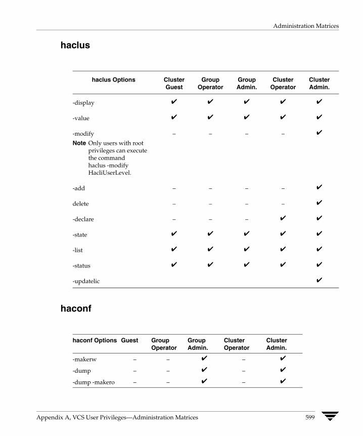
Administration Matrices
haclus
haclus Options Cluster Group Group Cluster Cluster Guest Operator Admin. Operator Admin.
-display ✔ ✔ ✔ ✔ ✔
-value ✔ ✔ ✔ ✔ ✔
-modify – – – – ✔
Note Only users with root privileges can execute the command haclus -modify HacliUserLevel.
-add – – – – ✔
delete – – – – ✔
-declare – – – ✔ ✔
-state ✔ ✔ ✔ ✔ ✔
-list ✔ ✔ ✔ ✔ ✔
-status ✔ ✔ ✔ ✔ ✔
-updatelic ✔
haconf
haconf Options Guest Group Group Cluster Cluster Operator Admin. Operator Admin.
-makerw – – ✔ – ✔
-dump – – ✔ – ✔
-dump -makero – – ✔ – ✔
Appendix A, VCS User Privileges—Administration Matrices 599
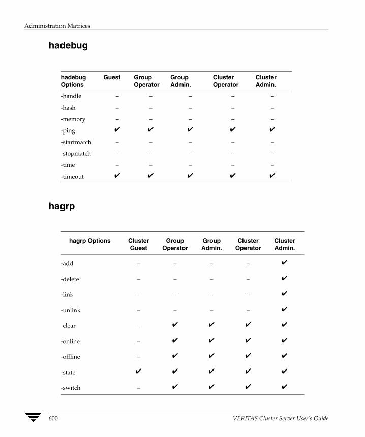
Administration Matrices
hadebug
hadebug Guest Group Group Cluster Cluster Options Operator Admin. Operator Admin.
-handle
-hash
-memory
-ping
-startmatch
-stopmatch
-time
-timeout
– – – – –
– – – – –
– – – – –
✔ ✔ ✔ ✔ ✔
– – – – –
– – – – –
– – – – –
✔ ✔ ✔ ✔ ✔
hagrp
hagrp Options Cluster Group Group Cluster Cluster Guest Operator Admin. Operator Admin.
-add – – – – ✔
-delete – – – – ✔
-link – – – – ✔
-unlink – – – – ✔
-clear – ✔ ✔ ✔ ✔
-online – ✔ ✔ ✔ ✔
-offline – ✔ ✔ ✔ ✔
-state ✔ ✔ ✔ ✔ ✔
-switch – ✔ ✔ ✔ ✔
600 VERITAS Cluster Server User’s Guide
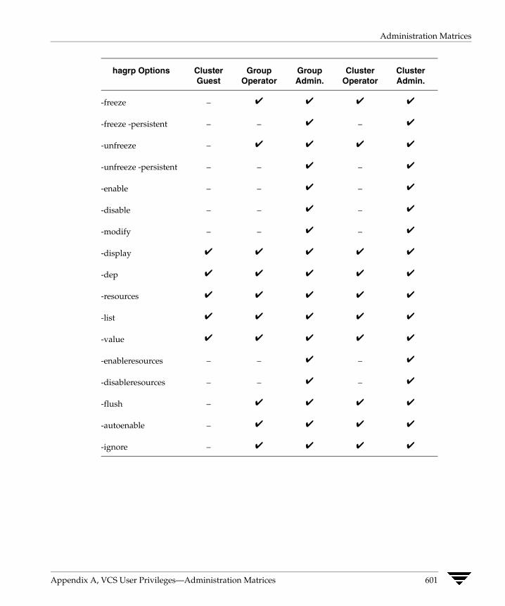
Administration Matrices
hagrp Options Cluster Group Group Cluster Cluster Guest Operator Admin. Operator Admin.
-freeze
-freeze -persistent
-unfreeze
-unfreeze -persistent
-enable
-disable
-modify
-display
-dep
-resources
-list
-value
-enableresources
-disableresources
-flush
-autoenable
-ignore
– ✔ ✔ ✔ ✔
– – ✔ – ✔
– ✔ ✔ ✔ ✔
– – ✔ – ✔
– – ✔ – ✔
– – ✔ – ✔
– – ✔ – ✔
✔ ✔ ✔ ✔ ✔
✔ ✔ ✔ ✔ ✔
✔ ✔ ✔ ✔ ✔
✔ ✔ ✔ ✔ ✔
✔ ✔ ✔ ✔ ✔
– – ✔ – ✔
– – ✔ – ✔
– ✔ ✔ ✔ ✔
– ✔ ✔ ✔ ✔
– ✔ ✔ ✔ ✔
Appendix A, VCS User Privileges—Administration Matrices 601

Administration Matrices
hahb
hahb Options Guest Group Group Cluster Cluster Operator Admin. Operator Admin.
-add – – – – ✔
-delete – – – – ✔
-local – – – – ✔
-global – – – – ✔
-display ✔ ✔ ✔ ✔ ✔
-state ✔ ✔ ✔ ✔ ✔
-list ✔ ✔ ✔ ✔ ✔
-value ✔ ✔ ✔ ✔ ✔
-help ✔ ✔ ✔ ✔ ✔
halog
halog Options Guest Group Group Cluster Cluster Operator Admin. Operator Admin.
-addtags – – – – ✔
-deltags – – – – ✔
-add – – – – ✔
-cache ✔ ✔ ✔ ✔ ✔
info ✔ ✔ ✔ ✔ ✔
602 VERITAS Cluster Server User’s Guide
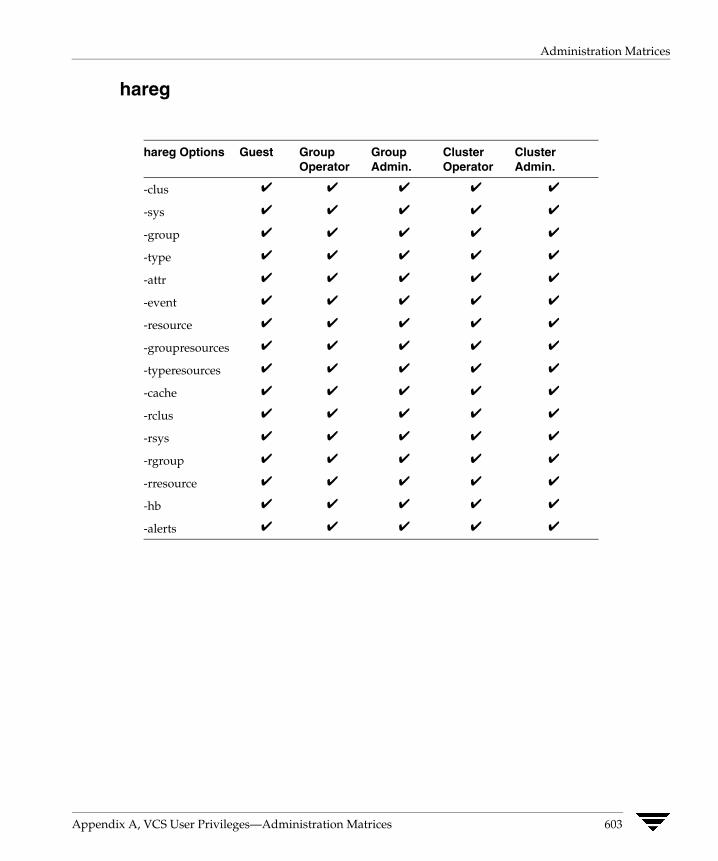
Administration Matrices
hareg
hareg Options Guest Group Group Cluster Cluster Operator Admin. Operator Admin.
-clus
-sys
-group
-type
-attr
-event
-resource
-groupresources
-typeresources
-cache
-rclus
-rsys
-rgroup
-rresource
-hb
-alerts
✔ ✔ ✔ ✔ ✔
✔ ✔ ✔ ✔ ✔
✔ ✔ ✔ ✔ ✔
✔ ✔ ✔ ✔ ✔
✔ ✔ ✔ ✔ ✔
✔ ✔ ✔ ✔ ✔
✔ ✔ ✔ ✔ ✔
✔ ✔ ✔ ✔ ✔
✔ ✔ ✔ ✔ ✔
✔ ✔ ✔ ✔ ✔
✔ ✔ ✔ ✔ ✔
✔ ✔ ✔ ✔ ✔
✔ ✔ ✔ ✔ ✔
✔ ✔ ✔ ✔ ✔
✔ ✔ ✔ ✔ ✔
✔ ✔ ✔ ✔ ✔
Appendix A, VCS User Privileges—Administration Matrices 603
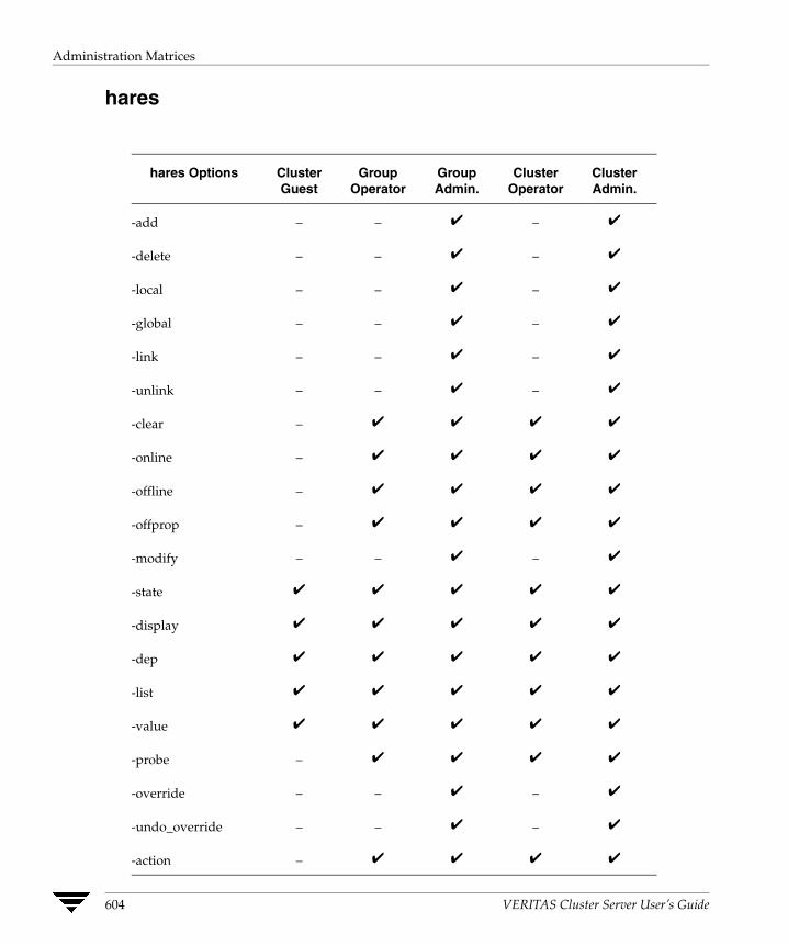
Administration Matrices
hares
hares Options Cluster Group Group Cluster Cluster Guest Operator Admin. Operator Admin.
-add
-delete
-local
-global
-link
-unlink
-clear
-online
-offline
-offprop
-modify
-state
-display
-dep
-list
-value
-probe
-override
-undo_override
-action
– – ✔ – ✔
– – ✔ – ✔
– – ✔ – ✔
– – ✔ – ✔
– – ✔ – ✔
– – ✔ – ✔
– ✔ ✔ ✔ ✔
– ✔ ✔ ✔ ✔
– ✔ ✔ ✔ ✔
– ✔ ✔ ✔ ✔
– – ✔ – ✔
✔ ✔ ✔ ✔ ✔
✔ ✔ ✔ ✔ ✔
✔ ✔ ✔ ✔ ✔
✔ ✔ ✔ ✔ ✔
✔ ✔ ✔ ✔ ✔
– ✔ ✔ ✔ ✔
– – ✔ – ✔
– – ✔ – ✔
– ✔ ✔ ✔ ✔
604 VERITAS Cluster Server User’s Guide

Administration Matrices
hares Options Cluster Group Group Cluster Cluster Guest Operator Admin. Operator Admin.
-refreshinfo – ✔ ✔ ✔ ✔
-flushinfo – ✔ ✔ ✔ ✔
hastatus
hastatus Cluster Group Group Cluster Cluster Options Guest Operator Admin. Operator Admin.
-sound ✔ ✔ ✔ ✔ ✔
-summary ✔ ✔ ✔ ✔ ✔
-sound -group ✔ ✔ ✔ ✔ ✔
Appendix A, VCS User Privileges—Administration Matrices 605
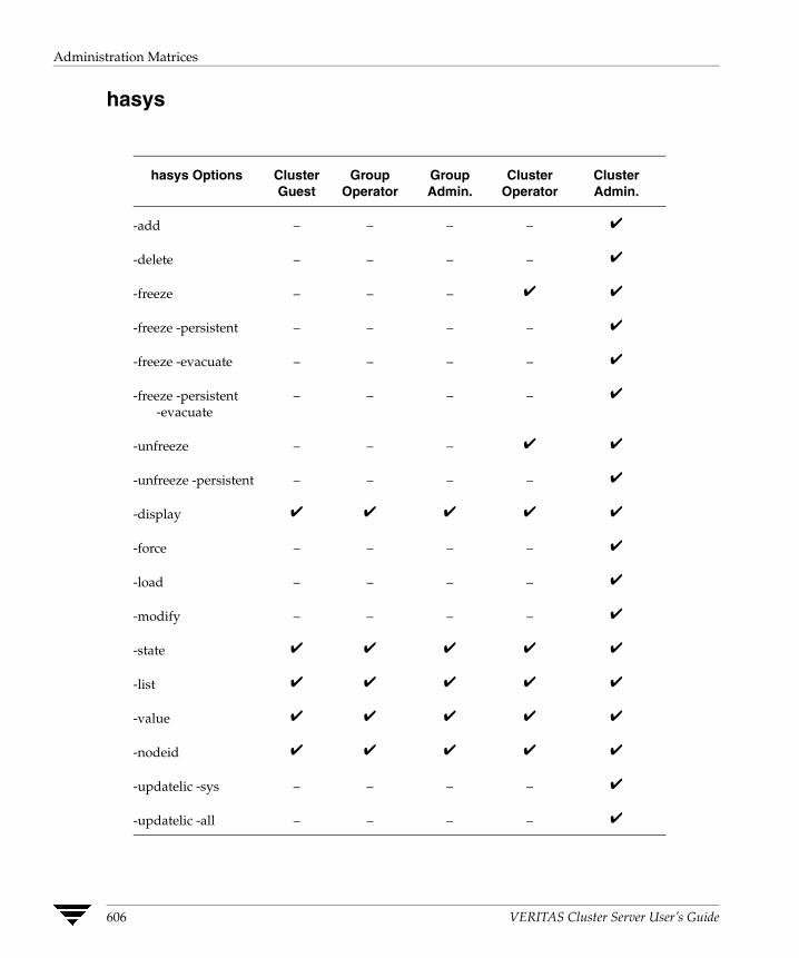
Administration Matrices
hasys
hasys Options Cluster Group Group Cluster Cluster Guest Operator Admin. Operator Admin.
-add
-delete
-freeze
-freeze -persistent
-freeze -evacuate
-freeze -persistent -evacuate
-unfreeze
-unfreeze -persistent
-display
-force
-load
-modify
-state
-list
-value
-nodeid
-updatelic -sys
-updatelic -all
– – – – ✔
– – – – ✔
– – – ✔ ✔
– – – – ✔
– – – – ✔
– – – – ✔
– – – ✔ ✔
– – – – ✔
✔ ✔ ✔ ✔ ✔
– – – – ✔
– – – – ✔
– – – – ✔
✔ ✔ ✔ ✔ ✔
✔ ✔ ✔ ✔ ✔
✔ ✔ ✔ ✔ ✔
✔ ✔ ✔ ✔ ✔
– – – – ✔
– – – – ✔
606 VERITAS Cluster Server User’s Guide
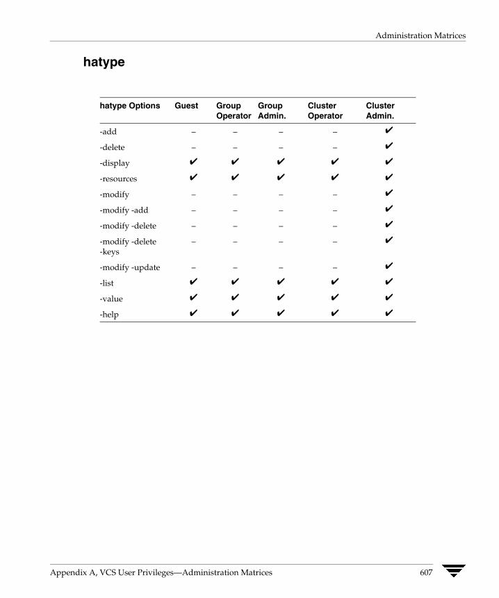
Administration Matrices
hatype
hatype Options Guest Group Group Cluster Cluster Operator Admin. Operator Admin.
-add
-delete
-display
-resources
-modify
-modify -add
-modify -delete
-modify -delete -keys
-modify -update
-list
-value
-help
– – – – ✔
– – – – ✔
✔ ✔ ✔ ✔ ✔
✔ ✔ ✔ ✔ ✔
– – – – ✔
– – – – ✔
– – – – ✔
– – – – ✔
– – – – ✔
✔ ✔ ✔ ✔ ✔
✔ ✔ ✔ ✔ ✔
✔ ✔ ✔ ✔ ✔
Appendix A, VCS User Privileges—Administration Matrices 607

Administration Matrices
hauser
hauser Options Cluster Group Group Cluster Cluster Guest Operator Admin. Operator Admin.
-add – – – – ✔
-delete – – – – ✔
-update – ✔ ✔ ✔ ✔
-display ✔ ✔ ✔ ✔ ✔
-list ✔ ✔ ✔ ✔ ✔
-addpriv – – ✔ – ✔
-delpriv – – ✔ – ✔
608 VERITAS Cluster Server User’s Guide
Configuring VCS in Zones
B Solaris zones provide an isolated and secure environment for running applications. Processes running in a zone are protected from interference from other processes in the system. While applications may run in zones, system resources including CPUs, I/O, and adapters, can be managed only at the global zone level.VCS provides high availability to applications running in zones by extending the failover capability to zones. VCS is installed in global zones and all VCS agents and engine components run in the global zone. For applications running within zones, agents run entry points inside the zones. If a zone configured under VCS control faults, VCS fails over the entire service group containing the zone.
VCS supports non-global zones in both secure and non-secure cluster environments. If VCS is running in a secure environment using VERITAS Security Services (VxSS), communication between non-global zones and global zones is secure.
The following VCS agents are zone-aware and support applications running in non-global zones:
◆ Process ◆ ProcessOnOnly ◆ Application
◆ Oracle ◆ DB2
The new Zone agent monitors zones, brings zones online, and takes them offline.
In secure clusters, the agent creates a user account with group administrative privileges to enable inter-zone communication, if the user account doesn’t exist. It also renews the VxSS authentication certificate before the certificate expires.
Two new attributes, ContainerType and ContainerName, define the zone where the application runs.
◆ ContainerType—A resource type static attribute, which indicates that the application runs in a Solaris zone. For applications running in zones, set this attribute to Zone.
◆ ContainerName—A resource attribute, which you set to the name of the zone.
When you set the ContainerName, VCS runs the entry points for the resource in the specified zone.
609

Configuring a Zone in VCS
Configuring a Zone in VCS Configuring a zone in VCS involves the following tasks:
First Review the “Prerequisites” on page 611.
Second Decide on the location of the zone root. See “Setting the Zone Root Path” on page 612.
Third Create the zone. See “Creating a Zone” on page 612.
Fourth Install the application in the zone. See “Installing the Application” on page 614.
Fifth Create the application service group. See “Configuring the Application Service Group” on page 614.
Sixth Configure zone-specific resources and set up inter-zone communication. “Setting Up the Zone Configuration in the Service Group” on page 615
610 VERITAS Cluster Server User’s Guide

Configuring a Zone in VCS
Prerequisites ✔ All nodes hosting applications configured in zones must be running the same version
of the operating system.
✔ Install VCS before creating zones.
✔ VCS supports UFS and VxFS mounts for the zone root; VCS does not support CFS mounts for the zone root.
✔ The autoboot property for the zone must be set to false.
✔ The VCS and VxSS install directories must be defined in the inherit-pkg-dir parameter in the zone configuration.
✔ All application mounts must be part of the zone configuration, and must be configured in the VCS service group.
✔ Mount points used by application running in zones must be set relative to the zone’s root. For example, if a zone z-ora needs to use /oracle, mount the file system at /export/home/z-ora/root/oracle. You must also set the MountPoint attribute of the Mount resource to this path.
✔ IP addresses configured for applications running in zones must be defined in the zone configuration file. Do not define IP resources in the VCS configuration file main.cf for applications running in zones. VCS does not monitor IP addresses in service groups configured for applications running in zones.
Using Custom Agents in Zones
✔ If you use custom agents to monitor applications running in zones, make sure the agents use script-based entry points. VCS does not support running C++ entry points inside a non-global zone.
✔ If the custom agent monitors an application running in a zone, add the resource type to the APP_TYPES environment variable.
If the custom agent monitors an application running in the global zone, add the resource type to the SYS_TYPES environment variable.
Appendix B, Configuring VCS in Zones 611
Configuring a Zone in VCS
Setting the Zone Root Path Each zone has its own section of the file system hierarchy in the zone root directory. Processes running in the zone can access files only within the zone root.
You can set the zone root in two ways:
◆ Zone root on shared storage—In this configuration, you create a zone on one node in the cluster and duplicate the zone configuration on other nodes.
Setting the zone root on a shared storage relieves you of installing the zone on all nodes. Secondly, the zone, along with the zone root, can be failed over to the other system. This also implies that the system software (including patches) on all the systems must be identical during the life span of a zone.
◆ Zone root on local storage—In this configuration, you must create a zone on each node in the cluster.
Creating a Zone
▼ To create a zone with its zone root on local disks
1. Create the zone using the zonecfg command.
2. Use the zonecfg command to set the zonepath parameter to the location of the zone root.
3. Set the autoboot property for the zone to false.
4. Install the zone using the zoneadm install program.
5. Boot the zone using the zoneadm boot command.
Repeat these instructions on each node in the cluster.
612 VERITAS Cluster Server User’s Guide
Configuring a Zone in VCS
▼ To create a zone with its zone root on shared disks
Creating a zone with its zone root on shared disks involves creating and installing the zone on a node and copying the zone definition to all other nodes in the cluster.
1. On the first node:
a. Create the zone using the zonecfg command.
b. Use the zonecfg command to set the zonepath parameter to the location of the zone root.
c. Set the autoboot property for the zone to false.
d. Install the zone using the zoneadm install program.
e. Open the file /etc/zones/index and locate the zone definition entry. The zone definition begins with the name of the zone. For example, the zone definition for the zone z-data-ora resembles:
z-data-ora:installed:/export/home/z-data-ora
2. On all other nodes in the cluster:
a. Make sure that no zone is running on the node.
a. Copy the zone definition entry to the file /etc/zones/index.
3. After copying the zone definition to all nodes, boot the zone from any node using the zoneadm boot command.
Appendix B, Configuring VCS in Zones 613
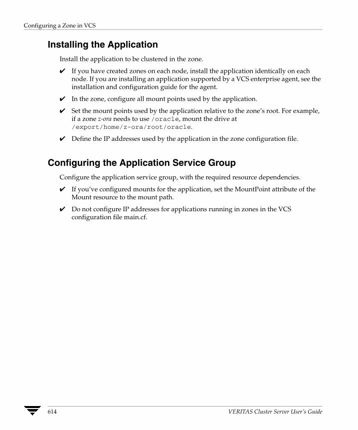
Configuring a Zone in VCS
Installing the Application Install the application to be clustered in the zone.
✔ If you have created zones on each node, install the application identically on each node. If you are installing an application supported by a VCS enterprise agent, see the installation and configuration guide for the agent.
✔ In the zone, configure all mount points used by the application.
✔ Set the mount points used by the application relative to the zone’s root. For example, if a zone z-ora needs to use /oracle, mount the drive at /export/home/z-ora/root/oracle.
✔ Define the IP addresses used by the application in the zone configuration file.
Configuring the Application Service Group Configure the application service group, with the required resource dependencies.
✔ If you’ve configured mounts for the application, set the MountPoint attribute of the Mount resource to the mount path.
✔ Do not configure IP addresses for applications running in zones in the VCS configuration file main.cf.
614 VERITAS Cluster Server User’s Guide
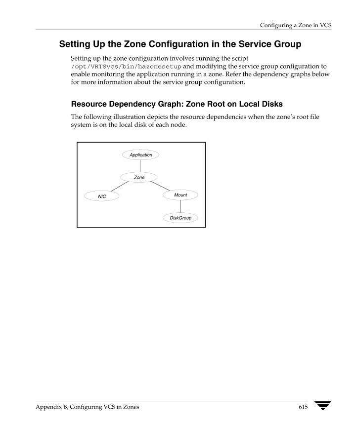
Configuring a Zone in VCS
Setting Up the Zone Configuration in the Service Group Setting up the zone configuration involves running the script /opt/VRTSvcs/bin/hazonesetup and modifying the service group configuration to enable monitoring the application running in a zone. Refer the dependency graphs below for more information about the service group configuration.
Resource Dependency Graph: Zone Root on Local Disks
The following illustration depicts the resource dependencies when the zone’s root file system is on the local disk of each node.
Application
NIC
DiskGroup
Mount
Zone
Appendix B, Configuring VCS in Zones 615
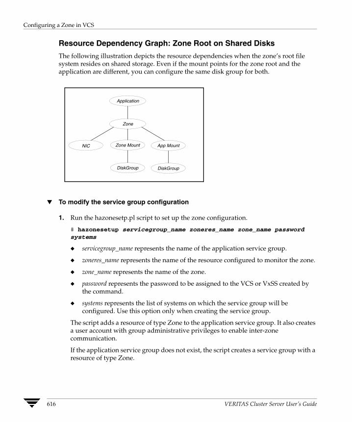
Configuring a Zone in VCS
Resource Dependency Graph: Zone Root on Shared Disks
The following illustration depicts the resource dependencies when the zone’s root file system resides on shared storage. Even if the mount points for the zone root and the application are different, you can configure the same disk group for both.
NIC
DiskGroup
App Mount
DiskGroup
Zone Mount
Application
Zone
▼ To modify the service group configuration
1. Run the hazonesetp.pl script to set up the zone configuration.
# hazonesetup servicegroup_name zoneres_name zone_name password systems
◆ servicegroup_name represents the name of the application service group.
◆ zoneres_name represents the name of the resource configured to monitor the zone.
◆ zone_name represents the name of the zone.
◆ password represents the password to be assigned to the VCS or VxSS created by the command.
◆ systems represents the list of systems on which the service group will be configured. Use this option only when creating the service group.
The script adds a resource of type Zone to the application service group. It also creates a user account with group administrative privileges to enable inter-zone communication.
If the application service group does not exist, the script creates a service group with a resource of type Zone.
616 VERITAS Cluster Server User’s Guide

Verifying the Zone Configuration
2. Modify the resource dependencies such that:
◆ The application resource depends on the Zone resource
◆ The Zone resource depends on the NIC and Mount resources. Note that the IP address is defined within the zone and is not configured in the VCS Service group.
See the resource dependency graphs for more information.
3. Set the ContainerType attribute for the application resource type to Zone.
4. Set the ContainerName attribute for the application resource to the name of the zone in which the application runs.
5. Save the service group configuration and bring the service group online.
Verifying the Zone Configuration If you use custom agents make sure the resource type is added to the APP_TYPES or SYS_TYPES environment variable. See “Using Custom Agents in Zones” on page 611 for more information.
Run the hazoneverify command to verify the zone configuration.
# hazoneverify servicegroup_name
The command verifies the following requirements:
✔ The systems hosting the service group have the required operating system to run zones.
✔ The service group does not have more than one resource of type Zone.
✔ The dependencies of the Zone resource are correct.
Maintenance Tasks ✔ Whenever you make a change that affects the zone configuration, you must run the
hazonesetup command to reconfigure the zones in VCS. See “Setting Up the Zone Configuration in the Service Group” on page 615 for more information.
✔ Make sure that the zone configuration files are consistent on all the nodes at all times. The file is located at /etc/zones/zone_name.xml.
✔ When you add a patch or upgrade the operating system on one node, make sure to upgrade the software on all nodes.
Appendix B, Configuring VCS in Zones 617
Maintenance Tasks
✔ Make sure that the application configuration is identical on all nodes. If you update the application configuration on one node, apply the same updates to all nodes.
618 VERITAS Cluster Server User’s Guide
Maintenance Tasks
Troubleshooting Information
VCS HA commands do not work.
Recommended Action:
Verify the VCS packages are installed.
Run the hazonesetup script to set up the zone configuration. Run the hazoneverify command to verify the configuration.
Run the halogin command from the zone. See “Logging On to VCS” on page 63 for more information.
Verify your VCS credentials. Make sure the password is not changed.
Verify the VxSS certificate is not expired.
Resource does not come online in the zone.
Recommended Action:
Verify VCS and the agent packages are installed correctly. Verify the application is installed in the zone.
Verify the configuration definition of the agent. Make sure the ContainerType and ContainerName attributes are defined.
Appendix B, Configuring VCS in Zones 619

Maintenance Tasks
620 VERITAS Cluster Server User’s Guide
Cluster and System States
C This appendix describes the various cluster and system states and the order in which they transition from one state to another.Remote Cluster States In global clusters, the “health” of the remote clusters is monitored and maintained by the wide-area connector process. The connector process uses heartbeats, such as ICMP, to monitor the state of remote clusters. The state is then communicated to HAD, which then uses the information to take appropriate action when required. For example, when a cluster is shut down gracefully, the connector transitions its local cluster state to EXITING and notifies the remote clusters of the new state. When the cluster exits and the remote connectors lose their TCP/IP connection to it, each remote connector transitions their view of the cluster to EXITED.
To enable wide-area network heartbeats, the wide-area connector process must be up and running. For wide-area connectors to connect to remote clusters, at least one heartbeat to the specified cluster must report the state as ALIVE.
There are three hearbeat states for remote clusters: HBUNKNOWN, HBALIVE, and HBDEAD.
621
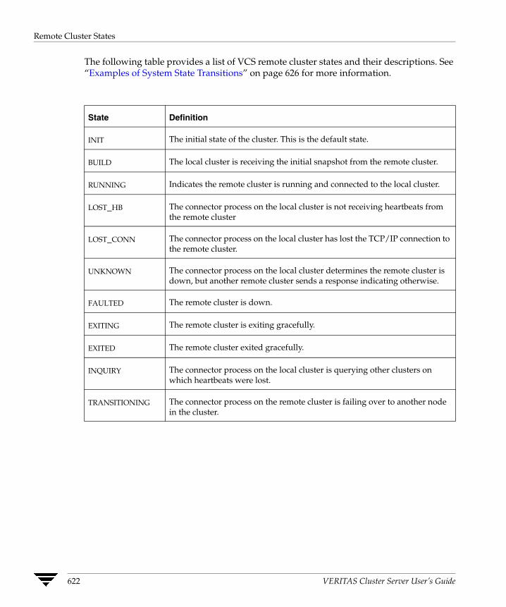
Remote Cluster States
The following table provides a list of VCS remote cluster states and their descriptions. See “Examples of System State Transitions” on page 626 for more information.
State Definition
INIT The initial state of the cluster. This is the default state.
BUILD The local cluster is receiving the initial snapshot from the remote cluster.
RUNNING Indicates the remote cluster is running and connected to the local cluster.
LOST_HB The connector process on the local cluster is not receiving heartbeats from the remote cluster
LOST_CONN The connector process on the local cluster has lost the TCP/IP connection to the remote cluster.
UNKNOWN The connector process on the local cluster determines the remote cluster is down, but another remote cluster sends a response indicating otherwise.
FAULTED The remote cluster is down.
EXITING The remote cluster is exiting gracefully.
EXITED The remote cluster exited gracefully.
INQUIRY The connector process on the local cluster is querying other clusters on which heartbeats were lost.
TRANSITIONING The connector process on the remote cluster is failing over to another node in the cluster.
622 VERITAS Cluster Server User’s Guide
Remote Cluster States
Examples of Cluster State Transitions ◆ If a remote cluster joins the global cluster configuration, the other clusters in the
configuration transition their “view” of the remote cluster to the RUNNING state:
INIT -> BUILD -> RUNNING
◆ If a cluster loses all heartbeats to a remote cluster in the RUNNING state, inquiries are sent. If all inquiry responses indicate the remote cluster is actually down, the cluster transitions the remote cluster state to FAULTED:
RUNNING -> LOST_HB -> INQUIRY -> FAULTED
◆ If at least one response does not indicate the cluster is down, the cluster transitions the remote cluster state to UNKNOWN:
RUNNING -> LOST_HB -> INQUIRY -> UNKNOWN
◆ When the ClusterService service group, which maintains the connector process as highly available, fails over to another system in the cluster, the remote clusters transition their view of that cluster to TRANSITIONING, then back to RUNNING after the failover is successful:
RUNNING -> TRANSITIONING -> BUILD -> RUNNING
◆ When a remote cluster in a RUNNING state is stopped (by taking the ClusterService service group offline), the remote cluster transitions to EXITED:
RUNNING -> EXITING -> EXITED
Appendix C, Cluster and System States 623
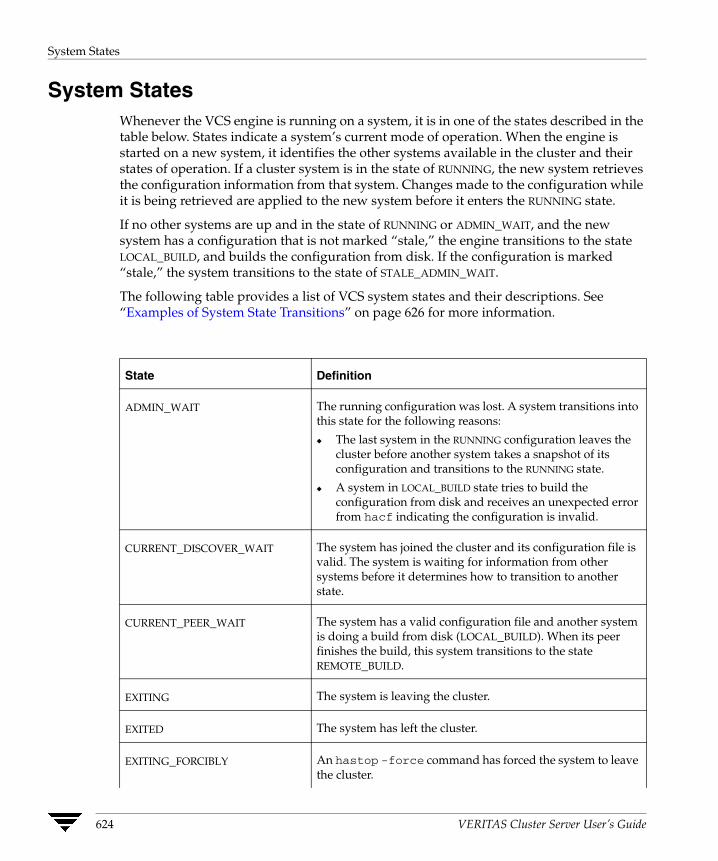
System States
System States Whenever the VCS engine is running on a system, it is in one of the states described in the table below. States indicate a system’s current mode of operation. When the engine is started on a new system, it identifies the other systems available in the cluster and their states of operation. If a cluster system is in the state of RUNNING, the new system retrieves the configuration information from that system. Changes made to the configuration while it is being retrieved are applied to the new system before it enters the RUNNING state.
If no other systems are up and in the state of RUNNING or ADMIN_WAIT, and the new system has a configuration that is not marked “stale,” the engine transitions to the state LOCAL_BUILD, and builds the configuration from disk. If the configuration is marked “stale,” the system transitions to the state of STALE_ADMIN_WAIT.
The following table provides a list of VCS system states and their descriptions. See “Examples of System State Transitions” on page 626 for more information.
State Definition
ADMIN_WAIT The running configuration was lost. A system transitions into this state for the following reasons:
◆ The last system in the RUNNING configuration leaves the cluster before another system takes a snapshot of its configuration and transitions to the RUNNING state.
◆ A system in LOCAL_BUILD state tries to build the configuration from disk and receives an unexpected error from hacf indicating the configuration is invalid.
CURRENT_DISCOVER_WAIT The system has joined the cluster and its configuration file is valid. The system is waiting for information from other systems before it determines how to transition to another state.
CURRENT_PEER_WAIT The system has a valid configuration file and another system is doing a build from disk (LOCAL_BUILD). When its peer finishes the build, this system transitions to the state REMOTE_BUILD.
EXITING The system is leaving the cluster.
EXITED The system has left the cluster.
EXITING_FORCIBLY An hastop -force command has forced the system to leave the cluster.
624 VERITAS Cluster Server User’s Guide
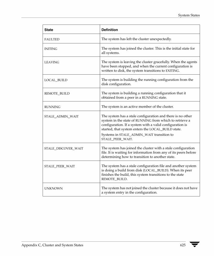
System States
State Definition
FAULTED The system has left the cluster unexpectedly.
INITING The system has joined the cluster. This is the initial state for all systems.
LEAVING The system is leaving the cluster gracefully. When the agents have been stopped, and when the current configuration is written to disk, the system transitions to EXITING.
LOCAL_BUILD The system is building the running configuration from the disk configuration.
REMOTE_BUILD The system is building a running configuration that it obtained from a peer in a RUNNING state.
RUNNING The system is an active member of the cluster.
STALE_ADMIN_WAIT The system has a stale configuration and there is no other system in the state of RUNNING from which to retrieve a configuration. If a system with a valid configuration is started, that system enters the LOCAL_BUILD state.
Systems in STALE_ADMIN_WAIT transition to STALE_PEER_WAIT.
STALE_DISCOVER_WAIT The system has joined the cluster with a stale configuration file. It is waiting for information from any of its peers before determining how to transition to another state.
STALE_PEER_WAIT The system has a stale configuration file and another system is doing a build from disk (LOCAL_BUILD). When its peer finishes the build, this system transitions to the state REMOTE_BUILD.
UNKNOWN The system has not joined the cluster because it does not have a system entry in the configuration.
Appendix C, Cluster and System States 625
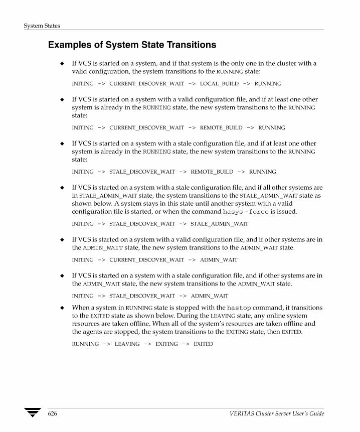
System States
Examples of System State Transitions
◆ If VCS is started on a system, and if that system is the only one in the cluster with a valid configuration, the system transitions to the RUNNING state:
INITING -> CURRENT_DISCOVER_WAIT -> LOCAL_BUILD -> RUNNING
◆ If VCS is started on a system with a valid configuration file, and if at least one other system is already in the RUNNING state, the new system transitions to the RUNNING state:
INITING -> CURRENT_DISCOVER_WAIT -> REMOTE_BUILD -> RUNNING
◆ If VCS is started on a system with a stale configuration file, and if at least one other system is already in the RUNNING state, the new system transitions to the RUNNING state:
INITING -> STALE_DISCOVER_WAIT -> REMOTE_BUILD -> RUNNING
◆ If VCS is started on a system with a stale configuration file, and if all other systems are in STALE_ADMIN_WAIT state, the system transitions to the STALE_ADMIN_WAIT state as shown below. A system stays in this state until another system with a valid configuration file is started, or when the command hasys -force is issued.
INITING -> STALE_DISCOVER_WAIT -> STALE_ADMIN_WAIT
◆ If VCS is started on a system with a valid configuration file, and if other systems are in the ADMIN_WAIT state, the new system transitions to the ADMIN_WAIT state.
INITING -> CURRENT_DISCOVER_WAIT -> ADMIN_WAIT
◆ If VCS is started on a system with a stale configuration file, and if other systems are in the ADMIN_WAIT state, the new system transitions to the ADMIN_WAIT state.
INITING -> STALE_DISCOVER_WAIT -> ADMIN_WAIT
◆ When a system in RUNNING state is stopped with the hastop command, it transitions to the EXITED state as shown below. During the LEAVING state, any online system resources are taken offline. When all of the system’s resources are taken offline and the agents are stopped, the system transitions to the EXITING state, then EXITED.
RUNNING -> LEAVING -> EXITING -> EXITED
626 VERITAS Cluster Server User’s Guide

VCS Attributes
D This chapter contains a comprehensive list of VCS attributes. Attributes are categorized by cluster object, as indicated below:◆ Resource Attributes
◆ Resource Type Attributes
◆ Service Group Attributes
◆ System Attributes
◆ Cluster Attributes
◆ Heartbeat Attributes (for global clusters)
You can modify the values of attributes labeled “user-defined” from the command line or graphical user interface, or by manually modifying the main.cf configuration file. The default values of VCS attributes are suitable for most environments; however, you can change the attribute values to better suit your environment and enhance performance.
Caution When changing the values of attributes, be aware that VCS attributes interact with each other. After changing the value of an attribute, observe the cluster systems to confirm that unexpected behavior does not impair performance.
The values of attributes labeled “system use only” are set by VCS and are read-only. They contain important information about the state of the cluster.
The values labeled “agent-defined” are set by the corresponding agent and are also read-only.
In addition to the attributes listed in this appendix, see the VERITAS Cluster Server Agent Developer’s Guide.
627
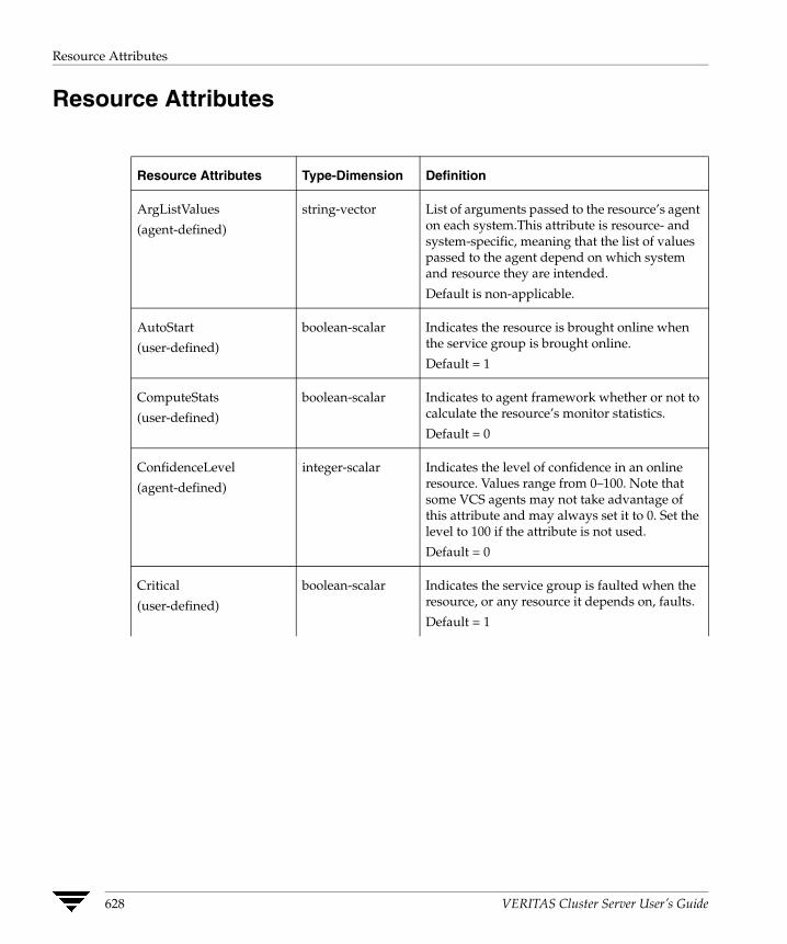
Resource Attributes
Resource Attributes
Resource Attributes Type-Dimension Definition
ArgListValues
(agent-defined)
string-vector List of arguments passed to the resource’s agent on each system.This attribute is resource- and system-specific, meaning that the list of values passed to the agent depend on which system and resource they are intended.
Default is non-applicable.
AutoStart
(user-defined)
boolean-scalar Indicates the resource is brought online when the service group is brought online.
Default = 1
ComputeStats
(user-defined)
boolean-scalar Indicates to agent framework whether or not to calculate the resource’s monitor statistics.
Default = 0
ConfidenceLevel
(agent-defined)
integer-scalar Indicates the level of confidence in an online resource. Values range from 0–100. Note that some VCS agents may not take advantage of this attribute and may always set it to 0. Set the level to 100 if the attribute is not used.
Default = 0
Critical
(user-defined)
boolean-scalar Indicates the service group is faulted when the resource, or any resource it depends on, faults.
Default = 1
628 VERITAS Cluster Server User’s Guide
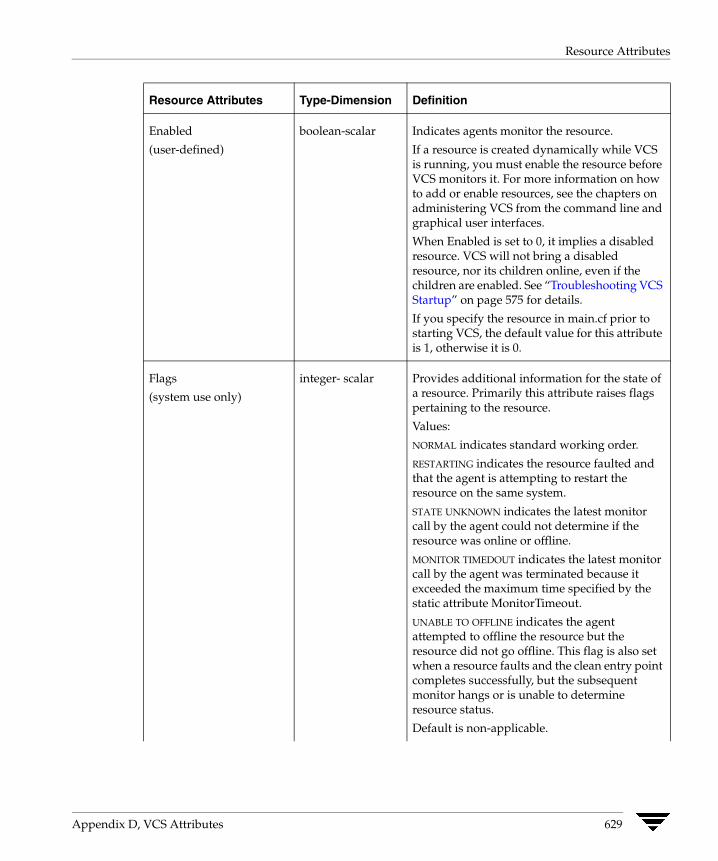
Resource Attributes
Enabled
(user-defined)
boolean-scalar Indicates agents monitor the resource.
If a resource is created dynamically while VCS is running, you must enable the resource before VCS monitors it. For more information on how to add or enable resources, see the chapters on administering VCS from the command line and graphical user interfaces.
When Enabled is set to 0, it implies a disabled resource. VCS will not bring a disabled resource, nor its children online, even if the children are enabled. See “Troubleshooting VCS Startup” on page 575 for details.
If you specify the resource in main.cf prior to starting VCS, the default value for this attribute is 1, otherwise it is 0.
Flags
(system use only)
integer- scalar Provides additional information for the state of a resource. Primarily this attribute raises flags pertaining to the resource.
Values:
NORMAL indicates standard working order.
RESTARTING indicates the resource faulted and that the agent is attempting to restart the resource on the same system.
STATE UNKNOWN indicates the latest monitor call by the agent could not determine if the resource was online or offline.
MONITOR TIMEDOUT indicates the latest monitor call by the agent was terminated because it exceeded the maximum time specified by the static attribute MonitorTimeout.
UNABLE TO OFFLINE indicates the agent attempted to offline the resource but the resource did not go offline. This flag is also set when a resource faults and the clean entry point completes successfully, but the subsequent monitor hangs or is unable to determine resource status.
Default is non-applicable.
Resource Attributes Type-Dimension Definition
Appendix D, VCS Attributes 629
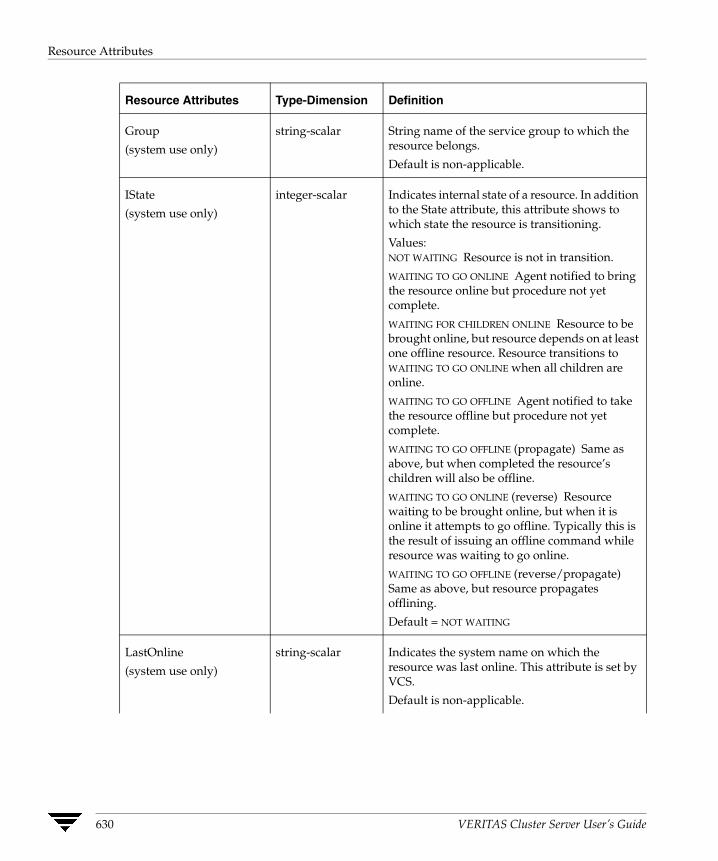
Resource Attributes
Group
(system use only)
string-scalar String name of the service group to which the resource belongs.
Default is non-applicable.
IState
(system use only)
integer-scalar Indicates internal state of a resource. In addition to the State attribute, this attribute shows to which state the resource is transitioning.
Values: NOT WAITING Resource is not in transition.
WAITING TO GO ONLINE Agent notified to bring the resource online but procedure not yet complete.
WAITING FOR CHILDREN ONLINE Resource to be brought online, but resource depends on at least one offline resource. Resource transitions to WAITING TO GO ONLINE when all children are online.
WAITING TO GO OFFLINE Agent notified to take the resource offline but procedure not yet complete.
WAITING TO GO OFFLINE (propagate) Same as above, but when completed the resource’s children will also be offline.
WAITING TO GO ONLINE (reverse) Resource waiting to be brought online, but when it is online it attempts to go offline. Typically this is the result of issuing an offline command while resource was waiting to go online.
WAITING TO GO OFFLINE (reverse/propagate) Same as above, but resource propagates offlining.
Default = NOT WAITING
LastOnline
(system use only)
string-scalar Indicates the system name on which the resource was last online. This attribute is set by VCS.
Default is non-applicable.
Resource Attributes Type-Dimension Definition
630 VERITAS Cluster Server User’s Guide

Resource Attributes
MonitorOnly
(system use only)
boolean-scalar Indicates if the resource can be brought online or taken offline. If set to 0, resource can be brought online or taken offline. If set to 1, resource can be monitored only.
Note This attribute can only be modified by the command hagrp -freeze.
Default = 0
MonitorTimeStats
(system use only)
string-association Valid keys are Average and TS. Average is the average time taken by the monitor entry point over the last Frequency number of monitor cycles. TS is the timestamp indicating when the engine updated the resource’s Average value.
Defaults:
Average = 0
TS = ""
Name
(system use only)
string-scalar Contains actual name of resource.
Default is non-applicable.
Path
(system use only)
boolean-scalar Set to 1 to identify a resource as a member of a path in the dependency tree to be taken offline on a specific system after a resource faults.
Default = 0
Probed
(system use only)
boolean-scalar Indicates whether the resource has been detected by the agent.
Default = 0
ResourceInfo
(system use only)
string-association This attribute has three predefined keys:
State: values are Valid, Invalid, or Stale
Msg: output of the info entry point captured on stdout by the agent framework
TS: timestamp indicating when the ResourceInfo attribute was updated by the agent framework
Defaults:
State = Valid
Msg = ""
TS = ""
Resource Attributes Type-Dimension Definition
Appendix D, VCS Attributes 631
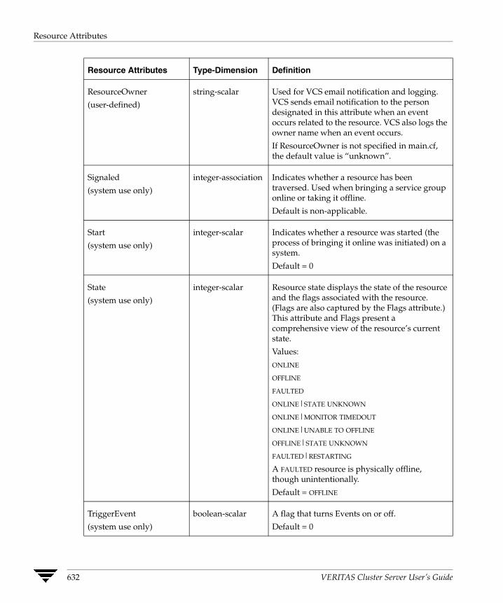
Resource Attributes
Resource Attributes Type-Dimension Definition
ResourceOwner
(user-defined)
string-scalar Used for VCS email notification and logging. VCS sends email notification to the person designated in this attribute when an event occurs related to the resource. VCS also logs the owner name when an event occurs.
If ResourceOwner is not specified in main.cf, the default value is “unknown”.
Signaled
(system use only)
integer-association Indicates whether a resource has been traversed. Used when bringing a service group online or taking it offline.
Default is non-applicable.
Start
(system use only)
integer-scalar Indicates whether a resource was started (the process of bringing it online was initiated) on a system.
Default = 0
State
(system use only)
integer-scalar Resource state displays the state of the resource and the flags associated with the resource. (Flags are also captured by the Flags attribute.) This attribute and Flags present a comprehensive view of the resource’s current state.
Values:
ONLINE
OFFLINE
FAULTED
ONLINE|STATE UNKNOWN
ONLINE|MONITOR TIMEDOUT
ONLINE|UNABLE TO OFFLINE
OFFLINE|STATE UNKNOWN
FAULTED|RESTARTING
A FAULTED resource is physically offline, though unintentionally.
Default = OFFLINE
TriggerEvent
(system use only)
boolean-scalar A flag that turns Events on or off.
Default = 0
632 VERITAS Cluster Server User’s Guide
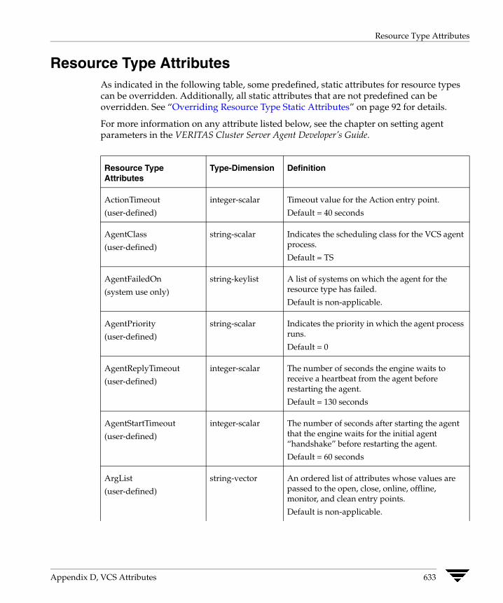
Resource Type Attributes
Resource Type Attributes As indicated in the following table, some predefined, static attributes for resource types can be overridden. Additionally, all static attributes that are not predefined can be overridden. See “Overriding Resource Type Static Attributes” on page 92 for details.
For more information on any attribute listed below, see the chapter on setting agent parameters in the VERITAS Cluster Server Agent Developer’s Guide.
Resource Type Attributes
Type-Dimension Definition
ActionTimeout
(user-defined)
integer-scalar Timeout value for the Action entry point.
Default = 40 seconds
AgentClass
(user-defined)
string-scalar Indicates the scheduling class for the VCS agent process.
Default = TS
AgentFailedOn
(system use only)
string-keylist A list of systems on which the agent for the resource type has failed.
Default is non-applicable.
AgentPriority
(user-defined)
string-scalar Indicates the priority in which the agent process runs.
Default = 0
AgentReplyTimeout
(user-defined)
integer-scalar The number of seconds the engine waits to receive a heartbeat from the agent before restarting the agent.
Default = 130 seconds
AgentStartTimeout
(user-defined)
integer-scalar The number of seconds after starting the agent that the engine waits for the initial agent “handshake” before restarting the agent.
Default = 60 seconds
ArgList
(user-defined)
string-vector An ordered list of attributes whose values are passed to the open, close, online, offline, monitor, and clean entry points.
Default is non-applicable.
Appendix D, VCS Attributes 633

Resource Type Attributes
AttrChangedTimeout
(user-defined)
Note This attribute can be overridden.
integer-scalar Maximum time (in seconds) within which the attr_changed entry point must complete or be terminated.
Default = 60 seconds
CleanTimeout
(user-defined)
Note This attribute can be overridden.
integer-scalar Maximum time (in seconds) within which the clean entry point must complete or else be terminated.
Default = 60 seconds
CloseTimeout
(user-defined)
Note This attribute can be overridden.
integer-scalar Maximum time (in seconds) within which the close entry point must complete or else be terminated.
Default = 60 seconds
ConfInterval
(user-defined)
Note This attribute can be overridden.
integer-scalar When a resource has remained online for the specified time (in seconds), previous faults and restart attempts are ignored by the agent. (See ToleranceLimit and RestartLimit attributes for details.)
Default = 600 seconds
ConntainerType
(user-defined)
string-scalar Indicates that the application being monitored runs in a Solaris zone.
For applications running in zones, set ContainerType to Zone and set the resource attribute ContainerName to the name of the zone.
Default = "" (null)
Resource Type Attributes
Type-Dimension Definition
634 VERITAS Cluster Server User’s Guide
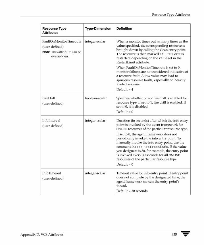
Resource Type Attributes
FaultOnMonitorTimeouts
(user-defined)
Note This attribute can be overridden.
integer-scalar When a monitor times out as many times as the value specified, the corresponding resource is brought down by calling the clean entry point. The resource is then marked FAULTED, or it is restarted, depending on the value set in the RestartLimit attribute.
When FaultOnMonitorTimeouts is set to 0, monitor failures are not considered indicative of a resource fault. A low value may lead to spurious resource faults, especially on heavily loaded systems.
Default = 4
FireDrill
(user-defined)
boolean-scalar Specifies whether or not fire drill is enabled for resource type. If set to 1, fire drill is enabled. If set to 0, it is disabled.
Default = 0
InfoInterval
(user-defined)
integer-scalar Duration (in seconds) after which the info entry point is invoked by the agent framework for ONLINE resources of the particular resource type.
If set to 0, the agent framework does not periodically invoke the info entry point. To manually invoke the info entry point, use the command hares -refreshinfo. If the value you designate is 30, for example, the entry point is invoked every 30 seconds for all ONLINE
resources of the particular resource type.
Default = 0
InfoTimeout
(user-defined)
integer-scalar Timeout value for info entry point. If entry point does not complete by the designated time, the agent framework cancels the entry point’s thread.
Default = 30 seconds
Resource Type Attributes
Type-Dimension Definition
Appendix D, VCS Attributes 635

Resource Type Attributes
LogDbg
(user-defined)
string-keylist Indicates the debug severities enabled for the resource type or agent framework. Debug severities used by the agent entry points are in the range of DBG_1–DBG_21. The debug messages from the agent framework are logged with the severities DBG_AGINFO, DBG_AGDEBUG
and DBG_AGTRACE, representing the least to most verbose.
Default = {} (none)
This attribute replaces the attributes LogLevel and LogTags. The following chart compares the previous functionality with the latest.
LogLevel -> LogDbg
info (DBG_AGINFO)
debug (DBG_AGINFO, DBG_AGDEBUG)
all (DBG_AGINFO, DBG_AGDEBUG
and DBG_AGTRACE)
LogTags -> LogDbg
F (DBG_1)
G (DBG_2)
: DBG_21)
LogFileSize
(user-defined)
integer-scalar Specifies the size (in bytes) of the agent log file. Minimum value is 65536 bytes. Maximum value is 134217728 bytes (128MB).
Default = 33554432 (32MB)
MonitorInterval
(user-defined)
Note This attribute can be overridden.
integer-scalar Duration (in seconds) between two consecutive monitor calls for an ONLINE or transitioning resource.
Default = 60 seconds
A lower value may impact performance if many resources of the same type exist. A higher value may delay detection of a faulted resource.
Resource Type Attributes
Type-Dimension Definition
(
636 VERITAS Cluster Server User’s Guide

Resource Type Attributes
MonitorStatsParam
(user-defined)
integer-association Stores the required parameter values for calculating monitor time statistics.
static str MonitorStatsParam = { Frequency = 10, ExpectedValue = 3000, ValueThreshold = 100, AvgThreshold = 40 }
Frequency: Defines the number of monitor cycles after which the average monitor cycle time should be computed and sent to the engine. If configured, the value for this attribute must be between 1 and 30. It is set to 0 by default.
ExpectedValue: The expected monitor time in milliseconds for all resources of this type. Default=3000.
ValueThreshold: The acceptable percentage difference between the expected monitor cycle time (ExpectedValue) and the actual monitor cycle time. Default=100.
AvgThreshold: The acceptable percentage difference between the benchmark average and the moving average of monitor cycle times. Default=40.
MonitorTimeout
(user-defined)
Note This attribute can be overridden.
integer-scalar Maximum time (in seconds) within which the monitor entry point must complete or else be terminated.
Default = 60 seconds
NameRule string-scalar This attribute is no longer used by VCS.
NumThreads
(user-defined)
integer-scalar Number of threads used within the agent process for managing resources. This number does not include threads used for other internal purposes.
Default = 10
Increasing to a significantly large value can degrade system performance. Decreasing to 1 prevents multiple threads. The agent framework limits the maximum value of this attribute to 20.
Resource Type Attributes
Type-Dimension Definition
Appendix D, VCS Attributes 637
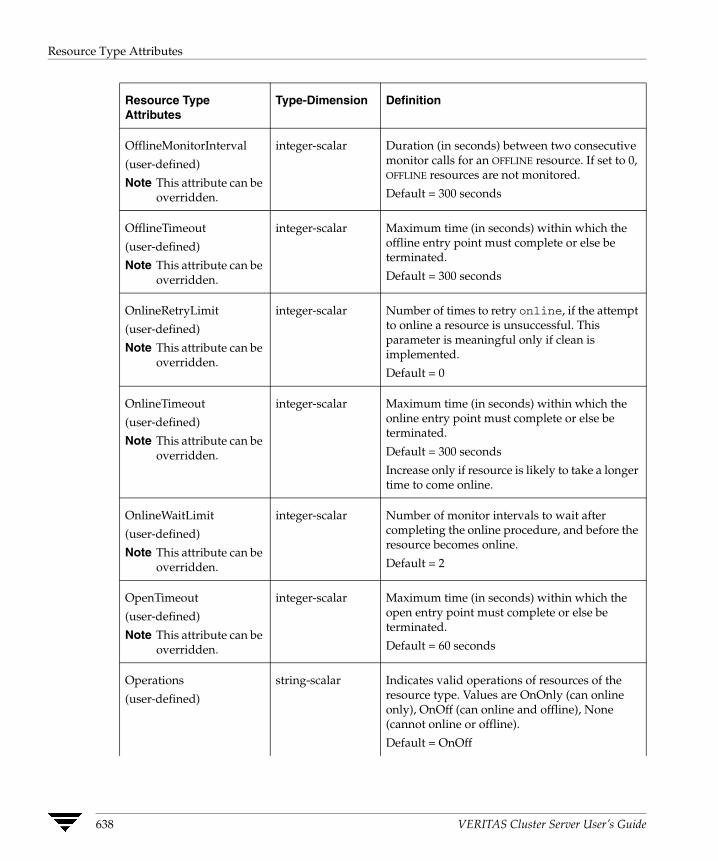
Resource Type Attributes
OfflineMonitorInterval
(user-defined)
Note This attribute can be overridden.
integer-scalar Duration (in seconds) between two consecutive monitor calls for an OFFLINE resource. If set to 0, OFFLINE resources are not monitored.
Default = 300 seconds
OfflineTimeout
(user-defined)
Note This attribute can be overridden.
integer-scalar Maximum time (in seconds) within which the offline entry point must complete or else be terminated.
Default = 300 seconds
OnlineRetryLimit
(user-defined)
Note This attribute can be overridden.
integer-scalar Number of times to retry online, if the attempt to online a resource is unsuccessful. This parameter is meaningful only if clean is implemented.
Default = 0
OnlineTimeout
(user-defined)
Note This attribute can be overridden.
integer-scalar Maximum time (in seconds) within which the online entry point must complete or else be terminated.
Default = 300 seconds
Increase only if resource is likely to take a longer time to come online.
OnlineWaitLimit
(user-defined)
Note This attribute can be overridden.
integer-scalar Number of monitor intervals to wait after completing the online procedure, and before the resource becomes online.
Default = 2
OpenTimeout
(user-defined)
Note This attribute can be overridden.
integer-scalar Maximum time (in seconds) within which the open entry point must complete or else be terminated.
Default = 60 seconds
Operations
(user-defined)
string-scalar Indicates valid operations of resources of the resource type. Values are OnOnly (can online only), OnOff (can online and offline), None (cannot online or offline).
Default = OnOff
Resource Type Attributes
Type-Dimension Definition
638 VERITAS Cluster Server User’s Guide

Resource Type Attributes
Resource Type Attributes
Type-Dimension Definition
RestartLimit
(user-defined)
Note This attribute can be overridden.
integer-scalar Number of times to retry bringing a resource online when it is taken offline unexpectedly and before VCS declares it FAULTED.
Default = 0
ScriptClass
(user-defined)
string-scalar Indicates the scheduling class of the script processes (for example, online) created by the agent.
Default = TS
ScriptPriority
(user-defined)
string-scalar Indicates the priority of the script processes created by the agent.
Default = 0
SourceFile
(user-defined)
string-scalar File from which the configuration was read. Always set to .\types.cf.
SupportedActions
(user-defined)
string-vector Valid action tokens for resource.
Default = {}
ToleranceLimit
(user-defined)
Note This attribute can be overridden.
integer-scalar Number of times the monitor entry point should return OFFLINE before declaring the resource FAULTED.
Default = 0
A large value could delay detection of a genuinely faulted resource.
Appendix D, VCS Attributes 639

Service Group Attributes
Service Group Attributes
Service Group Attributes
Type-Dimension Definition
ActiveCount
(system use only)
integer-scalar Number of resources in a service group that are active (online or waiting to go online). When the number drops to zero, the service group is considered offline.
Administrators
(user-defined)
string-keylist List of VCS users with privileges to administer the group.
Note A Group Administrator can perform all operations related to a specific service group, but cannot perform generic cluster operations. See “VCS User Privileges” on page 51 for details.
Default = ""
Authority
(user-defined)
integer-scalar Indicates whether or not the local cluster is allowed to bring the service group online. If set to 0, it is not, if set to 1, it is. Only one cluster can have this attribute set to 1 for a specific global group. See “Administering Service Groups” on page 475 for details.
Default = 0
AutoDisabled
(system use only)
boolean-scalar Indicates that VCS does not know the status of a service group (or specified system for parallel service groups). This is due to:
◆ Group not probed (on specified system for parallel groups) in the SystemList attribute.
◆ VCS engine is not running on a node designated in the SystemList attribute, but the node is visible.
AutoFailOver
(user-defined)
boolean-scalar Indicates whether VCS initiates an automatic failover if the service group faults.
Default = 1 (enabled)
640 VERITAS Cluster Server User’s Guide

Service Group Attributes
AutoRestart
(user-defined)
boolean-scalar Restarts a service group after a faulted persistent resource becomes online. See “Categories of Service Group Dependencies” on page 385 for details.
Note This attribute applies to persistent resources only.
Default = 1 (enabled)
AutoStart
(user-defined)
boolean-scalar Designates whether a service group is automatically started when VCS is started. Default = 1 (enabled)
AutoStartIfPartial
(user-defined)
boolean-scalar Indicates whether to initiate bringing a service group online if the group is probed and discovered to be in a PARTIAL state when VCS is started.
Default = 1 (enabled)
AutoStartList
(user-defined)
string-keylist List of systems on which, under specific conditions, the service group will be started with VCS (usually at system boot). For example, if a system is a member of a failover service group’s AutoStartList attribute, and if it is not already running on another system in the cluster, the group is brought online when the system is started.
VCS uses the AutoStartPolicy attribute (described below) to determine the system on which to bring the service group online.
Note For the service group to start, AutoStart must be enabled and Frozen must be 0. Also, beginning with 1.3.0, you must define the SystemList attribute prior to setting this attribute.
Default = "" (none)
Service Group Attributes
Type-Dimension Definition
Appendix D, VCS Attributes 641

Service Group Attributes
AutoStartPolicy
(user-defined)
string-scalar Sets the policy VCS uses to determine on which system to bring a service group online if multiple systems are available.
This attribute has three options:
Order (default): Systems are chosen in the order in which they are defined in the AutoStartList attribute.
Load: Systems are chosen in the order of their capacity, as designated in the AvailableCapacity system attribute. System with the highest capacity is chosen first.
Priority: Systems are chosen in the order of their priority in the SystemList attribute. Systems with the lowest priority is chosen first.
Default = Order
ClusterFailOverPolicy
(user-defined)
string-scalar Determines how a global service group behaves when a cluster faults.
◆ If set to Manual, the group does not fail over to another cluster automatically.
◆ If set to Auto, the group fails over to another cluster automatically if it is unable to fail over within the local cluster, or if the entire cluster faults.
◆ If set to Connected, the group fails over automatically to another cluster only if it is unable to fail over within the local cluster.
Default = Manual
ClusterList
(user-defined)
integer-association Specifies the list of clusters on which the service group is configured to run.
Default is non-applicable.
CurrentCount
(system use only)
integer-scalar Number of systems on which the service group is active.
DeferAutoStart
(system use only)
boolean-scalar Indicates whether HAD defers the auto-start of a local group in case the global cluster is not fully connected.
Service Group Attributes
Type-Dimension Definition
642 VERITAS Cluster Server User’s Guide

Service Group Attributes
Enabled
(user-defined)
boolean-scalar Indicates if a group can be failed over or brought online. If any of the local values are disabled, the group is disabled.
Default = 1 (enabled)
Evacuate
(user-defined)
boolean-scalar Indicates if VCS initiates an automatic failover when user issues hastop -local -evacuate.
Default = 1
Evacuating
(system use only)
integer-scalar Indicates the node ID from which the service group is being evacuated.
Failover
(system use only)
boolean-scalar Indicates service group is in the process of failing over.
FailOverPolicy
(user-defined)
string-scalar Sets the policy VCS uses to determine which system a group fails over to if multiple systems exist.
Values:
Priority (default): The system defined as the lowest priority in the SystemList attribute is chosen.
Load: The system defined with the least value in the system’s Load attribute is chosen.
RoundRobin: Systems are chosen according to how many active service groups they are hosting. The system with the least number of active service groups is chosen first.
Service Group Attributes
Type-Dimension Definition
Appendix D, VCS Attributes 643
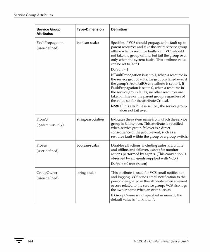
Service Group Attributes
FaultPropagation
(user-defined)
boolean-scalar Specifies if VCS should propagate the fault up to parent resources and take the entire service group offline when a resource faults, or if VCS should not take the group offline, but fail the group over only when the system faults. This attribute value can be set to 0 or 1.
Default = 1
If FaultPropagation is set to 1, when a resource in the service group faults, the group is failed over if the group’s AutoFailOver attribute is set to 1. If FaultPropagation is set to 0, when a resource in the service group faults, no other resources are taken offline nor the parent group, regardless of the value set for the attribute Critical.
Note If this attribute is set to 0, the service group does not fail over.
FromQ
(system use only)
string-association Indicates the system name from which the service group is failing over. This attribute is specified when service group failover is a direct consequence of the group event, such as a resource fault within the group or a group switch.
Frozen
(user-defined)
boolean-scalar Disables all actions, including autostart, online and offline, and failover, except for monitor actions performed by agents. (This convention is observed by all agents supplied with VCS.)
Default = 0 (not frozen)
GroupOwner
(user-defined)
string-scalar This attribute is used for VCS email notification and logging. VCS sends email notification to the person designated in this attribute when an event occurs related to the service group. VCS also logs the owner name when an event occurs.
If GroupOwner is not specified in main.cf, the default value is “unknown”.
Service Group Attributes
Type-Dimension Definition
644 VERITAS Cluster Server User’s Guide
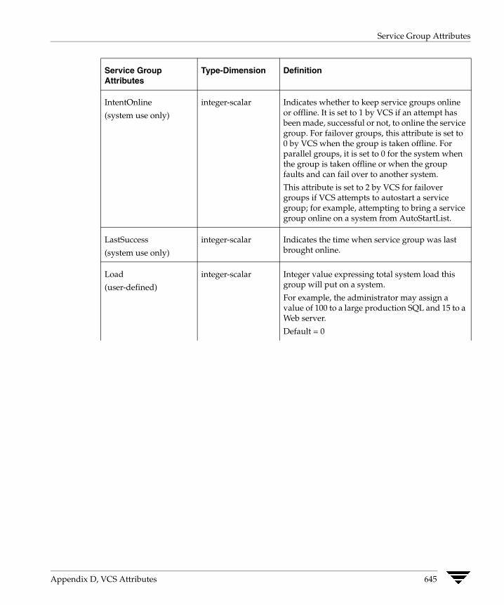
Service Group Attributes
IntentOnline
(system use only)
integer-scalar Indicates whether to keep service groups online or offline. It is set to 1 by VCS if an attempt has been made, successful or not, to online the service group. For failover groups, this attribute is set to 0 by VCS when the group is taken offline. For parallel groups, it is set to 0 for the system when the group is taken offline or when the group faults and can fail over to another system.
This attribute is set to 2 by VCS for failover groups if VCS attempts to autostart a service group; for example, attempting to bring a service group online on a system from AutoStartList.
LastSuccess
(system use only)
integer-scalar Indicates the time when service group was last brought online.
Load
(user-defined)
integer-scalar Integer value expressing total system load this group will put on a system.
For example, the administrator may assign a value of 100 to a large production SQL and 15 to a Web server.
Default = 0
Service Group Attributes
Type-Dimension Definition
Appendix D, VCS Attributes 645
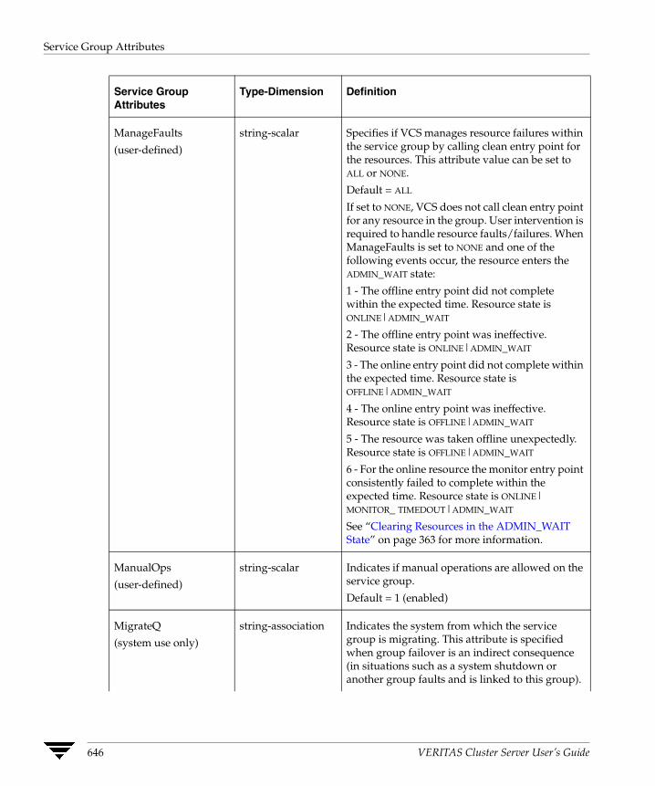
Service Group Attributes
ManageFaults
(user-defined)
string-scalar Specifies if VCS manages resource failures within the service group by calling clean entry point for the resources. This attribute value can be set to ALL or NONE.
Default = ALL
If set to NONE, VCS does not call clean entry point for any resource in the group. User intervention is required to handle resource faults/failures. When ManageFaults is set to NONE and one of the following events occur, the resource enters the ADMIN_WAIT state:
1 - The offline entry point did not complete within the expected time. Resource state is ONLINE|ADMIN_WAIT
2 - The offline entry point was ineffective. Resource state is ONLINE|ADMIN_WAIT
3 - The online entry point did not complete within the expected time. Resource state is OFFLINE|ADMIN_WAIT
4 - The online entry point was ineffective. Resource state is OFFLINE|ADMIN_WAIT
5 - The resource was taken offline unexpectedly. Resource state is OFFLINE|ADMIN_WAIT
6 - For the online resource the monitor entry point consistently failed to complete within the expected time. Resource state is ONLINE| MONITOR_ TIMEDOUT|ADMIN_WAIT
See “Clearing Resources in the ADMIN_WAIT State” on page 363 for more information.
ManualOps
(user-defined)
string-scalar Indicates if manual operations are allowed on the service group.
Default = 1 (enabled)
MigrateQ
(system use only)
string-association Indicates the system from which the service group is migrating. This attribute is specified when group failover is an indirect consequence (in situations such as a system shutdown or another group faults and is linked to this group).
Service Group Attributes
Type-Dimension Definition
646 VERITAS Cluster Server User’s Guide
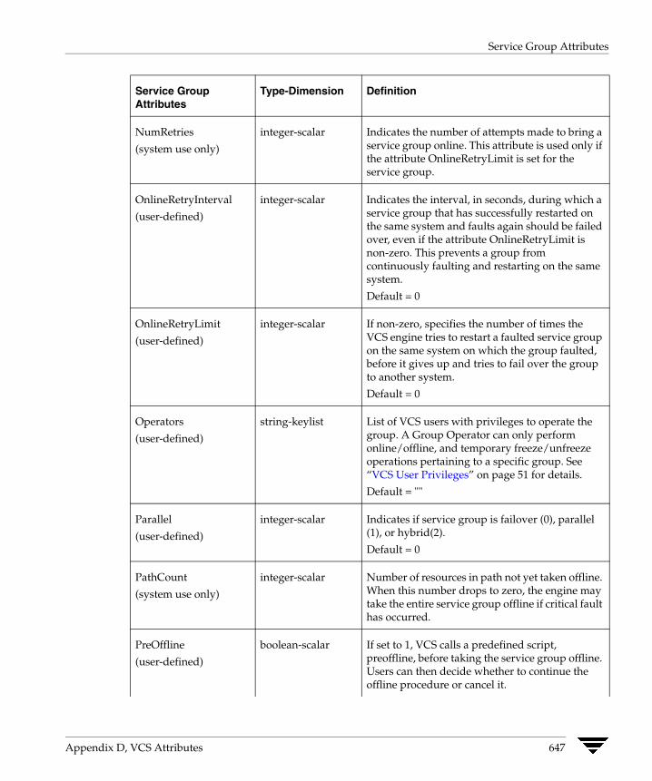
Service Group Attributes
NumRetries
(system use only)
integer-scalar Indicates the number of attempts made to bring a service group online. This attribute is used only if the attribute OnlineRetryLimit is set for the service group.
OnlineRetryInterval
(user-defined)
integer-scalar Indicates the interval, in seconds, during which a service group that has successfully restarted on the same system and faults again should be failed over, even if the attribute OnlineRetryLimit is non-zero. This prevents a group from continuously faulting and restarting on the same system.
Default = 0
OnlineRetryLimit
(user-defined)
integer-scalar If non-zero, specifies the number of times the VCS engine tries to restart a faulted service group on the same system on which the group faulted, before it gives up and tries to fail over the group to another system.
Default = 0
Operators
(user-defined)
string-keylist List of VCS users with privileges to operate the group. A Group Operator can only perform online/offline, and temporary freeze/unfreeze operations pertaining to a specific group. See “VCS User Privileges” on page 51 for details.
Default = ""
Parallel
(user-defined)
integer-scalar Indicates if service group is failover (0), parallel (1), or hybrid(2).
Default = 0
PathCount
(system use only)
integer-scalar Number of resources in path not yet taken offline. When this number drops to zero, the engine may take the entire service group offline if critical fault has occurred.
PreOffline
(user-defined)
boolean-scalar If set to 1, VCS calls a predefined script, preoffline, before taking the service group offline. Users can then decide whether to continue the offline procedure or cancel it.
Service Group Attributes
Type-Dimension Definition
Appendix D, VCS Attributes 647
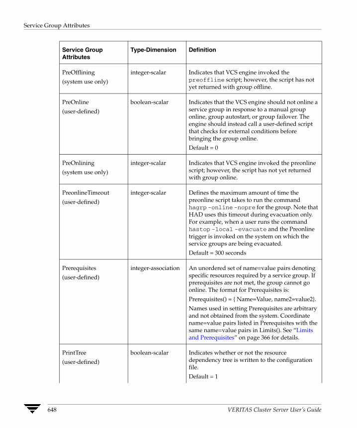
Service Group Attributes
PreOfflining
(system use only)
integer-scalar Indicates that VCS engine invoked the preoffline script; however, the script has not yet returned with group offline.
PreOnline
(user-defined)
boolean-scalar Indicates that the VCS engine should not online a service group in response to a manual group online, group autostart, or group failover. The engine should instead call a user-defined script that checks for external conditions before bringing the group online.
Default = 0
PreOnlining
(system use only)
integer-scalar Indicates that VCS engine invoked the preonline script; however, the script has not yet returned with group online.
PreonlineTimeout
(user-defined)
integer-scalar Defines the maximum amount of time the preonline script takes to run the command hagrp -online -nopre for the group. Note that HAD uses this timeout during evacuation only. For example, when a user runs the command hastop -local -evacuate and the Preonline trigger is invoked on the system on which the service groups are being evacuated.
Default = 300 seconds
Prerequisites
(user-defined)
integer-association An unordered set of name=value pairs denoting specific resources required by a service group. If prerequisites are not met, the group cannot go online. The format for Prerequisites is:
Prerequisites() = { Name=Value, name2=value2}.
Names used in setting Prerequisites are arbitrary and not obtained from the system. Coordinate name=value pairs listed in Prerequisites with the same name=value pairs in Limits(). See “Limits and Prerequisites” on page 366 for details.
PrintTree
(user-defined)
boolean-scalar Indicates whether or not the resource dependency tree is written to the configuration file.
Default = 1
Service Group Attributes
Type-Dimension Definition
648 VERITAS Cluster Server User’s Guide
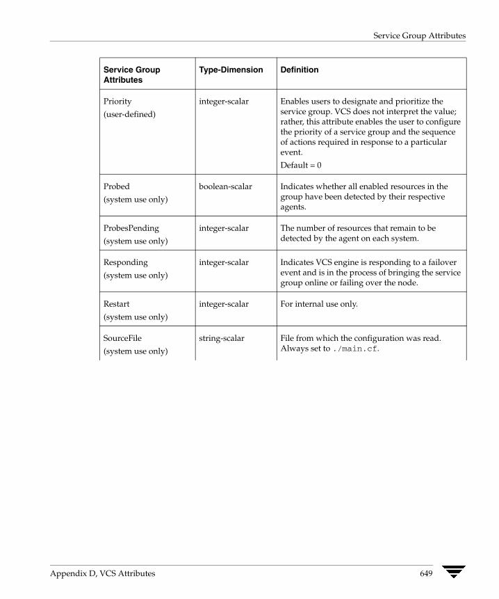
Service Group Attributes
Priority
(user-defined)
integer-scalar Enables users to designate and prioritize the service group. VCS does not interpret the value; rather, this attribute enables the user to configure the priority of a service group and the sequence of actions required in response to a particular event.
Default = 0
Probed
(system use only)
boolean-scalar Indicates whether all enabled resources in the group have been detected by their respective agents.
ProbesPending
(system use only)
integer-scalar The number of resources that remain to be detected by the agent on each system.
Responding
(system use only)
integer-scalar Indicates VCS engine is responding to a failover event and is in the process of bringing the service group online or failing over the node.
Restart
(system use only)
integer-scalar For internal use only.
SourceFile
(system use only)
string-scalar File from which the configuration was read. Always set to ./main.cf.
Service Group Attributes
Type-Dimension Definition
Appendix D, VCS Attributes 649
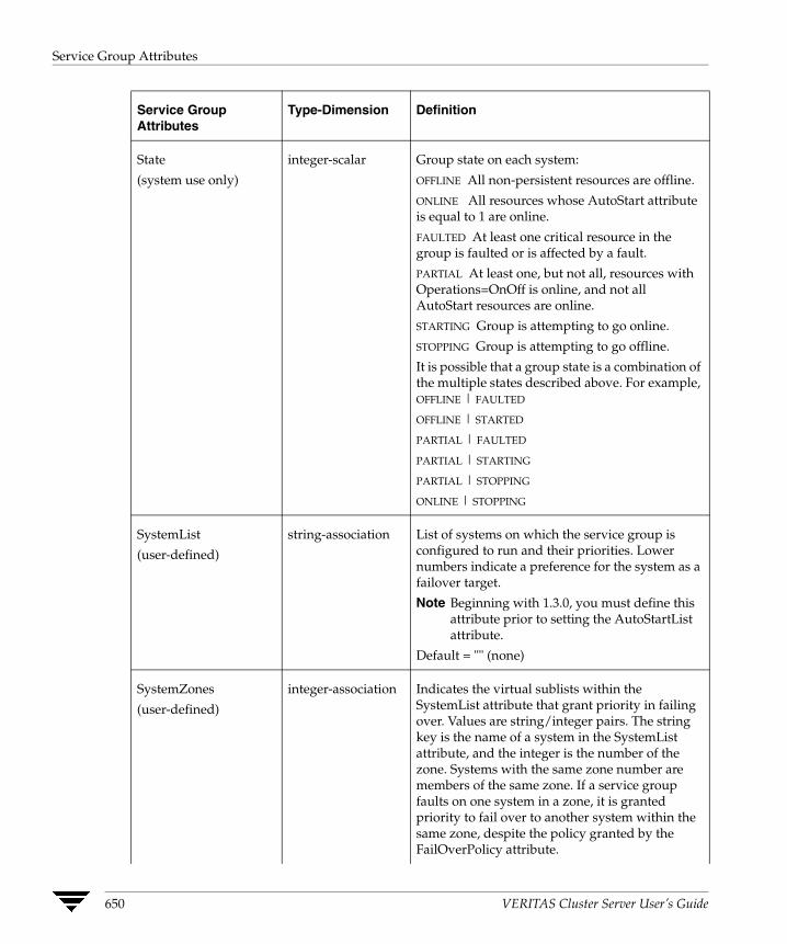
Service Group Attributes
State
(system use only)
integer-scalar Group state on each system:
OFFLINE All non-persistent resources are offline.
ONLINE All resources whose AutoStart attribute is equal to 1 are online.
FAULTED At least one critical resource in the group is faulted or is affected by a fault.
PARTIAL At least one, but not all, resources with Operations=OnOff is online, and not all AutoStart resources are online.
STARTING Group is attempting to go online.
STOPPING Group is attempting to go offline.
It is possible that a group state is a combination of the multiple states described above. For example, OFFLINE | FAULTED
OFFLINE | STARTED
PARTIAL | FAULTED
PARTIAL | STARTING
PARTIAL | STOPPING
ONLINE | STOPPING
SystemList
(user-defined)
string-association List of systems on which the service group is configured to run and their priorities. Lower numbers indicate a preference for the system as a failover target.
Note Beginning with 1.3.0, you must define this attribute prior to setting the AutoStartList attribute.
Default = "" (none)
SystemZones
(user-defined)
integer-association Indicates the virtual sublists within the SystemList attribute that grant priority in failing over. Values are string/integer pairs. The string key is the name of a system in the SystemList attribute, and the integer is the number of the zone. Systems with the same zone number are members of the same zone. If a service group faults on one system in a zone, it is granted priority to fail over to another system within the same zone, despite the policy granted by the FailOverPolicy attribute.
Service Group Attributes
Type-Dimension Definition
650 VERITAS Cluster Server User’s Guide
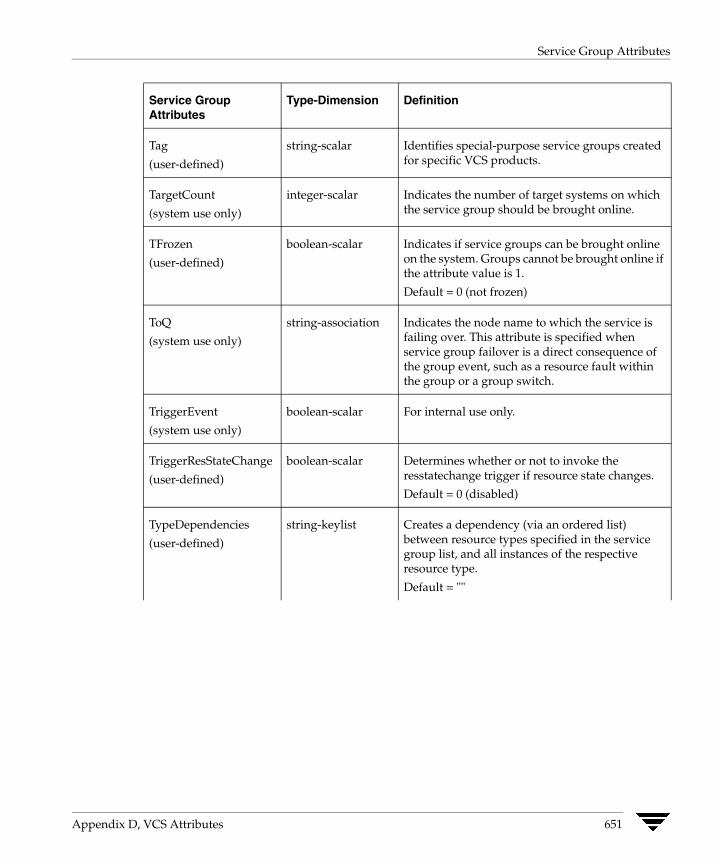
Service Group Attributes
Tag
(user-defined)
string-scalar Identifies special-purpose service groups created for specific VCS products.
TargetCount
(system use only)
integer-scalar Indicates the number of target systems on which the service group should be brought online.
TFrozen
(user-defined)
boolean-scalar Indicates if service groups can be brought online on the system. Groups cannot be brought online if the attribute value is 1.
Default = 0 (not frozen)
ToQ
(system use only)
string-association Indicates the node name to which the service is failing over. This attribute is specified when service group failover is a direct consequence of the group event, such as a resource fault within the group or a group switch.
TriggerEvent
(system use only)
boolean-scalar For internal use only.
TriggerResStateChange
(user-defined)
boolean-scalar Determines whether or not to invoke the resstatechange trigger if resource state changes.
Default = 0 (disabled)
TypeDependencies
(user-defined)
string-keylist Creates a dependency (via an ordered list) between resource types specified in the service group list, and all instances of the respective resource type.
Default = ""
Service Group Attributes
Type-Dimension Definition
Appendix D, VCS Attributes 651
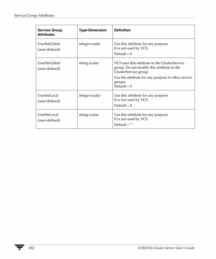
Service Group Attributes
Service Group Attributes
Type-Dimension Definition
UserIntGlobal
(user-defined)
integer-scalar Use this attribute for any purpose. It is not used by VCS.
Default = 0
UserStrGlobal
(user-defined)
string-scalar VCS uses this attribute in the ClusterService group. Do not modify this attribute in the ClusterService group.
Use the attribute for any purpose in other service groups. Default = 0
UserIntLocal
(user-defined)
integer-scalar Use this attribute for any purpose. It is not used by VCS.
Default = 0
UserStrLocal
(user-defined)
string-scalar Use this attribute for any purpose. It is not used by VCS.
Default = ""
652 VERITAS Cluster Server User’s Guide
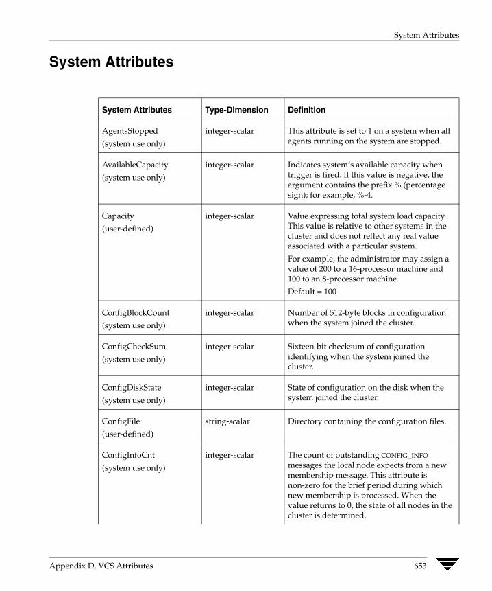
System Attributes
System Attributes
System Attributes Type-Dimension Definition
AgentsStopped
(system use only)
integer-scalar This attribute is set to 1 on a system when all agents running on the system are stopped.
AvailableCapacity
(system use only)
integer-scalar Indicates system’s available capacity when trigger is fired. If this value is negative, the argument contains the prefix % (percentage sign); for example, %-4.
Capacity
(user-defined)
integer-scalar Value expressing total system load capacity. This value is relative to other systems in the cluster and does not reflect any real value associated with a particular system.
For example, the administrator may assign a value of 200 to a 16-processor machine and 100 to an 8-processor machine.
Default = 100
ConfigBlockCount
(system use only)
integer-scalar Number of 512-byte blocks in configuration when the system joined the cluster.
ConfigCheckSum
(system use only)
integer-scalar Sixteen-bit checksum of configuration identifying when the system joined the cluster.
ConfigDiskState
(system use only)
integer-scalar State of configuration on the disk when the system joined the cluster.
ConfigFile
(user-defined)
string-scalar Directory containing the configuration files.
ConfigInfoCnt
(system use only)
integer-scalar The count of outstanding CONFIG_INFO
messages the local node expects from a new membership message. This attribute is non-zero for the brief period during which new membership is processed. When the value returns to 0, the state of all nodes in the cluster is determined.
Appendix D, VCS Attributes 653

System Attributes
ConfigModDate
(system use only)
integer-scalar Last modification date of configuration when the system joined the cluster.
CPUBinding
(user-defined)
string-association Binds the HAD process to the specified CPU. Set this attribute to prevent HAD from getting interrupted.
The format for CPUBinding is:
CPUBinding = {BindTo = binding, CPUNumber = number}
The variable binding can take the following values:
◆ NONE indicates that CPU binding will not be used
◆ ANY indicates that HAD will bind to any available CPU
◆ CPUNUM indicates that HAD will bind to CPU specified in the CPUNumber attribute
The variable number specifies the number of the CPU.
CPUUsage
(system use only)
integer-scalar Indicates the system’s CPU usage by CPU percentage utilization. This attribute’s value is valid if the Enabled value in the CPUUsageMonitoring attribute (below) equals 1. The value of this attribute is updated when there is a change of five percent since the last indicated value.
System Attributes Type-Dimension Definition
654 VERITAS Cluster Server User’s Guide

System Attributes
CPUUsageMonitoring string-association Monitors the system’s CPU usage using various factors.
Defaults for this attribute are:
Enabled = 0, NotifyThreshold = 0, NotifyTimeLimit = 0, ActionThreshold = 0, ActionTimeLimit = 0, Action = NONE.
The values for ActionTimeLimit and NotifiyTimeLimt represent the time in seconds. The values for ActionThreshold and NotifyThreshold represent the threshold in terms of CPU percentage utilization.
See “Monitoring CPU Usage” on page 567 for more information regarding this attribute and its role in VCS performance.
CurrentLimits
(system use only)
integer-association System-maintained calculation of current value of Limits.
CurrentLimits = Limits - (additive value of all service group Prerequisites).
DiskHbStatus
(system use only)
string-association Indicates status of communication disks on any system.
DynamicLoad
(user-defined)
integer-scalar System-maintained value of current dynamic load. The value is set external to VCS with the hasys -load command.
EngineRestarted
(system use only)
boolean-scalar Indicates whether the VCS engine (HAD) was restarted by the hashadow process on a node in the cluster. The value 1 indicates that the engine was restarted; 0 indicates it was not restarted.
Frozen
(user-defined)
boolean-scalar Indicates if service groups can be brought online on the system. Groups cannot be brought online if the attribute value is 1.
System Attributes Type-Dimension Definition
Appendix D, VCS Attributes 655

System Attributes
GUIIPAddr
(user-defined)
string-scalar Determines the local IP address that VCS uses to accept connections. Incoming connections over other IP addresses are dropped. If GUIIPAddr is not set, the default behavior is to accept external connections over all configured local IP addresses.
For additional information, see “User Privileges for CLI and Cluster Shell Commands” on page 55.
LicenseType
(system use only)
integer-scalar Indicates the license type of the base VCS key used by the system. Possible values are:
◆ 0—DEMO
◆ 1—PERMANENT
◆ 2—PERMANENT_NODE_LOCK
◆ 3—DEMO_NODE_LOCK
◆ 4—NFR
◆ 5—DEMO_EXTENSION
◆ 6—NFR_NODE_LOCK
◆ 7—DEMO_EXTENSION_NODE_LOCK
Limits
(user-defined)
integer-association An unordered set of name=value pairs denoting specific resources available on a system. Names are arbitrary and are set by the administrator for any value. Names are not obtained from the system.
The format for Limits is: Limits = { Name=Value, Name2=Value2 }.
Default = ""
LinkHbStatus
(system use only)
string-association Indicates status of private network links on any system.
LLTNodeId
(system use only)
integer-scalar Displays the node ID defined in the file /etc/llttab.
LoadTimeCounter
(system use only)
integer-scalar System-maintained internal counter of how many seconds the system load has been above LoadWarningLevel. This value resets to zero anytime system load drops below the value in LoadWarningLevel.
System Attributes Type-Dimension Definition
656 VERITAS Cluster Server User’s Guide

System Attributes
LoadTimeThreshold
(user-defined)
integer-scalar How long the system load must remain at or above LoadWarningLevel before the LoadWarning trigger is fired. If set to 0 overload calculations are disabled.
Default = 600 seconds
LoadWarningLevel
(user-defined)
integer-scalar A value expressed as a percentage of total capacity where load has reached a critical limit. If set to 0 overload calculations are disabled.
For example, setting LoadWarningLevel = 80 sets the warning level to 80 percent.
The value of this attribute can be set from 1 to 100. If set to 1, system load must equal 1 percent of system capacity to begin incrementing the LoadTimeCounter. If set to 100, system load must equal system capacity to increment the LoadTimeCounter.
Default = 80 percent
MajorVersion
(system use only)
integer-scalar Major version of system’s join protocol.
MinorVersion
(system use only)
integer-scalar Minor version of system’s join protocol.
NoAutoDisable
(system use only)
boolean-scalar When set to 0, this attribute autodisables service groups when the VCS engine is taken down. Groups remain autodisabled until the engine is brought up (regular membership).
Setting this attribute to 1 bypasses the autodisable feature.
Default = 0
NodeId
(system use only)
integer-scalar System (node) identification specified in /etc/llttab.
OnGrpCnt
(system use only)
integer-scalar Number of groups that are online, or about to go online, on a system.
System Attributes Type-Dimension Definition
Appendix D, VCS Attributes 657
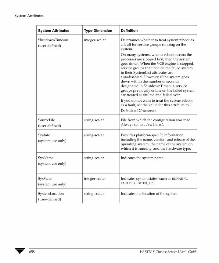
System Attributes
ShutdownTimeout
(user-defined)
integer-scalar Determines whether to treat system reboot as a fault for service groups running on the system.
On many systems, when a reboot occurs the processes are stopped first, then the system goes down. When the VCS engine is stopped, service groups that include the failed system in their SystemList attributes are autodisabled. However, if the system goes down within the number of seconds designated in ShutdownTimeout, service groups previously online on the failed system are treated as faulted and failed over.
If you do not want to treat the system reboot as a fault, set the value for this attribute to 0.
Default = 120 seconds
SourceFile
(user-defined)
string-scalar File from which the configuration was read. Always set to ./main.cf.
SysInfo
(system use only)
string-scalar Provides platform-specific information, including the name, version, and release of the operating system, the name of the system on which it is running, and the hardware type.
SysName
(system use only)
string-scalar Indicates the system name.
SysState
(system use only)
integer-scalar Indicates system states, such as RUNNING, FAULTED, EXITED, etc.
SystemLocation
(user-defined)
string-scalar Indicates the location of the system.
System Attributes Type-Dimension Definition
658 VERITAS Cluster Server User’s Guide
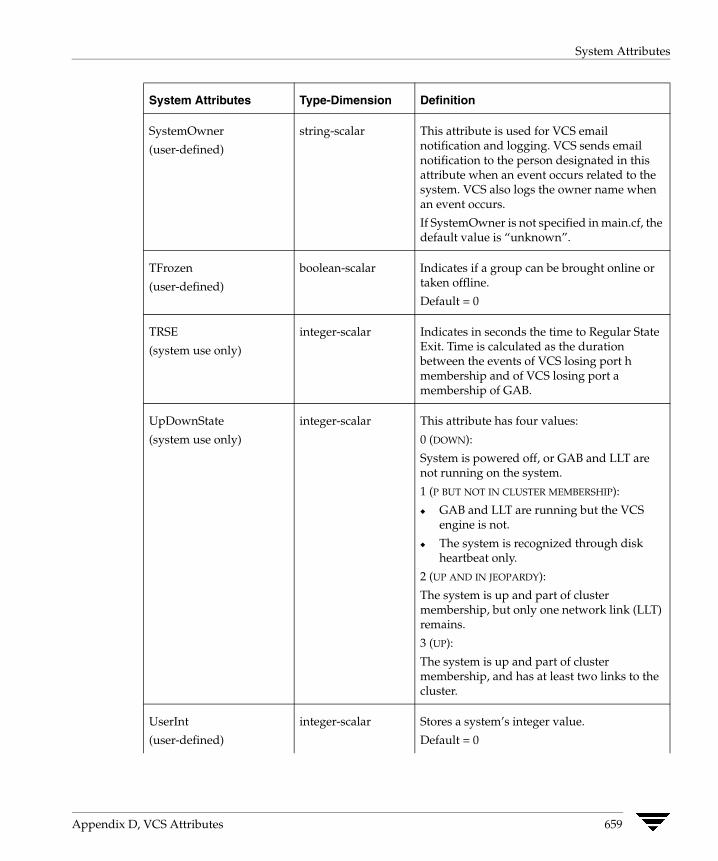
System Attributes
SystemOwner
(user-defined)
string-scalar This attribute is used for VCS email notification and logging. VCS sends email notification to the person designated in this attribute when an event occurs related to the system. VCS also logs the owner name when an event occurs.
If SystemOwner is not specified in main.cf, the default value is “unknown”.
TFrozen
(user-defined)
boolean-scalar Indicates if a group can be brought online or taken offline.
Default = 0
TRSE
(system use only)
integer-scalar Indicates in seconds the time to Regular State Exit. Time is calculated as the duration between the events of VCS losing port h membership and of VCS losing port a membership of GAB.
UpDownState
(system use only)
integer-scalar This attribute has four values:
0 (DOWN):
System is powered off, or GAB and LLT are not running on the system.
1 (P BUT NOT IN CLUSTER MEMBERSHIP):
◆ GAB and LLT are running but the VCS engine is not.
◆ The system is recognized through disk heartbeat only.
2 (UP AND IN JEOPARDY):
The system is up and part of cluster membership, but only one network link (LLT) remains.
3 (UP):
The system is up and part of cluster membership, and has at least two links to the cluster.
UserInt
(user-defined)
integer-scalar Stores a system’s integer value.
Default = 0
System Attributes Type-Dimension Definition
Appendix D, VCS Attributes 659
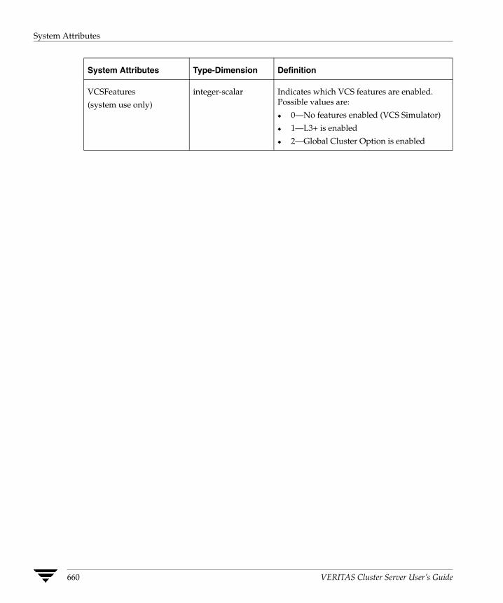
System Attributes
System Attributes Type-Dimension Definition
VCSFeatures
(system use only)
integer-scalar Indicates which VCS features are enabled. Possible values are:
◆ 0—No features enabled (VCS Simulator)
◆ 1—L3+ is enabled
◆ 2—Global Cluster Option is enabled
660 VERITAS Cluster Server User’s Guide

Cluster Attributes
Cluster Attributes
Cluster Attributes Type-Dimension Definition
Administrators
(user-defined)
string-keylist Contains list of users with Administrator privileges.
Default = ""
AutoStartTimeout
(user-defined)
integer-scalar If the local cluster cannot communicate with one or more remote clusters, this attribute specifies the number of seconds the VCS engine waits before initiating the AutoStart process for an AutoStart global service group.
Default = 150 seconds
ClusState
(system use only)
string-scalar Indicates the current state of the cluster.
Default is non-applicable.
ClusterAddress
(system use only)
string-scalar Specifies the cluster’s virtual IP address (used by a remote cluster when connecting to the local cluster).
Default is non-applicable.
ClusterLocation
(user-defined)
string-scalar Specifies the location of the cluster.
Default = ""
ClusterName
(user-defined)
string-scalar Arbitrary string containing the name of cluster.
Default = ""
ClusterOwner
(user-defined)
string-scalar This attribute is used for VCS notification; specifically, VCS sends notifications to persons designated in this attribute when when an event occurs related to the cluster. See “How Notification Works” on page 413 for more information.
If ClusterOwner is not specified in main.cf, the default value is “unknown”.
ClusterTime
(system use only)
string-scalar The number of seconds since January 1, 1970. This is defined by the lowest node in running state.
Appendix D, VCS Attributes 661

Cluster Attributes
ClusterUUID
(system use only)
string-scalar Unique UUIID assigned to the cluster by Availability Manager.
CompareRSM
(user-defined)
integer-scalar Indicates if VCS engine is to verify that replicated state machine is consistent. This can be set by running the hadebug command.
Default = 0
ConnectorState
(system use only)
integer-scalar Indicates the state of the wide-area connector (wac). If 0, wac is not running. If 1, wac is running and communicating with the VCS engine.
Default is non-applicable.
CounterInterval
(user-defined)
integer-scalar Intervals counted by the attribute GlobalCounter indicating approximately how often a broadcast occurs that will cause the GlobalCounter attribute to increase.
The default value of the GlobalCounter increment can be modified by changing CounterInterval. If you increase this attribute to exceed five seconds, consider increasing the default value of the ShutdownTimeout attribute.
Default = 5
CredRenewFrequency integer-scalar The number of days after which the VCS engine renews its credentials with the authentication broker. For example, the value 5 indicates that credentials are renewed every 5 days; the value 0 indicates that credentials are not renewed.
Default=0
DumpingMembership
(system use only)
integer-scalar Indicates that the engine is writing to disk.
Default is non-applicable.
EngineClass
(user-defined)
string-scalar Indicates the scheduling class for the VCS engine (HAD).
Default = RT
Cluster Attributes Type-Dimension Definition
662 VERITAS Cluster Server User’s Guide
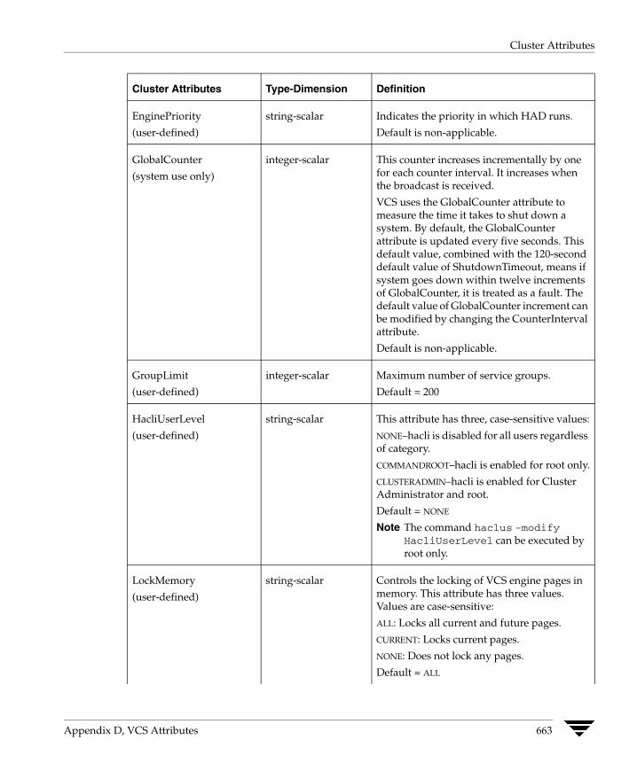
Cluster Attributes
EnginePriority
(user-defined)
string-scalar Indicates the priority in which HAD runs.
Default is non-applicable.
GlobalCounter
(system use only)
integer-scalar This counter increases incrementally by one for each counter interval. It increases when the broadcast is received.
VCS uses the GlobalCounter attribute to measure the time it takes to shut down a system. By default, the GlobalCounter attribute is updated every five seconds. This default value, combined with the 120-second default value of ShutdownTimeout, means if system goes down within twelve increments of GlobalCounter, it is treated as a fault. The default value of GlobalCounter increment can be modified by changing the CounterInterval attribute.
Default is non-applicable.
GroupLimit
(user-defined)
integer-scalar Maximum number of service groups.
Default = 200
HacliUserLevel
(user-defined)
string-scalar This attribute has three, case-sensitive values:
NONE–hacli is disabled for all users regardless of category.
COMMANDROOT–hacli is enabled for root only.
CLUSTERADMIN–hacli is enabled for Cluster Administrator and root.
Default = NONE
Note The command haclus -modify HacliUserLevel can be executed by root only.
LockMemory
(user-defined)
string-scalar Controls the locking of VCS engine pages in memory. This attribute has three values. Values are case-sensitive:
ALL: Locks all current and future pages.
CURRENT: Locks current pages.
NONE: Does not lock any pages.
Default = ALL
Cluster Attributes Type-Dimension Definition
Appendix D, VCS Attributes 663
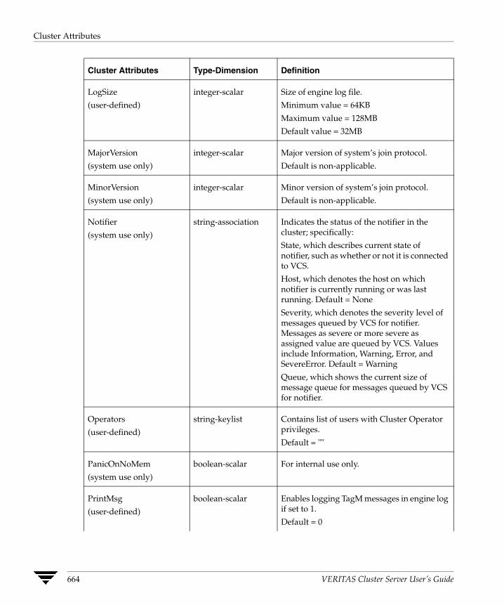
Cluster Attributes
LogSize
(user-defined)
integer-scalar Size of engine log file.
Minimum value = 64KB
Maximum value = 128MB
Default value = 32MB
MajorVersion
(system use only)
integer-scalar Major version of system’s join protocol.
Default is non-applicable.
MinorVersion
(system use only)
integer-scalar Minor version of system’s join protocol.
Default is non-applicable.
Notifier
(system use only)
string-association Indicates the status of the notifier in the cluster; specifically:
State, which describes current state of notifier, such as whether or not it is connected to VCS.
Host, which denotes the host on which notifier is currently running or was last running. Default = None
Severity, which denotes the severity level of messages queued by VCS for notifier. Messages as severe or more severe as assigned value are queued by VCS. Values include Information, Warning, Error, and SevereError. Default = Warning
Queue, which shows the current size of message queue for messages queued by VCS for notifier.
Operators
(user-defined)
string-keylist Contains list of users with Cluster Operator privileges.
Default = ""
PanicOnNoMem
(system use only)
boolean-scalar For internal use only.
PrintMsg
(user-defined)
boolean-scalar Enables logging TagM messages in engine log if set to 1.
Default = 0
Cluster Attributes Type-Dimension Definition
664 VERITAS Cluster Server User’s Guide
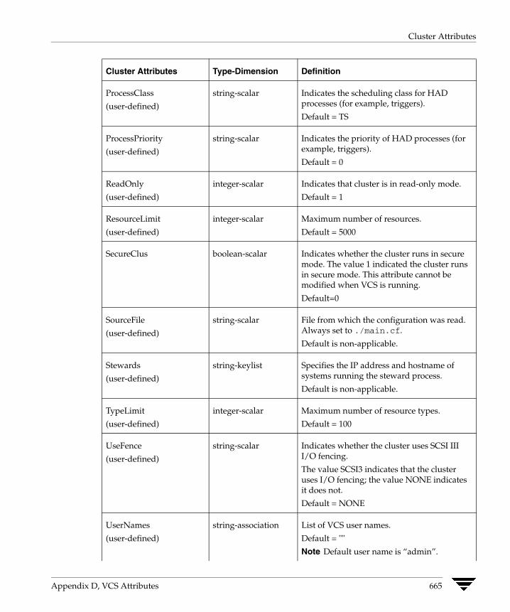
Cluster Attributes
ProcessClass
(user-defined)
string-scalar Indicates the scheduling class for HAD processes (for example, triggers).
Default = TS
ProcessPriority
(user-defined)
string-scalar Indicates the priority of HAD processes (for example, triggers).
Default = 0
ReadOnly
(user-defined)
integer-scalar Indicates that cluster is in read-only mode.
Default = 1
ResourceLimit
(user-defined)
integer-scalar Maximum number of resources.
Default = 5000
SecureClus boolean-scalar Indicates whether the cluster runs in secure mode. The value 1 indicated the cluster runs in secure mode. This attribute cannot be modified when VCS is running.
Default=0
SourceFile
(user-defined)
string-scalar File from which the configuration was read. Always set to ./main.cf.
Default is non-applicable.
Stewards
(user-defined)
string-keylist Specifies the IP address and hostname of systems running the steward process.
Default is non-applicable.
TypeLimit
(user-defined)
integer-scalar Maximum number of resource types.
Default = 100
UseFence
(user-defined)
string-scalar Indicates whether the cluster uses SCSI III I/O fencing.
The value SCSI3 indicates that the cluster uses I/O fencing; the value NONE indicates it does not.
Default = NONE
UserNames
(user-defined)
string-association List of VCS user names.
Default = ""
Note Default user name is “admin”.
Cluster Attributes Type-Dimension Definition
Appendix D, VCS Attributes 665

Cluster Attributes
Cluster Attributes Type-Dimension Definition
VCSi3Info
(system use only)
string-association Enables VCS service groups to be mapped to VERITAS i3 applications. This attribute is managed by the i3 product and should not be set or modified by the user.
Contact your local VERITAS Sales Representative for more information on the benefits of integrating VCS availability management with i3 performance management.
VCSFeatures
(system use only)
integer-scalar Indicates which VCS features are enabled. Possible values are:
◆ 0—No features are enabled (VCS Simulator)
◆ 1—L3+ is enabled
◆ 2—Global Cluster Option is enabled
VCSMode
(system use only)
integer-scalar Denotes the mode for which VCS is licensed, including VCS, Traffic Director, and VCS_OPS.
WACPort
(user-defined)
integer-scalar The TCP port on which the wac (Wide-Area Connector) process on the local cluster listens for connection from remote clusters. The attribute can take a value from 0 to 65535.
Default = 14155
666 VERITAS Cluster Server User’s Guide
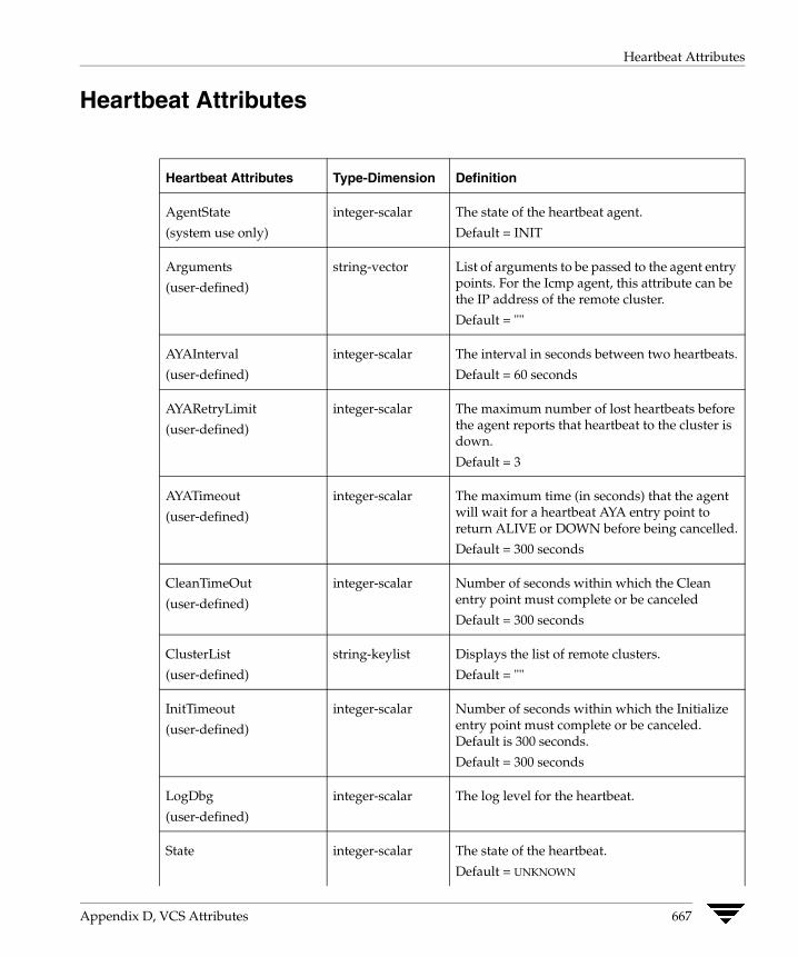
Heartbeat Attributes
Heartbeat Attributes
Heartbeat Attributes Type-Dimension Definition
AgentState
(system use only)
integer-scalar The state of the heartbeat agent.
Default = INIT
Arguments
(user-defined)
string-vector List of arguments to be passed to the agent entry points. For the Icmp agent, this attribute can be the IP address of the remote cluster.
Default = ""
AYAInterval
(user-defined)
integer-scalar The interval in seconds between two heartbeats.
Default = 60 seconds
AYARetryLimit
(user-defined)
integer-scalar The maximum number of lost heartbeats before the agent reports that heartbeat to the cluster is down.
Default = 3
AYATimeout
(user-defined)
integer-scalar The maximum time (in seconds) that the agent will wait for a heartbeat AYA entry point to return ALIVE or DOWN before being cancelled.
Default = 300 seconds
CleanTimeOut
(user-defined)
integer-scalar Number of seconds within which the Clean entry point must complete or be canceled
Default = 300 seconds
ClusterList
(user-defined)
string-keylist Displays the list of remote clusters.
Default = ""
InitTimeout
(user-defined)
integer-scalar Number of seconds within which the Initialize entry point must complete or be canceled. Default is 300 seconds.
Default = 300 seconds
LogDbg
(user-defined)
integer-scalar The log level for the heartbeat.
State integer-scalar The state of the heartbeat.
Default = UNKNOWN
Appendix D, VCS Attributes 667

Heartbeat Attributes
Heartbeat Attributes Type-Dimension Definition
StartTimeout
(user-defined)
integer-scalar Number of seconds within which the Start entry point must complete or be canceled
Default = 300 seconds
StopTimeout
(user-defined)
integer-scalar Number of seconds within which the Stop entry point must complete or be canceled without stopping the heartbeat
Default = 300 seconds
668 VERITAS Cluster Server User’s Guide
Administering VERITAS Web Server
E VERITAS Web Server (VRTSweb) is a Web Server component shared by various VERITAS Web consoles, including VERITAS Cluster Server, VERITAS Volume Replicator, and VERITAS Traffic Director.This document describes how to administer VRTSweb and provides instructions for common configuration tasks. Note that changes to the VRTSweb configuration apply to all Web consoles sharing the Web server.
Note The Web server is installed at the path /opt/VRTSweb/ on UNIX systems. On Windows systems, the default installation path is C:\Program Files\VERITAS\VRTSweb.
669
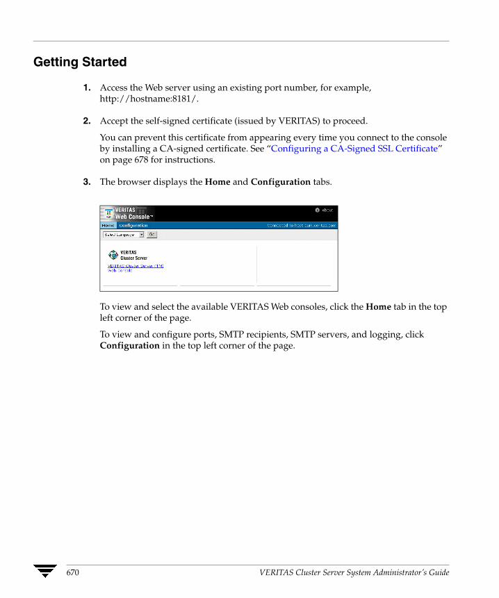
Getting Started
1. Access the Web server using an existing port number, for example, http://hostname:8181/.
2. Accept the self-signed certificate (issued by VERITAS) to proceed.
You can prevent this certificate from appearing every time you connect to the console by installing a CA-signed certificate. See “Configuring a CA-Signed SSL Certificate” on page 678 for instructions.
3. The browser displays the Home and Configuration tabs.
To view and select the available VERITAS Web consoles, click the Home tab in the top left corner of the page.
To view and configure ports, SMTP recipients, SMTP servers, and logging, click Configuration in the top left corner of the page.
670 VERITAS Cluster Server System Administrator’s Guide

Reviewing the Web Server Configuration
Reviewing the Web Server Configuration
1. Access the Web server using an existing port number; for example, http://hostname:8181/.
2. Click the Configuration tab.
The Configured Ports table lists information about the configured ports.
The SMTP Recipients table displays information about configured SMTP recipients and the SMTP server.
The Logging table lists the log levels for various Web server components.
Appendix E, Administering VERITAS Web Server 671
Configuring Ports for VRTSweb
Configuring Ports for VRTSweb By default, VRTSweb is configured to serve HTML content on two ports: 8181 (HTTP) and 8443 (HTTPS). Additionally, VRTSweb uses port 14300 as an administrative port.
If you use any of these ports for another application on the system, you must configure VRTSweb to use different ports.
Port 8181 is the non-secure port, used for backward compatibility; 8443 is the secure SSL port. Users accessing the Web server on the non-secure port are redirected to the secure port.
When accessing content over the secure port, VRTSweb presents a self-signed SSL certificate (issued by VERITAS) to the browser. You must accept the certificate before accessing the secure Web consoles. The SSL protocol prevents malicious users from sniffing Web console data from the network.
Retrieving the List of Ports
▼ From the command line
Run the following command on the system where VRTSweb is installed:
# $VRTSWEB_HOME/bin/webgui listports
The output displays the list of configured ports and their protocols.
▼ From the Web Console
1. Access the Web server using an existing port number; for example, http://hostname:8181/.
2. Click the Configuration tab.
The Configured Ports table on the right side of the Configuration page lists the ports.
672 VERITAS Cluster Server System Administrator’s Guide
Configuring Ports for VRTSweb
Adding Ports
▼ From the command line
Run the following command on the system where VRTSweb is installed:
# $VRTSWEB_HOME/bin/webgui addport portno protocol bind_ip_address
The variable portno represents the port number to be added. The variable protocol represents the protocol for the port. HTTP specifies a normal HTTP port, HTTPS specifies a secure SSL port.
Web servers using the HTTP port can be accessed at http://hostname:portno/.
Web servers using the HTTPS port can be accessed at https://hostname:portno/.
The optional variable bind_ip_address specifies that the new port be bound to a particular IP address instead of each IP address on the system. Use this option to restrict Web server access to specific administrative subnets. If specified, the IP address must be available on the system before the Web server is started. Otherwise, the Web server fails to start.
For example:
# /opt/VRTSweb/bin/webgui addport 443 HTTPS 101.1.1.2# /opt/VRTSweb/bin/webgui addport 80 HTTP.
▼ From the Web console
1. Access the Web server using an existing port number; for example, http://hostname:8181/.
2. Click the Configuration tab.
3. Click Add Port on the left side of the Configuration page.
Appendix E, Administering VERITAS Web Server 673

Configuring Ports for VRTSweb
4. In the Add Port dialog box:
a. Enter the port number to be added.
b. Choose the HTTP option to add a normal port; choose the HTTPS option to add a secure SSL port.
Web servers using the HTTP port can be accessed at http://hostname:portno/.
Web servers using the HTTPS port can be accessed at https://hostname:portno/.
c. Enter an IP address to bind the new port to a specific IP address instead of each IP address on the system. Ensure the IP address is available on the system before starting the Web server. Use this attribute to restrict Web server access to specific administrative subnets.
d. Enter the name and password for a user having superuser (administrative) privileges on the Web server system.
e. Click OK.
674 VERITAS Cluster Server System Administrator’s Guide
Configuring Ports for VRTSweb
Deleting Ports
▼ From the command line
Run the following command on the system where VRTSweb is installed:
# $VRTSWEB_HOME/bin/webgui delport <portno> [bind_ip_address]
The variable portno represents the port number to be deleted. If the port was bound to a particular IP address, use the bind_ip_address option.
You must ensure that at least one port remains configured for the Web server.
For example:
# /opt/VRTSweb/bin/webgui delport 443 101.1.1.2# /opt/VRTSweb/bin/webgui delport 80
▼ From the Web console
1. Access the Web server using an existing port number; for example, http://hostname:8181/.
2. Click the Configuration tab.
3. Click Delete Port on the left side of the Configuration page.
Appendix E, Administering VERITAS Web Server 675

Configuring Ports for VRTSweb
4. In the Delete Port dialog box:
a. Enter the port number to be deleted. You cannot delete the port being used to access the Web page.
b. If the port was bound to a particular IP address, enter the IP address.
c. Enter the name and password for a user having superuser (administrative) privileges on Web server system.
d. Click OK.
Changing the Administrative Port You can change the administrative port for VRTSweb only from the command line.
1. Stop the Web server:
# $VRTSWEB_HOME/bin/webgui stop force
2. Set the administrative port to a new value:
# $VRTSWEB_HOME/bin/webgui adminport new_port_no
3. Restart the Web server:
# $VRTSWEB_HOME/bin/webgui restart
676 VERITAS Cluster Server System Administrator’s Guide

Managing VRTSweb SSL Certificates
Managing VRTSweb SSL Certificates When serving content over the secure port, VRTSweb presents a self-signed SSL certificate (issued by VERITAS) to the browser. This section describes how you can manage the certificate.
Note Certificate management commands are available only via the command line interface. Commands that modify the certificate require a server restart. You can use the webgui restart command to restart the Web server.
Viewing SSL Certificate Information To view information about the configured SSL certificate, run the following command on the system where VRTSweb is installed:
# $VRTSWEB_HOME/bin/webgui cert display
Creating a Self-Signed SSL Certificate To create a custom self-signed SSL certificate for VRTSweb, run the following interactive command on the system where VRTSweb is installed:
# $VRTSWEB_HOME/bin/webgui cert create
The command guides you through the process of creating a new certificate.
Please answer the following questions to create a self-signed SSL certificate. This is required to enable the HTTPS protocol for the web server.+++++++++++++++++++++++++++++++++++++++++++++++++++++++++++++++++With what hostname/IP will you access this web server? [thor106]:thor106What is the name of your organizational unit? [Unknown]:EngineeringWhat is the name of your organization? [Unknown]:Your CompanyWhat is the name of your City or Locality? [Unknown]: Mountain ViewWhat is the name of your State or Province? [Unknown]:CaliforniaWhat is the two-letter country code for this unit? [Unknown]:USIs CN=thor106, OU=Engineering, O=Your Company, L=Mountain View, ST=California, C=US correct? [no]:yesCertificate created successfully
Note You must restart the server for the new certificate to take effect.
Appendix E, Administering VERITAS Web Server 677
Managing VRTSweb SSL Certificates
Exporting SSL Certificate to a File You can export the public key associated with an SSL certificate to a file. This key can then be imported into other applications that will trust the VRTSweb instance.
Run the following command on the system where VRTSweb is installed:
# $VRTSWEB_HOME/bin/webgui cert export cert_file [rfc]
If the VRTSweb SSL certificate does not exist, the command prompts you to create one. If you specify the RFC option, the key output is encoded in a printable format, defined by the Internet RFC 1421 standard.
For example:
# /opt/VRTSweb/bin/webgui cert export /myapp/vrtsweb.cer rfc
Configuring a CA-Signed SSL Certificate By default, VRTSweb presents a self-signed SSL certificate every time you access VRTSweb over the SSL port. You can install a certificate signed by a Certificate Authority (CA) like Verisign.com or Thawte.com.
1. If you do not have a self-signed certificate with information that can be verified by the CA, create one.
# $VRTSWEB_HOME/bin/webgui cert create
See “Creating a Self-Signed SSL Certificate” on page 677 for more information.
2. Generate a Certificate Signing Request (CSR) for the certificate. Run the following command on the system where VRTSweb is installed:
# $VRTSWEB_HOME/bin/webgui cert certreq certreq_file
The variable certreq_file specifies the file to which the CSR will be written. The file is written using the Public-Key Cryptography Standard PKCS#10.
For example:
# /opt/VRTSweb/bin/webgui cert certreq /myapp/vrtsweb.csr
3. Submit the CSR to a certification authority, who will issue a CA-signed certificate.
678 VERITAS Cluster Server System Administrator’s Guide
Managing VRTSweb SSL Certificates
4. Import the CA-issued certificate to VRTSweb. Run the following command on the system where VRTSweb is installed:
# $VRTSWEB_HOME/bin/webgui import ca_cert_file
The variable cert_file represents the certificate issued to you by the certification authority.
For example:
# /opt/VRTSweb/bin/webgui cert import /myapp/vrtsweb.cer
Note that the import command fails if the CA root certificate is not a part of the trust store associated with VRTSweb. If the command fails, add the CA root certificate to the VRTSweb trust store:
# $VRTSWEB_HOME/bin/webgui cert trust ca_root_cert_file
For example:
# /opt/VRTSweb/bin/webgui cert trust /myapp/caroot.cer
Once the certificate used to sign the CSR is added to VRTSweb trust store, you can import the CA-assigned certificate into VRTSweb.
5. Restart VRTSweb:
# $VRTSWEB_HOME/bin/webgui restart
Cloning the VRTSweb SSL Certificate You can clone the VRTSweb SSL keypair into a keystore and use the cloned VRTSweb certificate for another application or Web server. Visit http://java.sun.com for more information about keystores.
# $VRTSWEB_HOME/bin/webgui cert clone keystore storepass aliaskeypass
If a clone keystore exists, the command renames it to keystore.old. If the VRTSweb SSL certificate does not exist, the command prompts you to create one.
For example:
# /opt/VRTSweb/bin/webgui webgui cert clone /myapp/myserv.keystore mystorepass myalias mykeypass
Appendix E, Administering VERITAS Web Server 679

Configuring SMTP Notification for VRTSweb
Configuring SMTP Notification for VRTSweb You can configure VRTSweb to send out email notifications about events associated with the Web server. For example:
◆ The Web server is starting/stopping [severity: INFORMATION]
◆ The Web console is starting/stopping [severity: INFORMATION]
◆ The Web server's allocated heap size very close to the maximum allowed [severity: SEVERE]
To send an email notification, VRTSweb needs to know the IP address or hostname of a configured SMTP server. The SMTP server address is also made available to all the Web consoles running on the Web server, thereby avoiding the need to configure the SMTP server at multiple places.
Retrieving the Name of the Configured SMTP Server
▼ From the command line
Run the following command on the system where VRTSweb is installed:
# $VRTSWEB_HOME/bin/webgui smtp getserver
The command displays the SMTP server address or hostname, if it is configured.
▼ From the Web console
1. Access the Web server using an existing port number. For example, http://hostname:8181/
2. Click the Configuration tab.
3. The SMTP Recipients table on the right side of the page displays the configured SMTP server.
680 VERITAS Cluster Server System Administrator’s Guide

Configuring SMTP Notification for VRTSweb
Setting the SMTP Server
▼ From the command line
Run any of the following commands on the system where VRTSweb is installed:
# $VRTSWEB_HOME/bin/webgui smtp setserver server_ip/hostname# $VRTSWEB_HOME/bin/webgui smtp delserver
The setserver command sets the SMTP server to the specified hostname/IP address. The delserver command deletes the SMTP server setting and disables SMTP notification.
For example:
# /opt/VRTSweb/bin/webgui smtp setserver smtphost.company.com# /opt/VRTSweb/bin/webgui smtp setserver 101.1.2.3# /opt/VRTSweb/bin/webgui smtp delserver
▼ From the Web Console
1. Access the Web server using an existing port number. For example, http://hostname:8181/
2. Click the Configuration tab.
3. Click Configure SMTP Server on the left side of the Configuration page.
Appendix E, Administering VERITAS Web Server 681

Configuring SMTP Notification for VRTSweb
4. In the Configure SMTP Server dialog box:
a. Enter the IP address or hostname of the SMTP server to be used for notification. An empty string will disable notification.
b. Enter the name and password for a user having superuser (administrative) privileges on the Web server system.
c. Click OK.
Retrieving Configured SMTP Recipients
▼ From the command line
Run the following command on the system where VRTSweb is installed:
# $VRTSWEB_HOME/bin/webgui smtp listrcpt
This command retrieves the email addresses of the configured recipients, the notification severity level, and the notification locale.
▼ From the Web console
1. Access the Web server using an existing port number. For example, http://hostname:8181/
2. Click the Configuration tab.
3. The SMTP Recipients table on the right side of the Configuration page lists the configured SMTP recipients.
682 VERITAS Cluster Server System Administrator’s Guide

Configuring SMTP Notification for VRTSweb
Adding an SMTP Recipient
▼ From the command line
Run the following command on the system where VRTSweb is installed:
# $VRTSWEB_HOME/bin/webgui smtp addrcpt email\[severity=<INFO|WARN|ERROR|SEVERE>] \[locale=<en|any_other_installed_locale>]
The variable email represents the email address of the new recipient.
The optional attribute severity represents the threshold for receiving Web server events. It can assume one of the following values: INFO|WARN|ERROR|SEVERE. If no value is specified for this attribute, it takes the default ERROR level.
The optional attribute locale specifies the locale in which the notification is to be sent. If no value is specified for this attribute, it takes the default locale of the system.
To retrieve the list of installed locales, run the following command:
# $VRTSWEB_HOME/bin/webgui smtp listlocales
For example:
# /opt/VRTSweb/bin/webgui smtp addrcpt [email protected] severity=INFO locale=ja_JP
# /opt/VRTSweb/bin/webgui smtp addrcpt [email protected] severity=ERROR
# /opt/VRTSweb/bin/webgui smtp addrcpt [email protected]
▼ From the Web console
1. Access the Web server using an existing port number. For example, http://hostname:8181/
2. Click the Configuration tab.
3. Click Add SMTP Recipient on the left side of the Configuration page.
Appendix E, Administering VERITAS Web Server 683
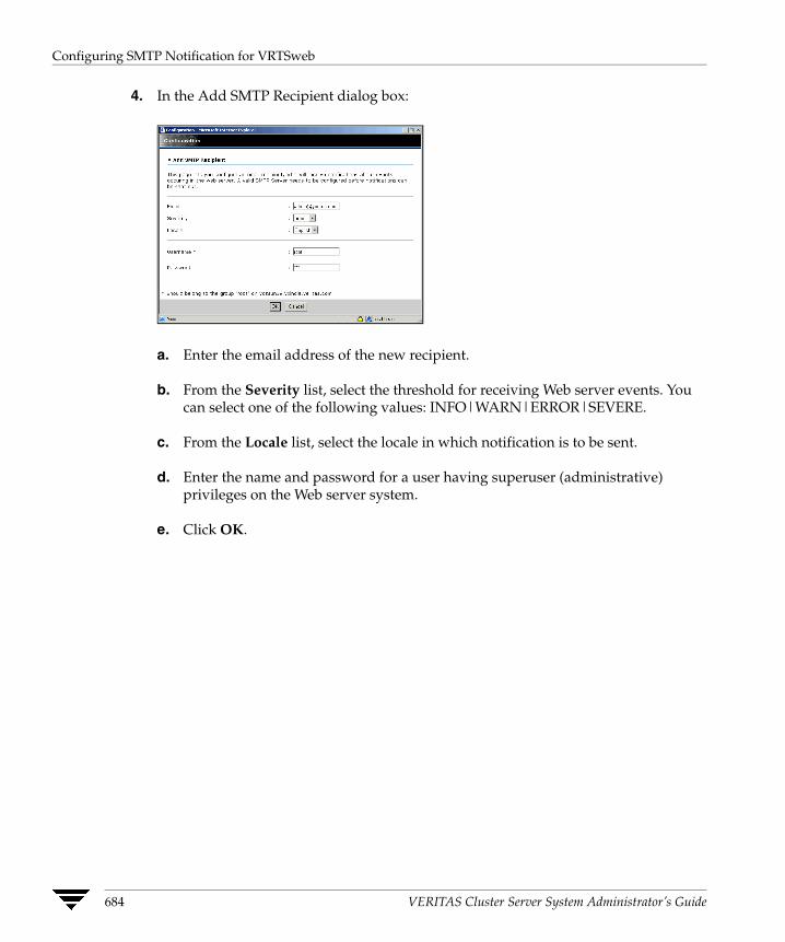
Configuring SMTP Notification for VRTSweb
4. In the Add SMTP Recipient dialog box:
a. Enter the email address of the new recipient.
b. From the Severity list, select the threshold for receiving Web server events. You can select one of the following values: INFO|WARN|ERROR|SEVERE.
c. From the Locale list, select the locale in which notification is to be sent.
d. Enter the name and password for a user having superuser (administrative) privileges on the Web server system.
e. Click OK.
684 VERITAS Cluster Server System Administrator’s Guide

Configuring SMTP Notification for VRTSweb
Deleting an SMTP Recipient
▼ From the command line
Run the following command on the system where VRTSweb is installed:
# $VRTSWEB_HOME/bin/webgui smtp delrcpt email
The variable email represents the email address of the recipient to be deleted.
For example:
# /opt/VRTSweb/bin/webgui smtp delrcpt [email protected]
▼ From the Web console
1. Access the Web server using an existing port number. For example, http://hostname:8181/
2. Click the Configuration tab.
3. Click Delete SMTP Recipient on the left side of the Configuration page.
4. In the Delete SMTP Recipient dialog box:
a. Enter the email address of the recipient to be deleted.
b. Enter the name and password for a user having superuser (administrative) privileges on the Web server system.
c. Click OK.
Appendix E, Administering VERITAS Web Server 685
Configuring VRTSweb Logging
Configuring VRTSweb Logging You can configure the amount of logs generated by individual VRTSWeb components. VRTSweb comprises the following components:
◆ Web server
◆ Web applications
◆ Other components
You can set the logging threshold for each component separately. The lower the threshold, the more are the logs generated. VERITAS recommends setting log levels to lower values only for debugging.
Most of the logs are located at:
◆ /var/VRTSweb/log (for UNIX)
◆ %VRTSWEB_HOME%\log (for Windows),
Individual VERITAS Web consoles choose their own locations for their logs. See the documentation of the specific Web console for more information.
Retrieving Log Levels
▼ From the command line
Run the following command on the system where VRTSweb is installed:
# $VRTSWEB_HOME/bin/webgui log
This returns the logging thresholds for various components and the limit and rollover count of various log files for VRTSweb.
▼ From the Web console
1. Access the Web server using an existing port number. For example, http://hostname:8181/
2. Click the Configuration tab.
3. The Logging table on the right side of the Configuration page lists the log levels for various components of the Web server. Note that the table does not display the limit and rollover count of various log files; you must use the command line to retrieve this information.
686 VERITAS Cluster Server System Administrator’s Guide

Configuring VRTSweb Logging
Modifying Log Levels
▼ From the command line
Run the following command on the system where VRTSweb is installed:
# $VRTSWEB_HOME/bin/webgui log [server=level] [webapps=level] [other=level]
You can specify any of the following values for the variable level for each Web server component: FINE|FINER|FINEST|CONFIG|INFO|WARNING|SEVERE.
Set the level to a lower value to generate more logs. FINEST is the lowest level while SEVERE is the highest level.
For example:
# /opt/VRTSweb/bin/webgui log server=FINEST webapps=INFO other=ERROR
# /opt/VRTSweb/bin/webgui log server=INFO
▼ From the Web console
1. Access the Web server using an existing port number. For example, http://hostname:8181/
2. Click the Configuration tab.
3. Click Configure Logging on the left side of the Configuration page.
Appendix E, Administering VERITAS Web Server 687
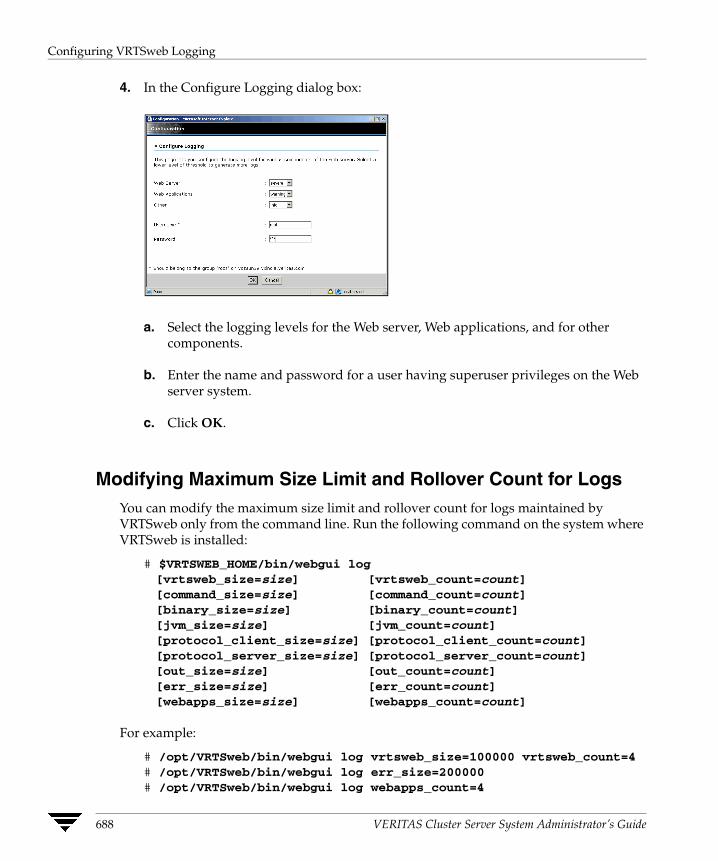
Configuring VRTSweb Logging
4. In the Configure Logging dialog box:
a. Select the logging levels for the Web server, Web applications, and for other components.
b. Enter the name and password for a user having superuser privileges on the Web server system.
c. Click OK.
Modifying Maximum Size Limit and Rollover Count for Logs You can modify the maximum size limit and rollover count for logs maintained by VRTSweb only from the command line. Run the following command on the system where VRTSweb is installed:
# $VRTSWEB_HOME/bin/webgui log [vrtsweb_size=size] [vrtsweb_count=count][command_size=size] [command_count=count][binary_size=size] [binary_count=count][jvm_size=size] [jvm_count=count][protocol_client_size=size] [protocol_client_count=count][protocol_server_size=size] [protocol_server_count=count][out_size=size] [out_count=count][err_size=size] [err_count=count][webapps_size=size] [webapps_count=count]
For example:
# /opt/VRTSweb/bin/webgui log vrtsweb_size=100000 vrtsweb_count=4# /opt/VRTSweb/bin/webgui log err_size=200000# /opt/VRTSweb/bin/webgui log webapps_count=4
688 VERITAS Cluster Server System Administrator’s Guide
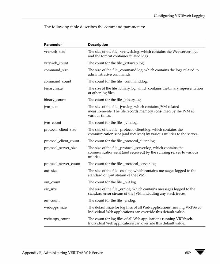
Configuring VRTSweb Logging
The following table describes the command parameters:
Parameter Description
vrtsweb_size The size of the file _vrtsweb.log, which contains the Web server logs and the tomcat container related logs.
vrtsweb_count The count for the file _vrtsweb.log.
command_size The size of the file _command.log, which contains the logs related to administrative commands.
command_count The count for the file _command.log.
binary_size The size of the file _binary.log, which contains the binary representation of other log files.
binary_count The count for the file _binary.log.
jvm_size The size of the file _jvm.log, which contains JVM-related measurements. The file records memory consumed by the JVM at various times.
jvm_count The count for the file _jvm.log.
protocol_client_size The size of the file _protocol_client.log, which contains the communication sent (and received) by various utilities to the server.
protocol_client_count The count for the file _protocol_client.log.
protocol_server_size The size of the file _protocol_server.log, which contains the communication sent (and received) by the running server to various utilities.
protocol_server_count The count for the file _protocol_server.log.
out_size The size of the file _out.log, which contains messages logged to the standard output stream of the JVM.
out_count The count for the file _out.log.
err_size The size of the file _err.log, which contains messages logged to the standard error stream of the JVM, including any stack traces.
err_count The count for the file _err.log.
webapps_size The default size for log files of all Web applications running VRTSweb. Individual Web applications can override this default value.
webapps_count The count for log files of all Web applications running VRTSweb. Individual Web applications can override this default value.
Appendix E, Administering VERITAS Web Server 689

Modifying the Maximum Heap Size for VRTSweb
Modifying the Maximum Heap Size for VRTSweb The default maximum allowed heap size for the VRTSWeb Java Virtual Machine (JVM) is 256MB. This prevents the Web server from increasing its memory footprint over the specified limit. However, for environments with a large number of VERITAS Web consoles sharing the same VRTSweb instance or with Web consoles managing large configurations, it may be necessary to modify this maximum limit.
You can modify the maximum heap size only from the command line.
# $VRTSWEB_HOME/bin/webgui maxheap new_size_in_MB
For example:
# /opt/VRTSweb/bin/webgui maxheap 512
You must restart the Web server after specifying a new limit.
# $VRTSWEB_HOME/bin/webgui restart
To display the current limit, run the command without specifying a new limit.
# $VRTSWEB_HOME/bin/webgui maxheap
690 VERITAS Cluster Server System Administrator’s Guide
Accessibility and VCS
F VERITAS products meet federal accessibility requirements for software as defined in Section 508 of the Rehabilitation Act:◆ http://www.access-board.gov/508.htm
Keyboard shortcuts are available for all major graphical user interface (GUI) operations and menu items. VERITAS products are compatible with operating system accessibility settings as well as a variety of assistive technologies. All manuals also are provided as accessible PDF files, and the online help is provided as HTML displayed in a compliant viewer.
Navigation and Keyboard Shortcuts VCS uses standard operating system navigation keys and keyboard shortcuts. For its unique functions, VCS uses its own navigation keys and keyboard shortcuts which are documented below.
Navigation in the Java Console The following table lists keyboard navigation rules and shortcuts used in Cluster Manager (Java Console), in addition to those provided by the operating system:
VCS Keyboard Input Result
[Shift F10] Opens a context-sensitive pop-up menu
[Spacebar] Selects an item
[Ctrl Tab] Navigates outside a table
[F2] Enables editing a cell
691
Support for Accessibility Settings
Navigation in the Web Console Cluster Manager (Web Console) supports standard browser-based navigation and shortcut keys for the following browsers:
◆ Internet Explorer 5.5 and 6.0
◆ Netscape Navigator 6.2 and 7.0
All VERITAS GUIs use the following keyboard navigation standards:
◆ Tab moves the focus to the next active area, field, or control, following a preset sequence. Shift+Tab moves the focus in the reverse direction through the sequence.
◆ Ctrl+Tab exits any Console area that you internally navigate with Tab.
◆ Up and Down arrow keys move focus up and down the items of a list.
◆ Alt in combination with the underlined mnemonic letter for a field or command button shifts the focus to that field or button.
◆ Either Enter or the Spacebar activates your selection. For example, after pressing Tab to select Next in a wizard panel, press the Spacebar to display the next screen.
Support for Accessibility Settings VERITAS software responds to operating system accessibility settings. On UNIX systems, you can change the accessibility settings using desktop preferences or desktop controls
Support for Assistive Technologies ◆ Cluster Manager (Java Console) is compatible with JAWS 4.5.
◆ Cluster Manager (Web Console) is compatible with IBM Home Page Reader version 3.0. It has been tested with Internet Explorer version 5.5 and IBM HPR version 3.0.
The Web Console offers the option of viewing the Resource Dependency graph as a text-only page to make it easier to read using assistive technologies. You can access the text-only Resource Dependency page from the Groups page.
◆ VERITAS recommends that you do not use the AutoUpdate mode in the Refresh Mode applet when using assistive technologies. You can change this mode from the Preferences page, available by clicking the Preferences link on the Cluster Summary page.
◆ Though graphics in VERITAS documentation can be read by screen readers, setting your screen reader to ignore graphics may improve performance.
◆ VERITAS has not tested screen readers for languages other than English.
692 VERITAS Cluster Server User’s Guide

Glossary
Agent
A process that starts, stops, and monitors all configured resources of a type, and reports their status to VCS.
Active/Active Configuration
A failover configuration where each systems runs a service group. If either fails, the other one takes over and runs both service groups. Also known as a symmetric configuration.
Active/Passive Configuration
A failover configuration consisting of one service group on a primary system, and one dedicated backup system. Also known as an asymmetric configuration.
Authentication Broker
The VERITAS Security Services component that serves, one level beneath the root broker, as an intermediate registration authority and a certification authority. The authentication broker can authenticate clients, such as users or services, and grant them a certificate that will become part of the VERITAS credential. An authentication broker cannot, however, authenticate other brokers. That task must be performed by the root broker. See “Root Broker.”
Cluster
One or more computers linked together for the purpose of multiprocessing and high availability. The term is used synonymously with VCS cluster, meaning one or more computers that are part of the same GAB membership.
Disaster Recovery
A solution that supports fail over to a cluster in a remote location in the event that the local cluster becomes unavailable. Disaster recovery global clustering, heartbeating, and replication.
693
Disk Heartbeats (GABDISK)
A heartbeat placed on a physical disk shared by all systems in the cluster.
Failover
A failover occurs when a service group faults and is migrated to another system.
GAB
Group Atomic Broadcast (GAB) is a communication mechanism of the VCS engine that manages cluster membership, monitors heartbeat communication, and distributes information throughout the cluster.
Global Service Group
A VCS service group that spans across two or more clusters. The ClusterList attribute for the group contains the list of clusters over which the group spans.
hashadow Process
A process that monitors and, when required, restarts HAD.
High Availability Daemon (HAD)
The core VCS process that runs on each system. The HAD process maintains and communicates information about the resources running on the local system and receives information about resources running on other systems in the cluster.
Jeopardy
A node is in jeopardy when it is missing one of the two required heartbeat connections. When a node is running with one heartbeat only (in jeopardy), VCS does not restart the applications on a new node. This action of disabling failover is a safety mechanism that prevents data corruption.
LLT
Low Latency Transport (LLT) is a communication mechanism of the VCS engine that provides kernel-to-kernel communications and monitors network communications.
main.cf
The file in which the cluster configuration is stored.
Network Partition
If all network connections between any two groups of systems fail simultaneously, a network partition occurs. When this happens, systems on both sides of the partition can restart applications from the other side resulting in duplicate services, or “split-brain.” A
694 VERITAS Cluster Server User’s Guide
split brain occurs when two independent systems configured in a cluster assume they have exclusive access to a given resource (usually a file system or volume). The most serious problem caused by a network partition is that it affects the data on shared disks. See “Jeopardy” and “Seeding”.
Node
The physical host or system on which applications and service groups reside. When systems are linked by VCS, they becomes nodes in a cluster.
N-to-1
An N-to-1 configuration is based on the concept that multiple, simultaneous server failures are unlikely; therefore, a single backup server can protect multiple active servers. When a server fails, its applications move to the backup server. For example, in a 4-to-1 configuration, one server can protect four servers, which reduces redundancy cost at the server level from 100 percent to 25 percent.
N-to-N
N-to-N refers to multiple service groups running on multiple servers, with each service group capable of being failed over to different servers in the cluster. For example, consider a four-node cluster with each node supporting three critical database instances. If any node fails, each instance is started on a different node, ensuring no single node becomes overloaded.
N-to-M
N-to-M (or Any-to-Any) refers to multiple service groups running on multiple servers, with each service group capable of being failed over to different servers in the same cluster, and also to different servers in a linked cluster. For example, consider a four-node cluster with each node supporting three critical database instances and a linked two-node back-up cluster. If all nodes in the four-node cluster fail, each instance is started on a node in the linked back-up cluster.
Replication
Replication is the synchronization of data between systems where shared storage is not feasible. The systems that are copied may be in local backup clusters or remote failover sites. The major advantage of replication, when compared to traditional backup methods, is that current data is continuously available.
Resources
Individual components that work together to provide application services to the public network. A resource may be a physical component such as a disk or network interface card, a software component such as Oracle8i or a Web server, or a configuration component such as an IP address or mounted file system.
Glossary 695
Resource Dependency
A dependency between resources is indicated by the keyword “requires” between two resource names. This indicates the second resource (the child) must be online before the first resource (the parent) can be brought online. Conversely, the parent must be offline before the child can be taken offline. Also, faults of the children are propagated to the parent.
Resource Types
Each resource in a cluster is identified by a unique name and classified according to its type. VCS includes a set of predefined resource types for storage, networking, and application services.
Root Broker
The first authentication broker, which has a self-signed certificate. The root broker has a single private domain that holds only the names of brokers that shall be considered valid. See “Authentication Broker.”
Seeding
Seeding is used to protect a cluster from a pre-existing network partition. By default, when a system comes up, it is not seeded. Systems can be seeded automatically or manually. Only systems that have been seeded can run VCS. Systems are seeded automatically only when: an unseeded system communicates with a seeded system or all systems in the cluster are unseeded and able to communicate with each other. See “Network Partition”.
Service Group
A service group is a collection of resources working together to provide application services to clients. It typically includes multiple resources, hardware- and software-based, working together to provide a single service.
Service Group Dependency
A mechanism by which two service groups can be linked by a dependency rule.
Shared Storage
Storage devices that are connected to and used by two or more systems.
SNMP Notification
Simple Network Management Protocol (SNMP) developed to manage nodes on an IP network.
696 VERITAS Cluster Server User’s Guide

State
The current activity status of a resource, group or system.
types.cf
The types.cf file describes standard resource types to the VCS engine; specifically, the data required to control a specific resource.
Virtual IP Address
A unique IP address that associated with the cluster. It may be brought up on any system in the cluster, along with the other resources of the service group. This address, also known as the IP alias should not be confused with the base IP address, which is the IP address that corresponds to the host name of a system.
Glossary 697

698 VERITAS Cluster Server User’s Guide

Index
A accessibility
assistive technology support 692 overview 691
ActionTimeout attribute 633 ActiveCount attribute 640 Administrators attribute
for clusters 661 for service groups 640
agent log format 571 location 571
AgentClass attribute 633 AgentFailedOn attribute 633 AgentPriority attribute 633 AgentReplyTimeout attribute 633 agents
classifications of 14DNS 448entry points 13framework 12Heartbeat 447impact on performance 556RVG 449RVGPrimary 449RVGSnapshot 449starting from command line 94stopping from command line 94Wide-Area Heartbeat 447
AgentStartTimeout attribute 633AgentState attribute 667AgentStopped attribute 653aggregate notifications, monitoring 426alerts
deleting from Java Console 213 deleting from Web Console 289 monitoring from Java Console 212 monitoring from Web Console 288
arbitration for cluster membership 320ArgList attribute 633ArgListValues attribute 628assistive technology support 692association attribute dimension 44asymmetric configuration 22AttrChangedTimeout attribute 634attribute dimensions
association 44 keylist 44 scalar 44 vector 44
attribute types boolean 43 integer 43 string 43
attributes editing from command line 90 editing from Java Console 203 editing from Web Console 283 for clusters 661 for heartbeats 667 for resource types 633 for resources 628 for service groups 640 for systems 653 local and global 46 overriding from command line 92 overriding from Java Console 184 overriding from Web Console 270 requirements for Cluster Shell 138 resource-specific 45 service group 243 static 46 type-dependent 44 type-independent 44 type-specific 45
authentication broker 17
699

Authority attribute about 447 definition 640
AutoDisabled attribute 640 AutoFailover attribute
about 347 definition 640
AutoRestart attribute 641 AutoStart attribute
for resources 628 for service groups 641
AutoStartIfPartial attribute 641 AutoStartList attribute 641 AutoStartPolicy attribute 642 AutoStartTimeout attribute 661 AvailableCapacity attribute 653
B binary message catalogs
about 572 location of 572
boolean attribute type 43 bundled agents 14
C campus configuration 31Capacity attribute 653CleanTimeout attribute 634client process, detecting failure 562CloseTimeout attribute 634ClusState attribute 661Cluster Administrator
about 52 adding user as 66
cluster attributes 661 Cluster Explorer
about 122accessing 122adding resources 176adding service groups 154adding systems 195adding users 151autoenabling service groups 168bringing resources online 180bringing service groups online 159changing user passwords 152changing user privileges 153clearing resource faults 187clearing ResourceInfo attribute 193closing configuration files 201
Cluster Query 141Cluster Shell 138Command Center 139configuration tree 125deleting resources 179deleting service groups 158deleting users 152disabling resources 186disabling service groups 167editing attributes 203enabling resources 185enabling service groups 166flushing service groups 169freezing service groups 164freezing systems 197importing resource types 194linking resources 188linking service groups 170logs 209modifying system lists for service groups 136monitoring group dependencies 129monitoring resource dependencies 130Notifier Wizard 140opening configuration files 199probing resources 183Properties view 128refreshing ResourceInfo attribute 193Remote Cluster Status View 134Resource View 130saving configuration files 200service group configuration wizard 174Service Group View 129Status View 127switching service groups 163System Connectivity View 133System Manager 136taking resources offline 181taking resources offline andpropagating 182taking service groups offline 161tear-off view 126Template View 135toolbar 123unfreezing service groups 165unfreezing systems 198unlinking resources 190unlinking service groups 172User Manager 137
700 VERITAS Cluster Server User’s Guide

view panel 126 Cluster Guest
about 53 adding user as 66
Cluster Manager (Java Console). See Java Console
Cluster Manager (Web Console). See Web Console
cluster membership about 314 with I/O fencing 314 without I/O fencing 330
Cluster Monitor about 115 adding clusters 145 administering 145 behavior during failover 117 collapsing displays 119 configuring existing panels 146 configuring new panels 145 expanding displays 119 icon colors 118 logging off of a cluster 150 logging on to a cluster 147 menus 116 monitoring cluster connection 117 monitoring cluster objects 118 panels 117 pausing scrolling panels 119 toolbar 116
cluster name, changing in global configuration 478
Cluster Operator about 52 adding user as 66
Cluster Query in Java Console 141 in Web Console 284
Cluster Shell accessing 138 executing commands 202
ClusterAddress attribute 661 ClusterFailOverPolicy attribute 642 clustering
criteria for data storage 5 criteria for monitor procedure 4 criteria for start procedure 3 criteria for stop procedure 3 license and host name issues 5
restarting application to known state 4 ClusterList attribute 642 ClusterLocation attribute 661 ClusterName attribute 661 ClusterOwner attribute 661 clusters
adding to Web Console 222administering from Java Console 199connecting to Cluster Monitor 145membership 314removing from Web Console 223
ClusterTime attribute 661 ClusterUUID attribute 662 Command Center
accessing 139adding resources 177adding service groups 156adding systems 195autoenabling service groups 168bringing resources online 180bringing service groups online 160clearing resource faults 187closing configuration files 201deleting resources 179deleting service groups 158deleting systems 196disabling resources 186disabling service groups 167editing attributes 204enabling resources 185enabling service groups 166executing commands 202flushing service groups 169freezing service groups 164freezing systems 197ignoreparent option 182linking resources 189linking service groups 171opening configuration files 199probing resources 183saving configuration files 200switching service groups 163taking resources offline 181taking resources offline and propagating 182taking service groups offline 162unfreezing service groups 165unfreezing systems 198
Index 701

unlinking resources 191 unlinking service groups 172
commands hazonesetup 615 scripting 106
commands, executing from Java Console 202
CompareRSM attribute 662 ComputeStats attribute 628 conditional statements 74 ConfidenceLevel attribute 628 ConfigBlockCount attribute 653 ConfigCheckSum attribute 653 ConfigDiskState attribute 653 ConfigFile attribute 653 ConfigInfoCnt attribute 653 ConfigModDate attribute 654 configuration
backing up 98 closing from Java Console 201 closing from Web Console 254 opening from Java Console 199 opening from Web Console 254 saving from Java Console 200 saving from Web Console 254 saving in VCS Simulator 548 setting to read/write 65 setting to read-only 65 verifying 48
configuration files backing up 98 generating 36 main.cf 36 read/write to read-only 65 removing stale designation 65 restoring 98 types.cf 36
configuration language local and global attributes 46 type-specific attributes 45
configurations asymmetric 22 campus 31 global cluster 34 N+1 26 N-to-1 24 N-to-N 28 replicated data 33 shared nothing 32
shared storage/replicated data 33 symmetric 23
ConfInterval attribute about 351 definition 634
ConnectorState attribute 662 ContainerType attribute
definition 634 coordinator disks 318 CounterInterval attribute 662 CPU binding of HAD 566 CPU usage, how VCS monitors 567 CPUBinding attribute 654 CPUUsage attribute 654 cpuusage event trigger 430 CPUUsageMonitoring attribute 655 Critical attribute 628 CurrentCount attribute 642 CurrentLimits attribute 655 custom agents
in zones 611 custom agents, about 14
D DeferAutoStart attribute 642 dependencies
between resources 278 for resources 8 for service groups
disability compliance in Java Console 109 in Web Console 215
disk heartbeats 331DiskHbStatus attribute 655DNS agent 448DumpingMembership attribute 662DynamicLoad attribute 655
E Enabled attribute
for resources 629 for service groups 643
Encrypting Passwords 83 engine log
format 571 location 571
EngineClass attribute 662 EnginePriority attribute 663 enterprise agents, about 14
702 VERITAS Cluster Server User’s Guide
entry points about 13 modifying for performance 557
environment variables 57 error messages
agent log 571 at startup 575 engine log 571 message catalogs 572
Evacuate attribute 643 Evacuating attribute 643 event triggers
about 429cpuusage 430injeopardy 431loadwarning 432location of 429multinicb 433nofailover 433postoffline 434postonline 434preonline 435resadminwait 436resfault 436resnotoff 437resstatechange 438sysoffline 439unable_to_restart_had 439using 429violation 440
F failback, about 25Failover attribute 643FailOverPolicy attribute 643FaultOnMonitorTimeouts attribute 635fire drills
about 466for global clusters 466for replicated data clusters 532
FireDrill attribute 635 Flags attribute 629 FromQ attribute 644 Frozen attribute
for service groups 644 for systems 655
G GAB
about 16 impact on performance 555 when a system panics 562
gab_isolate_time timer 562gabconfig -d command 340gabconfig -l command 341gabconfig -q command 340GABDISK 331GCO Configuration wizard 454global attributes 46global cluster configuration 34global clusters
adding from Java Console 482adding from Web Console 502administering from command line 469administering from Java Console 481administering from Web Console 501bringing remote groups online 494deleting from Java Console 487deleting from Web Console 505operation 444prerequisites for 451setting up 453switching remote groups 496upgrading to 454user privileges 55
Global Group Configuration wizard 461
global heartbeats administering from command line 479 administering from Java Console 497 administering from Web Console 521 deleting from Java Console 500 deleting from Web Console 522 modifying from Java Console 499 modifying from Web Console 523
global service groups administering from command line 475 administering from Java Console 491 administering from Web Console 513 converting to local groups 491 creating from Java Console 491 creating from local groups 491 querying from command line 469
GlobalCounter attribute 663
Index 703
Group Administrator about 52 adding user as 66
Group attribute 630 group dependencies. See service group
dependencies Group Operator
about 52 adding user as 66
GroupLimit attribute 663 GroupOwner attribute 644 GUI. See Java Console or Web Console GUIIPAddr attribute 656
H haagent -display command 71 haagent -list command 74 haagent -start command 94 haagent -stop command 94 haattr -add command 93 haattr -default command 93 haattr -delete command 93 hacf utility
about 48 creating multiple .cf files 48 dumping a configuration 48 loading a configuration 48 pretty-printing 48
hacf -verify command 48 HacliUserLevel attribute
about 52 configuring 138 definition 663
haclus -add command 477 haclus command, permission matrix 599 haclus -declare command 478 haclus -delete command 477 haclus -display command
for global clusters 473 for local clusters 71
haclus -list command 473 haclus -modify command 478 haclus -state command 473 haclus -status command 473 haclus -value command
for global clusters 473 for local clusters 71
haclus -wait command 106 haconf -dump -makero command 65
haconf -makerw command 65 HAD
about 15 binding to CPU 566 impact on performance 556
hagrp -add command 87hagrp -clear command 76hagrp command, permission matrix 600hagrp -delete command 91hagrp -dep command 69hagrp -disable command 76hagrp -disableresources command 76hagrp -display command
for global clusters 470 for local clusters 69
hagrp -enable command 76 hagrp -enableresources command 76 hagrp -freeze command 75 hagrp -list command
for global clusters 470 for local clusters 74
hagrp -modify command 87 hagrp -offline command
for global clusters 476 for local clusters 75
hagrp -online command for global clusters 475 for local clusters 75
hagrp -resources command 69 hagrp -state command
for global clusters 470 for local clusters 69
hagrp -switch command for global clusters 476 for local clusters 75
hagrp -unfreeze command 75 hagrp -unlink command 91 hagrp -value command 469 hagrp -wait command 106 hahb -add command 479 hahb -display command 474 hahb -list command 474 halogin command 63, 64 hamsg -info command 72 hamsg -list command 72 hanotify utility 417 hares -action command 477 hares -add command 89 hares -clear command 77
704 VERITAS Cluster Server User’s Guide

hares command, permission matrix 604hares -delete command 91hares -dep command 70hares -display command
for global clusters 471 for local clusters 70
hares -global command 70 hares -info command 477 hares -link command 90 hares -list command
for global clusters 471 for local clusters 74
hares -local command 85 hares -modify command 90 hares -offline command 77 hares -offprop command 77 hares -online command 77 hares -override command 92 hares -probe command 77 hares -state command 471 hares -undo_override command 92 hares -unlink command 91 hares -value command 471 hares -wait command 106 hashadow process 19 hasnap -backup command 99 hasnap -delete command 105 hasnap -display command 100 hasnap -exclude command 104 hasnap -export command 103 hasnap -fdiff command 102 hasnap -include command 103 hasnap -restore command 100 hasnap -sdiff command 101 hastart command 60 hastart -onenode command 61 hastart -ts command 61 hastatus command
for global clusters 474 for local clusters 72
hastatus command, permission matrix 605 hastatus -group command 72 hastatus -summary command 72 hastop command 61 hasys command, permission matrix 606 hasys -display command
for global clusters 472 for local clusters 71
hasys -force command 78
hasys -freeze command 78 hasys -list command
for global clusters 472 for local clusters 71
hasys -modify command 78 hasys -nodeid command 78 hasys -state command 472 hasys -unfreeze command 78 hasys -value command
for global clusters 472 hasys -wait command 106 hatype -add command 92 hatype -delete command 92 hatype -display command 70 hatype -list command 70 hatype -modify command 92 hatype -resources command 70 hauser -add command 66 hauser -addpriv command 66 hauser command, permission matrix 608 hauser -delete command 67 hauser -delpriv command 66, 67 hauser -display command 68 hauser -list command 68 hazonesetup command 615 heap size for VRTSweb 690 Heartbeat agent 447 heartbeat attributes 667 heartbeats
modifying for global clusters 479 on disks 331
host name issues 5
I I/O fencing
about 16 components of 318 need for 315 startup sequence 327
icons colors of 118 in Java Console 113
include clauses, about 36 InfoInterval attribute 635 InfoTimeout attribute 635 injeopardy event trigger 431 integer attribute type 43 IntentOnline attribute 645 Intra-Node Communication 311
Index 705

IP aliasing 2 Istate attribute 630
J Java Console
about 19 administering clusters 109 administering global clusters 481 administering logs 209 administering resources 176 administering service groups 154 administering systems 195 administering user profiles 151 administering VCS Simulator 544 arranging icons 131 Cluster Explorer 122 Cluster Manager 113 Cluster Monitor 115 Cluster Query 141 components of 113 customizing display 120 disability compliance 109 executing commands 202 icons 113 impact on performance 558 logging off of a cluster 150 logging on to a cluster 147 overview 109 running commands from 202 setting initial display 110 starting 112 user profiles 151 using with ssh 111 viewing server credentials 144 viewing user credentials 144
Java Console views Properties 128 Remote Cluster Status 134 Resource 130 Service Group 129 Status 127 System Connectivity 133 tear-off option 126
jeopardy about 331 conditions 332 membership 330
K keylist attribute dimension 44 keywords, list of 47
L LastOnline attribute 630 LastSuccess attribute 645 license keys
about 59installing 59troubleshooting 591upgrading 59
LicenseType attribute 656licensing issues 5Limits attribute 656LinkHbStatus attribute 656links, low priority 331LLT, about 15LLTNodeId attribute 656Load attribute 645Load policy for SGWM 364LoadTimeCounter attribute 656LoadTimeThreshold attribute 657loadwarning event trigger 432LoadWarningLevel attribute 657local attributes 46LockMemory attribute 663LogDbg attribute 636LogFileSize attribute 636logging
agent log 571 engine log 571 message tags 571 VRTSweb 686
logs customizing display in Java Console 209 customizing display in Web Console 287 for VRTSweb 686 searching from Java Console 209 viewing from Java Console 142
LogSize attribute 664 low priority links 331
M main.cf
about 36 cluster definition 36 group dependency clause 38
706 VERITAS Cluster Server User’s Guide
include clauses 36 resource definition 38 resource dependency clause 38 sample configuration 38 service group definition 37 system definition 37
MajorVersion attribute for clusters 664 for systems 657
ManageFaults attribute about 348 definition 646
ManualOps attribute 646 membership arbitration 320 message tags, about 571 MigrateQ attribute 646 MinorVersion attribute
for clusters 664 for systems 657
MonitorInterval attribute 636 MonitorOnly attribute 631 MonitorStartParam attribute 637 MonitorTimeout attribute 637 MonitorTimeStats attribute 631 multinicb event trigger 433 myVCS page 234
about 234 creating 285
N N+1 configuration 26Name attribute 631network failure 133network links, detecting failure 561networks, detecting failure 562NFS service groups, configuring 304NoAutoDisable attribute 657NodeId attribute 657nofailover event trigger 433notification
about 413deleting messages 415error messages 414error severity levels 414event and trap list 418event triggers 429hanotify utility 417message queue 415notifier process 416
setting using wizard 206 SNMP files 422 troubleshooting 581
Notifier attribute 664notifier process 416Notifier Resource Configuration wizard 206N-to-1 configuration 24N-to-N configuration 28NumRetries attribute 647NumThreads attribute
definition 637modifying for performance 557
O offline group dependency 385 OfflineMonitorInterval attribute 638 OfflineTimeout attribute 638 OnGrpCnt attribute 657 online group dependency 385 OnlineRetryInterval attribute 647 OnlineRetryLimit attribute
for resource types 638 for service groups 647
OnlineTimeout attribute 638 OnlineWaitLimit attribute 638 On-Off resource 9 On-Only resource 9 OpenTimeout attribute 638 Operations attribute 638 Operators attribute
for clusters 664 for service groups 647
overload warning for SGWM 365
P PanicOnNoMem attribute 664 Parallel attribute 647 passwords
authenticating 55, 63changing from Java Console 152changing from Web Console 252
Path attribute 631 PathCount attribute 647 performance
agents 556GAB 555HAD 556impact of VCS 555Java Console 558modifying entry points 557
Index 707
modifying NumThreads attribute 557monitoring CPU usage 567when a cluster is booted 558when a resource fails 560when a resource is brought online 559when a resource is taken offline 559when a service group fails over 563when a service group is brought online 559when a service group is taken offline 560when a system fails 561
Persistent resource 9postoffline event trigger 434postonline event trigger 434PreOffline attribute 647PreOfflining attribute 648PreOnline attribute 648preonline event trigger 435PreOnlineTimeout attribute 648PreOnlining attribute 648Prerequisites attribute 648pretty-printing 48PrintMsg attribute 664PrintTree attribute 648priorities
defaults 565ranges 565scheduling 564specifying 565
Priority attribute 649Priority policy for SGWM 364priority ranges for sched. classes 564privileges. See user privilegesProbed attribute
for resources 631for service groups 649
ProbesPending attribute 649ProcessClass attribute 665ProcessPriority attribute 665
Q quick reopen 562
R ReadOnly attribute 665Recovering After a Disaster 531refresh modes, in Web console 233Remote Cluster Configuration wizard 482Remote Cluster States 621
remote clustersmonitoring from Java Console 134monitoring from Web Console 127states of 622
replicated data configuration 33resadminwait event trigger 436reserved words, list of 47resfault event trigger 436resnotoff event trigger 437resource attributes 628resource dependencies
creating from command line 90creating from Java Console 188creating from Web Console 277displaying from command line 70removing from command line 91removing from Java Console 190removing from Web Console 278
resource faultsclearing from Java Console 187simulating 549
resource type attributes 633resource types
importing 194querying from command line 70
ResourceInfo attributeclearing from Java Console 193clearing from Web Console 280definition 631refreshing from Java Console 193refreshing from Web Console 280
ResourceLimit attribute 665ResourceOwner attribute 632resources
about 8adding from command line 89adding from Java Console 176adding from Web Console 275administering from Java Console 176administering from Web Console 268bringing online from command line 77bringing online from Java Console 180bringing online from Web Console 268categories of 9clearing faults from Java Console 187clearing faults from Web Console 271conditional statements 74creating faults in VCS Simulator 549deleting from command line 91
708 VERITAS Cluster Server User’s Guide

deleting from Java Console 179deleting from Web Console 276dependencies 248disabling from command line 360disabling from Java Console 186disabling from Web Console 272enabling from command line 76enabling from Java Console 185enabling from Web Console 273how disabling affects states 362invoking action script 279invoking actions 192limitations of disabling 360linking from command line 90linking from Java Console 188On-Off 9On-Only 9Persistent 9probing from Java Console 183probing from Web Console 271querying from command line 70taking offline from command line 77taking offline from Java Console 181taking offline from Web Console 268troubleshooting 579unlinking 278unlinking from command line 91unlinking from Java Console 190unlinking from Web Console 278
resource-specific attributes 45 Responding attribute 649 resstatechange event trigger 438 Restart attribute 649 RestartLimit attribute
about 351 definition 639
root broker 17 Round Robin policy for SGWM 364 RVG agent 449 RVGPrimary agent 449 RVGSnapshot agent 449
S scalar attribute dimension 44 scheduling classes 564
defaults 565 priority ranges 565
ScriptClass attribute 639 scripting VCS commands 106
ScriptPriority attribute 639 SCSI reservations
about 317 limitations of 317
SCSI-III Persistent Reservations 319secure VCS. See VERITAS Security Servicesseeding 339server credentials
viewing 144 service group attributes 640 service group dependencies
about 383automatic failover 398automatic online 397autorestart 397benefits of 384categories of 385configurations 389configuring 396creating 396creating from Java Console 170creating from Web Console 265failover parent/failover child 403failover parent/parallel child 406firm 387global 386hard 388limitations of 402local 386locations of 386manual offline 401manual online 400manual switch 401offline 385online 385parallel parent/failover child 408parallel parent/parallel child 410remote 386removing from Java Console 172removing from Web Console 266soft 387types of 387
service group workload management Capacity and Load attributes 365 Limits and Prerequisites attributes 366 load policy 364 load-based autostart 367 overload warning 365 priority policy 364
Index 709

Round Robin policy 364 sample configurations 368 SystemZones attribute 367
service groups adding from command line 87 adding from Java Console 154 adding from Web Console 255 administering from command line 75 administering from Java Console 154 administering from Web Console 255 autoenabling from Java Console 168 autoenabling from Web Console 264 bringing online from command line 75 bringing online from Java Console 159 bringing online from Web Console 260 clearing from Web Console 267 creating using configuration wizard 174 deleting from command line 91 deleting from Java Console 158 deleting from Web Console 260 disabling from Java Console 167 disabling from Web Console 263 displaying dependencies from command line 69 enabling from Java Console 166 enabling from Web Console 263 flushing from Java Console 169 flushing from Web Console 262 freezing from command line 75 freezing from Java Console 164 freezing from Web Console 261 impact on performance 560 linking from Java Console 170 linking from Web Console 265 querying from command line 69 switching from Java Console 163 switching from Web Console 261 taking offline from Java Console 161 taking offline from Web Console 260 taking remote groups offline 495 troubleshooting 576 unfreezing from command line 75 unfreezing from Java Console 165 unfreezing from Web Console 262 unlinking from Java Console 172 unlinking from Web Console 266
shared nothing configuration 32 shared storage/replicated data
configuration 33
ShutdownTimeout attribute 658Signaled attribute 632Simulator. See VCS Simulatorsingle sign-on, configuring in Web
Console 225 SMTP notification
configuring for VRTSweb 680 SMTP server, retrieving name of 680 SNMP 413
files for notification 422HP OpenView 422merging events with HP OpenView NNM 422
SourceFile attribute for clusters 665 for resource types 639 for service groups 649 for systems 658
split-brain about 315 in global clusters 450 preventing 316
ssh configuration for Java Console 111Start attribute 632State attribute
for resources 632 for service groups 650
static attributes 46 steward process
about 450 configuring 460
Stewards attribute 665 string attribute type 43 SupportedActions attribute 639 symmetric configuration 23 SysInfo attribute 658 SysName attribute 658 sysoffline event trigger 439 SysState attribute 658 System Attributes 653 system attributes 653 system states 624 SystemList attribute
about 88 definition 650 modifying 88
SystemLocation attribute 658 SystemOwner attribute 659
710 VERITAS Cluster Server User’s Guide
systems adding from command line 79 adding from Java Console 195 administering from command line 78 administering from Java Console 195 administering from Web Console 281 bringing online in VCS Simulator 548 client process failure 562 deleting from Java Console 196 detecting failure 561 displaying node ID from command line 78 freezing from Java Console 197 freezing from Web Console 281 panic 562 quick reopen 562 starting from command line 60 states 624 unfreezing from Java Console 198 unfreezing from Web Console 282
systems and nodes 7 SystemZones attribute 650
T Tag attribute 651 TargetCount attribute 651 templates
accessing Template View 135 adding resources from 178 adding service groups from 157
TFrozen attribute for service groups 651 for systems 659
ToleranceLimit attribute 639 ToQ attribute 651 TriggerEvent attribute
for resources 632 for service groups 651
TriggerResStateChange attribute 651 triggers. See event triggers troubleshooting
back up and restore files 587license keys 591logging 571notification 581resources 579service groups 576VCS startup 575Web Console 582
TRSE attribute 659TypeDependencies attribute 651type-dependent attributes 44type-independent attributes 44TypeLimit attribute 665types.cf 36type-specific attributes 45
U unable_to_restart_had trigger 439 unlink
resource 278 UpDownState attribute 659 UseFence attribute 665 user credentials, viewing 144 user privileges
about 51assigning from command line 66changing from Java Console 153changing from Web Console 253Cluster Administrator 52Cluster Guest 53Cluster Operator 52for specific commands 597Group Administrator 52Group Operator 52in global clusters 55removing from command line 66, 67setting explicitly 53
UserInt attribute 659 UserIntGlobal attribute 652 UserIntLocal attribute 652 UserNames attribute 665 users
adding from command line 65 adding from Java Console 151 adding from Web Console 251 deleting from command line 67 deleting from Java Console 152 deleting from Web Console 252 displaying from command line 68
UserStrGlobal attribute 652 UserStrLocal attribute 652 utilities
hacf 48 hanotify 417 vxlicinst 59
Index 711
V VCS
accessibility 691 additional considerations for stopping 62 assistive technology support 692 event triggers 429 logging 571 logging off of 63, 64 logging on to 63, 64 notification 413 querying from command line 69 seeding 339 SNMP and SMTP 413 starting as time-sharing process 61 starting from command line 60 starting on single node 61 stopping from command line 61 stopping with other options 62 stopping without -force 62 troubleshooting resources 579 troubleshooting service groups 576
VCS Agent Statistics 568VCS agent statistics 568VCS seeding 339VCS Simulator
administering from Java Console 544bringing systems online 548clearing cluster faults from Java Console 549creating power outages 548description of 107faulting resources 549installing 541saving offline configurations 548simulating cluster faults from commandline 553simulating cluster faults from Java Console 549starting from command line 544
VCSFeatures attribute for clusters 666 for systems 660
VCSi3Info attribute 666 VCSMode attribute 666 vector attribute dimension 44 VERITAS Security Services
about 17authentication broker 17
disabling 81enabling 81root broker 17viewing credentials 144
VERITAS Traffic Director integrating with Web Console 290
violation event trigger 440 virtual IP address 2 VRTSweb
adding ports 673adding SMTP recipients 683deleting ports 675deleting SMTP recipients 685logging 686modifying log levels 687notification for 680ports for 672retrieving log levels 686retrieving ports 672setting heap size 690setting SMTP server 681
vxfen. See fencing module vxlicinst utility 59
W wac 446 WACPort attribute 666 Web Console
See Also Web Console pagesabout 215adding cluster to console 222administering global clusters 501administering resources 268administering service groups 255administering systems 281Alerts page 241connecting from URL 221customizing log display 287customizing view 285disability compliance 215integrating with Traffic Director 290Java plug-in for 220Java Plug-in requirements 220logging in 224logging out 224Logs page 240managing cluster configuration 254managing users 251navigation buttons 228
712 VERITAS Cluster Server User’s Guide
navigation in 228navigation links 228navigation trails 228online help 226querying configuration 284refresh modes 233refreshing 233removing cluster from console 223single sign-on 225Systems page 237troubleshooting 582Update icon 233viewing 229
Web Console pages Alerts 241 All Attributes 239 Cluster Heartbeats 250 Cluster Summary 230 Group Dependency 236 Logs 240 Management Host 229 myVCS 232 Preferences 233 Resource 247 Resource Dependency 248 Resource Dependency graph 248 Resource Dependency text 249 Resource Type 246
Resource Types 238Service Group 242Service Groups 234System 244System Heartbeats 245Systems 237VCS Users 232
WERO 319wide-area connector 446wide-area failover 34Wide-Area Heartbeat agent 447wizards
GCO Configuration 454Global Group Configuration 461NFS 304Notifier Resource Configuration 206Remote Cluster Configuration 482
Z zone root 612 zones
attributes 609 configuring VCS in 609 creating 612 prerequisites 611 setting zone root 612 supported agents 609 using custom agents 611
Index 713
Related Documents