The Journal of Supercomputing, 25, 215–236, 2003 # 2003 Kluwer Academic Publishers. Manufactured in The Netherlands. Cluster Queue Structure for Shared-Memory Multiprocessor Systems W. ZHU [email protected] School of Computer Science, The University of New South Wales, ADFA, ACT 2600 New South Wales, Australia Abstract. Three basic structures have been proposed to organize the task queues for shared-memory multiprocessor systems: centralized, distributed, and hierarchical. Centralized structures are not suitable for massively parallel systems since the shared queue becomes a bottleneck for frequent enqueuing and dequeuing operations. Distributed structures have load imbalancing problem because of no support for workload sharing between queues. Hierarchical structures intend to combine the advantage of the previous two structures and eliminate their disadvantages. Unfortunately, we find load imbalancing still exists in the hierarchical structure, and has significant impact on system performance, particularly when the workload is heavy and irregular. After identifying the cause of this problem, we propose the use of a clustered structure in place of the hierarchical one. Analyzes and simulations show the proposed structure can provide better load balancing and less contention than the hierarchical one. Keywords: task scheduling, queue structure, performance evaluation, simulation and multiprocessor 1. Introduction Shared-memory multiprocessors (SMM), including cluster-based SMM, are an important class of parallel processing systems and have received considerable attention [1, 2]. A number of commercial products and experimental prototypes have been developed in the past, such as Cedar [3], teraDASH [4], BBN TC2000 [5], KSR- 1 [6], SGI origin, Cray T3D, Sun 100000, IBM S80 and Stanford Flash [7]. In order to obtain high performance in terms of task waiting time and throughput in these systems, workload must be evenly distributed among processors, especially when tasks are independent. To achieve this, various queue structures have been proposed that allow processors to share workload and reduce the contention created by accessing the shared workload. Nevertheless, load balancing and contention reduction conflict with each other. A solution in favor of one goal often sacrifices the other to some degree, as Ni and Wu [8] pointed out. The quality of a queue structure is measured by its ability to find a tradeoff between these two goals. Queue structures proposed in the past can be divided into three classes: centralized, distributed, and hierarchical. For a small system with a limited number of processors, the centralized structure stands out from the others by its excellent load balancing nature. When the number of processors exceeds a limit, the single queue shared by all processors becomes a bottleneck that prevents further improvement of performance, since both enqueuing and dequeuing operations must be performed in an exclusive manner. The distributed structure assigns a queue

Welcome message from author
This document is posted to help you gain knowledge. Please leave a comment to let me know what you think about it! Share it to your friends and learn new things together.
Transcript
The Journal of Supercomputing, 25, 215–236, 2003
# 2003 Kluwer Academic Publishers. Manufactured in The Netherlands.
Cluster Queue Structure for Shared-MemoryMultiprocessor Systems
W. ZHU [email protected]
School of Computer Science, The University of New South Wales, ADFA, ACT 2600 New South Wales,
Australia
Abstract. Three basic structures have been proposed to organize the task queues for shared-memory
multiprocessor systems: centralized, distributed, and hierarchical. Centralized structures are not suitable
for massively parallel systems since the shared queue becomes a bottleneck for frequent enqueuing and
dequeuing operations. Distributed structures have load imbalancing problem because of no support for
workload sharing between queues. Hierarchical structures intend to combine the advantage of the
previous two structures and eliminate their disadvantages. Unfortunately, we find load imbalancing still
exists in the hierarchical structure, and has significant impact on system performance, particularly when
the workload is heavy and irregular. After identifying the cause of this problem, we propose the use of a
clustered structure in place of the hierarchical one. Analyzes and simulations show the proposed structure
can provide better load balancing and less contention than the hierarchical one.
Keywords: task scheduling, queue structure, performance evaluation, simulation and multiprocessor
1. Introduction
Shared-memory multiprocessors (SMM), including cluster-based SMM, are animportant class of parallel processing systems and have received considerableattention [1, 2]. A number of commercial products and experimental prototypes havebeen developed in the past, such as Cedar [3], teraDASH [4], BBN TC2000 [5], KSR-1 [6], SGI origin, Cray T3D, Sun 100000, IBM S80 and Stanford Flash [7]. In orderto obtain high performance in terms of task waiting time and throughput in thesesystems, workload must be evenly distributed among processors, especially whentasks are independent. To achieve this, various queue structures have been proposedthat allow processors to share workload and reduce the contention created byaccessing the shared workload. Nevertheless, load balancing and contentionreduction conflict with each other. A solution in favor of one goal often sacrificesthe other to some degree, as Ni and Wu [8] pointed out. The quality of a queuestructure is measured by its ability to find a tradeoff between these two goals.Queue structures proposed in the past can be divided into three classes:
centralized, distributed, and hierarchical. For a small system with a limited numberof processors, the centralized structure stands out from the others by its excellentload balancing nature. When the number of processors exceeds a limit, the singlequeue shared by all processors becomes a bottleneck that prevents furtherimprovement of performance, since both enqueuing and dequeuing operationsmust be performed in an exclusive manner. The distributed structure assigns a queue
to a processor, which greatly reduces enqueuing and dequeuing contention, butcreates load imbalancing that affects system performance. The hierarchical structureproposed in Dandamudi and Cheng [9] tends to end the conflict between contentionand load balancing. It organizes multiple queues into a tree structure and attachesprocessors to leaf nodes. Newly arrived tasks are assigned to the root for sharing.Every processor adopts a self-scheduling principle to search for tasks that requires aprocessor to follow the path from the leaf where it is attached to the root. The uniquefeature relies on its dequeuing method that allows a processor to take multiple taskseach time from a queue, which are then shared by a group of processors located inthe same subtree as the processor taking the tasks. Although this method reducesdequeuing contention, the method creates load imbalance between subtrees, which isvery serious for a large system with a burst workload.To solve the problem, we propose a cluster queue structure in this paper that
divides the processors of a system into clusters and distributes arrival tasks to theclusters according to a dispatching policy, such as round robin (RR) or joining theshortest queue (JSQ). The dispatching policy aims to create a more stable arrivalprocess than the original one for a cluster. Each cluster can have its own queuestructure that can be hierarchical or centralized, depending on the number ofprocessors within the cluster. If the benefit of this stabilization exceeds the penalty ofload difference between clusters, the cluster structure performs better than others.Hence, the question is how to identify a cluster structure that can maximize gainagainst penalty, thereby providing better performance in terms of average taskwaiting time and throughput. The paper tends to answer this question by analyzesand simulations.The rest of the paper is organized as follows: Section 2 details the load imbalance
problem within the hierarchical structure. We model and analyze the loadimbalancing in the hierarchical structure, we also identify the optimal hierarchicalstructure in this section. In Section 3, we propose the cluster structure to replace thehierarchical one. A comparison between the two structures based on simulations ispresented in Section 4. The last section is devoted to concluding remarks.
2. Load imbalance in hierarchical structure
The hierarchical structure proposed in Dandamudi and Cheng [9] and Dandamudi[11] intends to combine the advantages of the centralized and distributed structurestogether. The hierarchical structure, as the centralized one, uses one queue, the root,to accommodate newly arrival tasks for workload sharing. Hence, the contentioncreated by enqueuing operations remains unchanged as the centralized structure. Toreduce the contention created by dequeuing operations, a processor in thehierarchical structure takes multiple tasks each time from a non-leaf queue, thetasks taken by the processor are then distributed to those queues located between thequeue and the leaf node to which the processor is attached. We call this methodproportional removal (PR) in the following discussion since the number of taskstaken each time from a queue is proportional to the number of processors embeddedin the subtree rooted at the queue.
216 ZHU

The PR method successfully eases the dequeuing contention since at most k (thebranch factor of a node) processors can compete with each other at a queue.However, we found that load imbalance still exist in the hierarchical structure, andvery severely when the workload is bursty. We further identified the cause of the loadimbalance is due to the use of the PR method that departs from the load balancingprinciple of taking one task at a time. For instance, assume two dequeuingoperations from different branches (subtrees) reach the root queue, one immediatelyafter the other. Also, assume the number of tasks queued at the root at that momentis equal to or less than the number of tasks a processor can take from the root. Thefirst processor, on behalf of its branch, takes all queued tasks and distributes themon the way back to its leaf node.1 If no new tasks arrive between these two dequeuingoperations, the second processor will be blocked at the root while at the same timesome tasks are waiting for service in the branch of the first processor. Apart from thesecond processor, there may be other processors blocked in the same branch. Theload imbalance can have substantial effects on system performance.
2.1. Simplified model
Our analysis focuses on the load imbalance created by the PR method, the degree ofload imbalancing (DLI), defined later, is used as the criterion to quantitativelyevaluate the impact of the PR on load imbalancing. Unfortunately, the complexity ofthe hierarchical structure prevents us from obtaining an exact solution since thequeues in the hierarchical structure are dependent, which in principle is as difficult asthe analysis of the JSQ policy in a system with more than two queues. Meanwhile, itis also impossible to apply the inventory theory on this analysis, even through the PRmethod is similar to the order used in a multi-level inventory system.Instead of an exact analysis, we use an approximate method that divides the
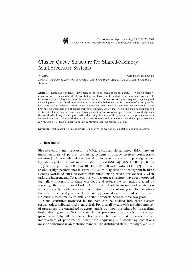
hierarchical structure into a number of subsystems, each has k processors. Thesteady-state distribution of a subsystem is estimated. Based on the result, we obtainthe DLI for the entire system. Let us assume the original structure has more than twolevels, every queue at the top two levels has k children. After the simplification, weobtain a structure as shown in Figure 1, in which a processor corresponds to asubtree in the original structure, the processor has an equal processing capacity asthose processors located in the subtree. The simplified structure provides betterperformance than the original one since a processor in the simplified structure onlytakes one task each time. If we can demonstrate the simplified structure has seriousload imbalancing, the hierarchical structure has even worse load imbalancing.
2.2. Load imbalance analysis
A subsystem as shown in Figure 1 consists of a queue and k identical processors. Todistinguish the queue shared by the k processors from the root, we call it local queue.A local queue has a finite capacity of Bn � 1 spaces to accommodate tasks waiting inthe subsystem. If the number of tasks in a subsystem, including tasks being served, is
CLUSTER QUEUE STRUCTURE FOR SMM SYSTEMS 217
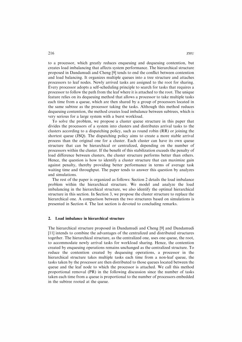
selected to describe the states of a subsystem, there are kþ Bn states in a subsystem,from 0 to kþ Bn � 1. Each time a processor can take at most Bn tasks from the rootto its local queue due to the space limitation. If a processor takes m; ð1 � m � BnÞ,tasks from the root, the processor starts to service one of the m tasks immediately,leaving m� 1 tasks in its local queue.Figure 2 shows all possible transitions in a subsystem, each circle represents a state
of the subsystem. The service rate of the subsystem varies from m to km, depending onthe state of the subsystem. Neither the arrival process nor the arrival rate of thesubsystem can be obtained even if a Poisson arrival process for the root is assumed.This is because each subsystem uses the PR method to take tasks from the root andthe number of tasks taken is a random variable, varying from 1 to Bn. Thus, eachsubsystem has a batch arrival process, but the interarrival time between batchescannot be determined since it depends upon the states of all subsystems and arrivalprocess at the root.The state space of a subsystem can be divided into three non-overlapping ranges,
underloaded, right-loaded, and overloaded. The two dotted boxes in Figure 2
Figure 1. Analysis model.
Figure 2. State-transition diagram in a subsystem.
218 ZHU
correspond to the underloaded and overloaded ranges. The underloaded rangecovers state 0 to state k� 1, in which at least a processor is idle. The right-loadedrange contains one state only, state k, in which all processors in the subsystem arebusy and no task is waiting at the local queue. The overloaded range covers all therest, from kþ 1 to kþ Bn � 1, in which all processors are busy and at least one taskis waiting at the local queue. To assist the following discussion, we will call states inthe underloaded range underloaded states, and similarly the states in the overloadedrange overloaded states.When a subsystem is in an underloaded state, its arrival is single arrival since a
processor from the subsystem is blocked at the root, and whenever a task arrives itwill be served immediately by one of the idle processors blocked at the root. For asubsystem, batch arrivals only occur when the subsystem is transiting from state kto state k� 1 and there are multiple tasks queued at the root. We use k� 1þ todenote it and distinguish it from state k� 1 where an idle processor is blocked atthe root. Let i; ði � 0Þ denote the number of tasks queued at the root while asubsystem is entering state k� 1þ, the subsystem may enter one of the followingstates:
. state kþ i � 1, if 0 < i < Bn, i.e., the subsystem takes all queued tasks to its localqueue; or
. state kþ Bn � 1, if i � Bn, i.e., the subsystem takes Bn tasks to its local queue; or
. state k� 1, if i ¼ 0. The idle processor is blocked at the root to wait for newarrival. In this case, the next possible state for the subsystem could be either k� 2or k, depending on the next event occurred in the subsystem. If the next event is atask arrival, the subsystem will enter state k; if the next event is a task departure,the subsystem moves to state k� 2.
Thus, a renewal point can be embedded at state k� 1þ, this point is merged withk� 1 in Figure 2 for simplicity reason, where ai is the distribution ofi; ð0 � i < BnÞ, task arrivals at the subsystem. The state transition of a subsystemcan be described by a semi-Markov process in which the service time yields anexponential distribution. To obtain a closed-form solution of the steady-statedistribution, we need to know ai; ð0 < i � BnÞ, which depends on the arrivalprocess at the root and the time distribution between two consecutive dequeuingoperations at the root DðtÞ. Current queueing theory fall short of methods toobtain the DðtÞ.Rather than pursuing the exact steady-state distribution of a subsystem, we use an
approximation to estimate the steady-state probability of a subsystem that ismodeled as a special GIx=M=k=Bn � 1 system. In this model, the arrival process is ageneral independent batch arrival process and there are k parallel exponentialprocessors, each has a service rate of m. Tasks arrive in groups following a renewalprocess with arrival rate l. In addition, the group size is a random variable X, itsprobability distribution is known as Pr½X ¼ i ¼ gi; ði ¼ 1; 2; . . . ;BnÞ. Also, assumeX has a finite mean mg. Based on these, in Yao et al. [12] provided a solution forGIx=M=k queue. We extend Yao’s result to the special GIx=M=k=Bn � 1 model andapply local balancing principle to obtain the stationary equations. Then, the steady-
CLUSTER QUEUE STRUCTURE FOR SMM SYSTEMS 219
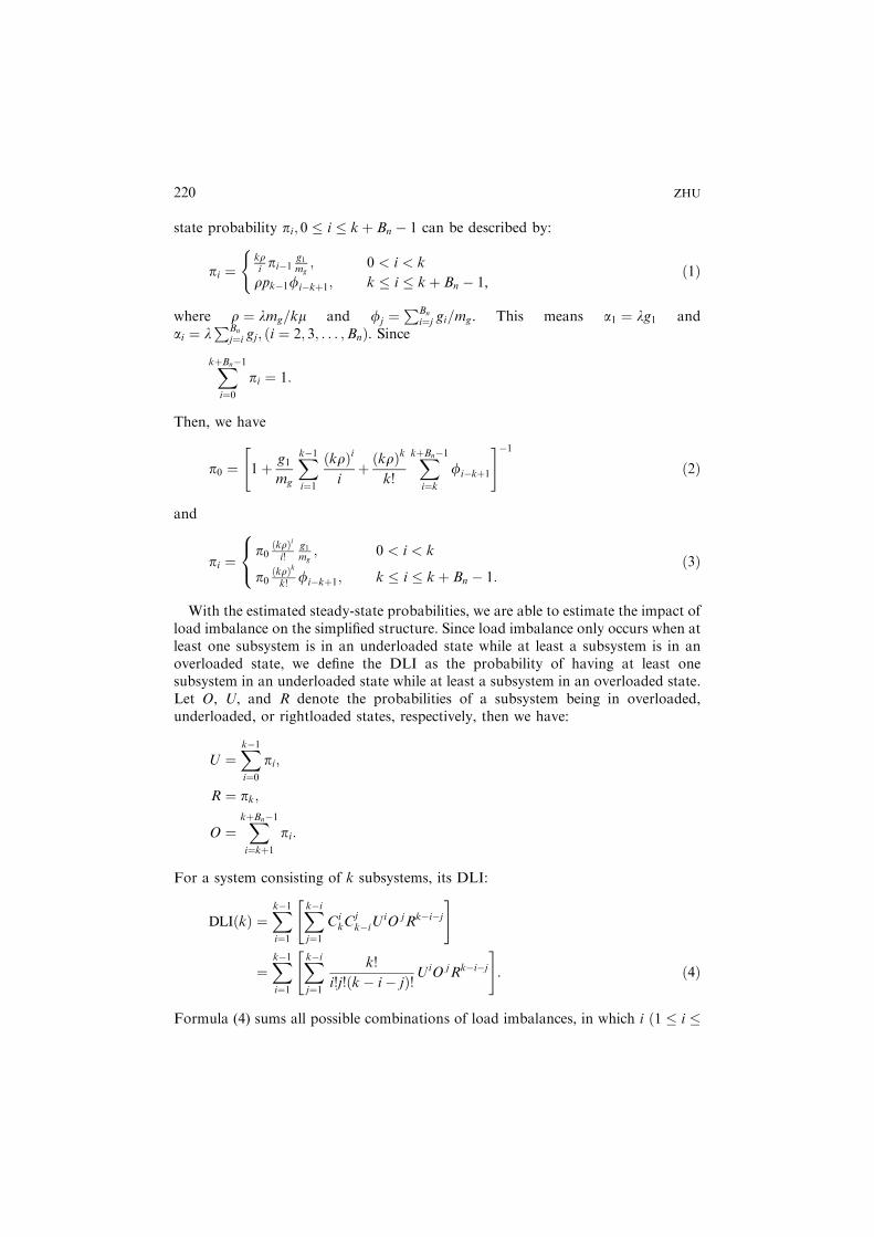
state probability pi; 0 � i � kþ Bn � 1 can be described by:
pi ¼kripi�1
g1mg
; 0 < i < k
rpk�1fi�kþ1; k � i � kþ Bn � 1,
(ð1Þ
where r ¼ lmg=km and fj ¼PBn
i¼j gi=mg. This means a1 ¼ lg1 andai ¼ l
PBn
j¼i gj; ði ¼ 2; 3; . . . ;BnÞ. Since
XkþBn�1
i¼0pi ¼ 1:
Then, we have
p0 ¼ 1þ g1
mg
Xk�1i¼1
ðkrÞi
iþ ðkrÞk
k!
XkþBn�1
i¼kfi�kþ1
" #�1
ð2Þ
and
pi ¼p0
ðkrÞii!
g1mg
; 0 < i < k
p0ðkrÞkk! fi�kþ1; k � i � kþ Bn � 1:
8<: ð3Þ
With the estimated steady-state probabilities, we are able to estimate the impact ofload imbalance on the simplified structure. Since load imbalance only occurs when atleast one subsystem is in an underloaded state while at least a subsystem is in anoverloaded state, we define the DLI as the probability of having at least onesubsystem in an underloaded state while at least a subsystem in an overloaded state.Let O, U, and R denote the probabilities of a subsystem being in overloaded,underloaded, or rightloaded states, respectively, then we have:
U ¼Xk�1i¼0
pi;
R ¼ pk;
O ¼XkþBn�1
i¼kþ1pi:
For a system consisting of k subsystems, its DLI:
DLIðkÞ ¼Xk�1i¼1
Xk�ij¼1
CikC
jk�iU
iO jRk�i�j
" #
¼Xk�1i¼1
Xk�ij¼1
k!
i!j!ðk� i � jÞ!UiO jRk�i�j
" #: ð4Þ
Formula (4) sums all possible combinations of load imbalances, in which i ð1 � i �
220 ZHU
k� 1Þ out of the k subsystems are in underloaded states, j ð1 � j � k� iÞ of the ksubsystems are in overloaded states, and the rest ðk� i � jÞ are rightloaded. Theabove formula is identical to that used in Ni and Wu [8].Three of the four parameters in (4), O, U, and R, are related since
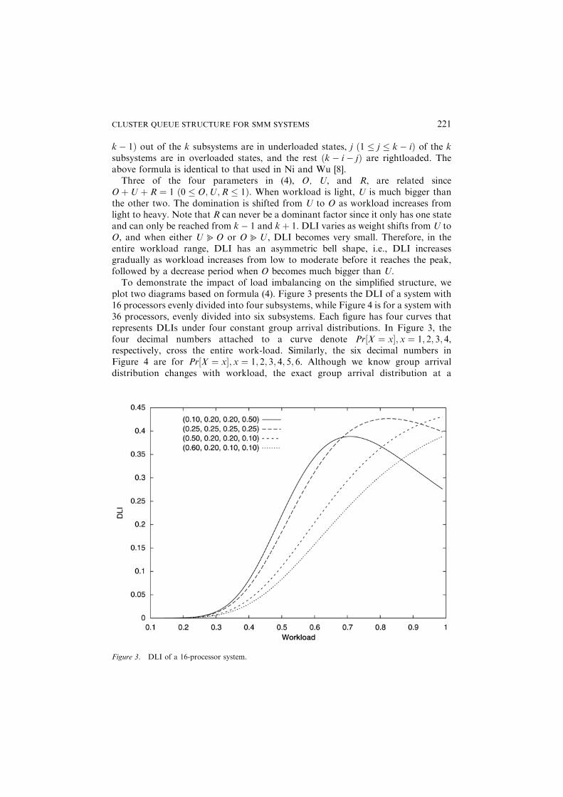
OþU þ R ¼ 1 ð0 � O;U;R � 1Þ. When workload is light, U is much bigger thanthe other two. The domination is shifted from U to O as workload increases fromlight to heavy. Note that R can never be a dominant factor since it only has one stateand can only be reached from k� 1 and kþ 1. DLI varies as weight shifts from U toO, and when either U4O or O4U, DLI becomes very small. Therefore, in theentire workload range, DLI has an asymmetric bell shape, i.e., DLI increasesgradually as workload increases from low to moderate before it reaches the peak,followed by a decrease period when O becomes much bigger than U.To demonstrate the impact of load imbalancing on the simplified structure, we
plot two diagrams based on formula (4). Figure 3 presents the DLI of a system with16 processors evenly divided into four subsystems, while Figure 4 is for a system with36 processors, evenly divided into six subsystems. Each figure has four curves thatrepresents DLIs under four constant group arrival distributions. In Figure 3, thefour decimal numbers attached to a curve denote Pr½X ¼ x; x ¼ 1; 2; 3; 4,respectively, cross the entire work-load. Similarly, the six decimal numbers inFigure 4 are for Pr½X ¼ x; x ¼ 1; 2; 3; 4; 5; 6. Although we know group arrivaldistribution changes with workload, the exact group arrival distribution at a
Figure 3. DLI of a 16-processor system.
CLUSTER QUEUE STRUCTURE FOR SMM SYSTEMS 221
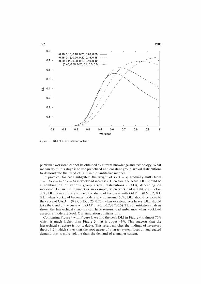
particular workload cannot be obtained by current knowledge and technology. Whatwe can do at this stage is to use predefined and constant group arrival distributionsto demonstrate the trend of DLI in a quantitative manner.In practice, for each subsystem the weight of Pr½X ¼ x gradually shifts from
x ¼ 1 to x ¼ 4 (or x ¼ 6) as workload increases. Therefore, the actual DLI should bea combination of various group arrival distributions (GAD), depending onworkload. Let us use Figure 3 as an example, when workload is light, e.g., below30%, DLI is more likely to have the shape of the curve with GAD ¼ (0.6, 0.2, 0.1,0.1); when workload becomes moderate, e.g., around 50%, DLI should be close tothe curve of GAD ¼ (0.25, 0.25, 0.25, 0.25); when workload gets heavy, DLI shouldtake the trend of the curve with GAD ¼ (0.1, 0.2, 0.2, 0.5). This quantitative analysisshows the hierarchical structure can have serious load imbalance when workloadexceeds a moderate level. Our simulation confirms this.Comparing Figure 4 with Figure 3, we find the peak DLI in Figure 4 is almost 75%
which is much higher than Figure 3 that is about 43%. This suggests that thehierarchical structure is not scalable. This result matches the findings of inventorytheory [13], which states that the root queue of a larger system faces an aggregateddemand that is more volatile than the demand of a smaller system.
Figure 4. DLI of a 36-processor system.
222 ZHU

2.3. Branch factor
The previous discussion points out that load imbalance only occurs when the root isempty. Therefore, the probability of having an empty root in some degree shows thepossibility of load imbalance in the hierarchical structure when workload exceeds amoderate level. With the same number of processors, there are a number ofalternatives to construct a hierarchical structure by using different branch factors.The question considered here is under the same condition which structure canminimize the probability of having an empty root. Subsequently, the identifiedstructure should have the smallest possibility to become load imbalanced. In order toobtain a closed form solution, we remodel the system. This time the system ismodeled as an M=MBn=k system, while the arrival process for the root is a Poissonprocess with arrival rate l. In this model, a subsystem is assumed as a batch serverwhich completes a batch of tasks before taking another batch from the root. Thebatch service time yields an exponential distribution with a mean of 1=mt, dependingon the number of processors in a subsystem.Figure 5 shows the steady state-transition of a multi-server and batch service
model. In this figure, each circle represents a state of the system. The data pair ðm; nÞin each circle denote the number of subsystems that have not yet completed theircurrent batch and the number of tasks queued at the root, respectively. For example,initially all subsystems are blocked on the empty root and the system is in state ð0; 0Þ.When a task arrives, the system enters state ð1; 0Þ, i.e., a subsystem starts its servicewith rate mr and no task waiting. If the next event is a task arrival, the system willenter state ð2; 0Þ. The root queue remains empty until all subsystems start theirservices, then if the next 5 events are all task arrivals, the system enters state ðk; 5Þ,later, the subsystem that first completes its task can take multiple tasks. The servicerate varies from mr to kmr, depending on system states. The steady-state probability isdefined as
Pm;nðtÞ ¼ Probfat time t; there are n tasks waiting at the root
and m subsystems are in serviceg; f0 � m � kg:
Obviously, if n > 0;m must be equal to k. Similarly if 0 � m < k; n must be 0. Using
Figure 5. Root state-transition diagram.
CLUSTER QUEUE STRUCTURE FOR SMM SYSTEMS 223
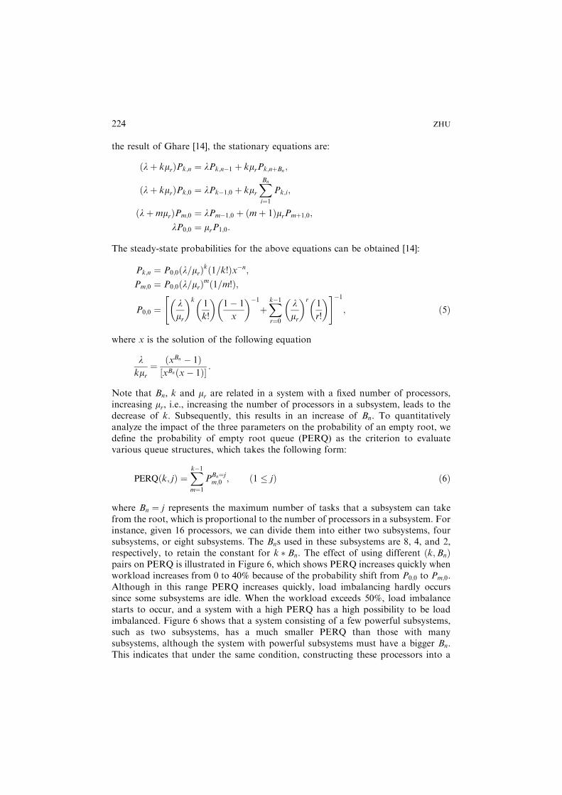
the result of Ghare [14], the stationary equations are:
ðlþ kmrÞPk;n ¼ lPk;n�1 þ kmrPk;nþBn;
ðlþ kmrÞPk;0 ¼ lPk�1;0 þ kmrXBn
i¼1Pk;i;
ðlþmmrÞPm;0 ¼ lPm�1;0 þ ðmþ 1ÞmrPmþ1;0;
lP0;0 ¼ mrP1;0:
The steady-state probabilities for the above equations can be obtained [14]:
Pk;n ¼ P0;0ðl=mrÞkð1=k!Þx�n;Pm;0 ¼ P0;0ðl=mrÞmð1=m!Þ;
P0;0 ¼lmr
k1
k!
1� 1
x
�1þXk�1r¼0
lmr
r1
r!
" #�1
; ð5Þ
where x is the solution of the following equation
lkmr
¼ ðxBn � 1Þ½xBnðx� 1Þ :
Note that Bn, k and mr are related in a system with a fixed number of processors,increasing mr, i.e., increasing the number of processors in a subsystem, leads to thedecrease of k. Subsequently, this results in an increase of Bn. To quantitativelyanalyze the impact of the three parameters on the probability of an empty root, wedefine the probability of empty root queue (PERQ) as the criterion to evaluatevarious queue structures, which takes the following form:
PERQðk; jÞ ¼Xk�1m¼1
PBn¼jm;0 ; ð1 � jÞ ð6Þ
where Bn ¼ j represents the maximum number of tasks that a subsystem can takefrom the root, which is proportional to the number of processors in a subsystem. Forinstance, given 16 processors, we can divide them into either two subsystems, foursubsystems, or eight subsystems. The Bns used in these subsystems are 8, 4, and 2,respectively, to retain the constant for k � Bn. The effect of using different ðk;BnÞpairs on PERQ is illustrated in Figure 6, which shows PERQ increases quickly whenworkload increases from 0 to 40% because of the probability shift from P0;0 to Pm;0.Although in this range PERQ increases quickly, load imbalancing hardly occurssince some subsystems are idle. When the workload exceeds 50%, load imbalancestarts to occur, and a system with a high PERQ has a high possibility to be loadimbalanced. Figure 6 shows that a system consisting of a few powerful subsystems,such as two subsystems, has a much smaller PERQ than those with manysubsystems, although the system with powerful subsystems must have a bigger Bn.This indicates that under the same condition, constructing these processors into a
224 ZHU
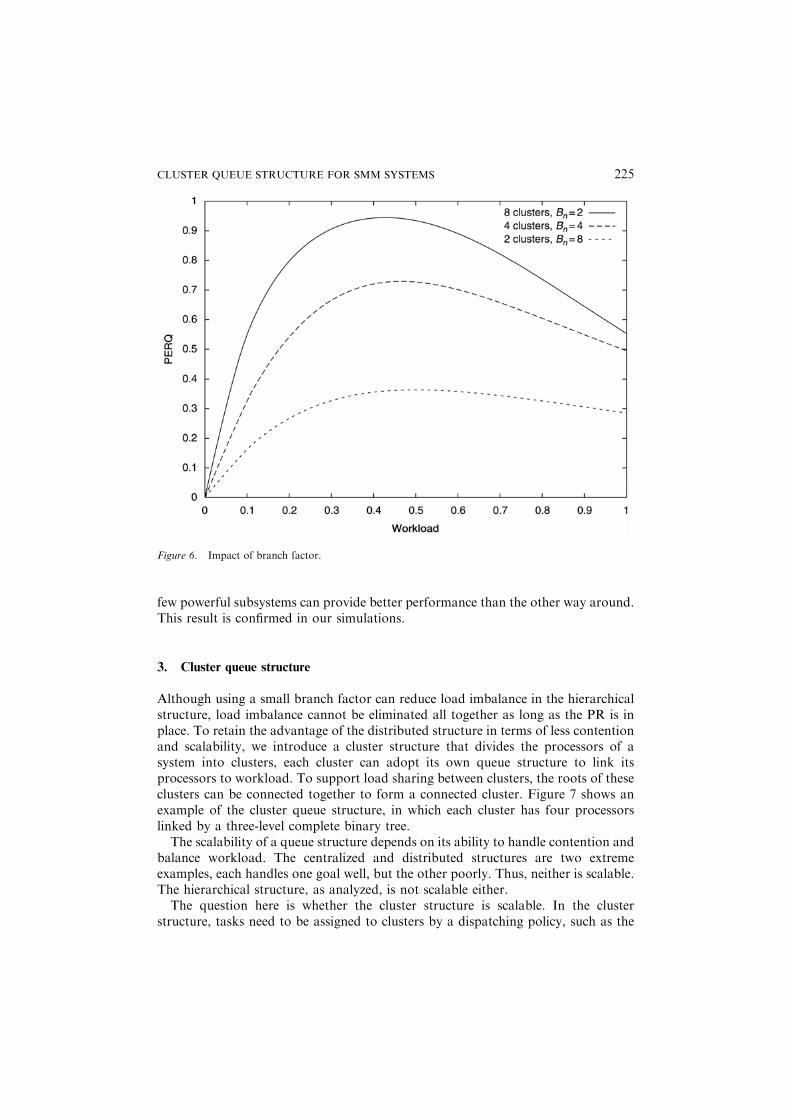
few powerful subsystems can provide better performance than the other way around.This result is confirmed in our simulations.
3. Cluster queue structure
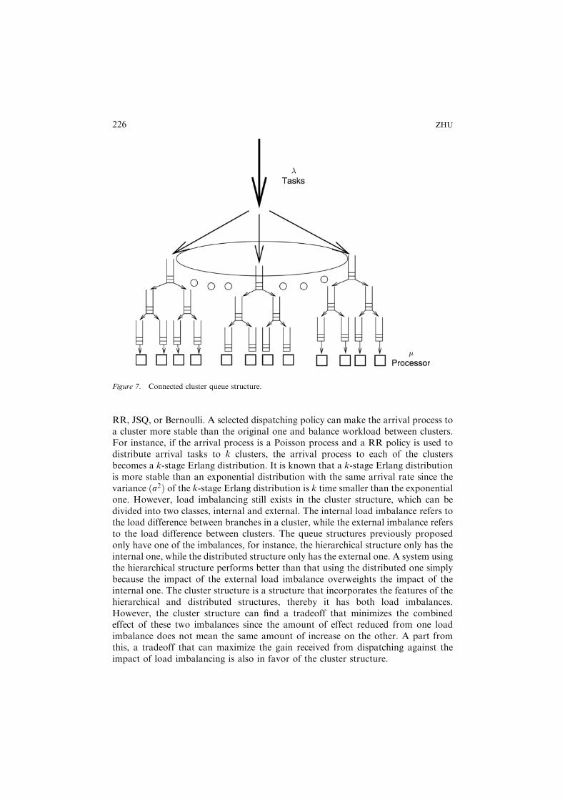
Although using a small branch factor can reduce load imbalance in the hierarchicalstructure, load imbalance cannot be eliminated all together as long as the PR is inplace. To retain the advantage of the distributed structure in terms of less contentionand scalability, we introduce a cluster structure that divides the processors of asystem into clusters, each cluster can adopt its own queue structure to link itsprocessors to workload. To support load sharing between clusters, the roots of theseclusters can be connected together to form a connected cluster. Figure 7 shows anexample of the cluster queue structure, in which each cluster has four processorslinked by a three-level complete binary tree.The scalability of a queue structure depends on its ability to handle contention and
balance workload. The centralized and distributed structures are two extremeexamples, each handles one goal well, but the other poorly. Thus, neither is scalable.The hierarchical structure, as analyzed, is not scalable either.The question here is whether the cluster structure is scalable. In the cluster
structure, tasks need to be assigned to clusters by a dispatching policy, such as the
Figure 6. Impact of branch factor.
CLUSTER QUEUE STRUCTURE FOR SMM SYSTEMS 225
RR, JSQ, or Bernoulli. A selected dispatching policy can make the arrival process toa cluster more stable than the original one and balance workload between clusters.For instance, if the arrival process is a Poisson process and a RR policy is used todistribute arrival tasks to k clusters, the arrival process to each of the clustersbecomes a k-stage Erlang distribution. It is known that a k-stage Erlang distributionis more stable than an exponential distribution with the same arrival rate since thevariance ðs2Þ of the k-stage Erlang distribution is k time smaller than the exponentialone. However, load imbalancing still exists in the cluster structure, which can bedivided into two classes, internal and external. The internal load imbalance refers tothe load difference between branches in a cluster, while the external imbalance refersto the load difference between clusters. The queue structures previously proposedonly have one of the imbalances, for instance, the hierarchical structure only has theinternal one, while the distributed structure only has the external one. A system usingthe hierarchical structure performs better than that using the distributed one simplybecause the impact of the external load imbalance overweights the impact of theinternal one. The cluster structure is a structure that incorporates the features of thehierarchical and distributed structures, thereby it has both load imbalances.However, the cluster structure can find a tradeoff that minimizes the combinedeffect of these two imbalances since the amount of effect reduced from one loadimbalance does not mean the same amount of increase on the other. A part fromthis, a tradeoff that can maximize the gain received from dispatching against theimpact of load imbalancing is also in favor of the cluster structure.
Figure 7. Connected cluster queue structure.
226 ZHU
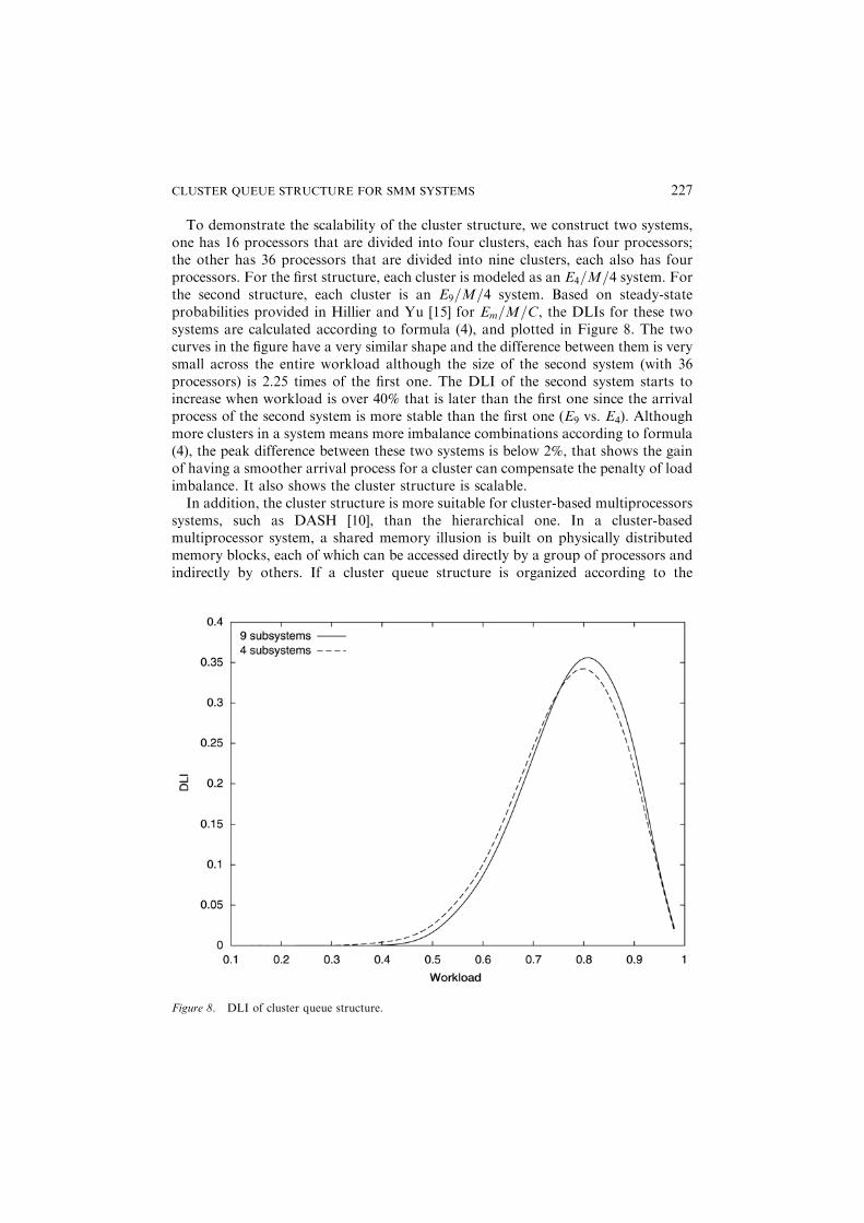
To demonstrate the scalability of the cluster structure, we construct two systems,one has 16 processors that are divided into four clusters, each has four processors;the other has 36 processors that are divided into nine clusters, each also has fourprocessors. For the first structure, each cluster is modeled as an E4=M=4 system. Forthe second structure, each cluster is an E9=M=4 system. Based on steady-stateprobabilities provided in Hillier and Yu [15] for Em=M=C, the DLIs for these twosystems are calculated according to formula (4), and plotted in Figure 8. The twocurves in the figure have a very similar shape and the difference between them is verysmall across the entire workload although the size of the second system (with 36processors) is 2.25 times of the first one. The DLI of the second system starts toincrease when workload is over 40% that is later than the first one since the arrivalprocess of the second system is more stable than the first one (E9 vs. E4). Althoughmore clusters in a system means more imbalance combinations according to formula(4), the peak difference between these two systems is below 2%, that shows the gainof having a smoother arrival process for a cluster can compensate the penalty of loadimbalance. It also shows the cluster structure is scalable.In addition, the cluster structure is more suitable for cluster-based multiprocessors
systems, such as DASH [10], than the hierarchical one. In a cluster-basedmultiprocessor system, a shared memory illusion is built on physically distributedmemory blocks, each of which can be accessed directly by a group of processors andindirectly by others. If a cluster queue structure is organized according to the
Figure 8. DLI of cluster queue structure.
CLUSTER QUEUE STRUCTURE FOR SMM SYSTEMS 227
hardware clusters, one cluster for a hardware cluster, a processor only needs toaccess the queues in its memory blocks for tasks. However, the hierarchical structureis not suitable for cluster-based multiprocessors because the root queue shared by allprocessors needs to be migrated frequently between memory blocks whenever aprocessor from a different hardware cluster wants to access it. The migrationintroduces extra delays on queue accesses.
4. Simulation results
A large number of simulations were carried out to evaluate the performance of theproposed cluster structure against the hierarchical one. A systematic approach wasused to conduct the simulations. Let m be the number of processors in a system andk be the branch factor used by the system. We first constructed a hierarchicalstructure to link these processors, assuming the number of processors allows us tobuild a balanced tree, i.e., m ¼ kn; n [N. We then removed the root from thehierarchical structure to create a cluster structure that has k identical clusters. Later,the roots of the k clusters are deleted to create a cluster structure with k2 clusters.This process continues until we reach a fully distributed structure. In thesesimulations, the maximum number of tasks that a processor can take from a queue,Bn, is proportional to the number of processors in a subtree connected to the queue.Each time when a new structure is constructed, including the hierarchical one, a
series of simulations were carried out with various workloads. The average taskwaiting time, which is proportional to the task response time, is used as the criterionto evaluate the quality of a structure. In these simulations, we fixed the mean servicerate ðmÞ. By adjusting the mean arrival rate ðlÞ, we can obtain various workload andensure r ¼ l=mm < 1. Each simulation, with a given workload, was executed for80,000 virtual time units, and the same amount of data collected in each simulation.If we use a confidence interval of 95%, the sample mean differs from the theoreticalmean by no more than 7610�3.Figure 9 shows the average task waiting time of two 64-processor systems with
branch factor k ¼ 2, one uses the hierarchical structure, the other uses the clusterstructure that divides the 64 processors into eight clusters, each has eight processors.The task service time yields an exponential distribution with mean ¼ 2. The twocurves depicted in the figure clearly show that when the load is light to moderateð< 65%Þ, the two structures have the same performance and the average waiting timeis 0, i.e., whenever a new task arrives, it is immediately assigned to an idle processorfor service and no task experiences any waiting.When the workload exceeds a moderate level ð� 65%Þ, not all tasks can be served
immediately when they arrive, some of them have to wait. Then, the loadimbalancing problem inherent to the hierarchical structure and the cluster structurestarts to affect system performance, however, the load imbalancing in thehierarchical structure is more serious than that in the cluster one as workloadincreases, which results in longer waiting time. Figure 9 shows that the system usingthe cluster structure has better performance than that using the hierarchical one
228 ZHU
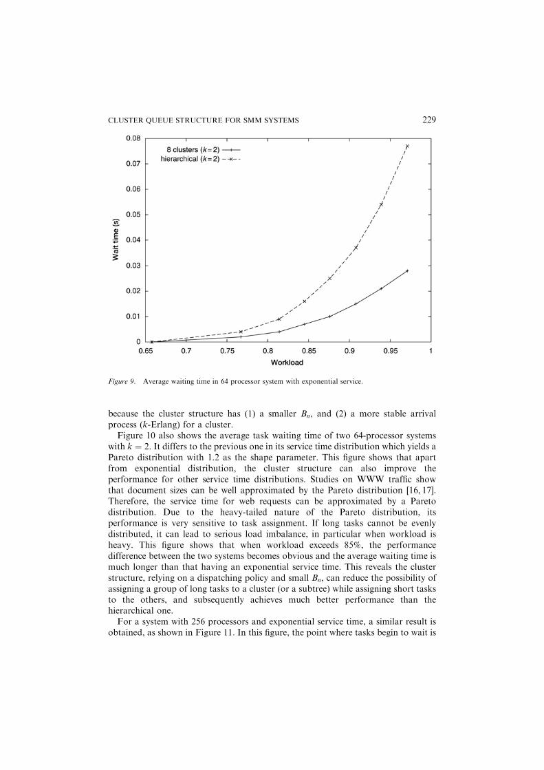
because the cluster structure has (1) a smaller Bn, and (2) a more stable arrivalprocess (k-Erlang) for a cluster.Figure 10 also shows the average task waiting time of two 64-processor systems
with k ¼ 2. It differs to the previous one in its service time distribution which yields aPareto distribution with 1.2 as the shape parameter. This figure shows that apartfrom exponential distribution, the cluster structure can also improve theperformance for other service time distributions. Studies on WWW traffic showthat document sizes can be well approximated by the Pareto distribution [16, 17].Therefore, the service time for web requests can be approximated by a Paretodistribution. Due to the heavy-tailed nature of the Pareto distribution, itsperformance is very sensitive to task assignment. If long tasks cannot be evenlydistributed, it can lead to serious load imbalance, in particular when workload isheavy. This figure shows that when workload exceeds 85%, the performancedifference between the two systems becomes obvious and the average waiting time ismuch longer than that having an exponential service time. This reveals the clusterstructure, relying on a dispatching policy and small Bn, can reduce the possibility ofassigning a group of long tasks to a cluster (or a subtree) while assigning short tasksto the others, and subsequently achieves much better performance than thehierarchical one.For a system with 256 processors and exponential service time, a similar result is
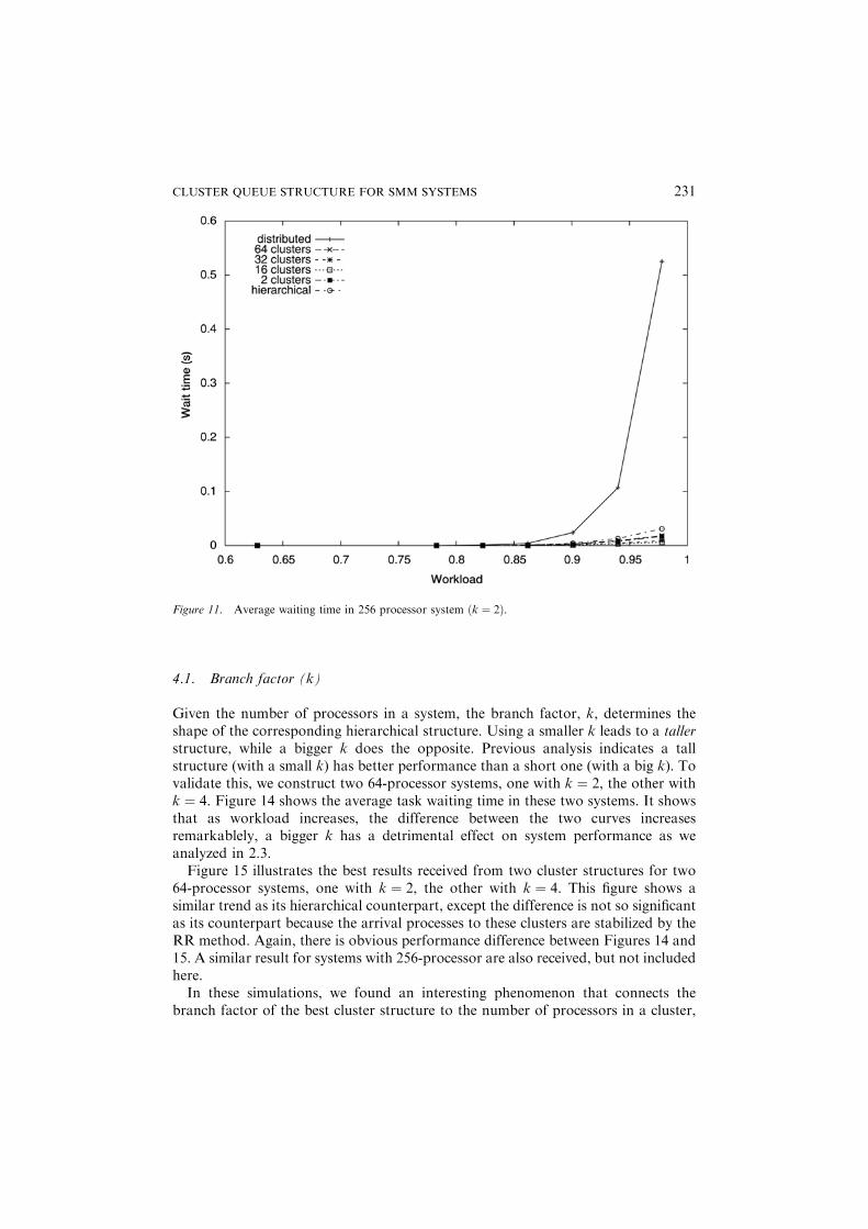
obtained, as shown in Figure 11. In this figure, the point where tasks begin to wait is
Figure 9. Average waiting time in 64 processor system with exponential service.
CLUSTER QUEUE STRUCTURE FOR SMM SYSTEMS 229

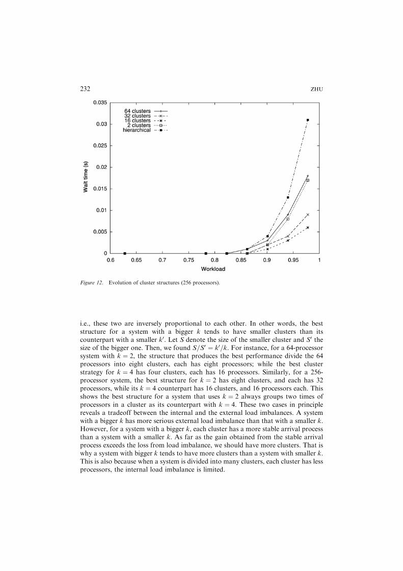
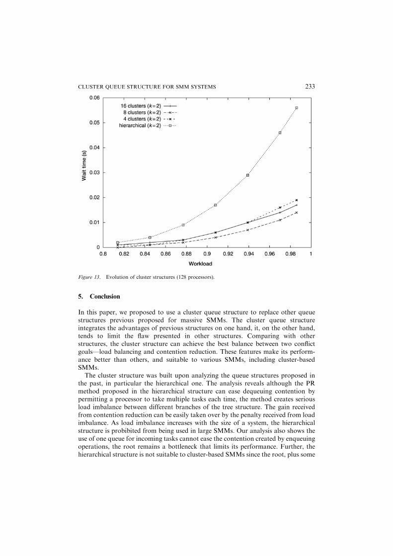
higher ð� 85%Þ than that of the 64 processor system. This is because a larger systemis more capable of delaying the time of queue buildup than a smaller one sinceaccording to Erlang C formula ðCðm; l=mÞ ¼ Pm=1� rÞ the waiting probability of atask is inversely proportional to the number of processors in a system. Six curves inthe figure show an evolutionary process starting from the hierarchical structure, viavarious cluster structures, and finally ending at the distributed one. It shows thedistributed structure performs far worse than all other structures due to seriousexternal load imbalance. To examine the difference between the other structures, wereplot the figure without the distributed one in Figure 12, which shows all clusterstructures perform better than the hierarchical one, the structure of 16 clustersperforms the best. Similar result for systems with 128 processors is shown in Figure13.The evolutionary process shows when a system departs from the hierarchical
structure to a cluster one, the gain received from having a more stable arrival processto each cluster exceeds the penalty introduced by the external load imbalance, whichleads to better performance. This trend continues until the penalty exceeds the gain.Then, performance starts to deteriorate, and finally when it reaches the fullydistributed structure, it has the worst performance.
Figure 10. Average waiting time in 64 processor system with Pareto service.
230 ZHU
4.1. Branch factor (k)
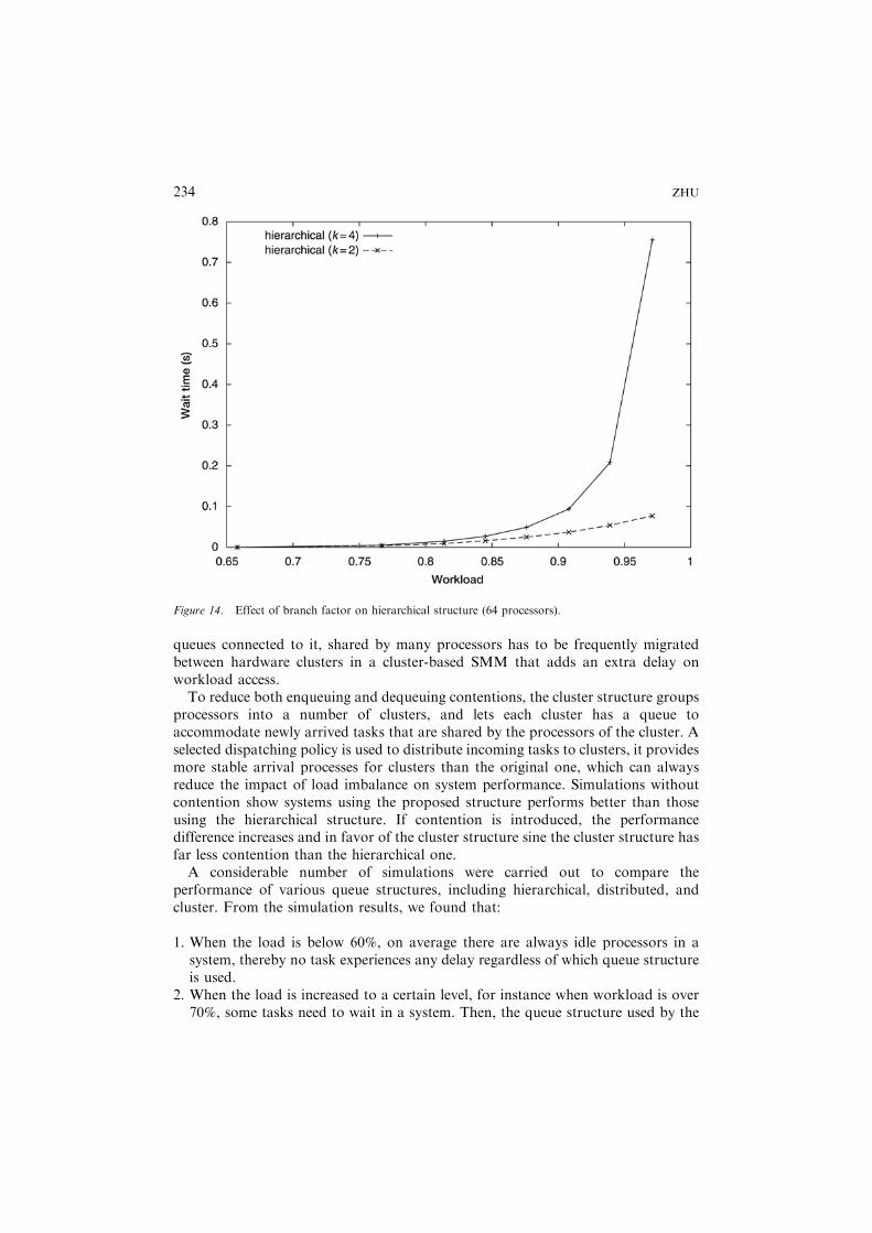
Given the number of processors in a system, the branch factor, k, determines theshape of the corresponding hierarchical structure. Using a smaller k leads to a tallerstructure, while a bigger k does the opposite. Previous analysis indicates a tallstructure (with a small k) has better performance than a short one (with a big k). Tovalidate this, we construct two 64-processor systems, one with k ¼ 2, the other withk ¼ 4. Figure 14 shows the average task waiting time in these two systems. It showsthat as workload increases, the difference between the two curves increasesremarkablely, a bigger k has a detrimental effect on system performance as weanalyzed in 2.3.Figure 15 illustrates the best results received from two cluster structures for two
64-processor systems, one with k ¼ 2, the other with k ¼ 4. This figure shows asimilar trend as its hierarchical counterpart, except the difference is not so significantas its counterpart because the arrival processes to these clusters are stabilized by theRR method. Again, there is obvious performance difference between Figures 14 and15. A similar result for systems with 256-processor are also received, but not includedhere.In these simulations, we found an interesting phenomenon that connects the
branch factor of the best cluster structure to the number of processors in a cluster,
Figure 11. Average waiting time in 256 processor system ðk ¼ 2Þ.
CLUSTER QUEUE STRUCTURE FOR SMM SYSTEMS 231
i.e., these two are inversely proportional to each other. In other words, the beststructure for a system with a bigger k tends to have smaller clusters than itscounterpart with a smaller k0. Let S denote the size of the smaller cluster and S0 thesize of the bigger one. Then, we found S=S0 ¼ k0=k. For instance, for a 64-processorsystem with k ¼ 2, the structure that produces the best performance divide the 64processors into eight clusters, each has eight processors; while the best clusterstrategy for k ¼ 4 has four clusters, each has 16 processors. Similarly, for a 256-processor system, the best structure for k ¼ 2 has eight clusters, and each has 32processors, while its k ¼ 4 counterpart has 16 clusters, and 16 processors each. Thisshows the best structure for a system that uses k ¼ 2 always groups two times ofprocessors in a cluster as its counterpart with k ¼ 4. These two cases in principlereveals a tradeoff between the internal and the external load imbalances. A systemwith a bigger k has more serious external load imbalance than that with a smaller k.However, for a system with a bigger k, each cluster has a more stable arrival processthan a system with a smaller k. As far as the gain obtained from the stable arrivalprocess exceeds the loss from load imbalance, we should have more clusters. That iswhy a system with bigger k tends to have more clusters than a system with smaller k.This is also because when a system is divided into many clusters, each cluster has lessprocessors, the internal load imbalance is limited.
Figure 12. Evolution of cluster structures (256 processors).
232 ZHU
5. Conclusion
In this paper, we proposed to use a cluster queue structure to replace other queuestructures previous proposed for massive SMMs. The cluster queue structureintegrates the advantages of previous structures on one hand, it, on the other hand,tends to limit the flaw presented in other structures. Comparing with otherstructures, the cluster structure can achieve the best balance between two conflictgoals—load balancing and contention reduction. These features make its perform-ance better than others, and suitable to various SMMs, including cluster-basedSMMs.The cluster structure was built upon analyzing the queue structures proposed in
the past, in particular the hierarchical one. The analysis reveals although the PRmethod proposed in the hierarchical structure can ease dequeuing contention bypermitting a processor to take multiple tasks each time, the method creates seriousload imbalance between different branches of the tree structure. The gain receivedfrom contention reduction can be easily taken over by the penalty received from loadimbalance. As load imbalance increases with the size of a system, the hierarchicalstructure is probibited from being used in large SMMs. Our analysis also shows theuse of one queue for incoming tasks cannot ease the contention created by enqueuingoperations, the root remains a bottleneck that limits its performance. Further, thehierarchical structure is not suitable to cluster-based SMMs since the root, plus some
Figure 13. Evolution of cluster structures (128 processors).
CLUSTER QUEUE STRUCTURE FOR SMM SYSTEMS 233
queues connected to it, shared by many processors has to be frequently migratedbetween hardware clusters in a cluster-based SMM that adds an extra delay onworkload access.To reduce both enqueuing and dequeuing contentions, the cluster structure groups
processors into a number of clusters, and lets each cluster has a queue toaccommodate newly arrived tasks that are shared by the processors of the cluster. Aselected dispatching policy is used to distribute incoming tasks to clusters, it providesmore stable arrival processes for clusters than the original one, which can alwaysreduce the impact of load imbalance on system performance. Simulations withoutcontention show systems using the proposed structure performs better than thoseusing the hierarchical structure. If contention is introduced, the performancedifference increases and in favor of the cluster structure sine the cluster structure hasfar less contention than the hierarchical one.A considerable number of simulations were carried out to compare the
performance of various queue structures, including hierarchical, distributed, andcluster. From the simulation results, we found that:
1. When the load is below 60%, on average there are always idle processors in asystem, thereby no task experiences any delay regardless of which queue structureis used.
2. When the load is increased to a certain level, for instance when workload is over70%, some tasks need to wait in a system. Then, the queue structure used by the
Figure 14. Effect of branch factor on hierarchical structure (64 processors).
234 ZHU
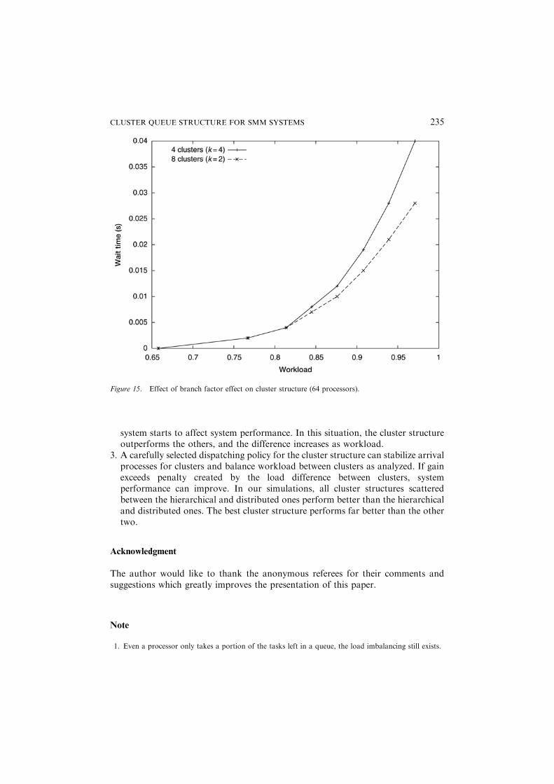
system starts to affect system performance. In this situation, the cluster structureoutperforms the others, and the difference increases as workload.
3. A carefully selected dispatching policy for the cluster structure can stabilize arrivalprocesses for clusters and balance workload between clusters as analyzed. If gainexceeds penalty created by the load difference between clusters, systemperformance can improve. In our simulations, all cluster structures scatteredbetween the hierarchical and distributed ones perform better than the hierarchicaland distributed ones. The best cluster structure performs far better than the othertwo.
Acknowledgment
The author would like to thank the anonymous referees for their comments andsuggestions which greatly improves the presentation of this paper.
Note
1. Even a processor only takes a portion of the tasks left in a queue, the load imbalancing still exists.
Figure 15. Effect of branch factor effect on cluster structure (64 processors).
CLUSTER QUEUE STRUCTURE FOR SMM SYSTEMS 235
References
1. D. G. Feitelson, L. Rudolph, U. Schwiehelshohn, K. C. Sevcik, and P. Wong. Theory and practice in
parallel job scheduling. In Job Scheduling Strategies for Parallel Processing, Lecture Notes in Computer
Science 1291, April 1997, pp. 1–34.
2. P. Stenstrom, E. Hagersten, D. J. Lilja, M. Martonosi, and M. Venugopal. Trends in shared memory
multiprocessing. IEEE Computer, pp. 44–50, December 1997.
3. C. Natarajan, R. K. Iyer, and S. Sharma. Experimental evaluation of performance and scalability of a
multiprogramd shared-memory multiprocessor. In Proc. of the 5th IEEE Symposium on Parallel and
Distributed Processing, pp. 11–18, December 1993.
4. D. E. Lenoski and W.-D. Weber. Scalable Shared-Memory Multiprocessing, Morgan Kaufmann
Publishers, 1997.
5. BBN Advanced Computer Inc. Inside the TC2000, 1989.
6. S. Frank, H. Burkhardt, and J. Rothnie. The KSR-1: Bridging the gap between shared memory and
MPPs. In Proc. of Compcon’93, pp. 285–294, 1993.
7. J. Kuskin et al. The stanford flash multiprocessor. In Proc. of the 21st International Symposium on
Computer Architecture, pp. 302–313, 1994.
8. L. M. Ni and C. E. Wu. Design tradeoff for process scheduling in shared memory multiprocessor
systems. IEEE Transactions on Software Engineering, SE-15(3):327–334, 1989.
9. S. P. Dandamudi and P. S. P. Cheng. A hierarchical task queue organization for shared-memory
multiprocessor systems. IEEE Transactions on Parallel and Distributed Systems, 6(1):1–16, 1995.
10. D. Lenoski, J. Laudon, K. Gharachorloo, W.-D. Weber, A. Gupta, J. Hennessy, M. Horowize, and
M. Lam. The Stanford dash multiprocessor. IEEE Computer, 25:63–79, Mar. 1992.
11. S. P. Dandamudi. Reducing run queue contention in shared memory multiprocessos. IEEE Computer,
pp. 82–89, March 1997.
12. D. D. Yao, M. L. Chaudhey, and J. G. C. Templeton. A Note on some relations in the queue GIx/M/c.
Operations Research Letters, 3(1):53–56, 1984.
13. F. Chen and Y. S. Zheng. One-warehouse multretailer systems with centralized stock information.
Operations Research, 45(2), 1997.
14. P. M. Ghare. Multichannel queueing system with bulk service. Operations Research, 16:189–192, 1968.
15. F. S. Hillier and O. S. Yu. Queueing Tables and Graphs, North Holland, 1981.
16. M. F. Arlitt and C. L. Williamson. Web server workload characterization: The search for invarants. In
Proc. ACM SIGMETRICS’96, pp. 126–137, 1996.
17. M. Nabe, M. Murata, and H. Miyahara. Analysis and modeling of world wide web traffic for capacity
dimensioning of internet access lines. Performance Evaluation, (34), 1998.
236 ZHU
Related Documents