Cluster observations of bow shock energetic ion transport through the magnetosheath into the cusp K. J. Trattner, 1 S. M. Petrinec, 1 S. A. Fuselier, 1 K. Nykyri, 2 and E. Kronberg 3 Received 4 March 2011; revised 31 May 2011; accepted 7 June 2011; published 10 September 2011. [1] The observation of energetic particles by polar orbiting satellites in the magnetospheric cusp resulted in a controversy about their source region. It has been suggested that these cusp energetic particles (CEP) with significant fluxes from magnetosheath energies up to several hundred keV/e are accelerated locally in the cusp by the turbulence found in cusp diamagnetic cavities (CDC). As an alternative to the local acceleration region, the quasi‐parallel shock is successful as a source region for CEP events. Energetic ions accelerated at the bow shock can be transported downstream and enter the cusp along newly reconnected field lines. Composition and energy spectra of these CEP events resemble those of bow shock energetic diffuse ions. This study investigates a northern cusp pass by the Cluster satellites that encountered two CDCs with CEP ions. We use recently developed techniques to determine the location of the reconnection site at the magnetopause, draping interplanetary magnetic field lines over the magnetopause and mapping those field lines back into the solar wind to show magnetic connection of the cusp regions, Earth’s bow shock, and upstream region. Energetic ions are also observed outside the magnetopause in the boundary layer streaming from the quasi‐parallel shock toward the cusp which supports an outside source region for CEP ions. Citation: Trattner, K. J., S. M. Petrinec, S. A. Fuselier, K. Nykyri, and E. Kronberg (2011), Cluster observations of bow shock energetic ion transport through the magnetosheath into the cusp, J. Geophys. Res., 116, A09207, doi:10.1029/2011JA016617. 1. Introduction [2] Over the past decade three different source regions have been introduced to explain the observation of Cusp Energetic Particles (CEP) in the high‐altitude cusp regions: local acceleration in the cusp [e.g., Chen et al., 1997; Whitaker et al., 2007], the quasi‐parallel bow shock [e.g., Chang et al., 1998; Trattner et al., 2001, 2010; Fuselier et al., 2009] and the magnetosphere [e.g., Blake, 1999]. [3] These CEP ions have been originally observed by the Charge and Mass Magnetospheric Ion Composition Experi- ment (CAMMICE) and the Comprehensive Energetic Par- ticle and Pitch Angle Distribution (CEPPAD) instruments [Blake et al., 1995] onboard the Polar spacecraft. CEP dis- tributions showed ion composition similar to that of the solar wind, particle energies above typical solar wind energies up to several hundred keV/e, and fluxes substantially higher than those in the solar wind. Because of their similarities with the solar wind, one origin of CEP ions is that they are pen- etrating magnetosheath ions accelerated locally by the reduced and turbulent magnetic field [Chen et al., 1997, 1998; Chen and Fritz, 1998] inside cusp diamagnetic cavities (CDC) [e.g., Fritz et al., 1999; Chen and Fritz, 2001; Niehof et al., 2005, 2008; Whitaker et al., 2006, 2007]. [4] An alternative to the local acceleration origin is remote transport from the quasi‐parallel bow shock which is a well known particle accelerator. Accelerated ions are convected with the solar wind into the magnetosheath and have access to the cusp region once interplanetary magnetic field (IMF) lines reconnect with geomagnetic field lines at the magne- topause. A conceptual model showing how the quasi‐parallel bow shock maps along draped, reconnected, interplanetary magnetic field lines (IMF) into the cusp was first presented by Chang et al. [1998, 2000]. Additional studies reported similarities between ion spectra upstream/downstream from the quasi‐parallel bow shock and CEP spectra in the cusps [Chang et al., 1998; Trattner et al., 1999] and well estab- lished characteristics of bow shock accelerated ions with CEP ions [Trattner et al., 2001]. These characteristics include spectral breaks in CEP spectra consistent with spectral breaks in bow shock accelerated ion spectra, similar density ratios of energetic to thermal protons and similar temperatures of energetic proton and helium distributions for CEP and bow shock accelerated ions. [5] Bow shock accelerated ions show an increasing expo- nential spectral slope with increasing solar wind velocity, predicted by various shock acceleration models [e.g., Ellison, 1981; Lee, 1982; Forman and Drury, 1983] and confirmed by upstream observations from AMPTE/IRM [e.g., Trattner et al., 1994]. The same dependency on solar wind veloc- ity can be found for CEP ions. Finally CEP and bow shock 1 Lockheed Martin Advanced Technology Center, Palo Alto, California, USA. 2 Department of Physical Sciences, Embry‐ Riddle Aeronautical University, Daytona Beach, Florida, USA. 3 Max Planck Institute for Solar System Research, Lindau, Germany. Copyright 2011 by the American Geophysical Union. 0148‐0227/11/2011JA016617 JOURNAL OF GEOPHYSICAL RESEARCH, VOL. 116, A09207, doi:10.1029/2011JA016617, 2011 A09207 1 of 12

Welcome message from author
This document is posted to help you gain knowledge. Please leave a comment to let me know what you think about it! Share it to your friends and learn new things together.
Transcript
Cluster observations of bow shock energetic ion transportthrough the magnetosheath into the cusp
K. J. Trattner,1 S. M. Petrinec,1 S. A. Fuselier,1 K. Nykyri,2 and E. Kronberg3
Received 4 March 2011; revised 31 May 2011; accepted 7 June 2011; published 10 September 2011.
[1] The observation of energetic particles by polar orbiting satellites in themagnetospheric cusp resulted in a controversy about their source region. It has beensuggested that these cusp energetic particles (CEP) with significant fluxes frommagnetosheath energies up to several hundred keV/e are accelerated locally in the cusp bythe turbulence found in cusp diamagnetic cavities (CDC). As an alternative to the localacceleration region, the quasi‐parallel shock is successful as a source region for CEPevents. Energetic ions accelerated at the bow shock can be transported downstream andenter the cusp along newly reconnected field lines. Composition and energy spectra ofthese CEP events resemble those of bow shock energetic diffuse ions. This studyinvestigates a northern cusp pass by the Cluster satellites that encountered two CDCs withCEP ions. We use recently developed techniques to determine the location of thereconnection site at the magnetopause, draping interplanetary magnetic field lines over themagnetopause and mapping those field lines back into the solar wind to show magneticconnection of the cusp regions, Earth’s bow shock, and upstream region. Energetic ionsare also observed outside the magnetopause in the boundary layer streaming from thequasi‐parallel shock toward the cusp which supports an outside source region for CEP ions.
Citation: Trattner, K. J., S. M. Petrinec, S. A. Fuselier, K. Nykyri, and E. Kronberg (2011), Cluster observations of bow shockenergetic ion transport through the magnetosheath into the cusp, J. Geophys. Res., 116, A09207, doi:10.1029/2011JA016617.
1. Introduction
[2] Over the past decade three different source regionshave been introduced to explain the observation of CuspEnergetic Particles (CEP) in the high‐altitude cusp regions:local acceleration in the cusp [e.g., Chen et al., 1997;Whitaker et al., 2007], the quasi‐parallel bow shock [e.g.,Chang et al., 1998; Trattner et al., 2001, 2010; Fuselieret al., 2009] and the magnetosphere [e.g., Blake, 1999].[3] These CEP ions have been originally observed by the
Charge and Mass Magnetospheric Ion Composition Experi-ment (CAMMICE) and the Comprehensive Energetic Par-ticle and Pitch Angle Distribution (CEPPAD) instruments[Blake et al., 1995] onboard the Polar spacecraft. CEP dis-tributions showed ion composition similar to that of the solarwind, particle energies above typical solar wind energies upto several hundred keV/e, and fluxes substantially higherthan those in the solar wind. Because of their similarities withthe solar wind, one origin of CEP ions is that they are pen-etrating magnetosheath ions accelerated locally by thereduced and turbulent magnetic field [Chen et al., 1997,1998;Chen and Fritz, 1998] inside cusp diamagnetic cavities
(CDC) [e.g., Fritz et al., 1999; Chen and Fritz, 2001; Niehofet al., 2005, 2008; Whitaker et al., 2006, 2007].[4] An alternative to the local acceleration origin is remote
transport from the quasi‐parallel bow shock which is a wellknown particle accelerator. Accelerated ions are convectedwith the solar wind into the magnetosheath and have accessto the cusp region once interplanetary magnetic field (IMF)lines reconnect with geomagnetic field lines at the magne-topause. A conceptual model showing how the quasi‐parallelbow shock maps along draped, reconnected, interplanetarymagnetic field lines (IMF) into the cusp was first presentedby Chang et al. [1998, 2000]. Additional studies reportedsimilarities between ion spectra upstream/downstream fromthe quasi‐parallel bow shock and CEP spectra in the cusps[Chang et al., 1998; Trattner et al., 1999] and well estab-lished characteristics of bow shock accelerated ions withCEP ions [Trattner et al., 2001]. These characteristicsinclude spectral breaks in CEP spectra consistent withspectral breaks in bow shock accelerated ion spectra, similardensity ratios of energetic to thermal protons and similartemperatures of energetic proton and helium distributions forCEP and bow shock accelerated ions.[5] Bow shock accelerated ions show an increasing expo-
nential spectral slope with increasing solar wind velocity,predicted by various shock acceleration models [e.g., Ellison,1981; Lee, 1982;Forman andDrury, 1983] and confirmed byupstream observations from AMPTE/IRM [e.g., Trattneret al., 1994]. The same dependency on solar wind veloc-ity can be found for CEP ions. Finally CEP and bow shock
1Lockheed Martin Advanced Technology Center, Palo Alto, California,USA.
2Department of Physical Sciences, Embry‐Riddle AeronauticalUniversity, Daytona Beach, Florida, USA.
3Max Planck Institute for Solar System Research, Lindau, Germany.
Copyright 2011 by the American Geophysical Union.0148‐0227/11/2011JA016617
JOURNAL OF GEOPHYSICAL RESEARCH, VOL. 116, A09207, doi:10.1029/2011JA016617, 2011
A09207 1 of 12
ion spectra show a similar helium to proton flux ratio that ispredicted by shock acceleration theory. These similarities ledto the conclusion that observed CEP spectra can be simplyexplained by transporting bow shock accelerated particlesalong connected magnetic field lines into the cusp [e.g.,Chang et al., 2000; Trattner et al., 2001].[6] The third CEP source region under consideration is the
magnetosphere itself [e.g., Sibeck et al., 1987; Fuselier et al.,1991b; Lavraud et al., 2005; Asikainen and Mursula,2006]. Energetic magnetospheric ions from the outer ringcurrent can enter the cusp along newly reconnected fieldlines which connect the cusp with the magnetopause [e.g.,Trattner et al., 2010]. On the dusk side of the magneto-sphere, drifting energetic ions from the magnetotail regioncan contribute to observed energetic cusp ions for energies>150 keV/e (usually not covered by bow shock acceleratedions). Magnetospheric ions may also drift directly into thecusp from the magnetosphere as shown in particle simula-tions by Blake [1999]. Thus the entire CEP spectrum can bereadily explained by contributions from outside sources withlittle or no local acceleration required.[7] Magnetic field lines in the cusp are connected to the
solar wind through magnetic reconnection. Therefore thesefield lines must cross the bow shock at some location. In thisstudy we investigate a Cluster cusp crossing on 14 February2003. We use recently developed techniques to determinethe location of the reconnection site at the magnetopause[e.g., Trattner et al., 2007] together with draping the IMFover the magnetopause [Cooling et al., 2001] to investigatethe energetic ion population in the magnetosheath. Recon-nected field lines are mapped back into the solar wind to showmagnetic connection between cusp regions, the Earth bowshock and the region upstream from the Earth’s bow shock.The study reveals an energetic particle distribution in theboundary layer outside the magnetopause streaming from thequasi‐parallel shock region toward the cusp and the CDC.
2. Instrumentation and Data Selection
[8] Ion observations used in this study are from theCluster spacecraft, which are in an orbit with a perigee of∼4 RE, an apogee of ∼19.7 RE, and an inclination of 90°. TheCluster mission comprises four identical spacecraft that havebeen launched in two pairs onboard Soyuz rockets in Julyand August 2000 [Escoubet et al., 2001]. The four spacecraftare in a tetrahedron configuration, usually around apogee, inthe plasma sheet or in the magnetopause/exterior cusp.[9] We focus on ion observations from the time‐of‐flight
Composition and Distribution Function Analyzers (CODIF)that is part of the Cluster Ion Spectrometers (CIS) [Rèmeet al., 2001]. The CODIF instruments are high time resolu-tion mass‐resolving spectrometers capable of providing full3‐D distributions of the major ion species (H+, He2+, He+ andO+) in the energy range from about 20 eV/e to 40 keV/eevery 4 s.[10] Supporting data are provided by the RAPID instru-
ment [Wilken et al., 1997] onboard Cluster. The RAPIDinstrument consists of two subinstruments for electrons andions with three detector heads that cover suprathermalplasma distributions in the energy range from 20 to 400 keVfor electrons, 40–1500 keV for hydrogen, and 10 keV/nucleon–1500 keV for heavier ions. Novel detector concepts
in combination with pinhole acceptance allow measurementof angular distributions over a range of 180° in polar angle.Because of failures of central detector heads, the RAPID ionmeasurements are not used for 3‐D phase space distributionsin the cusp, boundary layers, or magnetosheath; but can beused to estimate omnidirectional flux.[11] In addition to Cluster data, IMF and solar wind
conditions were observed by the ACE Magnetic FieldInstrument (MFI) [Smith et al., 1998] and the ACE SolarWind Experiment (SWE) [McComas et al., 1998], respec-tively. The IMF and solar wind data are provided by theISTP key parameter web page.
3. Observations
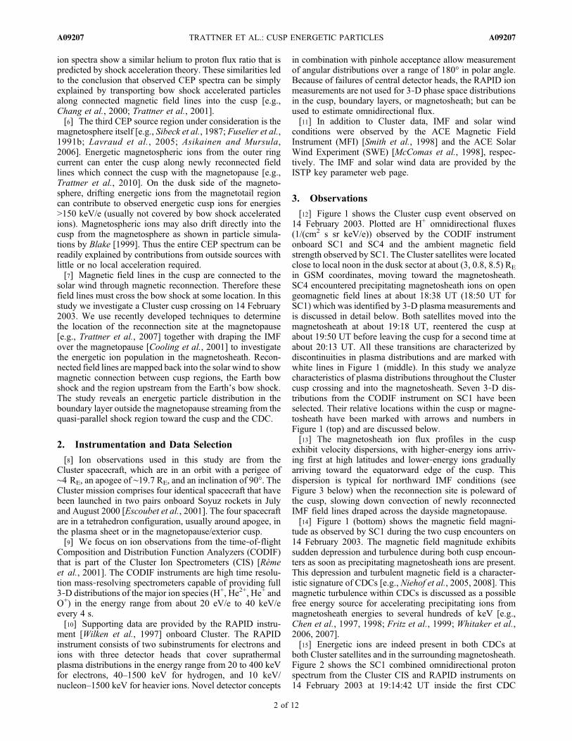
[12] Figure 1 shows the Cluster cusp event observed on14 February 2003. Plotted are H+ omnidirectional fluxes(1/(cm2 s sr keV/e)) observed by the CODIF instrumentonboard SC1 and SC4 and the ambient magnetic fieldstrength observed by SC1. The Cluster satellites were locatedclose to local noon in the dusk sector at about (3, 0.8, 8.5) RE
in GSM coordinates, moving toward the magnetosheath.SC4 encountered precipitating magnetosheath ions on opengeomagnetic field lines at about 18:38 UT (18:50 UT forSC1) which was identified by 3‐D plasma measurements andis discussed in detail below. Both satellites moved into themagnetosheath at about 19:18 UT, reentered the cusp atabout 19:50 UT before leaving the cusp for a second time atabout 20:13 UT. All these transitions are characterized bydiscontinuities in plasma distributions and are marked withwhite lines in Figure 1 (middle). In this study we analyzecharacteristics of plasma distributions throughout the Clustercusp crossing and into the magnetosheath. Seven 3‐D dis-tributions from the CODIF instrument on SC1 have beenselected. Their relative locations within the cusp or magne-tosheath have been marked with arrows and numbers inFigure 1 (top) and are discussed below.[13] The magnetosheath ion flux profiles in the cusp
exhibit velocity dispersions, with higher‐energy ions arriv-ing first at high latitudes and lower‐energy ions graduallyarriving toward the equatorward edge of the cusp. Thisdispersion is typical for northward IMF conditions (seeFigure 3 below) when the reconnection site is poleward ofthe cusp, slowing down convection of newly reconnectedIMF field lines draped across the dayside magnetopause.[14] Figure 1 (bottom) shows the magnetic field magni-
tude as observed by SC1 during the two cusp encounters on14 February 2003. The magnetic field magnitude exhibitssudden depression and turbulence during both cusp encoun-ters as soon as precipitating magnetosheath ions are present.This depression and turbulent magnetic field is a character-istic signature of CDCs [e.g., Niehof et al., 2005, 2008]. Thismagnetic turbulence within CDCs is discussed as a possiblefree energy source for accelerating precipitating ions frommagnetosheath energies to several hundreds of keV [e.g.,Chen et al., 1997, 1998; Fritz et al., 1999; Whitaker et al.,2006, 2007].[15] Energetic ions are indeed present in both CDCs at
both Cluster satellites and in the surrounding magnetosheath.Figure 2 shows the SC1 combined omnidirectional protonspectrum from the Cluster CIS and RAPID instruments on14 February 2003 at 19:14:42 UT inside the first CDC
TRATTNER ET AL.: CUSP ENERGETIC PARTICLES A09207A09207
2 of 12
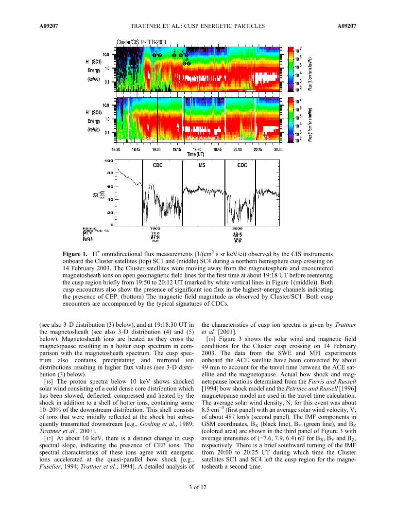
(see also 3‐D distribution (3) below), and at 19:18:30 UT inthe magnetosheath (see also 3‐D distribution (4) and (5)below). Magnetosheath ions are heated as they cross themagnetopause resulting in a hotter cusp spectrum in com-parison with the magnetosheath spectrum. The cusp spec-trum also contains precipitating and mirrored iondistributions resulting in higher flux values (see 3‐D distri-bution (3) below).[16] The proton spectra below 10 keV shows shocked
solar wind consisting of a cold dense core distribution whichhas been slowed, deflected, compressed and heated by theshock in addition to a shell of hotter ions, containing some10–20% of the downstream distribution. This shell consistsof ions that were initially reflected at the shock but subse-quently transmitted downstream [e.g., Gosling et al., 1989;Trattner et al., 2001].[17] At about 10 keV, there is a distinct change in cusp
spectral slope, indicating the presence of CEP ions. Thespectral characteristics of these ions agree with energeticions accelerated at the quasi‐parallel bow shock [e.g.,Fuselier, 1994; Trattner et al., 1994]. A detailed analysis of
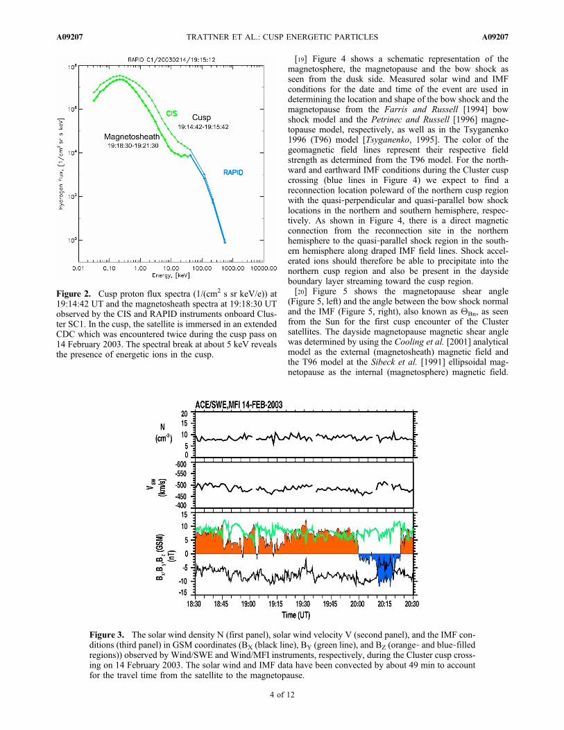
the characteristics of cusp ion spectra is given by Trattneret al. [2001].[18] Figure 3 shows the solar wind and magnetic field
conditions for the Cluster cusp crossing on 14 February2003. The data from the SWE and MFI experimentsonboard the ACE satellite have been convected by about49 min to account for the travel time between the ACE sat-ellite and the magnetopause. Actual bow shock and mag-netopause locations determined from the Farris and Russell[1994] bow shock model and the Petrinec and Russell [1996]magnetopause model are used in the travel time calculation.The average solar wind density, N, for this event was about8.5 cm−3 (first panel) with an average solar wind velocity, V,of about 487 km/s (second panel). The IMF components inGSM coordinates, BX (black line), BY (green line), and BZ
(colored area) are shown in the third panel of Figure 3 withaverage intensities of (−7.6, 7.9, 6.4) nT for BX, BY and BZ,respectively. There is a brief southward turning of the IMFfrom 20:00 to 20:25 UT during which time the Clustersatellites SC1 and SC4 left the cusp region for the magne-tosheath a second time.
Figure 1. H+ omnidirectional flux measurements (1/(cm2 s sr keV/e)) observed by the CIS instrumentsonboard the Cluster satellites (top) SC1 and (middle) SC4 during a northern hemisphere cusp crossing on14 February 2003. The Cluster satellites were moving away from the magnetosphere and encounteredmagnetosheath ions on open geomagnetic field lines for the first time at about 19:18 UT before reenteringthe cusp region briefly from 19:50 to 20:12 UT (marked by white vertical lines in Figure 1(middle)). Bothcusp encounters also show the presence of significant ion flux in the highest‐energy channels indicatingthe presence of CEP. (bottom) The magnetic field magnitude as observed by Cluster/SC1. Both cuspencounters are accompanied by the typical signatures of CDCs.
TRATTNER ET AL.: CUSP ENERGETIC PARTICLES A09207A09207
3 of 12
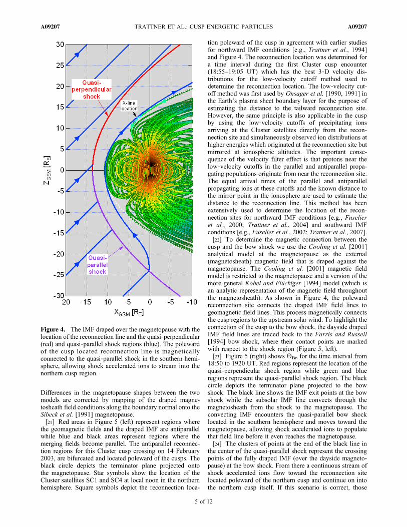
[19] Figure 4 shows a schematic representation of themagnetosphere, the magnetopause and the bow shock asseen from the dusk side. Measured solar wind and IMFconditions for the date and time of the event are used indetermining the location and shape of the bow shock and themagnetopause from the Farris and Russell [1994] bowshock model and the Petrinec and Russell [1996] magne-topause model, respectively, as well as in the Tsyganenko1996 (T96) model [Tsyganenko, 1995]. The color of thegeomagnetic field lines represent their respective fieldstrength as determined from the T96 model. For the north-ward and earthward IMF conditions during the Cluster cuspcrossing (blue lines in Figure 4) we expect to find areconnection location poleward of the northern cusp regionwith the quasi‐perpendicular and quasi‐parallel bow shocklocations in the northern and southern hemisphere, respec-tively. As shown in Figure 4, there is a direct magneticconnection from the reconnection site in the northernhemisphere to the quasi‐parallel shock region in the south-ern hemisphere along draped IMF field lines. Shock accel-erated ions should therefore be able to precipitate into thenorthern cusp region and also be present in the daysideboundary layer streaming toward the cusp region.[20] Figure 5 shows the magnetopause shear angle
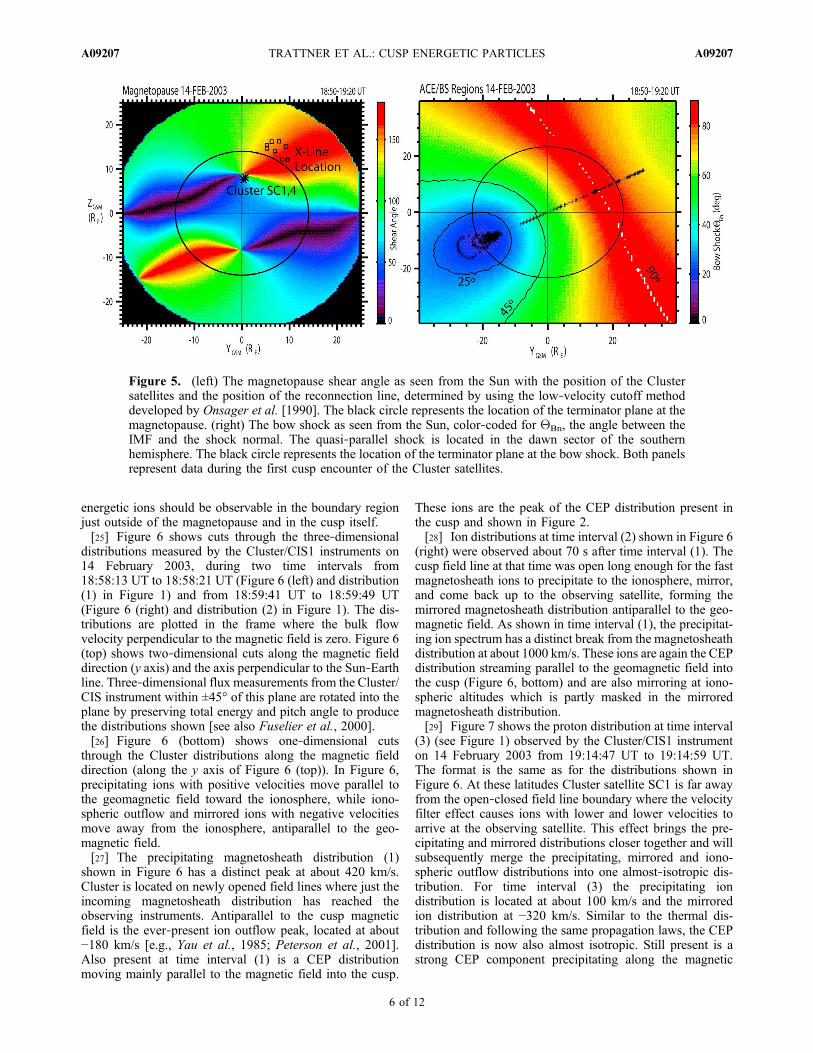
(Figure 5, left) and the angle between the bow shock normaland the IMF (Figure 5, right), also known as QBn, as seenfrom the Sun for the first cusp encounter of the Clustersatellites. The dayside magnetopause magnetic shear anglewas determined by using the Cooling et al. [2001] analyticalmodel as the external (magnetosheath) magnetic field andthe T96 model at the Sibeck et al. [1991] ellipsoidal mag-netopause as the internal (magnetosphere) magnetic field.
Figure 3. The solar wind density N (first panel), solar wind velocity V (second panel), and the IMF con-ditions (third panel) in GSM coordinates (BX (black line), BY (green line), and BZ (orange‐ and blue‐filledregions)) observed by Wind/SWE and Wind/MFI instruments, respectively, during the Cluster cusp cross-ing on 14 February 2003. The solar wind and IMF data have been convected by about 49 min to accountfor the travel time from the satellite to the magnetopause.
Figure 2. Cusp proton flux spectra (1/(cm2 s sr keV/e)) at19:14:42 UT and the magnetosheath spectra at 19:18:30 UTobserved by the CIS and RAPID instruments onboard Clus-ter SC1. In the cusp, the satellite is immersed in an extendedCDC which was encountered twice during the cusp pass on14 February 2003. The spectral break at about 5 keV revealsthe presence of energetic ions in the cusp.
TRATTNER ET AL.: CUSP ENERGETIC PARTICLES A09207A09207
4 of 12
Differences in the magnetopause shapes between the twomodels are corrected by mapping of the draped magne-tosheath field conditions along the boundary normal onto theSibeck et al. [1991] magnetopause.[21] Red areas in Figure 5 (left) represent regions where
the geomagnetic fields and the draped IMF are antiparallelwhile blue and black areas represent regions where themerging fields become parallel. The antiparallel reconnec-tion regions for this Cluster cusp crossing on 14 February2003, are bifurcated and located poleward of the cusps. Theblack circle depicts the terminator plane projected ontothe magnetopause. Star symbols show the location of theCluster satellites SC1 and SC4 at local noon in the northernhemisphere. Square symbols depict the reconnection loca-
tion poleward of the cusp in agreement with earlier studiesfor northward IMF conditions [e.g., Trattner et al., 1994]and Figure 4. The reconnection location was determined fora time interval during the first Cluster cusp encounter(18:55–19:05 UT) which has the best 3‐D velocity dis-tributions for the low‐velocity cutoff method used todetermine the reconnection location. The low‐velocity cut-off method was first used by Onsager et al. [1990, 1991] inthe Earth’s plasma sheet boundary layer for the purpose ofestimating the distance to the tailward reconnection site.However, the same principle is also applicable in the cuspby using the low‐velocity cutoffs of precipitating ionsarriving at the Cluster satellites directly from the recon-nection site and simultaneously observed ion distributions athigher energies which originated at the reconnection site butmirrored at ionospheric altitudes. The important conse-quence of the velocity filter effect is that protons near thelow‐velocity cutoffs in the parallel and antiparallel propa-gating populations originate from near the reconnection site.The equal arrival times of the parallel and antiparallelpropagating ions at these cutoffs and the known distance tothe mirror point in the ionosphere are used to estimate thedistance to the reconnection line. This method has beenextensively used to determine the location of the recon-nection sites for northward IMF conditions [e.g., Fuselieret al., 2000; Trattner et al., 2004] and southward IMFconditions [e.g., Fuselier et al., 2002; Trattner et al., 2007].[22] To determine the magnetic connection between the
cusp and the bow shock we use the Cooling et al. [2001]analytical model at the magnetopause as the external(magnetosheath) magnetic field that is draped against themagnetopause. The Cooling et al. [2001] magnetic fieldmodel is restricted to the magnetopause and a version of themore general Kobel and Flückiger [1994] model (which isan analytic representation of the magnetic field throughoutthe magnetosheath). As shown in Figure 4, the polewardreconnection site connects the draped IMF field lines togeomagnetic field lines. This process magnetically connectsthe cusp regions to the upstream solar wind. To highlight theconnection of the cusp to the bow shock, the dayside drapedIMF field lines are traced back to the Farris and Russell[1994] bow shock, where their contact points are markedwith respect to the shock region (Figure 5, left).[23] Figure 5 (right) shows QBn for the time interval from
18:50 to 1920 UT. Red regions represent the location of thequasi‐perpendicular shock region while green and blueregions represent the quasi‐parallel shock region. The blackcircle depicts the terminator plane projected to the bowshock. The black line shows the IMF exit points at the bowshock while the subsolar IMF line convects through themagnetosheath from the shock to the magnetopause. Theconvecting IMF encounters the quasi‐parallel bow shocklocated in the southern hemisphere and moves toward themagnetopause, allowing shock accelerated ions to populatethat field line before it even reaches the magnetopause.[24] The clusters of points at the end of the black line in
the center of the quasi‐parallel shock represent the crossingpoints of the fully draped IMF (over the dayside magneto-pause) at the bow shock. From there a continuous stream ofshock accelerated ions flow toward the reconnection sitelocated poleward of the northern cusp and continue on intothe northern cusp itself. If this scenario is correct, those
Figure 4. The IMF draped over the magnetopause with thelocation of the reconnection line and the quasi‐perpendicular(red) and quasi‐parallel shock regions (blue). The polewardof the cusp located reconnection line is magneticallyconnected to the quasi‐parallel shock in the southern hemi-sphere, allowing shock accelerated ions to stream into thenorthern cusp region.
TRATTNER ET AL.: CUSP ENERGETIC PARTICLES A09207A09207
5 of 12
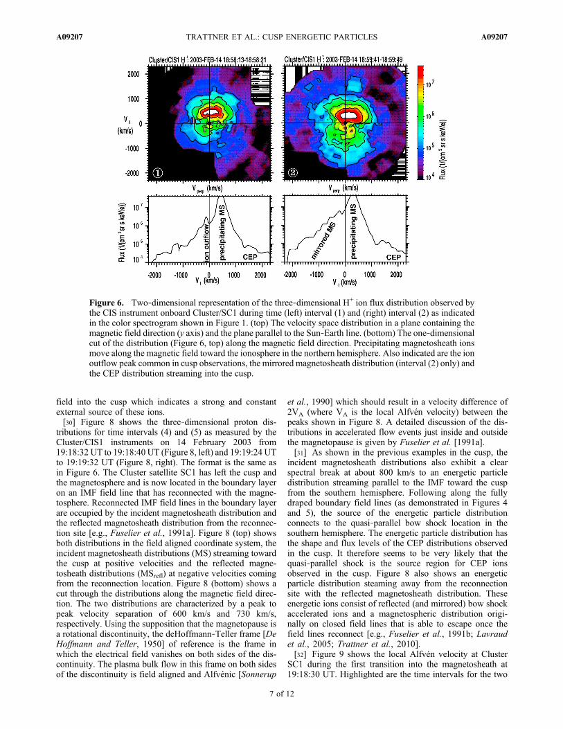
energetic ions should be observable in the boundary regionjust outside of the magnetopause and in the cusp itself.[25] Figure 6 shows cuts through the three‐dimensional
distributions measured by the Cluster/CIS1 instruments on14 February 2003, during two time intervals from18:58:13 UT to 18:58:21 UT (Figure 6 (left) and distribution(1) in Figure 1) and from 18:59:41 UT to 18:59:49 UT(Figure 6 (right) and distribution (2) in Figure 1). The dis-tributions are plotted in the frame where the bulk flowvelocity perpendicular to the magnetic field is zero. Figure 6(top) shows two‐dimensional cuts along the magnetic fielddirection (y axis) and the axis perpendicular to the Sun‐Earthline. Three‐dimensional flux measurements from the Cluster/CIS instrument within ±45° of this plane are rotated into theplane by preserving total energy and pitch angle to producethe distributions shown [see also Fuselier et al., 2000].[26] Figure 6 (bottom) shows one‐dimensional cuts
through the Cluster distributions along the magnetic fielddirection (along the y axis of Figure 6 (top)). In Figure 6,precipitating ions with positive velocities move parallel tothe geomagnetic field toward the ionosphere, while iono-spheric outflow and mirrored ions with negative velocitiesmove away from the ionosphere, antiparallel to the geo-magnetic field.[27] The precipitating magnetosheath distribution (1)
shown in Figure 6 has a distinct peak at about 420 km/s.Cluster is located on newly opened field lines where just theincoming magnetosheath distribution has reached theobserving instruments. Antiparallel to the cusp magneticfield is the ever‐present ion outflow peak, located at about−180 km/s [e.g., Yau et al., 1985; Peterson et al., 2001].Also present at time interval (1) is a CEP distributionmoving mainly parallel to the magnetic field into the cusp.
These ions are the peak of the CEP distribution present inthe cusp and shown in Figure 2.[28] Ion distributions at time interval (2) shown in Figure 6
(right) were observed about 70 s after time interval (1). Thecusp field line at that time was open long enough for the fastmagnetosheath ions to precipitate to the ionosphere, mirror,and come back up to the observing satellite, forming themirrored magnetosheath distribution antiparallel to the geo-magnetic field. As shown in time interval (1), the precipitat-ing ion spectrum has a distinct break from the magnetosheathdistribution at about 1000 km/s. These ions are again the CEPdistribution streaming parallel to the geomagnetic field intothe cusp (Figure 6, bottom) and are also mirroring at iono-spheric altitudes which is partly masked in the mirroredmagnetosheath distribution.[29] Figure 7 shows the proton distribution at time interval
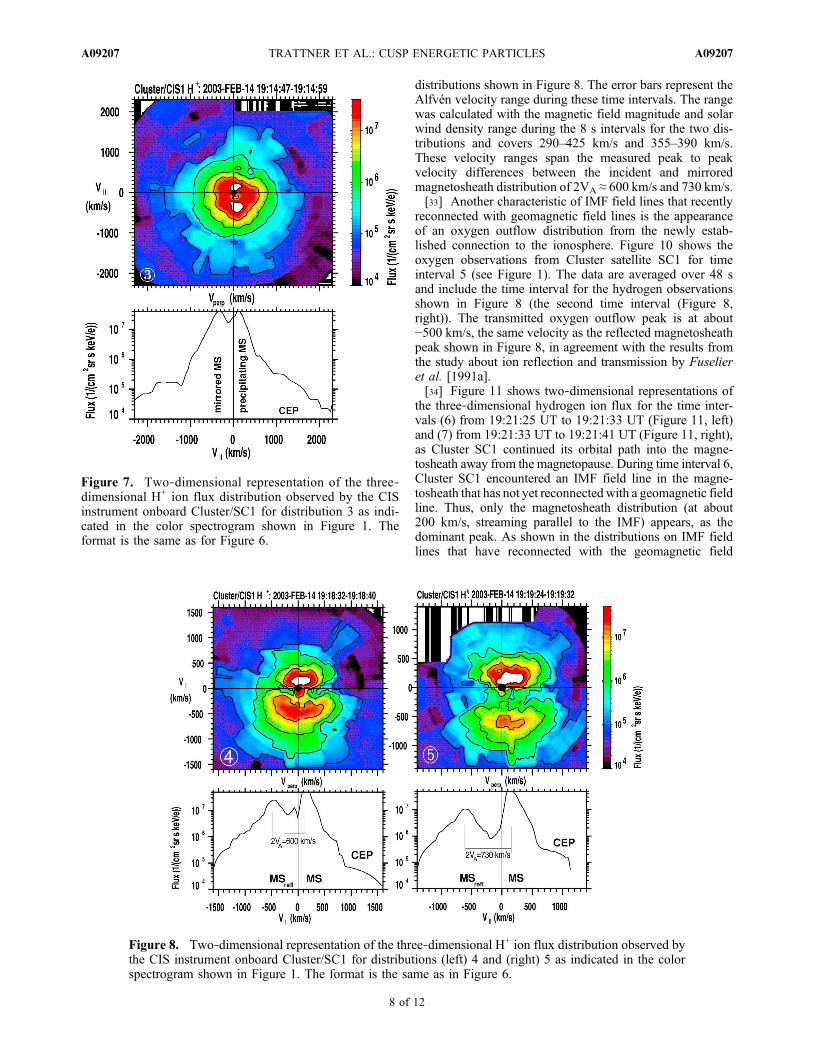
(3) (see Figure 1) observed by the Cluster/CIS1 instrumenton 14 February 2003 from 19:14:47 UT to 19:14:59 UT.The format is the same as for the distributions shown inFigure 6. At these latitudes Cluster satellite SC1 is far awayfrom the open‐closed field line boundary where the velocityfilter effect causes ions with lower and lower velocities toarrive at the observing satellite. This effect brings the pre-cipitating and mirrored distributions closer together and willsubsequently merge the precipitating, mirrored and iono-spheric outflow distributions into one almost‐isotropic dis-tribution. For time interval (3) the precipitating iondistribution is located at about 100 km/s and the mirroredion distribution at −320 km/s. Similar to the thermal dis-tribution and following the same propagation laws, the CEPdistribution is now also almost isotropic. Still present is astrong CEP component precipitating along the magnetic
Figure 5. (left) The magnetopause shear angle as seen from the Sun with the position of the Clustersatellites and the position of the reconnection line, determined by using the low‐velocity cutoff methoddeveloped by Onsager et al. [1990]. The black circle represents the location of the terminator plane at themagnetopause. (right) The bow shock as seen from the Sun, color‐coded for QBn, the angle between theIMF and the shock normal. The quasi‐parallel shock is located in the dawn sector of the southernhemisphere. The black circle represents the location of the terminator plane at the bow shock. Both panelsrepresent data during the first cusp encounter of the Cluster satellites.
TRATTNER ET AL.: CUSP ENERGETIC PARTICLES A09207A09207
6 of 12
field into the cusp which indicates a strong and constantexternal source of these ions.[30] Figure 8 shows the three‐dimensional proton dis-
tributions for time intervals (4) and (5) as measured by theCluster/CIS1 instruments on 14 February 2003 from19:18:32 UT to 19:18:40 UT (Figure 8, left) and 19:19:24 UTto 19:19:32 UT (Figure 8, right). The format is the same asin Figure 6. The Cluster satellite SC1 has left the cusp andthe magnetosphere and is now located in the boundary layeron an IMF field line that has reconnected with the magne-tosphere. Reconnected IMF field lines in the boundary layerare occupied by the incident magnetosheath distribution andthe reflected magnetosheath distribution from the reconnec-tion site [e.g., Fuselier et al., 1991a]. Figure 8 (top) showsboth distributions in the field aligned coordinate system, theincident magnetosheath distributions (MS) streaming towardthe cusp at positive velocities and the reflected magne-tosheath distributions (MSrefl) at negative velocities comingfrom the reconnection location. Figure 8 (bottom) shows acut through the distributions along the magnetic field direc-tion. The two distributions are characterized by a peak topeak velocity separation of 600 km/s and 730 km/s,respectively. Using the supposition that the magnetopause isa rotational discontinuity, the deHoffmann‐Teller frame [DeHoffmann and Teller, 1950] of reference is the frame inwhich the electrical field vanishes on both sides of the dis-continuity. The plasma bulk flow in this frame on both sidesof the discontinuity is field aligned and Alfvénic [Sonnerup
et al., 1990] which should result in a velocity difference of2VA (where VA is the local Alfvén velocity) between thepeaks shown in Figure 8. A detailed discussion of the dis-tributions in accelerated flow events just inside and outsidethe magnetopause is given by Fuselier et al. [1991a].[31] As shown in the previous examples in the cusp, the
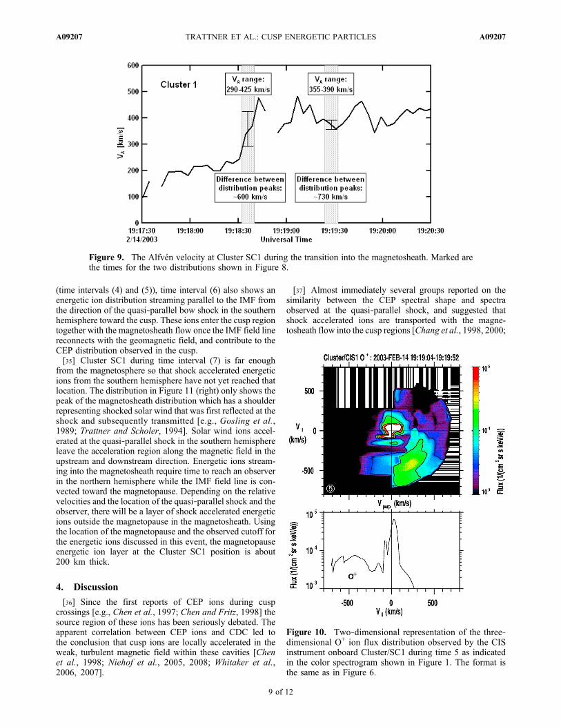
incident magnetosheath distributions also exhibit a clearspectral break at about 800 km/s to an energetic particledistribution streaming parallel to the IMF toward the cuspfrom the southern hemisphere. Following along the fullydraped boundary field lines (as demonstrated in Figures 4and 5), the source of the energetic particle distributionconnects to the quasi‐parallel bow shock location in thesouthern hemisphere. The energetic particle distribution hasthe shape and flux levels of the CEP distributions observedin the cusp. It therefore seems to be very likely that thequasi‐parallel shock is the source region for CEP ionsobserved in the cusp. Figure 8 also shows an energeticparticle distribution steaming away from the reconnectionsite with the reflected magnetosheath distribution. Theseenergetic ions consist of reflected (and mirrored) bow shockaccelerated ions and a magnetospheric distribution origi-nally on closed field lines that is able to escape once thefield lines reconnect [e.g., Fuselier et al., 1991b; Lavraudet al., 2005; Trattner et al., 2010].[32] Figure 9 shows the local Alfvén velocity at Cluster
SC1 during the first transition into the magnetosheath at19:18:30 UT. Highlighted are the time intervals for the two
Figure 6. Two‐dimensional representation of the three‐dimensional H+ ion flux distribution observed bythe CIS instrument onboard Cluster/SC1 during time (left) interval (1) and (right) interval (2) as indicatedin the color spectrogram shown in Figure 1. (top) The velocity space distribution in a plane containing themagnetic field direction (y axis) and the plane parallel to the Sun‐Earth line. (bottom) The one‐dimensionalcut of the distribution (Figure 6, top) along the magnetic field direction. Precipitating magnetosheath ionsmove along the magnetic field toward the ionosphere in the northern hemisphere. Also indicated are the ionoutflow peak common in cusp observations, the mirrored magnetosheath distribution (interval (2) only) andthe CEP distribution streaming into the cusp.
TRATTNER ET AL.: CUSP ENERGETIC PARTICLES A09207A09207
7 of 12
distributions shown in Figure 8. The error bars represent theAlfvén velocity range during these time intervals. The rangewas calculated with the magnetic field magnitude and solarwind density range during the 8 s intervals for the two dis-tributions and covers 290–425 km/s and 355–390 km/s.These velocity ranges span the measured peak to peakvelocity differences between the incident and mirroredmagnetosheath distribution of 2VA ≈ 600 km/s and 730 km/s.[33] Another characteristic of IMF field lines that recently
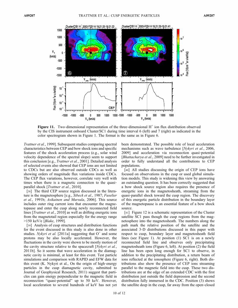
reconnected with geomagnetic field lines is the appearanceof an oxygen outflow distribution from the newly estab-lished connection to the ionosphere. Figure 10 shows theoxygen observations from Cluster satellite SC1 for timeinterval 5 (see Figure 1). The data are averaged over 48 sand include the time interval for the hydrogen observationsshown in Figure 8 (the second time interval (Figure 8,right)). The transmitted oxygen outflow peak is at about−500 km/s, the same velocity as the reflected magnetosheathpeak shown in Figure 8, in agreement with the results fromthe study about ion reflection and transmission by Fuselieret al. [1991a].[34] Figure 11 shows two‐dimensional representations of
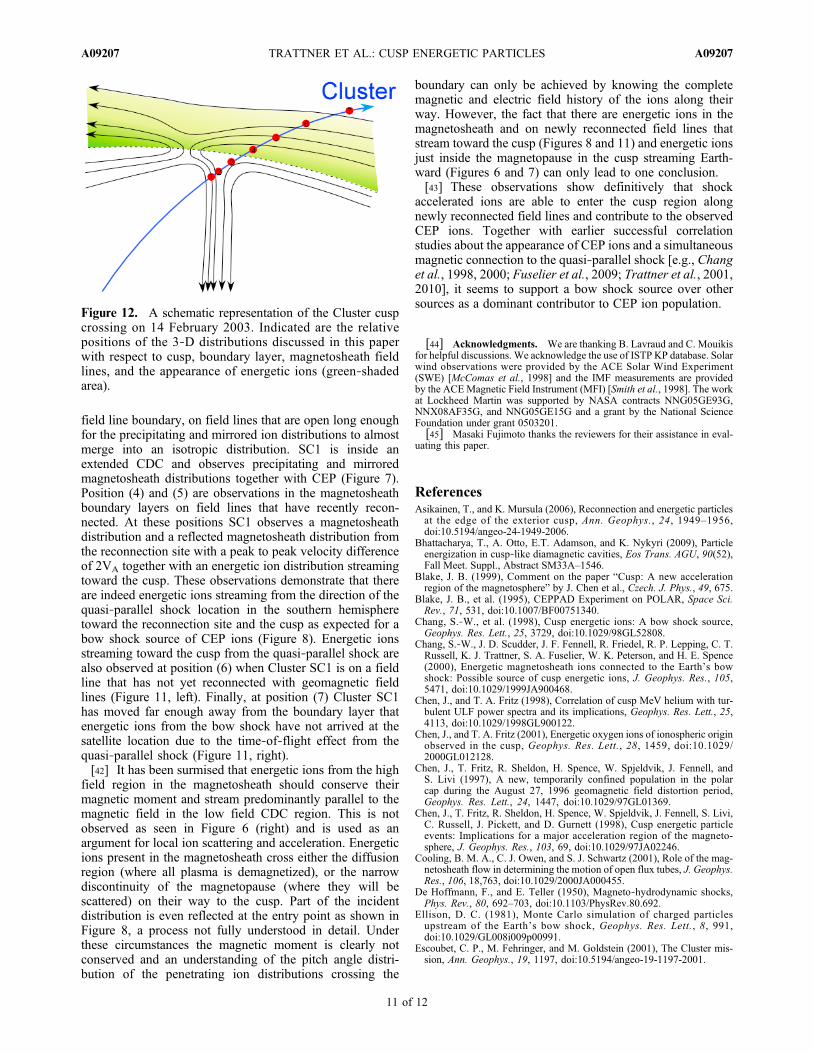
the three‐dimensional hydrogen ion flux for the time inter-vals (6) from 19:21:25 UT to 19:21:33 UT (Figure 11, left)and (7) from 19:21:33 UT to 19:21:41 UT (Figure 11, right),as Cluster SC1 continued its orbital path into the magne-tosheath away from the magnetopause. During time interval 6,Cluster SC1 encountered an IMF field line in the magne-tosheath that has not yet reconnected with a geomagnetic fieldline. Thus, only the magnetosheath distribution (at about200 km/s, streaming parallel to the IMF) appears, as thedominant peak. As shown in the distributions on IMF fieldlines that have reconnected with the geomagnetic field
Figure 8. Two‐dimensional representation of the three‐dimensional H+ ion flux distribution observed bythe CIS instrument onboard Cluster/SC1 for distributions (left) 4 and (right) 5 as indicated in the colorspectrogram shown in Figure 1. The format is the same as in Figure 6.
Figure 7. Two‐dimensional representation of the three‐dimensional H+ ion flux distribution observed by the CISinstrument onboard Cluster/SC1 for distribution 3 as indi-cated in the color spectrogram shown in Figure 1. Theformat is the same as for Figure 6.
TRATTNER ET AL.: CUSP ENERGETIC PARTICLES A09207A09207
8 of 12
(time intervals (4) and (5)), time interval (6) also shows anenergetic ion distribution streaming parallel to the IMF fromthe direction of the quasi‐parallel bow shock in the southernhemisphere toward the cusp. These ions enter the cusp regiontogether with the magnetosheath flow once the IMF field linereconnects with the geomagnetic field, and contribute to theCEP distribution observed in the cusp.[35] Cluster SC1 during time interval (7) is far enough
from the magnetosphere so that shock accelerated energeticions from the southern hemisphere have not yet reached thatlocation. The distribution in Figure 11 (right) only shows thepeak of the magnetosheath distribution which has a shoulderrepresenting shocked solar wind that was first reflected at theshock and subsequently transmitted [e.g., Gosling et al.,1989; Trattner and Scholer, 1994]. Solar wind ions accel-erated at the quasi‐parallel shock in the southern hemisphereleave the acceleration region along the magnetic field in theupstream and downstream direction. Energetic ions stream-ing into the magnetosheath require time to reach an observerin the northern hemisphere while the IMF field line is con-vected toward the magnetopause. Depending on the relativevelocities and the location of the quasi‐parallel shock and theobserver, there will be a layer of shock accelerated energeticions outside the magnetopause in the magnetosheath. Usingthe location of the magnetopause and the observed cutoff forthe energetic ions discussed in this event, the magnetopauseenergetic ion layer at the Cluster SC1 position is about200 km thick.
4. Discussion
[36] Since the first reports of CEP ions during cuspcrossings [e.g., Chen et al., 1997; Chen and Fritz, 1998] thesource region of these ions has been seriously debated. Theapparent correlation between CEP ions and CDC led tothe conclusion that cusp ions are locally accelerated in theweak, turbulent magnetic field within these cavities [Chenet al., 1998; Niehof et al., 2005, 2008; Whitaker et al.,2006, 2007].
[37] Almost immediately several groups reported on thesimilarity between the CEP spectral shape and spectraobserved at the quasi‐parallel shock, and suggested thatshock accelerated ions are transported with the magne-tosheath flow into the cusp regions [Chang et al., 1998, 2000;
Figure 9. The Alfvén velocity at Cluster SC1 during the transition into the magnetosheath. Marked arethe times for the two distributions shown in Figure 8.
Figure 10. Two‐dimensional representation of the three‐dimensional O+ ion flux distribution observed by the CISinstrument onboard Cluster/SC1 during time 5 as indicatedin the color spectrogram shown in Figure 1. The format isthe same as in Figure 6.
TRATTNER ET AL.: CUSP ENERGETIC PARTICLES A09207A09207
9 of 12
Trattner et al., 1999]. Subsequent studies comparing spectralcharacteristics between CEP and bow shock ions and specificfeatures of the shock acceleration process (e.g., solar windvelocity dependence of the spectral slope) seem to supportthis conclusion [e.g., Trattner et al., 2001]. Detailed analysisof selected events also showed that CEP ions are not limitedto CDCs but are also observed outside CDCs as well asshowing orders of magnitude flux variations inside CDCs.The CEP flux variations, however, correlate very well withtimes when there is a magnetic connection to the quasi‐parallel shock [Trattner et al., 2010].[38] The third CEP source region discussed in the litera-
ture is the magnetosphere [e.g., Sibeck et al., 1987; Fuselieret al., 1991b; Asikainen and Mursula, 2006]. This sourceincludes outer ring current ions that encounter the magne-topause and enter the cusp along newly reconnected fieldlines [Trattner et al., 2010] as well as drifting energetic ionsfrom the magnetotail region especially for the energy range>150 keV/e [Blake, 1999].[39] Analysis of cusp structures and distribution functions
for the event discussed in this study is also done in otherstudies. Nykyri et al. [2011a] suggesting that O+ and someprotons may be also locally accelerated. However, thefluctuations in the cavity were shown to be mostly motion ofthe cavity structure relative to the spacecraft [Nykyri et al.,2011b]. So it seems that wave acceleration in the diamag-netic cavity is minimal, at least for this event. Test particlesimulations and comparison with RAPID and EFW data forthis event (K. Nykyri et al., On the origin of high‐energyparticles in the cusp diamagnetic cavity, submitted toJournal of Geophysical Research, 2011) suggest that parti-cles can gain energy perpendicular to the magnetic field inreconnection “quasi‐potential” up to 50 keV. However,local acceleration to several hundreds of keV has not yet
been demonstrated. The possible role of local accelerationmechanisms such as wave turbulence [Nykyri et al., 2006,2009] and acceleration via reconnection quasi‐potential[Bhattacharya et al., 2009] need to be further investigated inorder to fully understand all the contributions to CEPpopulations.[40] All studies discussing the origin of CEP ions have
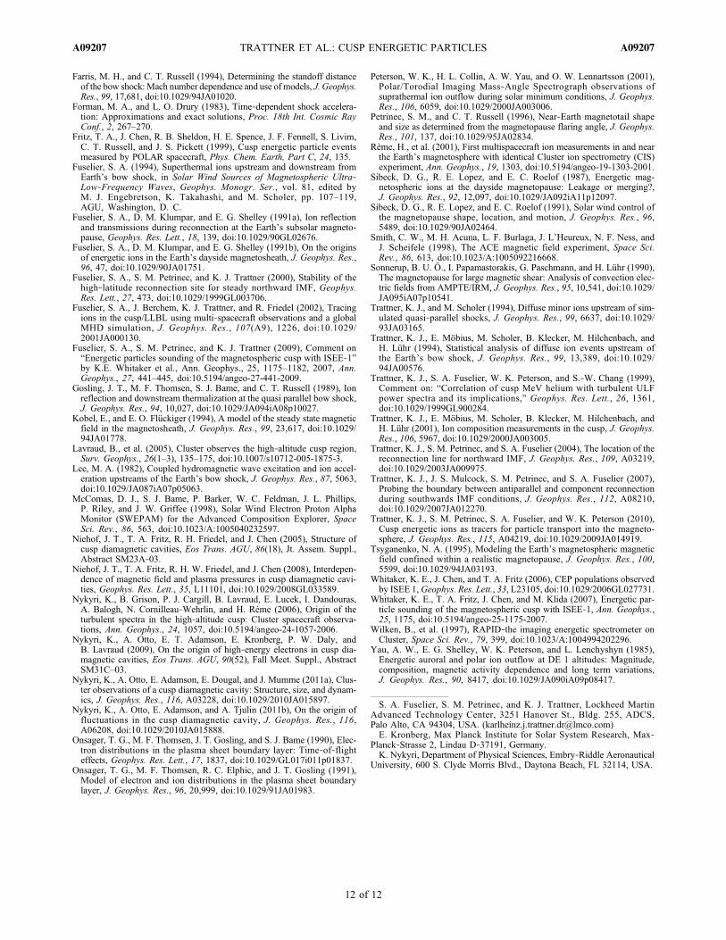
focused on observations in the cusp or used global simula-tion models. This study is widening this view by answeringan outstanding question. It has been correctly suggested thata bow shock source region also requires the presence ofenergetic ions in the magnetosheath, streaming from thequasi‐parallel shock toward the cusp region. The discoveryof this energetic particle distribution in the boundary layerof the magnetopause is an essential feature of a bow shocksource.[41] Figure 12 is a schematic representation of the Cluster
satellite SC1 pass though the cusp regions from the mag-netosphere into the magnetosheath. The numbers along thepath mark the relative position of the satellite and theassociated 3‐D distributions discussed in this paper withrespect to cusp, boundary layer and magnetosheath fieldlines (see Figure 1). At position (1) SC1 is on a newlyreconnected field line and observes only precipitatingmagnetosheath ions (Figure 6, left). At position (2) the fieldline has been open long enough for SC1 to observe, inaddition to the precipitating distribution, a return beam ofions reflected at the ionosphere (Figure 6, right). Both dis-tributions also show the presence of CEP ions streamingparallel to the magnetic field into the cusp. These two dis-tributions are at the edge of an extended CDC with the firstdistribution just outside the field depression and the seconddistribution fully immersed in the CDC. Position (3) showsthe satellite deep in the cusp, far away from the open‐closed
Figure 11. Two‐dimensional representation of the three‐dimensional H+ ion flux distribution observedby the CIS instrument onboard Cluster/SC1 during time interval 6 (left) and 7 (right) as indicated in thecolor spectrogram shown in Figure 1. The format is the same as in Figure 6.
TRATTNER ET AL.: CUSP ENERGETIC PARTICLES A09207A09207
10 of 12
field line boundary, on field lines that are open long enoughfor the precipitating and mirrored ion distributions to almostmerge into an isotropic distribution. SC1 is inside anextended CDC and observes precipitating and mirroredmagnetosheath distributions together with CEP (Figure 7).Position (4) and (5) are observations in the magnetosheathboundary layers on field lines that have recently recon-nected. At these positions SC1 observes a magnetosheathdistribution and a reflected magnetosheath distribution fromthe reconnection site with a peak to peak velocity differenceof 2VA together with an energetic ion distribution streamingtoward the cusp. These observations demonstrate that thereare indeed energetic ions streaming from the direction of thequasi‐parallel shock location in the southern hemispheretoward the reconnection site and the cusp as expected for abow shock source of CEP ions (Figure 8). Energetic ionsstreaming toward the cusp from the quasi‐parallel shock arealso observed at position (6) when Cluster SC1 is on a fieldline that has not yet reconnected with geomagnetic fieldlines (Figure 11, left). Finally, at position (7) Cluster SC1has moved far enough away from the boundary layer thatenergetic ions from the bow shock have not arrived at thesatellite location due to the time‐of‐flight effect from thequasi‐parallel shock (Figure 11, right).[42] It has been surmised that energetic ions from the high
field region in the magnetosheath should conserve theirmagnetic moment and stream predominantly parallel to themagnetic field in the low field CDC region. This is notobserved as seen in Figure 6 (right) and is used as anargument for local ion scattering and acceleration. Energeticions present in the magnetosheath cross either the diffusionregion (where all plasma is demagnetized), or the narrowdiscontinuity of the magnetopause (where they will bescattered) on their way to the cusp. Part of the incidentdistribution is even reflected at the entry point as shown inFigure 8, a process not fully understood in detail. Underthese circumstances the magnetic moment is clearly notconserved and an understanding of the pitch angle distri-bution of the penetrating ion distributions crossing the
boundary can only be achieved by knowing the completemagnetic and electric field history of the ions along theirway. However, the fact that there are energetic ions in themagnetosheath and on newly reconnected field lines thatstream toward the cusp (Figures 8 and 11) and energetic ionsjust inside the magnetopause in the cusp streaming Earth-ward (Figures 6 and 7) can only lead to one conclusion.[43] These observations show definitively that shock
accelerated ions are able to enter the cusp region alongnewly reconnected field lines and contribute to the observedCEP ions. Together with earlier successful correlationstudies about the appearance of CEP ions and a simultaneousmagnetic connection to the quasi‐parallel shock [e.g., Changet al., 1998, 2000; Fuselier et al., 2009; Trattner et al., 2001,2010], it seems to support a bow shock source over othersources as a dominant contributor to CEP ion population.
[44] Acknowledgments. We are thanking B. Lavraud and C. Mouikisfor helpful discussions. We acknowledge the use of ISTP KP database. Solarwind observations were provided by the ACE Solar Wind Experiment(SWE) [McComas et al., 1998] and the IMF measurements are providedby the ACEMagnetic Field Instrument (MFI) [Smith et al., 1998]. The workat Lockheed Martin was supported by NASA contracts NNG05GE93G,NNX08AF35G, and NNG05GE15G and a grant by the National ScienceFoundation under grant 0503201.[45] Masaki Fujimoto thanks the reviewers for their assistance in eval-
uating this paper.
ReferencesAsikainen, T., and K. Mursula (2006), Reconnection and energetic particlesat the edge of the exterior cusp, Ann. Geophys., 24, 1949–1956,doi:10.5194/angeo-24-1949-2006.
Bhattacharya, T., A. Otto, E.T. Adamson, and K. Nykyri (2009), Particleenergization in cusp‐like diamagnetic cavities, Eos Trans. AGU, 90(52),Fall Meet. Suppl., Abstract SM33A–1546.
Blake, J. B. (1999), Comment on the paper “Cusp: A new accelerationregion of the magnetosphere” by J. Chen et al., Czech. J. Phys., 49, 675.
Blake, J. B., et al. (1995), CEPPAD Experiment on POLAR, Space Sci.Rev., 71, 531, doi:10.1007/BF00751340.
Chang, S.‐W., et al. (1998), Cusp energetic ions: A bow shock source,Geophys. Res. Lett., 25, 3729, doi:10.1029/98GL52808.
Chang, S.‐W., J. D. Scudder, J. F. Fennell, R. Friedel, R. P. Lepping, C. T.Russell, K. J. Trattner, S. A. Fuselier, W. K. Peterson, and H. E. Spence(2000), Energetic magnetosheath ions connected to the Earth’s bowshock: Possible source of cusp energetic ions, J. Geophys. Res., 105,5471, doi:10.1029/1999JA900468.
Chen, J., and T. A. Fritz (1998), Correlation of cusp MeV helium with tur-bulent ULF power spectra and its implications, Geophys. Res. Lett., 25,4113, doi:10.1029/1998GL900122.
Chen, J., and T. A. Fritz (2001), Energetic oxygen ions of ionospheric originobserved in the cusp, Geophys. Res. Lett., 28, 1459, doi:10.1029/2000GL012128.
Chen, J., T. Fritz, R. Sheldon, H. Spence, W. Spjeldvik, J. Fennell, andS. Livi (1997), A new, temporarily confined population in the polarcap during the August 27, 1996 geomagnetic field distortion period,Geophys. Res. Lett., 24, 1447, doi:10.1029/97GL01369.
Chen, J., T. Fritz, R. Sheldon, H. Spence, W. Spjeldvik, J. Fennell, S. Livi,C. Russell, J. Pickett, and D. Gurnett (1998), Cusp energetic particleevents: Implications for a major acceleration region of the magneto-sphere, J. Geophys. Res., 103, 69, doi:10.1029/97JA02246.
Cooling, B. M. A., C. J. Owen, and S. J. Schwartz (2001), Role of the mag-netosheath flow in determining the motion of open flux tubes, J. Geophys.Res., 106, 18,763, doi:10.1029/2000JA000455.
De Hoffmann, F., and E. Teller (1950), Magneto‐hydrodynamic shocks,Phys. Rev., 80, 692–703, doi:10.1103/PhysRev.80.692.
Ellison, D. C. (1981), Monte Carlo simulation of charged particlesupstream of the Earth’s bow shock, Geophys. Res. Lett., 8, 991,doi:10.1029/GL008i009p00991.
Escoubet, C. P., M. Fehringer, and M. Goldstein (2001), The Cluster mis-sion, Ann. Geophys., 19, 1197, doi:10.5194/angeo-19-1197-2001.
Figure 12. A schematic representation of the Cluster cuspcrossing on 14 February 2003. Indicated are the relativepositions of the 3‐D distributions discussed in this paperwith respect to cusp, boundary layer, magnetosheath fieldlines, and the appearance of energetic ions (green‐shadedarea).
TRATTNER ET AL.: CUSP ENERGETIC PARTICLES A09207A09207
11 of 12
Farris, M. H., and C. T. Russell (1994), Determining the standoff distanceof the bow shock: Mach number dependence and use of models, J. Geophys.Res., 99, 17,681, doi:10.1029/94JA01020.
Forman, M. A., and L. O. Drury (1983), Time‐dependent shock accelera-tion: Approximations and exact solutions, Proc. 18th Int. Cosmic RayConf., 2, 267–270.
Fritz, T. A., J. Chen, R. B. Sheldon, H. E. Spence, J. F. Fennell, S. Livim,C. T. Russell, and J. S. Pickett (1999), Cusp energetic particle eventsmeasured by POLAR spacecraft, Phys. Chem. Earth, Part C, 24, 135.
Fuselier, S. A. (1994), Superthermal ions upstream and downstream fromEarth’s bow shock, in Solar Wind Sources of Magnetospheric Ultra‐Low‐Frequency Waves, Geophys. Monogr. Ser., vol. 81, edited byM. J. Engebretson, K. Takahashi, and M. Scholer, pp. 107–119,AGU, Washington, D. C.
Fuselier, S. A., D. M. Klumpar, and E. G. Shelley (1991a), Ion reflectionand transmissions during reconnection at the Earth’s subsolar magneto-pause, Geophys. Res. Lett., 18, 139, doi:10.1029/90GL02676.
Fuselier, S. A., D. M. Klumpar, and E. G. Shelley (1991b), On the originsof energetic ions in the Earth’s dayside magnetosheath, J. Geophys. Res.,96, 47, doi:10.1029/90JA01751.
Fuselier, S. A., S. M. Petrinec, and K. J. Trattner (2000), Stability of thehigh‐latitude reconnection site for steady northward IMF, Geophys.Res. Lett., 27, 473, doi:10.1029/1999GL003706.
Fuselier, S. A., J. Berchem, K. J. Trattner, and R. Friedel (2002), Tracingions in the cusp/LLBL using multi‐spacecraft observations and a globalMHD simulation, J. Geophys. Res., 107(A9), 1226, doi:10.1029/2001JA000130.
Fuselier, S. A., S. M. Petrinec, and K. J. Trattner (2009), Comment on“Energetic particles sounding of the magnetospheric cusp with ISEE‐1”by K.E. Whitaker et al., Ann. Geophys., 25, 1175–1182, 2007, Ann.Geophys., 27, 441–445, doi:10.5194/angeo-27-441-2009.
Gosling, J. T., M. F. Thomsen, S. J. Bame, and C. T. Russell (1989), Ionreflection and downstream thermalization at the quasi parallel bow shock,J. Geophys. Res., 94, 10,027, doi:10.1029/JA094iA08p10027.
Kobel, E., and E. O. Flückiger (1994), A model of the steady state magneticfield in the magnetosheath, J. Geophys. Res., 99, 23,617, doi:10.1029/94JA01778.
Lavraud, B., et al. (2005), Cluster observes the high‐altitude cusp region,Surv. Geophys., 26(1–3), 135–175, doi:10.1007/s10712-005-1875-3.
Lee, M. A. (1982), Coupled hydromagnetic wave excitation and ion accel-eration upstreams of the Earth’s bow shock, J. Geophys. Res., 87, 5063,doi:10.1029/JA087iA07p05063.
McComas, D. J., S. J. Bame, P. Barker, W. C. Feldman, J. L. Phillips,P. Riley, and J. W. Griffee (1998), Solar Wind Electron Proton AlphaMonitor (SWEPAM) for the Advanced Composition Explorer, SpaceSci. Rev., 86, 563, doi:10.1023/A:1005040232597.
Niehof, J. T., T. A. Fritz, R. H. Friedel, and J. Chen (2005), Structure ofcusp diamagnetic cavities, Eos Trans. AGU, 86(18), Jt. Assem. Suppl.,Abstract SM23A‐03.
Niehof, J. T., T. A. Fritz, R. H. W. Friedel, and J. Chen (2008), Interdepen-dence of magnetic field and plasma pressures in cusp diamagnetic cavi-ties, Geophys. Res. Lett., 35, L11101, doi:10.1029/2008GL033589.
Nykyri, K., B. Grison, P. J. Cargill, B. Lavraud, E. Lucek, I. Dandouras,A. Balogh, N. Cornilleau‐Wehrlin, and H. Rème (2006), Origin of theturbulent spectra in the high‐altitude cusp: Cluster spacecraft observa-tions, Ann. Geophys., 24, 1057, doi:10.5194/angeo-24-1057-2006.
Nykyri, K., A. Otto, E. T. Adamson, E. Kronberg, P. W. Daly, andB. Lavraud (2009), On the origin of high‐energy electrons in cusp dia-magnetic cavities, Eos Trans. AGU, 90(52), Fall Meet. Suppl., AbstractSM31C–03.
Nykyri, K., A. Otto, E. Adamson, E. Dougal, and J. Mumme (2011a), Clus-ter observations of a cusp diamagnetic cavity: Structure, size, and dynam-ics, J. Geophys. Res., 116, A03228, doi:10.1029/2010JA015897.
Nykyri, K., A. Otto, E. Adamson, and A. Tjulin (2011b), On the origin offluctuations in the cusp diamagnetic cavity, J. Geophys. Res., 116,A06208, doi:10.1029/2010JA015888.
Onsager, T. G., M. F. Thomsen, J. T. Gosling, and S. J. Bame (1990), Elec-tron distributions in the plasma sheet boundary layer: Time‐of‐flighteffects, Geophys. Res. Lett., 17, 1837, doi:10.1029/GL017i011p01837.
Onsager, T. G., M. F. Thomsen, R. C. Elphic, and J. T. Gosling (1991),Model of electron and ion distributions in the plasma sheet boundarylayer, J. Geophys. Res., 96, 20,999, doi:10.1029/91JA01983.
Peterson, W. K., H. L. Collin, A. W. Yau, and O. W. Lennartsson (2001),Polar/Torodial Imaging Mass‐Angle Spectrograph observations ofsuprathermal ion outflow during solar minimum conditions, J. Geophys.Res., 106, 6059, doi:10.1029/2000JA003006.
Petrinec, S. M., and C. T. Russell (1996), Near‐Earth magnetotail shapeand size as determined from the magnetopause flaring angle, J. Geophys.Res., 101, 137, doi:10.1029/95JA02834.
Rème, H., et al. (2001), First multispacecraft ion measurements in and nearthe Earth’s magnetosphere with identical Cluster ion spectrometry (CIS)experiment, Ann. Geophys., 19, 1303, doi:10.5194/angeo-19-1303-2001.
Sibeck, D. G., R. E. Lopez, and E. C. Roelof (1987), Energetic mag-netospheric ions at the dayside magnetopause: Leakage or merging?,J. Geophys. Res., 92, 12,097, doi:10.1029/JA092iA11p12097.
Sibeck, D. G., R. E. Lopez, and E. C. Roelof (1991), Solar wind control ofthe magnetopause shape, location, and motion, J. Geophys. Res., 96,5489, doi:10.1029/90JA02464.
Smith, C. W., M. H. Acuna, L. F. Burlaga, J. L’Heureux, N. F. Ness, andJ. Scheifele (1998), The ACE magnetic field experiment, Space Sci.Rev., 86, 613, doi:10.1023/A:1005092216668.
Sonnerup, B. U. Ö., I. Papamastorakis, G. Paschmann, and H. Lühr (1990),The magnetopause for large magnetic shear: Analysis of convection elec-tric fields from AMPTE/IRM, J. Geophys. Res., 95, 10,541, doi:10.1029/JA095iA07p10541.
Trattner, K. J., and M. Scholer (1994), Diffuse minor ions upstream of sim-ulated quasi‐parallel shocks, J. Geophys. Res., 99, 6637, doi:10.1029/93JA03165.
Trattner, K. J., E. Möbius, M. Scholer, B. Klecker, M. Hilchenbach, andH. Lühr (1994), Statistical analysis of diffuse ion events upstream ofthe Earth’s bow shock, J. Geophys. Res., 99, 13,389, doi:10.1029/94JA00576.
Trattner, K. J., S. A. Fuselier, W. K. Peterson, and S.‐W. Chang (1999),Comment on: “Correlation of cusp MeV helium with turbulent ULFpower spectra and its implications,” Geophys. Res. Lett., 26, 1361,doi:10.1029/1999GL900284.
Trattner, K. J., E. Möbius, M. Scholer, B. Klecker, M. Hilchenbach, andH. Lühr (2001), Ion composition measurements in the cusp, J. Geophys.Res., 106, 5967, doi:10.1029/2000JA003005.
Trattner, K. J., S. M. Petrinec, and S. A. Fuselier (2004), The location of thereconnection line for northward IMF, J. Geophys. Res., 109, A03219,doi:10.1029/2003JA009975.
Trattner, K. J., J. S. Mulcock, S. M. Petrinec, and S. A. Fuselier (2007),Probing the boundary between antiparallel and component reconnectionduring southwards IMF conditions, J. Geophys. Res., 112, A08210,doi:10.1029/2007JA012270.
Trattner, K. J., S. M. Petrinec, S. A. Fuselier, and W. K. Peterson (2010),Cusp energetic ions as tracers for particle transport into the magneto-sphere, J. Geophys. Res., 115, A04219, doi:10.1029/2009JA014919.
Tsyganenko, N. A. (1995), Modeling the Earth’s magnetospheric magneticfield confined within a realistic magnetopause, J. Geophys. Res., 100,5599, doi:10.1029/94JA03193.
Whitaker, K. E., J. Chen, and T. A. Fritz (2006), CEP populations observedby ISEE 1,Geophys. Res. Lett., 33, L23105, doi:10.1029/2006GL027731.
Whitaker, K. E., T. A. Fritz, J. Chen, and M. Klida (2007), Energetic par-ticle sounding of the magnetospheric cusp with ISEE‐1, Ann. Geophys.,25, 1175, doi:10.5194/angeo-25-1175-2007.
Wilken, B., et al. (1997), RAPID‐the imaging energetic spectrometer onCluster, Space Sci. Rev., 79, 399, doi:10.1023/A:1004994202296.
Yau, A. W., E. G. Shelley, W. K. Peterson, and L. Lenchyshyn (1985),Energetic auroral and polar ion outflow at DE 1 altitudes: Magnitude,composition, magnetic activity dependence and long term variations,J. Geophys. Res., 90, 8417, doi:10.1029/JA090iA09p08417.
S. A. Fuselier, S. M. Petrinec, and K. J. Trattner, Lockheed MartinAdvanced Technology Center, 3251 Hanover St., Bldg. 255, ADCS,Palo Alto, CA 94304, USA. ([email protected])E. Kronberg, Max Planck Institute for Solar System Research, Max‐
Planck‐Strasse 2, Lindau D‐37191, Germany.K. Nykyri, Department of Physical Sciences, Embry‐Riddle Aeronautical
University, 600 S. Clyde Morris Blvd., Daytona Beach, FL 32114, USA.
TRATTNER ET AL.: CUSP ENERGETIC PARTICLES A09207A09207
12 of 12
Related Documents