CLS200 Series User’s Guide Watlow 1241 Bundy Boulevard Winona, MN 55987 Customer Service: Phone ........ 1-800-414-4299 Fax............. 1-800-445-8992 Technical Support: Phone ........+1 (507) 494-5656 Fax ............+1 (507) 452-4507 Email ......... [email protected] Part No. 0600-3050-2000 Rev. A November 2008

Welcome message from author
This document is posted to help you gain knowledge. Please leave a comment to let me know what you think about it! Share it to your friends and learn new things together.
Transcript

CLS200 Series
User’s Guide
Watlow
1241 Bundy BoulevardWinona, MN 55987
Customer Service:Phone........1-800-414-4299Fax.............1-800-445-8992
Technical Support:Phone........+1 (507) 494-5656Fax ............+1 (507) 452-4507Email [email protected] No. 0600-3050-2000 Rev. ANovember 2008

Copyright
©
1998-2003, Watlow Anafaze
Information in this manual is subject to change without notice. No part of this publi-cation may be reproduced, stored in a retrieval system, or transmitted in any formwithout written permission from Watlow Anafaze.
Warranty
Watlow Anafaze, Incorporated warrants that the products furnished under this Agree-ment will be free from defects in material and workmanship for a period of three yearsfrom the date of shipment. The Customer shall provide notice of any defect to WatlowAnafaze, Incorporated within one week after the Customer's discovery of such defect.The sole obligation and liability of Watlow Anafaze, Incorporated under this warrantyshall be to repair or replace, at its option and without cost to the Customer, the defec-tive product or part.
Upon request by Watlow Anafaze, Incorporated, the product or part claimed to bedefective shall immediately be returned at the Customer's expense to Watlow Anafaze,Incorporated. Replaced or repaired products or parts will be shipped to the Customerat the expense of Watlow Anafaze, Incorporated.
There shall be no warranty or liability for any products or parts that have been sub-ject to misuse, accident, negligence, failure of electric power or modification by theCustomer without the written approval of Watlow Anafaze, Incorporated. Final deter-mination of warranty eligibility shall be made by Watlow Anafaze, Incorporated. If awarranty claim is considered invalid for any reason, the Customer will be charged forservices performed and expenses incurred by Watlow Anafaze, Incorporated in han-dling and shipping the returned unit.
If replacement parts are supplied or repairs made during the original warrantyperiod, the warranty period for the replacement or repaired part shall terminate withthe termination of the warranty period of the original product or part.
The foregoing warranty constitutes the sole liability of Watlow Anafaze, Incorporatedand the Customer's sole remedy with respect to the products. It is in lieu of all otherwarranties, liabilities, and remedies. Except as thus provided, Watlow Anafaze, Inc.disclaims all warranties, express or implied, including any warranty of merchantabil-ity or fitness for a particular purpose.
Please Note: External safety devices must be used with this equipment.
Doc.# 0600-3050-2000 Watlow Anafaze iii
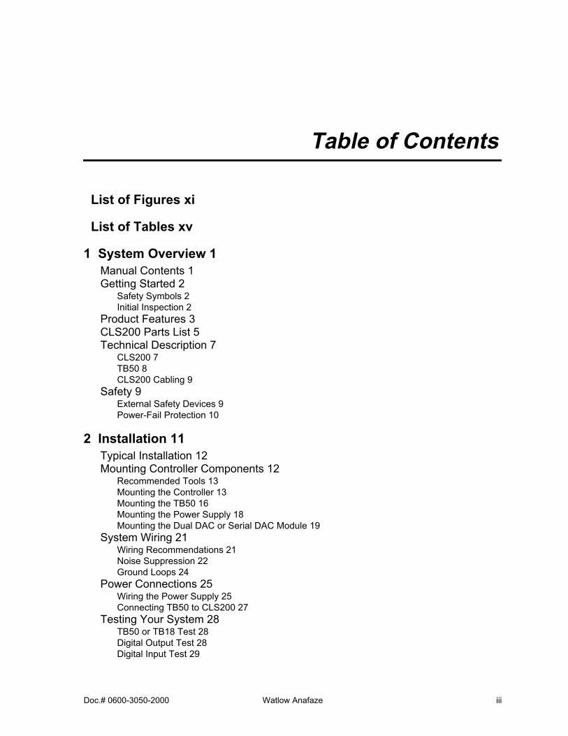
Table of Contents
List of Figures xi
List of Tables xv
1 System Overview 1
Manual Contents 1Getting Started 2
Safety Symbols 2Initial Inspection 2
Product Features 3CLS200 Parts List 5Technical Description 7
CLS200 7TB50 8CLS200 Cabling 9
Safety 9
External Safety Devices 9Power-Fail Protection 10
2 Installation 11
Typical Installation 12Mounting Controller Components 12
Recommended Tools 13Mounting the Controller 13Mounting the TB50 16Mounting the Power Supply 18Mounting the Dual DAC or Serial DAC Module 19
System Wiring 21
Wiring Recommendations 21Noise Suppression 22Ground Loops 24
Power Connections 25
Wiring the Power Supply 25Connecting TB50 to CLS200 27
Testing Your System 28
TB50 or TB18 Test 28Digital Output Test 28Digital Input Test 29

Table of Contents CLS200 Series User’s Guide
iv Watlow Anafaze Doc.# 0600-3050-2000
Sensor Wiring 29
Input Wiring Recommendations 30Thermocouple Connections 31RTD Input Connections 32Reference Voltage Terminals 32Voltage Input Connections 32Current Input Connections 33Pulse Input Connections 34
Wiring Control and Digital I/O 35
Output Wiring Recommendations 35Cable Tie Wraps 35Digital Outputs 35Digital Inputs 38TB18 Connections (CLS204 and CLS208 Only) 40TB50 Connections 41
Analog Outputs 43
Wiring the Dual DAC 43Wiring the Serial DAC 44
Serial Communications 45
EIA/TIA-232 Interface 45EIA/TIA-485 Interface 47EIA/TIA-485 Converters and Laptop Computers 49
3 Using the CLS200 51
Front Panel 52
Front Panel Keys 53
Displays 55
Bar Graph Display 55Single Loop Display 57Alarm Displays 58System Alarms 60
Job Display 60Changing the Setpoint 61Selecting the Control Status 61
Manual and Automatic Control 61Autotuning a Loop 62
Using Alarms 64
Alarm Delay 64Failed Sensor Alarms 65Process Alarms 66Global Alarm 68
Ramp/Soak 69
4 Setup 71
How to Access the Setup Menus 71
How to Change a Parameter 72
Setup Global Parameters Menu
74
Load Setup From Job 75Save Setup to Job 75Job Select Digital Inputs 76

CLS200 Series User’s Guide Table of Contents
Doc.# 0600-3050-2000 Watlow Anafaze v
Job Select Digital Inputs Active 77Output Override Digital Input 77Override Digital Input Active 77Startup Alarm Delay 78Keyboard Lock Status 78Power Up Output Status 78Process Power Digital Input 79Controller Address 79Communications Baud Rate 80Communications Protocol 80Communications Error Checking 80AC Line Frequency 81Digital Output Polarity on Alarm 81EPROM Information 81
Setup Loop Input Menu 82
Input Type 83Loop Name 84Input Units 84Input Reading Offset 84Reversed T/C Detection 85Input Pulse Sample Time 85Linear Scaling Parameters 86Input Filter 89
Setup Loop Control Parameters Menu 90
Heat or Cool Control PB 91Heat or Cool Control TI 91Heat or Cool Control TD 91Heat or Cool Output Filter 91Spread 92Restore PID Digital Input 92
Setup Loop Outputs Menu 93
Enable or Disable Heat or Cool Outputs 94Heat or Cool Output Type 94Heat or Cool Cycle Time 95SDAC Mode 95SDAC Low Value 95SDAC High Value 95Heat or Cool Output Action 96Heat or Cool Output Limit 96Heat or Cool Output Limit Time 96Sensor Fail Heat or Cool Output 97Heat or Cool Thermocouple Break Output Average 97Heat or Cool Linearity 98
Setup Loop Alarms Menu 99
High Process Alarm Setpoint 100High Process Alarm Type 100High Process Alarm Output Number 100Deviation Alarm Value 100High Deviation Alarm Type 101High Deviation Alarm Output Number 101Low Deviation Alarm Type 101Low Deviation Alarm Output Number 101Low Process Alarm Setpoint 102

Table of Contents CLS200 Series User’s Guide
vi Watlow Anafaze Doc.# 0600-3050-2000
Low Process Alarm Type 102Low Process Alarm Output Number 102Alarm Deadband 102Alarm Delay 103
Manual I/O Test 103
Digital Inputs 103Test Digital Output 104Digital Output Number 104Keypad Test 105Display Test 105
5 Extruder Control 107
Setup Loop Outputs Menu 107
Cool Output Nonlinear Output Curve 107
Defaults 108Extruder Control Algorithm 110
6 Enhanced Features 111
Process Variable Retransmit 113
Setup Loop Process Variable Retransmit Menu 113Process Variable Retransmit Example: Data Logging 115
Cascade Control 118
Setup Loop Cascade Menu 119Cascade Control Example: Water Tank 121
Ratio Control 124
Setup Loop Ratio Control Menu 125Ratio Control Example: Diluting KOH 126
Remote Analog Setpoint 129
Remote Analog Setpoint Example: Setting a Setpoint with a PLC 129
Differential Control 131
Differential Control Example: Thermoforming 131
7 Ramp/Soak 133
Features 134Ramp/Soak Menus 136Setup Global Parameters Menu 137
Ramp/Soak Time Base 137
Setup Ramp/Soak Profile Menu 137
Edit Ramp/Soak Profile 137Copy Setup From Profile 138Tolerance Alarm Time 138Ready Segment Setpoint 138Ready Segment Edit Events 139External Reset Input Number 139Edit Segment Number 140Segment Time 140Segment Setpoint 140Edit Segment Events 141Edit Segment Triggers 142Segment Tolerance 143
CLS200 Series User’s Guide Table of Contents
Doc.# 0600-3050-2000 Watlow Anafaze vii
Last Segment 144Repeat Cycles 144Setpoints and Tolerances for Various Input Types 144
Using Ramp/Soak 145
Ramp/Soak Displays 146Assigning a Profile to a Loop 148Running a Profile 148Holding a Profile or Continuing from Hold 150Responding to a Tolerance Alarm 151Resetting a Profile 151In Case of a Power Failure 152
8 Tuning and Control 153
Control Algorithms 153
On/Off Control 154Proportional Control 154Proportional and Integral Control 155Proportional, Integral and Derivative Control 155Heat and Cool Outputs 156
Control Outputs 157
Output Control Signals 157Output Filter 158Reverse and Direct Action 159
Setting Up and Tuning PID Loops 159
Proportional Band (PB) Settings 159Integral Settings 160Derivative Settings 160
General PID Constants by Application 161
Proportional Band Only (P) 161Proportional with Integral (PI) 161PI with Derivative (PID) 161
9 Troubleshooting and Reconfiguring 163
When There is a Problem 163
Returning Your Unit 164
Troubleshooting Controllers 164
Process and Deviation Alarms 164Failed Sensor Alarms 166System Alarms 166Other Behaviors 167
Corrective and Diagnostic Procedures 168
Low Power 168Battery Dead 168Ambient Warning 168H/W Ambient Failure 169H/W Gain or Offset Failure 170Keys Do Not Respond 170Checking Analog Inputs 171Earth Grounding 172Checking Control Outputs 172Testing Control Output Devices 173

Table of Contents CLS200 Series User’s Guide
viii Watlow Anafaze Doc.# 0600-3050-2000
Testing the TB18 and TB50 173Testing Control and Digital Outputs 173Testing Digital Inputs 173
Additional Troubleshooting for Computer Supervised Systems 174
Computer Problems 174Communications 175Ground Loops 175Software Problems 176
NO-Key Reset 176Replacing the EPROM 176Changing Communications 179Installing Scaling Resistors 180
CLS204 and CLS208 Input Circuit 180CLS204 and CLS208 Current Inputs 181CLS204 and CLS208 Voltage Inputs 182CLS204 and CLS208 RTDs and Thermistors 183CLS216 Input Circuit 184CLS216 Current Inputs 184CLS216 Voltage Inputs 185Scaling and Calibration 186
Configuring Dual DAC Outputs 186Configuring Serial DAC Outputs 188
10 Linear Scaling Examples 189
Example 1: A 4-to-20 mA Sensor 189Example 2: A 0-to-5V
Î
(dc) Sensor 191Example 3: A Pulse Encoder 192
11 Specifications 193
CLS200 System Specifications 193
CLS200 Processor Physical Specifications 194TB50 Physical Specifications 196Inputs 200Outputs 202
CLS200 Power Supply 205Dual DAC Specifications 207
Dual DAC Inputs 208Dual DAC Analog Outputs 208
Serial DAC Specifications 209
Serial DAC Inputs 210Serial DAC Analog Outputs 211
Glossary 213
Index 221
Menu Structure 233
Declaration of Conformity 234

Doc.# 0600-3050-2000 Watlow Anafaze ix
List of Figures
1 System Overview
Figure 1.1—CLS200 Part Numbering 5Figure 1.2—CLS200 Special Inputs Parts List 6Figure 1.3—CLS200 Rear Views 7Figure 1.4—CLS200 Front Panel 8Figure 1.5—TB50 8
2 Installation
Figure 2.1—CLS200 System Components 12Figure 2.2—Clearance with Straight SCSI Cable 14Figure 2.3—Clearance with Right-Angle SCSI Cable 14Figure 2.4—Wiring Clearances 15Figure 2.5—Mounting Bracket 16Figure 2.6—Mounting the TB50 16Figure 2.7—TB50 Mounted on a DIN Rail (Front) 17Figure 2.8—TB50 Mounted on DIN Rail (Side) 17Figure 2.9—Mounting a TB50 with Standoffs 18Figure 2.10—CLS200 Power Supply Mounting Bracket 19Figure 2.11—Dual DAC and Serial DAC Dimensions 20Figure 2.12—CLS200 Series Controller with TB18 25Figure 2.13—CLS200 Series Controller with TB50 25Figure 2.14—Power Connections with the CLS200 Power Supply 27Figure 2.15—CLS200 Connector Locations 30Figure 2.16—Thermocouple Connections 31Figure 2.17—RTD Connections to CLS204 or CLS208 32Figure 2.18—Linear Voltage Signal Connections 33Figure 2.19—Linear Current Signal Connections 33Figure 2.20—Encoder with 5V
Î
(dc) TTL Signal 34Figure 2.21—Encoder Input with Voltage Divider 34Figure 2.22—Digital Output Wiring 36Figure 2.23—Sample Heat, Cool and Alarm Output Connections 37Figure 2.24—Output Connections Using External Power Supply 38Figure 2.25—TB50 Watchdog Timer Output 38Figure 2.26—TB18 Watchdog Timer Output 38Figure 2.27—Wiring Digital Inputs 39Figure 2.28—Dual DAC with Current Output 43Figure 2.29—Dual DAC with Voltage Output 44

List of Figures CLS200 Series User’s Guide
x Watlow Anafaze Doc.# 0600-3050-2000
Figure 2.30—Single/Multiple Serial DACs 45Figure 2.31—Connecting One CLS200 to a Computer Using EIA/TIA-232 46Figure 2.32—EIA/TIA-485 Wiring 47Figure 2.33—Recommended System Connections 48
3 Using the CLS200
Figure 3.1—Operator Displays 51Figure 3.2—CLS200 Front Panel 52Figure 3.3—Bar Graph Display 55Figure 3.4—Single Loop Display 57Figure 3.5—Single Loop Display, Heat and Cool Outputs Enabled 57Figure 3.6—Single Loop Display with a Process Alarm 58Figure 3.7—Failed Sensor Alarm in the Single Loop Display 58Figure 3.8—Alarm Symbols in the Bar Graph Display 58Figure 3.9—Activation and Deactivation of Process Alarms 68
4 Setup
Figure 4.1—CLS200 Menu Tree 73Figure 4.2—Two Points Determine Process Variable Conversion 86Figure 4.3—Process Variable Limited by Input Reading Range 87Figure 4.4—Linear and Nonlinear Outputs 98Figure 4.5—Digital Inputs Screen 104
5 Extruder Control
Figure 5.1—Cool Output Nonlinear Output Curve 108
6 Enhanced Features
Figure 6.1—Enhanced Features Option Menus 112Figure 6.2—Linear Scaling of Process Variable for Retransmit 115Figure 6.3—Application Using Process Variable Retransmit 116Figure 6.4—Relationship Between the Primary Loop’s Output and the Secondary
Loop’s Setpoint 119Figure 6.5—Application Using Cascade Control 121Figure 6.6—Secondary Loop Setpoint Related to Primary Loop Output 123Figure 6.7—Relationship Between the Master Loop’s Process Variable and the Ratio
Loop’s Setpoint 124Figure 6.8—Application Using Ratio Control 127
7 Ramp/Soak
Figure 7.1—Sample Ramp/Soak Profile 133Figure 7.2—Setup Ramp/Soak Profiles Menu 136Figure 7.3—Positive and Negative Tolerances 143Figure 7.4—Ramp/Soak Screens 145

CLS200 Series User’s Guide List of Figures
Doc.# 0600-3050-2000 Watlow Anafaze xi
8 Tuning and Control
Figure 8.1—On/Off Control 154Figure 8.2—Proportional Control 155Figure 8.3—Proportional and Integral Control 155Figure 8.4—Proportional, Integral and Derivative Control 156Figure 8.5—Time Proportioning and Distributed Zero Crossing Waveforms 157
9 Troubleshooting and Reconfiguring
Figure 9.1—Removal of Electronics Assembly from Case 177Figure 9.2—Screws Locations on PC Board 178Figure 9.3—EPROM Location 178Figure 9.4—Remove EPROM 178Figure 9.5—Jumper Configurations 179Figure 9.6—CLS204 and CLS208 Input Circuit 181Figure 9.7—CLS216 Input Circuit 184Figure 9.8—Dual DAC 187Figure 9.9—Serial DAC Voltage/Current Jumper Positions 188
11 Specifications
Figure 11.1—CLS200 Processor Module Dimensions 194Figure 11.2—CLS200 Clearances with Straight SCSI Cable 195Figure 11.3—CLS200 Clearances with Right-Angle SCSI Cable 195Figure 11.4—TB50 Dimensions 197Figure 11.5—TB50 Dimensions with Straight SCSI Cable 198Figure 11.6—TB50 Dimensions with Right-Angle SCSI Cable 199Figure 11.7—Power Supply Dimensions (Bottom View) 206Figure 11.8—Dual DAC Dimensions 207Figure 11.9—Serial DAC Dimensions 209

List of Figures CLS200 Series User’s Guide
xii Watlow Anafaze Doc.# 0600-3050-2000

Doc.# 0600-3050-2000 Watlow Anafaze xiii
List of Tables
2 Installation
Table 2.1—Cable Recommendations 22Table 2.2—Power Connections 26Table 2.3—Digital Output States and Values Stored in the Controller 36Table 2.4—Digital Inputs States and Values Stored in the Controller 39Table 2.5—TB18 Connections 40Table 2.6—TB50 Connections for CLS204 and CLS208 41Table 2.7—TB50 Connections for CLS216 42Table 2.8—EIA/TIA-232 Connections 46Table 2.9—RTS/CTS Pins in DB-9 and DB-25 Connectors 46
3 Using the CLS200
Table 3.1—Bar Graph Display Symbols 55Table 3.2—Control Status Symbols on the Bar Graph and Single Loop Displays 56Table 3.3—Alarm Type and Symbols 59
4 Setup
Table 4.1—Global Parameters 74Table 4.2—Job Select Inputs 76Table 4.3—Job Selected for Various Input States 76Table 4.4—Firmware Option Codes 81Table 4.5—Setup Loop Input 82Table 4.6—CLS200 Input Types and Ranges 83Table 4.7—Input Character Sets 84Table 4.8—Input Reading Offset 85Table 4.9—Display Formats 87Table 4.10—Setup Loop Control Parameters 90Table 4.11—Setup Loop Outputs 93Table 4.12—Heat / Cool Output Types 94Table 4.13—Setup Loop Alarms 99Table 4.14—Manual I/O Test 103
5 Extruder Control
Table 5.1—Default Control Parameters for Fan Cool Output 109Table 5.2—Default Control Parameters for Oil Cool Output 109Table 5.3—Default Control Parameters for H2O Cool Output 109
List of Tables CLS200 Series User’s Guide
xiv Watlow Anafaze Doc.# 0600-3050-2000
6 Enhanced Features
Table 6.1—Application Example: Setting Up Process Variable Retransmit 117Table 6.2—Application Example: Setting Up Cascade Control 122Table 6.3—Application Example: Setting Up Ratio Control 128Table 6.4—Application Example: Setting Up Remote Setpoint 130Table 6.5—Application Example: Setting Up Differential Control 132
7 Ramp/Soak
Table 7.1—Ramp/Soak Specifications 135Table 7.2—Trigger Latch Logic 143Table 7.3—Display Formats 145Table 7.4—Ramp/Soak Single Loop Display 146Table 7.5—Ramp/Soak Control Status Symbols 147Table 7.6—Ramp/Soak Profile Modes 150
8 Tuning and Control
Table 8.1—Proportional Band Settings 159Table 8.2—Integral Term and Reset Settings 160Table 8.3—Derivative Term Versus Rate 160Table 8.4—General PID Constants 162
9 Troubleshooting and Reconfiguring
Table 9.1—Controller Alarm Codes for Process and Deviation Alarms 164Table 9.2—Operator Response to Alarms 165Table 9.3—Failed Sensor Alarm Codes 166Table 9.4—Hardware Error Messages 166Table 9.5—Other Symptoms 167Table 9.6—Resistor Values for CLS204 and CLS208 Current Inputs 181Table 9.7—Resistor Locations for CLS204 and CLS208 Current Inputs 181Table 9.8—Resistor Values for CLS204 and CLS208 Voltage Inputs 182Table 9.9—Resistor Locations for CLS204 and CLS208 Voltage Inputs 182Table 9.10—Resistor Values for CLS204/208 RTD and Thermistor Inputs 183Table 9.11—Resistor Locations for CLS204/208 RTD and Thermistor Inputs 183Table 9.12—Resistor Values for CLS216 Current Inputs 184Table 9.13—Resistor Locations for CLS216 Current Inputs 185Table 9.14—Resistor Values for CLS216 Voltage Inputs 185Table 9.15—Resistor Locations for CLS216 Voltage Inputs 186Table 9.16—Dual DAC Jumper Settings 187
10 Linear Scaling Examples
Table 10.1—Input Readings 190Table 10.2—Scaling Values 190Table 10.3—Input Readings and Calculations 191Table 10.4—Scaling Values 191Table 10.5—Scaling Values 192

CLS200 Series User’s Guide List of Tables
Doc.# 0600-3050-2000 Watlow Anafaze xv
11 Specifications
Table 11.1—Agency Approvals / Compliance 193Table 11.2—Environmental Specifications 194Table 11.3—Physical Dimensions 194Table 11.4—Processor with Straight SCSI 195Table 11.5—Processor with Right Angle SCSI 195Table 11.6—Processor Connections 196Table 11.7—TB50 Physical Dimensions 196Table 11.8—TB50 Connections 197Table 11.9—TB50 with Straight SCSI 198Table 11.10—TB50 with Right Angle SCSI 199Table 11.11—Analog Inputs 200Table 11.12—Pulse Inputs 201Table 11.13—Thermocouple Range and Resolution 201Table 11.14—RTD Range and Resolution 201Table 11.15—Input Resistance for Voltage Inputs 202Table 11.16—Digital Inputs 202Table 11.17—Digital Outputs Control / Alarm 203Table 11.18—CPU Watchdog Output 203Table 11.19—5V
Î
(dc) Output (Power to Operate Solid-State Relays) 204Table 11.20—Reference Voltage Output (Power to Operate Bridge Circuit
Sensors) 204Table 11.21—Processor Serial Interface 204Table 11.22—Processor Power Requirements 204Table 11.23—Power Supply Environmental Specifications 205Table 11.24—Power Supply Agency Approvals / Compliance 205Table 11.25—Power Supply Physical Specifications 205Table 11.26—Power Supply with Mounting Bracket 205Table 11.27—Power Supply Inputs 206Table 11.28—Power Supply Outputs 206Table 11.29—Dual DAC Environmental Specifications 207Table 11.30—Dual DAC Physical Specifications 207Table 11.31—Dual DAC Power Requirements 208Table 11.32—Dual DAC Specifications by Output Range 208Table 11.33—Serial DAC Environmental Specifications 209Table 11.34—Serial DAC Physical Specifications 209Table 11.35—Serial DAC Agency Approvals / Compliance 210Table 11.36—Serial DAC Inputs 210Table 11.37—Serial DAC Power Requirements 210Table 11.38—Serial DAC Analog Output Specifications 211

List of Tables CLS200 Series User’s Guide
xvi Watlow Anafaze Doc.# 0600-3050-2000
Doc.# 0600-3050-2000 Watlow Anafaze 1
1
System Overview
Manual Contents
This manual describes how to install, set up, and operate a CLS204, CLS208 or CLS216 controller. Each chapter cov-ers a different aspect of your control system and may apply to different users:
•
Chapter 1: System Overview
provides a component list and summary of features for the CLS200 series controllers.
•
Chapter 2: Installation
provides detailed instruc-tions on installing the CLS200 series controller and its peripherals.
•
Chapter 3: Using the CLS200
provides an overview of operator displays used for system monitoring and job selection.
•
Chapter 4: Setup
provides detailed descriptions of all menus and parameters for controller setup.
•
Chapter 5: Extruder Control
explains the addition-al features of a CLS200 controller equipped with Ex-truder Control Firmware.
•
Chapter 6: Enhanced Features
describes process variable retransmit, ratio, differential and cascade control features available with the enhanced features option.
•
Chapter 7: Ramp/Soak
explains how to set up and use the features of the ramp/soak option.
•
Chapter 8: Tuning and Control
describes available control algorithms and provides suggestions for appli-cations.
•
Chapter 9: Troubleshooting and Reconfiguring
includes troubleshooting, upgrading and reconfigur-ing procedures for technical personnel.

Chapter 1: System Overview CLS200 Series User’s Guide
2 Watlow Anafaze Doc.# 0600-3050-2000
•
Chapter 10: Linear Scaling Examples
provides an example configuring a pressure sensor, a flow sensor, and an encoder using linear scaling.
•
Chapter 11: Specifications
lists detailed specifica-tions of the controller and optional components.
Getting Started
The following sections provide information regarding prod-uct features, technical descriptions, safety requirements, and preparation for operation.
Safety Symbols
These symbols are used throughout this manual:
WARNING!
Indicates a potentially hazardous situationwhich, if not avoided, could result in death orserious injury.
CAUTION!
Indicates a potentially hazardous situationwhich, if not avoided, could result in minor ormoderate injury or property damage.
NOTE!
Indicates pertinent information or an itemthat may be useful to document or label forlater reference.
Initial Inspection
Accessories may or may not be shipped in the same con-tainer as the CLS200, depending upon their size. Check the shipping invoice carefully against the contents received in all boxes.
CLS200 Series User’s Guide Chapter 1: System Overview
Doc.# 0600-3050-2000 Watlow Anafaze 3
Product Features
The CLS200 series controllers provide 4, 8 or 16 fully inde-pendent control loops. When used as a stand-alone control-ler, you may operate the CLS200 via the two-line 16-character display and touch keypad. You can also use it as the key element in a computer-supervised data acquisition and control system; the CLS200 can be locally or remotely controlled via an EIA/TIA-232 or EIA/TIA-485 serial com-munications interface.
The CLS200 features include:
•
Direct Connection of Mixed Thermocouple Sen-sors:
Connect most thermocouples to the controller with no hardware modifications. Thermocouple inputs feature reference junction compensation, lineariza-tion, process variable offset calibration to correct for sensor inaccuracies, detection of broken, shorted or re-versed thermocouples, and a choice of Fahrenheit or Celsius display.
•
Accepts Resistive Temperature Detectors (RTDs):
Use 3-wire, 100
Ω
, platinum, 0.00385-curve sensors with two choices for range and precision of measurements. (To use this input, order a CLS204 or CLS208 controller with scaling resistors.)
•
Automatic Scaling for Linear Analog Inputs:
The CLS200 series automatically scales linear inputs used with industrial process sensors. Enter two points, and all input values are automatically scaled in your units. Scaling resistors must be installed.
•
Dual Outputs:
The CLS200 series includes both heat and cool control outputs for each loop. Independent control parameters are provided for each output.
•
Independently Selectable Control and Output Modes:
You can set each control output to on/off, time proportioning, Serial DAC (digital-to-analog convert-er), or distributed zero crossing mode. Set up to two outputs per loop for on/off, P, PI or PID control with re-verse or direct action.
•
Control Outputs:
Set high/low deviation and high/low process limits to operate digital outputs as on/off control functions or alarms.
• Flexible Alarm Outputs: Independently set high/low process alarms and a high/low deviation band alarm for each loop. Alarms can activate a digital out-put by themselves, or they can be grouped with other alarms to activate an output.
• Global Alarm Output: When any alarm is triggered, the global alarm output is also triggered, and it stays on until you acknowledge it.

Chapter 1: System Overview CLS200 Series User’s Guide
4 Watlow Anafaze Doc.# 0600-3050-2000
• CPU Watchdog: The CLS200 series CPU watchdog timer output notifies you of system failure. Use it to hold a relay closed while the controller is running, so you are notified if the microprocessor shuts down.
• Front Panel or Computer Operation: Set up and run the controller from the front panel or from a local or remote computer. Watlow Anafaze offers WatView, a Windows® compatible Human Machine Interface (HMI) software package that includes data logging and graphing features in addition to process monitor-ing and parameter setup screens.
• Modbus RTU Protocol, EIA/TIA-232 and 485 Communications: Connect to PLCs, operator inter-face terminals and third-party software packages us-ing the widely supported Modbus RTU protocol.
• Multiple Job Storage: Store up to eight jobs in mem-ory, and access them locally by entering a single job number or remotely via digital inputs. Each job is a set of operating conditions, including setpoints and alarms.
• Nonlinear Output Curves: Select either of two non-linear output curves for each control output.
• Autotuning: Use the autotune feature to set up your system quickly and easily. The CLS200 internal ex-pert system table finds the correct PID parameters for your process.
• Pulse Counter Input: Use the pulse counter input for precise control of motor or belt speed.
• Low Power Shutdown: The controller shuts down and turns off all outputs when it detects the input volt-age drop below the minimum safe operating level.
CLS200 Series User’s Guide Chapter 1: System Overview
Doc.# 0600-3050-2000 Watlow Anafaze 5
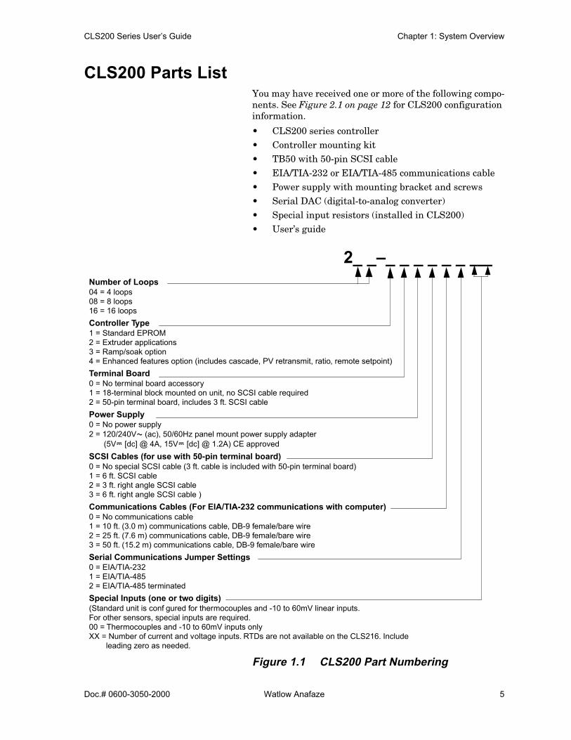
CLS200 Parts ListYou may have received one or more of the following compo-nents. See Figure 2.1 on page 12 for CLS200 configuration information.
• CLS200 series controller• Controller mounting kit• TB50 with 50-pin SCSI cable• EIA/TIA-232 or EIA/TIA-485 communications cable• Power supply with mounting bracket and screws• Serial DAC (digital-to-analog converter)• Special input resistors (installed in CLS200)• User’s guide
Figure 1.1 CLS200 Part Numbering
Number of Loops04 = 4 loops08 = 8 loops16 = 16 loopsController Type1 = Standard EPROM2 = Extruder applications3 = Ramp/soak option4 = Enhanced features option (includes cascade, PV retransmit, ratio, remote setpoint)Terminal Board0 = No terminal board accessory1 = 18-terminal block mounted on unit, no SCSI cable required2 = 50-pin terminal board, includes 3 ft. SCSI cablePower Supply 0 = No power supply2 = 120/240VÅ (ac), 50/60Hz panel mount power supply adapter
(5VÎ [dc] @ 4A, 15VÎ [dc] @ 1.2A) CE approved SCSI Cables (for use with 50-pin terminal board)0 = No special SCSI cable (3 ft. cable is included with 50-pin terminal board)1 = 6 ft. SCSI cable2 = 3 ft. right angle SCSI cable3 = 6 ft. right angle SCSI cable )Communications Cables (For EIA/TIA-232 communications with computer)0 = No communications cable1 = 10 ft. (3.0 m) communications cable, DB-9 female/bare wire2 = 25 ft. (7.6 m) communications cable, DB-9 female/bare wire 3 = 50 ft. (15.2 m) communications cable, DB-9 female/bare wire Serial Communications Jumper Settings0 = EIA/TIA-2321 = EIA/TIA-4852 = EIA/TIA-485 terminatedSpecial Inputs (one or two digits)(Standard unit is conf gured for thermocouples and -10 to 60mV linear inputs.For other sensors, special inputs are required.00 = Thermocouples and -10 to 60mV inputs onlyXX = Number of current and voltage inputs. RTDs are not available on the CLS216. Include
leading zero as needed.
2_ _–_ _ _ _ _ _ ___
Chapter 1: System Overview CLS200 Series User’s Guide
6 Watlow Anafaze Doc.# 0600-3050-2000
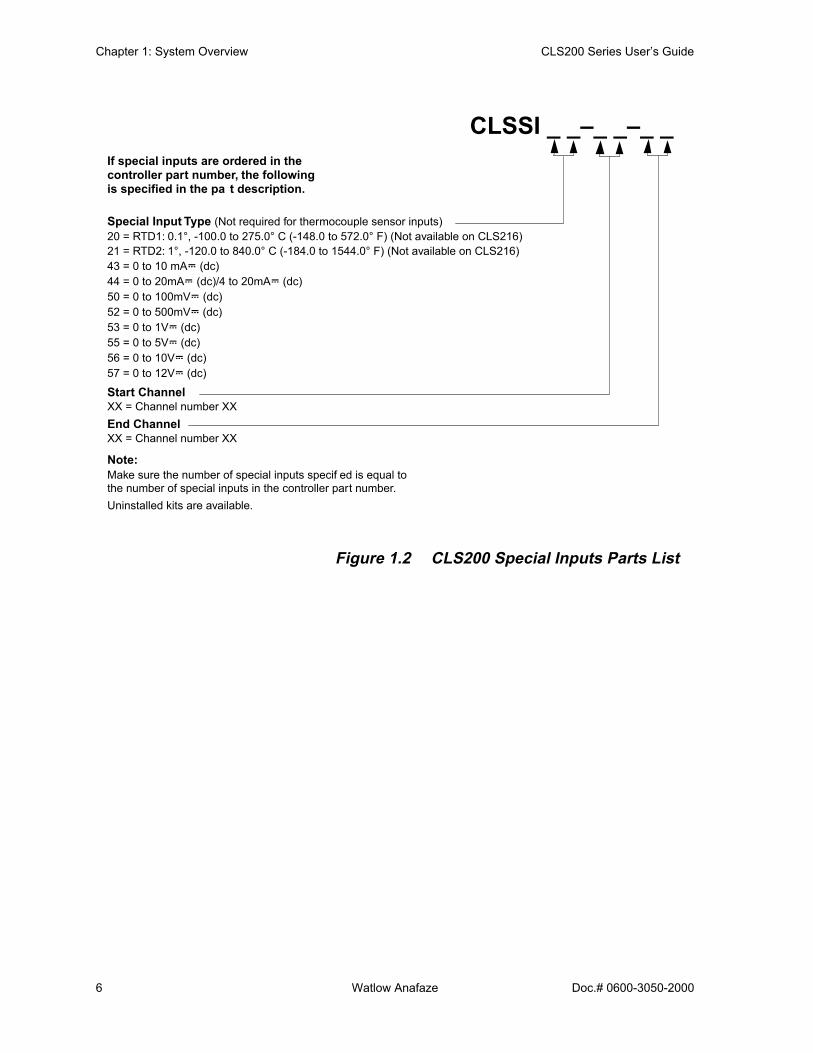
Figure 1.2 CLS200 Special Inputs Parts List
If special inputs are ordered in thecontroller part number, the followingis specified in the pa t description.
Special Input Type (Not required for thermocouple sensor inputs)20 = RTD1: 0.1°, -100.0 to 275.0° C (-148.0 to 572.0° F) (Not available on CLS216)21 = RTD2: 1°, -120.0 to 840.0° C (-184.0 to 1544.0° F) (Not available on CLS216)43 = 0 to 10 mAÎ (dc)44 = 0 to 20mAÎ (dc)/4 to 20mAÎ (dc)50 = 0 to 100mVÎ (dc)52 = 0 to 500mVÎ (dc)53 = 0 to 1VÎ (dc)55 = 0 to 5VÎ (dc)56 = 0 to 10VÎ (dc)57 = 0 to 12VÎ (dc)
Start ChannelXX = Channel number XXEnd ChannelXX = Channel number XX
Note:Make sure the number of special inputs specif ed is equal tothe number of special inputs in the controller part number.Uninstalled kits are available.
CLSSI _ _–_ _–_ _
CLS200 Series User’s Guide Chapter 1: System Overview
Doc.# 0600-3050-2000 Watlow Anafaze 7
Technical Description This section contains a technical description of each compo-nent of your CLS200 series controller.
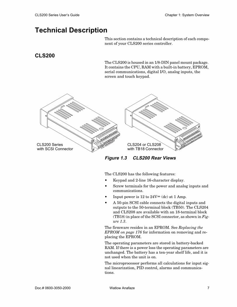
CLS200 The CLS200 is housed in an 1/8-DIN panel mount package. It contains the CPU, RAM with a built-in battery, EPROM, serial communications, digital I/O, analog inputs, the screen and touch keypad.
Figure 1.3 CLS200 Rear Views
The CLS200 has the following features:
• Keypad and 2-line 16-character display.• Screw terminals for the power and analog inputs and
communications.
• Input power is 12 to 24VÎ (dc) at 1 Amp.
• A 50-pin SCSI cable connects the digital inputs and outputs to the 50-terminal block (TB50). The CLS204 and CLS208 are available with an 18-terminal block (TB18) in place of the SCSI connector, as shown in Fig-ure 1.3.
The firmware resides in an EPROM. See Replacing the EPROM on page 176 for information on removing and re-placing the EPROM.
The operating parameters are stored in battery-backed RAM. If there is a power loss the operating parameters are unchanged. The battery has a ten-year shelf life, and it is not used when the unit is on.
The microprocessor performs all calculations for input sig-nal linearization, PID control, alarms and communica-tions.
CLS200 Serieswith SCSI Connector
CLS204 or CLS208with TB18 Connector

Chapter 1: System Overview CLS200 Series User’s Guide
8 Watlow Anafaze Doc.# 0600-3050-2000
Front Panel Description The display and touch keypad provide an intelligent way to operate the controller. The display has 16 alphanumeric or graphic characters per line. The 8-key keypad allows you to change the operating parameters, controller functions, and displays.
The information-packed displays show process variables, setpoints, and output levels for each loop. A bar graph dis-play, single loop display, scanning display and an alarm display offer a real-time view of process conditions. Two ac-cess levels allow operator changes and supervisor changes.
Figure 1.4 CLS200 Front Panel
TB50 The TB50 is a screw-terminal interface for control wiring which allows you to connect relays, encoders and discrete I/O devices to the CLS200. The screw terminal blocks accept wires as large as 18 AWG (0.75 mm2). A 50-pin SCSI cable connects the TB50 to the CLS200.
Figure 1.5 TB50
WATLOW ANAFAZE CLS200
CLS200 Series User’s Guide Chapter 1: System Overview
Doc.# 0600-3050-2000 Watlow Anafaze 9
CLS200 CablingWatlow Anafaze provides cables required to install your CLS200. A 50-pin SCSI cable connects the TB50 to the CLS200.
The optional cable used to connect the CLS200 to a comput-er using EIA/TIA-232 communications has a DB9 or DB25 connector for the computer and bare wires for connecting to the CLS200.
SafetyWatlow Anafaze has made every effort to ensure the reli-ability and safety of this product. In addition, we have pro-vided recommendations that will allow you to safely install and maintain this controller.
External Safety DevicesThe CLS200 controller may fail full-on (100% output pow-er) or full-off (0% output power), or may remain full-on if an undetected sensor failure occurs. For more information about failed sensor alarms, see Failed Sensor Alarms on page 65.
Design your system to be safe even if the controller sends a 0% or 100% output power signal at any time. Install inde-pendent, external safety devices that will shut down the system if a failure occurs.
Typically, a shutdown device consists of an FM-approved high/low process limit controller that operates a shutdown device such as an mechanical contactor. The limit control-ler monitors for a hazardous condition such as an under-temperature or over-temperature fault. If a hazardous con-dition is detected, the limit controller sends a signal to open the contactor.
The safety shutdown device (limit controller and contactor) must be independent from the process control equipment.
WARNING! The controller may fail in a 0% or 100% poweroutput state. To prevent death, personal inju-ry, equipment damage or property damage,install external safety shutdown devices. Ifdeath or injury may occur, you must installFM-approved safety shutdown devices thatoperate independently from the process con-trol equipment.With proper approval and installation, thermal fuses may be used in some processes.
Chapter 1: System Overview CLS200 Series User’s Guide
10 Watlow Anafaze Doc.# 0600-3050-2000
Power-Fail ProtectionIn the occurrence of a sudden loss of power, this controller can be programmed to reset the control outputs to off (this is the default). Typically, when power is re-started, the con-troller restarts to data stored in memory. If you have pro-grammed the controller to restart with control outputs on, the memory-based restart might create an unsafe process condition for some installations. Therefore, you should only set the restart with outputs on if you are certain your sys-tem will safely restart. (See the Process Power Digital In-put on page 79).
When using a computer or host device, you can program the software to automatically reload desired operating con-stants or process values on power-up. Keep in mind that these convenience features do not eliminate the need for in-dependent safety devices.
Contact Watlow Anafaze immediately if you have any ques-tions about system safety or system operation.

Doc.# 0600-3050-2000 Watlow Anafaze 11
2Installation
This chapter describes how to install the CLS200 series controller and its peripherals. Installation of the controller involves the following procedures:
• Determining the best location for the controller• Mounting the controller and TB50• Power connection• Input wiring• Communications wiring (EIA/TIA-232 or EIA/TIA-
485)• Output wiring
WARNING! Risk of electric shock. Shut off power to yourentire process before you begin installationof the controller.
WARNING! The controller may fail in a 0% or 100% poweroutput state. To prevent death, personal inju-ry, equipment damage or property damage,install external safety shutdown devices. Iffailure may cause death or injury, you mustinstall FM-approved safety shutdown devic-es that operate independently from the pro-cess control equipment.

Chapter 2: Installation CLS200 Series User’s Guide
12 Watlow Anafaze Doc.# 0600-3050-2000
Typical InstallationFigure 2.1 shows typical installations of the controller with the TB50 and the TB18 terminal blocks. The type of termi-nal block you use greatly impacts the layout and wiring of your installation site. (See Figures 2.2 to 2.11.)We recommend that you read this entire chapter first be-fore beginning the installation procedure. This will help you to carefully plan and assess the installation.
Figure 2.1 CLS200 System Components
Mounting Controller Components Install the controller in a location free from excessive heat (more than 50º C [122° F]), dust, and unauthorized han-dling. Electromagnetic and radio frequency interference can induce noise on sensor wiring. Select locations for the CLS200 and TB50 such that wiring can be routed clear of sources of interference such as high voltage wires, power switching devices and motors.
NOTE! For indoor use only.
CLS200 with TB50
CLS200 with TB18
Signal Inputs
Signal Inputs
SCSI Cable
11 Digital Outputs (Control/Alarm)2 Digital Inputs, 1 Digital/Pulse Input
CLS200Power supply
8 Digital Inputs,35 Digital Outputs (Control/Alarm) Pulse Input
CLS200Power supply

CLS200 Series User’s Guide Chapter 2: Installation
Doc.# 0600-3050-2000 Watlow Anafaze 13
WARNING! To reduce the risk of fire or electric shock, in-stall the CLS200 in a controlled environment,relatively free of contaminants.
Recommended ToolsUse any of the following tools to cut a hole of the appropri-ate size in the panel.
• Jigsaw and metal file, for stainless steel and heavy-weight panel doors.
• Greenlee 1/8-DIN rectangular punch (Greenlee part number 600-68), for most panel materials and thick-nesses.
• Nibbler and metal file, for aluminum and lightweight panel doors.
You will also need these tools:
• Phillips head screwdriver• 1/8 in. (3 mm) flathead screwdriver for wiring• Multimeter
Mounting the ControllerMount the controller before you mount the terminal block or do any wiring. The controller’s placement affects place-ment and wiring considerations for the other components of your system.
Ensure there is enough clearance for mounting brackets, terminal blocks, and cable and wire connections; the con-troller extends up to 7.0 inches (178 mm) behind the panel face and the screw brackets extend 0.5 inch (13 mm) above and below it. If using a straight SCSI cable, allow for an ad-ditional 1.6 inches (41 mm) beyond the terminal block. If using a right-angle SCSI cable, allow an additional 0.6 inch (15 mm). (See Figure 2.2 and Figure 2.3.)

Chapter 2: Installation CLS200 Series User’s Guide
14 Watlow Anafaze Doc.# 0600-3050-2000
Figure 2.2 Clearance with Straight SCSI Cable
Figure 2.3 Clearance with Right-Angle SCSI Cable
1.0 inch 7.0 inches 1.6 inch(25 mm) (178 mm) (41 mm)
1.0 inch 7.0 inches 0.6 inch(25 mm) (178 mm) (41 mm)

CLS200 Series User’s Guide Chapter 2: Installation
Doc.# 0600-3050-2000 Watlow Anafaze 15
Figure 2.4 Wiring Clearances
We recommend you mount the controller in a panel not more than 0.2 in. (5 mm) thick.
1. Choose a panel location free from excessive heat (morethan 50° C [122° F]), dust, and unauthorized handling.(Make sure there is adequate clearance for the mount-ing hardware, terminal blocks, and cables. The con-troller extends 7.40 in. (178 mm) behind the panel.Allow for an additional 0.60 to 1.60 in. (15 to 41 mm)beyond the connectors.)
2. Temporarily cover any slots in the metal housing sothat dirt, metal filings, and pieces of wire do not enterthe housing and lodge in the electronics.
3. Cut a hole in the panel 1.80 in. (46 mm) by 3.63 in. (92mm) as shown below. (This picture is NOT a template;it is for illustration only.) Use caution; the dimensionsgiven here have 0.02 in. (1 mm) tolerances.
4. Remove the brackets and collar from the processormodule, if they are already in place.
5. Slide the processor module into the panel cutout.
6. Slide the mounting collar over the back of the proces-sor module, making sure the mounting screw indenta-tions face toward the back of the processor module.
1.80 ± 0.020 inch(45.7 ± 0.5 mm)
Maximum Panel Thickness 0.2 inch (5 mm)
3.63 ± 0.020 inches(92.2 ± 0.5 mm)

Chapter 2: Installation CLS200 Series User’s Guide
16 Watlow Anafaze Doc.# 0600-3050-2000
Figure 2.5 Mounting Bracket
7. Loosen the mounting bracket screws enough to allowfor the mounting collar and panel thickness. Placeeach mounting bracket into the mounting slots (headof the screw facing the back of the processor module).Push each bracket backward then to the side to secureit to the processor module case.
8. Make sure the case is seated properly. Tighten the in-stallation screws firmly against the mounting collar tosecure the unit. Ensure that the end of the mountingscrews fit into the indentations on the mounting collar.
Mounting the TB50There are two ways you can mount the TB50: Use the pre-installed DIN rail mounting brackets or use the plastic standoffs. Follow the corresponding procedures to mount the board.
Figure 2.6 Mounting the TB50
+
2
4
6
8
10
12
14
16
18
20
22
24
26
1
3
5
7
9
11
13
15
17
19
21
23
25
Bracket (top and bottom)Panel
Bezel Mounting Collar
TB50Mountedwith Standoffs
TB50 Mounted to DIN Rail
CLS200 Series User’s Guide Chapter 2: Installation
Doc.# 0600-3050-2000 Watlow Anafaze 17
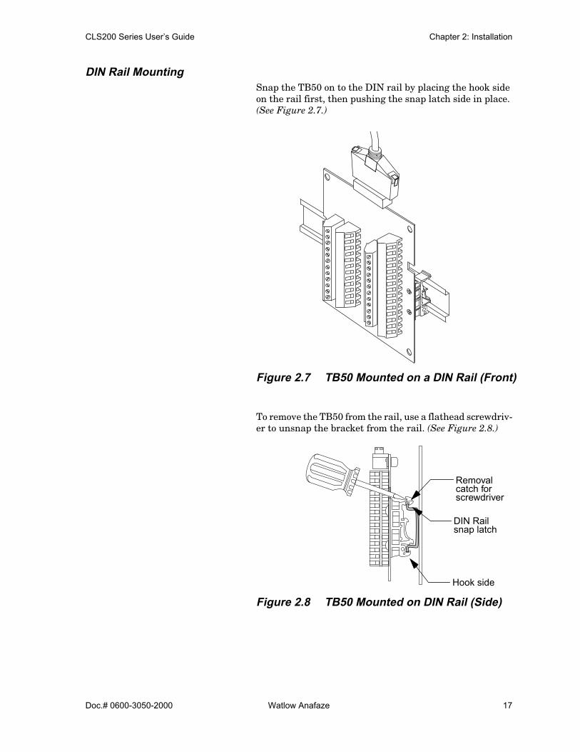
DIN Rail MountingSnap the TB50 on to the DIN rail by placing the hook side on the rail first, then pushing the snap latch side in place. (See Figure 2.7.)
Figure 2.7 TB50 Mounted on a DIN Rail (Front)
To remove the TB50 from the rail, use a flathead screwdriv-er to unsnap the bracket from the rail. (See Figure 2.8.)
Figure 2.8 TB50 Mounted on DIN Rail (Side)
Removalcatch forscrewdriver
DIN Railsnap latch
Hook side

Chapter 2: Installation CLS200 Series User’s Guide
18 Watlow Anafaze Doc.# 0600-3050-2000
Mounting with Standoffs1. Remove the DIN rail mounting brackets from the
TB50.
2. Select a location with enough clearance to remove theTB50, its SCSI cable and the controller itself.
3. Mark the four mounting holes.
4. Drill and tap four mounting holes for #6 (3.5 mm)screws or bolts.
5. Mount the TB50 with four screws.
There are four smaller holes on the terminal board. Use these holes to secure wiring to the terminal block with tie wraps.
Figure 2.9 Mounting a TB50 with Standoffs
Mounting the Power Supply If you use your own power supply for the CLS200, refer to the power supply manufacturer’s instructions for mounting information. Choose a Class 2 power supply that supplies an isolated regulated 12 to 24VÎ (dc) at 1 A.
3.4 in(86 mm)
3.6 in(91 mm)
2.6 in(66 mm)
(18 mm)
0.2 in(5 mm)
0.2 in(5 mm)
SCSI Connector
0.2 in
4 holes for
0.7 in
(5 mm)
#6 (3.5 mm)screws or bolts

CLS200 Series User’s Guide Chapter 2: Installation
Doc.# 0600-3050-2000 Watlow Anafaze 19
Mounting Environment Leave enough clearance around the power supply so that it can be removed.
Figure 2.10 CLS200 Power Supply Mounting Bracket
Mounting Steps
CAUTION! Use 6-32, 1/4-inch screws only. Longerscrews may extend too far into the powersupply and short to components, damagingthe power supply.
1. Attach the bracket to the power supply using thebracket’s two center holes.
2. Select a location with enough clearance to remove thepower supply and bracket. (See Figure 2.10.)
3. When a location has been determined for the powersupply, mark the bracket’s two outer holes for mount-ing.
4. Drill and tap the two mounting holes. (The bracketholes accept up to #10 [5.0 mm] screws.)
5. Mount the power supply on the panel.
6. Tighten the screws.
Mounting the Dual DAC or Serial DAC ModuleThis section describes how to install the optional Dual DAC and Serial DAC digital-to-analog converters.
0.3 inch(8 mm)
0.7 inch(18 mm)8.1 inches
(206 mm)
7.5 inches(191 mm)
1.4 inch(36 mm)
Two holes for #10 (5.0 mm) screws or bolts
Wilsea
Rectangle

Chapter 2: Installation CLS200 Series User’s Guide
20 Watlow Anafaze Doc.# 0600-3050-2000
InstallationInstallation of the Dual DAC and Serial DAC is essentially the same. The main differences are in the dimensions and the wiring. Follow this procedure to correctly install these devices.
JumpersThe output signal range of the Dual DAC and Serial DAC modules is configured with jumpers. See Configuring Dual DAC Outputs on page 186 and Configuring Serial DAC Outputs on page 188 for information on setting these jump-ers.
Mounting1. Select a location. The unit is designed for wall mount-
ing. Install it as close to the controller as possible.
2. Mark and drill four holes for screw mounting. Holesaccommodate #8 (4.0 mm) size screws. See Figure 2.11for screw locations. Install the unit with the fourscrews.
Figure 2.11 Dual DAC and Serial DACDimensions
3.00 in
3.7 in
Electricalconnections
Electricalconnections
Dual DAC
3.00 in3.62 in
4.7 in
Electricalconnections
Serial DAC
4.40 in 5.40 in
0.3 in(8 mm)
(76 mm)(91 mm)
(119 mm)
(137 mm)
(76 mm)3.62 in
(91 mm)
(94 mm)
1.75 in(44 mm)
(112 mm)
0.37 in(9 mm)
0.65 in(17 mm)
1.75 in(44 mm)
0.65 in(17 mm)
0.37 in(9 mm)
0.3 in(8 mm)
Electricalconnections
4 holes for #8 (4.0 mm)screws or bolts
4 holes for #8 (4.0 mm)screws or bolts
CLS200 Series User’s Guide Chapter 2: Installation
Doc.# 0600-3050-2000 Watlow Anafaze 21
System WiringSuccessful installation and operation of the control system can depend on placement of the components and on selec-tion of the proper cables, sensors, and peripheral compo-nents.
Routing and shielding of sensor wires and proper ground-ing of components can insure a robust control system. This section includes wiring recommendations, instructions for proper grounding and noise suppression, and consider-ations for avoiding ground loops.
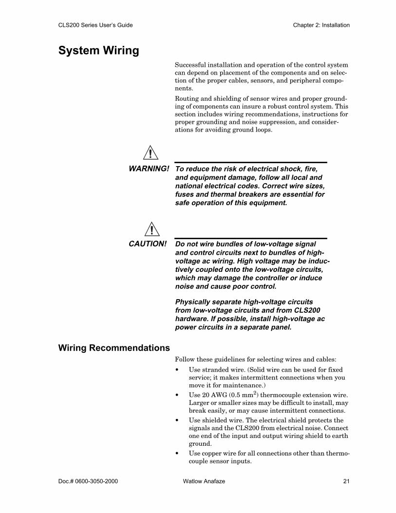
WARNING! To reduce the risk of electrical shock, fire,and equipment damage, follow all local andnational electrical codes. Correct wire sizes,fuses and thermal breakers are essential forsafe operation of this equipment.
CAUTION! Do not wire bundles of low-voltage signaland control circuits next to bundles of high-voltage ac wiring. High voltage may be induc-tively coupled onto the low-voltage circuits,which may damage the controller or inducenoise and cause poor control.
Physically separate high-voltage circuitsfrom low-voltage circuits and from CLS200hardware. If possible, install high-voltage acpower circuits in a separate panel.
Wiring RecommendationsFollow these guidelines for selecting wires and cables:
• Use stranded wire. (Solid wire can be used for fixed service; it makes intermittent connections when you move it for maintenance.)
• Use 20 AWG (0.5 mm2) thermocouple extension wire. Larger or smaller sizes may be difficult to install, may break easily, or may cause intermittent connections.
• Use shielded wire. The electrical shield protects the signals and the CLS200 from electrical noise. Connect one end of the input and output wiring shield to earth ground.
• Use copper wire for all connections other than thermo-couple sensor inputs.

Chapter 2: Installation CLS200 Series User’s Guide
22 Watlow Anafaze Doc.# 0600-3050-2000
Table 2.1 Cable Recommendations
Noise Suppression The CLS200’s outputs are typically used to drive solid state relays. These relays may in turn operate more inductive types of loads such as electromechanical relays, alarm horns and motor starters. Such devices may generate elec-tromagnetic interference (EMI or noise). If the controller is placed close to sources of EMI, it may not function correct-ly. Below are some tips on how to recognize and avoid prob-lems with EMI.
For earth ground wire, use a large gauge and keep the length as short as possible. Additional shielding may be achieved by connecting a chassis ground strap from the panel to CLS200 case.
Symptoms of RFI/EMIIf your controller displays the following symptoms, suspect EMI:
• The controller’s display blanks out and then reenergiz-es as if power had been turned off for a moment.
• The process variable does not display correctly.
EMI may also damage the digital output circuit—so digital outputs will not turn on. If the digital output circuit is dam-aged, return the controller to Watlow Anafaze for repair.
Function Mfr. P/N No. of Wires AWG mm2 Maximum
Length
Analog Inputs Belden 9154Belden 8451
22
2022
0.50.5
RTD Inputs Belden 8772Belden 9770
33
2022
0.50.5
Thermocouple Inputs T/C Ext. Wire 2 20 0.5
Control Outputs andDigital I/O
Belden 9539Belden 9542Ribbon Cable
92050
2424
22 to 14
0.20.2
0.5 to 2.5
Analog Outputs Belden 9154Belden 8451
22
2022
0.50.5
Computer Communica-tion: EIA/TIA-232, 422 or 485, or 20 mA
Belden 9729Belden 9730Belden 9842Belden 9843Belden 9184
46464
2424242422
0.20.20.20.20.5
4,000 ft. (1,219 m)
4,000 ft. (1,219 m)
6,000 ft. (1,829 m)

CLS200 Series User’s Guide Chapter 2: Installation
Doc.# 0600-3050-2000 Watlow Anafaze 23
Avoiding RFI/EMI• To avoid or eliminate most RFI/EMI noise problems:• Connect the CLS200 case to earth ground. The
CLS200 system includes noise suppression circuitry. This circuitry requires proper grounding.
• Separate the 120 or 240VÅ (ac) power leads from the low-level input and output leads connected to the CLS200 series controller. Do not run the digital I/O or control output leads in bundles with ac wires.
• Where possible, use solid-state relays (SSRs) instead of electromechanical relays. If you must use electro-mechanical relays, try to avoid mounting them in the same panel as the CLS200 series equipment.
• If you must use electromechanical relays and you must place them in a panel with CLS200 series equip-ment, use a 0.01 microfarad capacitor rated at 1000VÅ (ac) (or higher) in series with a 47 Ω, 0.5 watt resistor across the N.O. contacts of the relay load. This is known as a snubber network and can reduce the amount of electrical noise.
• You can use other voltage suppression devices, but they are not usually required. For instance, you can place a metal oxide varistor (MOV) rated at 130VÅ for 120VÅ (ac) control circuits across the load, which lim-its the peak ac voltage to about 180VÅ (ac) (Watlow Anafaze part number 26-130210-00). You can also place a transorb (back-to-back zener diodes) across the digital output, which limits the digital output voltage.
Additional Recommendations for a Noise Immune SystemIt is strongly recommended that you:
• Isolate outputs through solid-state relays, where pos-sible.
• Isolate RTDs or “bridge” type inputs from ground.• Isolate digital inputs from ground through solid state
relays. If this is not possible, then make sure the digi-tal input is the only connection to earth ground other than the chassis ground.
• If you are using EIA/TIA-232 from a non-isolated host, either (1) do not connect any other power common point to earth ground, or (2) use an optical isolator in the communications line.
Chapter 2: Installation CLS200 Series User’s Guide
24 Watlow Anafaze Doc.# 0600-3050-2000
Ground LoopsGround loops occur when current passes from the process through the controller to ground. This can cause instru-ment errors or malfunctions.
A ground loop may follow one of these paths, among others:
• From one sensor to another.• From a sensor to the communications port.• From a sensor to the dc power supply.
The best way to avoid ground loops is to minimize unneces-sary connections to ground. Do not connect any of the fol-lowing terminals to each other or to earth ground:
• Power supply dc common • TB1, terminals 5, 6, 11, 12 (analog common)• TB1, terminal 17 (reference voltage common)• TB1, terminals 23, 24 (communications common)• TB2, terminal 2 (dc power common)
Special Precautions for the CLS216The CLS216 has single-ended inputs. All the negative sen-sor leads are tied to the analog common. That means there is no sensor-to-sensor isolation. Proper grounding is critical for this unit. Take these additional precautions with a CLS216:
• Use all ungrounded or all well-grounded thermocou-ples, not a mix.
• If using a mixture of thermocouples or low-voltage in-puts (<500 mV) and current inputs, connect the nega-tive leads of the current transmitters to terminal 17 (Ref Com) on TB1.
• If using voltage transmitters, use only sourcing mod-els or configuration. Sinking configurations will not work.
• Isolate the controller’s communication port (if used) by using an optically isolated 232-to-485 converter.
Personal Computers and Ground LoopsMany PC communications ports connect the communica-tions common to chassis ground. When such a PC is con-nected to the controller, this can provide a path to ground for current from the process that can enter the controller through a sensor (such as a thermocouple). This creates a ground loop that can affect communications and other con-troller functions. To eliminate a ground loop, either use an optically isolated communications adapter or take mea-sures to ensure that sensors and all other connections to the controller are isolated and not conducting current into the unit.

CLS200 Series User’s Guide Chapter 2: Installation
Doc.# 0600-3050-2000 Watlow Anafaze 25
Power ConnectionsThis section covers making the power connections to the CLS200 and connecting the TB50.
Figure 2.12 CLS200 Series Controller with TB18
Figure 2.13 CLS200 Series Controller with TB50
Wiring the Power Supply
WARNING! Use a power supply with a Class 2 ratingonly. UL approval requires a Class 2 powersupply.
Connect power to the controller before any other connec-tions, This allows you to ensure that the controller is work-ing before any time is taken installing inputs and outputs.
TB2(to power supply)
TB1(to signal inputs
TB18(to digital outputs)
SCSI-2 (to TB50)
TB2(to power supply)
TB1(to signal inputs
Chapter 2: Installation CLS200 Series User’s Guide
26 Watlow Anafaze Doc.# 0600-3050-2000
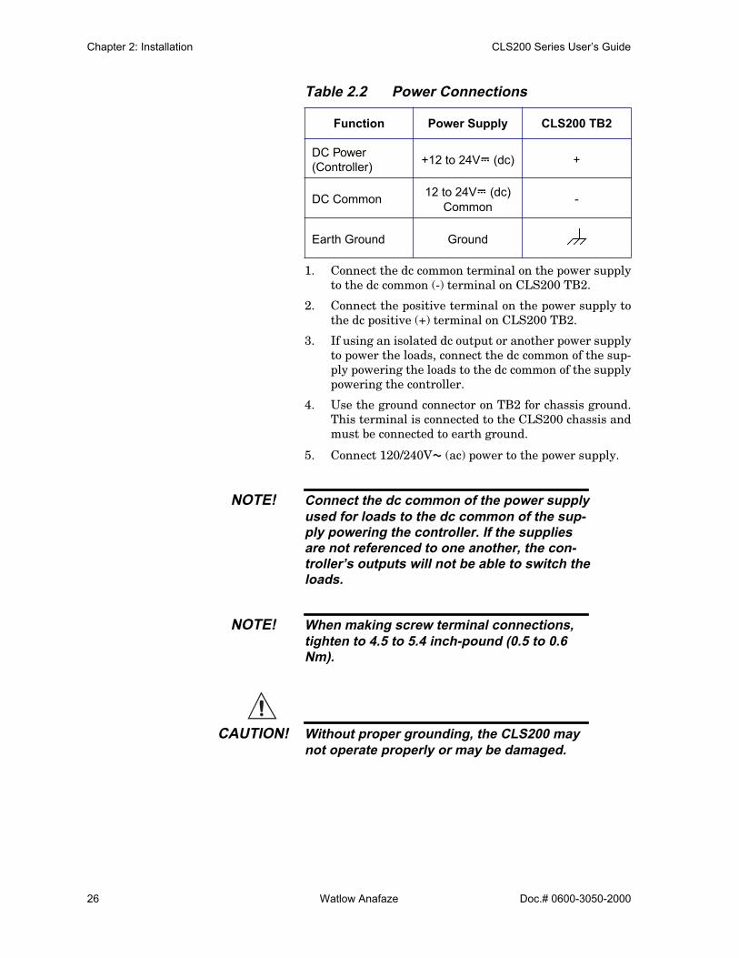
Table 2.2 Power Connections
1. Connect the dc common terminal on the power supplyto the dc common (-) terminal on CLS200 TB2.
2. Connect the positive terminal on the power supply tothe dc positive (+) terminal on CLS200 TB2.
3. If using an isolated dc output or another power supplyto power the loads, connect the dc common of the sup-ply powering the loads to the dc common of the supplypowering the controller.
4. Use the ground connector on TB2 for chassis ground.This terminal is connected to the CLS200 chassis andmust be connected to earth ground.
5. Connect 120/240VÅ (ac) power to the power supply.
NOTE! Connect the dc common of the power supplyused for loads to the dc common of the sup-ply powering the controller. If the suppliesare not referenced to one another, the con-troller’s outputs will not be able to switch theloads.
NOTE! When making screw terminal connections,tighten to 4.5 to 5.4 inch-pound (0.5 to 0.6Nm).
CAUTION! Without proper grounding, the CLS200 maynot operate properly or may be damaged.
Function Power Supply CLS200 TB2
DC Power (Controller) +12 to 24VÎ (dc) +
DC Common 12 to 24VÎ (dc) Common -
Earth Ground Ground
CLS200 Series User’s Guide Chapter 2: Installation
Doc.# 0600-3050-2000 Watlow Anafaze 27
CAUTION! To prevent damage from incorrect connec-tions, do not turn on the ac power before test-ing the connections as explained in TestingYour System on page 28.
NOTE! Do not connect the controller’s dc common(COM) to earth ground . Doing so will de-feat the noise protection circuitry, makingmeasurements less stable.
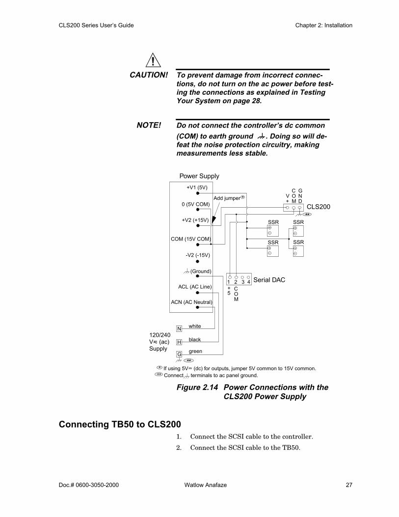
Figure 2.14 Power Connections with the CLS200 Power Supply
Connecting TB50 to CLS2001. Connect the SCSI cable to the controller.
2. Connect the SCSI cable to the TB50.
** Connect terminals to ac panel ground.
SSR
SSR SSR
SSR
GNDAdd jumper *
COM
+5
Serial DAC
CLS200
Power Supply
1 2 3 4
white
black
greenG
H
N120/240
Supply
**
**
* If using 5VÎ (dc) for outputs, jumper 5V common to 15V common.
COM
V+
Vı (ac)
+V1 (5V)
0 (5V COM)
+V2 (+15V)
COM (15V COM)
-V2 (-15V)
ACL (AC Line)
ACN (AC Neutral)
(Ground)

Chapter 2: Installation CLS200 Series User’s Guide
28 Watlow Anafaze Doc.# 0600-3050-2000
Testing Your SystemThis section explains how to test the controller after instal-lation and prior to making field wiring connections.
TB50 or TB18 Test Use this procedure to verify that the TB50 or TB18 is prop-erly connected and supplied with power:
1. Turn on power to the CLS200. The display should readCALCULATING CHECKSUM then show the bar graphdisplay. (See Figure 3.3.) If you do not see these dis-plays, disconnect power and check wiring and powersupply output.
2. Measure the +5VÎ (dc) supply at the TB50 or TB18:
a) Connect the voltmeter’s common lead to TB50 orTB18 terminal 3 or TB18 terminal 2.
b) Connect the voltmeter’s positive lead to TB50 orTB18 screw terminal 1. The voltage should be+4.75 to +5.25VÎ (dc).
Digital Output TestUse this procedure to test the controller’s outputs before loads are connected. If using it at another time for trouble-shooting, disconnect loads from outputs before testing.
1. Connect a 500 Ω to 100 kΩ resistor between TB50 orTB18 screw terminal 1 and a digital output terminal.(See Table 2.5, TB18 Connections on page 40; Table2.6, TB50 Connections for CLS204 and CLS208 onpage 41; or Table 2.7, TB50 Connections for CLS216 onpage 42.)
2. Connect the voltmeter’s positive lead to screw terminal 1.
3. Connect the common lead to the digital output terminal.
4. Use the digital output test in the MANUAL I/O TESTmenu to turn the digital output on and off. (See TestDigital Output on page 104 and Digital Output Num-ber on page 104.) When the output is ON, the outputvoltage should be less than 1V. When the output isOFF, the output voltage should be between 4.75 and5.25V.
NOTE! By default, heat outputs are enabled. Onlydisabled outputs may be turned on using themanual I/O test. To test heat outputs, set thecorresponding loop to manual mode 100%output. See Selecting the Control Status onpage 61.
CLS200 Series User’s Guide Chapter 2: Installation
Doc.# 0600-3050-2000 Watlow Anafaze 29
Digital Input TestUse the following procedure to test digital inputs before connecting to field devices:
1. Disconnect any system wiring from the input to betested.
2. Go to the DIGITAL INPUTS test in the MANUAL I/OTEST menu. (See Digital Inputs on page 103.) This testshows whether the digital inputs are H (high, or open)or L (low, or closed).
3. Attach a wire to the terminal of the digital input youwant to test. See tables 2.5 to 2.7 on pages 40 to 42 forconnections.
a) When the wire is connected only to the digital in-put terminal, the digital input test should showthat the input is H (high, or open).
b) When you connect the other end of the wire to thecontroller common (TB50 terminal 3 or TB18 ter-minal 2), the digital input test should show thatthe input is L (low, or closed).
Sensor WiringThis section describes how to properly connect thermocou-ples, RTDs, current and voltage inputs to your controller. The controller can accept any mix of available input types. Some input types require that special scaling resistors be installed (generally done by Watlow Anafaze before the controller is delivered).
All inputs are installed at the CH input connectors (TB1) at the back of the controller. The illustrations below show the connector locations for all the CLS200 series controllers.
CAUTION! Never run input leads in bundles with highpower wires or near other sources of EMI.This could inductively couple voltage ontothe input leads and damage the controller, orcould induce noise and cause poor measure-ment and control.

Chapter 2: Installation CLS200 Series User’s Guide
30 Watlow Anafaze Doc.# 0600-3050-2000
Figure 2.15 CLS200 Connector Locations
Input Wiring Recommendations Use multicolored stranded shielded cable for analog inputs. Watlow Anafaze recommends that you use 20 AWG wire (0.5 mm2). If the sensor manufacturer requires it, you can also use 24 or 22 AWG wiring (0.2 mm2). Most inputs use a shielded twisted pair; some require a 3-wire input.
Follow the instructions pertaining to the type(s) of input(s) you are installing.
The controller accepts the following inputs without any special scaling resistors:
• J, K, T, S, R, B and E thermocouples.• Linear inputs with ranges between -10 and 60 mV.
Any unused inputs should be set to SKIP or jumpered to avoid thermocouple break alarms.
CLS200 Series User’s Guide Chapter 2: Installation
Doc.# 0600-3050-2000 Watlow Anafaze 31
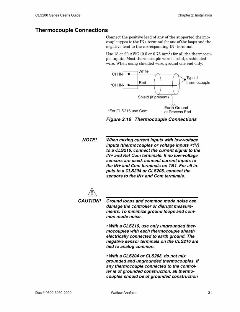
Thermocouple ConnectionsConnect the positive lead of any of the supported thermo-couple types to the IN+ terminal for one of the loops and the negative lead to the corresponding IN- terminal.
Use 18 or 20 AWG (0.5 or 0.75 mm2) for all the thermocou-ple inputs. Most thermocouple wire is solid, unshielded wire. When using shielded wire, ground one end only.
Figure 2.16 Thermocouple Connections
NOTE! When mixing current inputs with low-voltageinputs (thermocouples or voltage inputs <1V)to a CLS216, connect the current signal to theIN+ and Ref Com terminals. If no low-voltagesensors are used, connect current inputs tothe IN+ and Com terminals on TB1. For all in-puts to a CLS204 or CLS208, connect thesensors to the IN+ and Com terminals.
CAUTION! Ground loops and common mode noise candamage the controller or disrupt measure-ments. To minimize ground loops and com-mon mode noise:
• With a CLS216, use only ungrounded ther-mocouples with each thermocouple sheathelectrically connected to earth ground. Thenegative sensor terminals on the CLS216 aretied to analog common.
• With a CLS204 or CLS208, do not mixgrounded and ungrounded thermocouples. Ifany thermocouple connected to the control-ler is of grounded construction, all thermo-couples should be of grounded construction
White
Red
CH IN+
*CH IN-
Shield (if present)
Earth Groundat Process End*For CLS216 use Com
Type J thermocouple

Chapter 2: Installation CLS200 Series User’s Guide
32 Watlow Anafaze Doc.# 0600-3050-2000
and each should be connected to ground atthe process end.
• Connect the earth ground terminal on TB2to a good earth ground, but do not connectthe analog common to earth ground. TheCLS200 uses a floating analog common forsensor measurements. The noise protectioncircuits on the sensor inputs function cor-rectly only when the controller is correctly in-stalled. See Ground Loops on page 24.
RTD Input ConnectionsThis input type requires scaling resistors. Watlow Anafaze recommends that you use a 100 Ω, 3-wire platinum RTD to prevent reading errors due to cable resistance. If you use a 2-wire RTD, jumper the negative input to common. If you must use a 4-wire RTD, leave the fourth wire unconnected.
Figure 2.17 RTD Connections to CLS204 or CLS208
Reference Voltage TerminalsThe +5V Ref and Ref Com terminals are provided in order to power external bridge circuits for special sensors. Do not connect any other types of devices to these terminals.
Voltage Input ConnectionsThis input type requires scaling resistors. Special input re-sistors installed at Watlow Anafaze divide analog input voltages such that the controller sees a -10 to 60 mV signal on the loop.
100 Ω RTD
IN +
IN -Com
CH
CH
CLS200 Series User’s Guide Chapter 2: Installation
Doc.# 0600-3050-2000 Watlow Anafaze 33
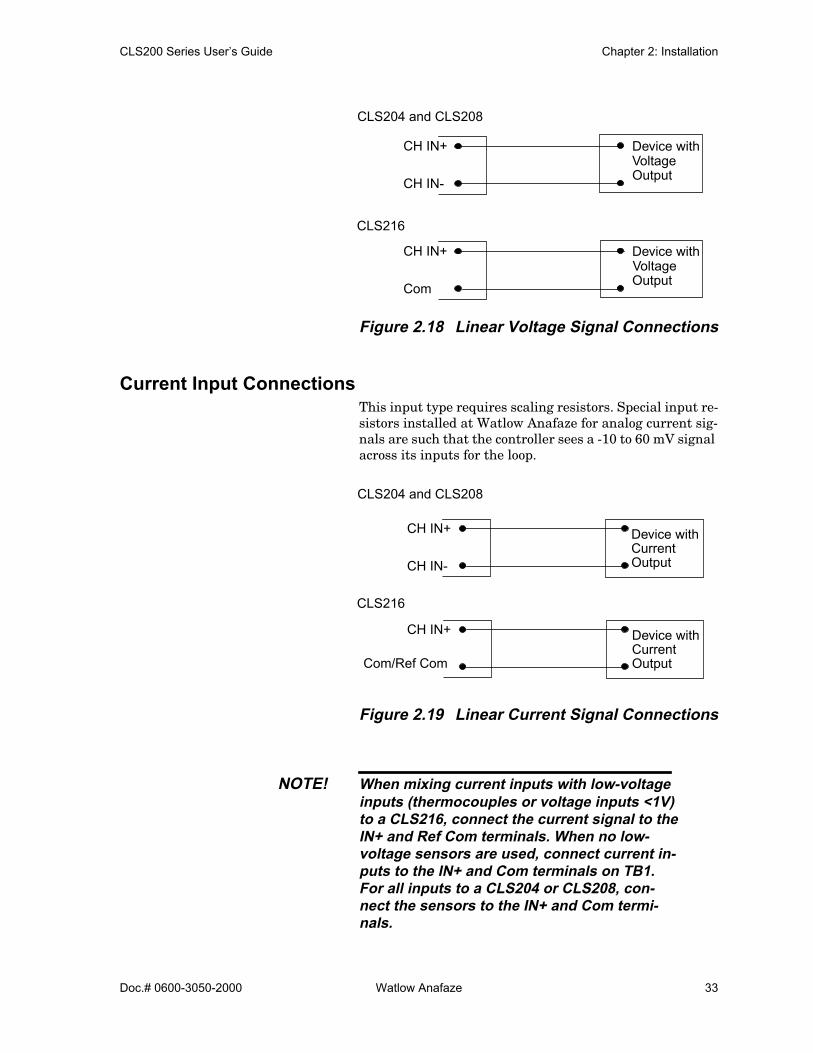
Figure 2.18 Linear Voltage Signal Connections
Current Input ConnectionsThis input type requires scaling resistors. Special input re-sistors installed at Watlow Anafaze for analog current sig-nals are such that the controller sees a -10 to 60 mV signal across its inputs for the loop.
Figure 2.19 Linear Current Signal Connections
NOTE! When mixing current inputs with low-voltageinputs (thermocouples or voltage inputs <1V)to a CLS216, connect the current signal to theIN+ and Ref Com terminals. When no low-voltage sensors are used, connect current in-puts to the IN+ and Com terminals on TB1.For all inputs to a CLS204 or CLS208, con-nect the sensors to the IN+ and Com termi-nals.
CH IN+
CH IN-
Device with
OutputVoltage
CH IN+
Com
Device with
OutputVoltage
CLS216
CLS204 and CLS208
CH IN+
CH IN-
Device withCurrentOutput
CH IN+
Com/Ref Com
Device withCurrentOutput
CLS216
CLS204 and CLS208
Chapter 2: Installation CLS200 Series User’s Guide
34 Watlow Anafaze Doc.# 0600-3050-2000
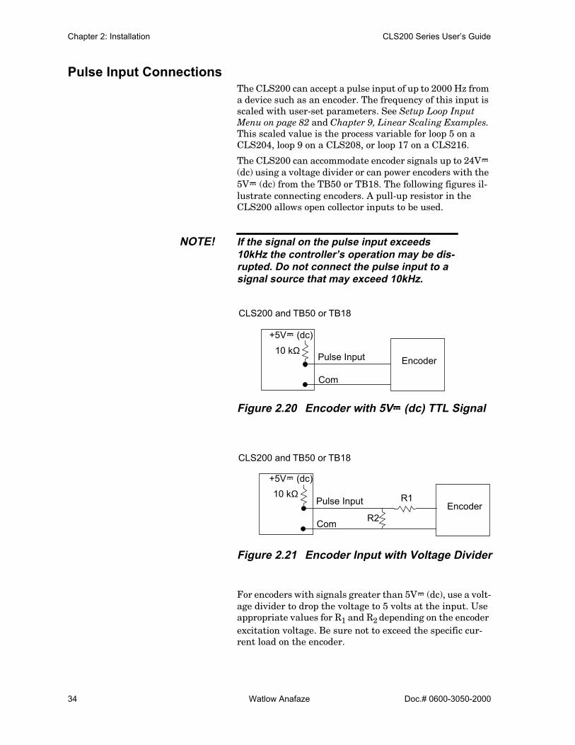
Pulse Input ConnectionsThe CLS200 can accept a pulse input of up to 2000 Hz from a device such as an encoder. The frequency of this input is scaled with user-set parameters. See Setup Loop Input Menu on page 82 and Chapter 9, Linear Scaling Examples. This scaled value is the process variable for loop 5 on a CLS204, loop 9 on a CLS208, or loop 17 on a CLS216.
The CLS200 can accommodate encoder signals up to 24VÎ (dc) using a voltage divider or can power encoders with the 5VÎ (dc) from the TB50 or TB18. The following figures il-lustrate connecting encoders. A pull-up resistor in the CLS200 allows open collector inputs to be used.
NOTE! If the signal on the pulse input exceeds10kHz the controller’s operation may be dis-rupted. Do not connect the pulse input to asignal source that may exceed 10kHz.
Figure 2.20 Encoder with 5VÎÎÎÎ (dc) TTL Signal
Figure 2.21 Encoder Input with Voltage Divider
For encoders with signals greater than 5VÎ (dc), use a volt-age divider to drop the voltage to 5 volts at the input. Use appropriate values for R1 and R2 depending on the encoder excitation voltage. Be sure not to exceed the specific cur-rent load on the encoder.
Pulse Input
Com
Encoder
+5VÎ (dc)10 kΩ
CLS200 and TB50 or TB18
Pulse Input
Com
Encoder
+5VÎ (dc)10 kΩ
R2
R1
CLS200 and TB50 or TB18
CLS200 Series User’s Guide Chapter 2: Installation
Doc.# 0600-3050-2000 Watlow Anafaze 35
Wiring Control and Digital I/OThis section describes how to wire and configure the control outputs for the CLS200 series controller.
NOTE! Control outputs are connected to theCLS200’s common when the control outputis on (low). Be careful when you connect ex-ternal devices that may have a low side at avoltage other than controller ground, sinceyou may create ground loops.
If you expect grounding problems, use isolat-ed solid state relays and isolate the controldevice inputs.
The CLS200 provides dual PID control outputs for each loop. These outputs can be enabled or disabled, and are connected via TB50 or TB18.
Output Wiring RecommendationsWhen wiring output devices, use multicolored, stranded, shielded cable for analog outputs and digital outputs con-nected to panel-mounted solid state relays.
• Analog outputs usually use a twisted pair. • Digital outputs usually have 9 to 20 conductors, de-
pending on wiring technique.
Cable Tie Wraps Once you have wired outputs to the TB50, install the cable tie wraps to reduce strain on the connectors.
Each row of terminals has a cable tie wrap hole at one end. Thread the cable tie wrap through the cable tie wrap hole. Then wrap the cable tie wrap around the wires attached to that terminal block.
Digital OutputsThe CLS200 series provides dual control outputs for up to 16 loops. The controller’s default configuration has all heat outputs enabled and all cool outputs disabled. Disabling a heat output makes that output available to be used as a control or an alarm output. See Enable or Disable Heat or Cool Outputs on page 94. The CPU watchdog timer output can be used to monitor the state of the controller with an external circuit or device. See CPU Watchdog Timer on page 38.

Chapter 2: Installation CLS200 Series User’s Guide
36 Watlow Anafaze Doc.# 0600-3050-2000
Table 2.3 Digital Output States and Values Stored in the Controller
The digital outputs sink current from the load to the con-troller common. The load may powered by the 5VÎ (dc) supplied by the controller at the TB50. Alternately, an ex-ternal power supply may be used to drive loads.
Keep in mind the following points when using an external power supply:
• The CLS200 power supply available from Watlow Anafaze includes a 5VÎ (dc) supply. When using it to supply output loads, connect the 5VÎ (dc) common to the 15VÎ (dc) common at the power supply.
• Do not exceed +24 volts. • If you tie the external load to earth ground, or if you
cannot connect it as shown in (See Figure 2.22), then use a solid-state relay.
All digital outputs are sink outputs referenced to the CLS200 series controller common supply. These outputs are low (pulled to common) when they are on.
The outputs conduct current when they are low or on. The maximum current sink capability is 60 mA at 24VÎ (dc). They cannot “source” current to a load.
Figure 2.22 Digital Output Wiring
State Value Description
Off High Open circuit
On Low Sinking current to common
Digital Output 1Digital Output 2
Control Common
+5VÎ (dc)
Loads
Digital Output 1Digital Output 2
Using External Power Supply
Do not connect
External Power
+-
TB50 or TB18
Using Internal Power Supply
Loads
Supply
TB50 or TB18
to earth ground orequipment ground
CLS200 Series User’s Guide Chapter 2: Installation
Doc.# 0600-3050-2000 Watlow Anafaze 37
Configuring OutputsKeep in mind the following points as you choose outputs for control and alarms:
• You can enable or disable the control outputs. The de-fault setting is heat outputs enabled, cool outputs dis-abled.
• You can program each control output individually for on/off, time proportioning, distributed zero crossing, or Serial DAC control.
• You can individually program each control output for direct or reverse action.
• Alarm outputs other than the global alarm are non-latching.
• Alarms can be suppressed during process start up and for preprogrammed durations. See Alarm Delay on page 103.
• Alarm outputs can be configured as a group as normal-ly on (low) or normally off (high). See Digital Output Polarity on Alarm on page 81.
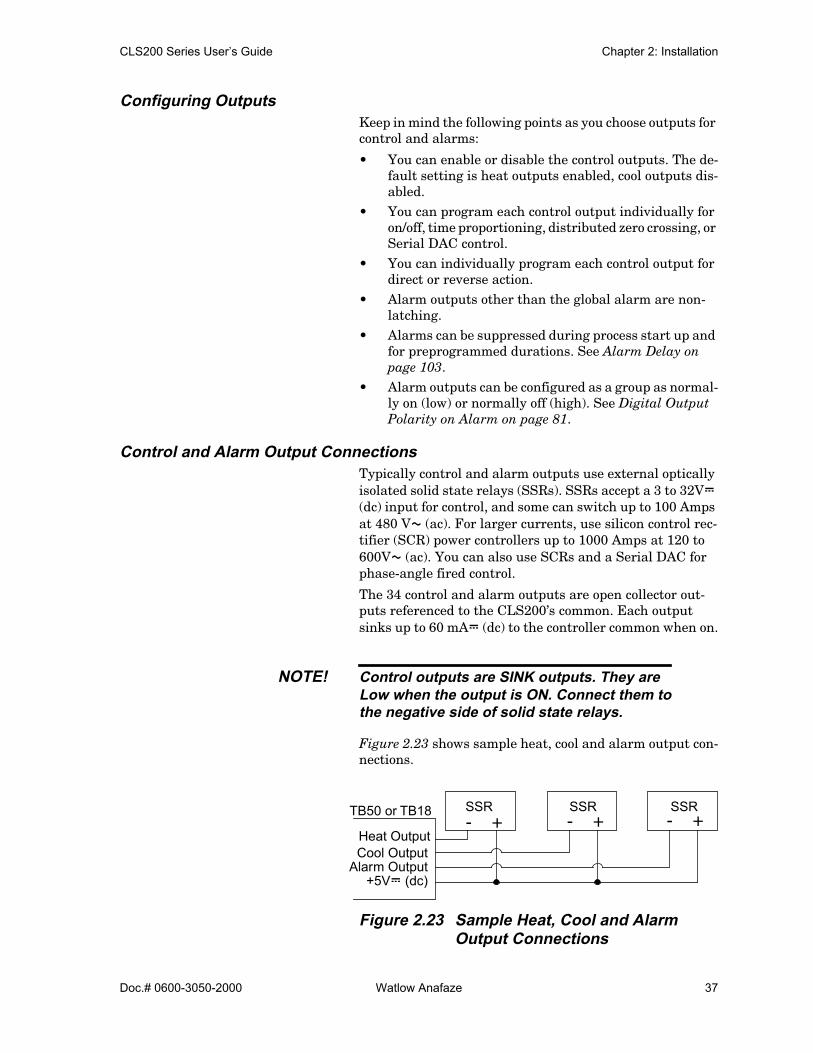
Control and Alarm Output ConnectionsTypically control and alarm outputs use external optically isolated solid state relays (SSRs). SSRs accept a 3 to 32VÎ (dc) input for control, and some can switch up to 100 Amps at 480 VÅ (ac). For larger currents, use silicon control rec-tifier (SCR) power controllers up to 1000 Amps at 120 to 600VÅ (ac). You can also use SCRs and a Serial DAC for phase-angle fired control.
The 34 control and alarm outputs are open collector out-puts referenced to the CLS200’s common. Each output sinks up to 60 mAÎ (dc) to the controller common when on.
NOTE! Control outputs are SINK outputs. They areLow when the output is ON. Connect them tothe negative side of solid state relays.
Figure 2.23 shows sample heat, cool and alarm output con-nections.
Figure 2.23 Sample Heat, Cool and AlarmOutput Connections
Cool OutputAlarm Output
+5VÎ (dc)
+- +- +-SSR SSR SSRTB50 or TB18
Heat Output

Chapter 2: Installation CLS200 Series User’s Guide
38 Watlow Anafaze Doc.# 0600-3050-2000
Figure 2.24 Output Connections UsingExternal Power Supply
CPU Watchdog TimerThe CPU watchdog timer constantly monitors the micro-processor. It is a sink output located on TB50 terminal 6 or TB18 terminal 3. The output can be connected to an exter-nal circuit or device in order to determine if the controller is powered and operational. Do not exceed 5VÎ (dc), 10 mAÎ (dc) rating for the watchdog output. The output is low (on) when the microprocessor is operating; when it stops operating, the output goes high (off).
Figure 2.25 and Figure 2.26 show the recommended circuit for the watchdog timer output for the TB50 and the TB18.
Figure 2.25 TB50 Watchdog Timer Output
Figure 2.26 TB18 Watchdog Timer Output
Digital InputsAll digital inputs are transistor-transistor logic (TTL) level inputs referenced to control common and the internal +5V power supply of the CLS200.
When an input is connected to the controller common, the input is considered on. Otherwise, the input is considered
Heat OutputCool Output
Alarm OutputCommon
+-SSRTB50 or TB18
- PS +
+-SSR
+-SSR
SSR+ 5VÎ (dc)
Watchdog Timer (Terminal 1)
(Terminal 6)
TB50
+
-
SSR+ 5VÎ (dc)
Watchdog Timer
(Terminal 1)
(Terminal 3)
TB18
+
-

CLS200 Series User’s Guide Chapter 2: Installation
Doc.# 0600-3050-2000 Watlow Anafaze 39
off. Most features that use the digital inputs can be user-configured to activate when an input is either on or off.
In the off state, internal 10 k resistors pull the digital in-puts high to 5VÎ (dc) with respect to the controller com-mon.
Table 2.4 Digital Inputs States and Values Stored in the Controller
External Switching DevicesTo ensure that the inputs are reliably switched, use a switching device with the appropriate impedances in the on and off states and do not connect the inputs to external power sources.
When off, the swiching device must provide an impedance of at least 11 kΩ to ensure that the voltage will rise to greater than 3.7VÎ (dc). When on, the switch must provide not more than 1 kΩ impedance to ensure the voltage drops below 1.3VÎ (dc).
To install a switch as a digital input, connect one lead to the common terminal on the TB50 (terminals 3 and 4) or TB18 (terminal 2). Connect the other lead to the desired digital input terminal on the TB50 (terminals 43 to 50) or TB18 (terminals 16 to 18).
Functions Activated by Digital InputsUse digital inputs to activate the following functions:
• Load a job that is stored in controller memory. See Job Select Digital Inputs on page 76.
• Change all loops to manual mode at specified output levels. See Output Override Digital Input on page 77.
• Enable thermocouple short detection. See Process Power Digital Input on page 79.
• Restore control automatically after a failed sensor has been repaired. See Restore PID Digital Input on page 92.
Figure 2.27 Wiring Digital Inputs
State Value Description
Off High Open circuit
On Low Digital Input connected to controller common
External SwitchingDevice
TB50 Input
Control Com
Chapter 2: Installation CLS200 Series User’s Guide
40 Watlow Anafaze Doc.# 0600-3050-2000
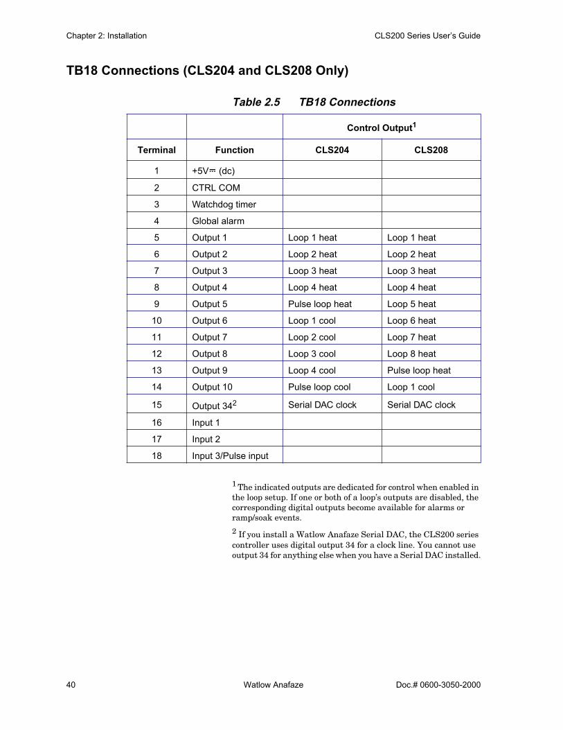
TB18 Connections (CLS204 and CLS208 Only)
Table 2.5 TB18 Connections
1 The indicated outputs are dedicated for control when enabled in the loop setup. If one or both of a loop’s outputs are disabled, the corresponding digital outputs become available for alarms or ramp/soak events.
2 If you install a Watlow Anafaze Serial DAC, the CLS200 series controller uses digital output 34 for a clock line. You cannot use output 34 for anything else when you have a Serial DAC installed.
Control Output1
Terminal Function CLS204 CLS208
1 +5VÎ (dc)
2 CTRL COM
3 Watchdog timer
4 Global alarm
5 Output 1 Loop 1 heat Loop 1 heat
6 Output 2 Loop 2 heat Loop 2 heat
7 Output 3 Loop 3 heat Loop 3 heat
8 Output 4 Loop 4 heat Loop 4 heat
9 Output 5 Pulse loop heat Loop 5 heat
10 Output 6 Loop 1 cool Loop 6 heat
11 Output 7 Loop 2 cool Loop 7 heat
12 Output 8 Loop 3 cool Loop 8 heat
13 Output 9 Loop 4 cool Pulse loop heat
14 Output 10 Pulse loop cool Loop 1 cool
15 Output 342 Serial DAC clock Serial DAC clock
16 Input 1
17 Input 2
18 Input 3/Pulse input
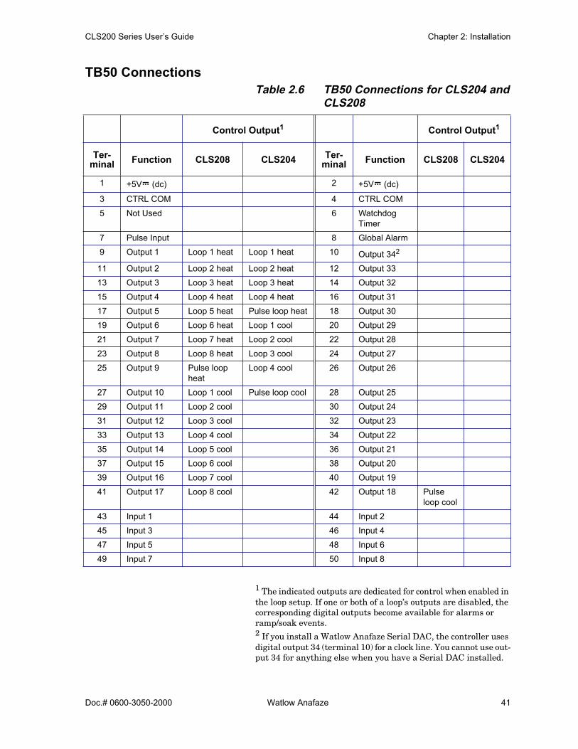
CLS200 Series User’s Guide Chapter 2: Installation
Doc.# 0600-3050-2000 Watlow Anafaze 41
TB50 ConnectionsTable 2.6 TB50 Connections for CLS204 and
CLS208
1 The indicated outputs are dedicated for control when enabled in the loop setup. If one or both of a loop’s outputs are disabled, the corresponding digital outputs become available for alarms or ramp/soak events.2 If you install a Watlow Anafaze Serial DAC, the controller uses digital output 34 (terminal 10) for a clock line. You cannot use out-put 34 for anything else when you have a Serial DAC installed.
Control Output1 Control Output1
Ter-minal Function CLS208 CLS204 Ter-
minal Function CLS208 CLS204
1 +5VÎ (dc) 2 +5VÎ (dc)
3 CTRL COM 4 CTRL COM
5 Not Used 6 Watchdog Timer
7 Pulse Input 8 Global Alarm
9 Output 1 Loop 1 heat Loop 1 heat 10 Output 342
11 Output 2 Loop 2 heat Loop 2 heat 12 Output 33
13 Output 3 Loop 3 heat Loop 3 heat 14 Output 32
15 Output 4 Loop 4 heat Loop 4 heat 16 Output 31
17 Output 5 Loop 5 heat Pulse loop heat 18 Output 30
19 Output 6 Loop 6 heat Loop 1 cool 20 Output 29
21 Output 7 Loop 7 heat Loop 2 cool 22 Output 28
23 Output 8 Loop 8 heat Loop 3 cool 24 Output 27
25 Output 9 Pulse loop heat
Loop 4 cool 26 Output 26
27 Output 10 Loop 1 cool Pulse loop cool 28 Output 25
29 Output 11 Loop 2 cool 30 Output 24
31 Output 12 Loop 3 cool 32 Output 23
33 Output 13 Loop 4 cool 34 Output 22
35 Output 14 Loop 5 cool 36 Output 21
37 Output 15 Loop 6 cool 38 Output 20
39 Output 16 Loop 7 cool 40 Output 19
41 Output 17 Loop 8 cool 42 Output 18 Pulse loop cool
43 Input 1 44 Input 2
45 Input 3 46 Input 4
47 Input 5 48 Input 6
49 Input 7 50 Input 8
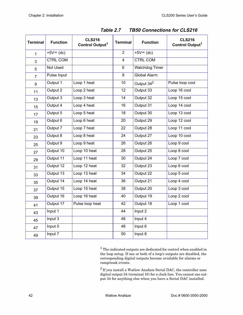
Chapter 2: Installation CLS200 Series User’s Guide
42 Watlow Anafaze Doc.# 0600-3050-2000
Table 2.7 TB50 Connections for CLS216
1 The indicated outputs are dedicated for control when enabled in the loop setup. If one or both of a loop’s outputs are disabled, the corresponding digital outputs become available for alarms or ramp/soak events.
2 If you install a Watlow Anafaze Serial DAC, the controller uses digital output 34 (terminal 10) for a clock line. You cannot use out-put 34 for anything else when you have a Serial DAC installed.
Terminal Function CLS216 Control Output1 Terminal Function CLS216
Control Output1
1 +5VÎ (dc) 2 +5VÎ (dc)
3 CTRL COM 4 CTRL COM
5 Not Used 6 Watchdog Timer
7 Pulse Input 8 Global Alarm
9 Output 1 Loop 1 heat 10 Output 342 Pulse loop cool
11 Output 2 Loop 2 heat 12 Output 33 Loop 16 cool
13 Output 3 Loop 3 heat 14 Output 32 Loop 15 cool
15 Output 4 Loop 4 heat 16 Output 31 Loop 14 cool
17 Output 5 Loop 5 heat 18 Output 30 Loop 13 cool
19 Output 6 Loop 6 heat 20 Output 29 Loop 12 cool
21 Output 7 Loop 7 heat 22 Output 28 Loop 11 cool
23 Output 8 Loop 8 heat 24 Output 27 Loop 10 cool
25 Output 9 Loop 9 heat 26 Output 26 Loop 9 cool
27 Output 10 Loop 10 heat 28 Output 25 Loop 8 cool
29 Output 11 Loop 11 heat 30 Output 24 Loop 7 cool
31 Output 12 Loop 12 heat 32 Output 23 Loop 6 cool
33 Output 13 Loop 13 heat 34 Output 22 Loop 5 cool
35 Output 14 Loop 14 heat 36 Output 21 Loop 4 cool
37 Output 15 Loop 15 heat 38 Output 20 Loop 3 cool
39 Output 16 Loop 16 heat 40 Output 19 Loop 2 cool
41 Output 17 Pulse loop heat 42 Output 18 Loop 1 cool
43 Input 1 44 Input 2
45 Input 3 46 Input 4
47 Input 5 48 Input 6
49 Input 7 50 Input 8

CLS200 Series User’s Guide Chapter 2: Installation
Doc.# 0600-3050-2000 Watlow Anafaze 43
Analog OutputsAnalog outputs can be provided by using a Dual DAC or Se-rial DAC module to convert the open collector outputs from the controller. Use multicolored stranded shielded cable for analog outputs. Analog outputs generally use a twisted pair wiring. The following sections describe how to connect the Dual DAC and Serial DAC modules to power the con-troller outputs and the load.
Wiring the Dual DACA Dual DAC module includes two identical circuits. Each can convert a distributed zero-cross (DZC) signal from the controller to a voltage or current signal. Watlow Anafaze strongly recommends using a power supply separate from the controller supply to power the Dual DAC. Using a sep-arate power supply isolates the controller’s digital logic cir-cuits and analog measurement circuits from the frequently noisy devices that take the analog signal from the Dual DAC.
Several Dual DAC modules may be powered by one power supply. Consult the Specifications chapter for the Dual DAC’s power requirements. Also note in the specifications that the Dual DAC does not carry the same industry ap-provals as the Serial DAC.
Figure 2.28 Dual DAC with Current Output
TB50 or TB18
+5VÎ (dc)
Control Output
+5V CTRL Supply1
2
3
4
5
6
DZC CTRL PID Output
+12/24VÎ (dc) External Power Supply+VÎ (dc) Load Connection
-mAÎ (dc) Load Connection
-External Power Supply/ VÎ (dc) Load Connection
Dual DAC
mA Load
12 to 24VÎ (dc) Power Supply
+
-
+ -

Chapter 2: Installation CLS200 Series User’s Guide
44 Watlow Anafaze Doc.# 0600-3050-2000
Figure 2.29 Dual DAC with Voltage Output
Wiring the Serial DACThe Serial DAC provides a robust analog output signal. The module converts the proprietary Serial DAC signal from the controller’s open collector output in conjunction with the clock signal to an analog current or voltage. See Figure 2.30 for wiring. The Serial DAC is user-configurable for voltage or current output through firmware configura-tion. See Configuring Serial DAC Outputs on page 188.
The Serial DAC optically isolates the controller’s control output from the load. When a single Serial DAC is used, it may be powered by the 5VÎ (dc) found on the TB50, or by an external supply referenced to the controller's power sup-ply. When using multiple Serial DACs, the controller can-not provide sufficient current; use the 5VÎ (dc) output from the CLS200 power supply
TB50 or TB18
PID Loop Output
Dual DAC
VÎ (dc) Load
+ -
+5VÎ (dc) 1
+5VÎ (dc) CTRL 1
2
3
4
5
6
DZC CTRL PID Output
+12/24VÎ (dc) Exter-nal Power Supply+VÎ (dc) Load Conn.
-mAÎ (dc) Load Conn.
-External Power Supply/ VÎ (dc) Load Conn.
+ -
12 to 24VÎ (dc) Power Supply

CLS200 Series User’s Guide Chapter 2: Installation
Doc.# 0600-3050-2000 Watlow Anafaze 45
Figure 2.30 Single/Multiple Serial DACs
Serial CommunicationsThe CLS200 series controllers are factory-configured for EIA/TIA-232 communications unless otherwise specified when purchased. However, the communications are jump-er-selectable, so you can switch between EIA/TIA-232 and EIA/TIA-485. See Changing Communications on page 179.
EIA/TIA-232 InterfaceEIA/TIA-232 provides communication to the serial port of an IBM PC or compatible computer. It is used for single-controller installations where the cable length does not ex-ceed 50 feet (15.2 m).
The EIA/TIA-232 interface is a standard three-wire inter-face. See the table below for connection information.
If you are using EIA/TIA-232 communications with grounded thermocouples, use an optical isolator between the controller and the computer to prevent ground loops.
Table 2.8 shows EIA/TIA-232 connections for 25-pin and 9-pin connectors or cables that are supplied by the factory.
EIA/TIA-232 may be used to connect a computer through a 232/485 converter, to an EIA/TIA-485 communications net-work with up to 32 CLS200 controllers.
Daisy chain up to 16 Serial DACs
TB50 or TB18
+5V In1
2
3
4
5
6
COM In
CLK In
Data In
+ Out
- Out
Serial DAC
Load
Serial DAC Clock
-+
Control Output
+5V
5V Common
15V Common
ControllerPower Supply

Chapter 2: Installation CLS200 Series User’s Guide
46 Watlow Anafaze Doc.# 0600-3050-2000
Table 2.8 EIA/TIA-232 Connections
Jumpers in EIA/TIA-232 ConnectorsSome software programs and some operator interface ter-minals require a Clear to Send (CTS) signal in response to their Request to Send (RTS) signal, or a Data Set Ready (DSR) in response to their Data Terminal Ready (DTR). The CLS200 is not configured to receive or transmit these signals. To use such software with the CLS200, jumper the RTS to the CTS and the DTR to the DSR in the DB connec-tor. Table 2.9 lists the standard pin assignments for DB-9 and DB-25 connectors.
Table 2.9 RTS/CTS Pins in DB-9 and DB-25 Connectors
Cables manufactured by Watlow Anafaze for EIA/TIA-232 communications include these jumpers. Neither AnaWin nor Anasoft software requires these jumpers.
Figure 2.31 Connecting One CLS200 to a Com-puter Using EIA/TIA-232
Wire Color
CLS200 TB1
DB 9 Connector
DB 25 Connector
White TX Pin 26 RX Pin 2 RX Pin 3
Red RX Pin 25 TX Pin 3 TX Pin 2
Black GND Pin 23 GND Pin 5 GND Pin 7
Green GND Pin 24 N/U Pin 9 N/U Pin 22
Shield N/C GND Pin 5 GND Pin 7
DB-9 DB-25
RTS 7 4CTS 8 5DTR 4 20DSR 6 6
WATLOW ANAFAZE CLS200
WATLOW ANAFAZE CLS200
LOOPLOOP
PROCESS
PROCESS
UNITSUNITS
ALARM
ALARM
SETPOINT
SETPOINT
STATUS
STATUS
OUT%OUT%
MAN
AUTO MAN
AUTO
CHNG
SP CHNG
SP
ALARM
ACK ALARM
ACK
RAMP
SOAK RAMP
SOAK
YES YES
NO NO
BACK BACK
ENTER ENTER
EIA/TIA-232cable
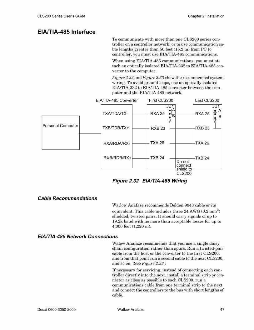
CLS200 Series User’s Guide Chapter 2: Installation
Doc.# 0600-3050-2000 Watlow Anafaze 47
EIA/TIA-485 InterfaceTo communicate with more than one CLS200 series con-troller on a controller network, or to use communication ca-ble lengths greater than 50 feet (15.2 m) from PC to controller, you must use EIA/TIA-485 communications.
When using EIA/TIA-485 communications, you must at-tach an optically isolated EIA/TIA-232 to EIA/TIA-485 con-verter to the computer.
Figure 2.32 and Figure 2.33 show the recommended system wiring. To avoid ground loops, use an optically isolated EIA/TIA-232 to EIA/TIA-485 converter between the com-puter and the EIA/TIA-485 network.
Figure 2.32 EIA/TIA-485 Wiring
Cable RecommendationsWatlow Anafaze recommends Belden 9843 cable or its equivalent. This cable includes three 24 AWG (0.2 mm2) shielded, twisted pairs. It should carry signals of up to 19.2k baud with no more than acceptable losses for up to 4,000 feet (1,220 m).
EIA/TIA-485 Network ConnectionsWalow Anafaze recommends that you use a single daisy chain configuration rather than spurs. Run a twisted-pair cable from the host or the converter to the first CLS200, and from that point run a second cable to the next CLS200, and so on. (See Figure 2.33.)
If necessary for servicing, instead of connecting each con-troller directly into the next, install a terminal strip or con-nector as close as possible to each CLS200, run a communications cable from one terminal strip to the next and connect the controllers to the bus with short lengths of cable.
EIA/TIA-485 Converter
TXA/TDA/TX-
TXB/TDB/TX+
RXA/RDA/RX-
RXB/RDB/RX+
RXA 25
RXB 23
TXA 26
TXB 24
RXA 25
RXB 23
TXA 26
TXB 24Do not
AB
AB
connectshield toCLS200
First CLS200 Last CLS200JU1 JU1
Personal Computer

Chapter 2: Installation CLS200 Series User’s Guide
48 Watlow Anafaze Doc.# 0600-3050-2000
To avoid unacceptable interference, use less than 10 feet(3 m) of cable from the terminal or connector to the CLS200 serial port.
Some systems may experience problems with sensor signal reading if the commons of multiple controllers are connect-ed. See Signal Common on page 48.
Refer to Termination on page 48 for more on terminating resistors.
Connect the shield drain to earth ground only at computer or host end.
.
Figure 2.33 Recommended SystemConnections
Signal CommonFor usual installations, do not connect the dc commons of the controllers together or to the converter or host device. Use an optically isolating EIA/TIA-232-to-485 converter to prevent problems with sensor readings.
TerminationIn order for EIA/TIA-485 signals to be transmitted proper-ly, each pair must be properly terminated. The value of the termination resistor should be equal to the impedance of the communications cable used. Values are typically 150 to 200 Ω.
The receive lines at the converter or host device should be terminated in the converter, the connector to the host de-vice or the device itself. Typically the converter documenta-tion provides instructions for termination.
Use a terminating resistor on the receive lines on the last controller on the 485 line. Set JU1 inside the CLS200 in po-sition B to connect a 200 Ω resistor across the receive lines. Refer to Changing Communications on page 179.
WATLOW ANAFA
ZE CLS200
WATLOW ANAFAZE CLS200
LOOPLOOP
PROCESS
PROCESS
UNITSUNITS
ALARM
ALARM
SETPOINT
SETPOINT
STATUS
STATUS
OUT%OUT%
MAN
AUTO MAN
AUTO
CHNG
SP CHNG
SP
ALARM
ACK ALARM
ACK
RAMP
SOAK RAMP
SOAK
YES YES
NO NO
BACK BACK
ENTER ENTER
WATLOW ANAFAZE CLS200
WATLOW ANAFAZE CLS200
LOOPLOOP
PROCESS
PROCESS
UNITSUNITS
ALARM
ALARM
SETPOINT
SETPOINT
STATUS
STATUS
OUT%OUT%
MAN
AUTO MAN
AUTO
CHNG
SP CHNG
SP
ALARM
ACK ALARM
ACK
RAMP
SOAK RAMP
SOAK
YES
NO
BACK BACK
ENTER ENTER
Serial Port
232 Communications 485 Communications
Shielded Twisted Pair CableOptically Isolating
232 to 485
First CLS200 Second CLS200 Last CLS200
Converter
WATLOW ANAFAZE CLS200
WATLOW ANAFAZE CLS200
LOOPLOOP
PROCESS
PROCESS
UNITSUNITS
ALARM
ALARM
SETPOINT
SETPOINT
STATUS
STATUS
OUT%OUT%
MAN
AUTO MAN
AUTO
CHNG
SP CHNG
SP
ALARM
ACK ALARM
ACK
RAMP
SOAK RAMP
SOAK
YES
NO
BACK BACK
ENTER ENTER

CLS200 Series User’s Guide Chapter 2: Installation
Doc.# 0600-3050-2000 Watlow Anafaze 49
EIA/TIA-485 Converters and Laptop ComputersIn order for an EIA/TIA-232-to-485 converter to optically isolate the computer from the 485 network, the 232 and 485 sides must be powered independently. Many 232-to-485 converters can be powered by the computer’s communica-tions port. Some computers, laptops in particular, do not automatically provide the appropriate voltages. These com-puter/converter combinations can usually be used by con-necting an external power supply to the 232 side of the converter. Not all converters have power inputs for the 232 side, however.
NOTE! When using Anasoft with a laptop computer,choose a converter with an external 232 pow-er input. AnaWin and Watview works with alltested converters without an external 232 in-put.

Chapter 2: Installation CLS200 Series User’s Guide
50 Watlow Anafaze Doc.# 0600-3050-2000

Doc.# 0600-3050-2000 Watlow Anafaze 51
3Using the CLS200
This chapter explains how to use the keypad and display to operate the controller. Figure 3.1 shows the operator menus and displays accessible from the front panel.
To change global parameters, loop inputs, control parame-ters, outputs, and alarms using the setup menus, see Chap-ter 4, Setup.
Figure 3.1 Operator Displays
PowerBar Graph Display
Single Loop Display
Job Display
BACK
BACK
Scanning
Display
ENTERENTER
AnyKey
Scanning Single LoopDisplay
ENTERENTER
AnyKey
Bar Graph
BACK
RAMPSOAK BACK
Change Setpoint
CHNG SP
Ramp/Soak
MANAUTO BACK
on
BACK
Manual,Automaticor AutotuneMode
Heat/Cool Output
BACKPercentage(Manual mode only)
ENTER(Manual)
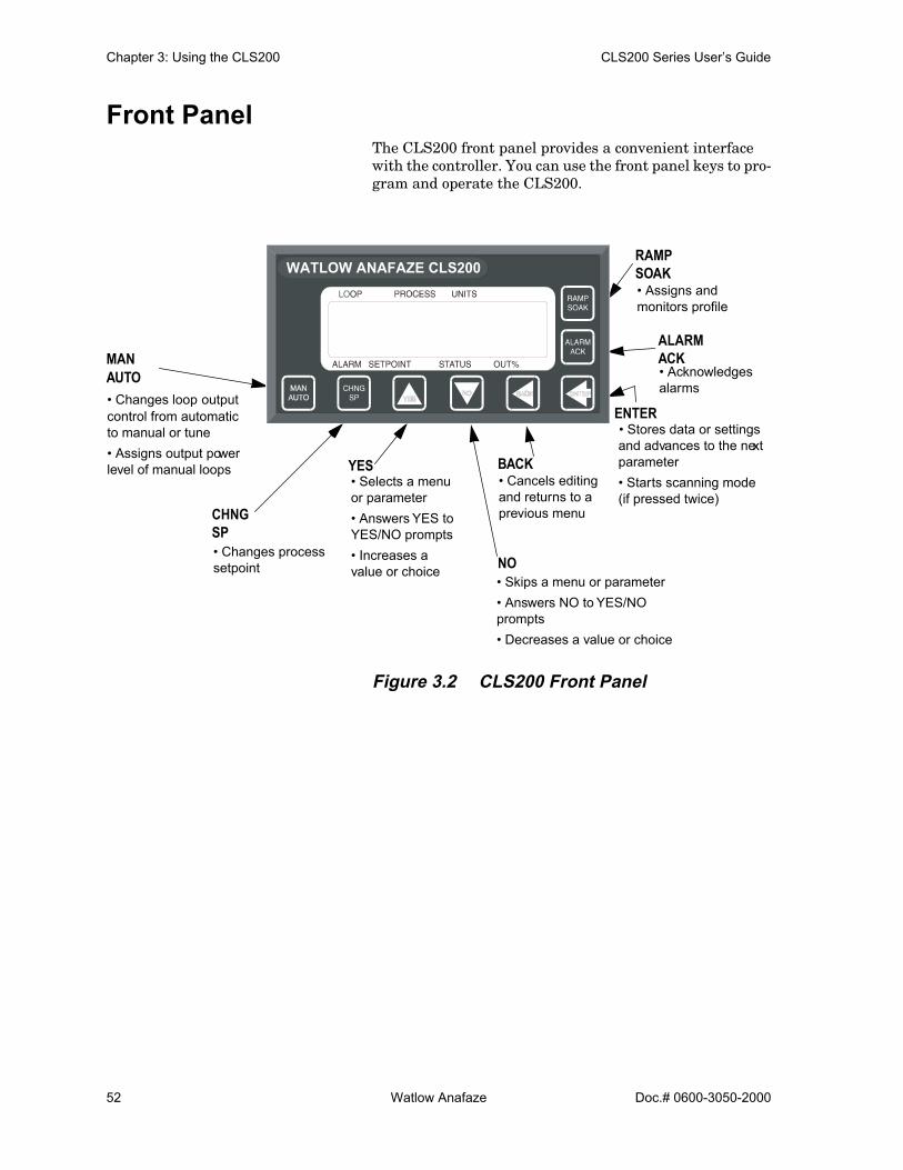
Chapter 3: Using the CLS200 CLS200 Series User’s Guide
52 Watlow Anafaze Doc.# 0600-3050-2000
Front PanelThe CLS200 front panel provides a convenient interface with the controller. You can use the front panel keys to pro-gram and operate the CLS200.
Figure 3.2 CLS200 Front Panel
RAMP
ALARM
ENTER
BACK
NO
YES
CHNG
MANAUTO
SP
SOAK
ACK
WATLOW ANAFAZE CLS200
• Changes loop output control from automatic to manual or tune• Assigns output power level of manual loops
• Changes process setpoint
• Selects a menu or parameter• Answers YES to YES/NO prompts• Increases a value or choice
• Cancels editing and returns to a previous menu
• Skips a menu or parameter• Answers NO to YES/NO prompts• Decreases a value or choice
• Assigns and monitors profile
• Acknowledges alarms
• Stores data or settings and advances to the next parameter• Starts scanning mode (if pressed twice)

CLS200 Series User’s Guide Chapter 3: Using the CLS200
Doc.# 0600-3050-2000 Watlow Anafaze 53
Front Panel Keys
Press YES to:
• Select a menu or parameter• Answer YES to the flashing ? prompts• Increase a value or choice when editing• Stop scanning mode
Press NO to:
• Skip a menu or parameter when the prompt is blinking• Answer NO to the flashing ? prompts• Decrease a value or choice when editing• Stop scanning mode• Perform a NO-key reset
NOTE! Pressing the NO key on power up performs aNO-key reset. This procedure clears the RAMand sets the controller’s parameters to theirdefault values. See NO-Key Reset on page176.
Press BACK to:
• Cancel editing• Return to a previous menu• Switch between bar graph, single loop and job displays• Stop scanning mode
Press ENTER to:
• Store data or a parameter choice after editing and go to the next parameter
• Start scanning mode (if pressed twice)
YES (up)
NO (down)
BACK
ENTER

Chapter 3: Using the CLS200 CLS200 Series User’s Guide
54 Watlow Anafaze Doc.# 0600-3050-2000
Press CHNG SP to change the loop setpoint
Press MAN/AUTO to:
• Toggle a loop between manual and automatic control• Adjust the output power level of manual loops• Automatically tune the loop
If your controller has the ramp/soak option, press RAMP/SOAK to:
• Assign a ramp/soak profile to the current loop• Select the ramp/soak mode• See the status of a running profile
Your controller may not have the ramp/soak option. If it does not, pressing the RAMP/SOAK key displays the message OPTION UNAVAILABLE.
Press ALARM ACK to:
• Acknowledge an alarm condition• Reset the global alarm output
CHNG SP
MANAUTO
RAMPSOAK
ALARMACK

CLS200 Series User’s Guide Chapter 3: Using the CLS200
Doc.# 0600-3050-2000 Watlow Anafaze 55
DisplaysThis section discusses the controller’s main displays: bar graph, single loop and job.
Bar Graph Display On power up, the controller displays general symbolic in-formation for up to eight loops. This screen is called the bar graph display. The diagram below shows the symbols used in the bar graph display.
Figure 3.3 Bar Graph Display
Table 3.1 explains the symbols you see on the top line of the bar graph display. These symbols appear when the con-troller is in dual output mode (heat and cool outputs en-abled) and single output mode (heat or cool outputs enabled, but not both).
Table 3.1 Bar Graph Display Symbols
Symbol Description
< Loop is in low process or low deviation alarm.
> Loop is in high process or high deviation alarm.
Loop is above setpoint. If you enable the high or low deviation alarm, this symbol is scaled to it. If you do not enable these alarms, these symbols are scaled to the setpoint +5% of the sensor’s range.Loop is at setpoint. If you enable the high or low deviation alarm, this symbol is scaled to it. If you do not enable these alarms, these sym-bols are scaled to the setpoint +5% of the sen-sor’s range.Loop is below setpoint. If you enable the high or low deviation alarm, this symbol is scaled to it. If you do not enable these alarms, these symbols are scaled to the setpoint +5% of the sensor’s range.
(blank) Loop’s input type is set to SKIP.
FOpen thermocouple (T/C), shorted T/C, reversed T/C, open RTD or shorted RTD.
ALARM
01> > < < 08 AAAA MAMA
Symbol
Loop Number or Name
Control Status
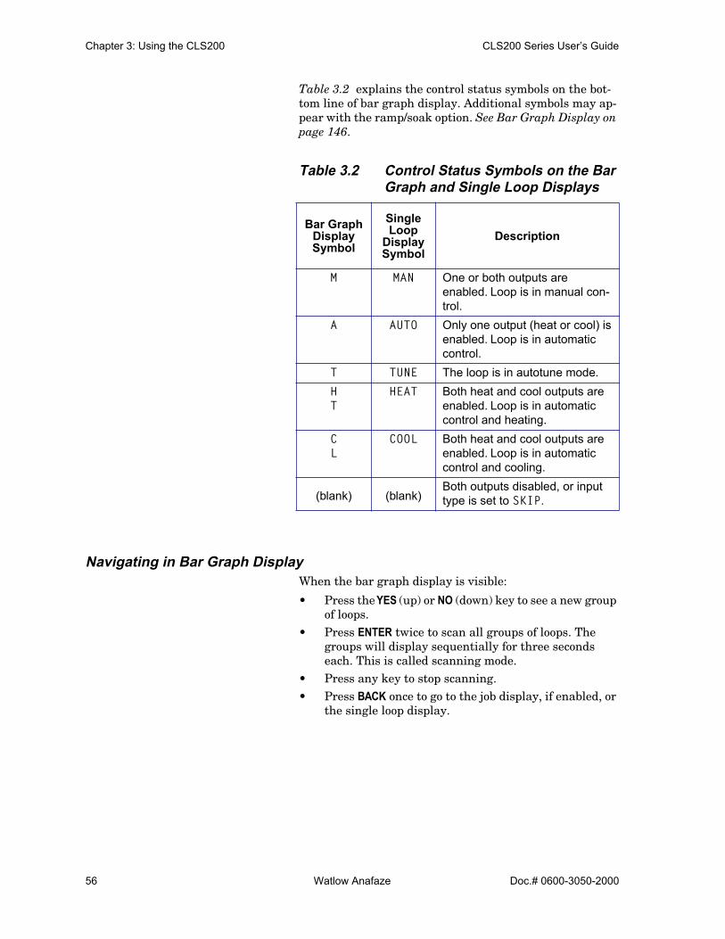
Chapter 3: Using the CLS200 CLS200 Series User’s Guide
56 Watlow Anafaze Doc.# 0600-3050-2000
Table 3.2 explains the control status symbols on the bot-tom line of bar graph display. Additional symbols may ap-pear with the ramp/soak option. See Bar Graph Display on page 146.
Table 3.2 Control Status Symbols on the Bar Graph and Single Loop Displays
Navigating in Bar Graph DisplayWhen the bar graph display is visible:
• Press the YES (up) or NO (down) key to see a new group of loops.
• Press ENTER twice to scan all groups of loops. The groups will display sequentially for three seconds each. This is called scanning mode.
• Press any key to stop scanning.• Press BACK once to go to the job display, if enabled, or
the single loop display.
Bar Graph DisplaySymbol
Single Loop
Display Symbol
Description
M MAN One or both outputs are enabled. Loop is in manual con-trol.
A AUTO Only one output (heat or cool) is enabled. Loop is in automatic control.
T TUNE The loop is in autotune mode.HT
HEAT Both heat and cool outputs are enabled. Loop is in automatic control and heating.
CL
COOL Both heat and cool outputs are enabled. Loop is in automatic control and cooling.
(blank) (blank)Both outputs disabled, or input type is set to SKIP.
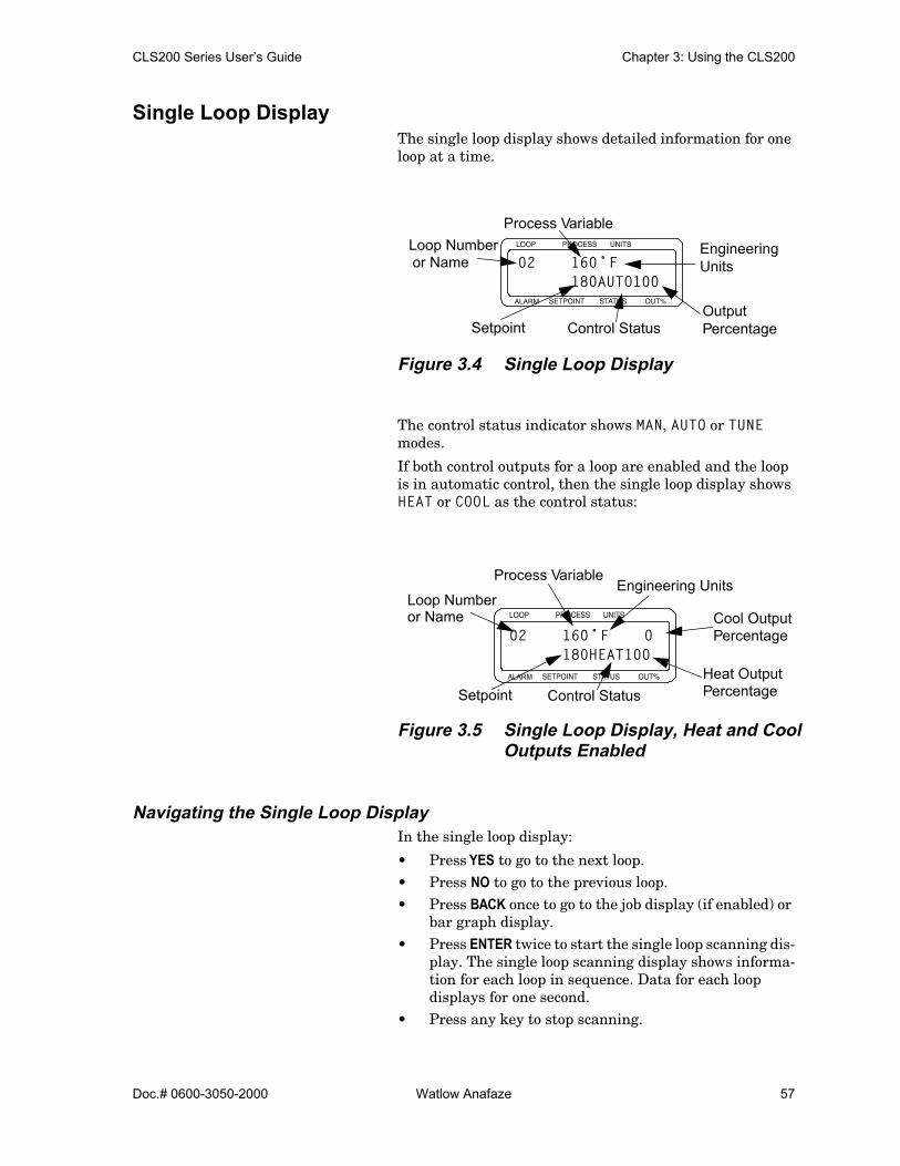
CLS200 Series User’s Guide Chapter 3: Using the CLS200
Doc.# 0600-3050-2000 Watlow Anafaze 57
Single Loop DisplayThe single loop display shows detailed information for one loop at a time.
Figure 3.4 Single Loop Display
The control status indicator shows MAN, AUTO or TUNE modes.
If both control outputs for a loop are enabled and the loop is in automatic control, then the single loop display shows HEAT or COOL as the control status:
Figure 3.5 Single Loop Display, Heat and Cool Outputs Enabled
Navigating the Single Loop DisplayIn the single loop display:
• Press YES to go to the next loop.• Press NO to go to the previous loop.• Press BACK once to go to the job display (if enabled) or
bar graph display.• Press ENTER twice to start the single loop scanning dis-
play. The single loop scanning display shows informa-tion for each loop in sequence. Data for each loop displays for one second.
• Press any key to stop scanning.
ALARM
EngineeringUnits
OutputPercentageControl StatusSetpoint
Loop Numberor Name
Process Variable
02 160˚F180AUTO100
ALARM
Control StatusHeat Output
Cool Output
Engineering UnitsProcess Variable
Setpoint
Loop Numberor Name
Percentage
Percentage
02 160˚F 0180HEAT100
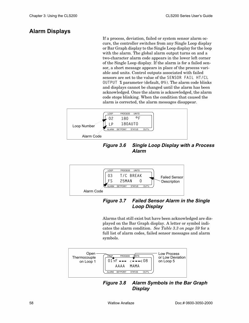
Chapter 3: Using the CLS200 CLS200 Series User’s Guide
58 Watlow Anafaze Doc.# 0600-3050-2000
Alarm DisplaysIf a process, deviation, failed or system sensor alarm oc-curs, the controller switches from any Single Loop display or Bar Graph display to the Single Loop display for the loop with the alarm. The global alarm output turns on and a two-character alarm code appears in the lower left corner of the Single Loop display. If the alarm is for a failed sen-sor, a short message appears in place of the process vari-able and units. Control outputs associated with failed sensors are set to the value of the SENSOR FAIL HT/CL OUTPUT % parameter (default, 0%). The alarm code blinks and displays cannot be changed until the alarm has been acknowledged. Once the alarm is acknowledged, the alarm code stops blinking. When the condition that caused the alarm is corrected, the alarm messages disappear.
Figure 3.6 Single Loop Display with a Process Alarm
Figure 3.7 Failed Sensor Alarm in the Single Loop Display
Alarms that still exist but have been acknowledged are dis-played on the Bar Graph display. A letter or symbol indi-cates the alarm condition. See Table 3.3 on page 59 for a full list of alarm codes, failed sensor messages and alarm symbols.
Figure 3.8 Alarm Symbols in the Bar Graph Display
ALARM
Alarm Code
Loop Number
180 °F180AUTO
02LP
ALARM
Failed Sensor
Alarm Code
Description03 T/C BREAKFS 25MAN 0
ALARM
01 F 08AAAA MAMA
Open Low Process or Low Deviation on Loop 5on Loop 1
Thermocouple
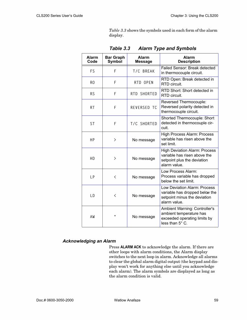
CLS200 Series User’s Guide Chapter 3: Using the CLS200
Doc.# 0600-3050-2000 Watlow Anafaze 59
Table 3.3 shows the symbols used in each form of the alarm display.
Table 3.3 Alarm Type and Symbols
Acknowledging an AlarmPress ALARM ACK to acknowledge the alarm. If there are other loops with alarm conditions, the Alarm display switches to the next loop in alarm. Acknowledge all alarms to clear the global alarm digital output (the keypad and dis-play won't work for anything else until you acknowledge each alarm). The alarm symbols are displayed as long as the alarm condition is valid.
AlarmCode
Bar Graph Symbol
Alarm Message
Alarm Description
FS F T/C BREAKFailed Sensor: Break detected in thermocouple circuit.
RO F RTD OPENRTD Open: Break detected in RTD circuit.
RS F RTD SHORTEDRTD Short: Short detected in RTD circuit.
RT F REVERSED TCReversed Thermocouple: Reversed polarity detected in thermocouple circuit.
ST F T/C SHORTEDShorted Thermocouple: Short detected in thermocouple cir-cuit.
HP > No messageHigh Process Alarm: Process variable has risen above the set limit.
HD > No message
High Deviation Alarm: Process variable has risen above the setpoint plus the deviation alarm value.
LP < No messageLow Process Alarm:Process variable has dropped below the set limit.
LD < No message
Low Deviation Alarm: Process variable has dropped below the setpoint minus the deviation alarm value.
AW * No message
Ambient Warning: Controller's ambient temperature has exceeded operating limits by less than 5° C.

Chapter 3: Using the CLS200 CLS200 Series User’s Guide
60 Watlow Anafaze Doc.# 0600-3050-2000
System Alarms When a system alarm occurs, the global alarm output turns on and an alarm message appears on the display. The mes-sage continues to be displayed until the error condition is removed and the alarm is acknowledged. The CLS200 can display the following system alarms:
• BATTERY DEAD See Battery Dead on page 168.
• LOW POWERSee Low Power on page 168.
• AWSee Ambient Warning on page 168.
• H/W FAILURE: AMBIENTSee H/W Ambient Failure on page 169.
• H/W FAILURE: GAIN See H/W Gain or Offset Failure on page 170.
• H/W FAILURE: OFFSETSee H/W Gain or Offset Failure on page 170.
Job DisplayThe job display appears only if:
• You have enabled JOB SELECT DIG INPUTS. (See Load Setup From Job on page 75.) – and –
• You have selected a job from the job load menu.After loading a job using the LOAD SETUP FROM JOB menu, the job display shows you the following screen:
If parameters are modified while the job is running, this screen will display:
If the job was loaded using digital inputs, the display shows:
ALARM
JOB 3 RUNNING
ALARM
JOB 3 RUNNINGDATA MODIFIED
ALARM
JOB 3 RUNNINGREMOTELY LOADED

CLS200 Series User’s Guide Chapter 3: Using the CLS200
Doc.# 0600-3050-2000 Watlow Anafaze 61
Changing the SetpointSelect the single loop display for the loop you want to change. Press CHNG SP. This display appears:
• Press YES to change the setpoint.
Press the up or down keys (YES or NO) to increase or de-crease the setpoint value.
• Press ENTER to save your changes and return to single loop display.– or –Press NO or BACK (without pressing ENTER) to return to single loop display without saving the new setpoint.
Selecting the Control StatusIf you set the control status to AUTO, the controller auto-matically controls the process according to the configura-tion information you give it.
If you set the control status to MAN, you need to set the out-put level.
If you set the control status to TUNE, the controller performs an autotune and chooses PID parameters.
NOTE! If the loop outputs are disabled, you cannottoggle between manual and automatic con-trol. If you try it, the screen shows an errormessage telling you that the outputs are dis-abled, as shown below. Use the SETUPLOOPS OUTPUT menu to enable the outputs.See Setup Loop Outputs Menu on page 93.
Manual and Automatic Control1. Switch to the single loop display for the loop.
2. Press MAN/AUTO.
3. Press YES to change the mode– or –if the mode is MAN, press NO to set the output power.
ALARM
01 SETPOINT ?25°F
ALARM
MAN/AUTO CONTROLOUTPUTS DISABLED

Chapter 3: Using the CLS200 CLS200 Series User’s Guide
62 Watlow Anafaze Doc.# 0600-3050-2000
Go to the next subsection, Manual Output Levels.– or –press NO if in AUTO to cancel and remain in AUTO mode.
4. Select a mode by pressing the up or down key (YES orNO) to scroll through the modes.
5. Press ENTER to make the mode change– or –press BACK to return to the single loop display withoutsaving the new mode setting.
6. If you set the loop to manual, you are prompted for theoutput power. Go to Manual Output Levels below.
Manual Output LevelsIf the loop to is set to manual control, the controller prompts for output levels for the enabled control outputs. Use this menu to set the manual heat and cool output lev-els. You should see a display like this:
1. Press YES to change the output power level. (If the heatoutputs are enabled, you will be able to change theheat output power level. If only the cool outputs areenabled, you will be able to change only the cool outputpower level.)– or –Press NO to go to the cool output, if available, and thenpress YES to change the cool output.
2. Press up or down (YES or NO) to select a new outputpower level.
3. Press ENTER to store your changes– or –press BACK to discard your changes and return to sin-gle loop display.
4. Repeat from Step 1 for the cool output, if available.
5. Press BACK at any time to discard your changes andreturn to single loop display.
Autotuning a LoopAutotuning is a process by which a controller determines the correct PID parameters for optimum control. This sec-tion explains how to autotune the CLS200.
PrerequisitesBefore autotuning the controller, it must be installed with control and sensor circuitry and the thermal load in place.
ALARM
01 SET HEAT OUTPUT? 90%
CLS200 Series User’s Guide Chapter 3: Using the CLS200
Doc.# 0600-3050-2000 Watlow Anafaze 63
It must be safe to operate the thermal system, and the ap-proximate desired operating temperature (setpoint) must be known.
The technician or engineer performing the autotune should know how to use the controller front panel or MMI software interface (e.g., AnaWin or Anasoft) to do the following:
1. Select a loop to operate and monitor.
2. Set a loop’s setpoint.
3. Change a loop’s control status (MAN, TUNE, AUTO).
4. Read and change the controller’s global and loop setupparameters.
BackgroundAutotuning is performed at the maximum allowed output. If you have set an output limit, autotuning occurs at that value. Otherwise, the control output is set to 100% during the autotune. Only the heat output (output 1) of a loop may be autotuned.
The PID constants are calculated according to process’s re-sponse to the output. The loop need not reach or cross set-point to successfully determine the PID parameters. While autotuning the controller looks at the delay between when power is applied and when the system responds in order to determine the proportional band (PB). The controller then looks for the slope of the rising temperature to become con-stant in order to determine the integral term (TI). The de-rivative term (TD) is derived mathematically from the TI.
When the controller has finished autotuning, the loop’s control status switches to AUTO. If the process reaches 75% of the setpoint or the autotuning time exceeds ten minutes, the controller switches to AUTO and applies the PID con-stants it has calculated up to that point.
The Watlow Anafaze autotune is started at ambient tem-perature or at a temperature above ambient. However, the temperature must be stable and there must be sufficient time for the controller to determine the new PID parame-ters.
Performing an Autotune
NOTE! A loop must be stable at a temperature wellbelow the setpoint in order to successfullyautotune. The controller will not completetuning if the temperature exceeds 75% of set-point before the new parameters are found.
The following procedure explains how to autotune a loop:
1. Select the single loop display of the loop to be tuned.

Chapter 3: Using the CLS200 CLS200 Series User’s Guide
64 Watlow Anafaze Doc.# 0600-3050-2000
2. Ensure the loop’s process variable is stable and theloop is in MAN control status.
3. Set the setpoint to a value as near the normal operat-ing temperature as is safe for the system.
WARNING! During autotuning, the controller will set theoutput to 100% until the process variable risesnear the setpoint. Set the setpoint within thesafe operating limits of your system.
4. Use the three-key sequence (ENTER, ALARM ACK, CHNGSP) to access the setup menus. In the SETUP LOOPINPUT menu, locate the INPUT FILTER parameter.Note the setting and then change it to 0 SCANS.
5. Press the BACK key until the single loop display appears.
6. Press the MAN/AUTO key.
7. Press the NO key to toggle to the TUNE mode.
8. Press the ENTER key to begin tuning the loop. TUNEflashes throughout the tuning process. When tuning iscompleted the control status indicator changes to AUTO.
9. Adjust the setpoint to the desired temperature.
10. Restore the INPUT FILTER parameter to its original value.
Using AlarmsThe CLS200 has three main types of alarms:
• Failed sensor alarms• Process alarms• System alarms
Alarm DelayYou can set the controller to delay normal alarm detection and alarm reporting. There are two kinds of alarm delay:
• Start-up alarm delay delays process alarms (but not failed sensor alarms) for all loops for a time period you set at the STARTUP ALARM DELAY parameter in the SETUP GLOBAL PARAMETERS menu.
• Loop alarm delay delays failed sensor alarms and pro-cess alarms for one loop until the alarm condition is continuously present for longer than the loop alarm delay time you set.
Failed sensor alarms are affected by the loop alarm delay even during the start-up alarm delay time period.
CLS200 Series User’s Guide Chapter 3: Using the CLS200
Doc.# 0600-3050-2000 Watlow Anafaze 65
Failed Sensor AlarmsFailed sensor alarms alert you if one of the following condi-tions occurs:
• Thermocouple open• Thermocouple shorted (must be enabled)• Thermocouple reversed (must be enabled)• RTD open positive input or open negative input• RTD short between the positive and negative inputs
What Happens if a Failed Sensor Alarm Occurs?If a failed sensor alarm occurs:
• The controller switches to manual mode at the output power indicated by the SENSOR FAIL HT OUTPUT and SENSOR FAIL CL OUTPUT parameters in the SETUP LOOP OUTPUTS menu. (The output power may be dif-ferent for a thermocouple open alarm; see Thermocou-ple Open Alarm on page 65.)
• The controller displays an alarm code and alarm mes-sage on the display. See Alarm Displays on page 58.
• The global alarm output is activated.
Thermocouple Open AlarmThe thermocouple open alarm occurs if the controller de-tects a break in a thermocouple or its leads.
If a thermocouple open alarm occurs, the controller switch-es to manual mode. The output level is determined as fol-lows:
• If the HEAT/COOL T/C BRK OUT parameter in the SETUP LOOP OUTPUTS menu is set to ON, then the con-troller sets the output power to an average of the re-cent output.
• If the HEAT/COOL T/C BRK OUT AVG parameter is set to OFF, then the controller sets the output to the level indicated by the SENSOR FAIL HT/CL OUTPUT pa-rameter in the SETUP LOOP OUTPUTS menu.
Thermocouple Reversed AlarmThe thermocouple reversed alarm occurs if the tempera-ture goes in the opposite direction and to the opposite side of ambient temperature than expected—for example, a loop is heating and the measured temperature drops below the ambient temperature.
The thermocouple reversed alarm is disabled by default. To enable this alarm, set the REVERSED T/C DETECT param-eter in the SETUP LOOP INPUTS menu to ON. It may be dis-abled if false alarms occur in your application.

Chapter 3: Using the CLS200 CLS200 Series User’s Guide
66 Watlow Anafaze Doc.# 0600-3050-2000
Thermocouple Short AlarmThe thermocouple short alarm occurs if the process power is on and the temperature does not rise or fall as expected. To enable the thermocouple short alarm, you must do the following:
• Choose a digital input for the PROCESS POWER DIGIN parameter in the SETUP GLOBAL PARAMETERS menu.
• Connect the digital input to a device that connects the input to controller common when the process power is on.
RTD Open or RTD Shorted AlarmThe RTD open alarm occurs if the controller detects that the positive or negative RTD lead is broken or disconnected.
The RTD shorted alarm occurs if the controller detects that the positive and negative RTD leads are shorted.
You do not have to set any parameters for the RTD alarms.
Restore Automatic Control After a Sensor FailureThis feature returns a loop to automatic control after a failed sensor is repaired. To enable this feature:
• Choose a digital input for the RESTORE PID DIGIN parameter in the SETUP LOOP CONTROL PARAMS menu.
• Connect the digital input to the dc common terminal on the controller.
Process AlarmsThe CLS200 has four process alarms, each of which you can configure separately for each loop:
• Low process alarm• High process alarm• Low deviation alarm• High deviation alarm
Setting Up AlarmsTo set up an alarm:
• Set the alarm setpoint (limit)• Set the alarm type• Choose an output, if desired• Set the alarm deadband• Set an alarm delay, if desired
The setpoints, deviation alarm values, and deadband all use the same decimal format as the loop’s process variable.

CLS200 Series User’s Guide Chapter 3: Using the CLS200
Doc.# 0600-3050-2000 Watlow Anafaze 67
What Happens If a Process Alarm Occurs?If a process alarm occurs, the controller does the following:
• Shows an alarm code on the display. (See Alarm Dis-plays on page 58.) .
• Activates the global alarm output. (See Global Alarm on page 68.)
• Activates the digital output that is assigned to the pro-cess alarm (if applicable). The digital output remains active until the process variable returns within the corresponding limit and deadband. The alarm output deactivates when the process returns to normal.
Process Alarm OutputsAny digital output that is not used as a control output can be assigned to one or more process alarms.
The controller activates the output if any alarm assigned to the output is active. Process alarm outputs are non-latch-ing—that is, the output is deactivated when the process re-turns to normal, whether or not the alarm has been acknowledged.
Specify the active state of process alarm outputs at the DIG OUT POLARITY ON ALARM setting in the SETUP GLOBAL PARAMETERS.
Alarm Type: Control or AlarmYou can configure each process alarm as either a control or alarm.
• Alarm configuration provides traditional alarm func-tionality: The operator must acknowledge the alarm message on the controller display, a latching global alarm is activated, and the alarm can activate a user-specified non-latching alarm output.
• Control configuration provides on/off control output using the alarm setpoints. For example, you could con-figure a high deviation alarm to turn on a fan. The alarm activates a user-specified non-latching output. Alarm messages do not have to be acknowledged, and the global alarm is not activated.
High and Low Process AlarmsA high process alarm occurs if the process variable rises above a user-specified value. A low process alarm occurs if the process variable drops below a separate user-specified value. See Figure 3.9.
Enter the alarm high and low process setpoints at the HI PROC ALARM SETPT and LO PROC ALARM SETPT param-eters in the SETUP LOOP ALARMS menu.

Chapter 3: Using the CLS200 CLS200 Series User’s Guide
68 Watlow Anafaze Doc.# 0600-3050-2000
Figure 3.9 Activation and Deactivation ofProcess Alarms
Deviation AlarmsA deviation alarm occurs if the process deviates from set-point by more than a user-specified amount. (See Figure 3.9.) Set the deviation with the DEV ALARM VALUE param-eter in the SETUP LOOP ALARMS menu.
Upon power up or when the setpoint changes, the behavior of the deviation alarms depends upon the alarm function:
• If the alarm type parameter is set to ALARM, then de-viation alarms do not activate until the after the pro-cess variable has first come within the deviation alarm band. This prevents nuisance alarms.
• If the alarm type parameter is set to CONTROL, then the deviation output switches on whenever the set-point and process variable differ by more than the de-viation setting, regardless of whether the process vari-able has been within the deviation band. This allows you to use boost control upon power up and setpoint changes.
Global AlarmThe CLS200 comes equipped with a global alarm output. The global output is activated if one or more of the follow-ing conditions occurs:
• A system alarm occurs, or• A failed sensor alarm occurs and is unacknowledged,
or
Setpoint
High process alarm set point
Low process alarm setpoint
Deadband
High process alarm on High process alarm off
Low process alarm on Low process alarm off
High deviation alarm off
High deviation alarm on
Low deviation alarm off
Low deviation alarm on
Setpoint + Deviation alarm value
Setpoint - Deviation alarm value
Deadband
Deadband
Deadband

CLS200 Series User’s Guide Chapter 3: Using the CLS200
Doc.# 0600-3050-2000 Watlow Anafaze 69
• A process alarm occurs and is unacknowledged. The global alarm occurs only if the alarm type is set to ALARM in the SETUP LOOP ALARMS menu. (The global alarm does not occur if the alarm function is set to CONTROL.)
The global alarm output stays active until all alarms have been acknowledged.
When the global alarm output is active, it conducts current to the controller’s dc common. When the global alarm out-put is not active, it does not conduct current.
NOTE! You cannot configure any parameters for theglobal alarm. The active state of the globalalarm output is NOT affected by the DIG OUTPOLARITY ON ALARM polarity parameter in theSETUP GLOBAL PARAMETERS menu.
Ramp/SoakIf you have a controller without the Ramp/Soak option, pressing the RAMP/SOAK key has no effect.
If you have a controller with this option installed, see Chapter 7, Ramp/Soak.

Chapter 3: Using the CLS200 CLS200 Series User’s Guide
70 Watlow Anafaze Doc.# 0600-3050-2000

Doc.# 0600-3050-2000 Watlow Anafaze 71
4Setup
The setup menus let you change detailed configuration in-formation. This section describes how to set up the control-ler from menus in the controller firmware. The following information is included in this chapter:
• Accessing the setup menus• Changing parameter settings• Description of controller parameters
If you have not set up a CLS200 series controller before, or if you do not know what values to enter, please read Chap-ter 8, Tuning and Control, which contains PID tuning con-stants and useful starting values.
How to Access the Setup MenusUse the three-key sequence to enter the setup menus:
1. Select the single loop display for the loop you wish toedit.
2. Press ENTER then ALARM ACK then CHNG SP to accessthe setup menus. Do not press these keys at the sametime; press them one at a time.
3. The first setup menu appears.
To prevent unauthorized personnel from accessing setup parameters, the controller reverts to the single loop display if you do not press any keys for three minutes.

Chapter 4: Setup CLS200 Series User’s Guide
72 Watlow Anafaze Doc.# 0600-3050-2000
How to Change a ParameterTo change a parameter, first select the appropriate menu, then the parameter.
When you enter the setup menus, the first menu is SETUP GLOBAL PARAMETERS. Refer to Figure 4.1 for a listing of all top level menus and their related parameters.
1. Select the single loop display for the loop to set up.
2. Enter the three-key sequence. (See How to Access theSetup Menus on page 71.) The first menu is displayed:SETUP GLOBAL PARAMETERS.
3. To select the appropriate menu:
• Press NO to move from one menu to the next. Themenus wrap around; pressing NO continuouslyadvances through the top level menus.
• Press YES to enter the displayed menu.
4. To select the parameter to be edited:
• Press NO to advance from one parameter to thenext. Parameters do not wrap around.
• Press YES to edit the displayed parameter.
5. To edit the parameter setting:
• Press up or down (YES or NO) to scroll to the valueor choice you want to select.
• Press ENTER to accept the change- or -press BACK to cancel the change without saving.
6. Select another parameter and repeat from step 4, orpress BACK to return to the top level menu.
7. Select another menu and repeat from step 3, - or -press BACK to exit the setup menus.
The following sections tell more about the parameters for each of the six top level menus. Each display illustration contains the default value for that specific parameter. If you have a controller with the enhanced features option, there will be additional menus. (See Chapter 6, Enhanced Features.)
Figure 4.1 shows the top level menus accessible from the single loop display.

CLS200 Series User’s Guide Chapter 4: Setup
Doc.# 0600-3050-2000 Watlow Anafaze 73
Figure 4.1 CLS200 Menu Tree
COMMUNICATIONS
SETUP LOOP INPUT?
SETUP LOOP CONTROL PARAMS?
SETUP LOOP OUTPUTS?
SETUP LOOP ALARMS?
MANUAL I/OTEST
INPUT TYPE? HEAT CONTROL PB? HEAT CONTROL OUTPUT?
HI PROC ALARM SETPT?
DIGITAL INPUTS
LOOP NAME? HEAT CONTROL TI? HEAT OUTPUT TYPE? HI PROC ALARM TYPE?
TEST DIGITAL OUTPUT?
JOB SELECTDIG INPUTS?
INPUT UNITS? HEAT CONTROL TD? HEAT OUTPUT CYCLE TIME? (TP)
HI PROC ALARM OUTPUT?
DIGITAL OUTPUT NUMBER XX
INPUT READING OFFSET
HEAT CONTROL FILTER?
SDAC PARAMETERS (SDAC)
DEV ALARMVALUE?
KEYPAD TEST
OUTPUT OVERRIDE DIG INPUT?
REVERSED T/C DETECT?
COOL CONTROL PB? HEAT OUTPUT ACTION?
HI DEV ALARMTYPE?
OVERRIDE DIG IN ACTIVE?
INPUT PULSE SAMPLE TIME?(Pulse input)
COOL CONTROL TI? HEAT OUTPUT LIMIT?
HI DEV ALARMOUTPUT?
STARTUP ALARM DELAY?
COOL CONTROL TD? HEAT OUTPUT LIMIT TIME?
LO DEV ALARMTYPE?DISP FORMAT?
(Linear and pulse)RAMP/SOAKTIME BASE?(Ramp/soak)
INPUT SCALING HI RDG?(Linear and pulse)
INPUT SCALING LO PV?(Linear and pulse)
INPUT SCALING LO RDG?(Linear and pulse)
INPUT FILTER?
INPUT SCALING HI PV?(Linear and pulse)
COOL CONTROL FILTER?
LO DEV ALARMOUTPUT?
SPREAD? HEAT T/C BRKOUT AVG?
LO PROC ALARM SETPT?
RESTORE PIDDIGIN?
HEAT OUTPUT? LO PROC ALARM TYPE?
COOL CONTROL OUTPUT?
LO PROC ALARM OUTPUT?
COOL OUTPUT TYPE? ALARM DEADBAND?
COOL OUTPUT CYCLE TIME?(TP)
ALARM DELAY?
SDAC PARAMETERS(SDAC)
COOL OUTPUT ACTION?
COOL OUTPUT LIMIT?
COOL OUTPUT LIMIT TIME?
SENSOR FAIL CL OUTPUT?
COOL T/C BRKOUT AVG?
COOL OUTPUT?
KEYBOARD LOCK STATUS?
POWER UP OUTPUT STATUS?
PROCESS POWER DIGIN?
CONTROLLER ADDRESS?
COMMUNICATIONS BAUD RATE?
COMMUNICATIONS PROTOCOL?
COMMUNICATIONS ERR CHECK?
AC LINE FREQ?
DIG OUT POLARITY ON ALARM?
CLS 200 [FIRMWARE INFO]
DISPLAY TEST
SETUP GLOBAL PARAMETERS?
SAVE SETUPTO JOB?
LOAD SETUPFROM JOB?
SENSOR FAIL HT OUTPUT?
JOB SEL DIG INS ACTIVE?
If the enhanced features option or ramp/soak feature is installed, refer to Chapter 6, En-hanced Features, or Chapter 7, Ramp/Soak for additional menus.

Chapter 4: Setup CLS200 Series User’s Guide
74 Watlow Anafaze Doc.# 0600-3050-2000
Setup Global Parameters Menu
Table 4.1 shows the parameters available in this menu.
Table 4.1 Global Parameters
* The RAMP/SOAK TIME BASE parameter appears only if the ramp/soak feature is installed.
Parameter Default Value
LOAD SETUP FROM JOB? 1
SAVE SETUP TO JOB? 1
JOB SELECT DIG INPUTS? NONE
JOB SEL DIG INS ACTIVE? LOW
OUTPUT OVERRIDE DIG INPUT? NONE
OVERRIDE DIG IN ACTIVE? LOW
STARTUP ALARM DELAY? 0 MINS
RAMP/SOAK TIME BASE?* HOURS/MINS
KEYBOARD LOCK STATUS? OFF
POWER UP OUTPUT STATUS? OFF
PROCESS POWER DIGIN? NONE
CONTROLLER ADDRESS? 1
COMMUNICATIONS BAUD RATE? 9600
COMMUNICATIONS PROTOCOL? ANA
COMMUNICATIONS ERR CHECK? BCC
AC LINE FREQ? 60 HERTZ
DIG OUT POLARITY ON ALARM? LOW
CLS200 [model no., fi mware rev.]
ALARM
SETUP GLOBALPARAMETERS
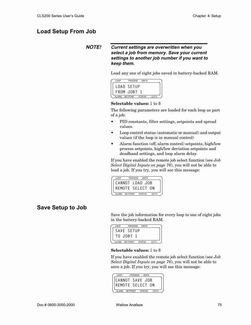
CLS200 Series User’s Guide Chapter 4: Setup
Doc.# 0600-3050-2000 Watlow Anafaze 75
Load Setup From Job
NOTE! Current settings are overwritten when youselect a job from memory. Save your currentsettings to another job number if you want tokeep them.
Load any one of eight jobs saved in battery-backed RAM.
Selectable values: 1 to 8
The following parameters are loaded for each loop as part of a job:
• PID constants, filter settings, setpoints and spread values.
• Loop control status (automatic or manual) and output values (if the loop is in manual control)
• Alarm function (off, alarm control) setpoints, high/low process setpoints, high/low deviation setpoints and deadband settings, and loop alarm delay.
If you have enabled the remote job select function (see Job Select Digital Inputs on page 76), you will not be able to load a job. If you try, you will see this message:
Save Setup to JobSave the job information for every loop to one of eight jobs in the battery-backed RAM.
Selectable values: 1 to 8
If you have enabled the remote job select function (see Job Select Digital Inputs on page 76), you will not be able to save a job. If you try, you will see this message:
ALARM
LOAD SETUPFROM JOB? 1
ALARM
CANNOT LOAD JOBREMOTE SELECT ON
ALARM
SAVE SETUPTO JOB? 1
ALARM
CANNOT SAVE JOB REMOTE SELECT ON
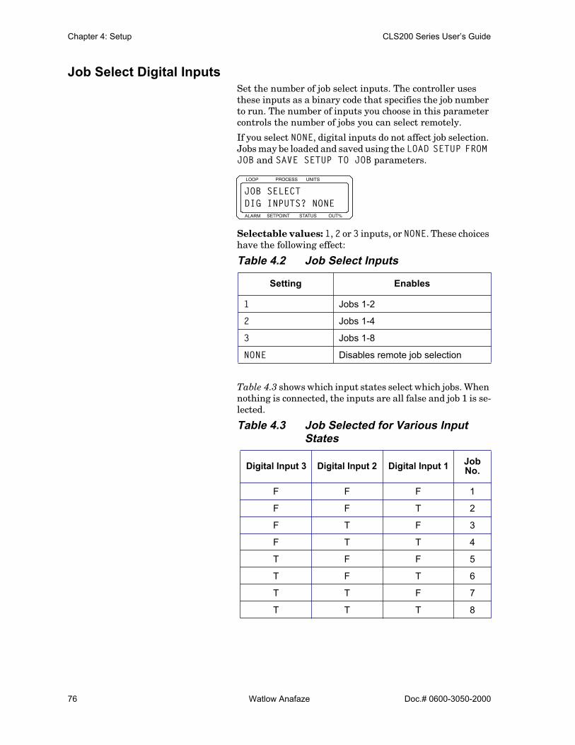
Chapter 4: Setup CLS200 Series User’s Guide
76 Watlow Anafaze Doc.# 0600-3050-2000
Job Select Digital InputsSet the number of job select inputs. The controller uses these inputs as a binary code that specifies the job number to run. The number of inputs you choose in this parameter controls the number of jobs you can select remotely.
If you select NONE, digital inputs do not affect job selection. Jobs may be loaded and saved using the LOAD SETUP FROM JOB and SAVE SETUP TO JOB parameters.
Selectable values: 1, 2 or 3 inputs, or NONE. These choices have the following effect:
Table 4.2 Job Select Inputs
Table 4.3 shows which input states select which jobs. When nothing is connected, the inputs are all false and job 1 is se-lected.
Table 4.3 Job Selected for Various Input States
Setting Enables
1 Jobs 1-2
2 Jobs 1-4
3 Jobs 1-8
NONE Disables remote job selection
Digital Input 3 Digital Input 2 Digital Input 1 Job No.
F F F 1
F F T 2
F T F 3
F T T 4
T F F 5
T F T 6
T T F 7
T T T 8
ALARM
JOB SELECTDIG INPUTS? NONE

CLS200 Series User’s Guide Chapter 4: Setup
Doc.# 0600-3050-2000 Watlow Anafaze 77
Job Select Digital Inputs ActiveSpecify which state is considered “true” for the digital in-puts used for job selection. Default is LOW, meaning that an input must be pulled low to be considered true. If HIGH is selected, an input will be considered true unless it is pulled low.
Selectable values: HIGH or LOW.
Changing this setting has the effect of reversing the order of the jobs in Table 4.3.
Output Override Digital InputTo enable the output override feature, select a digital in-put. When the specified input is activated, the controller sets all loops to manual mode at the output levels specified at the SENSOR FAIL HT OUTPUT and SENSOR FAIL CL OUTPUT parameters in the SETUP LOOP OUTPUTS menu.
Selectable values: NONE or input number 1 to 8.
Use the next parameter, OVERRIDE DIG IN ACTIVE, to set the signal state that activates the output override feature.
WARNING! Do not rely solely on the output override fea-ture to shut down your process. Install exter-nal safety devices or over-temperaturedevices for emergency shutdowns.
Override Digital Input ActiveSpecify whether a low or high signal activates the output override feature (see OUTPUT OVERRIDE DIG INPUT above).
Selectable values: HIGH or LOW.
ALARM
JOB SEL DIG INSACTIVE ? LOW
ALARM
OUTPUT OVERRIDEDIG INPUT? NONE
ALARM
OVERRIDE DIG INACTIVE ? LOW

Chapter 4: Setup CLS200 Series User’s Guide
78 Watlow Anafaze Doc.# 0600-3050-2000
You can set the input to be active when low or active when high. When the input selected for OUTPUT OVERRIDE DIG INPUT changes to the specified state, all the loop’s outputs are set to their sensor fail levels.
Startup Alarm DelaySet a startup delay for process and deviation alarms for all loops. The controller does not report these alarm conditions for the specified number of minutes after the controller powers up. This feature does not delay failed sensor alarms.
Selectable values: 0 to 60 minutes.
Keyboard Lock StatusSet this parameter to ON to disable the CHNG SP, MAN/AUTO, and RAMP/SOAK keys on the keypad. If the keys are dis-abled, pressing them has no effect. If you want to use these functions, turn off the keyboard lock.
Selectable values: ON or OFF.
Power Up Output Status
WARNING! Do not set the controller to start from memo-ry if it may be unsafe for your process to haveoutputs on upon power-up.
Set the initial power-up state of the control outputs. If you choose OFF, all loops are initially set to manual mode at 0% output. If you choose MEMORY, the loops are restored to the control status and output value prior to powering down.
See In Case of a Power Failure on page 152 for information about how this feature affects ramp/soak profiles.
ALARM
STARTUP ALARMDELAY ? 0 MINS
ALARM
KEYBOARD LOCKSTATUS ? OFF

CLS200 Series User’s Guide Chapter 4: Setup
Doc.# 0600-3050-2000 Watlow Anafaze 79
Selectable values: OFF or MEMORY.
Process Power Digital InputTo enable the thermocouple short detection feature, select a digital input (1 to 8). Connect the specified input to a de-vice that pulls the input low when the process power is on. A short is indicated when the process power is on and the temperature does not rise as expected.
If the controller determines that there is a thermocouple short, it sets the loop to manual mode at the power level set for the SENSOR FAIL HT OUTPUT or SENSOR FAIL CL OUTPUT parameter in the SETUP LOOP OUTPUTS menu.
Selectable values: 1 to 8, or NONE.
Controller AddressSet the communications address for the controller. On an EIA/TIA-485 communication loop, each controller must have a unique address. Begin with address 1 for the first controller and assign each subsequent controller the next higher address.
Selectable values: 1 to 247. When using one controller with Anasoft, select address 1. When using multiple con-trollers with Anasoft, use consecutive addresses from 1 to 16 only.
ALARM
POWER UP OUTPUTSTATUS ? OFF
ALARM
PROCESS POWERDIGIN ? NONE
ALARM
CONTROLLERADDRESS ? 1
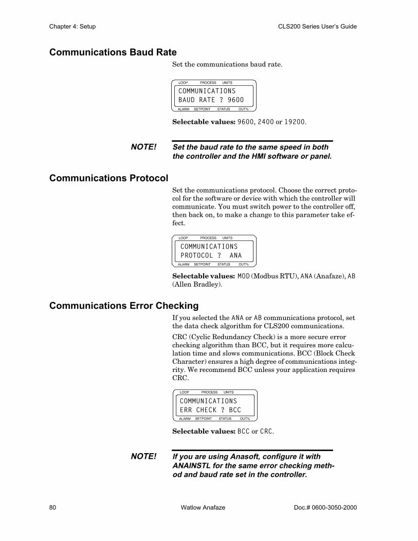
Chapter 4: Setup CLS200 Series User’s Guide
80 Watlow Anafaze Doc.# 0600-3050-2000
Communications Baud RateSet the communications baud rate.
Selectable values: 9600, 2400 or 19200.
NOTE! Set the baud rate to the same speed in boththe controller and the HMI software or panel.
Communications ProtocolSet the communications protocol. Choose the correct proto-col for the software or device with which the controller will communicate. You must switch power to the controller off, then back on, to make a change to this parameter take ef-fect.
Selectable values: MOD (Modbus RTU), ANA (Anafaze), AB (Allen Bradley).
Communications Error CheckingIf you selected the ANA or AB communications protocol, set the data check algorithm for CLS200 communications.
CRC (Cyclic Redundancy Check) is a more secure error checking algorithm than BCC, but it requires more calcu-lation time and slows communications. BCC (Block Check Character) ensures a high degree of communications integ-rity. We recommend BCC unless your application requires CRC.
Selectable values: BCC or CRC.
NOTE! If you are using Anasoft, configure it withANAINSTL for the same error checking meth-od and baud rate set in the controller.
ALARM
COMMUNICATIONSBAUD RATE ? 9600
ALARM
COMMUNICATIONSPROTOCOL ? ANA
ALARM
COMMUNICATIONSERR CHECK ? BCC

CLS200 Series User’s Guide Chapter 4: Setup
Doc.# 0600-3050-2000 Watlow Anafaze 81
AC Line FrequencySpecify the ac line frequency. Since the controller reduces the effect of power line noise on the analog measurement by integrating the signal over the period of the ac line frequen-cy, the controller must know the frequency of power in use.
You must switch power to the controller off, then back on, to make a change to this parameter take effect.
Selectable values: 50 or 60 Hz.
Digital Output Polarity on AlarmSet the polarity of all digital outputs used for alarms. If LOW is selected, if an alarm occurs the outputs sink to analog common. If HIGH is selected, the outputs sink to common when no alarm is active and go high when an alarm occurs.
Selectable values: HIGH or LOW.
This parameter does not affect the Global Alarm output or the Watchdog Alarm output.
EPROM InformationThe display shows the controller type, firmware options, the firmware version and the EPROM checksum. Table 4.4 lists the available firmware options.
Table 4.4 Firmware Option Codes
Firmware Option Description
(none) Standard Firmware
-EF Enhanced Features Option
-RS Ramp/Soak Option
-EX Extruder Option
ALARM
AC LINE FREQ ?60 HERTZ
ALARM
DIG OUT POLARITY ON ALARM ? LOW
ALARM
CLS208-RSV03.13 CS=ED74
Firmware Option
EPROM ChecksumFirmware Version
Controller Model

Chapter 4: Setup CLS200 Series User’s Guide
82 Watlow Anafaze Doc.# 0600-3050-2000
NOTE! If the EPROM information does not matchthis description, the EPROM probably con-tains a custom program. Custom programsmay not work as described in this manual. Ifthat is the case, contact your dealer for moreinformation about the firmware.
Setup Loop Input Menu
The SETUP LOOP INPUT menu includes parametersrelated to the loop input:
• Input type• Input units• Input scaling and calibration• Input filtering
Table 4.5 Setup Loop Input
1 This parameter is available only for the pulse loop (loop 5 on CLS204, loop 9 on CLS208, loop 17 on CLS216).
2 These parameters are available only if LINEAR is selected for INPUT TYPE.
3 These parameter is available only if INPUT TYPE is set to one of the thermocouple or RTD options.
Parameter Default Value
INPUT TYPE? J
LOOP NAME? 01
INPUT UNITS? °F
INPUT READING OFFSET? 0° F
REVERSED T/C DETECT?3 OFF
INPUT PULSE SAMPLE TIME?1 1
DISP FORMAT?2 -999 TO 3000
INPUT SCALING HI PV?2 1000
INPUT SCALING HI RDG?2 100.0% FS
INPUT SCALING LO PV?2 0
INPUT SCALING LO RDG?2 0.0% FS
INPUT FILTER? 3 SCANS
ALARM
SETUP LOOP 01INPUT ?
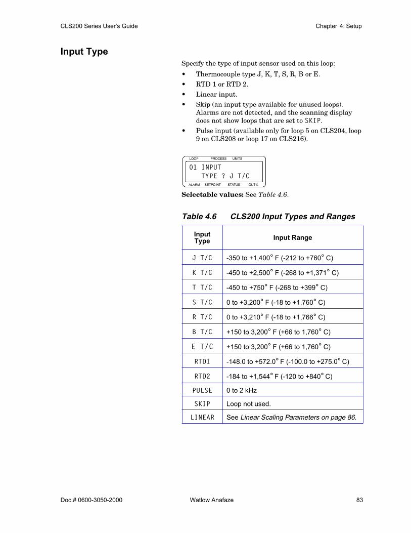
CLS200 Series User’s Guide Chapter 4: Setup
Doc.# 0600-3050-2000 Watlow Anafaze 83
Input Type Specify the type of input sensor used on this loop:
• Thermocouple type J, K, T, S, R, B or E.• RTD 1 or RTD 2.• Linear input. • Skip (an input type available for unused loops).
Alarms are not detected, and the scanning display does not show loops that are set to SKIP.
• Pulse input (available only for loop 5 on CLS204, loop 9 on CLS208 or loop 17 on CLS216).
Selectable values: See Table 4.6.
Table 4.6 CLS200 Input Types and Ranges
Input Type Input Range
J T/C -350 to +1,400° F (-212 to +760° C)
K T/C -450 to +2,500° F (-268 to +1,371° C)
T T/C -450 to +750° F (-268 to +399° C)
S T/C 0 to +3,200° F (-18 to +1,760° C)
R T/C 0 to +3,210° F (-18 to +1,766° C)
B T/C +150 to 3,200° F (+66 to 1,760° C)
E T/C +150 to 3,200° F (+66 to 1,760° C)
RTD1 -148.0 to +572.0° F (-100.0 to +275.0° C)
RTD2 -184 to +1,544° F (-120 to +840° C)
PULSE 0 to 2 kHz
SKIP Loop not used.
LINEAR See Linear Scaling Parameters on page 86.
ALARM
01 INPUT TYPE ? J T/C
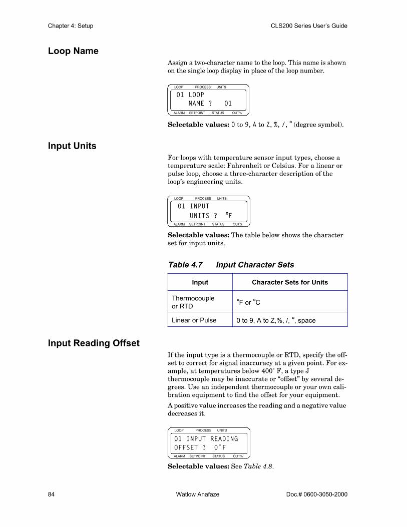
Chapter 4: Setup CLS200 Series User’s Guide
84 Watlow Anafaze Doc.# 0600-3050-2000
Loop NameAssign a two-character name to the loop. This name is shown on the single loop display in place of the loop number.
Selectable values: 0 to 9, A to Z, %, /, ° (degree symbol).
Input UnitsFor loops with temperature sensor input types, choose a temperature scale: Fahrenheit or Celsius. For a linear or pulse loop, choose a three-character description of the loop’s engineering units.
Selectable values: The table below shows the character set for input units.
Table 4.7 Input Character Sets
Input Reading OffsetIf the input type is a thermocouple or RTD, specify the off-set to correct for signal inaccuracy at a given point. For ex-ample, at temperatures below 400˚ F, a type J thermocouple may be inaccurate or “offset” by several de-grees. Use an independent thermocouple or your own cali-bration equipment to find the offset for your equipment.
A positive value increases the reading and a negative value decreases it.
Selectable values: See Table 4.8.
Input Character Sets for Units
Thermocouple or RTD °F or °C
Linear or Pulse 0 to 9, A to Z,%, /, °, space
ALARM
01 LOOP NAME ? 01
ALARM
01 INPUT UNITS ? °F
ALARM
01 INPUT READINGOFFSET ? 0˚F

CLS200 Series User’s Guide Chapter 4: Setup
Doc.# 0600-3050-2000 Watlow Anafaze 85
Table 4.8 Input Reading Offset
Reversed T/C DetectionSet this parameter to ON to enable polarity checking for thermocouples. If a reversed thermocouple is detected, the controller sets the loop to manual control at the SENSOR FAIL HT OUTPUT or SENSOR FAIL CL OUTPUT power level and displays the alarm.
Selectable values: ON or OFF.
Input Pulse Sample TimeYou can connect a digital pulse signal of up to 2 kHz to the pulse input. Use this parameter to set the time over which pulses are counted. The controller counts pulses for the amount of time you set here before calculating the frequn-cy. The controller scales this frequency and uses the result-ing value as the process variable for the pulse loop. Generally, the longer the pulse sample time, the more sta-ble the process variable, but the slower the response of the pulse loop.
This parameter is available only for loop 5 on the CLS204, loop 9 on the CLS208 or loop 17 on the CLS216.
Selectable values: 1 to 20 seconds.
Type of SensorOffset Range
°F °C
RTD2JKT
-300 to +300 -300 to +300
RTD1 -300.0 to +300.0 -300.0 to +300.0
BS -300 to +76 -300 to +300
R -300 to +66 -300 to +300
ALARM
01 REVERSED T/CDETECT ? OFF
ALARM
17 INPUT PULSESAMPLE TIME ? 1S

Chapter 4: Setup CLS200 Series User’s Guide
86 Watlow Anafaze Doc.# 0600-3050-2000
Linear Scaling ParametersThe following parameters are only available if the input type is LINEAR or PULSE. These parameters let you scale the raw input readings (in millivolts or Hertz) to the engi-neering units of the process variable.
For linear inputs, the input reading is in percent (0 to 100%) representing the 0 to 60mV input range of the con-troller. For pulse inputs, the input reading is in Hertz (cy-cles per second.)
The scaling function is defined by two points on a conver-sion line. This line relates the process variable (PV) to the input signal. The engineering units of the process variable can be any units—the graph in Figure 4.2 shows PSI as an example.
Figure 4.2 Two Points Determine Process Variable Conversion
Before you enter the values determining the two points for the conversion line, you must choose an appropriate dis-play format. The controller has six characters available for process display; select the setting with the desired number of decimal places. Use a display format that matches the range of the process variable and resolution of the sensor. The display format you choose is used for the process vari-able setpoint, alarms limits, deadband, spread and propor-tional band.
The process variable range for the scaled input is between the process variable values that correspond to the 0% and 100% input readings. For the pulse input, it is between the 0 Hz and 2000 Hz readings. The process variable range de-fines the limits for the setpoint and alarms. See Figure 4.3.
High ProcessVariable
Low ProcessVariable
LowReading
HighReadingInput Reading
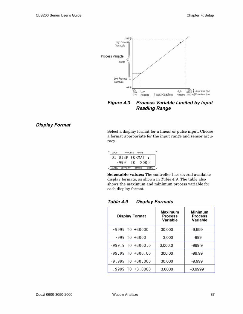
CLS200 Series User’s Guide Chapter 4: Setup
Doc.# 0600-3050-2000 Watlow Anafaze 87
Figure 4.3 Process Variable Limited by Input Reading Range
Display Format Select a display format for a linear or pulse input. Choose a format appropriate for the input range and sensor accu-racy.
Selectable values: The controller has several available display formats, as shown in Table 4.9. The table also shows the maximum and minimum process variable for each display format.
Table 4.9 Display Formats
Display FormatMaximum Process Variable
Minimum Process Variable
-9999 TO +30000 30,000 -9,999
-999 TO +3000 3,000 -999
-999.9 TO +3000.0 3,000.0 -999.9
-99.99 TO +300.00 300.00 -99.99
-9.999 TO +30.000 30.000 -9.999
-.9999 TO +3.0000 3.0000 -0.9999
High ProcessVariabale
Process Variable
Low ProcessVariabale
LowReading
HighReadingInput Reading
ALARM
01 DISP FORMAT ? -999 TO 3000
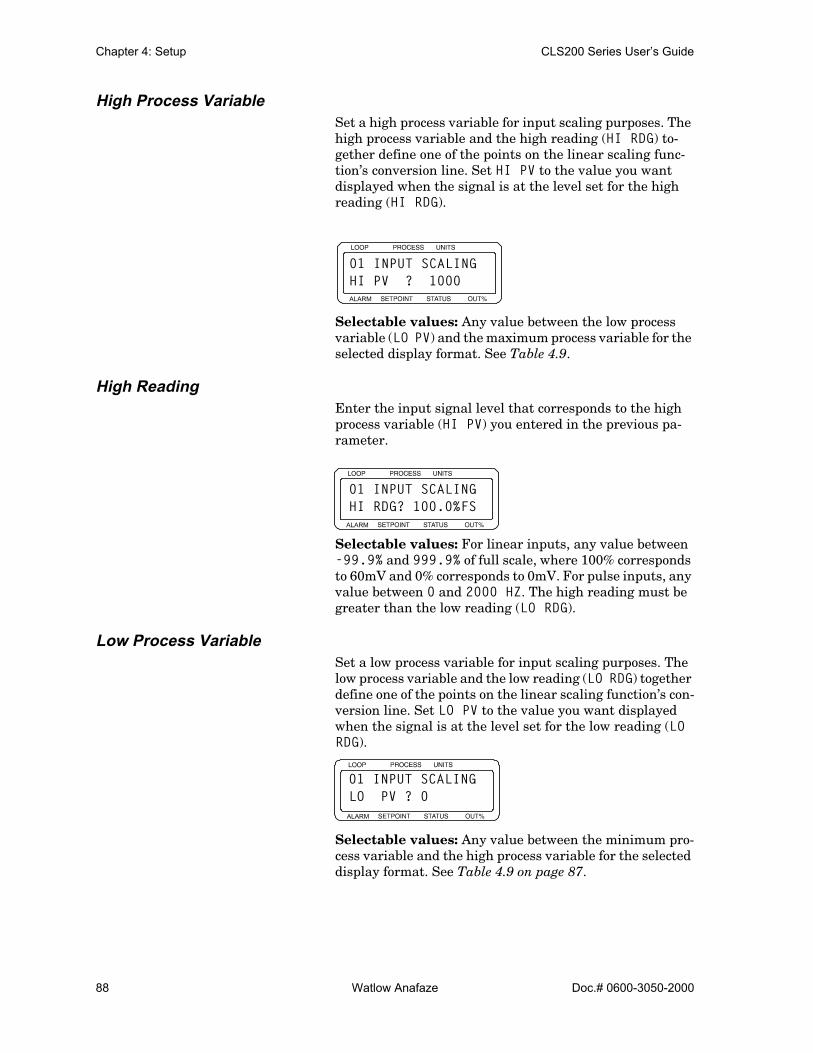
Chapter 4: Setup CLS200 Series User’s Guide
88 Watlow Anafaze Doc.# 0600-3050-2000
High Process VariableSet a high process variable for input scaling purposes. The high process variable and the high reading (HI RDG) to-gether define one of the points on the linear scaling func-tion’s conversion line. Set HI PV to the value you want displayed when the signal is at the level set for the high reading (HI RDG).
Selectable values: Any value between the low process variable (LO PV) and the maximum process variable for the selected display format. See Table 4.9.
High ReadingEnter the input signal level that corresponds to the high process variable (HI PV) you entered in the previous pa-rameter.
Selectable values: For linear inputs, any value between -99.9% and 999.9% of full scale, where 100% corresponds to 60mV and 0% corresponds to 0mV. For pulse inputs, any value between 0 and 2000 HZ. The high reading must be greater than the low reading (LO RDG).
Low Process VariableSet a low process variable for input scaling purposes. The low process variable and the low reading (LO RDG) together define one of the points on the linear scaling function’s con-version line. Set LO PV to the value you want displayed when the signal is at the level set for the low reading (LO RDG).
Selectable values: Any value between the minimum pro-cess variable and the high process variable for the selected display format. See Table 4.9 on page 87.
ALARM
01 INPUT SCALINGHI PV ? 1000
ALARM
01 INPUT SCALINGHI RDG? 100.0%FS
ALARM
01 INPUT SCALINGLO PV ? 0
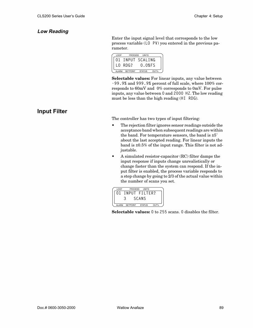
CLS200 Series User’s Guide Chapter 4: Setup
Doc.# 0600-3050-2000 Watlow Anafaze 89
Low ReadingEnter the input signal level that corresponds to the low process variable (LO PV) you entered in the previous pa-rameter.
Selectable values: For linear inputs, any value between -99.9% and 999.9% percent of full scale, where 100% cor-responds to 60mV and 0% corresponds to 0mV. For pulse inputs, any value between 0 and 2000 HZ. The low reading must be less than the high reading (HI RDG).
Input FilterThe controller has two types of input filtering:
• The rejection filter ignores sensor readings outside the acceptance band when subsequent readings are within the band. For temperature sensors, the band is ±5˚ about the last accepted reading. For linear inputs the band is ±0.5% of the input range. This filter is not ad-justable.
• A simulated resistor-capacitor (RC) filter damps the input response if inputs change unrealistically or change faster than the system can respond. If the in-put filter is enabled, the process variable responds to a step change by going to 2/3 of the actual value within the number of scans you set.
Selectable values: 0 to 255 scans. 0 disables the filter.
ALARM
01 INPUT SCALINGLO RDG? 0.0%FS
ALARM
01 INPUT FILTER? 3 SCANS

Chapter 4: Setup CLS200 Series User’s Guide
90 Watlow Anafaze Doc.# 0600-3050-2000
Setup Loop Control Parameters MenuUse the SETUP LOOP CONTROL PARAMS menu to adjust heat and cool control parameters, including:
• Proportional band (PB, or gain), integral (TI or reset), and derivative (TD, or rate) settings
• Output filter• Spread between heat and cool outputs
The controller has separate PID and filter settings for heat and cool outputs. The screens used to set these parameters are nearly identical. In this section, only the heat screens are shown and explained. The heat and cool parameters ap-pear only if the corresponding output is enabled.
See Setup Loop Outputs Menu on page 93 for help enabling and disabling heat and cool outputs.
Table 4.10 shows the parameters available in the SETUP LOOP CONTROL PARAMS menu.
Table 4.10 Setup Loop Control Parameters
Parameter Default Value
HEAT CONTROL PB? Depends upon the INPUT TYPE setting; 50 for J-type thermocouple.
HEAT CONTROL TI? Depends upon the INPUT TYPE setting; 180 SEC/R for J-type ther-mocouple.
HEAT CONTROL TD? 0
HEAT CONTROL FILTER? 3
COOL CONTROL PB 50
COOL CONTROL TI? Depends upon the INPUT TYPE setting; 60 SEC/R for J-type ther-mocouple.
COOL CONTROL TD? Depends upon the INPUT TYPE setting; 0 SECONDS for J-type ther-mocouple.
COOL CONTROL FILTER? 3
SPREAD? 5
RESTORE PID DIGIN? NONE
ALARM
SETUP LOOP 01CONTROL PARAMS?
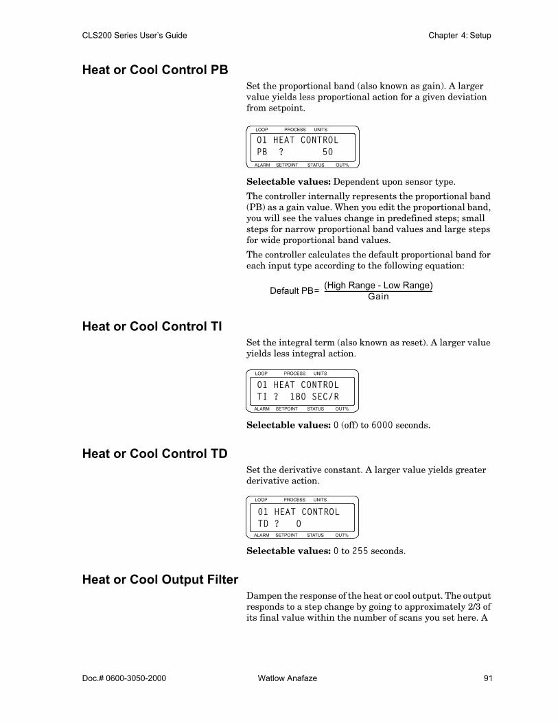
CLS200 Series User’s Guide Chapter 4: Setup
Doc.# 0600-3050-2000 Watlow Anafaze 91
Heat or Cool Control PB Set the proportional band (also known as gain). A larger value yields less proportional action for a given deviation from setpoint.
Selectable values: Dependent upon sensor type.
The controller internally represents the proportional band (PB) as a gain value. When you edit the proportional band, you will see the values change in predefined steps; small steps for narrow proportional band values and large steps for wide proportional band values.
The controller calculates the default proportional band for each input type according to the following equation:
Heat or Cool Control TI Set the integral term (also known as reset). A larger value yields less integral action.
Selectable values: 0 (off) to 6000 seconds.
Heat or Cool Control TD Set the derivative constant. A larger value yields greater derivative action.
Selectable values: 0 to 255 seconds.
Heat or Cool Output FilterDampen the response of the heat or cool output. The output responds to a step change by going to approximately 2/3 of its final value within the number of scans you set here. A
ALARM
01 HEAT CONTROLPB ? 50
Default PB (High Range - Low Range)Gain-----------------------------------------------------------------------=
ALARM
01 HEAT CONTROLTI ? 180 SEC/R
ALARM
01 HEAT CONTROLTD ? 0
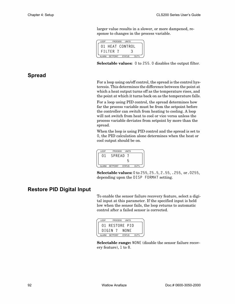
Chapter 4: Setup CLS200 Series User’s Guide
92 Watlow Anafaze Doc.# 0600-3050-2000
larger value results in a slower, or more dampened, re-sponse to changes in the process variable.
Selectable values: 0 to 255. 0 disables the output filter.
Spread For a loop using on/off control, the spread is the control hys-teresis. This determines the difference between the point at which a heat output turns off as the temperature rises, and the point at which it turns back on as the temperature falls.
For a loop using PID control, the spread determines how far the process variable must be from the setpoint before the controller can switch from heating to cooling. A loop will not switch from heat to cool or vice versa unless the process variable deviates from setpoint by more than the spread.
When the loop is using PID control and the spread is set to 0, the PID calculation alone determines when the heat or cool output should be on.
Selectable values: 0 to 255, 25.5, 2.55, .255, or.0255, depending upon the DISP FORMAT setting.
Restore PID Digital InputTo enable the sensor failure recovery feature, select a digi-tal input at this parameter. If the specified input is held low when the sensor fails, the loop returns to automatic control after a failed sensor is corrected.
Selectable range: NONE (disable the sensor failure recov-ery feature), 1 to 8.
ALARM
01 HEAT CONTROLFILTER ? 3
ALARM
01 SPREAD ? 5
ALARM
01 RESTORE PIDDIGIN ? NONE

CLS200 Series User’s Guide Chapter 4: Setup
Doc.# 0600-3050-2000 Watlow Anafaze 93
Setup Loop Outputs MenuUse the SETUP LOOP OUTPUTS menu to:
• Enable or disable outputs• Set output type• Set cycle time for time proportioning outputs• Enter Serial DAC parameters (for Serial DAC out-
puts)• Select control action• Set output level limit and limit time• Select sensor fail output (output override)• Select a nonlinear output curve
Table 4.11 shows the parameters available in the SETUP LOOP OUTPUTS menu. Both heat and cool outputs have the same parameters; only one of each parameter is shown.
Table 4.11 Setup Loop Outputs
* The SDAC parameters are available only if you select SDAC as the output type. Use these parameters to configure the Serial DAC signal output.
Parameter Default Value
HEAT CONTROL OUTPUT? ENABLED
HEAT OUTPUT TYPE? TP
HEAT OUTPUT CYCLE TIME? 10S
SDAC MODE?* VOLTAGE
SDAC LO VALUE?* 0.00 VDC
SDAC HI VALUE?* 10.00 VDC
HEAT OUTPUT ACTION? REVERSE
HEAT OUTPUT LIMIT? 100%
HEAT OUTPUT LIMIT TIME? CONT
SENSOR FAIL HT OUTPUT? 0%
HEAT T/C BRK OUT AVG? OFF
HEAT OUTPUT? LINEAR
COOL CONTROL OUTPUT? DISABLED
ALARM
SETUP LOOP 01OUTPUTS ?
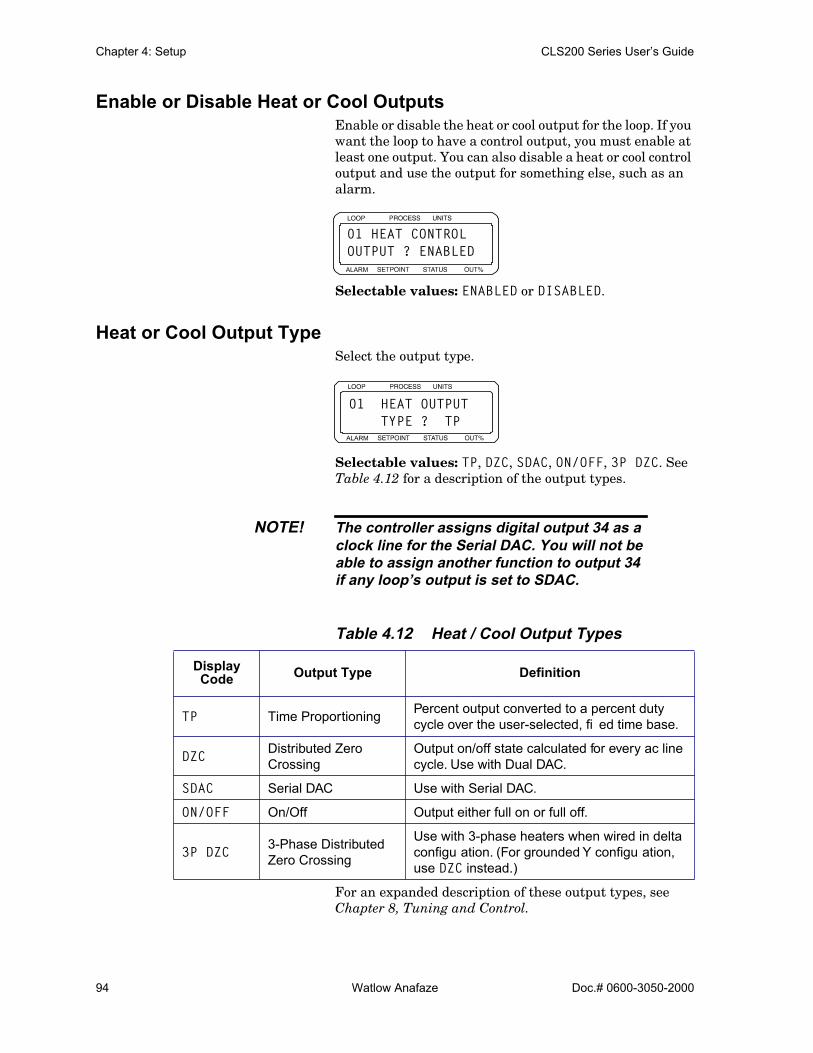
Chapter 4: Setup CLS200 Series User’s Guide
94 Watlow Anafaze Doc.# 0600-3050-2000
Enable or Disable Heat or Cool Outputs Enable or disable the heat or cool output for the loop. If you want the loop to have a control output, you must enable at least one output. You can also disable a heat or cool control output and use the output for something else, such as an alarm.
Selectable values: ENABLED or DISABLED.
Heat or Cool Output Type Select the output type.
Selectable values: TP, DZC, SDAC, ON/OFF, 3P DZC. See Table 4.12 for a description of the output types.
NOTE! The controller assigns digital output 34 as aclock line for the Serial DAC. You will not beable to assign another function to output 34if any loop’s output is set to SDAC.
Table 4.12 Heat / Cool Output Types
For an expanded description of these output types, see Chapter 8, Tuning and Control.
Display Code Output Type Definition
TP Time Proportioning Percent output converted to a percent duty cycle over the user-selected, fi ed time base.
DZC Distributed Zero Crossing
Output on/off state calculated for every ac line cycle. Use with Dual DAC.
SDAC Serial DAC Use with Serial DAC.
ON/OFF On/Off Output either full on or full off.
3P DZC 3-Phase Distributed Zero Crossing
Use with 3-phase heaters when wired in delta configu ation. (For grounded Y configu ation, use DZC instead.)
ALARM
01 HEAT CONTROLOUTPUT ? ENABLED
ALARM
01 HEAT OUTPUT TYPE ? TP

CLS200 Series User’s Guide Chapter 4: Setup
Doc.# 0600-3050-2000 Watlow Anafaze 95
Heat or Cool Cycle Time Set the cycle time for time proportioning outputs.
This parameter appears only if the heat or cool output type for the loop is set to time proportioning (TP).
Selectable values: 1 to 255 seconds.
SDAC ModeSelect the Serial DAC output signal.
Selectable values: CURRENT or VOLTAGE.
SDAC Low ValueSet the low output signal level for the Serial DAC. The Se-rial DAC converts 0% output from the controller to the val-ue set here.
Set the high and low values to match the input range of the output device. For instance, if the output device has a 0.00-10.00 V range, set the SDAC LO VALUE to 0.00 VDC and set the SDAC HI VALUE to 10.00 VDC.
Selectable values: 0.00 to 9.00 VDC or 0.0 to 19.90 MA. This value must be less than the SDAC HI VALUE.
SDAC High ValueSet the high output signal level for the Serial DAC. The Se-rial DAC converts 100% output from the controller to the value set here.
Set the high and low values to match the range of the out-put device. For instance, if the output device has a 4 to 20
ALARM
01 HEAT OUTPUTCYCLE TIME? 10S
ALARM
01 SDAC MODE? VOLTAGE
ALARM
01 SDAC LO VALUE? 0.00 VDC
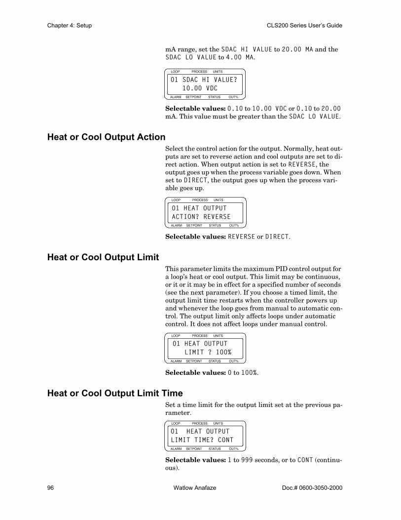
Chapter 4: Setup CLS200 Series User’s Guide
96 Watlow Anafaze Doc.# 0600-3050-2000
mA range, set the SDAC HI VALUE to 20.00 MA and the SDAC LO VALUE to 4.00 MA.
Selectable values: 0.10 to 10.00 VDC or 0.10 to 20.00 mA. This value must be greater than the SDAC LO VALUE.
Heat or Cool Output Action Select the control action for the output. Normally, heat out-puts are set to reverse action and cool outputs are set to di-rect action. When output action is set to REVERSE, the output goes up when the process variable goes down. When set to DIRECT, the output goes up when the process vari-able goes up.
Selectable values: REVERSE or DIRECT.
Heat or Cool Output LimitThis parameter limits the maximum PID control output for a loop’s heat or cool output. This limit may be continuous, or it or it may be in effect for a specified number of seconds (see the next parameter). If you choose a timed limit, the output limit time restarts when the controller powers up and whenever the loop goes from manual to automatic con-trol. The output limit only affects loops under automatic control. It does not affect loops under manual control.
Selectable values: 0 to 100%.
Heat or Cool Output Limit Time Set a time limit for the output limit set at the previous pa-rameter.
Selectable values: 1 to 999 seconds, or to CONT (continu-ous).
ALARM
01 SDAC HI VALUE? 10.00 VDC
ALARM
01 HEAT OUTPUTACTION? REVERSE
ALARM
01 HEAT OUTPUT LIMIT ? 100%
ALARM
01 HEAT OUTPUTLIMIT TIME? CONT

CLS200 Series User’s Guide Chapter 4: Setup
Doc.# 0600-3050-2000 Watlow Anafaze 97
Sensor Fail Heat or Cool OutputWhen a sensor fail alarm occurs or when the OUTPUT OVERRIDE DIG INPUT (page 77) becomes active on a loop that is in automatic control, that loop goes to manual con-trol at the percent power output set here.
Selectable values: 0 to 100%.
NOTE! When a sensor fails or the override input isdetected, both the heat and cool outputs areset to their fail settings. In most applications,SENSOR FAIL HT OUTPUT and SENSORFAIL CL OUTPUT should be set to 0%.
WARNING! Do not rely solely on the sensor fail alarm toadjust the output in the event of a sensor fail-ure. If the loop is in manual control when afailed sensor alarm occurs, the output is notadjusted. Install independent external safetydevices that will shut down the system if afailure occurs.
Heat or Cool Thermocouple Break Output AverageIf you set this parameter to ON and a thermocouple break occurs, a loop set to automatic control status will go to man-ual mode at a percentage equal to the average output prior to the break.
Selectable range: ON or OFF
ALARM
01 SENSOR FAILHT OUTPUT ? 0%
ALARM
01 HEAT T/C BRKOUT AVG ? OFF
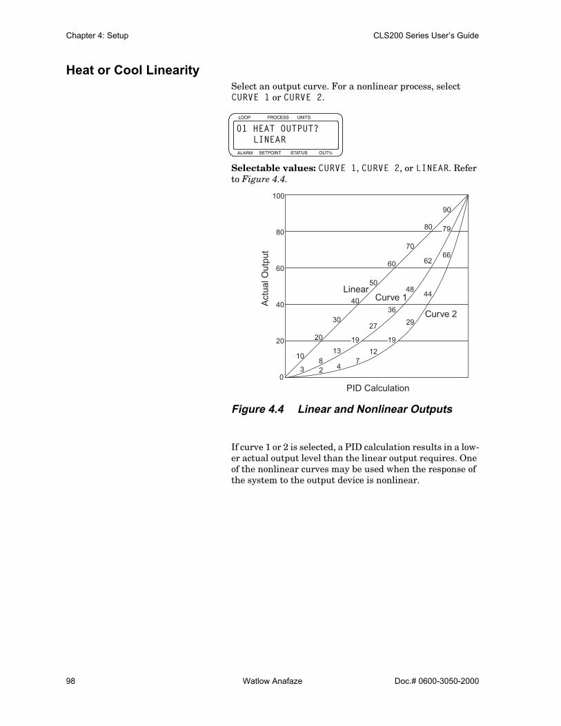
Chapter 4: Setup CLS200 Series User’s Guide
98 Watlow Anafaze Doc.# 0600-3050-2000
Heat or Cool LinearitySelect an output curve. For a nonlinear process, select CURVE 1 or CURVE 2.
Selectable values: CURVE 1, CURVE 2, or LINEAR. Refer to Figure 4.4.
Figure 4.4 Linear and Nonlinear Outputs
If curve 1 or 2 is selected, a PID calculation results in a low-er actual output level than the linear output requires. One of the nonlinear curves may be used when the response of the system to the output device is nonlinear.
ALARM
01 HEAT OUTPUT? LINEAR
Act
ual O
utpu
t
0
20
40
60
80
100
PID Calculation
10
20
30
40
50
60
70
80
90
38
13
27
48
62
2 47
12
29
44
66
LinearCurve 1
Curve 236
19 19
79
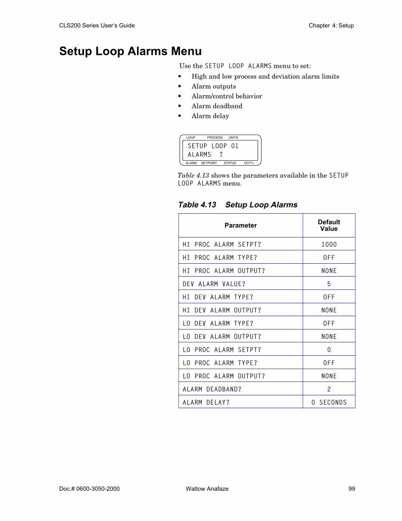
CLS200 Series User’s Guide Chapter 4: Setup
Doc.# 0600-3050-2000 Watlow Anafaze 99
Setup Loop Alarms Menu Use the SETUP LOOP ALARMS menu to set:
• High and low process and deviation alarm limits• Alarm outputs• Alarm/control behavior• Alarm deadband• Alarm delay
Table 4.13 shows the parameters available in the SETUP LOOP ALARMS menu.
Table 4.13 Setup Loop Alarms
Parameter Default Value
HI PROC ALARM SETPT? 1000
HI PROC ALARM TYPE? OFF
HI PROC ALARM OUTPUT? NONE
DEV ALARM VALUE? 5
HI DEV ALARM TYPE? OFF
HI DEV ALARM OUTPUT? NONE
LO DEV ALARM TYPE? OFF
LO DEV ALARM OUTPUT? NONE
LO PROC ALARM SETPT? 0
LO PROC ALARM TYPE? OFF
LO PROC ALARM OUTPUT? NONE
ALARM DEADBAND? 2
ALARM DELAY? 0 SECONDS
ALARM
SETUP LOOP 01ALARMS ?

Chapter 4: Setup CLS200 Series User’s Guide
100 Watlow Anafaze Doc.# 0600-3050-2000
High Process Alarm SetpointSet the value at which the high process alarm activates.
Selectable values: Any point within the scaled sensor range.
High Process Alarm TypeSelect an alarm type for the high process alarm.
Selectable values: OFF, ALARM, or CONTROL.
High Process Alarm Output NumberChoose a digital output to activate when the high process alarm occurs, if desired.
Selectable values: NONE, or any output from 1 to 34 not enabled for closed-loop control or for the Serial DAC clock.
Deviation Alarm ValueSet the deviation from setpoint at which the high and low deviation alarms occur.
Selectable values: 0 to 255, 25.5, 2.55, .255 or.0255, depending on the INPUT TYPE and DISP FORMAT settings.
ALARM
01 HI PROC ALARM SETPT ? 1000
ALARM
01 HI PROC ALARM TYPE ? OFF
ALARM
01 HI PROC ALARM OUTPUT? NONE
ALARM
01 DEV ALARMVALUE ? 5
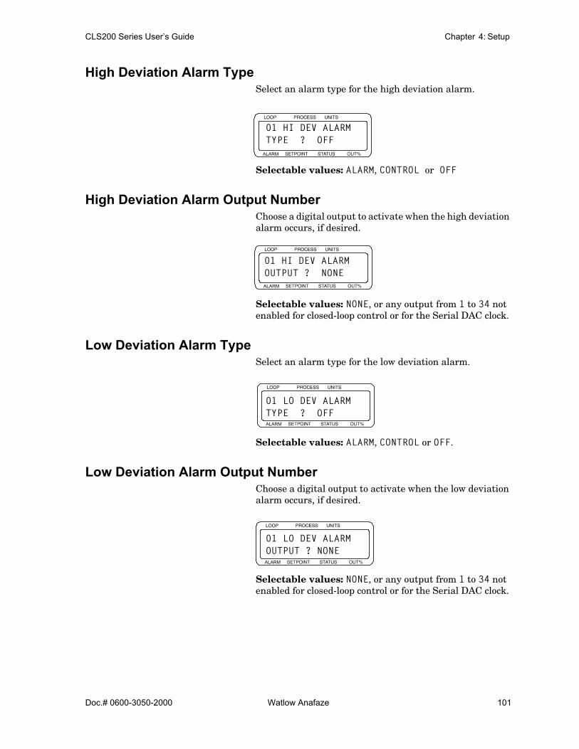
CLS200 Series User’s Guide Chapter 4: Setup
Doc.# 0600-3050-2000 Watlow Anafaze 101
High Deviation Alarm TypeSelect an alarm type for the high deviation alarm.
Selectable values: ALARM, CONTROL or OFF
High Deviation Alarm Output NumberChoose a digital output to activate when the high deviation alarm occurs, if desired.
Selectable values: NONE, or any output from 1 to 34 not enabled for closed-loop control or for the Serial DAC clock.
Low Deviation Alarm TypeSelect an alarm type for the low deviation alarm.
Selectable values: ALARM, CONTROL or OFF.
Low Deviation Alarm Output NumberChoose a digital output to activate when the low deviation alarm occurs, if desired.
Selectable values: NONE, or any output from 1 to 34 not enabled for closed-loop control or for the Serial DAC clock.
ALARM
01 HI DEV ALARM TYPE ? OFF
ALARM
01 HI DEV ALARMOUTPUT ? NONE
ALARM
01 LO DEV ALARMTYPE ? OFF
ALARM
01 LO DEV ALARMOUTPUT ? NONE

Chapter 4: Setup CLS200 Series User’s Guide
102 Watlow Anafaze Doc.# 0600-3050-2000
Low Process Alarm SetpointSet a low process alarm setpoint. See Process Alarms on page 66.
Selectable values: Any value within the input sensor’s range.
Low Process Alarm TypeSelect an alarm type for the low process alarm.
Selectable values: ALARM, CONTROL or OFF.
Low Process Alarm Output NumberChoose a digital output to activate when the low process alarm occurs, if desired.
Selectable values: NONE, or any output from 1 to 34 not enabled for closed-loop control or for the Serial DAC clock.
Alarm DeadbandSet an alarm deadband. This deadband value applies to the high process, low process, high deviation and low deviation alarms for the loop. Use the alarm deadband to avoid re-peated alarms as the process variable cycles around an alarm value.
Selectable values: 0 to 255, 25.5, 2.55, .255 or .0255, depending on the INPUT TYPE and DISP FORMAT settings.
ALARM
01 LO PROC ALARM SETPT? 0
ALARM
01 LO PROC ALARM TYPE ? OFF
ALARM
01 LO PROC ALARMOUTPUT ? NONE
ALARM
01 ALARM DEAD-BAND ? 2
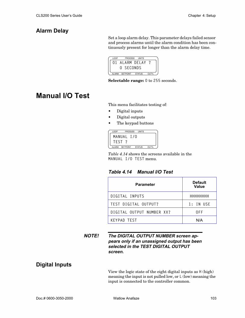
CLS200 Series User’s Guide Chapter 4: Setup
Doc.# 0600-3050-2000 Watlow Anafaze 103
Alarm DelaySet a loop alarm delay. This parameter delays failed sensor and process alarms until the alarm condition has been con-tinuously present for longer than the alarm delay time.
Selectable range: 0 to 255 seconds.
Manual I/O TestThis menu facilitates testing of:
• Digital inputs• Digital outputs• The keypad buttons
Table 4.14 shows the screens available in the MANUAL I/O TEST menu.
Table 4.14 Manual I/O Test
NOTE! The DIGITAL OUTPUT NUMBER screen ap-pears only if an unassigned output has beenselected in the TEST DIGITAL OUTPUTscreen.
Digital InputsView the logic state of the eight digital inputs as H (high) meaning the input is not pulled low, or L (low) meaning the input is connected to the controller common.
Parameter Default Value
DIGITAL INPUTS HHHHHHHH
TEST DIGITAL OUTPUT? 1: IN USE
DIGITAL OUTPUT NUMBER XX? OFF
KEYPAD TEST N/A
ALARM
01 ALARM DELAY ? 0 SECONDS
ALARM
MANUAL I/OTEST ?

Chapter 4: Setup CLS200 Series User’s Guide
104 Watlow Anafaze Doc.# 0600-3050-2000
This screen shows the state of inputs 1 to 8 from left to right. See Figure 4.5. Since inputs are pulled high when they are not connected, test an input by shorting it to con-troller common and making sure this screen shows the cor-rect state for that input.
Figure 4.5 Digital Inputs Screen
When you are done testing digital inputs, press YES or NO to advance to the next screen, or press BACK to return to the MANUAL I/O TEST menu.
Test Digital OutputSelect one of the digital alarm outputs to test. You will test the output on the next screen.
You cannot force the state of an output enabled for control.
Selectable values: Any output from 1 to 34 that is not en-abled for closed-loop control or for the Serial DAC clock and GA, the global alarm output.
Digital Output NumberThis screen appears only if you selected an output that is not in use for control at the TEST DIGITAL OUTPUT screen.
Use this parameter to manually toggle a digital output on or off to test it. Toggling an output ON sinks current from the output to the controller common. Toggling the output OFF stops current flow. All tested outputs are set to OFF when you exit the MANUAL I/O TEST menu.
You cannot toggle outputs enabled for control. To test a control loop output, first disable it using the SETUP LOOP OUTPUTS menu.
Selectable values: ON or OFF.
ALARM
DIGITAL INPUTSHHHHHHHH
Input 1 Input 8
ALARM
TEST DIGITALOUTPUT? 1:IN USE
ALARM
DIGITAL OUTPUT NUMBER XX ? OFF

CLS200 Series User’s Guide Chapter 4: Setup
Doc.# 0600-3050-2000 Watlow Anafaze 105
Keypad TestTest the keypad. The test begins automatically when the screen appears.
• Press any key to test the keypad. The controller will display the name of the key you have pressed.
• Press NO twice to end the test and return to the top of the MANUAL I/O TEST menu.
Display TestUse this function to test the display.
Press YES to enter the test and display the instruction screen.
Press YES to begin the display of a discernable pixel pat-tern.
• Press YES to toggle the pixel pattern.• Press NO to end the test and return to the top of
the MANUAL I/O TEST menu.
ALARM
KEYPAD TESTQUIT = "NO"+"NO"
ALARM
DISPLAY TEST?
ALARM
TO TEST DISPLAYY-TOGGLE N-QUIT

Chapter 4: Setup CLS200 Series User’s Guide
106 Watlow Anafaze Doc.# 0600-3050-2000

Doc.# 0600-3050-2000 Watlow Anafaze 107
5Extruder Control
This chapter explains the additional features for the CLS200 series controller equipped with Extruder Control Firmware. Except for setup, default and control algorithm differences described below, the Extruder Control Firm-ware operates the same as the standard control firmware.
Setup Loop Outputs MenuThe SETUP LOOP OUTPUTS menu contains a parameter with descriptors for the selections that are different than those in the standard control firmware.
Cool Output Nonlinear Output CurveSelect linear or nonlinear output curves for the cool output.
Selectable Values: FAN, OIL or H2O. See Figure 5.1.
ALARM
SETUP LOOP 01OUTPUTS ?
ALARM
01 COOL OUTPUT FAN

Chapter 5: Extruder Control CLS200 Series User’s Guide
108 Watlow Anafaze Doc.# 0600-3050-2000
Figure 5.1 Cool Output Nonlinear Output Curve
The COOL OUTPUT parameter is located in the SETUP LOOP OUTPUTS menu. Select one of three nonlinear or lin-ear output curves for cooling.
DefaultsThe Extruder Control Firmware uses different defaults for some parameters in the SETUP LOOP CONTROL PARAMS menu. Furthermore, a unique set of control de-faults are asserted whenever the COOL OUTPUT parame-ter on the SETUP LOOP OUTPUTS menu is changed. Table 5.1 through Table 5.3 on page 109 list the default pa-rameter settings for each cool output curve.
NOTE! Changing the cool output curve parameterwill change control parameter settings to de-faults for that particular cool output curve.
Calculated by PID
Out
put
00 3 2
47
12
19
29
44
66
8
13
19
27
36
48
62
79
10
20
40
60
80
100
30
50
70
90
20
40
60
80
100
Oil
Fan
H2O
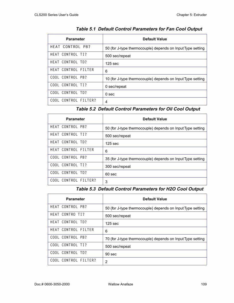
CLS200 Series User’s Guide Chapter 5: Extruder
Doc.# 0600-3050-2000 Watlow Anafaze 109
Table 5.1 Default Control Parameters for Fan Cool Output
Table 5.2 Default Control Parameters for Oil Cool Output
Table 5.3 Default Control Parameters for H2O Cool Output
Parameter Default Value
HEAT CONTROL PB? 50 (for J-type thermocouple) depends on Input Type settingHEAT CONTROL TI? 500 sec/repeatHEAT CONTROL TD? 125 secHEAT CONTROL FILTER 6COOL CONTROL PB? 10 (for J-type thermocouple) depends on Input Type settingCOOL CONTROL TI? 0 sec/repeatCOOL CONTROL TD? 0 secCOOL CONTROL FILTER? 4
Parameter Default Value
HEAT CONTROL PB? 50 (for J-type thermocouple) depends on Input Type settingHEAT CONTROL TI? 500 sec/repeatHEAT CONTROL TD? 125 secHEAT CONTROL FILTER 6COOL CONTROL PB? 35 (for J-type thermocouple) depends on Input Type settingCOOL CONTROL TI? 300 sec/repeatCOOL CONTROL TD? 60 secCOOL CONTROL FILTER? 3
Parameter Default Value
HEAT CONTROL PB? 50 (for J-type thermocouple) depends on Input Type settingHEAT CONTRO TI? 500 sec/repeatHEAT CONTROL TD? 125 secHEAT CONTROL FILTER 6COOL CONTROL PB? 70 (for J-type thermocouple) depends on Input Type settingCOOL CONTROL TI? 500 sec/repeatCOOL CONTROL TD? 90 secCOOL CONTROL FILTER? 2
Chapter 5: Extruder Control CLS200 Series User’s Guide
110 Watlow Anafaze Doc.# 0600-3050-2000
Extruder Control AlgorithmThe Extruder Control Firmware uses a control algorithm that has been optimized for controlling temperature loops in plastic extruder equipment. Typically, overshoot is un-desirable and ambient cooling is not sufficient to dampen the effects of self heating that are inherent in the extrusion process. This control method uses both heat and cool out-puts. Under some conditions both heat and cool outputs may be on at the same time.

Doc.# 0600-3050-2000 Watlow Anafaze 111
6Enhanced Features
This chapter explains five additional features for the CLS200 controller when enabled with enhanced features option firmware:
• Process variable retransmit• Cascade control• Ratio control• Remote analog setpoint• Differential control

Chapter 6: Enhanced Features CLS200 Series User’s Guide
112 Watlow Anafaze Doc.# 0600-3050-2000
Figure 6.1 Enhanced Features Option Menus
SETUPGLOBAL PARAMETERS
SETUP LOOP INPUTS
SETUPLOOP CONTROL PARAMETERS
SETUPLOOPOUTPUTS
SETUPLOOP PVRETRANSMIT
SETUPLOOP CASCADE
SETUPLOOP RATIOCONTROL
SETUPLOOPALARMS
MANUALI/OTEST
HEAT OUTPUTRETRANS PV?
HEAT RETRANSMIN INP?
HEAT RETRANSMIN OUT%?
HEAT RETRANSMAX INP?
HEAT RETRANSMAX OUT%?
COOL OUTPUT RETRANS PV?
COOL RETRANS MIN INP?
COOL RETRANS MIN OUT%?
COOL RETRANS MAX INP?
COOL RETRANS MAX OUT%?
Enter 1-9
Enter 1-9
CASCADEPRIM. LOOP?
CASCADEBASE SP?
CASCADE MIN SP?
CASCADE MAX SP?
CASCADE HT SPAN?
CASCADE CL SPAN?
YES
Enter NONE or NO
YES
RATIO CONTROL MAX SP?
RATIO CONTROL CTRL RATIO?
RATIO CONTROL SP DIFF?
YES
RATIO CONTROL MIN SP?
RATIO CONTROL MSTR LOOP?
Enter NONE or NO

CLS200 Series User’s Guide Chapter 6: Enhanced Features
Doc.# 0600-3050-2000 Watlow Anafaze 113
Process Variable RetransmitThe process variable retransmit feature retransmits the process signal of one loop (primary) via the control output of another loop (secondary). This signal is linear and pro-portional to the engineering units of the primary loop in-put.
Typical uses include data logging to analog recording sys-tems and long distance transmission of the primary signal to avoid degradation of the primary signal. The signal can also be used as an input to other types of control systems such as a PLC.
Any available output (heat or cool) may be used as a re-transmit output. Any process variable (including the same loop number input) may be retransmitted.
The controller output signal must be connected to a Dual DAC or Serial DAC converter to get a 4 to 20 mAÎ (dc) or 0 to 5VÎ (dc) signal. The choice of converter depends on ap-plication requirements.
The process variable retransmit feature is included in both the ramp/soak and enhanced features options.
NOTE! If an output is defined as a process variableretransmit, it cannot be used for PID control.
Setup Loop Process Variable Retransmit MenuThe setup parameters for the process variable retransmit feature appear in the SETUP LOOP PV RETRANSMIT menu.
Press YES to view the process variable retransmit parame-ters.
ALARM
SETUP LOOP 02PV RETRANSMIT?
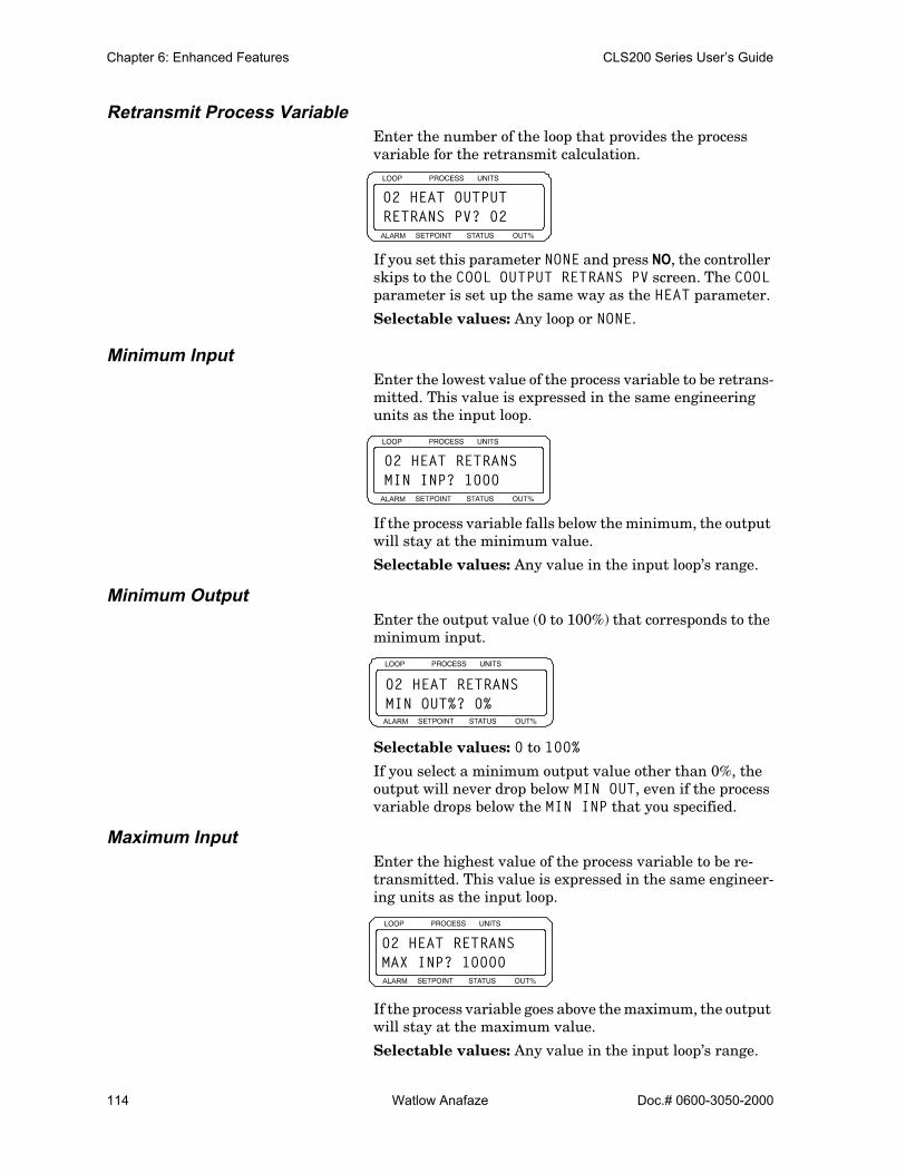
Chapter 6: Enhanced Features CLS200 Series User’s Guide
114 Watlow Anafaze Doc.# 0600-3050-2000
Retransmit Process VariableEnter the number of the loop that provides the process variable for the retransmit calculation.
If you set this parameter NONE and press NO, the controller skips to the COOL OUTPUT RETRANS PV screen. The COOL parameter is set up the same way as the HEAT parameter.
Selectable values: Any loop or NONE.
Minimum InputEnter the lowest value of the process variable to be retrans-mitted. This value is expressed in the same engineering units as the input loop.
If the process variable falls below the minimum, the output will stay at the minimum value.
Selectable values: Any value in the input loop’s range.
Minimum OutputEnter the output value (0 to 100%) that corresponds to the minimum input.
Selectable values: 0 to 100%
If you select a minimum output value other than 0%, the output will never drop below MIN OUT, even if the process variable drops below the MIN INP that you specified.
Maximum InputEnter the highest value of the process variable to be re-transmitted. This value is expressed in the same engineer-ing units as the input loop.
If the process variable goes above the maximum, the output will stay at the maximum value.
Selectable values: Any value in the input loop’s range.
ALARM
02 HEAT OUTPUTRETRANS PV? 02
ALARM
02 HEAT RETRANSMIN INP? 1000
ALARM
02 HEAT RETRANSMIN OUT%? 0%
ALARM
02 HEAT RETRANSMAX INP? 10000
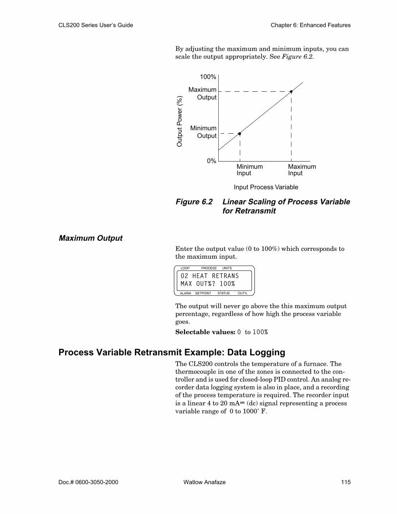
CLS200 Series User’s Guide Chapter 6: Enhanced Features
Doc.# 0600-3050-2000 Watlow Anafaze 115
By adjusting the maximum and minimum inputs, you can scale the output appropriately. See Figure 6.2.
Figure 6.2 Linear Scaling of Process Variable for Retransmit
Maximum OutputEnter the output value (0 to 100%) which corresponds to the maximum input.
The output will never go above the this maximum output percentage, regardless of how high the process variable goes.
Selectable values: 0 to 100%
Process Variable Retransmit Example: Data LoggingThe CLS200 controls the temperature of a furnace. The thermocouple in one of the zones is connected to the con-troller and is used for closed-loop PID control. An analog re-corder data logging system is also in place, and a recording of the process temperature is required. The recorder input is a linear 4 to 20 mAÎ (dc) signal representing a process variable range of 0 to 1000˚ F.
0%
100%
MaximumOutput
MinimumOutput
MinimumInput
MaximumInput
Out
put P
ower
(%)
Input Process Variable
ALARM
02 HEAT RETRANSMAX OUT%? 100%
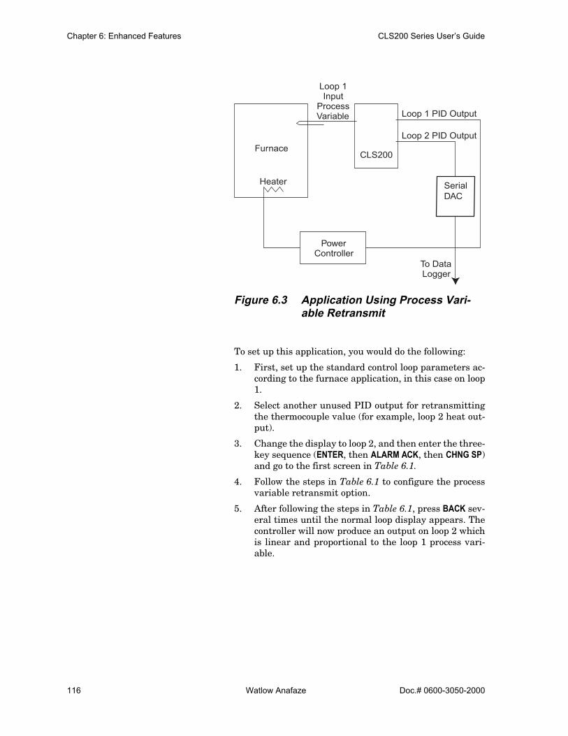
Chapter 6: Enhanced Features CLS200 Series User’s Guide
116 Watlow Anafaze Doc.# 0600-3050-2000
Figure 6.3 Application Using Process Vari-able Retransmit
To set up this application, you would do the following:
1. First, set up the standard control loop parameters ac-cording to the furnace application, in this case on loop1.
2. Select another unused PID output for retransmittingthe thermocouple value (for example, loop 2 heat out-put).
3. Change the display to loop 2, and then enter the three-key sequence (ENTER, then ALARM ACK, then CHNG SP)and go to the first screen in Table 6.1.
4. Follow the steps in Table 6.1 to configure the processvariable retransmit option.
5. After following the steps in Table 6.1, press BACK sev-eral times until the normal loop display appears. Thecontroller will now produce an output on loop 2 whichis linear and proportional to the loop 1 process vari-able.
CLS200Furnace
PowerController
To DataLogger
Loop 1 PID Output
Loop 2 PID Output
Heater
Loop 1Input
ProcessVariable
SerialDAC
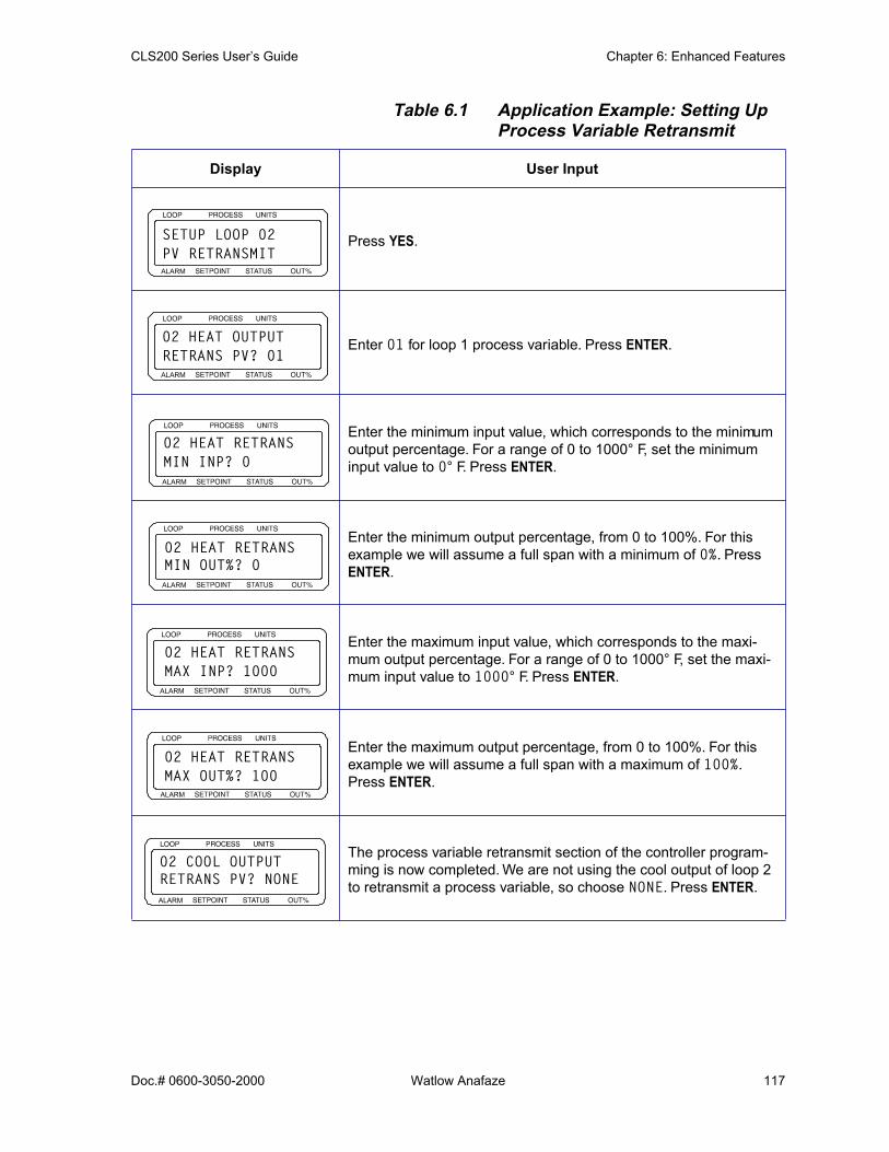
CLS200 Series User’s Guide Chapter 6: Enhanced Features
Doc.# 0600-3050-2000 Watlow Anafaze 117
Table 6.1 Application Example: Setting Up Process Variable Retransmit
Display User Input
Press YES.
Enter 01 for loop 1 process variable. Press ENTER.
Enter the minimum input value, which corresponds to the minimum output percentage. For a range of 0 to 1000° F, set the minimum input value to 0° F. Press ENTER.
Enter the minimum output percentage, from 0 to 100%. For this example we will assume a full span with a minimum of 0%. Press ENTER.
Enter the maximum input value, which corresponds to the maxi-mum output percentage. For a range of 0 to 1000° F, set the maxi-mum input value to 1000° F. Press ENTER.
Enter the maximum output percentage, from 0 to 100%. For this example we will assume a full span with a maximum of 100%. Press ENTER.
The process variable retransmit section of the controller program-ming is now completed. We are not using the cool output of loop 2 to retransmit a process variable, so choose NONE. Press ENTER.
ALARM
SETUP LOOP 02PV RETRANSMIT
ALARM
02 HEAT OUTPUTRETRANS PV? 01
ALARM
02 HEAT RETRANSMIN INP? 0
ALARM
02 HEAT RETRANS MIN OUT%? 0
ALARM
02 HEAT RETRANSMAX INP? 1000
ALARM
02 HEAT RETRANSMAX OUT%? 100
ALARM
02 COOL OUTPUT RETRANS PV? NONE

Chapter 6: Enhanced Features CLS200 Series User’s Guide
118 Watlow Anafaze Doc.# 0600-3050-2000
Notes about this application:
• This is not a thermocouple curve type of signal and re-quires a linear input range in the recorder.
• To complete this configuration, the loop 2 output must be enabled and tailored to meet the requirements of the data-application. In this example, the data logger requires an analog input of 4 to 20 mA.
• The CLS200 Series controllers must be used with a Watlow Anafaze Serial DAC.
Consult Chapter 4, Setup for information on setting up the other options of the controller.
Cascade ControlCascade control is used to control thermal systems with long lag times, which cannot be as accurately controlled with a single control loop. The output of the first (primary) loop is used to adjust the setpoint of the second (secondary) loop. The secondary loop normally executes the actual con-trol.
The cascade control feature allows the output percentage of one control loop to determine the setpoint of a second con-trol loop. By adjusting the setpoint (SP) parameters, the user can adjust the influence that the primary loop has on the setpoint of the secondary loop. See Figure 6.4.
Some applications, such as aluminum casting, use two-zone cascade control where the primary output is used for the primary heat control and the cascaded output is used for boost heat. The CLS200 allows you to use the primary heat output for both control and for determining the set-point of the secondary loop.

CLS200 Series User’s Guide Chapter 6: Enhanced Features
Doc.# 0600-3050-2000 Watlow Anafaze 119
Figure 6.4 Relationship Between the Primary Loop’s Output and the Secondary Loop’s Setpoint
NOTE! Cascade control cannot be used on the samecontrol loop as ratio control. However, bothfeatures may be used in the same multiloopcontroller.
Setup Loop Cascade MenuThe setup parameters for cascade control appear under the SETUP LOOP CASCADE menu.
Press YES to set up the cascade parameters. The loop cur-rently displayed (loop 02 in this case) will be the secondary control loop, which performs the actual control.
Primary LoopEnter the primary loop number. The output percentage of this loop will control the setpoint of the secondary loop.
Selectable values: Any loop except the secondary loop.
Calculation of new secondary loop setpoint:
Maximum SP
Minimum SP
Base SP
100% Cool 0% Heat
Base SP + |Cool O
utput Power| * Cool Span +
SP2 = Base SP + |Cool Output Power| * Cool Span + |Heat Output Power| * Heat Span
Primary Loop’s Output (%)
Sec
onda
ry L
oop’
s S
etpo
int
100%
|Heat Output Power| *
Heat Span
ALARM
SETUP LOOP 02CASCADE?
ALARM
02 CASCADEPRIM. LOOP? 03

Chapter 6: Enhanced Features CLS200 Series User’s Guide
120 Watlow Anafaze Doc.# 0600-3050-2000
Base SetpointEnter the setpoint that corresponds to 0% (heat and cool) output from the primary loop (PRIM. LOOP). This value is expressed in the same engineering units as the secondary loop’s process variable.
Selectable values: Any value from the secondary loop’s minimum process variable to its maximum process vari-able.
Minimum SetpointEnter the lowest value of the secondary loop setpoint. This minimum setpoint overrides any calculation caused by the primary loop calling for a lower setpoint. This value is ex-pressed in the same engineering units as the secondary loop’s process variable.
Selectable values: Any value from the secondary loop’s minimum process variable to its maximum process vari-able.
Maximum SetpointEnter the highest value of the secondary loop setpoint. This maximum setpoint overrides any calculation caused by the primary loop calling for a higher setpoint. This value is ex-pressed in the same engineering units as the secondary loop’s process variable.
Selectable values: Any value from the secondary loop’s minimum process variable to its maximum process vari-able.
ALARM
02 CASCADEBASE SP? 25
ALARM
02 CASCADEMIN SP? 25
ALARM
02 CASCADEMAX SP? 180

CLS200 Series User’s Guide Chapter 6: Enhanced Features
Doc.# 0600-3050-2000 Watlow Anafaze 121
Heat SpanEnter the multiplier to apply to the primary loop heat out-put percentage.
Selectable values: -9999 to +9999.
Cool SpanEnter the multiplier to apply to the primary loop cool out-put percentage.
Selectable values: -9999 to +9999.
Cascade Control Example: Water TankA tank of water has an inner and outer thermocouple. The outer thermocouple is located in the center of the water. The inner thermocouple is located near the heating ele-ment. The desired temperature of the water is 150˚ F, which is measured at the outer thermocouple. Using cas-cade control, the outer thermocouple is used on the primary loop (in this example, loop 1), and the inner thermocouple is used on the secondary loop (loop 2). The heater is con-trolled by loop 2 with a setpoint range of 150 to 190˚ F.
Figure 6.5 Application Using CascadeControl
ALARM
02 CASCADEHT SPAN? +9999
ALARM
02 CASCADECL SPAN? +9999
CLS200
Water150°
PowerController
Loop 2 PID Output
Heater
Loop 1 InputProcess Variable
Loop 1: Primary Cascade LoopLoop 2: Secondary Cascade Loop
Loop 2 InputProcess Variable
OuterThermocouple
Inner Thermocouple

Chapter 6: Enhanced Features CLS200 Series User’s Guide
122 Watlow Anafaze Doc.# 0600-3050-2000
To set up this application, you would do the following:
1. Change the display to loop 2, which will be the second-ary loop, and then enter the three-key sequence (EN-TER, then ALARM ACK, then CHNG SP) and go to the firstscreen in Table 6.2.
2. Follow the steps in Table 6.2 to configure cascade control.
Table 6.2 Application Example: Setting Up Cascade Control
Display User Input
Press YES to set up the cascade parameters with loop 2 as the sec-ondary loop.
Enter 01 to make loop 1 the primary loop. Press ENTER.
The base setpoint corresponds to the 0% level output of the primary loop. Enter the base setpoint of the secondary loop. For this exam-ple, we will assume a base setpoint of 150° F, which is the desired water temperature. Press ENTER.
Enter the minimum setpoint of the secondary loop. For this example, we will use a minimum setpoint of -350° F. Press ENTER.
Enter the maximum setpoint of the secondary loop. For this exam-ple, we will use a maximum setpoint of 1400° F. Press ENTER.
Enter the heat span of the secondary loop. This is the span over which the primary output from 0 to 100% is used to change the set-point. The desired setpoint range is 150 to 190° F. We will assume a linear rise in setpoint, so the heat span is 40° F. Press ENTER.
Enter the cool span of the secondary loop. For this example we will assume no low-side adjustment to the setpoint, so the cool span is 0° F. Press ENTER.
ALARM
SETUP LOOP 02CASCADE?
ALARM
02 CASCADEPRIM. LOOP? 01
ALARM
02 CASCADEBASE SP? 150
ALARM
02 CASCADEMIN SP? -350
ALARM
02 CASCADEMAX SP? 1400
ALARM
02 CASCADEHT SPAN? 40
ALARM
02 CASCADECL SPAN? 0
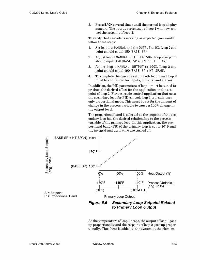
CLS200 Series User’s Guide Chapter 6: Enhanced Features
Doc.# 0600-3050-2000 Watlow Anafaze 123
3. Press BACK several times until the normal loop displayappears. The output percentage of loop 1 will now con-trol the setpoint of loop 2.
To verify that cascade is working as expected, you would follow these steps:
1. Set loop 1 to MANUAL and the OUTPUT to 0%. Loop 2 set-point should equal 150 (BASE SP).
2. Adjust loop 1 MANUAL OUTPUT to 50%. Loop 2 setpointshould equal 170 (BASE SP + 50% of HT SPAN)
3. Adjust loop 1 MANUAL OUTPUT to 100%. Loop 2 set-point should equal 190 (BASE SP + HT SPAN).
4. To complete the cascade setup, both loop 1 and loop 2must be configured for inputs, outputs, and alarms.
In addition, the PID parameters of loop 1 must be tuned to produce the desired effect for the application on the set-point of loop 2. For a cascade control application that uses the secondary loop for PID control, loop 1 typically uses only proportional mode. This must be set for the amount of change in the process variable to cause a 100% change in the output level.
The proportional band is selected so the setpoint of the sec-ondary loop has the desired relationship to the process variable of the primary loop. In this application, the pro-portional band (PB) of the primary loop is set to 10˚ F and the integral and derivative are turned off.
Figure 6.6 Secondary Loop Setpoint Related to Primary Loop Output
As the temperature of loop 1 drops, the output of loop 1 goes up proportionally and the setpoint of loop 2 goes up propor-tionally. Thus heat is added to the system at the element
190°F
150°F
0% 50% 100%Sec
onda
ry L
oop
Set
poin
t
Process Variable 1
(SP1-PB1)(SP1)
170°F
150°F 145°F 140°F
Heat Output (%)
(BASE SP + HT SPAN)
(BASE SP)
(eng. units)
SP: SetpointPB: Proportional Band
(eng
. uni
ts)
Primary Loop Output
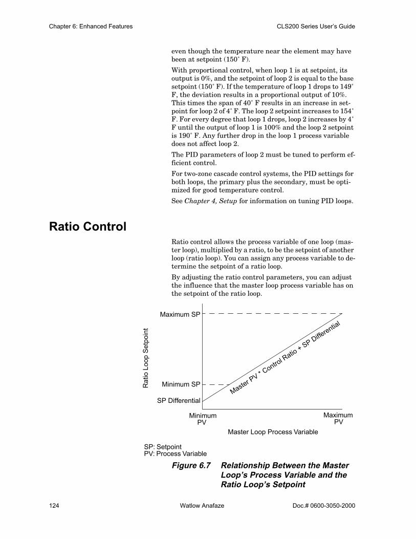
Chapter 6: Enhanced Features CLS200 Series User’s Guide
124 Watlow Anafaze Doc.# 0600-3050-2000
even though the temperature near the element may have been at setpoint (150˚ F).
With proportional control, when loop 1 is at setpoint, its output is 0%, and the setpoint of loop 2 is equal to the base setpoint (150˚ F). If the temperature of loop 1 drops to 149˚ F, the deviation results in a proportional output of 10%. This times the span of 40˚ F results in an increase in set-point for loop 2 of 4˚ F. The loop 2 setpoint increases to 154˚ F. For every degree that loop 1 drops, loop 2 increases by 4˚ F until the output of loop 1 is 100% and the loop 2 setpoint is 190˚ F. Any further drop in the loop 1 process variable does not affect loop 2.
The PID parameters of loop 2 must be tuned to perform ef-ficient control.
For two-zone cascade control systems, the PID settings for both loops, the primary plus the secondary, must be opti-mized for good temperature control.
See Chapter 4, Setup for information on tuning PID loops.
Ratio ControlRatio control allows the process variable of one loop (mas-ter loop), multiplied by a ratio, to be the setpoint of another loop (ratio loop). You can assign any process variable to de-termine the setpoint of a ratio loop.
By adjusting the ratio control parameters, you can adjust the influence that the master loop process variable has on the setpoint of the ratio loop.
Figure 6.7 Relationship Between the Master Loop’s Process Variable and the Ratio Loop’s Setpoint
Maximum SP
Minimum SP
Minimum Maximum
Master PV * C
ontrol Ratio + SP Differential
Rat
io L
oop
Set
poin
t
Master Loop Process Variable
SP Differential
SP: SetpointPV: Process Variable
PV PV

CLS200 Series User’s Guide Chapter 6: Enhanced Features
Doc.# 0600-3050-2000 Watlow Anafaze 125
NOTE! Ratio control cannot be used on the samecontrol loop as cascade control. However,both features may be used in the same multi-loop controller.
Setup Loop Ratio Control MenuThe ratio control parameters appear in the SETUP LOOP RATIO CONTROL menu.
Press YES to set up the ratio control parameters with loop number 2 as the ratio loop.
Master LoopEnter the master loop which will provide the output to the internal controller setpoint calculation for the ratio loop setpoint.
Selectable values: Any loop except the loop currently se-lected (in this case, loop 02). Choose NONE for no ratio con-trol.
Minimum SetpointEnter the lowest allowable setpoint for the ratio loop. This minimum setpoint overrides any ratio calculation calling for a lower setpoint. This value is expressed in the same en-gineering units as the ratio loop’s process variable.
Selectable values: Any value from the minimum value of the ratio loop’s process variable to its maximum value.
Maximum SetpointEnter the highest allowable setpoint for the ratio loop. This maximum setpoint overrides any ratio calculation calling
ALARM
SETUP LOOP 02RATIO CONTROL?
ALARM
02 RATIO CONTROL MSTR LOOP? NONE
ALARM
02 RATIO CONTROL MIN SP? 25

Chapter 6: Enhanced Features CLS200 Series User’s Guide
126 Watlow Anafaze Doc.# 0600-3050-2000
for a higher setpoint. This value is expressed in the same engineering units as the ratio loop’s process variable.
Selectable values: Any value from the minimum value of the ratio loop’s process variable to its maximum value.
Control RatioEnter the multiplier to apply to the master loop’s process variable.
Selectable values: 0.1 to 999.9.
Setpoint DifferentialEnter the value to add or subtract from the ratio loop set-point calculation before using it as the setpoint. This value is expressed in the same engineering units as the ratio loop’s process variable.
Selectable values: -9999 to 9999 with the decimal placement determined by the DISP FORMAT setting for the ratio loop.
Ratio Control Example: Diluting KOHA chemical process requires a formula of two parts water (H2O) to one part potassium hydroxide (KOH) to produce diluted potassium hydroxide. The desired flow of H2O is 10 gallons per second (gps), so the KOH should flow at 5 gps. Separate pipes for each chemical feed a common pipe. The flow rate of each feeder pipe is measured by a CLS200, with H2O flow as process variable 1 and KOH flow as process variable 2. The outputs of loops 1 and 2 adjust motorized valves.
ALARM
02 RATIO CONTROL MAX SP? 25
ALARM
02 RATIO CONTROL CTRL RATIO? 1.0
ALARM
02 RATIO CONTROL SP DIFF? 0

CLS200 Series User’s Guide Chapter 6: Enhanced Features
Doc.# 0600-3050-2000 Watlow Anafaze 127
Figure 6.8 Application Using Ratio Control
To set up this application, you would do the following:
1. Adjust and tune loop 1 (H2O) for optimal performancebefore implementing the ratio setup.
2. Switch the controller to display loop 2 (KOH), andthen enter the three-key sequence (ENTER, then ALARMACK, then CHNG SP ) and go to the first screen inTable 6.3.
3. Follow the steps in Table 6.3 to configure ratio control.
CLS200
Loop 1 PID Output
Loop 2 PID Output
Loop 1 InputProcess Variable
Loop 2 InputProcess Variable
Motorized Control Valve 2MotorizedControlValve 1
Mixture Output
Water Input KOH Input
FlowTransducer
Loop 1: Water Flow Control LoopLoop 2: KOH Flow Control Loop
SerialDACSerialDAC

Chapter 6: Enhanced Features CLS200 Series User’s Guide
128 Watlow Anafaze Doc.# 0600-3050-2000
Table 6.3 Application Example: Setting Up Ratio Control
4. Press BACK several times until the normal loop displayappears. The setpoint of loop 2 will now be equal to onehalf of the process variable of loop 2.
5. To complete the ratio setup, configure both loops 1 and2 for inputs, outputs, and alarms. See Chapter 4, Setupfor information on loop setup.
Display User Input
Press YES to set up the ratio control parameters for loop 02.
Assign loop 01 as the master loop. Press ENTER.
Enter the minimum ratio loop setpoint. For this example, we will use 0.0 gallons per second as a minimum. Press ENTER.
Enter the maximum ratio loop setpoint. For this example, we will use 7.0 gallons per second as a maximum. Press ENTER.
Enter the control ratio, which is the multiple applied to the master. The H2O fl w rate is multiplied by 0.5 to obtain the KOH fl w rate setpoint. Press ENTER.
Enter the setpoint differential (or offset). For this example we have no offset requirement and will use 0. Press ENTER.
ALARM
SETUP LOOP 02RATIO CONTROL?
ALARM
02 RATIO CONTROLMSTR LOOP? 01
ALARM
02 RATIO CONTROLMIN SP? 0.0
ALARM
02 RATIO CONTROLMAX SP? 7.0
ALARM
02 RATIO CONTROLCTRL RATIO? 0.5
ALARM
02 RATIO CONTROLSP DIFF.? 0

CLS200 Series User’s Guide Chapter 6: Enhanced Features
Doc.# 0600-3050-2000 Watlow Anafaze 129
Remote Analog SetpointThe remote analog setpoint is set up identically to ratio control. To provide a setpoint remotely, typically a voltage or current source is connected to an analog input on the controller. This input is configured as a linear input type and the master loop for ratio control. All other input types are also usable as remote analog setpoint inputs.
Specify the loop to which the analog input is connected as the master loop and setup the rest of the ratio control pa-rameters as outlined in Setup Loop Ratio Control Menu on page 125.
Remote Analog Setpoint Example: Setting a Setpoint with a PLCRemote analog setpoint allows external equipment, such as a PLC or other control system, to change the setpoint of a loop.
Both the remote analog setpoint feature and the process variable retransmit feature can be used with PLC systems as the link between multiloop PID control systems and PLC systems.
For example, a 0 to 5 VÎ (dc) signal representing 0 to 300˚ F will be used as a remote setpoint input to the CLS200. The input signal will be received on loop 1 with the control being performed on loop 2. Note that proper scaling resis-tors must be installed on the input of loop 1 to allow it to accept a 0 to 5 VÎ (dc) input.
To set up this application, you would do the following:
1. In the loop 1 SETUP LOOP INPUT menu, set the INPUTTYPE to LINEAR, set HI PV to 300, set LO PV to 0, setHI RDG to 100.0% and set LO RDG to 0.0%.
2. Change the display to loop 2, and then enter the setupparameters. Go to the first screen in Table 6.4.
3. Follow the steps in Table 6.4 to configure the processvariable retransmit option.

Chapter 6: Enhanced Features CLS200 Series User’s Guide
130 Watlow Anafaze Doc.# 0600-3050-2000
Table 6.4 Application Example: Setting Up Remote Setpoint
4. Press BACK several times until the normal loop displayappears. The setpoint of loop 2 will now be equal to theprocess variable of loop 1.
5. To complete the remote analog setpoint setup, loop 1may be configured for outputs and alarms. Likewise,loop 2 must be configured for inputs, outputs, andalarms. See Chapter 4, Setup for information on loopsetup.
Display User Input
Press YES to set up the ratio control parameters for loop 2.
Assign loop 01 to be the master loop. Press ENTER.
Enter the minimum ratio loop setpoint. For this example, we will use 0° F. Press ENTER.
Enter the maximum ratio loop setpoint. For this example, we will use 300.0° F as a maximum. Press ENTER.
Enter the control ratio, which is the multiple applied to the master process variable. In this example the ratio is 1.0. Press ENTER.
Enter the setpoint differential (or offset). For this example we have no offset requirement and will use 0. Press ENTER.
ALARM
SETUP LOOP 02RATIO CONTROL?
ALARM
02 RATIO CONTROLMSTR LOOP? 01
ALARM
02 RATIO CONTROLMIN SP? 0
ALARM
02 RATIO CONTROLMAX SP? 300.0
ALARM
02 RATIO CONTROLCTRL RATIO? 1.0
ALARM
02 RATIO CONTROLSP DIFF.? 0

CLS200 Series User’s Guide Chapter 6: Enhanced Features
Doc.# 0600-3050-2000 Watlow Anafaze 131
Differential ControlDifferential control is a simple application of the ratio con-trol option, used to control one process (ratio loop) at a dif-ferential, or offset, to another (master loop). To use differential control, set the ratio value to 1.0 to provide the desired offset.
Differential Control Example: ThermoformingA thermal forming application requires that the outside heaters operate at a higher temperature than the center heaters. The differential control point is determined by the master loop which is using infrared (IR) sensors for temper-ature feedback. Secondary loops use thermocouples for feedback.
The loop using the IR sensor as an input is assigned to the master loop in the SETUP LOOP RATIO CONTROL menu. The secondary loop is the differential control loop. Setting the setpoint differential (SP DIFF) to the desired offset will produce the desired offset between the secondary and mas-ter loops.
For example, the master loop can be controlled at 325º F and the secondary loop at 375º F by using a differential of 50º F.
Loop 1 must be set up for PID control of the setpoint at 325º F.
To set up this application, you would do the following:
1. Change the display to loop 2, and then enter the setupparameters. Go to the first screen in Table 6.5.
2. Follow the steps in Table 6.5 to configure the processvariable retransmit option.
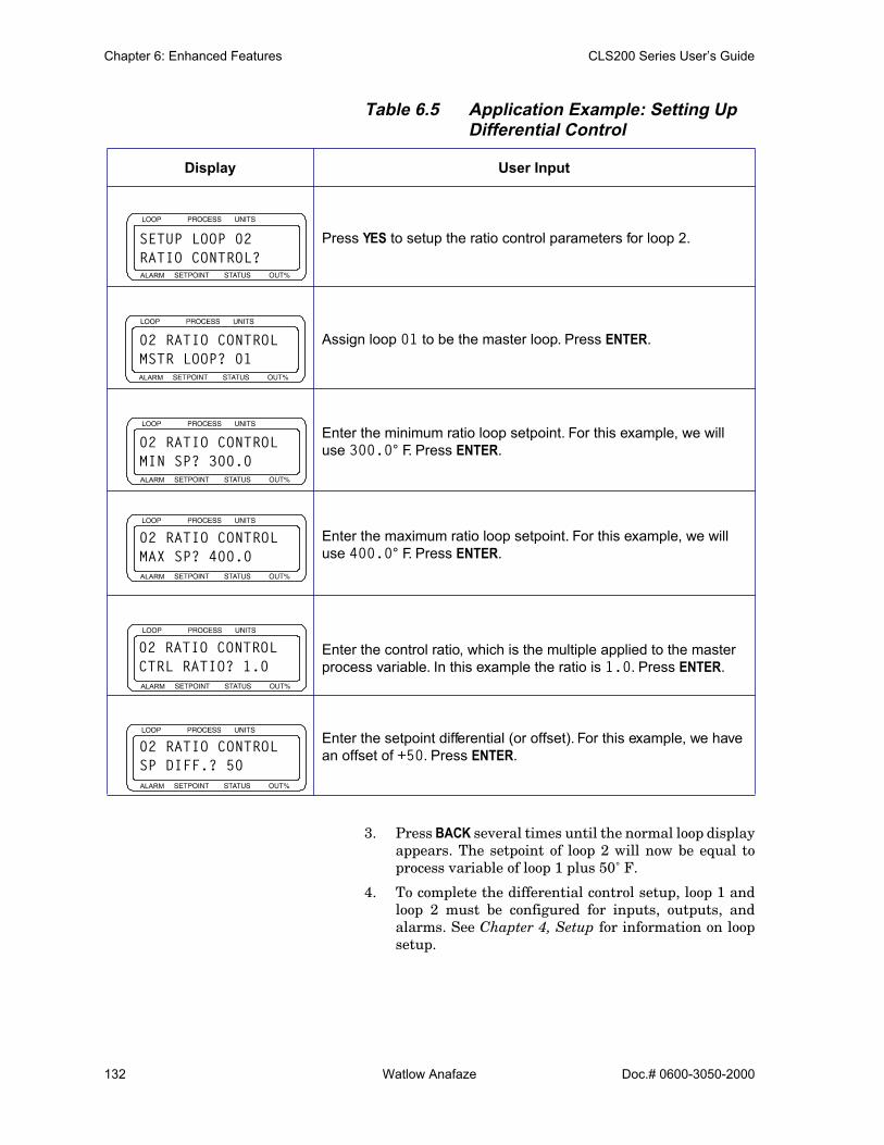
Chapter 6: Enhanced Features CLS200 Series User’s Guide
132 Watlow Anafaze Doc.# 0600-3050-2000
Table 6.5 Application Example: Setting Up Differential Control
3. Press BACK several times until the normal loop displayappears. The setpoint of loop 2 will now be equal toprocess variable of loop 1 plus 50˚ F.
4. To complete the differential control setup, loop 1 andloop 2 must be configured for inputs, outputs, andalarms. See Chapter 4, Setup for information on loopsetup.
Display User Input
Press YES to setup the ratio control parameters for loop 2.
Assign loop 01 to be the master loop. Press ENTER.
Enter the minimum ratio loop setpoint. For this example, we will use 300.0° F. Press ENTER.
Enter the maximum ratio loop setpoint. For this example, we will use 400.0° F. Press ENTER.
Enter the control ratio, which is the multiple applied to the master process variable. In this example the ratio is 1.0. Press ENTER.
Enter the setpoint differential (or offset). For this example, we have an offset of +50. Press ENTER.
ALARM
SETUP LOOP 02RATIO CONTROL?
ALARM
02 RATIO CONTROLMSTR LOOP? 01
ALARM
02 RATIO CONTROLMIN SP? 300.0
ALARM
02 RATIO CONTROLMAX SP? 400.0
ALARM
02 RATIO CONTROLCTRL RATIO? 1.0
ALARM
02 RATIO CONTROLSP DIFF.? 50

Doc.# 0600-3050-2000 Watlow Anafaze 133
7Ramp/Soak
This chapter covers setup and operation of ramp/soak pro-files in CLS200 series controllers.
These features are available in controllers that have the optional ramp/soak firmware installed.
The ramp/soak feature turns your controller into a power-ful and flexible batch controller. Ramp/soak lets you pro-gram the controller to change a process setpoint in a preset pattern over time. This preset pattern, or temperature profile, consists of several segments. During a segment, the temperature goes from the previous segment’s setpoint to the current segment’s setpoint.
• If the current segment’s setpoint is higher or lower than the previous segment’s setpoint, it is called a ramp segment.
• If the current segment’s setpoint is the same as the previous segment’s setpoint, it is called a soak seg-ment.
Figure 7.1 Sample Ramp/Soak Profile
Ramp Ramp
Soak
Profile
Segment 1 Segment 2 Segment 3
Pro
cess
Var
iabl
e

Chapter 7: Ramp/Soak CLS200 Series User’s Guide
134 Watlow Anafaze Doc.# 0600-3050-2000
FeaturesRamp/soak in the CLS200 includes the following features:
• Ready segment sets loop up for profile: Ready segment can control at setpoint until profile needs to run. Ready segment events set all available event out-puts to desired states before profile starts.
• Up to 20 segments per profile: The controller can store up to 17 profiles, each with up to 20 segments.
• Multiple profiles run independently: Each loop can run a different profile or the same profile can be run independently on more than one loop.
• Up to two triggers per segment: Triggers are digi-tal inputs that can be programmed to start and hold segments based on the trigger’s digital state. You can use any one of the eight digital inputs for triggers. You can also use the same trigger for more than one seg-ment or more than one profile.
• Up to four events per segment: Digital outputs con-trolled by the ramp/soak profile. Events outputs are set at the end of a segment. You can use any of the dig-ital outputs that are not used for control or for the Se-rial DAC clock.
• Tolerance hold ensures time at temperature: Set a limit on how far the process variable can vary above or below setpoint. The profile clock only runs when the process variable is within the limit.
• Tolerance alarm indicates process not tracking setpoint: Set a maximum amount of time for the tol-erance hold to wait for a process deviation before noti-fying the operator. The operator can acknowledge the alarm and proceed if desired.
• User-configurable time base: Program profiles to run for hours and minutes or for minutes and seconds.
• Repeatable profiles: Set any profile to repeat from 1 to 99 times or continuously.
• Fast setup for similar profiles: Set up one profile, then copy it and alter it to set up the rest.
• External reset: Select a digital input you can use to hold a profile in the “start” state and restart it.
Table 7.1 summarizes the ramp/soak features of the CLS200.
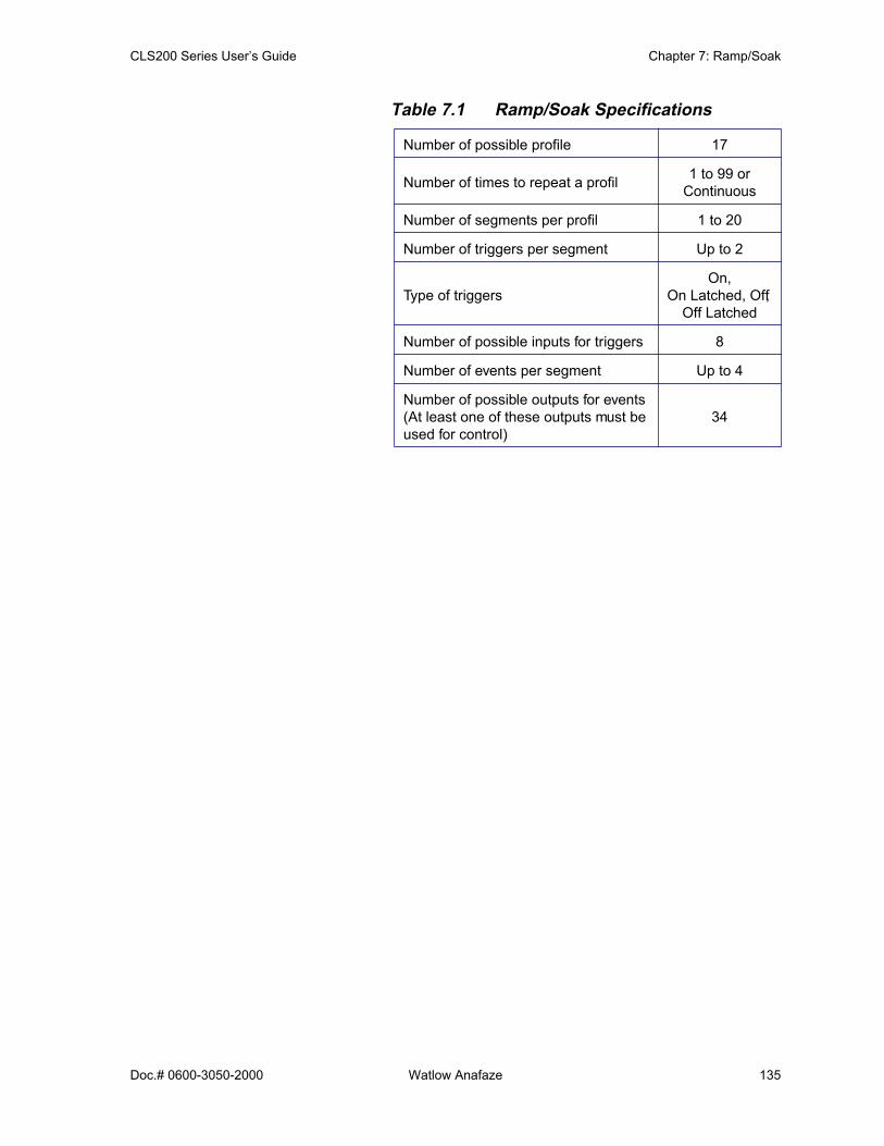
CLS200 Series User’s Guide Chapter 7: Ramp/Soak
Doc.# 0600-3050-2000 Watlow Anafaze 135
Table 7.1 Ramp/Soak Specifications
Number of possible profile 17
Number of times to repeat a profil 1 to 99 or Continuous
Number of segments per profil 1 to 20
Number of triggers per segment Up to 2
Type of triggersOn,
On Latched, Off, Off Latched
Number of possible inputs for triggers 8
Number of events per segment Up to 4
Number of possible outputs for events(At least one of these outputs must be used for control)
34
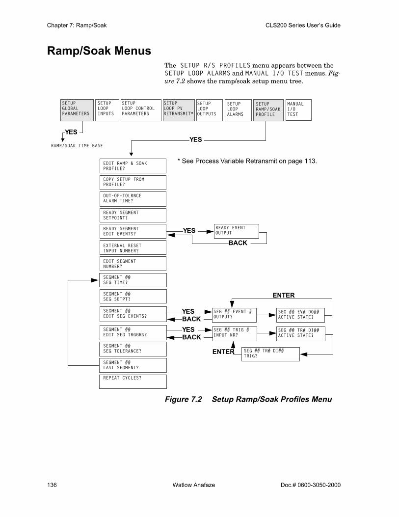
Chapter 7: Ramp/Soak CLS200 Series User’s Guide
136 Watlow Anafaze Doc.# 0600-3050-2000
Ramp/Soak MenusThe SETUP R/S PROFILES menu appears between the SETUP LOOP ALARMS and MANUAL I/O TEST menus. Fig-ure 7.2 shows the ramp/soak setup menu tree.
Figure 7.2 Setup Ramp/Soak Profiles Menu
ENTER
ENTER
SETUPLOOPINPUTS
SETUPLOOP CONTROL PARAMETERS
SETUPLOOPOUTPUTS
SETUPLOOPALARMS
MANUALI/OTEST
YES
SETUP RAMP/SOAK PROFILE
YES
YES
BACK
YESBACKYESBACK
SETUPLOOP PVRETRANSMIT*
* See Process Variable Retransmit on page 113.
RAMP/SOAK TIME BASE
SETUP GLOBAL PARAMETERS
EDIT RAMP & SOAK PROFILE?
COPY SETUP FROM PROFILE?
OUT-OF-TOLRNCE ALARM TIME?
READY SEGMENT SETPOINT?
READY SEGMENT EDIT EVENTS?
EXTERNAL RESET INPUT NUMBER?
EDIT SEGMENT NUMBER?
SEGMENT ## SEG TIME?
SEGMENT ## SEG SETPT?
SEGMENT ## EDIT SEG EVENTS?
SEGMENT ## EDIT SEG TRGGRS?
SEGMENT ## SEG TOLERANCE?
SEGMENT ## LAST SEGMENT?
REPEAT CYCLES?
READY EVENTOUTPUT
SEG ## EVENT #OUTPUT?
SEG ## TRIG #INPUT NR?
SEG ## EV# DO##ACTIVE STATE?
SEG ## TR# DI##ACTIVE STATE?
SEG ## TR# DI## TRIG?
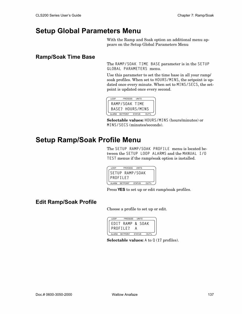
CLS200 Series User’s Guide Chapter 7: Ramp/Soak
Doc.# 0600-3050-2000 Watlow Anafaze 137
Setup Global Parameters Menu With the Ramp and Soak option an additional menu ap-pears on the Setup Global Parameters Menu
Ramp/Soak Time BaseThe RAMP/SOAK TIME BASE parameter is in the SETUP GLOBAL PARAMETERS menu.
Use this parameter to set the time base in all your ramp/soak profiles. When set to HOURS/MINS, the setpoint is up-dated once every minute. When set to MINS/SECS, the set-point is updated once every second.
Selectable values: HOURS/MINS (hours/minutes) or MINS/SECS (minutes/seconds).
Setup Ramp/Soak Profile MenuThe SETUP RAMP/SOAK PROFILE menu is located be-tween the SETUP LOOP ALARMS and the MANUAL I/O TEST menus if the ramp/soak option is installed.
Press YES to set up or edit ramp/soak profiles.
Edit Ramp/Soak ProfileChoose a profile to set up or edit.
Selectable values: A to Q (17 profiles).
ALARM
RAMP/SOAK TIMEBASE? HOURS/MINS
ALARM
SETUP RAMP/SOAKPROFILE?
ALARM
EDIT RAMP & SOAK PROFILE? A

Chapter 7: Ramp/Soak CLS200 Series User’s Guide
138 Watlow Anafaze Doc.# 0600-3050-2000
Copy Setup From ProfileSet up similar profiles quickly by copying the setup of an existing profile.
Selectable values: A to Q.
Tolerance Alarm TimeSet a limit on how long the process variable can be outside the tolerance set for the segment before the tolerance alarm occurs.
If the process variable does not return within the tolerance, the tolerance alarm will recur after the tolerance alarm time elapses again.
If the alarm persists, you may want to reset the profile.
Selectable values: 0:00 to 99:59 (minutes or hours, de-pending on the time base setting).
Ready Segment SetpointWhen you assign a profile to a loop, the profile does not start immediately. Instead, it goes to the ready segment (segment 0) and stays there until you put the profile in run mode.
You can set a setpoint, assign events, and set event states for the ready segment. Use this parameter to set the ready segment setpoint. Setting the setpoint to OFF ensures that control outputs for the loop running the profile will not come on.
Selectable values: -999 to 9999, or OFF. See Setpoints and Tolerances for Various Input Types on page 144.
ALARM
COPY SETUPFROM PROFILE ? Q
ALARM
A OUT-OF-TOLRNCEALARM TIME? 1:00
ALARM
A READY SEGMENTSETPOINT? OFF

CLS200 Series User’s Guide Chapter 7: Ramp/Soak
Doc.# 0600-3050-2000 Watlow Anafaze 139
Ready Segment Edit EventsPress YES to set or edit the ready state for all outputs that are not used for control or for the Serial DAC clock. When you assign a profile, the controller starts the ready seg-ment: it goes to the setpoint and puts all the outputs in the state you set here. The outputs stay in the states they are set to until their states are changed at the end of subse-quent segments.
Press NO to advance to EXTERNAL RESET INPUT NUMBER.
Ready Event OutputPress NO to increment the output number. Press YES to set the event state to ON or OFF.
This parameter appears only if you answered YES to READY SEGMENT EDIT EVENTS?.
Selectable values: ON or OFF.
When you are done, press BACK to return to READY SEG-MENT EDIT EVENTS, then press NO to go to the next pa-rameter.
External Reset Input NumberSelect one of the eight digital inputs as an external reset. When the reset input is on, the profile is set to RUN mode at the beginning of the first segment. As long as the reset in-put is on, the profile is held at the beginning of the first seg-ment. Once the reset input turns off the profile begins to run.
Selectable values: 1 to 8, or N (for no external reset).
ALARM
A READY SEGMENTEDIT EVENTS ?
ALARM
A READY EVENTOUTPUT 15? OFF
ALARM
A EXTERNAL RESETINPUT NUMBER? N

Chapter 7: Ramp/Soak CLS200 Series User’s Guide
140 Watlow Anafaze Doc.# 0600-3050-2000
Edit Segment NumberEach profile is made up of several segments (up to 20). Choose the segment to edit.
Selectable values: 1 to 20.
The first time you use this parameter, it defaults to seg-ment 1. When you finish editing a segment, the controller goes to the next segment. This loop continues until you make a segment the last segment of a profile.
Segment TimeEnter the duration of the segment.
Selectable values: 0:00 to 999:59 (hours and minutes or minutes and seconds, depending on the selected time base).
Segment SetpointEnter the ending setpoint for the segment you are editing. For a ramp, the setpoint changes steadily over the segment time from the end setpoint of the previous segment to the value set here. For a soak, set the value here equal to the end setpoint of the previous segment.
Selectable values: -999 to 3276, or OFF (no output dur-ing segment). See Setpoints and Tolerances for Various In-put Types on page 144.
ALARM
A EDIT SEGMENTNUMBER? 15
ALARM
A SEGMENT 11SEG TIME? 000:00
ALARM
C SEGMENT 5SEG SETPT? OFF

CLS200 Series User’s Guide Chapter 7: Ramp/Soak
Doc.# 0600-3050-2000 Watlow Anafaze 141
Edit Segment EventsYou can assign up to four digital outputs, or events, to each segment. When the segment ends, the outputs you select are set to the state you specify. Press YES to select outputs and specify their states.
Press NO to advance to the EDIT SEG TRGGRS parameter.
NOTE! Events are set at the end of segments. If youwant a segment to start with an event, pro-gram the event in the previous segment. Youcan also create a segment with zero time pre-ceding the segment during which you wantthe event on.
Segment Event OutputSelect a digital output for the event. Use a digital output that is not being used for PID control or for Serial DAC clock.
This parameter appears only if you answered YES to EDIT SEG EVENTS?
Selectable values: Any digital output from 1 to 34, except those in use, or NONE (no event).
When you are done setting segment events, press BACK to return to EDIT SEG EVENTS, then press NO to go to the next parameter.
Segment Events Output StatesAssign a state to the event. At the end of the segment, the output goes to the state you assign here.
This parameter appears only if you answered YES to EDIT SEG EVENTS?
Selectable values: OFF (high) or ON (low).
ALARM
A SEGMENT 5EDIT SEG EVENTS?
ALARM
A SEG 20 EVENT 3 OUTPUT? 30
ALARM
A SEG20 EV3 DO 30 ACTIVE STATE? OFF
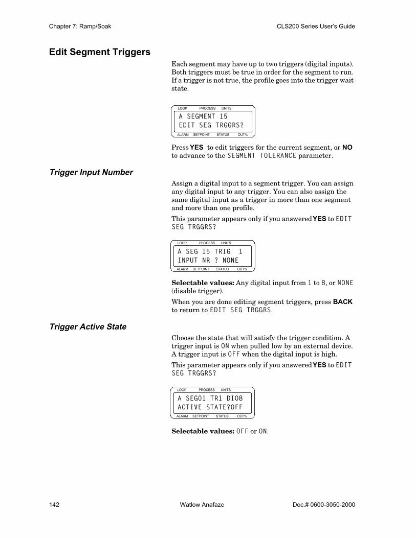
Chapter 7: Ramp/Soak CLS200 Series User’s Guide
142 Watlow Anafaze Doc.# 0600-3050-2000
Edit Segment TriggersEach segment may have up to two triggers (digital inputs). Both triggers must be true in order for the segment to run. If a trigger is not true, the profile goes into the trigger wait state.
Press YES to edit triggers for the current segment, or NO to advance to the SEGMENT TOLERANCE parameter.
Trigger Input NumberAssign a digital input to a segment trigger. You can assign any digital input to any trigger. You can also assign the same digital input as a trigger in more than one segment and more than one profile.
This parameter appears only if you answered YES to EDIT SEG TRGGRS?
Selectable values: Any digital input from 1 to 8, or NONE (disable trigger).
When you are done editing segment triggers, press BACK to return to EDIT SEG TRGGRS.
Trigger Active StateChoose the state that will satisfy the trigger condition. A trigger input is ON when pulled low by an external device. A trigger input is OFF when the digital input is high.
This parameter appears only if you answered YES to EDIT SEG TRGGRS?
Selectable values: OFF or ON.
ALARM
A SEGMENT 15EDIT SEG TRGGRS?
ALARM
A SEG 15 TRIG 1INPUT NR ? NONE
ALARM
A SEG01 TR1 DIO8ACTIVE STATE?OFF

CLS200 Series User’s Guide Chapter 7: Ramp/Soak
Doc.# 0600-3050-2000 Watlow Anafaze 143
Trigger Latch StatusChoose whether the trigger is latched or unlatched.
• A latched trigger is checked once, at the beginning of a segment.
• An unlatched trigger is checked constantly while a segment is running. If an unlatched trigger becomes false, the segment timer stops and the loop goes into trigger wait state.
When using two triggers with a segment, the following log-ic applies:
Table 7.2 Trigger Latch Logic
This parameter appears only if you answered YES to EDIT SEG TRGGRS?
Selectable values: LATCHED or UNLATCHED.
Segment ToleranceSet a positive or negative tolerance value for each segment. Tolerance works as shown in Figure 7.3.
Figure 7.3 Positive and Negative Tolerances
If you enter a positive tolerance, the process is out of toler-ance when the process variable goes above the setpoint plus the tolerance.
Trigger Settings Trigger Logic
Both Triggers Latched ORed Trigger starts a segment
Both Triggers Unlatched ANDed Triggers start/continue a segment
One Trigger Latched, One Trigger Unlatched
• The unlatched trigger starts/continues a segment.• The latched trigger has no effect.
ALARM
A SEG01 TR1 DI08 TRIG? UNLATCHED
Positive Tolerance Value Negative Tolerance Value
Out of ToleranceWithin Tolerance
Setpoint
Out of Tolerance Within Tolerance
SetpointToleranceSetting Tolerance
Setting

Chapter 7: Ramp/Soak CLS200 Series User’s Guide
144 Watlow Anafaze Doc.# 0600-3050-2000
If you enter a negative tolerance, the process goes out of tol-erance when the process variable goes below the setpoint minus the tolerance.
Selectable values: -99 to 99, or OFF (no tolerance limit). See Setpoints and Tolerances for Various Input Types on page 144.
Last SegmentSpecify whether the current segment is the last one in the profile.
Selectable values: NO or YES.
Repeat CyclesSet the number of times you want a profile to repeat or cycle.
The profile returns to START mode after completing the number of cycles specified here.
Selectable values: 1 to 99, or C (continuous cycling).
Setpoints and Tolerances for Various Input TypesSetpoints and tolerances are set in segments before the profile is assigned to a particular loop. When the profile is used with a loop, the INPUT TYPE and DISP FORMATS set-tings are applied to the following parameters:
• Ready setpoint• Segment setpoint• Segment tolerance
Refer to Table 7.3 to determine how these parameters are affected for the various INPUT TYPE and DISP FORMAT settings.
ALARM
A SEGMENT 01SEG TOLERNCE? OFF
ALARM
A SEGMENT 01LAST SEGMENT? NO
ALARM
A REPEAT CYCLES ? 1

CLS200 Series User’s Guide Chapter 7: Ramp/Soak
Doc.# 0600-3050-2000 Watlow Anafaze 145
Table 7.3 Display Formats
Using Ramp/SoakThis section explains how to assign a profile to a loop, how to put a profile in RUN or HOLD mode, how to reset a profile, and how to display profile statistics. Figure 7.4 shows the ramp/soak screens:
Figure 7.4 Ramp/Soak Screens
Input Type Display Format Effect on Parameter
Thermocouples and RTDs N/A No decimal shift
Linear
-999 to 3000 No decimal shift
-9999 to 30000 Setting multiplied by 10
-999.9 to 3000.0 No decimal shift; additional tenth in display
-99.99 to 300.00 Settings divided by 10
-9.999 to 30.000 Settings divided by 100
-0.9999 to 3.0000 Settings divided by 1,000
ASSIGN R/S
TIME REMAINING
CYCLE NUMBER
SET MODE
RESET
RAMP/SOAK
RAMP/SOAK
NO
RAMP/SOAK
NoProfileAssignedSingle
LoopDisplay
BACK
BACK
BACK
ProfileAssigned
BACK
BA
CK
YES
EN
TER
PROFILE
NO

Chapter 7: Ramp/Soak CLS200 Series User’s Guide
146 Watlow Anafaze Doc.# 0600-3050-2000
Ramp/Soak DisplaysThe single loop and bar graph displays show additional codes when ramp/soak firmware is installed.
Single Loop DisplayWhen the controller is running a profile, the single loop dis-play shows the ramp/soak mode where it would usually show MAN or AUTO. Table 7.4 describes the modes.
Table 7.4 Ramp/Soak Single Loop Display
This is the single loop display when a profile is running. If a tolerance alarm occurs, the controller displays a flashing T in the alarm symbol position.
Bar Graph DisplayThe ramp/soak mode is also displayed on the bar graph dis-play.
Table 7.5 describes the control status symbols used for loops with ramp/soak profiles assigned.
Ramp/Soak Mode Description
STRT The profile is in the ready segment
RUN The profile is unning.
HOLD The user has put the profile in hold mod .
TOHO The profile is in tole ance hold.
WAIT The profile is in t igger wait state.
ALARM
02 347 ˚FT 180TOHO50
Loop Number
Alarm Symbol
Engineering Units
Setpoint Ramp/Soak Mode
Output Percentage
Process Variable
ALARM
01> > < < 08 RSHS ROMA
SymbolLoop Number
Ramp/Soak Mode

CLS200 Series User’s Guide Chapter 7: Ramp/Soak
Doc.# 0600-3050-2000 Watlow Anafaze 147
Table 7.5 Ramp/Soak Control Status Symbols
Time Remaining DisplayFrom the single loop display, press the RAMP/SOAK key once.
This screen shows how much time remains to complete the profile. All screens that are accessed by pressing RAMP/SOAK key have the same information on the top line.
Cycle Number DisplayFrom the single loop display, press the RAMP/SOAK key twice. This screen displays the number of times the profile has run out of the total number of cycles. In this example, the ramp/soak profile is on the 10th of 15 cycles to be per-formed.
Set Mode DisplayFrom the single loop display, press the RAMP/SOAK key three times. The SET MODE parameter allows you to change the ramp/soak mode.
Ramp/Soak Symbol Description
R A profile is unning.
H A profile is holding
S A profile is in ready stat .
O A profile is in tole ance hold.
W A profile is in t igger wait.
ALARM
04 A SEG10/20 RTIM REM= 32:11
Loop Number
Profile LetterCurrent Segment
Number of Segments
Ramp/Soak Mode
in Profile
Time Remaining
ALARM
04 A SEG10/20 R CYCLE NR= 10/15
ALARM
01 A SEG01/05 RSET MODE? START

Chapter 7: Ramp/Soak CLS200 Series User’s Guide
148 Watlow Anafaze Doc.# 0600-3050-2000
See Running a Profile on page 148 and Holding a Profile or Continuing from Hold on page 150 for instructions on changing the ramp/soak mode.
Assigning a Profile to a LoopUse this parameter to assign a profile to a loop.
Selectable Values: A to Q or NONE
Assigning a Profile the First TimeTo assign a profile to a loop that does not have a profile cur-rently assigned:
1. In the single loop display, switch to the loop you wantto assign a profile to.
2. Press the RAMP/SOAK key. The ASSIGN R/S PRO-FILE parameter appears.
3. Choose one of the available profiles and press ENTER- or -press BACK to return to single loop display withoutsending profile data to the controller.
Assigning, Changing and Unassigning a ProfileTo assign a new profile to a loop that already has one assigned:
1. In the single loop display, switch to the loop in whichyou want to change or unassign the profile.
2. Press the RAMP/SOAK key three times.
3. Press the NO key. You will see the RESET PROFILEparameter. See Resetting a Profile on page 151.
4. Press YES then ENTER to reset the profile. You willsee the ASSIGN PROFILE parameter. See Assigning aProfile to a Loop on page 148.
5. Choose one of the available profiles or NONE (to unassign) and press ENTER.
6. To return to the single loop display without changingthe profile assignments, press BACK.
Running a ProfileWhen you assign a profile, it does not start running imme-diately. Instead, the loop is in the START mode and the
ALARM
01 ASSIGN R/S PROFILE? A

CLS200 Series User’s Guide Chapter 7: Ramp/Soak
Doc.# 0600-3050-2000 Watlow Anafaze 149
READY segment (segment 0). Use the SET MODE parameter to start a profile (put it in RUN mode).
Starting a ProfileYou can start a profile only when it is in the READY seg-ment.
1. In the single loop display, switch to the loop you wantto start.
2. Press the RAMP/SOAK key three times. The SETMODE parameter appears.
3. Press YES and ENTER to start the profile. While theprofile is in START mode, the only mode available isthe RUN mode.
Running Several Profiles SimultaneouslyTo run several profiles simultaneously, follow these steps:
1. Set up the profiles so that segment 1 of each profilehas the same latched trigger.
2. Assign the profiles to the appropriate loops. The loopswill go to the READY segment of each profile.
3. Set each profile to RUN mode.
4. Trip the trigger.
Editing a Profile While It Is RunningYou can edit a profile while it is running. Changes made to segments after the current segment will take effect when the segment is reached. Changes made to the segments that have already been completed will take effect the next time the profile is run. Do not edit the current segment. Changes to the current segment can have unexpected con-sequences.
ALARM
01 A SEG01/05 RSET MODE? RUN

Chapter 7: Ramp/Soak CLS200 Series User’s Guide
150 Watlow Anafaze Doc.# 0600-3050-2000
Holding a Profile or Continuing from HoldUse the SET MODE parameter to select the ramp/soak pro-file mode. Table 7.6 shows the available modes.
Table 7.6 Ramp/Soak Profile Modes
Holding a ProfileIn HOLD mode, all loop parameters stay at their current set-tings until you change the mode or reset the profile. To put a profile into HOLD mode, follow these steps:
1. In the single loop display, switch to the loop you wantto hold.
2. Press the RAMP/SOAK key three times to see the SETMODE parameter:
3. Press YES to set the mode. While the profile is run-ning, the only mode you will be able select is HOLD.
4. Press ENTER to hold the profile.
Continuing a ProfileTo resume or continue a profile that is holding:
1. In the single loop display, switch to the loop you wantto run.
2. Press the RAMP/SOAK key three times. The SETMODE parameter appears.
3. Press YES to set the mode. While the profile is holding,the only mode you will be able select is CONT (continue).
4. Press ENTER to run the profile.
CurrentMode
Available Mode Description
START RUN Begin running the assigned profil .
HOLD CONT
Continue from user-selected hold. The pro-file uns from the point when you put the pro-file in HOLD mode. (You cannot continue from a tolerance hold or a trigger wait.)After you choose this mode, the controller switches back to RUN mode.
RUN HOLD Hold the profil .
ALARM
01 A SEG01/05 RSET MODE? HOLD

CLS200 Series User’s Guide Chapter 7: Ramp/Soak
Doc.# 0600-3050-2000 Watlow Anafaze 151
Responding to a Tolerance AlarmA tolerance can be set for each segment. The following oc-curs when the process variable goes outside this tolerance:
• The profile goes into tolerance hold• The segment timer holds• The loop’s single loop display shows TOHO• The tolerance alarm timer starts
If the process variable returns within the segment toler-ance before the tolerance alarm time elapses, the profile re-turns to RUN mode and the tolerance alarm timer resets.
The following occurs if the profile remains out of tolerance for longer than the tolerance alarm time:
• The controller displays the single loop display with the tolerance alarm (a flashing T)
• The global alarm output turns on
Press ALARM ACK to:
• Turn off the global alarm output• Reset the tolerance alarm timer• Clear the tolerance alarm
If the process variable does not return within the tolerance, the tolerance alarm will recur after the tolerance alarm time elapses again.
If the alarm persists you may want to reset the profile.
Resetting a ProfileTo reset a profile, follow these steps:
1. In the single loop display, switch to the loop you wantto reset.
2. Press the RAMP/SOAK key three times to see the SET MODE parameter.
3. Press the NO key. The following screen will display:
4. Press YES to reset the profile, and then ENTER to con-firm your choice.
When you reset a profile, the following happens:
• The profile returns to the ready segment. The setpoint goes to the ready setpoint, and the event outputs go to the states you specified for the READY EVENT OUTPUT parameter in the READY SEGMENT EDIT EVENTS sub-menu (See Ready Segment Edit Events on page 139.)
ALARM
01 A SEG01/05 RSET MODE? RESET

Chapter 7: Ramp/Soak CLS200 Series User’s Guide
152 Watlow Anafaze Doc.# 0600-3050-2000
• The controller shows you the ASSIGN R/S PROFILE screen in case you would like to assign a different pro-file to the loop or select NONE to unassign the profile.
In Case of a Power FailureIf the power fails or the controller is otherwise powered down while running a ramp/soak profile, by default the pro-file is set to the START mode when power is restored.
If the POWER UP OUTPUT STATUS parameter in the SETUP GLOBAL PARAMETERS menu is set to MEMORY, then after a power failure the profile will resume operation at the elapsed time of the segment that was active when the pow-er failure occurred.

Doc.# 0600-3050-2000 Watlow Anafaze 153
8Tuning and Control
This chapter describes the different methods of control available with the CLS200. This chapter covers control al-gorithms, control methods, PID control, starting PID val-ues and tuning instructions to help appropriately set control parameters in the CLS200 system. For more infor-mation on PID control, consult the Watlow Anafaze Practi-cal Guide to PID.
Control AlgorithmsThis section explains the algorithms available for control-ling a loop.
The control algorithm dictates how the controller responds to an input signal. Do not confuse control algorithms with control output signals (for example, analog or pulsed dc voltage). There are several control algorithms available:
• On/off • Proportional (P)• Proportional and integral (PI)• Proportional with derivative (PD)• Proportional with integral and derivative (PID)
P, PI or PID control is necessary when process variable cy-cling is unacceptable or if the load or setpoint varies.
NOTE! For any of these control statuses to function,the loop must be in automatic mode.
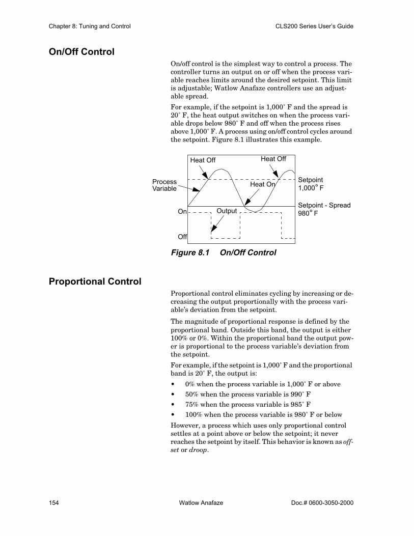
Chapter 8: Tuning and Control CLS200 Series User’s Guide
154 Watlow Anafaze Doc.# 0600-3050-2000
On/Off ControlOn/off control is the simplest way to control a process. The controller turns an output on or off when the process vari-able reaches limits around the desired setpoint. This limit is adjustable; Watlow Anafaze controllers use an adjust-able spread.
For example, if the setpoint is 1,000˚ F and the spread is 20˚ F, the heat output switches on when the process vari-able drops below 980˚ F and off when the process rises above 1,000˚ F. A process using on/off control cycles around the setpoint. Figure 8.1 illustrates this example.
Figure 8.1 On/Off Control
Proportional ControlProportional control eliminates cycling by increasing or de-creasing the output proportionally with the process vari-able’s deviation from the setpoint.
The magnitude of proportional response is defined by the proportional band. Outside this band, the output is either 100% or 0%. Within the proportional band the output pow-er is proportional to the process variable’s deviation from the setpoint.
For example, if the setpoint is 1,000˚ F and the proportional band is 20˚ F, the output is:
• 0% when the process variable is 1,000˚ F or above• 50% when the process variable is 990˚ F• 75% when the process variable is 985˚ F• 100% when the process variable is 980˚ F or below
However, a process which uses only proportional control settles at a point above or below the setpoint; it never reaches the setpoint by itself. This behavior is known as off-set or droop.
Heat Off
Heat On Setpoint
Setpoint - Spread
Process
On
Heat Off
Output
Off
Variable
980° F
1,000° F

CLS200 Series User’s Guide Chapter 8: Tuning and Control
Doc.# 0600-3050-2000 Watlow Anafaze 155
Figure 8.2 Proportional Control
Proportional and Integral ControlWith proportional and integral control, the integral term corrects for offset by repeating the proportional band’s er-ror correction until there is no error. For example, if a pro-cess tends to settle about 5˚ F below the setpoint, appropriate integral control brings it to the desired setting by gradually increasing the output until there is no devia-tion.
Figure 8.3 Proportional and Integral Control
Proportional and integral action working together can bring a process to setpoint and stabilize it. However, with some processes the user may be faced with choosing be-tween parameters that make the process very slow to reach setpoint and parameters that make the controller respond quickly, but introduce some transient oscillations when the setpoint or load changes. The extent to which these oscilla-tions of the process variable exceed the setpoint is called overshoot.
Proportional, Integral and Derivative ControlDerivative control corrects for overshoot by anticipating the behavior of the process variable and adjusting the out-put appropriately. For example, if the process variable is
OffsetProportional
Setpoint
Process Variable
Band
Proportional
Setpoint
Process Variable
Band
Over-shoot

Chapter 8: Tuning and Control CLS200 Series User’s Guide
156 Watlow Anafaze Doc.# 0600-3050-2000
rapidly approaching the setpoint from below, derivative control reduces the output, anticipating that the process variable will reach setpoint. Use it to reduce overshoot and oscillation of the process variable common to PI control. Figure 8.4 shows a process under full PID control.
Figure 8.4 Proportional, Integral and Deriva-tive Control
Heat and Cool OutputsEach loop may have one or two outputs. Often a heater is controlled according to the feedback from a thermocouple, in which case only one output is needed.
In other applications, two outputs may be used for control according to one input. For example, a system with a heater and a proportional valve that controls cooling water flow can be controlled according to feedback from one thermo-couple.
In such systems, the control algorithm avoids switching too frequently between heat and cool outputs. The on/off algo-rithm uses the SPREAD parameter to prevent such oscilla-tions (see Spread on page 92). When PID control is used for one or both loop outputs, both the SPREAD parameter and PID parameters determine when control switches between heating and cooling.
Proportional
Setpoint
Process Variable
Band
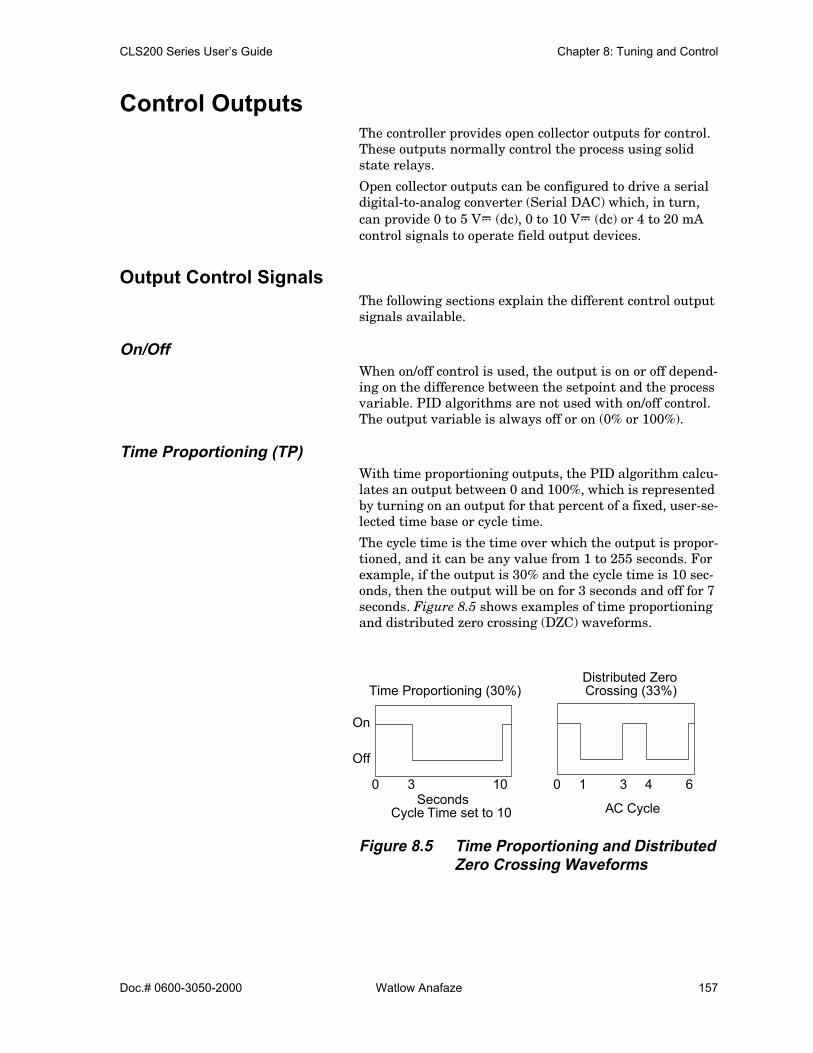
CLS200 Series User’s Guide Chapter 8: Tuning and Control
Doc.# 0600-3050-2000 Watlow Anafaze 157
Control OutputsThe controller provides open collector outputs for control. These outputs normally control the process using solid state relays.
Open collector outputs can be configured to drive a serial digital-to-analog converter (Serial DAC) which, in turn, can provide 0 to 5 VÎ (dc), 0 to 10 VÎ (dc) or 4 to 20 mA control signals to operate field output devices.
Output Control SignalsThe following sections explain the different control output signals available.
On/OffWhen on/off control is used, the output is on or off depend-ing on the difference between the setpoint and the process variable. PID algorithms are not used with on/off control. The output variable is always off or on (0% or 100%).
Time Proportioning (TP)With time proportioning outputs, the PID algorithm calcu-lates an output between 0 and 100%, which is represented by turning on an output for that percent of a fixed, user-se-lected time base or cycle time.
The cycle time is the time over which the output is propor-tioned, and it can be any value from 1 to 255 seconds. For example, if the output is 30% and the cycle time is 10 sec-onds, then the output will be on for 3 seconds and off for 7 seconds. Figure 8.5 shows examples of time proportioning and distributed zero crossing (DZC) waveforms.
Figure 8.5 Time Proportioning and Distributed Zero Crossing Waveforms
Time Proportioning (30%)
On
Off
0 3 10Seconds
Cycle Time set to 10
Distributed Zero
0 1 3 4 6
AC Cycle
Crossing (33%)

Chapter 8: Tuning and Control CLS200 Series User’s Guide
158 Watlow Anafaze Doc.# 0600-3050-2000
Distributed Zero Crossing (DZC) With DZC outputs, the PID algorithm calculates an output between 0 and 100%, but the output is distributed on a variable time base. For each ac line cycle, the controller de-cides whether the power should be on or off. There is no fixed cycle time since the decision is made for each line cy-cle. When used in conjunction with a zero crossing device, such as a solid state relay (SSR), switching is done only at the zero crossing of the ac line, which helps reduce electri-cal noise.
Using a DZC output should extend the life of heaters. Since the time period for 60 Hz power is 16.6 ms, the switching interval is very short and the power is applied uniformly. DZC should be used with SSRs. Do not use DZC output for electromechanical relays.
The combination of DZC output and a solid state relay can inexpensively approach the effect of analog, phase-angle fired control. Note, however, DZC switching does not limit the current and voltage applied to the heater as phase-an-gle firing does.
Three-Phase Distributed Zero Crossing (3P DZC)This output type performs exactly the same as DZC except that the minimum switching time is three ac line cycles. This may be advantageous in some applications using three-phase heaters and three-phase power switching.
Analog OutputsFor analog outputs, the PID algorithm calculates an output between 0 and 100%. This percentage of the analog output range can be applied to an output device via a Dual DAC or a Serial DAC.
Output FilterThe output filter digitally smooths PID control output sig-nals. It has a range of 0 to 255 scans, which gives a time constant of 0 to 170 seconds for a CLS216, 0 to 85 seconds for a CLS208 or 0 to 43 seconds for a CLS204. Use the out-put filter if you need to filter out erratic output swings due to extremely sensitive input signals, like a turbine flow sig-nal or an open air thermocouple in a dry air gas oven.
The output filter can also enhance PID control. Some pro-cesses are very sensitive and would otherwise require a large proportional band, making normal control methods ineffective. Using the output filter allows a smaller propor-tional band to be used, achieving better control.
Also, use the filter to reduce the process output swings and output noise when a large derivative is necessary, or to make badly tuned PID loops and poorly designed processes behave properly.
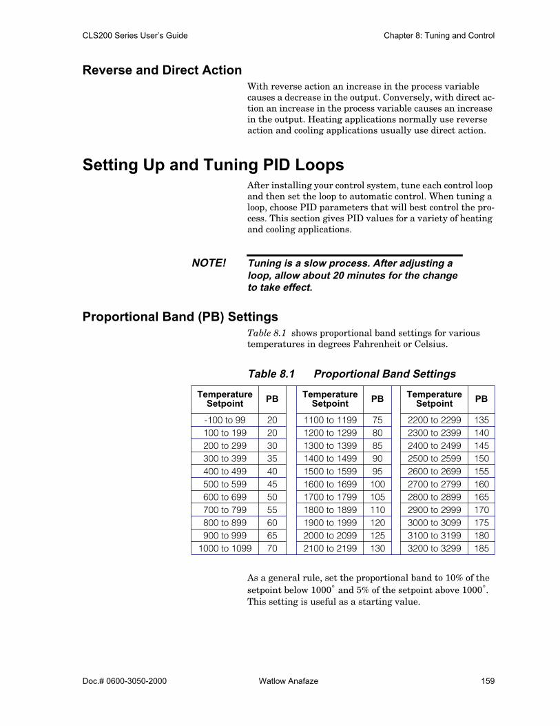
CLS200 Series User’s Guide Chapter 8: Tuning and Control
Doc.# 0600-3050-2000 Watlow Anafaze 159
Reverse and Direct ActionWith reverse action an increase in the process variable causes a decrease in the output. Conversely, with direct ac-tion an increase in the process variable causes an increase in the output. Heating applications normally use reverse action and cooling applications usually use direct action.
Setting Up and Tuning PID LoopsAfter installing your control system, tune each control loop and then set the loop to automatic control. When tuning a loop, choose PID parameters that will best control the pro-cess. This section gives PID values for a variety of heating and cooling applications.
NOTE! Tuning is a slow process. After adjusting aloop, allow about 20 minutes for the changeto take effect.
Proportional Band (PB) SettingsTable 8.1 shows proportional band settings for various temperatures in degrees Fahrenheit or Celsius.
Table 8.1 Proportional Band Settings
As a general rule, set the proportional band to 10% of the setpoint below 1000˚ and 5% of the setpoint above 1000˚. This setting is useful as a starting value.
TemperatureSetpoint PB Temperature
Setpoint PB TemperatureSetpoint PB
-100 to 99 20 1100 to 1199 75 2200 to 2299 135100 to 199 20 1200 to 1299 80 2300 to 2399 140200 to 299 30 1300 to 1399 85 2400 to 2499 145300 to 399 35 1400 to 1499 90 2500 to 2599 150400 to 499 40 1500 to 1599 95 2600 to 2699 155500 to 599 45 1600 to 1699 100 2700 to 2799 160600 to 699 50 1700 to 1799 105 2800 to 2899 165700 to 799 55 1800 to 1899 110 2900 to 2999 170800 to 899 60 1900 to 1999 120 3000 to 3099 175900 to 999 65 2000 to 2099 125 3100 to 3199 180
1000 to 1099 70 2100 to 2199 130 3200 to 3299 185
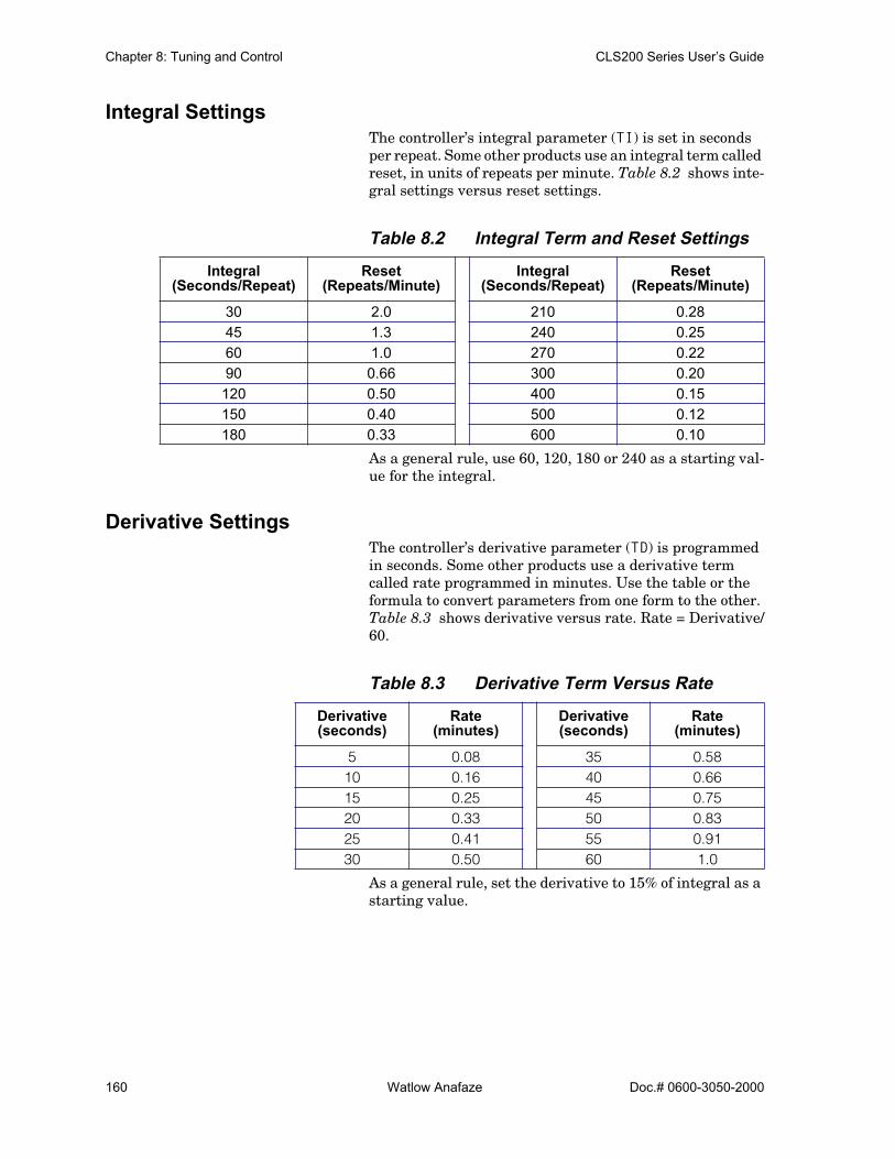
Chapter 8: Tuning and Control CLS200 Series User’s Guide
160 Watlow Anafaze Doc.# 0600-3050-2000
Integral SettingsThe controller’s integral parameter (TI) is set in seconds per repeat. Some other products use an integral term called reset, in units of repeats per minute. Table 8.2 shows inte-gral settings versus reset settings.
Table 8.2 Integral Term and Reset Settings
As a general rule, use 60, 120, 180 or 240 as a starting val-ue for the integral.
Derivative SettingsThe controller’s derivative parameter (TD) is programmed in seconds. Some other products use a derivative term called rate programmed in minutes. Use the table or the formula to convert parameters from one form to the other. Table 8.3 shows derivative versus rate. Rate = Derivative/60.
Table 8.3 Derivative Term Versus Rate
As a general rule, set the derivative to 15% of integral as a starting value.
Integral(Seconds/Repeat)
Reset(Repeats/Minute)
Integral(Seconds/Repeat)
Reset(Repeats/Minute)
30 2.0 210 0.2845 1.3 240 0.2560 1.0 270 0.2290 0.66 300 0.20120 0.50 400 0.15150 0.40 500 0.12180 0.33 600 0.10
Derivative(seconds)
Rate(minutes)
Derivative(seconds)
Rate(minutes)
5 0.08 35 0.5810 0.16 40 0.6615 0.25 45 0.7520 0.33 50 0.8325 0.41 55 0.9130 0.50 60 1.0

CLS200 Series User’s Guide Chapter 8: Tuning and Control
Doc.# 0600-3050-2000 Watlow Anafaze 161
NOTE! While the basic PID algorithm is well definedand widely recognized, various controllersimplement it differently. Parameters may notbe taken from one controller and applied toanother with optimum results even if theabove unit conversions are performed.
General PID Constants by ApplicationThis section gives PID values for many applications. They are useful as control values or as starting points for PID tuning.
Proportional Band Only (P)Set the proportional band to 7% of the setpoint.(Example: Setpoint set to 450, proportional band set to 31).
Proportional with Integral (PI)• Set the proportional band to 10% of setpoint.
(Example: Setpoint set to 450, proportional band set to 45).
• Set integral to 60.• Set derivative to Off.• Set the output filter to 2.
PI with Derivative (PID)• Set the proportional band to 10% of the setpoint.
(Example: Setpoint set to 450, proportional band set to 45).
• Set the integral to 60.• Set the derivative to 15% of the integral.
(Example: Integral set to 60, derivative set to 9).• Set the output filter to 2.
Table 8.4 on page 162 shows general PID constants by ap-plication.

Chapter 8: Tuning and Control CLS200 Series User’s Guide
162 Watlow Anafaze Doc.# 0600-3050-2000
Table 8.4 General PID Constants
Application Proportional Band Integral Derivative Filter Output
TypeCycle Time Action
Electrical heat with solid state relays
50° 60 15 4 DZC - Reverse
Electrical heat with electrome-chanical relays
50° 60 15 6 TP 20 Reverse
Cool with sole-noid valve 70° 500 90 4 TP 10 Direct
Cool with fans 10° Off 10 4 TP 10 Direct
Electric heat with open heat coils
30° 20 Off 4 DZC - Reverse
Gas heat with motorized valvesSetpoint>1200
60°
100°
120
240
25
40
8 Analog - Reverse
Doc.# 0600-3050-2000 Watlow Anafaze 163
9Troubleshooting and Reconfiguring
When There is a ProblemThe controller is only one part of your control system. Of-ten, what appears to be a problem with the controller is re-ally a problem with other equipment, so check these things first:
• Controller is installed correctly. (See Chapter 2, In-stallation for help.)
• Sensors, such as thermocouples and RTDs, are in-stalled correctly and working.
NOTE! If you suspect your controller has been dam-aged, do not attempt to repair it yourself, oryou may void the warranty.
If the troubleshooting procedures in this chapter do not solve your system’s problems, call Application Engineering for additional troubleshooting help. If you need to return the unit to Watlow Anafaze for testing and repair, Custom-er Service will issue you an RMA number. See Returning Your Unit on page 164.
CAUTION! Before trying to troubleshoot a problem byreplacing your controller with another one,first check the installation. If you have short-ed sensor inputs to high voltage lines or atransformer is shorted out, and you replacethe controller, you will risk damage to thenew controller.

Chapter 9: Troubleshooting and Reconfiguring CLS200 Series User’s Guide
164 Watlow Anafaze Doc.# 0600-3050-2000
If you are certain the installation is correct, you can try re-placing the controller. If the second unit works correctly, then the problem is specific to the controller you replaced.
Returning Your UnitBefore returning a controller, contact your supplier or call Watlow for technical support.
Controllers purchased as part of a piece of equipment must be serviced or returned through the equipment manufac-turer. Equipment manufacturers and authorized distribu-tors should call customer service to obtain a return materials authorization (RMA) number. Shipments with-out an RMA will not be accepted. Other users should con-tact their suppliers for instructions on returning products for repair.
Troubleshooting ControllersA problem may be indicated by one or more of several types of symptoms:
• A process or deviation alarm• A failed sensor alarm• A system alarm• Unexpected or undesired behavior
The following sections list symptoms in each of these cate-gories and suggest possible causes and corrective actions.
Process and Deviation AlarmsWhen a process or deviation alarm occurs, the controller switches to the single loop display for the loop with the alarm and displays the alarm code on the screen. Software such as AnaWin or WatView displays a message on the alarm screen and logs the alarm in the event log.
Table 9.1 Controller Alarm Codes forProcess and Deviation Alarms
Code Alarm Description
HP High Process Process variable has risen above the high process alarm setpoint.
HD High Deviation Process variable has risen above the setpoint by more than the devia-tion alarm value.
LD Low Deviation Process variable has dropped below the setpoint by more than the deviation alarm value.
LP Low Process Process variable has dropped below the low process alarm setpoint.

CLS200 Series User’s Guide Chapter 9:Troubleshooting and Reconfiguring
Doc.# 0600-3050-2000 Watlow Anafaze 165
Responding to Process and Deviation AlarmsIn a heating application, a low process or low deviation alarm may indicate one of the following:
• The heater has not had time to raise the temperature.• The load has increased and the temperature has fall-
en.• The control status is set to manual instead of automatic.• The heaters are not working due to a hardware failure.• The sensor is not placed correctly and is not measuring
the load’s temperature.• The deviation limit is too narrow.• The system is so poorly tuned that the temperature is
cycling about setpoint by more than the alarm limit.
NOTE! In cooling applications, similar issues causehigh process and high deviation alarms.
In a heating application, a high process alarm or high devi-ation alarm may indicate one of the following:
• The setpoint and high process limit have been lowered and the system has not had time to cool to within the new alarm limit.
• The control status is set to manual and the heat out-put is greater than 0%.
• The load has decreased such that the temperature has risen.
• The heater is full-on due to a hardware failure.• The system is so poorly tuned that the temperature is
cycling about setpoint by more than the alarm limit.
Resetting a Process or Deviation AlarmYour response to an alarm depends upon the alarm type setting, as explained in Table 9.2 below.
Table 9.2 Operator Response to Alarms
Alarm Type Operator Response
ControlThe operator does not need to do anything. The alarm clears automatically when the pro-cess variable returns within limits.
Alarm
Acknowledge the alarm by pressing ALARM ACK on the controller or by using software. The alarm clears after the process variable returns within the limits and the operator has acknowledged it.

Chapter 9: Troubleshooting and Reconfiguring CLS200 Series User’s Guide
166 Watlow Anafaze Doc.# 0600-3050-2000
Failed Sensor Alarms
When a failed sensor alarm occurs, the controller switches to the single loop display for the loop with the alarm and displays an alarm code on the screen. AnaWin or WatView displays a message on the alarm screen and logs the alarm in the event log.
Table 9.3 Failed Sensor Alarm Codes
A failed sensor alarm clears once it has been acknowledged and the sensor is repaired.
System Alarms
If the controller detects a hardware problem, it displays a message. The message persists until the condition is cor-rected.
Table 9.4 Hardware Error Messages
Code Alarm Description
FS
Failed Sensor Open thermocouple.
RT
Reversed Thermocouple Temperature changed in the opposite direction than expected.
ST
Shorted Thermocouple Temperature failed to change as expected.
RO
RTD Open Positive or negative lead is broken or disconnected.
RS
RTD Shorted Positive and negative leads are shorted.
Message Possible Cause Recommended Action
LOW POWER
Power supply failed. See
Low Power on page 168
.
BATTERY DEAD
RAM battery is dead. See
Battery Dead on page 168
.
AW
Ambient warning. Ambient tem-perature exceeds operating lim-its by less than 5° C (9° F).
See
Ambient Warning on page 168
.
H/W AMBIENT FAILURE
Ambient temperature exceeds operating limits by 5° C (9° F).
Reference voltage (5V
Î
[dc]) shorted to common.Hardware failed due to exces-sive voltage on inputs.
See
H/W Ambient Failure on page 169
.
H/W GAIN FAILURE
Hardware failed due to exces-sive voltage on inputs.
See
H/W Gain or Offset Failure on page 170
.
H/W OFFSET FAILURE
Hardware failed due to exces-sive voltage on inputs.
See
H/W Gain or Offset Failure on page 170
.

CLS200 Series User’s Guide Chapter 9:Troubleshooting and Reconfiguring
Doc.# 0600-3050-2000 Watlow Anafaze 167
Other BehaviorsThe following table indicates potential problems with the system or controller and recommends corrective actions.
Table 9.5 Other Symptoms
Symptom Possible Causes Recommended Action
Indicated tempera-ture not as expected
Controller not communicatingSensor wiring incorrectNoise
See Checking Analog Inputs on page 171.
CLS 200 display is not lit
Power connection incorrect Check wiring and service. See Wiring the Power Supply on page 25.
No EPROM or bad EPROM Replace the EPROM. See Replacing the EPROM on page 176.
CLS200 damaged or failed Return the CLS200 for repair. See Return-ing Your Unit on page 164.
CLS200 display is lit, but keys do not work
Keypad is locked See Keys Do Not Respond on page 170.
CLS200 damaged or failed Return the CLS200 for repair. See Return-ing Your Unit on page 164.
Control status of one or more loops changes from auto-matic to manual
Failed sensor Check the display or software for a failed sensor message.
Digital job select feature is enabled and has changed jobs
Set JOB SELECT DIG INPUTS to NONE. This parameter is only accessible using the controller’s keypad and display. See Job Select Digital Inputs on page 76.
All loops are set to manual 0%
Power is intermittent
Check wiring and service. See Wiring the Power Supply on page 25.Use a separate dc supply for the controller.Provide backup power (UPS).Set POWER UP OUTPUT STATUS to MEM-ORY. See Power Up Output Status on page 78.
Analog reference voltage is overloaded
Disconnect any wiring from the +5V Ref connection on TB1.
Hardware failureCheck the controller front panel for a hard-ware alarm. See System Alarms on page 166.
Controller does not behave as expected
Corrupt or incorrect values in RAM
Perform a NO-key reset. See NO-Key Reset on page 176.

Chapter 9: Troubleshooting and Reconfiguring CLS200 Series User’s Guide
168 Watlow Anafaze Doc.# 0600-3050-2000
Corrective and Diagnostic ProceduresThe following sections detail procedures you may use to di-agnose and correct problems with the controller.
Low PowerIf the controller displays LOW POWER or the display is not lit:
1. Acknowledge the alarm.
2. If the error message remains, turn the power to thecontroller off, then on again.
3. If the error message returns, check that the powersupplied to the controller is at least 12.0VÎ (dc) @ 1 A.See Wiring the Power Supply on page 25.
4. If the error message returns again, make a record ofthe settings if possible (using software). Then, performa NO-key reset (see NO-Key Reset on page 176).
5. If the error is not cleared, contact your supplier for fur-ther troubleshooting guidance. See Returning YourUnit on page 164.
Battery DeadThe dead battery alarm indicates that the CLS200 battery is not functioning correctly or has low power or no power. If this alarm occurs, parameters have reset to the factory de-fault settings.
NOTE! The controller will retain its settings whenpowered. The battery is required to keep thesettings in memory only when the controlleris powered down.
If the controller displays BATTERY DEAD:
1. Acknowledge the alarm.
2. If the error message remains, turn the power to thecontroller off, then on again.
3. If the error message returns when power is restored,perform a NO-key reset. See NO-Key Reset on page 176.
4. If the error is not cleared, contact your supplier for fur-ther troubleshooting guidelines. See Returning YourUnit on page 164.
Ambient WarningThe ambient warning alarm indicates that the ambient temperature of the controller is too hot or too cold. Ambient warning occurs when the controller’s temperature is in the

CLS200 Series User’s Guide Chapter 9:Troubleshooting and Reconfiguring
Doc.# 0600-3050-2000 Watlow Anafaze 169
range of 23 to 32° F or 122 to 131° F (-5 to 0° C or 50 to 55° C). The operating limits are 32 to 122° F (0 to 50° C).
If the controller displays AW in the lower left corner of the display:
1. Acknowledge the alarm.
2. If the error message remains, check the ambient airtemperature near the controller. Adjust ventilation,cooling or heating to ensure that the temperaturearound the controller is 32 to 122° F (0 to 50° C). If theunit is functioning correctly, the error will clear whenthe ambient temperature is within range and thealarm has been acknowledged.
3. If the ambient temperature is within range and the er-ror persists:
a) Turn the power to the controller off.
b) Remove the boards from the CLS200 housing.See Replacing the EPROM on page 176.
c) Reseat the boards and turn the power on.
4. If the error persists, make a record of the settings thenperform a NO-key reset. See NO-Key Reset on page 176.
5. If the error is not cleared, contact your supplier for fur-ther troubleshooting guidelines. See Returning YourUnit on page 164.
H/W Ambient FailureThe hardware ambient failure alarm indicates that the am-bient sensor in the CLS200 is reporting that the tempera-ture around the controller is outside of the acceptable range of 0 to 50° C. This error can also occur when there is a hardware failure.
If the controller displays H/W AMBIENT FAILURE:
1. Acknowledge the alarm.
2. If the error message remains, check the ambient airtemperature near the controller. Adjust ventilation,cooling or heating to ensure that the temperaturearound the controller is 0 to 50° C. If the unit is func-tioning correctly, the error will clear automaticallywhen the ambient temperature is within range andthe alarm has been acknowledged.
3. Remove any connections to the 5VÎ (dc) reference(TB1-18) on the back of the controller. If this correctsthe problem, there was an error in the wiring. Youmay need to consult technical support to determinethe correct wiring.
4. If the ambient temperature is within range and the er-ror persists:

Chapter 9: Troubleshooting and Reconfiguring CLS200 Series User’s Guide
170 Watlow Anafaze Doc.# 0600-3050-2000
a) Turn the power to the controller off.
b) Remove the boards from the CLS200 housing.
c) Reseat the boards and turn power on.
5. If the error persists, make a record of the settings,then perform a NO-key reset. See NO-Key Reset onpage 176.
6. If the error is not cleared, contact your supplier for fur-ther troubleshooting guidelines. See Returning YourUnit on page 164.
NOTE! If the controller has failed, it is likely that itwas damaged by excessive voltage or noise.Before replacing the controller, troubleshootfor noise and ground loops.
H/W Gain or Offset FailureIf the controller displays H/W GAIN FAILURE orH/W OFFSET FAILURE:
1. Acknowledge the alarm.
2. If the error message remains, turn the power to thecontroller off, then on again.
3. If the H/W Gain error is reported, remove any connec-tions to the 5VÎ (dc) reference (TB1-18) on the back ofthe controller. If this corrects the problem, there wasan error in the wiring. You may need to consult tech-nical support to determine the correct wiring.
4. If the error persists, make a record of the settings (us-ing software), then perform a NO-key reset. See NO-Key Reset on page 176.
5. If the error is not cleared, contact your supplier for fur-ther troubleshooting guidelines. See Returning YourUnit on page 164.
NOTE! If the controller has failed, it is likely that itwas damaged by excessive voltage or noise.Before replacing the controller, troubleshootfor noise and ground loops.
Keys Do Not RespondIf the CLS200 seems to function but the MAN/AUTO, CHNG SP, ALARM ACK, and RAMP/SOAK keys do not respond when you press them, the keypad is probably locked. Unlock the keypad according to the instructions in Keyboard Lock Sta-tus on page 78.

CLS200 Series User’s Guide Chapter 9:Troubleshooting and Reconfiguring
Doc.# 0600-3050-2000 Watlow Anafaze 171
Checking Analog InputsIf the process variable displayed in the software and on the controller do not agree:
1. Verify that the controller is communicating.
2. If the process variable indicated on the controller dis-play is incorrect:
a) Verify that you have selected the correct inputtype for the affected loops.
b) Verify that sensors are properly connected.
3. If the sensors are correctly connected, with power on tothe heaters check for high common mode voltage:
a) Set a voltmeter to measure volts ac.
b) Connect the negative lead to a good earth ground.
c) One by one, check each input for ac voltage byconnecting the positive lead on the voltmeter tothe positive and negative sensor input connec-tions. The process variable should indicate ambi-ent temperature. If it does not, contact yoursupplier to return the unit for repair. See Return-ing Your Unit on page 164.
NOTE! Noise in excess of 1VÅ (ac) should be elimi-nated by correctly grounding the CLS200.See Wiring the Power Supply on page 25.
4. Verify the sensors:
• For thermocouples, remove the thermocoupleleads and use a digital voltmeter to measure theresistance between the positive and negativethermocouple leads. A value of 2 to 20 Ω is nor-mal. Readings in excess of 200 Ω indicate a prob-lem with the sensor.
• For RTDs, measure between the IN+ and IN- ter-minals of TB1. RTD inputs should read between20 and 250 Ω.
5. To verify that the controller hardware is working cor-rectly, check any input (except the pulse input or anRTD) as follows:
a) Disconnect the sensor wiring.
b) Set the INPUT TYPE to J T/C in the SETUP LOOPINPUT menu.
c) Place a short across the input. The controllershould indicate the ambient temperature on thechannel you are testing.
Chapter 9: Troubleshooting and Reconfiguring CLS200 Series User’s Guide
172 Watlow Anafaze Doc.# 0600-3050-2000
Earth GroundingIf you suspect a problem with the ac ground or a ground loop:
• Measure for ac voltage between ac neutral and panel chassis ground. If ac voltage above 2VÅ (ac) is ob-served, then there may be a problem with the ac power wiring. This should be corrected per local electrical codes.
• With ac power on, measure for ac voltage that may be present between control panels’ chassis grounds. Any ac voltage above 2VÅ (ac) may indicate problems with the ac ground circuit.
• Check for ac voltage on thermocouples with the heater power on. A control output providing power to the heaters will increase the ac voltage if there is heater leakage and an improper grounding circuit. Measure from either positive or negative thermocouple lead to ac ground. AC voltage above 2VÅ (ac) may indicate the ground lead is not connected to the CLS200 TB2 ground terminal.
If the above tests indicate proper ac grounding but the con-troller is indicating incorrect temperatures or process read-ings:
• Verify which type of sensor is installed and that the INPUT TYPE parameter is set accordingly.
• For an RTD or linear voltage or current input, check that the correct input scaling resistors are installed (page 180) and check the input scaling parameter set-tings (page 86).
• If readings are erratic, look for sources of electrical noise. See Noise Suppression on page 22.
• Eliminate possible ground loops. See Ground Loops on page 24.
• Contact your supplier for further troubleshooting guidance. See Returning Your Unit on page 164.
Checking Control OutputsTo check control outputs:
• Set the loop you want to check to manual mode. • Set the output power percentage to the desired level. • Set the output type to ON/OFF or TP (see Chapter 4,
Setup).
If the control output is not connected to an output device like an SSR, connect an LED in series with a 1 kΩ resistor from +5V to the output. (Tie the anode of the LED to +5V.) The LED should be off when the output is 0% and on when the output is 100%.
CLS200 Series User’s Guide Chapter 9:Troubleshooting and Reconfiguring
Doc.# 0600-3050-2000 Watlow Anafaze 173
Testing Control Output DevicesConnect the solid state relay (SSR) control terminals to the CLS200 control output and connect a light bulb (or other load that can easily be verified) to the output terminals on the SSR. Put the loop in manual mode and set the output to 100%. The ac load should turn on.
Do not attempt to measure ac voltage at the SSR’s output terminals. Without a load connected, the SSR’s output ter-minals do not turn off. This makes it difficult to determine whether the SSR is actually working. Measure the voltage across a load or use a load that can be visually verified, such as a light bulb.
Testing the TB18 and TB501. Turn on power to the controller.
2. Measure the +5VÎ (dc) supply at the TB18 or TB50.The voltage should be +4.75 to +5.25VÎ (dc):
a) Connect the voltmeter’s common lead to the TB18screw terminal 2 or TB50 screw terminal 3.
b) Connect the voltmeter’s positive lead to the TB18or TB50 screw terminal 1.
Testing Control and Digital Outputs1. Turn off power to the controller.
2. Disconnect any process output wiring on the output tobe tested.
3. Connect a 500 Ω to 100 kΩ resistor between the +5V terminal (TB18 or TB50 screw terminal 1) and theoutput terminal you want to test.
4. Connect the voltmeter’s common lead to the outputterminal, and connect the voltmeter’s positive lead tothe +5V terminal.
5. Restore power to the controller.
6. If you are testing a PID control output, use the MAN/AUTO key to turn the output on (100%) and off (0%).When the output is off, the output voltage should beless than 1V. When the output is on, the output volt-age should be between +3.75 and +5.25V.
7. If you are testing a digital output not used for control,use the MANUAL I/O TEST menu to turn the output onand off. See Manual I/O Test on page 103.
Testing Digital Inputs1. Turn off power to the controller.
2. Disconnect any system wiring from the input to betested.

Chapter 9: Troubleshooting and Reconfiguring CLS200 Series User’s Guide
174 Watlow Anafaze Doc.# 0600-3050-2000
3. Restore power to the controller.
4. Go to the DIGITAL INPUTS parameter in the MANUALI/O TEST menu. This parameter shows whether thedigital inputs are H (high, or open) or L (low, or closed).
5. Attach a wire to the terminal of the digital input totest. When the wire is connected only to the digital in-put terminal, the DIGITAL INPUTS parameter shouldshow that the input is H (high). When you connect theother end of the wire to controller common (TB50 ter-minal 3), the DIGITAL INPUTS parameter shouldshow that the input is L (low).
Additional Troubleshooting for ComputerSupervised Systems
These four elements must work properly in a computer-su-pervised system:
• The controller• The computer and its EIA/TIA-232 or EIA/TIA-485 se-
rial interface• The EIA/TIA-232 or EIA/TIA-485 communication lines• The computer software
For troubleshooting, disconnect the communications line from the computer and follow the troubleshooting steps in the first section of this chapter. The next few sections ex-plain troubleshooting for the other elements of computer supervised systems.
Computer ProblemsIf you are having computer or serial interface problems, check the following:
• Check your software manual and make sure your com-puter meets the software and system requirements.
• Check the communications interface, cables, and con-nections. Make sure the serial interface is set accord-ing to the manufacturer’s instructions.
• To test an EIA/TIA-232 interface, purchase an EIA/TIA-232 tester with LED indicators. Attach the tester between the controller and the computer. When the computer sends data to the controller, the tester’s TX LED should blink. When the computer receives data from the controller, the RX LED should blink.
• You can also connect an oscilloscope to the transmit or receive line to see whether data is being sent or re-ceived. If the serial port does not appear to be working, the software setup may need to be modified or the hardware may need to be repaired or replaced.

CLS200 Series User’s Guide Chapter 9:Troubleshooting and Reconfiguring
Doc.# 0600-3050-2000 Watlow Anafaze 175
CommunicationsMost communications problems are due to incorrect wiring or incorrectly set communications parameters. Therefore, when there is a problem, check the wiring and communica-tions settings first. Verify the following:
• Communications port: Software must be configured to use the communications port to which the controller is connected.
• Software protocol: Set the controller to MOD (Modbus) for AnaWin or WatView, ANA (Anafaze) for Anasoft or Anascan.
• Controller address: Configure software to look for the controller at the correct address. In a multiple-control-ler installation, each controller must have a unique address.
• Baud rate: Software and controller must be set the same.
• Error checking (ANA protocol only): Software and con-troller must be set the same (CRC or BCC).
• Hardware protocol: PC and controller must use the same protocol, or a converter must be used. The con-troller is typically configured for EIA/TIA-232 when it is shipped. See Changing Communications on page 179 to change between EIA/TIA-232 and EIA/TIA-485. To communicate with more than one controller, or when more than 50 feet of cable is required, use EIA/TIA-485. Even for a single controller, you may use EIA/TIA-485 and an optically isolating converter to eliminate ground loops.
• Converter: Make sure that the EIA/TIA-232-to-485 converter is powered, configured and wired correctly.
• Cables: Check continuity by placing a resistor across each pair of wires and measuring the resistance with an ohmmeter at the other end.
Ground LoopsMany PC communications ports have their common wires connected to chassis ground. Once connected to the control-ler, this can provide a path to ground for current from the process that can enter the controller through a sensor (such as a thermocouple). This creates a ground loop that can af-fect communications and other controller functions. To eliminate a ground loop, either use an optically isolated communications adapter or take measures to ensure that sensors and all other connections to the controller are iso-lated and not conducting current into the unit.
Chapter 9: Troubleshooting and Reconfiguring CLS200 Series User’s Guide
176 Watlow Anafaze Doc.# 0600-3050-2000
Software ProblemsIf the controller and serial communications connections seem to be working correctly, but you are still not getting the result you expect, consult the resources you have avail-able for the software program you are using.
WatView, AnaWin or AnasoftConsult the AnaWin or Anasoft User’s Guide for help with the user interface. WatView comes with a context-sensitive help explaining operation of the software. Context-sensi-tive means that you can press the F1 key to get help related to the part of the program you are using.
User-Written SoftwareYou can request a communications specification from Wat-low Anafaze if you want to write your own software. Wat-low Anafaze will answer technical questions that arise during your software development process, but does not otherwise support user-developed or third-party software in any way.
NO-Key ResetPerforming a NO-key reset returns all controller settings to their defaults. All recipes are also cleared.
To perform a NO-key reset:
1. Make a record of the controller’s settings.
2. Turn off power to the unit.
3. Press and hold the NO key on the keypad.
4. Turn on power to the controller still holding the NOkey.
5. When prompted RESET WITH DEFAULTS?, release theNO key and press the YES key.
6. If you do not see the RESET WITH DEFAULTS? promptor do not get a chance to press YES, repeat the proce-dure.
7. Restore the controller settings.
If you have a stand-alone system, there is no way to recover your original parameters. If you have a computer-super-vised system with AnaWin or Anasoft, a copy of your pa-rameters can be saved to a job file.
Replacing the EPROMReplacing the EPROM involves minor mechanical disas-sembly and reassembly of the controller. You will need a Phillips screwdriver and a small flathead screwdriver.

CLS200 Series User’s Guide Chapter 9:Troubleshooting and Reconfiguring
Doc.# 0600-3050-2000 Watlow Anafaze 177
CAUTION! The EPROM and other components are sen-sitive to damage from electrostatic discharge(ESD). To prevent ESD damage, use an ESDwrist strap or other antistatic device.
NOTE! Replacing the EPROM with another versionresults in full erasure of RAM. Make a recordof all parameters before changing theEPROM.
1. Make a record of system parameters.
2. Power down the controller.
3. Remove the four screws from the sides of the controllerfront panel.
4. Remove the electronics assembly from the case, asshown in Figure 9.1.
Figure 9.1 Removal of Electronics Assembly from Case
5. Unscrew the four screws at the corners of the topboard and carefully unplug this board to access thebottom board (processor board). Figure 9.2 shows thescrews to remove:
WATLOW ANAFAZE CLS200
WATLOW ANAFAZE CLS200

Chapter 9: Troubleshooting and Reconfiguring CLS200 Series User’s Guide
178 Watlow Anafaze Doc.# 0600-3050-2000
Figure 9.2 Screws Locations on PC Board
6. Locate the EPROM on the circuit board. The EPROMis a 32-pin socketed chip that is labeled with the mod-el, version and checksum.
Figure 9.3 EPROM Location
7. Remove the existing EPROM from its socket with anIC extraction tool or a jeweler’s flathead screwdriver.
Figure 9.4 Remove EPROM
8. Carefully insert the new EPROM into the EPROMsocket. Make sure that the chip is oriented so that itsnotch fits in the corresponding corner of the socket.
9. Reverse steps 2 through 4 to reassemble the unit.
10. Power up the controller.
11. Re-enter parameters.
WATLOW ANAFAZE CLS200
EPROM
SRAM
MP
Pin 1
Notch
EPROM Detail
U2

CLS200 Series User’s Guide Chapter 9:Troubleshooting and Reconfiguring
Doc.# 0600-3050-2000 Watlow Anafaze 179
Changing CommunicationsTo switch between EIA/TIA-232 and EIA/TIA-485, change the jumpers as shown in Figure 9.5.
Figure 9.5 Jumper Configurations
You will need tweezers and a Phillips head screwdriver to switch between EIA/TIA-232 and EIA/TIA-485. Follow these steps:
1. Power down the unit.
2. Remove the controller’s metal casing. See Replacingthe EPROM on page 176 for step-by-step instructions.
3. Find jumpers JU2, JU3, JU4, and JU5 on the board.
4. Use tweezers to carefully grasp the jumpers and gen-tly slide them off the pins.
5. Use tweezers to gently slide jumpers JU2, JU3, JU4and JU5 onto the correct pins (see Figure 9.5).
6. If you are configuring the controller as the last deviceon an EIA/TIA-485 network, move JU1 to the B posi-tion.
7. Reassemble the controller.
JU1JU2JU3JU4JU5
A B A B A B
Configured for EIA/TIA-232
Configured forEIA/TIA-485
Last controller insystem configured
for EIA/TIA-485

Chapter 9: Troubleshooting and Reconfiguring CLS200 Series User’s Guide
180 Watlow Anafaze Doc.# 0600-3050-2000
Installing Scaling ResistorsResistors are installed for all inputs on the CLS200. Inputs with signal ranges between -10 and +60 mV use 0 Ω resis-tors in the RC position only. All other input signals require special input scaling resistors.
CAUTION! Scaling resistors are soldered to the circuitboard. Only qualified technicians should at-tempt to install or remove these components.Improper techniques, tools or materials canresult in damage to the controller that is notcovered by the warranty.
CLS204 and CLS208 Input CircuitThe CLS204 and CLS208 can accept differential thermo-couple, mVÎ (dc), VÎ (dc), mAÎ (dc) and RTD inputs. Un-less ordered with special inputs these controller accept only signals within the standard range -10 to 60mVÎ (dc).
To accommodate other signals, the input circuit must be modified. When configured for thermocouple inputs, 0 Ω re-sistors are installed in all RC locations. To accommodate voltage signals outside the standard range, milliamp cur-rent signals or RTDs, resistors are added or replaced to scale the signals to the standard range. These resistor can be installed by Watlow Anafaze or by a qualified electronics technician using scaling resistors supplied by Watlow Anafaze.
Figure 9.6 shows the input circuit for one differential, ana-log input. See CLS204 and CLS208 Current Inputs on page 181 through CLS204 and CLS208 RTDs and Thermistors on page 183 for specific instructions and resistor values for voltage, current and RTD inputs.
NOTE! When adding your own scaling resistors tothe controller, for voltage and RTD inputsyou will have to carefully remove one of theRC resistors in order to install the resistorlisted in the table.

CLS200 Series User’s Guide Chapter 9:Troubleshooting and Reconfiguring
Doc.# 0600-3050-2000 Watlow Anafaze 181
Figure 9.6 CLS204 and CLS208 Input Circuit
CLS204 and CLS208 Current InputsFor each current input on a CLS204 or CLS208 controller you must install a resistor. The value of the resistor must be correct for the expected input range. Install the resistor in the listed resistor pack (RP) location. Note the resistor pack locations have three through holes. Install the resis-tor as shown in the illustration below.
Table 9.6 Resistor Values for CLS204 and CLS208 Current Inputs
Resistor tolerance: ±0.1%
Table 9.7 Resistor Locations for CLS204 and CLS208 Current Inputs
Input Range Resistor Value RD
0 to 10 mA 6.0 Ω0 to 20 mA 3.0 Ω
Loop Resistor Location RD Loop Resistor
Location RD
1 RP1 5 RP5
2 RP2 6 RP6
3 RP3 7 RP7
4 RP4 8 RP8
Com
IN-RC (RTD)
IN+
RD
RP
AnalogInput
Terminal
Internal RP+5VÎ (dc) Reference To CLS200
Circuitry
RC (Voltage)
+
-
RP#
RD
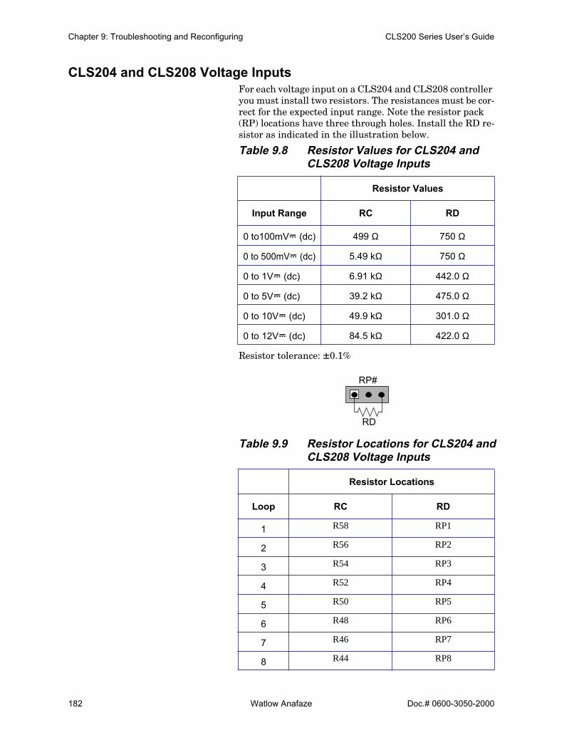
Chapter 9: Troubleshooting and Reconfiguring CLS200 Series User’s Guide
182 Watlow Anafaze Doc.# 0600-3050-2000
CLS204 and CLS208 Voltage InputsFor each voltage input on a CLS204 and CLS208 controller you must install two resistors. The resistances must be cor-rect for the expected input range. Note the resistor pack (RP) locations have three through holes. Install the RD re-sistor as indicated in the illustration below.
Table 9.8 Resistor Values for CLS204 and CLS208 Voltage Inputs
Resistor tolerance: ±0.1%
Table 9.9 Resistor Locations for CLS204 and CLS208 Voltage Inputs
Resistor Values
Input Range RC RD
0 to100mVÎ (dc) 499 Ω 750 Ω
0 to 500mVÎ (dc) 5.49 kΩ 750 Ω
0 to 1VÎ (dc) 6.91 kΩ 442.0 Ω
0 to 5VÎ (dc) 39.2 kΩ 475.0 Ω
0 to 10VÎ (dc) 49.9 kΩ 301.0 Ω
0 to 12VÎ (dc) 84.5 kΩ 422.0 Ω
Resistor Locations
Loop RC RD
1 R58 RP1
2 R56 RP2
3 R54 RP3
4 R52 RP4
5 R50 RP5
6 R48 RP6
7 R46 RP7
8 R44 RP8
RP#
RD

CLS200 Series User’s Guide Chapter 9:Troubleshooting and Reconfiguring
Doc.# 0600-3050-2000 Watlow Anafaze 183
CLS204 and CLS208 RTDs and Thermistors For each RTD or thermistor input on a CLS204 or CLS208 controller, you must install three resistors: RA, RB, and RC. The resistance must be correct for the expected input range. RA and RB are a matched pair of resistors. Install them in the resistor pack (RP) locations as shown in the il-lustration below.
Table 9.10 Resistor Values for CLS204/208 RTD and Thermistor Inputs
Resistor tolerances: RA/RB matched to 0.02% (2 ppm/˚C) and absolute tolerance is 0.1% (10 ppm/˚C) RC accurate to 0.05%.
Table 9.11 Resistor Locations for CLS204/208 RTD and Thermistor Inputs
Resistor Values
Input RA/RB RC
RTD1 10.0 kΩ 80 Ω
RTD2 25.0 kΩ 100 Ω
Resistor Locations
Loop RA/RB RC
1 RP1 R57
2 RP2 R55
3 RP3 R53
4 RP4 R51
5 RP5 R49
6 RP6 R47
7 RP7 R45
8 RP8 R43
RP#
RA RB

Chapter 9: Troubleshooting and Reconfiguring CLS200 Series User’s Guide
184 Watlow Anafaze Doc.# 0600-3050-2000
CLS216 Input CircuitThe CLS216 can accept single-ended thermocouple, mVÎ (dc), VÎ (dc) and mAÎ (dc) inputs. Unless ordered with special inputs, the controller accepts only signals within the standard range of -10 to 60mVÎ (dc).
To accommodate other signals, the input circuit must be modified. When configured for thermocouple inputs, 0 Ω re-sistors are installed in all RC locations. To accommodate milliamp current signals or voltage signals outside the standard range, resistors are added or replaced to scale the signals to the standard range. These resistors can be in-stalled by Watlow Anafaze or by a qualified electronics technician using scaling resistors supplied by Watlow Anafaze.
Figure 9.7 shows the schematic for one single-ended sensor input to the CLS216. See CLS216 Current Inputs on page 184 and CLS216 Voltage Inputs on page 185 for specific in-structions and resistor values for voltage and current in-puts.
Figure 9.7 CLS216 Input Circuit
CLS216 Current InputsFor each current input on a CLS216 controller, you must install one resistor. The value of the resistor must be cor-rect for the expected input range. Install the resistor in the listed resistor location.
Table 9.12 Resistor Values for CLS216 Cur-rent Inputs
Resistor tolerance: ±0.1%
Input Range Resistor Value RD
0 to 10 mA 6.0 Ω
0 to 20 mA 3.0 Ω
IN +
RD
AnalogInput
TerminalsRC
Com
To CLS200
Circuitry
(Voltage only)
(Voltage and Current)
Measurement
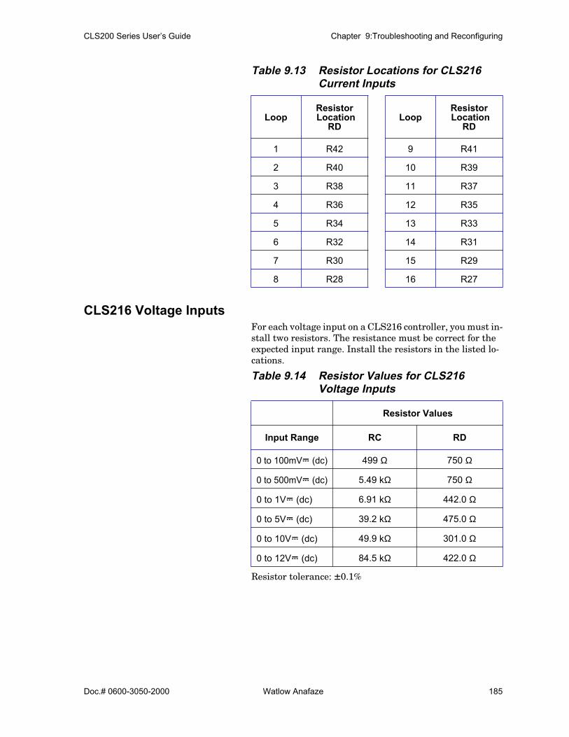
CLS200 Series User’s Guide Chapter 9:Troubleshooting and Reconfiguring
Doc.# 0600-3050-2000 Watlow Anafaze 185
Table 9.13 Resistor Locations for CLS216 Current Inputs
CLS216 Voltage InputsFor each voltage input on a CLS216 controller, you must in-stall two resistors. The resistance must be correct for the expected input range. Install the resistors in the listed lo-cations.
Table 9.14 Resistor Values for CLS216Voltage Inputs
Resistor tolerance: ±0.1%
LoopResistor Location
RDLoop
Resistor Location
RD
1 R42 9 R41
2 R40 10 R39
3 R38 11 R37
4 R36 12 R35
5 R34 13 R33
6 R32 14 R31
7 R30 15 R29
8 R28 16 R27
Resistor Values
Input Range RC RD
0 to 100mVÎ (dc) 499 Ω 750 Ω
0 to 500mVÎ (dc) 5.49 kΩ 750 Ω
0 to 1VÎ (dc) 6.91 kΩ 442.0 Ω
0 to 5VÎ (dc) 39.2 kΩ 475.0 Ω
0 to 10VÎ (dc) 49.9 kΩ 301.0 Ω
0 to 12VÎ (dc) 84.5 kΩ 422.0 Ω

Chapter 9: Troubleshooting and Reconfiguring CLS200 Series User’s Guide
186 Watlow Anafaze Doc.# 0600-3050-2000
Table 9.15 Resistor Locations for CLS216 Voltage Inputs
Scaling and CalibrationThe controller provides offset calibration for thermocouple, RTD, and other fixed ranges, and offset and span (gain) cal-ibration for linear and pulse inputs. In order to scale linear input signals, you must:
1. Install appropriate scaling resistors. (Contact WatlowAnafaze’s Customer Service Department for more in-formation about installing scaling resistors.)
2. Select the display format. The smallest possible rangeis -.9999 to +3.0000; the largest possible range is-9,999 to 30,000.
3. Enter the appropriate scaling values for your process.
Configuring Dual DAC OutputsDual DAC modules ship with both outputs configured for the signal type and span ordered. The module contains two independent circuits (DAC1 and DAC2). These circuits can be configured for different output types. Remove the board from the housing and set the jumpers. The odd numbered jumpers determine the signal from DAC1; the even num-bered jumpers determine the output from DAC2.
Resistor Locations Resistor Locations
Loop RC RD Loop RC RD
1 R58 R42 9 R57 R41
2 R56 R40 10 R55 R39
3 R54 R38 11 R53 R37
4 R52 R36 12 R51 R35
5 R50 R34 13 R49 R33
6 R48 R32 14 R47 R31
7 R46 R30 15 R45 R29
8 R44 R28 16 R43 R27

CLS200 Series User’s Guide Chapter 9:Troubleshooting and Reconfiguring
Doc.# 0600-3050-2000 Watlow Anafaze 187
Figure 9.8 Dual DAC
Table 9.16 Dual DAC Jumper Settings
1. Power down the system (if the Dual DAC is already in-stalled and wired).
2. Ensure the DAC1 and DAC2 terminal blocks or asso-ciated wires are labeled such that you will know whichterminal block connects to which side of the board ifthe module is already installed and wired.
3. Unplug the two terminal blocks.
4. Depending on the installation, you may need to un-mount the Dual DAC module before proceeding. Re-move the four screws from the end plate on theopposite side of the module from the terminal blocks.
Output Type
Jumper Settings
1/2 3/4 5/6 7/8 9/10 11/12 13/14
0 to 5VÎ (dc) B A A O B A O
0 to 10VÎ (dc) B A A O B O O
4 to 20 mA O A B A A O A
A = Load jumper in the “A” position, or load jumper if header has only two pins.B = Load jumper in the “B” position.O = Open. Do not load jumper.
1 2
3 4
5 6
1 2
3 4
5 6
1 2
3 4
5 6
+5V I
NDZ
C IN
+10-2
4V IN
V OUT
I SINK
OUT C
OM
+5V I
NDZ
C IN
+10-2
4V IN
V OUT
I SINK
OUT C
OM DAC 2
DAC 1
ANAFAZEDUAL DAC
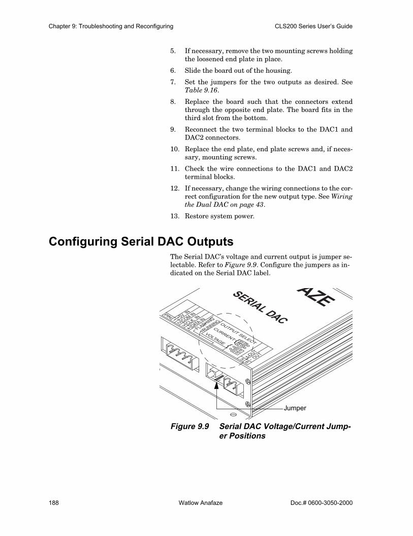
Chapter 9: Troubleshooting and Reconfiguring CLS200 Series User’s Guide
188 Watlow Anafaze Doc.# 0600-3050-2000
5. If necessary, remove the two mounting screws holdingthe loosened end plate in place.
6. Slide the board out of the housing.
7. Set the jumpers for the two outputs as desired. SeeTable 9.16.
8. Replace the board such that the connectors extendthrough the opposite end plate. The board fits in thethird slot from the bottom.
9. Reconnect the two terminal blocks to the DAC1 andDAC2 connectors.
10. Replace the end plate, end plate screws and, if neces-sary, mounting screws.
11. Check the wire connections to the DAC1 and DAC2terminal blocks.
12. If necessary, change the wiring connections to the cor-rect configuration for the new output type. See Wiringthe Dual DAC on page 43.
13. Restore system power.
Configuring Serial DAC OutputsThe Serial DAC’s voltage and current output is jumper se-lectable. Refer to Figure 9.9. Configure the jumpers as in-dicated on the Serial DAC label.
Figure 9.9 Serial DAC Voltage/Current Jump-er Positions
+5V IN
COM IN
CLK IN
DATA IN
FLASHING
=RUNNING
+ OUT
- OUT
PIN: 1 2 3 4
5 6
OUTPUT SELECT
CURRENTVOLTAGE
FAZESERIAL DAC
Jumper

Doc.# 0600-3050-2000 Watlow Anafaze 189
10Linear Scaling Examples
This chapter provides three linear scaling examples. The examples describe:
• A pressure sensor generating a 4 to 20 mA signal• A flow sensor generating a 0 to 5V signal• A pulse encoder generating 900 pulses per inch of
movement
Example 1: A 4-to-20 mA Sensor
SituationA pressure sensor that generates a 4 to 20 mA signal is con-nected to the controller. The specifications of the sensor state it generates 4 mA at 0.0 pounds per square inch (PSI) and 20 mA at 50.0 PSI.
SetupThe sensor is connected to a loop input set up with a resis-tor scaling network producing 60mV at 20 mA.
The INPUT TYPE for the loop is set to LINEAR. The sensor measures PSI in tenths, so the DISP FORMAT is set to-999.9 TO +3000.0.
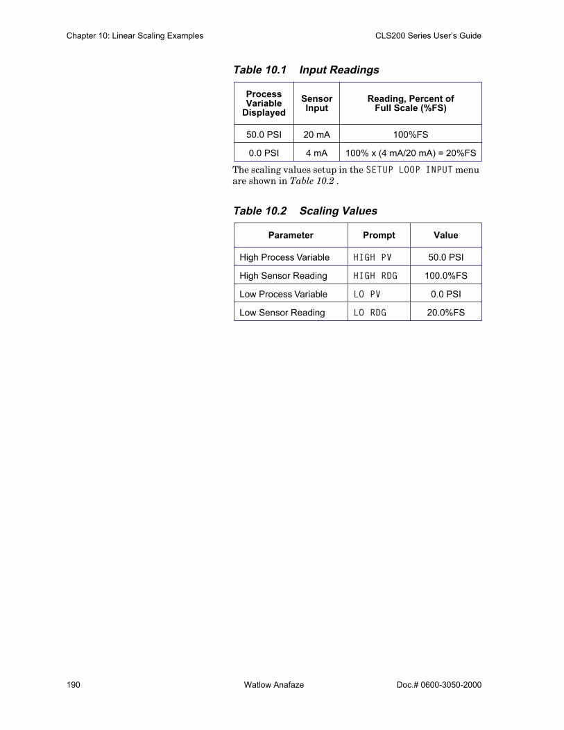
Chapter 10: Linear Scaling Examples CLS200 Series User’s Guide
190 Watlow Anafaze Doc.# 0600-3050-2000
Table 10.1 Input Readings
The scaling values setup in the SETUP LOOP INPUT menu are shown in Table 10.2 .
Table 10.2 Scaling Values
Process Variable
DisplayedSensor Input
Reading, Percent of Full Scale (%FS)
50.0 PSI 20 mA 100%FS
0.0 PSI 4 mA 100% x (4 mA/20 mA) = 20%FS
Parameter Prompt Value
High Process Variable HIGH PV 50.0 PSI
High Sensor Reading HIGH RDG 100.0%FS
Low Process Variable LO PV 0.0 PSI
Low Sensor Reading LO RDG 20.0%FS

CLS200 Series User’s Guide Chapter 10: Linear Scaling Examples
Doc.# 0600-3050-2000 Watlow Anafaze 191
Example 2: A 0-to-5VÎ (dc) Sensor
SituationA flow sensor connected to the controller measures the flow in a pipe. The sensor generates a 0 to 5V signal. The sen-sor’s output depends on its installation. Independent cali-bration measurements of the flow in the pipe indicate that the sensor generates 0.5V at three gallons per minute (GPM) and 4.75V at 65 GPM. The calibration instruments are accurate to within 1 gallon per minute.
SetupThe sensor is connected to a loop input set up with a resis-tor voltage divider network producing 60mV at 5V.
The INPUT TYPE for the loop is set to LINEAR. The calibrat-ing instrument is precise to ±1 GPM, so the DISP FORMAT is set to -999 to +3000.
This table shows the input readings and the percentage calculation from the 60mV full scale input.
Table 10.3 Input Readings and Calculations
Table 10.4 Scaling Values
Process Variable
DisplayedSensor Input
Reading, Percent of Full Scale (%FS)
65 GPM 4.75 (4.75V / 5.00V) x 100%=95%FS
3 GPM 0.5 (0.5V / 5.00V) x 100%=10%FS
Parameter Prompt Value
High Process Variable HIGH PV 65 GPM
High Sensor Reading HIGH RDG 95.0%FS
Low Process Variable LO PV 0.0 GPM
Low Sensor Reading LO RDG 10.0%FS

Chapter 10: Linear Scaling Examples CLS200 Series User’s Guide
192 Watlow Anafaze Doc.# 0600-3050-2000
Example 3: A Pulse Encoder
SituationA pulse encoder which measures the movement of a convey-or is connected to the controller. The encoder generates 900 pulses for every inch the conveyor moves. You want to mea-sure conveyor speed in feet per minute (FPM).
SetupThe encoder input is connected to the controller’s pulse in-put. The INPUT TYPE for the loop is set to PULSE. A one-second sample time gives adequate resolution of the con-veyor’s speed. The resolution is:
A DISP FORMAT of -99.99 TO +300.00 is appropriate.
The input readings are as follows:
• At 0 Hz, the input reading will be 0.00 FPM.• At the maximum pulse rate of the CLS200 (2000 Hz):
Table 10.5 Scaling Values
Parameter Prompt Value
High Process Variable HIGH PV 11.11 FPM
High Sensor Reading HIGH RDG 2000 Hz
Low Process Variable LO PV 0 FPM
Low Sensor Reading LO RDG 0 Hz
1 pulse1 second--------------------------x60 seconds
1 minute---------------------------------x 1 inch900 pulses-------------------------------x 1 foot
12 inches--------------------------- 0.006 FPM=
2000 pulses1 second----------------------------------x60 seconds
1 minute---------------------------------x 1 inch900 pulses-------------------------------x 1 foot
12 inches--------------------------- 11.11 FPM=
Doc.# 0600-3050-2000 Watlow Anafaze 193
11Specifications
This chapter contains specifications for the CLS200 series controllers, TB50 terminal board, Dual DAC module, Serial DAC module and the CLS200 power supply.
CLS200 System SpecificationsThis section contains CLS200 series controller specifica-tions for environmental specifications and physical dimen-sions, inputs, outputs, the serial interface and system power requirements.
The controller described consists of a processor module and a 50-terminal block (TB50).
Table 11.1 Agency Approvals / Compliance
CE Directive Electromagnetic Compatibility (EMC) Directive 89/336/EEC
UL and C-UL UL 916, Standard for Energy Manage-ment Equipment File E177240

Chapter 11: Specifications CLS200 Series User’s Guide
194 Watlow Anafaze Doc.# 0600-3050-2000
CLS200 Processor Physical Specifications
Table 11.2 Environmental Specifications
Table 11.3 Physical Dimensions
* Without SCSI connector or with TB18 option.
Figure 11.1 CLS200 Processor Module Dimensions
Storage Temperature -20 to 60° C
Operating Temperature 0 to 50° C
Humidity 10 to 95% non-condensing
Environment The controller is for indoor use only
Weight 1.98 lbs 0.9 kg
Length* 8.0 inches 203 mm
Width 3.78 inches 96 mm
Height 1.96 inches 50 mm
1.96 in.(50 mm)
8.0 in.(203 mm)
6.12 in.(155 mm)
3.78 in.(96 mm)
1.76 in.(45 mm)
3.55 in.(90 mm)

CLS200 Series User’s Guide Chapter 11: Specifications
Doc.# 0600-3050-2000 Watlow Anafaze 195
Table 11.4 Processor with Straight SCSI
Figure 11.2 CLS200 Clearances with Straight SCSI Cable
Table 11.5 Processor with Right Angle SCSI
Figure 11.3 CLS200 Clearances with Right-Angle SCSI Cable
Length 9.6 inches 244 mm
Width 3.78 inches 96 mm
Height 1.96 inches 50 mm
Length 8.6 inches 218 mm
Width 3.78 inches 96 mm
Height 1.96 inches 50 mm
1.0 in. 7.0 in. 1.6 in.(25 mm) (178 mm) (41 mm)
1.96 in.(50 mm)
1.0 in. 7.0 in. 0.60 in.(25 mm) (178 mm) (15 mm)
1.96 in.(50 mm)

Chapter 11: Specifications CLS200 Series User’s Guide
196 Watlow Anafaze Doc.# 0600-3050-2000
Table 11.6 Processor Connections
TB50 Physical Specifications
Table 11.7 TB50 Physical Dimensions
Power Terminals (TB2) Captive screw cage clamp
Power Wire Gauge (TB2) 22 to 18 AWG (0.5 to 0.75 mm2)
Power Terminal Torque (TB2) 4.4 to 5.3 in-lb. (0.5 to 0.6 Nm)
Sensor Terminals (TB1) Captive screw cage clamp
Sensor Wire Gauge (TB1)Thermocouples: 20 AWG (0.5 mm2)Linear: 22 to 20 AWG (0.5 mm2)Communications: 24 AWG (0.2 mm2)
Sensor Terminal Torque (TB1) 4.4 to 5.3 in-lb. (0.5 to 0.6 Nm)
Output Terminals (TB18) Captive screw cage clamp
Output Wire Gauge (TB18) Multiconductor cables: 24 AWG (0.2 mm2)Single-wire: 22 to 18 AWG (0.5 to 0.75 mm2)
Output Terminal Torque (TB18) 4.4 to 5.3 in-lb. (0.5 to 0.6 Nm)
SCSI Connector SCSI-2 female
Weight 0.32 lb. 0.15 kg
Length 4.1 inches 104 mm
Width 4.0 inches 102 mm
Height 1.5 inches 37 mm
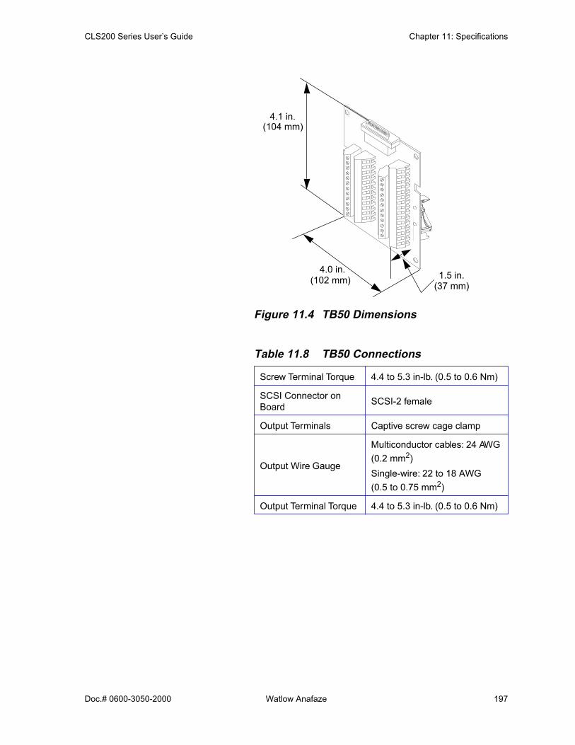
CLS200 Series User’s Guide Chapter 11: Specifications
Doc.# 0600-3050-2000 Watlow Anafaze 197
Figure 11.4 TB50 Dimensions
Table 11.8 TB50 Connections
Screw Terminal Torque 4.4 to 5.3 in-lb. (0.5 to 0.6 Nm)
SCSI Connector on Board SCSI-2 female
Output Terminals Captive screw cage clamp
Output Wire Gauge
Multiconductor cables: 24 AWG (0.2 mm2)Single-wire: 22 to 18 AWG (0.5 to 0.75 mm2)
Output Terminal Torque 4.4 to 5.3 in-lb. (0.5 to 0.6 Nm)
(37 mm)
4.1 in.(104 mm)
4.0 in.(102 mm) 1.5 in.
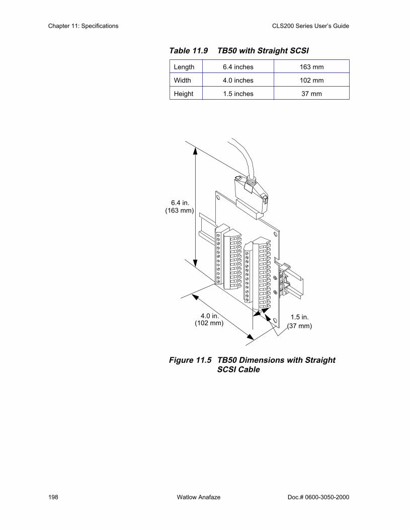
Chapter 11: Specifications CLS200 Series User’s Guide
198 Watlow Anafaze Doc.# 0600-3050-2000
Table 11.9 TB50 with Straight SCSI
Figure 11.5 TB50 Dimensions with Straight SCSI Cable
Length 6.4 inches 163 mm
Width 4.0 inches 102 mm
Height 1.5 inches 37 mm
6.4 in.(163 mm)
4.0 in.(102 mm) (37 mm)
1.5 in.

CLS200 Series User’s Guide Chapter 11: Specifications
Doc.# 0600-3050-2000 Watlow Anafaze 199
Table 11.10 TB50 with Right Angle SCSI
Figure 11.6 TB50 Dimensions with Right-Angle SCSI Cable
Length 5.4 inches 137 mm
Width 4.0 inches 102 mm
Height 1.5 inches 37 mm
5.4 in.(137 mm)
4.0 in.(102 mm)
(37 mm)1.5 in.

Chapter 11: Specifications CLS200 Series User’s Guide
200 Watlow Anafaze Doc.# 0600-3050-2000
Inputs The controller accepts analog sensor inputs which are mea-sured and may be used as feedback for control loops. It also accepts digital (TTL) inputs which may be used to trigger certain firmware features.
Table 11.11 Analog Inputs
Parameter Description
Number of Control Loops CLS204: 5; CLS208: 9; CLS216: 17
Number of Analog InputsCLS204: 4 with full range of input types, plus one pulseCLS208: 8 with full range of input types, plus one pulseCLS216: 16 with full range of input types, plus one pulse
Input Switching CLS204 and CLS208: Differential solid state multiplexerCLS216: Single-ended, solid state multiplexer
Input Sampling RateCLS204: 6 Hz (167 ms) at 60 Hz; 5 Hz (200 ms) at 50 Hz.CLS208: 3 Hz (333 ms) at 60 Hz; 2.5 Hz (400 ms) at 50 Hz.CLS216:1.5 Hz (667 ms) at 60 Hz; 1.25 Hz (800 ms) at 50 Hz
Analog Over Voltage Protection ±20V referenced to digital ground.
Maximum Common Mode Voltage 5V input to input or input to analog common (CLS204 and CLS208)
Common Mode Rejection (CMR)
For inputs that do not exceed ±5V, >60 dB dc to 1 kHz, and 120 dB at selected line frequency.
A/D Converter Integrates voltage to frequency
Input Range -10 to +60mV, or 0 to 25V with scaling resistors
Resolution 0.006%, greater than 14 bits (internal)
Accuracy0.03% of full scale (60mV) at 25° C
0.08% of full scale (60mV) at 0 to 50° C
Calibration Automatic zero and full scale
DC Common to Frame Ground Maximum Potential 20V
Thermocouple Break Detection Pulse type for upscale break detection
Milliampere Inputs 0 to 20 mA (3 Ω resistance) or 0 to 10 mA (6 Ω resistance), with scaling resistors
Linear Voltage Input Ranges Avail-able
0 to12V, 0 to 10V, 0 to 5V, 0 to 1V, 0 to 500 mV, 0 to 100 mV with scaling resistors.
Source Impedance
For 60mV thermocouple, measurements are within specification with up to 500 Ω source resistanceFor other types of analog signals, the maximum source imped-ance is 5,000 Ω
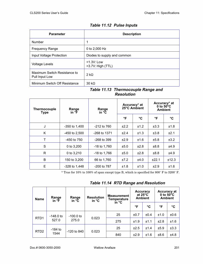
CLS200 Series User’s Guide Chapter 11: Specifications
Doc.# 0600-3050-2000 Watlow Anafaze 201
Table 11.12 Pulse Inputs
Table 11.13 Thermocouple Range and Resolution
* True for 10% to 100% of span except type B, which is specified for 800˚ F to 3200˚ F.
Table 11.14 RTD Range and Resolution
Parameter Description
Number 1
Frequency Range 0 to 2,000 Hz
Input Voltage Protection Diodes to supply and common
Voltage Levels <1.3V: Low>3.7V: High (TTL)
Maximum Switch Resistance to Pull Input Low 2 kΩ
Minimum Switch Off Resistance 30 kΩ
Thermocouple Type
Rangein °F
Rangein °C
Accuracy* at25°C Ambient
Accuracy* at0 to 50°CAmbient
°F °C °F °C
J -350 to 1,400 -212 to 760 ±2.2 ±1.2 ±3.3 ±1.8
K -450 to 2,500 -268 to 1371 ±2.4 ±1.3 ±3.8 ±2.1
T -450 to 750 -268 to 399 ±2.9 ±1.6 ±5.8 ±3.2
S 0 to 3,200 -18 to 1,760 ±5.0 ±2.8 ±8.8 ±4.9
R 0 to 3,210 -18 to 1,766 ±5.0 ±2.8 ±8.8 ±4.9
B 150 to 3,200 66 to 1,760 ±7.2 ±4.0 ±22.1 ±12.3
E -328 to 1,448 -200 to 787 ±1.8 ±1.0 ±2.9 ±1.6
Name Rangein °F
Rangein °C
Resolutionin °C
MeasurementTemperature
in °C
Accuracyat 25°C
Ambient
Accuracy at0 to 50°CAmbient
°F °C °F °C
RTD1 -148.0 to 527.0
-100.0 to 275.0 0.023
25 ±0.7 ±0.4 ±1.0 ±0.6
275 ±1.9 ±1.1 ±2.8 ±1.6
RTD2 -184 to 1544 -120 to 840 0.023
25 ±2.5 ±1.4 ±5.9 ±3.3
840 ±2.9 ±1.6 ±8.6 ±4.8

Chapter 11: Specifications CLS200 Series User’s Guide
202 Watlow Anafaze Doc.# 0600-3050-2000
Table 11.15 Input Resistance for Voltage Inputs
Table 11.16 Digital Inputs
OutputsThe controller directly accommodates switched dc and open-collector outputs only. These outputs can be used to control a wide variety of loads. They are typically used to control SSRs or other power switching devices which in turn control, for example, heaters. They may also be used to signal another device of an alarm condition in the con-troller.
Analog outputs may be accomplished by using Dual DAC or Serial DAC modules in conjunction with one of the control outputs.
An open-collector CPU watchdog output is also provided so that an external device may monitor the CPU state.
Range Input Resistance
0 to 12V 85 kΩ
0 to 10V 50 kΩ
0 to 5V 40 kΩ
0 to 1V 7.4 kΩ
0 to 500mV 6.2 kΩ
0 to 100mV 1.2 kΩ
Parameter Description
Number 8
Configu ation 8 selectable for output override, remote job selection
Input Voltage Protection Diodes to supply and common. Source must limit current to 10 mA for override conditions
Voltage Levels<1.3V: Low>3.7V: High (TTL)5V maximum, 0V minimum
Maximum Switch Resistance to Pull Input Low 1 kΩ
Minimum Switch Off Resistance 11 kΩ
Update Rate 6 Hz
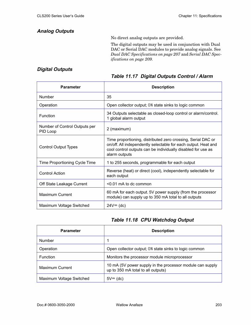
CLS200 Series User’s Guide Chapter 11: Specifications
Doc.# 0600-3050-2000 Watlow Anafaze 203
Analog OutputsNo direct analog outputs are provided.
The digital outputs may be used in conjunction with Dual DAC or Serial DAC modules to provide analog signals. See Dual DAC Specifications on page 207 and Serial DAC Spec-ifications on page 209.
Digital OutputsTable 11.17 Digital Outputs Control / Alarm
Table 11.18 CPU Watchdog Output
Parameter Description
Number 35
Operation Open collector output; ON state sinks to logic common
Function 34 Outputs selectable as closed-loop control or alarm/control. 1 global alarm output
Number of Control Outputs per PID Loop 2 (maximum)
Control Output Types
Time proportioning, distributed zero crossing, Serial DAC or on/off. All independently selectable for each output. Heat and cool control outputs can be individually disabled for use as alarm outputs
Time Proportioning Cycle Time 1 to 255 seconds, programmable for each output
Control Action Reverse (heat) or direct (cool), independently selectable for each output
Off State Leakage Current <0.01 mA to dc common
Maximum Current 60 mA for each output. 5V power supply (from the processor module) can supply up to 350 mA total to all outputs
Maximum Voltage Switched 24VÎ (dc)
Parameter Description
Number 1
Operation Open collector output; ON state sinks to logic common
Function Monitors the processor module microprocessor
Maximum Current 10 mA (5V power supply in the processor module can supply up to 350 mA total to all outputs)
Maximum Voltage Switched 5VÎ (dc)
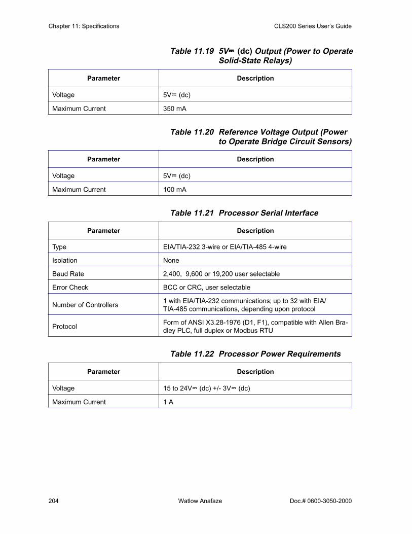
Chapter 11: Specifications CLS200 Series User’s Guide
204 Watlow Anafaze Doc.# 0600-3050-2000
Table 11.19 5VÎÎÎÎ (dc) Output (Power to Operate Solid-State Relays)
Table 11.20 Reference Voltage Output (Power to Operate Bridge Circuit Sensors)
Table 11.21 Processor Serial Interface
Table 11.22 Processor Power Requirements
Parameter Description
Voltage 5VÎ (dc)
Maximum Current 350 mA
Parameter Description
Voltage 5VÎ (dc)
Maximum Current 100 mA
Parameter Description
Type EIA/TIA-232 3-wire or EIA/TIA-485 4-wire
Isolation None
Baud Rate 2,400, 9,600 or 19,200 user selectable
Error Check BCC or CRC, user selectable
Number of Controllers 1 with EIA/TIA-232 communications; up to 32 with EIA/TIA-485 communications, depending upon protocol
Protocol Form of ANSI X3.28-1976 (D1, F1), compatible with Allen Bra-dley PLC, full duplex or Modbus RTU
Parameter Description
Voltage 15 to 24VÎ (dc) +/- 3VÎ (dc)
Maximum Current 1 A
CLS200 Series User’s Guide Chapter 11: Specifications
Doc.# 0600-3050-2000 Watlow Anafaze 205
CLS200 Power SupplyComplete specifications for the CLS200 power supply are available at www.watlow.com. See the links on the CLS200 page.
Wilsea
Rectangle

Chapter 11: Specifications CLS200 Series User’s Guide
206 Watlow Anafaze Doc.# 0600-3050-2000
Figure 11.7 Power Supply Dimensions (Bottom View)
Table 11.27 Power Supply Inputs
Table 11.28 Power Supply Outputs
Voltage 120/240Vı (ac) at 0.75 A, 50/60 Hz
Voltage V1 5VÎ (dc) @ 4 A
Voltage V2 15 VÎ (dc) @ 1.2 A
6.9 inches(175 mm)
3.9 inches(99 mm)
1.4 in(36 mm)
8.1 inches with mounting bracket(206 mm)
7.5 inches(191 mm)
0.19 (3/16) inch diameter
0.7 inch(18 mm)
0.3 inch
(5 mm)
(8 mm)
Wilsea
Rectangle

CLS200 Series User’s Guide Chapter 11: Specifications
Doc.# 0600-3050-2000 Watlow Anafaze 207
Dual DAC SpecificationsThe Watlow Anafaze Dual DAC (digital-to-analog convert-er) is an optional module for the CLS200 series controller. The Dual DAC converts a distributed zero crossing (DZC) output signal to an analog process control signal. Watlow Anafaze provides the following version of the Dual DAC:
• 4 to 20 mA dc
• 0 to 5VÎ (dc)
• 0 to 10VÎ (dc)
Table 11.29 Dual DAC Environmental Specifi-cations
Table 11.30 Dual DAC Physical Specifications
Figure 11.8 Dual DAC Dimensions
Storage Temperature -20 to 60° C
Operating Temperature 0 to 50° C
Humidity 10 to 95% non-condensing
Weight 0.42 lb. 0.19 kg
Length 4.4 inches 112 mm
Width 3.6 inches 91 mm
Height 1.8 inches 44 mm
1 2
3 4
5 6
1 2
3 4
5 6
1 2
3 4
5 6
+5V I
NDZ
C IN
+10-2
4V IN
V OUT
I SINK
OUT C
OM
+5V I
NDZ
C IN
+10-2
4V IN
V OUT
I SINK
OUT C
OM DAC 2
DAC 1
ANAFAZEDUAL DAC
0.162 in. diameter
4.4 in.(112 mm)3.6 in.
(91 mm)
1.8 in.(44 mm)
3.0 in.(76 mm)
3.7 in.(94 mm)
0.3 in. 0.4 in.(10 mm)
(4 mm)
(8 mm)

Chapter 11: Specifications CLS200 Series User’s Guide
208 Watlow Anafaze Doc.# 0600-3050-2000
Dual DAC InputsThe Dual DAC accepts an open-collector signal from the CLS200 controller and the power from an external power supply. See Table 11.31.
Table 11.31 Dual DAC Power Requirements
Dual DAC Analog OutputsTable 11.32 Dual DAC Specifications by Output
Range
Parameter Description
Voltage 12 to 24VÎ (dc)
Current 100 mA @ 15VÎ (dc)
Version 4-20 mA 0-5 V 0-10 V Units
Gain Accuracy ± 6 ± 6 ± 6 %
Output Offset ± 0.75 ± 0.75 ± 0.75 % of full scale range
Ripple 1.6 1.6 1.6 % of full scale range
Time Constant 2 2 2 seconds
Maximum Current Output 20 10 10 mA dc
Load Resistance (12V) 250 maximum 500 minimum 1000 minimum Ω
Load Resistance (24V) 850 maximum n/a n/a Ω
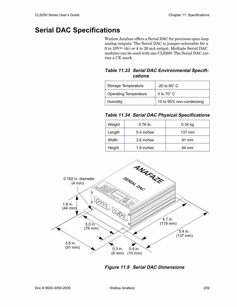
CLS200 Series User’s Guide Chapter 11: Specifications
Doc.# 0600-3050-2000 Watlow Anafaze 209
Serial DAC SpecificationsWatlow Anafaze offers a Serial DAC for precision open-loop analog outputs. The Serial DAC is jumper-selectable for a 0 to 10VÎ (dc) or 4 to 20 mA output. Multiple Serial DAC modules can be used with one CLS200. The Serial DAC car-ries a CE mark.
Table 11.33 Serial DAC Environmental Specifi-cations
Table 11.34 Serial DAC Physical Specifications
Figure 11.9 Serial DAC Dimensions
Storage Temperature -20 to 60° C
Operating Temperature 0 to 70° C
Humidity 10 to 95% non-condensing
Weight 0.76 lb. 0.34 kg
Length 5.4 inches 137 mm
Width 3.6 inches 91 mm
Height 1.8 inches 44 mm
+5V IN
COM IN
CLK IN
DATA IN
FLASHING
=RUNNING
+ OUT
- OUT
PIN: 1 2 3 4
5 6
OUTPUT SELECT
CURRENTVOLTAGE
ANAFAZESERIAL DAC
0.162 in. diameter(4 mm)
5.4 in.(137 mm)
3.6 in.(91 mm)
1.8 in.(44 mm)
3.0 in.(76 mm)
4.7 in.(119 mm)
0.3 in.(8 mm)
0.4 in.(10 mm)
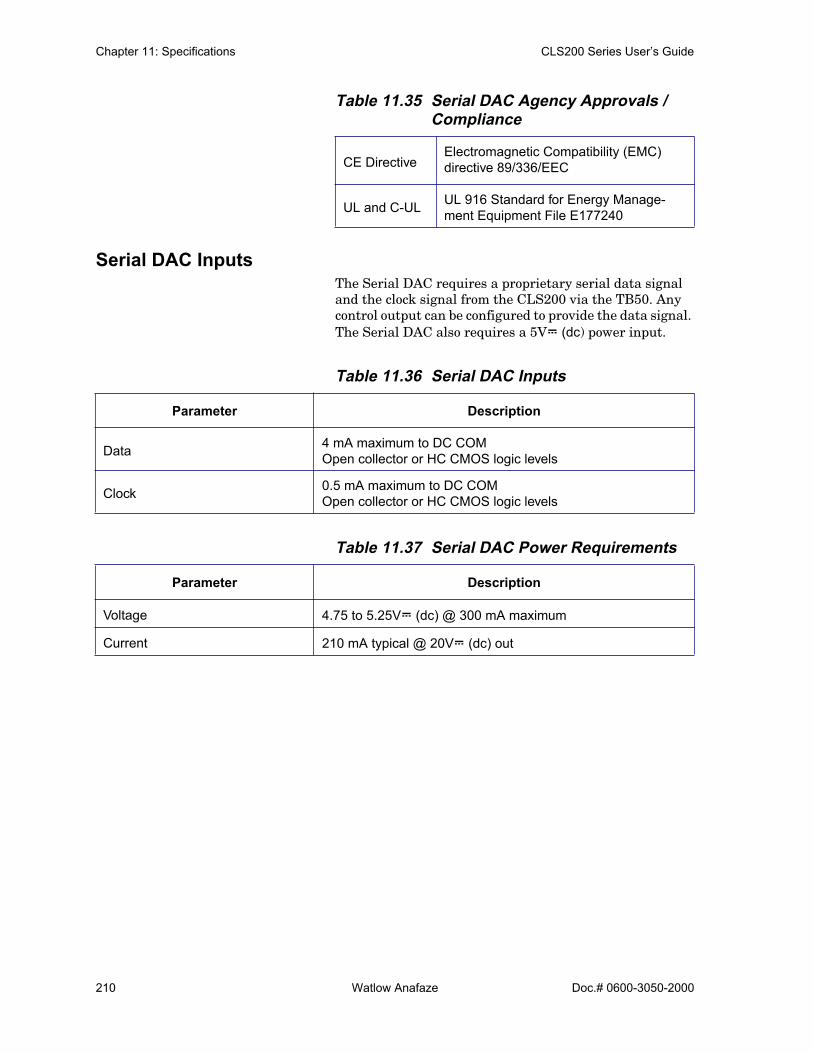
Chapter 11: Specifications CLS200 Series User’s Guide
210 Watlow Anafaze Doc.# 0600-3050-2000
Table 11.35 Serial DAC Agency Approvals / Compliance
Serial DAC InputsThe Serial DAC requires a proprietary serial data signal and the clock signal from the CLS200 via the TB50. Any control output can be configured to provide the data signal. The Serial DAC also requires a 5VÎ (dc) power input.
Table 11.36 Serial DAC Inputs
Table 11.37 Serial DAC Power Requirements
CE DirectiveElectromagnetic Compatibility (EMC) directive 89/336/EEC
UL and C-UL UL 916 Standard for Energy Manage-ment Equipment File E177240
Parameter Description
Data 4 mA maximum to DC COMOpen collector or HC CMOS logic levels
Clock 0.5 mA maximum to DC COMOpen collector or HC CMOS logic levels
Parameter Description
Voltage 4.75 to 5.25VÎ (dc) @ 300 mA maximum
Current 210 mA typical @ 20VÎ (dc) out

CLS200 Series User’s Guide Chapter 11: Specifications
Doc.# 0600-3050-2000 Watlow Anafaze 211
Serial DAC Analog OutputsTable 11.38 Serial DAC Analog Output Specifi-
cations
Parameter Description
Absolute Maximum Common Mode Voltage
Measured between output terminals and controller common: 1,000V
Resolution15 bits (plus polarity bit for voltage outputs)(0.305mV for 10V output range)(0.00061 mA for 20 mA output range)
Accuracy (Calibrated for Voltage Output)
For voltage output: ± 0.005V (0.05% at full scale)For current output: ± 0.1 mA (0.5% at full scale)
Temperature coefficien 440 ppm/ °C typical
Isolation Breakdown Voltage 1,000V between input power and signals
Current 0 to 20 mA (500 Ω load max.)
Voltage 0 to 10VÎ (dc) with 10 mA source capability
Output Response Time 1 ms typical
Update Rate
Once per controller A/D cycle nominal. Twice per second max-imum for 60 Hz clock rate.Output changes are step changes due to the fast time con-stant. All Serial DAC loop outputs are updated at the same time.

Chapter 11: Specifications CLS200 Series User’s Guide
212 Watlow Anafaze Doc.# 0600-3050-2000

CLS200 Series User’s Guide Glossary
Doc.# 0600-3050-2000 Watlow Anafaze 213
Glossary
AACSee Alternating Current.
AC Line FrequencyThe frequency of the AC power line measuredin Hertz (Hz), usually 50 or 60 Hz.
AccuracyCloseness between the value indicated by ameasuring instrument and a physical constantor known standards.
ActionThe response of an output when the processvariable is changed. See also Direct Action,Reverse Action.
AddressA numerical identifier for a controller whenused in computer communications.
AlarmA signal that indicates that the process hasexceeded or fallen below a certain rangearound the setpoint. For example, an alarmmay indicate that a process is too hot or toocold. See also:
Deviation AlarmFailed Sensor AlarmGlobal AlarmHigh Deviation AlarmHigh Process AlarmLoop AlarmLow Deviation AlarmLow Process Alarm
Alarm DelayThe lag time before an alarm is activated.
Alternating Current (AC)An electric current that reverses at regularintervals, and alternates positive and negativevalues.
Ambient TemperatureThe temperature of the air or other mediumthat surrounds the components of a thermal
system.
American Wire Gauge (AWG)A standard of the dimensional characteristicsof wire used to conduct electrical current orsignals. AWG is identical to the Brown andSharpe (B&S) wire gauge.
AmmeterAn instrument that measures the magnitudeof an electric current.
Ampere (Amp)A unit that defines the rate of flow of electric-ity (current) in the circuit. Units are one cou-lomb (6.25 x 10¹⁸ electrons) per second.
Analog OutputA continuously variable signal that is used torepresent a value, such as the process value orsetpoint value. Typical hardware configurationsare 0 to 20mA, 4 to 20mA or 0 to 5 VÎ (dc).
Automatic ModeA feature that allows the controller to set PIDcontrol outputs in response to the ProcessVariable (PV) and the setpoint.
AutotuneA feature that automatically sets temperaturecontrol PID values to match a particular ther-mal system.
AWGSee American Wire Gauge.
BBaud RateThe rate of information transfer in serial com-munications, measured in bits per second.
Block Check Character (BCC)A serial communications error checkingmethod. An acceptable method for most appli-cations, BCC is the default method. See alsoCyclic Redundancy Check.
Bumpless TransferA smooth transition from automatic (closedloop) to manual (open loop) operation. The con-trol output does not change during the trans-fer.

Glossary CLS200 Series User’s Guide
214 Watlow Anafaze Doc.# 0600-3050-2000
CCalibrationThe comparison of a measuring device (anunknown) against an equal or better standard.
Celsius (Centigrade)Formerly known as Centigrade. A temperaturescale in which water freezes at 0˚C and boils at100˚C at standard atmospheric pressure. Theformula for conversion to the Fahrenheit scale:˚F = (1.8 x ˚C) + 32.
Central Processing Unit (CPU)The unit of a computing system that includesthe circuits controlling the interpretation ofinstructions and their execution.
CircuitAny closed path for electrical current. A config-uration of electrically or electromagnetically-connected components or devices.
Closed LoopA control system that uses a sensor to measurea process variable and makes decisions basedon that feedback.
Cold JunctionConnection point between thermocouple met-als and the electronic instrument.
Common Mode Rejection RatioThe ability of an instrument to reject electricalnoise, with relation to ground, from a commonvoltage. Usually expressed in decibels (dB).
CommunicationsThe use of digital computer messages to linkcomponents. See also Serial Communications,Baud Rate.
Control ActionThe response of the PID control output relativeto the error between the process variable andthe setpoint. For reverse action (usually heat-ing), as the process decreases below the set-point the output increases. For direct action(usually cooling), as the process increasesabove the setpoint, the output increases.
Control StatusThe type of action that a controller uses. Forexample, on/off, time proportioning, PID, auto-matic or manual, and combinations of these.
CurrentThe rate of flow of electricity. The unit of mea-sure is the ampere (A). 1 ampere = 1 coulomb per second.
Cycle TimeThe time required for a controller to completeone on-off-on cycle. It is usually expressed inseconds.
Cyclic Redundancy Check (CRC)An error checking method in communications.It provides a high level of data security but ismore difficult to implement than Block CheckCharacter (BCC). See also Block Check Char-acter.
DDACSee Digital-to-Analog Converter.
Data LoggingA method of recording a process variable overa period of time. Used to review process perfor-mance.
DCSee Direct Current.
DeadbandThe range through which a variation of theinput produces no noticeable change in theoutput. In the deadband, specific conditionscan be placed on control output actions. Opera-tors select the deadband. It is usually abovethe heating proportional band and below thecooling proportional band.
Default ParametersThe programmed instructions that are perma-nently stored in the microprocessor software.
Derivative Control (D)The last term in the PID algorithm. Actionthat anticipated the rate of change of the pro-cess, and compensates to minimize overshootand undershoot. Derivative control is aninstantaneous change of the control output inthe same direction as the proportional error.This is caused by a change in the process vari-able (PV) that decreases over the time of thederivative (TD). The TD is in units of seconds.
Deutsche Industrial Norms (DIN)

CLS200 Series User’s Guide Glossary
Doc.# 0600-3050-2000 Watlow Anafaze 215
A set of technical, scientific and dimensionalstandards developed in Germany. Many DINstandards have worldwide recognition.
Deviation AlarmWarns that a process has exceeded or fallenbelow a certain range around the setpoint.
Digital-to-Analog Converter (DAC)A device that converts a numerical input sig-nal to a signal that is proportional to the inputin some way.
Direct ActionAn output control action in which an increasein the process variable, causes an increase inthe output. Cooling applications usually usedirect action.
Direct Current (DC)An electric current that flows in one direction.
Distributed Zero Crossing (DZC)A form of digital output control in which theoutput on/off state is calculated for every acline cycle. Power is switched at the zero cross,which reduces electrical noise. See also ZeroCross.
EEarth GroundA metal rod, usually copper, that provides anelectrical path to the earth, to prevent orreduce the risk of electrical shock.
EIA/TIASee Serial Communications.
Electrical NoiseSee Noise.
Electromagnetic Interference (EMI)Electrical and magnetic noise imposed on asystem. There are many possible causes, suchas switching ac power on inside the sine wave.EMI can interfere with the operation of con-trols and other devices.
Electrical-Mechanical RelaysSee Relay, Electromechanical.
EmissivityThe ratio of radiation emitted from a surfacecompared to radiation emitted from a black-
body at the same temperature.
Engineering UnitsSelectable units of measure, such as degreesCelsius and Fahrenheit, pounds per squareinch, newtons per meter, gallons per minute,liters per minute, cubic feet per minute orcubic meters per minute.
EPROMErasable Programmable, Read-Only Memoryinside the controller.
ErrorThe difference between the correct or desiredvalue and the actual value.
FFahrenheitThe temperature scale that sets the freezingpoint of water at 32˚ F and its boiling point at212˚ F at standard atmospheric pressure. Theformula for conversion to Celsius: ˚C = 5/9 (˚F -32).
Failed Sensor AlarmWarns that an input sensor no longer producesa valid signal. For example, when there arethermocouple breaks, infrared problems orresistance temperature detector (RTD) open orshort failures.
FilterFilters are used to handle various electricalnoise problems.
Digital Filter (DF) — A filter that allows theresponse of a system when inputs changeunrealistically or too fast. Equivalent to astandard resistor-capacitor (RC) filter
Digital Adaptive Filter — A filter thatrejects high frequency input signal noise (noisespikes).
Heat/Cool Output Filter — A filter thatslows the change in the response of the heat orcool output. The output responds to a stepchange by going to approximately 2/3 its finalvalue within the numbers of scans that are set.
FrequencyThe number of cycles over a specified period of

Glossary CLS200 Series User’s Guide
216 Watlow Anafaze Doc.# 0600-3050-2000
time, usually measured in cycles per second.Also referred to as Hertz (Hz). The reciprocalis called the period.
GGainThe amount of amplification used in an electri-cal circuit. Gain can also refer to the Propor-tional (P) mode of PID.
Global AlarmAlarm associated with a global digital outputthat is cleared directly from a controller orthrough a user interface.
Global Digital OutputsA pre-selected digital output for each specificalarm that alerts the operator to shut downcritical processes when an alarm conditionoccurs.
GroundAn electrical line with the same electricalpotential as the surrounding earth. Electricalsystems are usually grounded to protect peopleand equipment from shocks due to malfunc-tions. Also referred to a “safety ground”.
HHertz (Hz)Frequency, measured in cycles per second.
High Deviation AlarmWarns that the process is above setpoint, butbelow the high process variable. It can be usedas either an alarm or control function.
High Power(As defined by Watlow Anafaze) Any voltageabove 24 Vac or Vdc and any current levelabove 50 mAac or mAdc.
High Process AlarmA signal that is tied to a set maximum valuethat can be used as either an alarm or controlfunction.
High Process VariableSee Process Variable (PV).
High ReadingAn input level that corresponds to the high
process value. For linear inputs, the high read-ing is a percentage of the full scale inputrange. For pulse inputs, the high reading isexpressed in cycles per second (Hz).
IInfrared (IR)A region of the electromagnetic spectrum withwavelengths ranging from one to 1,000microns. These wavelengths are most suitedfor radiant heating and infrared (noncontact)temperature sensing.
InputProcess variable information that is suppliedto the instrument.
Input ScalingThe ability to scale input readings (readings inpercent of full scale) to the engineering units ofthe process variable.
Input TypeThe signal type that is connected to an input,such as thermocouple, RTD, linear or process.
Integral Control (I)Control action that automatically eliminatesoffset, or droop, between setpoint and actualprocess temperature.
JJobA set of operating conditions for a process thatcan be stored and recalled in a controller’smemory. also called a recipe.
JunctionThe point where two dissimilar metal conduc-tors join to form a thermocouple.
LLagThe delay between the output of a signal andthe response of the instrument to which thesignal is sent.
Linear InputA process input that represents a straight linefunction.

CLS200 Series User’s Guide Glossary
Doc.# 0600-3050-2000 Watlow Anafaze 217
LinearityThe deviation in response from an expected ortheoretical straight line value for instrumentsand transducers. also called linearity error.
Liquid Crystal Display (LCD)A type of digital display made of a materialthat changes reflectance or transmittancewhen an electrical field is applied to it.
LoadThe electrical demand of a process, expressedin power (watts), current (amps) or resistance(ohms). The item or substance that is to beheated or cooled.
Loop AlarmAny alarm system that includes high and lowprocess, deviation band, deadband, digital out-puts, and auxiliary control outputs.
Low Deviation AlarmWarns that the process is below the setpoint,but above the low process variable. It can beused as either an alarm or control function.
Low Process Alarm A signal that is tied to a set minimum valuethat can be used as either an alarm or controlfunction.
Low ReadingAn input level corresponding to the low pro-cess value. For linear inputs, the low reading isa percentage of the full scale input range. Forpulse inputs, the low reading is expressed incycles per second (Hz).
MManual ModeA selectable mode that has no automatic con-trol aspects. The operator sets output levels.
Manual ResetSee Reset.
Milliampere (mA)One thousandth of an ampere.
MMIMan-machine interface.
N
NO-Key ResetA method for resetting the controller’s memory(for instance, after an EPROM change).
NoiseUnwanted electrical signals that usually pro-duce signal interference in sensors and sensorcircuits. See also Electromagnetic Interfer-ence.
Noise SuppressionThe use of components to reduce electricalinterference that is caused by making orbreaking electrical contact, or by inductors.
NonlinearThrough Anafaze software, the Nonlinear fieldsets the system to linear control, or to one oftwo nonlinear control options. Input 0 for lin-ear, 1 or 2 for nonlinear.
OOffsetThe difference in temperature between the set-point and the actual process temperature. Off-set is the error in the process variable that istypical of proportional-only control.
On/Off ControlA method of control that turns the output fullon until setpoint is reached, and then off untilthe process error exceeds the hysteresis.
Open LoopA control system with no sensory feedback.
Operator MenusThe menus accessible from the front panel of acontroller. These menus allow operators to setor change various control actions or features.
Optical IsolationTwo electronic networks that are connectedthrough an LED (Light Emitting Diode) and aphotoelectric receiver. There is no electricalcontinuity between the two networks.
OutputControl signal action in response to the differ-ence between setpoint and process variable.
Output TypeThe form of PID control output, such as time
Glossary CLS200 Series User’s Guide
218 Watlow Anafaze Doc.# 0600-3050-2000
proportioning, distributed zero crossing, SerialDAC or analog. Also the description of the elec-trical hardware that makes up the output.
OvershootThe amount by which a process variableexceeds the setpoint before it stabilizes.
PPanel LockA feature that prevents operation of the frontpanel by unauthorized people.
PIDProportional, Integral, Derivative. A controlstatus with three functions: Proportionalaction dampens the system response, integralcorrects for droops, and derivative preventsovershoot and undershoot.
PolarityThe electrical quality of having two oppositepoles, one positive and one negative. Polaritydetermines the direction in which a currenttends to flow.
Process Variable (PV)The parameter that is controlled or measured.Typical examples are temperature, relativehumidity, pressure, flow, fluid level, events, etc.The high process variable is the highest valueof the process range, expressed in engineeringunits. The low process variable is the lowestvalue of the process range.
Proportional (P)Output effort proportional to the error fromsetpoint. For example, if the proportional bandis 20˚ and the process is 10˚ below the setpoint,the heat proportioned effort is 50%. The lowerthe PB value, the higher the gain.
Proportional Band (PB)A range in which the proportioning function ofthe control is active. Expressed in units,degrees or percent of span. See also PID.
Proportional ControlA control using only the P (proportional) valueof PID control.
Pulse InputDigital pulse signals from devices, such asoptical encoders.
RRampA programmed increase in the temperature ofa setpoint system.
RangeThe area between two limits in which a quan-tity or value is measured. It is usuallydescribed in terms of lower and upper limits.
RecipeSee Job.
Reflection Compensation ModeA control feature that automatically correctsthe reading from a sensor.
Relay A switching device.
Electromechanical Relay — A powerswitching device that completes or inter-rupts a circuit by physically moving electri-cal contacts into contact with each other.Not recommended for PID control.
Solid State Relay (SSR) — A switchingdevice with no moving parts that completesor interrupts a circuit electrically.
ResetControl action that automatically eliminatesoffset or droop between setpoint and actualprocess temperature. See also Integral.
Automatic Reset — The integral functionof a PI or PID temperature controller thatadjusts the process temperature to the set-point after the system stabilizes. Theinverse of integral.
ResistanceOpposition to the flow of electric current, mea-sured in ohms.
Resistance Temperature Detector (RTD)A sensor that uses the resistance temperaturecharacteristic to measure temperature. Thereare two basic types of RTDs: the wire RTD,which is usually made of platinum, and thethermistor which is made of a semiconductormaterial. The wire RTD is a positive tempera-ture coefficient sensor only, while the ther-mistor can have either a negative or positive

CLS200 Series User’s Guide Glossary
Doc.# 0600-3050-2000 Watlow Anafaze 219
temperature coefficient.
Reverse ActionAn output control action in which an increasein the process variable causes a decrease in theoutput. Heating applications usually usereverse action.
RTDSee Resistance Temperature Detector.
SSerial CommunicationsA method of transmitting information betweendevices by sending all bits serially over a sin-gle communication channel.
EIA/TIA-232—An Electronics Industries ofAmerica (EIA) standard for interface betweendata terminal equipment and data communi-cations equipment for serial binary data inter-change. This is usually for communicationsover a short distance (50 feet [15 m] or less)and to a single device.
EIA/TIA-485—An Electronics Industries ofAmerica (EIA) standard for electrical charac-teristics of generators and receivers for use inbalanced digital multipoint systems. This isusually used to communicate with multipledevices over a common cable or where dis-tances over 50 feet (15 m) are required.
Setpoint (SP)The desired value programmed into a control-ler. For example, the temperature at which asystem is to be maintained.
ShieldA metallic foil or braided wire layer surround-ing conductors that is designed to prevent elec-trostatic or electromagnetic interference fromexternal sources.
SignalAny electrical transmittance that conveysinformation.
Solid State Relay (SSR)See Relay, Solid State.
SpanThe difference between the lower and upper
limits of a range expressed in the same unitsas the range.
SpreadIn heat/cool applications, the +/- differencebetween heat and cool. Also known as processdeadband. See also Deadband.
StabilityThe ability of a device to maintain a constantoutput with the application of a constantinput.
TT/C Extension WireA grade of wire used between the measuringjunction and the reference junction of a ther-mocouple. Extension wire and thermocouplewire have similar properties, but extensionwire is less costly.
TD (Timed Derivative)The derivative function.
ThermistorA temperature-sensing device made of semi-conductor material that exhibits a largechange in resistance for a small change in tem-perature. Thermistors usually have negativetemperature coefficients, although they arealso available with positive temperature coeffi-cients.
Thermocouple (T/C)A temperature sensing device made by joiningtwo dissimilar metals. This junction producesan electrical voltage in proportion to the differ-ence in temperature between the hot junction(sensing junction) and the lead wire connectionto the instrument (cold junction).
TI (Timed Integral)The Integral term.
TransmitterA device that transmits temperature data fromeither a thermocouple or RTD by way of a two-wire loop. The loop has an external power sup-ply. The transmitter acts as a variable resistorwith respect to its input signal. Transmittersare desirable when long lead or extensionwires produce unacceptable signal degrada-tion.

Glossary CLS200 Series User’s Guide
220 Watlow Anafaze Doc.# 0600-3050-2000
UUpscale Break ProtectionA form of break detection for burned-out ther-mocouples. Signals the operator that the ther-mocouple has burned out.
UndershootThe amount by which a process variable fallsbelow the setpoint before it stabilizes.
VVolt (V)The unit of measure for electrical potential,voltage or electromotive force (EMF). See alsoVoltage.
Voltage (V)The difference in electrical potential betweentwo points in a circuit. It’s the push or pres-sure behind current flow through a circuit.One volt (V) is the difference in potentialrequired to move one coulomb of chargebetween two points in a circuit, consuming onejoule of energy. In other words, one volt (V) isequal to one ampere of current (I) flowingthrough one ohm of resistance (R), or V = IR.
ZZero CrossAction that provides output switching only ator near the zero-voltage crossing points of theac sine wave.

CLS200 Series User’s Guide Index
Doc.# 0600-3050-2000 Watlow Anafaze 221
IndexAA control status symbol 56AC LINE FREQ
default value 74description 81location 73, 233
agency compliancecontroller 193power supply 205Serial DAC 210
ALARM ACK keyacknowledging alarms 59–60description 54does not work 170
ALARM DEADBANDdefault value 99description 102location 73, 233
ALARM DELAYdefault value 99description 103location 73, 233location of 64
Alarm High SP parameter 67Alarm Low SP parameter 67alarms
acknowledging 59–60alarm high, see process alarmsalarm low, see process alarmscodes 164, 166deadband 102delaying 64, 100, 103deviation 164deviation, see process alarmsdigital output polarity 81disabling control on alarm outputs 94displays 58failed sensor 65, 166global 99global alarm output 68high deviation alarm settings 100–101high process alarm settings 100hysteresis 68loop delay 64low deviation alarm settings 100–101low process alarm settings 102messages 166process 164resetting 165restoring control after sensor failure 92reversed thermocouple 85RTD, see failed sensor alarmsSCRs 37sensor fail percent output power 97setting up 66–69setup parameters 99–103solid state relays 37startup delay 64, 78system 60, 166T/C BREAK, switching to manual mode 97
thermocouple, see failed sensor alarmstolerance 138, 151troubleshooting 164, 166wiring 37
ambient temperatureH/W AMBIENT FAILURE message 169operating range 12
AMBIENT WARNING 168ANAINSTL 80analog inputs, see sensor inputsanalog output 158
see also Dual DAC or Serial DACASSIGN R/S PROFILE 148AUTO 56, 61automatic control, selecting 61automatic mode
restoring after failed sensor repair 66autotuning 62–64
BBACK key 53bar graph display 55–56
control status symbols 56navigating in 56ramp/soak symbols 147symbols 55, 58when running ramp/soak profile 146
battery 7BATTERY DEAD 166baud rate 80BCC, see block check characterblock check character 80boost output 67bridge circuit 32
Ccables
communications 9, 47SCSI 7, 9tie wrapping 35troubleshooting 175
CALCULATING CHECKSUM 28CANNOT LOAD JOB 75CANNOT SAVE JOB 75CASCADE BASE SP
description 120location 112, 233
CASCADE CL SPANdescription 121location 112, 233
cascade control 118–124application example 121relationship of secondary setpoint to primary
output 123setting up, example 122setup parameters 119–121testing setup, example 123
CASCADE HT SPANdescription 121location 112, 233
CASCADE MAX SPdescription 120location 112, 233
Index CLS200 Series User’s Guide
222 Watlow Anafaze Doc.# 0600-3050-2000
CASCADE MIN SPdescription 120location 112, 233
CASCADE PRIM. LOOPdescription 119location 112, 233
case, removing 177CE, see agency complianceCHNG SP key
changing the setpoint 61description 54does not work 170locking and unlocking 78
clearance, see installationcommunications
baud rate 80cable 9, 47controller address 79error checking algorithm 80ground loops 24, 175installation 45–49jumper configurations 179protocol 80software problems 176specifications 204troubleshooting 174–176wire sizes and lengths 22see also EIA/TIA
COMMUNICATIONS BAUD RATEdefault value 74description 80location 73, 233
COMMUNICATIONS ERR CHECKdefault value 74description 80location 73, 233
COMMUNICATIONS PROTOCOLdefault value 74description 80location 73, 233
computer, see communications 174control algorithms 153–156
on/off 154proportional (P) 154, 161proportional with integral (PI) 155, 161proportional, integral and derivative (PID) 155,
161control outputs 157–162
action 96automatic control, see automatic controlcascade control, see cascade controlcontrol algoritms, see control algorithmscontrol status, see control statuscurve 98cycle time 95direct action 96, 159disabling 94distributed zero crossing 94, 158Dual DAC, see Dual DACenabling 94filter 91, 158limit 96manual control, see manual controlon/off 94, 157
process variable retransmit 113ratio control, see ratio controlreverse action 96, 159SCRs 37Serial DAC, see Serial DACsolid state relays 37spread 92status on power up 78time proportioning 94, 157troubleshooting 172–173wiring 37
control parameters 90–92control status 61–64
symbols on display 56unexpected switches from automatic to
manual 167controller
agency compliance 193clearance 13, 195connecting to TB50 27dimensions 194environment 194input specifications 200–202mounting 13–16output specifications 202–204specifications 193–196terminal specifications 196troubleshooting, see troubleshootingwire sizes 196
CONTROLLER ADDRESSdefault value 74description 79location 73, 233
COOL 56COOL CONTROL FILTER
default value 90description 91location 73, 233
COOL CONTROL OUTPUTdefault value 93description 94location 73, 233
COOL CONTROL PBdefault value 90description 91location 73, 233
COOL CONTROL TDdefault value 90description 91location 73, 233
COOL CONTROL TIdefault value 90description 91location 73, 233
COOL OUTPUTcurves 98description 98location 73, 233
COOL OUTPUT ACTIONdescription 96location 73, 233
COOL OUTPUT CYCLE TIMEdescription 95location 73, 233

CLS200 Series User’s Guide Index
Doc.# 0600-3050-2000 Watlow Anafaze 223
COOL OUTPUT LIMITdescription 96location 73, 233
COOL OUTPUT LIMIT TIMEdescription 96location 73, 233
COOL OUTPUT RETRANS PVdescription 114location 112, 233
COOL OUTPUT TYPEdescription 94location 73, 233
cool output, see control outputsCOOL RETRANS MAX INP
description 114location 112, 233
COOL RETRANS MAX OUT%description 115location 112, 233
COOL RETRANS MIN INPdescription 114location 112, 233
COOL RETRANS MIN OUT%description 114location 112, 233
COOL T/C BRK OUT AVGdescription 97location 73, 233
COPY SETUP FROM PROFILEdescription 138location 136, 233
CPU watchdog timer 38, 203CRC, see cyclic redundancy checkC-UL, see agency compliancecurrent inputs
scaling resistors 33, 181, 184wiring 33
CYCLE NR= 147cycle time 95cyclic redundancy check 80
DD/O alarm polarity parameter 68DAC, see Dual DAC or Serial DACdata logging 113, 115derivative
description 155guidelines for setting 160–162setting a value 91settings from other controllers 161term versus rate settings 160
DEV ALARM VALUEdefault value 99description 100location 73, 233
deviation alarms, see process alarmsdifferential control, see ratio control 131DIG OUT POLARITY ON ALARM
default value 74description 81location 73, 233
DIGITAL INPUTSdefault value 103description 103
location 73, 233using for testing 29
digital inputsexternal switching devices 39functions activated 39output override 77ramp/soak external reset 139ramp/soak triggers 142remote job selection 76–77restoring control after sensor failure 92specifications 202technical information 38testing 29, 103thermocouple short detection 79troubleshooting 173wiring 38
DIGITAL OUTPUT NUMBERdefault value 103description 104location 73, 233
digital outputspolarity for alarms 81ramp/soak events 141specifications 203testing 28, 104troubleshooting 173will not turn on 22wiring 35–36
dimensionscontroller 194Dual DAC 20, 207power supply 205–206power supply bracket 19Serial DAC 20, 209TB50 196–199
direct action, see control outputsDISP FORMAT
default value 82description 87effect on ramp/soak parameters 144location 73, 233scaling parameters 86values 87
displaybar graph, see bar graph displaydoes not work 167job display 60process variable not correct 167, 171single loop, see single loop display
distributed zero crossing 94, 158down-arrow key 53Dual DAC
configuring outputs 186–188dimensions 20, 207environment 207input specifications 208jumper settings 187mounting 19–20output specifications 208process variable retransmit 113, 118specifications 207–208wiring 43–44
dust 12DZC, see distributed zero crossing

Index CLS200 Series User’s Guide
224 Watlow Anafaze Doc.# 0600-3050-2000
Eearth, see groundEDIT RAMP & SOAK PROFILE
description 137location 136, 233
EDIT SEGMENT NUMBERdescription 140location 136, 233
EIA/TIA-232 45–46connections 46jumper configurations 179jumpers in connectors 46specifications 204troubleshooting 174–175see also communications
EIA/TIA-485 47–49EIA/TIA-232-to-485 converter 47, 49jumper configurations 179network connections 47–48signal common 48specifications 204termination 48troubleshooting 175see also communications
electrostatic discharge 177EMI, see noiseencoders 34enhanced features option 111–132
cascade control, see cascade controlfirmware code shown on display 81menu tree 112process variable restransmit, see process variable
retransmitENTER key 53environment 12
controller 194Dual DAC 207power supply 205Serial DAC 209
EPROMchecksum 81replacing 176–178
error checking 80ESD, see electrostatic dischargeexternal bridge circuit 32EXTERNAL RESET INPUT NUMBER
description 139location 136, 233
external safety devices 9external switching devices 39extruder control 107–110extruder control algorithm 110extruder firmware option code 81
Ffailed sensor alarms
restoring automatic control after sensor repair 66RTD open 66RTD shorted 66setting up 65–66thermocouple open 65thermocouple short 66
filteroutput 91, 158sensor input 89
firmwarecustom 82version 81
frequency 81front panel 8
navigation 51overview 52
FS alarm code 166functions activated by digital inputs 39
Ggain, see proportional bandground loops 24
communications 47isolation 35paths 24and personal computers 24and thermocouples 31troubleshooting 172, 175
grounding, troubleshooting 172
HH/W AMBIENT FAILURE 166, 169H/W GAIN FAILURE 166, 170H/W OFFSET FAILURE 166, 170HD alarm code 164HEAT 56HEAT CONTROL FILTER
default value 90description 91location 73, 233
HEAT CONTROL OUTPUTdefault value 93description 94location 73, 233
HEAT CONTROL PBdefault value 90description 91location 73, 233
HEAT CONTROL TDdefault value 90description 91location 73, 233
HEAT CONTROL TIdefault value 90description 91location 73, 233
HEAT OUTPUTcurves 98default value 93description 98location 73, 233
HEAT OUTPUT ACTIONdefault value 93description 96location 73, 233
HEAT OUTPUT CYCLE TIMEdefault value 93description 95location 73, 233

CLS200 Series User’s Guide Index
Doc.# 0600-3050-2000 Watlow Anafaze 225
HEAT OUTPUT LIMITdefault value 93description 96location 73, 233
HEAT OUTPUT LIMIT TIMEdefault value 93description 96location 73, 233
HEAT OUTPUT RETRANS PVdescription 114location 112, 233
HEAT OUTPUT TYPEdefault value 93description 94location 73, 233
heat output, see control outputsHEAT RETRANS MAX INP
description 114location 112, 233
HEAT RETRANS MAX OUT%description 115location 112, 233
HEAT RETRANS MIN INPdescription 114location 112, 233
HEAT RETRANS MIN OUT%description 114location 112, 233
HEAT T/C BRK OUT AVGdefault value 93description 97location 73, 233
HEAT/COOL SPREADlocation 233
Heat/Cool Thermocouple Break Out 65HI DEV ALARM OUTPUT
default value 99description 101location 73, 233
HI DEV ALARM TYPEdefault value 99description 101location 73, 233
HI PROC ALARM OUTPUTdefault value 99description 100location 73, 233
HI PROC ALARM SETPTdefault value 99description 100location 73, 233
HI PROC ALARM TYPEdefault value 99description 100location 73, 233
high deviation alarm, see process alarmsHP alarm code 164humidity
controller 194Dual DAC 207power supply 205Serial DAC 209
hysteresisalarm 68
hysteresis, see spread
IINPUT FILTER
default value 82description 89location 73, 233setting before autotuning 64
input power, see power supplyINPUT PULSE SAMPLE TIME
default value 82description 85location 73, 233
INPUT READING OFFSETdefault value 82description 84location 73, 233values 85
INPUT SCALING HI PVdefault value 82description 88location 73, 233scaling parameters 86
INPUT SCALING HI RDGdefault value 82description 88location 73, 233scaling parameters 86
INPUT SCALING LO PVdefault value 82description 88location 73, 233scaling parameters 86
INPUT SCALING LO RDGdefault value 82description 89location 73, 233scaling parameters 86
INPUT TYPEdefault value 82description 83effect on ramp/soak parameters 144location 73, 233values 83
INPUT UNITSdefault value 82description 84location 73, 233
inputsanalog, see sensor inputscurrent, see current inputsdigital, see digital inputsfilter 89pulse, see pulse inputsRTD, see RTDscaling resistors 180–186sensor, see sensor inputssetup parameters 82–89specifications 200–202thermocouple, see thermocouplesvoltage, see voltage inputswiring, see installation
installation 11–49alarm wiring 37clearance 13–15, 195communications 45–49

Index CLS200 Series User’s Guide
226 Watlow Anafaze Doc.# 0600-3050-2000
control output wiring 37controller 13–16CPU watchdog timer 38digital output wiring 35–36Dual DAC 19–20environment 12ground loops, see ground loopslocation 12noise suppression, see noiseoverview 11panel hole dimensions 15panel thickness 15power supply 18–19, 25–27reference voltage terminals 32sensor input wiring 29–34Serial DAC 19–20TB50 16–18, 27testing 28–29tie-wrapping cables 35tools 13torque for screw terminals 26typical 12wire recommendations 21, 30, 35, 47wire sizes 22wiring 21–27, 29–49
integraldescription 155guidelines for setting 160–162setting a value 91settings from other controllers 161term versus reset settings 160
JJOB RUNNING 60JOB RUNNING DATA MODIFIED 60JOB RUNNING REMOTELY LOADED 60JOB SEL DIG INS ACTIVE
default value 74description 77location 73, 233
JOB SELECT DIG INPUTSdefault value 74description 76location 73, 233
jobsloading from memory 75remote selection 76–77saving to memory 75
jumpersDual DAC 187EIA/TIA-232 179EIA/TIA-485 179in EIA/TIA-232 connectors 46power supply common 27Serial DAC 188unused inputs 30when using 2-wire RTD 32
KKEYBOARD LOCK STATUS
default value 74description 78location 73, 233
keypadALARM ACK, see ALARM ACK keyBACK, see BACK keyCHNG SP, see CHNG SP keyENTER, see ENTER keykeys do not work 167, 170locking 78MAN/AUTO, see MAN/AUTO keyNO, see NO keyoverview 52RAMP/SOAK, see RAMP/SOAK keytesting 105unlocking 78YES, see YES key
KEYPAD TESTdescription 105how to quit 105location 73, 233
LLD alarm code 164limit controller 9limit, output 96linear inputs
decimal shift in ramp/soak parameters 145display format 87engineering units 84scaling and calibration 186scaling examples 189–192scaling parameters 86–89
LO DEV ALARM OUTPUTdefault value 99description 101location 73, 233
LO DEV ALARM TYPEdefault value 99description 101location 73, 233
LO PROC ALARM OUTPUTdefault value 99description 102location 73, 233
LO PROC ALARM SETPTdefault value 99description 102location 73, 233
LO PROC ALARM TYPEdefault value 99description 102location 73, 233
LOAD SETUP FROM JOBCANNOT LOAD JOB 75default value 74description 75job display 60location 73, 233
locking the keypad 78LOOP NAME
default value 82description 84location 73, 233
loopsautotuning, see autotuningnaming 84
CLS200 Series User’s Guide Index
Doc.# 0600-3050-2000 Watlow Anafaze 227
number available 200ramp/soak profiles, see ramp/soak 148single loop display, see single loop displaytuning 159–161
low deviation alarm, see process alarmsLOW POWER 166, 168LP alarm code 164
MM control status symbol 56MAN 56, 61MAN/AUTO CONTROL OUTPUTS DISABLED 61MAN/AUTO key 54
does not work 170locking and unlocking 78switching control statuses 61
manual controlselecting 61setting the output level 62
MANUAL I/O TEST 103location 73, 233parameters in menu 103
menu treeall setup menus 233enhanced features 112ramp/soak profiles 136standard setup menus 73
menusaccessing 71global parameters 74loop alarms 99loop control 90loop input 82loop outputs 93manual I/O test 103menu tree, see menu treeprocess variable retransmit 113ramp/soak profile 137
model informationaccessing through display 81location in firmware 73model number description 5
mounting, see installation
NNO key
description 53NO-key reset 176
noiseeliminating problems with 23isolation 23reducing with zero-cross switching 158suppression 22–23symptoms 22
Oon/off control
control signal 157description 154selecting 94spread 92
operator displays 51
OUT-OF-TOLRNCE ALARM TIMEdescription 138location 136, 233
output override 77, 97OUTPUT OVERRIDE DIG INPUT
default value 74description 77location 73, 233
outputs5 Vdc output power 204alarm, see alarmsanalog, see Dual DAC or Serial DACboost output 67control, see control outputsCPU watchdog timer, see CPU watchdog timerdigital, see digital outputsfilter 91process variable retransmit, see process variable
retransmitramp/soak ready state 139reference voltage, see reference voltagesetup parameters 93–98solid state relays 37specifications 202–204wiring, see installation
OVERRIDE DIG IN ACTIVEdefault value 74description 77location 73, 233
over-temperature shutdown devices 9
Ppanel, see installationparameters
accessing 71alarm 99–103changing values 72control 90–92global 74–82input 82–89menu tree, see menu treeoutput 93–98process variable retransmit 113ramp/soak profile 137–143storage of in RAM 7test 103
parts list 5personal computer, see communications 174PID
autotuning, see autotuningderivative constant, see derivativeintegral term, see integralproportional band, see proportional bandsettings for various applications 162settings from other controllers 161tuning 159–161
PLCtransmitting process data to 113using to set a setpoint, example 129see also communications
power failure 10output status upon restart 78ramp/soak profile upon restart 152

Index CLS200 Series User’s Guide
228 Watlow Anafaze Doc.# 0600-3050-2000
power supplydimensions 205–206dimensions of mounting bracket 19for Dual DAC 43inputs 206mounting 18–19outputs 206powering loads with 36requirements 18specifications 205–206wiring 25–27
POWER UP OUTPUT STATUSdefault value 74description 78effect on ramp/soak profiles 152location 73, 233
process alarmsalarm high 67alarm low 67boost output 67function 67high deviation 68low deviation 68outputs 67setting up 66
PROCESS POWER DIGINdefault value 74description 79location 73, 233
process variablenot displayed correctly 22, 167, 171retransmit, see process variable retransmit
process variable retransmit 113–118application example 115scaling the output 115setting up, example 116setup parameters 113
profile, see ramp/soakproportional band
and cascade control 123description 154guidelines for setting 159, 161–162setting a value 91settings for various temperature ranges 159settings from other controllers 161
protocol 80pulse inputs
display format 87encoder signals 34engineering units 84loops available on 34sample time 85scaling and calibration 186scaling parameters 86–89specifications 201technical information 34wiring 34
PV, see process variable
RRAM 7, 177ramp/soak 133–152
assigning profiles to loops 148continuing from hold 150
cycle number 147decimal shift 145editing a profile while it is running 149events 141firmware option code 81holding a profile 150mode symbols on display 146–147mode, setting 147overview 133–135power failure while running profile 152process variable retransmit, see process variable
retransmitprofile setup parameters 137–143resetting a profile 151running a profile 148screens for RAMP/SOAK key 145specifications 135time base 137time remaining 147tolerance 143tolerance alarm, see alarms, tolerancetriggers 142
RAMP/SOAK key 54assigning profiles 148cycle number 147does not work 64, 69, 170locking and unlocking 78screens accessed by pressing 145set mode 147time remaining 147unassigning profiles 148
RAMP/SOAK TIME BASEdefault value 74description 137location 73, 136, 233
ratio control 124–132application example 126, 129, 131differential control 131remote analog setpoint 129setting up, example 127, 129, 131setup parameters 125–126
RATIO CONTROL CTRL RATIOdescription 126location 112, 233
RATIO CONTROL MAX SPdescription 125location 112, 233
RATIO CONTROL MIN SPdescription 125location 112, 233
RATIO CONTROL MSTR LOOPdescription 125location 112, 233
RATIO CONTROL SP DIFFdescription 126location 112, 233
READY EVENT OUTPUTdescription 139location 136, 233
READY SEGMENT EDIT EVENTSdescription 139location 136, 233
READY SEGMENT SETPOINTdescription 138
CLS200 Series User’s Guide Index
Doc.# 0600-3050-2000 Watlow Anafaze 229
location 136, 233Ref terminals, see reference voltagereference voltage 32, 204remote analog setpoint, see ratio controlrepair, returning controller for 164REPEAT CYCLES
description 144location 136, 233
resetexternal 139integral, see integralNO-key reset 176
RESET PROFILE 148RESET WITH DEFAULTS 176RESTORE PID DIGIN
default value 90description 92location 73, 233
RestoreAuto parameter 66retransmit, see process variable retransmitreturning the controller 164reverse action, see control outputsREVERSED T/C DETECT
default value 82description 85location 73, 233
RFI, see noiseRMA number 164RO alarm code 166RS alarm code 166RS-232, see EIA/TIA-232RS-485, see EIA/TIA-485RT alarm code 166RTD
accuracy 201offset 84range 201recommended type 32resolution 201scaling resistors 32, 183troubleshooting 171wiring 32
RTD open alarm 66RTD shorted alarm 66
Ssafety
external safety devices 9output status on power up 10symbols and signal words in this manual 2
SAVE SETUP TO JOBCANNOT SAVE JOB 75default value 74description 75location 73, 233
scaling parametersexample settings, flow sensor with 0-5 Vdc
signal 191example settings, pressure sensor with 4-20mA
signal 190example settings, pulse encoder 192linear inputs 86–89process variable retransmit 114–115pulse inputs 86–89
scaling resistorsCLS204 and CLS208 input circuit 180CLS216 input circuit 184for current inputs 33, 181, 184for RTD inputs 32, 183for thermistor inputs 183for voltage inputs 32, 182, 185installing 180–186
SCSI cable 7, 9clearance 13–14, 195installing 27
SDAC HI VALUEdefault value 93description 95location 233
SDAC LO VALUEdefault value 93description 95location 233
SDAC MODEdefault value 93description 95location 233
SEG ## EV# DO## ACTIVE STATEdescription 141location 136, 233
SEG ## EVENT # OUTPUTdescription 141location 136, 233
SEG ## TR# DI## ACTIVE STATEdescription 142location 136, 233
SEG ## TR# DI## TRIGdescription 143location 136, 233
SEG ## TRIG # INPUT NRdescription 142location 136, 233
SEGMENT ## EDIT SEG EVENTSdescription 141location 136, 233
SEGMENT ## EDIT SEG TRGGRSdescription 142location 136, 233
SEGMENT ## LAST SEGMENTdescription 144location 136, 233
SEGMENT ## SEG SETPTdescription 140location 136, 233
SEGMENT ## SEG TIMEdescription 140location 136, 233
SEGMENT ## SEG TOLERANCEdescription 143location 136, 233
SENSOR FAIL CL OUTPUTand output override feature 77and reversed thermocouple detection 85and thermocouple short detection 79description 97location 73, 233values 97
Sensor Fail Cool Output parameterand failed sensor alarm 65
Index CLS200 Series User’s Guide
230 Watlow Anafaze Doc.# 0600-3050-2000
Sensor Fail Heat Output parameterand failed sensor alarm 65
SENSOR FAIL HT OUTPUTand output override feature 77and reversed thermocouple detection 85and thermocouple short detection 79default value 93description 97location 73, 233values 97
sensor inputsengineering units 84failed sensor alarms 166filter 89offset 84ranges 83specifications 200troubleshooting 171type, setting 83wiring 29–34
Serial DACagency compliance 210clock input 210configuring outputs 188configuring the controller output 94dimensions 20, 209environment 209input specifications 210jumper positions 188mounting 19–20output specifications 211process variable retransmit 113, 118specifications 209–211wiring 44–45
SET COOL OUTPUT 62SET HEAT OUTPUT 62SET MODE 147–148SETPOINT 61setpoint
changing 61ramp/soak ready setpoint 138using cascade control to set 118using PLC to set, example 129using ratio control to set 124
SETUP GLOBAL PARAMETERS 74location 73, 233parameters in menu 74
SETUP LOOP ALARMS 99location 73, 233parameters in menu 99
SETUP LOOP CASCADE 119location 112, 233
SETUP LOOP CONTROL PARAMS 90location 73, 233parameters in menu 90
SETUP LOOP INPUT 82location 73, 233parameters in menu 82
SETUP LOOP OUTPUTS 93location 73, 233parameters in menu 93
SETUP LOOP PV RETRANSMITdescription 113location 112, 233
SETUP LOOP RATIO CONTROLdescription 125location 112, 233
SETUP RAMP/SOAK PROFILE 137location 136, 233
shutdown devices 9single loop display 56
control status symbols 56navigating 57ramp/soak symbols 146when running ramp/soak profile 146
solid state relays5 Vdc power from controller 204distributed zero crossing 158troubleshooting controller connections 173
specifications 193–211communications 204controller 204controller inputs 200–202controller outputs 202–204CPU watchdog timer 203Dual DAC 207–208power supply 205–206Serial DAC 209–211TB50 196
SPREADdefault value 90description 92, 156location 73
spread 92ST alarm code 166STARTUP ALARM DELAY
default value 74description 78location 73, 233
TT control status symbol 56TB18
alarm outputs 37–38connections 40CPU watchdog timer output 38digital output wiring 36testing after installation 28to power encoders 34troubleshooting 173
TB50alarm outputs 37–38connecting to controller 27connections for CLS204 41connections for CLS208 41connections for CLS216 42CPU watchdog timer output 38digital output wiring 36dimensions 196–199for powering Serial DAC 44mounting on DIN rail 17mounting with standoffs 18specifications 196technical description 8terminal specifications 197testing after installation 28to power encoders 34troubleshooting 173

CLS200 Series User’s Guide Index
Doc.# 0600-3050-2000 Watlow Anafaze 231
TD, see derivativetemperature
incorrect on display 167, 171operating 194, 205, 207, 209storage 194, 205, 207, 209
terminal specificationscontroller 196TB50 197
TEST DIGITAL OUTPUTdefault value 103description 104location 73, 233
testingTB18 after installation 28TB50 after installation 28see also troubleshooting
thermistor inputs, scaling resistors for 183Thermocouple Short Alarm parameter 66thermocouples
accuracy 201ground loops 31manual mode if break occurs 97offset 84polarity checking 85range 201resolution 201reversed detection 85short detection 79troubleshooting 171types supported 83wiring 31–32
thermoforming example 131three-key sequence 71TI, see integraltie wraps 35TIM REM= 147time proportioning 94
cycle time 95description 157
TOHO 151torque, see terminal specificationstriggers, ramp/soak 142troubleshooting 163–176
alarms 164, 166all loops are set to manual 0% 167AMBIENT WARNING 168check these things first 163communications 174–176control outputs 172–173control status switches unexpectedly 167digital inputs 29, 103, 173digital outputs 28, 104, 173display does not work 167grounding problems 172, 175H/W AMBIENT FAILURE 169H/W GAIN FAILURE 170H/W OFFSET FAILURE 170keypad 105, 167, 170LOW POWER 168process variable incorrect on display 167, 171sensor inputs 171software 176TB18 173TB50 173
tolerance alarms 151unexpected behavior 167
TUNE 56, 61, 64tuning control loops 159–161
UUL, see agency complianceunder-temperature shutdown devices 9unlocking the keypad 78up-arrow key 53
Vvoltage inputs
ranges 202resistance 202scaling resistors 32, 182, 185wiring 32
Wweight
controller 194Dual DAC 207power supply 205Serial DAC 209TB50 196
wire sizescontroller 196
wiring, see installation
YYES key 53

Index CLS200 Series User’s Guide
232 Watlow Anafaze Doc.# 0600-3050-2000
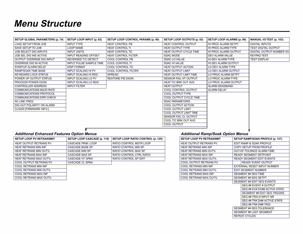
Menu StructureSETUP GLOBAL PARAMETERS (p. 74) SETUP LOOP INPUT (p. 82) SETUP LOOP CONTROL PARAMS (p. 90) SETUP LOOP OUTPUTS (p. 93) SETUP LOOP ALARMS (p. 99) MANUAL I/O TEST (p. 103)LOAD SETUP FROM JOB INPUT TYPE HEAT CONTROL PB HEAT CONTROL OUTPUT HI PROC ALARM SETPT DIGITAL INPUTSSAVE SETUP TO JOB LOOP NAME HEAT CONTROL TI HEAT OUTPUT TYPE HI PROC ALARM TYPE TEST DIGITAL OUTPUTJOB SELECT DIG INPUTS INPUT UNITS HEAT CONTROL TD HEAT OUTPUT CYCLE TIME HI PROC ALARM OUTPUT DIGITAL OUTPUT NUMBER XXJOB SEL DIG INS ACTIVE INPUT READING OFFSET HEAT CONTROL FILTER SDAC MODE DEV ALARM VALUE KEYPAD TESTOUTPUT OVERRIDE DIG INPUT REVERSED T/C DETECT COOL CONTROL PB SDAC LO VALUE HI DEV ALARM TYPE TEST DISPLAYOVERRIDE DIG IN ACTIVE INPUT PULSE SAMPLE TIME COOL CONTROL TI SDAC HI VALUE HI DEV ALARM OUTPUTSTARTUP ALARM DELAY DISP FORMAT COOL CONTROL TD HEAT OUTPUT ACTION LO DEV ALARM TYPERAMP/SOAK TIME BASE INPUT SCALING HI PV COOL CONTROL FILTER HEAT OUTPUT LIMIT LO DEV ALARM OUTPUTKEYBOARD LOCK STATUS INPUT SCALING HI RDG SPREAD HEAT OUTPUT LIMIT TIME LO PROC ALARM SETPTPOWER UP OUTPUT STATUS INPUT SCALING LO PV RESTORE PID DIGIN SENSOR FAIL HT OUTPUT LO PROC ALARM TYPEPROCESS POWER DIGIN INPUT SCALING LO RDG HEAT T/C BRK OUT AVG LO PROC ALARM OUTPUTCONTROLLER ADDRESS INPUT FILTER HEAT OUTPUT ALARM DEADBANDCOMMUNICATIONS BAUD RATE COOL CONTROL OUTPUT ALARM DELAYCOMMUNICATIONS PROTOCOL COOL OUTPUT TYPECOMMUNICATIONS ERR CHECK COOL OUTPUT CYCLE TIMEAC LINE FREQ SDAC PARAMETERSDIG OUT POLARITY ON ALARM COOL OUTPUT ACTIONCLS200 [FIRMWARE INFO.] COOL OUTPUT LIMIT
COOL OUTPUT LIMIT TIMESENSOR FAIL CL OUTPUTCOOL T/C BRK OUT AVGCOOL OUTPUT
Additional Enhanced Features Option Menus Additional Ramp/Soak Option MenusSETUP LOOP PV RETRANSMIT SETUP LOOP CASCADE (p. 119) SETUP LOOP RATIO CONTROL (p. 125) SETUP LOOP PV RETRANSMIT SETUP RAMP/SOAK PROFILE (p. 137)HEAT OUTPUT RETRANS PV CASCADE PRIM. LOOP RATIO CONTROL MSTR LOOP HEAT OUTPUT RETRANS PV EDIT RAMP & SOAK PROFILEHEAT RETRANS MIN INP CASCADE BASE SP RATIO CONTROL MIN SP HEAT RETRANS MIN INP COPY SETUP FROM PROFILEHEAT RETRANS MIN OUT% CASCADE MIN SP RATIO CONTROL MAX SP HEAT RETRANS MIN OUT% OUT-OF-TOLRNCE ALARM TIMEHEAT RETRANS MAX INP CASCADE MAX SP RATIO CONTROL CTRL RATIO HEAT RETRANS MAX INP READY SEGMENT SETPOINTHEAT RETRANS MAX OUT% CASCADE HT SPAN RATIO CONTROL SP DIFF HEAT RETRANS MAX OUT% READY SEGMENT EDIT EVENTSCOOL OUTPUT RETRANS PV CASCADE CL SPAN COOL OUTPUT RETRANS PV READY EVENT OUTPUTCOOL RETRANS MIN INP COOL RETRANS MIN INP EXTERNAL RESET INPUT NUMBERCOOL RETRANS MIN OUT% COOL RETRANS MIN OUT% EDIT SEGMENT NUMBERCOOL RETRANS MAX INP COOL RETRANS MAX INP SEGMENT ## SEG TIMECOOL RETRANS MAX OUT% COOL RETRANS MAX OUT% SEGMENT ## SEG SETPT
SEGMENT ## EDIT SEG EVENTSSEG ## EVENT # OUTPUTSEG ## EV# DO## ACTIVE STATESEGMENT ## EDIT SEG TRGGRSSEG ## TRIG # INPUT NRSEG ## TR# DI## ACTIVE STATESEG ## TR# DI## TRIG
SEGMENT ## SEG TOLERANCESEGMENT ## LAST SEGMENTREPEAT CYCLES

Declaration of Conformity
30590-00 REV E
Declaration of Conformity
CLS200 SeriesWATLOW ANAFAZE314 Westridge DriveWatsonville, California 95076 USA
Declares that the following product: English Designation: CLS200 Series Model Number(s): 2 (04, 08 or 16) - (1,2,3 or 4) (0,1 or 2) (0 or 2)
(0,1,2 or 3) (0,1,2 or 3) (0,1, or 2)(1 or 2 letters or numbers)
Classification: Installation Category II, Pollution Degree II Rated Voltage: 15 to 24 VDC Rated Current: 610mA maximumMeets the essential requirements of the following European Union Directive(s) using the relevantsection(s) of the normalized standards and related documents shown:
89/336/EEC Electromagnetic Compatibility DirectiveEN 61326: 1997 Electrical equipment for measurement, control and
laboratory use - EMC requirements (Class A)EN 61000-3-2: 1995 Limits for harmonic currentEN 61000-3-3: 1995 Limitations of voltage fluctuations and flickerEN 61000-4-2: 1995 Electrostatic dischargeEN 61000-4-3: 1997 Radiated immunityEN 61000-4-4: 1995 Electrical fast transientsEN 61000-4-5: 1995 Surge immunityEN 61000-4-6: 1994 Conducted immunityEN 61000-4-11: 1994 Voltage dips, short interruptions and
voltage variations immunityENV 50204: 1995 Cellular phone
Déclare que le produit suivant : Français Désignation : Série CLS200 Numéro(s) de modèle(s): 2 - (04, 08 ou 16) - (1, 2, 3 ou 4) (0,1 ou 2)
(0, 1 ou 2) (0, 1, 2 ou 3) (0, 1, 2 ou 3) (0, 1 ou 2)(1 ou 2 lettres ou chiffren)
Classification : Installation catégorie II, degré de pollution II Tension nominale : 15 à 24V c.c. Courant nominal : 610 mA maximumConforme aux exigences de la (ou des) directive(s) suivante(s) de l’UnionEuropéenne figurant aux sections correspondantes des normes et documentsassociés ci-dessous :
89/336/EEC Directive de compatibilité électromagnétiqueEN 61326: 1995 Appareillage électrique pour la mesure, la commande
et l’usage de laboratoire –— Prescriptions relativesà la Compatilité Electro Magnétique (Classe A)
EN 61000-3-2 : 1995 Limites d’émission de courant harmon iqueEN 61000-3-3 : 1995 Limites de fluctuation de tensionEN 61000-4-2 : 1995 Décharge électrostatiqueEN 61000-4-3: 1997 Insensibilité à l’énergie rayonnéeEN 61000-4-4 : 1995 Courants électriques transitoires rapidesEN 61000-4-5 : 1995 Insensibi lité aux surtensionsEN 61000-4-6: 1996 Insensibilité à l’énergie par conductionEN 61000-4-11 : 1994 Insensibilité aux chutes subites, aux courtes
interruptions et aux variations de tensionENV 50204 : 1995 Téléphone cellulaire
Erklärt, daß das folgende Produkt: Deutsch Beschreibung: Serie CLS200 Modellnummer(n): 2 (04, 08 oder 16) - (1, 2, 3 oder 4) (0,1 oder 2)
(0,1 oder 2) (0,1,2 oder 3) (0,1,2 oder 3) (0,1 oder 2)(1 oder 2 Buchstabe oder Ziffern)
Klassifikation: Installationskategorie II, Emissionsgrad II Nennspannung: 15 bis 24 Vdc Nominaler Stromverbrauch: max. 610 mAErfüllt die wichtigsten Normen der folgenden Anweisung(en) der Europäischen Unionunter Verwendung des wichtigsten Abschnitts bzw. der wichtigsten Abschnitte dernormalisierten Spezifikationen und der untenstehenden einschlägigen Dokumente:
89/336/EEC Elektromagnetische Übereinstimmungsanw eEN 61326: 1997 Elektrogeräte zur Messung, Regelung und zum
Laboreinsatz EMC - Richtlinien (Klasse A)EN 61000-3-2: 1995 Grenzen der OberwellenstromemissionenEN 61000-3-3: 1995 Grenzen der SpannungsschwankungenEN 61000-4-2: 1995 Elektrostatische EntladungEN 61000-4-3: 1997 StrahlungsimmunitätEN 61000-4-4: 1995 Elektrische schnelle StößeEN 61000-4-5: 1995 SpannungsstoßimmunitätEN 61000-4-6: 1994 StörimmunitätEN 61000-4-11: 1994 Immunität gegen Spannungsgefälle, kurze
Unterbrechungen und SpannungsabweichungenENV 50204: 1995 Mobiltelefon
Declara que el producto siguiente: Español Designación: Serie CLS200 Números de modelo: 2 - (04, 08 ó 16) - (1, 2, 3 ó 4) (0,1 ó 2)
(0,1 ó 2) (0,1,2 ó 3) (0,1,2 ó 3) (0,1 ó 2)(1 ó 2 letras ó numeros)
Clasificación: Categoría de instalación II, grado de contaminaciónambiental II
Tensión nominal: 15 a 24Vcc Consumo nominal de energía: 610 mA máximoCumple con los requisitos esenciales de las siguientes Directivas de la UniónEuropea, usando las secciones pertinentes de las reglas normalizadas y losdocumentos relacionados que se muestran:
89/336/EEC - Directiva de Compatibilidad Electromagn éEN 61326: 1997 Equipo elétrico para medición control y uso en
laboratorios - Requisitos de compatibilidadelectromagnética (Clase A)
EN 61000-3-2 1995 Límites para emisiones de corriente armónicaEN 61000-3-3 1995 Limitaciones de fluctuaciones del voltajeEN 61000-4-2: 1995 Descarga electrostáticaEN 61000-4-3: 1997 Inmunidad radiadaEN 61000-4-4: 1995 Perturbaciones transitorias eléctricas rápidasEN 61000-4-5: 1995 SobretensiónEN 61000-4-6: 1994 Inmunidad conducidaEN 61000-4-11: 1994 Caídas de tensión, interrupciones breves y variaciones
de tensiónENV 50204: 1995 Teléfono portátil
Sean Wilkinson Watsonville, California. USA Name of Authorized Representative Place of Issue
Manager Feb 28, 2003 Title of Authorized Representative Date of Issue
________________________________Signature of Authorized Representative

Related Documents