Workbook TP 511 With CD-ROM Festo Didactic 094469 en Closed-Loop Hydraulics

Welcome message from author
This document is posted to help you gain knowledge. Please leave a comment to let me know what you think about it! Share it to your friends and learn new things together.
Transcript
Workbook TP 511
With CD-ROM
Festo Didactic
094469 en
Closed-Loop Hydraulics

© Festo Didactic 94469
Authorised applications and liability
The Learning System for Automation and Communication has been de-veloped and prepared exclusively for training in the field of automation and communication. The training organisation and / or trainee shall en-sure that the safety precautions described in the accompanying Tech-nical documentation are fully observed.
Festo Didactic hereby excludes any liability for injury to trainees, to the training organisation and / or to third parties occurring as a result of the use or application of the station outside of a pure training situation, un-less caused by premeditation or gross negligence on the part of Festo Didactic.
Order No.: 094469 Edition: 08/2000 Layout: 08.2000, OCKER Ingenieurbüro Graphics: OCKER Ingenieurbüro Authors: A.Zimmermann, D.Scholz
© Festo Didactic SE, 73770 Denkendorf, Germany, 2015 All rights reserved. Internet: www.festo-didactic.com E-mail: [email protected]
The purchaser shall receive a single right of use which is non-exclusive, non-time-limited and limited geographically to use at the purchaser's site/location as follows.
The purchaser shall be entitled to use the work to train his/her staff at the pur-chaser's site/location and shall also be entitled to use parts of the copyright ma-terial as the basis for the production of his/her own training documentation for the training of his/her staff at the purchaser's site/location with acknowledge-ment of source and to make copies for this purpose. In the case of schools/technical colleges and training centres, the right of use shall also in-clude use by school and college students and trainees at the purchaser's site/location for teaching purposes.
The right of use shall in all cases exclude the right to publish the copyright mate-rial or to make this available for use on intranet, Internet and LMS platforms and databases such as Moodle, which allow access by a wide variety of users, in-cluding those outside of the purchaser's site/location.
Entitlement to other rights relating to reproductions, copies, adaptations, transla-tions, microfilming and transfer to and storage and processing in electronic sys-tems, no matter whether in whole or in part, shall require the prior consent of Festo Didactic.
© Festo Didactic 94469
3
Preface
Festo Didactic’s Learning System for Automation and Communications is designed to meet a number of different training and vocational re-quirements. The Training Packages are structured accordingly:
Basic Packages provide fundamental knowledge which is not limited to a specific technology.
Technology Packages deal with the important areas of open-loop and closed-loop control technology.
Function Packages explain the basic functions of automation sys-tems.
Application Packages provide basic and further training closely ori-ented to everyday industrial practice.
Technology Packages deal with the technologies of pneumatics, elec-tropneumatics, programmable logic controllers, hydraulics, electrohy-draulics, proportional hydraulics closed loop pneumatics and hydraulics.
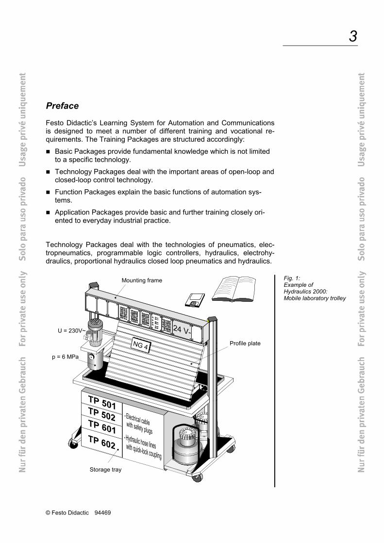
Fig. 1: Example of Hydraulics 2000: Mobile laboratory trolley
Mounting frame
Profile plate
U = 230V~
p = 6 MPa
Storage tray
© Festo Didactic 94469
4
The modular structure of the Learning System permits applications to be assembled which go beyond the scope of the individual packages. It is possible, for example, to use PLCs to control pneumatic, hydraulic and electrical actuators.
All training packages have an identical structure:
Hardware
Courseware
Software
Courses
The hardware consists of industrial components and installations, adapted for didactic purposes.
The courseware is matched methodologically and didactically to the training hardware. The courseware comprises:
Textbooks (with exercises and examples)
Workbooks (with practical exercises, explanatory notes, solutions and data sheets)
OHP transparencies, electronic transparencies for PCs and videos (to bring teaching to life)
Teaching and learning media are available in several languages. They have been designed for use in classroom teaching but can also be used for self-study purposes.
In the software field, CAD programs, computer-based training programs and programming software for programmable logic controllers are avail-able.
Festo Didactic’s range of products for basic and further training is com-pleted by a comprehensive selection of courses matched to the contents of the technology packages.
© Festo Didactic 94469
5
Latest information about the technology package Closed loop hydraulics TP511.
New in Hydraulic 2000:
Industrial components on the profile plate.
Exercises with exercise sheets and solutions, leading questions.
Fostering of key qualifications: Technical competence, personal competence and social competence form professional competence.
Training of team skills, willingness to co-operate, willingness to learn, independence and organisational skills.
Aim – Professional competence
Content Part A Course Exercises
Part B Fundamentals Reference to the text book
Part C Solutions Function diagrams, circuits, descriptions of solutions and equipment lists
Part D Appendix Storage tray, mounting technology and datasheets

© Festo Didactic 94469
6
Table of contents
Technology package TP511 “Closed loop hydraulics” 12
Safety recommendations 13
Notes on procedure 13
Standard method of representation used in circuit diagrams 14
Technical notes 15
Component/exercise table 16
Equipment set TP511 18
Section A – Course
1. Pressure control loop
Exercise 1: Pipe-bending machine Characteristics of a pressure sensor A-3
Exercise 2: Forming plastic products Pressure characteristic curve of a dynamic directional control valve A-13
Exercise 3: Cold extrusion Regulated pressure control A-25
Exercise 4: Thread rolling machine Characteristics of a PID controller card A-33
Exercise 5: Stamping machine Transition function of a P controller A-39
Exercise 6: Clamping device Control quality of a pressure control loop with P controller A-49
Exercise 7: Injection moulding machine Transition functions of I and PI controllers A-61
Exercise 8: Pressing-in of bearings Transition functions of D, PD and PID controllers A-75
Exercise 9: Welding tongs of a robot Empirical setting of parameters of a PID controller A-89
Exercise 10: Pressure roller of a rolling machine Setting parameters using the Ziegler-Nichols method A-97
© Festo Didactic 94469
7
Exercise 11: Edge-folding press with feeding device Modified controlled system with disturbance variables A-105
2. Position control loop
Exercise 12: Table-feed of a milling machine Characteristic curve of a displacement sensor A-115
Exercise 13: X/Y-axis table of a drilling machine Flow characteristic curves of a dynamic directional control valve A-125
Exercise 14: Feed unit of an assembly station Linear unit as controlled system for position control A-141
Exercise 15: Automobile simulator Assembly and commissioning of a position control loop A-159
Exercise 16: Contour milling Lag error in position control loop A-173
Exercise 17: Machining centre Position control with modified controlled system A-185
Exercise 18: Drilling of bearing surfaces Commissioning of a position control loop with disturbance variables A-191
Exercise 19: Feed on a shaping machine Characteristics and transition functions of a status controller A-205
Exercise 20: Paper feed of a printing machine Parameterisation of a status controller A-215
Exercise 21: Horizontal grinding machine Position control loop with disturbance variables and active load A-227
© Festo Didactic 94469
8
Part B – Fundamentals
Chapter 1 Fundamentals B-7
1.1 Signals B-7
1.2 Block diagram B-11
1.3 Signal flow diagram B-14
1.4. Test signals B-16
1.5 Open-loop and closed-loop control B-18
1.6 Closed-loop control terminology B-21
1.7 Stability and instability B-23
1.8 Steady-state and dynamic behaviour B-25
1.9 Response to setpoint changes and interference B-28
1.10 Fixed value, follow-up and time control systems B-30
1.11 Differentiation of a signal B-32
1.12 Integration of a signal B-36
Chapter 2 Hydraulic closed-loop control systems B-41
2.1 Controlled systems with and without compensation B-42
2.2 Short-delay hydraulic controlled systems B-44
2.3 First-order hydraulic controlled systems B-46
2.4 Second-order hydraulic controlled systems B-47
2.5 Third-order hydraulic controlled systems B-49
2.6 Classification of controlled systems according to their step response behaviour B-51
2.7 Operating point and system gain B-52
Chapter 3 Controller structures B-55
3.1 Non-dynamic controllers B-57
3.2 Block diagrams for non-dynamic controllers B-59
3.3 P controllers B-60
3.4 I controllers B-62
3.5 D-controller ratio B-64
© Festo Didactic 94469
9
3.6 PI-,PD- and PID controllers B-67
3.7 Block diagrams for standard dynamic controllers B-74
3.8 Status controllers B-78
3.9 Choice of controller structure B-81
3.10 Response to interference and control factor B-83
Chapter 4 Technical implementation of closed-loop controllers B-89
4.1 Structure of closed control loops B-89
4.2 Hydraulic-mechanical and electrical controllers B-95
4.3 Analogue and digital closed-loop controllers B-97
4.4 Selection criteria for closed-loop controllers B-100
Chapter 5 Directional control valves B-101
5.1 Valve designs B-101
5.2 Functions and components of a directional control valve B-102
5.3 Designations and symbols for dynamic directional control valves B-106
5.4 Mode of operation of a dynamic 4/3-way valve B-109
5.5 Steady-state characteristics of dynamic directional control valves B-115
5.6 Dynamic behaviour of dynamic directional control valves B-121
5.7 Selection criteria for directional control valves B-126
Chapter 6 Pressure regulators B-127
6.1 Functions of a pressure regulator B-127
6.2 Pressure regulator designs B-128
6.3 Mode of operation of a pressure regulator B-129
6.4 Pressure regulation with a directional control valve B-133
6.5 Selection criteria for pressure regulators B-134
© Festo Didactic 94469
10
Chapter 7 Measuring systems B-135
7.1 Function of a measuring system B-135
7.2 Measuring system designs and interfaces B-136
7.3 Selection criteria for measuring systems B-139
Chapter 8 Design, commissioning and fault finding B-141
8.1 Closed control loops in automation B-141
8.2 Planning B-144
8.3 Construction B-147
8.4 Commissioning B-149
8.5 Controller settings B-152
8.6 Fault finding B-158
Section C – Solutions
Exercise 1: Pipe-bending machine C-3
Exercise 2: Forming of plastic products C-5
Exercise 3: Cold extrusion C11
Exercise 4: Thread rolling machine C-13
Exercise 5: Stamping machine C-15
Exercise 6: Clamping device C-19
Exercise 7: Injection moulding machine C-23
Exercise 8: Pressing-in of bearings C-25
Exercise 9: Welding tongs of a robot C-29
Exercise 10: Pressure roller of a rolling machine C-31
Exercise 11: Edge-folding press with feeding device C-35
Exercise 12: Table-feed of a drilling machine C-39
Exercise 13: X/Y-axis table of a drilling machine C-41
Exercise 14: Feed unit of an assembly station C-49
Exercise 15: Automobile simulator C-55
Exercise 16: Contour milling C-61
© Festo Didactic 94469
11
Exercise 17: Machining centre C-65
Exercise 18: Drilling of bearing surfaces C-67
Exercise 19: Feed on a shaping machine C-73
Exercise 20: Paper feed of a printing machine C-77
Exercise 21: Horizontal grinding machine C-81
Section D – Appendix
Operating notes 2
Storage tray 3
Mounting technology 4
Sub-base 6
Coupling system 7
Guidelines and standards 9
List of literature 10
Index 11
Data sheets 19
© Festo Didactic 94469
12
Technology package TP511 “Closed loop hydraulics”
The technology package TP511 “Closed loop hydraulics” forms part of Festo Didactic’s Learning System for Automation and Communications.
The training aims of TP511 are concerned with learning the fundamen-tals of analogue control technology. With electrical control and closed loop elements, hydraulic actuators are activated. A basic knowledge of electrohydraulics and electrical measuring technology is therefore rec-ommended to work with this technology package.
The exercises in TP511 cover the following main topics:
Pressure control with PID controller (exercise 1 – 11)
Position control with PID controller (exercise 12 – 18)
Position control with status controller (exercise 19 – 21)
The fundamentals dealt with in TP511 concern:
A classification of hydraulic controlled systems
A description of different controller structures
Notes regarding the technical implementation of controllers, valves and sensors
Tips on the assembly and commissioning of hydraulic closed control loops
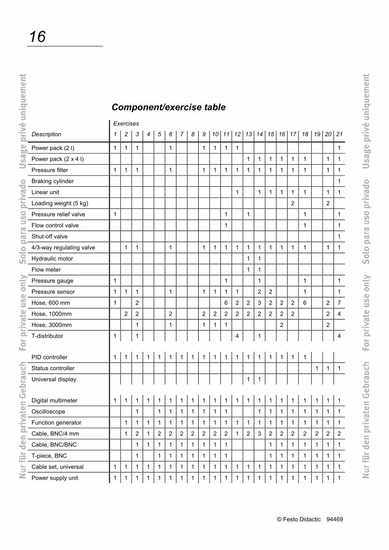
The components of the equipment set to be used for the individual exer-cises are listed in the component/exercise table overleaf.
© Festo Didactic 94469
13
Safety recommendations
The following safety advice should be observed in the interest of your own safety:
Caution! Cylinders may advance as soon as the hydraulic power pack is switched on!
Do not exceed the permitted working pressure (see data sheets).
Use only extra-low voltages of up to 24 V.
Observe general safety regulations (DIN58126 and VDE100).
Notes on procedure
Construction
The following steps are to be observed when constructing a control cir-cuit.
1. The hydraulic power pack and the electrical power supply unit must be switched off during the construction of the circuit.
2. All components must be securely attached to the slotted profile plate i.e. safely latched and securely mounted.
3. Please check that all return lines are connected and all hoses secure-ly connected.
4. Make sure that all cable connections have been established and that all plugs are securely plugged in.
5. First, switch on the electrical power supply unit and then the hydraulic power pack.
6. Make sure that the hydraulic components are pressure relieved prior to dismantling the circuit, since:
Couplings must be connected unpressurised!
7. First, switch off the hydraulic power pack and then the electrical pow-er supply unit.
© Festo Didactic 94469
14
Standard method of representation used in circuit diagrams
The hydraulic circuit diagrams are based on the following rules:
Clear representation avoiding crossovers as far as possible
Symbols conforming to DIN/ISO 1219 Part 1
Circuit diagrams with several loads are divided into control chains
Identification of components in accordance with DIN/ISO 1219 Part 2:
• Each control chain is assigned an ordinal number 1xx, 2xx, etc.
• The hydraulic power pack is control chain 0xx.
• Identification of components by letters:
A – Power component
B – Electrical sensors
P – Pump
S – Signal generator
V – Valve
Z – Other component
• The complete code for a component consists of
– a digit for the control chain,
– a letter for the component,
– a digit for the consecutive numbering of components in accord-ance with the direction of flow in the control chain.
Example: 1V2 = Second valve in control chain 1.
© Festo Didactic 94469
15
Technical notes
The following notes are to be observed in order to ensure trouble-free operation.
An adjustable pressure relief valve has been integrated in the hydrau-lic power pack Pt. No. 152962. For reasons of safety, the sys-tem pressure has been limited to approx. 6 MPa (60 bar).
The maximum permissible pressure for all hydraulic components is 12 MPa (120 bar).
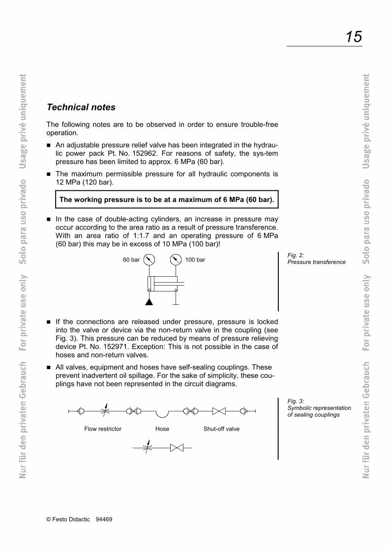
The working pressure is to be at a maximum of 6 MPa (60 bar). In the case of double-acting cylinders, an increase in pressure may
occur according to the area ratio as a result of pressure transference. With an area ratio of 1:1.7 and an operating pressure of 6 MPa (60 bar) this may be in excess of 10 MPa (100 bar)!
If the connections are released under pressure, pressure is locked
into the valve or device via the non-return valve in the coupling (see Fig. 3). This pressure can be reduced by means of pressure relieving device Pt. No. 152971. Exception: This is not possible in the case of hoses and non-return valves.
All valves, equipment and hoses have self-sealing couplings. These prevent inadvertent oil spillage. For the sake of simplicity, these cou-plings have not been represented in the circuit diagrams.
Flow restrictor Hose Shut-off valve
Fig. 2: Pressure transference
Fig. 3: Symbolic representation of sealing couplings
© Festo Didactic 94469
16
Component/exercise table Exercises
Description 1 2 3 4 5 6 7 8 9 10 11 12 13 14 15 16 17 18 19 20 21
Power pack (2 l) 1 1 1 1 1 1 1 1 1
Power pack (2 x 4 l) 1 1 1 1 1 1 1 1
Pressure filter 1 1 1 1 1 1 1 1 1 1 1 1 1 1 1 1
Braking cylinder 1
Linear unit 1 1 1 1 1 1 1 1
Loading weight (5 kg) 2 2
Pressure relief valve 1 1 1 1 1
Flow control valve 1 1 1
Shut-off valve 1
4/3-way regulating valve 1 1 1 1 1 1 1 1 1 1 1 1 1 1 1
Hydraulic motor 1 1
Flow meter 1 1
Pressure gauge 1 1 1 1 1
Pressure sensor 1 1 1 1 1 1 1 1 2 2 1 1
Hose, 600 mm 1 2 6 2 2 3 2 2 2 6 2 7
Hose, 1000mm 2 2 2 2 2 2 2 2 2 2 2 2 2 4
Hose, 3000mm 1 1 1 1 1 2 2
T-distributor 1 1 4 1 4
PID controller 1 1 1 1 1 1 1 1 1 1 1 1 1 1 1 1 1 1
Status controller 1 1 1
Universal display 1 1
Digital multimeter 1 1 1 1 1 1 1 1 1 1 1 1 1 1 1 1 1 1 1 1 1
Oscilloscope 1 1 1 1 1 1 1 1 1 1 1 1 1 1 1 1
Function generator 1 1 1 1 1 1 1 1 1 1 1 1 1 1 1 1 1 1 1 1
Cable, BNC/4 mm 1 2 1 2 2 2 2 2 2 2 1 2 3 2 2 2 2 2 2 2
Cable, BNC/BNC 1 1 1 1 1 1 1 1 1 1 1 1 1 1 1 1
T-piece, BNC 1 1 1 1 1 1 1 1 1 1 1 1 1 1 1
Cable set, universal 1 1 1 1 1 1 1 1 1 1 1 1 1 1 1 1 1 1 1 1 1
Power supply unit 1 1 1 1 1 1 1 1 1 1 1 1 1 1 1 1 1 1 1 1 1
© Festo Didactic 94469
17
Workbook concept
The workbook is divided into the following sections:
Section A – Course
Section B – Fundamentals
Section C – Solutions
Section D – Appendix
In Section A, “Course”, progressive exercises are used to explain the assembly and commissioning of analogue closed control loops.
The necessary technical knowledge required to complete an exercise is provided at the start of each exercise. Non-essential details are avoided. More detailed information is given in Section B.
Section C, “Solutions” gives the results of the exercises with a brief explanation.
Section B, “Fundamentals” contains general technical knowledge, which complements the training contents of the exercises in Section A. Theoretical relationships are illustrated and the necessary specialist terminology is explained in a clearly understandable way by means of examples.
Section D, “Appendix” is intended as a means of reference. It contains data sheets, a list of literature and an index.
The layout of the book has been structured to allow the use of its con-tents both for practical training, e.g. in classroom courses, and for self-study purposes.
© Festo Didactic 94469
18
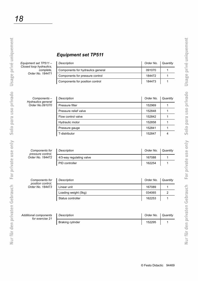
Equipment set TP511 Description Order No. Quantity
Components for hydraulics general 091070 1
Components for pressure control 184472 1
Components for position control 184473 1
Description Order No. Quantity
Pressure filter 152969 1
Pressure relief valve 152848 1
Flow control valve 152842 1
Hydraulic motor 152858 1
Pressure gauge 152841 1
T-distributor 152847 4
Description Order No. Quantity
4/3-way regulating valve 167088 1
PID controller 162254 1
Description Order No. Quantity
Linear unit 167089 1
Loading weight (5kg) 034065 2
Status controller 162253 1
Description Order No. Quantity
Braking cylinder 152295 1
Equipment set TP511 – Closed loop hydraulics,
complete, Order No. 184471
Components – Hydraulics general
Order No.091070
Components for pressure control,
Order No. 184472
Components for position control,
Order No. 184473
Additional components for exercise 21
© Festo Didactic 94469
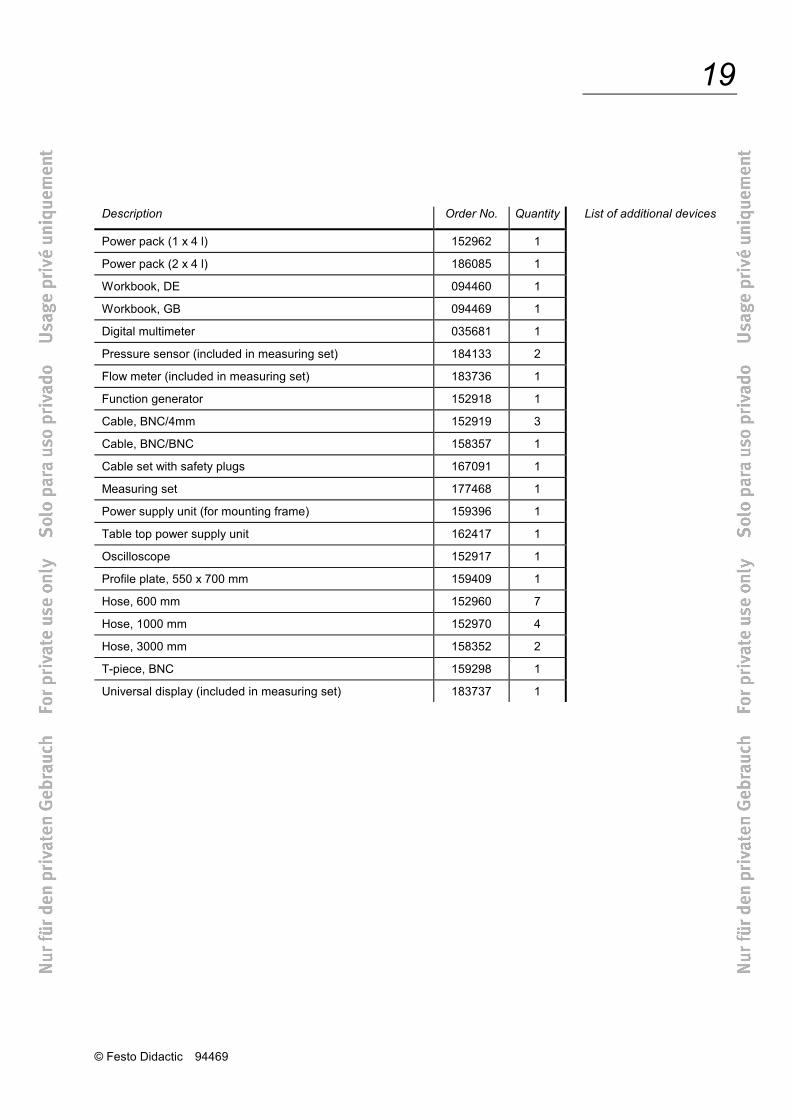
19
Description Order No. Quantity
Power pack (1 x 4 l) 152962 1
Power pack (2 x 4 l) 186085 1
Workbook, DE 094460 1
Workbook, GB 094469 1
Digital multimeter 035681 1
Pressure sensor (included in measuring set) 184133 2
Flow meter (included in measuring set) 183736 1
Function generator 152918 1
Cable, BNC/4mm 152919 3
Cable, BNC/BNC 158357 1
Cable set with safety plugs 167091 1
Measuring set 177468 1
Power supply unit (for mounting frame) 159396 1
Table top power supply unit 162417 1
Oscilloscope 152917 1
Profile plate, 550 x 700 mm 159409 1
Hose, 600 mm 152960 7
Hose, 1000 mm 152970 4
Hose, 3000 mm 158352 2
T-piece, BNC 159298 1
Universal display (included in measuring set) 183737 1
List of additional devices

© Festo Didactic 94469
20
Designation Explanation Symbol
Double-acting cylinder single-ended piston rod
Double-acting cylinder double-ended piston rod
Pressure gauge
Flow control valve adjustable
Pressure relief valve adjustable
Pressure regulating valve adjustable
Shut-off valve
Reservoir Connection at both sides
Energy source hydraulic
Manual operation general
Plugged port
2/2-way valve Normally closed
Symbols for the equipment set TP511
© Festo Didactic 94469
21
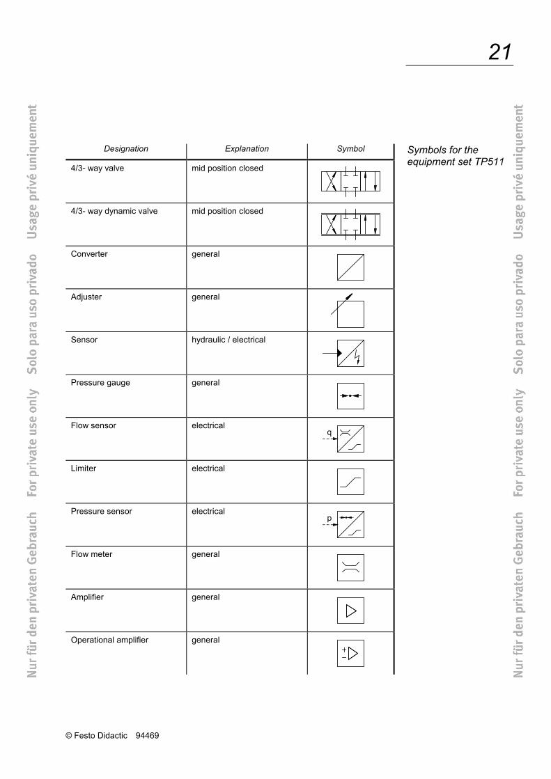
Designation Explanation Symbol
4/3- way valve mid position closed
4/3- way dynamic valve mid position closed
Converter general
Adjuster general
Sensor hydraulic / electrical
Pressure gauge general
Flow sensor electrical
Limiter electrical
Pressure sensor electrical
Flow meter general
Amplifier general
Operational amplifier general
Symbols for the equipment set TP511
© Festo Didactic 94469
22
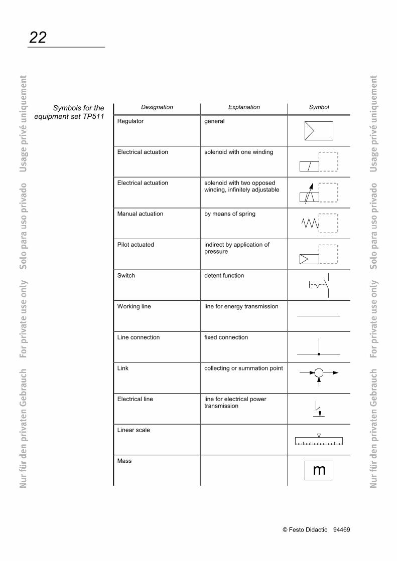
Designation Explanation Symbol
Regulator general
Electrical actuation solenoid with one winding
Electrical actuation solenoid with two opposed winding, infinitely adjustable
Manual actuation by means of spring
Pilot actuated indirect by application of pressure
Switch detent function
Working line line for energy transmission
Line connection fixed connection
Link collecting or summation point
Electrical line line for electrical power transmission
Linear scale
Mass
Symbols for the equipment set TP511
© Festo Didactic 94469
23
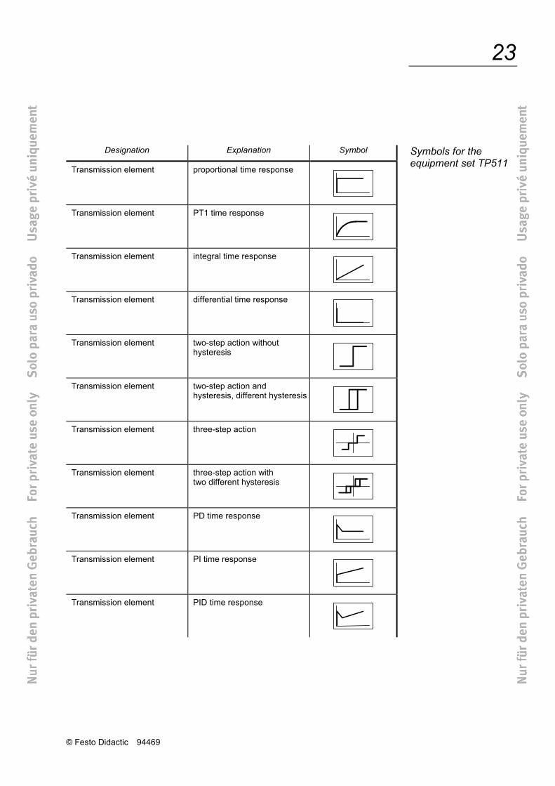
Designation Explanation Symbol
Transmission element proportional time response
Transmission element PT1 time response
Transmission element integral time response
Transmission element differential time response
Transmission element two-step action without hysteresis
Transmission element two-step action and hysteresis, different hysteresis
Transmission element three-step action
Transmission element three-step action with two different hysteresis
Transmission element PD time response
Transmission element PI time response
Transmission element PID time response
Symbols for the equipment set TP511
© Festo Didactic 94469
24
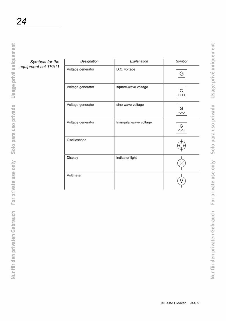
Designation Explanation Symbol
Voltage generator D.C. voltage
Voltage generator square-wave voltage
Voltage generator sine-wave voltage
Voltage generator triangular-wave voltage
Oscilloscope
Display indicator light
Voltmeter
Symbols for the equipment set TP511
© Festo Didactic 94469
A-1
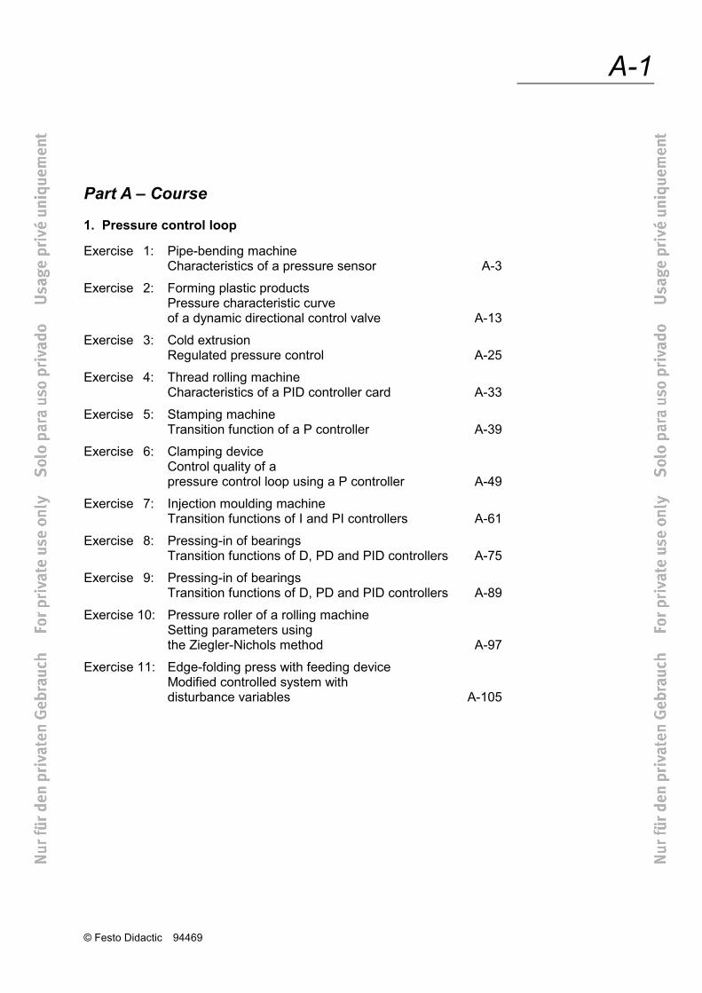
Part A – Course
1. Pressure control loop
Exercise 1: Pipe-bending machine Characteristics of a pressure sensor A-3
Exercise 2: Forming plastic products Pressure characteristic curve of a dynamic directional control valve A-13
Exercise 3: Cold extrusion Regulated pressure control A-25
Exercise 4: Thread rolling machine Characteristics of a PID controller card A-33
Exercise 5: Stamping machine Transition function of a P controller A-39
Exercise 6: Clamping device Control quality of a pressure control loop using a P controller A-49
Exercise 7: Injection moulding machine Transition functions of I and PI controllers A-61
Exercise 8: Pressing-in of bearings Transition functions of D, PD and PID controllers A-75
Exercise 9: Pressing-in of bearings Transition functions of D, PD and PID controllers A-89
Exercise 10: Pressure roller of a rolling machine Setting parameters using the Ziegler-Nichols method A-97
Exercise 11: Edge-folding press with feeding device Modified controlled system with disturbance variables A-105
© Festo Didactic 94469
A-2
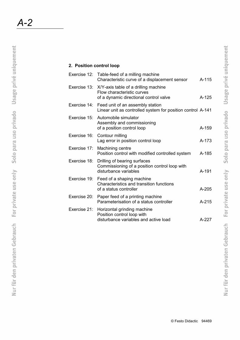
2. Position control loop
Exercise 12: Table-feed of a milling machine Characteristic curve of a displacement sensor A-115
Exercise 13: X/Y-axis table of a drilling machine Flow characteristic curves of a dynamic directional control valve A-125
Exercise 14: Feed unit of an assembly station Linear unit as controlled system for position control A-141
Exercise 15: Automobile simulator Assembly and commissioning of a position control loop A-159
Exercise 16: Contour milling Lag error in position control loop A-173
Exercise 17: Machining centre Position control with modified controlled system A-185
Exercise 18: Drilling of bearing surfaces Commissioning of a position control loop with disturbance variables A-191
Exercise 19: Feed of a shaping machine Characteristics and transition functions of a status controller A-205
Exercise 20: Paper feed of a printing machine Parameterisation of a status controller A-215
Exercise 21: Horizontal grinding machine Position control loop with disturbance variables and active load A-227
© Festo Didactic 94469
A-3 Exercise 1
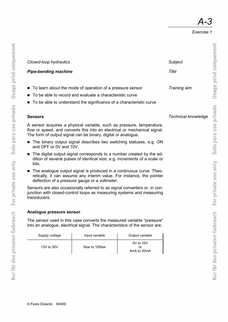
Closed-loop hydraulics
Pipe-bending machine
To learn about the mode of operation of a pressure sensor
To be able to record and evaluate a characteristic curve
To be able to understand the significance of a characteristic curve
Sensors
A sensor acquires a physical variable, such as pressure, temperature, flow or speed, and converts this into an electrical or mechanical signal. The form of output signal can be binary, digital or analogue.
The binary output signal describes two switching statuses, e.g. ON and OFF or 0V and 10V.
The digital output signal corresponds to a number created by the ad-dition of several pulses of identical size, e.g. increments of a scale or bits.
The analogue output signal is produced in a continuous curve. Theo-retically, it can assume any interim value. For instance, the pointer deflection of a pressure gauge or a voltmeter.
Sensors are also occasionally referred to as signal converters or, in con-junction with closed-control loops as measuring systems and measuring transducers.
Analogue pressure sensor
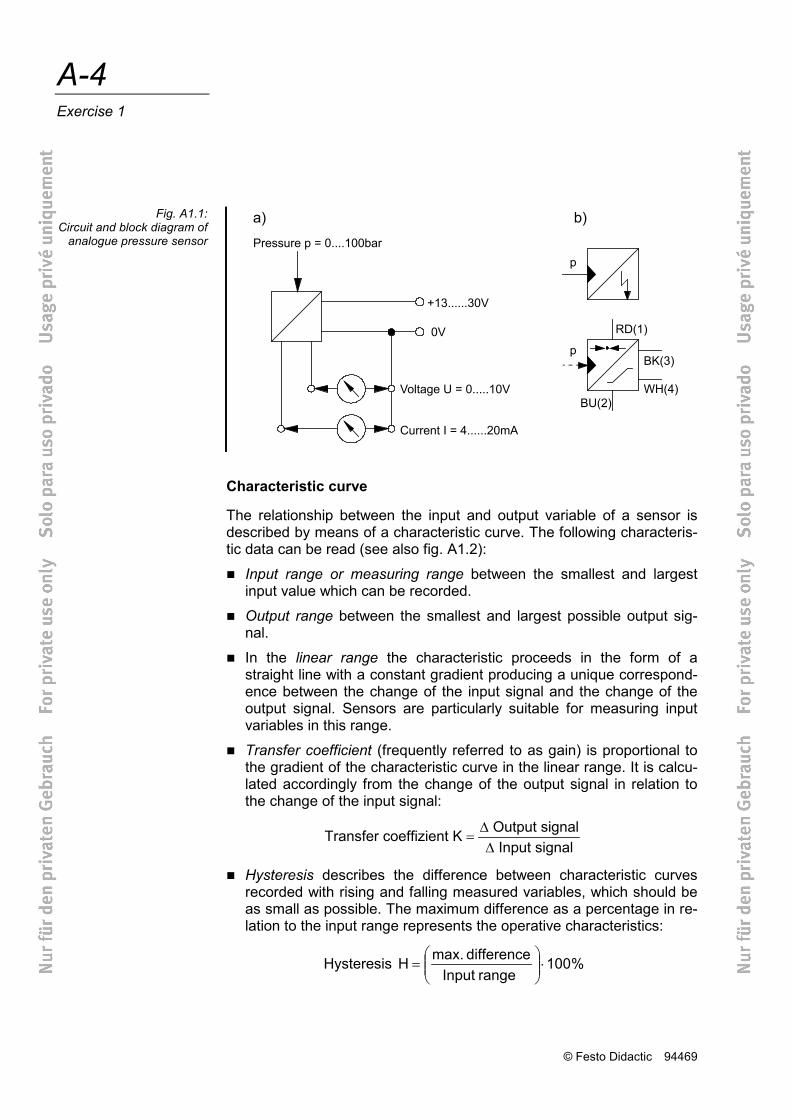
The sensor used in this case converts the measured variable “pressure” into an analogue, electrical signal. The characteristics of the sensor are:
Supply voltage Input variable Output variable
13V to 30V 0bar to 100bar 0V to 10V
or 4mA to 20mA
Subject
Title
Training aim
Technical knowledge
© Festo Didactic 94469
A-4 Exercise 1
Characteristic curve
The relationship between the input and output variable of a sensor is described by means of a characteristic curve. The following characteris-tic data can be read (see also fig. A1.2):
Input range or measuring range between the smallest and largest input value which can be recorded.
Output range between the smallest and largest possible output sig-nal.
In the linear range the characteristic proceeds in the form of a straight line with a constant gradient producing a unique correspond-ence between the change of the input signal and the change of the output signal. Sensors are particularly suitable for measuring input variables in this range.
Transfer coefficient (frequently referred to as gain) is proportional to the gradient of the characteristic curve in the linear range. It is calcu-lated accordingly from the change of the output signal in relation to the change of the input signal:
Transfer coeffizient K Output signal Input signal
=∆∆
Hysteresis describes the difference between characteristic curves recorded with rising and falling measured variables, which should be as small as possible. The maximum difference as a percentage in re-lation to the input range represents the operative characteristics:
%100 range Input
difference max.H Hysteresis ⋅
=
Fig. A1.1: Circuit and block diagram of
analogue pressure sensor

© Festo Didactic 94469
A-5 Exercise 1
Fig. A1.2: Characteristic curve of a sensor
© Festo Didactic 94469
A-6 Exercise 1
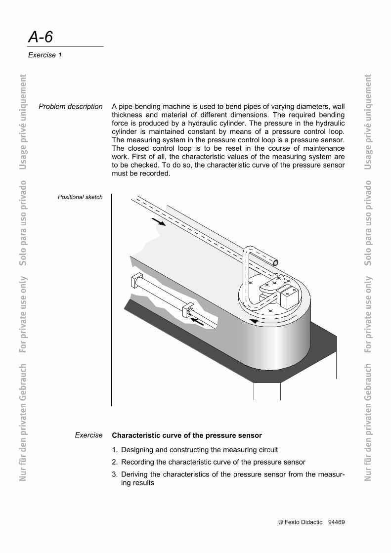
A pipe-bending machine is used to bend pipes of varying diameters, wall thickness and material of different dimensions. The required bending force is produced by a hydraulic cylinder. The pressure in the hydraulic cylinder is maintained constant by means of a pressure control loop. The measuring system in the pressure control loop is a pressure sensor. The closed control loop is to be reset in the course of maintenance work. First of all, the characteristic values of the measuring system are to be checked. To do so, the characteristic curve of the pressure sensor must be recorded.
Characteristic curve of the pressure sensor
1. Designing and constructing the measuring circuit
2. Recording the characteristic curve of the pressure sensor
3. Deriving the characteristics of the pressure sensor from the measur-ing results
Problem description
Positional sketch
Exercise
© Festo Didactic 94469
A-7 Exercise 1
1. Measuring circuit
Frequently, a characteristic curve has to be recorded on the spot using the devices available. Hence the input variable of the pressure sensor (= pressure in bar) is measured by means of a pressure gauge and the output variable (= voltage in V) by means of a multimeter. The accuracy of a measuring circuit of this type is generally adequate to check the sensor function. A pressure relief valve is built into the hydraulic circuit to set the different pressures. These are displayed by means of a pres-sure gauge.
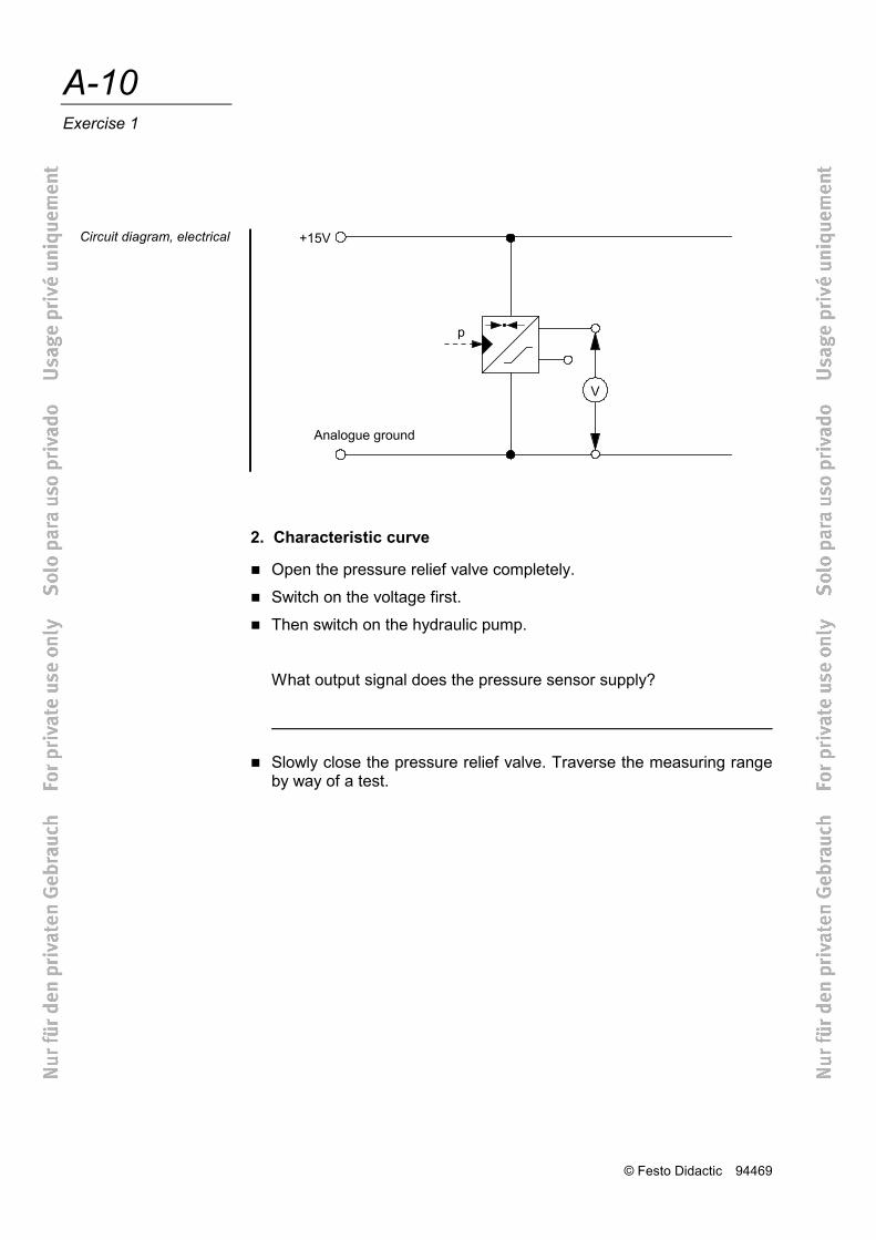
The electrical circuit consists of the voltage supply for the pressure sen-sor and a voltage measuring device for the output signal of the pressure sensor.
2. Characteristic curve
First, the pressure relief valve is opened completely. The entire oil flow returns de-pressurised from the pump to the tank. The pressure sensor display shows 0V. Pressure is then gradually increased by closing the pressure relief valve. The pressure levels and the pressure sensor readout are entered in a values table. Once the maximum pump pres-sure has been reached, this series of measurements is repeated with falling pressure.
Note the following when recording the characteristic curve
accurate setting of pressure values
rising or falling direction of measurement.
The characteristic curve of the pressure sensor is represented by plot-ting
the input variable (pressure p in bar) on the x-axis and
the output variable (voltage V in Volts) on the y-axis.
Execution
© Festo Didactic 94469
A-8 Exercise 1
3. Characteristics
The most important characteristics of a pressure sensor are:
Measuring range
Connection values
Transfer coefficient
Hysteresis.
These values can be taken from the data sheet. It is, however, often necessary to carry out a check by means of a series of measurements.
It is not possible to establish the complete measuring range of the pres-sure sensor with the items of equipment available. Since the pump sup-plies less than 100bar, it is not possible to traverse the entire input pressure range. It is nevertheless possible to calculate the transfer coef-ficient in the linear range, which is the most important one for setting a closed control loop. There is no point in calculating hysteresis, since any possible differences are more likely due to the inaccuracy of the pres-sure gauge rather than the features of the pressure sensor.

© Festo Didactic 94469
A-9 Exercise 1
WORKSHEET
Characteristic curve of a pressure sensor
1. Measuring circuit
Familiarise yourself with the required items of equipment.
What characteristics describe the pressure sensor?
Input range: ____________________________________________
Output range: ___________________________________________
Supply voltage: __________________________________________
Designate the characteristics of the pressure gauge:
Measuring rang: _________________________________________
Measuring accuracy: _____________________________________
Construct the measuring circuit, starting with the hydraulic and then the electrical part.
Circuit diagram, hydraulic
© Festo Didactic 94469
A-10 Exercise 1
2. Characteristic curve
Open the pressure relief valve completely.
Switch on the voltage first.
Then switch on the hydraulic pump.
What output signal does the pressure sensor supply?
Slowly close the pressure relief valve. Traverse the measuring range
by way of a test.
Circuit diagram, electrical
© Festo Didactic 94469
A-11 Exercise 1
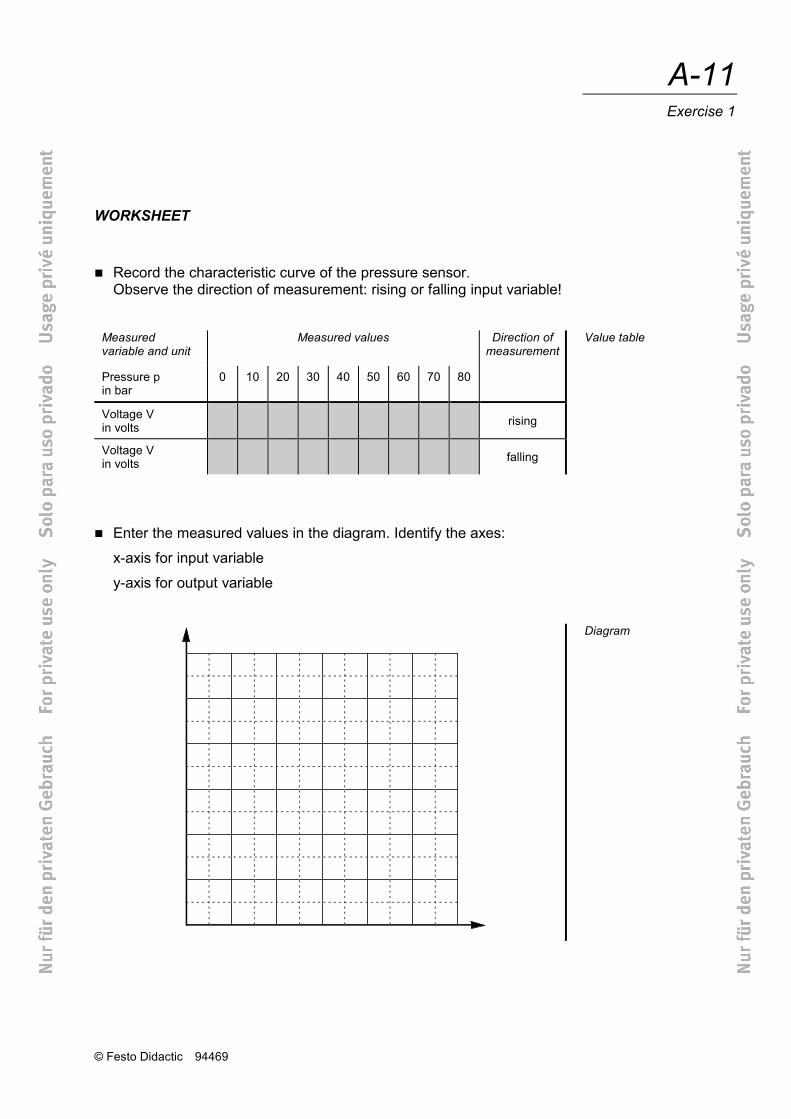
WORKSHEET
Record the characteristic curve of the pressure sensor. Observe the direction of measurement: rising or falling input variable!
Measured variable and unit
Measured values Direction of measurement
Pressure p in bar
0 10 20 30 40 50 60 70 80
Voltage V in volts
rising
Voltage V in volts
falling
Enter the measured values in the diagram. Identify the axes:
x-axis for input variable
y-axis for output variable
Value table
Diagram
© Festo Didactic 94469
A-12 Exercise 1
3. Characteristics
Establish the following characteristics from the diagram:
Input range:
Output range:
Measuring rang:
Linear range:
Transfer coefficient:
Hysteresis:
How do you evaluate the use of this pressure sensor within the framework of the circuits given with this equipment set?
State your reasons for this:
© Festo Didactic 94469
C-1
Part C – Solutions
Exercise 1: Pipe bending machine C-3
Exercise 2: Forming plastic products C-5
Exercise 3: Cold extrusion C-11
Exercise 4: Thread rolling machine C-13
Exercise 5: Stamping machine C-15
Exercise 6: Clamping device C-19
Exercise 7: Injection moulding machine C-23
Exercise 8: Pressing-in of bearings C-25
Exercise 9: Welding tongs of a robot C-29
Exercise 10: Pressure roller of a rolling machine C-31
Exercise 11: Edge-folding press with feeding device C-35
Exercise 12: Table-feed of a milling machine C-39
Exercise 13: X/Y-axis table of a drilling machine C-41
Exercise 14: Feed unit of an assembly station C-49
Exercise 15: Automobile simulator C-55
Exercise 16: Contour milling C-61
Exercise 17: Machining centre C-65
Exercise 18: Drilling of bearing surfaces C-67
Exercise 19: Feed of a shaping machine C-73
Exercise 20: Paper feed of a printing machine C-77
Exercise 21: Horizontal grinding machine C-81

© Festo Didactic 94469
C-2
© Festo Didactic 94469
C-3 Solution 1
Closed loop hydraulics
Pipe bending machine
Characteristic curve of a pressure sensor
1. Designing and constructing the measuring circuit
2. Recording the characteristic curve of the pressure sensor
3. Deriving the characteristics of the pressure sensor from the measur-ing results
1. Measuring circuit
The characteristics of a pressure sensor are:
Input range: 0bar to 100bar
Output range: 0V to 10V
Supply voltage: 15V The characteristics of the pressure gauge are:
Measuring range: 0bar to 100bar
Measuring accuracy: ± 1.6bar (corresponding to ± 1.6% of final value, see data sheet) The measuring circuit is to be constructed in accordance with the circuit diagrams. 2. Characteristic curve
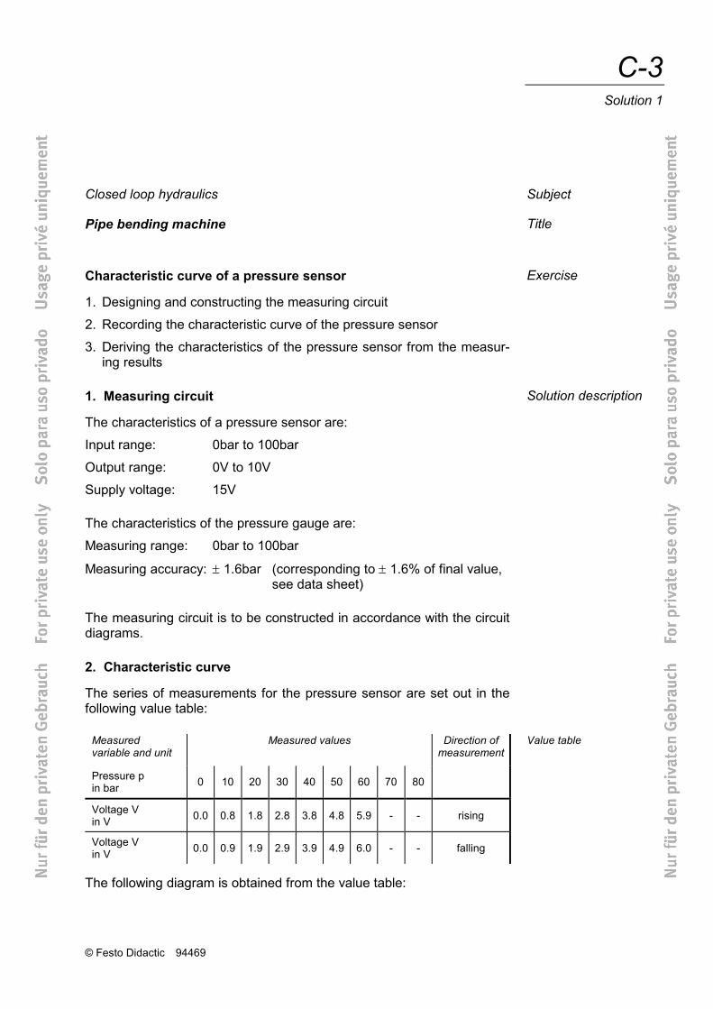
The series of measurements for the pressure sensor are set out in the following value table:
Measured variable and unit
Measured values Direction of measurement
Pressure p in bar 0 10 20 30 40 50 60 70 80
Voltage V in V 0.0 0.8 1.8 2.8 3.8 4.8 5.9 - - rising
Voltage V in V 0.0 0.9 1.9 2.9 3.9 4.9 6.0 - - falling
The following diagram is obtained from the value table:
Subject
Title
Exercise
Solution description
Value table
© Festo Didactic 94469
C-4 Solution 1
3. Characteristics
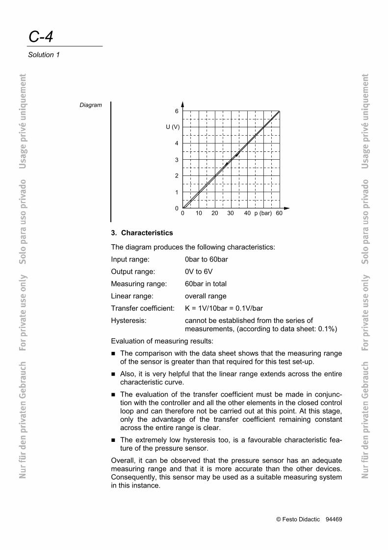
The diagram produces the following characteristics:
Input range: 0bar to 60bar
Output range: 0V to 6V
Measuring range: 60bar in total
Linear range: overall range
Transfer coefficient: K = 1V/10bar = 0.1V/bar
Hysteresis: cannot be established from the series of measurements, (according to data sheet: 0.1%)
Evaluation of measuring results:
The comparison with the data sheet shows that the measuring range of the sensor is greater than that required for this test set-up.
Also, it is very helpful that the linear range extends across the entire characteristic curve.
The evaluation of the transfer coefficient must be made in conjunc-tion with the controller and all the other elements in the closed control loop and can therefore not be carried out at this point. At this stage, only the advantage of the transfer coefficient remaining constant across the entire range is clear.
The extremely low hysteresis too, is a favourable characteristic fea-ture of the pressure sensor.
Overall, it can be observed that the pressure sensor has an adequate measuring range and that it is more accurate than the other devices. Consequently, this sensor may be used as a suitable measuring system in this instance.
Diagram
Related Documents