Clogging Indicators INNOVATIVE FLUID POWER 213 Purpose of Indicators Clogging indicators are warning devices that signal visually and/ or electrically that the filter element is filled with contaminants and should be changed or cleaned. These devices activate (trip) when the flow of fluid causes a pressure drop across the filter element that exceeds the indicator setting. In filters that incorporate bypass valves, contaminated fluid will bypass the element if the operator does not respond to the indicator warning signal within a reasonable time. In non-bypass filters, if the indicator warning is not heeded, the pressure across the filter will build up to the point where system performance is degraded, the element fails, or the system relief valve is actuated. The indicator is set to trip well before the element becomes fully clogged (14 psid / 1 bar lower than bypass), thereby giving the operator sufficient time to take corrective action. The indicator warning may be a visual signal at the filter site (pop-up button, light, etc.); or, some form of signal at a remote location (trouble light, sound alarm, etc.). In some critical applications, where contamination is intolerable, the signal from the indicator may be used to shut down the system so that personnel must immediately service the unit. Some users install filters without indicators, preferring instead to change and/or clean elements according to a fixed time schedule — or based on number of hours of operation. There is some risk in utilizing this approach. It may be difficult to establish a reliable schedule for installing new elements because the rate of dirt ingression is not known, and, in fact, may vary from time-to-time and from machine-to-machine. Use of a clogging indicator has two main benefits: first, it eliminates the need to guess when the element will clog; second, it avoids the unnecessary cost of replacing elements too soon. Indicator Settings In a majority of applications, a HYDAC indicator is set to trip at 15 psid (1 bar) below the bypass valve cracking pressure; or, for a non-bypass filter, at 15 psid below the element design changeout pressure. Typically, a HYDAC pressure filter bypass valve begins to crack at 87 psid (6 bar), so the indicator is set to trip at 72 psid (5 bar). A HYDAC return filter ordinarily begins to bypass at 43 psid (3 bar), so the indicator is set to trip at 29 psid (2 bar). Consequently, the operator has a period of time in which to change or clean the element before the bypass valve opens and passes contaminated fluid to sensitive components downstream of the filter. Typically, the time from indication to bypass is 5-15% of the life of the element. For instance, if the normal service life of the element is 100 days, there is a grace period of 5-15 days before the filter begins bypassing. Nevertheless, it is advisable to change the element as soon as the indicator trips. Non-standard indicator settings are often employed for various reasons. For instance, in lubrication systems, filters may not be allowed to have a high pressure drop, therefore, the indicator may be set to trip at less than 15 psid. When the filter is installed on the suction side of a pump, it is a common practice to limit the ∆P across the filter to 3 psid, and to set the indicator at a correspondingly low amount. Certain HYDAC non-bypass filters, such as the DFDK duplex series and DFZ series of sandwich filters, utilize indicators that are set at 116 psid (8 bar) in order to maximize the dirt retention and service life of the elements. In most cases, HYDAC pressure and return line filters bypass at higher pressures than other commonly used filters, meaning that indicator settings also are higher than usual. This has the advantage of extending element service life. Types of Indicators Filter assemblies may be ordered with or without indicators. When ordered with an indicator, the assembly model code includes a letter symbol for the indicator, such as B, C, or D. When ordered separately, an indicator has its own complete model code, as described subsequently in this brochure. A type B or BM visual indicator is suitable when only a local warning is required. When it is necessary to signal a remote warning device, control panel, or PLC, one of the electric switches should be specified. Various kinds of switches are available to provide a range of electrical configurations, contact ratings, and connections. The D indicator incorporates a switch and built-in light for both local and remote warning signals. Type Description B Visual Indicator with pop-up button or display that automatically resets after filter ∆P drops below trip- point BM Visual Indicator with pop-up button that must be manually reset after the indicator trips C, F, G, J, J4 Electric Switch that provides a contact operation to control a warning device or indication at a remote control station. Several models offer differing electrical ratings, contact configurations, and types of connections D Electric Switch and Light that provides a contact operation for control or indication to a remote location and a light energizes locally at the filter to indicate 100% Clogged E, ES Pressure Gauges with dial faces for local clogging indication UE Vacuum Gauge on suction filter for local indication UF, UG Vacuum Switch on suction filter that provides a contact operation for control or indication to a warning device or remote control station LE Electrical Switch with visual pop-up button LZ Electrical Switch with 75% and 100% contact operations, and local visual pop-up button at 100% clogged - optional LED’s GC, GW Electrical Analog (4 - 20 ma)/ Electrical switch with 75% and 100% warning points - optional LED’s K Vacuum / Pressure Gauge for Filler / Breather

Clogging Indicator
Oct 30, 2014
Welcome message from author
This document is posted to help you gain knowledge. Please leave a comment to let me know what you think about it! Share it to your friends and learn new things together.
Transcript

Clogging Indicators
INNOVATIVE FLUID POWER213
Purpose of IndicatorsClogging indicators are warning devices that signal visually and/or electrically that the filter element is filled with contaminants and should be changed or cleaned. These devices activate (trip) when the flow of fluid causes a pressure drop across the filter element that exceeds the indicator setting. In filters that incorporate bypass valves, contaminated fluid will bypass the element if the operator does not respond to the indicator warning signal within a reasonable time. In non-bypass filters, if the indicator warning is not heeded, the pressure across the filter will build up to the point where system performance is degraded, the element fails, or the system relief valve is actuated.
The indicator is set to trip well before the element becomes fully clogged (14 psid / 1 bar lower than bypass), thereby giving the operator sufficient time to take corrective action. The indicator warning may be a visual signal at the filter site (pop-up button, light, etc.); or, some form of signal at a remote location (trouble light, sound alarm, etc.). In some critical applications, where contamination is intolerable, the signal from the indicator may be used to shut down the system so that personnel must immediately service the unit.
Some users install filters without indicators, preferring instead to change and/or clean elements according to a fixed time schedule — or based on number of hours of operation. There is some risk in utilizing this approach. It may be difficult to establish a reliable schedule for installing new elements because the rate of dirt ingression is not known, and, in fact, may vary from time-to-time and from machine-to-machine. Use of a clogging indicator has two main benefits: first, it eliminates the need to guess when the element will clog; second, it avoids the unnecessary cost of replacing elements too soon.
Indicator SettingsIn a majority of applications, a HYDAC indicator is set to trip at 15 psid (1 bar) below the bypass valve cracking pressure; or, for a non-bypass filter, at 15 psid below the element design changeout pressure. Typically, a HYDAC pressure filter bypass valve begins to crack at 87 psid (6 bar), so the indicator is set to trip at 72 psid (5 bar). A HYDAC return filter ordinarily begins to bypass at 43 psid (3 bar), so the indicator is set to trip at 29 psid (2 bar). Consequently, the operator has a period of time in which to change or clean the element before the bypass valve opens and passes contaminated fluid to sensitive components downstream of the filter.
Typically, the time from indication to bypass is 5-15% of the life of the element. For instance, if the normal service life of the element is 100 days, there is a grace period of 5-15 days before the filter begins bypassing. Nevertheless, it is advisable to change the element as soon as the indicator trips.
Non-standard indicator settings are often employed for various reasons. For instance, in lubrication systems, filters may not be allowed to have a high pressure drop, therefore, the indicator may be set to trip at less than 15 psid. When the filter is installed on the suction side of a pump, it is a common practice to limit the ∆P across the filter to 3 psid, and to set the indicator at a correspondingly low amount.
Certain HYDAC non-bypass filters, such as the DFDK duplex series and DFZ series of sandwich filters, utilize indicators that are set at 116 psid (8 bar) in order to maximize the dirt retention and service life of the elements.
In most cases, HYDAC pressure and return line filters bypass at higher pressures than other commonly used filters, meaning that indicator settings also are higher than usual. This has the advantage of extending element service life.
Types of IndicatorsFilter assemblies may be ordered with or without indicators. When ordered with an indicator, the assembly model code includes a letter symbol for the indicator, such as B, C, or D. When ordered separately, an indicator has its own complete model code, as described subsequently in this brochure.
A type B or BM visual indicator is suitable when only a local warning is required. When it is necessary to signal a remote warning device, control panel, or PLC, one of the electric switches should be specified. Various kinds of switches are available to provide a range of electrical configurations, contact ratings, and connections.
The D indicator incorporates a switch and built-in light for both local and remote warning signals.
Type Description
B Visual Indicator with pop-up button or display that automatically resets after filter ∆P drops below trip-point
BM Visual Indicator with pop-up button that must be manually reset after the indicator trips
C, F, G, J, J4
Electric Switch that provides a contact operation to control a warning device or indication at a remote control station. Several models offer differing electrical ratings, contact configurations, and types of connections
D
Electric Switch and Light that provides a contact operation for control or indication to a remote location and a light energizes locally at the filter to indicate 100% Clogged
E, ES Pressure Gauges with dial faces for local clogging indication
UE Vacuum Gauge on suction filter for local indication
UF, UGVacuum Switch on suction filter that provides a contact operation for control or indication to a warning device or remote control station
LE Electrical Switch with visual pop-up button
LZElectrical Switch with 75% and 100% contact operations, and local visual pop-up button at 100% clogged - optional LED’s
GC, GWElectrical Analog (4 - 20 ma)/ Electrical switch with 75% and 100% warning points - optional LED’s
K Vacuum / Pressure Gauge for Filler / Breather

Clogging Indicators
INNOVATIVE FLUID POWER 214
Key FeaturesAutomatic vs. Manual Reset
All indicators with electric switches reset automatically to their original position when the pressure across the filter drops below trip pressure. This is true, also, for the type B visual indicator. However, on the type BM visual indicator with manual reset, the signal arm extends once the trip pressure is exceeded and remains that way until physically reset. The advantage is that the indicator signals that the element is dirty even after the system is shut down, thus, simplifying maintenance.
Thermal Lockout
When mobile and other equipment is started in the cold, the hydraulic or lube fluid is likely to be highly viscous until it approaches normal operating temperature. The high pressure drop created by a highly viscous fluid can trip the indicator and falsely signify that the element is clogged. An optional thermal lockout device, available on many HYDAC electric indicators, prevents the indicator from tripping until the fluid reaches a certain specified temperature. The device consists of a switch in series in the indicator circuit, which is caused to make or break by a bi-metal strip that alters in shape according to temperature.
The thermal lockout feature may be chosen so that the indicator is deactivated at a fluid temperature less than 100˚ F ±5˚ (called T100).
Because electric indicators automatically reset once the fluid heats up, thermal lockout is necessary only when a false signal of filter condition during cold start-up poses a problem.
Single Pole, Double Throw Switches (SPDT)
HYDAC’s differential pressure and most static pressure electrical indicators contain single-pole, double-throw switches. This provides the choice of normally open or normally closed contacts when the pressure differential is below trip-point.
Whether the contacts are normally open (N/O) or normally closed (N/C) is determined by the way in which the indicator is wired on site.
Magnetic Coupling
Most of HYDAC’s indicators employ magnetic coupling, which separates the fluid from the actuating device. The benefit is that there is no need for a dynamic seal, therefore, far less chance of fluid leakage under high system pressure.
InterchangeabilityHYDAC indicators are designed for use only with HYDAC filters, and should not be applied to other makes of filters.
Certain differential pressure indicators can be used in non-filter applications when mounted on special blocks. Detailed information regarding blocks of various kinds is presented subsequently in this brochure.
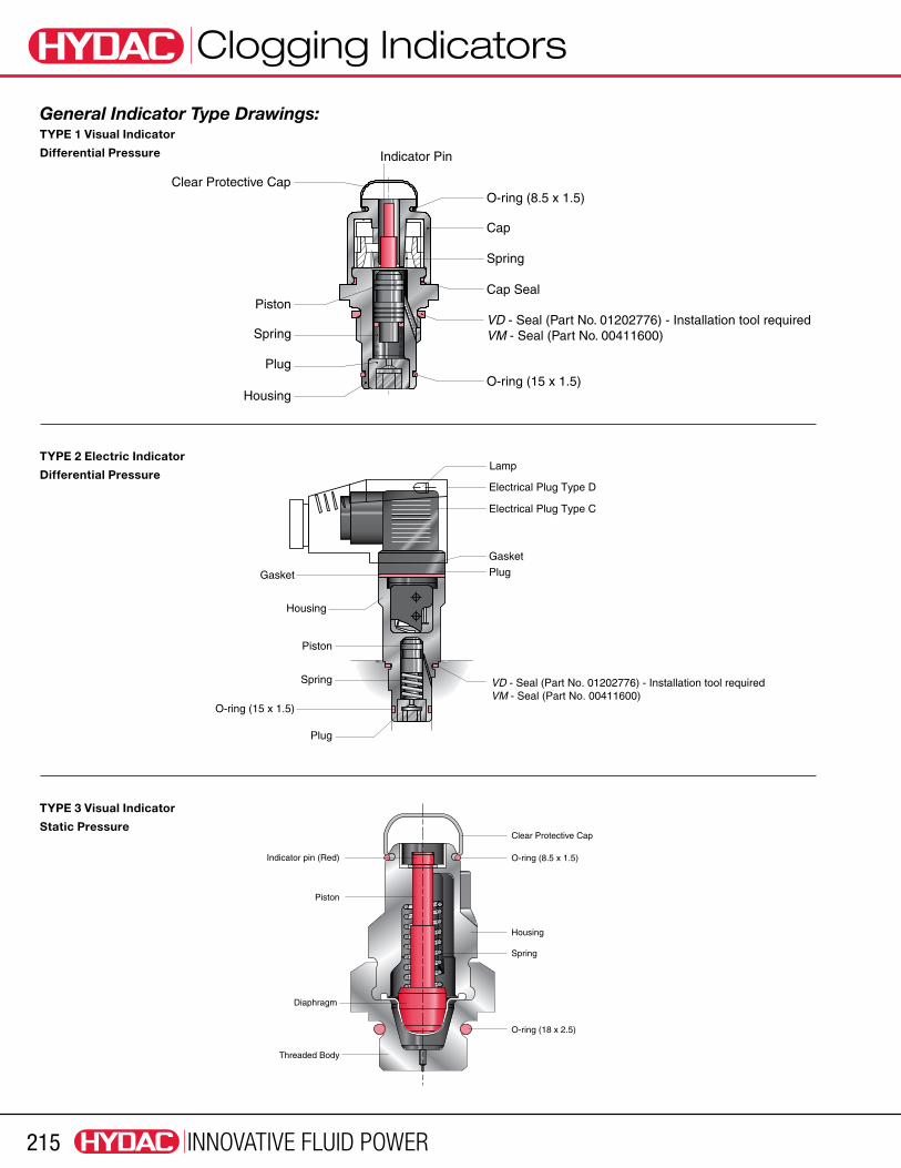
OperationIn the drawings on the following page, examples of two types of differential pressure indicators and a static pressure indicator are provided.
Application Guidelines
Differential pressure indicators react to the pressure drop across the filter that is caused by the flow of fluid through the filter housing and element. These devices measure the difference in pressure upstream and downstream of the filter element, regardless of the system pressure. They are utilized in most pressure and inline return filters.
Static pressure indicators measure only the build-up of pressure upstream of the filter element (downstream pressure is ambient - tank vented to atmosphere). Consequently, if any components are located downstream of the filter, the indicator will measure the pressure drop caused by the filter and that component, thus, causing a false reading of ∆P across the filter. As a result, static indicators are recommended only on filters that discharge directly to vented tanks and have minimal back pressure.
A filter that incorporates a differential pressure indicator should be used whenever there is a significant resistance to flow in the line after the filter, even when system pressure is relatively low. For example, the filter in the feed line of a lube system requires a differential pressure indicator, although the system pressure may be low.
Differential Pressure Indicator Operation
As the differential pressure across the filter increases, the piston / magnet assembly is driven down against a spring until the attractive force between the magnet and indicator pin (Type 1) or a switch actuator lever (Type 2) is reduced sufficiently to allow the indicator to trip. In a visual indicator (Type 1), tripping results in the indicator pin rising and giving visual indication that the filter must be serviced. In an electric indicator (Type 2), tripping causes a switch to make or break, permitting a remote indication to warn of the need for servicing. When the ∆P drops below the trip pressure for any reason, (installation of a clean element, heating of the oil, etc.), the piston/magnet assembly returns to its original position.
With a visual indicator, the pop-up indicator pin may then respond in one of two ways: (1) With Manual Reset (type BM) the pin remains extended, even after the system is shut down, and must be physically pushed down to reset (2) With Automatic Reset (type B) the indicator pin retracts to its original position along with the piston. With all electric indicators, the circuit is automatically restored to its original normally closed or normally open position once the ∆P drops below the trip setting.
Static Pressure Indicator Operation
Increasing pressure upstream of the filter acts upon a diaphragm in the indicator (Type 3) and causes the indicator pin to overcome an opposing spring force until it trips at a pre-set pressure. The indicator pin automatically resets once pressure is reduced below the trip pressure. Electric static pressure indicators, which also operate mechanically, are available as well. These, too, reset automatically.Note: certain indicators have a red/ yellow/ green display in addition to, or instead of, the pop-up indicator pin.
Clogging Indicators
INNOVATIVE FLUID POWER215
Clear Protective Cap
Indicator pin (Red) O-ring (8.5 x 1.5)
Spring
Piston
Housing
Diaphragm
O-ring (18 x 2.5)
Threaded Body
Lamp
Gasket
Electrical Plug Type D
Electrical Plug Type C
O-ring (15 x 1.5)
Plug
Gasket
Piston
Spring
Plug
Housing
VD - Seal (Part No. 01202776) - Installation tool requiredVM - Seal (Part No. 00411600)
O-ring (8.5 x 1.5)
O-ring (15 x 1.5)
Cap
Indicator Pin
Clear Protective Cap
Piston
Spring
Plug
Housing
VD - Seal (Part No. 01202776) - Installation tool required VM - Seal (Part No. 00411600)
Cap Seal
Spring
General Indicator Type Drawings:TYPE 1 Visual Indicator
Differential Pressure
TYPE 2 Electric Indicator
Differential Pressure
TYPE 3 Visual Indicator
Static Pressure

Clogging Indicators
INNOVATIVE FLUID POWER 216
Quick Reference GuideFilter Model Indicator Model Trip Pressure, psi [bar] Indicator Type Options
Low Pressure
RF VR 29 (2) (standard), 72 (5) (optional) A, B, FD, H, D, E, F, LE, LZ, GC
NF 1.0 (In-Tank Version) VR 29 (2) (standard), 72 (5) (optional) A, B, H, D, E, F, UE, GC
NF 2.0, 3.0 (Inline Version) VD, VM, VL 29 (2) (standard), 72 (5) (optional) A, B, C, D, LE, LZ, GC, GW
RFD VR 29 (2) (standard), 72 (5) (optional) A, B, H, D, E, F, LE, LZ, GC
NFD (In-Tank Version) VR 29 (2) (standard), 72 (5) (optional) A, B, H, D, E, F
NFD (Inline Version) VD, VM, VL 29 (2) (standard), 72 (5) (optional) A, B, C, D, LE, LZ, GC, GW
RFM VR (Sizes 30, 330-851), VMF (Sizes 75-270)
29 (2) (standard), 72 (5) (optional) W, A, B, BM, C, D, E, F, FD, H
HF4R(S) VMF 1 (0.08), 10 (0.8), 20 (1.4), 29 (2) A, C, E, G, J, J4, LE, LZ
RKM VMF 29 (2) (standard), 72 (5) (optional) W, A, E, F, FD, K, UF
RFM…S/Set Series N/A N/A W
RFL (Cast Series) VM, VD, VL 29 (2) (standard), 72 (5) (optional) A, B, BM, C, D, LE, LZ, GC, GW
RFL (Welded Series) VM, VD, VL 29 (2) (standard), 72 (5) (optional) A, B, BM, C, D, LE, LZ, GC, GW
FLN VM, VD 29 (2), 72 (5), 116 (8) A, B, C, D, LE, LZ
NFH VM, VD, VL 29 (2) (standard), 72 (5) (optional) A, B, BM C, D, J, J4, GC, GW
RFLD (Cast Series) VM, VD, VL 29 (2) (standard), 72 (5) (optional) A, B, BM C, D, LE, LZ, GC, GW
RFLD (Welded Series) VM, VD, VL 29 (2) (standard), 72 (5) (optional) A, B, BM C, D, LE, LZ, GC, GW
FLND VM, VD, VL 29 (2), 72 (5), 116 (8) A, B, C, D, LE, LZ
NFHD VM, VD, VL 29 (2) (standard), 72 (5) (optional) A, B, BM C, D, J, J4, GC, GW
Spin-ons - MF, MFD, MFDS VMF 20 (1.4), 29 (2) A, E, G, UE, UG, B, C, W
SF VR 3 (0.2) A, C, D, UE
MFX VL, VM 15 (1), 36 (2.5) W, A, B, C, CD, D, BF, M, J, J4
Medium Pressure
HF4RL VM, VD, VL 29 (2) (optional), 72 (5) (standard) A, B, BM, C, D, J, J4, LE, LZ, GC, GW
LPF VM, VD, VL, B..HFV (LPF 660) 29 (2) (optional), 72 (5) (standard) A, B, BM, BF C, CD, D, J, J4, LE, LZ, GC, GW
LF VM, VD, VL 29 (2) (optional), 72 (5) (standard) A, B, BM, C, CD, D, J, J4, LE, LZ, GC, GW
FMND VD 29 (2) (optional), 72 (5) (standard) A, B, C, D, J, J4, LE, LZ, GC
High Pressure
DF VD 29 (2), 72 (5) (standard), 116 (8) A, B, BM, C, D, J, J4, LE, LZ, GC
DF/DFF 1500 VD 29 (2), 72 (5), 116 (8) A, B, BM, C, D, J, J4, LE, LZ, GC
HF2P VD 29 (2), 72 (5) (standard), 116 (8) A, B, BM, C, D, J, J4, LE, LZ, GC
HF3P VD 29 (2), 72 (5) (standard), 116 (8) A, B, BM, C, D, J, J4, LE, LZ, GC
HF4P VD 29 (2), 72 (5) (standard), 116 (8) A, B, BM, C, D, J, J4, LE, LZ, GC
MFM VD 72 (5) W, A, B, BM, C, CD, D, J, J4, LE, LZ, GC
HFM VD 72 (5) W, A, B, BM, C, CD, D, J, J4, LE, LZ, GC
DFDK VD 116 (8) A, B, BM, C, D, J, J4, LE, LZ, GC
HFDK4P VD 72 (5), 116 (8) (standard) B, BM, C, D, J, J4, LE, LZ, GC
DFFH VD 29 (2), 72 (5) (standard) A, B, BM, C, D, J, J4, LE, LZ, GC
DFFHM VD 29 (2), 72 (5) (standard) A, B, BM, C, D, J, J4, LE, LZ, GC
DF…QE VD 29 (2), 72 (5) (standard) A, B, BM, C, D, J, J4, LE, LZ, GC
DFP VD 29 (2), 72 (5) (standard) A, B, BM, C, D, J, J4, LE, LZ, GC
DFZ VD 116 [8] A, B, BM, C, D, J, J4, LE, LZ, GC
CF N/A N/A W
CP-C16 N/A N/A W
CP-SAE N/A N/A W

Clogging Indicators
INNOVATIVE FLUID POWER217
Model Code: Static VacuumVR 0.2 B . X / .
Indicator Prefix VR = Clogging Indicator for Return FiltersTrip Pressure / Gauge Indication Range 0.2 = 3 psi (0.2 bar) (standard for UE vacuum gauge and UF vacuum switch for suction filters) 2 = 29 psid (2 bar) (standard for VR and VMF indicators on return filters except spin-ons) 5 = 72 psid (5 bar) (optional on VR and VMF indicators)(types B,D,F, & H only)
Type of Indicator B = Visual pop-up with automatic reset BM = Visual pop-up with manual reset D = Electric switch and light E/ES = Horizontal gauge / Vertical gauge F = Electric pressure switch GC = Electronic Analog (4 - 20ma or 1 - 10V) / pressure switch 75% and 100% trips H = Electric pressure switch LE = Electric pressure switch / Visual pop-up button LZ = Electric pressure switch at 75% and 100% / visual pop-up button UE = Vacuum gauge UF = Vacuum switchModification Number (the latest version always supplied)
Supplementary Details Light Voltage (D type indicators only)
L24 = 24V L110 = 110V Seals (omit) = Nitrile (NBR) (standard) V = Fluoroelastomer (FPM) EPR = Ethylene Propylene (EPDM) (not available on VR2B or VR2BM) “LZ” type details (for type LZ only - omit for all other types) CN = electrical connection, 1 plug connector to DIN 43651 with 3 LED’s (to CNOMO standard) DB = electrical connection, 1 plug connector to DIN 43651 with 3 LED’s (to Daimler-Benz standard)
“GC” type details (for type GC only - omit for all other types) SP = analogue signal: voltage output 1-10V if SP or SQ not specified SQ = analogue signal: voltage output 4-20mA (current source) “current sink” model supplied 13 = N/O function pressure peak suppression up to 10 sec. cold start suppression 123 = N/C function of switching outputs (PNP technique, positive switching) LED = 3 LED’s (red, green, yellow) in cable box PF = floating switching outputs (due to relay in the plug) 30C = cold start suppression of switching outputs up to 30˚C (other temperatures on request)
VMF 0.2 B . X / .Indicator Prefix VMF = Clogging Indicator for Mobile Filters BSF = Clogging Indicator for Suction FiltersTrip Pressure / Gauge Indication Range 0.2 = 3 psi (0.2 bar) (standard for VMF UF & UE and BSF indicators used on suction filters) 0.6 = 9 psid (0.6 bar) (applies to K gauge only) 0.8 = 12 psid (.8 bar) (applies to VMF0.8E gauge only) 1 = 15 psid (1 bar) (non-standard) 1.4 = 20 psid (1.4 bar) (standard for VMF1.4E gauges and VMF1.4G switches on nominal spin-on filters)(1 1.6 = 23 psid (1.6 bar) (applies to VMF1.6E gauge only) 1.7 = 25 psid (1.7 bar) (standard for VMF1.7G switch for absolute spin-ons) 2 = 29 psid (2 bar) (standard for VR and VMF indicators on return filters except spin-ons) 5 = 72 psid (5 bar) (optional on VR and VMF indicators)(types B,D,F, & H only)Type of Indicator(2 B = Visual pop-up with automatic reset (VMF only) C = Electric switch D = Electric switch and light E = Horizontal gauge ES = Vertical gauge F,G,& H = Electric pressure switches (VMF only) UE = Vacuum gauge UF = Vacuum switch K = Gauge (for reservoir breathers)(3
Modification Number (the latest version always supplied)Supplementary Details Light Voltage (D type indicators only) L24 = 24V L110 = 110V Seals (omit) = Nitrile (NBR) (standard) V = Fluoroelastomer (FPM) EPR = Ethylene Propylene (EPDM)(3
1) MFBN 80/85 absolute rated spin-ons use VMF1.4G.0 indicators 2) VMF indicators are available in all types except types C and K. BSF indicators are available only on types C and D 3) EPR seals are not available with VMF2B indicators. Model K gauges are available only with nitrile (NBR) seals

Clogging Indicators
INNOVATIVE FLUID POWER 218
Static Pressure Indicators for Return Filters and Vacuum Indicators for Suction Filters
General Information
Model Code VR2B.0 & VR2BM.0 VR2C.1 VR2D.1
Method of Indication
Visual: Red pin pops up to signal clogged element. Type B: Automatic Reset Type BM: Manual Reset
Electric: Electric switch activates to indicate 100% clogged element.
Visual: LED energizes for local 100% Clogged Indication. Electrical Contact: N/O or N/C Contact at 100%
Port Connection G1/2 (ISO 228) G1/2 (ISO 228) G1/2 (ISO 228)
Adapter — included, VR-1/8-S P/N 00246881
included, VR-1/8-S P/N 00246881
Housing Material aluminum steel aluminum
Seals nitrile (NBR) - standard fluoroelastomer (FPM)
nitrile (NBR) - standard fluoroelastomer (FPM) ethylene propylene (EPR)
nitrile (NBR) - standard fluoroelastomer (FPM) ethylene propylene (EPR)
Weight 0.18 lbs (80 grams) 0.31 lbs (140 grams) 0.84 lbs (380 grams)
Torque Rating 11 Lbf-ft 11 Lbf-ft 11 Lbf-ft
Other Characteristics — Trip Pressure adjustable from 15 psi to 145 psi
Trip Pressure factory adjustable from 10 psi to 130 psi
Hydraulic Data
Operating Pressure 100 psi (7 bar) 290 psi (20 bar) 290 psi (20 bar)
Trip Pressure (or Indication Range)
29 psi (2 bar) -10% (contact HYDAC for special settings from 15 psi to 120 psi)
29 psi (2 bar) -15%29 psi (2 bar) -10% (contact HYDAC for special settings from 15 psi to 120 psi)
Thermal Lockout not available — not available
Temperature Range -22°F to 250°F (-30°C to 121°C) -22°F to 250°F (-30°C to 121°C) -22°F to 250°F (-30°C to 121°C)
Electrical Data
Contact Voltage max. — 250 VAC or 24 VDC 250 VAC or 24 VDC
Maximum Induction-free Power Rating — 5 A at 250 VAC
4 A at 24 VDC5 A at 250 VAC 4 A at 24 VDC
Lamp / LED Supply Voltage — — 24 VDC 110/220 VAC
Electrical Connection — M20 x 1.5mm M20 x 1.5mm
Switching Type — Normally Open and Normally Closed Contacts (SPDT)
Normally Open and Normally Closed Contacts (SPDT)
Insulation — IP65, Terminal IP00 IP65
Other Electrical Data — for high voltage, low amperage (See Type GW schematic on page 237)
Optional voltages for indicator light: 24V or 110V (See Type D schematic on page 237)
Note: Applicable Filters - see page 216, Quick Reference Guide.
Clogging Indicators
INNOVATIVE FLUID POWER219
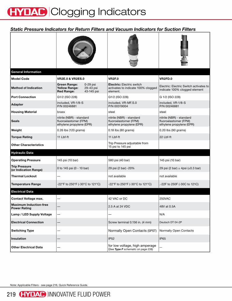
Static Pressure Indicators for Return Filters and Vacuum Indicators for Suction Filters
General Information
Model Code VR2E.0 & VR2ES.0 VR2F.0 VR2FD.0
Method of IndicationGreen Range: 0-29 psi Yellow Range: 29-43 psi Red Range: 43-145 psi
Electric: Electric switch activates to indicate 100% clogged element.
Electric: Electric Switch activates to indicate 100% clogged element
Port Connection G1/2 (ISO 228) G1/2 (ISO 228) G 1/2 (ISO 228)
Adapter included, VR-1/8-S P/N 00246881
included, VR-MF.S.0 P/N 00319004
included, VR-1/8-S P/N 00246881
Housing Material brass steel steel
Sealsnitrile (NBR) - standard fluoroelastomer (FPM) ethylene propylene (EPR)
nitrile (NBR) - standard fluoroelastomer (FPM) ethylene propylene (EPR)
nitrile (NBR) - standard fluoroelastomer (FPM) ethylene propylene (EPR)
Weight 0.26 lbs (120 grams) 0.18 lbs (80 grams) 0.20 lbs (90 grams)
Torque Rating 11 Lbf-ft 11 Lbf-ft 22 Lbf-ft
Other Characteristics Trip Pressure adjustable from 15 psi to 145 psi
Hydraulic Data
Operating Pressure 145 psi (10 bar) 580 psi (40 bar) 145 psi (10 bar)
Trip Pressure (or Indication Range) 0 to 145 psi (0 - 10 bar) 29 psi (2 bar) -20% 29 psi (2 bar) ± 4psi (±0.3 bar)
Thermal Lockout — not available not available
Temperature Range -22°F to 250°F (-30°C to 121°C) -22°F to 250°F (-30°C to 121°C) .-22F to 250F (-30C to 121C)
Electrical Data
Contact Voltage max. — 42 VAC or DC 250VAC
Maximum Induction-free Power Rating — 2.5 A at 24 VDC 48V at 0.5A
Lamp / LED Supply Voltage — — N/A
Electrical Connection — Screw terminal 0.156 in. (4 mm) Deutsch DT 04-2P
Switching Type — Normally Open Contacts (SPST) Normally Open Contacts
Insulation — IP52 IP65
Other Electrical Data — for low voltage, high amperage (See Type F schematic on page 238)
—
Note: Applicable Filters - see page 216, Quick Reference Guide.

Clogging Indicators
INNOVATIVE FLUID POWER 220
Static Pressure Indicators for Return Filters and Vacuum Indicators for Suction Filters
General Information
Model Code VR2GC.0 VR2LE.0 VR2LZ.0
Method of Indication
Electric: Electronic-analog (4-20 ma) and two electrical switches at 75% and 100% clogged.
Electric: Electric switch activates to indicate 100% clogged element. Visual: Red pin pops up to indicate 100% clogged element.
Electric: 2 electric switches activate to indicate 75% & 100% clogged element. Visual: Red pin pops up to indicate 100% clogged element.
Port Connection G1/2 (ISO 228) G1/2 (ISO 228) G1/2 (ISO 228)
Adapter — —
Housing Material steel steel
Sealsnitrile (NBR) - standard fluoroelastomer (FPM) ethylene propylene (EPR)
nitrile (NBR) - standard fluoroelastomer (FPM) ethylene propylene (EPR)
nitrile (NBR) - standard fluoroelastomer (FPM) ethylene propylene (EPR)
Weight 0.75 lbs (340 grams) 0.54 lbs (245 grams) 0.67 lbs (305 grams)
Torque Rating 11 Lbf-ft 11 Lbf-ft 11 Lbf-ft
Other Characteristics — —
Hydraulic Data
Operating Pressure 100 psi (7 bar) 100 psi (7 bar) 100 psi (7 bar)
Trip Pressure (or Indication Range) 29 psi (2 bar) -20% 29 psi (2 bar) -20% 29 psi (2 bar) -15%
Thermal Lockout optional not available not available
Temperature Range -22°F to 250°F (-30°C to 121°C) -22°F to 250°F (-30°C to 121°C) -22°F to 250°F (-30°C to 121°C)
Electrical Data
Contact Voltage max. 20-30 VDC 115 VAC 24 VDC
Maximum Induction-free Power Rating
6 A at 220 VAC 6 A at 24 VDC 1 A at 15 VAC 1 A at 15 VAC
Lamp / LED Supply Voltage — — 24 VDC
Electrical Connection 7 pin plug connector to DIN 43651 M20 x 1.5mm M20 x 1.5mm
Switching Type Normally Open and Normally Closed Contacts (SPDT)
Normally Open and Normally Closed Contacts (SPDT) reed contacts
Normally Open (75% alarm) (SPST) Normally Closed (100% alarm) (SPST) reed contacts
Insulation IP65 IP65 IP65
Other Electrical Data See Type GC schematic on page 227for low voltage, high amperage (See Type LE schematic on page 228)
for low voltage, high amperage (See Type LZ schematic on page 228)
Note: Applicable Filters - see page 216, Quick Reference Guide.

Clogging Indicators
INNOVATIVE FLUID POWER221
Static Pressure Indicators for Return Filters and Vacuum Indicators for Suction Filters
General Information
Model Code VMF2B.0 VMF2D.0/L… & VMF5D.0/L… VMF2F.0
Method of IndicationVisual: Red pin pops up to indicate 100% clogged element. resets automatically.
Visual/Electric: Electric switch and light activate to indicate 100% clogged element.
Electric: Electric switch activates to indicate 100% clogged element.
Port Connection G1/8” G1/8” G1/8” male
Adapter — — —
Housing Material aluminum aluminum steel
Seals nitrile (NBR) - standard fluoroelastomer (FPM)
nitrile (NBR) - standard fluoroelastomer (FPM) ethylene propylene (EPR)
nitrile (NBR) - standard fluoroelastomer (FPM) ethylene propylene (EPR)
Weight 0.26 lbs (120 grams) 0.77 lbs (350 grams) 0.80 lbs (365 grams)
Torque Rating 11 Lbf-ft 11 Lbf-ft 11 Lbf-ft
Other Characteristics Trip Pressure adjustable from 10 psi to 130 psi —
Hydraulic Data
Operating Pressure 100 psi (7 bar) 580 psi (40 bar) 580 psi (40 bar)
Trip Pressure (or Indication Range)
29 psi (2 bar) -10% (contact HYDAC for special settings from 15 psi to 120 psi)
29 psi (2 bar) -10% (contact HYDAC for special settings from 15 psi to 120 psi)
29 psi (2 bar) -20% (contact HYDAC for special settings from 15 psi to 120 psi)
Thermal Lockout not available not available —
Temperature Range -22°F to 250°F (-30°C to 121°C) -22°F to 250°F (-30°C to 121°C) -22°F to 250°F (-30°C to 121°C)
Electrical Data
Contact Voltage max. — 220 VAC or 24 VDC 42 VAC or VDC
Maximum Induction-free Power Rating — 6 A at 220 VAC
6 A at 24 VDC 2.5 A at 24 VDC
Lamp / LED Supply Voltage — 24 VDC 110/220 VAC —
Electrical Connection — M20 x 1.5mm Screw terminal 0.156 in. (4 mm)
Switching Type — Normally Open and Normally Closed Contacts (SPDT)
Normally Open Contacts (SPST)
Insulation — IP65 IP65, Terminal IP00
Other Electrical Data —Optional voltages for indicator light: 24 V or 110 V (See Type F schematic on page 238)
for high voltage, low amperage (See Type F schematic on page 238)
Note: Applicable Filters - see page 216, Quick Reference Guide.

Clogging Indicators
INNOVATIVE FLUID POWER 222
Static Pressure Indicators for Return Filters and Vacuum Indicators for Suction Filters
General Information
Model Code VMF2FD.0 VMF2C.1 & VMF5C.1 VMF0.2UF.0
Method of Indication Electric: Electric Switch activates to indicate 100% clogged element
Electric: Electric switch activates to indicate 100% clogged element.
Electric: Electric vacuum switch activates at vacuum setting to indicate 100% clogged element.
Port Connection G1/8” G1/8” G1/8” male
Adapter — HF4R 1/8NPT male x M10x1 female RKM G1/8 male x M10x1 female HF4S 1/8NPT male x M10x1 female
Housing Material steel steel steel
Sealsnitrile (NBR) - standard fluoroelastomer (FPM) ethylene propylene (EPR)
nitrile (NBR) - standard fluoroelastomer (FPM) ethylene propylene (EPR)
nitrile (NBR) - standard fluoroelastomer (FPM) ethylene propylene (EPR)
Weight 0.16 lbs (70 grams) 0.26 lbs (120 grams) 0.34 lbs (155 grams)
Torque Rating 22 Lbf-ft 11 Lbf-ft 11 Lbf-ft
Other Characteristics — Trip Pressure adjustable from 3 psi to 96 psi
Indicator mounts after element to measure vacuum before pump
Hydraulic Data
Operating Pressure 160 psi (11 bar) 290 psi (20 bar) 300 psi (20 bar)
Trip Pressure (or Indication Range) 29 psi (2 bar) -10%
29 psi (2 bar) -10% (contact HYDAC for special settings from 15 psi to 120 psi)
-3 psi (0.2 bar) -0.2 bar (contact HYDAC for special settings from 15 psi to 120 psi)
Thermal Lockout not available not available not available
Temperature Range -22°F to 250°F (-30°C to 121°C) -22°F to 250°F (-30°C to 121°C) -22°F to 250°F (-30°C to 121°C)
Electrical Data
Contact Voltage max. 250 VAC 250 VAC or 24 VDC 42 VAC or VDC
Maximum Induction-free Power Rating
5 A at 250 VAC, 3A at 12, 24 VDC, 1 A at 60VDC
5 A at 250 VAC 4 A at 24 VDC 2.5 A at 24 VDC
Lamp / LED Supply Voltage — — —
Electrical Connection Deutsch DT 04-2P M20 x 1.5mm Screw terminal 0.156 in. (4 mm)
Switching Type Normally Open Contacts Normally Open and Normally Closed Contacts (SPDT)
Normally Open Contacts (SPST)
Insulation IP65 IP65, terminals IP00 IP65, Terminal IP00
Other Electrical Data — — (See Type UF schematic on page 238)
Note: Applicable Filters - see page 216, Quick Reference Guide.

Clogging Indicators
INNOVATIVE FLUID POWER223
Static Pressure Indicators for Return Filters and Vacuum Indicators for Suction Filters
General Information
Model Code VMF2E.0 VMF...E.0/3 VMF1.4G.0/3
Method of Indication
Visual: 3 color gauge Green Range: 0-29 psi Yellow Range: 29-43 psi Red Range: 43-145 psi
Visual: 3 color gauge Green Range: 0-12 / 0-20 psi Yellow Range: 12-15 / 20-25 psi Red Range: 15-60 / 25-60 psi
Electric: Electric switch activates to indicate 100% clogged element.
Port Connection G1/8” 1/8 NPT male 1/8 NPT male
Adapter — — —
Housing Material brass brass steel
Seals — — nitrile (NBR) - standard
Weight 0.23 lbs (105 grams) 0.23 lbs (105 grams) 0.195 lbs (88.5 grams)
Torque Rating 11 Lbf-ft 11 Lbf-ft 11 Lbf-ft
Other Characteristics — — Trip Pressure adjustable from 10 psi to 24 psi
Hydraulic Data
Operating Pressure 145 psi (10 bar) 60 psi (4 bar) 150 psi (10 bar)
Trip Pressure (or Indication Range) 29 psi (2 bar) VMF0.8E.0: 0 to 12 psi
VMF1.4E.0: 0 to 20 psi 20 psi (1.3 bar)
Thermal Lockout — — not available
Temperature Range -22°F to 250°F (-30°C to 121°C) -22°F to 250°F (-30°C to 121°C) -22°F to 250°F (-30°C to 121°C)
Electrical Data
Contact Voltage max. — — 240 VAC or 24 VDC
Maximum Induction-free Power Rating — —
0.5 A at 240 VAC 4 A at 24 VDC 9 mA at 24 VDC
Lamp / LED Supply Voltage — — —
Electrical Connection — — #8 - 32 screw terminals
Switching Type — — Normally Open Contacts (SPST)
Insulation — — —
Other Electrical Data — — (See Type G schematic on page 237
Note: Applicable Filters - see page 216, Quick Reference Guide.

Clogging Indicators
INNOVATIVE FLUID POWER 224
Static Pressure Indicators for Return Filters and Vacuum Indicators for Suction Filters
General Information
Model Code VMF1.7G.0/3 VMF0.2UE.0/3
Method of IndicationElectric: Electric switch activates to indicate 100% clogged element.
Visual: Vacuum gauge
Port Connection 1/8 NPT Male 1/8 NPT male
Adapter — —
Housing Material steel brass
Seals nitrile (NBR) - standard —
Weight 0.195 lbs (88.5 grams) 0.23 lbs (105 grams)
Torque Rating 11 Lbf-ft 11 Lbf-ft
Other Characteristics — Trip Pressure factory adjustable from 10 psi to 130 psi
Hydraulic Data
Operating Pressure 150 psi (10 bar) 0 psi (0 bar)
Trip Pressure (or Indication Range)
29 psi (2 bar) -10% (contact HYDAC for special settings from 15 psi to 120 psi)
-14.5 to 0 psi (-1 to 0 bar) -10%
Thermal Lockout not available —
Temperature Range -22°F to 250°F (-30°C to 121°C) -22°F to 250°F (-30°C to 121°C)
Electrical Data
Contact Voltage max. 240 VAC or 24 VDC —
Maximum Induction-free Power Rating
0.5 A at 220 VAC 4 A at 24 VDC —
Lamp / LED Supply Voltage #8-32 Screw Terminals —
Electrical Connection Normally Open Contacts (SPST) —
Switching Type — —
Insulation — —
Other Electrical Data (See Type G schematic on page 237) —
Note: Applicable Filters - see page 216, Quick Reference Guide.

Clogging Indicators
INNOVATIVE FLUID POWER225
Static Pressure Indicators for Return Filters and Vacuum Indicators for Suction Filters
General Information
Model Code BSF0.2C.0 BSF0.2D.0/L...
Method of IndicationElectric: Electric switch activates to indicate that filter is in bypass
Visual/Electric: Electric switch and light activate to indicate that filter is in bypass
Port Connection G1/2 (ISO 228) G1/2 (ISO 228)
Adapter — —
Housing Material aluminum aluminum
Sealsnitrile (NBR) - standard fluoroelastomer (FPM) ethylene propylene (EPR)
nitrile (NBR) - standard fluoroelastomer (FPM) ethylene propylene (EPR)
Weight 0.31 lbs (140.6 grams) 0.365lbs (165.6 grams)
Torque Rating 11 Lbf-ft 11 Lbf-ft
Other Characteristics — —
Hydraulic Data
Operating Pressure 3000 psi (210 bar) 3000 psi (210 bar)
Trip Pressure (or Indication Range) 3 psi (0.2 bar) 3 psi (0.2 bar)
Thermal Lockout not available not available
Temperature Range -22°F to 250°F (-30°C to 121°C) -22°F to 250°F (-30°C to 121°C)
Electrical Data
Contact Voltage max. 250 VAC 250 VAC
Maximum Induction-free Power Rating 5 A at 250 VAC 5 A at 250 VAC
Lamp / LED Supply Voltage — —
Electrical Connection M 20 x 1.5mm M 20 x 1.5mm
Switching Type Normally Open and Normally Closed Contacts (SPDT)
Normally Open and Normally Closed Contacts (SPDT)
Insulation IP65 IP65
Other Electrical Data (See Type C schematic on page 237)Optional voltages for indicator light: 24V or 110 V (See Type D schematic on page 237)
Note: Applicable Filters - see page 216, Quick Reference Guide.

Clogging Indicators
INNOVATIVE FLUID POWER 226
Static Pressure Indicators for Return Filters and Vacuum Indicators for Suction Filters
General Information
Model Code VR0.2UE.0 VR0.2UF.0 VMF0.6K.0
Method of Indication Visual: Vacuum gauge including graduated scale
Electric: Electric switch activates to indicate 100% clogged element
Visual: Gauge includes graduated scale
Port Connection G1/2 (ISO 228) G1/2 (ISO 228) G1/8”
Adapter included, G1/2 male x 1/8NPTF P/N 02067828
included, VR-1/8-S P/N 00246881 —
Housing Material brass brass aluminum
Sealsnitrile (NBR) - standard fluoroelastomer (FPM) ethylene propylene (EPR)
nitrile (NBR) - standard fluoroelastomer (FPM) ethylene propylene (EPR)
nitrile (NBR) - standard
Weight 0.23 lbs (105 grams) 0.34 lbs (155 grams) 0.21 lbs (100 grams)
Torque Rating 11 Lbf-ft 11 Lbf-ft 11 Lbf-ft
Other Characteristics — — —
Hydraulic Data
Operating Pressure 0 psi (0 bar) 0 psi (0 bar) 8.7 psi (0.6 bar)
Trip Pressure (or Indication Range)
-14.5 to 0 psi (-1 to 0 bar) (contact HYDAC for special settings from 15 psi to 120 psi)
-3 psi (-0.2 bar) (contact HYDAC for special settings from 15 psi to 120 psi)
-15 psi to +8.7 psi (-1 bar to + 0.6 bar)
Thermal Lockout — — —
Temperature Range -22°F to 250°F (-30°C to 121°C) -22°F to 250°F (-30°C to 121°C) -22°F to 250°F (-30°C to 121°C)
Electrical Data
Contact Voltage max. — 42 VAC or VDC —
Maximum Induction-free Power Rating — 2.5 A at 42 V —
Lamp / LED Supply Voltage — — —
Electrical Connection — Screw Terminal 0.156 in. (4mm) —
Switching Type — Normally Open Contacts (SPST) —
Insulation — IP65, terminals IP00 —
Other Electrical Data — For low voltage, high amperage (See Type UF schematic on page 238)
—
Note: Applicable Filters - see page 216, Quick Reference Guide.

Clogging Indicators
INNOVATIVE FLUID POWER227
Model Code: Differential Pressure IndicatorsVM 5 B . X / .
Indicator Prefix VM = G 1/2 3000 psi VD = G 1/2 6000 psi VL = G 1/2 360 psiTrip Pressure / Gauge Indication Range 1 = 15 psi (1 bar) (optional for typically for lube applications) 2 = 29 psid (2 bar) (standard for use on return line filters) 5 = 72 psid (5 bar) (standard for use on pressure filters, except DFDK & DFZ) 8 = 116 psid (8 bar) (standard for use on DFDK filters & DFZ)
Type of Indicator B = Visual pop-up with automatic reset (VD & VM only) BM = Visual pop-up with manual reset (VD & VM only) C = Electric switch (VD, VM, VD...T, & VMH...T only) D = Electric switch and light (VD, VM, VD...T, & VMH...T only) GC = Electronic Analog (4-20ma or 1-10V) / pressure switch 75% and 100% trips (VD only) GW = Electronic Analog (4-20ma or 1-10V) / pressure switch 75% and 100% trips & bypass monitoring (VL only) J = Electric switch (Brad Harrison 5-pin mini connection) (VDH only) J4 = Electric switch (Brad Harrison 4-pin micro connection) (VDH & VMH only) LE = Electric pressure switch / Visual pop-up button (VD only) LZ = Electric pressure switch at 75% and 100% / visual pop-up button (VD only)
Modification Number (latest version always supplied)
Supplementary Details Seals (omit)= Nitrile (NBR) (standard) V = Fluoroelastomer (FPM) EPR = Ethylene Propylene (EPDM) Light Voltage (D type indicators only) L24 = 24V L110 = 110V “LZ” type details (for type LZ only - omit for all other types) CN = electrical connection, 1 plug connector to DIN 43651 with 3 LED’s (to CNOMO standard) DB = electrical connection, 1 plug connector to DIN 43651 with 3 LED’s (to Daimler-Benz standard) BO = (M12x1) Brad Harrison 4-pin micro connection “GC” type details (for type GC only - omit for all other types) SP = analogue signal: voltage output 1-10V if SP or SQ not specified SQ = analogue signal: voltage output 4-20mA (current source) “current sink” model supplied 113 = N/O function pressure peak suppression up to 10 sec. cold start suppression 123 = N/C function of switching outputs (PNP technique, positive switching)
LED = 3 LED’s (red, green, yellow) in cable box PF = floating switching outputs (due to relay in the plug) 30C = cold start suppression of switching outputs up to 30˚C (other temperatures on request)
Thermal Lockout (VM, VD types C, D, J, and J4 only) T100 = Lockout below 100°FUnderwrighters Approval CRUUS = Electrical Indicators VMC, VMD, VMJ, VMJ4, VDC, VDD, VDJ, VDJ4
B 2 210 B HF V / .Indicator Prefix B = 3/4 - 16 UNF Thread (SAE - Ported)
Trip Pressure / Gauge Indication Range 1 = 15 psi (1 bar) (optional for typically for lube applications) 2 = 29 psid (2 bar) (standard for B indicators use on return line filters) 5 = 72 psid (5 bar) (standard for B indicators use on pressure filters, except DF-ZS0104H) 8 = 120 psid (8 bar) (standard for B indicators use on DF-ZS0104H)
Operating Pressure 210 = 3000 psi (210 bar) (B & BE not available) 420 = 6000 psi (420 bar)Type of Indicator B = Visual pop-up with automatic reset BM = Visual pop-up with manual reset C = Electric switch D = Electric switch and light J = Electric switch (Brad Harrison 5-pin mini connection) J4 = Electric switch (Brad Harrison 4-pin micro connection)
Application HF = Hydraulic filtersSeals V = Fluoroelastomer (FPM) (standard) EPR = Ethylene Propylene (EPDM)Supplementary Details Light Voltage (D type indicators only) L24 = 24V L110 = 110V Thermal Lockout (types C, D, J, and J4 only) T100 = Lockout below 100˚F
Clogging Indicators
INNOVATIVE FLUID POWER 228
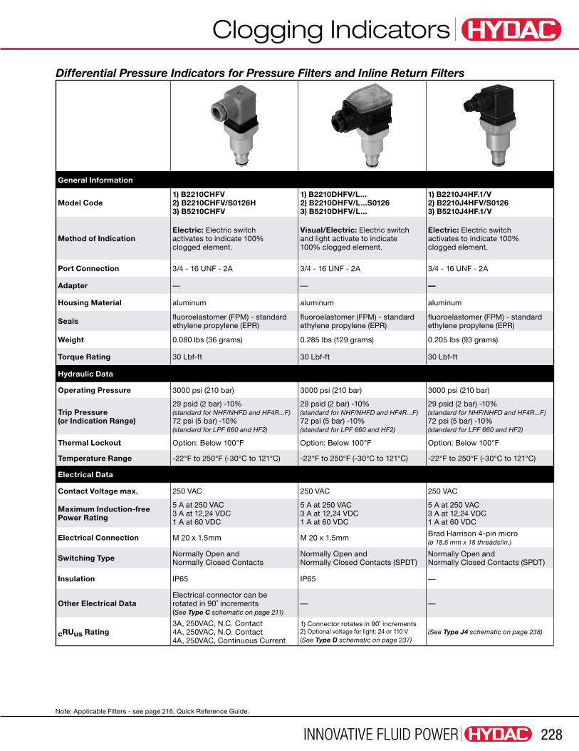
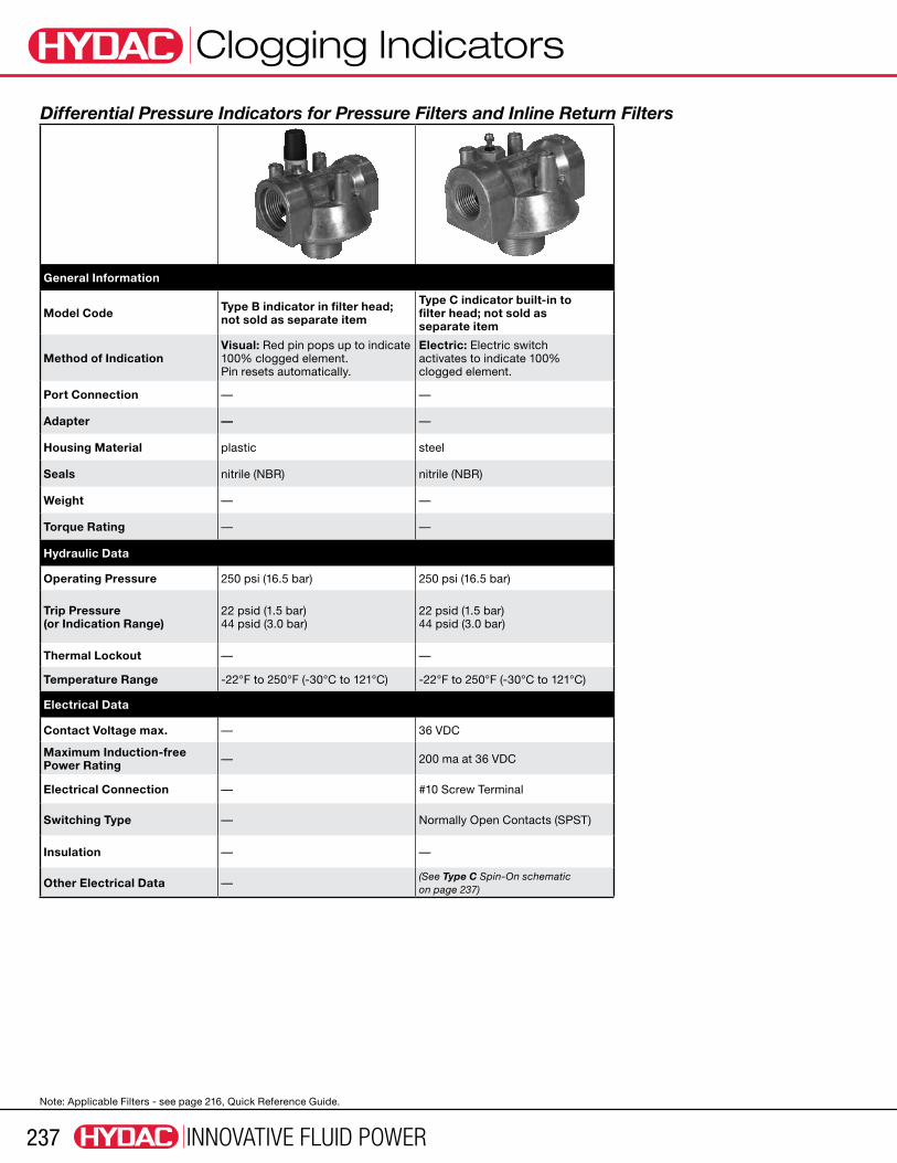
Differential Pressure Indicators for Pressure Filters and Inline Return Filters
General Information
Model Code1) B2210CHFV 2) B2210CHFV/S0126H 3) B5210CHFV
1) B2210DHFV/L... 2) B2210DHFV/L...S0126 3) B5210DHFV/L...
1) B2210J4HF.1/V 2) B2210J4HFV/S0126 3) B5210J4HF.1/V
Method of IndicationElectric: Electric switch activates to indicate 100% clogged element.
Visual/Electric: Electric switch and light activate to indicate 100% clogged element.
Electric: Electric switch activates to indicate 100% clogged element.
Port Connection 3/4 - 16 UNF - 2A 3/4 - 16 UNF - 2A 3/4 - 16 UNF - 2A
Adapter — — —
Housing Material aluminum aluminum aluminum
Seals fluoroelastomer (FPM) - standard ethylene propylene (EPR)
fluoroelastomer (FPM) - standard ethylene propylene (EPR)
fluoroelastomer (FPM) - standard ethylene propylene (EPR)
Weight 0.080 lbs (36 grams) 0.285 lbs (129 grams) 0.205 lbs (93 grams)
Torque Rating 30 Lbf-ft 30 Lbf-ft 30 Lbf-ft
Hydraulic Data
Operating Pressure 3000 psi (210 bar) 3000 psi (210 bar) 3000 psi (210 bar)
Trip Pressure (or Indication Range)
29 psid (2 bar) -10% (standard for NHF/NHFD and HF4R...F) 72 psi (5 bar) -10% (standard for LPF 660 and HF2)
29 psid (2 bar) -10% (standard for NHF/NHFD and HF4R...F) 72 psi (5 bar) -10% (standard for LPF 660 and HF2)
29 psid (2 bar) -10% (standard for NHF/NHFD and HF4R...F) 72 psi (5 bar) -10% (standard for LPF 660 and HF2)
Thermal Lockout Option: Below 100°F Option: Below 100°F Option: Below 100°F
Temperature Range -22°F to 250°F (-30°C to 121°C) -22°F to 250°F (-30°C to 121°C) -22°F to 250°F (-30°C to 121°C)
Electrical Data
Contact Voltage max. 250 VAC 250 VAC 250 VAC
Maximum Induction-free Power Rating
5 A at 250 VAC 3 A at 12,24 VDC 1 A at 60 VDC
5 A at 250 VAC 3 A at 12,24 VDC 1 A at 60 VDC
5 A at 250 VAC 3 A at 12,24 VDC 1 A at 60 VDC
Electrical Connection M 20 x 1.5mm M 20 x 1.5mm Brad Harrison 4-pin micro (ø 18.6 mm x 18 threads/in.)
Switching Type Normally Open and Normally Closed Contacts
Normally Open and Normally Closed Contacts (SPDT)
Normally Open and Normally Closed Contacts (SPDT)
Insulation IP65 IP65 —
Other Electrical DataElectrical connector can be rotated in 90˚ increments (See Type C schematic on page 211)
— —
cRUus Rating3A, 250VAC, N.C. Contact 4A, 250VAC, N.O. Contact 4A, 250VAC, Continuous Current
1) Connector rotates in 90˚ increments 2) Optional voltage for light: 24 or 110 V (See Type D schematic on page 237)
(See Type J4 schematic on page 238)
Note: Applicable Filters - see page 216, Quick Reference Guide.

Clogging Indicators
INNOVATIVE FLUID POWER229
Differential Pressure Indicators for Pressure Filters and Inline Return Filters
General Information
Model Code 1) VL 2 GW.0 2) VL 5 GW.0
1) VM2B.1 2) VM5B.1
1) VM2BM.1 2) VM5BM.1
Method of IndicationElectric: Electric analog (4-20ma) and two electric switches activate to indicate 75% and 100% clogged.
Visual: Green or red display indicates when element is clean or 100% clogged
Visual: Green or red display indicates when element is clean or 100% clogged
Port Connection G1/2 G1/2 G1/2
Adapter — — —
Housing Material aluminum aluminum aluminum
Seals nitrile (NBR) - standard fluoroelastomer (FPM)
nitrile (NBR) - standard fluoroelastomer (FPM) ethylene propylene (EPR)
nitrile (NBR) - standard fluoroelastomer (FPM)) ethylene propylene (EPR)
Weight 0.35 lbs (159 grams) 0.12 lbs (55 grams) 0.12 lbs (55 grams)
Torque Rating 24 Lbf-ft 24 Lbf-ft 24 Lbf-ft
Hydraulic Data
Operating Pressure 360 psi (25 bar) 3000 psi (210 bar) 3000 psi (210 bar)
Trip Pressure (or Indication Range)
29 psi (2 bar) -10% 43 psi (3 bar) -10% 72 psi (5 bar) -10% (contact HYDAC for special settings from 15 psi to 120 psi)
29 psid (2 bar) -10% (standard for RFL/RFLD & LFM) 72 psi (5 bar) -10% (standard for LF, LPF, DF-AFA, & MDF)
29 psid (2 bar) -10% (standard for RFL/RFLD & LFM) 72 psi (5 bar) -10% (standard for LF, LPF, DF-AFA, & MDF)
Thermal Lockout Optional not available not available
Temperature Range -40°F to 184°F (-40°C to 85°C) -22°F to 250°F (-30°C to 121°C) -22°F to 250°F (-30°C to 121°C)
Electrical Data
Contact Voltage max. 20-30 VDC — —
Maximum Induction-free Power Rating — — —
Electrical Connection M12 x a, 8 pole male connector — —
Switching Type — — —
Insulation IP65 — —
Other Electrical Data
Current input: 25mA + signal current 600 Ω max resistance Current output: <400 mA connected <1 mA disconnected
— —
cRUus Rating — — —
Note: Applicable Filters - see page 216, Quick Reference Guide.

Clogging Indicators
INNOVATIVE FLUID POWER 230
Differential Pressure Indicators for Pressure Filters and Inline Return Filters
General Information
Model Code 1) VM2C.0 & VM2C.1/T... 2) VM5C.0 & VM5C.1/T...
1) VM2CD.0/2M0 2) VM5CD.0/2M0 3) VM2CD.0/2M0-OE 2) VM5CD.0/2M0-OE
1) VM2D0/L... & VM2D.1/L...T... 2) VM5D0/L... & VM5D.1/L...T...
Method of IndicationElectric: Electric switch activates to indicate 100% clogged element.
Electric: Electric Switch activates to indicate 100% clogged element
Visual/Electric: Electric switch and light activate to indicate 100% clogged element.
Port Connection G 1/2 G 1/2 (ISO 228) G 1/2
Adapter — — —
Housing Material aluminum aluminum aluminum
Sealsnitrile (NBR) - standard fluoroelastomer (FPM) ethylene propylene (EPR)
nitrile (NBR) - standard fluoroelastomer (FPM) ethylene propylene (EPR)
nitrile (NBR) - standard fluoroelastomer (FPM)) ethylene propylene (EPR)
Weight 0.33 lbs (150 grams) 0.22 lbs (100 grams) 0.33 lbs (150 grams)
Torque Rating 24 Lbf-ft 24 Lbf-ft 24 Lbf-ft
Hydraulic Data
Operating Pressure 3000 psi (210 bar) 3000 psi (210 bar) 3000 psi (210 bar)
Trip Pressure (or Indication Range)
29 psid (2 bar) -10% (standardfor RFL/RFLD & LFM) 72 psi (5 bar) -10% (standard for LF, LPF, DF-AFA, & MDF)
29 psid (2 bar) -10% (standardfor RFL/RFLD & LFM) 72 psi (5 bar) -10% (standard for LF, LPF, DF-AFA, & MDF))
29 psid (2 bar) -10% (standardfor RFL/RFLD & LFM) 72 psi (5 bar) -10% (standard for LF, LPF, DF-AFA, & MDF)
Thermal Lockout Option: Below 70°F or 100°F not available Option: Below 70°F or 100°F
Temperature Range -22°F to 250°F (-30°C to 121°C) -22°F to 250°F (-30°C to 121°C) -22°F to 250°F (-30°C to 121°C)
Electrical Data
Contact Voltage max. 250 VAC 250 VAC 250 VAC
Maximum Induction-free Power Rating
5 A at 250 VAC 3 A at 12,24 VDC 1 A at 60 VDC
48 V at 0.5 A5 A at 250 VAC 3 A at 12,24 VDC 1 A at 60 VDC
Lamp / LED Supply Voltage — — 24 VDC, 110/220 VAC
Electrical Connection M 20 x 1.5mm Deutsch DT 04-2P M 20 x 1.5mm
Switching Type Normally Open and Normally Closed Contacts (SPDT)
Normally Open or Normally Closed (OE) Change Over Contacts
Normally Open and Normally Closed Contacts (SPDT)
Insulation IP65 IP65 IP65
Other Electrical Data (See Type C schematic on page 237) —Optional voltages for light: 24 or 110 V (See Type D schematic on page 237)
cRUus Rating3A, 250VAC, N.C. Contact 4A, 250VAC, N.O. Contact 4A, 250VAC, Continuous Current
—3A, 250VAC, N.C. Contact 4A, 250VAC, N.O. Contact 4A, 250VAC, Continuous Current
Note: Applicable Filters - see page 216, Quick Reference Guide.

Clogging Indicators
INNOVATIVE FLUID POWER231
Differential Pressure Indicators for Pressure Filters and Inline Return Filters
General Information
Model Code1) VM2J4.1 2) VM5J4.13) VM5J4.0 Automotive
1) VM2J.1 2) VM5J.13) VM5J.0 Automotive
1) VD5B.1 2) VD8B.1
Method of IndicationElectric: Electric switch activates to indicate 100% clogged element.
Electric: Electric switch activates to indicate 100% clogged element.
Visual: Green and red display indicates when element is clean or 100% clogged.
Port Connection G 1/2 G1/2 G1/2
Adapter — — —
Housing Material aluminum aluminum stainless steel
Sealsnitrile (NBR) - standard fluoroelastomer (FPM) ethylene propylene (EPR)
nitrile (NBR) - standard fluoroelastomer (FPM) ethylene propylene (EPR)
nitrile (NBR) - standard fluoroelastomer (FPM)) ethylene propylene (EPR)
Weight 0.33 lbs (150 grams) 0.33 lbs (150 grams) 0.24 lbs (110 grams)
Torque Rating 24 Lbf-ft 24 Lbf-ft 75 Lbf-ft
Hydraulic Data
Operating Pressure 3000 psi (210 bar) 3000 psi (210 bar) 6000 psi (420 bar)
Trip Pressure (or Indication Range)
29 psid (2 bar) -10% (standard for RFL/RFLD & LFM) 72 psi (5 bar) -10% (standard for LF, LPF, DF-AFA, & MDF)
29 psid (2 bar) -10% (standard for RFL/RFLD & LFM) 72 psi (5 bar) -10% (standard for LF, LPF, DF-AFA, & MDF)
1) 72 psid (5 bar) -10% (standard) 2) 116 psid (8 bar) -10% (standard)
Thermal Lockout Option: Below 70°F or 100°F Option: Below 70°F or 100°F not available
Temperature Range -22°F to 250°F (-30°C to 121°C) -22°F to 250°F (-30°C to 121°C) -22°F to 250°F (-30°C to 121°C)
Electrical Data
Contact Voltage max. 250 VAC 250 VAC —
Maximum Induction-free Power Rating
5 A at 250 VAC 3 A at 12,24 VDC 1 A at 60 VDC
5 A at 250 VAC 3 A at 12,24 VDC 1 A at 60 VDC
—
Electrical Connection Brad Harrison 4-pin micro (M12)Brad Harrison 5-pin mini (ø 7/8” x 16 threads/in.)
—
Switching Type Normally Open and Normally Closed Contacts (SPDT)
Normally Open and Normally Closed Contacts (SPDT) —
Insulation — — —
Other Electrical Data (See Type J4 schematic on page 238) (See Type J schematicon page 238) —
cRUus Rating3A, 250VAC, N.C. Contact 4A, 250VAC, N.O. Contact 4A, 250VAC, Continuous Current
3A, 250VAC, N.C. Contact 4A, 250VAC, N.O. Contact 4A, 250VAC, Continuous Current
—
Note: Applicable Filters - see page 216, Quick Reference Guide.
Clogging Indicators
INNOVATIVE FLUID POWER 232
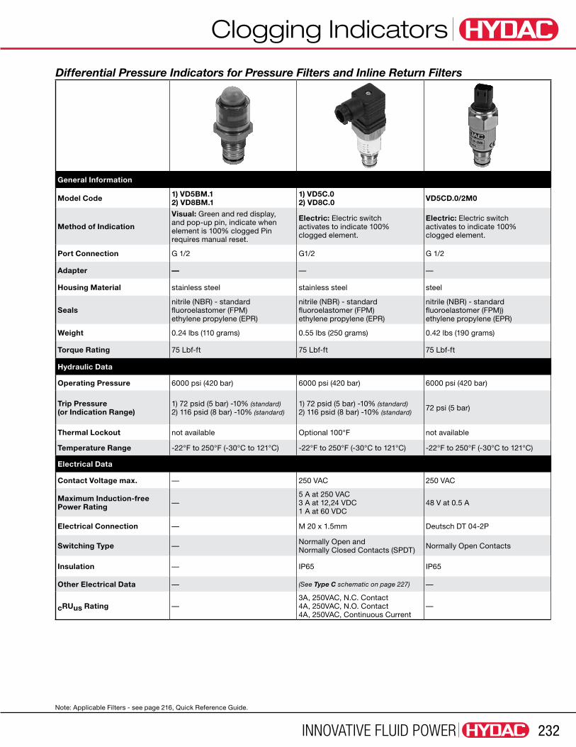
Differential Pressure Indicators for Pressure Filters and Inline Return Filters
General Information
Model Code 1) VD5BM.1 2) VD8BM.1
1) VD5C.0 2) VD8C.0 VD5CD.0/2M0
Method of Indication
Visual: Green and red display, and pop-up pin, indicate when element is 100% clogged Pin requires manual reset.
Electric: Electric switch activates to indicate 100% clogged element.
Electric: Electric switch activates to indicate 100% clogged element.
Port Connection G 1/2 G1/2 G 1/2
Adapter — — —
Housing Material stainless steel stainless steel steel
Sealsnitrile (NBR) - standard fluoroelastomer (FPM) ethylene propylene (EPR)
nitrile (NBR) - standard fluoroelastomer (FPM) ethylene propylene (EPR)
nitrile (NBR) - standard fluoroelastomer (FPM)) ethylene propylene (EPR)
Weight 0.24 lbs (110 grams) 0.55 lbs (250 grams) 0.42 lbs (190 grams)
Torque Rating 75 Lbf-ft 75 Lbf-ft 75 Lbf-ft
Hydraulic Data
Operating Pressure 6000 psi (420 bar) 6000 psi (420 bar) 6000 psi (420 bar)
Trip Pressure (or Indication Range)
1) 72 psid (5 bar) -10% (standard) 2) 116 psid (8 bar) -10% (standard)
1) 72 psid (5 bar) -10% (standard) 2) 116 psid (8 bar) -10% (standard)
72 psi (5 bar)
Thermal Lockout not available Optional 100°F not available
Temperature Range -22°F to 250°F (-30°C to 121°C) -22°F to 250°F (-30°C to 121°C) -22°F to 250°F (-30°C to 121°C)
Electrical Data
Contact Voltage max. — 250 VAC 250 VAC
Maximum Induction-free Power Rating —
5 A at 250 VAC 3 A at 12,24 VDC 1 A at 60 VDC
48 V at 0.5 A
Electrical Connection — M 20 x 1.5mm Deutsch DT 04-2P
Switching Type — Normally Open and Normally Closed Contacts (SPDT) Normally Open Contacts
Insulation — IP65 IP65
Other Electrical Data — (See Type C schematic on page 227) —
cRUus Rating —3A, 250VAC, N.C. Contact 4A, 250VAC, N.O. Contact 4A, 250VAC, Continuous Current
—
Note: Applicable Filters - see page 216, Quick Reference Guide.

Clogging Indicators
INNOVATIVE FLUID POWER233
Differential Pressure Indicators for Pressure Filters and Inline Return Filters
General Information
Model Code 1) VD5D.0/L... 2) VD8D.0/L...
1) VD2GC.0 2) VD5GC.0
1) VD2J.1 2) VD5J.13) VDH5J.0 Automotive
Method of IndicationVisual/Electric: Electric switch and light activate to indicate 100% clogged element.
Electric: Electric-analog (4-20 ma) and two electric switches activate to indicate 75% and 100% clogged
Electric: Electric switch activates to indicate 100% clogged element.
Port Connection G 1/2 G1/2 G1/2
Adapter — — —
Housing Material stainless steel stainless steel stainless steel
Sealsnitrile (NBR) - standard fluoroelastomer (FPM) ethylene propylene (EPR)
nitrile (NBR) - standard fluoroelastomer (FPM) ethylene propylene (EPR)
nitrile (NBR) - standard fluoroelastomer (FPM)) ethylene propylene (EPR)
Weight 0.55 lbs (250 grams) 0.88 lbs (400 grams) 0.55 lbs (250 grams)
Torque Rating 75 Lbf-ft 75 Lbf-ft 75 Lbf-ft
Hydraulic Data
Operating Pressure 6000 psi (420 bar) 6000 psi (420 bar) 6000 psi (420 bar)
Trip Pressure (or Indication Range)
1) 72 psid (5 bar) -10% (standard) 2) 116 psid (8 bar) -10% (standard)
1) 30 psid (2 bar) -10% (standard) 2) 72 psid (5 bar) -10% (standard)
1) 30 psid (2 bar) -10% (standard) 2) 72 psid (5 bar) -10% (standard)
Thermal Lockout not available Optional not available
Temperature Range -22°F to 250°F (-30°C to 121°C) -22°F to 250°F (-30°C to 121°C) -22°F to 250°F (-30°C to 121°C)
Electrical Data
Contact Voltage max. 250 VAC 20-30 VDC 250 VAC
Maximum Induction-free Power Rating
5 A at 250 VAC 3 A at 12,24 VDC 1 A at 60 VDC
12 VA5 A at 250 VAC 3 A at 12,24 VDC 1 A at 60 VDC
Lamp / LED Supply Voltage — 24 VDC —
Electrical Connection M 20 x 1.5mm 7 pin plug connector to DIN 43651
Brad Harrison 5 pin mini (ø 7/8” x 16 threads/in.)
Switching Type Normally Open and Normally Closed Contacts (SPDT)
Normally Open and Normally Closed Contacts (SPDT)
Normally Open and Normally Closed Contacts (SPDT)
Insulation IP65 IP65 —
Other Electrical DataOptional voltages for light: 24 or 110 V (See Type D schematic on page 237)
(See Type GC schematic on page 237) (See Type J schematic on page 238)
cRUus Rating3A, 250VAC, N.C. Contact 4A, 250VAC, N.O. Contact 4A, 250VAC, Continuous Current
—3A, 250VAC, N.C. Contact 4A, 250VAC, N.O. Contact 4A, 250VAC, Continuous Current
Note: Applicable Filters - see page 216, Quick Reference Guide.

Clogging Indicators
INNOVATIVE FLUID POWER 234
Differential Pressure Indicators for Pressure Filters and Inline Return Filters
General Information
Model Code1) VD5J4.1 2) VD8J4.13) VDH5J4.0 Automotive
1) VD2LE.1 2) VD5LE.1 3) VD8LE.1
1) VD2LZ.1 2) VD5LZ.1 3) VD8LZ.1
Method of IndicationElectric: Electric switch activates to indicate 100% clogged element.
Visual: Red pin and electrical switch activates to indicate 100% clogged element
Visual: Red pin and electrical switches activate to indicate 75% and 100% clogged conditions. LED’s optional
Port Connection G 1/2 G1/2 G1/2
Adapter — — —
Housing Material stainless steel stainless steel stainless steel
Sealsnitrile (NBR) - standard fluoroelastomer (FPM) ethylene propylene (EPR)
nitrile (NBR) - standard fluoroelastomer (FPM) ethylene propylene (EPR)
nitrile (NBR) - standard fluoroelastomer (FPM)) ethylene propylene (EPR)
Weight 0.42 lbs (190 grams) 0.72 lbs (325 grams) 0.72 lbs (325 grams)
Torque Rating 75 Lbf-ft 75 Lbf-ft 75 Lbf-ft
Hydraulic Data
Operating Pressure 6000 psi (420 bar) 6000 psi (420 bar) 6000 psi (420 bar)
Trip Pressure (or Indication Range)
1) 72 psid (5 bar) -10% (standard) 2) 116 psid (8 bar) -10% (standard)
1) 30 psid (2 bar) -10% (standard) 2) 72 psid (5 bar) -10% (standard) 3) 116 psid (8 bar) -10% (standard)
1) 30 psid (2 bar) -10% (standard) 2) 72 psid (5 bar) -10% (standard) 3) 116 psid (8 bar) -10% (standard)
Thermal Lockout not available not available not available
Temperature Range -22°F to 250°F (-30°C to 121°C) -22°F to 250°F (-30°C to 121°C) -22°F to 250°F (-30°C to 121°C)
Electrical Data
Contact Voltage max. 250 VAC 115 VAC 24 VDC
Maximum Induction-free Power Rating
5 A at 250 VAC 3 A at 12, 24 VDC 1 A at 60 VDC
1 A at 15 VDC 1 A at 15 VAC
1 A at 15 VDC 1 A at 15 VAC
Lamp / LED Supply Voltage — — 24 VDC
Electrical Connection Brad Harrison 4 pin micro M20 x 1.5mm M20 x 1.5mm
Switching Type Normally Open and Normally Closed Contacts (SPDT)
Normally Open and Normally Closed Contacts (SPDT)
Normally Open and Normally Closed Contacts (SPDT)
Insulation — IP65 IP65
Other Electrical Data (See Type J4 schematic on page 228) (See Type LE schematic on page 228) (See Type LZ schematic on page 228)
cRUus Rating3A, 250VAC, N.C. Contact 4A, 250VAC, N.O. Contact 4A, 250VAC, Continuous Current
— —
Note: Applicable Filters - see page 216, Quick Reference Guide.

Clogging Indicators
INNOVATIVE FLUID POWER235
Differential Pressure Indicators for Pressure Filters and Inline Return Filters
General Information
Model Code1) B2420BHFV 2) B5420BHFV 3) B8420BHFV
1) B2420BMHFV 2) B5420BMHFV 3) B8420BMHFV
1) B5420CHFV 2) B8420CHFV
Method of IndicationVisual: Red pin pops up to indicate 100% clogged element. Pin resets automatically.
Visual: Red pin pops up to indicate 100% clogged element. Pin requires manual reset.
Electric: Electric switch activates to indicate 100% clogged element.
Port Connection 3/4 - 16 UNF - 2A 3/4 - 16 UNF - 2A 3/4 - 16 UNF - 2A
Adapter — — —
Housing Material stainless steel stainless steel stainless steel
Seals fluoroelastomer (FPM) - standard ethylene propylene (EPR)
fluoroelastomer (FPM) - standard ethylene propylene (EPR)
fluoroelastomer (FPM) - standard ethylene propylene (EPR)
Weight 0.18 lbs (82 grams) 0.18 lbs (82 grams) 0.38 lbs (172 grams)
Torque Rating 30 Lbf-ft 30 Lbf-ft 30 Lbf-ft
Hydraulic Data
Operating Pressure 6000 psi (420 bar) 6000 psi (420 bar) 6000 psi (420 bar)
Trip Pressure (or Indication Range)
1) 72 psid (5 bar) -10% (standard) 2) 116 psid (8 bar) -10% (standard)
1) 30 psid (2 bar) -10% (standard) 2) 72 psid (5 bar) -10% (standard)
1) 30 psid (2 bar) -10% (standard) 2) 72 psid (5 bar) -10% (standard)
Thermal Lockout not available not available Option: Below 70°F or 100°F
Temperature Range -22°F to 250°F (-30°C to 121°C) -22°F to 250°F (-30°C to 121°C) -22°F to 250°F (-30°C to 121°C)
Electrical Data
Contact Voltage max. — — 250 VAC
Maximum Induction-free Power Rating — —
5 A at 250 VAC 3 A at 12,24 VDC 1 A at 60 VDC
Electrical Connection — — M 20 x 1.5mm
Switching Type — — Normally Open and Normally Closed Contacts (SPDT)
Insulation — — —
Other Electrical Data — —Electrical connector can rotate in 90˚ increments (See Type C schematic on page 237)
cRUus Rating — —3A, 250VAC, N.C. Contact 4A, 250VAC, N.O. Contact 4A, 250VAC, Continuous Current
Note: Applicable Filters - see page 216, Quick Reference Guide.

Clogging Indicators
INNOVATIVE FLUID POWER 236
Differential Pressure Indicators for Pressure Filters and Inline Return Filters
General Information
Model Code 1) B5420DHFV/L... 2) B8420DHFV/L...
1) B5420JHF.1/V 2) B8420JHF.1/V 3) B2420JHF.1/V 4) B2420JHF.1/V-S0126H5) B5420JHFV Automotive6) B2420JHFV Automotive
1) B5420J4HF.1/V 2) B8420J4HF.1/V3) B5420J4HFV Automotive4) B2420J4HFV Automotive
Method of IndicationVisual/Electric: Electric switch and light activate to indicate 100% clogged element.
Electric: Electric switch activates to indicate 100% clogged element.
Electric: Electric switch activates to indicate 100% clogged element.
Port Connection 3/4 - 16 UNF - 2A 3/4 - 16 UNF - 2A 3/4 - 16 UNF - 2A
Adapter — — —
Housing Material stainless steel stainless steel stainless steel
Seals fluoroelastomer (FPM) - standard ethylene propylene (EPR)
fluoroelastomer (FPM) - standard ethylene propylene (EPR)
fluoroelastomer (FPM) - standard ethylene propylene (EPR)
Weight 0.45 lbs (204 grams) 0.33 lbs (150 grams) 0.33 lbs (150 grams)
Torque Rating 30 Lbf-ft 30 Lbf-ft 30 Lbf-ft
Hydraulic Data
Operating Pressure 6000 psi (420 bar) 6000 psi (420 bar) 6000 psi (420 bar)
Trip Pressure (or Indication Range)
1) 72 psid (5 bar) -10% (standard) 2) 116 psid (8 bar) -10% (standard)
1) 72 psid (5 bar) -10% (standard) 2) 116 psid (8 bar) -10% (standard)
1) 72 psid (5 bar) -10% (standard) 2) 116 psid (8 bar) -10% (standard)
Thermal Lockout Option: Below 70°F or 100°F Option: Below 70°F or 100°F Option: Below 70°F or 100°F
Temperature Range -22°F to 250°F (-30°C to 121°C) -22°F to 250°F (-30°C to 121°C) -22°F to 250°F (-30°C to 121°C)
Electrical Data
Contact Voltage max. 250 VAC 250 VAC 250 VAC
Maximum Induction-free Power Rating
5 A at 250 VAC 3 A at 12, 24 VDC 1 A at 60 VDC
5 A at 250 VAC 3 A at 12.24 VDC 1 A at 60 VDC
5 A at 250 VAC 3 A at 12.24 VDC 1 A at 60 VDC
Lamp / LED Supply Voltage 24 VDC, 110 / 220 VAC — —
Electrical Connection M 20 x 1.5mm Brad Harrison 5 pin mini(ø 7/8 - 16 threads/in.)
Brad Harrison 4 pin micro
Switching Type Normally Open and Normally Closed Contacts (SPDT)
Normally Open and Normally Closed Contacts (SPDT)
Normally Open and Normally Closed Contacts (SPDT)
Insulation — — —
Other Electrical Data1) Connector rotates in 90˚ increments 2) Optional voltage for light: 24 or 110 V (See Type D schematic on page 237)
(See Type J schematic on page 238) (See Type J4 schematic on page 238)
cRUus Rating3A, 250VAC, N.C. Contact 4A, 250VAC, N.O. Contact 4A, 250VAC, Continuous Current
3A, 250VAC, N.C. Contact 4A, 250VAC, N.O. Contact 4A, 250VAC, Continuous Current
3A, 250VAC, N.C. Contact 4A, 250VAC, N.O. Contact 4A, 250VAC, Continuous Current
Note: Applicable Filters - see page 216, Quick Reference Guide.
Clogging Indicators
INNOVATIVE FLUID POWER237
Differential Pressure Indicators for Pressure Filters and Inline Return Filters
General Information
Model Code Type B indicator in filter head; not sold as separate item
Type C indicator built-in to filter head; not sold as separate item
Method of IndicationVisual: Red pin pops up to indicate 100% clogged element. Pin resets automatically.
Electric: Electric switch activates to indicate 100% clogged element.
Port Connection — —
Adapter — —
Housing Material plastic steel
Seals nitrile (NBR) nitrile (NBR)
Weight — —
Torque Rating — —
Hydraulic Data
Operating Pressure 250 psi (16.5 bar) 250 psi (16.5 bar)
Trip Pressure (or Indication Range)
22 psid (1.5 bar) 44 psid (3.0 bar)
22 psid (1.5 bar) 44 psid (3.0 bar)
Thermal Lockout — —
Temperature Range -22°F to 250°F (-30°C to 121°C) -22°F to 250°F (-30°C to 121°C)
Electrical Data
Contact Voltage max. — 36 VDC
Maximum Induction-free Power Rating — 200 ma at 36 VDC
Electrical Connection — #10 Screw Terminal
Switching Type — Normally Open Contacts (SPST)
Insulation — —
Other Electrical Data —(See Type C Spin-On schematic on page 237)
Note: Applicable Filters - see page 216, Quick Reference Guide.

Clogging Indicators
INNOVATIVE FLUID POWER 238
high pressure
Ø57
51
38.1
12.7
25.4
5.31
3.50 1.50
0.62
3.00
G 1/2 G 1/2
G 1/2
Ø30
G 1/2
87
G 1/2
G 1/2
95
5 32 40
60
Ø25.4
84
84
35
G 1/2
25.4
12.7
69.9
3/4-16UNF-2A
low pressure
high pressure
ELECTRICAL INDICATOR
VISUAL INDICATOR
low pressure
A
Section A-A
Section A-A
A
A
A
7/16-20UNF-2B SAE-4 Port 2 places
3/4-16UNF-2A
high pressure
Ø57
51
38.1
12.7
25.4
5.31
3.50 1.50
0.62
3.00
G 1/2 G 1/2
G 1/2
Ø30
G 1/2
87
G 1/2
G 1/2
95
5 32 40
60
Ø25.4
84
84
35
G 1/2
25.4
12.7
69.9
3/4-16UNF-2A
low pressure
high pressure
ELECTRICAL INDICATOR
VISUAL INDICATOR
low pressure
A
Section A-A
Section A-A
A
A
A
7/16-20UNF-2B SAE-4 Port 2 places
3/4-16UNF-2A
Dual Indicator/Gauge BlocksDual Gauge Block - G 1/2 (Part No. 02061666 & 02061667) - used to replace differential indicator
Dual Gauge Block - 3/4-16UNF (Part No. 02059931) used to replace differential indicator
50.8mm
200
-1
38.1mm
50mm
10mm
8mm
34mm
SAE-4 PortHigh Pressure Port
15mm
ø 7mm THRU2 places
G 1/2Indicator Cavity
SAE-4 PortLow Pressure Port
Pipe Connection Block - G1/2” Indicator SAE-4 Ports (Part No. 02080588)
high pressure
Ø57
51
38.1
12.7
25.4
5.31
3.50 1.50
0.62
3.00
G 1/2 G 1/2
G 1/2
Ø30
G 1/2
87
G 1/2
G 1/2
95
5 32 40
60
Ø25.4
84
84
35
G 1/2
25.4
12.7
69.9
3/4-16UNF-2A
low pressure
high pressure
ELECTRICAL INDICATOR
VISUAL INDICATOR
low pressure
A
Section A-A
Section A-A
A
A
A
7/16-20UNF-2B SAE-4 Port 2 places
3/4-16UNF-2A
Dual Indicator Block - Differential - 3/4-16UNF (Part No. 02063707)
high pressure
Ø57
51
38.1
12.7
25.4
5.31
3.50 1.50
0.62
3.00
G 1/2 G 1/2
G 1/2
Ø30
G 1/2
87
G 1/2
G 1/2
95
5 32 40
60
Ø25.4
84
84
35
G 1/2
25.4
12.7
69.9
3/4-16UNF-2A
low pressure
high pressure
ELECTRICAL INDICATOR
VISUAL INDICATOR
low pressure
A
Section A-A
Section A-A
A
A
A
7/16-20UNF-2B SAE-4 Port 2 places
3/4-16UNF-2A
Dual Indicator Block - Static - G 1/2 (Part No. 00318741)
high pressure
Ø57
51
38.1
12.7
25.4
5.31
3.50 1.50
0.62
3.00
G 1/2 G 1/2
G 1/2
Ø30
G 1/2
87
G 1/2
G 1/2
95
5 32 40
60
Ø25.4
84
84
35
G 1/2
25.4
12.7
69.9
3/4-16UNF-2A
low pressure
high pressure
ELECTRICAL INDICATOR
VISUAL INDICATOR
low pressure
A
Section A-A
Section A-A
A
A
A
7/16-20UNF-2B SAE-4 Port 2 places
3/4-16UNF-2A
Dual Indicator Block - Differential - G 1/2 (Part No. 00318732)
Part No. Connections 02061666 1/4 NPT
02061667 SAE 4 (7/16-20UNF)

Clogging Indicators
INNOVATIVE FLUID POWER239
Electrical Schematics
Type GC
A
B
2
1
3
6
4
5
2
1
3
6
4
5
S 1 max400 ma
1 max400 ma
T
P
analoguesignal
0V
alarm
warning
20..24..30VRW < 10%
A
Ub (20…30 V DC) 1
3
6
2
4
5
7
8
∆pWarning
∆pAlarm
∆p = pA-pB
OV
PA (4…20 mA)
(4…20 mA)
PAR - do not connect
IP 65 - DIN EN 60529
Mic
rop
roce
ssor
B
Type GW
Type G
Type C Type C Spin-On
Type D
P
A
B
Clean Element Condition ShownBelow Trip Pressure
ground
black
gray
yellow
ground
black
gray
yellow
3
1
2
3
1
2
ThermalLockout
P
A
B
Clean Element Condition ShownBelow Trip Pressure
ground
black
gray
yellow
0 (mp)
3
1
2
ground
black
gray
yellow
3
1
2
ThermalLockout

Clogging Indicators
INNOVATIVE FLUID POWER 240
Type J Type J4 Clean Element Condition ShownBelow Trip Pressure
brown
white
blue
black
1
2
Not Used - 3
4
brown
white
blue
black
1
2
Not Used - 3
Thermal Lockout
4
Clean Element Condition ShownBelow Trip Pressure
green
white
orange
black
red
3
1
4
Not Used - 5
2
green
white
orange
black
red
3
1
4
5
2
Thermal Lockout Switchwill close at a predetermined temp.
Switch available for the temp. of:70°F (21°C) standard100°F (38°C) option
Type LE Type LZ
P
A
B
213
P
A
B
1 3
2
switch warning 75% switch alarm 100%
P 1 3
2
P
A
B
Type UF & F

Clogging Indicators
INNOVATIVE FLUID POWER241
Dimensions
ø 1.26”(32mm)
1.06”(27mm)
2.50”(64mm)
VD/VM...B
ø 1.26”(32mm)
2.50”(64mm)
VD/VM...BM
G 1/2
1.89”(48mm)
4.13”(105mm)
VD/VM...C
G 1/2”
1.89”(48mm)
4.29”(109mm)
VD/VM...D
3.19”(81mm)
6.17”(156.65mm)
VD...GC
G1/2
ø1.81”(ø46mm)
3.58”(91mm)3.18”
(80.7mm)
4.29”(58mm)
3.64”(92.4mm)
VL…GWVD...LE
4.98”(126.4mm)
2.28”(58mm)
3.64”(92.5mm)
VD...LZ
2.80”(71mm)
ø 1.02”(26mm)
SW 30
VMF2B.0
G 1/8”
1.89”(48mm)
3.56”(90.5mm)
G 1/8”
3.41”(86.5mm)
1.89”(48mm)
VMF…DVMF…C
1.77”(45mm)
ø 1.97”(50mm)
VMF.2E
Dimensions shown are for general information and overall envelope size only. For complete dimensions please contact HYDAC to request a certified print.

Clogging Indicators
INNOVATIVE FLUID POWER 242
2.91”(74mm)
ø 1.19”(30.2mm)
VMF2F.0
4.09”(104mm)
ø 1.19”(30.2mm)
VMF0.2UF.0
1.77”(45mm)
ø 1.97”(50mm)
VMF0.2UE.0
1.77”(45mm)
ø 1.97”(50mm)
VMF0.6K.0
Dimensions
1.67”(42.5mm)
ø 1.02”(26mm)
SW 30
VR2B.0 & VR2BM.0
G 1/2”
1.89”(48mm)
4.23”(107.5mm)
G 1/2”
1.89”(48mm)
4.63”(117.5mm)
VR…DVR…C
2.52”(64mm)
ø 1.97”(50mm)
VR...E
3.10”(78.7mm)
1.81”(30mm)
ø 1.97”(50mm)
100
2
3
bar
VR2ES.0
3.74”(95mm)
ø 1.19”(30.2mm)
VR...F...
2.78”(70.5mm)
5.96”(151.5mm)
VR...GC
3.18”(80.7mm)
4.29”(58mm)
3.46”(87.8mm)
VR2LE.0
4.98”(126.4mm)
2.28”(58mm)
3.64”(92.5mm)
VR2LZ.0
Dimensions shown are for general information and overall envelope size only. For complete dimensions please contact HYDAC to request a certified print.
Related Documents