CLM 01.3-A Four-Axis Positioning Control DOK-CONTRL-CLM01.3*A**-ANW1-AE-P User´s Manual mannesmann Rexroth engineering Indramat 279795

Welcome message from author
This document is posted to help you gain knowledge. Please leave a comment to let me know what you think about it! Share it to your friends and learn new things together.
Transcript
CLM 01.3-AFour-Axis Positioning Control
DOK-CONTRL-CLM01.3*A**-ANW1-AE-P
User´s Manual
mannesmannRexroth
engineering
Indramat279795
Copyright 1993 and 1998 by Indramat Division,The Rexroth Corporation.
All Rights Reserved.
Publication Number IA 74794Revision C, May 1998
Information in this document is subject to change without notice. No part of this manualmay be reproduced or transmitted in any form, by any means, electronic, mechanical;including photocopying and recording, for any purpose without the express writtenpermission of Indramat.
REV. C, 5/98 FOREWORD iii
FOREWORD
Special Notations:
Special notations are used in this manual to assist the reader in identifying unique conditions orinformation that is important. Three categories of notations are listed below in ascending orderof importance.
Note: A NOTE is a tip, suggestion or emphasized procedure for operating the equipment.
Caution: A CAUTION appears when a condition exists that could cause operating faults ordamage to the equipment.
Warning: WARNING statements identify conditions that could cause bodily harm and/or severedamage to the equipment if the operator is not careful operation the equipment. A WARNING willtypically describe the potential hazard, its possible effect, and measures that must be taken toavoid the hazards.
Please NOTE that due to variations found in the operating conditions of certainapplications and their working environments, the notations in this manual cannotidentify all potential problems or hazards. Caution and discretion must always beused in operating machinery and especially when using electrical power.Equipment should only be installed and operated by trained personnel.
* Repair and Training services are available from REXROTH INDRAMAT.
The Rexroth CorporationIndramat Division
5150 Prairie Stone ParkwayHoffman Estates, Illinois 60192
Phone (847) 645-3600 n FAX (847) 645-6201
IAE 74794 REXROTHCLM-01.3-A INDRAMAT
iv FOREWORD REV. C, 5/98
RECORD OF REVISIONS
_______________________________________________________________________
Revision Date Description of ChangeLevel
A 2/93 Initial Release
B 9/93 Update to 3000 blocks of memory
C 3/98 New parameter descriptionsChanges to existing parametersNew drawings in Appendix F
REV. C, 5/98 FOREWORD v
TABLE OF CONTENTS
FOREWORD...................................................................................................................... iii
RECORD OF REVISIONS.................................................................................................. iv
TABLE OF CONTENTS.....................................................................................................v
1. GENERAL DESCRIPTION.............................................................................................1-1
1.1 About this Manual...............................................................................................................................1-31.1.1 Hardware and Software Support ..............................................................................................1-31.1.2 How To Use This Manual..........................................................................................................1-3
1.2 System Features ................................................................................................................................1-51.3 Physical Description of the CLM Control ...........................................................................................1-101.4 Brief Operational Description .............................................................................................................1-121.5 Specifications .....................................................................................................................................1-13
1.5.1 Physical .....................................................................................................................................1-131.5.2 Control Specifications ...............................................................................................................1-131.5.3 Options......................................................................................................................................1-14
2. CONTROLS AND INDICATORS....................................................................................2-1
2.1 Keypad and Display............................................................................................................................2-12.2 Data Entry Keys..................................................................................................................................2-32.3 Display Screens .................................................................................................................................2-4
2.3.1 Scrolling Through Display Screens...........................................................................................2-42.3.2 Parameter Mode Display Screens ............................................................................................2-112.3.3 Software Version / Control Status / Fault Display Screens ......................................................2-122.3.4 System I/O Display Screens .....................................................................................................2-132.3.5 Counter Display Screen ............................................................................................................2-192.3.6 Axis Position Display Screen ....................................................................................................2-192.3.7 Mode/Tasks Display Screens ...................................................................................................2-222.3.8 Edit Mode Display Screen.........................................................................................................2-23
2.4 Lower Front Panel ..............................................................................................................................2-25
3. FUNCTIONAL DESCRIPTION OF I/O CONNECTIONS.................................................3-1
3.1 Signal Definitions................................................................................................................................3-13.2 Interface Descriptions ........................................................................................................................3-2
3.2.1 Operating Mode Selection ........................................................................................................3-53.2.2 Servo System Operation Enables.............................................................................................3-63.2.3 Safety Interlocks........................................................................................................................3-7
IAE 74794 REXROTHCLM-01.3-A INDRAMAT
vi FOREWORD REV. C, 5/98
3.2.4 Normal Operation Signals.........................................................................................................3-83.2.5 Axis Homing ..............................................................................................................................3-93.2.6 Manual Operations ....................................................................................................................3-123.2.7 Fault/Diagnostic Monitoring.......................................................................................................3-133.2.8 Feed Monitoring / Program Interruption....................................................................................3-133.2.9 Special Functions ......................................................................................................................3-15
3.3 Input Signal Descriptions....................................................................................................................3-173.3.1 Parameter Mode Select.............................................................................................................3-173.3.2 Automatic Mode Select .............................................................................................................3-173.3.3 Emergency Stop........................................................................................................................3-183.3.4 Cycle Start .................................................................................................................................3-183.3.5 Cycle Stop .................................................................................................................................3-193.3.6 Amplifier Ready (Axis #1 through #4) .......................................................................................3-193.3.7 Clear (External) .........................................................................................................................3-193.3.8 Jog Forward (Axis 1 through 4).................................................................................................3-203.3.9 Jog Reverse (Axis 1 through 4) ................................................................................................3-203.3.10 Restart Select ..........................................................................................................................3-203.3.11 High Speed Registration Mark Detect.....................................................................................3-21
3.4 Output Signal Descriptions.................................................................................................................3-223.4.1 Manual Mode Indicator..............................................................................................................3-223.4.2 Automatic Mode Indicator..........................................................................................................3-223.4.3 Parameter Mode Indicator.........................................................................................................3-223.4.4 Amplifier Enable, RF (Axis #1 through #4) ...............................................................................3-233.4.5 Brake Release (Axis #1 through #4) .........................................................................................3-233.4.6 System Fault Indicator...............................................................................................................3-243.4.7 Restart Possible Indicator .........................................................................................................3-24
4. PARAMETERS ..............................................................................................................4-1
4.1 Description of Parameter Sets ...........................................................................................................4-14.2 Parameter List ....................................................................................................................................4-24.3 Entering the Parameters.....................................................................................................................4-3
4.3.1 Displaying of Decimals..............................................................................................................4-54.3.2 Auxiliary Inputs/Outputs ............................................................................................................4-54.3.3 Unit of Measurement.................................................................................................................4-6
4.4 Linear or Rotary Operation .................................................................................................................4-74.5 Parameter Descriptions......................................................................................................................4-8
4.5.1 Parameter Ax00 - Maximum Velocity, Axis 1 - 4 ......................................................................4-94.5.2 Parameter Ax01 - Jog Velocity, Axis 1 - 4 ...............................................................................4-104.5.3 Parameter Ax02 - Acceleration, Axis 1 - 4 ................................................................................4-114.5.4 Parameter Ax03 - Position Gain (KV Factor) Axis 1 - 4............................................................4-124.5.5 Parameter Ax04 - Incremental Encoder Data, Axis 1 - 4..........................................................4-134.5.6 Parameter Ax05 - Absolute Encoder Data, Axis 1 - 4...............................................................4-144.5.7 Parameter Ax06 - Position Tolerance, Axis 1 - 4 ......................................................................4-154.5.8 Parameter Ax07 - Position Pre-Signal, Axis 1 - 4 .....................................................................4-164.5.9 Parameter Ax08 - Feed Constant, Axis 1 - 4 ............................................................................4-174.5.10 Parameter Ax09 - Direction of Operation, Axis 1 - 4...............................................................4-184.5.11 Parameter Ax10 - Homing, Incremental Encoder, Axis 1 - 4..................................................4-194.5.12 Parameter Ax10 - Homing, Absolute Encoder, Axis 1 - 4.......................................................4-20
REV. C, 5/98 FOREWORD vii
4.5.13 Parameter Ax11 - Homing Offset, Axis 1 - 4 ..........................................................................4-214.5.14 Parameter Ax12 - Homing Acknowledgement, Axis 1 - 4 ......................................................4-224.5.15 Parameter Ax13 - Travel Limit, Minimum Value, Axis 1 - 4 ...................................................4-234.5.16 Parameter Ax14 - Travel Limit, Maximum Value, Axis 1 - 4 ..................................................4-244.5.17 Parameter Ax15 - Special Functions, Axis 1 - 4 (Position Loop Reset/VelocityAchieved/Master Encoder Averaging) ...............................................................................................4-254.5.18 Parameter Ax16 - Rotary Axis Gear Ratio, Axis 1 - 4.............................................................4-274.5.19 Parameter Ax17 - Second Acceleration Rate, Axis 1 - 4........................................................4-284.5.20 Parameter Ax18 - Single/Dual Speed Motor Positioning (Max), Axis 1 - 4 ............................4-294.5.21 Parameter Ax19 - Single/Dual Speed Motor Positioning (Min), Axis 1 - 4 .............................4-304.5.22 Parameter Ax20 - Feed Angle Monitoring, Feed Interrupt, Axis 1 - 4 ....................................4-314.5.23 Parameter Ax21 - Drive Input Sensitivity, Axis 1 - 4...............................................................4-324.5.24 Parameter Ax22 - Monitor Window, Axis 1 - 4 .......................................................................4-334.5.25 Parameter Ax23 - Follow / Synchronous / Measuring Wheel.................................................4-364.5.26 Parameter Ax24 - Delay Axis x ...............................................................................................4-384.5.27 Parameter Ax25 - Jerk constant .............................................................................................4-394.5.28 Parameter B000 - Enable Axis 2.............................................................................................4-404.5.29 Parameter B001 - Enable Axis 3.............................................................................................4-414.5.30 Parameter B002 - Enable Axis 4.............................................................................................4-424.5.31 Parameter B003 - Serial Interface Information.......................................................................4-434.5.32 Parameter B004 - Serial Interface Information.......................................................................4-444.5.33 Parameter B005 - Memory Display.........................................................................................4-454.5.34 Parameter B006 - Start Task 2 & 3.........................................................................................4-464.5.35 Parameter B007 - Display Language / Decimal Place / Keypad Lockout ..............................4-474.5.36 Parameter B008 - Variations...................................................................................................4-494.5.37 Parameter B009 - Start Program Block - Task 4, Task 5 .......................................................4-504.5.38 Parameter B010 - Clear Outputs ............................................................................................4-504.5.39 Parameter B011 - Manual Vector ...........................................................................................4-514.5.40 Parameter B012 - Program Interrupt Vector...........................................................................4-534.5.41 Parameter B013 - Analog Input ..............................................................................................4-544.5.42 Parameter B014 - Restart Vector............................................................................................4-564.5.43 Parameter B015 - Cycle Time.................................................................................................4-574.5.44 Parameter B016 - Measuring Wheel Encoder.......................................................................4-574.5.45 Parameter B017 - Measuring Wheel Encoder, Lines/Revolution...........................................4-584.5.46 Parameter B018 - Measuring Wheel Feed Constant ............................................................4-584.5.47 Parameter B019 - Measuring Wheel Offset ..........................................................................4-58
5. PROGRAMMING...........................................................................................................5-1
5.1 Positioning..........................................................................................................................................5-15.2 Auxiliary Inputs/Outputs .....................................................................................................................5-2
5.2.1 Programming Inputs/Outputs....................................................................................................5-25.2.2 Inputs/Outputs Signal Definition ...............................................................................................5-2
5.3 Multi-tasking .......................................................................................................................................5-45.4 Start of the Program...........................................................................................................................5-45.5 End of the Program ............................................................................................................................5-45.6 Programming Mode ...........................................................................................................................5-45.7 General Format ..................................................................................................................................5-55.8 Command Summary ..........................................................................................................................5-6
IAE 74794 REXROTHCLM-01.3-A INDRAMAT
viii FOREWORD REV. C, 5/98
5.8.1 Positioning Commands .............................................................................................................5-65.8.2 Position Support Commands ....................................................................................................5-75.8.3 Branch Commands ...................................................................................................................5-85.8.4 Jump Commands......................................................................................................................5-85.8.5 Auxiliary Functions ....................................................................................................................5-95.8.6 Counter Commands ..................................................................................................................5-95.8.7 Timer Commands......................................................................................................................5-95.8.8 Other Commands......................................................................................................................5-10
5.9 Command Descriptions......................................................................................................................5-115.10 ACC Acceleration Change...............................................................................................................5-125.11 AEA Auxiliary Output ON/OFF ........................................................................................................5-13
5.11.1 AEO Acceleration Override ....................................................................................................5-145.12 AKN Acknowledge Single Input.......................................................................................................5-165.13 AKP Parallel Acknowledgment Input...............................................................................................5-17
5.13.1 ANC Analog Input Compare ..................................................................................................5-195.14 APE Activate Parallel Outputs.........................................................................................................5-205.15 APJ Activate Parallel Output, then Jump ........................................................................................5-225.16 ATS Acknowledge Output Status ....................................................................................................5-245.17 BAC Branch And Count ...................................................................................................................5-255.18 BCA Branch Conditional on Acknowledgment (Output-Dependent)...............................................5-275.19 BCB Binary Conditional Branch (Inputs) .........................................................................................5-285.20 BCD BCD Conditional Branch.........................................................................................................5-305.21 BCE Branch Conditional on Input....................................................................................................5-325.22 BIO Branch Input/Output Compare .................................................................................................5-335.23 BMB Branch on Multiple Binary Outputs .........................................................................................5-345.24 BPA Branch on Parallel Acknowledgments (Outputs) ....................................................................5-355.25 BPE Branch on Parallel Inputs ........................................................................................................5-365.26 BPT Branch on Position Test...........................................................................................................5-375.27 BZP Branch If the Target Position Exceeds the Position Limit .......................................................5-385.28 CID Change Instruction Data...........................................................................................................5-395.29 CIO Copy Input/Output to Output ....................................................................................................5-415.30 CLA Clear Axis (Absolute Encoder Value)......................................................................................5-435.31 CLC Clear Counter ..........................................................................................................................5-435.32 COC Cam Output Control ...............................................................................................................5-445.33 CON Continuous Operation.............................................................................................................5-465.34 COU Count ......................................................................................................................................5-475.35 CST Change Subroutine Stack .......................................................................................................5-48
5.35.1 DEC Deceleration Change.....................................................................................................5-505.36 FAK Factor All Motions....................................................................................................................5-515.37 FMS Follow Master .........................................................................................................................5-535.38 FOL Follow (Axis Synchronization) .................................................................................................5-545.39 FUN Functions.................................................................................................................................5-555.40 HOM Home Axis..............................................................................................................................5-565.41 JMP Jump Unconditional.................................................................................................................5-575.42 123 Jump to Subroutine ...................................................................................................................5-575.43 JST Jump and Stop .........................................................................................................................5-585.44 JTK Jump in Task............................................................................................................................5-595.45 KDI Copy Position Difference..........................................................................................................5-60
5.45.1 MLO Material Length Output..................................................................................................5-615.46 NOP No Operation (Blank Block) ....................................................................................................5-62
REV. C, 5/98 FOREWORD ix
5.47 PBK Position Break .........................................................................................................................5-635.48 POA Position Absolute ....................................................................................................................5-645.49 POI Position Incremental.................................................................................................................5-655.50 POM Position On Memory ..............................................................................................................5-665.51 PSA Position Absolute (With In-Position Signal) ............................................................................5-675.52 PSI Position Incremental (With In-Position Signal).........................................................................5-685.53 PSM Position On Memory (with In-Position Signal) .......................................................................5-695.54 PST Position Test............................................................................................................................5-705.55 REF Referencing (Detect Registration Mark Input) ........................................................................5-715.56 REP Registration Position Limit (Search Limit Branch)..................................................................5-725.57 RMI Registration Mark Interrupt......................................................................................................5-735.58 RSV Restart Vector .........................................................................................................................5-765.59 RTM Rotary Table Mode ..................................................................................................................5-775.60 RTS Return from Subroutine............................................................................................................5-785.61 SAC Set Absolute Counter..............................................................................................................5-795.62 SIN Sine Oscillation.........................................................................................................................5-805.63 SO1 Scanning of Inputs and Modifying a Length (Special Option #1) ..........................................5-815.64 SO2 Position Correction Via Analog Input ......................................................................................5-84
5.64.1 STO Send Information To Outputs .........................................................................................5-875.65 VCA Velocity Change Absolute.......................................................................................................5-895.66 VCC Velocity Change Command....................................................................................................5-905.67 VEO Velocity Override Command ..................................................................................................5-915.68 WAI Wait (Time Delay) ...................................................................................................................5-935.69 WRI Write in Absolute Position (Teach Command) .......................................................................5-94
6. INSTALLATION/START-UP..........................................................................................6-1
6.1 Unpacking / Parts Inventory ...............................................................................................................6-16.2 Mounting Cabinet ...............................................................................................................................6-36.3 Power .................................................................................................................................................6-46.4 Cable Routing.....................................................................................................................................6-46.5 Transformer - Heat Dissipation..........................................................................................................6-46.6 Hardware Installation..........................................................................................................................6-56.7 Electrical Installation...........................................................................................................................6-56.8 CLM Connectors ................................................................................................................................6-66.9 Pre-Operation Start Up Tests.............................................................................................................6-96.10 Connections......................................................................................................................................6-96.11 Inputs................................................................................................................................................6-106.12 Outputs .............................................................................................................................................6-116.13 Power-up ..........................................................................................................................................6-116.14 Parameter Entry ...............................................................................................................................6-126.15 Program Entry ..................................................................................................................................6-136.16 Axis Jogging In Manual Mode..........................................................................................................6-156.17 Automatic Mode Operation ..............................................................................................................6-15
7. SERIAL INTERFACE.....................................................................................................7-1
7.1 Connector Wiring (DB-25)..................................................................................................................7-27.1.1 Signal Level Requirements.......................................................................................................7-3
IAE 74794 REXROTHCLM-01.3-A INDRAMAT
x FOREWORD REV. C, 5/98
7.1.2 Serial Cable Configurations ......................................................................................................7-47.2 Data Format........................................................................................................................................7-5
7.2.1 Word Length..............................................................................................................................7-57.2.2 Parity Check ..............................................................................................................................7-57.2.3 Baud Rate..................................................................................................................................7-67.2.4 Interface Mode...........................................................................................................................7-6
7.3 CLM Control String Protocol...............................................................................................................7-77.3.1 First (1) Control String Character (Transmission Type)............................................................7-77.3.2 Second (2) Control String Character (CLM Unit # Identifier) ....................................................7-87.3.3 Third (3) Control String Character (Information Type)..............................................................7-87.3.4 Other Important Control Characters..........................................................................................7-9
7.4 Information Characters.......................................................................................................................7-107.5 CHECKSUM Calculations ..................................................................................................................7-117.6 Sending Information to the CLM.........................................................................................................7-12
7.6.1 Sending Program Blocks to the CLM........................................................................................7-127.6.2 Sending Parameters to the CLM...............................................................................................7-13
7.7 Information Request ...........................................................................................................................7-167.7.1 Requesting a Program Block from the CLM.............................................................................7-167.7.2 Requesting a System Parameter from the CLM.......................................................................7-177.7.3 Requesting System Status from the CLM.................................................................................7-18
8. DIAGNOSTICS AND TROUBLESHOOTING..................................................................8-1
8.1 SYSTEM RELATED ERROR CODES ...............................................................................................8-18.2 AXIS RELATED ERROR CODES......................................................................................................8-5
A. APPENDIX A: LA PROGRAMMING NOTES..............................................................A-1
A.1 LA PROGRAMMING NOTES ............................................................................................................A-1A.2 Axis Homing for the CLM...................................................................................................................A-1
A.2.1 General .....................................................................................................................................A-1A.2.2 Normal Homing.........................................................................................................................A-1A.2.3 Homing Without Using the Homing Routine ............................................................................A-3A.2.4 Homing to a Switch...................................................................................................................A-3A.2.5 Homing to the Marker Pulse .....................................................................................................A-6
A.3 Aligning a Stegmann Absolute Encoder to a CLM ............................................................................A-7
B. DOCUMENTATION, EKITS AND CABLES...................................................................B-1
B.1 Manuals and Drawings ......................................................................................................................B-1B.2 CLM-01.3 E-Kits................................................................................................................................B-2B.3 CLM 01.3A Cable Sets.......................................................................................................................B-3
REV. C, 5/98 FOREWORD xi
C. CLM DISPLAY SCREEN MAP......................................................................................C-1
D. CLM PROGRAM COMMANDS/FORMAT.....................................................................D-1
D.1 CLM-01.3-A / LA01.3-01.x Alphabetical Listing of Program Command Formats...........................D-1
E. PARAMETER INPUT SHEETS.....................................................................................E-1
E.1 Axis 1 Parameter Input Sheet............................................................................................................E-1E.2 Axis 2 Parameter Input Sheet............................................................................................................E-2E.3 Axis 3 Parameter Input Sheet............................................................................................................E-3E.4 Axis 4 Parameter Input Sheet............................................................................................................E-4E.5 "B" System Parameters Input Sheet.................................................................................................E-5
F. DRAWINGS AND SCHEMATICS..................................................................................F-1
F.1 Encoder Input Connections, Axis 1....................................................................................................F-2F.2 Encoder Input Connections, Axis 2....................................................................................................F-3F.3 Input Connections ..............................................................................................................................F-4F.4 Output Connections ...........................................................................................................................F-5F.5 Power Supply Connections................................................................................................................F-6F.6 Interface Connections ........................................................................................................................F-7F.7 RS 232 / RS 485 Interface Connections ............................................................................................F-8F.8 RS 485 (w / SOT) Interface Connections ..........................................................................................F-9F.9 Input Connections ..............................................................................................................................F-10F.10 Input Connections ............................................................................................................................F-11F.11 Output Connections .........................................................................................................................F-12F.12 Command Value / Drive Enable and I/O Connections ....................................................................F-13F.13 Encoder Inputs, Axis 3 .....................................................................................................................F-14F.14 Encoder Inputs, Axis 4 .....................................................................................................................F-15F.15 CLM-TVM / TDM 1.2 & 2.1...............................................................................................................F-16F.16 CLM-TVM / TDM 1.2 & 2.1...............................................................................................................F-17F.17 CLM-TVM / TDM 1.2 & 2.1...............................................................................................................F-18F.18 CLM-TVM / TDM 3.2........................................................................................................................F-19F.19 CLM-TVM / TDM 3.2........................................................................................................................F-20F.20 CLM-KDV / KDS...............................................................................................................................F-21F.21 CLM-KDV / KDS...............................................................................................................................F-22F.22 CLM-RAC 3.1...................................................................................................................................F-23F.23 CLM-RAC 2.2...................................................................................................................................F-24F.24 CLM-NAM / TVD / DDS ...................................................................................................................F-25F.25 CLM-NAM / TVD / DDS (Incremental).............................................................................................F-26F.26 CLM-NAM / TVD / DDS (Absolute)..................................................................................................F-27F.27 CLM-DKS / DAE (Incremental) ........................................................................................................F-28F.28 CLM-DKA / DAA (Absolute).............................................................................................................F-29F.29 CLM-DKC (Incremental) ..................................................................................................................F-30F.30 CLM-DKC (Absolute) .......................................................................................................................F-31
IAE 74794 REXROTHCLM-01.3-A INDRAMAT
xii FOREWORD REV. C, 5/98
G. INSTALLATION DRAWINGS........................................................................................G-1
G.1 Keypad Replacement Face Plate Panel Dimensions (AM 1037)......................................................G-1
H. CLM TYPE CODE DESCRIPTIONS..............................................................................H-1
H.1 CLM Hardware Type Code Description.............................................................................................H-1H.2 Software Type Code Description.......................................................................................................H-2H.3 IDS Hardware Type Code Description ..............................................................................................H-3H.4 IDS Software Type Code Description................................................................................................H-3H.5 SOT Hardware Type Codes...............................................................................................................H-4H.6 SOT Software Type Codes................................................................................................................H-5
IAE 74794
CLM-01.3-A
REV. C, 5/98 GENERAL DESCRIPTION 1-1
1. GENERAL DESCRIPTION
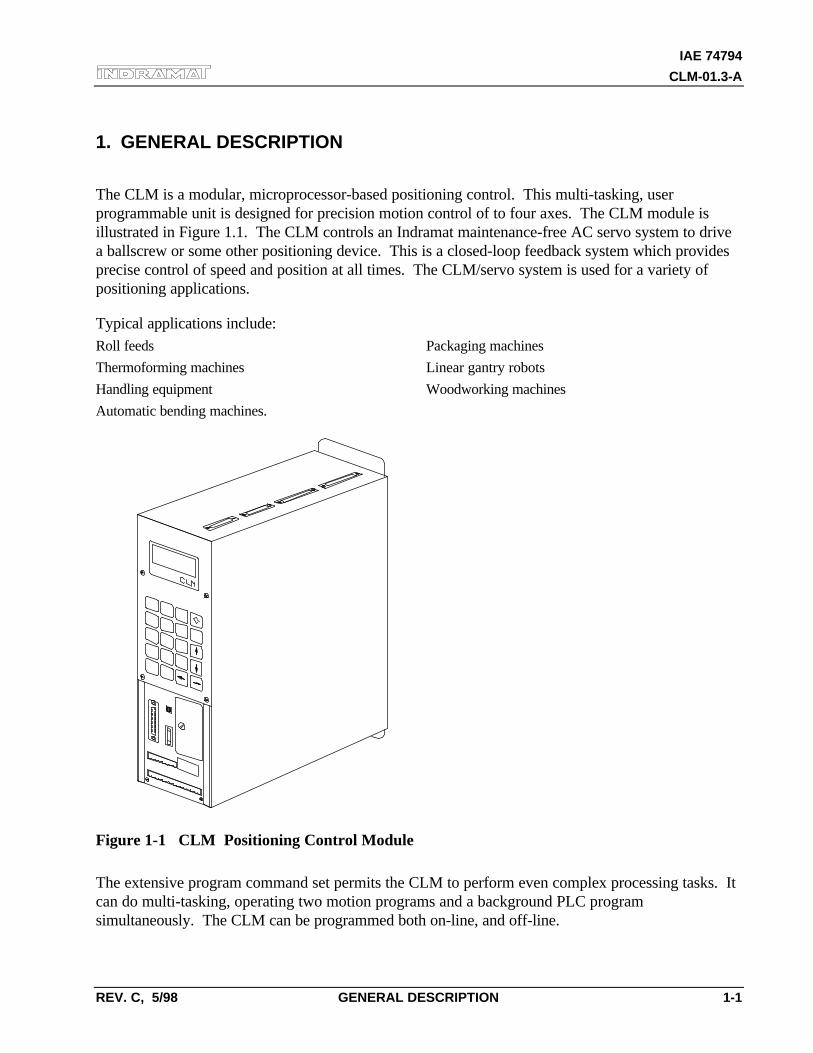
The CLM is a modular, microprocessor-based positioning control. This multi-tasking, userprogrammable unit is designed for precision motion control of to four axes. The CLM module isillustrated in Figure 1.1. The CLM controls an Indramat maintenance-free AC servo system to drivea ballscrew or some other positioning device. This is a closed-loop feedback system which providesprecise control of speed and position at all times. The CLM/servo system is used for a variety ofpositioning applications.
Typical applications include:Roll feeds Packaging machines
Thermoforming machines Linear gantry robots
Handling equipment Woodworking machines
Automatic bending machines.
Figure 1-1 CLM Positioning Control Module
The extensive program command set permits the CLM to perform even complex processing tasks. Itcan do multi-tasking, operating two motion programs and a background PLC programsimultaneously. The CLM can be programmed both on-line, and off-line.
IAE 7479
CLM-01.3-A
1-2 GENERAL DESCRIPTION REV. C, 5/98
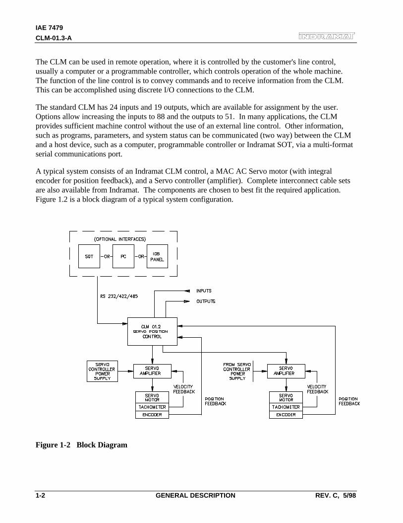
The CLM can be used in remote operation, where it is controlled by the customer's line control,usually a computer or a programmable controller, which controls operation of the whole machine.The function of the line control is to convey commands and to receive information from the CLM.This can be accomplished using discrete I/O connections to the CLM.
The standard CLM has 24 inputs and 19 outputs, which are available for assignment by the user.Options allow increasing the inputs to 88 and the outputs to 51. In many applications, the CLMprovides sufficient machine control without the use of an external line control. Other information,such as programs, parameters, and system status can be communicated (two way) between the CLMand a host device, such as a computer, programmable controller or Indramat SOT, via a multi-formatserial communications port.
A typical system consists of an Indramat CLM control, a MAC AC Servo motor (with integralencoder for position feedback), and a Servo controller (amplifier). Complete interconnect cable setsare also available from Indramat. The components are chosen to best fit the required application.Figure 1.2 is a block diagram of a typical system configuration.
Figure 1-2 Block Diagram
IAE 74794
CLM-01.3-A
REV. C, 5/98 GENERAL DESCRIPTION 1-3
1.1 About this Manual
This document is written for machine builder and end user operating personnel. It explains how tointerface, install, setup and operate the Indramat CLM Positioning Control with LA software.
1.1.1 Hardware and Software Support
This manual describes the CLM-01.3-A hardware, used with LA01.3-02.x software (x=minorrevision number).
Indramat provides assistance for any problems you may encounter with this system. Yourfirst source of information should be this manual. To report a problem or request assistance,call Indramat at [800] 860-1055. Ask for Technical Service. You may also write or FAX tothe following:
Rexroth-Indramat
Attn.: Technical Service
5150 Prairie Stone Parkway
Hoffman Estates, Illinois 60192
FAX Number: [847] 645-1201
1.1.2 How To Use This Manual
The manual is organized such that Chapters 1 and 2 describe the control and its operation.These chapters, plus Chapter 8 on diagnostics, will be sufficient for most operating personnel.Chapters 3-8 provide functional description, installation, setup, parameter entry,programming, and diagnostic and troubleshooting information required by the machine builderand setup personnel.
Chapter 1. General Description Describes the CLM control and the features which make itwell suited for motion control. Describes and illustratesvarious options. Lists specifications.
Chapter 2. Controls &Indicators
Describes the controls and indicators of the CLM and itsoptions.
Chapter 3. FunctionalDescription
Describes all pre-defined, plus several user definable, inputand output signals and the various interfacing and operatingmodes of the CLM. This information is necessary forinterfacing the CLM to the machine builder’s equipment,control panel design and troubleshooting.
IAE 7479
CLM-01.3-A
1-4 GENERAL DESCRIPTION REV. C, 5/98
Chapter 4. Parameters Describes all user-entered parameters required to adapt theCLM to the mechanical and electrical characteristics of eachapplication.
Chapter 5. Programming Describes all program commands provided in the CLM forthe user to create the executable program, as desired for theapplication.
Chapter 6. Installation/Start-up Describes procedures for installing a CLM control system.Provides an example of a CLM start-up and testingprocedure.
Chapter 7. Serial Interface Describes the multi-format RS-232/422/485 port and theprotocol for two way communication between the CLM and ahost device.
Chapter 8. Diagnostics &Troubleshooting
Describes the CLM's self-diagnostic system, lists andexplains all diagnostic messages and describestroubleshooting procedures.
Appendix A LA Programming Notes, this section is periodically updatedwith hints and examples of use for programming commands.
Appendix B References to other Indramat documentation.
Appendix C Display Map (CLM control panel display screens)
Appendix D Listing of each LA command and its format.
Appendix E Blank parameter record forms (in proper format) for use indocumenting your system parameters.
Appendix F Drawings & schematics of the CLM and its connections.
Appendix G Installation drawings & details for the CLM and options:CLM keypad (remote mounting), CLM outline/mountingdimensions.
Appendix H A CLM type code description shows how to interpret the dataplate for hardware/software options included.
Registration Form Complete and return to Indramat to receive revisions to thismanual.
IAE 74794
CLM-01.3-A
REV. C, 5/98 GENERAL DESCRIPTION 1-5
1.2 System Features
Superior Performance
The system offers high precision motion control with feed resolution of 0.001 inch. Note thatmaximum system performance depends on the mechanical characteristics of the user's system.
Easy to Operate
The user simply and easily operates the control system by entering a simple user program using frontpanel controls or optional interfaces. Operating status messages appear on the display in the userselected language - English, French, German, Spanish or Italian. Other input and display options aredescribed later in this section. The CLM system includes features to make setup quick and easy,eliminating time consuming mechanical setup or complex programming when changing parts.
Parameter-adaptable to Multiple Machines
The machine manufacturer or the user easily adapts the CLM to the mechanical and electricalcharacteristics of an application by entering data into a set of parameters, using the CLM's 20 digitkeypad and liquid crystal display. These parameters define the characteristics of the machine, such as:maximum and minimum feed lengths, jog, acceleration and deceleration rates, units of feedmeasurement, RS-232/422/485 serial communication characteristics, etc. This allows one single typeof CLM control to handle the mechanics of various types of different machines. Thus, plantpersonnel need be familiar with only one control system.
Generally, parameters are entered once when setting up the system, then changed only if theconfiguration changes or if different types of operations are required. The factory installed CLMexecutive program interprets the parameters to match the CLM to the machine, and translatesoperator-entered commands into motion control signals, coordinating the feed motion with the partsof the other machinery. Complicated system programming is not required.
Fully Self-Diagnostic
System protection is paramount. The CLM detects normal operating status, operator errors, errors inthe control itself and machine faults.
Fault and normal status messages are displayed on the CLM control panel in the user selectedlanguage. Thus, the operator is informed of the current operating status of the system and alerted toany condition that causes a fault. These messages help the operator quickly locate and correctproblems.
The CLM processor models and predicts the motion profile, and continuously compares it with theactual response of the servo drive, thereby detecting irregularities in drive conditions, such as driverunaway or excess position lag conditions. Parameters allow the user to set the magnitude of certainvariations, as required for the application, before an error is considered a fault condition.
IAE 7479
CLM-01.3-A
1-6 GENERAL DESCRIPTION REV. C, 5/98
Programming Structure
The basic program for standard motions is user programmed. The user prepares a program of up to3000 lines/blocks, utilizing pre-defined commands. These commands, represented by three lettermnemonic codes on the CLM display, specify the function. The CLM display guides the user forproper entry of the necessary data for each command/function utilized, such as axis number, desiredposition, desired velocity, etc. The CLM can be programmed to run up to three separate tasksimultaneously (multi-tasking). The CLM can be programmed with several sub-routines. The usercan select a different sub-routine from the main program to run different applications. The user cancustomize the operation of the CLM control for any number of particular applications. The user candownload program blocks to the CLM from a host device (computer, PLC, etc.), while the control isin operation.
Programmable Acceleration Rate
The acceleration rate, set by parameter, can be changed (reduced) by programming command. Therate can be changed to different levels for subsequent moves "on the fly" in automatic mode. This isuseful for establishing proper rates for new materials or setting required rates for different materialswithout changing parameter settings.
Knee Point Acceleration
Parameters allow the user to generate a two point (knee-point) acceleration profile, which increasesmachine life and allows handling difficult, compliant or delicate materials at increased productionrates.
Programmable I/O
The Standard CLM includes a set of 24 auxiliary inputs and 19 auxiliary outputs which can be definedby the user for electrically controlling and acknowledging machine functions. The Expanded CLMoption increases the auxiliary I/O to 88 inputs and 51 outputs. Additional outputs can beprogrammed as flags.
The CLM I/O connections are illustrated in Figure 1.5. The additional I/O connections are illustratedas optional, available only with the Extended version CLM.
IAE 74794
CLM-01.3-A
REV. C, 5/98 GENERAL DESCRIPTION 1-7
Control/Machine Synchronization
The CLM has 24 input and 18 output connections which are pre-defined. They include connectionsto the machine and its control panel for mode selection, cycle start and stop, emergency stop, modeselection acknowledgment, etc. These connections are typically made to keep synchronizationbetween the control and machine. For example, on a slide, the control will not feed if the ram is tooclose to the material, and/or the external operation will not start until the controlled feed is complete.The axis will not feed if an external operation is pending.
Homing
Homing allows absolute referencing of one or both axes when using an incremental encoder. Theuser can initiate homing in the manual mode or automatic mode of operation. The CLM offers agreat deal of flexibility in customizing the homing routine to compensate for backlash, forward-moving-only applications, homing to a switch, or a variety of other needs.
Registration Control
Registration control maintains each feed as close as possible to a registration mark printed on thematerial. This ensures that printed patterns are kept in alignment with the finished product.
RS-232/422/485 Serial Interface
A multi-format serial interface allows communication with a programmable logic controller, aIndramat IDS or SOT, a personal computer or other host device. All information normally enteredwith the keypad and displayed on the LCD (except for registration display) can be communicated atrates of up to 19200 Baud.
Remote Keypad/Display Mounting
The CLM front panel with keypad/display can be mounted separately from the CLM, up to 2 metersaway. Thus the CLM can be panel-mounted inside a cabinet, with the CLM's front panel separatelymounted on the cabinet surface.
IAE 7479
CLM-01.3-A
1-8 GENERAL DESCRIPTION REV. C, 5/98
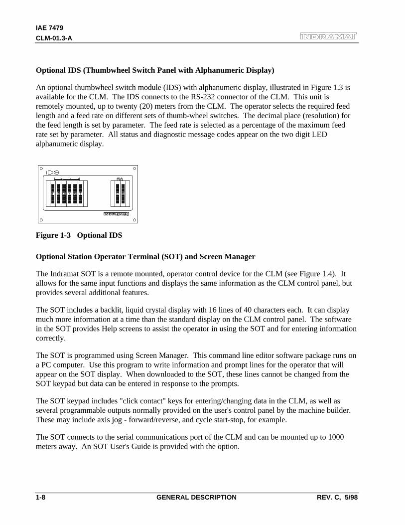
Optional IDS (Thumbwheel Switch Panel with Alphanumeric Display)
An optional thumbwheel switch module (IDS) with alphanumeric display, illustrated in Figure 1.3 isavailable for the CLM. The IDS connects to the RS-232 connector of the CLM. This unit isremotely mounted, up to twenty (20) meters from the CLM. The operator selects the required feedlength and a feed rate on different sets of thumb-wheel switches. The decimal place (resolution) forthe feed length is set by parameter. The feed rate is selected as a percentage of the maximum feedrate set by parameter. All status and diagnostic message codes appear on the two digit LEDalphanumeric display.
Figure 1-3 Optional IDS
Optional Station Operator Terminal (SOT) and Screen Manager
The Indramat SOT is a remote mounted, operator control device for the CLM (see Figure 1.4). Itallows for the same input functions and displays the same information as the CLM control panel, butprovides several additional features.
The SOT includes a backlit, liquid crystal display with 16 lines of 40 characters each. It can displaymuch more information at a time than the standard display on the CLM control panel. The softwarein the SOT provides Help screens to assist the operator in using the SOT and for entering informationcorrectly.
The SOT is programmed using Screen Manager. This command line editor software package runs ona PC computer. Use this program to write information and prompt lines for the operator that willappear on the SOT display. When downloaded to the SOT, these lines cannot be changed from theSOT keypad but data can be entered in response to the prompts.
The SOT keypad includes "click contact" keys for entering/changing data in the CLM, as well asseveral programmable outputs normally provided on the user's control panel by the machine builder.These may include axis jog - forward/reverse, and cycle start-stop, for example.
The SOT connects to the serial communications port of the CLM and can be mounted up to 1000meters away. An SOT User's Guide is provided with the option.
IAE 74794
CLM-01.3-A
REV. C, 5/98 GENERAL DESCRIPTION 1-9
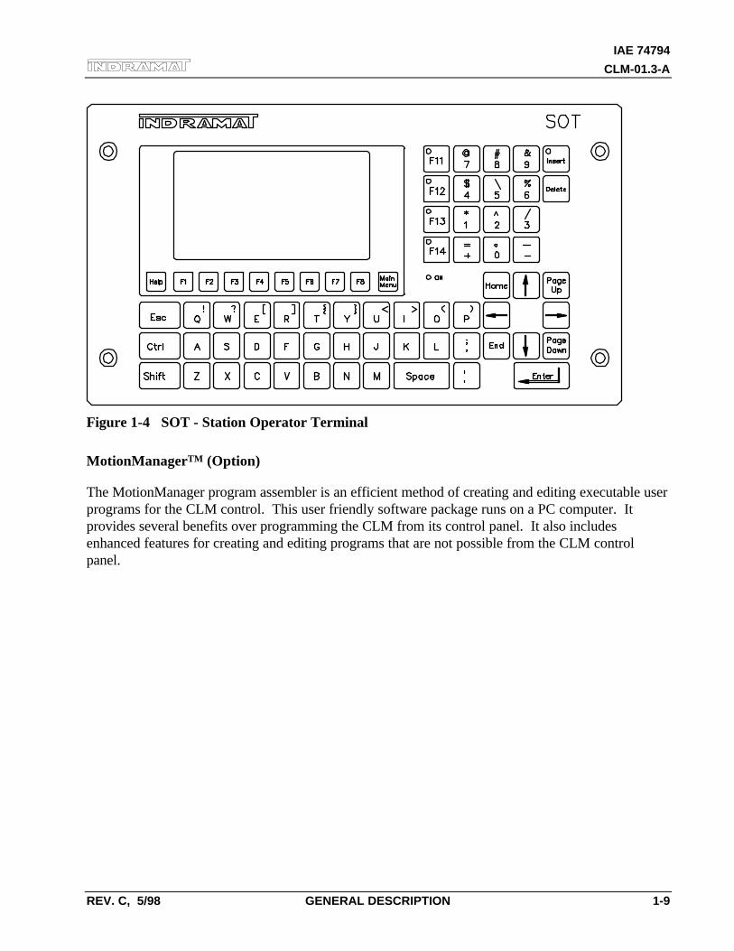
Figure 1-4 SOT - Station Operator Terminal
MotionManagerTM (Option)
The MotionManager program assembler is an efficient method of creating and editing executable userprograms for the CLM control. This user friendly software package runs on a PC computer. Itprovides several benefits over programming the CLM from its control panel. It also includesenhanced features for creating and editing programs that are not possible from the CLM controlpanel.
IAE 7479
CLM-01.3-A
1-10 GENERAL DESCRIPTION REV. C, 5/98
1.3 Physical Description of the CLM Control
The modular CLM Control mounts to the panel of a control cabinet (electrical enclosure) using twoscrews. It is designed for mounting side-by-side with the servo amplifiers (one for each axis) and theservo power supply. Installation procedures are described in Chapter 6.
The CLM control panel includes a keypad for entering operating data and a liquid crystal displaywhich shows operating status and diagnostic fault conditions. This keypad / display module can beremotely mounted -- up to 30 meters from the CLM module (i.e. on the user's control panel). Thefunctions and use of the keypad and display are described in detail in Chapter 2.
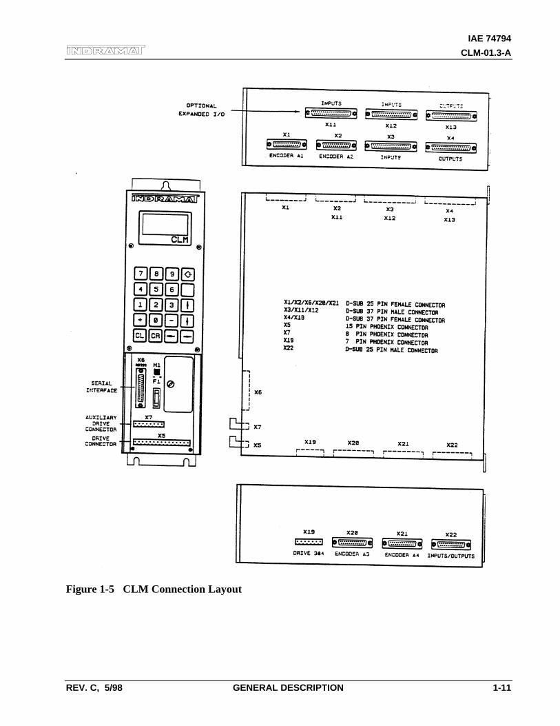
The CLM includes a set of auxiliary inputs and outputs (I/O) which can be defined by the user forcontrolling and acknowledging machine functions. The CLM I/O connectors are illustrated in Figure1.5. The Standard CLM includes 24 auxiliary inputs and 19 auxiliary outputs. The expanded versionCLM includes additional connections to expand the I/O to 88 auxiliary inputs and 51 auxiliaryoutputs. Chapter 3 provides a functional description of each I/O signal connection.
The CLM includes:
• A Motorola 68000 microprocessor.
• 256K of EPROM -- Contains the executive program, exclusively designed for positioning control,eliminating the need for complicated system user programming. It cannot be altered or changedby the user.
• 128K of RAM -- Contains the user-entered parameter data. A lithium backup battery maintainsstored memory when power is OFF. The battery is located on the slide out memory card (Figure2.3).
• 48 inputs and 37 outputs for the Standard CLM/machine interface (the expanded version CLMincreases this number of I/O to 88 inputs and 51 outputs).
• 24 inputs and 19 outputs are user definable and programmable (24 inputs and 18 outputs have apre-defined use for CLM to machine interface).
IAE 74794
CLM-01.3-A
REV. C, 5/98 GENERAL DESCRIPTION 1-11
Figure 1-5 CLM Connection Layout
IAE 7479
CLM-01.3-A
1-12 GENERAL DESCRIPTION REV. C, 5/98
1.4 Brief Operational Description
The CLM, servo amplifier, servo power supply and servomotor are designed into a mechanicalsystem. It, for example, could feed some type of material into another processing station, such as apunch press, thermoforming station, packaging machine, etc.
The machine builder or user enters data into the CLM parameters to specify the mechanical andoperating characteristics of the system. Based on this data, plus the feed length and feed rate enteredby the operator, the CLM issues positioning commands to the servo amplifier, which controls thecurrent driving the servomotor, which drives the mechanical feed mechanism.
The servomotor includes a tachometer and encoder which provide velocity and position feedback tothe control, ensuring precise, repeatable positioning of the material being fed. The final accuracy ofthe feed system depends on various factors, such as type of material, gearbox backlash and othermachine mechanics.
System components are modular, thus installation and replacement of any component of the controlsystem is fast and easy. The CLM module, servo amplifier and servomotor have quick-connectcabling. The servo amplifier and motor are matched for optimum operation using a plug-in"personality" module. Thus, should a failure occur, amplifier replacement is accomplished quicklywithout the need for electronic fine tuning. This results in a minimum of lost production.
The system is designed to ensure operating integrity and safety, using various inputs and outputs forhandshaking to assure that the feeder and subsequent processing station or device operate inharmony. A complete diagnostic system monitors all inputs / outputs and operating conditions andstops the system if a fault is detected. Diagnostic messages are displayed to aid the operator introubleshooting problems and quickly getting the system back into production.
IAE 74794
CLM-01.3-A
REV. C, 5/98 GENERAL DESCRIPTION 1-13
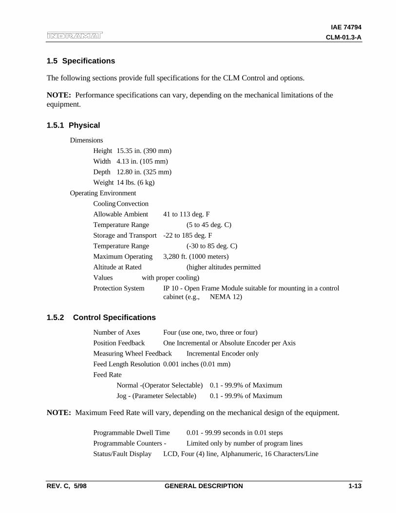
1.5 Specifications
The following sections provide full specifications for the CLM Control and options.
NOTE: Performance specifications can vary, depending on the mechanical limitations of theequipment.
1.5.1 Physical
Dimensions
Height 15.35 in. (390 mm)
Width 4.13 in. (105 mm)
Depth 12.80 in. (325 mm)
Weight 14 lbs. (6 kg)
Operating Environment
Cooling Convection
Allowable Ambient 41 to 113 deg. F
Temperature Range (5 to 45 deg. C)
Storage and Transport -22 to 185 deg. F
Temperature Range (-30 to 85 deg. C)
Maximum Operating 3,280 ft. (1000 meters)
Altitude at Rated (higher altitudes permitted
Values with proper cooling)
Protection System IP 10 - Open Frame Module suitable for mounting in a control cabinet (e.g., NEMA 12)
1.5.2 Control Specifications
Number of Axes Four (use one, two, three or four)
Position Feedback One Incremental or Absolute Encoder per Axis
Measuring Wheel Feedback Incremental Encoder only
Feed Length Resolution 0.001 inches (0.01 mm)
Feed Rate
Normal -(Operator Selectable) 0.1 - 99.9% of Maximum
Jog - (Parameter Selectable) 0.1 - 99.9% of Maximum
NOTE: Maximum Feed Rate will vary, depending on the mechanical design of the equipment.
Programmable Dwell Time 0.01 - 99.99 seconds in 0.01 steps
Programmable Counters - Limited only by number of program lines
Status/Fault Display LCD, Four (4) line, Alphanumeric, 16 Characters/Line
IAE 7479
CLM-01.3-A
1-14 GENERAL DESCRIPTION REV. C, 5/98
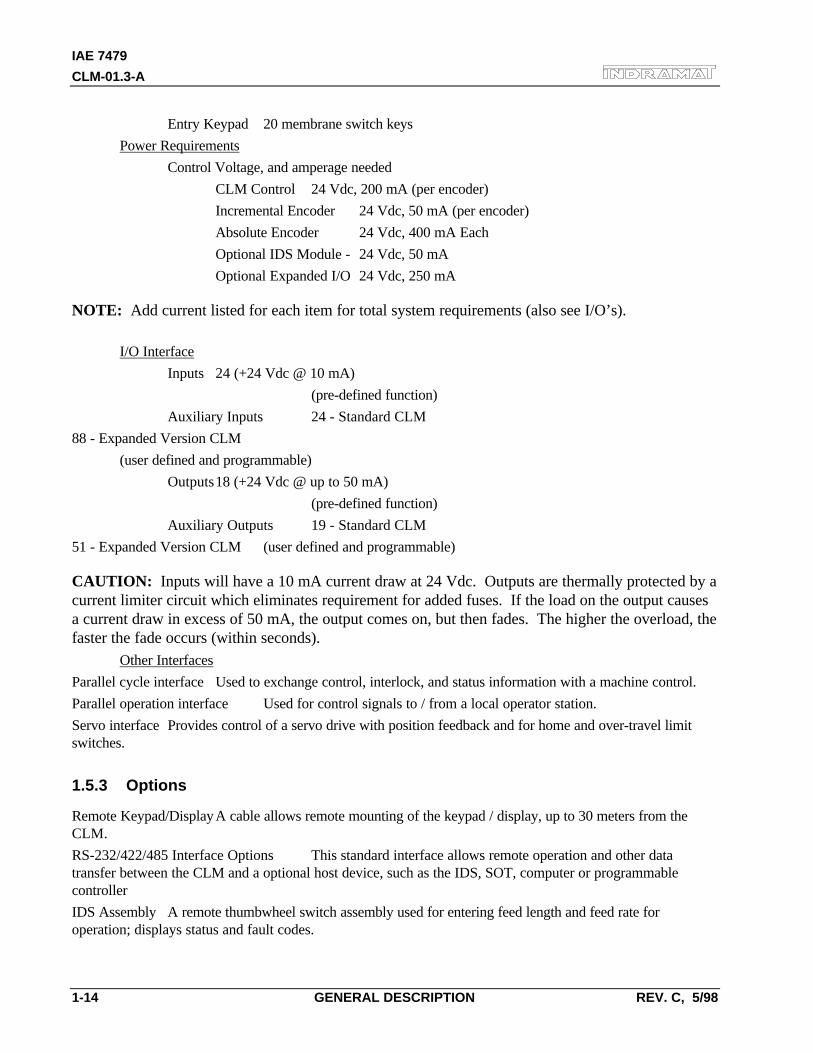
Entry Keypad 20 membrane switch keys
Power Requirements
Control Voltage, and amperage needed
CLM Control 24 Vdc, 200 mA (per encoder)
Incremental Encoder 24 Vdc, 50 mA (per encoder)
Absolute Encoder 24 Vdc, 400 mA Each
Optional IDS Module - 24 Vdc, 50 mA
Optional Expanded I/O 24 Vdc, 250 mA
NOTE: Add current listed for each item for total system requirements (also see I/O’s).
I/O Interface
Inputs 24 (+24 Vdc @ 10 mA)
(pre-defined function)
Auxiliary Inputs 24 - Standard CLM
88 - Expanded Version CLM
(user defined and programmable)
Outputs18 (+24 Vdc @ up to 50 mA)
(pre-defined function)
Auxiliary Outputs 19 - Standard CLM
51 - Expanded Version CLM (user defined and programmable)
CAUTION: Inputs will have a 10 mA current draw at 24 Vdc. Outputs are thermally protected by acurrent limiter circuit which eliminates requirement for added fuses. If the load on the output causesa current draw in excess of 50 mA, the output comes on, but then fades. The higher the overload, thefaster the fade occurs (within seconds).
Other Interfaces
Parallel cycle interface Used to exchange control, interlock, and status information with a machine control.
Parallel operation interface Used for control signals to / from a local operator station.
Servo interface Provides control of a servo drive with position feedback and for home and over-travel limitswitches.
1.5.3 Options
Remote Keypad/DisplayA cable allows remote mounting of the keypad / display, up to 30 meters from theCLM.
RS-232/422/485 Interface Options This standard interface allows remote operation and other datatransfer between the CLM and a optional host device, such as the IDS, SOT, computer or programmablecontroller
IDS Assembly A remote thumbwheel switch assembly used for entering feed length and feed rate foroperation; displays status and fault codes.

IAE 74794
CLM-01.3-A
REV. C, 5/98 GENERAL DESCRIPTION 1-15
SOT Station Operator Terminal- Used for displaying diagnostics, entering feed length, feed rate, etc.
IAE 74794
CLM-01.3-A
REV. C, 5/98 GENERAL DESCRIPTION 2-1
2. CONTROLS AND INDICATORS
This chapter contains a general description of the CLM control layout, plus the following information:
• Description of CLM keypad and display.
• Description of the functions of the keys on the keypad.
• Description of display screens; how to scroll through different screens and how to interpret andchange data on the screens.
• Description of the lower front panel.
Figure 1.5 illustrates the CLM front panel, plus top and bottom views of the CLM connectors for thestandard and expanded versions. The CLM front panel consists of two sections. The keypad anddisplay module (Figure 2.1) normally attaches to the front of the CLM. The bottom of the front panelincludes connectors and other components (Figure 2.3). They are each described in the followingsections. The system input/output connections (top and bottom of CLM) are described in Chapter 3.The connections are further described in Chapter 6 for installation.
2.1 Keypad and Display
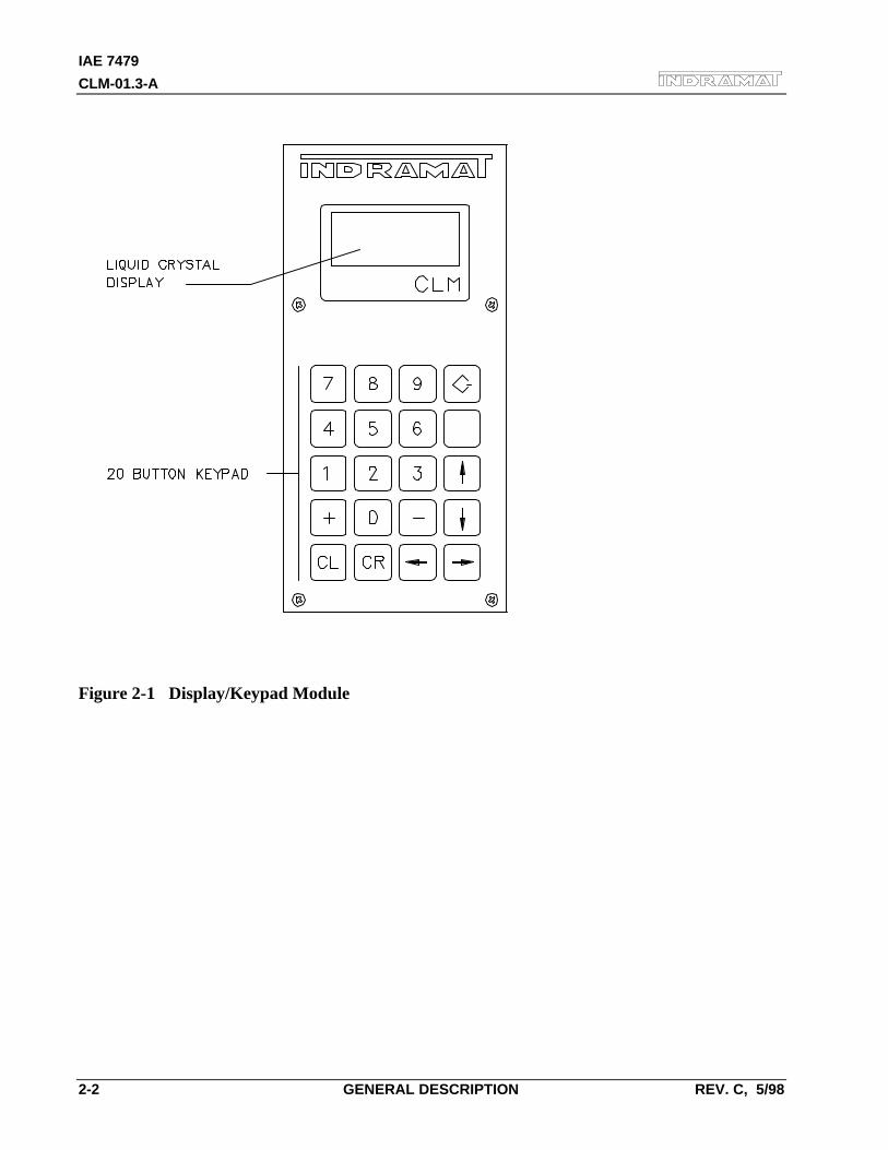
The CLM keypad / display panel consist of a keypad with 20 pressure-sensitive membrane type keysand a liquid crystal display (LCD) which shows up to four lines of up to 16 alphanumeric characterseach. The number of lines and characters showing depends on the selected display mode and thecurrent operating status of the control.
The display informs the operator of the operating status of the CLM system and displays alldiagnostic messages. It is also used when entering or editing program or parameters.
The keypad contains all the keys required for data entry, cursor movement, clearing fault/errormessages, entering program and parameter data, etc.
The following sections describe the key and display functions.
The keypad and display module are usually attached to the front of the CLM. However, the modulecan be removed and remotely mounted up to two meters away (with required cable).
IAE 7479
CLM-01.3-A
2-2 GENERAL DESCRIPTION REV. C, 5/98
Figure 2-1 Display/Keypad Module
IAE 74794
CLM-01.3-A
REV. C, 5/98 GENERAL DESCRIPTION 2-3
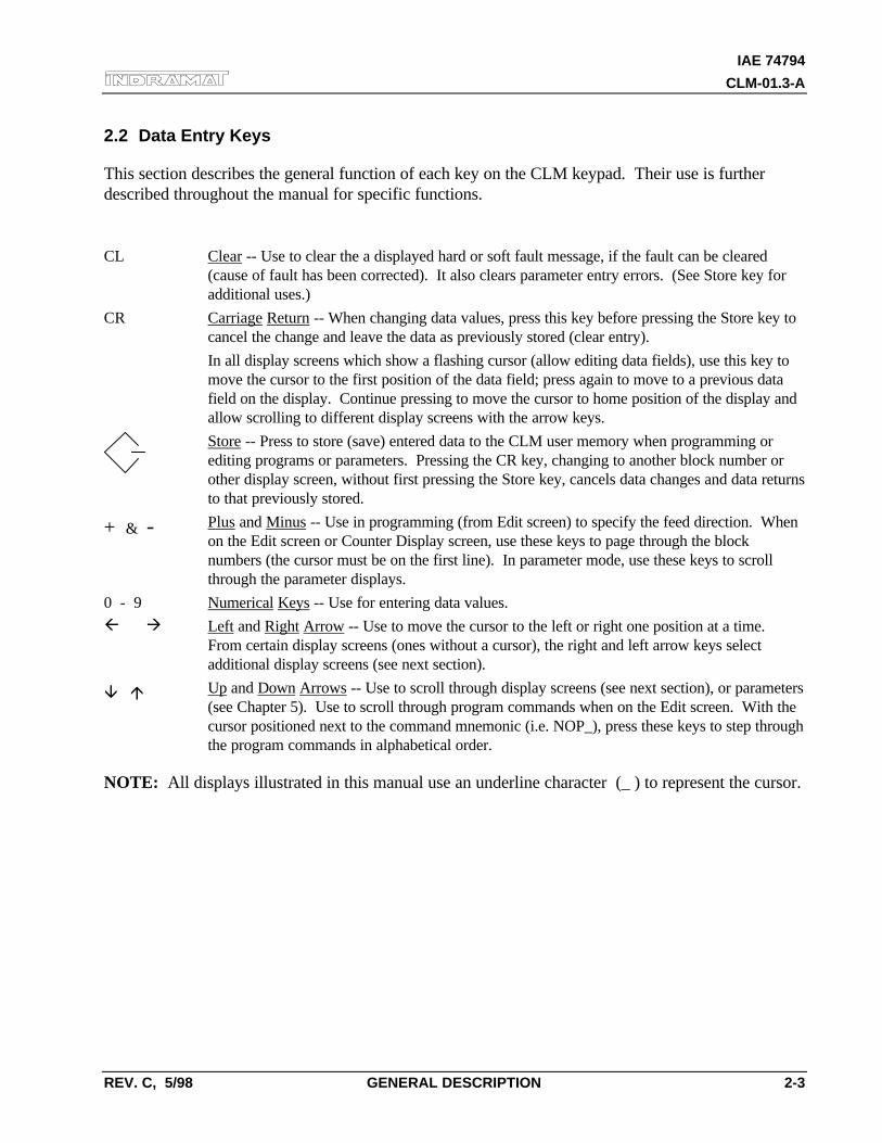
2.2 Data Entry Keys
This section describes the general function of each key on the CLM keypad. Their use is furtherdescribed throughout the manual for specific functions.
CL Clear -- Use to clear the a displayed hard or soft fault message, if the fault can be cleared(cause of fault has been corrected). It also clears parameter entry errors. (See Store key foradditional uses.)
CR Carriage Return -- When changing data values, press this key before pressing the Store key tocancel the change and leave the data as previously stored (clear entry).
In all display screens which show a flashing cursor (allow editing data fields), use this key tomove the cursor to the first position of the data field; press again to move to a previous datafield on the display. Continue pressing to move the cursor to home position of the display andallow scrolling to different display screens with the arrow keys.
Store -- Press to store (save) entered data to the CLM user memory when programming orediting programs or parameters. Pressing the CR key, changing to another block number orother display screen, without first pressing the Store key, cancels data changes and data returnsto that previously stored.
+ & - Plus and Minus -- Use in programming (from Edit screen) to specify the feed direction. Whenon the Edit screen or Counter Display screen, use these keys to page through the blocknumbers (the cursor must be on the first line). In parameter mode, use these keys to scrollthrough the parameter displays.
0 - 9 Numerical Keys -- Use for entering data values.
ß à Left and Right Arrow -- Use to move the cursor to the left or right one position at a time.From certain display screens (ones without a cursor), the right and left arrow keys selectadditional display screens (see next section).
â á Up and Down Arrows -- Use to scroll through display screens (see next section), or parameters(see Chapter 5). Use to scroll through program commands when on the Edit screen. With thecursor positioned next to the command mnemonic (i.e. NOP_), press these keys to step throughthe program commands in alphabetical order.
NOTE: All displays illustrated in this manual use an underline character (_ ) to represent the cursor.
IAE 7479
CLM-01.3-A
2-4 GENERAL DESCRIPTION REV. C, 5/98
2.3 Display Screens
The CLM uses its liquid crystal display for several screens. The operating mode and keyboardselections determine the resulting display.
When the CLM is in Parameter Mode, data for each parameter can be viewed, entered or edited.While in Automatic or Manual Mode, other display screens show the control software version,operation status messages, faults, status of each input and output, counters, etc. The Edit screenallows programming or editing the program data.
The following section describes procedures for scrolling through each of these display screens. Eachfollowing section describes the function of each screen, procedures to edit the screens data, etc.
2.3.1 Scrolling Through Display Screens
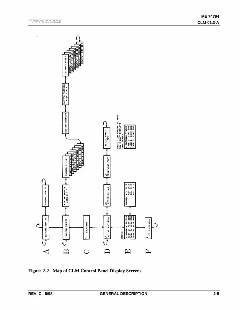
Refer to the "Display Map" in Figure 2.2 for a full illustration of the display access procedure.For convience, the same illustration is included in Appendix C. This section describes thebasic procedures for reading this "map" and scrolling through the different displays. Eachdisplay screen is fully described in the following sections.
To allow easier description, each row of the map is labeled A, B, C, etc. In general, use theup or down arrow keys to change to the "home" display screen of the proceeding or followingrow. Use the left or right arrow keys to scroll through the displays on each row. All rowsallow wrapping from the last screen on the row back to the first screen, and vice versa, bycontinuing to press the right (or left) arrow key.
NOTE: The CLM display provides four lines with 16 character spaces on each line. However, alldisplay screens do not require all the lines or character spaces. For simplicity, this manual typicallyillustrates the example displays at the size required for the screen's data.
IAE 74794
CLM-01.3-A
REV. C, 5/98 GENERAL DESCRIPTION 2-5
Figure 2-2 Map of CLM Control Panel Display Screens
IAE 7479
CLM-01.3-A
2-6 GENERAL DESCRIPTION REV. C, 5/98
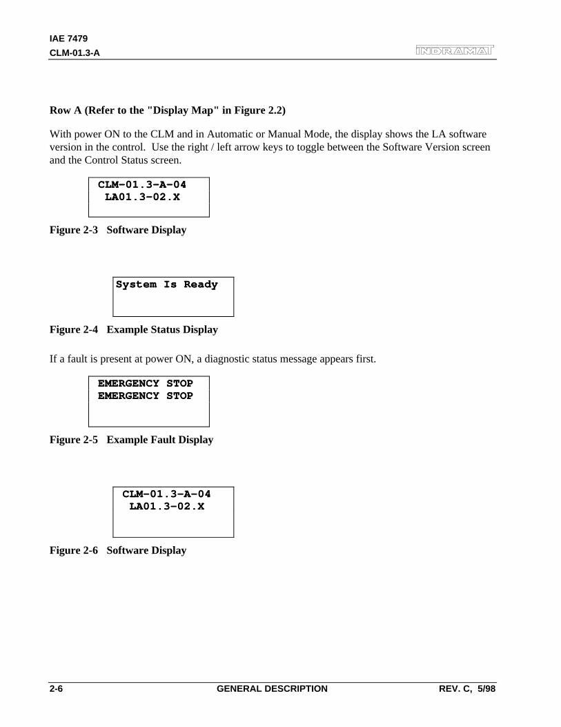
Row A (Refer to the "Display Map" in Figure 2.2)
With power ON to the CLM and in Automatic or Manual Mode, the display shows the LA softwareversion in the control. Use the right / left arrow keys to toggle between the Software Version screenand the Control Status screen.
CLM-01.3-A-04 CLM-01.3-A-04 LA01.3-02.X LA01.3-02.X
Figure 2-3 Software Display
⇔
System Is ReadySystem Is Ready
Figure 2-4 Example Status Display
If a fault is present at power ON, a diagnostic status message appears first.
EMERGENCY STOP EMERGENCY STOP EMERGENCY STOP EMERGENCY STOP
Figure 2-5 Example Fault Display
⇔
CLM-01.3-A-04 CLM-01.3-A-04 LA01.3-02.X LA01.3-02.X
Figure 2-6 Software Display
IAE 74794
CLM-01.3-A
REV. C, 5/98 GENERAL DESCRIPTION 2-7
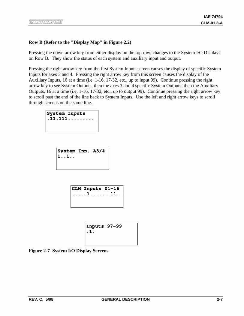
Row B (Refer to the "Display Map" in Figure 2.2)
Pressing the down arrow key from either display on the top row, changes to the System I/O Displayson Row B. They show the status of each system and auxiliary input and output.
Pressing the right arrow key from the first System Inputs screen causes the display of specific SystemInputs for axes 3 and 4. Pressing the right arrow key from this screen causes the display of theAuxiliary Inputs, 16 at a time (i.e. 1-16, 17-32, etc., up to input 99). Continue pressing the rightarrow key to see System Outputs, then the axes 3 and 4 specific System Outputs, then the AuxiliaryOutputs, 16 at a time (i.e. 1-16, 17-32, etc., up to output 99). Continue pressing the right arrow keyto scroll past the end of the line back to System Inputs. Use the left and right arrow keys to scrollthrough screens on the same line.
System InputsSystem Inputs.11.111..........11.111.........
⇔
System Inp. A3/4System Inp. A3/41..1..1..1..
⇔
CLM Inputs 01-16CLM Inputs 01-16.....1.......11......1.......11.
⇔
Inputs 97-99Inputs 97-99.1..1.
Figure 2-7 System I/O Display Screens
IAE 7479
CLM-01.3-A
2-8 GENERAL DESCRIPTION REV. C, 5/98
System OutputsSystem Outputs.1.111111........1.111111.......
⇔
System Outp.A3/4System Outp.A3/41.1.1.1.
⇔
CLM Output 01-16CLM Output 01-16..1.1......1......1.1......1....
⇔
CLM Output 97-99CLM Output 97-99.1..1.
Figure 2-8 System I/O Display Screens (cont'd)
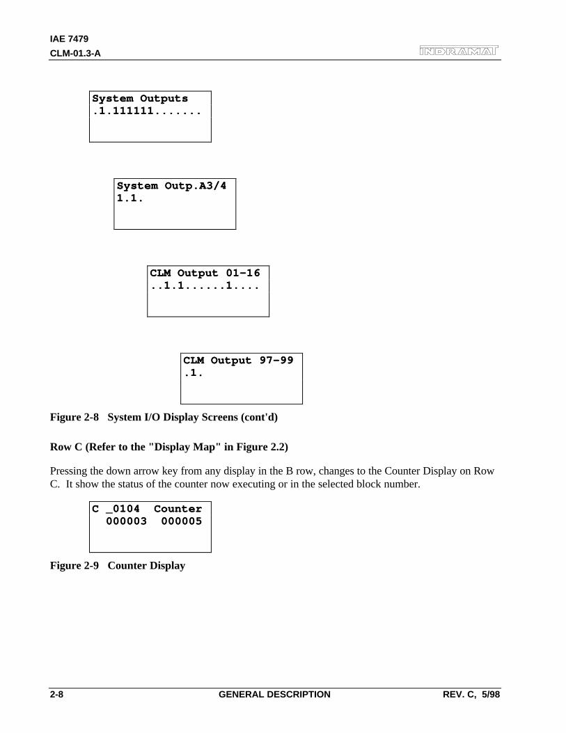
Row C (Refer to the "Display Map" in Figure 2.2)
Pressing the down arrow key from any display in the B row, changes to the Counter Display on RowC. It show the status of the counter now executing or in the selected block number.
C _0104 CounterC _0104 Counter 000003 000005 000003 000005
Figure 2-9 Counter Display
IAE 74794
CLM-01.3-A
REV. C, 5/98 GENERAL DESCRIPTION 2-9
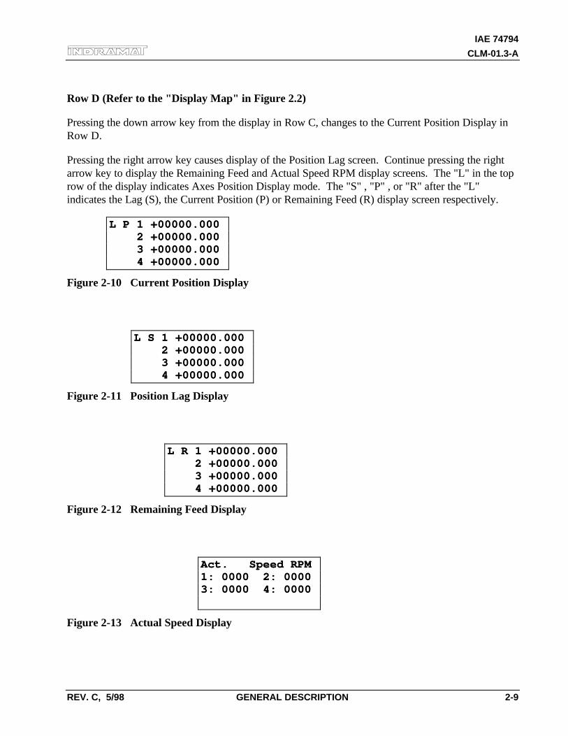
Row D (Refer to the "Display Map" in Figure 2.2)
Pressing the down arrow key from the display in Row C, changes to the Current Position Display inRow D.
Pressing the right arrow key causes display of the Position Lag screen. Continue pressing the rightarrow key to display the Remaining Feed and Actual Speed RPM display screens. The "L" in the toprow of the display indicates Axes Position Display mode. The "S" , "P" , or "R" after the "L"indicates the Lag (S), the Current Position (P) or Remaining Feed (R) display screen respectively.
L P 1 +00000.000L P 1 +00000.000 2 +00000.000 2 +00000.000 3 +00000.000 3 +00000.000 4 +00000.000 4 +00000.000
Figure 2-10 Current Position Display
⇔
L S 1 +00000.000L S 1 +00000.000 2 +00000.000 2 +00000.000 3 +00000.000 3 +00000.000 4 +00000.000 4 +00000.000
Figure 2-11 Position Lag Display
⇔
L R 1 +00000.000L R 1 +00000.000 2 +00000.000 2 +00000.000 3 +00000.000 3 +00000.000 4 +00000.000 4 +00000.000
Figure 2-12 Remaining Feed Display
⇔
Act. Speed RPMAct. Speed RPM1: 0000 2: 00001: 0000 2: 00003: 0000 4: 00003: 0000 4: 0000
Figure 2-13 Actual Speed Display
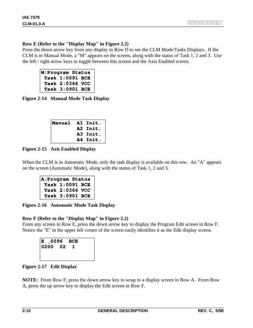
IAE 7479
CLM-01.3-A
2-10 GENERAL DESCRIPTION REV. C, 5/98
Row E (Refer to the "Display Map" in Figure 2.2)Press the down arrow key from any display in Row D to see the CLM Mode/Tasks Displays. If theCLM is in Manual Mode, a "M" appears on the screen, along with the status of Task 1, 2 and 3. Usethe left / right arrow keys to toggle between this screen and the Axis Enabled screen.
M:Program StatusM:Program Status Task 1:0091 BCE Task 1:0091 BCE Task 2:0366 VCC Task 2:0366 VCC Task 3:0901 BCE Task 3:0901 BCE
Figure 2-14 Manual Mode Task Display
⇔
Manual A1 Init.Manual A1 Init. A2 Init. A2 Init. A3 Init. A3 Init. A4 Init. A4 Init.
Figure 2-15 Axis Enabled Display
When the CLM is in Automatic Mode, only the task display is available on this row. An "A" appearson the screen (Automatic Mode), along with the status of Task 1, 2 and 3.
A:Program StatusA:Program Status Task 1:0091 BCE Task 1:0091 BCE Task 2:0366 VCC Task 2:0366 VCC Task 3:0901 BCE Task 3:0901 BCE
Figure 2-16 Automatic Mode Task Display
Row F (Refer to the "Display Map" in Figure 2.2)From any screen in Row E, press the down arrow key to display the Program Edit screen in Row F.Notice the "E" in the upper left corner of the screen easily identifies it as the Edit display screen.
E _0096 BCEE _0096 BCE0200 02 10200 02 1
Figure 2-17 Edit Display
NOTE: From Row F, press the down arrow key to wrap to a display screen in Row A. From RowA, press the up arrow key to display the Edit screen in Row F.
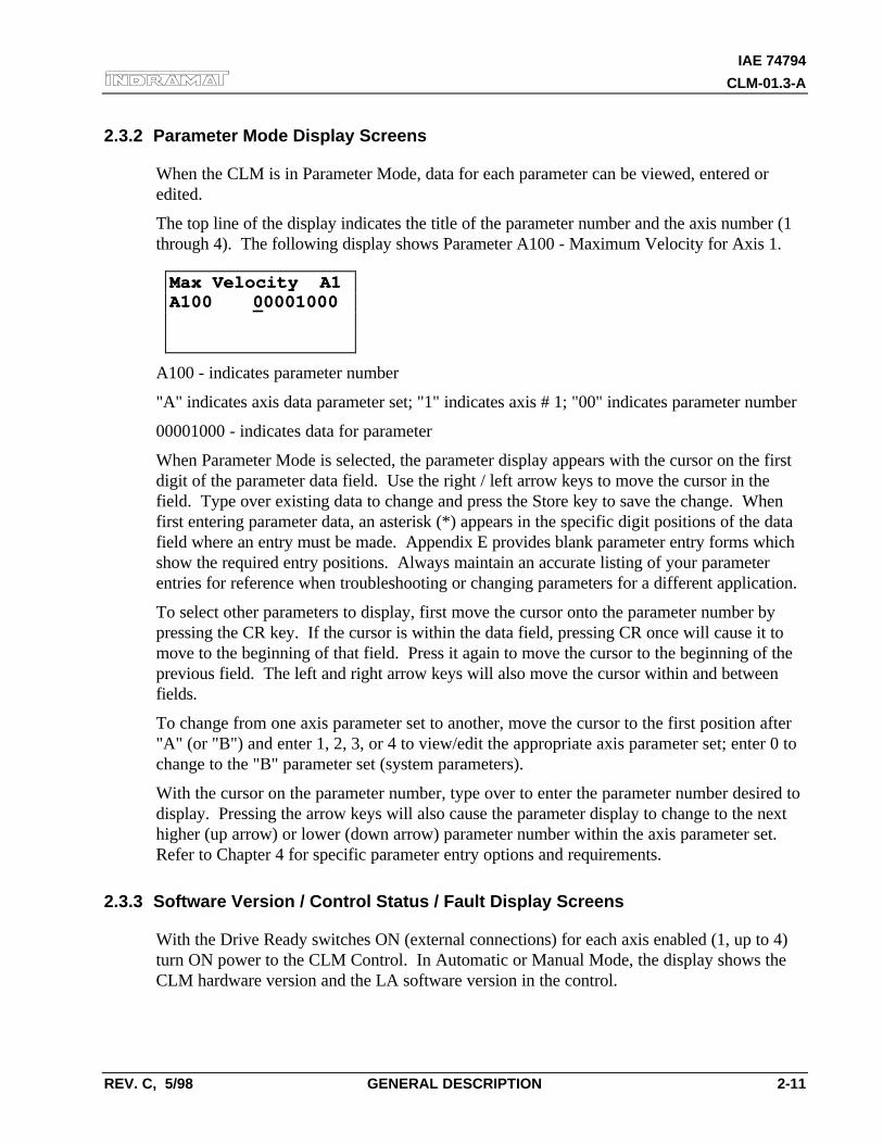
IAE 74794
CLM-01.3-A
REV. C, 5/98 GENERAL DESCRIPTION 2-11
2.3.2 Parameter Mode Display Screens
When the CLM is in Parameter Mode, data for each parameter can be viewed, entered oredited.
The top line of the display indicates the title of the parameter number and the axis number (1through 4). The following display shows Parameter A100 - Maximum Velocity for Axis 1.
Max Velocity A1Max Velocity A1A100 A100 0000010000001000
A100 - indicates parameter number
"A" indicates axis data parameter set; "1" indicates axis # 1; "00" indicates parameter number
00001000 - indicates data for parameter
When Parameter Mode is selected, the parameter display appears with the cursor on the firstdigit of the parameter data field. Use the right / left arrow keys to move the cursor in thefield. Type over existing data to change and press the Store key to save the change. Whenfirst entering parameter data, an asterisk (*) appears in the specific digit positions of the datafield where an entry must be made. Appendix E provides blank parameter entry forms whichshow the required entry positions. Always maintain an accurate listing of your parameterentries for reference when troubleshooting or changing parameters for a different application.
To select other parameters to display, first move the cursor onto the parameter number bypressing the CR key. If the cursor is within the data field, pressing CR once will cause it tomove to the beginning of that field. Press it again to move the cursor to the beginning of theprevious field. The left and right arrow keys will also move the cursor within and betweenfields.
To change from one axis parameter set to another, move the cursor to the first position after"A" (or "B") and enter 1, 2, 3, or 4 to view/edit the appropriate axis parameter set; enter 0 tochange to the "B" parameter set (system parameters).
With the cursor on the parameter number, type over to enter the parameter number desired todisplay. Pressing the arrow keys will also cause the parameter display to change to the nexthigher (up arrow) or lower (down arrow) parameter number within the axis parameter set.Refer to Chapter 4 for specific parameter entry options and requirements.
2.3.3 Software Version / Control Status / Fault Display Screens
With the Drive Ready switches ON (external connections) for each axis enabled (1, up to 4)turn ON power to the CLM Control. In Automatic or Manual Mode, the display shows theCLM hardware version and the LA software version in the control.
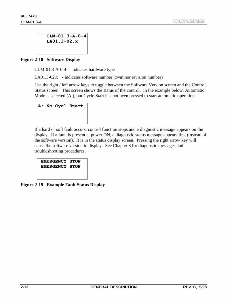
IAE 7479
CLM-01.3-A
2-12 GENERAL DESCRIPTION REV. C, 5/98
CLM-01.3-A-0-4 CLM-01.3-A-0-4 LA01.3-02.x LA01.3-02.x
Figure 2-18 Software Display
CLM-01.3-A-0-4 - indicates hardware type
LA01.3-02.x - indicates software number (x=minor revision number)
Use the right / left arrow keys to toggle between the Software Version screen and the ControlStatus screen. This screen shows the status of the control. In the example below, AutomaticMode is selected (A:), but Cycle Start has not been pressed to start automatic operation.
A: No Cycl StartA: No Cycl Start
If a hard or soft fault occurs, control function stops and a diagnostic message appears on thedisplay. If a fault is present at power ON, a diagnostic status message appears first (instead ofthe software version). It is in the status display screen. Pressing the right arrow key willcause the software version to display. See Chapter 8 for diagnostic messages andtroubleshooting procedures.
EMERGENCY STOP EMERGENCY STOP EMERGENCY STOP EMERGENCY STOP
Figure 2-19 Example Fault Status Display
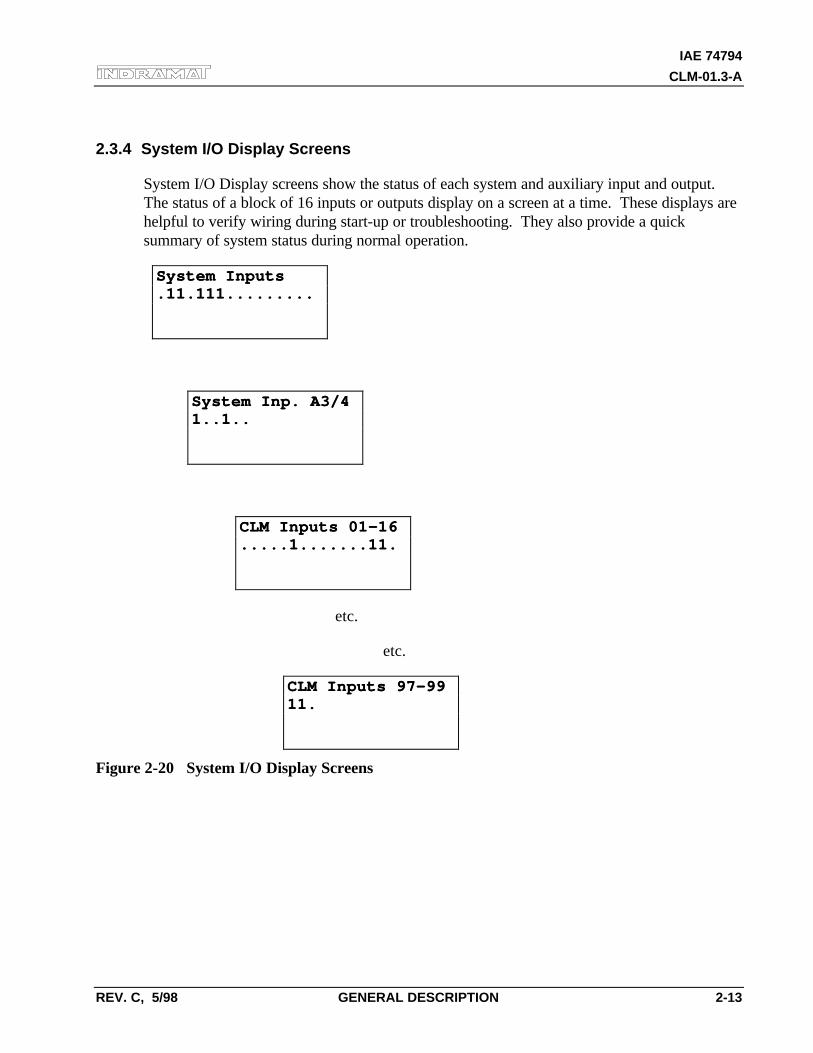
IAE 74794
CLM-01.3-A
REV. C, 5/98 GENERAL DESCRIPTION 2-13
2.3.4 System I/O Display Screens
System I/O Display screens show the status of each system and auxiliary input and output.The status of a block of 16 inputs or outputs display on a screen at a time. These displays arehelpful to verify wiring during start-up or troubleshooting. They also provide a quicksummary of system status during normal operation.
System InputsSystem Inputs.11.111..........11.111.........
⇔
System Inp. A3/4System Inp. A3/41..1..1..1..
⇔
CLM Inputs 01-16CLM Inputs 01-16.....1.......11......1.......11.
etc.
etc.
CLM Inputs 97-99CLM Inputs 97-9911.11.
Figure 2-20 System I/O Display Screens
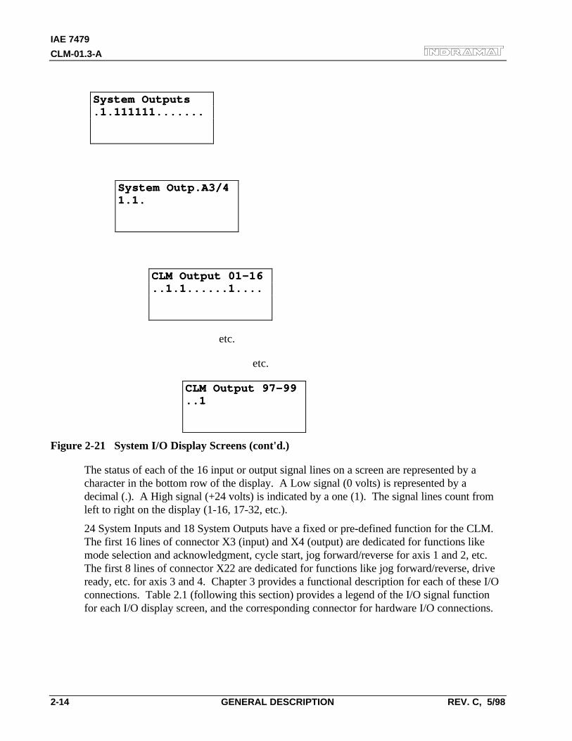
IAE 7479
CLM-01.3-A
2-14 GENERAL DESCRIPTION REV. C, 5/98
System OutputsSystem Outputs.1.111111........1.111111.......
⇔
System Outp.A3/4System Outp.A3/41.1.1.1.
⇔
CLM Output 01-16CLM Output 01-16..1.1......1......1.1......1....
etc.
etc.
CLM Output 97-99CLM Output 97-99..1..1
Figure 2-21 System I/O Display Screens (cont'd.)
The status of each of the 16 input or output signal lines on a screen are represented by acharacter in the bottom row of the display. A Low signal (0 volts) is represented by adecimal (.). A High signal (+24 volts) is indicated by a one (1). The signal lines count fromleft to right on the display (1-16, 17-32, etc.).
24 System Inputs and 18 System Outputs have a fixed or pre-defined function for the CLM.The first 16 lines of connector X3 (input) and X4 (output) are dedicated for functions likemode selection and acknowledgment, cycle start, jog forward/reverse for axis 1 and 2, etc.The first 8 lines of connector X22 are dedicated for functions like jog forward/reverse, driveready, etc. for axis 3 and 4. Chapter 3 provides a functional description for each of these I/Oconnections. Table 2.1 (following this section) provides a legend of the I/O signal functionfor each I/O display screen, and the corresponding connector for hardware I/O connections.
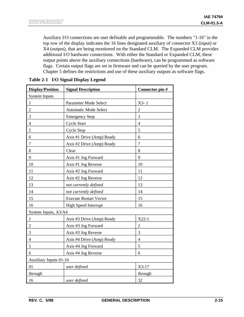
IAE 74794
CLM-01.3-A
REV. C, 5/98 GENERAL DESCRIPTION 2-15
Auxiliary I/O connections are user definable and programmable. The numbers "1-16" in thetop row of the display indicates the 16 lines designated auxiliary of connector X3 (input) orX4 (output), that are being monitored on the Standard CLM. The Expanded CLM providesadditional I/O hardware connections. With either the Standard or Expanded CLM, theseoutput points above the auxiliary connections (hardware), can be programmed as softwareflags. Certain output flags are set in firmware and can be queried by the user program.Chapter 5 defines the restrictions and use of these auxiliary outputs as software flags.
Table 2-1 I/O Signal Display Legend
Display/Position Signal Description Connector pin #
System Inputs
1 Parameter Mode Select X3- 1
2 Automatic Mode Select 2
3 Emergency Stop 3
4 Cycle Start 4
5 Cycle Stop 5
6 Axis #1 Drive (Amp) Ready 6
7 Axis #2 Drive (Amp) Ready 7
8 Clear 8
9 Axis #1 Jog Forward 9
10 Axis #1 Jog Reverse 10
11 Axis #2 Jog Forward 11
12 Axis #2 Jog Reverse 12
13 not currently defined 13
14 not currently defined 14
15 Execute Restart Vector 15
16 High Speed Interrupt 16
System Inputs, A3/A4
1 Axis #3 Drive (Amp) Ready X22-1
2 Axis #3 Jog Forward 2
3 Axis #3 Jog Reverse 3
4 Axis #4 Drive (Amp) Ready 4
5 Axis #4 Jog Forward 5
6 Axis #4 Jog Reverse 6
Auxiliary Inputs 01-16
01 user defined X3-17
through through
16 user defined 32
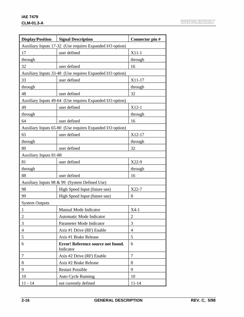
IAE 7479
CLM-01.3-A
2-16 GENERAL DESCRIPTION REV. C, 5/98
Display/Position Signal Description Connector pin #
Auxiliary Inputs 17-32 (Use requires Expanded I/O option)
17 user defined X11-1
through through
32 user defined 16
Auxiliary Inputs 33-48 (Use requires Expanded I/O option)
33 user defined X11-17
through through
48 user defined 32
Auxiliary Inputs 49-64 (Use requires Expanded I/O option)
49 user defined X12-1
through through
64 user defined 16
Auxiliary Inputs 65-80 (Use requires Expanded I/O option)
65 user defined X12-17
through through
80 user defined 32
Auxiliary Inputs 81-88
81 user defined X22-9
through through
88 user defined 16
Auxiliary Inputs 98 & 99 (System Defined Use)
98 High Speed Input (future use) X22-7
99 High Speed Input (future use) 8
System Outputs
1 Manual Mode Indicator X4-1
2 Automatic Mode Indicator 2
3 Parameter Mode Indicator 3
4 Axis #1 Drive (RF) Enable 4
5 Axis #1 Brake Release 5
6 Error! Reference source not found.Indicator
6
7 Axis #2 Drive (RF) Enable 7
8 Axis #2 Brake Release 8
9 Restart Possible 9
10 Auto Cycle Running 10
11 - 14 not currently defined 11-14
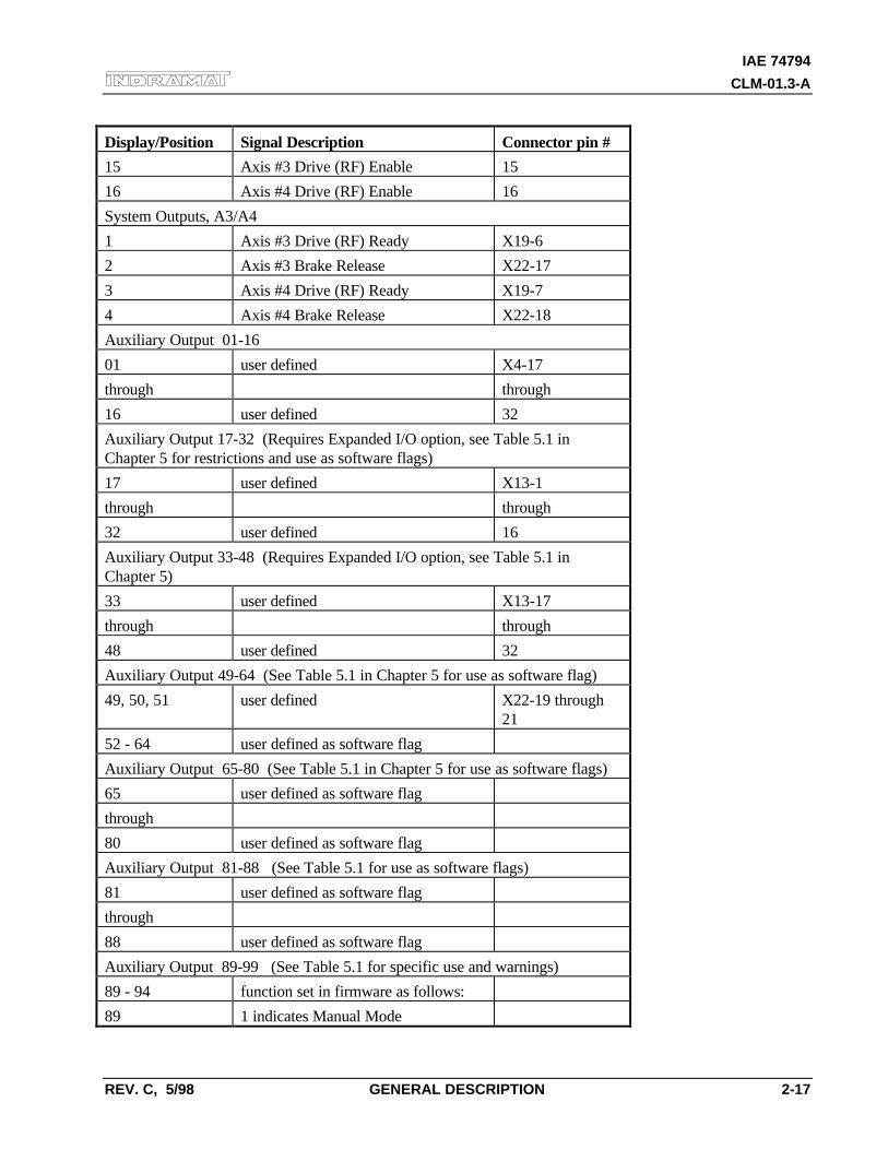
IAE 74794
CLM-01.3-A
REV. C, 5/98 GENERAL DESCRIPTION 2-17
Display/Position Signal Description Connector pin #
15 Axis #3 Drive (RF) Enable 15
16 Axis #4 Drive (RF) Enable 16
System Outputs, A3/A4
1 Axis #3 Drive (RF) Ready X19-6
2 Axis #3 Brake Release X22-17
3 Axis #4 Drive (RF) Ready X19-7
4 Axis #4 Brake Release X22-18
Auxiliary Output 01-16
01 user defined X4-17
through through
16 user defined 32
Auxiliary Output 17-32 (Requires Expanded I/O option, see Table 5.1 inChapter 5 for restrictions and use as software flags)
17 user defined X13-1
through through
32 user defined 16
Auxiliary Output 33-48 (Requires Expanded I/O option, see Table 5.1 inChapter 5)
33 user defined X13-17
through through
48 user defined 32
Auxiliary Output 49-64 (See Table 5.1 in Chapter 5 for use as software flag)
49, 50, 51 user defined X22-19 through21
52 - 64 user defined as software flag
Auxiliary Output 65-80 (See Table 5.1 in Chapter 5 for use as software flags)
65 user defined as software flag
through
80 user defined as software flag
Auxiliary Output 81-88 (See Table 5.1 for use as software flags)
81 user defined as software flag
through
88 user defined as software flag
Auxiliary Output 89-99 (See Table 5.1 for specific use and warnings)
89 - 94 function set in firmware as follows:
89 1 indicates Manual Mode
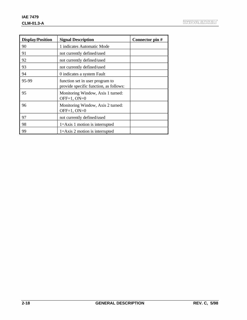
IAE 7479
CLM-01.3-A
2-18 GENERAL DESCRIPTION REV. C, 5/98
Display/Position Signal Description Connector pin #
90 1 indicates Automatic Mode
91 not currently defined/used
92 not currently defined/used
93 not currently defined/used
94 0 indicates a system Fault
95-99 function set in user program toprovide specific function, as follows:
95 Monitoring Window, Axis 1 turned:OFF=1, ON=0
96 Monitoring Window, Axis 2 turned:OFF=1, ON=0
97 not currently defined/used
98 1=Axis 1 motion is interrupted
99 1=Axis 2 motion is interrupted
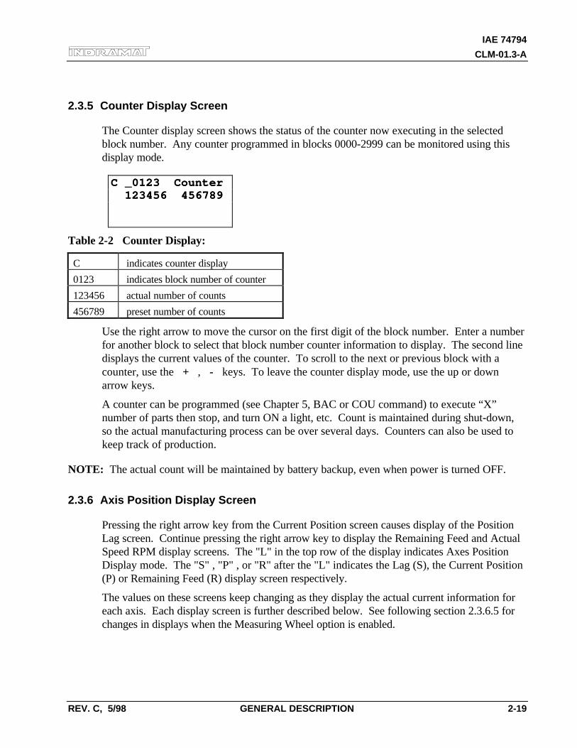
IAE 74794
CLM-01.3-A
REV. C, 5/98 GENERAL DESCRIPTION 2-19
2.3.5 Counter Display Screen
The Counter display screen shows the status of the counter now executing in the selectedblock number. Any counter programmed in blocks 0000-2999 can be monitored using thisdisplay mode.
C _0123 CounterC _0123 Counter 123456 456789 123456 456789
Table 2-2 Counter Display:
C indicates counter display
0123 indicates block number of counter
123456 actual number of counts
456789 preset number of counts
Use the right arrow to move the cursor on the first digit of the block number. Enter a numberfor another block to select that block number counter information to display. The second linedisplays the current values of the counter. To scroll to the next or previous block with acounter, use the + , - keys. To leave the counter display mode, use the up or downarrow keys.
A counter can be programmed (see Chapter 5, BAC or COU command) to execute “X”number of parts then stop, and turn ON a light, etc. Count is maintained during shut-down,so the actual manufacturing process can be over several days. Counters can also be used tokeep track of production.
NOTE: The actual count will be maintained by battery backup, even when power is turned OFF.
2.3.6 Axis Position Display Screen
Pressing the right arrow key from the Current Position screen causes display of the PositionLag screen. Continue pressing the right arrow key to display the Remaining Feed and ActualSpeed RPM display screens. The "L" in the top row of the display indicates Axes PositionDisplay mode. The "S" , "P" , or "R" after the "L" indicates the Lag (S), the Current Position(P) or Remaining Feed (R) display screen respectively.
The values on these screens keep changing as they display the actual current information foreach axis. Each display screen is further described below. See following section 2.3.6.5 forchanges in displays when the Measuring Wheel option is enabled.
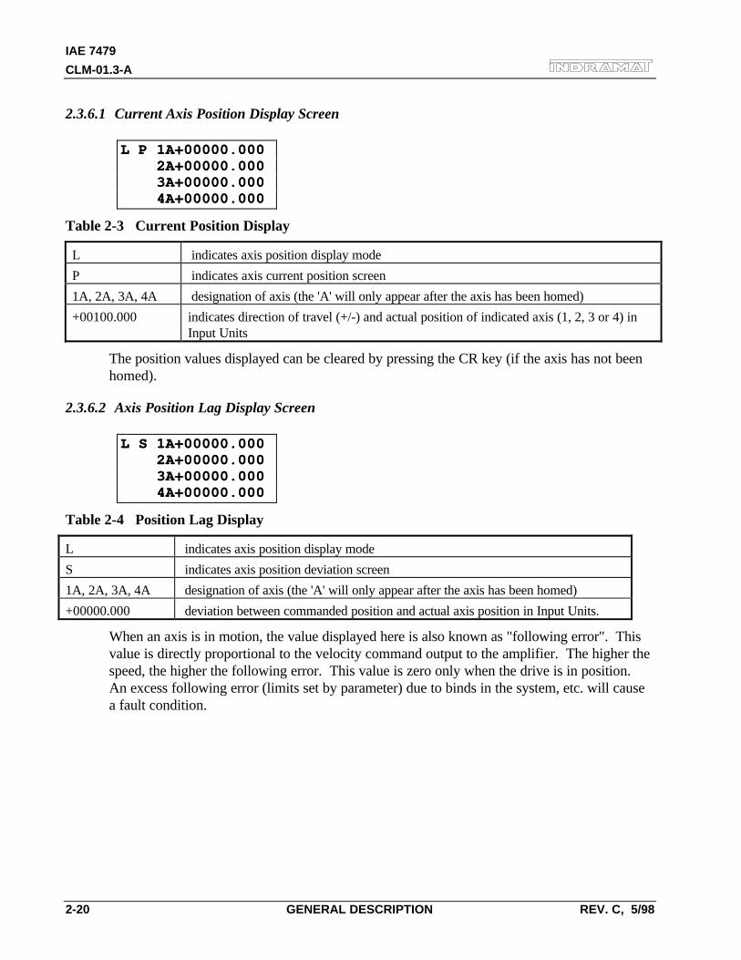
IAE 7479
CLM-01.3-A
2-20 GENERAL DESCRIPTION REV. C, 5/98
2.3.6.1 Current Axis Position Display Screen
L P 1A+00000.000L P 1A+00000.000 2A+00000.000 2A+00000.000 3A+00000.000 3A+00000.000 4A+00000.000 4A+00000.000
Table 2-3 Current Position Display
L indicates axis position display mode
P indicates axis current position screen
1A, 2A, 3A, 4A designation of axis (the 'A' will only appear after the axis has been homed)
+00100.000 indicates direction of travel (+/-) and actual position of indicated axis (1, 2, 3 or 4) inInput Units
The position values displayed can be cleared by pressing the CR key (if the axis has not beenhomed).
2.3.6.2 Axis Position Lag Display Screen
L S 1A+00000.000L S 1A+00000.000 2A+00000.000 2A+00000.000 3A+00000.000 3A+00000.000 4A+00000.000 4A+00000.000
Table 2-4 Position Lag Display
L indicates axis position display mode
S indicates axis position deviation screen
1A, 2A, 3A, 4A designation of axis (the 'A' will only appear after the axis has been homed)
+00000.000 deviation between commanded position and actual axis position in Input Units.
When an axis is in motion, the value displayed here is also known as "following error". Thisvalue is directly proportional to the velocity command output to the amplifier. The higher thespeed, the higher the following error. This value is zero only when the drive is in position.An excess following error (limits set by parameter) due to binds in the system, etc. will causea fault condition.
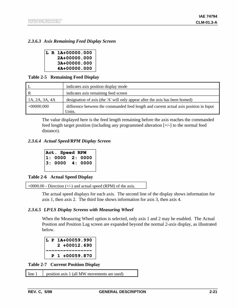
IAE 74794
CLM-01.3-A
REV. C, 5/98 GENERAL DESCRIPTION 2-21
2.3.6.3 Axis Remaining Feed Display Screen
L R 1A+00000.000L R 1A+00000.000 2A+00000.000 2A+00000.000 3A+00000.000 3A+00000.000 4A+00000.000 4A+00000.000
Table 2-5 Remaining Feed Display
L indicates axis position display mode
R indicates axis remaining feed screen
1A, 2A, 3A, 4A designation of axis (the 'A' will only appear after the axis has been homed)
+00000.000 difference between the commanded feed length and current actual axis position in InputUnits.
The value displayed here is the feed length remaining before the axis reaches the commandedfeed length target position (including any programmed alteration [+/-] to the normal feeddistance).
2.3.6.4 Actual Speed/RPM Display Screen
Act. Speed RPMAct. Speed RPM1: 0000 2: 00001: 0000 2: 00003: 0000 4: 00003: 0000 4: 0000
Table 2-6 Actual Speed Display
+0000.00 - Direction (+/-) and actual speed (RPM) of the axis.
The actual speed displays for each axis. The second line of the display shows information foraxis 1, then axis 2. The third line shows information for axis 3, then axis 4.
2.3.6.5 LP/LS Display Screens with Measuring Wheel
When the Measuring Wheel option is selected, only axis 1 and 2 may be enabled. The ActualPosition and Position Lag screen are expanded beyond the normal 2-axis display, as illustratedbelow.
L P 1A+00059.990L P 1A+00059.990 2 +00012.690 2 +00012.690-------------------------------- P 1 +00059.870 P 1 +00059.870
Table 2-7 Current Position Display
line 1 position axis 1 (all MW movements are used)
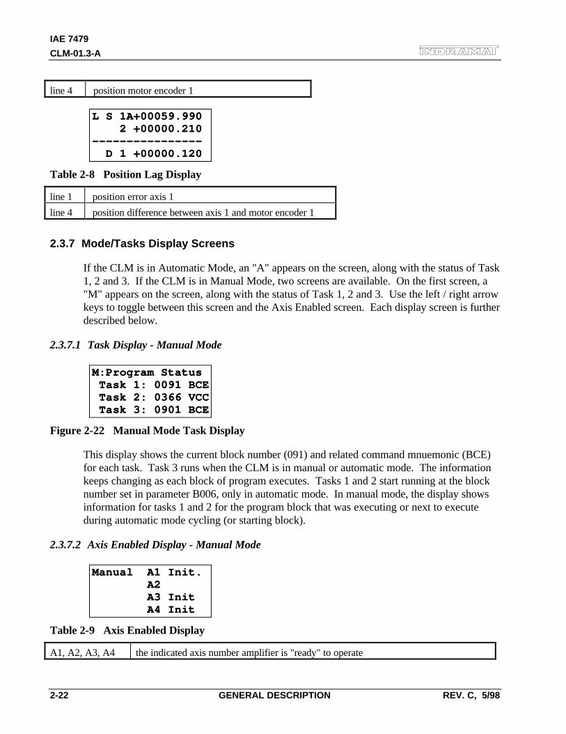
IAE 7479
CLM-01.3-A
2-22 GENERAL DESCRIPTION REV. C, 5/98
line 4 position motor encoder 1
L S 1A+00059.990L S 1A+00059.990 2 +00000.210 2 +00000.210-------------------------------- D 1 +00000.120 D 1 +00000.120
Table 2-8 Position Lag Display
line 1 position error axis 1
line 4 position difference between axis 1 and motor encoder 1
2.3.7 Mode/Tasks Display Screens
If the CLM is in Automatic Mode, an "A" appears on the screen, along with the status of Task1, 2 and 3. If the CLM is in Manual Mode, two screens are available. On the first screen, a"M" appears on the screen, along with the status of Task 1, 2 and 3. Use the left / right arrowkeys to toggle between this screen and the Axis Enabled screen. Each display screen is furtherdescribed below.
2.3.7.1 Task Display - Manual Mode
M:Program StatusM:Program Status Task 1: 0091 BCE Task 1: 0091 BCE Task 2: 0366 VCC Task 2: 0366 VCC Task 3: 0901 BCE Task 3: 0901 BCE
Figure 2-22 Manual Mode Task Display
This display shows the current block number (091) and related command mnuemonic (BCE)for each task. Task 3 runs when the CLM is in manual or automatic mode. The informationkeeps changing as each block of program executes. Tasks 1 and 2 start running at the blocknumber set in parameter B006, only in automatic mode. In manual mode, the display showsinformation for tasks 1 and 2 for the program block that was executing or next to executeduring automatic mode cycling (or starting block).
2.3.7.2 Axis Enabled Display - Manual Mode
Manual A1 Init.Manual A1 Init. A2 A2 A3 Init A3 Init A4 Init A4 Init
Table 2-9 Axis Enabled Display
A1, A2, A3, A4 the indicated axis number amplifier is "ready" to operate
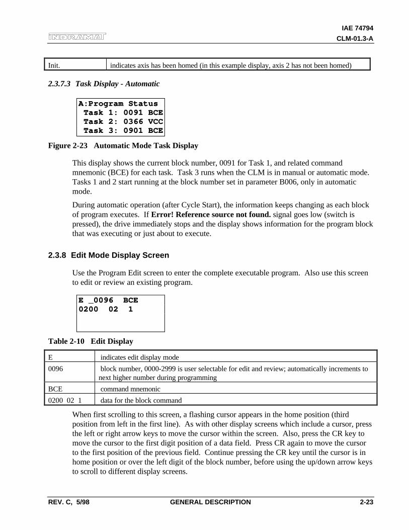
IAE 74794
CLM-01.3-A
REV. C, 5/98 GENERAL DESCRIPTION 2-23
Init. indicates axis has been homed (in this example display, axis 2 has not been homed)
2.3.7.3 Task Display - Automatic
A:Program StatusA:Program Status Task 1: 0091 BCE Task 1: 0091 BCE Task 2: 0366 VCC Task 2: 0366 VCC Task 3: 0901 BCE Task 3: 0901 BCE
Figure 2-23 Automatic Mode Task Display
This display shows the current block number, 0091 for Task 1, and related commandmnemonic (BCE) for each task. Task 3 runs when the CLM is in manual or automatic mode.Tasks 1 and 2 start running at the block number set in parameter B006, only in automaticmode.
During automatic operation (after Cycle Start), the information keeps changing as each blockof program executes. If Error! Reference source not found. signal goes low (switch ispressed), the drive immediately stops and the display shows information for the program blockthat was executing or just about to execute.
2.3.8 Edit Mode Display Screen
Use the Program Edit screen to enter the complete executable program. Also use this screento edit or review an existing program.
E _0096 BCEE _0096 BCE0200 02 10200 02 1
Table 2-10 Edit Display
E indicates edit display mode
0096 block number, 0000-2999 is user selectable for edit and review; automatically increments tonext higher number during programming
BCE command mnemonic
0200 02 1 data for the block command
When first scrolling to this screen, a flashing cursor appears in the home position (thirdposition from left in the first line). As with other display screens which include a cursor, pressthe left or right arrow keys to move the cursor within the screen. Also, press the CR key tomove the cursor to the first digit position of a data field. Press CR again to move the cursorto the first position of the previous field. Continue pressing the CR key until the cursor is inhome position or over the left digit of the block number, before using the up/down arrow keysto scroll to different display screens.
IAE 7479
CLM-01.3-A
2-24 GENERAL DESCRIPTION REV. C, 5/98
To select different program blocks of information to display (for review or edit), press theright/left arrow keys to position the cursor over the first digit of the block number and typeover the existing block number. Command and data for this selected block will then appear.To scroll through the block numbers, press the CR key to locate the cursor in the top line,then use the + or - key to scroll through the blocks (with previous version software, thecursor must be to the left of the block number - home position). The block number willincrease or decrease accordingly and display the respective data for each block.
To enter program, start at block "0000" for task 1. Note that task 2 and task 3 program startsat the block number assigned by the user in parameter B006. If block "0000" is not displayed,press the right arrow key one time from home position to move the cursor on the first digit ofthe block number. Type the number "0000" to display that block number.
To enter or change a program command for each block, first press the right arrow key untilthe cursor moves to the right of the three digit program command mnemonic (i.e. NOP_).Press the up or down arrow keys to increment or decrement through the commandsalphabetically. When the desired command appears on the screen, press the right arrow key.The cursor moves to the beginning of the second line where the data fields appear specificallyfor the selected command. If this block was not previously programmed with this samecommand, asterisks (*) appear in the digit positions where data must be entered. Afterentering and verifying the program, press the Store key to save the programmed block tomemory. The next program block number automatically appears, waiting to be programmed.Continue this process until all lines of user program are done. Note that the program can beedited or added to at a later time.
When changing data from the Edit display screen, pressing the CR key before pressing theStore key, will cancel the change and leave the data as previously stored (saved). The displayremains at the same block number and the cursor moves to the first position of the previousfield. Changing to another block number, display screen, etc. without first pressing the Storekey also causes loss of a change to a block's data.
Chapter 5 provides the information on commands required for creating the user executableprogram.
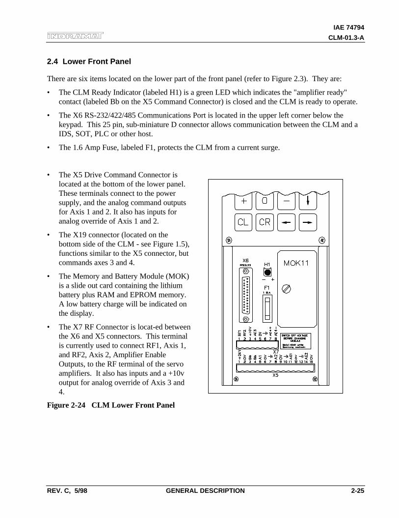
IAE 74794
CLM-01.3-A
REV. C, 5/98 GENERAL DESCRIPTION 2-25
2.4 Lower Front Panel
There are six items located on the lower part of the front panel (refer to Figure 2.3). They are:
• The CLM Ready Indicator (labeled H1) is a green LED which indicates the "amplifier ready"contact (labeled Bb on the X5 Command Connector) is closed and the CLM is ready to operate.
• The X6 RS-232/422/485 Communications Port is located in the upper left corner below thekeypad. This 25 pin, sub-miniature D connector allows communication between the CLM and aIDS, SOT, PLC or other host.
• The 1.6 Amp Fuse, labeled F1, protects the CLM from a current surge.
• The X5 Drive Command Connector islocated at the bottom of the lower panel.These terminals connect to the powersupply, and the analog command outputsfor Axis 1 and 2. It also has inputs foranalog override of Axis 1 and 2.
• The X19 connector (located on thebottom side of the CLM - see Figure 1.5),functions similar to the X5 connector, butcommands axes 3 and 4.
• The Memory and Battery Module (MOK)is a slide out card containing the lithiumbattery plus RAM and EPROM memory.A low battery charge will be indicated onthe display.
• The X7 RF Connector is locat-ed betweenthe X6 and X5 connectors. This terminalis currently used to connect RF1, Axis 1,and RF2, Axis 2, Amplifier EnableOutputs, to the RF terminal of the servoamplifiers. It also has inputs and a +10voutput for analog override of Axis 3 and4.
Figure 2-24 CLM Lower Front Panel

IAE 7479
CLM-01.3-A
2-26 GENERAL DESCRIPTION REV. C, 5/98
IAE 74794
CLM-01.3-A
REV. C, 5/98 FUNCTIONAL DESCRIPTION OF I/O CONNECTIONS 3-1
3. FUNCTIONAL DESCRIPTION OF I/O CONNECTIONS
The CLM motion control system is designed to function harmoniously within the machine builder'sequipment design. Several input / output signals of the CLM control provide communication to /from the other components of the machine builder's equipment. This chapter describes the functionaloperation of the interfacing inputs and outputs of the CLM.
The first sections of this chapter describe the various interface functions in terms of the inputs /outputs involved with each. This includes the pre-defined I/O connections of the CLM, as well ascertain functions which the user can select through parameter or programming, using auxiliary I/Oconnections. Certain auxiliary output functions are set in firmware, as described in Chapter 5 for userprogramming.
This first section is followed by an individual description of each pre-defined I/O signal, includingname, pin assignments, and functional description. The designer utilizes these signals as necessary toimplement the CLM for his application, including the design of his system control panel.
3.1 Signal Definitions
The states of the input and output signals described in this manual are:
• High = +24 Vdc
• Low = 0 Vdc
A signal line is described as "active high" when its associated action is initiated by a high (+24 Vdc)signal level. It is described as "active low" when its function is initiated by a low signal (0 volts).Active low signals are shown in this manual (when specifically referred to as a signal) with a bar (line)
over the signal name, as an example, Emergency Stop . This signal must be high during normaloperation. If it goes low, the CLM initiates the actions required for an emergency stop function.
IAE 7479
CLM-01.3-A
3-2 FUNCTIONAL DESCRIPTION OF I/O CONNECTIONS REV. C, 5/98
3.2 Interface Descriptions
The CLM input and output signals provide communication to/from the machine builder's equipment.Certain I/O signals should be considered as functional groups of signals, working in concert.
These functions include:
• Operating Mode Selection
• Servo System Operation Enables
• Safety Interlocks
• Normal Operation Signals
• Axis Homing
• Manual Operations
• Fault/Diagnostic Circuitry
• Feed Monitoring / Program Interruption
• Special Functions
Figures 3.1, 3.2 and 3.3 illustrate the X3 Input, X4 Output and X22 Input/Output connectors andeach pin designation.
The following sections describe each group of interface functions, first listing the I/O signals involved(and section where each signal is individually described), then describing the general function of thesignals.
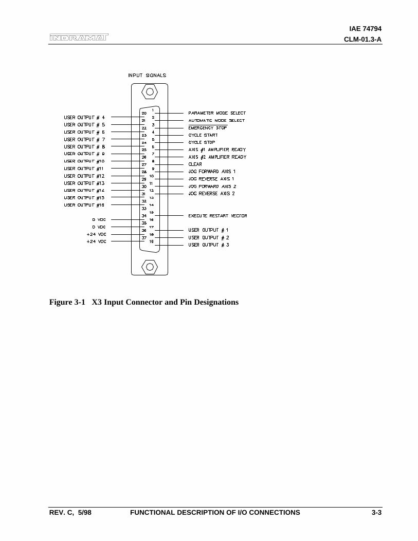
IAE 74794
CLM-01.3-A
REV. C, 5/98 FUNCTIONAL DESCRIPTION OF I/O CONNECTIONS 3-3
Figure 3-1 X3 Input Connector and Pin Designations
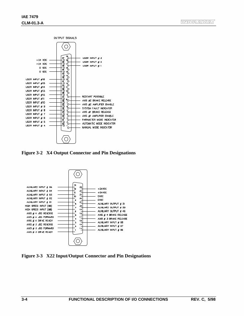
IAE 7479
CLM-01.3-A
3-4 FUNCTIONAL DESCRIPTION OF I/O CONNECTIONS REV. C, 5/98
Figure 3-2 X4 Output Connector and Pin Designations
Figure 3-3 X22 Input/Output Connector and Pin Designations
IAE 74794
CLM-01.3-A
REV. C, 5/98 FUNCTIONAL DESCRIPTION OF I/O CONNECTIONS 3-5
3.2.1 Operating Mode Selection
InputsParameter Mode Select (3.3.1)
Automatic Mode Select (3.3.2)
OutputsManual Mode Indicator (3.4.1)
Auto Mode Indicator (3.4.2)
Parameter Mode Indicator (3.4.3)
The CLM will always be in one of three operating modes:
Parameter Mode Allows entry/verification of the parameters required to adapt the control for the specificrequirements of the application.
Automatic Mode Runs the user written executable program for automatic cycle operation (process 1 and 2run after a Cycle Start input).
Manual Mode Default mode when neither of the above are selected. In this mode, use the jog inputs tomove the material forward or reverse through the system.
Parameter and Automatic Modes are selected by bringing the appropriate signal line high (+24Vdc). A fault is diagnosed and an "Invalid Mode Selection" error message is issued if bothAutomatic and Parameter Mode signal lines are high simultaneously.
The suggested interface design is to wire the Parameter Mode signal to a key-switch, where akey is required to enter Parameter Mode and/or mount the switch inside the cabinet. Thishelps to prevent unauthorized parameter changes. Wire the Automatic Mode input signal to atwo-position selector switch, where Manual Mode is selected when the switch is set to anopen contact position.
The CLM has outputs to verify or acknowledge the currently selected mode. These aretypically wired to indicator lights on the user's control panel or to a PLC.
IAE 7479
CLM-01.3-A
3-6 FUNCTIONAL DESCRIPTION OF I/O CONNECTIONS REV. C, 5/98
3.2.2 Servo System Operation Enables
InputsAxis 1 Amplifier Ready (3.3.6)
Axis 2 Amplifier Ready (3.3.6)
Axis 3 Amplifier Ready (3.3.6)
Axis 4 Amplifier Ready (3.3.6)
OutputsAxis 1 Amplifier Enable (3.4.4)
Axis 1 Brake Release (3.4.5)
Axis 2 Amplifier Enable (3.4.4)
Axis 2 Brake Release (3.4.5)
Axis 3 Amplifier Enable (3.4.4)
Axis 3 Brake Release (3.4.5)
Axis 4 Amplifier Enable (3.4.4)
Axis 4 Brake Release (3.4.5)
The CLM is designed so that various conditions must be satisfied to allow the servos tooperate. If these conditions are not satisfied, the appropriate diagnostic message is displayed.
When the system is powered up, the CLM expects to receive Amplifier Ready inputs for eachaxis (#1 through #4) that has been enabled in parameters B000-B003, indicating the servoamplifiers and power supply have properly powered up and the amplifiers are ready for anEnable signal.
Assuming conditions are appropriate for operation, the CLM issues axis #1 through #4Amplifier Enable outputs to allow the amplifier to operate and axis #1 through #4 BrakeRelease outputs to lift the spring-loaded servomotor brake (if using motor versions wherebrake is present).
IAE 74794
CLM-01.3-A
REV. C, 5/98 FUNCTIONAL DESCRIPTION OF I/O CONNECTIONS 3-7
3.2.3 Safety Interlocks
InputsEmergency Stop (3.3.3)
Motor Overtemp
Outputs
System Fault Indicator (3.4.6)
As described in the previous section, the CLM and its servos must perform operational checksand provide the proper signals to enable operation. There are other signals which serve asinterlocks.
Emergency Stop -- The Emergency Stop input must remain high for the CLM to operate.The system incorporates an Emergency Stop (E-Stop) chain. This is a circuit connected inseries to both the CLM and the user's machine. Should any sensor in the E-stop chain open,all operations immediately stop. Note that the time taken to stop depends on the wiringmethod used, and inertia of the load connected to the servo motor on the machine.
Elements connected in the E-stop chain commonly include the Emergency Stop switch on theuser's control panel; E-stop switch(es) on the machine; switches on lubrication or coolantpumps; and various safety interlock switches on guards and doors.
Motor Overtemp -- The thermally activated switch (TAS) of an Indramat MAC servomotoris typically connected to the respective Drive Ready input through a relay (to provide isolationfor the motor power cable). If a motor overheats, the TAS opens and drops the +24 Vdcsignal (de-energizing the relay, opening the Drive Ready input line). The "Drive Not Ready"diagnostic message is displayed and the system is halted. Although not a direct input to theCLM, this TAS circuit is important for servo motor protection.
There are several categories of faults, as described in Chapter 8. In general, once a fault is
detected, an error message is displayed on the CLM display, the System Fault Indicatoroutput turns OFF and all axes are decelerated to a stop.
The fault recovery procedure is to first troubleshoot and remedy the problem. Then, press theClear key on the CLM control panel (or external Clear input on user control panel, seesection 3.2.7) to clear the CLM fault status and diagnostic message on the display.
IAE 7479
CLM-01.3-A
3-8 FUNCTIONAL DESCRIPTION OF I/O CONNECTIONS REV. C, 5/98
3.2.4 Normal Operation Signals
InputsCycle Start (3.3.4)
Cycle Stop (3.3.5)
OutputsAxis Nearing Position (Pre Signal) (Ax07)
Axis In-Position (Ax06)
The automatic execution of the user program begins when the Cycle Start line goes high(momentary) with the CLM in Automatic Mode. Once the automatic cycle begins, it isnormally stopped by actuating the Error! Reference source not found. input (signal goes low). Thesystem will also stop if an error is detected or if the CLM is switched to Manual Mode.
An auxiliary output can be assigned for each axis in parameters Ax07 (Position Pre-signal) toturn ON when the feed axis position is at a specified distance (in input units) from the targetposition of the commanded feed. Use this pre-signal when there is a need to anticipate theend of a feed, so another process can be initiated ahead of time. An example use would be toturn on a heater for bag sealing or plastic thermal forming operations. See Chapter 4 forfurther information on this parameter function.
NOTE: As described in Chapter 4, an "A" parameter set is provided for each axis (1 through 4).The first number after the "A" determines the axis number. Throughout this manual, when referringto an "A" parameter that effects all axes, an "x" is used in the second position to indicate 1, 2, 3,and/or 4.
An auxiliary output (Axis In-Position) can be assigned for each axis in parameters Ax06 toturn ON when the feed axis position is within the position threshold specified in theparameter. This position threshold does not affect the accuracy of the feed. It tells theprogram when to read the next program block (see PSI, PSA in Chapter 5). This output canbe used to turn ON a light or buzzer on the user's control panel, or as a flag in the program tostart a sub-routine program operation, etc. See Chapter 4 for further information on thisparameter function.
IAE 74794
CLM-01.3-A
REV. C, 5/98 FUNCTIONAL DESCRIPTION OF I/O CONNECTIONS 3-9
3.2.5 Axis Homing
InputsInitiate Homing in Manual Mode
Home Switch
OutputsHome Established Indicator
For absolute referencing of the axis with an incremental encoder, it is necessary to establish acorrect measurement reference with the help of a homing routine. To initiate homing duringmanual operation, use auxiliary input signals (as defined in parameter Ax12); during automaticoperation, by use of the "HOM" command.
Auxiliary inputs (Initiate Homing) can be assigned for each axis in parameters Ax12 to initiatethe homing process in Manual Mode by a push-button switch or from a PLC output. Homeposition can be set to an Incremental Encoder marker pulse, or to a Home Switch (assign anauxiliary input for the home switch in parameter).
Homing each axis in Automatic Mode is accomplished through use of the HOM command(when using an incremental encoder). After reading in this command for one axis, the nextblock is read in with the same command for the second axis, allowing the homing procedureto occur simultaneously for both axes. Use an ATS command to monitor the HomeEstablished auxiliary output (as set in parameter Ax12) to prevent reading any AbsolutePosition commands (POA, PSA) until the home procedure is finished.
3.2.5.1 Homing Procedure--Refer to Figure 3.4
1. Homing command is issued.
2. If the slide is not on the Home Limit switch, it moves in "reverse" at the Velocity 1 (V1)speed (set in Ax10) toward home until the switch closes. It will then decelerate, reversedirection and move "forward" at V2 speed (25% of V1) until the switch opens. If theslide is already on the switch when the command is issued, it moves forward off the switchat V2 speed.
NOTE: For any amount of travel that exists in the minus direction of the home switch point, thehome switch must remain closed. The home switch dog must be at least as long as the reverse traveldistance from the home switch.
3. The axis decelerates, reverses direction and creeps in the "reverse" direction at V3 speed(5000 pulses/second) passing and closing the Home Limit switch, and continues in the"reverse" direction at a super creep rate until the zero (or marker) pulse of the encoderoccurs.
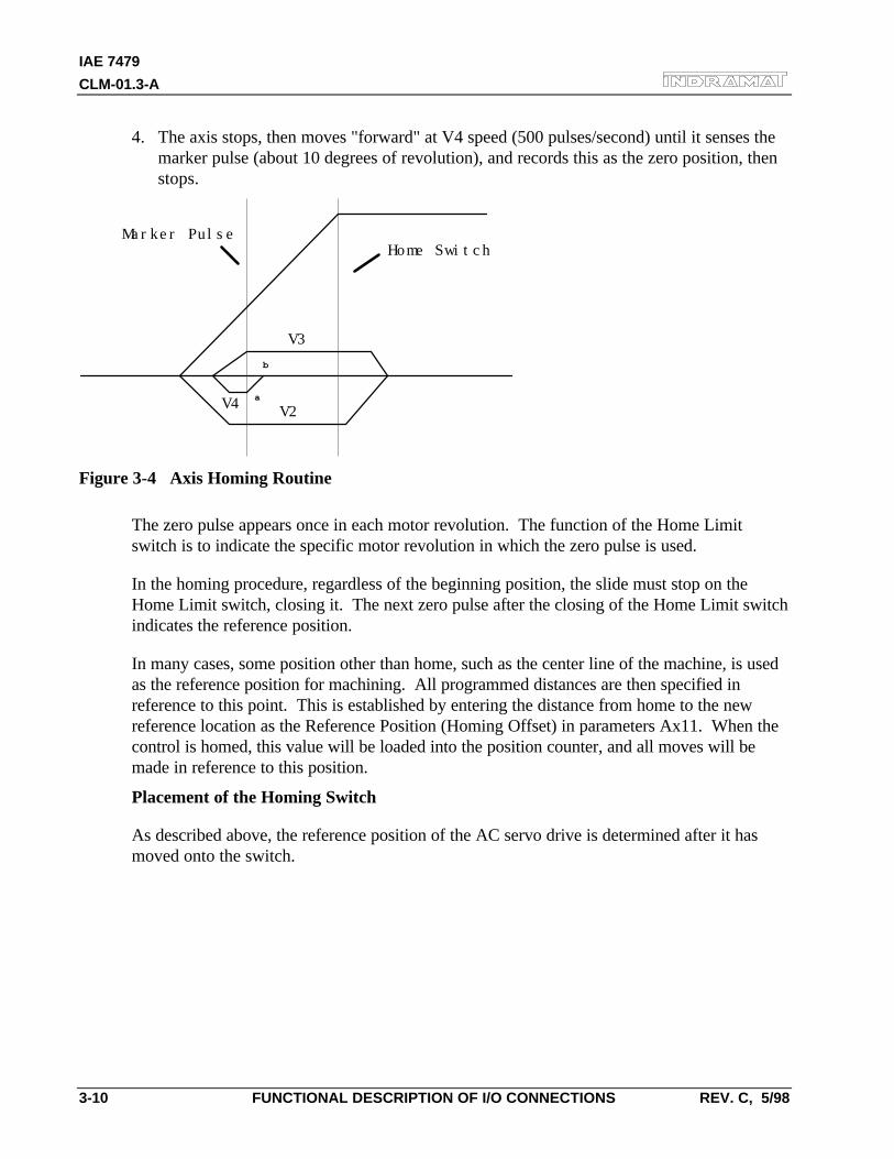
IAE 7479
CLM-01.3-A
3-10 FUNCTIONAL DESCRIPTION OF I/O CONNECTIONS REV. C, 5/98
4. The axis stops, then moves "forward" at V4 speed (500 pulses/second) until it senses themarker pulse (about 10 degrees of revolution), and records this as the zero position, thenstops.
Marker PulseHome Switch
V3
V4 V2
b
a
Figure 3-4 Axis Homing Routine
The zero pulse appears once in each motor revolution. The function of the Home Limitswitch is to indicate the specific motor revolution in which the zero pulse is used.
In the homing procedure, regardless of the beginning position, the slide must stop on theHome Limit switch, closing it. The next zero pulse after the closing of the Home Limit switchindicates the reference position.
In many cases, some position other than home, such as the center line of the machine, is usedas the reference position for machining. All programmed distances are then specified inreference to this point. This is established by entering the distance from home to the newreference location as the Reference Position (Homing Offset) in parameters Ax11. When thecontrol is homed, this value will be loaded into the position counter, and all moves will bemade in reference to this position.
Placement of the Homing Switch
As described above, the reference position of the AC servo drive is determined after it hasmoved onto the switch.
IAE 74794
CLM-01.3-A
REV. C, 5/98 FUNCTIONAL DESCRIPTION OF I/O CONNECTIONS 3-11
The reference position can be set in steps of one motor revolution each, by using the positionthe switch is in when it is activated. By monitoring the switching point of the homing switchand the marker pulse, a CLM diagnostic check eliminates the danger that these two are soclose to each other that the switching tolerance limits will result in uncertainty about themotor revolution to be evaluated. If the switching point of the homing switch is closer than1/16 of a motor revolution, with respect to the marker pulse, the control unit will notcomplete the homing process, and will change over to fault indication. The display will show:Marker Pulse 1? (or 2, 3, or 4, depending on the axis affected). The homing switch should berelocated by 1/3 of the feed constant.
Activating the Homing Switch
Activating the homing switch must be done in such a way that the switch closes upon backingup, i.e. upon the movement away from the work piece. The dog cam for activating thehoming switch must be long enough so that the activation is not canceled by a continuingreverse movement up to the minus travel limit of the axis. This is required to indicate to thecontrol unit in which direction the slide must be moved in order to approach the referenceposition.
Since the interrelationship between the direction of rotation of a servo motor and themovement away from, and toward, the work piece depends on the particular design of themachine, the homing direction must be also set correctly in the parameters.
If there is no marker pulse from the encoder within one revolution of the encoder, homingsequence is halted, and a fault is displayed. The display will show: "No Marker Pulse 1" (or2, 3, 4 - affected axis).
Interruption of the Homing Routine
If, while in manual operation, there is a stop, an interruption, feed angle monitoring, or aswitch of operating modes, the homing cycle is interrupted and must be restarted. After aninterruption or stop occurs while in automatic operation, the homing cycle is restartedimmediately by activating the Cycle Start input. After a fault or a change of operating modesduring the homing cycle, the CLM must be re-initiated (switch to Auto Mode, press CycleStart).
Over-travel Switches
It is recommended that you install forward and reverse over-travel switches on applicationsthat have limited axis travel, such as a slide or a ballscrew driven axis. The switches can bewired either to the "drives ON" circuit or to the Cycle Stop input of the CLM. See appendixF for recommended interconnection. You must reserve distance beyond the limit switches toallow for deceleration of the axis to a stop.
IAE 7479
CLM-01.3-A
3-12 FUNCTIONAL DESCRIPTION OF I/O CONNECTIONS REV. C, 5/98
3.2.6 Manual Operations
InputsJog Forward (Axis 1) (3.3.8)
Jog Reverse (Axis 1) (3.3.9)
Jog Forward (Axis 2) (3.3.8)
Jog Reverse (Axis 2) (3.3.9)
Jog Forward (Axis 3) (3.3.8)
Jog Reverse (Axis 3) (3.3.9)
Jog Forward (Axis 4) (3.3.8)
Jog Reverse (Axis 4) (3.3.9)
Initiate Manual Vector Program
OutputsNone
The CLM's Jog inputs allow jogging of each axis forward and reverse. Parameter Ax01specifies the jog feed rate for each axis. It usually is set to approximately 10% of themaximum feed rate. It can never be more than the maximum feed rate.
In Manual Mode, either axis can be jogged forward or reverse. The Jog inputs are notfunctional in Parameter or Automatic Modes. A high on the Jog Forward input causes theaxis to feed forward at the velocity set in parameter. The feed continues as long as the JogForward remains high. The Jog Reverse operates similarly, jogging the axis in the reversedirection.
In order to make use of the software travel limits when in Manual Mode, the axis must behomed first. It is recommended to prevent jogging by interlock until home is established forthe axis. The Home Established output (Ax12) can be used for this purpose.
An auxiliary input, Initiate Manual Vector Program, can be assigned in parameter B011 andused to initiate a user program to run in Manual Mode. This program may not contain anyfeed instructions and should not be located in the main program. Select by parameter to startthis program by an external input (push-button switch) or automatically when mode ischanged from Automatic to Manual. The program is aborted if switched out of ManualMode. The manual vector is not accepted while jogging or homing in Manual Mode (see lastsection). Jogging or homing is not possible while the manual vector program is running.
An example use of the Manual Vector program is to use the APE command to set the statesof auxiliary outputs. This command is programmed to set a bank/group of ten outputsindividually to ON, OFF or Don't Care states. This allows setting outputs for a "shut-down"mode, or as default before starting automatic operation. See Chapter 4 for additionalinformation on parameters and Chapter 5 for programming commands.
IAE 74794
CLM-01.3-A
REV. C, 5/98 FUNCTIONAL DESCRIPTION OF I/O CONNECTIONS 3-13
3.2.7 Fault/Diagnostic Monitoring
InputsClear (External) (3.3.7)
Restart Select (3.3.10)
Outputs
System Fault Indicator (3.4.6)
Restart Possible Indicator (3.4.7)
The CLM includes extensive diagnostic monitoring circuitry, detecting normal operatingstatus, operator errors, errors in the control itself and machine faults.
There are several categories of faults, as described in Chapter 8. In general, once a fault is
detected, an error message is displayed on the CLM display, the System Fault Indicatoroutput turns OFF (turns OFF “System OK” or turns ON “Fault” light, driven by relay, on usercontrol panel) and both axes are decelerated to a stop.
The fault recovery procedure is to first troubleshoot and remedy the problem. Then, press theClear key on the CLM control panel (or external Clear input on user control panel) to clearthe CLM fault status and diagnostic message on the display.
If the user program is interrupted by a power loss, system error or mode change, the status ofoutputs, absolute target position and velocity are temporarily stored in memory. Parameter 56can be used to define the starting program block for a Restart Vector routine. Based on thetype of error and system configuration, it may be possible to restore the status of the CLM asbefore the interrupt. This is indicated by the Restart Possible output (ON = restart possible,OFF = restart not possible). The Restart Vector routine is initiated by a momentary inputpulse, OFF to ON, from the Restart Select input. The Restart Vector program should startwith the RSV command. See Chapter 5 for information on programming commands. SeeChapter 4 for further information on this parameter function. Diagnostics and faulttroubleshooting procedures are described in Chapter 8.
3.2.8 Feed Monitoring / Program Interruption
InputsInterrupt Vector Program
Feed Angle, Axis 1
Feed Angle, Axis 2
Feed Interrupt , Axis 1
Feed Interrupt , Axis 2
OutputsNone
IAE 7479
CLM-01.3-A
3-14 FUNCTIONAL DESCRIPTION OF I/O CONNECTIONS REV. C, 5/98
An auxiliary input, Interrupt Vector/Program, can be assigned in parameter B012 tointerrupt the user program at any time and start an Interrupt Vector sub-routine program(Automatic Mode only). When this input goes high, the current program sequence will beinterrupted immediately or after the current sub-routine program is finished (option set inparameter). The program sequence will then continue at the start program block numberassigned in the parameter for the Interrupt Vector program. See Chapter 4 for furtherinformation on this parameter function.
An auxiliary input, Feed Angle Monitoring, can be assigned for each axis in parameter Ax20to prevent the program from executing any feed length commands. The CLM will process allprogram blocks not containing any feed lengths. If there is no signal at the assigned input, theprogram continues to execute until it processes to a block containing a feed length. The CLMwill stop in this block until there is a signal at the input. If the input signal turns OFF during afeed, the feed will be stopped and an error message will be displayed.
An auxiliary input, Feed Interrupt ( Feed Hold ), can be assigned for each axis in parameterAx40 to prevent the program from executing any feed length commands. The CLM willprocess all program blocks not containing any feed lengths. If the input is low, the programcontinues to execute until it processes to a block containing a feed length. The CLM will stopin this block until the assigned input goes high. If the input goes low during a feed, the feedwill be stopped. Feed will automatically resume as soon as the signal goes high.
An example of use for this signal is in conjunction with a material loop. Material is fed from
an uncoiler into a looping pit, with an optical sensor in the pit tied to the Feed Interrupt line.If the material pulls too tight, the signal goes low and the feed cycle is interrupted. As soon asan adequate amount of material is fed into the looping pit, the signal returns high and the feedcycle immediately resumes. Another example of use for this signal is in conjunction with apress type system. For a punch press, this signal would come up shortly after the ram clearsthe material on its upstroke. The signal would drop (go low) on the ram downstroke,allowing some safety margin before the ram reaches the material. The material feed must havestopped before this signal drops. See Chapter 4 for further information on this parameterfunction.
WARNING: If the automatic cycle is interrupted by a low on the Feed Interrupt line, all feedmotion is suspended. Once this signal is restored high, the feed cycle will immediately resume. Thework area should not be entered if the feed has stopped as a result of this signal.
IAE 74794
CLM-01.3-A
REV. C, 5/98 FUNCTIONAL DESCRIPTION OF I/O CONNECTIONS 3-15
3.2.9 Special Functions
InputsDetect Registration Mark (High Speed) (3.3.11)
Position Loop Reset
Interrupt Vector/Program
Enable Measuring Wheel Operation and Dual Encoder Option
OutputsAcknowledge Roll Lifting Active
Achieved Programmed Velocity
An auxiliary input, Detect Registration Mark, can be assigned in the REF programcommand to cause the CLM to search for a registration or reference mark on the material. Toprovide this input signal, use a sensor which detects a printed mark or stamp on each piece ofmaterial. A high signal must be present on this input when a reference mark is present underthe sensor.
The accuracy and duration of this signal is essential to the proper operation of positioncorrection, especially if the mark needs to be detected at high speeds. Three high speedinputs are provided for this specific purpose. They can detect an input signal of 150microseconds duration, compared to the 2 to 4 milliseconds duration required for otherinputs. Refer to the REF program command in Chapter 5 for additional information on usingthis feature.
For Measuring Wheel operation, set options in parameters B009 and B010. Theseparameters establish the feed rate constant and the number impulses of the measuring wheelencoder. They also allow assigning an auxiliary input for selecting measuring wheel or motorencoder feedback. During measuring wheel operation, the measurement of lengths is from themeasuring wheel encoder, rather than the integral motor encoder.
The Dual Encoder Option in parameter B008 allows quicker response with measuring wheeloperation. When selected, the position loop is closed using motor encoder feedback and themeasuring wheel encoder provides adjustments to the length during feeding. When this optionis not selected, the Position Loop is closed using the measuring wheel encoder. Lack ofstiffness in the mechanical components between the motor and the wheel can require using alower gain, which increases the response time.
During manual operation, the position feedback always comes from the motor encoder.During automatic operation, there is a choice between continuous measuring wheel operationand using an auxiliary input signal to select measuring wheel operation.
IAE 7479
CLM-01.3-A
3-16 FUNCTIONAL DESCRIPTION OF I/O CONNECTIONS REV. C, 5/98
The following conditions must be met:
• The material is in the feed rolls and under the measuring wheel
• The feed rolls are closed
• The measuring wheel is pressing against the material
If one of the above conditions is not met, the drive can run temporarily out of control until itis stopped through an internal error detection procedure of the control unit.
Error messages are:
• Encoder Error
• Drive Runaway
If the feed roll has to be lifted in conjunction with the measuring wheel operation, the auxiliaryinput signal must be used to discontinue the "measuring wheel operation" while the roll islifted. Care must be taken that the timing is correct during the cycling of the feed rollscontacting and releasing from the material. Refer to Chapter 4 for additional information onthis parameter function.
Auxiliary inputs, Position Loop Reset inputs, can be assigned in parameters Ax15 for eachaxis. This function allows shifting of the incremental position without causing a position fault.This parameter also allows user assigned auxiliary outputs to indicate when Position Loop isreset and separately, when the programmed velocity has been achieved. Their are mechanicallimitations that must be considered when using this function. Consult a Indramat CLMApplication Engineer for additional requirements. Refer to Chapter 4 for additionalinformation on this parameter function.
IAE 74794
CLM-01.3-A
REV. C, 5/98 FUNCTIONAL DESCRIPTION OF I/O CONNECTIONS 3-17
3.3 Input Signal Descriptions
This section describes the Inputs to the CLM control from external sources. The Input and Outputsignal lines of the CLM are optically isolated from the CLM's internal bus structure to minimizeelectrical noise interference.
The connectors and pin numbers of these signals are described in the following sections and shown inFigures 3.1 (X3) and 3.3 (X22).
3.3.1 Parameter Mode Select
Connector X3, pin 1
Function (Input) Selects Parameter Mode
+24 Vdc Parameter Mode selected.
0 Vdc Parameter Mode is not selected; another mode is selected or the system has defaulted to theManual Mode.
The Parameter Mode Select will override any other mode selection input. If properly wired,selecting Parameter Mode while Automatic Mode is already selected, does not cause an error.When Parameter Mode is deselected, the CLM returns to the previously selected mode -Automatic or Manual (default when no other modes are selected).
NOTE: Task 3 stops in Parameter Mode.
3.3.2 Automatic Mode Select
Connector X3, pin 2
Function (Input) Selects Automatic Mode
+24 Vdc Automatic Mode selected.
0 Vdc Automatic Mode is not selected; another mode is selected or the system has defaulted to theManual Mode.
If this signal line is high at the same time the Parameter Mode is selected (input high), theCLM issues the "Invalid Mode Selection" diagnostic error message.
NOTE: Task 3 will be running in either Manual or Automatic Mode.
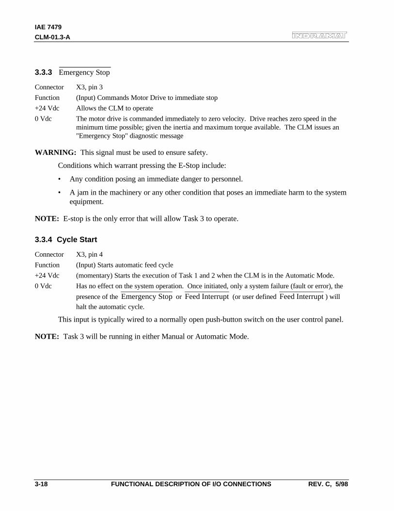
IAE 7479
CLM-01.3-A
3-18 FUNCTIONAL DESCRIPTION OF I/O CONNECTIONS REV. C, 5/98
3.3.3 Emergency Stop
Connector X3, pin 3
Function (Input) Commands Motor Drive to immediate stop
+24 Vdc Allows the CLM to operate
0 Vdc The motor drive is commanded immediately to zero velocity. Drive reaches zero speed in theminimum time possible; given the inertia and maximum torque available. The CLM issues an"Emergency Stop" diagnostic message
WARNING: This signal must be used to ensure safety.
Conditions which warrant pressing the E-Stop include:
• Any condition posing an immediate danger to personnel.
• A jam in the machinery or any other condition that poses an immediate harm to the systemequipment.
NOTE: E-stop is the only error that will allow Task 3 to operate.
3.3.4 Cycle Start
Connector X3, pin 4
Function (Input) Starts automatic feed cycle
+24 Vdc (momentary) Starts the execution of Task 1 and 2 when the CLM is in the Automatic Mode.
0 Vdc Has no effect on the system operation. Once initiated, only a system failure (fault or error), the
presence of the Emergency Stop or Feed Interrupt (or user defined Feed Interrupt ) will
halt the automatic cycle.
This input is typically wired to a normally open push-button switch on the user control panel.
NOTE: Task 3 will be running in either Manual or Automatic Mode.
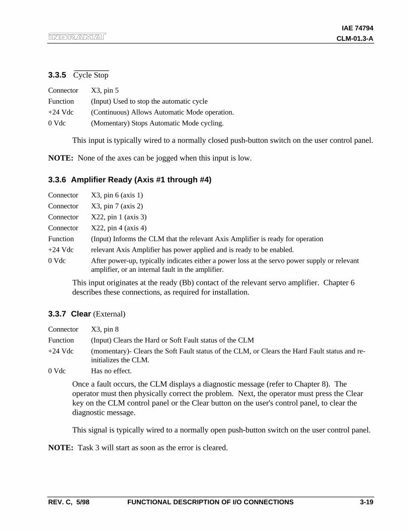
IAE 74794
CLM-01.3-A
REV. C, 5/98 FUNCTIONAL DESCRIPTION OF I/O CONNECTIONS 3-19
3.3.5 Cycle Stop
Connector X3, pin 5
Function (Input) Used to stop the automatic cycle
+24 Vdc (Continuous) Allows Automatic Mode operation.
0 Vdc (Momentary) Stops Automatic Mode cycling.
This input is typically wired to a normally closed push-button switch on the user control panel.
NOTE: None of the axes can be jogged when this input is low.
3.3.6 Amplifier Ready (Axis #1 through #4)
Connector X3, pin 6 (axis 1)
Connector X3, pin 7 (axis 2)
Connector X22, pin 1 (axis 3)
Connector X22, pin 4 (axis 4)
Function (Input) Informs the CLM that the relevant Axis Amplifier is ready for operation
+24 Vdc relevant Axis Amplifier has power applied and is ready to be enabled.
0 Vdc After power-up, typically indicates either a power loss at the servo power supply or relevantamplifier, or an internal fault in the amplifier.
This input originates at the ready (Bb) contact of the relevant servo amplifier. Chapter 6describes these connections, as required for installation.
3.3.7 Clear (External)
Connector X3, pin 8
Function (Input) Clears the Hard or Soft Fault status of the CLM
+24 Vdc (momentary)- Clears the Soft Fault status of the CLM, or Clears the Hard Fault status and re-initializes the CLM.
0 Vdc Has no effect.
Once a fault occurs, the CLM displays a diagnostic message (refer to Chapter 8). Theoperator must then physically correct the problem. Next, the operator must press the Clearkey on the CLM control panel or the Clear button on the user's control panel, to clear thediagnostic message.
This signal is typically wired to a normally open push-button switch on the user control panel.
NOTE: Task 3 will start as soon as the error is cleared.
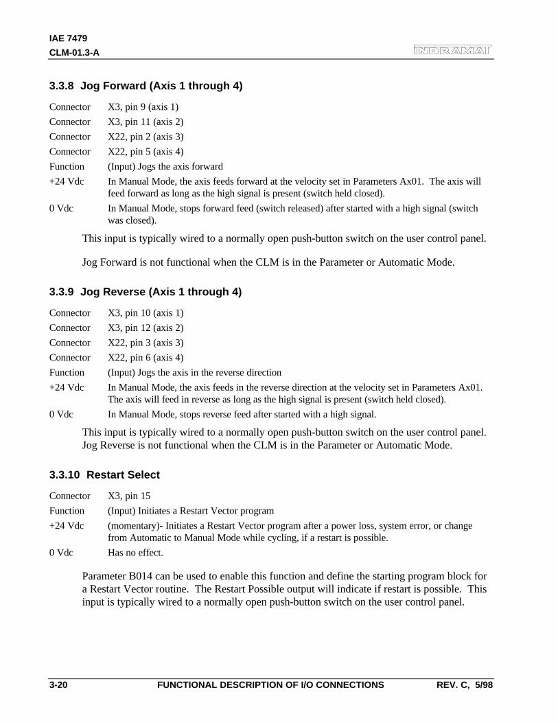
IAE 7479
CLM-01.3-A
3-20 FUNCTIONAL DESCRIPTION OF I/O CONNECTIONS REV. C, 5/98
3.3.8 Jog Forward (Axis 1 through 4)
Connector X3, pin 9 (axis 1)
Connector X3, pin 11 (axis 2)
Connector X22, pin 2 (axis 3)
Connector X22, pin 5 (axis 4)
Function (Input) Jogs the axis forward
+24 Vdc In Manual Mode, the axis feeds forward at the velocity set in Parameters Ax01. The axis willfeed forward as long as the high signal is present (switch held closed).
0 Vdc In Manual Mode, stops forward feed (switch released) after started with a high signal (switchwas closed).
This input is typically wired to a normally open push-button switch on the user control panel.
Jog Forward is not functional when the CLM is in the Parameter or Automatic Mode.
3.3.9 Jog Reverse (Axis 1 through 4)
Connector X3, pin 10 (axis 1)
Connector X3, pin 12 (axis 2)
Connector X22, pin 3 (axis 3)
Connector X22, pin 6 (axis 4)
Function (Input) Jogs the axis in the reverse direction
+24 Vdc In Manual Mode, the axis feeds in the reverse direction at the velocity set in Parameters Ax01.The axis will feed in reverse as long as the high signal is present (switch held closed).
0 Vdc In Manual Mode, stops reverse feed after started with a high signal.
This input is typically wired to a normally open push-button switch on the user control panel.Jog Reverse is not functional when the CLM is in the Parameter or Automatic Mode.
3.3.10 Restart Select
Connector X3, pin 15
Function (Input) Initiates a Restart Vector program
+24 Vdc (momentary)- Initiates a Restart Vector program after a power loss, system error, or changefrom Automatic to Manual Mode while cycling, if a restart is possible.
0 Vdc Has no effect.
Parameter B014 can be used to enable this function and define the starting program block fora Restart Vector routine. The Restart Possible output will indicate if restart is possible. Thisinput is typically wired to a normally open push-button switch on the user control panel.
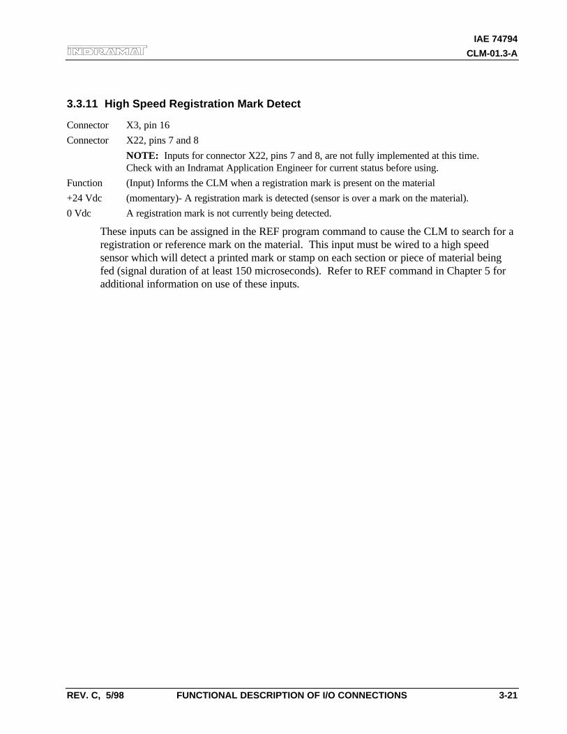
IAE 74794
CLM-01.3-A
REV. C, 5/98 FUNCTIONAL DESCRIPTION OF I/O CONNECTIONS 3-21
3.3.11 High Speed Registration Mark Detect
Connector X3, pin 16
Connector X22, pins 7 and 8
NOTE: Inputs for connector X22, pins 7 and 8, are not fully implemented at this time.Check with an Indramat Application Engineer for current status before using.
Function (Input) Informs the CLM when a registration mark is present on the material
+24 Vdc (momentary)- A registration mark is detected (sensor is over a mark on the material).
0 Vdc A registration mark is not currently being detected.
These inputs can be assigned in the REF program command to cause the CLM to search for aregistration or reference mark on the material. This input must be wired to a high speedsensor which will detect a printed mark or stamp on each section or piece of material beingfed (signal duration of at least 150 microseconds). Refer to REF command in Chapter 5 foradditional information on use of these inputs.
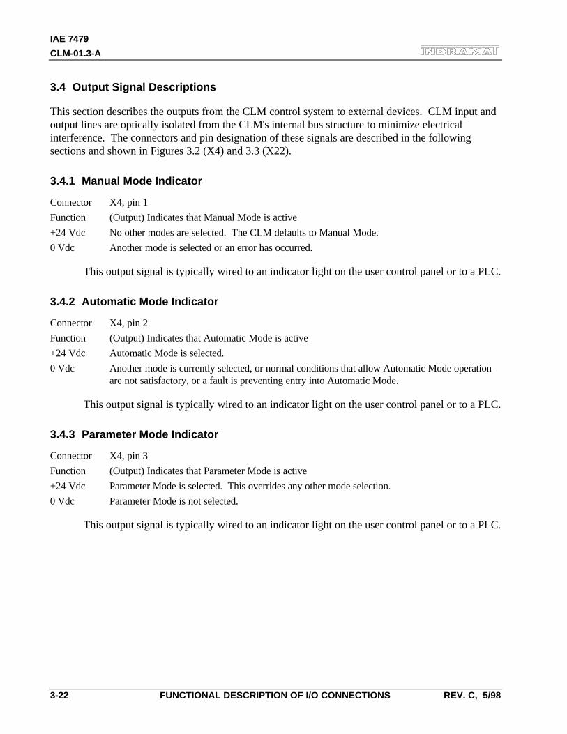
IAE 7479
CLM-01.3-A
3-22 FUNCTIONAL DESCRIPTION OF I/O CONNECTIONS REV. C, 5/98
3.4 Output Signal Descriptions
This section describes the outputs from the CLM control system to external devices. CLM input andoutput lines are optically isolated from the CLM's internal bus structure to minimize electricalinterference. The connectors and pin designation of these signals are described in the followingsections and shown in Figures 3.2 (X4) and 3.3 (X22).
3.4.1 Manual Mode Indicator
Connector X4, pin 1
Function (Output) Indicates that Manual Mode is active
+24 Vdc No other modes are selected. The CLM defaults to Manual Mode.
0 Vdc Another mode is selected or an error has occurred.
This output signal is typically wired to an indicator light on the user control panel or to a PLC.
3.4.2 Automatic Mode Indicator
Connector X4, pin 2
Function (Output) Indicates that Automatic Mode is active
+24 Vdc Automatic Mode is selected.
0 Vdc Another mode is currently selected, or normal conditions that allow Automatic Mode operationare not satisfactory, or a fault is preventing entry into Automatic Mode.
This output signal is typically wired to an indicator light on the user control panel or to a PLC.
3.4.3 Parameter Mode Indicator
Connector X4, pin 3
Function (Output) Indicates that Parameter Mode is active
+24 Vdc Parameter Mode is selected. This overrides any other mode selection.
0 Vdc Parameter Mode is not selected.
This output signal is typically wired to an indicator light on the user control panel or to a PLC.
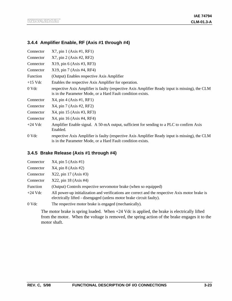
IAE 74794
CLM-01.3-A
REV. C, 5/98 FUNCTIONAL DESCRIPTION OF I/O CONNECTIONS 3-23
3.4.4 Amplifier Enable, RF (Axis #1 through #4)
Connector X7, pin 1 (Axis #1, RF1)
Connector X7, pin 2 (Axis #2, RF2)
Connector X19, pin 6 (Axis #3, RF3)
Connector X19, pin 7 (Axis #4, RF4)
Function (Output) Enables respective Axis Amplifier
+15 Vdc Enables the respective Axis Amplifier for operation.
0 Vdc respective Axis Amplifier is faulty (respective Axis Amplifier Ready input is missing), the CLMis in the Parameter Mode, or a Hard Fault condition exists.
Connector X4, pin 4 (Axis #1, RF1)
Connector X4, pin 7 (Axis #2, RF2)
Connector X4, pin 15 (Axis #3, RF3)
Connector X4, pin 16 (Axis #4, RF4)
+24 Vdc Amplifier Enable signal. A 50-mA output, sufficient for sending to a PLC to confirm AxisEnabled.
0 Vdc respective Axis Amplifier is faulty (respective Axis Amplifier Ready input is missing), the CLMis in the Parameter Mode, or a Hard Fault condition exists.
3.4.5 Brake Release (Axis #1 through #4)
Connector X4, pin 5 (Axis #1)
Connector X4, pin 8 (Axis #2)
Connector X22, pin 17 (Axis #3)
Connector X22, pin 18 (Axis #4)
Function (Output) Controls respective servomotor brake (when so equipped)
+24 Vdc All power-up initialization and verifications are correct and the respective Axis motor brake iselectrically lifted - disengaged (unless motor brake circuit faulty).
0 Vdc The respective motor brake is engaged (mechanically).
The motor brake is spring loaded. When +24 Vdc is applied, the brake is electrically liftedfrom the motor. When the voltage is removed, the spring action of the brake engages it to themotor shaft.
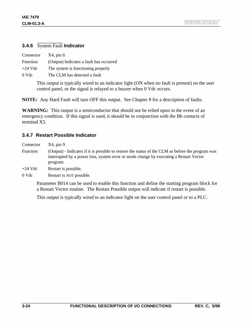
IAE 7479
CLM-01.3-A
3-24 FUNCTIONAL DESCRIPTION OF I/O CONNECTIONS REV. C, 5/98
3.4.6 System Fault Indicator
Connector X4, pin 6
Function (Output) Indicates a fault has occurred
+24 Vdc The system is functioning properly
0 Vdc The CLM has detected a fault
This output is typically wired to an indicator light (ON when no fault is present) on the usercontrol panel, or the signal is relayed to a buzzer when 0 Vdc occurs.
NOTE: Any Hard Fault will turn OFF this output. See Chapter 8 for a description of faults.
WARNING: This output is a semiconductor that should not be relied upon in the event of anemergency condition. If this signal is used, it should be in conjunction with the Bb contacts ofterminal X5.
3.4.7 Restart Possible Indicator
Connector X4, pin 9
Function (Output) - Indicates if it is possible to restore the status of the CLM as before the program wasinterrupted by a power loss, system error or mode change by executing a Restart Vectorprogram.
+24 Vdc Restart is possible.
0 Vdc Restart is NOT possible.
Parameter B014 can be used to enable this function and define the starting program block fora Restart Vector routine. The Restart Possible output will indicate if restart is possible.
This output is typically wired to an indicator light on the user control panel or to a PLC.
IAE 74794
CLM-01.3-A
REV. C, 5/98 PARAMETERS 4-1
4. PARAMETERS
This chapter describes the user entered parameters required for the CLM to perform the motioncontrol operation. The user adapts the CLM to his machine and the mechanical characteristics of theapplication by entering values for various parameters. These parameters permit a standard controlsystem to conform to different but similar applications. It also assures that all application programsare written with a uniform data format. The user must enter parameter values into the CLM memoryprior to the operation and programming of the CLM control.
NOTE: All values for parameters must be known before an application program can be written. If afunction is programmed or attempted which would exceed the bounds established by the parameters,the control will halt and a diagnostic error will be displayed.
4.1 Description of Parameter Sets
The CLM includes the following sets of parameters.
Parameter Set A:
This axis oriented parameter set includes the axis operating values for Automatic and Manual Modeoperation. These parameters allow the user to configure the CLM for the motor and drive packagethat the CLM is controlling. They also allow the user to set the various factors of the motion profile,as required for the material and application. These include the resolution of the feed, acceleration anddeceleration rates, feed rates in different modes, etc.
Each of the up to four axes have separate but identical parameter sets (A1xx-A4xx), as described inthe next section.
Parameter Set B:
This system oriented parameter set establishes the operating arrangement of the CLM. It allows theuser to configure the CLM for various options such as the language that shows on the display(English, German, Spanish or French); selecting control interface options, such as the IDS or SOT;selecting and configuring other optional features like synchronization, multi-tasking, axis enable, etc.
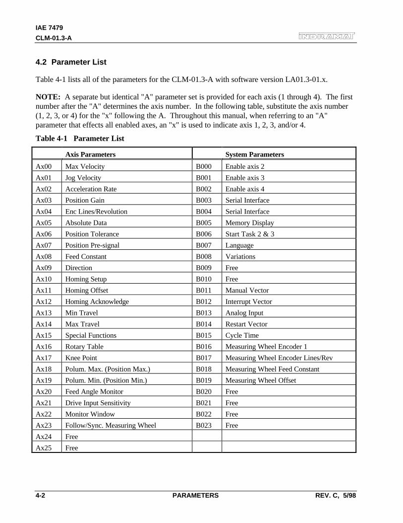
IAE 7479
CLM-01.3-A
4-2 PARAMETERS REV. C, 5/98
4.2 Parameter List
Table 4-1 lists all of the parameters for the CLM-01.3-A with software version LA01.3-01.x.
NOTE: A separate but identical "A" parameter set is provided for each axis (1 through 4). The firstnumber after the "A" determines the axis number. In the following table, substitute the axis number(1, 2, 3, or 4) for the "x" following the A. Throughout this manual, when referring to an "A"parameter that effects all enabled axes, an "x" is used to indicate axis 1, 2, 3, and/or 4.
Table 4-1 Parameter List
Axis Parameters System Parameters
Ax00 Max Velocity B000 Enable axis 2
Ax01 Jog Velocity B001 Enable axis 3
Ax02 Acceleration Rate B002 Enable axis 4
Ax03 Position Gain B003 Serial Interface
Ax04 Enc Lines/Revolution B004 Serial Interface
Ax05 Absolute Data B005 Memory Display
Ax06 Position Tolerance B006 Start Task 2 & 3
Ax07 Position Pre-signal B007 Language
Ax08 Feed Constant B008 Variations
Ax09 Direction B009 Free
Ax10 Homing Setup B010 Free
Ax11 Homing Offset B011 Manual Vector
Ax12 Homing Acknowledge B012 Interrupt Vector
Ax13 Min Travel B013 Analog Input
Ax14 Max Travel B014 Restart Vector
Ax15 Special Functions B015 Cycle Time
Ax16 Rotary Table B016 Measuring Wheel Encoder 1
Ax17 Knee Point B017 Measuring Wheel Encoder Lines/Rev
Ax18 Polum. Max. (Position Max.) B018 Measuring Wheel Feed Constant
Ax19 Polum. Min. (Position Min.) B019 Measuring Wheel Offset
Ax20 Feed Angle Monitor B020 Free
Ax21 Drive Input Sensitivity B021 Free
Ax22 Monitor Window B022 Free
Ax23 Follow/Sync. Measuring Wheel B023 Free
Ax24 Free
Ax25 Free
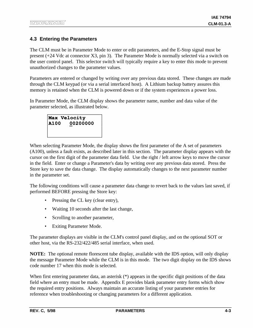
IAE 74794
CLM-01.3-A
REV. C, 5/98 PARAMETERS 4-3
4.3 Entering the Parameters
The CLM must be in Parameter Mode to enter or edit parameters, and the E-Stop signal must bepresent (+24 Vdc at connector X3, pin 3). The Parameter Mode is normally selected via a switch onthe user control panel. This selector switch will typically require a key to enter this mode to preventunauthorized changes to the parameter values.
Parameters are entered or changed by writing over any previous data stored. These changes are madethrough the CLM keypad (or via a serial interfaced host). A Lithium backup battery assures thismemory is retained when the CLM is powered down or if the system experiences a power loss.
In Parameter Mode, the CLM display shows the parameter name, number and data value of theparameter selected, as illustrated below.
Max VelocityMax VelocityA100 A100 0002000000200000
When selecting Parameter Mode, the display shows the first parameter of the A set of parameters(A100), unless a fault exists, as described later in this section. The parameter display appears with thecursor on the first digit of the parameter data field. Use the right / left arrow keys to move the cursorin the field. Enter or change a Parameter's data by writing over any previous data stored. Press theStore key to save the data change. The display automatically changes to the next parameter numberin the parameter set.
The following conditions will cause a parameter data change to revert back to the values last saved, ifperformed BEFORE pressing the Store key:
• Pressing the CL key (clear entry),
• Waiting 10 seconds after the last change,
• Scrolling to another parameter,
• Exiting Parameter Mode.
The parameter displays are visible in the CLM's control panel display, and on the optional SOT orother host, via the RS-232/422/485 serial interface, when used.
NOTE: The optional remote florescent tube display, available with the IDS option, will only displaythe message Parameter Mode while the CLM is in this mode. The two digit display on the IDS showscode number 17 when this mode is selected.
When first entering parameter data, an asterisk (*) appears in the specific digit positions of the datafield where an entry must be made. Appendix E provides blank parameter entry forms which showthe required entry positions. Always maintain an accurate listing of your parameter entries forreference when troubleshooting or changing parameters for a different application.
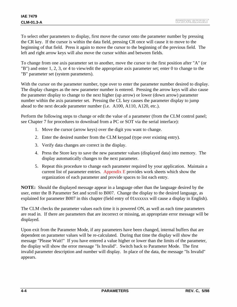
IAE 7479
CLM-01.3-A
4-4 PARAMETERS REV. C, 5/98
To select other parameters to display, first move the cursor onto the parameter number by pressingthe CR key. If the cursor is within the data field, pressing CR once will cause it to move to thebeginning of that field. Press it again to move the cursor to the beginning of the previous field. Theleft and right arrow keys will also move the cursor within and between fields.
To change from one axis parameter set to another, move the cursor to the first position after "A" (or"B") and enter 1, 2, 3, or 4 to view/edit the appropriate axis parameter set; enter 0 to change to the"B" parameter set (system parameters).
With the cursor on the parameter number, type over to enter the parameter number desired to display.The display changes as the new parameter number is entered. Pressing the arrow keys will also causethe parameter display to change to the next higher (up arrow) or lower (down arrow) parameternumber within the axis parameter set. Pressing the CL key causes the parameter display to jumpahead to the next decade parameter number (i.e. A100, A110, A120, etc.).
Perform the following steps to change or edit the value of a parameter (from the CLM control panel;see Chapter 7 for procedures to download from a PC or SOT via the serial interface):
1. Move the cursor (arrow keys) over the digit you want to change.
2. Enter the desired number from the CLM keypad (type over existing entry).
3. Verify data changes are correct in the display.
4. Press the Store key to save the new parameter values (displayed data) into memory. Thedisplay automatically changes to the next parameter.
5. Repeat this procedure to change each parameter required by your application. Maintain acurrent list of parameter entries. Appendix E provides work sheets which show theorganization of each parameter and provide spaces to list each entry.
NOTE: Should the displayed message appear in a language other than the language desired by theuser, enter the B Parameter Set and scroll to B007. Change the display to the desired language, asexplained for parameter B007 in this chapter (field entry of 01xxxxxx will cause a display in English).
The CLM checks the parameter values each time it is powered ON, as well as each time parametersare read in. If there are parameters that are incorrect or missing, an appropriate error message will bedisplayed.
Upon exit from the Parameter Mode, if any parameters have been changed, internal buffers that aredependent on parameter values will be re-calculated. During that time the display will show themessage "Please Wait!" If you have entered a value higher or lower than the limits of the parameter,the display will show the error message "Is Invalid". Switch back to Parameter Mode. The firstinvalid parameter description and number will display. In place of the data, the message "Is Invalid"appears.
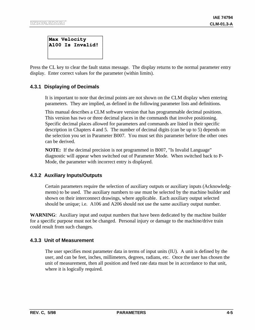
IAE 74794
CLM-01.3-A
REV. C, 5/98 PARAMETERS 4-5
Max VelocityMax VelocityA100 Is Invalid!A100 Is Invalid!
Press the CL key to clear the fault status message. The display returns to the normal parameter entrydisplay. Enter correct values for the parameter (within limits).
4.3.1 Displaying of Decimals
It is important to note that decimal points are not shown on the CLM display when enteringparameters. They are implied, as defined in the following parameter lists and definitions.
This manual describes a CLM software version that has programmable decimal positions.This version has two or three decimal places in the commands that involve positioning.Specific decimal places allowed for parameters and commands are listed in their specificdescription in Chapters 4 and 5. The number of decimal digits (can be up to 5) depends onthe selection you set in Parameter B007. You must set this parameter before the other onescan be derived.
NOTE: If the decimal precision is not programmed in B007, "Is Invalid Language"diagnostic will appear when switched out of Parameter Mode. When switched back to P-Mode, the parameter with incorrect entry is displayed.
4.3.2 Auxiliary Inputs/Outputs
Certain parameters require the selection of auxiliary outputs or auxiliary inputs (Acknowledg-ments) to be used. The auxiliary numbers to use must be selected by the machine builder andshown on their interconnect drawings, where applicable. Each auxiliary output selectedshould be unique; i.e. A106 and A206 should not use the same auxiliary output number.
WARNING: Auxiliary input and output numbers that have been dedicated by the machine builderfor a specific purpose must not be changed. Personal injury or damage to the machine/drive traincould result from such changes.
4.3.3 Unit of Measurement
The user specifies most parameter data in terms of input units (IU). A unit is defined by theuser, and can be feet, inches, millimeters, degrees, radians, etc. Once the user has chosen theunit of measurement, then all position and feed rate data must be in accordance to that unit,where it is logically required.
IAE 7479
CLM-01.3-A
4-6 PARAMETERS REV. C, 5/98
For example, the input unit could be specified as inches. The maximum feed rate in parameterA100 might be programmed as 12 inches/second. The acceleration parameter would then bein units of inches per second squared. Note that positioning commands for the applicationprogram are to two or three decimal places. If you require positioning to 0.001", set thedecimal selection in parameter B007 to three places. In general, when using US System(inches) measurements, set B007 for three decimal places. When using Metric (millimeters),set B007 for two decimal places.
IAE 74794
CLM-01.3-A
REV. C, 5/98 PARAMETERS 4-7
4.4 Linear or Rotary Operation
The CLM is capable of Linear or Rotary operation for each axis. Most applications will utilize thelinear method of programming (i.e. Ball Screw, Belt, Slide). Some applications require the specialfeatures allowed with rotary programming (Ax16 - Rotary Axis Gear Ratio).
Linear operation (programming) allows each axis minimum and maximum software over-travel limits(effective after the axis has been Homed). Motions can be programmed in any type of Input Units(i.e. inches, mm, degrees, etc.).
Rotary operation (programming) allows each axis the capability of 360 degrees of motion. The actualposition screen (L P Screen), counts from 0 degrees to the value set in Ax08, resetting back to zeroafter each complete revolution (360 degrees). Each axis can be programmed to make multiplerevolutions in either direction (direction is relative to the programming of Ax09 - Direction ofOperation). The software over-travel limits are disabled when implementing rotary programming.
IAE 7479
CLM-01.3-A
4-8 PARAMETERS REV. C, 5/98
4.5 Parameter Descriptions
The following sections describe each parameter, as required for the CLM to command motion. Eachparameter description includes an illustration of the CLM display and the formula required to obtainthe parameter value, where applicable.
For easy reference, this section describes each parameter in numerical order, (Ax00 through Ax25,then B000 through B023), as shown in Table 4.1, and each new parameter begins on a new page.The parameter description for A100 is the same for A200, A300 and A400, only the axis number isdifferent. Therefore, this section combines the common descriptions for the A parameter set, using"x" to indicate any axis 1 through 4.
NOTE: Enter parameter data for axis 1 in parameters A100-A125, for axis 2 in parameters A200-A225, etc. Also enter system parameter data in parameters B000-B023. Parameters Ax08 (FeedConstant) for each axis must be determined before the velocity parameters can be entered correctly.These parameters set the Input Units for each axis movement.
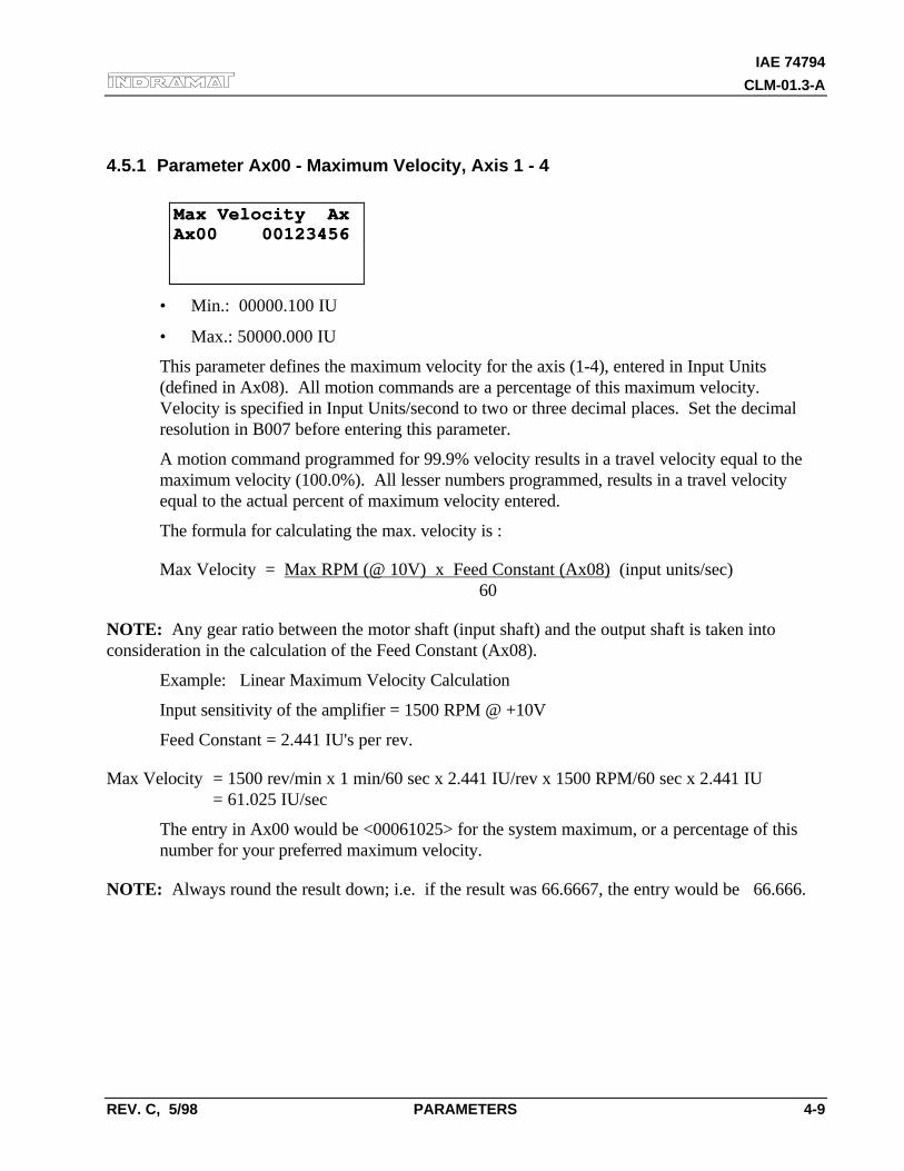
IAE 74794
CLM-01.3-A
REV. C, 5/98 PARAMETERS 4-9
4.5.1 Parameter Ax00 - Maximum Velocity, Axis 1 - 4
Max Velocity AxMax Velocity AxAx00 00123456Ax00 00123456
• Min.: 00000.100 IU
• Max.: 50000.000 IU
This parameter defines the maximum velocity for the axis (1-4), entered in Input Units(defined in Ax08). All motion commands are a percentage of this maximum velocity.Velocity is specified in Input Units/second to two or three decimal places. Set the decimalresolution in B007 before entering this parameter.
A motion command programmed for 99.9% velocity results in a travel velocity equal to themaximum velocity (100.0%). All lesser numbers programmed, results in a travel velocityequal to the actual percent of maximum velocity entered.
The formula for calculating the max. velocity is :
Max Velocity = Max RPM (@ 10V) x Feed Constant (Ax08) (input units/sec)60
NOTE: Any gear ratio between the motor shaft (input shaft) and the output shaft is taken intoconsideration in the calculation of the Feed Constant (Ax08).
Example: Linear Maximum Velocity Calculation
Input sensitivity of the amplifier = 1500 RPM @ +10V
Feed Constant = 2.441 IU's per rev.
Max Velocity = 1500 rev/min x 1 min/60 sec x 2.441 IU/rev x 1500 RPM/60 sec x 2.441 IU= 61.025 IU/sec
The entry in Ax00 would be <00061025> for the system maximum, or a percentage of thisnumber for your preferred maximum velocity.
NOTE: Always round the result down; i.e. if the result was 66.6667, the entry would be 66.666.
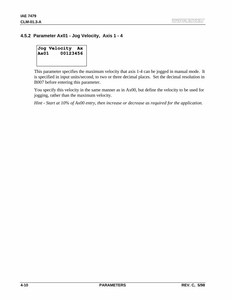
IAE 7479
CLM-01.3-A
4-10 PARAMETERS REV. C, 5/98
4.5.2 Parameter Ax01 - Jog Velocity, Axis 1 - 4
Jog Velocity AxJog Velocity AxAx01 00123456Ax01 00123456
This parameter specifies the maximum velocity that axis 1-4 can be jogged in manual mode. Itis specified in input units/second, to two or three decimal places. Set the decimal resolution inB007 before entering this parameter.
You specify this velocity in the same manner as in Ax00, but define the velocity to be used forjogging, rather than the maximum velocity.
Hint - Start at 10% of Ax00 entry, then increase or decrease as required for the application.
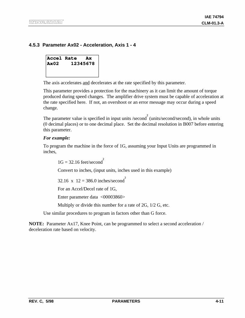
IAE 74794
CLM-01.3-A
REV. C, 5/98 PARAMETERS 4-11
4.5.3 Parameter Ax02 - Acceleration, Axis 1 - 4
Accel Rate AxAccel Rate AxAx02 12345678Ax02 12345678
The axis accelerates and decelerates at the rate specified by this parameter.
This parameter provides a protection for the machinery as it can limit the amount of torqueproduced during speed changes. The amplifier drive system must be capable of acceleration atthe rate specified here. If not, an overshoot or an error message may occur during a speedchange.
The parameter value is specified in input units /second² (units/second/second), in whole units(0 decimal places) or to one decimal place. Set the decimal resolution in B007 before enteringthis parameter.
For example:
To program the machine in the force of 1G, assuming your Input Units are programmed ininches,
1G = 32.16 feet/second²
Convert to inches, (input units, inches used in this example)
32.16 x 12 = 386.0 inches/second²
For an Accel/Decel rate of 1G,
Enter parameter data <00003860>
Multiply or divide this number for a rate of 2G, 1/2 G, etc.
Use similar procedures to program in factors other than G force.
NOTE: Parameter Ax17, Knee Point, can be programmed to select a second acceleration /deceleration rate based on velocity.
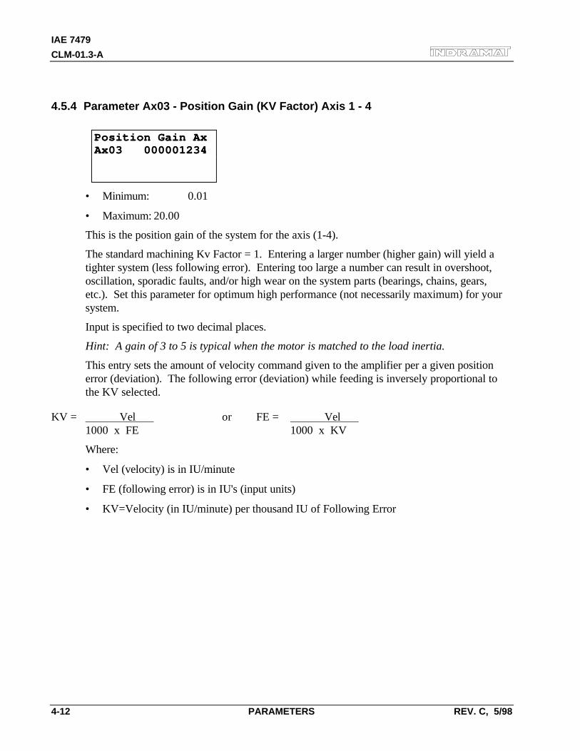
IAE 7479
CLM-01.3-A
4-12 PARAMETERS REV. C, 5/98
4.5.4 Parameter Ax03 - Position Gain (KV Factor) Axis 1 - 4
Position Gain AxPosition Gain AxAx03 000001234Ax03 000001234
• Minimum: 0.01
• Maximum: 20.00
This is the position gain of the system for the axis (1-4).
The standard machining Kv Factor = 1. Entering a larger number (higher gain) will yield atighter system (less following error). Entering too large a number can result in overshoot,oscillation, sporadic faults, and/or high wear on the system parts (bearings, chains, gears,etc.). Set this parameter for optimum high performance (not necessarily maximum) for yoursystem.
Input is specified to two decimal places.
Hint: A gain of 3 to 5 is typical when the motor is matched to the load inertia.
This entry sets the amount of velocity command given to the amplifier per a given positionerror (deviation). The following error (deviation) while feeding is inversely proportional tothe KV selected.
KV = Vel or FE = Vel 1000 x FE 1000 x KV
Where:
• Vel (velocity) is in IU/minute
• FE (following error) is in IU's (input units)
• KV=Velocity (in IU/minute) per thousand IU of Following Error
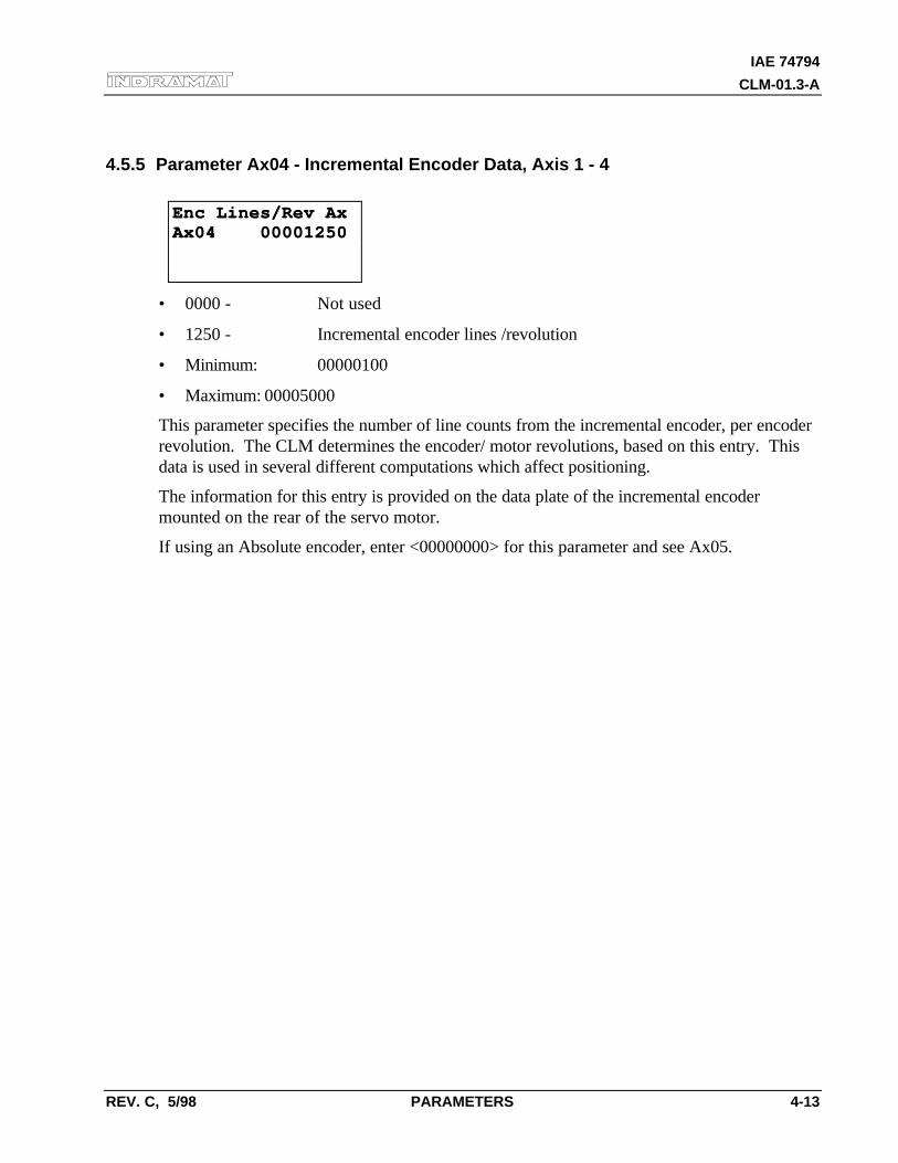
IAE 74794
CLM-01.3-A
REV. C, 5/98 PARAMETERS 4-13
4.5.5 Parameter Ax04 - Incremental Encoder Data, Axis 1 - 4
Enc Lines/Rev AxEnc Lines/Rev AxAx04 00001250Ax04 00001250
• 0000 - Not used
• 1250 - Incremental encoder lines /revolution
• Minimum: 00000100
• Maximum: 00005000
This parameter specifies the number of line counts from the incremental encoder, per encoderrevolution. The CLM determines the encoder/ motor revolutions, based on this entry. Thisdata is used in several different computations which affect positioning.
The information for this entry is provided on the data plate of the incremental encodermounted on the rear of the servo motor.
If using an Absolute encoder, enter <00000000> for this parameter and see Ax05.
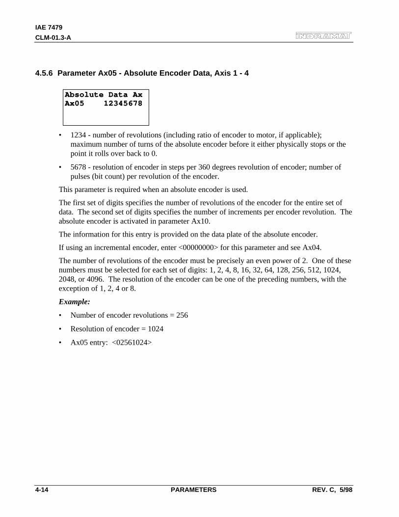
IAE 7479
CLM-01.3-A
4-14 PARAMETERS REV. C, 5/98
4.5.6 Parameter Ax05 - Absolute Encoder Data, Axis 1 - 4
Absolute Data AxAbsolute Data AxAx05 12345678Ax05 12345678
• 1234 - number of revolutions (including ratio of encoder to motor, if applicable);maximum number of turns of the absolute encoder before it either physically stops or thepoint it rolls over back to 0.
• 5678 - resolution of encoder in steps per 360 degrees revolution of encoder; number ofpulses (bit count) per revolution of the encoder.
This parameter is required when an absolute encoder is used.
The first set of digits specifies the number of revolutions of the encoder for the entire set ofdata. The second set of digits specifies the number of increments per encoder revolution. Theabsolute encoder is activated in parameter Ax10.
The information for this entry is provided on the data plate of the absolute encoder.
If using an incremental encoder, enter <00000000> for this parameter and see Ax04.
The number of revolutions of the encoder must be precisely an even power of 2. One of thesenumbers must be selected for each set of digits: 1, 2, 4, 8, 16, 32, 64, 128, 256, 512, 1024,2048, or 4096. The resolution of the encoder can be one of the preceding numbers, with theexception of 1, 2, 4 or 8.
Example:
• Number of encoder revolutions = 256
• Resolution of encoder = 1024
• Ax05 entry: <02561024>
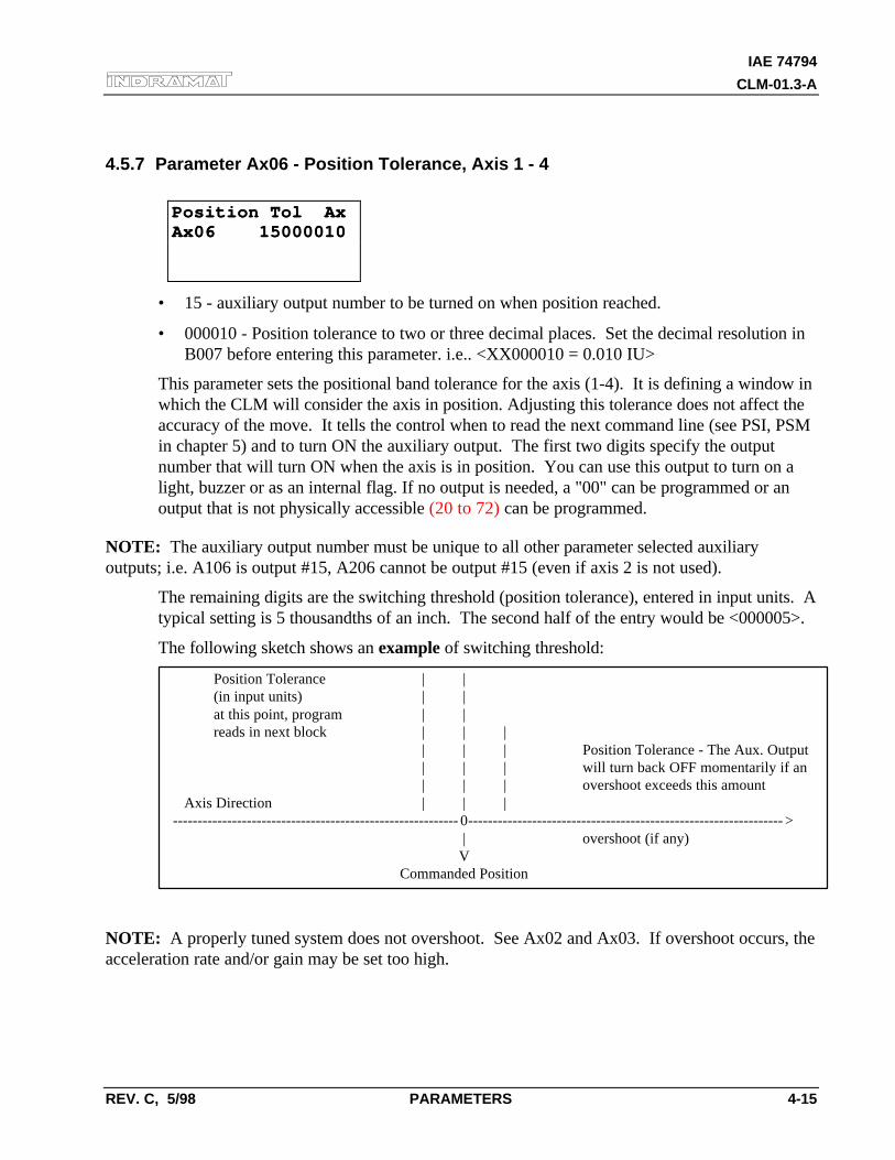
IAE 74794
CLM-01.3-A
REV. C, 5/98 PARAMETERS 4-15
4.5.7 Parameter Ax06 - Position Tolerance, Axis 1 - 4
Position Tol AxPosition Tol AxAx06 15000010Ax06 15000010
• 15 - auxiliary output number to be turned on when position reached.
• 000010 - Position tolerance to two or three decimal places. Set the decimal resolution inB007 before entering this parameter. i.e.. <XX000010 = 0.010 IU>
This parameter sets the positional band tolerance for the axis (1-4). It is defining a window inwhich the CLM will consider the axis in position. Adjusting this tolerance does not affect theaccuracy of the move. It tells the control when to read the next command line (see PSI, PSMin chapter 5) and to turn ON the auxiliary output. The first two digits specify the outputnumber that will turn ON when the axis is in position. You can use this output to turn on alight, buzzer or as an internal flag. If no output is needed, a "00" can be programmed or anoutput that is not physically accessible (20 to 72) can be programmed.
NOTE: The auxiliary output number must be unique to all other parameter selected auxiliaryoutputs; i.e. A106 is output #15, A206 cannot be output #15 (even if axis 2 is not used).
The remaining digits are the switching threshold (position tolerance), entered in input units. Atypical setting is 5 thousandths of an inch. The second half of the entry would be <000005>.
The following sketch shows an example of switching threshold:
Position Tolerance | |(in input units) | |at this point, program ⇒| | ⇐reads in next block | | |
| ⇒ | |⇐ Position Tolerance - The Aux. Output| | | will turn back OFF momentarily if an| | | overshoot exceeds this amount
Axis Direction ⇒ | | | ---------------------------------------------------------- 0---------------------------------------------------------------- >
| overshoot (if any) ⇒V
Commanded Position
NOTE: A properly tuned system does not overshoot. See Ax02 and Ax03. If overshoot occurs, theacceleration rate and/or gain may be set too high.
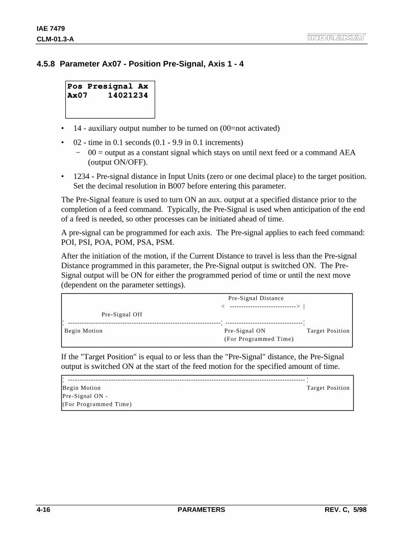
IAE 7479
CLM-01.3-A
4-16 PARAMETERS REV. C, 5/98
4.5.8 Parameter Ax07 - Position Pre-Signal, Axis 1 - 4
Pos Presignal AxPos Presignal AxAx07 14021234Ax07 14021234
• 14 - auxiliary output number to be turned on (00=not activated)
• 02 - time in 0.1 seconds (0.1 - 9.9 in 0.1 increments)− 00 = output as a constant signal which stays on until next feed or a command AEA
(output ON/OFF).
• 1234 - Pre-signal distance in Input Units (zero or one decimal place) to the target position.Set the decimal resolution in B007 before entering this parameter.
The Pre-Signal feature is used to turn ON an aux. output at a specified distance prior to thecompletion of a feed command. Typically, the Pre-Signal is used when anticipation of the endof a feed is needed, so other processes can be initiated ahead of time.
A pre-signal can be programmed for each axis. The Pre-signal applies to each feed command:POI, PSI, POA, POM, PSA, PSM.
After the initiation of the motion, if the Current Distance to travel is less than the Pre-signalDistance programmed in this parameter, the Pre-Signal output is switched ON. The Pre-Signal output will be ON for either the programmed period of time or until the next move(dependent on the parameter settings).
Pre-Signal Distance< ----------------------------- > |
Pre-Signal Off¦ ------------------------------------------------------------------- ¦ ---------------------------------- ¦ Begin Motion Pre-Signal ON Target Position
(For Programmed Time)
If the "Target Position" is equal to or less than the "Pre-Signal" distance, the Pre-Signaloutput is switched ON at the start of the feed motion for the specified amount of time.
¦ -------------------------------------------------------------------------------------------------------- ¦Begin Motion Target PositionPre-Signal ON -(For Programmed Time)
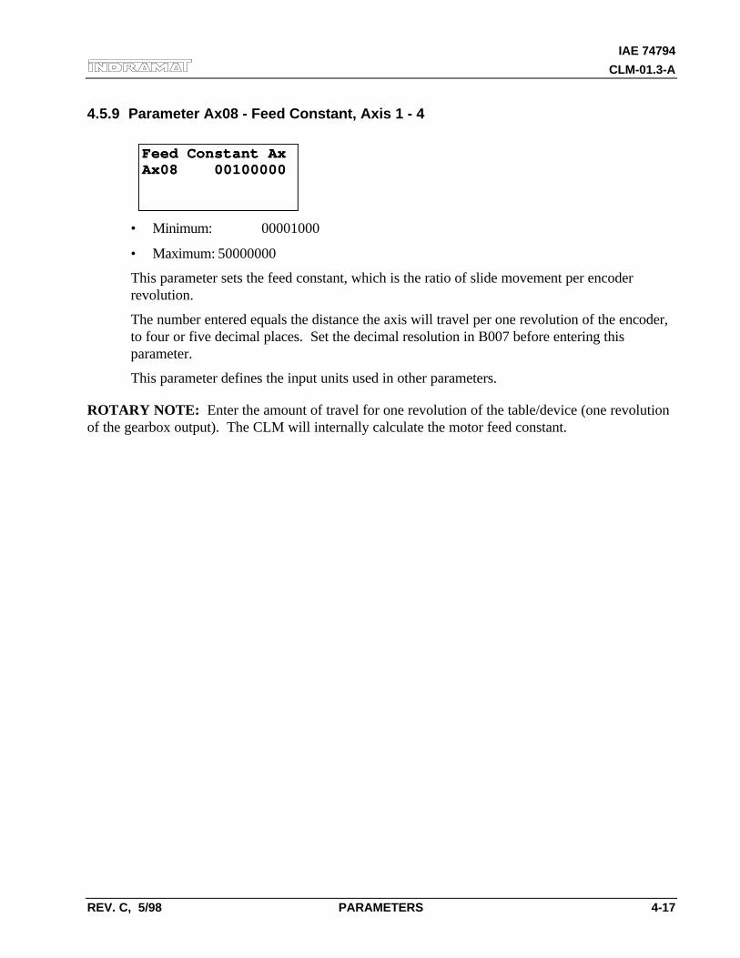
IAE 74794
CLM-01.3-A
REV. C, 5/98 PARAMETERS 4-17
4.5.9 Parameter Ax08 - Feed Constant, Axis 1 - 4
Feed Constant AxFeed Constant AxAx08 00100000Ax08 00100000
• Minimum: 00001000
• Maximum: 50000000
This parameter sets the feed constant, which is the ratio of slide movement per encoderrevolution.
The number entered equals the distance the axis will travel per one revolution of the encoder,to four or five decimal places. Set the decimal resolution in B007 before entering thisparameter.
This parameter defines the input units used in other parameters.
ROTARY NOTE: Enter the amount of travel for one revolution of the table/device (one revolutionof the gearbox output). The CLM will internally calculate the motor feed constant.
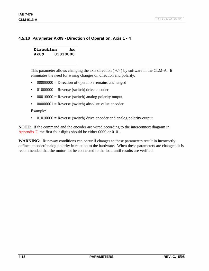
IAE 7479
CLM-01.3-A
4-18 PARAMETERS REV. C, 5/98
4.5.10 Parameter Ax09 - Direction of Operation, Axis 1 - 4
Direction AxDirection AxAx09 01010000Ax09 01010000
This parameter allows changing the axis direction ( +/- ) by software in the CLM-A. Iteliminates the need for wiring changes on direction and polarity.
• 00000000 = Direction of operation remains unchanged
• 01000000 = Reverse (switch) drive encoder
• 00010000 = Reverse (switch) analog polarity output
• 00000001 = Reverse (switch) absolute value encoder
Example:
• 01010000 = Reverse (switch) drive encoder and analog polarity output.
NOTE: If the command and the encoder are wired according to the interconnect diagram inAppendix F, the first four digits should be either 0000 or 0101.
WARNING: Runaway conditions can occur if changes to these parameters result in incorrectlydefined encoder/analog polarity in relation to the hardware. When these parameters are changed, it isrecommended that the motor not be connected to the load until results are verified.
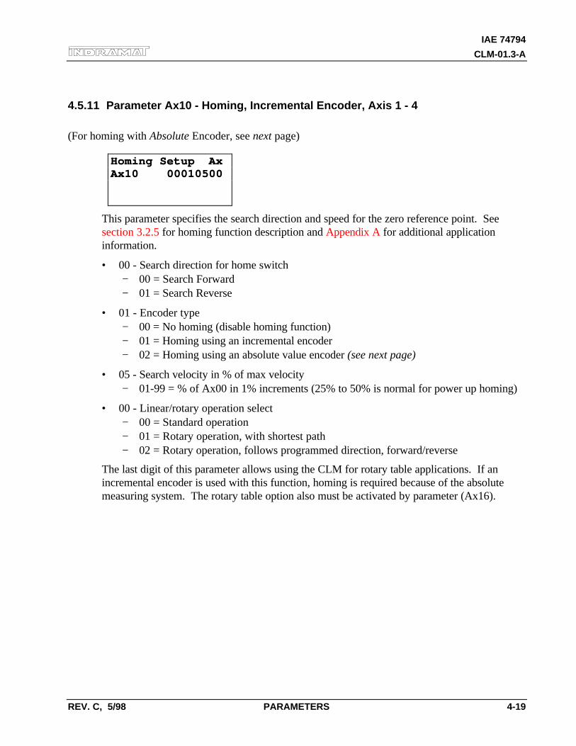
IAE 74794
CLM-01.3-A
REV. C, 5/98 PARAMETERS 4-19
4.5.11 Parameter Ax10 - Homing, Incremental Encoder, Axis 1 - 4
(For homing with Absolute Encoder, see next page)
Homing Setup AxHoming Setup AxAx10 00010500Ax10 00010500
This parameter specifies the search direction and speed for the zero reference point. Seesection 3.2.5 for homing function description and Appendix A for additional applicationinformation.
• 00 - Search direction for home switch− 00 = Search Forward− 01 = Search Reverse
• 01 - Encoder type− 00 = No homing (disable homing function)− 01 = Homing using an incremental encoder− 02 = Homing using an absolute value encoder (see next page)
• 05 - Search velocity in % of max velocity− 01-99 = % of Ax00 in 1% increments (25% to 50% is normal for power up homing)
• 00 - Linear/rotary operation select− 00 = Standard operation− 01 = Rotary operation, with shortest path− 02 = Rotary operation, follows programmed direction, forward/reverse
The last digit of this parameter allows using the CLM for rotary table applications. If anincremental encoder is used with this function, homing is required because of the absolutemeasuring system. The rotary table option also must be activated by parameter (Ax16).
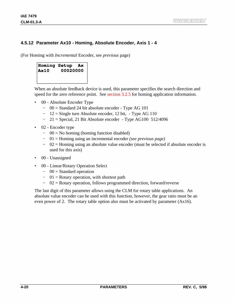
IAE 7479
CLM-01.3-A
4-20 PARAMETERS REV. C, 5/98
4.5.12 Parameter Ax10 - Homing, Absolute Encoder, Axis 1 - 4
(For Homing with Incremental Encoder, see previous page)
Homing Setup AxHoming Setup AxAx10 00020000Ax10 00020000
When an absolute feedback device is used, this parameter specifies the search direction andspeed for the zero reference point. See section 3.2.5 for homing application information.
• 00 - Absolute Encoder Type− 00 = Standard 24 bit absolute encoder - Type AG 101− 12 = Single turn Absolute encoder, 12 bit, - Type AG 110− 21 = Special, 21 Bit Absolute encoder - Type AG100 512/4096
• 02 - Encoder type− 00 = No homing (homing function disabled)− 01 = Homing using an incremental encoder (see previous page)− 02 = Homing using an absolute value encoder (must be selected if absolute encoder is
used for this axis)
• 00 - Unassigned
• 00 - Linear/Rotary Operation Select− 00 = Standard operation− 01 = Rotary operation, with shortest path− 02 = Rotary operation, follows programmed direction, forward/reverse
The last digit of this parameter allows using the CLM for rotary table applications. Anabsolute value encoder can be used with this function, however, the gear ratio must be aneven power of 2. The rotary table option also must be activated by parameter (Ax16).
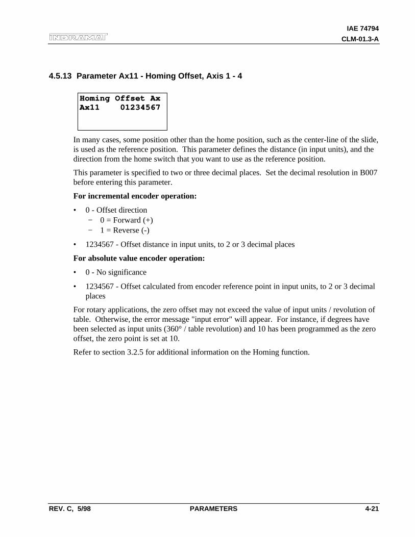
IAE 74794
CLM-01.3-A
REV. C, 5/98 PARAMETERS 4-21
4.5.13 Parameter Ax11 - Homing Offset, Axis 1 - 4
Homing Offset AxHoming Offset AxAx11 01234567Ax11 01234567
In many cases, some position other than the home position, such as the center-line of the slide,is used as the reference position. This parameter defines the distance (in input units), and thedirection from the home switch that you want to use as the reference position.
This parameter is specified to two or three decimal places. Set the decimal resolution in B007before entering this parameter.
For incremental encoder operation:
• 0 - Offset direction− 0 = Forward (+)− 1 = Reverse (-)
• 1234567 - Offset distance in input units, to 2 or 3 decimal places
For absolute value encoder operation:
• 0 - No significance
• 1234567 - Offset calculated from encoder reference point in input units, to 2 or 3 decimalplaces
For rotary applications, the zero offset may not exceed the value of input units / revolution oftable. Otherwise, the error message "input error" will appear. For instance, if degrees havebeen selected as input units (360° / table revolution) and 10 has been programmed as the zerooffset, the zero point is set at 10.
Refer to section 3.2.5 for additional information on the Homing function.
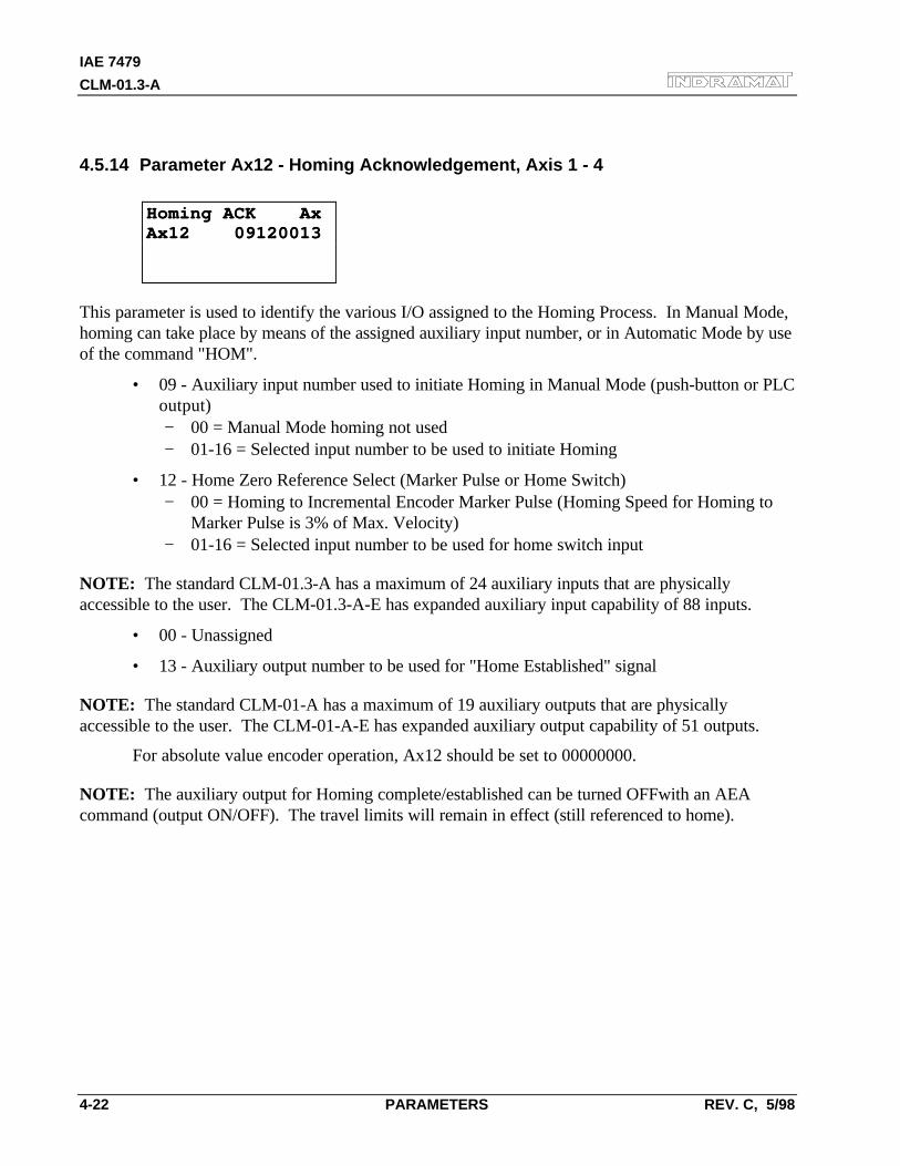
IAE 7479
CLM-01.3-A
4-22 PARAMETERS REV. C, 5/98
4.5.14 Parameter Ax12 - Homing Acknowledgement, Axis 1 - 4
Homing ACK AxHoming ACK AxAx12 09120013Ax12 09120013
This parameter is used to identify the various I/O assigned to the Homing Process. In Manual Mode,homing can take place by means of the assigned auxiliary input number, or in Automatic Mode by useof the command "HOM".
• 09 - Auxiliary input number used to initiate Homing in Manual Mode (push-button or PLCoutput)− 00 = Manual Mode homing not used− 01-16 = Selected input number to be used to initiate Homing
• 12 - Home Zero Reference Select (Marker Pulse or Home Switch)− 00 = Homing to Incremental Encoder Marker Pulse (Homing Speed for Homing to
Marker Pulse is 3% of Max. Velocity)− 01-16 = Selected input number to be used for home switch input
NOTE: The standard CLM-01.3-A has a maximum of 24 auxiliary inputs that are physicallyaccessible to the user. The CLM-01.3-A-E has expanded auxiliary input capability of 88 inputs.
• 00 - Unassigned
• 13 - Auxiliary output number to be used for "Home Established" signal
NOTE: The standard CLM-01-A has a maximum of 19 auxiliary outputs that are physicallyaccessible to the user. The CLM-01-A-E has expanded auxiliary output capability of 51 outputs.
For absolute value encoder operation, Ax12 should be set to 00000000.
NOTE: The auxiliary output for Homing complete/established can be turned OFFwith an AEAcommand (output ON/OFF). The travel limits will remain in effect (still referenced to home).
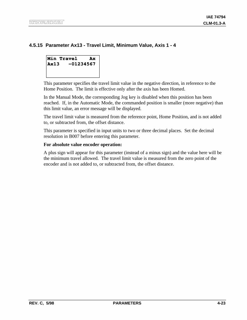
IAE 74794
CLM-01.3-A
REV. C, 5/98 PARAMETERS 4-23
4.5.15 Parameter Ax13 - Travel Limit, Minimum Value, Axis 1 - 4
Min Travel AxMin Travel AxAx13 -01234567Ax13 -01234567
This parameter specifies the travel limit value in the negative direction, in reference to theHome Position. The limit is effective only after the axis has been Homed.
In the Manual Mode, the corresponding Jog key is disabled when this position has beenreached. If, in the Automatic Mode, the commanded position is smaller (more negative) thanthis limit value, an error message will be displayed.
The travel limit value is measured from the reference point, Home Position, and is not addedto, or subtracted from, the offset distance.
This parameter is specified in input units to two or three decimal places. Set the decimalresolution in B007 before entering this parameter.
For absolute value encoder operation:
A plus sign will appear for this parameter (instead of a minus sign) and the value here will bethe minimum travel allowed. The travel limit value is measured from the zero point of theencoder and is not added to, or subtracted from, the offset distance.
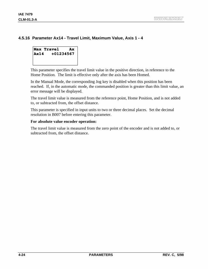
IAE 7479
CLM-01.3-A
4-24 PARAMETERS REV. C, 5/98
4.5.16 Parameter Ax14 - Travel Limit, Maximum Value, Axis 1 - 4
Max Travel AxMax Travel AxAx14 +01234567Ax14 +01234567
This parameter specifies the travel limit value in the positive direction, in reference to theHome Position. The limit is effective only after the axis has been Homed.
In the Manual Mode, the corresponding Jog key is disabled when this position has beenreached. If, in the automatic mode, the commanded position is greater than this limit value, anerror message will be displayed.
The travel limit value is measured from the reference point, Home Position, and is not addedto, or subtracted from, the offset distance.
This parameter is specified in input units to two or three decimal places. Set the decimalresolution in B007 before entering this parameter.
For absolute value encoder operation:
The travel limit value is measured from the zero point of the encoder and is not added to, orsubtracted from, the offset distance.
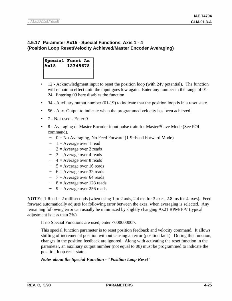
IAE 74794
CLM-01.3-A
REV. C, 5/98 PARAMETERS 4-25
4.5.17 Parameter Ax15 - Special Functions, Axis 1 - 4(Position Loop Reset/Velocity Achieved/Master Encoder Averaging)
Special Funct AxSpecial Funct AxAx15 12345678Ax15 12345678
• 12 - Acknowledgment input to reset the position loop (with 24v potential). The functionwill remain in effect until the input goes low again. Enter any number in the range of 01-24. Entering 00 here disables the function.
• 34 - Auxiliary output number (01-19) to indicate that the position loop is in a reset state.
• 56 - Aux. Output to indicate when the programmed velocity has been achieved.
• 7 - Not used - Enter 0
• 8 - Averaging of Master Encoder input pulse train for Master/Slave Mode (See FOLcommand).− 0 = No Averaging, No Feed Forward (1-9=Feed Forward Mode)− 1 = Average over 1 read− 2 = Average over 2 reads− 3 = Average over 4 reads− 4 = Average over 8 reads− 5 = Average over 16 reads− 6 = Average over 32 reads− 7 = Average over 64 reads− 8 = Average over 128 reads− 9 = Average over 256 reads
NOTE: 1 Read = 2 milliseconds (when using 1 or 2 axis, 2.4 ms for 3 axes, 2.8 ms for 4 axes). Feedforward automatically adjusts for following error between the axes, when averaging is selected. Anyremaining following error can usually be minimized by slightly changing Ax21 RPM/10V (typicaladjustment is less than 2%).
If no Special Functions are used, enter <00000000>.
This special function parameter is to reset position feedback and velocity command. It allowsshifting of incremental position without causing an error (position fault). During this function,changes in the position feedback are ignored. Along with activating the reset function in theparameter, an auxiliary output number (not equal to 00) must be programmed to indicate theposition loop reset state.
Notes about the Special Function - "Position Loop Reset"

IAE 7479
CLM-01.3-A
4-26 PARAMETERS REV. C, 5/98
With a potential of 24 volts at the acknowledgment input, Position Loop Reset takes placeonly if the axis is stopped; i.e., the motor is in position according to the position toleranceparameter set in Ax06.
CAUTION: While Position Loop Reset takes place, zero volts is output as the velocity commandvalue. This may cause the drive to drift.
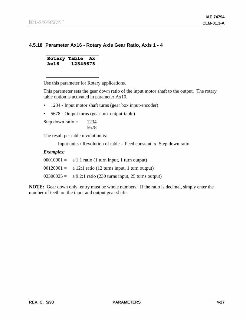
IAE 74794
CLM-01.3-A
REV. C, 5/98 PARAMETERS 4-27
4.5.18 Parameter Ax16 - Rotary Axis Gear Ratio, Axis 1 - 4
Rotary Table AxRotary Table AxAx16 12345678Ax16 12345678
Use this parameter for Rotary applications.
This parameter sets the gear down ratio of the input motor shaft to the output. The rotarytable option is activated in parameter Ax10.
• 1234 - Input motor shaft turns (gear box input-encoder)
• 5678 - Output turns (gear box output-table)
Step down ratio = 12345678
The result per table revolution is:
Input units / Revolution of table = Feed constant x Step down ratio
Examples:
00010001 = a 1:1 ratio (1 turn input, 1 turn output)
00120001 = a 12:1 ratio (12 turns input, 1 turn output)
02300025 = a 9.2:1 ratio (230 turns input, 25 turns output)
NOTE: Gear down only; entry must be whole numbers. If the ratio is decimal, simply enter thenumber of teeth on the input and output gear shafts.
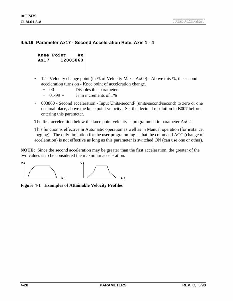
IAE 7479
CLM-01.3-A
4-28 PARAMETERS REV. C, 5/98
4.5.19 Parameter Ax17 - Second Acceleration Rate, Axis 1 - 4
Knee Point AxKnee Point AxAx17 12003860Ax17 12003860
• 12 - Velocity change point (in % of Velocity Max - Ax00) - Above this %, the secondacceleration turns on - Knee point of acceleration change.− 00 = Disables this parameter− 01-99 = % in increments of 1%
• 003860 - Second acceleration - Input Units/second² (units/second/second) to zero or onedecimal place, above the knee point velocity. Set the decimal resolution in B007 beforeentering this parameter.
The first acceleration below the knee point velocity is programmed in parameter Ax02.
This function is effective in Automatic operation as well as in Manual operation (for instance,jogging). The only limitation for the user programming is that the command ACC (change ofacceleration) is not effective as long as this parameter is switched ON (can use one or other).
NOTE: Since the second acceleration may be greater than the first acceleration, the greater of thetwo values is to be considered the maximum acceleration.
Figure 4-1 Examples of Attainable Velocity Profiles
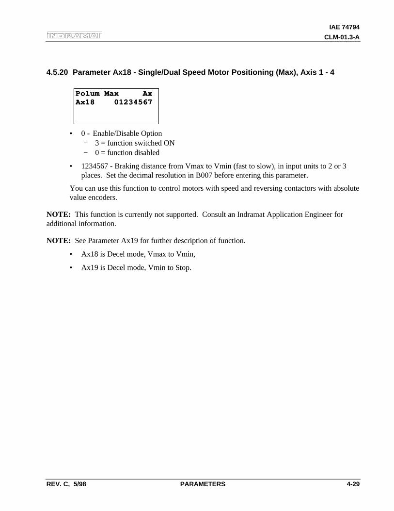
IAE 74794
CLM-01.3-A
REV. C, 5/98 PARAMETERS 4-29
4.5.20 Parameter Ax18 - Single/Dual Speed Motor Positioning (Max), Axis 1 - 4
Polum Max AxPolum Max AxAx18 01234567Ax18 01234567
• 0 - Enable/Disable Option− 3 = function switched ON− 0 = function disabled
• 1234567 - Braking distance from Vmax to Vmin (fast to slow), in input units to 2 or 3places. Set the decimal resolution in B007 before entering this parameter.
You can use this function to control motors with speed and reversing contactors with absolutevalue encoders.
NOTE: This function is currently not supported. Consult an Indramat Application Engineer foradditional information.
NOTE: See Parameter Ax19 for further description of function.
• Ax18 is Decel mode, Vmax to Vmin,
• Ax19 is Decel mode, Vmin to Stop.
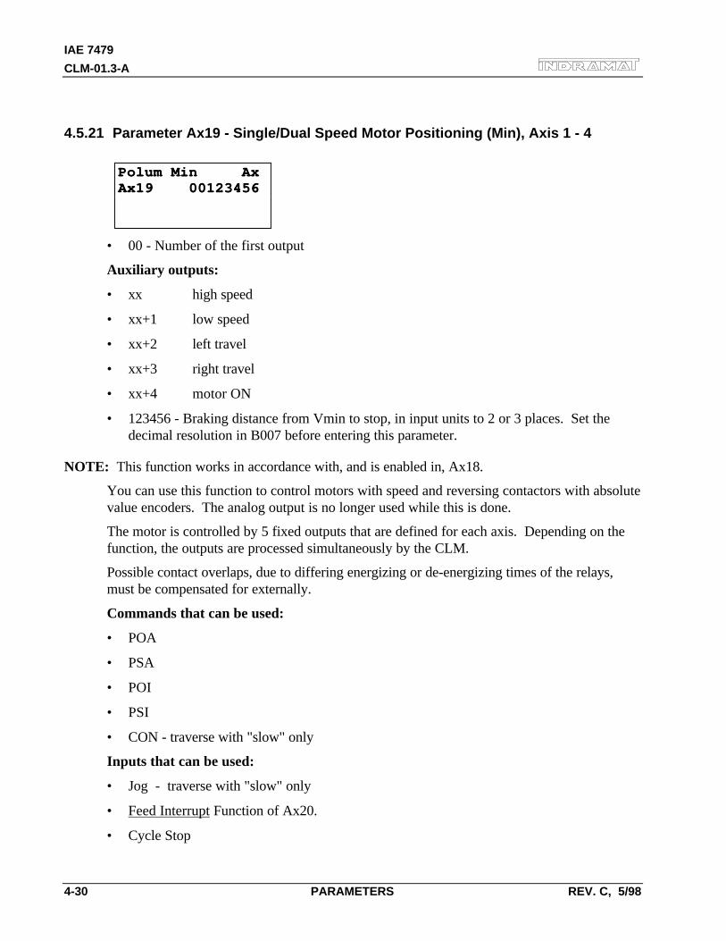
IAE 7479
CLM-01.3-A
4-30 PARAMETERS REV. C, 5/98
4.5.21 Parameter Ax19 - Single/Dual Speed Motor Positioning (Min), Axis 1 - 4
Polum Min AxPolum Min AxAx19 00123456Ax19 00123456
• 00 - Number of the first output
Auxiliary outputs:
• xx high speed
• xx+1 low speed
• xx+2 left travel
• xx+3 right travel
• xx+4 motor ON
• 123456 - Braking distance from Vmin to stop, in input units to 2 or 3 places. Set thedecimal resolution in B007 before entering this parameter.
NOTE: This function works in accordance with, and is enabled in, Ax18.
You can use this function to control motors with speed and reversing contactors with absolutevalue encoders. The analog output is no longer used while this is done.
The motor is controlled by 5 fixed outputs that are defined for each axis. Depending on thefunction, the outputs are processed simultaneously by the CLM.
Possible contact overlaps, due to differing energizing or de-energizing times of the relays,must be compensated for externally.
Commands that can be used:
• POA
• PSA
• POI
• PSI
• CON - traverse with "slow" only
Inputs that can be used:
• Jog - traverse with "slow" only
• Feed Interrupt Function of Ax20.
• Cycle Stop
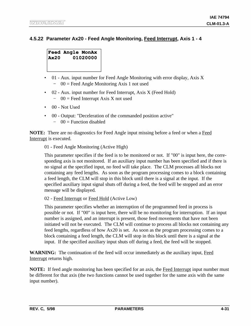
IAE 74794
CLM-01.3-A
REV. C, 5/98 PARAMETERS 4-31
4.5.22 Parameter Ax20 - Feed Angle Monitoring, Feed Interrupt, Axis 1 - 4
Feed Angle MonAxFeed Angle MonAxAx20 01020000Ax20 01020000
• 01 - Aux. input number for Feed Angle Monitoring with error display, Axis X− 00 = Feed Angle Monitoring Axis 1 not used
• 02 - Aux. input number for Feed Interrupt, Axis X (Feed Hold)− 00 = Feed Interrupt Axis X not used
• 00 - Not Used
• 00 - Output: "Deceleration of the commanded position active"− 00 = Function disabled
NOTE: There are no diagnostics for Feed Angle input missing before a feed or when a FeedInterrupt is executed.
01 - Feed Angle Monitoring (Active High)
This parameter specifies if the feed is to be monitored or not. If "00" is input here, the corre-sponding axis is not monitored. If an auxiliary input number has been specified and if there isno signal at the specified input, no feed will take place. The CLM processes all blocks notcontaining any feed lengths. As soon as the program processing comes to a block containinga feed length, the CLM will stop in this block until there is a signal at the input. If thespecified auxiliary input signal shuts off during a feed, the feed will be stopped and an errormessage will be displayed.
02 - Feed Interrupt or Feed Hold (Active Low)
This parameter specifies whether an interruption of the programmed feed in process ispossible or not. If "00" is input here, there will be no monitoring for interruption. If an inputnumber is assigned, and an interrupt is present, those feed movements that have not beeninitiated will not be executed. The CLM will continue to process all blocks not containing anyfeed lengths, regardless of how Ax20 is set. As soon as the program processing comes to ablock containing a feed length, the CLM will stop in this block until there is a signal at theinput. If the specified auxiliary input shuts off during a feed, the feed will be stopped.
WARNING: The continuation of the feed will occur immediately as the auxiliary input, FeedInterrupt returns high.
NOTE: If feed angle monitoring has been specified for an axis, the Feed Interrupt input number mustbe different for that axis (the two functions cannot be used together for the same axis with the sameinput number).
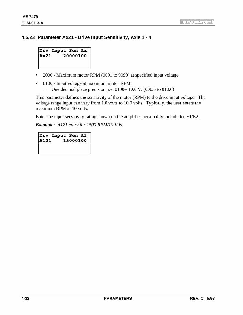
IAE 7479
CLM-01.3-A
4-32 PARAMETERS REV. C, 5/98
4.5.23 Parameter Ax21 - Drive Input Sensitivity, Axis 1 - 4
Drv Input Sen AxDrv Input Sen AxAx21 20000100Ax21 20000100
• 2000 - Maximum motor RPM (0001 to 9999) at specified input voltage
• 0100 - Input voltage at maximum motor RPM− One decimal place precision, i.e. 0100= 10.0 V. (000.5 to 010.0)
This parameter defines the sensitivity of the motor (RPM) to the drive input voltage. Thevoltage range input can vary from 1.0 volts to 10.0 volts. Typically, the user enters themaximum RPM at 10 volts.
Enter the input sensitivity rating shown on the amplifier personality module for E1/E2.
Example: A121 entry for 1500 RPM/10 V is:
Drv Input Sen A1Drv Input Sen A1A121 15000100A121 15000100
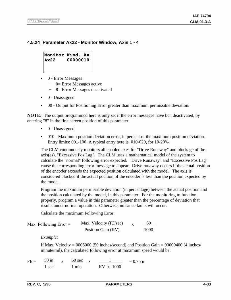
IAE 74794
CLM-01.3-A
REV. C, 5/98 PARAMETERS 4-33
4.5.24 Parameter Ax22 - Monitor Window, Axis 1 - 4
Monitor Wind. AxMonitor Wind. AxAx22 00000010Ax22 00000010
• 0 - Error Messages− 0= Error Messages active− 8= Error Messages deactivated
• 0 - Unassigned
• 00 - Output for Positioning Error greater than maximum permissible deviation.
NOTE: The output programmed here is only set if the error messages have ben deactivated, byentering "8" in the first screen position of this parameter.
• 0 - Unassigned
• 010 - Maximum position deviation error, in percent of the maximum position deviation.Entry limits: 001-100. A typical entry here is 010-020, for 10-20%.
The CLM continuously monitors all enabled axes for "Drive Runaway" and blockage of theaxis(es), "Excessive Pos Lag". The CLM uses a mathematical model of the system tocalculate the "normal" following error expected. "Drive Runaway" and "Excessive Pos Lag"cause the corresponding error message to appear. Drive runaway occurs if the actual positionof the encoder exceeds the expected position calculated with the model. The axis isconsidered blocked if the actual position of the encoder is less than the position expected bythe model.
Program the maximum permissible deviation (in percentage) between the actual position andthe position calculated by the model, in this parameter. For the monitoring to functionproperly, program a value in this parameter greater than the percentage of deviation thatresults under normal operation. Otherwise, nuisance faults will occur.
Calculate the maximum Following Error:
Max. Following Error = Max. Velocity (IU/sec) x 60
Position Gain (KV) 1000
Example:
If Max. Velocity = 0005000 (50 inches/second) and Position Gain = 00000400 (4 inches/minute/mil), the calculated following error at maximum speed would be:
FE = 50 in x 60 sec x 1 = 0.75 in1 sec 1 min KV x 1000
IAE 7479
CLM-01.3-A
4-34 PARAMETERS REV. C, 5/98
If Ax22 = 00000005, the CLM will issue an error if the actual following error differs from theexpected following error by more than 5%. Take 5% of 0.750 inches: 0.05 x 0.750 = 0.0375.When feeding at maximum velocity, the LS display screen (following error) would read about0.750 inches.
An "E.P.L." error would occur if the following error exceeded 0.750 + 0.0375 = 0.788 inches.A "D.R." error would occur if the following error went below 0.750 - 0.0375 = 0.712 inches.When feeding at a lower velocity, the following error will be lower, but the maximumdeviation from the expected following error will still be ± 0.0375 inches.
Note the following:
If you change the parameters Position Gain or Maximum Velocity, you do not need to repro-gram the Monitor Window, because it is entered in percentage of maximum positiondeviation.
If the Monitor Window entry, as converted, is smaller than the Position Tolerance, the CLMis unable to correctly distinguish between "Drive Runaway" and "Excessive Position Lag."Therefore, the converted Monitor Window parameter should be greater than the PositionTolerance.
If the programmed entry for Monitor Window is too small, even a normal feed will generate a"Drive Runaway" or "Excessive Position Lag" error.
The Monitor Window value depends on your application. You should enter the lowestpercentage possible that will not cause nuisance faults.
Possible causes for "Drive Runaway"
• The parameter "Direction of Operation" is incompatible with the wiring of the encoder orwith the command inputs E1/E2/E3/E4.
• The axis moved when no command value has been output.
• Ax04 does not correspond to the actual encoder data (too small).
• The maximum RPM in Ax21 is smaller than specified on the amplifier personality module.
• Ax22 entry is too small (typical setting is 10%).
Possible causes for "Excess Position Lag"
• Feed command issued, but no movement detected:− the encoder cable is not connected,− the encoder cable or encoder is defective,− the motor cannot turn because of a mechanical bind.
• Ax04 does not correspond to the actual encoder data (too large).
• The maximum RPM in Ax21 is greater than specified on the amplifier personality module.
• The acceleration is too great (Ax02, also Ax17 second acceleration).
• The CLM signal controller enable is not reaching the drive.

IAE 74794
CLM-01.3-A
REV. C, 5/98 PARAMETERS 4-35
• The CLM velocity command is not reaching the drive.
• Ax22 entry is too small (typical setting is 10%).
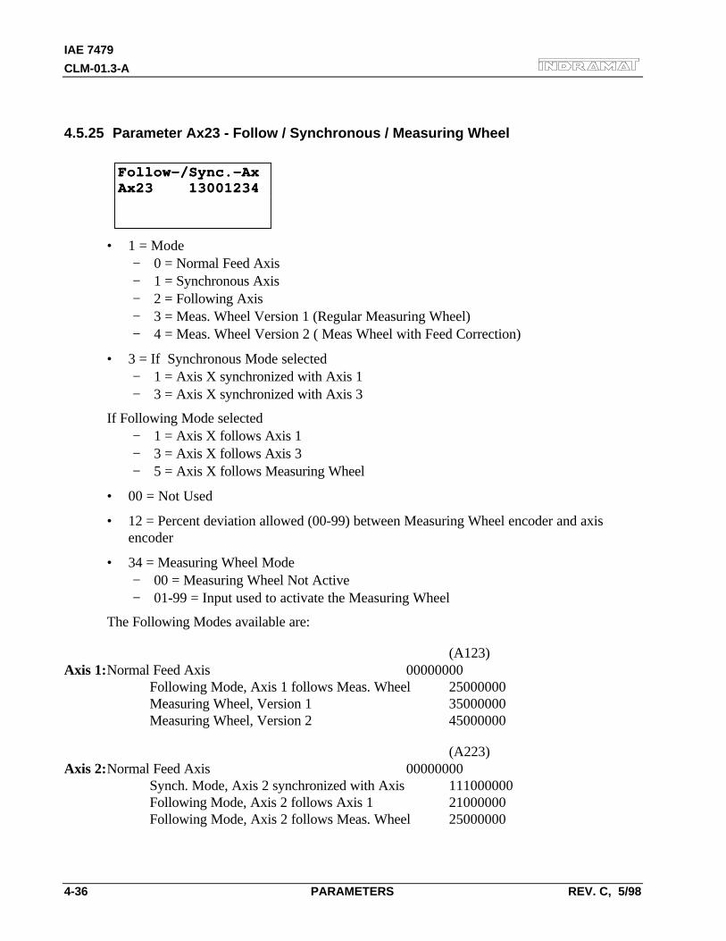
IAE 7479
CLM-01.3-A
4-36 PARAMETERS REV. C, 5/98
4.5.25 Parameter Ax23 - Follow / Synchronous / Measuring Wheel
Follow-/Sync.-AxFollow-/Sync.-AxAx23 13001234Ax23 13001234
• 1 = Mode− 0 = Normal Feed Axis− 1 = Synchronous Axis− 2 = Following Axis− 3 = Meas. Wheel Version 1 (Regular Measuring Wheel)− 4 = Meas. Wheel Version 2 ( Meas Wheel with Feed Correction)
• 3 = If Synchronous Mode selected− 1 = Axis X synchronized with Axis 1− 3 = Axis X synchronized with Axis 3
If Following Mode selected− 1 = Axis X follows Axis 1− 3 = Axis X follows Axis 3− 5 = Axis X follows Measuring Wheel
• 00 = Not Used
• 12 = Percent deviation allowed (00-99) between Measuring Wheel encoder and axisencoder
• 34 = Measuring Wheel Mode− 00 = Measuring Wheel Not Active− 01-99 = Input used to activate the Measuring Wheel
The Following Modes available are:
(A123)Axis 1:Normal Feed Axis 00000000
Following Mode, Axis 1 follows Meas. Wheel 25000000Measuring Wheel, Version 1 35000000Measuring Wheel, Version 2 45000000
(A223)Axis 2:Normal Feed Axis 00000000
Synch. Mode, Axis 2 synchronized with Axis 111000000Following Mode, Axis 2 follows Axis 1 21000000Following Mode, Axis 2 follows Meas. Wheel 25000000
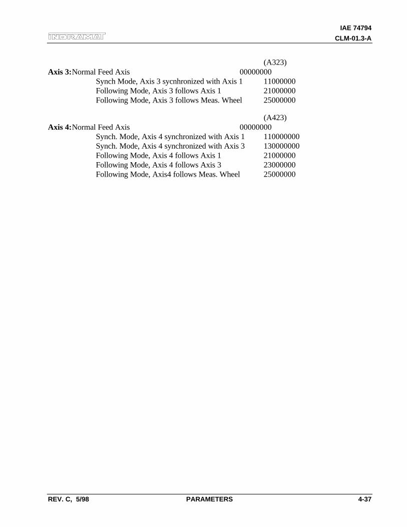
IAE 74794
CLM-01.3-A
REV. C, 5/98 PARAMETERS 4-37
(A323)Axis 3:Normal Feed Axis 00000000
Synch Mode, Axis 3 sycnhronized with Axis 1 11000000Following Mode, Axis 3 follows Axis 1 21000000Following Mode, Axis 3 follows Meas. Wheel 25000000
(A423)Axis 4:Normal Feed Axis 00000000
Synch. Mode, Axis 4 synchronized with Axis 1 110000000Synch. Mode, Axis 4 synchronized with Axis 3 130000000Following Mode, Axis 4 follows Axis 1 21000000Following Mode, Axis 4 follows Axis 3 23000000Following Mode, Axis4 follows Meas. Wheel 25000000

IAE 7479
CLM-01.3-A
4-38 PARAMETERS REV. C, 5/98
4.5.26 Parameter Ax24 - Delay Axis x
(as of software version LA01.3-3.0)
Delay AxDelay Ax
Ax24Ax240000000.00000000.0
Delay AxDelay Ax
Ax24Ax240000000000000000
• 00000000 - Maximum delay in EGE/s
or
• 0000000.0 - Additional programming for the delay can be done using the DEC command(in ‰ of maximum amount in Ax24)
• Range: As in Parameter Ax02
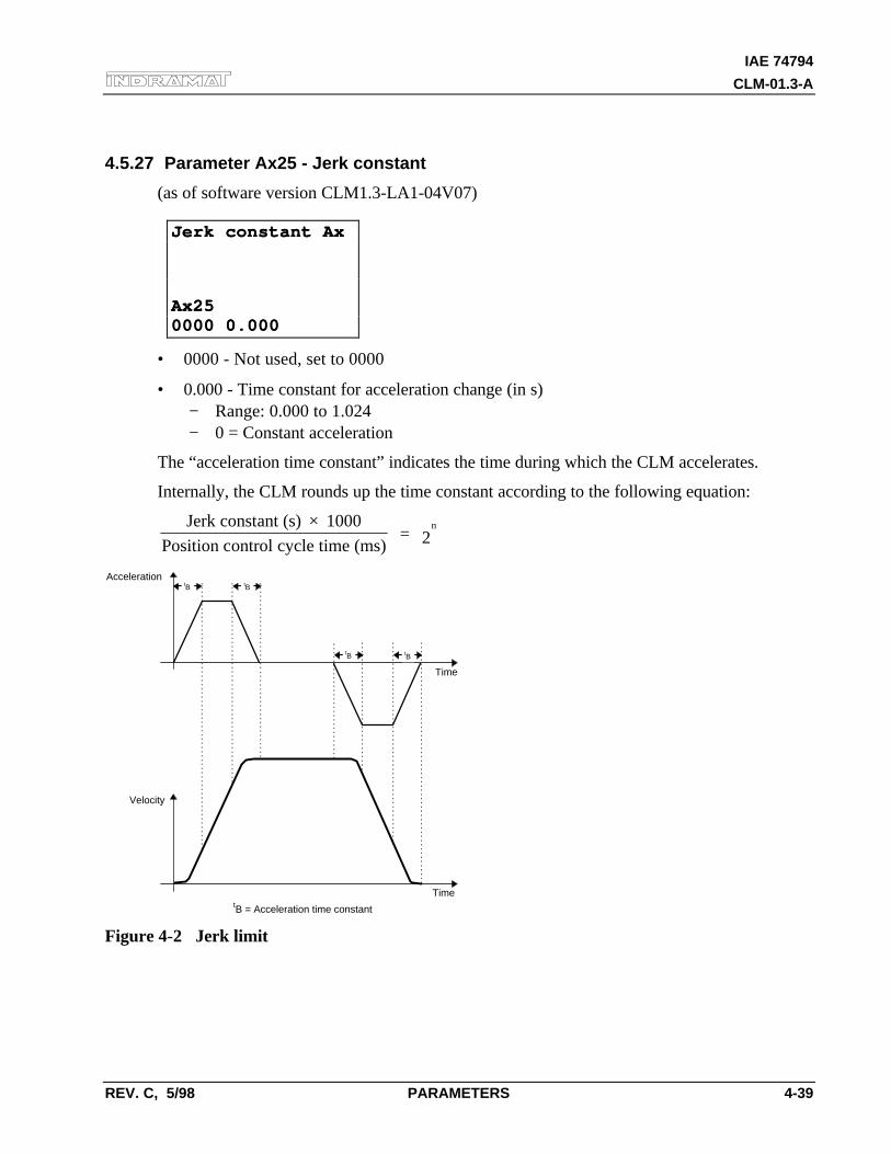
IAE 74794
CLM-01.3-A
REV. C, 5/98 PARAMETERS 4-39
4.5.27 Parameter Ax25 - Jerk constant
(as of software version CLM1.3-LA1-04V07)
Jerk constant AxJerk constant Ax
Ax25Ax250000 0.0000000 0.000
• 0000 - Not used, set to 0000
• 0.000 - Time constant for acceleration change (in s)− Range: 0.000 to 1.024− 0 = Constant acceleration
The “acceleration time constant” indicates the time during which the CLM accelerates.
Internally, the CLM rounds up the time constant according to the following equation:
Jerk constant (s) 1000
Position control cycle time (ms) = 2
n×
tB
Time
Time
Acceleration
Velocity
tB = Acceleration time constant
tB
tB tB
Figure 4-2 Jerk limit
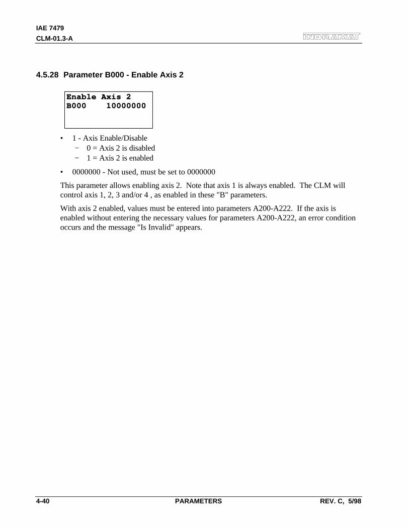
IAE 7479
CLM-01.3-A
4-40 PARAMETERS REV. C, 5/98
4.5.28 Parameter B000 - Enable Axis 2
Enable Axis 2Enable Axis 2B000 10000000B000 10000000
• 1 - Axis Enable/Disable− 0 = Axis 2 is disabled− 1 = Axis 2 is enabled
• 0000000 - Not used, must be set to 0000000
This parameter allows enabling axis 2. Note that axis 1 is always enabled. The CLM willcontrol axis 1, 2, 3 and/or 4 , as enabled in these "B" parameters.
With axis 2 enabled, values must be entered into parameters A200-A222. If the axis isenabled without entering the necessary values for parameters A200-A222, an error conditionoccurs and the message "Is Invalid" appears.
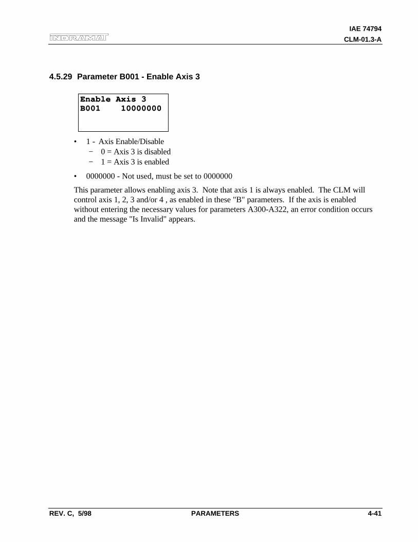
IAE 74794
CLM-01.3-A
REV. C, 5/98 PARAMETERS 4-41
4.5.29 Parameter B001 - Enable Axis 3
Enable Axis 3Enable Axis 3B001 10000000B001 10000000
• 1 - Axis Enable/Disable− 0 = Axis 3 is disabled− 1 = Axis 3 is enabled
• 0000000 - Not used, must be set to 0000000
This parameter allows enabling axis 3. Note that axis 1 is always enabled. The CLM willcontrol axis 1, 2, 3 and/or 4 , as enabled in these "B" parameters. If the axis is enabledwithout entering the necessary values for parameters A300-A322, an error condition occursand the message "Is Invalid" appears.
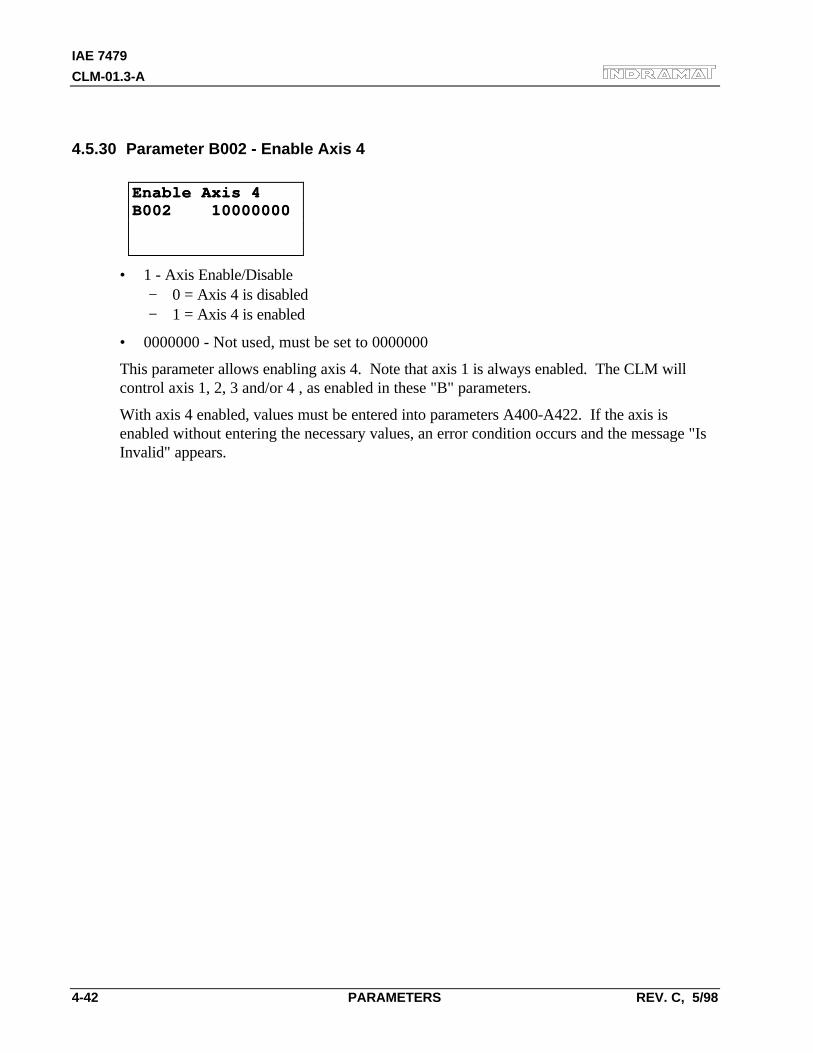
IAE 7479
CLM-01.3-A
4-42 PARAMETERS REV. C, 5/98
4.5.30 Parameter B002 - Enable Axis 4
Enable Axis 4Enable Axis 4B002 10000000B002 10000000
• 1 - Axis Enable/Disable− 0 = Axis 4 is disabled− 1 = Axis 4 is enabled
• 0000000 - Not used, must be set to 0000000
This parameter allows enabling axis 4. Note that axis 1 is always enabled. The CLM willcontrol axis 1, 2, 3 and/or 4 , as enabled in these "B" parameters.
With axis 4 enabled, values must be entered into parameters A400-A422. If the axis isenabled without entering the necessary values, an error condition occurs and the message "IsInvalid" appears.
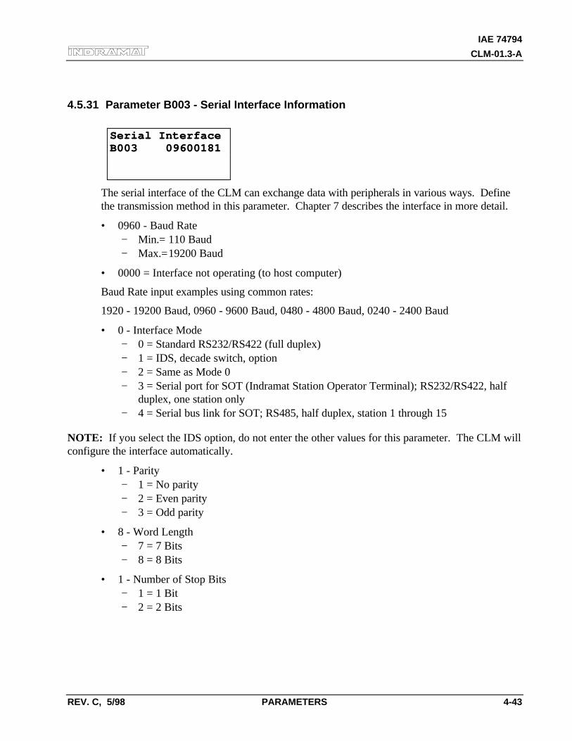
IAE 74794
CLM-01.3-A
REV. C, 5/98 PARAMETERS 4-43
4.5.31 Parameter B003 - Serial Interface Information
Serial InterfaceSerial InterfaceB003 09600181B003 09600181
The serial interface of the CLM can exchange data with peripherals in various ways. Definethe transmission method in this parameter. Chapter 7 describes the interface in more detail.
• 0960 - Baud Rate− Min.= 110 Baud− Max.=19200 Baud
• 0000 = Interface not operating (to host computer)
Baud Rate input examples using common rates:
1920 - 19200 Baud, 0960 - 9600 Baud, 0480 - 4800 Baud, 0240 - 2400 Baud
• 0 - Interface Mode− 0 = Standard RS232/RS422 (full duplex)− 1 = IDS, decade switch, option− 2 = Same as Mode 0− 3 = Serial port for SOT (Indramat Station Operator Terminal); RS232/RS422, half
duplex, one station only− 4 = Serial bus link for SOT; RS485, half duplex, station 1 through 15
NOTE: If you select the IDS option, do not enter the other values for this parameter. The CLM willconfigure the interface automatically.
• 1 - Parity− 1 = No parity− 2 = Even parity− 3 = Odd parity
• 8 - Word Length− 7 = 7 Bits− 8 = 8 Bits
• 1 - Number of Stop Bits− 1 = 1 Bit− 2 = 2 Bits
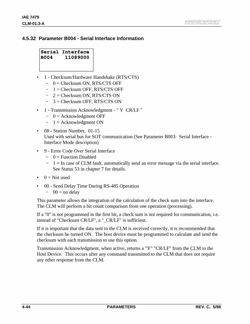
IAE 7479
CLM-01.3-A
4-44 PARAMETERS REV. C, 5/98
4.5.32 Parameter B004 - Serial Interface Information
Serial InterfaceSerial InterfaceB004 11089000B004 11089000
• 1 - Checksum/Hardware Handshake (RTS/CTS)− 0 = Checksum ON, RTS/CTS OFF− 1 = Checksum OFF, RTS/CTS OFF− 2 = Checksum ON, RTS/CTS ON− 3 = Checksum OFF, RTS/CTS ON
• 1 - Transmission Acknowledgment - " Y CR/LF "− 0 = Acknowledgment OFF− 1 = Acknowledgment ON
• 08 - Station Number, 01-15Used with serial bus for SOT communication (See Parameter B003: Serial Interface -Interface Mode description)
• 9 - Error Code Over Serial Interface− 0 = Function Disabled− 1 = In case of CLM fault, automatically send an error message via the serial interface.
See Status 53 in chapter 7 for details.
• 0 = Not used
• 00 - Send Delay Time During RS-485 Operation− 00 = no delay
This parameter allows the integration of the calculation of the check sum into the interface.The CLM will perform a bit count comparison from one operation (processing).
If a "0" is not programmed in the first bit, a check sum is not required for communication, i.e.instead of "Checksum CR/LF", a "_CR/LF" is sufficient.
If it is important that the data sent to the CLM is received correctly, it is recommended thatthe checksum be turned ON. The host device must be programmed to calculate and send thechecksum with each transmission to use this option.
Transmission Acknowledgment, when active, returns a "Y" "CR/LF" from the CLM to theHost Device. This occurs after any command transmitted to the CLM that does not requireany other response from the CLM.
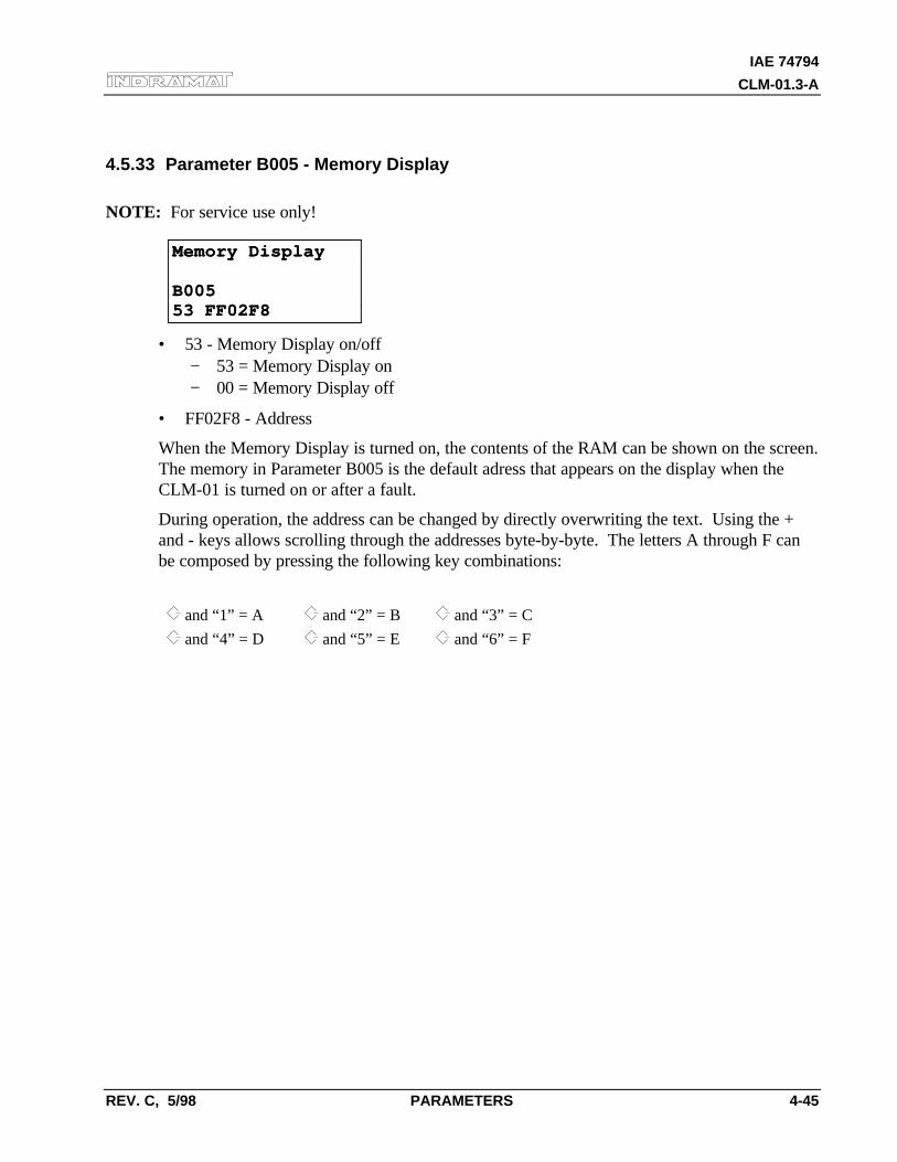
IAE 74794
CLM-01.3-A
REV. C, 5/98 PARAMETERS 4-45
4.5.33 Parameter B005 - Memory Display
NOTE: For service use only!
Memory DisplayMemory Display
B005B00553 FF02F853 FF02F8
• 53 - Memory Display on/off− 53 = Memory Display on− 00 = Memory Display off
• FF02F8 - Address
When the Memory Display is turned on, the contents of the RAM can be shown on the screen.The memory in Parameter B005 is the default adress that appears on the display when theCLM-01 is turned on or after a fault.
During operation, the address can be changed by directly overwriting the text. Using the +and - keys allows scrolling through the addresses byte-by-byte. The letters A through F canbe composed by pressing the following key combinations:
and “1” = A and “2” = B and “3” = C
and “4” = D and “5” = E and “6” = F
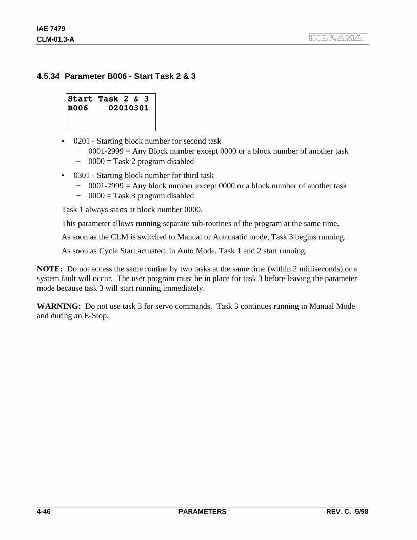
IAE 7479
CLM-01.3-A
4-46 PARAMETERS REV. C, 5/98
4.5.34 Parameter B006 - Start Task 2 & 3
Start Task 2 & 3Start Task 2 & 3B006 02010301B006 02010301
• 0201 - Starting block number for second task− 0001-2999 = Any Block number except 0000 or a block number of another task− 0000 = Task 2 program disabled
• 0301 - Starting block number for third task− 0001-2999 = Any block number except 0000 or a block number of another task− 0000 = Task 3 program disabled
Task 1 always starts at block number 0000.
This parameter allows running separate sub-routines of the program at the same time.
As soon as the CLM is switched to Manual or Automatic mode, Task 3 begins running.
As soon as Cycle Start actuated, in Auto Mode, Task 1 and 2 start running.
NOTE: Do not access the same routine by two tasks at the same time (within 2 milliseconds) or asystem fault will occur. The user program must be in place for task 3 before leaving the parametermode because task 3 will start running immediately.
WARNING: Do not use task 3 for servo commands. Task 3 continues running in Manual Modeand during an E-Stop.
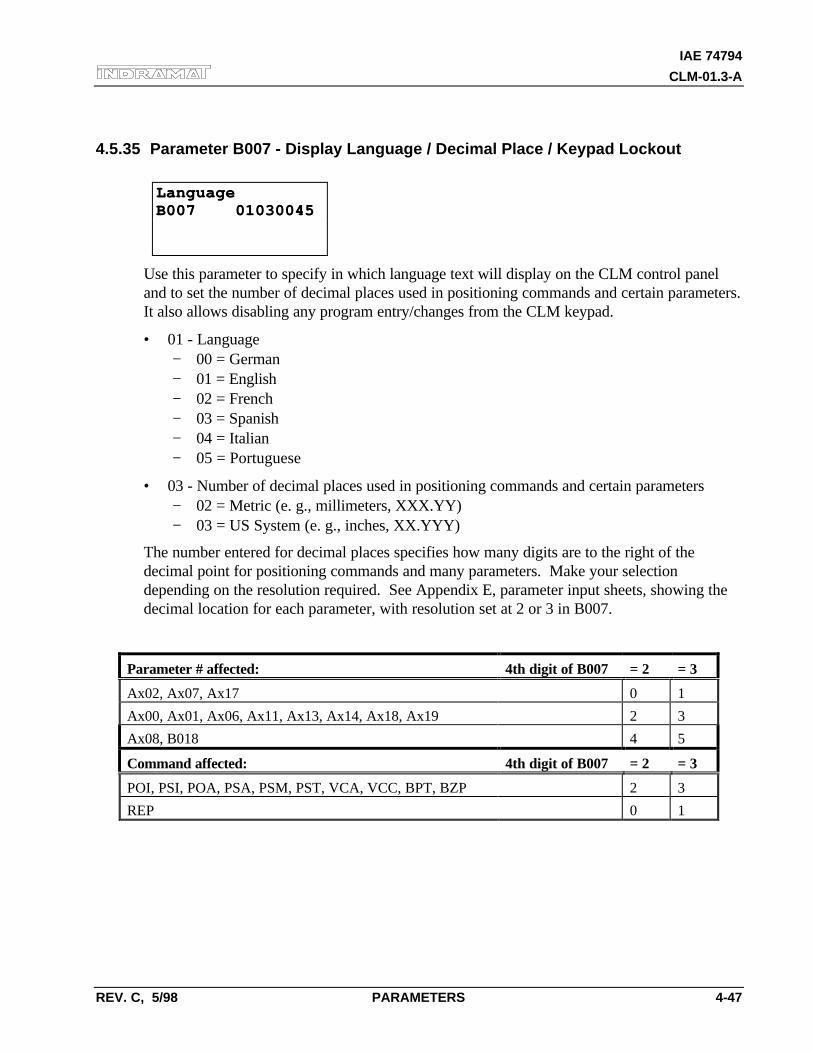
IAE 74794
CLM-01.3-A
REV. C, 5/98 PARAMETERS 4-47
4.5.35 Parameter B007 - Display Language / Decimal Place / Keypad Lockout
LanguageLanguageB007 01030045B007 01030045
Use this parameter to specify in which language text will display on the CLM control paneland to set the number of decimal places used in positioning commands and certain parameters.It also allows disabling any program entry/changes from the CLM keypad.
• 01 - Language− 00 = German− 01 = English− 02 = French− 03 = Spanish− 04 = Italian− 05 = Portuguese
• 03 - Number of decimal places used in positioning commands and certain parameters− 02 = Metric (e. g., millimeters, XXX.YY)− 03 = US System (e. g., inches, XX.YYY)
The number entered for decimal places specifies how many digits are to the right of thedecimal point for positioning commands and many parameters. Make your selectiondepending on the resolution required. See Appendix E, parameter input sheets, showing thedecimal location for each parameter, with resolution set at 2 or 3 in B007.
Parameter # affected: 4th digit of B007 = 2 = 3
Ax02, Ax07, Ax17 0 1
Ax00, Ax01, Ax06, Ax11, Ax13, Ax14, Ax18, Ax19 2 3
Ax08, B018 4 5
Command affected: 4th digit of B007 = 2 = 3
POI, PSI, POA, PSA, PSM, PST, VCA, VCC, BPT, BZP 2 3
REP 0 1
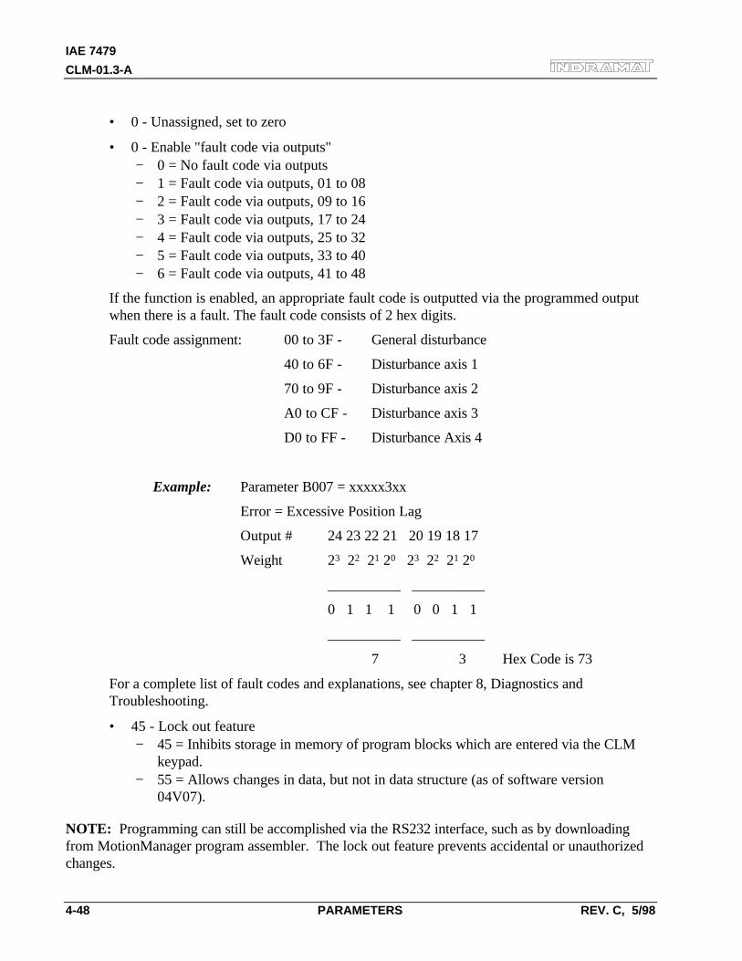
IAE 7479
CLM-01.3-A
4-48 PARAMETERS REV. C, 5/98
• 0 - Unassigned, set to zero
• 0 - Enable "fault code via outputs"− 0 = No fault code via outputs− 1 = Fault code via outputs, 01 to 08− 2 = Fault code via outputs, 09 to 16− 3 = Fault code via outputs, 17 to 24− 4 = Fault code via outputs, 25 to 32− 5 = Fault code via outputs, 33 to 40− 6 = Fault code via outputs, 41 to 48
If the function is enabled, an appropriate fault code is outputted via the programmed outputwhen there is a fault. The fault code consists of 2 hex digits.
Fault code assignment: 00 to 3F - General disturbance
40 to 6F - Disturbance axis 1
70 to 9F - Disturbance axis 2
A0 to CF - Disturbance axis 3
D0 to FF - Disturbance Axis 4
Example: Parameter B007 = xxxxx3xx
Error = Excessive Position Lag
Output # 24 23 22 21 20 19 18 17
Weight 23 22 21 20 23 22 21 20
__________ __________
0 1 1 1 0 0 1 1
__________ __________
7 3 Hex Code is 73
For a complete list of fault codes and explanations, see chapter 8, Diagnostics andTroubleshooting.
• 45 - Lock out feature− 45 = Inhibits storage in memory of program blocks which are entered via the CLM
keypad.− 55 = Allows changes in data, but not in data structure (as of software version
04V07).
NOTE: Programming can still be accomplished via the RS232 interface, such as by downloadingfrom MotionManager program assembler. The lock out feature prevents accidental or unauthorizedchanges.
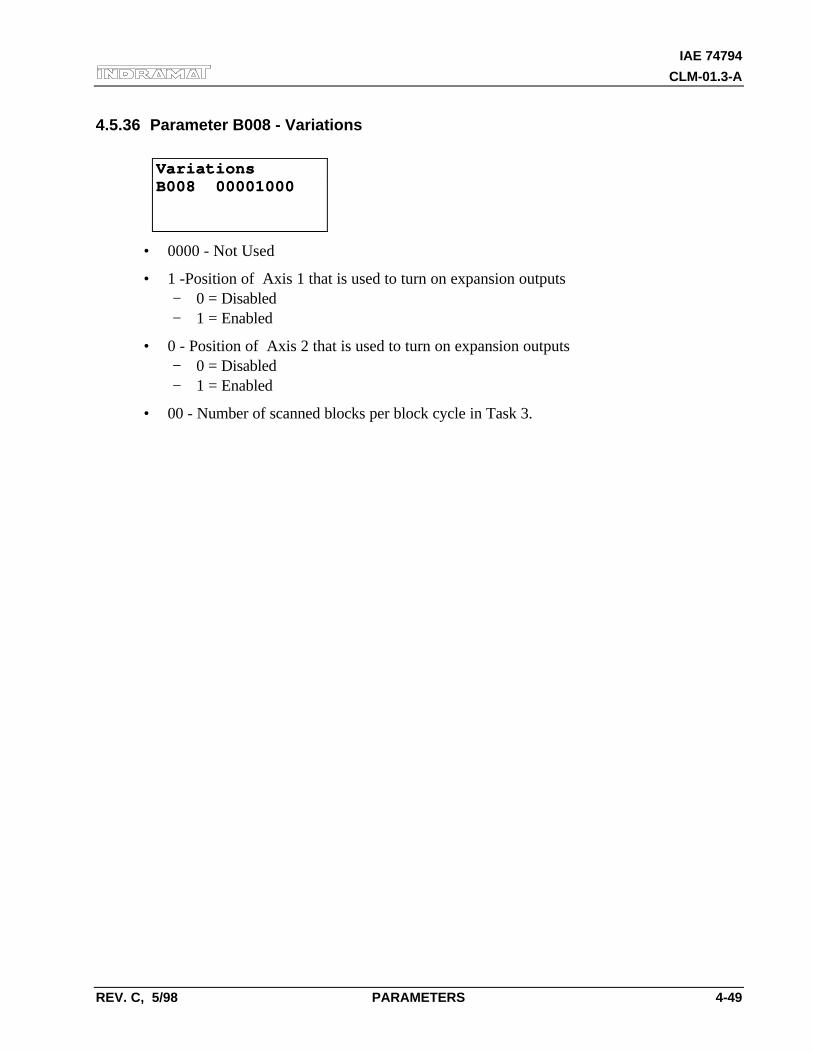
IAE 74794
CLM-01.3-A
REV. C, 5/98 PARAMETERS 4-49
4.5.36 Parameter B008 - Variations
VariationsVariationsB008 00001000B008 00001000
• 0000 - Not Used
• 1 -Position of Axis 1 that is used to turn on expansion outputs− 0 = Disabled− 1 = Enabled
• 0 - Position of Axis 2 that is used to turn on expansion outputs− 0 = Disabled− 1 = Enabled
• 00 - Number of scanned blocks per block cycle in Task 3.
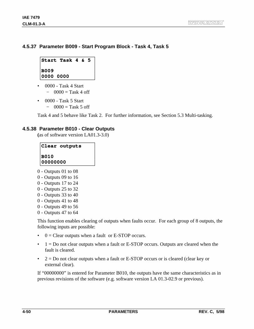
IAE 7479
CLM-01.3-A
4-50 PARAMETERS REV. C, 5/98
4.5.37 Parameter B009 - Start Program Block - Task 4, Task 5
Start Task 4 & 5Start Task 4 & 5
B009B0090000 00000000 0000
• 0000 - Task 4 Start− 0000 = Task 4 off
• 0000 - Task 5 Start− 0000 = Task 5 off
Task 4 and 5 behave like Task 2. For further information, see Section 5.3 Multi-tasking.
4.5.38 Parameter B010 - Clear Outputs(as of software version LA01.3-3.0)
Clear outputsClear outputs
B010B0100000000000000000
0 - Outputs 01 to 080 - Outputs 09 to 160 - Outputs 17 to 240 - Outputs 25 to 320 - Outputs 33 to 400 - Outputs 41 to 480 - Outputs 49 to 560 - Outputs 47 to 64
This function enables clearing of outputs when faults occur. For each group of 8 outputs, thefollowing inputs are possible:
• 0 = Clear outputs when a fault or E-STOP occurs.
• 1 = Do not clear outputs when a fault or E-STOP occurs. Outputs are cleared when thefault is cleared.
• 2 = Do not clear outputs when a fault or E-STOP occurs or is cleared (clear key orexternal clear).
If “00000000” is entered for Parameter B010, the outputs have the same characteristics as inprevious revisions of the software (e.g. software version LA 01.3-02.9 or previous).
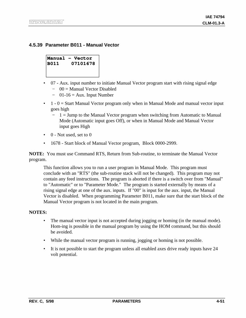
IAE 74794
CLM-01.3-A
REV. C, 5/98 PARAMETERS 4-51
4.5.39 Parameter B011 - Manual Vector
Manual - VectorManual - VectorB011 07101678B011 07101678
• 07 - Aux. input number to initiate Manual Vector program start with rising signal edge− 00 = Manual Vector Disabled− 01-16 = Aux. Input Number
• 1 - 0 = Start Manual Vector program only when in Manual Mode and manual vector inputgoes high− 1 = Jump to the Manual Vector program when switching from Automatic to Manual
Mode (Automatic input goes Off), or when in Manual Mode and Manual Vectorinput goes High
• 0 - Not used, set to 0
• 1678 - Start block of Manual Vector program, Block 0000-2999.
NOTE: You must use Command RTS, Return from Sub-routine, to terminate the Manual Vectorprogram.
This function allows you to run a user program in Manual Mode. This program mustconclude with an "RTS" (the sub-routine stack will not be changed). This program may notcontain any feed instructions. The program is aborted if there is a switch over from "Manual"to "Automatic" or to "Parameter Mode." The program is started externally by means of arising signal edge at one of the aux. inputs. If "00" is input for the aux. input, the ManualVector is disabled. When programming Parameter B011, make sure that the start block of theManual Vector program is not located in the main program.
NOTES:
• The manual vector input is not accepted during jogging or homing (in the manual mode).Hom-ing is possible in the manual program by using the HOM command, but this shouldbe avoided.
• While the manual vector program is running, jogging or homing is not possible.
• It is not possible to start the program unless all enabled axes drive ready inputs have 24volt potential.
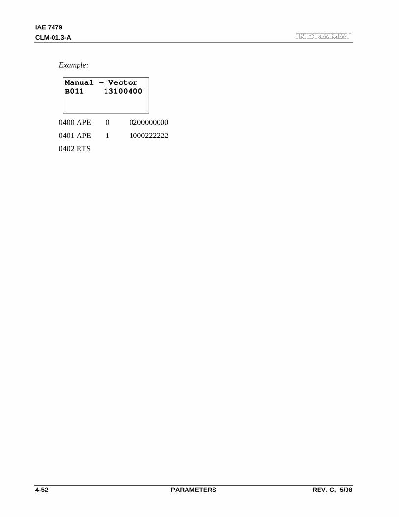
IAE 7479
CLM-01.3-A
4-52 PARAMETERS REV. C, 5/98
Example:
Manual - VectorManual - VectorB011 13100400B011 13100400
0400 APE 0 0200000000
0401 APE 1 1000222222
0402 RTS
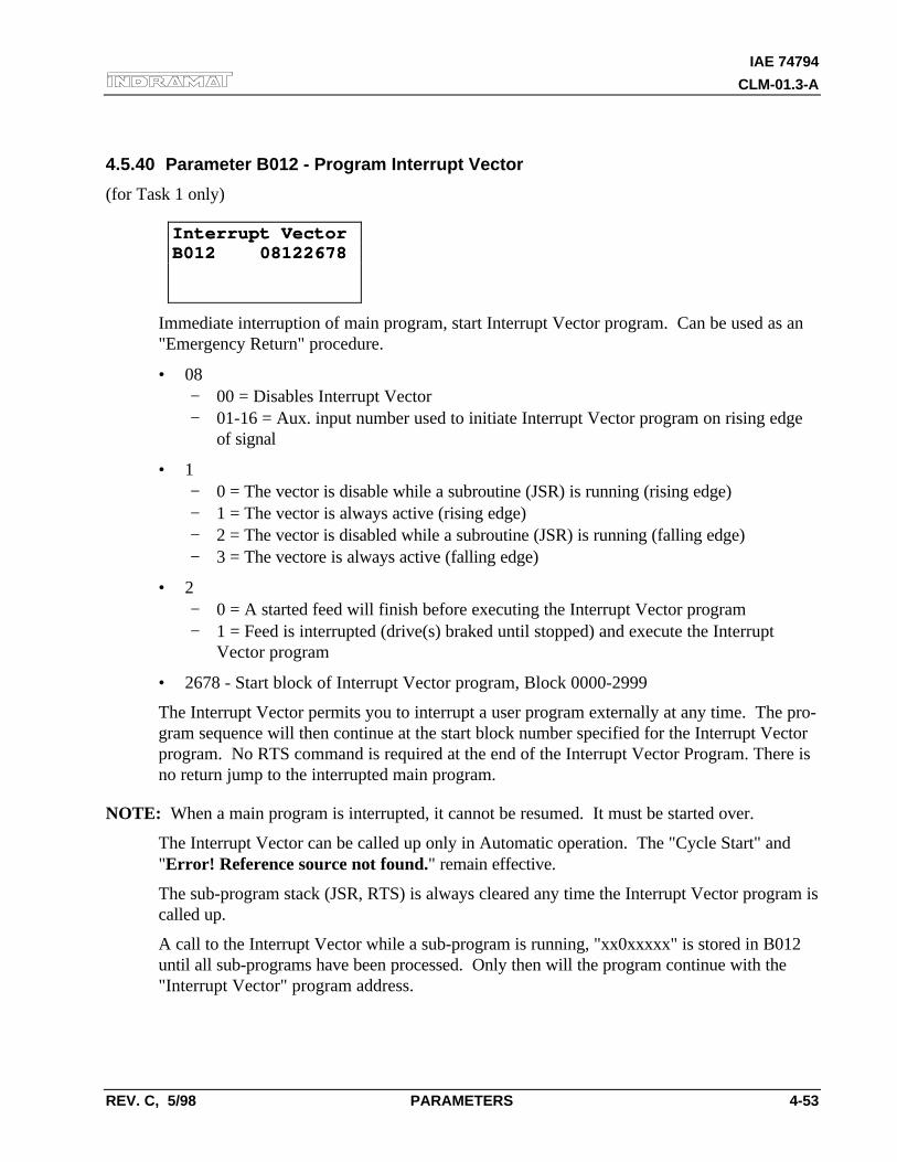
IAE 74794
CLM-01.3-A
REV. C, 5/98 PARAMETERS 4-53
4.5.40 Parameter B012 - Program Interrupt Vector
(for Task 1 only)
Interrupt VectorInterrupt VectorB012 08122678B012 08122678
Immediate interruption of main program, start Interrupt Vector program. Can be used as an"Emergency Return" procedure.
• 08− 00 = Disables Interrupt Vector− 01-16 = Aux. input number used to initiate Interrupt Vector program on rising edge
of signal
• 1− 0 = The vector is disable while a subroutine (JSR) is running (rising edge)− 1 = The vector is always active (rising edge)− 2 = The vector is disabled while a subroutine (JSR) is running (falling edge)− 3 = The vectore is always active (falling edge)
• 2− 0 = A started feed will finish before executing the Interrupt Vector program− 1 = Feed is interrupted (drive(s) braked until stopped) and execute the Interrupt
Vector program
• 2678 - Start block of Interrupt Vector program, Block 0000-2999
The Interrupt Vector permits you to interrupt a user program externally at any time. The pro-gram sequence will then continue at the start block number specified for the Interrupt Vectorprogram. No RTS command is required at the end of the Interrupt Vector Program. There isno return jump to the interrupted main program.
NOTE: When a main program is interrupted, it cannot be resumed. It must be started over.
The Interrupt Vector can be called up only in Automatic operation. The "Cycle Start" and"Error! Reference source not found." remain effective.
The sub-program stack (JSR, RTS) is always cleared any time the Interrupt Vector program iscalled up.
A call to the Interrupt Vector while a sub-program is running, "xx0xxxxx" is stored in B012until all sub-programs have been processed. Only then will the program continue with the"Interrupt Vector" program address.
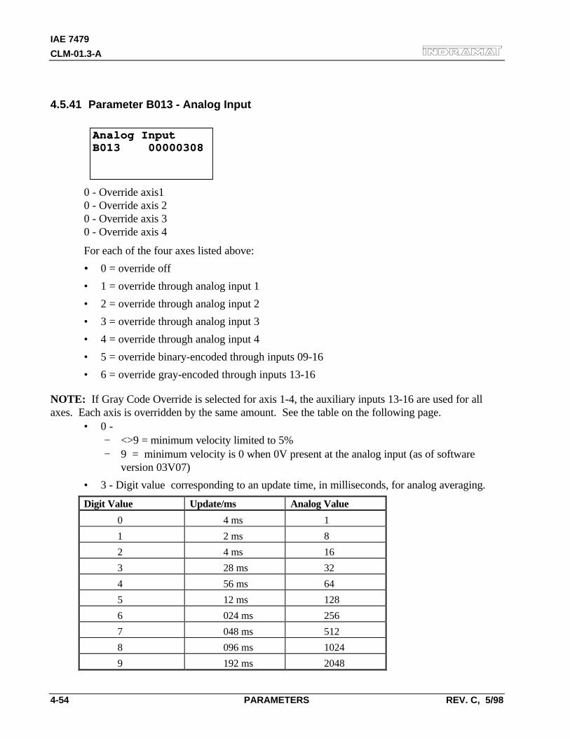
IAE 7479
CLM-01.3-A
4-54 PARAMETERS REV. C, 5/98
4.5.41 Parameter B013 - Analog Input
Analog InputAnalog InputB013 00000308B013 00000308
0 - Override axis10 - Override axis 20 - Override axis 30 - Override axis 4
For each of the four axes listed above:
• • 0 = override off
• 1 = override through analog input 1
• 2 = override through analog input 2
• 3 = override through analog input 3
• 4 = override through analog input 4
• 5 = override binary-encoded through inputs 09-16
• 6 = override gray-encoded through inputs 13-16
NOTE: If Gray Code Override is selected for axis 1-4, the auxiliary inputs 13-16 are used for allaxes. Each axis is overridden by the same amount. See the table on the following page.
• 0 -− <>9 = minimum velocity limited to 5%− 9 = minimum velocity is 0 when 0V present at the analog input (as of software
version 03V07)
• 3 - Digit value corresponding to an update time, in milliseconds, for analog averaging.
Digit Value Update/ms Analog Value
0 4 ms 1
1 2 ms 8
2 4 ms 16
3 28 ms 32
4 56 ms 64
5 12 ms 128
6 024 ms 256
7 048 ms 512
8 096 ms 1024
9 192 ms 2048
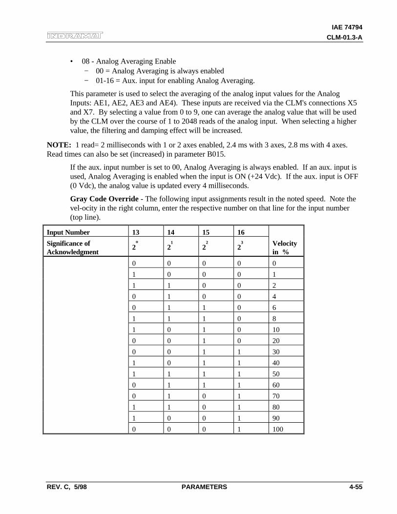
IAE 74794
CLM-01.3-A
REV. C, 5/98 PARAMETERS 4-55
• 08 - Analog Averaging Enable− 00 = Analog Averaging is always enabled− 01-16 = Aux. input for enabling Analog Averaging.
This parameter is used to select the averaging of the analog input values for the AnalogInputs: AE1, AE2, AE3 and AE4). These inputs are received via the CLM's connections X5and X7. By selecting a value from 0 to 9, one can average the analog value that will be usedby the CLM over the course of 1 to 2048 reads of the analog input. When selecting a highervalue, the filtering and damping effect will be increased.
NOTE: 1 read= 2 milliseconds with 1 or 2 axes enabled, 2.4 ms with 3 axes, 2.8 ms with 4 axes.Read times can also be set (increased) in parameter B015.
If the aux. input number is set to 00, Analog Averaging is always enabled. If an aux. input isused, Analog Averaging is enabled when the input is ON (+24 Vdc). If the aux. input is OFF(0 Vdc), the analog value is updated every 4 milliseconds.
Gray Code Override - The following input assignments result in the noted speed. Note thevel-ocity in the right column, enter the respective number on that line for the input number(top line).
Input Number 13 14 15 16
Significance ofAcknowledgment
2º 2¹ 2² 2³ Velocityin %
0 0 0 0 0
1 0 0 0 1
1 1 0 0 2
0 1 0 0 4
0 1 1 0 6
1 1 1 0 8
1 0 1 0 10
0 0 1 0 20
0 0 1 1 30
1 0 1 1 40
1 1 1 1 50
0 1 1 1 60
0 1 0 1 70
1 1 0 1 80
1 0 0 1 90
0 0 0 1 100
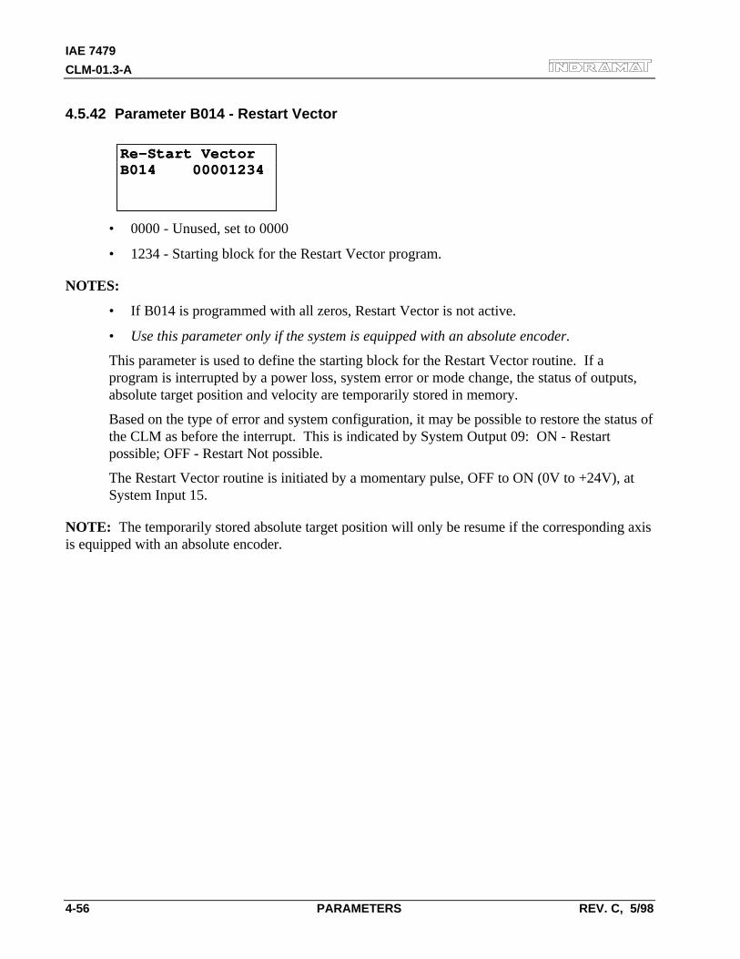
IAE 7479
CLM-01.3-A
4-56 PARAMETERS REV. C, 5/98
4.5.42 Parameter B014 - Restart Vector
Re-Start VectorRe-Start VectorB014 00001234B014 00001234
• 0000 - Unused, set to 0000
• 1234 - Starting block for the Restart Vector program.
NOTES:
• If B014 is programmed with all zeros, Restart Vector is not active.
• Use this parameter only if the system is equipped with an absolute encoder.
This parameter is used to define the starting block for the Restart Vector routine. If aprogram is interrupted by a power loss, system error or mode change, the status of outputs,absolute target position and velocity are temporarily stored in memory.
Based on the type of error and system configuration, it may be possible to restore the status ofthe CLM as before the interrupt. This is indicated by System Output 09: ON - Restartpossible; OFF - Restart Not possible.
The Restart Vector routine is initiated by a momentary pulse, OFF to ON (0V to +24V), atSystem Input 15.
NOTE: The temporarily stored absolute target position will only be resume if the corresponding axisis equipped with an absolute encoder.
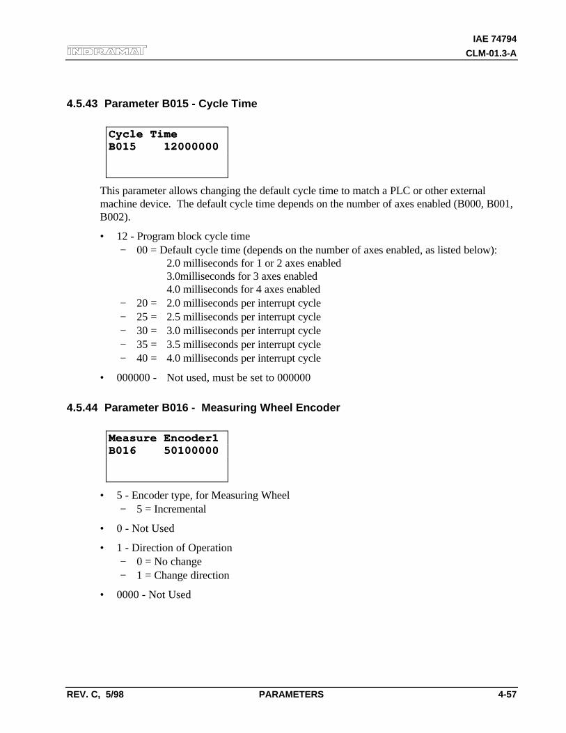
IAE 74794
CLM-01.3-A
REV. C, 5/98 PARAMETERS 4-57
4.5.43 Parameter B015 - Cycle Time
Cycle TimeCycle TimeB015 12000000B015 12000000
This parameter allows changing the default cycle time to match a PLC or other externalmachine device. The default cycle time depends on the number of axes enabled (B000, B001,B002).
• 12 - Program block cycle time− 00 = Default cycle time (depends on the number of axes enabled, as listed below):
2.0 milliseconds for 1 or 2 axes enabled3.0milliseconds for 3 axes enabled4.0 milliseconds for 4 axes enabled
− 20 = 2.0 milliseconds per interrupt cycle− 25 = 2.5 milliseconds per interrupt cycle− 30 = 3.0 milliseconds per interrupt cycle− 35 = 3.5 milliseconds per interrupt cycle− 40 = 4.0 milliseconds per interrupt cycle
• 000000 - Not used, must be set to 000000
4.5.44 Parameter B016 - Measuring Wheel Encoder
Measure Encoder1Measure Encoder1B016 50100000B016 50100000
• 5 - Encoder type, for Measuring Wheel− 5 = Incremental
• 0 - Not Used
• 1 - Direction of Operation− 0 = No change− 1 = Change direction
• 0000 - Not Used
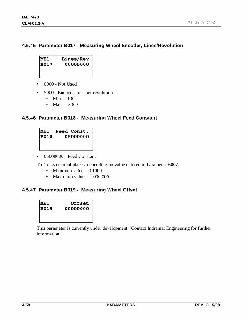
IAE 7479
CLM-01.3-A
4-58 PARAMETERS REV. C, 5/98
4.5.45 Parameter B017 - Measuring Wheel Encoder, Lines/Revolution
ME1 Lines/RevME1 Lines/RevB017 00005000B017 00005000
• 0000 - Not Used
• 5000 - Encoder lines per revolution− Min. = 100− Max. = 5000
4.5.46 Parameter B018 - Measuring Wheel Feed Constant
ME1 Feed Const.ME1 Feed Const.B018 05000000B018 05000000
• 05000000 - Feed Constant
To 4 or 5 decimal places, depending on value entered in Parameter B007.− Minimum value = 0.1000− Maximum value = 1000.000
4.5.47 Parameter B019 - Measuring Wheel Offset
ME1 OffsetME1 OffsetB019 00000000B019 00000000
This parameter is currently under development. Contact Indramat Engineering for furtherinformation.
IAE 74794
CLM-01.3-A
REV. C, 5/98 PROGRAMMING 5-1
5. PROGRAMMING
The application program of the system is defined and entered by the user. It can be entered directlyvia the CLM-01.3-A keyboard, or from a remote terminal device interfaced through the RS-232, RS-422, or RS-485 port. The application program flow is similar to a Basic program. Three lettermnemonic commands are used. There are 3000 programming lines/blocks available for userprogramming, numbered 0000 through 2999.
The Indramat MotionManagerTM Program Assembler provides an efficient method of creating and
editing the user program for the CLM control. It is a software package that runs on any DOS-basedcomputer. It provides several benefits over programming the CLM from its control panel. It alsoincludes enhanced features for creating and editing program that are not possible from the CLMcontrol panel. Refer to Publication IA 74733 for specific information on using this software program.
This chapter begins by describing some basic information that should be considered before creating aprogram for the CLM. It then describes the methods to enter the user program directly into the CLMcontrol panel. It further describes the programming commands and their function in a user program.
5.1 Positioning
Two types of positioning can be selected in the system, absolute and incremental. All positioning isdone in the units of your choice and are referred to as Input Units (IU). Input Units are the user’sdesired units of measure (i.e. inches, mm, radians, degrees, etc.).
In absolute positioning, all movements of the slide are made some absolute distance from the machinereference point. Thus, if the slide is at +2 inches from home, and an absolute position command tomove +3 inches is executed, a one inch feed in the positive direction will result.
In incremental positioning, all movements of the slide are made in the commanded direction to thedistance specified, starting from the current position. Thus, if a slide is at +2 inches from home, anincremental command to move +3 inches will result in the slide being positioned +5 inches fromhome.
IAE 7479
CLM-01.3-A
5-2 PROGRAMMING REV. C, 5/98
5.2 Auxiliary Inputs/Outputs
The CLM has a set of I/O points with a predefined use. It also includes a set of I/O points which canbe defined by the user for controlling machine functions. They will be referred to as auxiliary inputsand auxiliary outputs (or aux. inputs and aux. outputs). Auxiliary inputs are also known asacknowledgments. Certain commands are provided for use to address these inputs and outputs. TheI/O Commands are described in section 5.8.5.
WARNING: Auxiliary input and output numbers that have been dedicated by the machine builderfor a specific purpose must not be changed. Personal injury or damage to the machine/drive traincould result from such changes.
5.2.1 Programming Inputs/Outputs
Certain outputs are predefined in the CLM internal program and cannot be changed by theuser program. When the CLM is powered ON, it sets certain outputs, per the internalprogram, to default position. Likewise, when a fault occurs, it sets many outputs OFF.Outputs are re-established, either through hardware or software, i.e. the Automatic ModeIndicator turns ON after that mode is selected by input (assuming all other conditions aremet), a software flag is turned ON or OFF as the user program executes the block containingthe command.
Chapter 2 describes the functional use of each system input/output, as well as manyprogramming and parameter entries specifying input or output connections. Several I/O areavailable for use as flags in the user program. Certain output flags are set in firmware and canbe queried by the user program. Table 5.1 list the hardware outputs that can be used inprogram to electrically control an external component. It also lists the output software flagsthat can be used internally in the program. It defines the output flags which are set infirmware. Refer to this table when programming an output. Also refer to Table 2.1 inChapter 2 which lists all inputs and outputs, along with hardware connections.
5.2.2 Inputs/Outputs Signal Definition
There are two states that system inputs/outputs and auxiliary inputs/outputs could hold. The"ON" or High state, means that there is a +24 Vdc signal present at the input/output. The"OFF" or Low state, means that there is a O Vdc signal at the input/output. A signal line isdescribed as “Active High” when its associated action is initiated by a High (+24 volts) signallevel. It is described as “Active Low” when its function is initiated by a Low signal (0 volts).An active low signal must remain in the high state to allow normal operation. If it goes low,the CLM initiates the actions required for an Emergency Stop condition. Refer to Chapter 3for further description of I/O signals.
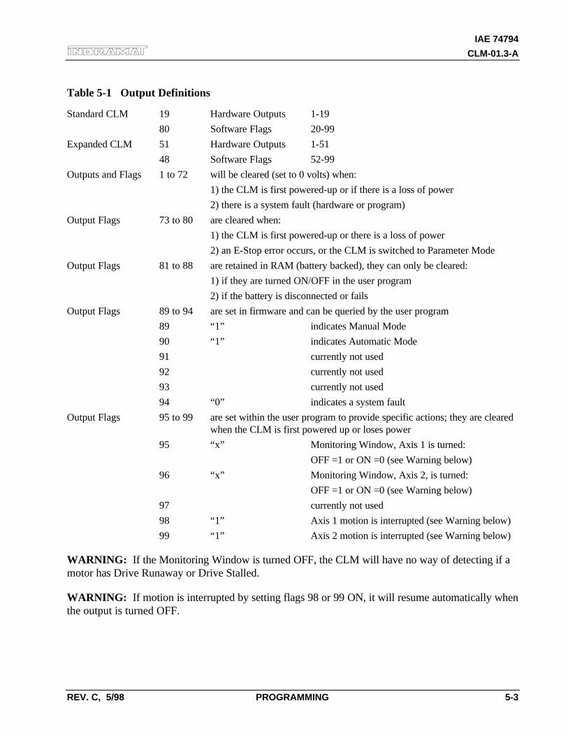
IAE 74794
CLM-01.3-A
REV. C, 5/98 PROGRAMMING 5-3
Table 5-1 Output Definitions
Standard CLM 19 Hardware Outputs 1-19
80 Software Flags 20-99
Expanded CLM 51 Hardware Outputs 1-51
48 Software Flags 52-99
Outputs and Flags 1 to 72 will be cleared (set to 0 volts) when:
1) the CLM is first powered-up or if there is a loss of power
2) there is a system fault (hardware or program)
Output Flags 73 to 80 are cleared when:
1) the CLM is first powered-up or there is a loss of power
2) an E-Stop error occurs, or the CLM is switched to Parameter Mode
Output Flags 81 to 88 are retained in RAM (battery backed), they can only be cleared:
1) if they are turned ON/OFF in the user program
2) if the battery is disconnected or fails
Output Flags 89 to 94 are set in firmware and can be queried by the user program
89 “1” indicates Manual Mode
90 “1” indicates Automatic Mode
91 currently not used
92 currently not used
93 currently not used
94 “0” indicates a system fault
Output Flags 95 to 99 are set within the user program to provide specific actions; they are clearedwhen the CLM is first powered up or loses power
95 “x” Monitoring Window, Axis 1 is turned:
OFF =1 or ON =0 (see Warning below)
96 “x” Monitoring Window, Axis 2, is turned:
OFF =1 or ON =0 (see Warning below)
97 currently not used
98 “1” Axis 1 motion is interrupted (see Warning below)
99 “1” Axis 2 motion is interrupted (see Warning below)
WARNING: If the Monitoring Window is turned OFF, the CLM will have no way of detecting if amotor has Drive Runaway or Drive Stalled.
WARNING: If motion is interrupted by setting flags 98 or 99 ON, it will resume automatically whenthe output is turned OFF.

IAE 7479
CLM-01.3-A
5-4 PROGRAMMING REV. C, 5/98
5.3 Multi-tasking
The CLM is capable of operating two motion programs and a background PLC program simulta-neously when multiple tasks are programmed (see next section). This allows a single CLM to operatetwo independent processes at the same time or utilize multi-tasking in a single process.
5.4 Start of the Program
When the CLM is first powered up or an error is cleared, the program block pointer is set to block0000 for Task 1. If Tasks 2 and 3 are used, they will start at their assigned starting point as userdefined in parameter B006. All programs must start at their assigned starting points; Task 1 muststart at block 0000. Blocks of numbers of programming will be followed sequentially unless a jumpor branch instruction is encountered.
If block 2999 is executed and it is not a jump command, all motions are stopped, and an error code isdisplayed. Typically, the last command block you enter will be a jump command to return to the startof the next cycle or to return from a sub-program routine.
5.5 End of the Program
Take extreme care to control the flow of the program. This is especially important when using multi-tasking. Most programs are designed so they will loop back to the start of each task and wait for theproper sequence of events before starting again. Make sure that each task will not interfere withanother task.
5.6 Programming Mode
The CLM must be in either Automatic or Manual mode to accept program entry/edit from the frontpanel. It is recommended that the CLM be placed in manual mode when editing the program,especially when this involves changing a command, or several blocks.
WARNING: Program entry in Automatic Mode, while the unit is in operation, will be accepted assoon as the Store key is pressed. The next time the block is scanned in the program, the updated datawill be executed. It is recommended that the CLM be placed in Manual Mode when editing theprogram. Complete and verify the program changes before returning to Automatic Mode. Haveaccurate listings of the program and parameters when editing, to reduce the possibility of errors.
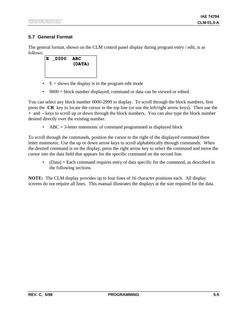
IAE 74794
CLM-01.3-A
REV. C, 5/98 PROGRAMMING 5-5
5.7 General Format
The general format, shown on the CLM control panel display during program entry / edit, is asfollows:
E _0000 ABCE _0000 ABC (DATA) (DATA)
• E = shows the display is in the program edit mode
• 0000 = block number displayed; command or data can be viewed or edited.
You can select any block number 0000-2999 to display. To scroll through the block numbers, firstpress the CR key to locate the cursor in the top line (or use the left/right arrow keys). Then use the+ and - keys to scroll up or down through the block numbers. You can also type the block numberdesired directly over the existing number.
• ABC = 3-letter mnemonic of command programmed in displayed block
To scroll through the commands, position the cursor to the right of the displayed command threeletter mnemonic. Use the up or down arrow keys to scroll alphabetically through commands. Whenthe desired command is on the display, press the right arrow key to select the command and move thecursor into the data field that appears for the specific command on the second line.
• (Data) = Each command requires entry of data specific for the commend, as described inthe following sections.
NOTE: The CLM display provides up to four lines of 16 character positions each. All displayscreens do not require all lines. This manual illustrates the displays at the size required for the data.
IAE 7479
CLM-01.3-A
5-6 PROGRAMMING REV. C, 5/98
5.8 Command Summary
The various commands can be classified into categories by their function, as described in thefollowing sections. These sections describe the general use and differences between all theprogramming commands. For future reference, you can use these sections to select the specificcommand desired for the general function. Then refer to that command description in section 5.9 forfurther details on how it works and requirements for its entry.
5.8.1 Positioning Commands
There are two major types of positioning commands: Incremental - movement from one pointto the next point, or Absolute - movement in relationship to a known home point. These canbe further broken into two different functional types of positional commands.
1. Commands that require the axis to be at the final programmed position, as determined bythe In Position Signal, before stepping to the next block. These are identified by the letter"S" in the mnemonic (Stop).
2. Commands that, after being read into the position buffer, immediately go to the next blockfor further program execution. These are identified by the letter "O" in the mnemonic(Onward).
The following is a list of the position commands:
• POI Incremental position command
• PSI Incremental position command with In Position Acknowledged
• POA Absolute position command
• PSA Absolute position command with In Position Acknowledged
• POM Incremental or Absolute positioning to IDS thumbwheel switch setting
• PSM Incremental or Absolute positioning to IDS with In Position Acknowledged
Position commands have the following characteristics:
• Position commands must include Axis, Position or Distance, and Velocity.
• Positions are programmed directly in units of your choice: inches, metric, degrees, etc.
• You can select either two or three decimal points of accuracy (in parameter B007).
• The acceleration rates specified in parameter Ax02 will be used as defaults, unless they arechanged with the ACC command prior to the motion.
• Select either Constant acceleration or Knee Point acceleration profile.
• Motion can be independent or simultaneous.
• Axis can be programmed for Rotary motion (rotation resetting to zero after one rev).
IAE 74794
CLM-01.3-A
REV. C, 5/98 PROGRAMMING 5-7
5.8.2 Position Support Commands
The following commands are used either in conjunction with a positioning command or bythemselves to achieve the specific result.
• ACC Change acceleration/deceleration rate (0.1 to 99.9% of Ax02)
• AEO Acceleration Override
• ANC Analog Input Compare
• CLA Clear absolute position buffer (set to zero)
• COC Cam Output Control - turn 6 outputs ON or OFF at axis position
• CON Constant velocity command (sets axis to a continuous speed)
• DEC Deceleration Change
• FAK Factor all feed distances by a set ratio
• FOL Axis synchronization factor (master/slave mode)
• FUN Functions
• HOM Execute a homing routine
• KDI Copy a position difference to a target block
• MLO Material Length Output
• PBK Position break (immediate stop of selected axis)
• PST Position test (turn output ON/OFF based on position)
• REF Move at a set velocity until a registration mark is detected
• REP Maximum search distance for REF command (branch if exceeded)
• RMI Registration mark interrupt (high speed)
• SAC Set Absolute position reference
• SIN Sinusoidal oscillation
• SO1 Read inputs to program a distance into memory
• SO2 Alter next feed distance based on an analog input level (0 to 10 Vdc)
• VCA Velocity change absolute
• VCC Velocity change during a profile
• VEO Velocity override (analog/binary/factor override)
• WRI Write current position to a target block (Teach)
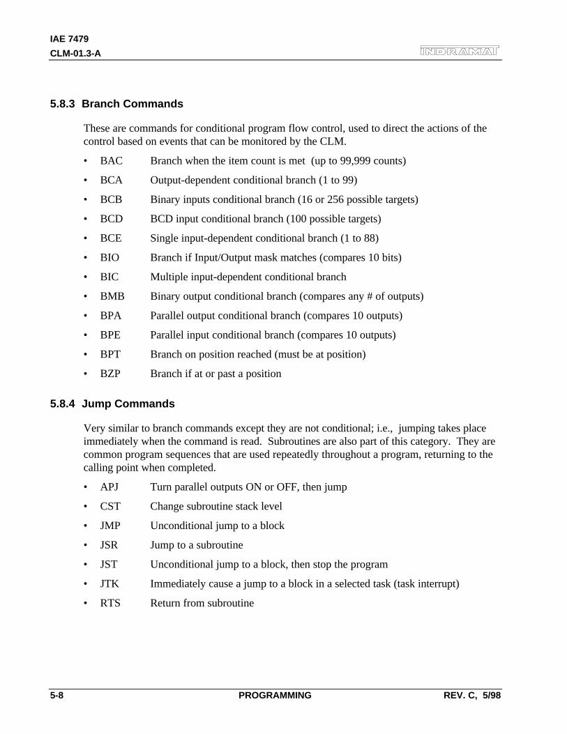
IAE 7479
CLM-01.3-A
5-8 PROGRAMMING REV. C, 5/98
5.8.3 Branch Commands
These are commands for conditional program flow control, used to direct the actions of thecontrol based on events that can be monitored by the CLM.
• BAC Branch when the item count is met (up to 99,999 counts)
• BCA Output-dependent conditional branch (1 to 99)
• BCB Binary inputs conditional branch (16 or 256 possible targets)
• BCD BCD input conditional branch (100 possible targets)
• BCE Single input-dependent conditional branch (1 to 88)
• BIO Branch if Input/Output mask matches (compares 10 bits)
• BIC Multiple input-dependent conditional branch
• BMB Binary output conditional branch (compares any # of outputs)
• BPA Parallel output conditional branch (compares 10 outputs)
• BPE Parallel input conditional branch (compares 10 outputs)
• BPT Branch on position reached (must be at position)
• BZP Branch if at or past a position
5.8.4 Jump Commands
Very similar to branch commands except they are not conditional; i.e., jumping takes placeimmediately when the command is read. Subroutines are also part of this category. They arecommon program sequences that are used repeatedly throughout a program, returning to thecalling point when completed.
• APJ Turn parallel outputs ON or OFF, then jump
• CST Change subroutine stack level
• JMP Unconditional jump to a block
• JSR Jump to a subroutine
• JST Unconditional jump to a block, then stop the program
• JTK Immediately cause a jump to a block in a selected task (task interrupt)
• RTS Return from subroutine
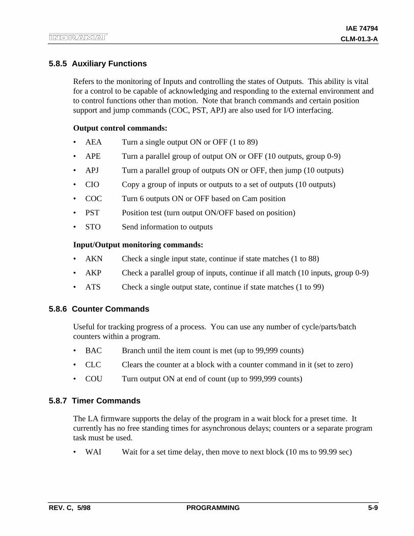
IAE 74794
CLM-01.3-A
REV. C, 5/98 PROGRAMMING 5-9
5.8.5 Auxiliary Functions
Refers to the monitoring of Inputs and controlling the states of Outputs. This ability is vitalfor a control to be capable of acknowledging and responding to the external environment andto control functions other than motion. Note that branch commands and certain positionsupport and jump commands (COC, PST, APJ) are also used for I/O interfacing.
Output control commands:
• AEA Turn a single output ON or OFF (1 to 89)
• APE Turn a parallel group of output ON or OFF (10 outputs, group 0-9)
• APJ Turn a parallel group of outputs ON or OFF, then jump (10 outputs)
• CIO Copy a group of inputs or outputs to a set of outputs (10 outputs)
• COC Turn 6 outputs ON or OFF based on Cam position
• PST Position test (turn output ON/OFF based on position)
• STO Send information to outputs
Input/Output monitoring commands:
• AKN Check a single input state, continue if state matches (1 to 88)
• AKP Check a parallel group of inputs, continue if all match (10 inputs, group 0-9)
• ATS Check a single output state, continue if state matches (1 to 99)
5.8.6 Counter Commands
Useful for tracking progress of a process. You can use any number of cycle/parts/batchcounters within a program.
• BAC Branch until the item count is met (up to 99,999 counts)
• CLC Clears the counter at a block with a counter command in it (set to zero)
• COU Turn output ON at end of count (up to 999,999 counts)
5.8.7 Timer Commands
The LA firmware supports the delay of the program in a wait block for a preset time. Itcurrently has no free standing times for asynchronous delays; counters or a separate programtask must be used.
• WAI Wait for a set time delay, then move to next block (10 ms to 99.99 sec)
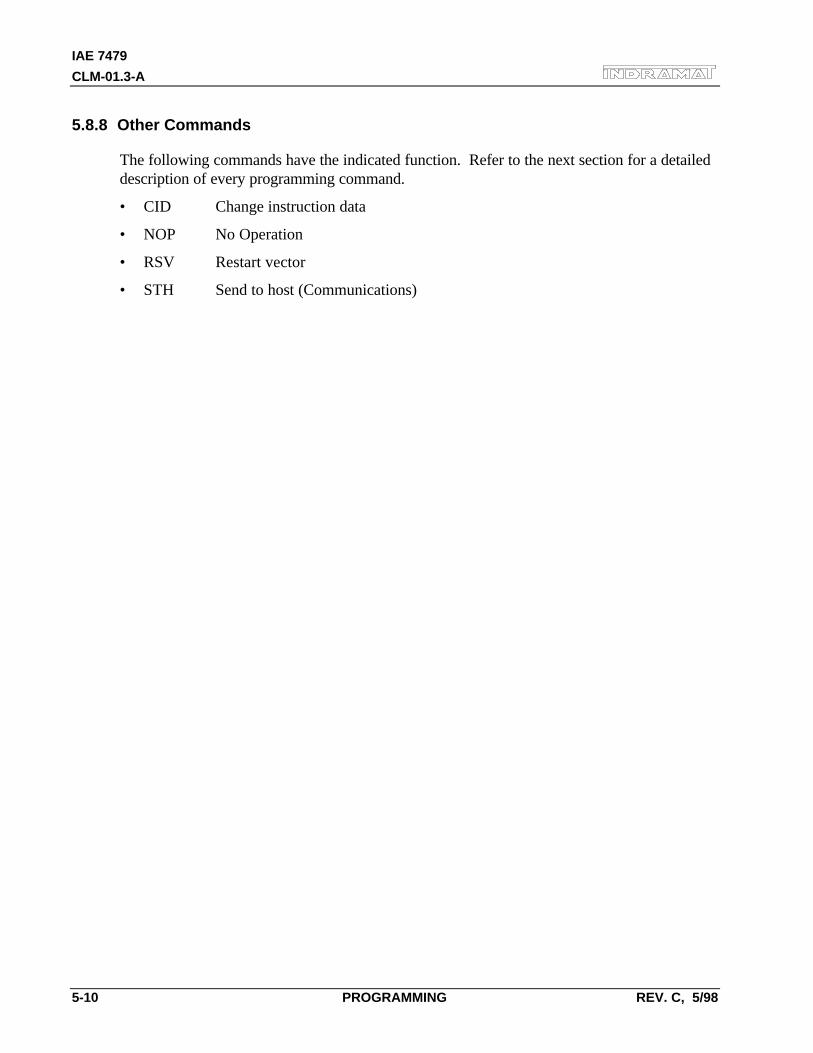
IAE 7479
CLM-01.3-A
5-10 PROGRAMMING REV. C, 5/98
5.8.8 Other Commands
The following commands have the indicated function. Refer to the next section for a detaileddescription of every programming command.
• CID Change instruction data
• NOP No Operation
• RSV Restart vector
• STH Send to host (Communications)
IAE 74794
CLM-01.3-A
REV. C, 5/98 PROGRAMMING 5-11
5.9 Command Descriptions
This section describes each programming command. The first line of the illustrated displays are aspreviously described, with E indicating Edit Mode, a random block line number, the three lettermnemonic for the command and relative data fields.
This manual principally describes hardware version CLM 01.3-A with software versionLA01.3-01.x. The software has parameter selected two or three decimal place precision in thecommands that involve positioning and position related parameters (See Parameter B007).
Each command requires specific data. All places for required data in a user program block whichcontains illegal characters (a space or an undefined character - not a number or the +/- sign) arereplaced by the asterisk character (*) in the display. This enables the user to easily recognize whichpoints in a command data need to be programmed. A block of program has the correct syntax whenit contains no asterisk (*) characters in the display.
NOTE: The following sections fully describe the use and data field entry requirements of eachcommand. For easier reference, the commands are listed in alphabetical order and each command'sdescription begins on a new page.
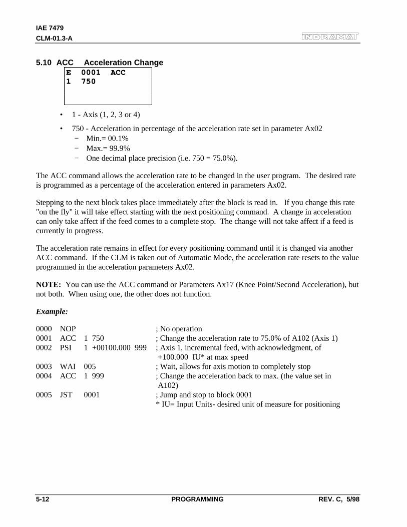
IAE 7479
CLM-01.3-A
5-12 PROGRAMMING REV. C, 5/98
5.10 ACC Acceleration ChangeE 0001 ACCE 0001 ACC1 7501 750
• 1 - Axis (1, 2, 3 or 4)
• 750 - Acceleration in percentage of the acceleration rate set in parameter Ax02− Min.= 00.1%− Max.= 99.9%− One decimal place precision (i.e. 750 = 75.0%).
The ACC command allows the acceleration rate to be changed in the user program. The desired rateis programmed as a percentage of the acceleration entered in parameters Ax02.
Stepping to the next block takes place immediately after the block is read in. If you change this rate"on the fly" it will take effect starting with the next positioning command. A change in accelerationcan only take affect if the feed comes to a complete stop. The change will not take affect if a feed iscurrently in progress.
The acceleration rate remains in effect for every positioning command until it is changed via anotherACC command. If the CLM is taken out of Automatic Mode, the acceleration rate resets to the valueprogrammed in the acceleration parameters Ax02.
NOTE: You can use the ACC command or Parameters Ax17 (Knee Point/Second Acceleration), butnot both. When using one, the other does not function.
Example:
0000 NOP ; No operation0001 ACC 1 750 ; Change the acceleration rate to 75.0% of A102 (Axis 1)0002 PSI 1 +00100.000 999 ; Axis 1, incremental feed, with acknowledgment, of
+100.000 IU* at max speed0003 WAI 005 ; Wait, allows for axis motion to completely stop0004 ACC 1 999 ; Change the acceleration back to max. (the value set in
A102)0005 JST 0001 ; Jump and stop to block 0001
* IU= Input Units- desired unit of measure for positioning
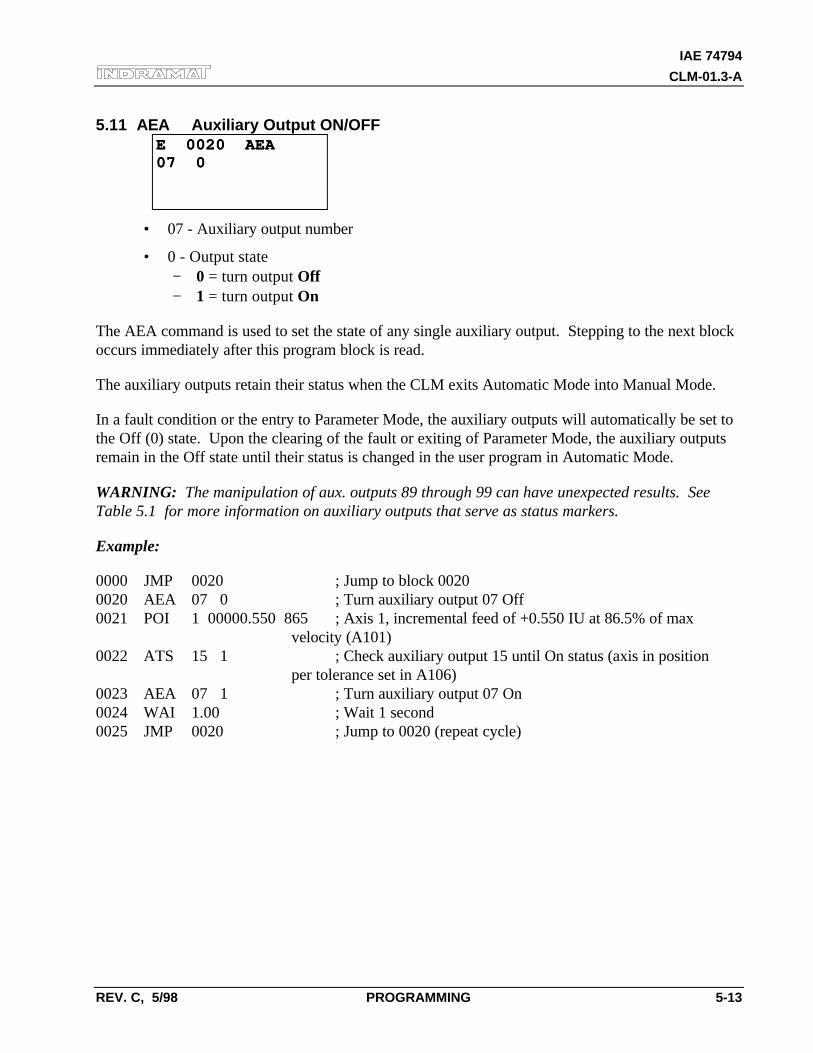
IAE 74794
CLM-01.3-A
REV. C, 5/98 PROGRAMMING 5-13
5.11 AEA Auxiliary Output ON/OFFE 0020 AEAE 0020 AEA07 007 0
• 07 - Auxiliary output number
• 0 - Output state− 0 = turn output Off− 1 = turn output On
The AEA command is used to set the state of any single auxiliary output. Stepping to the next blockoccurs immediately after this program block is read.
The auxiliary outputs retain their status when the CLM exits Automatic Mode into Manual Mode.
In a fault condition or the entry to Parameter Mode, the auxiliary outputs will automatically be set tothe Off (0) state. Upon the clearing of the fault or exiting of Parameter Mode, the auxiliary outputsremain in the Off state until their status is changed in the user program in Automatic Mode.
WARNING: The manipulation of aux. outputs 89 through 99 can have unexpected results. SeeTable 5.1 for more information on auxiliary outputs that serve as status markers.
Example:
0000 JMP 0020 ; Jump to block 00200020 AEA 07 0 ; Turn auxiliary output 07 Off0021 POI 1 00000.550 865 ; Axis 1, incremental feed of +0.550 IU at 86.5% of max
velocity (A101)0022 ATS 15 1 ; Check auxiliary output 15 until On status (axis in position
per tolerance set in A106)0023 AEA 07 1 ; Turn auxiliary output 07 On0024 WAI 1.00 ; Wait 1 second0025 JMP 0020 ; Jump to 0020 (repeat cycle)
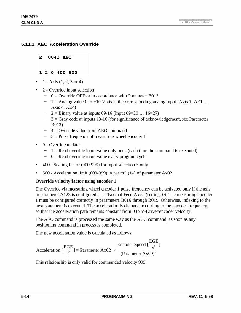
IAE 7479
CLM-01.3-A
5-14 PROGRAMMING REV. C, 5/98
5.11.1 AEO Acceleration Override
E 0043 AEOE 0043 AEO
1 2 0 400 5001 2 0 400 500
• 1 - Axis (1, 2, 3 or 4)
• 2 - Override input selection− 0 = Override OFF or in accordance with Parameter B013− 1 = Analog value 0 to +10 Volts at the corresponding analog input (Axis 1: AE1 …
Axis 4: AE4)− 2 = Binary value at inputs 09-16 (Input 09=20 … 16=27)− 3 = Gray code at inputs 13-16 (for significance of acknowledgement, see Parameter
B013)− 4 = Override value from AEO command− 5 = Pulse frequency of measuring wheel encoder 1
• 0 - Override update− 1 = Read override input value only once (each time the command is executed)− 0 = Read override input value every program cycle
• 400 - Scaling factor (000-999) for input selection 5 only
• 500 - Acceleration limit (000-999) in per mil (‰) of parameter Ax02
Override velocity factor using encoder 1
The Override via measuring wheel encoder 1 pulse frequency can be activated only if the axisin parameter A123 is configured as a “Normal Feed Axis” (setting: 0). The measuring encoder1 must be configured correctly in parameters B016 through B019. Otherwise, indexing to thenext statement is executed. The acceleration is changed according to the encoder frequency,so that the acceleration path remains constant from 0 to V-Drive=encoder velocity.
The AEO command is processed the same way as the ACC command, as soon as anypositioning command in process is completed.
The new acceleration value is calculated as follows:
Acceleration [EGE
sParameter Ax02
Encoder Speed [EGE
s(Parameter Ax00)22
2
]]
= ×
This relationship is only valid for commanded velocity 999.

IAE 74794
CLM-01.3-A
REV. C, 5/98 PROGRAMMING 5-15
When the scaling factor is selected, the new acceleration value is calculated as follows:
Acceleration [EGE
sParameter Ax02
Encoder Speed [EGE
s(Parameter Ax00)
Scaling Factor22
2
1000]
]= × ×
The acceleration cannot be below the minimum acceleration set in the AEO command.
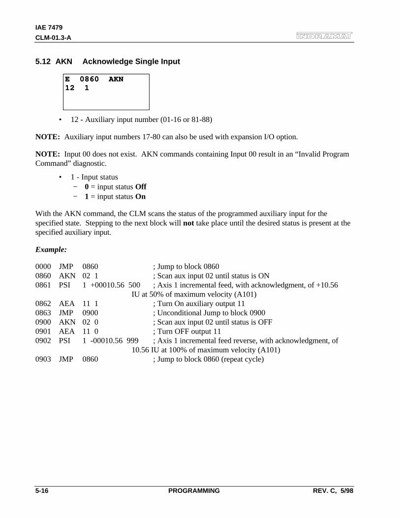
IAE 7479
CLM-01.3-A
5-16 PROGRAMMING REV. C, 5/98
5.12 AKN Acknowledge Single Input
E 0860 AKNE 0860 AKN12 112 1
• 12 - Auxiliary input number (01-16 or 81-88)
NOTE: Auxiliary input numbers 17-80 can also be used with expansion I/O option.
NOTE: Input 00 does not exist. AKN commands containing Input 00 result in an “Invalid ProgramCommand” diagnostic.
• 1 - Input status− 0 = input status Off− 1 = input status On
With the AKN command, the CLM scans the status of the programmed auxiliary input for thespecified state. Stepping to the next block will not take place until the desired status is present at thespecified auxiliary input.
Example:
0000 JMP 0860 ; Jump to block 08600860 AKN 02 1 ; Scan aux input 02 until status is ON0861 PSI 1 +00010.56 500 ; Axis 1 incremental feed, with acknowledgment, of +10.56
IU at 50% of maximum velocity (A101)0862 AEA 11 1 ; Turn On auxiliary output 110863 JMP 0900 ; Unconditional Jump to block 09000900 AKN 02 0 ; Scan aux input 02 until status is OFF0901 AEA 11 0 ; Turn OFF output 110902 PSI 1 -00010.56 999 ; Axis 1 incremental feed reverse, with acknowledgment, of
10.56 IU at 100% of maximum velocity (A101)0903 JMP 0860 ; Jump to block 0860 (repeat cycle)
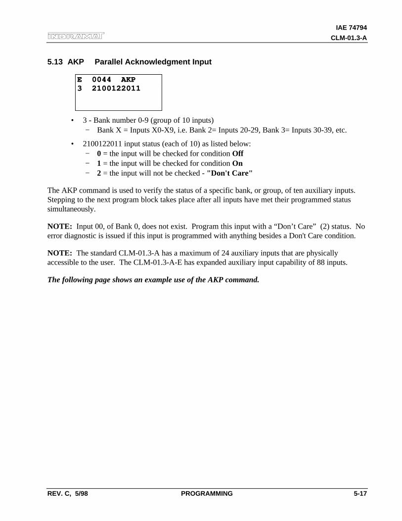
IAE 74794
CLM-01.3-A
REV. C, 5/98 PROGRAMMING 5-17
5.13 AKP Parallel Acknowledgment Input
E 0044 AKPE 0044 AKP3 21001220113 2100122011
• 3 - Bank number 0-9 (group of 10 inputs)− Bank X = Inputs X0-X9, i.e. Bank 2= Inputs 20-29, Bank 3= Inputs 30-39, etc.
• 2100122011 input status (each of 10) as listed below:− 0 = the input will be checked for condition Off− 1 = the input will be checked for condition On− 2 = the input will not be checked - "Don't Care"
The AKP command is used to verify the status of a specific bank, or group, of ten auxiliary inputs.Stepping to the next program block takes place after all inputs have met their programmed statussimultaneously.
NOTE: Input 00, of Bank 0, does not exist. Program this input with a “Don’t Care” (2) status. Noerror diagnostic is issued if this input is programmed with anything besides a Don't Care condition.
NOTE: The standard CLM-01.3-A has a maximum of 24 auxiliary inputs that are physicallyaccessible to the user. The CLM-01.3-A-E has expanded auxiliary input capability of 88 inputs.
The following page shows an example use of the AKP command.
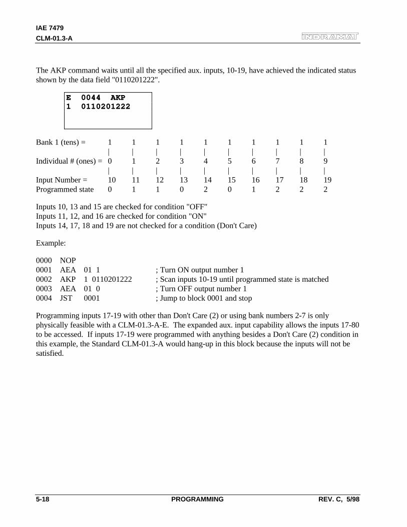
IAE 7479
CLM-01.3-A
5-18 PROGRAMMING REV. C, 5/98
The AKP command waits until all the specified aux. inputs, 10-19, have achieved the indicated statusshown by the data field "0110201222".
E 0044 AKPE 0044 AKP1 01102012221 0110201222
Bank 1 (tens) = 1 1 1 1 1 1 1 1 1 1| | | | | | | | | |
Individual # (ones) = 0 1 2 3 4 5 6 7 8 9| | | | | | | | | |
Input Number = 10 11 12 13 14 15 16 17 18 19Programmed state 0 1 1 0 2 0 1 2 2 2
Inputs 10, 13 and 15 are checked for condition "OFF"Inputs 11, 12, and 16 are checked for condition "ON"Inputs 14, 17, 18 and 19 are not checked for a condition (Don't Care)
Example:
0000 NOP0001 AEA 01 1 ; Turn ON output number 10002 AKP 1 0110201222 ; Scan inputs 10-19 until programmed state is matched0003 AEA 01 0 ; Turn OFF output number 10004 JST 0001 ; Jump to block 0001 and stop
Programming inputs 17-19 with other than Don't Care (2) or using bank numbers 2-7 is onlyphysically feasible with a CLM-01.3-A-E. The expanded aux. input capability allows the inputs 17-80to be accessed. If inputs 17-19 were programmed with anything besides a Don't Care (2) condition inthis example, the Standard CLM-01.3-A would hang-up in this block because the inputs will not besatisfied.
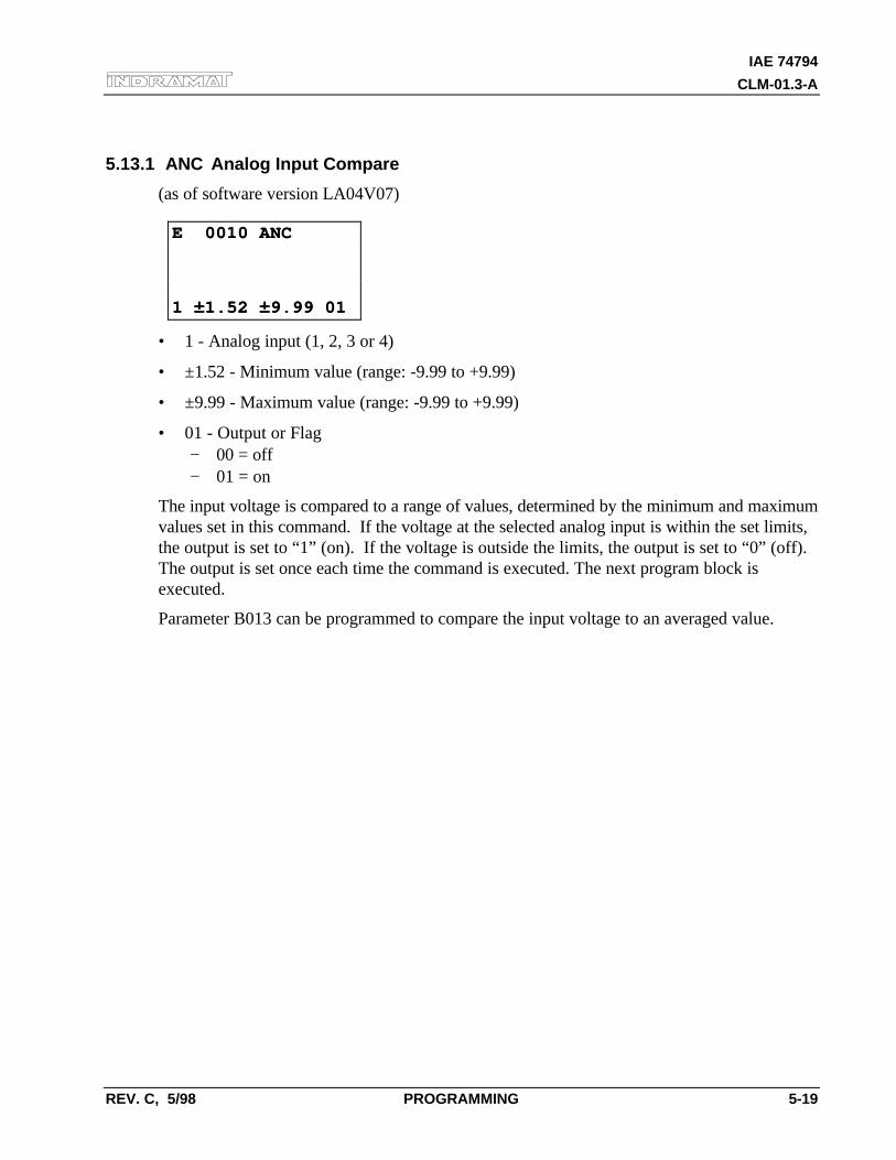
IAE 74794
CLM-01.3-A
REV. C, 5/98 PROGRAMMING 5-19
5.13.1 ANC Analog Input Compare
(as of software version LA04V07)
E 0010 ANCE 0010 ANC
1 ±1.52 ±9.99 011 ±1.52 ±9.99 01
• 1 - Analog input (1, 2, 3 or 4)
• ±1.52 - Minimum value (range: -9.99 to +9.99)
• ±9.99 - Maximum value (range: -9.99 to +9.99)
• 01 - Output or Flag− 00 = off− 01 = on
The input voltage is compared to a range of values, determined by the minimum and maximumvalues set in this command. If the voltage at the selected analog input is within the set limits,the output is set to “1” (on). If the voltage is outside the limits, the output is set to “0” (off).The output is set once each time the command is executed. The next program block isexecuted.
Parameter B013 can be programmed to compare the input voltage to an averaged value.
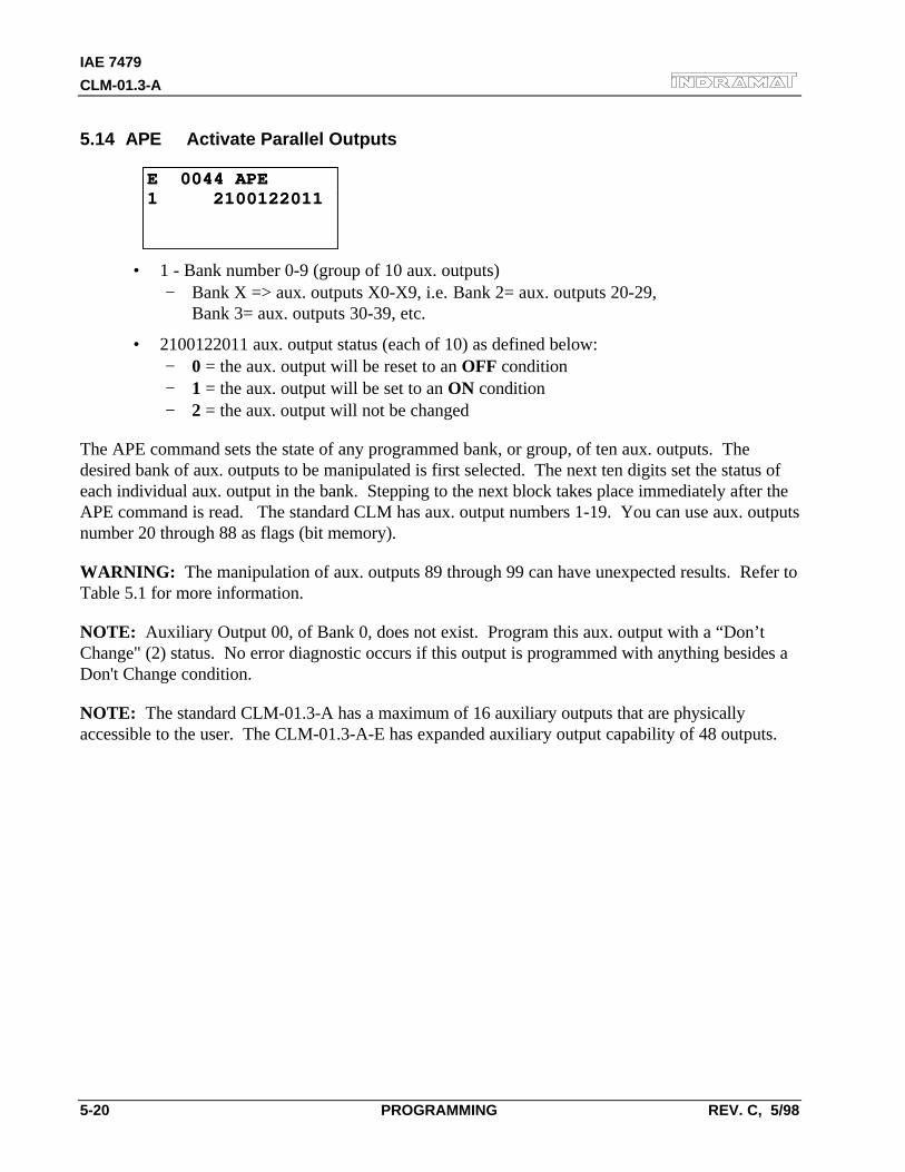
IAE 7479
CLM-01.3-A
5-20 PROGRAMMING REV. C, 5/98
5.14 APE Activate Parallel Outputs
E 0044 APEE 0044 APE1 21001220111 2100122011
• 1 - Bank number 0-9 (group of 10 aux. outputs)− Bank X => aux. outputs X0-X9, i.e. Bank 2= aux. outputs 20-29,
Bank 3= aux. outputs 30-39, etc.
• 2100122011 aux. output status (each of 10) as defined below:− 0 = the aux. output will be reset to an OFF condition− 1 = the aux. output will be set to an ON condition− 2 = the aux. output will not be changed
The APE command sets the state of any programmed bank, or group, of ten aux. outputs. Thedesired bank of aux. outputs to be manipulated is first selected. The next ten digits set the status ofeach individual aux. output in the bank. Stepping to the next block takes place immediately after theAPE command is read. The standard CLM has aux. output numbers 1-19. You can use aux. outputsnumber 20 through 88 as flags (bit memory).
WARNING: The manipulation of aux. outputs 89 through 99 can have unexpected results. Refer toTable 5.1 for more information.
NOTE: Auxiliary Output 00, of Bank 0, does not exist. Program this aux. output with a “Don’tChange" (2) status. No error diagnostic occurs if this output is programmed with anything besides aDon't Change condition.
NOTE: The standard CLM-01.3-A has a maximum of 16 auxiliary outputs that are physicallyaccessible to the user. The CLM-01.3-A-E has expanded auxiliary output capability of 48 outputs.
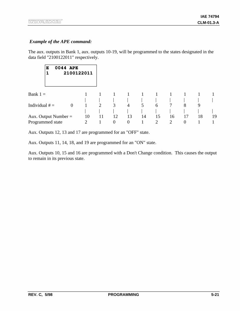
IAE 74794
CLM-01.3-A
REV. C, 5/98 PROGRAMMING 5-21
Example of the APE command:
The aux. outputs in Bank 1, aux. outputs 10-19, will be programmed to the states designated in thedata field "2100122011" respectively.
E 0044 APEE 0044 APE1 21001220111 2100122011
Bank 1 = 1 1 1 1 1 1 1 1 1 1| | | | | | | | | |
Individual # = 0 1 2 3 4 5 6 7 8 9| | | | | | | | | |
Aux. Output Number = 10 11 12 13 14 15 16 17 18 19Programmed state 2 1 0 0 1 2 2 0 1 1
Aux. Outputs 12, 13 and 17 are programmed for an "OFF" state.
Aux. Outputs 11, 14, 18, and 19 are programmed for an "ON" state.
Aux. Outputs 10, 15 and 16 are programmed with a Don't Change condition. This causes the outputto remain in its previous state.
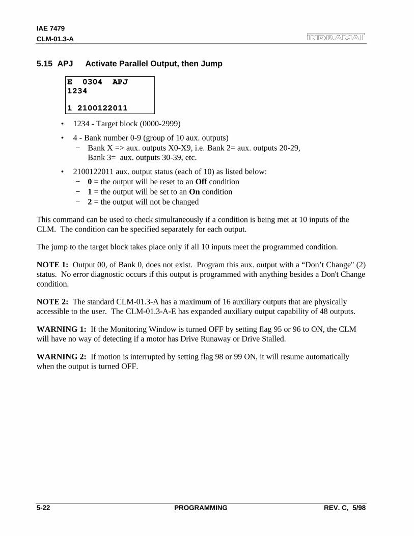
IAE 7479
CLM-01.3-A
5-22 PROGRAMMING REV. C, 5/98
5.15 APJ Activate Parallel Output, then Jump
E 0304 APJE 0304 APJ12341234
1 21001220111 2100122011
• 1234 - Target block (0000-2999)
• 4 - Bank number 0-9 (group of 10 aux. outputs)− Bank X => aux. outputs X0-X9, i.e. Bank 2= aux. outputs 20-29,
Bank 3= aux. outputs 30-39, etc.
• 2100122011 aux. output status (each of 10) as listed below:− 0 = the output will be reset to an Off condition− 1 = the output will be set to an On condition− 2 = the output will not be changed
This command can be used to check simultaneously if a condition is being met at 10 inputs of theCLM. The condition can be specified separately for each output.
The jump to the target block takes place only if all 10 inputs meet the programmed condition.
NOTE 1: Output 00, of Bank 0, does not exist. Program this aux. output with a “Don’t Change" (2)status. No error diagnostic occurs if this output is programmed with anything besides a Don't Changecondition.
NOTE 2: The standard CLM-01.3-A has a maximum of 16 auxiliary outputs that are physicallyaccessible to the user. The CLM-01.3-A-E has expanded auxiliary output capability of 48 outputs.
WARNING 1: If the Monitoring Window is turned OFF by setting flag 95 or 96 to ON, the CLMwill have no way of detecting if a motor has Drive Runaway or Drive Stalled.
WARNING 2: If motion is interrupted by setting flag 98 or 99 ON, it will resume automaticallywhen the output is turned OFF.
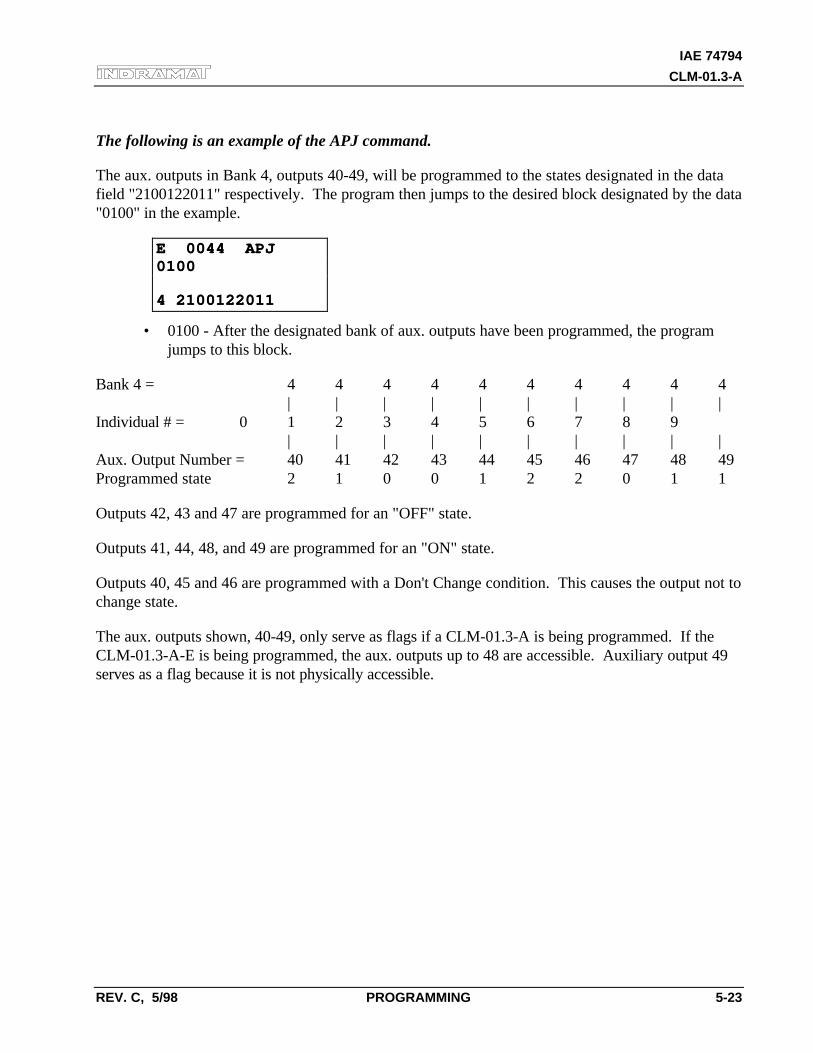
IAE 74794
CLM-01.3-A
REV. C, 5/98 PROGRAMMING 5-23
The following is an example of the APJ command.
The aux. outputs in Bank 4, outputs 40-49, will be programmed to the states designated in the datafield "2100122011" respectively. The program then jumps to the desired block designated by the data"0100" in the example.
E 0044 APJE 0044 APJ01000100
4 21001220114 2100122011
• 0100 - After the designated bank of aux. outputs have been programmed, the programjumps to this block.
Bank 4 = 4 4 4 4 4 4 4 4 4 4| | | | | | | | | |
Individual # = 0 1 2 3 4 5 6 7 8 9| | | | | | | | | |
Aux. Output Number = 40 41 42 43 44 45 46 47 48 49Programmed state 2 1 0 0 1 2 2 0 1 1
Outputs 42, 43 and 47 are programmed for an "OFF" state.
Outputs 41, 44, 48, and 49 are programmed for an "ON" state.
Outputs 40, 45 and 46 are programmed with a Don't Change condition. This causes the output not tochange state.
The aux. outputs shown, 40-49, only serve as flags if a CLM-01.3-A is being programmed. If theCLM-01.3-A-E is being programmed, the aux. outputs up to 48 are accessible. Auxiliary output 49serves as a flag because it is not physically accessible.
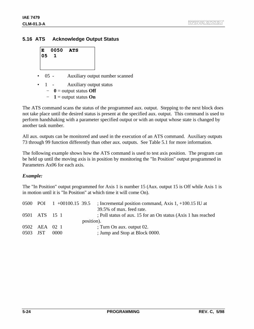
IAE 7479
CLM-01.3-A
5-24 PROGRAMMING REV. C, 5/98
5.16 ATS Acknowledge Output Status
E 0050 ATSE 0050 ATS05 105 1
• 05 - Auxiliary output number scanned
• 1 - Auxiliary output status− 0 = output status Off− 1 = output status On
The ATS command scans the status of the programmed aux. output. Stepping to the next block doesnot take place until the desired status is present at the specified aux. output. This command is used toperform handshaking with a parameter specified output or with an output whose state is changed byanother task number.
All aux. outputs can be monitored and used in the execution of an ATS command. Auxiliary outputs73 through 99 function differently than other aux. outputs. See Table 5.1 for more information.
The following example shows how the ATS command is used to test axis position. The program canbe held up until the moving axis is in position by monitoring the "In Position" output programmed inParameters Ax06 for each axis.
Example:
The "In Position" output programmed for Axis 1 is number 15 (Aux. output 15 is Off while Axis 1 isin motion until it is "In Position" at which time it will come On).
0500 POI 1 +00100.15 39.5 ; Incremental position command, Axis 1, +100.15 IU at 39.5% of max. feed rate.
0501 ATS 15 1 ; Poll status of aux. 15 for an On status (Axis 1 has reached position).
0502 AEA 02 1 ; Turn On aux. output 02.0503 JST 0000 ; Jump and Stop at Block 0000.
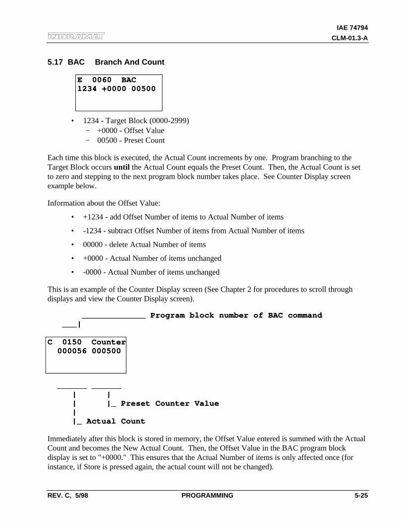
IAE 74794
CLM-01.3-A
REV. C, 5/98 PROGRAMMING 5-25
5.17 BAC Branch And Count
E 0060 BACE 0060 BAC1234 +0000 005001234 +0000 00500
• 1234 - Target Block (0000-2999)− +0000 - Offset Value− 00500 - Preset Count
Each time this block is executed, the Actual Count increments by one. Program branching to theTarget Block occurs until the Actual Count equals the Preset Count. Then, the Actual Count is setto zero and stepping to the next program block number takes place. See Counter Display screenexample below.
Information about the Offset Value:
• +1234 - add Offset Number of items to Actual Number of items
• -1234 - subtract Offset Number of items from Actual Number of items
• 00000 - delete Actual Number of items
• +0000 - Actual Number of items unchanged
• -0000 - Actual Number of items unchanged
This is an example of the Counter Display screen (See Chapter 2 for procedures to scroll throughdisplays and view the Counter Display screen).
_____________ Program block number of BAC command _____________ Program block number of BAC command ___| ___|
C 0150 CounterC 0150 Counter 000056 000500 000056 000500
______ ______ ______ ______ | | | | | |_ Preset Counter Value | |_ Preset Counter Value | | |_ Actual Count |_ Actual Count
Immediately after this block is stored in memory, the Offset Value entered is summed with the ActualCount and becomes the New Actual Count. Then, the Offset Value in the BAC program blockdisplay is set to "+0000." This ensures that the Actual Number of items is only affected once (forinstance, if Store is pressed again, the actual count will not be changed).
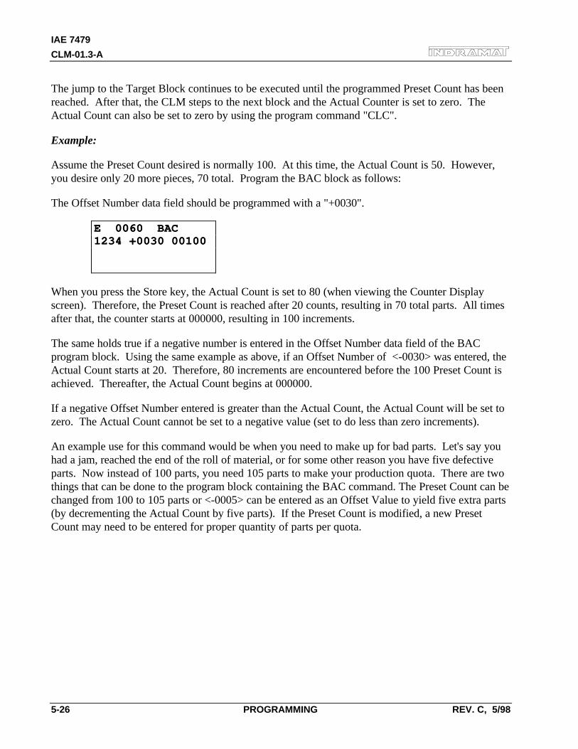
IAE 7479
CLM-01.3-A
5-26 PROGRAMMING REV. C, 5/98
The jump to the Target Block continues to be executed until the programmed Preset Count has beenreached. After that, the CLM steps to the next block and the Actual Counter is set to zero. TheActual Count can also be set to zero by using the program command "CLC".
Example:
Assume the Preset Count desired is normally 100. At this time, the Actual Count is 50. However,you desire only 20 more pieces, 70 total. Program the BAC block as follows:
The Offset Number data field should be programmed with a "+0030".
E 0060 BACE 0060 BAC1234 +0030 001001234 +0030 00100
When you press the Store key, the Actual Count is set to 80 (when viewing the Counter Displayscreen). Therefore, the Preset Count is reached after 20 counts, resulting in 70 total parts. All timesafter that, the counter starts at 000000, resulting in 100 increments.
The same holds true if a negative number is entered in the Offset Number data field of the BACprogram block. Using the same example as above, if an Offset Number of <-0030> was entered, theActual Count starts at 20. Therefore, 80 increments are encountered before the 100 Preset Count isachieved. Thereafter, the Actual Count begins at 000000.
If a negative Offset Number entered is greater than the Actual Count, the Actual Count will be set tozero. The Actual Count cannot be set to a negative value (set to do less than zero increments).
An example use for this command would be when you need to make up for bad parts. Let's say youhad a jam, reached the end of the roll of material, or for some other reason you have five defectiveparts. Now instead of 100 parts, you need 105 parts to make your production quota. There are twothings that can be done to the program block containing the BAC command. The Preset Count can bechanged from 100 to 105 parts or <-0005> can be entered as an Offset Value to yield five extra parts(by decrementing the Actual Count by five parts). If the Preset Count is modified, a new PresetCount may need to be entered for proper quantity of parts per quota.
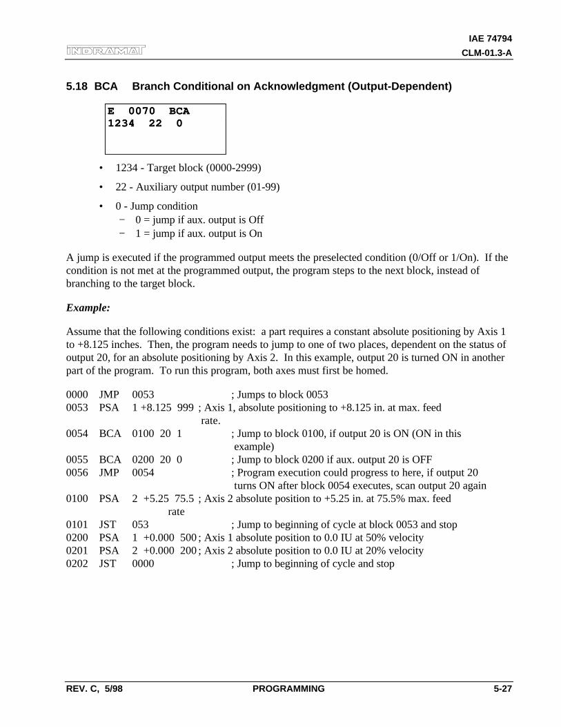
IAE 74794
CLM-01.3-A
REV. C, 5/98 PROGRAMMING 5-27
5.18 BCA Branch Conditional on Acknowledgment (Output-Dependent)
E 0070 BCAE 0070 BCA1234 22 01234 22 0
• 1234 - Target block (0000-2999)
• 22 - Auxiliary output number (01-99)
• 0 - Jump condition− 0 = jump if aux. output is Off− 1 = jump if aux. output is On
A jump is executed if the programmed output meets the preselected condition (0/Off or 1/On). If thecondition is not met at the programmed output, the program steps to the next block, instead ofbranching to the target block.
Example:
Assume that the following conditions exist: a part requires a constant absolute positioning by Axis 1to +8.125 inches. Then, the program needs to jump to one of two places, dependent on the status ofoutput 20, for an absolute positioning by Axis 2. In this example, output 20 is turned ON in anotherpart of the program. To run this program, both axes must first be homed.
0000 JMP 0053 ; Jumps to block 00530053 PSA 1 +8.125 999 ; Axis 1, absolute positioning to +8.125 in. at max. feed
rate.0054 BCA 0100 20 1 ; Jump to block 0100, if output 20 is ON (ON in this
example)0055 BCA 0200 20 0 ; Jump to block 0200 if aux. output 20 is OFF0056 JMP 0054 ; Program execution could progress to here, if output 20
turns ON after block 0054 executes, scan output 20 again0100 PSA 2 +5.25 75.5 ; Axis 2 absolute position to +5.25 in. at 75.5% max. feed
rate0101 JST 053 ; Jump to beginning of cycle at block 0053 and stop0200 PSA 1 +0.000 500 ; Axis 1 absolute position to 0.0 IU at 50% velocity0201 PSA 2 +0.000 200 ; Axis 2 absolute position to 0.0 IU at 20% velocity0202 JST 0000 ; Jump to beginning of cycle and stop
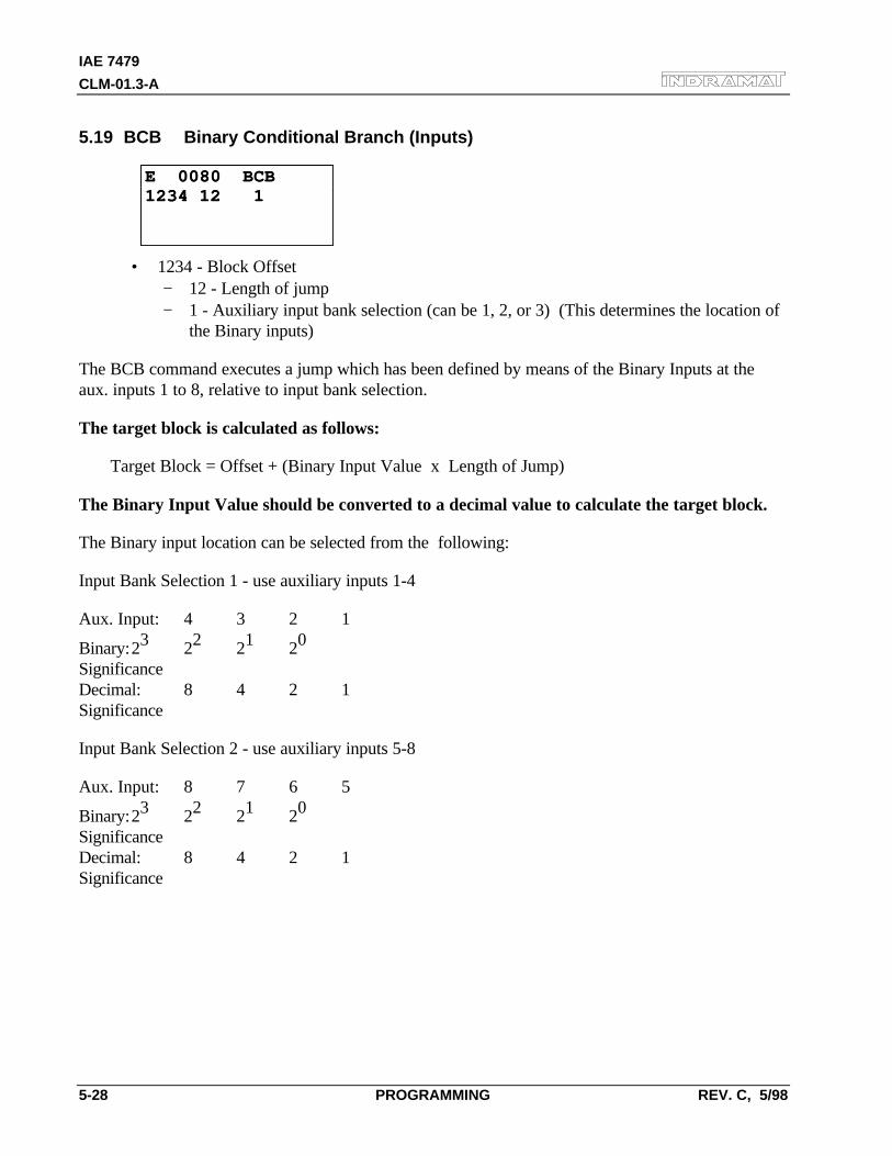
IAE 7479
CLM-01.3-A
5-28 PROGRAMMING REV. C, 5/98
5.19 BCB Binary Conditional Branch (Inputs)
E 0080 BCBE 0080 BCB1234 12 11234 12 1
• 1234 - Block Offset− 12 - Length of jump− 1 - Auxiliary input bank selection (can be 1, 2, or 3) (This determines the location of
the Binary inputs)
The BCB command executes a jump which has been defined by means of the Binary Inputs at theaux. inputs 1 to 8, relative to input bank selection.
The target block is calculated as follows:
Target Block = Offset + (Binary Input Value x Length of Jump)
The Binary Input Value should be converted to a decimal value to calculate the target block.
The Binary input location can be selected from the following:
Input Bank Selection 1 - use auxiliary inputs 1-4
Aux. Input: 4 3 2 1
Binary:23 22 21 20
SignificanceDecimal: 8 4 2 1Significance
Input Bank Selection 2 - use auxiliary inputs 5-8
Aux. Input: 8 7 6 5
Binary:23 22 21 20
SignificanceDecimal: 8 4 2 1Significance
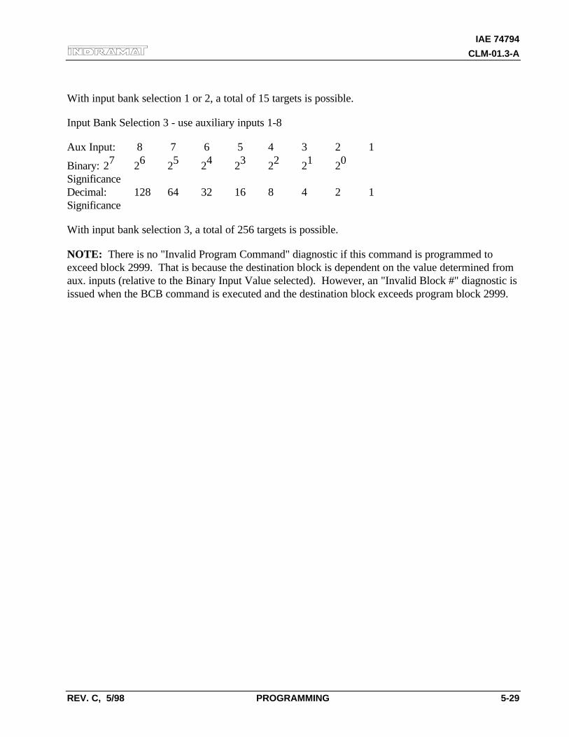
IAE 74794
CLM-01.3-A
REV. C, 5/98 PROGRAMMING 5-29
With input bank selection 1 or 2, a total of 15 targets is possible.
Input Bank Selection 3 - use auxiliary inputs 1-8
Aux Input: 8 7 6 5 4 3 2 1
Binary: 27 26 25 24 23 22 21 20
SignificanceDecimal: 128 64 32 16 8 4 2 1Significance
With input bank selection 3, a total of 256 targets is possible.
NOTE: There is no "Invalid Program Command" diagnostic if this command is programmed toexceed block 2999. That is because the destination block is dependent on the value determined fromaux. inputs (relative to the Binary Input Value selected). However, an "Invalid Block #" diagnostic isissued when the BCB command is executed and the destination block exceeds program block 2999.
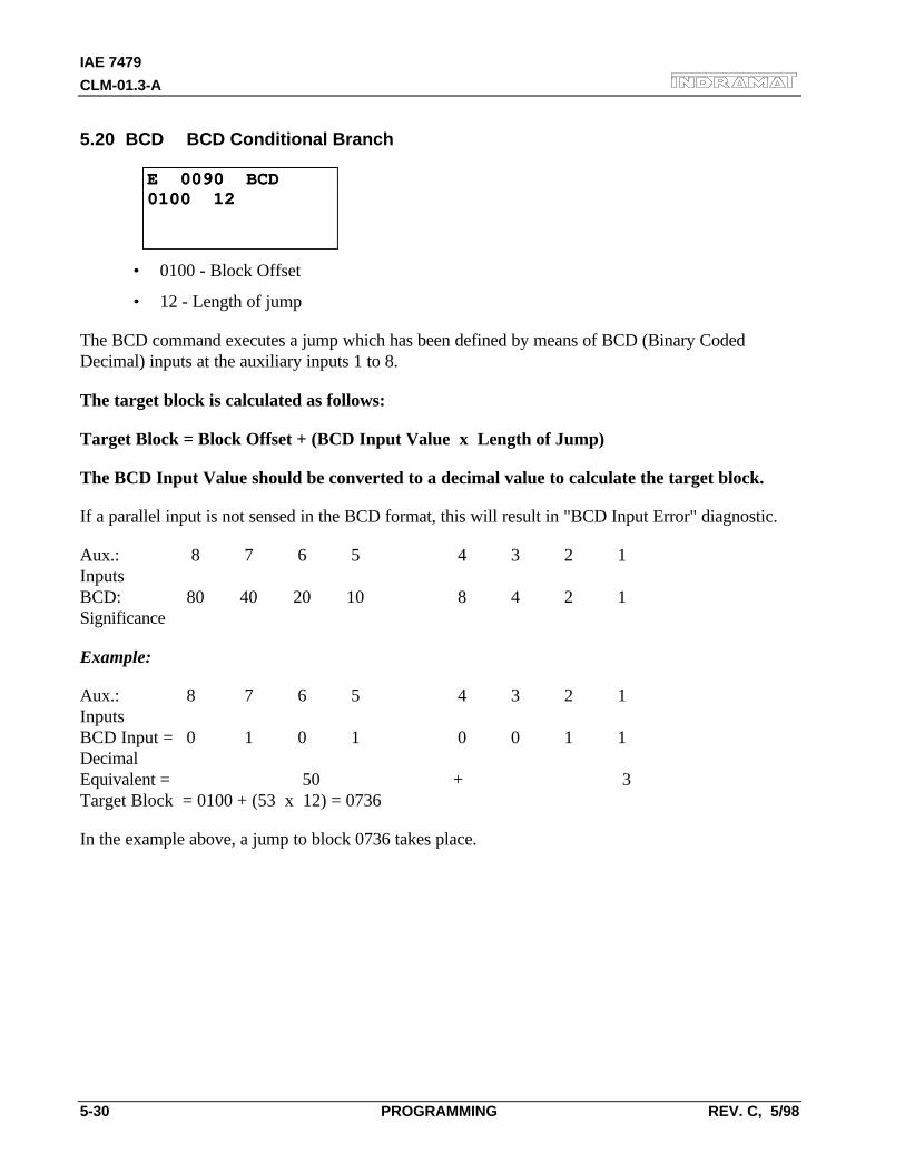
IAE 7479
CLM-01.3-A
5-30 PROGRAMMING REV. C, 5/98
5.20 BCD BCD Conditional Branch
E 0090 BCDE 0090 BCD0100 120100 12
• 0100 - Block Offset
• 12 - Length of jump
The BCD command executes a jump which has been defined by means of BCD (Binary CodedDecimal) inputs at the auxiliary inputs 1 to 8.
The target block is calculated as follows:
Target Block = Block Offset + (BCD Input Value x Length of Jump)
The BCD Input Value should be converted to a decimal value to calculate the target block.
If a parallel input is not sensed in the BCD format, this will result in "BCD Input Error" diagnostic.
Aux.: 8 7 6 5 4 3 2 1InputsBCD: 80 40 20 10 8 4 2 1Significance
Example:
Aux.: 8 7 6 5 4 3 2 1InputsBCD Input = 0 1 0 1 0 0 1 1DecimalEquivalent = 50 + 3Target Block = 0100 + (53 x 12) = 0736
In the example above, a jump to block 0736 takes place.
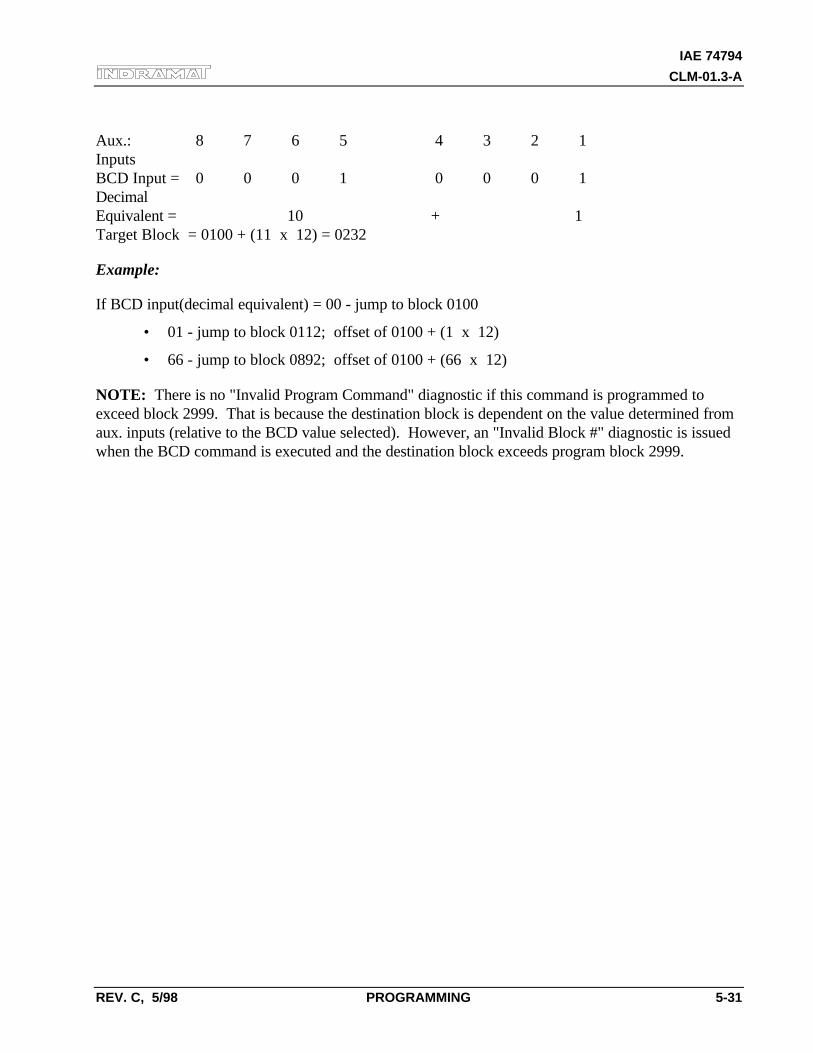
IAE 74794
CLM-01.3-A
REV. C, 5/98 PROGRAMMING 5-31
Aux.: 8 7 6 5 4 3 2 1InputsBCD Input = 0 0 0 1 0 0 0 1DecimalEquivalent = 10 + 1Target Block = 0100 + (11 x 12) = 0232
Example:
If BCD input(decimal equivalent) = 00 - jump to block 0100
• 01 - jump to block 0112; offset of 0100 + (1 x 12)
• 66 - jump to block 0892; offset of 0100 + (66 x 12)
NOTE: There is no "Invalid Program Command" diagnostic if this command is programmed toexceed block 2999. That is because the destination block is dependent on the value determined fromaux. inputs (relative to the BCD value selected). However, an "Invalid Block #" diagnostic is issuedwhen the BCD command is executed and the destination block exceeds program block 2999.
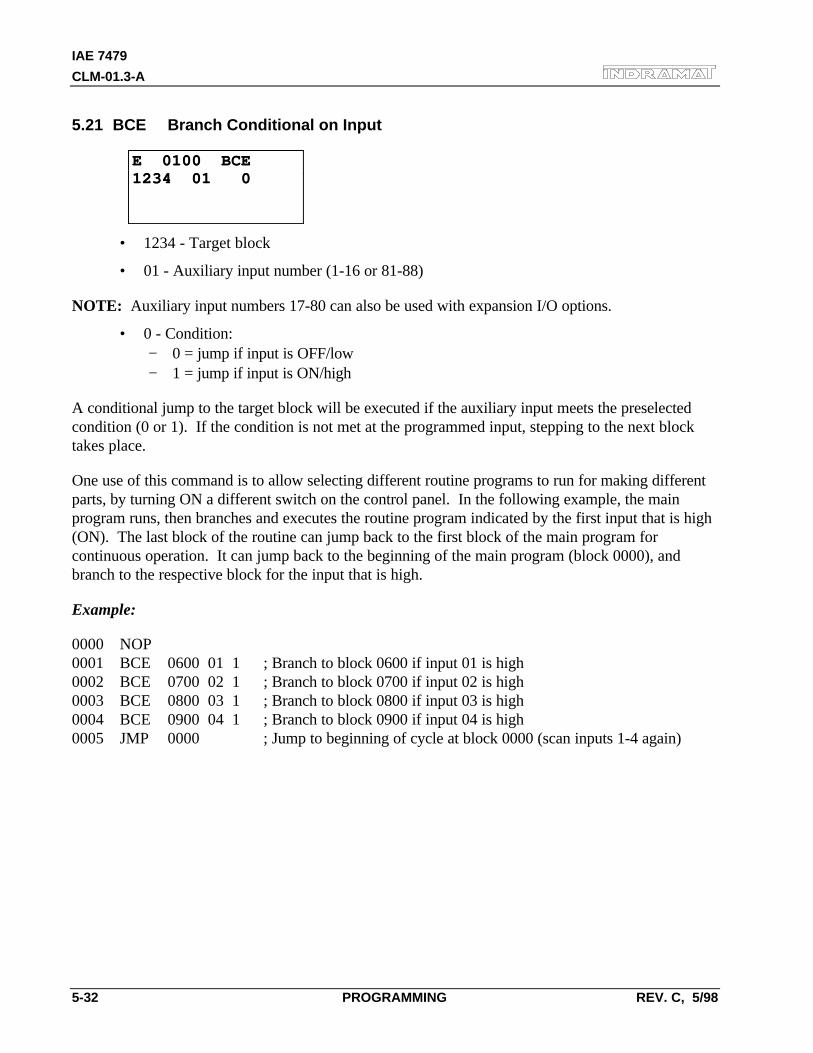
IAE 7479
CLM-01.3-A
5-32 PROGRAMMING REV. C, 5/98
5.21 BCE Branch Conditional on Input
E 0100 BCEE 0100 BCE1234 01 01234 01 0
• 1234 - Target block
• 01 - Auxiliary input number (1-16 or 81-88)
NOTE: Auxiliary input numbers 17-80 can also be used with expansion I/O options.
• 0 - Condition:− 0 = jump if input is OFF/low− 1 = jump if input is ON/high
A conditional jump to the target block will be executed if the auxiliary input meets the preselectedcondition (0 or 1). If the condition is not met at the programmed input, stepping to the next blocktakes place.
One use of this command is to allow selecting different routine programs to run for making differentparts, by turning ON a different switch on the control panel. In the following example, the mainprogram runs, then branches and executes the routine program indicated by the first input that is high(ON). The last block of the routine can jump back to the first block of the main program forcontinuous operation. It can jump back to the beginning of the main program (block 0000), andbranch to the respective block for the input that is high.
Example:
0000 NOP0001 BCE 0600 01 1 ; Branch to block 0600 if input 01 is high0002 BCE 0700 02 1 ; Branch to block 0700 if input 02 is high0003 BCE 0800 03 1 ; Branch to block 0800 if input 03 is high0004 BCE 0900 04 1 ; Branch to block 0900 if input 04 is high0005 JMP 0000 ; Jump to beginning of cycle at block 0000 (scan inputs 1-4 again)
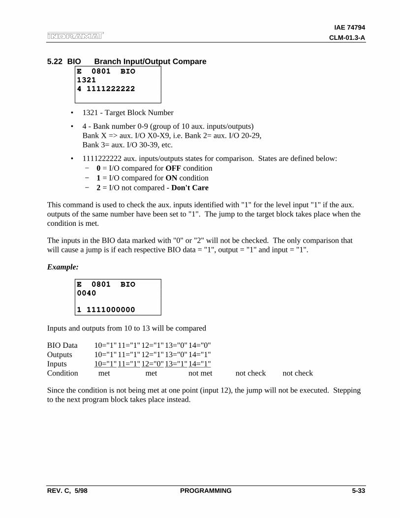
IAE 74794
CLM-01.3-A
REV. C, 5/98 PROGRAMMING 5-33
5.22 BIO Branch Input/Output CompareE 0801 BIOE 0801 BIO132113214 11112222224 1111222222
• 1321 - Target Block Number
• 4 - Bank number 0-9 (group of 10 aux. inputs/outputs)Bank X => aux. I/O X0-X9, i.e. Bank 2= aux. I/O 20-29,Bank 3= aux. I/O 30-39, etc.
• 1111222222 aux. inputs/outputs states for comparison. States are defined below:− 0 = I/O compared for OFF condition− 1 = I/O compared for ON condition− 2 = I/O not compared - Don't Care
This command is used to check the aux. inputs identified with "1" for the level input "1" if the aux.outputs of the same number have been set to "1". The jump to the target block takes place when thecondition is met.
The inputs in the BIO data marked with "0" or "2" will not be checked. The only comparison thatwill cause a jump is if each respective BIO data = "1", output = "1" and input = "1".
Example:
E 0801 BIOE 0801 BIO00400040
1 11110000001 1111000000
Inputs and outputs from 10 to 13 will be compared
BIO Data 10="1" 11="1" 12="1" 13="0" 14="0"Outputs 10="1" 11="1" 12="1" 13="0" 14="1"Inputs 10="1" 11="1" 12="0" 13="1" 14="1"Condition met met not met not check not check
Since the condition is not being met at one point (input 12), the jump will not be executed. Steppingto the next program block takes place instead.
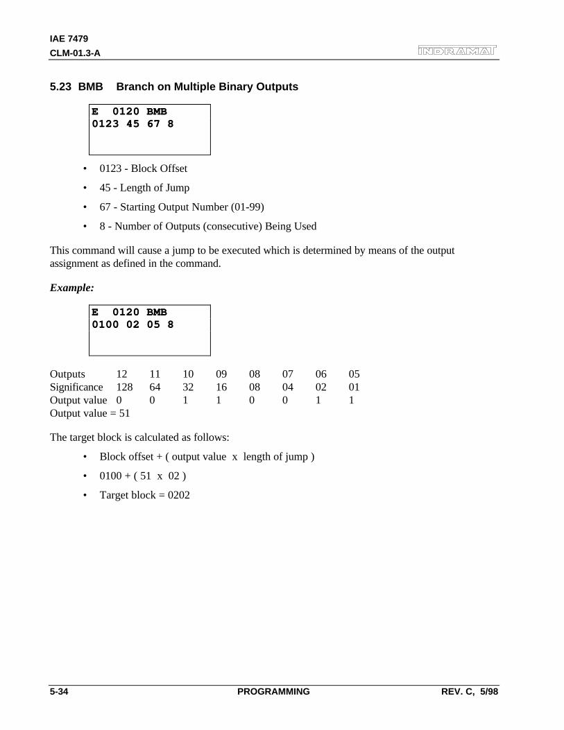
IAE 7479
CLM-01.3-A
5-34 PROGRAMMING REV. C, 5/98
5.23 BMB Branch on Multiple Binary Outputs
E 0120 BMBE 0120 BMB0123 45 67 80123 45 67 8
• 0123 - Block Offset
• 45 - Length of Jump
• 67 - Starting Output Number (01-99)
• 8 - Number of Outputs (consecutive) Being Used
This command will cause a jump to be executed which is determined by means of the outputassignment as defined in the command.
Example:
E 0120 BMBE 0120 BMB0100 02 05 80100 02 05 8
Outputs 12 11 10 09 08 07 06 05Significance 128 64 32 16 08 04 02 01Output value 0 0 1 1 0 0 1 1Output value = 51
The target block is calculated as follows:
• Block offset + ( output value x length of jump )
• 0100 + ( 51 x 02 )
• Target block = 0202
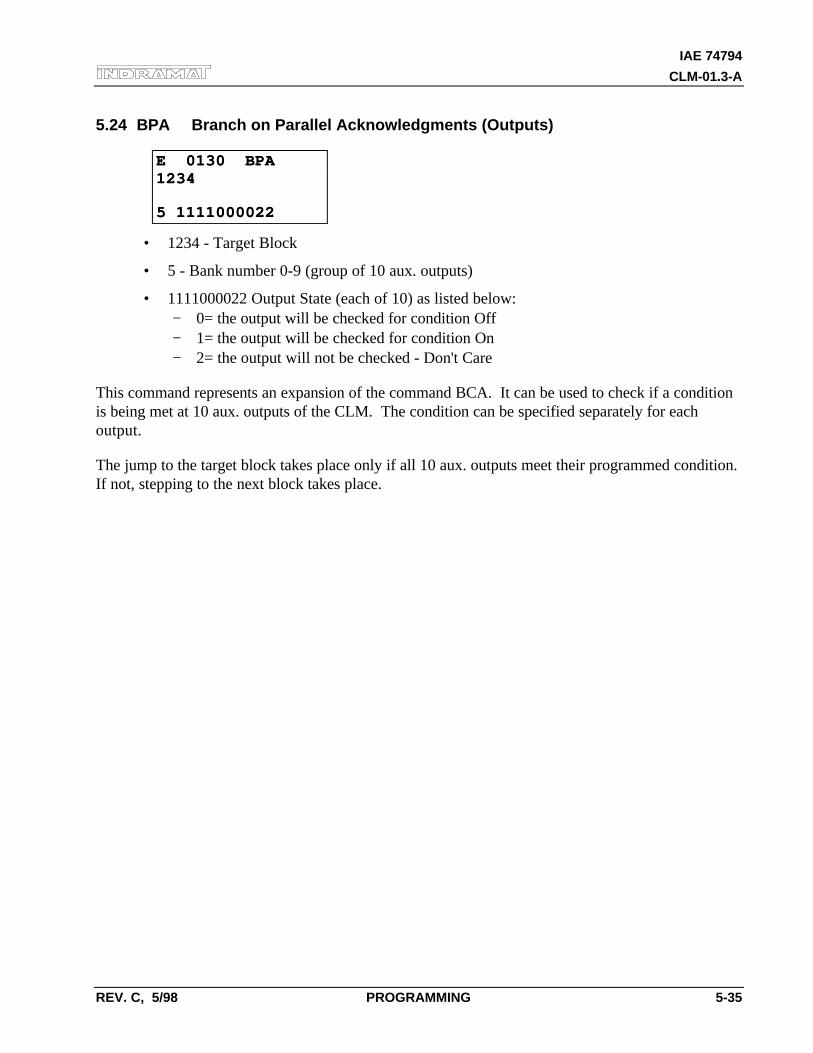
IAE 74794
CLM-01.3-A
REV. C, 5/98 PROGRAMMING 5-35
5.24 BPA Branch on Parallel Acknowledgments (Outputs)
E 0130 BPAE 0130 BPA12341234
5 11110000225 1111000022
• 1234 - Target Block
• 5 - Bank number 0-9 (group of 10 aux. outputs)
• 1111000022 Output State (each of 10) as listed below:− 0= the output will be checked for condition Off− 1= the output will be checked for condition On− 2= the output will not be checked - Don't Care
This command represents an expansion of the command BCA. It can be used to check if a conditionis being met at 10 aux. outputs of the CLM. The condition can be specified separately for eachoutput.
The jump to the target block takes place only if all 10 aux. outputs meet their programmed condition.If not, stepping to the next block takes place.
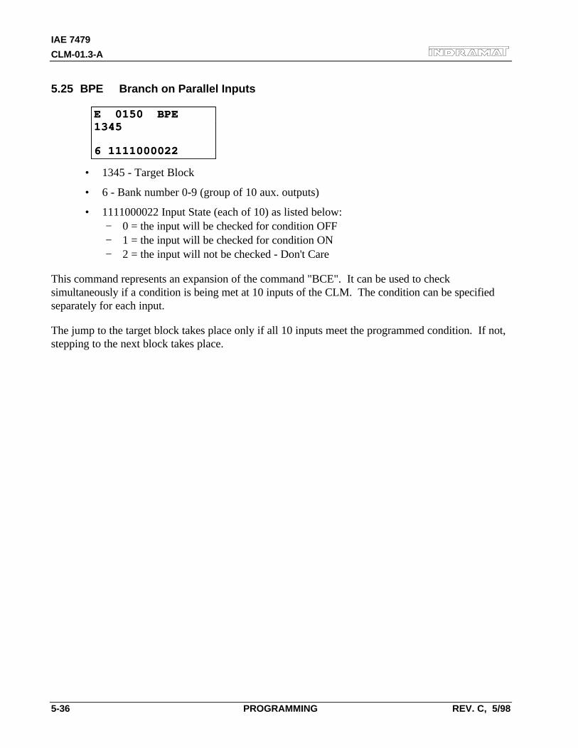
IAE 7479
CLM-01.3-A
5-36 PROGRAMMING REV. C, 5/98
5.25 BPE Branch on Parallel Inputs
E 0150 BPEE 0150 BPE13451345
6 11110000226 1111000022
• 1345 - Target Block
• 6 - Bank number 0-9 (group of 10 aux. outputs)
• 1111000022 Input State (each of 10) as listed below:− 0 = the input will be checked for condition OFF− 1 = the input will be checked for condition ON− 2 = the input will not be checked - Don't Care
This command represents an expansion of the command "BCE". It can be used to checksimultaneously if a condition is being met at 10 inputs of the CLM. The condition can be specifiedseparately for each input.
The jump to the target block takes place only if all 10 inputs meet the programmed condition. If not,stepping to the next block takes place.
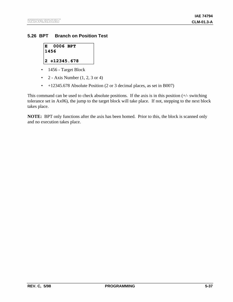
IAE 74794
CLM-01.3-A
REV. C, 5/98 PROGRAMMING 5-37
5.26 BPT Branch on Position Test
E 0006 BPTE 0006 BPT14561456
2 +12345.6782 +12345.678
• 1456 - Target Block
• 2 - Axis Number (1, 2, 3 or 4)
• +12345.678 Absolute Position (2 or 3 decimal places, as set in B007)
This command can be used to check absolute positions. If the axis is in this position (+/- switchingtolerance set in Ax06), the jump to the target block will take place. If not, stepping to the next blocktakes place.
NOTE: BPT only functions after the axis has been homed. Prior to this, the block is scanned onlyand no execution takes place.
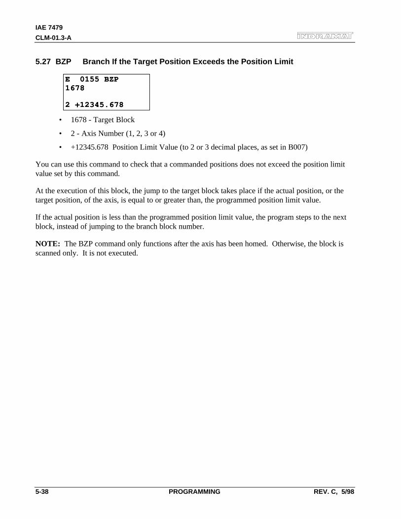
IAE 7479
CLM-01.3-A
5-38 PROGRAMMING REV. C, 5/98
5.27 BZP Branch If the Target Position Exceeds the Position Limit
E 0155 BZPE 0155 BZP16781678
2 +12345.6782 +12345.678
• 1678 - Target Block
• 2 - Axis Number (1, 2, 3 or 4)
• +12345.678 Position Limit Value (to 2 or 3 decimal places, as set in B007)
You can use this command to check that a commanded positions does not exceed the position limitvalue set by this command.
At the execution of this block, the jump to the target block takes place if the actual position, or thetarget position, of the axis, is equal to or greater than, the programmed position limit value.
If the actual position is less than the programmed position limit value, the program steps to the nextblock, instead of jumping to the branch block number.
NOTE: The BZP command only functions after the axis has been homed. Otherwise, the block isscanned only. It is not executed.
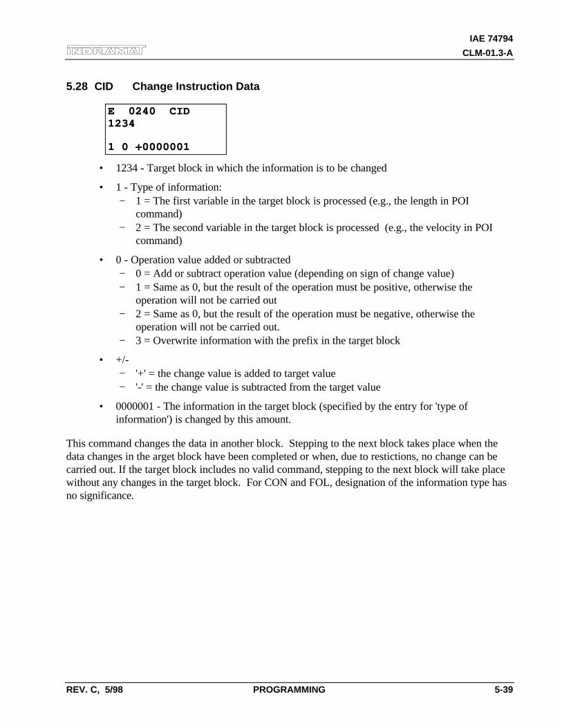
IAE 74794
CLM-01.3-A
REV. C, 5/98 PROGRAMMING 5-39
5.28 CID Change Instruction Data
E 0240 CIDE 0240 CID12341234
1 0 +00000011 0 +0000001
• 1234 - Target block in which the information is to be changed
• 1 - Type of information:− 1 = The first variable in the target block is processed (e.g., the length in POI
command)− 2 = The second variable in the target block is processed (e.g., the velocity in POI
command)
• 0 - Operation value added or subtracted− 0 = Add or subtract operation value (depending on sign of change value)− 1 = Same as 0, but the result of the operation must be positive, otherwise the
operation will not be carried out− 2 = Same as 0, but the result of the operation must be negative, otherwise the
operation will not be carried out.− 3 = Overwrite information with the prefix in the target block
• +/-− '+' = the change value is added to target value− '-' = the change value is subtracted from the target value
• 0000001 - The information in the target block (specified by the entry for 'type ofinformation') is changed by this amount.
This command changes the data in another block. Stepping to the next block takes place when thedata changes in the arget block have been completed or when, due to restictions, no change can becarried out. If the target block includes no valid command, stepping to the next block will take placewithout any changes in the target block. For CON and FOL, designation of the information type hasno significance.
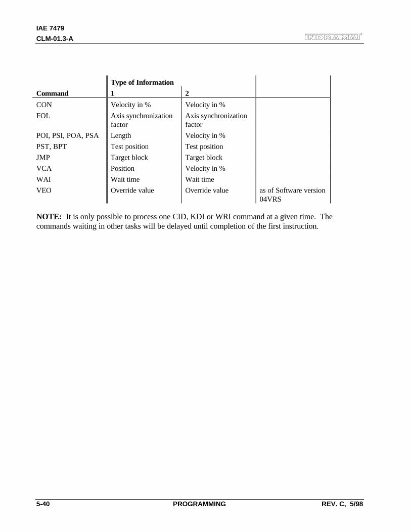
IAE 7479
CLM-01.3-A
5-40 PROGRAMMING REV. C, 5/98
Type of Information
Command 1 2
CON Velocity in % Velocity in %
FOL Axis synchronizationfactor
Axis synchronizationfactor
POI, PSI, POA, PSA Length Velocity in %
PST, BPT Test position Test position
JMP Target block Target block
VCA Position Velocity in %
WAI Wait time Wait time
VEO Override value Override value as of Software version04VRS
NOTE: It is only possible to process one CID, KDI or WRI command at a given time. Thecommands waiting in other tasks will be delayed until completion of the first instruction.
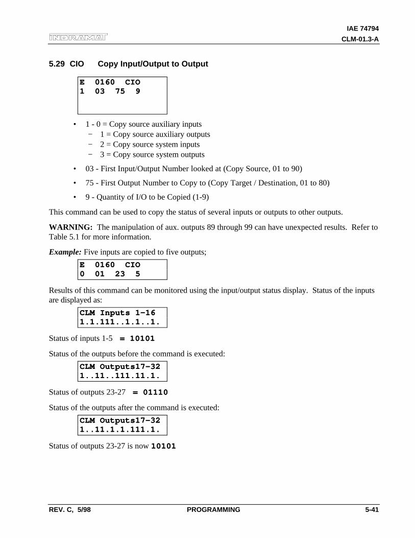
IAE 74794
CLM-01.3-A
REV. C, 5/98 PROGRAMMING 5-41
5.29 CIO Copy Input/Output to Output
E 0160 CIOE 0160 CIO1 03 75 91 03 75 9
• 1 - 0 = Copy source auxiliary inputs− 1 = Copy source auxiliary outputs− 2 = Copy source system inputs− 3 = Copy source system outputs
• 03 - First Input/Output Number looked at (Copy Source, 01 to 90)
• 75 - First Output Number to Copy to (Copy Target / Destination, 01 to 80)
• 9 - Quantity of I/O to be Copied (1-9)
This command can be used to copy the status of several inputs or outputs to other outputs.
WARNING: The manipulation of aux. outputs 89 through 99 can have unexpected results. Refer toTable 5.1 for more information.
Example: Five inputs are copied to five outputs;
E 0160 CIOE 0160 CIO0 01 23 50 01 23 5
Results of this command can be monitored using the input/output status display. Status of the inputsare displayed as:
CLM Inputs 1-16CLM Inputs 1-161.1.111..1.1..1.1.1.111..1.1..1.
Status of inputs 1-5 = 10101 = 10101
Status of the outputs before the command is executed:
CLM Outputs17-32CLM Outputs17-321..11..111.11.1.1..11..111.11.1.
Status of outputs 23-27 = 01110 = 01110
Status of the outputs after the command is executed:
CLM Outputs17-32CLM Outputs17-321..11.1.1.111.1.1..11.1.1.111.1.
Status of outputs 23-27 is now 1010110101
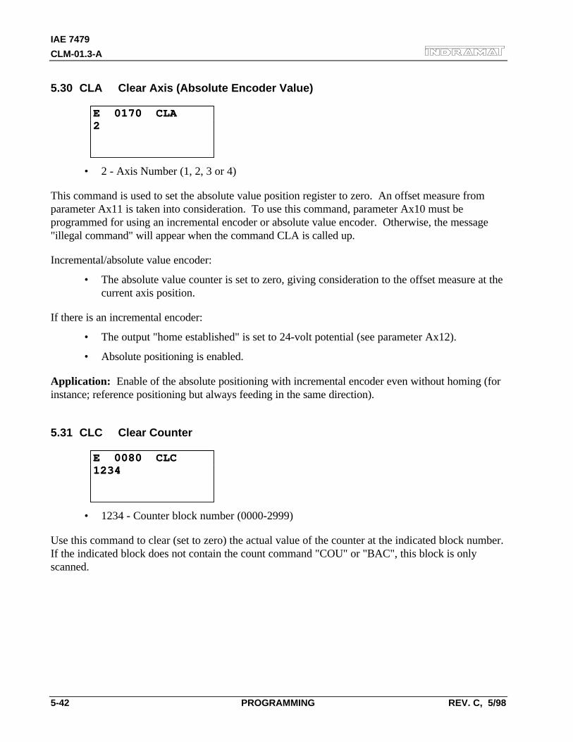
IAE 7479
CLM-01.3-A
5-42 PROGRAMMING REV. C, 5/98
5.30 CLA Clear Axis (Absolute Encoder Value)
E 0170 CLAE 0170 CLA22
• 2 - Axis Number (1, 2, 3 or 4)
This command is used to set the absolute value position register to zero. An offset measure fromparameter Ax11 is taken into consideration. To use this command, parameter Ax10 must beprogrammed for using an incremental encoder or absolute value encoder. Otherwise, the message"illegal command" will appear when the command CLA is called up.
Incremental/absolute value encoder:
• The absolute value counter is set to zero, giving consideration to the offset measure at thecurrent axis position.
If there is an incremental encoder:
• The output "home established" is set to 24-volt potential (see parameter Ax12).
• Absolute positioning is enabled.
Application: Enable of the absolute positioning with incremental encoder even without homing (forinstance; reference positioning but always feeding in the same direction).
5.31 CLC Clear Counter
E 0080 CLCE 0080 CLC12341234
• 1234 - Counter block number (0000-2999)
Use this command to clear (set to zero) the actual value of the counter at the indicated block number.If the indicated block does not contain the count command "COU" or "BAC", this block is onlyscanned.
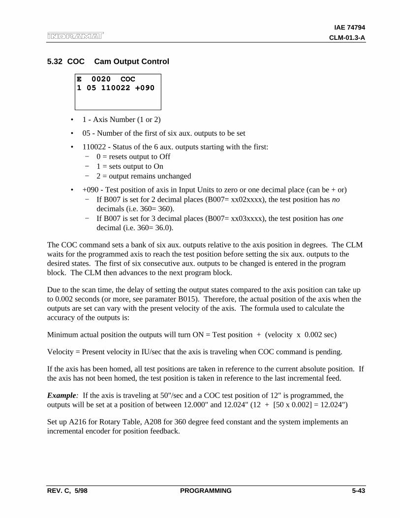
IAE 74794
CLM-01.3-A
REV. C, 5/98 PROGRAMMING 5-43
5.32 COC Cam Output Control
E 0020 COCE 0020 COC1 05 110022 +0901 05 110022 +090
• 1 - Axis Number (1 or 2)
• 05 - Number of the first of six aux. outputs to be set
• 110022 - Status of the 6 aux. outputs starting with the first:− 0 = resets output to Off− 1 = sets output to On− 2 = output remains unchanged
• +090 - Test position of axis in Input Units to zero or one decimal place (can be + or)− If B007 is set for 2 decimal places (B007= xx02xxxx), the test position has no
decimals (i.e. 360= 360).− If B007 is set for 3 decimal places (B007= xx03xxxx), the test position has one
decimal (i.e. 360= 36.0).
The COC command sets a bank of six aux. outputs relative to the axis position in degrees. The CLMwaits for the programmed axis to reach the test position before setting the six aux. outputs to thedesired states. The first of six consecutive aux. outputs to be changed is entered in the programblock. The CLM then advances to the next program block.
Due to the scan time, the delay of setting the output states compared to the axis position can take upto 0.002 seconds (or more, see paramater B015). Therefore, the actual position of the axis when theoutputs are set can vary with the present velocity of the axis. The formula used to calculate theaccuracy of the outputs is:
Minimum actual position the outputs will turn ON = Test position + (velocity x 0.002 sec)
Velocity = Present velocity in IU/sec that the axis is traveling when COC command is pending.
If the axis has been homed, all test positions are taken in reference to the current absolute position. Ifthe axis has not been homed, the test position is taken in reference to the last incremental feed.
Example: If the axis is traveling at 50"/sec and a COC test position of 12" is programmed, theoutputs will be set at a position of between 12.000" and 12.024" (12 + [50 x 0.002] = 12.024")
Set up A216 for Rotary Table, A208 for 360 degree feed constant and the system implements anincremental encoder for position feedback.
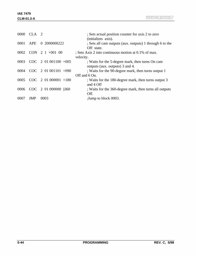
IAE 7479
CLM-01.3-A
5-44 PROGRAMMING REV. C, 5/98
0000 CLA 2 ; Sets actual position counter for axis 2 to zero (initializes axis).
0001 APE 0 2000000222 ; Sets all cam outputs (aux. outputs) 1 through 6 to the Off state.
0002 CON 2 1 +001 00 ; Sets Axis 2 into continuous motion at 0.1% of max. velocity.
0003 COC 2 01 001100 +005 ; Waits for the 5-degree mark, then turns On cam outputs (aux. outputs) 3 and 4.
0004 COC 2 01 001101 +090 ; Waits for the 90-degree mark, then turns output 1 Off and 6 On.
0005 COC 2 01 000001 +180 ; Waits for the 180-degree mark, then turns output 3 and 4 Off
0006 COC 2 01 000000 )360 ; Waits for the 360-degree mark, then turns all outputs Off.
0007 JMP 0003 ;Jump to block 0003.
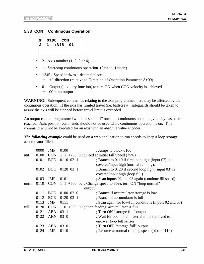
IAE 74794
CLM-01.3-A
REV. C, 5/98 PROGRAMMING 5-45
5.33 CON Continuous Operation
E 0190 CONE 0190 CON2 1 +345 012 1 +345 01
• 2 - Axis number (1, 2, 3 or 4)
• 1 - Start/stop continuous operation (0=stop, 1=start)
• +345 - Speed in % to 1 decimal place− +/- direction (relative to Direction of Operation Parameter Ax09)
• 01 - Output (auxiliary function) to turn ON when CON velocity is achieved− 00 = no output
WARNING: Subsequent commands relating to the axis programmed here may be affected by thecontinuous operation. If the axis has limited travel (i.e. ballscrew), safeguards should be taken toassure the axis will be stopped before travel limit is exceeded.
An output can be programmed which is set to "1" once the continuous operating velocity has beenreached. Axis position commands should not be used while continuous operation is on. Thiscommand will not be executed for an axis with an absolute value encoder.
The following example could be used on a web application to run speeds to keep a loop storageaccumulator filled:
0000 JMP 0100 ; Jumps to block 0100init 0100 CON 1 1 +750 00 ; Feed at initial Fill Speed (75%)
0101 BCE 0110 02 1 ; Branch to 0110 if first loop light (input 02) is covered/input high (normal running),
0102 BCE 0120 03 1 ; Branch to 0120 if second loop light (input 03) is covered/input high (loop full)
0103 JMP 0101 ; Scan inputs 02 and 03 again (continue fill speed)norm 0110 CON 1 1 +500 02 ; Change speed to 50%, turn ON "loop normal"
output0111 BCE 0100 02 0 ; Branch if accumulator storage is low0112 BCE 0120 03 1 ; Branch if accumulator is full0113 JMP 0111 ; Scan again for low/full conditions (inputs 02 and 03)
full 0120 CON 1 0 +000 00 ; Stop feeding, accumulator is full0121 AEA 03 1 ; Turn ON "storage full" output0122 AKN 03 0 ; Wait for additional material to be removed to
uncover loop full sensor0123 AEA 03 0 ; Turn OFF "storage full" output0124 JMP 0110 ; Resume at normal running speed (block 0110)
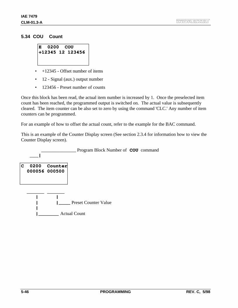
IAE 7479
CLM-01.3-A
5-46 PROGRAMMING REV. C, 5/98
5.34 COU Count
E 0200 COUE 0200 COU+12345 12 123456+12345 12 123456
• +12345 - Offset number of items
• 12 - Signal (aux.) output number
• 123456 - Preset number of counts
Once this block has been read, the actual item number is increased by 1. Once the preselected itemcount has been reached, the programmed output is switched on. The actual value is subsequentlycleared. The item counter can be also set to zero by using the command 'CLC.' Any number of itemcounters can be programmed.
For an example of how to offset the actual count, refer to the example for the BAC command.
This is an example of the Counter Display screen (See section 2.3.4 for information how to view theCounter Display screen).
____________ ____________ Program Block Number of COU COU command ___| ___|
C 0200 CounterC 0200 Counter 000056 000500 000056 000500
______ ______ ______ ______ | | | | | |____ | |____ Preset Counter Value | | |_______ |_______ Actual Count
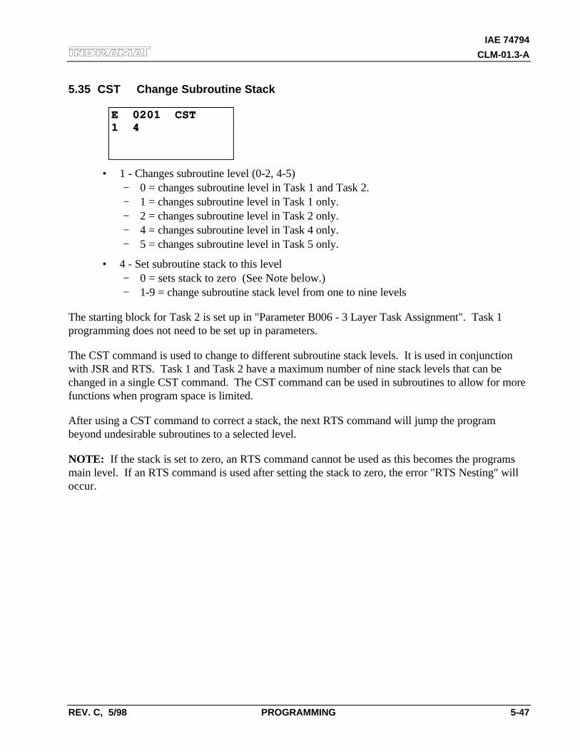
IAE 74794
CLM-01.3-A
REV. C, 5/98 PROGRAMMING 5-47
5.35 CST Change Subroutine Stack
E 0201 CSTE 0201 CST1 41 4
• 1 - Changes subroutine level (0-2, 4-5)− 0 = changes subroutine level in Task 1 and Task 2.− 1 = changes subroutine level in Task 1 only.− 2 = changes subroutine level in Task 2 only.− 4 = changes subroutine level in Task 4 only.− 5 = changes subroutine level in Task 5 only.
• 4 - Set subroutine stack to this level− 0 = sets stack to zero (See Note below.)− 1-9 = change subroutine stack level from one to nine levels
The starting block for Task 2 is set up in "Parameter B006 - 3 Layer Task Assignment". Task 1programming does not need to be set up in parameters.
The CST command is used to change to different subroutine stack levels. It is used in conjunctionwith JSR and RTS. Task 1 and Task 2 have a maximum number of nine stack levels that can bechanged in a single CST command. The CST command can be used in subroutines to allow for morefunctions when program space is limited.
After using a CST command to correct a stack, the next RTS command will jump the programbeyond undesirable subroutines to a selected level.
NOTE: If the stack is set to zero, an RTS command cannot be used as this becomes the programsmain level. If an RTS command is used after setting the stack to zero, the error "RTS Nesting" willoccur.
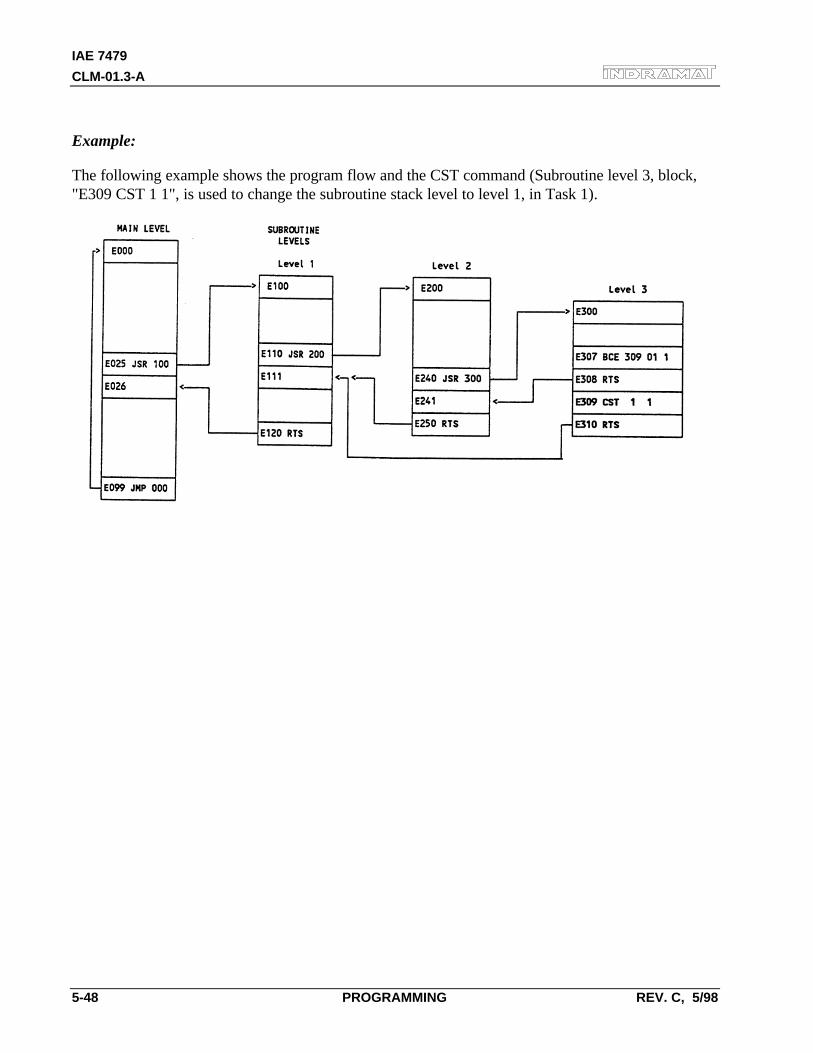
IAE 7479
CLM-01.3-A
5-48 PROGRAMMING REV. C, 5/98
Example:
The following example shows the program flow and the CST command (Subroutine level 3, block,"E309 CST 1 1", is used to change the subroutine stack level to level 1, in Task 1).
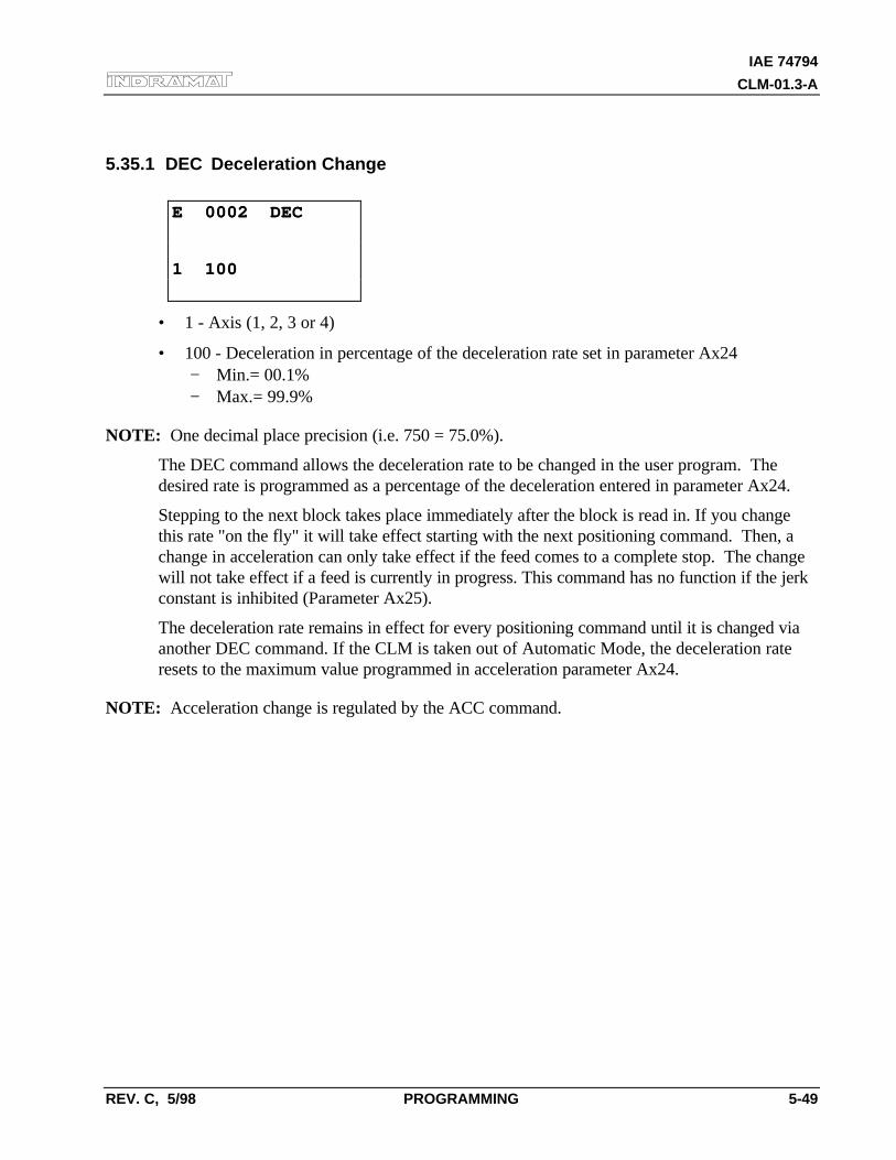
IAE 74794
CLM-01.3-A
REV. C, 5/98 PROGRAMMING 5-49
5.35.1 DEC Deceleration Change
E 0002 DECE 0002 DEC
1 1001 100
• 1 - Axis (1, 2, 3 or 4)
• 100 - Deceleration in percentage of the deceleration rate set in parameter Ax24− Min.= 00.1%− Max.= 99.9%
NOTE: One decimal place precision (i.e. 750 = 75.0%).
The DEC command allows the deceleration rate to be changed in the user program. Thedesired rate is programmed as a percentage of the deceleration entered in parameter Ax24.
Stepping to the next block takes place immediately after the block is read in. If you changethis rate "on the fly" it will take effect starting with the next positioning command. Then, achange in acceleration can only take effect if the feed comes to a complete stop. The changewill not take effect if a feed is currently in progress. This command has no function if the jerkconstant is inhibited (Parameter Ax25).
The deceleration rate remains in effect for every positioning command until it is changed viaanother DEC command. If the CLM is taken out of Automatic Mode, the deceleration rateresets to the maximum value programmed in acceleration parameter Ax24.
NOTE: Acceleration change is regulated by the ACC command.
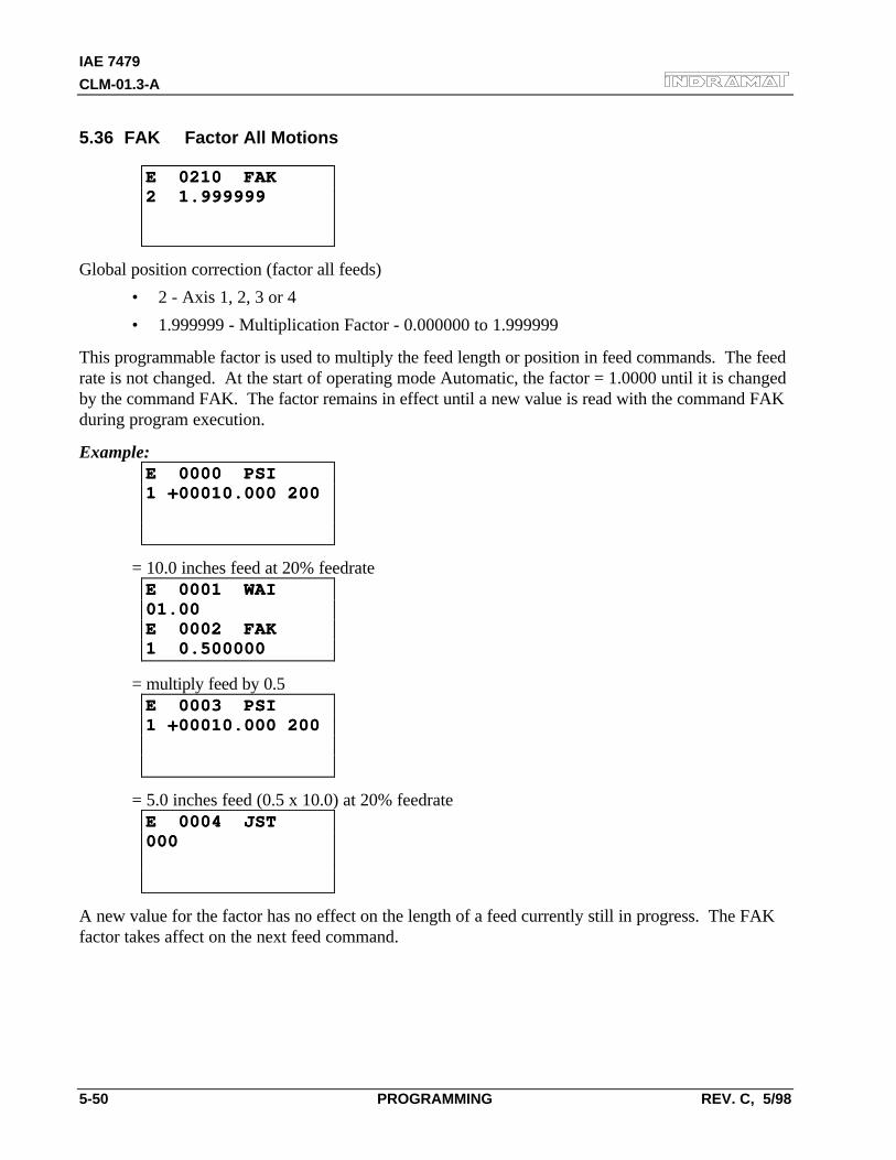
IAE 7479
CLM-01.3-A
5-50 PROGRAMMING REV. C, 5/98
5.36 FAK Factor All Motions
E 0210 FAKE 0210 FAK2 1.9999992 1.999999
Global position correction (factor all feeds)
• 2 - Axis 1, 2, 3 or 4
• 1.999999 - Multiplication Factor - 0.000000 to 1.999999
This programmable factor is used to multiply the feed length or position in feed commands. The feedrate is not changed. At the start of operating mode Automatic, the factor = 1.0000 until it is changedby the command FAK. The factor remains in effect until a new value is read with the command FAKduring program execution.
Example:E 0000 PSIE 0000 PSI1 +00010.000 2001 +00010.000 200
= 10.0 inches feed at 20% feedrateE 0001 WAIE 0001 WAI01.0001.00E 0002 FAKE 0002 FAK1 0.5000001 0.500000
= multiply feed by 0.5E 0003 PSIE 0003 PSI1 +00010.000 2001 +00010.000 200
= 5.0 inches feed (0.5 x 10.0) at 20% feedrateE 0004 JSTE 0004 JST000000
A new value for the factor has no effect on the length of a feed currently still in progress. The FAKfactor takes affect on the next feed command.
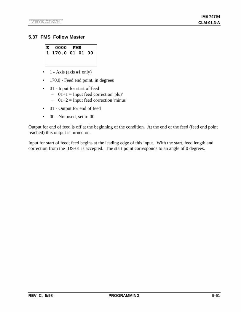
IAE 74794
CLM-01.3-A
REV. C, 5/98 PROGRAMMING 5-51
5.37 FMS Follow Master
E 0000 FMSE 0000 FMS1 170.0 01 01 001 170.0 01 01 00
• 1 - Axis (axis #1 only)
• 170.0 - Feed end point, in degrees
• 01 - Input for start of feed− 01+1 = Input feed correction 'plus'− 01+2 = Input feed correction 'minus'
• 01 - Output for end of feed
• 00 - Not used, set to 00
Output for end of feed is off at the beginning of the condition. At the end of the feed (feed end pointreached) this output is turned on.
Input for start of feed; feed begins at the leading edge of this input. With the start, feed length andcorrection from the IDS-01 is accepted. The start point corresponds to an angle of 0 degrees.
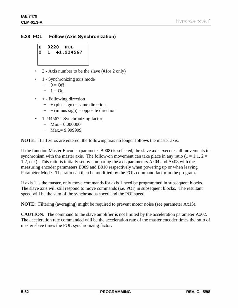
IAE 7479
CLM-01.3-A
5-52 PROGRAMMING REV. C, 5/98
5.38 FOL Follow (Axis Synchronization)
E 0220 FOLE 0220 FOL2 1 +1.2345672 1 +1.234567
• 2 - Axis number to be the slave (#1or 2 only)
• 1 - Synchronizing axis mode− 0 = Off− 1 = On
• + - Following direction− + (plus sign) = same direction− − (minus sign) = opposite direction
• 1.234567 - Synchronizing factor− Min.= 0.000000− Max.= 9.999999
NOTE: If all zeros are entered, the following axis no longer follows the master axis.
If the function Master Encoder (parameter B008) is selected, the slave axis executes all movements insynchronism with the master axis. The follow-on movement can take place in any ratio (1 = 1:1, 2 =1:2, etc.). This ratio is initially set by comparing the axis parameters Ax04 and Ax08 with themeasuring encoder parameters B009 and B010 respectively when powering up or when leavingParameter Mode. The ratio can then be modified by the FOL command factor in the program.
If axis 1 is the master, only move commands for axis 1 need be programmed in subsequent blocks.The slave axis will still respond to move commands (i.e. POI) in subsequent blocks. The resultantspeed will be the sum of the synchronous speed and the POI speed.
NOTE: Filtering (averaging) might be required to prevent motor noise (see parameter Ax15).
CAUTION: The command to the slave amplifier is not limited by the acceleration parameter Ax02.The acceleration rate commanded will be the acceleration rate of the master encoder times the ratio ofmaster:slave times the FOL synchronizing factor.
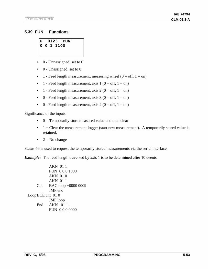
IAE 74794
CLM-01.3-A
REV. C, 5/98 PROGRAMMING 5-53
5.39 FUN Functions
E 0123 FUNE 0123 FUN0 0 1 11000 0 1 1100
• 0 - Unnassigned, set to 0
• 0 - Unassigned, set to 0
• 1 - Feed length measurement, measuring wheel (0 = off, 1 = on)
• 1 - Feed length measurement, axis 1 (0 = off, 1 = on)
• 1 - Feed length measurement, axis 2 (0 = off, 1 = on)
• 0 - Feed length measurement, axis 3 (0 = off, 1 = on)
• 0 - Feed length measurement, axis 4 (0 = off, 1 = on)
Significance of the inputs:
• 0 = Temporarily store measured value and then clear
• 1 = Clear the measurement logger (start new measurement). A temporarily stored value isretained.
• 2 = No change
Status 46 is used to request the temporarily stored measurements via the serial interface.
Example: The feed length traversed by axis 1 is to be determined after 10 events.
AKN 01 1FUN 0 0 0 1000AKN 01 0AKN 01 1
Cnt BAC loop +0000 0009JMP end
LoopBCE cnt 01 0JMP loop
End AKN 01 1FUN 0 0 0 0000
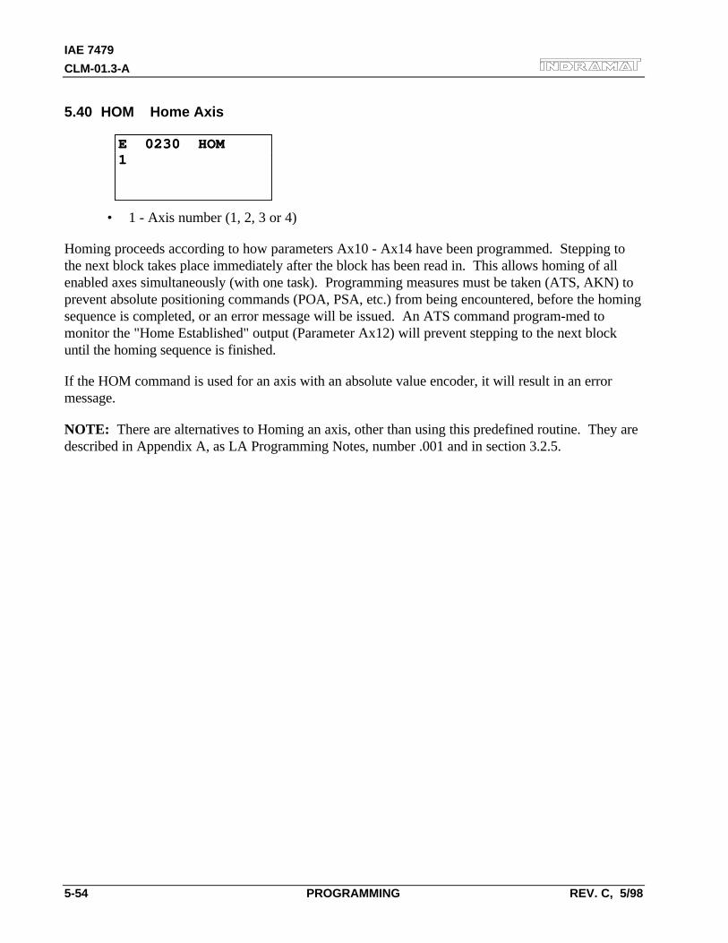
IAE 7479
CLM-01.3-A
5-54 PROGRAMMING REV. C, 5/98
5.40 HOM Home Axis
E 0230 HOME 0230 HOM11
• 1 - Axis number (1, 2, 3 or 4)
Homing proceeds according to how parameters Ax10 - Ax14 have been programmed. Stepping tothe next block takes place immediately after the block has been read in. This allows homing of allenabled axes simultaneously (with one task). Programming measures must be taken (ATS, AKN) toprevent absolute positioning commands (POA, PSA, etc.) from being encountered, before the homingsequence is completed, or an error message will be issued. An ATS command program-med tomonitor the "Home Established" output (Parameter Ax12) will prevent stepping to the next blockuntil the homing sequence is finished.
If the HOM command is used for an axis with an absolute value encoder, it will result in an errormessage.
NOTE: There are alternatives to Homing an axis, other than using this predefined routine. They aredescribed in Appendix A, as LA Programming Notes, number .001 and in section 3.2.5.
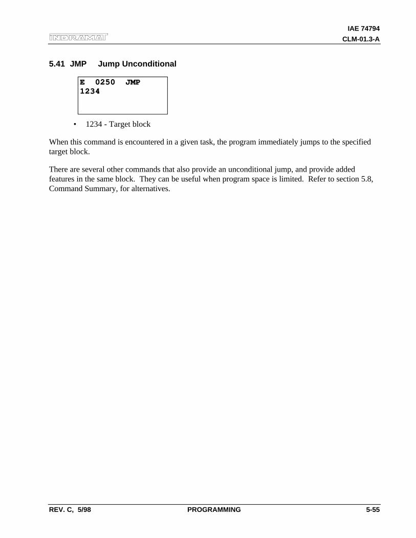
IAE 74794
CLM-01.3-A
REV. C, 5/98 PROGRAMMING 5-55
5.41 JMP Jump Unconditional
E 0250 JMPE 0250 JMP12341234
• 1234 - Target block
When this command is encountered in a given task, the program immediately jumps to the specifiedtarget block.
There are several other commands that also provide an unconditional jump, and provide addedfeatures in the same block. They can be useful when program space is limited. Refer to section 5.8,Command Summary, for alternatives.
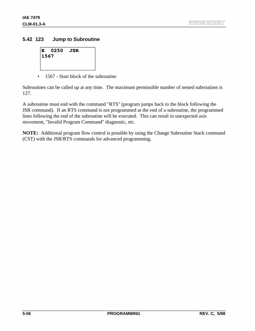
IAE 7479
CLM-01.3-A
5-56 PROGRAMMING REV. C, 5/98
5.42 123 Jump to Subroutine
E 0250 JSRE 0250 JSR15671567
• 1567 - Start block of the subroutine
Subroutines can be called up at any time. The maximum permissible number of nested subroutines is127.
A subroutine must end with the command "RTS" (program jumps back to the block following theJSR command). If an RTS command is not programmed at the end of a subroutine, the programmedlines following the end of the subroutine will be executed. This can result in unexpected axismovement, "Invalid Program Command" diagnostic, etc.
NOTE: Additional program flow control is possible by using the Change Subroutine Stack command(CST) with the JSR/RTS commands for advanced programming.
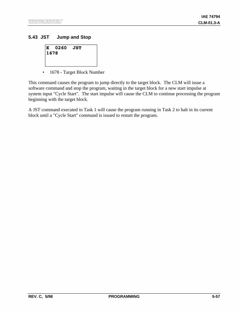
IAE 74794
CLM-01.3-A
REV. C, 5/98 PROGRAMMING 5-57
5.43 JST Jump and Stop
E 0260 JSTE 0260 JST16781678
• 1678 - Target Block Number
This command causes the program to jump directly to the target block. The CLM will issue asoftware command and stop the program, waiting in the target block for a new start impulse atsystem input "Cycle Start". The start impulse will cause the CLM to continue processing the programbeginning with the target block.
A JST command executed in Task 1 will cause the program running in Task 2 to halt in its currentblock until a "Cycle Start" command is issued to restart the program.
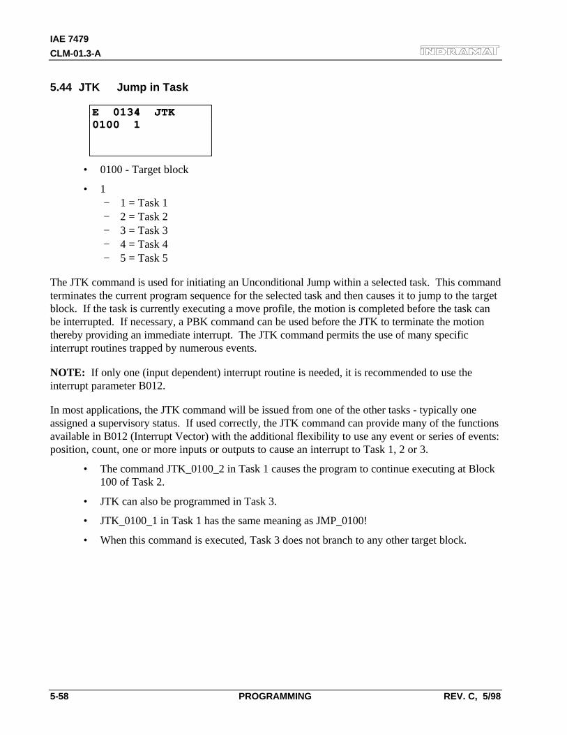
IAE 7479
CLM-01.3-A
5-58 PROGRAMMING REV. C, 5/98
5.44 JTK Jump in Task
E 0134 JTKE 0134 JTK0100 10100 1
• 0100 - Target block
• 1− 1 = Task 1− 2 = Task 2− 3 = Task 3− 4 = Task 4− 5 = Task 5
The JTK command is used for initiating an Unconditional Jump within a selected task. This commandterminates the current program sequence for the selected task and then causes it to jump to the targetblock. If the task is currently executing a move profile, the motion is completed before the task canbe interrupted. If necessary, a PBK command can be used before the JTK to terminate the motionthereby providing an immediate interrupt. The JTK command permits the use of many specificinterrupt routines trapped by numerous events.
NOTE: If only one (input dependent) interrupt routine is needed, it is recommended to use theinterrupt parameter B012.
In most applications, the JTK command will be issued from one of the other tasks - typically oneassigned a supervisory status. If used correctly, the JTK command can provide many of the functionsavailable in B012 (Interrupt Vector) with the additional flexibility to use any event or series of events:position, count, one or more inputs or outputs to cause an interrupt to Task 1, 2 or 3.
• The command JTK_0100_2 in Task 1 causes the program to continue executing at Block100 of Task 2.
• JTK can also be programmed in Task 3.
• JTK_0100_1 in Task 1 has the same meaning as JMP_0100!
• When this command is executed, Task 3 does not branch to any other target block.
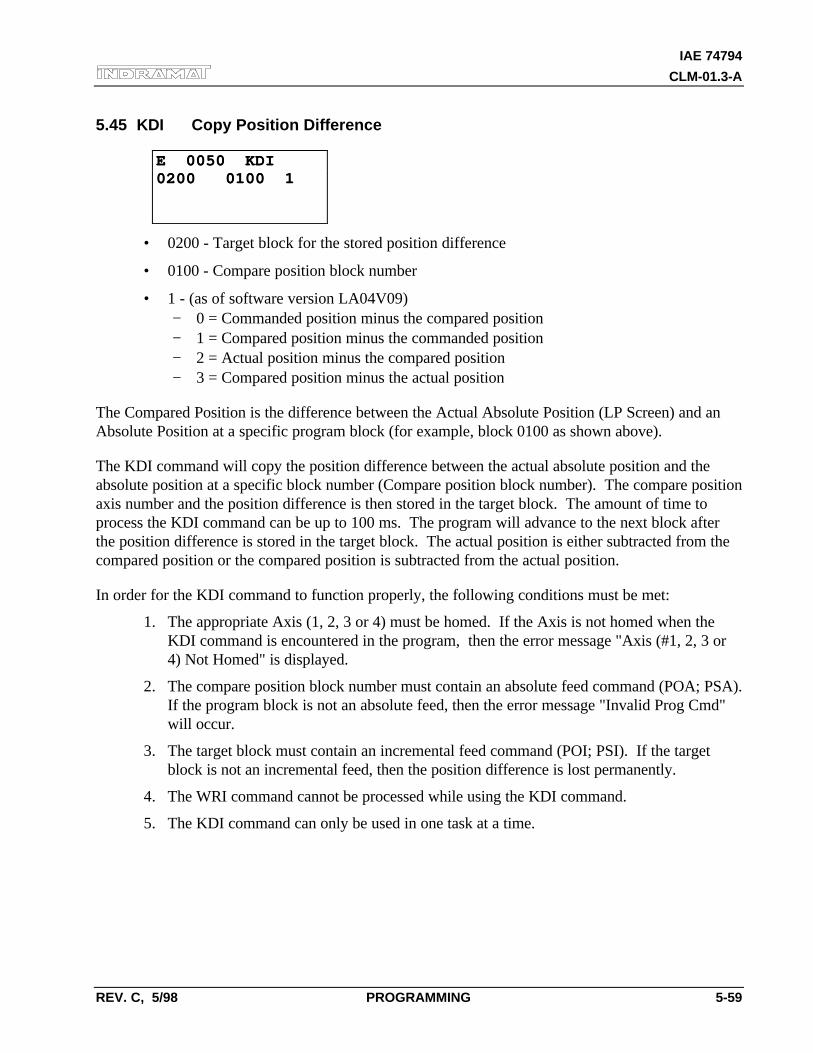
IAE 74794
CLM-01.3-A
REV. C, 5/98 PROGRAMMING 5-59
5.45 KDI Copy Position Difference
E 0050 KDIE 0050 KDI0200 0100 10200 0100 1
• 0200 - Target block for the stored position difference
• 0100 - Compare position block number
• 1 - (as of software version LA04V09)− 0 = Commanded position minus the compared position− 1 = Compared position minus the commanded position− 2 = Actual position minus the compared position− 3 = Compared position minus the actual position
The Compared Position is the difference between the Actual Absolute Position (LP Screen) and anAbsolute Position at a specific program block (for example, block 0100 as shown above).
The KDI command will copy the position difference between the actual absolute position and theabsolute position at a specific block number (Compare position block number). The compare positionaxis number and the position difference is then stored in the target block. The amount of time toprocess the KDI command can be up to 100 ms. The program will advance to the next block afterthe position difference is stored in the target block. The actual position is either subtracted from thecompared position or the compared position is subtracted from the actual position.
In order for the KDI command to function properly, the following conditions must be met:
1. The appropriate Axis (1, 2, 3 or 4) must be homed. If the Axis is not homed when theKDI command is encountered in the program, then the error message "Axis (#1, 2, 3 or4) Not Homed" is displayed.
2. The compare position block number must contain an absolute feed command (POA; PSA).If the program block is not an absolute feed, then the error message "Invalid Prog Cmd"will occur.
3. The target block must contain an incremental feed command (POI; PSI). If the targetblock is not an incremental feed, then the position difference is lost permanently.
4. The WRI command cannot be processed while using the KDI command.
5. The KDI command can only be used in one task at a time.
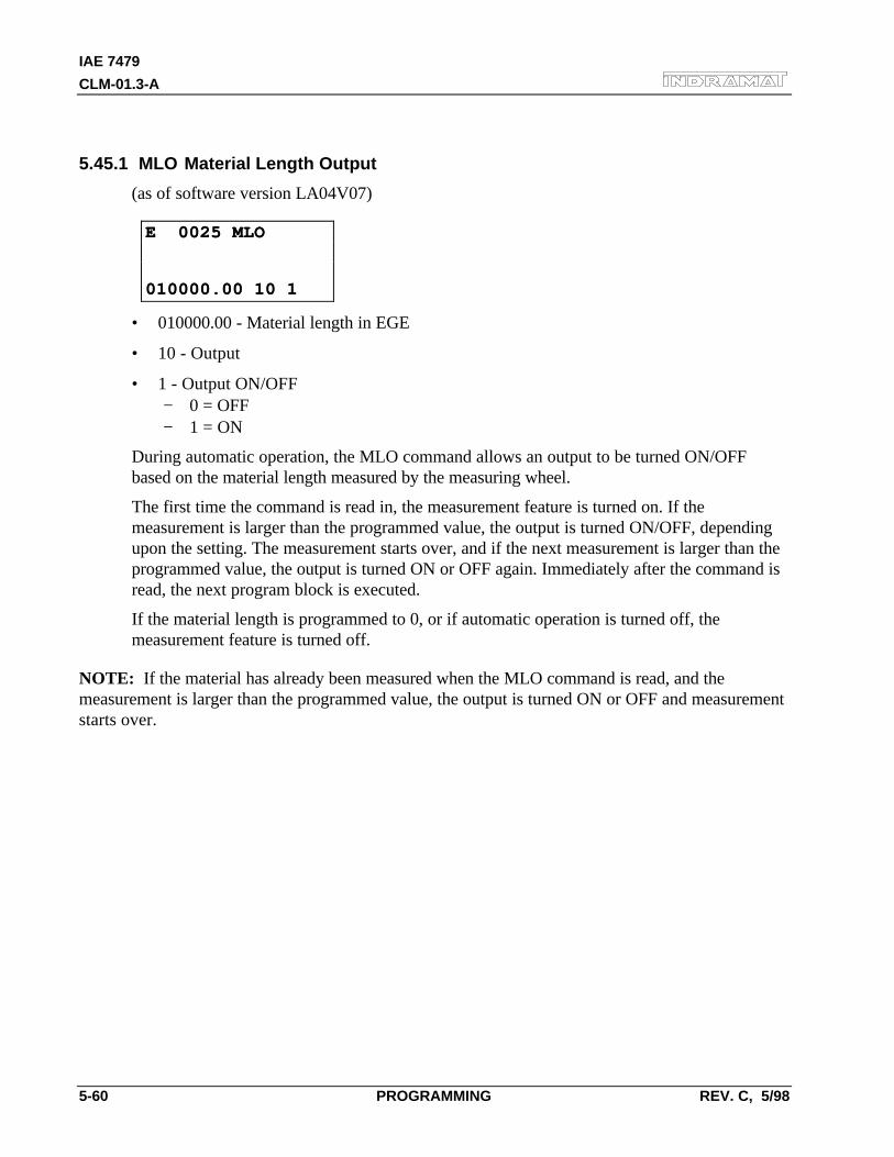
IAE 7479
CLM-01.3-A
5-60 PROGRAMMING REV. C, 5/98
5.45.1 MLO Material Length Output
(as of software version LA04V07)
E 0025 MLOE 0025 MLO
010000.00 10 1010000.00 10 1
• 010000.00 - Material length in EGE
• 10 - Output
• 1 - Output ON/OFF− 0 = OFF− 1 = ON
During automatic operation, the MLO command allows an output to be turned ON/OFFbased on the material length measured by the measuring wheel.
The first time the command is read in, the measurement feature is turned on. If themeasurement is larger than the programmed value, the output is turned ON/OFF, dependingupon the setting. The measurement starts over, and if the next measurement is larger than theprogrammed value, the output is turned ON or OFF again. Immediately after the command isread, the next program block is executed.
If the material length is programmed to 0, or if automatic operation is turned off, themeasurement feature is turned off.
NOTE: If the material has already been measured when the MLO command is read, and themeasurement is larger than the programmed value, the output is turned ON or OFF and measurementstarts over.
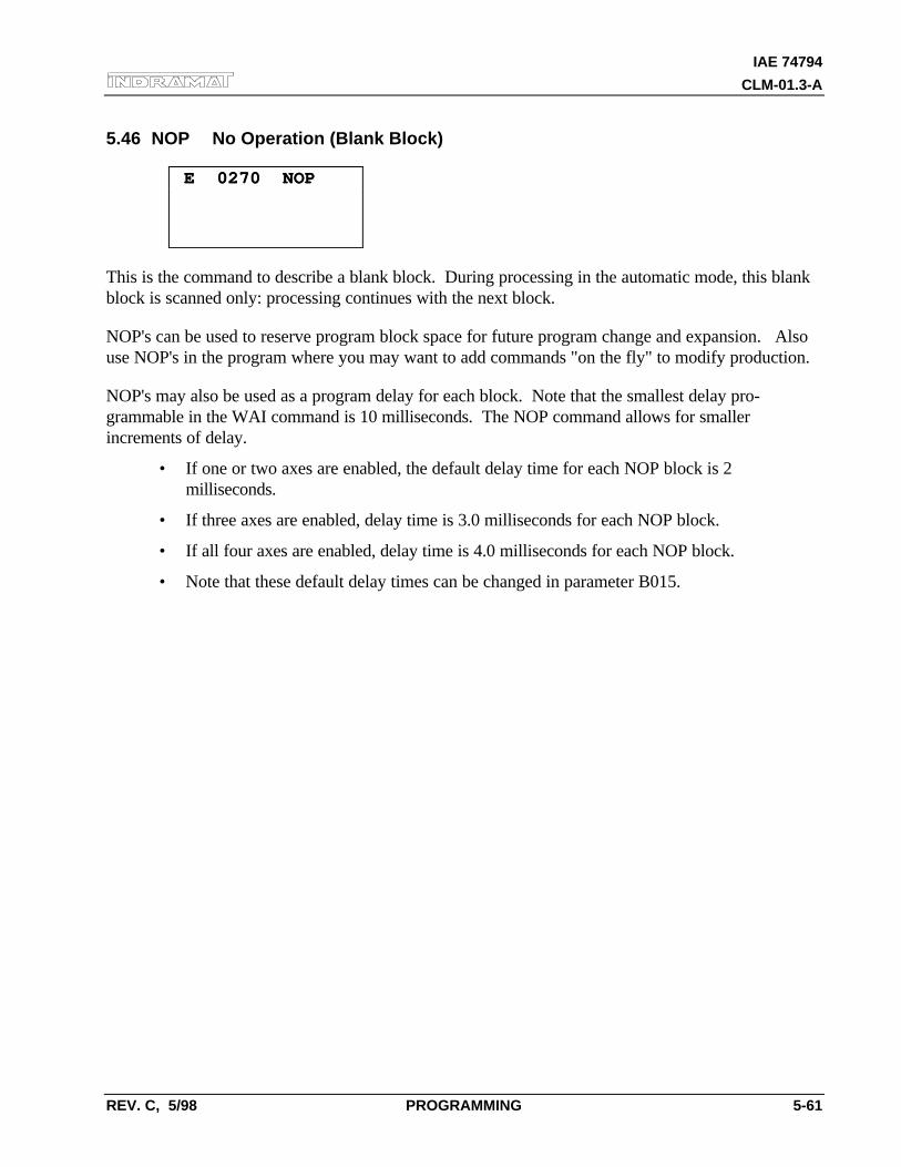
IAE 74794
CLM-01.3-A
REV. C, 5/98 PROGRAMMING 5-61
5.46 NOP No Operation (Blank Block)
E 0270 NOP E 0270 NOP
This is the command to describe a blank block. During processing in the automatic mode, this blankblock is scanned only: processing continues with the next block.
NOP's can be used to reserve program block space for future program change and expansion. Alsouse NOP's in the program where you may want to add commands "on the fly" to modify production.
NOP's may also be used as a program delay for each block. Note that the smallest delay pro-grammable in the WAI command is 10 milliseconds. The NOP command allows for smallerincrements of delay.
• If one or two axes are enabled, the default delay time for each NOP block is 2milliseconds.
• If three axes are enabled, delay time is 3.0 milliseconds for each NOP block.
• If all four axes are enabled, delay time is 4.0 milliseconds for each NOP block.
• Note that these default delay times can be changed in parameter B015.
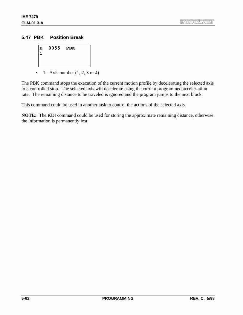
IAE 7479
CLM-01.3-A
5-62 PROGRAMMING REV. C, 5/98
5.47 PBK Position Break
E 0055 PBKE 0055 PBK11
• 1 - Axis number (1, 2, 3 or 4)
The PBK command stops the execution of the current motion profile by decelerating the selected axisto a controlled stop. The selected axis will decelerate using the current programmed acceler-ationrate. The remaining distance to be traveled is ignored and the program jumps to the next block.
This command could be used in another task to control the actions of the selected axis.
NOTE: The KDI command could be used for storing the approximate remaining distance, otherwisethe information is permanently lost.
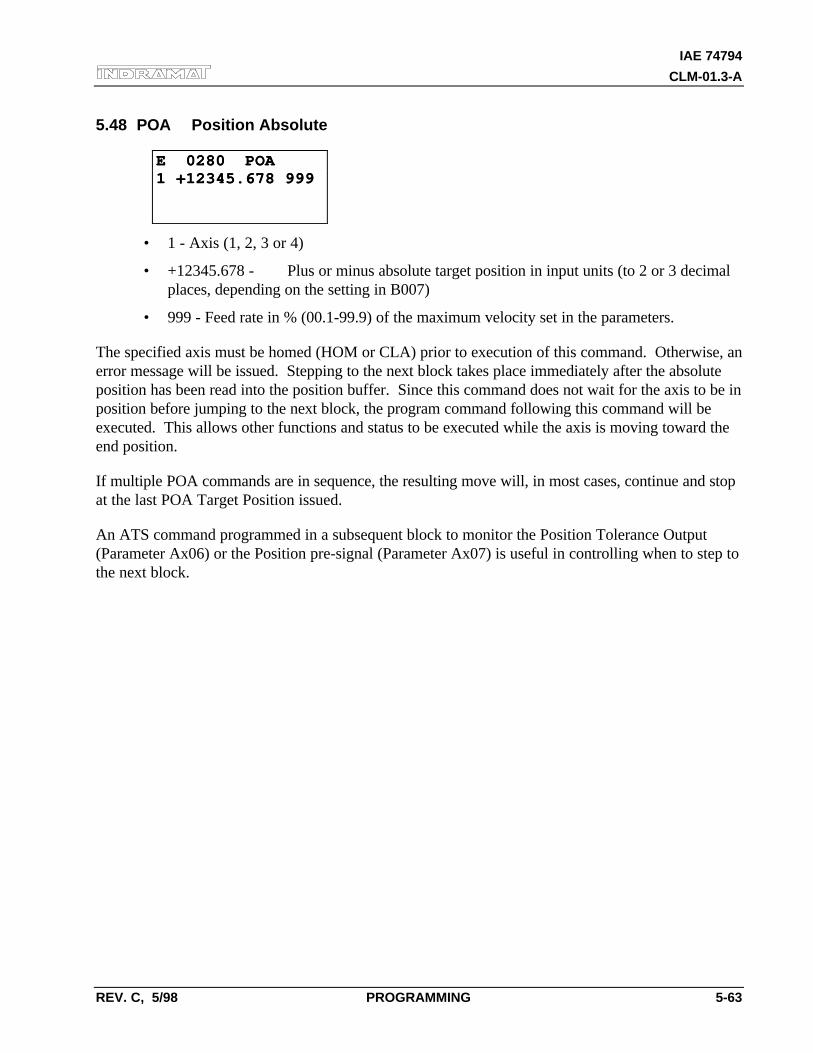
IAE 74794
CLM-01.3-A
REV. C, 5/98 PROGRAMMING 5-63
5.48 POA Position Absolute
E 0280 POAE 0280 POA1 +12345.678 9991 +12345.678 999
• 1 - Axis (1, 2, 3 or 4)
• +12345.678 - Plus or minus absolute target position in input units (to 2 or 3 decimalplaces, depending on the setting in B007)
• 999 - Feed rate in % (00.1-99.9) of the maximum velocity set in the parameters.
The specified axis must be homed (HOM or CLA) prior to execution of this command. Otherwise, anerror message will be issued. Stepping to the next block takes place immediately after the absoluteposition has been read into the position buffer. Since this command does not wait for the axis to be inposition before jumping to the next block, the program command following this command will beexecuted. This allows other functions and status to be executed while the axis is moving toward theend position.
If multiple POA commands are in sequence, the resulting move will, in most cases, continue and stopat the last POA Target Position issued.
An ATS command programmed in a subsequent block to monitor the Position Tolerance Output(Parameter Ax06) or the Position pre-signal (Parameter Ax07) is useful in controlling when to step tothe next block.
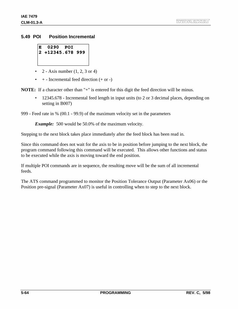
IAE 7479
CLM-01.3-A
5-64 PROGRAMMING REV. C, 5/98
5.49 POI Position Incremental
E 0290 POIE 0290 POI2 +12345.678 9992 +12345.678 999
• 2 - Axis number (1, 2, 3 or 4)
• + - Incremental feed direction (+ or -)
NOTE: If a character other than "+" is entered for this digit the feed direction will be minus.
• 12345.678 - Incremental feed length in input units (to 2 or 3 decimal places, depending onsetting in B007)
999 - Feed rate in % (00.1 - 99.9) of the maximum velocity set in the parameters
Example: 500 would be 50.0% of the maximum velocity.
Stepping to the next block takes place immediately after the feed block has been read in.
Since this command does not wait for the axis to be in position before jumping to the next block, theprogram command following this command will be executed. This allows other functions and statusto be executed while the axis is moving toward the end position.
If multiple POI commands are in sequence, the resulting move will be the sum of all incrementalfeeds.
The ATS command programmed to monitor the Position Tolerance Output (Parameter Ax06) or thePosition pre-signal (Parameter Ax07) is useful in controlling when to step to the next block.
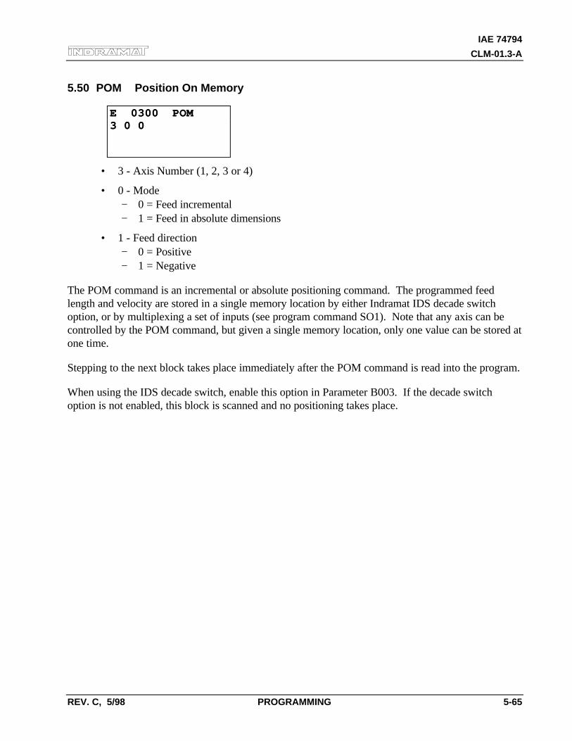
IAE 74794
CLM-01.3-A
REV. C, 5/98 PROGRAMMING 5-65
5.50 POM Position On Memory
E 0300 POME 0300 POM3 0 03 0 0
• 3 - Axis Number (1, 2, 3 or 4)
• 0 - Mode− 0 = Feed incremental− 1 = Feed in absolute dimensions
• 1 - Feed direction− 0 = Positive− 1 = Negative
The POM command is an incremental or absolute positioning command. The programmed feedlength and velocity are stored in a single memory location by either Indramat IDS decade switchoption, or by multiplexing a set of inputs (see program command SO1). Note that any axis can becontrolled by the POM command, but given a single memory location, only one value can be stored atone time.
Stepping to the next block takes place immediately after the POM command is read into the program.
When using the IDS decade switch, enable this option in Parameter B003. If the decade switchoption is not enabled, this block is scanned and no positioning takes place.
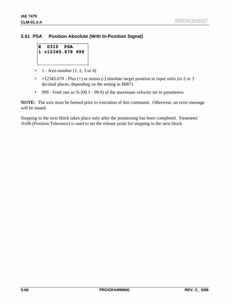
IAE 7479
CLM-01.3-A
5-66 PROGRAMMING REV. C, 5/98
5.51 PSA Position Absolute (With In-Position Signal)
E 0310 PSAE 0310 PSA1 +12345.678 9991 +12345.678 999
• 1 - Axis number (1, 2, 3 or 4)
• +12345.678 - Plus (+) or minus (-) absolute target position in input units (to 2 or 3decimal places, depending on the setting in B007)
• 999 - Feed rate as % (00.1 - 99.9) of the maximum velocity set in parameters
NOTE: The axis must be homed prior to execution of this command. Otherwise, an error messagewill be issued.
Stepping to the next block takes place only after the positioning has been completed. ParameterAx06 (Position Tolerance) is used to set the release point for stepping to the next block.
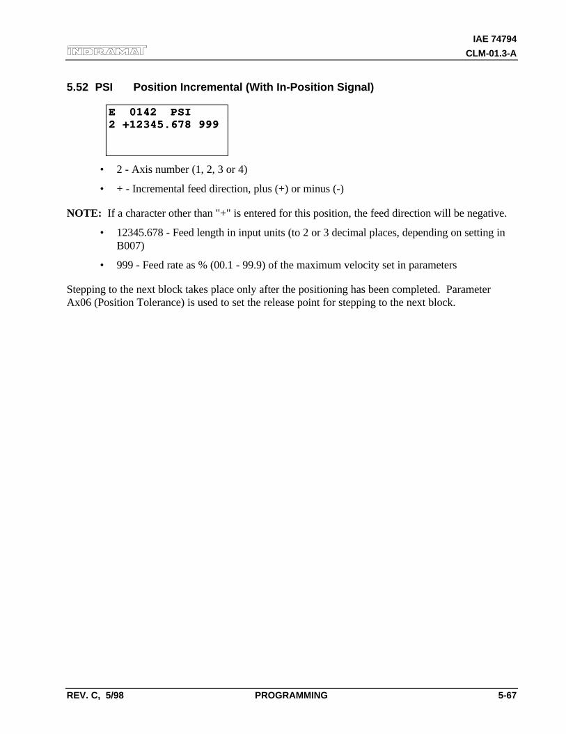
IAE 74794
CLM-01.3-A
REV. C, 5/98 PROGRAMMING 5-67
5.52 PSI Position Incremental (With In-Position Signal)
E 0142 PSIE 0142 PSI2 +12345.678 9992 +12345.678 999
• 2 - Axis number (1, 2, 3 or 4)
• + - Incremental feed direction, plus (+) or minus (-)
NOTE: If a character other than "+" is entered for this position, the feed direction will be negative.
• 12345.678 - Feed length in input units (to 2 or 3 decimal places, depending on setting inB007)
• 999 - Feed rate as % (00.1 - 99.9) of the maximum velocity set in parameters
Stepping to the next block takes place only after the positioning has been completed. ParameterAx06 (Position Tolerance) is used to set the release point for stepping to the next block.
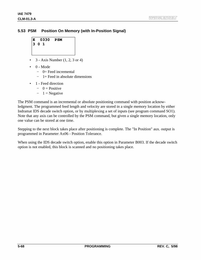
IAE 7479
CLM-01.3-A
5-68 PROGRAMMING REV. C, 5/98
5.53 PSM Position On Memory (with In-Position Signal)
E 0330 PSME 0330 PSM3 0 13 0 1
• 3 - Axis Number (1, 2, 3 or 4)
• 0 - Mode− 0= Feed incremental− 1= Feed in absolute dimensions
• 1 - Feed direction− 0 = Positive− 1 = Negative
The PSM command is an incremental or absolute positioning command with position acknow-ledgment. The programmed feed length and velocity are stored in a single memory location by eitherIndramat IDS decade switch option, or by multiplexing a set of inputs (see program command SO1).Note that any axis can be controlled by the PSM command, but given a single memory location, onlyone value can be stored at one time.
Stepping to the next block takes place after positioning is complete. The "In Position" aux. output isprogrammed in Parameter Ax06 - Position Tolerance.
When using the IDS decade switch option, enable this option in Parameter B003. If the decade switchoption is not enabled, this block is scanned and no positioning takes place.
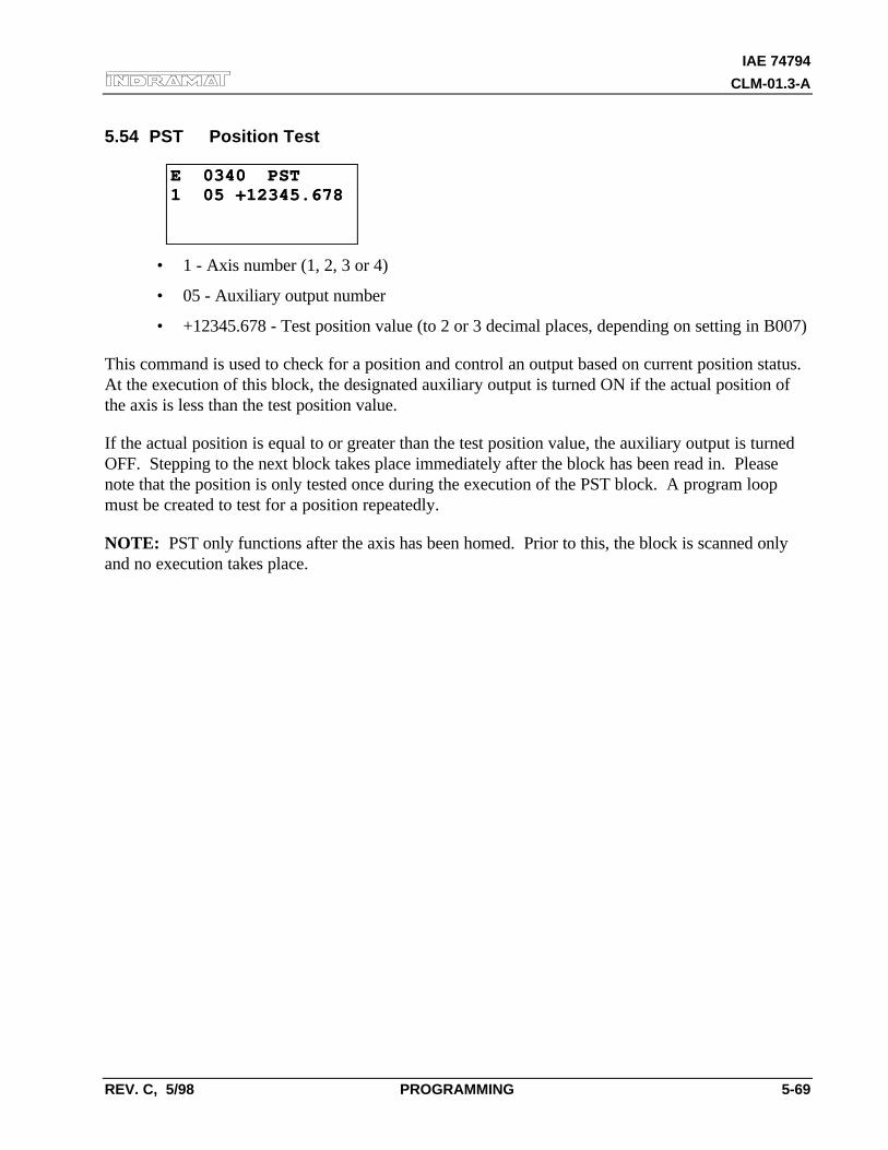
IAE 74794
CLM-01.3-A
REV. C, 5/98 PROGRAMMING 5-69
5.54 PST Position Test
E 0340 PSTE 0340 PST1 05 +12345.6781 05 +12345.678
• 1 - Axis number (1, 2, 3 or 4)
• 05 - Auxiliary output number
• +12345.678 - Test position value (to 2 or 3 decimal places, depending on setting in B007)
This command is used to check for a position and control an output based on current position status.At the execution of this block, the designated auxiliary output is turned ON if the actual position ofthe axis is less than the test position value.
If the actual position is equal to or greater than the test position value, the auxiliary output is turnedOFF. Stepping to the next block takes place immediately after the block has been read in. Pleasenote that the position is only tested once during the execution of the PST block. A program loopmust be created to test for a position repeatedly.
NOTE: PST only functions after the axis has been homed. Prior to this, the block is scanned onlyand no execution takes place.
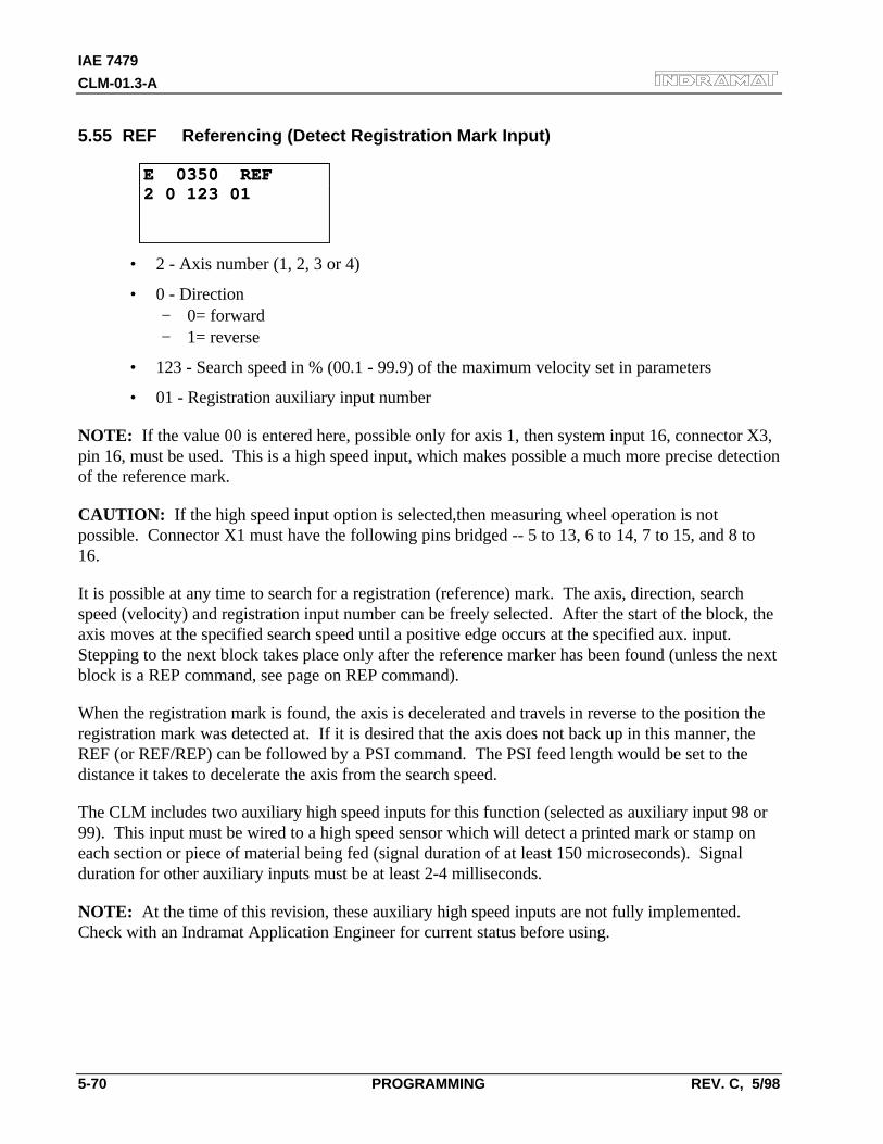
IAE 7479
CLM-01.3-A
5-70 PROGRAMMING REV. C, 5/98
5.55 REF Referencing (Detect Registration Mark Input)
E 0350 REFE 0350 REF2 0 123 012 0 123 01
• 2 - Axis number (1, 2, 3 or 4)
• 0 - Direction− 0= forward− 1= reverse
• 123 - Search speed in % (00.1 - 99.9) of the maximum velocity set in parameters
• 01 - Registration auxiliary input number
NOTE: If the value 00 is entered here, possible only for axis 1, then system input 16, connector X3,pin 16, must be used. This is a high speed input, which makes possible a much more precise detectionof the reference mark.
CAUTION: If the high speed input option is selected,then measuring wheel operation is notpossible. Connector X1 must have the following pins bridged -- 5 to 13, 6 to 14, 7 to 15, and 8 to16.
It is possible at any time to search for a registration (reference) mark. The axis, direction, searchspeed (velocity) and registration input number can be freely selected. After the start of the block, theaxis moves at the specified search speed until a positive edge occurs at the specified aux. input.Stepping to the next block takes place only after the reference marker has been found (unless the nextblock is a REP command, see page on REP command).
When the registration mark is found, the axis is decelerated and travels in reverse to the position theregistration mark was detected at. If it is desired that the axis does not back up in this manner, theREF (or REF/REP) can be followed by a PSI command. The PSI feed length would be set to thedistance it takes to decelerate the axis from the search speed.
The CLM includes two auxiliary high speed inputs for this function (selected as auxiliary input 98 or99). This input must be wired to a high speed sensor which will detect a printed mark or stamp oneach section or piece of material being fed (signal duration of at least 150 microseconds). Signalduration for other auxiliary inputs must be at least 2-4 milliseconds.
NOTE: At the time of this revision, these auxiliary high speed inputs are not fully implemented.Check with an Indramat Application Engineer for current status before using.
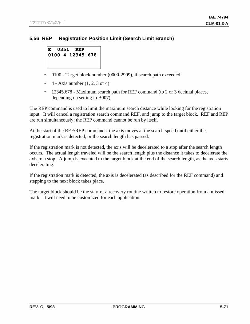
IAE 74794
CLM-01.3-A
REV. C, 5/98 PROGRAMMING 5-71
5.56 REP Registration Position Limit (Search Limit Branch)
E 0351 REPE 0351 REP0100 4 12345.6780100 4 12345.678
• 0100 - Target block number (0000-2999), if search path exceeded
• 4 - Axis number (1, 2, 3 or 4)
• 12345.678 - Maximum search path for REF command (to 2 or 3 decimal places,depending on setting in B007)
The REP command is used to limit the maximum search distance while looking for the registrationinput. It will cancel a registration search command REF, and jump to the target block. REF and REPare run simultaneously; the REP command cannot be run by itself.
At the start of the REF/REP commands, the axis moves at the search speed until either theregistration mark is detected, or the search length has passed.
If the registration mark is not detected, the axis will be decelerated to a stop after the search lengthoccurs. The actual length traveled will be the search length plus the distance it takes to decelerate theaxis to a stop. A jump is executed to the target block at the end of the search length, as the axis startsdecelerating.
If the registration mark is detected, the axis is decelerated (as described for the REF command) andstepping to the next block takes place.
The target block should be the start of a recovery routine written to restore operation from a missedmark. It will need to be customized for each application.
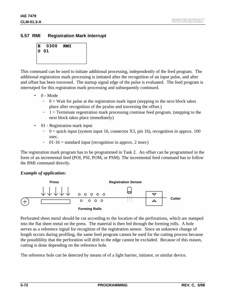
IAE 7479
CLM-01.3-A
5-72 PROGRAMMING REV. C, 5/98
5.57 RMI Registration Mark Interrupt
E 0300 RMIE 0300 RMI0 010 01
This command can be used to initiate additional processing, independently of the feed program. Theadditional registration mark processing is intitated after the recognition of an input pulse, and afterand offset has been traversed. The startup signal edge of the pulse is evaluated. The feed program isinterrutped for this registration mark processing and subsequently continued.
• 0 - Mode− 0 = Wait for pulse at the registration mark input (stepping to the next block takes
place after recognition of the pyulse and traversing the offset.)− 1 = Terminate regestration mark processing continue feed program. (stepping to the
next block takes place immediately)
• 01 - Registration mark input− 0 = quick input (system input 16, connector X3, pin 16), recognition in approx. 100
usec.− 01-16 = standard input (recognition in approx. 2 msec)
The registration mark program has to be programmed in Task 2. An offset can be programmed in theform of an incremental feed (POI, PSI, POM, or PSM). The incremental feed command has to followthe RMI command directly.
Example of application:
Press Registration Sensor
Forming Rolls
Cutter
Perforated sheet metal should be cut according to the location of the perforations, which are stampedinto the flat sheet metal on the press. The material is then fed through the forming rolls. A holeserves as a reference signal for recogition of the registration sensor. Since an unknown change oflength occurs during profiling, the same feed program cannot be used for the cutting process becausethe possiblility that the perforation will drift to the edge cannot be excluded. Because of this reason,cutting is done depending on the reference hole.
The reference hole can be detected by means of of a light barrier, initiator, or similar device.
IAE 74794
CLM-01.3-A
REV. C, 5/98 PROGRAMMING 5-73
NOTES:
• Possible only with Axis 1; not usable with an adjusting axis or a motor with reversiblepoles.
• Not usable with synchronous axis, in accordance with paramter 46 = 03XXXXXX
• Cannot be used simultaneously with a REF command for Axis 1
• Will be ignored in the case of re-start
• The RMI works correctly only with feeds and offset feeds in positive direction (e.g., PSI 1+....)
• In Task 2, (RMI program) there should be not other feed except for the offset
• After the RMI command (RMI 0 XX) has been called up, masking a hole is no longerpossible
• Recognition of an additional registration mark prior to the comand 'RMI 1 XX' is notpossible
The velocity that can be changed by means of the offset feed is returned to its old value when the feedprogram resumes. The interruption, feed monitoring and override functions may be used.
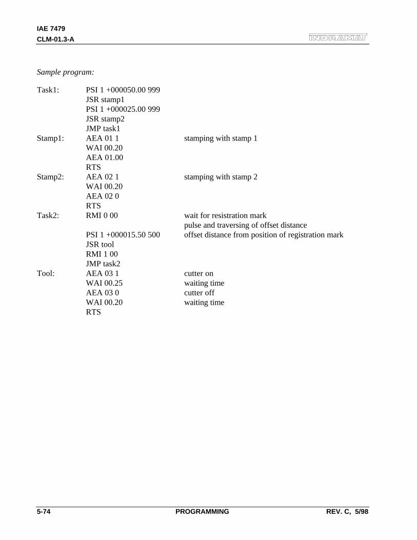
IAE 7479
CLM-01.3-A
5-74 PROGRAMMING REV. C, 5/98
Sample program:
Task1: PSI 1 +000050.00 999JSR stamp1PSI 1 +000025.00 999JSR stamp2JMP task1
Stamp1: AEA 01 1 stamping with stamp 1WAI 00.20AEA 01.00RTS
Stamp2: AEA 02 1 stamping with stamp 2WAI 00.20AEA 02 0RTS
Task2: RMI 0 00 wait for resistration markpulse and traversing of offset distance
PSI 1 +000015.50 500 offset distance from position of registration markJSR toolRMI 1 00JMP task2
Tool: AEA 03 1 cutter onWAI 00.25 waiting timeAEA 03 0 cutter offWAI 00.20 waiting timeRTS
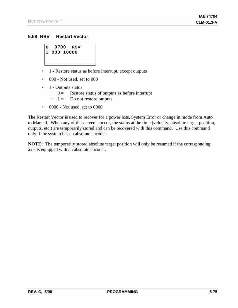
IAE 74794
CLM-01.3-A
REV. C, 5/98 PROGRAMMING 5-75
5.58 RSV Restart Vector
E 0700 RSVE 0700 RSV1 000 100001 000 10000
• 1 - Restore status as before interrupt, except outputs
• 000 - Not used, set to 000
• 1 - Outputs status− 0 = Restore status of outputs as before interrupt− 1 = Do not restore outputs
• 0000 - Not used, set to 0000
The Restart Vector is used to recover for a power loss, System Error or change in mode from Autoto Manual. When any of these events occur, the status at the time (velocity, absolute target position,outputs, etc.) are temporarily stored and can be recovered with this command. Use this commandonly if the system has an absolute encoder.
NOTE: The temporarily stored absolute target position will only be resumed if the correspondingaxis is equipped with an absolute encoder.
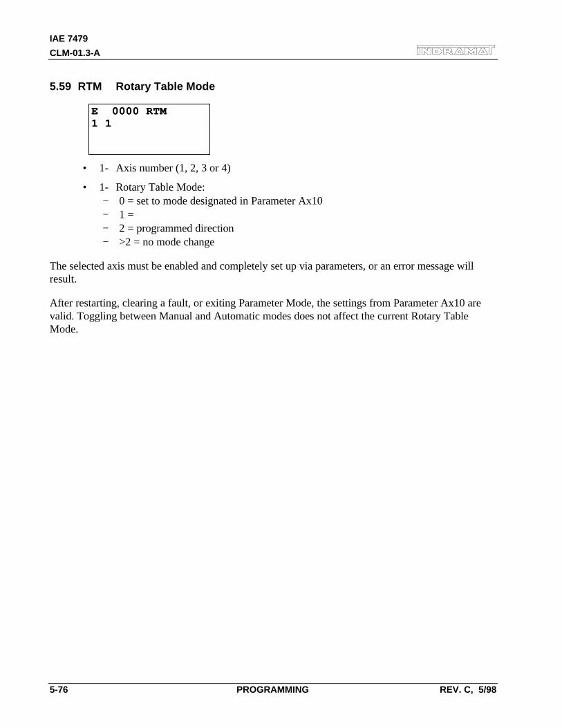
IAE 7479
CLM-01.3-A
5-76 PROGRAMMING REV. C, 5/98
5.59 RTM Rotary Table Mode
E 0000 RTME 0000 RTM1 11 1
• 1- Axis number (1, 2, 3 or 4)
• 1- Rotary Table Mode:− 0 = set to mode designated in Parameter Ax10− 1 =− 2 = programmed direction− >2 = no mode change
The selected axis must be enabled and completely set up via parameters, or an error message willresult.
After restarting, clearing a fault, or exiting Parameter Mode, the settings from Parameter Ax10 arevalid. Toggling between Manual and Automatic modes does not affect the current Rotary TableMode.
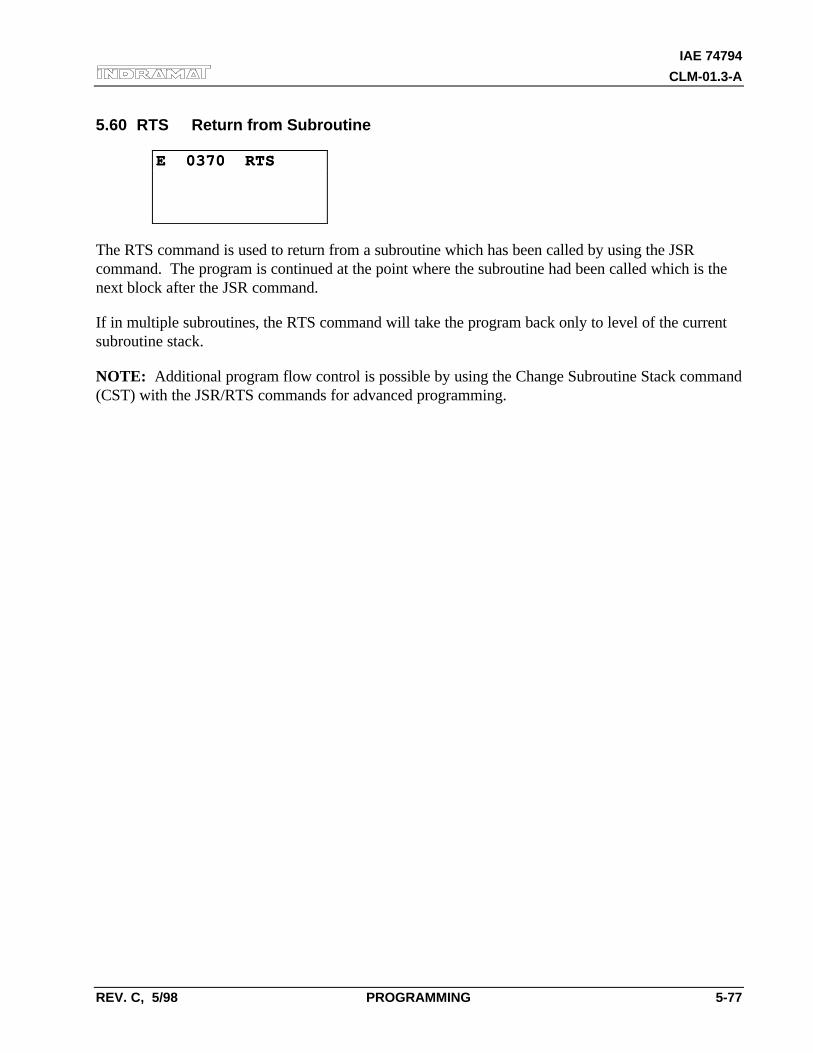
IAE 74794
CLM-01.3-A
REV. C, 5/98 PROGRAMMING 5-77
5.60 RTS Return from Subroutine
E 0370 RTSE 0370 RTS
The RTS command is used to return from a subroutine which has been called by using the JSRcommand. The program is continued at the point where the subroutine had been called which is thenext block after the JSR command.
If in multiple subroutines, the RTS command will take the program back only to level of the currentsubroutine stack.
NOTE: Additional program flow control is possible by using the Change Subroutine Stack command(CST) with the JSR/RTS commands for advanced programming.
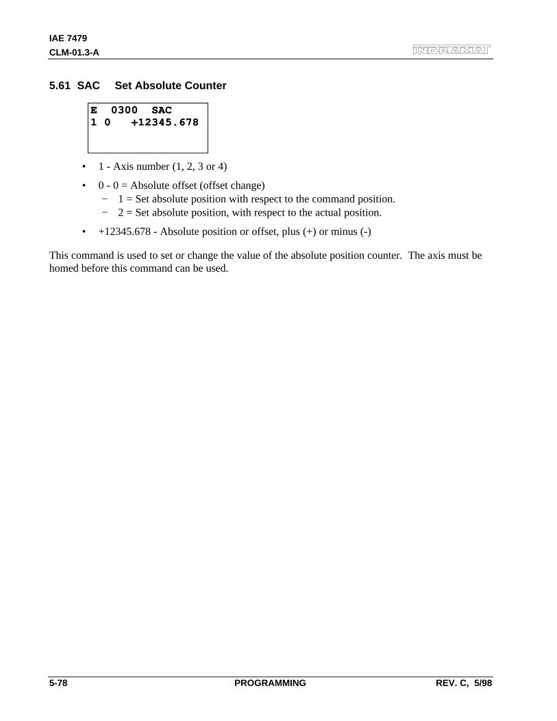
IAE 7479
CLM-01.3-A
5-78 PROGRAMMING REV. C, 5/98
5.61 SAC Set Absolute Counter
E 0300 SACE 0300 SAC1 0 +12345.6781 0 +12345.678
• 1 - Axis number (1, 2, 3 or 4)
• 0 - 0 = Absolute offset (offset change)− 1 = Set absolute position with respect to the command position.− 2 = Set absolute position, with respect to the actual position.
• +12345.678 - Absolute position or offset, plus (+) or minus (-)
This command is used to set or change the value of the absolute position counter. The axis must behomed before this command can be used.
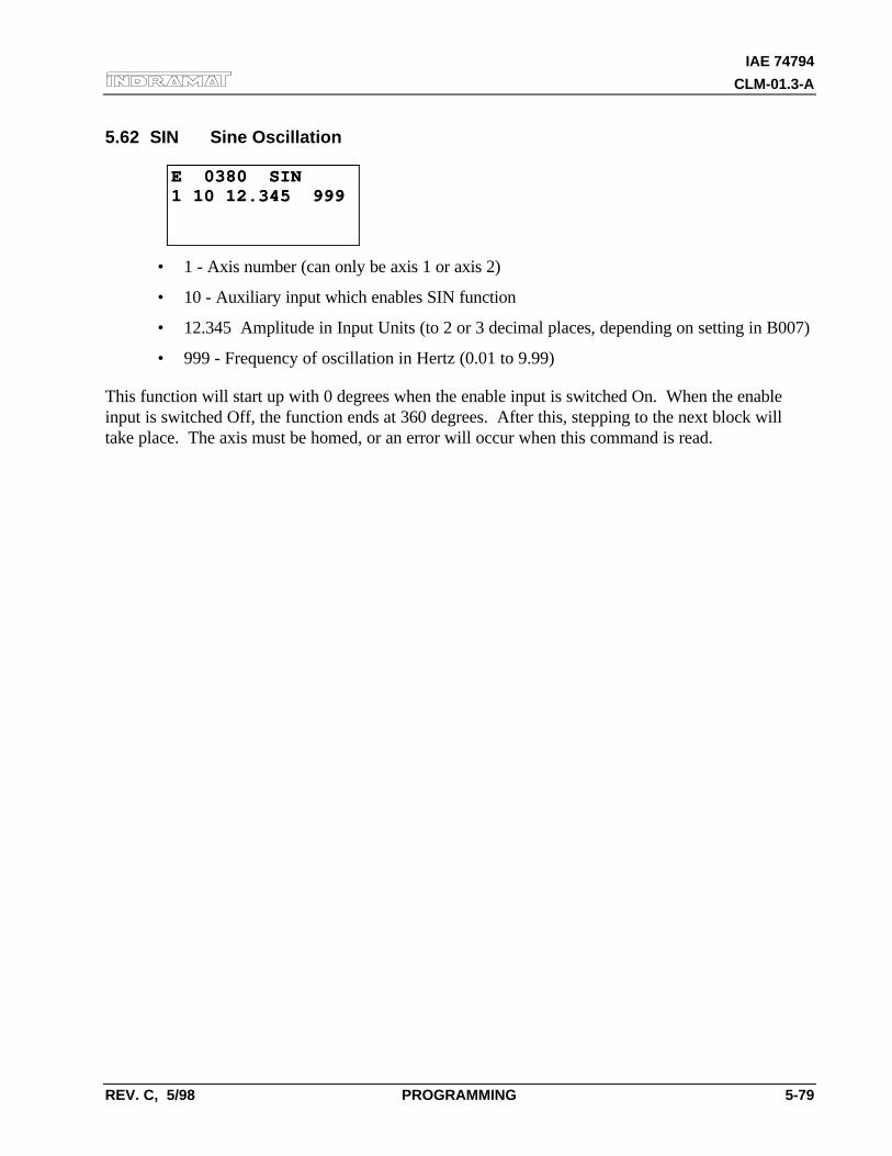
IAE 74794
CLM-01.3-A
REV. C, 5/98 PROGRAMMING 5-79
5.62 SIN Sine Oscillation
E 0380 SINE 0380 SIN1 10 12.345 9991 10 12.345 999
• 1 - Axis number (can only be axis 1 or axis 2)
• 10 - Auxiliary input which enables SIN function
• 12.345 Amplitude in Input Units (to 2 or 3 decimal places, depending on setting in B007)
• 999 - Frequency of oscillation in Hertz (0.01 to 9.99)
This function will start up with 0 degrees when the enable input is switched On. When the enableinput is switched Off, the function ends at 360 degrees. After this, stepping to the next block willtake place. The axis must be homed, or an error will occur when this command is read.
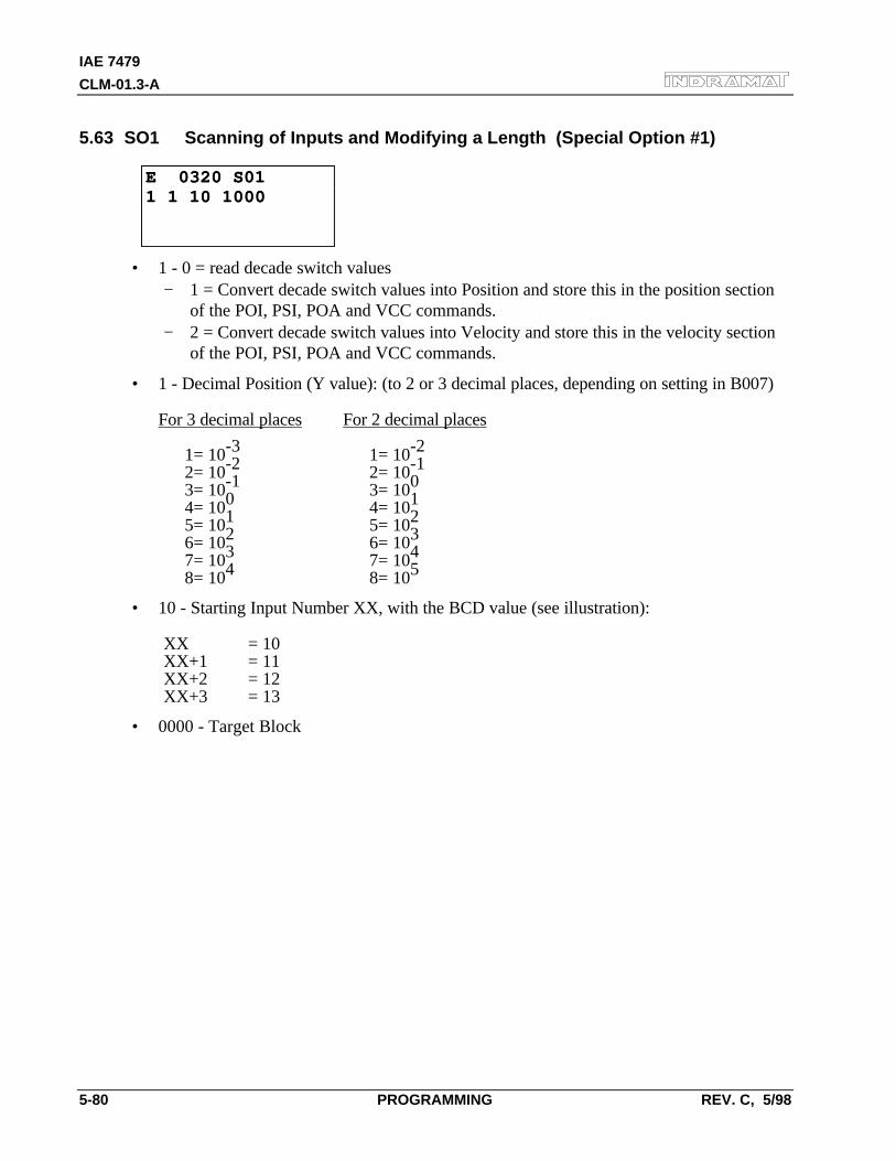
IAE 7479
CLM-01.3-A
5-80 PROGRAMMING REV. C, 5/98
5.63 SO1 Scanning of Inputs and Modifying a Length (Special Option #1)
E 0320 S01E 0320 S011 1 10 10001 1 10 1000
• 1 - 0 = read decade switch values− 1 = Convert decade switch values into Position and store this in the position section
of the POI, PSI, POA and VCC commands.− 2 = Convert decade switch values into Velocity and store this in the velocity section
of the POI, PSI, POA and VCC commands.
• 1 - Decimal Position (Y value): (to 2 or 3 decimal places, depending on setting in B007)
For 3 decimal places For 2 decimal places
1= 10-3 1= 10-2
2= 10-2 2= 10-1
3= 10-1 3= 100
4= 100 4= 101
5= 101 5= 102
6= 102 6= 103
7= 103 7= 104
8= 104 8= 105
• 10 - Starting Input Number XX, with the BCD value (see illustration):
XX = 10XX+1 = 11XX+2 = 12XX+3 = 13
• 0000 - Target Block
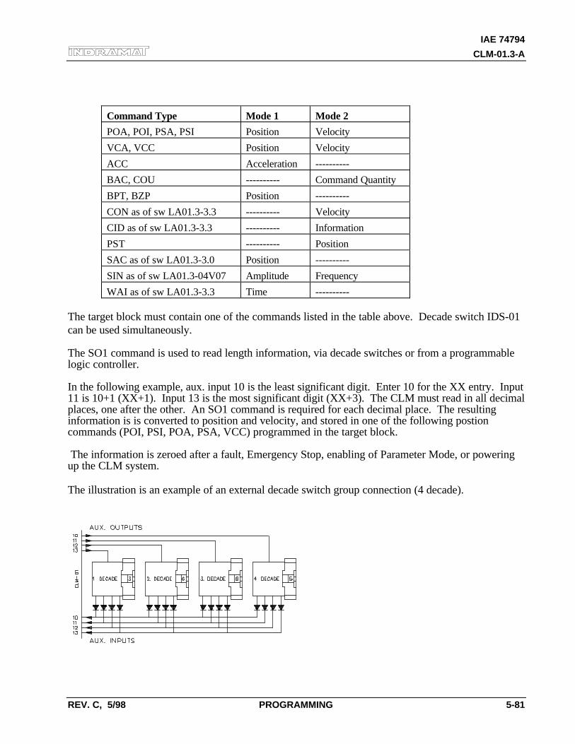
IAE 74794
CLM-01.3-A
REV. C, 5/98 PROGRAMMING 5-81
Command Type Mode 1 Mode 2
POA, POI, PSA, PSI Position Velocity
VCA, VCC Position Velocity
ACC Acceleration ----------
BAC, COU ---------- Command Quantity
BPT, BZP Position ----------
CON as of sw LA01.3-3.3 ---------- Velocity
CID as of sw LA01.3-3.3 ---------- Information
PST ---------- Position
SAC as of sw LA01.3-3.0 Position ----------
SIN as of sw LA01.3-04V07 Amplitude Frequency
WAI as of sw LA01.3-3.3 Time ----------
The target block must contain one of the commands listed in the table above. Decade switch IDS-01can be used simultaneously.
The SO1 command is used to read length information, via decade switches or from a programmablelogic controller.
In the following example, aux. input 10 is the least significant digit. Enter 10 for the XX entry. Input11 is 10+1 (XX+1). Input 13 is the most significant digit (XX+3). The CLM must read in all decimalplaces, one after the other. An SO1 command is required for each decimal place. The resultinginformation is is converted to position and velocity, and stored in one of the following postioncommands (POI, PSI, POA, PSA, VCC) programmed in the target block.
The information is zeroed after a fault, Emergency Stop, enabling of Parameter Mode, or poweringup the CLM system.
The illustration is an example of an external decade switch group connection (4 decade).
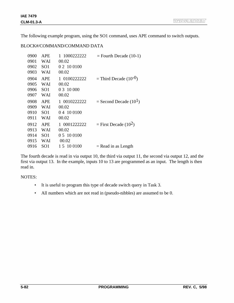
IAE 7479
CLM-01.3-A
5-82 PROGRAMMING REV. C, 5/98
The following example program, using the SO1 command, uses APE command to switch outputs.
BLOCK#/COMMAND/COMMAND DATA
0900 APE 1 1000222222 = Fourth Decade (10-1)0901 WAI 00.020902 SO1 0 2 10 01000903 WAI 00.02
0904 APE 1 0100222222 = Third Decade (10-0)0905 WAI 00.020906 SO1 0 3 10 0000907 WAI 00.02
0908 APE 1 0010222222 = Second Decade (101)0909 WAI 00.020910 SO1 0 4 10 01000911 WAI 00.02
0912 APE 1 0001222222 = First Decade (102)0913 WAI 00.020914 SO1 0 5 10 01000915 WAI 00.020916 SO1 1 5 10 0100 = Read in as Length
The fourth decade is read in via output 10, the third via output 11, the second via output 12, and thefirst via output 13. In the example, inputs 10 to 13 are programmed as an input. The length is thenread in.
NOTES:
• It is useful to program this type of decade switch query in Task 3.
• All numbers which are not read in (pseudo-nibbles) are assumed to be 0.
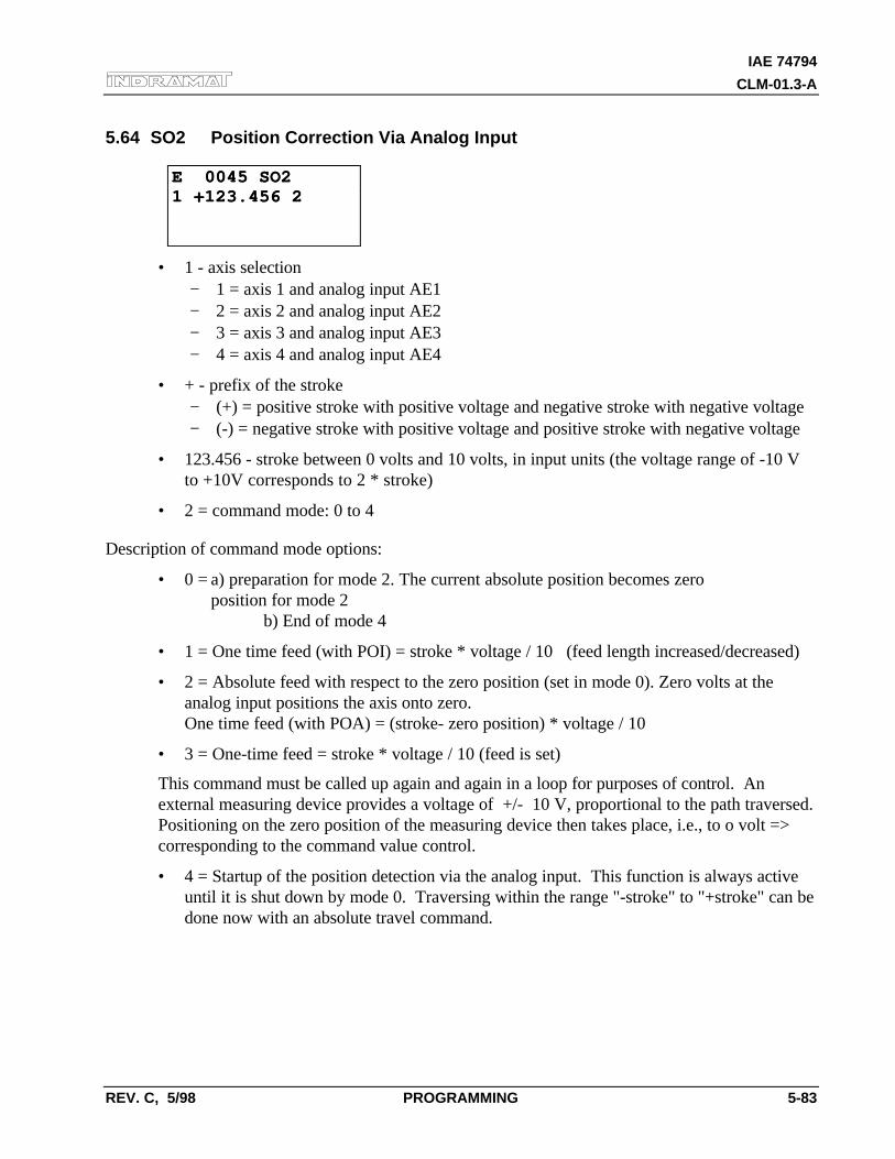
IAE 74794
CLM-01.3-A
REV. C, 5/98 PROGRAMMING 5-83
5.64 SO2 Position Correction Via Analog Input
E 0045 SO2E 0045 SO21 +123.456 21 +123.456 2
• 1 - axis selection− 1 = axis 1 and analog input AE1− 2 = axis 2 and analog input AE2− 3 = axis 3 and analog input AE3− 4 = axis 4 and analog input AE4
• + - prefix of the stroke− (+) = positive stroke with positive voltage and negative stroke with negative voltage− (-) = negative stroke with positive voltage and positive stroke with negative voltage
• 123.456 - stroke between 0 volts and 10 volts, in input units (the voltage range of -10 Vto +10V corresponds to 2 * stroke)
• 2 = command mode: 0 to 4
Description of command mode options:
• 0 = a) preparation for mode 2. The current absolute position becomes zero position for mode 2
b) End of mode 4
• 1 = One time feed (with POI) = stroke * voltage / 10 (feed length increased/decreased)
• 2 = Absolute feed with respect to the zero position (set in mode 0). Zero volts at theanalog input positions the axis onto zero.One time feed (with POA) = (stroke- zero position) * voltage / 10
• 3 = One-time feed = stroke * voltage / 10 (feed is set)
This command must be called up again and again in a loop for purposes of control. Anexternal measuring device provides a voltage of +/- 10 V, proportional to the path traversed.Positioning on the zero position of the measuring device then takes place, i.e., to o volt =>corresponding to the command value control.
• 4 = Startup of the position detection via the analog input. This function is always activeuntil it is shut down by mode 0. Traversing within the range "-stroke" to "+stroke" can bedone now with an absolute travel command.
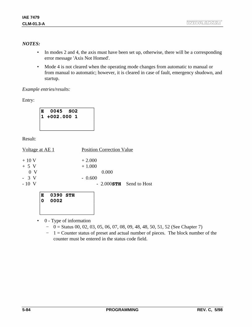
IAE 7479
CLM-01.3-A
5-84 PROGRAMMING REV. C, 5/98
NOTES:
• In modes 2 and 4, the axis must have been set up, otherwise, there will be a correspondingerror message 'Axis Not Homed'.
• Mode 4 is not cleared when the operating mode changes from automatic to manual orfrom manual to automatic; however, it is cleared in case of fault, emergency shudown, andstartup.
Example entries/results:
Entry:
E 0045 SO2E 0045 SO21 +002.000 11 +002.000 1
Result:
Voltage at AE 1 Position Correction Value
+ 10 V + 2.000+ 5 V + 1.000 0 V 0.000- 3 V - 0.600- 10 V - 2.000STHSTH Send to Host
E 0390 STHE 0390 STH0 00020 0002
• 0 - Type of information− 0 = Status 00, 02, 03, 05, 06, 07, 08, 09, 48, 48, 50, 51, 52 (See Chapter 7)− 1 = Counter status of preset and actual number of pieces. The block number of the
counter must be entered in the status code field.
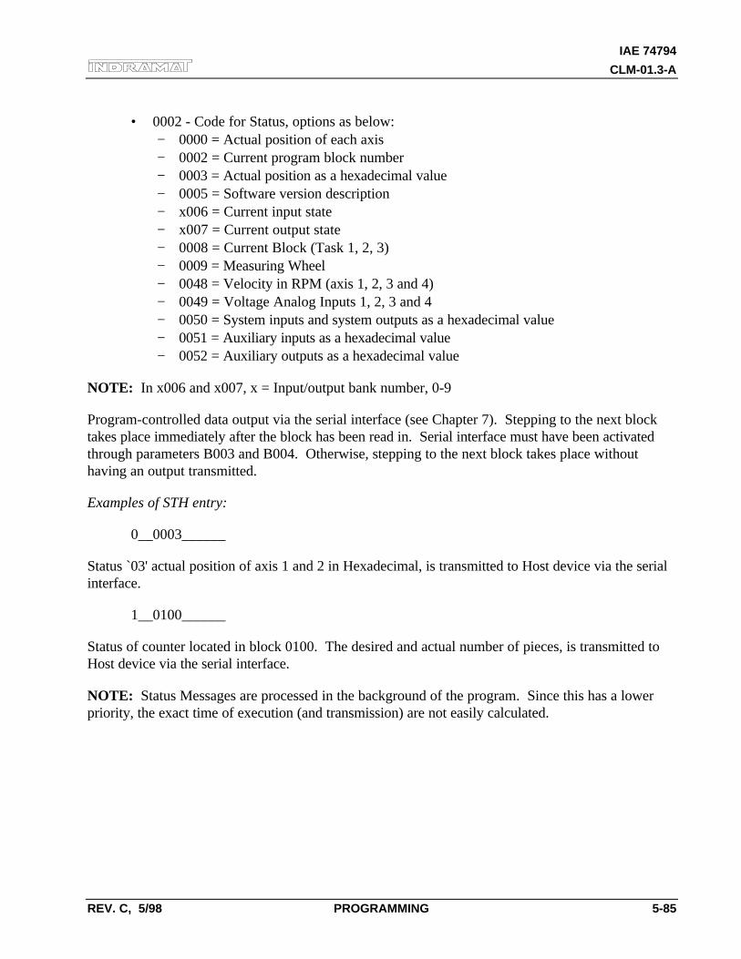
IAE 74794
CLM-01.3-A
REV. C, 5/98 PROGRAMMING 5-85
• 0002 - Code for Status, options as below:− 0000 = Actual position of each axis− 0002 = Current program block number− 0003 = Actual position as a hexadecimal value− 0005 = Software version description− x006 = Current input state− x007 = Current output state− 0008 = Current Block (Task 1, 2, 3)− 0009 = Measuring Wheel− 0048 = Velocity in RPM (axis 1, 2, 3 and 4)− 0049 = Voltage Analog Inputs 1, 2, 3 and 4− 0050 = System inputs and system outputs as a hexadecimal value− 0051 = Auxiliary inputs as a hexadecimal value− 0052 = Auxiliary outputs as a hexadecimal value
NOTE: In x006 and x007, x = Input/output bank number, 0-9
Program-controlled data output via the serial interface (see Chapter 7). Stepping to the next blocktakes place immediately after the block has been read in. Serial interface must have been activatedthrough parameters B003 and B004. Otherwise, stepping to the next block takes place withouthaving an output transmitted.
Examples of STH entry:
0__0003______
Status `03' actual position of axis 1 and 2 in Hexadecimal, is transmitted to Host device via the serialinterface.
1__0100______
Status of counter located in block 0100. The desired and actual number of pieces, is transmitted toHost device via the serial interface.
NOTE: Status Messages are processed in the background of the program. Since this has a lowerpriority, the exact time of execution (and transmission) are not easily calculated.
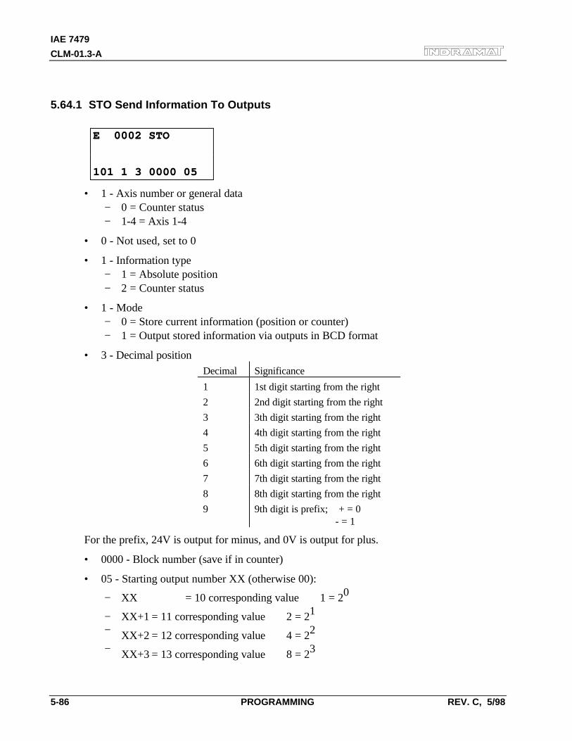
IAE 7479
CLM-01.3-A
5-86 PROGRAMMING REV. C, 5/98
5.64.1 STO Send Information To Outputs
E 0002 STOE 0002 STO
101 1 3 0000 05101 1 3 0000 05
• 1 - Axis number or general data− 0 = Counter status− 1-4 = Axis 1-4
• 0 - Not used, set to 0
• 1 - Information type− 1 = Absolute position− 2 = Counter status
• 1 - Mode− 0 = Store current information (position or counter)− 1 = Output stored information via outputs in BCD format
• 3 - Decimal positionDecimal Significance
1 1st digit starting from the right
2 2nd digit starting from the right
3 3th digit starting from the right
4 4th digit starting from the right
5 5th digit starting from the right
6 6th digit starting from the right
7 7th digit starting from the right
8 8th digit starting from the right
9 9th digit is prefix; + = 0 - = 1
For the prefix, 24V is output for minus, and 0V is output for plus.
• 0000 - Block number (save if in counter)
• 05 - Starting output number XX (otherwise 00):
− XX = 10 corresponding value 1 = 20
− XX+1 = 11 corresponding value 2 = 21
− XX+2 = 12 corresponding value 4 = 22
− XX+3 = 13 corresponding value 8 = 23
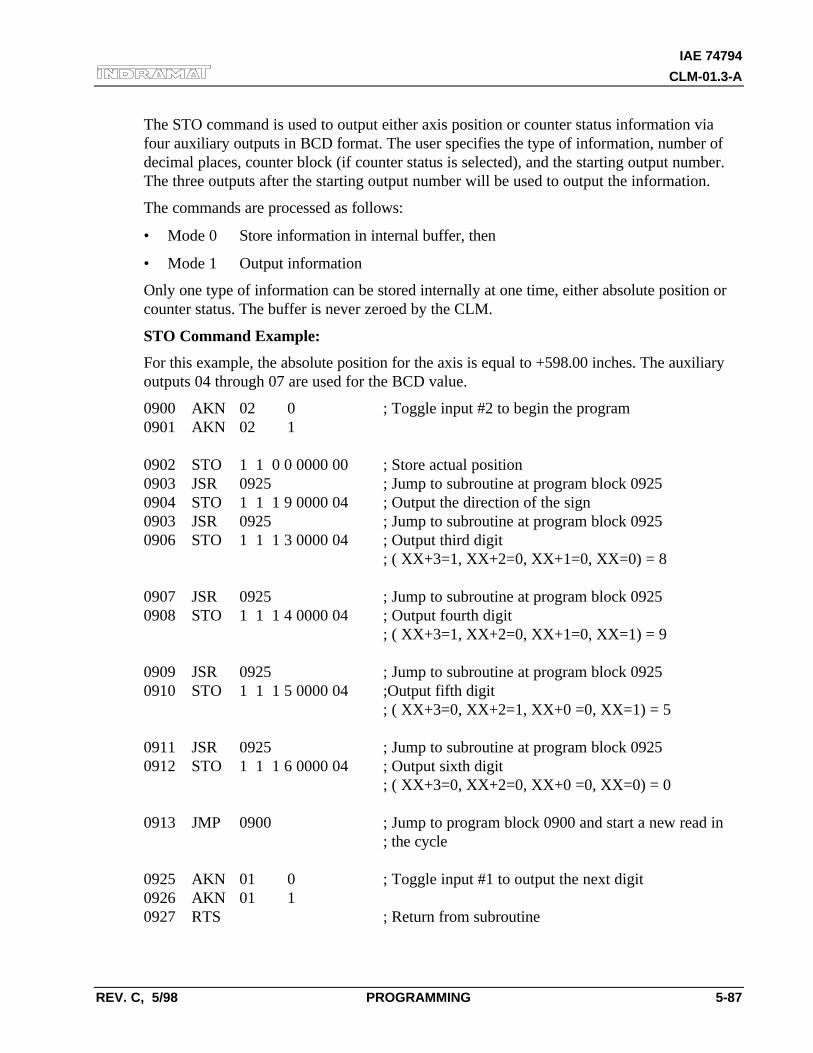
IAE 74794
CLM-01.3-A
REV. C, 5/98 PROGRAMMING 5-87
The STO command is used to output either axis position or counter status information viafour auxiliary outputs in BCD format. The user specifies the type of information, number ofdecimal places, counter block (if counter status is selected), and the starting output number.The three outputs after the starting output number will be used to output the information.
The commands are processed as follows:
• Mode 0 Store information in internal buffer, then
• Mode 1 Output information
Only one type of information can be stored internally at one time, either absolute position orcounter status. The buffer is never zeroed by the CLM.
STO Command Example:
For this example, the absolute position for the axis is equal to +598.00 inches. The auxiliaryoutputs 04 through 07 are used for the BCD value.
0900 AKN 02 0 ; Toggle input #2 to begin the program0901 AKN 02 1
0902 STO 1 1 0 0 0000 00 ; Store actual position0903 JSR 0925 ; Jump to subroutine at program block 09250904 STO 1 1 1 9 0000 04 ; Output the direction of the sign0903 JSR 0925 ; Jump to subroutine at program block 09250906 STO 1 1 1 3 0000 04 ; Output third digit
; ( XX+3=1, XX+2=0, XX+1=0, XX=0) = 8
0907 JSR 0925 ; Jump to subroutine at program block 09250908 STO 1 1 1 4 0000 04 ; Output fourth digit
; ( XX+3=1, XX+2=0, XX+1=0, XX=1) = 9
0909 JSR 0925 ; Jump to subroutine at program block 09250910 STO 1 1 1 5 0000 04 ;Output fifth digit
; ( XX+3=0, XX+2=1, XX+0 =0, XX=1) = 5
0911 JSR 0925 ; Jump to subroutine at program block 09250912 STO 1 1 1 6 0000 04 ; Output sixth digit
; ( XX+3=0, XX+2=0, XX+0 =0, XX=0) = 0
0913 JMP 0900 ; Jump to program block 0900 and start a new read in; the cycle
0925 AKN 01 0 ; Toggle input #1 to output the next digit0926 AKN 01 10927 RTS ; Return from subroutine
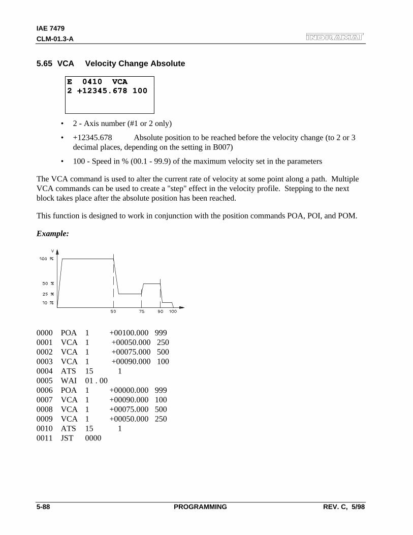
IAE 7479
CLM-01.3-A
5-88 PROGRAMMING REV. C, 5/98
5.65 VCA Velocity Change Absolute
E 0410 VCAE 0410 VCA2 +12345.678 1002 +12345.678 100
• 2 - Axis number (#1 or 2 only)
• +12345.678 Absolute position to be reached before the velocity change (to 2 or 3decimal places, depending on the setting in B007)
• 100 - Speed in % (00.1 - 99.9) of the maximum velocity set in the parameters
The VCA command is used to alter the current rate of velocity at some point along a path. MultipleVCA commands can be used to create a "step" effect in the velocity profile. Stepping to the nextblock takes place after the absolute position has been reached.
This function is designed to work in conjunction with the position commands POA, POI, and POM.
Example:
0000 POA 1 +00100.000 9990001 VCA 1 +00050.000 2500002 VCA 1 +00075.000 5000003 VCA 1 +00090.000 1000004 ATS 15 10005 WAI 01 . 000006 POA 1 +00000.000 9990007 VCA 1 +00090.000 1000008 VCA 1 +00075.000 5000009 VCA 1 +00050.000 2500010 ATS 15 10011 JST 0000
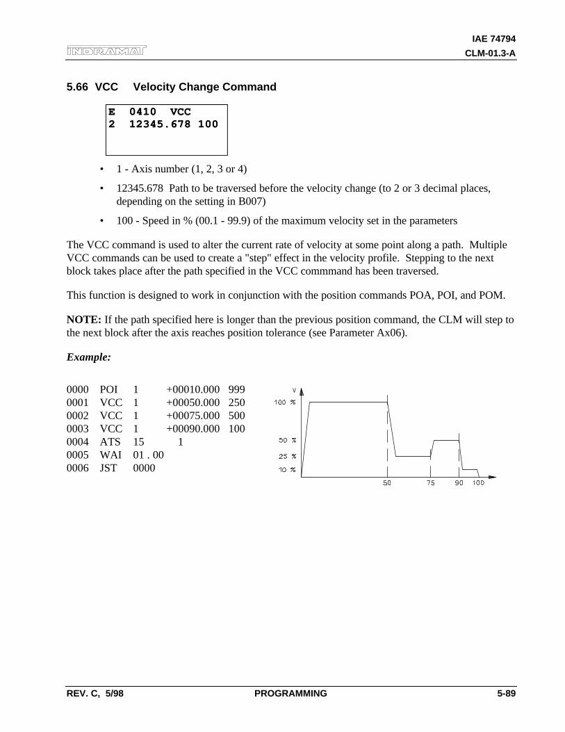
IAE 74794
CLM-01.3-A
REV. C, 5/98 PROGRAMMING 5-89
5.66 VCC Velocity Change Command
E 0410 VCCE 0410 VCC2 12345.678 1002 12345.678 100
• 1 - Axis number (1, 2, 3 or 4)
• 12345.678 Path to be traversed before the velocity change (to 2 or 3 decimal places,depending on the setting in B007)
• 100 - Speed in % (00.1 - 99.9) of the maximum velocity set in the parameters
The VCC command is used to alter the current rate of velocity at some point along a path. MultipleVCC commands can be used to create a "step" effect in the velocity profile. Stepping to the nextblock takes place after the path specified in the VCC commmand has been traversed.
This function is designed to work in conjunction with the position commands POA, POI, and POM.
NOTE: If the path specified here is longer than the previous position command, the CLM will step tothe next block after the axis reaches position tolerance (see Parameter Ax06).
Example:
0000 POI 1 +00010.000 9990001 VCC 1 +00050.000 2500002 VCC 1 +00075.000 5000003 VCC 1 +00090.000 1000004 ATS 15 10005 WAI 01 . 000006 JST 0000
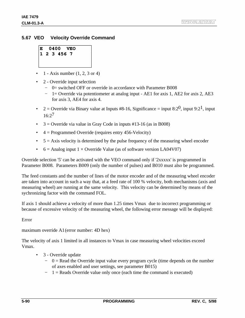
IAE 7479
CLM-01.3-A
5-90 PROGRAMMING REV. C, 5/98
5.67 VEO Velocity Override Command
E 0400 VEOE 0400 VEO1 2 3 456 71 2 3 456 7
• 1 - Axis number (1, 2, 3 or 4)
• 2 - Override input selection− 0= switched OFF or override in accordance with Parameter B008− 1= Override via potentiometer at analog input - AE1 for axis 1, AE2 for axis 2, AE3
for axis 3, AE4 for axis 4.
• 2 = Override via Binary value at Inputs #8-16, Significance = input 8:20, input 9:21, input
16:27
• 3 = Override via value in Gray Code in inputs #13-16 (as in B008)
• 4 = Programmed Override (requires entry 456-Velocity)
• 5 = Axis velocity is determined by the pulse frequency of the measuring wheel encoder
• 6 = Analog input 1 × Override Value (as of software version LA04V07)
Override selection '5' can be activated with the VEO command only if '2xxxxx' is programmed inParameter B008. Parameters B009 (only the number of pulses) and B010 must also be programmed.
The feed constants and the number of lines of the motor encoder and of the measuring wheel encoderare taken into account in such a way that, at a feed rate of 100 % velocity, both mechanisms (axis andmeasuring wheel) are running at the same velocity. This velocity can be determined by means of thesychronizing factor with the command FOL.
If axis 1 should achieve a velocity of more than 1.25 times Vmax due to incorrect programming orbecause of excessive velocity of the measuring wheel, the following error message will be displayed:
Error
maximum override A1(error number: 4D hex)
The velocity of axis 1 limited in all instances to Vmax in case measuring wheel velocities exceedVmax.
• 3 - Override update− 0 = Read the Override input value every program cycle (time depends on the number
of axes enabled and user settings, see parameter B015)− 1 = Reads Override value only once (each time the command is executed)
IAE 74794
CLM-01.3-A
REV. C, 5/98 PROGRAMMING 5-91
• 456 - Velocity factor to 3 decimal places (.001-.999). This factor is significant only if '4' isselected in the second digit. Subsequent feeds are reduced by this factor.
• 7− 0 = Override input value represents a factor to determine the resulting velocity. All
subsequent feeds will be scaled.− 1 = Override input value represents a limiting factor. Position commands that have a
lower velocity than this are not affected.
The VEO command is used to override programmed velocity by several means.
The override via the analog input is typically used with a master potentiometer mounted on thecontrol panel, to provide the operator a means to speed up or slow down a process.
The Binary or Gray scale might be used in conjunction with a PLC.
The limiting sector is typically a internal software switch in the user program.
Programmed override is a means of scaling or limiting the velocity of the subsequent process after thecommand is read and will remain in effect until it is changed.
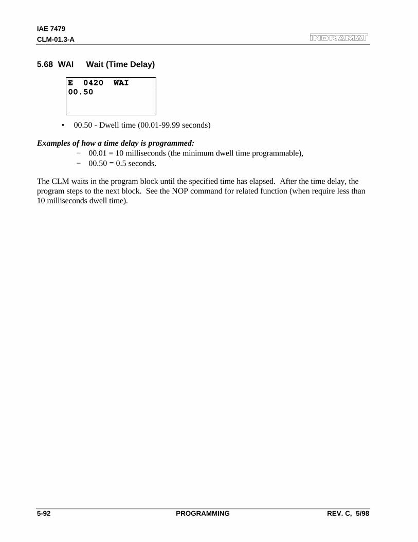
IAE 7479
CLM-01.3-A
5-92 PROGRAMMING REV. C, 5/98
5.68 WAI Wait (Time Delay)
E 0420 WAIE 0420 WAI00.5000.50
• 00.50 - Dwell time (00.01-99.99 seconds)
Examples of how a time delay is programmed:− 00.01 = 10 milliseconds (the minimum dwell time programmable),− 00.50 = 0.5 seconds.
The CLM waits in the program block until the specified time has elapsed. After the time delay, theprogram steps to the next block. See the NOP command for related function (when require less than10 milliseconds dwell time).
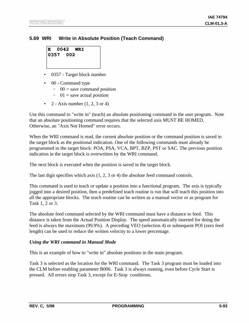
IAE 74794
CLM-01.3-A
REV. C, 5/98 PROGRAMMING 5-93
5.69 WRI Write in Absolute Position (Teach Command)
E 0042 WRIE 0042 WRI0357 0020357 002
• 0357 - Target block number
• 00 - Command type− 00 = save command position− 01 = save actual position
• 2 - Axis number (1, 2, 3 or 4)
Use this command to "write in" (teach) an absolute positioning command in the user program. Notethat an absolute positioning command requires that the selected axis MUST BE HOMED.Otherwise, an "Axis Not Homed" error occurs.
When the WRI command is read, the current absolute position or the command position is saved inthe target block as the positional indication. One of the following commands must already beprogrammed in the target block: POA, PSA, VCA, BPT, BZP, PST or SAC. The previous positionindication in the target block is overwritten by the WRI command.
The next block is executed when the position is saved in the target block.
The last digit specifies which axis (1, 2, 3 or 4) the absolute feed command controls.
This command is used to teach or update a position into a functional program. The axis is typicallyjogged into a desired position, then a predefined teach routine is run that will teach this position intoall the appropriate blocks. The teach routine can be written as a manual vector or as program forTask 1, 2 or 3.
The absolute feed command selected by the WRI command must have a distance to feed. Thisdistance is taken from the Actual Position Display. The speed automatically inserted for doing thefeed is always the maximum (99.9%). A preceding VEO (selection 4) or subsequent POI (zero feedlength) can be used to reduce the written velocity to a lower percentage.
Using the WRI command in Manual Mode
This is an example of how to "write in" absolute positions in the main program.
Task 3 is selected as the location for the WRI command. The Task 3 program must be loaded intothe CLM before enabling parameter B006. Task 3 is always running, even before Cycle Start ispressed. All errors stop Task 3, except for E-Stop conditions.
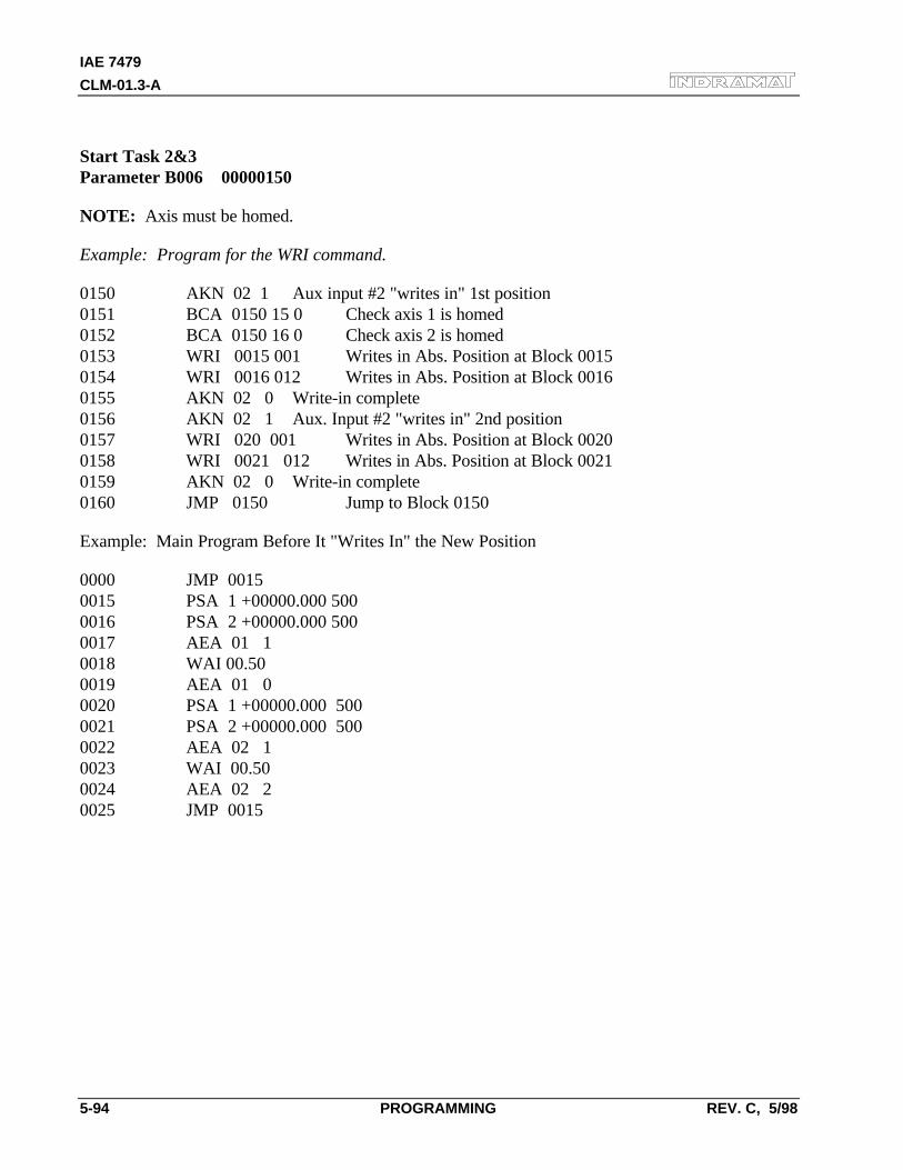
IAE 7479
CLM-01.3-A
5-94 PROGRAMMING REV. C, 5/98
Start Task 2&3Parameter B006 00000150
NOTE: Axis must be homed.
Example: Program for the WRI command.
0150 AKN 02 1 Aux input #2 "writes in" 1st position0151 BCA 0150 15 0 Check axis 1 is homed0152 BCA 0150 16 0 Check axis 2 is homed0153 WRI 0015 001 Writes in Abs. Position at Block 00150154 WRI 0016 012 Writes in Abs. Position at Block 00160155 AKN 02 0 Write-in complete0156 AKN 02 1 Aux. Input #2 "writes in" 2nd position0157 WRI 020 001 Writes in Abs. Position at Block 00200158 WRI 0021 012 Writes in Abs. Position at Block 00210159 AKN 02 0 Write-in complete0160 JMP 0150 Jump to Block 0150
Example: Main Program Before It "Writes In" the New Position
0000 JMP 00150015 PSA 1 +00000.000 5000016 PSA 2 +00000.000 5000017 AEA 01 10018 WAI 00.500019 AEA 01 00020 PSA 1 +00000.000 5000021 PSA 2 +00000.000 5000022 AEA 02 10023 WAI 00.500024 AEA 02 20025 JMP 0015
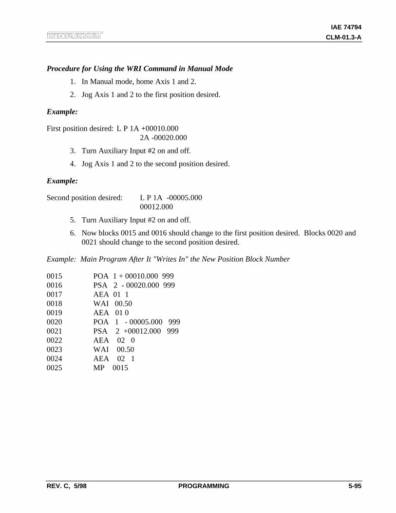
IAE 74794
CLM-01.3-A
REV. C, 5/98 PROGRAMMING 5-95
Procedure for Using the WRI Command in Manual Mode
1. In Manual mode, home Axis 1 and 2.
2. Jog Axis 1 and 2 to the first position desired.
Example:
First position desired: L P 1A +00010.0002A -00020.000
3. Turn Auxiliary Input #2 on and off.
4. Jog Axis 1 and 2 to the second position desired.
Example:
Second position desired: L P 1A -00005.00000012.000
5. Turn Auxiliary Input #2 on and off.
6. Now blocks 0015 and 0016 should change to the first position desired. Blocks 0020 and0021 should change to the second position desired.
Example: Main Program After It "Writes In" the New Position Block Number
0015 POA 1 + 00010.000 9990016 PSA 2 - 00020.000 9990017 AEA 01 10018 WAI 00.500019 AEA 01 00020 POA 1 - 00005.000 9990021 PSA 2 +00012.000 9990022 AEA 02 00023 WAI 00.500024 AEA 02 10025 MP 0015

IAE 7479
CLM-01.3-A
5-96 PROGRAMMING REV. C, 5/98
IAE 74794
CLM-01.3-A
REV. C, 5/98 INSTALLATION/START-UP 6-1
6. INSTALLATION/START-UP
This Chapter covers the installation and initial start up testing procedures for the CLM controlsystem. The system consists of the following components:
• The CLM Control Module
• The Servo Amplifier(s)
• The Power Supply
• The Servomotor(s)
The instructions in this chapter primarily describe the installation of the CLM Control Module. Theinstallation particulars of the other components (such as a TVM or KDV power supply, and TDM orKDS servo amplifiers) are explained in detail in their respective manuals. Appendix B list relevantpublications which you may require.
Tools required:
• A small 1/8" blade, standard screwdriver
• A multi-meter (VOM)
• An appropriate wrench for 1/4" machine type bolts (use for mounting module[s] tocabinet).
6.1 Unpacking / Parts Inventory
The CLM system is shipped in reinforced cardboard cartons and is sufficiently packed to withstandnormal shipping activity. Upon receiving equipment, inspect shipping carton for any evidence ofexternal damage (i.e., ripped or punctured carton, water marks, etc.). Should carton show any signsof damage, immediately inspect contents and contact carrier for damage claim if necessary.
Open cartons and remove the Styrofoam and bubble packing material from around the equipment.Remove the equipment and place on a firm level surface.
IAE 7479
CLM-01.3-A
6-2 INSTALLATION/START-UP REV. C, 5/98
The CLM carton contains the following items:
• The CLM module
• CLM cable set (SK5001) contains:− 1 Input cable− 1 Output cable− 1 Encoder cable
• CLM Electrical Accessory Kit (E15-CLM) which contains:− 15 pin Phoenix connector (X5)− Wire tie wraps− 7 pin Phoenix connector (X7)
CLM optional equipment includes:
• Remote Keypad - accessories include:− Remote keypad extension cable (typically 2 meters)− 2 dual side adhesive foam gaskets for keypad− A dummy CLM face plate
• IDS Assembly - with Electrical accessory kit that contains:− A 5 pin Phoenix connector− A serial interface cable with a RS-232 connector at one end and Ferrule connectors
on the other.
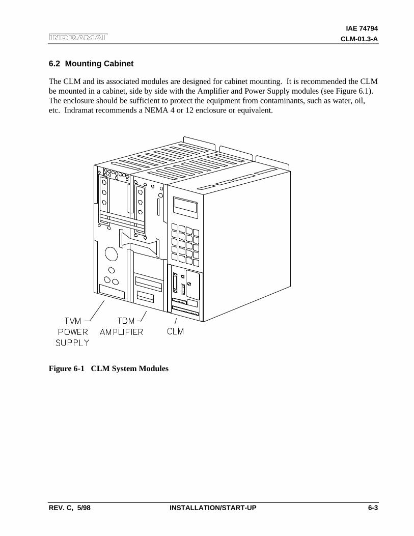
IAE 74794
CLM-01.3-A
REV. C, 5/98 INSTALLATION/START-UP 6-3
6.2 Mounting Cabinet
The CLM and its associated modules are designed for cabinet mounting. It is recommended the CLMbe mounted in a cabinet, side by side with the Amplifier and Power Supply modules (see Figure 6.1).The enclosure should be sufficient to protect the equipment from contaminants, such as water, oil,etc. Indramat recommends a NEMA 4 or 12 enclosure or equivalent.
Figure 6-1 CLM System Modules
IAE 7479
CLM-01.3-A
6-4 INSTALLATION/START-UP REV. C, 5/98
6.3 Power
The CLM requires 24 Vdc to operate. This voltage is supplied from the TVM (KDV) or from anexternal 24 Vdc supply. Refer to section 1.6.2 for power specifications for the CLM and its options.Refer to separate manuals (listed in Appendix B) for power requirements of the other modules(power supply, servo amplifier, etc.).
6.4 Cable Routing
For higher reliability, the feedback cables must be shielded and routed away from high voltage powersources to reduce electrical noise.
Do not route the CLM cables near high amperage type machines, like welding equipment, whichproduce strong magnetic field interference.
Suppress inductive loads (such as solenoids and motors) that are switched ON and OFF during CLMoperation, with R-C networks (AC) or diodes (DC).
Correct grounding is essential for trouble free operation. The ground connection must be made byobserving strictly the branching conditions shown in the wiring diagram.
6.5 Transformer - Heat Dissipation
The incoming 3-Phase power must be ground referenced. Use an isolation transformer with a "Y"secondary if this cannot be confirmed. Refer to TVM/KDV (or appropriate) manual for additionalinformation.
If a transformer is needed for operation, exercise caution on its location. Do not install thetransformer in the same cabinet as the CLM modules unless a sufficient method of cooling is applied.
IAE 74794
CLM-01.3-A
REV. C, 5/98 INSTALLATION/START-UP 6-5
6.6 Hardware Installation
The CLM and its supporting modules mount to the back wall of the equipment enclosure (cabinet).The mounting brackets of the modules are pre-drilled to accept a 1/4" machine bolt.
See Appendix G for mounting hole dimensions and location of the CLM module, the cut-outdimensions for the remote keypad, keypad gasket, and keypad replacement panel (dummy face plate),and mounting holes and cut-out dimensions for the optional IDS.
The mounting dimensions and cabinet cut-out data for the TVM (KDV) and the TDM (KDS) arelocated in the units respective support manuals.
The method of mounting the MAC servomotor is dependent upon the application. Additionalinformation and a drawing package for the MAC servomotor is available on request from Indramat.
6.7 Electrical Installation
There are many variations of wiring techniques used to connect the CLM to the machine builder'sequipment. The Interconnect Drawings supplied with this manual (see Appendix F) show an exampleof the CLM connections to a typical metalforming machine.
IAE 7479
CLM-01.3-A
6-6 INSTALLATION/START-UP REV. C, 5/98
6.8 CLM Connectors
This section describes all the connectors on the CLM module. Refer to Figure 1.5 in Chapter 1 for anillustration of the CLM module and its connector locations.
X - 1: Encoder Input Axis 1
Female, DB 25 connector is located on the top of the CLM and used for inputs from the respectiveencoder assembly for axis 1 and measuring encoder.
X - 2: Encoder Input Axis 2
Female, DB 25 connector is located on the top of the CLM and used for inputs from the respectiveencoder assembly for axis 2.
X - 3: System Input
Male, DB 37 connector is located on the top of the CLM and used for inputs from various locationsof the system (see Chapter 3 for I/O descriptions; see Table 2.1 for quick reference to I/Oconnections).
X - 4: System Output
Female, DB 37 connector is located on the top of the CLM and used for various outputs (see Chapter3 for I/O descriptions; see Table 2.1 for quick reference to I/O connections).
IAE 74794
CLM-01.3-A
REV. C, 5/98 INSTALLATION/START-UP 6-7
X - 5: Command Connector
A 15 pin Phoenix connector is located on the lower front panel of the CLM. This is a multi-functional connector.
The various contacts of X - 5 are:
• 24 Vdc Power Supply - ins 1 & 2
• Bb motor Contacts - pins 3 & 4
• Analog Command Axis 1 (A1) - pins 5 & 6
• Analog Command Axis 2 (A2) - pins 8 & 9
• Ground (not used) - pins 7 & 10
• Analog Input, Axis 1 (AE1) - pins 11 & 12
• Analog Input, Axis 2 (AE2) - pins 14 & 15
NOTE: To prevent a ground loop condition, connect the shields for the command cables to theservo amplifier only. Refer to Appendix F, drawing BE 1117, sheet 3, coordinates B1.
X - 6: RS-232/422/485 Communications Port (Interface)
Female, DB 25 connector is located on the lower front panel of the CLM. It is used for serialcommunication between the CLM and a host terminal, SOT or the IDS option. Refer to Chapter 7for description of this multi-functional, two-way communications port.
X - 7: Auxiliary Drive Connector
An 8 pin Phoenix connector is located above the X - 5 connector on the lower front panel of theCLM. See Figure 2.3 for an illustration and description of the lower front connector panel.
The various contacts of X - 7 are:
• Enables Axis 1 Amplifier for operation (RF1) - pin 1
• Enables Axis 2 Amplifier for operation (RF2) - pin 2
• Potentiometer supply for analog override (+10 Vdc) - pin 3
• Analog Input, Axis 3 (AE3/0 Vdc) - pins 4 & 5
• Ground (not used) - pin 6
• Analog Input, Axis 4 (AE4 +/-) - pins 7 & 8
IAE 7479
CLM-01.3-A
6-8 INSTALLATION/START-UP REV. C, 5/98
X - 11 & 12: Optional System Input
These connectors are included with the optional Expanded version CLM only. These Male, DB 37connectors are located on the top of the CLM and used for inputs from various locations of thesystem (see Chapter 3 for I/O descriptions; see Table 2.1 for quick reference to I/O connections).
X - 13: Optional System Output
This connector is included with the optional Expanded version CLM only. This Female, DB 37connector is located on the top of the CLM and used for various outputs (see Chapter 3 for I/Odescriptions; see Table 2.1 for quick reference to I/O connections).
X - 19: Command and Drive Enable Connector
A 7 pin Phoenix connector is located on the bottom of the CLM. This is a multi-functionalconnector.
The various contacts of X - 19 are:
• Analog Command Axis 3 (A3) - pins 1 & 2
• Ground/shield (not used) - pin 6
• Analog Command Axis 4 (A4) - pins 4 & 5
• Enable Axis 3 Amplifier for operation (RF3) - pin 6
• Enable Axis 4 Amplifier for operation (RF4) - pin 7
NOTE: To prevent a ground loop condition, connect the shields for the command cables to theservo amplifier only. Refer to Appendix F, drawing BE 1117, sheet 3, coordinates B1.
X - 20: Encoder Input Axis 3
Female, DB 25 connector is located on the bottom of the CLM and used for inputs from therespective encoder assembly for axis 3.
X - 21: Encoder Input Axis 4
Female, DB 25 connector is located on the bottom of the CLM and used for inputs from therespective encoder assembly for axis 4.
X - 22: System Input/Output
Male, DB 25 connector is located on the bottom of the CLM and used for various system (axis 3 and4) and auxiliary inputs and outputs (see Chapter 3 for I/O descriptions; see Table 2.1 for quickreference to I/O connections).
IAE 74794
CLM-01.3-A
REV. C, 5/98 INSTALLATION/START-UP 6-9
6.9 Pre-Operation Start Up Tests
The following sections are intended to provide the user with an example of a CLM start-up. Theyprovide an example of a single axis application that will verify proper function of the system.
WARNING: The information given in the following sections may not be suitable for a specificapplication. If you use this example for testing, do not mechanically connect the servomotor to theactual load.
Refer to the drawings in the Appendixes F and G for additional mounting and connection information.
6.10 Connections
NOTE: Do NOT apply power until all connections have been made. Refer to section 6.8 forconnector descriptions.
1. Install the TVM (or KDV) power supply and the TDM (or KDS) amplifier per theirrespective support manuals.
2. Make connections to the CLM Command Connector X5 (24 Vdc supply, Bb motorcontacts, analog command for each servo amplifier).
3. Make the motor connections per drawings in Appendix F, and the TDM and motorsupport manuals.
4. Connect the encoder(s) to X1 connector for axis 1; X2 connector for axis 2; X20connector for axis 3; X21 connector for axis 4.
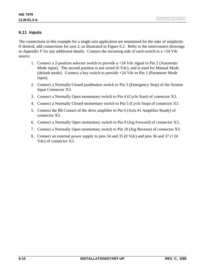
IAE 7479
CLM-01.3-A
6-10 INSTALLATION/START-UP REV. C, 5/98
6.11 Inputs
The connections in this example for a single axis application are minimized for the sake of simplicity.If desired, add connections for axis 2, as illustrated in Figure 6.2. Refer to the interconnect drawingsin Appendix F for any additional details. Connect the incoming side of each switch to a +24 Vdcsource.
1. Connect a 2-position selector switch to provide a +24 Vdc signal to Pin 2 (AutomaticMode input). The second position is not wired (0 Vdc), and is used for Manual Mode(default mode). Connect a key switch to provide +24 Vdc to Pin 1 (Parameter Modeinput).
2. Connect a Normally Closed pushbutton switch to Pin 3 (Emergency Stop) of the SystemInput Connector X3.
3. Connect a Normally Open momentary switch to Pin 4 (Cycle Start) of connector X3.
4. Connect a Normally Closed momentary switch to Pin 5 (Cycle Stop) of connector X3.
5. Connect the Bb Contact of the drive amplifier to Pin 6 (Axis #1 Amplifier Ready) ofconnector X3.
6. Connect a Normally Open momentary switch to Pin 9 (Jog Forward) of connector X3..
7. Connect a Normally Open momentary switch to Pin 10 (Jog Reverse) of connector X3.
8. Connect an external power supply to pins 34 and 35 (0 Vdc) and pins 36 and 37 (+24Vdc) of connector X3.
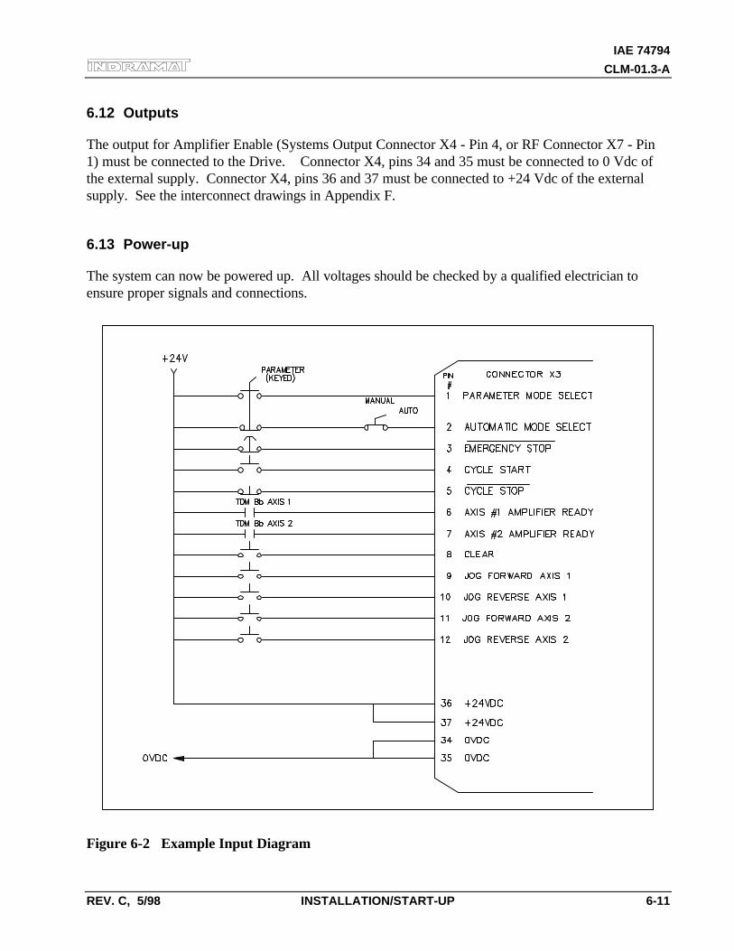
IAE 74794
CLM-01.3-A
REV. C, 5/98 INSTALLATION/START-UP 6-11
6.12 Outputs
The output for Amplifier Enable (Systems Output Connector X4 - Pin 4, or RF Connector X7 - Pin1) must be connected to the Drive. Connector X4, pins 34 and 35 must be connected to 0 Vdc ofthe external supply. Connector X4, pins 36 and 37 must be connected to +24 Vdc of the externalsupply. See the interconnect drawings in Appendix F.
6.13 Power-up
The system can now be powered up. All voltages should be checked by a qualified electrician toensure proper signals and connections.
Figure 6-2 Example Input Diagram
IAE 7479
CLM-01.3-A
6-12 INSTALLATION/START-UP REV. C, 5/98
6.14 Parameter Entry
The parameters given here are the minimum required to operate the CLM for this example. Thefollowing descriptions assume an IU = 1 inch. Turn the key switch to the Parameter Mode to enableparameter entry. Enter the following parameters (refer to Chapter 4 for parameter entry proceduresor for further description of each parameter, if necessary); also enter A2xx parameters when testing a2-axes system.
• B007 Language 01030000 (English display, resolution to 3 places)
• A100 Max Velocity Refer to Amplifier personality module nameplate for E1/E2rating. See example entries at bottom of page.
• A101 Jog Velocity 00005000 (5.0 in/sec)
• A102 Acceleration 00000250 (25.0 in/sec²)
• A103 Position Gain 00000100 (1.0 in/min/mil of Following Error)
• A104 Encoder Lines/Rev. Refer to motor encoder nameplate.
The two most common encoders are:− 625 Enter 00000625 (625 lines/encoder rev)− 1250 Enter 00001250 (1250 lines/encoder rev)
• A106 Position Tolerance 15000050 (output 15, Axis 1 pos. tol.= 0.050 in)
• A108 Feed Constant 01000000 (1.0 in/motor rev)
• A109 Direction 00000000 (direction of operation is unchanged)
• A121 Drive Input Sensitivity Refer to Amplifier personality module nameplate forE1/E2 rating. See example entries below.
• A122 Monitor Window 00000010 (10% window)
Following are three examples for A100 and A121 input. Refer to Parameter Ax00 descriptionto calculate the Max Velocity.
• E1/E2 Sensitivity A121 Entry A100 Entry
• 1500 / 10 V 15000100 00025000 (25 in/sec)
• 2000 / 10 V 20000100 00033333 (33.333 in/sec)
• 3000 / 10 V 30000100 00050000 (50 in/sec)
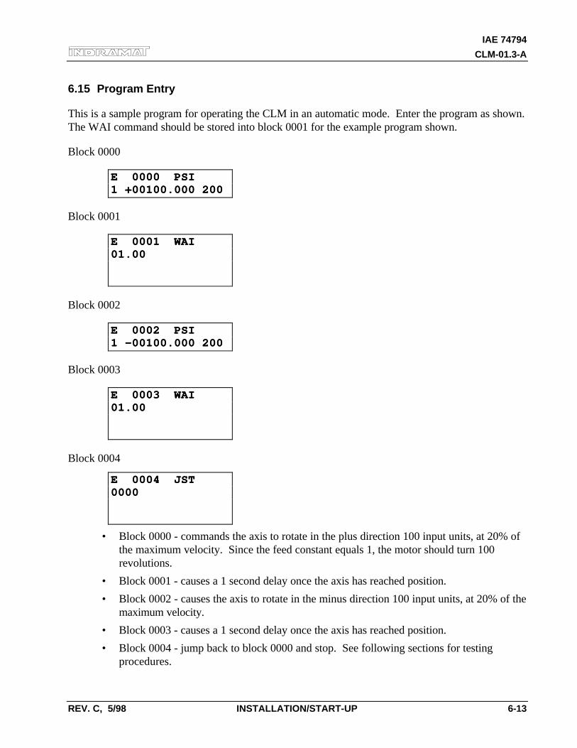
IAE 74794
CLM-01.3-A
REV. C, 5/98 INSTALLATION/START-UP 6-13
6.15 Program Entry
This is a sample program for operating the CLM in an automatic mode. Enter the program as shown.The WAI command should be stored into block 0001 for the example program shown.
Block 0000
E 0000 PSIE 0000 PSI1 +00100.000 2001 +00100.000 200
Block 0001
E 0001 WAIE 0001 WAI01.0001.00
Block 0002
E 0002 PSIE 0002 PSI1 -00100.000 2001 -00100.000 200
Block 0003
E 0003 WAIE 0003 WAI01.0001.00
Block 0004
E 0004 JSTE 0004 JST00000000
• Block 0000 - commands the axis to rotate in the plus direction 100 input units, at 20% ofthe maximum velocity. Since the feed constant equals 1, the motor should turn 100revolutions.
• Block 0001 - causes a 1 second delay once the axis has reached position.
• Block 0002 - causes the axis to rotate in the minus direction 100 input units, at 20% of themaximum velocity.
• Block 0003 - causes a 1 second delay once the axis has reached position.
• Block 0004 - jump back to block 0000 and stop. See following sections for testingprocedures.
IAE 7479
CLM-01.3-A
6-14 INSTALLATION/START-UP REV. C, 5/98
6.16 Axis Jogging In Manual Mode
To verify proper motor hook-up, and control of the motor, jog the axis in Manual Mode. Turn theselector switches to the OFF position so that Automatic nor Parameter Mode inputs are high (defaultsto Manual Mode).
NOTE: Verify Drive is ON and H-1 LED on lower front of CLM is ON.
1. Press the Forward Jog pushbutton (connected to X3, Pin 9). The axis should jog in theforward direction, until the button is released.
2. Press the Reverse Jog pushbutton (connected to X3, Pin 10). The axis should jog in thereverse direction, until the button is released.
3. Should either the forward or reverse motor movement fail to react, check all cableconnections and verify the CLM is in Manual Mode.
NOTE: If the CLM displays any errors, refer to Chapter 8, Diagnostics.
6.17 Automatic Mode Operation
To run the sample program and check Automatic Mode operation:
1. Turn the selector switch to Automatic Mode (wired to connector X3, Pin 2).
2. Press the Cycle Start pushbutton (connected to X3, Pin 4)
NOTE: The CLM will execute the sample program and stop after one cycle. Change block 0004 toJMP 0000 to run the cycle continuously.
3. Press the Cycle Stop pushbutton to stop operation. Press Cycle Start to restart theprogram.
NOTE: Cycle Stop will cause an immediate stop without error. Emergency Stop will cause animmediate stop also, but will cause a fault to be displayed. De-actuate the E-stop switch and pressthe CL (clear) key on the CLM keypad to clear the fault, to allow restarting the operation.
IAE 74794
CLM-01.3-A
REV. C, 5/98 SERIAL INTERFACE 7-1
7. SERIAL INTERFACE
The CLM Control includes a multi-format RS-232/422/485 port for two-way communication ofprograms, parameters and system status between the CLM and a host device. The interface protocolis designed to easily transmit and receive data to and from the CLM. This chapter describes theprotocol and other communication requirements.
The host device must strictly adhere to the communications format as described in this chapter toachieve proper communication, or one of several "RS Format Errors" will be returned through theport (or indicated on the control status display, see Figure 2.2 for a map of displays) indicating thatthe information was not properly formatted or understood.
User programs (Block information) can be downloaded to the CLM when it is in any mode ofoperation (Auto, Manual, or Parameter). The same is true for system status. System parameters canbe downloaded to the CLM, only when it is in Parameter Mode. If attempted in any other mode, thehost receives a "Invalid Mode" error message through the port. Parameters can be read from theCLM in any mode.
The optional Indramat program assembler software (MotionManager) allows you to write and edituser programs and parameter list on any DOS based computer. You can download these into theCLM control through the serial interface. You can also upload the information from the CLM andmake a print out of your program and parameter files.
The optional Indramat SOT (Station Operator Terminal) is a remote mounted, operator controldevice for the CLM. It is used to communicate program and parameter information between theCLM and SOT. The software in the SOT includes Help screens to assist the operator in using theSOT and for entering information correctly. The Indramat command line editor (Screen Manager), isused to write information and prompt lines for the operator that will appear on the SOT display (16lines, 40 characters each). Contact Indramat for additional information on these options.
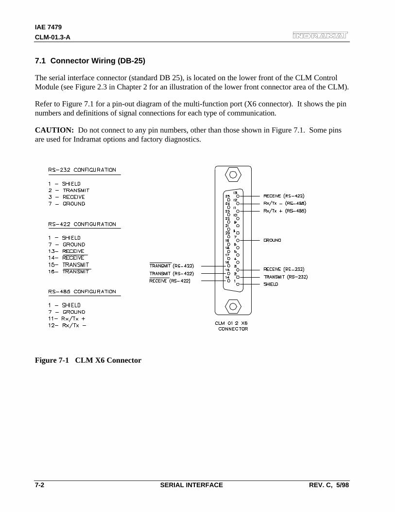
IAE 7479
CLM-01.3-A
7-2 SERIAL INTERFACE REV. C, 5/98
7.1 Connector Wiring (DB-25)
The serial interface connector (standard DB 25), is located on the lower front of the CLM ControlModule (see Figure 2.3 in Chapter 2 for an illustration of the lower front connector area of the CLM).
Refer to Figure 7.1 for a pin-out diagram of the multi-function port (X6 connector). It shows the pinnumbers and definitions of signal connections for each type of communication.
CAUTION: Do not connect to any pin numbers, other than those shown in Figure 7.1. Some pinsare used for Indramat options and factory diagnostics.
Figure 7-1 CLM X6 Connector
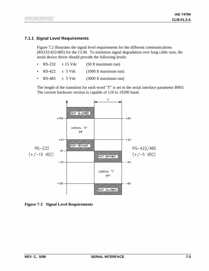
IAE 74794
CLM-01.3-A
REV. C, 5/98 SERIAL INTERFACE 7-3
7.1.1 Signal Level Requirements
Figure 7.2 illustrates the signal level requirements for the different communications(RS232/422/485) for the CLM. To minimize signal degradation over long cable runs, theserial device driver should provide the following levels:
• RS-232 ± 15 Vdc (50 ft maximum run)
• RS-422 ± 5 Vdc (1000 ft maximum run)
• RS-485 ± 5 Vdc (3000 ft maximum run)
The length of the transition for each word "T" is set in the serial interface parameter B003.The current hardware version is capable of 110 to 19200 baud.
Figure 7-2 Signal Level Requirements
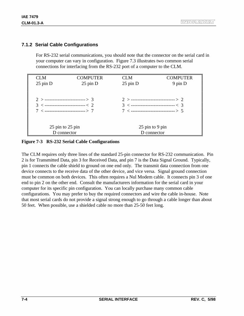
IAE 7479
CLM-01.3-A
7-4 SERIAL INTERFACE REV. C, 5/98
7.1.2 Serial Cable Configurations
For RS-232 serial communications, you should note that the connector on the serial card inyour computer can vary in configuration. Figure 7.3 illustrates two common serialconnections for interfacing from the RS-232 port of a computer to the CLM.
CLM COMPUTER CLM COMPUTER25 pin D 25 pin D 25 pin D 9 pin D
2 > ------------------------- > 3 2 > --------------------------- > 23 < ------------------------- < 2 3 < --------------------------- < 37 < ------------------------- > 7 7 < --------------------------- > 5
25 pin to 25 pin 25 pin to 9 pinD connector D connector
Figure 7-3 RS-232 Serial Cable Configurations
The CLM requires only three lines of the standard 25-pin connector for RS-232 communication. Pin2 is for Transmitted Data, pin 3 for Received Data, and pin 7 is the Data Signal Ground. Typically,pin 1 connects the cable shield to ground on one end only. The transmit data connection from onedevice connects to the receive data of the other device, and vice versa. Signal ground connectionmust be common on both devices. This often requires a Nul Modem cable. It connects pin 3 of oneend to pin 2 on the other end. Consult the manufacturers information for the serial card in yourcomputer for its specific pin configuration. You can locally purchase many common cableconfigurations. You may prefer to buy the required connectors and wire the cable in-house. Notethat most serial cards do not provide a signal strong enough to go through a cable longer than about50 feet. When possible, use a shielded cable no more than 25-50 feet long.
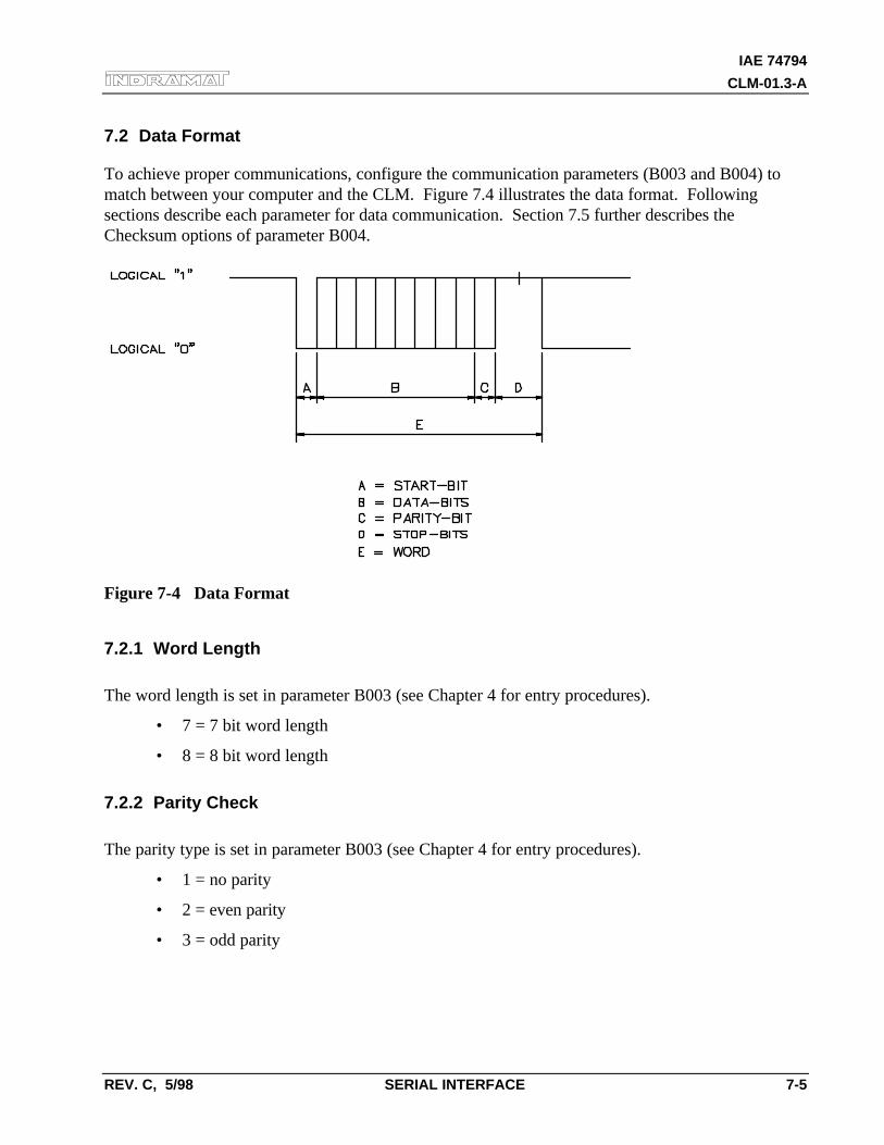
IAE 74794
CLM-01.3-A
REV. C, 5/98 SERIAL INTERFACE 7-5
7.2 Data Format
To achieve proper communications, configure the communication parameters (B003 and B004) tomatch between your computer and the CLM. Figure 7.4 illustrates the data format. Followingsections describe each parameter for data communication. Section 7.5 further describes theChecksum options of parameter B004.
Figure 7-4 Data Format
7.2.1 Word Length
The word length is set in parameter B003 (see Chapter 4 for entry procedures).
• 7 = 7 bit word length
• 8 = 8 bit word length
7.2.2 Parity Check
The parity type is set in parameter B003 (see Chapter 4 for entry procedures).
• 1 = no parity
• 2 = even parity
• 3 = odd parity
IAE 7479
CLM-01.3-A
7-6 SERIAL INTERFACE REV. C, 5/98
7.2.3 Baud Rate
The baud rate is set in parameter B003 (see Chapter 4 for entry procedures). You may choose anybaud rate from among the following values:
Parameter BaudEntry Rate
0015 =01500030 =03000060 =06000090 =09000120 =12000180 =18000240 =24000360 =36000480 =48000570 =57000720 =72000960 =96001920 =19200
7.2.4 Interface Mode
The interface mode is set in parameter B003 (see Chapter 4 for entry procedures). You may choosefrom among the following:
• 0 = Standard RS232/RS422 (Full Duplex)
• 1 = IDS, decade switch option
• 2 = Same as Mode 0
• 3 = serial port for SOT (Station Operator Terminal); RS-232/422, half duplex, one stationONLY
• 4 = serial bus for SOT; RS-485, half duplex, station 1 through 15
IAE 74794
CLM-01.3-A
REV. C, 5/98 SERIAL INTERFACE 7-7
7.3 CLM Control String Protocol
The following sections describe each control character requirements for proper protocol.
7.3.1 First (1) Control String Character (Transmission Type)
All data transmissions to the CLM must start with one of the following control characters to identifywhat type of transmission is to follow:
• ? Hexadecimal 3F
The CLM interprets this character (received via the RxD channel) as a "Request for Information" -when followed by the proper requesting codes, the CLM will transmit the desired data via the TxDchannel.
• # Hexadecimal 23
This character signifies a block of "Information to be Stored" into memory. The data that follows willbe read into the proper memory location.
• ! Hexadecimal 21
This character signifies a "System Parameter" or "Control Command" is to follow.
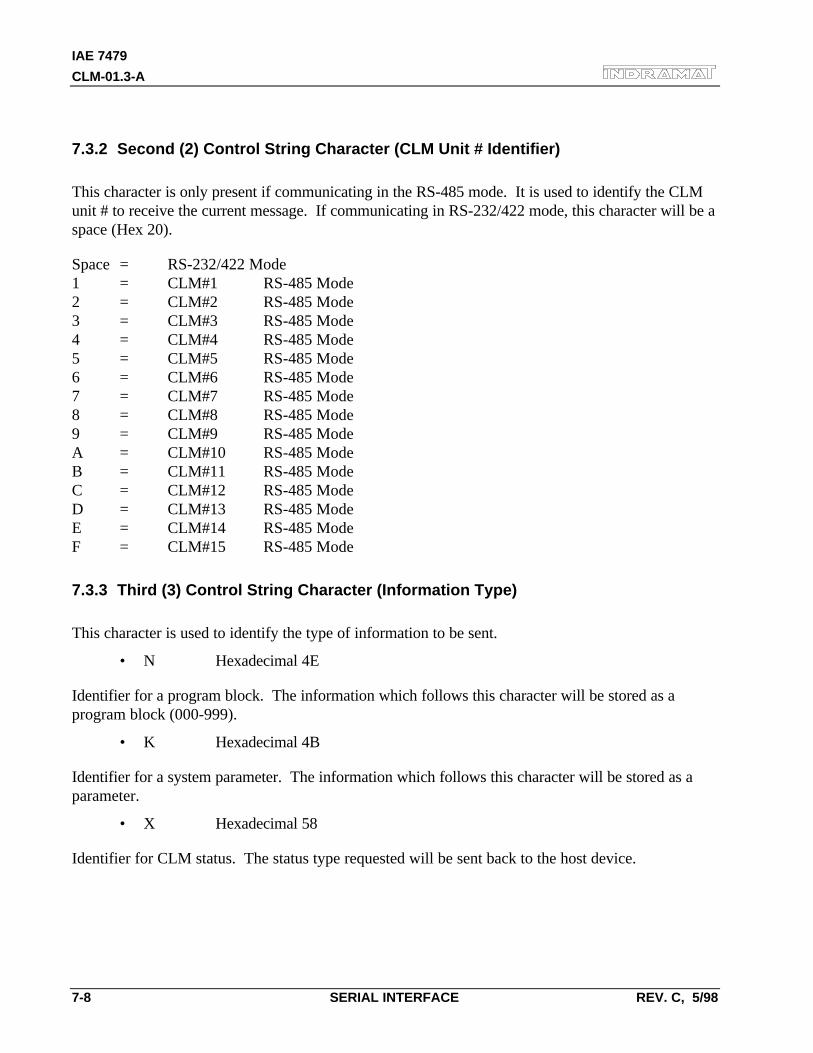
IAE 7479
CLM-01.3-A
7-8 SERIAL INTERFACE REV. C, 5/98
7.3.2 Second (2) Control String Character (CLM Unit # Identifier)
This character is only present if communicating in the RS-485 mode. It is used to identify the CLMunit # to receive the current message. If communicating in RS-232/422 mode, this character will be aspace (Hex 20).
Space = RS-232/422 Mode1 = CLM#1 RS-485 Mode2 = CLM#2 RS-485 Mode3 = CLM#3 RS-485 Mode4 = CLM#4 RS-485 Mode5 = CLM#5 RS-485 Mode6 = CLM#6 RS-485 Mode7 = CLM#7 RS-485 Mode8 = CLM#8 RS-485 Mode9 = CLM#9 RS-485 ModeA = CLM#10 RS-485 ModeB = CLM#11 RS-485 ModeC = CLM#12 RS-485 ModeD = CLM#13 RS-485 ModeE = CLM#14 RS-485 ModeF = CLM#15 RS-485 Mode
7.3.3 Third (3) Control String Character (Information Type)
This character is used to identify the type of information to be sent.
• N Hexadecimal 4E
Identifier for a program block. The information which follows this character will be stored as aprogram block (000-999).
• K Hexadecimal 4B
Identifier for a system parameter. The information which follows this character will be stored as aparameter.
• X Hexadecimal 58
Identifier for CLM status. The status type requested will be sent back to the host device.
IAE 74794
CLM-01.3-A
REV. C, 5/98 SERIAL INTERFACE 7-9
7.3.4 Other Important Control Characters
The following are additional control characters required for proper protocol.
• $ Hexadecimal 24
Identifier for check sum. The two characters following this character represent the check sum of theinformation transmitted. This check sum must be transmitted along with every transmission.
• CR Hexadecimal OD
• LF Hexadecimal OA
These two characters, CR (Carriage Return) and LF (Line Feed) form the end of every transmission.
• X-ON Hexadecimal 11
• X-OFF Hexadecimal 13
Serial transmission can be controlled using handshaking.
• If the CLM is sending data via the TxD channel and receives the "X-OFF" signal(Hexadecimal 13/ASCII DC3) via the RxD channel, the CLM will interrupt thetransmission until the "X-ON" signal (Hexadecimal 11/ASCII DC1) is received again viathe RxD channel.
• If the CLM is receiving data via the RxD channel, and an interruption of the datatransmission becomes necessary, the CLM will send the "X-OFF" signal (Hexadecimal13/ASCII DC3) via the TxD channel. When the transmission can be resumed, the CLMwill send the "X-ON" signal (Hexadecimal 11/ASCII DC1) via the TxD channel.
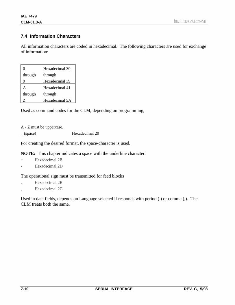
IAE 7479
CLM-01.3-A
7-10 SERIAL INTERFACE REV. C, 5/98
7.4 Information Characters
All information characters are coded in hexadecimal. The following characters are used for exchangeof information:
0 Hexadecimal 30
through through
9 Hexadecimal 39
A Hexadecimal 41
through through
Z Hexadecimal 5A
Used as command codes for the CLM, depending on programming,
A - Z must be uppercase.
_ (space) Hexadecimal 20
For creating the desired format, the space-character is used.
NOTE: This chapter indicates a space with the underline character.+ Hexadecimal 2B
- Hexadecimal 2D
The operational sign must be transmitted for feed blocks. Hexadecimal 2E
, Hexadecimal 2C
Used in data fields, depends on Language selected if responds with period (.) or comma (,). TheCLM treats both the same.
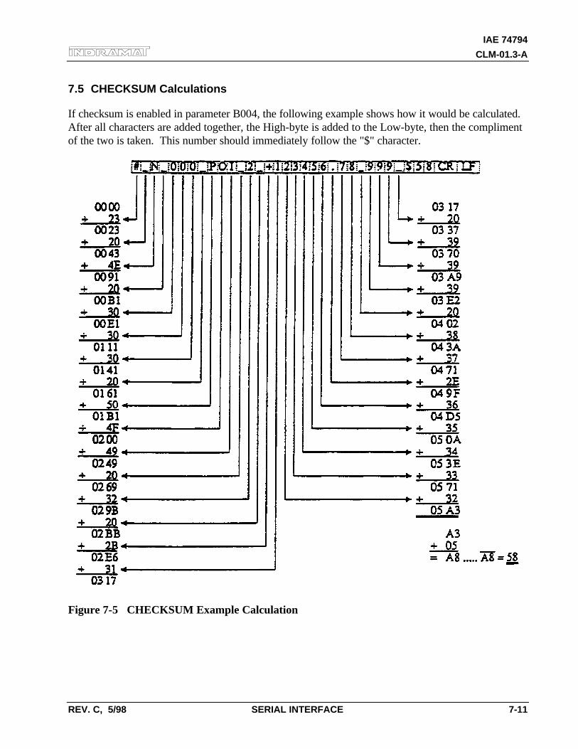
IAE 74794
CLM-01.3-A
REV. C, 5/98 SERIAL INTERFACE 7-11
7.5 CHECKSUM Calculations
If checksum is enabled in parameter B004, the following example shows how it would be calculated.After all characters are added together, the High-byte is added to the Low-byte, then the complimentof the two is taken. This number should immediately follow the "$" character.
Figure 7-5 CHECKSUM Example Calculation
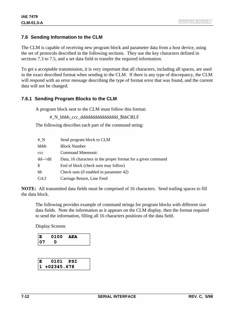
IAE 7479
CLM-01.3-A
7-12 SERIAL INTERFACE REV. C, 5/98
7.6 Sending Information to the CLM
The CLM is capable of receiving new program block and parameter data from a host device, usingthe set of protocols described in the following sections. They use the key characters defined insections 7.3 to 7.5, and a set data field to transfer the required information.
To get a acceptable transmission, it is very important that all characters, including all spaces, are usedin the exact described format when sending to the CLM. If there is any type of discrepancy, the CLMwill respond with an error message describing the type of format error that was found, and the currentdata will not be changed.
7.6.1 Sending Program Blocks to the CLM
A program block sent to the CLM must follow this format:
#_N_bbbb_ccc_dddddddddddddddd_$hhCRLF
The following describes each part of the command string:
#_N Send program block to CLM
bbbb Block Number
ccc Command Mnemonic
dd-->dd Data, 16 characters in the proper format for a given command
$ End of block (check sum may follow)
hh Check sum (if enabled in parameter 42)
CrLf Carriage Return, Line Feed
NOTE: All transmitted data fields must be comprised of 16 characters. Send trailing spaces to fillthe data block.
The following provides example of command strings for program blocks with different sizedata fields. Note the information as it appears on the CLM display, then the format requiredto send the information, filling all 16 characters positions of the data field.
Display Screens
E 0100 AEAE 0100 AEA07 007 0
E 0101 PSIE 0101 PSI1 +02345.6781 +02345.678
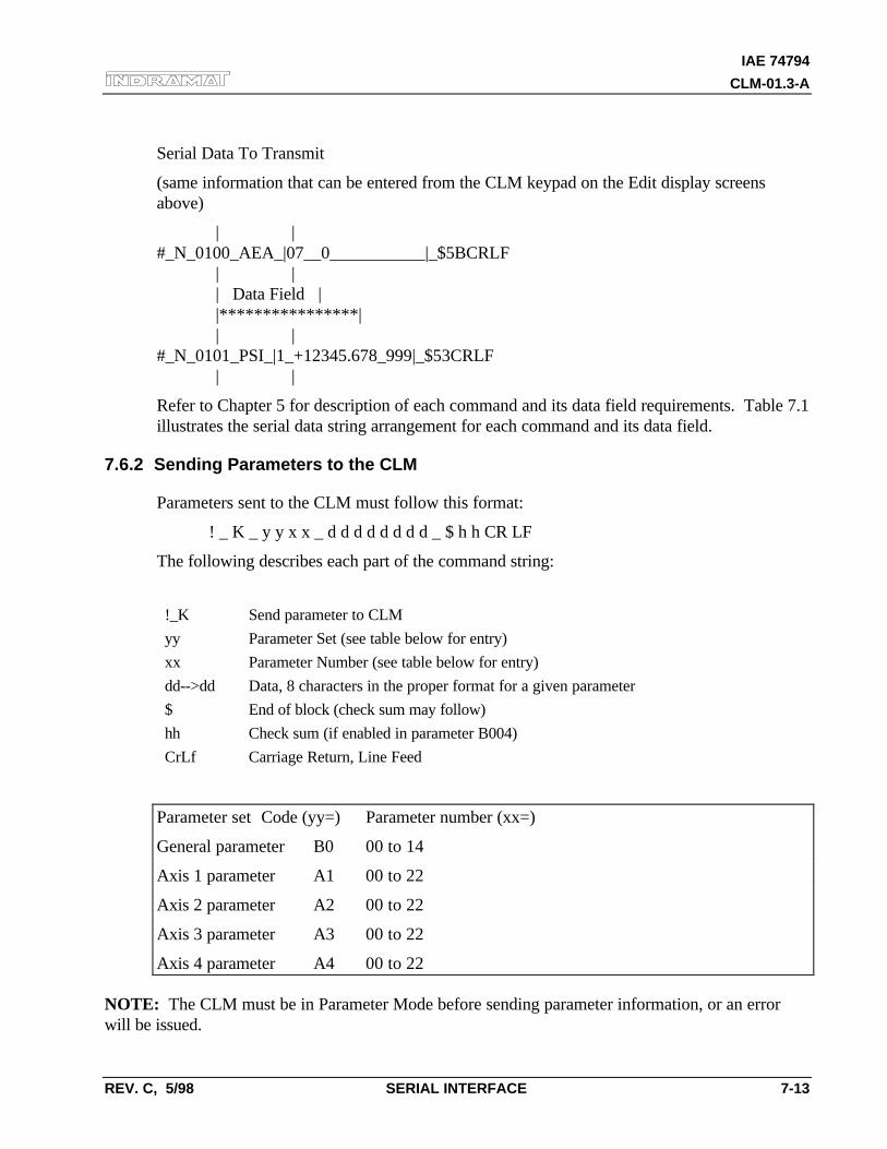
IAE 74794
CLM-01.3-A
REV. C, 5/98 SERIAL INTERFACE 7-13
Serial Data To Transmit
(same information that can be entered from the CLM keypad on the Edit display screensabove)
| |#_N_0100_AEA_|07__0___________|_$5BCRLF | | | Data Field | |****************| | |#_N_0101_PSI_|1_+12345.678_999|_$53CRLF | |
Refer to Chapter 5 for description of each command and its data field requirements. Table 7.1illustrates the serial data string arrangement for each command and its data field.
7.6.2 Sending Parameters to the CLM
Parameters sent to the CLM must follow this format:
! _ K _ y y x x _ d d d d d d d d _ $ h h CR LF
The following describes each part of the command string:
!_K Send parameter to CLM
yy Parameter Set (see table below for entry)
xx Parameter Number (see table below for entry)
dd-->dd Data, 8 characters in the proper format for a given parameter
$ End of block (check sum may follow)
hh Check sum (if enabled in parameter B004)
CrLf Carriage Return, Line Feed
Parameter set Code (yy=) Parameter number (xx=)
General parameter B0 00 to 14
Axis 1 parameter A1 00 to 22
Axis 2 parameter A2 00 to 22
Axis 3 parameter A3 00 to 22
Axis 4 parameter A4 00 to 22
NOTE: The CLM must be in Parameter Mode before sending parameter information, or an errorwill be issued.
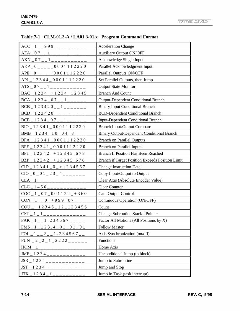
IAE 7479
CLM-01.3-A
7-14 SERIAL INTERFACE REV. C, 5/98
Table 7-1 CLM-01.3-A / LA01.3-01.x Program Command Format
ACC _ 1 _ _ 9 9 9 _ _ _ _ _ _ _ _ _ _ Acceleration Change
AEA _ 0 7 _ _ 1 _ _ _ _ _ _ _ _ _ _ _ Auxiliary Output ON/OFF
AKN _ 0 7 _ _ 1 _ _ _ _ _ _ _ _ _ _ _ Acknowledge Single Input
AKP _ 0 _ _ _ _ _ 0 0 0 1 1 1 2 2 2 0 Parallel Acknowledgment Input
APE _ 0 _ _ _ _ _ 0 0 0 1 1 1 2 2 2 0 Parallel Outputs ON/OFF
APJ _ 1 2 3 4 4 _ 0 0 0 1 1 1 2 2 2 0 Set Parallel Outputs, then Jump
ATS _ 0 7 _ _ 1 _ _ _ _ _ _ _ _ _ _ _ Output State Monitor
BAC _ 1 2 3 4 _ + 1 2 3 4 _ 1 2 3 4 5 Branch And Count
BCA _ 1 2 3 4 _ 0 7 _ _ 1 _ _ _ _ _ _ Output-Dependent Conditional Branch
BCB _ 1 2 3 4 2 0 _ _ 1 _ _ _ _ _ _ _ Binary Input Conditional Branch
BCD _ 1 2 3 4 2 0 _ _ _ _ _ _ _ _ _ _ BCD-Dependent Conditional Branch
BCE _ 1 2 3 4 _ 0 7 _ _ 1 _ _ _ _ _ _ Input-Dependent Conditional Branch
BIO _ 1 2 3 4 1 _ 0 0 0 1 1 1 2 2 2 0 Branch Input/Output Compare
BMB _ 1 2 3 4 _ 1 0 _ 0 4 _ 8 _ _ _ _ Binary Output-Dependent Conditional Branch
BPA _ 1 2 3 4 1 _ 0 0 0 1 1 1 2 2 2 0 Branch on Parallel Outputs
BPE _ 1 2 3 4 1 _ 0 0 0 1 1 1 2 2 2 0 Branch on Parallel Inputs
BPT _ 1 2 3 4 2 _ + 1 2 3 4 5 . 6 7 8 Branch If Position Has Been Reached
BZP _ 1 2 3 4 2 _ + 1 2 3 4 5 . 6 7 8 Branch if Target Position Exceeds Position Limit
CID _ 1 2 3 4 1 _ 0 _ + 1 2 3 4 5 6 7 Change Instruction Data
CIO _ 0 _ 0 1 _ 2 3 _ 4 _ _ _ _ _ _ _ Copy Input/Output to Output
CLA _ 1 _ _ _ _ _ _ _ _ _ _ _ _ _ _ _ Clear Axis (Absolute Encoder Value)
CLC _ 1 4 5 6 _ _ _ _ _ _ _ _ _ _ _ _ Clear Counter
COC _ 1 _ 0 7 _ 0 0 1 1 2 2 _ + 3 6 0 Cam Output Control
CON _ 1 _ _ 0 _ + 9 9 9 _ 0 7 _ _ _ _ Continuous Operation (ON/OFF)
COU _ + 1 2 3 4 5 _ 1 2 _ 1 2 3 4 5 6 Count
CST _ 1 _ 1 _ _ _ _ _ _ _ _ _ _ _ _ _ Change Subroutine Stack - Pointer
FAK _ 1 _ _ 1 . 2 3 4 5 6 7 _ _ _ _ _ Factor All Motions (All Positions by X)
FMS _ 1 _ 1 2 3 . 4 _ 0 1 _ 0 1 _ 0 1 Follow Master
FOL _ 1 _ _ 2 _ _ 1 . 2 3 4 5 6 7 _ _ Axis Synchronization (on/off)
FUN _ 2 _ 2 _ 1 _ 2 2 2 2 _ _ _ _ _ _ Functions
HOM _ 1 _ _ _ _ _ _ _ _ _ _ _ _ _ _ _ Home Axis
JMP _ 1 2 3 4 _ _ _ _ _ _ _ _ _ _ _ _ Unconditional Jump (to block)
JSR _ 1 2 3 4 _ _ _ _ _ _ _ _ _ _ _ _ Jump to Subroutine
JST _ 1 2 3 4 _ _ _ _ _ _ _ _ _ _ _ _ Jump and Stop
JTK _ 1 2 3 4 _ 1 _ _ _ _ _ _ _ _ _ _ Jump in Task (task interrupt)
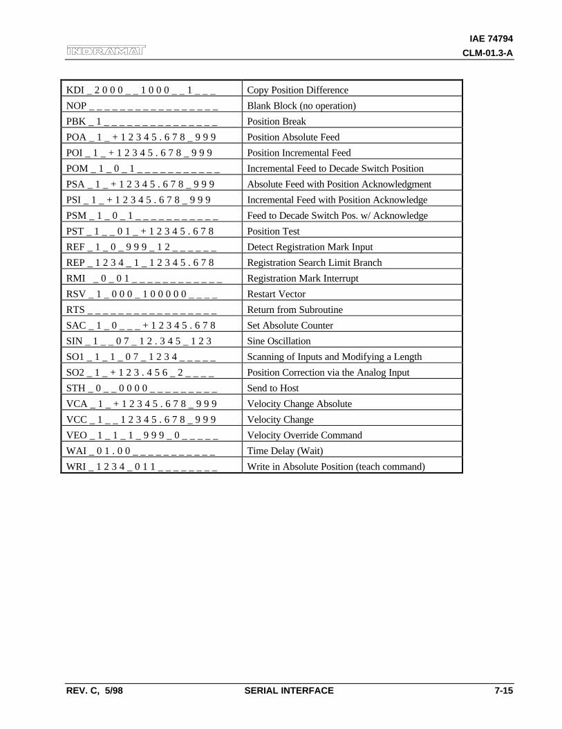
IAE 74794
CLM-01.3-A
REV. C, 5/98 SERIAL INTERFACE 7-15
KDI _ 2 0 0 0 _ _ 1 0 0 0 _ _ 1 _ _ _ Copy Position Difference
NOP _ _ _ _ _ _ _ _ _ _ _ _ _ _ _ _ _ Blank Block (no operation)
PBK _ 1 _ _ _ _ _ _ _ _ _ _ _ _ _ _ _ Position Break
POA _ 1 _ + 1 2 3 4 5 . 6 7 8 _ 9 9 9 Position Absolute Feed
POI _ 1 _ + 1 2 3 4 5 . 6 7 8 _ 9 9 9 Position Incremental Feed
POM _ 1 _ 0 _ 1 _ _ _ _ _ _ _ _ _ _ _ Incremental Feed to Decade Switch Position
PSA _ 1 _ + 1 2 3 4 5 . 6 7 8 _ 9 9 9 Absolute Feed with Position Acknowledgment
PSI _ 1 _ + 1 2 3 4 5 . 6 7 8 _ 9 9 9 Incremental Feed with Position Acknowledge
PSM _ 1 _ 0 _ 1 _ _ _ _ _ _ _ _ _ _ _ Feed to Decade Switch Pos. w/ Acknowledge
PST _ 1 _ _ 0 1 _ + 1 2 3 4 5 . 6 7 8 Position Test
REF _ 1 _ 0 _ 9 9 9 _ 1 2 _ _ _ _ _ _ Detect Registration Mark Input
REP _ 1 2 3 4 _ 1 _ 1 2 3 4 5 . 6 7 8 Registration Search Limit Branch
RMI _ 0 _ 0 1 _ _ _ _ _ _ _ _ _ _ _ _ Registration Mark Interrupt
RSV _ 1 _ 0 0 0 _ 1 0 0 0 0 0 _ _ _ _ Restart Vector
RTS _ _ _ _ _ _ _ _ _ _ _ _ _ _ _ _ _ Return from Subroutine
SAC _ 1 _ 0 _ _ _ + 1 2 3 4 5 . 6 7 8 Set Absolute Counter
SIN _ 1 _ _ 0 7 _ 1 2 . 3 4 5 _ 1 2 3 Sine Oscillation
SO1 _ 1 _ 1 _ 0 7 _ 1 2 3 4 _ _ _ _ _ Scanning of Inputs and Modifying a Length
SO2 _ 1 _ + 1 2 3 . 4 5 6 _ 2 _ _ _ _ Position Correction via the Analog Input
STH _ 0 _ _ 0 0 0 0 _ _ _ _ _ _ _ _ _ Send to Host
VCA _ 1 _ + 1 2 3 4 5 . 6 7 8 _ 9 9 9 Velocity Change Absolute
VCC _ 1 _ _ 1 2 3 4 5 . 6 7 8 _ 9 9 9 Velocity Change
VEO _ 1 _ 1 _ 1 _ 9 9 9 _ 0 _ _ _ _ _ Velocity Override Command
WAI _ 0 1 . 0 0 _ _ _ _ _ _ _ _ _ _ _ Time Delay (Wait)
WRI _ 1 2 3 4 _ 0 1 1 _ _ _ _ _ _ _ _ Write in Absolute Position (teach command)
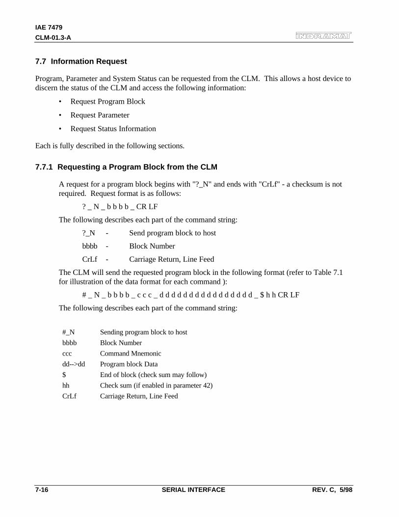
IAE 7479
CLM-01.3-A
7-16 SERIAL INTERFACE REV. C, 5/98
7.7 Information Request
Program, Parameter and System Status can be requested from the CLM. This allows a host device todiscern the status of the CLM and access the following information:
• Request Program Block
• Request Parameter
• Request Status Information
Each is fully described in the following sections.
7.7.1 Requesting a Program Block from the CLM
A request for a program block begins with "?_N" and ends with "CrLf" - a checksum is notrequired. Request format is as follows:
? _ N _ b b b b _ CR LF
The following describes each part of the command string:
?_N - Send program block to host
bbbb - Block Number
CrLf - Carriage Return, Line Feed
The CLM will send the requested program block in the following format (refer to Table 7.1for illustration of the data format for each command ):
# _ N _ b b b b _ c c c _ d d d d d d d d d d d d d d d d _ $ h h CR LF
The following describes each part of the command string:
#_N Sending program block to host
bbbb Block Number
ccc Command Mnemonic
dd-->dd Program block Data
$ End of block (check sum may follow)
hh Check sum (if enabled in parameter 42)
CrLf Carriage Return, Line Feed
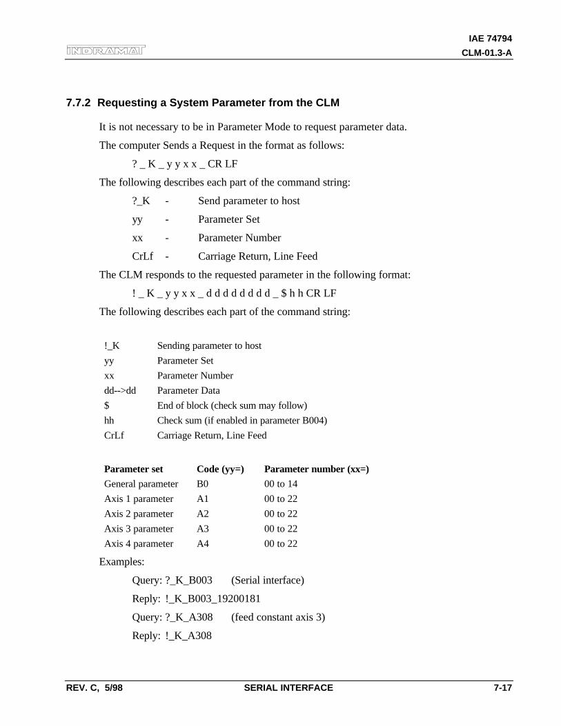
IAE 74794
CLM-01.3-A
REV. C, 5/98 SERIAL INTERFACE 7-17
7.7.2 Requesting a System Parameter from the CLM
It is not necessary to be in Parameter Mode to request parameter data.
The computer Sends a Request in the format as follows:
? _ K _ y y x x _ CR LF
The following describes each part of the command string:
?_K - Send parameter to host
yy - Parameter Set
xx - Parameter Number
CrLf - Carriage Return, Line Feed
The CLM responds to the requested parameter in the following format:
! _ K _ y y x x _ d d d d d d d d _ $ h h CR LF
The following describes each part of the command string:
!_K Sending parameter to host
yy Parameter Set
xx Parameter Number
dd-->dd Parameter Data
$ End of block (check sum may follow)
hh Check sum (if enabled in parameter B004)
CrLf Carriage Return, Line Feed
Parameter set Code (yy=) Parameter number (xx=)
General parameter B0 00 to 14
Axis 1 parameter A1 00 to 22
Axis 2 parameter A2 00 to 22
Axis 3 parameter A3 00 to 22
Axis 4 parameter A4 00 to 22
Examples:
Query: ?_K_B003 (Serial interface)
Reply: !_K_B003_19200181
Query: ?_K_A308 (feed constant axis 3)
Reply: !_K_A308
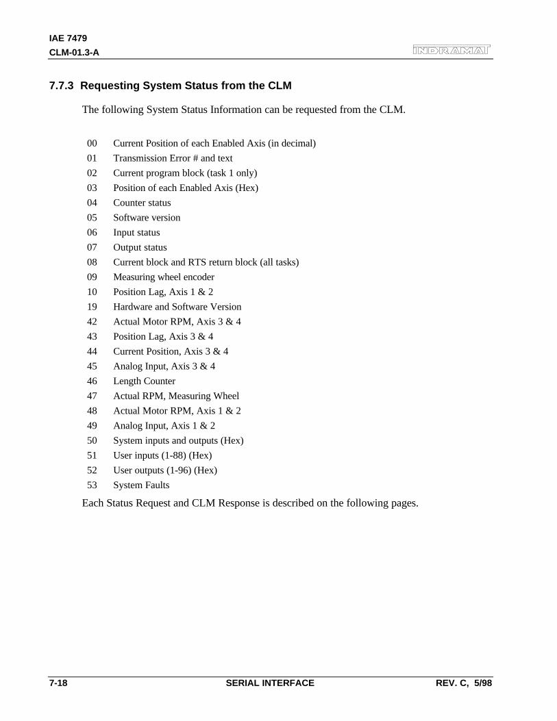
IAE 7479
CLM-01.3-A
7-18 SERIAL INTERFACE REV. C, 5/98
7.7.3 Requesting System Status from the CLM
The following System Status Information can be requested from the CLM.
00 Current Position of each Enabled Axis (in decimal)
01 Transmission Error # and text
02 Current program block (task 1 only)
03 Position of each Enabled Axis (Hex)
04 Counter status
05 Software version
06 Input status
07 Output status
08 Current block and RTS return block (all tasks)
09 Measuring wheel encoder
10 Position Lag, Axis 1 & 2
19 Hardware and Software Version
42 Actual Motor RPM, Axis 3 & 4
43 Position Lag, Axis 3 & 4
44 Current Position, Axis 3 & 4
45 Analog Input, Axis 3 & 4
46 Length Counter
47 Actual RPM, Measuring Wheel
48 Actual Motor RPM, Axis 1 & 2
49 Analog Input, Axis 1 & 2
50 System inputs and outputs (Hex)
51 User inputs (1-88) (Hex)
52 User outputs (1-96) (Hex)
53 System Faults
Each Status Request and CLM Response is described on the following pages.
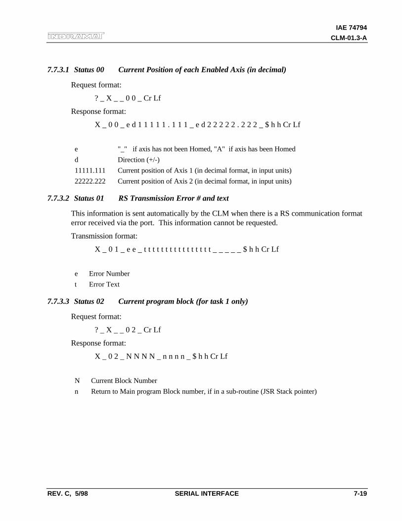
IAE 74794
CLM-01.3-A
REV. C, 5/98 SERIAL INTERFACE 7-19
7.7.3.1 Status 00 Current Position of each Enabled Axis (in decimal)
Request format:
? _ X _ _ 0 0 _ Cr Lf
Response format:
X _ 0 0 _ e d 1 1 1 1 1 . 1 1 1 _ e d 2 2 2 2 2 . 2 2 2 _ $ h h Cr Lf
e "_" if axis has not been Homed, "A" if axis has been Homed
d Direction (+/-)
11111.111 Current position of Axis 1 (in decimal format, in input units)
22222.222 Current position of Axis 2 (in decimal format, in input units)
7.7.3.2 Status 01 RS Transmission Error # and text
This information is sent automatically by the CLM when there is a RS communication formaterror received via the port. This information cannot be requested.
Transmission format:
X _ 0 1 _ e e _ t t t t t t t t t t t t t t t t _ _ _ _ _ $ h h Cr Lf
e Error Number
t Error Text
7.7.3.3 Status 02 Current program block (for task 1 only)
Request format:
? _ X _ _ 0 2 _ Cr Lf
Response format:
X _ 0 2 _ N N N N _ n n n n _ $ h h Cr Lf
N Current Block Number
n Return to Main program Block number, if in a sub-routine (JSR Stack pointer)
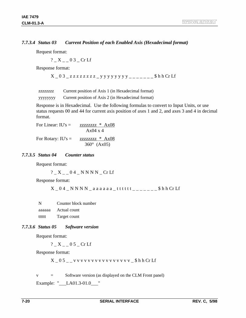
IAE 7479
CLM-01.3-A
7-20 SERIAL INTERFACE REV. C, 5/98
7.7.3.4 Status 03 Current Position of each Enabled Axis (Hexadecimal format)
Request format:
? _ X _ _ 0 3 _ Cr Lf
Response format:
X _ 0 3 _ z z z z z z z z _ y y y y y y y y _ _ _ _ _ _ _ $ h h Cr Lf
zzzzzzzz Current position of Axis 1 (in Hexadecimal format)
yyyyyyyy Current position of Axis 2 (in Hexadecimal format)
Response is in Hexadecimal. Use the following formulas to convert to Input Units, or usestatus requests 00 and 44 for current axis position of axes 1 and 2, and axes 3 and 4 in decimalformat.
For Linear: IU's = zzzzzzzz * Ax08 Ax04 x 4
For Rotary: IU's = zzzzzzzz * Ax08 360° (Ax05)
7.7.3.5 Status 04 Counter status
Request format:
? _ X _ _ 0 4 _ N N N N _ Cr Lf
Response format:
X _ 0 4 _ N N N N _ a a a a a a _ t t t t t t _ _ _ _ _ _ _ $ h h Cr Lf
N Counter block number
aaaaaa Actual count
tttttt Target count
7.7.3.6 Status 05 Software version
Request format:
? _ X _ _ 0 5 _ Cr Lf
Response format:
X _ 0 5 _ _ v v v v v v v v v v v v v v v v _ $ h h Cr Lf
v = Software version (as displayed on the CLM Front panel)
Example: "___LA01.3-01.0___"
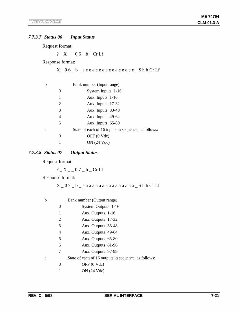
IAE 74794
CLM-01.3-A
REV. C, 5/98 SERIAL INTERFACE 7-21
7.7.3.7 Status 06 Input Status
Request format:
? _ X _ _ 0 6 _ b _ Cr Lf
Response format:
X _ 0 6 _ b _ e e e e e e e e e e e e e e e e _ $ h h Cr Lf
b Bank number (Input range)
0 System Inputs 1-16
1 Aux. Inputs 1-16
2 Aux. Inputs 17-32
3 Aux. Inputs 33-48
4 Aux. Inputs 49-64
5 Aux. Inputs 65-80
e State of each of 16 inputs in sequence, as follows:
0 OFF (0 Vdc)
1 ON (24 Vdc)
7.7.3.8 Status 07 Output Status
Request format:
? _ X _ _ 0 7 _ b _ Cr Lf
Response format:
X _ 0 7 _ b _ a a a a a a a a a a a a a a a a _ $ h h Cr Lf
b Bank number (Output range)
0 System Outputs 1-16
1 Aux. Outputs 1-16
2 Aux. Outputs 17-32
3 Aux. Outputs 33-48
4 Aux. Outputs 49-64
5 Aux. Outputs 65-80
6 Aux. Outputs 81-96
7 Aux. Outputs 97-99
a State of each of 16 outputs in sequence, as follows:
0 OFF (0 Vdc)
1 ON (24 Vdc)
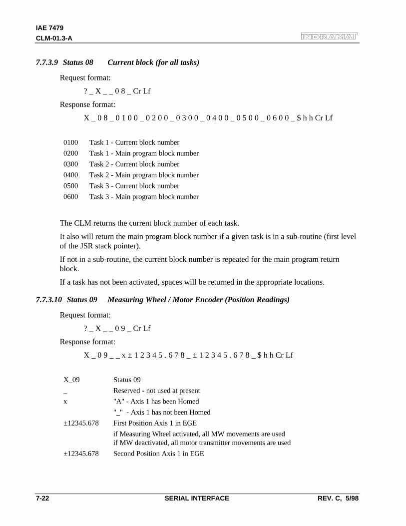
IAE 7479
CLM-01.3-A
7-22 SERIAL INTERFACE REV. C, 5/98
7.7.3.9 Status 08 Current block (for all tasks)
Request format:
? _ X _ _ 0 8 _ Cr Lf
Response format:
X _ 0 8 _ 0 1 0 0 _ 0 2 0 0 _ 0 3 0 0 _ 0 4 0 0 _ 0 5 0 0 _ 0 6 0 0 _ $ h h Cr Lf
0100 Task 1 - Current block number
0200 Task 1 - Main program block number
0300 Task 2 - Current block number
0400 Task 2 - Main program block number
0500 Task 3 - Current block number
0600 Task 3 - Main program block number
The CLM returns the current block number of each task.
It also will return the main program block number if a given task is in a sub-routine (first levelof the JSR stack pointer).
If not in a sub-routine, the current block number is repeated for the main program returnblock.
If a task has not been activated, spaces will be returned in the appropriate locations.
7.7.3.10 Status 09 Measuring Wheel / Motor Encoder (Position Readings)
Request format:
? _ X _ _ 0 9 _ Cr Lf
Response format:
X _ 0 9 _ _ x ± 1 2 3 4 5 . 6 7 8 _ ± 1 2 3 4 5 . 6 7 8 _ $ h h Cr Lf
X_09 Status 09
_ Reserved - not used at present
x "A" - Axis 1 has been Homed
"_" - Axis 1 has not been Homed
±12345.678 First Position Axis 1 in EGE
if Measuring Wheel activated, all MW movements are usedif MW deactivated, all motor transmitter movements are used
±12345.678 Second Position Axis 1 in EGE
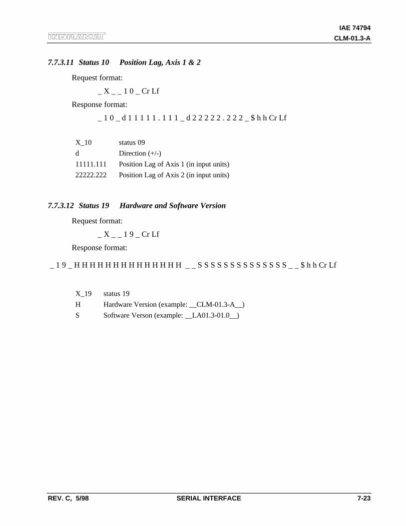
IAE 74794
CLM-01.3-A
REV. C, 5/98 SERIAL INTERFACE 7-23
7.7.3.11 Status 10 Position Lag, Axis 1 & 2
Request format:
_ X _ _ 1 0 _ Cr Lf
Response format:
_ 1 0 _ d 1 1 1 1 1 . 1 1 1 _ d 2 2 2 2 2 . 2 2 2 _ $ h h Cr Lf
X_10 status 09
d Direction (+/-)
11111.111 Position Lag of Axis 1 (in input units)
22222.222 Position Lag of Axis 2 (in input units)
7.7.3.12 Status 19 Hardware and Software Version
Request format:
_ X _ _ 1 9 _ Cr Lf
Response format:
_ 1 9 _ H H H H H H H H H H H H H H _ _ S S S S S S S S S S S S S S _ _ $ h h Cr Lf
X_19 status 19
H Hardware Version (example: __CLM-01.3-A__)
S Software Verson (example: __LA01.3-01.0__)
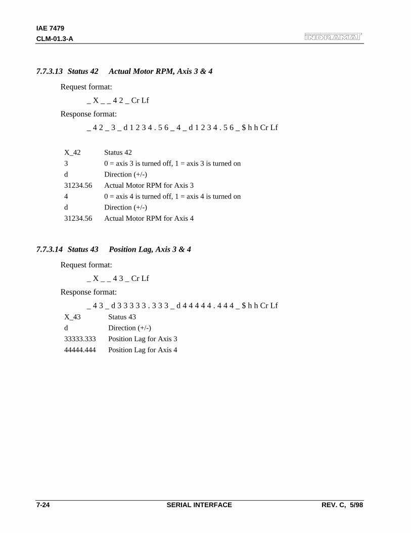
IAE 7479
CLM-01.3-A
7-24 SERIAL INTERFACE REV. C, 5/98
7.7.3.13 Status 42 Actual Motor RPM, Axis 3 & 4
Request format:
_ X _ _ 4 2 _ Cr Lf
Response format:
_ 4 2 _ 3 _ d 1 2 3 4 . 5 6 _ 4 _ d 1 2 3 4 . 5 6 _ $ h h Cr Lf
X_42 Status 42
3 0 = axis 3 is turned off, 1 = axis 3 is turned on
d Direction (+/-)
31234.56 Actual Motor RPM for Axis 3
4 0 = axis 4 is turned off, 1 = axis 4 is turned on
d Direction (+/-)
31234.56 Actual Motor RPM for Axis 4
7.7.3.14 Status 43 Position Lag, Axis 3 & 4
Request format:
_ X _ _ 4 3 _ Cr Lf
Response format:
_ 4 3 _ d 3 3 3 3 3 . 3 3 3 _ d 4 4 4 4 4 . 4 4 4 _ $ h h Cr LfX_43 Status 43
d Direction (+/-)
33333.333 Position Lag for Axis 3
44444.444 Position Lag for Axis 4
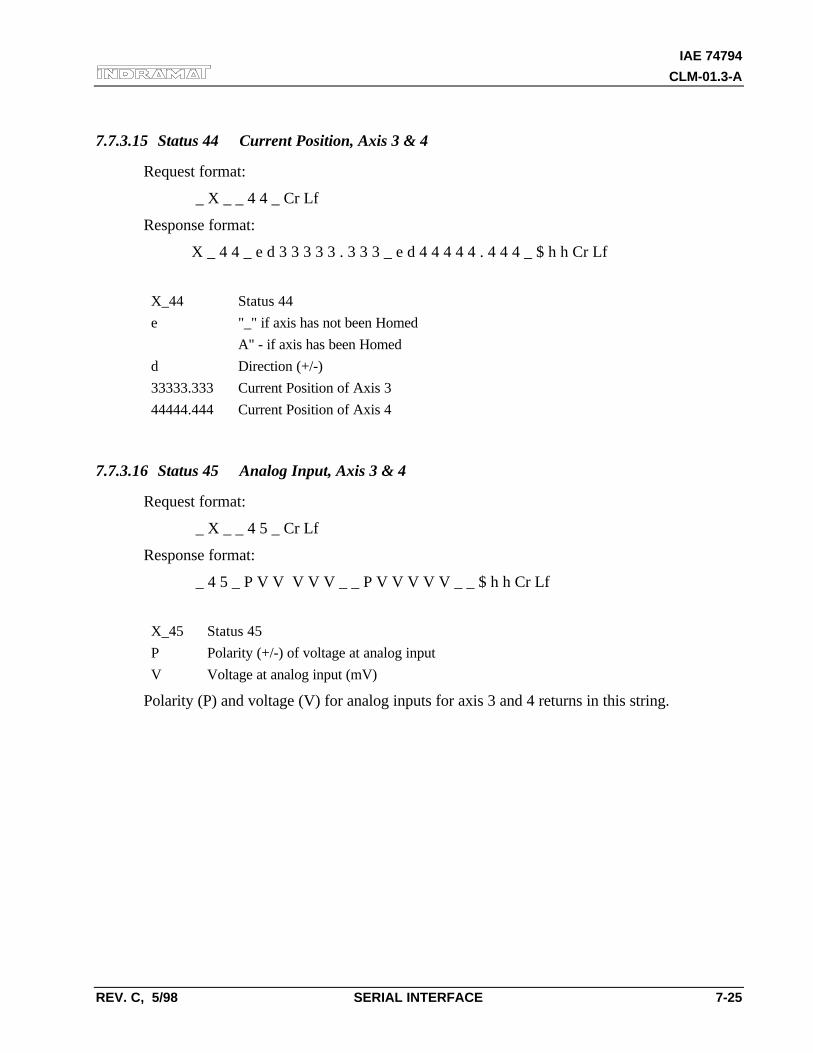
IAE 74794
CLM-01.3-A
REV. C, 5/98 SERIAL INTERFACE 7-25
7.7.3.15 Status 44 Current Position, Axis 3 & 4
Request format:
_ X _ _ 4 4 _ Cr Lf
Response format:
X _ 4 4 _ e d 3 3 3 3 3 . 3 3 3 _ e d 4 4 4 4 4 . 4 4 4 _ $ h h Cr Lf
X_44 Status 44
e "_" if axis has not been Homed
A" - if axis has been Homed
d Direction (+/-)
33333.333 Current Position of Axis 3
44444.444 Current Position of Axis 4
7.7.3.16 Status 45 Analog Input, Axis 3 & 4
Request format:
_ X _ _ 4 5 _ Cr Lf
Response format:
_ 4 5 _ P V V V V V _ _ P V V V V V _ _ $ h h Cr Lf
X_45 Status 45
P Polarity (+/-) of voltage at analog input
V Voltage at analog input (mV)
Polarity (P) and voltage (V) for analog inputs for axis 3 and 4 returns in this string.
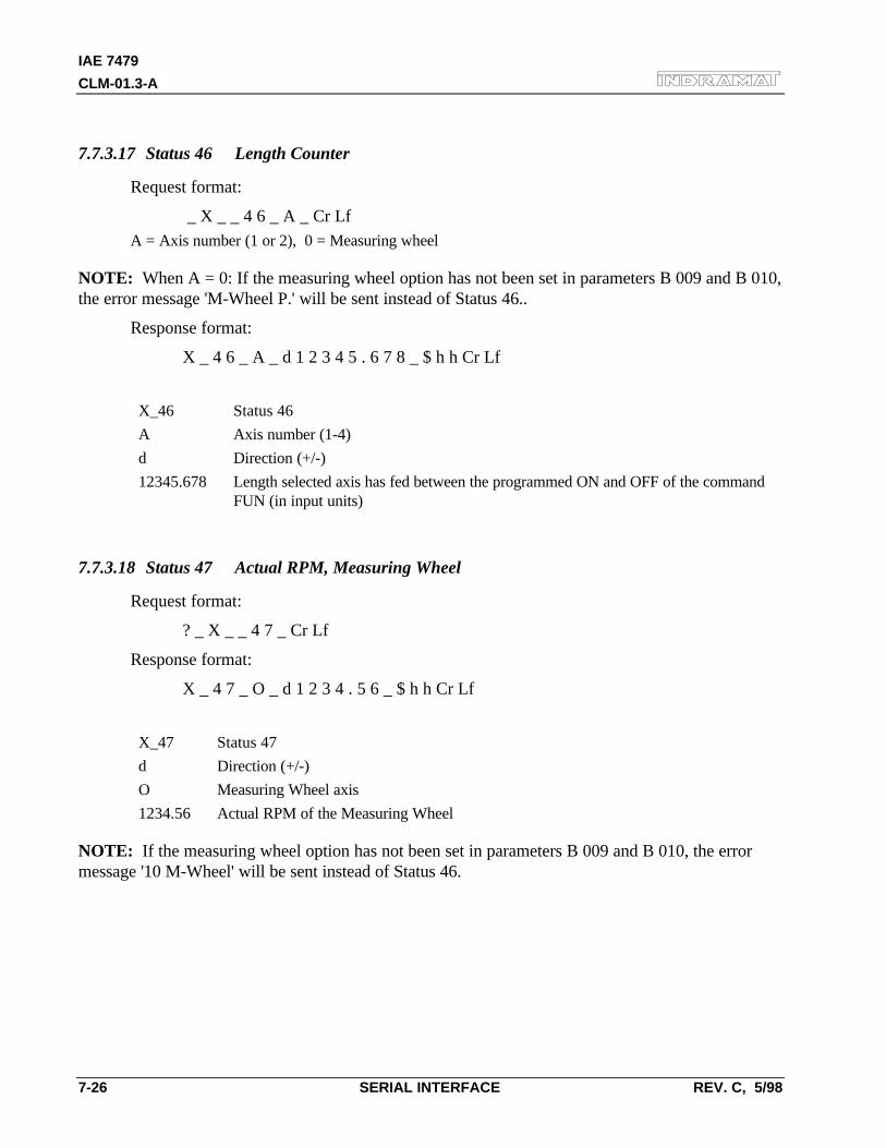
IAE 7479
CLM-01.3-A
7-26 SERIAL INTERFACE REV. C, 5/98
7.7.3.17 Status 46 Length Counter
Request format:
_ X _ _ 4 6 _ A _ Cr LfA = Axis number (1 or 2), 0 = Measuring wheel
NOTE: When A = 0: If the measuring wheel option has not been set in parameters B 009 and B 010,the error message 'M-Wheel P.' will be sent instead of Status 46..
Response format:
X _ 4 6 _ A _ d 1 2 3 4 5 . 6 7 8 _ $ h h Cr Lf
X_46 Status 46
A Axis number (1-4)
d Direction (+/-)
12345.678 Length selected axis has fed between the programmed ON and OFF of the commandFUN (in input units)
7.7.3.18 Status 47 Actual RPM, Measuring Wheel
Request format:
? _ X _ _ 4 7 _ Cr Lf
Response format:
X _ 4 7 _ O _ d 1 2 3 4 . 5 6 _ $ h h Cr Lf
X_47 Status 47
d Direction (+/-)
O Measuring Wheel axis
1234.56 Actual RPM of the Measuring Wheel
NOTE: If the measuring wheel option has not been set in parameters B 009 and B 010, the errormessage '10 M-Wheel' will be sent instead of Status 46.
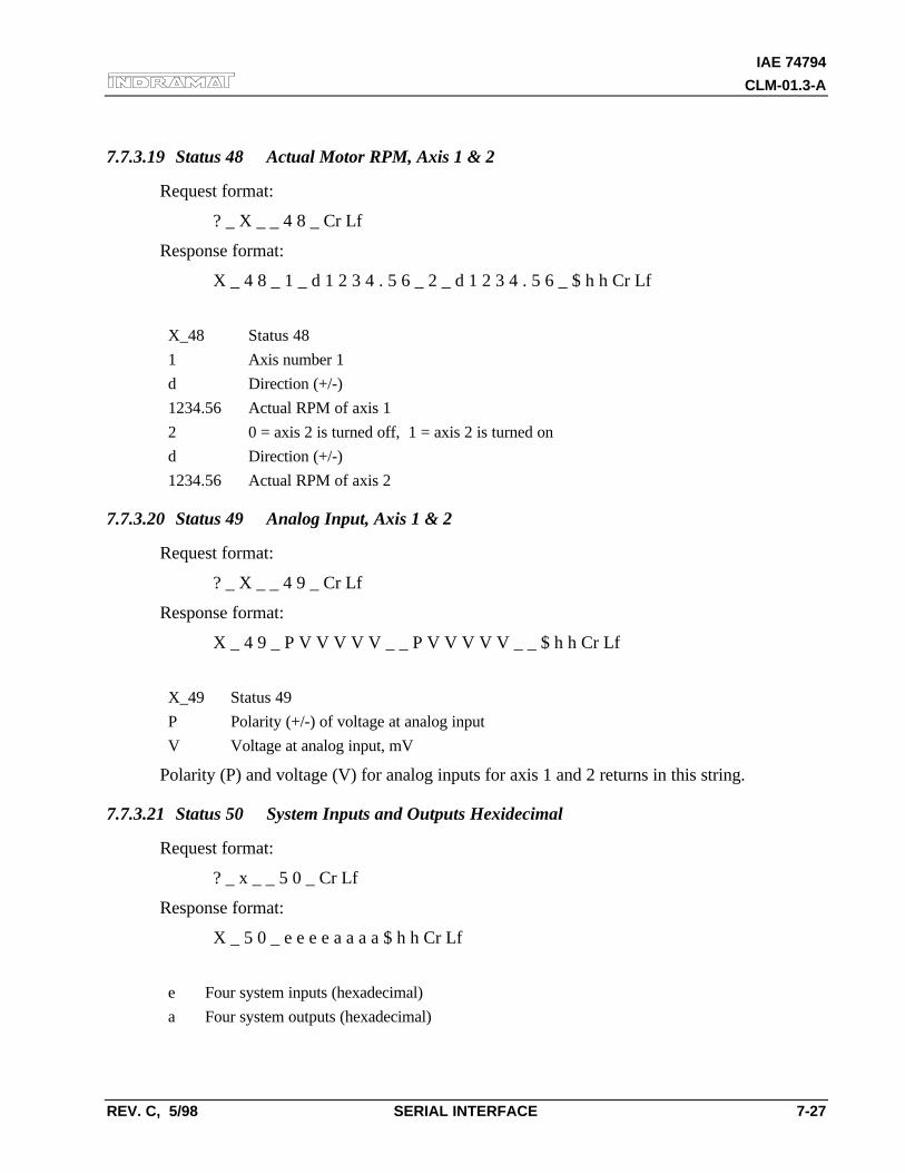
IAE 74794
CLM-01.3-A
REV. C, 5/98 SERIAL INTERFACE 7-27
7.7.3.19 Status 48 Actual Motor RPM, Axis 1 & 2
Request format:
? _ X _ _ 4 8 _ Cr Lf
Response format:
X _ 4 8 _ 1 _ d 1 2 3 4 . 5 6 _ 2 _ d 1 2 3 4 . 5 6 _ $ h h Cr Lf
X_48 Status 48
1 Axis number 1
d Direction (+/-)
1234.56 Actual RPM of axis 1
2 0 = axis 2 is turned off, 1 = axis 2 is turned on
d Direction (+/-)
1234.56 Actual RPM of axis 2
7.7.3.20 Status 49 Analog Input, Axis 1 & 2
Request format:
? _ X _ _ 4 9 _ Cr Lf
Response format:
X _ 4 9 _ P V V V V V _ _ P V V V V V _ _ $ h h Cr Lf
X_49 Status 49
P Polarity (+/-) of voltage at analog input
V Voltage at analog input, mV
Polarity (P) and voltage (V) for analog inputs for axis 1 and 2 returns in this string.
7.7.3.21 Status 50 System Inputs and Outputs Hexidecimal
Request format:
? _ x _ _ 5 0 _ Cr Lf
Response format:
X _ 5 0 _ e e e e a a a a $ h h Cr Lf
e Four system inputs (hexadecimal)
a Four system outputs (hexadecimal)
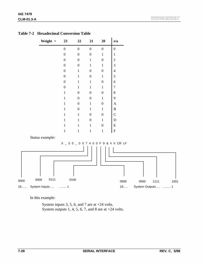
IAE 7479
CLM-01.3-A
7-28 SERIAL INTERFACE REV. C, 5/98
Table 7-2 Hexadecimal Conversion Table
Weight = 23 22 21 20 e/a
0 0 0 0 0
0 0 0 1 1
0 0 1 0 2
0 0 1 1 3
0 1 0 0 4
0 1 0 1 5
0 1 1 0 6
0 1 1 1 7
1 0 0 0 8
1 0 0 1 9
1 0 1 0 A
1 0 1 1 B
1 1 0 0 C
1 1 0 1 D
1 1 1 0 E
1 1 1 1 F
Status example:
X _ 5 0 _ 0 0 7 4 0 0 F 9 & h h CR LF
0000 0000 0111 0100 0000 0000 1111 1001
16...... System Inputs .... ........ 1 16..... System Outputs .... ......... 1
In this example:
System inputs 3, 5, 6, and 7 are at +24 volts.System outputs 1, 4, 5, 6, 7, and 8 are at +24 volts.
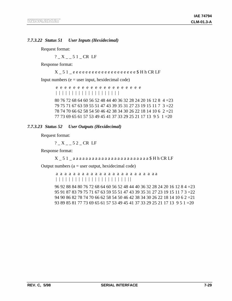
IAE 74794
CLM-01.3-A
REV. C, 5/98 SERIAL INTERFACE 7-29
7.7.3.22 Status 51 User Inputs (Hexidecimal)
Request format:
? _ X _ _ 5 1 _ CR LF
Response format:
X _ 5 1 _ e e e e e e e e e e e e e e e e e e e e $ H h CR LF
Input numbers (e = user input, hexidecimal code)
e e e e e e e e e e e e e e e e e e e e | | | | | | | | | | | | | | | | | | | |
80 76 72 68 64 60 56 52 48 44 40 36 32 28 24 20 16 12 8 4 =2379 75 71 67 63 59 55 51 47 43 39 35 31 27 23 19 15 11 7 3 =2278 74 70 66 62 58 54 50 46 42 38 34 30 26 22 18 14 10 6 2 =2177 73 69 65 61 57 53 49 45 41 37 33 29 25 21 17 13 9 5 1 =20
7.7.3.23 Status 52 User Outputs (Hexidecimal)
Request format:
? _ X _ _ 5 2 _ CR LF
Response format:
X _ 5 1 _ a a a a a a a a a a a a a a a a a a a a a a a a $ H h CR LF
Output numbers (a = user output, hexidecimal code)
a a a a a a a a a a a a a a a a a a a a a a a a | | | | | | | | | | | | | | | | | | | | | | | |
96 92 88 84 80 76 72 68 64 60 56 52 48 44 40 36 32 28 24 20 16 12 8 4 =2395 91 87 83 79 75 71 67 63 59 55 51 47 43 39 35 31 27 23 19 15 11 7 3 =2294 90 86 82 78 74 70 66 62 58 54 50 46 42 38 34 30 26 22 18 14 10 6 2 =2193 89 85 81 77 73 69 65 61 57 53 49 45 41 37 33 29 25 21 17 13 9 5 1 =20
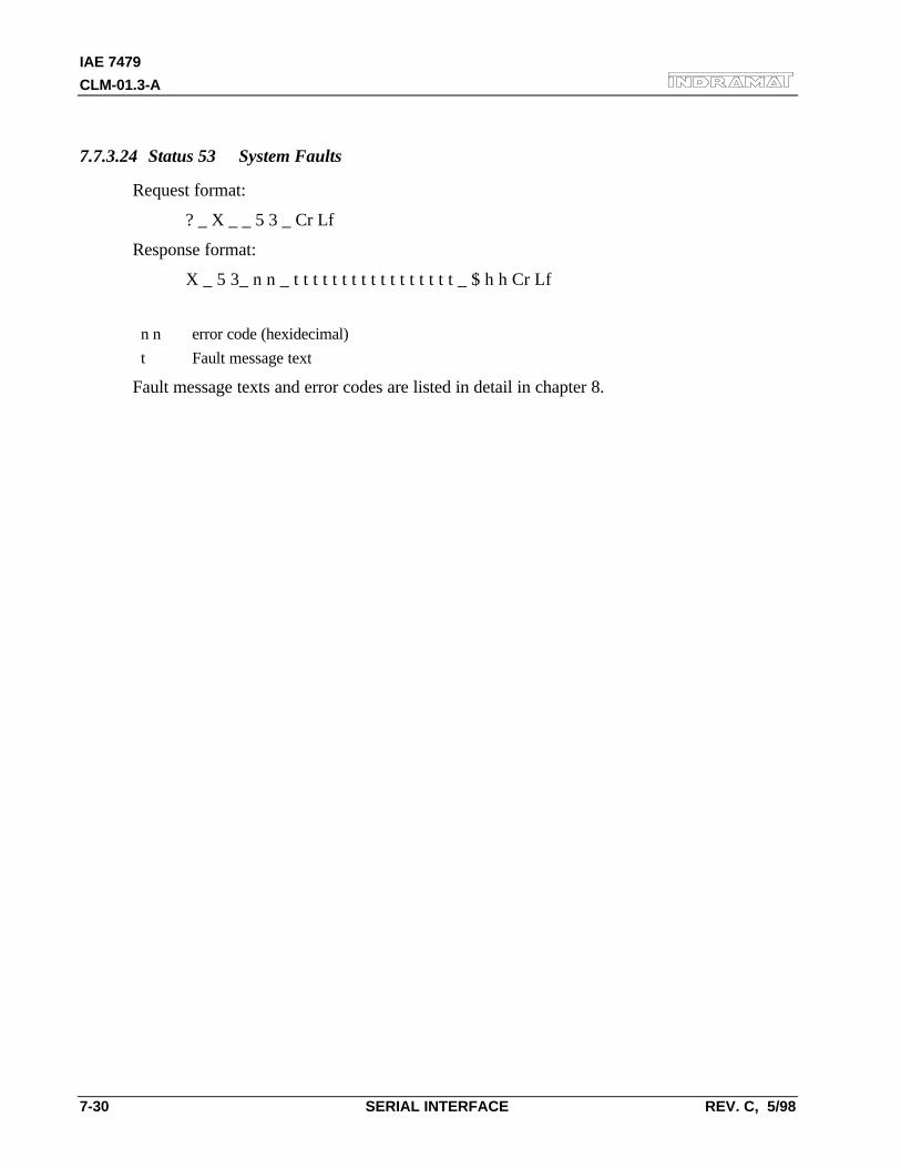
IAE 7479
CLM-01.3-A
7-30 SERIAL INTERFACE REV. C, 5/98
7.7.3.24 Status 53 System Faults
Request format:
? _ X _ _ 5 3 _ Cr Lf
Response format:
X _ 5 3_ n n _ t t t t t t t t t t t t t t t t t _ $ h h Cr Lf
n n error code (hexidecimal)
t Fault message text
Fault message texts and error codes are listed in detail in chapter 8.
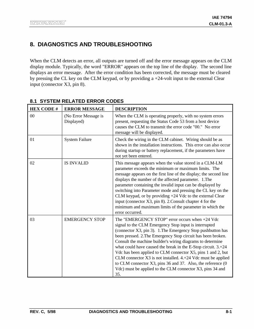
IAE 74794
CLM-01.3-A
REV. C, 5/98 DIAGNOSTICS AND TROUBLESHOOTING 8-1
8. DIAGNOSTICS AND TROUBLESHOOTING
When the CLM detects an error, all outputs are turned off and the error message appears on the CLMdisplay module. Typically, the word "ERROR" appears on the top line of the display. The second linedisplays an error message. After the error condition has been corrected, the message must be clearedby pressing the CL key on the CLM keypad, or by providing a +24-volt input to the external Clearinput (connector X3, pin 8).
8.1 SYSTEM RELATED ERROR CODES
HEX CODE # ERROR MESSAGE DESCRIPTION
00 (No Error Message isDisplayed)
When the CLM is operating properly, with no system errorspresent, requesting the Status Code 53 from a host devicecauses the CLM to transmit the error code "00." No errormessage will be displayed.
01 System Failure Check the wiring in the CLM cabinet. Wiring should be asshown in the installation instructions. This error can also occurduring startup or battery replacement, if the parameters havenot yet been entered.
02 IS INVALID This message appears when the value stored in a CLM-LMparameter exceeds the minimum or maximum limits. Themessage appears on the first line of the display; the second linedisplays the number of the affected parameter. 1.Theparameter containing the invalid input can be displayed byswitching into Parameter mode and pressing the CL key on theCLM keypad, or by providing +24 Vdc to the external Clearinput (connector X3, pin 8). 2.Consult chapter 4 for theminimum and maximum limits of the parameter in which theerror occurred.
03 EMERGENCY STOP The "EMERGENCY STOP" error occurs when +24 Vdcsignal to the CLM Emergency Stop input is interrupted(connector X3, pin 3). 1.The Emergency Stop pushbutton hasbeen pressed. 2.The Emergency Stop circuit has been broken.Consult the machine builder's wiring diagrams to determinewhat could have caused the break in the E-Stop circuit. 3.+24Vdc has been applied to CLM connector X5, pins 1 and 2, butCLM connector X3 is not installed. 4.+24 Vdc must be appliedto CLM connector X3, pins 36 and 37. Also, the reference (0Vdc) must be applied to the CLM connector X3, pins 34 and35.
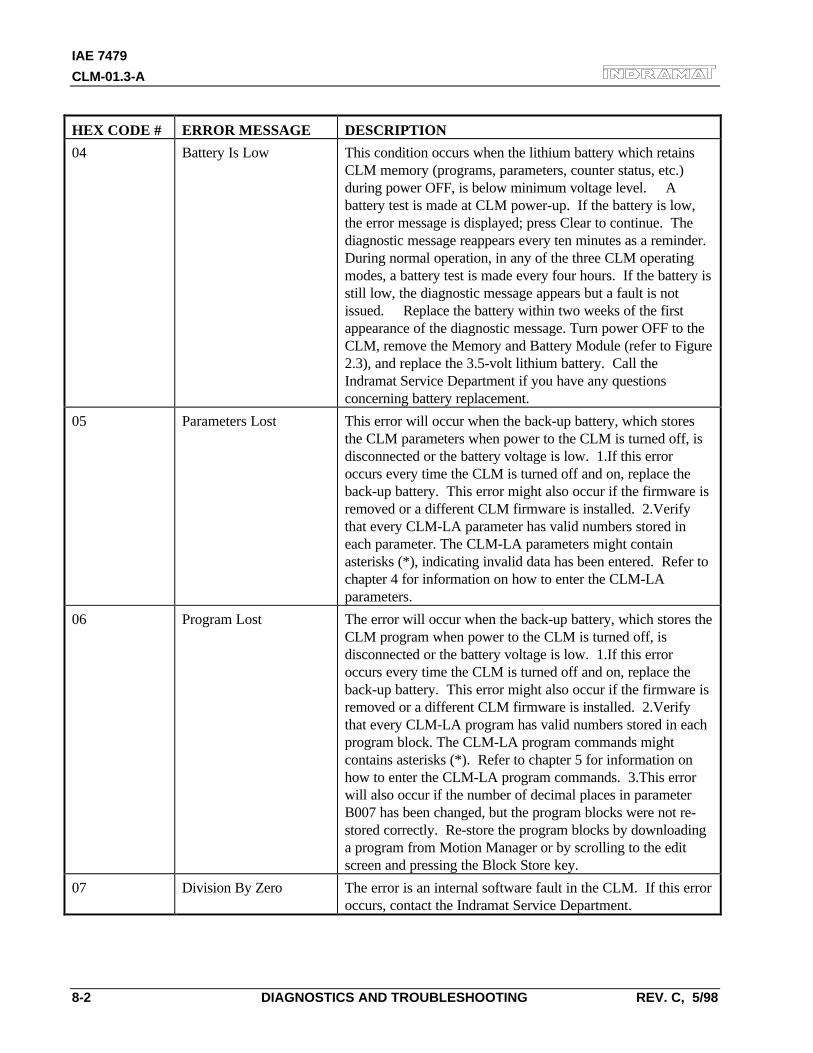
IAE 7479
CLM-01.3-A
8-2 DIAGNOSTICS AND TROUBLESHOOTING REV. C, 5/98
HEX CODE # ERROR MESSAGE DESCRIPTION
04 Battery Is Low This condition occurs when the lithium battery which retainsCLM memory (programs, parameters, counter status, etc.)during power OFF, is below minimum voltage level. Abattery test is made at CLM power-up. If the battery is low,the error message is displayed; press Clear to continue. Thediagnostic message reappears every ten minutes as a reminder.During normal operation, in any of the three CLM operatingmodes, a battery test is made every four hours. If the battery isstill low, the diagnostic message appears but a fault is notissued. Replace the battery within two weeks of the firstappearance of the diagnostic message. Turn power OFF to theCLM, remove the Memory and Battery Module (refer to Figure2.3), and replace the 3.5-volt lithium battery. Call theIndramat Service Department if you have any questionsconcerning battery replacement.
05 Parameters Lost This error will occur when the back-up battery, which storesthe CLM parameters when power to the CLM is turned off, isdisconnected or the battery voltage is low. 1.If this erroroccurs every time the CLM is turned off and on, replace theback-up battery. This error might also occur if the firmware isremoved or a different CLM firmware is installed. 2.Verifythat every CLM-LA parameter has valid numbers stored ineach parameter. The CLM-LA parameters might containasterisks (*), indicating invalid data has been entered. Refer tochapter 4 for information on how to enter the CLM-LAparameters.
06 Program Lost The error will occur when the back-up battery, which stores theCLM program when power to the CLM is turned off, isdisconnected or the battery voltage is low. 1.If this erroroccurs every time the CLM is turned off and on, replace theback-up battery. This error might also occur if the firmware isremoved or a different CLM firmware is installed. 2.Verifythat every CLM-LA program has valid numbers stored in eachprogram block. The CLM-LA program commands mightcontains asterisks (*). Refer to chapter 5 for information onhow to enter the CLM-LA program commands. 3.This errorwill also occur if the number of decimal places in parameterB007 has been changed, but the program blocks were not re-stored correctly. Re-store the program blocks by downloadinga program from Motion Manager or by scrolling to the editscreen and pressing the Block Store key.
07 Division By Zero The error is an internal software fault in the CLM. If this erroroccurs, contact the Indramat Service Department.
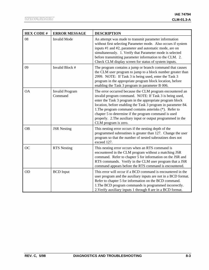
IAE 74794
CLM-01.3-A
REV. C, 5/98 DIAGNOSTICS AND TROUBLESHOOTING 8-3
HEX CODE # ERROR MESSAGE DESCRIPTION
08 Invalid Mode An attempt was made to transmit parameter informationwithout first selecting Parameter mode. Also occurs if systeminputs #1 and #2, parameter and automatic mode, are onsimultaneously. 1. Verify that Parameter mode is selectedbefore transmitting parameter information to the CLM. 2.Check CLM display screen for status of system inputs.
09 Invalid Block # The program contains a jump or branch command that causesthe CLM user program to jump to a block number greater than2999. NOTE: If Task 3 is being used, enter the Task 3program in the appropriate program block location, beforeenabling the Task 3 program in parameter B 006.
OA Invalid ProgramCommand
The error occurred because the CLM program encountered aninvalid program command. NOTE: If Task 3 is being used,enter the Task 3 program in the appropriate program blocklocation, before enabling the Task 3 program in parameter 84.1.The program command contains asterisks (*). Refer tochapter 5 to determine if the program command is usedproperly. 2.The auxiliary input or output programmed in theCLM program is zero.
OB JSR Nesting This nesting error occurs if the nesting depth of theprogrammed subroutines is greater than 127. Change the userprogram so that the number of nested subroutines does notexceed 127.
OC RTS Nesting This nesting error occurs when an RTS command isencountered in the CLM program without a matching JSRcommand. Refer to chapter 5 for information on the JSR andRTS commands. Verify in the CLM user program that a JSRcommand appears before the RTS command is encountered.
OD BCD Input This error will occur if a BCD command is encountered in theuser program and the auxiliary inputs are not in a BCD format.Refer to chapter 5 for information on the BCD command.1.The BCD program commands is programmed incorrectly.2.Verify auxiliary inputs 1 through 8 are in a BCD format.
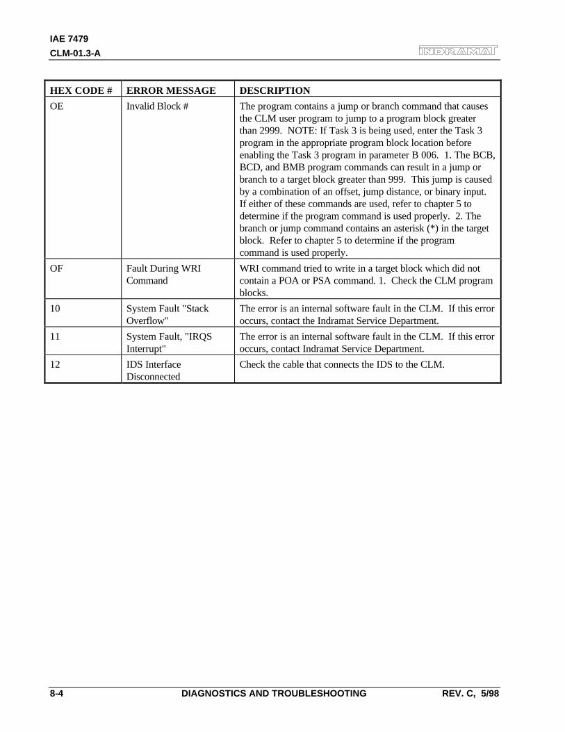
IAE 7479
CLM-01.3-A
8-4 DIAGNOSTICS AND TROUBLESHOOTING REV. C, 5/98
HEX CODE # ERROR MESSAGE DESCRIPTION
OE Invalid Block # The program contains a jump or branch command that causesthe CLM user program to jump to a program block greaterthan 2999. NOTE: If Task 3 is being used, enter the Task 3program in the appropriate program block location beforeenabling the Task 3 program in parameter B 006. 1. The BCB,BCD, and BMB program commands can result in a jump orbranch to a target block greater than 999. This jump is causedby a combination of an offset, jump distance, or binary input.If either of these commands are used, refer to chapter 5 todetermine if the program command is used properly. 2. Thebranch or jump command contains an asterisk (*) in the targetblock. Refer to chapter 5 to determine if the programcommand is used properly.
OF Fault During WRICommand
WRI command tried to write in a target block which did notcontain a POA or PSA command. 1. Check the CLM programblocks.
10 System Fault "StackOverflow"
The error is an internal software fault in the CLM. If this erroroccurs, contact the Indramat Service Department.
11 System Fault, "IRQSInterrupt"
The error is an internal software fault in the CLM. If this erroroccurs, contact Indramat Service Department.
12 IDS InterfaceDisconnected
Check the cable that connects the IDS to the CLM.
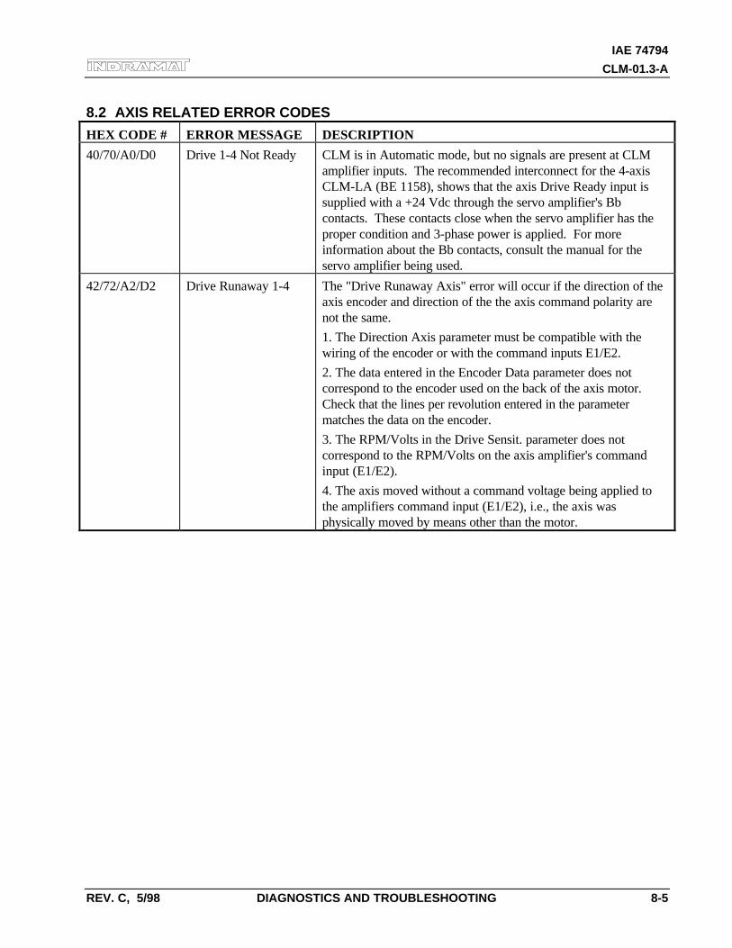
IAE 74794
CLM-01.3-A
REV. C, 5/98 DIAGNOSTICS AND TROUBLESHOOTING 8-5
8.2 AXIS RELATED ERROR CODES
HEX CODE # ERROR MESSAGE DESCRIPTION
40/70/A0/D0 Drive 1-4 Not Ready CLM is in Automatic mode, but no signals are present at CLMamplifier inputs. The recommended interconnect for the 4-axisCLM-LA (BE 1158), shows that the axis Drive Ready input issupplied with a +24 Vdc through the servo amplifier's Bbcontacts. These contacts close when the servo amplifier has theproper condition and 3-phase power is applied. For moreinformation about the Bb contacts, consult the manual for theservo amplifier being used.
42/72/A2/D2 Drive Runaway 1-4 The "Drive Runaway Axis" error will occur if the direction of theaxis encoder and direction of the the axis command polarity arenot the same.
1. The Direction Axis parameter must be compatible with thewiring of the encoder or with the command inputs E1/E2.
2. The data entered in the Encoder Data parameter does notcorrespond to the encoder used on the back of the axis motor.Check that the lines per revolution entered in the parametermatches the data on the encoder.
3. The RPM/Volts in the Drive Sensit. parameter does notcorrespond to the RPM/Volts on the axis amplifier's commandinput (E1/E2).
4. The axis moved without a command voltage being applied tothe amplifiers command input (E1/E2), i.e., the axis wasphysically moved by means other than the motor.
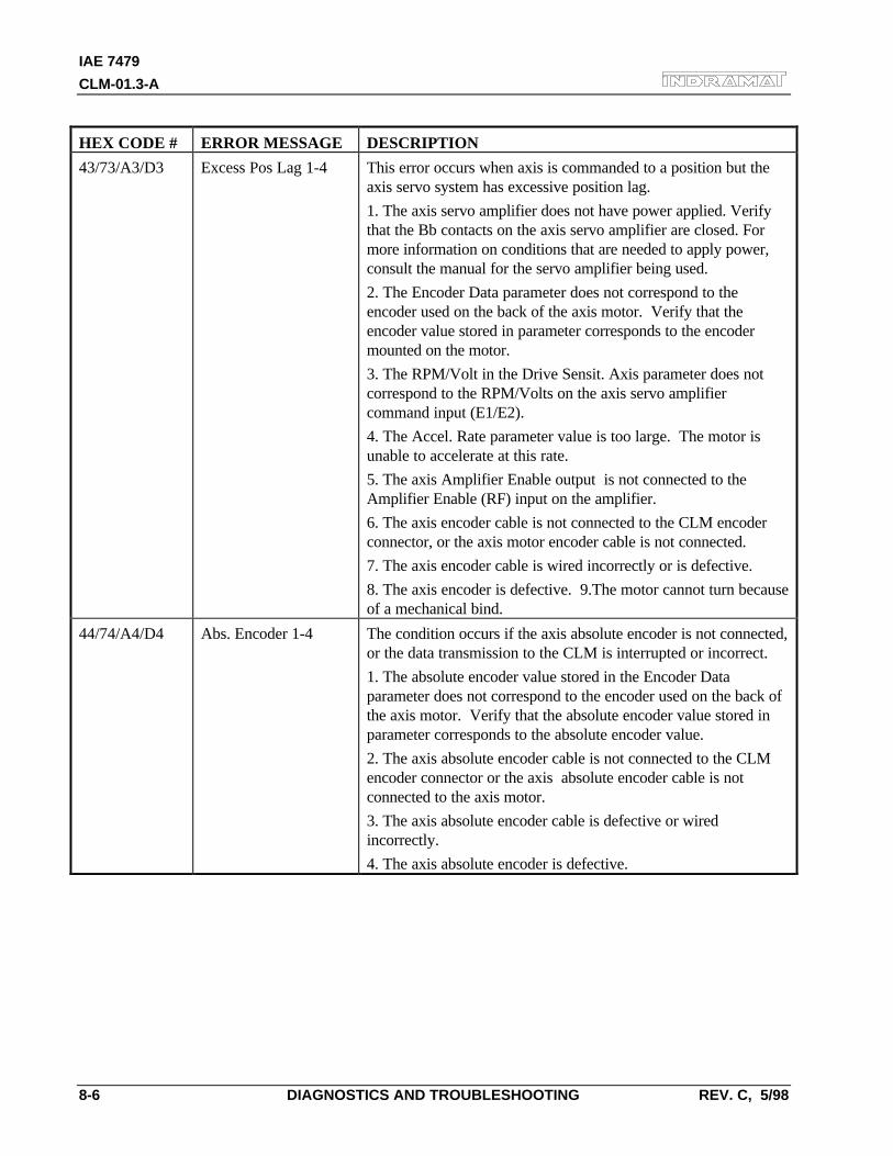
IAE 7479
CLM-01.3-A
8-6 DIAGNOSTICS AND TROUBLESHOOTING REV. C, 5/98
HEX CODE # ERROR MESSAGE DESCRIPTION
43/73/A3/D3 Excess Pos Lag 1-4 This error occurs when axis is commanded to a position but theaxis servo system has excessive position lag.
1. The axis servo amplifier does not have power applied. Verifythat the Bb contacts on the axis servo amplifier are closed. Formore information on conditions that are needed to apply power,consult the manual for the servo amplifier being used.
2. The Encoder Data parameter does not correspond to theencoder used on the back of the axis motor. Verify that theencoder value stored in parameter corresponds to the encodermounted on the motor.
3. The RPM/Volt in the Drive Sensit. Axis parameter does notcorrespond to the RPM/Volts on the axis servo amplifiercommand input (E1/E2).
4. The Accel. Rate parameter value is too large. The motor isunable to accelerate at this rate.
5. The axis Amplifier Enable output is not connected to theAmplifier Enable (RF) input on the amplifier.
6. The axis encoder cable is not connected to the CLM encoderconnector, or the axis motor encoder cable is not connected.
7. The axis encoder cable is wired incorrectly or is defective.
8. The axis encoder is defective. 9.The motor cannot turn becauseof a mechanical bind.
44/74/A4/D4 Abs. Encoder 1-4 The condition occurs if the axis absolute encoder is not connected,or the data transmission to the CLM is interrupted or incorrect.
1. The absolute encoder value stored in the Encoder Dataparameter does not correspond to the encoder used on the back ofthe axis motor. Verify that the absolute encoder value stored inparameter corresponds to the absolute encoder value.
2. The axis absolute encoder cable is not connected to the CLMencoder connector or the axis absolute encoder cable is notconnected to the axis motor.
3. The axis absolute encoder cable is defective or wiredincorrectly.
4. The axis absolute encoder is defective.
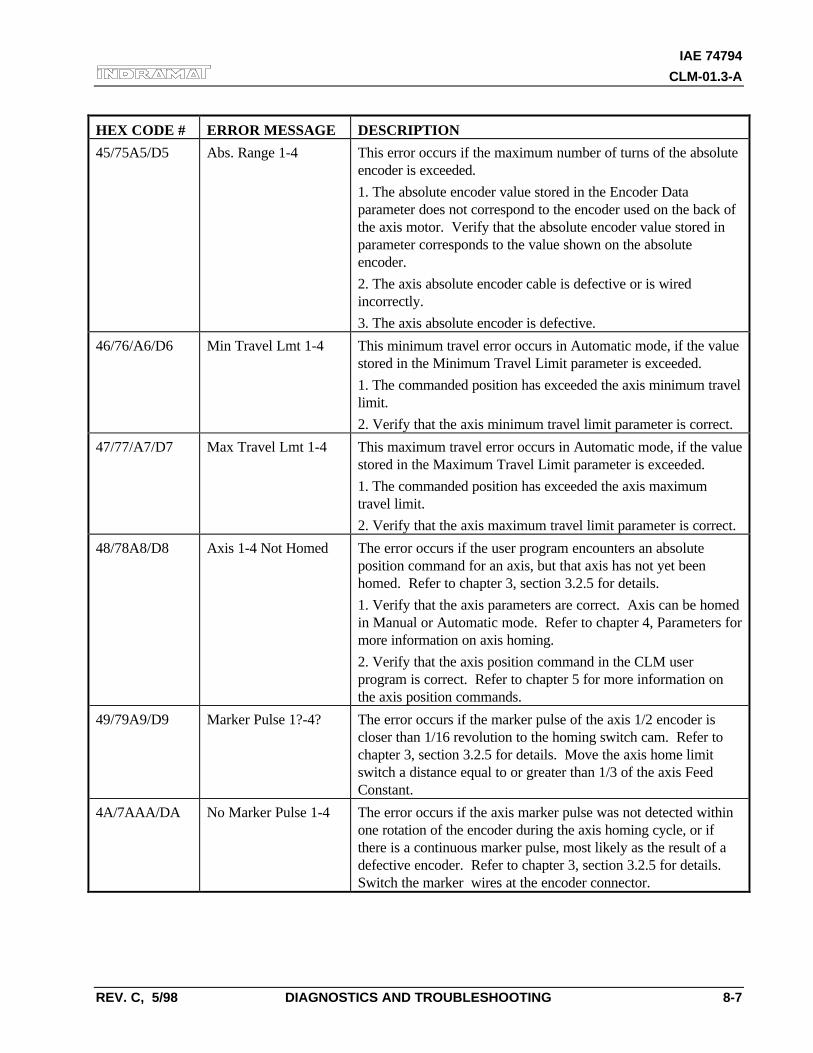
IAE 74794
CLM-01.3-A
REV. C, 5/98 DIAGNOSTICS AND TROUBLESHOOTING 8-7
HEX CODE # ERROR MESSAGE DESCRIPTION
45/75A5/D5 Abs. Range 1-4 This error occurs if the maximum number of turns of the absoluteencoder is exceeded.
1. The absolute encoder value stored in the Encoder Dataparameter does not correspond to the encoder used on the back ofthe axis motor. Verify that the absolute encoder value stored inparameter corresponds to the value shown on the absoluteencoder.
2. The axis absolute encoder cable is defective or is wiredincorrectly.
3. The axis absolute encoder is defective.
46/76/A6/D6 Min Travel Lmt 1-4 This minimum travel error occurs in Automatic mode, if the valuestored in the Minimum Travel Limit parameter is exceeded.
1. The commanded position has exceeded the axis minimum travellimit.
2. Verify that the axis minimum travel limit parameter is correct.
47/77/A7/D7 Max Travel Lmt 1-4 This maximum travel error occurs in Automatic mode, if the valuestored in the Maximum Travel Limit parameter is exceeded.
1. The commanded position has exceeded the axis maximumtravel limit.
2. Verify that the axis maximum travel limit parameter is correct.
48/78A8/D8 Axis 1-4 Not Homed The error occurs if the user program encounters an absoluteposition command for an axis, but that axis has not yet beenhomed. Refer to chapter 3, section 3.2.5 for details.
1. Verify that the axis parameters are correct. Axis can be homedin Manual or Automatic mode. Refer to chapter 4, Parameters formore information on axis homing.
2. Verify that the axis position command in the CLM userprogram is correct. Refer to chapter 5 for more information onthe axis position commands.
49/79A9/D9 Marker Pulse 1?-4? The error occurs if the marker pulse of the axis 1/2 encoder iscloser than 1/16 revolution to the homing switch cam. Refer tochapter 3, section 3.2.5 for details. Move the axis home limitswitch a distance equal to or greater than 1/3 of the axis FeedConstant.
4A/7AAA/DA No Marker Pulse 1-4 The error occurs if the axis marker pulse was not detected withinone rotation of the encoder during the axis homing cycle, or ifthere is a continuous marker pulse, most likely as the result of adefective encoder. Refer to chapter 3, section 3.2.5 for details.Switch the marker wires at the encoder connector.
IAE 74794
CLM-01.3-A
REV. C, 5/98 LA PROGRAMMING NOTES A-1
A. APPENDIX A: LA PROGRAMMING NOTES
A.1 LA PROGRAMMING NOTES
This section is periodically updated with hints and examples of use and application of differentprogramming commands.
Notes included in this section:
Page DescriptionA-1 Axis Homing for the CLMA-7 Aligning a Stegmann Absolute Encoder to a CLM
A.2 Axis Homing for the CLM
A.2.1 General
Homing of a linear or rotary axis is required if you need to do absolute positioning and areusing an incremental position feedback device mounted on the motor or machine. The homingprocess, usually a series of back and forth moves to locate a reference point in relation to amechanical setup, can be accomplished through a variety of methods when using the CLMcontrol. This Programming Note describes several different homing methods in detail.
NOTE: In some applications, for mechanical or safety reasons, the axis cannot be homed after theprocess has started. For these applications, a Synchronous Serial Data (SSD) absolute encoder isrequired. Because an absolute device is capable of providing a known position relative to themachine's mechanical limits at all times, homing is not required.
A.2.2 Normal Homing
The CLM includes a homing routine suitable for most applications. This is described in detailin section 3.2.5 of the CLM manual. This routine, in conjunction with parameters and a homeswitch, provides a fast and easy way for the user to implement a homing sequence. Thisroutine is activated by an input in manual mode or through a short seies of commands inautomatic mode. This home sequence in either mode starts with the selected axis performingthe following steps.
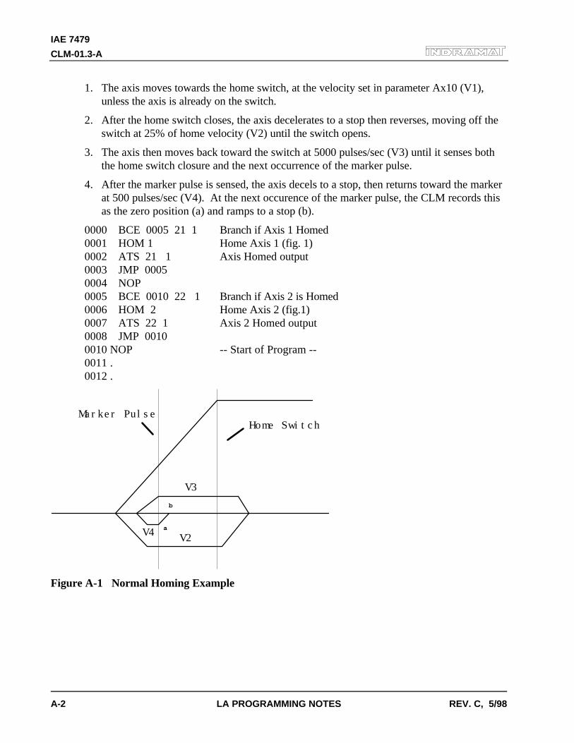
IAE 7479
CLM-01.3-A
A-2 LA PROGRAMMING NOTES REV. C, 5/98
1. The axis moves towards the home switch, at the velocity set in parameter Ax10 (V1),unless the axis is already on the switch.
2. After the home switch closes, the axis decelerates to a stop then reverses, moving off theswitch at 25% of home velocity (V2) until the switch opens.
3. The axis then moves back toward the switch at 5000 pulses/sec (V3) until it senses boththe home switch closure and the next occurrence of the marker pulse.
4. After the marker pulse is sensed, the axis decels to a stop, then returns toward the markerat 500 pulses/sec (V4). At the next occurence of the marker pulse, the CLM records thisas the zero position (a) and ramps to a stop (b).
0000 BCE 0005 21 1 Branch if Axis 1 Homed0001 HOM 1 Home Axis 1 (fig. 1)0002 ATS 21 1 Axis Homed output0003 JMP 00050004 NOP0005 BCE 0010 22 1 Branch if Axis 2 is Homed0006 HOM 2 Home Axis 2 (fig.1)0007 ATS 22 1 Axis 2 Homed output0008 JMP 00100010 NOP -- Start of Program --0011 .0012 .
Marker PulseHome Switch
V3
V4 V2
b
a
Figure A-1 Normal Homing Example
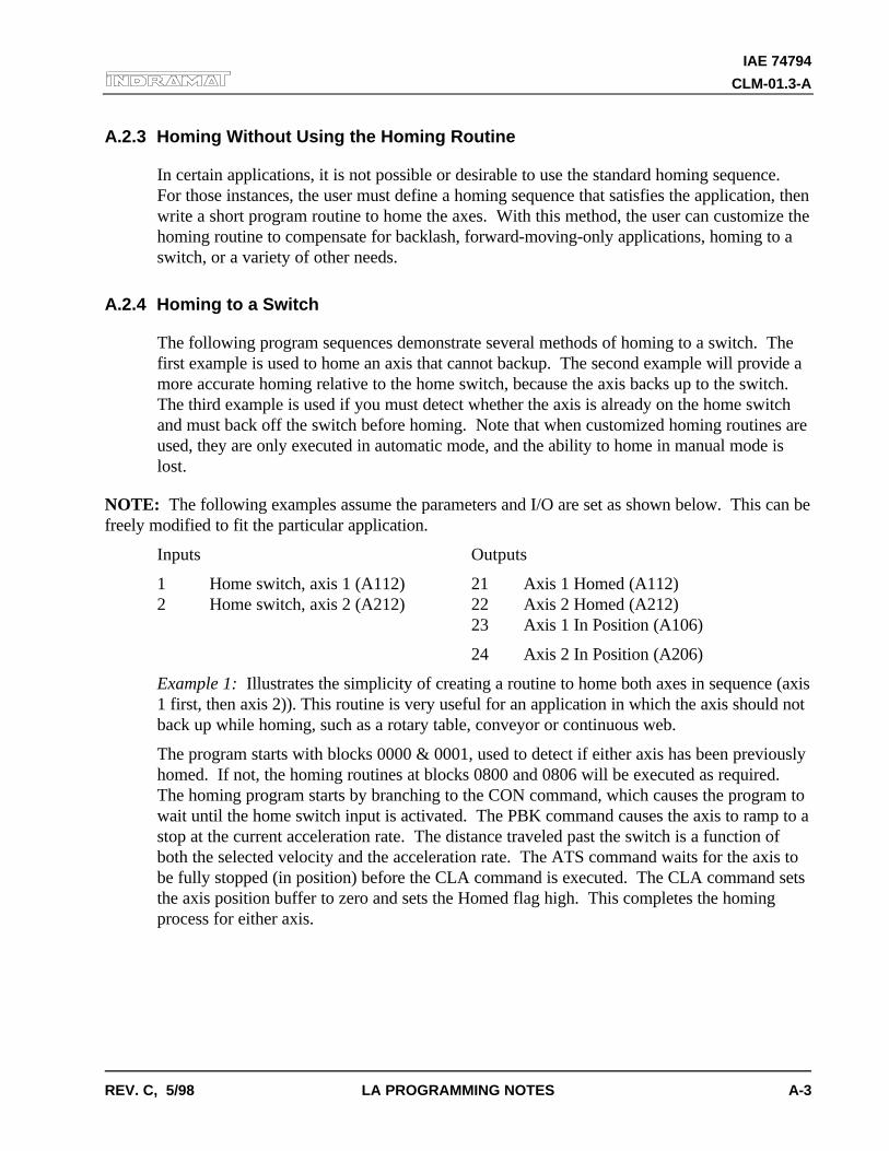
IAE 74794
CLM-01.3-A
REV. C, 5/98 LA PROGRAMMING NOTES A-3
A.2.3 Homing Without Using the Homing Routine
In certain applications, it is not possible or desirable to use the standard homing sequence.For those instances, the user must define a homing sequence that satisfies the application, thenwrite a short program routine to home the axes. With this method, the user can customize thehoming routine to compensate for backlash, forward-moving-only applications, homing to aswitch, or a variety of other needs.
A.2.4 Homing to a Switch
The following program sequences demonstrate several methods of homing to a switch. Thefirst example is used to home an axis that cannot backup. The second example will provide amore accurate homing relative to the home switch, because the axis backs up to the switch.The third example is used if you must detect whether the axis is already on the home switchand must back off the switch before homing. Note that when customized homing routines areused, they are only executed in automatic mode, and the ability to home in manual mode islost.
NOTE: The following examples assume the parameters and I/O are set as shown below. This can befreely modified to fit the particular application.
Inputs Outputs
1 Home switch, axis 1 (A112) 21 Axis 1 Homed (A112)2 Home switch, axis 2 (A212) 22 Axis 2 Homed (A212)
23 Axis 1 In Position (A106)
24 Axis 2 In Position (A206)
Example 1: Illustrates the simplicity of creating a routine to home both axes in sequence (axis1 first, then axis 2)). This routine is very useful for an application in which the axis should notback up while homing, such as a rotary table, conveyor or continuous web.
The program starts with blocks 0000 & 0001, used to detect if either axis has been previouslyhomed. If not, the homing routines at blocks 0800 and 0806 will be executed as required.The homing program starts by branching to the CON command, which causes the program towait until the home switch input is activated. The PBK command causes the axis to ramp to astop at the current acceleration rate. The distance traveled past the switch is a function ofboth the selected velocity and the acceleration rate. The ATS command waits for the axis tobe fully stopped (in position) before the CLA command is executed. The CLA command setsthe axis position buffer to zero and sets the Homed flag high. This completes the homingprocess for either axis.
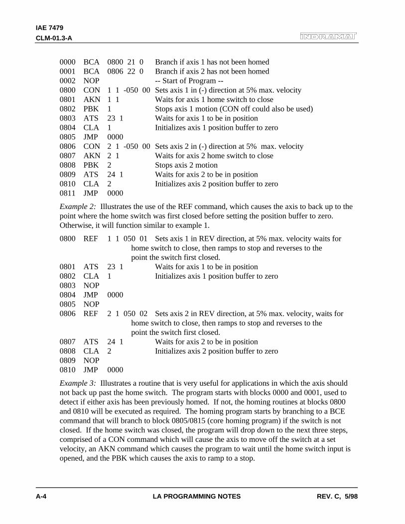
IAE 7479
CLM-01.3-A
A-4 LA PROGRAMMING NOTES REV. C, 5/98
0000 BCA 0800 21 0 Branch if axis 1 has not been homed0001 BCA 0806 22 0 Branch if axis 2 has not been homed0002 NOP -- Start of Program --0800 CON 1 1 -050 00 Sets axis 1 in (-) direction at 5% max. velocity0801 AKN 1 1 Waits for axis 1 home switch to close0802 PBK 1 Stops axis 1 motion (CON off could also be used)0803 ATS 23 1 Waits for axis 1 to be in position0804 CLA 1 Initializes axis 1 position buffer to zero0805 JMP 00000806 CON 2 1 -050 00 Sets axis 2 in (-) direction at 5% max. velocity0807 AKN 2 1 Waits for axis 2 home switch to close0808 PBK 2 Stops axis 2 motion0809 ATS 24 1 Waits for axis 2 to be in position0810 CLA 2 Initializes axis 2 position buffer to zero0811 JMP 0000
Example 2: Illustrates the use of the REF command, which causes the axis to back up to thepoint where the home switch was first closed before setting the position buffer to zero.Otherwise, it will function similar to example 1.
0800 REF 1 1 050 01 Sets axis 1 in REV direction, at 5% max. velocity waits for home switch to close, then ramps to stop and reverses to the point the switch first closed.
0801 ATS 23 1 Waits for axis 1 to be in position0802 CLA 1 Initializes axis 1 position buffer to zero0803 NOP0804 JMP 00000805 NOP0806 REF 2 1 050 02 Sets axis 2 in REV direction, at 5% max. velocity, waits for
home switch to close, then ramps to stop and reverses to the point the switch first closed.
0807 ATS 24 1 Waits for axis 2 to be in position0808 CLA 2 Initializes axis 2 position buffer to zero0809 NOP0810 JMP 0000
Example 3: Illustrates a routine that is very useful for applications in which the axis shouldnot back up past the home switch. The program starts with blocks 0000 and 0001, used todetect if either axis has been previously homed. If not, the homing routines at blocks 0800and 0810 will be executed as required. The homing program starts by branching to a BCEcommand that will branch to block 0805/0815 (core homing program) if the switch is notclosed. If the home switch was closed, the program will drop down to the next three steps,comprised of a CON command which will cause the axis to move off the switch at a setvelocity, an AKN command which causes the program to wait until the home switch input isopened, and the PBK which causes the axis to ramp to a stop.
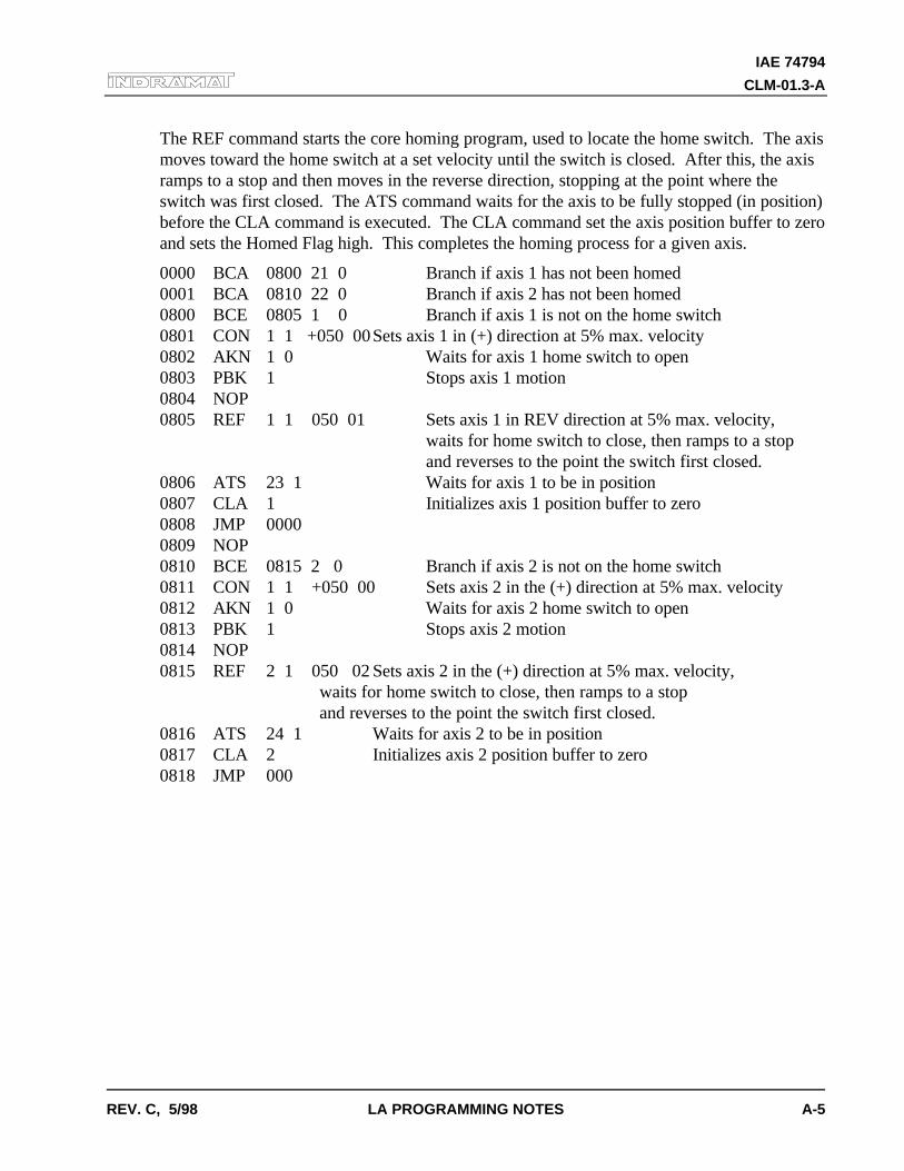
IAE 74794
CLM-01.3-A
REV. C, 5/98 LA PROGRAMMING NOTES A-5
The REF command starts the core homing program, used to locate the home switch. The axismoves toward the home switch at a set velocity until the switch is closed. After this, the axisramps to a stop and then moves in the reverse direction, stopping at the point where theswitch was first closed. The ATS command waits for the axis to be fully stopped (in position)before the CLA command is executed. The CLA command set the axis position buffer to zeroand sets the Homed Flag high. This completes the homing process for a given axis.
0000 BCA 0800 21 0 Branch if axis 1 has not been homed0001 BCA 0810 22 0 Branch if axis 2 has not been homed0800 BCE 0805 1 0 Branch if axis 1 is not on the home switch0801 CON 1 1 +050 00Sets axis 1 in (+) direction at 5% max. velocity0802 AKN 1 0 Waits for axis 1 home switch to open0803 PBK 1 Stops axis 1 motion0804 NOP0805 REF 1 1 050 01 Sets axis 1 in REV direction at 5% max. velocity,
waits for home switch to close, then ramps to a stop and reverses to the point the switch first closed.
0806 ATS 23 1 Waits for axis 1 to be in position0807 CLA 1 Initializes axis 1 position buffer to zero0808 JMP 00000809 NOP0810 BCE 0815 2 0 Branch if axis 2 is not on the home switch0811 CON 1 1 +050 00 Sets axis 2 in the (+) direction at 5% max. velocity0812 AKN 1 0 Waits for axis 2 home switch to open0813 PBK 1 Stops axis 2 motion0814 NOP0815 REF 2 1 050 02 Sets axis 2 in the (+) direction at 5% max. velocity,
waits for home switch to close, then ramps to a stop and reverses to the point the switch first closed.
0816 ATS 24 1 Waits for axis 2 to be in position0817 CLA 2 Initializes axis 2 position buffer to zero0818 JMP 000
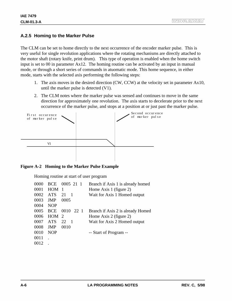
IAE 7479
CLM-01.3-A
A-6 LA PROGRAMMING NOTES REV. C, 5/98
A.2.5 Homing to the Marker Pulse
The CLM can be set to home directly to the next occurrence of the encoder marker pulse. This isvery useful for single revolution applications where the rotating mechanisms are directly attached tothe motor shaft (rotary knife, print drum). This type of operation is enabled when the home switchinput is set to 00 in parameter Ax12. The homing routine can be activated by an input in manualmode, or through a short series of commands in atuomatic mode. This home sequence, in eithermode, starts with the selected axis performing the following steps:
1. The axis moves in the desired direction (CW, CCW) at the velocity set in parameter Ax10,until the marker pulse is detected (V1).
2. The CLM notes where the marker pulse was sensed and continues to move in the samedirection for approximately one revolution. The axis starts to decelerate prior to the nextoccurrence of the marker pulse, and stops at a position at or just past the marker pulse.
First occurenceof marker pulse
Second occurenceof marker pulse
V1
Figure A-2 Homing to the Marker Pulse Example
Homing routine at start of user program
0000 BCE 0005 21 1 Branch if Axis 1 is already homed0001 HOM 1 Home Axis 1 (figure 2)0002 ATS 21 1 Wait for Axis 1 Homed output0003 JMP 00050004 NOP0005 BCE 0010 22 1 Branch if Axis 2 is already Homed0006 HOM 2 Home Axis 2 (figure 2)0007 ATS 22 1 Wait for Axis 2 Homed output0008 JMP 00100010 NOP -- Start of Program --0011 .0012 .
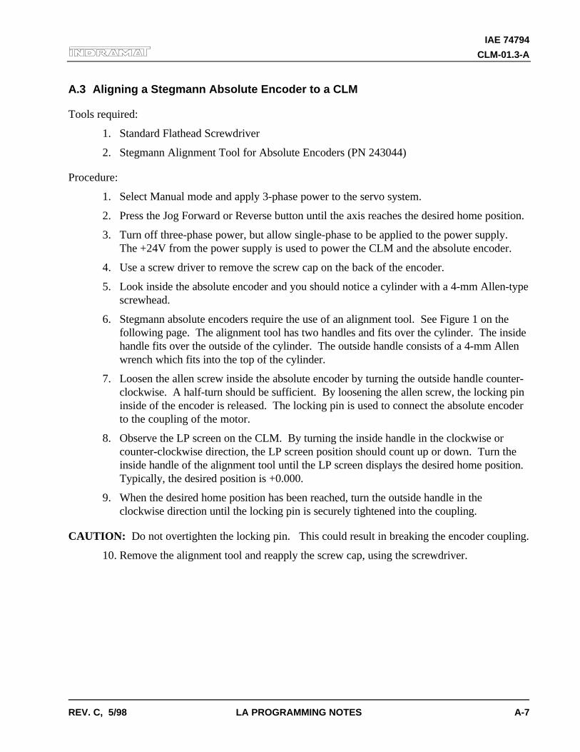
IAE 74794
CLM-01.3-A
REV. C, 5/98 LA PROGRAMMING NOTES A-7
A.3 Aligning a Stegmann Absolute Encoder to a CLM
Tools required:
1. Standard Flathead Screwdriver
2. Stegmann Alignment Tool for Absolute Encoders (PN 243044)
Procedure:
1. Select Manual mode and apply 3-phase power to the servo system.
2. Press the Jog Forward or Reverse button until the axis reaches the desired home position.
3. Turn off three-phase power, but allow single-phase to be applied to the power supply.The +24V from the power supply is used to power the CLM and the absolute encoder.
4. Use a screw driver to remove the screw cap on the back of the encoder.
5. Look inside the absolute encoder and you should notice a cylinder with a 4-mm Allen-typescrewhead.
6. Stegmann absolute encoders require the use of an alignment tool. See Figure 1 on thefollowing page. The alignment tool has two handles and fits over the cylinder. The insidehandle fits over the outside of the cylinder. The outside handle consists of a 4-mm Allenwrench which fits into the top of the cylinder.
7. Loosen the allen screw inside the absolute encoder by turning the outside handle counter-clockwise. A half-turn should be sufficient. By loosening the allen screw, the locking pininside of the encoder is released. The locking pin is used to connect the absolute encoderto the coupling of the motor.
8. Observe the LP screen on the CLM. By turning the inside handle in the clockwise orcounter-clockwise direction, the LP screen position should count up or down. Turn theinside handle of the alignment tool until the LP screen displays the desired home position.Typically, the desired position is +0.000.
9. When the desired home position has been reached, turn the outside handle in theclockwise direction until the locking pin is securely tightened into the coupling.
CAUTION: Do not overtighten the locking pin. This could result in breaking the encoder coupling.
10. Remove the alignment tool and reapply the screw cap, using the screwdriver.
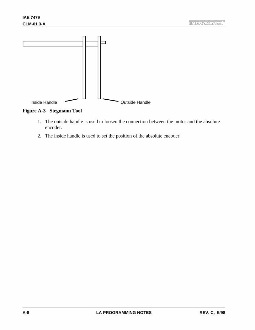
IAE 7479
CLM-01.3-A
A-8 LA PROGRAMMING NOTES REV. C, 5/98
Inside Handle Outside Handle
Figure A-3 Stegmann Tool
1. The outside handle is used to loosen the connection between the motor and the absoluteencoder.
2. The inside handle is used to set the position of the absolute encoder.
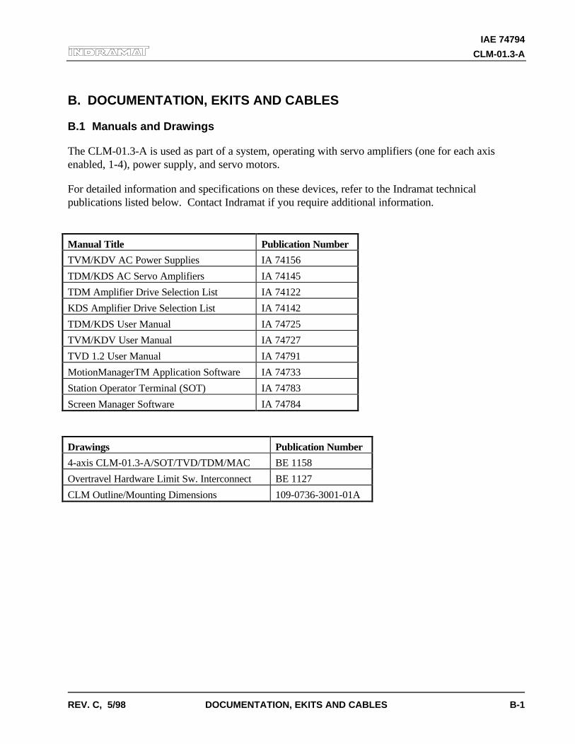
IAE 74794
CLM-01.3-A
REV. C, 5/98 DOCUMENTATION, EKITS AND CABLES B-1
B. DOCUMENTATION, EKITS AND CABLES
B.1 Manuals and Drawings
The CLM-01.3-A is used as part of a system, operating with servo amplifiers (one for each axisenabled, 1-4), power supply, and servo motors.
For detailed information and specifications on these devices, refer to the Indramat technicalpublications listed below. Contact Indramat if you require additional information.
Manual Title Publication Number
TVM/KDV AC Power Supplies IA 74156
TDM/KDS AC Servo Amplifiers IA 74145
TDM Amplifier Drive Selection List IA 74122
KDS Amplifier Drive Selection List IA 74142
TDM/KDS User Manual IA 74725
TVM/KDV User Manual IA 74727
TVD 1.2 User Manual IA 74791
MotionManagerTM Application Software IA 74733
Station Operator Terminal (SOT) IA 74783
Screen Manager Software IA 74784
Drawings Publication Number
4-axis CLM-01.3-A/SOT/TVD/TDM/MAC BE 1158
Overtravel Hardware Limit Sw. Interconnect BE 1127
CLM Outline/Mounting Dimensions 109-0736-3001-01A
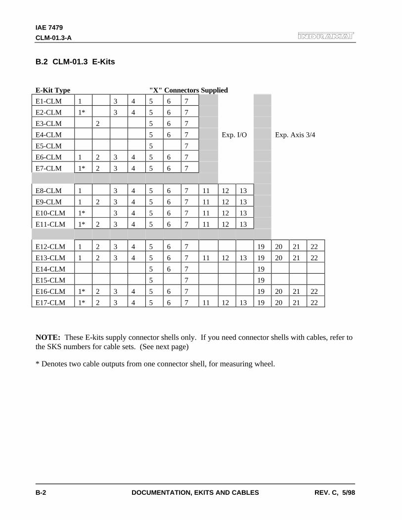
IAE 7479
CLM-01.3-A
B-2 DOCUMENTATION, EKITS AND CABLES REV. C, 5/98
B.2 CLM-01.3 E-Kits
E-Kit Type "X" Connectors Supplied
E1-CLM 1 3 4 5 6 7
E2-CLM 1* 3 4 5 6 7
E3-CLM 2 5 6 7
E4-CLM 5 6 7 Exp. I/O Exp. Axis 3/4
E5-CLM 5 7
E6-CLM 1 2 3 4 5 6 7
E7-CLM 1* 2 3 4 5 6 7
E8-CLM 1 3 4 5 6 7 11 12 13
E9-CLM 1 2 3 4 5 6 7 11 12 13
E10-CLM 1* 3 4 5 6 7 11 12 13
E11-CLM 1* 2 3 4 5 6 7 11 12 13
E12-CLM 1 2 3 4 5 6 7 19 20 21 22
E13-CLM 1 2 3 4 5 6 7 11 12 13 19 20 21 22
E14-CLM 5 6 7 19
E15-CLM 5 7 19
E16-CLM 1* 2 3 4 5 6 7 19 20 21 22
E17-CLM 1* 2 3 4 5 6 7 11 12 13 19 20 21 22
NOTE: These E-kits supply connector shells only. If you need connector shells with cables, refer tothe SKS numbers for cable sets. (See next page)
* Denotes two cable outputs from one connector shell, for measuring wheel.
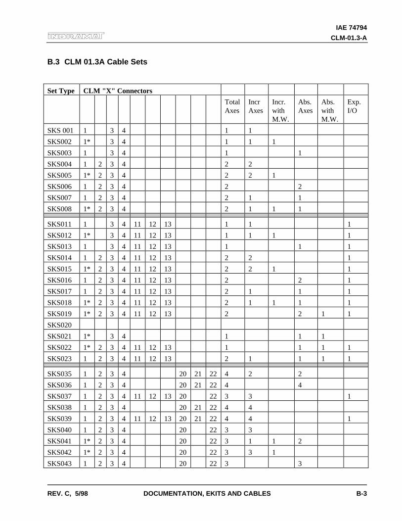
IAE 74794
CLM-01.3-A
REV. C, 5/98 DOCUMENTATION, EKITS AND CABLES B-3
B.3 CLM 01.3A Cable Sets
Set Type CLM "X" Connectors
TotalAxes
IncrAxes
Incr.withM.W.
Abs.Axes
Abs.withM.W.
Exp.I/O
SKS 001 1 3 4 1 1
SKS002 1* 3 4 1 1 1
SKS003 1 3 4 1 1
SKS004 1 2 3 4 2 2
SKS005 1* 2 3 4 2 2 1
SKS006 1 2 3 4 2 2
SKS007 1 2 3 4 2 1 1
SKS008 1* 2 3 4 2 1 1 1
SKS011 1 3 4 11 12 13 1 1 1
SKS012 1* 3 4 11 12 13 1 1 1 1
SKS013 1 3 4 11 12 13 1 1 1
SKS014 1 2 3 4 11 12 13 2 2 1
SKS015 1* 2 3 4 11 12 13 2 2 1 1
SKS016 1 2 3 4 11 12 13 2 2 1
SKS017 1 2 3 4 11 12 13 2 1 1 1
SKS018 1* 2 3 4 11 12 13 2 1 1 1 1
SKS019 1* 2 3 4 11 12 13 2 2 1 1
SKS020
SKS021 1* 3 4 1 1 1
SKS022 1* 2 3 4 11 12 13 1 1 1 1
SKS023 1 2 3 4 11 12 13 2 1 1 1 1
SKS035 1 2 3 4 20 21 22 4 2 2
SKS036 1 2 3 4 20 21 22 4 4
SKS037 1 2 3 4 11 12 13 20 22 3 3 1
SKS038 1 2 3 4 20 21 22 4 4
SKS039 1 2 3 4 11 12 13 20 21 22 4 4 1
SKS040 1 2 3 4 20 22 3 3
SKS041 1* 2 3 4 20 22 3 1 1 2
SKS042 1* 2 3 4 20 22 3 3 1
SKS043 1 2 3 4 20 22 3 3

IAE 7479
CLM-01.3-A
B-4 DOCUMENTATION, EKITS AND CABLES REV. C, 5/98
Cable sets "SKS 001 - 008" are for a CLM 01.3 with 2 axes.
Cable sets "SKS 011 - 023" are for a CLM 01.3 with expansion I/O.
Cable sets "SKS 035 - 043" are for a CLM with 4 axes.
* Denotes two cables from one connector shell.
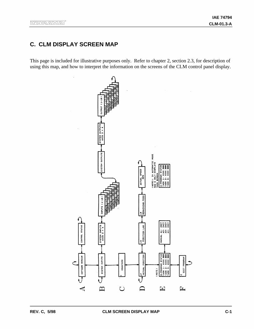
IAE 74794
CLM-01.3-A
REV. C, 5/98 CLM SCREEN DISPLAY MAP C-1
C. CLM DISPLAY SCREEN MAP
This page is included for illustrative purposes only. Refer to chapter 2, section 2.3, for description ofusing this map, and how to interpret the information on the screens of the CLM control panel display.

IAE 7479
CLM-01.3-A
C-2 CLM SCREEN DISPLAY MAP REV. C, 5/98
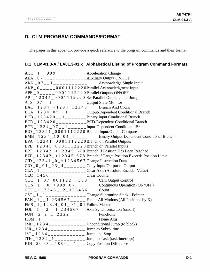
IAE 74794
CLM-01.3-A
REV. C, 5/98 PROGRAM COMMANDS D-1
D. CLM PROGRAM COMMANDS/FORMAT
The pages in this appendix provide a quick reference to the program commands and their format.
D.1 CLM-01.3-A / LA01.3-01.x Alphabetical Listing of Program Command Formats
ACC _ 1 _ _ 9 9 9 _ _ _ _ _ _ _ _ _ _Acceleration ChangeAEA _ 0 7 _ _ 1 _ _ _ _ _ _ _ _ _ _ _Auxiliary Output ON/OFFAKN _ 0 7 _ _ 1 _ _ _ _ _ _ _ _ _ _ _ Acknowledge Single InputAKP _ 0 _ _ _ _ _ 0 0 0 1 1 1 2 2 2 0Parallel Acknowledgment InputAPE _ 0 _ _ _ _ _ 0 0 0 1 1 1 2 2 2 0 Parallel Outputs ON/OFFAPJ _ 1 2 3 4 4 _ 0 0 0 1 1 1 2 2 2 0 Set Parallel Outputs, then JumpATS _ 0 7 _ _ 1 _ _ _ _ _ _ _ _ _ _ _ Output State MonitorBAC _ 1 2 3 4 _ + 1 2 3 4 _ 1 2 3 4 5 Branch And CountBCA _ 1 2 3 4 _ 0 7 _ _ 1 _ _ _ _ _ _Output-Dependent Conditional BranchBCB _ 1 2 3 4 2 0 _ _ 1 _ _ _ _ _ _ _Binary Input Conditional BranchBCD _ 1 2 3 4 2 0 _ _ _ _ _ _ _ _ _ _BCD-Dependent Conditional BranchBCE _ 1 2 3 4 _ 0 7 _ _ 1 _ _ _ _ _ _ Input-Dependent Conditional BranchBIO _ 1 2 3 4 1 _ 0 0 0 1 1 1 2 2 2 0 Branch Input/Output CompareBMB _ 1 2 3 4 _ 1 0 _ 0 4 _ 8 _ _ _ _ Binary Output-Dependent Conditional BranchBPA _ 1 2 3 4 1 _ 0 0 0 1 1 1 2 2 2 0 Branch on Parallel OutputsBPE _ 1 2 3 4 1 _ 0 0 0 1 1 1 2 2 2 0 Branch on Parallel InputsBPT _ 1 2 3 4 2 _ + 1 2 3 4 5 . 6 7 8 Branch If Position Has Been ReachedBZP _ 1 2 3 4 2 _ + 1 2 3 4 5 . 6 7 8 Branch if Target Position Exceeds Position LimitCID _ 1 2 3 4 1 _ 0 _ + 1 2 3 4 5 6 7 Change Instruction DataCIO _ 0 _ 0 1 _ 2 3 _ 4 _ _ _ _ _ _ _ Copy Input/Output to OutputCLA _ 1 _ _ _ _ _ _ _ _ _ _ _ _ _ _ _Clear Axis (Absolute Encoder Value)CLC _ 1 4 5 6 _ _ _ _ _ _ _ _ _ _ _ _ Clear CounterCOC _ 1 _ 0 7 _ 0 0 1 1 2 2 _ + 3 6 0 Cam Output ControlCON _ 1 _ _ 0 _ + 9 9 9 _ 0 7 _ _ _ _ Continuous Operation (ON/OFF)COU _ + 1 2 3 4 5 _ 1 2 _ 1 2 3 4 5 6 CountCST _ 1 _ 1 _ _ _ _ _ _ _ _ _ _ _ _ _ Change Subroutine Stack - PointerFAK _ 1 _ _ 1 . 2 3 4 5 6 7 _ _ _ _ _ Factor All Motions (All Positions by X)FMS _ 1 _ 1 2 3 . 4 _ 0 1 _ 0 1 _ 0 1 Follow MasterFOL _ 1 _ _ 2 _ _ 1 . 2 3 4 5 6 7 _ _ Axis Synchronization (on/off)FUN _ 2 _ 2 _ 1 _ 2 2 2 2 _ _ _ _ _ _ FunctionsHOM _ 1 _ _ _ _ _ _ _ _ _ _ _ _ _ _ _ Home AxisJMP _ 1 2 3 4 _ _ _ _ _ _ _ _ _ _ _ _ Unconditional Jump (to block)JSR _ 1 2 3 4 _ _ _ _ _ _ _ _ _ _ _ _ Jump to SubroutineJST _ 1 2 3 4 _ _ _ _ _ _ _ _ _ _ _ _ Jump and StopJTK _ 1 2 3 4 _ 1 _ _ _ _ _ _ _ _ _ _ Jump in Task (task interrupt)KDI _ 2 0 0 0 _ _ 1 0 0 0 _ _ 1 _ _ _ Copy Position Difference
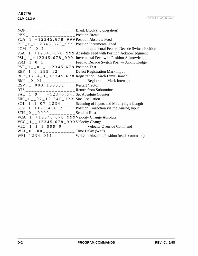
IAE 7479
CLM-01.3-A
D-2 PROGRAM COMMANDS REV. C, 5/98
NOP _ _ _ _ _ _ _ _ _ _ _ _ _ _ _ _ _Blank Block (no operation)PBK _ 1 _ _ _ _ _ _ _ _ _ _ _ _ _ _ _ Position BreakPOA _ 1 _ + 1 2 3 4 5 . 6 7 8 _ 9 9 9 Position Absolute FeedPOI _ 1 _ + 1 2 3 4 5 . 6 7 8 _ 9 9 9 Position Incremental FeedPOM _ 1 _ 0 _ 1 _ _ _ _ _ _ _ _ _ _ _ Incremental Feed to Decade Switch PositionPSA _ 1 _ + 1 2 3 4 5 . 6 7 8 _ 9 9 9 Absolute Feed with Position AcknowledgmentPSI _ 1 _ + 1 2 3 4 5 . 6 7 8 _ 9 9 9 Incremental Feed with Position AcknowledgePSM _ 1 _ 0 _ 1 _ _ _ _ _ _ _ _ _ _ _Feed to Decade Switch Pos. w/ AcknowledgePST _ 1 _ _ 0 1 _ + 1 2 3 4 5 . 6 7 8 Position TestREF _ 1 _ 0 _ 9 9 9 _ 1 2 _ _ _ _ _ _ Detect Registration Mark InputREP _ 1 2 3 4 _ 1 _ 1 2 3 4 5 . 6 7 8 Registration Search Limit BranchRMI _ 0 _ 0 1 _ _ _ _ _ _ _ _ _ _ _ _ Registration Mark InterruptRSV _ 1 _ 0 0 0 _ 1 0 0 0 0 0 _ _ _ _ Restart VectorRTS _ _ _ _ _ _ _ _ _ _ _ _ _ _ _ _ _ Return from SubroutineSAC _ 1 _ 0 _ _ _ + 1 2 3 4 5 . 6 7 8 Set Absolute CounterSIN _ 1 _ _ 0 7 _ 1 2 . 3 4 5 _ 1 2 3 Sine OscillationSO1 _ 1 _ 1 _ 0 7 _ 1 2 3 4 _ _ _ _ _ Scanning of Inputs and Modifying a LengthSO2 _ 1 _ + 1 2 3 . 4 5 6 _ 2 _ _ _ _ Position Correction via the Analog InputSTH _ 0 _ _ 0 0 0 0 _ _ _ _ _ _ _ _ _ Send to HostVCA _ 1 _ + 1 2 3 4 5 . 6 7 8 _ 9 9 9 Velocity Change AbsoluteVCC _ 1 _ _ 1 2 3 4 5 . 6 7 8 _ 9 9 9 Velocity ChangeVEO _ 1 _ 1 _ 1 _ 9 9 9 _ 0 _ _ _ _ _ Velocity Override CommandWAI _ 0 1 . 0 0 _ _ _ _ _ _ _ _ _ _ _ Time Delay (Wait)WRI _ 1 2 3 4 _ 0 1 1 _ _ _ _ _ _ _ _ Write in Absolute Position (teach command)
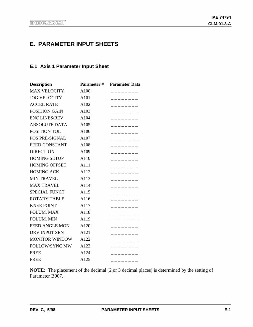
IAE 74794
CLM-01.3-A
REV. C, 5/98 PARAMETER INPUT SHEETS E-1
E. PARAMETER INPUT SHEETS
E.1 Axis 1 Parameter Input Sheet
Description Parameter # Parameter Data
MAX VELOCITY A100 _ _ _ _ _ _ _ _
JOG VELOCITY A101 _ _ _ _ _ _ _ _
ACCEL RATE A102 _ _ _ _ _ _ _ _
POSITION GAIN A103 _ _ _ _ _ _ _ _
ENC LINES/REV A104 _ _ _ _ _ _ _ _
ABSOLUTE DATA A105 _ _ _ _ _ _ _ _
POSITION TOL A106 _ _ _ _ _ _ _ _
POS PRE-SIGNAL A107 _ _ _ _ _ _ _ _
FEED CONSTANT A108 _ _ _ _ _ _ _ _
DIRECTION A109 _ _ _ _ _ _ _ _
HOMING SETUP A110 _ _ _ _ _ _ _ _
HOMING OFFSET A111 _ _ _ _ _ _ _ _
HOMING ACK A112 _ _ _ _ _ _ _ _
MIN TRAVEL A113 _ _ _ _ _ _ _ _
MAX TRAVEL A114 _ _ _ _ _ _ _ _
SPECIAL FUNCT A115 _ _ _ _ _ _ _ _
ROTARY TABLE A116 _ _ _ _ _ _ _ _
KNEE POINT A117 _ _ _ _ _ _ _ _
POLUM. MAX A118 _ _ _ _ _ _ _ _
POLUM. MIN A119 _ _ _ _ _ _ _ _
FEED ANGLE MON A120 _ _ _ _ _ _ _ _
DRV INPUT SEN A121 _ _ _ _ _ _ _ _
MONITOR WINDOW A122 _ _ _ _ _ _ _ _
FOLLOW/SYNC MW A123 _ _ _ _ _ _ _ _
FREE A124 _ _ _ _ _ _ _ _
FREE A125 _ _ _ _ _ _ _ _
NOTE: The placement of the decimal (2 or 3 decimal places) is determined by the setting ofParameter B007.
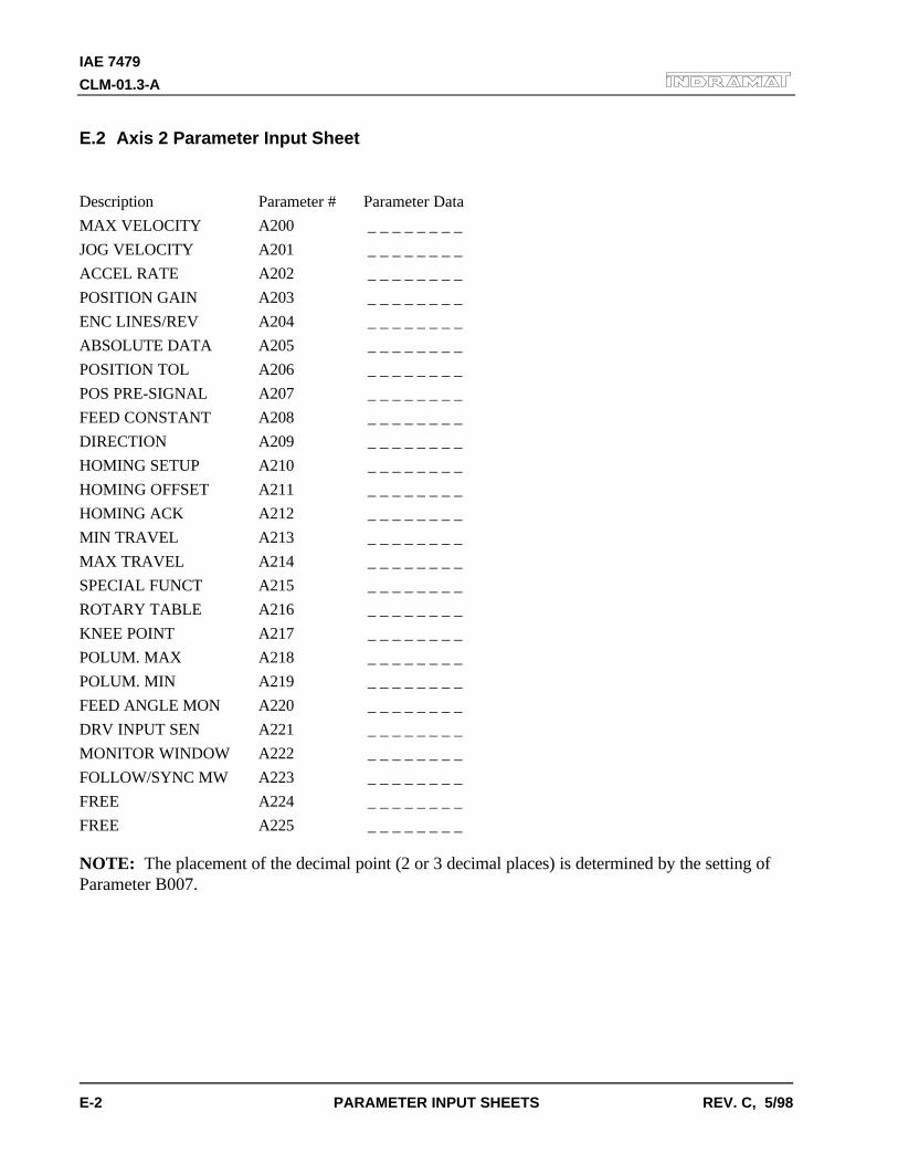
IAE 7479
CLM-01.3-A
E-2 PARAMETER INPUT SHEETS REV. C, 5/98
E.2 Axis 2 Parameter Input Sheet
Description Parameter # Parameter Data
MAX VELOCITY A200 _ _ _ _ _ _ _ _
JOG VELOCITY A201 _ _ _ _ _ _ _ _
ACCEL RATE A202 _ _ _ _ _ _ _ _
POSITION GAIN A203 _ _ _ _ _ _ _ _
ENC LINES/REV A204 _ _ _ _ _ _ _ _
ABSOLUTE DATA A205 _ _ _ _ _ _ _ _
POSITION TOL A206 _ _ _ _ _ _ _ _
POS PRE-SIGNAL A207 _ _ _ _ _ _ _ _
FEED CONSTANT A208 _ _ _ _ _ _ _ _
DIRECTION A209 _ _ _ _ _ _ _ _
HOMING SETUP A210 _ _ _ _ _ _ _ _
HOMING OFFSET A211 _ _ _ _ _ _ _ _
HOMING ACK A212 _ _ _ _ _ _ _ _
MIN TRAVEL A213 _ _ _ _ _ _ _ _
MAX TRAVEL A214 _ _ _ _ _ _ _ _
SPECIAL FUNCT A215 _ _ _ _ _ _ _ _
ROTARY TABLE A216 _ _ _ _ _ _ _ _
KNEE POINT A217 _ _ _ _ _ _ _ _
POLUM. MAX A218 _ _ _ _ _ _ _ _
POLUM. MIN A219 _ _ _ _ _ _ _ _
FEED ANGLE MON A220 _ _ _ _ _ _ _ _
DRV INPUT SEN A221 _ _ _ _ _ _ _ _
MONITOR WINDOW A222 _ _ _ _ _ _ _ _
FOLLOW/SYNC MW A223 _ _ _ _ _ _ _ _
FREE A224 _ _ _ _ _ _ _ _
FREE A225 _ _ _ _ _ _ _ _
NOTE: The placement of the decimal point (2 or 3 decimal places) is determined by the setting ofParameter B007.
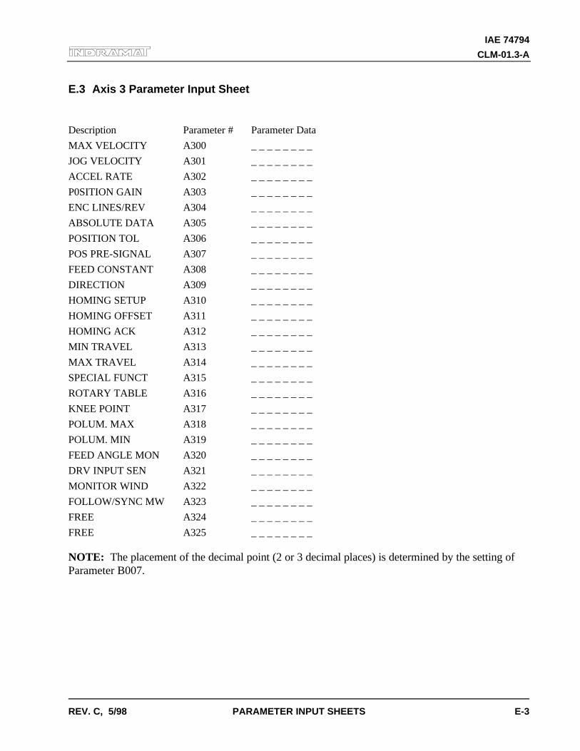
IAE 74794
CLM-01.3-A
REV. C, 5/98 PARAMETER INPUT SHEETS E-3
E.3 Axis 3 Parameter Input Sheet
Description Parameter # Parameter Data
MAX VELOCITY A300 _ _ _ _ _ _ _ _
JOG VELOCITY A301 _ _ _ _ _ _ _ _
ACCEL RATE A302 _ _ _ _ _ _ _ _
P0SITION GAIN A303 _ _ _ _ _ _ _ _
ENC LINES/REV A304 _ _ _ _ _ _ _ _
ABSOLUTE DATA A305 _ _ _ _ _ _ _ _
POSITION TOL A306 _ _ _ _ _ _ _ _
POS PRE-SIGNAL A307 _ _ _ _ _ _ _ _
FEED CONSTANT A308 _ _ _ _ _ _ _ _
DIRECTION A309 _ _ _ _ _ _ _ _
HOMING SETUP A310 _ _ _ _ _ _ _ _
HOMING OFFSET A311 _ _ _ _ _ _ _ _
HOMING ACK A312 _ _ _ _ _ _ _ _
MIN TRAVEL A313 _ _ _ _ _ _ _ _
MAX TRAVEL A314 _ _ _ _ _ _ _ _
SPECIAL FUNCT A315 _ _ _ _ _ _ _ _
ROTARY TABLE A316 _ _ _ _ _ _ _ _
KNEE POINT A317 _ _ _ _ _ _ _ _
POLUM. MAX A318 _ _ _ _ _ _ _ _
POLUM. MIN A319 _ _ _ _ _ _ _ _
FEED ANGLE MON A320 _ _ _ _ _ _ _ _
DRV INPUT SEN A321 _ _ _ _ _ _ _ _
MONITOR WIND A322 _ _ _ _ _ _ _ _
FOLLOW/SYNC MW A323 _ _ _ _ _ _ _ _
FREE A324 _ _ _ _ _ _ _ _
FREE A325 _ _ _ _ _ _ _ _
NOTE: The placement of the decimal point (2 or 3 decimal places) is determined by the setting ofParameter B007.

IAE 7479
CLM-01.3-A
E-4 PARAMETER INPUT SHEETS REV. C, 5/98
E.4 Axis 4 Parameter Input Sheet
Description Parameter # Parameter Data
MAX VELOCITY A400 _ _ _ _ _ _ _ _
JOG VELOCITY A401 _ _ _ _ _ _ _ _
ACCEL RATE A402 _ _ _ _ _ _ _ _
POSITION GAIN A403 _ _ _ _ _ _ _ _
ENC LINES/REV A404 _ _ _ _ _ _ _ _
ABSOLUTE DATA A405 _ _ _ _ _ _ _ _
POSITION TOL A406 _ _ _ _ _ _ _ _
POS PRE-SIGNAL A407 _ _ _ _ _ _ _ _
FEED CONSTANT A408 _ _ _ _ _ _ _ _
DIRECTION A409 _ _ _ _ _ _ _ _
HOMING SETUP A410 _ _ _ _ _ _ _ _
HOMING OFFSET A411 _ _ _ _ _ _ _ _
HOMING ACK A412 _ _ _ _ _ _ _ _
MIN TRAVEL A413 _ _ _ _ _ _ _ _
MAX TRAVEL A414 _ _ _ _ _ _ _ _
SPECIAL FUNCT A415 _ _ _ _ _ _ _ _
ROTARY TABLE A416 _ _ _ _ _ _ _ _
KNEE POINT A417 _ _ _ _ _ _ _ _
POLUM. MAX A418 _ _ _ _ _ _ _ _
POLUM. MIN A419 _ _ _ _ _ _ _ _
FEED ANGLE MON A420 _ _ _ _ _ _ _ _
DRV INPUT SEN A421 _ _ _ _ _ _ _ _
MONITOR WIND A422 _ _ _ _ _ _ _ _
FOLLOW/SYNC MW A423 _ _ _ _ _ _ _ _
FREE A424 _ _ _ _ _ _ _ _
FREE A425 _ _ _ _ _ _ _ _
NOTE: The placement of the decimal point (2 or 3 decimal places) is determined by the setting ofParameter B007.
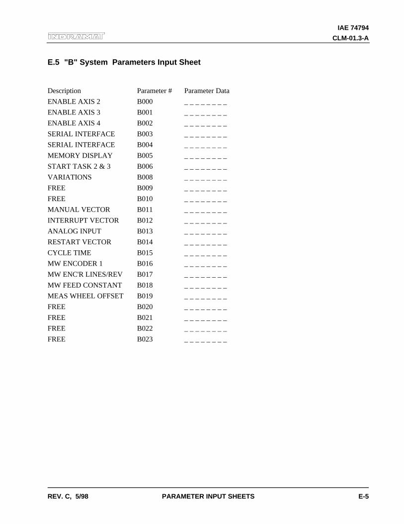
IAE 74794
CLM-01.3-A
REV. C, 5/98 PARAMETER INPUT SHEETS E-5
E.5 "B" System Parameters Input Sheet
Description Parameter # Parameter Data
ENABLE AXIS 2 B000 _ _ _ _ _ _ _ _
ENABLE AXIS 3 B001 _ _ _ _ _ _ _ _
ENABLE AXIS 4 B002 _ _ _ _ _ _ _ _
SERIAL INTERFACE B003 _ _ _ _ _ _ _ _
SERIAL INTERFACE B004 _ _ _ _ _ _ _ _
MEMORY DISPLAY B005 _ _ _ _ _ _ _ _
START TASK 2 & 3 B006 _ _ _ _ _ _ _ _
VARIATIONS B008 _ _ _ _ _ _ _ _
FREE B009 _ _ _ _ _ _ _ _
FREE B010 _ _ _ _ _ _ _ _
MANUAL VECTOR B011 _ _ _ _ _ _ _ _
INTERRUPT VECTOR B012 _ _ _ _ _ _ _ _
ANALOG INPUT B013 _ _ _ _ _ _ _ _
RESTART VECTOR B014 _ _ _ _ _ _ _ _
CYCLE TIME B015 _ _ _ _ _ _ _ _
MW ENCODER 1 B016 _ _ _ _ _ _ _ _
MW ENC'R LINES/REV B017 _ _ _ _ _ _ _ _
MW FEED CONSTANT B018 _ _ _ _ _ _ _ _
MEAS WHEEL OFFSET B019 _ _ _ _ _ _ _ _
FREE B020 _ _ _ _ _ _ _ _
FREE B021 _ _ _ _ _ _ _ _
FREE B022 _ _ _ _ _ _ _ _
FREE B023 _ _ _ _ _ _ _ _

IAE 7479
CLM-01.3-A
E-6 PARAMETER INPUT SHEETS REV. C, 5/98

IAE 74794
CLM-01.3-A
REV. C, 5/98 DRAWINGS/SCHEMATICS F-1
F. DRAWINGS AND SCHEMATICS
CAUTION: The drawings in this Appendix are included for illustrative purposes only and aresubject to change without notice. Check with Indramat to be sure you are working with the latestdrawings prior to installing, wiring and powering equipment.
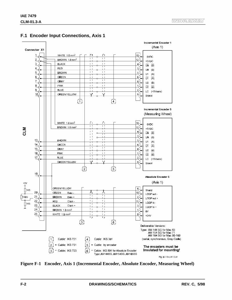
IAE 7479
CLM-01.3-A
F-2 DRAWINGS/SCHEMATICS REV. C, 5/98
F.1 Encoder Input Connections, Axis 1
Figure F-1 Encoder, Axis 1 (Incremental Encoder, Absolute Encoder, Measuring Wheel)
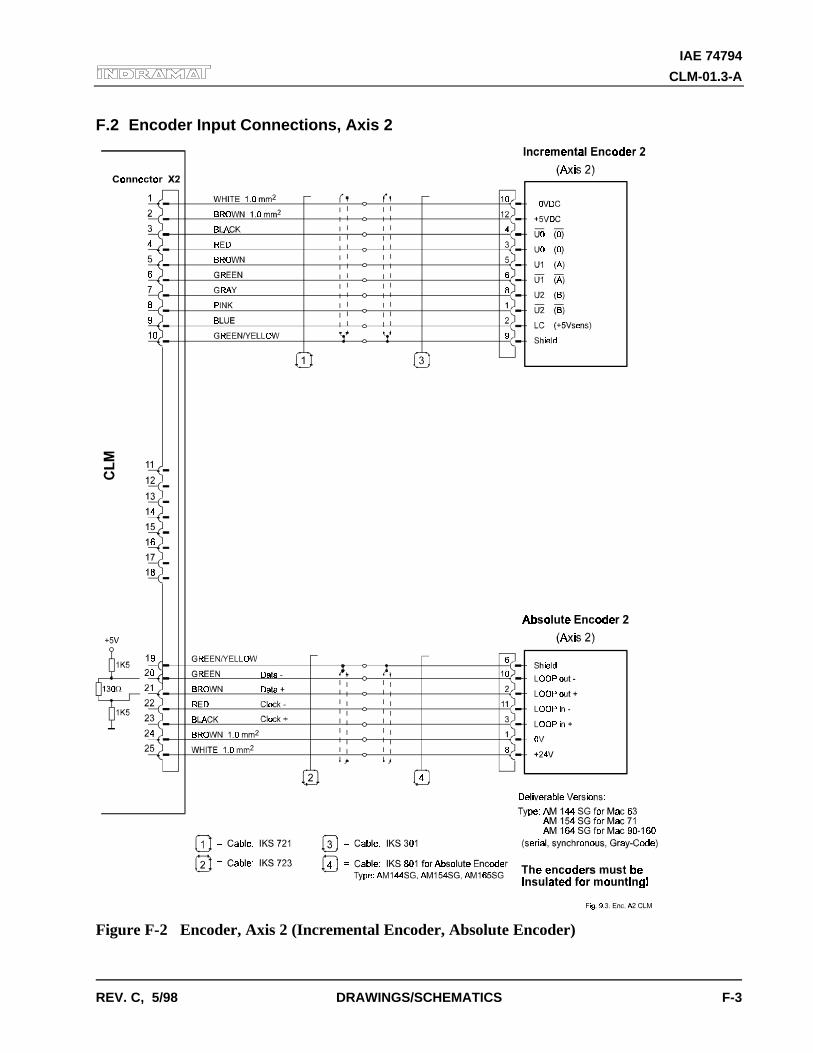
IAE 74794
CLM-01.3-A
REV. C, 5/98 DRAWINGS/SCHEMATICS F-3
F.2 Encoder Input Connections, Axis 2
Figure F-2 Encoder, Axis 2 (Incremental Encoder, Absolute Encoder)
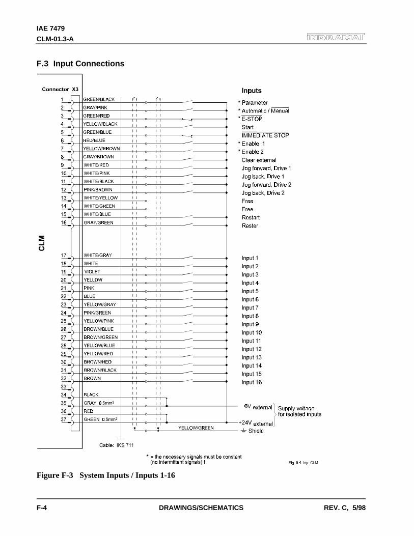
IAE 7479
CLM-01.3-A
F-4 DRAWINGS/SCHEMATICS REV. C, 5/98
F.3 Input Connections
Figure F-3 System Inputs / Inputs 1-16
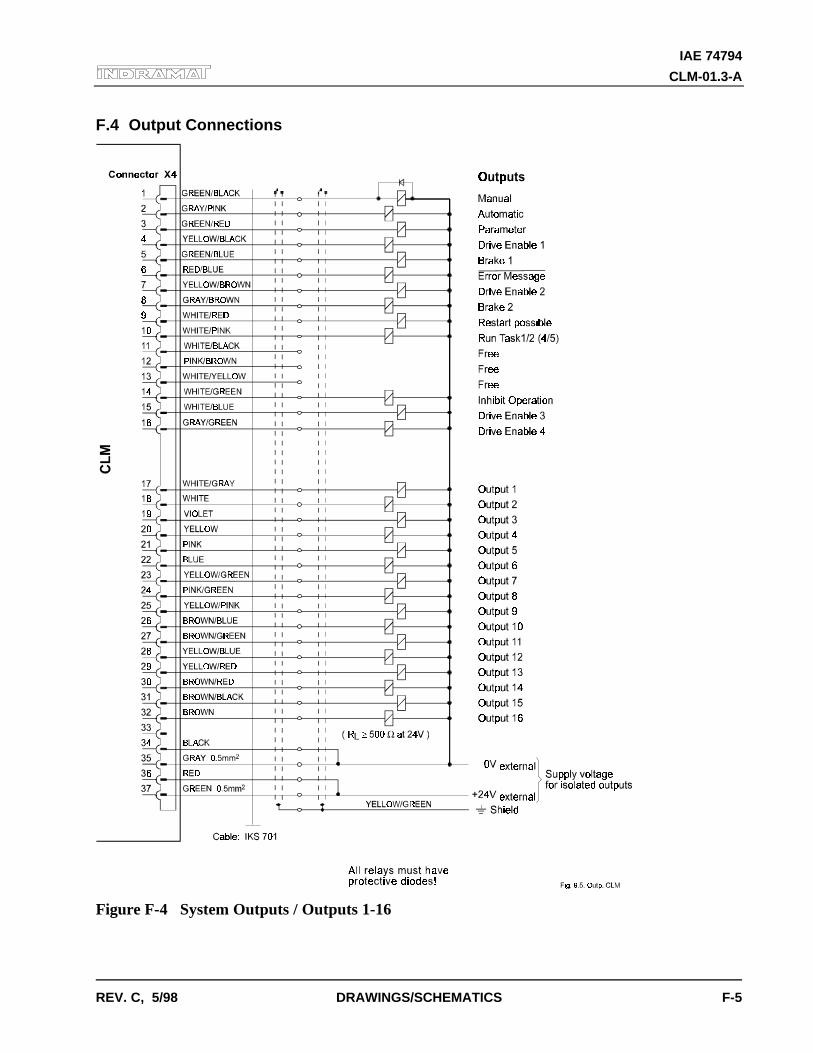
IAE 74794
CLM-01.3-A
REV. C, 5/98 DRAWINGS/SCHEMATICS F-5
F.4 Output Connections
Figure F-4 System Outputs / Outputs 1-16
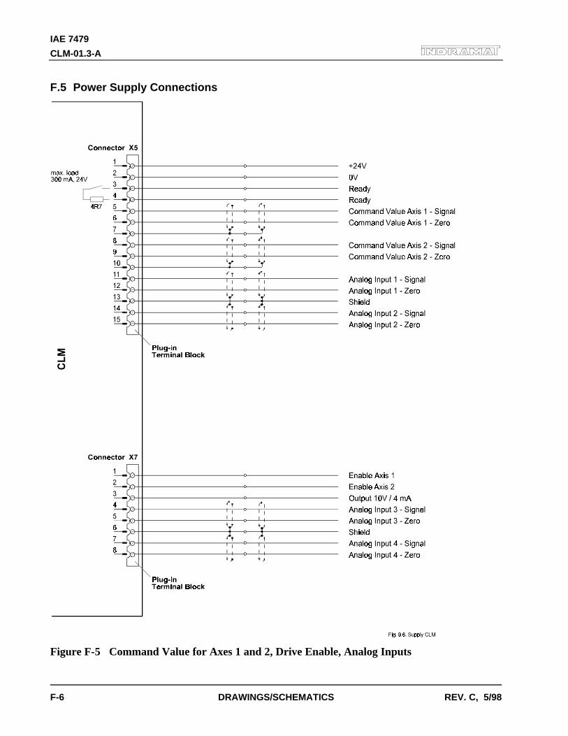
IAE 7479
CLM-01.3-A
F-6 DRAWINGS/SCHEMATICS REV. C, 5/98
F.5 Power Supply Connections
Figure F-5 Command Value for Axes 1 and 2, Drive Enable, Analog Inputs
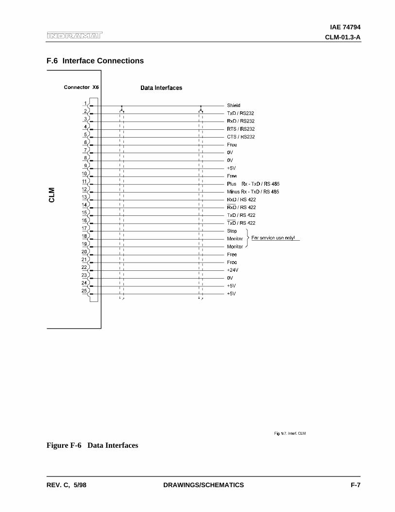
IAE 74794
CLM-01.3-A
REV. C, 5/98 DRAWINGS/SCHEMATICS F-7
F.6 Interface Connections
Figure F-6 Data Interfaces
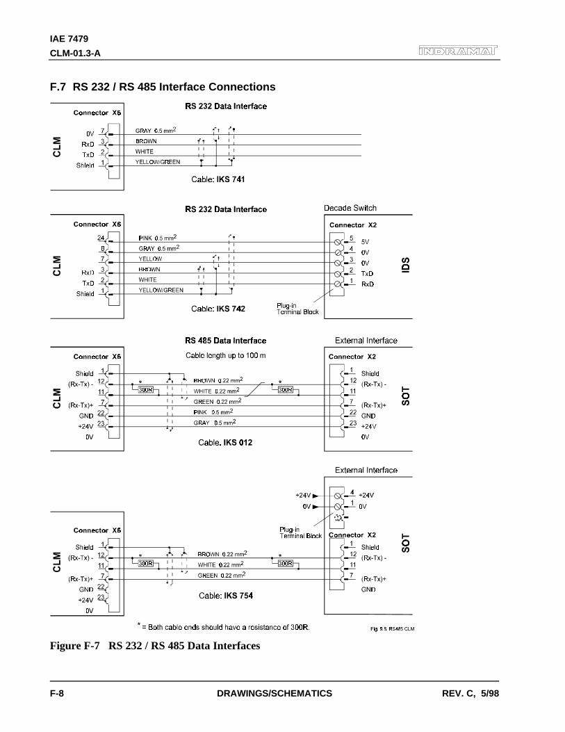
IAE 7479
CLM-01.3-A
F-8 DRAWINGS/SCHEMATICS REV. C, 5/98
F.7 RS 232 / RS 485 Interface Connections
Figure F-7 RS 232 / RS 485 Data Interfaces
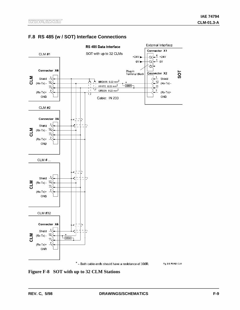
IAE 74794
CLM-01.3-A
REV. C, 5/98 DRAWINGS/SCHEMATICS F-9
F.8 RS 485 (w / SOT) Interface Connections
Figure F-8 SOT with up to 32 CLM Stations
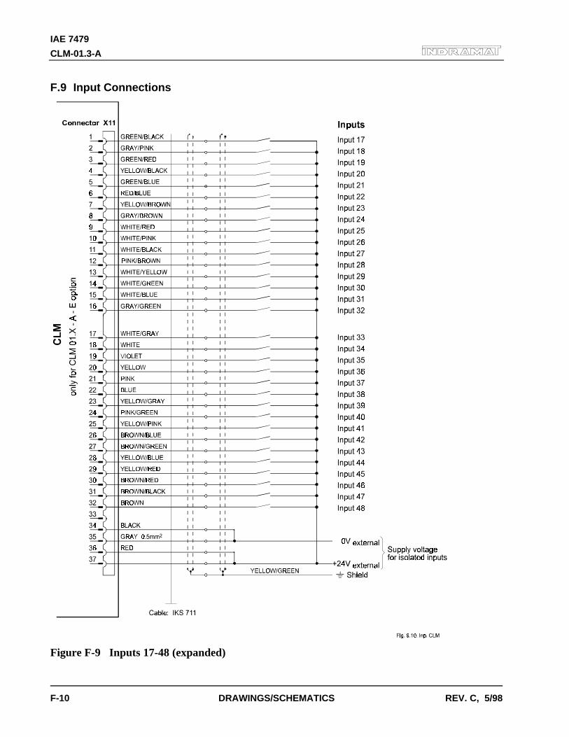
IAE 7479
CLM-01.3-A
F-10 DRAWINGS/SCHEMATICS REV. C, 5/98
F.9 Input Connections
Figure F-9 Inputs 17-48 (expanded)
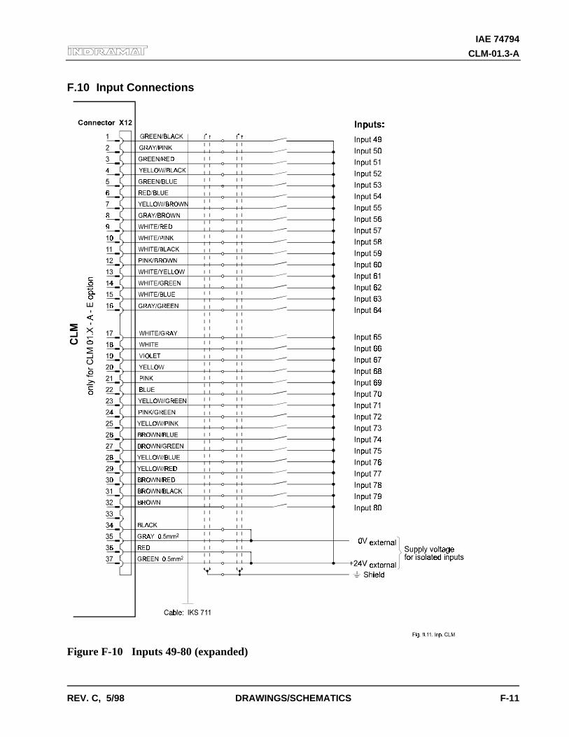
IAE 74794
CLM-01.3-A
REV. C, 5/98 DRAWINGS/SCHEMATICS F-11
F.10 Input Connections
Figure F-10 Inputs 49-80 (expanded)
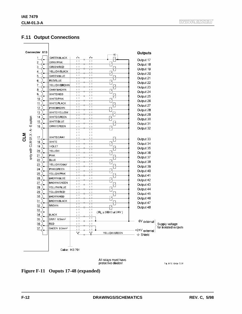
IAE 7479
CLM-01.3-A
F-12 DRAWINGS/SCHEMATICS REV. C, 5/98
F.11 Output Connections
Figure F-11 Ouputs 17-48 (expanded)
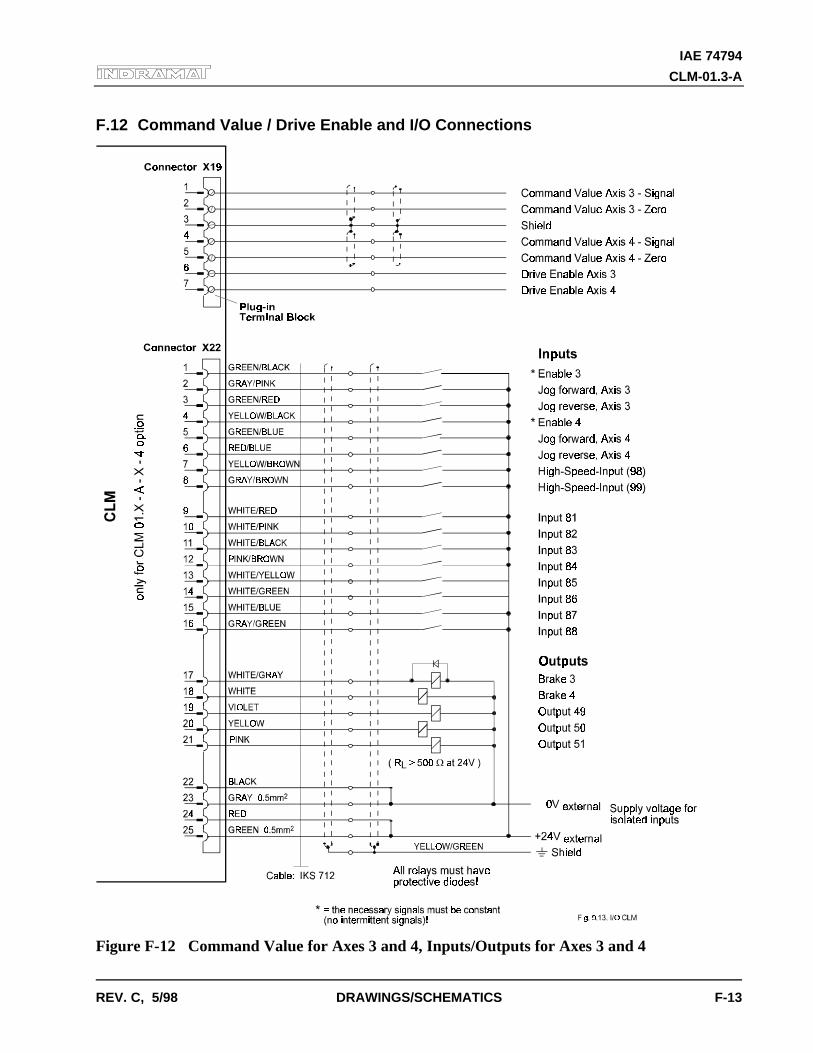
IAE 74794
CLM-01.3-A
REV. C, 5/98 DRAWINGS/SCHEMATICS F-13
F.12 Command Value / Drive Enable and I/O Connections
Figure F-12 Command Value for Axes 3 and 4, Inputs/Outputs for Axes 3 and 4
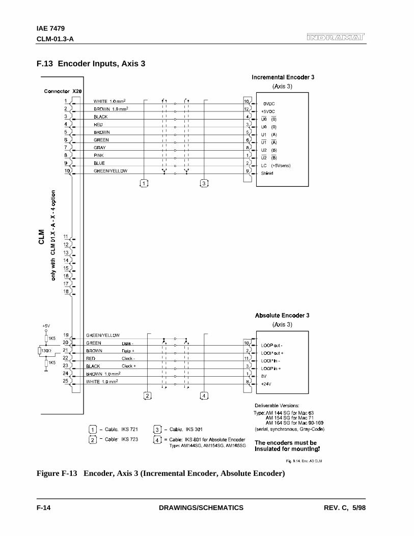
IAE 7479
CLM-01.3-A
F-14 DRAWINGS/SCHEMATICS REV. C, 5/98
F.13 Encoder Inputs, Axis 3
Figure F-13 Encoder, Axis 3 (Incremental Encoder, Absolute Encoder)
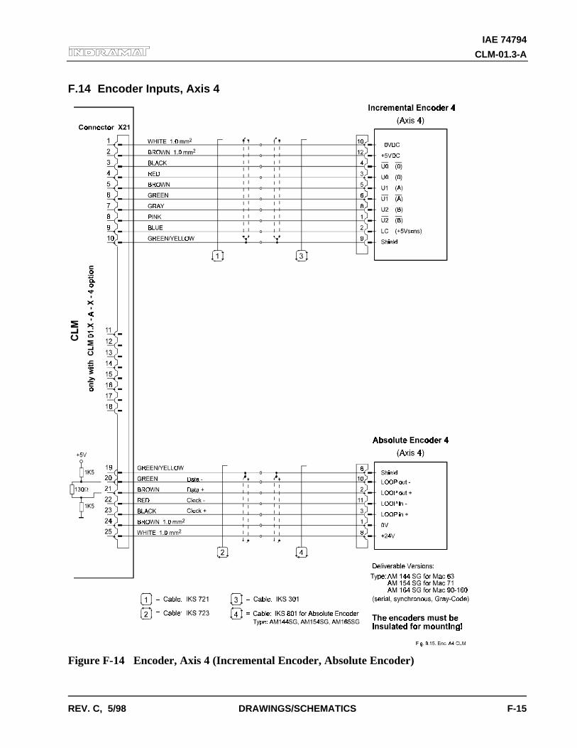
IAE 74794
CLM-01.3-A
REV. C, 5/98 DRAWINGS/SCHEMATICS F-15
F.14 Encoder Inputs, Axis 4
Figure F-14 Encoder, Axis 4 (Incremental Encoder, Absolute Encoder)
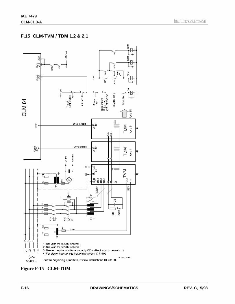
IAE 7479
CLM-01.3-A
F-16 DRAWINGS/SCHEMATICS REV. C, 5/98
F.15 CLM-TVM / TDM 1.2 & 2.1
Figure F-15 CLM-TDM
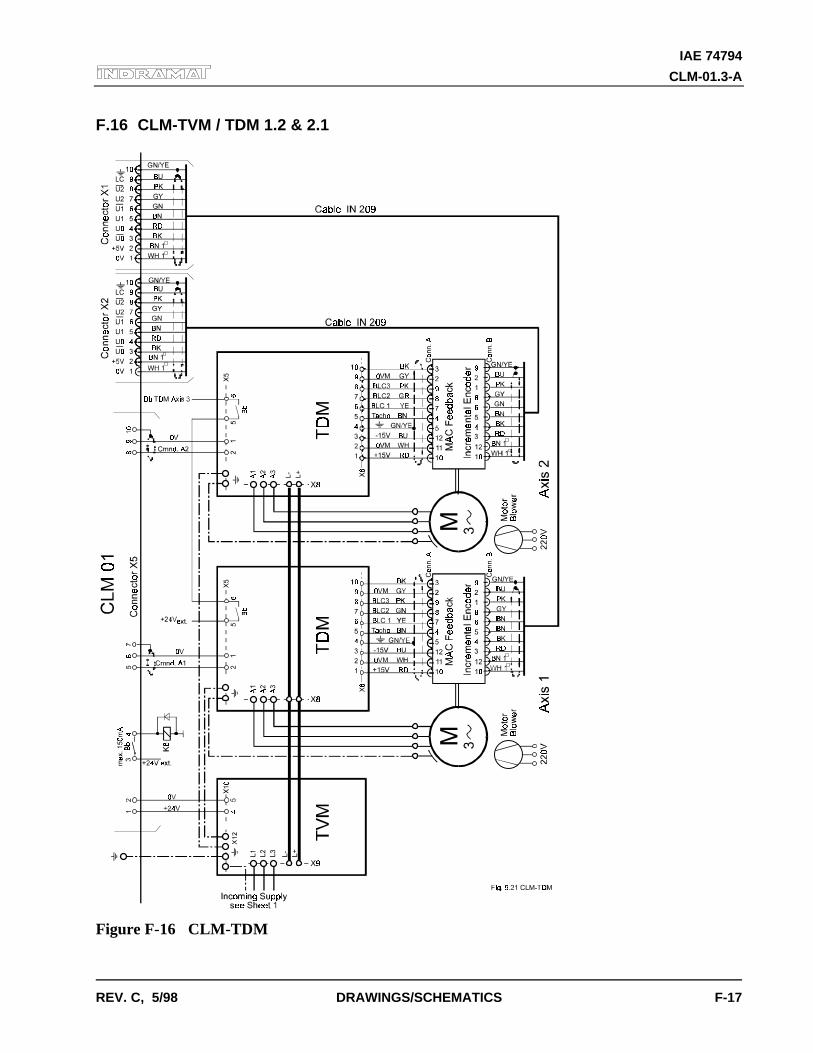
IAE 74794
CLM-01.3-A
REV. C, 5/98 DRAWINGS/SCHEMATICS F-17
F.16 CLM-TVM / TDM 1.2 & 2.1
Figure F-16 CLM-TDM
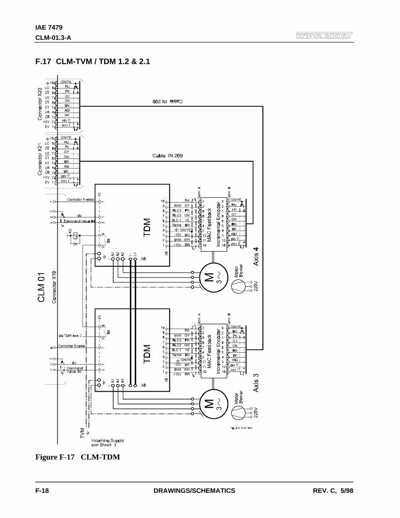
IAE 7479
CLM-01.3-A
F-18 DRAWINGS/SCHEMATICS REV. C, 5/98
F.17 CLM-TVM / TDM 1.2 & 2.1
Figure F-17 CLM-TDM
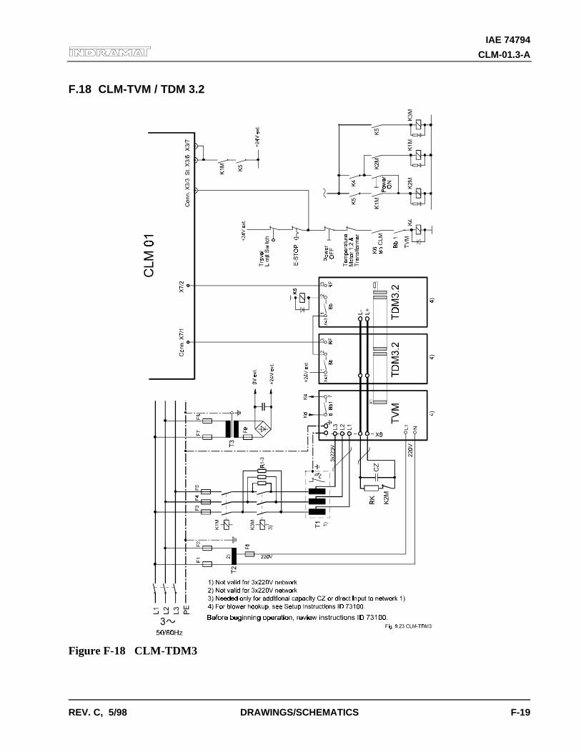
IAE 74794
CLM-01.3-A
REV. C, 5/98 DRAWINGS/SCHEMATICS F-19
F.18 CLM-TVM / TDM 3.2
Figure F-18 CLM-TDM3
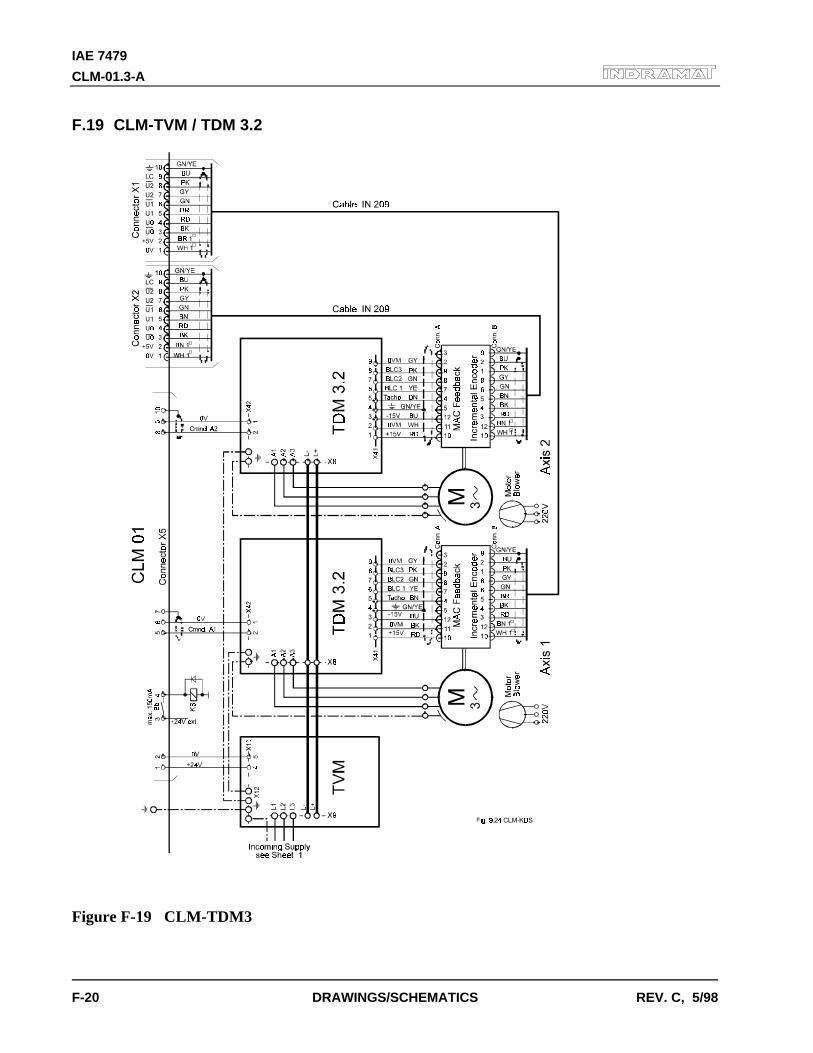
IAE 7479
CLM-01.3-A
F-20 DRAWINGS/SCHEMATICS REV. C, 5/98
F.19 CLM-TVM / TDM 3.2
Figure F-19 CLM-TDM3
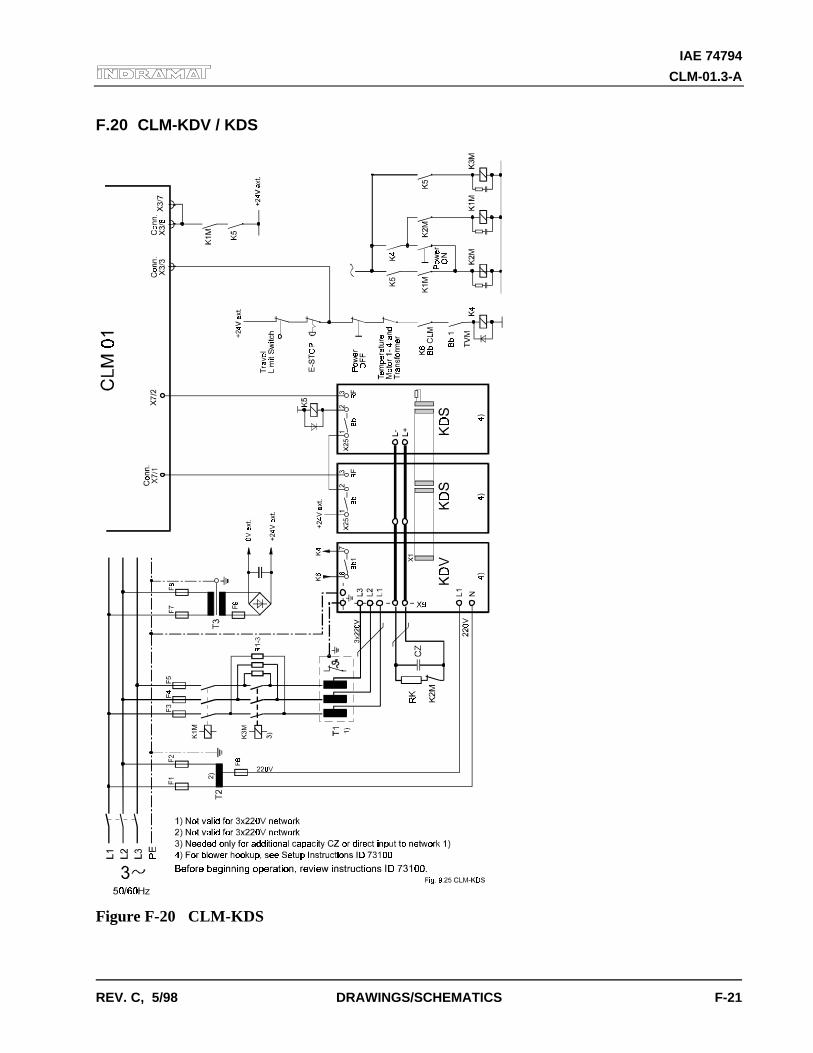
IAE 74794
CLM-01.3-A
REV. C, 5/98 DRAWINGS/SCHEMATICS F-21
F.20 CLM-KDV / KDS
Figure F-20 CLM-KDS
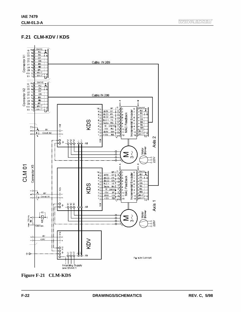
IAE 7479
CLM-01.3-A
F-22 DRAWINGS/SCHEMATICS REV. C, 5/98
F.21 CLM-KDV / KDS
Figure F-21 CLM-KDS
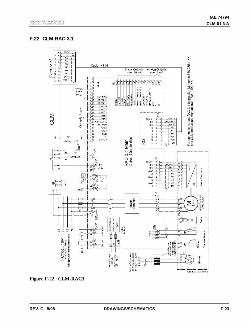
IAE 74794
CLM-01.3-A
REV. C, 5/98 DRAWINGS/SCHEMATICS F-23
F.22 CLM-RAC 3.1
Figure F-22 CLM-RAC3
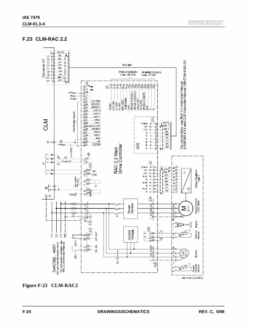
IAE 7479
CLM-01.3-A
F-24 DRAWINGS/SCHEMATICS REV. C, 5/98
F.23 CLM-RAC 2.2
Figure F-23 CLM-RAC2
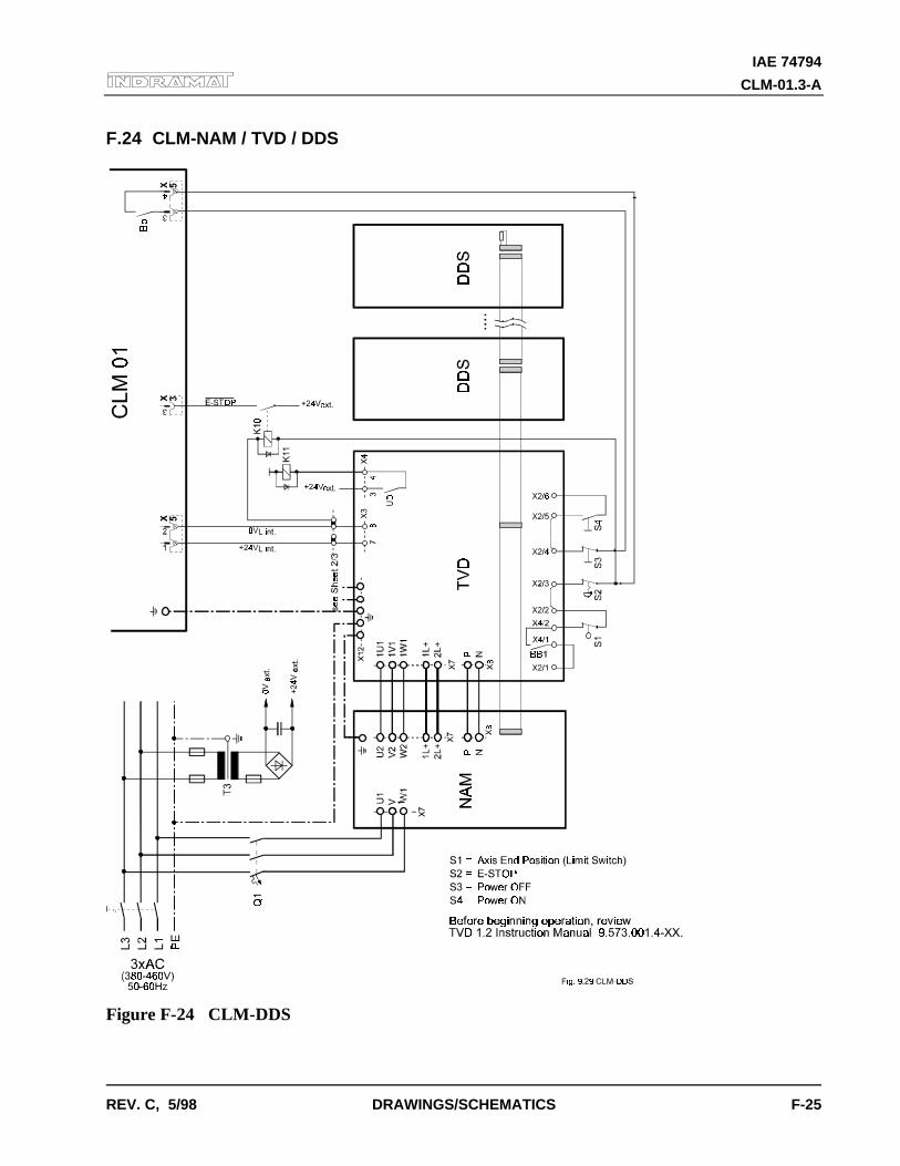
IAE 74794
CLM-01.3-A
REV. C, 5/98 DRAWINGS/SCHEMATICS F-25
F.24 CLM-NAM / TVD / DDS
Figure F-24 CLM-DDS
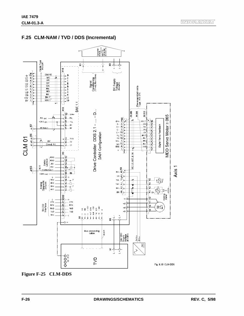
IAE 7479
CLM-01.3-A
F-26 DRAWINGS/SCHEMATICS REV. C, 5/98
F.25 CLM-NAM / TVD / DDS (Incremental)
Figure F-25 CLM-DDS
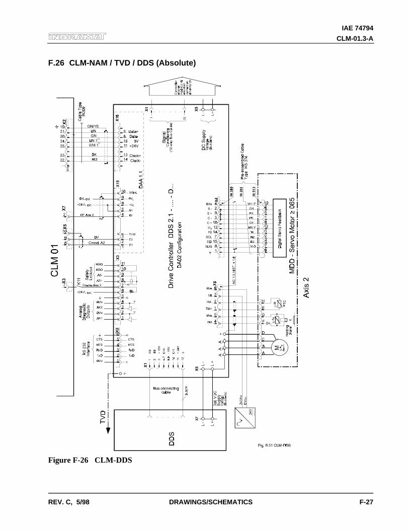
IAE 74794
CLM-01.3-A
REV. C, 5/98 DRAWINGS/SCHEMATICS F-27
F.26 CLM-NAM / TVD / DDS (Absolute)
Figure F-26 CLM-DDS
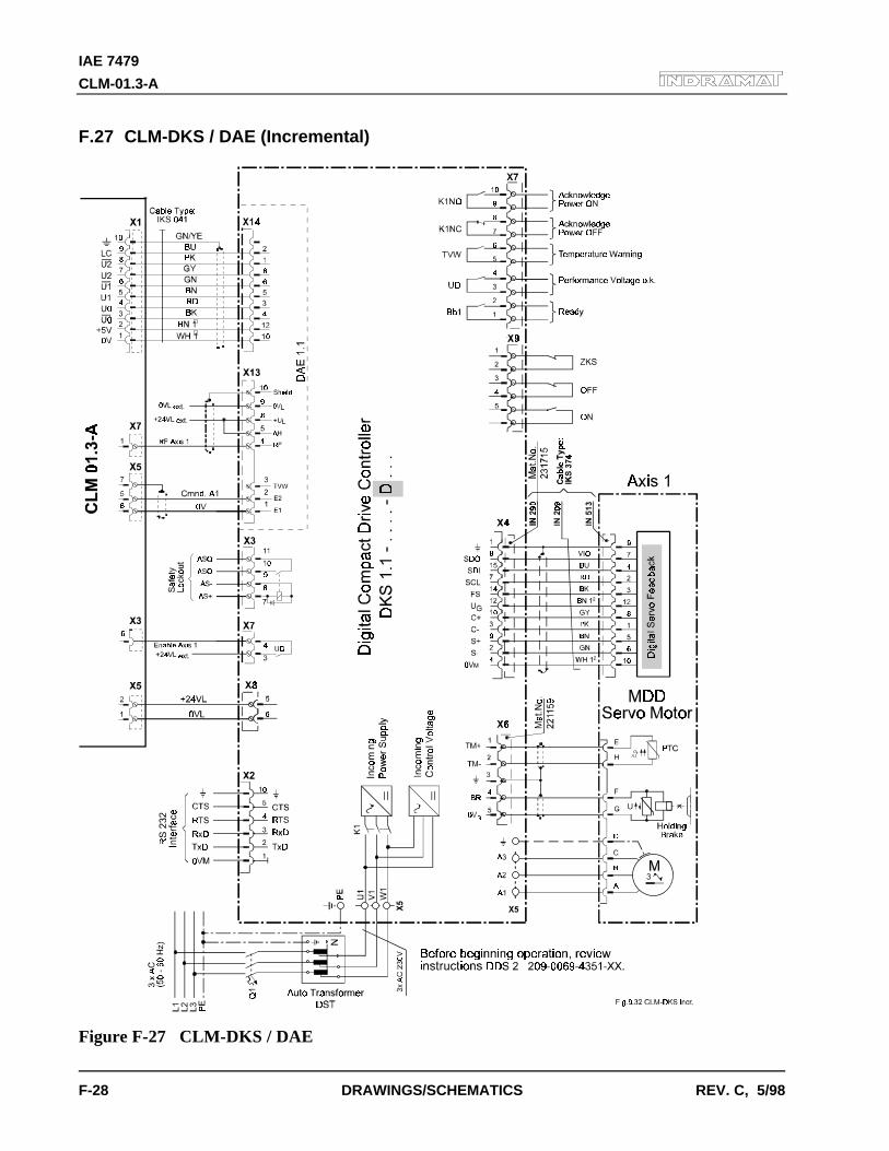
IAE 7479
CLM-01.3-A
F-28 DRAWINGS/SCHEMATICS REV. C, 5/98
F.27 CLM-DKS / DAE (Incremental)
Figure F-27 CLM-DKS / DAE
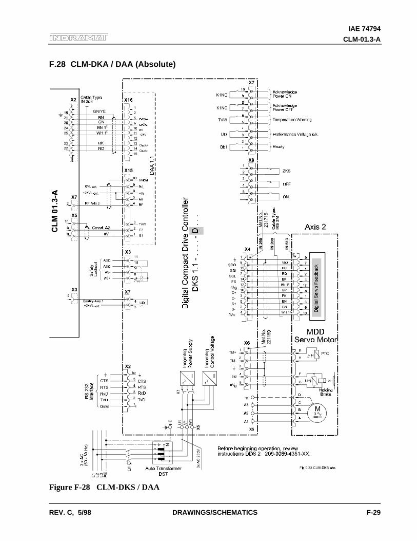
IAE 74794
CLM-01.3-A
REV. C, 5/98 DRAWINGS/SCHEMATICS F-29
F.28 CLM-DKA / DAA (Absolute)
Figure F-28 CLM-DKS / DAA
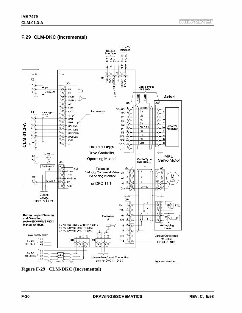
IAE 7479
CLM-01.3-A
F-30 DRAWINGS/SCHEMATICS REV. C, 5/98
F.29 CLM-DKC (Incremental)
Figure F-29 CLM-DKC (Incremental)
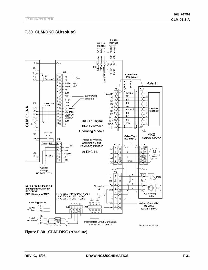
IAE 74794
CLM-01.3-A
REV. C, 5/98 DRAWINGS/SCHEMATICS F-31
F.30 CLM-DKC (Absolute)
Figure F-30 CLM-DKC (Absolute)

IAE 7479
CLM-01.3-A
F-32 DRAWINGS/SCHEMATICS REV. C, 5/98

IAE 74794
CLM-01.3-A
REV. C, 5/98 CLM TYPE CODE DESCRIPTIONS G-1
G. INSTALLATION DRAWINGS
CAUTION: The drawings in this Appendix are included for illustrative purposes only and aresubject to change without notice. Check with Indramat to be sure you are working with the latestdrawings prior to installing, wiring and powering equipment.
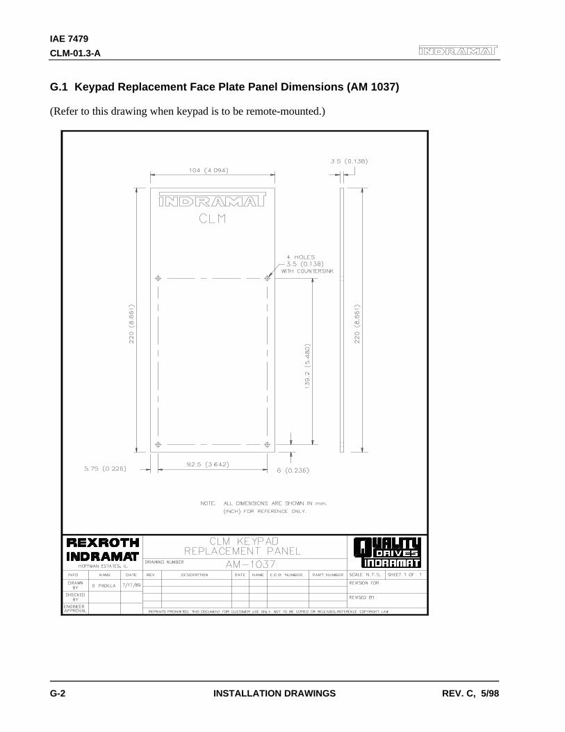
IAE 7479
CLM-01.3-A
G-2 INSTALLATION DRAWINGS REV. C, 5/98
G.1 Keypad Replacement Face Plate Panel Dimensions (AM 1037)
(Refer to this drawing when keypad is to be remote-mounted.)
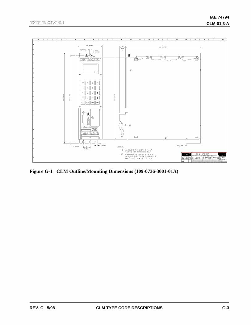
IAE 74794
CLM-01.3-A
REV. C, 5/98 CLM TYPE CODE DESCRIPTIONS G-3
Figure G-1 CLM Outline/Mounting Dimensions (109-0736-3001-01A)
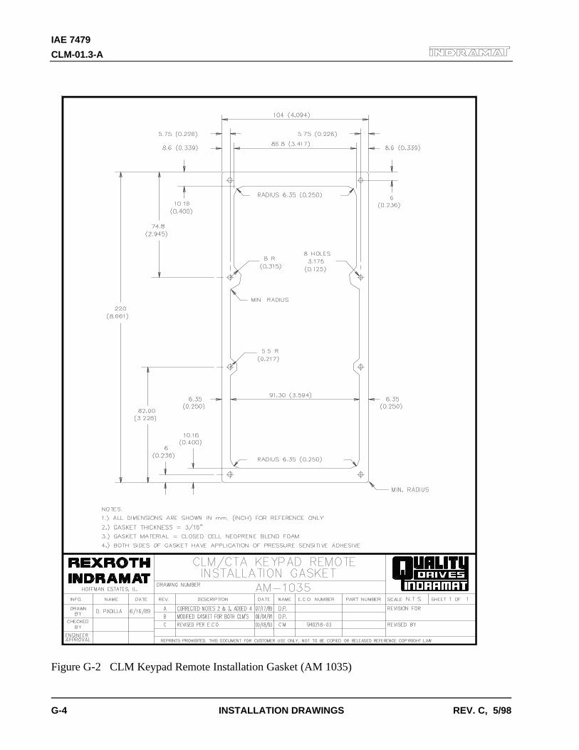
IAE 7479
CLM-01.3-A
G-4 INSTALLATION DRAWINGS REV. C, 5/98
Figure G-2 CLM Keypad Remote Installation Gasket (AM 1035)
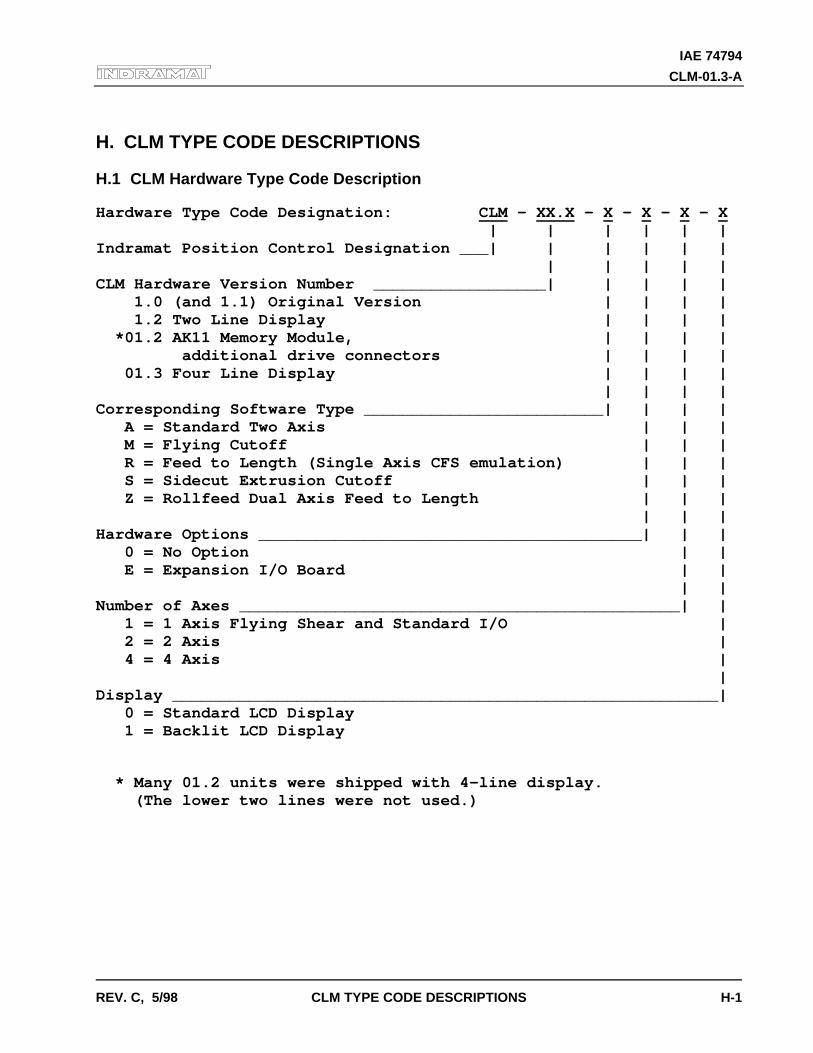
IAE 74794
CLM-01.3-A
REV. C, 5/98 CLM TYPE CODE DESCRIPTIONS H-1
H. CLM TYPE CODE DESCRIPTIONS
H.1 CLM Hardware Type Code Description
Hardware Type Code Designation: CLM - XX.X - X - X - X - X | | | | | |Indramat Position Control Designation ___| | | | | | | | | | |CLM Hardware Version Number __________________| | | | | 1.0 (and 1.1) Original Version | | | | 1.2 Two Line Display | | | | *01.2 AK11 Memory Module, | | | | additional drive connectors | | | | 01.3 Four Line Display | | | | | | | |Corresponding Software Type _________________________| | | | A = Standard Two Axis | | | M = Flying Cutoff | | | R = Feed to Length (Single Axis CFS emulation) | | | S = Sidecut Extrusion Cutoff | | | Z = Rollfeed Dual Axis Feed to Length | | | | | |Hardware Options ________________________________________| | | 0 = No Option | | E = Expansion I/O Board | | | |Number of Axes ______________________________________________| | 1 = 1 Axis Flying Shear and Standard I/O | 2 = 2 Axis | 4 = 4 Axis | |Display _________________________________________________________| 0 = Standard LCD Display 1 = Backlit LCD Display
* Many 01.2 units were shipped with 4-line display. (The lower two lines were not used.)
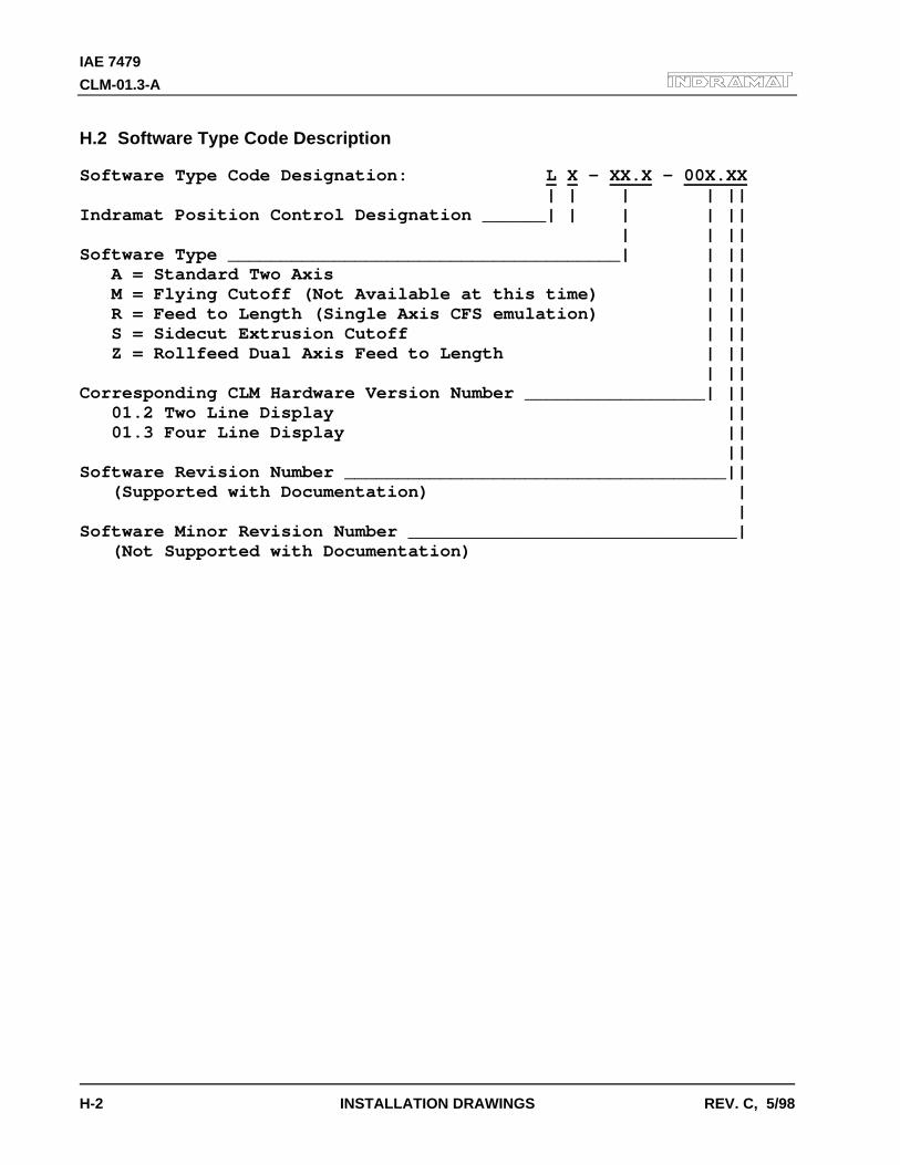
IAE 7479
CLM-01.3-A
H-2 INSTALLATION DRAWINGS REV. C, 5/98
H.2 Software Type Code Description
Software Type Code Designation: L X - XX.X - 00X.XX | | | | ||Indramat Position Control Designation ______| | | | || | | ||Software Type _____________________________________| | || A = Standard Two Axis | || M = Flying Cutoff (Not Available at this time) | || R = Feed to Length (Single Axis CFS emulation) | || S = Sidecut Extrusion Cutoff | || Z = Rollfeed Dual Axis Feed to Length | || | ||Corresponding CLM Hardware Version Number _________________| || 01.2 Two Line Display || 01.3 Four Line Display || ||Software Revision Number ____________________________________|| (Supported with Documentation) | |Software Minor Revision Number _______________________________| (Not Supported with Documentation)
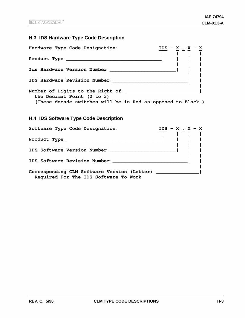
IAE 74794
CLM-01.3-A
REV. C, 5/98 CLM TYPE CODE DESCRIPTIONS H-3
H.3 IDS Hardware Type Code Description
Hardware Type Code Designation: IDS - X . X - X | | | |Product Type _________________________________| | | | | | |Ids Hardware Version Number _______________________| | | | |IDS Hardware Revision Number __________________________| | |Number of Digits to the Right of _________________________| the Decimal Point (0 to 3) (These decade switches will be in Red as opposed to Black.)
H.4 IDS Software Type Code Description
Software Type Code Designation: IDS - X . X - X | | | |Product Type _________________________________| | | | | | |IDS Software Version Number _______________________| | | | |IDS Software Revision Number __________________________| | |Corresponding CLM Software Version (Letter) _______________| Required For The IDS Software To Work
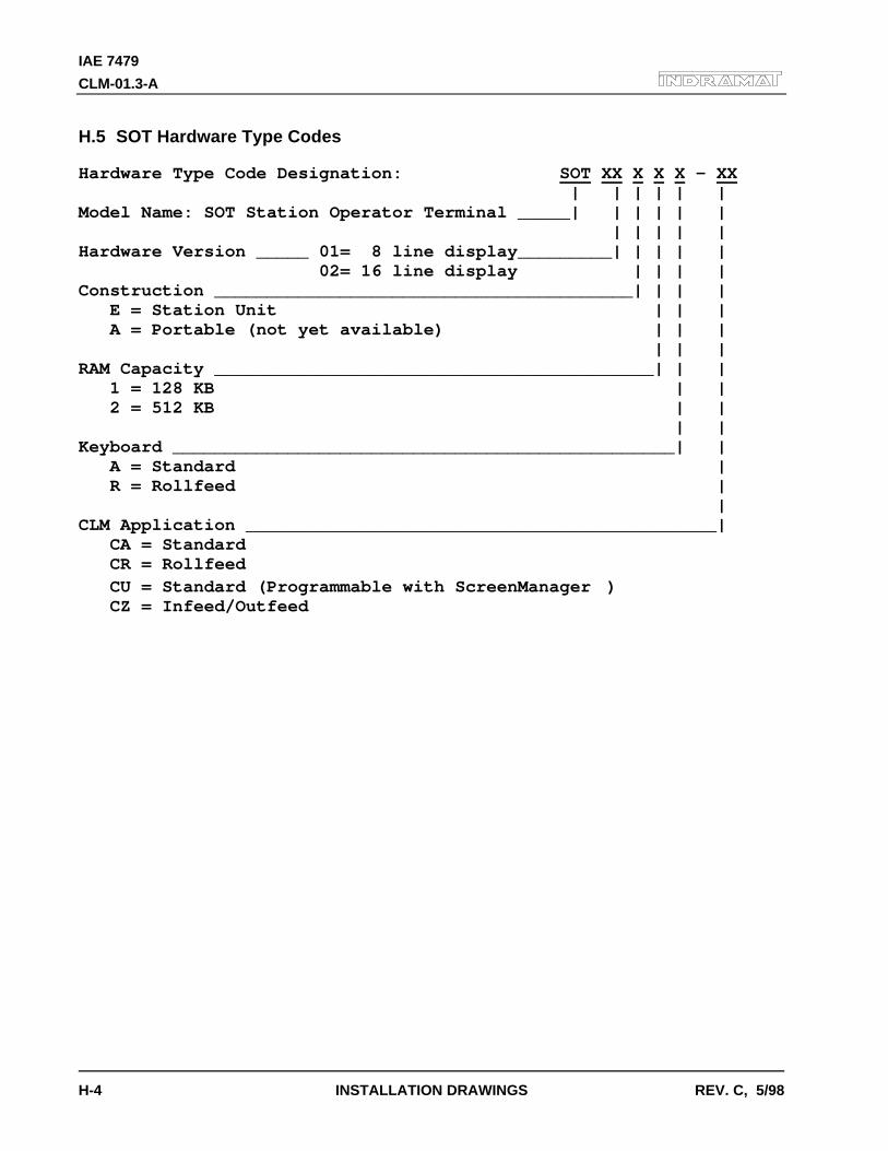
IAE 7479
CLM-01.3-A
H-4 INSTALLATION DRAWINGS REV. C, 5/98
H.5 SOT Hardware Type Codes
Hardware Type Code Designation: SOT XX X X X - XX | | | | | |Model Name: SOT Station Operator Terminal _____| | | | | | | | | | |Hardware Version _____ 01= 8 line display_________| | | | | 02= 16 line display | | | |Construction ________________________________________| | | | E = Station Unit | | | A = Portable (not yet available) | | | | | |RAM Capacity __________________________________________| | | 1 = 128 KB | | 2 = 512 KB | | | |Keyboard ________________________________________________| | A = Standard | R = Rollfeed | |CLM Application _____________________________________________| CA = Standard CR = Rollfeed CU = Standard (Programmable with ScreenManager) CZ = Infeed/Outfeed
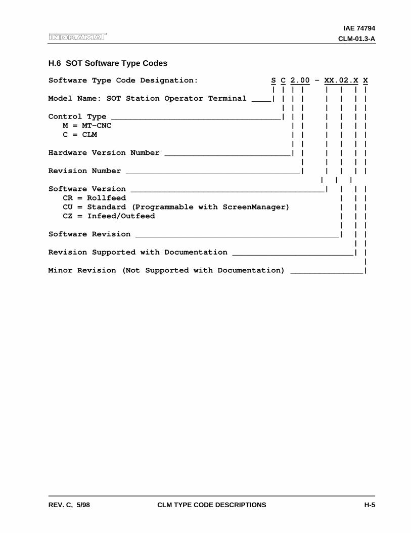
IAE 74794
CLM-01.3-A
REV. C, 5/98 CLM TYPE CODE DESCRIPTIONS H-5
H.6 SOT Software Type Codes
Software Type Code Designation: S C 2.00 - XX.02.X X | | | | | | | |Model Name: SOT Station Operator Terminal ____| | | | | | | | | | | | | | |Control Type ___________________________________| | | | | | | M = MT-CNC | | | | | | C = CLM | | | | | | | | | | | |Hardware Version Number __________________________| | | | | | | | | | |Revision Number ____________________________________| | | | | | | | Software Version ________________________________________| | | | CR = Rollfeed | | | CU = Standard (Programmable with ScreenManager) | | | CZ = Infeed/Outfeed | | | | | |Software Revision __________________________________________| | | | |Revision Supported with Documentation _________________________| | |Minor Revision (Not Supported with Documentation) _______________|

IAE 7479
CLM-01.3-A
H-6 INSTALLATION DRAWINGS REV. C, 5/98

READER COMMENT CARD AND REGISTRATION FORM
We welcome your evaluation of this manual. Please complete this form to help us to improve our publications andalso to receive notification of revisions to this manual.
Publication: CLM 01.3-A Four-Axis Positioning ControlType of Manual: User’s ManualPublication No. 74794Part No. 279795Revision: C, 05/98
Please indicate the degree to which each statement applies to you by circling whether you� strongly agree, � agree, � are uncertain, � disagree, or � strongly disagree with the statement.
1. The manual is well organized. � � � � �
2. I can find the information I want. � � � � �
3. The index is thorough. � � � � �
4. The information is easy to understand. � � � � �
5. The manual is clearly written. � � � � �
6. Concepts and vocabulary are easy to understand. � � � � �
7. Examples are clear and helpful. � � � � �
8. The manual contains enough illustrations. � � � � �
9. Layout and format enhance the manual's usefulness. � � � � �
10. The quality of this manual would influence any repeat purchase decision. � � � � �
11. The scope of the information in the manual meets my needs. � � � � �
Name
Company
Address Dept
City State Zip
Telephone (____)
Comments:

------------------------------------------ Tape ** Closed --------------------------------------------
From:
Technical Documentation DepartmentRexroth Corporation/Indramat Division5150 Prairie Stone ParkwayHoffman Estates, Illinois 60192U.S.A.
------------------------------------------ Tape ** Closed --------------------------------------------

Indramat
Related Documents


![O Espetacular Homem-Aranha v3 #01.3 [HQOnline.com.Br]](https://static.cupdf.com/doc/110x72/5695cfda1a28ab9b028fcfa5/o-espetacular-homem-aranha-v3-013-hqonlinecombr.jpg)

