SURFCAM Reference Manual, Chapter 7 • Configuration Tools Copyright © 2000 by Surfware, Inc. All Rights Reserved. Click To See: How to Use Online Documents SURFCAM Online Documents &21),*85$7,21722/6 SURFCAM’s default configuration parameters are contained in the SURFCAM.INI file. You can temporarily override many of these default values using commands on the Options menu which is accessed from any of SURFCAM’s NC menus. Refer to 1. 2 Axis Options: the SURFCAM Getting Started Manual, Chapter 6: 2 Axis, Section 6.1.4: 2 Axis Options Tab on page 181, 2. 3 Axis Options: Chapter 3: 3 Axis, Section 3.1.3: 3 Axis Options Tab on page 219, 3. 4 and 5 Axis Options: Chapter 4: 4 Axis and 5 Axis, Section 4.9: 4 And 5 Axis Options Tab on page 287, 4. Lathe Options: Chapter 5: Lathe, Section 5.1.4: Lathe Options Tab on page 318, or 5. Wire EDM Options: Chapter 6: Wire EDM, Section 6.3.3: EDM Options Tab on page 363. 7 7.1 INTRODUCTION Figure 1: NC > 2 Axis menu > Options The defaults for these parameters can be set using the SURFCAM Configuration Tools utility. You will have to restart SURFCAM before the changes become active. To access SURFCAM Configuration Tools, click Start > Programs > SURFCAM 2000.1 > SURFCAM Tools > SURFCAM Config Tools. Then click the left mouse button. Figure 2: Access Configuration Tools

Welcome message from author
This document is posted to help you gain knowledge. Please leave a comment to let me know what you think about it! Share it to your friends and learn new things together.
Transcript
Click To See: How to Use Online Documents SURFCAM Online Documents
J 685)&$0�5HIHUHQFH�0DQXDO
���������������
SURFCAM’s default configuration parameters are contained in the SURFCAM.INI file. You can temporarily override many of these default values using commands on the Options menu which is accessed from any of SURFCAM’s NC menus.
Refer to
1. 2 Axis Options: the SURFCAM Getting Started Manual, Chapter 6: 2 Axis, Section 6.1.4: 2 Axis Options Tab on page 181,
2. 3 Axis Options: Chapter 3: 3 Axis, Section 3.1.3: 3 Axis Options Tab on page 219,
3. 4 and 5 Axis Options: Chapter 4: 4 Axis and 5 Axis, Section 4.9: 4 And 5 Axis Options Tab on page 287,
4. Lathe Options: Chapter 5: Lathe, Section 5.1.4: Lathe Options Tab on page 318, or
5. Wire EDM Options: Chapter 6: Wire EDM, Section 6.3.3: EDM Options Tab on page 363.
7
7.1 INTRODUCTION
Figure 1: NC > 2 Axis menu > Options
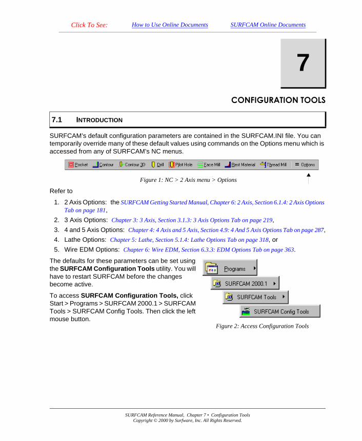
The defaults for these parameters can be set using the SURFCAM Configuration Tools utility. You will have to restart SURFCAM before the changes become active.
To access SURFCAM Configuration Tools, click Start > Programs > SURFCAM 2000.1 > SURFCAM Tools > SURFCAM Config Tools. Then click the left mouse button.
Figure 2: Access Configuration Tools
SURFCAM Reference Manual, Chapter 7 • Configuration ToolsCopyright © 2000 by Surfware, Inc. All Rights Reserved.
368 SURFCAM Reference Manual, Chapter 7 • Configuration Tools
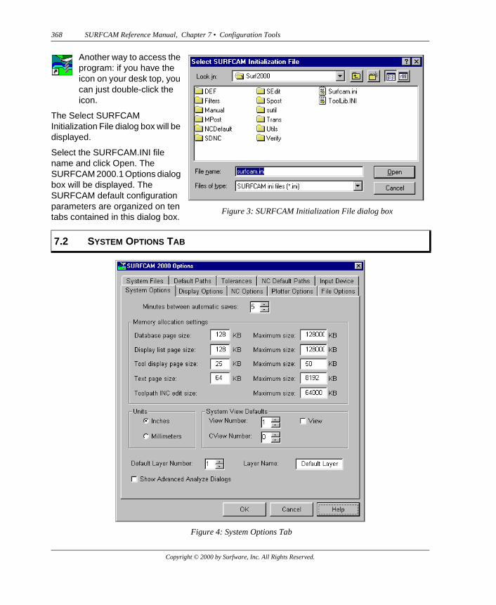
Another way to access the program: if you have the icon on your desk top, you can just double-click the icon.
The Select SURFCAM Initialization File dialog box will be displayed.
Select the SURFCAM.INI file name and click Open. The SURFCAM 2000.1 Options dialog box will be displayed. The SURFCAM default configuration parameters are organized on ten tabs contained in this dialog box.
Figure 3: SURFCAM Initialization File dialog box
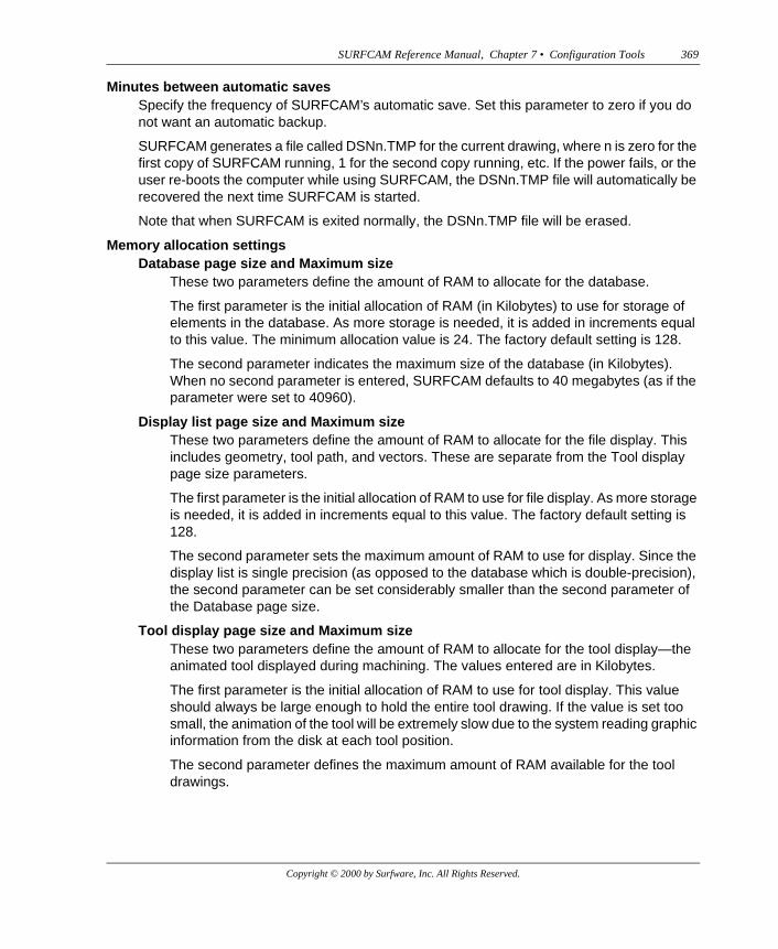
7.2 SYSTEM OPTIONS TAB
Figure 4: System Options Tab
Copyright © 2000 by Surfware, Inc. All Rights Reserved.
SURFCAM Reference Manual, Chapter 7 • Configuration Tools 369
Minutes between automatic savesSpecify the frequency of SURFCAM’s automatic save. Set this parameter to zero if you do not want an automatic backup.
SURFCAM generates a file called DSNn.TMP for the current drawing, where n is zero for the first copy of SURFCAM running, 1 for the second copy running, etc. If the power fails, or the user re-boots the computer while using SURFCAM, the DSNn.TMP file will automatically be recovered the next time SURFCAM is started.
Note that when SURFCAM is exited normally, the DSNn.TMP file will be erased.
Memory allocation settingsDatabase page size and Maximum size
These two parameters define the amount of RAM to allocate for the database.
The first parameter is the initial allocation of RAM (in Kilobytes) to use for storage of elements in the database. As more storage is needed, it is added in increments equal to this value. The minimum allocation value is 24. The factory default setting is 128.
The second parameter indicates the maximum size of the database (in Kilobytes). When no second parameter is entered, SURFCAM defaults to 40 megabytes (as if the parameter were set to 40960).
Display list page size and Maximum sizeThese two parameters define the amount of RAM to allocate for the file display. This includes geometry, tool path, and vectors. These are separate from the Tool display page size parameters.
The first parameter is the initial allocation of RAM to use for file display. As more storage is needed, it is added in increments equal to this value. The factory default setting is 128.
The second parameter sets the maximum amount of RAM to use for display. Since the display list is single precision (as opposed to the database which is double-precision), the second parameter can be set considerably smaller than the second parameter of the Database page size.
Tool display page size and Maximum sizeThese two parameters define the amount of RAM to allocate for the tool display—the animated tool displayed during machining. The values entered are in Kilobytes.
The first parameter is the initial allocation of RAM to use for tool display. This value should always be large enough to hold the entire tool drawing. If the value is set too small, the animation of the tool will be extremely slow due to the system reading graphic information from the disk at each tool position.
The second parameter defines the maximum amount of RAM available for the tool drawings.
Copyright © 2000 by Surfware, Inc. All Rights Reserved.
370 SURFCAM Reference Manual, Chapter 7 • Configuration Tools
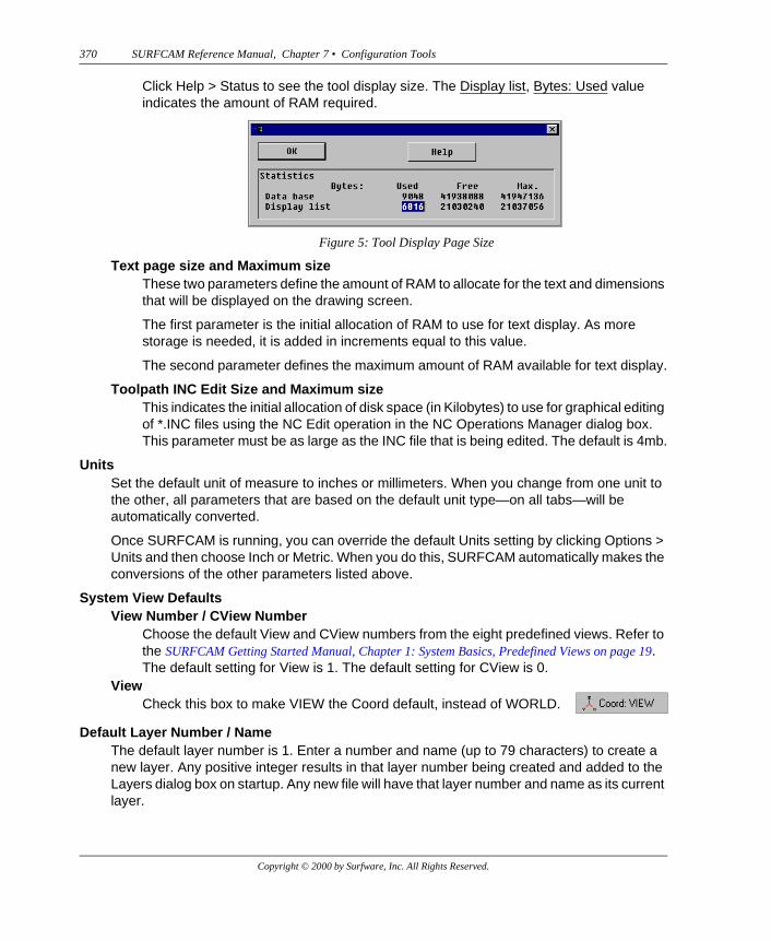
Click Help > Status to see the tool display size. The Display list, Bytes: Used value indicates the amount of RAM required.
Text page size and Maximum sizeThese two parameters define the amount of RAM to allocate for the text and dimensions that will be displayed on the drawing screen.
The first parameter is the initial allocation of RAM to use for text display. As more storage is needed, it is added in increments equal to this value.
The second parameter defines the maximum amount of RAM available for text display.
Toolpath INC Edit Size and Maximum sizeThis indicates the initial allocation of disk space (in Kilobytes) to use for graphical editing of *.INC files using the NC Edit operation in the NC Operations Manager dialog box. This parameter must be as large as the INC file that is being edited. The default is 4mb.
UnitsSet the default unit of measure to inches or millimeters. When you change from one unit to the other, all parameters that are based on the default unit type—on all tabs—will be automatically converted.
Once SURFCAM is running, you can override the default Units setting by clicking Options > Units and then choose Inch or Metric. When you do this, SURFCAM automatically makes the conversions of the other parameters listed above.
System View DefaultsView Number / CView Number
Choose the default View and CView numbers from the eight predefined views. Refer to the SURFCAM Getting Started Manual, Chapter 1: System Basics, Predefined Views on page 19. The default setting for View is 1. The default setting for CView is 0.
Default Layer Number / NameThe default layer number is 1. Enter a number and name (up to 79 characters) to create a new layer. Any positive integer results in that layer number being created and added to the Layers dialog box on startup. Any new file will have that layer number and name as its current layer.
Figure 5: Tool Display Page Size
ViewCheck this box to make VIEW the Coord default, instead of WORLD.
Copyright © 2000 by Surfware, Inc. All Rights Reserved.
SURFCAM Reference Manual, Chapter 7 • Configuration Tools 371
If you choose 0, SURFCAM will be launched with 0 as the default layer and no layers will be listed in the Layers dialog box.
Show Advanced Analyze DialogsCheck this to cause a more advanced set of Analyze dialog boxes to be displayed when you use the Elements command on the SURFCAM Analyze menu.
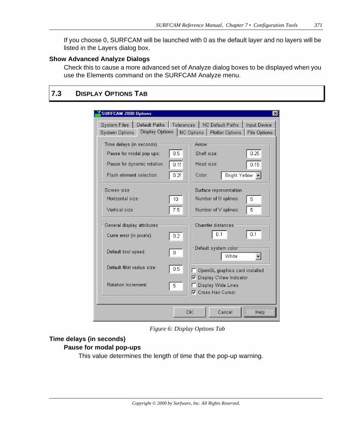
Time delays (in seconds)Pause for modal pop-ups
This value determines the length of time that the pop-up warning.
7.3 DISPLAY OPTIONS TAB
Figure 6: Display Options Tab
Copyright © 2000 by Surfware, Inc. All Rights Reserved.
372 SURFCAM Reference Manual, Chapter 7 • Configuration Tools
Pause for dynamic rotationThe number of seconds the system will wait to redraw the screen when the mouse is used to rotate or pan the image. This delay must be introduced to prevent the screen from being redrawn whenever a mouse pulse is detected.
Flash Element SelectionThis value determines the length of time that selected elements are displayed in the highlight color.
ArrowShaft Size, Head Size, and Color
The first parameter indicates the size of the shaft—in the same units of measure that are used for the ScreenSize parameter.
The second parameter indicates the size of the arrow's head.
Note: When the first and second parameters are set to zero, the arrow is not displayed.
The third parameter indicates the color of the arrows.
Note: When the color is set to element color or zero, the arrow will appear the same color as the surface. In drawings that contain many surfaces, this makes it easier to determine the surface to which an arrow belongs.
Screen SizeThe width and height (in inches or millimeters) of your video display screen. The closer these values are set to the actual dimensions of your screen, the closer the dimensions of objects drawn on the screen will be to their actual size when the viewing scale in the Status menu is set to 1. If the values you enter are not in the correct ratio, you will get distortion; for example, a circle would look like an ellipse. Measure the height and width of your screen with a ruler to determine the actual physical dimensions. Note that the first number in the INI file is the horizontal dimension, the second is the vertical.
Surface representation: Number of U and V splinesThese parameters set the number of U and V direction splines displayed when a surface is created. When you enter a zero for these defaults, the surface is displayed using the knots. When the numbers are greater than zero, the splines are displayed equally spaced.
General display attributesCurve Error (in Pixels)
Tolerance within which curves are drawn on the screen. Error is in pixels.
Default tool speedSet the tool animation speed of the tool display. The tool animation speed ranges from 0.0 (fastest) to 0.9 (slowest).
Default fillet radius sizeThe default radius when either Create > Fillet or Create > Surface > Fillet is first selected.
Copyright © 2000 by Surfware, Inc. All Rights Reserved.
SURFCAM Reference Manual, Chapter 7 • Configuration Tools 373
Rotation IncrementSpecify the rotation increment value. This is the amount that an image will be rotated when you use the arrow keys in conjunction with the rotation function to rotate the image.
Chamfer distancesThese are the default values for the First Trim Value and Second Trim Value parameters on the Chamfer dialog box that will be displayed when you click Change Chamfer on the Create > Chamfer menu. Refer to Chapter 1: Menus and Dialog Boxes, Section 1.3.7: Create > Chamfer on page 55.
Default system colorThe color of elements when they are displayed on the screen. Refer to the online SURFCAM Support Utilities Manual, Chapter 1: Miscellaneous Utilities, Section 1.4.3: Color File on page 9 for the numbers of the colors.
OpenGL graphics card installedCheck the box if you have an OpenGL card installed.
An Open GL graphics card causes rendered or shaded images to remain shaded when the design model is panned, dynamically rotated, or zoomed. If the dynamic rotation seems not to display all of the surfaces as the design model is rotated, increase the value for Pause for dynamic rotation in the Time delays (in seconds) section of the Display Options tab.
If you check the box and do not have an OpenGL card installed, SURFCAM will use the OpenGL graphics functions, but your system will display graphics very slowly.
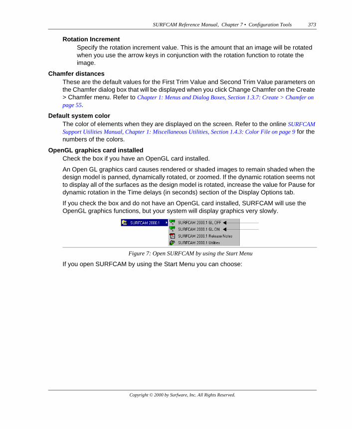
If you open SURFCAM by using the Start Menu you can choose:
Figure 7: Open SURFCAM by using the Start Menu
Copyright © 2000 by Surfware, Inc. All Rights Reserved.
374 SURFCAM Reference Manual, Chapter 7 • Configuration Tools
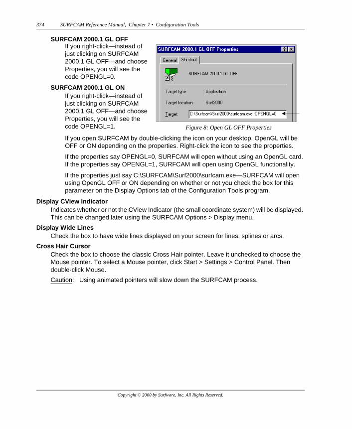
SURFCAM 2000.1 GL OFF
If you open SURFCAM by double-clicking the icon on your desktop, OpenGL will be OFF or ON depending on the properties. Right-click the icon to see the properties.
If the properties say OPENGL=0, SURFCAM will open without using an OpenGL card. If the properties say OPENGL=1, SURFCAM will open using OpenGL functionality.
If the properties just say C:\SURFCAM\Surf2000\surfcam.exe—SURFCAM will open using OpenGL OFF or ON depending on whether or not you check the box for this parameter on the Display Options tab of the Configuration Tools program.
Display CView IndicatorIndicates whether or not the CView Indicator (the small coordinate system) will be displayed. This can be changed later using the SURFCAM Options > Display menu.
Display Wide LinesCheck the box to have wide lines displayed on your screen for lines, splines or arcs.
Cross Hair CursorCheck the box to choose the classic Cross Hair pointer. Leave it unchecked to choose the Mouse pointer. To select a Mouse pointer, click Start > Settings > Control Panel. Then double-click Mouse.
Caution: Using animated pointers will slow down the SURFCAM process.
If you right-click—instead of just clicking on SURFCAM 2000.1 GL OFF—and choose Properties, you will see the code OPENGL=0.
SURFCAM 2000.1 GL ONIf you right-click—instead of just clicking on SURFCAM 2000.1 GL OFF—and choose Properties, you will see the code OPENGL=1. Figure 8: Open GL OFF Properties
Copyright © 2000 by Surfware, Inc. All Rights Reserved.

SURFCAM Reference Manual, Chapter 7 • Configuration Tools 375
Cutting DisplayYou can set various options for the display of the tool and the toolpaths. Check the options you want.
7.4 NC OPTIONS TAB
Figure 9: NC Options tab
Copyright © 2000 by Surfware, Inc. All Rights Reserved.
376 SURFCAM Reference Manual, Chapter 7 • Configuration Tools
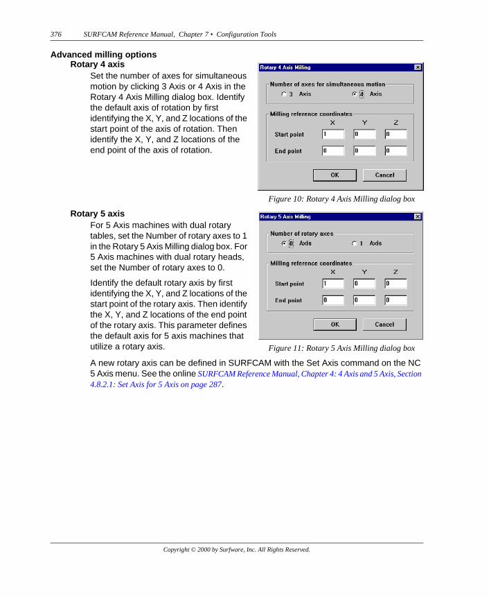
Advanced milling options
A new rotary axis can be defined in SURFCAM with the Set Axis command on the NC 5 Axis menu. See the online SURFCAM Reference Manual, Chapter 4: 4 Axis and 5 Axis, Section 4.8.2.1: Set Axis for 5 Axis on page 287.
Rotary 4 axisSet the number of axes for simultaneous motion by clicking 3 Axis or 4 Axis in the Rotary 4 Axis Milling dialog box. Identify the default axis of rotation by first identifying the X, Y, and Z locations of the start point of the axis of rotation. Then identify the X, Y, and Z locations of the end point of the axis of rotation.
Figure 10: Rotary 4 Axis Milling dialog box
Rotary 5 axisFor 5 Axis machines with dual rotary tables, set the Number of rotary axes to 1 in the Rotary 5 Axis Milling dialog box. For 5 Axis machines with dual rotary heads, set the Number of rotary axes to 0.
Identify the default rotary axis by first identifying the X, Y, and Z locations of the start point of the rotary axis. Then identify the X, Y, and Z locations of the end point of the rotary axis. This parameter defines the default axis for 5 axis machines that utilize a rotary axis. Figure 11: Rotary 5 Axis Milling dialog box
Copyright © 2000 by Surfware, Inc. All Rights Reserved.
SURFCAM Reference Manual, Chapter 7 • Configuration Tools 377
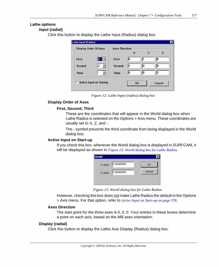
Lathe optionsInput (radial)
Click this button to display the Lathe Input (Radius) dialog box.
Display Order of Axes
First, Second, ThirdThese are the coordinates that will appear in the World dialog box when Lathe Radius is selected on the Options > Axis menu. These coordinates are usually set to X, Z, and -.
The - symbol prevents the third coordinate from being displayed in the World dialog box.
Active Input on Start-upIf you check this box, whenever the World dialog box is displayed in SURFCAM, it will be displayed as shown in Figure 13: World dialog box for Lathe Radius.
However, checking this box does not make Lathe Radius the default in the Options > Axis menu. For that option, refer to Active Input on Start-up on page 378.
Axes DirectionThe start point for the three axes is 0, 0, 0. Your entries in these boxes determine a point on each axis, based on the Mill axes orientation.
Display (radial)Click this button to display the Lathe Axis Display (Radius) dialog box.
Figure 12: Lathe Input (radius) dialog box
Figure 13: World dialog box for Lathe Radius
Copyright © 2000 by Surfware, Inc. All Rights Reserved.
378 SURFCAM Reference Manual, Chapter 7 • Configuration Tools
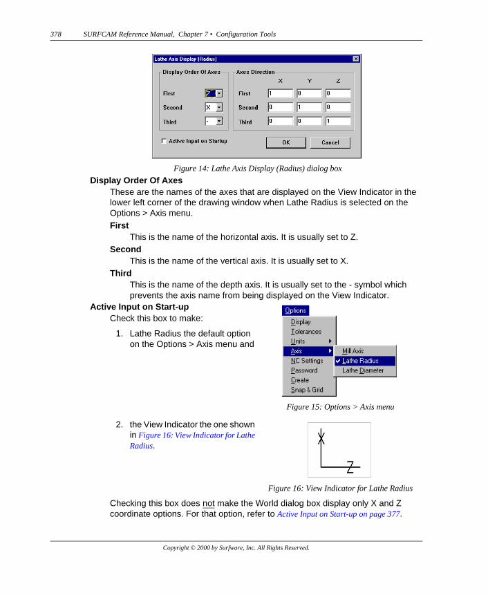
Display Order Of AxesThese are the names of the axes that are displayed on the View Indicator in the lower left corner of the drawing window when Lathe Radius is selected on the Options > Axis menu.First
This is the name of the horizontal axis. It is usually set to Z.Second
This is the name of the vertical axis. It is usually set to X.Third
This is the name of the depth axis. It is usually set to the - symbol which prevents the axis name from being displayed on the View Indicator.
Checking this box does not make the World dialog box display only X and Z coordinate options. For that option, refer to Active Input on Start-up on page 377.
Figure 14: Lathe Axis Display (Radius) dialog box
Active Input on Start-upCheck this box to make:
1. Lathe Radius the default option on the Options > Axis menu and
Figure 15: Options > Axis menu
2. the View Indicator the one shown in Figure 16: View Indicator for Lathe Radius.
Figure 16: View Indicator for Lathe Radius
Copyright © 2000 by Surfware, Inc. All Rights Reserved.
SURFCAM Reference Manual, Chapter 7 • Configuration Tools 379
Axes DirectionThe start point for the three axes is 0, 0, 0. Your entries in these boxes determine a point on each axis, based on the Mill axes orientation.
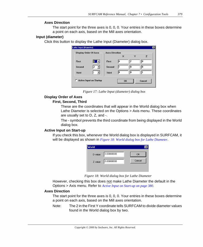
Input (diameter)Click this button to display the Lathe Input (Diameter) dialog box.
Display Order of AxesFirst, Second, Third
These are the coordinates that will appear in the World dialog box when Lathe Diameter is selected on the Options > Axis menu. These coordinates are usually set to D, Z, and -.The - symbol prevents the third coordinate from being displayed in the World dialog box.
Active Input on Start-upIf you check this box, whenever the World dialog box is displayed in SURFCAM, it will be displayed as shown in Figure 18: World dialog box for Lathe Diameter.
However, checking this box does not make Lathe Diameter the default in the Options > Axis menu. Refer to Active Input on Start-up on page 380.
Axes DirectionThe start point for the three axes is 0, 0, 0. Your entries in these boxes determine a point on each axis, based on the Mill axes orientation.
Note: The 2 in the First Y coordinate tells SURFCAM to divide diameter values found in the World dialog box by two.
Figure 17: Lathe Input (diameter) dialog box
Figure 18: World dialog box for Lathe Diameter
Copyright © 2000 by Surfware, Inc. All Rights Reserved.
380 SURFCAM Reference Manual, Chapter 7 • Configuration Tools
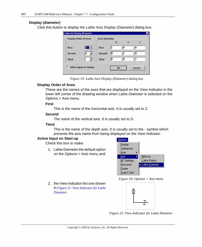
Display (diameter)Click this button to display the Lathe Axis Display (Diameter) dialog box.
Display Order of AxesThese are the names of the axes that are displayed on the View Indicator in the lower left corner of the drawing window when Lathe Diameter is selected on the Options > Axis menu.
FirstThis is the name of the horizontal axis. It is usually set to Z.
SecondThe name of the vertical axis. It is usually set to D.
ThirdThis is the name of the depth axis. It is usually set to the - symbol which prevents the axis name from being displayed on the View Indicator.
Figure 19: Lathe Axis Display (Diameter) dialog box
Active Input on Start-upCheck this box to make:
1. Lathe Diameter the default option on the Options > Axis menu and
Figure 20: Options > Axis menu2. the View Indicator the one shown
in Figure 21: View Indicator for Lathe Diameter.
Figure 21: View Indicator for Lathe Diameter
Copyright © 2000 by Surfware, Inc. All Rights Reserved.
SURFCAM Reference Manual, Chapter 7 • Configuration Tools 381
Checking this box does not make the World dialog box display only D and Z coordinate options. For that option, refer to Active Input on Start-up on page 379.
Axes DirectionThe start point for the three axes is 0, 0, 0. Your entries in these boxes determine a point on each axis, based on the Mill axes orientation.
Use Tool Library Gauge LengthCheck an NC mode box, like 2 Axis, to have the total height value for a newly selected tool displayed in the Z Gauge Length box on the Tool Information tab for that NC mode. Total height is a value associated with each tool in the Tool Library. You will usually check these boxes when you are using an NC machine that must make use of a tool gauge length.
l
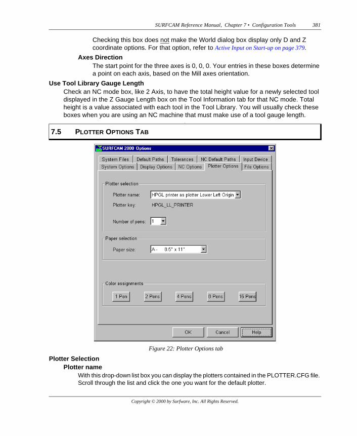
Plotter SelectionPlotter name
With this drop-down list box you can display the plotters contained in the PLOTTER.CFG file. Scroll through the list and click the one you want for the default plotter.
7.5 PLOTTER OPTIONS TAB
Figure 22: Plotter Options tab
Copyright © 2000 by Surfware, Inc. All Rights Reserved.
382 SURFCAM Reference Manual, Chapter 7 • Configuration Tools
Plotter keyThis is a key word associated with the Plotter name. It will be the plotter designation used in the Plotter parameter line in the SURFCAM.INI file.
Number of pensWith this drop-down list box you indicate the number of pens on the plotter. Pen carousels for plotters are usually limited to one, two, four, eight, or sixteen pens. This number will be the last entry on the Plotter parameter line in the SURFCAM.INI file. SURFCAM will use this number to tell which pen color assignment line to read in the SURFCAM.INI file.
Paper selectionPaper size
With this drop-down list box you indicate the size of the paper used by the plotter. The letter in front of the size description will be one of the entries on the Plotter line in the SURFCAM.INI file.
The paper sizes are indicated below.
INCHES MILLIMETERS
A 8.5 BY 11 A6 105 BY 148B 11 BY 17 A5 148 BY 210C 17 BY 22 A4 210 BY 297D 22 BY 34 A3 297 BY 420E 34 BY 44 A2 420 BY 594
A1 584 BY 841A0 841 BY 1189
Figure 23: Paper Selection
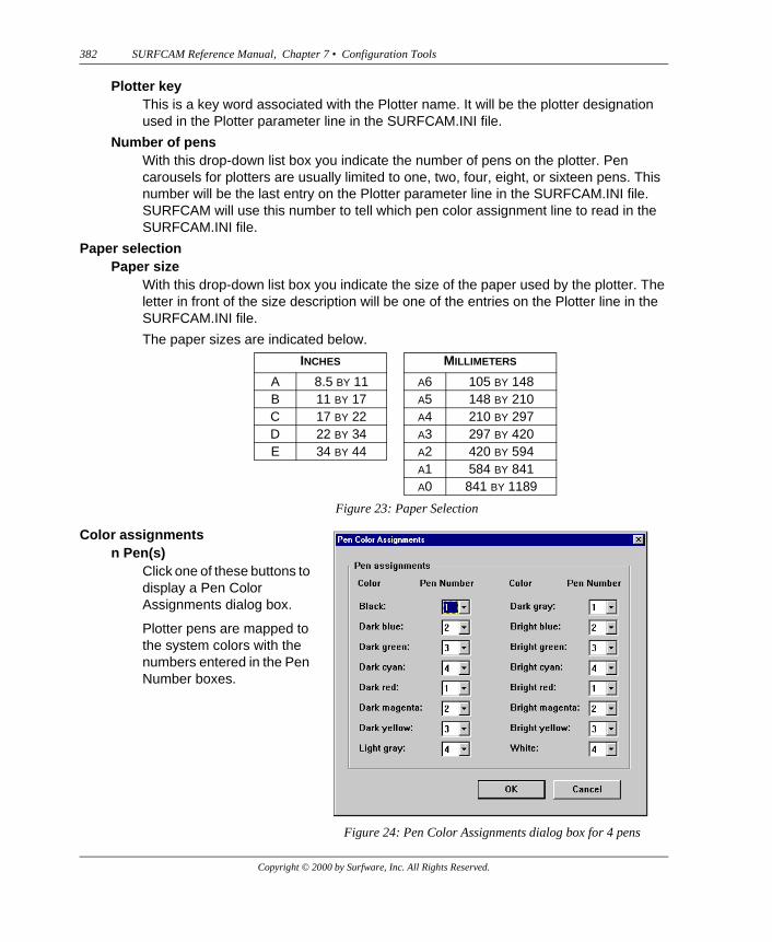
Color assignmentsn Pen(s)
Click one of these buttons to display a Pen Color Assignments dialog box.
Plotter pens are mapped to the system colors with the numbers entered in the Pen Number boxes.
Figure 24: Pen Color Assignments dialog box for 4 pens
Copyright © 2000 by Surfware, Inc. All Rights Reserved.

SURFCAM Reference Manual, Chapter 7 • Configuration Tools 383
File formatWith this drop-down list box you can display the file format type names that are contained in the SURFCAM.INI file. The entries in this box are the parameter names used in each of the lines in the SURFCAM.INI file that identify the types of files that can be saved and opened in SURFCAM.
Format propertiesFile description
These are the names of the file types that appear in the File of type drop-down list box on the Open dialog box and the Save as type drop-down list box on the Save As dialog box.
Extension(s)These are the file extensions that a file of this type can have. For example, a file with an extension TLE is a file that represents the design of a tool with the unit of measurement in inches (English units). It is in the same format as a DSN file which represents the design of a part.
7.6 FILE OPTIONS TAB
Figure 25: File Options tab
Copyright © 2000 by Surfware, Inc. All Rights Reserved.
384 SURFCAM Reference Manual, Chapter 7 • Configuration Tools
“To DSN” translator DLLFor a file type that can be translated into a DSN file, this is the name of the DLL file that will do the translating.
“From DSN” translator DLLIf it can be done, this is the name of the DLL file that will translate a DSN file into a file of this type.
“To DSN” DLL entry pointThis is a set of characters located in the DLL file that marks the beginning of the instructions that implement the translation of this type of file into a DSN file.
“From DSN” DLL entry pointThis is a set of characters located in the DLL file that marks the beginning of the instructions that implement the translation of a DSN file into this type of file.
Default directoryThis is the name of the sub-directory where files of this type will be stored.
Append FileThis is the default setting for the Append box on the on the Files > Open dialog box.
NeverAppend is never checked when the Open dialog box is displayed.
TrueAppend is initially checked and maintains last checked state.
FalseAppend is initially NOT checked and maintains last checked state.
AlwaysAppend is always checked when Open dialog box is displayed.
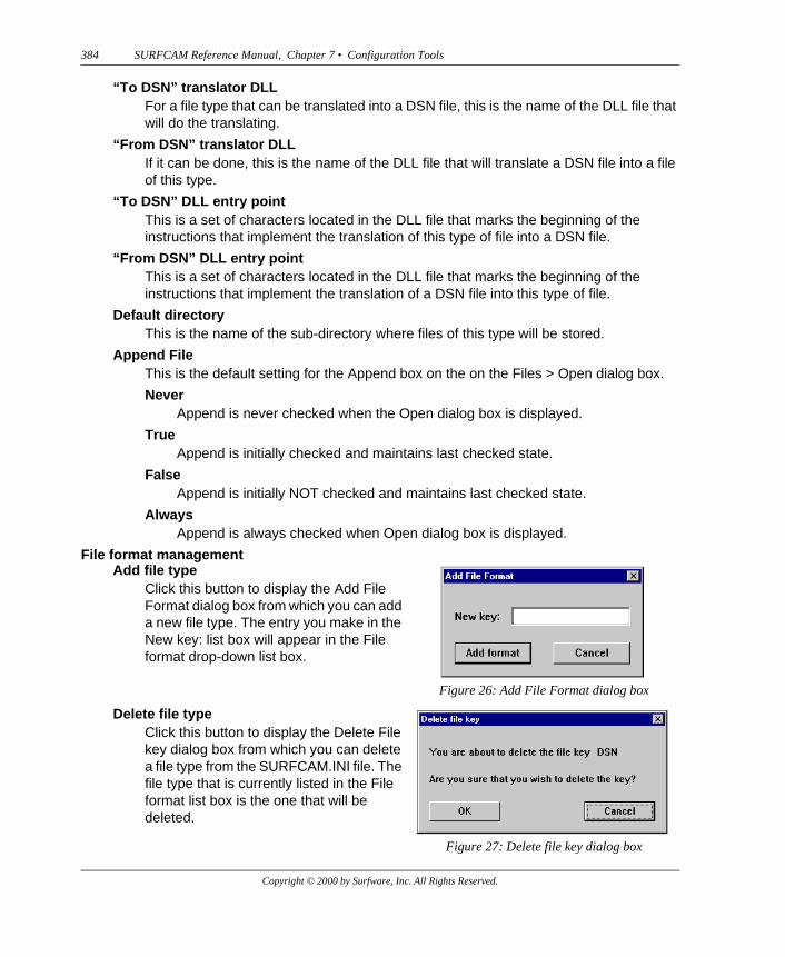
File format managementAdd file type
Click this button to display the Add File Format dialog box from which you can add a new file type. The entry you make in the New key: list box will appear in the File format drop-down list box.
Figure 26: Add File Format dialog box
Delete file typeClick this button to display the Delete File key dialog box from which you can delete a file type from the SURFCAM.INI file. The file type that is currently listed in the File format list box is the one that will be deleted.
Figure 27: Delete file key dialog box
Copyright © 2000 by Surfware, Inc. All Rights Reserved.
SURFCAM Reference Manual, Chapter 7 • Configuration Tools 385
UndeleteThis button appears only when the Delete file type button has been clicked and the OK button on the Delete file key dialog box has been clicked. Click Undelete to undelete the last file type you deleted.
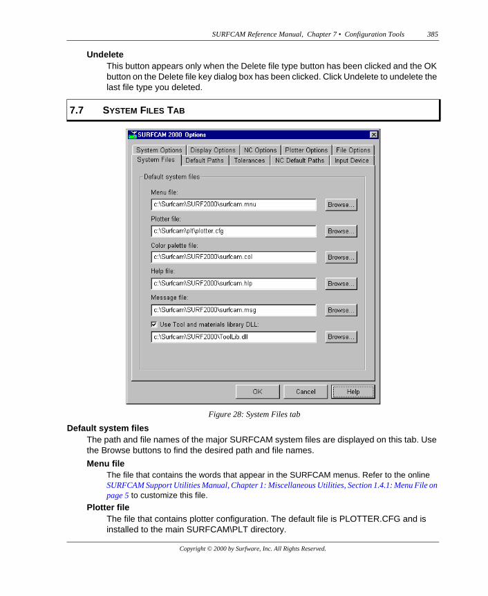
Default system filesThe path and file names of the major SURFCAM system files are displayed on this tab. Use the Browse buttons to find the desired path and file names.
Menu fileThe file that contains the words that appear in the SURFCAM menus. Refer to the online SURFCAM Support Utilities Manual, Chapter 1: Miscellaneous Utilities, Section 1.4.1: Menu File on page 5 to customize this file.
Plotter fileThe file that contains plotter configuration. The default file is PLOTTER.CFG and is installed to the main SURFCAM\PLT directory.
7.7 SYSTEM FILES TAB
Figure 28: System Files tab
Copyright © 2000 by Surfware, Inc. All Rights Reserved.
386 SURFCAM Reference Manual, Chapter 7 • Configuration Tools
Color palette fileThe file that contains the information that defines the colors used by the system. The default color palette file is SURFCAM.COL and is installed to the main SURFCAM directory.
Help filesThe files that contains the SURFCAM online help. The default help file is SURFCAM.HLP and is installed to the main SURFCAM directory.
Message fileThe file that contains the prompts that appear on the prompt line and the error messages that may appear in dialog boxes. This is the file that is installed with the system. Refer to the online SURFCAM Support Utilities Manual, Chapter 1: Miscellaneous Utilities, Section 1.4.2: Message Files on page 7 to customize this file.
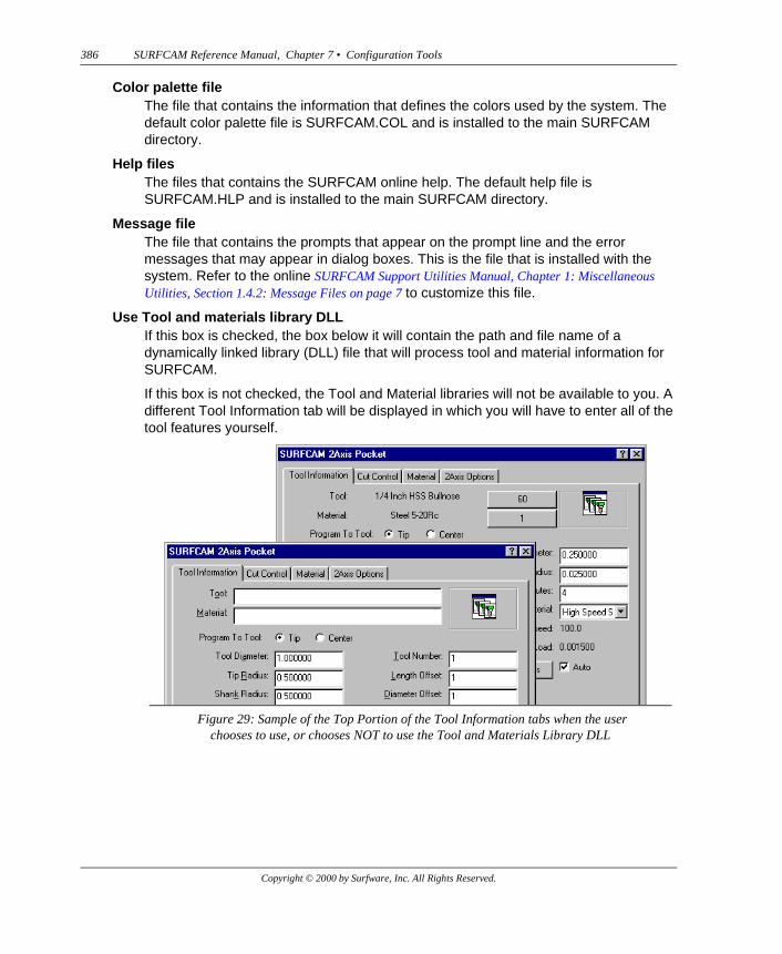
Use Tool and materials library DLLIf this box is checked, the box below it will contain the path and file name of a dynamically linked library (DLL) file that will process tool and material information for SURFCAM.
If this box is not checked, the Tool and Material libraries will not be available to you. A different Tool Information tab will be displayed in which you will have to enter all of the tool features yourself.
Figure 29: Sample of the Top Portion of the Tool Information tabs when the userchooses to use, or chooses NOT to use the Tool and Materials Library DLL
Copyright © 2000 by Surfware, Inc. All Rights Reserved.

SURFCAM Reference Manual, Chapter 7 • Configuration Tools 387
Default pathsFont directory
The directory where SURCAM screen fonts are stored.
PLT directoryThe directory where SURFCAM writes plotter output (PLT) files.
Tool directoryThe directory used to store the files containing the drawings of tools and tool holders. These are design files similar to DSN files except they have a TLE file extension. Each tool listed in one of several tool libraries (such as MILLTLB.MDB) has a tool and a tool holder file from this directory assigned to it. When that tool is selected for an NC operation, the tool and tool holder drawings from these files will be displayed as the tool path is drawn on the screen. Refer to the SURFCAM Getting Started Manual, Chapter 3: Common NC Parameters, Drawing Files on page 74.
7.8 DEFAULT PATHS TAB
Figure 30: Default Paths tab
Copyright © 2000 by Surfware, Inc. All Rights Reserved.
388 SURFCAM Reference Manual, Chapter 7 • Configuration Tools
Temp directoryThe directory used by SURFCAM to store temporary files.
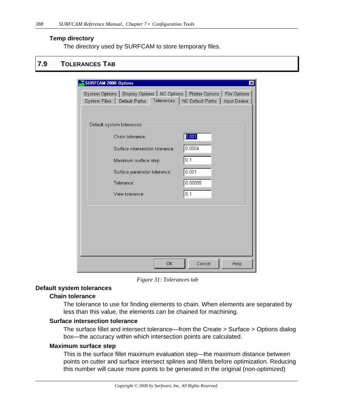
Default system tolerancesChain tolerance
The tolerance to use for finding elements to chain. When elements are separated by less than this value, the elements can be chained for machining.
Surface intersection toleranceThe surface fillet and intersect tolerance—from the Create > Surface > Options dialog box—the accuracy within which intersection points are calculated.
Maximum surface stepThis is the surface fillet maximum evaluation step—the maximum distance between points on cutter and surface intersect splines and fillets before optimization. Reducing this number will cause more points to be generated in the original (non-optimized)
7.9 TOLERANCES TAB
Figure 31: Tolerances tab
Copyright © 2000 by Surfware, Inc. All Rights Reserved.
SURFCAM Reference Manual, Chapter 7 • Configuration Tools 389
spline, which may increase the accuracy, but will also increase the time it takes to calculate the spline, and consume more memory. The default is in inches.
Surface parameter toleranceThis parameter controls the creation of nodes in surfaces built by cross sections. A small value may cause more nodes in the resultant surface, but it will match the sections very closely. A larger value will have fewer nodes but may deviate from the sections.
ToleranceThis parameter defines the distance separating two elements that SURFCAM recognizes as intersecting. When two elements are closer than this value, SURFCAM determines that they are intersecting.
View toleranceWhen SURFCAM attempts to create a fillet between two elements, it evaluates the angle at which the planes containing each of the elements intersect. If that angle is greater than the View tolerance, SURFCAM will not create the fillet.
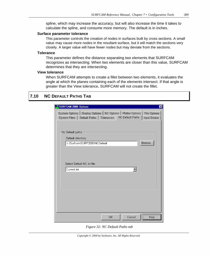
7.10 NC DEFAULT PATHS TAB
Figure 32: NC Default Paths tab
Copyright © 2000 by Surfware, Inc. All Rights Reserved.
390 SURFCAM Reference Manual, Chapter 7 • Configuration Tools
NC Default pathsRefer to Chapter 1: Menus and Dialog Boxes, Section 1.8.5: Options > NC Settings on page 161.
Default directoryThe directory where the files containing the default NC settings are stored. The default name of this directory is NCDefault.
Select Default NC ini fileThe name of the INI file that will contain the current NC settings. The default name of this file is Current.ini.
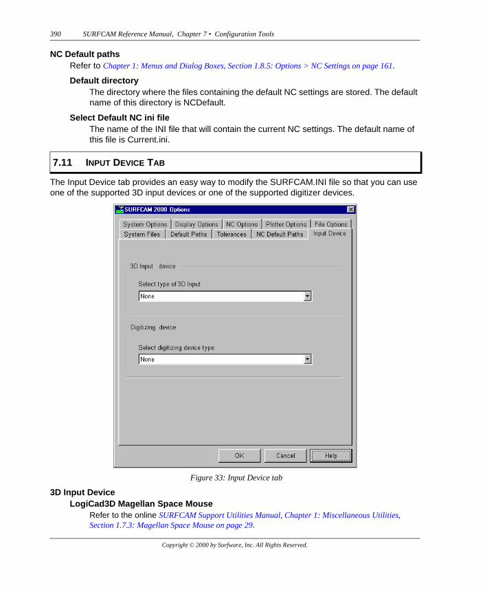
The Input Device tab provides an easy way to modify the SURFCAM.INI file so that you can use one of the supported 3D input devices or one of the supported digitizer devices.
3D Input DeviceLogiCad3D Magellan Space Mouse
Refer to the online SURFCAM Support Utilities Manual, Chapter 1: Miscellaneous Utilities, Section 1.7.3: Magellan Space Mouse on page 29.
7.11 INPUT DEVICE TAB
Figure 33: Input Device tab
Copyright © 2000 by Surfware, Inc. All Rights Reserved.

SURFCAM Reference Manual, Chapter 7 • Configuration Tools 391
Labtec (Spacetec) SpaceballRefer to the online SURFCAM Support Utilities Manual, Chapter 1: Miscellaneous Utilities, Section 1.7.2: Labtec Spaceball on page 29.
Digitizing deviceFaro Arm
Refer to the online SURFCAM Support Utilities Manual, Chapter 1: Miscellaneous Utilities, Section 1.6: FARO Arm on page 14.
Digitizer TabletRefer to the online SURFCAM Support Utilities Manual, Chapter 1: Miscellaneous Utilities, Section 1.7.1: Digtab on page 29.
Copyright © 2000 by Surfware, Inc. All Rights Reserved.

392 SURFCAM Reference Manual, Chapter 7 • Configuration Tools
Copyright © 2000 by Surfware, Inc. All Rights Reserved.
Related Documents