$30.00 U.S. CLEAVER-BROOKS MODEL Manual Part No. 75.0-150 CBW PACKAGED BOILERS Milwaukee, Wisconsin 53201 Service and Parts Coast to Coast Boilers and Accessories for the Complete Boiler Room

Welcome message from author
This document is posted to help you gain knowledge. Please leave a comment to let me know what you think about it! Share it to your friends and learn new things together.
Transcript
$30.00 U.S.
CLEAVER-BROOKS MODEL
Manual Part No. 75.0-150
CBW PACKAGED BOILERS
Milwaukee, Wisconsin 53201
Service and Parts Coast to Coast Boilers and Accessories for the Complete Boiler Room
NReuter
Text Box
Compliments of Power Mechanical, Inc.


CLEAVER-BROOKS MODELCBW
PACKAGED BOILERS
Operation, Service, and Part Manual
100 thru 400 HP
Fuel: Gas, Light Oil, Heavy Oil or Gas Combination
Cleave
Please direct purchase orders for replacement manuals to your local Cleaver-Brooks representative
Manual Part No. 750-150
Printed in U.S.A.

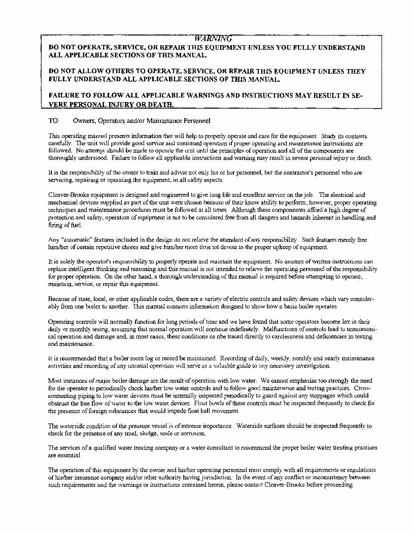
WARNING DO NOT OPERATE, SERVICE, OR REPAIR THIS EQUIPMENT UNLESS YOU FULLY UNDERSTAND ALL APPLICABLE SECTIONS OF THIS MANUAL.
DO NOT ALLOW OTHERS TO OPERATE, SERVICE, OR REPAIR THIS EQUIPMENT UNLESS THEY FULLY UNDERSTAND ALL APPLICABLE SECTIONS OF THIS MANUAL.
FA.ll..URE TO FOLLOW ALL APPLICABLE WARNINGS AND INSTRUCTIONS MAY RESULT IN SEVERE PERSONAL INJURY OR DEATH.
TO: Owners, Operators and/or Maintenance Personnel
This operating manual presents information that will help to properly operate and care for the equipment. Study its contents carefully. The unit will provide good service and continued operation if proper operating and maintenance instructions are followed. No attempt should be made to operate the tmit until the principles of operation and all of the components are thoroughly understood. Failure to follow all applicable instructions and warning may result in severe personal injury or death.
It is the responsibility of the owner to train and advise not only his or her personnel, but the contractor's personnel who are servicing, repairing or operating the equipment, in all safety aspects.
Cleaver-Brooks equipment is designed and engineered to give long life and excellent service on the job. The electrical and mechanical devices supplied as part of the unit were chosen because of their know ability to perform; however, proper operating techniques and maintenance procedures must be followed at all times. Although these componesnts afford a high degree of protection and safety, operation of equipment is not to be considered free from all dangers and hazards inherent in handling and firing of fuel.
Any "automatic" features included in the design do not relieve the attendant of any responsibility. Such features merely free him/her of certain repetitive chores and give him/her more time tot devote to the proper upkeep of equipment.
It is solely the operator's responsibility to properly operate and maintain the equipment. No amount of written instructions can replace intelligent thinking and reasoning and this manual is not intended to relieve the operating personnel of the responsibility for proper operation. On the other hand, a thorough understanding of this manual is required before attempting to operate, maintain, service, or repair this equipment. ·
Because of state, local, or other applicable codes, there are a variety of electric controls and safety devices which vary considerably from one boiler to another. This manual contains information designed to show how a basic boiler operates.
Operating controls will normally fi.mction for long periods of ~e and we have found that some operators become lax in their daily or monthly tesing, assuming that normal operation will continue indefinitely. Malfi.mctions of controls lead to uneconomical operation and damage and, in most cases, these conditions ca nbe traced directly to carelessness and deficiencies in testing and maintenance.
It is recommended that a boiler room log or record be maintained. Recording of daily, weekly, nonthly and yearly maintenance activities and recording of any unusual operation will serve as a valuable guide to any necessary investigation.
Most instances of major boiler damage are the result of operation with low water. We cannot emphasize too strongly the need for the operator to periodically check his/her low water controls and to follow good maintenance and testing practices. Cross· connecting piping to low water devices must be internally inspected periodically to guard against any stoppages which could obstruct the free flow of water to the low water devices. Float bowls of these controls must be inspected frequently to check for the presence of foreign substances that would impede float ball movement.
The waterside condition of the pressure vessel is of extreme importance. Waterside surfaces should be inspected frequently to check for the presence of any mud, sludge, scale or corrosion.
The services of a qualified water treating company or a water consultant to recommend the proper boiler water treating practices are essential.
The operation of this equipment by the owner and his/her operating personnel must comply with all requirements or regulations of his/her insurance company and/or other authority having jurisdiction. In the event of any conflict or inconsistency between such requirements and the warnings or instructions contained herein, please contact Cleaver-Brooks before proceeding.
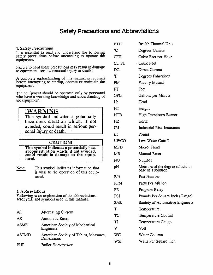
Safety precautions and Abbreviations
1. Safety Precautions It is essential to read and understand the following safe.ty precautions before attempting to operate the eqmpmenL
Failure to heed these precautions may result in damage to equipment, serious personal injury or death!
A complete understanding of this manual is required_bef<:;~re attempting to- startup, operate or main tam the equtpmenL
The equipment should be o~rated only by personnel who have a working knowledge and understanding of the equipment.
!WARNING This symbol indicates a potentially hazardous situation which, if not avoided, could result in serious per-sonal in· or death.
CAUTION! This symbol indicates a ~tentially hazardous situation which, if not avoided, could result in damage to the equip .. ment.
Note: This symbol indicates information that is vital to the operation of this equipment.
2. Abbreviations Following is an exP.lanation of the abbreviations, acronyms, and symbols used in this manual.
AC
AR
ASME
ASThfD
BHP
Alternating Current
Automatic Reset
American Society of Mechanical Engineers
American Society of Tables, Measures, Dimensions
Boiler Horsepower
ii
BTU
·c CFH
Cu. Ft.
DC OF
FM
FT
GPM
Hd
'HT
HTB
HZ
IRI
Lb
LWCO
:MFD
MR
NO
pH
PIN PPM
PR
PSI
SAE
T
TC
11
v we WSI
British Thermal Unit
Degrees Celsius
Cubic Feet per Hour
· Cubic Feet
Direct Current
Degrees Fahrenheit
Factory Mutual
Feet
Gallons per Minute
Head
Height
High Turndown Burner
Hertz
Industrial Risk Insurance
Pound
Low Water Cutoff
Micro Farad
Manual Reset
Number
Measure of the degree of acid or base of a sol uti on
Part Number
Parts Per Million
Program Relay
Pounds Per Square Inch (Gauge)
Society of Automotive Engineers
Tern perature
Temperature Control
Temperature Gauge
Volt
Water Column
Watts Per Square Inch
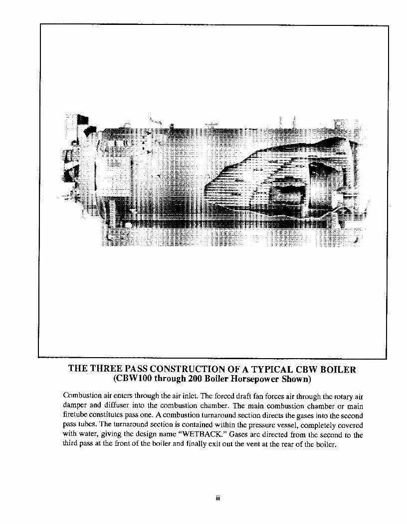
THE THREE PASS CONSTRUCTION OF A TYPICAL CBW BOILER (CBWlOO through 200 Boiler Horsepower Shown)
Combustion air enters through the air inlet. The forced draft fan forces air through the rotary air damper and diffuser into the combustion chamber. The main combustion chamber or main firetube constitutes pass one. A combustion turnaround section directs the gases into the second pass tubes. The turnaround section is contained within the pressure vessel, completely covered with water, giving the design name "WETBACK." Gases are directed from the second to the third pass at the front of the boiler and finally exit out the vent at the rear of the boiler.
iii

Table of Contents
CHAPTER 1 1-1
GENERAL DESCRIPTION AND PRINCIPLES OF OPERATION • .1·1 A The Boiler 1-2 B. The Burner and Control System 1·2 C. Control and Component Function 1-3 D. Controls Common to aJI Boilers 1-4 E. Steam Controls (AJI Fuels) 1-6 F. Hot Water Controls (AJI Fuels) 1-8 G. Controls for Gas Firing 1-8 H. Controls Common to Oil Fired Boilers
(lncfuding combination) · 1-10 I. Additional Controls For Heavy Oil 1-13 J. Controls for Combination Burners Only 1-16 K CombustionAir 1-16 L . Automatic Ignition 1-16 M. Atomizing Air 1-16 N. Oil Fuel Flow - Ught Oil 1-18 0. Oil Fuel Flow - Heavy Oil 1-18 P. Gas Fuel Flow 1-21 Q. Modulating Firing 1-22
CHAPTER 2 2-1
THE PRESSURE VESSEL • • • • II e • • • • a • • • • • • e • • 2·1 A General 2-1
B. Construction 2-2
C. Water Requirements 2-2
D. Water Treatment 2-6
E. Cleaning 2-7 F. Boil-out of a New Unit 2-8
G. Washing Out 2-10
H. Slowdown- Steam Boiler 2-10 I. Periodic Inspection 2-13 J. Preparation for Extended Lay-up 2-14

CHAPTER 3 3-1
SEQUENCE OF OPERATION • • • • • • • • • • • • • • • • • • • 3-1
CHAPTER 4
A General 3--1 B. c. D.
Circuit and Interlock Controls 3--6
Sequence of Operation - Oil Or Gas 3-7
Flame Loss Sequence 3-9
STARTING AND OPERATING INSTRUCTIONS • • • • • • • • • 4-1
CHAPTER 5
A General Preparation
For Start-Up - AJI Fuels B. ControiSe~ngs-
Steam And Hot Water
C. Gas Pilot
4-1
4-2
4-3
D. Atomizing Air 4-4 E. Firing Preparations for No. 2 Oil
(Sseries 1 00-200) 4-5
F. Firing Preparati~n For No. 6 Oil
(Series 400-600) 4-6 G. Firing Preparations For gas
(Series 200-400-700) 4-8
H. Start-up, Operating and Shutdown
- AJI Fuels 4-9
I. Control Operational Test and Checks 4-11
5-1
ADJUSTMENT PROCEDURES • • • • • • • • • • • • • • • • • . 5-1
A Gene raJ 5-2
B. Unkage-Modulating Motor
and Air Damper 5-3
c. Modulating Motor 5-4
D. Modulating Motor Switches -
Low Fire and High Fire 5-5
E. Burner Operating Controls - General 5-5
F. Modulating Pressure Control (Steam) 5-7
G. Operating Umit Pressure Control
(Steam) 5-8
H. High Umit Pressure Control (Steam) 5-8
I. Modulating Temperature Control (Hot Water) 5-8
J. Operating Umit Temperature Control (Hot Water) 5·8
K High Umit Temperature Control (Hot Water) 5-9
L Low Water Cutoff Devices (Steam and Hot Water) 5-9
M. Combustion Air Proving Switch 5-9 N. Atomizing Air Proving switch 5-9 0. Gas Pilot Flame Adjustment 5-10 P. Gas Pressure and Flow Information 5-12 a. Gas Fuel Combustion Adjustment 5-15 R. Low Gas Pressure Switch 5-17 s. High Gas Pressure Switch 5-18 T. Fuel Oil Pressure And Temperature -
General 5-18 u. Fuel Oil Combustion Adjustment 5-19 v. Burner Drawer Adjustment 5-23 w. Oil Drawer Switch 5-23 X. Low Oil Temperature Switch 5-23 Y. High Oil Temperature Switch (Optional) 5-24 z. Low Oii_Pressure Switch (Optional) 5-24 AA. Electric Oil Heater Thermostat
(400 and 600 Series -Steam) 5-24 88. Steam Oil Heater Thermostat
(No.6 Oil) (400 and 600 Series - Steam) 5-24
cc. Hot Water Oil Heater Thermostat ( 400 and 600 Series) 5-24
DO. Steam Heater Pressure Regulator (400 and 600 Series- Steam) 5-25
CHAPTER 6 6-1
TROUBLE SHOOTING • • • • • • • • • • • • • • • • • • • • • • 8-1 A Burner Does Not Start 6-2 B. No Ignition 6-2 c. Pilot Flame, But No Main Flame 6·3 D. Burner Stays In Low Fire 6-4 E. Shutdown Occurs During Firing 6-4 F. Modulating Motor Does Not Operate 6-5
CHAPTER 7 7·1
INSPECTION AND MAINTENANCE • a • • a a e • e e • G • e e 7•1
A General 7-2 B. Fireside Cleaning 7-3 G. Water Level Controls 7-3 D. Water Gauge Glass 7-4 E. EJectriccU Controls 7-4 F. Flame Safeguard Control 7-6 G. Oil Bumer Maintenance 7-7 H. Gas Bumer Maintenance 7-9 I. Motorized Gas Valve(s) 7-9 J. Sole~oid Valves 7-9 K Air Control Damper, Unkage
and Cam Spring 7-12 L Forced Draft Fan 7w12 M. Safety Valves 7-13 N. Fuel Oil Metering Valve,
Adjusting and Relief Valves 7-13 0. The Air Pump and Lubricating System 7-15 P. Refractory 7-16 a. Opening And Closing Doors 7-20 A. Lubrication 7·20 s. Oil Heaters -
Electric, Steam, Hot Water 7-22 T. Combustion 7-22
CHAPTER 8 8-·1
PARTS ORDER/UST INSTRUCTIONS •.•.•.•••••.•• 8-1

CHAPTERl GENERAL DESCRIPTION AND J?RINCIPLES OF OPERATION
CHAPTER 1
GENERAL DESCRIPTION AND PRINCIPLES OF OPERATION
A The Boiler B. The Burner And Control System C. Control And Component Function D. Controls Common To All Boilers E. Steam Controls (All Fuels) F. Hot Water Controls (All Fuels) G. Controls For Gas Firing (Including Combination) H. Controls For Oil Fired Boilers I. Co~trols For Heavy Oil J. Controls For Combination Burners K. Combustion Air L. Automatic Ignition M. Atomizing Air N. Oil Fuel Flow - Light Oil 0. Oil Fuel Flow - Heavy Oil P. Gas Fuel Flow Q. Modulating Firing
NOTE: If your boiler is equipped with a CB-HA WK™ boiler manage· ment control system, refer to CBHawk. Installation, Operating, and Servicing Manual No. 750-133 for information regarding controls discussed in this section.
Series 100 - Light Oil (No. 2) Series 200 - Light Oil (No. 2) Or Gas Series 400 - Heavy Oil (No. 6) Or Gas Series 600- Heavy Oil (No. 6) Only Series 700- Gas Only
The general information in this manual applies directly to Cleaver-Brooks "CBW'' Boiler Models in sizes ranging from 100 through 400 boiler horsepower for the following fuels:
750-150
NOTE: Although the Series 400 or 600 burner is designed and designated to bum No. 6 oil, the burner will handle grades 4 and 5 equally well with some possible modifications. While this manual contains peninent infonnation on
CHAPTER 1 .. 1
CHAPTER! GENERAL DESCRIPTION AND PRINCIPLES OF OPERATION
No. 6 fuel oil, all references to this fuel should be considered applicable to all grades of heavy oil.
The boiler and related equipment installation, by others, is to be in compliance with the standards of the National Board of Fire Underwriters. Installation also should conform to state and local codes governing such equipment. Prior to installation, the proper authorities having jurisdiction are to be consulted, permits .obtained, etc. All boilers in the above series comply, when equipped with optional equipment, to Industrial Risk Insurers (I.R.I.), Factory Mutual (FM), or other insuring underwriters requirements.
A. THE BOILER
The "CBW" Boiler is a packaged :firetube boiler of welded steel construction and consists of a pressure vessel, burner, burner controls, forced draft fan, damper, air pump, refractory and appropriate boiler trim.
Rated Capacity . . .100 through 400)-IP
Operating Pressure .Steam 15-250 psig, or higher if.specified
Hot Water . . . . . . . .30-250 psig or higher if specified
Fuel . . ; . . . . . . . .Oil or Gas or Combination
Ignition .Automatic
Firing . . . . . . . . . .Full Modulation Through Operating Ranges
CHAPTER 1-2
Burner (Oil) ....... (Low Pressure) Air Atomizing
Burner (Gas) ...... Non-premix Otificed Type
Air Damper . . . . . . . Rotary Type (Electrically Modulated)
Steam Trim . . . . . . . ASME Code
Water Trim . . . . . . . ASME Code
The horsepower rating of the boiler is indicated by the numbers following the fuel series. Thus, CBW700-200 indicates a gas fired 200 HP boiler.
B. THE BURNER AND CONTROL SYSTEM
The oil burner is of the low pressure, air atomiz~ ing (nozzle) type. The gas burner is of the nonpremix orifice type. The burners are ignited by spark ignited gas pilot. The pilot is of the interrupted type and is extinguished after the main flame is established.
NOTE: A Series 100 boiler is usually equipped with a light oil pilot although a gas pilot frequently is used.
The burners equipped to burn oil and gas include equipment for each distinct fuel. Since the burner uses only one type of fuel at a time, a gas/oil selector switch is incorporated in a combination burner.
It is important that the burner model and serial number, shown on the nameplate, be included in any correspondence or parts order.
750-150

CHAPTER I GENERAL DESCRIPTION AND PRINCIPLES OF OPERATION
Regardless of which fuel is used, the burner operates with full modulation (within its rated operating range) through potentiometer-type positioning controls, and the burner returns to minimum firing position for ignition. High pressure boilers (above 15 psi) can be wired for both low pressure and high pressure modulation as optional equipment. This enables the boiler to operate at lower pressure during off-load hours, but at a somewhat reduced steam output dependent upon lower steam pressure and steam nozzle sizing.
The flame safeguard and program relay include a flame detector to supervise both oil· and gas flames and to shut the burner down in the event ofloss of flame signal. The programming portion of the control provides a . pre-purging period, proving of the pilot and main flame, and a period of continued blower operation to postpurge the boiler of all unburned fuel vapors. Other safety controls shut down the burner under low water conditions, excess steam pressure or high water tern perature.
The safety interlock controls include combustion and atomizing air proving switches and, depend-· ing upon the fuel and insurance carrier requirements, controls that prove the presence of adequate fuel pressure plus temperature proving controls when heated fuel oil is used.
The sequence of burner operatiop from start-up through shut-down is governed by the program relay in conjunction with the operating, limit and interlock devices, which are wired into the circuitry to provide safe operation and help to protect against incorrect operating techniques.
All "CBW" model boilers ·have the burner assembly attached to the front head. The entire head may be swung open for inspection and maintenance.
Combustion air is provided by a centrifugal blower located in the front head. Combustion air delivery to the burner is under the control of the damper motor. This same motor regulates the flow of gas fuel through a linkage system connected to the gas butterfly valve and the flow of
750-150
fuel oil through a cam operated metering valve. Fuel input and air are thus properly proportioned for most efficient combustion.
Filtered primary air for atomizing fuel oil is furnished independently of combustion air by an air pump. The burner control circuit operates on 115 volt, single phase 60 hertz (or SO hertz when so equipped) alternating current. The forced draft fan motor is generally operated on 3 phase service at the available main power supply voltage.
Indicator lights signaling load demand, fuel valve, low water, and flame failure conditions are standard equipment.
In addition to the standard basic controls supplied, other devices may be required to meet specific requirements of an insurance carrier or local code. Refer to the Wiring Wiagram (WD) prepared by Cleaver-Brooks for your specific installation to determine the specific controls in the burner and limit control circuits. The function of individual components is outlined in this chapter and the electrical sequence is covered in Chapter 3.
C. CONTROL AND COMPONENT FUNCTION
The term "control" covers the more important valves and components, including but not limited to electrical controls or those monitored by the program relay. The operator must become familiar with the individual functioning of all controls before he can understand the boiler's operation and procedures outlined in the manual.
Identify and locate each item using the figure callout.
The actual controls furnished with any given boiler will depend upon the type of fuel for which it is equipped and whether it is a hot water or steam boiler. Refer to the applicable group or groups listed which apply to the particular boiler.
CHAPTER 1--3
CHAPTER! GENERAL DESCRIPTION AND PRINCIPLES OF OPERATION
GAS CONTROL VALVE
FUEL OIL CONTROLLER OIL RELIEF VALVE
ERATING, HIGH LIMIT AND LATING PRESSURE CONTROLS
WATER COLUMN AND PUMP CONTROLS
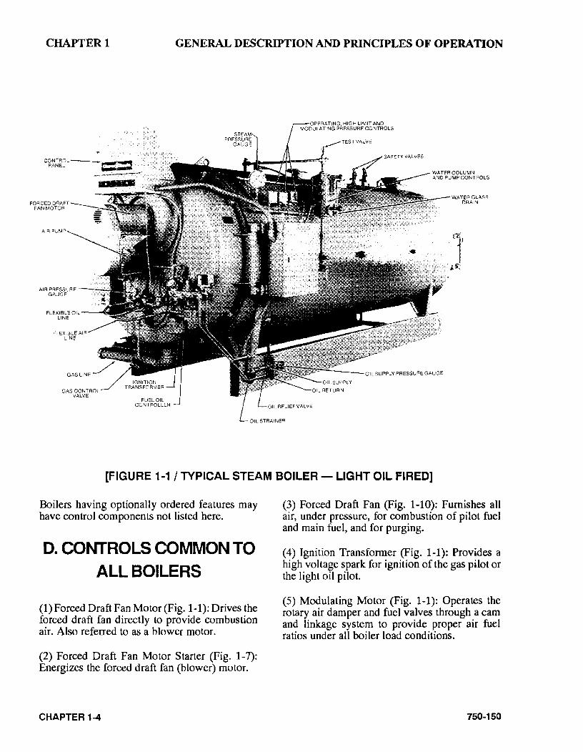
[FIGURE 1-1 I TYPICAL STEAM BOILER- LIGHT OIL FIRED]
Boilers having optionally ordered features may have control components not listed here.
D. CONTROLS COMMON TO
ALL BOILERS
(1) Forced Draft Fan Motor (Fig. 1-1): Drives the forced draft fan directly to provide combustion air. Also referred to as a blower motor.
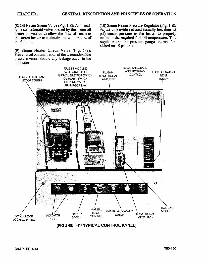
(2) Forced Draft Fan Motor Starter (Fig. 1-7): Energizes the forced draft fan (blower) motor.
CHAPTER 1-4
(3) Forced Draft Fan (Fig. 1-10): Furnishes all air, under pressure, for combustion of pilot fuel and main fuel, and for purging.
( 4) Ignition Transfonner (Fig. 1-1 ): Provides a high voltage spark for ignition of the gas pilot or the light oil pilot.
(5) Modulating Motor (Fig. 1-1): Operates the rotary air damper and fuel valves through a cam and linkage system to provide proper air fuel ratios under all boiler load conditions.
750-150
CHAPTER! GENERAL DESCRIPTION AND PRINCIPLES OF OPERATION
OIL STRAINEfl OIL SUPPLY PFESSUAE
GAUGe
WATER FIEUEF VALVES
HOTWA~ OILHEATER .
BVP..a&VAL\IE
EI009"1"EF! WATER PUMP
0Pe=IA11NG TEMPeRATURE.
HIGHUMIT • T'EJIIFIEAA TURE
AND MOOULA11NG
'T"EMP'ERA TUAE CONTROLS
HOT WATER OIL HEATER
COIL
WATER 'T"EMPERA TUAE
GAUGE
NOTE: FOR STREAM COMPONENTS ~TO FIGURE 1-8
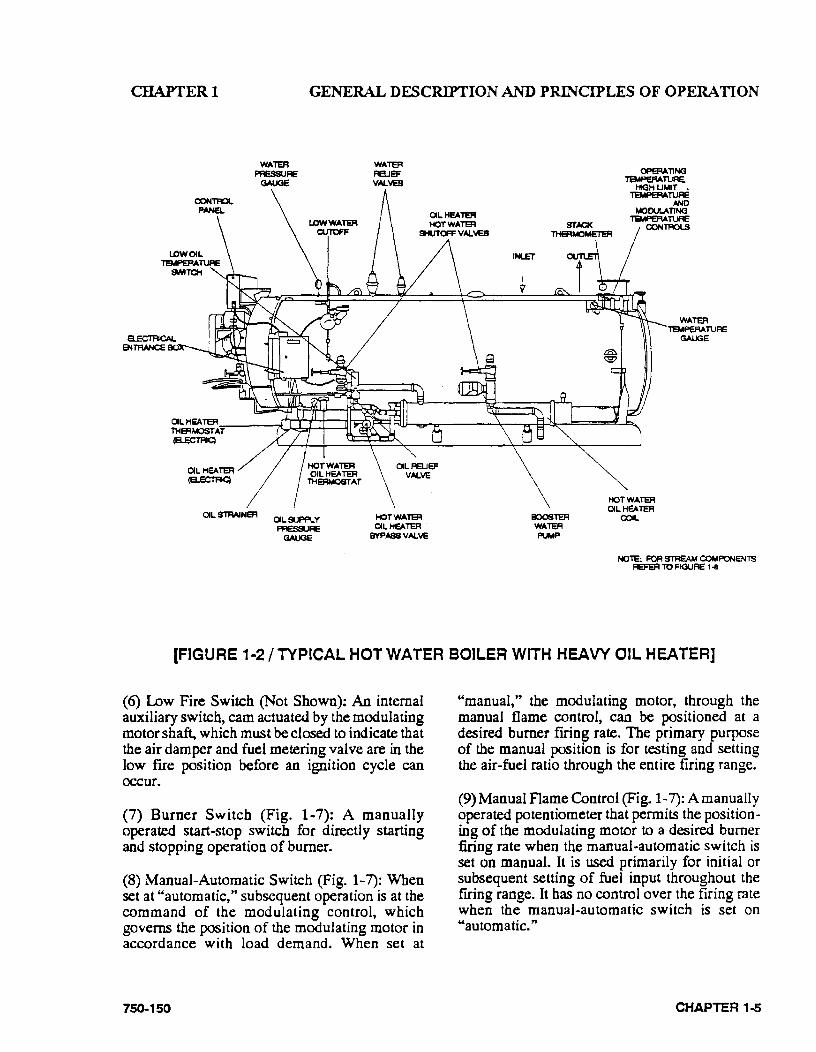
[FIGURE 1-2 I TYPICAL HOT WATER BOILER WITH HEAVY OIL HEATER]
(6) Low Fire Switch (Not Shown): An internal auxiliary switch, cam actuated by the modulating motor shaft, which must be closed to indicate that the air damper and fuel metering valve are in the low fire position before an ignition cycle can occur.
(7) Burner Switch (Fig. 1·7): A manually operated start·stop switch for directly starting and stopping operation of burner.
(8) Manual*Automatic Switch (Fig. 1-7): When set at "automatic," subsequent operation is at the command of the modulating control, which governs the position of the modulating motor in accordance with load demand. When set at
750-150
"manual," the modulating motor, through the manual flame control, can be positioned at a desired burner firing rate. The primary purpose of the manual position is for testing and setting the air-fuel ratio through the entire firing range.
(9) Manual Flame Control (Fig. 1-7): A manually operated potentiometer that permits the positioning of the modulating motor to a desired burner firing rate when the manual·automatic switch is set on manual. It is used primarily for initial or subsequent setting of fuel input throughout the frring range. It has no control over the firing rate when the manual-automatic switch is set on "automatic."
CHAPTER 1..5
CHAPTER! GENERAL DESCRIPTION AND PRINCIPLES OF OPERATION
(10) Modulating Motor Transformer (located in the mod motor): Reduces control circuit voltage (115V Aq to required voltage (24V Aq for operation of the modulating motor.
(11) Indicator Lights (Fig. 1-7): Provide visual information on operation of the boiler as follows:
Flame Failure
Load Demand
Fuel Valve (valve open)
Low Water
(12) Program Relay and Flame Safe Guard Control (Fig. 1~ 7): Automatically programs each starting, operating and shutdown period in conjunction with operating limit and interloc,k devices. This includes, in a timed and proper sequence, the operation of the blower motor, ignition system, fuel valve(s), and the damper motor. The sequence includes air purge periods prior to ignition and upon burner shutdown.
The flame detector portion of this control monitors both oil and gas flames and provides protection in the event of the loss of a flame signal.
The control re~ycles automatically during normal operation or following a power interruption. It must be manually reset following a safety shut~own caused by a loss of flame. lncor· porated is an internal checking circuit, effective on every start that will prevent burner operation in the event anything causes the flame relay to h~ld in during this period.
(13) Flame Detector (Fig. 1-1): Monitors gas or oil pilot and energizes the programmer's flame relay in response to a flame signal. It continues to monitor main flame (oil or gas) after expiration
CHAPTER 1-6
of pilot proving period. A standard equipped boiler has a ·lead sulfide (infrared sensitive) detector.
(14) Combustion Air Proving Switch (Fig. 1-1): A pressure sensitive switch actuated by air pressure from the forced draft fan. Its contacts close to prove the presence of combustion air. The fuel valves cannot be energized unless this switch is satisfied.
(15) Alarm (Not Shown): Sounds to notify the operator of a condition requiring attention. The alarm is available as optional equipment.
(16) Stack Thennometer (Fig. 1-1): Indicates the temperature of the vented flue gases.
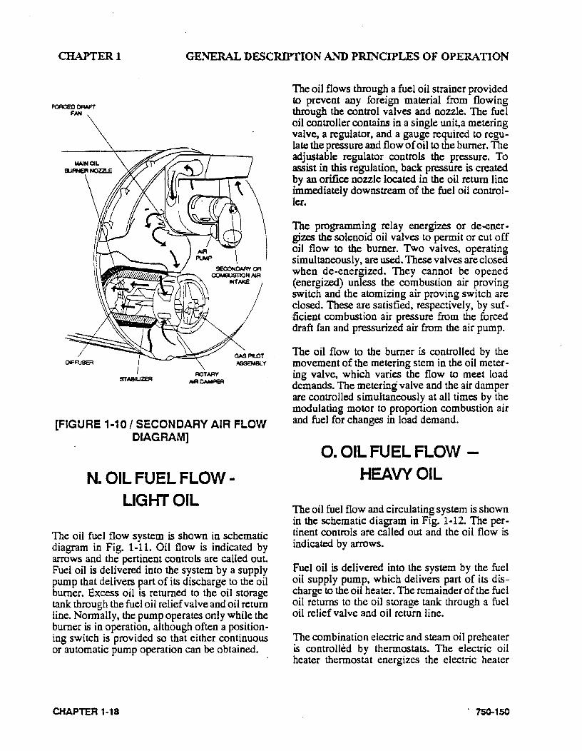
(17) Diffuser (Figs. 1-4 and 1-10): This is a circular plate located at the furnace end of the burner drawer, which imparts a rotary swirling motion to combustion air immediately prior to its entering· the furnace, thus providing for thorough and efficient mixing with the fuel.
(18) Rotary Air Damper (Figs. 1-4 and 1-10): This damper provides accurate control of combustion air in proportion to fuel input for various load demands. It consists of two concentric cylinders with openings. The outer is stationary. The inner is rotated, under control of the modulating motor, to vary the effective size of the openings where they overlap.
E. STEAM CONTROLS (ALL FUELS)
(1) Steam Pressure Gauge (Fig. 1-1): Indicates the pressure in the boiler.
(2) Operating Limit Pressure Control (Fig. 1-1): Breaks a circuit to stop the burner operation on a rise of boiler pressure above a selected setting. It is adjusted to stop or start the burner at a preselected pressure setting.
750-150
CHAPTER I GENERAL DESCRIPTION AND PRINCIPLES OF OPERATION
(3) High Limit Pressure Control (Fig. 1-1 ): Breaks a circuit to stop the burner operation on a rise of pressure above a selected setting. It is adjusted to stop the burner at a preselected pressure above the operating limit control setting. This control is normally equipped with a manual reset.
(4) Modulating Pressure Control (Fig. 1-1): Senses the changing boiler pressures and transmits this information to the modulating motor to change the burner's firing rate when the manualautomatic switch is set on automatic.
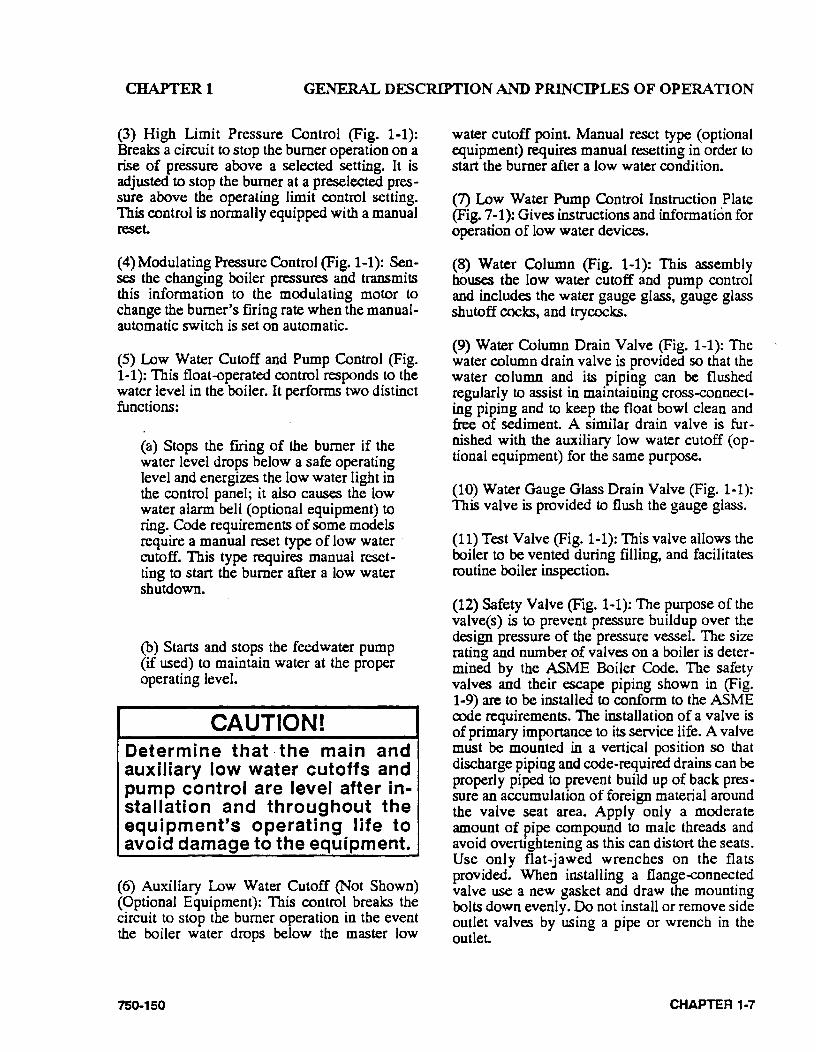
(5) Low Water Cutoff and Pump Control (Fig. 1-1): This float-operated control responds to the water level in the boiler. It performs two distinct functions:
(a) Stops the fuing of the burner if the water level drops below a safe operating level and energizes the low water light in the control panel; it also causes the low water alarm bell (optiOI~al equipment) to ring. Code requirements of some models require a manual reset. type. of low water cutoff. This type requires manual re8et-· ting to start the burner after a low water shutdown. ·
(b) Starts and stops the feed water pump (if used) to maintain water at the proper operating level.
CAUTION! Determine that ·the main and auxiliary low water cutoffs and pump control are level after installation and throughout the equipment's operating life to avoid damage to the equipment.
(6) Auxiliary Low Water Cutoff (Not Shown) (Optional Equipment): This control breaks the circuit to stop the burner operation in the event the boiler water drops below the master low
750-150
water cutoff point. Manual reset type (optional equipment) requires manual resetting in order to start the burner after a low water condition.
(7) Low Water Pump Control Instruction Plate (Fig. 7-1): Gives instructions and information for operation of low water devices.
(8) Water Column (Fig. 1-1): This assembly houses the low water cutoff and pump control and includes the water gauge glass, gauge gl~ shutoff cocks, and trycocks.
(9) Water Column Drain Valve (Fig. 1-1): The water column drain valve is provided so that the water column and its piping can be flushed regularly to assist in maintaining cross-connecting piping and to keep the float bowl clean and free of sediment. A similar drain valve is furnished with the auxiliary low water cutoff ( optional equipment) for the same purpose.
(10) Water Gauge Glass Drain Valve (Fig. 1-1): This valve is provided to flush the gauge glass.
(11) Test Valve (Fig. 1-1): This valve allows the boiler to be vented during filling, and facilitates routine boiler inspection.
(12) Safety Valve (Fig. 1-1): The purpose of the valve(s) is to prevent pressure buildup over the design pressure of the pressure vessel. The size rating and number of valves on a boiler is determined by the ASME Boiler Code. The safety valves and their escape piping shown in (Fig. 1-9) are to be installed to conform to the ASME code requirements. The installation of a valve is of primary importance to its service life. A valve must be mounted in a vertical position so that discharge piping and code-required drains can be properly piped to prevent build up of back pressure an accumulation of foreign material around the valve seat area. Apply only a moderate amount of pipe compound to male threads and avoid overtightening as this can dis toft the seats. Use only flatwjawed wrenches on the flats provided. When installing a flange-connected valve use a new gasket and draw the mounting bolts down evenly. Do not install or remove side outlet valves by using a pipe or wrench in the outlet
CHAPTER 1·7
CHAPTER! GENERAL DESCRIPTION AND PRINCIPLES OF OPERATION
A drip pan elbow or a flexible connection between the valve and the escape pipe is recommened (see Fig. 1-9). The discharge piping must be properly arranged and supported so that its weight does not bear upon ~e valve.
Do not paint, oil, or otherwise covery any interior or working parts of the safety valve. A valve does not require any lubrication or protective coating to work properly.
!WARNING Only properly certified personnel such as the safety valve manufacturer's certified representative should adj~st or repair the boiler safety valves. Failure to heed this warning could result in serious personal injury or death.
F. HOT WATER CONTROLS (ALL i=UELS)
(1) Water Temperature Gauge (Fig. 1-2): Indicates water temperature in the boiler.
(2) Water Pressure Gauge (Fig. 1-2): Indicates water pressure in the boiler.
(3) Operating Limit Temperature Control (Fig. 1-2): Breaks a circuit to stop the burner operation on a rise of boiler temperature above a selected setting. It is adjusted to stop or start the burner at a preselected operating temperature.
(4) High Limit Temperature Control (Fig. 1-2): Breaks a circuit to stop the burner operation on a rise of temperature above a selected setting. It is adjusted to stop the burner at a preselected temperature above the operating control setting. The high limit temperature control normally is equipped with a manual reset.
CHAPTER 1...S
(5) Modulating Temperature Control (Fig. 1-2): Senses changing boiler temperature and transmits this information to the modulating motor to change the burner's frring rate when the manualautomatic switch is set on automatic.
(6) low Water Cutoff (Fig. 1-2): Breaks the circuit to stop the burner operation if the water level in the boiler drops below a safe operating level, activating the low water light and optional alarm bell if the boiler is so equipped.
(7) Auxiliary low Water Cutoff (Not Shown) (Optional): Breaks the circuit to stop the burner operation if the water level in the boiler drops below the master low water cutoff point.
(8) Relief Valve(s) (Fig. 1-2): Relief valve(s) relieve the boiler of pressure higher than the design pressure (or a lower pressure, if designated). Relief valves and their discharge piping are to be installed to conform to ASME code requirements.
!WARNING .Only properly certified personnel such as the relief valve manufac· · turer's certified representative should adjust or repair the boiler relief valves. Failure to heed this warning could result In serious personal injury or death.
G. CONTROLS FOR GAS FIRING
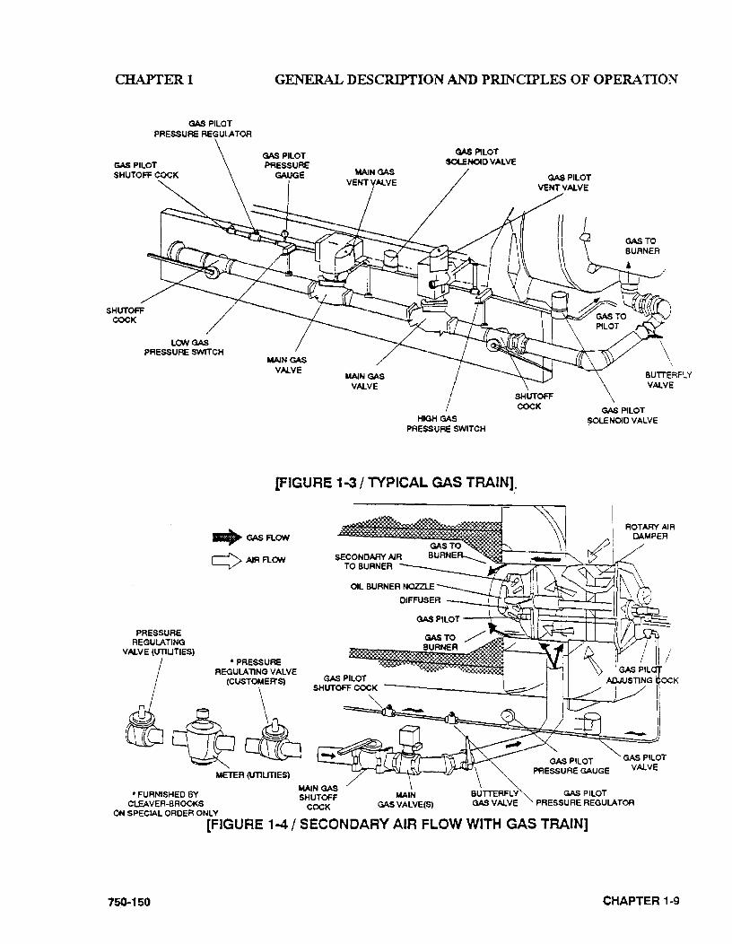
Depending upon the requirements of the in· surance carrier or other governing agencies, the gas flow control system, or gas train, may consist of some, or all, of the following items. Refer to the Dimension Diagram (DD) prepared by Cleaver-Brooks for your specific installation. A typical gas train is shown in Fig. 1-3.
750-150
CHAPTER! GENERAL DESCRIPTION AND PRINCIPLES OF OPERATION
GAS PILOT PRESSURE REGULA TOR
GAS PILOT SHUTOFF COCK
LON GAS PRESSURE SWITCH
GAS PILOT PRESSURE
GAUGE
MAIN GAS VALVE
GAS PILOT SOU:N040 VALVE
HIGH GAS PRESSURE SWITCH
SHUTOFF COCK
BUTTERFLY VALVE
GAS PILOT ~ENOIOVALVE
[FIGURE 1·3/ TYPICAL GAS TRAIN],.
PRESSURE REGULATING
VALVE (UTlUTIES)
.. GASFLCIN
YAIRFLON
*PRESSURE REGULATlNG VALVE
~ul *FURNISHED BY
CLEAVER-BROOKS
METER (UT1UT1ES)
ON SPECIAL ORDER ONLY
MAIN GAS SHUTOFF
COCK
ROTARY AIR DAMPER
GAS PILOT PRESSURE REGULATOR
[FIGURE 1-4 I SECONDARY AIR FlOW WITH GAS TRAIN]
750-150 CHAPTER 1-9
CHAPTER! GENERAL DESCRIPTION AND PRINCIPLES OF OPERATION
(1) Gas Pilot Valve: A solenoid valve that opens during the ignition period to admit fuel to the pilot. It closes after main flame is established. The sequence of energizing and de-energizing is controlled by the programming relay. A second gas pilot valve may be required by insurance regulations.
(2) Gas Pilot Vent Valve: When a secorid gas pilot valve is required, a normally open vent valve is installed between them. Its purpose is to vent gas to the atmosphere, should any be present in the pilot line when the pilot valves are closed. The valve closes when the pilot valves are ener-gized.
(3) Gas Pilot Shut ...off Cock: For manually opening or closing the gas supply to the gas pilot valve.
(4) Gas Pilot Adjusting Cock (Fig. 5-10): Provided to regulate the size of the gas pilot flame.
(5) Gas Pilot Aspirator (Fig. 5-10): Improves the flow of gas to the pilot.
(6) Gas Pressure Gauge: Indicates gas pressure to the pilot.
(7) Gas Pressure Regulating Valve: Reduces incoming gas pressure to suit the pilot's requirement of between 5" to 10" W .. C.
(8) Butterfly Gas Valve: The pivoted disc in this valve is actuated by connecting linkage from the gas modulating cam to regulate the rate of gas flow to the burner.
(9) Gas Modulating Cam (Fig. 5-6): An assembly of a series of adjustable allen-head screws and a contour spring, providing for adjustment of gas input at any poirit in the modulating range.
(10) Main Gas Cock: For m~nually opening and closing the main fuel gas supply downstream of the main gas line pressure regulator. A second shut-off cock, downstream of the main gas valve(s), may be installed to provide a means of shutting off the gas line whenever a test is made for leakage across the main gas valve.
CHAPTER 1-10
(11) Main Gas Valves: Electrically actuated shutoff valves that open simultaneously to admit gas to the burner. The downstream valve is equipped with a "proof of closure" switch that is connected into the pre-ignition interlock circuit.
(12) Main Gas Vent Valve: A normally open solenoid valve installed between the two main gas valves to vent the gas to the atmosphere should any be present in the main gas line when the gas valves are de-energized. The vent valve closes when the gas valves are energized.
(13) Low Gas Pressure Switch: A pressure actuated switch that is closed whenever main gas line pressure is above a preselected pressure. Should the pressure drop below this setting, the switch contacts will open a circuit causing the main gas valve(s) to close, or prevent the burner from starting. This switch is usually equipped with a device that must be manually reset after being tripped.
(14) High Gas Pressure Switch: A pressure actuated switch that is closed whenever the main gas line pressure is below a preselected pressure. Should the pressure riSe above this setting, the switch contacts will open a circuit causing the main gas valve(s) to close or prevent the burner from starting~ This switch is usually equipped with a device that must be manually reset after being tripped.
(15) Leakage Connection: The body of the gas valve has a plugged opening that is used whenever it is necessary or desirous to conduct a test for possible leakage across the closed valve.
H. CONTROLS COMMON TO OIL FIRED BOILERS
QNCLUDING COMBINATION)
The following items are applicable to all oil fired or gas and oil fired boilers. Additional controls for No. 6 oil are listed in Section I.
75()..150
CHAPTERl GENERAL DESCRIPTION AND PRINCIPLES OF OPERATION
750·150
OIL MODULATING CAM
OIL BURNER PRESSURE GAUGE
OIL PRESSURE REGULATOR
OIL SUPPLY
OIL RETURN
+ TO MAIN OIL SOLENOID VALVE
[FIGURE 1-5 I OIL CONTROL VALVE ASSEMBLY- FOR LIGHT OIL]
OIL BURNER PRESSURE GAUGE
ORIFICED VALVE
OIL MODULATING CAM
OIL METERING VALVE
PACKING GLAND
OIL PRESSURE REGULATOR
OIL RETURN PRESSURE GAUGE
FUEL OIL THERMOMETER
OIL RETURN
OIL SUPPLY
MANUAL BY·PASS VALVE TO MAIN OIL
SOLENOID VALVE BACK PRESSURE VALVE
[FIGURE 1-6 I OIL CONTROL VALVE ASSEMBLY- FOR HEAVY OIL]
CHAPTER 1-11
CHAPTER! GENERAL DESCRIPTION AND PRINCIPLES OF OPERATION
(1) Oil Dra'(ver Switch (Fig. 4-1): Opens the limit circuit if the oil drawer burner gun is not latched in the forward position required for burning oil.
(2) Atomizing Air Proving Switch (Fig. 1-1): Pressure actuated switch whose contacts are closed when sufficient atomizing air pressure from the air pump is present for oil firing. Oil valve(s) will not open or will not remain open unless the switch contacts are closed.
(3) Air Pump Module (Figs. 1-1 and 7-8): This assembly provides the compressed air required to atomize the fuel oil for proper combustion. It is started automatically by the programmer's sequence. It includes the components described below.
(a)Air Pump Motor (Fig. 7-8): This motor drives the air pump and an air cooling fan. The motor is started and stopped simultaneously with the forced draft fan motor.
(b)Air Pump (Fig. 7-8): Provides air for atomization of fuel oil.
(c)Air Filter (Fig. 7-8): An air inlet strainer to clean the air supply prior to entering the air pump.
(d)Check Valve (Figs. 1-11 and 1-12): Prevents lubricating oil and compressed air from surging back through the pump and air filter when the pump stops.
(e)Air·oil Receiver Tank (Fig. 7-8): Holds a supply of oil for lubricating the air pump and separates the 1 ube oil from the atomizing air before delivery to the oil nozzle.
CHAPTER 1-12
(f)Lube Oil Level Sight Glass (Fig. 7-8): Indicates the level of lubricating oil in the air-oil receiver tank.
(g)Lube Oil Cooling Coil (not shown): Cools the lubricating oil before it enters the air pump. A fan driven by the air pump motor circulates the cooling air over the coil.
(h)Lube Oil Fill Pipe and Strainer (Fig. 7-8): Used when adding oil to the air-oil receiver tank.
(4) Atomizing Air Pressure Gauge (Fig. 1-1): Indicates the atomizing air pressure at the burner gun.
(5) Low Oil Pressure Switch (Optional): Switch contacts open when fuel oil pressure drops below a selected pressure. The switch will interrupt the limit circuit upon loss of sufficient fuel oil pressure for correct combuStion.
(6) Oil Solenoid Valve (Fig. 1-1): Opens when energized through contacts in the programmer and allows fuel oil flow from the oil metering valve to the burner nozzle. A light oil fired burner uses two valves operating simultaneously.
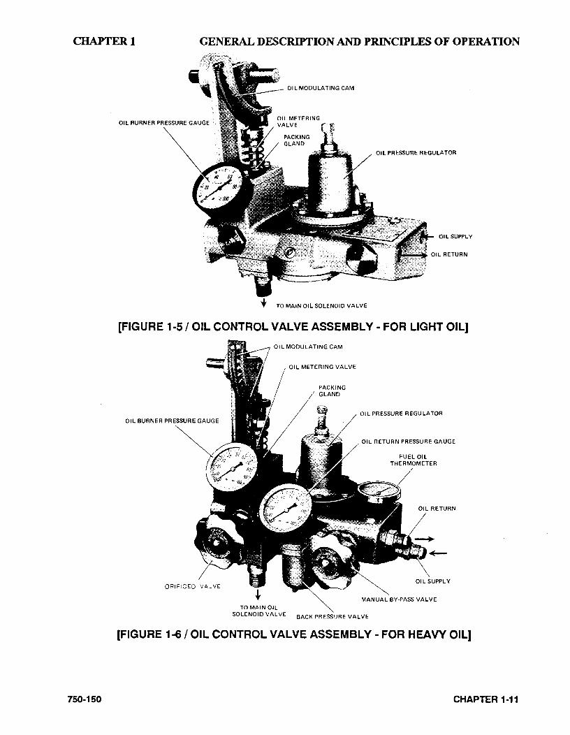
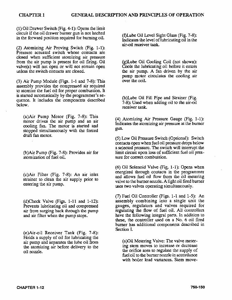
(7) Fuel Oil Controller (Figs. 1-1 and 1-5): An assembly combining into a single unit the gauges, regulators and valves required for regulating the flow of fuel oil. All controllers have the following integral parts. In addition to these, the controller used on a No. 6 oil fired burner has additional components described in Section I.
(a )Oil Metering Valve: The valve metering stem moves to increase or decrease the orifice area to regulate the supply of fuel oil to the burner nozzle in accordance with boiler load variances. Stem move-
750-150
CHAPTER I GENERAL DESCRIPTION AND PRINCIPLES OF OPERATION
ment is controlled by the modulating motor through linkage and the oil metering cam.
(b)Oil Modulating Cam: An assembly consisting of a series of adjustable allenhead screws and a contour spring providing for adjustment of oil input at any point in the modulating range.
( c )Oil Burner Pressure Gauge: Indicates pressure of the fuel oil at the metering valve.
(d)Oil Pressure Regulator: For adjustment of the oil pressure at the metering valve.
(8) Fuel Oil Pump (Not ~hown): Transfers fuel oil from the storage tank and delivers it under pressure to the burner system.
(9) Oil Relief Valve (Fig. 1-1): Maintains a constant oil supply pressure to the fuel oil controller by bypassing excess fuel oil.
(10) Fuel Oil Strainer (Fig. 1-1): Provided to prevent foreign matter from entering the burner system.
(11) Gas Pilot: See Section G for description of the various components.
(12) Light Oil Pilot Valve (Not Shown): When a light oil. pilot is furnished, a solenoid valve is provided to control the flow of fuel to the pilot nozzle. It is energized through programmer contacts. It is de-energized to shut off pilot fuel flow after main flame is ignited and established.
(13) Back Pressure Orifice (Fig. 1-1): A restriction located in the oil return line immediately downstream of the fuel oil controller to create back pressure (100 and 200 series only).
750-150
L ADDITIONAL CONTROLS FOR HEAVY OIL
NOTE: Items 6 and 7 are applicable only on a hot water boiler.
(1) Oil Heater Switch (Fig. 1-7): Manually provides power to the oil beater system.
(2) Oil Heater (Electric) (Figs. 1-2 and 1-8): Used for heating sufficient fuel oil for low fire flow during cold starts before steam or hot water is available for heating. The heater must be turned off during extended boiler lay-up, or any time that the fuel oil transfer pump is stopped.
(3) Oil Heater (Steam/Hot Water) (Figs. 1-2 and 1-8): Heats fuel oil through the medium of steam or hot water. The electric heater is housed in the steam heater, but is housed separately on a hot water heater. Steam oil heaters on 15 psi boilers will operate at boiler pressure. Steam oil heaters furnished on high pressure boilers are also to be operated at less than 15 psi. This is accomplished through use of a steam pressure regulator valve.
(4) Electric Oil Heater Thennostat (Figs. 1-2 and 1-8): Senses the fuel oil temperature and energizes or de-energizes the electric oil heater to maintain the required temperature of the fuel oil.
(5) Steam Oil HeaterThennostat (Fig. 1-8): Senses the fuel oil temperature and controls the opening and closing of the steam heater valve to maintain the required temperature of the fuel oil.
(6) Hot Water Oil Heater Thennostat (Fig. 1-2): This control is used on a hot water boiler to sense the fuel oil temperature and control the starting and stopping of the booster water pump to supp I y hot water to the pre-heating assembly to maintain the required temperature of the fuel oil.
(7) Booster Water Pump (Fig. 1-2): Started and stopped by the hot water thermostat to regulate the flow of hot water through the hot water oil heater to maintain the temperature of the fuel oil.
CHAPTER 1·13
CHAPTER I GENERAL DESCRIPTION AND PRINCIPLES OF OPERATION
(8) Oil Heater ~team Valve (Fig. 1-8): A normally closed solenoid valve opened by the steam oil heater thermostat to allow the flow of steam to the steam heater to maintain the temperature of the fuel oil.
(9) Steam Heater Check Valve (Fig. 1-8): Prevents oil contamination of the waterside of the pressure vessel should any leakage occur in the oil heater.
PLUG-IN MODULES AS REQUIRED FOR:
GAS-OIL SELECTOR SvVlTCH OIL HEATER SWITCH OIL PUMP SWITCH AIR PURGE
(10) Steam Heater Pressure Regulator (Fig. 1-8): Adjust to provide reduced (usually less than 15 psi) steam pressure to the heater to properly maintain the required fuel oil temperature. This regulator and the pressure gauge are not furnished on 15 psi units.
Fl.Afv1E SAFEGUARD AND PROGRAM LOCKOUT SvVlTCH
RESET BUTTON
SWITCH LEDGE LOCKING SCREW
I MANUAL
FLAME CONTROL
[FIGURE 1·7 I TYPICAL CONTROL PANEL]
CHAPTER 1-14 750-150
CHAPTER! GENERAL DESCRIPTION AND PRINCIPLES OF OPERATION
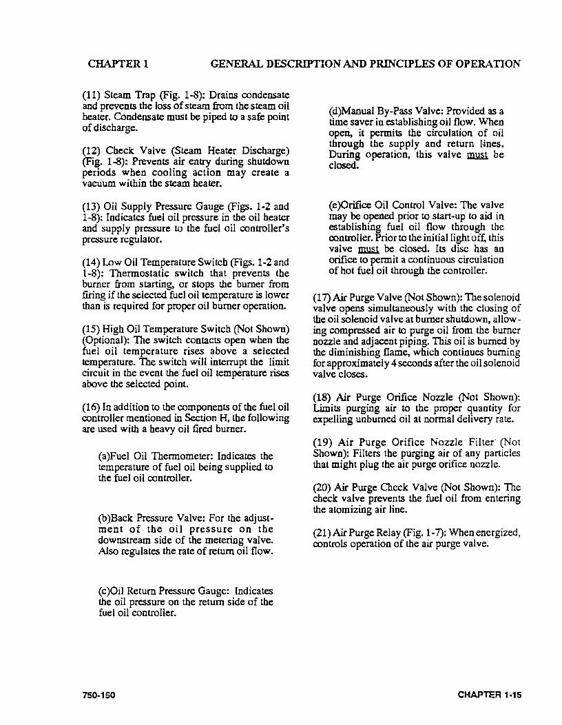
(11) Steam Trap (Fig. 1·8): Drains condensate and prevents the loss of steam from the steam oil heater. Condensate must be piped to a safe point of discharge.
(12) Check Valve (Steam Heater Discharge) (Fig. 1-8): Prevents air entry during shutdown periods when cooling action may create a vacuum within the steam heater.
(13) Oil Supply Pressure Gauge (Figs. 1·2 and 1-8): Indicates fuel oil pressure in the oil heater and supply pressure to the fuel oil controller's pressure regulator.
(14) Low Oil Temperature Switch (Figs. 1-2 and 1-8): Thermostatic switch that prevents the burner from starting, or stops the burner from firing if the selected fuel oil temperature is lower than is required for proper oil burner operation.
(15) High Oil Temperature Switch (Not Shown) (Optional): The switch contacts open when the fuel oil temperature rises above a selected temperature. The switch will interrupt the limit circuit in the event the fuel oil temperature rises above the selected point. ·
(16) In addition to the components of the fuel oil controller mentioned in Section H, the following are used with a heavy oil fired burner.
(a)Fuel Oil Thermometer: Indicates the temperature of fuel oil being supplied to the fuel oil controller.
(b)Back Pressure· Valve: For the adjustment of the oil pressure on the downstream side of the metering valve. Also regulates the rate of return oil flow.
(c)Oil Return Pressure Gauge: Indicates the oil pressure on the return side of the fuel oil controller.
750-150
(d)Manual By-Pass Valve: Provided as a time saver in establishing oil flow. When operi, it permits the circulation of oil through the supply and return l-ines. During operation, this valve 1IlJ.W. be closed.
(e)Orifice Oil Control Valve: The valve may be opened prior to start·up to aid in establishing fuel oil flow through the controller. Prior to the initial light off, this valve ~ be closed. Its disc has an orifice to permit a continuous circulation of hot fuel oil through the controller.
(17) Air Purge Valve (Not Shown): The solenoid valve opens simultaneously with the closing of the oil solenoid valve at burner shutdown, allowing compressed air to purge oil from the burner nozzle and adjacent piping. This oil is burned by the diminishing flame, which continues burning for approximately 4 seconds after the oil solenoid valve closes.
(18) Air Purge Orifice Nozzle (Not Shown): Limits purging air to the proper quantity for expelling unburned oil at normal delivery rate.
(19) Air Purge Orifice Nozzle Filter· (Not Shown): Filters the purging air of any particles that might plug the air purge orifice nozzle.
(20) Air Purge Check Valve (Not Shown): The check valve prevents the fuel oil from entering the atomizing air line.
(21) Air Purge Relay (Fig. 1-7): When energized, controls operation of the air purge valve.
CHAPTER 1-15
CHAPTER I GENERAL DESCRIPTION AND PRINCIPLES OF OPERATION
J. CONTROLS FOR COMBINATION BURNERS
ONLY
(1) Gas-Oil Switch (Fig. 1-7): Burners equipped to bum either oil or gas include equipment for each ~el.. The selector switch engages the appropnate Interlocks and controls for gas or oil operation. Chapter 4 details the required mechanical functions of each fuel system.
K. COMBUSTION AIR
Air for combustion of fuel (often referred to as "secondary" air) is furnished by the forced draft fan (Fig. 1-1 0) mounted in the boiler head. In operation, air pressure is built up in the entire
· head and is forced through a diffuser plate for a thorough mixture with the fuel for proper combustion. The supply of secondary air to the burner is governed by automatically throttling the output of the fan by regulating the rotary air damper. This furnishes the proper amount of air for the correct ratio of air to fuel for efficient combustion at all firing rates.
L. AUTOMATIC IGNITION
Oil or gas burners are ignited by an interrupted type pilot.. The pilot flame is ignited automatically by an electric spark.
A series 100 burner usually is equipped with a pilot fired with light oil fuel. All other burners, as well as a series 100 burner complying with insurance underwriters requirements, are equipped with a gas burning pilot. In the case of a combination burner, the gas pilot is used to ignite either the main gas flame or the oil flame. Either pilot serves the same function and unless exception is taken in the text, the term pilot is used interchangeably.
CHAPTER 1-16
At the beginning of the ignition cycle, and governed by the program relay, the pilot solenoid valve and ignition transformer are simultaneously energized.
The ignition transformer supplies high voltage current for the igniting spark. A gas pilot has a single electrode and a spark arcs between the tip of the electrode and the wall of the tube surrounding it.. A light oil pilot has two electrodes and the arc is between their tips. The pilot solenoid valve and the transformer are de-energized after the main flame is ignited and established.
Fuel for the gas pilot is supplied from the utility's ~ain or ~om a ta~ (bott~e) supply. Secondary a1r flows 10to and m1xes w1th the pilot gas stream to provide an adequate flame.
Insurance regulations may require two gas pilot solenoids with a normally open vent valve be~een them. The vent valve closes when the gas ptlot valves open, and opens when the gas pilot valv~ sh~t to ve~t gas should any be present in the pilot hoe dunng the de-energized period of the gas pilot valves.
Fuel for a light oil pilot is provided from the line that supplies oil under pressure for the main flame. A solenoid actuated valve controls the flow of oil to the pilot nozzle. This valve is energized simultaneously with the ignition trans~ormer at the beginning of the ignition cycle and IS de-energized after the main flame is ignited and established.
M ATOMIZING AIR
Air for atomizing the fuel oil (often referred to as "primary air") is pumped by the air pump into the air-oil receiver tank and delivered under pressure through a manifold block to the oil burner nozzle.
The atomizing air mixes with the fuel oil just prior to the oil leaving the nozzle.
Atomizing air pressure is indicated by the air pressure gauge on the burner gun.
750-150
CHAPTER! GENERAL DESCRIPTION AND PRINCIPLES OF OPERATION
OIL SUPPLY PAESSUFE GAUGe
NOTE: FOR HOT WATER COMPONENTS
FEFERTO FIGURE 1·2
STEAM PRESSUFE GAUOE
STEAM PRESSURE FEGULATOR
STEAM SHUTOFF
VALVE
~~=C~~l===~~aSTEAM 1..-'-_._-"""'"'"..,..,_ __ -i.-.f __ INLET
OIL INLET FROM TANK
STEAM HEA SOLENOIOV
LOW PRESSURE BOflERS ONLY
NOTE: AU CONOENSA TE FROM STEAM TRAP MUST BE WASTED AND PIPED TO A SAFE POINT OF DISCHARGE.
[FIGURE 1-8/ OIL HEATING ASSEMBLY (STEAM)]
Air pressure from the pump also forces sufficient oil from the tank to the pump bearings to lubricate them and also to provide a seal and lubrication for the pump vanes. As a result, the air delivered to the tank contains some lube oil; however, most of it is recovered through baffles and filters in the tank before the air passes to the burner.
Some of the primary air also is used to assist the oil pressure regulators of the fuel oil controller. This is explained in Chapter 4.
750-150
ro sro.M SIJIIfii(.Jtf F'RCII aUIU'IHC ~T
a::lNS't'RUCTia.
[FIGURE 1·9/ RECOMMENDED SAFETY VALVE INSTALLATION PROCEDURE]
CHAPTER 1-17
CHAPTER! GENERAL DESCRIPTION AND PRINCIPLES OF OPERATION
[FIGURE 1·1 0 I SECONDARY AIR FLOW CIA GRAM]
N. OIL FUEL FLOWUGI-ITOIL
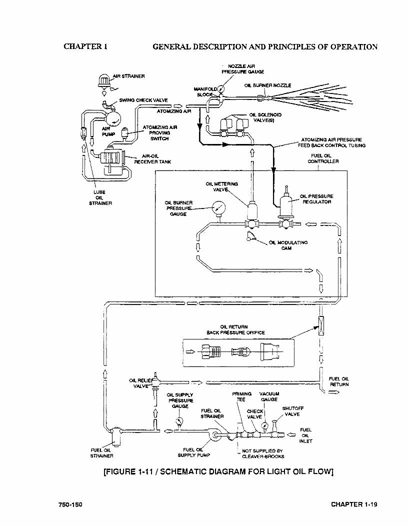
The oil fuel flow system is shown in schematic diagram in Fig. 1-11. Oil flow is indicated by arrows and the pertinent controls are called out. Fuel oil is delivered into the system by a supply pump that delivers part of its discharge to the oil burner. Excess oil is returned to the oil storage tank through the fuel oil relief valve and oil return line. Normally, the pump operates only while the burner is in operation, although often a positioning switch is provided so that either continuous or automatic pump operation can be obtained.
CHAPTER 1-18
The oil flows through a fuel oil strainer provided to prevent any foreign material from flowing through the control valves and nozzle. The fuel oil controller contains in a single unit,a metering valve, a regulator, and a gauge required to regulate the pressure and flow of oil to the burner. The adjustable regulator controls the pressure. To assist in this regulation, back pressure is created by an orifice nozzle located in the oil return line immediately downstream of the fuel oil controller.
The programming relay energizes or de-energizes the solenoid oil valves to permit or cut off oil flow to the burner. Two valves, operating simultaneously, are used. These valves are closed when de-energized. They cannot be opened (energized) unless the combustion air proving switch and the atomizing air proving switch are closed. These are satisfied, respectively, by suf·ficient combustion air pressure from the forced draft fan and pressurized air from the air pump.
The oil flow to the burner is controlled by the movement of the metering stem in the oil meter• ing valve, which varies the flow to meet load demands. The metering valve and the air dam per are controlled simultaneously at all times by the modulating motor to proportion combustion air and fuel for changes in load demand.
0. OIL FUEL FLOW -HEAVY OIL
The oil fuel flow and circulating system is shown in the schematic diagram in Fig. 1-12. The pertinent controls are called out and the oil flow is indicated by arrows.
Fuel oil is delivered into the system by the fuel oil supply pump, which delivers part of its discharge to the oil heater. The remainder of the fuel oil returns to the oil storage tank through a fuel oil relief valve and oil return line.
The combination electric and steam oil preheater is controlled by thermostats. The electric oil heater thermostat energizes the electric heater
. 750-150
CHAPTER! GENERAL DESCRIPTION AND PRINCIPLES OF OPERATION
750 .. 150
~A STRAINER
oo--
LUBE OIL
STRAINER
swiNo CHECK VAlVE
ATOMIZING AIR PROVING SWITCH
0
· NOZZL.E AIR PRESSURE GAUGE
ATOMIZING AIR PRESSURE FEED BACK CONTROl TUBING
OIL METERING VAlV
~OIL MODULATING CAM
FUEL OIL CONTROLLER
~==================' 0 D 0
OIL RETURN BACK PRESSURE ORIFICE
0
rl~====~~ C' ==========================~~~~~ PRIMING VACUUM ......_.....
FUEL OIL STRAINER
FUEL 01 SUPPLY PUMP
TEE GAUGE
SHUTOFF VALVE
NOT SUPPUED BY CLEAVER-BROOKS
(FIGURE 1·11 I SCHEMATIC DIAGRAM FOR LIGHT OIL FLOW]
CHAPTER 1-19
CHAPTER! GENERAL DESCRIPTION AND PRINCIPLES OF OPERATION
WBE OIL
STRAINER
@II
SWING CHECK VN..VE
ATOIIMZING AIR
£=.=:=:::l 0 c:::::====l
wee AIR PURGE ORIFlCE
OIL NOZZLE I
8;;;::£D [3 NOTE: DIAGRAM SHOWS COMPO· NENTS USED WITH STEAM GENEAATO~S. ~EFE~ TO FIGU~E 1·2 FOR CORRESPONDING HOT WATER HEATING COMPONENTS.
OIL SUPA. Y OIL REUEF ~FE VN..VE
OIL HEATER (B..ECTRq'
OIL HEA 113=1 THEMOSTAT (S...ECTRiq
OILHEATCR . SH8.J..
CXLHEATER THe:IMOSTAT
(STEAM)
• THESE ll"E1o6 ARE USED ON HIGH fiFIESSURE GENERATOFB ONLY
ou LOWOIL D
TEMPERATURE SWITCH
NOTE: CONCENSA TE FROM STEAM TFIAP MUST BE WASTED ANC PIPED TO A SAFE POINT OF DISCHARGE.
VACUUM GAUGE
SHUTOFF VN..VE
[FIGURE 1-12/ SCHEMATIC DIAGRAM FOR NO.6 HEAVY OIL FLOW (STEAM-ELECTRIC HEATER))
CHAPTER 1 ~20 750-150
CHAPTER! GENERAL DESCRIPTION AND PRINCIPLES OF OPERATION
that is provided to supply heated oil on cold starts. The steam heater thermostat controls the operation of the steam solenoid valve to permit a flow of steam to the heater when steam is available.
A hot water boiler is equipped to heat the oil with hot water from the boiler unless other pre-heating equipment is utilized. The electric heater, which is housed separate! y, is sized to provide heated oil on a cold start. The hot water thermostat controls the operation of a pump that supplies hot water to the oil heater when hot water is available.
The heated oil flows through a fuel oil strainer to prevent any foreign matter from entering the control valves and nozzle.
The fuel oil controller contains in a single unit the necessary valves, regulators and gauges to regulate the pressure and flow of oil to the burner.
The program relay energizes or de-energizes the solenoid oil valve to permit or cut off oil fJow to the burner. The oil solenoid is closed when deenergized. It cannot be opened (energized) unless the combustion air proving switch, the atomizing air proving switch and the low oil temperature and any pressure switches are closed. These are satisfied, respectively, by sufficient combustion air pressure from the forced draft fan, pressurized air from the air pump and sufficient oil temperature and pressure.
Oil flow to the burner is controlled by the movement of the metering stem of the oil metering valve, which varies the flow to meet load demands. The metering valve and the air dam per are controlled simultaneously at all times by the modulating motor to proportion combustion air and fuel for changes in load demand.
Oil is purged from the burner gun upon each burner shut down. The air purge solenoid valve opens as the fuel valve closes and diverts atomizing air through the oil line. This assures a clean nozzle and line for the subsequent restart.
750-150
P. GAS FUEL FLOW
The gas flow system is shown in Fig. 1-4. Gas flow is indicated by arrows and the pertinent controls are shown. Combustion air travel is also shown and indicated by a different type of arrow.
Metered gas from the utility flows through the pressure regulator at a reduced pressure suitable to the burner's requirements, through the main gas shut-off cock, main gas valve(s) and modulating butterfly gas valve to the non-premix orifice type burner.
The main gas valve is of the normally closed type and is opened (energized) in proper sequence by the programming relay.
The butterfly gas valve modulates the flow of gas from low through high flre settings. The position ofthe butterfly valve disc is governed by the gas modulating cam. The butterfly gas valve, and the air control damper are controlled simultaneously by the modulating inotor to proportion combustion air and fuel for changes to load demand.
The gas flow rate required for rated burner input depends upon the heating value (BTU/cubic foot) of the gas supplied. The gas pressure regulator adjusts the gas pressure (flow rate) to the entrance of the gas train. The regulator is not always supplied with the burner, but may be provided by others.
The main gas valves cannot be energized (opened) unless the combustion air proving switch is closed to indicate a sufficient supply of combustion air. The low gas pressure and high gas pressure switches must be closed to prove sufficient, but not excessive, gas fuel pressure.
CHAPTER 1·21

CHAPTERl GENERAL DESCRIPTION AND PRINCIPLES OF OPERATION
Q. MODULATING FIRING
The modulating motor, through a linkage arrangement, controls the air damper and the butterfly gas valve or the oil metering valve to maintain a ·constant air-fuel ratio throughout the firing range.
During burner operation, the motor is controlled by a modulating pressure control on a steam boiler, or by a modulating temperature control on a hot water boiler. A manually operated potentiometer is provided to permit the positioning of the motor at a desired burner firing rate. This is used primarily for initial or subsequent checking and setting of fuel input. Normal operation should be with the manual-automatic switch in the "automatic" position and under the control of the modulating control.
The modulating motor (commonly called a · damper motor) is reversible. It has an internal limit switch that restricts shaft rotation to 90". During nonnal operation the motor will move in either direction or stop at any position within this range.
The motor's potentiometer is electrically connected to a matching potentiometer in the modulating control. Changing steam pressure or water temperature alters the electrical resistance
CHAPTER 1 ~22
of the modulating controller's potentiometer. This change in resistance compels an integral balancing relay to start, stop, or reverse the motor rotation. Rotation in either direction continues until the resistance ratio of the two potentiometers are equal.
When this occurs, the motor stops in a position that allows the proper fuel and combustion air flow to meet operating demands.
A feature designed into the circuitry is that the modulating motor must be in the low fire position during ignition and remain there until the main flame is established. A low fire switch, integral to the motor, is actuated by the rotation of the motor. The switch must be closed to establish that the damper and fuel metering valves are in low fire position before the programmer commences into the ignition period. During this time, neither the manual flame control nor the modulating control have any control over the damper motor, regardless of their setting.
An optionally equipped boiler has a second integral switch used to es~blish th~t .the mo~or has driven the damper to an open pos1t1on dunng the pre-purge period. This switch closes, as high fire position is approached, to complete an internal circuit in the programmer and allow continuation of the programming cycle.
750-150
CHAPI'ER2 THE PRESSURE VESSEL
CHAPTER2
THE PRESSURE VESSEL
A. General B. Construction C. Water Requirements
1. Hot water boiler 2 Steam boiler
D. Water Treatment E. Cleaning F. Boil-out of a New Unit G. Washing out
1. Hot Water Boiler 2 Steam Boiler
H.
I. 1.
Slowdown -Steam Boiler 1. Types of Slowdown
Periodic Inspection Preparation for Extended Lay-up
A. GENERAL
This chapter is devoted primarily to the waterside care of the pressure vessel.
The type of service that your boiler is required to provide has an important bearing in the amount of waterside care it will requir~ ..
Although it is of prime importance, the subject of water supply and treatment cannot adequately be covered in this manual. For specific information or assistance with your water treatment requirements, contact your Cleaver-Brooks service and parts representative.
750-150
Feedwater equipment should be checked and ready for use. See that all valves, piping, boiler feed pumps, and receivers are installed in accordance with prevailing codes and practices.
Water requirements for both steam and hot water boilers are essential to boiler life and length of service. Constant attention to this area will pay dividen~ in the form of longer life, less downtime, and prevention of costly repairs. Care taken in placing the pressure vessel into initial service is vital. The waterside of new boilers and new or remodeled steam or hot water systems may contain oil, grease or other foreign matter. A method of boiling out the vessel to remove these accumulations is described later in this chapter.
The operator should be familiar with this chapter before attempting to place the unit into operation.
CHAPTER 2-1
CHAPTER2
Boilers, as a part of a hot water syste~ require proper circulation and the system must be operated as intended by its designer to avoid shock or severe, possibly damaging, stresses occurring to the pressure vessel.
B. CONSTRUCTION
Those steam boilers designed for 15 psig and hot water boilers designed for zso•p at 125 psi or less are constructed in accordance with Section IV, Power Boilers, of the ASME Code.
Those steam boilers designed for operation exceeding 15 psig are constructed in accordance with Section I, Power Boilers, of the ASME Code. Hot water boilers for operation over zso•p or 125 psi are likewise built to this Code.
C. WATER REQUIREMENTS
1. Hot Water Boiler
Air Removal The hot water outlet includes a dip tube which extends 2 to 3 inches into the boiler. This dip tube reduces the possibility of any air which may be trapped at the top of the shell from entering into the system.
Any oxygen or air which is released in the boiler will collect or be trapped at the top of the boiler shell.
The air vent tapping on the top center line of the boiler should be piped into the expansion or compression tank. Any air that is trapped at the top of the boiler will fmd its way out of the boiler through this tapping.
Minimum Boiler Water Temperature- The minimum recommended operating boiler water temperature is 170°F. When water temperatures lower than 170oF are used, the combustion gases are reduced in temperature to a point where the water vapor condenses. The net result is that corrosion occurs in the boiler and breeching.
CHAPTER 2·2
THE PRESSURE VESSEL
This condensation problem is more severe on a unit that operates intermittently and that is greatly oversized for the actual load. This is not a matter which can be controlled by boiler design, since an efficient boiler extracts all the possible heat from the combustion gases. However, this problem can be minimized by maintaining boiler water temperatures above 170•F.
Another reason for maintaining boiler water temperature above 170°F is to provide a sufficient temperature "head" when No. 6 fuel oil is to be heated to the proper atomizing temperature by the boiler water in a safety type oil preheater. (The electric preheateron the boiler must provide additional heat to the oil if boiler water temperature is not maintained above zoo·F.)
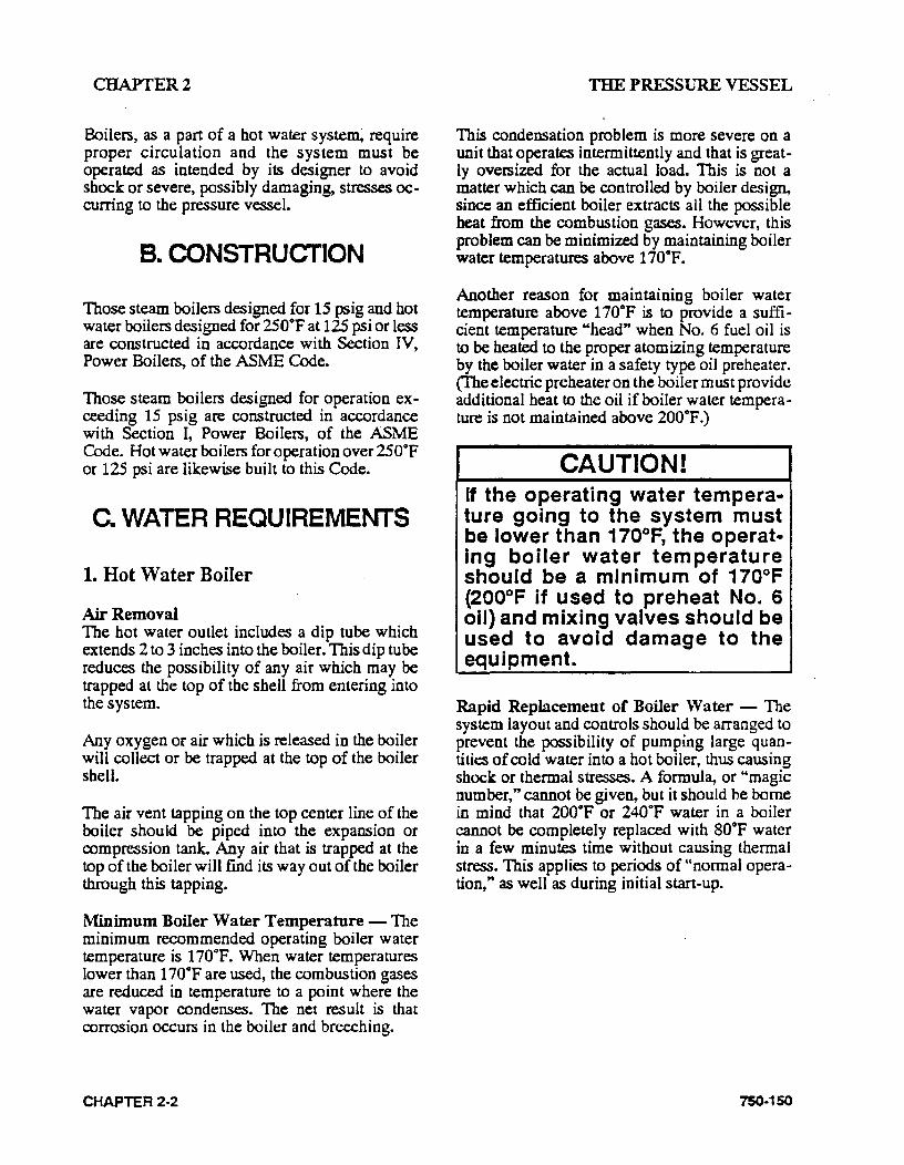
CAUTION! If the operating water temperature going to the system must be lower than 170°F, the operatIng boiler water temperature should be a minimum of 170°F (200°F if used to preheat No. 6 oil) and mixing valves should be used to avoid damage to the equipment.
Rapid Replacement of Boiler Water- The system layout and controls should be arranged to prevent the possibility of pumping large quantities of cold water into a hot boiler, thus causing shock or thermal stresses. A formula, or "magic number," cannot be given, but it should be borne in mind that 200oF or 240oF water in a boiler cannot be completely replaced with so•p water in a few minutes time without causing thermal stress. This applies to periods of "normal operation," as well as during initial stan-up.
75()..150
CHAPTER2 THE PRESSURE VESSEL
8cH.., Boner System T..,pe,.ture Crap- De9,... F
S!a Ou•t 10 1 20 30 I 40 50 10 70 "' 10 100 {1000)
(BHP) Btu/Hr Muimum =n:uiattnv Rllte - GPM
15 500 100 1 50 33 25 20 17 ,. 12 11 10
20 670 13-4 I 61 •s 33 27 221 19 11 1 15 13
30 1.005 2001 100 67 50 4&0j 33 29 251 22 20
4&0 1,340 25a I 13-4 89 61 I So4l 45 38 33 30 27
so 1,675 3351 HS8 I 112 1 &4 67 sol .aj 42 I 37 33
60 2.010 4021 201 134 101 ! sol 67 sa sol 45 40
70 2.34! •1o 1 235j 157 1 11e I 941 1a 1 57 s9 1 52 47
80 2.580 5361 2sa 1 179 1 134 I 101 1 901 nj stl 60 5:4 100 3..150 I 67o 1 3351 223 168 13-4 ,2, 961 841 75 1 67
125 •.18.5 I 8361 -'18 1 2791 209 I 168 I 1.-o I 120 I 1os I 931 &4
150 s.02S 1 1.oos I 503 335j 251 201 1 1sa 1 ,...,. 1 126 112 1 100
200 I 6.695 1.340 I 67o 1 4o&7 335 I 268 I 22• I 192 I 168 I 1•e I 134
2SO a.370 1 1 .s1s I 8381 ssal <419 I 3351280 24&0 1 210 1 186 167 I
300
'
1o,045 \ 2.o1o 1 , .oos I 67o I S03 I 402 I ns I 2a1 I 251 I 223 I 201
3SO 11.120 1 2..35o 1 1.11s 1 78A I 587 ·I •10 I 392 I 338 294 I 251 2:35
40) I 13,AOO I 2.680 I 1.340 I 895 610 535 I ~7 I 383 33512981258 5CXl 16.740 1 3.350 1 1.67s 1 1.120 838 I 670 ! ssa I •79 I •1e I 312 33.5
600 . 20.080 •.020 I 2..01 o 1,340 ' 1.005 sos ! 67o I 575 r sa2 I 4.&8 4.02
700 23.430 •.aso I 2..3<45 1.565 1 1. 175 I s.o 1 1a.s 1 67o I sas .520 1 47o
800 26.780 s.3eo I 2.680 1,785 1.340 1.075 J 895 1 1ss 1 sto 595 S3S
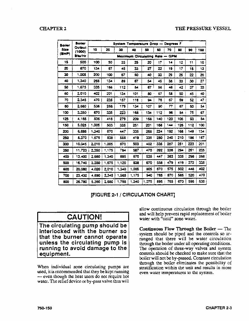
[FIGURE 2·1 I CIRCULATION CHART]
CAUTION! The circulating pump should be interlocked with the burner so that the burner cannot operate unless the circulating pump is running to avoid damage to the equipment.
When individual zone circulating pumps are used, it is recommended that they be kept running - even though the heat users do not require hot water. The relief device or by-pass valve thus will
750-150
allow continuous circulation through the boiler and will help prevent rapid replacement of boiler water with "cold" zone water.
Continuous Flow Through the Boiler - The . system should be piped and the controls so arranged that there will be water circulation through the boiler under all operating conditions. The operation of three-way valves and system controls should be checked to make sure that the boiler will not be by-passed. Constant circulation through the boiler eliminates the possibility of stratification within the unit and results in more even water temperatures to the system.
CHAPTER 2...3

CHAPTER2
A rule of thumb of Vz to 1 GPM per boiler horsepower can be used to determine the mini .. mum continuous flow rate through the boiler under all operating conditions.
The operator should determine that a flow of water exists through the boiler before initial firing or refiring after the boiler has been drained.
Water Circulation The chart in Fig. 2-1 shows the maximum GPM circulation rate of boiler water in relation to full boiler output and system temperature drop.
Multiple Boiler Installations- When multiple boilers of equal or unequal size are used, care must be taken to ensure adequate or proportional flow through the boilers. This can best be accomplished by use of balancing cocks and gauges in the supply line from each boiler. If balancing cocks or orifice plates are used, a significant pressure drop (e.g., 3-5 psi) must be taken across the balancing device to accomplish this purpose.
If care is not taken to ensure adequate or propor· tiona! flow through the boilers, this can result in wide variations in firing rates between the boilers.
In extreme cases, one boiler may be in the high fire position, and the other boiler or boilers may be at low fire. The net result would be that the common header water temperature to the system would not be up to the desired point. This is an important consideration in multiple boiler installations.
Pressure Drop Through Boiler - There will be a pressure drop of less than three feet head (1 psi - 2.31 ft. hd.) through all standard equipped Qeaver-Brooks boilers operating in any system which has more than a 10°F temperature drop.
Pump Location - It is recommended that the system circulating pumps take suction from the outlet connection on the boiler and that they discharge to the system load. This puts the boiler and the expansion tank on the suction side of the pump. This location is preferred because it decreases air entry into the system and does not impose the system head on the boiler.
CHAPTER 2-4
THE PRESSURE VESSEL
It is common practice to install a standby system circulating pump. The main circulating pump usually is located adjacent to the boilers in the boiler room.
Pump Operation- Pumps are n9rmally started and stopped by manual switches. It is also desirable to interlock the pump with the burner so that the burner cannot operate unless the circulating pump is running.
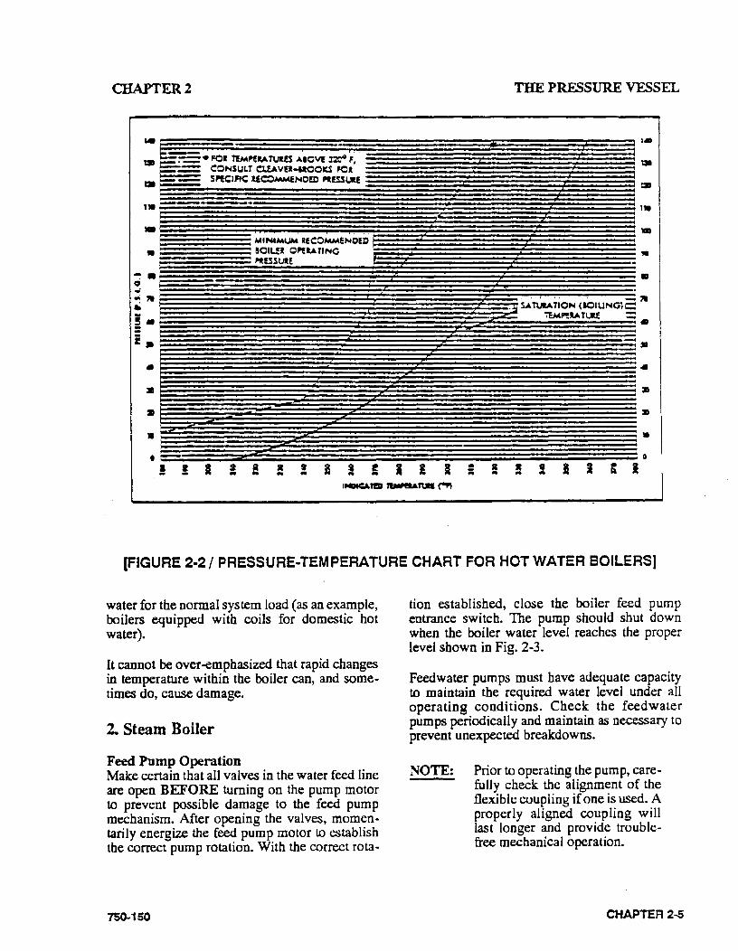
Pressure The design of the system and the usage requirements often will dictate the pressure exerted upon the boiler. Some systems are pressurized with air or with an inert gas, such as nitrogen. Caution must be exercised to make sure that the proper relationship of pressure to temperature· exists within the boiler so that all of the boiler's internal surfaces are fully wetted at all times. It is for this reason that the internal boiler pressure, ~ indicated on the water pressure gauge, must be held to the level shown in Fig. 2-2.
When initially firing a 'newly installed boiler or when .bringing an existing boiler into an operating system, the boiler or boilers to be brought on line MUST be pressurized equal to the system and/or other boilers prior to opening the header valves.
It is advisable to have a thermometer installed in the return line to indicate return water temperature. With this determined and with the supply water temperature to system known, the temperature differential will be established. With knowledge of the pumping rate, the operator easily can detect any excessive load condition and take appropriate corrective action (see Fig. 2-1).
Special caution must be taken to guard against any conditio~ or combination of conditions, which might ·lead to the transfer of cold water to a hot boiler or hot water to a cold boiler. This particularly is true in the case of boilers that are operated for purposes other than supplying hot
750-150
CHAPTERl
,.~--
-"
~-0 ... .. ,. .. -!• .. .. i.
.. a
a
• •
! ! I
MINIMUM l!COMMENCEJ) !IOIL!l Q~I.AfiNCi ll'tt!SSU.E
! !! lit t .. ..
THE PRESSURE VESSEL
-- ,.
•
•
-- • .. :a
:D
10
0
• ;:; R ... I ; I lit ... !
(FIGURE 2·2/ PRESSURE-TEMPERATURE CHART FOR HOT WATER BOILERS]
water for the normal system load (as an example, boilers equipped with coils for domestic hot water).
It cannot be over-emphasized that rapid changes in temperature within the boiler can, and sometimes do, cause damage.
2. Steam Boiler
Feed Pump Operation Make certain that all valves in the water feed line are open BEFORE turning on the pump motor to prevent possible damage to the feed pump mechanism. After opening the valves, momentarily energize the feed pump motor to establish the correct pump rotation. With the correct rota-
750-150
tion established, close the boiler feed pump entrance switch. The pump should shut down when the boiler water level reaches the proper level shown in Fig. 2-3.
Feedwater pumps must have adequate capacity to maintain the required water level under all operating conditions. Check the feedwater pumps periodically and maintain as necessary to prevent unexpected breakdowns.
NOTE: Prior to operating the pump, carefully check the alignment of the flexible coupling if one is used. A properly aligned coupling will last longer and provide troublefree mechanical operation.
CHAPTER 2-5
CHAPTER 2 THE PRESSURE VESSEL
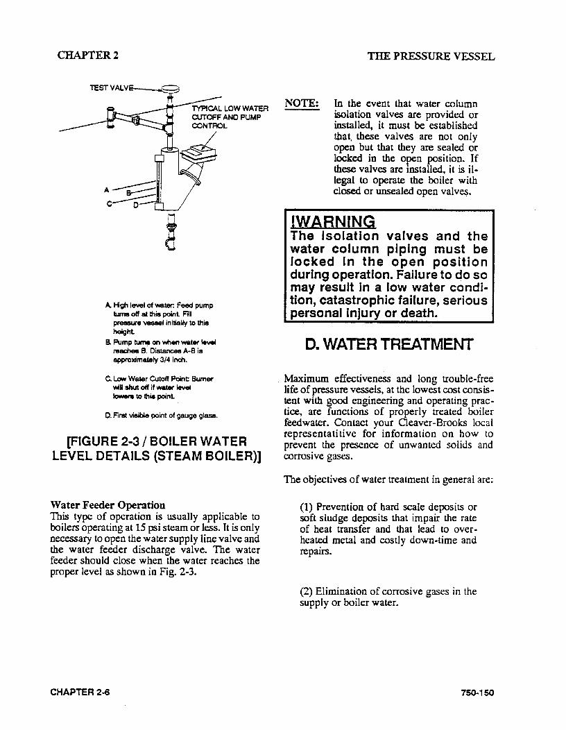
A Hgh level of water: Feed pump turns off at this point Fill pressure "V88881 initially to thie height
B. Pump tu~ on wnen water level reac:tlee B. Dis:tances A-8 is approximately 3/4 inch.
C. low Water Cutoff Point Burner wiH shut off if water level Jowers to thMa point
0. First visi~e point of gauge glase.
[FIGURE 2·3 I BOILER WATER LEVEL DETAILS (STEAM BOILER)]
Water Feeder Operation This type of operation is usually applicable to boilers operating at 15 psi steam or less. It is only necessary to open the water supply line valve and the water feeder discharge valve. The water feeder should close when the water reaches the proper level as shown in Fig. 2-3.
CHAPTER 2..6
NOTE: In the event that water column isolation valves are provided or installed, it must be established that. these valves are not only open but that they are sealed or locked in the open position. If these valves are installed, it is illegal to operate the boiler with closed or unsealed open valv~.
!WARNING The Isolation valves and the water column piping must be locked In the open position during operation. Failure to do so may result in a low water condition, catastrophic failure, serious personal injury or death.
D. WATER TREATMENT
Maximum effectiveness and long trouble-free life of pressure vessels, at the lowest cost consistent with good engineering and operating practice, are functions of properly treated boiler feedwater. Contact your Cleaver-Brooks local representatitive for information on how to prevent the presence of unwanted solids and corrosive gases.
The objectives of water treatment in general are:
(1) Prevention of hard scale deposits or soft sludge deposits that impair the rate of heat transfer and that lead to overheated metal and costly down-time and repairs.
(2) Elimination of corrosive gases in the supply or boiler water.
750-150
CHAPTER2
(3) Prevention of intercrystalline cracking or caustic embrittlement of the boiler metal. ·
( 4) Prevention of carryover and foaming.
The accomplishment of these objectives generally requires proper feed water treatment before and after introduction of water into the boiler. The selection of pre-treatment processes depends upon the water source, its chemical characteristics, amount of makeup water needed, plant operating practices, etc. These treating methods include filtering, softening, de-mineralizing, deaerating, and pre-heating. After-treatment involves chemical treatment of the boiler water.
Because of the variables involved, no one "boiler compound" can be considered a "cure-all" nor is it advisable to experiment with homemade treating methods. Sound recommendations and their employment should be augmented by a periodic analysis of the feed water, boiler water, and condensate.
The internal or waterside surfaces of the pressure vessel should be inspected with sufficient frequency to determine the presence of any contamination, accumulations of foreign matter, of corrosion and/or pitting. If these conditions are detected, contact your Cleaver-Brooks local representative for advice on corrective action.
It is recommended that a properly sized water meter be installed in the raw water make-up line to accurately determine the amount of raw water admitted to the boiler (steam or hot water) to aid the water treatment program in maintaining proper waterside conditions.
The general feeling exists that a hot water boiler does not require water treatment, but this is a false assumption. Even though these units generally operate on closed systems and blowdown is seldom practiced, the need remains to be alert to system water losses and a water meter is recommended for water make-up lines.
750-150
THE PRESSURE VESSEL
E. CLEANING
Hot Water and Steam Piping Steam and water piping systems connected to the boiler may contain oil, grease or foreign matter. These impurities must be removed to prevent damage to pressure vessel heating surfaces. On a steam system, the condensate should be wasted until tests show the elimination of undesirable impurities. During the period that condensate is wasted, attention must be given to the treatment of the raw water used as make-up so that an accumulation of unwanted materials or corrosion does not occur. For more information, contact your local Cleaver-Brooks representative.
On a hot water system, chemical cleaning is generally necessary.and the entire system should be drained after treatment Consult your local Oeaver-Brooks representative for recommendations, cleaning compounds, and application procedures.
Pressure Vessel · The waterside of the pressure vessel must be kept clean from grease, sludge and foreign material. Such deposits, if present, will not only shorten the life of the pressure vessel and interfere with efficient operation and functioning of control or safety devices, but might quite possibly cause unnecessary and expensive re-work, repairs and down-time.
The installation and operating conditions that the boiler will be subjected to should be considered and cleaning of the waterside of the pressure vessel should be provided during the course of initial start-up.
The pressure vessel and the steam and return lines or hot water piping represent, in effect, a closed system. Although the steam and return (condensate) lines or the hot water piping system may have been previously cleaned, it is possible that:
(1) Cleaning has been inadequate.
CHAPTER 2·7
CHAPTER2
(2) Partial or total old system is involved.
(3) Conditions may prevent adequate cleaning of piping.
The pressure vessel waterside should be inspected on a periodic basis. This will reveal true internal conditions and serve as a check against conditions indicated by chemical analysis of the boiler water. Inspection should be made three months after initial starting and at regular 6-, 9-, or 12-month intervals thereafter. The frequency of further periodic inspections will depend upon the internal conditions found.
If any unwanted conditions are observed, contact your Cleaver-Brooks local representative for recommendations.
Any sludge, mud, or sediment found will have to be flushed out. The effectiveness of the blow .. down practiced on steam boilers should be verified and scheduling or frequency of blowdown may have to be revised. The need for periodic draining or washout will also be indi ~ cated.
Any oil or grease present on the heating surfaces should be removed promptly by a boil-out with · an alkaline detergent solution.
NOTE: Temperature of initial fill of water for hydrostatic tests, boilout, or for normal operation should be as stated in the ASME Boiler Code.
F. BOIL-OUT OF A NEW UNIT
The internal surfaces of a newly installed boiler may have oil, grease or other protective coatings used in manufacturing. Such coatings must be removed since they lower the heat transfer rate and could cause over-heating of a tube. Before boiling out procedures may begin, the burner
CHAPTER 2-8
THE PRESSURE VESSEL
should be ready for fuing. The operator must be familiar with the procedure outlined under burner operation.
!WARNING Use of a suitable face mask, goggles, rubber gloves, and protective garments Is strongly recommended when handling or mixing caustic chemicals. Do not permit the dry material or the concentrated solution to come in contact with skin or clothing. Failure to follow these precautions could result in serious personal injury or death.
Your Cleaver-Brooks local representative wiU be able to recommend a cleaning or boil-out prOcedure. In the event such service is unavailable or is yet unscheduled, the following information may be of assistance.
There are several chemicals suitable for this purpose. Soda ash (sodium carbonate) and caustic soda (sodium hydroxide at the rate of 3 to 5 pounds each per 1,000 pounds of water, along with a small amount of laundry detergent added as a wetting agent is one combination often used.
Generator JYatcr- O:allccs , JYatct- Wci~bt Si?P:<IOI. Normal I F" "'lOCrec I Nnrm~l I F1CXXIea
100 875 1032 7260 8570
125 825 980 6825 8130
150 995 1180 8270 9810
200 1335 1580 11070 13100
250 1371 1630 11380 13510
300 1635 1935 13550 16050
350 1870 2220 15525 18420
400 2175 2570 18070 21350
(FIG. 2-4 I WATER CAPACirf CHARn
750-150
CHAPTER2
The suggested general procedure for cleaning a boiler is:
(1) Refer to Fig. 2-4 to determine water capacity. Have sufficient cleaning material on hand to complete the job.
(2) When dissolving chemicals, the following procedure is suggested. Warm water should be put into a suitable container. Slowly introduce the dry chemical into the water stirring it all times until the chemical is completely dissolved. Add the chemical slowly and in small amounts to prevent excessive heat and turbulence.
(3) An over-flow pipe should be attached to one of the top boiler openings and routed to a safe point of discharge. A relief or safety valve tapping is usually used. .
(4) Water relief valves and steam safety valves must be removed before adding the boil-out solution so that neither it nor the grease that it may carry ~ill contaminate these valves. Use care in removing and re-installing valves.
Refer to Section Min Chapter 7 for valve installation instructions.
(5) All valves in the piping leading to or from the system must be closed to prevent the cleaning solution from getting into the system.
(6) Fill the pressure vessel with clean water until all tubes are covered. Add the cleaning solution and then fill to the top. The temperature of the water used in this initial fill should be at ambient temperature.
750-150
THE PRESSURE VESSEL
(7) The boiler should then be fired inter· mittently at a low rate sufficient to hold the solution just at the boiling point. Boil the water for at least five hours. Do not produce steam pressure.
(8) Allow a small amount of fresh water to enter the boiler to create a slight overflow that will carry off surface impurities.
(9) Continue to boil and overflow until the water clears. Shut the burner down.
(10) Let the boiler cool to 120oF or less.
!WARNING Be sure to drain the hot water to a safe point of discharge to avoid scalding or . other serious personal Injury or death.
(11) Remove the hand hole plates and wash the waterside surfaces thoroughly using a high pressure water stream.
(12) Inspect the waterside surfaces. If they are not clean, repeat the bailout.
(13) After closing the openings and reinstalling the safety or relief valves, fill the boiler and fire until water is heated to at least 180°F to drive off any dissolved gases that might otherwise corrode the metal.
CHAPTER 2·9
CHA.PTER2
The above procedure may be omitted in the case of a unit previously used or known to be internally clean. However, consideration must be given to the possibility of contaminating materials entering the boiler from the system.
On a steam system, the condensate should be wasted until tests show the elimination of undesirable impurities. During the period that condensate is wasted, attention must be given to the treatment of the raw water used as make-up so than an accumulation of unwanted materials or corrosion does not occur.
On a hot water system., chemical cleaning is generally necessary and the entire system should be drained after treatment. Consult your QeaverBrooks local representative for recommendations, cleaning compounds, and application procedures.
G. WASHING OUT
1. Hot Water Boiler In theory, a· hot water system and boiler that have been initially cleaned, filled with raw water (and that water treated), and with no make-up water added, will require no further cleaning or treatment. However, since the system (new or old) may allow entrance of air and unnoticed or undetected leakage of water, introductions of raw water make-up or air may lead to pitting, corrosion and fonnation of sludge, sediment, scale, etc., on the pressure vessel watexside.
If the operator is absolutely certain that the system is tight, then an annual waterside inspection may be sufficient.
If there is any doubt, then the pressure vessel watexside should be inspected no later than three months after initially placing the boiler into operation and periodically thereafter as indicated by conditions observed during inspections.
THE PRESSURE VESSEL
2. Steam Boiler No later than three months after initially placing the boiler into operation and starting service, and thereafter as conditions warrant, the pressure vessel should be drained after being properly cooled to near ambient temperature, handhole covers removed, and waterside surfaces inspected for corrosion, pitting, or formation of deposits.
Flushing of Pressure Vessel Interior Upon completion of inspection, the pressure vessel interior should be flushed out as required with a high pressure hose. If deposits are not fully removed by flushing, this may require immediate consultation with your Cleaver-Brooks local representative and in extreme cases, it may be necessary to resort to acid cleaning. Professional advice is recommended if acid cleaning is required.
These inspections will indicate the effectiveness of the feedwater treatment. The effectiveness of treatment, the water conditions, and the amount of fresh water make-up required are all factors to be considered in esta~lishing the frequency of pressure vessel washouts. Contact your Cleaver· Brooks local representative for more infonnation.
H. SLOWDOWN STEAM BOILER
Boiler water blowdown is the removal of some of the concentrated water from the pressure vessel and its replacement with feedwater so that a lowering of the concentration of solids in the boiler water occurs.
Solids are brought in by the feedwater even though this water is treated prior to use through external processes that are designed. to remove unwanted substances that contribute to scale and deposit formations. However, none of these are in themselves capable of removing all substances and regardless of their efficiency, some solids will be present in the boiler feedwater.
750-150
CHAPTER2
Solids become less soluble in the high temperature of the boiler water and tend to accumulate on heating surfaces. Blowdown and internal chemical treatment is, therefore, required to prevent the solids from forming harmful scale and sludge.
Scale has a low heat transfer value and acts as an insulation barrier. This retards heat transfer, which not only results in lower operating ef-. ficiency and consequently higher fuel consumption but, more importantly, can cause overheating of boiler metal. This can result in tube failures or other pressure vessel metal damage causing boiler down-time and costly repairs.
Scale is ca~ primarily by calcium and magnesium salts, silica and oil. Any calcium and magnesium salts in the boiler water generally are precipitated by the use of sodium phosphate, along with organic materials, to maintain these precipitates or "sludge" in a fluid form. The solids such as sodium salts and suspended dirt do not readily form scale but, as the boiler water boils off as relatively pure steam, the remaining water is thicker with the solids. If this concentration is permitted to accumulate, foaming and priming will occur and the sludge can cause harmful deposits that bring about overheating of the metal.
The lowering or removal of this concentration requires the use of boiler water blowdown.
1. Types of Blow down There are two principal types of blowdown: intermittent manual blowdown and continuous blowdown.
:Manual Blowdown Manual or sludge blowdown is necessary for the operation of the boiler regardless of whether or not continuous blowdown is employed.
The blowdown tappings are located at the bottom or lowest part of the boiler so that in addition to lowering the concentration of dissolved solids in
750-150
THE PRESSURE VESSEL
the pressure vessel water, it also removes a portion of the sludge which accumulates in the lower part of the vessel.
Equipment generally consists of a quick opening valve and a shut-off valve. These, along with the necessary piping, are ~ot normally furnished with the boiler, but supplied by others. All piping must be to a safe point of discharge. Piping must be properly supported and free to expand.
Continuous Blowdown Continuous blowdown is used in <?Onjunction with a surface blow-off tapping (furnished on units 60" diameter and larger) and is the continuous removal of concentrated water.
The surface blow-off opening, when furnished, is on the top center line of the pressure vessel and is provided with an internal collecting pipe terminating slightly below the working water level for the purpose of skimming surface sediment, oil or other impurities from the surface of the pressure vessel water.
A controlled orifice valve is used to allow a continual-yet controlled-flow of concentrated water .
Periodic adjustments are made to the valve setting to increase or decrease the amount of blowdown in accordance with water analysis results.
The flow control valve and piping are generally provided by others. All piping must be to a safe point of discharge.
Frequency or Manual Blowdown When continuous blowdown is utilized, manual blowdown is primarily used to remove suspended solids or sludge. The continuous blowdown removes sediment and oil from the surface of the water along with a prescribed amount of dissolved solids.
When surface or continuous blowdown is not utilized, manual blowdown is used to control the dissolved or suspended solids in addition to the sludge.
CHAPTER 2·11
CHAPTER2
In practice, the valve(s) of the bottom blowdown are opened periodically in accordance with an operating schedule and/or chemical control tests. From the standpoint of control, economy and results, frequent short blows are preferred to infrequent lengthy blows. This is particularly true when suspended solids content of the water is high. With the use of frequent short blows a more uniform concentration of the pressure vessel water is maintained.
In cases where the feedwater is exceptionally pure, or where there is a high percentage of return condensate, blowdown may be employed less frequently since less sludge accumulates in the pressure vessel. When dissolved and/or suspended solids approach or exceed predetermined limits, manual blowdown to lower these concentrations is required.
Generally it is recommended that a steam boiler be blown down at least once in every eight·hour period, but this may vary depending upon water and operating conditions. The blowdown amounts and schedule can be recommended by . your Cleaver~Brook:s local representative.
A hot water boiler does not normally include openings for surface blowdown and bottom blowdown since blowdowns are seldom practiced. The need remains to be alert to system water losses and corresponding amount of raw water make·up. A water meter is recommended for water make-up lines.
:Manual Blowdown Procedure Slowdown is most effective at a time when generation of steam is at the lowest rate since feedwater input then is also low providing a minimum dilution of the boiler water with low concentration feedwater.
Make sure the blowdown piping and the tank, if used, are in proper operating condition, the discharge vents are clear of obstruction, and that the waste is piped to a point of safe discharge.
Most blowdown lines are provided with two valves, generally a quick opening valve nearest the boiler and a slow opening globe type valve downstream. Two slow opening valves or tan-
CHAPTER 2·12
THE PRESSURE VESSEL
dem valves may be used. Valves will vary depending upon pressure involved and the make or manufacture. If seatless valves are installed, follow the manufacturer's recommendations.
If a quick opening valve and globe type or slow opening valve are in combination, the former is normally opened first and closed last with blowing down accomplished with the globe or slow opening valve.
When opening the second or down stream valve, crack it slightly to allow the lines to warm up, then continue opening slowly.
CAUTION! Do not pump the lever action valve open and closed, as water hammer is apt to break the valve bodies or pipe fittings or damage to the equipment could occur.
The length of each blow should be determined by actual water analysis. Lowering the water in the gauge glass approximately 1/2" is often acceptable as a guide to adequate blow. However, this should not be interpreted as a rule since water analysis procedures should prevail. If the glass cannot be viewed by the party operating the valve, another operator should watch the glass and direct the valve operator.
Close the downstream (slow opening) valve first and as fast as possible. Then close the valve next to the boiler. Slightly crack the downstream valve and then close it tightly.
Under no circumstances should a blowdown valve be left open and the operator should never leave until the blowdown operation is completed and valves closed.
750·150
CHAPTERl
I. PERIODIC INSPECTION
Insurance regulations or local laws will require a periodic inspection of the pressure vessel by an authorized inspector. Sufficient notice is generally given to permit removal of the boiler from service and preparation for inspection.
!WARNING To avoid the hazard of electrical shock, which could cause serious personal injury or death, we recommend the use of a low voltage flashlight during an internal inspection. Preferably, inspectors should work in pairs.
When shutting down, the load should be reduced gradually and the· pressure vessel cooled at a rate that avoids damaging the temperature differential that can cause harmful stresses. Vessels ~hou!d not norm~lly be drained until all pressure · IS relieved -agatn to prevent uneven contraction and temperature differentials that can cause expanded tubes to leak. Draining the unit too quickly may cause the baking of deposits that may be present on the heating surfaces. Some heat, however, may be desirable to dry out the interior of the boiler.
If the internal inspection is being made at the request of an authorized inspector, it is well to learn from him whether he desires to observe the conditions prior to cleaning or flushing of waterside surfaces.
Be certain that a supply of manhole and handhole gaskets is available, along with any other gaskets or items needed to place the unit back into operation after inspection.
Have available information on the boiler design, dimensions, generating capacity, operating pres· sure or temperature, time in service, defects
75()..150
THE PRESSURE VESSEL
found previously, and any repairs or modifications. Also have available for reference records of previous inspections.
Be prepared to perform any testing required by the inspector including a hydrostatic test.
After proper cooling and draining of the vessel, flush out the waterside with a high pressure water hose. Remove any scale or deposits from the waterside surfacea and check for internal or extemal corrosion and leakage.
The fireside surface also should be thoroughly cleaned so that metal surfaces, welds, joints, tube ends, fittings and any previous repairs can be readily checked.
Be sure that system valves and valves to expan· sian tank (hot water), steam valves, feedwater valves, blow-off valves, all fuel valves, valves to expansion tank, and electrical switches are shut off prior to opening bandholes, manhole, front or rear doors, and crawlway plug. Adequately vent the pressure vessel prior to entry.
Qean out the low water cut-off piping, the water level controls and cross-connecting pipes. Replace water gauge glass and clean out water cocks and tri...cock:s. Also check and clean drain and blowdown valves and piping.
Check all water and steam piping and valves for leaks, wear, corrosion, and other damage. Replace or repair as required.
CHAPTER 2·13
CHAPTER2
J. PREPARATION FOR EXTENDED LAY-UP
Many boilers used for heating or seasonal loads or for stand-by service may have extended periods of non-use. Special attention must be given to these boilers so that neither waterside nor fireside surfaces are allowed to deteriorate from corrosion.
Too many conditions exist to lay down definite rules. There are two methods of storage: wet or dry. Your Cleaver-Brooks local representative can recommend the better method depending upon circumstances in the particular installation.
Whichever method is used, common sense dictates a periodic recheck of fli'eside and waterside conditions during lay-up to allow variations from the above methods for special area or job-site conditions.
Swing open the boiler head at the stack end of the unit to prevent the flow· of warm, moist air through the boiler tubes.
Although pollution control regulations may continue to limit ihe permissible sulphur content of fuel oils, care must be taken to avoid corrosion problems that sulphur can cause, especially in a boiler that is seasonally shutdown.. Dormant periods, and even frequent shutdowns, expose the fireside surfaces to condensation below the dew point during cooling. This moisture and any sulphur residue can form an acid solution .. Under certain conditions, and especially in areas with high humidity, the corrosive effect of the acid will be serious enough to eat through or severely damage boiler tubes or other metal heating surfaces during the time that a boiler is out of service.
This condition does not generally occur during normal fli'ing operation since the high temperature of operation vaporizes any condensation. However, proper boiler operation must be main-
THE PRESSURE VESSEL
tained, especially with a hot water boiler, to prevent the flue gases from falling below the dew point.
At the start of lay-up, thoroughly clean the fireside by removing any soot or other products of combustion from the tubes, tube sheets and other fireside surfaces. Brushing will generally suffice. Sweep away or vacuum any accumulation. The fireside surfaces may be flushed with water. However, all moisture must be eliminated after flushing and the surface dried by blowing air or applying some form of heat. It is good practice to protect the cleaned surfaces by coating them with an anti-corrosive material to prevent rust.
To prevent condensation from forming in the control cabinet, keep the control circuit energized. For extended lay-up periods, especially where high humidity or large swings in ambient temperature occur, the control should be removed and stored in a dry atmosphere.
Dry storage is generally employed when the boiler will be out of service for some time or where freezing temperatures may exist. In this method, the boiler must be thoroughly dried because any moisture would cause corrosion. Both fireside ·and waterside surfaces must be cleaned of all scale, deposits, soot, etc. Steps must be taken to eliminate moisture by placing moistureabsorbing materials such as quick lime (at 2 pounds for 3 cubic feet of volume) or silica gel (at 5 pounds for 30cubic feet of volume) on trays inside the vessel. Fireside surfaces may be coated with an anti-corrosive material or grease or tar paint. Refractories should be brushed clean and wash coaJ,eci. All openings to the pressure vessel, such as manhole and handholes, should be shut tightly. Feed water and steam valves should be closed. Damper and vents should be closed to prevent air from reaching fireside surfaces. Periodic inspection should be made and absorption materials renewed.
Wet storage generally is used for a boiler held in stand-by condition or in cases where dry storage is not practical. The possibility of freezing temperatures must be considered. Care must again be taken to protect metal surfaces. Vari-
750-150
CHAPTER2
abies preclude definite recommendations. How· ever, it is suggested that the pressure vessel be drafoed, thoroughly cleaned internally, and refilled to overflowing with treated water. If deaerated water is not available, the unit should be fired to boil the water for a short period of time. Additional chemicals may be suggested by
750-150
THE PRESSURE VESSEL
your Cleaver-Brooks local representative to min~ imize corrosion. Internal water pressure should be maintained at greater than atmospheric pres. sure. Nitrogen often is used to pressurize the vessel. Fireside surfaces must be thoroughly cleaned and the refractory should be wash coated.
CHAPTER 2-15

CHAPTER3 SEQUENCE OF OPERATION
CHAPTER3
SEQUENCE OF OPERATION
General A B. c. D.
Circuit and Interlock Controls Sequence of Operation - Oil or Gas Flame Loss Sequence
A. GENERAL
This chapter outlines the electrical sequencing of various controls through the pre-purge, ignition, run, and shutdown cycles of the burner.
The program relay establishes the sequence of operation and directs the operat~on of all other controls and components to provide an overall operating sequence.
NOTE: The make or model of the program relay provided will vary depending upon job specifications. The following sequence applies regardless of the make or model. Please refer to the Wiring Diagram (WD) prepared by Oeaver-Brooks for your specific installation.
In the schematic type wiring diagram provided for the boiler, the grounded (common) side of the power supply is shown as a vertical line on the right side of the diagram. All inductive components (coils, solenoids, transformers, lights, etc.) are connected to it. The hot side of the power supply is shown as a vertical line on the left side of the electrical schematic. All the inductive
750-150
components are connected to it through switches or contacts that permit the component to function when required.
Abbreviations for the various electrical componerits are listed in Figure 3-1. The sequences outlined in this chapter employ these designations to aid in applying the text to the wiring diagram.
For an explanatocy booklet on schematic wirlnlj djaiWlms. reQuest Cleaver-Brooks Bulletin C17-4095 from your Cleaver-Brooks local representative.
The burner and control system are in a starting condition when the following conditions exist:
The boiler water is up to the correct level closing the low water cut-off switch.
• The low water ~ight (panel) is off.
• The operating limit pressure control (steam boiler) or the operating lim it temperature control (hot water boiler) and high limit pressure or temperature control are below their cut-off setting.
CHAPTER 3-1
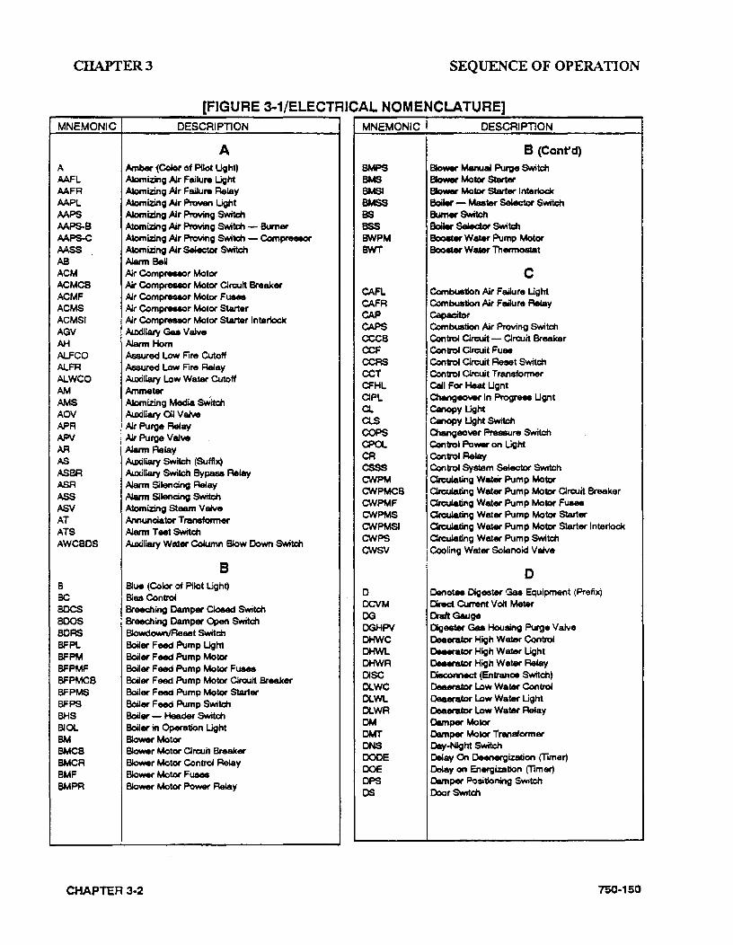
CHAPTER3 SEQUENCE OF OPERATION
r-------r-------.:[::....F....:.IG....:.U--R:.::E_:3-....:1.:..:/E=L=E.::.CT.:..:.RICAL NOM ENCLA TU RE] MNEMONIC DESCRIPTION MNEMONIC DESCRIPTION
A AAFL .AAFR AAPL AAPS AAPS--8 .AAPS-C AASS AS ACM ACMCS ACMF ACMS ACMSI AGV AH AL.FCO Al..FR AlWCO AM AMS AOV APR APV AR AS
ASBA ASR ASS AS>/ AT ATS AWCBOS
8 BC BOCS BOOS BCRS BFPL BFPM BFPMF BFPMCS BFPMS BFPS BHS BIOL BM BMCS BMCR BMF BMPR
A Amber 1Cdor of Pilot Ught) Alcmizing AJr Failure Light Alcmi.zing AJr Faiklre Relay Alcmizing AJr Proven Light Atcmlzing AJr Provi~ SwitA:I'I Alcmizing AJr Proving S>Mtd'l - Burner Atcmizing AJr Proving S>Mtd1 - Compreeeor Alcmiz:ing AJr SMctor Switch Alarm BeM AJr Compreseor Motor Air Compresaor Motor Circuit Breaker ~r Compresaor Motor Fusee Air Compreaaor Motor Starter ~r Compreeaor Motor Starter lntertoek A.uxillary Gu VaJve Alarm Hom Assured Low Fire CUtoff Assured Low Fire Relay Auxiltary Low Watl!ir Cutoff Ammetl!ir Atcmizing Media sWitcn Auxiltary Ctl v eJye
AJr Purge Relay Ail Purge v &lYe Alarm Relay Auxiltary Switch (Suffix) Auxiliary Switch Bypass Relay Alarm Silencing Relay Alarm Silencing Swttch Alcmiz:ing Steam VaJve Annundator Transfcrmer Alarm T erlt swnc:n Auxiltary Water Column Blow Down 5\l.titch
B Slue (Color of Pilot Light) Biaa Con~ Breecning Camper Cloeed Swttcn Breecning Camper Open Switch Slowdown/Reset Switcn BciJer Feed Pump Light Boiler Feed Pump Motor Boiler Feed Pump Motor Fusee BoiJer Feed Pump Motet Circuit Breaker Boiler Feed Pump Motor Starter Boiler Feed Pump Switch BciJ•- Header swnc:n BciJer in Operation Light Blower Motor Blower Motor Circuit Breaker Blower Motor Contro4 ~y Blower Motor Fusee Blower Motor Flower Reiay
CHAPTER 3-2
BMPS BMS eMS~ BMSS BS ass BWPM FNIT
CAA. CAFR CAP CAPS ceca CCF CCRS CCT CFHL OPL Cl ClS COPS CPOL CR csss C'NPM C'NPMCS CWPMF C'NPMS C'NPMSI C'NPS cwsv
0 OCVM OG OOHPV OHWC OHWL OHWR DISC r:x.wc Cll.WL Cll.WA OM OMT ONS OOCE DOE OPS OS
B (Confd) 8lo\wr Manu• Purge Switch Blower Motor Starter Slower Motor Starter lnterioc:k Bc:Nier - Master Seklct.or Switch Burner Switch Bc:Nier Selector Switch eoo.t. WafM Pump Motor eoo.ter WafM Thennostat
c Combustion AJr Failure Ught Combustion AJr Failure Relay Capacitor Combustion AJr Proving Switch Con~ Cln:uit- Circuit Breaker Controf Circuit Fuae Controf Cln:uit Reset Switcn Con~ OR::uit Transformer CaU For Heat Ught Changeo\W In Progreee Ught Canof:»yUght Canopy Light Switch Changeover Pressure Switch Control Power on Light Contro4 FleMly Controf System Selec1or Switch Crculating wat.er Pump Motor Orcula.ting Water Pump Motor Clrc:uit Breaker OrcuJating Water Pump Motor Fuaee OrcuJating Water Pump Motor Starter Crculadng Water Pump Motor Starter lntet1ock Orculating Water Pump Switch Cooling Water Solenoid VaJve
0 Denotes Oigestl!ir Gaa Equipment (Prefix) CMect Current VoH Meter Oratt Gauge [)geeter Gas Housing Purge Valve Oeaerator High Water Control Oeaerator High Water Light Deaetator High Water Relay Dieconnect (Entrance Switcn) Oeaerator Low WafM Control Deaerator Low Watar Ught Oeaerator Low Water Relay Camper Motet Damper Motet Transtormer Day-Night Switch Oe4ay On Oeenergization (1imer) o.May on Energization (1imer) Damper Flo:sitioning Switch Door s-wnc:n
750·150
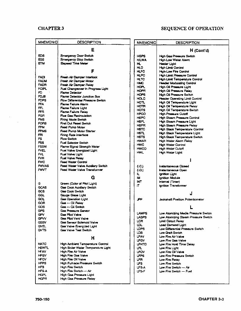
CHAPTER3 SEQUENCE OF OPERATION
MNEMONIC DESCRIPTION
E EDS Emergency Ooof' Switch ESS Emergency Stop Switch ETM 8apMd Time Meter
F FAOI Frean AJr Damper lnter1odc FADM Freeh. Ak Camper Motor FAOR Fteeh AJr Damper Ae4ay FCIPL Fuel Chengeowr In Prcgreu. Ught FD Flame Detector FDJS Aame Oetec::tor Jundion Box FOPS Flow Differential Preeaure Switch FFA Flame Failure AJatm FFl Aame Failure Ught FFR Flame F aiJure R.May FGA Flue Gas Recirculation FMS Firing Mode Switch FOAS Firat Out Reset Switch FPM Feed Pump Mo'&or FPMS Feed Pump Motor Starter FRI Firing Rate Interlace FS Flow Switch FSS Fua Selector Switch FSSM Aame ~gnal Strength Meter FVEL Fua V8Ne Energized Ught FVL Fuel Vaive Ught FVR Fua Vaive Relay F'NC Feed WatM Conirol FWVAS Feed WatM V8Ne Auxiliary Switch FWVT Feed Wafl!llf V8Ne Transformer
G G Green (Color of p;fot Ught) GCAS Gsa Cock Auxiliary Switch GCS Gaa Cock Switch GGL Gauge Glasa Ught OOL Gaa Operation Ught OOR Gaa- Oil Ae4ay GOS Gaa- Oil Switch GPS Gaa Presaure Senaor GPV Gsa Pilot vaNe GPW Gaa p;fot Vent Valve GSSV Gaa Seneor Solenctd V aJve GVEL Gaa Valve Energized Ught GVTS Gaa Valve Test Switch
H HATC Hgh Ambient Temperature Con1rol HSWTL Hgh Boiler WafM Temperature Ught HFAV Hgh Fire Air V e.Ne HFGV High Fire Gaa Vahle HFOV Hgh Fire 01 Ve.Ne HFPS Hgh Furnace Preaaure Switch HFS Hgh Fire Switch HFS-A Hgh Fire Switch - Air HGPL Hgh Gu Pressure Light HGPA Hgh Gu Pressure ~lay
750-150
MNEMONIC DESCRIPTION
HGPS HILWA H.. H..C H..FC H..PC H..TC HMO HOPl HOPA HOPS HOLC HOTL HOTA HOTS HPCO HSPC HSPL HSPA HSTC HSTL HSTS HWAA HWC HWCO HWL
o.c.) o.o.) IL IM INT rT
H (Cont'd) High Gaa Preeeute Switch Hgh Low Water Alarm HeaWUght High Umit Conirol 1-igtH.ow Fire Conirol High Umit Pree.Jre Control Hgh Limit Temperature Control Header Modulating Controt High OW Pree.Jre Ught Hgh Oil Preeeure Ae4ay High Oil Praeaure Switch Header Operating Umit Contro4 Hgh OW Temperawre Ught Hgh OW Temperature Relay Hgh Oil Temperature Switch High Preeaure Cutoff High Steam Preeaure Control Hgh Steam Presaure Ught High Steam Preaeure Relay High Stack Temperature Con1rol High Stack Temperature Ught High Stack Temperature Switch Hgh WatM Alarm Relay Hgh WatM Con1rol Hgh WatAr Cutoff High WatAr Ught
lnstantaneoua Cloaed lnatantaneoua Open lgrdticn Ught Ignition Module Interval (Timer) Ignition Transformer
J ..PP Jackahatt Position Potentiometer
LAMPS LASPS LCR LDL LOPS LOS LFAV LFGV LFHTO L.Ft. LFOV LFPS LFR LFS LFS-A LFS-F
L Low Atomizing Media Pressure Switch Low Atomizing S1eam Preaaure Switch Umit Circuit Relay Load Demand Light Low Differential Preaeure Switch Low Draft Switch Low Fire Air Valve Low Fire Gu Ve.ive Low Fire Hold 1ime Delay Low Fire Ught Low Fire Oil Valve Low Fire Prei!IISUre Switch Low Fire Relay Low Fire Switch Low Fire Switch - Air Low Fire Switch - Fuel
CHAPTER 3...J

CHAPTER3 SEQUENCE OF OPERATION
MNEMONIC DESCRIPTION MNEMONIC DESCRIPTION
L (Cont'd) M (Cont'd) LFS-G Low Fire Switd'l- Gu (M~ Mrlnual Aeelt LFS-0 Low Fire Switch - Oil MTC Modu&aung Temperature~ LFTC Low Fire Temperature Con~ WA Make-Up Valve Actuator LGPL Low Gaa Pre.ure Ught LGPR Low Gaa Preeeure Relay N LGPS Low Gaa Pre.uN Switch UAPS Low lnlltr'Urn.nt AJr Pr.eure Switch LLPC Low Umit Prealure Control LLPR Low Urnit Pre8lure Relay U..TC Low Umit Temperature Con~
N OenotM Natural Gaa Equipment (Prefix) (N.C.) NormaJiy CSoeed (N.C.) NomlaBy Opened NGHPV Na1Ur'al Gu Housing Purge Valve
U..TR Low Umit TemperatUre ReUay LOPl Low Oil Preuure Light 0 LOPR Low Oil Pressure Relay OCA Outa.t Camper Actuator LOPS Low Oil Preuure Switd'l · OOM Outa.t Camper Mot« LOTL Low Oil Temperature Light COMAS CutJet Camper Motor Auxiliary Switch LOTR Low Oil Temperature Relay OOMT OutJet Camper Motor Transtcnner LOTS Low Oil Temperature Switch ocs 011 Drawer Switch LPAPS Low Pfant IW Pressure Switch OH Oil Heater LPCO Low Pre881.1At Cutoff OHCS Oil Heater Orcuit Breaker LPS Low Preaaure Switch OHF 01 Heatl!lr Fusee LSPC Low Steam Preeaunt Con~ OHR Oil Heater Relay LSPL Low Steam Pressure Light OHS Oil Heater Switch LSPS Low Steam Presaure Switch OHT 01 Heater Thennoatat LTS Lamp Teet Switch OLC Operating Limit Control LWA Low WatM Alarm OLPC Operating Umit Preaaure Control LWAR Low Wafllr Alarm Relay OL'S Thermal Overtoade LWCO Low WatM Cutoff OLTC Operating Umit Temperature Control LWFL Low Wafllit Flow Light <XX.. Ol~tionUght LWL Low WatM Ught ('.)PM 01 Pump Motor LWA Low WatM Relay OPMCB 01 Pump Motor CRuit Breaker LWRR Low WatM Reeet ANy OPMF 011 Pump Motor Fuaee
M ('.)PI\.tS 01 Pump Motor Starter OPPM 011 Purge Pump Motor
MA Milll....amp MAS ManuaJ - Automatic Switch MAM Mic:roammeter MC Moclulatlng Control MCS Manual Control Switch MJM Moclulating Camper Motor ~MAS Moclulatlng Camper Motor Auxiliary Switch MFC ManuaJ Flame Con~ (Potentiometsr) ~L Main Fuel VaJve Ught WFW\1 Motorized Feed Watl!lr Vakve PNJV Main GM Valve PNJVAS Main GM Valve Au:ldliary Switch MGVEl Main GM Valve Energized Ught PNJW Main Gaa Vent Valve
OPR 01 Purge Relay OPRL 01 Pump Running Ught OPRS 01 Preeaure Sensor OPS 01 Pump Switch OPSPM 01 Pilot Supply Pump Motor OPV 01 Purge VaJve OFN Ql Aetum Valve OSCN 01 Shutoff Valve oss 01 Selector Switd'l OT Outdocr Thermostat OTS 01 Temperature Sensor CN OIIVatve CNAS 01 V&Ne Auxiliary Switch CNEl 01 V&Ne Energized Ught
""-.C Moclulatlng Levet Control (MC.)M) Momentary ~v Main Oil Valve ~VAS Main Oil Valve Auxiliary Switch ~VEL Main Oil- Valw Energized Light MPC Moclulating Pressure Control MPCS Main Power Circuit Breaker ~p ManuaJ Positioning Potentiometer
CHAPTER 3-4 750·150
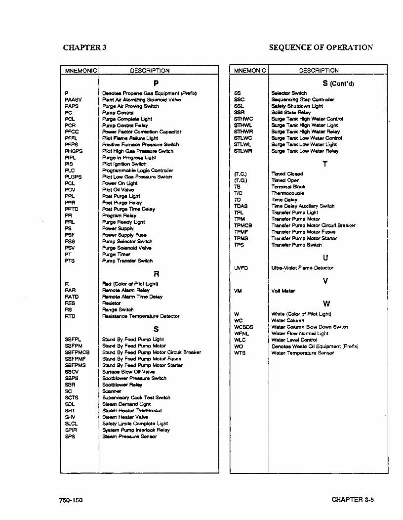
CHAPTER3 SEQUENCE OF OPERATION
MNEMONIC DESCRIPTION MNEMONIC DESCRI Pll ON
p S (Cont'd) p Denote. Propene Gas Equipment (Prefile) ss S.Mtdor Switch PAASV Rant Ak Atomizing Sdenotd Valve sse Sequencing Step Controller PAPS Purge AJI Pro~ Switch SSl Safety Shutdown Light PC Pump Con11'01 SSR Solid Stat. Relay PCL Purge Complete ~t STHWC Surge Tank High Water C4ntrol PCR Pump Contro4 ReM!y STHWL Surge Tank High Water Light PFCC Power Fec:tor Correction Capacitor STHWR Surge Tank High Water Relay PFFL Pilot Flame Failure Light sn.wc Surge Tank Low Water Contro4 PFPS Politlw Furnace Preeaure Switch STl..Wl Surge Tank Low Water Ught PHGPS Pilot High Gas Preeaure Switch STl..WR Surge Tank low Watsr Relay P1Pl Purge in Progreee Ught P1S Pilot Ignition Switch T PLC Programmable Logic Controller PLGPS Pilot low Gas PT'eeaure Swftcn POl Power On Ught POV Pilot Oil Valw PPL Poet Purge Ught PPR Poet Purge ReM!y PPTO Post Purge lime Delay PR Program Relay PRL Purge Ready Ught PS Power Supply PSF Power Supply Fuse PSS Pump Selector Switch PSN Purge So4enoid Valw
(T.C.) limed Ooeed (T.O.) Tmed Open T8 T enninal Block T/C 'Thennocouple TO lime Delay TOAS Ttme Delay Auxiliary Switch TPL Transfer Pump Light TPM Transfer Pump MotOf TPMCB Transfer Pump MotOf Circuit Breaker TPMF Transfer Pump MotOf Fusee TPMS · Transfer Pump MotOf Starter TPS . Transfer Pump Switch
PT Purgelimer FTS Pump Transfer Switch u
lNFO Utra-Violet Flame Detector R
R Red (Color of Pilot Ught) v RAR Remote Alarm Relay VM Volt Meter AATO Remote Alarm rme Delay RES Resistor w RS Range Switc:n RTO Ae&Jatance Temperature Deted:Of w White (C41or of Pilot Light)
we Water C41umn
s WCBDS Wawr Column Blow Down Switch WFNL Water Flow Normal Ught
SBFPL Stand BY Feed Pump Ught WLC Water level Control SBFPM Stand By Feed Pump Motor wo OenotAIS Waat4 Oil Equipment (Prefix) SBFPMCB Stand By Feed Pump Motor Ciroutt Breaker WTS wau,r Temperature Sensor SBFPMF Stand By Feed Pump Motor Fusee SBFPMS Stand By Feed Pump Motor Starter SBOV Surlace ~ow OH Valve SBPS Sootblower Pree8w'e Switch SBR Sootblower Relay sc Scanner SCTS SupeNieoty Cock Test Swttc:n SOL Steam Demand Ught SHT Steam Heater Thennostat SHV Steam Heater Valve SLCL Setety Limits Complete Light SPIR System Pump lnteriock Relay SPS Steam Presll.ure Senaor
750 .. 150 CHAPTER 3...S
CHAPTERJ
• All applicable limits are correct for the burner operation.
• The load demand light glows.
All entrance switches are closed and the power is present at the line terminals of:
-Blower motor starter
-Air compressor motor starter (if provided)
-Oil heater relay (if provided)
~il pump motor starter (if provided)
These sequences do not attempt to correlate the action of the fuel supply system or feedwater system except for the interlock controls that directly relate to the action of the program relay. Chapters 4 a_nd 5 contain operating instructions and specific information on setting and adjusting the controls.
B. CIRCUIT AND INTERLOCK CONTROLS
The burner control circuit is a two-wire system designed for 115 volt, single phase, 60Hz, alternating current.
The electrical portion of the boiler is made up of individual circuits with controls that are wired in a manner designed to provide a safe workable system. The program relay provides connection points for the interconnection of these various circuits.
CHAPTER 3-6
SEQUENCE OF OPERATION
The controls used vary depending upon the fuel - oil or gas - and the specific requirement of applicable regulatory bodies. Refer to the boiler wiring diagram to determine the actual controls provided. The circuits and controls normally used in these circuits are listed below and referred to in the following sequence of operation.
Limit Circuit:
• Burner switch (BS)
• Operating limit control (OLC)- pressure or temperature
• High limit control (HLC) - pressure or temperature
• Low water cut-off (LWCO)
• Gas-oil selector switch (GOS) - (Com· bination burner only)
• Oil drawer switch (ODS) - Oil burner
• Low oil temperature switch (LOTS)(No. 5 and 6 oil only)
• Low gas pressure switch (LGPS)
• High gas pressure switch (HGPS)
• Fuel Valve Interlock Circuit
• Main gas valve auxiliary switch ~GVAS)
Oil valve auxiliary switch (OV AS)
Blower Motor Start Circuit
• Blower motor starter (BMS)
Air compressor motor starter (ACMS) (if provided)
Air purge valve (APV) (No. 5 or 6 oil only)
750-150

CHAPTER3
Running Interlock Circuit
• Blower motor starter interlock (BMSI)
• Combustion air proving switch (CAPS)
Atomizing air proving switch (AAPS) (if provided)
Low Fire Proving Circuit
• Low frre switch (LFS)
Pilot Ignition Circuit
Gas pilot valve (GPV)
• Ignition transfonner (I1)
Gas pilot vent valve (GPVV) (if provided)
Flame Detector Circuit
Flame Detector (FD)
Main Fuel Valve Circuit
• Main gas valve (M:GV)
• Main gas vent valve (M:GVV) (if provided)
• Oil valve (OV)
Main fuel valve light (FVL)
Firing Rate Circuit
Damper motor transfonner (DMT)
Modulating damper motor (MOM)
Manual·automatic switch (MAS)
Manual flame control (MFC)
750-150
SEQUENCE OF OPERATION
• Modulating control (MC) To comply with requirements of insurance underwriters such as Factory Mutual (F.M.), Industrial Risk Insurers (I. R.I.) or others, additional interlock devices may be used in addition to those mentioned above.
High Fire Proving Circuit
• High fire switch (HFS)
Running Interlock and Limit Circuit
• Low oil pressure switch (LOPS)
High oil pressure switch (HOPS)
• High oil temperature switch (HOTS)
• Auxiliary low water cutoff (AL WCO)
C. SEQUENCE OF OPERATION - OIL. OR GAS
On a combination fuel unit, the gas/oil switch must be set for the proper fuel.
The following sequence occurs with power present at the program relay (PR) input tenninals and with all other operating conditions satisfied:
Pre-Purge Cycle - When the burner switch (BS) is turned "on," and controls wired in the "limit" and "fuel valve interlock" circuits are closed and no flame signal is present, the "blower motor start circuit" is powered energizing the blower motor starter (BMS). The load demand light (LDL) turns on. When firing oil, the air compressor motor starter (ACMS) (if provided) is also powered. The air purge valve (APV) (No. 5 and 6 oil only) remains de..energized.
At the same time, the program relay signals the modulating damper motor (MOM) to open the air damper. The damper begins to open and drives
CHAPTER 3-7
CHAPTER3
to its full open or high fire position. This allows a flow of purging air through the boiler prior to the ignition cycle.
On certain boilers the circuitry will include a high fire switch (HFS). The purpose of this switch is to prove that the modulating damper motor (MOM) has driven the damper to the open position during the pre-purge cycle. In this instance, the "high fire proving circuit" is utilized.
The controls wired into the "running. interlock circuit" must be closed within 10 seconds after the start sequence. In the event any of these controls are not closed at this time, or if they subsequently open, the program relay will go into a safety shutdown.
At the completion ofthe high flre purge period, the program relay signals the modulating damper motor (MDM) to drive the air damper to its low fire position.
To assure that the system is in low fire position prior to ignition, the low fire switch (LFS) must be closed to complete the "low fire proving cir .. cui t." The sequence will stop and hold until the modulating damper motor (MDM) has returned to the low fire position and the contacts of the low fire switch (LFS) are closed. Once the low fire switch is closed, the sequence is allowed to continue.
NOTE: The ignition trial cannot be started if flame or a flame simulating condition is sensed during the pre-purge period. A safety shutdown will occur if the flame is sensed at this time.
Ignition Cycle - The ignition transformer (IT) and gas pilot valve (GPV) are energized from the appropriate pilot ignition terminal.
NOTE: An oil-fired burner may be equipped with an oil pilot rather than a gas pilot .. The ignition sequence of both is identical.
CHAPTER 3--8
SEQUENCE OF OPERATION
The pilot flame must be established and proven by the flame detector (FD) within a 10 second period in order for the ignition cycle to continue. If for any reason this does not happen, the system will shut down and safety lockout will occur.
NOTE: Depending upon the requirements of the regulatory body, insurer or fuel being burned, either the 10 or 15 second pilot ignition terminal may be used. Both provide the same function but differ in the time interval allowed for proving main flame ignition. Refer to the boiler wiring diagram.
With a proven pilot, the main fuel valve(s) (OV or MGV) is energized and the main fuel valve light (FVL) in the panel is lighted. The main flame is ignited and the trial period for proving the main flame begins. It lasts 10 seconds for light oil and natural gas, and 15 seconds for heavy oil. At the end of the proving period, if the flame detector still detects main flame, the ignition transformer and pilot valve are de-energized and the pilot flame is extinguished.
NOTE: If the main flame does not light, or stay lit, the fuel valve will close. The safety switch will trip to lockout the control. Refer to flame loss sequence section for description of action.
!WARNING The cause for loss of flame or any other unusual condition should be Investigated and corrected before attempting to restart. Failure to do so may result In serious personal Injury or death.
Run Cycle- With main flame established, the program relay releases the modulating damper motor (MDM) from its low fire position to control by either the manual flame control (14FC) or
75()..150
CHAPTER3
the modulating control (MC) depending upon the position of the manual-automatic switch (MAS). This allows operation above low fire.
With the manual-automatic switch (MAS) set at automatic, subsequent modulated firing will be at the command of the modulating control (MC) which governs the position of the modulating damper motor (MDM). The air damper and the fuel valve(s) are actuated by the motor through a linkage and cam assembly to provide modulated firing rates.
NOTE: Normal operation of the burner should be with the switch in the manual-automatic position and under the direction of the modulating control. The manual position is provided for initial adjustment of the burner over the entire fll'ing range. When a shutdown occurs while operating in the manual position at other than low fll'e, the damper will not be in a closed position thus allowing more air than desired to flow through the boiler~ This subjects the pressure vessel metal and refractory to undesirable conditions. The effectiveness of nozzle purging is lost on a No.6 oil fired burner.
This is the end of the burner starting cycle. The (LDL) and (FVL) lights on the panel remain lit. Demand firing continues as required by load conditions.
Burner Shut,;.Down Post Purge - The burner will fire until steam pressure or water temperature in excess of demand is generated. With modulated fll'ing, the modulating damper motor (MDM) should return to the low fire position before the operating limit control (OLC) opens. When the limit control circuit is opened, the following sequence occurs:
The main fuel valve circuit is de-energized causing the main fuel valve (MGV) or (OV) to close. The flame is extinguished. The control panel
750·150
SEQUENCE OF OPERATION
lights (LDL) and (FVL) are turned off. The blower motor continues to run to force air through the boiler for the post purge period.
On a No. 6 oil fired burner, the air purge valve (APV) is powered from the blower motor start circuit via the contacts of the air purge relay (APR) to provide an air purge of the oil nozzle. The damper motor returns to the low fire position if it is not already in that position.
The blower motor start circuit is de-energized at the end of the post purge cycle and the shutdown cycle is complete.
The program relay now is in readiness for subsequent recycling and, when steam pressure or water temperature drops sufficiently to close the contacts of the operating control, the burner again goes through its normal starting and operat· ing cycle.
D. FLAME LOSS SEQUENCE
The program relay will recycle automatically each time the operating control closes or after a power failure. It will lockout following a safety shutdown caused by failure to ignite the pilot, or the main flame, or by loss of flame. Lockout will also occur if a flame or a flame simulating condition occurs during the pre-pu~ge period.
The control will prevent start-up or ignition if the limit circuit controls or the fuel valve interlocks are open. The control will lockout upon any abnormal condition affecting air supervisory eontrols wired in the running interlock circuit.
CHAPTER 3·9
CIIAPTER3
CAUTION! The lockout switch must be manually reset following a safety shutdown.The cause for loss of flame or any unusual condition should be lnvestlg~ted and corrected before attempting to restart In order to avoid damage to the equipment.
(1) No pilot flame.
The pilot flame must be ignited and proven within a 1 0-second period after the ignition cycle begins. If not proven within this period, the main fuel valve circuit will not be powered and the fuel valve(s) will not be energized. The igni • tion circuit is inuilediately de--energized and the pilot valve closes. The reset switch lights and lockout occurs immedi· ately.
The blower motor will continue to operate. The flame failure light and the alarm bell (optional) are energized 10 seconds later.
The blower motor will be de--energized. The lockout switch must be manually reset before operation can be resumed. (Refer to the previous caution.)
(2) Pilot but no main flame.
When the pilot flame is proven, the main fuel valve circuit is energized. Depending upon the length of the trial-for-ignition period, the pilot flame will be extin-
CHAPTER 3-10
SEQUENCE OF OPERATION
guished 10 or 15 seconds later. The flame detecting circuit will respond to de-energize the main fuel valve circuit within 2 to 4 seconds to stop the flow of fuel. The reset switch lights and lockout occurs immediately. The blower motor will continue to operate.
The flame failure light and alarm bell (optional) are energized 10 seconds later.
The blower motor will be de-energized. The lockout switch must be manually reset before operation can be resumed. (Refer to the previous caution.)
(3) Loss of flame.
If a flame outage occurs during nonnal operation and/or the flame is no longer sensed by the detector, the flame relay will trip within 2 to 4 seconds to de-energize the fuel valve circuit and shut off the fuel flow. The reset switch lights and lockout occurs immediately. The blower motor continues operation. The flame failure light and alarm bell (optional) are energized 10 seconds later.
The blower motor will be de-energized. The lockout switch must be manually reset before operation can be resumed. (Refer to the previous caution.)
If the burner will not start, or upon a safety lockout, the trouble shooting section in the operating manual and the technical bulletin should be referred to for assistance in pinpointing problems that may not be readily apparent.
750-150
CHAPTER3
Most program relays have the capability to self diagnose and to display a code or message that indicates the failure condi .. tion. Refer to the control bulletin for specifics and suggested remedies. Familiarity with the program relay and other controls in the system can be obtained by studying the contents of the manual and this bulletin.
Knowledge of the system and its controls will make troubleshooting much easier in the event it is necessary. Costly down · time or delays can be prevented by systematic checks of the actual operation against the normal sequence to determine the stage at which performance deviates from normal. Following a routine may
750-150
SEQUENCE OF OPERATION
possibly eliminate overlooking an obvious condition, often one that is relative~ ly simple to correct.
Remember that this is a safety device and for the most part it is doing its job when it shuts down or refuses to operate. ~ attempt to circumvent any of the safety features.
Preventive maintenance and scheduled inspection of all comJX>nents should be followed. Periodic checking of the relay to see that a safety lockout will occur under conditions of failure to ignite either pilot of main flame or from loss of flame is recommended.
CHAPTER 3-11

CHAPTER4 STARTING AND OPERATlNG INSTRUCTIONS
CHAPTER 4
STARTING AND OPERATING INSTRUCTIONS
A. General Rreparation for Start-up - All Fuels B. Control Settings - Steam and Hot Water C. Gas Pilot D. Atomizing Air E. _Firing Preparations for No.2 Oil (Series 100-200) F. Firing Preparations for No. 6 Oil (Series 400-600) G. Firing Preparations for Gas (Series 200-400-700) H. Start-up, Operating and Shutdown - All Fuels I. Control Operational Tests and Checks
NOTE: If your boiler is equipped with a CB-HA WKTM boiler management control system, refer to CBHA WK Installation, Operating, and Servicing Manual No. 750-133 for specific information regarding procedures described in this section.
A. GENERAL PREPARATION
FOR START-UP -ALL FUELS
Instructions in this chapter assume that installation is complete and that all electrical, fuel, water and vent stack connections have been made.
The operator should be familiar with the burner, boiler, and all controls and components. To quickly locate and identify the various controls
750 .. 150
and components mentioned in the following paragraphs, refer to call-out photographs and the contents of Chapter 1. Adjustment of the major components are given in Chapter 5 and this should be reviewed prior to frring. The wiring diagram should also have been studied, along with the sequence in Chapter 3.
!WARNING It Is recommended that these starting Instructions be read through completely until they are thoroughly understood, before attempting to operate the boiler, rather than performing each operation as it is read for the first time. Failure to heed this warning could result in serious personal injury or death.
Verify the supply of fuel and the proper voltage. Check for blown fuses, open circuit breakers, dropped out overloads, etc. Check reset of all
CHAPTER 4-1
CHAPTER4 STARTING AND OPERATING INSTRUCfiONS
starters and controls having manual reset features. Check the lockout switch on the program· mer and reset if necessary.
The boiler should be filled with water to the proper operating level using water of ambient temperature. Make sure that treated feedwater is available and used .. In heating applications, the entire system should be filled and vented. Refer to Chapter 2 for water requirements. On a steam boiler, open the test valve (Fig. 1-1) to vent air displaced during filling. Leave the test valve open until the escape of steam is noted after the burner is operating.
CAUTION! Prior to firing a boiler, make sure that the discharge piping from the safety valves or the relief valves, and the discharge piping from all the blowdown and drain valves are ·piped to a SAFE point of discharge, so that emission of hot water or steam ·cannot possibly cause serious personal Injury or death to personnel or damage to property.
Check all linkage for full and free movement of the damper and metering valves and cams. This can be done by loosening the linkage at the damper motor connecting arm and manipulating the linkage by hand.
Check for rotation of all motors by momentarily closing the motor starter or relay. The blower impeller rotation is counter-clockwise when viewed from the front of the boiler. Air pump rotation is clockwise when viewed from its drive end.
Before operating the boiler feed pump or oil supply pump, be sure all the valves in the line are open or properly positioned.
CHAPTER 4-2
For safety's sake, make a final pre~start-up inspection, especially checking for any loose or incomplete piping or wiring or any other situations that might present a hazard.
CAUTION! Note that the pressure vessel support legs are welded to mounting skids In front and secured by bolts at the rear of the pressure vessel. These bolts are tightened for ship· ment. When the boiler Is installed, and prior to initial firing, the bolts securing the rear legs to the skid must be loosened to allow for expansion and contraction caused by differences In temperature between pres-
. sure vessel and skids and avoid damage to the equipment.
B. CONTROL SETTINGS -STEAM AND HOT WATER
See Chapter 5 for adjustment instructions for the following controls.
Inspect operating limit control for proper setting.
(1) The pressure control of a steam boiler should be set slightly above the highest desired steam pressure, but at least 10% lower than the setting of the safety valve.
(2) The temperature control on a hot water boiler should be set slightly above the highest desired water temperature but within the limits of the pressure vessel.
Inspect the high limit control for the proper setting.
750-150
CHAPTER4 SfARTING AND OPERATING INSTRUCfiONS
(1) On a high pressure steam boiler, this control should be set approximately 10 lbs. above the operating limit pressure control setting, if feasible, or midway between the operating limit pressure and safety valve setting. The setting on a low pressure steam boiler may be 2 or 3 lbs. above the operating limit setting, but must not exceed the safety valve setting.
(2) On a hot water boiler, the high limit temperature control should be 5-10• above the operating limit temperature control setting, but within the limits of the design pressure of the pressure vessel.
Inspect the modulating control for proper setting. This control must be set and adjusted so that the modulating motor returns to low fire position before the operating limit control opens. It is further desirable to have its low point setting somewhat below the cut-in setting of the limit control so that burner operates in low fire position for a brief period on each start rather than immediately driving to a high fire position.
NOTE: The settings of all the above controls may require some readjustment after the boiler is started and running for a short period. The scale settings on the controls are relatively accurate, but principally are for use as guides. Final adjustment should be based on and agree with the reading of the steam pressure gauge or the water temperature thermometer.
Inspect the low water cut-off and pump control as well as the auxiliary low water cut-off (if equipped with this optional device). Normally, no adjustment is required since these controls are pre-set by the original manufacturer. Check for freedom of float movement. Float movement can be verified by observing the level of water in the gauge glass when the water supply has been cut off either by lhe stopping of the feed pump or by
750-150
the closing of a valve, and the restarting of the pump or opening of the valve when water is drained from the pressure vessel. The importance of proper functioning of low water controls cannot be over-emphasized. Make sure that the control and the piping are level.
The settings of controls relating to fuel, either oil or gas, are covered in subsequent sections.
In the event the boiler is equipped with optional control devices not listed here, be certain to ascertain that their settings are correct. If additional information if required, see your Cleaver-Brooks local representative or contact Cleaver-Brooks.
On initial start-up or whenever the boiler is placed into operation from a "cold" start, the manual-automatic selector switch should be set at "manual" and the manual flame control set at "close." After the boiler is in operation and thoroughly warmed, the selector switch should be turned to "automatic,".so that the burner firing rate may be controlled by the modulating control in accordance with load demands.
aose all power entrance switches (supplied by others).
C. GAS PILOT
The gas pilot should be checked for satisfactory performance prior to initial firing. Follow the pilot flame adjustment instructions given in Chapter 5.
On initial starting attempts, several efforts might be required to accomplish bleeding time of pilot line. While checking the pilot adjustment, observe whether the pilot flame is extinguished promptly when the burner switch is opened. A lingering flame is indicative of a leaking gas pilot valve and a condition requiring correction before proceeding.
CHAPTER 4-3
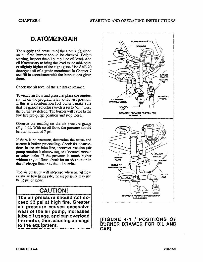
CHAPTER4 STARTING AND OPERATING INSTRUCfiONS
D. ATOMIZING AIR
The supply and pressure of the atomizin'g air on an oil fired burner should be checked. Before starting, inspect the oil pump lube oil level. Add oil if necessary to bring the level to the mid-point or slightly higher of the sight glass. Use SAE 20 detergent oil of a grade mentioned in Chapter 7 and fill in accordance with the instructions given there.
Check the oil level of the air intake strainer.
To verify air flow and pressure, place the run/test switch on the program relay to the test position. If this is a combination fuel burner, make sure that the gas/oil selector switch is set to "oil." Tum the burner switch on. The burner will cycle to the low fire pre-purge position and stop there.
Observe the readmg on the air pressure gauge (Fig. 4-1). With no oil flow, the pressure should be a minimum of 7 psi.
If there is no pressure, determine the cause and correct it before proceeding. Check for obstruc· tions in the air inlet line, incorrect rotation (air pump rotation is clockwise), or a loose oil nozzle or other leaks. If the pressure is much higher without any oil flow, check for an obstruction·in the discharge line or at the oil nozzle.
The air pressure will increase when an oil flow exists. At low firing rate, the air pressure may rise to 12 psi or more.
CAUTION! The air pressure should not exceed 30 psi at high fire. Greater air pressure causes excessive wear of the air pump, Increases lube oil usage, and can overload the motor, thus causing damage to the equipment.
CHAPTER4-4
FUB.OIL UNE
0RAweA IN FOFIWAFIO POSITION FOR EI.IRNING OIL
OAAWER IN REAFIWAAD POSITION ~ EI.IRNING GAS
[FIGURE 4-1 I POSITIONS OF BURNER DRAWER FOR OIL AND GAS]
750-150
CHAPTER4 STARTING AND OPERATING INSTRUCfiONS
NOTE: Abnormally high pressure indicated on the nozzle air pr~ure gauge is an indication that the burner nozzle has become clogged. In this event, check the nozzle and clean as n~ary.
After the air flow has been verified, tum the burner switch off and return the run/test switch to the run position.
E. FIRING PREPARATIONS FORN0.201L
(SERIES 1 00-200)
Prior to initial firing, oil flow and pressure should be established and verified. Atomizing air pressure should also be established as outlined in Section D. The schematic flow diagram (Fig. 1-11) indicates the flow of fuel and atomizing air.
. If the burner is a combination fuel mOdel, make certain that the main gas shut-off cock is closed and set the gas/oil selector switch to "oil." Insert the burner drawer gun . into its most forward position and latch it in place (see Fig. 4-1).
Oil Flow- Open all valves in the oil suction and oil return lines.
If the oil supply tank is located above the level of the pump and flow to the pump is by gravity, then it usually will be necessary to vent the suction line to allow oil to fill the line. This generally can be accomplished by cracking a union fitting, or by opening the cap of the oil strainer using care to prevent spillage of oil. Tighten fitting or cap as soon as oil flow appears.
If the oil supply tank is below the level of oil pump, it is MANDATORY that the suction line to the pump must be completely filled with oil prior to starting the pump to avoid the possibility of damage to the pump gears through operation
750-150
without the lubrication afforded by the fuel oil. Non-lubricating fluids such as kerosene should not be used for priming.
Prior to priming the suction line and the initial start, check to make certain that all plugs, connections, etc., have been securely tightened to prevent leaks.
If the fuel oil supply originates from a pressurized loop, it is assumed that the pressure of the loop will be at a minimum of 75 psi. Boilers would not then have individual pumps furnished as standard equipment Under these conditions, the relief valve at the terminal block should be adjusted to the point where it becomes inoperative.
A standard equipped boiler has a selector switch incorporated in the oil pump motor starter. Momentarily energize the starter to check for proper pump rotation. With the rotation verified, operate the pump to determine that oil circulation exists. Observe the oil burner pressure gauge for ·indication that flow is established. If no pressure shows on this gaug~ after a few moments, stop the oil pump· and re-prime. If the supply tank is lower than the pump, it is possible that the initial priming of the suction line, followed by operation of the pump, will not eStablish oil flow. This might be caused by obstruction in the suction line, excessive lift, inadequate priming, suction line leaks, etc. If the oil flow is not read i1 y established, avoid prolonged operation of the pump to minimize risk of damage to internal parts of the pump.lftheoil flow is not established after a second or third priming attempt, a full investigation is required to determine the cause.
A vacuum (or a compound pressure-vacuum) gauge should be installed at the suction port of the pump and its reading observed and recorded for future guidance. If a vacuum condition exists, this reading will reveal the tightness of the sys· tem. It is advisable to maintain the vacuum reading at less than 10" W.C. A vacuum in excess of this may allow oil to vaporize causing cavitation, loss of prime, and an unstable firing condition.
CHAPTER 4..S
CHAPTER4 STARTING AND OPERATING INSTRUCfiONS
Oil Pressure- Oil supply pressure is regulated by adjusting the pressure relief valve at the oil terminal block (Fig. 1-1). A pressure gauge should be installed in the terminal block and the relief valve adjusted to obtain a minimum read· ing of 75 psi when the burner is flring at maximum rate.
When oil is supplied from a pressurized loop to a multiple boiler installation, the relief valve in the loop should be properly adjusted to provide this reading. In this circumstance, the relief valve at the terminal block should be adjusted to the point where it will be inoperative (or removed and openings plugged). To render the valve inoperative, tum the adjusting screw in as far as possible. ·
Adjustment may also be required to the regulator on the fuel oil controller (Fig. 1-5). This pressure regulating valve is equipped with tubing that directs and adds atomizing air pressure to the adjustable spring pressure. Since the atomizing air pump is not running at this time, only tentative adjustment can be made. Without this air supply, adjust the fuel oil pressure regulator so that the oil burner gauge registers approximately 35 psi.
The pressure will be higher when the flame is present, and will increase as the firing rate increases. After the burner is firing and when the air pump is running, final adjustment can be made at the fuel oil controller.
Final regulation of the oil flow to the nozzle can be done later, if necessary, by adjusting the metering cam screws as outlined in Chapter 5.
Suggested oil pressures at high fire operation:
Oil Supply at the Fuel Oil Controller . . . 75 psi
Oil Burner Pressure Guage . . . . .30-45 psi
CHAPTER4-6
Starting - When all the conditions covered above and in Sections A, B, C and D are assured, the burner is ready for firing. Refer to Section H ?f this c~apter for funher starting and operating mfortnation.
F. FIRING PREPARATION FORNO. SOIL
(SERIES 400-600)
Prior to initial firing, the oil flow, pressure, and temperature should be established and verified. The atomizing air pressure should also be established as outlined in Section D. The schematic flow diagram (Fig.1-12) indicates the flow of fuel and atomizing air.
If the boiler is a combination fuel model, make certain that the main gas· shut-off cock is closed and set the gas/oil selector switch to "oil." Insert the burnet drawer gun into its most forward position and latch it in place (see Fig. 4-1).
Oil Flow- Open all valves in the oil suction and oil return lines. Open the by-pass valve on the fuel oil controller (Fig. 1..6) until the oil flow is established. Nonnally, the orifice valve is left in a closed position. However, on cold starts, it may be opened for brief periods to aid in establishing oil flow. The by-pass and orifice valves must be returned to a closed position as soon as proper oil flow is established as indicated by a reading on the oil supply pressure gauge (Figs. 1-2 and 1..S). Do not attempt to set pressures while these valves are open.
Momentarily energize the fuel oil pump starter to check for proper pump rotation. With the rotation verified, prime the suction line strainer with oil and start the fuel oil pump by closing its power entrance switch. Observe the oil supply pressure gauge for indication that oil flow is established. If no pressure shows on gauge after a few moments, stop the oil pump and re-prime. Heavy oil in the storage tank must be at a temperature to provide oil viscosity to permit flow through the oil pump and suction line. If oil flow is not
750-150
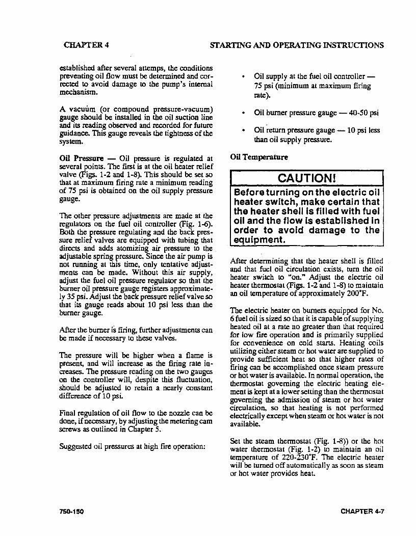
CHAPTER4 STARTING AND OPERATING INSTRUCfiONS
establis~ed a;fter several attemps, the conditions preventing oil flow must be determined and corrected ~ avoid damage to the pump's internal mechaniSm.
A vacuum (or ~ompound pressure-vacuum) gauge should be mstalled in the oil suction line and its reading observed and recorded for future guidance. This gauge reveals the tightness of the system.
On P~re - Oil pressure is regulated at several points. The first is at the oil heater relief valve (Figs. 1-2 and 1-8). This should be set so that at maximum firing rate a minimum reading of 75 psi is obtained on the oil supply pressure gauge.
The other pressure adjustments are made at the regulators on the fuel oil controller (Fig. 1-6). Both th~ pressure regulat~ng and the back pres· s~re rehef valves are equipped with tubing that di~ts and a~ds atomizing air pressure to the adjustabl~ spnng pr~ure. Since the air pump is not runnmg at th1s time, only tentative adjustments can be made. Without this air supply adjust th~ fuel oil pressure regulator so that th~ burner ~II p~ure gauge registers approximately 3S.pst. AdJUSt the back pressure relief valve so that Its gauge reads about 10 psi less than the burner gauge.
After the burner is firing, further adjustments can be made if necessary to these valves.
The pressure will be higher when a flame is present, and will increase as the firing rate increases. The pressure re~ding on the two gauges on the controller will, despite this fluctuation should be adjusted to retain a nearly constant difference of 10 psi.
Final regulation of oil flow to the nozzle can be done, if necessary, by adjusting the metering cam screws as outlined in Chapter S.
Suggested oil pressures at high fire operation:
750-150
•
•
•
Oil supply at the fuel oil controller -75 psi (minimum at maximum firing rate).
Oil burner pressure gauge - 40-SO psi
Oil return pressure gauge - 10 psi less than oil supply pressure.
on Temperature
CAUTION! Before turning on the electric oil heater switch, make certain that the heater shell is filled with fuel oil and the flow Is established in order to avoid damage to the equipment.
After determining that the heater shell is filled and that fuel oil circulation exists, tum the oil heater switch to "on." Adjust the electric oil hea~r thermostat (Figs. 1-2 and 1-8) to maintain an od temperature of approximately 200°F.
The electric heater on burners equipped for No. 6 fuel oil. is sized so that it is capable of supplying heated ml at a rate no greater than that required for low fue. operation and is primarily supplied fo~. C?nve~:uence on cold starts. Heating coils utllt~tng etther.steam or hot water are supplied to provide suffictent heat so that higher rates of firing can he: acco~plished once steam pressure or hot water IS available. In normal operation, the thermostat governing the electric heating element is kept at a lower setting than the thermostat governing the admission of steam or hot water circul~tion, so that heating is not performed electncally except when steam or hot water is not available.
Set the steam thermostat (Fig. 1-8)) or the hot water thermostat (Fig. 1-2) to maintain an oil temperature of 220·230°F. The electric heater will be turned off automatically as soon as steam or hot water provides heat.
CHAPTER 4-7
CHAPTER4 SI' ARTING AND OPERATING INSTRUCfiONS
NOTE: The temperatures listed are tentative. The composition of the fuel oil in a given grade can vary necessitating a higher or lower preheating temperature. The vis .. cosity of the oil at the nozzle should be less than 300 SSU and preferably less than 150 SSU. The actual temperature of the oil at the burner should be determined by flame appearance and good combustion based on a stack analysis. See Chapter 5 for additional information.
aose the manual by-pass valve after temperature rise on the fuel oil controller thermometer is noted. Make certain that hot oil is moving through the controller. The orifice gate valve must ~lso be closed. If te~pe~ture drops, open the onfice gate valve unul a nse is noted then close it. · '
Once the correct setting of the heater thermostats h~ been ~tablished, set the low oil temperature SWitch (Ftgs. 1-2 and 1-8) at a point approximate· ly 30• lower than the normal operating temperature. H the system is equipped with a high oil te~per:tu!e switch, this should be set to open at 20 -30 higher than normal operating temperature.
Starting - When all the conditions covered above and in Sections A, B, C and D are assured the b~mer is ready for firing. Refer to Section H ?f thiS c~apter for further starting and operating mformation.
G. FIRING PREPARATIONS FOR GAS
(SERIES 200-400-700)
Prior to initial starting, check the linkage attached to the gas butterfly valve to see that movement is free from binding.
CHAPTER 4-8
Verify the presence and availability of gas. On a new installation., representatives of the gas utility should be present when gas first flows into the system to supervise purging of the new gas line unless they already have done so.
Determine that the pilot is operating properly as outlin~ in Section C of this chapter.
Determine that sufficient pressure exists at the ~tranC:C to the gas train. This can be done by tnstalhng a te·st gauge downstream of the regulator.
The gas pressure regulator must be adjusted to the proper pressure level. Since this regulator is generally supplied by others, adjustment should proceed according to instructions supplied by its manufacturer.
It is necessary for the operator to know the burner ~quirem~nts in gas quantity and pressure. This tnformatton can generally be found on the Dimension Diagram (DO) supplied by CleaverBrooks for the specific installation. Should this information not be read.ily available, consult the a~ver-~rooks Service Department, giving the botler senal number. Chapter 5 contains additional infonnation along with standard gas flow and pressure requirements. This section should be completely reviewed prior to start·up.
H the burner is a combination fuel model, set the gas/oil switch to "gas." Withdraw the oil burner gun and latch it in its rearward position.
On initial start-up, it is recommended that the main gas shut-off cock (Fig. 1-3) remain closed until the programmer has cycled through prepurge and pilot sequences. When the fuel valve lig~tt on the control panel comes on, observe the action of the motorized gas valve stem to deter· m~n~ that it opens when energized. As soon as thiS IS confirmed, tum the burner switch "off' and let the.programmer finish its cycle. Check to see that the gas valve has closed. Again tum the burner "on" and when the fuel valve light glows slowly open the main gas cock. The main flame should ignite unless there is air present in the line. If the flame is not established within about 5 seconds, tum the burner switch "off' and allow
750-150
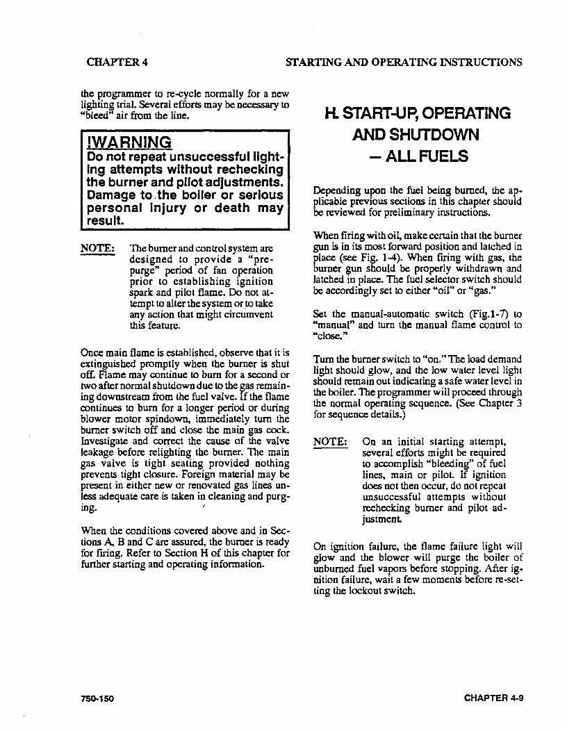
CHAPTER4 SfARTING AND OPERATING INSTRUCfiONS
the programmer to re-cycle normally for a new lighting trial. Several efforts may be necessary to "bleed" air from the line.
!WARNING Do not repeat unsuccessful lightIng attempts without rechecking the burner and pilot adjustments. Damage to. the boiler or serious personal Injury or death may result.
NOTE: The burner and control system are designed to provide a "prepurge" period of fan operation prior to establishing ignition spark and pilot flame. Do not at .. tempt to alter the system or ~o take any action that might circumvent this feature.
Once main flame is established, observe that it is extinguished promptly when the burner is shut off. Flame may continue to bum for a second or two after normal shutdown due to the gas remaining downstream from the fuel valve. If the flame continues to bum for a longer period or. during blower motor spindown, immediately tum the burner switch off and close the main gas cock. Investigate and correct the cause of the valve leakage before relighting the burner. The main gas valve is tight seating provided nothing prevents tight closure. Foreign material may be present in either new or renovated gas lines unless adequate care is taken in cleaning and purg· ing. ,
When the conditions covered above and in Sections A, B and C are assured, the burner is ready for firing. Refer to Section H of this chapter for further starting and operating information.
75()...150
H. START-UP, OPERATING AND SHUTDOWN
-ALLFUELS
Depending upon the fuel being burned, the applicable previous sections in this chapter should be reviewed for preliminary instructions.
When firing with oil, make certain that the burner gun is in its most forward position and latched in place (see Fig. 1-4). When frring with gas, the burner gun should be properly withdrawn and latched in place. The fuel selector switch should be accordingly set to either "oil" or "gas."
Set the manual-automatic switch (Fig.l-7) to "manual" and tum the manual flame control to "close."
Tum the burner switch to "on." The load demand light should glow, and the low water level light should remain out indicating a safe water level in the boiler. The programmer will proceed through the normal operating sequence. (See Chapter 3 for sequence details.)
NOTE: On an initial starting attempt, several efforts might be required to accomplish "bleeding" of fuel lines, main or pilot. If ignition does not then occur, do not repeat unsuccessful attempts without rechecking burner and pilot adjustment.
On ignition failure, the flame failure light will glow and the blower will purge the boiler of unburned fuel vapors before stopping. After ig· nition failure, wait a few moments before re-setting the lockout switch.
CHAPTER 4-9
CHAPTER4 STARTING AND OPERATING INSTRUCfiONS
!WARNING Do not re-light the pilot or attempt to start the main burner, either oil or gas, If the combustion chamber Is hot and/or If gas or oil vapor combustion gases are present In the furnance or flue passages. Fallur to heed this warning could result In serious personal Injury or death.
CAUTION! The burner and control system are designed to provide a "prepurge" period of fan operation prior to establishing ignition spark and pilot flame. Do not attempt to alter the system or take any action that might circumvent this feature thus causing damage to the equipment.
After main flame ignition, the burner should be left on manual control at its low fire setting (that is, with manual flame control at "close") until the boiler is properly warmed. Close the steam header. ·
In the case of a steam boiler, CLOSE THE TEST VALVE when steam begins to appear.
A hot water boiler must have a continuous flow of system water through the vessel during the wann·up period. The entire water content of the system and boiler must be warmed prior to increasing fuel input.
If the flame at low fire provides insufficient heat to reach normal operating pressure or temperature after 30 minutes, w-adually increa.Se the firing rate by turning the manual flame control in one point increments to no higher than the third cam screw. Operate at this increased fuel input rate for a period of time until an increase is noted in pressure or temperature.
CHAPTER 4-10
After the boiler is thoroughly warmed, tum the manual flame control to high fue. At this point, a combustion analysis should be made with instruments, and the fuel flow regulated as required. Refer to adjustment procedures in Cbapter 5. After making the high-fire adjustment, manually decrease the firing rate, stopping at each cam screw to analyze combustion gases and adjust as required.
To properly perform this testing and adjusting, it is necessary that the burner be allowed to fire at each rate sufficiently long enough to achieve a stable condition.
Operating - Normal operation of the burner should be with the switch in the automatic position and under the direction of the modulating control. The manual position is provided for initial adjustment of the burner over the entire firing range. When a shutdown occurs while operating in the manual position at other than low fire, the damper will not be in a closed position, thus allowing more air . than desired to flow through the boiler. The hot flame to cool air cycling subjects the pressure vessel metal and refractory to undesi~ble conditions.
With the switch set at "auto," the burner will operate on a modulating basis according to the load de.mand.
The burner will continue to operate with modulated firing until operating limit pressure or temperature is reached, unless:
(1) The burner is manually turned "off."
(2) A low water condition is detected by the low water level control.
(3) The current or fuel supply is interrupted.
(4) Combustion or atomizing air pressure drops below the minimum level.
750-150
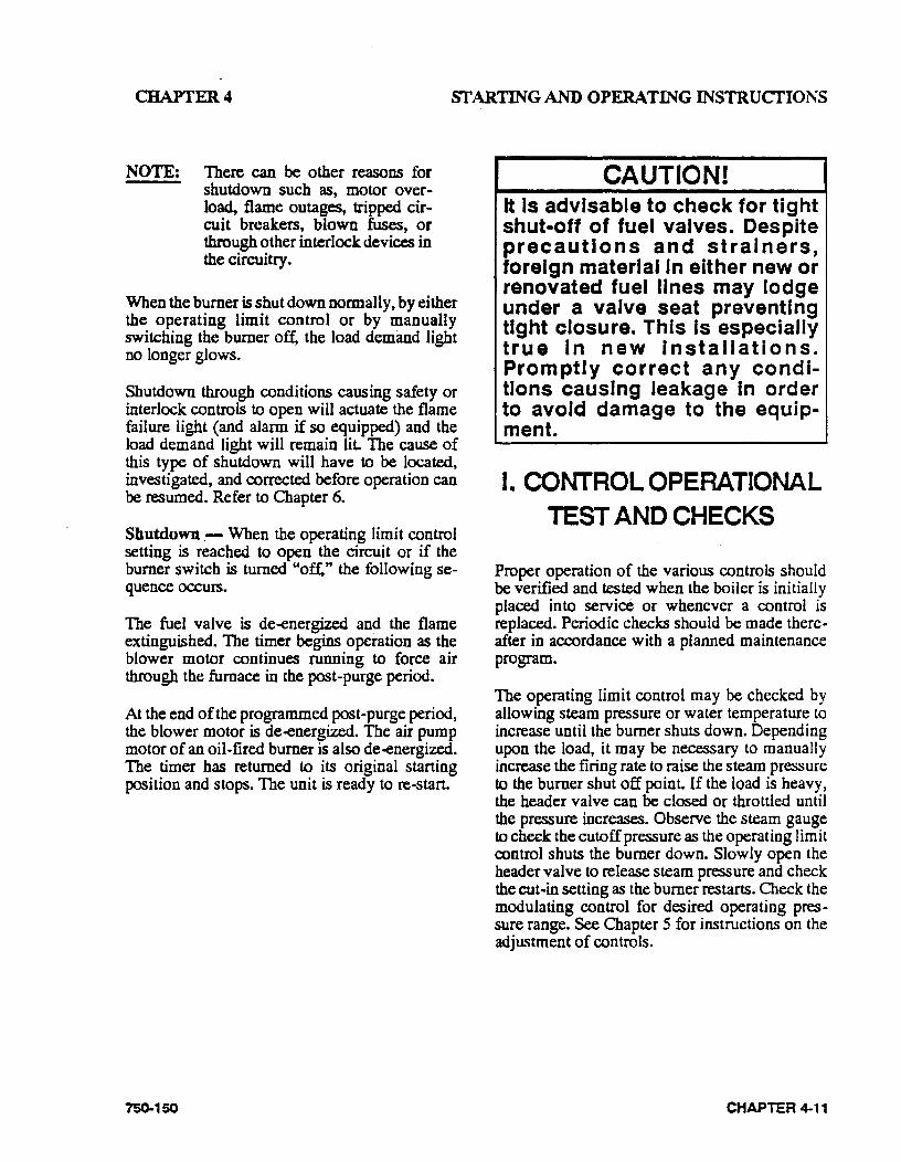
CHAPTER4 sr ARTING AND OPERATING INSTRUCfiONS
NOTE: There can be other reasons for shutdown such as, motor overload, flame outages, tripped cir .. cuit breakers, blown fuses, or through other interlock devices in the circuitry.
When the burner is shut down normally, by either the operating limit control or by manually switching the burner off, the load demand light no longer glows.
Shutdown through conditions causing safety or interlock controls to open will actuate the flame failure light (and alarm if so equipped) and the load demand light will remain liL The cause of this type of shutdown will have to be located, investigated, and corrected before operation can be resumed. Refer to Chapter 6.
Shutdown.- When the operating limit control setting is reached to open the circuit or if the burner switch is turned "of:f," the following sequence occurs.
The fuel valve is de--energized and the flame extinguished. The timer begins operation as the blower motor continues running to force air through the furnace in the post-purge period.
At the end of the programmed post-purge period, the blower motor is de--energized. The air pump motor of an oil-fired burner is also de--energized. The timer has returned to its original starting position and stops. The unit is ready to re-start.
75Q..150
CAUTION! It Is advisable to check for tight shut-off of fuel valves. Despite precautions and strainers, foreign material In either new or renovated fuel lines may lodge under a valve seat preventing tight closure. This Is especially true In new Installations. Promptly correct any conditions causing leakage In order to avoid damage to the equipment.
I. CONTROL OPERATIONAL TEST AND CHECKS
Proper operation of the various controls should be verified and tested when the boiler is initially placed into service or whenever a control is replaced. Periodic checks should be made thereafter in accordance with a planned maintenance program.
The operating limit control may be checked by allowing steam pressure or water temperature to increase until the burner shuts down. Depending upon the load, it may be necessary to manually increase the firing rate to raise the steam pressure to the burner shut off point. If the load is heavy, the header valve can be closed or throttled until the pressure increases. Observe the steam gauge to check the cutoff pressure as the operating limit control shuts the burner down. Slowly open the header valve to release steam pressure and check the cut-in setting as the burner restarts. Check the modulating control for desired operating pressure range. See Chapter 5 for instructions on the adjustment of controls.
CHAPTER 4-11
CHAPTER4 SfARTING AND OPERATING INSTRUCfiONS
Water temperature, on a hot water boiler that may be operating at less than full load, may be raised by manually increasing the firing rate until the burner shuts. down through the action of the operating limit control. Observe the thermometer to verify the desired settings at the point of cutout and again when the burner restarts. Return the manual automatic switch to "automatic" and check the modulating control for the desired temperature range. See Chapter S for instructions on the adjustment of the controls.
Check the proper operation and setting of the low water cut-off (and pump operating control, if used).
CHAPTER 4-12
Proper operation of the flame failure device should be checked at the time of startup and at least once a week thereafter. Refer to Chapter 7 for information on flame safety checks. Check the program relay's annunciation of any system failure. Observe the promptness of ignition of the pilot flame and the main flame.
Cleek for tight shut..off of all fuel valves. Despite precautions and strainers, foreign material may lodge under a valve seat preventing tight closure. Promptly correct any conditions causing leakage.
Refer to the adjustment procedures and maintenance instructions given in Chapters S and 7.
7S0-150
CHAPTERS ADJUSTMENT PROCEDURES
CHAPTERS
ADJUSTMENT PROCEDURES
A General B. Linkage-Modulating Motor & Air Damper C. Modulating Motor D. Modulating Motor Switches -Low Fire and High Fire E. Operating Controls General F. Modulating Pressure Controls -(Steam) G. Operating Limit Pressure Control -(Steam) H. High Limit Pressure Control -(Steam) I. Modulating Temperature Control- (Hot Water) J. Operating Limit Temperature Control - (Hot Water) K. Hi.gh Limit Temperature Contt:pl- (Hot Water) L. Low Water Cut-Off Devices M. Combustion Air Proving Switch N. Atomizing Air Proving Switch 0. Gas Pilot Flame Adjustment P. Gas Pressure and Flow Information Q. Gas Fuel Combustion Adjustment R. Low Gas Pressure Switch S. High Gas Pressure Switch T. Fuel Oil Pressure and Temperature -General U. Fuel Oil Combustion Adjustment V. Burner Drawer Adjustments W. Oil Drawer Switch X. Low Oil Temperature Switch Y. High Oil Temperature Switch Z. Low Oil Pressure Switch AA. Electric Oil Heater Thermostat BB. Steam Oil Heater Thermostat CC. Hot Water Oil Heater Thermostat DD. Steam Heater Pressure Regulator
NOTE: If. your boiler is equipped with a CB-HA WKTM boiler manage· ment control system, refer to CBHA WK. Installation, Operating and Servicing Manual No. 750-
133 for specific information regarding procedures described in this section.
75()..150 CHAPTER 5-1
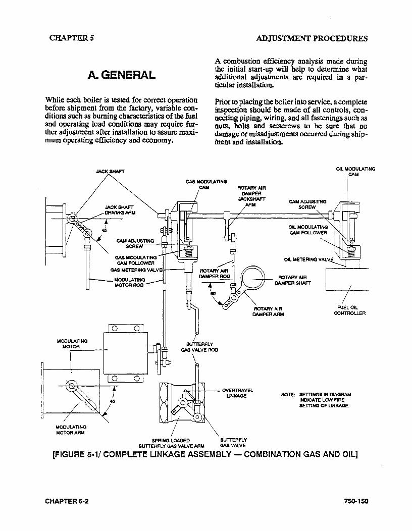
CHAPTERS
A. GENERAL
While each boiler is tested for correct operation before shipment from the factory, variable conditions such as burning characteristics of the fuel and operating load conditions may require further adjustment after installation to assure maximum operating efficiency and economy.
ADJUSTMENT PROCEDURES
A combustion efficiency analysis made during the initial start-up will help to determine what additional adjustments are required in a particular installation.
Prior to placing the boiler into service, a complete inspection should be made of all controls, con~ necting piping, wiring, and all fastenings such as nuts, bolts and setscrews to be sure that no damage or misadjustments occurred during shipment and installation.
OIL MODULATING ~M
GAS MODULATING
MODULATING MOTOR
MODULATING MOTOR ARM
CAM ·ROTARY AIR
BUTTERFLY GAS VAL.VE ROO
I:WotPER JACKS HAFT
AAM
.o..--~-..,...;..~- OVERTRAVEl UNKAGE
SPRINQ LOADED 8U1TERFL Y BUTTERFLY GAS VAlVE AAM GAS VAlVE
CAM ADJUSTING SCREW
OIL METERING VAL
ROTARY AIR CAMPER SHAFT
FUEL OIL CONTROLLER
NOTE: SETllNGS IN DIAGRAM INDICATE LON ARE SETllNG OF UNKAGE.
[FIGURE 5·1/ COMPLETE UNKAGE ASSEMBLY- COMBINATION GAS AND OIL]
CHAPTER 5-2 750-150
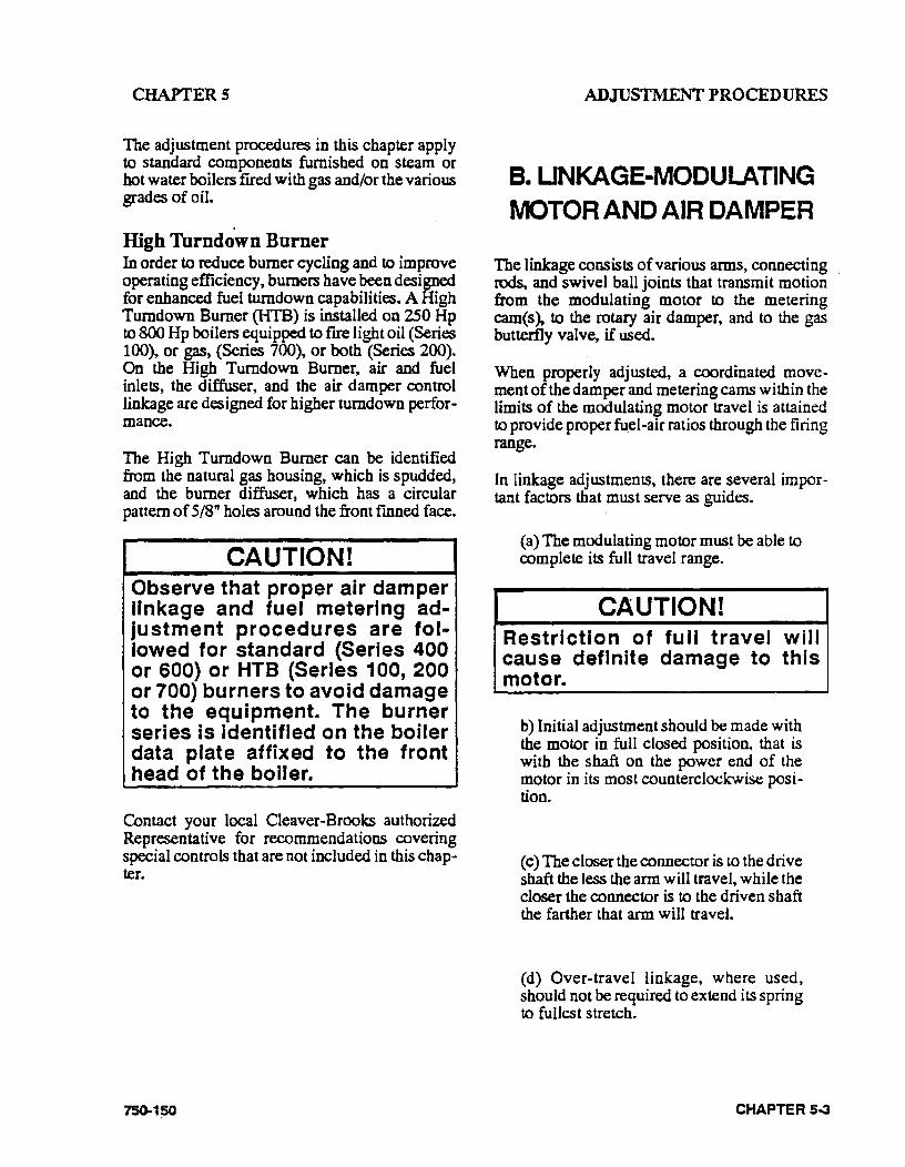
CHAPTERS
The adjustment procedures in this chapter apply to standard components furnished on steam or hot water boilers fired with gas and/or the various grades of oil.
High Turndown Burner In order to reduce burner cycling and to improve operating efficiency, burners have been designed for enhanced fuel turndown capabilities. A High Turndown Burner (IITB) is installed on 250 Hp to 800 Hp boilers equipped to fire light oil (Series 1 00), or gas, (Series 700), or both (Series 200). On the High Turndown Burner, air and fuel inlets, the diffuser, and the air damper control linkage are designed for higher turndown performance.
The High Turndown Burner can be identified from the natural gas housing, which is spudded, and the burner diffuser, which. has a circular pattern of 5/8" holes around the front fmned face.
CAUTION! Observe that proper air damper linkage and fuel metering adjustment procedures are followed for standard (Series 400 or SOO) or HTB (Series 1 00, 200 or 700) burners to avoid damage to the equipment. The burner series· is identified on the boiler data plate affixed to the front head of the boiler.
Contact your local Cleaver-Brooks authorized Representative for recommendations covering special controls that are not included in this chapter.
750-150
ADJUSTMrnNTPROCEDURES
B. UNKAGE-MODULATING IVIOTOR AND AIR DAMPER
The linkage consists of various arms, connecting rods, and swivel ball joints that transmit motion from the modulating motor to the metering cam(s), to the rotary air damper, and to the gas butterfly valve, if used.
When properly adjusted, a coordinated movement of the damper and metering cams within the limits of the modulating motor trav~l is attained to provide proper fu.el-air ratios through the firing range.
In linkage adjustments, there are several important factors that must serve as guides.
(a) The modulating motor must be able to complete its full travel range.
CAUTION! Restriction of full travel will cause definite damage to this motor.
b) Initial adjustment should be made with the motor in full closed position, that is with the shaft on the power end of the motor in its most counterclockwise position.
(c) The closer the connector is to the drive shaft the less the ann will travel, while the closer the connector is to the driven shaft the farther that arm will travel.
(d) Over-travel linkage, where used, should not be required to extend its spring to fullest stretch.
CHAPTER S--3
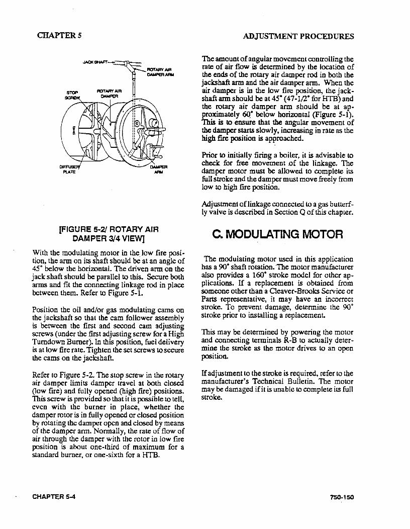
CHAPTERS
JAC<SHAFT-:r- FIOTARV AIR OMtF"et .AIW
ROTARY AIR DAMPER II
[FIGURE 5·2/ ROTARY AIR CAMPER 3/4 VIEVV]
With the modulating motor in the low fire position, the arm on its shaft should be at an angle of 45° below the horizontal. The driven arm on the jack shaft should be parallel to this. Secure both arms and fit the connecting linkage rod in place between them. Refer to Figure 5-1.
Position the oil and/or gas modulating cams on the jackshaft so that the cam follower assembly is between the first and second cam adjusting screws (under the first adjusting screw for a High Turndown Burner). In this position, fuel delivery is at low fire rate. Tighten the set screws to secure the cams on the jacks haft.
Refer to Figure 5-2. The stop screw in the rotary air damper limits damper travel at both closed (low fire) and fully opened (high fire) positions. This screw is provided so that it is possible to tell, even with the burner in place, whether the damper rotor is in fully opened or closed position by rotating the damper open and closed by means of the damper arm. Normally, the rate of flow of air through the damper with the rotor in low fire position is about one-third of maximum for a standard burner, or one~sixth for a HTB.
CHAPTER 5-4
ADJUSTMENT PROCEDURES
The amount of angular movement controlling the rate of air flow is determined by the location of the ends of the rotary air damper rod in both the jackshaft arm and the air damper arm. When the air damper is in the low fire position, the jackshaft arm should be at 45• (47-1/2° for HTB) and the rotary air damper arm should be at approximately 6Q• below horizontal (Figure 5-1). This is to ensure that the angular movement of the damper starts slowly, increasing in rate as the high fire position is approached.
Prior to initially firing a boiler, it is advisable to check for free movement .of the linkage. The damper motor must be allowed to complete its full stroke and the damper must move freely from low to high fire position.
Adjustment of linkage connected to a gas butterfly valve is described in Section Q of this chapter.
C. MODULATING MOTOR
The modulating motor used in this application has a 90o shaft rotation.·The motor manufacturer also provides a 160° stroke model for other ap· plications. If a replacement is obtained from someone other than a Cleaver-Brooks Service or Parts representative, it may have an incorrect stroke. To prevent damage, determine the 90° stroke prior to installing a replacement.
This may be determined by powering the motor and connecting terminals R-B to actually determine the stroke as the motor drives to an open position.
If adjustment to the stroke is required, refer to the manufacturer's Technical Bulletin. The motor may be damaged if it is unable to complete its full stroke.
750-150
CHAPTERS
D. MODULATING MOTOR SWITCHES - LOW FIRE
AND HIGH FIRE
The modulating motor contains either one or two internal switches depending upon application. These single-pole, double-throw, microswitches are actuated by adjustable cams at· tached to the motor shaft.
Factory replacement motors have the cams preset. The low fire start switch 1s set to make the red and yellow leads at approximately s· on the motor closing. The high tire purge air proving switch (M954B motor) is set to make red and blue tracer leads at approximately 60. on motor opening. Normally these settings are left as is but job conditions may require readjustment.
If the cams require adjustment or resetting, follow the instructions in the manufacturer's Technical Manual.
E. BURNER OPERATING CONTROLS - GENERAL
In general, when adjusting controls check to see that they are level, especially those containing mercury switches. On temperature sensing controls, make sure that the bulb is properly bottomed in its well and that connecting tubing is not kinked.
Controls are carefully calibrated during their manufacture and normally do not require recalibration. The dial settings generally are quite accurate although it is not unus~al to have a slight variation between a scale setting and an actual pressure gauge or the~ometer readi~g and to readjust the control settmg to agree wtth these readings. This is predicated, however, on pressure· gauges and thermometers being accurate.
75()...150
ADJUSTMENT PROCEDURES
Burner controls properly set to match load demands will provide operational advantages and achieve the following desirable objectives:
(a) The burner will operate in low fire position prior to shut down.
(b) The burner will operate at low fire for a brief period on each start during normal operation.
(c) Frequent bumeron-offcycling will be avoided.
Figure 5 .. 3 depicts a typical relationship of the setting of the operating limit control .an~ the modulating control. Please note that thlS IS not drawn to any scale. The burner will be "on" whenever the pressure or temperature is below point B and "off' whenever pressure or temperature is above point A The distance between points A and B represents the "on-off'' differential of the ·operating limit control.
In normal operation, the burner will shut down whenever the pressure or temperature reaches setting A. The switch in the operating limit control will open. As the pressure or temperature drops back to B, the switch closes and the burner will restart. The modulating control will be calling for the modulating motor to be in lo~ fire position at this point. If the load exceeds this low fire input, the modulating control will respond to increase the firing rate proportionately as pressure or temperature falls toward the point D. The modulating motor will stop at any intermediate point between C and D whenever the fuel input balances the load requirement. As the load requirement changes, the firing rate will change accordingly. This is referred to as modulated firing.
Point D represents the maximum firing rate of the burner. In the event pressure or temperature drops while the burner is firing at its maximum input, this is indicative that the load exceeds the generating rate of the boiler.
CHAPTER 5-S
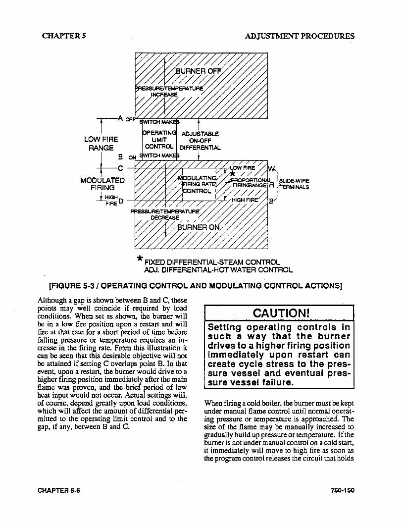
CHAPTERS ADJUSTMENT PROCEDURES
*FIXED DIFFERENTlAL-STEAM CONTROL ADJ. CIFFEREM1AL-HOTWATER CONTROL
[FIGURE 5-3/ OPERATING CONTROL AND MODULATING CONTROL ACTIONS]
Although a gap is shown between B and C, these points may well coincide if required by load conditions. When set as shown, the burner will be in a low fire position upon a restart and will fire at that rate for a short period of time before falling pressure or temperature requires an increase in the fuing rate. From this illustration it can be seen that this desirable objective will not be attained if setting C overlaps point B. In that event, upon a restart, the burner would drive to a higher firing position immediately after the main flame was proven, and the brief period of low heat input would not occur. Actual settings will, of course, depend greatly upon load conditions, which will affect the amount of differential permitted to· the operating limit control and to the gap, if any, between B and C.
CHAPTER 5-6
CAUTION! Setting operating controls in such a way that the burner drives to a higher firing position Immediately upon restart can create cycle stress to the pressure vessel and eventual pressure vessel failure.
When fuing a cold boiler, the burner must be kept under manual flame control until normal operat .. ing pressure or temperature is approached. The size of the flame may be manually increased to gradually build up pressure or temperature. If the burner is not under manual control on a cold start, it immediately will move to high fire as soon as the program control releases the circuit that holds
750-150
CHAPTERS
the burner in low fire during ignition. The modulating control will be calling for higher input and the burner will move to that position as rapidly as the damper motor can complete its travel. This rapid heat input can subject the pres· sure vessel metal and refractory to undesirable conditions.
Any control setting must not cause the boiler to operate at or in excess of the safety valve setting. Settings that do not exceed 90% of the valve setting are recommended, with lower settings greatly desirable if system conditions permit. Avoid having the operating pressure too near the valve set pressure, because the closer the operat· ing pressure is to the valve pressure, the greater the possibility of valve leakage. Continued leakage, however slight, will cause erosion and necessitate early valve replacement. The control settings on a hot water boiler must be within the temperature and pressure limits of the boiler as shown in Fig. 2.2
Ideally, the burner operating controls should be set under actual load conditions. Often, especially on new construction, the boiler is initially started and set to operate under less than full load req~irements. As soon as possible thereafter the controls should be reset to provide for maximum utilization of the modulating firing system.
To accomplish this, and assuming that air/fuel combustion ratios have been set, make approximate adjustments to the controls to bring the boiler pressure or temperature to meet the load requirements.
To properly set the modulating control, carefully adjust it under load conditions, until the load is maintained with the burner fi.ring at a steady rate. The firing rate at that point may be full high fire or slightly less, depending upon the relationship of the boiler size to the load.
When the modulating control is set in this manner and if the burner is at full high frre, the scale setting of the modulating pressure control on a steam boiler will have a reading that indicates the low point of the modulating range. This fixed differential range is described later in this section. The scale setting of the modulating
750-150
ADJUSTMENTPR9CEDURES
temperature control on a hot water boiler will have a reading that indicates the midpoint of the modulating range. This also is described later.
The operating limit control now should be adjusted and its differential established. See directions later in this section for the mechanics of adjusting. In an installation that does not require a very close control of steam pressure or water temperature this adjustable differential should be set as widely as conditions permit, since this will provide less frequent burner cycling.
The high limit control provides a safety factor to shut the burner off in the event the operating limit control should fail to do so. The setting of this control should be sufficiently above the operating limit control to avoid nuisance shutdowns. The setting, however, must be within the limits of the safety valve settings and preferably not exceed 90 percent of the valve setting. This control requires manual resetting after tripping.
In the setting of these controls, consideration . must be given to the time required for a burner restart. Upon each s~rt, there is a pre purge period of some length, plus the fixed time required for the proving of the pilot and main flame. This, plus approximately 1/2 minute required for damper motor travel from low to high fire, may allow pressure or temperature to drop below desirable limits.
The mechanics of setting the controls are:
F. MODULATING PRESSURE CONTROL (Steam)
Tum the adjusting screw until the indicator is opposite the low point of the desired modulating range. Modulated firing will range between this point and a higher point equal to the modulating range of the particular control. In 0-15 psi controls the range is 1/2lb.; in 5·150 psi controls the range is 5 lbs.; in 10-300 psi controls the range is 12 lbs.
CHAPTER 5-7
CHAPTERS
CAUTION! To prevent burner shutdown at other tf:"lan low fire setting, adjust the modulating pressure control to modulate to low fire BEFORE the operating limit pressure control shuts off the burner. Failure to heed this caution could result In damage to the equipment. ·
G. OPERATING LIMIT PRESSURE CONTROL
(Steam)
Set "cut-out" (burner-off) pressure on the main scale using the large adjusting screw. Set differential on the short scale turning the small adjusting screw until the indicator points to the desired difference between cut-out and cut-in pressures. The "cut-in" (burner-on) pressure is the cut-out pressure MINUS the differential. The cut-out pressure should not exceed 90% of the safety valve setting.
H. HIGH LIMIT PRESSURE CONTROL (Steam)
Set "cut-out" (burner off) pressure on the scale using the adjusting screw. The control will break a circuit when pressure reaches this point. The setting should be sufficiently above the operating limit pressure control to avoid shutdowns, and preferably not exceed 90% of the safety valve setting. This control requires manual resetting after tripping on a pressure increase. To reset, allow pressure to return to normal and then press the reset button.
. CHAPTER s..a
ADJUSTMENT PROCEDURES
L MODULATING TEMPERATURE CONTROL
(Hot Water)
Tum the knob on front of the case until the pointer indicates the desired setpoint temperature. This is the center point of a proportional ia.nge. The control has a 3 .. 3o• differential and may be adjusted to vary the temperature range · within which modulation is desired. With the cover off, tum the adjustment wheel until the pointer indicates the desired range.
CAUTION! To prevent burner shutdown at other than low fire setting, adjust the modulating temperature control to modulate to low fire BEFORE the operating limit temperature control shuts off the burner. Failure to heed this caution could result In damage to the equipment.
J. OPERATING LIMIT TEMPERATURE CONTROL
(Hot Water)
Set the "cut-out" (burner off) temperature on the scale by inserting a screwdriver through the cover opening to engage the slotted head adjusting screw.
The "cut-in" (burner on) temperature is the cutout temperature MINUS the differential. The differential is adjusted from So to 30° F.
750-150

CHAPTERS
K. HIGH LIMIT TEMPERATURE CONTROL
(Hot Water)
Set the "cut-out" (burner off) temperature on the scale using the adjusting screw. This control will break the circuit and lock out on a rise in water temperature above the setting. The setting should be sufficiently above the operating limit temperature to avoid unnecessary shutdowns. On a 30 lb. hot water boiler, the setting is not to exceed 240° F. The control requires manual resetting after tripping on a temperature increase. To reset, allow water temperature to drop below the cutout setting less differential, and then press the manual reset button.
L. LOWWATERCUTOFF. DEVICES
(Steam and Hot Water)
No adjustment is required since these controls are · preset by the original manufacturer. However, if water level is not maintained as shown in Figure 2-3, inspect these devices immediately and replace as required.
M. COMBUSTION AIR PROVING SWITCH
Air pressure against the diaphragm actuates the switch which, when closed, completes a circuit to prove the presence of combustion air. Since the pressure of the combustion air is at its minimum value when the damper is full open, the switch should be adjusted under that condition. It should be set slightly below the minimum pressure, but not so close as to cause nuisance shutdowns.
750--150
ADJUSTMrnNTPROCEDURES
The run/test switch on the program relay should be set to TEST. Tum the burner switch on. The blower will start (provided that all limit circuits are completed) and the programmer will proceed through the prepurge portion of the sequence, stopping at the low fire prepurge position.
NOTE: On an oil fired boiler, the atomizing air proving switch (AAPS) must also be closed.
On a combination fuel fired burner, the fuel selector switch could be set at "gas" to eliminate the atomizing air proving switch from the circuitry.
To have the modulating damper motor drive to high fire (damper open), remove the cover from the motor and remove the wire from terminal W.
Slowly tum down the ·air switch adjusting screw until it breaks the circuit. At this point the programmerwilllockout and it must be manually reset before it can be restarted. Add a half tum or so to the adjusting screw to remake its circuit.
Recycle the program relay to be sure that normal operation is obtained. Replace the wire on terminal Wand reinstall the cover. Return the test switch to the RUN position.
N. ATOMIZING AIR PROVING SWITCH
Air pressure against the diaphragm actuates the switch which, when closed, completes a circuit to prove the presence of atomizing air. Since the pressure of the atomizing air is at its minimum value when there is no fuel present at the nozzle, adjustment of the switch should be done while the unit is running but not firing. The control should be set slightly below the minimum pres~ sure, but not so close as to cause nuisance shutdowns.
CHAPTER 5~9
CHAPTERS
The control adjustment may be made during the prepurge period of operation by stopping the programmer during the prepurge period through the use of the TEST switch. Refer to the control instruction bulletin for details.. ·
The adjustment screw of the atomizing air proving switch then can be adjusted until it breaks the circuiL At this point, the programmer will lockout and it must be manually reset before it can be restarted. Tum the adjusting screw up a half tum or so to remake the circuiL
Since the adjustment of the air switch may be made either during the damper closed or damper open position of prepurge, ~t is also possible to make the adjustment with the relay stopped in the damper open position in a similar manner to the adjustment of the combustion air proving switch described in the previous section.
After making the adjustment, recycle the control to be sure that normal operation is obtained. The TEST switch must be set to the RUN. position.
0. GAS PILOT FLAME ADJUSTMENT
The size of the gas pilot flame is regulated by adjusting the gas flow through the pilot gas regulator and the adjusting cock. The flame must be sufficient to ignite the main flame and to be seen by the flame detector but an extremely large flame is not required .. An overly rich flame can cause sooting of the flame detector. Too small a flame can cause ignition problems.
Although it is possible to visibly adjust the size of the pilot flame, it is preferable to obtain a microamp reading of the flame signal.
The amplifier of the standardly used program relay has a meter jack for this purpose. This reading may be measured with a good quality micro-ammeter or a suitable multi-meter with a 0 to 25 micro-amp DC rating.
CHAPTER 5-10
ADJUSTMENT PROCEDURES
The meter is connected to the jack using a meter connecting plug harness (Cleaver-Brooks 884-72). Connect the plus (red meter lead) to the red tab of the harness and the minus (black meter lead) to the black tab before inserting the plug in " the meter jack.
The program relay used may be of the type that provides message information that includes a constant flame signal of DC voltage. In this case a separate DC voltmeter is not required.
To Measure and Adjust Pilot:
(1) When making a pilot adjustment, tum the manual-automatic switch to "manual" and the manual flame control to "close." Open both the pilot shutoff cock and the pilot adjusting cock. The main gas cock should remain closed.
The regulator in the pilot line, if provided, reduces the gas pressure to suit the pilot requirement of between 5-10" W.C. The final adjustment of the pilot flame with the adjusting cock is less sensitive with a lower pilot pressure.
(2) Connect the micro-ammeter as outlined earlier.
(3) Tum the burner switch on. Let the burner go through the normal prepurge cycle. When the ignition trial period is signaled, set the test switch to the TEST position to stop the sequence.
(4) If the pilot flame is not established within ten seconds, tum off the burner switch. Repeat the lighting attempt.
750-150
CHAPTERS
NOTE: On an initial starting attempt, portions of the fuel lines may be empty and require "bleeding" time. It is better to accomplish this with repeated short lighting trial periods with intervening purge periods than to risk prolonged fuel introduction. If the pilot does not light after several attempts, check all components of the pilot system.
(5) When the pilot flame is established, and with the pilot adjusting cock wide open, remove the flame detector from the burner plate. The pilot flame then can be observed through this opening.
!WARNING Wear a protective shield or suitable glasses and keep eyes sufficiently away from the sight tube opening to avoid serious personal Injury or death. Never remove the flame detector while the main burner is firing.
(6) To make the fmal adjustment, slowly close the gas pilot adjusting cock until the flame no longer can be seen through the sight tube. Then slowly open the cock until a flame providing full sight tube coverage is observed.
This adjustment must be accomplished within the time limit of the safety switch or approximately 30 seconds after the detector is removed. If the control shuts down, manually reset it. Replace the detector and repeat from step 5.
750-150
ADJUSTMENT PROCEDURES
(7) When a suitable flame as indicated in number 6 is obtained, replace the detector. Observe the reading on the microammeter. The reading should be between 2-1/4 and S microam.ps when using a lead sulfide detector and a standard amplifier. See the flame signal table in the manufacturer's bulletin for values of other combinations.
The flame signal indicated on the annunciator type relay should not be less than 10 volts D.C. and many be as high as 20 or greater.
The reading must be steady. If the reading fluctuates, recheck the adjustment. Make sure that the flame detector is properly seated and that the lens is clean.
(8) Return the ·test switch to the RUN position.
(9) If the main flame previously has not been established, proceed to do so in accordance with instructions elsewhere in the manual.
(10) The reading of the main flame signal should also be checked. Observe the flame signal for pilot alone, pilot and main burner flame together and the main burner flame at high, low, and intermediate firing rate positions. Readings should be steady and in the range indi-
CHAPTER 5-11
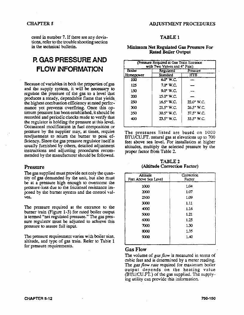
CHAPTERS
cated in number 7. If there are any deviations, refer to the trouble shooting section in the technical bulletin.
P. GAS PRESSURE AND FLOW INFORMATJON
Because of variables in both the properties of gas and the supply system, it will be necessary to regulate the pressure of the gas to a level that produces a steady, dependable flame that yields. the highest combustion efficiency at rated perfor· mance yet prevents overtiring. Once this optimum pressure has been established, it should be recorded and periodic checks made to verify that the regulator is holding the pressure at this level. Occasional modification in fuel comp(:>sition or pressure by the supplier may, at times, require readjustment to return the burner to peak efficiency. Since the gas pressure regulator itself is usually furnished by others, detailed adjustment instructions and adjusting procedures recommended by the manufacturer should be followed.
Pressure The gas supplied must provide not only the quantity of gas demanded by the unit, but also must be at a pressure high enough to overcome the pressure-loss due to the frictional resistance imposed by the burner system and the control valves.
The pressure required at the entrance to the burner train (Figure 1-3) for rated boiler output is termed "net regulated pressure." The gas pressure regulator must be adjusted to achieve this pressure to assure full input.
The pressure requirement varies with boiler size, altitude, and type of gas train. Refer to Table 1 for pressure requirements.
CHAPTER 5-12
ADJUSTMENT PROCEDURES
TABLEt
Minimum Net Regulated Gas Pressure For Rated Boiler Output
cr Horse er
100 125
150 9.0" w.c. 200 lS.O"W.C.
250 16..5" W.C. 22.0"W.C.
300 21..5" w.c. 26.5" W.C.
350 30.5" w.c. 37.5" w.c. 400 23.5" w.c. 33.5" w.c.
The pressures listed are based on 1000 BTU/CU.FT. natural gas at elevations up to 700 feet above sea level. For installation at higher altitudes, multiply the selected pressure by the proper factor from Table 2.
TABLE% (Altitude Correction Factor)
Altituc.le Correction Feet Above Sea Leve) Factor
1000 1.04
2000 1.07
2500 1.09
3000 1.11
4000 1.16
5000 1.21
6000 1.25
7000 1.30 8)()() 1.35
~ 1.40
Gas Flow The volume of gas flow is measured in terms of cubic feet and is determined by a meter reading. The gas flow rate required for maximum boiler output depends on the heating value (BTU/CU.FT.) of the gas supplied. The supplying utility can provide this information.
750-150
CHAPTERS
To obtain the required number of cubic feet per hour of gas, divide the heating value (BTU/CU.Ff.) into the required burner input (BT.U/HR. ).
See Tables 3 and 4 for burner gas input requirements at high or low fire for standard or High Turndown Burners ..
Boiler
TABLE3 (Standard Burner
Required Input- Btu/H.r)
Higb Fire Minimum Low Fire Horsepower Input BTU/Hr Input BTU!HR
100 4,184,()(X) 1,046,()(X)
125 5,230,000 1,308,000
150 6;2.77 ,()(X) 1,S69,()(X)
200 8,369,000 2,~()(X)
250 10,461,(X)() 2,615,()(X) 3(X) 12,553,(X)() 3,138,000
350 14,645,<XX> 3,661,()(X)
400 16,737,500 4,184,()(X)
TABLE4 (High Turndown Burner Required
Input- BTU/Hr) Boiler HighFire Minimum LowFire
Horsepower Input BTUIHR . Input BTUIHR 250 10,461,000 1,046,100
300 12,553,000 1,255,300
350 14,645,000 1,464,500
400 16,737,500 1,673,750
Pressure Correction The flow rate outlined in the previous section is figured on a "base" pressure, which is usually atmospheric or 14.7 psi.
Meters generally measure gas in cubic feet at "line" or supply pressure. The pressure at which each cubic foot is measured and the correction factor for this pressure must be known in order to convert the quantity indicated by the meter into the quantity that would be measured at "base" pressure.
750-150
ADJUS~PROCEDURES
To express the volume obtained from an actual meter reading into cubic feet at base pressure it is necessary to multiply the meter index reading by the proper pressure factor obtained from Table s.
TABLES Pressure Correction Factors
Regulator Inlet Pressure
Regulatcr lnJet Pressure
Pressure Factor Pressure Factor 1 pstg 1.05 ~ pstg 1 • .:>9
2psig 1.11 10 psig 1.66
3 psig 1.18 11 psig 1.72
4psig 1.25 12 psig 1.81 5 psig 1.32 13 psig 1.86
6psig 1.39 14 psig 1.93
7psig 1.45 15 psig 2.00
8psig 1.53
Conversely; To determine what the meter index reading should. be in order to provide the volume of gas required for input, divide the desired flow rate by the proper pressure correction factor. This answer indicates the number of cubic feet at line pressure that must pass through the meter to deliver the equivalent number of cubic feet at base pressure.
As an example: Assume that a 150 horsepower boiler is installed at ~000 feet above sea level; is equipped with a standard gas train; and that 1,000 BTU natural gas is available with an incoming gas pressure of 3 psig. The pressure and flow requirements can be determined as follows:
Pressure Correction for the 2,000 feet altitude must be made since altitude has a bearing on the net regulated gas pressure. The standard gas train requires 9.5" W.C. gas pressure at sea level (Table 1). Table 2 indicates a correction factor of 1.13 for 2,000 feet Multiplying these results in a calculated net regulated gas requirement of approximately 10. 7" W.C. This is the initial pressure to which the regulator should be adjusted.
CHAPTER 5-13
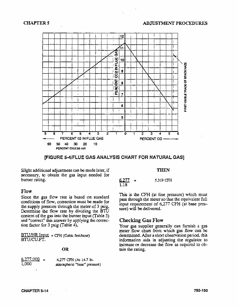
CHAPTERS
L
v -~
/ w 3
L ,
u..
/ ;::; N
v 0 0
/ / ~ w
/"' 0 a: / w
a.
/ v ,
9 8 7 6 54 3 2
- PERCENT 02 IN FLUE GAS
60 50 40 30 20 10 PERCENT EXCESS AIR
12
-"'
1'1 '\ 1\
10 '
9
8
7
6
5
0
ADJUSTMENT PROCEDURES
I I
!...
' '" \ I ""' ' I
i\ I \ I
' I
1\ I I
\ I I
\: ~
2 3 4 5 6 PERCENT CO---
[FIGURE 5-4/FLUE GAS ANALYSIS CHART FOR NATURAL GAS]
Slight additional adjustment can be made later, if necessary, to obtain the gas input needed for burner rating.
Flow Since the gas flow rate is based on standard conditions of flow, correction must be made for the supply pressure through the meter of 3 psi g. Determine the flow rate by dividing the BTU content of the gas into the burner input (Table 3) and "correct" this answer by applying the correction factor for 3 psig (Table 4).
BTUIHR Input = CFH (Cubic feet/hour) BTU/CU.Fr.
6.277.000 :: 1,000
CHAPTER 5-14
OR
6)."n CFH (A114.7 lb· atmcspheric "base" pressure)
Q;]JJ_ :: 1.18
THEN
5,319 CFH
This is the CFH (at line pressure) which must pass through the meter so that the equivalent full input requirement of 6,277 CFH (at base pressure) will be delivered.
Checking Gas Flow Your gas supplier generally can furnish a gas meter flow chart from which gas flow can be determined. After a short observation period, this information aids in adjusting the regulator to increase or decrease the flow as required to obtain the rating.
750 .. 150
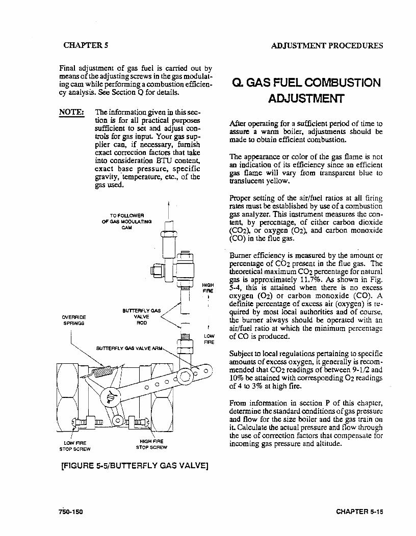
CHAPTERS
Final adjustment of gas fuel is carried out by means of the adjusting screws in the gas modulating cam while performing a combustion efficiency analysis. See Section Q for details.
NOTE: The information given in this section is for all practical purposes sufficient to set and adjust controls for gas input. Your gas sup· plier can, if necessary, furnish exact correction factors that take into consideration BTU content, exact base pressure, specific gravity, ·temperature, etc., of the gas used.
OVERRIDE SPRINGS
LON ARE STOP SCREW
TOFOUONER OF GAS MOOULA TING
CAM
HIGH ARE STOP SCREW
HIGH ARE
t
! LON ARE
[FIGURE 5-5/BUTTERFLY GAS VALVE]
1So..1so
ADJUSTMrnNTPROCEDURES
Q. GAS FUEL COMBUSTION ADJUSTMENT
After operating for a sufficient period of time to assure a warm boiler, adjustments should be made to obtain efficient combustion.
The appearance or color of the gas flame is not an indication of its efficiency since an efficient gas flame will vary from transparent blue to translucent yellow.
Proper setting of the air/fuel ratios at all firing rates must be established by use of a combustion gas analyzer. This instrument measures the content, by percentage, of either carbon dioxide (COz), or oxygen (Oz), and carbon monoxide (CO) in the flue gas.
Burner efficiency is measured by the amount or percentage of C02 present in the flue gas. The theoretical maximum C02 percentage for natural gas is approximately 11.7%. As shown in Fig. S-4, this is attained when there is no excess oxygen (02) or carbon monoxide (CO). A definite percentage of excess air (oxygen) is re· quired by most local authorities and of course, the burner always should be operated with an air/fuel ratio at which the minimum percentage of CO is produced.
Subject to local regulations pertaining to specific amounts of excess oxygen, it generally is recommended that C02 readings of between 9-1/2 and 10% be attained with corresponding Oz readings of 4 to 3% at high fire.
From information in section P of this chapter, detennine the standard conditions of gas pressure and flow for the size boiler and the gas train on it. Calculate the actual pressure and flow through the use of correction factors that compensate for incoming gas pressure and altitude.
CHAPTER 5-15
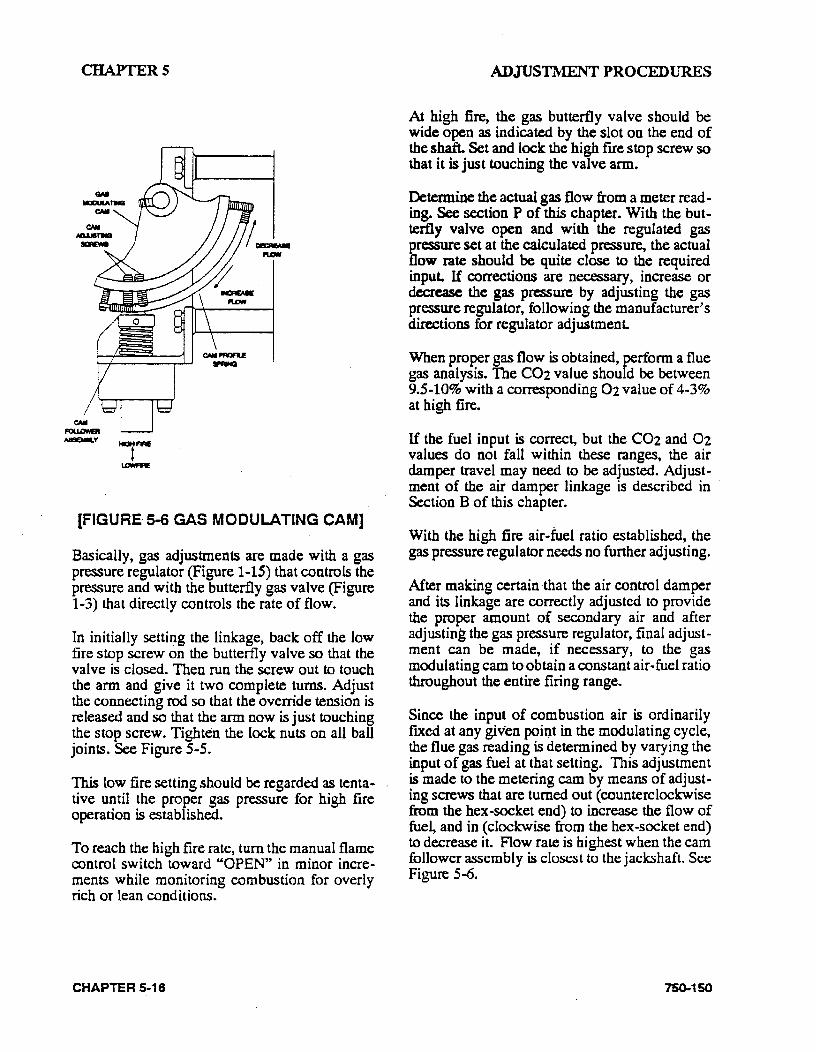
CHAPTERS
(FIGURE· 5-6 GAS MODULATING CAM]
Basically, gas adjustments are made with a gas pressure regulator (Figure 1-15) that controls the pressure and with the butterfly gas valve (Figure 1-3) that directly controls the rate of flow.
In initially setti~g the linkage, back off the low fire stop screw on the butterfly valve so that the valve is closed. Then run the screw out to touch the arm and give it two complete turns. Adjust the connecting rod so that the override tension is released and so that the arm now is just touching the stop screw. Tighten the lock nuts on all ball joints. See Figure S-5.
This low fire setting should be regarded as tentative until the proper gas pressure for high fire operation is established.
To reach the high fire rate, tum the manual flame rontrol switch toward "OPEN" in minor increments while monitoring combustion for overly rich or lean conditions.
CHAPTER 5-16
ADJUSTMENT PROCEDURES
At high fire, the gas butterfly valve should be wide open as indicated by the slot on the end of the shaft. Set and lock the high fue stop screw so that it is just touching the valve arm.
Determine the actual gas flow from a meter reading. See section P of this chapter. With the butterfly valve open and with the regulated gas pressure set at the calculated pressu~ the actual flow rate should be quite close to the required input. If corrections are necessary, increase or decrease the gas pressure by adjusting the gas pressure regulator, following the manufacturer's directions for regulator adjustment.
When proper gas flow is obtained, perform. a flue gas analysis. The C02 value should be between 9.5-10% with a corresponding 02 value of 4-3% at high fire.
If the fuel input is correct, but the C02 and 02 values do not fall within these ranges, the air damper travel may need to be adjusted. Adjustment of the air damper linkage is described in · Section B of this chapter.
With the high fire air-fuel ratio established, the gas pressure regulator needs no further adjusting.
After making certain ·that the air control damper and its linkage are correctly adjusted to provide the proper amount of secondary air and after adjusting the gas pressure regulator, final adjustment can be made, if necessary, to the gas modulating cam to obtain a constant air-fuel ratio throughout the entire firing range.
Since the input of combustion air is ordinarily ftxed at any given poiQt in the modulating cycle, the flue gas reading is determined by varying the input of gas fuel at that setting. This adjustment is made to the metering cam by means of adjusting screws that are turned out (counterclockwise from the hex-socket end) to increase the flow of fue~ and in (clockwise from the hex-socket end) to decrease it. Flow rate is highest when the cam follower assembly is closest to the jack:shaft. See Figure S--6.
75().150
CHAPTERS
Through the manual flame control switch, position the cam so that the adjusting screw adjacent to the end or high fire screw contacts the cam follower. Perform a combustion analysis at this point. If an adjustment is necessary, tum the adjustment screw accordingly to increase or decrease the fuel flow. Take a combustion read .. ing to verify the input. Repeat as necessary until the desired flow is obtained. Repeat this process, stopping at each adjusting screw, until the low fire adjusting screw is reached.
CAUTION! Do not use any lubricant on the adjusting setscrews. These have a nylon locking Insert Intended to provide locking torque and resistance to loosening and could damage ·equipment.
Standard Burner Low Fire Adjustment With the low fire cam screw, the fuel input should be adjusted to approximately 25% of that at high fire (Table 3). At low frre the C02 flue gas content should be 8.8-9.1% with 4-4.5% 02.
It may be necessary to readjust the setting of the low fire stop screw in order to obtain the proper air/fuel ratio at the low fire rate. To ensure that the low fire position of the gas butterfly valve is always the same, allow one tum of the stop screw for overtravel.
If the air damper needs to be adjusted in order to provide the correct low fire air/fuel ratio, combustion must be rechecked at higher firing rates and adjusted as required.
If all cam screws are properly adjusted, none will deviate from the general overall contour of the cam face.
750-150
ADJUSTMENT PROCEDURES
High Turndown Burner Low Fire Adjustment With the low fire cam screw, gas flow should be adjusted to obtain a minimum fuel input 10% of that at high frre (Table 4). The resulting flue gas COz content should be 5.8-6. 7% with a corresponding 02 content of 11-9.5%.
It may be necessary to readjust the setting of the low fire stop screw in order to obtain the proper air/fuel ratio at low fire. To ensure that the low fire position of the gas butterfly valve is always the same, allow a half tum of the stop screw for overtravel.
H the air damper must be reset to meet the low fire air/fuel requirements, combustion at higher firing rates must be rechecked.
The second cam adjusting screw may need to be adjusted in order to maintain a smooth cam profile. If all screws are properly adjusted, none will deviate from the general overall contour of the cam Jace.
R. LOW GAS PRESSURE SWITCH
Adjust the scale setting to slightly below the normal burning pressure. The control circuit will be broken when the pressure falls below this point. Since gas line distribution pressure may decrease under some conditions, shutdowns may result if the setting is too close to nonnal. However, regulations reqqire that the setting may not be less than 50% of the rated pressure downstream of the regulator.
Manual resetting is necessary after a pressure drop. Press the reset lever after the pressure is restored. Make sure that a mercury switch equipped control is level.
CHAPTER 5-17
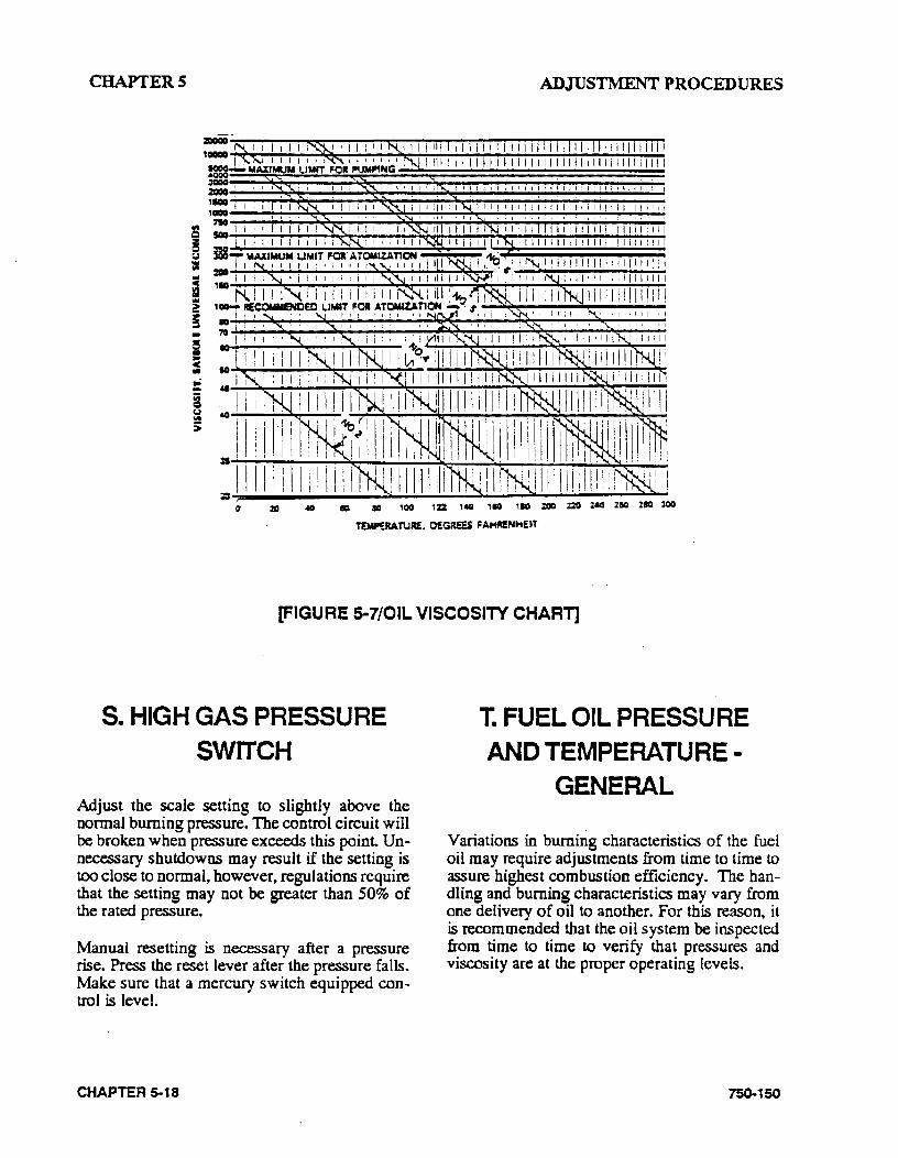
CHAPTERS ADJUSTMENT PROCEDURES
1: :za 40 ea 10 100 122. 1110 ,. 110 :ZOD :ZO 2110 :ZICI
T!MP!RATUR£. OEGREES FA.HRENHE.T
[FIGURE 5-7/0IL VISCOSITY CHART]
S. HIGH GAS PRESSURE SWITCH
Adjust the scale s.etting to slightly above the normal burning pressure. The control circuit will be broken when pressure exceeds this point. Unnecessary shutdowns may result if the setting is too close to normal, however, regulations require that the setting may not be greater than 50% of the rated pressure.
Manual resetting is necessary after a pressure rise. Press the reset lever after the pressure fa lis. Make sure that a mercury switch equipped control is level.
CHAPTER 5-18
T. FUEL OIL PRESSURE AND TEMPERATURE
GENERAL
Variations in burning characteristics of the fuel oil may require adjustments from time to time to assure highest combustion efficiency. The handling and burning characteristics may vary from one delivery of oil to another. For this reason, it is recommended that the oil system be inspected from time to time to verify that pressures and viscosity are at the proper operating levels.
75()..150
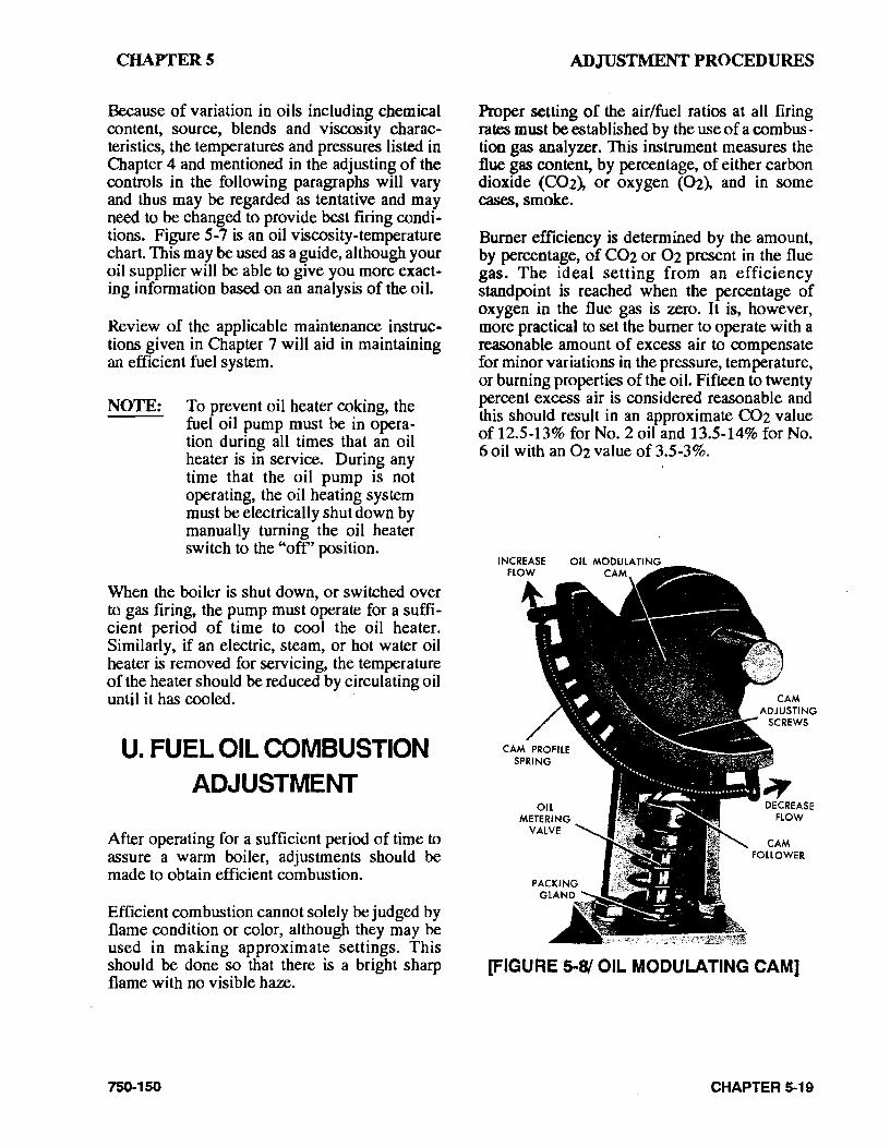
CHAPTERS
Because of variation in oils including chemical content, source, blends and viscosity characteristics, the temperatures and pressures listed in Chapter 4 and mentioned in the adjusting of the controls in the following paragraphs will vary and thus may be regarded as tentative and may need to be changed to provide best firing condi • tions. Figure 5-7 is an oil viscosity-temperature chart. This may be used as a guide, although your oil supplier will be able to give you more exacting information based on an analysis of the oil.
Review of the applicable maintenance instructions given in Chapter 7 will aid in maintaining an efficient fuel system.
NOTE: To prevent oil heater coking, the fuel oil pump must be in operation during all times that an oil heater is in service. During any time that the oil pump is not operating, the oil heating system must be electrically shut down by manually turning the oil heater switch to the "off' position.
When the boiler is shut down, or switched over to gas firing, the pump must operate for a sufficient period of time to cool the oil heater. Similarly, if an electric, steam, or hot water oil heater is removed for servicing, the temperature of the heater should be reduced by circulating oil until it has cooled. ·
U. FUEL OIL COMBUSTION ADJUSTMENT
After operating for a sufficient period of time to assure a warm boiler, adjustments should be made to obtain efficient combustion.
Efficient combustion cannot solely be judged by flame condition or color, although they may be used in making approximate settings. This should be done so that there is a bright sharp flame with no visible haze.
750-150
ADJUSTMENT PROCEDURES
Proper setting of the air/fuel ratios at all firing rates must be established by the use of a com bus. tion gas analyzer. This instrument measures the flue gas content, by percentage, of either carbon dioxide (C02), or oxygen (02), and in some cases, smoke.
Burner efficiency is determined by the amount, by percentage, of C02 or 02 present in the flue gas. The ideal setting from an efficiency standpoint is reached when the percentage of oxygen in the flue gas is zero. It is, however, more practical to set the burner to operate with a reasonable amount of excess air to compensate for minor variations in the pressure, temperature, or burning properties of the oil. Fifteen to twenty percent excess air is considered reasonable and this should result in an approximate C02 value of 12.5-13% for No.2 oil and 13.5-14% for No. 6 oil with an 02 value of 3.5-3%.
OIL METERING
VALVE
DECREASE FlOW
[FIGURE 5-81 OIL MODULATING CAM]
CHAPTER 5-19
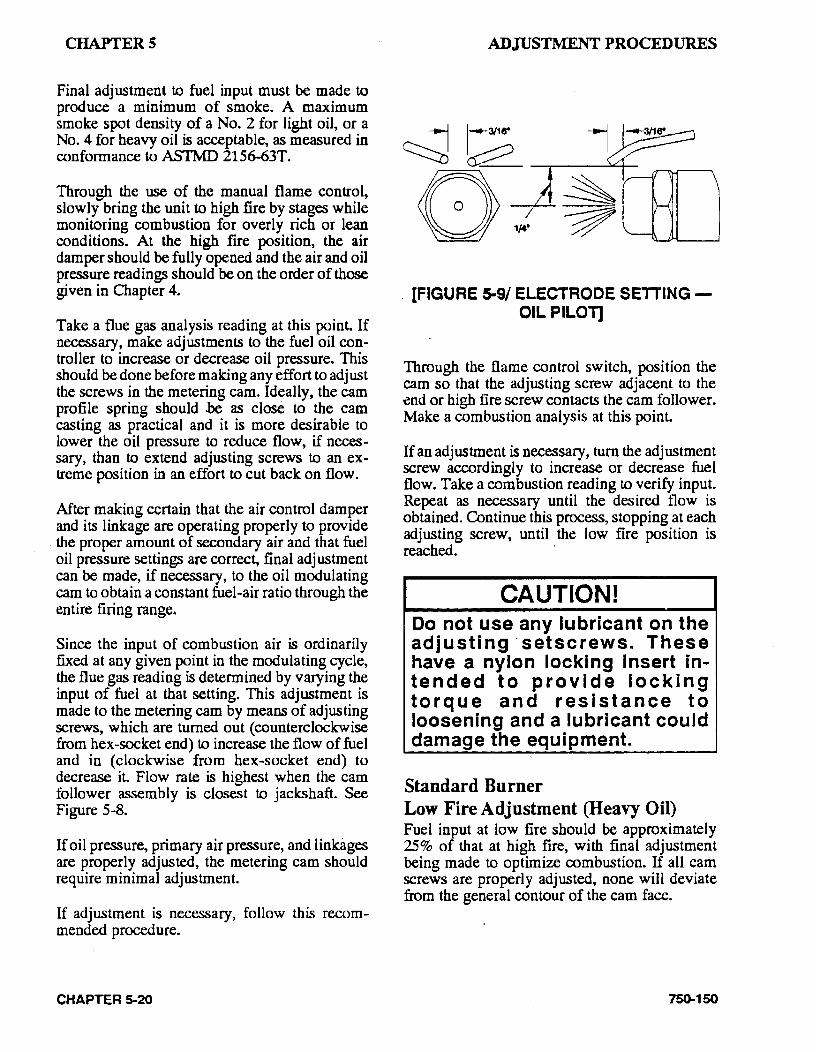
CHAPTERS
Final adjustment to fuel input must be made to produce a minimum of smoke. A maximum smoke spot density of a No. 2 for light oil, or a No. 4 for heavy oil is acceptable, as measured in conformance to ASTMD 2156-63T.
Through the use of the manual flame control, slowly bring the unit to high fire by stages while monitoring combustion for overly rich or lean conditions. At the high fire position, the air damper should be fully opened and the air and oil pressure readings should be on the order of those given in Chapter 4.
Take a flue gas analysis reading at this point. If necessary, make adjustments to the fuel oil con~ troller to increase or decrease oil pressure. This should be done before making any effort to adjust the screws in the metering cam. Ideally, the cam profile spring should be as close to the cam casting as practical and it is more desirable to lower the oil pressure to reduce flow, if necessary, than to extend adjusting screws to an extreme position in an effort to cut back on flow.
After making certain that the air control damper and its linkage are operating properly to provide
. the proper amount of secondary air and that fuel oil pressure settings are correct, final adjustment can be made, if necessary, to the oil modulating cam to obtain a constant fuel~air ratio through the entire firing range.
Since the input of combustion air is ordinarily fixed at any given point in the modulating cycle, the flue gas reading is determined by varying the input of fuel at that setting. This adjustment is made to the metering cam by means of adjusting screws, which are turned out (counterclockwise from hex-socket end) to increase the flow of fuel and in (clockwise from hex-socket end) to decrease it. Flow rate is highest when the cam follower assembly is closest to jackshaft. See Figure 5-8.
If oil pressure, primary air pressure, and linkages are properly adjusted, the metering cam should require minimal adjustment.
If adjustment is necessary, follow this recommended procedure.
CHAPTER 5-20
ADJUSTMENT PROCEDURES
[FIGURE 5-9/ ELECTRODE SETTINGOIL PILOT]
Through the flame control switch, position the cam so that the adjusting screw adjacent to the end or high fire screw contacts the cam follower. Make a combustion analysis at this point.
If an adjustment is necessary, turn the adjustment screw accordingly to increase or decrease fuel flow. Take a combustion reading to verify input. Repeat as necessary until the desired flow is obtained. Continue this process, stopping at each adjusting screw, until the low fire position is reached. ·
CAUTION! Do not use any lubricant on the adjusting· setscrews. These have a nylon locking Insert intended to provide locking torque and resistance to loosening and a lubricant could damage the equipment.
Standard Burner Low Fire Adjustment (Heavy Oil) Fuel input at low fire should be approximately 25% of that at high fire, with final adjustment being made to optimize combustion. If all cam screws are properly adjusted, none will deviate from the general contour of the cam face.
750-150
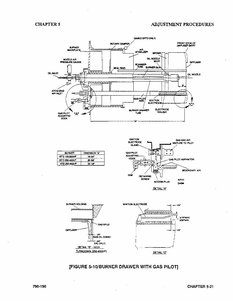
CHAPTERS ADJUSTMENT PROCEDURES
750-150
GASKET(HTD ONLY)
F'FIONT EDGE OF DIFFUSER SKJRT
,.....---~/
t-----------''A' -__,.----------1
ElJANER DIMENSION 'A'
sro 1oo-200HP 18-3,44' src2!5()..4()()HP 2\5-!5.8'
HTO~P 22·1.4!'
OfF
3(<4' (OIL ONLY)
DETAIL '8" ·HIGH
TURNDOWN t250-400HP)
IGNITlON a.ECn:lOOE
GASANOAIR
lfl"""-• MIXTURE TO PILOT
DETAIL "A"
DETAIL "C"
(FIGURE 5-10/BURNER DRAWER WITH GAS PILOT]
CHAPTER 5-21
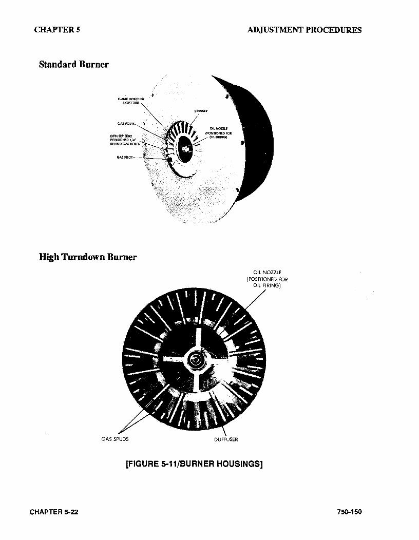
CHAPTERS
Standard Burner
FLAME DETECTOR SIGHl :UBE
GASPORT$
OIFRJSER SKIRT POSITIONED 1/4' BEHIND GAS HOLES
High Turndown Burner
GAS SPUDS DUFF USER
ADJUSTMENT PROCEDURES
OIL NOZZLE (POSITIONED FOR
OIL FIRING)
[FIGURE 5-11/BURNER HOUSINGS]
CHAPTER 5-22 750-150
CHAPTERS
High Turndown Burner Low Fire Adjustment (Light Oil) Fuel input at low fire should be approximately 125% of that at high fire. The low fire cam screw should be adjusted to obtain this flow rate with resulting flue gas content of 8.5-9.5% ccn and 9.3-7.8% 02. The second cam adjusting screw may need to be adjusted in order to maintain a smooth cam profile.
At the low· frre screw, the oil flow should be adjusted to obtain the necessary input for the fuel turndown required. The second adjusting screw may need to be adjusted in order to maintain a smooth cam profile.
V. BURNER DRAWER ADJUSTMENT
There are relatively few adjustments that can be . made to the burner. However, a check should be made to see that all components are properly located and that all holding screws are properly tightened. Figures S-10 and S-11 show various views or portions of the burner.
The diffuser location on gas fired boilers is quite important. There should be 1/4" between the edges of the diffuser fins and the gas outlet tubes (spuds). (See Figure 5-11) The setting of an oil fired burner is less exacting and the diffuser should be located with the skirt approximately 1-1/8" from the end of the burner tube.
When the proper diffuser location is ascertained, the setting of the nozzle in relation to the diffuser should be checked. This generally is set at the time of manufacture and seldom needs altering. It is most important that oil spray does not impinge upon the diffuser. The distance that the nozzle is behind the diffuser has some latitude and individual installations may require a slight deviation. The spacing indicated is 2".
Check the setting of the ignition electrode(s) for proper gap and position. See Figure 5-10 for the gas pilot electrode and Figure 5-9 for the light oil
750-150
ADJUSTMENT PROCEDURES
pilot. Make sure that the porcelain insulator is not cracked and that the ignition cable connections are tight.
The oil nozzle tip sho1:1ld be seated tightly in the body with the swirler and the seating spring in place. See Section G in Chapter 7 for additional nozzle tip information.
Cleek to see that the flame detector sight tube and the gas pilot tube extend through their respective openings in the diffuser face. .
W. OIL DRAWER SWITCH
The integral contacts of this control are closed by proper positioning and latching of the oil drawer in its forward position. Adjustment of the switch must be such that its contacts open if the oil drawer is· not properly positioned for oil firing. The switch is electrically removed from the circuit when a combination fuel burner is fired on gas.
X. LOW OIL TEMPERATURE SWITCH
This control prevents the burner from starting, or stops its operation, if the temperature of the oil is below the normal operating temperature.
To adjust this control, insert a screwdriver into the center slot in the control cover and tum the dial until the fixed (center) pointer is approximately 30•F lower than the oil heater thermostat setting. Tum the differential adjusting screw (located above the dial) until the movable indicator is approximately s· F above the setting on the main scale.
On a hot water boiler, the low oil temperature switch is an integral part of the electric oil heater. The switch is nonadjustable and is factory set at approximately 40• F below the maximum operating temperature of the heater.
CHAPTER 5·23
CHAPTERS
Y. HIGH OIL TEMPERATURE SWITCH (OPTIONAL)
This control prevents the burner from starting, or stops its operation, if the temperature of the oil exceeds the normal operating temperature.
To adjust, tum the dial until the pointer is approximately 25• F above the normal operating temperature. These controls generally have a set differential and will close s• F below the set point..
Z. LOW OIL PRESSURE SWITCH (OPTIONAL)
This control prevents burner ignition, or stops its operation, when the oil pressure is below a set _(X)int.. Adjust the control by turning the screw on top of the control case to an indicated pressure 10 psi below the established primary oil pressure setting indicated on the oil supply pressure gauge. The switch will remain in a closed position as long as the oil pressure exceeds this setting. The control normally used automatically rese~ when pressure is restored after a drop.
AA • ELECTRIC OIL HEATER THERMOSTAT
(400 and 600 Series -Steam)
The maximum temperature setting of the control is stamped on the dial. This is attained with the adjusting knob turned to the "high" end of the scale .. Lower settings are obtained by turning the adjusting knob clockwise, using the thermometer in the fuel oil controller as a guide.
The final setting of this theFlllostat should be at a temperature approximately ts• lower than the steam heater thennostat. This prevents electric
CHAPTER 5-24
ADJUSTMENT PROCEDURES
heater operation when the steam heater is functioning. The electric heater is sized to pro .. vide sufficient heated oil for low fire operation on cold starts before steam is available.
A 0.005 MFD capacitor is wired in parallel with the thermostat lead connections to prevent con
. tact bounce and arcing. The control differential is nonadjustable.
88. STEAM OIL HEATER THERMOSTAT (No. 6 Oil)
(400 and 600 Series - Steam)
The maximum temperature setting of the control is stamped on the dial. This is attained with the adjusting knob turned to the "high" end of the scale. Lower settings are obtained by turning the adjusting knob clockwise usi~g the thermometer in the fuel oil controller as a guide.
The final setting of this thermostat should provide oil at a sufficient ·temperature for efficient combustion based on the flue gas analysis. There is no need to heat the oil in excess of this tern per ature.
A 0.005 MFD capacitor is wired in parallel with the thermostat lead connections to prevent contact bounce and arcing. The control differential is nonadjustable.
CC. HOT WATER OIL HEATER THERMOSTAT
(400 and 600 Series)
To adjust, insert a screwdriver into the center slot in the control cover and tum the dial until the pointer is at the desired temperature level. This control generally has a set differential and will close s•F below the set point.
750-150
CHAPTERS
The thermostat contacts close to energize the booster water pump, which pumps water from the boiler through the heater. On cold starts, it is normal practice to manually close the valve in the pump discharge line until the boiler water temperature exceeds the temperature of the fuel oil entering the beater.
The electric oil heater on a hot water boiler burning No. 6 oil and equipped with a hot water oil heater has a built-in adjustable thermostat. The maximum temperature setting is stamped on its dial. The desired temperature can be obtained by turning the adjusting screw. The thermostat should be set at a temperature approximately 15 degrees lower than the hot water heater thermostat. This prevents electric heater operation when the water heater is functioning. The electric heater is sized to provide sufficient heated oil for low fire operation on cold starts before hot water is available.
750-150
ADJUSTMENT PROCEDURES
DO. STEAM HEATER PRESSURE REGULATOR
(400 and 600 Series - Steam)
This regulator is provided on a boiler designed to operate at boiler pressures above 15 psi for the purpose of reducing boiler steam pressure to the level necessary for proper operation of the steam oil heater. This pressure should be reduced to a point that permits sufficient temperature to heat the oil while allowing as continuous a steam flow as possible. Pressure that is too high will result in frequent cycling of the steam solenoid valve.
It is best to adjust the regulator under typical flow conditions. To do this, it is suggested that the globe valve in the steam supply line be closed so that there is n~ pressure on the regulator. Tum out the adjusting screw fully to relieve compression on the regulator spring, thus closing the regulator. With steam at normal pressure, open the globe valve and then set the secondary pres~ sure by turning the adjusting screw or handle until the downstream gauge shows the desired pressure.
CHAPTER 5-25

CHAPTER6 TROUBLE SHOOTING
CHAPTER 6
TROUBLE SHOOTING
A Burner Does Not Start B. No Ignition C. Pilot Flame, But No Main Flame D. Burner Stays in Low Fire E. Shutdown Occurs During Firing F. Modulating Motor
!WARNING Trouble shooting should be performed only by personnel who are familiar with the equipment and who have read and understand the contents of this manual. lfyou have questions, contact your local CleaverBrooks authorized Representative for assistance. Failure to heed this warning could result In serious personal injury or death.
!WARNING Disconnect and lock out the main power supply in order to avoid the hazard of electrical shock, which could result in serious personal injury or death.
750-150
NOTE: If your boiler is equipped with a CB-HA WKTM boiler management control system, refer to CBHA WK. Installation, Operating and Ser\ricing Manual No. 750- . 133 for specific information regarding procedures described in this section.
This section assumes that the unit has been properly installed and adjusted, and that it has been running for some time. It is further assumed that the operator has become thoroughly familiar with both the burner and the manual by this time. The points under each heading are set down as briefly as possible causes, suggestions or clues to simplify locating the source of trouble. Methods of correcting the trouble, once it has been identified, may be found elsewhere in this manual.
If the burner will not start or if it will not operate properly, this trouble shooting section should be referred to for assistance in pinpointing problems that may not be readily apparent.
The program relay has the capability to self-diagnose and to display a code or message that indicates the failure condition. Refer to the control bulletin for specifics and suggested remedies.
CHAPTER 6--1
CHAPTER6
Familiarity with the programmer and other controls in the system may be obtained by studying the contents of this manual and the bulletin. Knowledge of the system and its controls will make trouble shooting much easier. Costly down-time or delays can be prevented by systematic checks of the actual operation against the normal sequence to determine the stage at which performance deviates from normal. Following a routine may possibly eliminate overlooking an obvious condition, often one that is relatively simple to correct.
If an obvious condition is not apparent, check the continuity of the circuits with a voltmeter or test lamp. Each circuit can be checked and the fault isolated and corrected. Most circuitry checking can be done between appropriate terminals on the terminal boards in the control cabinet or the entrance box. Refer to the schematic wiring diagram for terminal identification.
A. BURNER DOES NOT START
(1) No voltage at the program relay power input terminals.
(a) Main disconnect switch open.
(b) Blown control circuit fuse.
(c) Loose or broken electrical connection.
(2) Program relay safety switch requires resetting.
(3) Limit circuit is not completed- no voltage at end of limit circuit program relay terminal.
CHAPTER 6-2
TROUBLE SHOOTING
(a) Pressure or temperature is above setting of operation control. (Load demand light will not glow.)
(b) Water below required level.
(i) Low water light (and alarm hom) should indicate this condition.
(ii) Check manual reset button, if provided, on low water control.
(c) Fuel pressure must be within settings of low pressure and high pressure switches.
(d) Oil fired unit - burner gun must be in full forward position to close oil drawer switch. ·
(e) Heavy oil frred unit- oil temperature below minimum setting.
(4) Fuel valve interlock circuit not completed.
{a) Fuel valve auxiliary switch not closed.
B. NO IGNITION
(1) Lack of spark.
(a) Electrode grounded or porcelain cracked.
750-150
CHAPTER6
(b) Improper electrode setting.
(c) Loose terminal on ignition cable; cable shorted.
(d) Inoperative ignition transformer.
(e) Insufficient or no voltage at pilot ig· nition circuit terminal.
(2) Spark but no flame.
(a) Lack of fuel- no gas pressure~ closed ·valve, empty tank, broken line, etc.
(b) Inoperative pilot solenoid.
(c) Insufficient or no voltage at pilot ignition circuit terminal.
(d) Too much air.
(3) Low fire switch open in low fire prov· ing circuit.
(a) Damper motor not closed, slipped cam, defective switch.
(b) Damper jammed or linkage binding.
750-150
TROUBLE SHOOTING
(4) Running interlock circuit not completed.
(a) Combustion or atomizing air proving switches defective or not properly set.
(b) Motor starter interlock contact not closed.
(S) Flame detector defective, sight tube obstructed, or lens dirty.
C. PILOT FLAME, BUT NO IVIAIN FLAME
(1) insufficient pilot flame.
(2) Gas Fired Unit.
(a) Manual gas cock closed.
(b) Main gas valve inoperative.
(c) Gas pressure regulator inoperative.
(3) Oil fired unit.
(a) Oil supply cut off by obstruction, closed valve, or loss of suction.
CHAPTER 6--3
CHAPTER6 ·
(b) Supply pump inoperative.
(c) No fuel.
(d) Main oil valve inoperative.
(e) Check oil nozzle, gun and lines.
( 4) Insufficient or no voltage at main fuel valve circuit terminal.
(5) Flame detector defective, sight tube obstructed or lens dirty.
D. BURNER STAYS IN LOW FIRE
(1) Pressure or temperature above modulating control setting.
(2) Manual-automatic switch in wrong position.
(3) Inoperative modulating motor (see Section F).
(4) Defective modulating control.
(5) Binding or loose linkage, cams, setscrews, etc.
CHAPTER 6-4
TROUBLE SHOOTING
E. SHUTDOWN OCCURS DURING FIRING
(1) Loss or stoppage of fuel supply.
(2) Defective fuel valve; loose electrical connection.
(3) Flame detector weak or defective.
(4) Lens dirty or sight tube obstructed.
(5) If the programmer lockout switch has not tripped, check the limit circuit for an opened safety control.
(6) If the programmer lockout switch has tripped:
(a) Check fuel lines and valves.
(b) Check flame detector.
(c) .Check for open circuit in running interlock circuit.
(d) The flame failure light is energized by ignition failure, main flame failure, inadequate flame signal, or open control in the running interlock circuit.
75()..150
CHAPTER6
(7) Improper air.fuel ratio (lean fue ).
(a) Slipping linkage.
(b) Damper stuck open.
(c) Fluctuating fuel supply.
(i) Temporary obstruction in fuel line.
(ii) Temporary drop in gas pressure.
(iii) Orifice gate valve accidentally opened (heavy oil).
(8) Interlock device inoperative or defective.
F. MODULATING MOTOR DOES NOT OPERATE
(1) Manual-automatic switch in wrong position.
(2) Linkage loose or jammed.
750-150
TROUBLE SHOOTING
(3) Motor does not drive to open or close during pre-purge or close on burner shut· down.
(a) Motor defective.
(b) Loose electrical connection.
(c) Damper motor transformer defective.
(4) Motor does not operate on demand.
(a) Manual:-automatic switch in wrong position.
(b) Modulating control improperly set or inoperative.
(c) Motor defective.
(d) Loose electrical connection.
(e) Damper motor transformer defective.
CHAPTER 6..S

CHAPTER 7 INSPECI10N AND :MAINTENANCE
CHAPTER 7
INSPECTION AND MAINTENANCE
A. General B. Fireside Cleaning C. Water Level Controls and Waterside D. Water Gauge Glass E. Electrical Controls F. Flame Safegaurd Control G. Oil Burner Maintenance H. Gas Burner Maintenance I. Motorized Gas Valve J. Solenoid Valves K. Air Ccmtrol Damper, Linkage and Cam Spring L. Forced Draft Fan M. Safety Valves N. Fuel Oil Valves 0. Air Pump and Components P. . Refractory Q. Opening and Closing Doors R. Lubrication S. Oil Heaters- Electric, Steam, Hot Water T. Combustion
NOTE: For more information on your flame safeguard system; refer to the appropriate manual that was provided with your boiler.
!WARNING Inspection and maintenance should be performed only by trained personnel who are familiar with this equipment. Failure to heed this warning could result In serious personal injury or death.
750-150 CHAPTER 7·1
CHAPTER 7
A. GENERAL
A well-planned maintenance program will help avoid unnecessary down-time or costly repairs, promote safety, and aid boiler inspectors. An inspection schedule with a listing of procedures should be established. It is recommended that a ooiler room log or record be maintained. Recording of daily, weekly, monthly, and yearly maintenance activities provides a valuable guide and aids in obtaining economical and lengthy service from Cleaver-Brooks equipment A boiler inspection schedule is shown at the end of this chapter in Fig. 7-13, which can be used as a guide. It is important to realize that the frequency of inspection will depend on variable conditions; such as, load, fuel, system requirements, boiler environment (indoor/outdoor), etc.
Good housekeeping helps maintain a professional appearing boiler room. Only trained· and authorized personnel should be permitted to operate, adjust or repair the boiler and its related equi pxnent The boiler room should be kept free of all material and equipment not necessary to the operation of the boiler or heating system.
Even though the boiler has electrical and mechanical devices that make it automatic or semi-automatic in operation, these devices require systematic and periodic maintenance. Any "automatic" feature does not relieve the operator from responsibility, but rather frees him of certain repetitive chores providing him time to devote to upkeep and maintenance.
Alertness in recognizing an unusual noise, improper gauge reading, leak, etc., can make the operator aware of a developing malfunction, permitting prompt corrective action that may prevent extensive repairs or unexpected downtime. Any leaks - fuel, water, steam, exhaust gas - should be repaired and under conditions that observe necessary safety precautions. Preventive maintenance measures such as regularly checking the tightness of connections, loc~uts, setscrews, packing glands, etc., should be mcluded in regular maintainance activities.
CHAPTER7-2
INSPEc;riON AND MAINTENANCE
Periodic Inspection Insurance regulations or local laws require a periodic inspection of the pressure vessel by an authorized inspector. Section I of Chapter 2 contains in.(ormation relative to this inspection.
Inspections of this type are usually, though not necessarily, scheduled for periods of normal boiler down-time such as an off season. This major inspection can often be used to accomplish maintenance, replacement, or repairs that cannot easily be done at other times .. This also serves as a good basis for establishing a schedule for annual, monthly or other periodic maintenance programs.
While this inspection pertains primarily to the waterside and fireside surfaces of the pressure vessel, it provides the operator an excellent opportunity for a detailed· inspection and check of all components of the bOiler, including; piping, valves, pumps, gaskets, refractory, etc. Complete cleaning, spot pai~ting or repainting, and the replacement of expendable items should be planned for and taken care of during this time. Any major repairs or replacements that may be required should also, if pqssible, be coordinated with this period of boiler shutdown.
Replacement spare parts, if not on hand, should be ordered sufficiently prior to shutdown.
CAUTION! Cleaver-Brooks genuine parts should be used to ensure proper operation and avoid damage to equipment.
Qeaver-Brooks boilers are designed, engineered and built to give long life and excellent service. Good operating practices and conscientious maintenance and care will promote efficiency and economy from their operation and contribute to many years of perfonnance.
The Cleaver-Brooks Total Protection Plan in· eludes a Planned Maintainance Program that covers many of the items included in this chapter.
750-150
CHAPTER 7
For information regarding the Total Protection Plan, contact your Cleaver-Brooks local authorized representative.
B. FIRESIDE CLEANING
Soot and non-combustibles are effective in· sulators and if allowed to accumulate will reduce heat transfer to the water and increase fuel consumption. Soot and other deposits can be very moisture-absorbent and may attract moisture to form corrosive acids that will deteriorate fireside metal.
Oean-out should be performed at regular frequent intervals depending upon load, type and quality of fuel, internal boiler temperature, and combustion efficiency. Stack temperature can be used as a guide to determine clean-out intervals, since an accumulation of soot deposits will raise
· the stack temperature.
Tube cleaning is accomplished by opening front and rear doors. Tubes may be brushed from either end. All loose soot and accumulations should be removed. Any soot or other deposits should be removed from the furnace and the tube sheets.
Refer to Section Q of this chapter for instructions . on properly opening and closing rear head.
The flue gas outlet and stack should be inspected annually and cleaned as necessary. Commercial firms are available to perform this work. The stack should also be inspected for damage and repaired as required.
The fireside should be thoroughly cleaned prior to any extended lay-up of the boiler. Depending upon circumstances, a protective coating may be required. See Section J in Chapter 2.
750-150
INSPECfiON AND MAINTENANCE
C. WATER LEVEL CONTROLS
The need to periodically check water level controls and the waterside of the pressure vessel cannot be overemphasized. Most instances of major boiler damage are the result of operating with low water or the use of untreated (or incorrectly) treated water.
Always be sure of the boiler water level. On steam boilers, the water column should be blown down daily. Check samples of boiler water and condensate in accordance with procedures recommended by your water consultant. Refer to Sections H and I in Chapter 2 for blowdown instructions and internal inspection procedures.
Since ~ow water cut-off devices are generally set by the original manufacturer, no attempt should be made to adjust these controls to alter the point of low water cut-off or point of pump cut-in or cut-out. If a low water device should become erratic iri operation or if its setting changes from previously established levels, contact your Oeaver-Brooks local authorized representative for assistance.
Steam Boiler Fig. 7-1 is a replica of the low water cut-off plate attached to a steam boiler. These instructions should be followed on a definite schedule. These controls normally function for long periods of time, which may lead to laxity in testing on the assumption that normal operation will continue indefinitely.
On a steam boiler, the head mechanism of the low water cut-off device(s) should be removed from the bowl at least semi-annually to check and clean the float ball, the internal moving parts, and the bowl or water column.
CHAPTER 7-3
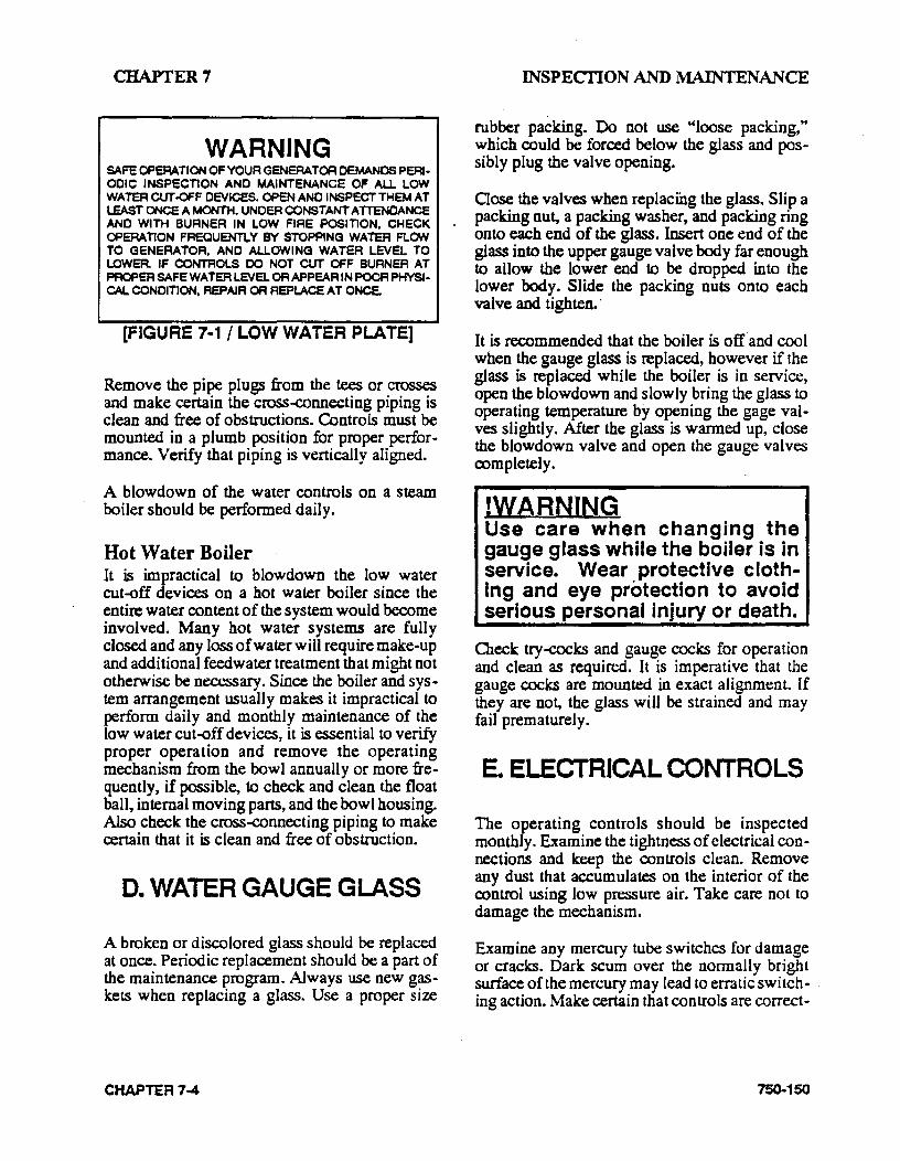
CHAPTER7
WARNING SAFE OPERATION OF YOUR GENERATOR DEMANDS PERl· OOIC INSPECTION ANO MAINTENANCE OF ALL LOW WATERCUT.QFF DEVICES. OPENANO INSPECTTHEMAT LEAST ONCE A MONTH. UNCER CONSTANT ATTENDANCE ANO WITH BURNER IN LOW FIRE POSITION, CHECK OPERAT10N FREQUENTLY BY STOPPING WATER FLON TO GENERATOR, ANO ALLOWING WATER LEVEL TO LOWER IF CONTROLS 00 NOT CUT OFF BURNER AT PROPER SAFE WATER LEVS. OR APPEAR IN POOR PHYSa· CAL CONOITION, REPAIR OR REPLACE AT ONCE.
[FIGURE 7-1 I L.OW WATER PlATE]
Remove the pipe plugs from the tees or crosses and make certain the cross-connecting piping is clean and free of obstructions. Controls must be mounted in a plumb position for proper performance. Verify that piping is vertically aligned.
A blowdown of the water controls on a steam boiler should be performed daily.
Hot Water Boiler It is impractical to blowdown the low water cut-off devices on a hot water boiler since the entire water content of the system would become involved. Many hot water systems are fully closed and any loss of water will require make-up and additional feedwater treatment that might not otherwise be necessary. Since the boiler and sys .. tem arrangement usually makes it impractical to perform daily and monthly maintenance of the low water cut-off devices, it is essential to verify proper operation and remove the operating mechanism from the bowl annually or more frequently, if possible, to check and clean the float ball, internal moving parts, and the bowl housing. Also check the cross-connecting piping to make certain that it is clean and free of obstruction.
D. WATER GAUGE GLASS
A broken or discolored glass should be replaced at once. Periodic replacement should be a part of the maintenance program. Always use new gaskets when replacing a glass. Use a proper size
CHAPTER7-4
INSPECriON AND MAINTENANCE
rubber packing. Do not use "loose packing," which could be forced below the glass and possibly plug the valve opening.
Qose the valves when replacfug the glass. Slip a . packing nut, a packing washer, and packing ring
onto each end of the glass. Insert one end of the glass into the upper gauge valve body far enough to allow the lower end to be dropped into the lower body. Slide the packing nuts onto each valve and tighten.·
It is recommended that the boiler is off' and cool when the gauge glass is replaced, however if the glass is replaced while the boiler is in service, open the blowdown and slowly bring the glass to operating temperature by opening the gage valves slightly. After the glass is warmed up, close the blowdown valve and open the gauge valves completely.
!WARNING Use care when changing· the gauge glass while the boiler is in service. Wear protective clothIng and eye protection to avoid serious personal injury or death.
Check try--cocks and gauge cocks for operation and clean as required. It is imperative that the gauge cocks are mounted in exact alignment. If they are not, the glass will be strained and may fail prematurely.
E. ELECTRICAL CONTROLS
The operating controls should be inspected monthly. Examine the tightness of electrical connections and keep the controls clean. Remove any dust that accumulates on the interior of the control using low pressure air. Take care not to damage the mechanism.
Examine any mercury tube switches for damage or cracks. Dark scum over the normally bright surface of the mercury may lead to erratic switch- . ing action. Make certain that controls are correct-
750-150
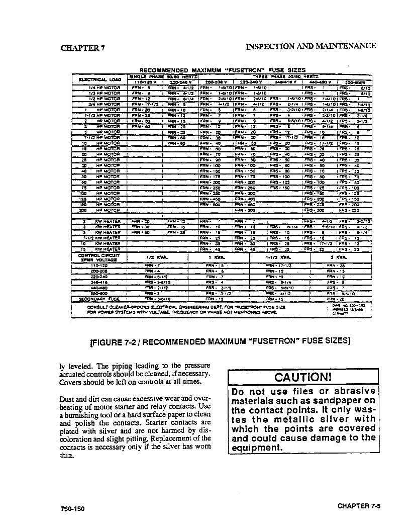
CHAPTER7 INSPEcriON AND l\1AINTENANCE
RI!COMMENDED MAXIMUM ••frUSETRON" FUSE SIZS:S
IUCTJHC.U.. LOAO .SINQU Pto!AS& 5011!10 HI!.RT% THRill IIIMASI 50/110 HIRTZ
110.1:0 y %20-UOY 200-2CM Y I 220-ZAOY I ;s.q..&18 v I ~y I !$C)o!JOOY
1/III.HPMOTOA FAN• a FRN• ... 1/:Z FAN• 1"""101 FRN • 1-8/10 I I FRS• 1 I FRS • !/10 t r.J HP MOTOR FAN • II FRH• .... ,:z FAN• 1-t/10 I FAN • 1-a110 I I FRS• 1 I FRS· !110 1/2 MP MOTOR FRN• t:Z FAN• 8-114 FRN· 2-t/10 FAN• 2-a/10 I FRS • 1-t/10 I FRS • 1'""'110 I FRS • I
31111. MPMOTOR P'fl!N • 17•112 FRN• II FRN• .... ,12 FRN• .. ,:z FRS• 2•114 I FRS· 1e4/10 I FRS· , ... ,,0 1 HPMOTOR FAN• 20 P'fl!N • 10 FAN• 5 FRN• 5 I FRS• 3-V10JFRS • 2•1/ .. I FRS• l-e/10 t•t/2 Hill MOTOR FAN• 2! II'JIN•IZ FAN• 1 FAN • 7 FRS• .. I FRS· 3•V,Of FRS· 2•1/::Z 2 MPWOTOR FRN•30 II'JIN• HI FAN • ' FAN• II I FRS• H/10 I FRS• .... ,12 I FRS• 3-11'2 3 MP MOTOR FRN•40 FAN • 20 FRN• 12 fi'RN • t:Z FRS• a I FRS• loll• I FRS • 5 5 HP MOTOR FRN•3S FJtN • 20 II'IIIN• 20 F'FtS. 12 I FRS• tO !FRS• a 1· t 12 Hit MOTOR FAN• 60 FRN• 30 F'JitN • 30 IIRS• t7•tl2 I F'JitS• 1! I FRS· 12
10 Mil MOTOR FAN• SO FAN• 40 I"'M• 35 FRS• 20 I FRS• 17•112 I FRS• 15 U5 MP MOTOR FRN• so I FAN• sa I FRS· 30 I FRS· 25 I FRS• 20 20 HP MOTOFI I FAN· ?'0 IFRN• 10 !FRS• 4C I FRS• 35 I FFIS • 25 25 HP MOTOFI FRN• ;a I FAN• 80 I FRS· !Q I FRS• 40 I FRS· ::15 30 HPMOTOR FAN• tOO FAN• tOO I FRS· eo I FRS• !Q lif'RS • 40 40 HPMQTOR I FAN• U50 I FFIN • H50 I Fr:IS• 80 I FI=IS· 70 I FRS• ~0
so HP MOTOR I FI=IN • 17!1 FI=IN • t75 I FRS • tOO I FRS• ao I F'RS • 70 eo MP MOTOR FFIN• ZOO I FRN• 200 I FRS • 125 I Fr:IS• 100 I FRS· ao 715 MP MOTOR I FRN• 2!0 FAN• 2$0 I FRS • 1!0 I FRS • 12!1 I F'RS • 100
100 MPMOTOR I FRN • 3!50 I FAN• 300 I I FRS• 1!!50 I FRS• 125 125 HP MOTOR I RtN •4150 I FAN• "CCli I FRS• 200 I F'RS • !50 ISO HP MOTOR FAN·~ I F'RH • 4150 I FRS • 225 I F'RS • 200 zoo HP MOTOR I I FRN• eciQ I FRS • 300 I F'RS • 2!10 I
I I I I 2 KW HeATER FRN• 20 FRN•T::Z RfN• 7 I FAN• 1 I I FRS· •tt2 ! FRS• 3-2/10 3 I<WHEA~ FRN•30 FRN• 15 FRN• tO I FAN• 10 !FRS• lo114 I FRS· !-6/1 0 I FRS • .. ,r:z 5 I<W HEllo TER RfN•50 FAN• 25 FRN• 15 I RfN• 15 FRS• 10 I FRS· s I FRS· 5-11"' MJ2KW HEATER FAN• 25 FAN• %.5 I FRS• us I FRS• 12 I F'RS. 10
10 i(W Ht!ATEJII I FAN• 30 I FAN• 30 IF'RS• 2-' I FRS• , ?'•t r:z I FRS· 12 ~~ KW HEATEA I FRN• .&6 I FAN• .&6 IF'RS• J.!5 I FRS· 25 -III"RS• 20
C::ON'T'IItCI. C::RCUfT 112 ICYA. t ICYA. 1•tl2 ICYA. 2 ICVA. XI'IIR VOI.TAQ.
11C)o120 FRN• 7 FRN • 15 FRN • 1 7·112 FRN • 2! Z00.208 I FRN•• FAN• a FRN• 12 FAN· 15 220-240 II="RN • 3-112 FRN• .1 FRN• 10 FAN • 12 ~HI ~- 2-a/10 FRS• "' FRS• loll" !="AS• ! ~ FRS• 2•112 FRS• 3-112 FRS• H/10 IOJIS. ., !150o<KIQ FRS· 2 FRS· 3•1/2 FRS• .. 112 FRS· $-4/10
SECONO.AAY ,1\JSI I II="RN• H/10 FRN• 12 FRN•HI FRN • 20
C:CHSULT c::..!AveAoeAOOK.S EI..!C'I"AACAL ~INI!JIIING OEPT. R:)R .,rusi'TROH"' 'USE SIZ!
I owo. ~ 130-•"2'$1 IIIIII'VISID I~
'CR ~ S'I"STTMS WI'TM VCLTAGI. FRI!QUINCY 0111 PloiASI HOT WE'NTIONI!I) A8CY!. 1:1...,,.,.
[FIGURE 7·2/ RECOMMENCED MAXIMUM "FUSETRON" FUSE SIZES]
ly leveled. The piping leading to the pressure actuated controls should be cleaned, if necessary. Covers should be left on controls at all times.
Dust and dirt can cause excessive wear and over· heating of motor starter and relay contacts. Use a burnishing tool or a hard surface paper to clean and polish the contacts. Starter contacts are plated with silver and are not harmed by discoloration and slight pitting. Replacement of the contacts is necessary only if the silver has worn thin.
750-150
CAUTION! Do not use files or abrasive materials such as sandpaper on the contact points. It only wastes the metallic silver with which the points are covered and could cause damage to the equipment.
CHAPTER 7..S
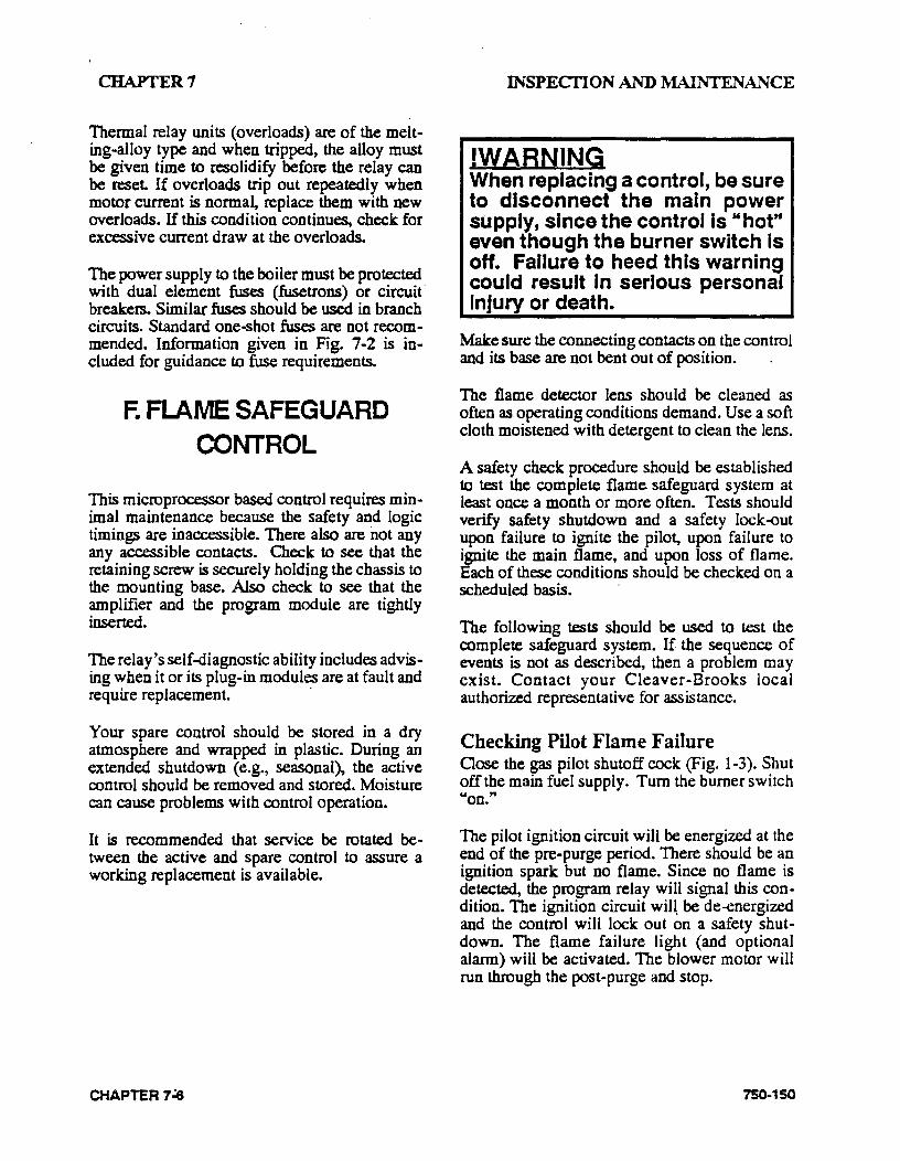
CHAPTER 7
Thermal relay units (overloads) are of the melting-alloy type and when tripped, the alloy must be given time to resolidify before the relay can be reset. If overloads trip out repeatedly when motor current is normal, replace them with new overloads. If this condition continues, check for excessive current draw at the overloads.
The power supply to the boiler must be protected with dual element fuses (fusetrons) or circuit" breakers. Similar fuses should be used in branch circuits. Standard one-shot fuses are not recommended. Information given in Fig. 7-2 is included for guidance to fuse requirements.
F. FLAME SAFEGUARD CONTROL
This microprocessor based control requires minimal maintenance because the safety and logic timings are inaccessible. There also are not any any accessible contacts. Check to see that the · retaining screw is securely holding the chassis to the mounting base. Also check to see that the amplifier and the program module are tightly inserted.
The relay's self-diagnostic ability includes advising when it or its plug-in modules are at fault and require replacement. ·
Your spare control should be stored in a dry atmosphere and wrapped in plastic. During an extended shutdown (e.g., seasonal), the active control should be removed and stored. Moisture can cause problems with control operation.
It is recommended that service be rotated be· tween the active and spare control to assure a working replacement is available.
CHAPTER7~
INSPECTION AND MAINTENANCE
!WARNING When replacing a control, be sure to disconnect the main power supply, since the control is "hot" even though the burner switch Is off. Failure to heed this warning could result in serious personal Injury or death.
Make sure the connecting contacts on the control and its base are not bent out of position.
The flame detector lens should be cleaned as often as operating conditions demand. Use a soft cloth moistened with detergent to clean the lens.
A safety check procedure should be established to test the complete flame safeguard system at least once a month or more often. Tests should verify safety shutdown and a safety lock-out upon failure to ignite the pilot, upon failure to ignite the main flame, and upon loss of flame. Each of these conditions should be checked on a scheduled basis.
The following tests should be used to test the complete safeguard system. If the sequence of events is not as described, then a problem may exist. Contact your Cleaver-Brooks local authorized representative for assistance.
Checking Pilot Flame Failure Qose the gas pilot shutoff cock (Fig. 1-3). Shut off the main fuel supply. Tum the burner switch "on."
The pilot ignition circuit will be energized at the end of the pre-purge period. There should be an ignition spark but no flame. Since no flame is detected, the program relay will signal this condition. The ignition circuit wil~ be de-energized and the control will lock out on a safety shutdown. The flame failure light (and optional alarm) will be activated. The blower motor will run through the post-purge and stop.
750-150
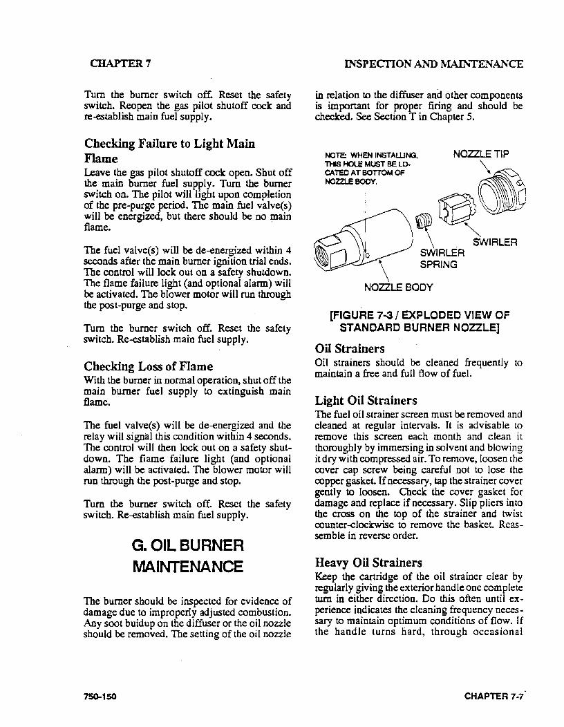
CHAPTER 7
Tum the burner switch off. Reset the safety switch. Reopen the gas pilot shutoff cock and re-establish main fuel supply.
Checking Failure to Light Main Flame Leave the gas pilot shutoff cock open .. Shut off the main burner fuel supply. Tum the burner switch on. The pilot will light upon completion of the pre-purge period. The main fuel valve(s) will be energized, but there should be no main flame.
The fuel valve(s) will be de-energized within 4 seconds after the main burner ignition trial ends. The control will lock out on a safety shutdown. The flame failure light (and optional alarm) will be activated. The blower motor will run through the post-purge and stop.
Tum the burner switch off. Reset the safety switch. Re-establish main fuel supply.
Checking Loss of Flame With the burner in normal operation, shut off the main burner fuel supply to extinguish main flame.
The fuel valve(s) will be de-energized and the relay will signal this condition within 4 seconds. The control will then lock out on a safety shutdown. The flame failure light (and optional alarm) will be activated. The blower motor will run through the post-purge and stop.
Tum the burner switch off. Reset the safety switch. Re-establish main fuel supply.
G. OIL BURNER l\t1AINTENANCE
The burner should be inspected for evidence of damage due to improperly adjusted combustion. Any soot buidup on the diffuser or the oil nozzle should be removed. The setting of the oil nozzle
750-150
INSPECTION AND MAINTENANCE
in relation to the diffuser and other components is imponant for proper firing and should be checked. See Section Tin Chapter 5.
NOTE: WHEN INSTAWNG, THS HOLE MUST BE LO. CATEO AT BOTTOM OF NOZZLE BOOY.
NOZZLE TIP
\
0~ ~ . )wiRLER
\ SWIRLER SPRING
NOZZLE BODY
[FIGURE 7-3 I EXPLODED VIEW OF STANOARD BURNER NOZZLE]
Oil Strainers Oil strainers should be cleaned frequently to maintain a free and. full flow of fuel.
Light Oil Strainers The fuel oil strainer screen must be removed and cleaned at regular intervals. It is advisable to remove this screen each month and clean it thoroughly by immersing in solvent and blowing it dry with compressed air. To remove, loosen the cover cap screw being careful not to lose the copper gasket. If necessary, tap the strainer cover gently to loosen. Check the cover gasket for damage and replace if necessary. Slip pliers into the cross on the top of the strainer and twist counter-clockwise to remove the basket Reassemble in reverse order.
Heavy Oil Strainers Keep the cartridge of the oil strainer clear by regularly giving the exterior handle one complete tum in either direction. Do this often until experience indicates the cleaning frequency necessary to maintain optimum conditions of flow. If the handle turns liard, through occasional
CHAPTER 7-7.
CHAPTER7
neglec~ rotate back and forth until the handle can be turned through a complete revolution. Do not force with a wrench or other tool.
Drain the sump as often as experience indicates the necessity. Remove the sump, or head and cartridge assembly for thorough cleaning and inspection at frequent intervals. Exercise care not to damage cartridge discs or cleaner blades. Wash the cartridge in solvents. Do not attempt to disassemble the cartridge.
Cleaning Oil Nozzle The design of the burner, together with the oil purge system on a heavy oil burner, make it unnecessary to clean the oil nozzle during periods of operation. A routine check should be made during off periods or when the burner is firing on gas and any necessary cleaning performed.
If at any time the burner flame appears "stringy" or "lazy," it' is possible that. the nozzle tip or swirler has become partially clogged or worn. Any blockage within the tip will cause. the air pressure gauge to increase above its normal value.
Disassemble with power off by unlatching and withdrawing the burner gun. Insen the nozzle body into the hanger vice and use the spanner wrench to remove the tip. Carefully remove the swirler and seating spring being careful not to drop or damage any parts. See Fig. 7-3.
Perform any necessary cleaning with a suitable solvent. Use a soft fiber brush or pointed piece of soft wood for cleaning. Do not use wire or a sharp metallic object which is apt to scratch or deform the orifices and the precision ground surfaces of the swirler and tip. Inspect for scratches or signs of wear or erosion which may make the nozzle unfit for further use. Take neces· sary precautions when working with solvents.
The tip and swirler are a matched set, which was precision lapped at the time of assembly. The close fit of these lapped surfaces must be maintained in order to provide optimum performance. Additional lapping may be required to provide
CHAPTER7-8
INSPECI'ION AND MAINTENANCE
better atomization for more efficient combustion. Do not interchange parts if a spare is kept. During reassembly, make certain that the seating spring is in place and that it is holding the swirler tightly against the tip. The swirler is stationary and does not rotate, but rather imparts a swirling motion to the oil.
See that the plugged bole is at the bottom of the nozzle body when the gun is installed (see Fig. 7-3).
Cleaning Air Purge Nozzle (No. 6 Oil) and Back Pressure Orifice Nozzle (No.2 Oil) The air purge nozzle and its strainer should be inspected periodically and cleaned. The nozzle consists of a tip and internal core. Clean all internal surfaces of the tip and the slotted parts of the core using a wood splinter to avoid damage from scratching. Replace the core, setting it tight· ly but not excessively so.
Qean the strainer screen carefully to remove any foreign matter. Use suitable solvents for cleaning. Extremely hot water at high velocity is also helpful for cleaning. Replace strainer by screw ... ing it into the nozzle body only finger tight. Do not use an orifice of a size other than originally installed.
Ignition System For best ignition results, maintain the proper gap and dimensions of the ignition electrode(s). Figs. S-9 and 5-10 show the proper settings.
Inspect the electrode tip(s) for signs of pitting or combustion deposits and dress as required with a fine file. Inspect the porcelain insulator(s) for any cracks that might be present. If cracks are present, replace the electrode since cracks can lead to grounding of the ignition voltage. Since carbon is an electrical conductor, it is necessary to keep the insulating portion of electrode(s) wiped clean. Ammonia will aid in removing carbon or soot.
750-150
CHAFTER7
Check ignition cables for cracks in the insulation. Also see that all connections between the transformer and electrodes are tight.
Periodically remove the access plug from the gas pilot aspirator (Fig. 5-1 0) and clean out any accumulated lint or foreign material.
H. GAS BURNER I\IIAINTENANCE
The gas burner components should be inspected for evidence of damage due to improperly adjusted combustion. Combustion adjustments should be checked monthly. See Section T in Chapter 5.
Check periodically for a proper seal between the end of the burner housing and oven refractory (see Fig. 7-10). Any deterioration of the seal should be corrected, as an improper or poor seal allows air leaks, which can cause overheating or burning of the burner housing.
Whenever the burner is removed, the diffuser, gas housing and gas spuds (HTB model only) should be checked for any deterioration. Verify that the diffuser skirt conionns to the bore of the butner housing so as to minimize the amount of combustion air which bypasses the diffuser. If the burner is an HTB model, check to see that the diffuser is properly located in reference to the gas spuds. There should be 1/4" between the edge of the diffuser fins and the gas spuds when the burner is installed. Check to see that the diffuser fins do not interfere with the gas ports or gas spuds in the burner housing (see Fig. 5-11). See Section V in Chapter 5 for more information.
Check the electrode setting for any cracks that might be present on the porcelain insulator. Replace the electrode if cracking is evident, since cracks can cause grounding of ignition voltage. Inspect the tip of the electrode for signs of pitting, combustion deposits, and wear and dress as required with a fme file. See Fig. 5-l 0 for electrode settings.
750-150
INSPECI'ION AND MAINTENANCE
Periodically remove the access plug from the gas pilot aspirator (Fig. 5-10) and clean out any accumulated foreign material.
Check the ignition cables for cracks in the insulation. Verify that all connections between the transformer and electrode are tight.
I. 1\nCTORIZED GAS VALVE(S)
The motorized gas valve (hydramotor) operating mechanism is completely immersed in oil and little maintenance is required, because of the sealed design. However, proper operation should be checked on a routine periodic basis.
Keep outer parts of the valve clean, especially the stem between the operator and the valve. A nicked, scored or otherwise damaged valve stem can cause leakage. Do not remove dust covers if installed.
The packing gland 'is of the 0-ring type. If oil is noticed around the operator base, or if leakage occurs, repair by replacing any leaking 0-rings and refill the actuator with oil.
If the actuator is sluggish or fails to operate, even after the oil level is checked, replace the entire operator portion.
J. SOLENOID VALVES
Foreign matter between the valve seat and seat disc can cause leakage. Valves are readily disas· sembled; however, care must be used during disassembly to be sure that internal parts are not damaged during removal and that reassembly is in proper order.
A low bum or buzzing will normally be audible when the coil is energized. If the valve develops a loud buzzing or a chattering noise, check for proper voltage and clean the plunger assembly and interior plunger tube thoroughly. Do not use
CHAPTER 7-9
CHAPTER7
CHAPTER 7 ·1 0
INSPECriON AND :MAINTENANCE
IMPE'1J..ER VNIES MJST NOT FIJS ON l<lUSING. BUT c::::u::A.AANCE MUST NOT EXCEED .030 INCH. ADJUST, IF NECESSARV. BY c::H.ANGING IMPEI....L.ER g;tAQNG WASHERS
FLON
IMPellER VIEWED FRC>M MOTOR SlOE
[FIGURE 7-4 I FORCED CRAFT FAN MOUNTING AND FLOW OF SECONDARY AIR -100-200 HP]
750-150
CHAPTER7
750-150
INSPECTION AND MAINTENANCE
FAN HOUSING
IMPEI..I...ER VANES ~NOT FlUB ON HOUSING, BUT ~MUST NOT EXCEED .030 INCH, AQJUST, IF NECESSAAY, BY CHNooiGINGi IMPS...l.EF4 SPACING WASHEFIS
FLON
AM ..... ~'I'. All
"==-:1/~~u.: ~11DN ........
IMPEllER VIEWED FFIOM MOTOR SIDE
[FIGURE 7-5/ FORCED DRAFT FAN MOUNTING AND FLOW OF SECONDARY AIR - 250-400 HP]
CHAPTER 7-11

. CHAPTER 7
any oil. Make sure that the plunger tube and solenoid are tight when reassembled. Take care not to nick, dent or damage the plunger tube.
Coils may be replaced without removing the valve from the line.
!WARNING Be sure to turn off power to the valve In order to avoid electrical shock, which could result In serious personal Injury or death.
Check the coil position and make sure that any insulating washers or retaining springs are reinstalled in proper order. ·
K. AIR CONTROL DAMPER, UNKAGE AND CAM SPRING
The burner air control damper should be checked for free movement as a part of the monthly inspection. With the burner off and the jackshaft damper control rod disconnected, the air control damper should rotate freely through its entire range of movement. Any resistance to movement or excessive play in the support bearing should be investigated and corrected before the burner is put back in operation.
The overall tightness of the linkage assembly should be checked monthly. If necessary, tighten the setscrews and the connections at the uniballs. Check the uniballs for wear and replace if necessary.
The linkage assembly should be tight but should not bind. If the linkage assembly is binding, determine the cause of the binding and correct as necessary.
Linkage rod end attachment points should be marked on the variable displacement linkage arms as an aid in subsequent reassembly.
CHAPTER 7-12
INSPEcriON AND :MAINTENAL'ICE
Inspection of the air damper and linkage bearings should be performed on a more frequent basis if the boiler is operating in a dirty environment.
The fuel cam profile spring should be inspected monthly for wear, scoring or distortion. If any of these conditions are found, the cam or cam spring must be replaced immediately to avoid the pos· sibility of breakage in service. Use care to avoid damaging the cam or spring during installation.
Lubricate the cam spring occasionally with a non-gumming, dripless, high-temperature lubricant such as graphite or a silicone derivative.
CAUTION! Combustion should be checked and readjusted as required whenever the burner is removed or any control linkage Is dis· turbed In order to avoid damage to the equipment.
L. FORCED DRAFT FAN
Figures 7-4 and 7-5 show the flow of secondary, or combustion air through the intake opening, connecting the duct housing and impeller.
The position of the impeller vanes with relation to the air intake housing is extremely important to the output capacity of the fan. The impeller vanes should not rub or contact the air housing but at the same time the clearance must not be more than .030 inch and preferably less.
The inset at lower right of figures 7-4 and 7-5 is a view of the impeller from the motor side in· dicating the direction of the rotation.
The inset at the upper right shows a designation of "clockwise" and "counter--clockwise'' as the terms are used throughout this manual.
<.:heck occasionally to see that the fan is securely tightened to the motor shaft. If the boiler is installed in a dusty location, check the vanes for
750-150
CHAPTER7
deposits of dust or dirt since these buildups can cause a decrease in air capacity or lead to an unbalanced condition.
CAUTION! If the boiler Is Installed In a dusty location, check 'the vanes occasionally for deposits of dust or dirt. These buildups can cause a decrease In air capacity, lead to an unbalanced condition, or cause damage to the equipment •.
M. SAFETY VALVES
The safety valve is a very important safety device and deserves attention accordingly.
Follow the recommendations of your boiler inspector regarding valve inspection and testing. The frequency of testing, either by the use of the lifting lever or by raising the steam pressure, should be based on the recommendation of your boiler inspector and/or the valve manufacturer, and in accordance with sections VI and VII of the AS~ Boiler and Pressure Vessel Code.
Avoid excessive operation of the safety valve because even one opening can provide a means of leakage. Safety valves should be operated only often enough to assure that they are in good working order. When a pop test is required, raise the operating pressure to the set pressure of the safety valve. Allow the valve to open and reseat as it would in normal service.
Do not hand operate the valve with less than 75% of the stamped set pressure exerted on the underside of the disc. When hand operating, be sure to hold the valve in an open position long enough to purge accumulated foreign material from the seat area and then allow the valve to snap shut.
750-150
INSPECilON AND MAINTENANCE
Frequent usage of the safety valve will cause the seat and disc to become worn and cause it not to seal properly. This will cause the valve to leak and necessitate down·time of the boiler for valve repair or replacement. Repair of a valve must be done only by the manufacturer or its authorized representative.
Avoid having the operating pressure too near the safety valve set pressure. A 10% differential is recommended. An even greater differential is desirable and will assure better seat tightness and valve longevity.
N. FUEL OIL METERING VALVE, ADJUSTING AND
RELIEF VALVES
In the event that a leak occurs in .the packing of the metering valve, the packing nut should be snugged gradually to stop the leak.
CAUTION! Excessive tightening of metering valve packing nut prevents free movement of the metering stem and can cause damage to the equipment.
If replacement of the metering valve packing is necessary, procure PIN 880-370 kit and install in accordance with the following procedure.
(1) Shut off the oil flow. Be sure no pressure shows on the gauge.
(2) Match mark the cam hub and drive shaft. This will enable replacement of the cam in the original position and result in a minimum of cam adjustment when the burner is refired.
CHAPTER 7·13
CHAPTER 7
(3) Camp or hold the metering stem in the down position.
( 4) Loosen the setscrews in the cam hub and rotate or move the cam to a position where it does not interfere with the stem removal.
(5) Withdraw the metering valve stem and spring. Do not drop or mishandle. Cleek for nicks or scratches. Check that the pin holding the metering portion is not protruding. Back off the packing gland.
(6) Remove the capscrews holding the jack shaft support br~cket so that the bracket can be moved. It may be necessary to also loosen the supporting bracket on the far end of the shaft.
(7) Remove the existing packing rings and guides. Do not reuse these.
(8) Lightly coat the stem with the lubricant provided with the packing kit. Place the new packing, 0-rings and guides onto the stem in the sequence shown in Fig. 7 .. s. The beveled face of the guides and the teflon rings must face upward, with the exception of the upper brass guide which is faced down. Make sure that the 0-rings are properly located.
(9) Using the stem as a guide, insert the assembled packing into the cavity; then withdraw the stem.
CHAPTER 7·14
INSPECTION AND MAINTENANCE
(1 0) In the event the packing is too high, remove one teflon packing from each side of the middle brass guide as needed. Under no circumstances eliminate the two teflon packings on only one side of the brass guide.
(11) Replace the gasket, put the support in place, and secure all fastenings.
(12) Replace the metering stem and spring. Lightly lubricate the stem to facilitate insertion and easy movement. Use care when inserting so that the orifice and the stem are not damaged.
(13) Snug the packing gland, but only sufficiently to place slight tension on the packing. The stem must move freely from the force of the spring.
(14) Work the stem up and down several times to insure that it moves freely.
(15) Depress the valve stem and replace the cam. Mate the match marks and secure the setscrews. Make sure the cam spring is centered in the roller.
(16) Restore the oil flow. Test fire the burner at various firing rates making cer • tain that the metering stem freely follows the cam.
(17) Tighten the packing gland after a period of operation, if required, to maintain proper tension on the packing. Do not overtighten.
7SQ..150
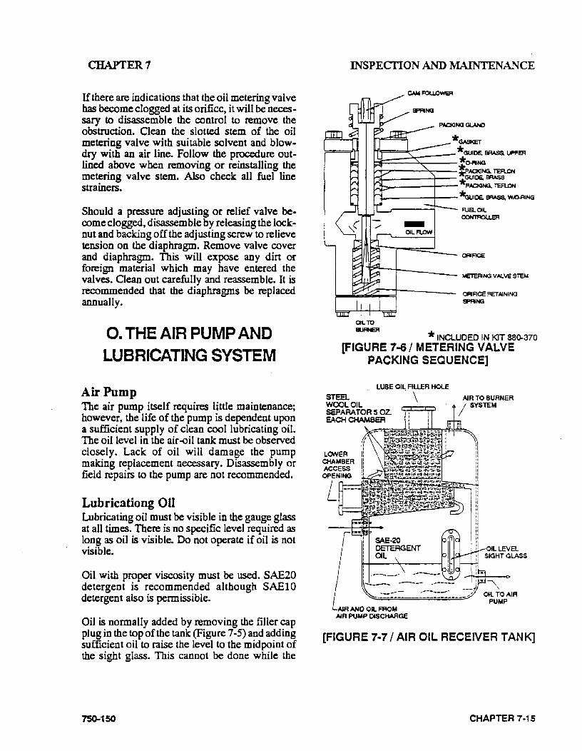
CHAPTER7
If there are indications that the oil metering valve has become clogged at its orifice, it will be necessary to disassemble the control to remove the obstruction. Clean the slotted stem of the oil metering valve with suitable solvent and blowdry with an air line. Follow the procedure out· lined above when removing or reinstalling the metering valve stem. Also check all fuel line strainers.
Should a pressure adjusting or relief valve become clogged, disassemble by releasing the locknut and backing off the adjusting screw to relieve tension on the diaphragm. Remove valve cover and diaphragm. This will expose any dirt or foreign material which may have entered the valves. Clean out carefully and reassemble. It is recommended that the diaphragms be replaced annually.
0. THE AIR PUMP AND LUBRICATING SYSTEM
Air Pump The air pump itself requires little maintenance; however, the life of the pump is dependent upon a su:f:ficient supply of clean cool lubricating oil. The oil level in the air ..oil tank must be observed closely. Lack of oil will damage the pump making replacement necessary. Disassembly or field repairs to the pump are not recommended.
Lubricationg Oil Lubricating oil must be visible in the gauge glass at all times. There is no specific level required as long as oil is visible. Do not operate if oil is not visible.
Oil with proper viscosity must be used. SAE20 detergent is recommended although SAElO detergent also is permissible.
Oil is normally added by removing the filler cap plug in the top of the tank (Figure 7-5) and adding sufficient oil to raise the level to the midpoint of the sight glass. This cannot be done while the
750-150
INSPECI'ION AND MAINTENANCE
P.a<ING GLANO
*GASKET *GUICE. BRASS, UPPER
~===s:;::== *0-ANG 1.-T':.?"'""--~-- ~ACKING, TEFLON ~-----t-- *GUICE, BRASS
PACKING, TEFl.ON
l-----+--*wiOE. E1F'AS8, W~ING FUS.OIL CCINTFW:)IJ.ER
OFIIACE
METERING VALVE STEM
CRACE RETAINING SPRNG
OIL TO EIJFIER * INCLUDED IN KIT 88~370
[FIGURE 7-6/ METERING VALVE PACKING SEQUENCE]
LUBE OIL FILLER HOlE
srea.. WOOL OIL SEPARATOR 5 OZ. EACH CHAMBER
I I
. \ AIR TO BURNER I SYSTEM
OIL LEVEL SIGHT GLASS
l ... ~--- ------- .------ ), ,. """"" ~:::.:::: ____ ~:::::::~----./ OIL TO AIR
AIR AHO OIL FROM AIR PUMP DISCHARGE
PUMP
[FIGURE 7·7 I AIR OIL RECEIVER TANK]
CHAPTER 7-15

CHAPTER7
boiler is in operation. If absolutely necessary to add oil during operation, remove the air cleaner and slowly add clean oil into this opening.
CAUTION! Oil must NEVER be added unless the pump Is In operation and the strainer screen In place in order to avoid damage to the equipment.
The oil and its container should be clean. Although there is a strainer in the lube oil line, its purpose is to remove any unwanted materials rather than to act as a filter for unclean oil.
Air Cleaner Never operate the air pump without the air cleaner in place. The cleaner itself must be periodically checked and its element flushed and cleaned. The correct level of oil must be maintained in the cleaner.
Ab·-Oil Tank The air-oil tank contains steel wool used as a filtering medium to separate the lube oil from the compressed air. A typical tank is show in figure 1-5. The wool is packed into two compartments each containing approximately five ounces. The wool should be replaced periodically whenever inspection reveals the need. Careful packing is necessary to assure even density. Do not over compress the wool and be sure it is fluffed out to fill all available space. Improper packing can cause high oil consumption. Use wool of proper density- refer to the parts list in Chapter 8.
Should sludge accumulate in the tank, drain it and flush with a suitable solvent..
Lube Oil Cooling Coil The fms on the tubing must be kept clean and free of any dust or dirt that would impede air flow and cause overheating. Use an air hose to blow away debris .. Internal cleaning of the tubes is seldom required if a good quality lube oil is used.
CHAPTER 7-16
INSPECTION AND MAINTENANCE
Lube OU Strainer The lube oil strainer screen must be removed and cleaned at regular intervals. It is advisable to remove this screen each month and clean thoroughly by immersing in solvent and blowing dry with compressed air. To remove, loosen the cover cap screw, being careful not to lose the copper gasket. Tap the strainer cover gently to loosen. Check the cover gasket. Slip the pliers into the cross on the top of the strainer and twist counterclockwise to remove the gasket. Re-assemble the strainer in reverse order.
General Keep the motor and other components free from dust and dirt to prevent overheating and damage.
P. REFRACTORY
The Cleaver-Brooks boiler is shipped with com .. pletely installed refractory. This consists of the rear head (Figure 7-6), the inner door and the furnace liner (Figure 7-7). Normal maintenance requires little time and expense and prolongs the operating life of the refractory. Preventive maintenance through periodic inspection will keep the operator informed of the condition of the refrac· tory and will guard against unexpected and unwanted down time and major repairs.
Frequent wash-coating of refractory surfaces is recommended. High temperature bonding airdry type mortar, dilluted with water to the consistency of light cream, is used for this purpose. Re-coating intervals will vary with operating loads and are best determined by the operator when the heads are opened for inspection.
Furnace Liner Maintenance consists of an occasional wash coating of the entire liner. Face all joints or cracks by applying high temperature bonding mortar with a trowel or fingertips. This should be done as soon as cracks are detected.
75()..150
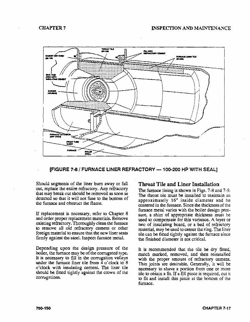
CHAPTER7 INSPEC110N AND :MAINTENANCE
(FIGURE 7-8 I FURNACE LJNER REFRACTORY- 100-200 HP WITH SEAL]
Should segments of the liner bum away or fall out, replace the entire refractory. Any refractory that may break out should be removed as soon as detected so that it will not fuse to the bottom of the furnace and obstruct the flame.
If replacement is necessary, refer to Chapter 8 and order proper replacement materials. Remove existing refractory. Thoroughly clean the furnace to remove all old . refractory cement or other foreign material to ensure that the new liner seats firmly against the steel. Inspect furnace metal.
Depending upon the design pressure of the ooiler, the furnace may be of the corrugated type. It is necessary to fill in the corrugation valleys under the furnace liner tile from 4 o'clock to 8 o'clock with insulating cement. The liner tile should be fitted tightly against the crown of the corrugations.
750-150
Throat Tile and Liner Installation The furnace lining is shown in Figs. 7-8 and 7-9. The throat tile must be installed to maintain an approximately 16" inside diameter and be centered in the furnace. Since the thickness of the furnace metal varies with the boiler design pres· sure, a shim of appropriate thickness must be used to compensate for this variance. A layer or two of insulating board, or a bed of refractory material, may be used to center the ring. The liner tile can be fitted tightly against the furnace since the finished diameter is not critical.
It is recommended that the tile be dry fitted, match marked, removed, and then reinstalled with the proper amount of refractory ce~en~. Thin joints are desirable. Generally, it will be necessary to shave a portion from one or more tile to obtain a fit. If a fill piece is required, cut it to fit and install this piece at the bottom of the furnace.
CHAPTER 7 ·17
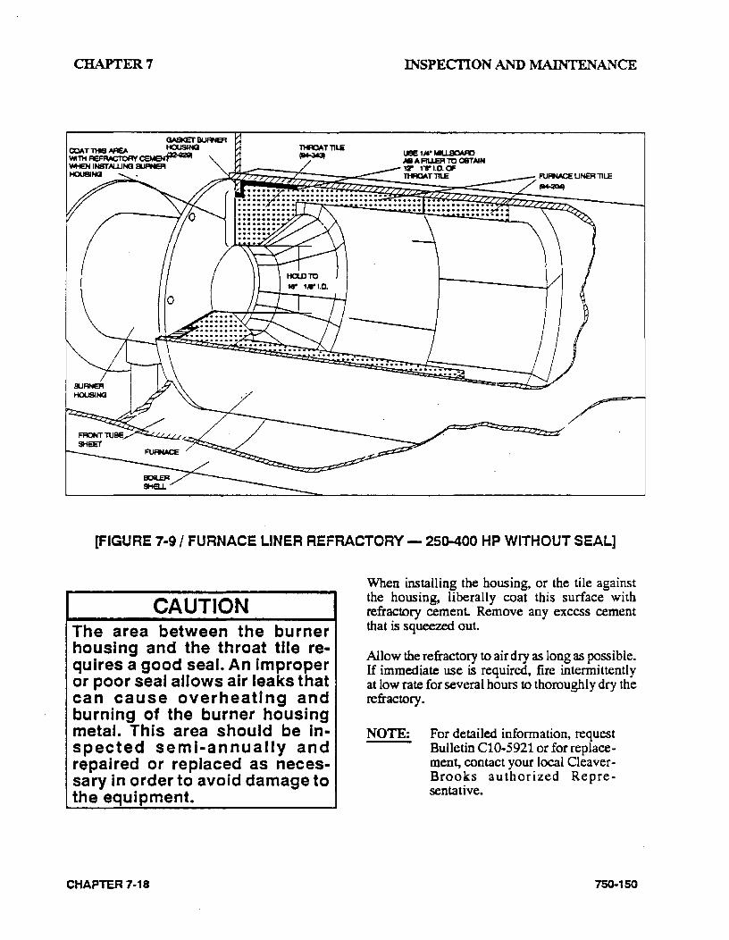
CHAPTER7
THROAT l1L.e ~
INSPECI10N AND l\1AINTENANCE
[FIGURE 7·9 I FURNACE LINER REFRACTORY- 25D-400 HP WITHOUT SEAL]
CAUTION The area between the burner housing and the throat tile requires a good seal. An improper or poor seal allows air leaks that can cause overheating and burning of the burner housing metal. This area should be in· spected semi-annually and repaired or replaced as necessary in order to avoid damage to the equipment.
CHAPTER 7-18
When installing the housing, or the tile against the housing, liberally coat this surface with refractory cement Remove any excess cement that is squeezed out.
Allow the refractory to air dry as long as possible. If immediate use is required, fire intermittently at low rate for several hours to thoroughly dry the refractory.
NOTE: For detailed information, request Bulletin Cl0-5921 or for replacement, contact your local Cleaver· Brooks authorized Representative.
750-150
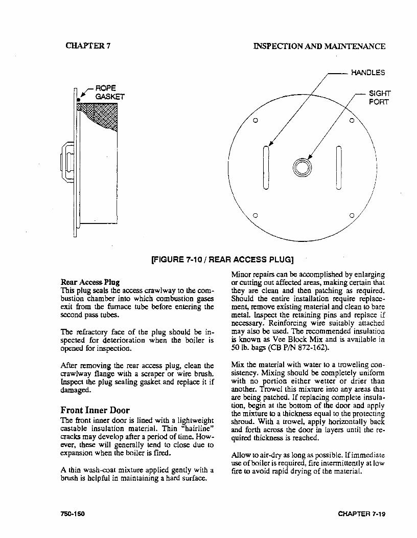
CHAPTER7 Il'iSPECfiON AND M.AINTEJ.'JANCE
------HANDLES
0
SIGHT PORT
[FIGURE 7-10 I REAR ACCESS PLUG]
Rear Access Plug This plug seals the access crawlway to the combustion chamber into which combustion gases exit from the furnace tube before entering the second pass tubes.
The refractory face of the plug should be inspected for deterioration when the boiler is opened for inspection.
After removing the rear access plug, clean the crawlway flange with a scraper or wire brush. Inspect the plug sealing gasket. and replace it if damaged.
Front Inner Door The front inner door is lined with a lightweight castable insulation material. Thin "hairline" cracks may develop after a period of time. However, these will generally tend to close due to expansion when the boiler is fired.
A thin wash-coat mixture applied gently with a brush is helpful in maintaining a hard surface.
750-150
Minor repairs can ~ accomplished by enlarging or cutting out affected areas, making certain that they are clean and then patching as required. Should the entire installation require replacement, remove existing material and clean to bare metal. Inspect th~ retaining pins and replace if necessary. Reinforcing wire suitably attached may also be used. The recommended insulation is known as Vee Block Mix and is available in SO lb. bags (CB PIN 872-162).
Mix the material with water to a troweling consistency. Mixing should be completely uniform with no portion either wetter or drier than another. Trowel this mixture into any areas that are being patched. If replacing complete insulation, begin at the bottom of thcr door and apply the mixture to a thickness equal to the protecting shroud. With a trowel, apply horizontally back and forth across the door in layers until the re· quired thickness is reached.
Allow to air-dry as long as possible. If immediate use of boiler is required, fire intennittently at low fire to avoid rapid drying of the material.
CHAPTER 7 ·19
CHAPTER7
Rear Door The rear door seals the chamber into which com· bustion gases flow after exiting the third pass and from which the gases are exhausted through the vent opening.
The rear door is insulated with a cerawool material which is stabilized with a ceramic rigidizer.
When the door is open for annual inspection, reapply the rigidizer to maintain a durable surface.
Q. OPENING AND CLOSING
DOORS
Opening Front or Rear Door
!WARNING Before loosening the door bolts, tighten the nut on the davit arm stud to support the door and avoid the possibility of serious personal Injury or death.
This will prevent sagging and facilitate opening of the door.
CAUTION Do not open a boiler when the boiler is hot. Rapid cooling by exposure to ambient air temperature may cause damage to the refractory or to the boiler itself.
After opening either door, support the open door with blocks or a jack and check the gaskets and sealing surfaces. If the door gaskets are hard or brittle, they should be replaced. The sealing sur-
CHAPTER 7-20
INSPECI10N AND MAINTENANCE
faces of the door and tube sheet should be clean. Make sure that all gasket retaining fasteners are in place.
Closing and Sealing Doors Coat the door gasket with an oil and graphite mixture., Swing the door to the closed position and run all of the retaining bolts in until snug. Tighten the bolts evenly, starting at the top center and alternating between the top and bottom bolts until both are tighL Do not overtighten. Tighten alternate bolts until all are secure and the door is gas tighL
CAUTION After closing the door, loosen the nut on the davit arm stud to release tension on the davit arm. Failure to do so may result In damage to the boiler due to thermal stresses during boiler operation.
After the boiler is back in operation, retighten the door bolts to compensate for compression of the gasket or movement of the door.
R. LUBRICATION
Electric Motors Manufacturers of electric motors vary in their specifications for lubrication and care of motor bearings, and their recommendations should be followed.
Ball bearing equipped motors are pre-lubricated. The length of time a bearing can run without having grease added will depend upon many factors. The rating of the motor, type of motor enclosure, duty, atmospheric conditions, humidity, and ambient temperatures are but a few of the factors involved.
750-150
CHAPTER 7 INSPECTION AND MAINTENANCE
[FIGURE 7-11 I REAR DOOR]
Complete renewal of grease, when necessary, can be accomplished by forcing out the old grease with the new grease. Thoroughly wipe those portions of the housing around the filler and drain plugs (above and below bearings). Remove the drain plug (bottom) and free the drain hole of any hardened grease which may have accumulated. With the motor not running, add new grease through the filler hole until clear grease starts to come out of the drain hole. Before replacing the drain plug, run the motor for 10 to 20 minutes to expel any excess grease. The filler and drain plugs should be thoroughly cleaned before they are replaced.
750-150
The lubricant used should be clean and equal to one of the good commercial grades of grease locally available. Some lubricants that are distributed nationally are:
Gulf Oil Precision Grease No.2
Humble Oil Andok B
Texaco Multifak No. 2
Phillips lB + RB No. 2
Fiske Bros. Ball Bearing Lubricant
Standard/Mobil Mobilux No. 2
CHAPTER 7-21
CHAPTER 7
Control Linkage Apply a non-gumming, dripless, high temperature lubrican~ such as graphite or a silicone derivative to all pivot points and moving parts. Work lubricant in well and wipe off any excess. Repeat application at required intervals to main· tain freedom of motion of parts.
Solenoid and Motorized Valves Solenoid valves and motorized valves require no lubrication.
S. OIL HEATERS ELECTRIC, STEAM, HOT
WATER
An annual maintenance of these heaters consists of removing the heating element from the shell and scraping any accumulation of carbonized oil or sludge_ deposits that may have collected on the heat exchanging surfaces.
Before breaking any of the electrical connections to the electric heating elements, mark all wires and terminals to assure rapid and correct replacement of wires.
Finish the cleaning process with a cleaning solvent to cut all hardened deposits from the heater elc~menL Because of the insulating effect of carbon and sludge, periodic cleaning is necessary to prevent overheating of the elements. If operation of the heater becomes sluggish, examine the elements at once and clean as required.
Inspect the shell or tank each time the heater is removed. Flush all accumulated sludge and sediment from the tank before reinstalling the heater.
The condensate from steam oil heaters must be safely discharged to waste. This waste should be checked periodically for any traces of oil which would indicate leaking tubes within the heater.
CHAPTER 7-'22.
INSPEcriON AND MAINTENANCE
The hot water oil heater (Fig. 7-14) contains a heat transfer solution. Oil flows through an inner tube while boiler water surrounds the outer tube. The space between the two tubes is filled with the heat transfer solution and is connected to an expansion chamber on the rear of the heater. A visual indicator on this cham her reveals the presence of any oil if an oil leak occurs.
A 50/50 solution of permanent anti-freeze and water is generally used as the heat transfer solution. If there is no danger of freezing, plain water may be used as a replenishment if necessary to refill.
Evidence of oil in either the steam heater condensate or in the water heater indicator demands prompt repair.
T. COMBUSTION
The frequency of burner adjustments depends upon several factors, including; type of burner, type of fuel, load conditions, ambient temperature, climatic variables, and general maintenance practices.
The air-fuel ratio should be checked monthly since this will alert the operator to losses in efficiency, which do not produce visible flame change. Any time maintenance is performed on the burner linkage the the air-fuel ratio should be checked. Readjustment of the burner may be required due to variations in fuel composition. A combustion analyzer should be used to adjust air-fuel ratio for maximum operating efficiency. If your burner requires adjustments, contact your Oeaver-Brooks local authorized representative for assistance.
750-150
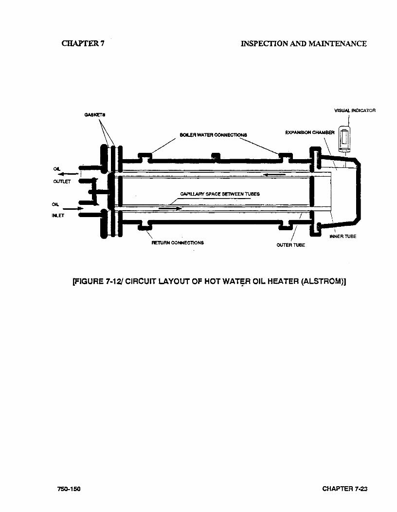
CHAPTER7
OIL ... OUTLET
OIL
IN..ET
GASKETS
INSPECI10N AND MAINTENANCE
VISUAL INDICATOR
CAPtUARV SPACE BE1WEEN TUBES
\ INNER TUBE
RETURN COHNEC'TIONS OUTERT\JBE
(FIGURE 7-1·2/ CIRCUIT LAYOUT OF HOT WAT~R OIL. HEATER (ALSTROM)]
75C).150 CHAPTER 7·23
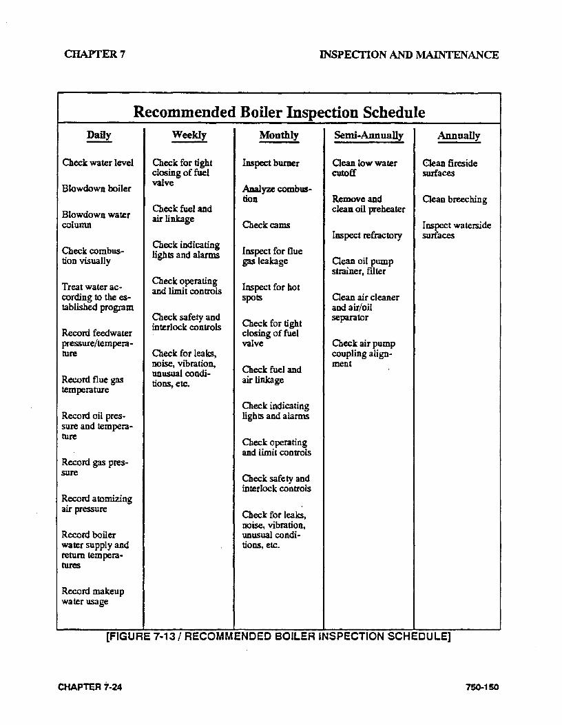
CHAPTER7 INSPECI10N AND MAINTENANCE
Recommended Boiler Inspection Schedule Daily Weekly Monthly Semi-Annually Annually
Check water level Check for tight Inspect burner aean low water aean fireside closing of fuel cutoff surfaces
Slowdown boiler valve
Analyze combus-tion Remove and aean breeching
Slowdown water Check fuel and clean oil preheater
column air linkage
Check cams Inspect waterside Inspect refractory surfaces
Check combus-Check indicating
Inspect for flue tion visually
lights and alarms gas leakage Cean oil pump
strainer, filter
Treat water ac· Check operating
Inspect for hot and limit controls cording to the es- spots aean air cleaner tablished program and air/oil
Check safety and Check for tight
separator
Record feedwater interlock controls
closing of fuel pressure/tempera- valve Check air pump ture Check for leaks, coupling align·
noise, vibration, Check fuel and
ment unusual condi-
Record flue gas tions, etc. air linkage temperature
Check indicating Record oil pres- lights and alarms sure and tempera-ture
Check operating and limit controls
Record gas pres-sure
Check safety and interlock controls
Record atomizing air pressure
Check for leaks, noise, vibration,
Record boiler unusual condi-water supply and tions, etc. return tempera-tures
Record makeup water usage
[FIGURE 7·13/ RECOMMENCED BOILER INSPECTION SCHEDULE]
CHAPTER 7'·24 750-150

CHAPTERS PARTS 'ORDER/LIST INSTRUcriONS
CHAPTER 8
PARTS ORDER/LIST INSTRUCTIONS
FURNISH COMPLETE INFORMATION WHEN ORDERING PARTS- When order .. ing parts for repair or spares, give description and state quantity of parts desired, together with the complete nameplate data, including rating, model, and serial number of the motor and all data.
WHERE TO ORDER PARTS. Repair or re .. placement parts should be ordered from your local Cleaver-Brooks authorized Representative.
~· CB PACKAGED BOILER
MOO B.. I I SERIAl NO.I I MAX. PRESSURE I IPSJ CATE I I INPUT I IBTUIHA c:JGAS D GPH OIL
ELECTRICAL REQUIREMENTS MAIN POWER SUPPLY
I IVOlTSDPHc:JHZ I lAMP.
IIINIMUM CIRCUIT AMPACilY I I ~. MAX. RAT1NG OF ClRCUIT PROTECllON lAMP.
BLOWER MOTOFI I IHP ~A COMPRESSOR MOT~ I IHP OIL HEATER I jKW CONTROl CIRCUIT
120 VOlTS 1 PH CJ HZ 7AMP. OIL PUMP MOTOR
I IVOLTSDPH c:JHZ I lAMP.
Cl.EAVEfl.£fn'.)I<S ~.INC.
WILWAl.IICCE WI, U.S.A
118-21')().8
Contact your local Cleaver-Brooks Representative for prompt supply of replacement parts.
750-150 CHAPTER a ... 1

Related Documents