CFLC ClearFire Condensing Boiler Boiler Book 05/2018

Welcome message from author
This document is posted to help you gain knowledge. Please leave a comment to let me know what you think about it! Share it to your friends and learn new things together.
Transcript

CFLCClearFire Condensing Boiler
Boiler Book05/2018

BOILER BOOK CFLC
2
Table of ContentsFEATURES AND BENEFITS . . . . . . . . . . . . . . . . . . . . . . . . . . . . . . . . . . . . . . . . . . . . . . . . . . . . . . . . . . . . . . . . . . . . . .3PRODUCT OFFERING . . . . . . . . . . . . . . . . . . . . . . . . . . . . . . . . . . . . . . . . . . . . . . . . . . . . . . . . . . . . . . . . . . . . . . . . . .5DIMENSIONS AND RATINGS . . . . . . . . . . . . . . . . . . . . . . . . . . . . . . . . . . . . . . . . . . . . . . . . . . . . . . . . . . . . . . . . . . . . .8PERFORMANCE DATA . . . . . . . . . . . . . . . . . . . . . . . . . . . . . . . . . . . . . . . . . . . . . . . . . . . . . . . . . . . . . . . . . . . . . . . . . .8ENGINEERING DATA . . . . . . . . . . . . . . . . . . . . . . . . . . . . . . . . . . . . . . . . . . . . . . . . . . . . . . . . . . . . . . . . . . . . . . . . . .15
List of FiguresAluFer Inserts . . . . . . . . . . . . . . . . . . . . . . . . . . . . . . . . . . . . . . . . . . . . . . . . . . . . . . . . . . . . . . . . . . . . . . . . . . . . . . . .3Burner service . . . . . . . . . . . . . . . . . . . . . . . . . . . . . . . . . . . . . . . . . . . . . . . . . . . . . . . . . . . . . . . . . . . . . . . . . . . . . . . .3Premix Burner Technology . . . . . . . . . . . . . . . . . . . . . . . . . . . . . . . . . . . . . . . . . . . . . . . . . . . . . . . . . . . . . . . . . . . . . . .4Model CFLC Cutaway View . . . . . . . . . . . . . . . . . . . . . . . . . . . . . . . . . . . . . . . . . . . . . . . . . . . . . . . . . . . . . . . . . . . . . . .5CFLC Control Panel . . . . . . . . . . . . . . . . . . . . . . . . . . . . . . . . . . . . . . . . . . . . . . . . . . . . . . . . . . . . . . . . . . . . . . . . . . . .7Model CFLC Dimensional Views . . . . . . . . . . . . . . . . . . . . . . . . . . . . . . . . . . . . . . . . . . . . . . . . . . . . . . . . . . . . . . . . . . .9CFLC Efficiency Curves . . . . . . . . . . . . . . . . . . . . . . . . . . . . . . . . . . . . . . . . . . . . . . . . . . . . . . . . . . . . . . . . . . . . . . . . .14Waterside Pressure Drop . . . . . . . . . . . . . . . . . . . . . . . . . . . . . . . . . . . . . . . . . . . . . . . . . . . . . . . . . . . . . . . . . . . . . . .18Condensate Piped Direct to Drain . . . . . . . . . . . . . . . . . . . . . . . . . . . . . . . . . . . . . . . . . . . . . . . . . . . . . . . . . . . . . . . . .22Condensate Treatment Tank - external . . . . . . . . . . . . . . . . . . . . . . . . . . . . . . . . . . . . . . . . . . . . . . . . . . . . . . . . . . . . . .23Condensate Treatment Tank - internal . . . . . . . . . . . . . . . . . . . . . . . . . . . . . . . . . . . . . . . . . . . . . . . . . . . . . . . . . . . . . .23Gas Piping Schematic . . . . . . . . . . . . . . . . . . . . . . . . . . . . . . . . . . . . . . . . . . . . . . . . . . . . . . . . . . . . . . . . . . . . . . . . . .24Gas Header Piping . . . . . . . . . . . . . . . . . . . . . . . . . . . . . . . . . . . . . . . . . . . . . . . . . . . . . . . . . . . . . . . . . . . . . . . . . . . .25Model CFLC Minimum Room Clearance Dimensions . . . . . . . . . . . . . . . . . . . . . . . . . . . . . . . . . . . . . . . . . . . . . . . . . . . .28Vent Terminations . . . . . . . . . . . . . . . . . . . . . . . . . . . . . . . . . . . . . . . . . . . . . . . . . . . . . . . . . . . . . . . . . . . . . . . . . . . .29Vertical Stack with Inside Combustion Air . . . . . . . . . . . . . . . . . . . . . . . . . . . . . . . . . . . . . . . . . . . . . . . . . . . . . . . . . . . .35Vertical Stack with Direct Venting/Sealed Combustion . . . . . . . . . . . . . . . . . . . . . . . . . . . . . . . . . . . . . . . . . . . . . . . . . . .36Two Opening Outside Wall Method . . . . . . . . . . . . . . . . . . . . . . . . . . . . . . . . . . . . . . . . . . . . . . . . . . . . . . . . . . . . . . . .38Two Opening Ducted Method . . . . . . . . . . . . . . . . . . . . . . . . . . . . . . . . . . . . . . . . . . . . . . . . . . . . . . . . . . . . . . . . . . . .39One Opening Method . . . . . . . . . . . . . . . . . . . . . . . . . . . . . . . . . . . . . . . . . . . . . . . . . . . . . . . . . . . . . . . . . . . . . . . . . .40Two Opening Engineered Method . . . . . . . . . . . . . . . . . . . . . . . . . . . . . . . . . . . . . . . . . . . . . . . . . . . . . . . . . . . . . . . . . .41Optional Direct Vent/Sealed Combustion Kit . . . . . . . . . . . . . . . . . . . . . . . . . . . . . . . . . . . . . . . . . . . . . . . . . . . . . . . . . .43 Falcon pinout . . . . . . . . . . . . . . . . . . . . . . . . . . . . . . . . . . . . . . . . . . . . . . . . . . . . . . . . . . . . . . . . . . . . . . . . . . . . . . .46
List of TablesU.S. Standard Dimensions Model CFLC Boiler . . . . . . . . . . . . . . . . . . . . . . . . . . . . . . . . . . . . . . . . . . . . . . . . . . . . . . . . .10Metric Dimensions Model CFLC Boiler . . . . . . . . . . . . . . . . . . . . . . . . . . . . . . . . . . . . . . . . . . . . . . . . . . . . . . . . . . . . . .11Model CFLC Boiler Ratings (Sea Level to 2000 Feet) . . . . . . . . . . . . . . . . . . . . . . . . . . . . . . . . . . . . . . . . . . . . . . . . . . . .12CFLC Efficiencies . . . . . . . . . . . . . . . . . . . . . . . . . . . . . . . . . . . . . . . . . . . . . . . . . . . . . . . . . . . . . . . . . . . . . . . . . . . . .13Model CFLC Boilers: Natural Gas, Estimated Emission Levels . . . . . . . . . . . . . . . . . . . . . . . . . . . . . . . . . . . . . . . . . . . . . .15Noise Level (dBA) measured 3 feet in front of boiler . . . . . . . . . . . . . . . . . . . . . . . . . . . . . . . . . . . . . . . . . . . . . . . . . . . . .15CFLC Flow Rates* . . . . . . . . . . . . . . . . . . . . . . . . . . . . . . . . . . . . . . . . . . . . . . . . . . . . . . . . . . . . . . . . . . . . . . . . . . . .16CFLC Flow Rates* (Metric) . . . . . . . . . . . . . . . . . . . . . . . . . . . . . . . . . . . . . . . . . . . . . . . . . . . . . . . . . . . . . . . . . . . . . .16Model CFLC Minimum Over Pressure Requirements (100% water) . . . . . . . . . . . . . . . . . . . . . . . . . . . . . . . . . . . . . . . . . .19Model CFLC Water Chemistry Requirements . . . . . . . . . . . . . . . . . . . . . . . . . . . . . . . . . . . . . . . . . . . . . . . . . . . . . . . . . .20Model CFLC Water Temperature Data (Non-Glycol) . . . . . . . . . . . . . . . . . . . . . . . . . . . . . . . . . . . . . . . . . . . . . . . . . . . . .20Glycol Application Guidelines - Model CFLC . . . . . . . . . . . . . . . . . . . . . . . . . . . . . . . . . . . . . . . . . . . . . . . . . . . . . . . . . .21Model CFLC Maximum Condensation . . . . . . . . . . . . . . . . . . . . . . . . . . . . . . . . . . . . . . . . . . . . . . . . . . . . . . . . . . . . . . .21CFLC Max Condensation . . . . . . . . . . . . . . . . . . . . . . . . . . . . . . . . . . . . . . . . . . . . . . . . . . . . . . . . . . . . . . . . . . . . . . . .24Model CFLC Minimum and Maximum Gas Pressure . . . . . . . . . . . . . . . . . . . . . . . . . . . . . . . . . . . . . . . . . . . . . . . . . . . . .26Model CFLC Minimum Required Gas Pressure Altitude Correction . . . . . . . . . . . . . . . . . . . . . . . . . . . . . . . . . . . . . . . . . . .26Altitude Correction for Input Capacity at Various Altitude Levels . . . . . . . . . . . . . . . . . . . . . . . . . . . . . . . . . . . . . . . . . . . .27Room Air Requirements . . . . . . . . . . . . . . . . . . . . . . . . . . . . . . . . . . . . . . . . . . . . . . . . . . . . . . . . . . . . . . . . . . . . . . . .41CFLC Combustion Air and Flue Venting Requirements . . . . . . . . . . . . . . . . . . . . . . . . . . . . . . . . . . . . . . . . . . . . . . . . . . .43Operating Conditions - Controller . . . . . . . . . . . . . . . . . . . . . . . . . . . . . . . . . . . . . . . . . . . . . . . . . . . . . . . . . . . . . . . . . .44Operating Conditions - Display/Interface . . . . . . . . . . . . . . . . . . . . . . . . . . . . . . . . . . . . . . . . . . . . . . . . . . . . . . . . . . . . .44Operating Conditions - VFD . . . . . . . . . . . . . . . . . . . . . . . . . . . . . . . . . . . . . . . . . . . . . . . . . . . . . . . . . . . . . . . . . . . . . .44 Falcon control sequence (Central Heat) . . . . . . . . . . . . . . . . . . . . . . . . . . . . . . . . . . . . . . . . . . . . . . . . . . . . . . . . . . . . .45

BOILER BOOK CFLC MODEL CFLC Features and Benefits
3
MODEL CFLC FEATURES AND BENEFITSCompact Firetube DesignThe Model CFLC boiler is a durable firetube condensinghot water boiler. The internal extended-heating surfacetubes provide very high levels of performance in acompact space, offering over 6 square feet of heatingsurface per boiler horsepower, providing many years oftrouble free performance.
Advanced TechnologyTubes are constructed from UNS S32101 duplexstainless steel with AluFer tube inserts (lower vessel) andcarbon steel with rifled surface (upper vessel) for optimalheat transfer.
Advanced ConstructionThe extended heating surface design provides the ideal solution for the demands of a condensingboiler and helps to recover virtually all the latent heat of the flue gas. Each tube consists of an outerstainless steel tube (waterside) and the AluFer extended surface profile on the flue gas side.
High EfficiencyWith the extended heating surface tubes the CFLC boiler will provide fuel to water efficiency of up to99% at low fire and 95% at high fire.
Ease of MaintenanceThe powder coated steel casing is designed for easy removal and re-assembly. As shown in Figure 2,the burner is hinged for simple opening for inspection of the burner cylinder, tubes and tube sheets.
Figure 2. Burner service
Quality ConstructionISO 9001:2001 certified manufacturing process ensures the highest degree of manufacturingstandards are always followed.
ASME Code construction ensures high quality design, safety, third party inspection, and reliability,and is stamped accordingly.
Premix TechnologyThe burner utilizes “Premix” technology to mix both gas fuel and combustion air prior to entering the
Figure 1. AluFer Inserts

BOILER BOOK CFLC MODEL CFLC Features and Benefits
4
burner canister, with air “leading” during burner firing transitions. Combined with a variable speedfan, this technology provides very low emission levels, exceptionally safe operation, and nearly 100%combustion efficiency.
Full ModulationThe variable speed fan provides modulated firing for reduced on/off cycling, excellent load tracking,and reduced operating costs. The burner does not require mechanical linkage connections betweenthe fuel input valve and air control. Instead, the microprocessor control positions the fan speed inaccordance with system demand, and this determines the fuel input without mechanical devicepositioning - that is, linkage-less fuel/air ratio control. This eliminates linkage slippage, minimizesburner maintenance, and provides control repeatability. This is shown schematically in Figure 3.
Figure 3. Premix Burner Technology
Designed For Heating ApplicationsThe pressure vessel is designed for 160 psig MAWP (Max. Allowable Working Pressure) and isconstructed of durable ASTM Grade Steel and Stainless Steel materials. Figure 4 shows the counterflow heat exchanger design that gives optimal heat transfer. The design also prevents hot spots, doesnot require a minimum flow for thermal shock protection, and does not require a minimum returnwater temperature. In fact, the design carries a 20-year thermal shock warranty.
Because of its design characteristics, the Model CFLC is well suited for applications utilizing indoor/outdoor reset controls, radiant floor heating, snow melt systems, ground source heat pump systemsand systems that utilize variable speed circulating pumps. It may also be employed in standard hotwater systems that require higher heated water at colder outdoor temperatures but then requireminimum temperatures during warmer heating days, realizing fuel efficiency savings over traditionalhot water boilers.
While the design does not lend itself to the direct supply of potable water, a separate storage tankwith an internal heat exchanger can be employed, as the microprocessor control permits domesticwater programming. Therefore, the Model CFLC can service both hydronic heating and domesticwater source heating.
Dual ReturnTwo return pipes - high and low temperature - allow condensing performance with as little as 10%return water at condensing temperature.

BOILER BOOK CFLC MODEL CFLC Product Offering
5
Figure 4. Model CFLC Cutaway View
MODEL CFLC PRODUCT OFFERINGInformation in this section applies to condensing hot water boiler sizes ranging from 4,000,000 BTUinput through 12,000,000 BTU input for operation on Natural Gas or LP Gas only. Installation is forindoor use only.
Dimensions, ratings, and product information may change due to market requirements and productimprovements. Therefore, use this information as a guide.
Standard EquipmentEquipment des cribed be low is for the s tandard boiler offering:
1. The BoilerA. Each boiler size is designed for a Maximum Allowable Working Pressure (MAWP) of 160 psig (11 Bar),
constructed in accordance with the ASME Code Section IV and bear the “H” stamp. MaximumOperating Pressure 144 psig. Maximum Allowable Working Temperature (MAWT) is 250 deg F (121C); Maximum operating set point temperature 230 deg F (110 C). Minimum supply set pointtemperature is 130 deg F. There is no minimum return temperature.
B. The insulated boiler is mounted on a base and enclosed in a powder coated steel casing.

BOILER BOOK CFLC MODEL CFLC Product Offering
6
C. One hot water outlet and dual return provided.2. Boiler Trim and Controls
A. The following items are furnished:B. Probe Type Low Water Cutoff control, manual reset.C. High Water Temperature Cutoff, manual reset.D. NTC (negative temp. coefficient) sensor for hot water supply temperature.E. NTC sensor for hot water return temperature.F. ASME Safety Relief Valve set @ 160 psig. (11 Bar)G. Temperature and pressure gauges.
3. Burner ControlA. Falcon burner control - an integrated burner management and modulation control with a touch-screen
display/operator interface. Its functions include the following:1. Two (2) heating loops with PID load control.2. Burner sequencing with safe start check, pre-purge, pilot ignition, and post purge.3. Electronic ignition.4. Flame Supervision.5. Safety shutdown with time-stamped display of lockout condition.6. Variable speed control of the combustion fan; Variable Speed Drive provided.7. Supervision of low and high gas pressure, air proving, stack back pressure, high limit, and low
water.8. First-out annunciator.9. Real-time data trending.
10. (3) pump/auxiliary relay outputs.11. Modbus communication capability.12. Outdoor temperature reset.13. Remote firing rate or setpoint control14. Setback/time-of-day setpoint15. Lead/Lag for up to 8 boilers16. Control circuit transformer
B. Variable Speed Drive for combustion air fan1. Compact packaged unit2. Factory configured and wired for boiler application
BOILER BOOK CFLC MODEL CFLC Product Offering
7
Figure 5. CFLC Control Panel4. Forced Draft Burner
A. The burner is a “Pre-mix” design consisting of a unitized venturi, gas valve(s) with safety shutoff andproof-of-closure, blower/motor, and burner head.
B. Full modulation is accomplished with a supplied variable speed fan for 5:1 turndown ratio.C. For near flameless combustion, the burner utilizes a Fecralloy-metal fiber head.D. Operating on Natural Gas, NOx emissions will be less than 20 PPM regardless of boiler size and the
boiler is certified for California and Texas for Low NOx emissions.E. As an option, the burner is capable of direct vent combustion.F. Ignition of the main flame is by gas pilot, with UV scanner for flame supervision.G. To ensure adequate combustion air is present prior to ignition, and to ensure the fan is operating, a
combustion air proving switch is furnished.H. A High Air Pressure Switch is provided to ensure burner lockout in case of excessive back pressure due
to a blocked condensate drain or a blocked stack.I. For ease of maintenance and inspection, the blower/motor assembly is furnished with a hinge which
permits the assembly to swing away. This provides access to the burner and electrode as well as thetube sheet and tubes.
J. Air filter provided as standard. Additional filter media can be ordered.K. VSD-duty TEFC 3-phase tri-voltage motor.
5. Burner Gas Train - The standard gas train is equipped in accordance with cULus certification and complies with ASME CSD-1. Each burner gas train includes:A. Low Gas Pressure Interlock, manual reset.B. High Gas Pressure Interlock, manual reset.C. ASME CSD-1 Test Cocks.D. Downstream manual ball type shutoff cock.E. Safety shutoff gas valve(s) with POC.
FALCON DISPLAY / OPERATOR INTERFACE
DEMAND SWITCH
IGNITION TRANSFORMER
FALCON CONTROLLER
LWCO CONTROLLER
TRANSFORMER, 115v/25v
TRANSFORMER, 460/230/208V PRI
TERMINAL TRACK
LWCO RESET
BOILER BOOK CFLC DIMENSIONS AND RATINGS
8
Optional EquipmentFor option details, contact the local authorized Cleaver-Brooks representative. In summary, here aresome of the options that can be provided with the boiler:
A. Condensate neutralization tank assembly - consists of neutralizing media, filter, and PVC condensateholding tank.
B. Direct vent kit for direct vent combustion.C. Outdoor temperature sensor for outdoor reset, frost protection, or warm weather shutdown.D. Header temperature sensor for multiple boiler Lead/Lag operation.E. Auxiliary Low Water Control (shipped loose) for field piping by others into the system piping.F. 100 dB Alarm Horn for safety shutdown (replaces standard Falcon alarm).G. Relays for output signal for burner on, fuel valve open.H. Stack thermometer (shipped loose - for field installation by others).I. Stack temperature limit-sensor.J. Auto air vent.K. Boiler drain valve.L. Gas pressure relief valveM. Gas pressure gaugeN. Water isolation valvesO. Circulating pumpsP. Seismic anchoring provisions
For options not listed here, consult your authorized Cleaver-Brooks representative.
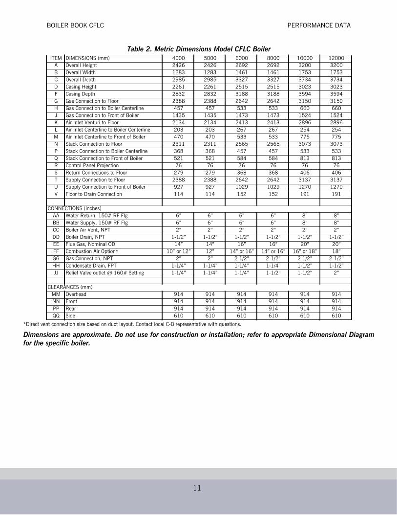
DIMENSIONS AND RATINGSFor layout purposes, the overall dimensions for the Model CFLC are shown in Table 1 (USDimensions) and Table 2 (Metric Dimensions) including the various pipe connection sizes for supplyand return water, drain, and vent. The performance ratings for the boiler are shown in Table 3.
Altitude Relative to the ratings shown, installation of the boiler above 2000 feet elevation will result in inputcapacity reduction. Please refer to Table 16 for input ratings of the boiler at various elevations.
PERFORMANCE DATAEfficiencyThe Model CFLC is a “full condensing” boiler realizing efficiency gain at variable operatingconditions. With its true counterflow arrangement and AluFer firetube extended heating surfacetechnology, the CFLC is designed to extract the latent heat of condensation over a greater range thanother designs. The nominal point of condensation is approximately 130 F (54.4 C). The ClearFire,due to its more efficient heat transfer design and lower stack temperature, is able to capture thelatent heat of condensation over a broader range.
Fuel-to-water efficiency is relative to specific operating conditions. The most significant contributingfactor for condensing performance is to operate with return water temperatures below 130F.Operating efficiency will be greater in the “condensing” mode of operation as noted above, yet withits inherently greater heat transfer surfaces and superior pre-mix burner, the ClearFire’s efficiencyunder “traditional” non-condensing hot water conditions is also outstanding. Table 4 shows theguaranteed efficiencies at various operating conditions and firing rates for Natural Gas. It should benoted that the efficiency is exceptional at high fire and low fire versus other designs where highefficiency is realized only with low fire or minimal firing rates and low temperature returns.

BOILER BOOK CFLC PERFORMANCE DATA
9
Figure 6. Model CFLC Dimensional Views

BOILER BOOK CFLC PERFORMANCE DATA
10
Table 1. U.S. Standard Dimensions Model CFLC Boiler
*Direct vent connection size based on duct layout. Contact local C-B representative with questions.
Dimensions are approximate. Do not use for construction or installation; refer to appropriate Dimensional Diagramfor the specific boiler.
ITEM DIMENSIONS (inches) 4000 5000 6000 8000 10000 12000A Overall Height 95.5 95.5 106 106 126 126B Overall Width 50.5 50.5 57.5 57.5 69 69C Overall Depth 117.5 117.5 131 131 147 147D Casing Height 89 89 99 99 119 119F Casing Depth 111.5 111.5 125.5 125.5 141.5 141.5G Gas Connection to Floor 94 94 104 104 124 124H Gas Connection to Boiler Centerline 18 18 21 21 26 26J Gas Connection to Front of Boiler 56.5 56.5 58 58 60 60K Air Inlet Venturi to Floor 84 84 95 95 114 114L Air Inlet Centerline to Boiler Centerline 8 8 10.5 10.5 10 10M Air Inlet Centerline to Front of Boiler 18.5 18.5 21 21 30.5 30.5N Stack Connection to Floor 91 91 101 101 121 121P Stack Connection to Boiler Centerline 14.5 14.5 18 18 21 21Q Stack Connection to Front of Boiler 20.5 20.5 23 23 32 32R Control Panel Projection 3 3 3 3 3 3S Return Connections to Floor 11 11 14.5 14.5 16 16T Supply Connection to Floor 94 94 104 104 123.5 123.5U Supply Connection to Front of Boiler 36.5 36.5 40.5 40.5 50 50V Floor to Drain Connection 4.5 4.5 6 6 7.5 7.5
CONNECTIONS (inches)AA Water Return, 150# RF Flg 6” 6” 6” 6” 8” 8”BB Water Supply, 150# RF Flg 6” 6” 6” 6” 8” 8”CC Boiler Air Vent, NPT 2” 2” 2” 2” 2” 2”DD Boiler Drain, NPT 1-1/2” 1-1/2” 1-1/2” 1-1/2” 1-1/2” 1-1/2”EE Flue Gas, Nominal OD 14” 14” 16” 16” 20” 20”FF Combustion Air Option* 10” or 12” 12” 14” or 16” 14” or 16” 16” or 18” 18”GG Gas Connection, NPT 2” 2” 2-1/2” 2-1/2” 2-1/2” 2-1/2”HH Condensate Drain, FPT 1-1/4” 1-1/4” 1-1/4” 1-1/4” 1-1/2” 1-1/2”JJ Relief Valve outlet @ 160# Setting 1-1/4” 1-1/4” 1-1/4” 1-1/2” 1-1/2” 2”
CLEARANCES (inches)MM Overhead 36 36 36 36 36 36NN Front 36 36 36 36 36 36PP Rear 36 36 36 36 36 36QQ Side 24 24 24 24 24 24
BOILER BOOK CFLC PERFORMANCE DATA
11
Table 2. Metric Dimensions Model CFLC Boiler
*Direct vent connection size based on duct layout. Contact local C-B representative with questions.
Dimensions are approximate. Do not use for construction or installation; refer to appropriate Dimensional Diagramfor the specific boiler.
ITEM DIMENSIONS (mm) 4000 5000 6000 8000 10000 12000A Overall Height 2426 2426 2692 2692 3200 3200B Overall Width 1283 1283 1461 1461 1753 1753C Overall Depth 2985 2985 3327 3327 3734 3734D Casing Height 2261 2261 2515 2515 3023 3023F Casing Depth 2832 2832 3188 3188 3594 3594G Gas Connection to Floor 2388 2388 2642 2642 3150 3150H Gas Connection to Boiler Centerline 457 457 533 533 660 660J Gas Connection to Front of Boiler 1435 1435 1473 1473 1524 1524K Air Inlet Venturi to Floor 2134 2134 2413 2413 2896 2896L Air Inlet Centerline to Boiler Centerline 203 203 267 267 254 254M Air Inlet Centerline to Front of Boiler 470 470 533 533 775 775N Stack Connection to Floor 2311 2311 2565 2565 3073 3073P Stack Connection to Boiler Centerline 368 368 457 457 533 533Q Stack Connection to Front of Boiler 521 521 584 584 813 813R Control Panel Projection 76 76 76 76 76 76S Return Connections to Floor 279 279 368 368 406 406T Supply Connection to Floor 2388 2388 2642 2642 3137 3137U Supply Connection to Front of Boiler 927 927 1029 1029 1270 1270V Floor to Drain Connection 114 114 152 152 191 191
CONNECTIONS (inches)AA Water Return, 150# RF Flg 6” 6” 6” 6” 8” 8”BB Water Supply, 150# RF Flg 6” 6” 6” 6” 8” 8”CC Boiler Air Vent, NPT 2” 2” 2” 2” 2” 2”DD Boiler Drain, NPT 1-1/2” 1-1/2” 1-1/2” 1-1/2” 1-1/2” 1-1/2”EE Flue Gas, Nominal OD 14” 14” 16” 16” 20” 20”FF Combustion Air Option* 10” or 12” 12” 14” or 16” 14” or 16” 16” or 18” 18”GG Gas Connection, NPT 2” 2” 2-1/2” 2-1/2” 2-1/2” 2-1/2”HH Condensate Drain, FPT 1-1/4” 1-1/4” 1-1/4” 1-1/4” 1-1/2” 1-1/2”JJ Relief Valve outlet @ 160# Setting 1-1/4” 1-1/4” 1-1/4” 1-1/2” 1-1/2” 2”
CLEARANCES (mm)MM Overhead 914 914 914 914 914 914NN Front 914 914 914 914 914 914PP Rear 914 914 914 914 914 914QQ Side 610 610 610 610 610 610

BOILER BOOK CFLC PERFORMANCE DATA
12
Table 3. Model CFLC Boiler Ratings (Sea Level to 2000 Feet)Description Units 4000 5000 6000 8000 10000 12000
Input Max. BTU/Hr. 4,000,000 5,000,000 6,000,000 8,000,000 10,000,000 12,000,000KCAL/Hr. 1,008,000 1,260,000 1,512,000 2,016,000 2,520,000 3,024,000
Natural Gas (1000 Btu/ft3) FT3/Hr 4000 5000 6000 8000 10000 12000Natural Gas M3/Hr 113 142 170 226 283 340Output at 130/80 F [54/27 C] 100%Firing
BTU/Hr. 3,760,000 4,700,000 5,640,000 7,520,000 9,400,000 11,280,000KCAL/Hr. 947,520 1,184,400 1,421,280 1,895,040 2,368,800 2,842,560BHP 112 140 168 225 281 337KW 1102 1377 1653 2204 2755 3305
Output at 180/140 F [82/60 C] 100%Firing
BTU/Hr. 3,520,000 4,400,000 5,280,000 7,040,000 8,800,000 10,560,000KCAL/Hr. 887,040 1,108,800 1,330,560 1,774,080 2,217,600 2,661,120BHP 105 131 158 210 263 315KW 1031 1289 1547 2063 2579 3094
MAWP PSI 160 160 160 160 160 160BAR 11 11 11 11 11 11
MAWT °F 250 250 250 250 250 250°C 121 121 121 121 121 121
Operating Temperature, Max. °F 230 230 230 230 230 230°C 110 110 110 110 110 110
Water Content Gallons 395 374 559 511 871 819Liters 1495 1416 2116 1934 3297 3100
Weight w/o Water (Shipping) Pounds 7,450 7,800 9,800 10,500 15,300 16,100Kg 3379 3538 4445 4763 6940 7303
Operating Weight Pounds 10,743 10,918 14,460 14,760 22,562 22,928Kg 4873 4952 6559 6695 10234 10400
Fireside Heating Surface ft2 756 915 1,123 1,454 1,885 2,223m2 70 85 104 135 175 207
Waterside Heating Surface ft2 298 344 441 546 750 862m2 28 32 41 51 70 80
Standby Heat Loss BTU/Hr 8,000 10,000 12,000 16,000 20,000 24,000Watts 2344 2930 3516 4689 5861 7033
Fan Motor Size 20ppm NOx HP 5 5 7.5 10 7.5 15Fan Motor Size 9ppm NOx HP 5 5 10 15 15 20Operating Voltage, Fan A Volts/Ph/Hz 460/3/60 460/3/60 460/3/60 460/3/60 460/3/60 460/3/60Control Circuit B Volts/Ph/Hz 115/1/60 115/1/60 115/1/60 115/1/60 115/1/60 115/1/60Incoming Power (Ampacity) Amps 10.5 10.5 14.8 18.5 27.3 34.8Flue Gas Mass Flow @ 100% Firing(Natural Gas)
lb/hr 4532 5665 6,798 9,064 11,330 13,596kg/h 2056 2570 3084 4111 5139 6167
Notes:A. Consult Cleaver Brooks for alternate voltage requirements.B. Single point 3-phase power requirement; control circuit transformer is provided as standard

BOILER BOOK CFLC PERFORMANCE DATA
13
ClearFire EfficienciesThe table below, and the series of graphs following it, show the operating efficiencies of each size ModelCFLC boiler, including radiation losses. As the Model CFLC is a fully condensing boiler, maximumefficiency is obtained when operating within the condensing mode, utilizing the latent heat of condensation.
Table 4. CFLC Efficiencies
Boiler Size
% Firing Rate
Return Water Temperature deg F (deg C)
68 80 100 120 130 140 160
(20) (27) (38) (49) (55) (60) (72)
20% 98.4 97.3 95.1 91.3 89.4 88.5 88.0
4000 50% 97.3 96.6 93.7 89.9 88.6 88.4 87.9
75% 95.9 94.8 92.4 89.3 88.2 88.2 87.6
100% 94.6 93.3 91.1 88.7 87.9 87.9 87.3
20% 97.8 97.2 94.7 91.5 89.9 88.6 88.0
5000 50% 97.4 95.9 92.8 90.0 89.0 88.4 87.9
75% 95.8 93.7 90.9 89.1 88.5 88.2 87.6
100% 94.5 93.2 90.6 88.5 88.0 87.9 87.3
20% 98.4 97.3 95.1 91.3 89.4 88.5 88.0
6000 50% 97.3 96.6 93.7 89.9 88.6 88.4 87.9
75% 95.9 94.8 92.4 89.3 88.2 88.2 87.6
100% 94.6 93.3 91.1 88.7 87.9 87.9 87.3
20% 97.8 97.2 94.7 91.5 89.9 88.6 88.0
8000 50% 97.4 95.9 92.8 90.0 89.0 88.4 87.9
75% 95.8 93.7 90.9 89.1 88.5 88.2 87.6
100% 94.5 93.2 90.6 88.5 88.0 87.9 87.3
20% 98.4 97.3 95.1 91.3 89.4 88.5 88.0
10000 50% 97.3 96.6 93.7 89.9 88.6 88.4 87.9
75% 95.9 94.8 92.4 89.3 88.2 88.2 87.6
100% 94.6 93.3 91.1 88.7 87.9 87.9 87.3
20% 97.8 97.2 94.7 91.5 89.9 88.6 88.0
12000 50% 97.4 95.9 92.8 90.0 89.0 88.4 87.9
75% 95.8 93.7 90.9 89.1 88.5 88.2 87.6
100% 94.5 93.2 90.6 88.5 88.0 87.9 87.3
Conditions:Natural gas firing35% excess airRelative Humidity = 50%Combustion air temperature = 80 0FR & C Loss = 0.2% of rated capacity

BOILER BOOK CFLC PERFORMANCE DATA
14
Figure 7. CFLC Efficiency Curves
86
88
90
92
94
96
98
100
60 [15] 80 [27] 100 [38] 120 [49] 140 [60] 160 [72]
20
50
75
100
% Firing Rate
Effic
ienc
y %
Return water temperature deg F [C]
4000
86
88
90
92
94
96
98
100
60 [15] 80 [27] 100 [38] 120 [49] 140 [60] 160 [72]
20
50
75
100
% Firing Rate
Effic
ienc
y %
Return water temperature deg F [C]
6000
86
88
90
92
94
96
98
100
60 [15] 80 [27] 100 [38] 120 [49] 140 [60] 160 [72]
20
50
75
100
% Firing RateEf
ficie
ncy
%
Return water temperature deg F [C]
10000
86
88
90
92
94
96
98
100
60 [15] 80 [27] 100 [38] 120 [49] 140 [60] 160 [72]
20
50
75
100
% Firing Rate
Return water temperature deg F [C]
5000
Effic
ienc
y %
86
88
90
92
94
96
98
100
60 [15] 80 [27] 100 [38] 120 [49] 140 [60] 160 [72]
20
50
75
100
% Firing Rate
Return water temperature deg F [C]
8000
Effic
ienc
y %
86
88
90
92
94
96
98
100
60 [15] 80 [27] 100 [38] 120 [49] 140 [60] 160 [72]
20
50
75
100
% Firing Rate
Return water temperature deg F [C]
12000
Effic
ienc
y %

BOILER BOOK CFLC ENGINEERING DATA
15
Emissions
Table 5. Model CFLC Boilers: Natural Gas, Estimated Emission Levels
A. ppm levels are given on a dry volume basis and corrected to 3% oxygen (15% excess air).B. Optional 9 ppm NOx available.
Noise LevelThe Model CFLC is exceptionally quiet at all operating levels, does not require any sound levelmodifications to provide ultra low noise levels, and is virtually vibration free. Thus, it is very suitablein applications that demand low noise levels.
Table 6 shows the noise levels of the CFLC at various firing rates.
Table 6. Noise Level (dBA) measured 3 feet in front of boiler
ENGINEERING DATABoiler InformationThe Model CFLC boiler is designed for service in any closed hydronic system and can be used toaugment any hot water system. It can be put into operation as a single stand-alone unit with 5:1turndown or in multiple units for larger turndown and capacity.
Clearfire boilers may be utilized in water heating systems with no minimum return temperature andsupply temperatures from 130 F (55 C) to 230 F (110 C). Because the Clearfire is a fullcondensing boiler, low return water temperature (below the dewpoint) restrictions do not apply. Infact, the lower the return the better the fuel savings.
Variable temperature differentials can be designed to make use of changing outdoor conditions andthus, the Clearfire is not restricted to a nominal 20 F (10 C) differential. The boiler is designed to
POLLUTANT UNITS
COppmA <10
lb/MMBtu <0.007
NOxppmA <20B
lb/MMBtu <0.024
SOxppmA <1
lb/MMBtu <0.001
HC/VOCppmA <4
lb/MMBtu <0.0016
PMppmA -
lb/MMBtu <0.01
20% Firing Rate 50% Firing Rate 100% Firing Rate
CFLC 4000 67 69 76CFLC 5000 70 71 80CFLC 6000 65 69 79CFLC 8000 67 70 82CFLC 10000 64 70 81CFLC 12000 65 72 85

BOILER BOOK CFLC ENGINEERING DATA
16
withstand thermal stresses with supply and return temperature differences up to 100 F (55 C;100% water only), without the use of a boiler-circulating pump, blend pump, or minimum water flowconflicts with the Delta T limit specified earlier.
Flow Rates and Pressure DropsTo maintain rated capacity of the boiler, recommended flow rates should not be exceeded as the flowwill remove the heat beyond the capacity of the boiler. Tables 7 and 8 can be used to determine thefull boiler output relative to system temperature drop and the corresponding system pump flow.Knowing the flow rate, the pressure drop through the boiler can be found in Figure 8.
System Operating ParametersTo prevent water flashing to steam within the boiler or system, hot water boilers must operate withproper over-pressure. System over-pressure requirements are shown in Table 9.
Note: The ASME Code Section IV limits the maximum setting of the excess temperature control to 250 F (121 C) for hot water boilers. This is to ensure that water temperature will not reach the boiling point (steaming) and therefore, so as not to exceed the maximum limit of this control and in compliance with the Code, the operating set point limit of 230 F (110 C) is set for normal boiler operation.
While proper overpressure is required, a means to relieve excess pressure at or beyond the designpressure of the boiler must be provided. As boiler water is heated, expansion occurs. And thisexpansion must be accounted for either with an expansion tank (air filled) or with a bladder typetank. These devices permit the water pressure to expand outside of the boiler and not impact thepressure vessel or pressure relieving device. But, in accordance with Code, each boiler is equippedwith an ASME approved safety relieving device should pressure build-up occur. Refer to boilerdimension diagrams for safety relief valve information.
Air VentingThe elimination of entrained air is required. It is recommended that each unit be piped to anexpansion tank. If this is not possible, then an auto air vent should be provided on the ventconnection of the boiler. The caveat in using an auto vent is that free oxygen can be introduced to thevessel as the boiler cools, or in some instances the vent can become plugged.
The hydronic system, in addition to individual boilers, should be provided with a mechanism for theelimination of air.
Table 7. CFLC Flow Rates*System Temperature Drop Deg F
Boiler Size
10 20 40 60 80 100
Flow Rate GPM
4000 752 376 188 125 94 75
5000 940 470 235 157 117 94
6000 1128 564 282 188 141 113
8000 1504 752 376 251 188 150
10000 1880 940 470 313 235 188
12000 2255 1128 564 376 282 226
Recommended Flow Rates relative to temperature drop so as not to exceedboiler output capacity
Table 8. CFLC Flow Rates* (Metric)System Temperature Drop Deg C
Boiler Size
6 11 22 33 44 56
Flow Rate m3/hr
4000 171 85 43 28 21 17
5000 213 107 53 36 27 21
6000 256 128 64 43 32 26
8000 341 171 85 57 43 34
10000 427 213 107 71 53 43
12000 512 256 128 85 64 51
Recommended Flow Rates relative to temperature drop so as not to exceed boiler output capacity
*Flow rates based on 94% nominal efficiency

BOILER BOOK CFLC ENGINEERING DATA
17
Hot Water PipingThe CFLC can be used in primary flow or primary-secondary arrangements. The large water volumefiretube design makes the CFLC a low-flow tolerant boiler. Variable speed or on/off pumps may beemployed in the piping scheme.
Example schematic diagrams of typical hydronic piping systems can be found on the Cleaver-Brooksweb site.
Table 9. Model CFLC Minimum Over Pressure Requirements (100% water)
Outlet Water Temperature Minimum System Pressure
(°F) (°C) PSIG Bar
80-180 27-82 12 0.83
181-185 83-85 15 1.03
186-205 86-96 18 1.24
206-215 97-101 24 1.66
216-225 102-107 30 2.07
226-240 108-116 42 2.90

BOILER BOOK CFLC ENGINEERING DATA
18
Figure 8. Waterside Pressure Drop
CFLC 4000 CFLC 5000
CFLC 6000 CFLC 8000
CFLC 10000 CFLC 12000
Pre
ssur
e P
SI
Pre
ssur
e P
SI
Pre
ssur
e P
SI
Pre
ssur
e P
SI
Pre
ssur
e P
SI
Pre
ssur
e P
SI
Flow rate GPM Flow rate GPM
Flow rate GPM Flow rate GPM
Flow rate GPM Flow rate GPM

BOILER BOOK CFLC ENGINEERING DATA
19
Water TreatmentCleaver-Brooks ClearFire condensing boilers are suitable for heating systems without significantoxygenation capacity. Systems with continuous oxygenation capacity due to unknown or unseenleaks must be equipped with a system separation or pretreatment device. Closed loop hydronicsystems should incorporate air separation, dirt elimination, and air venting.
Clean, soft water is generally the best heating medium for filling and make-up water in systemsutilizing the Model CFLC. If the water available from the main system is not suitable for use, thendemineralization and/or treatment with inhibitors is necessary. Treated filling and make-up watermust be checked at least once a year or more frequently if so specified in the application guidelinesfrom the inhibitor manufacturer.
Those parts of the boiler in contact with water are manufactured with both ferrous materials andcorrosion-resistant stainless steel. The chloride content of the heating water should not exceed 30ppm and the pH level should be between 8.3 to 10.5 after six weeks of operation.
To maintain the boiler's efficiency and prevent overheating of the heating surfaces, the values inTable 10 should not be exceeded. Water make-up during the lifetime of the boiler should not begreater than 3 times the system volume. A water meter should be installed on the makeup line tomonitor makeup water volume.
Should the system require flushing or cleaning after installation of the CFLC, take care that noparticulate matter reaches the boiler during the cleaning process.
Table 10. Model CFLC Water Chemistry Requirements
Table 11. Model CFLC Water Temperature Data (Non-Glycol)
Note: Corrosion and sludge deposits in old systems must be removedprior to installation of a new boiler.
Parameter Limit Means of controlGlycol 25-50% Glycol fill/mixing station
pH 8.3 - 10.5 Buffering agentNitrates 50 ppm
Chemical additivesSulfates 50 ppmChloride < 250 ppmOxygen < 0.1 ppm Air separator/eliminator
Specific Conductivity < 3500 mmho/cmTotal Hardness < 10 ppm Softener
Minimum inlet temp. 33oFMaximum operating supply set point temp. 230oFMaximum design temp. 250oFMinimum supply set point temperature 130oFMax allowable Delta T 100oF

BOILER BOOK CFLC ENGINEERING DATA
20
GlycolThe Model CFLC boiler may be operated with a solution of glycol and water. Where glycols areadded, the system must first be cleaned and flushed. Correct glycol selection and regular monitoringof the in-use concentration and its stability is essential to ensure adequate, long-term freezeprotection, as well as protection from the effects of glycol-derived corrosion resulting from glycoldegradation.
Typically, ethylene glycol is used for freeze protection, but other alternatives exist, such as propyleneglycol. Glycol reduces the water-side heat capacity (lower specific heat than 100% water) and canreduce the effective heat transfer to the system. Because of this, design flow rates and pumpselections should be sized with this in mind.
Generally, corrosion inhibitors are added to glycol systems. However, all glycols tend to oxidize overtime in the presence of oxygen, and when heated, form aldehydes, acids, and other oxidationproducts. Whenever inadequate levels of water treatment buffers and corrosion inhibitors are used,the resulting water glycol mixture pH may be reduced to below 7.0 (frequently reaching 5) and acidcorrosion results. Thus, when pH levels drop below 7.0 due to glycol degradation the onlyalternative is to drain, flush, repassivate, and refill with a new inhibited glycol solution.
The following recommendations should be adhered to in applying ClearFire model CFLC boilers tohydronic systems using glycol:
1) Maximum allowable antifreeze proportion (volume%): 50% antifreeze (glycol)50% water
2) Glycol minimum temperature rating 300 deg F (149 deg C).3) Maximum allowable boiler outlet/supply temperature: 200 deg F (93 deg C).4) Minimum water circulation through the boiler:
a) The minimum water circulation must be defined in such a way that the temperature difference betweenthe boiler outlet/supply and inlet/return is a maximum of 40 deg F (22 deg C), defined as DT (Delta T).
A DT Limit algorithm should be enabled in the boiler controller.
b) Independent from the hydraulics of the heating system, constant water circulation through each boiler isrequired. (Requires a dedicated boiler pump if in a primary/secondary loop arrangement.) Refer to tablebelow for minimum boiler circulation rates.
5) Minimum over-pressure at the boiler:
For outlet temperatures up to the maximum of 200 deg F (93 deg C), a minimum operating pressure of 30 psig(2.1 bar) is required.
6) pH level should be maintained between 8.3 and 10.5
Table 12. Glycol Application Guidelines - Model CFLC
Minimum required boiler circulation rate (gpm) at maximum firing rateClearFireModel-Size
System ΔT (˚F)
ΔT = 10˚ ΔT = 20˚ ΔT = 30˚ ΔT = 40˚
CFLC-4000 813 407 271 203
CFLC-5000 1016 508 339 254
CFLC-6000 1220 610 374 281
CFLC-8000 1626 813 499 368
CFLC-10000 2033 1016 624 468
CFLC-12000 2439 1220 749 562

BOILER BOOK CFLC ENGINEERING DATA
21
CondensationAs the Model CFLC boiler is a full condensing boiler, condensation will develop during startup of acold boiler or at any time when the return water temperature is below the dew point or approximately132 F (55.5 C).
The condensation collects in the flue gas collection chamber from the tube surfaces and from thestack. As prescribed by local codes, this condensate may be discharged directly to the drain ortreated using an optional treatment assembly. Figure 9 depicts piping without the treatmentassembly and Figure 10 shows the optional treatment assembly. Table 13 shows the amount ofcondensation that will form when the boiler operates in full condensing mode.
Table 13. Model CFLC Maximum Condensation
The condensate generated during normal boiler operation must be removed in accordance with localcodes and regulations. The condensate can be piped to a local treatment system or run into theoptional condensate treatment assembly.
The water trap must be filled with water prior to commissioning and checked or refilled at eachrequired maintenance interval.
The condensate occurring during operation in both the boiler and the flue gas pipeline should be neutralizedand piped to a safe drain. The conditions for the discharge of condensates into public drain systems aredetermined by the local authorities and municipalities.
Condensate leaving the boiler normally has a pH of 4-6. The responsible authority will inform youif a higher pH value is required for condensate piped to drain. The CFLC neutralization systemcontains the granulate NEUTRALAT, a natural compound which acts to increase the pH of thecondensate flowing through it. The neutralization system comprises the plastic neutralization tankwith condensate inlet, granulate chamber and condensate outlet.
Notes/Limitations:1. Glycol concentration limit of 25%-50%. Minimum required system operating pressure is 30 psig.2. Maximum system operating temperature of 200 ˚F. Maximum ΔT of 40˚.3. Circulation rates correlate with boiler output based on 92% nominal efficiency.4. Standard altitude (<2000' ASL). Contact C-B for high altitude applications.5. Pumps should be sized based on system design ΔT and minimum required flow rates.6. At minimum firing rate, the minimum circulation rate should correspond to the boiler's turndown.
Boiler Size Gallons per Hour Liters per Hour4000 27 102.25000 34 128.76000 41 155.28000 54 204.410000 68 257.412000 82 310.4
*Boiler operating @ maximum in full condensing mode*Based on 68°F (20°C) return water temperature* pH of 4.0 - 5.5

BOILER BOOK CFLC ENGINEERING DATA
22
Condensate tank setup options
(1) Condensate direct to drain - The condensate is piped directly to a drain through the piping andwater trap supplied during installation (see Figure 9). Piping is to be a minimum of 1-1/4” NPT.
(2) Condensate to treatment tank - The condensate is held in a condensate tank(s) under or nearthe boiler. The condensate is neutralized as it passes through a bed of granular material. Theneutralized condensate is then piped to the drain.
• To install the system, assemble the tank and fittings per instructions supplied with tank. Neutralization media are already installed in tank.
• For CFLC 4000/5000 the tank must be installed external to the boiler (Figure 10). For sizes 6000-12000 the tank(s) may be mounted internally or externally.
• Install the condensate tank cover and connect tank to boiler condensate discharge.
Pipe to an appropriate drain.
Figure 9. Condensate Piped Direct to Drain
Note: To ensure compliance with regulations, it is important to contact the responsible authorities priorto the planning and execution of the boiler installation. Condensate flow of 20 to 80 GPH can beexpected depending on boiler size and return water temperature.
COLD WATER RETURN
CONDENSATE DRAIN
DRAIN
WARM WATER RETURN
BOILER REAR
A CONDENSATE TRAPIS PIPED WITHIN THEBOILER.

BOILER BOOK CFLC ENGINEERING DATA
23
The neutralization media will require periodic replacement, to be determined by pH analysis ofcondensate. If condensate is too acidic (pH is below acceptable value) the neutralization mediashould be replaced.
The number of condensate treatment tanks required depends on the total amount of condensateproduced by the system. As a general rule, CB recommends one tank per boiler for sizes 4,000 -8,000 and two tanks for sizes 10,000 - 12,000.
Gas Fuel ConnectionsThe local Gas Company should be consulted for the requirements for installation and inspection ofgas supply piping. Installation of gas supply piping and venting must be in accordance with all
Figure 10. Condensate Treatment Tank - external
Figure 11. Condensate Treatment Tank - internal
SIZE 6000-8000 SIZES 10,000-12,000

BOILER BOOK CFLC ENGINEERING DATA
24
applicable engineering guidelines and regulatory codes. All connections made to the boiler must bearranged so that all components are accessible for inspection, cleaning, and maintenance.
A drip leg should be installed in the supply line before the connection to the boiler. The drip legshould be at least as large as the gas piping connection on the boiler. See Figure 12 and Figure 13for piping suggestions.
Figure 12. Gas Piping Schematic
Consideration of volume and pressure requirements must be given when selecting gas supply piping.
Connections to the burner gas train must include a union so that the burner may be opened forinspection and maintenance.
A. Gas supply connection is at top of the boiler.B. Table 14 shows the gas pressure required at the inlet of the gas line.C. Table 15 shows the correction factors for gas pressure at elevations at 2000 feet and higher
above sea level.
Same or larger than boiler
Drip leg required for any vertical
As required
Gas header - size for boiler roomAs required
TO GAS TRAIN
As required
run of piping
gas connection size
capacity and to minimize pressure loss

BOILER BOOK CFLC ENGINEERING DATA
25
Figure 13. Gas Header Piping
Regulator
Header Pipe
MeterFrom
Gas Header Piping, Typical
Gas Strainer
Relief ValveSee Note 5
Manual Shut Off
See Note 1
NOTES:1. Dedicated gas pressure regulator required for each boiler if gas supply greater than max. pressure in Table 14.2. Refer to local fuel gas codes when applicable.3. Header to be sized for room capacity.4. Provision required for measuring gas supply pressure at boiler.5. Overpressure protection required if gas supply pressure > 5 psig.

BOILER BOOK CFLC ENGINEERING DATA
26
For proper and safe operation, each CFLC Series boiler requires a stable gas supply pressure. Seetable below for pressure requirements.
Table 14. Model CFLC Minimum and Maximum Gas Pressure
*Listed max. pressures are without the use of a step-down regulator. The CFLC can accommodatehigher supply pressures with the addition of an upstream regulator:CFLC 4000 - 5000 >1/2 psig requires step-down regulator
>5 psig requires overpressure protectionCFLC 6000 - 12000 >2 psig requires step-down regulator
>7 psig requires overpressure protectionWhen an upstream regulator is installed, required minimum pressures will be higher due to thepressure drop across the regulator.Actual gas pressure should be measured when the burner is firing using a manometer at theupstream test port connection on the main gas valve. For a multiple unit installation, gas pressureshould be set for a single unit first, then the remaining units should be staged on to ensure that gassupply pressure drop is not more than 7" w.c. and never below the required pressure. Fluctuatinggas pressure readings could be indicative of a faulty supply regulator or improper gas train pipingto the boiler. Refer to Tables 2-6 and 2-7 for gas piping recommendations.
To measure pilot gas pressure, use the test port on the pilot solenoid valve.
Table 15. Model CFLC Minimum Required Gas Pressure Altitude Correction
Gas Supply Pressure (at gas regulator outlet)Natural Gas 20ppm Natural Gas 9ppm Propane Gas pilot
pressure (“WC)Boiler size Min (“WC) Max* (“WC) Min (“WC) Max* (“WC) Min (“WC) Max (“WC)4000 9 14 10 14 9 14 3-55000 9 14 10 14 9 14 3-56000 35 56 35 56 31 56 3-58000 35 56 42 56 31 56 3-510000 38 56 38 56 35 56 3-512000 38 56 40 56 35 56 3-5
Altitude in Feet Correction Factor Altitude in Feet Correction Factor
1000 1.04 6000 1.25
2000 1.07 7000 1.3
3000 1.11 8000 1.35
4000 1.16 9000 1.4
5000 1.21
To obtain minimum required inlet pressure, select altitude of installation and multiply the pressureshown in Table 15 by the correction factor corresponding to the altitude listed above.

BOILER BOOK CFLC ENGINEERING DATA
27
Table 16. Altitude Correction for Input Capacity at Various Altitude Levels
Ratings assume 35% excess air, 80°F combustion airBlower speed adjustments should be made to match performance and local conditions accordingly.For minimum gas pressure requirements, corrections for altitude should be made per Boiler Book Table 16.Natural gas heating value of 1000 BTU/SCF assumed.
Boiler Room InformationThe boiler must be installed on a level non-combustible surface. If the surface is not level, piers or araised pad, slightly larger than the length and width of the boiler base dimensions, will make boilerleveling possible. Installing the boiler on a raised pad or piers will make boiler drain connectionsmore accessible and will keep water from splashing onto the boiler whenever the boiler room floor iswashed.
Note: The pad or piers must be of sufficient load bearing strength to safely support the operating weight of the boiler and any additional equipment installed with it. Approximate operating weights are shown in Dimensions and Ratings.
Leveling Once the boiler is placed, it must be leveled side to side and front to back using the supply andreturn nozzles for horizontal and vertical positions. If shims are required to level the boiler, theweight of the boiler must be evenly distributed at all points of support.
ClearancesThe boiler must be installed so that all components remain accessible. Clearance height above allCFLC boilers is 36”.Under special circumstances, alternate clearances may be feasible. Contactyour C-B authorized representative for assistance.
Natural Gas
700' ASL 2000’ 4000’ 6000’ 8000’ 10000’
CFLC 4000 4000 MBTU/hr 4000 3800 3610 3430 3258
CFLC 5000 5000 5000 4750 4513 4287 4073
CFLC 6000 6000 6000 5700 5415 5144 4887
CFLC 8000 8000 8000 7600 7220 6859 6516
CFLC 10000 10000 10000 9500 9025 8574 8145
CFLC 12000 12000 12000 11400 10830 10289 9774

BOILER BOOK CFLC ENGINEERING DATA
28
Figure 14. Model CFLC Minimum Room Clearance Dimensions
Venting Connections - GeneralProper installation of flue gas exhaust venting is critical for efficient, reliable, and safe operation ofthe CFLC boiler. The boiler’s appliance category is a major factor determining venting system design.
Definitions:
Boilers are divided into four categories based on the pressure and temperature produced in theexhaust stack and the likelihood of condensate production in the vent.
• Category I. A boiler which operates with a non-positive vent static pressure and with a vent gas temperature that avoids excessive condensate production in the vent.
• Category II. A boiler which operates with a non-positive vent static pressure and with a vent gas temperature that may cause excessive condensate production in the vent.
• Category III. A boiler which operates with a positive vent pressure and with a vent gas temperature that avoids excessive condensate production in the vent.
• Category IV. A boiler which operates with a positive vent pressure and with a vent gas temperature that may cause excessive condensate production in the vent.

BOILER BOOK CFLC ENGINEERING DATA
29
Depending on the application, the Model CFLC may be considered Category II, III, or IV. Thespecifying engineer should dictate flue venting as appropriate to the installation. CFLC condensingapplications will typically utilize Category IV venting.For additional information on boiler categorization, see appropriate ANSI Z21 Standard and the latest edition Standard ofNational Fuel Gas Code or in Canada, the latest edition of CSA Standard B149 Installation Code for Gas BurningAppliances and Equipment, or applicable provisions of local building codes
Flue Venting System Design
The flue venting should be supported to maintain proper clearances from combustible materials.
Flue venting should be supported by the building structure. The maximum load that the boiler flueconnection can support is 500 lbs.
Use insulated vent pipe spacers where the vent passes through combustible roofs and walls.
Vent material should be appropriate for the Appliance Category. Application-specific information willfurther determine the material selected.
For Category II, III & IV appliance categories, Cleaver-Brooks highly recommends that the fluesystem be Listed to standard UL 1738 Special Gas Vent and be installed in accordance with theNational Fuel Gas Code (NFPA 54) or ANSI Z21.47/ CSA 2.3. Type B Vent shall not be allowed forpositive pressure (forced draft burner) or condensing vent systems.
Draft calculations should be performed for any condensing boiler flue system. It is good practice toperform calculations at several operating conditions to ensure draft tolerances are maintained.
For best performance, individual, through-the-roof vertical flue venting is recommended for CFLCboilers. Cleaver-Brooks recommends vertical straight flue (no loss) or velocity cone flue termination.
Note: Traditional rain caps should not be used, as moist, condensing flue gases can be directed downward toward the building and air intakes. In cold climates and freezing ambient temperatures, rain caps can lead to ice formation, air intake blockage, and flue blockage that result from condensing water vapor in the flue gases.
Figure 15. Vent Terminations
BOILER BOOK CFLC ENGINEERING DATA
30
Cleaver-Brooks discourages the use of horizontal through-the-wall flue termination with CFLCboilers. Vertical flue terminations are recommended for optimum combustion performance andbuilding exterior maintenance.
An active draft inducer may be necessary for a horizontal flue arrangement that exceeds theallowable draft tolerance.
Contact the Cleaver-Brooks authorized representative for consideration of horizontal flue terminationwith CFLC boilers.
Common flue venting for multiple boilers:
Cleaver-Brooks recommends that each model CFLC in a multiple boiler installation be ventedindividually for safe, reliable, and optimum combustion performance. If common flue venting is theonly feasible solution, ensure an unrestricted flow of flue gas from each boiler and a draft within theallowable tolerances.
To help maintain balanced draft conditions in common flue vented CFLC boiler systems, isolationdampers (flue or combustion air) with “prove open” switches are required. The damper prove mustbe wired in the boiler's safety interlock circuit.
When there is insufficient (or excessive) vertical flue stack to ensure neutral draft, active draftcontrols are recommended for common flue vented CFLC boilers.
Ductwork sizing, layout, and connections require special attention in common flue venting systems.Good design practice should be followed such as the use of 45 degree wye connections (not 'tees')for boiler branch connections into common flue duct. The number of elbows should be kept to aminimum.
Common flue venting should always be larger than the boiler branch connection joining it. As a rule-of-thumb, the cross-sectional area of any ductwork downstream of a wye branch connection shouldbe equal to or greater than the combined area of the incoming vent sections.
When multiple CFLC boiler are connected in a Falcon Lead-Lag network, a 'Fan rate during off cycle'feature is available. When enabled, a boiler that goes off line and completes its post purge willcontinue to operate the combustion air blower at a user-selectable rate. This feature provides afurther measure when needed to prevent flue gases from flowing back into the boiler and room.
To ensure safe and reliable operation of multiple CFLC boilers in a common flue venting system,please contact the Cleaver-Brooks authorized representative. Cleaver-Brooks offers proven fluesystems for all Cleaver-Brooks models through its Exhaust Solutions group.

BOILER BOOK CFLC ENGINEERING DATA
31
COMMON VENTING EXAMPLES:
EXAMPLE 1
EXAMPLE 2
�
From boilers
45o
26” 26” 26”
14” 14” 14”
From boilers
to roof vent
GOOD
BAD
�
From boilers
14”
20”
45o
14”
From boilers
GOOD BAD

BOILER BOOK CFLC ENGINEERING DATA
32
EXAMPLE 3
Draft Tolerances
For Individual flue vented boilers:
Maximum allowed pressure at vent connection is minus 0.25 inches to plus 0.10 to WC.Recommended maximum design pressure at vent connection is minus 0.10 to plus 0.10 inchesWC.For common flue vented boilers:Maximum allowed pressure at vent connection is minus 0.25 inch to 0.0 inch WC.Recommended maximum design pressure at vent connection is minus 0.10 to 0.0 inch WC.
Vent Terminal Location
Give special attention to the location of the vent termination to avoid possibility of property damage,compromised performance, or personal injury. For best results with condensing boilers, use verticalstraight (no loss) flue discharge or velocity cone termination. These terminations are suited tomoving flue gases and water vapor away from building exterior surfaces and air intakes.
1. Combustion gases can form a white vapor plume in the winter. The plume could obstruct a window view if the termination is installed in close proximity to windows.
2. Prevailing winds could cause freezing of condensate and water/ice buildup on building, plants orroof.
14”
14” 14” 14”
From Boilers
14” 14”
�16” 24” 30”
16” 16” 16”
From Boilers
�
6” 10” 14”
6” 6” 6”
From Boilers
�GOOD
BAD
GOOD

BOILER BOOK CFLC ENGINEERING DATA
33
3. The bottom of the vent terminal, as well as the air intake, shall be located at least 24 inches abovegrade, including normal snow line.
4. Uninsulated single-wall metal vent pipe shall not be used outside in cold climates for ventingcombustion gas.
5. Through-the-wall vents for Category II and IV appliances and non-categorized condensingappliances shall not terminate over public walkways or over an area where condensate or vaporcould create a nuisance or hazard or could be detrimental to the operation of other equipment.Where local experience indicates that condensate is a problem with Category III appliances, thisprovision shall also apply.
6. Locate and guard vent termination to prevent accidental contact by people and pets. 7. DO NOT terminate vent in window well, alcove, stairwell or other recessed area, unless previously
approved by local authority. 8. DO NOT terminate above any door, window, or gravity air intake. Condensate can freeze causing
ice formations. 9. Locate or guard vent to prevent condensate from damaging exterior finishes. Use a 2' x 2' rust
resistant sheet metal backing plate against brick or masonry surfaces. Extend the termination atleast 2” from exterior surface.
10. DO NOT extend exposed stack pipe outside of building. In winter conditions condensate couldfreeze and block stack pipe.
Note: During winter months check the vent cap and make sure no blockage occurs from build up of snow. Condensate can freeze on the vent cap. Frozen condensate on the vent cap can result in a blocked flue condition.
U.S. Installations- Refer to latest edition of the National Fuel Gas Code. Vent termination requirements are as follows: 1. Vent must terminate at least eight (8) feet above, eight (8) feet horizontally, or three (3) foot above
any door, window or gravity air inlet to the building, including combustion air intakes.2. The vent must not be less than seven (7) feet above grade when located adjacent to public
walkways. 3. Terminate vent at least three (3) feet above any forced air inlet located within ten (10) feet. 4. Vent must terminate at least four (4) feet horizontally, and in no case above or below unless four
(4) feet horizontal distance is maintained, from electric meters, gas meters, regulators, and reliefequipment.
5. Terminate vent at least six (6) feet away from adjacent walls. 6. DO NOT terminate vent closer than five (5) feet below roof overhang.
Canada Installations- Refer to the latest edition of CAN/CSA-B149.1 and B149.2
A vent shall not terminate:
1. Directly above a paved sidewalk or driveway which is located between two single family dwellings and serves both dwellings.
2. Less than 7 ft. (2.13m) above a paved sidewalk or paved driveway located on public property. 3. Within 6 ft. (1.8m) of a mechanical air supply inlet to any building. 4. Above a meter/regulator assembly within 3 ft. (900mm) horizontally of the vertical center-line of
the regulator. 5. Within 6 ft. (1.8m) if any gas service regulator vent outlet. 6. Less than 1 ft. (300mm) above grade level.

BOILER BOOK CFLC ENGINEERING DATA
34
7. Within 3 ft. (1m) of a window or door which can be opened in any building, any non-mechanicalair supply inlet to any building to the combustion air inlet of any other appliance.
8. Underneath a veranda, porch or deck, unless: • The veranda, porch or deck is fully open on a minimum of two sides beneath the floor.
• The distance between the top of the vent termination and the underside of the veranda, porch or deck is greater than 1 ft. (30cm)
Vertical Venting / Inside Combustion Air
These installations utilize the boiler-mounted blower to vent the combustion products to the outside.Combustion air is taken from inside the room and the vent is installed vertically through the roof tothe outside. Adequate combustion and ventilation air must be supplied to the boiler room in
Figure 16. Vertical Stack with Inside Combustion Air
Flue Gas Vent
24"Minimum
10'-0" or Less
48"Minimum
Termination

BOILER BOOK CFLC ENGINEERING DATA
35
accordance with the National Fuel Gas Code or, in Canada, the latest edition of CAN/CSA-B 149.1and 149.2 Installation Code for Gas Burning Appliances and Equipment.
To prevent accumulation of condensation in the vent, it is required to install the horizontal portionof vent with a slight slope of at least 1/4” per foot of horizontal run, pitched either back to the boileror to a low point equipped with suitable condensate trap and drain.
No substitutions of flue pipe or vent cap material are allowed. Such substitutions wouldjeopardize the safety and health of occupants.
Vertical Venting / Direct Vent or Sealed Combustion Air
These installations utilize the boiler-mounted blower to draw combustion air from outside and ventcombustion products to the outside.
To prevent accumulation of condensation in the vent, it is required to install the horizontal portionof vent with a slight slope of at least 1/4” per foot of horizontal run, pitched either back to the boileror to a low point equipped with suitable condensate trap and drain.
Figure 17. Vertical Stack with Direct Venting/Sealed Combustion
Vent TerminationAir Intake (w/Screen)
48" Minimum48" Minimum
12" Minimumabove roofor snow line
Vent Termination
Air Intake (w/Screen)
48" Minimum
12" Minimumabove parapetor snow line
36" Minimumabove intake
24" Minimum
With parapet wall

BOILER BOOK CFLC ENGINEERING DATA
36
Combustion air/boiler room ventilation requirementsThe boiler(s) must be supplied with adequate quantities ofuncontaminated air to support proper combustion and equipmentventilation. Air shall be free of chlorides, halogens, fluorocarbons,construction dust or other contaminants that are detrimental to theburner/boiler. If these contaminants are present, we recommend theuse of direct vent combustion provided the outside air source isuncontaminated.
Combustion air can be supplied by means of conventional boilerroom venting, where ambient combustion air is drawn from thearea immediately surrounding the boiler (boiler room must bepositive pressure*), or with air ducted from the outdoors to theburner cabinet (direct venting) or burner air intake (sealedcombustion). All installations must comply with local Codes andwith NFPA 54 (the National Fuel Gas Code - NFGC) for the U.S.and for Canada, CAN/CGA B 149.1 and B 149.2.
*A boiler room exhaust fan is not recommended as this type of device can cause a negative pressure in the boiler room if using a conventional wall louvered air intake.
“Sealed combustion” is a special air ducting method that implies a gas-tight ducted connection tothe burner’s air intake. Contact your Cleaver-Brooks authorized representative to determine if directvent or sealed combustion is appropriate for the installation.
C-B provides optional Combustion Air Adapter kits which can be used in either Direct Vent or SealedCombustion configurations.
In accordance with NFPA54, the required volume of indoor air shall be determined in accordancewith the “Standard Method” or “Known Air Infiltration Rate” Method. Where the air infiltration rate isknown to be less than 0.40 Air Changes per Hour, the Known Air Infiltration Rate Method shall beused (see Section 8.3 in the NFPA54 Handbook for additional information).
Air Supply - Unconfined Spaces (For U.S. Installations Only)1. All Air From Inside the Building - If all combustion air is drawn from inside the building (the
mechanical equipment room does not receive air from outside via louvers or vent openings and the boiler is not equipped with direct vent combustion) and the boiler is located in an unconfined space, use the following guidelines: A. The mechanical equipment room must be provided with two permanent openings linked
directly with additional room (s) of sufficient volume so that the combined volume of allspaces meet the criteria for an unconfined space. Note: An "unconfined space" is defined asa space whose volume is more than 50 cubic feet per 1,000 Btu per hour of aggregate inputrating of all appliances installed in that space.
B. Each opening must have a minimum free area of one square inch per 1,000 Btu per hour ofthe total input rating of all gas utilizing equipment in the mechanical room.
C. One opening must terminate within twelve inches of the top, and one opening must terminatewithin twelve inches of the bottom of the room.
D. Refer to the NFGC, Section 8.3 for additional information.
Combustion air methods
ROOM AIRAir is drawn from the boiler room.
DIRECT VENTINGAir is ducted from the outdoors to the burner cabinet. No direct con-nection to burner air intake.
SEALED COMBUSTIONOutside air is ducted directly to the burner air intake.

BOILER BOOK CFLC ENGINEERING DATA
37
2. All Air From Outdoors - If all combustion air will be received from outside the building (the mechanical room equipment is linked with the outdoors), the following methods can be used:
A. Two Opening Method - The mechanical equipment room must be provided with twopermanent openings, one terminating within twelve inches from the top, and one openingterminating within twelve inches of the bottom of the room.3. The openings must be linked directly (Figure 18) or by ducts (Figure 19) with the outdoors.4. Each opening must have a minimum free area of one square inch per 4,000 Btu per hour of total
input rating of all equipment in the room, when the opening is directly linked to the outdoors or through vertical ducts.
5. The minimum free area required for horizontal ducts is one square inch per 2,000 Btu per hour of total input rating of all the equipment in the room.
Figure 18. Two Opening Outside Wall Method
GASVENT
WATERHEATER
GASVENT
INTERIOR WALL
FRESH AIR OPENING
FRESH AIR OPENING
12" MINIMUM
12" MINIMUM
CLEARFIREBOILER

BOILER BOOK CFLC ENGINEERING DATA
38
Figure 19. Two Opening Ducted Method
B. One Opening Method (Figure 20) - One permanent opening, commencing within 12 inchesof the top of the enclosure, shall be provided. 1. The equipment shall have clearances of at least 1 inch from the sides and back and 6
inches from the front of the appliance.2. The opening shall directly communicate with the outdoors and shall have a minimum free
area of 1 square inch per 3000 BTU's per hour of the total input rating of all equipment located in the enclosure, and not less than the sum of the areas of all vent connectors in the confined space.
3. Refer to the NFGC, Section 8.3 for additional information.
GASVENT
CLEARFIREBOILER
WATERHEATER
GASVENT
EXTERIOR WALL
INTERIOR WALL
FRESH AIRINLET DUCT
OUTLET AIR DUCT
12" MINIMUM
12" MINIMUM

BOILER BOOK CFLC ENGINEERING DATA
39
Figure 20. One Opening Method
Air Supply - Engineered MethodWhen determining boiler room air requirements for an unconfined space, the size of the room,airflow, and velocity of air must be reviewed as follows:
• Two permanent air supply openings in the outer walls of the boiler room are recommended.Locate one at each end of the boiler room, preferably below a height of 7 feet. This allows air tosweep the length of the boiler. See Figure 21.
• Air supply openings can be louvered for weather protection, but they should not be covered withfine mesh wire, as this type of covering has poor air flow qualities and is subject to clogging withdirt and dust.
• A vent fan in the boiler room is not recommended, as it could create a slight vacuum undercertain conditions and cause variations in the quantity of combustion air. This can result inunsafe burner performance.
• Under no condition should the total area of the air supply openings be less than one square foot.
GASVENT
WATERHEATER
GASVENT
EXTERIOR WALL
FRESH AIR OPENING
12" MINIMUM

BOILER BOOK CFLC ENGINEERING DATA
40
Figure 21. Two Opening Engineered Method
Table 17. Room Air RequirementsCFLC 20 ppm Combustion air SCFM Vent air SCFM Total room air SCFM
4000 1000 200 12005000 1250 250 15006000 1500 300 18008000 2000 400 240010000 2500 500 300012000 3000 600 3600
CFLC 9 ppm Combustion air SCFM Vent air SCFM Total room air SCFM4000 1075 200 12755000 1350 250 16006000 1625 300 19258000 2150 400 255010000 2700 500 320012000 3225 600 3825
GASVENT
WATERHEATER
GASVENT
EXTERIOR WALL
FRESH AIR OPENING
EXTERIOR WALL
FRESH AIR OPENING
BOILER BOOK CFLC ENGINEERING DATA
41
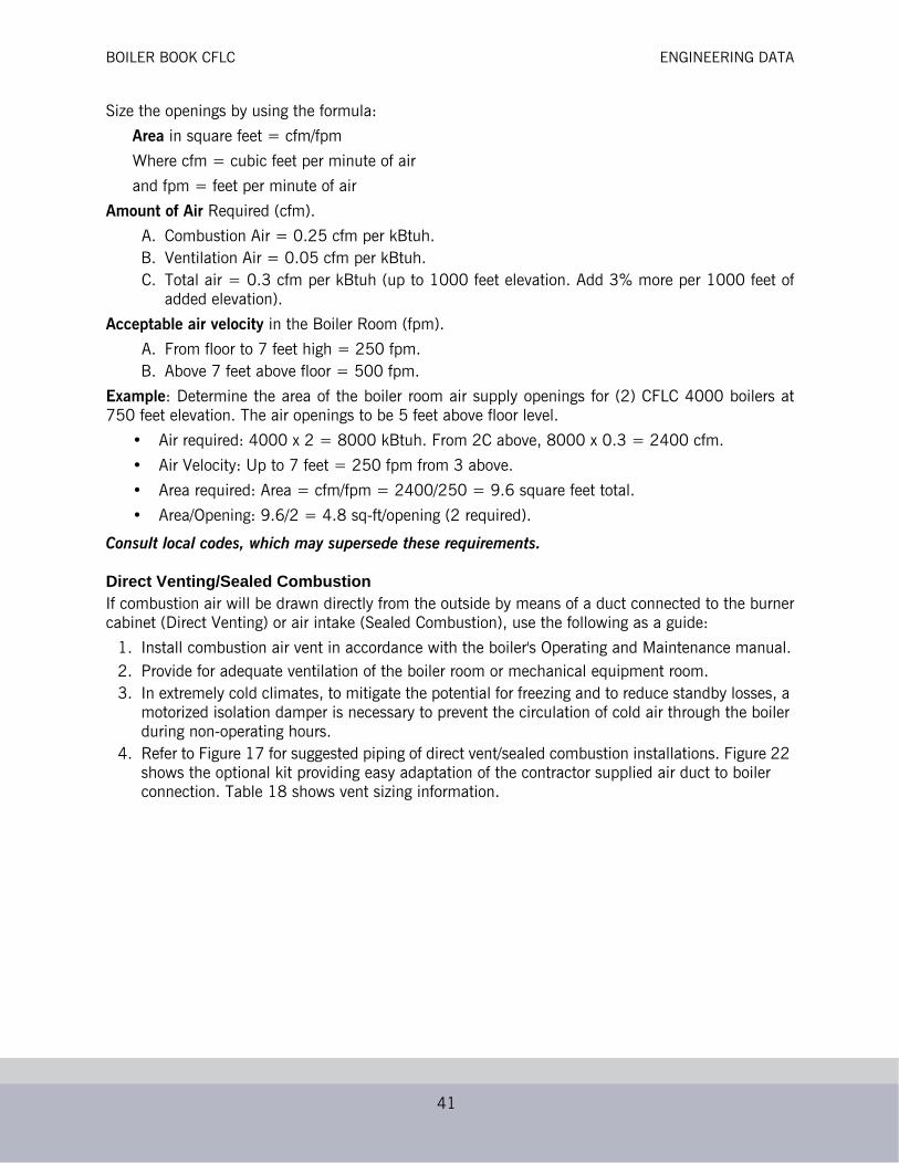
Size the openings by using the formula:
Area in square feet = cfm/fpm
Where cfm = cubic feet per minute of air
and fpm = feet per minute of air
Amount of Air Required (cfm).
A. Combustion Air = 0.25 cfm per kBtuh.B. Ventilation Air = 0.05 cfm per kBtuh. C. Total air = 0.3 cfm per kBtuh (up to 1000 feet elevation. Add 3% more per 1000 feet of
added elevation).
Acceptable air velocity in the Boiler Room (fpm).
A. From floor to 7 feet high = 250 fpm.B. Above 7 feet above floor = 500 fpm.
Example: Determine the area of the boiler room air supply openings for (2) CFLC 4000 boilers at750 feet elevation. The air openings to be 5 feet above floor level.
• Air required: 4000 x 2 = 8000 kBtuh. From 2C above, 8000 x 0.3 = 2400 cfm.
• Air Velocity: Up to 7 feet = 250 fpm from 3 above.
• Area required: Area = cfm/fpm = 2400/250 = 9.6 square feet total.
• Area/Opening: 9.6/2 = 4.8 sq-ft/opening (2 required).
Consult local codes, which may supersede these requirements.
Direct Venting/Sealed CombustionIf combustion air will be drawn directly from the outside by means of a duct connected to the burnercabinet (Direct Venting) or air intake (Sealed Combustion), use the following as a guide:
1. Install combustion air vent in accordance with the boiler's Operating and Maintenance manual.2. Provide for adequate ventilation of the boiler room or mechanical equipment room.3. In extremely cold climates, to mitigate the potential for freezing and to reduce standby losses, a
motorized isolation damper is necessary to prevent the circulation of cold air through the boiler during non-operating hours.
4. Refer to Figure 17 for suggested piping of direct vent/sealed combustion installations. Figure 22 shows the optional kit providing easy adaptation of the contractor supplied air duct to boiler connection. Table 18 shows vent sizing information.

BOILER BOOK CFLC ENGINEERING DATA
42
Figure 22. Optional Direct Vent/Sealed Combustion Kit
*Requirements may vary based on application. Consult your local Cleaver-Brooks representative with any questions.
ElectricalVoltage requirements for the Fan Motor are 208/230/460. Control Circuit voltage is 120/1/60 for allboiler sizes. A transformer is provide. Refer to Table 3 “Ratings” for ampacity requirements.
Table 18. CFLC Combustion Air and Flue Venting Requirements*
20ppm NOx Combustion air SCFM
Minimum duct diameter inches
Max allowable comb. air pressure drop (inches WC)
Direct vent adapter kit
options
Flue diameter Draft tolerance (inches WC)
CFLC 4000 1000 10 0.25 10” or 12” 14” -0.25/+0.10”CFLC 5000 1250 12 0.25 12” 14” -0.25/+0.10”CFLC 6000 1500 14 0.25 14” or 16” 16” -0.25/+0.10”CFLC 8000 2000 14 0.25 14” or 16” 16” -0.25/+0.10”CFLC 10000 2500 16 0.50 16” or 18” 20” -0.25/+0.10”CFLC 12000 3000 18 0.50 18” 20” -0.25/+0.10”9ppm NOxCFLC 4000 1075 10 0.25 10” or 12” 14” -0.25/+0.10”CFLC 5000 1350 12 0.25 12” 14” -0.25/+0.10”CFLC 6000 1625 14 0.25 14” or 16” 16” -0.25/+0.10”CFLC 8000 2150 16 0.25 14” or 16” 16” -0.25/+0.10”CFLC 10000 2700 16 0.50 16” or 18” 20” -0.25/+0.10”CFLC 12000 3225 18 0.50 18” 20” -0.25/+0.10”
! Caution
Combustion air ductwork should be securely attached to the boiler casing. No weight should be sup-ported by the venturi. Venting should be installed to allow easy disconnection for burner service. For best results, the Cleaver-Brooks direct vent/sealed combus-tion kit is recommended. See Table 6-2 for kit part numbers.
For Direct Vent use, omit the flexibleduct connector and air intake collar.
For Sealed Combustion, assemble all components as shown.

BOILER BOOK CFLC ENGINEERING DATA
43
Falcon Controller1. Control Description - The Falcon hydronic control is an integrated burner management and
modulation control with a touch-screen display/operator interface.2. Functionality - The controller is capable of the following functions:
• Flame supervision• Burner sequencing• Heating/modulation control• Hot water system pump control• High Limit temperature control• Thermowell-mounted NTC temperature sensors to provide measured process variable signals to the controller.• User-friendly touchscreen interface• Modbus communication capability• Alarm/lockout messaging with history (last 15 messages)• Annunciation• Outdoor reset• Central Heating and Domestic Hot Water loop control• Password protection of configurable parameters• High Stack Temperature limit• Remote reset• Lead/Lag sequencing• (3) configurable pump relays• Remote modulation/remote setpoint• Frost protection• Time of Day (dual setpoint) control• Three levels of access to control configuration:
•End-user•Installer/Service Engineer (password protected)•OEM Manufacturer (password protected)
Table 19. Operating Conditions - Controller
Temperature RangeOperating -4 F to 150 F (-20 C to 66 C)
Storage -40 F to 150 F (-40 C to 66 C)
Humidity 85% max. relative humidity, non-condensing
Table 20. Operating Conditions - Display/Interface
Temperature RangeOperating 32 F to 122 F (0 C to 50 C)
Storage -40 F to 150 F (-40 C to 66 C)
Humidity 85% max. relative humidity
Table 21. Operating Conditions - VFD
Temperature RangeOperating 14 F to 122 F (-10 C to 50 C)
Storage -40 F to 185 F (-40 C to 85 C)
Humidity 95% max. relative humidity, non-condensing

BOILER BOOK CFLC ENGINEERING DATA
44
3. Main Voltage Connection - 208/230/460V, 3phase, 60Hz4. Local/Remote demand switch5. Combustion Air Proving Switch - This input is used for proving airflow sufficient for proper
combustion throughout the burner run sequence.6. High Air Pressure Switch - prevents boiler operation in the event of high stack back pressure
(blocked flue or condensate drain).7. Gas Pressure Switch - Gas pressure switches for low gas pressure and high gas pressure prevent
the burner from being activated if either is open. Each switch is a physical manual reset device, requiring physical depression of the reset button if either switch is not closed prior to burner start or during burner operation.
8. NTC (Negative Temperature Coefficient) Thermistor Inputs (10k @ 25 oC)A.Flow Temperature (Outlet water temperature)B.Return Temperature (Inlet water temperature)C.Optional Domestic Water TemperatureD.Optional Outdoor TemperatureE.Optional Stack TemperatureF.Optional Header Temperature
9. System Configuration - Falcon configuration is arranged into the following functional groups:
Table 22. Falcon control sequence (Central Heat)
1. Heat request detected (CH demand)
2. Boiler pump enabled or isolation valve opened
3. Safe Start Check, dynamic ILK input test (if enabled), blower switched on
4. If ILK input and CAPS switch closed and high fire switch is made, begin 30 sec-ond prepurge
5. When purge complete, blower to lightoff speed; low fire switch closes
6. Pilot Trial for Ignition - 10 seconds; pilot gas valve energized for 10 sec., ignition transformer for 5 sec.
7. Main Trial for Ignition - 5 seconds
8. Main gas valve(s) switched on
9. Pilot turned off at the end of MTFI period; 10 sec. stabilization time
10. Release to modulation (Run)
11. At the end of CH heat demand, burner fuel valve(s) close and blower stays on for 15 sec. post purge period. Boiler enters standby mode.
•System Identification & Access •CH - Central Heat Configuration•Outdoor Reset Configuration •DHW - Domestic Hot Water Configuration•Modulation Configuration •Pump Configuration•Statistics Configuration •High Limits•Stack Limit •Other Limits•Anti-condensation Configuration •Frost Protection Configuration•Annunciation Configuration •Burner Control Interlocks•Burner Control Timings & Rates •Burner Control Ignition•Burner Control Flame Failure •System Configuration•Fan Configuration •Lead Lag Configuration

BOILER BOOK CFLC ENGINEERING DATA
45
10. Falcon Access - There are three levels of access to the Falcon controller:
• End User Level - read or view parameters; change setpoints. No password required.
• Installer/Service Level - read all parameters; enables changing of most parameters. This access level is used to configure the Falcon for a particular installation, and is password-protected.
• OEM Level - read/change all parameters; for factory configuration of boiler-specific parameters. Password-protected and restricted to CB or factory authorized service personnel.
For additional information regarding service and setup of the burner controller, refer to CFLC manual750-363 or to the Falcon manual 750-265.
Figure 23. Falcon pinout
3
1
4
2
FLAMESTRENGTH
LOCALMODBUSA B C
GLOBALMODBUSA B C
POWER
FLAME
ALARM
RESET
PIM
1
2
3
4
5
6
HYDRONICCONTROL
J1 J2
J3ECOMD R C
L1
L2 FOR 120VAC OR 24VAC RETURN (OPTOS)
EGND
BLOWER/HSI
EX. IGNITION
ALARM
MAIN VALVEPILOT VALVE
ANNUN 1/IASANNUN 2
ANNUN 3ANNUN 4ANNUN 5ANNUN 6
PRE IGN INTLK
INTERLOCK
P
P
P
LCI
PUMP A
{{
{
{
PUMP B
PUMP C
ANNUN 7 HFSANNUN 8 LFS
24 VAC24 VAC RTN
INLET TEMPINLET TEMP RTN
4-20 mA REMOTE SOURCE
OUTLET TEMP AOUTLET TEMP RTN
OUTLET TEMP BOUTDOOR TEMP
OUTDOOR TEMP RTNOR HEADER TEMP
DHW TEMP ADHW TEMP RTN
DHW TEMP BSTACK TEMP A
STACK TEMP RTNSTACK TEMP B
TODREMOTE RESET
0 - 10 VDC MA /VDC RTN
4 TO 20 MAV
I
BUILDINGAUTOMATION
SYSTEM
System Display
LEAD LAG MODBUSLOCALMODBUS
++–
UVBLUE
WHITE
STAT
FALCON HYDRONIC CONTROLPLUG CONNECTORS
J4
J5
J6
J7
J8
J9
J10
121110 9 8 7 6 5 4 3 2 1
7654321
87654321
7654321
123456789
101112
1234567
12345678
+_
MODBUS GATEWAY
MOD.OUTPUT

Related Documents