Cleaning Robot Working at Height Final Fan-Qi XU * International School, Beijing University of Posts and Telecommunications, Beijing 100876, China [email protected], [email protected] *Corresponding author Keywords: Cleaning Robot, Negative Pressure, STM32F103zet6, C51, PID Abstract. To help people clean the window at high altitudes, we design a window cleaning robot that. The robot should be able to walk on most glass walls according to designated routes. To achieve uniform speed, turning, automatic speed control and other functions, we firstly used C51 programming technology to control speed. Then, in order to improve the performance, we used STM32F103zet6 programming and we used PID algorithm. For the hardware, we used DC motor and air pump to achieve negative pressure for the purpose of walking along the window stably. Compared with the cleaning robot sold in the market nowadays, our robot can clean a vertical surface. This paper gives you the hardware and software design of this new robot. Introduction After witnessing the danger of the Spider-Man cleaning window curtain walls at high altitudes, we decided to make a window cleaning robot that could replace them at high altitudes. The robot should be able to walk on most glass walls according to designated routes. To achieve uniform speed, turning, automatic speed control and other functions. We firstly used C51 programming technology and PWM technology to make the drive design. Then, in order to improve the drive design and control the speed, we used STM32F103zet6 programming and we used PID algorithm. For the hardware, we used DC motor and air pump to achieve negative pressure for the purpose of walking along the wall or window stably. Hardware Design DC Motor and air pump. A motor is a device that converts electrical energy into mechanical energy. Motor control in the past 20 years has undergone great changes. Among them, the simulation of motor control strategy is gradually out of the stage of history, and the use of microprocessors, FPGA / CPLD, general-purpose computer, PWM control technology and other modern means of digital control system has been developed rapidly. Application of advanced control algorithms, the development of all-digital intelligent control motion control system will become a new generation of control system design.[1] In our equipment, the use of two DC motor control car forward, single-chip AT89C51 and L298N control speed, change the motor speed, to achieve the two wheels under the action of the straight, forward, reverse and other functions. We used air pump to achieve negative pressure for the purpose of walking along the wall or window stably. Chip. AT89C51. AT89C51 ATMEL Corporation AT89C51 is one of the series, it MCS-51 series with many models are compatible, and has a wide range of representative. AT89C51 is a low-voltage, high-performance CMOS 8-bit microprocessor with a 4Kbyte Flash Programmable Erasable Read Only Memory (MCU), commonly known as a single-chip microcomputer. The AT89C2051 is a single-chip microcomputer with 2Kbytes of flash erasable programmable read-only memory. The erasable read-only memory of the microcontroller can be erased 100 times. SCM control circuit mainly to an 89C51 as the control core, the main realization of the glass Proceedings of the 3rd International Conference on Material Engineering and Application (ICMEA 2016) Copyright © 2016, the Authors. Published by Atlantis Press. This is an open access article under the CC BY-NC license (http://creativecommons.org/licenses/by-nc/4.0/). 544 Advances in Engineering Research, volume 103

Welcome message from author
This document is posted to help you gain knowledge. Please leave a comment to let me know what you think about it! Share it to your friends and learn new things together.
Transcript

Cleaning Robot Working at Height Final
Fan-Qi XU*
International School, Beijing University of Posts and Telecommunications, Beijing 100876, China
[email protected], [email protected]
*Corresponding author
Keywords: Cleaning Robot, Negative Pressure, STM32F103zet6, C51, PID
Abstract. To help people clean the window at high altitudes, we design a window cleaning robot that.
The robot should be able to walk on most glass walls according to designated routes. To achieve
uniform speed, turning, automatic speed control and other functions, we firstly used C51
programming technology to control speed. Then, in order to improve the performance, we used
STM32F103zet6 programming and we used PID algorithm. For the hardware, we used DC motor and
air pump to achieve negative pressure for the purpose of walking along the window stably. Compared
with the cleaning robot sold in the market nowadays, our robot can clean a vertical surface. This
paper gives you the hardware and software design of this new robot.
Introduction
After witnessing the danger of the Spider-Man cleaning window curtain walls at high altitudes, we
decided to make a window cleaning robot that could replace them at high altitudes. The robot should
be able to walk on most glass walls according to designated routes. To achieve uniform speed,
turning, automatic speed control and other functions. We firstly used C51 programming technology
and PWM technology to make the drive design. Then, in order to improve the drive design and
control the speed, we used STM32F103zet6 programming and we used PID algorithm. For the
hardware, we used DC motor and air pump to achieve negative pressure for the purpose of walking
along the wall or window stably.
Hardware Design
DC Motor and air pump. A motor is a device that converts electrical energy into mechanical energy.
Motor control in the past 20 years has undergone great changes. Among them, the simulation of
motor control strategy is gradually out of the stage of history, and the use of microprocessors, FPGA
/ CPLD, general-purpose computer, PWM control technology and other modern means of digital
control system has been developed rapidly. Application of advanced control algorithms, the
development of all-digital intelligent control motion control system will become a new generation of
control system design.[1]
In our equipment, the use of two DC motor control car forward, single-chip AT89C51 and L298N
control speed, change the motor speed, to achieve the two wheels under the action of the straight,
forward, reverse and other functions. We used air pump to achieve negative pressure for the purpose
of walking along the wall or window stably.
Chip.
AT89C51. AT89C51 ATMEL Corporation AT89C51 is one of the series, it MCS-51 series with
many models are compatible, and has a wide range of representative. AT89C51 is a low-voltage,
high-performance CMOS 8-bit microprocessor with a 4Kbyte Flash Programmable Erasable Read
Only Memory (MCU), commonly known as a single-chip microcomputer. The AT89C2051 is a
single-chip microcomputer with 2Kbytes of flash erasable programmable read-only memory. The
erasable read-only memory of the microcontroller can be erased 100 times.
SCM control circuit mainly to an 89C51 as the control core, the main realization of the glass
Proceedings of the 3rd International Conference on Material Engineering and Application (ICMEA 2016)
Copyright © 2016, the Authors. Published by Atlantis Press. This is an open access article under the CC BY-NC license (http://creativecommons.org/licenses/by-nc/4.0/).
544
Advances in Engineering Research, volume 103

barrier detection, responsible for controlling the motor speed, direction change, forward, reverse and
other functions. [2]
Driver circuit design - L298N Chip and BTN7971b H-bridge Driver. BTN7971b and L298N
have the same H-bridge circuit, and the microcontroller work together in the 5V, but compared to
BTN7971b dual-drive, the maximum current up to 25V, with greater stability, stronger drive
capability. Replacement is also similar with the L298N, Vcc external 5V connected with ER1, EN
enable side, two-way PWM input signal, you can complete the drive. [3]
As the micro-vacuum pump is driven by the DC motor, essentially the same principle with the DC
gear motor control, so we use the same control and drive circuit. Considering the driving voltage of
the drive circuit is 12V, the current is 0.3A and the size and other factors, this paper uses L298
constitute the drive circuit. L298 is a company ST produced a high-voltage, high-current
motor-driven chip. The main features of the chip is the high voltage, high output current,
instantaneous peak current up to 3 A, continuous operating current of 2 A. High-voltage, high-current
full-bridge driver with two H-bridges can be used to drive inductive loads such as DC motors to meet
the specific requirements of DC gear motors for drive voltage and current.
Four output pins of L298, OUT1, OUT2, OUT3, OUT4, respectively, connected with left and right
wheel drive DC motor at both ends. The output of the motor as shown in Table 1, where, ENA chip to
enable the signal, A, B are respectively the two terminals of DC motor, H and L, respectively, are for
the control signal high and low levels.
Table1. The output of the motor
ENA A B Running condition of motor
H H L Forward
H L H Backward
H B A Stop quickly
L X X Stop
Figure 1 is a DC gear motor and micro-vacuum pump control driver module circuit, including
L298 driver chip and its related circuits.
Fig1. A DC gear motor and micro-vacuum pump control driver module circuit
Crystal Oscillator Circuit. Oscillation circuit is the core of the work of single-chip
microcomputer system, which provides the power of single-chip work, through two microcontroller
pin for the microcontroller to provide "clock pulse", crystal frequency is 12MHZ, a machine cycle is
equal to 12 vibration cycles, The CPU clock cycle, that is, the microcontroller to perform a statement,
for example: assign a value; count N plus 1, so the timing time t = count N * machine cycle T (1us),
which will be used in making a count in timer. The cleaning robot designed on L298N is shown in
Figure 2.
545
Advances in Engineering Research, volume 103

Fig. 2. Robot with AT89C51
New Chip-- STM32F103zet6. We have chosen the new chip to solve the problem of the lack of
the original chip timer to enhance the speed and improve the ability to deal with data, enrich the
interface, easy to increase after the robot's new features (as shown in Figure 3).
RB-STM32F103 is a cost-effective, multi-functional STM32 microcontroller development
platform, with a common 32-bit microcontroller chip resources, simulation interface, with the
information provided with the board and routines that allow you in the shortest possible time, of the
master STM32 microcontroller programming technology, especially for single-chip developers and
electronic enthusiasts use.
Figure3. Robot with New Chip-- STM32F103ZET6
Pump Design
We used two pumps to design our water supply system (showed in Figure 4). Because the robot
will walk on the window in the two-way, we have to use two pumps to ensure that they can supply
water in the whole process. At the end of the pipe, we use nozzle to supply only a little water every
time it clean the window, by which we won’t make the cleaned place dirty and we can save the water.
546
Advances in Engineering Research, volume 103

Fig.4. Water Supply System Based on the Theory of Pump
Software Design
Drive Design.
Motor PWM (Pulse Width Modulation) Driver Module Design and Implementation. Motor
control using pulse width modulation (PWM), works: by generating rectangular wave, changing the
duty cycle, in order to achieve the purpose of adjusting the pulse width.
Using the PWM technology, the microcontroller output a constant frequency square wave, the use
of its pulse width modulation to change the speed of motor rotation. When the output is low, the
motor stops. When the output is high, the motor speed is at maximum. [4]
Interrupt Program Design. There are five interrupt sources in 51 chip, that is, there are five kinds
of situations occur, it will make the microcontroller to interrupt the program, in this innovation we
use a disruption of the situation ---- timer interrupt.
When the touch to the corner of the glass, the car front-end switch off, triggering the INT0
interrupt microcontroller, interrupt service subroutine in the query switch position, according to the
detected signal to control the car steering.
The robot has the ability to achieve omnidirectional rotation in a plane, which can be changed
clockwise or counter-clockwise from any angle to any direction. Thereby it can change the direction
of travel. Figure 5 shows the in-situ turning of the robot.
Fig. 5. The in-situ turning of the robot a. counter-clockwise b. original c. clockwise
547
Advances in Engineering Research, volume 103
Timers. There are 16 programmable timer / counters in the MCU, namely timer T0 and timer T1.
They have both timer function and count function. They can enable the timer function or count
function by setting special function registers associated with them. It should be noted that this timer
system.
The steps to set a timer are as follows:
Write the microcontroller timer program, the program needs to start the timer and interrupt
registers to do initialization settings, usually timer initialization process is as follows:
Assign values to TMOD to determine how T0 and T1 work
Calculate the initial value and write the initial value to TH0, TL0 or TH1, TL1 interrupt mode,
the IE assignment, open interrupt
Set TR0 or TR1 to start the timer
Delayed Program Design.
Use For statement to achieve delay, for example:
Unsigned char i,
For (i = 100; i> 0; i-)
For (j = 200; j> 0; j--);
With this nested delay statement, we can also nest three to four layers to increase the time, or
change the variable type, the variable initial value increases.
Constant Speed Design—PID.
Algorithm Principle of PID. In the control process, the incremental PID steady-state error for the
control system is not great, but the control performance and its parameters, in general, to meet the DC
motor speed control system requirements. And then compare the difference between the given speed
and the current speed, adjust the output of the PWM wave of the microcomputer through the
incremental PID algorithm, realize the speed regulation of the DC motor of the intelligent car, and use
the timer to collect the pulse number, calculate the current speed of the car, The shortest time to
complete the speed adjustment, thereby enhancing its control effect. Based on the incremental PID
controller, the control precision is high, the reliability is high and the algorithm is easy to understand.
Method of Parameter Adjustment. For the PID control, the choice of parameters is always a
very complicated job, need to go through continuous adjustment in order to get more satisfactory
control effect. PID parameters in the design of the steps to determine the following:
Determine the scaling factor Kp
Determine the integral time constant Ti
Differential time constant
Incremental PID algorithm is used to control the increment, and cannot be used to directly control
the motor speed, replaced by PWM duty cycle control, by increasing or decreasing the PWM duty
cycle method to achieve the motor acceleration and deceleration control. In seeking the amount of
deviation, the test is used every 5ms actually expected to turn the motor through the number of gears
and the actual number of gear motor, use the difference between the two, and then multiplied by the
corresponding parameters, the three coefficients of the control, calculate the value of the
corresponding PWM duty cycle. In this design, various factors are taken into account. In order to
stabilize the controller and make the system oscillate violently, the last sampling period is 5ms, that
is, the motor is sampled once every 5ms.
Through constant tuning, the program, Kp take 6, Ti 0.4, Td is 0.01. Set the target value, the car
through the adjustment to the appropriate speed. As the hardware in the physical state of the two
motor differences, the latter still need to continue to adjust.
Route Plan. The path planning problem of smart window cleaning robots is to design a path
covering the whole wall under the condition that the time, efficiency and energy consumption are the
best, so that it can finish the cleaning task with the least utilization of all kinds of resources. There are
2 ways to clean the window (as shown in Figure 6).
548
Advances in Engineering Research, volume 103
Fig.6. Route Plan for the Robot
Since the path in (b) mainly involves horizontal movement, only once from the bottom to the top.
And the path consists of multiple vertical movements. The machine needs to constantly climb up and
down the glass surface. From the bottom to the top of the upward movement, the robot need to
overcome gravity to do work, move more difficult, walk slower and take longer time. We decided to
choose (a).
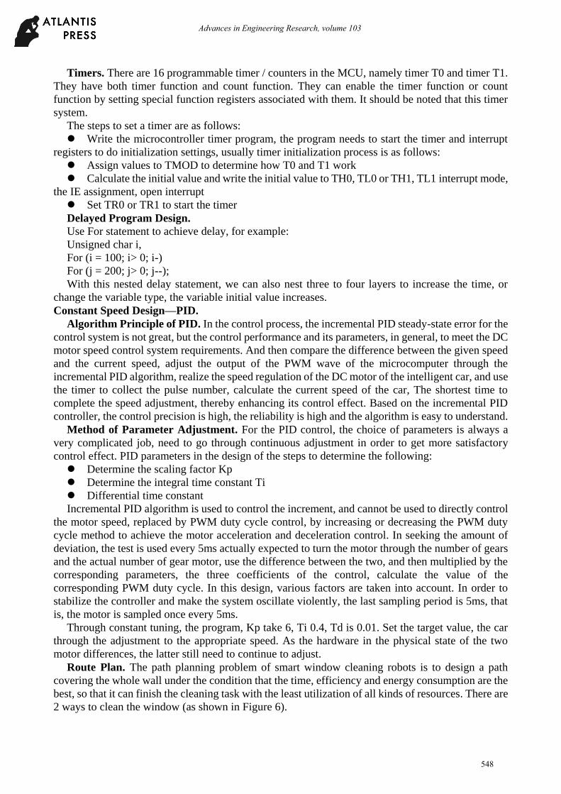
Summary
Fig. 7. Robot with Basic Functions
We have accomplished the basic function of the robot (showed in Figure 7). Then we want to
improve the performance of it.
First of all, due to the poor stability of the feedback value of the previous optical gate, the output is
unstable, the decision based on existing hardware, and further through the use of PID algorithm or
select other accelerometers, the robot can automatically adjust the duty cycle, walking straight, Of the
offset error of the straight line, the error control to about 10 meters per shift offset within 2cm.
Secondly, we choose a plane traversing algorithm with strong universality, aiming at the
maximum range of cleaning effect and achieving the basic purpose of the product. The use of PCB
board to make the circuit more integrated to replace the existing use of excessive wire connections.
The type and brand of the water supply, the safety rope and the cleaning agent will be determined
before the completion of the project. And look for sites near the school to find the actual cleaning
results to be clean glass test, as well as simulation of the product of the compressive performance of
unexpected events, such as simulated power suddenly observed when the machine.
549
Advances in Engineering Research, volume 103

Acknowledgement
I would like to express my deepest gratitude to all the people whose kindness and advice have
made this work possible. I am greatly indebted to my advisor Wen-bo ZHANG who gave me valuable
instructions and has improved me in language. His effective advice, shrewd comments have kept the
thesis in the right direction.
I would like to thank my teammates for giving me constructive advice and they constantly
encouraged me when I felt frustrated with this dissertation.
References
[1] Dong XU, Design of Vertical Glass Curtain Wall Cleaning Robot, China Science and
Technology Information. (2011)
[2] Xiao-li LU, Research and Application of Intelligent Cleaning Robot in Modern Building
Exterior Wall Cleaning, China High-tech Enterprises. (2015)
[3] Bo-yan TANG, Design and Research of Mechanical Structure of Self - climbing Curtain Wall
Cleaning Robot, Beijing University of Industry. (2005)
[4] Function and Shape Design of High - Final Exterior Wall Cleaning Robot, Henan Mechanical
and Electrical Engineering. (2010)
550
Advances in Engineering Research, volume 103
Related Documents