Copy 3 FM 536 D E PAR T M E N T OF T H E A RMY F I E L D MA NUA L ROUTE RECONNAISSANCE AND CLASSIFICATION HEADQ UARTERS, DEPARTMENT OF THE ARMY MAY 1 965 AGO 8282A

Welcome message from author
This document is posted to help you gain knowledge. Please leave a comment to let me know what you think about it! Share it to your friends and learn new things together.
Transcript
Copy 3 FM 536D E PAR T M E N T OF T H E A R M Y F I E L D MA N U A L
ROUTE RECONNAISSANCEAND
CLASSIFICATION
HEADQ UARTERS, DEPARTMENT OF THE ARMY
MAY 1 965AGO 8282A
FM 5-361
CHANGE HEADQUARTERSDEPARTMENT OF THE ARMY
No. 1 ) WASHINGTON, D.C., 21 April 1966
ROUTE RECONNAISSANCE AND CLASSIFICATION
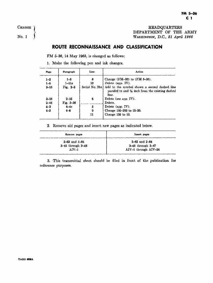
FM 5-36, 14 May 1965, is changed as follows:
1. Make the following pen and ink changes.
Page Paragraph Line Action
1-2 1-3 8 Change (FM-30) to (FM 5-30).1-5 1-lla 10 Delete (app. IV).2-15 Fíg. 2-3 Serial No. 21a Add to the symbol shown a second dashed line
parallel to and Y8 inch from the existing dashedline.
2-18 2-15 8 Delete (see app. IV).3-48 Fig. 3-56 .............. Delete.4-2 4-4c 5 Delete (app. IV).4-3 4-6 9 Change 150-200 to 15-20.
11 Change 150 to 15.
2. Remove old pages and insert new pages as indicated below.
Remove pages Insert pages
2-63 and 3-64 2-63 and 2-643-45 through 3-48 3-45 through 3-47
AIV-1 AIV-1 through AIV-24
3. This transmittal sheet should be filed in front of the publication forreference purposes.
TAGO $O92A
C 1, FM 5-36
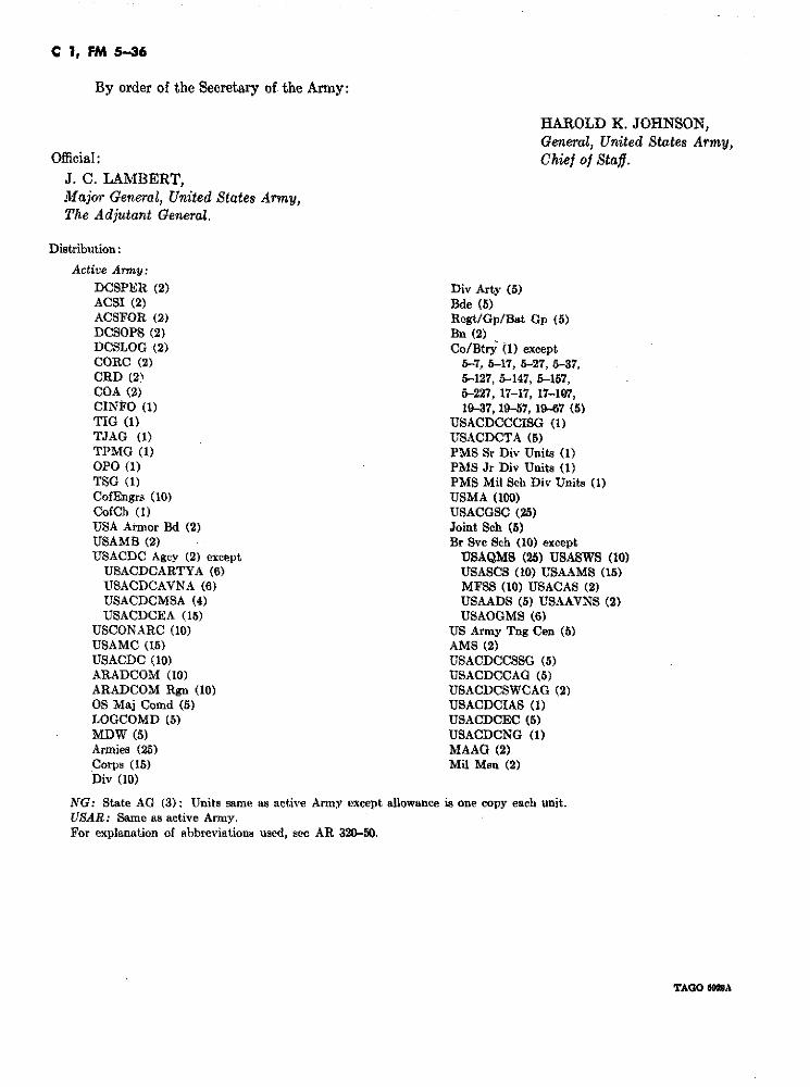
By order of the Secretary of the Army:
HAROLD K. JOHNSON,General, United States Army,
Official: Chief of Staff.J. C. LAMBERT,Major General, United States Army,The Adjutant General.
Distribution:
Active Army:
DCSPER (2) Div Arty (5)ACSI (2) Bde (5)ACSFOR (2) Regt/Gp/Bat Gp (5)DCSOPS (2) Bn (2)DCSLOG (2) Co/Btry (1) exceptCORC (2) 5-7, 5-17, 5-27, 5-37,CRD (2) 5-127, 5-147, 5-157,COA (2) 5-227, 17-17, 17-107,CINFO (1) 19-37, 19-57, 19-67 (5)TIG (1) USACDCCCISG (1)TJAG (1) USACDCTA (5)TPMG (1) PMS Sr Div Units (1)OPO (1) PMS Jr Div Units (1)TSG (1) PMS Mil Sch Div Units (1)CofEngrs (10) USMA (100)CofCh (1) USACGSC (25)USA Armor Bd (2) Joint Sch (5)USAMB (2) Br Svc Sch (10) exceptUSACDC Agcy (2) except USAQMS (25) USASWS (10)
USACDCARTYA (6) USASCS (10) USAAMS (15)USACDCAVNA (6) MFSS (10) USACAS (2)USACDCMSA .(4) USAADS (5) USAAVNS (2)USACDCEA (15) USAOGMS (6)
USCONARC (10) US Army Tng Cen (5)USAMC (15) AMS (2)USACDC (10) USACDCCSSG (5)ARADCOM (10) USACDCCAG (5)ARADCOM Rgn (10) USACDCSWCAG (2)OS Maj Comd (5) USACDCIAS (1)LOGCOMD (5) USACDCEC (5)MDW (5) USACDCNG (1)Armies (25) MAAG (2)Corps (15) Mil Msn (2)Div (10)
NG: State AG (3): Units same as active Army except allowance is one copy each unit.USAR: Same as active Army.For explanation of abbreviations used, see AR 320-50.
TAGO 699A
· FM 5-36
FIELD MANUAL HEADQUARTERSDEPARTMENT OF THE ARMY
No. 5-36 WASHINGTON, D.C., 14 May 1965
ROUTE RECONNAISSANCE AND CLASSIFICATION
Paraaph Page
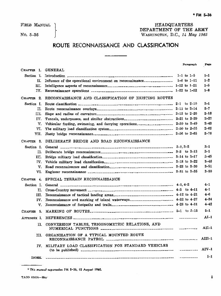
CHAPTr R 1. GENERAL
Section 1. Introduction --------- … ..---------------------------------------------- 1-1 to 1-5 1-1
]I[. Influence of the operational environment on reconnaissance ------------- -- 1-6 to 1-11 1-2IIL. Intelligence aspects of reconnaissance--__- . . . ____------------ --------_ 1-12 to 1-21 1-5IV. Reconnaiseanee operations --------------------------------------------- 1-22 to 1-32 1-8
CHAPTER 2. RECONNAISSANCE AND CLASSIFICATION OF EXISTING ROUTES
Section I. Route classification ------------ …..------------------------------------ 2-1 to 2-10 2-1
I. Route reconnaissance overlays- --------. .----------------------------- - 2-11 to 2-14 2-7
IHL. Slope and radius of curvature__ _________________________------------- 2-15 to 2-20 2-18
XV. Tunnels, underpasses, and similar obstructions--_____-----------------… . _ 2-21 to 2-29 2-27
V. Vehicular fording, swimming, and ferrying operations ----- …............. 2-30 to 2-49 2-43
VL. The military load classification system…__--_--…__---------------------_- 2-50 to 2-55 2-62
VII. Hasty bridge reconnaissance ------------_-------- -------- ------------- 2-56 to 2-65 2-76
CHAPTER 3. DELIBERATE BRIDGE AND ROAD RECONNAXSSANCE
Section I. General ------------- … . . ...............------------------------------ 3-1,3-2 3-1
[H. Deliberate bridge reconnaissance--__- ____----- _-------- … ------- _-- 3-3 to 3-13 3-1
I[I. Bridge military load classification…_ ----------------- … ~------------ 3-14 to 3-17 3-45
IV. Vehicle military load classification -- ____--------- ___--------------- _ 3-18 to 3-22 3-46
V. Road reconnaissance and classification ___------------------…__ 3-23 to 3-30 3-51
VI. Engineer reconnaissance …--------------_----- ------------------- 3-31 to 3-35 3-60
CHAPTER 4. SPECIAL TERRAIN RECONNAISSANCE
Section I. General -------. . ..---------___---_-------- ~----------------------- 4-1, 4-2 4-1
II. Cross-Country movement ------ …-.------…_--------------------------- --- 4-3 to 4-11 4-1
III. Reconnaissance of tactical landing areas …---------.--------------- .------ 4-12 to 4-21 4-6
IV. Reconnaissance and marking of inland waterways ------------------ _____ 4-22 to 4-27 4-24
V. Reconnaissance of footpaths and trails -----------------------.--------- 4-28 to 4-31 4-42
CHAPTER 5. MARKING OF ROUTES --- . . . ...........---------------------------- 5-1 to 5-15 5-1
APPENDIX 1. REFERENCES ----------------..----------------------.....--______ AI-1
II. CONVERSION TABLES, TRIGONOMETRIC RELATIONS, ANDNUMERICAL FUNCTIONS ------. ----------------------------- --------- AII-1
HII. ORGANIZATION OF A TYPICAL MOUNTED ROUTERECONNAISSANCE PATROL ----...------------------------ ------ AIII-1
IV. MILITARY LOAD CLASSIFICATION FOR STANDARD VEHICLES(to be published) ---------------------------------------- ---------- AIV-1
INDEX. ---------------------------------------- ---------- I-1
This manual supersedes FM 5-36, 15 August 1960.
TAGO 8282A-May

FM 5-36
CHAPTER 1
GENERAL
Section 1. INTRODUCTION
1o1. Purpose divided into two categories: hasty reconnais-Maneuver, one of the principles of war, is an _ sance and deliberate reconnaissance. Hasty
essential ingredient of combat power. It, in reconnaissance provides limited route informa-itself, is not decisive; however, when properly tion necessary for planning and executing nor-employed in conjunction with the principles of mal military movement and is a prerequisite ofmass and economy of force, decisive combat tactical maneuver. Deliberate route reconnais-results are obtainable. Maneuver is dependent sance, on the other hand, provides essentialon adequate lines of communication within the and additional engineer data which form thearea of operations. Without prior intelligence basis for technical classification and thoroughconcerning available routes, a commirander's analysis of routes throughout an area of opera-scheme of maneuver and logistical plan is tion. The remaining portion of the text dis-jeopardized. To support this intelligence re- cusses special types of terrain reconnaissancequirement, doctrinal procedures are established and route marking. Traffic control reconnais-by this manual for the collection, evaluation, sance although a form of ground reconnais-and reporting of terrain data concerning mili- sance, is not considered in the text but discussedtary routes. In addition, instructional and in detail in FM 19-25.reference material applicable to the technical b. This manual incorporates terminology andclassification of routes to sustain military traffic methods of reporting, classifying, and markingis furnished for reconnaissance personnel re- military routes as approved for use by membergardless of branch. nations of the North Atlantic Treaty Organiza-
tion (NATO), the Southeastern Treaty Organi-8-2. Scope zations (SEATO), and the United States,
a. This manual describes the influence of the United Kingdom, Canadian, and Australianoperational environment in reconnaissance op- Armies Nonmateriel Standardization Program.erations, the intelligence aspects and funda- In each appropriate paragraph throughout thementals of route reconnaissance, and methods text, applicable promulgating agreements-of reconnoitering and classifying routes for NATOStandardizationAgreement (STANAG),military use. Emphasis is placed on natural SEATO Standardization Agreement (SEA-and manmade characteristics of routes whichinfluence " raffic f . . STAG), and Standardization of Operations andinfluence traffic flow. The interruption ofmovement by enemy action, an equally impor- Logistics (SOLOG)-are identified by shorttant consideration in route reconnaissance, is title and number. Additionally, a compilationdiscussed in general terms only; specific details of related standardization agreements is citedare not within the scope of this manual al- in appendix I.though thoroughly discussed in field manuals c. The material presented herein is applica-appropriate to the mission and organization of ble to peacetime and counterinsurgency opera-the reconnoitering force (see app. I). Route tions as well as to limited war either nuclear orreconnaissance as presented by this manual is nonnuclear and general war.
AGO 8282A901
FM 5-36
d. Users of this manual are encouraged to combat movements are made. Routes of com-submit recommended changes or comments to munication include navigable waters, aircraftimprove the manual. Comments should be landing facilities, and rail facilities.keyed to the specific page, paragraph, and line c. A route is the road or roads, includingof the text in which the change is recommended. tracks and bridges, used when moving fromReasons should be provided for each commentReasonse should be provided for each commee t one place to another. It includes those roads,
to insure understanding and complete evalua- bridges, tunnels, fords, and other terrain fea-tion. Comments should be forwarded directly*tion. Cornxmnts shOudbe forwarded , tures affecting traffic flow selected for militaryto the Commanding Officer, U.S. Army CombatDevelopments Command Engineer Agency, Fort movement.Belvoir, Va. d. Route reconnaissance is the careful survey
of a route for military purposes, often by aerial-
1-3. Combat and Engineer Intelligence ~vehicle. The purpose of route reconnaissanceCombat intelligence is evaluated information is to collect, evaluate, and report information
of the enemy, weather, and geographic features which will aid in the selection of a route orof the terrain required by a commander to plan routes to be used for the movement of troops,and conduct tactical operations (FM 30-5). equipment, and supplies in military operations.Engineer intelligence is also concerned withinformation regarding terrain features and the 1-5. Systems of iMeasurement (STANAGeffects of weather and terrain on engineer ac- 2015 and SOLOG 53)tivities within an area of operations (FM-30). In accordance with AR 525-8, velocities andBoth fields of intelligence conduct route re- linear distances of a tactical nature are ex-connaissance to acquire terrain information. pressed in the metric system throughout theClose cooperation between engineer intelligence text. Tabular data and structural dimensions,and other intelligence agencies is, therefore, however, are given in the English system foressential to avoid duplication in the overall ease in mathematical computations. .LsrepQmtfcollection effort. Additionally, standard meth- ing the results of route reconnaissance, eitherods of reporting route reconnaissance data as the metric systen or the English systern oipresented by this manual facilitate the ex- th may be used to fit the requirements ofboth may be used to fit the requirements ofchange of information and aid in the wide as the command. Webster's standard abbreviawell as timely dissemination of route intelli- tions such as "km" (kilometers), "m" (me-
tions such as "km" (kilometers), "m" (me-gence. ters), "ft" (feet), and "mi" (miles) must be
1-4. Definitions (AR 320-5) used to clearly identify measurement units.When operations are in conjunction with allies--
a. Lines of communication (logistic routes) and if only one measurement system is used,are all routes, land, water, and air which con- the reporting headquarters prepares a tablenect an operating military force with a base of or diagram showing the relationship betweenoperations and along which supplies and rein- the two systems to accompany the report.forcements move. Tables for ease in converting from one system
b. A route of communication is a network of of measurement to the other are included inroads, etc., over which supplies are carried and appendix II.
Section II. INFLUENCE OF THE OPERATIONAL ENVIRONMENTON RECONNAISSANCE
1-6. General which consequently, bear on the decisions ofThe operational environment is composed of the commander. Major elements comprising
the conditions and circumstances which influ- the operational environment include: The na-ence the employment of military forces and tional and military objectives of the operation;
AGO 8282A
FM 5-36
the terrain and climatie features of the area of provide concealment and cover is ex-operations; the characteristics and attitudes of ploited.the local population; the nature of the conflict (3) Obstacles.to include the weapons systems employed or (a) The effect of obstacles, either in re-threatened; and the composition and missions straint or in support of operations,of the opposing forces. The combination of is considered.these variable elements creates a wide range of (b) Obstacles may be natural, man-conditions and circumstances within which mili- mde, or combintions thereof to in-tary forces must be capable of operating effec- elude obstacles created by chemicaltively. and nuclear fires.
7". hMission (c) Obstacles are employed by bothfriendly and enemy forces to
The mission of the command is the single friendly and enemy forces tofactor of the operational environment that of key terrain for observaton anddominates reconnaissance operations. Recon-o defensive positions, to assist innaissance is conducted to assist in the produc- economy-of-force measures and totion of intelligence necessary to support the protec he flnk of a moving force.military plan. Information is collected, evalu- protect the flank of a moving force.Obstacles are also used to separateated, and interpreted for its significance in re- attackng echeons such as dis-lationship to the accomplishment of the mission. inThus, a knowledge and understanding of the mounted infantry from tankoverall unit mission is desirable to insure that (d) Nuclear weapons can create thepersonnel engaged in reconnaissance do not following obstacles: areas of in-overlook important information. Reconnais- duced and fallout radiation, craters,
rubble, fires, and tree' blowdown.sanee is continuous and does not cease in the rubble, fires, and tree blowdown.absence of specific missions. Logical missions (4) Key terrain. Key terrain is any lo-are assumed, and reconnaissance continues in cality or area the control of whichthe anticipation of an assignment. affords a marked advantage to either
combatant. Key terrain is seized, neu-D-8. Charecteristics of the Area of tralized, or controlled by other means
Operations in order to deny its use by the enemyTerrain and weather are important factors or permit its subsequent use by friend-
ly forces.in military operations. Route reconnaissance.is frequently employed to gather terrain infor- (5) Avenues of approach.mation and to determine the effects of climatic (a) Likely avenues of approach arevariations on specific terrain features within analyzed in accordance with theanB operatiornal area. availability of observation and fire,
concealment and cover, obstacles,a. Terrain. key terrain, space for dispersion
(1) Observation and fire. The effect of ob- and maneuver, trafficability, andservation on both friendly and enemy the effects of nuclear weapons.operations is considered. High ground (b) In analyzing avenues of approachthat affords line-of-sight observation for airmobile operations, the majorand good fields of fire are of particular concern is achieving or avoidingimportance. tactical surprise. Favorable air
(2) Concealment and cover. Concealment routes provide adequate airspaceis protection from observation. Cover and defilade to limit the enemy'sis protection from fire. Every advan- detection and interception capa-tage afforded to friendly forces by the bility. Heavily f o r e s t e d andterrain and conditions of visibility to swampy areas provide good routes
AGO 8282A 1-3
FM 5-36
since ground troops have little op- 1-10. Nature of the Conflictportunity to see or fire at low-flying The same general requirements for terrainaircraft. Ridges reduce the possi- information exist under all forms of warfare.bility of detection by radar. How- The nature of the conflict, however, may changeever, steep defiles or canyons are the emphasis placed on the various aspects ofavoided because possible downdrafts reconnaissance.
may affect the control of aircraft. a. Cold War. Under the conditions of coldb. Weather. Weather conditions have an im- war, reconnaissance requirements are influ-
portant bearing on reconnaissance and are a enced by the preparation of military forces forvital consideration in operational planning. conflict. Without active enemy opposition, ter-Weather primarily affects mobility and visi- rain intelligence is emphasized. Reconnaissancebility, both on the ground and aloft, and is of of routes within probable areas of operation isspecial importance in the conduct of operations made to meet contingencies that may arise dur-that include nuclear, chemical, and biological ing open warfare.warfare. Fallout, chemical, and biological cloud b. Counterinsurgency. In counterinsurgencytravel is channelled by- weather conditions. situations, route reconnaissance is essential forMeteorological elements which have a signifi- the conduct of counterguerrilla warfare andcant influence on operations are wind directions those nonmilitary activities employed to winand speed, temperature, humidity, cloud cover, the support of the populace. Subversive in-precipitation, and atmospheric stability. Weath- surgency movements are generally associateder intelligence provided by weather teams at with developing countries and, particularly, inthe tactical operations center (TOC) contains the remote or rural areas of these countries.forecasts for these meteorological elements and Consequently, these areas do not have adequatelight data such as beginning morning nautical roads. Trais, rivers, and canals are used for
. .n .military operations and commerce. Route re-twilight (BMNT), sunrise, sunset, and eveng connaissance may be required to provide infor-nautical twilight (EENT), moonrise, and mation for the construction of roads and air-moonset. landing facilities to support military and
nonmilitary activities.1-9. Civil Population
c. Limited War. In limited conventionalThe attitude, actions, and capabilities of the
war, route reconnaissance considers not onlycivil population significantly affect reconnais- war, route reconnaissance considers not onlyterrain features but also the likelihood andsance operations. A friendly populace confers effect of the disruption of lines of communica-valuable assistance in the collection of intelli- tions by enemy action or adverse weather. Thegence data. Time is saved in the collection of immediate emphasis is determined by the re-terrain information through the interrogation quirement to support the existing operationalof friendly civilians who have intimate knowl- situation; reconnaissance personnel must, how-edge of the local area. High water levels and ever, be prepared to quickly assume greater re-similar seasonal data are, at times, only avail- sponsibilities resulting from an expansion ofable from local interrogations. Conversely, a the conflict. In limited nuclear war, reconnais-hostile population makes reconnaissance opera- sance requirements vary in accordance withtions more difficult. Bridge classification and the severity and type of nuclear exchange.route directional signs, for example, may be d. General War. Nuclear warfare is char-removed or altered; misleading information acterized by relatively sudden and drasticmay cause delay; and reconnaissance parties changes in the tactical situation. Dispersion,may expect continual harassment by unfriendly mobility, decentralization of control, rapid ex-civilians. Regardless of the civil attitude, how- ploitation, and the reduction of reaction timeever, care must be exercised in evaluating all are characteristic. Under this type of environ-data obtained from civilian sources. ment, route reconnaissance assumes even great-
1-4 AGO 8282A-..4
FM 5-36
er importance. Not only will more routes be b. Enemy Forces. Although not within therequired to support military operations, but scope of this manual, reconnaissance personnelreconnaissance personnel must be ever alert to must be trained to recognize and counter enemyrecognize wide spread areas of contamination action. Enemy influence along a route maycreated by mass destruction weapons. vary from nuisance mining to stubborn de-
fensive resistance. A route, regardless of lo-I-11. Friendly andi Enemy Forces cation, is always vulnerable to interdiction by
a. Friendly Forces. In general, intelligence enemy air and missile or artillery attack. Re-operations are oriented on characteristics of connaissance personnel must avoid drawing un-the operational environment which are external due attention to their operations especially in
likely target areas such as bridges, road junc-to the command; that is, the terrain, weather, tions, and defiles. As reconnaissance partiesand enemy. However, route reconnaissance is
are usually small in number and generally op-further affected by the mission, composition, erate in areas remote from friendly forces, theorganization, and size of the unit for which threat of attack is ever present whether closeroutes are being reconnoitered. Reconnaissance to the FEBA or in rear areas where infiltratorspersonnel must be completely familiar with ve- or irregular forces may stage ambushes orhicular specifications and limitations (app. IV). establish road blocks. Regardless of the recon-If route reconnaissance is conducted by other naissance mission, the threat of enemy inter-than organic elements, it is desirable that liai- ference must be considered at all times, andson agents accompany the supporting recon- reconnaissance personnel constantly preparednaissance element. to take positive steps to overcome opposition.
Section III. INTELLIGENCE ASPECTS OF RECONNAISSANCE
1-12. Intelligence Requirements tion resources within the command are di-a. General. Intelligence requirements are rected toward definite intelligence objectives
those variable factors concerning the weather, in priority of need. To facilitate the establish-terrain, and enemy which, when known, ma- ment of priorities, intelligence requirementsterially assist in the execution of a unit's mis- are categorized as essential elements of infor-sion. Because of the ever changing operational mation and other intelligence requirements.environment, intelligence requirements are not b. Essential Elements of Information. Es-constant. A commander relies on his intelli- sential elements of information (EEI) are thegence staff officer (S2/G2) for the production highest priority intelligence requirements. Anof intelligence. The intelligence officer, in turn, EEI is an item of intelligence or informationrequests or directs appropriate individuals or
of the characteristics of the area of operationsorganizations that collect intelligence informa- and the enemy which the commander feels hetion-henceforth referred to as collection agen-needs before he can reasonably arrive at acies-to provide data in support of the intelli- sond decision These decision are of the type
gsound decision. These decisions accordance witof their capa- io hession t ypegence effort. In accordance with their capa-bilities, agencies employ various methods in which involve the mission of the command andcollection. Those most common in acquiring the choice of a course of action to accomplishterrain information are: interrogation, ob- the mission. The nature and number of EEIservation and listening posts, ground and air- will vary with the type of operation, the phaseborne surveillance devices, air and ground re- of the operation, and the extent and accuracyconnaissance, and radiological monitoring and of the available information and intelligence.survey. Collection capabilities, however, are When the available information and intelli-rarely sufficient to satisfy all intelligence re- gence are complete enough to satisfy the com-quirements simultaneously. Therefore, collec- mander in making a decision with confidence,
AGO 8282A 1-5
FM 5-36
the commander has no outstanding priorities; 1-15. Enemy Activityhowever, at no time is the available informa- Enemy activity is also a source of terraintion or intelligence so complete that additional information; however, +';t- volume and type ofrequirements do not exist. information concerninG enemy activities are
c. Other Intelligence Requirements. Other limited by the capabilities of available detec-intelligence requirements are derived from tion and observation equipment and the meas-command and staff requirements which are im- ures taken by the enemy to conceal his ac-portant but do not qualify as EEI. After the tivities. For example, intelligence reportsallocation of means to collect information nec- concerning the type and size of enemy vehiclesessary to satisfy the EEI's, the remaining utilizing a bridge provide an estimate of themeans are used for the collection of informa- bridge's capacity. In addition, informationtion that also significantly affect the mission. that the enemy is not engaged in certain activi-
ties is often of great significance. For ex-1-13. Sources of Intelligence ample, negative reports of enemy movement
Sources of information are the actual origin along a route apparently suitable for militaryfrom which information concerning the opera- traffic may indicate the presence of mines ortional environment is obtained. An important other obstacles barring travel.consideration by collection agencies is the selec-tion of proper sources. A knowledge of sources 1-16. Prisoners of War, Civilians, andand type of information which each can provide Recovered Personnelis essential in planning reconnaissance mis- a. Prisoners of war are valuable sources ofsions. The more common sources applicable to information, particularly of the immediate bat-reconnaissance operations are: friendly troops; tle area. Maximum information is obtainedenemy activity; prisoners of war; local civil- through skillful handling of prisoners of warians; recovered friendly military personnel; from the time of capture until interrogation isimagery; maps; captured documents; weather completed. Personnel conducting interroga-forecasts; and studies, reports, and other ref- tions are carefully briefed on the desired in-erence material of intelligence value. formation and are provided with appropriate
[-14. Friendly Troops aids such as maps and aerial photos.All units have capabilities which contribute b. Civilians who have been within enemy-
to the collection of intelligence information. controlled areas may be valuable sources of in-Combat and combat support units are especial- formation and often give information readily.ly useful for supplying information of enemy Such sources can provide information on ter-and terrain in forward areas. Some units ravide in enemy-controlled areas and may pro-such as armored cavalry units and long-range vide information of enemy installations andreconnaissance patros are specifically or*gan- activities. Civilians are particularly valuableized for ground reconnaissance operations. sources of information in cold war operations.Target acquisition and surveillance units col- c. Military personnel recovered from enemy-lect information by ground and aerial observa- controlled areas are sources of information oftion. Combat service support units acquire the area of operations and enemy dispositionssignificant amounts of terrain data during the and activities. Interrogation of recoveredconduct of normal operations. Military police military personnel is conducted in accordanceunits are valuable sources of information con- with regulations prescribed by the theatercerning physical characteristics of areas oc- headquarters.cupied by friendly forces. Civil affairs unitsare capable of gaining much information about 1-17. Imagerythe area of operations by close liaison with the a. Permanent imagery obtained by groundindigenous population and through perusal of and airborne sensors is an excellent source ofcivil records and files. graphic information for terrain evaluation.
AGO 8282A
FM 5-36
Current types of image-producing sensors are 1-19. Captured Documentsthe camera, infrared detector, and radar.Each of these types of image-producing sen- Enemy documents may provide great assis-sors operates in a different portion of the elec- tance in the field terrain intelligence. Com-tromagnetic spectrum and each detects and re- pilations of route data by the enemy andcords different data. captured maps can considerably reduce the
collection effort. However, the possibility thatb. Imagery obtained by airborne sensors, a document has been purposely planted to de-
manned or unmanned, is particularly useful ceive intelligence personnel concerning enemyin reconnaissance planning. If properly em- activities and terrain is ever present.ployed, it is an excellent means for collectinginformation to assist in- Q-20. Weather Forecasts
(1) Locating enermy offensive and defen- Weather information in the field army con-sive installations; supply installations sists of weather forecasts, weather observa-and limes of communications; and tions, both surface and aloft, and weatherarmored, motorized, and personnel summaries. Weather forecasts are providedconcentrations. by the Air Weather Service (AWS) of the Air
(2) Analyzing terrain. Force. These forecasts are based on the(3) Confirming or denying intelligence weather observations provided within the field
information obtained from other army by AWS observing teams and artillerysources of agencies. meteorological sections supplemented by ob-
(4) Preparing target folders. servations from other units. Weather sum-(5) Assessing damage. maries of past weather conditions are com-(6) Preparing mosaics and panoramas for piled as required by both army and air force
planning purposes. units.(7) Correcting maps and making map
supplem(7) Correcting maps and making map -2 1. Reports, Studies, and Referencesupplements. MaterialMaterial
1-18. Maps and Geodetic Data a. General Sources. Valuable terrain in-Maps provide a basic source of terrain in- formation can be found in a wide variety of
formation. The reliability of a map is deter- both technical and nontechnical books, periodi-mined by the data used in preparation, and the cals, and reports published by governmentaldate of production or revision is generally in- and private agencies. These include tradecluded as a part of the marginal data. Maps journals, economic atlases, tide tables, pilots'are supplemented by aerial or ground photo- handbooks, tourist guides, and similar publi-graphs and other permanent imagery means, cations. Unpublished systematic records cov-sketches, visual observation, trig lists, and ering meteorological, hydrological, and similargazetteers. Trig lists are publications contain- scientific data prepared by governmental agen-ing the exact location and elevation of bench cies, engineering firms, private societies, andmarks and other survey points together with individuals also contribute valuable terrain in-a complete description of their characteristics. formation. While utilized chiefly for terrainTrig lists are of particular value to artillery, studies made at higher headquarters, materialmissile, and engineer units and are required of this type, when locally available, can be offor locating and orienting certain surveillance considerable -value to lower echelons.devices. Special maps and overlays are de- b. Intelligence Reports. Strategic intelli-signed for specific purposes, such as trafficabil- gence studies prepared at the National level byity, transportation facilities, and soils, and may the Department of Defense (DOD) or by over-be of particular value in terrain evaluation. sea commands provide detailed informationThe classification of U.S. maps by type and concerning major geographical areas. Suchscale is described in AR 117-5. studies include-
AGO 8282A 1-7
FM 5-36
(1) National intelligence surveys. These (3) Lines of communication (LOC) stud-studies present a concise digest of the ies. These studies, prepared on eitherbasic intelligence required for stra- medium scale maps or single smalltegic planning and the operations of scale foldup sheets, contain an anal-major units. Each study describes ysis of transportation facilities withthe pertinent terrain characteristics general information on railroads, in-of a specific area, supported by de- land waterways, highways, airfields,scriptive material, such as maps, pipelines, ports and beaches.charts, tables, and bibliographies.
(4) Route reconnaissance reports. Most(2) Engineer intelligence studies (EIS). important for terrain information at
These are a series of documents de- lower levels are local reports whichscribing in detail those natural and
summarize data obtained by physicalmanmade features of an area that route reconnaissance. Such reportsaffect the capabilities of militaryforces. These studies are being sup- are of particular value in providingplemented and in some cases super- current, detailed information aboutseded by DOD and command initiated routes of communication. The prep-lines of communications, port, and aration of these reports is discussedterrain type studies. throughout this text.
Section IV. RECONNAISSANCE OPERATIONS
1-22. General a. Orient on the Location or Movement ofReconnaissance is the directed effort in the the Intelligence Objectives. Units engaged in
field to collect information of the enemy and reconnaissance operations maneuver accordingthe area of operations through ground and air to the location or movement of the intelligenceactivities. The purpose of reconnaissance is to objective rather than the location or movementobtain information of the enemy and the area of friendly forces. The objective may beof operations for the production of intelligence. enemy troops, a terrain feature, or a locality.Reconnaissance information and the resulting To effectively perform reconnaissance, com-intelligence seek to reduce the unknown as- manders of reconnaissance elements are al-pects of the enemy and the area of operations lowed maximum freedom of action commen-and to contribute to the accuracy of evaluating surate with the mission.risks and the successful application of combat b. Report All Information Accurately. Re-power. Reconnaissance is a continuing respon- connaissance is conducted to obtain informa-sibility of each commander and every soldier. tion to be used in the production of intelligence.Unit training, standard operating procedures, All items of military significance are reported.and the commander's instructions to subor- Moreover, to be of value, reconnaissance re-dinates must emphasize the important of time- ports must be complete, timely, and accurate.ly and accurate reports of both positive and . void Decisive Engagement. Units per-negative information of the enemy and opera- forming reco issance obtain information by
forming reconnaissance obtain information bystealth whenever possible; combat is con-
1-23. Fundamentais of Reconnaissance ducted only when necessary to gain the desiredinformation and in self-defense. The recon-Reconnaissance operations vary with the op-
erational environment; with the assigned mis- naissance mission must not be jeopardized byerational environment; with the assigned mis-sion; and with the size, type, and composition unnecessary combat.of the reconnaissance element. Ground recon- d. Maintain Contact with the Enemy. Innaissance operations are performed in con- the performance of a reconnaissance missionformance with the following fundamentals: to obtain information of an enemy force, visual
1-8 AGO 82S2A
FM 5-36
or electronic contact with the enemy is gained the road net, terrain type, informa-as soon as possible. Once contact has been tion desired, anticipated enemy ac-made, it is maintained and is not voluntarily tion, troops available, weather, visibil-broken without proper authority. Contact may ity, and time allotted to accomplishbe maintained either by ground or aerial sur- the mission.veillance. c. Area Reconnaissance.
e. Develop the Situation. When enemy con- (1) Area reconnaissance is the directedtact is made or an obstacle is encountered, the effort to obtain detailed informationsituation is developed rapidly. To determine of all routes, terrain, and enemythe location, composition, and disposition of forces within any clearly defined area.the enemy force or obstacle, evasive or com-bat action is quickly undertaken in accordance (2) Area reconnaissance is performed towith specific reconnaissance instructions. gain information of defnite geographi-
cal areas such as towns, woods, or1-24. Types of Reconnaissance Missions stream-crossing sites. An area may be
There are three types of ground reconnais- reconnoitered for enemy activity or tosance missions: route, zone, and area. The determine an area's suitability for usetype to be employed is determined after con- by friendly forces as an assemblysidering the nature and urgency of the infor- area, defensive position, or other pur-mation desired, the operational environment, poses. Similar reconnoitering tech-and the composition of the reconnaissance niques are employed as those pre-
force.»~~~~~~~~~ ~scribed for zone reconnaissance.force.
a. Route Reconnaissance. 0-25. Reconnaissance in Force(1) Route reconnaissance is directed in(1) Route reconnaissance is directed in A reconnaissance in force differs from aorder to obtain information of the route, zone, or area reconnaissance in that itenemy, obstacles, route conditions,eney, obstales, route conditions, is a limited objective offensive operation by aand critical terrain features along a considerable force to discover and test the
specific route. enemy's dispositions and strength or to develop(2) The techniques employed and the re- other intelligence. Route reconnaissance teams
quirements of route reconnaissance are often included in reconnaissance in forceare less time consuming and are, con- operations to assist in gathering terrain in-sequently, performed more rapidly formation. Although the primary aim of athan other types of reconnaissance. reconnaissance in force is to gain intelligence
b. Zone Reconnaissance. information, it may discover weaknesses in the(1) Zone reconnaissence is the directed enemy disposition which, if exploited promptly,
effort to obtain detailed information may enhance tactical success. A reconnaissanceof all routes, terrain, and enemy ac- in force normally develops information moretivity in a zone established by definite rapidly and in more detail than other recon-lateral boundaries. Zone reconnais- naissance methods.sance is more thorough and time con-suming than other reconnaissance 1-26. Reconnaissance of Suspect Areasmissions. a. In reconnoitering areas along a route
(2) When the enemy's location is in doubt which are likely to be defended by enemy de-or if it is desired to locate suitable tachments such as bridge approaches, defiles,routes or determine conditions of or built-up areas, reconnaissance should com-cross-country trafficability, zone re- mence from the flanks or rear. Detailed ob-connaissance may be directed. The servation precedes actual reconnaissance; andwidth of the zone assigned to recon- approach routes are checked for mines, booby-naissance elements is determined by traps, and signs of ambush.
AGO 8282A 1-9
FM 5-36
b. When time is available, dismounted per- vision devices are often helpful; and whensonnel are first sent forward covered by the employed, their use is integrated into theremaining elements of the unit. The number overall reconnaissance and security plan.of dismounted personnel depends upon the sizeof the objective and upon available approaches, 1-29. Reconnaissance by Aircraftcover, and concealment. If the dismounted a. General. Aerial reconnaissance is a valu-patrols find that the near edge of the area is able aid in route reconnaissance. Aerial re-clear, the remainder of the unit moves quickly connaissance has the capability of coveringforward. The dismounted patrols then con- enemy lines of communication such as roads,tinue the reconnaissance, overwatched and fol- air landing facilities, railroads, and waterways.lowed closely by the remainder of the unit. This is accomplished by means of visual and
c. In conducting a mounted reconnaissance, airborne sensor systems. Aerial reconnais-part of the unit remains mounted and moves sance may be conducted by medium range air-forward cautiously but rapidly, overwatched craft of the division aerial surveillance andby the remaining mounted elements. If the target acquisition platoon, other army aircraft,near edge of the area is clear, the overwatching or aircraft of the air force. Visual aerial re-elements move forward quickly and the advance connaissance is normally employed in fluidcontinues. situations to obtain general information con-
cerning enemy movements and locations and
1-27. Reconnaissance by Fire the condition of roads, bridges, terrain fea-tures, and waterways. Photographic recon-
a. Reconnaissance by fire is accomplished by tures, and waterways. Photoraph recon-firing on likely or suspected enemy positions in naissance is employed to deny or confirm, i
detail, information obtained by visual recon-an attempt to remove camouflage and to cause naissance or other means. Reports from pho-the enemy to disclose his presence by movement tography provtde information on the condp-tography provide information on the condi-or return fire. During reconnaissance by fire,
tion, surface material, and width of roads andpositions being reconnoitered must be observedcntinuously so that enemy activity can be trails; the condition, type, classification, length,
width, and construction material of bridges;*uickly and definitely located. and information concerning fording sites, by-
b. Reconnaissance by fire may be employed passes, and obstacles.by route reconnaissance teams as a security Battlefleld surveillanceb. Army Aviation. Battlefield surveillancemeasure when time is critical and the loss of
surprise is not essentia. by army aircraft supplements and, in somesurpris is not essentiacases, replaces ground reconnaissance. To ful-
c. If the enemy returns the fire, the situation fill reconnaissance requirements, commandersis further developed. If the fire is not returned, not having organic aircraft request aerial sup-the reconnaissance continues. However, cau- port through intelligence channels (see FMtion should be exercised, for reconnaissance by 30-20). Army aircraft may be employed infire often fails to disclose the presence of well- conjunction with and in close support of grounddisciplined troops. reconnaissance parties. Aircraft are useful in
selecting routes for ground reconnaissance and1-28. Reconnaissance at Night in locating enemy forces which may delay or
Route reconnaissance operations are slower endanger ground reconnaissance elements. Air-and less effective at night. Night recon- craft may also confirm and obtain additionalnaissance is limited usually to electronic information of activities and installations ini-surveillance devices, dismounted patrolling, ob- tially detected by other means. Often, it isservation of routes, and the use of listening possible to combine reconnaissance capabilitiesposts. Only against light enemy resistence by placing ground reconnaissance teams aboardand upon favorable terrain can vehicular re- army aircraft. This procedure permits groundconnaissance be employed without being pre- elements to be dropped off at terrain featuresceded by dismounted patrols. Use of night which require detailed inspection while the air-
1-10 AGO 8282A
FM 5-36
craft continues more general battlefield sur- tographic prints, are normally sent to the sup-veillance. Under nuclear warfare conditions, ported unit.aircraft are effective in conducting radiological e. Techniques. In aerial battlefield surveil-surveys and, subsequently, locating routes lance, identification of objects on the ground isthrough or around contaminated areas. The simplified when observed from several lines ofairborne infrared detector and side looking view. An additional aid in aerial observationairborne radar (SLAR) have the capability of is to view ground objects with the sun to theproviding surveillance during periods of re- rear; this procedure relieves eye-strain for per-duced visibility. The sensor carrying aircraft sonnel in the aircraft; whereas, enemy groundhas in addition a night photographic capability. observers, who must continually look into theTo assist in reconnaissance planning, character- sun, become quickly fatigued. Area search sup-istics of army aircraft to include range, load, plemented by route reconnaissance is the nor-and speed are shown in table 4-4. mal method of conducting. aerial battlefield
c. Drones. Drones may be used to supple- surveillance although specific search may bement route reconnaissance when it would be instituted in densely populated areas or whereimpractical or too hazardous to use manned observation of a limited number of terrainaircraft. In addition, the drone also has a features will satisfy intelligence requirementsnight photographic capability. However, (see FM 1-80).weather, visibility, and enemy activity must be f. Limitations. Terrain orientation is diffi-considered before employing drones carrying cult for the inexperienced observer, however,visual, photographic, and electronic sensor de- practice soon overcomes initial confusion.vices (see FM 1-130). Much information can be collected by a trained
d. Coordination. The value of visual aerial and experienced observer even though observa-surveillance lies in the quantity and speed with tion is limited by the speed and vibration of thewhich information can be relayed to friendly aircraft, the altitude from which observation isunits. Visual observation from aircraft bridges made, enemy air defense and concealment meas-the gap between ground reconnaissance and ures, and conditions of adverse weather anddata gathered by aerial photography and other visibility. Specific limitations of inflight visualmeans of permanent imagery. Coordination of observation applicable to route reconnaissanceground and aerial reconnaissance activities to are-include communication between cooperating ele- (1) Strength data of bridges and similarments must be specified in the overall recon- structures can only be estimated andnaissance plan. Aerial reconnaissance person- confirmation is usually required bynel require detailed briefings similar in nature ground reconnaissance or aerial pho-to those received by ground collectior agencies tography.to insure that reconnaissance missioris are un- (2) Terrain surface type are easily mis-derstood and effectively executed. Methods for interpreted.expeditiously processing and disseminating the (3) Mined and boobytrapped areas aregreat bulk of intelligence data that is normally difficult to locate.acquired from aerial reconnaissance are manda- (4) The load-carrying capacity of roadstory. Imagery interpretation personnel, who and cross-country routes are difficultare located at division and higher headquarters, to establish.should be called upon to assist in the analysis (5) Stream depths, bottom conditions, andof route imagery coverage. In most cases, current velocities can only be esti-these personnel, by virtue of their training, are mated.more capable of quickly interpreting imagery (6) Critical dimensions such as streamthan the staff of the supported unit. There- widths and vehicular overhead andfore, to expedite reconnaissance reports and horizontal clearances cannot be accur-insure completeness, written reports, not pho- ately measured.
AGO 8282A |-I I
FM 5-36
1-30. Route Reconnaissance Planning d. Route or routes to be reconnoitered.EEI and other intelligence requirements pro- e. When, where, and how information is to
vide the framework for collection. Orders and be reported.requests for specific intelligence informationare sent to the collection agencies. Upon re-ceipt of a mission, reconnaissance agencies com- g. Appropriate control measures.mence planning. Sources of information are h. Action to be taken when the mission isfirst checked for data already available con-cerning the reconnaissance target (see para.1-13). Reconnaissance plans are drawn up i. Special equipment requirements.and completed sufficiently early to give execut-ing units time to make their own preparations, 1-31. Coordination and Control Duringconduct the reconnaissance, and report results Reconnaissance Operationsin sufficient time to be of use. (For a sug- a. To insure maximum results from collec-gested organization of a route reconnaissance tion and to avoid unnecessary duplication, re-patrol, see app. III.) Reconnaissance instruc- levels ofconnaissance is coordinated at all levels oftions are complete and include exactly what command. Coordination is accomplished pri-information is to be obtained, the time by which
te* nrmaton .s to berepomarily by the assignment of one specific mis-the information is to be reported, where theinormation is to be sought, action to be taken sion to each reconnaissance element. Route and
information is to be sought, action to be takenupon enemy contact, and when the mission is to time schedules may be employed to assist inbe executed. Essential details include:
a. Pertinent known information of the en- b. Commanders of reconnaissance elementsemy, friendly troops, and the area of opera- normally employ radio as the primary meanstions. of control. Phase lines, checkpoints, contact
points, boundaries, routes, objectives, and timeb. Proposed plans of higher commands to. limitations provide further assistance in direct-
include anticipated traffic flow (single or dou- ing reconnaissance units. Liaison personnel,ble) along the route and types of vehicles to be sta officers, messengers, and aircraft are alsoemployed. employed to transmit reconnaissance instruc-
c. Specific information desired. tions and relay reports.
1-12 AGO 8282A
FM 5-36
CHAPTER 2
RECONNAISSANCE AND CLASSIFICATION OF EXISTING ROUTES
Section 1. ROUTE CLASSIFICATIONS
2-1. General c. Deliberate route reconnaissance is made
a. The ability of an army to carry out its when sufficient time and qualified personnel aremission depends heavily upon available lines of available to provide necessar¡ data for a thor-communications and, in particular, the land ough analysis and classification of significantroutes over which troops, equipment, and sup- terran features along a route to include, wenplies .are moved. Vehicular routes not ofnly required, repair or demolition procedures. De-
liberate reconnaissance, therefore, by its verysupplement rail and air transportation but oc- nature is detailed. Deliberate route reconnais-éasionally assume the entire logistical burden sance r s differ from hasty reconnaisssance reports differ from hasty reconnaissanceduring periods in which other routes are dis- reports only in the degree and completeness ofrupted by enemy action or adverse weather. reported information. Usually, an overlay isTherefore, reconnaissance and classification of employed to point out the exact map location ofexisting vehicular routes in the theater of op- each reconnoitered terrain feature. Inclosureserations is of great importance to the success are attached to the overlay which describe inof the tactical plan. detail each terrain feature covered by the re-
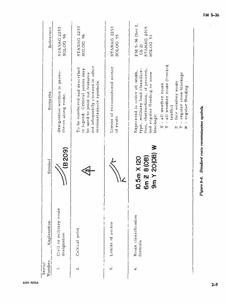
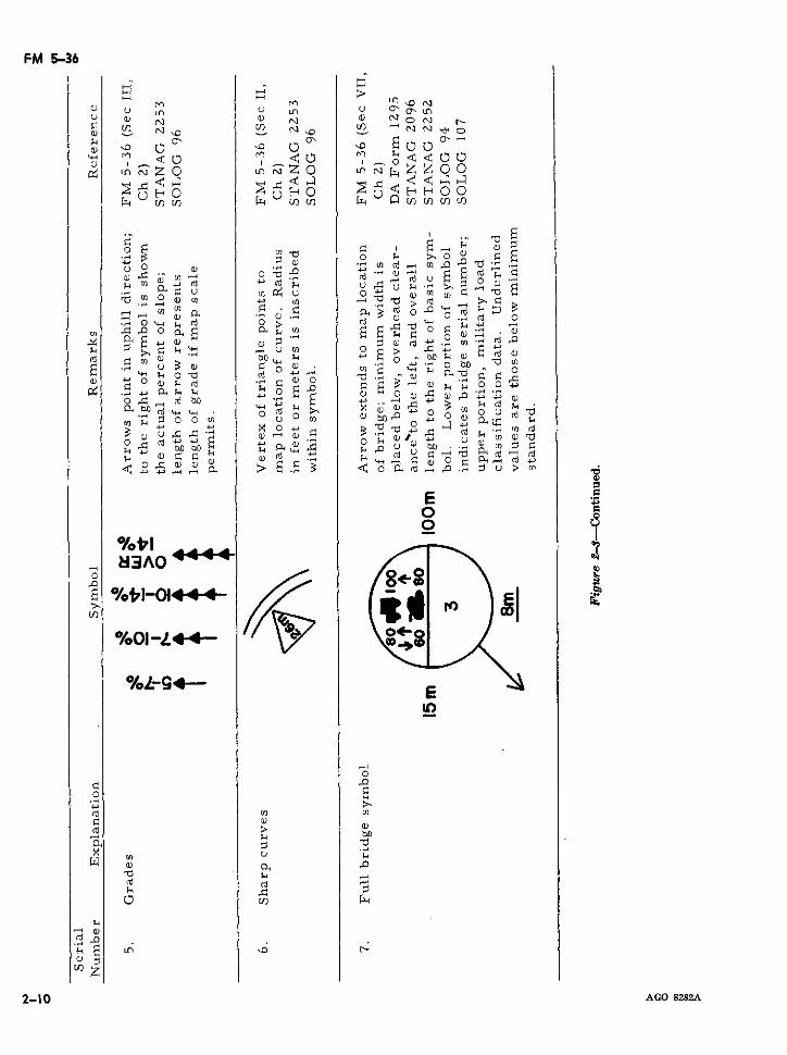
b. Hasty route reconnaissance is conducted port. The use of DA Reconnaissance Reportto determine the immediate military traffica- forms as inclosures establishes a permanentbility of a specified route. Such information is record and insures that sufficient detail is in-vital to all units engaged in planning and ex- cluded concerning important route character-ecuting vehicular movement and is limited to istics.critical terrain data which is necessary forroute classification and meets the intelligencerequirements of the situation. A route is a Factors of terrain which are important incomposite of terrain factors. Full apprecia- route reconnaissance and require consideration,tion of a route's capability cannot be deter- when applicable, are-mined until each factor affecting traffic flow is a. Existing routes and their physical char-separately analyzed. The report of hasty route acteristics.reconnaissance usually consists of a map over- b. Gradients and radii of curvature.lay supplemented by additional reports (de-pendent on the detail required) concerning c. Bridges.various aspects of the terrain. The route recon- d. Vehicular fording, ferrying, and swim-naissance overlay is accurate, clear, and con- ming sites.cise. Standard topographic (FM 21-31), mili- 'cise. Standard topographic (FM 21-31), mili- e. Tunnels, underpasses, and similar obstruc-tary (FM 21-30), and route reconnaissance tions to traffic flow.symbols are employed to insure that route re-connaissance reports are universally under- / f. Artificial obstacles such as areas of CBRstood. The route reconnaissance overlay, dis- contamination, roadblocks, craters, and mine-cussed in the following section, includes a fields.summary of pertinent reconnaissance symbols. g. Rock falls and slide areas.
AGO 8282A 2-1
FM 3-36
h. Drainage. (vpd). The capacity of a specific
i. Other natural or manmade features, such route is limited to the maxti um traf-as wooded and built-up areas, which may af- fi flow at its most restrictive point.fect movement. (2) The road capacity in tons is the maxi-
mum number of tons which can be2-3. Military Route Definitions (STANAG moved over a particular route in the
2151) same direction within a specified time.a. A basic military road network includes It is generally expressed in tons per
all routes designated in peacetime by the host hour and is the product of the numbernation to meet anticipated allied and national of vehicles per hour (vph) and themilitary vehicular movement and transporta- average payload of the vehicles usingtion requirements. A basic network has suf- the route. (For example: 200 vph x 5ficient capacity and is equipped with necessary tons per vehicle 1000 tons perfacilities to support normal military move- hour.)ments. (3) Existing conditions determine the
amount and type of traffic flow. Theseb. A military road maneuver network is the conditions include-system of routes required by a commander toconduct a specific military operation including (a) Route characteristis (terrain, typelogistical support. The network is formed of surface, width of traveled ways,around the existing basic military road net- maintenance requirements, and loadwork within the area of operations which may capacites).be modified, if required, to meet the military (b) Military traffic regulations (den-situation. The military road maneuver net- sity, speed limit, and traffic direc-work is designated and controlled by the mili- tion).tary commander exercising local territorial re- (c) Types of vehicles employed.sponsibility. (d) Light and weather conditions.
c. An axial route is part of a military road f. A movement credit is the time allocatedmaneuver network which leads to and runs gen- for one or more vehicles to move over a con-erally perpendicular to the FEBA. It is iden- trolled route (STANAG 2154). Movementtified by an odd number and is depicted on credits are issued by the appropriate trafficmilitary maps and overlays by a solid line. control headquarters in the operational area.
d. A lateral route is part of a military road g. A controlled route is a route subject tomaneuver network which runs generally par-. traffic or movement restrictions. Controlledallel to the FEBA and leads into or across axial ,routes include the following:routes. It is identified by an even number and (1) A supervised route is a route overis depicted on military maps and overlays by which control is exercised by meansbroken lines. of traffic control posts, traffic patrols,
e. Road capacity expressed in vehicles or or both. A movement credit is re-tons varies in accordance with the amount of quired for convoys of 10 or more ve-traffic. The maximum capacity of a route ex- hicles or by individual vehicles of ex-pressed either in vehicular flow or tonnage is ceptional size or weight.essential in transportation planning (see FM (2) A dispatch route is a road over which55-15). full control, both priority and regula-
(1) The road capacity in vehicles is the lation of traffic movement, is exer-maximum traffic flow obtainable on a cised. A movement credit is requiredgiven roadway using all available by individual vehicles as well as bylanes, usually expressed in vehicles groups of vehicles regardless of num-per hour (vph) or vehicles per day ber or type.
2-2 AGO 8282A
FM 5-36
(3) A reserved route is a controlled route cumstances other than normal by which move-which is either: ment is contemplated. Routes are classified ac-
(a) Allocated exclusively to a particular cording to the factors of minimum width, worstcommand or unit. (For example, a route type, least bridge military load classifica-route reserved exclusively for the tion, and obstructions to traffic flow.10th Division);
(b) or intended to meet a particular re- 2-5. Widthsquirement. (For example, a route The width of a route including bridges, tun-reserved exclusively for evacua- nels, roads, and other constrictions is the nar-tion.) rowest width of the route expressed in meters
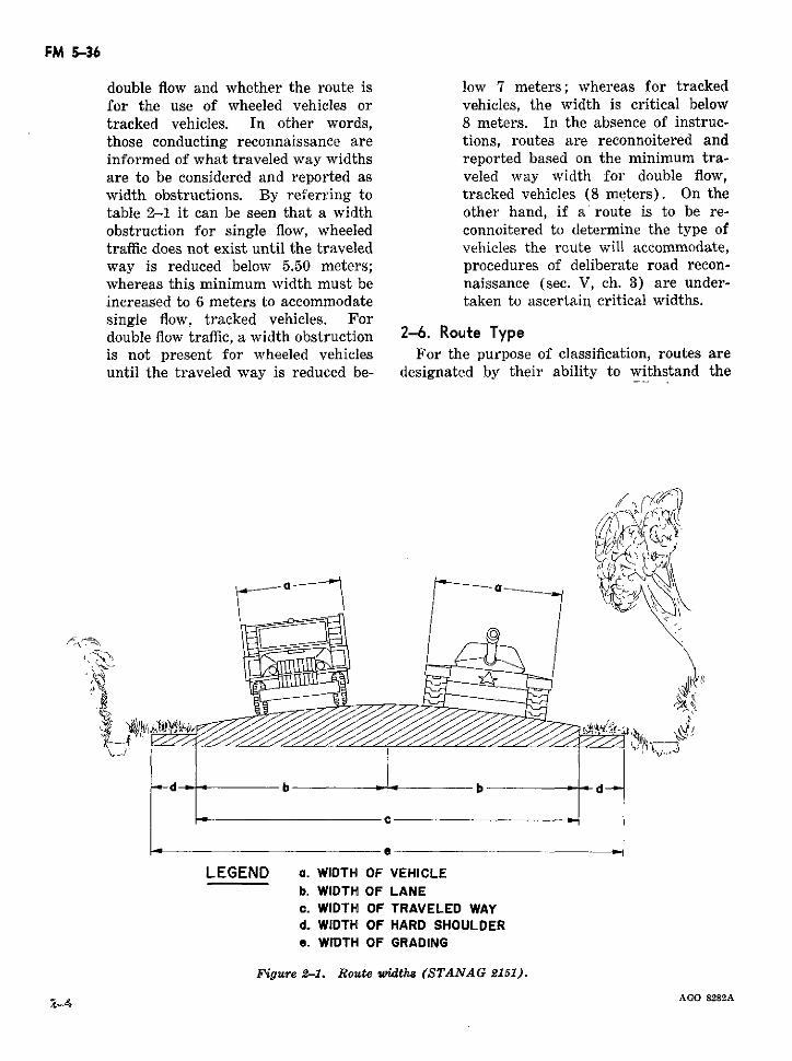
-/h. An open route is a route for which no or feet.'movement credit is required. a. Route widths are illustrated in figure 2-1.
i. A one-way road is a route on which ve- b. The number of lanes of a given route ishicles move in one direction only. determined by the width of the traveled way.
The average width of a lane required for theA sgned route is a route along which a movement of one column is established at 3.50unit has placed unit directional signs on its own meters (11o ft) for wheeled vehicles and 4
initiative, for its exclusive use, and under the meters (13 ft) for tracked vehicles. Singleconditions prescribed by the command or ma-
~neuver regulations. lanes accommodate vehicular traffic in one di-rection only with no overtaking in the same di-
k. A route where guides are provided is a rection or passing in the oncoming direction.route included in one of the above categories c. Traffic flow is determined by the numberupon which a unit has placed guides on its own of lanes (table 2-1).initiative and under the conditions prescribedby the command or maneuver regulations; (1) A route or traveled way is single flowthese guides direct personnel and vehicles of when it allows a column of vehicles totheir own unit but do not direct other units. proceed and, in addition, individultoncoming or overtaking vehicles to
1. Prohibited route or a prohibited section of pass at predetermined points. Theroute is one over which traffic is prohibited re- width of a single flow route, therefore,gardless of cause. is equal to at least l1/2 lanes.
~-4. Rou>e Claissification System (STANAG (2). A route is double flow when it allows201 5 and SOLOG 53) two columns of vehicles to proceed
simultaneously either in the same orThe route classification system is designed to opposite direction. The width of a
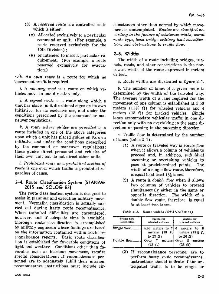
assist in planning and executing military move- double flow route, therefore, is equalment. Normally, classification is actually car- to at least two lanes.ried out during hasty route reconnaissance.When technical difficulties are encountered, Table 2-1. Route widths (STANAG 2151)however, and if adequate time is available, Traflie flow Widths for Widths forthorough route classification is accomplished possibilities wheeled vehicles tracked vehiclesby military engineers whose findings are based Single flow ------ 5.50 meters to 7 6 meters to 8on the information contained within route re- meters (18 ft meters (19% ftconnaissance reports. Basic route classifica- to 23 ft) to 26 ft)tion is established for favorable conditions of Double flow Over 7 meters Over 8 meterslight and weather. Conditions other than fa-vorable, such as blackout movement, require (3) If reconnaissance personnel are tospecial considerations; if reconnaissance per- perform hasty route reconnaissance,sonnel are to adequately fulfill their mission, instructions should indicate if the an-reconnaissance instructions must include cir- ticipated traffic is to be single or
AGO 8282A 2-3
FM 5-36
double flow and whether the route is low 7 meters; whereas for trackedfor the use of wheeled vehicles or vehicles, the width is critical belowtracked vehicles. In other words, 8 meters. In the absence of instruc-those conducting reconnaissance are tions, routes are reconnoitered andinformed of what traveled way widths reported based on the minimum tra-are to be considered and reported as veled way width for double flow,width obstructions. By referring to tracked vehicles (8 meters). On thetable 2-1 it can be seen that a width other hand, if a' route is to be re-obstruction for single flow, wheeled connoitered to determine the type oftraffic does not exist until the traveled vehicles the route will accommodate,way is reduced below 5.50 meters; procedures of deliberate road recon-whereas this minimum width must be naissance (sec. V, ch. 3) are under-increased to 6 meters to accommodate taken to ascertain critical widths.single flow, tracked vehicles. Fordouble flow traffic, a width obstruction 2-6. Route Typeis not present for wheeled vehicles For the purpose of classification, routes areuntil the traveled way is reduced be- designated by their ability to withstand the
d -| b ' b -d-"
e
LEGEND a. WIDTH OF VEHICLEb. WIDTH OF LANEc. WIDTH OF TRAVELED WAYd. WIDTH OF HARD SHOULDERe. WIDTH OF GRADING
Figure 2-1. Route widths (STANAG 2151).
AGO 8282A4-
FM 5-36
effects of weather. Route type is determined regardless of vehicle type or conditions ofby the worst section of the route. Routes as traffic flow determines the military load classifi-classified by type are- cation of a route. By selecting the lowest
a. Type X-Al-GWeather Route is any route bridge classification number, it is assured thatwhich with reasonable maintenance is passable the route is not overloaded. In those casesthroughout the year to traffic never appreci- where vehicles bear a higher military load clas-ably less than maximum capacity. The roads sification than the route, the route reconnais-which form this type of route normally have sance overlay is checked or a special recon-waterproof surfaces and are only slightly af- naissance is initiated to determine if a changefected by precipitation or temperature fluctua- in traffic control procedures, such as a singletions. At no time is the route closed to traffic flow crossing, may permit utilization of theby weather effects other than temporary snow route by heavier traffic. If no bridge is locatedor flood blockage. on the route or if roads are particularly bad,
the worst section of road governs the route'sb. T~y~pe Y-AIlWeatlher Route (Lim·ite~d· classification (see sec. V, ch. 3).
Traffic Due to Weather) is any route whichwith reasonable maintenance can be kept open c. Classification of Military Road Maneuverin all weather but sometimes only to traffic Networks. The classification of a military roadconsiderably less than maximum capacity. The maneuver network is fixed by the minimumroads which form this type of route usually do route classification of the network. To facili-not have waterproof surfaces and are con- tate movement of heavier equipment, however,siderably affected by precipitation or tempera- individual routes included in a lower classifica-ture fluctuations. Traffic may be completely tion network may be grouped and identified inhalted for short periods. Heavy unrestricted the following general categories (STANAGuse during adverse weather may cause complete 2151):collapse of the surface. (1) Average traffic routes:
c. Type Z-Fair-Weather Route is any route Classification 50which quickly becomes impassable in adverse (2) Heavy traffic routes:weather and cannot be kept open by mainte- Classification 80nance short of major construction. This cate- (3) Very heavy traffic routes:gory of route is so seriously affected by weather Classification 120that traffic may be brought to a halt for long Whenever possible, the basic military roadperiods. maneuver network is composed of average
.2-7. Military Load .ssification .routes (Classification 50) and includes a num-ber of heavy traffic routes (Classification 80)
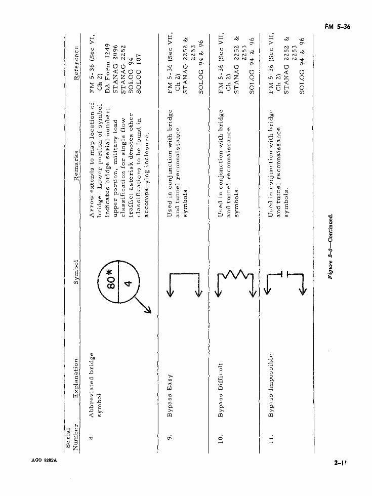
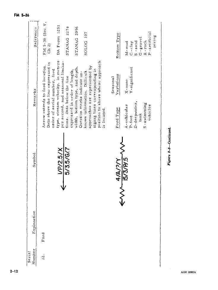
a. General. The military load classification and a few very heavy traffic routes (Classifi-system is a load capacity rating system which cation 120).considers a vehicle's weight and type and itseffect on routes and bridges. The classification 2-8. Obstructions to Traffic Flowsystem is represented by whole numbers as- Route obstructions are factors which restrictsigned to vehicles, bridges, and routes. (For the type and amount or speed of traffic flow.detailed discussion, see secs. III and IV, ch 3.) Route obstructions with the exception of bridgeMost allied military vehicles are externally capacities, which are reported separately as amarked with their respective classificationnumber (see para. 2-53).Brimilitary load classification, are indicated in thenumber (see para. 2-53). Bridges and routes route classification formula (para. 2-9) by theare assigned military load classifications based abbreviation (OB). Moreover, reconnaissanceon their safe load capacity and physical di- symbols are used to describe the nature of eachmensions. obstruction on the route reconnaissance over-
b. Route Classification. Normally, the low- lay (see fig. 2-2). Obstructions to be reportedest bridge military load classification number 'include-
AGO 8282A 2-5
FM 5-36
a. Overhead obstructions such as bridges, (3) Curves with radii 30 meters (100 ft)tunnels, underpasses, overhead wires, and over- or less.hanging buildings whose overhead clearance ís (4) Fords and ferries.less than 4.25 meters (14 ft). (5) It should be noted that 20 feet of
b. Reduction in traveled way widths which traveled way limits this route to singleare below standard minimums prescribed for flow traffic without a width obstruc-the type of traffic flow (single or double, tion. If the route is to be used forwheeled or tracked, see table 2-1). Examples double flow traffic, however, 20 feet ofare bridges, tunnels, craters, lanes through traveled way constitutes an obstruc-mined areas, and projecting buildings or rub- tion and is indicated in the formulable. as an obstruction (OB).
c. Gradients (slopes) of 7 percent or greater. c. 7m Y 50 (OB). This example formuladescribes a limited all-weather route with a
d. Curves whose radii of curvature are lessed aer*han 30 meters (100 fminimum traveled way of 7 meters, a militarythan 30 meters (100 ft). load classification of 50 and with obstruc-
e. Ferries. tion(s).
f. Fords. Note. For double flow, wheeled traffic the traveledway width is adequate; however, the route's width is
2-9. Route Classification Formula not suitable for double flow, tracked vehicles. This2--9. Route Classification Formula width constriction would be indicated as (OB) in theThe route classification formula is developed route classification formula if the route were to be
from notations expressed in the standardized used for both types of vehicles.sequence of minimum traveled way width, route d. 10.5m X 120 (OB). This example form-type, lowest military load classification, and an ula describes an all-weather route with a mini-obstruction or obstructions if present. The mum traveled way width of 10.5 meters, whichformula briefly describes a specific route and is suitable for double flow traffic of bothis used together with a route reconnaissarce wheeled and tracked vehicles, a military loadoverlay. If an obstruction(s) appears in the classification of 120 with an obstruction(s).route classification formula it is necessary to 2-10. Special Conditionsrefer to the route reconnaissance overlay in~~~~~~~~- . ~a. Snow Blockage. The effects of snow areorder to determine the exact nature of the ob-,t·cio ) not normally considered as an obstruction tostruction(s). Illustrative formulas are shownstructio-(s). Illustrative formulas are shown *traffic flow in route classification since vehicu-below: lar movement is determined by the depth of the
a. 20ft Z 10. This example formula de- snow and the availability of snow removalscribes a fair-weather route with a minimum equipment. In those cases, however, wheretraveled way of 20 feet and a military; load snow blockage is regular, recurrent, and seri-classification of 10. This route, based on its ous; the formula for classifying a route is fol-minimum width of traveled way (see table lowed by the symbol (T), for example:2-1), accommodates both wheeled and tracked, (1) 20ft Y 50 (T).single flow traffic without obstruction. (2) 7m Y 50 (OB) (T).
b. 2Oft Z 10 (OB). This example formula b. Flooding. The effect of flooding on trafficdescribes a route with similar characteristics flow is also not normally considered in routeas in example a. but with an obstruction(s). classification. However, where flooding isThis obstruction(s) could consist of one or regular, recurrent, and serious, the formulamore of the following: for classifying a route is followed by the sym-
(1) Overhead clearances of less than 4.25 bol (W); for example:meters (14 ft). (1) 20ft Y 50 (W).
(2) Grades of 7 percent or greater. (2) 7m Y 50 (OB) (W).
2-6 AGO 8282'A
FM 5-36
Section 51. ROUTE RECONNAISSANCE OVERLAYS
2-1 1. General h. Locations and limiting dimensions of tun-This section provides guidance in the prep- nels to include suitable bypasses.
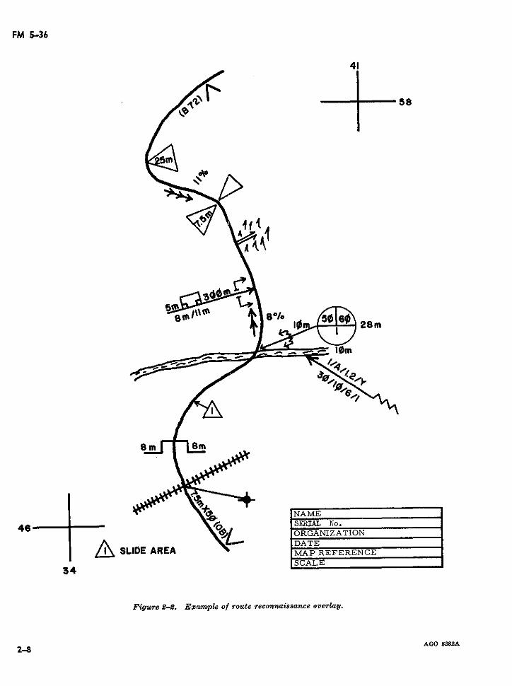
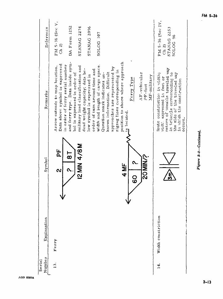
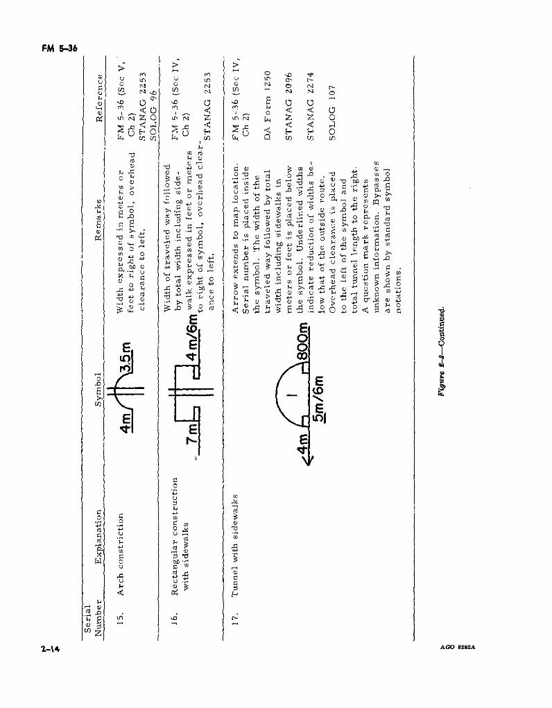
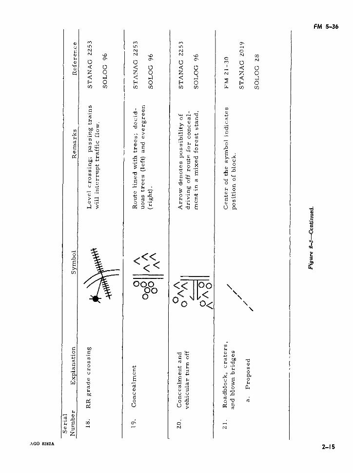
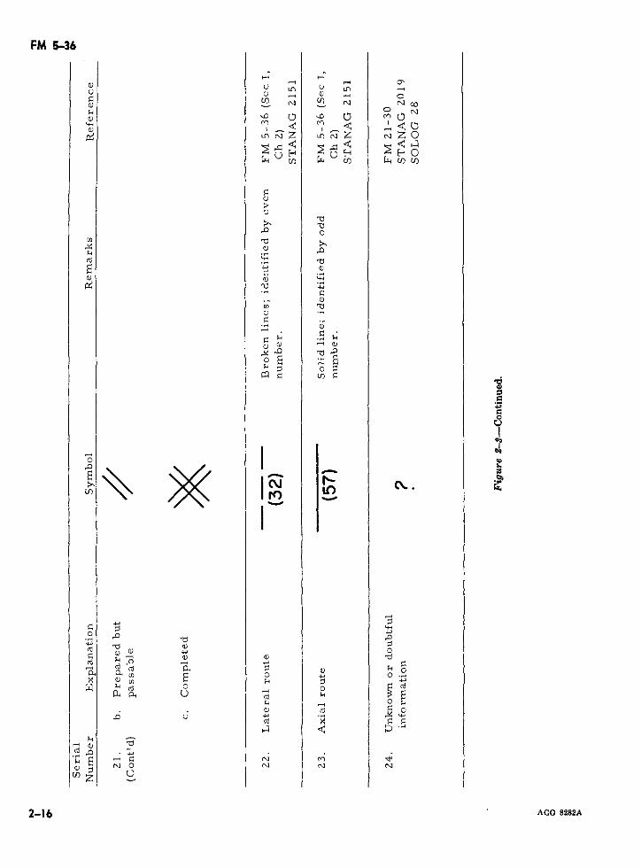
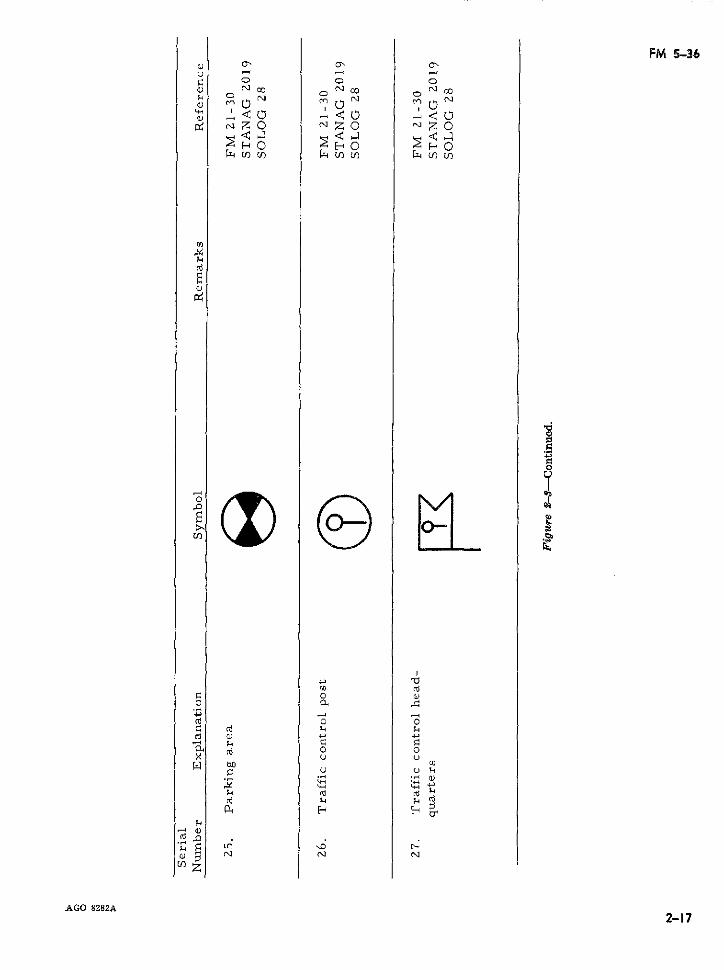
aration of route reconnaissance overlays used i. Suitable areas for short halts and bivouacsin hasty and deliberate reconnaissance. A which offer drive-off facilities, adequate disper-summary of route reconnaissance symbols used sion, cover, and concealment.in overlay preparation is included. The route j. Areas of rock falls and slides which mayreconnaissance overlay is an accurate and con- present a traffic hazard.cise report of the conditions affecting trafficflow along a specified route and is the preferred 2-13. Route Reconnaissance Symbolsmethod of preparing a route reconnaissance Figure 2-3 provides a summary of standardreport. An overlay normally satisfies the re- route reconnaissance and related symbols. Inquirements of hasty route reconnaissance. If,however, more detail is required to support thereconnaissance, the overlay is supplemented in greater detail, are provided for each entrywith written reports describing critical route 2-14. Reportrng of Opened and Ciosed'characteristics in more detail. An example of Routes (STANAG 2096 and SOLOGa route reconnaissance overlay is shown in 107)figure 2-2.
Reconnaissance personnel may often find2=12. Route Reconnaissance Checklist themselves required to report the closure of
To insure that critical terrain data during axial or lateral routes or a portion of suchroute reconnaissance are not overlooked and to routes due to enemy action, climatic conditions,aid in the preparation of reconnaissance re- or other reasons. In addition to reporting theports, a checklist based on the characteristics closure of a route, it is usually necessary toof the area of operations is recommended. reconnoiter and report suitable bypasses orGeneral items for consideration are- detours. Conversely, when routes are again
opened, a report to this effect is also required.a. Identification and location of the recon-Standardized formats for both situations (figs.2-4 and 2-5) have been developed. Although
b. Distances between easily recognized points primarily designed for electrical transmissionsboth on the ground and map. in conjunction with standard message forms
c. The percent of slope and length of grades (DD Form 173 and DA Form 11-170), thewhich are 7 percent or greater. formats, which are reproduced locally, may
d. Sharp curves whose radii of curvature also be used to supplement overlay or mapare 30 meters (100 ft) or less. reconnaissance reports. The originator com-
e. Bridge military load classifications and pletes only those parts of the format which arelimiting dimensions to include suitable by- applicable or for which information is avail-passes. able. Each item of the report, however, must
f. Locations and limiting data of fords and be accompanied by the appropriate letter desig-ferries. nation from the format to establish the correct
g. Route constrictions, such as underpasses, category of information. Messages are pre-which are below minimum standard and, if ceded by the term, ROUTECLOSEDREP orappropriate, the distances such restrictions ex- ROUTEOPENREP, which ever applies, or antend. identifying codeword.
AGO 8282A 2-7
FM 5-36
41
58
3$i
28m
46 INAME
46I SERIAL No.ORGANIZATION
DATEAl~ SULDE AREA MAP REFERENCE
SCALE34
Figure 2-2. Example of route reconnaissance overlay.
AGO 8282A2-8
FM 5-36
e.) rn r1 r Lnu Ln Ln U') UCN n N N "D
u i/ ' N' L U) N,--
z 0 z 0 z 0 J) z o¢ 4 ¢ 4 < 4 çl < ¢H u0 EH 0O H
C'.1 0'1 0,1 ~~C,
hi" *..O , Oh Z C'- O ,
U) U) z U) u) *Qt
e) O D )9 O
73 W~ O rd +-' ¿
g, (D d U) C4
0~~~~ ~~~~~ ~ ~ ~~~~~~~~~~~~~~~~~~~~~~~~~ 0
Zo Z o 4o . 0o
< \ <~ < X
\\ t o E ao
.~~~~~ · 3 F~~~~~> 1 - 4 4 (e
u~~~~~~~
0 U)
AGO 8 2- o '
1~ ~ k c kkkn
4~~~~~~~~~~~,-
U , o., oo .Í
~~~~~~~~~~~~~~~~~~~~~~~~.~.~
0~~~~ M .o.9..0
--, X (; -~oD 0,,i d
d FI M pu, a, , o ·i Co N
c: a> F: c~o E E di ·
0~~~~~~~
'4
' ~i o.,~:l, 41
.~. o '~~ X oP
'0 '
> u) j
U)~~~~~~~~V
AGO 8282A 2-
E E~~~~~~~~-
FM 5-36
uO m ZO U0Cfl N N Ni NON r-
aN -'.0 0 <0 '
z o<0 i<<O z z 00
U in SUZO Ln·ZOO
· cn a 4 U U U) U) U
C) d l - C)F 5
.~o~ -
un i O w ' ~G o 8 8
· ~d e o I
"/ oBa,,t o k;, -
~13AO 44..4-4-·" O M a r4
U)o~~ ~ o L0u0) 4~
4-100 ,J 4*
AOOúiz u2u)
O 1 o uE
FM 5-36
1 ) m 444\ o~~ ~I ~~o i-i oNI s
N U) N N N)
$~~~~~~ 0 , < Z0 , ¢ 0Q) ~0, . - ,~ ,.-1 ,-. 1
z O 0 On i: z 0 n i;5 0 n X:~
<, o .o 0 .
h~~~~ ~ ° O;, Qi SqNV.N
$~~~~~~~( $0 4 °>
'1 " S V"; CS ..
0~~~~~~~~~~~
0
o~"~o U o ~
u) -- illoU -- 0
o .
<i .,- rr% rB rr :~ r B 6 r, ( i
'h -, ' V g u)
¢ > k *e M V
,.U u a
I>~~~~~~~~~~~~~~~~~',
A' ~UUOGOr t( c8 u
E r O O
U)zAGoz U)
5 au F: u d u~~~~~~~~~~~~~UE m k M ~~~~~~w co ~~~~~''' ~
"~~~dT: oe>~~U U) u) aX~~~~~~~~~~-l k"~~~~~~~~~~~~~~~~~~~~(
"ou~~~~u~~ 6~~~ C~~~ d cri~~~PQ) a, ,;U E: d ~~~~~.' d r3p
00 " 6U)a ~ ~u. E ' 3 O.
AGO 8282A 2-·11 ~~P +'
FM 536
U) N o
·O EO a, 7 4M°w x t O a aa , ,a°:
X CEo : ~o u
El 0
d Ln N 6i O c4' h
x Wa a8~~ a Daa la3Eu
X~x fh E zi~~~~~~~
2-12 AGOa8282Affl fU) ) W c
0 uo
2-12~~~~~~ A~(tjm .o U)sz
41 > m z 'C> E o 4
O k ·0 d C 0 r , 4 a C3 FI (dri [~ F (d
-41 P (O - 1
2-12 AGO 8282A~~.(d Oi4
FA 5-36
© Nu r-L~n u in L
NNo,~~~~~~~~~~FI ai~N D _o) N
,~~~ o z ~ o(B~ o
U) rd (d~a
Z wE P Zo 5
F ~~~ ai p d a o ~~~~~~zi 0a) tO "D, r1 d (dF dr - :
P. --- U) 4 e, 4a
3 ~ ~ ~ ~ ~ e u , .1CH > :
ro ~ ~ ~ ~ ~ ~ ~ o
cn c d 4 or .o rd m , C l.cp, 0 lo 4-, E : a.d 41 F .9 .~.~ ·4D .
> P z pCH k
>, - 0 or .r o
k.~ 4 0 -do P-
w o p 0qm c
-oO 8o-8 A
2-13
id L (
(d · C O)41 >p I CdoEei.r dCa 0 ~ ~
rd~~~~~~~~~~~~~~~~~~~~~~~~~~~~~~~~~~~~~~~~~~P a o' i l r c r
U) z~~~~~~~~~~
AGO 8282A4
a>~~~~~~~~~~~~~~~~~21
FM 5-36
u~~~~~~~~~~,, oNE o
ais 0 ·D ( F 3> ) 3 " >
b~~rncn ~ W , W - -a ]si U
rd bl~~~0 d r m.
Up, :0
~% ·i a, rd d r
u~~~~~~~~~~~c u ,-~' ,,-iE
k~~~~ .~U~i~'
O .C<W rn ~~~~~~~~~~A~o 8~
O O Ohq
u >a p e icrB w M k a~~~~~~~~~3 al(Id ~ ~ ~ ~ "Z'
,Sd~~~~~~a
z i o(r aO
cn z x ao.. I , ,r :" I SF
1-14 AGO 8282A~,~~
FM 5-36
u L L. Ln i> N N - N °-
h O N
« ¢aO ¢O ¢,O N¢O~~1 01 01
< o <: o <
a ~ ~ ~~~, orH 0 E 0 Z 0 ~ H 0U)] U) (/] U) ] U/) U)t/
> BaM o~>o~ 0d u
E >o a, W Wa1 z 4 W O C
n ,. . PV o eA41 U z B 2 = =
0 ,0 >0
;d 0 ai · e'
h~~~~~~~~~~~~~~~~
0~~~~. 0 o
0~~~~~~~
< <
U) _
<<< 0
r k, UD,
do O~~~~~~~
· "~Oo <<JI)ao x
AGO 8282A02-15
\\ k .T' 2-
"0 u o ~ 0 .
c~ c~ c{ ,
,,..co 82Aio~~~~~~~~~~~~~~~~~~~~-1 $·
FM 5-36
a> O in U Ln 3~~~~~~~~~~~ia) -i o"1 N IA Nq N CO
~~~~> ~ ~ ~
a) LnaL~ NZ
CO
.~~~~~ca)Z
t<O
•_)~~~~~~~~~~~~~~~~~~~a
00
Zi o
an '0~~~~~~~~~a
cu-
0~~~~~~~~~~~~~~~~~'
a~~~~~~~~ P, ~ ~ ~ ~ ~ ~ ~ ~ e
3ai~~~~~4
p, p, ~ ~ ~ ~ ~ -,a
a)
a) 2a) a) -~~ a)
o d=P~~~ P0
*c'a) a)
0 " 4- o
aa~~~~~~~)0
.0 u 4-' U
2-1 AGO 8282A
FM 5-36
a o o o
d N«Z N Z Nt0
( -i00
AGO 8282A
o o
o ou u
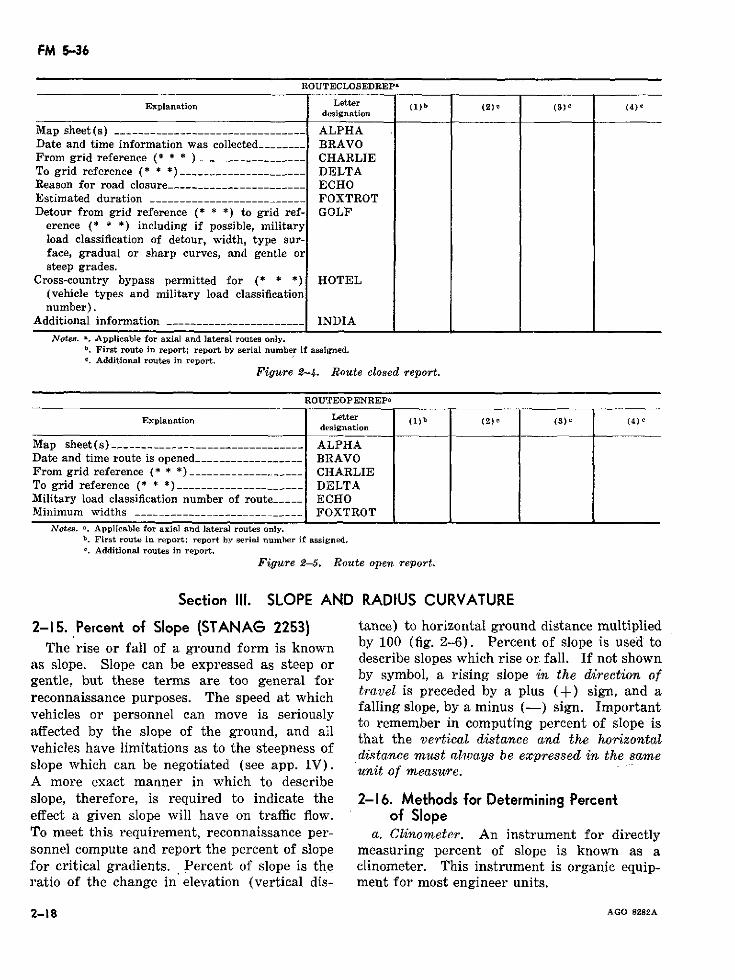
FM 5-36
ROUTECLOSEDREP'
Explanation Letter (1) b (2) c (4)designation
Map sheet(s) -----________--_______ ____ ___--- ALPHADate and time information was collected--_----- BRAVOFrom grid reference (* * * )__________________ CHARLIETo grid reference (* * *) --______-__________ - DELTAReason for road closure_----__________________ ECHOEstimated duration _______________________--- FOXTROTDetour from grid reference (* * *) to grid ref- GOLF
erence ( * * *) including if possible, militaryload classification of detour, width, type sur-face, gradual or sharp curves, and gentle orsteep grades.
Cross-country bypass permitted for (* * *) HOTEL(vehicle types and military load classificationnumber).
Additional information _----_________________- INDIA
Notes. a. Applicable for axial and lateral routes only.b. First route in report; report by serial number if assigned.c. Additional routes in report.
Figure 2-4.. Route closed report.
ROUTEOPENREPa
Explanation Letter (1) b (2) (3)e (4)designation
Map sheet(s) .-------- __----------------___ _ ALPHADate and time route is opened -------_---__---- BRAVOFrom grid reference (* * *) _____-___-- _______ CHARLIETo grid reference (* * *)_____________________ DELTAMilitary load classification number of route ---- ECHOMinimum widths ____________________________ FOXTROT
Notes. -. Applicable for axial and lateral routes only.b. First route in report: report by serial number if assigned.c. Additional routes in report.
Figure 2-5. Route open report.
Section III. SLOPE AND RADIUS CURVATURE
2-15. Percent of Slope (STANAG 2253) tance) to horizontal ground distance multipliedThe rise or fall of a ground form is known by 100 (fig. 2-6). Percent of slope is used to
as slope. Slope can be expressed as steep or describe slopes which rise or fall. If not showngentle, but these terms are too general for by symbol, a rising slope in the direction ofreconnaissance purposes. The speed at which travel is preceded by a plus (+) sign, and a
falling slope, by a minus (-) sign. Importantvehicles or personnel can move is seriouslyaffected by the slope of the ground, and all
that the vertical distance and the horizontalvehicles have limitations as to the steepness of distance must always be expressed in the sameslope which can be negotiated (see app. IV). unit of measure.A more exact manner in which to describeslope, therefore, is required to indicate the 2-16. Methods for Determining Percenteffect a given slope will have on traffic flow. of SlopeTo meet this requirement, reconnaissance per- a. Clinometer. An instrument for directlysonnel compute and report the percent of slope measuring percent of slope is known as afor critical gradients. Percent of slope is the clinometer. This instrument is organic equip-ratio of the change in elevation (vertical dis- ment for most engineer units.
2-18 AGO 8282A
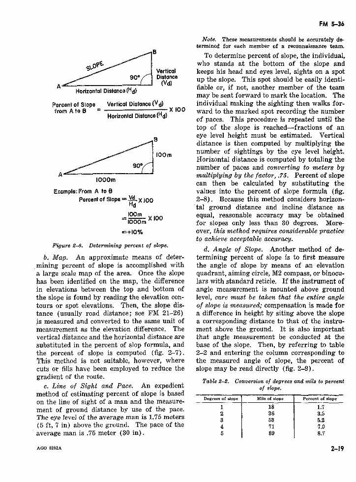
FM 5-36
Note. These measurements should be accurately de-termined for each member of a reconnaissance team.
B a To determine percent of slope, the individual,who stands at the bottom of the slope and
Vertical keeps his head and eyes level, sights on a spot90* Distance up the slope. This spot should be easily identi-
A Horizontal Distnc(Hd) fiable or, if not, another member of the teammay be sent forward to mark the location. The
Percent of Slope Vertical Distance (Vd) individual making the sighting then walks for-from A to B = X 100 ward to the marked spot recording the number
Horizontal Distance(Hd) of paces. This procedure is repeated until thetop of the slope is reached-fractions of aneye level height must be estimated. Verticaldistance is then computed by multiplying the
lOOm number of sightings by the eye level height.Horizontal distance is computed by totaling the
/90r number of paces and converting to meters byAOOOm nmultiplying by the factor, .75. Percent of slope
can then be calculated by substituting theExample: From A to B values into the percent of slope formula (fig.
Percent of Slope V- :d X 100 2-8). Because this method considers horizon-Hd 'tal ground distance and incline distance aslOOm X 100 equal, reasonable accuracy may be obtained
0O X for slopes only less than 30 degrees. More-2+10% over, this method requires considerable practice
to achieve acceptable accuracy.Figure 2-6. Deter7mining percent of slope. d. Angle of Slope. Another method of de-
b. Map. An approximate means of deter- termining percent of slope is to first measuremining percent of slope is accomplished with the angle of slope by means of an elevationa large scale map of the area. Once the slope quadrant, aiming circle, M2 compass, or binocu-has been identified on the map, the difference lars with standard reticle. If the instrument ofin elevations between the top and bottom of angle measurement is mounted above groundthe slope is found by reading the elevation con- level, care must be taken. that the entire angletours or spot elevations. Then, the slope dis- of slope is measured; compensation is made fortance (usually road distance; see FM 21-26) a difference in height by siting above the slopeis measured and converted to the same unit of a corresponding distance to that of the instru-measurement as the elevation difference. The ment above the ground. It is also importantvertical distance and the horizontal distance are that angle measurement be conducted at thesubstituted in the percent of slop formula, and base of the slope. Then, by referring to tablethe percent of slope is computed (fig. 2-7). 2-2 and entering the column corresponding toThis method is not suitable, however, where the measured angle of slope, the percent ofcuts or fills have been employed to reduce the slope may be read directly (fig. 2-9).gradient of the route.
Table 2-2. Conversion of degrees and mils to percentc. Line of Sight and Pace. An expedient of slope.
method of estimating percent of slope is basedon the line of sight of a man and the measure- Degrees of pe uis of slope Percet of pement of ground distance by use of the pace. 836 3.5The eye leve] of the average man is 1.75 meters 3 53 5.2(5 ft, 7 in) above the ground. The pace of the 4 71 7.0average man is .75 meter (30 in). 5 89 8.7
AGO 8282A 2-19
FM 5-36
Table 2-2. Conversion of degrees and mils to percent flow and are indicated by the abbreviationof slope-Continued. (OB) in the route classification formula (para.
Degrees of slope Mils of slope Percent of slope 2-8).
10 178 17.615 267 26.7 2-19. Methods of Measuring Curves20 356 36.4 a. The radius of a very sharp curve may be25 444 46.62530 533 57467 estimated by using a tape to swing an arc as35 622 70.0 illustrated in figure 2-11. The curve is in-40 711 83.9 scribed as a part of a circle by swinging an45 800 100.0 arc with tracing tape from the experimentally50 889 108.7 located center of a circle. The length of the55 1067 117.6 tape from the center of the circle to its circum-
ference is the radius of the curve. This method
2-17. Methods of Recording Percent of is practical for curves having a radius up toSlope (STANAG 2253 and SOLOG 15 meters and located on relatively level ground.
Note. In figures 2-11, 2-12, and 2-13: C = centerline; PC =96) point of curvature; and PT = point of tangency.
Most vehicles which are required to negotiate b. Another method for determining the ap-slopes of 7 percent or greater for any signifi- proximate radius of a curve is by laying outcant distance will be slowed down. Route right triangles (3:4:5 proportion) at the PCreconnaissance, therefore, is required to locate and PT locations as shown in figure 2-12. Thesuch obstructions to traffic flow and to accu- intersection, O, formed by extending the baserately report slope characteristics. Reconnais- legs of each triangle, represents the center ofsance symbols have, consequently, been adopted a cirele. Therefore, the distance R from pointto symbolically portray gradients (percent of O to either points PC or PT represents theslopes) on maps and overlays. A single headed curve radius.arrow along the trace of a route pointing inthe uphill direction indicates a 5 but less than c. Another method for determining the ra-7 percent grade; two arrowheads represent a dius of a curve (fig. 2-13) is based on thegrade greater than 7 but less than 10 percent; formula-three arrowheads represent a grade greater R = cd2/8m + m/2than 10 but less than 14 percent; and four c = length of tapearrowheads represent a grade over 14 percent m = perpendicular distance from(fig. 2-10). The value of the grade in percent the center of tape to the cen-of slope is further written to the right of the terline ( ( ) of road.arrow. Whenever the map scale permits, the R = radius of the circlelength of the arrow shaft drawn to scale rep- By fixing m always at 2 meters, the formularesents the approximate length of the grade becomes-(fig. 2-2). It should be remembered that slopes R = c2/16 + 1of 7 percent or greater are considered as ob-od of Recordstruction to traaG fow and are ·indicated by 2-20. Methods of Recording Radius ofstruction to trafflc flow and are indicated by Curvature <STANAG 2253 andthe abbreviation (OB) in the route classifica- SOLOG 93)tion formula (para. 2-8).
Sharp curves along a specified route whose2-18. Radius of Curvature radii are less than 30 meters (100 ft) are
The speed at which vehicles can move along symbolically represented on maps or overlaysa specified route is also affected by sharp by means of a triangle whose vertex points tocurves. For reconnaissance purposes, curves the exact map location of the curve. In addi-whose radii of curvature are less than 30 me- 'tion, the measured value in meters or feet forters (100 ft), are reported. Curves of this the radius of curvature is inscribed inside thenature are considered as obstructions to traffie triangle (fig. 2-14).
2-20 AGO 8282A
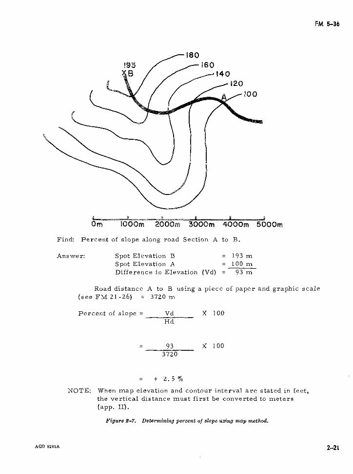
FM 5-36
80
B /4020
O D00m 20000000 m 30I0m 4000m 5000r
Find: Percent of slope along road Section A to B.
Answer: Spot Elevation B = 193 mSpot Elevation A = 100 mDifference in Elevation (Vd) = 93 m
Road distance A to B using a piece of paper and graphic scale(see FM 21-26) = 3720 m
Percent of slope = Vd X 100Hd
= 93 X 100
3720
= + 2.5 %
NOTE: When map elevation and contour interval are stated in feet,the vertical distance must first be converted to meters(app. II).
Figure 2-7. Determining percent of slope using map method.
AGO 8282A 2-21
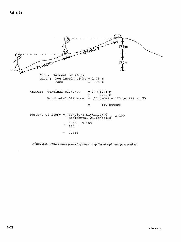
FM 5-36
1.75m
Find: Percent of slope.Given: Eye level height = 1.75 m
Pace = .75 m
Answer: Vertical Distance = 2 x 1.75 m= 3.50 m
Horizontal Distance = (75 paces + 125 paces) x .75
= 150 meters
Percent of Slope = Vertical Distance(Vd) X 100Horizontal Distance(Hd)
3.50 X 100150
= 2.34%
Figure 2-8. Dete&rmining percent of slope using line of sight and pace method.
2-22 AGO 8282A
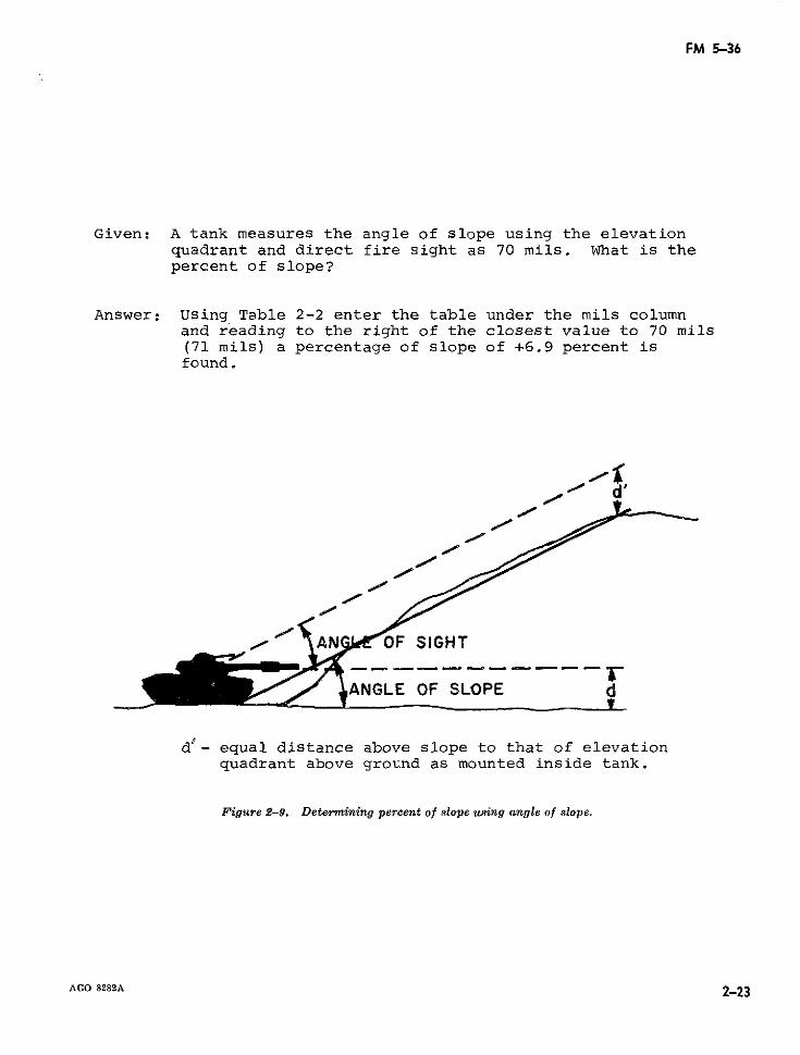
FM 5-36
Given: A tank measures the angle of slope using the elevationquadrant and direct fire sight as 70 mils. What is thepercent of slope?
Answer: Using Table 2-2 enter the table under the mils columnand reading to the right of the closest value to 70 mils(71 mils) a percentage of slope of +6.9 percent isfound.
ANGLE OF SLOPE d
d- equal distance above slope to that of elevationquadrant above ground as mounted inside tank.
Figure 2-9. Determining percent of slope using angle of slope.
AGO 8282A 2-23
?~~~~~~22
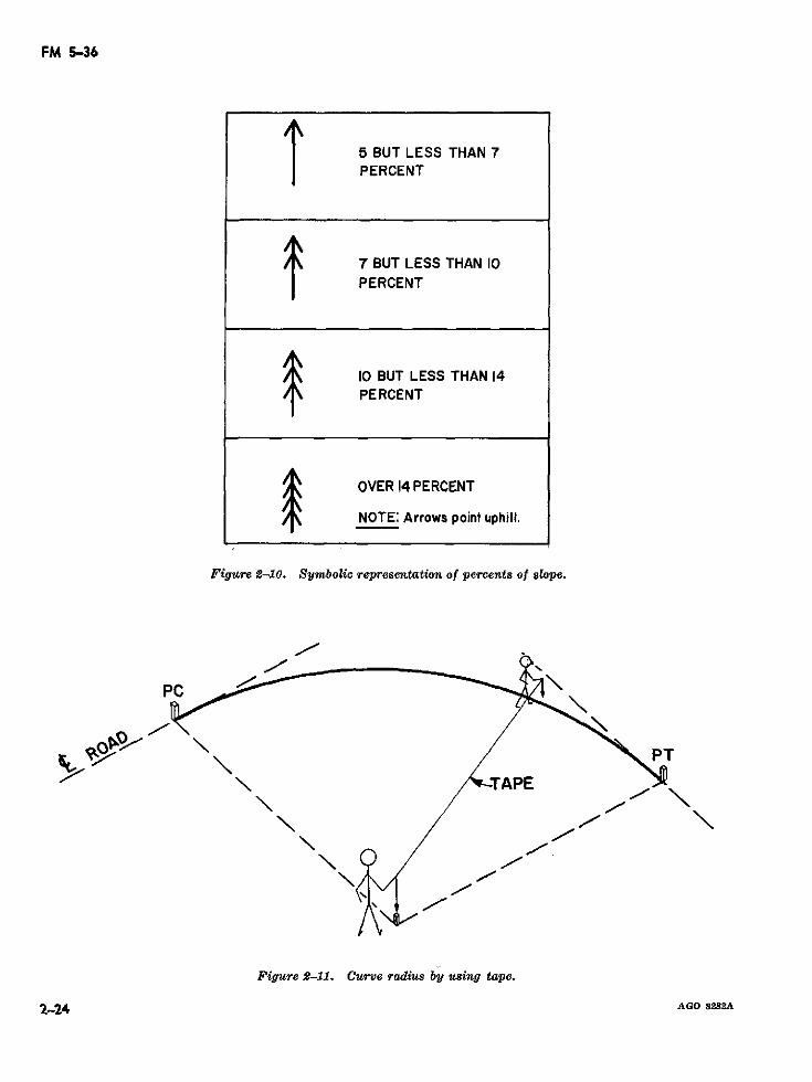
FM 5-36
5 BUT LESS THAN 7PERCENT
7 BUT LESS THAN 10PERCENT
10 BUT LESS THAN 14PERCENT
OVER 14 PERCENT
NOTE: Arrows point uphill.
Figure 12-10. Symbolic representation of percents of slope.
/\ /
Figure 2-1I. Curve radius by using tape.
2-24 AGO 8282A
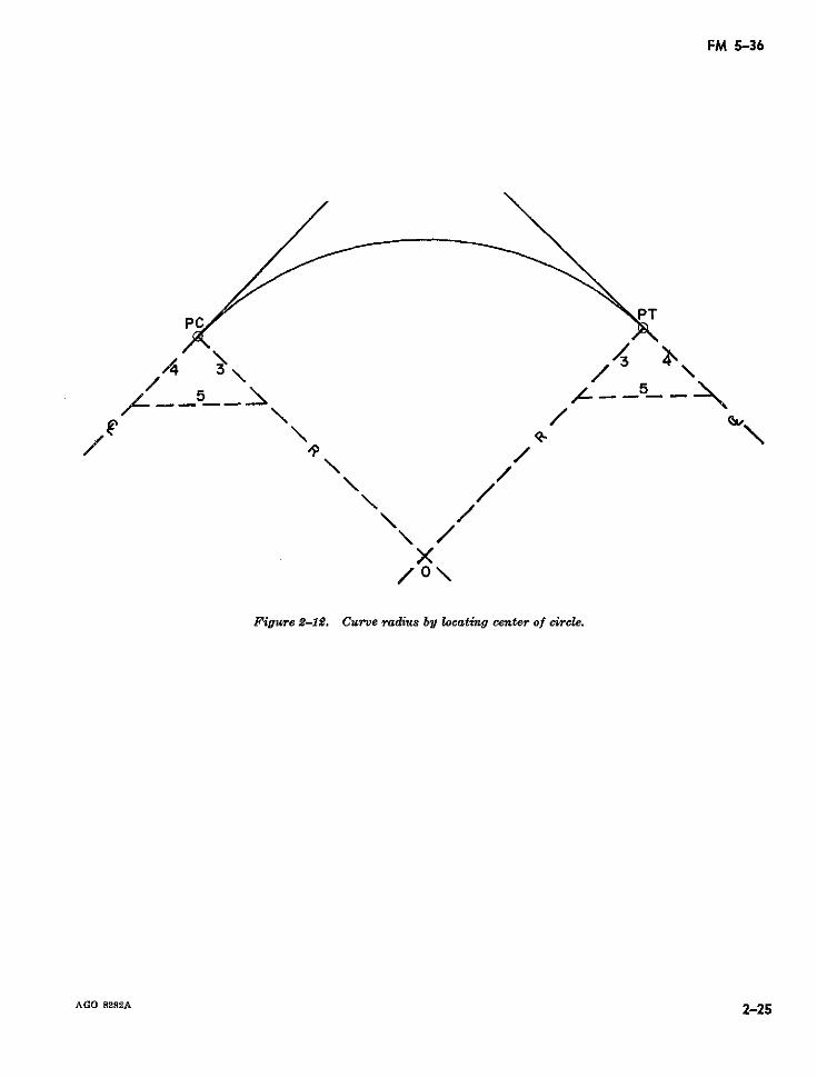
FM 5-36
/4 /3
AGO 8282A 2-25
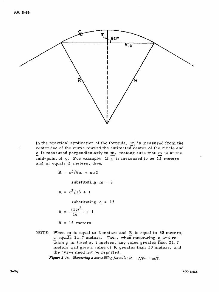
FM 5-36
In the practical application of the formula, m is measured from thecenterline of the curve toward the estimated center of the circle andc is measured perpendicularly to m, making sure that m is at the
mid-point of c. For example: If c is measured to be 15 metersand m equals 2 meters, then:
R = c2/8m + m/2
substituting m = 2
R = c 2 /16 + 1
substituting c = 15
R =(15)2 + 116
R = 15 meters
NOTE: When m is equal to 2 meters and R is equal to 30 meters,c equals 21.7 meters. Thus, when measuring c and re-taining m fixed at 2 meters, any value greater than 21.7meters will give a value of R greater than 30 meters, andthe curve need not be reported.
Figure ,-1S. Measuring a curve using fonmula: R = cd/8m + m/2.
2-26 AGO 8282A
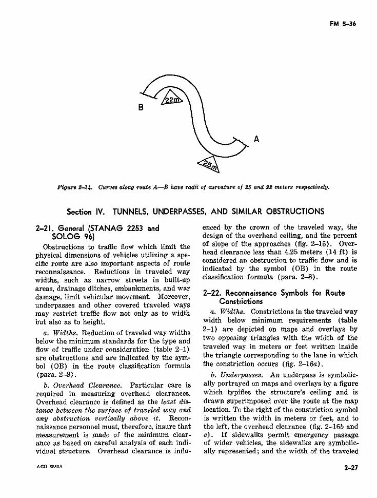
FM 5-36
B
A
Figure 2-14. Curves along route A-B have radii of curvature of 25 and 22 meters respectively,
Section IV. TUNNELS, UNDERPASSES, AND SIMILAR OBSTRUCTIONS
2-21. General (STANAGr 2253 and enced by the crown of the traveled way, theSOLOG 96) design of the overhead ceiling, and the percent
Obstructions to traffic flow which limit the of slope of the approaches (fig. 2-15). Over-physical dimensions of vehicles utilizing a spe- head clearance less than 4.25 meters (14 ft) iscific route are also important aspects of route considered an obstruction to traffic flow and isreconnaissance. Reductions in traveled way indicated by the symbol (OB) in the routewidths, such as narrow streets in built-up classification formula (para. 2-8).areas, drainage ditches, embankments, and wardamage, limit vehicular movement. Moreover, connaissanc Symbols forunderpasses and other covered traveled waysmay restrict traffic flow not only as to width a. Widths. Constrictions in the traveled waybut also as to height. width below minimum requirements (table
a. Widths. Reduction of traveled way widths 2-1) are depicted on maps and overlays bybelow the minimum standards for the type and two opposing triangles with the width of theflow of trafflc under consideration (table 2-1) traveled way in meters or feet written insideare obstructions and are indicated by the sym- the triangle corresponding to the lane in whichbol (OB) in the route classification formula the constriction occurs (fig. 2-16a).(para. 2-8). b. Underpasses. An underpass is symbolic-
b. Overhead Clearance. Particular care is ally portrayed on maps and overlays by a figurerequired in measuring overhead clearances. which typifies the structure's ceiling and isOverhead clearance is defined as the least dis- drawn superimposed over the route at the maptance between the surface of traveled way and location. To the right of the constriction symbolany obstruction vertically above it. Recon- is written the width in meters or feet, and tonaissance personnel must, therefore, insure that the left, the overhead clearance (fig. 2-16b andmeasurement is made of the minimum clear- c). If sidewalks permit emergency passageance as based on careful analysis of each indi- of wider vehicles, the sidewalks are symbolic-vidual structure. Overhead clearance is influ- ally represented; and the width of the traveled
AGO 8282A 2-27
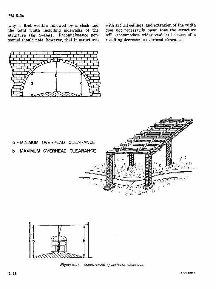
FM 5-36
way is first written followed by a slash and with arched ceilings, and extension of the widththe total width including sidewalks of the does not necessarily mean that the structurestructure (fig. 2-16d). Reconnaissance per- will accommodate wider vehicles because of asonnel should note, however, that in structures resulting decrease in overhead clearance.
a - MINIMUM OVERHEAD CLEARANCE
b - MAXIMUM OVERHEAD CLEARANCE
b b
1.1
Figure 2-15. Measurement of overhead clearances.
2-28 AGO 8282A
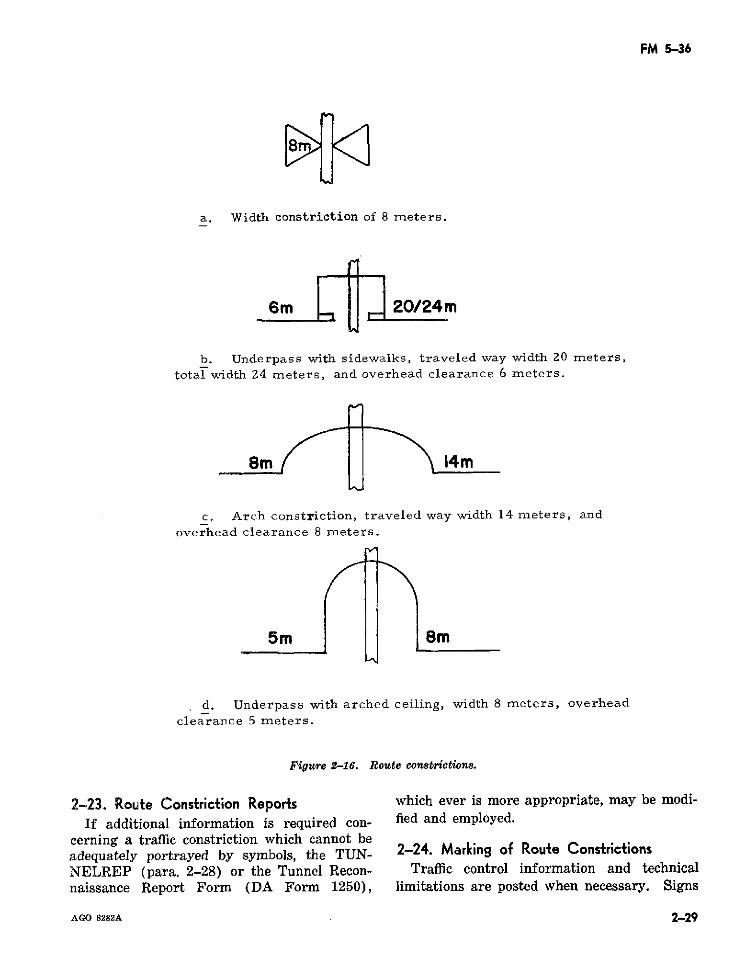
FM 5-36
a. Width constriction of 8 meters.
6m L 2024m
b. Underpass with sidewalks, traveled way width 20 meters,total width Z4 meters, and overhead clearance 6 meters.
Sm f'~~ 14m
c. Arch constriction, traveled way width 14 meters, andoverhead clearance 8 meters.
5m 8m
d. Underpass with arched ceiling, width 8 meters, overheadclearance 5 meters.
Figure 2-16. Route constrictions.
2-23. Route Constriction Reports which ever is more appropriate, may be modi-
If additional information is required con- fied and employed.cerning a traffic constriction which cannot beadequately portrayed by symbols, the TUN- 2-24. Marking of Route ConstrictionsNELREP (para. 2-28) or the Tunnel Recon- Traffic control information and technicalnaissance Report Form (DA Form 1250), limitations are posted when necessary. Signs
AGO 8282A 2-29
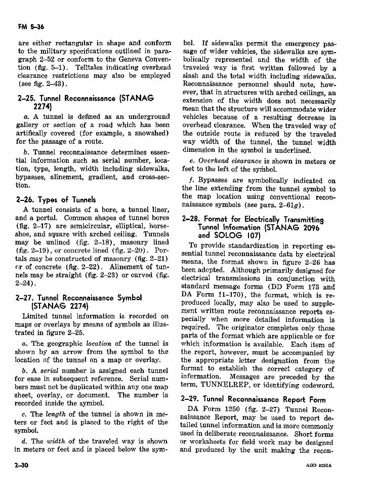
FM 5-36
are either rectangular in shape and conform bol. If sidewalks permit the emergency pas-to the military specifications outlined in para- sage of wider vehicles, the sidewalks are sym-graph 2-52 or conform to the Geneva Conven- bolically represented and the width of thetion (fig. 5-1). Telltales indicating overhead traveled way is first written followed by aclearance restrictions may also be employed slash and the total width including sidewalks.(see fig. 2-43). Reconnaissance personnel should note, how-
ever, that in structures with arched ceilings, an2-25. Tunnel Reconnaissance (STANAG extension of the width does not necessarily
2274) mean that the structure will accommodate widera. A tunnel is defined as an underground vehicles because of a resulting decrease in
gallery or section of a road which has been overhead clearance. When the traveled way ofartifically covered (for example, a snowshed) the outside route is reduced by the traveledfor the passage of a route. way width of the tunnel, the tunnel width
b. Tunnel reconnaissance determines essen- dimension in the symbol is underlined.tial information such as serial number, loca- e. Overhead clearance is shown in meters ortion, type, length, width including sidewalks, feet to the left of the symibol.bypasses, alinement, gradient, and cross-sec- f. Bypasses are symbolically indicated ontion. the line extending from the tunnel symbol to
2-26. Types of Tunnels the map location using conventional recon-naissance symbols (see para. 2-61g).
A tunnel consists of a bore, a tunnel liner,and a portal. Common shapes of tunnel bores 2-28. Format for Electrically Transmitting(fig. 2-17) are semicircular, elliptical, horse- Tunnel Information (STANAG 2096shoe, and square with arched ceiling. Tunnels and SOLOG 107)may be unlined (fig. 2-18), masonry lined To provide standardization in reporting es-(fig. 2-19), or concrete lined (fig. 2-20). Por- sential tunnel reconnaissance data by electricaltals may be constructed of masonry (fig. 2-21) means, the format shown in figure 2-26 hascr of concrete (fig. 2-22). Alinement of tun- been adopted. Although primarily designed fornels may be straight (fig. 2-23) or curved (fig. electrical transmissions in conjunction with2-24). standard message forms (DD Form 173 and
2-27. Tunnel Reconnaissance Symbol DA Form 11-170), the format, which is re-(STANAn 2274) produced locally, may also be used to supple-[t~~STANAG 2274) ~ment written route reconnaissance reports es-
Limited tunnel information is recorded onl pecially when more detailed information ismaps or overlays by means of symbols as illus- required. The originator completes only thosetrated in figure 2-25. parts of the format which are applicable or for
a. The geographic location of the tunnel is which information is available. Each item ofshown by an arrow from the symbol to the the report, however, must be accompanied bylocation of the tunnel on a map or overlay. the appropriate letter designation from the
b. A ser·ial number is assigned each tunnel format to establish the correct category offor ease in subsequent reference. Serial num- information. Messages are preceded by thebers must not be duplicated within any one map term, TUNNELREP, or identifying codeword.sheet, overlay, or document. The number isrecorded inside the symbol. 2-29. Tunnel Reconnaissance Report FormDA Form 1250 (fig. 2-27) Tunnel Recon-
c. The length of the tunnel is shown in me- naissance Report, may be used to report de-ters or feet and is placed to the right of the tailed tunnel information and is more commonlysymbol. used in deliberate reconnaissance. Short forms
d. The width of the traveled way is shown or worksheets for field work may be designedin meters or feet and is placed below the sym- and produced by the unit making the recon-
2-30 AGO 8282A
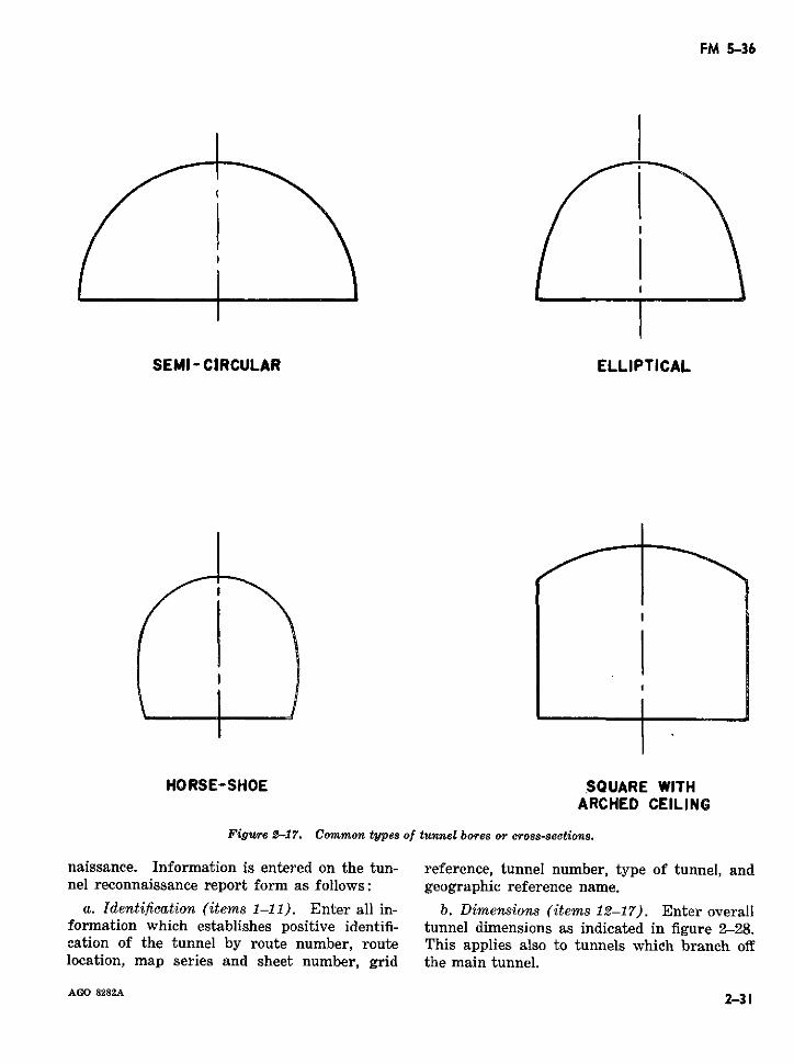
FM 5-36
SEMI - CIRCULAR ELLIPTICAL
HORSE-SHOE SQUARE WITHARCHED CEILING
Figure 2-17. Common types of tunnel bores or cross-sections.
naissance. Information is entered on the tun- reference, tunnel number, type of tunnel, andnel reconnaissance report form as follows: geographic reference name.
a. Identification (items 1-11). Enter all in- b. Dimensions (items 12-17). Enter overallformation which establishes positive identifi- tunnel dimensions as indicated in figure 2-28.cation of the tunnel by route number, route This applies also to tunnels which branch offlocation, map series and sheet number, grid the main tunnel.
AGO 8282A 2-312--3
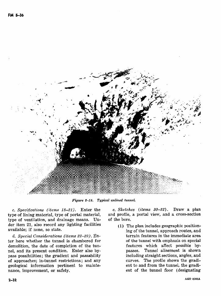
FM 5-36
Figure 218. Typical unlrned tunnel.
c. Specifications (items 18-21). Enter the e. Sketches (items 30-32). Draw a plantype of lining material, type of portal material, and profile, a portal view, and a cross-sectiontype of ventilation, and drainage means. Un- of the bore.der item 21, also record any lighting facilities (1) The plan includes geographic position-available; if none, so state. ing of the tunnel, approach routes, and
d. Special Considerations (items 22-29). En- terrain features in the immediate areater here whether the tunnel is chambered for of the tunnel with emphasis on specialdemolition, the date of completion of the tun- features which affect possible by-nel, and its present condition. Enter also by- passes. Tunnel alinement is shownpass possibilities; the gradient and passability including straight sections, angles, andof approaches; in-tunnel restrictions; and any curves. The profile shows the gradi-geological information pertinent to mainte- ent to and from the tunnel, the gradi-nance, improvement, or safety. ent of the tunnel floor (designating
~:2-32 AGO 8282A2-32 AGO 8282A
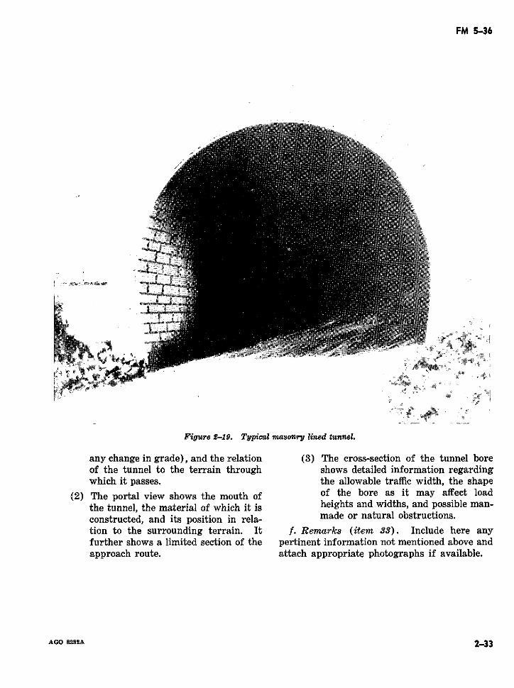
FM 5-36
Figure 2-19. Typical masonry lined tunnel.
any change in grade), and the relation (3) The cross-section of the tunnel boreof the tunnel to the terrain through shows detailed information regardingwhich it passes. the allowable traffic width, the shape
(2) The portal view shows the mouth of of the bore as it may affect loadthe tunnel, the material of which it is heights and widths, and possible man-constructed, and its position in rela- made or natural obstructions.tion to the surrounding terrain. It f. Remarks (item 33). Include here anyfurther shows a limited section of the pertinent information not mentioned above andapproach route. attach appropriate photographs if available.
AGO 8282A 2-332-33
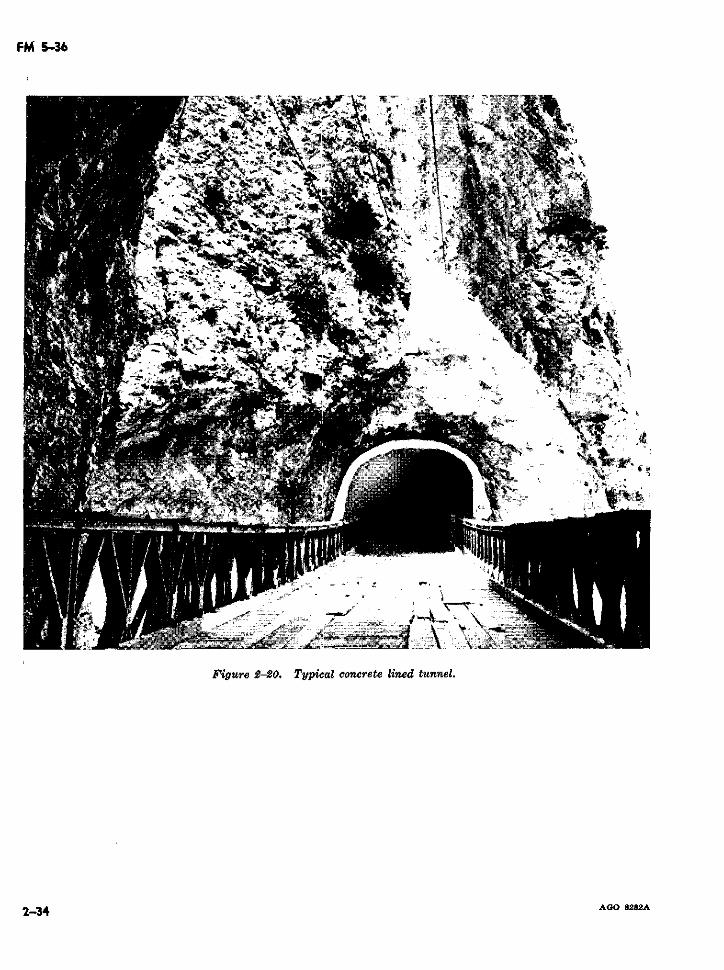
FM 5-36
U ~ ~ o-g-, , ~ t1·~~~C
Fiur 2-0 Typca cocee¡cdtn¿L
2-34~~~~~~~~r AGO'
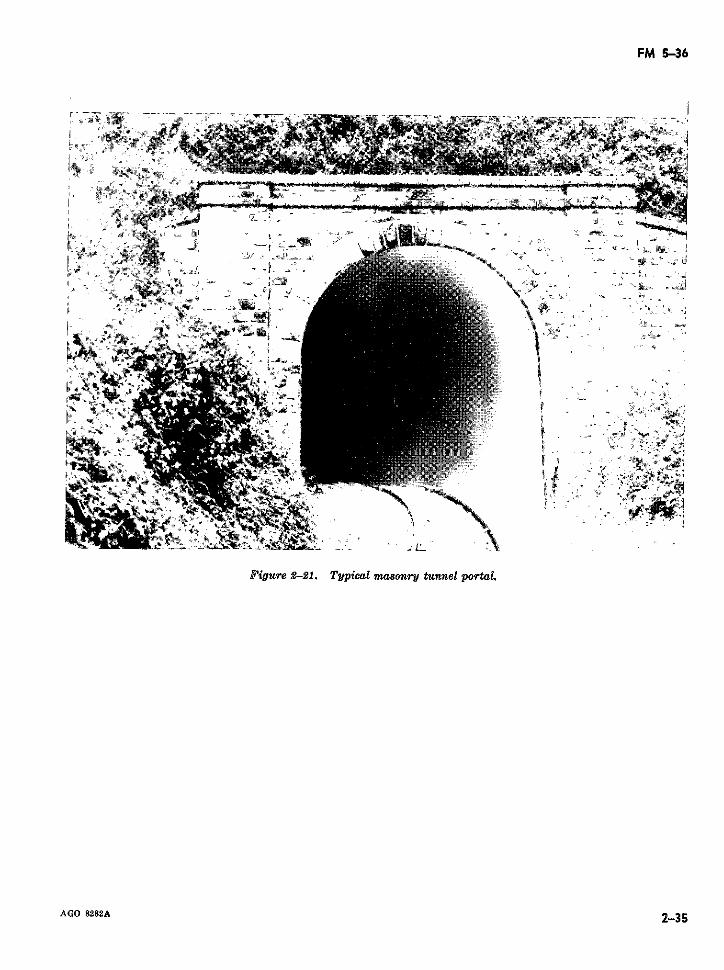
FM 5-36
r~·-"~*4~-_ A- it -ancl;~ -;r
1 X
·- ~ ~ ~ ~~~~yia masnr tunnl portalFigure 2-21. ~ ~ ~ ~ ~ ~ ~ rJ
AGO~ 8282A· 2-35,
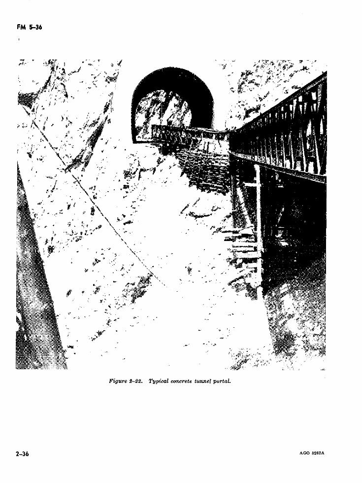
FM 5-36
?a * % ~ aa fo ~ . ~ s - d ,~: ,~~;'~~
''e .
'1 ~~~~~ $-
A 't'.9', ' ' Oh'>{' a\'' ' .,. 'I A ' f ;UA"'' 0- · <4,, 4 -i
Figure 2-22. Typical concrete tunnel portal.
I2-36
2-36 ~~~~~~~~~~~~~~~~~~~~~~~~AGO 8282A
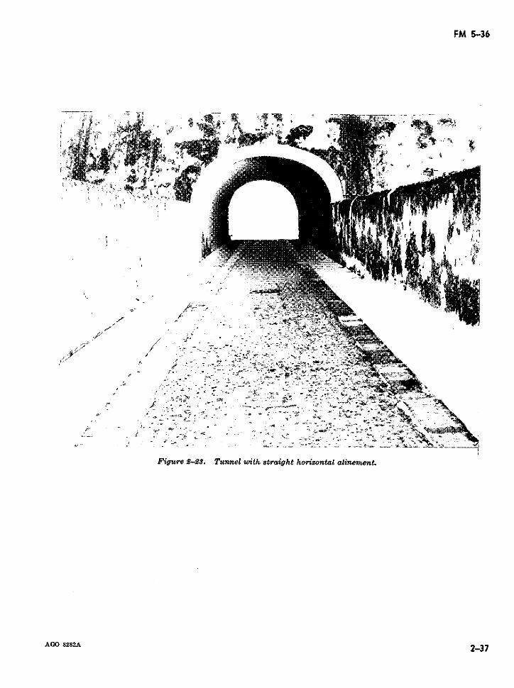
FM 5-36
s. 1 1 dtI^i st~~~~~~~~~~~~~~~~~~~~~~~~~~~~~~~~~~~~~~~~~~~~~~~~~~~~~~~~~~~~~~~~
-~~~sa ~ ' _ E .'_ .- '~ ~. ! ae '¿ , r e
C:~~~~~~~~~~~~~· -. ,
i 1o> c' _0 }_
1~~~~~~~~~~~~~~~~
Figure 2-23. Tunnel with straight horizontal alinement.
AGO 8282A 2-37
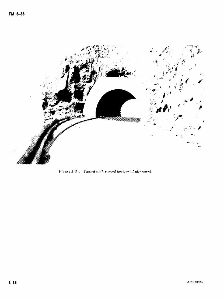
FM 5-36
,~ ~:~ ~' ' tS; , téc 1% Mi ffi, .g * Ab t,~~~ -- ~ ~
Lu Cis i r l¿ is +
*· i ,i 1 r j
A,~~~. "s: '(o~y se1 1
asió_· *J. I ,iJ/
X Y ; r- '<s r s
Figure 2-24. Tunnel with curved horizontal alinement.
2-38 AGO 8282A
P~~~~~~~~~~~~~~~~~~~~~ S~SZArl~ r
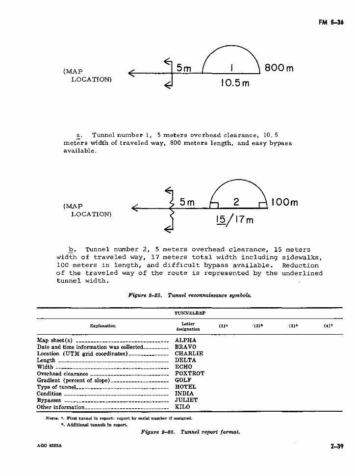
FM 5-36
(MAAP ' <5m I 800mLOCATION) 10.5 m
a. Tunnel number 1, 5 meters overhead clearance, 10. 5meters width of traveled way, 800 meters length, and easy bypassavailable.
(MAP5m OLOCATION) /17 m
b. Tunnel number 2, 5 meters overhead clearance, 15 meterswidth of traveled way, 17 meters total width including sidewalks,100 meters in length, and difficult bypass available. Reductionof the traveled way of the route is represented by the underlinedtunnel width.
Figure 2-25. Tunnel reconnaissance symbols.
TUNNELREP
Explanation Letter (1), '(2)b (8) b (4)bdesignation
Map sheet(s) -------------------------------- ALPHADate and time information was collected--------- BRAVOLocation (UTM grid coordinates)__ ------------ CHARLIELength -----_______________-- ------------------- DELTAWidth______________________________________ -ECHOOverhead clearance ------------------------_-- FOXTROTGradient (percent of slope) -------------------- GOLFType of tunnel _____________---_----- _ ___----- HOTELCondition ---_____------_--_--_------ ___------ INDIABypasses -----_------------------------------ JULIETOther information ------------------------.--- KILO
Notes. *. First tunnel in report; report by serial number if assigned.b. Additional tunnels in report.
Figure 2-26. Tunnel report format.
AGO 8282A 2-39
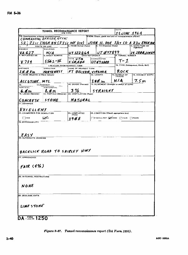
FM 5-36
TUNNEL RECONNAISSANCE REPORT DAT(rM 5-s36) 1° 4A tE i 164
TO: ('Headquartero orderlng reconnaiOsance) FROM: (Name, grade end Umlt of reonnaleaanc ofl.cet)
( OMM AIv'4 O FF CEe 4A r7'-AS2; Zlsr EN6R s1 ( ,sr IAIF Dlv) IJ/OtlA H1. POE 1Zr CO A 21sr E IUI
1. J ROUTE OR LINE 2. FROM (nnitt Point) 3. TO (Terminal Point) 4. DATE/TIME (Of_ _lnature)
HICHWAY R A I L
ROAD
VA. C1 7 ¡ir/A (url o2 8 C4 ¡Jro0?78 iR? lf -78i .S. MAP SERIES NR 6. SHEET NUMBER 7. GRID REFERENCE 8. TUNNEL NUMBER
TYPE JIjrM COORDINATESV 73: I .. ::5',id UTe'Isa I -1 .
9. LOCATION FROM NEAREST TOWN 10. TYPE (Subaqu.oue, Ro;k, Soil)
DISTANCE DIRECTION NAME OF NEAREST TOWN
1. 0 ,m NNOóRrIW 5r FT O EB VOR. wit41 t,4 R OC K11. NAME (M~.Ontoín Or Watr, feat.re) 12. LENGTH 13. NUMBER OF 114. ROADWAY WIDTH
TRAC KS
A CC6 T) ¡S. /.' I /_' 7. S'm15. CLEARANCE 16. GRADE (Pr-cent) 17. ALINEMENT (Staight or radi.A ol cu..r.)
VERTICAL HORIZONTAL
6 ! 0Ltt _ 8 im _ 3 %_ s f18. LINING (Mat.,ral) 19. PORTALS (Maetorla) 20. VENTILATION (Typs)
CONCREVt s roNE, A rJoA LL21. DRAINAGE
22. CHAMBERED FOR DEMOLITION . COMPLETE 24. CONDITION (Check approprlat box)(Year)
WYES IO 1 r 98EXCELLENT líaOOD OFAIR W POOR
25. BYPASSABILITY
26. ALTERNATE CROSSING
BIACkF.C#l ROAPD TO 5s#t0 Y kHWY27. APPROACHES
frAli (4%)
28. IN-TUNNEL RESTRICTIONS
NObNE
29. GEOLOGIC DATA
DA IJAN,5 1250
Pigure 2-27. Tunnel reconnaissance report (DA Form 1250).
2-40 AGO 8282A
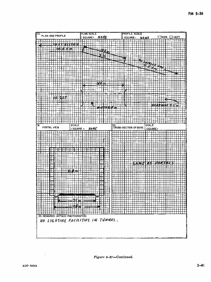
FM 5-36
30. PLAN SCALEPROFILE SCALE
33. REMARKS (ATTACH PHOTOGRAPHS)
PORTAL VIEW ISQULAE= E4 CROSS-SECTION OFBORE ISQUALE=
Figure £-27-Continued.
AGO 8282A 2-41
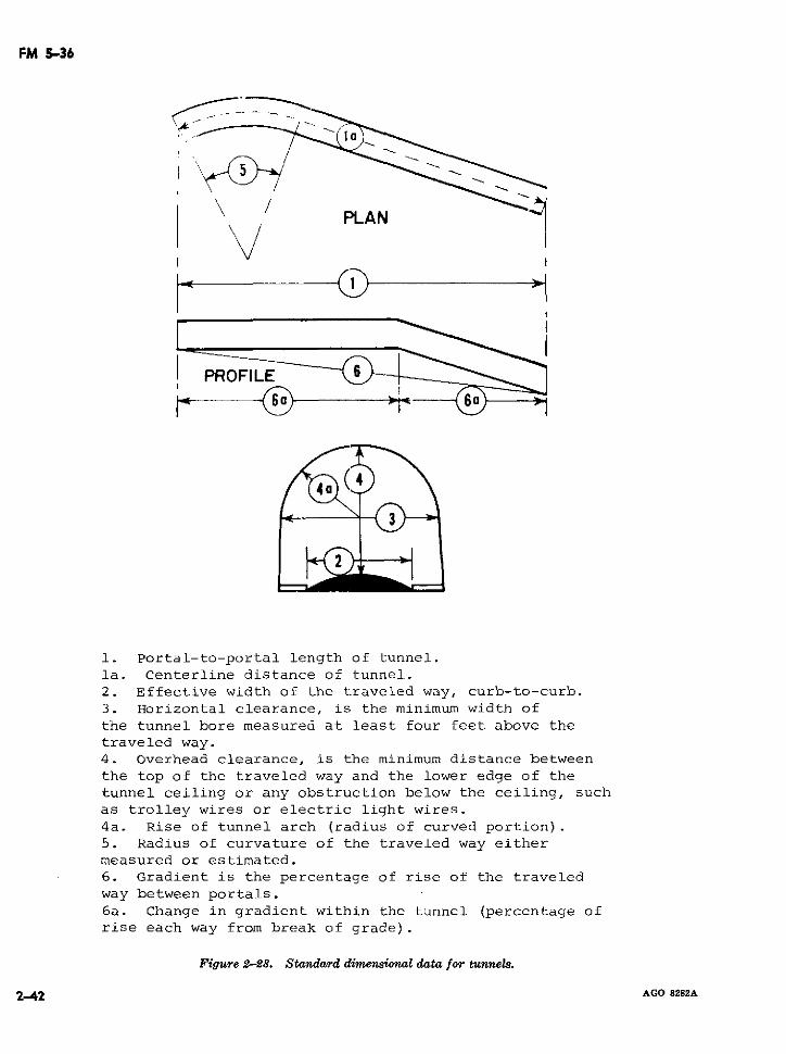
FM 5-36
PLAN
1. Portal-to-portal length of tunnel.
la. Centerline distance of tunnel.
2. Effective width of the traveled way, curb-to-curb.
3. Horizontal clearance, is the minimum width of
the tunnel bore measured at least four feet above the
traveled way.
4. Overhead clearance, is the minimum distance between
the top of the traveled way and the lower edge of the
tunnel ceiling or any obstruction below the ceiling, such
as trolley wires or electric light wires.
4a. Rise of tunnel arch (radius of curved portion).
5. Radius of curvature of the traveled way either
measured or estimated.
6. Gradient is the percentage of rise of the traveled
way between portals.
6a. Change in gradient within the tunnel (percentage of
rise each way from break of grade).
Figure 2-28. Standard dimensional data for tunnels.
2-42 AGO 8282A
FM 5-36
Section V. VEHICULAR FORDING, SWIMMING, AND FERRYING OPERATIONS
2-30. General 45° (800 mils) at variance with the previouslyModern military vehicles and equipment pro- recorded azimuth. The distance between the
vide the commander with increased capabilities two points on the near shore is measured; thisto conduct vehicular fording, swimming, and distance is equal to the distance across theferrying operations. Mass destruction weap- stream.ons demand dispersion and the reduction of b. Using a Surveying Instrument (fig. 2-31).obstructions to traffic which create lucrative (1) Trigonometric relationships. Using atargets. It can be expected, therefore, that transit, aiming cire, azimuth di-the employment of the inherent stream crossing trans, or alg cirle, azimuth indi-characteristics of modern military vehicles will cator, or alidade, the ange betweenbecome increasingly more common. Reconnais- two points a known distance apart onsance personnel will be required to locate and the near shore and a third point di-accurately report suitable stream crossing sites. rectly across the river from one ofConsiderations of terrain common to fording, these points is measured. The distanceswimming, and ferrying operations are: depth across the stream is computed usingof stream, width of stream, approaches to the trigonometric relationships (app. IIstream, entrances and exists to the stream, and TM 5-232).stream velocities, and natural and manmadeobstacles (fig. 2-29). Fords and ferries are (2) Usng stadia formula. A man is sentconsidered as obstructions to traffic flow and across the stream with either a stadiaare indicated by the abbreviation (OB) in the rod or range pole. Using either aroute classification formula (para. 2-8). transit or level, the intercept between
the stadia hairs is determined and the2-3 . Determining Depth of Stream distance computed using the stadia
Field expedients are usually required such as formula as described in TM 5-232.measured poles or weighted ropes for determin- c. Short Gaps. In the measurement of shorting depths. Depth readings are normally taken gaps, one member of the reconnaissance teamevery three meters. A sluggish stream or river holds an end of a tape or rope on the near bank.may become a torrent in a few hours or even Another member of the team crosses to theminutes as a result of sudden heavy rainfall. opposite bank and pulls the tape tight. TheThis is particularly true in tropical and arid length of tape which corresponds to the distanceregions. Therefore, depths and currents must across the gap is then measured. This methodbe checked at frequent intervals to provide is particularly useful during darkness whenwarning of such changes. Additional factors lights are prohibited. The width of the gapwhich require consideration are upstream locks may be indicated on the tape and measuredor dams which may cause floods when opened later in an area where lights may be used.or destroyed thus temporarily disrupting cross-ing. 2-33. Determining Stream Velocity2-32. Detersminng Stream W.dth Current velocities vary in different parts of
a stream. In general, the current is usuallya. Using a Compass (fig. 2-30). From aa.* Us*ng a Cmg.2-30.Fslower near the shore and swifter in the mainpoint on the near shore and close to the water'sedge, the azimuth to a point on the opposite channel; similarly, the current is slower as theshore is taken and recorded. Another point on stream widens. To determine the velocity of aline at a right angle to the azimuth selected is stream, a distance is measured along the river-established on the near shore from which the bank. A light object which floats is thrownazimuth to the same point on the far shore is into the stream, and the time the object requires
AGO 8282A 2-43
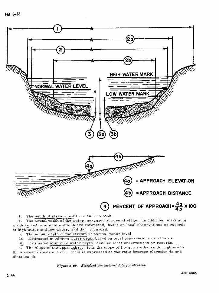
FM 5-36
HIGH WATER MARK
NORMAL WATER LEVEL_ _
` -- = [--~/~//'" = APPROACH ELEVATION
//) = APPROACH DISTANCE
___ PERCENT OF APPROACH= 4b X 1004b1. The width of stream bed from bank to bank.
2. The actual width of the water measured at normal stage. In addition, maximumwidth Za and minimuni width Zb are estimated, based on local observations or records
of high water and low water, and then recorded.
3. The actual depth of the stream at normal water level.3a. Estimated maximum water depth based on local observations or records.
3b. Estimated minimum water depth based on local observations or records.
4. The slope of the approaches. It is the slope of the stream banks through which
the approach roads are cut. This is expressed as the ratio between elevation 4a and
distance 4b.
Figure 2-29. Standard dimensional data for streams.
AGO 8282A2-44
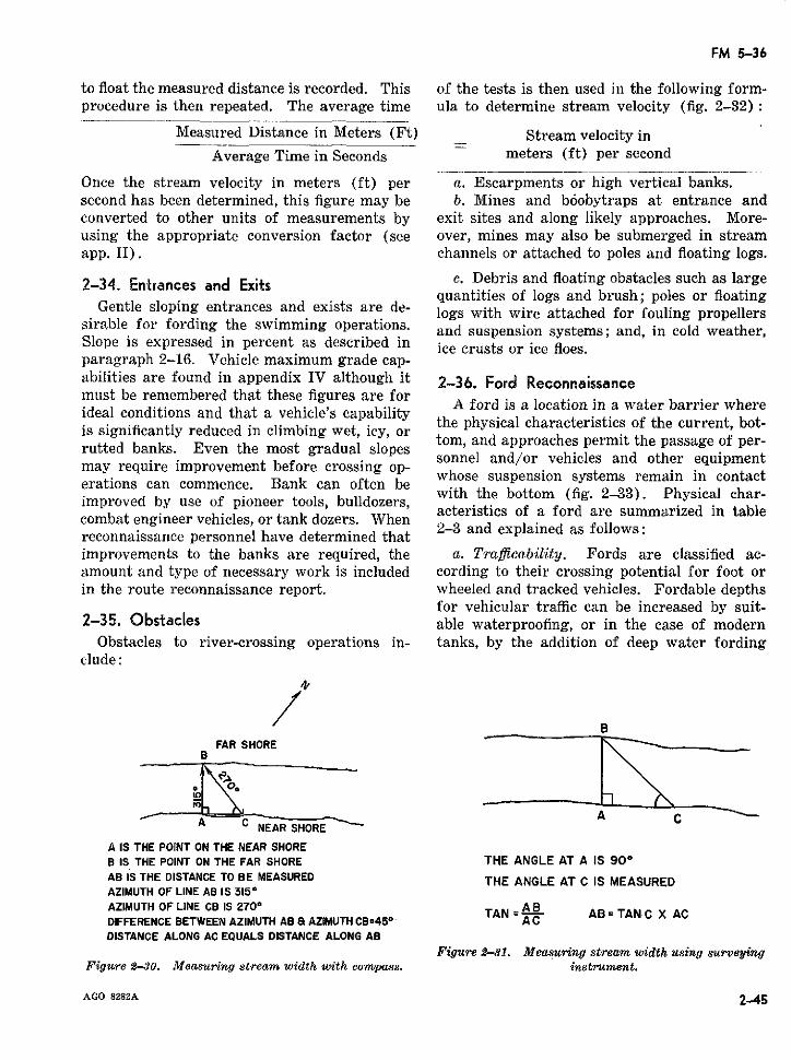
FM 5-36
to float the measured distance is recorded. This of the tests is then used in the following form-procedure is then repeated. The average time ula to determine stream velocity (fig. 2-32):
Measured Distance in Meters (Ft) Stream velocity inAverage Time in Seconds meters (ft) per second
Once the stream velocity in meters (ft) per a. Escarpments or high vertical banks.second has been determined, this figure may be b. Mines and bóobytraps at entrance andconverted to other units of measurements by exit sites and along likely approaches. More-using the appropriate conversion factor (see over, mines may also be submerged in streamapp. II). channels or attached to poles and floating logs.
2-34.. Entrances and Exits c. Debris and floating obstacles such as largequantities of logs and brush; poles or floatingGentle sloping entrances and exists are de-
sirable for fording the operations. logs with wire attached for fouling propellerssirable for fording the swimming operations. and suspension systems; and, in cold weather,
Slope is expressed in percent as described in ice crusts or ice floes.paragraph 2-16. Vehicle maximum grade cap-abilities are found in appendix IV although it 2-36. Ford Reconnaissancemust be remembered that these figures are for A ford is a location in a water barrier whereideal conditions and that a vehicle's capabilityis significantly reduced in climbing wet, icy, or the physical characteristics of the current, bot-
rutted banks. tom, and approaches permit the passage of per-rutted banks. Even the most gradual slopes sonnel and/or vehicles and other equipmentmay require improvement before crossing op-erations can commence. Bank can often be whose suspension systems remain in contact,rio cwith the bottom (fig. 2-33). Physical char-improved by use of pioneer tools, bulldozers,
acteristics of a ford are summarized in tablecombat engineer vehicles, or tank dozers. Whenreconnaissance personnel have determined that 2-3 and explained as followsimprovements to the banks are required, the a. Tra1licability. Fords are classified ac-amount and type of necessary work is included cording to their crossing potential for foot orin the route reconnaissance report. wheeled and tracked vehicles. Fordable depths
for vehicular traffic can be increased by suit-2-35. Obstacles able waterproofing, or in the case of modern
Obstacles to river-crossing operations in- tanks, by the addition of deep water fordingelude:
4,
FAR SHORE
A C_ _ _ A _ _ _A C NEAR SHORE
A IS THE POINT ON THE NEAR SHOREB IS THE POINT ON THE FAR SHORE THE ANGLE AT A IS 900AB IS THE DISTANCE TO BE MEASURED THE ANGLE AT C IS MEASUREDAZIMUTH OF LINE AB IS 3150AZIMUTH OF LINE CB IS 2700 TAN= AB =TANC X ACDIFFERENCE BETWEEN AZIMUTH AB 8 AZIMUTH CB:45°- A CDISTANCE ALONG AC EQUALS DISTANCE ALONG AB
Figure 2-31. Measuring stream width using surveyingFigure 2-30. Measuring stream width. with compass. instrument.
AGO 8282A 2-45
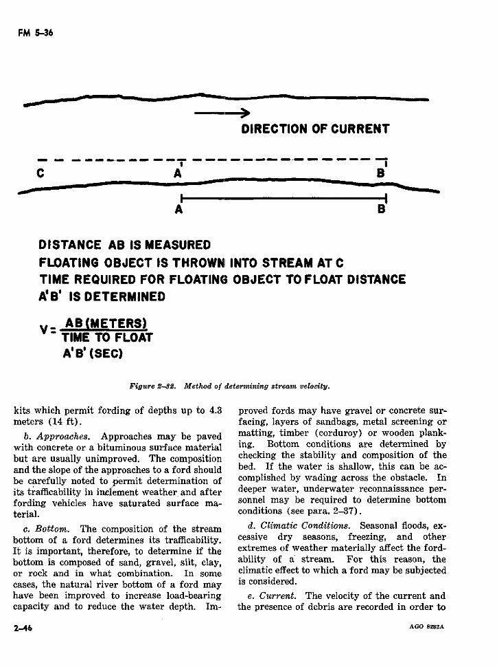
FM 5-36
DIRECTION OF CURRENT
C A B
A B
DISTANCE AB IS MEASUREDFLOATING OBJECT IS THROWN INTO STREAM AT CTIME REQUIRED FOR FLOATING OBJECT TO FLOAT DISTANCEA'B' IS DETERMINED
V- AB(METERS)TIME TO FLOATA' ' (SEC)
Figure 2-32. Method of determining stream velocity.
kits which permit fording of depths up to 4.3 proved fords may have gravel or concrete sur-meters (14 ft). facing, layers of sandbags, metal screening or
b. Approaches. Approaches may be paved matting, timber (corduroy) or wooden plank-with concrete or a bituminous surface material ing. Bottom conditions are determined bybut are usually unimproved. The composition checking the stability and composition of theand the slope of the approaches to a ford should bed. If the water is shallow, this can be ac-be carefully noted to permit determination of complished by wading across the obstacle. Inits trafficability in inciement weather and after deeper water, underwater reconnaissance per-fording vehicles have saturated surface ma- sonnel may be required to determine bottomterial. conditions (see para. 2-37).
c. Bottom. The composition of the stream d. Climatic Conditions. Seasonal floods, ex-bottom of a ford determines its trafficability. cessive dry seasons, freezing, and otherIt is important, therefore, to determine if the extremes of weather materially affect the ford-bottom is composed of sand, gravel, silt, clay, ability of a stream. For this reason, theor rock and in what combination. In some climatic effect to which a ford may be subjectedcases, the natural river bottom of a ford may is considered.have been improved to increase load-bearing e. Current. The velocity of the current andcapacity and to reduce the water depth. Im- the presence of debris are recorded in order to
2-46 AGO 8282A
FM 5-36
determine their effect, if any, on the condition friendly shore; or if on the far side of a wideand passability of the ford. Current is esti- obstacle, they signal when ready to be pickedmated as swift (more than 1.5 meters per up. Additionally, helicopters can be used tosecond), moderate (1 to 1.5 meters per second), drop off teams in the water or place teams onand slow (less than 1 meter per second). the far shore if the situation permits.
Table 2-3. TrafJicability of ford&. b. To assist underwater reconnaissance teamsin maintaining direction, weighted ropes may
Maximnum be placed across the bottom of the water ob-Shallow Minimum desirable
Type of trafflc fordable width percent of stacle. Attached to these ropes are buoys ordepth (metera) slope for
(meters) approache~e other floating objects to indicate the area of
Foot ....----- 1 (40") 1 (40") 100% responsibility of each team. When the cur-(single file) rent is in excess of 1.3 meters per second (4.252 (80") feet per second), underwater reconnaissance
(column of 3's) personnel have difficulty maintaining a positionTrucks and .6 (24") 3.6 (12') 33% along the line selected. To assist swimmers
truck-drawn another weighted rope, parallel to the direc-artillery. tional rope, may be placed upstream with
Light tank ---- 1 (40") 4.2 (14') 50% lateral lines connecting both ropes.Medium tanks _ 1.2 (48") 4.2 (14') 50%
e. During periods of good visibility and whenBased on hard. dry surface. the water is clear, bottom conditions can be
2 Depths up to 4.8 meters can be negotiated with deep water easily determined. Under blackout conditions,fording kit.
however, or when the water is murky, recon-f. Low Water Bridges. During high water naissance is much slower since swimmers must
periods, low water bridges may be easily con- feel their way across. If the tactical situationfused with paved fords as both are completelysubmerged. This type of bridge consists of permits, searchlights and flares may be em-two or more intermediate supports with con- ployed in addition to waterproof lights usedcrete decking and located wholly within ra- by the swimmers.vines or gullies. In reconnaissance it is im- d. The length of time that underwater recon-portant to differentiate between this type of naissance personnel can remain in the waterbridge and a paved ford because of correspond- depends upon their training, the current, watering military load limitations. temperature, and equipment. When conduct-
ing a reconnaissance in any current, a swimmer2-37. Underwater Reconnaissance expends more energy, tires more easily, and
a. Physical reconnaissance and selection of uses his air supply more quickly. In tempera-deep water fording sites are conducted by tures between 70° and 85° F, divers can workteams trained and equipped for underwater comfortably in their underwear but chill in 1reconnaissance. When the water obstacle is to 2 hours if not exercising. In temperaturesnarrow, underwater reconnaissance personnel above 85° F, the diver overheats and the maxi-may enter from the near bank and conduct mum temperature that can be endured, even attheir reconnaissance by swimming to the far a rest, is 96° F. Protective covering is usuallybank. When the distance between banks can- needed when the water temperature is belownot be easily spanned by swimming personnel, 70° F; furthermore, in cold water sense ofswimming vehicles or reconnaissance boats en- touch and ability to work with hands are af-ter the water once an entrance has been selected fected. Air tanks vary in size; the capacity ofand drop off teams at regular intervals. Craft the tank and working conditions govern howremain in the water during reconnaissance and long a diver can operate. Extra tanks shouldpick up swimmers when the operation is com- be readily available for underwater reconnais-pleted unless the area is under enemy fire or sance teams and recharging equipment locatedobservation. In this case, divers swim to the so as to be responsive to team requirements.
AGO 8282A 2-47
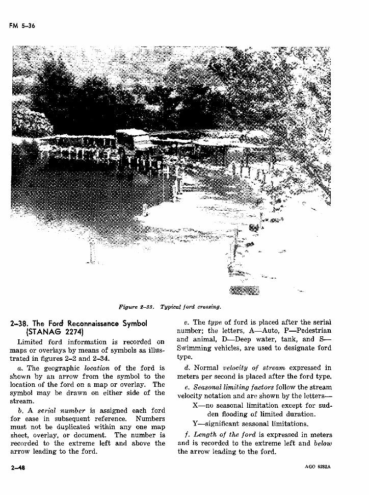
FM 5-36
Umi@<
Figure 2-33. Typical ford crossing.
2-38. The Ford, Reconnaissance Symbol e. The type of ford is placed after the serial(STANAG 2274) number; the letters, A-Auto, P-Pedestrian
Limited ford information is recorded on and animal, D-Deep water, tank, and S-maps or overlays by means of symbols as illus- Swimming vehicles, are used to designate fordtrated in figures 2-2 and 2-34. type.
a. The geographic location of the ford is d. Normal velocity of stream expressed inshown by an arrow from the symbol to the meters per second is placed after the ford type.location of the ford on a map or overlay. The e. Seasonal limiting factors follow the streamsymbol may be drawn on either side of the velocity notation and are shown by the letters-stream. X-no seasonal limitation except for sud-
b. A serial number is assigned each ford den flooding of limited duration.for ease in subsequent reference. Numbersmust not be duplicated within any one mapsheet, overlay, or document. The number is f. Length of the ford is expressed in metersrecorded to the extreme left and above the and is recorded to the extreme left and belowarrow leading to the ford. the arrow leading to the ford.
248 AGO 8282A
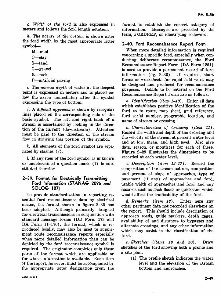
FM 5-36
g. Width of the ford is also expressed in format to establish the correct category ofmeters and follows the ford length notation. information. Messages are preceded by the
h. The nature of the bottom is shown after term, FORDREP, or identifying codeword.the ford width by the most appropriate letter
.ymbol- 240. Ford Reconnaissance Report FormM-mud When more detailed information is required
concerning a specific ford, especially when con-ducting deliberate reconnaissance, the Ford
S-sand Reconnaissance Report Form (DA Form 1251)G-gravel is used to provide a permanent record of fordR-rock information (fig. 2-36). If required, shortP-artificial paving forms or worksheets for rapid field work may
be designed and produced for reconnaissancei. The normal depth of water at the deepest purposes. Details to be entered on the Ford
point is expressed in meters and is placed be- Reconnaissance Report Form are as follows:low the arrow immediately after the symbolexpressing the type of bottom. a. Identification (item 1-10). Enter all data
which establishes positive identification of thej. A diflicult approach is shown by irregular ford as to route, map sheet, grid reference,
lines placed on the corresponding side of the ford serial number, geographic location, andbasic symbol. The left and right bank of a name of stream or crossing.stream is ascertained by looking in the direc- b. Chrteritition of the current (downstream). Attention b. CharacterGstics of Crosstng (ter 11).tion of the current (downstream). Attention Record the width and depth of the crossing andmust be paid to the direction of the stream the velocity of the stream at present water levelflow in drawing this portion of the symbol. and at low, mean, and high level. Also give
and at low, mean, and high level. Also givek. All elements of the ford symbol are sepa- data, season, or month(s) for each of these.
rated by slashes (/). Figure 2-29 illustrates the dimensions to be1. If any item of the ford symbol is unknown recorded at each water level.
or undetermined a question mark (?) is sub- c. Description (item 12-17). Record thestituted therefor. composition of the stream bottom, composition
and percent of slope of approaches, type of2-39. Format for Electrically Transmitting pavement (if any) of approaches and ford,
Ford Information (STANAG 2096 and usable width of approaches and ford, and anySOLOG 107) hazards such as flash floods or quicksand which
To provide standardization in reporting es- would affect the trafficability of the ford.sential ford reconnaissance data by electrical d. Remarks (item 18). Enter here anymeans, the format shown in figure 2-35 has other pertinent data not recorded elsewhere onbeen adopted. Although primarily designed the report. This should include description offor electrical transmissions in conjunction with approach roads, guide markers, depth gages,standard message forms (DD Form 173 and availability of and distances to bypasses andDA Form 11-170), the format, which is re- alternate crossings, and any other informationproduced locally, may also be used to supple- which may assist in the classification of thement route reconnaissance reports especially ford.when more detailed information than can bedepicted by the ford reconnaissance symbol is e. Sketches (items 19 and 20). Drawrequired. The originator completes only those sketches of the ford showing both a profile andparts of the format which are applicable or a site plan.for which information is available. Each item (1) The profile sketch indicates the waterof the report, however, must be accompanied by level and the elevation of the streamthe appropriate letter designation from the bottom and approaches.
AGO 8282A 2-49
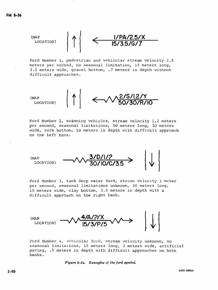
FM 5-36
O(MAP TN I/PA/2.5/XLOCATION) | | < 15/3.5/G/7
Ford Number 1, pedestrian and vehicular stream velocity 2.5meters per second, no seasonal limitation, 15 meters long,3.5 meters wide, gravel bottom, .7 meters in depth without
difficult approaches.
~~~(MAP 1 --- AA2/S/I.2/YLOCATION) -v v 50/30/R/10
Ford Number 2, swimming vehicles, stream velocity 1.2 metersper second, seasonal limitations, 50 meters long, 30 meterswide, rock bottom, 10 meters in depth with difficult approach
on the left bank.
(MAP 3/D/l/?LOCATION) 3 /C/3 5 I l
Ford Number 3, tank deep water ford, stream velocity 1 meterper second, seasonal limitations unknown, 30 meters long,
10 meters wide, clay bottom, 3.5 meters in depth with a
difficult approach on the right bank.
(MAP 4/A/?/XLOCATION) 15//P/5
Ford Number 4, vehicular ford, stream velocity unknown, noseasonal limitations, 15 meters long, 3 meters wide, artificialpaving, .5 meters in depth with difficult approaches on bothbanks.
Figure 2-34. Examples of the ford symbol.
2-50 AGO 8282A
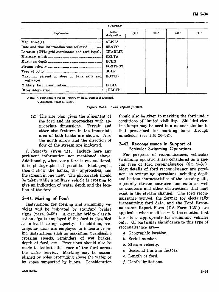
FM 5-36
FORDREP
Explanation Letter (1) ( 2 ) b () b (4) bdesignation
Map sheet (s) -----------__------------------- ALPHADate and time information was collected ------- BRAVOLocation (UTM grid coordinates and ford type)_ CHARLIEMinimum width ----------------------------- DELTAMaximum depth -----------_---___ -----_------ ECHOStream velocity ----------------------.------- FOXTROTType of bottom.---------__---------- _------- GOLFMaximum percent of slope on bank exits and HOTEL
entrances.Military load classification --____---_-------- - INDIAOther information -------------------------- _ JULIET
Notea. n. First ford in report; report by serial number if assigned.
b. Additional fords in report.
Figure 2-35. Ford report format.
(2) The site plan gives the alinement of should also be given to marking the ford underthe ford and its approaches with ap- conditions of limited visibility. Shielded elec-propriate dimensions. Terrain and tric lamps may be used in a manner similar toother site features in the immediate that prescribed for marking lanes througharea of both banks are shown. Also minefields (see FM 20-32).the north arrow and the direction offlow of the stream are indicated. 2-42. Reconnaissance in Support of
f. Remarks (item 21). Include here any Vehicular Swimming Operationspertinent information not mentioned above. For purposes of reconnaissance, vehicularAdditionally, whenever a ford is reconnoitered, swimming operations are considered as a spe-it is photographed if possible. Photographs cial type of ford reconnaissance (fig. 2-37).should show the banks, the approaches, and Most details of ford reconnaissance are perti-the stream in one view. The photograph should nent to swimming operations including depthbe taken while a military vehicle is crossing to and bottom characteristics of the crossing site,give an indication of water depth and the loca- especially stream entrance and exits as welltion of the ford. as sandbars and other obstructions that may
exist in the stream channel. The ford recon-2-41. Marking of Fords naissance symbol, the format for electrically
Instructions for fording and swimming ve- transmitting ford data, and the Ford Recon-hicles will be indicated by standard bridge naissance Report Form (DA Form 1251) aresigns (para. 2-52). A circular bridge classifi- applicable when modified with the notation thatcation sign is employed if the ford is classified the site is appropriate for swimming vehiclesas to load-bearing capacity. In addition, rec- only. Of particular significance to this type oftangular signs are employed to indicate cross- reconnaissance are-ing instructions such as maximum permissible a. Geographic location.crossing speeds, reminders of wet brakes, b. Serial number.depth of ford, etc. Provisions should also be c. Stream velocity.made to indicate the trace of the ford acrossthe water barrier. Marking may be accom-plished by poles protruding above the water or e. Length of ford.by ropes supported by buoys. Consideration f. Depth limitations.
AGO 8282A 2-51
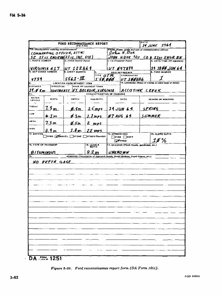
FM 5-36
FORD RECONNAISSANCE REPORT ID4TE(PM 5-36) i4 t 9&4
TO2 ¢Hmdqoufrter. orderIn r.onon't.Indo) FROMI: N.. g'd® rand mlt ofl rnenlmnc. otflcer)
COMMAeNOID,4 o rffcRzE, A rr: . :$5 ZIsf. EN&gl Zs r INF IV) JORN 14.DOE /r Co 1 21'sr Ef7R Bg,
1. ROUTE NUMBER 2. FROM ¢Inltl.l Point) TO (Temninl Point) 4. DATE/TIME (Of .Inature)
VI?/N/,Q 617 ur T 2 2 UT 97899 1 18. J'64S. MAP SERIES NUHBER 6. SHEET NUMBER 7. GRID REFERENCE 1. FORD NUMBER
v751 _- '. - . r . . u 1 69. LOCATION FROM NEAREST TOWN 10. CROSSING (Ne:o of *tr.~ o othr body ol wnter)
DISTANCE DIRECTION NAME OF NEARET TOWN
1 f OK. K ko TFOAgiSr 1.4 BL VYO I Ry/gql YtlA A CCOT/0 rl A c EtK .11. CHARACTERISTICS OF CROSSING
WATERLEVELS WIDTH DEPTH VELOCITY DATE SEASON OR MONTH(I)
TODAY 7Z 3 m m -5mrs 1 4 JUN / 4 PLOW
.OWm . Sm 1. m 07 Al# 5 LIM MEI'MEAN 7.3 5
HIGH jlO __
12. BOTTOM 13. APPROACHES 14. SLOPE RATIOEOSAND I[2RAVEL OSTONE nOTHER<Sp.cly)>: IFIRM ESOFT
. fAVED
15. TYPE OF PAVEMENT IS. USABLE 17. HAZARDS (Pl..h loode, gdoktn4 etc.)WIDTH
I¡UtJM NO LIS 8.-m LI/fNKN4OW#VlB. REMARKS (D.-eclptíon of Approa h Rod..e Ouldo MIrkrc. Depth Gad.. *tc..)
NO PF-PrI# CMAO
DA PoRM 1251
Figure 2-86. Ford reconnaissance report form (DA Form 1251).
2-52 AGO 8282A
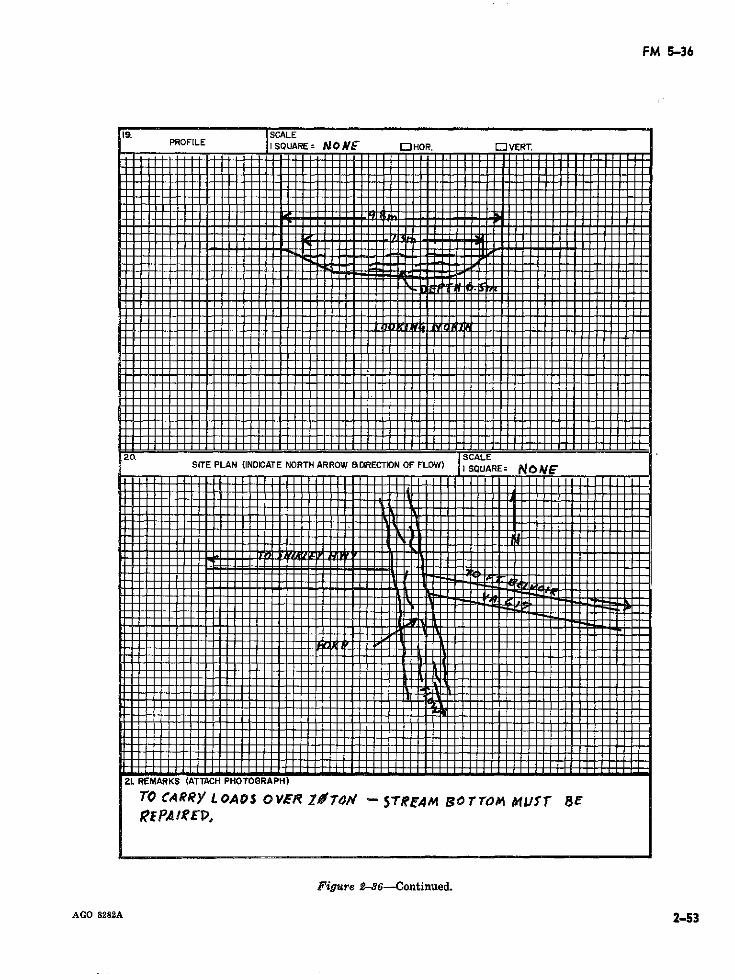
FM 5-36
2L REMARKS (ATTACH PHOTOGRAPH)
TO ¢ARR)/ LOA DS 01/~'R Z~TOff - 5TR'AM BOTT~4 A 1U~'T 8E
P SCALEaP,
PROFILE I SQUARE= NoME UHOR. OlVERT.
F-igure --- 6~- Continued.
AGO 8282A 2-53
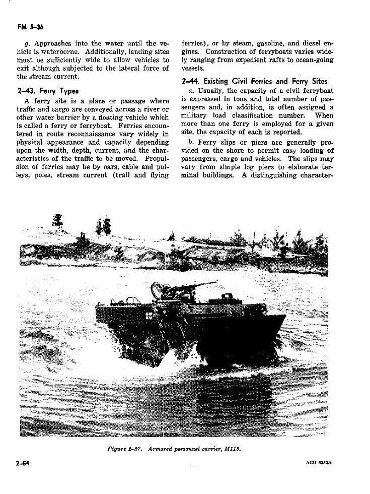
FM 5-36
g. Approaches into the water until the ve- ferries), or by steam, gasoline, and diesel en-hicle is waterborne. Additionally, landing sites gines. Construction of ferryboats varies wide-must be sufficiently wide to allow vehicles to ly ranging from expedient rafts to ocean-goingexit although subjected to the lateral force of vessels.the stream current.
2-44. Existing Civil Ferries and Ferry Sites2-43. Ferry Types a. Usually, the capacity of a civil ferryboat
A ferry site is a place or passage where is expressed in tons and total number of pas-traffic and cargo are conveyed across a river or sengers and, in addition, is often assigned aother water barrier by a floating vehicle which military load classification number. Whenis called a ferry or ferryboat. Ferries encoun- more than one ferry is employed for a giventered in route reconnaissance vary widely in site, the capacity of each is reported.physical appearance and capacity depending b. Ferry slips or piers are generally pro-upon the width, depth, current, and the char- vided on the shore to permit easy loading ofacteristics of the traffic to be moved. Propul- passengers, cargo and vehicles. The slips maysion of ferries may be by oars, cable and pul- vary from simple log piers to elaborate ter-leys, poles, stream current (trail and flying minal buildings. A distinguishing character-
Figure 2-37. Armored personnel earrier, M13.
2-54 AGO 8282A
FM 5-36
istic o' T slip is often the floating pier f. Sites clear of obstacles immediatelywhi'r adjusts to the height of the downstream.fe luctuations in the water depth. g. Sites clear of mines and boobytraps.
.utes to ferry installations h. Sufficient depth to prevent grounding theA," ,n iml bearing on the use of the raft or ferry during loading and unloading op-ferry. Tfb the condition of the ap- erations or when crossing.proaches i,. s load-carrying capacity ofproaches rí. 9 load-carrying capacity of i. Holding areas for vehicles awaiting pass-landing facilití. investigated and recorded.
age.d. Limiting charatteristics of ferry sites
are considered, such as: 2-46. Ferry Reconnaissance Symbol(1) Width of the water barrier from bank (STANAG 2274)
to bank. Limited ferry information is recorded onmaps or overlays by means of symbols as il-(2) The distance and time traveled by the maps or overlays by means of symbols as
ferryboat from one side to the otherside. a. The geographic location of the ferry is
shown by an arrow from the symbol to the(3) Deslip. of the water at each ferry location of the ferry on a map or overlay. The
symbol may be drawn on the map or overlaye. Climatic conditions have a marked effect on either side of the stream.
on ferry operations. Fog and ice substantially b A serial number is arbitrarily assignedb. A serial number is arbitrarily assignedreduce the total traffic-moving capacity and in- eah ferry for ease in subsequent referene.each ferry for ease in subsequent reference.crease the hazard of the water route. There- Numbers must not be duplicated within anyfore, data on tide fluctuations, freezing periods, one map sheet, overlay, or document. Thefloods, excessive dry spells, and their effects on number is recorded to the extreme left andferry operation are considered. above the symbol.2-45. M§\ali¡tary Ferry and lRafting Sites c. The type of ferry (AF-vehicular ferry,
PF-pedestrian ferry, MF--military ferry) islReconnaissance personnel may be requiredto locate and report suitable sites for militaryrafting and/or ferrying operations. Equip- d. The military load classification of thement presently available for such operations ferry is expressed by a value placed inside theare either components of military floating symbol and to the left.bridges, which are assembled into rafts at the e. The dead weight capacity of the ferry iswater's edge, or units of the mobile assault shown inside the symbol to the right of thebridge (MAB) which consists of individual military load classification.self-propelled amphibious vehicles assembled f The turn around time is shown by theinto a ferry when in the water (fig. 2-28). number of minutes required and is placed toFor military rafting operations, the following the left and below the symbol.site characteristics are desirable:
g. The length and width (in that order) ofa. Current velocity between O and 1.5 meters the area aboard the ferry available to accom-
per second. modate cargo is separated by a slash (/) andb. Banks which permit loading without a placed below the symbol to the right of the
great deal of preparation. turn around time.
c. Approaches which permit easy access and h. A difficult approach is shown by irregularegress. lines placed on the corresponding side of the
basic symbol (see para. 2-38j). Attentiond. Strong natural holdfasts. must be paid to the direction of stream flow ine. No shoals, sandbars, or snags. drawing this portion of the symbol.
AGO 8282A 2-55
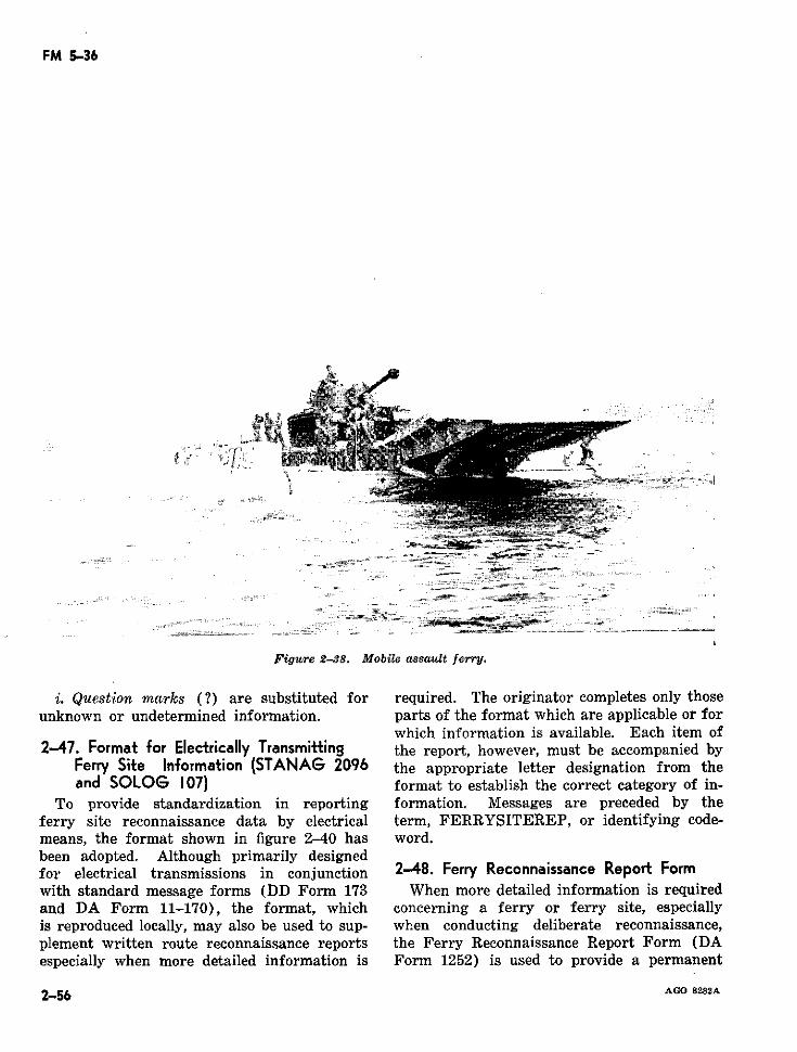
FM 5-36
Figure 2-38. Mobile assault ferry.
i. Question marks (?) are substituted for required. The originator completes only thoseunknown or undetermined information. parts of the format which are applicable or for
which information is available. Each item of2-47. Format for Electrically Transmitting the report, however, must be accompanied by
Ferry Site Information (STANAG 2096 the appropriate letter designation from theand SOLOG 107) format to establish the correct category of in-
To provide standardization in reporting formation. Messages are preceded by theferry site reconnaissance data by electrical term, FERRYSITEREP, or identifying code-means, the format shown in figure 2-40 has word.been adopted. Although primarily designedfor electrical transmissions in conjunction 2-48. Ferry Reconnaissance Report Formwith standard message forms (DD Form 173 When more detailed information is requiredand DA Form 11-170), the format, which concerning a ferry or ferry site, especiallyis reproduced locally, may also be used to sup- when conducting deliberate reconnaissance,plement written route reconnaissance reports the Ferry Reconnaissance Report Form (DAespecially when more detailed information is Form 1252) is used to provide a permanent
2-56 AGO 8282A
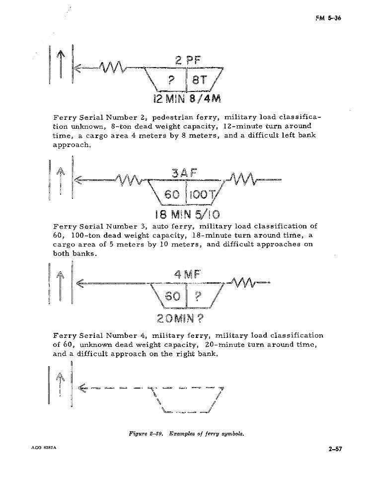
FM 5-36
2 PF
12 MIN 8/4MFerry Serial Number 2, pedestrian ferry, military load classifica-tion unknown, 8-ton dead weight capacity, lZ-minute turn aroundtime, a cargo area 4 meters by 8 meters, and a difficult left bankapproach.
18 MIN 5/10Ferry Serial Number 3, auto ferry, military load classification of60, 100-ton dead weight capacity, 18-minute turn around tirze, acargo area of 5 meters by 10 meters, and difficult approaches onboth banks.
4MF
60 ?
Ferry Serial Number 4, military ferry, military load classificationof 60, unknown dead weight capacity, 20-minute turn around time,and a difficult approach on the right bank.
\u 23 xmeofl/J
Figure 2-39. Eamples of ferry symbols.
AGO 8282A 2-57
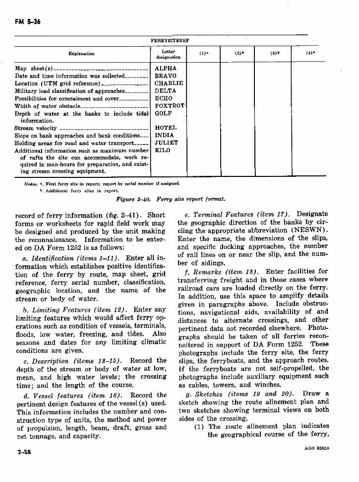
FM 5-36
FERRYSITEREP
Explanation Letter () (2) b (3) b (4) bdesignation
Map sheet (s) -------------.----------------- ALPHADate and time information was collected-------- BRAVOLocation (UTM grid reference) -__------------- CHARLIEMilitary load classification of approaches-------- DELTAPossibilities for concealment and cover---------- ECHOWidth of water obstacle----------------------- FOXTROTDepth of water at the banks to include tidal GOLF
information.Stream velocity -----------------_------------ HOTELSlope on bank approaches and bank conditions___-- INDIAHolding areas for road and water transport----- JULIETAdditional information such as maximum number KILO
of rafts the site can accommodate, work re-quired in man-hours for preparation, and exist-ing stream crossing equipment.
Notes. '. First ferry site in report; report by serial number if assigned.
b. Additional ferry sites in report.
Figure 2-40. Ferry site report format.
record of ferry information (fig. 2-41). Short e. Terminal Features (item 17). Designateforms or worksheets for rapid field work may the geographic direction of the banks by cir-
be designed and produced by the unit making cling the appropriate abbreviation (NESWN).
the reconnaissance. Information to be enter- Enter the name, the dimensions of the slips,
ed on DA Form 1252 is as follows: and specific docking approaches, the number
a. Identification (items 1-11). Enter all ill- of rail lines on or near the slip, and the num-
formation which establishes positive identifica- ber of sidings.tion of the ferry by route, map sheet, grid f. Remarks (item 18). Enter facilities forreference, ferry serial number, classification, transferring freight and in those cases wheregeographic location, and the name of the railroad cars are loaded directly on the ferry.stream or body of water. In addition, use this space to amplify details
given in paragraphs above. Include obstruc-b. Limiting Features (item 12). Enter any tions, navigational aids, availability of and
limiting features which would affect ferry op- distances to alternate crossings, and othererations such as condition of vessels, terminals, pertinent data not recorded elsewhere. Photo-
floods, low water, freezing, and tides. Also graphs should be taken of all ferries recon-seasons and dates for any limiting climatic noitered in support of DA Form 1252. Theseconditions are given. photographs include the ferry site, the ferry
c. Description (items 13-15). Record the slips, the ferryboats, and the approach routes.
depth of the stream or body of water at low, If the ferryboats are not self-propelled, themean, and high water levels; the crossing photographs include auxiliary equipment such
time; and the length of the course. as cables, towers, and winches.
d. Vessel features (item 16). Record the g. Sketches (items 19 and 20). Draw a
pertinent design features of the vessel(s) used. sketch showing the route alinement plan andThis information includes the number and con- two sketches showing terminal views on both
struction type of units, the method and power sides of the crossing.of propulsion, length, beam, draft, gross and (1) The route alinement plan indicatesnet tonnage, and capacity. the geographical course of the ferry,
AGO 8282A2-58

FM 5-36
terminals, and approaches to the slips. and details of the slips, ramps, andParticular care is taken in recording bumper piles.obstructions. Navigational aids suchas buoys and lights are shown. The 2-49. Ferry Applications of Bridge Markingsposition of the approaches includingsurrounding terrain features is in- Marking for ferries is accomplished in ac-cluded in the sketch. cordance with applicable instructions for mark-
(2) Two separate sketches are made ing bridges (para. 2-52). Hazard, regulatory,showing each terminal including the and guide signs, as appropriate, are posted ongeographical position of each bank approach routes and at ferry slips (fig. 2-42).
AGO 8282A 2-59
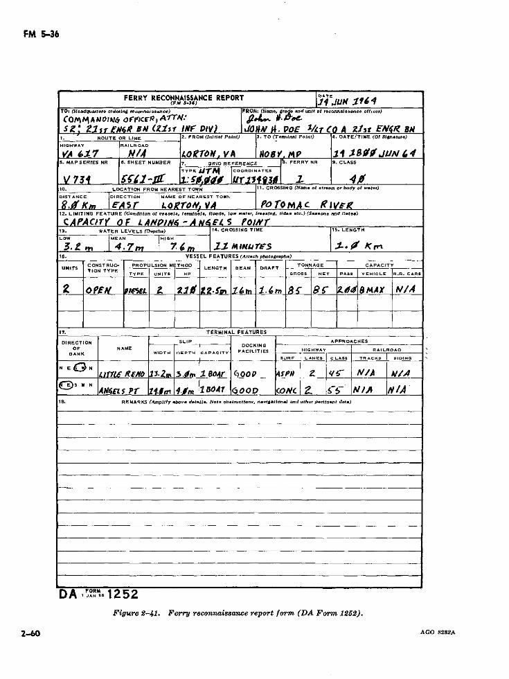
FM 5-36
FERRY RECONNAISSANCE REPORT DATE(FM 5-36) -14 JUN 17
TO: HeMadquart.r ordorin4 reconnaueanc.) FROM: (N-.me. grade and tmit of reconnaleeance offcer)
COM M A N I0I O FFICER) Arl".' pÁ, Y k.os,3 21s yr e ; #A (Zls INF PlV) ¡JOITV IT. POE / ¢O A r y,' ZsrF t
1. ROUTE OR LINE 2. FROM (Inll Poní) 3. TO (Teinel Pont) 4. DATE/TIME (Of Slánattue)
HIGHWAY RAILROAD
6.17 N/ tORO, VA Io Y p 11 t 9p'IJ/uN 6 45. MLAPSERIES NR 8. SHEET NUMEER 7. ORIO REFERENCE r. FERRY NR 9. CLASS
TYPE j/i't4 COORDINATES
V73t 5Sj-I :J ur5 3 e 1. 4r10. LOCATION FROM NEAREST TOWN 11. CROSSING (Name olf teeam or body of warte)
DISTANCE DIRECTION NAME OF NEAREST TOWN
8. Km A S r LOr 7k Ia, Po ro Ac Rc K £,12. LIMITING FEATURE (Condliton ol ve.ele, terominle, flood., losw watr, freeing. tidas atc.) (Sea.eona nd Date.)
C PAc/ry OF LAN4P/ -A e4 S folarLOW MEAN HIGH
3. L n 4 .7 mr Zdm 6 1 1 M MRS z M m¡L16. VESSEL FEATURES (Attach photoarsph.)
UNITS CONSTRUC- PROPULSION METHOD LENGTH 1EAM DRAFT TONNAGE CAPACITYUNl T T LENGTS BEAM DRAFT
TYPE UNITS HP GROSS NET PASS VEHICLE R.R CARS
2 oP lco 2 VI 21W1 6 1.m 8 d MmAY M/A
17. , TERMINAL FEATURES
DIRECTION SLIP APPROACHESDOCKING
BANK WlDTH DEPTH CAPACITY FACILITIES HIGHWAY RAILROADI *URF LANES CLASS TRACKS SIDING
N E _ N _ 1 _
l 5.12m 1 OO r 4oop sPo I s NI/A AI/A(_5s W N ANEs Pr 15 0 ..'|oD COC [s I /A18. REMARKS (Amplify above detalis. Note obstructlons, navsiatlonal end other pertinent data)
DA *JA..N. 1252Figure 2-41. Ferry reconnaissance report form (DA Form 1252).
2-60 AGO 8282A
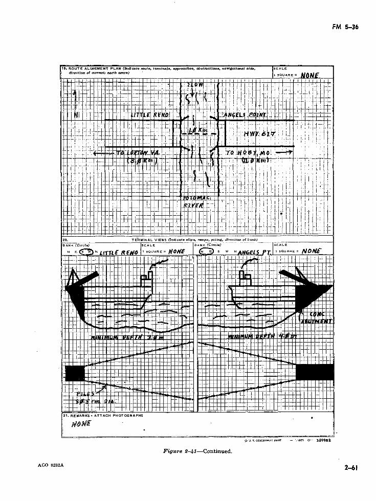
FM 5-36
19. ROUTE ALUEMENT PLAN (Indict. rouéto, term/nle. .pporoch., obet-uclns., ndl.,tonol AIde, SC ALE
dl3rctlon ol cunrent; north ,.ow)
L rLLt.... _ 1 . ii L._
· - .,-,
J?--
I- -
ANK (Circle) ISCALE SBANK (CirclO)
:1_---
21. REMARP¿S- A TTACH PHOTOGRAPHS. _
* U. S. GOVERNMENT PRINT - :195 0- 39982
Fig--re 2-41-Continued.
~~~~Cía)CALE-AGO 8282A 12-61
AGO 8282A 2-61leN~(Crce)lsnL
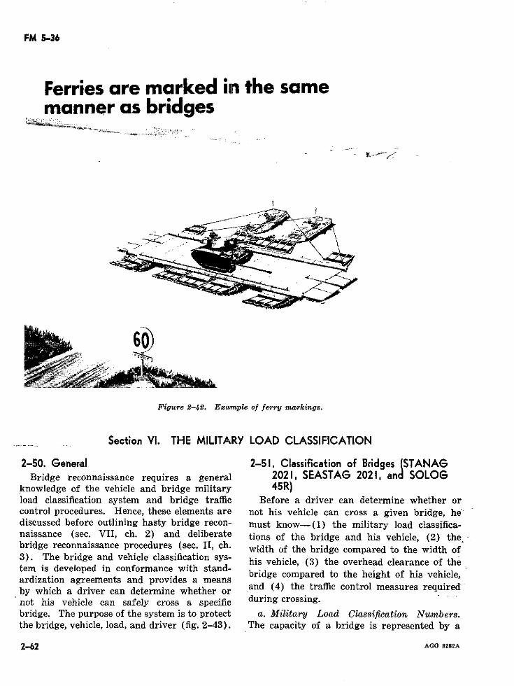
FM 5-36
Ferries are marked in the samemanner as bridges
Figure 2-42. Example of ferry markings.
Section VI. THE MILITARY LOAD CLASSIFICATION
2-50. General 2-51. Classification of Bridges (STANAGBridge reconnaissance requires a general 2021, SEASTAG 2021, and SOLOG
knowledge of the vehicle and bridge military 45R)load classification system and bridge traffic Before a driver can determine whether orcontrol procedures. Hence, these elements are not his vehicle can cross a given bridge, hediscussed before outlining hasty bridge recon- must know-(1) the military load classifica-naissance (sec. VII, ch. 2) and deliberate tions of the bridge and his vehicle, (2) thebridge reconnaissance procedures (sec. II, ch. width of the bridge compared to the width of3). The bridge and vehicle classification sys-
his vehicle, (3) the overhead clearance of thetem is developed in conformance with stand-ardization agreements and provides a means bridge compared to the height of his vehicle,
by which a driver can determine whether or and (4) the traffic control measures requirednot his vehicle can safely cross a specific during crossing.bridge. The purpose of the system is to protect a. Military Load Classification Numbers.the bridge, vehicle, load, and driver (fig. 2-43). The capacity of a bridge is represented by a
2-62 AGO 8282A
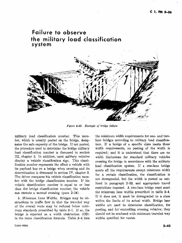
C 1, FM 5--6
Failure to observethe mífiltary load classificationsystem
Figtre 2-43. Example of bridge failure.
military load classification number. This num- the minimum width requirements for one- and two-ber, which is usually posted on the bridge, desig- lane bridges according to military load classifica-nates the safe capacity of the bridge. If not posted, tion. If a bridge of a specific class meets thesethe procedure used to determine the bridge military width requirements, no posting of the width isload classification number is discussed in section required; and it is understood that there are noIII, chapter 3. In addition, most military vehicles width limitations for standard military vehiclesdisplay a vehicle classification sign. This classi- crossing the bridge in accordance with the militaryfication number represents the effect a vehicle with load classification system. If a one-lane bridgeits payload has on a bridge when crossing and its meets a the requirements except minimum widthdetermination is discussed in section IV, chapter 3.in lassification, the lassification isThe driver compares his vehicle classification num-
bedrwivter bridges hlsseiel sfication nun. hi .. not downgraded, but the width is posted as out-
vehicle classification number is equal to or ess lined in paragraph 2-52, and appropriate travelthan the bridge classification number, the vehicle restrictions imposed A two-lane bridge must meetcan execute a normal crossing (para 2-54). the minimum lane widths prescribed in table 2-4.
b. Minimum Lane Widths. Bridges may be ob- If it does not, it must be downgraded to a class
structions to traffic flow in that the traveled way within the limits of its actual width. Bridge laneof the overall route may be reduced below mini- widths are used to determine classification, formum standards prescribed by table 2-1. If so, the posting, and for'controlling crossing vehicles; theybridge is reported as a width obstruction (OB) should not be confused with minimum traveled wayin the route classification formula. Table 2-4 lists widths specified for routes.
TAGO 6929A 2-63
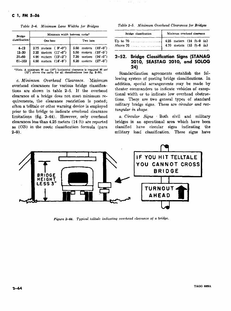
C 1, FM 5-36
Table 2-4. Minimum Lane Widths for Bridges Table 2-5. Minimum Overhead Clearances for Bridges
Bridge Minimum width between curbs* Bridge classification Minimum overhead clearance
classification One lane Two lane Up to 70 ................... 425 meters (14 ft-O in)
Above 70 .................. 4.70 meters (15 ft-6 in)4-12 2.75 meters ( 9'-0") 5.50 meters (18'-") Aboe 7070 eters (15 ft in)
13-30 3.35 meters (11'-0") 550 meters .(18'-O")31-60 4.00 meters (13'-2") 7.30 meters (24'-0") 2-52. Bridge Classification Signs (STANAG61-100 4.50 meters (14'-9") 820 meters (27'-0") 2010, SEASTAG 2010, and SOLOG
24)'Note. A minimum 25 cm (10") horizontal clearance is required 30 Cm' 24)(12") above the curbs for all classifications (see fig. 3-19). Standardization agreements establish the fol-
c. Minimum Overhead Clearance. Minimum lowing system of posting bridge classifications. In
overhead clearances for various bridge classifica- addition, special arrangements may be made bytions are shown in table 2-5. If the overhead theater commanders to indicate vehicles of excep-clearance of a bridge does not meet minimum re- tional width or to indicate low overhead obstruc-quirements, the clearance restriction is posted; tions. There are two general types of standardoften a telltale or other warning device is employed military bridge signs. These are circular and rec-prior to the bridge to indicate overhead clearance tangular in shapelimitations (fig. 2-44). However, only overhead a. Circular Signs Both civil and militaryclearances less than 4.25 meters (14 ft) are reported bridges in an operational area which have beenas (OB) in the route classification formula (para classified have circular signs indicating the
2-9). military load classification. These signs have
IF YOU HIT TELLTALEYOU CANNOT CROSS
*3BRIDGEHEIGHTLESs 3"
TURNOUTAHEAD
Figure 2-44. Typical telltale indicating overhead clearance oj a bridge.
TAGO 6921A2-64
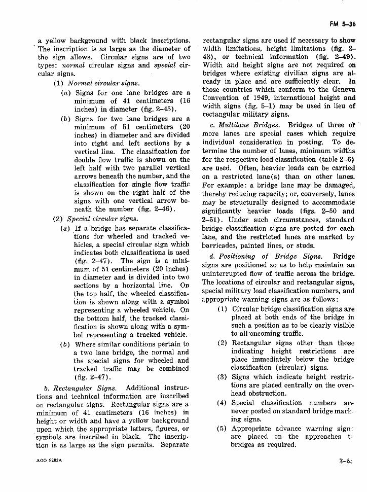
FM 5-36
a yellow background with black inscriptions. rectangular signs are used if necessary to showThe inscription is as large as the diameter of width limitations, height limitations (fig. 2-the sign allows. Circular signs are of two 48), or technical information (fig. 2-49).types: normal circular signs and special cir- Width and height signs are not required oncular signs. bridges where existing civilian signs are al-
(1) Normal circular signs. ready in place and are sufficiently clear. In(a) Signs for one lane bridges are a those countries which conform to the Geneva
minimum of 41 centimeters (16 Convention of 1949, international height andinches) in diameter (fig. 2-45). width signs (fig. 5-1) may be used in lieu of
rectangular Imilitary signs.(b) Signs for two lane bridges are a
minimum of 51 centimeters (20 c. Multilane Bridges. Bridges of three orinches) in diameter and are divided more lanes are special cases which requireinto right and left sections by a individual consideration in posting. To de-vertical line. The classification for termine the number of lanes, minimum widthsdouble flow traffic is shown on the for the respective load classification (table 2-6)left half with two parallel vertical are used. Often, heavier loads can be carriedarrows beneath the number, and the on a restricted lane(s) than on other lanes.classification for single flow traffic For example: a bridge lane may be damaged,is shown on the right half of the thereby reducing capacity; or, conversely, lanessigns with one vertical arrow be- may be structurally designed to accommodateneath the number (fig. 2-46). significantly heavier loads (figs. 2-50 and
(2) Special circular signs. 2-51). Under such circumstances, standard(a) If a bridge has separate classifica- bridge classification signs are posted for each
tions for wheeled and tracked ve- lane, and the restricted lanes are marked byhicles, a special circular sign which barricades, painted lines, or studs.indicates both classifications is used d. Postonn of Brde Sns. Brde(fig. 2-47). The sign is a mini-(fig. 2-47). The sign( is a mini- signs are positioned so as to help maintain anmum of 51 centimeters (20 inches)in diameter and is divided into two uninterrupted flow of traffic across the bridge.sections by ad horizontal line. On aThe locations of circular and rectangular signs,sections by a horizontal line. Onthe top half, the wheeled classifica- special military load classification numbers, andtion is shown along with a symbol appropriate warning signs are as follows:representing a wheeled vehicle. On (1) Circular bridge classification signs arethe bottom half, the tracked classi- placed at both ends of the bridge infication is shown along with a sym- such a position as to be clearly visiblebol representing a tracked vehicle. to all-oncoming traffic.
(b) Where similar conditions pertain to (2) Rectangular signs other than thosea two lane bridge, the normal and indicating height restrictions arethe special signs for wheeled and place immediately below the bridgetracked traffic may be combined classification (circular) signs.(fig. 2-47). (3) Signs which indicate height restric-
b. Rectangular Signs. Additional instruc- tions are placed centrally on the over-tions and technical information are inscribed head obstruction.on rectangular signs. Rectangular signs are a (4) Special classification numbers artminimum of 41 centimeters (16 inches) in never posted on standard bridge mark-height or width and have a yellow background ing signs.upon which the appropriate letters, figures, or (5) Appropriate advance warning sign:symbols are inscribed in black. The inscrip- are placed on the approaches t:tion is as large as the sign permits. Separate bridges as required.
AGO 8282A 2-6-
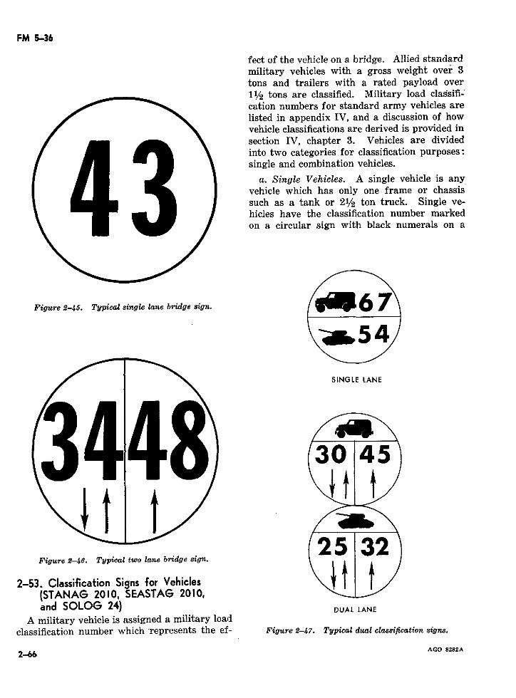
FM 5-36
fect of the vehicle on a bridge. Allied standardmilitary vehicles with a gross weight over 3tons and trailers with a rated payload over11/2 tons are classified. Military load classifi-cation numbers for standard army vehicles arelisted in appendix IV, and a discussion of howvehicle classifications are derived is provided insection IV, chapter 3. Vehicles are dividedinto two categories for classification purposes:single and combination vehicles.
a. Single Vehicles. A single vehicle is anyvehicle which has only one frame or chassissuch as a tank or 21/2 ton truck. Single ve-hicles have the classification number markedon a circular sign with black numerals on a
Figure 2-45. Typical single lane bridge sign. i 6 7
-w54
SINGLE LANE
3045
25 32Figure 2-46. Typical twvo lane bridge sign.
2-53. Classification Signs for Vehicles t
(STANAG 2010, SEASTAG 2010,and SOLOG 24) DUAL LANE
A military vehicle is assigned a military loadclassification number which -represents the ef- Figure 2-47. Typical dual classification signs.
2-66 AGO 8282A
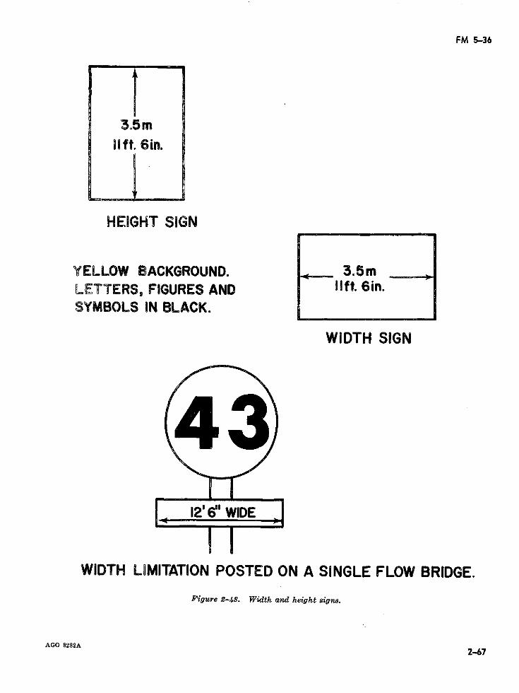
FM 5-36
3.5mlift. 6in.
HEIGHT SIGN
YELLOW BACKGROUND. _ 3.5mLETTERS, FIGURES AND lift. 6in.SYMBOLS IN BLACKo
WIDTH SIGN
12'6" WIDE
WIDTH LOMITATION POSTED ON A SINGLE FLOW BRIDGE.
Figure 2-48. Width and height signs.
AGO 8282A2-67
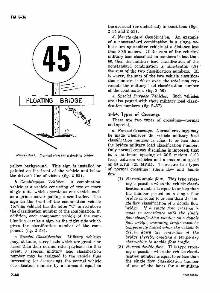
FM 5-36
the overload (or underload) in short tons (figs.2-54 and 2-55). .
d. Nonstandard Combination. An exampleof a nonstandard combination is a single ve-hicle towing another vehicle at a distance lessthan 30.5 meters. If the sum of the vehicles'military load classification numbers is less than60, then the military load classification of thenonstandard combination is nine-tenths (.9)the sum of the two classification numbers. If,however, the sum of the two vehicle classifica-tion numbers is 60 or over, the total sum rep-resents the military load classification number
,JI ' - of the combination (fig. 2-56).e. Special Purpose Vehicles. Such vehicles
FLOATING BRIDGE are also posted with their military load classi-fication numbers (fig. 2-57).
~1;' á2-54. Types of Crossings/ \> (r:There are two types of crossings-normal: ld Io nand special.
a. Normal Crossings. Normal crossings maybe made whenever the vehicle military loadclassification number is equal to or less thanthe bridge military load classification number.Only normal convoy discipline is imposed; that
Figure 2-49. Typical sign for a foating bridge. is, a minimum spacing of 30.5 meters (100feet) between vehicles and a maximum speed
yellow background. This sign is installed or of 40 KPH (25 MPH). There are two typespainted on the front of the vehicle and below of normal crossings: single flow and doublethe driver's line of vision (fig. 2-52). flow
(1) Normal single flow. This type cross-b. Combination Vehicles. A combination ing is possible when the vehicle classi-
vehicle is a vehicle consisting of two or more fication number is equal to or less thansingle units which operate as one vehicle such the number posted on a single flowas a prime mover pulling a semitrailer. The bridge or equal to or less than the sin-sign on the front of the combination vehicle gle flow classification of a double flow(towing vehicle) has theletter "C" in red above bridge. If a single flow crossing isthe classification number of the combination. In made in accordance with the singleaddition, each component vehicle of the com- flow classification number on a doublebination carries a sign on the right side which flow bridge, oncoming traffic must begives the classification number of the com- temporarily halted while the vehicle isponent (fig. 2-53). driven down the centerline of the
c. Special Classification. Military vehicles bridge thereby creating a temporarymay, at times, carry loads which are greater or obstruction to double flow traffic.lesser than their normal rated payloads. In this (2) Normal double flow. This type cross-event, a special military load classification ing is possible when the vehicle classi-number may be assigned to the vehicle thus fication number is equal to or less thanincreasing (or decreasing) the normal vehicle the single flow classification numberclassification number by an amount equal to of one of the lanes for a multilane
2-68 AGO 8282A
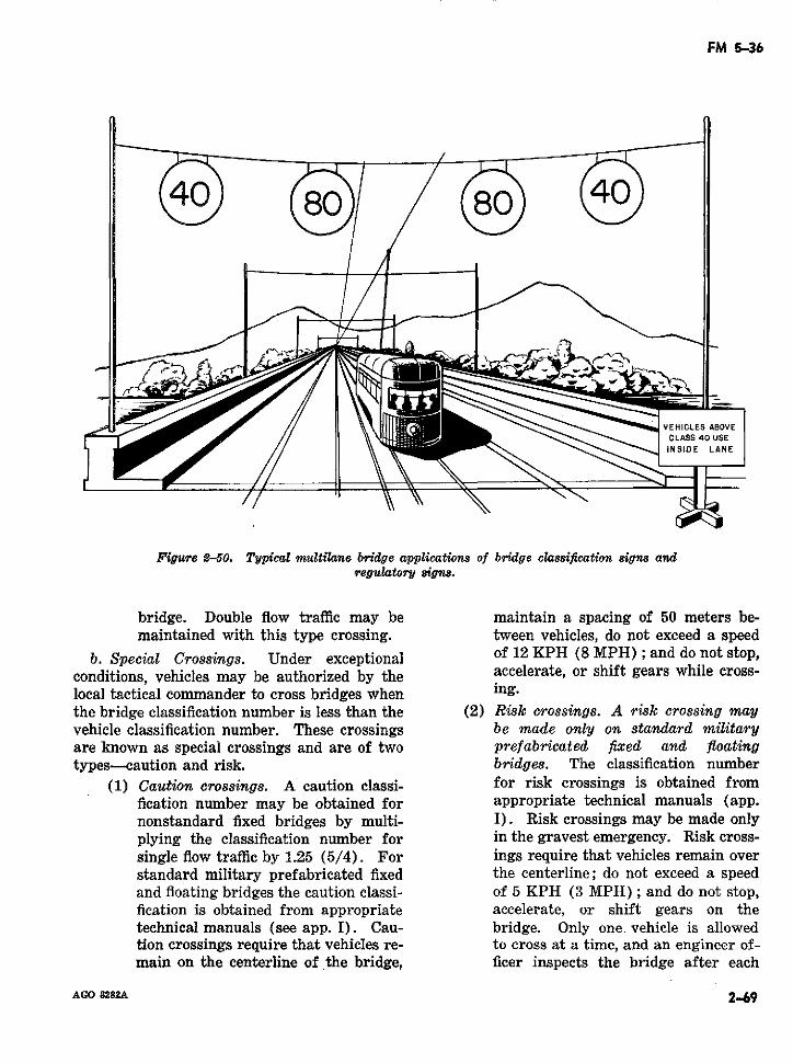
FM 5-36
VEHICLES ABOVECLASS 40 USE
INSIDE LANE
Figure 2-50. Typical multilane bridge applications of bridge classification signs andregulatory s8gns.
bridge. Double flow traffic may be maintain a spacing of 50 meters be-maintained with this type crossing. tween vehicles, do not exceed a speed
b. Special Crossings. Under exceptional of 12 KPH (8 MPH); and do not stop,conditions, vehicles may be authorized by the accelerate, or shift gears while cross-local tactical commander to cross bridges when ing.the bridge classification number is less than the (2) Risk crossings. A risk crossing mayvehicle classification number. These crossings be made only on standard militaryare known as special crossings and are of two prefabricated fixed and floatingtypes-caution and risk. bridges. The classification number
(1) Caution crossings. A caution classi- for risk crossings is obtained fromfication number may be obtained for appropriate technical manuals (app.nonstandard fixed bridges by multi- I). Risk crossings may be made onlyplying the classification number for in the gravest emergency. Risk cross-single flow traffic by 1.25 (5/4). For ings require that vehicles remain overstandard military prefabricated fixed the centerline; do not exceed a speedand floating bridges the caution classi- of 5 KPH (3 MPH); and do not stop,fication is obtained from appropriate accelerate, or shift gears on thetechnical manuals (see app. I). Cau- bridge. Only one vehicle is allowedtion crossings require that vehicles re- to cross at a time, and an engineer of-main on the centerline of the bridge, ficer inspects the bridge after each
AGO 8282A 2-69
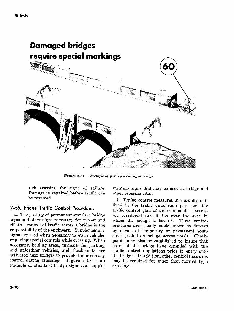
FM 5-36
Damaged bridgesrequire special markings
4 60
Figure 2-51. Example of posting a damaged bridge.
risk crossing for signs of failure. mentary signs that may be used at bridge andDamage is repaired before traffic can other crossing sites.be resumed. b. Traffic control measures are usually out-
lined in the traffic circulation plan and the2-55. Bridge Traffic Control Procedures traffic control plan of the commander exercis-a. The posting of permanent standard bridge ing territorial jurisdiction over the area in
signs and other signs necessary for proper and which the bridge is located. These controlefficient control of traffic across a bridge is the measures are usually made known to driversresponsibility of the engineers. Supplementary by means of temporary or permanent routesigns are used when necessary to warn vehicles signs posted on bridge access roads. Check-requiring special controls while crossing. When points may also be established to insure thatnecessary, holding areas, turnouts for parking users of the bridge have complied with theand unloading vehicles, and checkpoints are traffic control regulations prior to entry ontoactivated near bridges to provide the necessary the bridge. In addition, other control measurescontrol during crossings. Figure 2-58 is an may be required for other than normal typeexample of standard bridge signs and supple- crossings.
2-70 AGO 8282A
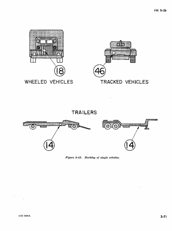
FM 5-36
WHEELED VEHICLES TRACKED VEHICLES
TRAILERS
Figure 2-52. Marking of single vehicles.
AGO 8282A 2-71
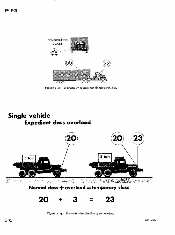
FM 5-36
COMBINATION .. *CLASS
Figure 2-53. Marking of typical combination vehicles.
Single vehicleExpedient class overload
/ 8 ton2 20
Normal class + overload = temporary class
20 + 3 = 23Figure 2-54. Example classification of an'overload.
2-72 AGO 8282A
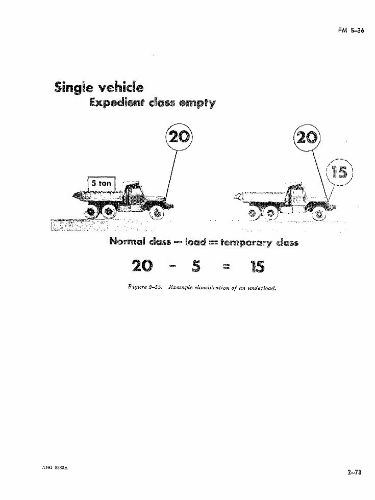
FM 5-36
Single vehicleExpedient cdass e pty
I \ (X5)
t ton
Normal class load = temporary ¢dss
20 5 15Figure 2-55. Example classification of an underload.
AGO 8282A2~73
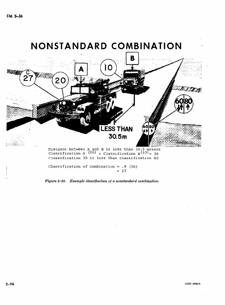
FM 5-36
NONSTANDARD COMBINATION
LESS THAN3_0. 5m
Distance between A and B is less than 30.5 metersClassification A (20) + Classification B(10)= 30Classification 30 is less than classification 60
Classification of combination = .9 (30)= 27
Figure 2-56. Example classification of a nonstandard combination.
2-74 AGO 8282A
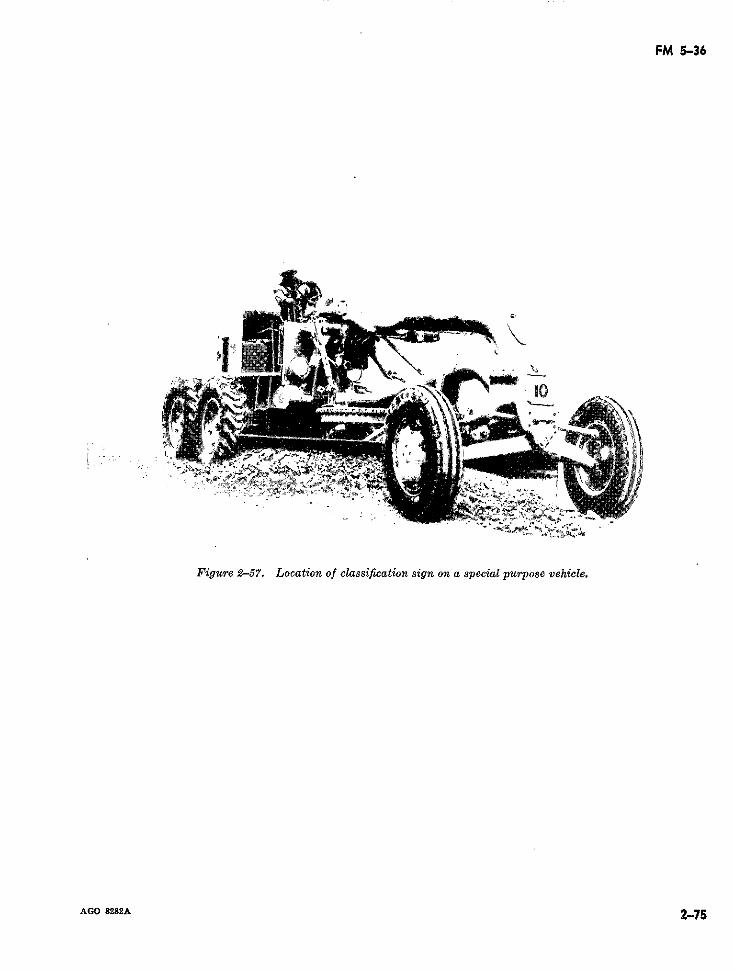
FM 5-36
.X_
Figure 2-57. Location of classification sign on a special purpose vehicle.
ACO 8282A 2-75
t~~~~~~~-7
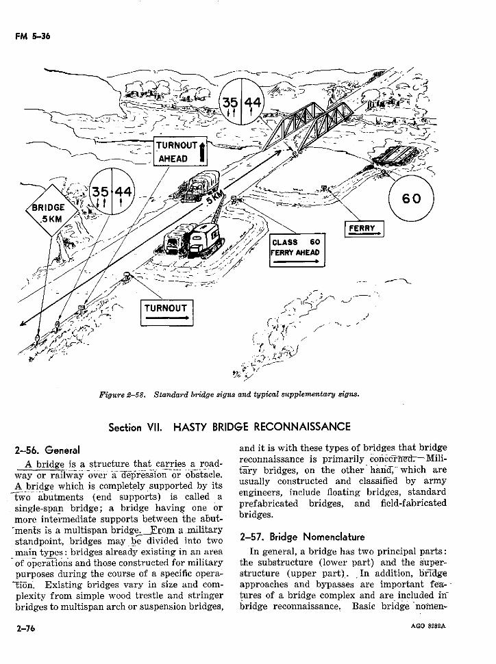
FM 5-36
- TURNOUT-
-AHEAD U
Section V. HASTY BRIDGE tRECONNAISSANCE
2-56. General and it is with these types of bridges that bridge
A bridge is a structure that carries a road- reconnaissance is primarily concerned.Mili-
A bridge which is completely supported by itsFigure 8. Standard bridge igens a i neers, include floating bridges, standard
2-56. General and it is with these types of bridges that bridge
single-span bridge;d a bridge ng oneers, include floating bridges, standardsingle-span bridge; a bridge having one or prefabricated dbridges, and fid-fabicated
more intermediate supports between the abut- bridges.'ments is a multispan bridge. From a militarystandpoint, bridges may be divided into two 2-57. Bridge Nomenclaturemain types: bridges already existing in an area In general, a bridge has two principal parts:of operations and those constructed for military the substructure (lower part) and the super-purposes during the course of a specific opera-. structure (upper part). ,In addition, bridgeoió#n. Existing bridges vary in size and com- approaches and bypasses are important fe-a--
plexity from simple wood trestle and stringer tures of a bridge complex and are included inbridges to multispan arch or suspension bridges, bridge reconnaissance. Basic bridge no0men-
2-76 AGO 8282A
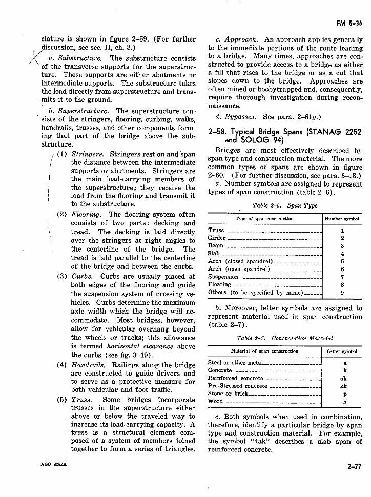
FM 5-36
clature is shown in figure 2-59. (For further c. Approach. An approach applies generallydiscussion, see sec. II, ch. 3.) to the immediate portions of the route leading
K( a. Substructure. The substructure consists to a bridge. Many times, approaches are con-of the transverse supports for the superstruc- structed to provide access to a bridge as eitherture. These supports are either abutments or a fill that rises to the bridge or as a cut thatintermediate supports. The substructure takes slopes down to the bridge. Approaches arethe load directly from superstructure and trans- often mined or boobytrapped and, consequently,mits it to the ground. require thorough investigation during recon-
naissance.b. Superstructure. The superstructure con-
sists of the stringers, flooring, curbing, walks, d. Bypasses. See para. 2-61g.)handrails, trusses, and other components form- Bridge Spans (STANAG 2252ing that part of the bridge above the sub- an SOLOG 94)structure.
Bridges are most effectively described by(1the distance between the intermediate span type and construction material. The morethe distance between the intermediate
suports or abutments. Stringers are common types of spans are shown in figurethe main load-carrying membSers of 2-60. (For further discussion, see para. 3-13.)the main load-carrying members of/ the superstructure; they receive the a. Number symbols are assigned to representload from the flooring and transmit it types of span construction (table 2-6).to the substructure. Table 2-6. Span Type
(2) Flooring. The flooring system oftenType of span construction Number symbol
consists of two parts: decking andtread. The decking is laid directly Truss --_-___________________________ 1over the stringers at right angles to Girder 2the centerline of the bridge. The Beam 3
Slab 4tread is laid parallel to the centerline Arch <closed spandrel)-5Arch (closed spandrel) --------------- 5of the bridge and between the curbs. Arch (open spandrel) _________________ 6
(3) Curbs. Curbs are usually placed at Suspension __________________________ 7both edges of the flooring and guide Floating ____________________________ 8the suspension system of crossing ve- Others (to be specified by name)----- 9hicles. Curbs determine the maximumaxle width which the bridge will ac- b. Moreover, letter symbols are assigned tocommodate. Mwiost bridges, however, represent material used in span constructionallow for vehicular overhang beyondthe wheels or tracks; this allowance Table 2-7. Construction Material
is termed horizontal clearance abovethe curbs (see fig. 3-19) . Material of span construction Letter symbol
(4) Handrails. Railings along the bridge Steel or other metal aare constructed to guide drivers and Conrete ---------------------------- k
Reinforced concrete . ................. akto serve as a protective measure for Reinforced concrete akPre-Stressed concrete ._.______________ kk
both vehicular and foot traffic.Stone or brick ....................... p
(5) Truss. Some bridges incorporate Wood ----------------------------- ntrusses in the superstructure eitherabove or below the traveled way to c. Both symbols when used in combination,increase its load-carrying capacity. A therefore, identify a particular bridge by spantruss is a structural element com- type and construction material. For example,posed of a system of members joined the symbol "4ak" describes a slab span ' oftogether to form a series of triangles. reinforced concrete.
AGO 8282A 2-77
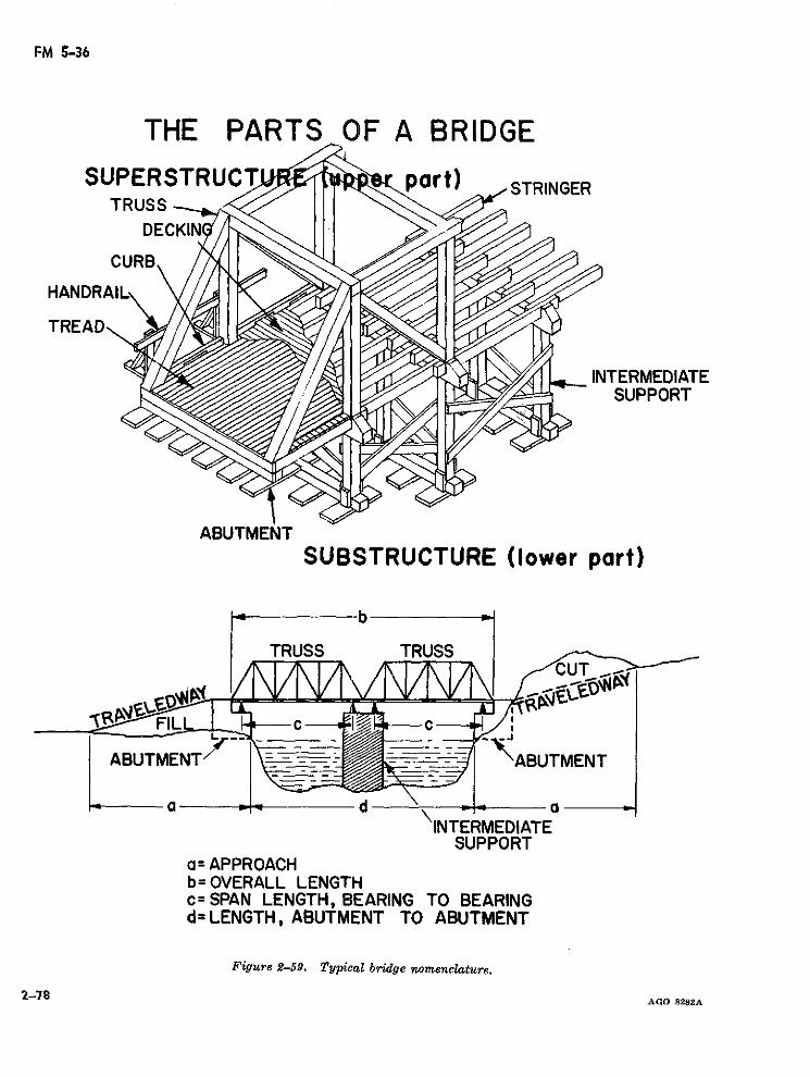
FM 5-36
THE PARTS OF A BRIDGE
SUPERSTRUC part) STRINGERTRUSS
DEI
CURB
HANDRAIL
TREAD
INTERMEDIATESUPPORT
ABUTMENTSUBSTRUCTURE (lower part)
b
TRUSS TRUSSCUT
FlL c
ABUTMET --- -CABUTMENT
INTERMEDIATESUPPORT
a=APPROACHb=OVERALL LENGTHc= SPAN LENGTH, BEARING TO BEARINGd=LENGTH, ABUTMENT TO ABUTMENT
Figure 2-59. Typical bridge nomenclature.
2-78 AGO 8282A
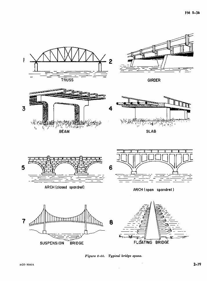
FM 5-36
TRUSS GIRDER
3 ( 4
BEAM SLAB
1 f 1 It 1 I I I t ' ' 1
ARCH (closed spandrel)ARCH (open spandrel)
SUSPENSION BRIDGE FLdATING BRIDGE
Figure 2-60. Typical bridge spans.
AGO 8282A 2-79
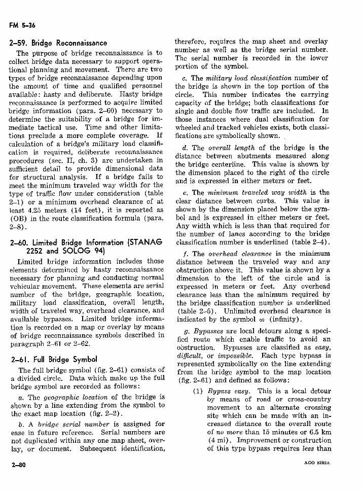
FM 5-36
2-59. Bridge Reconnaissance therefore, requires the map sheet and overlay
The purpose of bridge reconnaissance is to number as wefl as the bridge serial number.collect bridge data necessary to support opera- The serial number is recorded in the lowertional planning and movement. There are two portion of the symbol.types of bridge reconnaissance depending upon c. The military load classification number ofthe amount of time and qualified personnel the bridge is shown in the top portion of theavailable: hasty and deliberate. Hasty bridge circle. This number indicates the carryingreconnaissance is performed to acquire limited capacity of the bridge; both classifications forbridge information (para. 2-60) necessary to single and double flow traffic are included. Indetermine the suitability of a bridge for im- those instances where dual classification formediate tactical use. Time and other limita- wheeled and tracked vehicles exists, both classi-tions preclude a more complete coverage. If fications are symbolically shown.calculation of a bridge's military load classifi-
d. The overall length of the bridge is thecation is required, deliberate reconnaissance distance between abutments measured alongprocedures (sec. II, ch. 3) are undertaken insufficient detail to provide dimensional data the brde centerle. Ths value is shown by
fostrctural a s r ariden al dt the dimension placed to the right of the circlefor structural analysis. If a bridge fails tomeet the minimum traveled way width for thetype of traffic flow under consideration (table e. The minimum traveled way width is the2-1) or a minimum overhead clearance of at clear distance between curbs. This value isleast 4.25 meters (14 feet), it is reported as shown by the dimension placed below the sym-(OB) in the route classification formula (para. bol and is expressed in either meters or feet.2-8). Any width which is less than that required for
the number of lanes according to the bridge2-60. Limited: Bridge Information (STANAG classification number is underlined (table 2-4).
2252 and SOLOG 94) f. The overhead clearance is the minimumLimited bridge information includes those distance between the traveled way and any
elements determined by hasty reconnaissance obstruction above it. This value is shown by anecessary for planning and conducting normal dimension to the left of the circle and isvehicular movement. These elements are serial expressed in meters or feet. Any overheadnumber of the bridge, geographic location, clearance less than the minimum required bymilitary load classification, overall length, the bridge classification number is underlinedwidth of traveled way, overhead clearance, and (table 2-5). Unlimited overhead clearance isavailable bypasses. Limited bridge informa- indicated by the symbol oo (infinity).tion is recorded on a map or overlay by meansof bridge reconnaissance symbols described in fied route which enable trafsl to avoid an
paragraph 2-61 or 2-62. fied route which enable traffic to avoid anobstruction. Bypasses are classified as easy,
2-61. FuIl Bridge Symbol difficult, or impossible. Each type bypass isrepresented symbolically on the line extending
The full bridge symbol (fig. 2-61) consists of from the bridge symbol to the bridge symbol to the map locationa divided circle. Data which make up the full (fig. 2-61) and defined as follows:bridge symbol are recorded as follows:
(1) Bypass easy. This is a local detoura. The geographic location of the bridge is by means of road or cross-country
shown by a line extending from the symbol to movement to an alternate crossing
the exact map location (fig. 2-2). site which can be made with an in-b. A bridge serial number is assigned for creased distance to the overall route
ease in future reference. Serial numbers are of no more than 15 minutes or 6.5 kmnot duplicated within any one map sheet, over- (4 mi). Improvement or constructionlay, or document. Subsequent identification, of this type bypass requires less than
2-80 AGO 8282A
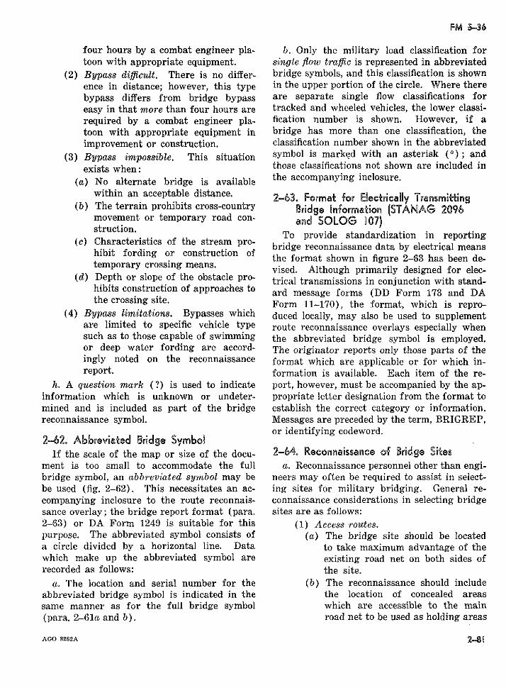
FM 5-36
four hours by a combat engineer pla- b. Only the military load classification fortoon with appropriate equipment. single flow traffic is represented in abbreviated
(2) Bypass difficult. There is no differ- bridge symbols, and this classification is shownence in distance; however, this type in the upper portion of the circle. Where therebypass differs from bridge bypass are separate single flow classifications foreasy in that more than four hours are tracked and wheeled vehicles, the lower classi-required by a combat engineer pla- fication number is shown. However, if atoon with appropriate equipment in bridge has more than one classification, theimprovement or construction. classification number shown in the abbreviated
(3) Bypass impossible. This situation symbol is marked with an asterisk (*); andexists when: those classifications not shown are included in
(a) No alternate bridge is available the acompanying inclosure.within an acceptable distance. 2-63. Format for Electrically -ransmitting
(b) The terrain prohibits cross-country Bridge Information (STANAG 2096movement or temporary road con- and SOLOG 107)struction. To provide standardization in reporting
(c) Characteristics of the stream pro- bridge reconnaissance data by electrical meanshibit fording or construction of the format shown in figure 2-63 has been de-temporary crossing means. vised. Although primarily designed for elec-
(d) Depth or slope of the obstacle pro- trical transmissions in conjunction with stand-hibits construction of approaches to ard message forms (DD Form 173 and DAthe crossing site. Form 11-170), the format, which is repro-
(4) Bypass limitations. Bypasses which duced locally, may also be used to supplementare limited to specific vehicle type route reconnaissance overlays especially whensuch as to those capable of swimming the abbreviated bridge symbol is employed.or deep water fording are accord- The originator reports only those parts of theingly noted on the reconnaissance format which are applicable or for which in-report. formation is available. Each item of the re-
h. A question mark (?) is used to indicate port, however, must be accompanied by the ap-information which is unknown or undeter- propriate letter designation from the format tomined and is included as part of the bridge establish the correct category or information.reconnaissance symbol. Messages are preceded by the term, BRIGREP,
or identifying codeword.2-62. A6breviated Bridge SymboR
If the scale of the map or size of the docu- 2=64. Reconnaissance of Bridge Sitesment is too small to accommodate the full a. Reconnaissance personnel other than engi-bridge symbol, an abbreviated symbol may be neers may often be required to assist in select-be used (fig. 2-62). This necessitates an ac- ing sites for military bridging. General re-companying inclosure to the route reconnais- connaissance considerations in selecting bridgesance overlay; the bridge report format (para. sites are as follows:2-63) or DA Form 1249 is suitable for this (1) Access routes.purpose. The abbreviated symbol consists of (a) The bridge site should be locateda circle divided by a horizontal line. Data to take maximum advantage of thewhich make up the abbreviated symbol are existing road net on both sides ofrecorded as follows: the site.
a. The location and serial number for the (b) The reconnaissance should includeabbreviated bridge symbol is indicated in the the location of concealed areassame manner as for the full bridge symbol which are accessible to the main(para. 2-61a and b). road net to be used as holding areas
AGO 8282A 2-8 g
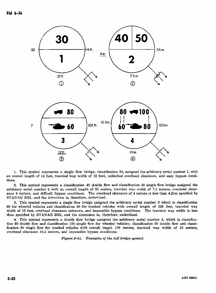
FM 5-36
~~00 it~~ J14ft. i 225m4m
10.5m2 p 60 126ft. 6080 IOO
i2 ft0 ¡ ig
1. This symbol represents a single flow bridge, clas sification 30, assigned the arbitrary serial number 1, withan overall length of 14 feet, traveled way width of 12 feet, unlimited overhead clearance, and easy bypass condi-tions.
2. This symbol represents a classification 40 double flow and classification 50 single flow bridge assigned thearbitrary serial number 2 with an overall length of 25 meters, traveled way width of 7.5 meters, overhead clear-ance 4 meters, and difficult bypass conditions. The overhead clearance of 4 meters is less than 4.25m specified bySTANAG 2021, and the dimension is, therefore, underlined.
3. This symbol represents a single flow bridge assigned the arbitrary serial number 3 which is classification80 for wheeled vehicles and classification 60 for tracked vehicles with overall length of 126 feet, traveled waywidth of 12 feet, overhead clearance unknown, and impossible bypass conditions. The traveled way width is lessthan specified by STANAG 2021, and the dimension is, therefore, underlined.
4. This symbol represents a double flow bridge assigned the arbitrary serial number 4, which is classifica-tion 80 double flow and classification 100 single flow for wheeled vehicles; classification 60 double flow and classi-fication 80 single flow for tracked vehicles with overall length 100 meters, traveled way width of 10 meters,overhead clearance 10.5 meters, and impossible bypass conditions.
Figure 2-61. Examples of the full bridge symbol.
2-2 AGO 8282A
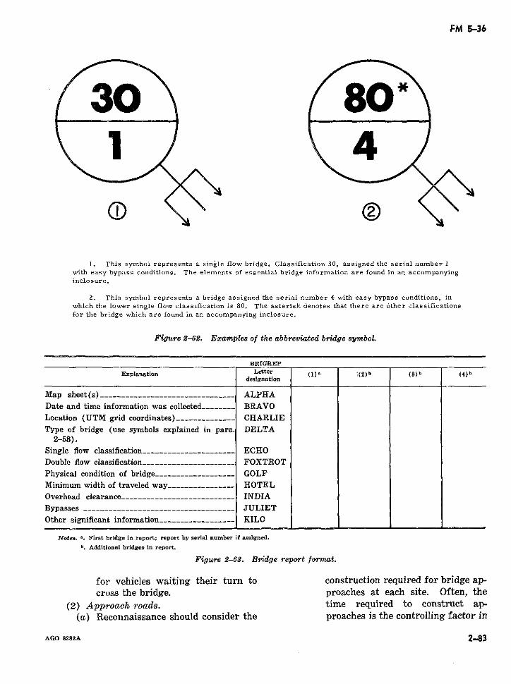
FM 5-36
30 80"
1. This symbol represents a single flow bridge, Classification 30, assigned the serial number 1with easy bypass conditions. The elements of essential bridge information are found in an accompanyinginclosure.
2. This symbol represents a bridge assigned the serial number 4 with easy bypass conditions, inwhich the lower single flow classification is 80. The asterisk denotes that there are other classificationsfor the bridge which are found in an accompanying inclosure.
Figure 2-62. Examples of the abbreviated bridge symbol.
BRIGRETP
Explanation Letter (1) (2)b (3) b (4 )bdesignation
Map sheet(s) -----------____._-------_ _____ _ ALPHADate and time information was collected -------_ BRAVOLocation (UTM grid coordinates) ---- __-----__ _ CHARLIEType of bridge (use symbols explained in para. DELTA
2-58).Single flow classification ---------------------- ECHODouble flow classification__-------__-------__-- - FOXTROTPhysical condition of bridge ------------------- GOLFMinimum width of traveled way --________________ HOTELOverhead clearance________------------------ -- INDIABypasses -------__--------------------------- JULIETOther significant information ----------------- KILO
Notes. a. First bridge in report; report by serial number if assigned.b. Additional bridges in report.
Figure 2-63. Bridge report format.
for vehicles waiting their turn to construction required for bridge ap-cross the bridge. proaches at each site. Often, the
(2) Approach roads. time required to construct ap-(a) Reconnaissance should consider the proaches is the controlling factor in
AGO 8282A 2-83
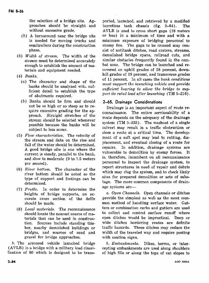
FM 5-36
the selection of a bridge site. Ap- ported, launched, and retrieved by a modifiedproaches should be straight and turretless tank chassis (fig. 2-64). Thewithout excessive grade. AVLB is used to cross short gaps (18 meters
(b) A turnaround near the bridge site or less) in a minimum of time and with ais needed for moving trucks and minimum exposure of bridging personnel tosemitrailers during the construction enemy fire. The gaps to be crossed may con-phase. sist of antitank ditches, road craters, streams,
(3) Width of stream. The width of the demolished bridge spans, railroad cuts, andstream must be determined accurately similar obstacles frequently found in the com-enough to establish the amount of ma-s bat zone. The bridge can be launched and re-terials and equipment needed. covered on uphill grades of 28 percent, down-
(4) Banks. hill grades of 19 percent, and transverse gradesof 11 percent. In all cases the bank conditions(a) The character and shape of the
banks should be analyzed witust support the launching vehicle and providesufficient bearing to allow the bridge to sup-ficient detail to establish the typeficient detail to establish the type port its rated load after launching (TM 5-216).of abutments required.
(b) Banks should be firm and should 2-65. Drainage Considerationsnot be so high or so steep as to re- Drainage is an important aspect of route re-quire excessive grading for the ap- connaissance. The entire serviceability of aproach. Straight stretches of the route depends on the adequacy of the drainagestream should be selected whenever system (TM 5-335). The washout of a singlepossible because the banks will bepossibsubject to less scour. the be culvert may result in a traffic obstruction or
close a route at a critical time. The develop-(5) Flow characteristics. The velocity of ment of a soft spot may lead to rutting, dis-
the stream and data on the rise andfailthe stream and data on the rise and placement, and eventual closing of a route forfall of the water should be determined. repars In addition, drainage systems arerepairs. In addition, drainage systems areA good bridge site is one where the
current is steady, parallel to the bank, vulnerable to demolition by enemy forces. Itand slow to moderate (0 to 1.5 meters is, therefore, incumbent on all reconnaissanceper second). personnel to inspect the drainage system, to
report structures in need of repair and debris(6) River bottom. The character of theriver bottom should be noted so the which may clog the system, and to check likely
type of support and footings can be sites for prepared demolition or acts of sabo-determined. tage. The more common components of drain-
(7) Profile. In order to determine the age systems are-heights of bridge supports, an ac- a. Open Channels. Open channels or ditchescurate cross section of the defile provide the simplest as well as the most com-should be made. mon method of handling surface water. Gut-
(8) Local materials. The reconnaissance ters or combination curbs and gutters are usedshould locate the nearest source of ma- to collect and control surface runoff whereterials that can be used in construc- open ditches would be impractical. Deep ortion. Sources include standing tim- wide ditches bordering routes are definiteber, nearby demolished buildings or traffic hazards. These ditches may reduce thebridges, and sources of sand and width of the traveled way and require postinggravel for bridge approaches. with caution signs.
b. The armored vehicle launched bridge b. Embankments. Dikes, berms, or inter-(AVLB) is a bridge with a military load classi- cepting embankments are used along shouldersfication of 60 which is designed to be trans- of high fills or along the tops of cut slopes to
2-84 AGO 8282A
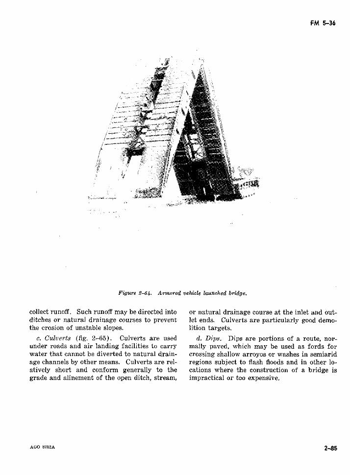
FM 5-36
i ..
Figure 2-64. Armored vehicle launched bridge.
collect runoff. Such runoff may be directed into or natural drainage course at the inlet and out-ditches or natural drainage courses to prevent let ends. Culverts are particularly good demo-the erosion of unstable slopes. lition targets.
c. Culverts (fig. 2-65). Culverts are used d. Dips. Dips are portions of a route, nor-under roads and air landing facilities to carry mally paved, which may be used as fords forwater that cannot be diverted to natural drain- crossing shallow arroyos or washes in semiaridage channels by other means. Culverts are rel- regions subject to flash floods and in other lo-atively short and conform generally to the cations where the construction of a bridge isgrade and alinement of the open ditch, stream, impractical or too expensive.
AGO 8282A 2-85
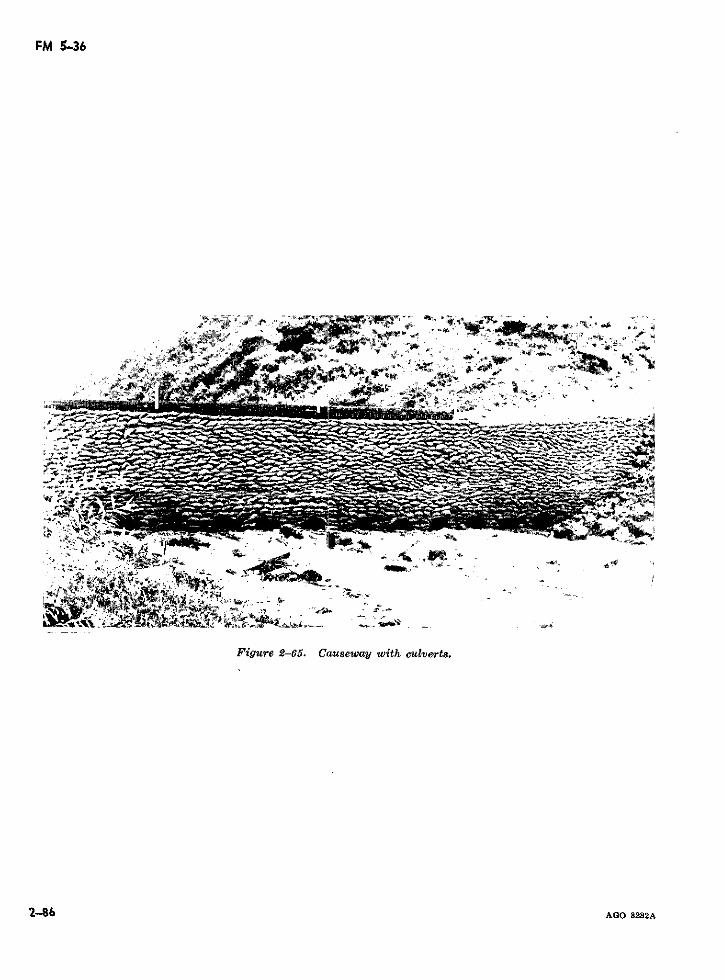
FM 5-36
c-~~~~~~~u
\.~~~~ ex-o.S, S, X, -A s -.~~~~~~~~~~~~~~~~~~~~~~~~~~~~~~~~~~~~~~~~~~~~~~~~~~~~~~~~~~~~~~~~~~~~~~~~~~~~~~~~~~~~~~~~~~~~~~~~~~~~~~~~~~~~~~~~~~~~~~~~~~~~~~~~~I · +
Ame_~~ . D
Figure 2-65. Causeway with culverts.
2-86 AGO 8282A
FM 5-36
CHAPTER 3
DELIBERATE BRIDGE AND ROAD RECONNAISSANCE
Section L GENERAL
3-81 Delibera:e Bridge and Road 3=2. Computation of Military LoadReconnaissance Classifications
With the exception of bridges and roads, suf- To a great extent, route classification isficient information for the conduct of deliberate based on the military load classification system.route reconnaissance is prescribed in chapter Existing bridges in a theater of operations as2. In this chapter, deliberate reconnaissance well as enemy and civilian nonstandard vehiclesprocedures for bridges and roads are discussed requisitioned for military use may often re-separately because of their technical nature and quire the computation of their respective classi-to facilitate instruction of those personnel, fications. To meet this likelihood, section III,primarily engineers, who bear staff responsibil- chapter 3 (Bridge Military Load Classifica-ity for the technical classification of existing tion) and section IV, chapter 3 (Vehicle Mili-routes. Section II, chapter 3 is devoted to de- tary Load Classification) are introduced fol-liberate bridge reconnaissance, section V, chap- lowing deliberate bridge reconnaissance toter 3, to deliberate road reconnaissance, and which the classification system is closely re-section VI to engineer reconnaissance. lated.
Section 81. DELIBERATE BRIDGE RECONNAISSANCE
3-3. General 3-4. Types of Bridge Information (STANAGThe purpose of bridge reconnaissance is to 2252 and SOLOG 94)
collect bridge data necessary to support opera- Three categories of bridge information aretional planning and movement. There are two established to assist in reconnaissance andmethods of bridge reconnaissance: standardization of reports:
a. Hasty Bridge Reconnaissance. Hasty re- a. Essential Bridge Information. Essentialconnaissance is performed to acquire limited bridge information is acquired mainly for engi-bridge information necessary to determine the neer purposes. The elements of essential infor-suitability of a bridge for immediate tactical mation are: serial number; location; militaryuse. This type of reconnaissance is discussed load classification; overall length; traveled wayin section VII, chapter 2. width; overhead clearance; bridge bypasses;
b. Deliberate Bridge Reconnaissance. De- horizontal clearance; underbridge clearance;liberate reconnaissance, on the other hand, is and a description of each span to include typeconducted when sufficient time and qualified and material of span construction, span length,personnel are available to consider all aspects and other pertinent information.of a bridge required for thorough structural b. Limited Bridge Information. Limitedanalysis. This analysis may be for the purpose bridge information includes those elements ofof repairs, demolition, or to calculate the mili- essential bridge information necessary fortary load classification. planning normal road movement. These ele-
AGO 8282A 3-1
FM 5-36
ments are serial number, location, military load d. Column 4. Underbridge clearance is theclassification, overall length, traveled way minimum clear distance in meters or feet be-width, overhead clearance, and bridge bypasses tween the underside of the bridge and the sur-(see para. 2-60). face of the ground or water at mean level.
c. Additional Bridge Information. Addi- Mean water level can be determined from gag-tional bridge information includes other items ing station records, observation of high andof description which are desirable to know in low water marks, or information gained fromplanning for the prolonged use of a bridge. local inhabitants.This category of information may include de- e. Column 5. Structural data for each spanscriptions of the approaches to the bridge and and the number of consecutive identical spanscharacteristics of the gap or obstacle spanned is recorded. Spans are listed in sequence start-by the bridge. Also descriptions of abutments, ing from the west. In those cases where theintermediate supports, and bridge structural orientation of the bridge is so close to northdata such as type and material of construction and south as to create uncertainty as to whichmay be included. is the most westerly span, the abbreviation for
north (N) is inserted in column 5 preceding3-5. Bridge Reconnaissance Report Form the number of spans; and the spans are listed
The Bridge Reconnaissance Report (DA in sequence starting from the north.Form 1249) supplements the route reconnais- f. Column 6. The type of span constructionsance overlay and is used more often in con- is recorded by applicable number symbol (tableducting and reporting deliberate reconnais- 2-6).sanee. The instructions for making the g. Column 7. The construction material ofreconnaissance guide the reconnaissance party each span is recorded by letter symbol (tablein the amount of detail required. Short forms 2-7).or bridge information tables may be designedand produced by the unit making the recon-and produced by the unit making the recon- meters or feet. This is the center-to-center dis-
naissance when DA forms are not available. tance between supports. The following special3-6. Essential Bridge Information information is also recorded:
Elements of essential bridge information are (1) Spans which are not usable becauserecorded in the columns of the Bridge Recon- of damage or destruction are indicatednaissance Report Form (fig. 3-1) as follows: by the symbol (#) placed after the
dimension of the span length.a. Column 1. The assigned serial number (2) Spans which are over water are in-
of the bridge is entered. This number cor- dicated by placing the symbol (W)responds to the serial number used in the after the dimension of the spanbridge symbol of the route reconnaissance over-lay (para. 2-61 and 2-62).
i. Unknown Information. Any item of in-b. Column 2. Bridge location is reported by formation which is unknown or undetermined
mes of UTM grid coordites. is represented by a question mark (?) in thec. Column 3. Horizontal clearance is the appropriate column of the report.
clear 'distance in meters or feet between theinside edges of the bridge structure measured 3-7. Limited Bridge Information andat a height of 30 centimeters (12 inches) above Bypassesthe surface of the traveled way. If the hori- The elements of limited bridge informationzontal distance between the inside of the curb and bypass conditions are reported by meansand the inside of the bridge structure is less of bridge symbols described in paragraphs 2-than 25 centimeters (10 inches), the horizontal 61 and 2-62. Bridge symbols are shown onclearance is underlined. Unlimited horizontal maps or overlays near the bridge location withclearance is indicated by the symbol (oo). a line leading to the exact map location. If
3-2 AGO 8282A
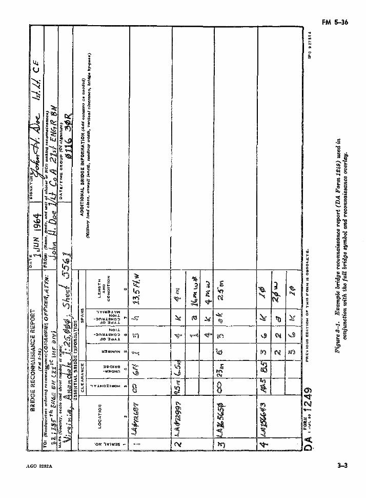
FM 5-36
oU
Qu
!si 1,9
IL~~~~~~~~~~~~~~~~~~~~~~~~~~~~~~~~~~~I
'0 o
~~~~u
19 :
1- ¡ai1- t 1 Ira
~~~~~~~~~~~~~~~e'I=·~~~~,4 ~
< ugz w
<~~lo
~ ~·· oo ezs ~,a 3-
g 'I OR~~~~~~~~~~~k) $ % sn~~~~~~~~~~~
.i 0
-3nMIENO 3 0 W 0
btetnNo 31
VA . BA Iro~~~~P ~~~P e $ uaaNn ~B~8 ~~o
.4 N~~~~~~~~~~~~~~~~~~~~~~~~~~~P
L e g O IVINOZMLOH e
AGBO 8282A 3-
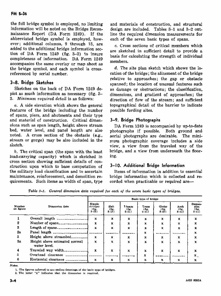
FM 5-36
the full bridge symbol is employed, no limiting and materials of construction, and structuralinformation will be noted on the Bridge Recon- design are included. Tables 3-1 and 3-2 out-naissance Report (DA Form 1249). If the line the required dimension measurements forabbreviated bridge symbol is employed, how- each of the seven basic types of spans.ever; additional columns, 9 through 13, are c. Cross sections of critical members whichadded to the additional bridge information sec- are sketched in sufficient detail to provide ation of DA Form 1249 (fig. 3-2) to insure basis for calculating the strength of individualcompleteness of information. DA Form 1249 members.accompanies the same overlay or map sheet asthe bridge symbol, and each symbol is cross- d. The site plan sketch which shows the lo-referenced by serial number. cation of the bridge; the alinement of the bridge
relative to approaches; the gap or obstacle3-8. Bridge Sketches spanned; the location of unusual features such
Sketches on the back of DA Form 1249 de- as damage or obstructions; the classification,pict as much information as necessary (fig. 3- dimensions, and gradient of approaches; the3. Minimum required detail is as follows: direction of flow of the stream; and sufficient
a. A side elevation which shows the general topographical detail of the barrier to indicatefeatures of the bridge including the number possible fording sites.of spans, piers, and abutments and their typeand material of construction. Critical dimen- 3-9. Bridge Photographssions such as span length, height above stream DA Form 1249 is accompanied by up-to-datebed, water level, and panel length are also photographs if possible. Both ground andnoted. A cross section of the obstacle (e.g., aerial photographs are desirable. The mini-stream or gorge) may be also included in the mum photographic coverage includes a sidesketch. view, a view from the traveled way of the
b. The critical span (the span with the least bridge, and a view from underneath the floor-load-carrying capacity) which is sketched in ing.cross section showing sufficient details of con-struction upon which to base computation of 3-10. Additional Bridge Informationthe military load classification and to ascertain Items of information in addition to essentialmaintenance, reinforcement, and demolition re- bridge information which is collected and re-quirements. Such items as width of span, type corded when practicable or required are-
Table 3-1. General dimension data required for each of the seven basic types of bridges.
Basic type of bridge
Simple Suspen-Number Dimension data stringer Slab T-beam Truss Girder Arch sionon figure (fig. (fg. (fig. (fig. (fig. (fig. (fig.
3-23) 3-21) 3-21) 3-31) 3-39) 3-42) 3-51)
1 Overall length ---------------- x x x x x x x2 Number of spans ______________ x x x x x x x2 Length of spans --------------- x x x x x x x2a Panel length ------------- - -------.- ------ ------- x _----- ------- x3 Height above streambed ------- x x x x x x x3a Height above estimated normal x x x x x x x
water level.4 Traveled way width ----------- x x x x x x x5 Overhead clearance ----- - ---- _-- ------- -------_ x -------- __ x6 Horizontal clearance ------ x x x x x x x
Notes.
1. The figures referred to are outline drawings of the basic type of bridges.2. The letter "x" indicates that the dimension is required.
3-4 AGO 8282A
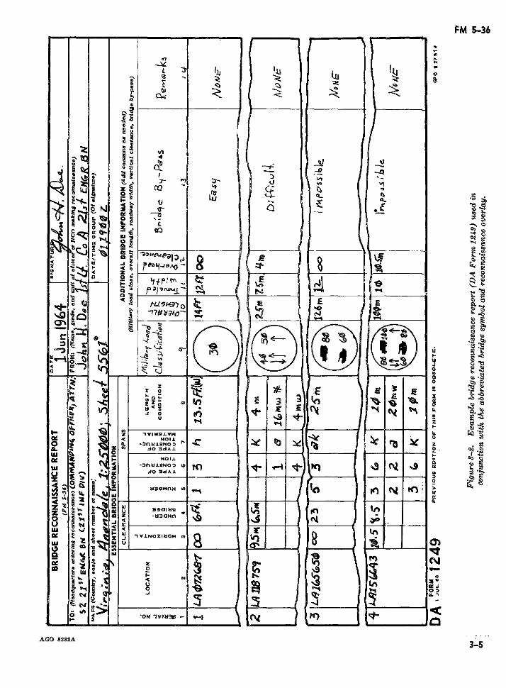
FM 5-36
tt. ~-, o D- ,
~~~~~~~~~~~~~~Q-z 4u Y
u UI~~~~~~~~~~~~~~~~~~~~~
~ S- _ , _.~_ _
~~~~~~-1ro ro x
LU c-
AG 822 3--
De Nt r ;h
d o E daiJ . a
enz -A3 ENE, s C 6<sa PCL3TIN6ZMOa 7r3A t<
"sp^ I~'N VI
AGO 8282A3-53
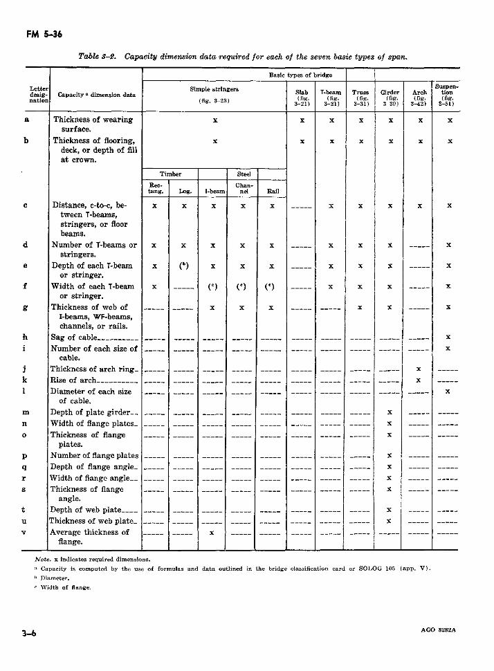
FM 5-36
Table 3-2. Capacity dimension data required for each of the seven basic types of span.
Basic types of bridge
Letter Simple stringers Sab T-be Suspen-desig- Capacity dimension data Slb T-beam Trusa Girder Arch tiondesnation (Capacityg. -dimension a (fig. ( fig. (fig. (fig. (fig- (fig.
3-21) 3-21) 3-31) 3-39) 3-42) 3-51)
a Thickness of wearing x x x x x x xsurface.
b Thickness of flooring, x x x x x x xdeck, or depth of fillat crown.
Timber Steel
Rec- Chan-tang. Log. I-beamni nel Rail
c Distance, c-to-c, be- x x x x x ----- x x x x xtween T-beams,stringers, or floorbeams.
d Number of T-beams or x x x x x ----- x x x x ----- xstringers.
e Depth of each T-beam x (b) x x- X X X ----- xor stringer.
f Width of each T-beam x ___ (C () ( C) _--_ x x x ---- xor stringer.
g Thickness of web of…----- ----- x x x ----- ----- x x ----- xI-beams, WF-beams,channels, or rails.
h Sag of cable_---__ --------- xi Number of each size of --- - ----- ---- ------ --- - ----- ----- --- x
cable.j Thickness of arch ring_ - ----- _--_ ----- ___-----_ _____- _____- ----- - x -----k Rise of arch--_-----__ __--__ ----- __ -----_ _ -----_ _ -- ----- -_- ------ x -----1 Diameter of each size ---- _ __--_ ___-- -_ ----- _ ----- _----- ----- ----- ----- x
of cable.m Depth of plate girder__ _____ __ _---- -- ____. ----- __----- ----- x .... -----n Width of flange plates_ __ __- ____-- __-__ _ ----- ----- _----- ---- x .... -----o Thickness of flange - -- ----- --- ----- ----- -----_ ----- ----- x .... ----
plates.p Number of flange plates---- _ -_---_ -__ ----- _ ----- ----- ----- ---- x .... -----q Depth of flange angle_ _____ ___._ __-__ ----- - - --- __ ----- __ ----- x .... -----r Width of flange angle-- _----- --- _ -__-- -----_ ----- ----- _---- ---- x ---- -----s Thickness of flange ----- _ ----- ---- ----- ----- ----- ____ ----- x _ _. .......
angle. it Depth of web plate____ - --- ---- ----- ----- ----- ----- xu Thickness of web plate - ----- __----- _----. ----- _--_ ----- ---- xv Average thickness of _----- _--- x ----- ----- ----- -- ---- ---
flange.
Note. x indicates required dimensions.a Capacity is computed by the use of formulas and data outlined in the bridge classification card or SOLOG 105 (app. V).b Diameter.
¢ Width of flange.
-b6 AGO 8282A
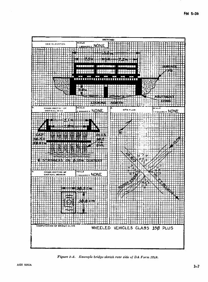
FM 5-36
SKETCHES
1DE ELEVAT^o IO NON E
r. CROSS-BECTION> OF :s C&LE I~ lcL
· · 11····· I s mRE' -NONE _
llllll-t-t-llll.ll-llllt lllUlll-T tf i .¡ 1
h CRla-~BTlCA SFt I8I=6 NONE:l ,T cA Ol
¢O,,..,~-r^-,-,o. OF .,.,.E C ,.. . .WHE:ELE~D VF~HIOLE5 CLA$5 15¢ PLUS
Figure 3-3. E xam ple bridge sketch rear side oDA Fo-m 1--9.-
AGO S2S2A 3--7
g _ ITI4TTTUTTTUJ , * I I 0~~~~~~~~~~~~1-1 4 1 N 1 l 1 -!
CRIT ICAL KEFI4 ER I SOUAR E N NON SIT IA I 3U E NO
Ctt-lidX~~~~~~~~~~~~~~~i 11iR~~~~~~~~~~~~~~~~~~-0 r
l~~~~~~~~~~~~~~~~~~~~~~~~-
-1~~~igr 5-.EanlArdg kthrarsdeo AF 29
AGO 8282A 3_7], 0
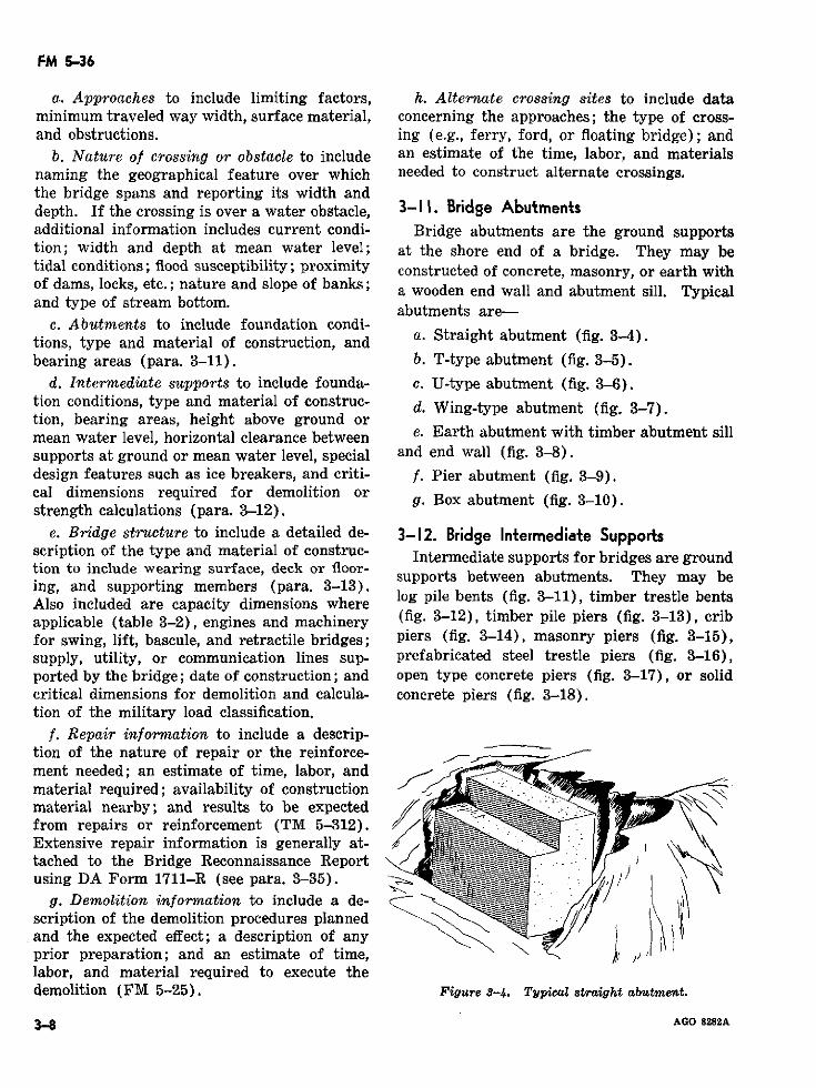
FM 5-36
a. Approaches to include limiting factors, h. Alternate crossing sites to include dataminimum traveled way width, surface material, concerning the approaches; the type of cross-and obstructions. ing (e.g., ferry, ford, or floating bridge); and
b. Nature of crossing or obstacle to include an estimate of the time, labor, and materialsnaming the geographical feature over which needed to construct alternate crossings.the bridge spans and reporting its width anddepth. If the crossing is over a water obstacle, 3-11. Bridge Abutmentsadditional information includes current condi- Bridge abutments are the ground supportstion; width and depth at mean water level; at the shore end of a bridge. They may betidal conditions; flood susceptibility; proximity constructed of concrete, masonry, or earth withof dams, locks, etc.; nature and slope of banks; a wooden end wall and abutment sill. Typicaland type of stream bottom. abutments are-
c. Abutments to include foundation condi-tions, type and material of construction, and a. Straight abutment (fig. 34).bearing areas (para. 3-11). b. T-type abutment (fig. 3-5).
d. Intermediate supports to include founda- c. U-type abutment (fig. 3-6).tion conditions, type and material of construc- d. Wing-type abutment (fig. 3-7).tion, bearing areas, height above ground ormean water level, horizontal clearance between e. Earth abutment with timber abutment sillsupports at ground or mean water level, special and end wall (fig. 3-8).design features such as ice breakers, and criti- f. Pier abutment (fig. 3-9).cal dimensions required for demolition orstrength calculations (para. 3-12).
e. Bridge structure to include a detailed de- 3-12. Bridge Intermediate Supportsscription of the type and material of construc- Intermediate supports for bridges are groundtion to include wearing surface, deck or floor- supports between abutments. They may be
supports between abutments. They may being, and supporting members (para. 3-13).Also included are capacity dimensions where log pile bents (fig. 3-11), timber trestle bentsapplicable (table 3-2), engines and machinery (fig. 3-12), timber pile piers (fig. 3-13), cribfor swing, lift, bascule, and retractile bridges; piers (fig. 3-14), masonry piers (fig. 3-15),supply, utility, or communication lines sup- prefabricated steel trestle piers (fig. 3-16),ported by the bridge; date of construction; and open type concrete piers (fig. 3-17), or solidcritical dimensions for demolition and calcula- concrete piers (fig. 3-18).tion of the military load classification.
f. Repair information to include a descrip-tion of the nature of repair or the reinforce-ment needed; an estimate of time, labor, andmaterial required; availability of constructionmaterial nearby; and results to be expectedfrom repairs or reinforcement (TM 5-312).Extensive repair information is generally at-tached to the Bridge Reconnaissance Reportusing DA Form 1711-R (see para. 3-35).
g. Demolition information to include a de-scription of the demolition procedures plannedand the expected effect; a description of anyprior preparation; and an estimate of time,labor, and material required to execute thedemolition (FM 5-25). Figure 3-4. Typical straight abutment.
3.8 AGO 8282A
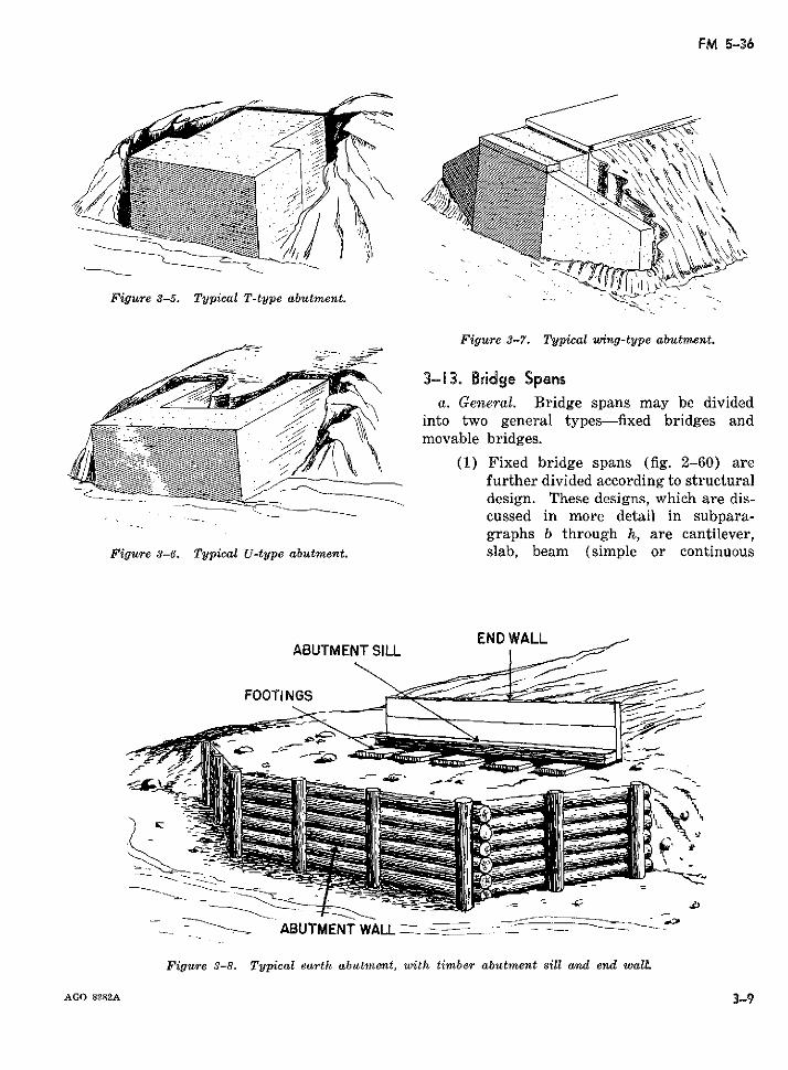
FM 5-36
Figure 3-5. Typical T-type abutment.
Figure 3-7. Typical wing-type abutment.
3-13. Bridge Spansa(. General. Bridge spans may be divided
into two general types-fixed bridges andmovable bridges.
(1) Fixed bridge spans (fig. 2-60) arefurther divided according to structuraldesign. These designs, which are dis-cussed in more detail in subpara-graphs b through h, are cantilever,
Figure 3-6. Typical U-type abutment. slab, beam (simple or continuous
ABUTMENT SILL END WALL
FOOTINGS ~ , _ -
ABUTMENT WALL : --- - --
Figure 3-8. Typical earth abutment, with timber abutment sill and end walL
AcG 82R2A 3-9
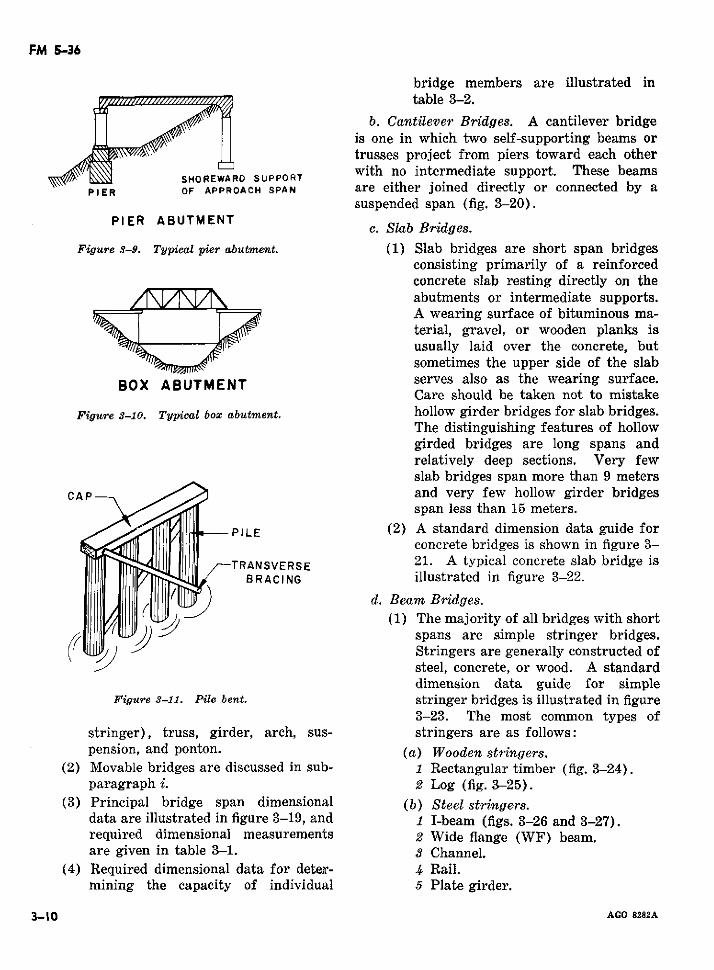
FM 5-36
bridge members are illustrated intable 3-2.
b. Cantilever Bridges. A cantilever bridgeis one in which two self-supporting beams ortrusses project from piers toward each other
SHOREWARD SUPPORT with no intermediate support. These beamsPIER OF APPROACH SPAN are either joined directly or connected by a
suspended span (fig. 3-20).PIER ABUTMENT c. Slab Bridges.
Figure 3-9. Typical pier abutment. (1) Slab bridges are short span bridgesconsisting primarily of a reinforcedconcrete slab resting directly on theabutments or intermediate supports.A wearing surface of bituminous ma-terial, gravel, or wooden planks isusually laid over the concrete, butsometimes the upper side of the slab
BOX ABUTMENT serves also as the wearing surface.Care should be taken not to mistake
Figure 3-10. Typical box abutment. hollow girder bridges for slab bridges.The distinguishing features of hollowgirded bridges are long spans andrelatively deep sections. Very fewslab bridges span more than 9 meters
CAP and very few hollow girder bridgesspan less than 15 meters.
-PILE (2) A standard dimension data guide forconcrete bridges is shown in figure 3-
TRANSVERSE 21. A typical concrete slab bridge isBRACING illustrated in figure 3-22.
d. Beam Bridges.(1) The majority of all bridges with short
spans are simple stringer bridges.Stringers are generally constructed ofsteel, concrete, or wood. A standarddimension data guide for simple
Figure 3-11. Pile bent. stringer bridges is illustrated in figure3-23. The most common types of
stringer), truss, girder, arch, sus- stringers are as follows:pension, and ponton. (a) Wooden stringers.
(2) Movable bridges are discussed in sub- 1 Rectangular timber (fig. 3-24).paragraph i. 2 Log (fig. 3-25).
(3) Principal bridge span dimensional (b) Steel stringers.data are illustrated in figure 3-19, and 1 I-beam (figs. 3-26 and 3-27).required dimensional measurements 2 Wide flange (WF) beam.are given in table 3-1. 3 Channel.
(4) Required dimensional data for deter- 4 Rail.mining the capacity of individual 5 Plate girder.
3-10 AGO 8282A
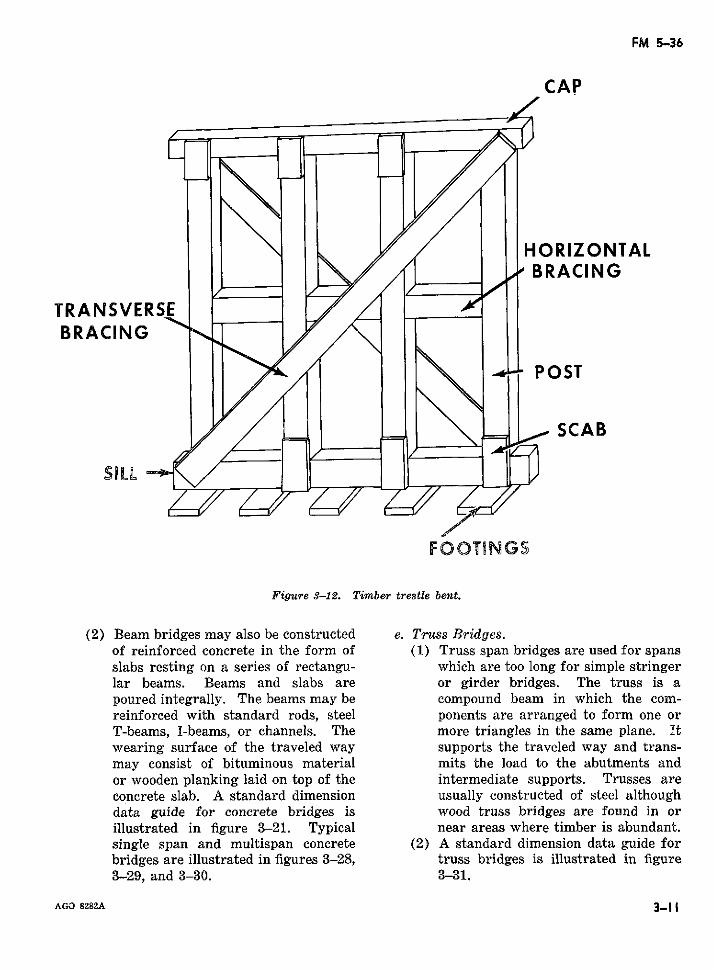
FM 5-36
CAP
HORIZONTALBRACING
TRANSVERSEBRACING
SCAB
FOOT NGS
Figure 3-12. Timber trestle bent.
(2) Beam bridges may also be constructed e. Truss Bridges.of reinforced concrete in the form of (1) Truss span bridges are used for spansslabs resting on a series of rectangu- which are too long for simple stringerlar beams. Beams and slabs are or girder bridges. The truss is apoured integrally. The beams may be compound beam in which the com-reinforced with standard rods, steel ponents are arranged to form one orT-beams, I-beams, or channels. The more triangles in the same plane. Itwearing surface of the traveled way supports the traveled way and trans-may consist of bituminous material mits the load to the abutments andor wooden planking laid on top of the intermediate supports. Trusses areconcrete slab. A standard dimension usually constructed of steel althoughdata guide for concrete bridges is wood truss bridges are found in orillustrated in figure 3-21. Typical near areas where timber is abundant.single span and multispan concrete (2) A standard dimension data guide forbridges are illustrated in figures 3-28, truss bridges is illustrated in figure3-29, and 3-30. 3-31.
AGO 8282A 3-11
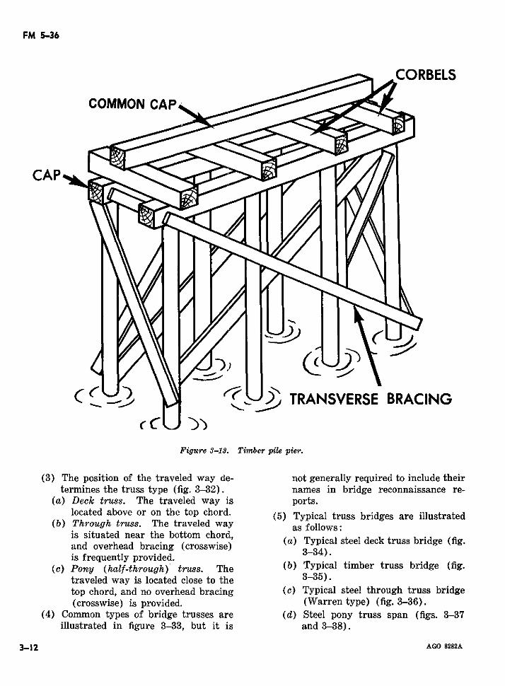
FM 5-36
CORBELS
_3' 5' TRANSVERSE BRACING
Figure 3-13. Timber pile pier.
(3) The position of the traveled way de- not generally required to include theirtermines the truss type (fig. 3-32). names in bridge reconnaissance re-
(a) Deck truss. The traveled way is ports.located abo*e or on the top chord. (5) Typical truss bridges are illustrated
(b) Through truss. The traveled way as follows:is situated near the bottom chord,is situated near the bottom chord, (a) Typical steel deck truss bridge (fig.and overhead bracing (crosswise) 334is frequently provided.
(c) Pony (half-through) truss. The (b) Typical timber truss bridge (fig.traveled way is located close to the 3-35).top chord, and no overhead bracing (c) Typical steel through truss bridge(crosswise) is provided. (Warren type) (fig. 3-36).
(4) Common types of bridge trusses are (d) Steel pony truss span (figs. 3-37illustrated in figure 3-33, but it is and 3-38).
3-12 AGO 8282A
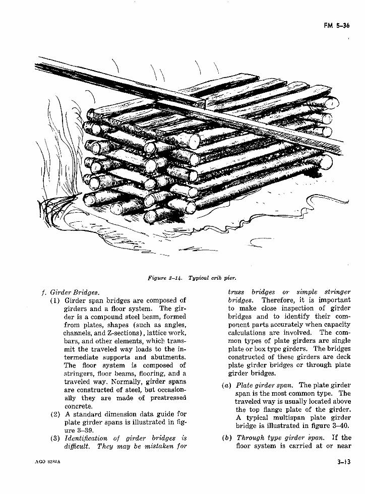
FM 5-36
Figure 3-14. Typical crib pier.
f. Girder Bridges. truss bridges or simple stringer(1) Girder span bridges are composed of bridges. Therefore, it is important
girders and a floor system. The gir- to make close inspection of girderder is a compound steel beam, formed bridges and to identify their com-from plates, shapes (such as angles, ponent parts accurately when capacitychannels, and Z-sections), lattice work, calculations are involved. The com-bars, and other elements, which trans- mon types of plate girders are singlemit the traveled way loads to the in- plate or box type girders. The bridgestermediate supports and abutments. constructed of these girders are deckThe floor system is composed of plate girder bridges or through platestringers, floor beams, flooring, and a girder bridges.traveled way. Normally, girder spanstraveled way. Normally, grder spans (a) Plate girder span. The plate girderare constructed of steel, but occasion- span is the most common type. Thespan is the most common type. Theally they are made of prestressed traveledwayis usuallylocated aboveconcrete. the top flange plate of the girder.
(2) A standard dimension data guide for A typical multispan plate girderplate girder spans is illustrated in fig- bridge is illustrated in figure 340.ure 3-39.
(3) Identification of girder bridges is (b) Through type girder span. If thedificult. They may be mistaken for floor system is carried at or near
AGO 8282A 3-13
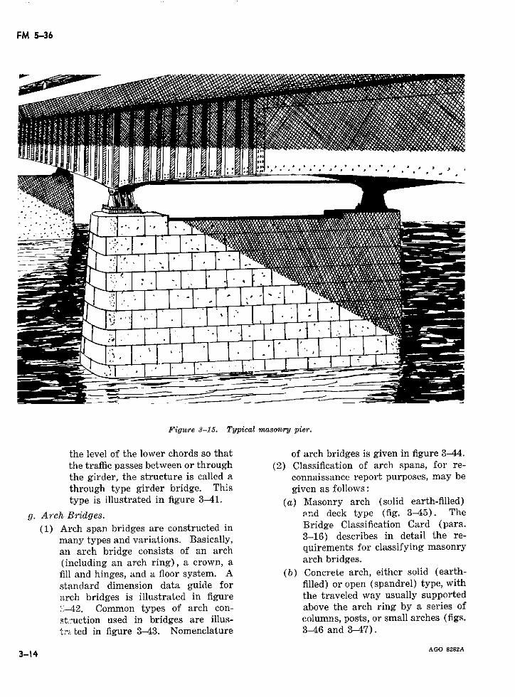
FM 5-36
·~ .- / .* .
Figure 3-15. Typical masonry pier.
the level of the lower chords so that of arch bridges is given in figure 3-44.the traffic passes between or through (2) Classification of arch spans, for re-the girder, the structure is called a connaissance report purposes, may bethrough type girder bridge. This given as follows:
type is illustrated in figure 3-41. (a) Masonry arch (solid earth-filled)
g. Arch Bridges. and deck type (fig. 3-45). The
(1) Arch span bridges are constructed in Bridge Classification Card (para.
many types and variations. Basically, 3-16) describes in detail the re-
an arch bridge consists of an arch quirements for classifying masonry
(including an arch ring), a crown, a arch bridges.fill and hinges, and a floor system. A (b) Concrete arch, either solid (earth-
standard dimension data guide for filled) or open (spandrel) type, with
arch bridges is illustrated in figure the traveled way usually supported
;-42. Common types of arch con- above the arch ring by a series of
st.-uction used in bridges are illus- columns, posts, or small arches (figs.
tr: ted in figure 3-43. Nomenclature 3-46 and 3-47).
3-14 AGO 8282A3-14
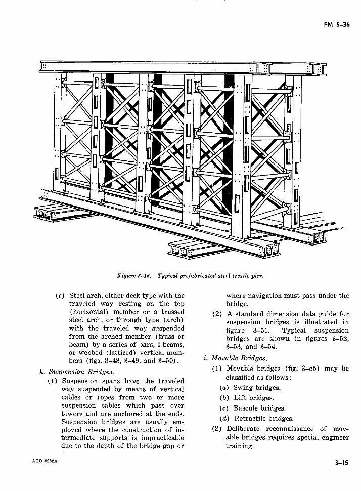
FM 5-36
'Pi.
Figure 3-16. Typical prefabricated steel trestle pier.
(c) Steel arch, either deck type with the where navigation must pass under thetraveled way resting on the top bridge.(horizontal) member or a trussed (2) A standard dimension data guide forsteel arch, or through type (arch) suspension bridges is illustrated inwith the traveled way suspended figure 3-51. Typical suspensionfrom the arched member (truss or bridges are shown in figures 3-52,beam) by a series of bars, I-beams, 3-53, and 3-54.or webbed (latticed) vertical mem-bers (figs. 3-48, 3-49, and 3-50). i. Movable Bridges.
h. Suspension Bridge,,. (1) Movable bridges (fig. 3-55) may be
(1) Suspension spans have the traveled classified as follows:way suspended by means of vertical (a) Swing bridges.cables or ropes from two or more (b) Lift bridges.suspension cables which pass over (c) Bascule bridges.towers and are anchored at the ends.Suspension bridges are usually em-ployed where the construction of in- (2) Deliberate reconnaissance of mov-termediate supports is impracticable able bridges requires special engineerdue to the depth of the bridge gap or training.
AGO 8282A 3-15
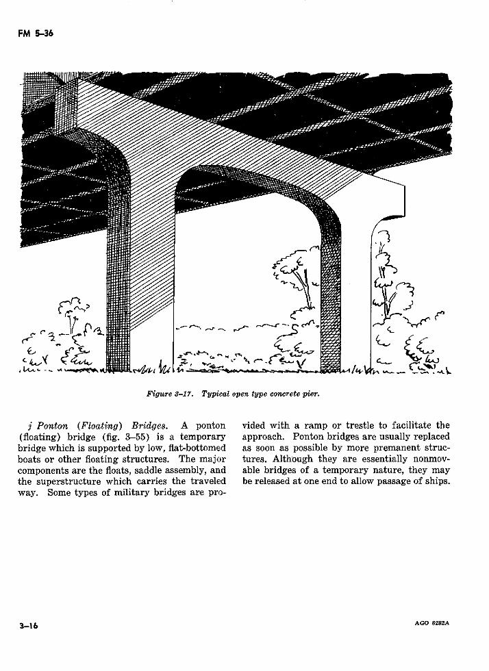
FM 5-36
,* -- - _e \" --/_..
Ij
Figure 3-17. Typical open type concrete pier.
j Ponton (Floating) Bridges. A ponton vided with a ramp or trestle to facilitate the(floating) bridge (fig. 3-55) is a temporary approach. Ponton bridges are usually replacedbridge which is supported by low, flat-bottomed as soon as possible by more premanent struc-boats or other floating structures. The major tures. Although they are essentially nonmov-components are the floats, saddle assembly, and able bridges of a temporary nature, they maythe superstructure which carries the traveled be released at one end to allow passage of ships.way. Some types of military bridges are pro-
3-16 AGO 8282A

FM 5-36
Figure 3-18. Typical solid concrete pier.
AGO 8282A 3-17
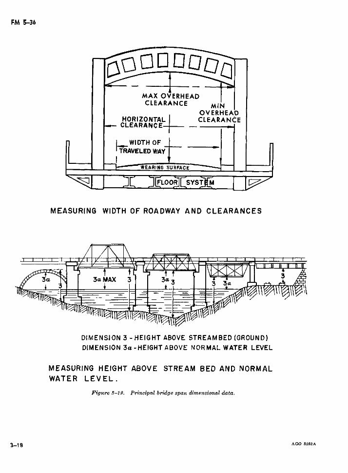
FM 5-36
MAX OVERHEADCLEARANCE MIN
OVERHEADHORIZONTAL CLEARANCECLEARANCE--
._WIDTH OF'TRAVELED WAY
MI _ DC ERLOOADWASYSTCM L
MEASURING WIDTH OF ROADWAY AND CLEARANCES
3cz~ I 3aMAX 3 I 3I I3
DIMENSION 3 -HEIGHT ABOVE STREAMBED (GROUND)DIMENSION 3a - HEIGHT ABOVE NORMAL WATER LEVEL
MEASURING HEIGHT ABOVE STREAM BED AND NORMALWATER LEVEL.
Figure 3-19. Principal bridge span dimensional data.
3-18 AGO 8282A
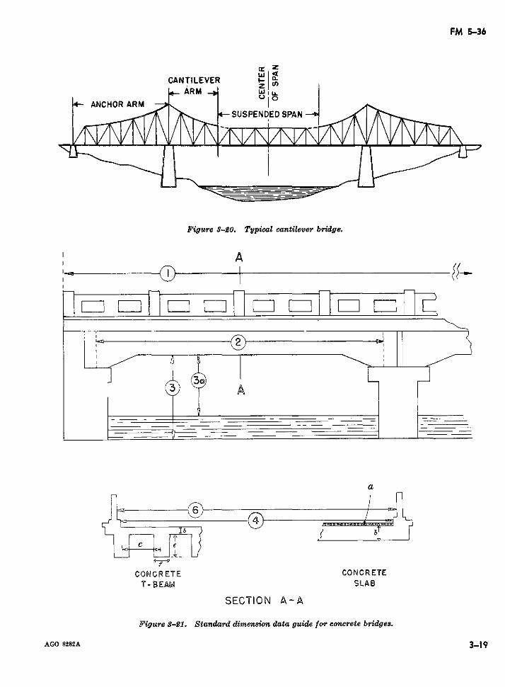
FM 5-36
CANTILEVER FARM Wlu.
- ANCHOR ARM K .SUSPENDED SPAN
I 1
Figure 3-20. Typical cantilever bridge.
A
SECTION A-A
Figure 3-21. Standard dimension data guide for concrete bridges.
AGO 8282A 3-19
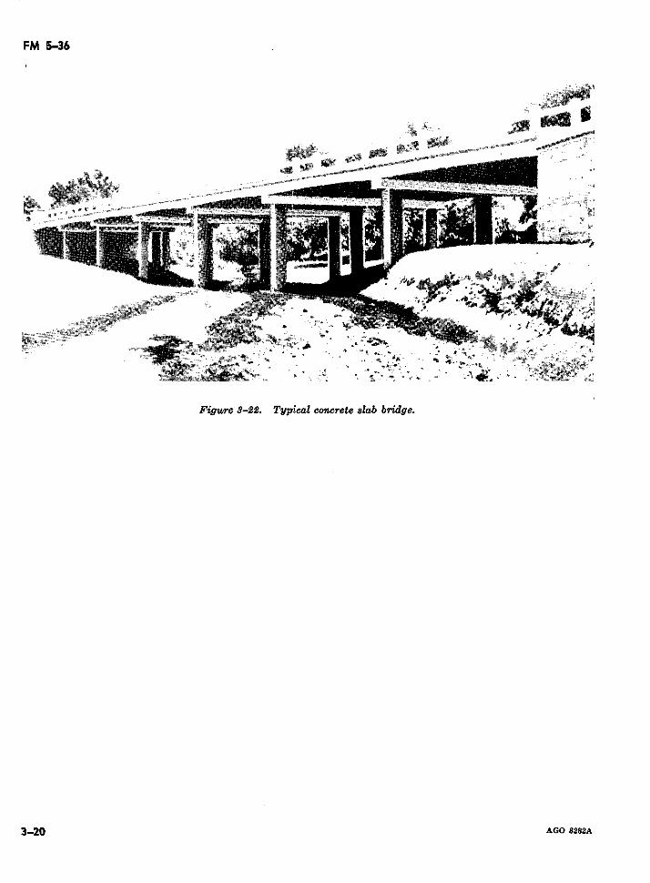
FM 5-36
4*
'~li-
Figure 3-22. Typical concrete slab bridge.
3-20 AGO 8282A
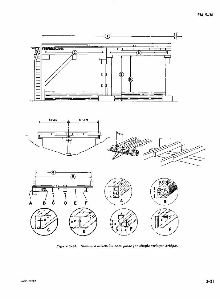
FM 5-36
SPAN , SPAN
i I 'DI
A 8 D E F
Figure 3-23. Standard dimension data guide for simple stringer bridges.
AGO 8282A 3-21
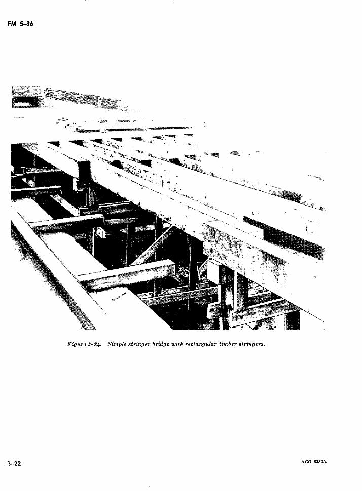
FM 5-36
;:-~~~~~~l
a _ _ _ __ __
It~O
B.. -..........
Figure 3-24. Simple stringer bridge zwith rectangular timber stringers.
3-22 AGO 8282A
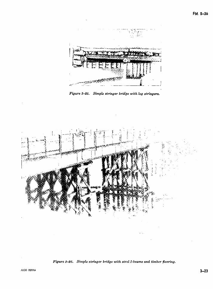
FM 5-36
Figure 3-25. Simple stringer bridge with log stringers.
:461 -" 1jioi:
Figure 8-26. Simple stringer bridge with steel I-beams and timber flooring.
AGO 8282A 3-23
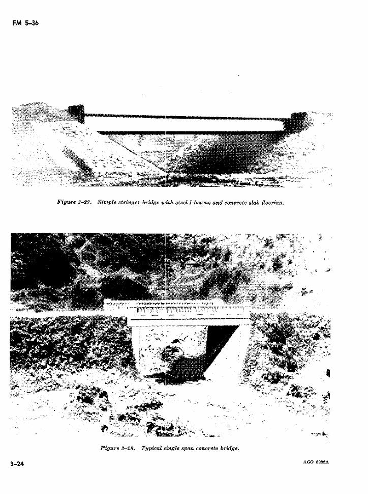
FM 5-36
F'igure 3-27. Simple stringer bridge with steel l-beams and concrete slab fl ooring.
..... . _ _ ~ ~- g q
o · """"`·~~~~ ~~··Q *-.a s2s
j ---
F~gue 8-7. Figure 3-28.ge Typical 8ing spelI~an s concrt bridge.esa poi
3-24 AGO 8282A~~~~~~~~~~~~.:
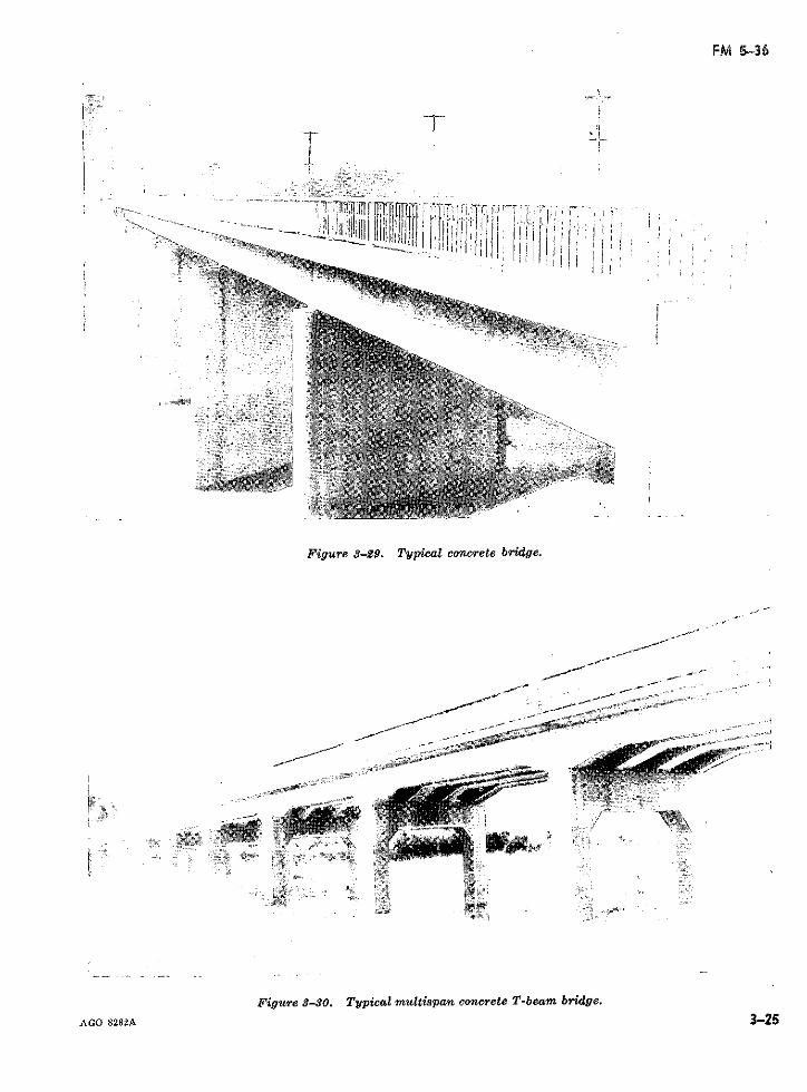
FM 5-36
T !r
Figure 3-29. Typical concrete bridge.
Figu gure -30 29. Typical concrete bri dge.
AGO 8282A 3-25
_,·;~~~~~~~~~~~~~~~~~~~~~~ ~ ~ ~ ~ -_-
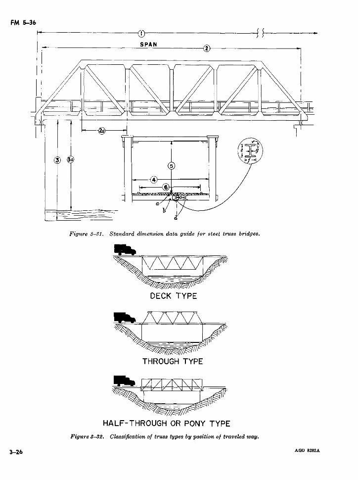
FM 5-36
SPAN
al"
Figure 3-31. Standard dimension data guide for steel truss bridges.
DECK TYPE
THROUGH TYPE
HALF-THROUGH OR PONY TYPE
Figure 3-32. Classification of truss types by position of traveled way.
3-26 AGO 8282A
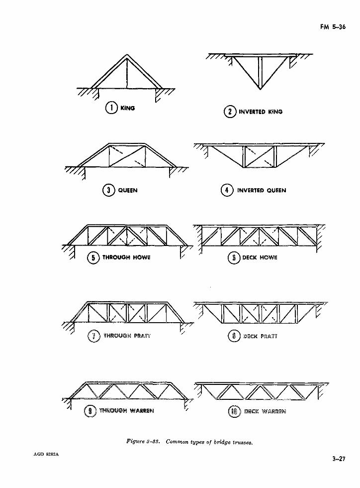
FM 5-36
ING O INVERTED KIN
K-79QUEEN INVERTED QUEEN
THROUGH HOWE/ DECK HOWE
Q THROUGH PRAT7 DECK PRA7T
THROUGH WARRIEN E BCK W©ARMI N
Figure 3-33. Common types of bridge trusses.
AGO 8282A 3-273-27r
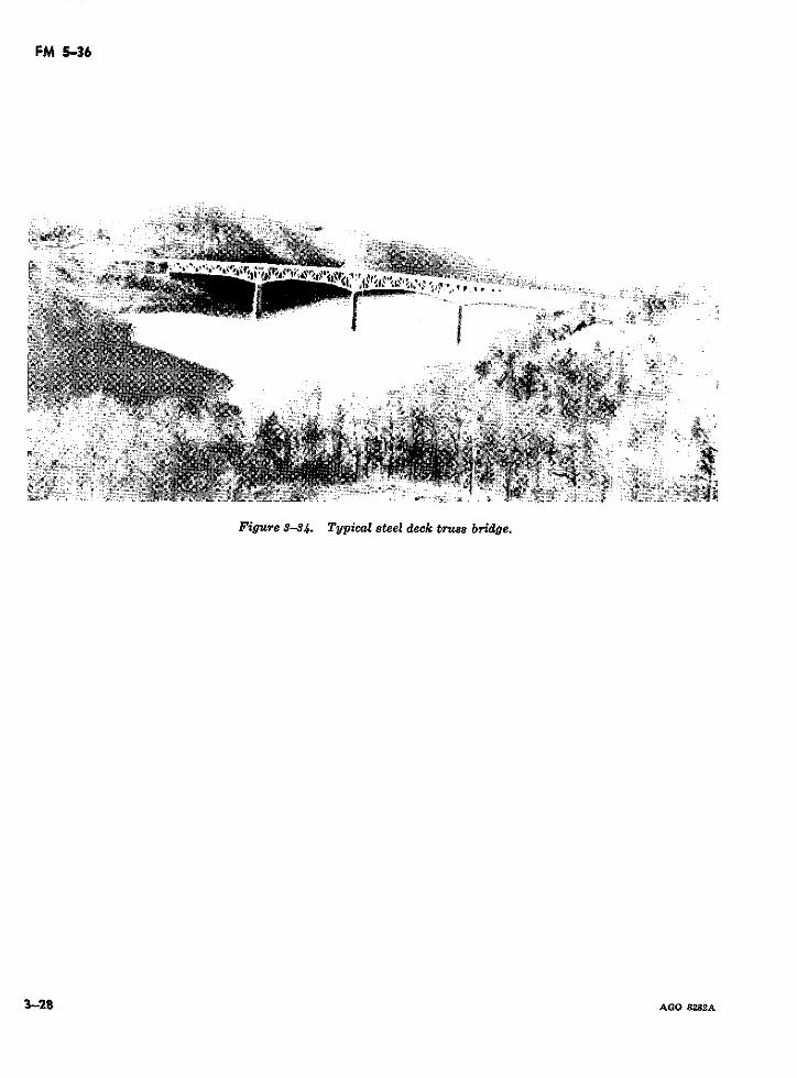
FM 5-36
Figure 3-34. Typical steel deck truss bridge.
3-28 AGO 8282A
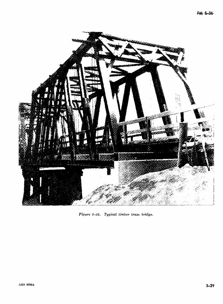
Figure 3-35. Typical timber truss bridge.
AGO 8282A 3-29
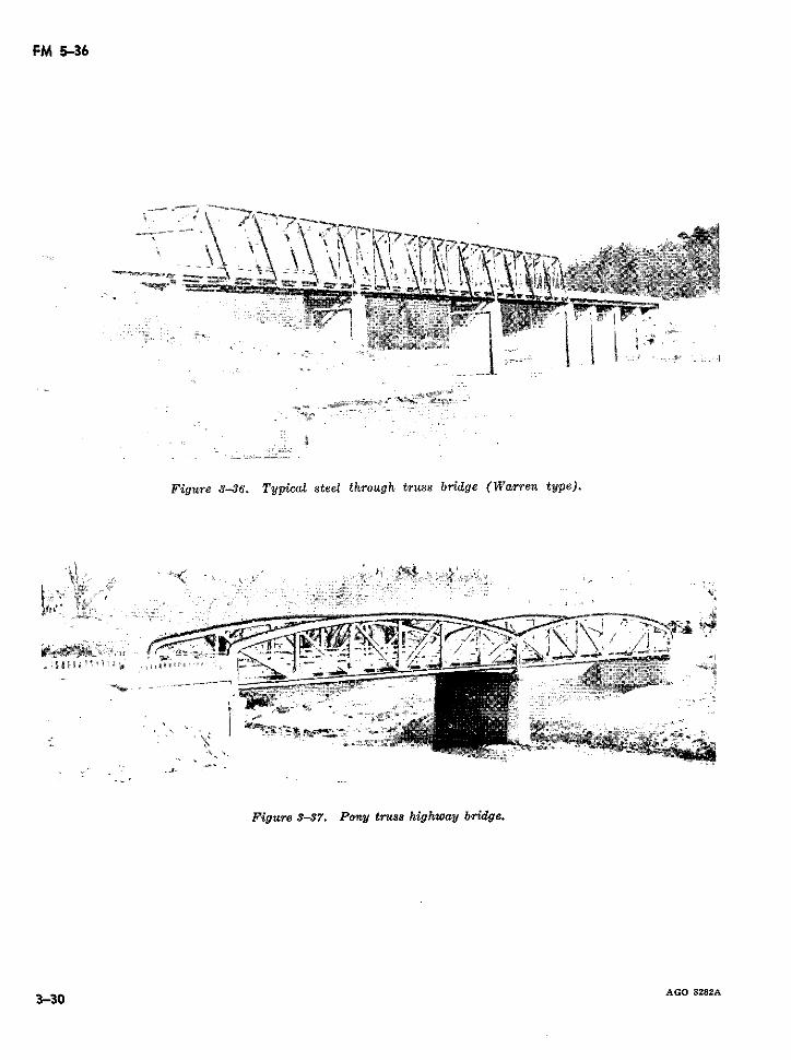
FM 5-36
-7 ~
Figure 3-37. Pony truss ,w bg.
3-30 -:· - 828 E, U; Q .
, ,~~~~~~~~~~~~~~~~~~~~~·
Figure 3-36. Tydpical steel through truss bridge (Warren type).
t VJá A--& 0 As Ajá 00 $ 0 s,~~~~~~~~~~~~~u
'~~~~~~~~~~~~~~~~- "$ '·
- 1 = ü } _0 Ji;;&t
Figure S-37. Pony tr-ues highway bridge.
3 30 ~~~~~~~~~~~~~~~~~~~~~~AGO 8282A
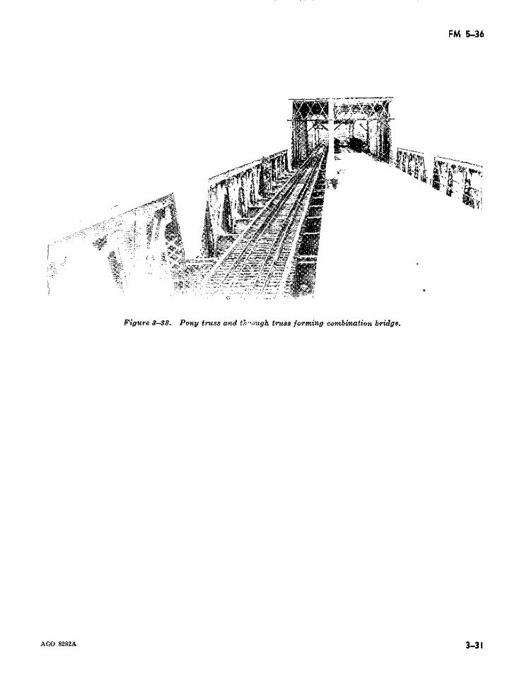
FM 5-36
Figure 3-38. Pony truss amnd trough truss forming combination bridge.
AGO 8282A 3-313-31
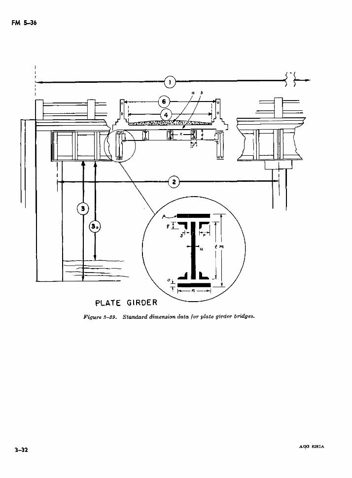
FM 5-36
= 01G
PLATE GIRDER
Figure 3-39. Standard dimension data for plate girder bridges.
3-32 AqO 8282A
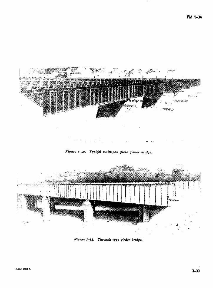
FM 5-36
Figure 3-40. Typical multispan plate girder bridge.
(~~~~~~~~~1 1
Figure 3-41. Through type girder bridge.
AGO 8282A 3333-33
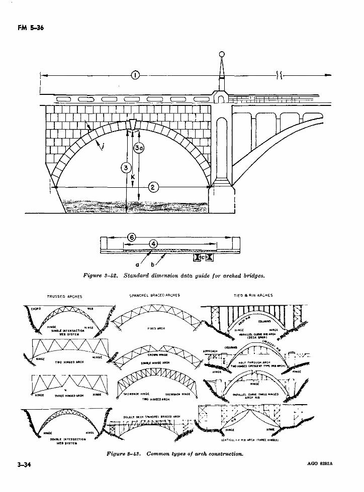
FM 536
, a ~III I1 ]
a b
Figure 3-42. Standard dimension data guide for arched bridges.
TRUSSED ARCHES SPANDREL BRACED ARCHES TIED 8 RIB ARCHES
SIH8E! ERSECTO l.IXED ARICH I [IN E NG1E
WE SYSTEN aRALLEL CM R
Figure $-43I. CommoD tlpes o arch constlctCn.
~~~~~~3-34*~~ A 8282Ac~TO 8INARC °C I
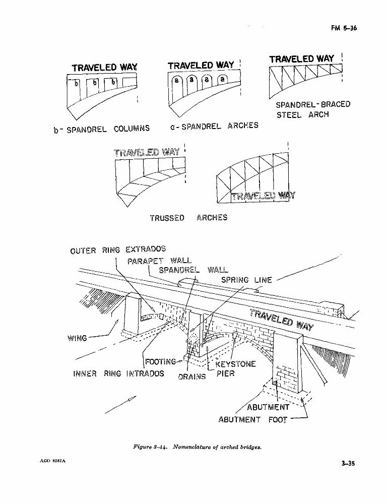
FM 5-36
TRAVELED WAY TRAVELED WAY' TRAVELEDWAY
SPANDREL- BRACEDSTEEL ARCH
b° SPANDREL COLUMNS Q-SPANDREL ARCHES
TRAELED WAY '
TRUSSED ARCHES
OUTER RING EXTRADOSPARAPET WALL
'=:A l SPANDREL WALL-_~ -~-~-- ~ "- - ~SPRING LINE
WING
FOQTING-$~~ -EYSTONE
INNER RING INTRADOS gRAINS PIER
ABUTMENT
ABUTMENT FOOT
Figure 3-44. Nomenclature of arched bridges.
AGO 8282A 3353-35
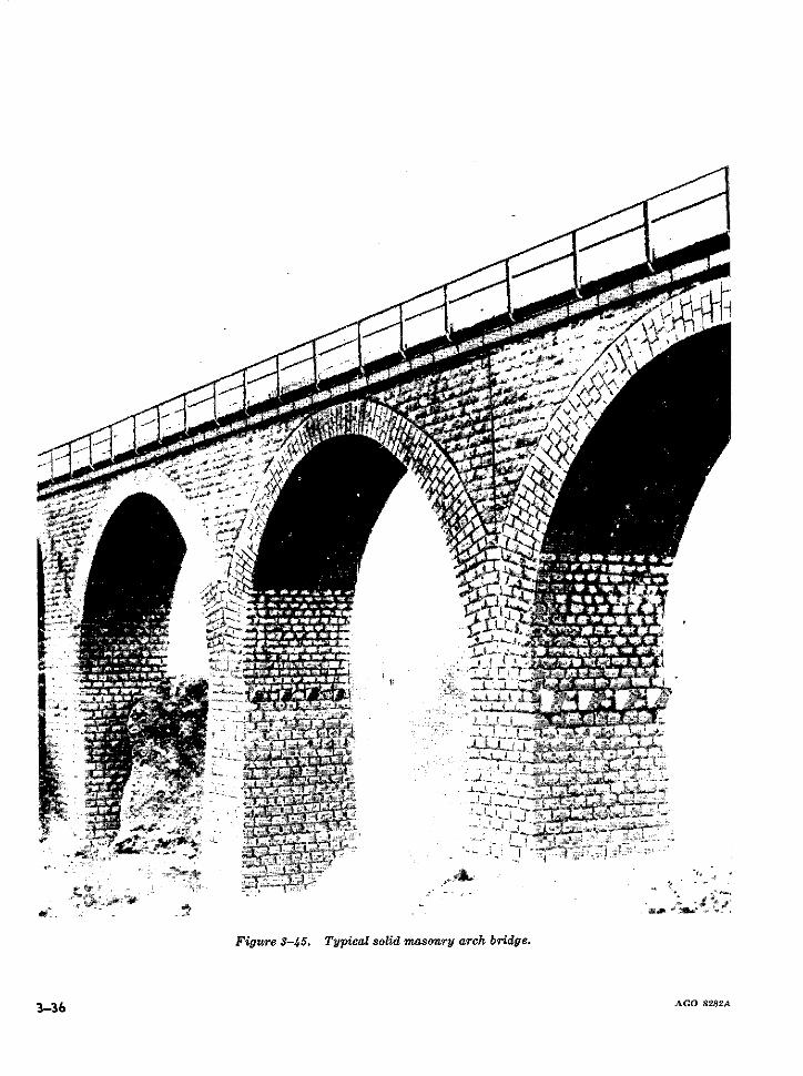
aprjL-i
Ja
-rprrr'
f-i "!·(
f ·· -;·-·- _,i-..
.��x�*
,i*·i"-:;·-
.o�pi· )
^<I · · ·,,'ri!t:,,
�-pi<- i`C:·*ez ·:
·- 7
�js*·9
II�i�:·,g��,*;
i J" Ir:I
-sA., erie-PB, Soa.I"-xii- ·· -L(ltl
.* - .-·
!; l�l-i �·' I
s -t-�J·.
r"* --i·-r
-`~*---i.
1-·:`u P (
s is ii· 5·�; _�,
i ts
fi , i
žI .�P"·- �i"-i·l II r-·%·,�·�s
FigureS-/Ci. Typicalsolidmason?-yarch. bridge.
3-36 AGO 8282A
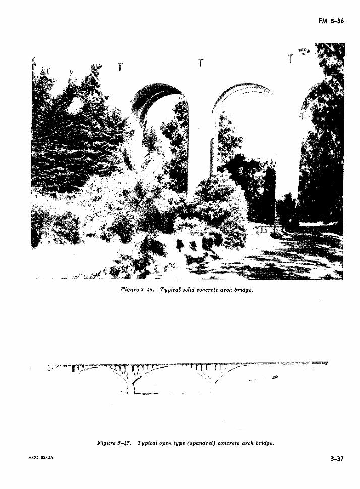
FM 5-36
~~~~~~~--a ! ~ ~ ~ ~ ~ ~V-
Figure 8-47. Typical open type (spandrel) concrete arch bridge.
AGO 8282A 3-37
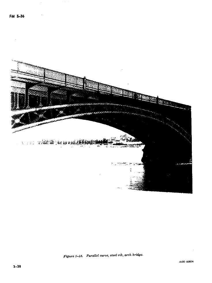
FM 5-36
Figure 3-48. Para*lel curve, steel rb, arch bridge.
AGO 8282A4
3-38
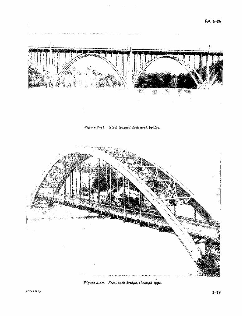
FM 5-36
Figure 3-49. Steel trussed deck arch bridge.
Figure 3-50. Steel arch bridge, through type.
AGO 8282A 3-39
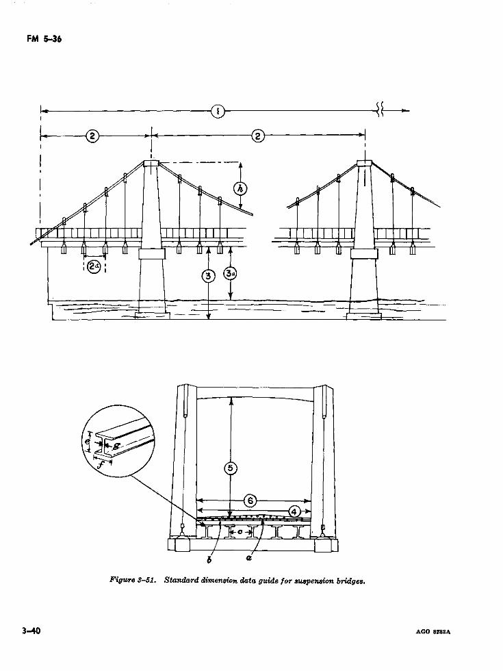
FM 5-36
~~F·~1 S i1 I l 1 1J3 Ja
& cZ
Figure -51J. Standard dimension data guide for suspenion bridges.
3-40 AGO 8282A
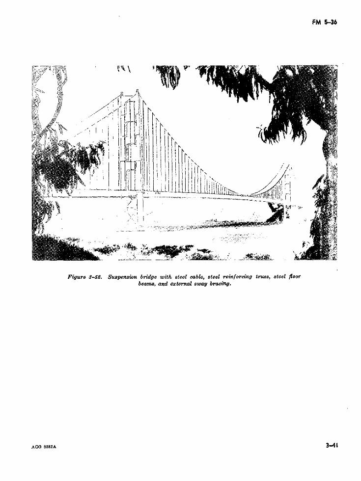
FM 5-36
fi9 4\\ 1>'f
Figure 3-52. Suspension bridge with steel cable, steel reinforcing truss, steel floorbeams, and external sway bracing.
AGO 8282A 3-41
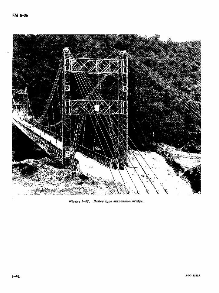
FM 5-36
Figure 3-58. Bailey type suspension bridge.
3-42 AGO 8282A
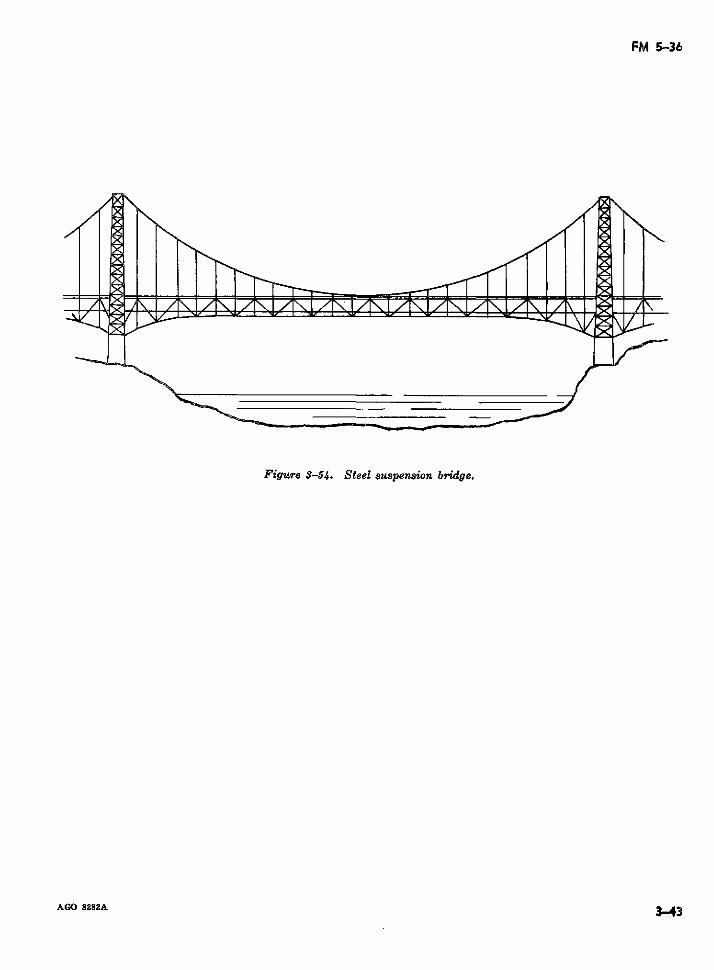
FM 5-36
Figure 3-5a. Steel suspension bridge.
AGO 8282A 3.-43
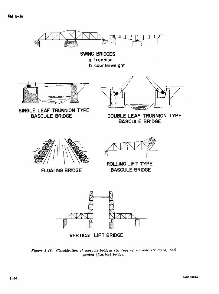
FM 5-36
SWING BRIDGESa. trunnionb. counterweight
SINGLE LEAF TRUNNION TYPEBASCULE BRIDGE DOUBLE LEAF TRUNNION TYPE
BASCULE BRIDGE
ROLLING LIFT TYPEFLOATING BRIDGE BASCULE BRIDGE
VERTICAL LIFT BRIDGE
Figure 3-55. Classification of movable bridges (by type of movable structure) andponton (floating) bridge.
3. 44 AGO 8282A
C 1, FM 5-36
Section III. BRIDGE MILITARY LOAD CLASSIFICATION
3-14. General bers are taken as previously outlined ina. A mobile army must make maximum use tables 3-1 and 3-2.
of existing bridges; but before any existing bridge (3) The span length. Span length is measuredcan be used to capacity, it requires classification from center to center of supports. Thein terms of the bridge and vehicle military load classification of the bridge is usually basedclassification system which has been adopted by on the weakest span; and if the weakestthe U.S. and allied nations. The classification span is readily apparent, no other spansof each bridge is posted to prevent overloading need be investigated. However, if thewhich may cause failure and, thereby, hamper weakest span is difficult or impossible tofuture operations. To classify bridges various meth- locate by visual observation, all spansods are available; however, this manual limits dis- require classification. Even if severalcussion to only one of these methods-GTA 5-35, spans appear identical, actual measure-The Bridge Classification Card (para 3-16). ments are taken to prevent error.
b. In the United States, load capacities and (4) The width of the traveled way. Thevehicle dimension restrictions are normally regu- traveled way width is the measured dis-lated and posted by individual state and county tance between the inside faces of the curbs.governments. Where bridges in foreign areas are (5) General condition. It is essential to notenot posted, it is sometimes possible to ascertain the general condition of the bridge pay-bridge dimensions and capacities by consulting ing particular attention to evidences oflocal civil authorities or military intelligence agen- damage from natural causes (rot, etc.) orcies. In many cases, however, data is not available, enemy action. Classification proceduresand the bridge on a route will require computation presume that a bridge is in good condition.of their respective military load classifications. If the bridge is in poor condition, the
classification obtained from mathematicalc. Bridge classification is basically the reverse
computations requires appropriate reduc-of design procedure. In designing a bridge, the tion in accordnce with the classifier'sdesired classification is established, and the re-quired quantity and size of individual bridge mem- Judgment.bers are calculated. In classifying a bridge, however, 3-16. Bridge Classification Cardthe members are already present; their dimensions
a. The Bridge Classification Card (GTA 5-35)need only be recorded and strength characteristics
considered to compute the load capacity. provides a rapid means of classifying bridges. Itutilizes a partially graphic method together with
3-15. Classification Factors several approximations to simplify procedures. Thecard outlines the procedures for determining thea. Before the classification of a bridge can beclassification of simple deck type, masonry arch,determined, observations and measurements which concrete T-beam, concrete slab, and truss typeinfluence the classification of the bridge are noted conrete T-beam, conrete slab, and truss type
as follows:(1) The number of members. In many cases b. A deck type bridge is one in which the traveled
the stringer is the critical member of the way is supported on or near the line of top mem-bridge. However, a check of the capacity bers with little more than a handrail system atof the posts must be made as outlined the sides.in the Bridge Classification Card. There- (1) Deck type bridges are usually classifiedfore, all load carrying members of the by investigation of the superstructurebridge are included in the reconnaissance only, as a balanced design in the sub-data. structure is generally assumed.
(2) Size of members. Exact and complete di- (2) For simplicity, the superstructure is di-mensions pertinent to specific bridge mem- vided into three categories: the curb and
TAGO 6929A 3.45
C 1, FM 5-36
handrail system, the flooring system, and safe to assume that the deck has beenthe stringer system. designed to give adequate load re-
(a) The curb and handrail system acts only sistance.as a guide for vehicles crossing the (c) The stringer system is classified usingbridge. It has no structural role, and the charts and procedural outline givenneeds only to be sufficiently adequate in the bridge classification card.to meet safety requirements.
(b) Timber flooring systems are checked by 3-17. Other Classification Methodsthe rule of thumb given in paragraph The Bridge Classification Card is based on manyE of thé Bridge Card. If the flooring assumptions in arriving at a specific military loaddoes not meet the specified criteria or if classification. This method is an expedient meansmembers are damaged, reinforcement or for rapidly estimating the military load classifica-repair is necessary prior to final classifi- tions of simple structure bridges under field con-cation. An analysis of a concrete slab ditions. When time and qualified personnel arefloor is virtually impossible without con- available to provide a more detailed analysis orstruction details pertaining to the rein- the bridge is of complicated design, more preciseforcing steel. However, it is usually methods are employed (TM 5-312).
Section IV. VEHICLE MILITARY LOAD CLASSIFICATION (STANAG2021, SEASTAG 2021, and SOLOG 45R)
3-18. General the using unit verifies as soon as possible the tem-
a. The basis of the vehicle military load classi- porary classification.fication system is the effect a vehicle has on a 3-19. Data Required for Vehilebridge while crossing. The effect is the result of Classificationa combination of factors which includes the grossweight of the vehicle; the distribution of this weight; a. The data required for mathematical com-the outside-to-outside width of tires or tracks; tire putation of a vehicle's classification are shown insize and air pressure; the speed at which the vehicle figures IV-1 through IV-7 (app IV).crosses the bridge; and the resulting impact on the b. Often, some of the necessary data for vehiclebridge. EHeavy loads common to military equip- classification may be obtained from the vehiclement, such as artillery and tanks, make vehicle weight and dimension card (STANAG 2163) whichclassification an extremely important factor in de- is displayed by vehicles during their transporttermining the suitability of a given route. Classi- (fig. 3-57).fication is applicable not only to individual wheeledvehicles but also to track-laying vehicles, towed 3-20. Assignment of Classificationvehicles, and vehicles being moved by transporter.In order to compute the total classification of some a. Military vehicles are described as wheeled or
*of these combinations, eac. component tracked. For classification purposes, military vehi-of these combin ations, each component requiresre'euaures acles are further divided into two categories: singleseparate evaluation.
vehicles and combination vehicles.b. A list of standard vehicles, their weights, and (1) A single vehicle is any military vehicle
classifications are given in appendix IV. Tempo- which has only one frame or one chassis.rary classification under emergency conditions may Examples are prime movers, tanks, fullbe made by comparing the axle loads, gross weight, trailers, and gun carriages (fig. 2-52).and dimensions of the unclassified vehicle with (2) A standard combination vehicle is a mili-those of a similar classified vehicle. A temporary tary vehicle consisting of two or moreclassification thus derived may be used, however, single vehicles which are connected to-
3-46 TAGO 6929A
C 1, FM 5-36
gether and operate as one unit. Examples 3-22. Field Procedure for Computation ofare prime movers with semitrailers and Vehicle Classificationtrucks towing trailers or gun carriages (fig. I sometimes becomes necessary to classify a2-53). A nonstandard combination is, for vehicle under field conditions. If time does not per-example, a single vehicle towing another- mit an accurate mathematical computation of thevehicle at a distance less than 30.5 meters military load classification, the following pro-(fig. 2-56). cedures for wheeled and tracked vehicles may be
used to estimate a vehicle's classification:b. Classification numbers are assigned to all vehi used to estmate a vehcle's classification:cles in military use which have a gross weight a. Wheeled Vehicles. The axle loads and spac-exceeding 3 tons and to all trailers which have a ings for the wheeled hypothetical vehicles uponrated payload exceeding 1½/2 tons. Baggage and which the vehicle classification system is based
(TM 5-312), represent typical military vehiclesother pole-type trailers with a rated capacity of1/2 ton or ess w normay be combed th of the United States and allied nations. Therefore,
any expedient rules which apply to the hypotheticaltheir towing vehicles for classification purposes vehicles als apply to a majority of actual militaryvehicles also apply to a majority of actual militaryalthough optional classification numnbers may be vehicles. The classification of wheeled hypotheticalassigned. vehicles is approximately equal to 85 percent of the
c. Temporary classification numbers may be as- gross weight. The initial task, then, is to deter-signed under special conditions (see para 2-53c mine the vehicle's gross weight. If the air pressureand d). in the tires (in pounds per square inch) is known,
it is multiplied by the total area in square inches3-21. Mathematical Procedure for Vehice of the tires in contact with the ground. This yields
Classification (STANAG, SEASTAG the approximate weight of the vehicle in pounds2021 and SOLOG 45R) which is then converted to tons. The expedient
classification for the wheeled vehicle will be 85The mathematical computation of a vehicle's percent of its weight in tons. If no gage is avail-
military load classification is beyond the capability able for measuring tire pressure, 75 psi may beof route reconnaissance teams. If a requirement selected as an average value. For vehicles havingto determine a vehicle's classification exists, recon- unusual load characteristics or odd axle spacings,naissance personnel supply higher headquarters a more deliberate vehicle classification procedure,with the dimensional characteristics of the vehicle as outlined in STANAG 2021, is required.in question (para 3-20), and request computation b. Tracked Vehicles. The procedure for classi-of the military and classification number (see TM fying tracked vehicles in the field is similar to5-312). the procedure for wheeled vehicles. Two
TAGO 6929A 3-47
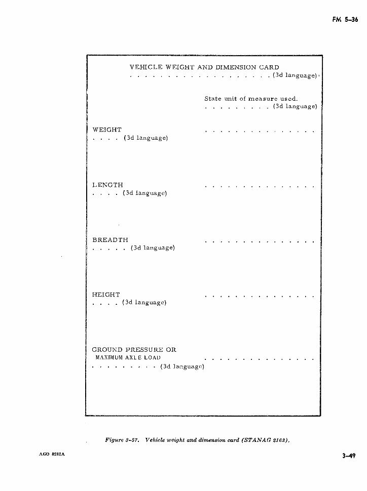
FM 5-36
VEHICLE WEIGHT AND DIMENSION CARD................... .(3d language)
State unit of measure used.......... .(3d language)
WEIGHT... . (3d language)
LENGTH. . . . (3d language)
BREADTH. .... (3d language)
HEIGHT... . (3d language)
GROUND PRESSURE ORMAXIMUM AXLE LOAD . . . . . . . . . . . . . . .
. ....... . (3d language)
Figure 3-57. Vehicle weight and dimension card (STANAG 2163).
AGO 8282A 3493-49
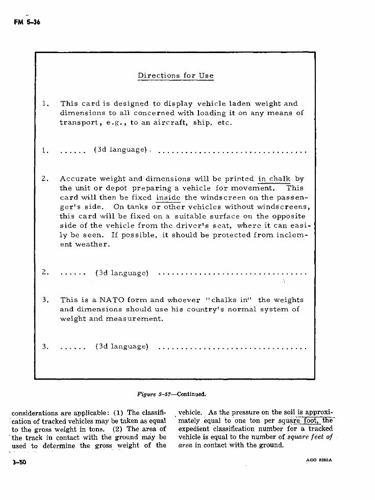
FM 5-36
Directions for Use
1. This card is designed to display vehicle laden weight anddimensions to all concerned with loading it on any means oftransport, e.g., to an aircraft, ship, etc.
1. ...... (3d language) .................................
2. Accurate weight and dimensions will be printed in chalk bythe unit or depot preparing a vehicle for movement. Thiscard will then be fixed inside the windscreen on the passen-ger's side. On tanks or other vehicles without windscreens,this card will be fixed on a suitable surface on the oppositeside of the vehicle from the driver's seat, where it can easi-ly be seen. If possible, it should be protected from inclem-ent weather.
2. ...... (3d language) ............. ....................
3. This is a NATO form and whoever "chalks in" the weightsand dimensions should use his country's normal system ofweight and measurement.
3. ...... (3d language) ................................
Figure 3-57-Continued.
considerations are applicable: (1) The classifi- vehicle. As the pressure on the soil is approxi-cation of tracked vehicles may be taken as equal mately equal to one ton per square o theto the gross weight in tons. (2) The area of expedient classification number for a tracked
'the track in contact with the ground may be vehicle is equal to the number of square feet ofused to determine the gross weight of the area in contact with the ground.
3-50 AGO 8282A
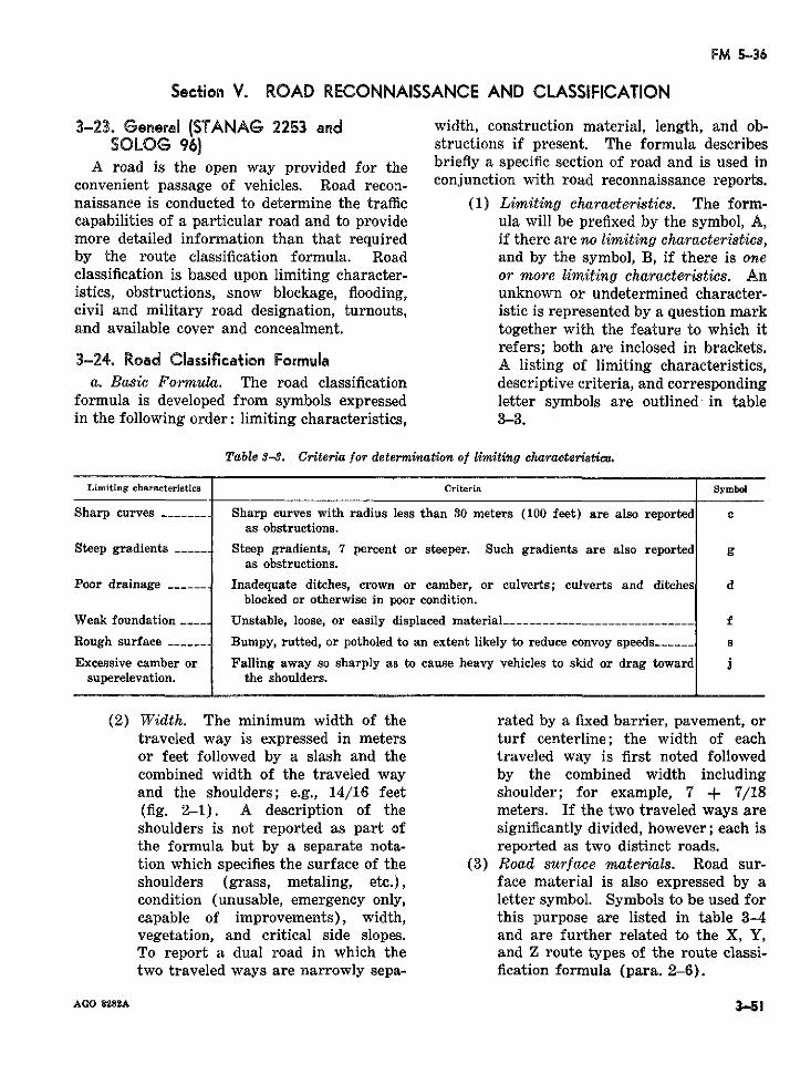
FM 5-36
Section V. ROAD RECONNAISSANCE AND CLASSIFICATION
3-23. General (STANAG 2253 and width, construction material, length, and ob-SOLOG 96) structions if present. The formula describes
A road is the open way provided for the briefly a specific section of road and is used inconvenient passage of vehicles. Road recon- conjunction with road reconnaissance reports.naissance is conducted to determine the traffic (1) Limiting characteristics. The form-capabilities of a particular road and to provide ula will be prefixed by the symbol, A,more detailed information than that required if there are no limiting characteristics,by the route classification formula. Road and by the symbol, B, if there is oneclassification is based upon limiting character- or more limiting characteristics. Anistics, obstructions, snow blockage, flooding, unknown or undetermined character-civil and military road designation, turnouts, istic is represented by a question markand available cover and concealment. together with the feature to which it
refers; both are inclosed in brackets.:3-24. Road Classification Formula A listing of limiting characteristics,
a. Basic Formula. The road classification descriptive criteria, and correspondingformula is developed from symbols expressed letter symbols are outlined in tablein the following order: limiting characteristics, 3-3.
Table 3-3. Criteria for determination of limitihg charaoteristics.
Limiting characteristics Criteria Symbol
Sharp curves ------- Sharp curves with radius less than 30 meters (100 feet) are also reported cas obstructions.
Steep gradients ___…_ Steep gradients, 7 percent or steeper. Such gradients are also reported gas obstructions.
Poor drainage ------ Inadequate ditches, crown or camber, or culverts; culverts and ditches dblocked or otherwise in poor condition.
Weak foundation Unstable, loose, or easily displaced material_-----_------__________---___ f
Rough surface ______ Bumpy, rutted, or potholed to an extent likely to reduce convoy speeds------ s
Excessive camber or Falling away so sharply as to cause heavy vehicles to skid or drag toward jsuperelevation. the shoulders.
(2) Width. The minimum width of the rated by a fixed barrier, pavement, ortraveled way is expressed in meters turf centerline; the width of eachor feet followed by a slash and the traveled way is first noted followedcombined width of the traveled way by the combined width includingand the shoulders; e.g., 14/16 feet shoulder; for example, 7 + 7/18(fig. 2-1). A description of the meters. If the two traveled ways areshoulders is not reported as part of significantly divided, however; each isthe formula but by a separate nota- reported as two distinct roads.tion which specifies the surface of the (3) Road surface materials. Road sur-shoulders (grass, metaling, etc.), face material is also expressed by acondition (unusable, emergency only, letter symbol. Symbols to be used forcapable of improvements), width, this purpose are listed in table 3-4vegetation, and critical side slopes. and are further related to the X, Y,To report a dual road in which the and Z route types of the route classi-two traveled ways are narrowly sepa- fication formula (para. 2-6).
AGO 8282A 351
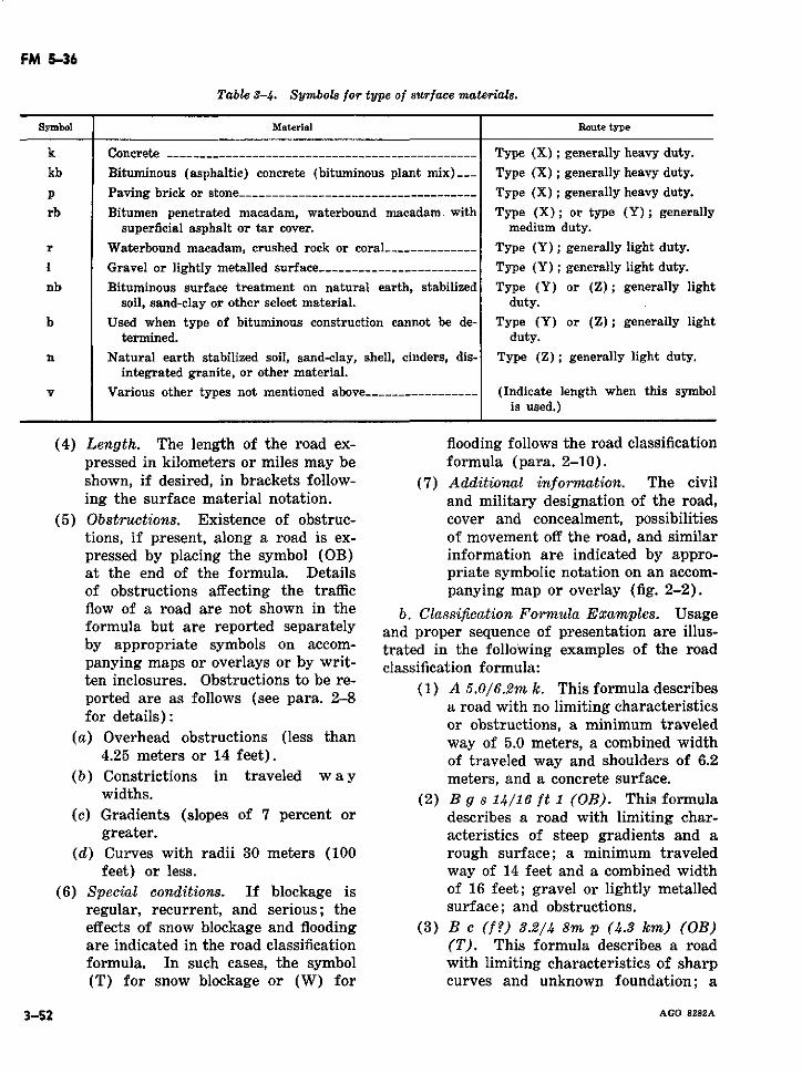
FM 5-36
Table 3-4. Symbols for type of surface materials.
Symbol Material Route type
k Concrete ----------------------------.------------------ Type (X); generally heavy duty.
kb Bituminous (asphaltic) concrete (bituminous plant mix)___-- Type (X); generally heavy duty.
p Paving brick or stone ----------------------------------- Type (X); generally heavy duty.
rb Bitumen penetrated macadam, waterbound macadam. with Type (X); or type (Y); generallysuperficial asphalt or tar cover. medium duty.
r Waterbound macadam, crushed rock or coral____---------- Type (Y); generally light duty.
1 Gravel or lightly metalled surface------------------------ Type (Y); generally light duty.
nb Bituminous surface treatment on natural earth, stabilized Type (Y) or (Z); generally lightsoil, sand-clay or other select material. duty.
b Used when type of bituminous construction cannot be de- Type (Y) or (Z); generally lighttermined. duty.
n Natural earth stabilized soil, sand-clay, shell, cinders, dis- Type (Z); generally light duty.integrated granite, or other material.
v Various other types not mentioned above----------------- (Indicate length when this symbolis used.)
(4) Length. The length of the road ex- flooding follows the road classificationpressed in kilometers or miles may be formula (para. 2-10).shown, if desired, in brackets follow- (7) Additional information. The civiling the surface material notation. and military designation of the road,
(5) Obstructions. Existence of obstruc- cover and concealment, possibilitiestions, if present, along a road is ex- of movement off the road, and similarpressed by placing the symbol (OB) information are indicated by appro-at the end of the formula. Details priate symbolic notation on an accom-of obstructions affecting the traffic panying map or overlay (fig. 2-2).flow of a road are not shown in the b. Classification Formula Examples. Usageformula but are reported separately and proper sequence of presentation are illus-by appropriate symbols on accom- trated in the following examples of the roadpanying maps or overlays or by writ- classification formula:
ten inclosures. Obstructions to be re- (1) A 5.0/6.2m k. This formula describesported are as follows (see para. 2-8 a road with no limiting characteristi
a road with no limiting characteristicsor obstructions, a minimum traveled
(a) Overhead obstructions (less than way of 5.0 meters, a combined width4.25 meters or 14 feet). of traveled way and shoulders of 6.2
(b) Constrictions in traveled w ay meters, and a concrete surface.widths. (2) B g s 14/16 ft 1 (OB). This formula
(c) Gradients (slopes of 7 percent or describes a road with limiting char-greater. acteristics of steep gradients and a
(d) Curves with radii 30 meters (100 rough surface; a minimum traveledfeet) or less. way of 14 feet and a combined width
(6) Special conditions. If blockage is of 16 feet; gravel or lightly metalledregular, recurrent, and serious; the surface; and obstructions.effects of snow blockage and flooding (3) B c (f.?) 3.2/4 8m p (4.3 km) (OB)are indicated in the road classification (T). This formula describes a roadformula. In such cases, the symbol with limiting characteristics of sharp(T) for snow blockage or (W) for curves and unknown foundation; a
3-52 AGO 8282A
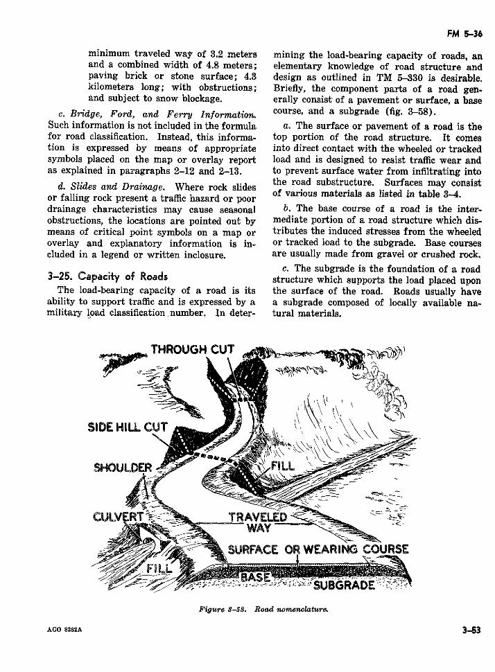
FM 5-36
minimum traveled way of 3.2 meters mining the load-bearing capacity of roads, anand a combined width of 4.8 meters; elementary knowledge of road structure andpaving brick or stone surface; 4.3 design as outlined in TM 5-330 is desirable.kilometers long; with obstructions; Briefly, the component parts of a road gen-and subject to snow blockage. erally consist of a pavement or surface, a base
c. Bridge, Ford, and Ferry Information. course, and a subgrade (fig. 3-58).Such information is not included in the formula a. The surface or pavement of a road is thefor road classification. Instead, this informa- top portion of the road structure. It comestion is expressed by means of appropriate into direct contact with the wheeled or trackedsymbols placed on the map or overlay report load and is designed to resist traffic wear andas explained in paragraphs 2-12 and 2-13. to prevent surface water from infiltrating into
the road substructure. Surfaces may consistor falling rock present a traffic hazard or poor of various materials as listed in table 3-4drainage characteristics may cause seasonal b. The base course of a road is the inter-obstructions, the locations are pointed out by mediate portion of a road structure which dis-means of critical point symbols on a map or tributes the induced stresses from the wheeledoverlay and explanatory information is in- or tracked load to the subgrade. Base coursescluded in a legend or written inclosure. are usually made from gravel or crushed rock.
c. The subgrade is the foundation of a road3-25. Capacity of Roads structure which supports the load placed upon
The load-bearing capacity of a road is its the surface of the road. Roads usually haveability to support traffic and is expressed by a a subgrade composed of locally available na-military load classification number. In deter- tural materials.
THROUGH CUT
SIDE HILL CUT
CULVERT TRAVE-WAY c .
SUR/U ACE OR WEARING COURSE
Figure 3-58. Road nomenclature.
AGO 8282A 353
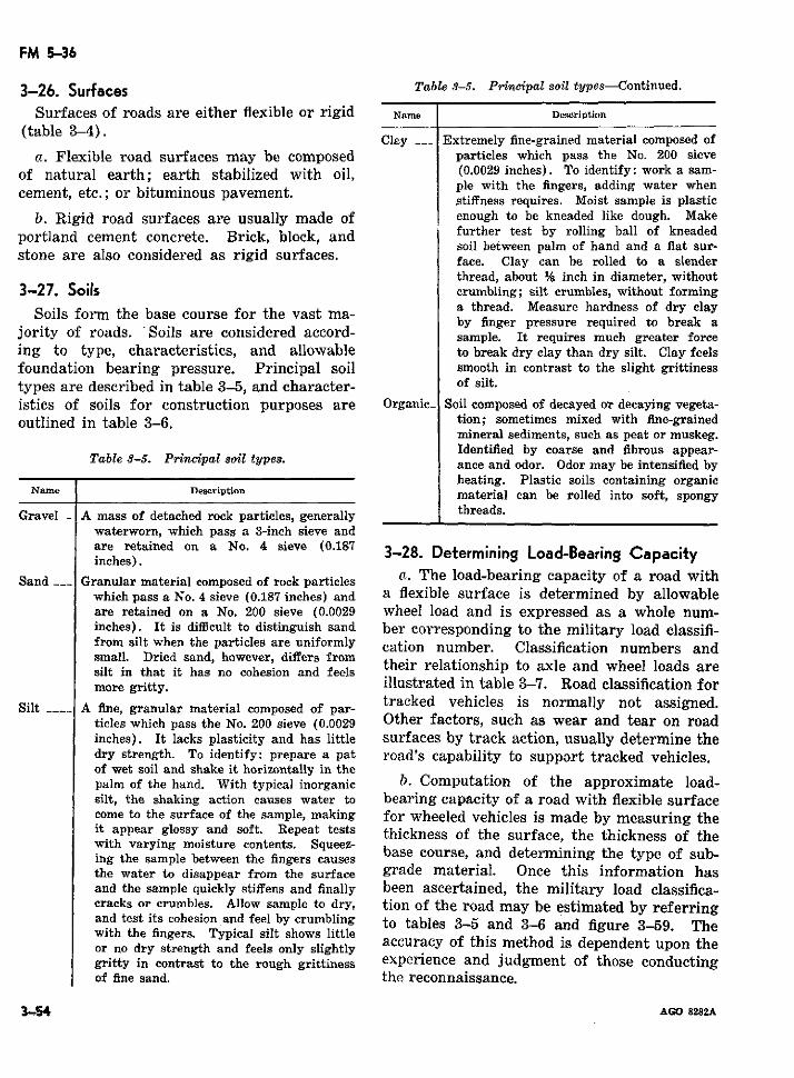
FM 5-36
3-26. Surfaces Table 3-5. Principal soil types-Continued.
Surfaces of roads are either flexible or rigid Name Description
(table 3-4). Clay __ Extremely fine-grained material composed of
a. Flexible road surfaces may be composed particles which pass the No. 200 sieveof natural earth; earth stabilized with oil, (0.0029 inches). To identify: work a sam-
cement, etc.; or bituminous paveent. ple with the fingers, adding water whencement, etc.; or bituminous pavement. stiffness requires. Moist sample is plasticb. Rigid road surfaces are usually made of enough to be kneaded like dough. Make
portland cement concrete. Brick, block, and further test by rolling ball of kneadedsoil between palm of hand and a flat sur-stone are also considered as rigid surfaces. face. Clay can be rolled to a slender
thread, about % inch in diameter, without3-27. Soils crumbling; silt crumbles, without forming
a thread. Measure hardness of dry claySoils form the base course for the vast ma- a thread. Measure hardness of dry layby finger pressure required to break ajority of roads. Soils are considered accord- sample. It requires much greater forceing to type, characteristics, and allowable to break dry clay than dry silt. Clay feelsfoundation bearing pressure. Principal soil smooth in contrast to the slight grittinesstypes are described in table 3-5, and character- of silt.istics of soils for construction purposes are Organic_ Soil composed of decayed or decaying vegeta-outlined in table 3-6. tion; sometimes mixed with fine-grained
mineral sediments, such as peat or muskeg.Identified by coarse and fibrous appear-
Table 8-5. Princi·pal soil tly~pes. ance and odor. Odor may be intensified byheating. Plastic soils containing organic
Name Description material can be rolled into soft, spongy
Gravel - A mass of detached rock particles, generally threads.waterworn, which pass a 3-inch sieve and
are res).tained on a No. 4 sieve (0.187 3-28. Determining Load-Bearing Capacityinches).
Sand __ Granular material composed of rock particles a. The load-bearing capacity of a road withwhich pass a No. 4 sieve (0.187 inches) and a flexible surface is determined by allowableare retained on a No. 200 sieve (0.0029 wheel load and is expressed as a whole num-inches). It is difficult to distinguish sand ber corresponding to the military load classifi-from silt when the particles are uniformly cation number. Classification numbers andsmal. Dried sand, however, differs from their relationship to axle and wheel loads aresilt in that it has no cohesion and feelsmore gritty. illustrated in table 3-7. Road classification for
Silt A fine, granular material composed of par- tracked vehicles is normally not assigned.Silt .... A fine, granular material composed of par- nticles which pass the No. 200 sieve (0.0029 Other factors, such as wear and tear on roadinches). It lacks plasticity and has little surfaces by track action, usually determine thedry strength. To identify: prepare a pat road's capability to support tracked vehicles.of wet soil and shake it horizontally in thepalm of the hand. With typical inorganic b. Computation of the approximate load-silt, the shaking action causes water to bearing capacity of a road with flexible surfacecome to the surface of the sample, making for wheeled vehicles is made by measuring theit appear glossy and soft. Repeat tests thickness of the surface, the thickness of thewith varying moisture contents. Squeez- base course, and determining the type of sub-ing the sample between the fingers causesthe water to disappear from the surface grade material. Once this information hasand the sample quickly stiffens and finally been ascertained, the military load classifica-cracks or crumbles. Allow sample to dry, tion of the road may be estimated by referringand test its cohesion and feel by crumbling to tables 3-5 and 3-6 and figure 3-59. Thewith the fingers. Typical silt shows littleor no dry strength and feels only slightly accuracy of this method is dependent upon thegritty in contrast to the rough grittiness experience and judgment of those conductingof fine sand. the reconnaissance.
3-54 AGO 8282A
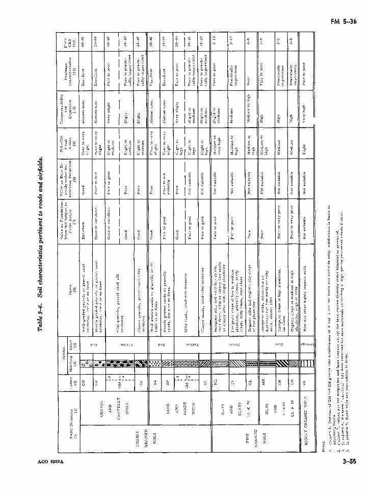
?, -a o a la -,,, - O
>9U-lo 4" " 14 4" 4" 4" 4
I I a
4~· ¡ f -.
1~~~~ ~~ ~ ~ ~ ~ o0 o o » 0
Y- - oE oE ~ 2 - ¡ I
7~~~ ~ .. . - o- .» O o . 00. o ... . 0 0
UL >4 14 2 9> > 14
.0~ ~ ~ 0 0 0 ¡ 0 ¡ o0~. o .: o o ¡ >:0
0 : ¡- l ~
i~~~~~> -E >9 2
E 4
U .! a o0
......... . . ..
C,~~<,
¡ i o o o0142 000 04 9 ii i i
pCO~~~~~~~~~~~~~~~~~~~~~~~~~~~~~~~0> 00 M9 9. 9> 9< 0 4 a
>0> 1 ¡> C 1 : ~E~f vE I
O~~~~~~~~ ~~~~~~~~~~~~~~~~~~~ 0 oHE
o " o~ -E
a . B :: 1 g " " 4a .0. 90
1~~~~~~~~~~~~ o> » oo. o . »
~~~~~~~~~~~~~~~~~~i E~~~~~~~~~~~~~~~~~~~~~~~~~~~~~~~~- 0, 0 a 00 a a >9
>~~~~~~~~~ - >0» 00o ~ ~~~~~~~~~~~ o 9 ' ->> o 0> 0o 9
9 =
a- ~ ~ ~ ~ ~ ~~~. 2 >m 0o a o9 a 22o· z~~~~~~ » o a; 0. -o
o: 00 a 0 0 0 ao 0 »>2 E a
· ; S~ ~~ ~~~0 o oo 90> o9 aI o» o 00 9i 0
0 0o a 0
0 0
O 20 0 > > > 0
a." o-" o 0
0> a0
o- >9 0 o>J ooo o 00 a
- - -Y -e - - - o 0
Ea~~~~ 00Ei ~ : B
2 0 > O 29 2 2U~~ · m~
>2~ ~~~~~~ > 2mr c~·e
>4· 2· >2 = >= >
%-M:,~~~~~~~ ~~~~~~ il V i 9 >0
iO "P; " h~~~~~~~~~ ui O qS~~~~~~~ m".í: i .i:~ oio,~0
2Z~ ~ 9>292 o>9
29 2 2 >9 0000
o-~~~~~~~~~~~~~~~~~~~~~>> 29
_ _ _ _ _ _ _ _ _ _ _ _ _ _ _ _ _ _ _ _ _ _ _ _ _ _ _ _ _ _ _ _ _ _ _ _ _ _ _ _ _ __.' >9a l -~r a o o a
AG 822 35
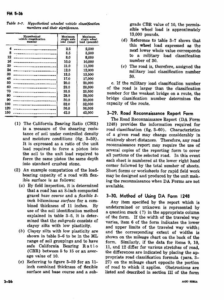
FM 5-36
Table 3-7. Hypothetical wheeled vehicle classifwation grade CBR value of 10, the permis-numbers and their significance. sible wheel load is approximately
Hypothetical aximum 13,000 pounds.vehicle classification single axe sngle whoeel (d) Reference to table 3-7 shows that
this wheel load expressed as the4 ------_________________ 2.5 2,500 next lower whole value corresponds8 _....__________________ 5.5 5,50018 __--------------------- 5.5 5,500 to a military load classification12 --.-------------------- 8.0 8,000
16 2---------------------. 10.0 10,000 number of 30.20 -------------- -------. .11.0 11,000 (e) The road is, therefore, assigned the24 --- ______________ ______ 12.0 12,000 military load classification number30 ----------------------- 13.5 13,50040 ----------------------- 17.0 17,00050 -------------- -------. .20.0 20,000 c. If the military load classification number60 -----------.----------- 23.0 23,000 of the road is larger than the classification70 ------------ ---------- 25.5 25,500 number for the weakest bridge on a route, the80 ……......... 28.0 28,00090 ---___________________ 30.0 30,000 bridge classification number determines the
100 …-_--------------.----- 32.0 32,000 capacity of the route.120 …-_-_…----------------- 36.0 36,000150 ___-------------------- 42.0 42,000 3-29. Road Reconnaissance Report Form
The Road Reconnaissance Report (DA Form(1) The California Bearing Ratio (CBR) 1248) provides the information required for
is a measure of the shearing resis- road classification (fig. 3-60). Characteristicstance of soil under controlled density of a given road may change considerably inand moisture conditions (fig. 3-59). relatively short distances. Therefore, any roadIt is expressed as a ratio of the unit reconnaissance report may require the use ofload required to force a piston into several copies of the reporting form to coverthe soil to the unit load required to all portions of the selected road. In this eventforce the same piston the same depth each sheet is numbered at the lower right handinto standard crushed stone. corner followed by the total number of sheets.
(2) An example computation of the load- Short forms or worksheets for rapid field workbearing capacity of a road with flex- may be designed and produced by the unit mak-ible surface is as follows: ing the reconnaissance when DA Forms are not
(a) By field inspection, it is determined available.that a road has an 8-inch compactedgravel base course and a flexible 3- 3-30. Method of Using DA Form 1248inch bituminous surface for a com- Any item specified by the report which isbined thickness of 11 inches. By undetermined or unknown is represented byuse of the soil identification method a question mark (?) in the appropriate columnexplained in table 3-5, it is deter- of the form. If the width of the traveled waymined that the subgrade consists of varies, item 6 of the form indicates the lowerclayey silts with low plasticity. and upper limits of the traveled way width;
(b) Clayey silts with low plasticity are and the corresponding extent of widths isshown in table 3-6 to be in the ML shown on the mileage chart on the back of therange of soil groupings and to have form. Similarly, if the data for items 9, 10,safe California Bearing R a t i o 11, and 12 differ for various stretches of road,(CBR) between 5 to 15 or an aver- the differences are indicated by placing the ap-age value of 10. propriate road classification formula (para. 3-
(c) Referring to figure 3-59 for an 11- 27) on the mileage chart opposite the portioninch combined thickness of flexible of road to which it applies. Obstructions aresurface and base course and a sub- listed and described in section III of the form
3-56 AGO su22A
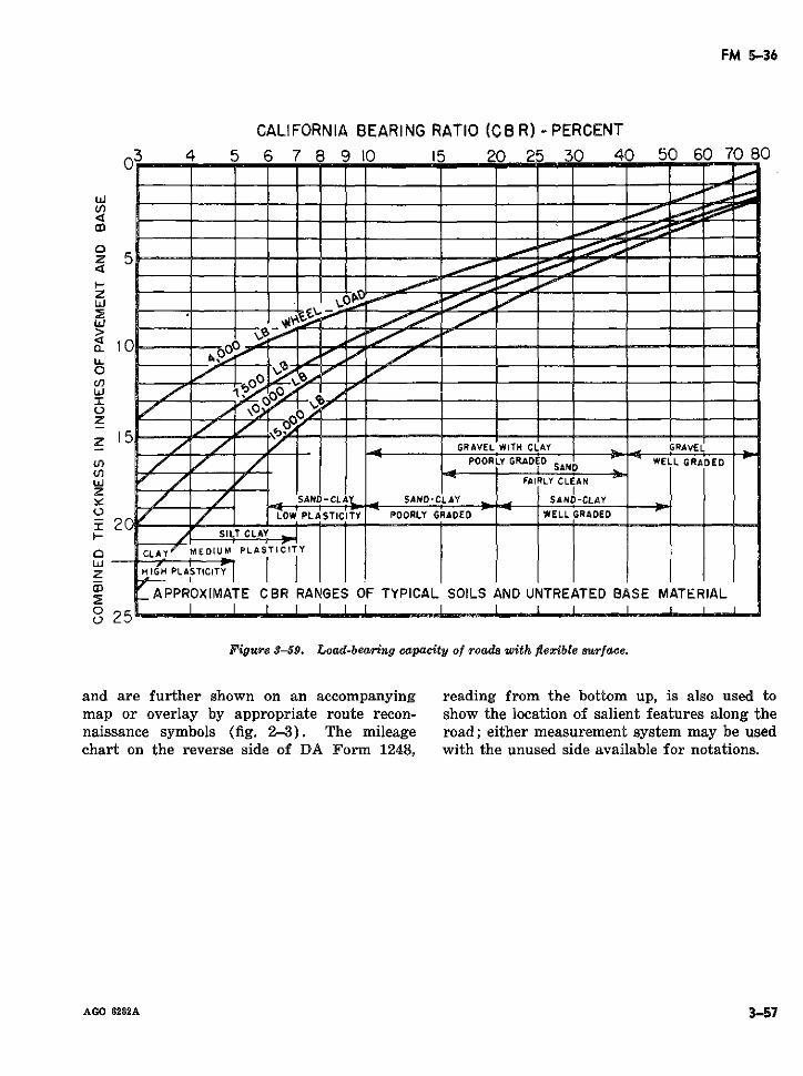
FM 5-36
CALIFORNIA BEARING RATIO (CBR) - PERCENT3 4 5 6 7 8 9 10 15 20 25 30 40 50 60 70 80
w /-
u,
o
5 - --
z 15I t-
U, 7 7 LOW PLASTICITY POORLy GRADE D "ELL GRAED"
I FAIRLY CLAN__ ___
: CLAY MESAND-CLAY.. SAND-CLAY SAND-CLAY
/' /O~ LOW PLASTICITY POORLY GRADED WELLGRAOED
1--- '
Q CLAY/
MEDIU PLA S yICITY
z HAIGH PLASTICITY
; APPROXIMATE CBR RANGES OF TYPICAL SOILS AND UNTREATED BASE MATERIAL
° 25
Figure 3-59. Load-bearing capacity of roads with flexible surface.
and are further shown on an accompanying reading from the bottom up, is also used tomap or overlay by appropriate route recon- show the location of salient features along thenaissance symbols (fig. 2-3). The mileage road; either measurement system may be usedchart on the reverse side of DA Form 1248, with the unused side available for notations.
AGO 8282A 3-57
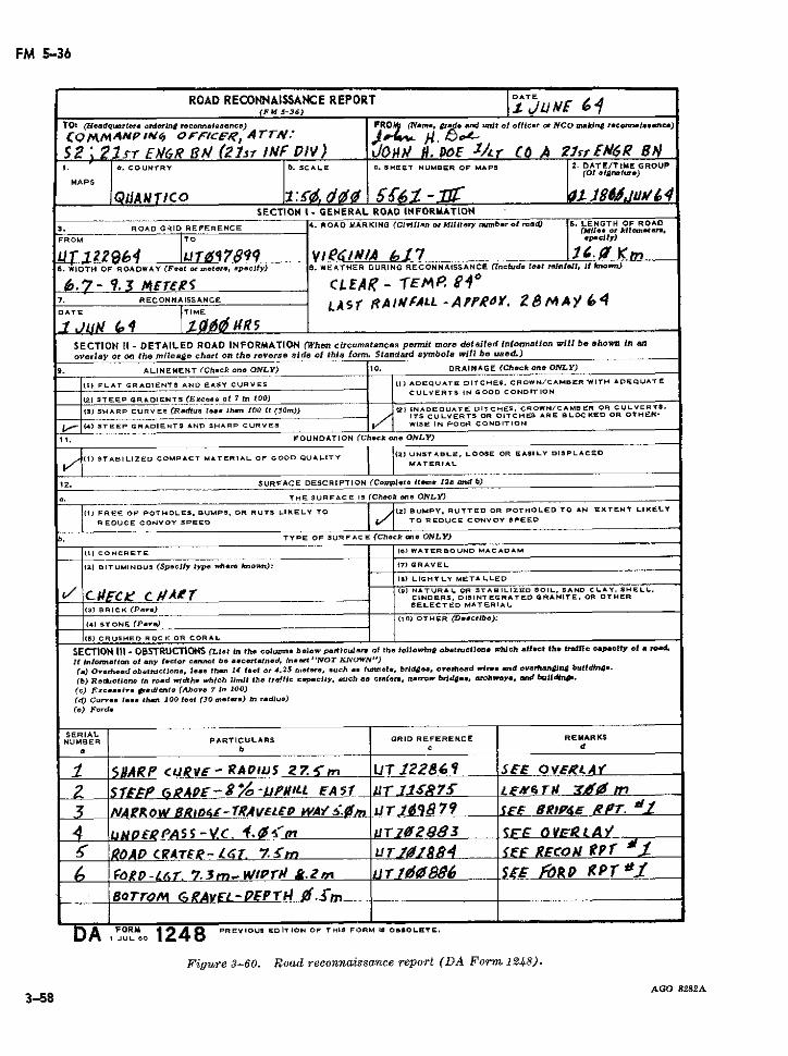
FM 5-36
ROAD RECONNAISSANCE REPORT DATE
<FM 5-36) .J¿JNE w£TO:s <3aadeqsart.ra otrdwrtnCg e.)OrlrlOinndflC FRO< (N ame, 5rade arnd lnit of ofleor mr NCO makltn reconrsaelacen)
COMMA4NPI A OFcICE ., ATN : ,. f -
S2 i lST EN&R BM/ (2zzr INF DIV) ACOH E. DoE '/r CO A i 'frfN6R 8N1. 0 . COUNTRY b. SCALE C SHEET NUMBER OP MAPS 2. DATE/TIME GROUP
SECTION 1- GENERAL ROAD INFORMATION
3. ROAD GRID REFERECE 4. ROAD MARKING (CIlillan or MitII tntb.r ol oa-d 5. LENGTH OF ROAD(Mita. a: kiler m.te.(,
FROM TO ap clify)
U l22964 uT~ [Ir 7899 V //A 617 1.- Kn6. WIDTH OF ROADWAY (Fe.t or me.ter, ap-cily) 8. WEATHER DURING RECONNAISSANCE (Includ.e lat rainalIl, Ift kbow)
.7- 9.53 M4£rees CLEAi' - TEMP. 84 0
7. RECONLNASSANACEr I AL-APP . 2'64D ATE |TIME LA S r R A FfA*LL -A f ). 2 8 MA / 41 JU (o4 |1 qa mR5
SECTION II - DETAILED ROAD INFORMATION (When circumstances permit more detailed )nformation will be ahown In en
overlay or OR the mileage chart on the reverse side of this form. Standard aymbole wvill be used.)
9. ALINEMENT (Check on- ONLY) 10. DRAINAGE (Check one ONLY)
_ 1) FLAT CRADIENTS AND EASY CURVES 1) ADEQUATE DITCHES. CROWN/CAMBER WITH ADEQUATE
_RAIN(.c... ._ 7i 0 CULVERTS IN GOOD CONDIT ION
__ STEEP GRADIENTS (ExcOs. Of 7 In 100)
(3) SHARP CURVES (R.dius liea than 100 ft (30m» (2) INADEQUATE DITCHES, CROWN/CAMBER OR CULVERTS-ITS CULVERTS OR DITCHIS ARE BLOC KED OR OTHER-
f,1(4) STEEP GRADIENTS AND SHARP CURVES W SE IN POOR CONDITION
1. FOUNDATION (Check on- ONLY)
1I STABILIZED COMPACT MATERIAL OF GOOD QUALITY | 2I UNSTAeLE. LOOSE OR EA$SILY DISPLACEDMATERIAL
12. SURFACE DESCRIPTION (Complte lemeo 12.a emd b)
a. THE SURFACE 15 (Check on. ONLY)
I") FREE OF POTHOLES. BUMPS. OR RUTS LIKELY TO 12) BUMPY. RUTTED OR POTHOLED TO AN EXTENT LIKELV
REDUCE CONVOY SPEED TO REDUCE CONVOY SPEED
TYPE OF SURFACE (Check sne ONLY)
(II CONCRETE 10) WATERBOUND MACADAM
z2) BITUMINOUS (Speciy type where Irmown): (71 GRAVEL
(8) LIGHTLY METALLED
C/ #E-Cje C / AO (9) NATURAL OR STABIlZED SOIL. SANO CLAY. SHELL.
CINDERS. DISINTEGRATED GRANITE. OR OTHERSELECTED MATERIAL
131 BRICK (Par.)
(4) STONE (PIae> (10) OTHER (Describe):
(l) CRUSHEO ROCK OR CORAL
SECTION III -OBSTRUCTIONS (Lst in tho colurina below particul~a of Ihe followin/ obstructlon which aIlect the tralfic capacty ol a ro.
tl Informatlon o atny factor cannol be aecertalned, Insert 'lVOT ICNOWN)
(a) Overh..d obtructions, les.. than 14 ..t or 4.25 met er, *uch as ltnela, brida.., o-rhead wlfre. ad ovarhanlini bullding.
(b) Rsductione In road wldths which limit the traffic capaclty, such a. crfaerl, narrow bride, archway, and bulldn~.
(c) E.xcsa. 1v gradcl nte (Above 7 In 100)
(d) Curvs lees... thn 100 feet (30 metar.) bl raditu)
(e) Ford.
SERIALENUMOER PARTICULARS GRID REFERENCE REMARKS
a Lb c d
J i//5ARP cURE-RADIUS 27.-rn lIUT 12286, SE OVER/ ¿ .,
F2 SEAE O GRArpE-,o-LJP L FA:5f TU.lÑé7S ¿E#GT# ¡¿t 0 m
NAErOW,6BRo4-TrA-VELEo WA/!4r. IJT1i <879 tSE BRIP4e R/r?. i
4 uNECPASS-vC. I.as<'m ÚrI0283 S ORLAY
' [ROAD CRATE'r-¿ T. ~7.m ZurT#884 ISEE REcoN RPf
FO PRD-Lr. 7. mn-WIPl'r &.i. ITjr1086 SE' MORD R P r '-_· BoTrOr GRAvLL-PEPrT 1.{n-
AULO 1248 PREVIOUS EDITION OF THIS FORM .5 O. OLETE.I JUL 60 1248
Figure 3-60. Road reconnaissance report (DA Form 1248).
AGO 8282A3-58
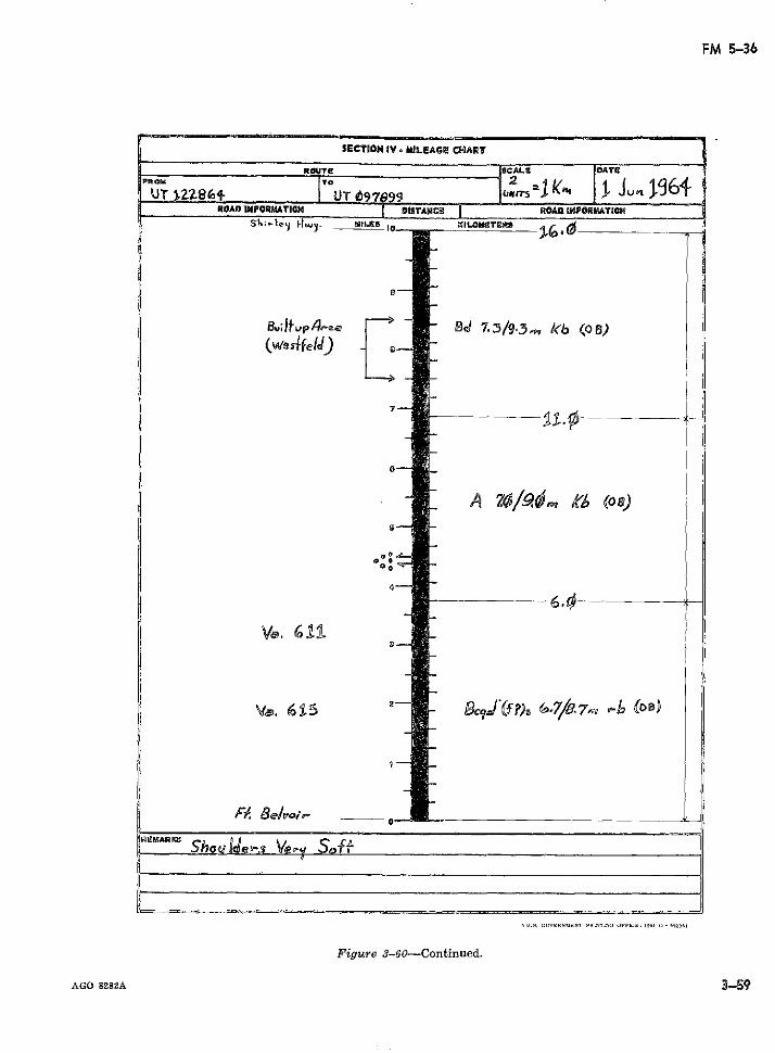
FM 5-36
SECTION IV o MILEAGE CHART
OUTE SCALE DATE
UT 2Z861 UT_ 97 9 ?SkLr5 1 | JLP196ROADO INFORMATION DISTANCÍ ROA iMPRATION
S.1OM = TOILOMCTER .FG
BJluip4 gea - BdQi 7.3/9-3,w kb (08)(we4 fe dJ)
G2 S-_ I 3 O
AGO 8282A 359
FM 5-36
Section Vl. ENGINEER RECONNAISSANCE
3-3 1. General tional military, topographic, and reconnaissanceEngineer reconnaissance, which is terrain symbols. In addition, symbols have been stand-
reconnaissance conducted to support engineer ardized to represent the more common engineeractivities, is designated as either general or resources and construction materials (fig. 3-special. General engineer reconnaissance pro- 62). In those cases where symbols fail to pro-vides engineer information of a broad nature vide an adequate explanation, each symbol iswithin the operational area and is concerned keyed by serial or critical point number on thewith locating and evaluating those items, such overlay and is referenced and fully describedas construction material, resources, and terrain in accompanying inclosures.features, which have engineer implications. 3-34. Formas for EleGeneral reconnaissance missions may be as- 334 Formats for Electlly Transmtnsigned on a zone, area, or route basis. Special Engineer Information (STANAG 2096engineer reconnaissance, on the other hand, ob- and SOLOG 107)tains more detailed information regarding a To provide standardization in reporting engi-specific engineer task or tasks; normally, such neer reconnaissance information by electricalreconnaissance follows and supports general means, the formats shown below have beenengineer reconnaissance. Special reconnais- adopted. Although primarily designed for elec-sance may be assigned as either an area or trical transmissions in conjunction with stand-route reconnaissance mission. ard message forms (DD Form 173 and DA Form
11-170), the formats, which are produced loc-3-32. Engineer Reconnaissance Techniques ally, may also be used to supplement engineer
When general or special engineer reconnais- reconnaissance reports especially when more de-sance is assigned as a route reconnaissance mis- tailed information than can be depicted by over-sion, appropriate procedures and reconnaissance lay symbols is required. The originator com-techniques previously outlined in this manual pletes only those parts of the format which areare followed. Moreover, engineer reconnais- applicable or for which information is availablesance is often conducted in conjunction with (figs. 3-63 to 3-69). Each item of the report,deliberate route reconnaissance in order to de- however, is accompanied by the appropriatetermine route conditions (including work esti- letter designation from the format to establishmates) and to locate construction material by the correct category of information. Messageswhich the route may be improved or maintained. are preceded by the type of the report or identi-The technical nature of engineer reconnaissance fying codeword.requires the issuance of detailed reconnaissance a. Installation (fig. 3-63).instructions. A check list to insure that impor-tant engineer aspects are not overlooked is
c. Local resources such as quarries, timberrecommended (fig. 3-61). The results of engi- c. Local resources such as quarries, timberneer reconnaissance are usually reported on an stands, sawmills, and brickyards (fig. 3-6).overlay which does not differ significantly from d. Enemy stores and equipment (fig. 3-66).the route reconnaissance overlay (sec. II, ch. 2). e. Water points (fig. 3-67).Standard route reconnaissance report forms and f. Dams and sluices (fig. 3-68).engineer reconnaissance forms (para. 3-35) are g. Obstacles (fig. 3-69).employed to supplement the reconnaissanceoverlay. 3-35. Engineer Reconnaissance Report
(DA Form 171 1-R)3-33. Engineer Resource Symbols (STANAG DA Form 1711-R (fig. 3-70) is used to re-
2269) port those items of engineer reconnaissance notThe location of important terrain features are adequately covered by DA report forms previ-
shown on the reconnaissance overlay by conven- ously discussed in route reconnaissance. The
3-60 AGO 8282A
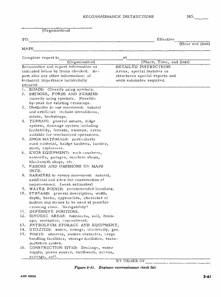
RECONNAISSANCE INSTRUCTIONS NO.
(Organization)
TO: Effective
(Hour and Date)MA PS
Complete report to at(Organization) (Place, Time, and Date)
Reconnoiter and report information as DETAILED INSTRUCTIONSindicated below by items checked. Re- Areas, special features orport also any other information; of structures special reports and
technical importance incidentally work estimates required.secured
1. ROADS: Classify using symbols.2. BRIDGES, FORDS AND FERRIES:
classify using symbols. Possibleby-pass for existing crossings.
3. Obstacles to our movement: naturaland artificial: include demolitions,
mines, boobytraps.
4. TERRAIN: general nature, ridgesystem, drainage system includingfordability, forests, swamps, areas
suitable for mechanized operations.5. ENGR MATERIALS: particularly
road material, bridge timbers, lumber,steel, explosives.
6. ENGR EQUIPMENT: rock crushers,
sawmills, garages, machine shops,blacksmith shops, etc.
7. ERRORS AND OMISSIONS ON MAPSUSED.
8. BARRIERS to enemy movement: natural,
artificial and sites for construction of
improvement. (work estimates)
9. WATER POINTS: recommended locations.10. STREAMS: general description, width,
depth, banks, approaches, character ofbottom and means to be used at possiblecrossing sites. Navigability?
11. DEFENSIVE POSITIONS.12. BIVOUAC AREAS: entrances, soil, drain-
age, sanitation, concealment.13. PETROLEUM STORAGE AND EQUIPMENT.
14. UTILITIES: water, sewage, electricity, gas.15. PORTS: wharves, sunken obstacles, cargo
handling facilities, storage facilities, trans-portation routes.
16. CONSTRUCTION SITES: Drainage, water
supply, power source, earthwork, access,
acreage, soil.BY ORDER OF
Figure 3-61. Engineer reconnaissance check list.
AGO 8282A 3 61

FM 5-36
SerialNumber Description Symbol
1. Sawmill
2. Lumber Yard
3. Stone
4. Aggregate (including gravel,slag, etc.)
5. Sand
6. Cement concrete products
7. Stocks of bricks and otherclay products
8. Iron and steel stock
9. Wire stock -
10. Paint
11. Glass stock
12. Gypsum and lime products
Figure 3-62. Engineer resources symbols.
3-62 AGO 8282A
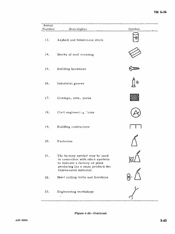
FM 5-36
SerialNumber Description Symbol
13. Asphalt and bituminous stock
14. Stocks of roof covering
15. Building hardware
16. Industrial gasses
17. Cordage, nets, yarns
18. Civil engineerl-g :irms
19. Building contractors |
20. Factories
21. The factory symbol may be usedin connection with other symbolsto indicate a factory or plantproducing (as a main product) therepresented material. 4
22. Steel rolling mills and foundries - n
23. Engineering workshops
Figure 3-62-Continued.
AGO 8282A 3-63
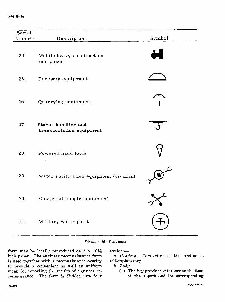
FM 5-36
SerialNumber Description Symbol
24. Mobile heavy construction oequipment
25. Forestry equipment
26. Quarrying equipment
27. Stores handling andtransportation equipment
28. Powered hand tools
29. Water purification equipment (civilian)
30. Electrical supply equipment
31. Military water point
Figure 3-62-Continued.
form may be locally reproduced on 8 x 101/2 sections-inch paper. The engineer reconnaissance form a. Heading. Completion of this section isis used together with a reconnaissance overlay self-explanatory.to provide a convenient as well as uniform b. Body.mean for reporting the results of engineer re- (1) The key provides reference to the itemconnaissance. The form is divided into four of the report and its corresponding
3-64 AGO 8282A
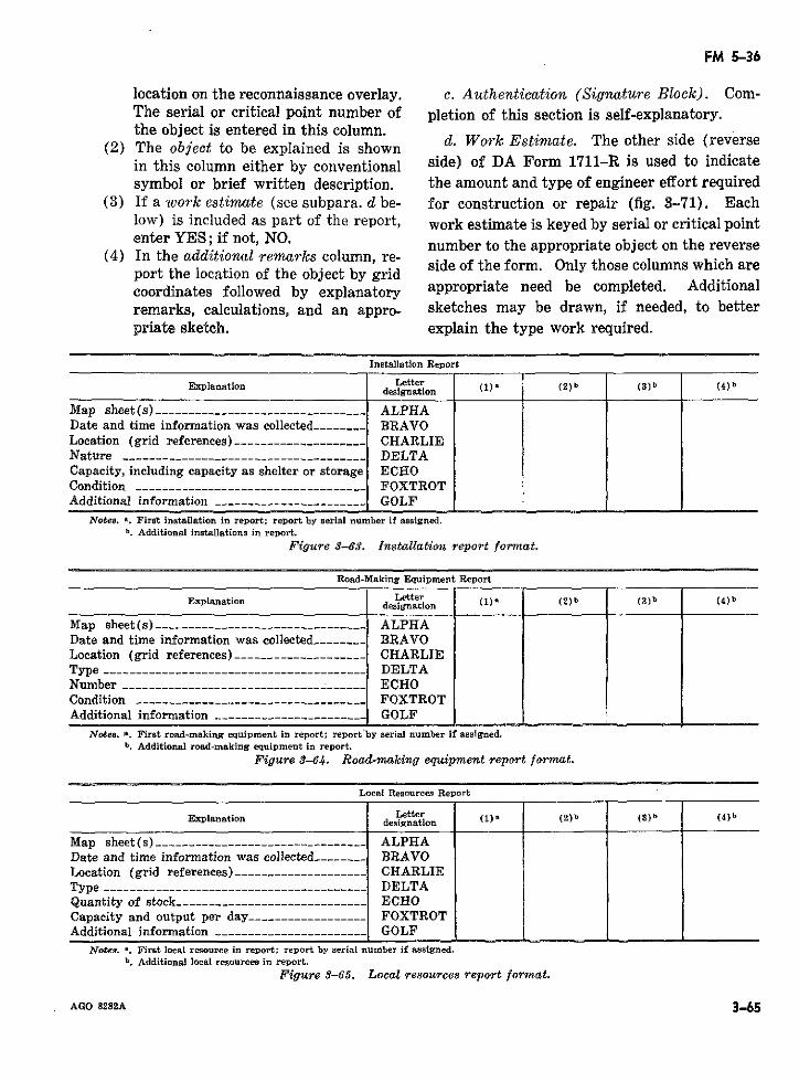
FM 5-36
location on the reconnaissance overlay, c. Authentication (Signature Block). Com-The serial or critical point number of pletion of this section is self-explanatory.the object is entered in this column.
(2) The object to be explained is shown d. Work Estimate. The other side (reversein this column either by conventional side) of DA Form 1711-R is used to indicatesymbol or brief written description. the amount and type of engineer effort required
(3) If a work estimate (see subpara. d be- for construction or repair (fig. 3-71). Eachlow) is included as part of the report, work estimate is keyed by serial or critical pointenter YES; if not, NO. number to the appropriate object on the reverse
(4) In the additional remarks column, re-portn the location o the object by grid side of the form. Only those columns which areport the location of the object by gridcoordinates followed by explanatory appropriate need be completed. Additionalremarks, calculations, and an appro- sketches may be drawn, if needed, to betterpriate sketch. explain the type work required.
Installation Report
Explanation Letter (2) b (8)b (4)bdesignation t (2)b
Map sheet(s) --__-----_------__------------ -_ ALPHADate and time information was collected ------- BRAVOLocation (grid references) ---- _-------___- CHARLIENature ---------------------------------- DELTACapacity, including capacity as shelter or storage ECHOCondition __-------------------------------- FOXTROTAdditional information - - GOLF
Notes. a. First installation in report; report by serial number if assigned.b. Additional installations in report.
Figure 3-63. Installation report format.
Road-Making Equipment Report
Explanation Letter (3)b (4)bdesignation (1)a (2)b (s)b (4)b
Map sheet(s) ----------------____________---- ALPHADate and time information was collected ------ .BRAVOLocation (grid references) ----__ _---______--_ CHARLIEType ___-----___---------------------------- DELTANumber -_--------_________------ ------- -__ _ ECHOCondition ----------------------------------- FOXTROTAdditional information ----------------------_ GOLF
Notes. A. First road-making equipment in report; report'by serial number if assigned.b. Additional road-making equipment in report.
Figure 3-64. Road-making equipment report format.
Local Resources Report
Explanation designation (2)b (3)b (4 )b
Map sheet(s) ----- . ....------- _-------------- ALPHADate and time information was collected ------- BRAVOLocation (grid references) . .................. CHARLIEType ------------------------------------ DELTAQuantity of stock ---- . . ..............-------- ECHOCapacity and output per day- ------------- FOXTROTAdditional information -_G---OLF---------_ GOLF
Notes. a. First local resource in report; report by serial number if assigned.b. Additional local resources in report.
Figure 3-65. Local resources report format.
AGO 8282A 365
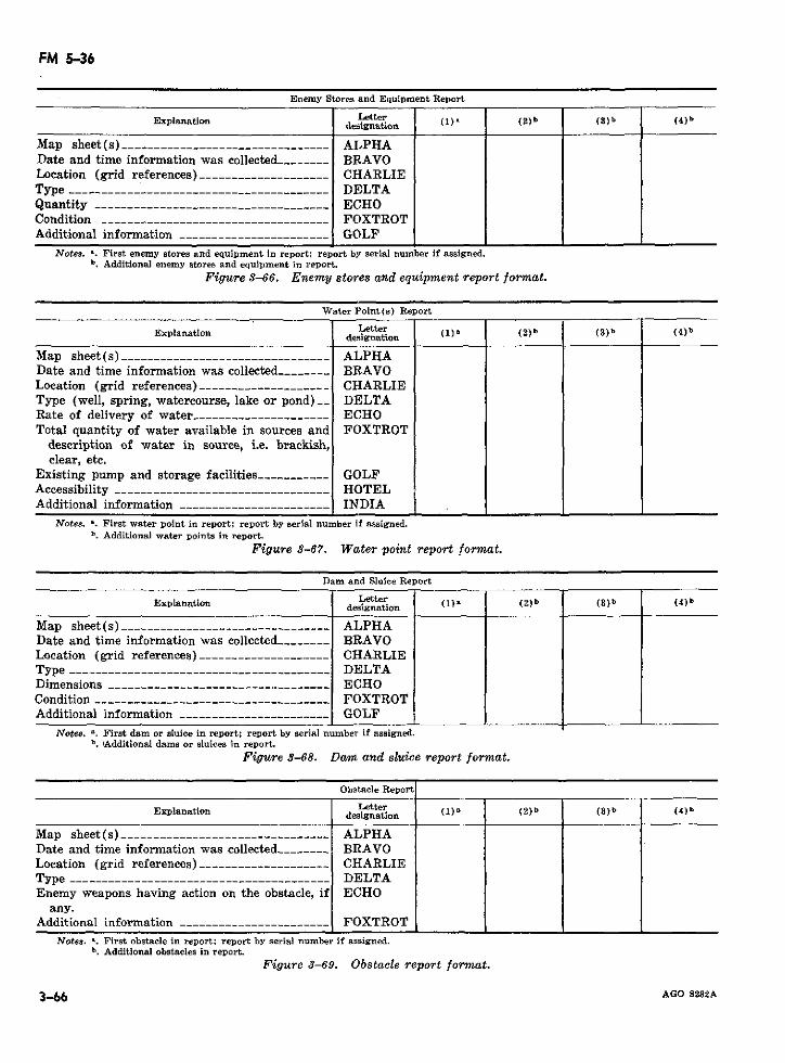
FM 5-36
Enemy Stores and Equipment Report
designation (2)Explanation Letter
Map sheet (s) -- _______________--------------- ALPHADate and time information was collected-___--- _ BRAVOLocation (grid references)____________________ CHARLIEType --- __________------------------------------ DELTAQuantity --------------------------------.--- ECHOCondition ----------.-- -_______ -_ _ ________ FOXTROTAdditional information ___-- ------------------ GOLF
Notes. a. First enemy stores and equipment in report; report by serial number if assigned.b. Additional enemy stores and equipment in report.
Figure 3-66. Enemy stores and equipment report format.
Water Point(s) Report
Letter (3)b (4)bExplanation designation tter( 1 ) ( 2) b (
Map sheet(s) -------------------------------- ALPHADate and time information was collected-___---- BRAVOLocation (grid references) ------_--------__--- CHARLIEType (well, spring, watercourse, lake or pond)__ DELTARate of delivery of water--------------------- ECHOTotal quantity of water available in sources and FOXTROT
description of water in source, i.e. brackish,clear, etc.
Existing pump and storage facilities ---------- GOLFAccessibility --_-----.------------------------ HOTELAdditional information ---------_ _ ------------ INDIA
Notes. a. First water point in report; report by serial number if assigned.b. Additional water points in report.
Figure 3-67. Water point report format.
Dam and Sluice Report
LetterExplanation designatio ) (2) b (3)b (4) b
Map sheet(s) ------------------------------- ALPHADate and time information was collected __----- BRAVOLocation (grid references) ------…_--__ -__---- CHARLIEType ---------------------------------------- DELTADimensions _____-- -------------------.-------- ECHOCondition -----------_----_-----.------__----- FOXTROTAdditional information --------.--------_----- GOLF
Notes. *. First dam or sluice in report; report by serial number if assigned.b. IAdditional dams or sluices in report.
Figure 3S-68. Dam and sluice report format.
Obstacle Report
LetterExplanation designation (1)8 (2)b (3)b (4)b
Map sheet(s) __---_------------.--------- ---- ALPHADate and time information was collected __----- BRAVOLocation (grid references) -------_------------ CHARLIEType -- ___-_--------------------------------- DELTAEnemy weapons having action on the obstacle, if ECHO
any.Additional information -_-------___-----_--- -- FOXTROT
Notes. a. First obstacle in report; report by serial number if assigned.b. Additional obstacles in report.
Figure 3-69. Obstacle report format.
3-66 AGO 8282A
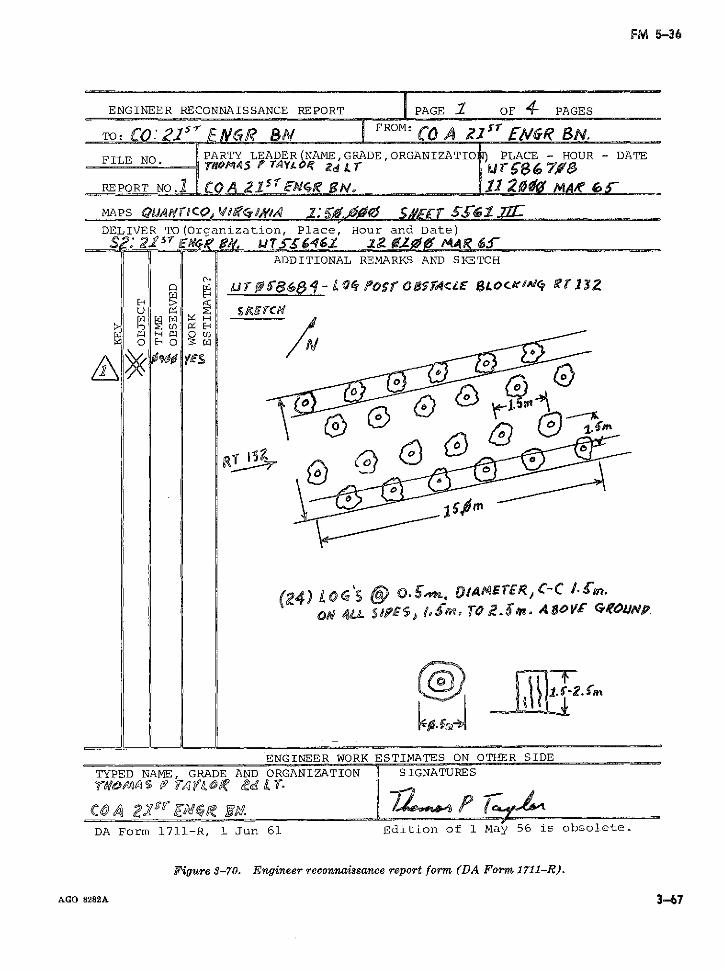
FM 5-36
ENGINEER RECONNAISSANCE REPORT PAGE 2 OF 4 PAGES
TO: C 2 [1 NCvR? BN FROM: CO A 2 1 ys EW&R B.
FILE NO PARTY LEADER(NAME,GRADE,ORGANIZATIO PLACE - HOUR - DATEFILE NO. i 5rA oL Ti FL~/,.) z L UVr38673
REPORT NO.1 C A . sfEN4R' eNo 11 20 M¶io 6
MAPS QgJaly0c ra c>d o : VMi&CIJAT S¿ff£[ SSI 7rDELIVER TO(Organization, Place, Hour and Date)
S 21515 E e J T. 03S461 1?0 2g9P4A MAR 6SADDITIONAL REMARKS AND SKETCH
C' . &rS ( -z t om'sr 6 Ob.S,,tE Lor6t/a, C-c/£,,,
Ru \
) 1VE
g(4) LO2wç C , I 3.s. '5AKES«, -C VIME0o 4¿L ¿eT$J o, TO E 2. . A 80 o CQ.YCOUNp
1 ' 62.
ENGINEER WORK ESTIMATES ON OTHER SIDE
TYPED NAME, GRADE AND ORGANIZATION SIGNATURES
DA Form 1711-R, 1 Jun 61 Edition of 1 May 56 is obsolete.
Figure 8-70. Engineer reconnaissance report form (DA Formn 1711-R).
AGO 8282A 367
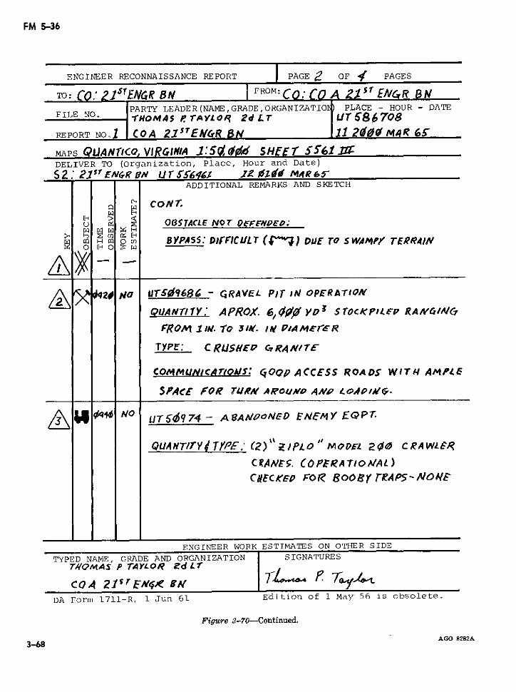
FM 5-36
ENGINEER RECONNAISSANCE REPORT PAGE 2 OF 4 PAGES
TO: CO.' 1£GR BN FROM: CO CO A 4 $ s E/NGR Bu
PARTY LEADER(NAME,GRADE,ORGANIZATIO PLACE - HOUR - DATEFILE NO. .-rOMAs45 eTAYLOF 2d LT ur 586708
REPORT NOJ1 COA 21s5 EPf &R SB 112 2014 MaR 6
MAPS QJANTICQ, VlR.GINIA 1:5'¿,M SHIEEr 5SS61 .DELIVER TO (Organization, Place, Hour and Date)
S 2 21S J EN';R ?r u VLIr $Ts646t U o, MAR 6-ADDITIONAL REMARKS AND SKETCH
' CONr.
tE !§ f OBSTACLE NOT DOEFEW*oD.o;
O m X O BYPASS55: DIrFICULT ( o"") DUE TO sWAN,"' TERRA4/I
Q 2 O# o UTSE/968G - GRAVEL PIT IN OPERAVTIQN
OUANTITY: APROX. 6I, « Yo3 STOCKPILFP RANM/4AIC
FROM 1 I>N. 'o 3Y/. /6 P/AMEr,'R
TYPE': C RLS.E'P cG4, RA N/TE
COMIMlUNICAIOAIS: 400p ACCESS ROADS WlTI4 Al^lE
SPACE ¢ FOR rTR¿W' AR'OuVO A4NP ¿OAP/4'1.
_ UT56Idq74- A 8A!OoNED ENE'MY E'QP,
QUANTIY TYPE.'- (2)" Z/PLO MODFL 210 CRAWLÉR
CR ANE5. COPEiRATIO/ AL)C#tCKEP FOl? BooErr EAPS-NOMFE
ENGINEER WORK ESTIMATES ON OTHER SIDE
TYPED NAME, GRADE AND ORGANIZATION SIGNATUREST//OMAS P TAYLOR Zd Lr
COA 21T < ZI5N¿f BrDA Form 1711-R, 1 Jun 61 Edition of 1 May 56 is obsolete.
Figure 3-70-Continued.
AGO 8282A3-68
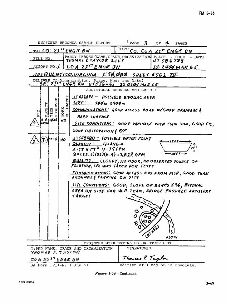
FM 5-36
ENGINEER RECONNAISSANCE REPORT IPAGE 3 OF - PAGES
TO: CO: 215sNr i FROM: Co: COA f 1 1 ENGRI UNPARTY LEADER(NAME, GRADE,ORGANIZATIO d PLACE - HOUR - DATEFILE NO. THOM4AS TÁAV/OR P¿L T U 7.8
REPORT NO.J COA 21t1ENCIJ? I &« 2 mdM AR I -
MAPS QUJANlco, vRc, lN,:A,' ' 5# sEEr G'61 Zy:DELIVER TO(Organization, Place, Hour and Date)
.:. 2.1 ' ENR v rSuTS- 461 12 ,dq MA,4a 6-ADDITIONAL REMARKS AND SKETCH
' UTZU269 - POS51'LE BIVOUAC AREAS PE 70.' > X 0?¿nd
> c t C H OMMUItlCAlTION$: QOP ACCESS ROAP W/ 0P P.74A/NA61,4
0 EO I HARP SURFACIB1 14361 t¿Oá e A.I 111'[ CoN'PION :S GCOOP PAAI'NAGe' WTN F¡IRi) Sol, GOO0 C/C,
GooP OgSERVAT/oN f/ff XG~ UTf58680 - PQoSS8lE WATER Poj1T
- 9ANJ4IILC: QAV6.4A-.31. 5 FTr V: 3 fP rlG = ( 1 S. S) ( 5) (6.4) 3, l2 QPM < 'QUALITY: CLOUvY, NO ODOR, NO OSERVE~D SouRcE OF
pOLUTLOr', SP4 WA5 TAK5' F :o TE'STrs
COMMUNICATIONS: GOOP ACCESS RPS FQOM MSR, G'oOp r¿u¡gAROLIÑD59 PARK>im OA slr&E
S17E CONPITONS. ° GOOP, SOPFE OF 84WKS 6%') 0IVOU4cAREA O SrTf' FoR W.P. TAMI, RKIGpE POSSI8L' ARIrl¿ERYTA R4ET
ENGINEER WORK ESTIMATES ON OTHER SIDE
TYPED NAME, GRADE AND ORGANIZATION 1 SIGNATURESTe39 om A s p. FA VI oI?
C.OA 22.5 # P i3W -A o ~ r-, 7b yDA Form 1711-R, 1 Jun 61 Edition of 1 May 56 is obsolete.
Figure 3-70-Continued.
AGO 8282A 3-69
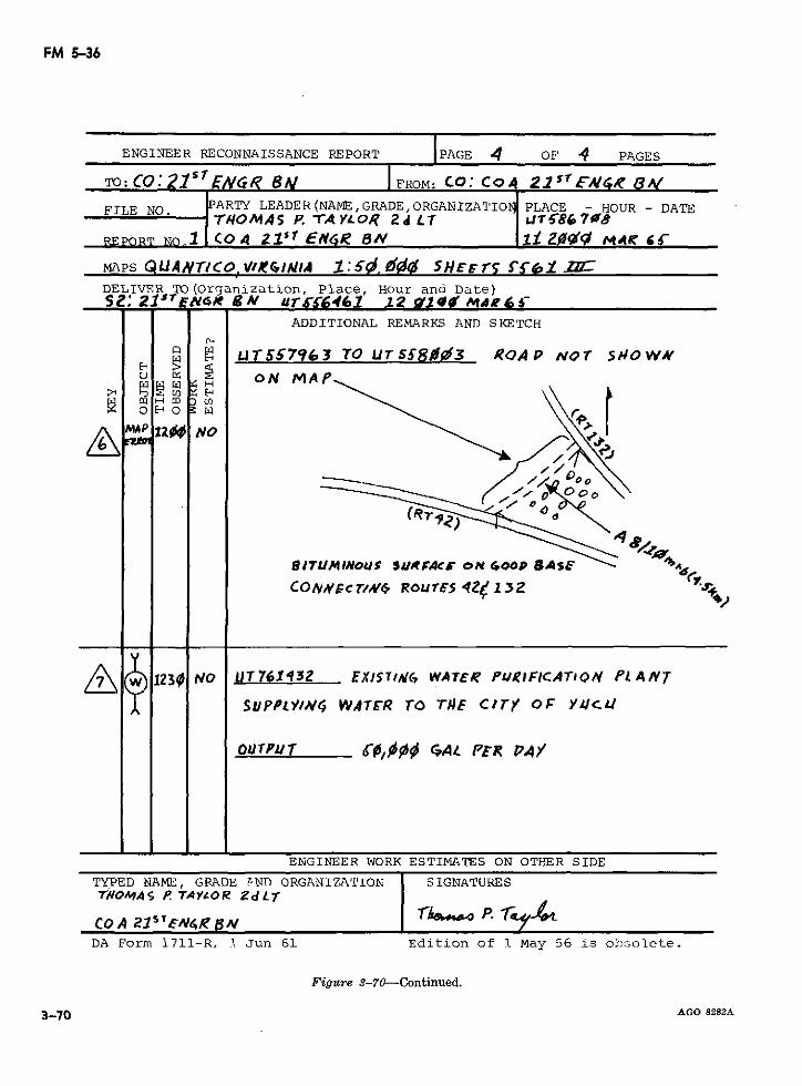
FM 5-36
ENGINEER RECONNAISSANCE REPORT IPAGE 4 OF 4 PAGES
TO: CO:Q21S ENVG1i 8} IFROM: CO: CQOG 2 1SrE/44, FO
FILE NO. ARTY LEADER(NAME,GRADE, ORGANIZATIOb PLACE - HOUR - DATEFILE NO. MA P. -rA YL¿OR 2d L Ja T86 70?8
REPORT NOl CO 4 215' EN4¡ en i -0 l < Z MAR C
MAPS QLUANTr/CO vIcIA 1 :'so, 5 0 ' SHr F rs ff~,1 ZDELIVER TO(Organization, Place, Hour and Date)S2: Z21isENT 4 SN ur-s6461 12 F1Z 0 Mais-6
ADDITIONAL REMARKS AND SKETCH
U¡JT567963 TO UT5f5803 ROAP NvOT SnOWNu a< oN MAP
O liso \\
' ia NO5 c
CONVVCcr/~ RourE' 4_< 1 3 '.-- %
/SupttwV, WAF£R TO T#E ciry o~F vyuc
ovrpv C0,000 GA¿ PtR PAY
ENGINEER WORK ESTIMATES ON OTHER SIDE
TYPED NAME, GRADE PND ORGANIZATION SIGNATURESTWOmA45 P TAY¿OR ZdL7T
COA z2sTE¿w4 gA r P.DA Form 1711-R, I Jun 61 Edition of 1 May 56 is obsolete.
Figure 3-70-Continued.
3-70 AGO 8282A
FM 5-36
4 -
z ~ ~ ~ .' Y-z
z 1
E -~ i u i
H N t
_,_ ., H os
r~ ~ ~ ~ ~ ~ ~~~aw
a 4
o _. .
U o
_~~~ F .--. ... .....0
iz :D r4
L~1 ~L \3
~~~~~~~B (U~~~~~~~~~~~~~~~~~~~~~~U
tu
e, ~ ~ c e, c~
H ujv
AGO 8282A
3-71
FM 5-36
CHAPTER 4
SPECIAL TERRAIN RECONNAISSANCE
Section U. GENERAL
4-1. Introduction quently, standardized formats and DA formsChapters 2 and 3 outline route reconnaissance have not been prepared, in most cases, to report
procedures for existing vehicular routes in an terrain data. Moreover, special terrain recon-operational area. Military activities, however, naissance is not easily divided into hasty andare not confined to road networks; and in many deliberate reconnaissance procedures. For thesituations, other types of routes such as water-ways, trails, and footpaths, are called upon to isupplement existing routes or, at times, com- is determined by the headquarters initiatingpletely support military operations. Under such the reconnaissance; consequently, reconnais-circumstances, it becomes necessary to initiate sance instructions must be more detailed thanarea or zone reconnaissance to exploit the capa- in routine route reconnaissance operations.bilities of modern cross-country vehicles and Overlay reports utilizing conventional militaryaircraft as well as route reconnaissance to ascer- and reconnaissance symbols are the preferredtain the potential of supplementary routes.
method of rendering special terrain reconnais-4-2. Scope of Reconnaissance sance reports. Nevertheless, particular atten-
Special terrain reconnaissance is greatly in- tion must be given to other reporting techniquesfluenced by the operational environment; conse- before reconnaissance elements are dispatched.
Section I1. CROSS-COUNTRY MOVEMENT
4-3. General (STANAG 2259 and quired to recognize and analyze the cross-SOLOG 100) country characteristics of an area. Factors of
Cross-country movement refers to the feasi- terrain that affect cross-country movement arebility for tactical movement by military tracked slope, soil composition, vegetation, manmadeand wheeled vehicles away from all-weather features, and drainage. Weather is also anroutes. The increased capability of military important consideration; but unlike the othervehicles to negotiate rough terrain provides the factors, weather affects cross-country move-commander with additional means to maintain ment indirectly by influencing soil compositionmobility. Although prepared routes are still and drainage. Rarely, does one factor by itselfessential for large-scale operations, especially determine cross-country movement; more com-combat support and combat service support monly, it is a combination. Therefore, althoughactivities, natural and manmade obstacles along each factor is discussed separately below, recon-a specified route may often be avoided or by- naissance personnel must realize that cross-passed by executing cross-country detours. country movement is usually dependent on aReconnaissance personnel, therefore, are re- variety of these factors.
AGO 8282A 4-1
FM 5-36
4-4. Slope to determine soil trafficability (TM 5-530);a. Ground reconnaissance permits on-the- however, inspection and passes with trial ve-
spot determination of slope percentages. An hicles are usually adequate for most purposes.instrument such as a clinometer for slope meas- b. The part of the soil most important tourement is recommended since slopes tend to cross-country mobility is the top layers, par-appear, particularly to the untrained eye, much ticularly from .15 to .30 meter (6 to 12 inches)steeper than they actually are. Because of the in depth although soil to a depth of .60 metertime involved, slopes can be accurately meas- (2 feet) may occasionally be of consequence.ured only on critical approaches; therefore, To a large extent, weather determines thegreat reliance must be placed upon other amount of moisture in the soil. If the moisturesources such as maps and aerial photographs content is known, it is possible on the basis offor obtaining general slope data over large weather forecasts to predict what the contentareas. may be at a later date; however, there is a point
b. Aerial photographs and aerial battlefield where soil becomes saturated and the amount ofsurveillance are admirably suited for quick in- moisture will not be appreciably exceeded.vestigation of slopes and are, perhaps, the best When the weather is warm enough to supportsource of information other than ground recon- plant growth, soil moisture becomes rapidlynaissance in ascertaining this factor. Aerial depleted. Slippery and sticky soils may alsophotographs provide permanent imagery rec- be troublesome, but they seldom cause immobi-ords of macro-relief features such as hills and lization of traffic, particularly tracked vehicles.mountains as well as micro-relief features such Nearly all immobilizations from soil are theas small gullies and rock ledges. Ditches, for result of loss of traction caused by vehiclesexample, which are not generally depieted on sinking so deeply that they become high-cen-topographic maps but which appreciably affect tered. Soil trafficability characteristics arecross-country movement, usually appear plainly generally applicable for wet periods only.on aerial photographs. c. Soils may be classified as to type such as
c. In eva1uatirng terrain for cross-country sand, silt, clay, etc., (tables 3-5 and 3-6) or asmovement, a 45 percent slope is commonly ac- to trafficability class (TC) as defined below andmovement, a 45 percent slope is commonly ac- further slarified in table 4-1.cepted as the reasonable uppeír limit for tanksand a 30 percent slope for wheeled vehicles (1) TC I-Soil permits at least 50 ve-(app. IV). If other factors are extremely fav- hicle passes in trace or oneorable, these percents of slope may be increased or more maneuvers by in-somewhat; but if unfavorable, reduction must dividual vehicles (starts,be made in accordance with the prevailing con- stops, sharp turns, orditions. For vertical slopes, such as rock ledges crossings of another trace)or curbs, heights between .6 to 1.2 meters (2 to in the same location.4 feet) are the practical upper limits for tracked (2) TC II-Soil permits approximatelyvehicles and .15 to .3 meter (6 to 12 inches) 10 to 50 passes in trace;for most wheeled vehicles. maneuvers by individual
vehicles are risky; cau-4-5. Soil Composition tious driving necessary;
a. Soil trafficability is defined as the capacity movement by vehicles fol-of soil to support traffic by military vehicles and lowing in trace should beis not the same as cross-country movement. avoided.Soils, when dry, will support vehicles almost (3) TC III-Soil permits 1 to approxi-without exception, but when wet, their capacity mately 10 passes in trace;to sustain cross-country movement is variable maneuvers by individualand difficult to evaluate. Engineers may be vehicles extremely risky;called upon to perform empirical tests in order very cautious driving nec-
4-2 AGO 8282A
FM 5-36
essary; movement by ve- (4) TC IV-Soil permits no vehicularhicles following in trace passes, and engineer workmust be avoided. is required for movement.
Table 4-1. Trafficability Characteristics of Wet Soils (STANAG 2259 And SOLOG 100)
Traffic- Slipperi- Stikines mmetability Soil type ness effectseclass effets
I Coarse-grained cohesionless sands Slight to None --- __ Will support continuous traffic ofand gravels. none. military vehicles. Wheeled ve-
hicles with standard tires maybe immobilized in dry sands.
I, II Inorganic clays of high plasticity, Severé to Severe to Usually will support more thanfat clays. slight. slight. 50 passes of military vehicles.
Going will be difficult at times.II, III Clayey gravels, gravel-sand-clay Severe to Moderate Often will not support 50 passes
mixtures. 'Clayey sands, sand- slight. to slight. of military vehicles, but usuallyclay mixtures. Gravelly clays, will support limited traffic.sandy clays, inorganic clays of Going will be difficult in mostlow to medium plasticity, lean cases.clays, silty clays.
III, IV Silty gravels, gravel-sand-silt mix- Moderate to Slight --__ Usually will not support 50tures. Silty sands, sand-silt mix- slight. passes of military vehicles.tures. Inorganic silts and very Often will not permit even afine sands, rock flour, silty or clay- single pass. Going will be ex-ey fine sands or clayey silts with tremely difficult in most cases.slight plasticity. Inorganic silts,micaceous or diatomaceous finesandy or silty soils; elastic silts.Organic clays of medium to highplasticity, organic silts.
4-6. Vegetation 4-7. Manmade FeaturesThe term vegetation includes not only natural Manmade features are those works of man
growth but also crops and orchards. Nearly such as railroad embankments, built-up areas,all forests, dependent upon the size of the tree stone walls, hedgerows, dikes, cuts, fills, etc.,diameters, have a slowing effect on wheeled which are deterrents or obstacles to movement.vehicular movement. Trees with trunk diame-ters less than two inches are only a slight 4-8. Drainagehindrance for tracked vehicles; whereas, the The water features of an area comprise itspractical upper limit of tree diameters to be drainage. They include streams and canals;toppled by medium tanks is from 150-200 centi- drainage and irrigation ditches; lakes, marshes,meters (6 to 8 inches). Trees somewhat less bogs, and swamps; artificial bodies of standingthan 150 centimeters (6 inches) in diameter, water such as reservoirs and ponds as well ashowever, may cause an obstacle when growing such subsurface outlets as springs and wells.very close together. The average distance to The character of these drainage features, ispermit vehicular passage between trees which determined by precipitation, temperature, re-cannot be felled is from 4.5 to 6 meters for lief, surface runoff, ground-water flow, andboth wheeled and tracked vehicles. This dis- various types of manmade drainage construc-tance is greater in width than standard mili- tion. If bridges, fords, or special purposetary vehicles, but allowance is made for indi- vehicles are unavailable, engineer assistance isvidual vehicle maneuver. usually required to negotiate obstacles of this
AGO 8282A ,1-3
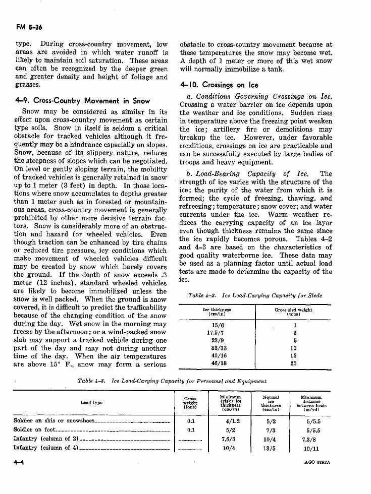
FM 5-36
type. During cross-country movement, low obstacle to cross-country movement because atareas are avoided in which water runoff is these temperatures the snow may become wet.likely to maintain soil saturation. These areas A depth of 1 meter or more of this wet snowcan often be recognized by the deeper green will normally immobilize a tank.and greater density and height of foliage andgrasses. 4-1'0. Crossings on Ice
a. Conditions Governing Crossings on Ice.4-9. Cross-Country iMnovement in Snow Crossing a water barrier on ice depends upon
Snow may be considered as similar in its the weather and ice conditions. Sudden riseseffect upon cross-country movement as certain in temperature above the freezing point weakentype soils. Snow in itself is seldom a critical the ice; artillery fire or demolitions mayobstacle for tracked vehicles although it fre- breakup the ice. However, under favorablequently may be a hindrance especially on slopes. conditions, crossings on ice are practicable andSnow, because of its slippery nature, reduces can be successfully executed by large bodies ofthe steepness of slopes which can be negotiated. troops and heavy equipment.On level or gently sloping terrain, the mobilityof tracked vehicles is generally retained in snow strength of es wth the structure of the
strength of ice varies with the structure of theup to 1 meter (3 feet) in depth. In those loca-tions where snow aecumulates to depths greater from which it isthan 1 meter such as in forested or mountain- formed; the cycle of freezing, thawing, and
ous areas, cross-country movement is generay refreezing; temperature; snow cover; and waterous areas, cross-country movement is generally currents under the ice. Warm weather re-prohibited by other more decisive terrain fac- duces the carrying capacity of an ice ayertors. Snow is considerably more of an obstruc- duces the carrying capacity of an ice ayertion and hazard for wheeled vehicles. Even even though thickness remains the same sincethough traction can be enhanced by tire chains the ice rapidly becomes porous Tables 4-2or reduced tire pressure, icy conditions which and 4-3 are based on the characterstacs ofmake movement of wheeled vehicles difficult good quality waterborne ice. These data maymake movement of wheeled vehicles difflcult
.ay be created by snow which barely covers .be used as a planning factor until actual loadthe ground. If the depth of snow exceeds .3 tests are made to det°ermine the capacity of themeter (12 inches), standard wheeled vehiclesare likely to become immobilized unless the
Table 4-2. Ice Load-Carying Capacity for Sledssnow is well packed. When the ground is snowcovered, it is difficult to predict the trafficability Ice thickness Gross sled weight
because of the changing condition of the snow (cm/in) (tons)
during the day. Wet snow in the morning may 15/6 1freeze by the afternoon; or a wind-packed snow 17.5/7 2slab may support a tracked vehicle during one 23/9 5part of the day and may not during another 33/13 10time of the day. When the air temperatures 40/16 15are above 15 ° F., snow may form a serious 46/18 20
Table 4-3. Ice Load-Carying Capacity for Personnel and Equipment
Gross Minimum Normal MinimumLoad type weight (risk) ice ice distance
(tons) thickness thickness between loada(cm/in) (cm/in) (m/yd)
Soldier on skis or snowshoes .........................._ 0.1 4/1.2 5/2 5/5.5
Soldier on foot ----------__--------------------- -___ 0.1 5/2 7/3 5/5.5Infantry (column of 2) _-----------___---_____-- _____ ________ 7.6/3 10/4 7.3/8Infantry (column of 4) ------------------ ---------- ________ 10/4 13/5 10/11
4--4 AGO 8282A
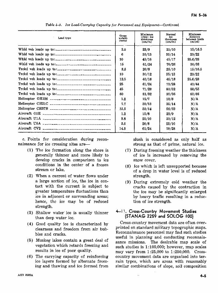
FM 5-36
Table 4-3. Ice Load-Carrying Capacity for Personnel and Equipment-Continued
Minimum Normal MinimumLoad type Groah (risk) ice lee distanceweighht thickneness between loada
(tons) (cm/in) (cm/in) (m/yd)
Whld veh loads up to: ------------------------------- 3.5 23/9 25/10 15/16.5Whld veh loads up to: ---------------.--- 6------------ 6 30/13 35/14 20/22Whld veh loads up to:-------------.------------------ 10 40/16 45/17 25.6/28Whld veh loads up to: ------------------------------ 15 61/24 70/26 30/33Trckd veh loads up to: ----------------------- __ ____ 3.5 20/8 25/10 15/16.5Trckd veh loads up to:_ _-_---_-- __--_ ______________ 10 30/12 35/13 20/22Trckd veh loads up to: -------------- --------___---- 12.5 40/16 45/18 25.6/28Trckd veh loads up to: ____--- _____-________-_____-_ 25 61/24 70/28 40/44Trckd veh loads up to:______-- ______________________ 45 71/28 80/32 50/55Trckd veh loads up to: ----------_____ _______________ 60 81/32 90/36 60/66Helicopter OH136 __________________-___-.------_- 1.2 15/7 18/8 N/AHelicopter CH21C ------------__ _____ _______________ 7.7 30/13 35/14 N/AHelicopter CH37B .. ......................-_____ 15.5 50/14 56/23 N/AAircraft O1E -------------------------------------- 1.2 15/8 23/9 N/AAircraft UlA ---------------------- _-_---_------ 3.8 25/10 30/12 N/AAircraft U6A -------------------------------------- 2.5 20/8 25/10 N/AAircraft CV2 _______________________ _____________ 14.3 61/24 70/28 N/A
c. Points for consideration during recon- slush is considered as only half asnaissance for ice crossing sites a:re- strong as that of prime, natural ice.
(1) The ice formation along the shore is (7) During freezing weather the thicknessgenerally thinner and more likely to of ice is increased by removing thedevelop cracks in comparison to ice snow cover.conditions in the center of a frozen (8) Ice which is left unsupported becausestream or lake. of a drop in water level is of reduced
(2) When a current of water flows under strength.a large section of ice, the ice in con- (9) During extremely cold weather thetact with the current is subject to cracks caused by the contraction ingreater temperature fluctuations than the ice may be significantly enlargedice in adjacent or surrounding areas; by heavy traffic resulting in a reduc-hence, the ice may be of reduced tion of ice strength.strength.
(3) Shallow water' ice is usually thinner 4-U1 . Cross-Country Movement Studiesthan deep water ice. (STANAG 2259 and SOLOG ¡00)
(4) Good quality ice is characterized by Cross-country movement data are often over-clearness and freedom from air bub- printed on standard military topographic maps.bles and cracks. Reconnaissance personnel may find such studies
useful in planning and conducting reconnais-(5) Muskeg lakes contain a great deal of sance missions. The desirable map scale of
vegetation which retards freezing and such studies is 1:100,000; however, map scalesresults in ice of poor quality. may vary from 1:25,000 to 1:250,000. Cross-
(6) The carrying capacity of reinforcing country movement data are organized into ter-ice layers formed by alternate freez- rain types, which are areas with reasonablying and thawing and ice formed from similar combinations of slope, soil composition
AGO 8282A - 4-5
FM 5-36
(including moisture content), and vegetation. three tones indicates this terrain group; theEach terrain type is, subsequently, divided into lighter tone represents terrain which offerssmaller terrain groups which are evaluated for better prospects for some seasonal movement;cross-country movement. The following three the intermediate tone for terrain which offersgroups are standard: poorer prospects for movement; and the dark-
a. Terrain Group A includes terrain with est tone for terrain which is too steep forsoil rated as Trafficability Class I regardless movement.of seasonal variations. Terrain Group A is d. Other Terrain Features. In addition tooverprinted without color (white) except for soil trafficability, other terrain features whichareas of steep slopes which are depicted by influence cross-country movement are repre-thin diagonal magenta lines. sented by conventional map symbols and colors.
b. Terrain Group B includes terrain with (1) Steep slopes in terrain other thansoil rated as Trafficability Class I more than 50 Group C. Dark magenta is used topercent of the time but is seasonally rated as represent escarpments, cuts, embank-Trafficability Class II, III, or even IV. Terrain ments, gravel pits, and other slopeGroup B is overprinted in two tones of yellow, obstacles in areas otherwise not toothe darker representing soil more susceptible to steep for movement.seasonal miring. As in Terrain Group A, areas (2) Vegetation. Green represents vege-of steep slopes are indicated by thin diagonal tation primarily forests that hindermagenta lines. movement. Distinctive patterns of
c. Terrain Group C includes terrain with green may be employed to representsoil rated only as Trafficability Class II, III, different types of vegetation.or IV except for prepared routes through the (3) Drainage. Blue is used to depictarea. Group C will usually include poorly water obstacles.drained terrain such as bogs, swamps, and (4) Urban areas. Built-up areas are rep-marshes or terrain which is too rough and resented by overprints of black criss-steep for vehicular movement. Magenta in cross lines.
Section III. RECONNAISSANCE OF TACTICAL LANDING AREAS4-12. General and sustained combat incident to operations on
Although landing area construction remains land. Aerial operations within the capabilitiesan engineer responsibility, the increased num- of army aircraft normally do not duplicateber of aircraft within any army area requires those of USAF. Army aircraft are designed tothat all reconnaissance personnel be generally perform the following functions:familiar with terrain characteristics pertinent a. Command and control.to airmobile operations. This section, there- b. Battlefield surveillance and aerial obser-fore, is designed to acquaint personnel with vation.specifications of the more common types of e. Aeromedical evacuation.army aircraft and their corresponding landing . Air mobility for troops, equipment, andrequirements. Aviation technicians and con-ty for troops, equpment, andstruction engineers will still be required to supples.reconnoiter the more permanent types of land- e. Aerial fire support.ing facilities, especially those for USAF air- 4-14. Characteristics of Army Aircraftcraft; however, procedures are herewith pro-vided for preliminary reconnaissance. For Army aircraft are sturdy, relatively easy togreater detail, see FM 1-100 and TM 5-330. maintain, and capable of operating from short,
unimproved fields. To assist in reconnaissance4-13. Role of Army Aviation planning, pertinent specifications of U.S. Army
The mission of army aviation is to augment aircraft are listed in table 4-4, and aircraft arethe capability of the army to conduct prompt illustrated in figures 4-1 and 4-2.
i46 AGO 8282A
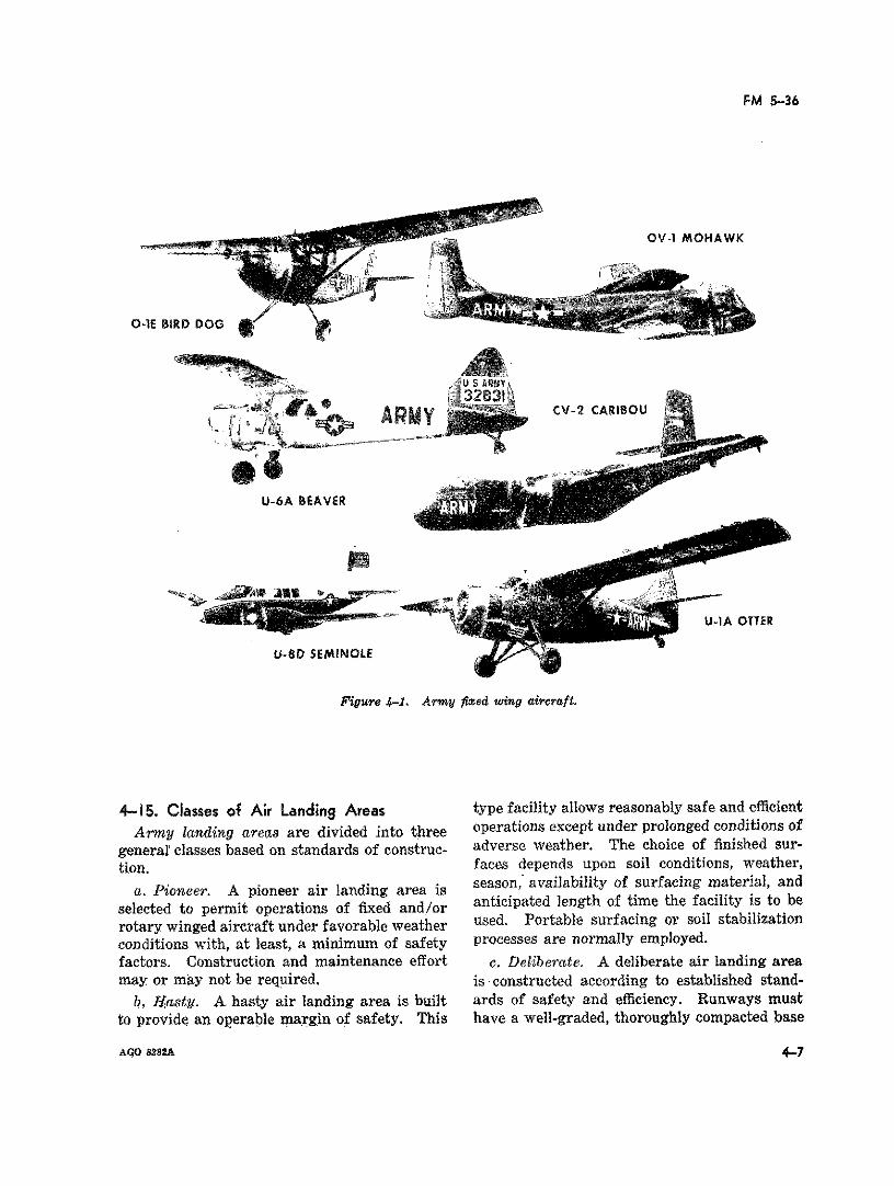
FM 5-36
OV-I MOHAWK
O-1E BIRD DOG
CV-2 CAR1BO0U
U-6A BEAVER
U-IA OTTER
U-8D SEMINOLE
Figure 4-1. Army fixed wing aircraft.
4-15. Classes of Air Landing Areas type facility allows reasonably safe and efficient
Army landing areas are divided into three operations except under prolonged conditions of
general classes based on standards of construc- adverse weather. The choice of finished sur-tion. faces depends upon soil conditions, weather,
Pioneer. A pioneer air landing area season, availability of surfacing material, and
selected to permit operations of fixed and/orrotary winged aircraft under favorable weather used. Portable surfacing or soil stabilization
conditions with, at least, a minimum of safety processes are normally employed.factors. Construction and maintenance effort ce Deliberate. A deliberate air landing areamay or may not be required. is constructed according to established stand-
b, Hasty. A hasty air landing area is built ards of safety and efficiency. Runways must
to provide an operable margin of safety. This have a well-graded, thoroughly compacted base
A9O 8282A 4-7
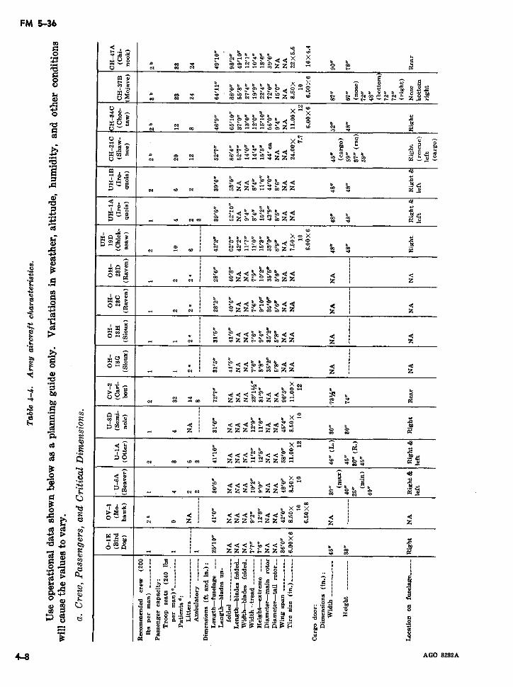
FM 5-36
~~~~~~~~~ z
N- k x¢ ON
E: ~~~~~~~~~~~~~~~~~~~~~~~~~~~~~~~~~~~~·~8 3 -~ 23 NN X NOZZ o*O bZD N b Uo~~~~~~~~~~~~~~~~~~~~~~~~~~~~~~~l
~~ oo u~~~~~~~~~~~~~~~~~t
U ; N N CO.o Z C _ CC o M· N
8 >-S -t CQ eO CO h D o m
lt~ ~~r
8~~~~~~~~~~~~~~c 3 c _ ' -_oceo e t k
E ~ ~ ~ ~ b ,, N , o ~ . .~ z¢ Z¢ e 'C .-CO¢
8 cm , 8 m_ _ eoeo z in
x Xoo k< Ó¢0 <> h r
1 m
= ~ g, S z z ... z -m ¢
aloz
mmn o=~=aaa~ Z a - Ñ3
c~~~ ~ ~~~~ w zz NZ ,O~ x:
* Wi N I N N eX , %% r I I I o : ' . [
4-8 AGO 8282A
N ~~~~ ip < $M<
z zz z z z~~~~~~
~~~~l·o!~~~~~~~~~~x0
O~~ E m ~ ~ i) b 21
un 9 w w Z <
~~s oC:& I -k x
co : 2 66r"$ P BL- 4~~Od < 0 C
ON ~~~~~~r~~p44 4~i
N N F<Hro>a ~ ~ ~ ~ ~ ~ ~~~~GO822
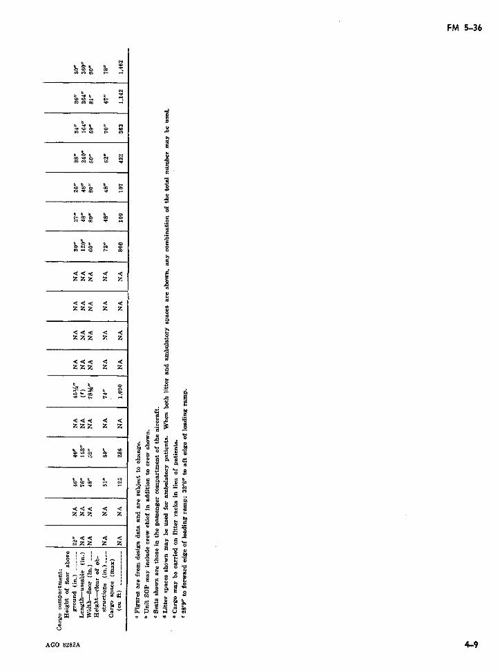
FM 5-36
oa eo t'- _
. o
,oCo to o o
zzz z z 0
.. ç
zz z z z
bo
A a 8 t< .0-
""- n z z z 0 c
Z zZ Z z . a>
>tO b
CO.22 4< _a
__ , N Z t Z aO *
CC a> a -cag>y_ o e ' cxa2
E i
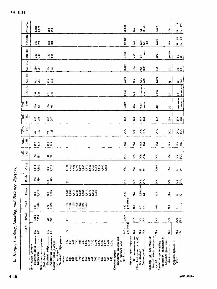
FM 5-36
PQ,0 0q
oo
1 0~~~~~~~~~~~~~~~~~~~~~i0O O~~~~~~~~~~~~~C
""~~~~~~~~~~~~~~~~~~~~~ cq coi OUO Oq
O cq10 .0- 1 C 49C - -
O
o, Oa 0% a z ;
o:, Ci C cO - O
O ~O00. O<· Or 00
oo 00 0J O 01CO~~~~~~~~~ 0)-- O" 4= 9O O OC:
Z·: ~. OCa
4i
cq " z z
to
00 ~01 e I
u, ~ ~~~~~~~~~~~~~~ 14.- 1 ~ 0.
fz
O 0-
o o lo4 4 4 4
o, O~~~~~~~~~~~~~~~~~~~~~~~~~~4O 92
4-1
--- ml 0-4 N C = . z OI
5 0~ 4,oo 444 4 4 41 O
o~" -" O
o O,
O C00 . 0 0 0 .
"~~~~~~~~~~~~~~ d 0L 4eai 0L s 0-…-z .Po~~~~~< U)~~~~~~~~~~~~~~~~< ~~~~~~a
- mf 2 2 C
1 ~ ~ ~ ra-~: 0Na,1B
O s .0W OC W E
CO 0 0 22 Z Z
4 ~ ~ ~ ~ i Q W· r ·
4-lO ~ ~ ~ ~ oo:= 4G 8282A1
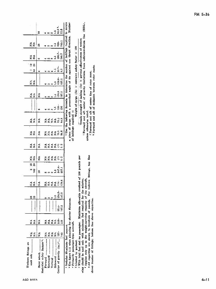
FM 5-36
a co m
o8
Z ' O O N - - -E --
· <
o 2
x uu
zz z zz z, _ .. s
0o o
» a aNN '~~ , ° -
,l <ll < < < , , , CO O « _ , ._
A I II28 2 _ .E O--
° ' u°| , b
b |.u. | UI - oÑa o o
~ ° C O == t b s 3 a 3 Ru
AGÓ 8282Auo
.~ << ~ u. u
riOAGÓ 8282A 4-1 1
O E: OONNr(;OLn M1- ~u3 m $ ·50~~u
zz z zzzzr:00 8~
~~7~~~6~~_3 89iu
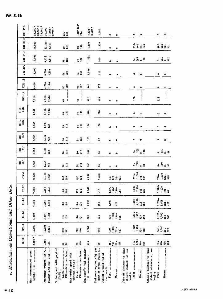
FM 5-36
C ° °4 °_
- et Oci O o
o I ~: ff "- ~° - - $ - O C °
a niar
- w
OC 04o a' C d$, C
0 '* o, 'CC
,, mU N -8_ _ o o ° o C o'
1 - N _ c o N C
t- 04 0- , ~O 3 _O ¢CC OC C 0 0 O 08 0N
ON ¢ 1 8 N C o 8 N8o
S: 4 C C O a
O _ ° . a C C -
C, C 0.
a 1 0 C> CC C CC
0. C : 040 0-C - o ¡O C S O 40
OC~ ~ 04C 04C - 0 C0O CC C0C
CC~ C C¡C C O
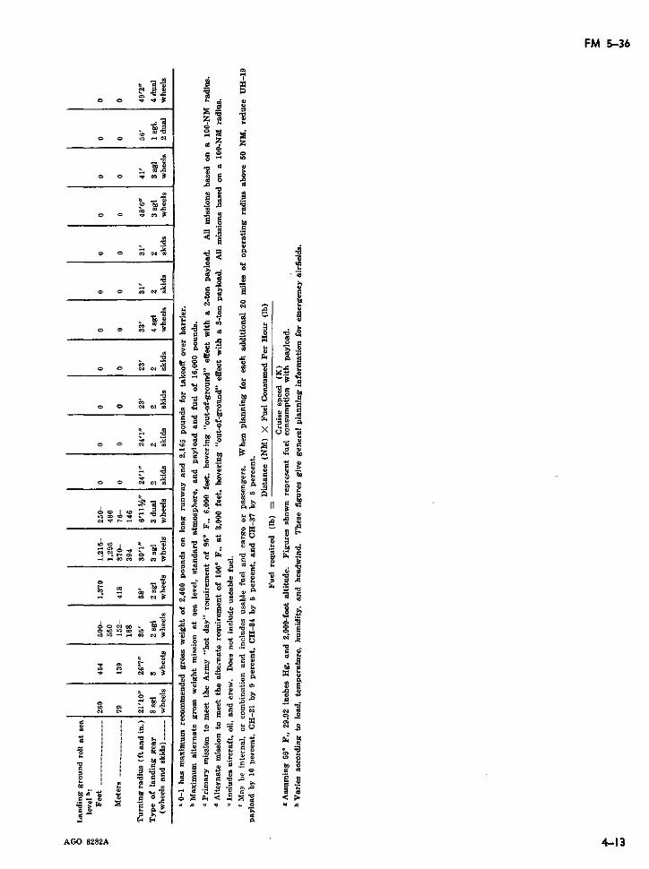
FM 5-36
cq ~ ~ ~ ~ m
_ o be tO
t o s o2s~ 4 -14, a
O O C N l 01 t C
o o 1 o 3c
C» d cow C)
4 m- j x e
o a ei m
Ñ N CJa o 8 X c d d to
E, E -, d
A gO 822 4*1 3 0 X r
· _ Na co 3 0 g S ~ B @ db t>
O 7 3f5 ç c " C
d ~ a c ci ciEE@.
C | *,C * 'K Yd sE b W C °
3 b > > 3 ¢
@~ ~ >· 0s· _a ao 6n caCpU
AGO~" 822 413
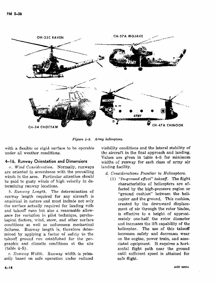
FM 5-36
OH-23C RAVEN CH-37A MOJAVE f
ARMY
CH-34 CHOCTAW
Figure 4-2. Army helicopters.
with a flexible or rigid surface to be operable visibility conditions and the lateral stability ofunder all weather conditions. the aircraft in the final approach and landing.
Values are given in table 4-5 for minimum4-16. Runway Orientation and Dimensions widths of runway for each class of army air
a(. Wind Consideration. Normally, runways landing facility.are oriented in accordance with the prevailing d. Considerations Peculiar to Helicopters.winds in the area. Particular attention should (1) "ln-ground effect" takeoff. The flightbe paid to gusty winds of high velocity in de-e fi
.erminin run. ay íocations. characteristics of helicopters are af-termining runway locations.b. Runwuwaly Lenogth. The determination of fected by the high-pressure region orb. Runwvay Length. The determination of "ground cushion" between the heli-
runway length required for any aircraft iscopter and the ground. This cushion,empirical in nature and must include not oncly
the surface actually required for landing rolls created by the downward displace-and takeoff runs but also a reasonable allow- ment of air through the rotor blades,ance for variation in pilot technique, psycho- is effective to a height of approxi-logical factors, wind, snow, and other surface mately one-half the rotor diameterconditions as well as unforeseen mechanical and increases the lift capability of thefailures. Runway length is, therefore deter- helicopter. The use of this takeoffmined by applying a factor of safety to the increases safety and decreases weartakeoff ground run established for the geo- on the engine, power train, and asso-graphic and climatic conditions at the site ciated equipment. It requires a hori-(table 4-5); zontal flight path near the ground
c. Punwcay Width. Runway width is prim- until sufficient speed is attained forarily based on safe operation under reduced safe flight.
4-14 AGO 8828A
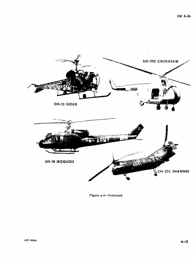
FM 5-36
UH-19D CHICKASAW
OH-13 SIOUX i
UH-1B IROQUOIS
CH-21C SHAWNEE
Figure 4-2-Continued.
AGO 8282A 4-15'
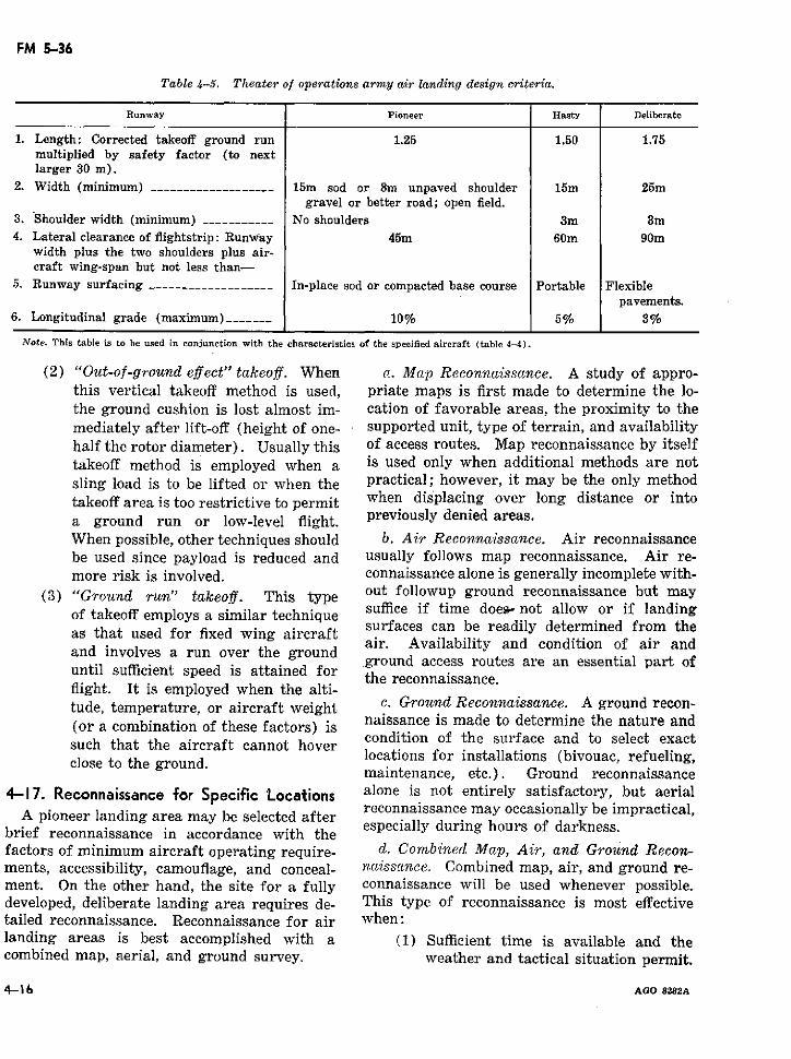
FM 5-36
Table 4-5. Theater of operations army air landing design criteria.
Runway Pioneer Hasty Deliberate
1. Length: Corrected takeoff ground run 1.25 1.50 1.75multiplied by safety factor (to nextlarger 30 m).
2. Width (minimum) ----____________ ___ 15m sod or 8m unpaved shoulder 15m 25mgravel or better road; open field.
3. Shoulder width (minimum) ___----- ___ No shoulders 3m 3m4. Lateral clearance of flightstrip: RunWay 45m 60m 90m
width plus the two shoulders plus air-craft wing-span but not less than-
5. Runway surfacing ___________________ In-place sod or compacted base course Portable Flexiblepavements.
6. Longitudinal grade (maximum)----___ 10% 5% 3%
Note. This table is to be used in conjunetion with the characteristics of the specified aircraft (table 4-4).
(2) "Out-of-ground effect" takeoff. When a. Map Reconnaissance. A study of appro-this vertical takeoff method is used, priate maps is first made to determine the lo-the ground cushion is lost almost im- cation of favorable areas, the proximity to themediately after lift-off (height of one- supported unit, type of terrain, and availabilityhalf the rotor diameter). Usually this of access routes. Map reconnaissance by itselftakeoff method is employed when a is used only when additional methods are notsling load is to be lifted or when the practical; however, it may be the only methodtakeoff area is too restrictive to permit when displacing over long distance or intoa ground run or low-level flight. previously denied areas.When possible, other techniques should b. Air Reconnaissance. Air reconnaissancebe used since payload is reduced and usually follows map reconnaissance. Air re-more risk is involved. connaissance alone is generally incomplete with-
(3) "Ground run" takeoff. This type out followup ground reconnaissance but mayof takeoff employs a similar technique suffice if time does not allow or if landing
Of takeoff employs a similar technique surfaces can be readily determined from theas that used for fixed wing aircraft surfaces can be readily determined from the,ad i aair. Availability and condition of air andand involves a run over the ground nground access routes are an essential part ofuntil sufficient speed is attained for the reconnaissance.
flight. It is employed when the alti-tude, temperature, or aircraft weight c. Ground Reconnaissance. A ground recon-(or a combination of these factors) is naissance is made to determine the nature and
such that the aircraft cannot hover condition of the surface and to select exactloseh tha the aiground. locations for installations (bivouac, refueling,
maintenance, etc.). Ground reconnaissance4-17. Reconnaissance for Specific Locations alone is not entirely satisfactory, but aerial
A pioneer landing area may be selected after reconnaissance may occasionally be impractical,brief reconnaissance in accordance with the especially during hours of darkness.factors of minimum aircraft operating require- d. Combined Map, Air, and Ground Recon-ments, accessibility, camouflage, and conceal- natissance. Combined map, air, and ground re-ment. On the other hand, the site for a fully connaissance will be used whenever possible.developed, deliberate landing area requires de- This type of reconnaissance is most effectivetailed reconnaissance. Reconnaissance for air when:landing areas is best accomplished with a (1) Sufficient time is available and thecombined map, aerial, and ground survey. weather and tactical situation permit.
4-16 AGO 8282A
FM 5-36
(2) A ground reconnaissance is made in tion in which the landing area is situated mayconjunction with the air reconnaissance. be misleading as to the conditions which pre-
vail at the landing area itself. This is particu-4-18. Air Landing Selection Criteria larly true of down drafts, cross currents, haze,
The following criteria are important in se- fog, and precipitation. If practicable, pro-lecting a landing area. These factors are in- posed landing areas near prominent features ofdicative of the specific information which is relief are flight tested to disclose the existencesought during reconnaissance for landing areas. and effect of hazardous air eddíes and currents.
Accessblity, Communiations, and Logi Ground haze and its effect upon visibility area. Accessibility, Communications, and Logis- also checked. Interrogation of local inhabitantsticsl One aim of landing area selection is to also checked. Interrogation of local inhabitantsmay help to confirm meteorological data and, inplace a minimum burden on supply channels some cases, may be the only source of suchby insuring that adequate supply routes by information. However, the primary source island, water, and air are available. The more the intelligence sections of division, corps, androutes available to the site, the simpler the army.supply problem. d. Drainage Conditions. Drainage condi-
b. Obstructions. A location which is free tions include the height of the ground-waterfrom obstructions around the entire landing table and its seasonal variations, the floodarea is preferable, but an approach zone with characteristics of streams bordering the loca-no obstructions at each end of the flightway tion, and tidal variations at coastal locations.satisfies minimum requirements. Removal of Unless care is taken, reconnaissance duringobstructions such as towers, smoke stacks, and the dry season may be misleading. Vegetationtrees may often be necessary. Besides physical sometimes discloses evidence of seasonal seep-obstructions, pilot reactions are considered. age or rise in the ground-water table. ForThere is a strong, psychological opposition to example, reeds, sedges, cottonwoods, and wil-landing over obstacles even though well marked lows thrive where seepage occurs, even thoughand below the glide path. Moreover, a landing the seepage is seasonal. Tree trunks alongarea on a plateau with steep sides falling away stream banks scarred by the abrasive action ofimmediately beyond the overruns may have ice floes during the breakup indicate the eleva-good approaches; however, under such circum- tion of high water.stances, pilots are included to land well downthe runway. A canal, ditch, bank, or pole line . Relief. A location with favorable reliefat the end of a runway has a similar effect. is one located on high ground with sufficient
slope for natural drainage and a reasonableThe result of these human reactions is equiv- smooth surface requiring little earthmoving.alent to a shortened runway, and compensation smooth surface r equiring little earthmoving.in the layout of the landing area should be Runway surfaces must be smooth enough toin madthe layout of the landing ara should be permit takeoffs and landings without damage
to aircraft even on pioneer landing areas. Up-c. Meteorological Conditions. Wind, rain- hill takeoffs and downhill landings require
fall, fog, snow, and frost are considered in longer runways.landing area selection because, singly or incombination, they can delay or damage con- f. Soil Characteristics and Quality of Sub-struction or restrict the operational use of the rc'dc. The character of the soil at the locationlocation. Meteorological data is frequently determines whether stabilization or surfacingdifficult to obtain. Extensive records of mete- is required and whether the surfacing or pave-orological observations at the exact site are ment can be placed directly on the preparedseldom available. To be of value, such records subgrade or whether a base course is required.must include observations taken over a length g. Vegetation. The primary considerationof time at the actual landing area. Because of in connection with ground vegetation is thedifferences in altitude and topography, mete- amount of clearing and grubbing involved. Theorological conditions noted in the general loca- difficulties of clearing, grubbing, and stripping
AGO 8282A 4-17
FM 5-36
varies in every climatic zone in accordance with naissance reports may be submitted in writing,the types of vegetation encountered. Consid- by electrical means, or both. Prepared formserations most pertinent to clearing are the den- are desirable since they insure full coverage ofsity of various vegetation and the nature of information and facilitate comparative evalua-the root systems. tion of two or more possible landing areas.
h. Availability of Local Materials. Recon- Forms should be locally produced and modifiednaissance should include investigation of to meet the desires of the headquarters con-sources near the location which yield suitable cerned and the pecularities of the operationalconstruction material. The location and evalu- area.ation of construction materials are discussed in b. Symbols. Reconnaissance symbols andTM 5-330. conventional topographic symbols are useful in
i. Water Sources. Large quantities of water graphically reporting tactical landing areas.generally are required during construction and c. Reports by Electrical Means. It is oftensubsequent use of landing area; reconnaissance imperative that an initial reconnaissance reportshould disclose likely sources. See FM 101-10 reach the supported headquarters with the leastand TM 5-700 for further information. possible delay. Formats established for this pur-
j. Cam ouflage. Desirable site characteristics pose and standardized by STANAG 2096 andinclude the absence of identifying Iandmarks SOLOG 107 are illustrated in figures 4-3 andinclude the absence of identifying landmarks
and sufficient natural concealment for serviceinstallations and supplies. To aid in camou- d. Written Reports. The following formatsflage, standing trees and brush outside of the are applicable for written reconnaissance re-landing areas are not removed unless necessary. ports:
k. Ground Defense. In order to maintain a (1) Airfield reconnaissance report (fig.tenable position for air operations, the prac- 4-5).ticability of ground defense against both ground (2) Ground reconnaissance of undevel-and air attack is a factor of consideration for oped landing area (see TM 5-330).each location. Terrain favorable for defense (3) Ground reconnaissance of capturedprovides observation, fields of fire, conceal- enemy landing area (TM 5-330).ment, obstacles, and routes of communication. (4) Annexes. Suitable sketches are at-Natural obstructions which prevent air land- tached to written reconnaissance re-ing in areas adjacent to the facility assist in ports when applicable (TM 5-330).the defense against hostile air mobile opera-tions. 4-20. Marking and Lighting of Landing Areas
1. Miscellaneous Factors. There are many (L. Airfield Marking.factors such as flash floods or sand storms in (1) Runways in the pioneer and hasty con-landing area selection which cannot be antici- figuration are normally marked topated. Such factors are not discussed because identify the airfield and aid the aviatorthey do not have broad application. For a in landing.particular location, however, they may be ex- (2) Marking is normally accomplishedtremely important; and their consideration re- using ground to air signal panels whichquires the application of sound judgment are issued to all units, company sizecoupled with practical experience. or larger.
(3) Marking is standard for all airfields4-19. Reconnaissance Reports for Landing and can vary from the minimum re-
a. Basic Considerations. Full details on the quirements (fig. 4-6) to optimummethod, place, and time of submitting recon- markings (fig. 4-7). These markingsnaissance reports are included in the instruc- are a guide only and can be altered astions given to the reconnaissance party. Recon- required for a special situation. The
4-18 AGO 8282A
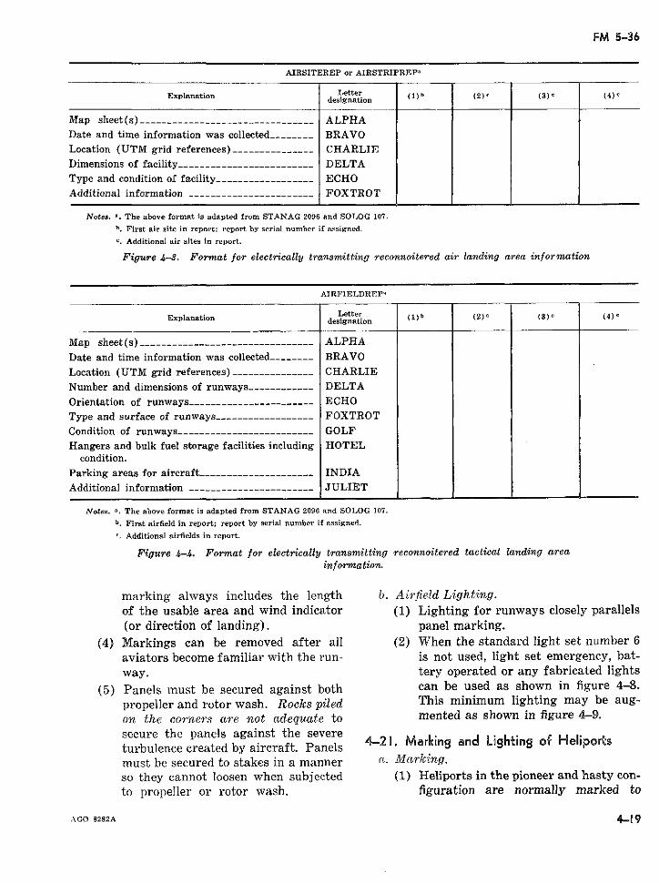
FM 5-36
AIRSITEREP or AIRSTRIPREP,
Explanation Letter ()b (2)e (3) (4)designation (1) (2) (
Map sheet (s) _____________________--_-_____-- ALPHADate and time information was collected_-______ BRAVOLocation (UTM grid references) ______-- _______ CHARLIEDimensions of facility-_____________-----______ DELTAType and condition of facility________-_________ ECHOAdditional information ---- _________-- -_______ FOXTROT
Notes. ". The above format is adapted from STANAG 2096 and SOLOG 107.
b. First air site in report; report by serial number if assigned.
'. Additional air sites in report.
Figure 4-3. Format for electrically transmitting reconnoitered air landing area information
AIRFIELDREPa
Explanation Letter (1) b (2) () (4)E
~~~Explanation ~designation
Map sheet(s) --_----------------------------- ALPHA
Date and time information was collected-------- BRAVO
Location (UTM grid references) --------------- CHARLIE
Number and dimensions of runways ----------- DELTA
Orientation of runways ---------------------- ECHOType and surface of runways ----------------- FOXTROTCondition of runways--------_---------------- GOLFHangers and bulk fuel storage facilities including HOTEL
condition.Parking areas for aircraft -------....-------- INDIAAdditional information --.---------.---------- JULIET
Notes. a. The above format is adapted from STANAG 2096 and SOLOG 107.
b. First airfield in report; report by serial number if assigned.
r. Additional airfields in report.
Figure 4-4. Format for electrically transmitting reconnoitered tactical landing areainformation.
marking always includes the length b). Airfield Lighting.of the usable area and wind indicator (1) Lighting for runways closely parallels(or direction of landing). panel marking.
(4) Markings can be removed after all (2) When the standard light set number 6aviators become familiar with the run- is not used, light set emergency, bat-way. tery operated or any fabricated lights
(5) Panels must be secured against both can be used as shown in figure 4-8.propeller and rotor wash. Rocks piled This minimum lighting may be aug-on the corners are not adequate to mented as shown in figure 4-9.secure the panels against the severeturbulence created by aircraft. Panels 4-20. Marking and Lighting of Helipor:smust be secured to stakes in a manner a. Marking.so they cannot loosen when subjected (1) Heliports in the pioneer and hasty con-to propeller or rotor wash. figuration are normally marked to
AGO 8282A 4-19
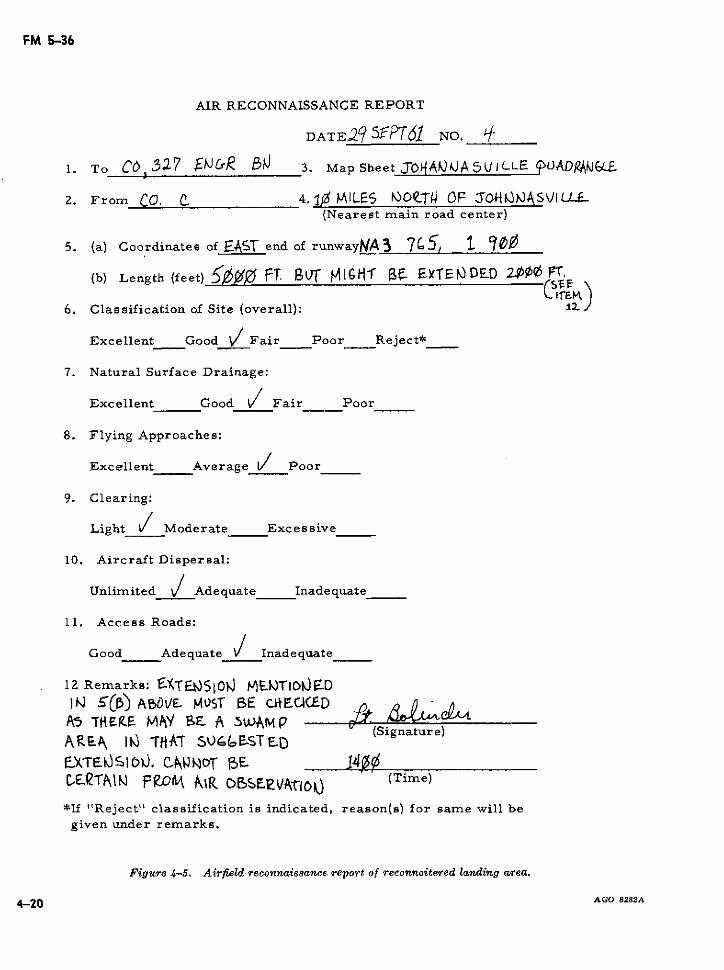
FM 5-36
AIR RECONNAISSANCE REPORT
DATE29 5EPT51 NO. q_
1. To CD3527 M&Ra 3. Map Sheet J-O04)JAS/ICL.LE UÁADAM.JLE
2. From CO. C 4. Ii MILES NuOTC.TU OF SOY4\ ViLLU-(Nearest main road center)
5. (a) Coordinates of EAST end of runwayNA3 7I5, 1 00
(b) Length (feet) MffH FT. [ MI-GHf 6. £XTEiDED ~ FT.
6. Classification of Site (overall): 1
Excellent Good / Fair Poor Reject*
7. Natural Surface Drainage:
Excellent Good / Fair Poor
8. Flying Approaches:
Excellent Average / Poor
9. Clearing:
Light / Moderate Excessive
10. Aircraft Dispersal:
Unlimited 1 Adequate Inadequate
11. Access Roads:
Good Adequate / Inadequate
12 Remarks: EXTUESlOVJ -r)TIOcN)ED
IK :(5) ABD^E- MSrT BE ci*E.CACEDAs TtMRE MNY BE A s5AMP
T(Signature)ARE& 1Ñ T-AT S50~CtSTED,kTEúSI b0, CN3ROr 05E. 141ACE\CTEI.K FWMk A\R Co>SFeVt'oT (Time)
*If "Reject" classification is indicated, reason(s) for same will begiven under remarks.
Figure 4-5. Airfield reconnaissance report of reconnoitered landing area.
4-20 AGO 8282A
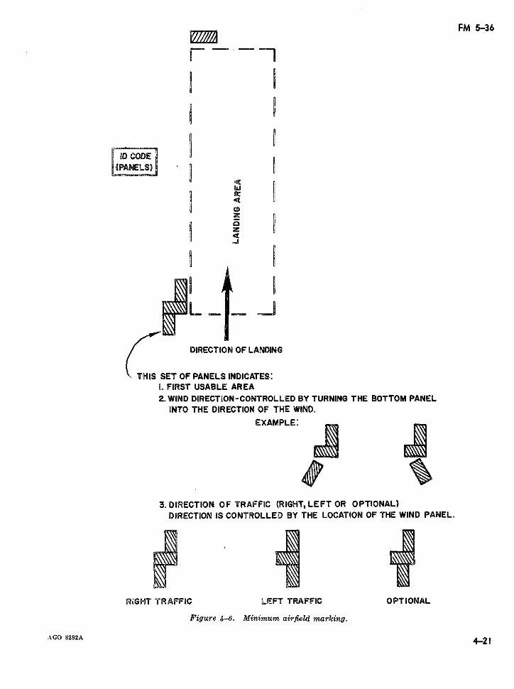
FM 5-36
r--
a a a¡LII
z
L_4
/j ~ DIRECTION OF LANDING
THS ET OF PANELS INDICATES:O. FIRST USABLE AREA2. WIND DIRECTION-CONTROLLED BY TURNING THE BOTTOM PANEL
INTO THE DIRECTION OF THE WIND.EXAMPLE:
3. DIRECTION OF TRAFFIC (RIGHT, LEFT OR OPTIONAL)DIRECTION IS CONTROLLED BY THE LOCATION OF THE WIND PANEL.
RIGHT TRAFFIC LEFT TRAFFIC OPTIONAL
Figure 4-6. Minimum airfield marking.
.AGO 8282A 4-214-21
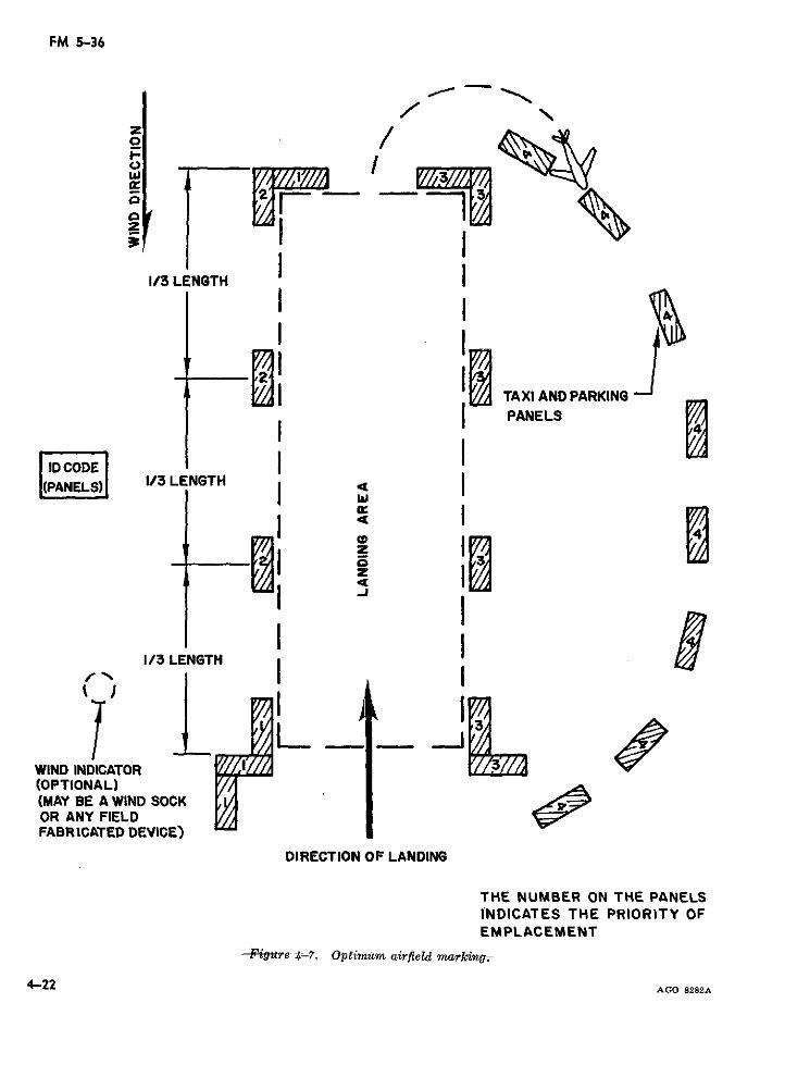
FM 5-36
z
LI
1/3 LENGTH
I I
| STAXI AND PARKINGPANELS
ID CODE
~~I rz
1/3 LENGTH
WIND INDICATOR(OPTIONAL)(MAY BE A WIND SOCKOR ANY FIELDFABRICATED DEVICE)
DIRECTION OF LANDING
THE NUMBER ON THE PANELSINDICATES THE PRIORITY OFEMPLACEMENT
-Fi.ttr~ ~:-7. Optirnum airtield marking7.
4-22 AGO 8282A
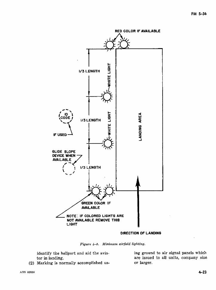
FM 5-36
RED COLOR IF AVAILABLE
1/3 LENGTH "
I-I
[ ID w .%CODE 0 w
, .1/3 LENGTH _
\ 0
IF USED 3 z
GLIDE SLOPEDEVICE WHEN 7AVAILABLE
f gB 1/3 LENGTH
GREEN COLOR IFAVAILAFLE
NOTE: IF COLORED LIGHTS ARENOT AVAILABLE REMOVE THISLIGHT
DIRECTION OF LANDING
Figure 4-8. Minimum airfield lighting.
identify the heliport and aid the avia- ing ground to air signal panels whichtor in landing. are issued to all units, company size
(2) Marking is normally accomplished us- or larger.
AGO 8282A 4-23
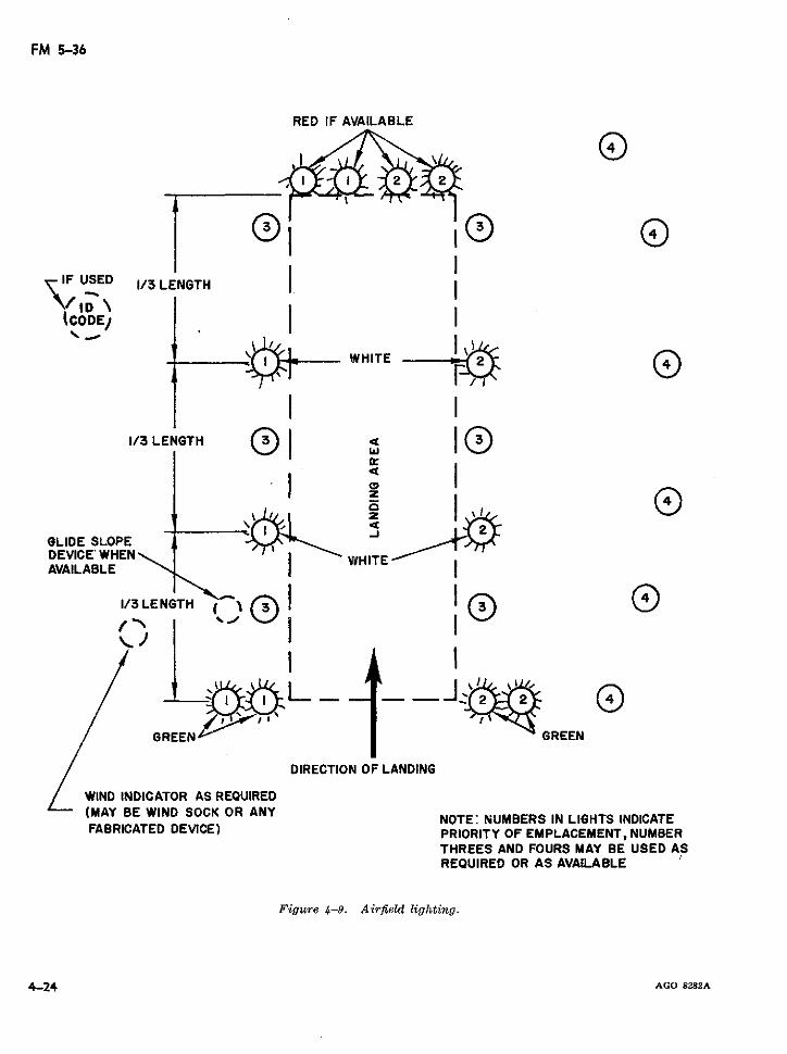
FM 5-36
RED IF AVAILABLE
,IF USED 1/3 LENGTH 1
(CODEJ
WHITE
¡ I1/3 LENGTH (. 1 I i
D \ZGLIDE SLOPEDEVICE WHEN WHITEAVAILABLE
I/3 LENGTH N' ~
"IXxC~· t 9 I '_ -GREEN GREEN
DIRECTION OF LANDING
WIND INDICATOR AS REQUIRED(MAY BE WIND SOCK OR ANY NOTE: NUMBERS IN LIGHTS INDICATEFABRICATED DEVICE) PRIORITY OF EMPLACEMENT, NUMBER
THREES AND FOURS MAY BE USED ASREOUIRED OR AS AVAILABLE
Figure 4-9. Airfield lighting.
4-24 AGO 8282A
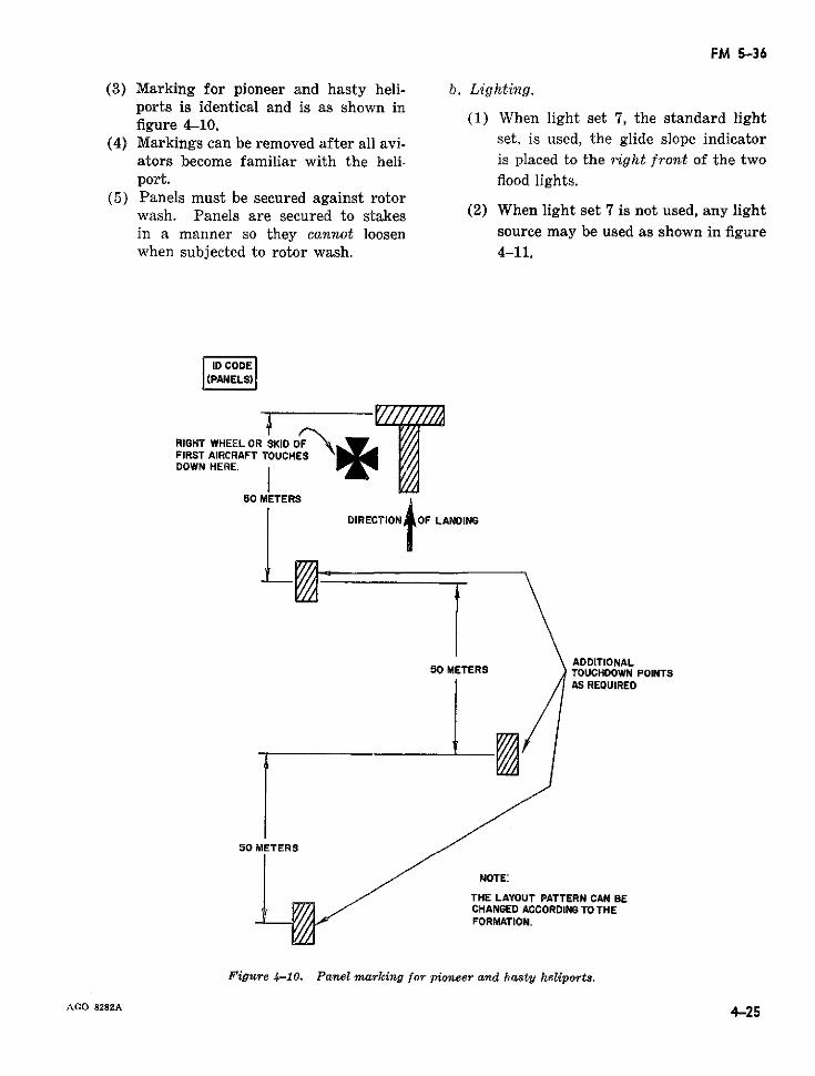
FM 5-36
(3) Marking for pioneer and hasty heli- b. Lighting.ports is identical and is as shown infigure d10. (1) When light set 7, the standard light
(4) Markings can be removed after all avi- set. is used, the glide slope indicatorators become familiar with the heli- is placed to the 9ight front of the twoport. flood lights.
(5) Panels must be secured against rotorwash. Panels are secured to stakes (2) When light set 7 is not used, any lightin a manner so they cannot loosen source may be used as shown in figurewhen subjected to rotor wash. 4-11.
ID CODE|L(PANELS)
RIGHT WHEEL OR SKID OFFIRST AIRCRAFT TOUCHESDOWN HERE.
50 METERS
DIRECTION OF LANDING
ADDITIONALSO METfERS ' TOUCHDOWN POINTS
AS REQUIRED
50 METERS
NOTE:
THE LAYOUT PATTERN CAN BECHANGED ACCORDING TO THEFORMATION.
Figure 4-10. Panel marking for pioneer and hasty heliports.
AGO 8282A 4-25
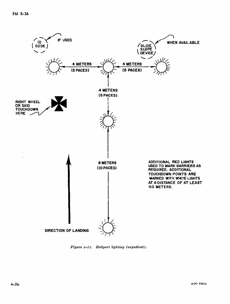
FM 5-36
IDF USED _ N WHEN AVAILABLE
( CODE /GULDE/ SLOPE
xJ v~~~~~~~~ \ DEVICE/
4 METERS 4 METERS
, "*/ (5 PACES) (5 PACES)
4 METERS(5 PACES)
RIGHT WHEELOR SKIDTOUCHDOWNHERE
8 METERS ADDITIONAL RED LIGHTSUSED TO MARK BARRIERS AS
(¡O PACES) REQUIRED. ADDITIONALTOUCHDOWN POINTS AREMARKED WITH WHITE LIGHTSAT A DISTANCE OF AT LEAST50 METERS.
DIRECTION OF LANDING
Figure 4-11. Heliport lighting (expedient).
4-26 AGO 8282A
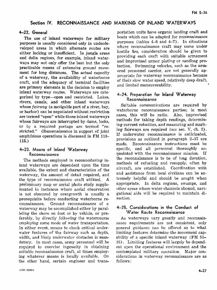
FM 5-36
Section IV. RECONNAISSANCE AND MARKING OF INLAND WATERWAYS
4-22. General portation units have organic landing craft andThe use of inland waterways for military boats which can be adapted for reconnaissance
purposes is usually considered only in underde- purposes (tables 4-6 and 4-7). In situationsveloped areas in which alternate routes are where reconnaissance craft may come undereither lacking or insufficient. In jungle areas hostile fire, consideration should be given toand delta regions, for example, inland water- providing each craft with suitable armamentways may not only offer the best but the only and improvised armor plating or sandbag pro-practicable means of extensive ground move- tection. Swimming vehicles, such as the arm-ment for long distances. The actual capacity ored personnel carrier, are not generally ap-of a waterway, the availability of waterborne propriate for waterway reconnaissance becausecraft, and the adequacy of terminal facilities of their slow water speed, relatively deep draft,are primary elements in the decision to employ and limited maneuverability.inland waterway routes. Waterways are cate- 24. Preparagorized by type-open and restricted. Lakes, 24 e n fr nland Waerwayrivers, canals, and other inland waterways Reconnaissancewhose fairway (a navigable part of a river, bay, Suitable communications are required byor harbor) can be negotiated without restriction waterborne reconnaissane parties; in mostare termed "open" while those inland waterways cases, this will be radio. Also, improvisedwhose fairways are interrupted by dams, locks, methods for taking depth readings, determin-or by a required portage are termed "re- ing current velocities, and measuring and mark-stricted." (Reconnaissance in support of joint ing fairways are required (see sec. V, ch. 2).amphibious operations is discussed in FM 110- underwater reconnaissance is anticipated,amphibious operations is discussed 115.) n FM provisions as outlined in paragraph 2-37 are
made. Reconnaissance instructions must be4-23. Means of Inland Waterway specific, and all personnel thoroughly ac-
Reconrnaissance quainted with the reconnaissance mission. IfThe methods employed in reconnoitering in- the reconnaissance is to be of long duration,
land waterways are dependent upon the time methods of refueling and resupply, often byavailable, the extent and characteristics of the aircraft, are established. Coordination withwaterway, the amount of detail required, and and assistance from local civilians can be ex-the type of reconnaissance craft utilized. A tremely helpful and should be sought whenpreliminary map or aerial photo study supple- appropriate. In delta regions, swamps, andmented in instances where aerial observation other areas where water channels abound, navi-is not obscured by overgrowth is usually a gational aids will be required to maintain di-prerequisite before conducting waterborne re- rection.connaissance. Ground reconnaissance of awaterway may be accomplished either by paral- 4-25. Considerations in the Conduct ofleling the shore on foot or by vehicle, or pre- Water Route Reconnaissanceferably, by directly following the watercourse As waterways vary greatly and reconnais-employing some mode of water transportation. sance requirements are not consistent, onlyIn either event, means to check critical under- general guidance can be offered as to whatwater features of the fairway such as depth, limiting features determine the movement cap-width, and likely underwater obstacles is man- ability of a specific inland waterway (FM 55-datory. In most cases, army personnel will be 15). Limiting features will largely be depend-required to exercise ingenuity in obtaining ent upon the operational environment and thesuitable reconnaissance craft, at times employ- contemplated military operation. Major con-ing whatever means is locally available. On siderations in waterway reconnaissance are asthe other hand, certain engineer and trans- follows:
AGO 8282A 4-27
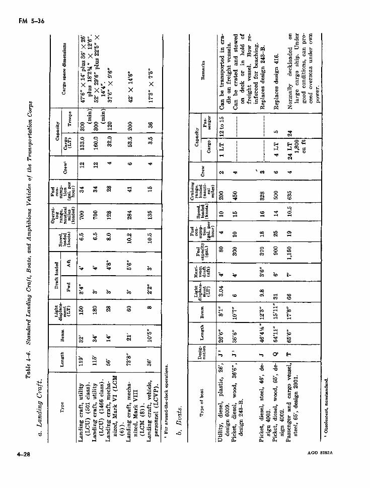
FM 5-36
coa X · '" ,.4Q
U,. U*~)cr C l. o
x ,z
~x
x 4, B o, _
. '~ . -°Ue ce <ic <e c ce i ¡ LeCd , 0 ',A C> bz N so zn 9 o Q> l~~u
e - ~ ~ ~ ~ ~ ~ ~ ~ ~ ~ ~ ~ ~ ~~~c -4 ¡¡cd .<
· 1X ·i x x ~.,.,
e-'~~~~~~ ~ ~ ~~ O O,~ Oo te te -'d~
ce ce ce tei eD E-' 1 E E O' 0i~ ni cu ~· o! F:4>~. ce a 3 b o °
e~~~~~~~~~~~~~~~~~~~~~~~~~~
4, -,~"- ll .~. . , ec4~Z
mc c c I I
F?~ ~ ~ ~ ~ ~~ 0E O~ te c Oc
V.. Cdr 0 ' -c -0~~~~~~~~~~~~~~~~~~~~~O 01 t'-4 0 t.
,z te or ~ ~
-Jc ce ce o O in
od -; O o O O
0 QQ- zO D <= l 00 V
c -_ _ _ _ _ _ _ _ _ _ _ _ _o o o t
U, -4~~i ¿ 6 ; 0 r,1- I
- 4>
Jo
·. <»'-í
rO Cr) ( ~~D iD DV I IlC,
U -
~---28~u ~ ~ ~ ~ ~ c cO Id2
~~·ct~~~ - ce>
Y; I ] I I U~~~~~~~~~~'D I
LO 00 cli to 0>
"o,~~~~~~~~~~~~~~~~~~~~~~~~~~~~sw o ce o ceLo
ce> ce d- ce -4i ceo) c t t
<u D ~ ~ ~ ci~CD w.;a~~~~~~~~~~~~~~~~~~~~~.
E -,;trcaE
U5 U ' p O ce e c u' te
ce c1e z CID e ew. ce c
¡ ce~~~~~~~~~~~~~~~~~~~~~~~~~~~~~~~~~~l
f~~~~~~~~~~~ .o~~~~~~~~~~~~z.i ~ c 4, ce ce ce~J
CID o)
41~ ~ ~ ~ ~ ~~~~~~~~~~~~~~~~~~~~~~~C-e c ce
~~o ~ ~ ~ ~ M nco? U r
0 ce Uhe ho to to il ~ ~ ~ ce ~ ~ 4
0 Cd Cd . co~ c e o
<4 04 (D a P
4-28 AGO 8282A~~~~~~~~~~~~~~~~~~~8
4ce O *-.Z'.-~~~~~~ 'odJ.
n, cu.f~'BC1 Ecc ro o ~-nic o- m i
¿~ ~'c m o,4 ~J i'~~~~~~~~iPE:~ ~ ~ ~ ~ ~ ~~,UoU U,
4-8 AG 8282ACP
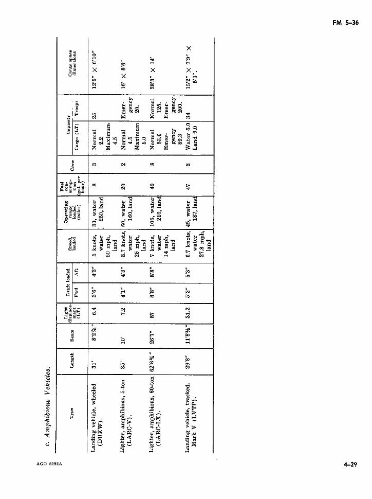
FM 5-36
x
Nt CC D k m¢Iz
oo
mu, t
a) c; ni1
;~.~ao0 r:
a cq C>O
Id c o o C
n r..rdu r..t~ o S
Aco _' E 4 - 2
u z S t S tX B;"
0: N f O
cS0r ccI cq 00
mc~~~~~~c.95
g;ta E Nn t < tzX C C- - X _ _
o _ N o o o u,: c cq
0 c r
o: S d c a s - W sE ?r
$ s t t t t~~~t t-
i,; C; COl t- ri 0a
E! ue > $· o o r
.~~~r
C HOY^ ,, 1 0E =~~~~~~~~??
CC t- N N
ÍA a, A co tcqu
con~~o
u; u>~~~~~~~~~Q
O A C A A . C~~C >>
o o! e b ¢ ¢
AGO 8282A 4-29
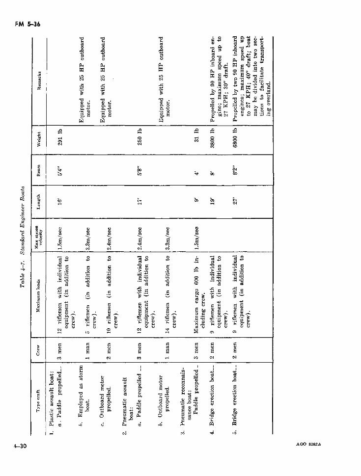
FM 5-36
o~~~2
o d o ov
0r 0
O o O or - u X ;
X~~~~ ;
. o j o: j- j 5
EE~e e; c- =~ e- = 2e U3
·· Q SE E ·r Ci EP
Cl Cl~~~~~~~~~~~~~~~~~~~CE cu 0Com
o~~~~~~~~~~~~~~~~~~~~~~~~~c
?z ~~~~C a) Q->
....... .
Q~ o E E: E E s1s ° E E E w; U
r E ro en ul r
W W W ° t
g > CID CIDe ~~~~~~~~~c¿ c c' ~ o
Y Q) eo Q)O O
.0 .0~~~~~~~~~~~
E oi
E E
O P o.> n
O) ~~.) C.> O.> O.>O.>P C) d .> O) z. O .Cl O C~~~~~~~~~~~l i (
O0 ) CO O> . COO ) O
p s ul aoi
cE 1 ¡8
p~~~ 0 0~* +
0~~~~~
d P.
B~~~~~~
U)l -E O o g u
) o.
U) O1 o-- O)
P.< al Al pp pp~~.o .0 CO C O
-*~~~ ~ . U
Cl-c C C O
4-30 AGO 8282A
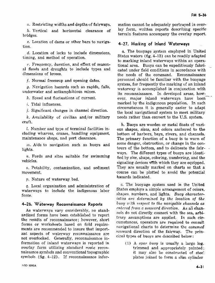
FM 5-36
a. Restricting widths and depths of fairways. mation cannot be adequately portrayed in over-b. Vertical and horizontal clearance of lay form, written reports describing specific
bridges. terrain features accompany the overlay report.
c. Location of dams or other bars to naviga- 4-27. Marking of Inland Waterwaystion.
d. Location of locks to include dimensions, a. The buoyage system employed in Unitedtiming, and method of operation. States waters (fig. 4-13) can be readily adapted
to marking inland waterways within an opera-e. Frequency, duration, and effect of season- tional area. Buoys can be expeditiously fabri-
al floods and droughts to include types and cated under field conditions in accordance withdimensions of levees. the needs of the command. Reconnaissance
f. Normal freezeup and opening dates. personnel should be familiar with the buoyagesystem, for frequently the marking of an inland
g. Navwgation hazards such as irapds, fal.s, waterway is accomplished in conjunction withunderwater and antiamphibious mines. its reconnaissance. In developed areas, how-
h. Speed and fluctuations of current. ever, major inland waterways have beeni. Tidal influences. marked by the indigenous population. In such
circumstances it is generally easier to adaptj. Significant changes in channel direction. the local navigational system to meet military
k. Availability of civilian and/or military needs rather than convert to the U.S. system.craft.
b. Buoys are wooden or metal floats of vari-I. Number and type of terminal facilities in- ous shapes, sizes, and colors anchored to the
cluding wharves, cranes, handling equipment, bottom of harbors, bays, rivers, and channels.maintenance shops, and port clearance. The primary function of a buoy is to warn of
in. Aids to navigation such as buoys and some danger, obstruction, or change in the con-lights. tours of the bottom, and to delineate the fair-
ways. The different types of buoys are identi-n. Fords and sites suitable for swimming fied by size, shape, coloring, numbering, and the
vehicles. signaling devices vwIth which they are equipped.o. Potability, contamination, and sediment They are usually marked on charts so that a
movement. course can be plotted to avoid the potentialhazards indicated.p. Nature of waterway bed.
q. Local organization and administration of c. The buoyage system used in the Unitedwaterways to include the indigenous labor States employs a simple arrangement of colors,force. shapes. numbers, and lights. Buoy character-
istics are determined by the location of the4-26. Waterway Reconnaissance Reports buoy ¿Lith respect to the navigable channels as
entered fronm c seaward direction. As all chan-As waterways vary considerably, no stand- .As .ateras varyconsdraynels do not directly connect with the sea, arbi-ardized forms have been established to report trary assumptions are applied. In such cir-the results of reconnaissance; however, short cumstances, operators are required to consultforms or worksheets based on fe eure- navigational charts to determine the assumedments are recommended to insure that import- seaward direction of the fairway. The prin-ant aspects of waterway reconnaissance are
not overlooked. Generally, reconnaissance ine cipal types of buoys are described below:not overlooked. Generally, reconnaissance in-formation of inland waterways is reported in (1) A spar buoy is usually a large log.overlay form utilizing standard route recon- trimmed and appropriately painted;naissance symbols and conventional topographic it may also be constructed of stee'symbols (fig. 4-12). If reconnaissance infor- plates joined to form a slim cylinder
A.GO 8282A 4.31
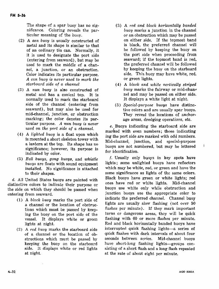
FM 5-36
The shape of a spar buoy has no sig- (3) A red and black horizontally bandednificance. Coloring reveals the par- buoy marks a junction in the channelticular meaning of the buoy. or an obstruction which may be passed
(2) A can buoy is usually constructed of on either side. If the topmost bandmetal and its shape is similar to that is black, the preferred channel willof an ordinary tin can. Normally, it be followed by keeping the buoy onit is used to designate the port side the port side when proceeding from(entering from seaward), but may be seaward; if the topmost band is red,used to mark the middle of a chan- the preferred channel will be followednel, a junction, or an obstruction. by keeping the buoy on the starboardColor indicates its particular purpose. side. This buoy may have white, red,A can buoy is never used to mark the or green lights.starboard side of a channel (4) A black and white vertically striped
(3) A nun buoy is also constructed of buoy marks the fairway or mid-chanJmetal and has a conical top. It is nel and may be passed on either side.normally used to mark the starboard It displays a white light at night.side of the channel (entering from (5) Special-purpose buoys have distinc-seaward), but may also be used for tive colors and are usually spar buoys.mid-channel, junction, or obstruction They reveal the locations of anchor-marking; the color denotes its par- age areas, dredging operations, etc.ticular purpose. A nun buoy is neverused on the poArt side of a channel. e. Buoys indicating the starboard side are
sed on the port side of a channel. marked with even numbers; those indicating(4) A lighted buoy is a float upon which ing the port side are marked with odd numbers.
is mounted a short skeleton tower withmounted a short skeleton tower with Mid-channel, junction, and special-purposea lantern at the top. Its shape has noa lantern at the top. Ithape has no buoys are not numbered, but may be letteredsignificance; however, its purpose for identification.indicated by color.
(5) Bell buoys, gong buoys, and whistle f. Usually only buoys in key spots havebuoys are floats with sound equipment lights; some unlighted buoys have reflectorsinstalled. No significance is attached which may be white, red, or green and have theto their shapes. same significance as lights of the same colors.
d. All United States buoys are painted with Black buoys have green or white lights; reddistinctive colors to indicate their purpose or ones have red or white lights. Mid-channelthe side on which they should be passed when buoys use white only while obstruction andentering from seaward. junction buoys use the appropriate color to
(1) A black buoy marks the port side of indicate the preferred channel. Channel buoya channel or the location of obstruc- lights are usually slow flashing (not over 30tions which must be passed by keep- flashes per minute). If they mark importanting the buoy on the port side of the turns or dangerous areas, they will be quickvessel. It displays white or green flashing with 60 or more flashes per minute.lights at night. Red and black horizontally banded buoys have
(2) A red buoy marks the starboard side interrupted quick flashing lights-a series ofof a channel or the location of ob- quick flashes with dark intervals of about fourstructions which must be passed by seconds between series. Mid-channel buoyskeeping the buoy on the starboard have short-long flashing lights-groups con-side. It displays white or red lights sisting of a short flash and a long flash repeatedat night. at the rate of about eight per minute.
4-32 AGO 8282A
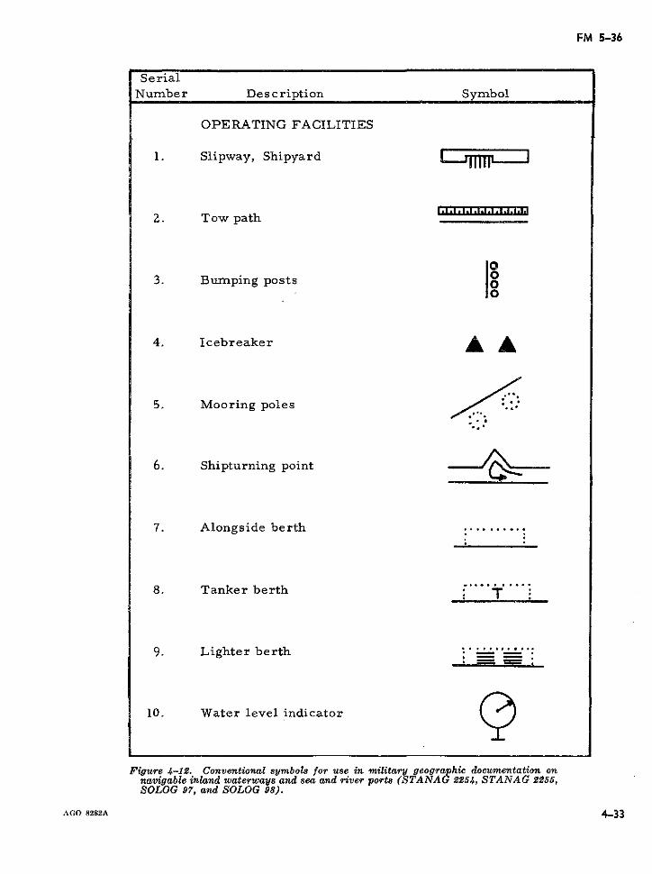
FM 5-36
SerialNumber Description Symbol
OPERATING FACILITIES
1. Slipway, Shipyard !
2. Tow path
3. Bumping posts
4. Icebreaker
5. Mooring poles /.
6. Shipturning point
7. Alongside berth
8. Tanker berth
9. Lighter berth
10. Water level indicator
Figure 4-12. Conventional symbols for use in military geographic documentation onnavigable inland waterways and sea and river ports (STANAG 2254, STANAG 2255,SOLOG 97, and SOLOG 98).
AGO 8282A 4-33
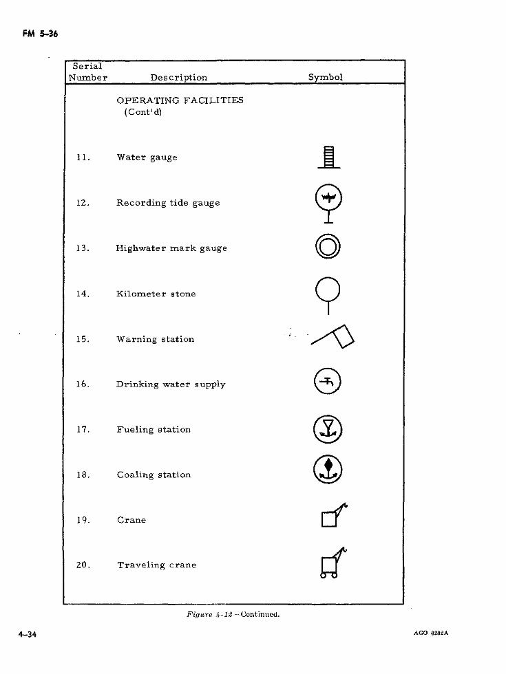
FM 5-36
SerialNumber Description Symbol
OPERATING FACILITIES(Cont'd)
11. Water gauge
12. Recording tide gauge
13. Highwater mark gauge
14. Kilometer stone
15. Warning station
16. Drinking water supply
17. Fueling station
18. Coaling station
19. Crane íI
20. Traveling crane
Figure 4-12-Continued.
4-34 AGO 8282A
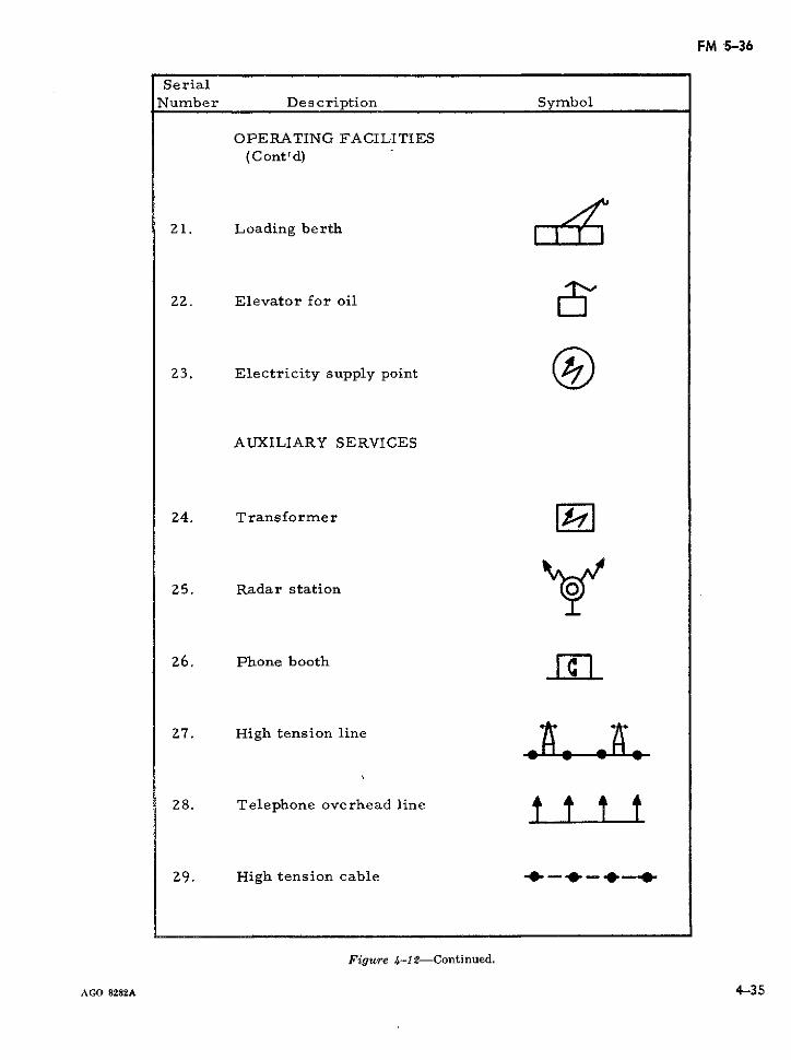
FM '5-36
SerialNumber Description Symbol
OPERATING FACILITIES(C ont ' d)
21. Loading berth
22. Elevator for oil
23. Electricity supply point
AUXILIARY SERVICES
24. Transformer -
25. Radar station
26. Phone booth
27. High tension line
28. Telephone overhead line t t t t
29. High tension cable '-- - _-
Figure 4-12-Continued.
AGO 8282A 4-35
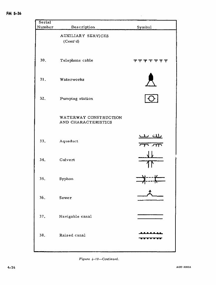
FM 5-36
Serial'Number Description Symbol
AUXILIARY SERVICES
(C ont' d)
30. Telephone cable TTr T T
31. Waterworks
32. Pumping station
WATERWAY CONSTRUCTIONAND CHARACTERIS.TICS
33. Aqueduct
34. Culvert
35. Syphon
36. Sewer
37. Navigable canal
38. Raised canal
Figure 4-12-Continued.
14-36 AGO 8282A
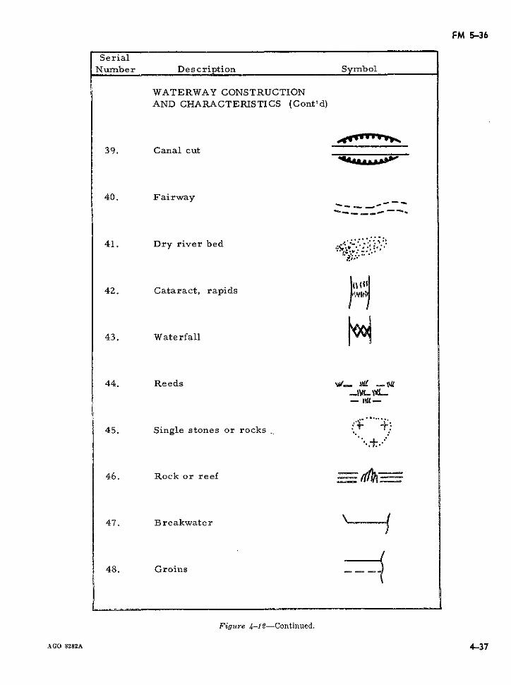
FM 5-36
SerialNumber Description Symbol
WATERWAY CONSTRUCTIONAND CHARACTERISTICS (Cont'd)
39. Canal cut
40. Fairway -
--- __ _----
41. Dry river bed .: .
42. Cataract, rapids
43. Waterfall
44. Reeds W' wg .-1- IgL{
45. Single stones or rocks
46. Rock or reef _- tl
47. Breakwater
48. Groins
Figure 4-12-Continued.
AGO 8282A 4-37
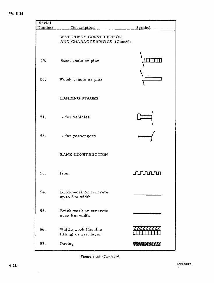
FM 5-36
SerialNumber Description Symbol
WATERWAY CONSTRUCTIONAND CHARACTERISTICS (Cont'd)
49. Stone mole or pier
50. Wooden mole or pier
LANDING STAGES
51. - for vehicles - -
52. - for passengers
BANK CONSTRUCTION
53. Iron Ji
54. Brick work or concreteup to 5 m width
55. Brick work or concreteover 5 m width
56. Wattle work (fascinefilling) or grit layer
57. Paving
Figure 4-12-Continued.
AGO 8282A4-38
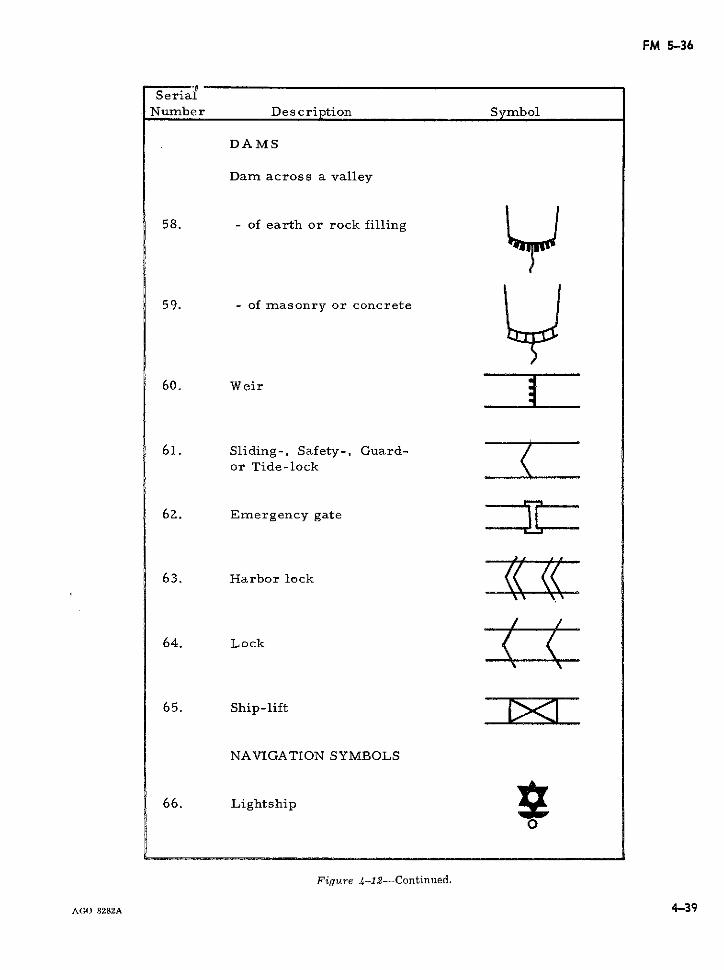
FM 5-36
SerialNumber Description Symbol
DAMS
Dam across a valley
58. - of earth or rock filling
59. - of masonry or concrete
60. Weir
61. Sliding-, Safety-, Guard-or Tide-lock
6Z. Emergency gate ii
63. Harbor lock
64. Lock <
65. Ship-lift
NAVIGATION SYMBOLS
66. Lightship
Figure 4-12-Continued.
AGc. 8282A 4-39
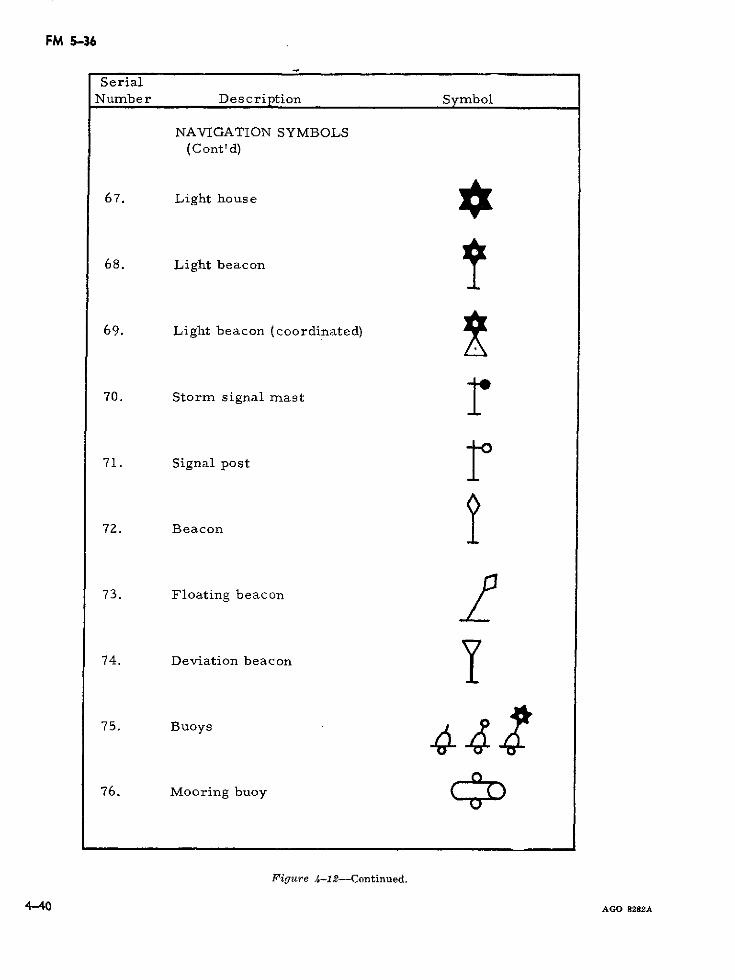
FM 5-36
SerialNumber Description Symbol
NAVIGATION SYMBOLS(Cont'd)
67. Light house *
68. Light beacon
69. Light beacon (coordinated)
70. Storm signal mast r
71. Signal post
72. Beacon
73. Floating beacon
74. Deviation beacon
75. Buoys 4 J
76. Mooring buoy C( D
Figure 4-12-Continued.
4-40 AGO 8282A
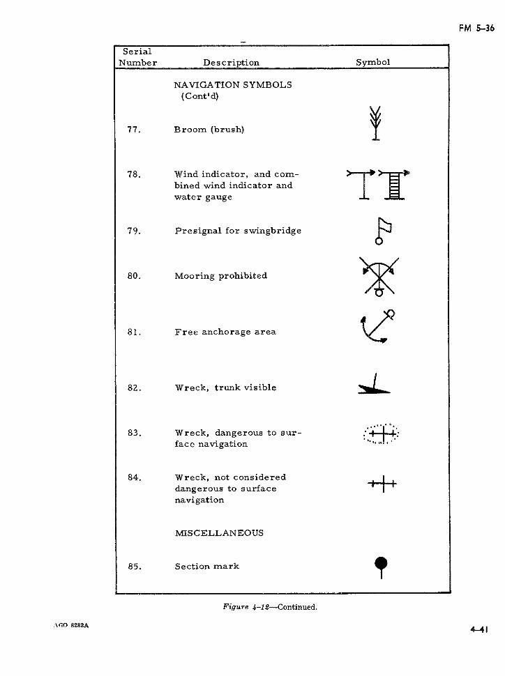
FM 5-36
SerialNumber Description Symbol
NAVIGATION SYMBOLS(Cont'd)
77. Broom (brush)
78. Wind indicator, and com-bined wind indicator andwater gauge
79. Presignal for swingbridge
80. Mooring prohibited
81. Free anchorage area
82. Wreck, trunk visible
83. Wreck, dangerous to sur-face navigation ''
84. Wreck, not considereddangerous to surfacenavigation
MISCELLANEOUS
85. Section mark
Figure 4-12-Continued.
AGO 8282A 4414- I
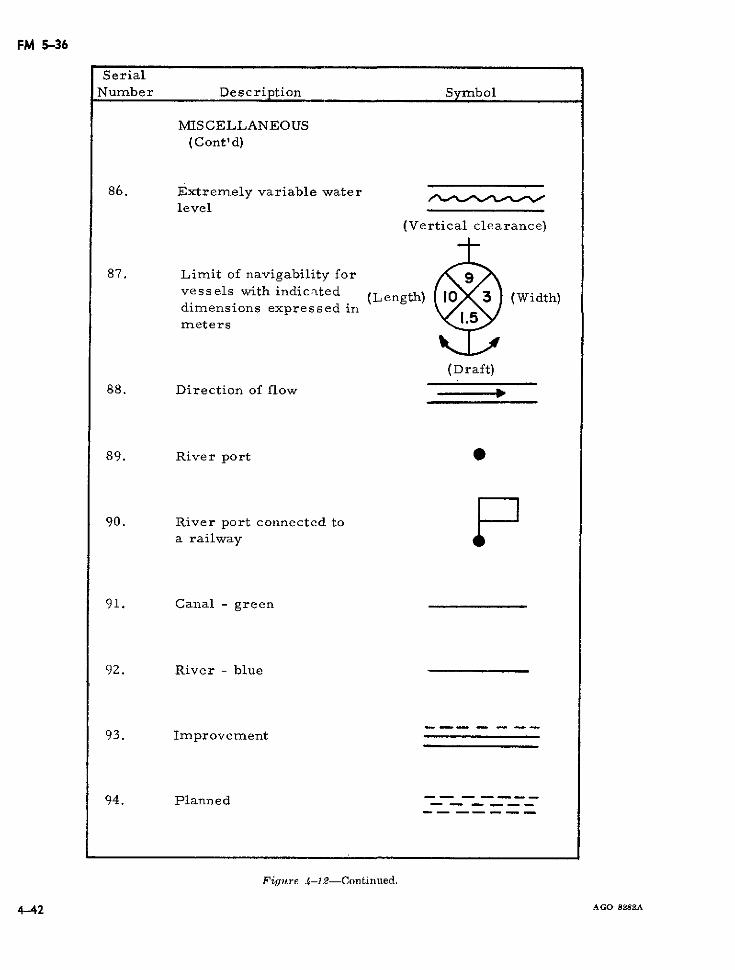
FM 5-36
SerialNumber Description Symbol
MIS CELLANEOUS(C ont' d)
86. Extremely variable waterlevel
(Vertical clearance)
87. Limit of navigability forvessels with indicated (Length) 10X 3 (Width)dimensions expressed inmeters
(Draft)88. Direction of flow
89. River port
90. River port connected to Fa railway
91. Canal- green
92. River - blue
93. Improvement
94. Planned
Figure 4-12-Continued.
4-42 AGO 8282A
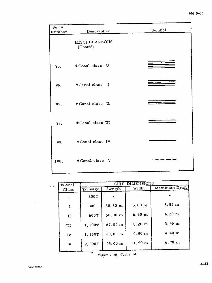
FM 5-36
SerialNumber Des cription Symbol
MISCELLANEOUS(Cont'd)
95. *Canal class O
96. *Canal class I
97. *Canal class II
98. *Canal class III
99. *Canal class IV
100. *Canal class V -
*Canal SHIP DIMENSIONS
Class Tonnage Length Width Maximum Draft
O 300T - -
I 300T 38.50 m 5.00 m 3.55 m
II 600T 50.00 m 6.60 m 4.20 m
III 1, J00T 67.00 m 8.20 m 3.95 m
IV 1,350T 80.00 m 9. 50 m 4.40 m
V 2, 000T 95.00 m 11.50 m 6.70 m
Figure 4-127 -Continued.
AGO 8282A
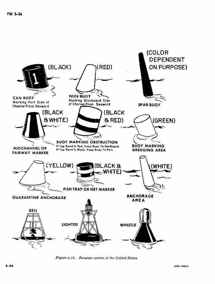
FM 5-36
(COLORDEPENDENT
^ (BLACK) /n(RED) QON PURPOSE)
C-
NUN BUOY -CAN BUOY'CArN BPort SidMarking Starboord SideMorking Port Side of of ChannelFrom Seaward SPAR BUOY
Chonnel From Seaword
(BLACK (BLACK&WHITE) a RED) (G(G REEN)
BUOY MARKING OBSTRUCTIONIf Top Band Is Red, Keep Buoy To Starboard. BUOY MARKING
MIDCHANNEL OR If Top Band ls Black, Keep Buoy To Port. DREDGING AREAFAIRWAY MARKER
(YELLOW) (BLACK & (WHITE)__tI _tW HITE) E)
FISH TRAP OR NET MARKER
QUARANTINE ANCHORAGE NCHORAGEAREA
BELL
LIGHTED //iWHISTLE
Figure 4-13. Buoyage system of the United States.
4_44 AGO 8282A
FM 5-36
Section. V. RECONNAISSANCE OF FOOTPATHS AND TRAILS
4-28. General who are passing through or find themselves atA route of communication is generally a net- a particular geographic point. Trail marks
work of roads over which supplies are carried may be simple or complex, depending upon theand combat movements are made; however, in degree of permanency desired, the amount ofcounterinsurgency operations, footpaths and information to be conveyed, and the require-trails rather than roads often may be the only ment for secrecy to prevent unauthorized per-reliable land means of reaching otherwise in- sons from identifying the trail marks and/oraccessible points. Therefore, particularly in correctly interpreting them.underdeveloped areas of the world where in-surgencies generally occur, forces must be pre- 431. Methods of Trail Markingpared to carry supplies and to conduct combat In an operational environment there willmovements in areas where only footpaths and likely be standard or accepted trail marks al-trails exist. ready in use by indigenous personnel of the
area. Such trail marks will probably utilize4-29. Factors Affecting Reconnaissance natural land marks and available resources of
Various factors affect reconnaissance of foot- the area. In general, conventional methods ofpaths and trails in an area of operations. trail marking include the following:Among these factors are the following: a. Tree blazing with distance and/or direc-
Ca. Degree of influence of the enemy in the tion being shown by the placement of the blazearea. mark.
b. Terrain and climatic features within the b. Marking the underbrush by breakingarea of operations. branches and/or twigs. Direction and method
c. Degree of training and ability of recon- of breaking may indicate direction and/or dis-naissance personnel. tance.
d. Ability to support reconnaissance person- c. Use of sticks, stones, or other indigenousnel through use of signal communications and material placed in particular pattern may con-aircraft. vey distance and/or direction.
d. Marked sticks placed in the ground maybe used to convey information. The length(s)
Trail marks are normally used to assist in of the stick(s) and/or cuts on the sticks mayland navigation by identifying a location, show- indicate various types of information.ing a direction, or indicating a distance. Trailmarks, however, may have other means, such e. Items abnormal to the environment, suchas indicating degree of enemy activity or de- as strings, rags, paper, etc., may be used to
mark a trail.gree of danger within an area. Trail marking,like route marking, is essentially a form of f. Use of paint to mark trees and other land-communication used to convey previously gath- marks may be used to convey almost any quan-ered or established information to personnel tity or type of information.
.\GO 8282A 4-45
FM 5-36
CHAPTER 5
MARKING OF ROUTES
5-1. Purpose and Responsibility (STANAG Table 5-1. General road signs applications-Continued.
2027 and SOLOG 62) TyPe Application
The procedures for the posting of military Crossroad.routes with signs have been standardized for Curves.the United States and allied nations; further- Danger or hazard.
more, the system may be integrated into exist- Dangerous corner.Dips.ing civil systems in accordance with military Junction T.requirements. Signs affecting routes include Junction Y.those specifically posted for the movement of Level railroad crossing, advance warn-troops and supplies and those designed to in- ing.form and to regulate traffic. Preparation and Men working.Railroad crossing.posting of permanent signs for route marking Road construction repairs.
and traffic control is an engineer responsibility. Road narrows.Signs are posted as directed in the traffic cir- Slippery road.
culation plan and traffic control plan. Op- Steep grades.erational responsibility for route signing, how- Steep hill.
ever, remains a command function.Regulatory__ No entry.
5-2. Dimensions One way.Parking restrictions.In general, the size of route signs is not Specific regulations for vehicles.
prescribed; however, they must be sufficiently Speed limit.
large to be easily read under poor lighting Bridge classification.conditions. Exceptions to this rule are bridgeclassification signs (para. 2-52) for which di- Detour begins.Detour begins.mensions are specific. As a guide, signs for Detour ends.civil international road use are normally not Directions.less than 16 inches square (fig. 5-1). Distances.
Information to help driver.
5-3. Types and Application of Signs Locations.Route number.Standard route signs are grouped into three
general types: hazard signs, regulatory signs, a. Militcary hazard signs are used to indicateand guide signs. Application of the three gen- traffic hazards. Employment of these signs ineral types listed in table 5-1. a communication zone normally requires co-
ordination with civil authorities. Hazard signsTable 5-1. General road signs applications. are square in shape and are installed with one
Type Application diagonal in a vertical position. A militaryhazard sign not included in the Geneva Con-
Hazard ____ Advance warning of stop signs and vention or in the system of the host countrytraffic signals.Bumps. has a yellow background with the legend orChanges in road width. symbol inscribed in black (fig. 5-2). The
AGO 8282A 5-1
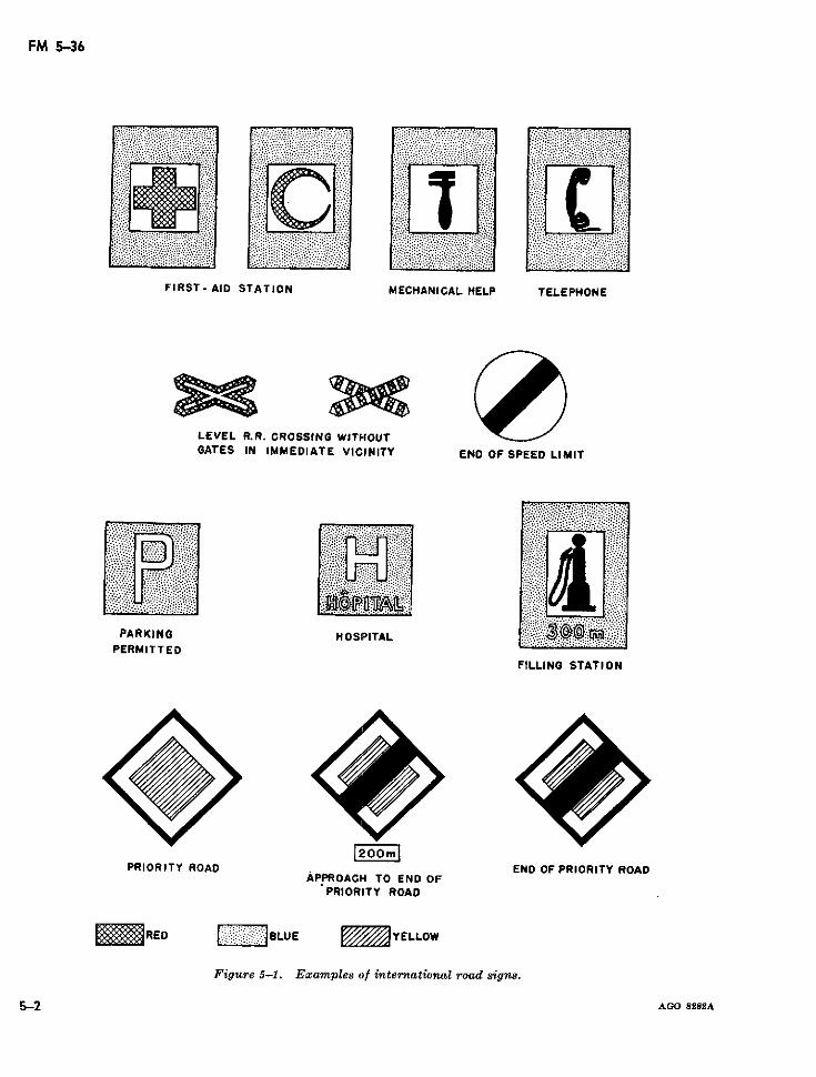
FM 5-36
FIRST- AID STATION MECHANICAL HELP TELEPHONE
LEVEL R.R. CROSSING WITHOUTGATES IN IMMEDIATE VICINITY END OF SPEED LIMIT
PARKING HOSPITALPERMITTEO
FILLING STATION
PRIORITY ROAD END OF PRIORITY ROADAPPROACH TO END OFPRIORITY ROAD
RED BLUE Y ELLOW
Figure 5-1. Examples of international road signs.
5-2 AGO 8282A5.2
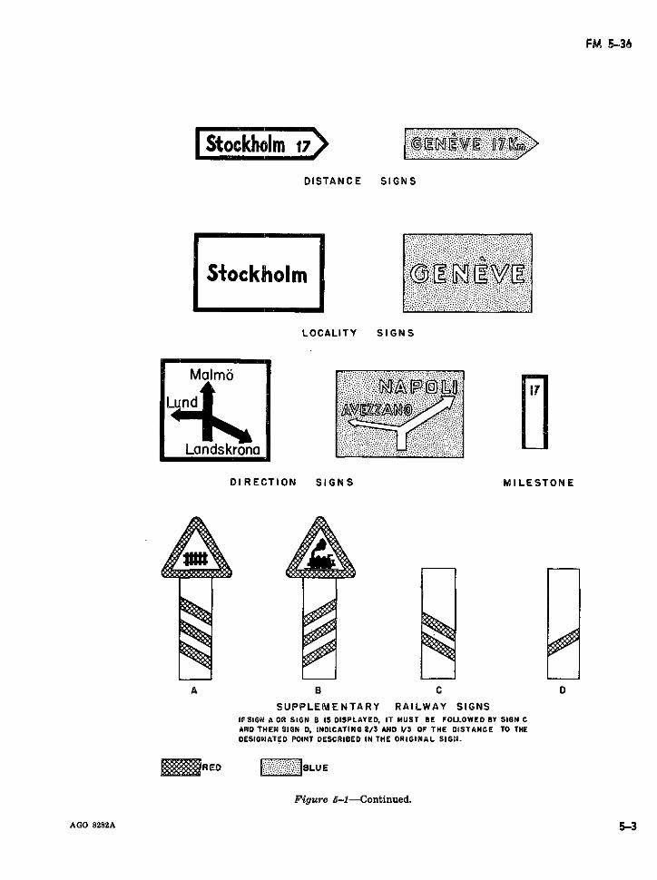
FM 5-36
Stockholm 17
DISTANCE SIGNS
Stockholm
LOCALITY SIGNS
Malmo
Lnd
Landskrona
DIRECTION SIGNS MILESTONE
A B C O
SUPPLEMENTARY RAILWAY SIGNSIFSIGN A OR SIGN B IS DISPLAYED, IT MUST BE FOLLOWED BY SIGN CAND THEN SIGN D, INDICATING 2/3 AND I/3 OF THE DISTANCE TO THEDESIGNATED POINT DESCRIBED IN THE ORIGINAL SIGN.
RED OLUE
Figure 5-1-Continued.
AGO 8282A 5-3
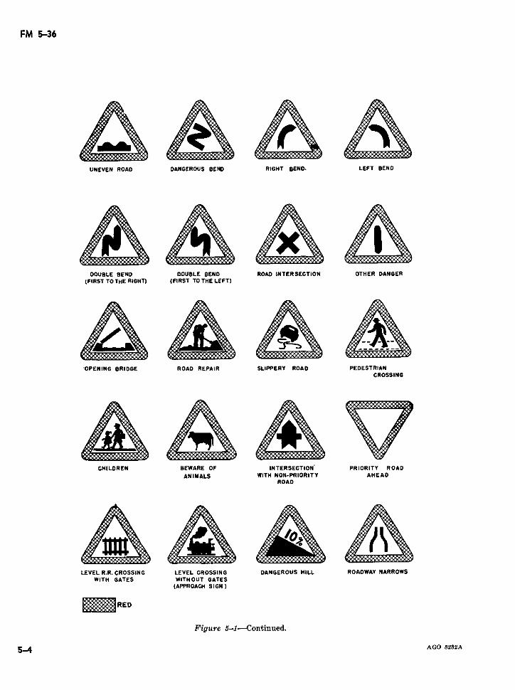
FM 5-36
UNEVEN ROAD DANGEROUS BEND RIGHT SENO, LEFT BENO
DOUBLE BEND DOUBLE BEND ROAD INTERSECTION OTHER DANGER(FIRST TO THE RIOGHT) (FIRST TO THE LEFT)
OPENING BRIDGE ROAD REPAIR SLIPPERY ROAD PEDESTRIANCROSSING
CHILDREN BEWARE OF INTERSECTION' PRIORITY ROAD
ANIMALS WITH NON-PRIORITY AHEADROAD
LEVEL R.R. CROSSING LEVEL CROSSING DANGEROUS HILL ROADWAY NARROWSWITH GATES WITHOUT GATES
(APPROACH SIGN}
RED
Figure 5-1-Continued.
AGO 8282A
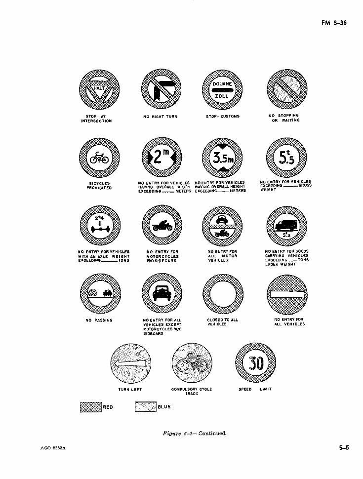
FM 5-36
STOP AT NO RIGHT TURN STOP- CUSTOMS NO STOPPINGINTERSECTION OR WAITING
BICYCLES NO ENTRY FOR VEHICLES NO ENTRY FOR VEHICLES NO ENTRY FOR VEHICLESPROHIBITED HAVING OVERALL WIDTH HAVING OVERALLHEIGHT EXCEEDING - GROSS
EXCEEDING METERS EXCEEDING METERS WEIGHT
NO ENTRY FOR VEHICLES NO ENTRY FOR NO ENTRY FOR NO ENTRY FOR GOODSWITH AN AXLE WEIGHT MOTORCYCLES ALL MOTOR CARRYING VEHICLESEXCEEDING TONS tWOSlOECA*RS VEHICLES EXCEEDING--TONS
LADEN WEIGHT
NO PASSING NO ENTRY FOR ALL CLOSED TO ALL NO ENTRY FORVEHICLES EXCEPT VEHICLES ALL VEHICLESMOTORCYCLES W/OSIDECARS
TURN LEFT COMPULSORY CYCLE SPEED LIMITTRACK
RED "E BLUE
Figure 5-1--Continued.
AGO 8282A 5-5
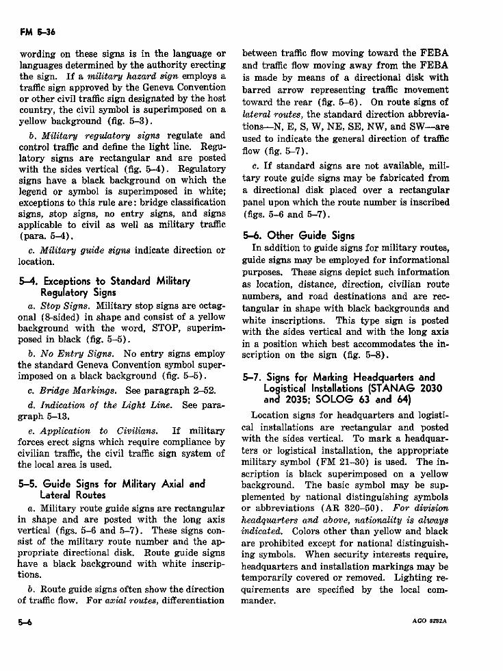
FM 5-36
wording on these signs is in the language or between traffic flow moving toward the FEBAlanguages determined by the authority erecting and traffic flow moving away from the FEBAthe sign. If a military hazard sign employs a is made by means of a directional disk withtraffic sign approved by the Geneva Convention barred arrow representing traffic movementor other civil traffic sign designated by the host toward the rear (fig. 5-6). On route signs ofcountry, the civil symbol is superimposed on a lateral routes, the standard direction abbrevia-yellow background (fig. 5-3). tions-N, E, S, W, NE, SE, NW, and SW-are
b. Military regulatory signs regulate and used to indicate the general direction of trafficcontrol traffic and define the light line. Regu- flow (fig. 5-7).latory signs are rectangular and are postedwith the sides vertical (fig. 5-4). Regulatory c. If standard signs are not available, mili-signs have a black background on which the tary route guide signs may be fabricated fromlegend or symbol is superimposed in white; a directional disk placed over a rectangularexceptions to this rule are: bridge classification panel upon which the route number is inscribedsigns, stop signs, no entry signs, and signs (figs. 5-6 and 5-7).applicable to civil as well as military traffic(para. 5-4). 5-6. Other Guide Signs
c. Military guide signs indicate direction or In addition to guide signs for military routes,location. guide signs may be employed for informational
purposes. These signs depict such information5-4. Exceptions to Standard Military as location, distance, direction, civilian route
Regulatory Signs numbers, and road destinations and are rec-a. Stop Signs. Military stop signs are octag- tangular in shape with black backgrounds and
onal (8-sided) in shape and consist of a yellow white inscriptions. This type sign is postedbackground with the word, STOP, superim- with the sides vertical and with the long axisposed in black (fig. 5-5). in a position which best accommodates the in-
b. No Entry Signs. No entry signs employ scription on the sign (fig. 5-8).the standard Geneva Convention symbol super-imposed on a black background (fig. 5-5). 5-7. Signs for Marking Headquarters and
c. Bridge Markings. See paragraph 2-52. Logistical Installations (STANAG 2030
d. Indication of the Light Line. See para- and 2035; SOLOG 63 and 64)graph 5-13. Location signs for headquarters and logisti-
e. Application to Civilians. If military cal installations are rectangular and postedforces erect signs which require compliance by with the sides vertical. To mark a headquar-civilian traffic, the civil traffic sign system of ters or logistical installation, the appropriatethe local area is used. military symbol (FM 21-30) is used. The in-
scription is black superimposed on a yellow5-5. Guide Signs for Military Axial and background. The basic symbol may be sup-
Lateral Routes plemented by national distinguishing symbolsa. Military route guide signs are rectangular or abbreviations (AR 320-50). For division
in shape and are posted with the long axis headquarters and above, nationality is alwaysvertical (figs. 5-6 and 5-7). These signs con- indicated. Colors other than yellow and blacksist of the military route number and the ap- are prohibited except for national distinguish-propriate directional disk. Route guide signs ing symbols. When security interests require,have a black background with white inscrip- headquarters and installation markings may betions. temporarily covered or removed. Lighting re-
b. Route guide signs often show the direction quirements are specified by the local com-of traffic flow. For axial routes, differentiation mander.
5-6 AGO 8282A
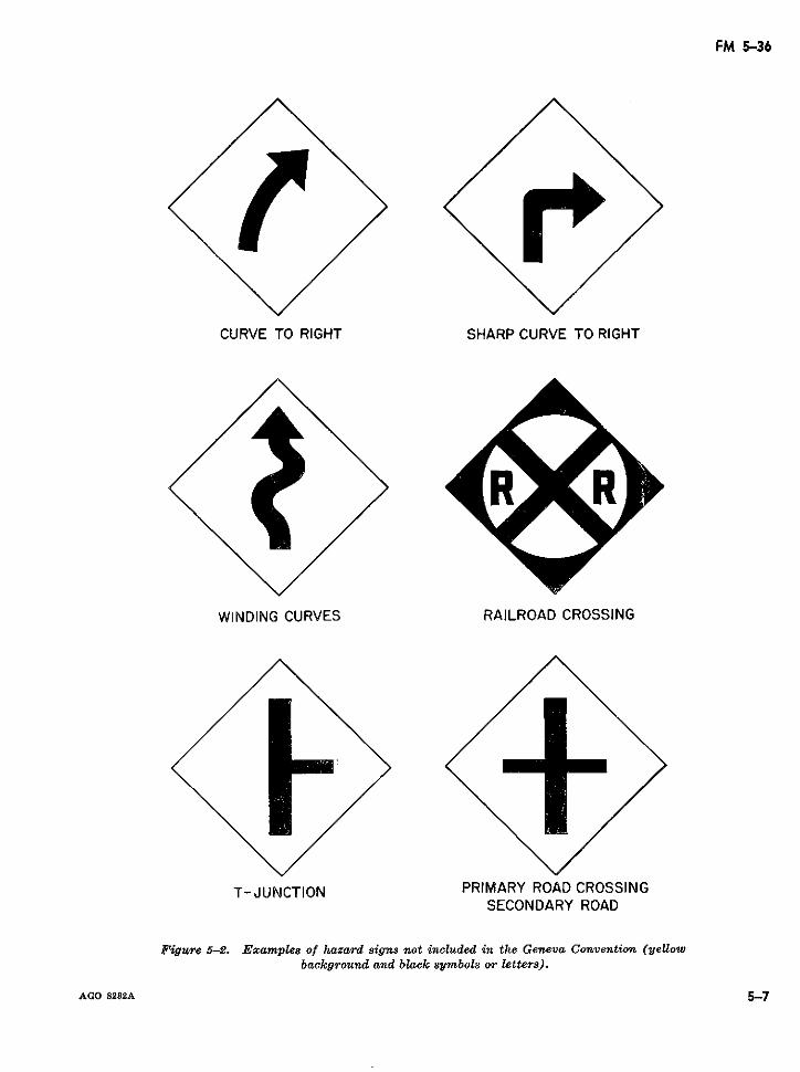
FM 5-36
CURVE TO RIGHT SHARP CURVE TO RIGHT
WINDING CURVES RAILROAD CROSSING
T-JUNCTION PRIMARY ROAD CROSSINGSECONDARY ROAD
Figure 5-2. Examples of hazard signs not included in the Geneva Convention (yeUowbackground and black symbols or letters).
AGO 8282A 5-7
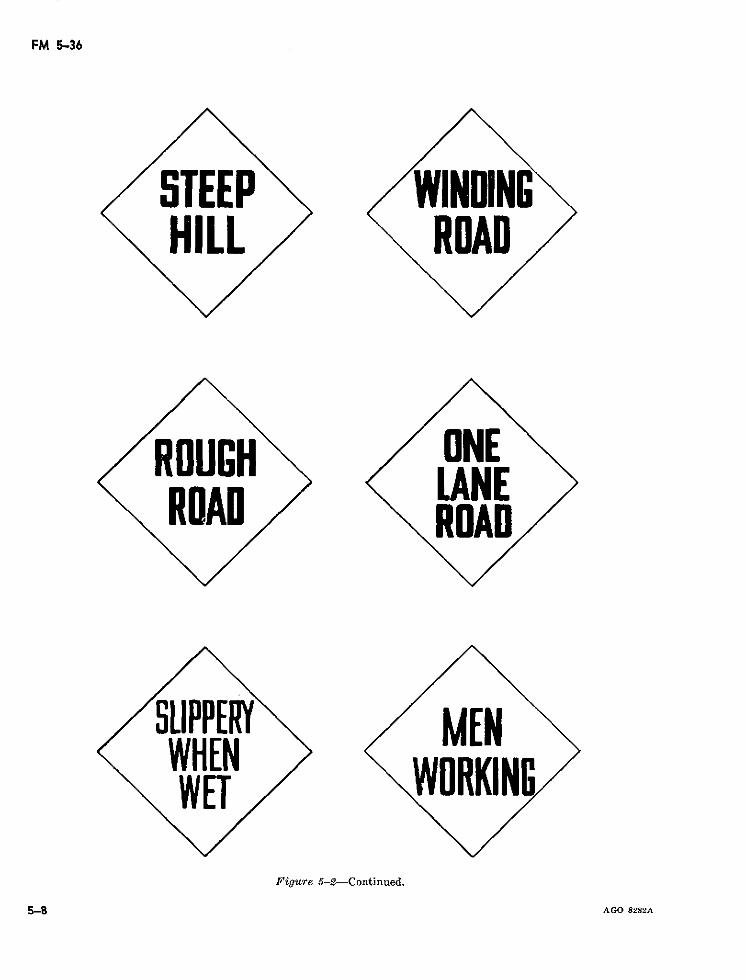
FM 5-36
Figure 5-2----Continued.
S~~~ ~~~~~TEEP vy~~~~~~~~~~~Ao s
ROUGIN HE
RIDAD
CLIPPERY EMHEN KNWET WRl
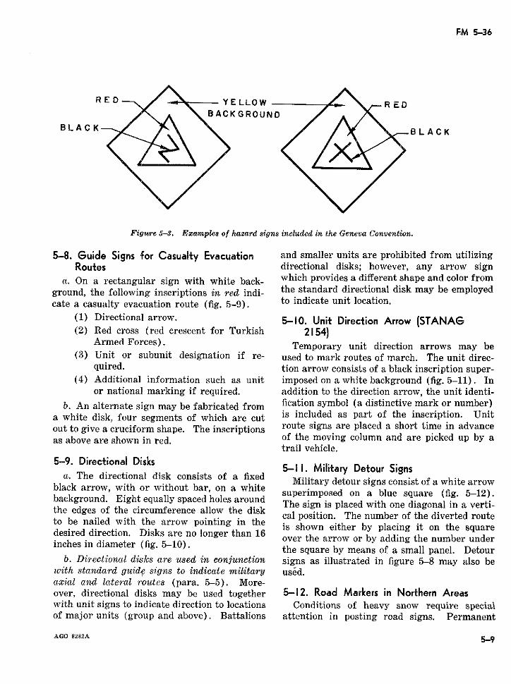
FM 5-36
RED / YE LLOWR E DBACKGROUND
BLACKBLACK
Figure 5-3. Examples of hazard signs included in the Geneva Convention.
5-8. Guide Signs for Casualty Evacuation and smaller units are prohibited from utilizingRoutes directional disks; however, any arrow sign
a. On a rectangular sign with white back- which provides a different shape and color fromground, the following inscriptions in red idi- the standard directional disk may be employedcate a casualty evacuation route (fig. 5-9). to indicate unit location.
(1) Directional arrow. 5-1. Unit Direction Arrow (STANAG(2) Red cross (red crescent for Turkish 2154)
Armed Forces). Temporary unit direction arrows may be(3) Unit or subunit designation if re- used to mark routes of march. The unit direc-
quired. tion arrow consists of a black inscription super-(4) Additional information such as unit imposed on a white background (fig. 5-11). In
or national marking if required. addition to the direction arrow, the unit identi-b. An alternate sign may be fabricated from fication symbol (a distinctive mark or number)
a white disk, four segments of which are cut is included as part of the inscription. Unitout to give a cruciform shape. The inscriptions route signs are placed a short time in advanceas above are shown in red. of the moving column and are picked up by a
trail vehicle.5-9. Directional Disks
5-1 1. Military Detour Signsa. The directional disk consists of a fixed Military detour signs consist of a white arrow
black arrow, with or without bar, on a white superimposed on a blue square (fig. 5-12).background. Eight equally spaced holes around The sign is placed with one diagonal in a verti-the edges of the circumference allow the disk cal position. The number of the diverted routeto be nailed with the arrow pointing in the squaredesired direction. Disks are no longer than 16 over the arrow or by adding the number under
inches in diameter (fig 51) the square by means of a small panel. Detourb. Directional disks are used in conjunction signs as illustrated in figure 5-8 may also be
with standard guide signs to indicate military uséd.axial and lateral routes (para. 5-5). More-over, directional disks may be used together 5-12. Road Markers in Northern Areaswith unit signs to indicate direction to locations Conditions of heavy snow require specialof major units (group and above). Battalions attention in posting road signs. Permanent
AGO 8282A 5-9
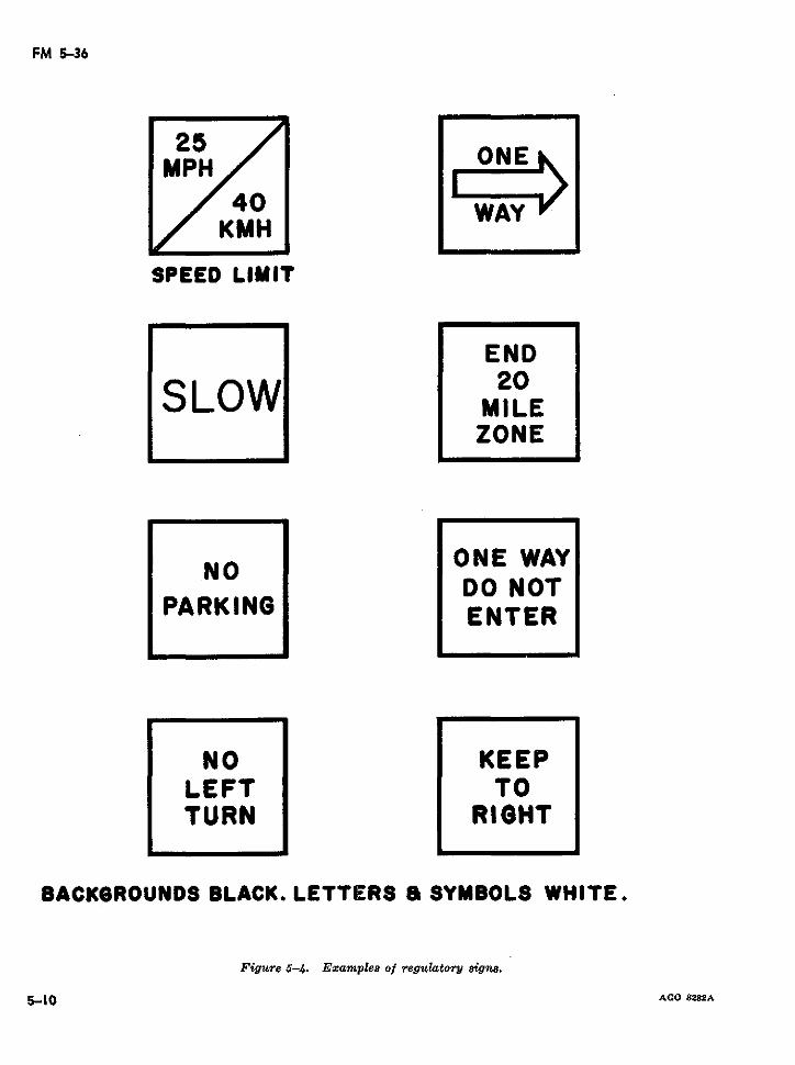
FM 5-36
MPH40
KMH
SPEED LIMIT
END20SLOW MILE
ZONE
~NO ~ONE WAYDO NOT
PARKING DNTERENTER
NO KEEPLEFT TOTURN RIGHT
BACKGROUNDS BLACK. LETTERS a SYMBOLS WHITE.
Figure 5-4. Examples of regulatory signs.
5-10 AGO 8282A
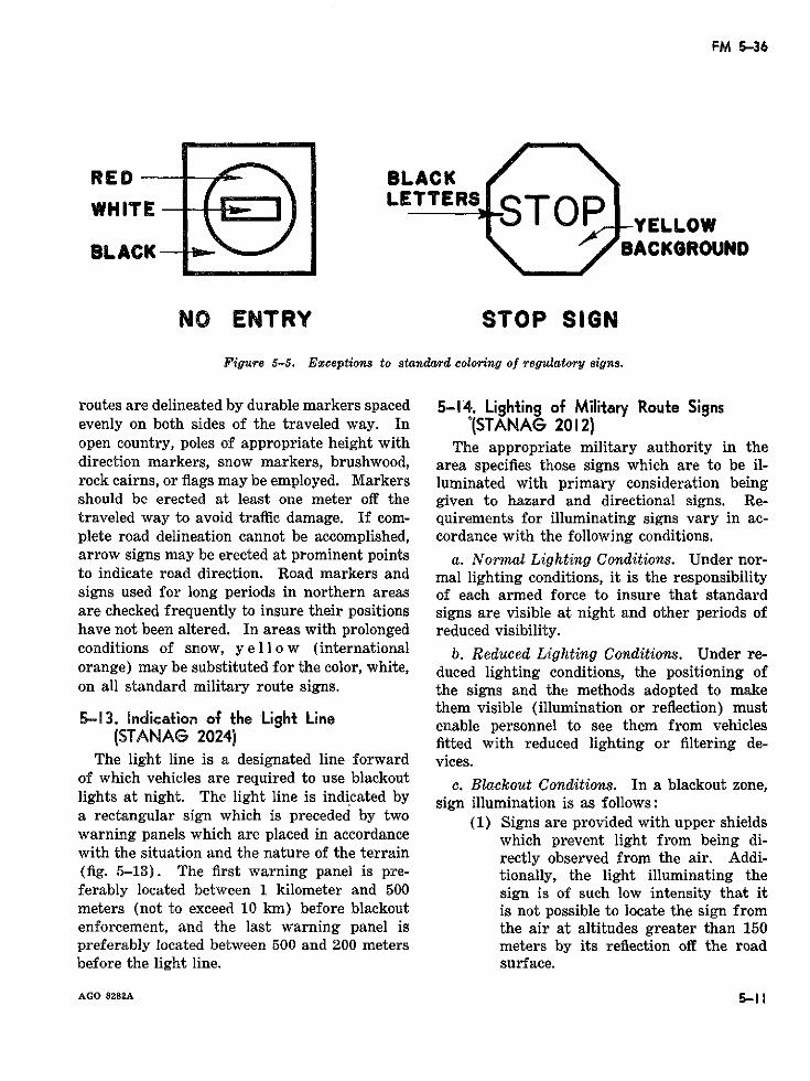
FM 5-36
RED- BLACKWHITE -E LETTERS STOP ELLO
J I v -YELLOWBLACK- BACKGROUND
NO ENTRY STOP SIGN
Figure 5-5. Exceptions to standard coloring of regulatory signs.
routes are delineated by durable markers spaced 5-14. Lighting of Military Route Signsevenly on both sides of the traveled way. In '(STANAG 2012)open country, poles of appropriate height with The appropriate military authority in thedirection markers, snow markers, brushwood, area specifies those signs which are to be il-rock cairns, or flags may be employed. Markers luminated with primary consideration beingshould be erected at least one meter off the given to hazard and directional signs. Re-traveled way to avoid traffic damage. If com- quirements for illuminating signs vary in ac-plete road delineation cannot be accomplished, cordance with the following conditions.arrow signs may be erected at prominent points a. Normal Lighting Conditions. Under nor-to indicate road direction. Road markers and mal lighting conditions, it is the responsibilitysigns used for long periods in northern areas of each armed force to insure that standardare checked frequently to insure their positions signs are visible at night and other periods ofhave not been altered. In areas with prolonged reduced visibility.conditions of snow, y e 11 o w (international b. Reduced Lighting Conditions. Under re-orange) may be substituted for the color, white, duced lighting conditions, the positioning ofon all standard military route signs. the signs and the methods adopted to make
them visible (illumination or reflection) must5-13. ndica.tion of the Lgkt LUne enable personnel to see them from vehicles
(STANAG 2024) fitted with reduced lighting or filtering de-The light line is a designated line forward vices.
of which vehicles are required to use blackout e. Blackout Conditions. In a blackout zone,lights at night. The light line is indicated by sign illumination is as follows:a rectangular sign which is preceded by two (1) Signs are provided with upper shieldswarning panels which are placed in accordance which prevent light from being di-with the situation and the nature of the terrain rectly observed from the air. Addi-(fig. 5-13). The first warning panel is pre- tionally, the light illuminating theferably located between 1 kilometer and 500 sign is of such low intensity that itmeters (not to exceed 10 km) before blackout is not possible to locate the sign fromenforcement, and the last warning panel is the air at altitudes greater than 150preferably located between 500 and 200 meters meters by its reflection off the roadbefore the light line. surface.
AGO 8282A 5-11
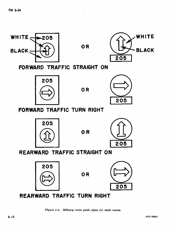
FM 5-36
WHITE 205 WHITE
BLACK R BLACK205
FORWARD TRAFFIC STRAIGHT ON
205
OR
205
FORWARD TRAFFIC TURN RIGHT
205
OR
205
REARWARD TRAFFIC STRAIGHT ON
205OR
I 205
REARWARD TRAFFIC TURN RIGHT
Figure 5-6. Military route guide signs for azial routes.
5-12 AGO 8282A
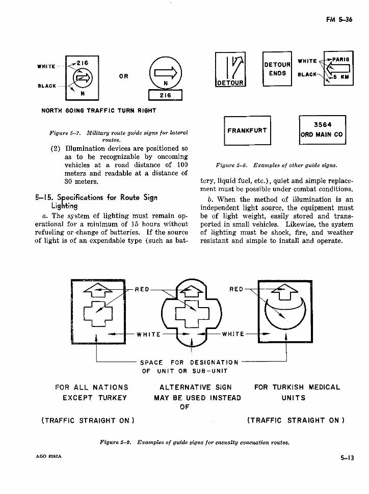
FM 5-36
W Hl TE - 2DETOU ITE `PARIS~WH#~~~ITE W~OR ILACK4W]
BLACK -
NORTH GOING TRAFFIC TURN RIGHT
5564Figure 5-7. Military route guide signs for lateral ORO MAIN CO
routes.
(2) Illumination devices are positioned soas to be recognizable by oncomingvehicles at a road distance of 100 Figure 5-8. Examples of other guide signs.meters and readable at a distance of30 meters. tery, liquid fuel, etc.), quiet and simple replace-
ment must be possible under combat conditions.
5-15. Specifications for Route Sign b. When the method of illumination is anLighting independent light source, the equipment must
a. The system of lighting must remain op- be of light weight, easily stored and trans-erational for a minimum of 15 hours without ported in small vehicles. Likewise, the systemrefueling or-change of batteries. If the source of lighting must be shock, fire, and weatherof light is of an expendable type (such as bat- resistant and simple to install and operate.
RED "L t RED
WHITE -" WHITE
SPACE FOR DESIGNATIONOF UNIT OR SUB-UNIT
FOR ALL NATIONS ALTERNATIVE SIGN FOR TURKISH MEDICAL
EXCEPT TURKEY MAY BE USED INSTEAD UNITSOF
(TRAFFIC STRAIGHT ON) (TRAFFIC STRAIGHT ON)
Figure 5-9. Examples of guide signs for casualty evacuation routes.
AGO 8282A 5-13
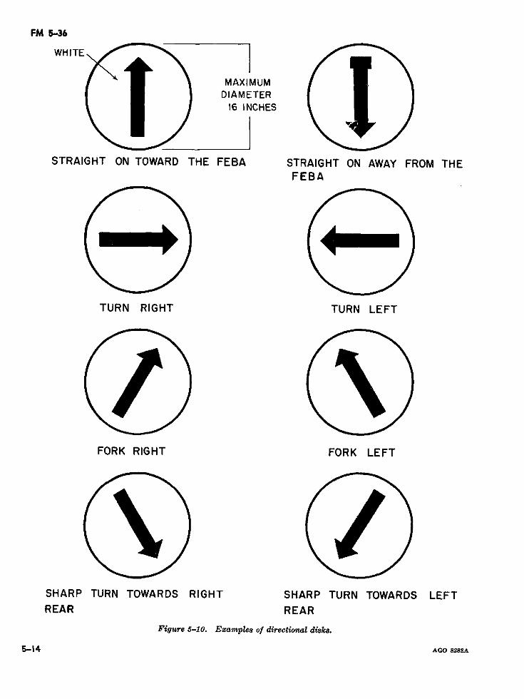
FM 5-36
WHITE
MAXIMUMDIAMETER
16 INCHES
STRAIGHT ON TOWARD THE FEBA STRAIGHT ON AWAY FROM THEFEBA
TURN RIGHT TURN LEFT
FORK RIGHT FORK LEFT
SHARP TURN TOWARDS RIGHT SHARP TURN TOWARDS LEFTREAR REAR
Figure 5-10. Examples of directional disks.
5-14 AGO 8282A
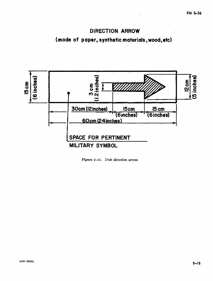
FM 5-36
DIRECTION ARROW(made of paper, synthetic materials,wood,etc)
E~~~~~~~~~~~~~~~~=__El ElE~~~~~~~~~oo
<o ?0~~~~~C4J
30cm (12 inches) 15cm 5c- (6inches) (6inches)
60cm (2.4inches)
SPACE FOR PERTINENTMILITARY SYMBOL
Figure 5-11. Unit direction arrow.
AGO 8282A 5-35
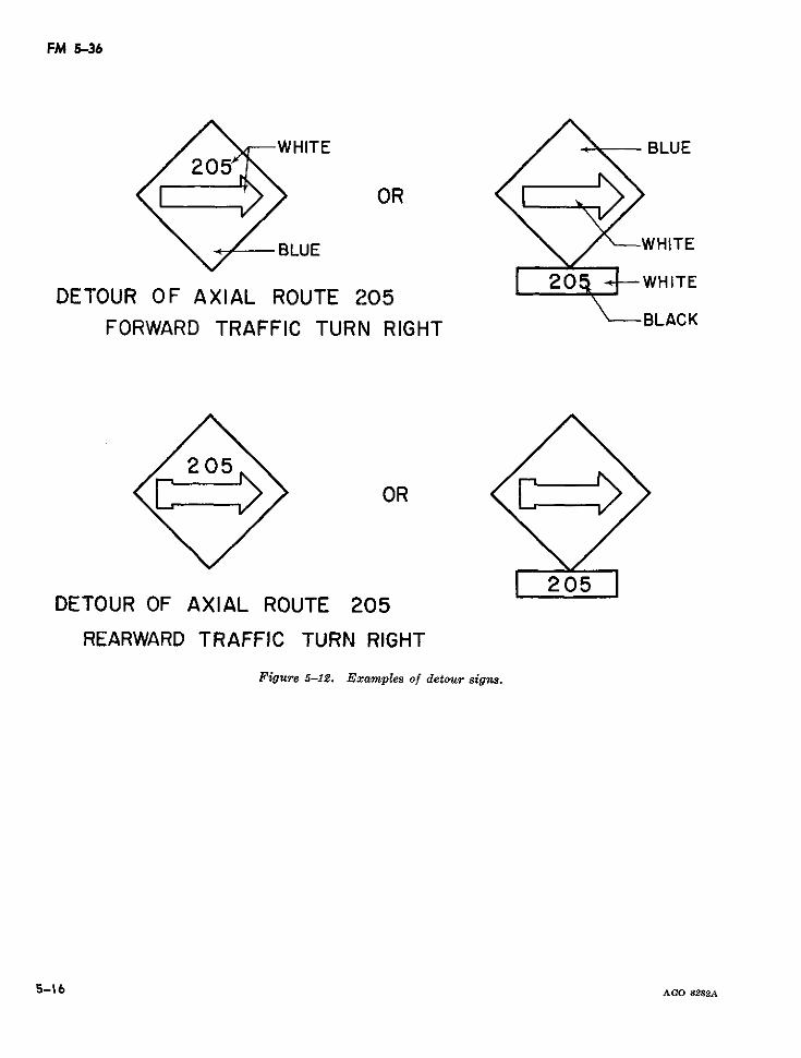
FM 5-36
WHITE BLUE
OR
BLUE WHITE
DETOUR OF AXIAL ROUTE 205 20WHITEFORWARD TRAFFIC TURN RIGHT BLACK
OR
DETOUR OF AXIAL ROUTE 205
REARWARD TRAFFIC TURN RIGHT
Figure 5-12. Examples of detour signs.
5-16 AGO 8282A
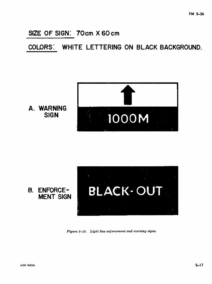
FM 5-36
SIZE OF SIGN: 70cm X 60 cm
COLORS: WHITE LETTERING ON BLACK BACKGROUND.
tA. WARNING
SIGN
B. ENFORCE- *MENT SIGN
Figure 5-13. Light line enforcement and warning signs.
AGO 8282A 5-17
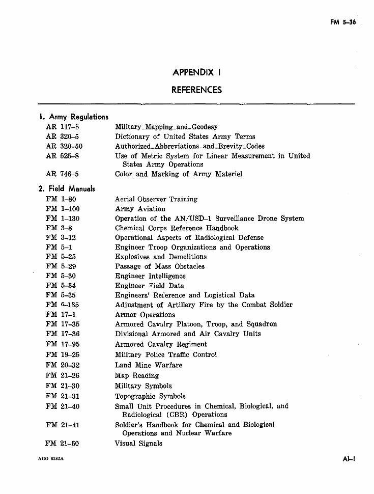
FM 5-36
APPENDIX I
REFERENCES
1. Army RegulationsAR 117-5 MilitaryMappingandGeodesyAR 320-5 Dictionary of United States Army TermsAR 320-50 AuthorizedAbbreviationsand Brevity_CodesAR 525-8 Use of Metric System for Linear Measurement in United
States Army OperationsAR 746-5 Color and Marking of Army Materiel
2. Field ManualsFM 1-80 Aerial Observer TrainingFM 1-100 Army AviationFM 1-130 Operation of the AN/USD-1 Surveillance Drone SystemFM 3-8 Chemical Corps Reference HandbookFM 3-12 Operational Aspects of Radiological DefenseFM 5-1 Engineer Troop Organizations and OperationsFM 5-25 Explosives and DemolitionsFM 5-29 Passage of Mass ObstaclesFM 5-30 Engineer IntelligenceFM 5-34 Engineer .ield DataFM 5-35 Engineers' Reference and Logistical DataFM 6-135 Adjustment of Artillery Fire by the Combat SoldierFM 17-1 Armor OperationsFM 17-35 Armored Cav:alry Platoon, Troop, and SquadronFM 17-36 Divisional Armored and Air Cavalry UnitsFM 17-95 Armored Cavalry RegimentFM 19-25 Military Police Traffic ControlFM 20-32 Land Mine WarfareFM 21-26 Map ReadingFM 21-30 Military SymbolsFM 21-31 Topographic SymbolsFM 21-40 Small Unit Procedures in Chemical, Biological, and
Radiological (CBR) OperationsFM 21-41 Soldier's Handbook for Chemical and Biological
Operations and Nuclear WarfareFM 21-60 Visual Signals
AGO 8282A AI-¡
FM 5-36
FM 21-75 Combat Training of the Individual Soldier and PatrollingFM 21-76 SurvivalFM 21-77 Evasion and EscapeFM 24-16 Signal Orders, Records, and ReportsFM 30-5 Combat IntelligenceFM 30-7 Combat Intelligence Battle Group, Combat Command, and Smaller UnitsFM 30-10 Terrain IntelligenceFM 30-20 Aerial SurveillanceFM 31-25 Desert OperationsFM 31-30 Jungle OperationsFM 31-50 Combat in Fortified and Built-up AreasFM 31-70 Basic Cold Weather ManualFM 31-71 Northern OperationsFM 31-72 Mountain OperationsFM 55-8 Transportation IntelligenceFM 55-15 Transportation Reference DataFM 55-30 Motor Transportation OperationsFM 57-35 Airmobile OperationsFM 57-38 Pathfinder OperationsFM 100-5 Field Service Regulations-OperationsFM 100-10 Field Service Regulations, AdministrationFM 101-10 Staff Officers' Field Manual; Organizational, Technical
and Logistical Data (Part I)FM 110-101 Intelligence, Joint Landing Force ManualFM 110-115 Amphibious Reconnaissance, Joint Landing Force Manual
3. Technical ManualsTM 5-210 Military Floating Bridge EquipmentTM 5-216 Armored Vehicle Launched BridgeTM 5-220 Passage of Obstacles other Than MinefieldsTM 5-232 Elements of SurveyingTM 5-277 Panel Bridge, Bailey Type, M2TM 5-312 Military Fixed BridgesTM 5-330 Planning, Site Selection, and Design of Roads, Airfields,
Heliports in the Theater of OperationsTM 5-335 Drainage Structures, Subgrades, and Base CoursesTM 5-530 Materials TestingTM 5-700 Field Water SupplyTM 9-500 Ordnance Corps EquipmentTM 30-246 Tactical Interpretation of Air Photos
4. Other DA PublicationsDA Pam 108-1 Index of Army Motion Pictures, Film Strips, Slides, and Phono RecordingsDA Pam 310-1 Index of Administrative Publications
Al-2 AGO 8282A

FM 5-36
DA Pam 310-2 Index of Blank FormsDA Pam 310-3 Index of Doctrinal, Training, and Organizational PublicationsDA Pam 310-4 Index of Technical Manuals, Technical Bulletins, Supply Manuals, Supply
Bulletins, Lubrication Orders, and Modification Work OrdersGTA 5-35 Bridge Classification CardGTA 19-5 Route Signs-Classification, Application, and DesignGTA 19-6 Military Route (Itineraire) Signing-NATOTA 50-901 Clothing and Equipment (Peace)TA 50-902 Clothing and Equipment (Mobilization)TA 50-914 Individual Safety and Protective Clothing and Equipment
AGO 8282A AI-3
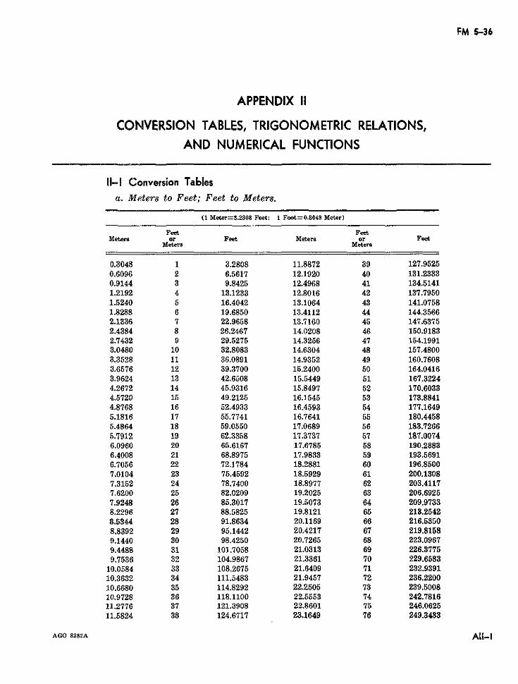
FM 5-36
APPENDIX II
CONVERSION TABLES, TRIGONOMETRIC RELATIONS,AND NUMERICAL FUNCTIONS
11I- Conversion Tablesa. Meters to Feet; Feet to Meters.
(1 Meter=3.2808 Feet; 1 Foot=0.8048 Meter)
Feet FeetMeters or Feet Meters or Feet
Meters Meters
0.3048 1 3.2808 11.8872 39 127.95250.6096 2 6.5617 12.1920 40 131.23330.9144 3 9.8425 12.4968 41 134.51411.2192 4 13.1233 12.8016 42 137.79501.5240 5 16.4042 13.1064 43 141.07581.8288 6 19.6850 13.4112 44 144.35662.1336 7 22.9658 13.7160 45 147.63752.4384 8 26.2467 14.0208 46 150.91832.7432 9 29.5275 14.3256 47 154.19913.0480 10 32.8083 14.6304 48 157.48003.3528 11 36.0891 14.9352 49 160.76083.6576 12 39.3700 15.2400 50 164.04163.9624 13 42.6508 15.5449 51 167.32244.2672 14 45.9316 15.8497 52 170.60334.5720 15 49.2125 16.1545 53 173.88414.8768 16 52.4933 16.4593 54 177.16495.1816 17 55.7741 16.7641 55 180.44585.4864 18 59.0550 17.0689 56 183.72665.7912 19 62.3358 17.3737 57 187.00746.0960 20 65.6167 17.6785 58 190.28836.4008 21 68.8975 17.9833 59 193.56916.7056 22 72.1784 18.2881 60 196.85007.0104 23 75.4592 18.5929 61 200.13087.3152 24 78.7400 18.8977 62 203.41177.6200 25 82.0209 19.2025 63 206.69257.9248 26 85.3017 19.5073 64 209.97338.2296 27 88.5825 19.8121 65 213.25428.5344 28 91.8634 20.1169 66 216.53508.8392 29 95.1442 20.4217 67 219.81589.1440 30 98.4250 20.7265 68 223.09679.4488 31 101.7058 21.0313 69 226.37759.7536 32 104.9867 21.3361 70 229.6583
10.0584 33 108.2675 21.6409 71 232.939110.3632 34 111.5483 21.9457 72 236.220010.6680 35 114.8292 22.2505 73 239.500810.9728 36 118.1100 22.5553 74 242.781611.2776 37 121.3908 22.8601 75 246.062511.5824 38 124.6717 23.1649 76 249.3433
AGO 8282A AlI-I
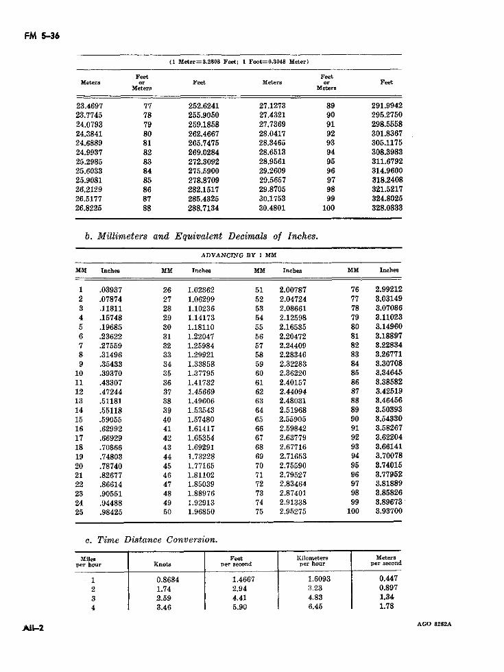
FM 5-36
(1 Meter=3.2808 Feet; 1 Foot=0.3048 Meter)
Feet FeetMeters or Feet Meters or Feet
Meters Meters
23.4697 77 252.6241 27.1273 89 291.994223.7745 78 255.9050 27.4321 90 295.275024.0793 79 259.1858 27.7369 91 298.555824.3841 80 262.4667 28.0417 92 301.836724.6889 81 265.7475 28.3465 93 305.117524.9937 82 269.0284 28.6513 94 308.398325.2985 83 272.3092 28.9561 95 311.679225.6033 84 275.5900 29.2609 96 314.960025.9081 85 278.8709 29.5657 97 318.240826.2129 86 282.1517 29.8705 98 321.521726.5177 87 285.4325 30.1753 99 324.802526.8225 88 288.7134 30.4801 100 328.0833
b. Millimeters and Equivalent Decimals of Inches.
ADVANCING BY 1 MM
MM Inches MM Inches MM Inches MM Inches
1 .03937 26 1.02362 51 2.00787 76 2.992122 .07874 27 1.06299 52 2.04724 77 3.031493 .11811 28 1.10236 53 2.08661 78 3.070864 .15748 29 1.14173 54 2.12598 79 3.110235 .19685 30 1.18110 55 2.16535 80 3.149606 .23622 31 1.22047 56 2.20472 81 3.188977 .27559 32 1.25984 57 2.24409 82 3.228348 .31496 33 1.29921 58 2.28346 83 3.267719 .35433 34 1.33858 59 2.32283 84 3.30708
10 .39370 35 1.37795 60 2.36220 85 3.3464511 .43307 36 1.41732 61 2.40157 86 3.3858212 .47244 37 1.45669 62 2.44094 87 3.4251913 .51181 38 1.49606 63 2.48031 88 3.4645614 .55118 39 1.53543 64 2.51968 89 3.5039315 .59055 40 1.57480 65 2.55905 90 3.5433016 .62992 41 1.61417 66 2.59842 91 3.5826717 .66929 42 1.65354 67 2.63779 92 3.6220418 .70866 43 1.69291 68 2.67716 93 3.6614119 .74803 44 1.73228 69 2.71653 94 3.7007820 .78740 45 1.77165 70 2.75590 95 3.7401521 .82677 46 1.81102 71 2.79527 96 3.7795222 .86614 47 1.85039 72 2.83464 97 3.8188923 .90551 48 1.88976 73 2.87401 98 3.8582624 .94488 49 1.92913 74 2.91338 99 3.8967325 .98425 50 1.96850 75 2.95275 100 3.93700
c. Time Distance Conversion.
Miles Feet Kilometers Metersper hour Knots per second per hour per second
1 0.8684 1.4667 1.6093 0.4472 1.74 2.94 3.23 0.8973 2.59 4.41 4.83 1.344 3.46 5.90 6.45 1.78
AGO 8282As91S-2
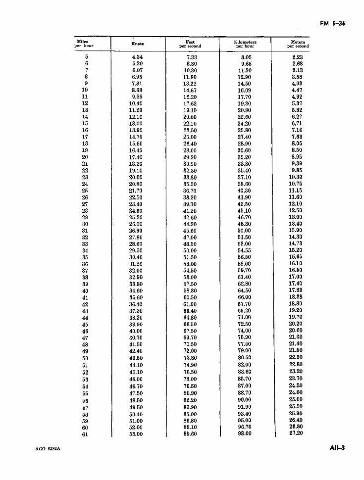
FM 5-36
Miles Feet Kilometers Metersper hour nots per second per hour per second
5 4.34 7.33 8.05 2.236 5.20 8.80 9.65 2.687 6.07 10.30 11.30 3.138 6.95 11.80 12.90 3.589 7.81 13.22 14.50 4.03
10 8.68 14.67 16.09 4.4711 9.55 16.20 17.70 4.9212 10.40 17.62 19.30 5.3713 11.23 19.10 20.90 5.8214 12.10 20.60 22.60 6.2715 13.00 22.10 24.20 6.7116 13.90 23.50 25.80 7.1617 14.75 25.00 27.40 7.6318 15.60 26.40 28.90 8.0519 16.45 28.00 30.60 8.5020 17.40 29.30 32.20 8.9521 18.20 30.90 33.80 9.3922 19.10 32.30 35.40 9.8523 20.00 33.80 37.10 10.8024 20.80 35.30 38.60 10.7525 21.70 36.70 40.30 11.1526 22.50 38.20 41.90 11.6027 23.40 39.70 43.50 12.1028 24.30 41.20 45.10 12.5029 25.20 42.60 46.70 13.0030 26.00 44.20 48.30 13.4031 26.90 45.60 50.00 13.9032 27.80 47.00 51.50 14.3033 28.60 48.50 53.00 14.7334 29.50 50.00 54.55 15.2035 30.40 51.50 56.50 15.6536 31.20 53.00 58.00 16.1037 32.00 54.50 59.70 16.5038 32.90 56.00 61.40 17.0039 33.80 57.50 62.80 17.4040 34.60 58.80 64.50 17.8341 35.60 60.50 66.00 18.3842 36.40 61.90 67.70 18.8043 37.30 63.40 69.20 19.2044 38.20 64.80 71.00 19.7045 38.90 66.50 72.50 20.2046 40.00 67.50 74.00 20.6047 40.70 69.70 75.90 21.0048 41.50 70.50 77.50 21.4049 42.40 72.00 79.00 21.8050 43.50 73.80 80.50 22.3051 44.10 74.90 82.00 22.8052 45.10 76.50 83.60 23.2053 46.00 78.00 85.70 23.7054 46.70 79.50 87.00 24.2055 47.50 80.90 88.70 24.6056 48.50 82.20 90.00 25.0057 49.50 83.90 91.90 25.5058 50.10 85.00 93.40 25.9059 51.00 86.80 95.00 26.4060 52.00 88.10 96.70 26.8061 53.00 89.60 98.00 27.20
AGO 8282A All-3
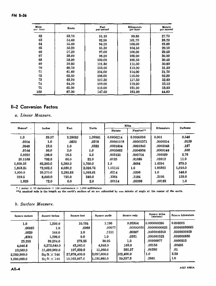
FM 5-36
Miles Knota Feet Kilometers Metersper hour per second per hour per second
62 53.70 91.10 99.80 27.7063 54.60 92.90 101.70 28.2064 55.60 94.20 103.00 28.6065 56.20 95.30 104.50 29.1066 57.20 97.00 106.00 29.5067 58.00 98.20 108.00 30.0068 58.90 100.00 109.50 30.4069 59.80 101.80 111.00 30.8070 60.70 103.00 113.00 31.3071 61.60 104.00 114.00 31.7072 62.50 106.00 116.00 32.2073 63.30 107.30 117.30 32.6074 64.20 109.00 119.00 33.1075 65.00 110.00 121.00 33.60
100 87.00 147.60 161.00 44.60
11-2 Conversion Factors
a. Linear Measure.
MilesMeters . Inches Feet Yards Kilometers Fathoms
Statute Nautical**
1.0 39.37 3.28083 1.09361 0.0006214 0.0005396 0.001 0.546.0254 1.0 .0833 .0278 .00001578 .00001371 .0000254 .0139.3048 12.0 1.0 .3333 .0001894 .0001645 .0003048 .167.9144 36.0 3.0 1.0 .0005682 .0004934 .0009144 .500
5.0292 198.0 16.5 5.5 .003125 .002714 .005029 2.7620.1168 792.0 66.0 22.0 .0125 .01085 .02012 11.0
1,609.35 63,360.0 5,280.0 1,760.0 1.0 .8684 1.6094 879.01,853.25 72,962.5 6,080.2 2,026.73 1.15155 1.0 1.85325 1,010.01,000.0 39,370.0 3,280.83 1,093.61 .6214 .5396 1.0 546.0
219.5 8,640.0 720.0 240.0 .1364 .1184 .2195 120.01.829 72.0 6.0 2.0 .00114 .00098 .00183 1.0
· 1 meter = 10 decimeters = 100 centimeters - 1.000 millimeters.·*A nautical mile is the length on the earth's surface of an arc subtended by one minute of angle at the center of the earth.
b. Surface Measure.
Square metero Square inches Square feet Square yards Square rods Square miles Square kilometers
1.0 1,550.0 10.764 1.196 0.03954 0.000000386 0.000001.00065 1.0 .0069 .00077 .00000026 .00000000025 .00000000065.0929 144.0 1.0 .1111 .00367 .0000000359 .0000000929,8361 1,296.0 9.0 1.0 .0331 .000000323 .000000836
25.293 39,204.0 272.25 30.25 1.0 .00000977 .00002534,046.8 6,272,640.0 43,560.0 4,840.0 160.0 .00156 .00405
10,000.0 15,499,969.0 107,639.0 11,960.0 395.37 .00386 .012,589,999.0 Sq ft X 144 27,878,400.0 3,097,600.0 102,400.0 1.0 2.591,000,000.0 Sq ft X 144 10,763,867.0 1,195,985.0 39,537.0 .3861 1.0
All-4 AGO 8282A
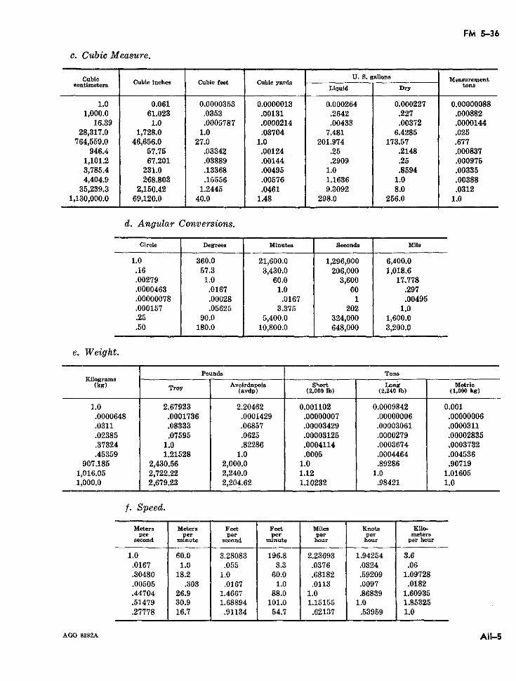
FM 5-36
c. Cubic Measure.
Cubie U. S. gallons Measurernentcentimeters CubieLiquid nhe Cubc feet Cubc yadDry tons
1.0 0.061 0.0000353 0.0000013 0.000264 0.000227 0.000000881,000.0 61.023 .0353 .00131 .2642 .227 .000882
16.39 1.0 .0005787 .0000214 .00433 .00372 .000014428,317.0 1,728.0 1.0 .03704 7.481 6.4285 .025
764,559.0 46,656.0 27.0 1.0 201.974 173.57 .677946.4 57.75 .03342 .00124 .25 .2148 .000837
1,101.2 67.201 .03889 .00144 .2909 .25 .0009753,785.4 231.0 .13368 .00495 1.0 .8594 .003354,404.9 268.803 .15556 .00576 1.1636 1.0 .00388
35,239.3 2,150.42 1.2445 .0461 9.3092 8.0 .03121,130,000.0 69,120.0 40.0 1.48 298.0 256.0 1.0
d. Angular Conversions.
Cirele Degrees Minutes Seconda Mils
1.0 360.0 21,600.0 1,296,000 6,400.0.16 57.3 3,430.0 206,000 1,018.6.00279 1.0 60.0 3,600 17.778.0000463 .0167 1.0 60 .297.00000078 .00028 .0167 1 .00495.000157 .05625 3.375 202 1.0.25 90.0 5,400.0 324,000 1,600.0.50 180.0 10,800.0 648,000 3,200.0
e. Weight.
Pounds TonsKilograms
(kg) Troy Avoirdupois S'iort Long Metric(avdp) (2,000 Ib) (2,240 Ib) (1,000 kg)
1.0 2.67923 2.20462 0.001102 0.0009842 0.001.0000648 .0001736 .0001429 .00000007 .00000006 .00000006.0311 .08333 .06857 .00003429 .00003061 .0000311.02385 .07595 .0625 .00003125 .0000279 .00002835.37324 1.0 .82286 .0004114 .0003674 .0003732.45359 1.21528 1.0 .0005 .0004464 .004536
907.185 2,430.56 2,000.0 1.0 .89286 .907191,016.05 2,722.22 2,240.0 1.12 1.0 1.016051,000.0 2,679.23 2,204.62 1.10232 .98421 1.0
f. Speed.
Meters Meters Feet Feet Miles Knots Kilo-per per per per per per meters
second minute second minute hour hour per hour
1.0 60.0 3.28083 196.8 2.23693 1.94254 3.6.0167 1.0 .055 3.3 .0376 .0324 .06.30480 18.2 1.0 60.0 .68182 .59209 1.09728.00505 .303 .0167 1.0 .0113 .0097 .0182.44704 26.9 1.4667 88.0 1.0 .86839 1.60935.51479 30.9 1.68894 101.0 1.15155 1.0 1.85325.27778 16.7 .91134 54.7 .62137 .53959 1.0
AGO 8282A AII-5
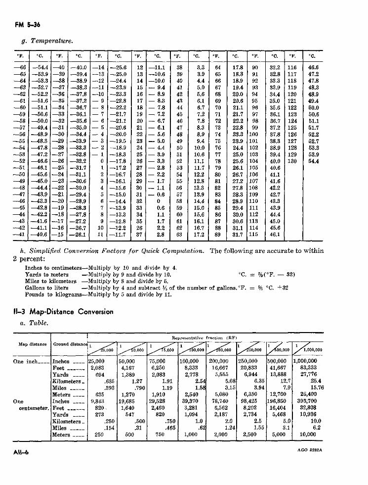
FM 5-36
g. Temperature.
°F. °C. °F. °C. °F. °C. °F. °C. °F. °C. °F. °C. °F. °C. °F. °C.
-66 -54.4 -40 -40.0 -14 -25.6 12 -11.1 38 3.3 64 17.8 90 32.2 116 46.6-65 -53.9 -39 -39.4 -13 -25.0 13 -10.6 39 3.9 65 18.3 91 32.8 117 47.2-64 -53.3 -38 -38.9 -12 -24.4 14 -10.0 40 4.4 66 18.9 92 33.3 118 47.8-63 - 52.7 -37 -38.3 -11 -23.9 15 - 9.4 41 5.0 67 19.4 93 33.9 119 48.3-62 -52.2 -36 ---37.8 -10 -23.3 16 - 8.9 42 5.6 68 20.0 94 34.4 120 48.9-61 -51.6 -35 -37.2 - 9 -22.8 17 - 8.3 43 6.1 69 20.6 95 35.0 121 49.4-60 -51.1 -34 --36.7 - 8 -22.2 18 - 7.8 44 6.7 70 21.1 96 35.6 122 50.0-59 -50.6 -33 -36.1 - 7 -21.7 19 - 7.2 45 7.2 71 21.7 97 36.1 123 50.6-58 -50.0 -32 -35.6 - 6 -- 21.1 20 - 6.7 46 7.8 72 22.2 98 36.7 124 51.1-57 -49.4 -31 -35.0 - 5 -20.6 21 - 6.1. 47 8.3 73 22.8 99 37.2 125 51.7-56 -- 48.9 -30 -34.4 - 4 -20.0 22 - 5.6 48 8.9 74 23.3 100 37.8 126 52.2-55 -48.3 -29 -33.9 - 3 -19.5 23 - 5.0 49 9.4 75 23.9 101 38.3 127 52.7-54 -- 47.8 -28 -33.3 - 2 -18.9 24 - 4.4 50 10.0 76 24.4 102 38.9 128 53.3-53 -47.2 -27 -32.8 - 1 -18.3 25 - 3.9 51 10.6 77 25.0 103 39.4 129 53.9-52 -46.6 -26 -32.2 0 -17.8 26 - 3.3 52 11.1 78 25.6 104 40.0 130 54.4-51 -46.1 -25 -31.7 1 -17.2 27 - 2.8 53 11.7 79 26.1 105 40.6-50 -45.6 -24 -31.1 2 -16.7 28 - 2.2 54 12.2 80 26.7 106 41.1-49 --45.0 -23 -30.6 3 -16.1 29 - 1.7 55 12.8 81 27.2 107 41.6-48 --44.4 -22 -30.0 4 -15.6 30 - 1.1 56 13.3 82 27.8 108 42.2-47 -43.9 -21 -29.4 5 -15.0 31 - 0.6 57 13.9 83 28.3 109 42.7-46 -43.3 -20 -28.9 6 -14.4 32 0 58 14.4 84 28.9 110 43.3-45 -42.8 -19 -28.3 7 -13.9 33 0.6 59 15.0 85 29.4 111 43.9-44 -42.2 -18 -27.8 8 -1.3.3 34 1.1 60 15.6 86 30.0 112 44.4--43 -41.6 -17 -27.2 9 -12.8 35 1.7 61 16.1 87 30.6 113 45.0-42 -41.1 -16 -26.7 10 -12.2 26 2.2 62 16.7 88 31.1 114 45.6-41 -40.6 -15 -26.1 11 -11.7 37 2.8 63 17.2 89 31.7 115 46.1
h. Simplified Conversion Factors for Quick Computation. The following are accurate to within2 percent:
Inches to centimeters-Multiply by 10 and divide by 4.Yards to meters -Multiply by 9 and divide by 10. 'C. = %(°F. - 32)Miles to kilometers -Multiply by 8 and divide by 5.Gallons to liters -Multiply by 4 and subtract M, of the number of gallons. F. = % 'C. +32Pounds to kilograms-Multiply by 5 and divide by 11.
11-3 Map-Distance Conversion
a. Table.
Representative fraction (RF)
Map distance Ground distane 1 1 1 1 1 1,000 ,000 ,000 000 0 ,00 00, 000 50000 00 1.000.000
One inch..____ Inches _--- 25,000 50,000 75,000 100,000 200,000 250,000 500,000 1,000,000Feet------ 2,083 4,167 6,250 8,333 16,667 20,833 41,667 83,333Yards ---- 694 1,389 2,083 2,778 5,555 6,944 13,888 27,776Kilometers .635 1.27 1.91 2.54 5.08 6.35 12.7 25.4Miles ----- .393 .790 1.19 1.58 3.15 3.94 7.9 15.76Meters ---- 635 1,270 1,910 2,540 5,080 6,350 12,700 25,400
One Inches _--_ 9,843 19,685 29,528 39,370 78,740 98,425 196,850 393,700centemeter. Feet ------ 820.. 1,640 2,460 3,281 6,562 8,202 16,404 32,808
Yards ---- 273 547 820 1,094 2,187 2,734 5,468 10,936Kilometers_ .250 .500 .750 1.0 2.0 2.5 5.0 10.0Miles __-__ .154 .31 .465 .6 1.24 1.55 3.1 6.2Meters -___ 250 500 750 1,000 2,000 2,500 5,000 10,000
AGO 8282A
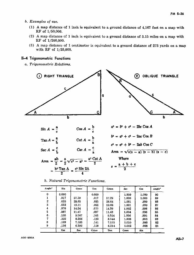
FM 5-36
b. Examples of use.
(1) A map distance of 1 inch is equivalent to a ground distance of 4,167 feet on a map withRF of 1/50,000.
(2) A map distance of 1 inch is equivalent to a ground distance of 3.15 miles on a map withRF of 1/200,000.
(3) A map distance of 1 centimeter is equivalent to a ground distance of 273 yards on a mapwith RF of 1/25,000.
11-4 Trigonometric Functions
a. Trigonometric Relations.
O RIGHT TRIANGLE B OBLIQUE TRIANGLE
b b
Sin A = a Cos A b a2 = b2 + ct - 2bc Cos Ac c
TanA = a Cot A b bl = a' + c - 2ac Cos BTan A= Cot A=b a c' - a' + b2 - 2ab Cos C
Sec A = Csc A = eb a Area = s(s -a) (s -b) (s -c)
ab a a2 Cot A WhereArea a¿ =i - a_ 2 =2 2 2 a+b+c
b_ Tan A cl Sin 2A 8 = 22 4
b. Natural Trigonometric Functions.
Angle °Sin Cosec Tan Cotan See Cos Anglde
0 0.000 0.000 1.000 1.000 901 .017 57.30 .017 57.29 1.000 1.000 892 .035 28.65 .035 28.64 1.001 .999 883 .052 19.11 .052 19.08 1.001 .999 874 .070 14.34 .070 14.30 1.002 .998 865 .087 11.47 .087 11.43 1.004 .996 856 .105 9.567 .105 9.514 1.006 .995 847 .122 8.206 .123 8.144 1.008 .993 838 .139 7.185 .141 7.115 1.010 .990 829 .156 6.392 .158 6.314 1.012 .988 81
Cos See Cotan Tan Cosee Sin
AGO 8282A All-7
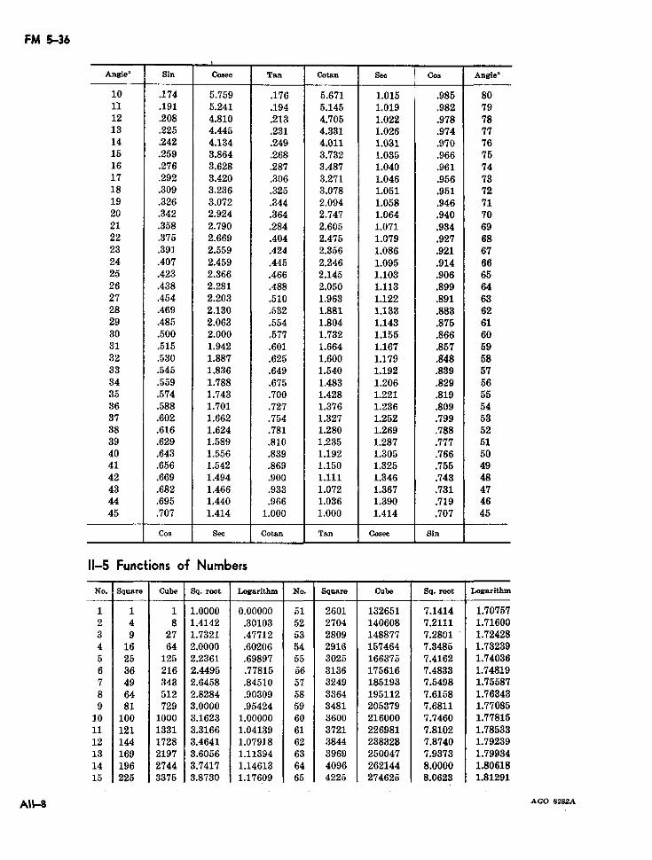
FM 5-36
Angle ° Sin Cosec Tan Cotan Se Cos Angle °
10 .174 5.759 .176 5.671 1.015 i .985 8011 .191 5.241 .194 5.145 1.019 .982 7912 .208 4.810 .213 4.705 1.022 .978 7813 .225 4.445 .231 4.331 1.026 .974 7714 .242 4.134 .249 4.011 1.031 .970 7615 .259 3.864 .268 3.732 1.035 .966 7516 .276 3.628 .287 3.487 1.040 .961 7417 .292 3.420 .306 3.271 1.046 .956 7318 .309 3.236 .325 3.078 1.051 .951 7219 .326 3.072 .344 2.094 1.058 .946 7120 .342 2.924 .364 2.747 1.064 .940 7021 .358 2.790 .284 2.605 1.071 .934 6922 .375 2.669 .404 2.475 1.079 .927 6823 .391 2.559 .424: 2.356 1.086 .921 6724 .407 2.459 .445 2.246 1.095 .914 6625 .423 2.366 .466 2.145 1.103 .906 6526 .438 2.281 .488 2.050 1.113 .899 6427 .454 2.203 .510 1.963 1.122 .891 6328 .469 2.130 .532 1.881 1.133 .883 6229 .485 2.063 .554 1.804 1.143 .875 6130 .500 2.000 .577 1.732 1.155 .866 6031 .515 1.942 .601 1.664 1.167 .857 5932 .530 1.887 .625 1.600 1.179 .848 5833 .545 1.836 .649 1.540 1.192 .839 5734 .559 1.788 .675 1.483 1.206 .829 5635 .574 1.743 .700 1.428 1.221 .819 5536 .588 1.701 .727 1.376 1.236 .809 5437 .602 1.662 .754 1.327 1.252 .799 5338 .616 1.624 .781 1.280 1.269 .788 5239 .629 1.589 .810 1.235 1.287 .777 5140 .643 1.556 .839 1.192 1.305 .766 5041 .656 1.542 .869 1.150 1.325 .755 4942 .669 1.494 .900 1.111 1.346 .743 4843 .682 1.466 .933 1.072 1.367 .731 4744 .695 1.440 .966 1.036 1.390 .719 4645 .707 1.414 1.000 1.000 1.414 .707 45
Cos See Cotan Tan Cosee Sin
11-5 Functions of Numbers
No. Square Cube Sq. root Logarithm No. Square Cube Sq. root Logarithm
1 1 1 1.0000 0.00000 51 2601 132651 7.1414 1.707572 4 8 1.4142 .30103 52 2704 140608 7.2111 1.716003 9 27 1.7321 .47712 53 2809 148877 7.2801 1.724284 16 64 2.0000 .60206 54 2916 157464 7.3485 1.732395 25 125 2.2361 .69897 55 3025 166375 7.4162 1.740366 36 216 2.4495 .77815 56 3136 175616 7.4833 1.748197 49 343 2.6458 .84510 57 3249 185193 7.5498 1.755878 64 512 2.8284 .90309 58 3364 195112 7.6158 1.763439 81 729 3.0000 .95424 59 3481 205379 7.6811 1.77085
10 100 1000 3.1623 1.00000 60 3600 216000 7.7460 1.7781511 121 1331 3.3166 1.04139 61 3721 226981 7.8102 1.7853312 144 1728 3.4641 1.07918 62 3844 238328 7.8740 1.7923913 169 2197 3.6056 1.11394 63 3969 250047 7.9373 1.7993414 196 2744 3.7417 1.14613 64 4096 262144 8.0000 1.8061815 225 3375 3.8730 1.17609 65 4225 274625 8.0623 1.81291
^AII4 AGO 8282A
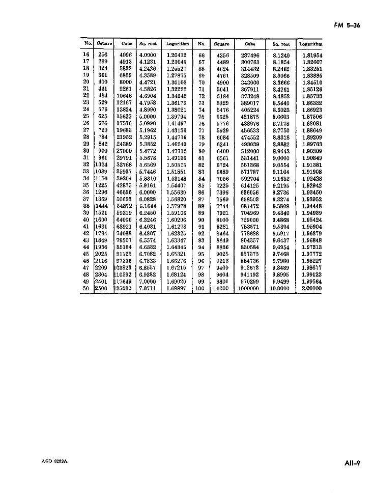
FM 5-36
No. Square Cube Sq. root Logarithm No. Square Cube Sq. root Logarithm
16 256 4096 4.0000 1.20412 66 4356 287496 8.1240 1.8195417 289 4913 4.1231 1.23045 67 4489 300763 8.1854 1.8260718 324 5832 4.2426 1.25527 68 4624 314432 8.2462 1.8325119 361 6859 4.3589 1.27875 69 4761 328509 8.3066 1.8388520 400 8000 4.4721 1.30103 70 4900 343000 8.3666 1.8451021 441 9261 4.5826 1.32222 71 5041 357911 8.4261 1.8512622 484 10648 4.6904 1.34242 72 5184 373248 8.4853 1.8573323 529 12167 4.7958 1.36173 73 5329 389017 8.5440 1.8633224 576 13824 4.8990 1.38021 74 5476 405224 8.6023 1.8692325 625 15625 5.0000 1.39794 75 5625 421875 8.6603 1.8750626 676 17576 5.0990 1.41497 76 5776 438976 8.7178 1.8808127 729 19683 5.1962 1.43136 77 5929 456533 8.7750 1.8864928 784 21952 5.2915 1.44716 78 6084 474552 8.8318 1.8920929 842 24389 5.3852 1.46240 79 6241 493039 8.8882 1.8976330 900 27000 5.4772 1.47712 80 6400 512000 8.9443 1.9030931 961 29791 5.5678 1.49136 81 6561 531441 9.0000 1.9084932 1024 32768 5.6569 1.50515 82 6724 551368 9.0554 1.9138133 1089 35937 5.7446 1.51851 83 6889 571787 9.1104 1.9190834 1156 39304 5.8310 1.53148 84 7056 592704 9.1652 1.9242835 1225 42875 5.9161 1.54407 85 7225 614125 9.2195 1.9294236 1296 46656 6.0000 1.55630 86 7396 636056 9.2736 1.9345037 1369 50653 6.0828 1.56820 87 7569 658503 9.3274 1.9395238 1444 54872 6.1644 1.57978 88 7744 681472 9.3808 1.9444839 1521 59319 6.2450 1.59106 89 7921 704969 9.4340 1.9493940 1600 64000 6.3246 1.60206 90 8100 729000 9.4868 1.9542441 1681 68921 6.4031 1.61278 91 8281 753571 9.5394 1.9590442 1764 74088 6.4807 1.62325 92 8464 778688 9.5917 1.9637943 1849 79507 6.5574 1.63347 93 8649 804357 9.6437 1.9684844 1936 85184 6.6332 1.64345 94 8836 830584 9.6954 1.9731345 2025 91125 6.7082 1.65321 95 9025 857375 9.7468 1.9777246 2116 97336 6.7823 1.66276 96 9216 884736 9.7980 1.9822747 2209 03823 6.8557 1.67210 97 9409 912673 9.8489 1.9867748 2304 10592 6.9282 1.68124 98 9604 941192 9.8995 1.9912349 2401 17649 7.0000 1.69020 99 9801 970299 9.9499 1.9956450 2500 :25000 7.0711 1.69897 100 10000 1000000 10.0000 2.00000
AGO 8282A All-9
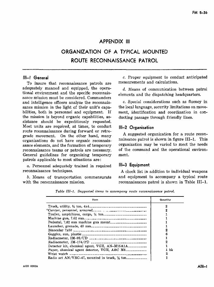
FM 5-36
APPENDIX III
ORGANIZATION OF A TYPICAL MOUNTED
ROUTE RECONNAISSANCE PATROL
lII-1 General c. Proper equipment to conduct anticipatedTo insure that reconnaissance patrols are measurements and calculations.
adequately manned and equipped, the opera- d. Means of communication between patroltional environment and the specific reconnais- elements and the dispatching headquarters.sance mission must be considered. Commandersand intelligence officers analyze the reconnais- e. Special considerations such as fluency insance mission in the light of their unit's capa- the local language, security limitations on move-bilities, both in personnel and equipment. If ment, identification and coordination in con-the mission is beyond organic capabilities, as- ducting passage through friendly lines.sistance should be expeditiously requested.Most units are required, at times, to conduct 111-2 Organizationroute reconnaissance during forward or retro-grade movement. On the other hand, many A suggested organization for a route recon-organizations do not have organic reconnais- naissance patrol is shown in figure III-1. Thissance elements, and the formation of temporary organization may be varied to meet the needsreconnaissance teams or patrols are necessary. of the command and the operational environ-General guidelines for organizing temporary ment.patrols applicable to most situations are:
a. Personnel adequately trained in required 111-3 Equipmentreconnaissance techniques. A check list in addition to individual weapons
b. Means of transportation commensurate and equipment to accompany a typical routewith the reconnaissance mission. reconnaissance patrol is shown in Table III-1.
Table II1-1. Suggested items to accompany route reconnaissance patrol.
Item Quantity
Truck, utility, 14 ton, 4x4 _--------______----- ______----__ 2"Carrier, personnel, armored ------------------ ___--------- 2Trailer, amphibious, cargo, 1/4 ton --_______________________ 1Machine gun, 7.62 mm _-_-----------_____---__----------- 1Pedestal, 7.62 mm machine gun mount___------______------ 1Launcher, grenade, 40 mm ----------_---------_---------- 1Binocular 7x50 …_______--- ___---____--------_________---- 2Goggles, sun, plastic _______-_______________--_______----- 6Radiacmeter, IM-93/UD ___…___-- ________----___.-------- 1Radiacmeter, IM-174/PD ____…___________----_______----- 2Detector kit, chemical agent, VGH, AN-M15A1A ________-- 1Paper, chemical agent detector, VGH, ABC M8 --__________ 1 bkWrist watch --------------------------------.----------- 2Radio set AN/VRC-47, mounted in truck, /4 ton_________--- 1
AGO 8282A A11I-I
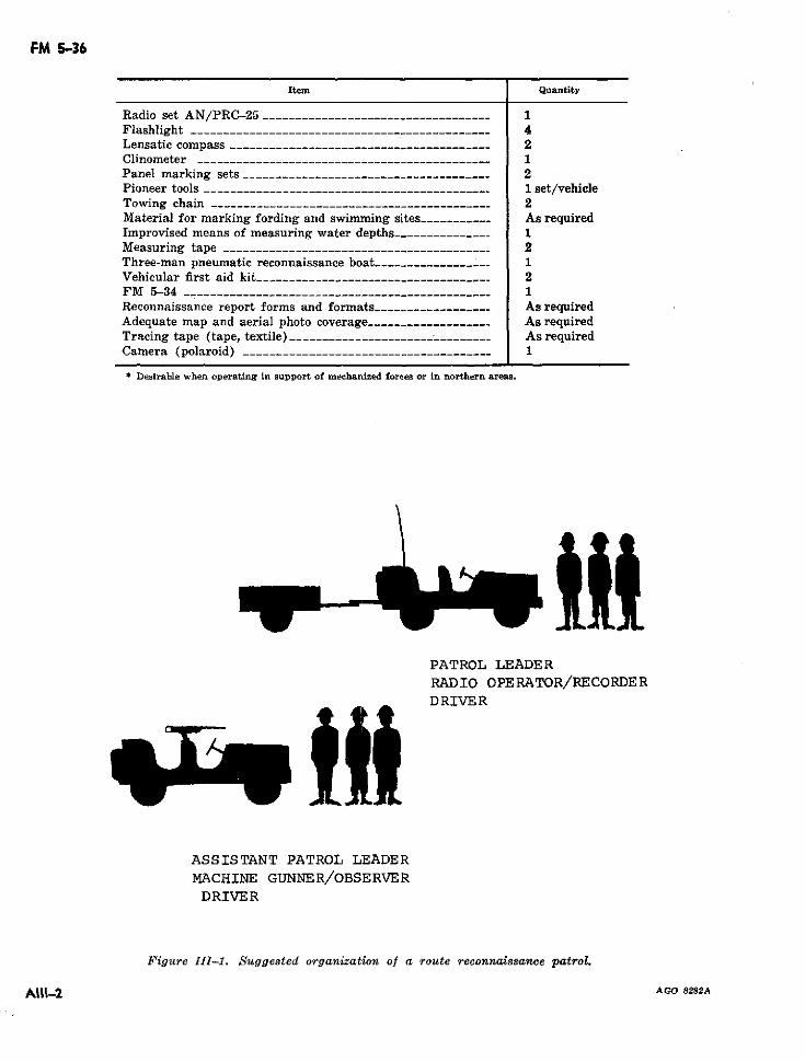
FM 5-36
Item Quantity
Radio set AN/PRC-25 .-------------------.------------- 1Flashlight ------------. ------- ------------ 4Lensatic compass ------.-............... _--_------_-- . 2Clinometer -------------- _----------------- - 1Panel marking sets __________________------------------ 2Pioneer tools -------------- _---------------_ 1 set/vehicleTowing chain -------------------- ---------------- 2Material for marking fording and swimming sites -----_---- As requiredImprovised means of measuring water depths_---------_--- 1Measuring tape -------.---- _----------_-- -- 2Three-man pneumatic reconnaissance boat---- ------------- 1Vehicular first aid kit__--- __----------.---------------- -.. 2FM 5-34 _ .--------- ____ ___--_______ _-___- _ ____ 1Reconnaissance report forms and formats ----------------- As requiredAdequate map and aerial photo coverage ---------------_.._ As requiredTracing tape (tape, textile) --_------------.._-----------___ As requiredCamera (polaroid) _------------- . ........ _-- - ---------- 1
* Desirable when operating in support of mechanized forces or in northern areas.
PATROL LEADERRADIO OPERATOR/RECORDERDRIVER
ASSISTANT PATROL LEADER
MACHINE GUNNER/OBSERVER
DRIVER
Figure III-1. Suggested organization of a route reconnaissance patrol.
A111-2 AGO 8282A
C 1, FM 5-36
APPENDIX IV
MILITARY LOAD CLASSIFICATION FOR STANDARD VEHICLES
IV-1. General C-Weight or class of vehicle with rated maxi-
The vehicle classification list presented in this mum cross country payload.appendix is not complete. However, future changes H-Weight or class of vehicle with rated maxi-to the manual will include data on new and cur- mum highway payload.rent items of equipment as the information becomes The weight elassification number to be posted onavailable. Data on certain items of equipment no vehicles will be assigned from the number listedlonger standard have been retained in the list when under the "C" subcolumn of the class column. Thisit was judged that their numbers in use by other number is taken from the normal design load of thenations warranted retention. Requests for classi- vehicle. Where no number appears in the "C"fication of vehicles should be addressed direct to column, take the number appearing in the "H"the Commanding Oflicer, U.S. Army Combat De- column, and if both of these columns are blankvelopments Command Engineer Agency, Fort Bel- take the number from the "E" column. The listingvoir, Va. 22060. The applicable following format, is organized into tables. as follows:filled out as completely as possible and modified Table IV-1. Tracked vehicles.where required, must accompany each request. Table IV-2. Half-tracked vehicles.
a. Tracked vehicle (fig. IV-1). Table IV-3. Wheeled vehicles.
b. Wheeled vehicle (fig. IV-2). Table IV-4. Towed vehicles.a. Artillery.c. Trailer (fig. IV-3). a. Artilery.b. Trailers.
d. Semitrailer (fig. IV-4). c. Semitrailers.
e. Combination track and wheel vehicle (fig. Table IV-5. Construction equipment.IV-5). Table IV-6. Missile and fire distribution sys-
f. Combination wheeled vehicle (fig. IV-6). tems.a. Pershing.
g. Combination wheeled (truck-tractor) vehicle b. Sergeant.
(fig. IV-7). c. Little John.d. Honest John.
IV-2. Military Load Classification List e. Hawk.
The symbols found in the heading of the listing f. Nike-Ajax.are defined below: g. Nike-Hercules.
E-Weight or class of vehicle w/o payload. Table IV-7. Combination vehicles.
TAGO 6929A AIV-1
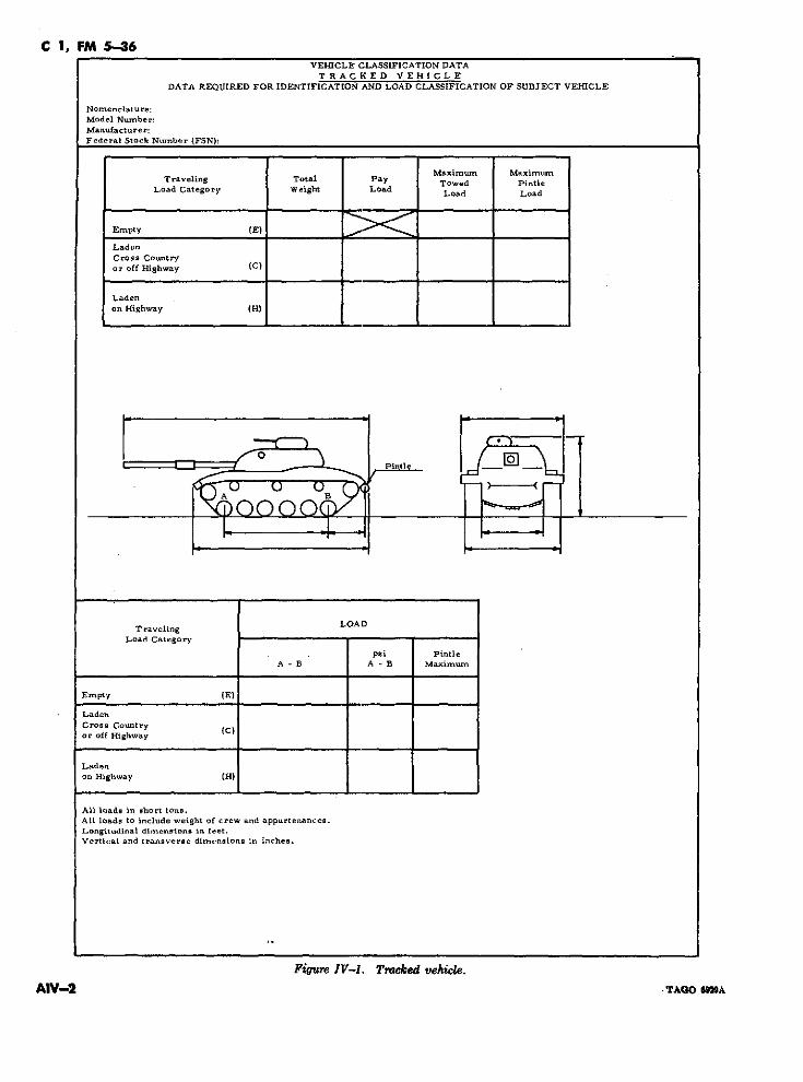
C 1, FM 5-36VEHICLE CLASSIFICATION DATA
T RACKED VEHICLEDATA REQUIRED FOR IDENTIFICATION AND LOAD CLASSIFICATION OF SUBJECT VEHICLE
Nomenclature:Model Number:Manufacturer:Federal Stock Number (FSN):
Maximum MaximumTraveling Total Pay Towed Pintle
Load Category Weight Load Load Load
Empty (E)
LadenCross Countryor off Highway (C)
Ladenon Highway (H)
· ,, ~o- ~k_ I pintie-- 'A °
Traveling LOADLoad Category
psi PintieA - B A - B Maximum
Empty (E)
LadenCross Countryor off Highway
Ladenon Highway (H)
All loads in short tons.All loads to include weight of crew and appurtenances.Longitudinal dimensions in feet.Vertical and transverse dimensions in inches.
Figure IV-I. Tracked vehicle.
AIV-2 .TAQ o 9A
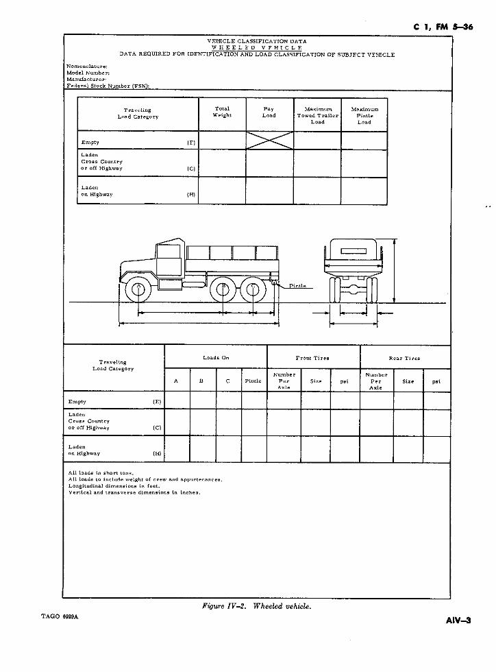
C 1, FM 5-36VEHICLE CLASSIFICATION DATAWHEELED VEHICLE
DATA REQUIRED FOR IDENTIFICATION AND LOAD CLASSIFICATION OF SUBJFCT VEHICLE
Nomenclature:Model Number:Manufacturer:Federal Stock Number (FSN):
T raveling Total Pay Maximum MaximumLoad Category Weight Load Towed Trailer Pintle
Load Load
Empty (F)
LadenCross Countryor off Highway (C)
Ladenon Highway (H)
Pintle
L II
Loads On Front Tires - Rear TiresT raveling
Load CategoryNunber Nu Sber
A B C Pintle Per Size psiAxle Axle
Empty (E)
Ladeo
Cross Countryor off Highway (C)
Ladenon Highway (H)
All loads in short tons.All loads to include weight of crew and appurtenances.Longitudinal dimensions in feet.Vertical and transverse dimensions in inches.
Figure IV-2. Wheeled vehicle.TAGO 6929A AIV-3
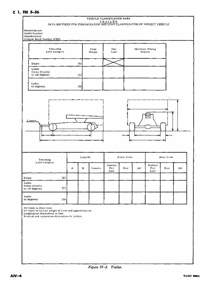
C 1, FM 5-36VEHICLE CLASSIFICATION DATA
TRAILERDATA REOUIRED FOR IDENTIFICATION AND LOAD CLASSIFICATION OF SUBJECT VEHICLE
Nomenclature:Model Number:Manufacturer:Federal Stock Number (FSN):
Traveling Total Pay Minimum TowingLoad Category Weight Load Vehicle
Empty (E)
LadenCross Countryor off Highway (C)
Ladenon Highway (H)
Lunette
Load On Front Tires Rear TiresTraveling
Load CategoryNumber Nu-mber
A B Lunette Per Size psi Per Size psiAxle Axle
Empty (E)
LadenCross Countryor off Highway (C)
Ladenon Highway (H)
All loads in short tons.All loads to include weight of crew and appurtenances.Longitudinal dimensions in feet.Vertical and transverse dimensions in inches.
Figure IV-3. Trailer.
AIV-4 TAGO OeM2A
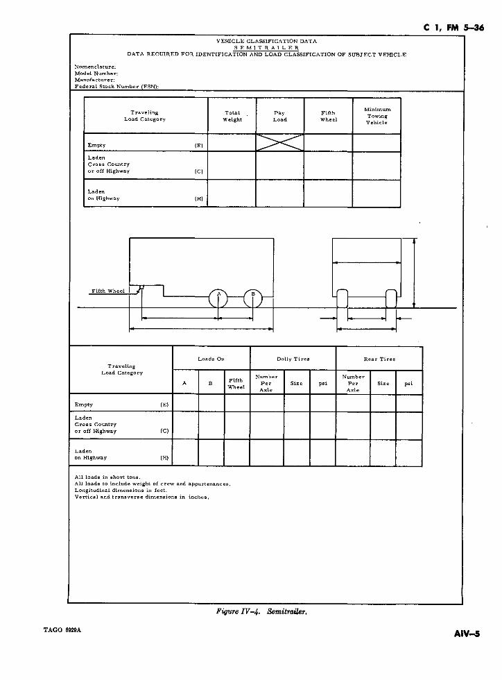
C 1, FM 5-36VEHICLE CLASSIFICATION DATA
SEMlTRAILERDATA REOUIRED FOR IDENTIFICATION AND LOAD CLASSIFICATION OF SUBJECT VEHICLE
Nomenclature:Model Number:Manufacturer:Federal Stock Number (FSN):
Traveling Total Pay FifthTowingLoad Category Weight Load Wheel Vehile
Empty (E)
LadenCross Countryor off Highway (C)
Ladenon Highway (H)
A, a
Loads On Dolly Tires Rear TiresTraveling
Load Category Nuber NumberFifth
A B Per Size psi Per Size psi_het Axle Axle
Empty (E)
LadenCross Countryor off Highway (C)
Ladenon Highway (H)
All loads in short tons.
All loads to include weight of crew and appurtenances.Longitudinal dimensions in feet.Vertical and transverse dimensions in inches.
Figure IV-4. Semitrailer.
TAGO 6929A AIV-5
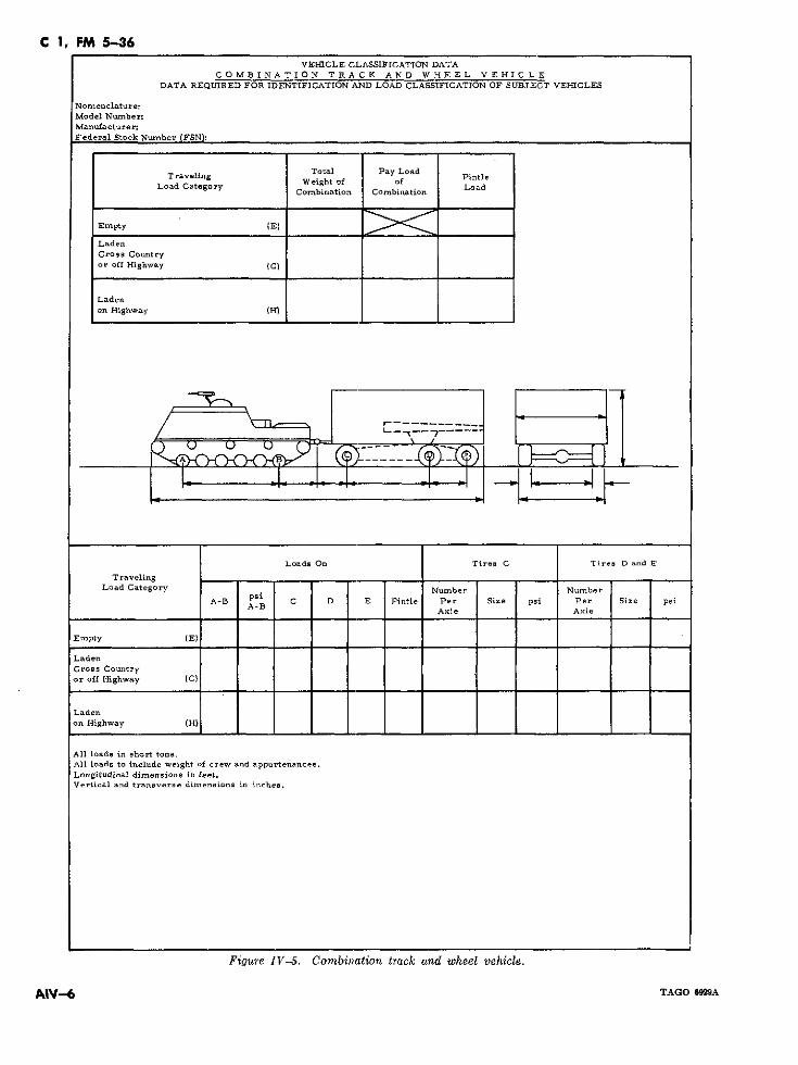
C 1, FM 5-36VEHICLE CLASSIFICATION DATA
COMBINATION TRACK AND WHEEL VEHICLEDATA REQUIRED FOR IDENTIFICATION AND LOAD CLASSIFICATION OF SUBJECT VEHICLES
Nomenclature:Model Number:Manufacturer:Federal Stock Number IFSN:
Traveling WeihTotal Pay LoadLoad Category Weight of f Load
CombLdation Combination Load
Empty (E)
LadenCross Countryor off Highway (C)
Ladenon Highway (H)
: -r: r -- e .U-C- -7-
Loads On Tires C Tires D and E
TravelingLoad Category Number Number
A-B C D E Pintie Per Size psi Per Size psiA-B
Axle Axle
Empty (E)
LadenCross Countryor off Highway (C)
Ladenon Highway (H)
All loada in short tons.All loads to include weight of crew and appurtenances.Longitudinal dimensions in feet.Vertical and transverse dimensions in inches.
Figure IV-5. Combination track and wheel vehicle.
A"V-6 TAGO 6929A
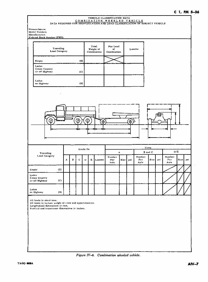
C 1, FM 5-36VEHICLE CLASSIFICATION DATA
COMBINATION WHEELED VEHICLEDATA REQUIRED FOR IDENTIFICATION AND LOAD CLASSIFICATION OF SUBJECT VEHICLE
Nomenclature:Model Number:Manufacturer:Federal Stock Number (FSN):
Total Pay LoadTraveling Weight of of Lunette
Load Category Combination Combination
Empty (E)
LadenCross Countryor off Highway (C)
Ladenon Highway (H)
r W
Tires _Loads On
T raveling __ On A B and C D/E
Load Category Number Number NumberA B C D E Lunette Per Size psi Per Size psi Per Size psi
Axie Axle Axle
Empty (E)
LadenCros.s Countryor off Highway (C)
Ladeoon Highway (H)
All loads in short tons.All loads to include weight of crew and appurtenances.Longitudinal dimensions in feet.Vertical and transverse dimensions in inches.
Figure IV-6. Combination wheeled vehicle.
TAGO 6MA AIV-7
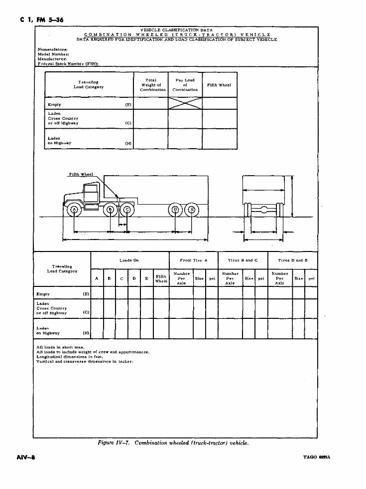
C 1, FM 5-36VEHICLE CLASSIFICATION DATA
COMBINATION WHEELED (TRUCK-TRACTOR) VEHICLEDATA REQUIRED FOR IDENTIFICATION AND LOAD CLASSIFICATION OF SUBJECT VEHICLE
Nomenclature:Model Number:Manufacturer.Federal Stock Number (FSN):
Tra~eling Total Pay LoadWeight of of Fifth WheelLoad Category
Combination Combination
Empty (E)
LadenCross Countryor off Highway (C)
Ladenon Highway (H)
Fifth Wheel
Loads On Front Tire A Tires B and C Tires D and E
TravelingLoad Category Number Nmber Number
A B C D E Fifth Per Size psi Per Size psi Per Size psiWheel Aile AIe AxIe
Empty (E)
LadenCross Countryor off Highway (C)
Ladenon Highway (H)
All loads in short tons.All loads to include weight of crew and appurtenances.Longitudinal dimensions in feet.Vertical and transverse dimensions in inches.
Figure IV-7. Combination wheeled (truck-tractor) vehicle.
AIV-S TAGO G929A
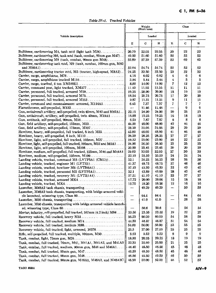
C 1, FM 5-36
Table IV-1. Tracked Vehicles
Weight Class(Short tone)
Vehiele description Loaded Loaded
E C H E C 'H
Bulldozer, earthmoving M4, tank mtd (light tank M24) .............. 20.70 22.05 22.05 20 22 22Bulldozer, earthmoving M6, tank mtd (tank, combat, 90mm gun M47).. 49.50 51.60 51.60 50 53 53Bulldozer, earthmoving M8 (tank, combat, 90mm gun M48) ......... 52.89 57.39 57.39 52 60 60Bulldozer, earthmoving tank mtd, M9 (tank, combat, 105mm gun, M60
and M60 A1) .................................................. 52.94 54.74 54.74 50 52 52Bulldozer, earthmoving tractor mtd, M5 (tractor, high-speed, M8A2).. 24.25 33.50 33.50 23 32 32Carrier, cargo, amphibious, M76 ................................... 4.16 6.02 6.02 4 6 6Carrier, cargo, amphibious tracked M116 ........................... 3.94 5.44 5.44 4 5 5Carrier, cargo, tracked, 6 ton XM548E1 ........................... 8.00 14.00 14.00 7 13 13Carrier, command post, light tracked, XM577 ...................... 11.40 11.95 11.95 11 11 11Carrier, personnel, full tracked, armored M59 ....................... 19.35 ..20.90 20.90 18 19 19Carrier, personnel, full tracked, armored M75 ....................... 18.34 20.75 20.75 17 20 20Carrier, personnel, full tracked, armored M113 .................... . 9.87 11.31 11.31 9 11 11Carrier, command and reconnaissance: armored, M114A1 ............ 6.45 7.37 7.37 7 7 7Flamethrower, self-propelled, M132 ............................... - 11.46 11.46 - 9 9Gun, antiaircraft artillery, self-propelled, twin 40mm, M42 and M42A1.. 22.15 24.90 24.90 20 23 23Gun, antiaircraft, artillery, self-propelled, twin 40mm, M19A1 ........ 16.88 19.25 19.25 16 18 18Gun, antitank, self-propelled, 90mm, M56 .......................... 6.25 7.87 7.87 6 8 8Gun, field artillery, self-propelled, 155mm, M53 ..................... 44.50 48.00 48.00 42 46 46Gun, field artillery, self-propelled, 175mm, M107 .................... 28.30 31.05 31.05 29 29 29Howitzer, heavy, self-propelled, full tracked, 8 inch M55 ............. 45 00 48.00 48.00 41 46 46Howitzcr, heavy, self-propelled, 8 inch, M110 ....................... 26.30 28.25 28.25 27 27 27Howitzer, light, self-propelled, fuil tracked, 105mm, M37 ............. 19.32 23.00 23.00 18 22 22Howitzer, light, self-propelled, full tracked, 105mm, M52 and M5A1 .... 24.90 26.50 26.50 23 25 25Howitzer, light, self-propelled, 105mm, M108 ....................... 20.50 23.45 23.45 20 20 20Howitzer, medium, self-propelled, full tracked, 155mm, M44 and M44A1 29.00 32.00 32.00 27 30 30Howitzer, medium, self-propelled, 155mm, M109 .................... 22.10 25.50 25.50 24 24 24Landing vehicle, tracked, command M5 (LVTP5A1 (CMD))......... 32.1 36.23 36.23 28 36 36Landing vehicle, tracked, engineer M1 (LVTE1) .................... 41.37 48.75 48.75 37 46 46Landing vehicle, tracked, howitzer M6 (LVTH6A1) ................. 37.10 43.30 43.30 33 40 40Landing vehicle, tracked, personnel M5 (LVTP5A1) ................. 32.1 43.89 43.89 28 40 40Landing vehicle, tracked, recovery M1 (LVTRIA1) .................. 37.51 41.10 41.10 33 37 37Landing vehicle, tracked, armored MK4 ........................... 17.72 20.00 20.00 15 18 18Landing vehicle, tracked, MK4 ................................... 13.70 18.2,0 18.20 12 16 16Launcher, M48A2 tank chassis, transporting ........................ - 49.29 49.29 - 50 50Launcher, M48A2 tank chassis, transporting, with bridge armored vehi-
cle launched, scissoring type, Class 60 ............................ - 64.4 64.4 - 64 64Launcher, M60 chassis, transporting ............................... - 41.0 41.0 - 38 38Launcher, M60 chassis, transporting with bridge armored vehicle launch
ed, scissoring type, Class 60 .................................... - 50.6 50.6 - 54 54Mortar, infantry, self-propelled, full tracked; 107mm (4.2 inch) M84 .... 20.56 23.55 23.55 19 22 22Recovery vehicle, full tracked, heavy M51 ......................... 56.25 60.00 60.00 54 58 58Recovery vehicle, full tracked, medium M74 ........................ 44.30 46.87 46.87 51 54 54Recovery vehicle, full tracked, medium M88 ........................ 54.00 56.00 56.00 53 55 55Recovery vehicle, full tracked, light, armored, M578 ................. 23.5 27.00 27.00 25 25 25Rifle, self-propelled, full tracked, multiple, 106mm, M50 ............. 8.22 9.52 9.52 8 9 9Tank, combat, light, 75mm gun, M24 .............................. 18.90 20.25 20.25 18 19 19Tank, combat, full tracked, 76mm, M41, M41A1, M41A2, and M41A3 22.35 25.90 25.90 21 25 25Tank, combat, full tracked, medium, 90mm gun, M46 and M46A1.... ... 46.40 48,50 48.50 45 48 48Tank, combat, full tracked, 90mm gun, M47 ....................... 46.50 48.50 48.50 45 48 48Tank, combat, full tracked, 9Omm gun, M48 ....................... 46.56 49.50 49.50 46 50 50Tank, combat, full tracked, 90mm gun, M48A1, M48A2, and M48A2C 48.50 52.00 52.00 46 52 52
TAGO 692DA AIV-9
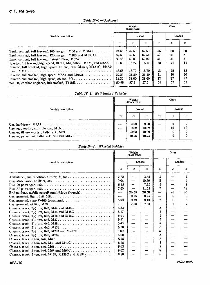
C 1, FM 5-36
Table IV-1 .-Continued
Weight Clas(Short tons)
Vehicle description Loaded Loaded
E C H E C H
Tank, combat, full tracked, 105mm gun, M60 and M60A1........... 47.65 52.50 52.50 45 50 50Tank, combat, full tracked, 120mm gun, M103 and M103A1......... 58.50 62.50 62.50 57 61 61Tank, combat, full tracked, flamethrower, M67AI ................... 50.48 52.89 52.89 51 51 51Tractor, full tracked, high speed, 13 ton, M5, M5A1, M5A2, and M5A4.. 12.60 15.77 15.17 12 14 14Tractor, full tracked, high speed, 18 ton, M4, M4A1, M4ALC, M4A2
and M4C .......... .......... .................. ....... 13.56 15.70 15.70 13 15 15Tractor, full tracked, high speed, M8A1 and M8A2 .................. 22.25 31.50 31.50 21 30 30Tractor, full tracked, high speed, 38 ton, M6 ....................... 34.30 38.00 38.00 32 37 37Vehicle, combat engineer, full tracked, T118E1 ..................... 50.45 57.5 57.5 54 57 57
Table IV-2. Half-tracked Vehicles
Weight Class(Short tons)
Vehicle deseription Loaded Loaded
E C H E C H
Car, half-track, M2A1 ......................................-..... 9.80 9.80 - 9 9Carriage, motor, multiple gun, M16 ............................... - 10.82 10.82 - 10 10Carrier, 81mm mortar, half-track, M21 ............................ - 10.00 10.00 10.00 9 9Carrier, personnel, half-track, M3 and M3A1 ....................... - 10.25 10.25 9 9
Table IV--. Wheeled Vehicles
Weight Class(Short tons)
Vehicle description Loaded Loaded
E C H E C H
Anibulance, metropolitan 4 litter, 3/ ton ........................... 2.70 - 3.52 3 - 4Bus, ambulance, 18 litter, 4x2 .................................... 9.04 - 10.79 8 - 9Bus, 29-passenger, 4x2 ........................................... 5.25 - 7.75 5 - 8Bus, 37-passenger, 4x2 ........................................... 7.60 - 11.95 7 - 12Bridge, float, mobile assault amphibious (French) ................... - 26.50 26.50 - 25 25Car, armored, light, 6x6, M8 ..................................... - 8.25 8.25 - 8 8Car, armored, type V-100 (commando) ............................ 6.80 8.13 8.13 7 8 8Car, armored, utility, M20 ...................... .......-........ 7.83 7.83 - 7 7Chassis, truck, 2Y ton, 6x6, M44 and M44C ....................... 5.33 5Chassis, truck, 2/ 2 ton, 6x6, M45 and M45C ....................... 5.47 - - 5 - -Chassis, truck, 2y/2 ton, 6x6, M45 and M46C ....................... 5.64 - - 5 - -Chassis, truck, 2Y2 ton, 6x6, M57 ......... ...................... 5.41 - - 5 - -Chassis, truck, 21/ ton, 6x6, M58 ................................. 5.43 - - 5 - -Chassis, truck, 21/2 ton, 6x6, M133 ................................. 5.58 - - 5 - -Chassis, truck, 2y2 ton, 6x6, M13207 and M20C ................... 5.80 - - 5 - -Chassis, truck, 2V2 ton, 6x6, M209 ........ ............. 5.60 - - 5 - -Chassis, truck, 5 ton, 6x6, M3 9 .......................... 75 ..... - 8 - -Chassis, truck, 5 ton, 6x6, M40 and M40C ......................... 8.75 - - 8 - -Chassis, truck, 5 ton, 6x6, M61 .... ............................... 9.02 - - 8 - -Chassis, truck, 5 ton, 6x6, M63 and M63C ......................... 9.62 - - 8 - -Chassis, truck, 5 ton, 6x6, M139, M139C and M39D ................ 9.80 - - 8 - -
AIV-1 0 TAGO 6929A
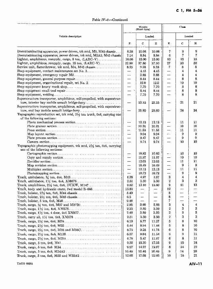
C 1, FM 5-46
Table IV-3.-Continued
Weight Class(Short tons)
Vehicle description Loaded Loaded
E C H E C H
Decontaminating apparatus, power driven, trk mtd, M9, M45 chassis... 8.38 10.08 10.08 7 9 9Decontaminating apparatus, power driven, trk mtd, M3A3, M45 chassis 7.14 8.84 8.84 6 7 7Lighter, amphibious, resupply, cargo, 5 ton, (LARC-V) .............. 10.00 15.00 15.00 10 15 15Lighter, amphibious, resupply, cargo, 15 ton, (LARC-V) ............. 22.50 37.50 37.50 27 50 50Service unit, flamethrower, trk mtd, M4, M45 chassis ............... 8.25 9.38 9.38 7 8 8Shop equipment, contact maintenance set No. 3 ..................... - 4.45 4.45 - 4 4Shop equipment, emergency repair M2 ............................. - 3.88 3.88 - 4 4Shop equipment, general purpose repair ............................ - 8.44 8.44 - 8 8Shop equipment, organizational repair, set No. 2 .................... - 12.0 12.0 - 10 10Shop equipment heavy mach shop ................................. - 7.70 7.70 - 8 8Shop equipment small tool repair .................................. - 8.44 8.44 - 8 8Shop equipment, welding ................... ..................... - 7.70 7.70 - 8 8Superstructure transporter, amphibious, self-propelled, with superstruc-
ture, interior bay mobile assault bridge-ferry ...................... - 23.35 23.35 - 21 21Superstructure transporter, amphibious, self-propelled, with superstruc-
ture, end bay mobile assault bridge-ferry ......................... - 25.80 25.80 - 24 24Topographic reproduction set, trk mtd, 2Y/ ton truck, 6x6, carrying one
of the following sections:Photo mechanical process section ............................ - 12.13 12.13 - 11 11Plate grainer section ....................................... - 10.21 10.21 - 10 10Press section .............................................. - 11.53 11.53 - 11 11Map layout section ........................................ - 9.04 9.04 - 9 9Plate process section ....................................... - 9.47 9.47 - 9 9Camera section .......................................... - 9.74 9.74 - 10 10
Topographic photomapping equipment, trk mtd, 2½ ton, 6x6, carryingone of the following sections:
Cartographic section ....................................... - 10.82 10.82 - 10 10Copy and supply section ................................... - 11.97 11.97 - 10 10Rectifier section ........................................... - 12.03 12.03 - 11 11Map revision section ....................................... - 10.49 10.49 - 9 9Multiplex section ....................................... - 12.13 12.13 - 11 11Photomapping section ..................................... - 10.72 10.72 - 9 9
Truck, ambulance, M4 ton, 4x4, M43 ............................... 4.39 4.97 4.97 3 4 4Truck, ambulance, 1l4 ton, 4x4, XM676 ........................... 2.51 3.50 3.50 2 3 3Truck, amphibious, 23/ ton, 6x6, DUKW, M147 ................... 9.60 12.10 13.60 9 11 13Truck, body and hydraulic crarre, fwd model B-666 ................. 13.80 - - 12 - -Truck, bolster, 2~y ton, 6x6, M44 chassis ........................... 5.49 - - 8 - -Truck, bolster, 212 ton, 6x6, M45 chassis ........................... 6.5 - - 8 - -Truck, bolster, 5 ton, 6x6, M40 ................................... 9.49 - - 7 - -Truck, cargo, Y4 ton, 4x4, M37 and M37B1 ........................ 2.85 3.60 3.85 3 4 4Truck, cargo, 112 ton, 4x4, XM676 ............................... 2.33 3.50 3.50 2 3 3Truck, cargo, 1 y ton, 4 door, 4x4 XM677 ......................... 2.48 3.50 3.50 2 3 3Truck, carry all, 1 ton, 4x4, XM678 ............................. 2.51 3.50 3.50 2 3 3Truck, cargo, 21½ ton, 6x6, M34 .................................. 6.10 8.77 11.27 5 8 10Truck, cargo, 2Y2 ton, 6x6, M35 .................................. 6.44 8.94 11.44 5 8 10Truck, cargo, 2V2 ton, 6x6, M36 and M36C ........................ 6.75 9.25 11.75 6 8 10Truck, cargo, 2/2 ton, 6x6, M135 ................................. 6.37 9.04 11.54 6 9 11Truck, cargo, 2½1 ton, 6x6, M211 ................................. 6.79 9.47 11.97 6 8 11Truck, cargo, 5 ton, 6x6, M41 .................................... 9.55 13.30 17.05 9 15 18Truck, cargo, 5 ton, 6x6 M54 .................................... 9.97 14.97 19.97 8 14 19Truck, cargo, 5 ton, 6x6, M54A2 ................................. 10.46 15.46 20.46 9 14 20Truck, cargo, 5 ton, 6x6, M55 and M55A2 ........................ 12.03 17.03 22.03 10 16 21
TAGO 6929A AIV-11
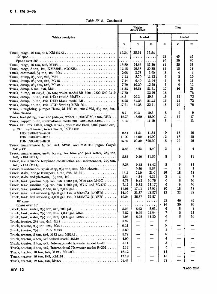
C 1, FM 5-36
Table IV-B.-Continued
Weight Class(Short tons)
Vehicle description Loaded Loaded
E C H E C H
Truck, cargo, 16 ton, 4x4, XM437E1 .............................. 19.34 35.54 35.5410' span .......................................................... ...... ...... 22 45 45Spans over 50' ..................................................... ............ 16 30 30
Truck, cargo, 10 ton, 6x6, M125 .................................. 15.80 24.55 33.30 14 25 33Truck, cargo, 8 ton, 4x4, XM520E1 (GOER) ............... 12.18 20.38 20.38 12 18 18Truck, command, 3 ton, 4x4, M42 ................................ 2.98 3.73 3.90 3 4 4Truck, dump, 2Y2 ton, 6x6, M59 .................................. 7.23 8.79 11.42 6 8 10Truck, dump, 2Y2 ton, 6x6, M215 ................................. 7.44 9.49 11.94 7 9 11Truck, dump, 2Y2 ton, 6x6, M342 ................................. 7.79 10.29 12.79 7 9 12Truck, dump, 5 ton, 6x6, M51 .................................... 11.33 16.51 21.51 10 16 21Truck, dump, 10 cu yd, (15 ton) white model SB-3001, 2320-540-3119 17.70 - 32.70 18 - 76Truck, dump, 15 ton, 4x2, DED Euclid M5FD .............. 14.3 29.3 29.3 15 72 72Truck, dump, 15 ton, 4x2, DED Mack model LR ................... 16.25 31.25 31.25 15 72 72Truck, dump, 15 ton, 4x2, GED Sterling MSB-301 .................. 17.71 31.25 32.71 18 76 76Truck, firefighting, pumper Hesse, M-HC-26, 500 GPM, 2Y2 ton, 6x6,
M44 chassis .................................................. 8.7 10.3 10.3 8 9 9Truck, firefighting, crash and pumper, walter, 1,500 GPM, 7 ton, GED... 12.78 18.00 18.00 11 17 17Truck, hopper, 5 ton, international model 201, 2320-273-4426 ........ 6.12 - 11.10 5 - 13Truck, lift, fork, GED, rough terrain, pneumatic tired, 6,000 pound cap,
at 24 in load center, baker model, RJF-060:FSN 3930-679-4458 ....................................... 8.51 11.51 11.51 9 16 16FSN 3930-073-8751 ....................................... 11.00 14.00 14.00 .12 18 18FSN 3930-073-8750 ....................................... 15.30 20.30 *20.30 15 29 29
Truck, maintenance 3 ton, 4x4, M201, and M201B1 (Signal Corps)V41/GT .................................. ....... ...... 3.48 4.23 4.40 3 4 4
Truck, maintenance, earth boring, machine and pole setter, 2~y ton,6x6, V18A1MTQ .............................................. 8.57 9.56 11.56 8 9 11
Truck, maintenance telephone construction and maintenance, 2Y2 ton,6x6, V17A/MTQ ..................................... ..... 8.28 9.42 11.42 8 9 11
Truck, maintenance repair shop, 2y ton, 6x6, M46 chassis ........... - 9.56 9.56 - 8 8*Truck, stake, bridge transport, 5 ton, 6x6, M139 .................... 13.2 21.0 21.0 10 18 18Truck, stake and platform, 1 2 ton, 4x2 ............................ 2.84 4.34 6.23 3 4 7Truck, tank, gasoline, 2h2 ton, 6x6, 1,200 gal, M49 and M49C ........ 6.75 9.42 10.75 6 8 10Truck, tank, gasoline, 2y2 ton, 6x6, 1,200 gal, M217 and M217C ...... 7.17 9.82 11.17 6 9 10Truck, tank, gasoline, 6 ton, 6x6, 2,000 gal ......................... 11.91 17.91 17.91 10 18 18Truck, tank, fuel servicing, 2,500 gal, 4x4, XM559E1 (GO:ER) ........ 14.10 23.87 23.87 12 22 22Truck, tank, fuel servicing, 5,000 gal, 4x4, XM438E2 (GOER) ........ 19.24 35.87 35.87
10' span . ................................................. ...... 22 46 46Spans over 50' ......................................................... ...... 16 30 30
Truck, tank, water, 2y ton, 6x6, 700 gal .......................... 5.96 8.63 8.63 6 8 8Truck, tank, water, 21/2 ton, 6x6, 1,000 gal, M50 .................... 7.52 9.49 11.94 7 8 11Truck, tank, water, 2j/2 ton, 6x6, 1,000 gal, M222 ................... 7.05 8.98 11.30 6 8 10Truck, tractor, 2V/ ton, 6x6, M48 ................................. 5.92 - - 6 - -Truck, tractor, 2j/2 ton, 6x6, M221 ............................... 6.05 - - 5 - -
Truck, tractor, 2y2 ton, 6x6, M275 ................................ 5.80 - - 5 - -
Truck, tractor, 5 ton, 6x6, M52 and M52A1 ........................ 9.72 - - 8 - -Truck, tractor, 5 ton, 4x2 federal model 45M2 ...................... 4.90 - - 4 - -Truck, tractor, 5 ton, 4x2, International-Harvester model L-201 ...... 5.11 - - 5 - -Truck, tractor, 5 ton, 4x2, International-Harvester model 1R-202 ...... 5.12 - - 5 - -Truck, tractor, 10 ton, 6x6, M123, M123C ......................... 16.12 - - 14 - -Truck, tractor, 10 ton, 8x8, XM191 ............................... 17.18 - - 15 - -
Truck, tractor, 12 ton, 6x6, M26A .-............................... 24.45 - - 28 -
AIV-12 TAGO 699A
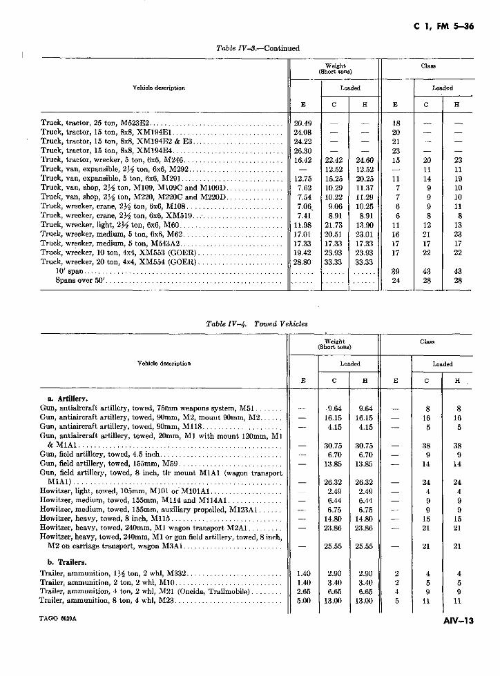
C 1, FM 5-36
Table IV-8.-Continued
Weight Clas(Short tons)
Vehicle description Loaded Loaded
E C H E C H
Truck, tractor, 25 ton, M523E2 ................................... 20.49 - - 18 -Truck, tractor, 15 ton, 8x8, XM194E1 ............................. 24.08 - - 20 -Truck, tractor, 15 ton, 8x8, XM194E2 & E3 ........................ 24.22 - - 21 -Truck, tractor, 15 ton, 8x8, XM194E4 ............................. 26.30 - - 23 -Truck, tractor, wrecker, 5 ton, 6x6, M246 .......................... 16.42 22.42 24.60 15 20 23Truck, van, expansible, 2M/ ton, 6x6, M292 ......................... - 12.52 12.52 - 11 11Truck, van, expansible, 5 ton, 6x6, M291 ........................... 12.75 15.25 20.25 11 14 19Truck, van, shop, 2?/ ton, M109, M109C and M109D ............... 7.62 10.29 11.37 7 9 10Truck, van, shop, 21/2 ton, M220, M220C and M220D ............... 7.54 10.22 11.29 7 9 10Truck, wrecker, crane, 22 ton, 6x6, M108 ......................... 7.06 9.06 10.25 6 9 11Truck, wrecker, crane, 23Y ton, 6x6, XM519........................ 7.41 8.91 8.91 6 8 8Truck, wrecker, light, 2y ton, 6x6, M60 .......................... 11.98 21.73 13.90 11 12 13Truck, wrecker, medium, 5 ton, 6x6, M62 .......................... 17.01 20.51 23.01 16 21 23Truck, wrecker, medium, 5 ton, M543A2 ........................... 17.33 17.33 17.33 17 17 17Truck, wrecker, 10 ton, 4x4, XM553 (GOER) ...................... 19.42 23.93 23.93 17 22 22Truck, wrecker, 20 ton, 4x4, XM554 (GOER) ...................... 28.80 33.33 33.33
10' span ................................................................... 39 43 43Spans over 50' ............... ............................. ............ ...... 24 28 28
Table IV-4. Towed Vehicles
Weight Class(Short tons)
Vehicle description Loaded Loaded
E C H E C H
a. Artillerv.Gun, antiaircraft artillery, towed, 75mm weapons system, M51 ....... - 9.64 9.64 - 8 8Gun, antiaircraft artillery, towed, 90mm, M2, mount 90mm, M2 ...... - 16.15 16.15 - 16 16Gun, antiaircraft artillery, towed, 90mm, M118 ..................... - 4.15 4.15 - 5 5Gun, antiaircraft artillery, towed, 20mm, M1 with mount 120mm, M1
& MA1 ..................................................... - 30.75 30.75 - 38 38Gun, field artillery, towed, 4.5 inch ............... .............. - 6.70 6.70 - 9 9Gun, field artillery, towed, 155mm, M59 ........................... - 13.85 13.85 - 14 14Gun, field artillery, towed, 8 inch, tlr mount MlA1 (wagon transport
M1A1) ...................................................... - 26.32 26.32 - 24 24Howitzer, light, towed, 105mm, M101 or MOlA ................... - 2.49 2.49 - 4 4Howitzer, medium, towed, 155mm, M114 and M114A1 .............. - 6.44 6.44 - 9 9Howitzer, medium, towed, 155mm, auxiliary propelled, M123A1 ...... - 6.75 6.75 - 9 9Howitzer, heavy, towed, 8 inch, M115 ............................. - 14.80 14.80 - 15 15Howitzer, heavy, towed, 240mm, M1 wagon transport M2A1 ......... - 23.86 23.86 - 21 21Howitzer, heavy, towed, 240mm, M1 or gun field artillery, towed, 8 inch,
M2 on carriage transport, wagon M3A1 .......................... - 25.55 25.55 - 21 21
b. Trailers.
Trailer, ammunition, 112 ton, 2 whl, M332 ......................... 1.40 2.90 2.90 2 4 4Trailer, ammunition, 2 ton, 2 whl, M10 ............................ 1.40 3.40 3.40 2 5 5Trailer, ammunition, 4 ton, 2 whl, M21 (Oneida, Trailmobile) ........ 2.65 6.65 6.65 4 9 9Trailer, ammunition, 8 ton, 4 whl, M23 ............................ 5.00 13.00 13.00 5 11 11
TAGO 6929A AIV-13
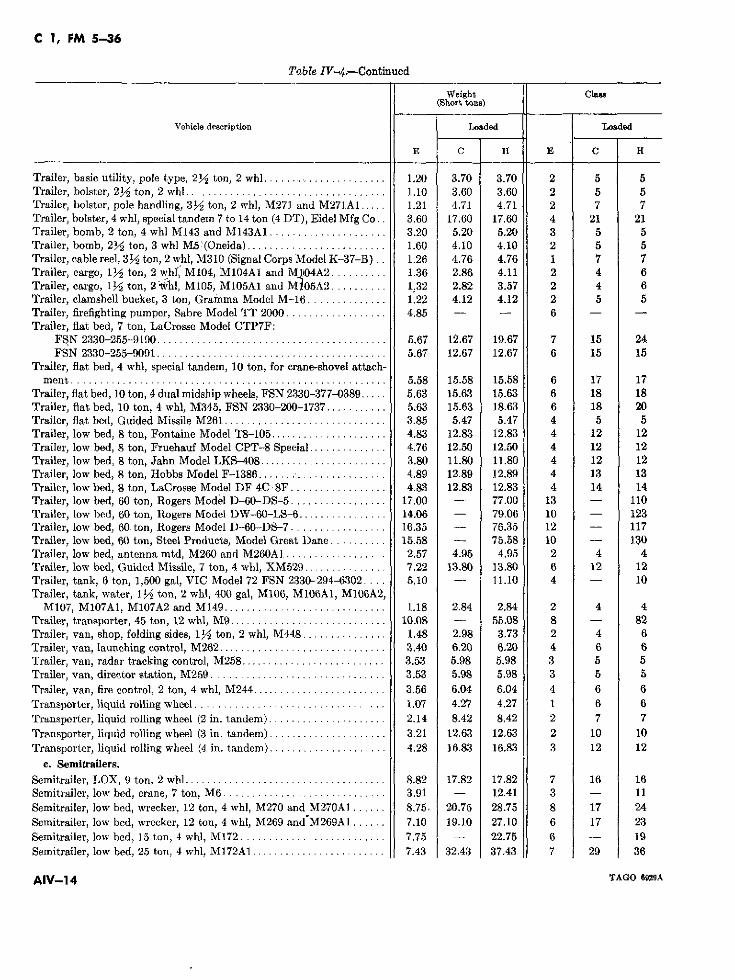
C 1, FM 5-36
Table IV-4.-Continued
Weight Class(Short tons)
Vehicle description Loaded .Loaded
E C H E C H
Trailer, basic utility, pole type, 2~y ton, 2 whl ........................ 1.20 3.70 3.70 2 5 5Trailer, bolster, 2Y2 ton, 2 whl .................................... 1.10 3.60 3.60 2 5 5Trailer, bolster, pole handling, 312 ton, 2 whl, M271 and M271A1 ..... 1.21 4.71 4.71 2 7 7Trailer, bolster, 4 whl, special tandem 7 to 14 ton (4 DT), Eidel Mfg Co.. 3.60 17.60 17.60 4 21 21Trailer, bomb, 2 ton, 4 whl M143 and M143A1 ..................... 3.20 5.20 5.20 3 5 5Trailer, bomb, 2Y2 ton, 3 whl M5:(Oneida) ......................... 1.60 4.10 4.10 2 5 5Trailer, cable reel, 3V2 ton, 2 whl, M310 (Signal Corps Model K-37-B) .. 1.26 4.76 4.76 1 7 7Trailer, cargo, 11/2 ton, 2 whf, M104, M104A1 and M1l04A2 .......... 1.36 2.86 4.11 2 4 6Trailer, cargo, 1li/ ton, 2 ;hl, M105, M105A1 and MN05A2 .......... 1.32 2.82 3.57 2 4 6Trailer, clamshell bucket, 3 ton, Gramma Model M-16 .............. 1.22 4.12 4.12 2 5 5Trailer, firefighting pumper, Sabre Model TT 2000 .................. 4.85 - - 6 - -Trailer, flat bed, 7 ton, LaCrosse Model CTP7F:
FSN 2330-255-9190 ......................................... 5.67 12.67 19.67 7 15 24FSN 2330-255-9091 ......................................... 5.67 12.67 12.67 6 15 15
Trailer, flat bed, 4 whl, special tandem, 10 ton, for crane-shovel attach-ment ....................................................... 5.58 15.58 15.58 6 17 17
Trailer, flat bed, 10 ton, 4 dual midship wheels, FSN 2330-377-0389 ..... 5.63 15.63 15.63 6 18 18Trailer, fiat bed, 10 ton, 4 whl, M345, FSN 2330-200-1737 ........... 5.63 15.63 18.63 6 18 20Trailer, flat bed, Guided Missile M261 ............................. 3.85 5.47 5.47 4 5 5Trailer, low bed, 8 ton, Fontaine Model T8-105 ..................... 4.83 12.83 12.83 4 12 12Trailer, low bed, 8 ton, Fruehauf Model CPT-8 Special .............. 4.76 12.50 12.50 4 12 12Trailer, low bed, 8 ton, Jahn Model LKS-408 ....................... 3.80 11.80 11.80 4 12 12Trailer, low bed, 8 ton, Hobbs Model F-1386 ....... ............... 4.89 12.89 12.89 4 13 13Trailer, low bed, 8 ton, LaCrosse Model DF 4C-8F ................. 4.83 12.83 12.83 4 14 14Trailer, low bed, 60 ton, Rogers Model D-60-DS-5 ................. 17.00 - 77.00 13 - 110Trailer, low bed, 60 ton, Rogers Model DW-60-LS-6 ................ 14.06 - 79.06 10 - 123Trailer, low bed, 60. ton, Rogers Model D-60-DS-7 ................. 16.35 - 76.35 12 - 117Trailer, low bed, 60 ton, Steel Products, Model Great Dane .......... 15.58 - 75.58 10 - 130Trailer, low bed, antenna mtd, M260 and M260A1 .................. 2.57 4.95 4.95 2 4 4Trailer, low bed, Guided Missile, 7 ton, 4 whl, XM529 ............... 7.22 13.80 13.80 6 12 12Trailer, tank, 6 ton, 1,500 gal, VIC Model 72 FSN 2330-294-6302 .... 5.10 - 11.10 4 - 10Trailer, tank, water, 1/2 ton, 2 whl, 400 gal, M106, M106A1, M106A2,
M107, M107A1, M107A2 and M149 ............................. 1.18 2.84 2.84 2 4 4Trailer, transporter, 45 ton, 12 whl, M9 ............................ 10.08 - 55.08 8 - 82Trailer, van, shop, folding sides, 1/y ton, 2 whl, M448 ............... 1.48 2.98 3.73 2 4 6Trailer, van, launching control, M262 .............................. 3.40 6.20 6.20 4 6 6Trailer, van, radar tracking control, M258 .......................... 3.53 5.98 5.98 3 5 5Trailer, van, director station, M259 ............................... 3.53 5.98 5.98 3 5 5Trailer, van, fire control, 2 ton, 4 whl, M244 ........................ 3.56 6.04 6.04 4 6 6Transporter, liquid rolling wheel .................................. 1.07 4.27 4.27 1 6 6Transporter, liquid rolling wheel (2 in. tandem) ..................... 2.14 8.42 8.42 2 7 7Tre.nsporter, liquid rolling wheel (3 in. tandem) ..................... 3.21 12.63 12.63 2 10 10Transporter, liquid rolling wheel (4 in. tandem) ..................... 4.28 16.83 16.83 3 12 12
c. Semitrailers.Semitrailer, LOX, 9 ton, 2 whl .................................... 8.82 17.82 17.82 7 16 16Semitrailer, low bed, crane, 7 ton, M6 ............................. 3.91 - 12.41 3 - 11Semitrailer, low bed, wrecker, 12 ton, 4 whl, M270 and M270A1 ...... 8.75. 20.75 28.75 8 17 24Semitrailer, low bed, wrecker, 12 ton, 4 whl, M269 and M269A1 ...... 7.10 19.10 27.10 6 17 23Semitrailer, low bed, 15 ton, 4 whl, M172 .......................... 7.75 - 22.75 6 - 19Semitrailer, low bed, 25 ton, 4 whl, M172A1 ........................ 7.43 32.43 37.43 7 29 36
AIV-14 TAGO 6929A
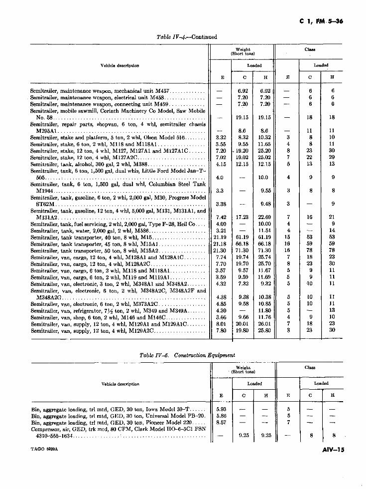
C 1, FM.5-36
Table IV-4.-Continued
Weight ClasS(Short tons)
Vehicle description Loaded Loaded
E C H E C H
Semitrailer, maintenance weapon, mechanical unit M457 ............. - 6.92 6.92 - 6 6Semitrailer, maintenance weapon, electrical unit M458 ............... - 7.20 7.20 - 6 6Semitrailer, maintenance weapon, connecting unit M459 ............. - 7.20 7.20 - 6 6Semitrailer, mobile sawmill, Corinth Machinery Co Model, Saw Mobile
No. 58 ....................................................... - 1.9.15 19.15 - 18 18Semitrailer, repair parts, shopvan, 6 ton, 4 whl, semitrailer chassis
M295A1 ..................................................... - 8.6 8.6 - 11 11Semitrailer, stake and platform, 5 ton, 2 whl, Olson Model 516 ........ 3.32 8.32 10.32 3 8 10Semitrailer, stake, 6 ton, 2 whl, M118 and M118A1 ................. 3.55 9.55 11.65 4 8 11Semitrailer, stake, 12 ton, 4 whl, M127, M127A1 and M127AlC ...... 7.20 .. 19.20 25.20 8 23 30Semitrailer, stake, 12 ton, 4 whl, M127A2C ......................... 7.02 19.02 25.02 7 22 29Semitrailer, tank, alcohol, 300 gal, 2 whl, M388 ..................... 4.15 12.15 12.15 5 13 13Semitrailer, tank, 6 ton, 1,500 gal, dual whls, Little Ford Model Jan-T-
505..... : ................................................... 4.0 - 10.0 4 9 9Semitrailer, tank, 6 ton, 1,500 gal, dual whl, Columbian Steel Tank
M1944 ....................................................... 3.3 - 9.55 3 8 8Semitrailer, tank, gasoline, 6 ton, 2 whl, 2,000 gal, M30, Progress Model
ST62M ...................................................... 3.38 - 9.48 3 - 9Semitrailer, tank, gasoline, 12 ton, 4 whl, 5,000 gal, M131, M131AI, and
M131A2 ..................................................... 7.42 17.23 22.69 7 16 21Semitrailer, tank, fuel servicing, 2 whl, 2,000 gal, Type F-28, Heil Co .... 4.00 - 10.00 4 - 9Semitrailer, tank, water, 2,000 gal, 2 whl, M586 ..................... 3.21 - 11.51 4 - 14Semitrailer, tank transporter, 40 ton, 8 whl, M15 .................... 21.19 61.19 61.19 15 53 53Semitrailer, tank transporter, 45 ton, 8 whl, M15A1 ................. 21.18 66.18 66.18 16 59 59Semitrailer, tank transporter, 50 ton, 8 whl, M15A2 ................. 21.30 71.30 71.30 16 78 78Semitrailer, van, cargo, 12 ton, 4 whl, M128A1 and M128A1C ........ 7.74 19.74 25.74 7 18 23Semitrailer, van, cargo, 12 ton, 4 whl, M128A2C .................... 7.70 19.70 25.70 8 23 30Semitrailer, van, cargo, 6 ton, 2 whl, M118 and M118A1 ............. 3.57 9.57 11.67 5 9 11Semitrailer, van, cargo, 6 ton, 2 whl, M119 and M119A1 ............. 3.59 9.59 11.69 5 9 11Semitrailer, van, electronic, 3 ton, 2 whl, M348A1 and M348A2 ....... 4.32 7.32 9.32 5 '10 11Semitrailer, van, electronic, 6 ton, 2 whl, M348A2C, M348A2F and
M348A2G .................................................... 4.38 9.38 10.38 5 10 11Semitrailer, van, electronic, 6 ton, 2 whl, M373A2C ................. 4.85 9.58 10.85 5 10 11Semitrailer, van, refrigerator, 7V2 ton, 2 whl, M349 and M349A ....... 4.30 - 11.80 5 - 13Semitrailer, van, shop, 6 ton, 2 whl, M146 and M146C ............... 3.66 9.66 11.76 4 9 10Semitrailer, van, supply, 12 ton, 4 whl, M129A1 and M129AIC ....... 8.01 20.01 26.01 7 18 23Semitrailer, van, supply, 12 ton, 4 whl, M129A2C ................... 7.80 19.80 25.80 8 23 30
Table IV-5. Construction Equipment
Weight Clase(Short tons)
Vehicle description Loaded Loaded
E C H E C H
Bin, aggregate loading, trl mtd, GED, 30 ton, Iowa Model 30-T ...... 5.93 - 5 - -
Bin, aggregate loading, trl mtd, GED, 30 ton, Universal Model PB-20. 5.86 - - 5 - -Bin, aggregate loading, trl mtd, GED, 30 ton, Pioneer Model 220 ..... 8.57 - - 7 - -Compressor, air, GED, trk mtd, 80 CFM, Clark Model HO-6-5C1 FSN
4310-555-1634 ............................................... 9.25 9.25 - 8 8
TAGO 6929A AIV-15
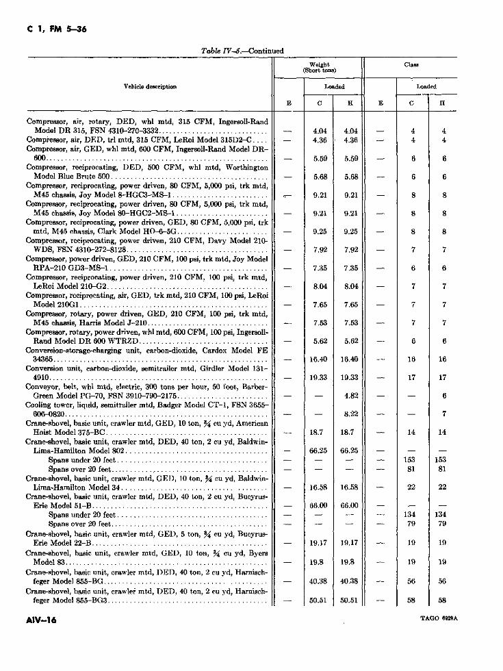
C 1, FM 5-36
Table IV-6.-Continued
Weight ClasI(Short tons)
Vehicle description Loaded Loaded
E C H E C H
Compressor, air, rotary, DED, whl mtd, 315 CFM, Ingersoll-RandModel DR 315, FSN 4310-270-3332 ................... ......... - 4.04 4.04 - 4 4
Compressor, air, DED, trl mtd, 315 CFM, LeRoi Model 315D2-C .... - 4.36 4.36 - 4 4Compressor, air, GED, whl mtd, 600 CFM, Ingersoll-Rand Model DR-
600 ........................................................ 5.59 5.59 - 6 6Compressor, reciprocating, DED, 500 CFM, whl mtd, Worthington
Model Blue Brute 500 ......................................... - 5.68 5.68 - 6 6Compressor, reciprocating, power driven, 80 CFM, 5,000 psi, trk mtd,
M45 chassis, Joy Model 8-HGC3-MS-1 ......................... 9.21 9.21 - 8 8Compressor, reciprocating, power driven, 80 CFM, 5,000 psi, trk mtd,
M45 chassis, Joy Model 80-HGC2-MS-1 ........................ 9.21 9.21 - 8 8Compressor, reciprocating, power driven, GED, 80 CFM, 5,000 psi, trk
mtd, M45 chassis, Clark Model HO-6-5G ........................ 9.25 9.25 - 8 8Compressor, reciprocating, power driven, 210 CFM, Davy Model 210-
WDS, FSN 4310-272-8128 .................................... - 7.92 7.92 - 7 7Compressor, power driven, GED, 210 CFM, 100 psi, trk mtd, Joy Model
RPA-210 GD3-MS-1 ......................................... 7.35 7.35 - 6 6Compressor, reciprocating, power driven, 210 CFM. 100 psi, trk mtd,
LeRoi Model 210-G2 ................... ................... ... 8.04 8.04 - 7 7Compressor, reciprocating, air, GED, trk mtd, 210 CFM, 100 psi, LeRoi
Model 210G1 ................................................. - 7.65 7.65 - 7 7Compressor, rotary, power driven, GED, 210 CFM, 100 psi, trk mtd,
M45 chassis, Harris Model J-210 ................... ............ - 7.53 7.53 - 7 7Compressor, rotary, power driven, whl mtd, 600 CFM, 100 psi, Ingersoll-
Rand Model DR 600 WTRZD ............. : .................... 5.62 5.62 6 6Conversion-storage-charging unit, carbon-dioxide, Cardox Model FE
34365 ....................................................... 16.40 16.40 - 16 16Conversion unit, carbon-dioxide, semitrailer mtd, Girdler Model 131-
4910 ......................................................... 19.33 19.33 17 17Conveyor, belt, whl mtd, electric, 300 tons per hour, 50 foot, Barber-
Green Model PG-70, FSN 3910-790-2175 ................... .... - - 4.82 - - 6Cooling tower, liquid, semitrailer mtd, Badger Model CT-1, FSN 3655-
606-0820 ................... ................................. -- 8.22 - - 7Crane-shovel, basic unit, crawler mtd, GED, 10 ton, 34 cu yd, American
Hoist Model 375-BC .......................................... - 18.7 18.7 - 14 14Crane-shovel, basic unit, crawler mtd, DED, 40 ton, 2 cu yd, Baldwin-
Lima-Hamilton Model 802 ..................................... 66.25 66.25 - -
Spans under 20 feet ....................................... - - - - 153 153Spans over 20 feet ........... .............................- - 81 81
Crane-shovel, basic unit, crawler mtd, GED, 10 ton, 34 cu yd, Baldwin-Lima-Hamilton Model 34 ...................................... - 16.58 16.58 - 22 22
Crane-shovel, basic unit., crawler mtd, DED, 40 ton, 2 cu yd, Bucyrus-Erie Model 51-B ................... .......................... 66.00 66.00 - - -
Spans under 20 feet ....................................... - - - - 134 134Spans over 20 feet ......................................... . .- - - 79 79
Crane-shovel, basic unit, crawler mtd, GED, 5 ton, 54 cu yd, Bucyrus-Erie Model 22-B ...................................... ........ 19.17 19.17 - 19 19
Crane-shovel, basic unit, crawler mtd, GED, 10 ton, 34 cu yd, ByersModel 83 ..................................................... - 19.8 19.8 - 19 19
Crane-shovel, basic unit, crawler mtd, DED, 40 ton, 2 cu yd, Harnisch-feger Model 855-BG ........................................... - 40.38 40.38 - 56 56
Crane-shovel, hasic unit, crawler mtd, DED, 40 ton, 2 cu yd, Harnisch-feger Model 855-BG3 ......................................-.... 50.51 50.51 - 58 58
AIV-16 TAGO 6929A
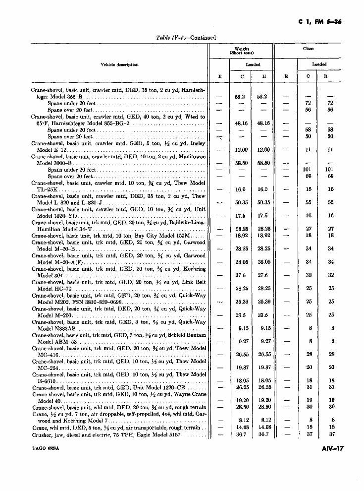
C 1, FM 5-36
Table IV-6.-Continued
Weight Claes(8hort tons)
Vehicle description Loaded Loaded
E C H E C H
Crane-shovel, basic unit, crawler mtd, DED, 35 ton, 2 cu yd, Harnisch-feger Model 855-B........................ - 53.2 53.2 - -
Spans under 20 feet ........................ - - - - 72 72Spans over 20 feet. ......................... - - - - 56 56
Crane-shovel, basic unit, crawler mtd, GED, 40 ton, 2 cu yd, Wtzd to65oF, Harnischfeger Model 855-BG-2 ........................... - 48.16 48.16 - - -
Spans under 20 feet ........................ ............... 58Spans over 20 feet ....................................... . -_ _ 50 50
Crane-shovel, basic unit, crawler mtd, GED, 5 ton, /2 cu yd, InsleyModel E-12 ................................. 12.00 12.00 - 11 11
Crane-shovel, basic unit, crawler mtd, DED, 40 ton, 2 cu yd, ManitowocModel 3000 -B.............................. - 58.50 58.50 - - -
Spans under 20 feet ........................ ........... - - - 101 101Spans over 20 feet ......................................... - - - 69 69
Crane-shovel, basic unit, crawler mtd, 10 ton, 3% cu yd, Thew ModelTL-25K.................................... - 16.0 16.0 - 15 15
Crane-shovel, basic unit, crawler mtd, DED, 35 ton, 2 cu yd, ThewModel L-820 and L-820-J ...................... - 50.35 50.35 - 55 55
Crane-shovel, basic unit, crawler mtd, GED, 10 ton, 34 cu yd, UnitModel 1020-YD .............................................. - 17.5 17.5 - 16 16
Crane-shovel, basic unit, trk mtd, GED, 20 ton, 34 cu yd, Baldwin-Lima-Hamilton Model 34-T ......................................... - 28.25 28.25 - 27 27
Crane-shovel, basic unit, trk mtd, 10 ton, Bay City Model 150M...... - 18.92 18.92 - 18 18Crane-shovel, basic unit, trk mtd, GED, 20 ton, %4 cu yd, Garwood
Model M -20-B ............................. - 28.25 28.25 - 34 34Crane-shovel, basic unit, trk mtd, GED, 20 ton, Y4 cu yd, Garwood
Model M -20-A(F) .... ........................ - 28.05 28.05 - 34 34Crane-shovel, basic unit, trk mtd, GED, 20 ton, %4 cu yd, Koehring
Model 304 ................................ - 27.6 27.6 - 32 32Crane-shovel, basic unit, trk mtd, GED, 20 ton, 34 cu yd, Link Belt
Model HC-70 ............................................ - 28.25 28.25 - 25 25Crane-shovel, basic unit, trk mtd, GED, 20 ton, 3 cu yd, Quick-Way
Model M202, FSN 3810-820-0698 ............................... - 25.39 25.39 - 25 25Crane-shovel, basic unit, trk mtd, DIED, 20 ton, %4 cu yd, Quick-Way
Model M -200 ................................................ 23.5 23.5 - 25 25Crane-shovel, basic unit, trk mtd, GED, 3 ton, Y/ cu yd, Quick-Way
Model N383A B ............................................... - 9.15 9.15 - 8 8Crane-shovel, basic unit, trk mtd, GED, 3 ton, %/ cu yd, Schield Bantam
Model ABM-53 ............................. 9.27 9.27 - 8 8Crane-shovel, basic unit, trk mtd, GED, 20 ton, 34 cu yd, Thew Model
MC-416 . ..... .......... ......... ......... - 26.55 26.55 - 28 28Crane-shovel, basic unit, trk mtd, GED, 10 ton, j/ cu yd, Thew Model
MC-254 ............................................. ....... _ - 19.87 19.87 - ' 20 20Crane-shovel, basic unit, trk mtd, GED, 10 ton, jY cu yd, Thew Model
E-6610................................... - 18.05 18.05 - 18 18Crane-shovel, basic unit, trk mtd, GED, Unit Model 1220-CE ........ - 26.25 26.25 - 31 31Crane-shovel, basic unit, trk mtd, GED, 10 ton, jY cu yd, Wayne Crane
Model 40 .................................. .......... 19.20 19.20 - 19 19Crane-shovel, basic unit, whl mtd, DED, 20 ton, 3 cu yd, rough terrain - 28.50 28.50 - 30 30Crane, Y/ cu yd, 7 ton, air droppable, self-propelled, 4x4, whl mtd, Gar-
wood and Koerhing Model 7 .................................... - 8.12 8.12 - 8 8Crane, whl mtd, DED, 5 ton, % cu yd, air transportable, rough terrain . - 14.68 14.68 - 15 15Crusher, jaw, diesel and electric, 75 TPH, Eagle Model 5157......... - 36.7 36.7 - 37 37
TAGO 6929A AIV-17
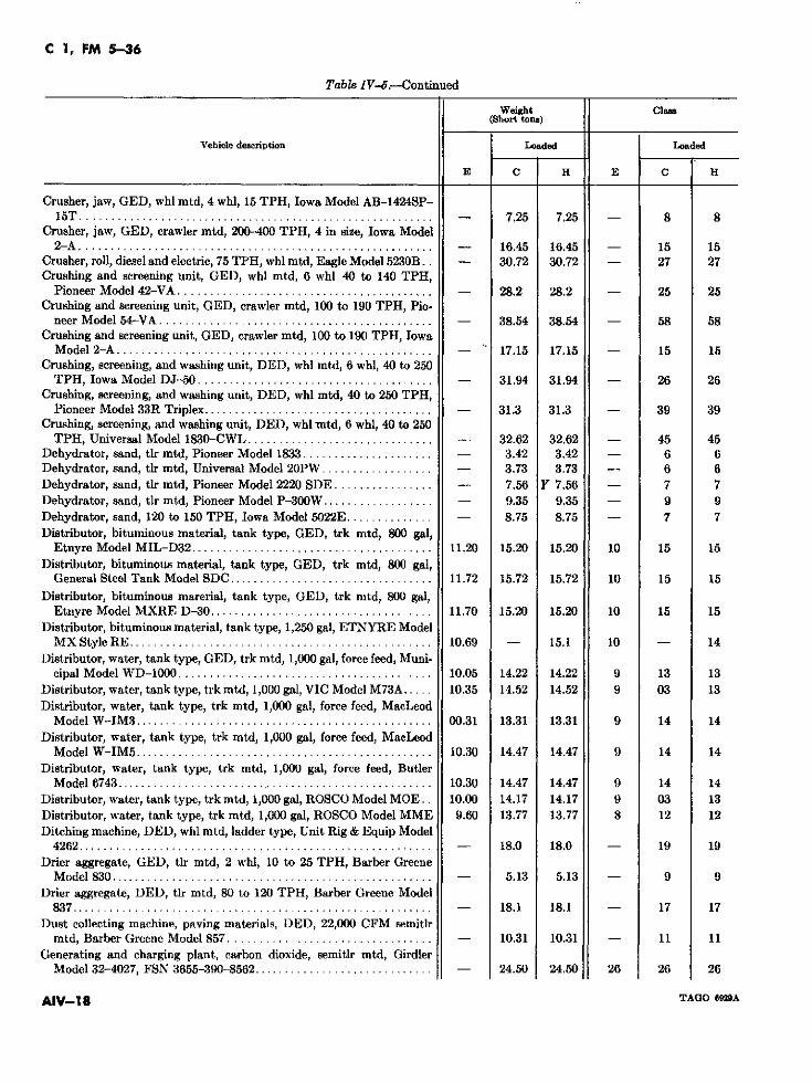
C 1, FM 5-36
Table IV-6.-Continued
Weight Class(Short tons)
Vehicle desription Loaded Loaded
E C H E C H
Crusher, jaw, GED, whl mtd, 4 whl, 15 TPH, Iowa Model AB-1424SP-15T ......................................................... - 7.25 7.25 - 8 8
Crusher, jaw, GED, crawler mtd, 200-400 TPH, 4 in size, Iowa Model2-A ......................................................... - 16.45 16.45 - 15 15
Crusher, roll, diesel and electric, 75 TPH, whl mtd, Eagle Model 5230B.. - 30.72 30.72 - 27 27Crushing and screening unit, GED, whl mtd, 6 whl 40 to 140 TPH,
Pioneer Model 42-VA ......................................... - 28.2 28.2 - 25 25Crushing and screening unit, GED, crawler mtd, 100 to 190 TPH, Pio-
neer Model 54-VA ............................................ - 38.54 38.54 - 58 58Crushing and screening unit, GED, crawler mtd, 100 to 190 TPH, Iowa
Model 2-A ................................ - 17.15 17.15 - 15 15Crushing, screening, and washing unit, DED, whl mtd, 6 whl, 40 to 250
TPH, Iowa Model DJ-50 ...................................... - 31.94 31.94 - 26 26Crushing, screening, and washing unit, DED, whl mtd, 40 to 250 TPH,
Pioneer Model 33R Triplex ..................................... - 31.3 31.3 - 39 39Crushing, screening, and washing unit, DED, whl mtd, 6 whl, 40 to 250
TPH, Universal Model 1830-CWL .............................. - 32.62 32.62 - 45 45Dehydrator, sand, tlr mtd, Pioneer Model 1833 ..................... - 3.42 3.42 - 6 6Dehydrator, sand, tlr mtd, Universal Model 20PW .................. - 3.73 3.73 - 6 6Dehydrator, sand, tlr mtd, Pioneer Model 2220 SDE ................ - 7.56 Y 7.56 - 7 7Dehydrator, sand, tlr mtd, Pioneer Model P-300W .................. - 9.35 9.35 - 9 9Dehydrator, sand, 120 to 150 TPH, Iowa Model 5022E .............. - 8.75 8.75 - 7 7Distributor, bituminous material, tank type, GED, trk mtd, 800 gal,
Etnyre Model MIL-D32 ....................................... 11.20 15.20 15.20 10 15 15Distributor, bituminous material, tank type, GED, trk mtd, 800 gal,
General Steel Tank Model SDC ................................ 11.72 15.72 15.72 10 15 15
Distributor, bituminous marerial, tank type, GED, trk rmtd, 800 gal,Etnyre Model MXRE D-30 .................................... 11.70 15.20 15.20 10 15 15
Distributor, bituminous material, tank type, 1,250 gal, ETNYRE ModelMX Style RE ................................................. 10.69 - 15.1 10 - 14
Distributor, water, tank type, GED, trk mtd, 1,000 gal, force feed, Muni-cipal Model WD-1000 ................................. 10.05 14.22 14.22 9 13 13
Distributor, water, tank type, trk mtd, 1,000 gal, VIC Model M73A..... 10.35 14.52 14.52 9 03 13Distributor, water, tank type, trk mtd, 1,000 gal, force feed, MacLeod
Model W-IM3 ................................................ 00.31 13.31 13.31 9 14 14Distributor, water, tank type, trk mtd, 1,000 gal, force feed, MacLeod
Model W-IM5 ................................................ 10.30 14.47 14.47 9 14 14Distributor, water, tank type, trk mtd, 1,000 gal, force feed, Butler
Model 6743 ................................................... 10.30 14.47 14.47 9 14 14Distributor, water, tank type, trk mtd, 1,000 gal, ROSCO Model MOE.. 10.00 14.17 14.17 9 03 13Distributor, water, tank type, trk mtd, 1,000 gal, ROSCO Model MME 9.60 13.77 13.77 8 12 12Ditching machine, DED, whl mtd, ladder type, Unit Rig & Equip Model
4262 ......................................................... - 18.0 18.0 - 19 19Drier aggregate, GED, tlr mtd, 2 whl, 10 to 25 TPH, Barber Greene
Model 830 .................................................... - 5.13 5.13 - 9 9Drier aggregate, DED, tlr mtd, 80 to 120 TPH, Barber Greene Model
837 .......................................................... - 18.1 18.1 - 17 17Dust collecting machine, paving materials, DED, 22,000 CFM semitlr
mtd, Barber Greene Model 857 ................................. - 10.31 10.31 - 11 11Generating and charging plant, carbon dioxide, semitlr mtd, Girdler
Model 32-4027, FSN 3655-390-8562 ............... .............. - 24.50 24.50 26 26 26
AIV-1 8 TAGO 6929A
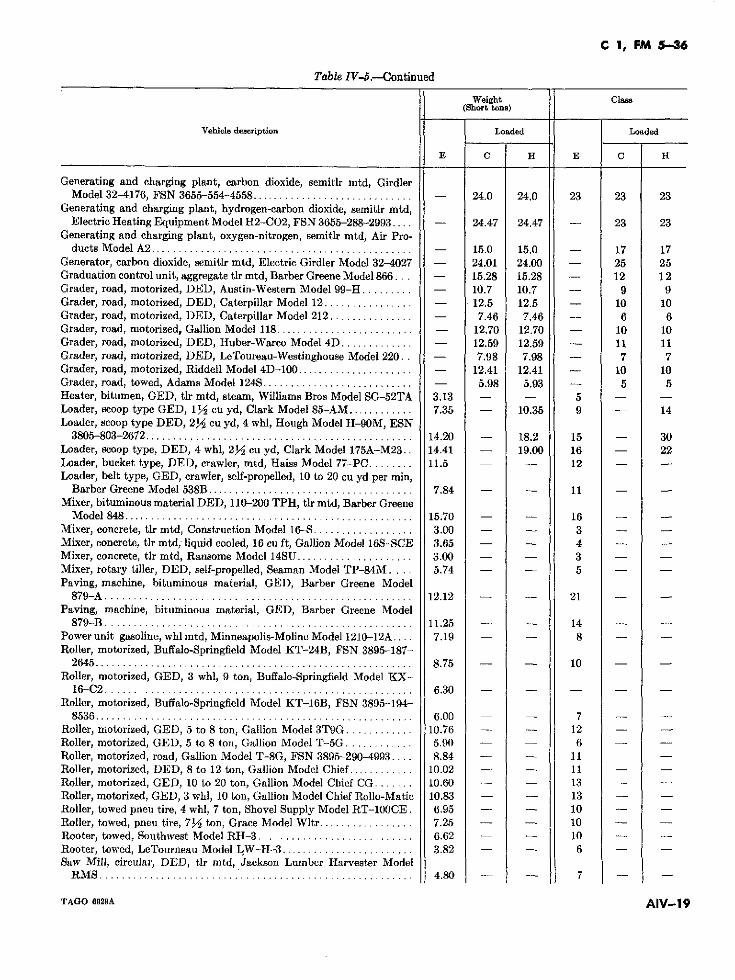
C 1, FM 5-36
Table IV-.--Continued
Weight Claass(Short tons)
Vehiele description Loaded Loaded
E C H E C H
Generating and charging plant, carbon dioxide, semitlr mtd, GirdlerModel 32-4176, FSN 3655-554-4558 ............................. - 24.0 24.0 23 23 23
Generating and charging plant, hydrogen-carbon dioxide, semitlr mtd,Electric Heating Equipment Model H2-C02, FSN 3655-288-2993.... - 24.47 24.47 - 23 23
Generating and charging plant, oxygen-nitrogen, semitlr mtd, Air Pro-ducts Model A2 ............................................... - 15.0 15.0 - 17 17
Generator, carbon dioxide, semitlr mtd, Electric Girdler Model 32-4027 - 24.01 24.00 - 25 25Graduation control unit, aggregate tlr mtd, Barber Greene Model 866... - 15.28 15.28 - 12 12Grader, road, motorized, DED, Austin-Western Model 99-H ......... - 10.7 10.7 - 9 9Grader, road, motorized, DED, Caterpillar Model 12 ................ - 12.5 12.5 - 10 10Grader, road, motorized, DED, Caterpillar Model 212 ............... - 7.46 7.46 - 6 6Grader, road, motorized, Gallion Model 118 ......................... - 12.70 12.70 - 10 10Grader, road, motorized, DED, Huber-Warco Model 4D ............. 4- 12.59 12.59 - 11 11Grader, road, motorized, DED, LeToureau-Westinghouse Model 220. . - 7.98 7.98 - 7 7Grader, road, motorized, Riddell Model 4D-100 ..................... - 12.41 12.41 - 10 10Grader, road, towed, Adams Model 124S ........................... - 5.98 5.93 - 5 5Heater, bitumen, GED, tlr mtd, steam, Williams Bros Model SG-52TA 3.13 - - 5 - -Loader, scoop type GED, 13i/ cu yd, Clark Model 85-AM ............ 7.35 - 10.35 9 - 14Loader, scoop type DED, 212 cu yd, 4 whl, Hough Model H-90M, ESN
3805-803-2672 ................................................ 14.20 - 18.2 15 - 30Loader, scoop type, DED, 4 whl, 2/- cu yd, Clark Model 175A-M23.. 14.41 - 19.00 16 - 22Loader, bucket type, DED, crawler, mtd, Haiss Model 77-PC ........ 11.5 - - 12 - -Loader, belt type, GED, crawler, self-propelled, 10 to 20 cu yd per min,
Barber Greene Model 538B ..................................... 7.84 - - 11 - -Mixer, bituminous material DED, 110-200 TPH, tlr mtd, Barber Greene
Model 848 .................................................... 15.70 - - 16 - -Mixer, concrete, tlr mtd, Construction Model 16-S .................. 3.00 - - 3 - -Mixer, concrete, tlr mtd, liquid cooled, 16 cu ft, Gallion Model 16S-SCE 3.65 - - 4 - -Mixer, concrete, tlr mtd, Ransome Model 14SU ..................... 3.00 - - 3 - -Mixer, rotary tiller, DED, self-propelled, Seaman Model TP-84M.... 5.74 - - 5 - -Paving, machine, bituminous material, GED, Barber Greene Model
879-A ....................................................... 12.12 - - 21 - -Paving, machine, bituminous material, GED, Barber Greene Model
879-B ....................................................... 11.25 - - 14 - -Power unit gasoline, whl mtd, Minneapolis-Moline Model 1210-12A.... 7.19 - - 8 - -Roller, motorized, Buffalo-Springfield Model KT-24B, FSN 3895-187-
2645 ......................................................... 8.75 - - 10 - -Roller, motorized, GED, 3 whl, 9 ton, Buffalo-Springfield Model KX-
16-C2 ....................................................... 6.30 - - - - -Roller, motorized, Buffalo-Springfield Model KT-16B, FSN 3895-194-
8536 ......................................................... 6.00 - - 7 - -Roller, motorized, GED, 5 to 8 ton, Gallion Model 3T9G ............ 10.76 - - 12 - -Roller, motorized, GED, 5 to 8 ton, Gallion Model T-5G ............ 5.90 - - 6 - -Roller, motorized, road, Gallion Model T-8G, FSN 3895-290-4993 .... 8.84 - - 11Roller, motorized, DED, 8 to 12 ton, Galiion Model Chief ............ 10.02 - - 11 - -Roller, motorized, GED, 10 to 20 ton, Gallion Model Chief CG ....... 10.60 - - 13 - -Roller, motorized, GED, 3 whl, 10 ton, Gallion Model Chief Rollo-Matic 10.83 - - 13 - -Roller, towed pneu tire, 4 whl, 7 ton, Shovel Supply Model RT-100CE. 6.95 - - 10 - -Roller, towed, pneu tire, 7Y2 ton, Grace Model Wltr ................. 7.25 - - 10 - -Rooter, towed, Southwest Model RH-3 ............................ 6.62 - - 10 - -Rooter, towed, LeTourneau Model LW-H-3 ........................ 3.82 - - 6 - -Saw Mill, circular, DED, tlr mtd, Jackson Lumber Harvester Model
RMS ....................................................... 4.80 - - 7 - -
TAGO 6929A AIV-19
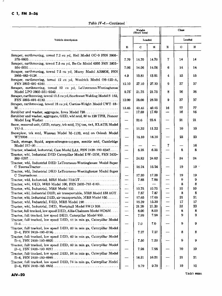
C 1, FM 5-36
Table IV-5.-Continued
Weight Class(Short tons)
Vehicle description Loaded Loaded
E C H E C H
Scraper, earthmoving, towed 7.2 cu yd, Heil Model OC-9 FSN 3805-378-9805 ..................................................... 7.70 14.70 14.70 7 14 14
Scraper, earthmoving, towed 7.5 cu yd, Be-Ge Model 6595 FSN 3805-554-5051 ..................................................... 7.06 14.06 14.06 6 14 14
Scraper, earthmoving, towed 7.5 cu yd, Murry Model AR88M, FSN3805-683-9126 ................................................ 4.9 13.81 13.81 4 15 15
Scraper, earthmoving, towed 12 cu yd, Woolrich Model OS-122-A,FSN 3805-691-6161 ............................................ 12.10 27.10 27.10 9 37 37
Scraper, earthmoving, towed 12 cu yd, LeTourneau-WestinghouseModel LPO 3805-351-9542 ..................................... 9.75' 21.75 21.75 8 26 26
Scraper, earthmoving, towed 13.5 cu yd, Southwest Welding Model S-152,FSN 3805-691-6132 ........................................... 12.00 28.00 28.00 9 37 37
Scraper, earthmoving, towed 18 cu yd, Curtiss-Wright Model CWT-18-M ........................................................ 15.45 40.45 40.45 16 77 77
Scrubber and washer, aggregate, Iowa Model 720 ................... - _ 17.69 17.69 - 16 16Scrubber and washer, aggregate, GED, whl mtd, 80 to 120 T'PH, Pioneer
Model Log Washer ............................................ - 23.6 23.6 - 21 21Snow, removal unit, GED, rotary, trk mtd, 7y/ ton, 4x4, KLAUR Model
TU-3 ................................... ...... :........... - 11.32 11.32 - 10 10Snowplow, trk mtd, Wausau Model M-1123, mtd on Oskosh Model
WT2206 ...................-.................................. - 16.10 16.10 - 23 23Tank, storage, liquid, argon-nitrogen-oxygen, semitlr mtd, Cambridge
Model 217-30 ................... .............................. - - - 7 - 16Tractor, wheeled, Industrial, Case Model LA1, FSN 2420-190-0347 ..... - 6.25 6.25 - 8 8Tractor, whl, Industrial DED Caterpillar Model DW-20M, FSN 2420-
200-1297 ..................................................... - 24.82 24.82 - 34 34Tractor, whl, Industrial DED LeTourneau-Westinghouse :Model Super
C TournaTractor .............................................. - 16.24 16.24 - 19 19Tractor, whl, Industrial DED LeTourneau-Westinghouse Model Super
C Tournadozer ................................................ - 17.30 17.30 - 19 19Tractor, whl, Industrial, MRS Model 72AGT ....................... - 7.88 7.88 - 9 9Tractor, whl, DED, MRS Model 100, FSN 2420-792-6163 ........... - - _ - - 8 8Tractor, whl, Industrial, MRS Model 125 ...................-....... - 10.75 10.75 - 10 10Tractor, whl, Industrial DED, air transportable, MRS Model 150 AGT. - 7.87 7.87 - 8 8Tractor, whl, Industrial DED, air transportable, MRS Model 150 ....... - 17.65 17.65 - 21 21Tractor, whl, Industrial, DED, MRS Model 190 ...................-. - 15.39 15.39 - 17 17Tractor, whl, Industrial, DED, Westphall Model SWD 300 ........... - 21.20 21.20 - 33 33Tractor, full tracked, low speed DED, Allis-Chalmers Model HD6M .... - 8.00 8.00 - 8 8Tractor, full tracked, low speed DED, Caterpillar Model 933 ......... - 7.99 7.99 - 9 9Tractor, full tracked, low speed DED, 44 in min ga, Caterpillar Model
D-4 ......................................................... - 7.0 7.0 - 9 9Tractor, full tracked, low speed DEI), 60 in min ga, Caterpillar Model
D-4, FSN 2410-190-0196 ...................-................... - 7.27 7.27 - 8 8Tractor, full tracked, low speed DED, 60 in min ga, Caterpillar Model
D-4, FSN 2410-190-0020 ...................-................... - 7.50 7.50 - 9 9Tractor, full tracked, low speed DED, 60 in min ga, Caterpillar Model
D-4, FSN 2410-190-0217 ...................-................... - 7.98 7.98 - 10 10Tractor, full tracked, low speed DED, 56 in min ga, Caterpillar Model
D-6, FSN 2410-190-0049 ...................-................... - 16.31 16.31 - 21 21Tractor, full tracked, low speed DED, 74 in min ga, Caterpillar Model
D-6, FSN 2410-185-0855 ...................-................... - 9.79 9.79 - 10 10
AIV-20 TAGO 6929A
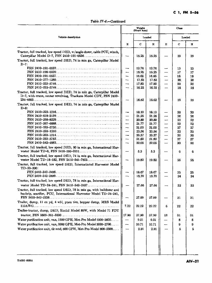
C 1, FM 5-36
Table IV-.-Continued
Weight Clase(Short tons)
Vehicle decription Loaded Loaded
E C H E C H
Tractor, full tracked, low speed DED, w/angle-dozer, cable PCU, winch,Caterpillar Model D-7, FSN 2410-191-0536 ...................... - 16.25 16.25 - 19 19
Tractor, full tracked, low speed DED, 74 in min ga, Caterpillar ModelD-7:
FSN 2410-191-0532 ....................................... - 12.76 12.76 - 13 13FSN 2410-190-0339 ....................................... - 16.25 16.25 - 17 17FSN 2410-191-0537 ....................................... - 16.65 16.65 - 18 18FSN 2410-277-1280 ....................................... - 17.83 17.83 - 20. 20FSN 2410-233-5746 ....................................... - 17.83 17.83 - 20 20FSN 2410-233-5749 ................... ................... - 16.25 16.25 - 18 18
Tractor, full tracked, low speed DED, 74 in min ga, Caterpillar ModelD-7, with crane, center revolving, Trackson Model CDT, FSN 2410-234-4603 ..................................................... - 16.62 16.62 - 19 19
Tractor, full tracked, low speed DED, 74 in min ga, Caterpillar ModelD-8:
FSN 2410-223-1216 ....................................... - 18.10 18.10 - 20 20FSN 2410-618-3139 ....................................... - 21.25 21.25 - 26 26FSN 2410-268-8229 ....................................... - 20.80 20.80 - 22 22FSN 2410-267-6888 ....................................... - 21.77 21.77 - 22 22FSN 2410-233-5750 ....................................... - 21.00 21.00 - 27 27FSN 2410-233-1210 ....................................... - 23.56 23.56 - 33 33FSN 2410-223-1214 ....................................... - 23.37 23.37 - 30 30FSN 2410-233-5752 ....................................... - 21.80 21.80 - 27 27FSN 2410-542-4882 ....................................... - 22.05 22.05 - 30 30
Tractor, full tracked, low speed DED, 60 in min ga, International Har-vester Model TD-9, FSN 2410-190-0211 ......................... - 5.3 5.3 - 6 6
Tractor, full tracked, low speed DED, 74 in min ga, International Har-vester Model TD-18-182, FSN 2410-541-7655 .................... - 19.82 19.82 - 25 25
Tractor, full tracked, low speed DED, International Harvester ModelTD-20-200:
FSN 2410-542-2498 ....................................... - 18.67 18.67 - 25 25FSN 2410-542-2499 ....................................... - 18.70 18.70 - 24 24
Tractor, full tracked, low speed DED, 78 in min ga, International Har-vester Model TD-24-241, FSN 2410-542-2337 .................... - 27.66 27.66 - 32 32
Tractor, full tracked, low speed DED, 78 in min ga, with bulldozer andbackrip, scarifier, PCU, International Harvester Model TD-24-241,FSN 2410-542-2338 ........................................... - 27.09 27.09 - 31 31
Trailer, dump, 11 cu yd, 4 whl, pneu tire, hopper dump, MRS Model11OAWG ..................................................... 7.22 22.22 22.22 6 22 22
Trailer-tractor, dump, DED, Euclid Model 89W, with Model 71 FDTtractor, FSN 3805-261-5830 .................................... 17.90 37.90 37.90 13 31 31
Water purification unit, van, 1500 GPH, Met-Pro Model 1500-2600 ..... - 9.51 9.51 - 8 8Water purification unit, van, 3000 GPH, Met-Pro Model 3000-2700 ..... - 10.71 10.71 - 9 9Water purification unit, tlr mtd, 600 GPH, Met-Pro Model 600-2500 .... - 2.91 2.91 - 5 5
TAGO 6929A AIV-21
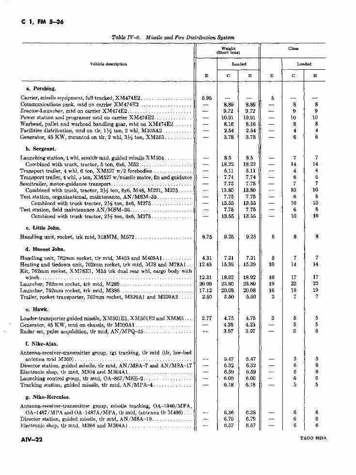
C 1, FM 5-36
Table IV-8. Missile an.d Fire Distribution System
Weight Class(Short tons)
Vehicle description Loaded Loaded
E C H E C H
a. Pershing.
Carrier, missile equipment, full tracked, XM474E2 .. ............ 5.95 - - 5 -Communications pack, mtd on carrier XM474E2 .................... - 8.89 8.89 - _ 8 8Erector-Launcher, mtd on carrier XM474E2 ...................-..... - 9.72 9.72 - 9 9Power station and programer mtd on carrier XM474E2 .............. -_ 10.91 10.91 - 10 10Warhead, pallet and warhead handling gear, mtd on XM474E2 ....... - 8.16 8.16 - 8 8Facilities distribution, mtd on tlr, 1/y ton, 2 whl, M105A2 ........... - 2.54 2.54 - 4 4Generator, 45 KW, mounted on tlr, 2 whl, 31/2 ton, XM353 .......... - 3.78 3.78 - 6 6
b. Sergeant.
Launching station, 4 whl, semitlr mtd, guided missile XM504 .......... - 8.5 8.5 - 7 7Combined with truck, tractor, 5 ton, 6x6, M52 ...................-. - 18.22 18.22 - 14 14
Transport trailer, 4 whl, 6 ton, XM527 w/2 forebodies ............... - _ 5.11 5.11 - 4 4Transport trailer, 4 whl, o ton, XM527 w/missile motor, fin and guidance - 7.74 7.74 - 6 6Semitrailer, motor-guidance transport ...........................-... - 7.75 7.75 - 7 7
Combined with truck, tractor, 2y/ ton, 6x6, M48, M221, M275 ..... - 13.80 13.80 - 10 10Test station, organizational, maintenance, AN/MSM-35 ............. - _ 7.75 7.75 - 6 6
Combined with truck tractor, 2M ton, 6x6, M275 ............... - 13.55 13.55 - 10 10Test station, field maintenance AN/MSM-36 ...................-.... - 7.75 7.75 - 6 6
Combined with truck tractor, 2V ton, 6x6, M275 ............... - 13.55 13.55 - 10 10
e. Little John.
Handling unit, rocket, trk mtd, 318MM, M572 ..................... 6.75 9.25 9.25 6 8 8
d. Honest John.
Handiing unit, 762mm rocket, tlr mtd, M405 and M405A1 ........... 4.31 7.31 7.31 5 7 7Heating and tiedown unit, 762mm rocket, trk mtd, M78 and M78A1.. 12.43 15.39 15.39 10 14 14Kit, 762mm rocket, XM78EI, M55 trk dual rear whl, cargo body with
winch ........................................................ 12.31 18.92 18.92 10 17 17Launcher, 762mm rocket, trk mtd, M289 ........................... 20.90 23.80 23.80 19 22 22Launcher, 762mm rocket, trk mtd, M386 ........................... 17.12 20.08 20.08 16 19 19Trailer, rocket transporter, 762mm rocket, M329A1 and M329A2 ..... 2.50 5.50 5.50 3 7 7
e. Hawk.
Loader-transporter guided missile, XM501E1, XM501E2 and XM501... 2.77 4.75 4.75 3 5 5Generator, 45 KW, mtd on chassis, tlr M200A1 ..................... _- 4.25 4.25 - 5 5Radar set, pulse acquisition, tlr mtd, AN/MPQ-35 .................. - _ 3.97 3.97 - 6 6
f. Nike-Ajax.
Antenna-receiver-transmitter group, tgt tracking, tlr mtd (tlr, low-bedantenna mtd M260) ........................................... - 5.47 5.47 - 5 5
Director station, guided missile, tlr mtd, AN/MSA-7 and AN/MSA-17 - 6.32 6.32 - 6 6Electronic shop, tlr mtd, M304 and M304A1 ...................-.... - 6.59 6.59 - 6 6Launching control group, tlr mtd, OA-867/MSE-2 .................. -- 6.00 6.00 - 6 6Tracking station, guided missile, tlr mtd, AN/MPA-4 .............. -- 6.18 6.18 - 5 5
g. Nike-Hercules.
Antenna-receiver-transmitter group, missile tracking, OA-1340/MPA,OA-1487/MPA and OA-1487A/MPA, tlr mtd, (antenna tlr M406) ... - 6.36 6.36 - 6 6
Director station, guided missile, tlr mtd, AN/MSA-19 ....... 7........ - 6.79 6. 9 - 6 6Electronic shop, tlr mtd, M304 and M304A1 ....................... -- 6.57 6.57 - 6 6
AIV-22 TAGO 6929A
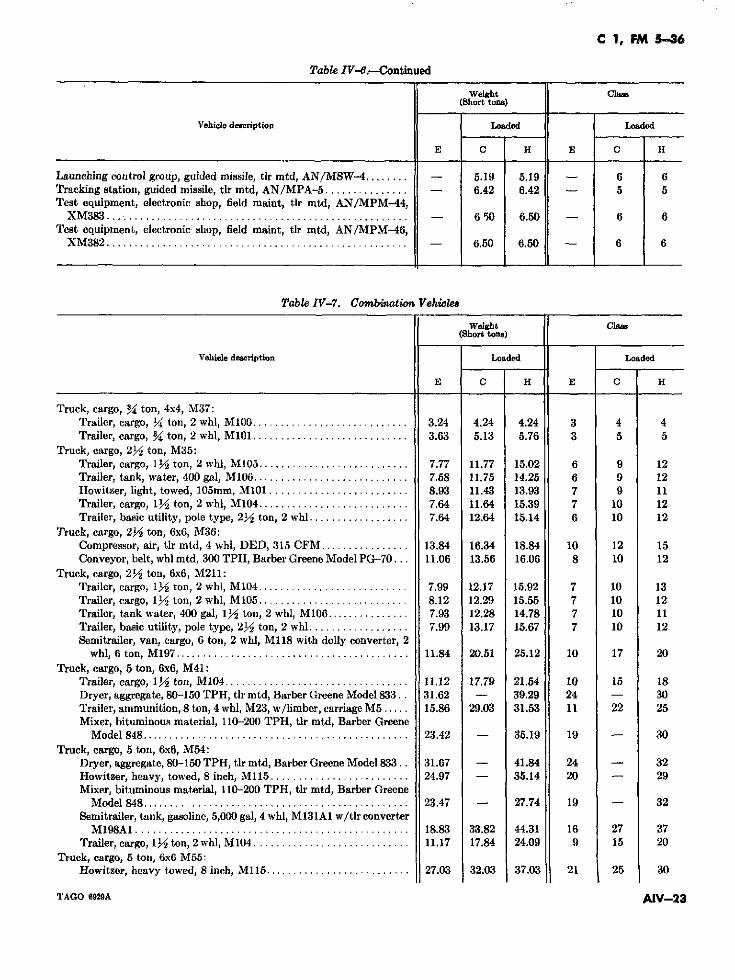
C 1, FM 5-36
Table IV-6.--Continued
Weight Clas(Short tons)
Vehicle description Loaded Loaded
E C H E C H
Launching control group, guided missile, tlr mtd, AN/MSW-4 ........ - 5.19 5.19 - 6 6Tracking station, guided missile, tlr mtd, AN/MPA-5 ............... - 6.42 6.42 - 5 5Test equipment, electronic shop, field maint, tlr mtd, AN/MPM-44,
XM383 ...................................................... - 6 50 6.50 - 6 6Test equipment, electronic shop, field maint, tlr mtd, AN/MPM-46,
XM382 ...................................................... - 6.50 6.50 - 6 6
Table IV-7. Combination Vehicles
Weight Class(Short tons)
Vehicle description Loaded Loaded
E C H E C H
Truck, cargo, N4 ton, 4x4, M37:Trailer, cargo, Y4 ton, 2 whl, M10 0 .......................... 3.24 4.24 4.24 3 4 4Trailer, cargo, /4 ton, 2 whl, M 1 0 1 ........................... 3.63 5.13 5.76 3 5 5
Truck, cargo, 2/2 ton, M35:Trailer, cargo, lV/ ton, 2 whl, M105 ........................... 7.77 11.77 15.02 6 9 12Trailer, tank, water, 400 gal, M106 ............................ 7.58 11.75 14.25 6 9 12Howitzer, light, towed, 105mm, M 1 0 1 ......................... 8.93 11.43 13.93 7 9 11Trailer, cargo, 11/2 ton, 2 whl, M104 ........................... 7.64 11.64 15.39 7 10 12Trailer, basic utility, pole type, 2/2 ton, 2 whl ................. 7.64 12.64 15.14 6 10 12
Truck, cargo, 2/ ton, 6x6, M36:Compressor, air, tlr mtd, 4 whl, DED, 315 CFM................ 13.84 16.34 18.84 10 12 15Conveyor, belt, whl mtd, 300 TPH, Barber Greene Model PG-70... 11.06 13.56 16.06 8 10 12
Truck, cargo, 2½2 ton, 6x6, M211:Trailer, cargo, 1/ ton, 2 whl, M104 ................... 7........ .99 12.17 15.92 7 10 13Trailer, cargo, 1½ ton, 2 whl, M105 ........................... 8.12 12.29 15.55 7 10 12Trailer, tank water, 400 gal, 1½ ton, 2 whl, M106............... 7.93 12.28 14.78 7 10 11Trailer, basic utility, pole type, 2/2 ton, 2 whl .................. 7.99 13.17 15.67 7 10 12Semitrailer, van, cargo, 6 ton, 2 whl, M118 with dolly converter, 2
whl, 6 ton, M197 ........................... 11.84 20.51 25.12 10 17 20Truck, cargo, 5 ton, 6x6, M41:
Trailer, cargo, 1/ ton, M104 ................... ......... 11.12 17.79 21.54 10 15 18Dryer, aggregate, 80-150 TPH, tlr mtd, Barber Greene Model 833.. 31.62 - 39.29 24 - .30Trailer, ammunition, 8 ton, 4 whl, M23, w/limber, carriage M5 ..... 15.86 29.03 31.53 11 22 25Mixer, bituminous material, 110-200 TPH, tlr mtd, Barber Greene
Model 848 ............................ 23.42 - 35.19 19 - 30Truck, cargo, 5 ton, 6x6, M54:
Dryer, aggregate, 80-150 TPH, tlr mtd, Barber Greene Model 833.. 31.67 - 41.84 24 - 32Howitzer, heavy, towed, 8 inch, M115 ......................... 24.97 - 35.14 20 - 29Mixer, bituminous material, 110-200 TPH, tlr mtd, Barber Greene
Model 848 .......................... 23.47 - 27.74 19 - 32Semitrailer, tank, gasoline, 5,000 gal, 4 whl, M131A1 w/tlr converter
M198A1 .......................... 18.83 38.82 44.31 16 27 37Trailer, cargo, 11 ton, 2 whl, M104 ........................... 11.17 17.84 24.09 9 15 20
Truck, cargo, 5 ton, 6x6 M55:Howitzer, heavy towed, 8 inch, Ml15 .......................... 27.03 32.03 37.03 21 25 30
TAGO 6929A AIV-23
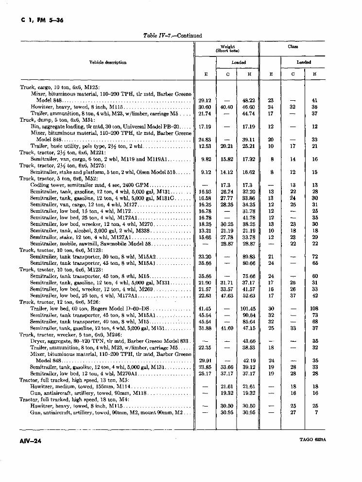
C 1, FM 5-36
Table IV-7.--Continued
Weight Claes(Short tons)
Vehicle description Loaded Loaded
E C H E C H
I'ruck, cargo, 10 ton, 6x6, M125:Mixer, bituminous material, 110-200 TPH, tlr mtd, Barber Greene
Model 848 ................................................ 29.12 - 48.22 23 - 41Howitzer, heavy, towed, 8 inch, M115 ................ 30.60 40.40 46.60 24 32 36Trailer, ammunition, 8 ton, 4 whl, M23, w/limber, carriage M5 .... 21.74 - 44.74 17 - 37
Truck, dump, 5 ton, 6x6, M51:Bin, aggregate loading, tlr mtd, 30 ton, Universal Model PB-20..... 17.19 - 17.19 12 - 12Mixer, bituminous material, 110-200 TPH, tlr mtd, Barber Greene
Model 848 ................................................ 24.83 - 39.11 20 - 33Trailer, basic utility, pole type, 2/2 ton, 2 whl ............ 12.53 20.21 25.21 10 17 21
Truck, tractor, 2y/ ton, 6x6, M221:Semitrailer, van, cargo, 6 ton, 2 whl, M119 'and M119A1 ....... 9.82 15.82 17.92 8 14 16
Truck, tractor, 2y/ ton, 6x6, M275:Semitrailer, stake and platform, 5 ton, 2 whl, Olsen Model 516 ...... 9.12 14.12 16.62 8 12 15
Truck, tractor, 5 ton, 6x6, M52:Codling tower, semitrailer mtd, 4 sec, 2400 GPM ................ - 17.3 17.3 - 13 13Semitrailer, tank, gasoline, 12 ton, 4 whl, 5,000 gal, M131 ........ 16.93 26.74 32.20 13 22 28Semitrailer, tank, gasoline, 12 ton, 4 whl, 5,000 gal, M131C ...... 16.58 27.77 33.86 13 2 4 30Semitrailer, van, cargo, 12 ton, 4 whl, M127 ............. 16.25 28.25 34.25 12 25 31Semitrailer, low bed, 15 ton, 4 whl, M172 .............. 16.78 - 31.78 12 - 25Semitrailer, low bed, 25 ton, 4 whl, M172A1 ............. 16.78 - 41.78 12 - 35Semitrailer, low bed, wrecker, 12 ton, 4 whl, M270 .......... 18.25 30.25 38.25 13 23 30Semitrailer, tank, alcohol, 3,000 gal, 2 whl, M338 ............ 13.21 21.19 21.19 10 18 18Semitrailer, stake, 12 ton, 4 whl, M127A1 .............. 15.68 27.78 33.78 12 23 29Semitrailer, mobile, sawmill, Sawmobile Model 58 ............... - 28.87 28.87 - 22 22
Truck, tractor, 10 ton, 6x6, M123:Semitrailer, tank transporter, 50 ton, 8 whl, M15A2 .......... 33.20 - 89.83 21 - 72Semitrailer, tank transporter, 45 ton, 8 whl, M15A1 .......... 35.66 - 80.66 24 - 65
Truck, tractor, 10 ton, 6x6, M123:Semitrailer, tank transporter, 45 ton, 8 whl, M15 ................ 35.66 - 75.66 24 - 60Semitrailer, tank, gasoline, 12 ton, 4 whl, 5,000 gal, M131 ........ 21.90 31.71 37.17 17 26 31Semitrailer, low bed, wrecker, 12 ton, 4 whl, M269 .......... 21.57 33.57 41.57 16 26 33Semitrailer, low bed, 25 ton, 4 whl, M172A1 ............. 22.63 47.63 52.63 17 37 42
Truck, tractor, 12 ton, 6x6, M26:Trailer, low bed, 60 ton, Rogers Model D-60-I)S ........... 41.45 - 101.45 30 - 108Semitrailer, tank transporter, 45 ton, 8 whl, M15A1.. ........... 45.64 - 90.64 32 - 73Semitrailer, tank transporter, 40 ton, 8 whl, M15 ................... 45.64 - 85.64 32 - 68Semitrailer, tank, gasoline, 12 ton, 4 whl, 5,000 gal, M131 ........ 31.88 41.69 47.15 25 33 37
Truck, tractor, wrecker, 5 ton, 6x6, M246:Dryer, aggregate, 80-120 TPN, tlr mtd. Barber Greene Model 833 - - 43.66 - - 35Trailer, ammunition, 8 ton, 4 whl, M23, w/limber, carriage M5 ..... 22.35 - 38.53 18 - 32Mixer, bituminous material, 110-200 TPH, tlr mtd, Barber Greene
Model 848 ................................................ 29.91 - 42.19 24 - 35Semitrailer, tank, gasoline, 12 ton, 4 whl, 5,000 gal, M131 .......... 23.85 33.66 39.12 19 28 33Semitrailer, low bed, 12 ton, 4 wbl, M270A1 ............. 25.17 37.17 37.17 19 28 28
Tractor, full tracked, high speed, 13 ton, M5:Howitzer, medium, towed, 155mm, M114 .....................-. - 21.61 21.61 - 18 18Gun, antiaircraft, artillery, towed, 90mm, M118 ................ - 19.32 19.32 - 16 16
Tractor, full tracked, high speed, 18 ton, M4:Howitzer, heavy, lowed, 8 inch, MI15 ......................... - 30.50 30.50 - 25 25Gun, antiaircraft, artillery, towed, 90mm, M2, mount 90mm, M2-... - 30.95 30.95 - 27 7
AIV-24 TAGO 6929A
FM 5-36
INDEX
Paragraph Page Paragraph Page
Abbreviated bridge symbol _________ 2-61 2-80 Concealment __-------_------------ 1-8a 1-3Abutments ________________________ 3-11 3-8 Constrictions ___------------------- 2-22 2-27Additional bridge information __---_ 3-10 3-4 Controlled route _----__--__ _------- 2-3g 2-2Aircraft __________________________ 4-13 4-6 Conversion tables _________-- ____-- App II AII-1Airlanding areas __________________ 4-14 4-6 Counterinsurgency ______---- ___-- _ 1-10b 1-4Airlanding area criteria --- ___-----_ 4-15 4-10 Cover ------ …___________ ------ 1-8a 1-3Airland area reports _______________ 4-18 4-14 Cross-country movement __-_____--- 4-3 4-1Air mobile operations ___________…__ 4-11 4-5 Cross-country movement studies _--- 4-10 4-4Air recognition panels ---___------_ 4-19 4-15 Culverts -----__-----_--------_---- 2-65c 2-85Air routes ------____----- -__-_-- - _ 1-8a 1-3 Curbs __________________________- 2-57b 2-77Air Weather Service ----___------_ 1-20 1-7 Curves __--_____--- _____--___--- - 2-18 2-20Amphibious vehicles _______________ 4-22 4-24 3-24a 3-51Angle of slope -___________________ 2-16d 2-19Approaches _______________________ 2-36b 2-46 Deck type bridge __________________ 3-16b 3-45
2-58c 2-77 Deliberate bridge reconnaissance ___- 2-59 2-80Arch bridges ___-____________3-13g -14 3-3 3-1Area reconnaissance _ …---_____--_-- 1-24c 1-9 Deliberate route reconnaissance _____ 1-2a 1-1Army aviation --_______-- _____--__ 1-29b 1-10 2-lc 2-1
4-12 4-6 Detour signs ______________________ 5-11 5-9Avenues of approach ___-__________ 1-8a 1-3 Dips _____-- _____________--______- 2-65d 2-85Armored vehicle launched bridge ___ 2-64b 2-84 Directional disks ----__------------ 5-9 5-9Axial route ---.-----------_------_ 2-3c 2-2 Dispatch route ____-____-- ___--- 2-3g 2-2
5-5 5-6 Documents, captured _____________- 1-19 1-7Double flow route _--_____--- ___--- 2-5c 2-3
Banks --______--_ _______________-_ 2-34 2-45 Drainage _--_____--- _ _________-- 2-65 2-84Base course ___…_______…-_________ 3-25b 3-53 Drones -----____.----------._--- - 1-29c 1-11Basic military road network ____--- 2-3a 2-2Beam bridges --_____--- ___-----__ 3-13d 3-10 Electronic surveillance _____…__…___ 1-29a 1-10Blackout conditions _--------------- 5-14c 5-11 Embankments ______________-______ 2-64b 2-84Bridge classification _ …_ . ....... 2-51 2-62 Enemy activity __----___---- ___---- 1-15 1-6
3-14 3-45 Enemy forces _____________…______- 1-llb 1-5Bridge classification card ___------_ 3-16 3-45 Engineer boats ___…______ ______ 4-22 4-24Bridge classification signs _____-_-- _ 2-52 2-64 Engineer intelligence studies ______- 1-21b 1-7Bridge, definition ____-----_-------- 2-56 2-76 Engineer materials -. .............. 3-33 3-60Bridge nomenclature …-------------- 2-57 2-76 Engineer reconnaissance _ …_.---- 3-31 3-60Bridge reconnaissance report __----_ 3-15 3-45 Engineer reconnaissance report _____ 3-35 3-60Bridge report format ---------…---_ 2-62 2-81 Essential bridge information -___--- 3-4a 3-1Bridge sites ----------------------… 2-63 2-81 Essential elements of informationBridge sketches -__-----_---------- 3-8 3-4 (EEI) ___________----- _- 1-12b 1-5Buoy system _ ---- --------------- 4-26 4-28 Evacuation signs ---__-_----------- 5-8 5-9Bypass ---------------------.----- 2-61g 2-80 Fairway
Fairway .......................... 4-21 4-16California bearing ratio ------------ 3-28b 3-54 Ferries, civil ______________--____-- 2-44 2-54Can buoy ---.---------.-----_----- 4-27c 4-28 Ferry definition ___--_____--- ___--- 2-43 2-54Cantilever bridges ___-------------- 3-13b 3-10 Ferry reconnaissance report . ....... 2-48 2-56Caution crossings ___-------------- 2-54b 2-69 Ferry report format --- …......----- 2-47 2-56Characteristics of area of operations 1-8 1-3 Ferry site%, military ----------…---- 2-45 2-55Civilians- ----------------- . 1-16b 1-6 Ferry symbol _______________---- - 2-46 2-55Classification factors ----- …_------- 3-15 3-45 Fields of fire _____-- ______--____-- 1-8a 1-3Clinometer ----.-----------__------ 2-16a 2-18 Fixed wing aircraft ____----_----- - 4-13 4-6Cold war __________________- 1-10a 1-4 Floating bridges __…________ _____- 3-13j 3-16Combination vehicles ------. ........ 2-53b 2-68 Flooding -. . ...................... 2-19b 2-6
AGO 8282A 1-1
FM 5-36
Paragraph Page Paragraph Page
Flooring__________________________ -2-57b 2-77 Marking air landing areas ---_---- 4-20 4-153-16b 3-45 4-20 4-15
Foot paths -___--_ _________________ 4-27 4-28 Measurement systems __--____-_---- 1-5 1-2Ford definition --__________________ 2-36 2-45 Measuring curve radius ____________ 2-19 2-20Ford markings --- _________________ 2-41 2-51 Military personnel _________________ 1-16c 1-6Ford reconnaissance report ____-- ___ 2-40 2-49 Military load classification __-----.. 2-7 2-5Ford report format --- …-----.------ 2-39 2-49 3-23 3-51Ford symbol __-___________________ 2-38 2-48 Military road maneuver network _--- 2-3b 2-2Forecasts, weather ___---- ____-- ___ 1-20 1-7 Military route definitions ___-______ 2-3 2-2Friendly forces --__________________ 1-lla 1-5 Minimum overhead clearances __---- 2-8a 2-6
1-14 1-6 2-51c 2-64Full bridge symbol ---__---___----- 2-61 2-80 Minimum lane width, bridges __-___ 2-51b 2-63Functions of numbers __----________ App II AII-1 Mission --____________--_________ 1-7 1-3
Movement credit ---___-- _______--- 2-3f 2-2Galleries -_______________________ 2-25a 2-30General war ______________________ 1-10d 1-4 National intelligence surveys ____--- 1-21b 1-7Geodetic data _--------__-____----- 1-18 1-7 Nature of conflict …____--------_--- 1-10 1-4Girder bridges ____________________ 3-13f 3-13 Nonstandard combination ------_--- 2-53d 2-68Gradients --___-- _________________- 2-15 2-18 Normal crossings --__--------_---- 2-54a 2-68
3-24a 3-51 Normal lighting conditions ____-___- 5-14a 5-11Guide signs ___--__________________ 5-5 5-6 Nuclear weapons ---___-- __________ 1-8a 1-3
Nun buoy ---------____________-- _ 4-27c 4-28Handrails -___-- _____________--___ 2-57b 2-77
3-16b 3-45 Observation __…___________________ 1-8a 1-3Hasty bridge reconnaissance __…____ 2-59 2-80 Obstacles _____--- _____--_______--_ 1-8b 1-4Hasty route reconnaissance ______- 1-2a 1-1 2-35 2-45
2-1b 2-1 Obstructions ______________________ 2-8 2-5Hazard signs -- ____---___-- __---- 5-3a 5-1 One-way road --------__-__---_---- 2-3i 2-3Headquarters signs ----_------_--- 5-7 5-6 Open route __-------___------- -__ _ 2-3h 2-3Helicopters __------- -___ _____-- _ 4-16b 4-11 Operational environment, elements __ 1-6 1-2
Operations, peacetime, counterin-Ice crossings __--____--_ ________-- 4-10 4-4 surgency, nuclear and nonnuclear _ 1-2c 1-1Imagery _____…-___________________ 1-17 1-6 Other intelligence requirements _---_ 1-12c 1-6Inland waterways _______-- ___-_--- 4-21 4-16 Overhead obstructions _--__________ 2-8a 2-6Inland waterway reconnaissance _-_- 4-22 4-24Installation signs ____________-____ 5-7 5-6 Pace _---________________________ 2-16c 2-19Intelligence, combat ---.--------- . 1-3 1-2 Pavement ___---------_________--- _ 3-24a 3-51Intelligence, engineer -----___--_--- 1-3 1-2 Percent of slope ---___-- __________ 2-15 2-18Intelligence officer -------_-------- 1-12a 1-5 Ponton bridges __--___-- __________ 3-13j 3-16Intelligence requirements -_________ 1-12 1-5 Population, civil ---- ___----____---_ 1-9 1-4Intermediate supports ---__---_ ____ 3-12 3-8 Prisoners of war __________________ 1-16a 1-6
Prohibited route ---___-- _____--- _ 2-31 2-3Key terrain __------------____--- _- 1-8a 1-3
Radius of curvature ___-___________ 2-18 2-20Landing craft -------------------- 4-22 4-24 Rafting sites, military _------__---- 2-45 2-55Lateral route ----------- _____----- 2-3d 2-2 Reconnaissance… ------__________--_ 1-22 1-8Light line -__---______------------ 5-13 5-11 Reconnaissance at night -_______-- _ 1-28 1-10Lighting of route signs ___________- 5-14 5-11 Reconnaissance by aircraft ---__---- 1-29 1-10Limited bridge information ___-___- 2-60 2-80 Reconnaissance by fire _--_---_----- 1-27 1-10Limited war _--___________________ 1-10c 1-4 Reconnaissance control _--_______-- _ 1-31b 1-12Limiting characteristics ---___-__--- 3-24a 3-51 Reconnaissance, coordination -__---- 1-31 1-12Line of sight---__--_---- __- ____--- 2-16c 2-19 Reconnaissance, fundamentals __---- 1-23 1-8Load-bearing capacity ________-____ 3-25 3-53 Reconnaissance in force -_______--- _ 1-25 1-9Low water bridges -------____----- 2-36f 2-47 Reconnaissance patrol _--_______--_ App III AIII-1
Reconnaissance planning --_ ____---- 1-30 1-12Maneuver ______________________ 1-1 1-1 Reconnaissance, suspect areas __---- 1-26 1-9Manmade features _______-____-____ 4-7 4-3 Reconnaissance, types _--______--- _ 1-24 1-9Maps ----------.......... 1-18 1-7 Recording curve radius --______2-20 2-20
2-16b 2-19 Recording percent of slope _____---_ 2-17 2-20Marking of inland waterways ___--__ 4-27 4-28 Reduced lighting _____-___________ 5-14b 5-11
l-2 AGO 8282A
FM 5-36
Paragraph Page Paragraph Page
References ---_------___----___---- App I AI-I Special crossings _----------------- 2-54b 2-69Regulatory signs ----__-----____--- 5-3b 5-6 Special purpose vehicle __ …___------ 2-53e 2-68Reserved route ------__-----__-_--- 2-3g 2-2 STANAG ------------------------ 1-2b 1-1Risk crossings _--____-----____---_ 2-54b 2-69 Stream approaches ---___--------- 2-34 2-45Road capacity _------_------__----- 2-3e, 2-2, Stream bottom __----------_------- 2-36c 2-46
3-25 3-53 Stream depth -____---------------- 2-31 2-43Road classification ________-8_______ 3-23 3-51 Stream velocity __-----_---------- 2-33 2-43Road classification formula ______--- 3-24 3-51 Stream width -___----------------- 232 2-43Road markers _------__------__---- 5-12 5-9 Stringers ------------------------. 2-57b 2-77Road reconnaissance ______-_____--- 3-23 3-51 Stringer bridges __---------------- 3-13d 3-10Road reconnaissance report -------- 3-29 3-56 Subgrade _-----__-----_----------- 3-25c 3-53Rock falls ---_-----__-----____---- 2-2g 2-1 Substructure --_------------------- 2-57a 2-77Route classification --__---------___ 2-4 2-3 Superstructure -------------------. 2-57b 2-77Route classification formula _____--- 2-9 2-6 Surfaces ------------------------- 3-26 3-54Route closed report -----__-__------ 2-14 2-7 Surface material symbols ----------- 3-24a 3-51Route constriction symbols -------- 2-22 2-27 Supervised route __---_------------ 2 -3g 2-2Route, definition ----___---- ____--- 1-4c 1-2 Suspension bridges -------- …------- 3-13h 3-15Route guides ____-- ____---- ____--- 2-3k 2-3Route marking _________________--- 5-1 5-1 Telltale __------------------------ 2-52c 2-65Route of communication -_______--- 1-4a 1-2 Temporary classification numbers ___ 3-22 3-47Route open report __…___-- ______--- 2-14 2-7 Terrain __…---- _____-- _____------- 1-8a 1-3Route reconnaissance ____-- _____--- 1-24a 1-9 Terrain considerations _------------ 2-2 2-1Route reconnaissance checklist -__--- 2-12 2-7 Terrain groups -- …---------------- 4-10 4-4Route reconnaissance definition __--- 1-4d 1-2 Trail marks -------------------- 4-29 4-42Route reconnaissance overlay ____--- 2-11 2-7 Trafficability class …_ . ............. 4-5 4-2Route reconnaissance report _------- 1-21b, 1-7, Traffic flow -- __------------------ 2-5c 2-3
2-1 2-1 Trails -___---- ____--- ______------- 3-2 3-1Route reconnaissance symbols _----- 2-13 2-7 Trigonometric functions ------------ App II AI-1Route sign lighting --__----___---- 5-15 5-13 Truss bridges ____--- 3-13e 3-11Route type …-----------__--_------ 2-6 2-4 Tunnels 2-25 2-30Runway dimensions -- __-- __------- 4-15 410 Tunnel reconnaissance report ----_ 2-29 2-30
Tunnel report format ------------- 2-28 2-30Scope of manual __--___--_ ____-- _- 1-2 1-1 Tunnel symbol __-_---------------- 2-27 2-30SEASTAG's ---------------------- 1-2b 1-1Signed route __-_-----__------- -__- 2-3i 2-3 Underpasses ------ --------------- 2-22 2-27Signs, route ---------_----------- 5-3 5-1 Underwater reconnaissance -_------- 2-37 2-47Single flow route -------- …--------- 2-5c 2-3 Unit direction arrow --------------- 5-10 5-9Single vehicle _…_____------__ ___--- 2-53a 2-66Slab bridges ---------___---------- 3-13c 3-10 Vegetation …______________----_-- 4-6 4-3Slides --------------------------… 2-2g 2-1 Vehicle classification signs _______-- 2-53 2-66
S~lope~s…2-15~ 2-18_______ VehicIe classification ________8______ 3-18 3-46Slopes ....-----------------------. 2-15 2-18
~Snow_____-_______________4_9 4-4 App IV IV-1Snow blockage-___________________ 2-lOa 26ó Vehicular swimming ----- _... ...... 2-42 2-51Soil ----------_--_ _ _ __------------ 4-5c 4-2 Waterway symbols -. .......------- 4-25 4-24
3-27 3-54 Weather __----_------- _---------- 18b 1-4SOLOG ___---__--------------------- 4-5 4-2 1-20 1-7Sources of information -_----------- 1-13 1-6 Widths, bridge lane _----_---------- 2-51b 2-63Spans .--------- -..------------- 2-58 2-77 Widths, road _-------------_------ 3-24a 3-51
3-13 3-9 Widths, route --------------------. 2-5 2-3Spar buoy ----_------------------- 4-27c 4-28Special classification ----------..---- 2-5 3 c 2-68 Zone reconnaissance ------ 1-24b 1-9
AGO 8282A 1-3
FM 5-36
By Order of the Secretary of the Army:
HAROLD K. JOHNSON,General, United States Army,
Official: Chief of Staff.
J. C. LAMBERT,Major General, United States Army,The Adjutant General.
Distribution:
Active Army:
DCSPER (2) Co/Btry (1) except TOE:ACSI (2) 5-7 (5)ACSFOR (2) 5-17 (5)DCSOPS (2) 5-27 (5)DCSLOG (2) 5-37 (5)CORC (2) 5-127 (5)CRD (2) 5-147 (5)COA (1) 5-157 (5)CINFO (1) 5-227 (5)TIG (1) 17-17 (5)
~~~4%~k~~~~G (1) ~17-107 (5)
tMG (9} 19-37 (5)OPO (i) 19-57 (5)TSG (1) 19-67 (5)CofEngrs (10) PMS Sr Div Units (1)CofCh (1) PMS Jr Div Units (1)USAARMBD (2) PMS Mil Sch Div Units (1)USAMB (2) USMA (5)USACDC Agcy (2) except USACGSC (25)
USACDCARTYA (6) Joint Sch (5)USACDCAVNA (6) Br Svc Sch (10) exceptUSACDCMSA (4) USAQMS (25)USACDCEA (15) USASWS (10)
USCONARC (10) USASCS (10)USAMC (15) USAAMS (15)USACDC (10) MDSS (10)ARADCOM (10) USACAS (2)ARADCOM Rgn (10) USAADS (5)OS Maj Comd (5) USAAVNS (21)LOGCOMD (5) USAOGMS (6)MDW (5) USATC (5)Armies (25) AMS (2)Corps (15) USACDCCSSG (5)Div (10) USACDCCAG (5)Div Arty (5) USACDCSWCAG (2)
Bde (5) USACDCIAS (1)Regt/Gp/Bg (5) USACDCEC (5)Bn'(2) ' USACDCNG (1)USACDCCCISG (1) MAAG (2)USACDCTA (5) Mil Msn (2)
NG: State AG (3); Units-same as Active Army.
USAR: Units-same as Active Army.
For explanation of abbreviations used, see AR 320-50.
r U. 5. GOVERNMENT PRINTING OFFICE: 1965-750-510
Related Documents