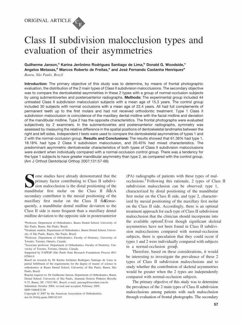
ORIGINAL ARTICLE Class II subdivision malocclusion types and evaluation of their asymmetries Guilherme Janson, a Karina Jerônimo Rodrigues Santiago de Lima, b Donald G. Woodside, c Angelos Metaxas, d Marcos Roberto de Freitas, a and José Fernando Castanha Henriques a Bauru, São Paulo, Brazil Introduction: The primary objective of this study was to determine, by means of frontal photographic evaluation, the distribution of the 2 main types of Class II subdivision malocclusions. The secondary objective was to compare the dentoskeletal asymmetries in these 2 types with a group of normal-occlusion subjects by using submentovertex and posteroanterior radiographs. Methods: The experimental group included 44 untreated Class II subdivision malocclusion subjects with a mean age of 15.3 years. The control group included 30 subjects with normal occlusions with a mean age of 22.4 years. All had full complements of permanent teeth up to the first molars and had not received orthodontic treatment. Type 1 Class II subdivision malocclusion is coincidence of the maxillary dental midline with the facial midline and deviation of the mandibular midline. Type 2 has the opposite characteristics. The frontal photographs were evaluated subjectively by 2 examiners. In the submentovertex and posteroanterior radiographs, symmetry was assessed by measuring the relative difference in the spatial positions of dentoskeletal landmarks between the right and left sides. Independent t tests were used to compare the dentoskeletal asymmetries of types 1 and 2 with the normal-occlusion group. Results and Conclusions: The results showed that 61.36% had type 1, 18.18% had type 2 Class II subdivision malocclusion, and 20.45% had mixed characteristics. The predominant asymmetric dentoalveolar characteristics of both types of Class II subdivision malocclusions were evident when individually compared with a normal-occlusion control group. There was a tendency for the type 1 subjects to have greater mandibular asymmetry than type 2, as compared with the control group. (Am J Orthod Dentofacial Orthop 2007;131:57-66) S ome studies have already demonstrated that the primary factor contributing to Class II subdivi- sion malocclusion is the distal positioning of the mandibular first molar on the Class II side. 1-3 A secondary contributor is the mesial positioning of the maxillary first molar on the Class II side. 2 Conse- quently, a mandibular dental midline deviation to the Class II side is more frequent than a maxillary dental midline deviation to the opposite side in posteroanterior (PA) radiographs of patients with these types of mal- occlusions. 2 Following this rationale, 2 types of Class II subdivision malocclusion can be observed: type 1, characterized by distal positioning of the mandibular first molar on the Class II side, and type 2, character- ized by mesial positioning of the maxillary first molar on the Class II side. Accordingly, there is an optimal treatment approach for each type of Class II subdivision malocclusion that the clinician should incorporate into the available options. 4 Even though significant skeletal asymmetries have not been found in Class II subdivi- sion malocclusions compared with normal-occlusion subjects, there is speculation that they could occur if types 1 and 2 were individually compared with subjects in a normal-occlusion group. 2 Therefore, based on these considerations, it would be interesting to investigate the prevalence of these 2 types of Class II subdivision malocclusions and to study whether the contribution of skeletal asymmetries would be greater when the 2 types are independently compared with normal-occlusion subjects. The primary objective of this study was to determine the prevalence of the 2 main types of Class II subdivision malocclusions among patients with such malocclusion through evaluation of frontal photographs. The secondary a Professor, Department of Orthodontics, Bauru Dental School, University of São Paulo, Bauru, São Paulo, Brazil. b Graduate student, Department of Orthodontics, Bauru Dental School, Univer- sity of São Paulo, Bauru, São Paulo, Brazil. c Professor, Department of Orthodontics, Faculty of Dentistry, University of Toronto, Toronto, Ontario, Canada. d Associate professor. Department of Orthodontics, Faculty of Dentistry, Uni- versity of Toronto, Toronto, Ontario, Canada. Supported by FAPESP (São Paulo State Research Foundation) Process #01/ 02964-0. Based on research by Dr Karina Jerônimo Rodrigues Santiago de Lima in partial fulfillment of the requirements for the degree of master of science in orthodontics at Bauru Dental School, University of São Paulo, Bauru, São Paulo, Brazil. Reprint requests to: Dr Guilherme Janson, Department of Orthodontics, Bauru Dental School, University of São Paulo, Alameda Octávio Pinheiro Brisolla 9-75, Bauru, SP, 17012-901, Brazil; e-mail, [email protected]. Submitted, October 2004; revised and accepted, February 2005. 0889-5406/$32.00 Copyright © 2007 by the American Association of Orthodontists. doi:10.1016/j.ajodo.2005.02.031 57

Welcome message from author
This document is posted to help you gain knowledge. Please leave a comment to let me know what you think about it! Share it to your friends and learn new things together.
Transcript
ORIGINAL ARTICLE
Class II subdivision malocclusion types andevaluation of their asymmetriesGuilherme Janson,a Karina Jerônimo Rodrigues Santiago de Lima,b Donald G. Woodside,c
Angelos Metaxas,d Marcos Roberto de Freitas,a and José Fernando Castanha Henriquesa
Bauru, São Paulo, Brazil
Introduction: The primary objective of this study was to determine, by means of frontal photographicevaluation, the distribution of the 2 main types of Class II subdivision malocclusions. The secondary objectivewas to compare the dentoskeletal asymmetries in these 2 types with a group of normal-occlusion subjectsby using submentovertex and posteroanterior radiographs. Methods: The experimental group included 44untreated Class II subdivision malocclusion subjects with a mean age of 15.3 years. The control groupincluded 30 subjects with normal occlusions with a mean age of 22.4 years. All had full complements ofpermanent teeth up to the first molars and had not received orthodontic treatment. Type 1 Class IIsubdivision malocclusion is coincidence of the maxillary dental midline with the facial midline and deviationof the mandibular midline. Type 2 has the opposite characteristics. The frontal photographs were evaluatedsubjectively by 2 examiners. In the submentovertex and posteroanterior radiographs, symmetry wasassessed by measuring the relative difference in the spatial positions of dentoskeletal landmarks between theright and left sides. Independent t tests were used to compare the dentoskeletal asymmetries of types 1 and2 with the normal-occlusion group. Results and Conclusions: The results showed that 61.36% had type 1,18.18% had type 2 Class II subdivision malocclusion, and 20.45% had mixed characteristics. Thepredominant asymmetric dentoalveolar characteristics of both types of Class II subdivision malocclusionswere evident when individually compared with a normal-occlusion control group. There was a tendency forthe type 1 subjects to have greater mandibular asymmetry than type 2, as compared with the control group.
(Am J Orthod Dentofacial Orthop 2007;131:57-66)Some studies have already demonstrated that theprimary factor contributing to Class II subdivi-sion malocclusion is the distal positioning of the
mandibular first molar on the Class II side.1-3 Asecondary contributor is the mesial positioning of themaxillary first molar on the Class II side.2 Conse-quently, a mandibular dental midline deviation to theClass II side is more frequent than a maxillary dentalmidline deviation to the opposite side in posteroanterioraProfessor, Department of Orthodontics, Bauru Dental School, University ofSão Paulo, Bauru, São Paulo, Brazil.bGraduate student, Department of Orthodontics, Bauru Dental School, Univer-sity of São Paulo, Bauru, São Paulo, Brazil.cProfessor, Department of Orthodontics, Faculty of Dentistry, University ofToronto, Toronto, Ontario, Canada.dAssociate professor. Department of Orthodontics, Faculty of Dentistry, Uni-versity of Toronto, Toronto, Ontario, Canada.Supported by FAPESP (São Paulo State Research Foundation) Process #01/02964-0.Based on research by Dr Karina Jerônimo Rodrigues Santiago de Lima inpartial fulfillment of the requirements for the degree of master of science inorthodontics at Bauru Dental School, University of São Paulo, Bauru, SãoPaulo, Brazil.Reprint requests to: Dr Guilherme Janson, Department of Orthodontics, BauruDental School, University of São Paulo, Alameda Octávio Pinheiro Brisolla9-75, Bauru, SP, 17012-901, Brazil; e-mail, [email protected], October 2004; revised and accepted, February 2005.0889-5406/$32.00Copyright © 2007 by the American Association of Orthodontists.
doi:10.1016/j.ajodo.2005.02.031(PA) radiographs of patients with these types of mal-occlusions.2 Following this rationale, 2 types of Class IIsubdivision malocclusion can be observed: type 1,characterized by distal positioning of the mandibularfirst molar on the Class II side, and type 2, character-ized by mesial positioning of the maxillary first molaron the Class II side. Accordingly, there is an optimaltreatment approach for each type of Class II subdivisionmalocclusion that the clinician should incorporate intothe available options.4 Even though significant skeletalasymmetries have not been found in Class II subdivi-sion malocclusions compared with normal-occlusionsubjects, there is speculation that they could occur iftypes 1 and 2 were individually compared with subjectsin a normal-occlusion group.2
Therefore, based on these considerations, it wouldbe interesting to investigate the prevalence of these 2types of Class II subdivision malocclusions and tostudy whether the contribution of skeletal asymmetrieswould be greater when the 2 types are independentlycompared with normal-occlusion subjects.
The primary objective of this study was to determinethe prevalence of the 2 main types of Class II subdivisionmalocclusions among patients with such malocclusion
through evaluation of frontal photographs. The secondary57

American Journal of Orthodontics and Dentofacial OrthopedicsJanuary 2007
58 Janson et al
objective was to determine the degree of dentoskeletalasymmetries in these 2 types of malocclusion comparedwith a group of normal-occlusion subjects in submen-tovertex (SMV) and PA radiographs.
MATERIAL AND METHODS
The experimental group consisted of 44 untreatedsubjects (23 male, 21 female) with Class II subdivisionmalocclusions, with a mean age of 15.3 years (SD, 3.73years; range, 11.9-31.9 years), selected from the files ofthe orthodontic department at Bauru Dental School,University of São Paulo, São Paulo, Brazil. The controlgroup comprised 30 subjects (10 male, 20 female) withnormal occlusions, selected from students and employ-ees who offered to participate in the study, with a meanage of 22.42 years (SD, 5.6 years; range, 15.1-41.1years).
The selection criterion for the 2 groups was thepresence of all maxillary and mandibular permanentteeth up to the first molars. The patients in the experi-mental group had complete Class I molar relationshipson 1 side of the dental arches with a full Class IIrelationship on the opposite side. Additional criteriaincluded no previous orthodontic treatment, no lateralmandibular shift during closure, no facial trauma ormedical condition that could have altered the growth ofthe apical bases,5 and no crowding (or at most, sym-metrical crowding up to 3 mm in the maxillary ormandibular dental arch).2 These criteria were evaluatedin clinical histories and examinations.
Photographs of the 44 subjects with Class II subdivi-sion malocclusions were taken with a camera (F801,Nikon, Tokyo, Japan) with a 105-mm macro lens (Nikon)and a ring flash (SB21B, Nikon). The photographs weretaken in centric occlusion with the patients smilingbroadly to allow observation of the maxillary andmandibular dental midline deviations in relation to areference line as described by Jerrold and Lowenstein.6
The distance from the lens to the patient was standard-ized at 1 m with the head in natural position. Afterprocessing, the photographs were magnified andprinted. The maxillary and mandibular dental midlinedeviations were evaluated in relation to an imaginaryline drawn through the center of glabella, perpendicularto the ground6 (Fig 1). According to this method, somemidline variations are possible. A possible variationoccurs when only the maxillary midline is off to 1 side.The initial visual facial evaluation of the maxillarymidline to the imaginary centered plumb line shows itsectopic position. Another midline variation is when thefacial and maxillary midlines are coordinated, but themandibular midline is eccentric.6 Two calibrated exam-
iners (K.J.R.S.L. and A.R.P.A.) classified the subjectsinto the 2 main types of Class II subdivision malocclu-sion. A subject was classified as type 1 when themaxillary dental midline was coincident to the facialmidline and the mandibular dental midline was devi-ated, and as type 2 when the mandibular dental midlinewas coincident to the facial midline and the maxillarydental midline was deviated.
Two radiographs were obtained from each subject:SMV and PA. The anatomic tracings were manuallymade on acetate paper and digitized (Numonics Accu-Grid XNT, model A30TL.F, Numonics, Montgomer-yville, Pa). These data were then stored on a computerand analyzed with Dentofacial Planner 7.0 (DentofacialPlanner Software, Toronto, Ontario, Canada).
The SMV radiographs were obtained according tothe literature.7,8 The machine used for the SMV radio-graph was the TUR D800 (Hermann Matern, Dresden,Germany), with Kodak X-Omat K film (Kodak, Roch-ester, NY) with an exposure time of 0.125 seconds, 70kV, and 32 mA. The distance from the focal point to theear rods was set at 152 cm, and the distance from theear rods to the film was set at 16 cm; this yielded amagnification factor of 9.55%. During exposure, thesubjects kept their teeth in centric occlusion under lightpressure, and the head was positioned with the Frank-fort plane perpendicular to the floor.
Cephalometric structures, landmarks, lines, and vari-ables were obtained according to the analysis of Ritucciand Burstone,9 to which some modifications for this studywere added. The tracings of the SMV radiographincluded foramen magnum, foramen spinosum, metal-
Fig 1. Frontal facial evaluation.
lic ear rods, mandible (including condyles, gonial
arches with line parallel to transpterygomaxillary axis
American Journal of Orthodontics and Dentofacial OrthopedicsVolume 131, Number 1
Janson et al 59
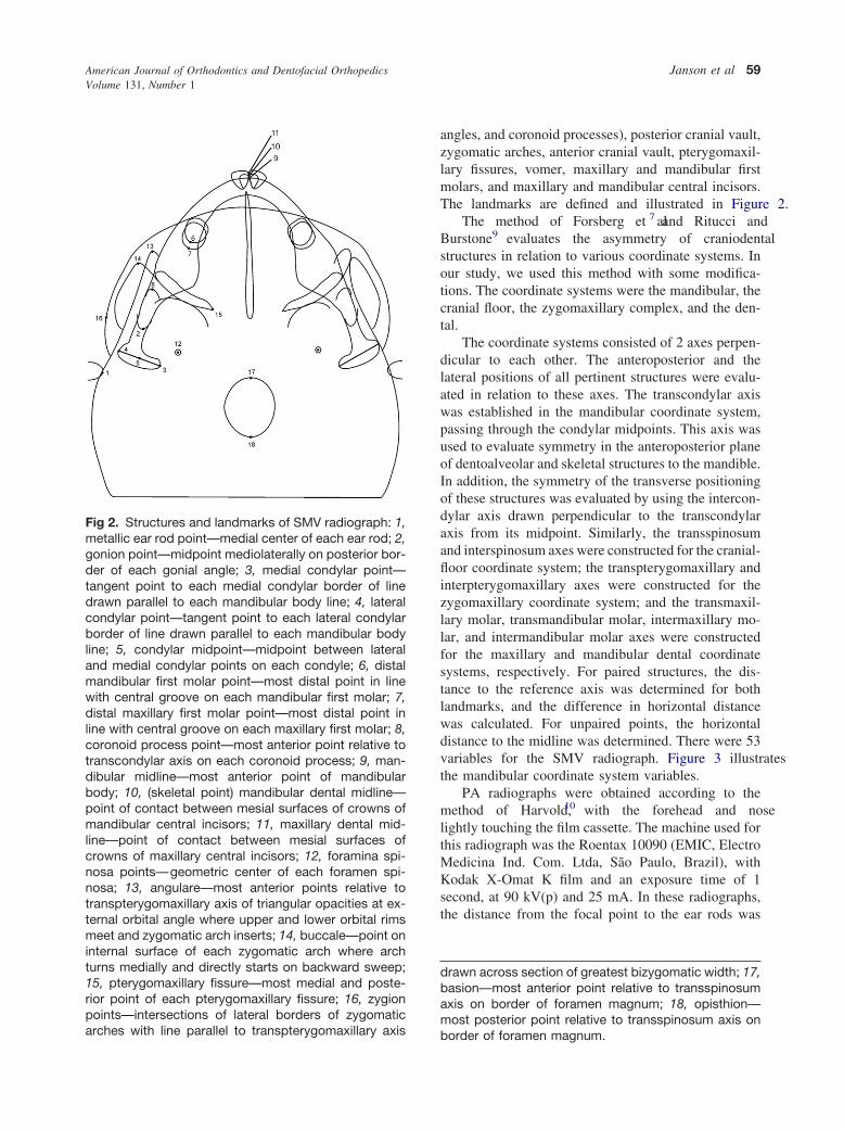
angles, and coronoid processes), posterior cranial vault,zygomatic arches, anterior cranial vault, pterygomaxil-lary fissures, vomer, maxillary and mandibular firstmolars, and maxillary and mandibular central incisors.The landmarks are defined and illustrated in Figure 2.
The method of Forsberg et al7 and Ritucci andBurstone9 evaluates the asymmetry of craniodentalstructures in relation to various coordinate systems. Inour study, we used this method with some modifica-tions. The coordinate systems were the mandibular, thecranial floor, the zygomaxillary complex, and the den-tal.
The coordinate systems consisted of 2 axes perpen-dicular to each other. The anteroposterior and thelateral positions of all pertinent structures were evalu-ated in relation to these axes. The transcondylar axiswas established in the mandibular coordinate system,passing through the condylar midpoints. This axis wasused to evaluate symmetry in the anteroposterior planeof dentoalveolar and skeletal structures to the mandible.In addition, the symmetry of the transverse positioningof these structures was evaluated by using the intercon-dylar axis drawn perpendicular to the transcondylaraxis from its midpoint. Similarly, the transspinosumand interspinosum axes were constructed for the cranial-floor coordinate system; the transpterygomaxillary andinterpterygomaxillary axes were constructed for thezygomaxillary coordinate system; and the transmaxil-lary molar, transmandibular molar, intermaxillary mo-lar, and intermandibular molar axes were constructedfor the maxillary and mandibular dental coordinatesystems, respectively. For paired structures, the dis-tance to the reference axis was determined for bothlandmarks, and the difference in horizontal distancewas calculated. For unpaired points, the horizontaldistance to the midline was determined. There were 53variables for the SMV radiograph. Figure 3 illustratesthe mandibular coordinate system variables.
PA radiographs were obtained according to themethod of Harvold,10 with the forehead and noselightly touching the film cassette. The machine used forthis radiograph was the Roentax 10090 (EMIC, ElectroMedicina Ind. Com. Ltda, São Paulo, Brazil), withKodak X-Omat K film and an exposure time of 1second, at 90 kV(p) and 25 mA. In these radiographs,the distance from the focal point to the ear rods was
drawn across section of greatest bizygomatic width; 17,basion—most anterior point relative to transspinosumaxis on border of foramen magnum; 18, opisthion—most posterior point relative to transspinosum axis on
Fig 2. Structures and landmarks of SMV radiograph: 1,metallic ear rod point—medial center of each ear rod; 2,gonion point—midpoint mediolaterally on posterior bor-der of each gonial angle; 3, medial condylar point—tangent point to each medial condylar border of linedrawn parallel to each mandibular body line; 4, lateralcondylar point—tangent point to each lateral condylarborder of line drawn parallel to each mandibular bodyline; 5, condylar midpoint—midpoint between lateraland medial condylar points on each condyle; 6, distalmandibular first molar point—most distal point in linewith central groove on each mandibular first molar; 7,distal maxillary first molar point—most distal point inline with central groove on each maxillary first molar; 8,coronoid process point—most anterior point relative totranscondylar axis on each coronoid process; 9, man-dibular midline—most anterior point of mandibularbody; 10, (skeletal point) mandibular dental midline—point of contact between mesial surfaces of crowns ofmandibular central incisors; 11, maxillary dental mid-line—point of contact between mesial surfaces ofcrowns of maxillary central incisors; 12, foramina spi-nosa points—geometric center of each foramen spi-nosa; 13, angulare—most anterior points relative totranspterygomaxillary axis of triangular opacities at ex-ternal orbital angle where upper and lower orbital rimsmeet and zygomatic arch inserts; 14, buccale—point oninternal surface of each zygomatic arch where archturns medially and directly starts on backward sweep;15, pterygomaxillary fissure—most medial and poste-rior point of each pterygomaxillary fissure; 16, zygionpoints—intersections of lateral borders of zygomatic
border of foramen magnum.

American Journal of Orthodontics and Dentofacial OrthopedicsJanuary 2007
60 Janson et al
standardized at 152 cm, and the distance from the earrods to the film was fixed at 16 cm; this yielded amagnification factor of 8.91%. During exposure, thesubjects kept their teeth in centric occlusion.
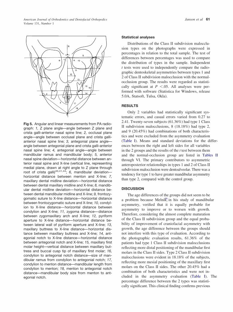
The tracings of the PA radiograph included thefollowing structures: orbits, contours of the nasal cav-ity, crista galli, zygomatic arches, mandibular contourfrom 1 condyle to the other, left and right maxillarycontours, lateral aspects of the frontal bone, lateralaspects of the zygomatic bones, maxillary and mandib-ular central incisors, and maxillary and mandibular firstmolars. The landmarks are defined and illustrated inFigure 4. The cephalometric measurements were ob-tained according to the method of Grummons and VanDe Coppello11 (Fig 5). For paired structures, the dis-tances to the reference midline were determined for
Fig 3. Measurements from SMV radiograph. Mandibu-lar coordinate system variables. Anteroposterior: 1,gonion to transcondylar axis; 2, coronoid process pointto transcondylar axis; 3, distal mandibular first molarpoint to transcondylar axis; 4, distal maxillary first molarpoint to transcondylar axis. Transverse: 5, gonion tointercondylar axis; 6, coronoid process point to inter-condylar axis; 7, distal mandibular first molar point tointercondylar axis; 8, distal maxillary first molar point tointercondylar axis; 9, mandibular midline to intercondy-lar axis; 10, mandibular dental midline to intercondylaraxis; 11, maxillary dental midline to intercondylar axis.
both landmarks, and the difference between the dis-
tances was calculated. For unpaired points, the horizon-tal distance to the midline was determined. This part ofthe analysis yielded 18 variables (Table VI).
For the 2 radiographs, absolute values were used forthe differences between the measurements of the rightand left sides, and for the horizontal distances to thereference midplanes. This kept any positive and nega-tive values from canceling themselves out in the calcu-lation of actual means for each group.12
For the evaluation of intraexaminer error, 20 ran-domly selected SMV and PA radiographs were re-traced, redigitized, and remeasured by the same exam-iner (K.J.R.S.L.). The casual error was calculatedaccording to Dahlberg’s formula13 (S2 � �d2/2n) and
Fig 4. Structures and landmarks of PA radiograph. 1,most lateral point on outline of nasal orifice in region ofeach pyriform aperture; 2, superolateral reference pointlocated at lateral aspect of each frontozygomatic su-ture; 3,lateral aspect of each zygomatic arch centeredvertically; 4, point at depth of concavity of each lateralmaxillary contour at junction of maxilla and zygomaticbuttress; 5, buccal cusp tip of each maxillary first molar;6, buccal cusp tip of each mandibular first molar; 7,point on superior surface of head of each condylecentered mediolaterally; 8, point at each gonial angle ofmandible; 9, point at each antegonial notch; 10, men-ton—most inferior point on anterior border of mandibleat symphysis; 11, most superior point of crista gallilocated ideally in skeletal midline. 12, tip of anteriornasal spine; 13, mean contact point between eachmaxillary and mandibular first molar; 14, midpoint be-tween maxillary central incisors; 15, midpoint betweenmandibular central incisors.
the systematic error with paired t test,14,15 at P �.05.
egonial notch.
American Journal of Orthodontics and Dentofacial OrthopedicsVolume 131, Number 1
Janson et al 61
Statistical analyses
Distributions of the Class II subdivision malocclu-sion types on the photographs were expressed inpercentages in relation to the total sample. The test ofdifferences between percentages was used to comparethe distribution of types in the sample. Independentt tests were used to independently compare the radio-graphic dentoskeletal asymmetries between types 1 and2 of Class II subdivision malocclusion with the normal-occlusion group. The results were regarded as statisti-cally significant at P �.05. All analyses were per-formed with software (Statistica for Windows, release5.0A, Statsoft, Tulsa, Okla).
RESULTS
Only 2 variables had statistically significant sys-tematic errors, and casual errors varied from 0.27 to2.41. Twenty-seven subjects (61.36%) had type 1 ClassII subdivision malocclusions, 8 (18.18%) had type 2,and 9 (20.45%) had combinations of both characteris-tics and were excluded from the asymmetry evaluation(Table I). Means and standard deviations for the differ-ences between the right and left sides for all variablesin the 2 groups and the results of the t test between themand the normal-occlusion group are listed in Tables IIthrough VI. The primary contributors to asymmetricanteroposterior relationships in types 1 and 2 of Class IIsubdivision malocclusion were dentoalveolar. There was atendency for type 1 to have greater mandibular asymmetrythan type 2, compared with the control group.
DISCUSSION
The age differences of the groups did not seem to bea problem because Melnik,16 in his study of mandibularasymmetry, verified that it is equally probable forasymmetry to improve or to worsen with growth.Therefore, considering the almost complete maturationof the Class II subdivision group and the equal proba-bility of improvement of craniofacial asymmetry withgrowth, the age difference between the groups shouldnot interfere with this type of evaluation. According tothe photographic evaluation results, 61.36% of thepatients had type 1 Class II subdivision malocclusionsreflecting more distal positioning of the mandibular firstmolars in the Class II sides. Type 2 Class II subdivisionmalocclusions were evident in 18.18% of the subjects,reflecting more mesial positioning of the maxillary firstmolars on the Class II sides. The other 20.45% had acombination of both characteristics and were not in-cluded in the asymmetry evaluation (Table I). Thepercentage difference between the 2 types was statisti-
Fig 5. Angular and linear measurements from PA radio-graph: 1, Z plane angle—angle between Z plane andcrista galli-anterior nasal spine line; 2, occlusal planeangle—angle between occlusal plane and crista galli-anterior nasal spine line; 3, antegonial plane angle—angle between antegonial plane and crista galli-anteriornasal spine line; 4, antegonial angle—angle betweenmandibular ramus and mandibular body; 5, anteriornasal spine deviation—horizontal distance between an-terior nasal spine and X-line (vertical line, representingmedial plane, drawn at right angle to Z plane throughroot of crista galli)40,41,44; 6, mandibular deviation—horizontal distance between menton and X-line; 7,maxillary dental midline deviation—horizontal distancebetween dental maxillary midline and X-line; 8, mandib-ular dental midline deviation—horizontal distance be-tween dental mandibular midline and X-line; 9, frontozy-gomatic suture to X-line distance—horizontal distancebetween frontozygomatic suture and X-line; 10, condyl-ion to X-line distance—horizontal distance betweencondylion and X-line; 11, zygoma distance—distancebetween zygomaxillary arch and X-line; 12, pyriformaperture to X-line distance—horizontal distance be-tween lateral wall of pyriform aperture and X-line; 13,maxillary buttress to X-line distance—horizontal dis-tance between maxillary buttress and X-line; 14, ant-egonial notch to X-line distance—horizontal distancebetween antegonial notch and X-line; 15, maxillary firstmolar height—vertical distance between maxillary but-tress and buccal cusp tip of maxillary first molar; 16,condylion to antegonial notch distance—size of man-dibular ramus from condylion to antegonial notch; 17,condylion to menton distance—mandibular length fromcondylion to menton; 18, menton to antegonial notchdistance—mandibular body size from menton to ant-
cally significant. This clinical finding confirms previous

American Journal of Orthodontics and Dentofacial OrthopedicsJanuary 2007
62 Janson et al
results of cephalometric investigations that had foundmore distal positioning of the mandibular first molaron the Class II side as the primary contributor to theasymmetric malocclusion, and the more mesial po-sitioning of the maxillary molar on the Class II sideas the secondary contributor.1-3 If the mandibularfirst molar is more frequently distally positioned, themandibular dental midline will be deviated towardthe Class II side with a greater frequency as well, andthis results in a greater percentage of type 1 Class IIsubdivision cases. These results also resemble pre-vious reports that found deviations of the mandibulardental midline in relation to the midsagittal plane asthe primary contributor to the asymmetric Class IImalocclusion2 and also that deviation of the mandib-ular dental midline was more frequent than deviationof the maxillary dental midline in this type ofmalocclusion.17
The clinical method of analysis we used, althoughsubject to criticism, is useful in identifying the primaryanomaly in relation to the patient’s soft-tissue frontalview, which is of utmost importance in diagnosisbecause the frontal appearance is evident at
Table I. Distribution of Class II subdivision malocclusand 2)
Type 1
Photographic analysis 61.36% (n � 27) 1
*Statistically significant at P �.05.
Table II. Mandibular coordinate system (measurements
Variable
o(
Mea
AnteroposteriorGonion to transcondylar axis 1.2Coronoid process point to transcondylar axis 1.3Mandibular molar distal point to transcondylar axis 0.9Maxillary molar distal point to transcondylar axis 0.9
TransverseGonion to intercondylar axis 1.9Coronoid process point to intercondylar axis 2.5First mandibular molar distal point to intercondylar axis 2.9First maxillary molar distal point to intercondylar axis 2.6Mandibular midline to intercondylar axis 1.8Mandibular dental midline to intercondylar axis 1.7Maxillary dental midline to intercondylar axis 1.5
*Statistically significant at P �.05.
first.11,18,19 Perhaps this method could provide
slightly different results when compared with ceph-alometric evaluations of midline deviations in indi-vidual analyses, as will be further discussed. How-ever, clinical manifestations of the asymmetries aremore important than cephalometric data, especiallynowadays.20-22 In addition, these results agree withprevious cephalometric findings.1-3 Sound concernscould be raised if the results had been contradictoryto previous observations.
SMV radiographs
Clinically distinguishing Class II subdivision mal-occlusion in 2 types did not greatly modify the primarydentoalveolar factors that contribute to this asymmetricmalocclusion, previously reported,1-3 as shown in Ta-ble II. The anteroposterior asymmetry degrees of themandibular and maxillary molars in the 2 types werestatistically greater than in the normal-occlusion group,as was observed previously in undistinguished Class IIsubdivision malocclusion samples.1-3 Only a smalldifference could be observed in the level of significancebetween the groups; ie, in the type in which asymmetrywould be expected for a molar, the level of significance
pes and results of test between 2 percentages (types 1
e 2 P Combined characteristics
(n � 8) .000* 20.45% (n � 9)
)
n)
Class IIsubdivision
malocclusion—type 1
(n � 27)
P
Class IIsubdivision
malocclusion—type 2
(n � 8)
PSD Mean SD Mean SD
.22 1.71 1.21 .132 1.55 1.30 .504
.85 1.58 1.05 .297 1.27 0.77 .893
.64 3.00 1.49 .000* 2.65 1.41 .000*
.72 1.43 .95 0.041* 1.80 1.06 .013*
.25 2.56 2.01 .169 1.76 2.26 .751
.82 2.25 2.04 .534 1.20 0.96 .047*
.04 3.04 2.51 .862 3.12 2.03 .824
.84 3.05 2.32 .510 3.37 2.55 .397
.50 2.18 1.70 .479 2.07 2.01 .771
.24 2.02 1.40 .392 2.01 1.85 .603
.12 1.58 1.59 .945 1.81 1.79 .619
ion ty
Typ
8.18%
in mm
Normalcclusion � 30
n
1 12 06 06 0
5 18 14 29 18 12 15 1
was greater than for the other type. Tables III and IV

American Journal of Orthodontics and Dentofacial OrthopedicsVolume 131, Number 1
Janson et al 63
Table III. Cranial-floor coordinate system (measurements in mm)
Variable
Normalocclusion(n � 30)
Class IIsubdivision
malocclusion—type 1
(n � 27)
P
Class IIsubdivision
malocclusion—type 2
(n � 8)
PMean SD Mean SD Mean SD
AnteroposteriorCondylar midpoint to transspinosum axis 1.59 1.27 1.45 1.33 .692 1.76 1.38 .749Gonion to transspinosum axis 1.63 1.42 2.36 1.44 .059 1.96 1.74 .578Coronoid process point to transspinosum axis 1.68 1.28 2.23 1.29 .109 1.72 0.88 .926First mandibular molar distal point to transspinosum axis 1.04 0.84 3.14 1.55 .000* 3.43 1.35 .000*First maxillary molar distal point to transspinosum axis 1.02 0.90 1.32 1.10 .256 1.26 0.87 .503Posterior cranial vault to transspinosum axis 0.86 0.68 0.94 0.68 .657 1.63 2.37 .116Middle cranial fossa to transspinosum axis 1.75 1.38 2.33 1.88 .184 2.42 1.00 .208
TransverseMidcondylar point to interspinosum axis 0.95 0.68 1.57 1.31 .027* 1.31 1.13 .263Gonion to interspinosum axis 1.78 1.31 2.81 1.98 .023* 2.22 1.02 .388Coronoid process point to interspinosum axis 2.74 1.92 2.91 1.97 .740 2.07 1.73 .376First mandibular molar distal point to interspinosum axis 3.26 2.41 3.59 2.33 .603 3.88 2.75 .534First maxillary molar distal point to interspinosum axis 2.86 2.15 3.51 2.13 .255 2.95 3.76 .932Mandibular midline to interspinosum axis 2.13 1.87 2.90 1.96 .133 2.63 2.41 .528Mandibular dental midline to interspinosum axis 1.90 1.67 2.21 1.86 .504 2.90 2.47 .184Maxillary dental midline to interspinosum axis 1.94 1.32 2.18 1.69 .547 2.08 1.87 .808Posterior cranial vault to interspinosum axis 2.50 1.93 3.40 2.04 .095 2.70 2.15 .807Middle cranial fossa to interspinosum axis 4.30 2.71 3.62 2.90 .364 1.62 1.27 .010*Basion to interspinosum axis 1.37 1.17 1.72 1.22 .280 2.25 2.04 .122Opisthion to interspinosum axis 1.50 1.35 2.23 1.45 .055 2.23 2.22 .246
*Statistically significant at P �.05.
Table IV. Zygomaxillary coordinate system (measurements in mm)
Variable
Normalocclusion(n � 30)
Class IIsubdivision
malocclusion—type 1
(n � 27)
P
Class IIsubdivision
malocclusion—type 2
(n � 8)
PMean SD Mean SD Mean SD
AnteroposteriorBuccale to transpterygomaxillary axis 2.27 1.73 3.18 2.22 .089 1.83 1.43 .516Zygion to transpterygomaxillary axis 1.25 1.80 1.54 1.77 .552 3.02 3.57 .056Anterior cranial vault to transpterygomaxillary axis 1.13 1.64 1.44 1.66 .482 2.85 3.32 .044*Angulare to transpterygomaxillary axis 2.27 1.88 3.06 2.33 .163 1.47 1.55 .278First mandibular molar distal point to transpterygomaxillary axis 1.27 0.95 3.68 2.32 .000* 2.66 1.80 .004*First maxillary molar distal point to transpterygomaxillary axis 1.23 0.90 1.36 1.07 .622 1.78 1.16 .157
TransverseBuccale to interpterygomaxillary axis 2.42 1.87 2.25 1.19 .697 1.76 1.03 .349Zygion to interpterygomaxillary axis 1.91 1.47 2.58 2.53 .223 1.95 1.46 .950Anterior cranial vault to interpterygomaxillary axis 3.84 2.54 4.05 3.38 .792 4.88 2.38 .305Angulare to interpterygomaxillary axis 2.89 1.81 2.13 1.79 .116 2.01 0.93 .194Anterior vomer point to interpterygomaxillary axis 1.08 0.72 1.16 0.97 .715 0.77 0.62 .285Posterior vomer point to interpterygomaxillary axis 0.64 0.56 0.64 0.60 .988 0.68 0.74 .866First mandibular molar distal point to interpterygomaxillary axis 2.52 2.66 2.93 1.89 .513 2.96 2.21 .674First maxillary molar distal point to interpterygomaxillary axis 2.26 2.61 2.71 2.02 .476 2.41 2.29 .884Maxillary dental midline to interpterygomaxillary axis 1.82 1.85 1.77 1.24 .907 1.95 1.26 .853Mandibular midline to interpterygomaxillary axis 1.94 1.92 2.27 2.03 .535 2.10 1.27 .829Mandibular dental midline to interpterygomaxillary axis 1.76 1.91 2.25 2.06 .361 1.96 1.60 .792
*Statistically significant at P �.05.
American Journal of Orthodontics and Dentofacial OrthopedicsJanuary 2007
64 Janson et al
show significantly greater anteroposterior asymmetryfor only the mandibular molars in both types ofsubdivision malocclusions in relation to normal occlu-sion. This means that the primary characteristic of type2 subdivision malocclusion (asymmetry of the maxil-lary molars) did not manifest in this evaluation and that,in this type, asymmetry of the mandibular molars alsoplays an important role, as previously shown.23 Thiscould be because of the small number of subjects in thismalocclusion type, requiring subsequent investigationswith a larger sample. Skeletally, in the zygomaxillarycoordinate system, there was greater asymmetry of theanterior cranial vault in relation to the transpterygo-maxillary axis for type 2 in relation to normal occlu-sion. However, this structure is not amenable tochanges with orthodontic treatment, and therefore thisasymmetry can be considered of minor importance.
Nevertheless, transversally, slight differences inskeletal asymmetries were suggested. In the mandibularcoordinate system, the asymmetry of the coronoidprocess point to the intercondylar axis was statisticallysmaller in type 2 than in the normal-occlusion group,whereas type 1 had similar asymmetry to the controlgroup. In the cranial-floor coordinate system, the man-dibular skeletal structures had statistically greaterasymmetry in type 1 than in the normal-occlusiongroup, whereas type 2 had similar asymmetries as thecontrol group. Therefore, this suggests the associationof mild mandibular asymmetry in type 1 subdivisionmalocclusion, and that type 2 patients have moresymmetrical mandibles. Additionally, the middlecranial fossa was more symmetrical in type 2 than inthe normal-occlusion group. This further reinforcesthat midface skeletal asymmetry does not contribute toClass II subdivision malocclusions as previously
Table V. Dental coordinate system (measurements in m
Variable Me
AnteroposteriorMandibular molar distal point to midcondylar point 1.6Maxillary molar distal point to midcondylar point 1.4
TransverseMandibular dental midline to mandibular intermolar axis 0.6Mandibular midline to mandibular intermolar axis 0.8Maxillary dental midline to maxillary intermolar axis 0.5Mandibular midline to maxillary intermolar axis 0.8
*Statistically significant at P �.05.
found.2
Dental coordinate system
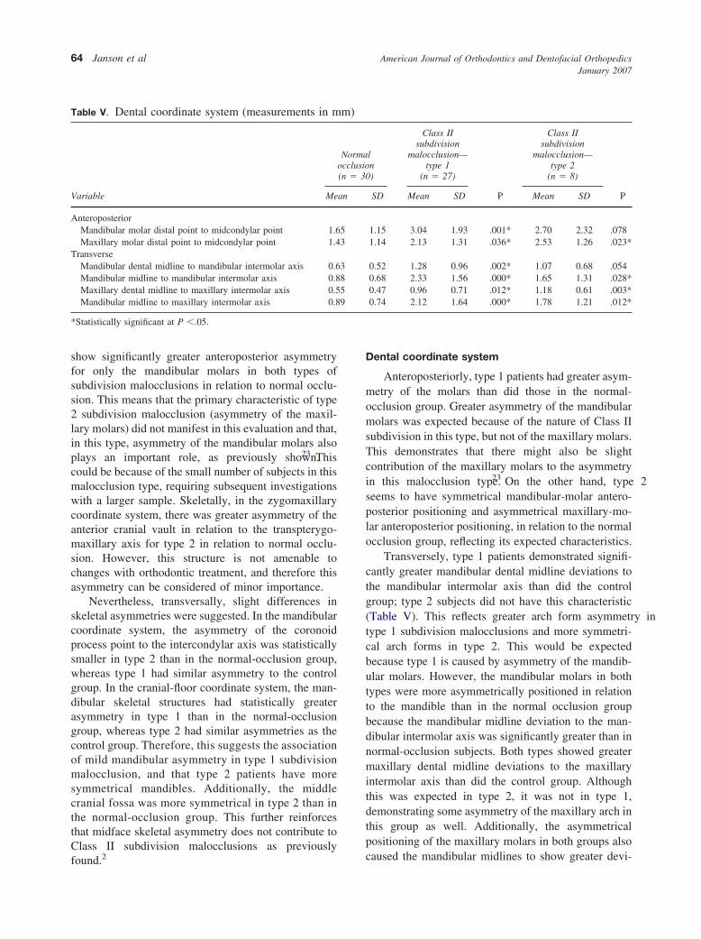
Anteroposteriorly, type 1 patients had greater asym-metry of the molars than did those in the normal-occlusion group. Greater asymmetry of the mandibularmolars was expected because of the nature of Class IIsubdivision in this type, but not of the maxillary molars.This demonstrates that there might also be slightcontribution of the maxillary molars to the asymmetryin this malocclusion type.23 On the other hand, type 2seems to have symmetrical mandibular-molar antero-posterior positioning and asymmetrical maxillary-mo-lar anteroposterior positioning, in relation to the normalocclusion group, reflecting its expected characteristics.
Transversely, type 1 patients demonstrated signifi-cantly greater mandibular dental midline deviations tothe mandibular intermolar axis than did the controlgroup; type 2 subjects did not have this characteristic(Table V). This reflects greater arch form asymmetry intype 1 subdivision malocclusions and more symmetri-cal arch forms in type 2. This would be expectedbecause type 1 is caused by asymmetry of the mandib-ular molars. However, the mandibular molars in bothtypes were more asymmetrically positioned in relationto the mandible than in the normal occlusion groupbecause the mandibular midline deviation to the man-dibular intermolar axis was significantly greater than innormal-occlusion subjects. Both types showed greatermaxillary dental midline deviations to the maxillaryintermolar axis than did the control group. Althoughthis was expected in type 2, it was not in type 1,demonstrating some asymmetry of the maxillary arch inthis group as well. Additionally, the asymmetricalpositioning of the maxillary molars in both groups also
ln)
Class IIsubdivision
malocclusion—type 1
(n � 27)
P
Class IIsubdivision
malocclusion—type 2
(n � 8)
PSD Mean SD Mean SD
1.15 3.04 1.93 .001* 2.70 2.32 .0781.14 2.13 1.31 .036* 2.53 1.26 .023*
0.52 1.28 0.96 .002* 1.07 0.68 .0540.68 2.33 1.56 .000* 1.65 1.31 .028*0.47 0.96 0.71 .012* 1.18 0.61 .003*0.74 2.12 1.64 .000* 1.78 1.21 .012*
m)
Normaocclusio(n � 30
an
53
3859
caused the mandibular midlines to show greater devi-

American Journal of Orthodontics and Dentofacial OrthopedicsVolume 131, Number 1
Janson et al 65
ations to their intermolar axes than did the normal-occlusion group.
From our results, it can be seen that the character-istics of each type are not always clearly manifested inevery coordinate system. However, the primary char-acteristics of each type prevail most of the time.
PA radiograph results
The statistically greater asymmetry of the mandib-ular dental midline deviations in type 1 compared withthe normal-occlusion group confirms the predominantcharacteristic in this malocclusion type—distal posi-tioning of the mandibular first molar on the Class IIside, with accompanying deviation of the mandibulardental midline, as also shown in the tables. In type 2subjects, the mandibular dental midlines had similardeviations as the normal-occlusion group but lessmandibular skeletal asymmetry (antegonial notch toX-line distance) than the control group; this was sur-prising. This reinforces that this malocclusion type hasrelatively symmetrical mandibular bones and denti-tions. However, greater maxillary dental midline devi-ations to X-line than the control group were notobserved and could not reinforce the primary contrib-utory factor to this malocclusion type—ie, a mesiallypositioned maxillary first molar accompanied by max-
Table VI. Posteroanterior radiograph
Variable
Normalocclusion(n � 30)
Mean S
Z plane angle (°) 89.90 1Occlusal plane angle (°) 89.34 1Antegonial plane angle (°) 88.63 1Anterior nasal spine deviation (mm) 1.33 0Mandibular deviation (mm) 2.71 1Maxillary dental midline deviation (mm) 1.40 0Mandibular dental midline deviation (mm) 1.58 0Antegonial angle (°) 2.40 1Frontozygomatic suture to X-line distance (mm) 1.77 1Condylion to X-line distance (mm) 3.20 2Zygoma distance (mm) 2.86 1Pyriform aperture to X-line distance (mm) 2.51 1Maxillary buttress to X-line distance (mm) 2.47 1Antegonial notch to X-line distance (mm) 4.25 3First maxillary molar height (mm) 1.37 1Condylion to antegonial notch distance (mm) 2.70 2Condylion to menton distance (mm) 2.26 2Menton to antegonial notch distance (mm) 2.28 1
*Statistically significant at P �.05.
illary midline deviation. Therefore, it seems that this
result in the PA radiograph does not agree with thephotographic evaluation method used to divide thesample into 2 groups. However, slight differencesbetween a frontal visual inspection and the PA radio-graph might occur because the subjects were notsimilarly standardized for both evaluations. In thephotographic evaluation, the patients were evaluatedsubjectively by the operator as to the best naturalfrontal view. In the PA radiograph, the subjects werestandardized by the cephalostat. The external auditorymeatus might have slight anteroposterior asymme-try11,24 that could rotate the head and consequentlyaffect evaluation of the structures in relation to themidsagittal plane. This could have accounted for thedifferent results obtained. Additionally, small asymme-tries of the overlying soft tissues could have alsocontributed to this difference. Perhaps this also explainssome diverging results of the SMV evaluation that wereunexpected. However, a patient’s clinical or photo-graphic frontal evaluation is more important than aradiographic evaluation.20-22 Nevertheless, becausethere were few type 2 subjects, these results shouldbe regarded with caution.
The other variables in the 2 groups did not havesignificant differences in relation to the normal-occlu-sion group; this is similar to previous results of undis-
Class IIsubdivision
malocclusion—type 1
(n � 27)
P
Class IIsubdivision
malocclusion—type 2
(n � 8)
PMean SD Mean SD
89.68 1.80 .585 90.30 1.40 .45290.02 1.97 0.171 90.66 1.66 0.06388.85 2.33 .658 89.15 3.84 .551
1.49 1.45 .594 1.187 0.80 .6712.68 1.71 .962 1.65 0.88 .0881.65 1.58 .463 1.32 0.76 .8162.36 1.53 .024* 1.70 1.26 .7733.42 2.81 .090 3.85 2.83 .0561.94 1.72 .668 1.51 0.90 .5904.23 3.24 .175 3.55 3.14 .7374.24 3.26 .055 3.30 2.29 .5902.76 2.55 .659 2.08 1.55 .4973.33 2.63 .143 2.21 1.69 .6924.27 3.32 .981 1.83 1.38 .045*1.93 1.73 .143 2.21 2.00 .1123.20 2.39 .401 3.33 4.23 .5522.37 2.22 .842 2.66 1.11 .6232.85 2.21 .297 3.96 2.83 .055
D
.27
.74
.51
.84
.63
.90
.97
.51
.24
.42
.96
.57
.65
.19
.05
.10
.21
.92
tinguished Class II subdivision samples.1,2
American Journal of Orthodontics and Dentofacial OrthopedicsJanuary 2007
66 Janson et al
Despite clinically dividing Class II subdivisionmalocclusions into types 1 and 2, the main factorscontributing to asymmetry were dentoalveolar, as pre-viously found in undistinguished Class II subdivisionmalocclusions.1-3 In our study, skeletal asymmetrieswere mild. These results did not strongly support specu-lations of finding skeletal asymmetries in the differenttypes of Class II subdivision malocclusions.2 However,they suggested slightly greater mandibular skeletalasymmetries in type 1 than in type 2 Class II subdivi-sion malocclusions. Further studies, with larger sam-ples, especially of type 2 Class II subdivision maloc-clusions, are necessary to confirm these tendencies.
CONCLUSIONS
The frequencies of Class II subdivision malocclu-sion types from the frontal photographic evaluationwere type 1, 61.36%; type 2, 18.18%; and a type withcombined characteristics, 20.45% (not evaluated re-garding the asymmetries).
The predominant asymmetric dentoalveolar charac-teristics of types 1 and 2 of Class II subdivisionmalocclusions were evident when individually com-pared with a normal-occlusion control group. Therewas a tendency for type 1 patients to have greatermandibular asymmetry than type 2 patients, as com-pared with the control group.
REFERENCES
1. Alavi DG, Begole EA, Schneider BJ. Facial and dental archasymmetries in Class II subdivision malocclusion. Am J OrthodDentofacial Orthop 1988;93:38-46.
2. Janson G, Metaxas A, Woodside DG, Freitas MR, Pinzan A.Three-dimensional evaluation of skeletal and dental asymmetriesin Class II subdivision malocclusions. Am J Orthod DentofacialOrthop 2001;119:406-18.
3. Rose JM, Sadowsky C, Begole EA, Moles R. Mandibularskeletal and dental asymmetry in Class II subdivision malocclu-sions. Am J Orthod Dentofacial Orthop 1994;105:489-95.
4. Janson G, Wooside D, Metaxas A, Henriques J, Freitas M.Orthodontic treatment of subdivision cases. World J Orthod2003;4:36-46.
5. Proffit WR, Vig KW, Turvey TA. Early fracture of the mandib-ular condyles: frequently an unsuspected cause of growth distur-
bances. Am J Orthod 1980;78:1-24.6. Jerrold L, Lowenstein L. The midline: diagnosis and treatment.Am J Orthod Dentofacial Orthop 1990;97:453-62.
7. Forsberg CT, Burstone CJ, Hanley KJ. Diagnosis and treatmentplanning of skeletal asymmetry with the submental-verticalradiograph. Am J Orthod 1984;85:224-37.
8. Legan HL. Surgical correction of patients with asymmetries.Semin Orthod 1998;4:189-98.
9. Ritucci R, Burstone CJ. Use of the submental vertical radiographin the assessment of asymmetry [thesis]. Farmington: Universityof Connecticut; 1981.
10. Harvold EP. A roentgen study of the postnatal morphogenesis ofthe facial skeleton in cleft palate [thesis]. Oslo: University ofOslo; 1954.
11. Grummons DC, Van De Coppello MAK. A frontal asymmetryanalysis. J Clin Orthod 1987;21:448-65.
12. Arnold TG, Anderson GC, Liljemark WF. Cephalometric norms forcraniofacial asymmetry using submental-vertical radiographs. Am JOrthod Dentofacial Orthop 1994;106:250-6.
13. Dahlberg G. Statistical methods for medical and biologicalstudents. New York: Intercience; 1940.
14. Houston WJB. The analysis of errors in orthodontic measure-ments. Am J Orthod 1983;83:382-90.
15. Richardson A. An investigation into the reproducibility of somepoints, planes, and lines used in cephalometric analysis. Am JOrthod 1966;52:637-51.
16. Melnik AK. A cephalometric study of mandibular asymmetry ina longitudinally followed sample of growing children. Am JOrthod Dentofacial Orthop 1992;101:355-66.
17. Araujo TM, Wilhelm RS, Almeida MA. Skeletal and dental archasymmetries in Class II Division 1 subdivision malocclusions.J Clin Pediatr Dent 1994;18:181-5.
18. Cox NH, van der Linden FP. Facial harmony. Am J Orthod1971;60:175-83.
19. Ferrario VF, Sforza C, Miani A, Tartaglia G. Craniofacialmorphometry by photographic evaluations. Am J Orthod Dento-facial Orthop 1993;103:327-37.
20. Arnett GW, Bergman RT. Facial keys to orthodontic diagnosisand treatment planning: part I. Am J Orthod Dentofacial Orthop1993;103:299-312.
21. Holdaway RA. A soft-tissue cephalometric analysis and its use inorthodontic treatment planning. Part I. Am J Orthod 1983;84:1-28.
22. Park YC, Burstone CJ. Soft-tissue profile: fallacies of hard-tissuestandards in treatment planning. Am J Orthod DentofacialOrthop 1986;90:52-62.
23. Janson GR, Cruz K, Woodside DG, Metaxas A, Freitas MR,Henriques JFC. Dentoskeletal treatment changes in Class IIsubdivision malocclusions in submentovertex and posteroante-rior radiographs. Am J Orthod Dentofacial Orthop 2004;126:451-63.
24. Farkas LG. Vertical location of the ear, assessed by the Leibertest, in healthy North American Caucasians 6-19 years of age.
Arch Otorhinolaryngol 1978;220:9-13.
Related Documents