Class #4 Aircraft Instruments

Class #4 Aircraft Instruments. Content Flight Instruments Engine Instruments Miscellaneous Instruments Gleim 2.1-2.8 JEPPESEN CHAPTER 2 SECTION C PHAK.
Dec 27, 2015
Welcome message from author
This document is posted to help you gain knowledge. Please leave a comment to let me know what you think about it! Share it to your friends and learn new things together.
Transcript

Class #4 Aircraft Instruments

Content• Flight Instruments• Engine Instruments• Miscellaneous Instruments• Gleim 2.1-2.8• JEPPESEN CHAPTER 2 SECTION C• PHAK Chapter 7

Flight Instruments (P85)
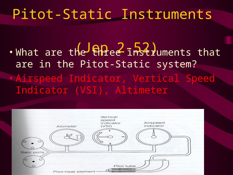
Pitot-Static Instruments (Jep 2-52)
• What are the three instruments that are in the Pitot-Static system?
• Airspeed Indicator, Vertical Speed Indicator (VSI), Altimeter

Airspeed Indicator• The only true pitot-static instrument
• Measures both Ram air (or pitot air) from the pitot tube and static air from the static port.
• Airspeed indicator subtracts static pressure, supplied from the static ports, from the total pressure provided by the pitot head (tube). This difference is called Dynamic Pressure, and measures the aircrafts forward speed IAS.
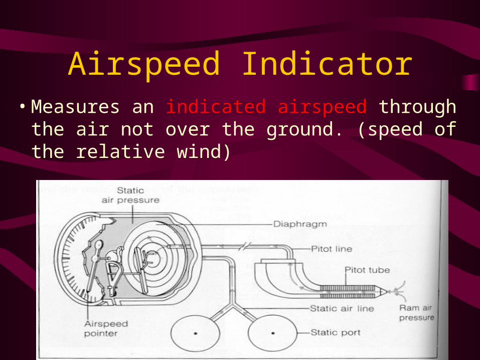
Airspeed Indicator• Measures an indicated airspeed through the
air not over the ground. (speed of the relative wind)

AIRSPEED
Airspeed Indicator• Diaphragm inside the instrument measures
pressure forces from the pitot tube. If you subtract the static pressure around this diagram you get your airspeed.

Airspeed Indicator• Pitot tube is blocked you will have no ram
air if relief holes clear airspeed will read 0.
• Pitot heat helps to eliminate ice blockage on the pitot tube, controlled by pilot.

BLOCKED PITOT & DRAIN CLEAR STATIC
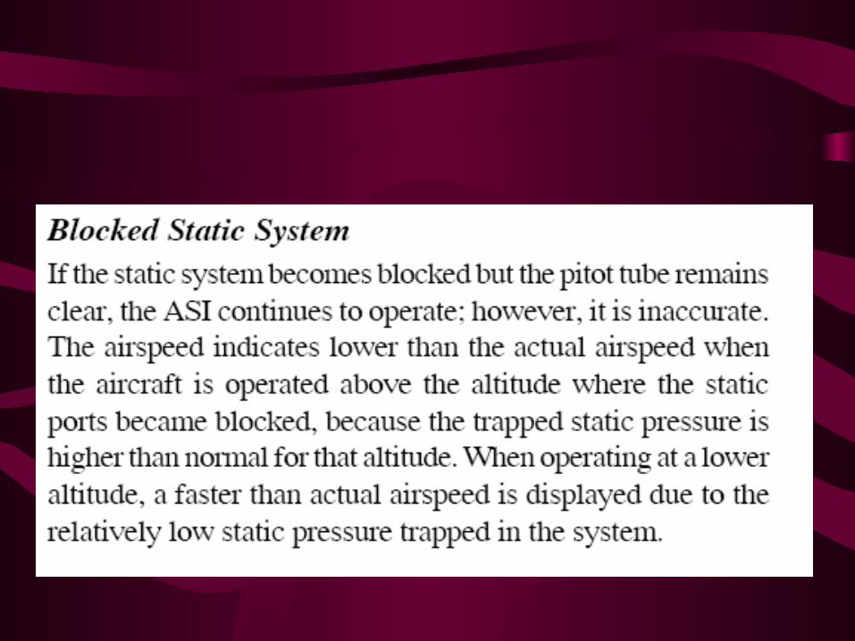
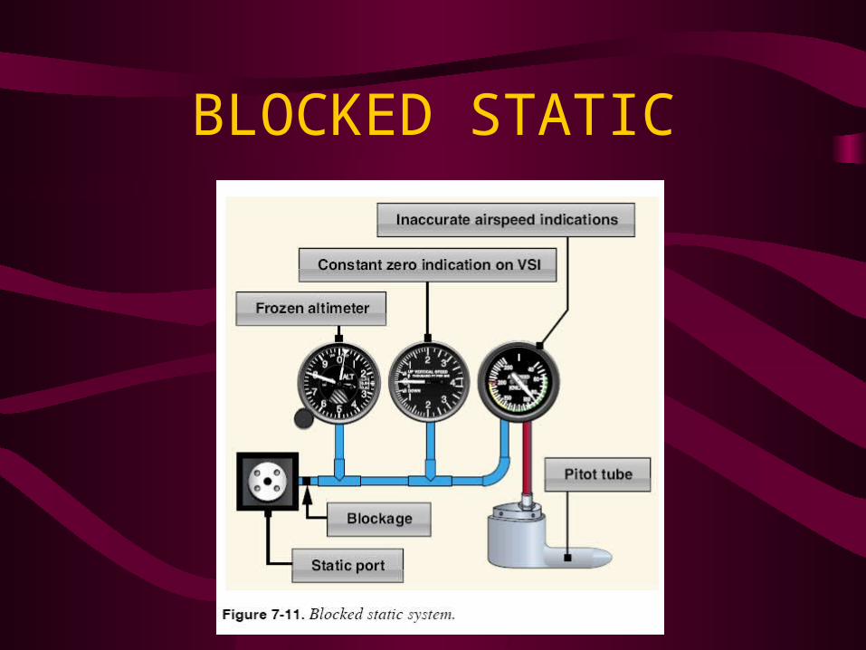
BLOCKED STATIC

Different types of Airspeed• ICET• Indicated Airspeed (IAS)-direct reading from
the face of the instrument• Calibrated Airspeed (CAS)- IAS corrected for
position and installation error. 5-8 B19• Equivalent Airspeed (EAS)-CAS corrected for
compressability.• True Airspeed (TAS)- EAS corrected for
altitude, temperature

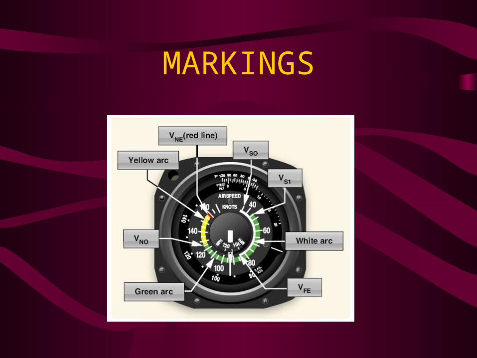
Airspeed Indicator (P98)• White arc, full flap operating range
• Green arc normal operating range
• Yellow arc operate with caution, only in smooth air
• Redline, maximum speed for all operations
MARKINGS

Airspeed Indicator• Most airspeed indicators will have MPH
inner scale, Knots outer scale
• Some airspeed indicators will also have a true airspeed indicator built in.
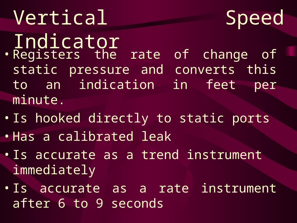
Vertical Speed Indicator• Registers the rate of change of static
pressure and converts this to an indication in feet per minute.
• Is hooked directly to static ports
• Has a calibrated leak
• Is accurate as a trend instrument immediately
• Is accurate as a rate instrument after 6 to 9 seconds

Vertical Speed Indicator

Altimeter• Altimeter translates the barometric pressure
into a display of elevation in feet
• Works on the principle that atmospheric pressure decreases with altitude.
• It has a sealed case except for static source inlet. Inside the case are aneroid wafers which sense changes in static pressure by expanding or contracting (are sealed with a reference pressure)

Mechanism of the altimeter

Altimeter (P101)
• How to read it
• Number Drum Altimeter
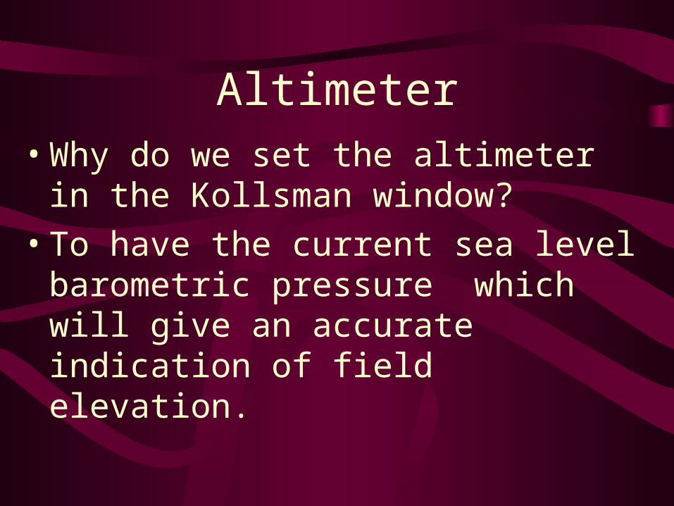
Altimeter• Why do we set the altimeter in the
Kollsman window?
• To have the current sea level barometric pressure which will give an accurate indication of field elevation.

Altimeter
• Approximately 1" of pressure measured in inches of mercury is equivalent to 1000' of altitude
• The altimeter must be calibrated before takeoff and about once an hour sometimes more and every 100 miles
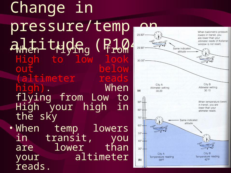
Change in pressure/temp on altitude (P104)• When flying from High
to low look out below (altimeter reads high). When flying from Low to High your high in the sky
• When temp lowers in transit, you are lower than your altimeter reads.

Altimeter• Current barometric pressure is set in the
Kollsman window, the scale goes from 28.00" to 31.00"
• Sometimes millibars are set in an alternate window (usually everywhere outside North America)
• Altitude should read + or - 75 feet

ALTERNATE STATIC SOURCEPOH 3-8, 5-8, 5-10

Different types of Altitudes

Different types of Altitudes• Indicated altitude-Read off altimeter
• Pressure altitude- Altimeter reading when set to 29.92
• Absolute altitude-Height above terrain
• True altitude-Height above sea level.
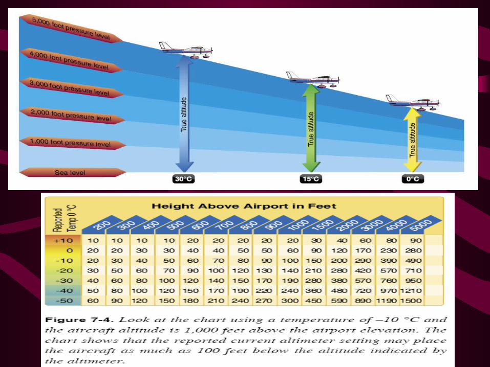
• Density Altitude-pressure altitude corrected for nonstandard temperature
Different types of Altitudes• Pressure altitude calculations• 29.92-station pressure=X• X times 1000 added to field
elevation equals pressure altitude at airport
• Density altitude need formula, E6B/or chart to figure out
Gyro Instruments
• Attitude Indicator
• Directional Gyro (or Heading Indicator)
• Turn Coordinator
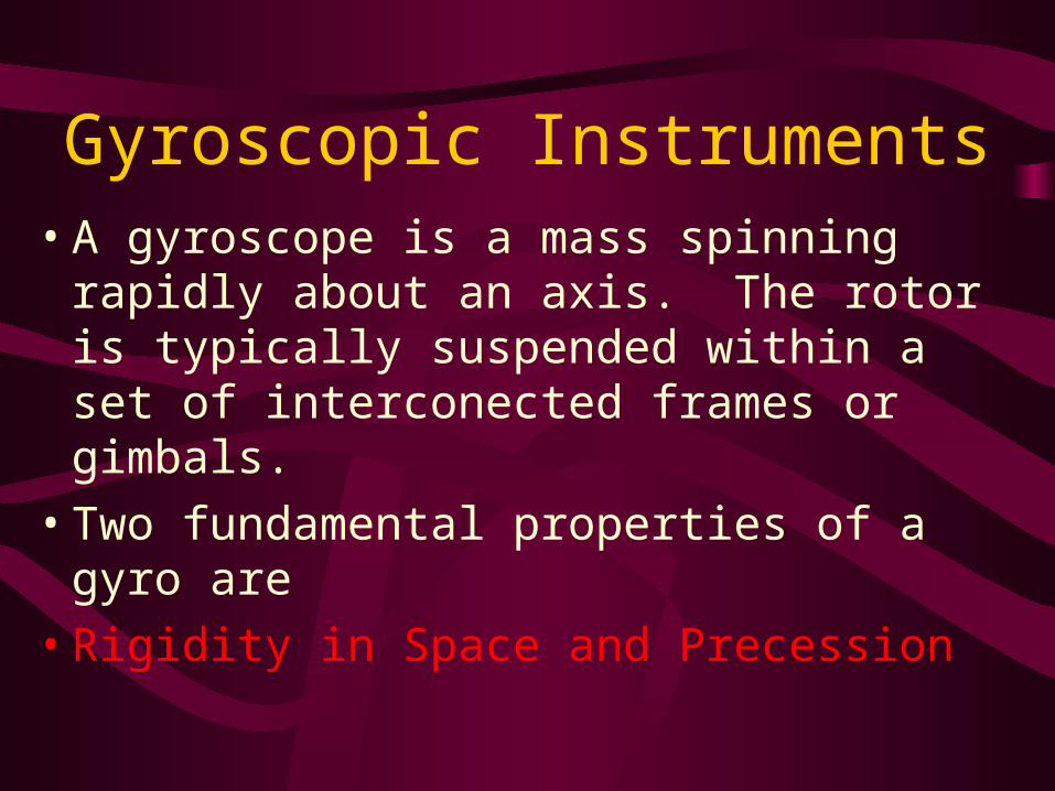
Gyroscopic Instruments• A gyroscope is a mass spinning rapidly
about an axis. The rotor is typically suspended within a set of interconected frames or gimbals.
• Two fundamental properties of a gyro are
• Rigidity in Space and Precession

Rigidity in Space and Precession
• Rigidity in Space = gyroscope will tend to maintain its orientation in space and resist any forces that tend to displace it.

Rigidity in Space and Precession
• Precession = When a gyro is displaced by a force that force acts 90 degrees from the applied force in the direction of rotation.

PRECESSION

PRECESSION
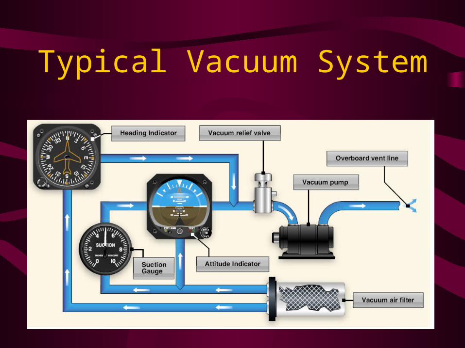
Typical Vacuum System

Attitude Indicator• Provides pilot with attitude indication in
respect to horizon.
• Gives Pitch and bank info; vacuum driven gyro; some are electric or pressure driven
• Gyro is gimbled on 3 axis
• Gyro is mounted with a vertical spin axis
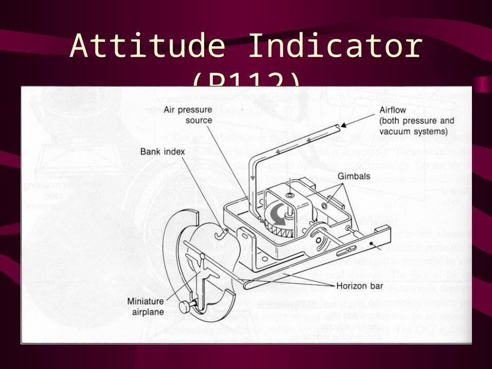
Attitude Indicator (P112)

Attitude Indicator


Attitude Indicator Limitations
• Bank limits 100 to 110 degrees
• Pitch limits 60 to 70 degrees
• If limits are exceeded gyro may tumble and become unreliable.
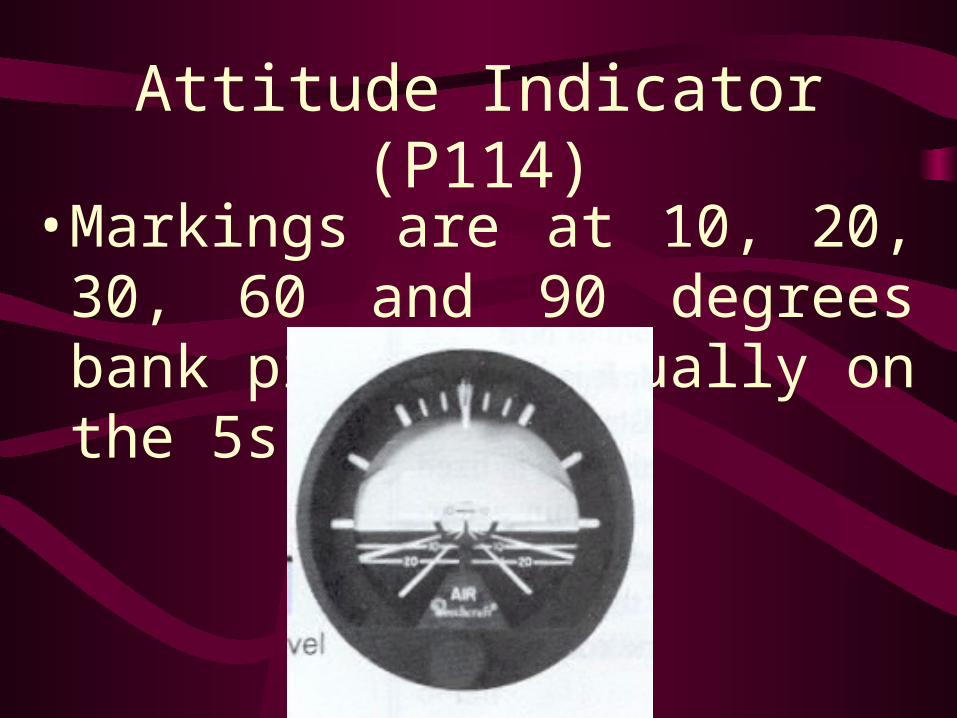
Attitude Indicator (P114)
• Markings are at 10, 20, 30, 60 and 90 degrees bank pitch is usually on the 5s
Heading Indicator
• Directional gyro instrument that is vacuum driven; some are electric; some are pressure driven
• 10,000 to 18,000 rpm
• Pitch and bank limits of about 55 degrees (older ones)

Heading Indicator
• Precession error of no more than 3 degrees in 15 minutes
• Gyro aligned horizontally and remains rigid in space as the azimuth card rotates around it

Heading Indicator (P119)
• Mechansim of the heading indicator


Vacuum Instruments (P120)• Attitude indicator, heading indicator, and
suction guage.
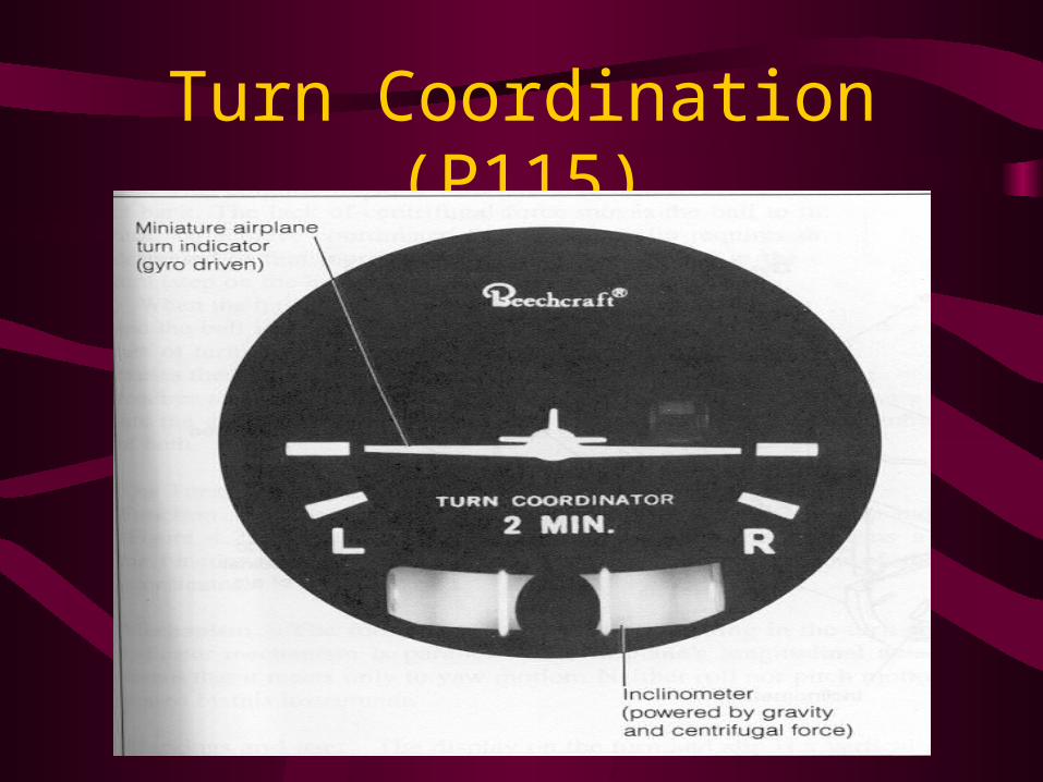
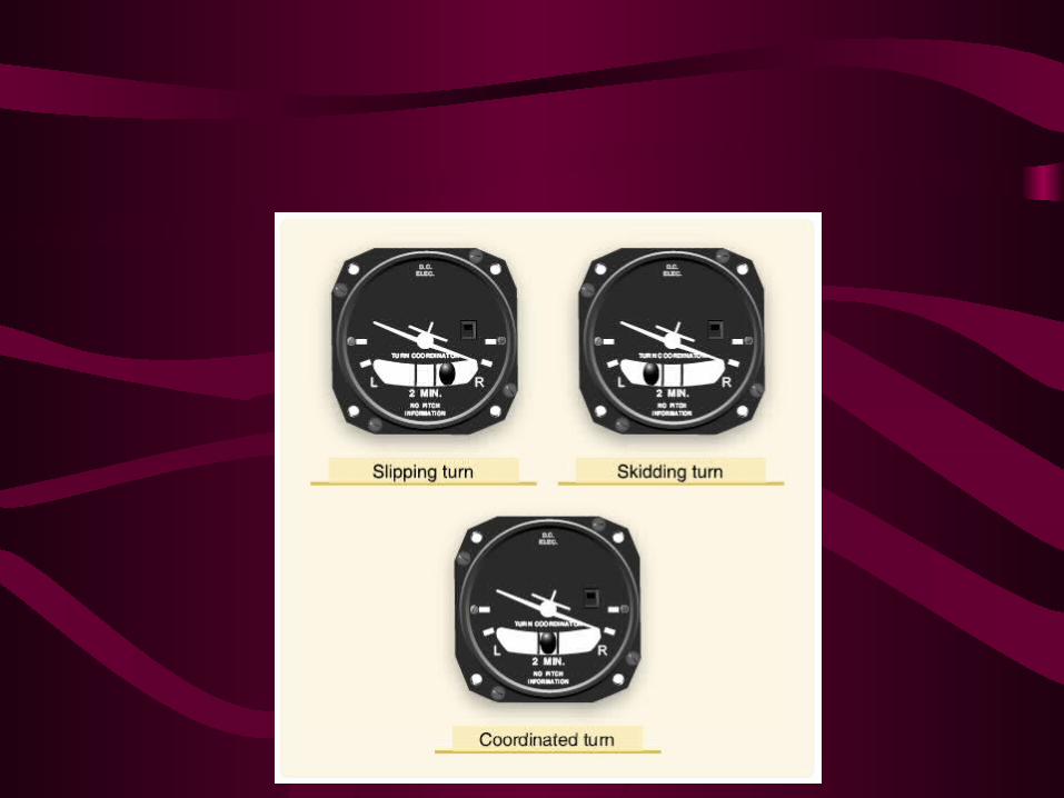
Turn Coordination (P115)

Turn Coordinator/Turn and Slip Indicator• Electric gyro instrument some are vacuum
• All indicate rate of turn in seconds
• A standard rate turn is 3 degrees per second
• A 360 degree turn takes 2 minutes
• Red flag to tell if you have electrical power or not.
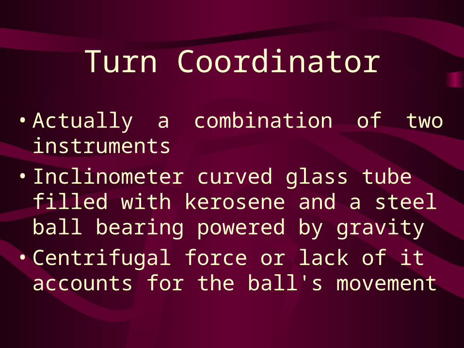
Turn Coordinator
• Actually a combination of two instruments
• Inclinometer curved glass tube filled with kerosene and a steel ball bearing powered by gravity
• Centrifugal force or lack of it accounts for the ball's movement

Turn Coordinator
• Turn coordinator gyro is mounted on a 30 deg angle
• The turn coordinator can sense both rate of roll, rate of turn and yaw
• Displays only rate of roll and rate of turn doesn't directly display bank angle
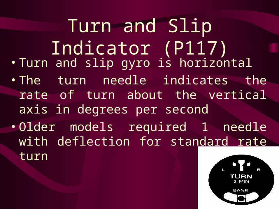
Turn and Slip Indicator (P117)• Turn and slip gyro is horizontal
• The turn needle indicates the rate of turn about the vertical axis in degrees per second
• Older models required 1 needle with deflection for standard rate turn


Magnetic Compass• Two magnetic needles attached to a floating
card inside a sealed case filled with acid free white Kerosene or alcohol (whiskey compass)
• The kerosene supports the card, dampens oscillations, and lubricates the pivot assembly that the card rotates around
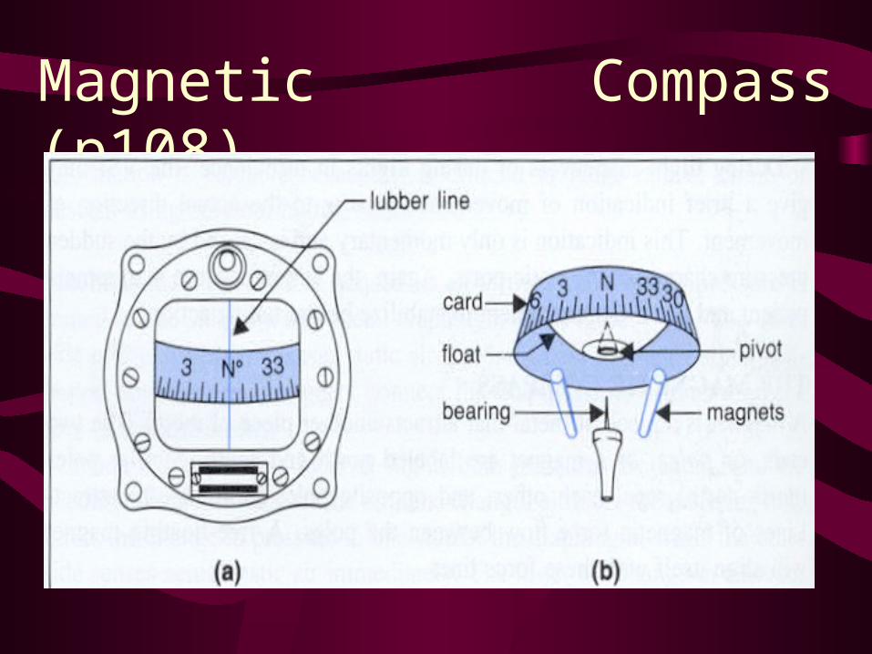
Magnetic Compass (p108)
Magnetic Compass• Lubber line inside the glass face
• Errors
• Variation angular difference between true north and magnetic north
• Deviation the pull of the aircraft's magnetic fields generated by radio and such on the compass card
• Reads opposite heading indicator


UNOS or NOSS
ANDS


Magnetic Compass
• Magnetic dip points downward closer to the poles causes errors
• Closer to the poles magnetic compass becomes unreliable.
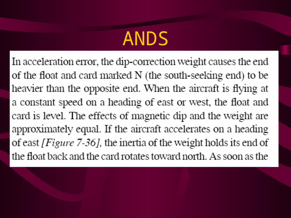
Magnetic Compass Errors• Acceleration-deceleration error - (ANDS) Most
appartent on easterly or westerly headings. If you accelerate in the northern hemisphere causes a dip and indication of a turn to the north. Deceleration turn to south
• Northerly turning error (NOSS) Most pernounced when the aircraft is headed north or south. Turned from a heading of north will initially indicate a turn in the opposite direction. Turn from the South compass will jump ahead and lead

Engine Instruments
• Ammeter
• Oil Temp Guage
• Oil Pressure Guage
• Fuel Pressure
• Fuel Flow
• EGT (exhaust gas temperature)
• Cylinder Head Temperature
• Tachometer
Ammeter
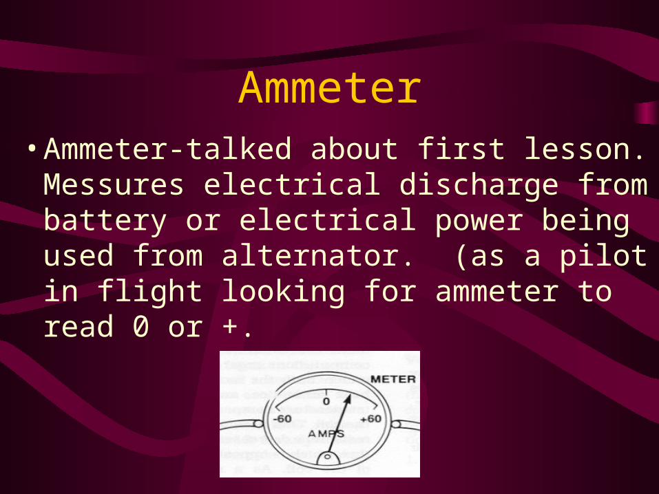
• Ammeter-talked about first lesson. Messures electrical discharge from battery or electrical power being used from alternator. (as a pilot in flight looking for ammeter to read 0 or +.

Oil Temp Guage
• The most common type of oil temperature gage is operated electrically and may utilize either a Wheatstone brige circuit or a ratiometer circuit. (604) (Higher heat greater resistance differential in voltage.) Connected to battery.

Fuel Pressure/Oil Pressure• Typically measure in units of PSI (pounds
per square inch)
• Use a Bourdon Tube design, diaphragm type, or bellows type design (600)
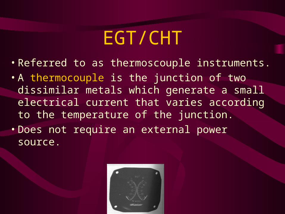
EGT/CHT• Referred to as thermoscouple instruments.
• A thermocouple is the junction of two dissimilar metals which generate a small electrical current that varies according to the temperature of the junction.
• Does not require an external power source.

Tachometer• Primary engine instrument designed to
provide an accurate indication of engine RPM.
• Can be mechanical, magnetic, electronic
• Upper limit of Tach in B-19
• 2700 RPM, red light will come on if you overspeed the prop.

Misc Instruments
• Outside Air Temperature Guage
• Altitude Alerter
• Clock
• Hobbs meter

Basic T arrangement
• Airspeed, Attitude Indicator, Altimeter, Heading Indicator

Inspections and Tests
• Pitot Static Instruments Must be inspected and tested every 24 calendar months for IFR
• Elt every 12 months
• Transponder and encoder every 24 months

Homework• Required VFR instrument
• FAR Part 91.205C
• TOMATO FLAMES• Tach, Oil Temp, Magnetic D.I., Airspeed, Temp
guage for liquid cooled engine, Oil Pressure
guage, Fuel Guage, Landing Gear lights, Altimeter, Manifold Pressure, ELT, Seatbelts
• Night FLAPS-Fuses, Landing light, Anti collision lights, Position lights, Source of Power
Related Documents