-. I I I I I I I 1! 1. 1. 1: 1: 1: [. ., I 1 1. r REPORT OF MONTGOMERY COmTY DEPARTMENT OF PERMITTNG SERVICES STUDY CLARKSBURG TOW CENTER,PHASE lB–PART 3 ~ Clarl<s Crossing Drive, CL Sta. 9+25 to 16+65 ~ Clarl<sburg Square Road, CL Sta. 34+50 to 45+79 Montgomery County, Maryland .~tlgUSt27,200 i Prepared For: Terrabrook Clarksbzirg, L.L.D. CIQ Dss, Inc. P.O. Box 2S7 Clarksbltrg, Maryland 20S71 GTA JobNo.: 99530 Prepa~edBy; Geo-Teckrz o[op Associates, IIIC. 9090 JunctionDrive Suite 9 A]mapolis Junction, ~ 20701 (410) 792-9446 or (301) 470-4470 Facsitile (41 O) 792.7395’

Welcome message from author
This document is posted to help you gain knowledge. Please leave a comment to let me know what you think about it! Share it to your friends and learn new things together.
Transcript
-.
I
II
I
III1!1.1.1:1:
1:[..,I11.
r
REPORT OFMONTGOMERY COmTYDEPARTMENT OF PERMITTNG SERVICES STUDY
CLARKSBURG TOW CENTER,PHASE lB–PART 3~Clarl<s Crossing Drive, CL Sta. 9+25 to 16+65
~ Clarl<sburg Square Road, CL Sta. 34+50 to 45+79Montgomery County, Maryland
.~tlgUSt27,200 i
Prepared For:
Terrabrook Clarksbzirg, L.L.D.CIQDss,Inc.P.O. Box 2S7Clarksbltrg, Maryland 20S71
GTA JobNo.: 99530
Prepa~edBy;
Geo-Teckrz o[op Associates, IIIC.9090 JunctionDriveSuite 9A]mapolis Junction,~ 20701(410) 792-9446 or (301) 470-4470Facsitile (41O) 792.7395’

j
II
IIIII1.
i
I!.,[l..LI1.
GEQ-TECHNOLOGY AssacjATEs, ]Nc,
GEOTECHNICALANDENVIRONMENTAL CONSULTANTS
A Proc/ici)zg ASFElblet?lber,C;r;?/
August 27,2001
Terrabrook Clarksburg, L.L.D
C/O DSS, hC.
P,O. Box 287
Clarksburg, MD 20871
.4ttn: hf~-,Jim Richmond
Re: Clnrksb!irg TotvIl Ce]lter, Pllos& 13 – P(Lrt 3Preljminaw Geotecbrrical Exploration
Montgomery County Department of Pemlitting Services Study
Clarks Crossjng Drive, CL Sta 9+25 to 16+6j;C]arksburg Square Road, CL Sta 34+50 to 4j+79;
Montgome~ ~oLuIty, Maryland
Gentlemen:
Terrabrook intends to develop roaas and utiiities tvithin Phase 1B of the Clarksbnrg TownCenter development in kloutgome~ Ccunty, Marykmd. h conjunction with tl-ie proposedconstruction, Geo-Tecko logy Associates, Inc. (GTA) ptrfonned a subsurface explo.ra lion, i.nc~uding
test borings and test pit excavati ens, and Iahoratory testing of recovered samples.
Thjs report presents GT.4’s c.onc]usions and recommendations regarding utility installation,pavement suppolt and site grading, based on en:ineeling analysis of the field and lahorato~ data.
Subsurface data for a proposed groundwater recharge facility is also included. The exploration wascompleted in accordance with Montgomery County Department of Permitting Services (NfCDPS)criteria, and in accordance with GTA’s proposal dated JLdy 10, 2001.
Proposed Grading
According to Grade Establishment Plans for Clarks Crossing Drive and Clarkshurg Square
Road, dated July 2001, prepared by Charles P, Johnson & Associates, Inc. (CPJ), cuts less than 5 feetand fills up to 22 feet wi~l be required to estzb lish final l-oadway grades. The roadways will beprimarily filled to proposed grades. The maximum fill depth is planned On C]arksburg Square Road
near CL Sta 41+00. Fills Llp to 20 feet will also be reqt~ired in the ligllt.of-way of CiaTksbLlrgCrossing Drive,
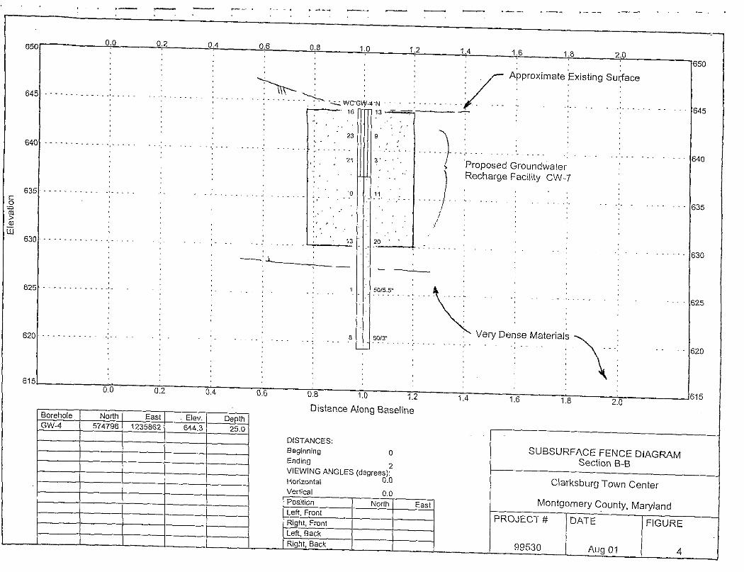
According to the plan entitled Clarksbug Town Center Stomrwater.Mana~ement, Section B,
~, prepared by CPJ, the proposed groundwater recharge facility, designated C\V-7, will requireexcavation up to 14 feet to reach tie proposed jnvert level.
❑ 3445-AEOXHILL CORPORATE CENTER DRIVE, ABINGOON, MO 21009 H 410-515-9446
d 9090 JUNCTION DRIVE, SUITE 9, ANNAPOL15 JUNCTION, MD z0701 .410-792-9446 s FAX 410792.73958 FM 410-515-4895
U 45000 UNDERWOOD LANE, SUITE M, STERLING, VA 20166 = 703-478-0055 ❑ FAX 703478-0137
❑ 5702 INOUSTRY LANE, SUITE A-3, FREDERICK, MD 21701 ~ 301-682-5226 m FM 301-682-9254
018 BOULDEN CIRCLE, SUITE 34, WILMINGTON, DE 19720 ~ 302-326-2100 m FAX 302-326-2399

;
I
,
I
i
I
iI
i
i
I/
i.
1:1’I
\
Terrabrook Clarksburg, L.L,D.
Re: Clarksburg Town Center, Phase IB – Pafl 3
August 27,2001Page 2
Detailed plans of the proposed utility installations and were not available at the date of this”repofl. Boring depths were planned based on estimated invert levels at the boring locations, as
provided by CPJ.
Site Conditions
Clarksburg Town Center is located on the east side of Frederick ‘Road (MD 355) in the
C1arksburg area of Montgorne~ County, Maryland. A Site Location Map is included as Figtlre 1 inAppendix A. The property is bound by Stringtown Road on the south, Frederick Road and Spire
Street on the west; Ciarksburg Road on the north, and Piedmont Road and private property to theeast, Phase 1B is located in the western portion of the property, and will be accessed from existing
Stringtowrr Road.
Phase lB is situated on an open rolling field, with slopes falling gently to moderately towardthe south and west. Approximate elevation above Mean Sea Level (MSLj ranges from 620 feet to670 feet in the area addressed by this submittal.
Geologv
According to the Geologic Map of Mawland (1973), and the Bedrock Map of Nlontgomem-
Countv, NIalVland (1975) the site is located in the Piedmont Physiographic Province. The Piedmontrock formations are generally metamolpllic, >vith younger igneous intrusions. The site is mappedwithin the Ij amsville Formation and the Marburg Schist, predominantly quartzic and muscoviticschists, which generally decompose to sand and silt, with siamificant clay and mica fractions in someinstances, Differential weathelirrg is common, and as a result, the fom]ations are characterized byin-egular rock profiles. The differential weathering is most drmatic where the more durable rock
veins are present within the schistose fomlation. Typical Piedmont rocks weather into saprolite ofvariable thickness, underlain by less weathered ~d then relatively sound rock. Please consult the
referenced geologic publications for further detail.
Subsurface Exploration
This exploration included recently drilled SPT borings and test pits excavated in December of2000, in conjunction with a previous submittal. The borings and test pits were perfomed at the
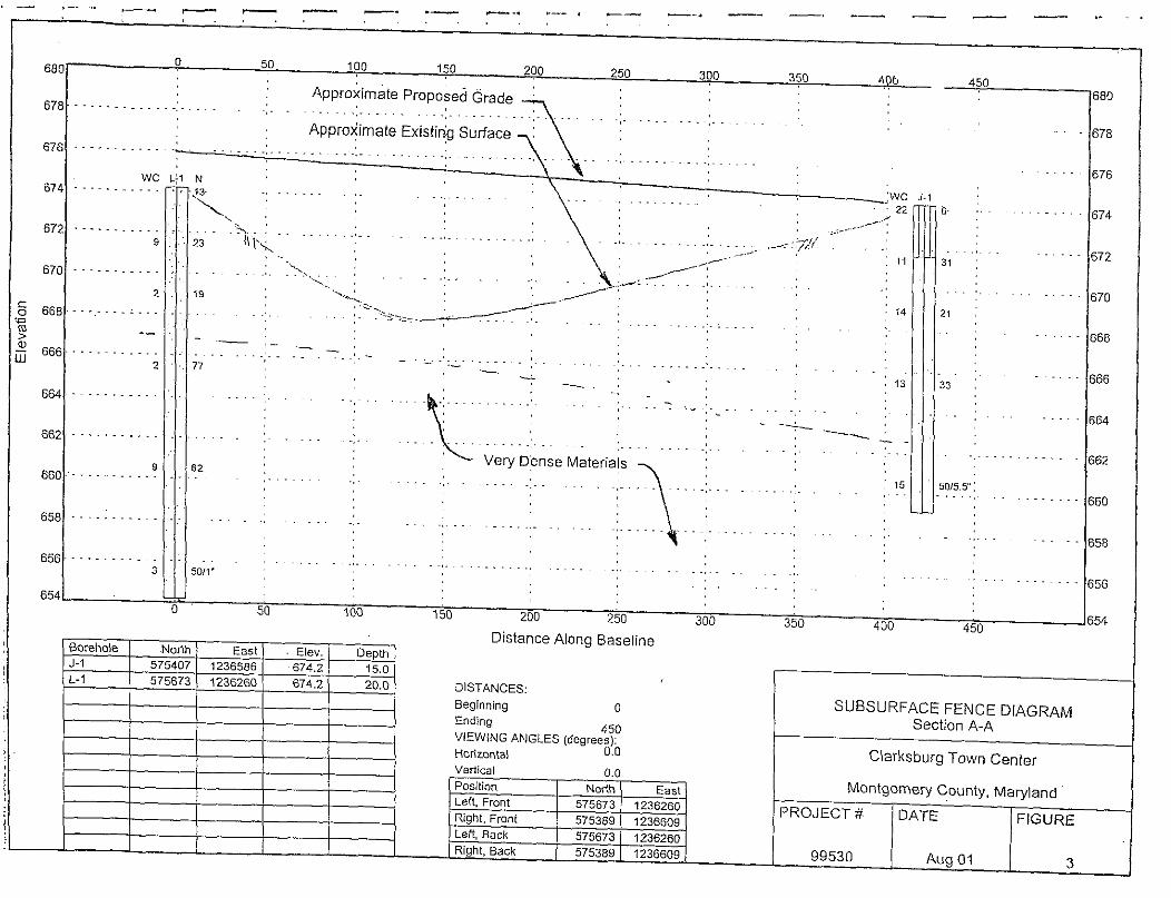
approximate locations indicated on The Test Location Plan, included as Figure 2 in Appendix A.Test Pits TP-4 through TP-7, and Borings L-1, L-2, J-1, and SB-12 were lo~ated in areas ofproposed
roadway and utility construction. Boring GW-4 WaSlocated within the site of proposed ~oundwaterrecharge facility CW-7. The boring and test pit locations were selected by the site civil engineer and
field-located via instrument survey, Due to access constraints caused by recent gading, boring GW-4 was offset approximately 60 feet eastward from the originally planned and staked location,

I Terrabrook Clarksburg, L,L.D,
Re: Clarksburg Town Center, Phase lB – Part 3August 27,2001
I Paqe 4
ISix samples were classified in accordance with the Unified Soil Classification System”
(USCS) and the system used by the American Association of State Highway and Transportationofficials (AASHTO), Five samples were also classified in accordance with the United States
iDepartment of A=ticu]ture (USDA) soil classification system. Two samples were subjected to soil
moisture-density relationship testing in accordance with AASHTO T-99, the Standard Proctor.
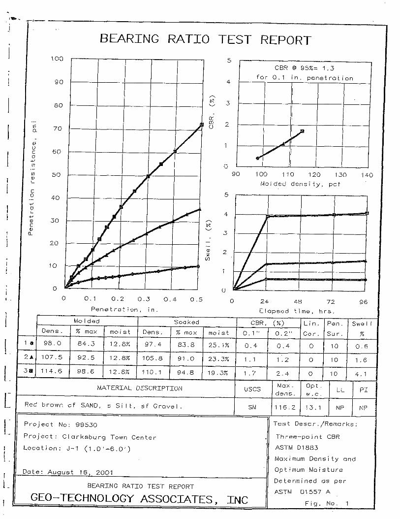
,.4 California Bearing Ratio (CBR) test was perfomed upon the sampIe of USCS SM soil
I from Boring J-1, 1 to 6 feet. The CBR is Llsed to characterize the relative suitability of a soil forroadway support. Results of this testing indicate that a CBR value of 1.3 may be assigned to theUSCS SV1 designated soils present at this location.
The laboratory compaction and classification test data is summarized in Tables A and B.II Please refer to the laboratory test data presented in Appendix B, and the laboratory summary sheet in.
Appendix C for further information.
I! TABLE A
SUMNIARY OF COMPACTION DATA(AASHTO T-99)
I
Boring. .Depth Maximum DV .Optimurn Natural,# “(ft)
MSHTODensity (pcf),: M6i:~ure(Yo) ~ .MOist:ri( Y:) ‘.Cla4siflcati0n
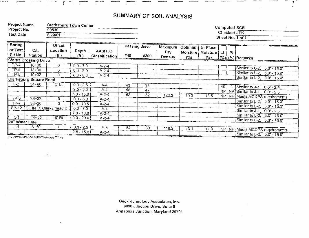
J-1 2.5–6,0 116.2 ?3.1 11.3 A-2-4
r L-2 2.5–5.0 123,2 10.3 13.5 A-4
TABLE BtSUNIMARY OF INDEX PROPERTY TESTINGI
! Boring :Depth Liquid Plasticity .Uriified .USDA
# (ft) Limit .C1.ossificationAASHT.O
Index Classification ‘Class.
1:0.5 – 1.5 40 4
SM, sand and clayey
silt, some gravelA-4
L-2 2.5–4.0 NP* NPSM, sand and silt, little
gravelLoam A-4
~ 5.0 – 6.5 NP NPSM, sand, some silt,
little gravelSandy Loam A-2-4
GW-4 18.5 –20.0 NP NPSM, sand, some silt,
trace gravelSandy Loam A-2-4
0.0 – 1.5 NP NPML, silt, some sand,
Silt Loam. some gravelA-4
J-12.5 – 4,0 NP NP
SM, sand, some silt,Sandy Loam
some gravelA-2-4
‘ Non-Plastic Soil
;
I
I
I
I
I
I
I
I
1.
I.
i.
I
1.
L
1
1.
Terrab~ook Clarksburg, L,L,D,Re: Clarksburg Town Center, Phase lB – Part 3
August 27,2001Page 5
Conclusions nnd Recommendations
Based upon the results of this exploration, it is our opinion that construction of the proposedimprovements is feasible, given that the following recommendations are observed, and that the
standal-d level of care is maintained during construction. GTA’s recommendations are provided inthe following paragraphs.
1. Utilities
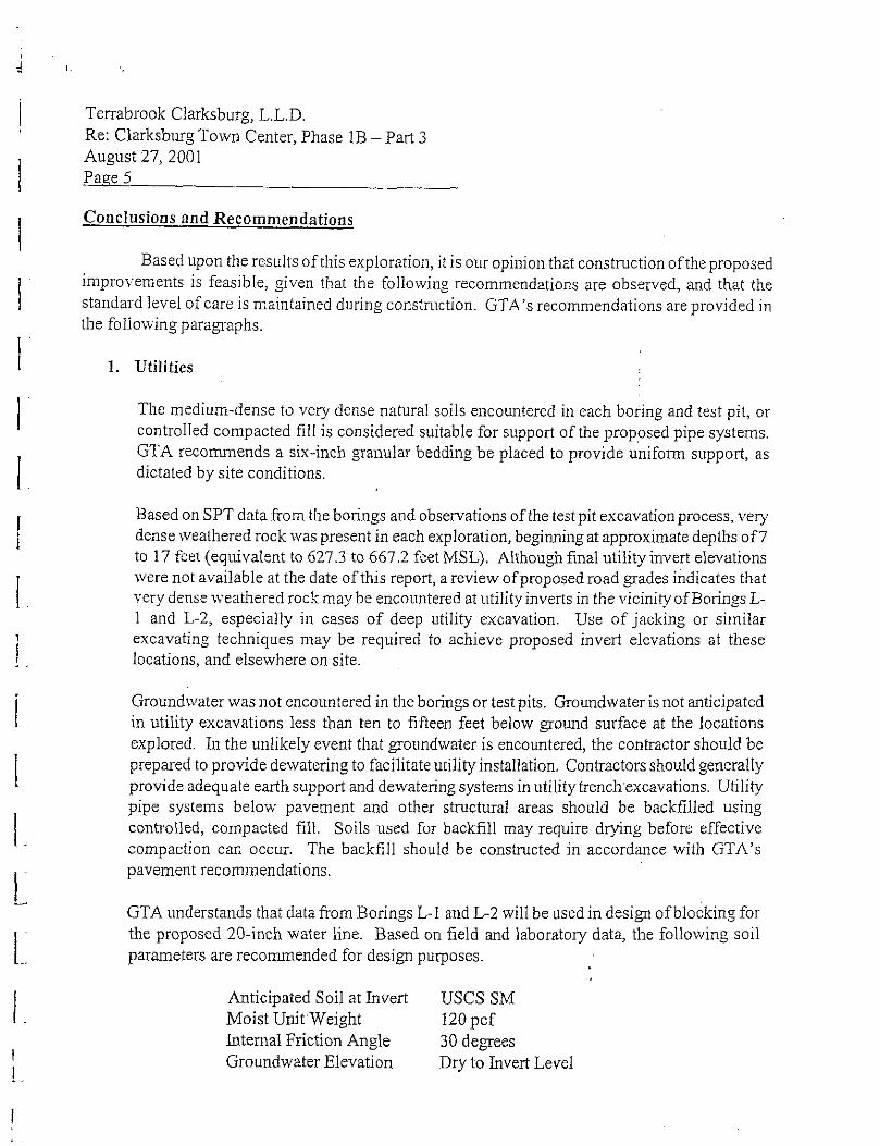
The medium-dense to very dense natural soils encountered in each boring and test pit, orcontrolled compacted fi11is considered suitable for support of the proposed pipe systems.GTA recommends a six-inch granular bedding be placed to provide unifon sL~pport, asdictated by site conditions.
Based on SPT data from the borings and observations of the test pit excavation process, verydense weathered rock \vas present in each exploration, beginning at approximate depths of7to 17 feet (equivalent to 627.3 to 667,2 feet MSL). Although final utility inveti elevationswere not available at the date of this report, a review of proposed road ~ades indicates that
very dense \veathered rock maybe encountered at ~ltility inverts in the vicinity of Borings L-1 and L-2, especially in cases of deep utility excavation. Use of jacking or similarexcavating techniques may be required to achieve proposed invert ele~ations at these
locations, and elsewhere on site.
Groundwater was not encountered in the borings or test pits, Gro~mdwater is not anticipatedin utility excavations less than ten to fifteen feet below ground surface at the locationsexplored. h the unlikely event that groundwater is encountered, the contractor should be
prepared to provide dewatering to facilitate utility installation. Contractors should generallyprovide adequate earth sLIpport and dewatering systems in utility trenchexcavations, Utilitypipe systems below pavement and other structural areas should be backfilled usingcontrolled, compacted fill, Soils used for backfill may require drying before effectivecompaction can occur. The backfill should be constructed in accordance with GTA’s
pavement recommendations.
GTA understands that data from Borings L-1 and L-2 will be used in design of blocking forthe proposed 20-inch water line. Based on field and laboratory data, the following soilparameters are recommended for design purposes.
Anticipated Soil at kvert USCS SMMoist UnitWeight 120 pcf
htemal Friction Angle 30 degreesGroundwater Elevation Dry to hvert Level
I

JI
I
i
I
[
1
1.
1’
I.,
!:
!~’1.
!
1.~“
i.
Terrabrook Clarksburg, L.L.D,Re: Clarksburg Town Center, Phase lB – Part 3
August 27,2001Page 6
2.
3.
Grouudwater Recharge Facility
GTA understands that data from Boring GLV-1 will be used in design of the proposed
~groundwater recharge facility at this loca[ion The Standards and Specifications forhfiltration Practices by the Maryland Department ofNarural Resources correlates USDA soilclassifications with minimum infiltration rates. A minimum infiltration rate of 1,02 inches
per hour is assiamed to the USDA Sandy Loam soils recovered from the boring. GTAcautions that very dense soil conditions below a depth of approximately 17 feet mxy result inmuch slower infiltration rates. Further testing of ill-situ soil conditions, including boreho le
permeability testing, and analysis of the impact on localized groundwater conditions shouldbe performed by”GTA when details of the proposed structure are finalized.
Pavement
Based on the referenced plans, the majority of roadways will be filled to proposed grades.Fill soils generated on site will likely consist of USCS SM and ML soils (AASHTO A-4 andA-2-4), As required by MCDPS, the top 12 inches of subgrade must meet the followingcriteria:
lMaximum density (AASHTO. T-99) 105 pcf minimumLiquid Limit (AASHTO T-89) 40 maximumPlasticity hldex (~SHTO T-90) 12 maximum
Based on the laboratory testing and visual classification of the soils, all soils tested meet
MCDPS plasticity and density requirements for the use in the top 12 inches of subgrade.Similar]y, all of the soils tested are suitable for placement as fill below the upper 12 inches ofsubgrade. Based on GTA’s experience on the Clarksburg Town Center project, some of thenear surface soils namowly meet the above requirements, and care should be taken not to use
materials that are more plastic in the upper 12 inches of subgrade.
Based on boring and laboratory data, and GTA’s experience on projects in Germantown and
Clarksburg, it is likely that the predominantly silty native soils present in the upper two tofive feet at the test locations will have low CBR values. Based on GTA’s experience, it islikely that even where. materials meet MCDPS specifications, treairnent with cement or the
inclusion of a stone base may be required due to low CBR values. Laboratory testing of
USCS SM soil recovered horn Boring J-1,1 to 6 feet, indicates that a CBR value of 1.3 maybe assi~ed to these soils.’ GTA recommends that co~ser soils, such as those that contain a
Terrabrook Clarksburg, L.L,D.
Re: Clarksburg Town Center, Phase 1B – Part 3
August 27,2001
I Pa,qe 7
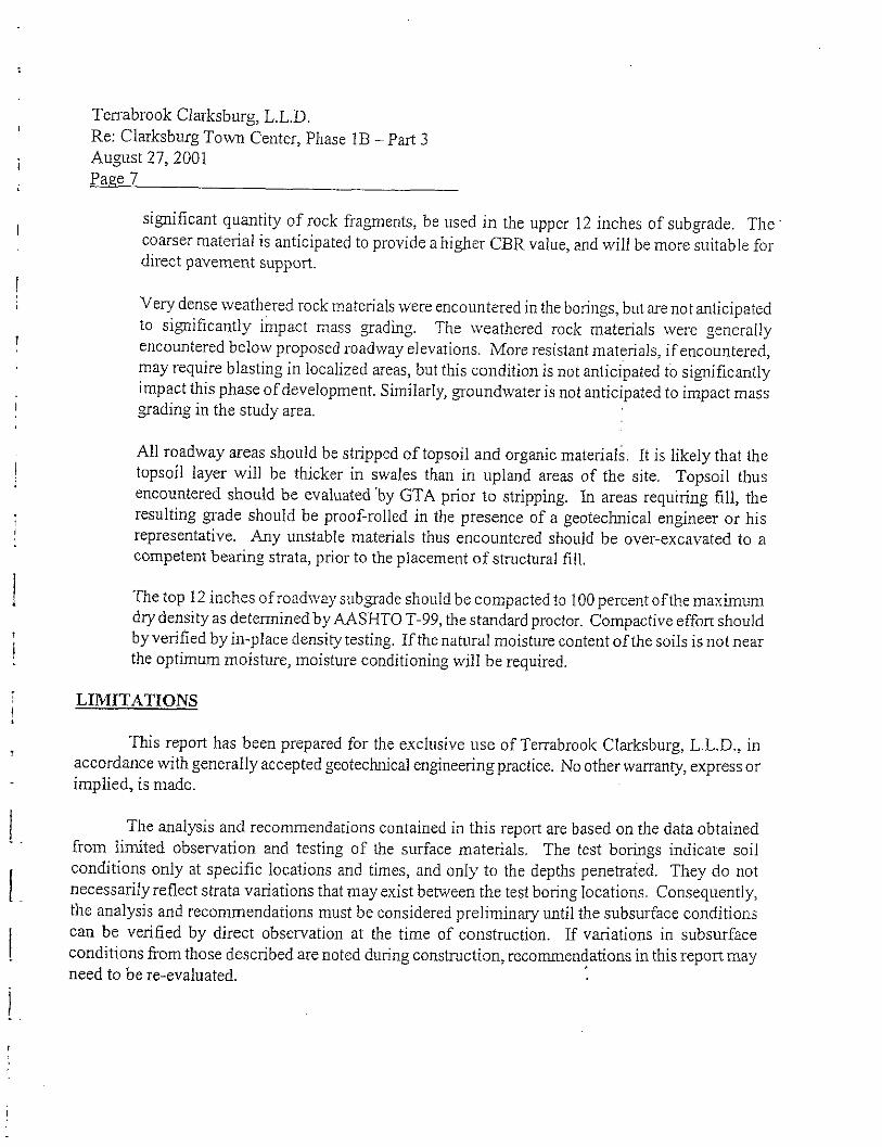
si~ificant quantity of rock fraaments, be used in the upper 12 inches of sub grade. TheI
coarser material is anticipated to provide a higher CBR value, and will be more suitable for
direct pavement support.
Very dense weathered rock materials were encountered in the borings, but are not anticipated
to si~ificantly impact mass grading.1
The weathered rock materials were generallyencountered belo~v proposed roadway e]evations. More resistant materials, if encountered,may require blasting in localized areas, but this condition is not anticipated to significantlyimpact this phase of development. Similarly, groundwater is not anticipated to impact mass
I grading in the study area,
All roadway areas should be stripped of topsoil and organic materials. It is likely that the! topsoi] layer will be thicker in swales than in upland areas of the site. Topsoil thus
encountered should be evaluated ‘by GTA prior to stripping. In areas requiring fill, the
resulting grade should be proof-rolled in the presence of a geotechnical engineer or hisjrepresentative, &y unstable materials thus encountered should be over-excavated to acompetent bearing strata, prior to the placement of structural fill,
! The top 12 inches of roadway sub=ade should be compacted to 100 percent oftl~e maximumdry density as deteminedby AASHTO T-99, the standard proctor, Compactive effon shouldby verified by in-place density testing, If the natural moisture content of the soils is not near
i the optimum moisture, moisture conditioning will be required.
LIMITATIONS1
This report has been prepared for the exclusive use of Terrabrook Clarksburg, L.L. D., in,
accordance with generally accepted geotechnical engineeringpractice. No other warranty, express or
implied, is made.
I The analysis and recommendations contained in this report are based on the data obtained.
from limited observation and testing of the surface materials, The test borings indicate soil
1.
conditions only at specific locations and times, and only to the depths penetrated. They do notnecessarily reflect strata variations that may exist betieen the test boring locations. Consequently,the analysis and recommendations must be considered prelimin~ until the subsurface conditions
{
can be verified by direct observation at the time of construction. If vtiations in subsurfaceconditions from those described are noted during construction, recommendations in this report may
need to be re-evaluated.

!
,I
i
I
I
!
I
1.
1:
1:
[:
1.
[.
I
1.
1.
I
Tel~abrook Clarksburg, L.L,D.Re: Clarksbug Town Center, Phase 1B – Part 3
August 27,2001Page a
h the event that any changes in the nature, design, or location of the facilities are planned, the.conclusions and recommendations contained in this repon should not be considered valid unless the
changes are revie~ved and conclusions of this repofl are verified in writing, Geo-TechologyAssociates, kc, is not responsible for any claims, damages, or liability associated with interpretation
of subsurface data or reuse of the subsurface data or engineering analysis witiout the express writtenauthorization of Geo-Teckology Associates, hrc.
h accordance with the ~~idelines of ASFE/The Association of Engineering firms Practicingin the Geosciences, it is recommended that Geo-Techology Associates, hc. be retained to providecontinuous soils engineering services for this project. Participation of’ GTA will facilitate
compliance with GTA’s recommendations, and allow changes to be made in these recommendations,in the event that subsurface conditions are found to vary from those anticipated prior to the start ofconstruction.
This report and the attached logs are instruments of service, Hcertain conditions or items arenoted during our investigation, Gee-Technology Associates, hc, may be required by prevailingstatutes to notify and provide information to regulatory or enforcement agencies. Gee-TechnologyAssociates, h]c. will notify our Client should a required disclosure condition exist.
This report was prepared by Gee-Technology Associates, Inc. (GTA) for the sole andexclusive use of Gee-Technology Associates, hLc, and Terrabrook Clarksburg, L,L.D. Use andreproduction of this report by any other pel-son without the expressed written permission of GTA andTemabrook Clarksburg, L.L.D. is UUaLlthOriZedand sLLchuse is at the sole risk of the user.
Thank ~OLlfor the oppo~unity to be of assistance on this project, If you have any questionsor need fLlrther information, please do not hesitate to call our office.
Sincerely,GEO-TEC~OLOGY ASSOCWTES, NC
S,LIOB-FILEM ch nClarkb.rg TC-99530\cl,rk2 bmcd(re,).doc1.0.99530
I
i
Geotechnical Services Are Pe~foymed forSpecific Purposes, Persons, and ProjectsGeotechnical engineers structure their services to meet the spe-
cific needs of their clients, A geotechnical engineering study con-
ducted for a civil engineer may not fulrTll the needs of a construc-
tion contractor or even another civil engineer. Because each geot-
echnical engineering study is unique, each geotechnical engi-
neering report is unique, prepared sole~ for the client. No one
except you should rely on your geotechnical engineering report
without first corrferfiflg with the geotechnical engineer who pre-
pared it. And no onenot even you+hould apply the report for
any purpose or project except the one originally contemplated,
A Beofechnical Enginee~ingReport 1sBased onR unique Set of Project-SDecific FactorsGeotechnical engineers consider a number of unique, project.spe.
cific factors when establishing the scope of a study. Typical factors
include: the cflen~s goals, objectives, and risk management pref-
erences; the general nature of the structure involved, its size, and
configuration; the location of the structure on the site; and other
planned or existing site improvements, such as access roads,
parting lots, and underground utilities. Unless the geotechnical
engineer who conducted the study specifically indicates other-
wise, do not rely on a geotechn;cal engineering report that was:
e flOt preQared for you,
e not prepared for your project,
e not prepared for the specific site explored, or
o completed before important project changes were made.
Typical changes that can erode the reliability of an existinggeotechnical engineering report include those that affect:
o the function of the prOpOsed structure, as when
i~s changed from a parking garage to an office
building, or from a light industrial plant to a
refrigerated warehouse,
e elevation, configuration, location, orientation, or
weight of the proposed structure,
e composition of the design team, or
n project ownership,
As a general rule, aAvays inform your geotechnica[ engineer
of project changes+ven mirror ones+nd request an
assessment of their impact. Geotechnical engineers cannotaccept responsibil;fy or liability for problems that occurbecause their reports do not consider developments of whichthey were not ;nformed.
Subsurface ConWtions Can ChangeA geotechnical engineering report is based on conditions that
existed at the time the study was performed. DOnot re&on ageotechnical engineering report whose adequacy may hwe
been affected by: the passage of time; by man-made events,
such as construction on or adjacent to the site; or by natural
events, such as floods, earthquakes, or groundwater fluctua-
tions. Always contact the geotechnical engineer before apply-
ing the report to determine if it is’still reliable. A minor amount
of additional testing or analysis could prevent major problems.
Most Geotechnical Fin~ngs ApeProfessional OpinionsSte exploration identifies subsurface conditions on~ at those
points where subsurface tests are conducted or samples are
taken. Geotechnical engineers review field and laboratory data
and then apply their professional judgment to render an opinion
about subsurface conditions throughout’ the site. Actual sub
surface conditions may differ-sometimes significantly-from
those indicated in your report. Retaining the geotechnical engi-
neer who developed your report to provide construction obser-
vation is the most effective method of managing the flsks asso
ciated with unarzticiuated conditions.
J

I
III
I
I
II1.
1:1:
I
L1:
i.
APPENDIXA
FIGURES

1.1:
1,
——
NBase map obtained from MAPTECH TERRAIN NAVIGATOR CD-ROM
USGS 7.5-Minute Seties (Topographic)
Germantown Quadrangle, Ma~land
1953, Photorevised 1979
-, . GEO-TECHNOLOGY ASSOCIATES, INC. Clarksburg Town Center~ti,w GEOTECHNICAL ANO ENVIRONMENTAL CONSULTANTS~w.m 9090 Junction Drive, Suite g
w
Annapolis Junction, MD 20701 SITE LOCATION MAP
Ph. (41 O) 792-9446 or (301) 470-4470 MONTGOMERY COUNTY,Fax (41 O) 792-7395 MARYLAND
I No: DATE: SCALE REVIEWED FIGURE‘R*WN ‘y” BY: NO:
;30
1~August 20,2001 Not to Scale SCR JPK 1

,:., /._
,’
.,. .
,
Figure >
L’s ‘??:::
~: APPROXIMATE BORING LOCATION - PERFORMED JUL
q: APPROXIMATE TEST PIT LOCATION - PERFORMED DE
1. BASEMAP DEVELOPMENT FROM ASITEPUNPROVI
THETESTBORINGS ANDTESTPITSWERE FIELD-LO(;NBy\TASHOULD BECONSIDEREO ACCURATE ONLY TOTHE
.- ,—. - ,__ ——— —..— —.. ._, _____ __, _ —— —..,., , .
; 666 ..-
664 ---
662 ---
650 ,.. .
2
...91658 ----------
658 ----------
Borellole Noflh East Elev. I DepthJ-1 575407 1236586 674.2 I 15.0L-1 575673 1236260 674.2 I 20.0
450
~660678
--- 676
1.1 :
~
6 ~~~ 674
31 : 672
:. .,, .,670
21
- 668
‘“33’ ; - 666
6 64
6 62
50/5.5:,.. ------6 60
‘-6 58
,. :.. --- 656
150 200 250 300 350 400 450654
Distance Along Baseline
DISTANCES:Beginning o SUBSURFACE FENCE DIAGRAM
SecfiOn A-A
Clarksburg Town Center
Montgomery County, Maryland
PROJECT # DATE FIGURE
Enting450
VIEWING ANGLES (degrees):HOfiZOntaI 0.0
verticalPosition
0.0Notih East
Lefl, Front 575673 1236260Rght, Front 575389 123660gLen, Back 575673 1236260
1 ) I I Nght, eack 575389 1236609 99530 Aug 01 3
,,, — _— _.. . . .._ ,h -.+_. __ _ .— —.. _. .. .. .. . ... _. . .,.
—
645 - . . -- . . . . . . . . . .. . . . . .. .
640 . . . . . . . . . .
635 . . . . . . . . . .
I I
.,
,-
,.
,-
.,.:“,. ’2:,.. .
,, .. . . . ..-,,,. .,,., ,,,,;:,.’,..,., 2
—, L,—
,.. 1.,.
8
Approximate Existing Sufiace
. . . . . . . . .
‘proposed Groundwater
Recharge Facility CW.7
:.. . ...
6501 0,0 0.2 0.4 0.6 0.8 1.0 1.2 1.4 1.6 1.8 2.0
%< ;: :
- WC ~.4 N .[ ,.
:,-[”
18 ,3~ —-
.’, .9“.
, ... . .. .. . .“.. ,.
~.,
.71’:.,.
,’~o. ,.—
50/5.s :
y50/3,, : ~ Very Dense Matetials
,- .: .-,
\“6150.0 0.2 0.4 0.6 0.0 1,0 1.2 1.4 1.6 1.8 2.0
Boreho[e NotihDistance Along Baseline
East Elev.Gw-4
Depth574798 1235862 644.3 25.0
015TANCES:Begin”i.g oEndl”gVIEWING ANGLES (de~rees)2Horizontal 0.0
Vertical 0,0Position North EastLeft, FrontRght, Fro”tLefl, sackRight, 6ack
:50
45
40
35
30
:5
?0
15
—
SUBSURFACE FENCE DIAGRAMSection B.B
Clarksburg Town Center
Montgomery County, Ma~land
~

,—--— ~.. — —_ _ -—. — __ —._ ____ __ ._. ,
.-
>1
;i
665 ---
680 ---
675 ---
~7~
665 .-.
660 --
655 ---
650 --
645 ---
690 0 100 200 300 400 500 600 700 800 900 1,000‘ 690
685
,.
,..
:----- .--: ---- -. !....
““+”’””’Approxjmate Existihg Sutiace
,.. . . ,. .,., . .:, . . . . . ., .:.
680
,. .-. ,-.
“3”;*?:.’””” ““:”””””” ‘“!” ‘“ -:”” “’””i-~’:~~gsq’iROafi L
675
:~:...:g...g “
G70.,
.---! 4,. ,22------. : -, -.. . . . . . . . . . . . / ,:
//
:. ..,.. . . . . . . . ...
/[
,.266521 41
,.~ ;:. -.\.\ . . . . . . . .; ..,: ..:. . . ../. +...... ;. . :7 .’ 75
;\: : 4, ;,4j:..,
,x
<.....’’:::;’
660
\
. . . . . . . . . . ,., ..,.,50/? :
{’ (~.:\, ; ,. /. .;...
/ ‘“’655
~:
\;/“ :
&csB.,z N : ),. . ..x . . . . . .;. .
.,
‘“””’:124.” ~~~ ,
~1--:.l.:.650
Very Dense Mater;a[s
““ 3
‘\: :1.. .: . . . ..: . . . . .../ . ...2. .. 2:.<:’. ., :
‘\. ;~,//,:, : j
645
6401 ., 501Y ;o 100
,,.200 300 400 500 $00 700 800 900 1,000
640
Distance Along BaselineBorehole Nofih East Elev.L-1
Deplh575673 1236260 674.2
L-220,0
575131 1235469 667.6 i 5.0 DISTANCES:SB-12 575498 1236110 650.7
)$0.0 Begi””ing o
Ending
VIEWING ANGLES (degrei~HorizontalVetica)
m
L
N:-. -<.....<3 :
23:
19
r?.: . . . .. ,,, ,
.. . .. . . . . . . . . .
iO/i! . . . . . . . . .
.. . . . . .
SUBSURFACE FENCE DIAGRAM
Section C.G
Clarksburg Town Center
99530 Aug 01 5

,—— — __-———— ————— —— —.-. . . . .
665
660 ---------
655 --------
650 . . . . . . . .
3
~ 645 ---------~u
640 ----------
635 ---
I630 --------
625 ----------
620 ----------
615~
:\..,\, :: .,, :,.
.. . :
‘“i..
:“” ”.-
.. . . . . . . .
}1 I I
m:.
,.:.. . . . . . ....>. . . . . . .,
- 670
665
--- 660
- 655
650
,. 645
---- 640
~~ 635
-6 30
6 25
- 620
1 300 350 400 450 500 550 600}615
ulstance Along Baseline
DISTANCES:
Ven{calP0si60” bLeft, FrontWght, Front
.—— Left, BackRigl>t, Back 01 1610 99530 Aug 23, 2001 6
Stegin”ing o SUBSURFACE FENCE DIAGRAMEnding Clarks Crossing DriveVIEWING ANGLEs (degre~s~OHorizontal 0.0 Clarksburg Town Center
0.0
=
Notih East Montgomery County, Maryland——: 1010 PROJECT #
1610DATE FIGURE
–0 1010
r - — ‘– - - -- - ‘“” ‘“ ‘“— ‘-’ ““-- “
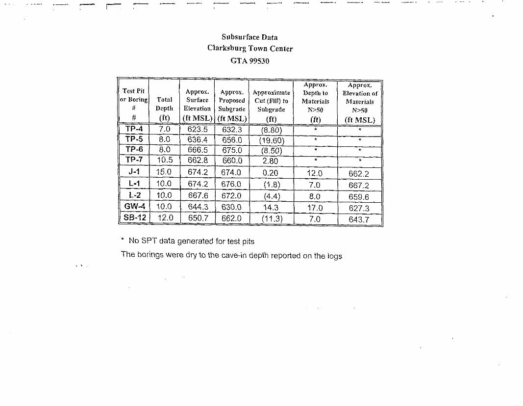
Subsurface Data
Clnrksburg Town Center
GTA 99530
Approx, Approx.Test Pit Approx. ApProx. Approxin\ate Depth to Elevation of
or Boring Total Surface Proposed Cut (Fill) to Materials# Depth
NfaterialsElevation Subgradt Subgrade N>50
#
N>50
(ft) (ft MSL) (ft MSL) (ft) (ft) (ft MSL)TP4 7.0 623,5 632.3 (8.80) * *TP-5 8.0 636.4 656.0 (19.60) * *TP-6 8.0 666.5 675.0 (8,50) * *TP-7 10.5 662.8 660.0 2.80 .’ *
J-1 15.0 674.2 674.0 0.20 12.0 662,2
L-1 10.0 674.2 676,0 (1 .8) 7.0 667.2
L-2 10.0 667.6 672.0 (4.4) 8.0 659.6
GW4 10.0 644.3 630.0 14.3 17.0 627.3S6-12 12.0 650.7 662.0 (11.3) 7.0 643.7
‘ No SPT data generated for test pits
The borings were d~ to the cave;n depth reported on the logs

I
I
/.
[-
I
APPENDIXB
SO!LBORINGLOGS

i
I
i
i
I
!.~
I
1.1.[:!.
FIELD CLASSIFiCATION SYSTEMFOR SOIL EXPLOMTION
NON COHESIVE SOILS(Wit, Sand, Gravel and Combinations)
u Patilcle S{ze IdentificationVery Loose -5 blows/ft. or less Boulders -a-inch diameter or moreLoose -6 to 10 blowslft Cobbles -3- to a-inch diameterMedium Dense -11 to 30 blows/ft. Gravel - Coarse -1 to 3 inchDense -31 to 50 biows/ft. - Medium -112 to 1 inchVe~ Oense -51 blows/fi. or more - Hne - 1/4 to 1/2 inch
Sand - Coarse - 0.6mm to 1/4 inchRelative Proportions - Medium -0.2 mm to 0.6 mmDescriptive Term Percent - fine -0.05 mm to 0.2 mmTrace 1-1o -0.06 mm to 0.002 mmbttle 11-20Some 21-35And 36-50
COHESIVE SOILS(Clay and Silt Combinations)
Consistency ~Very Soft -3 blow/ft. Degree of,Sofl
Plasticity- ~ to 5 blows/fi, ~
Medium StiffIndex
-6 to 10 blows/fl. None to slightstiff
o-4-11 to 15 blows/ft Slight 5-7
Very Stiff -16 to 30 biows/ft. MediumHard
8-50-31 blows/ft. or more High to Ve~ High Over 50
Classification on logs ara made by visual inspection.
Standard Penetration Test - Driving a 2.0’ O. D., 1 3/8 I.D., sampler a distance of one foot into
undisturbed soi( with a 140-pound hammer free fa{hng a distance of 30 inches. It is customa~ to dtive
the spoon 6 inches to seat into undisturbed soil, then peflorm the test. The number of hammer blows forseating the spoon and making the tests are recorded for each 6 inches of penetration on the drill log. Thestandard penetration test results can be obtained by adding at last two figures,
Strata Chanqes [n the column “Soil Descriptions” on the dflll log, the horizontal fines represent
approximate strata changes.
Groundwater observations were made at the times indicated. Porosity of soil strata, weather conditions,site topography, etc. may cause changes in the water levels indicated on the logs.
Graphic Legend:

PROJECTPROJECT NO
(PROJECT LOCATION
OATE STARTED:
I OATE COMPLETED[ DRILLING CONTRACTOR:
DR
I
!I
i
i
l..1.[.:
DRILLER:NG METHOD:Vc :THOD:
— —
LOG OF BORING NO. TP-4
Clarksburg Town Center99530Montgomery County, Ma~land
WATER LEVEL: ~ DW
OATE: 12/05/00
CAVED (ft):
Sheet.1 of 1
Y Y.-— -——.
-
December 5,2000 GROUNDSURFACEELEVATION: 623.5December 5, 2000 OATUM: MSL
est Pit?st Pit
I
—
EQUIPMENT: BackhoeLOGGEO BY S. Cutter
CHECKED BY: P. K1.ima
DESCRIPTION REMARKS
Topsoil.
Brown, Silty Sand kvith Gravel,
AASHTO: A-2-4
Bottom of Hole at 7.0 ft.
Backfilled Upon Completion.
Location: Clarksburg Crossing Dtive, CL Sta, 16+00
Proposed Finish Elevation: 632.3
Waler NotEncountered
ordinates:
0.0
1600.0
‘=9“:~1 GEO-TECHNOLOGYLOG OF BORING NO. TP4
-,. .. –,.
>2
PROJECTPROJECT NO:
“iPROJECT LOCATION
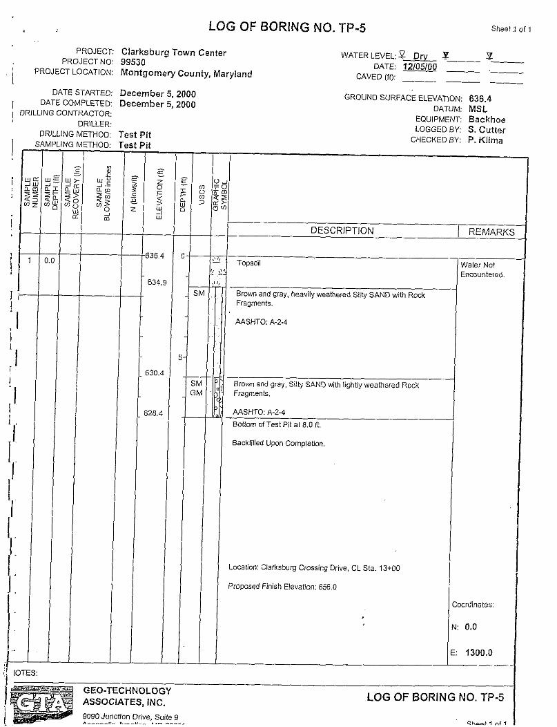
LOG OF BORING NO. TP-5 Slleet ~ of i
Clarksburg Town Center V/ATER LEVEL: ~ DW ~99530
Y
DATE: 12/05/00-—
MontgomeW County, Maryland CAVEO (ft):.—
—.
i
:1:1
‘i,.1.
IOTES:
‘tt
,I
t1
—
j36
631
j30
DATE STARTED: December 5, 2000GRoUND SURFACEELEVATION: 636.4
I DATECOMPLETED. December 5,2000DATUM: MSL
/ DRILLING CONTP&CTOR:
DRILLER:DRILLING METHOD:
j—5THOD:
/:
:.i: u:
J .–
~: ~~
0:
i
1
II
,1
628.
L
EQUIPMENT: BackhoeLOGGEO BY S, Cutter
CHECKED BY: P. Klima
$ :2~ 2Z2 g&
DESCRIPTION REMARKS—
—i Topsoil
Brown and gray, heavily weathered Slty SAND with RockFragments,
AASHTO A-2.4
Brohv” and gray, SIV SAND with lightly weathered RockFragmen1s
AASHTO: A-24
Bottom of Test Rt at 8.0 ff.
Backfilled Upon Completion.
Location: Clarksburg Crossing Drive, CL Sta. i 3+OO
Proposed finish Elevaflon: 656.0
Ualer Not~ncountered.
zrdinaies:
0.0
1300.0
. *=*-’m’*;&~ GEO-TECHNOLOGY_ ASSOCIATES, INC. LOG OF BORING NO. TP-5
9090 Junction Drive, Suite gA--.._,:. ,..--,:—. . .. . . . . . . . . . . 4 ., ,

.,
PROJECTPROJECT NO:
PROJECT LOCATION:
DATE STARTED:DATE COMPLETEO:
LOG OF BORING NO. TP-6 Sheet i of 1
Clarksburg Town Center WATER LEVEL: YQ ~ Y99530
— -—DATE: 12/05/00
Montgome~ County, MaWland CAVED (ft) — — _
December 5,2000 GROUNO SURFACE ELEVATION: 666.5December 5, 2000 DATUM: MSL
DRILLING CONTRACTOR:
tt
—
j66.:
665
j62.5
;58,5
EQUIPMENT: BackhoeLOGGED BY. S. Cutter
CHECKED BY: P. Kljma
DESCRIPTION REMARKS
Topsoil.
Brow”, Silty SAND.
AASHTO: A.2.4
Brown and gray, Silty SAND with tightly weathered RockFragments.
AASHTO: A-2-4
Bottom of Test Pit at 8.0 ft.
Backfilled Upon Completion.
Loca$on: CL ln~ Clarksburg Crossing Dfive and ClarksburgSquare Road
Hnish ElevaOon:675.0
Eocounte fed
)or~na [es:
0.0
1010,0
LOG OF BORING NO. TP-6
-,, ... .

J;”PROJECT:
PROJECT NO:! PROJECT LOCATION:I
DATE STARTED:
i
DATE COMPLETED:DRILLING CONTRACTOR:
DRILLER:DRILLING METHOD:
—
TEs:
3THOD:
LOG OF BORING NO. TP-7
Ciarksburg Town Center99530Montgomery County, Ma~Iand
December 5,2000December 5, 2000
Test PitTest Pit
-662,
.661
652.:
—
WATER LEVEL ~ Drv
DATE: 12/05/00
CAVED (ft):
Sheet I.of i
x Y— -—— ._
——
GROUND SURFACE ELEVATION: 662.8
DATUM: MSL
EQUIPMENT: BackhoeLOGGED BY; S. Cutter
CHECKED BY P. Klima
I
~
Red to brown, Silty ROCK FRAGMENTS and SAND.,
WSHTO : A-2-4 I A-1-b
Bottom of Tesi Pit al 10.5 ft.
Backfilled UOonCompletion.
Location Clark$burg Square Road, CL Sta. 38+30
Proposed finish Elevalion: 66o.o
‘EO”TECHNOLOGYASSOCIATES, INC.
9090 Junction Drive, Suite 9
Water NotEncountered.
ordinates:
LOG OF BORING NO. TP-7
. . . .. . . . .
—

I ,,
PROJECT:PROJECT NO:
I PROJECT LOCATION:
OATE STARTEO:
I
DATE COMPLETED:ORILLING CONTRACTOR:
DRILLER:ORILLING METHOO:
I
I
I
i
I
I
I
II1I!
I
1
1.
1
LOG OF BORING NO. GW-4
Clarksburg Town Center99530Montgome~ County, Maryland
August 3,2001August 3, 2001Gee-Technology Associates, Inc.Gee-Technology Associates, Inc.HSA
SAMPLING METHOO: Split Spoon
@
=: ~.
y% yg52 ~: e :2 ;&mLELy $~ ;
~$? :k ~g .
n% : #
1 0.0 6 4.6-7,3 644,2
3.4-5
2-1-2
4-5-s
7*.14
50/59
4-38.50/3
33
637.
T—
>—
z—
G—
—
619.3
Sheet 1.of 1
WATER LEVEL: ~ Drv ~ DW y
OATE: 08/03/01 08/06/01
CAVED (R) 17.0 17.5
GROUND SURFACE ELEVATION: 644.3
OATUM: MSLEQUIPMENT 6-61
LOGGEO BY: TC/DKCHECKEO BY S. Rowe
UA~g
$?Jm
DESCRIPTION REMARKS
~
Red-brown, mo[at, medium dense to vey loose, Clayey SILTand coarse to fine SAND, little Rock Fragments. (Possible Hll)
1AASHTO: A4
I erOwn to gmy-brown, moist, medium dense to ve~ dense,medium to fine SAND, some Silt, fitfle mefl”m to fine RockFragmenb.
MSHTO: A-2.4
USDA Sandy Loam
Bottom of Hole at 25.0 R,
Topsoil: Oin.
Water NotEnmuntered WtiDrilling.
<
>ortinates:
574798.0
1235862.0
I
.0 ‘w=?.-? GEO-TECHNOLOGY~; - ASSOCIATES, INC.
LOG OF BORING NO. GW-4
9090 Junction Drive, Suite 9——.,. .. —–.. -------- C..., 4 nf 1

!., ,,.PROJECT:
PROJECT NO:
IPROJECT LOCATION:
LOG OF BORING NO. J-f Sheet I. of 1
Clarksburg Town Center WATER LEVEL: ~ DW ~ DN ~99530 OATE: 08/03/01 08/06/01Montgome~ County, Ma~Iand CAVED (ft): ~ 10.5
DATE STARTEO:1 DATE COMPLETED:
DRILLING CONTRACTOR:
DRILLER:DRILLING METHOD:
—
I
I1.I
II1:
1:1:l.:1I,–!‘Q@—.-! NOTES:
August 3,2001 GROUNO SURFACE ELEVATION: 674.2August 3,2001 DATUM: MSLGee-Technology Associates, Inc. EQUIPMENT: B-61Gee-Technology Associates, Inc. LOGGED BY TC/DKHSA CHECKED BY: S. Rowe
MPLING METHOD: Split Spoon
F :.= . : _Wg u> u: @
F E2~ <~ 2’; g:~ :g~ $g $ ~ ~
a Oz . 0i K
!
————
;—
9-13-?
7-10-1
7.,2.2,
12-50/5,5
!674
“ 67
DESCRIPTION REMAXKS
Brow”, moist, loose, SILT, some coarse to fine Sand, some fitRock Fragme”b.
mAASHTO A-4Red-brown, moist, metium dense to vev dense, coarse to O“+
, SANO, some Silt, some fine Rock Fragmenk.
AASHTO: A-2-4
eottom of Hole at 15.0 ft.
Boring Location: 20, WAT Line, Sta. 6+30
Topsoil: in.
Waler NotEncountered WhOtilRng.
Bag Sample: 1.05,0n.
]ordina! es:
575407.0
1236586.0
GEO-TECHNOLOGYASSOCIATES, INC.
9090 Junction Drive, Suite 9A...._,:- ,... . .. . . .. . . . .
LOG OF BORING NO. J-f
c.--, 4.’ ,

J ‘ PROJECT
IPRoJECT NO
PROJECT LOCATION
LOG OF BORING NO. L-q
Clarksburg Town Center
99530
Montgome~ County, Ma~land
OATE STARTED: August 3,2001DATE COMPLETED August 3,2001
ORILLING CONTRACTOR: Gee-Technology Associates, lnc,
DRILLER: Gee-Technology Associates, Inc.DRILLING METHOD: HSA
6-9.?[
76-24-3
31-382.
50/7.
LI
—
—7
—
—6
—
—iOfi
—
—
t}
654.: —
—
Sheet 1 of i
WATER LEVEL ~ DW ~ DW ~DATE: 08/03/01 08/06/01
CAVED (ft} ~ 14.1
GROUND SURFACE ELEVATION: 674.2
DATUM: MSLEQuIPMENT: B-61LOGGED BY: TC/DK
CHECKED BY: S. Rowe
I8r0wn !0 red-brown, moist [o d~, medum dense to ve~ dense,coarse to fine SAND and SILT, some coarse to fine RockFragments.
AASHTO: A-4/ A-2-4
Bottom of Hole at 20.0 fi.
Boring Location: Clarksburg Square Road, CL Sta. 44+55, 5 ft.Nght
Topsoil: in.
Nater Notencountered)flllng,
IN: 575673.,
I
E: 1236260
LOG OF BORING NO. L-:
c..., +-$

1
(
1
I
i
I
I
I
1:
1:
I
1/’..:
i
1.
,!:j
,,PROJECT
PROJECT NO;PROJECT LOCATION:
OATE STARTEO:OATE COMPLETEO:
DRILLING CONTRACTOR:
DRILLER:DRILLING METHOO:
lTES:
LOG OF BORiNG NO. L-2 Sheet I,of 1
Clarksburg To~mnCenter99530Montgome~ County, Ma~land
WATER LEVEL: Z DW xD~YDATE: 08/03/01 08/06/01
CAVED (f!) 9.8 10.6
August 3,2001 GROUND SURFACE ELEVATION: 667.6August 3,2001
DATUM: MSLGeo-Technology Associates, Inc. EQUIPMENT. B-61Gee-Technology Associates, Inc. LOGGED BY: TC/DKHSA
MPLING METHOO: Split Spoon
IT
:
y5u yz
$$ ;~g~~ ;
~
—
—
—
—
;
—
—
—
46.(
6-10-
15-19.:
23-28-<
50/3
-667
66!
66:
?52.
—
+1 DESCRIPTION REMARKS
—
Brown, moist, med”m dense, micaceous, SANO and ClayeySILT, some coarse to fine Rock Fmgme”ti.
>AASHTO: A-4Brown, moist to d~, medium dense, medium 10fine SILT andcoarse to fine SAND, little flue Rock Fragments.
wsHTO A-4Gray-brawn, moist fo d~, dense to ve~ dense, coarse to finsSAND, some Silt, Iiitle fine Rock Fragments.
AASHTO : A-2-4
TTopsoil: in,
Water NotEncountered WhilDrilfing.
6.0 ft.Bag Sample: 1.0-
Bottom of Hole at 15.o fi.
Boring Location: 2W WAT Line, Sta. 14+25
COOrtinates:
N: 575131.0
E: 1235469.0
1=-~-
~s!;
‘%=~-~! GEO-TECHNOLOGY
~ - ASSOCIATES, INC.
?-. .. . ..9090 JunctionDrive,Suiteg
LOG OF BORING NO. L-2
. .. . . . . . . .
,,,PROJECT
PROJECT NO:
PROJECT LOCATION:
DATE STARTED:DATE COMPLETED:
DRILLING CONTRACTOR:
DRILLER:DRILLING METHOD:
,TES:
310 3.6.!
—
—
—
7-12.1
7-12.1
21-50/:
—
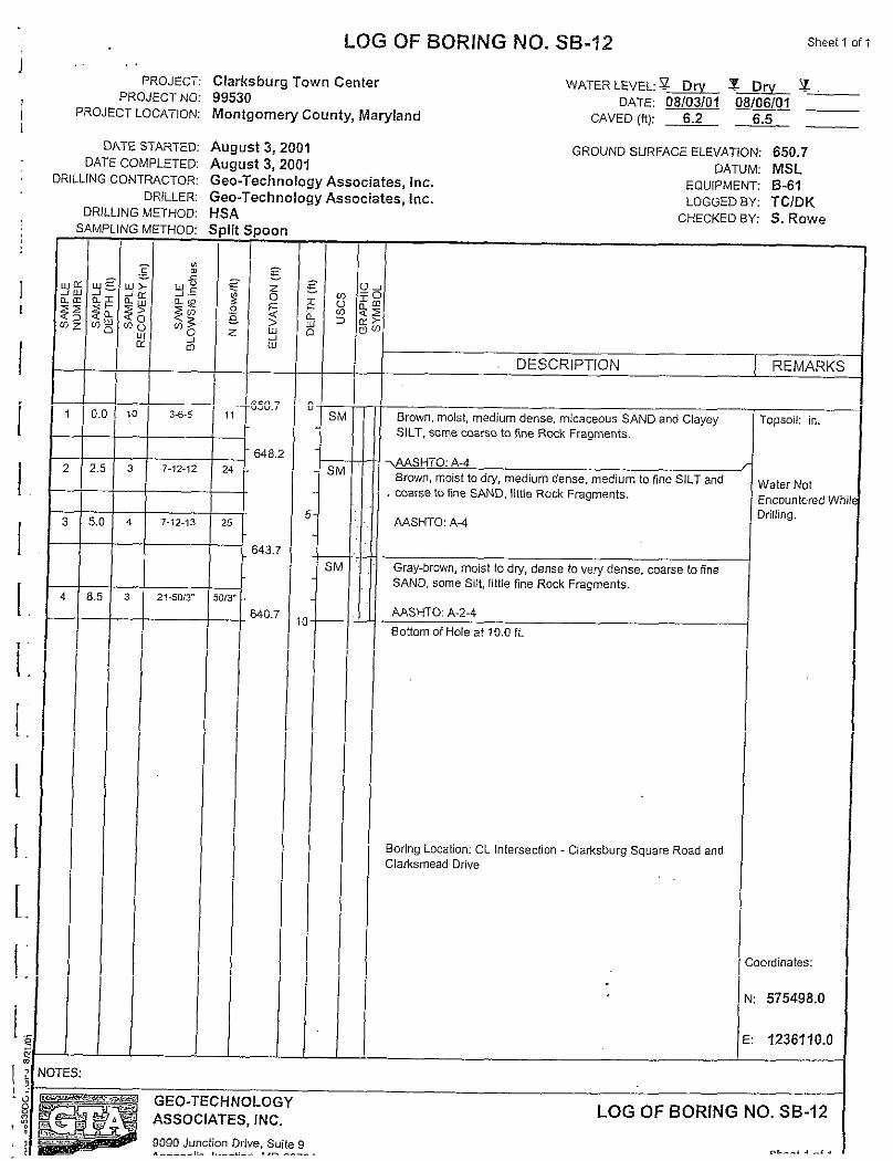
LOG OF BORING NO. SB-12 Sheet 1 of 1
Clarksburg Town Center99530Montgome~ County, Maryland
WATER LEVEL %= ~ DW Y--DATE: 08/03/01 08106101
CAVED (ft): 6.2 6.5
,Ugust 3, 2001 GROUND SURFACE ELEVATION:.Ugust 3, 2001 DATUM:ieo-Tech nology Associates, Inc. EQUIPMENTco-Technology Associates, Inc. LOGGED BY:SAplit Spo[
T ?!,
1&
—
650
641
642
640
— —
CHECKED BY
650.7MSLB-61TC/DKS. Rowe
DESCRIPTION REMARKS
Brown, moist, medium dense, micaceous SAND and ClayeySILT, some aa(se to fine RWk Fragments.
>WSHTO: A-4Brown, moist to dw, medium dense, medium to fine SILT and
, coarse to fine SAND, li\tIe Rock Fragments.
WSHTO: A4
Gray-brown, moist to dry, dense to veV dense, coarse 10fineSAND, some Silt, hltle fine Rock Fragments.
~SHTO: A-2-4
Bottom of Hole at ?0.0 ft.
Boring Location: CL Intersection Clarksburg Square Road andClarksmead Drive
Topsoil: in.
Waler NotEncountered WhDrilling.
]ordinates:
575498.0
1236110.0
LOG OF BORING NO. SB-12
. . . . . . . . .

I
I
II
I
I1.
i.
1.
[.
APPENDIXc
LABORATORY TESTRESULTS
1..I

~,, ,
‘> GEO-TECHNOLOGY ASSOCIATES, INC.
Natural Moisture Content Summay
I Clarksburg Town Center
August f14,2001
I99530
?$: ?:.:.:. . .+,,:... ..,: .,:.:.,. ... ,,,,.::,,,:,,,: :+.,,::;,. ..,,,, ....,,.,.,.,.,:,...,:,, ~,,,::::i, .::.,.:$;.;,:.i;:.,;:,:;,,, , .. , :
~“’’~~$R[NG:~’(”:”;”::’‘i::;::’$’::;;’”~:?:~::”’:;?y’-:;..:...=.:...;.,;.:3..:;$+:,>.NAzumq$g$;’; :;;:
:’ ‘:: :<?:,”.: :.’:,::SAM PEE#’: ;.i’: :<~; .;<j,!;..?:::;tig:+i’ f~~:;$-:: “r::?si::MNsFiR2:;xi:;,’:..:..,:.-: “ ,: :;, :, ., ..... . .,<,,.,,..,,::..- :.:. .:;::.:“:;:’;:!i(:.:;.?.,.!:,’i.:,.;:;;;.::.,. ~ :. <.::<..:.?.:.:..’>~~.-Je~$:..,-2s :,!:
~z: .’,$.CONTEN.T:..Y<:.: < ;“”
I
s-1 0.0-1,5 18.5
s-2‘SB-12
2.5-4.0 14.5
I
s-3 5.0-6.5 12.0
s-4 8.5-10,0 9.4
I
TP-4s-i 3 19.2
s-3 9
1:
19.9
TP-5s-1 2 20.2
s-2 4 18,2
1s-2 6 18.9
s-3 7 16.4
1.TP-6 s-1 2 22.8
1,
s-2 5 24.2
s-3 8 27.8
s-4 10 23.2
‘i. TP-7 s-1 2 23.5
r s-2 5 19.8
:, s-1 0.1-5.0 13.1
I
s-2 2.5-4.0 9.2
L-1s-3 5.0-6.5 2.0
Is-4 8.5-10.0 1.5
s-5 13.5-15.0
1’
8.9
S-6 18.5-20.0 2.5
I
i’0f2
i
I
!I
II1:i.i’. .
i.
1:
[.
1.
1
[:
l..
I
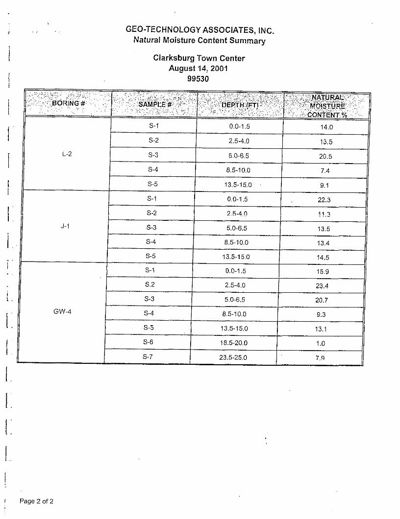
GEO-TECHNOLOGYASSOCIATES, INC.
Natural Moisture Content Summa~
Clarksburg Town CenterAugust 14,2001
99530
,.. ,...,,::.,$..,., .,:.....>.:}.!:,,., ,,~::,:::.,.:.:;?,:.:,,...: .... .. .. ,:,.?+;,:?::?7;.,, ..:.:,,:,,::, .:.::;+::?,:::NATumE::,,: ;, , ,.:
::’;:j::;BORING”# : “’:;:i:; :::::‘:-::slMPiE”*:;ijj:;.;;:?:”..ii,;D.Ekxti;(E;]i.;::::::::;;;;’!::l;i:itiblsT~RE:;:i’;:::~,.:.,.,...,,...,.................,,,,:..... ...& ., ,,:;,;.:.:..,;.:.., ,,.... . . . ,, . . ...> ?. :~::c6N?iN?:.%..’:’s-1 0,0-1.5 14.0
s-2 2.5-4.0 13.5
L-2 s-3 5.0-6,5 20.5
s-4 8.5-10.0 7.4
s-5 13.5 -15.0 9.1
s-1 0.0-1,5 22.3
s-2 2.5-4,0 11.3
J-1 s-3 5.0-6.5 13.5
s-4 8.5-10.0 13.4
s-5 13.5-15.0 14.5
s-l 0.0-1,5 15.9
S.2 2.5-4,0 23.4
s-3 5.0-6,5 20.7
GW-4 s-4 8.5-10.0 9.3
s-5 13.5-15,0 13.1
S-6 18.5-20.0 1.0
s-7 23.5-25.0 7.9
1 Page 2 of 2
I
I
I
I
I
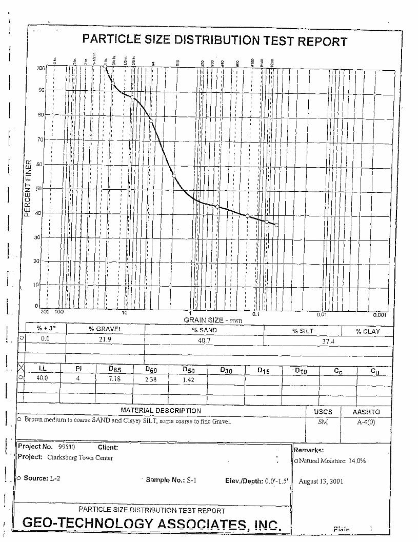
PARTICLE SIZE DISTRIBUTION TEST REPORT2
GRAIN SIZE - mm./. + 3,, % GWVEL Y. SAND % SILT ‘A CLAY
3 0.0 21.9 40.7 37,4I
I Ik LL PI 085 D60 D50 D30 D15 Dlo cc0 40.0 4
Cu7.18 2,38 1.42
MATERIAL DESCRIPTION Uses AASHTO
0 Bro!snmedium toco~se S~ and ClayeySILT,somecoarseto f,ne Gavel. Skf A-4(0)
Project No. 99s30 Clienti I Remarks:‘rojeck Clarksbug Town Center o Namal Moistire: 14,O“/O
Source: L-2 Sample No.: S-1 Elev./Depth: O.O’-I.j( August 13,2001
PARTICLE SIZE DISTRIBUTION TEST REPORT
GEO-TECHNOLOGYASSOCIATES,INC.Ii Plate 1
!
IiI
IIIIIij
ii!
1.
1.
1:
1.
B,,
70
; Ii;
1’1:60 :
1,,,,,
50;;!,,,II,,
40;:,,,,(,II
30 ,,
20
10
0200 100
PARTICLE SIZE DISTRIBUTiON TEST REPORT
I
LLIIu1’il~
k
+wT,,,
i’ ‘Ill
n .,. .. ,GRAIN SIZE - mm ‘“’
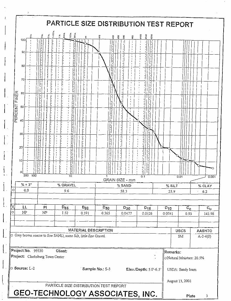
./. + 3,, “/. GRAVEL ‘/. SAND y. SILT Y. CLAY0,0 9.6 jS.3 2j, Y 6.2
I
LL PI D85 D60 D50 D30 Dq5 Dlo cc c“m m 1,52 0.j91 0.365 00477 0.0126 0.0041 0.93 142.9S
MATERIAL DESCRIPTION Uses MSHTO&ey bro!vncoarseto fineS~, someSilt, littie [me Gavel. SM A-2-4(O)
I Iojeti No. 99530 Clienti Remarks:Oject: Claksburg TOW Center oNatiral Nloisture:20.j”A
Source: L-2 Sample No.: S-3 Elev,/Depth: 5.O’-6.j’ USDA: Smdy loam
August 13,2001PARTICLE SIZE DISTRIBUTION TEST REPORT
2E0-TECHNOLOGYASSOCIATES,INC. Plate 3
I
I
I
I
I
I
1
f
PARTICLE SIZE DISTRIBUTION TEST REPORT
I
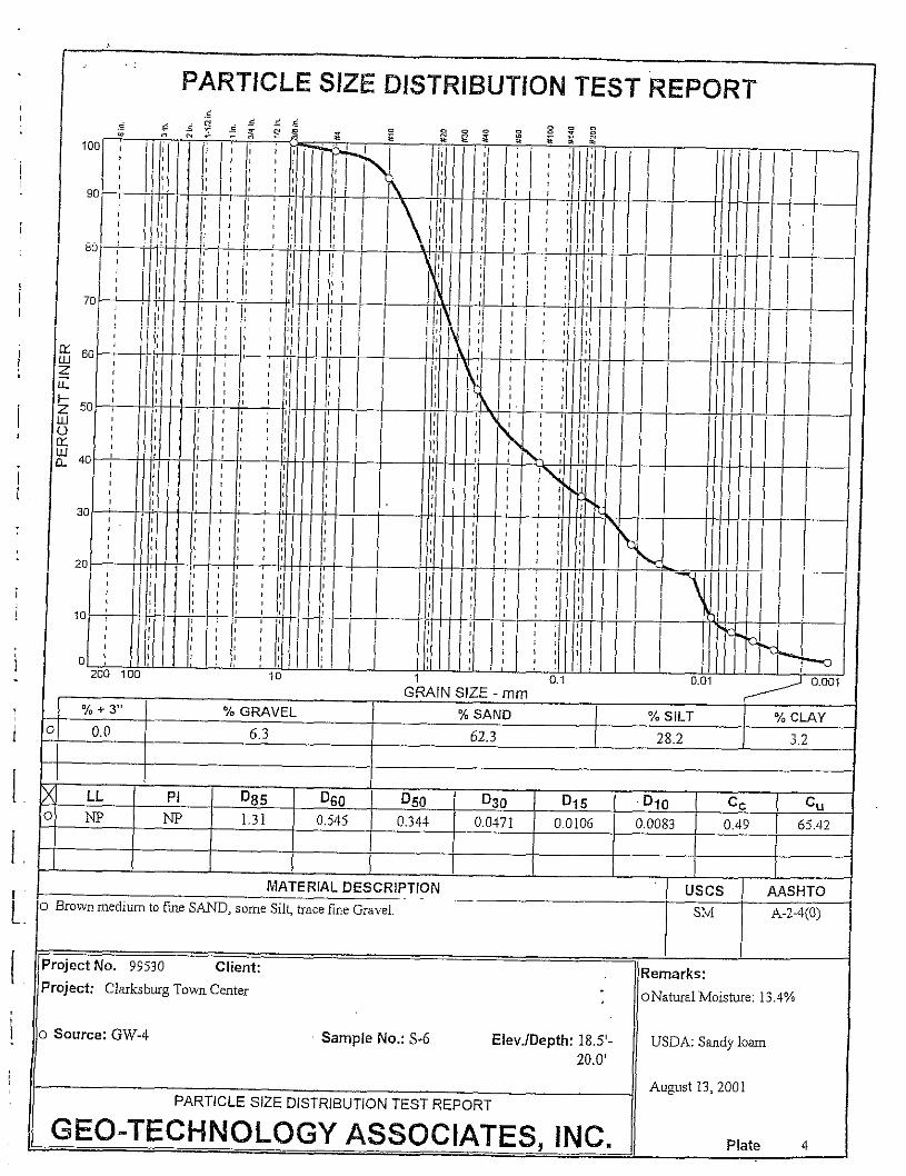
x LL PI Dg5 D60 Dso D30 D15 Dlo cc0 w
c“
m 1.31 0.j45 0.344 0.0471 0.0106 0.0083 0.49 6j.42
klATERIAL DESCRIPTION Uses MSHTO
0 Bro\vnmedium tofme S~, someSilt, tracefine Gavel. ski ~.~.4(o)
Aug~[st13, 2001PARTICLE SIZE DISTRIBUTION TEST REPORT
~~0-~~~~~O~O~y ASSOCIATES,INC. Plate 4
I
I
I
I
I
I
I
I
I
I
I
1
l..
[
[;
1:
I
1
PARTICLE SIZE DISTRiBUT!ON TEST REPORT=,,
I
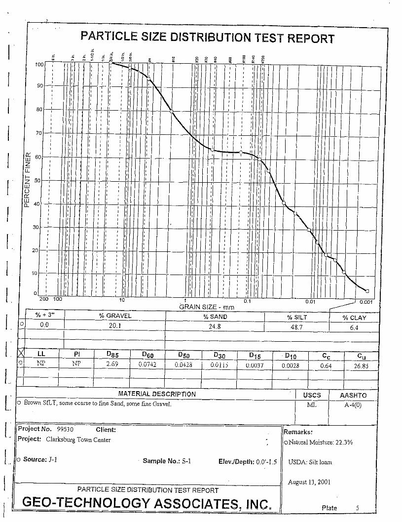
LL PI D85 D60 D50 D30 Dq5 Dlo cc Cu
m m 2.69 0.0742 0.042S O.Ollj 0.0037 0,0028 0.64 26.8j
MATERIAL DESCRIPTION Uses AASHTO
Brown S~T, somecoarseto t-meSand,somefme @a”eI. b~ A-4(0)
I I
‘eject No. 9953o Client: Remarks:
‘Ojecti Clmksb~g TOW~ Cmter oNatild Moistire: 22.3”/o
Source; J-1 Sample No.: S-1 Elev./Oepth: 0.0’-1.5 IUSDA:SiltIom
August 13,2001
PARTICLE SIZE DISTRIBUTION TEST REPORT
GEO-TECHNOLOGYASSOCIATES,INC. Plate j
1.1.
1:1’.
1.
[:
1:
1.!
PARTICLE SIZE DISTRIBUTION TEST REPORT.
10
=.:
200 i 00GRAIN SIZE - mm
y. + 3,, “AGMVEL Y. SAND
0,0
Y. SILT % CLAY
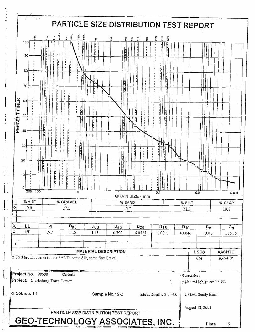
27,2 40.7 21.3 10.8
. . , 0.01 0,00
, 1
LL PI 085 D60 D50 D30 D15 Dqo cc c“
m N 11,8 1.46 0.700 0.0j25 0.0098 0.0046 0.41 316.15
hlATERIAL DESCRIPTION Uses ~SHTO
Red bro>vncause to fmeSANO,someSilt, somefmeGavel. SM A-2-4(O)
I I
reject No. 99530 Client: Remarks:reject Claksburg To~vnCenter oNaturalMoistie: 11,30/0
Source: J-1 Sample No.: S-2 Elev./Depth: 2.5’-4,0’ USDA Sandyloam
Au~st 13,2001
PARTICLE SIZE DISTRIBUTION TEST REPORT
GEO-TECHNOLOGY ASSOCIATES.INC. Plate 6

!
!
I
I
I
I
1.
i.
1:/
[
I
1:
1.[1..:
1.
Date 8/13/01
Source of Material J-1
Sample Number/Depth Bulk / 2.5-6 fl
Description of MateHal Red brown cf SAND, s Silt, sf
Test Method
Gravel.
ASTM D698 Method A
TEST RESULTS
Maximum Dry Density ~ PCF
Optimum Moisture Content & Y.
11,3 YoNatural Moisture Content _
SOIL CLASSIFICATIONS
USCS Classification SM
AASHTO C[assificatioo A-24
WATER CONTENT, %
v
Gee-Technology Associates, Inc. MOISTURE-DENSITY RELATIONSHIPp .,, , m 9090Junction Drive, Suite g Proiect Clarksburg Town Center
= Annapolis Junction, MD 20701_ Te,ephone: 410-792-9446 Location: Montgome~ County, Maryland
Fax: 410-792-7395 .,, .-— -“
ATTERBERG LIMITS
LL & &
NP NP NP
Cuwes of 1007. Saturationfor Specific Gravity Equal to:
I

Date 814 3/01
Source of Material L-2
Sample Number/Depth Bulk/ 2,5-5.OFt
Description of Material Bro\vn mf SILT and cf SAND,
little fine Gravel.
Test Method ASTM D698 Method A
TEST RESULTS
Maximum Dry Density ~ PCF
Optimum Moisture Content _ 10.3 Y,
Natural Moisture Content _ 13.5 Y.
SOIL CLASSIFICATIONS
USCS ClassificatiOo SM
AASHTO Classification A-4
ATTERBERG LIMITS
,9 .—
,.
B~RING RATIO TEST REPORT
100 5CBR @ 95%= 1.3
for 0.1 in. penetration30 4
I~ 1so 3
E- 1;7 7a )’ Ez1 I
1;~
150 j
~ &,> 0
)> 50 90 1~~ I ‘1o 1 2(3 130 I 40
t,lolded density, pcf
405
/
430
K
3
20—
;2
6
101
+
o 0 I
o 0.1 0.2 0.3 0.4 0.5 0 24 48 72 96
Penetruti3n, in. Elapsed time, hrs,
.. . . . . ._, __ _— ~— —.— —— —— —— —.. .—.’— .*,>
SUMMARY OF SOIL ANALYSIS
Project Name Clarksburg Town CenterProject No. 99530
Computed SCR
Test Date 8/20/01Checked JPK
.—
Sheet No. 1 of 1
Gee-Technology Associates, Inc.
9090 Junction Drive, Suite 9
Annapolis Junction, Maryland 20701
Related Documents