Clarki Quad-band M2M Antenna Part No. A10464 Product Specification 1 Features • Adjustable GSM antenna targeting M2M applications • Resonant frequency adjustable using single tuning component • Space-saving corner mount enables antenna space to be shared with GSM module • Works in both upper right and left corners • High efficiency • Easy to integrate • Intended for corner mounting with screw fixings (x2) • Supplied in trays Clarki supports the following communication standards: GSM/GPRS/EDGE Other Standards GSM850 (E)GSM900 GSM1800 (DCS) GSM1900 (PCS) CDMA Band II CDMA Band V Korean PCS AWS 2 Description A10464 is designed to be mounted in either corner of a PCB by means of a robust screw-in fixing ideal for M2M application. The design allows an SMT GSM/GPRS module to occupy part of the space under the antenna, allowing an optimal use of the space on the host PCB. The antenna is not symmetric, and therefore performance when mounted on left and right corner is slightly different, with a little advantage in the left corner position. A10464 uses the host PCB ground plane in order to radiate efficiently and so its performance depend also on the size and design of the host PCB; a minimum PCB length of 100mm is recommended, although the antenna works on smaller PCBs, with performance decreasing with PCB size. The ground plane extends under the antenna, but for optimal performance a 3mm ground clearance strip along the edge of the PCB in correspondence of the antenna is recommended. The antenna uses a matching circuit to achieve optimized results for the specific frequency bands that are required, and the resonant frequency of the antenna can be adjusted using an additional component to compensate for the effect of nearby objects like a plastic cover. This product specification shows the performance of the antenna on an Antenova reference board, A10464-U1, when optimized to cover a typical quad-band reception: GSM850/900/1800/1900. Antennas for Wireless M2M Applications

Welcome message from author
This document is posted to help you gain knowledge. Please leave a comment to let me know what you think about it! Share it to your friends and learn new things together.
Transcript
1Product Specification 12MD-0047-3-PS
Clarki Quad-band M2M Antenna Part No. A10464 Product Specification
1 Features
• Adjustable GSM antenna targeting M2M applications • Resonant frequency adjustable using single tuning component • Space-saving corner mount enables antenna space to be shared with GSM module • Works in both upper right and left corners • High efficiency • Easy to integrate • Intended for corner mounting with screw fixings (x2) • Supplied in trays
Clarki supports the following communication standards:
GSM/GPRS/EDGE Other Standards
GSM850 (E)GSM900
GSM1800 (DCS) GSM1900 (PCS)
CDMA Band II CDMA Band V Korean PCS
AWS
2 Description
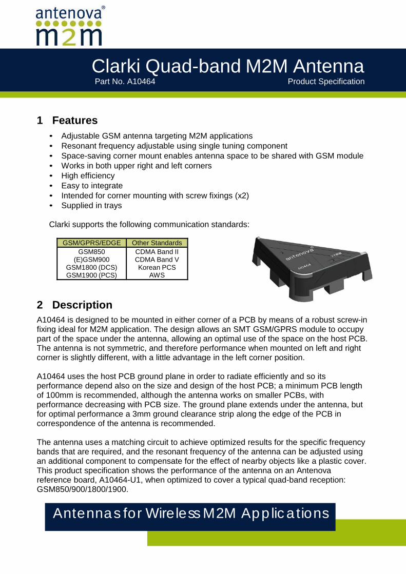
A10464 is designed to be mounted in either corner of a PCB by means of a robust screw-in fixing ideal for M2M application. The design allows an SMT GSM/GPRS module to occupy part of the space under the antenna, allowing an optimal use of the space on the host PCB. The antenna is not symmetric, and therefore performance when mounted on left and right corner is slightly different, with a little advantage in the left corner position.
A10464 uses the host PCB ground plane in order to radiate efficiently and so its performance depend also on the size and design of the host PCB; a minimum PCB length of 100mm is recommended, although the antenna works on smaller PCBs, with performance decreasing with PCB size. The ground plane extends under the antenna, but for optimal performance a 3mm ground clearance strip along the edge of the PCB in correspondence of the antenna is recommended.
The antenna uses a matching circuit to achieve optimized results for the specific frequency bands that are required, and the resonant frequency of the antenna can be adjusted using an additional component to compensate for the effect of nearby objects like a plastic cover. This product specification shows the performance of the antenna on an Antenova reference board, A10464-U1, when optimized to cover a typical quad-band reception: GSM850/900/1800/1900.
Antennas for Wireless M2M Applications
Clarki GSM M2M AntennaPart No. A10464
Antennas for Wireless M2M Applications 2
Product Specification 12MD-0047-3-PS
3 Applications
• Smart Metering/AMR • Tracker devices • Industrial Applications • Femto / Pico base stations • Other M2M communication
4 Part number
5 General data
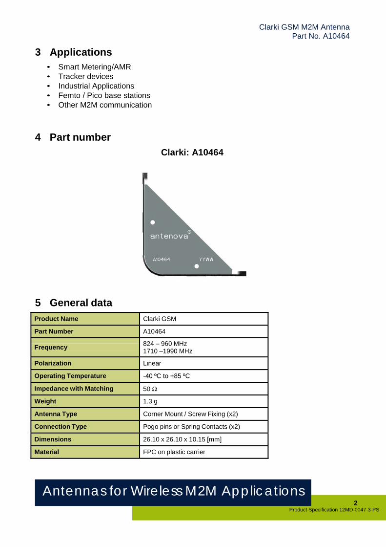
Clarki: A10464
Product Name Clarki GSM Part Number A10464
Frequency 824 – 960 MHz
1710 –1990 MHz Polarization Linear Operating Temperature -40 ºC to +85 ºC Impedance with Matching 50 Ω Weight 1.3 g Antenna Type Corner Mount / Screw Fixing (x2) Connection Type Pogo pins or Spring Contacts (x2) Dimensions 26.10 x 26.10 x 10.15 [mm] Material FPC on plastic carrier
Antennas for Wireless M2M Applications 3
Product Specification 12MD-0047-3-PS
Clarki GSM M2M AntennaPart No. A10464
6 Electrical characteristics
Typical Performance
Frequency
Left Corner
Right Corner Left Corner With Module1
Right CornerWith Module1
Peak Gain [dBi]
824-960 MHz 1.4 1.0 1.3 1.0 1710-1990 MHz 2.4 3.0 2.2 2.7
Minimum Efficiency [%]
824-960 MHz 55 59 53 57 1710-1990 MHz 67 57 62 52
Average Efficiency [%]
824-960 MHz 62 64 60 63 1710-1990 MHz 73 64 68 60
Minumum Return Loss
[dB]
824-960 MHz 7.0 7.4 6.8 7.2 1710-1990 MHz 8.0 6.2 7.2 6.0
VSWR
824-960 MHz 2.6:1 2.5:1 2.7:1 2.5:1 1710-1990 MHz 2.3:1 2.9:1 2.5:1 3.0:1
Conditions
All data measured on Antenova’s reference board, part number A10464-U1.
1Typical commercially available SMT GSM Module

Antennas for Wireless M2M Applications 4
Product Specification 12MD-0047-3-PS
Clarki GSM M2M AntennaPart No. A10464
7 Electrical performance
7-1 Return Loss
Figure 1: Impedance Matching (Left and Right positions) - No module
Antennas for Wireless M2M Applications 5
Product Specification 12MD-0047-3-PS
Clarki GSM M2M AntennaPart No. A10464
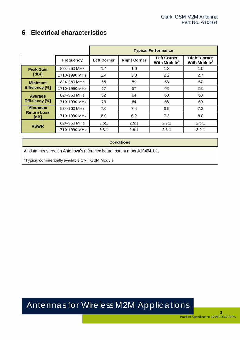
Figure 2: Impedance Matching (Left and Right positions) - with typical SMT GSM Module
Antennas for Wireless M2M Applications 6
Product Specification 12MD-0047-3-PS
Clarki GSM M2M AntennaPart No. A10464
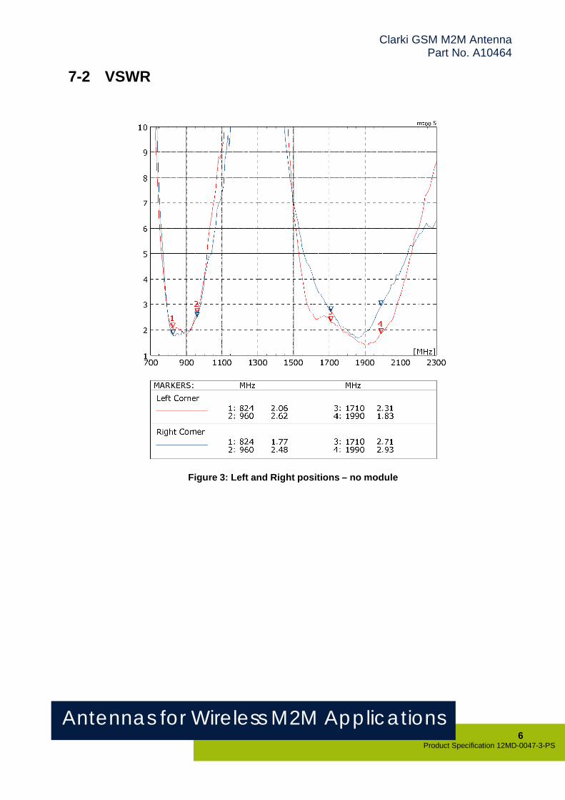
7-2 VSWR
Figure 3: Left and Right positions – no module
Antennas for Wireless M2M Applications 7
Product Specification 12MD-0047-3-PS
Clarki GSM M2M AntennaPart No. A10464
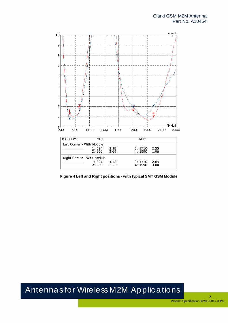
Figure 4 Left and Right positions - with typical SMT GSM Module
Antennas for Wireless M2M Applications 8
Product Specification 12MD-0047-3-PS
Clarki GSM M2M AntennaPart No. A10464
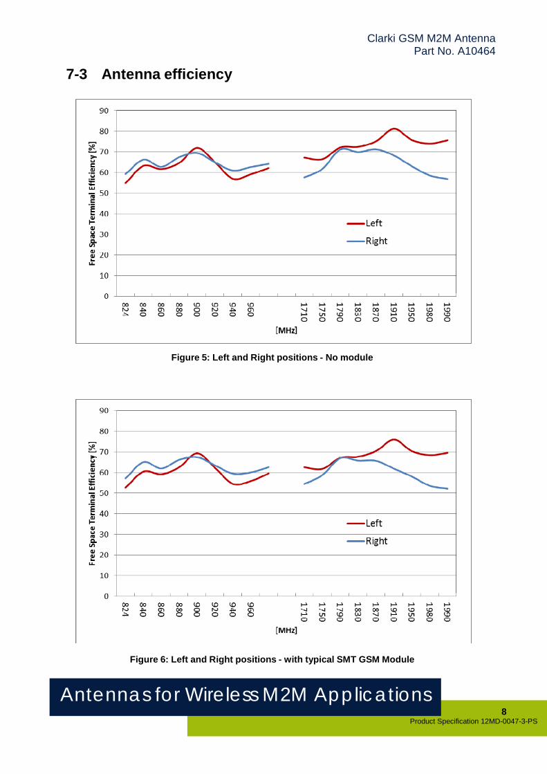
7-3 Antenna efficiency
Figure 5: Left and Right positions - No module
Figure 6: Left and Right positions - with typical SMT GSM Module
Antennas for Wireless M2M Applications 9
Product Specification 12MD-0047-3-PS
Clarki GSM M2M AntennaPart No. A10464
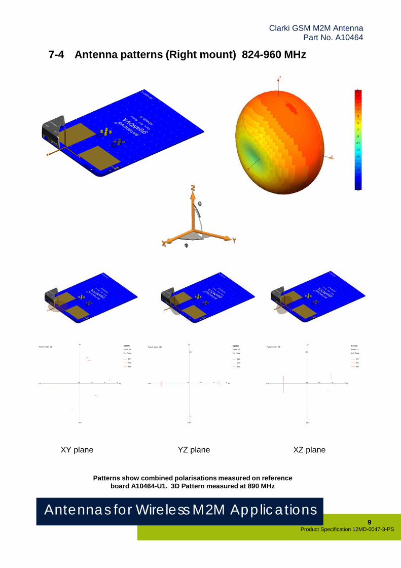
Antenna patterns (Right mount) 824-960 MHz 7-4
0° Radial Scale: dBi E16486
Plane XY
Pol. Total
0° Radial Scale: dBi E16486
Plane YZ
Pol. Total
0° Radial Scale: dBi E16486
Plane XZ
Pol. Total
824
900
960
824
900
960
824
900
960
270° -25 -15 -5 5 90°
180°
270° -25 -15 -5 5 90°
180°
270° -25 -15 -5 5 90°
180°
XY plane YZ plane XZ plane
Patterns show combined polarisations measured on reference board A10464-U1. 3D Pattern measured at 890 MHz

Antennas for Wireless M2M Applications 10
Product Specification 12MD-0047-3-PS
Clarki GSM M2M AntennaPart No. A10464
Antenna patterns (Left mount) 824-960 MHz 7-5
0° Radial Scale: dBi E16484
Plane XY Pol. Total
0° Radial Scale: dBi E16484
Plane YZ Pol. Total
0° Radial Scale: dBi E16484
Plane XZ Pol. Total
824 824 824
900 900 900
960 960 960
270° -25 -15 -5 5 90°
180°
270° -25 -15 -5 5 90°
180°
270° -25 -15 -5 5 90°
180°
XY plane YZ plane XZ plane
Patterns show combined polarisations measured on reference board A10464-U1. 3D Pattern measured at 890 MHz
Antennas for Wireless M2M Applications 11
Product Specification 12MD-0047-3-PS
Clarki GSM M2M AntennaPart No. A10464
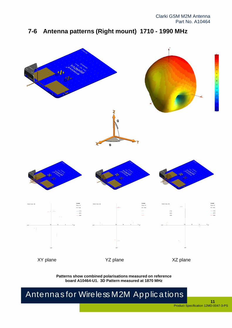
7-6 Antenna patterns (Right mount) 1710 - 1990 MHz
Radial Scale: dBi E16486 Plane XY
Pol. Total
Radial Scale: dBi E16486 Plane YZ
Pol. Total
Radial Scale: dBi E16486 Plane XZ
Pol. Total
1710 1710 1710
1870 1870 1870
1990 1990 1990
270°
-25 -15 -5 5 90°
180°
270° -25 -15 -5 5 90°
180°
270° -25 -15 -5 5 90°
180°
XY plane YZ plane XZ plane
Patterns show combined polarisations measured on reference board A10464-U1. 3D Pattern measured at 1870 MHz
Antennas for Wireless M2M Applications 12
Product Specification 12MD-0047-3-PS
Clarki GSM M2M AntennaPart No. A10464
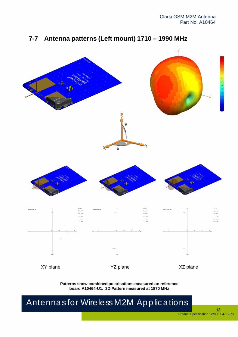
7-7 Antenna patterns (Left mount) 1710 – 1990 MHz
0° Radial Scale: dBi E16484
Plane XY
Pol. Total
0° Radial Scale: dBi E16484
Plane YZ
Pol. Total
0° Radial Scale: dBi E16484
Plane XZ
Pol. Total
1710
1870
1989
1710
1870
1990
1710
1870
1990
270° -25 -15 -5 5 90°
180°
270° -25 -15 -5 5 90°
180°
270° -25 -15 -5 5 90°
180°
XY plane YZ plane XZ plane
Patterns show combined polarisations measured on reference board A10464-U1. 3D Pattern measured at 1870 MHz
Antennas for Wireless M2M Applications 13
Product Specification 12MD-0047-3-PS
Clarki GSM M2M AntennaPart No. A10464
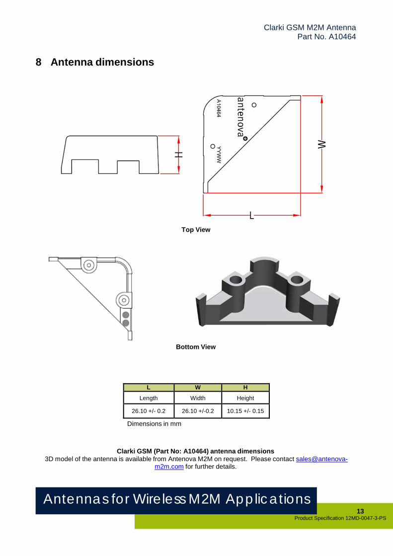
8 Antenna dimensions
Top View
Bottom View
L W H
Length Width Height 26.10 +/- 0.2 26.10 +/-0.2 10.15 +/- 0.15
Dimensions in mm
Clarki GSM (Part No: A10464) antenna dimensions 3D model of the antenna is available from Antenova M2M on request. Please contact sales@antenova-
m2m.com for further details.

Antennas for Wireless M2M Applications 14
Product Specification 12MD-0047-3-PS
Clarki GSM M2M AntennaPart No. A10464
9 Antenna footprint
Clarki GSM (Part No: A10464) Placement on PCB CAD files of the antenna footprint are available from Antenova M2M on request. Please contact
[email protected] for further details.
A B C D E F G H I 9.78 ±0.15
0.5 ±0.15
11.0 ±0.15
10.42 ±0.15 20.70 ±0.15 10.40 ±0.15 2.98 ±0.15 5.00 DIA ±0.15
2.50 ±0.15
Dimensions in millimeters

Antennas for Wireless M2M Applications 15
Product Specification 12MD-0047-3-PS
Clarki GSM M2M AntennaPart No. A10464
10 Electrical interface
10-1 Transmission lines
The antenna should be connected using an RF transmission line.
All transmission lines should be designed to have a characteristic impedance of 50 Ω The length of the transmission lines should be kept to a minimum. Any other parts of the RF system like transceivers, power amplifiers, etc, should also be designed to have an impedance of 50 Ω
Once the material for the PCB has been chosen (PCB thickness and dielectric constant), a co-planar transmission line can easily be designed using any of the commercial software packages for transmission line design. For the chosen PCB thickness, copper thickness and substrate dielectric constant, the program will calculate the appropriate transmission line width and gaps on either side of the track so the characteristic impedance of the co-planar transmission line is 50 Ω.
Please contact Antenova M2M ([email protected]) if assistance is required.
10-2 Matching circuit
The A10464 antenna requires an impedance matching circuit that must be optimized for each customer’s product. The matching circuit will typically require 3 matching components, and up to five components depending on the impedance of the antenna when situated in the device. It is recommended that all the components in the reference schematic (Fig 7) are included in the layout. Moreover, the antenna requires an additional inductor L1 on the return pin, which is used to adjust the resonant frequency in the low band (see below).
Important: The position of the antenna feed and return pads are fixed for this product and the positions cannot be swapped over. Please check the reference layout for the relative position.
P1
Feed Return
C4 C2
Connect to Radio module using 50Ω line
C1 L2 C1 L1
Figure 7: Antenna matching circuit and frequency adjustment
Antennas for Wireless M2M Applications 16
Product Specification 12MD-0047-3-PS
Clarki GSM M2M AntennaPart No. A10464
The values of the matching component given in the below table are for the A10464-U1 reference boards and might be different on a customer host board.
Designator Value Tolerance Size Manufacturer PN L1 3.9nH ±0.2nH 0402 Murata LQW15AN3N9C00 L2 8.2nH ±3% 0402 Murata LQW15AN8N2H00C1 - 0402 Not fitted C2 2.7pF ±0.1pF 0402 AVX 04023U2R7BAT2AC3 0.5pF ±0.1pF 0402 AVX 04025U0R5BAT2AC4 33pF ±5% 0402 Any P1 See below
Note: The component values for the matching circuit will vary depending on the size of the PCB and surrounding components. The impedance of the antenna should be measured before selecting suitable matching components. Antenova offers a matching service on request. Contact [email protected] for further information
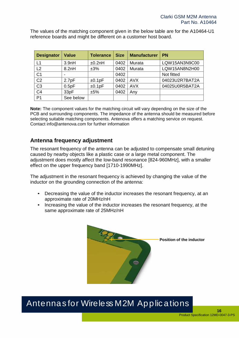
Antenna frequency adjustment
The resonant frequency of the antenna can be adjusted to compensate small detuning caused by nearby objects like a plastic case or a large metal component. The adjustment does mostly affect the low-band resonance [824-960MHz], with a smaller effect on the upper frequency band [1710-1990MHz].
The adjustment in the resonant frequency is achieved by changing the value of the inductor on the grounding connection of the antenna:
• Decreasing the value of the inductor increases the resonant frequency, at an
approximate rate of 20MHz/nH • Increasing the value of the inductor increases the resonant frequency, at the
same approximate rate of 25MHz/nH
Position of the inductor
Antennas for Wireless M2M Applications 17
Product Specification 12MD-0047-3-PS
Clarki GSM M2M AntennaPart No. A10464
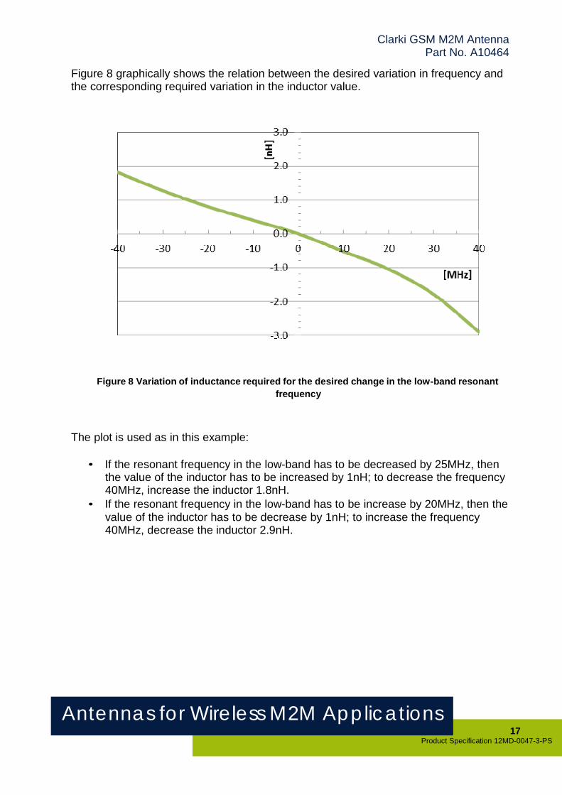
Figure 8 graphically shows the relation between the desired variation in frequency and the corresponding required variation in the inductor value.
Figure 8 Variation of inductance required for the desired change in the low-band resonant frequency
The plot is used as in this example:
• If the resonant frequency in the low-band has to be decreased by 25MHz, then the value of the inductor has to be increased by 1nH; to decrease the frequency 40MHz, increase the inductor 1.8nH.
• If the resonant frequency in the low-band has to be increase by 20MHz, then the value of the inductor has to be decrease by 1nH; to increase the frequency 40MHz, decrease the inductor 2.9nH.

Antennas for Wireless M2M Applications 18
Product Specification 12MD-0047-3-PS
Clarki GSM M2M AntennaPart No. A10464
10-3 Antenna placement
Clarki should be fitted to the device so that power from the antenna can radiate into free space. Antenova strongly recommends placing the antenna in a corner of the board. A low profile (<3.5mm) GSM/GPRS module can be placed under the antenna as shown in Fig.9 below. The placements shown here are for guidance only, as the actual performance differences will depend on each individual device.
Antenova M2M offers a full range of development support to ensure efficient implementation of the antenna into the specific design. To overcome RF design issues, matching circuits, transmission lines, layout and other components, please contact Antenova M2M ([email protected]) for design and placement recommendations.
Figure 9: Recommended right or left corner placement of antenna with possible GSM/GPRS module placement outlined in yellow.
Antennas for Wireless M2M Applications 19
Product Specification 12MD-0047-3-PS
Clarki GSM M2M AntennaPart No. A10464
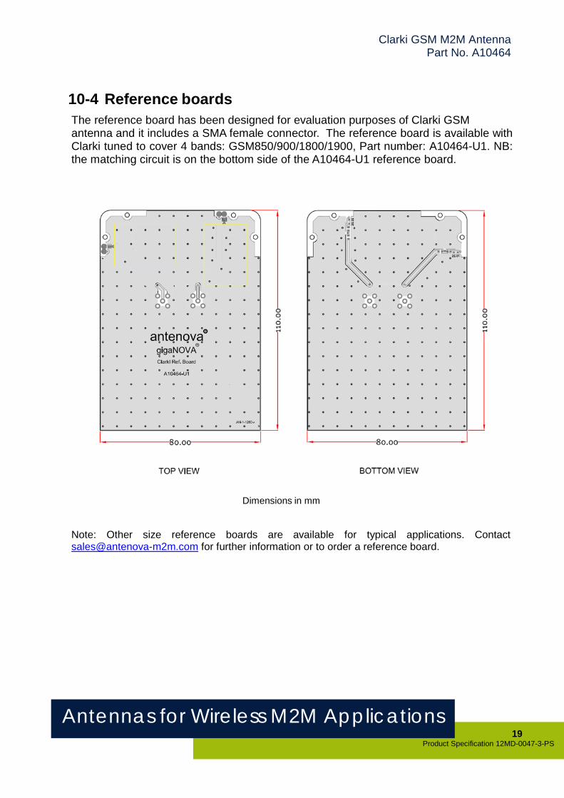
10-4 Reference boards
The reference board has been designed for evaluation purposes of Clarki GSM antenna and it includes a SMA female connector. The reference board is available with Clarki tuned to cover 4 bands: GSM850/900/1800/1900, Part number: A10464-U1. NB: the matching circuit is on the bottom side of the A10464-U1 reference board.
Dimensions in mm
Note: Other size reference boards are available for typical applications. Contact [email protected] for further information or to order a reference board.
Antennas for Wireless M2M Applications 20
Product Specification 12MD-0047-3-PS
Clarki GSM M2M AntennaPart No. A10464
11 Mounting
This antenna is intended for fixing utilizing two metal M2x4 or M2x4.5 screws.
11-1 Connection
For the spring pin (a.k.a. “pogo pins”) P1 in the reference schematic, the recommended parts are:
• C.C.P. F618AA01-02254MR (http://www.pccp.com.tw/) [pair] • C.C.P. N103M1 (http://www.pccp.com.tw/) [single] • C.C.P. N103M5-02B250MR (http://www.pccp.com.tw/) [pair] • Mill-Max 0900-1-00-00-00-00-11-0 (http://www.mill-max.com) [single]
12 Hazardous material regulation conformance
The antenna has been tested to conform to RoHS requirements.
13 Packaging
Clarki to be supplied in trays. Please contact Antenova to discuss your tray requirements.

Clarki GSM M2M AntennaPart No. A10464
Antennas for Wireless M2M Applications 21
Product Specification 12MD-0047-3-PSRelease Date 20 June 2013
www.antenova-m2m.com
Corporate Headquarters Antenova Ltd.
North America Headquarters
Antenova Ltd.
Asia Headquarters
Antenova Asia Ltd. Far Field House Albert Road Stow-cum-Quy Cambridge CB25 9AR
Rogers Business Park2541 Technology Drive Suite 403 Elgin, IL 60124
4F, No. 324, Sec. 1, Nei-Hu RoadNei-Hu District Taipei 11493 Taiwan, ROC
Tel: +44 1223 810600 Fax: +44 1223 810650 Email: [email protected]
Tel: +1 (847) 551 9710 Fax +1 (847) 551 9719 Email: [email protected]
Tel: +886 (0) 2 8797 8630 Fax: +886 (0) 2 8797 6890 Email: [email protected]
Copyright® 2013 Antenova Ltd. All Rights Reserved. Antenova®, Antenova M2M, gigaNOVA®, and the Antenova and Antenova M2M logos are trademarks and/or registered trademarks of Antenova Ltd. Any other
names and/or trademarks belong to their respective companies.
The materials provided herein are believed to be reliable and correct at the time of print. Antenova does not warrant the accuracy or completeness of the information, text, graphics or other items contained within these
information. Antenova further assumes no responsibility for the use of this information, and all such information shall be entirely at the user’s risk.
Related Documents