CLIP EXPRESS SM product catalog CFS FRAMING CONNECTORS STRONGER THAN STEEL SM .

Welcome message from author
This document is posted to help you gain knowledge. Please leave a comment to let me know what you think about it! Share it to your friends and learn new things together.
Transcript
CLIP EXPRESSSM product catalog
C F S F R A M I N G C O N N E C T O R S
S T R O N G E R T H A N S T E E LSM.

C O N N E C T I O N SP L A Y A V I T A L R O L E.
P E A C E O F M I N D. A N D S O D O E S
C L I P E X P R E S S S M

ClarkDietrich Clip ExpressSM stands alone in the industry. The vast lineup of products, quick delivery service and philosophy are unique in every respect—and especially in sum total. That’s because Clip Express was created to give our customers an unmatched level of confidence.
E V E R Y T H I N G Y OU N E E D F RO M O N E C O N V E N I E N T S OU RC E .
We know that having the right products, at the right time, and at the right price is absolutely essential to getting the job done. Clip Express is a single source for the industry’s widest and most cost-effective array of rigid, deflection, bridging, and general-purpose clips, connectors, supports and framing hardware for commercial and residential cold-formed steel framing.
C O N S I S T E N T, H I G H - QU A L I T Y P RO DUC T S .
When you design or specify by ClarkDietrich product name or number, you get fully engineered and rigorously tested systems and connectors—the same precision-formed products each and every time. It’s exactly the kind of thing you’d expect from a partner like ClarkDietrich. The products we manufacture—like FastClip™ Slide Clips and Fast Top™ Clips—are created specifically to work as a system. It’s an approach that leads to enhanced performance on the job.
VA L U E T H AT C O N T R I B U T E S T O Y OU R B O T T O M L I N E .
While you may find a cheaper price than ClarkDietrich, you won’t find a lower overall cost or better value. We offer unmatched service through numerous plants and engineering offices—and nationwide product availability. From technical assistance to complete engineering services, we’ve truly put together an incredible array of resources to help you be successful on any project. This catalog is a great example. It’s one of the most comprehensive light-gauge steel connector, clip, support and framing hardware manuals or resources available.
C O N N E C T I O N S Y OU C A N C OU N T O N .
If getting what you want, when and how you want it is a must, ClarkDietrich Clip Express is ready to deliver. In fact, a wide array of shipping options is available, from standard ground to overnight. If we get your order today, you can get it tomorrow.
Count on ClarkDietrich to deliver products, systems and services that keep your costs down and productivity up.
Need help with product selection, ordering, scheduling, delivery, or anything else? Call the Clip Express sales team:
Clip Express—866-638-1908
Need Product Submittals? Use SubmittalPro® at clarkdietrich.com.
TABLE OF CONTENTS
Overview 4–13
Custom–Fabricated Specialty Products 4–5
Fastening Options 6–8
General Notes 9
How To Use This Catalog 10-11
Product Information 12
Support and Services 13
Deflection Connectors 14–35 Drift Connections 36–59
Rigid Connections 60–97
Floor Framing Connections 98–113
Bridging, Bracing and Backing 114–135
Roof and Truss Connections 136–143
Specialty Clips and Accessories 144–163
Typical Construction Details 164–165
Index 166–167
Clip ExpressSM Display Program 168
Trademarks and Warranty 168
Code Approvals 169
Locations 169
The technical content of this literature is effective 08/23/21 and supersedes all previous information.Pub. No. CD-ClipExpress 08/21 clarkdietrich.com
O V E R V I E W
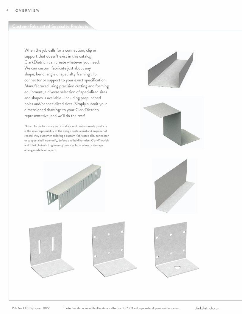
When the job calls for a connection, clip or support that doesn’t exist in this catalog, ClarkDietrich can create whatever you need. We can custom fabricate just about any shape, bend, angle or specialty framing clip, connector or support to your exact specification. Manufactured using precision cutting and forming equipment, a diverse selection of specialized sizes and shapes is available—including prepunched holes and/or specialized slots. Simply submit your dimensioned drawings to your ClarkDietrich representative, and we'll do the rest!
Note: The performance and installation of custom-made products is the sole responsibility of the design professional and engineer of record. Any customer ordering a custom-fabricated clip, connector or support shall indemnify, defend and hold harmless ClarkDietrich and ClarkDietrich Engineering Services for any loss or damage arising in whole or in part.
Custom-Fabricated Specialty Products
4
The technical content of this literature is effective 08/23/21 and supersedes all previous information. The technical content of this literature is effective 08/23/21 and supersedes all previous information. Pub. No. CD-ClipExpress 08/21clarkdietrich.com
O V E R V I E W
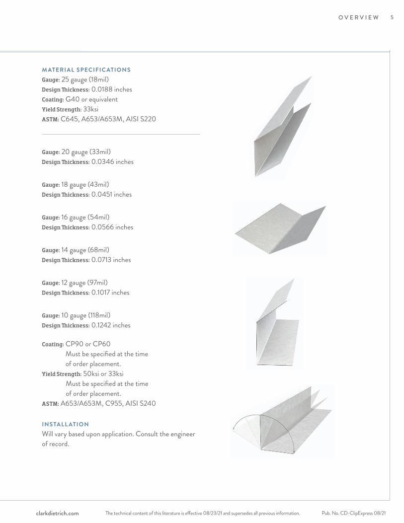
M ATERIAL SPECIFIC ATIONSGauge: 25 gauge (18mil)Design Thickness: 0.0188 inchesCoating: G40 or equivalentYield Strength: 33ksiASTM: C645, A653/A653M, AISI S220
Gauge: 20 gauge (33mil)Design Thickness: 0.0346 inches
Gauge: 18 gauge (43mil)Design Thickness: 0.0451 inches
Gauge: 16 gauge (54mil)Design Thickness: 0.0566 inches
Gauge: 14 gauge (68mil)Design Thickness: 0.0713 inches
Gauge: 12 gauge (97mil)Design Thickness: 0.1017 inches
Gauge: 10 gauge (118mil)Design Thickness: 0.1242 inches
Coating: CP90 or CP60 Must be specified at the time of order placement.
Yield Strength: 50ksi or 33ksi Must be specified at the time of order placement.
ASTM: A653/A653M, C955, AISI S240
INSTALL ATIONWill vary based upon application. Consult the engineer of record.
5
The technical content of this literature is effective 08/23/21 and supersedes all previous information.Pub. No. CD-ClipExpress 08/21 clarkdietrich.com
O V E R V I E W
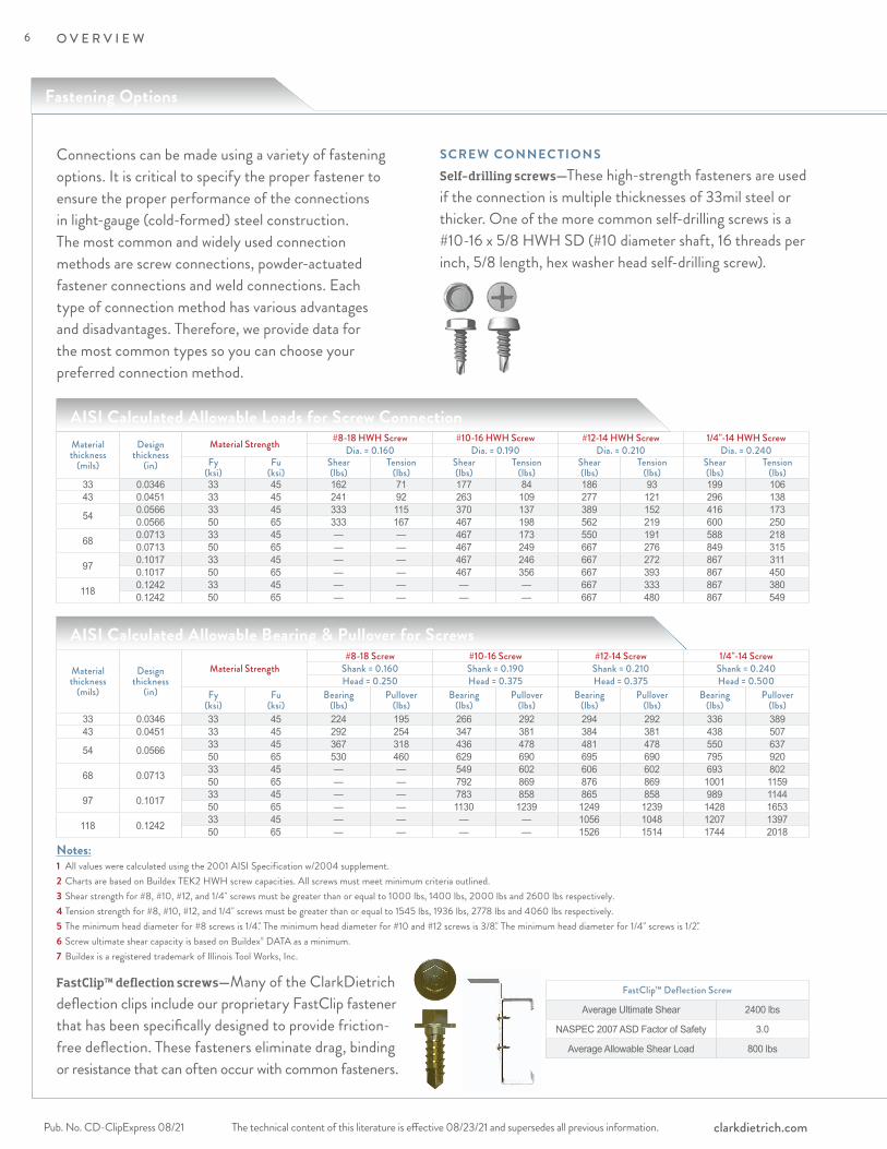
SCREW CONNEC TIONS Self-drilling screws— These high-strength fasteners are used if the connection is multiple thicknesses of 33mil steel or thicker. One of the more common self-drilling screws is a #10-16 x 5/8 HWH SD (#10 diameter shaft, 16 threads per inch, 5/8 length, hex washer head self-drilling screw).
FastClip™ deflection screws— Many of the ClarkDietrich deflection clips include our proprietary FastClip fastener that has been specifically designed to provide friction-free deflection. These fasteners eliminate drag, binding or resistance that can often occur with common fasteners.
Connections can be made using a variety of fastening options. It is critical to specify the proper fastener to ensure the proper performance of the connections in light-gauge (cold-formed) steel construction. The most common and widely used connection methods are screw connections, powder-actuated fastener connections and weld connections. Each type of connection method has various advantages and disadvantages. Therefore, we provide data for the most common types so you can choose your preferred connection method.
FastClip™ Deflection Screw
Average Ultimate Shear 2400 lbs
NASPEC 2007 ASD Factor of Safety 3.0
Average Allowable Shear Load 800 lbs
Material thickness
(mils)
Design thickness
(in)
Material Strength #8-18 HWH Screw #10-16 HWH Screw #12-14 HWH Screw 1/4"-14 HWH ScrewDia. = 0.160 Dia. = 0.190 Dia. = 0.210 Dia. = 0.240
Fy(ksi)
Fu(ksi)
Shear(lbs)
Tension(lbs)
Shear(lbs)
Tension(lbs)
Shear(lbs)
Tension(lbs)
Shear(lbs)
Tension(lbs)
33 0.0346 33 45 162 71 177 84 186 93 199 10643 0.0451 33 45 241 92 263 109 277 121 296 138
54 0.0566 33 45 333 115 370 137 389 152 416 1730.0566 50 65 333 167 467 198 562 219 600 250
68 0.0713 33 45 — — 467 173 550 191 588 2180.0713 50 65 — — 467 249 667 276 849 315
97 0.1017 33 45 — — 467 246 667 272 867 3110.1017 50 65 — — 467 356 667 393 867 450
118 0.1242 33 45 — — — — 667 333 867 3800.1242 50 65 — — — — 667 480 867 549
Notes:1 All values were calculated using the 2001 AISI Specification w/2004 supplement.2 Charts are based on Buildex TEK2 HWH screw capacities. All screws must meet minimum criteria outlined.3 Shear strength for #8, #10, #12, and 1/4" screws must be greater than or equal to 1000 lbs, 1400 lbs, 2000 lbs and 2600 lbs respectively.4 Tension strength for #8, #10, #12, and 1/4" screws must be greater than or equal to 1545 lbs, 1936 lbs, 2778 lbs and 4060 lbs respectively.5 The minimum head diameter for #8 screws is 1/4." The minimum head diameter for #10 and #12 screws is 3/8." The minimum head diameter for 1/4" screws is 1/2."6 Screw ultimate shear capacity is based on Buildex® DATA as a minimum.7 Buildex is a registered trademark of Illinois Tool Works, Inc.
Material thickness
(mils)
Design thickness
(in)
Material Strength #8-18 Screw #10-16 Screw #12-14 Screw 1/4"-14 Screw
Shank = 0.160 Shank = 0.190 Shank = 0.210 Shank = 0.240Head = 0.250 Head = 0.375 Head = 0.375 Head = 0.500
Fy(ksi)
Fu(ksi)
Bearing (lbs)
Pullover(lbs)
Bearing (lbs)
Pullover (lbs)
Bearing (lbs)
Pullover (lbs)
Bearing (lbs)
Pullover (lbs)
33 0.0346 33 45 224 195 266 292 294 292 336 38943 0.0451 33 45 292 254 347 381 384 381 438 507
54 0.0566 33 45 367 318 436 478 481 478 550 63750 65 530 460 629 690 695 690 795 920
68 0.0713 33 45 — — 549 602 606 602 693 80250 65 — — 792 869 876 869 1001 1159
97 0.1017 33 45 — — 783 858 865 858 989 114450 65 — — 1130 1239 1249 1239 1428 1653
118 0.1242 33 45 — — — — 1056 1048 1207 139750 65 — — — — 1526 1514 1744 2018
AISI Calculated Allowable Bearing & Pullover for Screws
AISI Calculated Allowable Loads for Screw Connection
Fastening Options
6
The technical content of this literature is effective 08/23/21 and supersedes all previous information. The technical content of this literature is effective 08/23/21 and supersedes all previous information. Pub. No. CD-ClipExpress 08/21clarkdietrich.com
O V E R V I E W
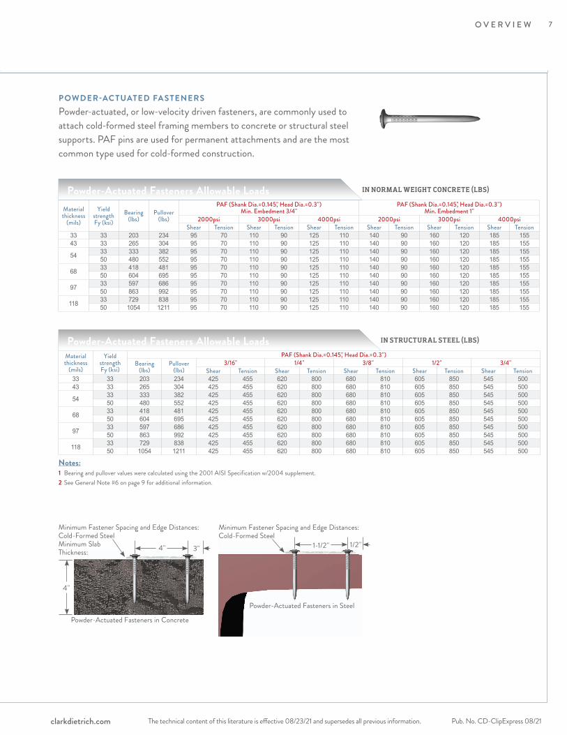
POWDER-AC TUATED FA STENERS Powder-actuated, or low-velocity driven fasteners, are commonly used to attach cold-formed steel framing members to concrete or structural steel supports. PAF pins are used for permanent attachments and are the most common type used for cold-formed construction.
Notes:1 Bearing and pullover values were calculated using the 2001 AISI Specification w/2004 supplement.2 See General Note #6 on page 9 for additional information.
IN STRUCTURAL STEEL (LBS)
IN NORMAL WEIGHT CONCRETE (LBS)
Material thickness
(mils)
Yield strength Fy (ksi)
PAF (Shank Dia.=0.145," Head Dia.=0.3")Bearing
(lbs)Pullover
(lbs)3/16" 1/4" 3/8" 1/2" 3/4"
Shear Tension Shear Tension Shear Tension Shear Tension Shear Tension33 33 203 234 425 455 620 800 680 810 605 850 545 50043 33 265 304 425 455 620 800 680 810 605 850 545 500
54 33 333 382 425 455 620 800 680 810 605 850 545 50050 480 552 425 455 620 800 680 810 605 850 545 500
68 33 418 481 425 455 620 800 680 810 605 850 545 50050 604 695 425 455 620 800 680 810 605 850 545 500
97 33 597 686 425 455 620 800 680 810 605 850 545 50050 863 992 425 455 620 800 680 810 605 850 545 500
118 33 729 838 425 455 620 800 680 810 605 850 545 50050 1054 1211 425 455 620 800 680 810 605 850 545 500
Material thickness
(mils)
Yield strength Fy (ksi)
Bearing (lbs)
Pullover (lbs)
PAF (Shank Dia.=0.145," Head Dia.=0.3") Min. Embedment 3/4"
PAF (Shank Dia.=0.145," Head Dia.=0.3") Min. Embedment 1"
2000psi 3000psi 4000psi 2000psi 3000psi 4000psiShear Tension Shear Tension Shear Tension Shear Tension Shear Tension Shear Tension
33 33 203 234 95 70 110 90 125 110 140 90 160 120 185 15543 33 265 304 95 70 110 90 125 110 140 90 160 120 185 155
54 33 333 382 95 70 110 90 125 110 140 90 160 120 185 15550 480 552 95 70 110 90 125 110 140 90 160 120 185 155
68 33 418 481 95 70 110 90 125 110 140 90 160 120 185 15550 604 695 95 70 110 90 125 110 140 90 160 120 185 155
97 33 597 686 95 70 110 90 125 110 140 90 160 120 185 15550 863 992 95 70 110 90 125 110 140 90 160 120 185 155
118 33 729 838 95 70 110 90 125 110 140 90 160 120 185 15550 1054 1211 95 70 110 90 125 110 140 90 160 120 185 155
Powder-Actuated Fasteners Allowable Loads
Powder-Actuated Fasteners Allowable Loads
Powder-Actuated Fasteners in Concrete
Minimum Fastener Spacing and Edge Distances:Cold-Formed SteelMinimum Slab Thickness: 3"4"
4"
Powder-Actuated Fasteners in Steel
Minimum Fastener Spacing and Edge Distances:Cold-Formed Steel
1/2"1-1/2"
7

Fastening Options
The technical content of this literature is effective 08/23/21 and supersedes all previous information.Pub. No. CD-ClipExpress 08/21 clarkdietrich.com
O V E R V I E W
WELDED CONNEC TIONS Fillet welds— Used to make lap joints, corner joints and T-joint connections. Weld metal is deposited in a corner formed by the fit-up of the two members and penetrates and fuses with the base metal to form the joint.
Flare welds— Used to join rounded or curved pieces.• A Flare Bevel groove weld is commonly used to join a rounded or curved
piece to a flat piece.• A Flare V groove weld is commonly used to join two rounded or curved parts.
Note: For graphical clarity, the weld illustrations do not show the penetration of the welded material. Weld penetration is critical in determining the quality of the weld.
Flare Bevel
Flare V
Fillet Welds
Material thickness
(mils)
Design thickness
(in)
Material Strength Fillet Weld Flare Groove WeldFy
(ksi)Fu
(ksi)Longitudinal
(lbs)Transverse
(lbs)Longitudinal
(lbs)Transverse
(lbs)Values for a single one (1) inch weld
43 0.0451 33 45 619 864 544 6630.0451 50 65 895 1247 785 958
54 0.0566 33 45 822 1084 682 8320.0566 50 65 1188 1566 985 1202
68 0.0713 33 45 1082 1365 859 10480.0713 50 65 1563 1972 1241 1514
97 0.1017 33 45 1480 1480 1226 14800.1017 50 65 1480 1480 1480 1480
118 0.1242 33 45 1808 1808 1497 18080.1242 50 65 1808 1808 1808 1808
Values for a single two (2) inch weld
43 0.0451 33 45 998 1727 1087 13260.0451 50 65 1442 2495 1570 1915
54 0.0566 33 45 1253 2168 1364 16640.0566 50 65 1809 3131 1971 2404
68 0.0713 33 45 1578 2731 1719 20960.0713 50 65 2279 3944 2483 3028
97 0.1017 33 45 2884 2961 2452 29610.1017 50 65 2961 2961 2961 2961
118 0.1242 33 45 3616 3616 2994 36160.1242 50 65 3616 3616 3616 3616
Values for a single three (3) inch weld
43 0.0451 33 45 1497 2591 1631 19890.0451 50 65 2163 3742 2356 2873
54 0.0566 33 45 1879 3251 2047 24960.0566 50 65 2714 4697 2956 3605
68 0.0713 33 45 2367 4096 2578 31440.0713 50 65 3419 5916 3724 4542
97 0.1017 33 45 3376 4441 3678 44410.1017 50 65 4441 4441 4441 4441
118 0.1242 33 45 4987 5424 4491 54240.1242 50 65 5424 5424 5424 5424
Notes:1 All values were calculated using the 2001 AISI Specification w/2004 supplement (Section E2).2 Fxx values were based off of Fxx >= 70ksi and that Fxx > Fu.3 Values include a factor of safety that varies depending on the AISI code calculation used.4 Longer weld values can be found by following the AISI Specification or by calling Technical Services at 888-437-3244;
however, using multiples of lengths shown for longer welds may result in incorrect values.5 Weld values listed are based on a minimum effective throat of .707 times the design thickness.
AISI Allowable Loads for Welded Connections
8

The technical content of this literature is effective 08/23/21 and supersedes all previous information. The technical content of this literature is effective 08/23/21 and supersedes all previous information. Pub. No. CD-ClipExpress 08/21clarkdietrich.com
O V E R V I E W
1 Install products per installation instructions detailed in this catalog.
2 Install all connectors and fasteners before load application.
3 Do not modify, change or alter any connector in this catalog.
4 Do not bend connectors unless they are specifically designed to be bent. Connectors that are not designed to be bent may fracture. Fractured steel will not carry load and must be replaced. Connectors that are designed to be bent shall only be bent one time.
5 Install fasteners per the manufacturer’s instructions.
6 Load tables have been developed using the following fastener data:
• Powder-Actuated Fastener (PAF)–Minimum shank diameter of 0.145" with a minimum head diameter of 0.300" placed in 3/16" steel minimum. All PAF pins must have a 5.0 safety factor and an allowable capacity greater than the values shown in the allowable load charts herein, either as a single pin or in multiples per each chart.
• Design capacities of PAF fasteners used with light gage steel connectors must comply with the provision of AISI S100 (2016) Section J5 Power-Actuated (PAF) Connections, as well as the PAF manufacture’s design guidelines.
• Hilti* Kwik-Con II–Reference 2011 Edition of the Hilti North American Product Technical Guide, Volume 2, page 340.
• #10-16 Screws–Capacities as calculated according to the AISI North American Specification for the Design of Cold-Formed Steel Members. The ultimate nominal screw shear capacity must be 1400# or greater.
• For additional allowable load tables and fastener options, please visit clarkdietrich.com.
7 Tabular footnotes must be followed and supercede general notes when in conflic
8 Fasteners other than those specified may be substituted with the approval of the engineer of record.
9 Allowable loads and material data listed in this catalog supercedes all information in previous publications.
10 Allowable loads, in some cases, have been increased by one-third per allowable codes. It is important to verify that the actual installation meets the requirements to allow the one-third increase. If not, the engineer of record should adjust the loads down.
11 Listed loads are the maximum monotonic design loads to be applied to the connection based on testing or calculations. Load tables have been developed using Allowable Stress Design methodologies.
12 Allowable loads are the maximum forces applied in one direction only. When loads are applied in multiple directions, the engineer of record is responsible for verifying the maximum capabilities based on an appropriate interaction equation.
13 Where maximum movements (deflections) are specified, they are the total movement in both directions. The fastener positioning and size will affect the amount of allowable movement.
14 ClarkDietrich strongly recommends the following language be included in plans and specifications: “ClarkDietrich connectors were utilized in developing the plans and specifications for this project. Before substituting another brand, the engineer of record must verify the load capacities and approve the substitution in writing.” * Hilti is a registered trademark of the Hilti Aktiengeseilschaft Corporation.
WARNING: Handling of these products without the proper use of hand and eye protection may result in injury.
General Notes
9
How To Use This Catalog
The technical content of this literature is effective 08/23/21 and supersedes all previous information.Pub. No. CD-ClipExpress 08/21 clarkdietrich.com
O V E R V I E W
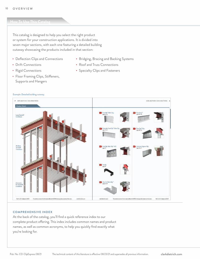
This catalog is designed to help you select the right product or system for your construction applications. It is divided into seven major sections, with each one featuring a detailed building cutaway showcasing the products included in that section:
Example: Detailed building cutaway.
COMPREHENSIVE INDEXAt the back of the catalog, you’ll find a quick reference index to our complete product offering. This index includes common names and product names, as well as common acronyms, to help you quickly find exactly what you’re looking for.
• Deflection Clips and Connections• Drift Connections• Rigid Connections • Floor Framing Clips, Stiffeners,
Supports and Hangers
• Bridging, Bracing and Backing Systems• Roof and Truss Connections • Specialty Clips and Fasteners
10
The technical content of this literature is effective 08/23/21 and supersedes all previous information. The technical content of this literature is effective 08/23/21 and supersedes all previous information. Pub. No. CD-ClipExpress 08/21clarkdietrich.com
O V E R V I E W
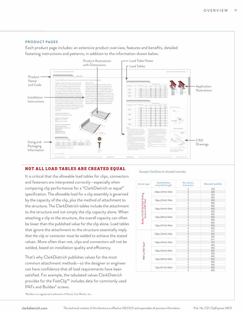
PRODUC T PAGESEach product page includes: an extensive product overview, features and benefits, detailed fastening instructions and patterns, in addition to the information shown below.
The technical content of this literature is effective 07/13/15 and supersedes all previous information. The technical content of this literature is effective 07/13/15 and supersedes all previous information. Pub. No. CD-ClipExpress 07/15Pub. No. CD-ClipExpress 07/15 clarkdietrich.com clarkdietrich.com
D E F L E C T I O N C O N N E C T I O N SD E F L E C T I O N C O N N E C T I O N S
DE
FLE
CTI
ON
CO
NN
EC
TIO
NS
ClarkDietrich Fast Top™ Clips are used in head-of-wall deflection conditions for in-fill curtain wall assemblies and/or interior nonload-bearing partitions to provide for vertical movement. These clips are used in place of, or in combination with, deflection track. They also make a positive attachment and eliminate the need to install bridging continuously throughout the upper-most punchouts. The Fast Top clip connectors can be attached to the underside of structural members, concrete decks or floor assemblies. Studs must be cut less than full height to enable vertical movement up to 2-1/2" (1-1/4" up and down). Fast Top clips install quickly with welds, screws or powder-actuated fasteners. FastClip™ deflection screws are used to attach the clip to the cold-formed framing and to ensure frictionless deflection. These clips are also embossed with fastening patterns to ensure accurate placement of fasteners.
ALTERNATIVE PRODUC TSMaxTrak® Slotted Deflection Track
PRODUC T DIMENSIONSFTC3: 1-1/2" x 4" x 3-1/4"FTC5: 1-1/2" x 4" x 4-3/4"
M ATERIAL SPECIFIC ATIONSGauge: 14 gauge (68mil)Design Thickness: 0.0713 inchesCoating: G90 Yield Strength: 50ksiASTM: A653/A653M
INSTALL ATIONConnections to the building can be made with screws, powder-actuated fasteners, drill-in concrete anchors or welding. Mechanical fasteners shall be equally spaced along the scored line of the 1-1/2" flange. When using the tabulated allowable loads in the tables on the opposite page, connections to the building structure must be made according to the notes. FastClip deflection screws are used to attach the clip to the cold-formed steel framing. Screws shall be driven through the slotted holes and positioned to allow for the appropriate building deflection. Two FastClip deflection screws are required with the FTC3, and three FastClip deflection screws are required with the FTC5.
Product codeThickness
Size (in)
Packaging Pcs./CartonGauge Mils Design
thickness (in)FTC3 14 68 0.0713 1-1/2 x 4 x 3-1/4 25FTC5 14 68 0.0713 1-1/2 x 4 x 4-3/4 30FTC8 14 68 0.0713 1-1/2 x 4 x 7-3/4 25
Notes:
Head-of-wall deflection conditions for exterior curtain wall and interior, nonload-bearing walls.
1 For the FTC3, tabulated values for welds are based on 3-1/4" of weld along each edge of the 1-1/2" clip leg.
2 For the FTC3, tabulated values for the PAFs and Buildex screws are based on the following: the outermost anchors are placed 1/2" (min.) away from the clip edge and/or bearing edge, anchors are spaced at 2-1/4" (min.) when using two anchors, and 1-1/8" (min.) when using three anchors.
3 For the FTC3, tabulated values for Hilti Kwik-Cons are based on the following: anchors are spaced at 2-1/4" o.c. (min.); anchors are placed 3/4" (min.) away from edge of building structure, and 1/2" (min.) away from edge of the Fast Top Clip. The tabulated values are based on 3000psi normal weight concrete.
4 For the FTC5, tabulated values for welds are based on 4-1/2" of weld along each edge of the 1-1/2" clip leg.
5 For the FTC5, tabulated values for the PAFs and Buildex screws are based on the following: the outermost anchors are placed 1/2" (min.) away from the clip edge and/or bearing edge; anchors are spaced at 3-3/4" (min.) when using two anchors, 1-7/8" (min.) when using three anchors, and 1-1/4" when using four anchors.
6 For the FTC5, tabulated values for Hilti Kwik-Cons are based on the following: anchors are spaced at 3-3/4" (min.) when using two anchors, and 1-7/8" when using three anchors; anchors are placed 3/4" (min.) away from edge of building structure and 1/2" (min.) away from edge of the Fast Top Clip. The tabulated values are based on 3000psi normal weight concrete.
7 Capacities listed for PAFs are based on minimum PAF requirements listed in General Note #6 on page 9.
8 #12-24 screws shall have ultimate shear and tension capacities equal to or greater than those listed on page 6.
9 It is the responsibility of the design professional to detail the project drawings for proper clip attachment.
10 Contact ClarkDietrich at 888-437-3244 for technical assistance.
11 Hilti is a registered trademark of Hilti Aktiengeseilschaft Corporation.
12 Buildex is a registered trademark of Illinois Tool Works, Inc.
MAINTAIN
Typical Construction Details
FTC3 FTC5
FTC3 includes 55 FastClip deflection screws per carton.FTC5 includes 110 FastClip deflection screws per carton.FTC8 includes 160 FastClip deflection screws per carton.
Fast Top™ C L I P S
Stud thickness and yield strength
Slip allowance (in)
Welded direct to structural steel
Mechanically Anchored
Number of anchors
PAF in steel (FS=5)
PAF in steel (FS=10)
Buildex #12-24 screws
in steel
Hilti 1/4" x 1-3/4"
Kwik-Cons in concrete
20ga (33mil) 33ksi
0.75 259 2 259 252 259 241259 3 259 259 259 —
1.25 259 2 259 219 259 206259 3 259 241 259 —
18ga (43mil) 33ksi
0.75 471 2 471 252 471 241471 3 471 286 471 —
1.25 471 2 437 219 471 206471 3 471 241 471 —
16ga (54mil) 33ksi
0.75 551 2 504 252 551 241551 3 551 286 551 —
1.25 551 2 437 219 551 206551 3 477 241 551 —
Stud thickness and yield strength
Slip allowance (in)
Welded direct to structural steel
Mechanically Anchored
Number of anchors
PAF in steel (FS=5)
PAF in steel (FS=10)
Buildex #12-24 screws
in steel
Hilti 1/4" x 1-3/4"
Kwik-Cons in concrete
20ga (33mil) 33ksi
0.75386 2 386 317 386 386386 3 386 386 386 386386 4 386 386 386 —
1.25386 2 386 286 386 386386 3 386 338 386 386386 4 386 371 386 —
18ga (43mil) 33ksi
0.75505 2 505 317 505 469505 3 505 389 505 466505 4 505 440 505 —
1.25505 2 505 286 505 411505 3 505 338 505 399505 4 505 371 505 —
16ga (54mil) 33ksi
0.75638 2 634 317 638 469638 3 638 389 638 466638 4 638 440 638 —
1.25638 2 571 286 638 411638 3 638 338 638 399638 4 638 371 638 —
16ga (54mil) 50ksi
0.751061 2 634 317 852 4691061 3 779 389 1061 4661061 4 879 440 1061 —
1.251061 2 571 286 789 4111061 3 676 338 922 3991061 4 738 371 922 —
F TC 3 A L LOWA B L E LOA D S (L B S )
F TC 5 A L LOWA B L E LOA D S (L B S )
Visit our CAD Library at clarkdietrich.com to view or download construction details in .dwg, .dxf, and .pdf formats.
Head-of-wall
U.S. Patent No. 6,688,069
FastClip Deflection Screw
4"
1-1/2"
4-3/4"
FTC5
Fast Top Clip Head-of-Wall Clips
FTC3
4"
1-1/2"
3-1/4"
Fast Top™ Clip (FTC3/FTC5)
26 27
Product Illustrations with Dimensions Load Tables
Load Table Notes
Application Illustrations
Sizing and Packaging Information
Product Name and Code
Installation Instructions
CAD Drawings
NO T A L L L OA D TA B L E S A R E C R E AT E D EQUA L
It is critical that the allowable load tables for clips, connectors and fasteners are interpreted correctly—especially when comparing clip performance for a “ClarkDietrich or equal” specification. The allowable load for a clip assembly is governed by the capacity of the clip, plus the method of attachment to the structure. The ClarkDietrich tables include the attachment to the structure and not simply the clip capacity alone. When attaching a clip to the structure, the overall capacity can often be lower than the published value for the clip alone. Load tables that ignore the attachment to the structure essentially imply that the clip or connector must be welded to achieve the stated values. More often than not, clips and connectors will not be welded, based on installation quality and efficiency.
That’s why ClarkDietrich publishes values for the most common attachment methods—so the designer or engineer can have confidence that all load requirements have been satisfied. For example, the tabulated values ClarkDietrich provides for the FastClip™ includes data for commonly used PAFs and Buildex* screws.*Buildex is a registered trademark of Illinois Tool Works, Inc.
Example: ClarkDietrich allowable load table.
Anchor type Stud thickness and yield strength
No. anchors to structure Allowable load (lbs)
Build
ex #
12-2
4 Te
k 5 S
elf-D
rillin
g Sc
rews
to 3
/16" S
teel
20ga (33mil) 33ksi2 4253 4254 425
18ga (43mil) 33ksi2 8523 8524 852
16ga (54mil) 50ksi2 8523 8524 852
14ga (68mil) 50ksi2 8523 8524 852
12ga (97mil) 50ksi2 8523 8524 852
PAF
to 3
/16" S
teel*
20ga (33mil) 33ksi2 5113 5874 587
18ga (43mil) 33ksi2 5113 7674 852
16ga (54mil) 50ksi2 8523 8524 852
14ga (68mil) 50ksi2 8523 8524 852
12ga (97mil) 50ksi2 8523 8524 852
11
The technical content of this literature is effective 08/23/21 and supersedes all previous information.Pub. No. CD-ClipExpress 08/21 clarkdietrich.com
O V E R V I E W
PRODUC T L ABELINGThe majority of the connectors listed in this catalog are identified using a very simple alphanumeric product code system. Each clip, connector or support is clearly embossed with an identifiable code so the installer can easily identify and use the proper connection hardware. For the engineer or architect, the embossed markings provide a very easy way to field verify that the correct connector or hanger is used.
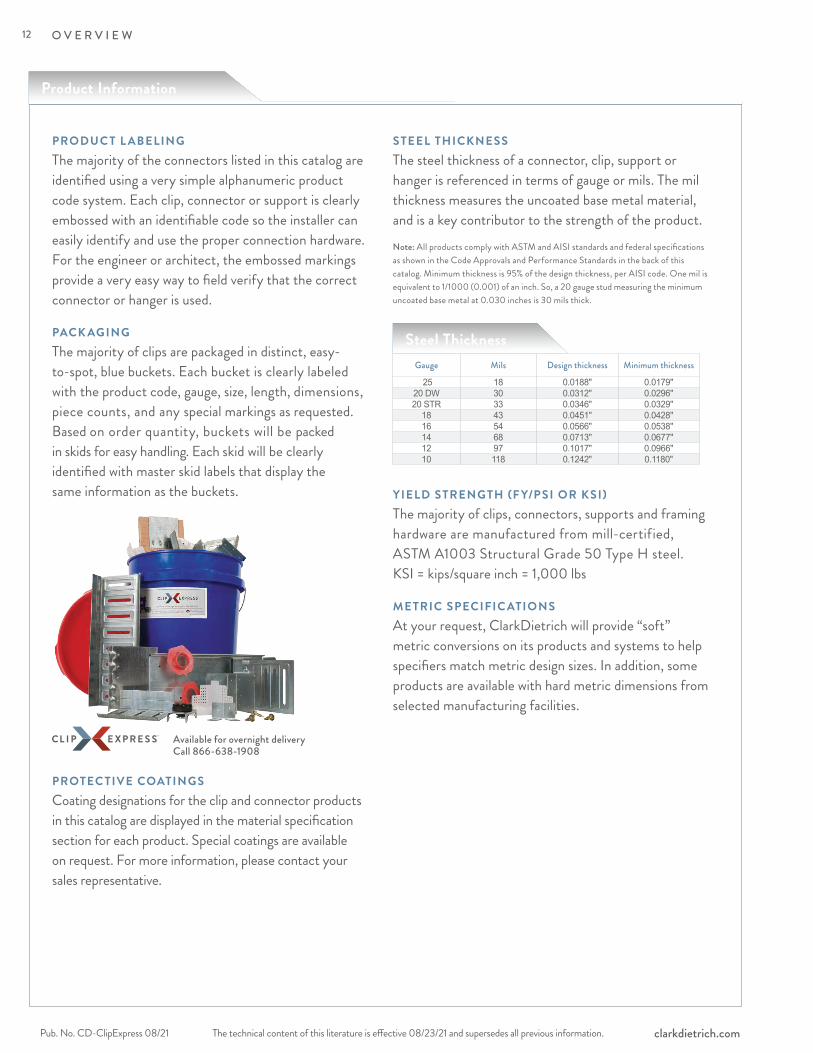
PACK AGINGThe majority of clips are packaged in distinct, easy-to-spot, blue buckets. Each bucket is clearly labeled with the product code, gauge, size, length, dimensions, piece counts, and any special markings as requested. Based on order quantity, buckets will be packed in skids for easy handling. Each skid will be clearly identified with master skid labels that display the same information as the buckets.
Available for overnight delivery Call 866-638-1908
PROTEC TIVE COATINGS Coating designations for the clip and connector products in this catalog are displayed in the material specification section for each product. Special coatings are available on request. For more information, please contact your sales representative.
STEEL THICKNESSThe steel thickness of a connector, clip, support or hanger is referenced in terms of gauge or mils. The mil thickness measures the uncoated base metal material, and is a key contributor to the strength of the product.Note: All products comply with ASTM and AISI standards and federal specifications as shown in the Code Approvals and Performance Standards in the back of this catalog. Minimum thickness is 95% of the design thickness, per AISI code. One mil is equivalent to 1/1000 (0.001) of an inch. So, a 20 gauge stud measuring the minimum uncoated base metal at 0.030 inches is 30 mils thick.
YIELD STRENGTH (F Y/PSI OR KSI)The majority of clips, connectors, supports and framing hardware are manufactured from mill-certified, ASTM A1003 Structural Grade 50 Type H steel. KSI = kips/square inch = 1,000 lbs
METRIC SPECIFIC ATIONSAt your request, ClarkDietrich will provide “soft” metric conversions on its products and systems to help specifiers match metric design sizes. In addition, some products are available with hard metric dimensions from selected manufacturing facilities.
Product Information
Gauge Mils Design thickness Minimum thickness
25 18 0.0188" 0.0179"20 DW 30 0.0312" 0.0296"20 STR 33 0.0346" 0.0329"
18 43 0.0451" 0.0428"16 54 0.0566" 0.0538"14 68 0.0713" 0.0677"12 97 0.1017" 0.0966"10 118 0.1242" 0.1180"
Steel Thickness
12
The technical content of this literature is effective 08/23/21 and supersedes all previous information. The technical content of this literature is effective 08/23/21 and supersedes all previous information. Pub. No. CD-ClipExpress 08/21clarkdietrich.com
O V E R V I E W
CL ARKDIETRICH ENGINEERING SERVICES
Smarter engineering and technical expertise.It’s support that extends beyond the structure itself.
From the initial design phase to jobsite installation, we are all about providing inventive, yet practical and hands-on know-how to help you think outside the box—or to help you just get it done.
ClarkDietrich Engineering Services is a full-service consulting firm that believes strongly in value engineering and customer input. Our engineering fees and lead times are competitive, and our customer service exceeds the industry standard with consistent point-of-contact through our regional project managers.
We offer Building Information Modeling (BIM) services that include specialty engineering collaborative design. We support the BIM movement by offering add-on tools that allow our products, and the rich data attached to them, to quickly be imported into digital designs. Our team is also comprised of LEED®-accredited professionals to consult on sustainable building design.• Electronically sealed shop drawings and calculations• Preliminary sizing and pre-bid engineering pricing• Reference plan on large projects• Detailed wall sections, full elevation opening
design and C-stud truss design
Our technical services team provides immediate response to questions ranging from general installation to detailed specification requirements, and can deliver one-day turnaround on technical sizing. We are experts on industry standards such as AISI, ASTM and SFIA. Our team also supports our online product submittal system, SubmittalPro,® and our design/engineering software is available as a free download from www.clarkdietrich.com. • Product support and typical member sizing• Framing detail recommendations• Compliance and industry standards, such as AISI, ASTM and SFIA• Engineering software and product submittal support• LEED requirements support
ClarkDietrich Engineering Services Toll-Free Phone: 877.832.3206Toll-Free Fax: 877.832.3208Technical Services: 888.437.3244Email: [email protected]
CENTRAL Crown Point, IN
NORTHEAST Bristol, CT
SOUTHEAST McDonough, GA
WEST Carlsbad, CA
Support and Services
13
The technical content of this literature is effective 08/23/21 and supersedes all previous information.Pub. No. CD-ClipExpress 08/21 clarkdietrich.com
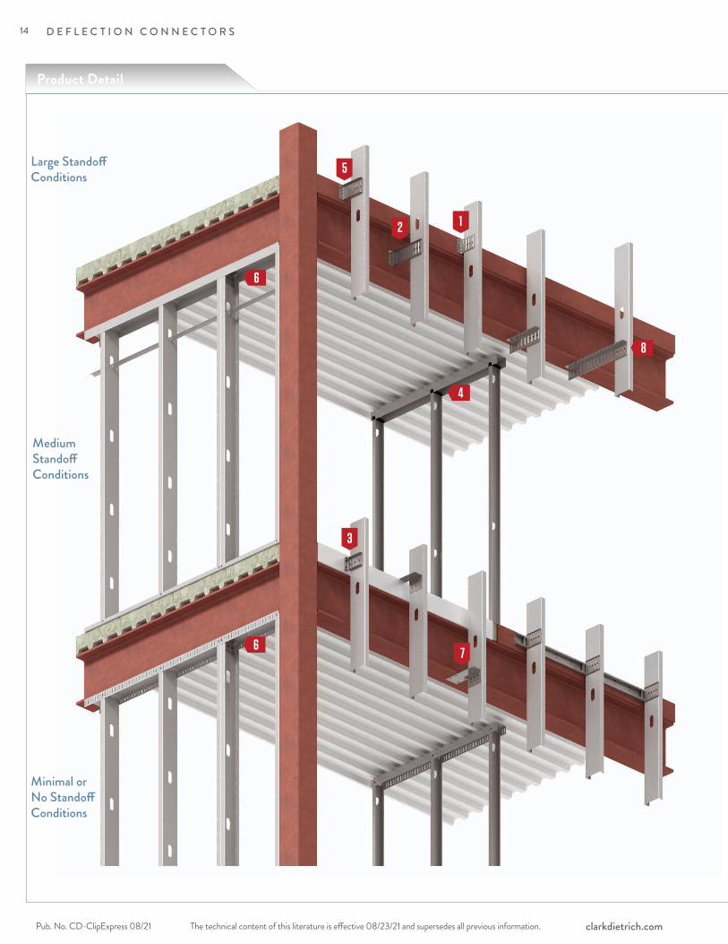
D E F L E C T I O N C O N N E C T O R S
Large Standoff Conditions
Medium Standoff Conditions
Minimal or No Standoff Conditions
12
7
3
Product Detail
8
6
4
6
5
14

The technical content of this literature is effective 08/23/21 and supersedes all previous information. The technical content of this literature is effective 08/23/21 and supersedes all previous information. Pub. No. CD-ClipExpress 08/21clarkdietrich.com
D E F L E C T I O N C O N N E C T O R S
DE
FLE
CTI
ON
CO
NN
EC
TIO
NSFast Top™ Clip
pages 28–30FastClip™ Slide Clip pages 16–18
Extended FastClip™ Slide Clip pages 19–21
Fast Strut™ pages 34–35
Flat Tail Slide Clip™ pages 31-33
FastClip Slide Clip™-HD page 22
1
3
2 7
6
4
5
Yurclip page 23
Universal Bypass Clip pages 24–27
8
15
Curtain Wall/BypassFastClip™ Slide Clip
The technical content of this literature is effective 08/23/21 and supersedes all previous information.Pub. No. CD-ClipExpress 08/21 clarkdietrich.com
D E F L E C T I O N C O N N E C T O R S
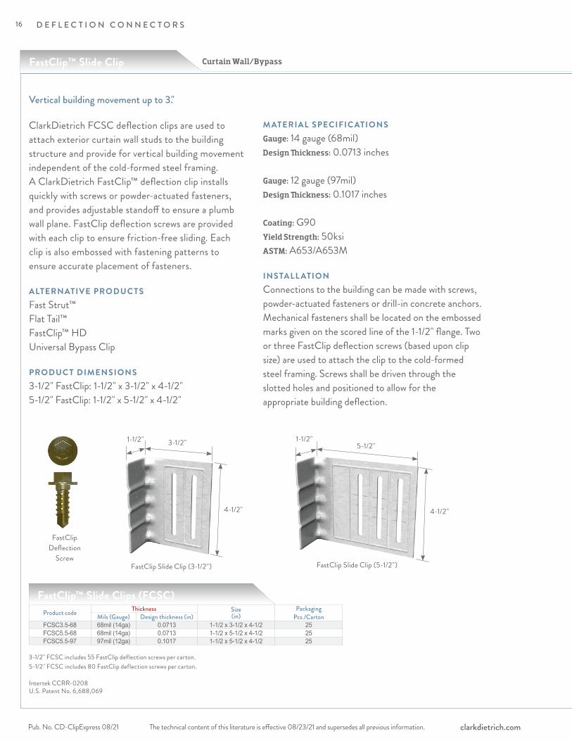
ClarkDietrich FCSC deflection clips are used to attach exterior curtain wall studs to the building structure and provide for vertical building movement independent of the cold-formed steel framing. A ClarkDietrich FastClip™ deflection clip installs quickly with screws or powder-actuated fasteners, and provides adjustable standoff to ensure a plumb wall plane. FastClip deflection screws are provided with each clip to ensure friction-free sliding. Each clip is also embossed with fastening patterns to ensure accurate placement of fasteners.
ALTERNATIVE PRODUC TSFast Strut™ Flat Tail™ FastClip™ HD Universal Bypass Clip
PRODUC T DIMENSIONS3-1/2" FastClip: 1-1/2" x 3-1/2" x 4-1/2"5-1/2" FastClip: 1-1/2" x 5-1/2" x 4-1/2"
M ATERIAL SPECIFIC ATIONSGauge: 14 gauge (68mil)Design Thickness: 0.0713 inches
Gauge: 12 gauge (97mil)Design Thickness: 0.1017 inches
Coating: G90 Yield Strength: 50ksiASTM: A653/A653M
INSTALL ATIONConnections to the building can be made with screws, powder-actuated fasteners or drill-in concrete anchors. Mechanical fasteners shall be located on the embossed marks given on the scored line of the 1-1/2" flange. Two or three FastClip deflection screws (based upon clip size) are used to attach the clip to the cold-formed steel framing. Screws shall be driven through the slotted holes and positioned to allow for the appropriate building deflection.
Vertical building movement up to 3."
FastClip Slide Clip (3-1/2")
FastClip Deflection
Screw
Product code Thickness Size (in)
Packaging Pcs./CartonMils (Gauge) Design thickness (in)
FCSC3.5-68 68mil (14ga) 0.0713 1-1/2 x 3-1/2 x 4-1/2 25FCSC5.5-68 68mil (14ga) 0.0713 1-1/2 x 5-1/2 x 4-1/2 25FCSC5.5-97 97mil (12ga) 0.1017 1-1/2 x 5-1/2 x 4-1/2 25
FastClip Slide Clip (5-1/2")
4-1/2"
5-1/2"1-1/2"
4-1/2"
3-1/2"1-1/2"
3-1/2" FCSC includes 55 FastClip deflection screws per carton.5-1/2" FCSC includes 80 FastClip deflection screws per carton.
FastClip™ Slide Clips (FCSC)
Intertek CCRR-0208U.S. Patent No. 6,688,069
16
The technical content of this literature is effective 08/23/21 and supersedes all previous information. The technical content of this literature is effective 08/23/21 and supersedes all previous information. Pub. No. CD-ClipExpress 08/21clarkdietrich.com
D E F L E C T I O N C O N N E C T O R S
DE
FLE
CTI
ON
CO
NN
EC
TIO
NS
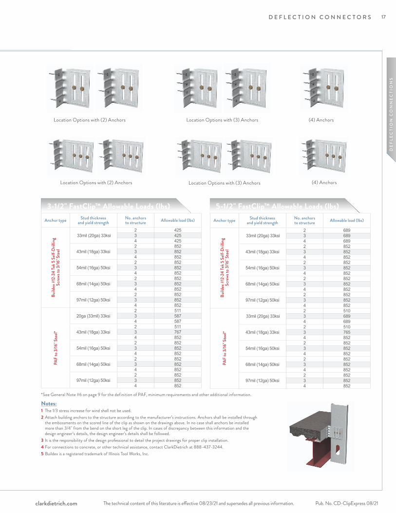
Location Options with (2) Anchors Location Options with (3) Anchors (4) Anchors
Location Options with (2) Anchors Location Options with (3) Anchors (4) Anchors
Anchor type Stud thickness and yield strength
No. anchors to structure Allowable load (lbs)
Build
ex #
12-2
4 Te
k 5 S
elf-D
rillin
g Sc
rews
to 3
/16" S
teel
33mil (20ga) 33ksi2 4253 4254 425
43mil (18ga) 33ksi2 8523 8524 852
54mil (16ga) 50ksi2 8523 8524 852
68mil (14ga) 50ksi2 8523 8524 852
97mil (12ga) 50ksi2 8523 8524 852
PAF
to 3
/16" S
teel*
20ga (33mil) 33ksi2 5113 5874 587
43mil (18ga) 33ksi2 5113 7674 852
54mil (16ga) 50ksi2 8523 8524 852
68mil (14ga) 50ksi2 8523 8524 852
97mil (12ga) 50ksi2 8523 8524 852
Anchor type Stud thickness and yield strength
No. anchors to structure Allowable load (lbs)
Build
ex #
12-2
4 Te
k 5 S
elf-D
rillin
g Sc
rews
to 3
/16" S
teel
33mil (20ga) 33ksi2 6893 6894 689
43mil (18ga) 33ksi2 8523 8524 852
54mil (16ga) 50ksi2 8523 8524 852
68mil (14ga) 50ksi2 8523 8524 852
97mil (12ga) 50ksi2 8523 8524 852
PAF
to 3
/16" S
teel*
33mil (20ga) 33ksi2 5103 6894 689
43mil (18ga) 33ksi2 5103 7654 852
54mil (16ga) 50ksi2 8523 8524 852
68mil (14ga) 50ksi2 8523 8524 852
97mil (12ga) 50ksi2 8523 8524 852
Notes:1 The 1/3 stress increase for wind shall not be used.2 Attach building anchors to the structure according to the manufacturer’s instructions. Anchors shall be installed through
the embossments on the scored line of the clip as shown on the drawings above. In no case shall anchors be installed more than 3/4" from the bend on the short leg of the clip. In cases of discrepancy between this information and the design engineer’s details, the design engineer’s details shall be followed.
3 It is the responsibility of the design professional to detail the project drawings for proper clip installation.4 For connections to concrete, or other technical assistance, contact ClarkDietrich at 888-437-3244.5 Buildex is a registered trademark of Illinois Tool Works, Inc.
3-1/2" FastClip™ Allowable Loads (lbs) 5-1/2" FastClip™ Allowable Loads (lbs)
*See General Note #6 on page 9 for the definition of PAF, minimum requirements and other additional information.
17

Curtain Wall/Bypass
The technical content of this literature is effective 08/23/21 and supersedes all previous information.Pub. No. CD-ClipExpress 08/21 clarkdietrich.com
D E F L E C T I O N C O N N E C T O R S
Anchor type Stud thickness and yield strength
No. anchors to structure Allowable load* (lbs) Allowable load# (lbs)
Build
ex #
12-2
4 Se
lf-D
rillin
g Sc
rews
to 3
/16" S
teel
33mil (20ga) 33ksi2 608 6083 608 6084 608 608
43mil (18ga) 33ksi2 905 9053 905 9054 905 905
54mil (16ga) 50ksi2 1004 10043 1506 15064 1553 1710
68mil (14ga) 50ksi2 1004 10043 1506 15064 1553 1710
97mil (12ga) 50ksi2 1004 10043 1506 15064 1553 1710
Hilt
i 0.15
7" X
-U P
owde
r-Act
uate
d Fa
stene
rs (P
AF) t
o 3/16
" Ste
el
33mil (20ga) 33ksi2 608 6083 608 6084 608 608
43mil (18ga) 33ksi2 905 9053 905 9054 905 905
54mil (16ga) 50ksi2 1064 10643 1553 15964 1553 1710
68mil (14ga) 50ksi2 1064 10643 1553 15964 1553 1710
97mil (12ga) 50ksi2 1064 10643 1553 15964 1553 1710
Gen
eric
Fa
stene
rs
to 3
/16" S
teel 33mil (20ga) 33ksi n 608 608
43mil (18ga) 33ksi n 905 90554mil (16ga) 50ksi n 1553 171068mil (14ga) 50ksi n 1553 171097mil (12ga) 50ksi n 1553 1710
Ultim
ate C
lip
Capa
city
33mil (20ga) 33ksi — 182543mil (18ga) 33ksi — 271554mil (16ga) 50ksi — 513068mil (14ga) 50ksi — 513097mil (12ga) 50ksi — 5130
5-1/2" 12ga FastClip™ (FCSC) Allowable Loads (lbs)
Notes:1 Tabulated allowable loads do not include a 1/3 stress increase for wind.2 * - Allowable capacity includes 1/8" service load limit.3 # - Allowable capacity does not include 1/8" service load limit.4 Mechanical fasteners should be attached to the structure in accordance with the manufacturer's instructions. All
fasteners were assumed to be installed at a distance of 3/4" from the bend of the structural leg.5 n - Number of generic mechanical fasteners required for connection to be determined by a design professional.
Capacity should not exceed tabulated allowable loads.6 Generic fastener capacities were calculated by considering clip-stud interaction, behavior of clip in tension and
compression only. The design professional has to detail for clip and desired fastener installation. 7 Ultimate clip capacities were tabulated for the purpose of blast loads and they do not assume a safety factor.8 Ultimate clip capacities were calculated by assuming that the structural leg of the clip fastened to 3/16" steel using (4)
Buildex #12-24 fasteners or (4) Hilti X-U fasteners.9 It is the responsibility of the design professional to detail the project drawings for proper clip and fastener installation.10 Buildex is a registered trademark of Illinois Tool Works, Inc.11 Hilti is a registered trademark of Hilti Aktiengeseilschaft Corporation.
5-1/2" FastClip™ Slide Clip
18

The technical content of this literature is effective 08/23/21 and supersedes all previous information. The technical content of this literature is effective 08/23/21 and supersedes all previous information. Pub. No. CD-ClipExpress 08/21clarkdietrich.com
D E F L E C T I O N C O N N E C T O R S
DE
FLE
CTI
ON
CO
NN
EC
TIO
NS
Extended FastClip™ Slide Clip Curtain Wall/Bypass
Extended FastClip™ Slide Clip (FCEC)
ClarkDietrich FCEC deflection clips are used to attach exterior curtain wall studs to the building structure and provide for vertical building movement independent of the cold-formed steel framing. The clips are available in standard lengths of 6," 8," 10" and 12" and are ideal for medium to larger standoff conditions. Extended FastClip™ deflection clips install quickly with screws, welds or powder-actuated fasteners, and provide adjustable standoff to ensure a plumb wall plane. FastClip deflection screws are provided with each clip to ensure friction-free sliding.
ALTERNATIVE PRODUC TSFast Strut™ Universal Bypass Clip
PRODUC T DIMENSIONS6" Extended FastClip: 1-7/8" x 6" x 4-3/4" 8" Extended FastClip: 1-7/8" x 8" x 4-3/4" 10" Extended FastClip: 1-7/8" x 10" x 4-3/4" 12" Extended FastClip: 1-7/8" x 12" x 4-3/4"
M ATERIAL SPECIFIC ATIONSGauge: 14 gauge (68mil)Design Thickness: 0.0713 inchesCoating: G90Yield Strength: 50ksiASTM: A653/A653M
INSTALL ATIONConnections to the building can be made with screws, welds, powder-actuated fasteners or drill-in concrete anchors. Mechanical fasteners shall be located on the embossed marks given on the scored line of the 1-7/8" flange. Three FastClip deflection screws are used to attach the clip to the cold-formed steel framing. Screws shall be driven through the slotted holes and positioned to allow for the appropriate building deflection.
FastClip Deflection
Screw
Product code Thickness Size (in)
Packaging Pcs./BucketMils (Gauge) Design thickness (in)
FCEC6-68 68mil (14ga) 0.0713 1-7/8 x 6 x 4-3/4 25FCEC8-68 68mil (14ga) 0.0713 1-7/8 x 8 x 4-3/4 25FCEC10-68 68mil (14ga) 0.0713 1-7/8 x 10 x 4-3/4 25FCEC12-68 68mil (14ga) 0.0713 1-7/8 x 12 x 4-3/4 25FCEC8-97 97mil (12ga) 0.1017 1-7/8 x 8 x 4-3/4 25
4-3/4"
3/4"
1-7/8"6," 8," 10," 12"
Vertical building movement up to 3," and commonly used for large standoff conditions.
Includes 80 FastClip deflection screws per bucket.
Intertek CCRR-0208 U.S. Patent No. 6,688,069
19

The technical content of this literature is effective 08/23/21 and supersedes all previous information.Pub. No. CD-ClipExpress 08/21 clarkdietrich.com
D E F L E C T I O N C O N N E C T O R S
Location Options with (2) Anchors
Location Options with (3) Anchors
(4) Anchors
Anchor type Stud thickness and yield strength
No. anchors to structure
Allowable load (lbs)
Build
ex #
12-2
4 Te
k 5 S
elf-D
rillin
g Sc
rews
to 3
/16" S
teel
33mil (20ga) 33ksi2 6893 6894 689
43mil (18ga) 33ksi2 8523 8524 852
54mil (16ga) 50ksi2 8523 8524 852
68mil (14ga) 50ksi2 8523 8524 852
97mil (12ga) 50ksi2 8523 8524 852
PAF
to 3
/16" S
teel*
33mil (20ga) 33ksi2 6893 6894 689
43mil (18ga) 33ksi2 5103 7654 852
54mil (16ga) 50ksi2 8523 8524 852
68mil (14ga) 50ksi2 8523 8524 852
97mil (12ga) 50ksi2 8523 8524 852
*See General Note #6 on page 9 for the definition of PAF, minimum requirements and other additional information.
Notes:1 The 1/3 stress increase for wind shall not be used.2 Attach building anchors to the structure according to the manufacturer’s instructions. Anchors shall be installed
through the embossments on the scored line of the clip as shown to the right. In no case shall anchors be installed more than 3/4" from the bend on the short leg of the clip. In cases of discrepancy between this information and the design engineer’s details, the design engineer’s details shall be followed.
3 It is the responsibility of the design professional to detail the project drawings for proper clip installation.4 For connections to concrete, or other technical assistance, contact ClarkDietrich at 888-437-3244.5 Buildex is a registered trademark of Illinois Tool Works, Inc.
Extended FastClip™ (FCEC) Allowable Loads (lbs)
Curtain Wall/BypassExtended FastClip™ Slide Clip
20

The technical content of this literature is effective 08/23/21 and supersedes all previous information. The technical content of this literature is effective 08/23/21 and supersedes all previous information. Pub. No. CD-ClipExpress 08/21clarkdietrich.com
D E F L E C T I O N C O N N E C T O R S
DE
FLE
CTI
ON
CO
NN
EC
TIO
NS
Location Options with (2) Anchors
Location Options with (3) Anchors
(4) Anchors
Notes:1 Tabulated allowable loads do not include a 1/3 stress increase for wind.2 * - Allowable capacity includes 1/8" service load limit.3 # - Allowable capacity does not include 1/8" service load limit.4 Allowable weld capacities were calculated by assuming 3 x 1" long welds at the ends and center of the clip bend.5 Listed weld capacities were calculated assuming an E60XX electrode.6 Mechanical fasteners should be attached to the structure in accordance with the manufacturer's instructions. All
fasteners were assumed to be installed at a distance of 3/4" from the bend of the structural leg.7 Generic fastener capacities were calculated by considering clip-stud interaction, behavior of clip in tension and
compression only. The design professional has to detail for clip and desired fastener installation.8 n - Number of generic mechanical fasteners required for connection to be determined by a design professional.
Capacity should not exceed tabulated allowable loads.9 Ultimate clip capacities were tabulated for the purpose of blast loads and they do not assume a safety factor.10 Ultimate clip capacities were calculated by assuming 3 x 1" long weld at the structural leg of the clip (clip bend)
welded to 3/16" steel.11 It is the responsibility of the design professional to detail the project drawings for proper clip and fastener installation.12 Buildex is a registered trademark of Illinois Tool Works, Inc.13 Hilti is a registered trademark of Hilti Aktiengeseilschaft Corporation.
Anchor type Stud thickness and yield strength
No. anchors to structure Allowable load* (lbs) Allowable load# (lbs)
Weld
(Fille
t/Fl
are G
roov
e)
E60X
X
33mil (20ga) 33ksi (3) 1" x 1/16" 608 60843mil (18ga) 33ksi (3) 1" x 1/16" 905 90554mil (16ga) 50ksi (3) 1" x 1/16" 1838 183868mil (14ga) 50ksi (3) 1" x 1/16" 2180 218097mil (12ga) 50ksi (3) 1" x 1/16" 2587 2587
Build
ex #
12-2
4 Se
lf-D
rillin
g Sc
rews
to 3
/16" S
teel
33mil (20ga) 33ksi2 608 6083 608 6084 608 608
43mil (18ga) 33ksi2 905 9053 905 9054 905 905
54mil (16ga) 50ksi2 1004 10043 1261 15064 1261 1838
68mil (14ga) 50ksi2 1004 10043 1261 15064 1261 2008
97mil (12ga) 50ksi2 1004 10043 1261 15064 1261 2008
Hilt
i 0.15
7" X
-U P
owde
r-Act
uate
d Fa
stene
rs (P
AF) t
o 3/16
" Ste
el
33mil (20ga) 33ksi2 608 6083 608 6084 608 608
43mil (18ga) 33ksi2 905 9053 905 9054 905 905
54mil (16ga) 50ksi2 1064 10643 1261 15964 1261 1838
68mil (14ga) 50ksi2 1064 10643 1261 15964 1261 2129
97mil (12ga) 50ksi2 1064 10643 1261 15964 1261 2129
Gen
eric
Fa
stene
rs
to 3
/16" S
teel 33mil (20ga) 33ksi n 608 608
43mil (18ga) 33ksi n 905 90554mil (16ga) 50ksi n 1261 183568mil (14ga) 50ksi n 1261 218097mil (12ga) 50ksi n 1261 2587
Ultim
ate C
lip
Capa
city
33mil (20ga) 33ksi — 182543mil (18ga) 33ksi — 271554mil (16ga) 50ksi — 551468mil (14ga) 50ksi — 654197mil (12ga) 50ksi — 7762
12ga Extended FastClip (FCEC) Allowable Loads (lbs)
8" 97mil Extended FastClip™ Slide Clip
21

The technical content of this literature is effective 08/23/21 and supersedes all previous information.Pub. No. CD-ClipExpress 08/21 clarkdietrich.com
D E F L E C T I O N C O N N E C T O R S
ALLOWABLE LOADS
Clip Designation
Stud thickness ga (mils)
Anchors to Structure
ASD Allowable Loads (lbs)
F1F2
w/ (2) screwsinto stud
F2 w/ (3) screws
into stud
FCSC-HD 68mils (14ga)
33mil (20ga) 33ksi
(1) 1/2" x 2" HiltiKWIK Bolt 3
50 433 65043mil (18ga) 33ksi 95 592 88754mil (16ga) 50ksi 152 1054 105468mil (14ga) 50ksi 188 1107 110797mil (12ga) 50ksi 188 1107 1107
Notes:1 Capacities listed in the table represent the capacity of the clip and the screws to the stud. Capacities listed in notes 3 are limits if the specified connector to the structure is used.2 Capacities listed in the table/notes assume that no load reduction are required for spacing or edge distance of anchors.3 Tension capacity is limited to 1069-lbs when using 1/2" x 2" Hilti KWIK Bolt TZ anchor into 3000psi cracked concrete.4 Other anchors may be used to achieve the full clip capacity but must be designed separately.5 Allowable loads have not been increased for wind, seismic, or other factors. 6 Hilti is a registered trademark of Hilti Aktiengeseilschaft Corporation.7 It is the responsibility of the designer to properly detail connections on the contract drawings.
FastClip™ Slide Clip w/Anchor Holes (FCSC-HD)
INSTALL ATIONTo attach the clip to the cold-formed steel framing stud, three FastClip deflection screws, shall be driven through the slotted holes and positioned to allow for the appropriate building deflection.
Attachment to the structure concrete slab can be made with 1/2" bolt anchors. Anchor connection design and edge distance requirements must be approved by a design professional before installation.
F2 Tension
Compression
F1
ClarkDietrich FCSC-HD 68mils (14ga) is used to attach exterior curtain-wall studs to the building concrete structure and provide for vertical building movement independent of the cold-formed steel framing. FastClip Deflection Screws are provided with each clip for attachment to the wall studs and allow for 3" vertical deflection (1-1/2" up and down) to ensure friction-free sliding. A 5/8" hole in the short leg of the clip allows for a 1/2" concrete anchor to be attached to the slab. (2) 3/8" holes allow 1/4" anchors.
Vertical building movement up to 3".
Product code Thickness Size (in) Packaging Pcs./BucketMils (Gauge) Design thickness (in)
FCSC-HD 68mil (14ga) 0.0713 1-1/2" x 6" x 4-1/4" 25
FCSC-HD includes (80) FastClip Deflection Screws
FCSC-HD Clips
FastClip Deflection Screws
(For Stud Connection)
M ATERIAL SPECIFIC ATIONSGauge: 14 gauge (68mil)Design Thickness: 0.0713 inches Yield Strength: 50ksiCoating: G90ASTM: A653/A1003
PRODUC T DIMENSIONSFCSC-HD: 1-1/2" x 4-1/4" x 6" long
Curtain Wall/Bypass Connected to Slab w/Anchor BoltFastClip™ Slide Clip w/Anchor Holes
22
The technical content of this literature is effective 08/23/21 and supersedes all previous information. The technical content of this literature is effective 08/23/21 and supersedes all previous information. Pub. No. CD-ClipExpress 08/21clarkdietrich.com
D E F L E C T I O N C O N N E C T O R S
DE
FLE
CTI
ON
CO
NN
EC
TIO
NS
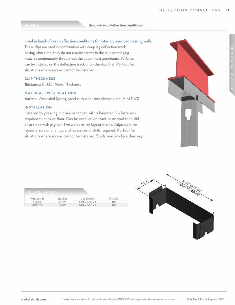
YurClip Head-of-wall deflection conditions
Used in head-of-wall deflection conditions for interior, non-load bearing walls.These clips are used in combination with deep leg deflection track. Saving labor time, they do not require screws in the stud or bridging installed continuously throughout the upper most punchouts. YurClips can be installed on the deflection track or on the stud first. Perfect for situations where screws cannot be installed.
CLIP THICKNESSThickness: 0.035" Nom. Thickness
M ATERIAL SPECIFIC ATIONS Material: Annealed Spring Steel with clear zinc electroplate, AISI 1070
INSTALL ATIONInstalled by pressing in place or tapped with a hammer. No fasteners required to deck or floor. Can be installed on track or on stud then slid onto track with pry bar. Two windows for layout marks. Adjustable for layout errors or changes and no screws or drills required. Perfect for situations where screws cannot be installed. Studs work in clip either way.
Product code Stud Size Clip Size (in) Pcs./Ctn.YDC2.5 2-1/2" 1-1/4 x 2-1/2 x 1 100
YDC3.625 3-5/8" 1-1/4 x 3-5/8 x 1 100
YurClip (YDC)
INSIDE TO INSIDE
2-1/2” OR 3-5/8”
1-1/4”
23
The technical content of this literature is effective 08/23/21 and supersedes all previous information.Pub. No. CD-ClipExpress 08/21 clarkdietrich.com
D E F L E C T I O N C O N N E C T O R S
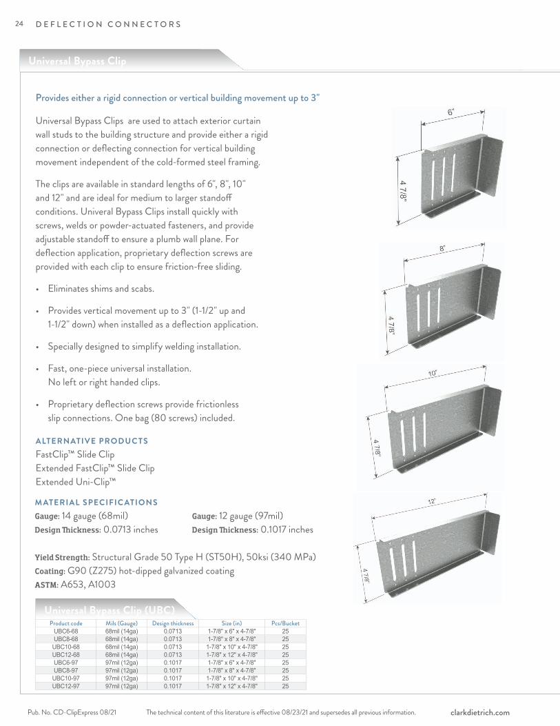
Universal Bypass Clip
Provides either a rigid connection or vertical building movement up to 3"
Universal Bypass Clips are used to attach exterior curtain wall studs to the building structure and provide either a rigid connection or deflecting connection for vertical building movement independent of the cold-formed steel framing.
The clips are available in standard lengths of 6", 8", 10" and 12" and are ideal for medium to larger standoff conditions. Univeral Bypass Clips install quickly with screws, welds or powder-actuated fasteners, and provide adjustable standoff to ensure a plumb wall plane. For deflection application, proprietary deflection screws are provided with each clip to ensure friction-free sliding.
• Eliminates shims and scabs.
• Provides vertical movement up to 3" (1-1/2" up and 1-1/2" down) when installed as a deflection application.
• Specially designed to simplify welding installation.
• Fast, one-piece universal installation. No left or right handed clips.
• Proprietary deflection screws provide frictionless slip connections. One bag (80 screws) included.
Product code Mils (Gauge) Design thickness Size (in) Pcs/BucketUBC6-68 68mil (14ga) 0.0713 1-7/8" x 6" x 4-7/8" 25UBC8-68 68mil (14ga) 0.0713 1-7/8" x 8" x 4-7/8" 25UBC10-68 68mil (14ga) 0.0713 1-7/8" x 10" x 4-7/8" 25UBC12-68 68mil (14ga) 0.0713 1-7/8" x 12" x 4-7/8" 25UBC6-97 97mil (12ga) 0.1017 1-7/8" x 6" x 4-7/8" 25UBC8-97 97mil (12ga) 0.1017 1-7/8" x 8" x 4-7/8" 25UBC10-97 97mil (12ga) 0.1017 1-7/8" x 10" x 4-7/8" 25UBC12-97 97mil (12ga) 0.1017 1-7/8" x 12" x 4-7/8" 25
Universal Bypass Clip (UBC)
ALTERNATIVE PRODUC TSFastClip™ Slide Clip Extended FastClip™ Slide Clip Extended Uni-Clip™
M ATERIAL SPECIFIC ATIONSGauge: 14 gauge (68mil)Design Thickness: 0.0713 inches
Yield Strength: Structural Grade 50 Type H (ST50H), 50ksi (340 MPa)Coating: G90 (Z275) hot-dipped galvanized coatingASTM: A653, A1003
Gauge: 12 gauge (97mil)Design Thickness: 0.1017 inches
24

The technical content of this literature is effective 08/23/21 and supersedes all previous information. The technical content of this literature is effective 08/23/21 and supersedes all previous information. Pub. No. CD-ClipExpress 08/21clarkdietrich.com
D E F L E C T I O N C O N N E C T O R S
DE
FLE
CTI
ON
CO
NN
EC
TIO
NS
INSTALL ATIONConnections to the building can be made with screws, welds powder-actuated fasteners. Mechanical fasteners shall be located on the embossed marks given on the scored line of the 1-7/8" flange. Attach building anchors to the structure according to the manufacture’s instructions. Anchors shall be installed through the embossments on the scored line of the clip as shown on the attached drawings. In no case shall anchors be installed more than 3/4" from the bend on the short leg of the clip. In cases of discrepancy between this information and the Design Engineer’s details, the Design Engineer’s details shall be followed.
For a Rigid Connection: Attach the Universal Bypass Clip to cold-formed steel framing members using (6) #10-16 minimum self-drilling screws (not included) for the 14ga clip and (6) #12-14 minimum self-drilling screws (not included) for the 12ga clip, through the clip holes into the steel framing.
For a Deflection Connection: Attach the Universal Bypass Clip to the cold-formed steel framing using (3) #14 proprietrary deflection screws (included) through the (3) slotted holes and positioned to allow for the appropriate building deflection.
Proprietary Deflection Screws: Many of the ClarkDietrich deflection clips include our proprietary deflection fastener that has been specifically designed to provide friction-free deflection. These fasteners eliminate drag, binding or resistance that can often occur with common fasteners.
25

The technical content of this literature is effective 08/23/21 and supersedes all previous information.Pub. No. CD-ClipExpress 08/21 clarkdietrich.com
D E F L E C T I O N C O N N E C T O R S
F3
F2F1
Universal Bypass Clip
UBC - 14ga (As a Deflection Connection)
(3) #14 Deflection Screw PatternShown in a UBC6 Clip
Notes:1 Allowable loads (ASD) listed represent the capacity of the clip to the stud only. (framing connection).2 Allowable Loads have not been increased for the wind, seismic, or other factors. 3 An 1/8-in service deflection load limit was applied to clips resisting F2 and F3 loads. In accordance with ICC AC 261, service deflection limit was not applied to clips resisting F1 loads.4 For Deflection connection, one #14 shouldered screw (Deflection Screw) shall be installed per slot, placed at the center. #14 Deflection Screws are provided with each Universal Bypass Clip.5 Listed capacities are based on the maximum screw pattern. For maximum screw pattern, fill #14 Deflection screws in each slot for a Deflection Clip.6 It is the responsibility of the design professional to design the attachment of the clips to the structure and verify that their capacity meets the requirements of the intended application.7 Nominal or LRFD loads are available upon request.
ATTACHMENT TO STRUCTURAL: DESIGNED BY OTHERS
UBC - 14ga (As a Deflection Connection)
Notes:1 Allowable Loads (ASD) have not been increased for the wind, seismic, or other factors. 2 For Deflection clip, one #14 shouldered screw (UBC Deflection Screw) shall be installed per slot, placed at the center. Clip gauge-specific #14 UBC Deflection Screws are provided with each Universal Bypass Clip.3 Listed capacities are based on the maximum screw pattern. For maximum screw pattern, fill #14 Deflection screws in each slot for a Deflection Clip.4 The Allowable loads listed for welds are based on the following weld lengths: - (2) Welds - 1" along back of short leg clip bend (each weld equally distanced from center of clip)5 Use E70XX (min.) electrodes. 6 It is the responsibility of the design professional to verify that the connection design meets the requirements of the intended application.7 Nominal or LRFD loads are available upon request.
Clip designationStud gauge
(mils) Yield Strength
ASD Allowable Loads (lbs)F1 (In-Plane)
w/ (3) #14F2 (Tension)
w/ (3) #14F3 (Compression)
w/ (3) #14
UBC6-68 68mil (14ga)
33mil (20ga) 33ksi 110 605 60543mil (18ga) 33ksi 140 905 90554mil (16ga) 50ksi 255 1275 143068mil (14ga) 50ksi 255 1275 143097mil (12ga) 50ksi 255 1275 1430
UBC8-68 68mil (14ga)
33mil (20ga) 33ksi 110 605 60543mil (18ga) 33ksi 140 905 90554mil (16ga) 50ksi 190 1275 134068mil (14ga) 50ksi 190 1275 134097 mil (12ga) 50ksi 190 1275 1340
UBC10-68 68mil (14ga)
33mil (20ga) 33ksi 110 605 60543mil (18ga) 33ksi 140 905 90554mil (16ga) 50ksi 150 1275 132568mil (14ga) 50ksi 150 1275 132597 mil (12ga) 50ksi 150 1275 1325
UBC12-68 68mil (14ga)
33mil (20ga) 33ksi 90 605 60543mil (18ga) 33ksi 90 905 90554mil (16ga) 50ksi 90 1275 130068mil (14ga) 50ksi 90 1275 130097 mil (12ga) 50ksi 90 1275 1300
ATTACHMENT TO STRUCTURAL: WELDED
F3
F2F1
For 12ga ASD Allowable Loads, visit clarkdietrich.com, Express Connect or iTools.
Clip designationStud gauge
(mils) Yield Strength
ASD Allowable Loads (lbs)F1 (In-Plane)
w/ (3) #14F2 (Tension)
w/ (3) #14F3 (Compression)
w/ (3) #14
UBC6-68 68mil (14ga)
33mil (20ga) 33ksi 110 605 60543mil (18ga) 33ksi 140 905 90554mil (16ga) 50ksi 255 1280 143068mil (14ga) 50ksi 255 1280 143097mil (12ga) 50ksi 255 1280 1430
UBC8-68 68mil (14ga)
33mil (20ga) 33ksi 110 605 60543mil (18ga) 33ksi 140 905 90554mil (16ga) 50ksi 190 1235 134068mil (14ga) 50ksi 190 1235 134097 mil (12ga) 50ksi 190 1235 1340
UBC10-68 68mil (14ga)
33mil (20ga) 33ksi 110 605 60543mil (18ga) 33ksi 140 905 90554mil (16ga) 50ksi 150 1185 132568mil (14ga) 50ksi 150 1185 132597 mil (12ga) 50ksi 150 1185 1325
UBC12-68 68mil (14ga)
33mil (20ga) 33ksi 90 605 60543mil (18ga) 33ksi 90 905 90554mil (16ga) 50ksi 90 1190 130068mil (14ga) 50ksi 90 1190 130097 mil (12ga) 50ksi 90 1190 1300
26

The technical content of this literature is effective 08/23/21 and supersedes all previous information. The technical content of this literature is effective 08/23/21 and supersedes all previous information. Pub. No. CD-ClipExpress 08/21clarkdietrich.com
D E F L E C T I O N C O N N E C T O R S
DE
FLE
CTI
ON
CO
NN
EC
TIO
NS
UBC - 14ga (As a Deflection Connection)
(3) #14 Deflection Screw PatternShown in a UBC6 Clip
Notes:1 Allowable Loads (ASD) have not been increased for the wind, seismic, or other factors. 2 An 1/8-in service deflection load limit was applied to clips resisting F2 and F3 loads. In accordance with ICC AC 261, service deflection limit was not applied to clips resisting F1 loads.3 For Deflection clip, one #14 shouldered screw (UBC Deflection Screw) shall be installed per slot, placed at the center. Clip gauge-specific #14 UBC Deflection Screws are provided with each UBC.4 Listed capacities are based on the maximum screw pattern. For maximum screw pattern, fill #14 Deflection screws in each slot for a Deflection Clip.5 #12-24 Fasteners shall be used for attachment to 3/16" steel structure. (4) Fastener configuration shall be used. Screws should be placed at indentations scribed on the short leg of the UBC clip.6 The minimum edge distance for each fastener type shall comply with the fastener manufacturer’s recommendation.7 It is the responsibility of the design professional to verify that the connection design meets the requirements of the intended application.8 Nominal or LRFD loads are available upon request.
Clip designationStud gauge
(mils) Yield Strength
ASD Allowable Loads (lbs)F1 (In-Plane)
w/ (3) #14F2 (Tension)
w/ (3) #14F3 (Compression)
w/ (3) #14
UBC6-68 68mil (14ga)
33mil (20ga) 33ksi 110 605 60543mil (18ga) 33ksi 140 905 90554mil (16ga) 50ksi 255 1280 143068mil (14ga) 50ksi 255 1280 143097mil (12ga) 50ksi 255 1280 1430
UBC8-68 68mil (14ga)
33mil (20ga) 33ksi 110 605 60543mil (18ga) 33ksi 140 905 90554mil (16ga) 50ksi 190 1235 134068mil (14ga) 50ksi 190 1235 134097 mil (12ga) 50ksi 190 1235 1340
UBC10-68 68mil (14ga)
33mil (20ga) 33ksi 110 605 60543mil (18ga) 33ksi 140 905 90554mil (16ga) 50ksi 150 1185 132568mil (14ga) 50ksi 150 1185 132597 mil (12ga) 50ksi 150 1185 1325
UBC12-68 68mil (14ga)
33mil (20ga) 33ksi 90 605 60543mil (18ga) 33ksi 90 905 90554mil (16ga) 50ksi 90 1190 130068mil (14ga) 50ksi 90 1190 130097 mil (12ga) 50ksi 90 1190 1300
ATTACHMENT TO STRUCTURAL: (4) #12-24 FASTENERS
UBC - 14ga (As a Deflection Connection)
Notes:1 Allowable Loads (ASD) have not been increased for the wind, seismic, or other factors. 2 Capacities considered for Hilti PAFs are based on fastener strengths listed in ICC ESR-2269. 3 It is the responsibility of the design professional to verify that the connection design meets the requirements of the intended application.4 Listed capacities are based on the maximum screw pattern. For maximum screw pattern, fill #14 Deflection screws in each slot for a Deflection Clip.5 Nominal or LRFD loads are available upon request.6 An 1/8-in service deflection load limit was applied to clips resisting F2 and F3 loads. In accordance with ICC AC 261, service deflection limit was not applied to clips resisting F1 loads.7 For Deflection clip, one #14 shouldered screw (UBC Deflection Screw) shall be installed per slot, placed at the center. Clip gauge-specific #14 UBC Deflection Screws are provided with each UBC.8 0.157" Hilti X-U PAFs shall be used for attachment to 3/16" steel structure. (4) Fastener configuration shall be used. PAFs should be placed at indentations scribed on the short leg of the UBC clip.
Clip designationStud gauge
(mils) Yield Strength
ASD Allowable Loads (lbs)F1 (In-Plane)
w/ (3) #14F2 (Tension)
w/ (3) #14F3 (Compression)
w/ (3) #14
UBC6-68 68mil (14ga)
33mil (20ga) 33ksi 110 605 60543mil (18ga) 33ksi 140 905 90554mil (16ga) 50ksi 255 1280 143068mil (14ga) 50ksi 255 1280 143097mil (12ga) 50ksi 255 1280 1430
UBC8-68 68mil (14ga)
33mil (20ga) 33ksi 110 605 60543mil (18ga) 33ksi 140 905 90554mil (16ga) 50ksi 190 1235 134068mil (14ga) 50ksi 190 1235 134097 mil (12ga) 50ksi 190 1235 1340
UBC10-68 68mil (14ga)
33mil (20ga) 33ksi 110 605 60543mil (18ga) 33ksi 140 905 90554mil (16ga) 50ksi 150 1185 132568mil (14ga) 50ksi 150 1185 132597 mil (12ga) 50ksi 150 1185 1325
UBC12-68 68mil (14ga)
33mil (20ga) 33ksi 90 605 60543mil (18ga) 33ksi 90 905 90554mil (16ga) 50ksi 90 1190 130068mil (14ga) 50ksi 90 1190 130097 mil (12ga) 50ksi 90 1190 1300
ATTACHMENT TO STRUCTURAL: (4) 0.157" PAFs
F3
F2F1
F3
F2F1
For 12ga ASD Allowable Loads, visit clarkdietrich.com, Express Connect or iTools.
27

The technical content of this literature is effective 08/23/21 and supersedes all previous information.Pub. No. CD-ClipExpress 08/21 clarkdietrich.com
D E F L E C T I O N C O N N E C T O R S
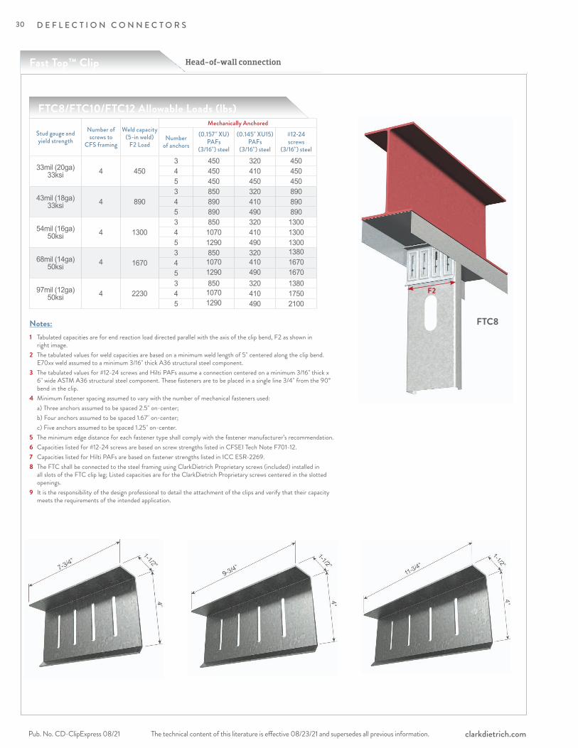
ClarkDietrich Fast Top™ Clips are used in head-of-wall deflection conditions for in-fill curtain wall assemblies and/or interior nonload-bearing partitions to provide for vertical movement. These clips are used in place of, or in combination with, deflection track. They also make a positive attachment and eliminate the need to install bridging continuously throughout the upper-most punchouts. The Fast Top clip connectors can be attached to the underside of structural members, concrete decks or floor assemblies. Studs must be cut less than full height to enable vertical movement up to 2-1/2" (1-1/4" up and down). Fast Top clips install quickly with welds, screws or powder-actuated fasteners. FastClip™ deflection screws are used to attach the clip to the cold-formed framing and to ensure frictionless deflection. These clips are also embossed with fastening patterns to ensure accurate placement of fasteners.
ALTERNATIVE PRODUC TSMaxTrak® Slotted Deflection Track
M ATERIAL SPECIFIC ATIONSGauge: 14 gauge (68mil)Design Thickness: 0.0713 inchesCoating: G90 Yield Strength: 50ksiASTM: A653/A653M
INSTALL ATIONConnections to the building can be made with screws, powder-actuated fasteners, drill-in concrete anchors or welding. Mechanical fasteners shall be equally spaced along the scored line of the 1-1/2" flange. When using the tabulated allowable loads in the tables on the opposite page, connections to the building structure must be made according to the notes. FastClip deflection screws are used to attach the clip to the cold-formed steel framing. Screws shall be driven through the slotted holes and positioned to allow for the appropriate building deflection. Two FastClip deflection screws are required with the FTC3, three FastClip deflection screws are required with the FTC5, and four FastClip deflection screws are required with the FTC8, FTC10, FTC12.
Product codeThickness
Size (in)
Packaging Pcs./BucketMils (Gauge) Design
thickness (in)FTC3 68mil (14ga) 0.0713 1-1/2 x 4 x 3-1/4 25FTC5 68mil (14ga) 0.0713 1-1/2 x 4 x 4-3/4 30FTC8 68mil (14ga) 0.0713 1-1/2 x 4 x 7-3/4 25FTC10 68mil (14ga) 0.0713 1-1/2 x 4 x 9-3/4 25FTC12 68mil (14ga) 0.0713 1-1/2 x 4 x 11-3/4 25
Head-of-wall deflection conditions for exterior curtain wall and interior, nonload-bearing walls.
FTC3 includes 55 FastClip deflection screws per carton.FTC5 includes 110 FastClip deflection screws per carton.FTC8 includes 110 FastClip deflection screws per carton.FTC10 includes 110 FastClip deflection screws per carton.FTC12 includes 110 FastClip deflection screws per carton.
Fast Top™ Clip (FTC)
FastClip Deflection
Screw
Head-of-wall connectionFast Top™ Clip
FTC3 FTC5 FTC8
FTC10 FTC12
28
The technical content of this literature is effective 08/23/21 and supersedes all previous information. The technical content of this literature is effective 08/23/21 and supersedes all previous information. Pub. No. CD-ClipExpress 08/21clarkdietrich.com
D E F L E C T I O N C O N N E C T O R S
DE
FLE
CTI
ON
CO
NN
EC
TIO
NS
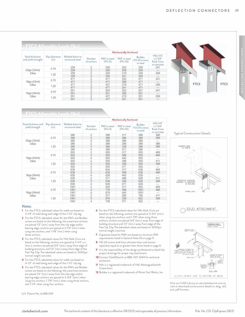
U.S. Patent No. 6,688,069
Notes:1 For the FTC3, tabulated values for welds are based on
3-1/4" of weld along each edge of the 1-1/2" clip leg.2 For the FTC3, tabulated values for the PAFs and Buildex
screws are based on the following: the outermost anchors are placed 1/2" (min.) away from the clip edge and/or bearing edge, anchors are spaced at 2-1/4" (min.) when using two anchors, and 1-1/8" (min.) when using three anchors.
3 For the FTC3, tabulated values for Hilti Kwik-Cons are based on the following: anchors are spaced at 2-1/4" o.c. (min.); anchors are placed 3/4" (min.) away from edge of building structure, and 1/2" (min.) away from edge of the Fast Top Clip. The tabulated values are based on 3000psi normal weight concrete.
4 For the FTC5, tabulated values for welds are based on 4-1/2" of weld along each edge of the 1-1/2" clip leg.
5 For the FTC5, tabulated values for the PAFs and Buildex screws are based on the following: the outermost anchors are placed 1/2" (min.) away from the clip edge and/or bearing edge; anchors are spaced at 3-3/4" (min.) when using two anchors, 1-7/8" (min.) when using three anchors, and 1-1/4" when using four anchors.
6 For the FTC5, tabulated values for Hilti Kwik-Cons are based on the following: anchors are spaced at 3-3/4" (min.) when using two anchors, and 1-7/8" when using three anchors; anchors are placed 3/4" (min.) away from edge of building structure and 1/2" (min.) away from edge of the Fast Top Clip. The tabulated values are based on 3000psi normal weight concrete.
7 Capacities listed for PAFs are based on minimum PAF requirements listed in General Note #6 on page 9.
8 #12-24 screws shall have ultimate shear and tension capacities equal to or greater than those listed on page 6.
9 It is the responsibility of the design professional to detail the project drawings for proper clip attachment.
10 Contact ClarkDietrich at 888-437-3244 for technical assistance.
11 Hilti is a registered trademark of Hilti Aktiengeseilschaft Corporation.
12 Buildex is a registered trademark of Illinois Tool Works, Inc.
MAINTAIN
Typical Construction Details
FTC3 FTC5
Stud thickness and yield strength
Slip allowance (in)
Welded direct to structural steel
Mechanically Anchored
Number of anchors
PAF in steel (FS=5)
PAF in steel (FS=10)
Buildex #12-24 screws
in steel
Hilti 1/4" x 1-3/4"
Kwik-Cons in concrete
20ga (33mil) 33ksi
0.75 259 2 259 252 259 241259 3 259 259 259 —
1.25 259 2 259 219 259 206259 3 259 241 259 —
18ga (43mil) 33ksi
0.75 471 2 471 252 471 241471 3 471 286 471 —
1.25 471 2 437 219 471 206471 3 471 241 471 —
16ga (54mil) 33ksi
0.75 551 2 504 252 551 241551 3 551 286 551 —
1.25 551 2 437 219 551 206551 3 477 241 551 —
Stud thickness and yield strength
Slip allowance (in)
Welded direct to structural steel
Mechanically Anchored
Number of anchors
PAF in steel (FS=5)
PAF in steel (FS=10)
Buildex #12-24 screws
in steel
Hilti 1/4" x 1-3/4"
Kwik-Cons in concrete
20ga (33mil) 33ksi
0.75386 2 386 317 386 386386 3 386 386 386 386386 4 386 386 386 —
1.25386 2 386 286 386 386386 3 386 338 386 386386 4 386 371 386 —
18ga (43mil) 33ksi
0.75505 2 505 317 505 469505 3 505 389 505 466505 4 505 440 505 —
1.25505 2 505 286 505 411505 3 505 338 505 399505 4 505 371 505 —
16ga (54mil) 33ksi
0.75638 2 634 317 638 469638 3 638 389 638 466638 4 638 440 638 —
1.25638 2 571 286 638 411638 3 638 338 638 399638 4 638 371 638 —
16ga (54mil) 50ksi
0.751061 2 634 317 852 4691061 3 779 389 1061 4661061 4 879 440 1061 —
1.251061 2 571 286 789 4111061 3 676 338 922 3991061 4 738 371 922 —
FTC3 Allowable Loads (lbs)
FTC5 Allowable Loads (lbs)
Visit our CAD Library at cad.clarkdietrich.com to view or download construction details in .dwg, .dxf, and .pdf formats.
29
The technical content of this literature is effective 08/23/21 and supersedes all previous information.Pub. No. CD-ClipExpress 08/21 clarkdietrich.com
D E F L E C T I O N C O N N E C T O R S
Head-of-wall connection
Notes:
FTC8/FTC10/FTC12 Allowable Loads (lbs)
Stud gauge and yield strength
Number of screws to
CFS framing
Weld capacity(5-in weld)
F2 Load
Mechanically Anchored
Number of anchors
(0.157" XU)PAFs
(3/16") steel
(0.145" XU15)PAFs
(3/16") steel
#12-24screws
(3/16") steel
33mil (20ga) 33ksi 4 450
3 450 320 4504 450 410 4505 450 450 450
43mil (18ga) 33ksi 4 890
3 850 320 8904 890 410 8905 890 490 890
54mil (16ga) 50ksi 4 1300
3 850 320 13004 1070 410 13005 1290 490 1300
68mil (14ga) 50ksi 4 1670
3 850 320 1380 4 1070 410 1670 5 1290 490 1670
97mil (12ga) 50ksi 4 2230
3 850 320 13804 1070 410 17505 1290 490 2100
1 Tabulated capacities are for end reaction load directed parallel with the axis of the clip bend, F2 as shown in right image.
2 The tabulated values for weld capacities are based on a minimum weld length of 5" centered along the clip bend. E70xx weld assumed to a minimum 3/16" thick A36 structural steel component.3 The tabulated values for #12-24 screws and Hilti PAFs assume a connection centered on a minimum 3/16" thick x 6" wide ASTM A36 structural steel component. These fasteners are to be placed in a single line 3/4" from the 90° bend in the clip.4 Minimum fastener spacing assumed to vary with the number of mechanical fasteners used: a) Three anchors assumed to be spaced 2.5" on-center; b) Four anchors assumed to be spaced 1.67" on-center; c) Five anchors assumed to be spaced 1.25" on-center.5 The minimum edge distance for each fastener type shall comply with the fastener manufacturer’s recommendation.6 Capacities listed for #12-24 screws are based on screw strengths listed in CFSEI Tech Note F701-12.7 Capacities listed for Hilti PAFs are based on fastener strengths listed in ICC ESR-2269.8 The FTC shall be connected to the steel framing using ClarkDietrich Proprietary screws (included) installed in all slots of the FTC clip leg; Listed capacities are for the ClarkDietrich Proprietary screws centered in the slotted openings.9 It is the responsibility of the design professional to detail the attachment of the clips and verify that their capacity meets the requirements of the intended application.
FTC8
F2
Fast Top™ Clip
30
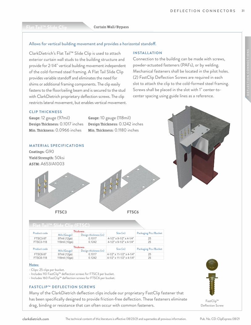
The technical content of this literature is effective 08/23/21 and supersedes all previous information. The technical content of this literature is effective 08/23/21 and supersedes all previous information. Pub. No. CD-ClipExpress 08/21clarkdietrich.com
D E F L E C T I O N C O N N E C T O R S
DE
FLE
CTI
ON
CO
NN
EC
TIO
NS
Allows for vertical building movement and provides a horizontal standoff.
ClarkDietrich’s Flat Tail™ Slide Clip is used to attach exterior curtain wall studs to the building structure and provide for 2-1/4" vertical building movement independent of the cold-formed steel framing. A Flat Tail Slide Clip provides variable standoff and eliminates the need for shims or additional framing components. The clip easily fastens to the floor/ceiling beam and is secured to the stud with ClarkDietrich proprietary deflection screws. The clip restricts lateral movement, but enables vertical movement.
CLIP THICKNESSGauge: 12 gauge (97mil) Design Thickness: 0.1017 inches Min. Thickness: 0.0966 inches
M ATERIAL SPECIFIC ATIONS Coatings: G90 Yield Strength: 50ksi ASTM: A653/A1003
INSTALL ATIONConnection to the building can be made with screws, powder-actuated fasteners (PAFs), or by welding. Mechanical fasteners shall be located in the pilot holes. (2) FastClip Deflection Screws are required in each slot to attach the clip to the cold-formed steel framing. Screws shall be placed in the slot with 1" center-to-center spacing using guide lines as a reference.
Notes: - Clips: 25 clips per bucket. - Includes 110 FastClip™ deflection screws for FTSC3 per bucket. - Includes 160 FastClip™ deflection screws for FTSC6 per bucket.
FastClip™ Deflection Screw
Curtain Wall/BypassFlat Tail™ Slide Clip
Product code Thickness Size (in) Packaging Pcs./BucketMils (Gauge) Design thickness (in)FTSC3-97 97mil (12ga) 0.1017 4-1/2" x 9-1/2" x 4-1/4" 25FTSC3-118 118mil (10ga) 0.1242 4-1/2" x 9-1/2" x 4-1/4" 25
Flat Tail™ Slide Clip (FTSC)
Product code Thickness Size (in) Packaging Pcs./BucketMils (Gauge) Design thickness (in)FTSC6-97 97mil (12ga) 0.1017 4-1/2" x 11-1/2" x 4-1/4" 25FTSC6-118 118mil (10ga) 0.1242 4-1/2" x 11-1/2" x 4-1/4" 25
Gauge: 10 gauge (118mil) Design Thickness: 0.1242 inches Min. Thickness: 0.1180 inches
FA STCLIP™ DEFLEC TION SCREWS Many of the ClarkDietrich deflection clips include our proprietary FastClip fastener that has been specifically designed to provide friction-free deflection. These fasteners eliminate drag, binding or resistance that can often occur with common fasteners.
FTSC3 FTSC6
31
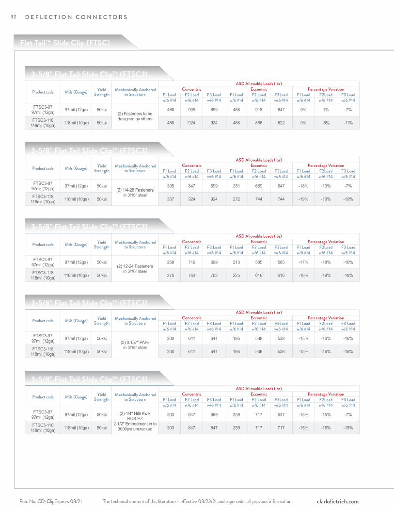
The technical content of this literature is effective 08/23/21 and supersedes all previous information.Pub. No. CD-ClipExpress 08/21 clarkdietrich.com
D E F L E C T I O N C O N N E C T O R S
Flat Tail™ Slide Clip (FTSC)
3-5/8" Flat Tail Slide Clip™ (FTSC3)
Product code Mils (Gauge) Yield Strength
Mechanically Anchored to Structure
ASD Allowable Loads (lbs)Concentric Eccentric Percentage Variation
F1 Load F2 Load F3 Load F1 Load F2 Load F3Load F1 Load F2Load F3 Loadw/6 #14 w/6 #14 w/6 #14 w/6 #14 w/6 #14 w/6 #14 w/6 #14 w/6 #14 w/6 #14
FTSC3-97 97mil (12ga) 97mil (12ga) 50ksi
(2) Fasteners to be designed by others
468 909 699 468 918 647 0% 1% -7%
FTSC3-118 118mil (10ga) 118mil (10ga) 50ksi 468 924 924 468 866 822 0% -6% -11%
3-5/8" Flat Tail Slide Clip™ (FTSC3)
Product code Mils (Gauge) Yield Strength
Mechanically Anchored to Structure
ASD Allowable Loads (lbs)Concentric Eccentric Percentage Variation
F1 Load F2 Load F3 Load F1 Load F2 Load F3Load F1 Load F2Load F3 Loadw/6 #14 w/6 #14 w/6 #14 w/6 #14 w/6 #14 w/6 #14 w/6 #14 w/6 #14 w/6 #14
FTSC3-97 97mil (12ga) 97mil (12ga) 50ksi
(2) 1/4-28 Fasteners in 3/16" steel
305 847 699 251 689 647 -18% -19% -7%
FTSC3-118 118mil (10ga) 118mil (10ga) 50ksi 337 924 924 272 744 744 -19% -19% -19%
3-5/8" Flat Tail Slide Clip™ (FTSC3)
Product code Mils (Gauge) Yield Strength
Mechanically Anchored to Structure
ASD Allowable Loads (lbs)Concentric Eccentric Percentage Variation
F1 Load F2 Load F3 Load F1 Load F2 Load F3Load F1 Load F2Load F3 Loadw/6 #14 w/6 #14 w/6 #14 w/6 #14 w/6 #14 w/6 #14 w/6 #14 w/6 #14 w/6 #14
FTSC3-97 97mil (12ga) 97mil (12ga) 50ksi
(2) 12-24 Fasteners in 3/16" steel
258 716 699 213 585 585 -17% -18% -16%
FTSC3-118 118mil (10ga) 118mil (10ga) 50ksi 276 763 763 225 616 616 -18% -19% -19%
3-5/8" Flat Tail Slide Clip™ (FTSC3)
Product code Mils (Gauge) Yield Strength
Mechanically Anchored to Structure
ASD Allowable Loads (lbs)Concentric Eccentric Percentage Variation
F1 Load F2 Load F3 Load F1 Load F2 Load F3Load F1 Load F2Load F3 Loadw/6 #14 w/6 #14 w/6 #14 w/6 #14 w/6 #14 w/6 #14 w/6 #14 w/6 #14 w/6 #14
FTSC3-97 97mil (12ga) 97mil (12ga) 50ksi
(2) 0.157" PAFs in 3/16" steel
230 641 641 195 538 538 -15% -16% -16%
FTSC3-118 118mil (10ga) 118mil (10ga) 50ksi 230 641 641 195 538 538 -15% -16% -16%
3-5/8" Flat Tail Slide Clip™ (FTSC3)
Product code Mils (Gauge) Yield Strength
Mechanically Anchored to Structure
ASD Allowable Loads (lbs)Concentric Eccentric Percentage Variation
F1 Load F2 Load F3 Load F1 Load F2 Load F3Load F1 Load F2Load F3 Loadw/6 #14 w/6 #14 w/6 #14 w/6 #14 w/6 #14 w/6 #14 w/6 #14 w/6 #14 w/6 #14
FTSC3-97 97mil (12ga) 97mil (12ga) 50ksi (2) 1/4" Hilti Kwik
HUS-EZ 2-1/2" Embedment in to
3000psi uncracked
303 847 699 259 717 647 -15% -15% -7%
FTSC3-118 118mil (10ga) 118mil (10ga) 50ksi 303 847 847 259 717 717 -15% -15% -15%
32
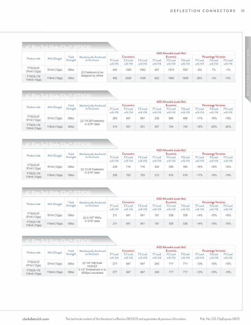
The technical content of this literature is effective 08/23/21 and supersedes all previous information. The technical content of this literature is effective 08/23/21 and supersedes all previous information. Pub. No. CD-ClipExpress 08/21clarkdietrich.com
D E F L E C T I O N C O N N E C T O R S
DE
FLE
CTI
ON
CO
NN
EC
TIO
NS
Product code Mils (Gauge) Yield Strength
Mechanically Anchored to Structure
ASD Allowable Loads (lbs)Concentric Eccentric Percentage Variation
F1 Load F2 Load F3 Load F1 Load F2 Load F3Load F1 Load F2Load F3 Loadw/6 #14 w/6 #14 w/6 #14 w/6 #14 w/6 #14 w/6 #14 w/6 #14 w/6 #14 w/6 #14
FTSC3-97 97mil (12ga) 97mil (12ga) 50ksi
(2) Fasteners to be designed by others
468 909 699 468 918 647 0% 1% -7%
FTSC3-118 118mil (10ga) 118mil (10ga) 50ksi 468 924 924 468 866 822 0% -6% -11%
Product code Mils (Gauge) Yield Strength
Mechanically Anchored to Structure
ASD Allowable Loads (lbs)Concentric Eccentric Percentage Variation
F1 Load F2 Load F3 Load F1 Load F2 Load F3Load F1 Load F2Load F3 Loadw/6 #14 w/6 #14 w/6 #14 w/6 #14 w/6 #14 w/6 #14 w/6 #14 w/6 #14 w/6 #14
FTSC3-97 97mil (12ga) 97mil (12ga) 50ksi
(2) 1/4-28 Fasteners in 3/16" steel
305 847 699 251 689 647 -18% -19% -7%
FTSC3-118 118mil (10ga) 118mil (10ga) 50ksi 337 924 924 272 744 744 -19% -19% -19%
Product code Mils (Gauge) Yield Strength
Mechanically Anchored to Structure
ASD Allowable Loads (lbs)Concentric Eccentric Percentage Variation
F1 Load F2 Load F3 Load F1 Load F2 Load F3Load F1 Load F2Load F3 Loadw/6 #14 w/6 #14 w/6 #14 w/6 #14 w/6 #14 w/6 #14 w/6 #14 w/6 #14 w/6 #14
FTSC3-97 97mil (12ga) 97mil (12ga) 50ksi
(2) 12-24 Fasteners in 3/16" steel
258 716 699 213 585 585 -17% -18% -16%
FTSC3-118 118mil (10ga) 118mil (10ga) 50ksi 276 763 763 225 616 616 -18% -19% -19%
Product code Mils (Gauge) Yield Strength
Mechanically Anchored to Structure
ASD Allowable Loads (lbs)Concentric Eccentric Percentage Variation
F1 Load F2 Load F3 Load F1 Load F2 Load F3Load F1 Load F2Load F3 Loadw/6 #14 w/6 #14 w/6 #14 w/6 #14 w/6 #14 w/6 #14 w/6 #14 w/6 #14 w/6 #14
FTSC3-97 97mil (12ga) 97mil (12ga) 50ksi
(2) 0.157" PAFs in 3/16" steel
230 641 641 195 538 538 -15% -16% -16%
FTSC3-118 118mil (10ga) 118mil (10ga) 50ksi 230 641 641 195 538 538 -15% -16% -16%
Product code Mils (Gauge) Yield Strength
Mechanically Anchored to Structure
ASD Allowable Loads (lbs)Concentric Eccentric Percentage Variation
F1 Load F2 Load F3 Load F1 Load F2 Load F3Load F1 Load F2Load F3 Loadw/6 #14 w/6 #14 w/6 #14 w/6 #14 w/6 #14 w/6 #14 w/6 #14 w/6 #14 w/6 #14
FTSC3-97 97mil (12ga) 97mil (12ga) 50ksi (2) 1/4" Hilti Kwik
HUS-EZ 2-1/2" Embedment in to
3000psi uncracked
303 847 699 259 717 647 -15% -15% -7%
FTSC3-118 118mil (10ga) 118mil (10ga) 50ksi 303 847 847 259 717 717 -15% -15% -15%
6" Flat Tail Slide Clip™ (FTSC6)
Product code Mils (Gauge) Yield Strength
Mechanically Anchored to Structure
ASD Allowable Loads (lbs)Concentric Eccentric Percentage Variation
F1 Load F2 Load F3 Load F1 Load F2 Load F3Load F1 Load F2Load F3 Loadw/6 #14 w/6 #14 w/6 #14 w/6 #14 w/6 #14 w/6 #14 w/6 #14 w/6 #14 w/6 #14
FTSC6-97 97mil (12ga) 97mil (12ga) 50ksi
(2) Fasteners to be designed by others
444 1383 1063 407 1474 1051 -8% 7% -1%
FTSC6-118 118mil (10ga) 118mil (10ga) 50ksi 492 2026 1439 622 1962 1629 26% -3% 13%
6" Flat Tail Slide Clip™ (FTSC6)
Product code Mils (Gauge) Yield Strength
Mechanically Anchored to Structure
ASD Allowable Loads (lbs)Concentric Eccentric Percentage Variation
F1 Load F2 Load F3 Load F1 Load F2 Load F3Load F1 Load F2Load F3 Loadw/6 #14 w/6 #14 w/6 #14 w/6 #14 w/6 #14 w/6 #14 w/6 #14 w/6 #14 w/6 #14
FTSC6-97 97mil (12ga) 97mil (12ga) 50ksi
(2) 1/4-28 Fasteners in 3/16" steel
283 847 847 236 689 689 -17% -19% -19%
FTSC6-118 118mil (10ga) 118mil (10ga) 50ksi 314 931 931 257 744 744 -18% -20% -20%
6" Flat Tail Slide Clip™ (FTSC6)
Product code Mils (Gauge) Yield Strength
Mechanically Anchored to Structure
ASD Allowable Loads (lbs)Concentric Eccentric Percentage Variation
F1 Load F2 Load F3 Load F1 Load F2 Load F3Load F1 Load F2Load F3 Loadw/6 #14 w/6 #14 w/6 #14 w/6 #14 w/6 #14 w/6 #14 w/6 #14 w/6 #14 w/6 #14
FTSC6-97 97mil (12ga) 97mil (12ga) 50ksi
(2) 12-24 Fasteners in 3/16" steel
239 716 716 200 585 585 -16% -18% -18%
FTSC6-118 118mil (10ga) 118mil (10ga) 50ksi 256 763 763 212 616 616 -17% -19% -19%
6" Flat Tail Slide Clip™ (FTSC6)
Product code Mils (Gauge) Yield Strength
Mechanically Anchored to Structure
ASD Allowable Loads (lbs)Concentric Eccentric Percentage Variation
F1 Load F2 Load F3 Load F1 Load F2 Load F3Load F1 Load F2Load F3 Loadw/6 #14 w/6 #14 w/6 #14 w/6 #14 w/6 #14 w/6 #14 w/6 #14 w/6 #14 w/6 #14
FTSC6-97 97mil (12ga) 97mil (12ga) 50ksi
(2) 0.157" PAFs in 3/16" steel
211 641 641 181 538 538 -14% -16% -16%
FTSC6-118 118mil (10ga) 118mil (10ga) 50ksi 211 641 641 181 538 538 -14% -16% -16%
6" Flat Tail Slide Clip™ (FTSC6)
Product code Mils (Gauge) Yield Strength
Mechanically Anchored to Structure
ASD Allowable Loads (lbs)Concentric Eccentric Percentage Variation
F1 Load F2 Load F3 Load F1 Load F2 Load F3Load F1 Load F2Load F3 Loadw/6 #14 w/6 #14 w/6 #14 w/6 #14 w/6 #14 w/6 #14 w/6 #14 w/6 #14 w/6 #14
FTSC6-97 97mil (12ga) 97mil (12ga) 50ksi (2) 1/4" Hilti Kwik
HUS-EZ 2-1/2" Embedment in to
3000psi uncracked
277 847 847 240 717 717 -13% -15% -15%
FTSC6-118 118mil (10ga) 118mil (10ga) 50ksi 277 847 847 240 717 717 -13% -15% -15%
33
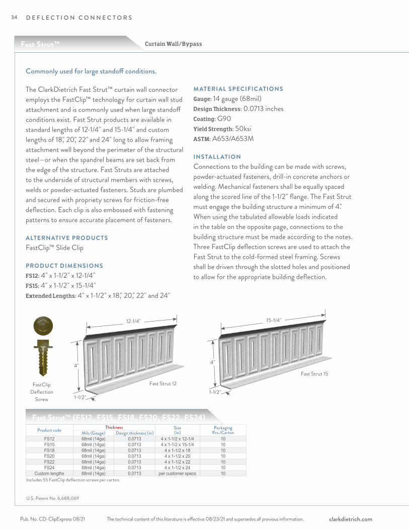
The technical content of this literature is effective 08/23/21 and supersedes all previous information.Pub. No. CD-ClipExpress 08/21 clarkdietrich.com
D E F L E C T I O N C O N N E C T O R S
The ClarkDietrich Fast Strut™ curtain wall connector employs the FastClip™ technology for curtain wall stud attachment and is commonly used when large standoff conditions exist. Fast Strut products are available in standard lengths of 12-1/4" and 15-1/4" and custom lengths of 18," 20," 22" and 24" long to allow framing attachment well beyond the perimeter of the structural steel—or when the spandrel beams are set back from the edge of the structure. Fast Struts are attached to the underside of structural members with screws, welds or powder-actuated fasteners. Studs are plumbed and secured with propriety screws for friction-free deflection. Each clip is also embossed with fastening patterns to ensure accurate placement of fasteners.
ALTERNATIVE PRODUC TSFastClip™ Slide Clip
PRODUC T DIMENSIONSFS12: 4" x 1-1/2" x 12-1/4"FS15: 4" x 1-1/2" x 15-1/4"Extended Lengths: 4" x 1-1/2" x 18," 20," 22" and 24"
M ATERIAL SPECIFIC ATIONSGauge: 14 gauge (68mil)Design Thickness: 0.0713 inchesCoating: G90Yield Strength: 50ksiASTM: A653/A653M
INSTALL ATIONConnections to the building can be made with screws, powder-actuated fasteners, drill-in concrete anchors or welding. Mechanical fasteners shall be equally spaced along the scored line of the 1-1/2" flange. The Fast Strut must engage the building structure a minimum of 4." When using the tabulated allowable loads indicated in the table on the opposite page, connections to the building structure must be made according to the notes. Three FastClip deflection screws are used to attach the Fast Strut to the cold-formed steel framing. Screws shall be driven through the slotted holes and positioned to allow for the appropriate building deflection.
Commonly used for large standoff conditions.
Product code Thickness Size (in)
Packaging Pcs./CartonMils (Gauge) Design thickness (in)
FS12 68mil (14ga) 0.0713 4 x 1-1/2 x 12-1/4 10FS15 68mil (14ga) 0.0713 4 x 1-1/2 x 15-1/4 10FS18 68mil (14ga) 0.0713 4 x 1-1/2 x 18 10FS20 68mil (14ga) 0.0713 4 x 1-1/2 x 20 10FS22 68mil (14ga) 0.0713 4 x 1-1/2 x 22 10FS24 68mil (14ga) 0.0713 4 x 1-1/2 x 24 10
Custom lengths 68mil (14ga) 0.0713 per customer specs 10
Fast Strut 15
15-1/4"
4"
Fast Strut 12
12-1/4"
4"
1-1/2"
FastClip Deflection
Screw
Includes 55 FastClip deflection screws per carton.
Fast Strut™ (FS12, FS15, FS18, FS20, FS22, FS24)
Curtain Wall/Bypass
1-1/2"
U.S. Patent No. 6,688,069
Fast Strut™
34
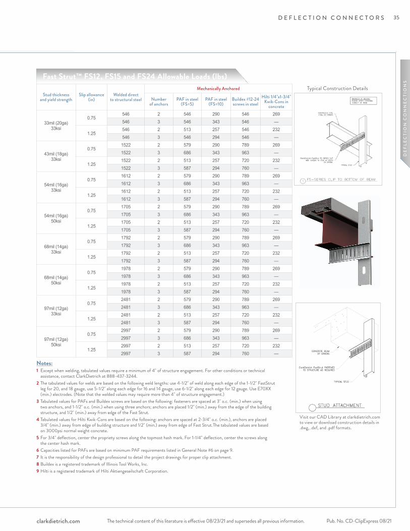
The technical content of this literature is effective 08/23/21 and supersedes all previous information. The technical content of this literature is effective 08/23/21 and supersedes all previous information. Pub. No. CD-ClipExpress 08/21clarkdietrich.com
D E F L E C T I O N C O N N E C T O R S
DE
FLE
CTI
ON
CO
NN
EC
TIO
NS
Visit our CAD Library at clarkdietrich.com to view or download construction details in .dwg, .dxf, and .pdf formats.
Notes:1 Except when welding, tabulated values require a minimum of 4" of structure engagement. For other conditions or technical
assistance, contact ClarkDietrich at 888-437-3244.2 The tabulated values for welds are based on the following weld lengths: use 4-1/2" of weld along each edge of the 1-1/2" FastStrut
leg for 20, and 18 gauge, use 5-1/2" along each edge for 16 and 14 gauge, use 6-1/2" along each edge for 12 gauge. Use E70XX (min.) electrodes. (Note that the welded values may require more than 4" of structure engagement.)
3 Tabulated values for PAFs and Buildex screws are based on the following: fasteners are spaced at 3" o.c. (min.) when using two anchors, and 1-1/2" o.c. (min.) when using three anchors; anchors are placed 1/2" (min.) away from the edge of the building structure, and 1/2" (min.) away from edge of the Fast Strut.
4 Tabulated values for Hilti Kwik-Cons are based on the following: anchors are spaced at 2-3/4" o.c. (min.), anchors are placed 3/4" (min.) away from edge of building structure and 1/2" (min.) away from edge of Fast Strut. The tabulated values are based on 3000psi normal weight concrete.
5 For 3/4" deflection, center the propriety screws along the topmost hash mark. For 1-1/4" deflection, center the screws along the center hash mark.
6 Capacities listed for PAFs are based on minimum PAF requirements listed in General Note #6 on page 9.7 It is the responsibility of the design professional to detail the project drawings for proper clip attachment.8 Buildex is a registered trademark of Illinois Tool Works, Inc.9 Hilti is a registered trademark of Hilti Aktiengeseilschaft Corporation.
Stud thickness and yield strength
Slip allowance (in)
Welded direct to structural steel
Mechanically Anchored
Number of anchors
PAF in steel (FS=5)
PAF in steel (FS=10)
Buildex #12-24 screws in steel
Hilti 1/4"x1-3/4" Kwik-Cons in
concrete
33mil (20ga) 33ksi
0.75546 2 546 290 546 269546 3 546 343 546 —
1.25546 2 513 257 546 232546 3 546 294 546 —
43mil (18ga) 33ksi
0.751522 2 579 290 789 2691522 3 686 343 963 —
1.251522 2 513 257 720 2321522 3 587 294 760 —
54mil (16ga) 33ksi
0.751612 2 579 290 789 2691612 3 686 343 963 —
1.251612 2 513 257 720 2321612 3 587 294 760 —
54mil (16ga) 50ksi
0.751705 2 579 290 789 2691705 3 686 343 963 —
1.251705 2 513 257 720 2321705 3 587 294 760 —
68mil (14ga) 33ksi
0.751792 2 579 290 789 2691792 3 686 343 963 —
1.251792 2 513 257 720 2321792 3 587 294 760 —
68mil (14ga) 50ksi
0.751978 2 579 290 789 2691978 3 686 343 963 —
1.251978 2 513 257 720 2321978 3 587 294 760 —
97mil (12ga) 33ksi
0.752481 2 579 290 789 2692481 3 686 343 963 —
1.252481 2 513 257 720 2322481 3 587 294 760 —
97mil (12ga) 50ksi
0.752997 2 579 290 789 2692997 3 686 343 963 —
1.252997 2 513 257 720 2322997 3 587 294 760 —
Typical Construction Details
Fast Strut™ FS12, FS15 and FS24 Allowable Loads (lbs)
35
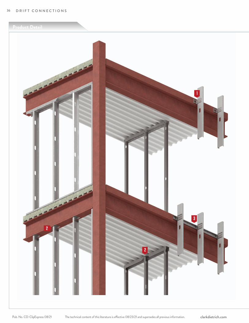
The technical content of this literature is effective 08/23/21 and supersedes all previous information.Pub. No. CD-ClipExpress 08/21 clarkdietrich.com
D R I F T C O N N E C T I O N S
Product Detail
1
2
2
3
36

The technical content of this literature is effective 08/23/21 and supersedes all previous information. The technical content of this literature is effective 08/23/21 and supersedes all previous information. Pub. No. CD-ClipExpress 08/21clarkdietrich.com
D R I F T C O N N E C T I O N S
DR
IFT
CO
NN
EC
TIO
NS
Drift FastClip™ Slide Clip pages 38–41
Drift Rail and Clippages 46–59
Drift Head-of-Wall Clip pages 42–45
1
3
2
37

The technical content of this literature is effective 08/23/21 and supersedes all previous information.Pub. No. CD-ClipExpress 08/21 clarkdietrich.com
D R I F T C O N N E C T I O N S
ClarkDietrich Drift FastClip™ Slide Clip 68mils (14ga) is used to attach exterior curtain-wall studs to the building structure and provide for both vertical and lateral movement. FastClip Deflection Screws are provided with each clip for attachment to the wall studs and allow for 2" vertical deflection (1" up and down) to ensure friction-free sliding. Step bushings are provided for the connection to the structure and allow for 2" lateral deflection (1" left and right).
Vertical and lateral building movement up to 2".
Product codeThickness
Size (in) Packaging Pcs./BucketMils (Gauge) Design thickness
(in) D-FCSC3.5-68 68mil (14ga) 0.0713 3-3/4" x 4" x 3-1/2" 25 D-FCSC6-68 68mil (14ga) 0.0713 3-3/4" x 4" x 6" 25 D-FCSC8-68 68mil (14ga) 0.0713 3-3/4" x 4" x 7-3/4" 25
Packaging: D-FCSC3.5 includes (55) FastClip Deflection Screws & (50) BushingsD-FCSC6 includes (80) FastClip Deflection Screws & (50) BushingsD-FCSC8 includes (110) FastClip Deflection Screws & (50) Bushings
Drift FastClip™ Slide Clip (D-FCSC)
FastClip Deflection Screws
(For Stud Connection)
Copper Bushing for 14ga Clips
D-FCSC3.5 D-FCSC8D-FCSC6
M ATERIAL SPECIFIC ATIONSGauge: 14 gauge (68mil)Design Thickness: 0.0713 inches Yield Strength: 50ksiCoating: G90ASTM: A653/A1003
ALTERNATIVE PRODUC TSDrift Rail and Clip
PRODUC T DIMENSIONSD-FCSC3.5: 3-3/4" x 4" x 3-1/2" longD-FCSC6: 3-3/4" x 4" x 6" longD-FCSC8: 3-3/4" x 4" x 8" long
Curtain Wall/Bypass with Drift & Vertical DeflectionDrift FastClip™ Slide Clip - 68mil (14ga)
(2) Bushings per Clip (2) Slots & Deflection Screws per Clip
(2) Bushings per Clip (3) Slots & Deflection Screws per Clip
(2) Bushings per Clip (4) Slots & Deflection Screws per Clip
38
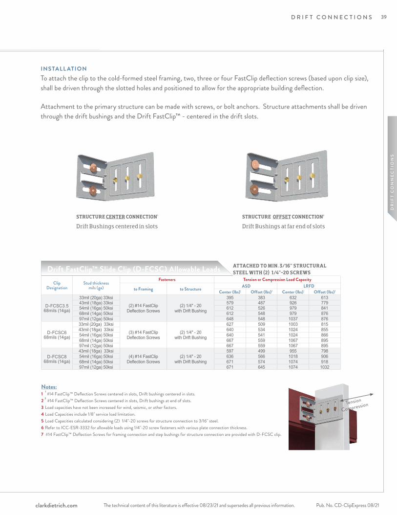
The technical content of this literature is effective 08/23/21 and supersedes all previous information. The technical content of this literature is effective 08/23/21 and supersedes all previous information. Pub. No. CD-ClipExpress 08/21clarkdietrich.com
D R I F T C O N N E C T I O N S
DR
IFT
CO
NN
EC
TIO
NS
ATTACHED TO MIN. 3/16" STRUCTURAL STEEL WITH (2) 1/4"-20 SCREWS
Clip Designation
Stud thickness mils (ga)
Fasteners Tension or Compression Load Capacity
to Framing to Structure ASD LRFDCenter (lbs)1 Offset (lbs)2 Center (lbs)1 Offset (lbs)2
D-FCSC3.5 68mils (14ga)
33mil (20ga) 33ksi
(2) #14 FastClip Deflection Screws
(2) 1/4" - 20 with Drift Bushing
395 383 632 61343mil (18ga) 33ksi 579 487 926 77954mil (16ga) 50ksi 612 526 979 84168mil (14ga) 50ksi 612 548 979 87697mil (12ga) 50ksi 648 548 1037 876
D-FCSC6 68mils (14ga)
33mil (20ga) 33ksi
(3) #14 FastClip Deflection Screws
(2) 1/4" - 20 with Drift Bushing
627 509 1003 81543mil (18ga) 33ksi 640 534 1024 85554mil (16ga) 50ksi 640 541 1024 86668mil (14ga) 50ksi 667 559 1067 89597mil (12ga) 50ksi 667 559 1067 895
D-FCSC8 68mils (14ga)
43mil (18ga) 33ksi(4) #14 FastClip
Deflection Screws(2) 1/4" - 20
with Drift Bushing
597 499 955 79854mil (16ga) 50ksi 636 566 1018 90668mil (14ga) 50ksi 671 574 1074 91897mil (12ga) 50ksi 671 645 1074 1032
Notes:1 1 #14 FastClip™ Deflection Screws centered in slots, Drift bushings centered in slots.2 2 #14 FastClip™ Deflection Screws centered in slots, Drift bushings at end of slots.3 Load capacities have not been increased for wind, seismic, or other factors.4 Load Capacities include 1/8" service load limitation. 5 Load Capacities calculated considering (2) 1/4"-20 screws for structure connection to 3/16" steel. 6 Refer to ICC-ESR-3332 for allowable loads using 1/4"-20 screw fasteners with various plate connection thickness.7 #14 FastClip™ Deflection Screws for framing connection and step bushings for structure connection are provided with D-FCSC clip.
Drift FastClip™ Slide Clip (D-FCSC) Allowable Loads
INSTALL ATIONTo attach the clip to the cold-formed steel framing, two, three or four FastClip deflection screws (based upon clip size), shall be driven through the slotted holes and positioned to allow for the appropriate building deflection.
Attachment to the primary structure can be made with screws, or bolt anchors. Structure attachments shall be driven through the drift bushings and the Drift FastClip™ - centered in the drift slots.
STRUCTURE CENTER CONNECTION1 Drift Bushings centered in slots
STRUCTURE OFFSET CONNECTION2 Drift Bushings at far end of slots
Tension
Compression
39
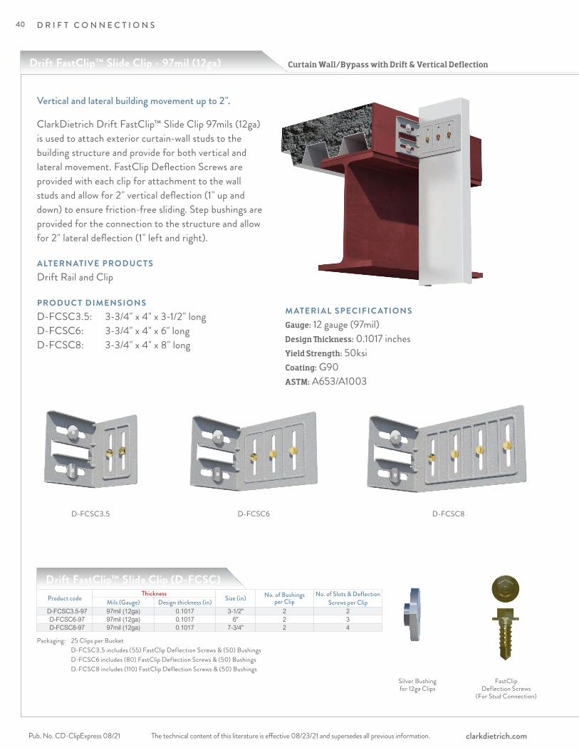
The technical content of this literature is effective 08/23/21 and supersedes all previous information.Pub. No. CD-ClipExpress 08/21 clarkdietrich.com
D R I F T C O N N E C T I O N S
ClarkDietrich Drift FastClip™ Slide Clip 97mils (12ga) is used to attach exterior curtain-wall studs to the building structure and provide for both vertical and lateral movement. FastClip Deflection Screws are provided with each clip for attachment to the wall studs and allow for 2" vertical deflection (1" up and down) to ensure friction-free sliding. Step bushings are provided for the connection to the structure and allow for 2" lateral deflection (1" left and right).
Vertical and lateral building movement up to 2".
Product codeThickness
Size (in) No. of Bushings per Clip
No. of Slots & Deflection Screws per ClipMils (Gauge) Design thickness (in)
D-FCSC3.5-97 97mil (12ga) 0.1017 3-1/2" 2 2 D-FCSC6-97 97mil (12ga) 0.1017 6" 2 3 D-FCSC8-97 97mil (12ga) 0.1017 7-3/4" 2 4
Packaging: 25 Clips per Bucket D-FCSC3.5 includes (55) FastClip Deflection Screws & (50) Bushings D-FCSC6 includes (80) FastClip Deflection Screws & (50) Bushings D-FCSC8 includes (110) FastClip Deflection Screws & (50) Bushings
Drift FastClip™ Slide Clip (D-FCSC)
FastClip Deflection Screws
(For Stud Connection)
Silver Bushing for 12ga Clips
M ATERIAL SPECIFIC ATIONSGauge: 12 gauge (97mil)Design Thickness: 0.1017 inchesYield Strength: 50ksiCoating: G90ASTM: A653/A1003
D-FCSC3.5 D-FCSC8D-FCSC6
ALTERNATIVE PRODUC TSDrift Rail and Clip
PRODUC T DIMENSIONSD-FCSC3.5: 3-3/4" x 4" x 3-1/2" longD-FCSC6: 3-3/4" x 4" x 6" longD-FCSC8: 3-3/4" x 4" x 8" long
Curtain Wall/Bypass with Drift & Vertical DeflectionDrift FastClip™ Slide Clip - 97mil (12ga)
40
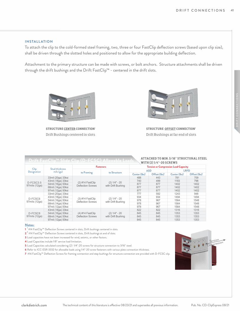
The technical content of this literature is effective 08/23/21 and supersedes all previous information. The technical content of this literature is effective 08/23/21 and supersedes all previous information. Pub. No. CD-ClipExpress 08/21clarkdietrich.com
D R I F T C O N N E C T I O N S
DR
IFT
CO
NN
EC
TIO
NS
ATTACHED TO MIN. 3/16" STRUCTURAL STEELWITH (2) 1/4"-20 SCREWS
STRUCTURE CENTER CONNECTION1 Drift Bushings centered in slots
STRUCTURE OFFSET CONNECTION2 Drift Bushings at far end of slots
Clip Designation
Stud thickness mils (ga)
Fasteners Tension or Compression Load Capacity
to Framing to Structure ASD LRFDCenter (lbs)1 Offset (lbs)2 Center (lbs)1 Offset (lbs)2
D-FCSC3.5 97mils (12ga)
33mil (20ga) 33ksi
(2) #14 FastClip Deflection Screws
(2) 1/4" - 20 with Drift Bushing
488 443 781 70943mil (18ga) 33ksi 740 499 1183 79854mil (16ga) 50ksi 877 877 1402 140268mil (14ga) 50ksi 877 877 1402 140297mil (12ga) 50ksi 877 877 1402 1402
D-FCSC6 97mils (12ga)
33mil (20ga) 33ksi
(3) #14 FastClip Deflection Screws
(2) 1/4" - 20 with Drift Bushing
777 592 1243 94843mil (18ga) 33ksi 934 934 1494 149454mil (16ga) 50ksi 978 967 1564 154868mil (14ga) 50ksi 978 967 1564 154897mil (12ga) 50ksi 978 967 1564 1548
D-FCSC8 97mils (12ga)
43mil (18ga) 33ksi(4) #14 FastClip
Deflection Screws(2) 1/4" - 20
with Drift Bushing
822 822 1316 131654mil (16ga) 50ksi 845 845 1353 135368mil (14ga) 50ksi 845 845 1353 135397mil (12ga) 50ksi 845 845 1353 1353
Notes:1 1 #14 FastClip™ Deflection Screws centered in slots, Drift bushings centered in slots.2 2 #14 FastClip™ Deflection Screws centered in slots, Drift bushings at end of slots.3 Load capacities have not been increased for wind, seismic, or other factors.4 Load Capacities include 1/8" service load limitation. 5 Load Capacities calculated considering (2) 1/4"-20 screws for structure connection to 3/16" steel. 6 Refer to ICC-ESR-3332 for allowable loads using 1/4"-20 screw fasteners with various plate connection thickness.7 #14 FastClip™ Deflection Screws for framing connection and step bushings for structure connection are provided with D-FCSC clip.
Drift FastClip™ Slide Clip (D-FCSC) Allowable Loads
INSTALL ATIONTo attach the clip to the cold-formed steel framing, two, three or four FastClip deflection screws (based upon clip size), shall be driven through the slotted holes and positioned to allow for the appropriate building deflection.
Attachment to the primary structure can be made with screws, or bolt anchors. Structure attachments shall be driven through the drift bushings and the Drift FastClip™ - centered in the drift slots.
Tension
Compression
41
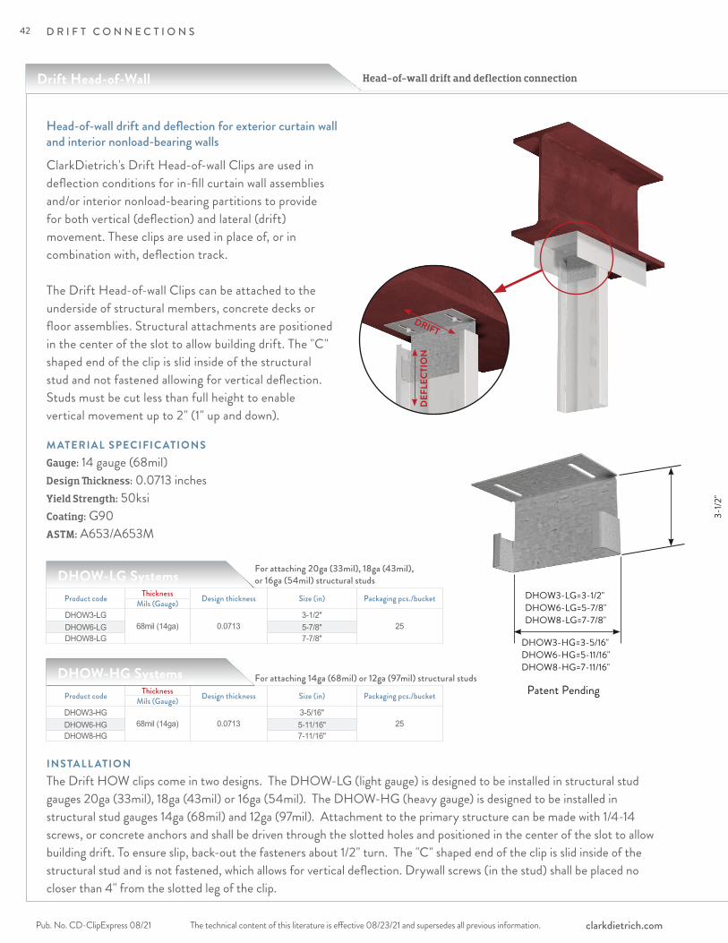
The technical content of this literature is effective 08/23/21 and supersedes all previous information.Pub. No. CD-ClipExpress 08/21 clarkdietrich.com
D R I F T C O N N E C T I O N S
ClarkDietrich's Drift Head-of-wall Clips are used in deflection conditions for in-fill curtain wall assemblies and/or interior nonload-bearing partitions to provide for both vertical (deflection) and lateral (drift) movement. These clips are used in place of, or in combination with, deflection track. The Drift Head-of-wall Clips can be attached to the underside of structural members, concrete decks or floor assemblies. Structural attachments are positioned in the center of the slot to allow building drift. The "C" shaped end of the clip is slid inside of the structural stud and not fastened allowing for vertical deflection. Studs must be cut less than full height to enable vertical movement up to 2" (1" up and down).
Head-of-wall drift and deflection for exterior curtain wall and interior nonload-bearing walls
Product code Thickness Design thickness Size (in) Packaging pcs./bucketMils (Gauge)DHOW3-LG
68mil (14ga) 0.07133-1/2"
25DHOW6-LG 5-7/8"DHOW8-LG 7-7/8"
DHOW-LG Systems
INSTALL ATIONThe Drift HOW clips come in two designs. The DHOW-LG (light gauge) is designed to be installed in structural stud gauges 20ga (33mil), 18ga (43mil) or 16ga (54mil). The DHOW-HG (heavy gauge) is designed to be installed in structural stud gauges 14ga (68mil) and 12ga (97mil). Attachment to the primary structure can be made with 1/4-14 screws, or concrete anchors and shall be driven through the slotted holes and positioned in the center of the slot to allow building drift. To ensure slip, back-out the fasteners about 1/2" turn. The "C" shaped end of the clip is slid inside of the structural stud and is not fastened, which allows for vertical deflection. Drywall screws (in the stud) shall be placed no closer than 4" from the slotted leg of the clip.
M ATERIAL SPECIFIC ATIONSGauge: 14 gauge (68mil)Design Thickness: 0.0713 inches Yield Strength: 50ksiCoating: G90ASTM: A653/A653M
Product code Thickness Design thickness Size (in) Packaging pcs./bucketMils (Gauge)DHOW3-HG
68mil (14ga) 0.07133-5/16"
25DHOW6-HG 5-11/16"DHOW8-HG 7-11/16"
D H OW_- LG S Y S T E M SDHOW-HG Systems
For attaching 20ga (33mil), 18ga (43mil), or 16ga (54mil) structural studs
For attaching 14ga (68mil) or 12ga (97mil) structural studs
DEF
LECT
ION
DRIFT
Head-of-wall drift and deflection connection
DHOW3-LG=3-1/2"DHOW6-LG=5-7/8"DHOW8-LG=7-7/8"
Patent Pending
DHOW3-HG=3-5/16"DHOW6-HG=5-11/16"DHOW8-HG=7-11/16"
Drift Head-of-Wall
3-1/2
"
42
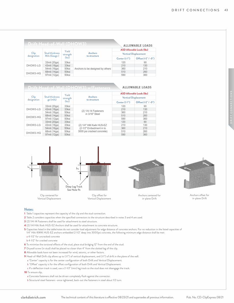
The technical content of this literature is effective 08/23/21 and supersedes all previous information. The technical content of this literature is effective 08/23/21 and supersedes all previous information. Pub. No. CD-ClipExpress 08/21clarkdietrich.com
D R I F T C O N N E C T I O N S
DR
IFT
CO
NN
EC
TIO
NS
3-1/2
"
Clip designation
Stud thickness Mils (Gauge )
Yield strength
(ksi) Anchors
to structure
ASD Allowable Loads (lbs)Vertical Displacement
Center (± 1") Offset (+2" / -0")
DHOW3-LG33mil (20ga) 33ksi
Anchors to be designed by others
120 9043mil (18ga) 33ksi 210 13054mil (16ga) 50ksi 360 210
DHOW3-HG 68mil (14ga) 50ksi 510 26097mil (12ga) 50ksi 590 360
Notes:1 Table 1 capacities represent the capacity of the clip and the stud connection.2 Table 2 considers capacities when the specified connectors to the structure described in notes 3 and 4 are used.3 (2) 1/4-14 Fasteners shall be used for attachment to steel structure.4 (2) 1/4 Hilti Kwik HUS-EZ Anchors shall be used for attachment to concrete structure.5 Capacities listed in the table/notes do not consider load adjustment for edge distance of concrete anchors. For no reduction in the listed capacities of 1/4" Hilti KWIK HUS-EZ anchors embedded 2-1/2" deep into 3000psi concrete, the following minimum edge distance shall be met: a 4-1/2" for uncracked concrete b 4-1/2" for cracked concrete6 To minimize the torsional effects of the stud, place stud bridging 12" from the end of the stud.7 Drywall screw (in stud) shall be placed no closer than 4" from the slotted leg of the clip.8 Allowable loads have not been increased for wind, seismic, or other factors.9 Head-of-Wall Drift clip allows up to (±1") of vertical displacement, and (±1") of drift in the plane of the wall. a "Center" capacity is for the center configuration of both Drift and Vertical Displacement. b "Offset" capacity is for the offset configuration of both Drift and Vertical Displacement. c If a deflection track is used, use a 2-1/2" (min) leg track so the stud does not disengage the track. 10 To ensure slip, a Concrete fasteners shall not be driven completely flush against the connector. b Structural steel fasteners -once tightened, back-out the fasteners in steel about 1/2 turn.
Drift Head-of-Wall (DHOW3)
ALLOWABLE LOADS
Clip designation
Stud thickness ga (mils)
Yield strength
(ksi) Anchors
to structure
ASD Allowable Loads (lbs)Vertical Displacement
Center (± 1") Offset (+2" / -0")
DHOW3-LG33mil (20ga) 33ksi
(2) 1/4-14 Fasteners in 3/16" Steel
120 9043mil (18ga) 33ksi 210 13054mil (16ga) 50ksi 360 210
DHOW3-HG 68mil (14ga) 50ksi 510 26097mil (12ga) 50ksi 590 360
DHOW3-LG33mil (20ga) 33ksi
(2) 1/4" Hilti Kwik HUS-EZ (2-1/2" Embedment in to
3000 psi cracked concrete)
120 9043mil (18ga) 33ksi 210 13054mil (16ga) 50ksi 360 210
DHOW3-HG 68mil (14ga) 50ksi 510 26097mil (12ga) 50ksi 590 360
Drift Head-of-Wall (DHOW3) w/Fasteners
Clip centered for Vertical Displacement
Clip offset for Vertical Displacement
Anchors centered for in-plane Drift
Anchors offset for in-plane Drift
1" 2"
Deep Leg Track See Note 9c
ALLOWABLE LOADS
43
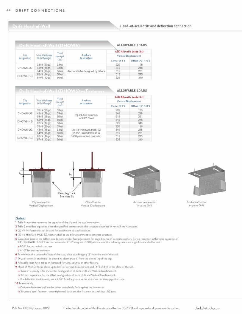
The technical content of this literature is effective 08/23/21 and supersedes all previous information.Pub. No. CD-ClipExpress 08/21 clarkdietrich.com
D R I F T C O N N E C T I O N S
Head-of-wall drift and deflection connection
ALLOWABLE LOADS
Clip designation
Stud thickness Mils (Gauge)
Yield strength
(ksi) Anchors
to structure
ASD Allowable Loads (lbs)Vertical Displacement
Center (± 1") Offset (+2" / -0")
DHOW6-LG33mil (20ga) 33ksi
Anchors to be designed by others
220 19643mil (18ga) 33ksi 340 24854mil (16ga) 50ksi 515 261
DHOW6-HG 68mil (14ga) 50ksi 515 27597mil (12ga) 50ksi 625 340
Drift Head-of-Wall (DHOW6)
ALLOWABLE LOADS
Clip designation
Stud thickness Mils (Gauge)
Yield strength
(ksi) Anchors
to structure
ASD Allowable Loads (lbs)Vertical Displacement
Center (± 1") Offset (+2" / -0")
DHOW6-LG33mil (20ga) 33ksi
(2) 1/4-14 Fasteners in 3/16" Steel
220 19643mil (18ga) 33ksi 340 24854mil (16ga) 50ksi 515 261
DHOW6-HG 68mil (14ga) 50ksi 515 27597mil (12ga) 50ksi 625 340
DHOW6-LG33mil (20ga) 33ksi
(2) 1/4" Hilti Kwik HUS-EZ (2-1/2" Embedment in to
3000 psi cracked concrete)
220 19643mil (18ga) 33ksi 340 24854mil (16ga) 50ksi 515 261
DHOW6-HG 68mil (14ga) 50ksi 515 27597mil (12ga) 50ksi 625 340
Drift Head-of-Wall (DHOW6) w/Fasteners
Notes:1 Table 1 capacities represent the capacity of the clip and the stud connection.2 Table 2 considers capacities when the specified connectors to the structure described in notes 3 and 4 are used.3 (2) 1/4-14 Fasteners shall be used for attachment to steel structure.4 (2) 1/4 Hilti Kwik HUS-EZ Anchors shall be used for attachment to concrete structure.5 Capacities listed in the table/notes do not consider load adjustment for edge distance of concrete anchors. For no reduction in the listed capacities of 1/4" Hilti KWIK HUS-EZ anchors embedded 2-1/2" deep into 3000psi concrete, the following minimum edge distance shall be met: a 4-1/2" for uncracked concrete b 4-1/2" for cracked concrete6 To minimize the torsional effects of the stud, place stud bridging 12" from the end of the stud.7 Drywall screw (in stud) shall be placed no closer than 4" from the slotted leg of the clip.8 Allowable loads have not been increased for wind, seismic, or other factors.9 Head-of-Wall Drift clip allows up to (±1") of vertical displacement, and (±1") of drift in the plane of the wall. a "Center" capacity is for the center configuration of both Drift and Vertical Displacement. b "Offset" capacity is for the offset configuration of both Drift and Vertical Displacement. c If a deflection track is used, use a 2-1/2" (min) leg track so the stud does not disengage the track. 10 To ensure slip, a Concrete fasteners shall not be driven completely flush against the connector. b Structural steel fasteners -once tightened, back-out the fasteners in steel about 1/2 turn.
Clip centered for Vertical Displacement
Clip offset for Vertical Displacement
Anchors centered for in-plane Drift
Anchors offset for in-plane Drift
1" 2"
Deep Leg Track See Note 9c
Drift Head-of-Wall
44

The technical content of this literature is effective 08/23/21 and supersedes all previous information. The technical content of this literature is effective 08/23/21 and supersedes all previous information. Pub. No. CD-ClipExpress 08/21clarkdietrich.com
D R I F T C O N N E C T I O N S
DR
IFT
CO
NN
EC
TIO
NS
ALLOWABLE LOADS
Clip designation
Stud thickness ga (mils)
Yield strength
(ksi) Anchors
to structure
ASD Allowable Loads (lbs)Vertical Displacement
Center (± 1") Offset (+2" / -0")
DHOW8-LG33mil (20ga) 33ksi
Anchors to be designed by others
− −43mil (18ga) 33ksi 120 11054mil (16ga) 50ksi 200 160
DHOW8-HG 68mil (14ga) 50ksi 260 19097mil (12ga) 50ksi 420 280
Drift Head-of-Wall (DHOW8)
ALLOWABLE LOADS
Clip designation
Stud thickness ga (mils)
Yield strength
(ksi) Anchors
to structure
ASD Allowable Loads (lbs)Vertical Displacement
Center (± 1") Offset (+2" / -0")
DHOW8-LG33mil (20ga) 33ksi
(2) 1/4-14 Fasteners in 3/16" Steel
− −43mil (18ga) 33ksi 120 11054mil (16ga) 50ksi 200 160
DHOW8-HG 68mil (14ga) 50ksi 260 19097mil (12ga) 50ksi 420 280
DHOW8-LG33mil (20ga) 33ksi
(2) 1/4" Hilti Kwik HUS-EZ (2-1/2" Embedment in to
3000 psi cracked concrete)
− −43mil (18ga) 33ksi 120 11054mil (16ga) 50ksi 200 160
DHOW8-HG 68mil (14ga) 50ksi 260 19097mil (12ga) 50ksi 420 280
Drift Head-of-Wall (DHOW8) w/Fasteners
Notes:1 Table 1 capacities represent the capacity of the clip and the stud connection.2 Table 2 considers capacities when the specified connectors to the structure described in notes 3 and 4 are used.3 (2) 1/4-14 Fasteners shall be used for attachment to steel structure.4 (2) 1/4 Hilti Kwik HUS-EZ Anchors shall be used for attachment to concrete structure.5 For the (2) fasteners attached to the structure, each fastener shall be installed in the any two slots of the clip leg.6 Capacities listed in the table/notes do not consider load adjustment for edge distance of concrete anchors. For no reduction in the listed capacities of 1/4" Hilti KWIK HUS-EZ anchors embedded 2-1/2" deep into 3000psi concrete, the following minimum edge distance shall be met: a 4-1/2" for uncracked concrete b 4-1/2" for cracked concrete7 To minimize the torsional effects of the stud, place stud bridging 12" from the end of the stud.8 Drywall screw (in stud) shall be placed no closer than 4" from the slotted leg of the clip.9 Allowable loads have not been increased for wind, seismic, or other factors.10 Head-of-Wall Drift clip allows up to (±1") of vertical displacement, and (±1") of drift in the plane of the wall. a "Center" capacity is for the center configuration of both Drift and Vertical Displacement. b "Offset" capacity is for the offset configuration of both Drift and Vertical Displacement. c If a deflection track is used, use a 2-1/2" (min) leg track so the stud does not disengage the track. 11 To ensure slip, a Concrete fasteners shall not be driven completely flush against the connector. b Structural steel fasteners -once tightened, back-out the fasteners in steel about 1/2 turn.
Clip centered for Vertical Displacement
Clip offset for Vertical Displacement
Anchors centered for in-plane Drift
Anchors offset for in-plane Drift
1" 2"
Deep Leg Track See Note 10c
45

The technical content of this literature is effective 08/23/21 and supersedes all previous information.Pub. No. CD-ClipExpress 08/21 clarkdietrich.com
D R I F T C O N N E C T I O N S
3.3875”
4.5”
1”
7.325”
4.5”
1”
5.875”
4.5”
1”
DRC3
DRC8
DRC6
Curtain Wall/Bypass with Drift and Vertical Deflection
ClarkDietrich (DRC) Drift Rail 97mil (12ga) and Clip 97 mil or 68mil (12ga or 14ga), is a uniquely designed two-piece system that is used to attach curtain-wall studs to the building structure and allows for vertical and lateral movement or to be rigidly attached. The system utilizes a C-Shaped Drift Rail and distinctively designed Drift Rail Clips that rotate into position for easy installation. The multifaceted Drift Rail Clips use FastClip™ Deflection Screws for attachment to the wall studs and allows for 3" vertical deflection (1-1/2" up and down) and is also designed with 1/8" holes to rigidly attach wall studs.
Vertical and lateral building movement
DRIF T R AILGauge: 12ga (97mil)Design Thickness: 0.1017"Min. Thickness: 0.0966"
Gauge: 14ga (68mil)Design Thickness: 0.0713"Min. Thickness: 0.0677"
DRIF T R AIL CLIPGauge: 12ga (97mil)Design Thickness: 0.1017"Min. Thickness: 0.0966"
ALTERNATIVE PRODUC TSDrift FastClip™ Slide Clip
M ATERIAL SPECIFIC ATIONSYield Strength: 50ksiCoating: G90ASTM: A653 / A1003
PACK AGINGDrift Clips: 25 Drift Clips per box. (Includes 55 or 80 FastClip Deflection Screws per box.)
12' Drift Rail is individually packaged.
Drift Rail and Clip
Product code Thickness Size (in) No. of slots per Clip
No. of holes per clipMils (Gauge)
DRC3-9797mil (12ga)
3.3875" 2 4DRC6-97 5.875" 4 8DRC8-97 7.325" 4 8
D H OW_- LG S Y S T E M SDRC - 12ga Clip / 12ga Rail
Product code Thickness Size (in) No. of slots per Clip
No. of holes per clipMils (Gauge)
DRC3-6868mil (14ga)
3.3875" 2 4DRC6-68 5.875" 4 8DRC8-68 7.325" 4 8
D H OW_- LG S Y S T E M SDRC - 14ga Clip / 12ga Rail
FastClip Deflection
Screws
46

The technical content of this literature is effective 08/23/21 and supersedes all previous information. The technical content of this literature is effective 08/23/21 and supersedes all previous information. Pub. No. CD-ClipExpress 08/21clarkdietrich.com
D R I F T C O N N E C T I O N S
DR
IFT
CO
NN
EC
TIO
NS
INSTALL ATION
Install the Drift Rail to minimum 3/16-in thick steel support structure using: • Welds • PAF fasteners • Self-drilling screws Install the Drift Rail to concrete support structure using: • Expansion anchors • Screw anchors
Pilot holes are provided along the length of the Drift Rail web at a spacing of 6-in on-center.
Design load capacities for commonly used fasteners are tabulated in the product Design Guide and include: • Hilti X-U Universal Knurled Shank Fasteners • #12-24 HWH Fasteners • Hilti 1/4" KWIK HUS-EZ anchor
With the Drift Rail installed on the structure, the Drift Clips can be positioned as required: • The framing stud web must contact the flat face of the long leg of the Drift Clip. • Note that one of the four slots in the channel portion of the Drift Clip is longer than the others. • Tilt the Drift Clip and position it so that the longer slot initially engages one leg of the Drift Rail. • Rotate the Drift Clip to the vertical position, engaging all four slots with the Drift Rail legs.
Connection between the Drift Clip and Framing Studs: • For bypass connections, FastClip Deflection Screws are placed through each slotted hole of the long leg, of the Drift Clip to the web of the stud. The required number and location of the slotted holes used to secure the stud is determined by the required design load capacity. • For rigid connections, self-drilling screws are placed through the pilot holes around the perimeter of the long leg of the Drift Clip to the web of the stud.
To restrict clip lateral movement (Drift) along the Drift Rail, install one of two types of stops: • Drift Locking Angle (DRLA) is an L-shaped clip − The long leg is inserted into the channel of the Drift Rail Clip, − The short leg is secured to the flange of the Drift Rail with a #10 self-drilling screw • Drift Locking Clip (DRLC) is a C-shaped clip − The DRLC sits within the channel of the Drift Clip, and straddles the flanges of the Drift Rail. − The two outside legs of the DRLC are secured to each flange of the Drift Rail with a #10 self-drilling screw.
12’-0” Long Rail
3-5/8”
1-1/8”
DRIFTDEFLECTION
Drift Locking Angle (DRLA)
Drift Locking Clip (DRLC)
47
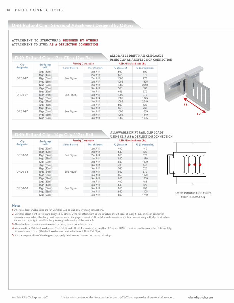
The technical content of this literature is effective 08/23/21 and supersedes all previous information.Pub. No. CD-ClipExpress 08/21 clarkdietrich.com
D R I F T C O N N E C T I O N S
Clip designation
Stud gauge (mils)
Framing Connection ASD Allowable Loads (lbs)Screw Pattern No. of Screws F2 (Tension) F3 (Compression)
DRC3-97
20ga (33mil)
See Figure
(2) x #14 560 60018ga (43mil) (2) x #14 655 67016ga (54mil) (2) x #14 1000 97014ga (68mil) (2) x #14 1085 132512ga (97mil) (2) x #14 1085 2040
DRC6-97
20ga (33mil)
See Figure
(3) x #14 560 60018ga (43mil) (3) x #14 655 67016ga (54mil) (3) x #14 1000 97014ga (68mil) (3) x #14 1085 132512ga (97mil) (3) x #14 1085 2040
DRC8-97
20ga (33mil)
See Figure
(3) x #14 560 62018ga (43mil) (3) x #14 655 73016ga (54mil) (3) x #14 1000 106014ga (68mil) (3) x #14 1085 134012ga (97mil) (3) x #14 1085 1965
Drift Rail and Clip - 12ga Clip / 12ga Rail
Drift Rail and Clip - 14ga Clip / 12ga Rail ALLOWABLE DRIFT RAIL CLIP LOADS USING CLIP AS A DEFLECTION CONNECTION
(3) #14 Deflection Screw PatternShown in a DRC6 Clip
Notes:1 Allowable loads (ASD) listed are for Drift Rail Clip to stud only (framing connection).2 Drift Rail attachment to structure designed by others. Drift Rail attachment to the structure should occur at every 6" o.c., and each connection capacity should satisfy the design load requirement of the project. Listed Drift Rail clip load capacities must be evaluated along with clip-to-structure connection capacity to establish the governing load capacity of the assembly.3 Allowable loads have not been increased for wind, seismic, or other factors.4 Minimum (2) x #14 shouldered screws (for DRC3) and (3) x #14 shouldered screws (for DRC6 and DRC8) must be used to secure the Drift Rail Clip for attachment to stud (#14 shouldered screws provided with each Drift Rail Clip).5 It is the responsibility of the designer to properly detail connections on the contract drawings.
Clip designation
Stud gauge (mils)
Framing Connection ASD Allowable Loads (lbs)Screw Pattern No. of Screws F2 (Tension) F3 (Compression)
DRC3-68
20ga (33mil)
See Figure
(2) x #14 490 44018ga (43mil) (2) x #14 540 52016ga (54mil) (2) x #14 850 87014ga (68mil) (2) x #14 850 117012ga (97mil) (2) x #14 850 1600
DRC6-68
20ga (33mil)
See Figure
(3) x #14 490 44018ga (43mil) (3) x #14 540 52016ga (54mil) (3) x #14 850 87014ga (68mil) (3) x #14 850 117012ga (97mil) (3) x #14 850 1600
DRC8-68
20ga (33mil)
See Figure
(3) x #14 490 48518ga (43mil) (3) x #14 540 62016ga (54mil) (3) x #14 850 90014ga (68mil) (3) x #14 850 110512ga (97mil) (3) x #14 850 1710
ALLOWABLE DRIFT RAIL CLIP LOADS USING CLIP AS A DEFLECTION CONNECTION
ATTACHMENT TO STRUCTURAL: DESIGNED BY OTHERSATTACHMENT TO STUD: AS A DEFLECTION CONNECTION
Drift Rail and Clip - Structural Attachment Designed by Others
48
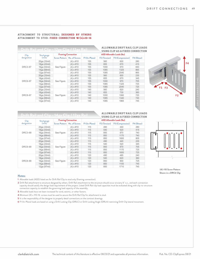
The technical content of this literature is effective 08/23/21 and supersedes all previous information. The technical content of this literature is effective 08/23/21 and supersedes all previous information. Pub. No. CD-ClipExpress 08/21clarkdietrich.com
D R I F T C O N N E C T I O N S
DR
IFT
CO
NN
EC
TIO
NS
Clip designation
Stud gauge (mils)
Framing Connection ASD Allowable Loads (lbs)Screw Pattern No. of Screws F1 (In-Plane) F2 (Tension) F3 (Compression) F4 (Shear)
DRC3-97
20ga (33mil)
See Figure
(4) x #10 155 560 600 28018ga (43mil) (4) x #10 155 655 670 41516ga (54mil) (4) x #10 155 1000 970 84014ga (68mil) (4) x #10 155 1085 1325 86512ga (97mil) (4) x #10 155 1085 2040 865
DRC6-97
20ga (33mil)
See Figure
(4) x #10 155 560 600 23518ga (43mil) (4) x #10 155 655 670 34516ga (54mil) (4) x #10 155 1000 970 70514ga (68mil) (4) x #10 155 1085 1325 72512ga (97mil) (4) x #10 155 1085 2040 725
DRC8-97
20ga (33mil)
See Figure
(4) x #10 140 560 620 24018ga (43mil) (4) x #10 140 655 730 36016ga (54mil) (4) x #10 140 1000 1060 72514ga (68mil) (4) x #10 140 1085 1340 74512ga (97mil) (4) x #10 140 1085 1965 745
Drift Rail and Clip - 12ga Clip / 12ga Rail
Drift Rail and Clip - 14ga Clip / 12ga Rail Clip
designationStud gauge
(mils) Framing Connection ASD Allowable Loads (lbs)
Screw Pattern No. of Screws F1 (In-Plane) F2 (Tension) F3 (Compression) F4 (Shear)
DRC3-68
20ga (33mil)
See Figure
(4) x #10 115 490 440 28018ga (43mil) (4) x #10 115 540 520 41516ga (54mil) (4) x #10 115 850 870 74014ga (68mil) (4) x #10 115 850 1170 74012ga (97mil) (4) x #10 115 850 1600 805
DRC6-68
20ga (33mil)
See Figure
(4) x #10 115 490 440 23518ga (43mil) (4) x #10 115 540 520 34516ga (54mil) (4) x #10 115 850 870 70514ga (68mil) (4) x #10 115 850 1170 72512ga (97mil) (4) x #10 115 850 1600 725
DRC8-68
20ga (33mil)
See Figure
(4) x #10 120 490 485 24018ga (43mil) (4) x #10 120 540 620 36016ga (54mil) (4) x #10 120 850 900 72514ga (68mil) (4) x #10 120 850 1105 74512ga (97mil) (4) x #10 120 850 1710 745
Notes:1 Allowable loads (ASD) listed are for Drift Rail Clip to stud only (framing connection).2 Drift Rail attachment to structure designed by others. Drift Rail attachment to the structure should occur at every 6" o.c., and each connection capacity should satisfy the design load requirement of the project. Listed Drift Rail clip load capacities must be evaluated along with clip-to-structure connection capacity to establish the governing load capacity of the assembly.3 Allowable loads have not been increased for wind, seismic, or other factors.4 Minimum (4) x #10-16 screws must be used to secure the Drift Rail Clip for attachment to stud.5 It is the responsibility of the designer to properly detail connections on the contract drawings.6 F1 (In-Plane) loads are based on using a Drift Locking Clip (DRLC) or Drift Locking Angle (DRLA) restricting Drift Clip lateral movement.
ALLOWABLE DRIFT RAIL CLIP LOADS USING CLIP AS A FIXED CONNECTION
(4) #10 Screw PatternShown in a DRC6 Clip
ALLOWABLE DRIFT RAIL CLIP LOADS USING CLIP AS A FIXED CONNECTION
ATTACHMENT TO STRUCTURAL: DESIGNED BY OTHERSATTACHMENT TO STUD: FIXED CONNECTION W/(4)#10-16
49

The technical content of this literature is effective 08/23/21 and supersedes all previous information.Pub. No. CD-ClipExpress 08/21 clarkdietrich.com
D R I F T C O N N E C T I O N S
Drift Rail and Clip - 12ga Clip / 12ga Rail
Drift Rail and Clip - 14ga Clip / 12ga Rail
Clip designation
Stud gauge (mils)
Framing Connection ASD Allowable Loads (lbs)Screw Pattern No. of Screws F1 (In-Plane) F2 (Tension) F3 (Compression) F4 (Shear)
DRC6-97
20ga (33mil)
See Figure
(8) x #10 155 560 600 39518ga (43mil) (8) x #10 155 655 670 58516ga (54mil) (8) x #10 155 1000 970 87514ga (68mil) (8) x #10 155 1085 1325 92012ga (97mil) (8) x #10 155 1085 2040 920
DRC8-97
20ga (33mil)
See Figure
(8) x #10 140 560 620 37518ga (43mil) (8) x #10 140 655 730 55516ga (54mil) (8) x #10 140 1000 1060 91014ga (68mil) (8) x #10 140 1085 1340 91012ga (97mil) (8) x #10 140 1085 1965 910
Clip designation
Stud gauge (mils)
Framing Connection ASD Allowable Loads (lbs)Screw Pattern No. of Screws F1 (In-Plane) F2 (Tension) F3 (Compression) F4 (Shear)
DRC6-68
20ga (33mil)
See Figure
(8) x #10 115 490 440 39518ga (43mil) (8) x #10 115 540 520 58516ga (54mil) (8) x #10 115 850 870 74014ga (68mil) (8) x #10 115 850 1170 74012ga (97mil) (8) x #10 115 850 1600 805
DRC8-68
20ga (33mil)
See Figure
(8) x #10 120 490 485 37518ga (43mil) (8) x #10 120 540 620 55516ga (54mil) (8) x #10 120 850 900 80014ga (68mil) (8) x #10 120 850 1105 80012ga (97mil) (8) x #10 120 850 1710 865
Notes:1 Allowable loads (ASD) listed are for Drift Rail Clip to stud only (framing connection).2 Drift Rail attachment to structure designed by others. Drift Rail attachment to the structure should occur at every 6" o.c., and each connection capacity should satisfy the design load requirement of the project. Listed Drift Rail clip load capacities must be evaluated along with clip-to-structure connection capacity to establish the governing load capacity of the assembly.3 Allowable loads have not been increased for wind, seismic, or other factors.4 Minimum (4) x #10-16 screws must be used to secure the Drift Rail Clip for attachment to stud.5 It is the responsibility of the designer to properly detail connections on the contract drawings.6 F1 (In-Plane) loads are based on using a Drift Locking Clip (DRLC) or Drift Locking Angle (DRLA) restricting Drift Clip lateral movement.
ALLOWABLE DRIFT RAIL CLIP LOADS USING CLIP AS A FIXED CONNECTION
(8) #10 Screw PatternShown in a DRC6 Clip
ALLOWABLE DRIFT RAIL CLIP LOADS USING CLIP AS A FIXED CONNECTION
ATTACHMENT TO STRUCTURAL: DESIGNED BY OTHERSATTACHMENT TO STUD: FIXED CONNECTION W/(8)#10-16
Drift Rail and Clip - Structural Attachment Designed by Others
50
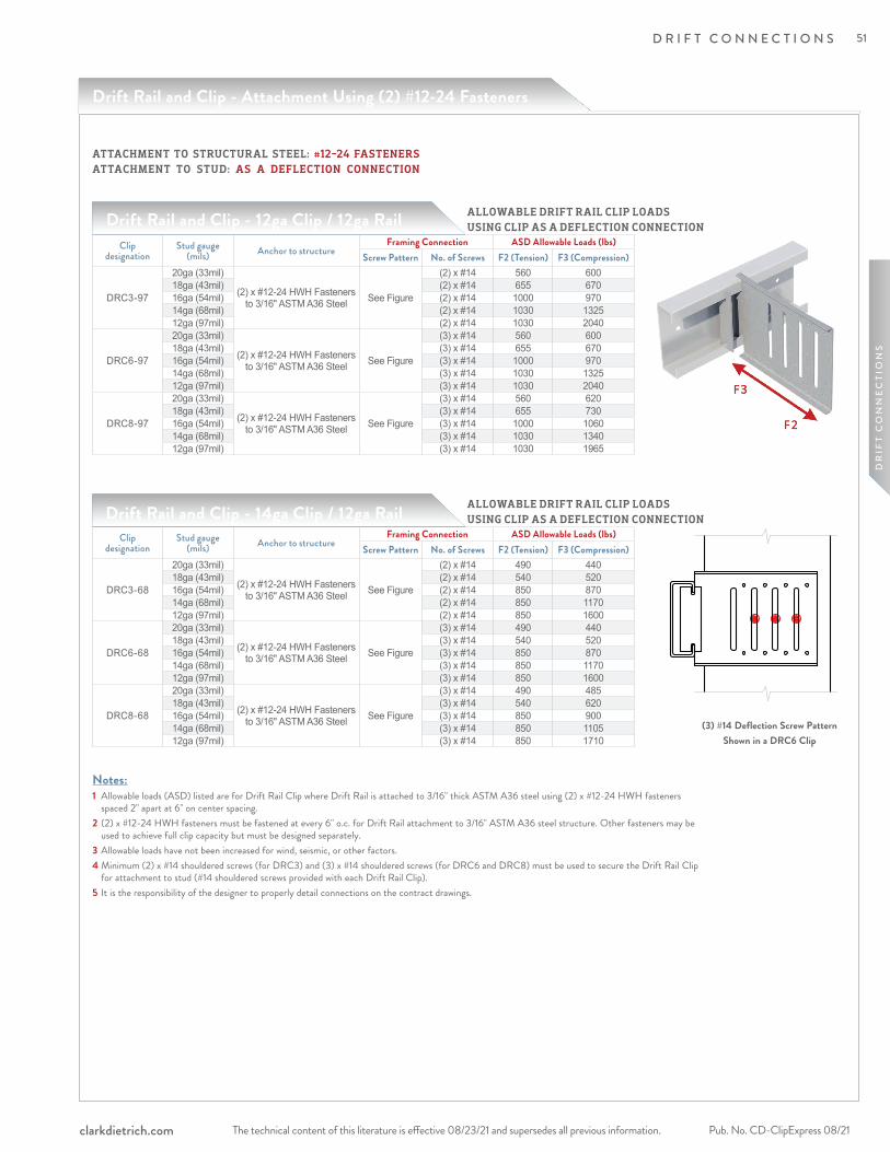
The technical content of this literature is effective 08/23/21 and supersedes all previous information. The technical content of this literature is effective 08/23/21 and supersedes all previous information. Pub. No. CD-ClipExpress 08/21clarkdietrich.com
D R I F T C O N N E C T I O N S
DR
IFT
CO
NN
EC
TIO
NS
Drift Rail and Clip - Attachment Using (2) #12-24 Fasteners
Drift Rail and Clip - 12ga Clip / 12ga Rail
Drift Rail and Clip - 14ga Clip / 12ga Rail ALLOWABLE DRIFT RAIL CLIP LOADS USING CLIP AS A DEFLECTION CONNECTION
(3) #14 Deflection Screw PatternShown in a DRC6 Clip
Clip designation
Stud gauge (mils) Anchor to structure
Framing Connection ASD Allowable Loads (lbs)Screw Pattern No. of Screws F2 (Tension) F3 (Compression)
DRC3-68
20ga (33mil)
(2) x #12-24 HWH Fasteners to 3/16" ASTM A36 Steel See Figure
(2) x #14 490 44018ga (43mil) (2) x #14 540 52016ga (54mil) (2) x #14 850 87014ga (68mil) (2) x #14 850 117012ga (97mil) (2) x #14 850 1600
DRC6-68
20ga (33mil)
(2) x #12-24 HWH Fasteners to 3/16" ASTM A36 Steel See Figure
(3) x #14 490 44018ga (43mil) (3) x #14 540 52016ga (54mil) (3) x #14 850 87014ga (68mil) (3) x #14 850 117012ga (97mil) (3) x #14 850 1600
DRC8-68
20ga (33mil)
(2) x #12-24 HWH Fasteners to 3/16" ASTM A36 Steel See Figure
(3) x #14 490 48518ga (43mil) (3) x #14 540 62016ga (54mil) (3) x #14 850 90014ga (68mil) (3) x #14 850 110512ga (97mil) (3) x #14 850 1710
Notes:1 Allowable loads (ASD) listed are for Drift Rail Clip where Drift Rail is attached to 3/16" thick ASTM A36 steel using (2) x #12-24 HWH fasteners spaced 2" apart at 6" on center spacing.2 (2) x #12-24 HWH fasteners must be fastened at every 6" o.c. for Drift Rail attachment to 3/16" ASTM A36 steel structure. Other fasteners may be used to achieve full clip capacity but must be designed separately.3 Allowable loads have not been increased for wind, seismic, or other factors.4 Minimum (2) x #14 shouldered screws (for DRC3) and (3) x #14 shouldered screws (for DRC6 and DRC8) must be used to secure the Drift Rail Clip for attachment to stud (#14 shouldered screws provided with each Drift Rail Clip).5 It is the responsibility of the designer to properly detail connections on the contract drawings.
ALLOWABLE DRIFT RAIL CLIP LOADS USING CLIP AS A DEFLECTION CONNECTION
Clip designation
Stud gauge (mils) Anchor to structure
Framing Connection ASD Allowable Loads (lbs)Screw Pattern No. of Screws F2 (Tension) F3 (Compression)
DRC3-97
20ga (33mil)
(2) x #12-24 HWH Fasteners to 3/16" ASTM A36 Steel See Figure
(2) x #14 560 60018ga (43mil) (2) x #14 655 67016ga (54mil) (2) x #14 1000 97014ga (68mil) (2) x #14 1030 132512ga (97mil) (2) x #14 1030 2040
DRC6-97
20ga (33mil)
(2) x #12-24 HWH Fasteners to 3/16" ASTM A36 Steel See Figure
(3) x #14 560 60018ga (43mil) (3) x #14 655 67016ga (54mil) (3) x #14 1000 97014ga (68mil) (3) x #14 1030 132512ga (97mil) (3) x #14 1030 2040
DRC8-97
20ga (33mil)
(2) x #12-24 HWH Fasteners to 3/16" ASTM A36 Steel See Figure
(3) x #14 560 62018ga (43mil) (3) x #14 655 73016ga (54mil) (3) x #14 1000 106014ga (68mil) (3) x #14 1030 134012ga (97mil) (3) x #14 1030 1965
ATTACHMENT TO STRUCTURAL STEEL: #12-24 FASTENERSATTACHMENT TO STUD: AS A DEFLECTION CONNECTION
51
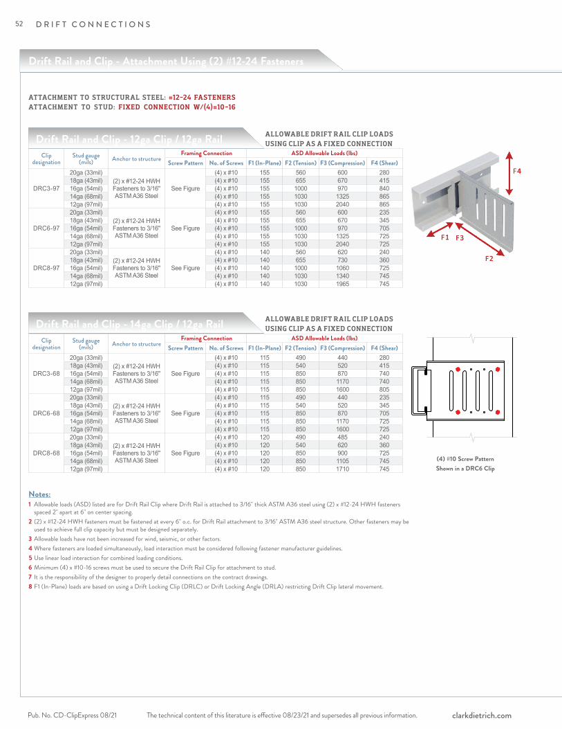
The technical content of this literature is effective 08/23/21 and supersedes all previous information.Pub. No. CD-ClipExpress 08/21 clarkdietrich.com
D R I F T C O N N E C T I O N S
Drift Rail and Clip - Attachment Using (2) #12-24 Fasteners
Drift Rail and Clip - 12ga Clip / 12ga Rail
Drift Rail and Clip - 14ga Clip / 12ga Rail
Clip designation
Stud gauge (mils) Anchor to structure
Framing Connection ASD Allowable Loads (lbs)Screw Pattern No. of Screws F1 (In-Plane) F2 (Tension) F3 (Compression) F4 (Shear)
DRC3-97
20ga (33mil)(2) x #12-24 HWH Fasteners to 3/16" ASTM A36 Steel
See Figure
(4) x #10 155 560 600 28018ga (43mil) (4) x #10 155 655 670 41516ga (54mil) (4) x #10 155 1000 970 84014ga (68mil) (4) x #10 155 1030 1325 86512ga (97mil) (4) x #10 155 1030 2040 865
DRC6-97
20ga (33mil)(2) x #12-24 HWH Fasteners to 3/16" ASTM A36 Steel
See Figure
(4) x #10 155 560 600 23518ga (43mil) (4) x #10 155 655 670 34516ga (54mil) (4) x #10 155 1000 970 70514ga (68mil) (4) x #10 155 1030 1325 72512ga (97mil) (4) x #10 155 1030 2040 725
DRC8-97
20ga (33mil)(2) x #12-24 HWH Fasteners to 3/16" ASTM A36 Steel
See Figure
(4) x #10 140 560 620 24018ga (43mil) (4) x #10 140 655 730 36016ga (54mil) (4) x #10 140 1000 1060 72514ga (68mil) (4) x #10 140 1030 1340 74512ga (97mil) (4) x #10 140 1030 1965 745
Clip designation
Stud gauge (mils) Anchor to structure
Framing Connection ASD Allowable Loads (lbs)Screw Pattern No. of Screws F1 (In-Plane) F2 (Tension) F3 (Compression) F4 (Shear)
DRC3-68
20ga (33mil)(2) x #12-24 HWH Fasteners to 3/16" ASTM A36 Steel
See Figure
(4) x #10 115 490 440 28018ga (43mil) (4) x #10 115 540 520 41516ga (54mil) (4) x #10 115 850 870 74014ga (68mil) (4) x #10 115 850 1170 74012ga (97mil) (4) x #10 115 850 1600 805
DRC6-68
20ga (33mil)(2) x #12-24 HWH Fasteners to 3/16" ASTM A36 Steel
See Figure
(4) x #10 115 490 440 23518ga (43mil) (4) x #10 115 540 520 34516ga (54mil) (4) x #10 115 850 870 70514ga (68mil) (4) x #10 115 850 1170 72512ga (97mil) (4) x #10 115 850 1600 725
DRC8-68
20ga (33mil)(2) x #12-24 HWH Fasteners to 3/16" ASTM A36 Steel
See Figure
(4) x #10 120 490 485 24018ga (43mil) (4) x #10 120 540 620 36016ga (54mil) (4) x #10 120 850 900 72514ga (68mil) (4) x #10 120 850 1105 74512ga (97mil) (4) x #10 120 850 1710 745
Notes:1 Allowable loads (ASD) listed are for Drift Rail Clip where Drift Rail is attached to 3/16" thick ASTM A36 steel using (2) x #12-24 HWH fasteners spaced 2" apart at 6" on center spacing.2 (2) x #12-24 HWH fasteners must be fastened at every 6" o.c. for Drift Rail attachment to 3/16" ASTM A36 steel structure. Other fasteners may be used to achieve full clip capacity but must be designed separately.3 Allowable loads have not been increased for wind, seismic, or other factors.4 Where fasteners are loaded simultaneously, load interaction must be considered following fastener manufacturer guidelines.5 Use linear load interaction for combined loading conditions.6 Minimum (4) x #10-16 screws must be used to secure the Drift Rail Clip for attachment to stud.7 It is the responsibility of the designer to properly detail connections on the contract drawings.8 F1 (In-Plane) loads are based on using a Drift Locking Clip (DRLC) or Drift Locking Angle (DRLA) restricting Drift Clip lateral movement.
ALLOWABLE DRIFT RAIL CLIP LOADS USING CLIP AS A FIXED CONNECTION
(4) #10 Screw PatternShown in a DRC6 Clip
ALLOWABLE DRIFT RAIL CLIP LOADS USING CLIP AS A FIXED CONNECTION
ATTACHMENT TO STRUCTURAL STEEL: #12-24 FASTENERSATTACHMENT TO STUD: FIXED CONNECTION W/(4)#10-16
52
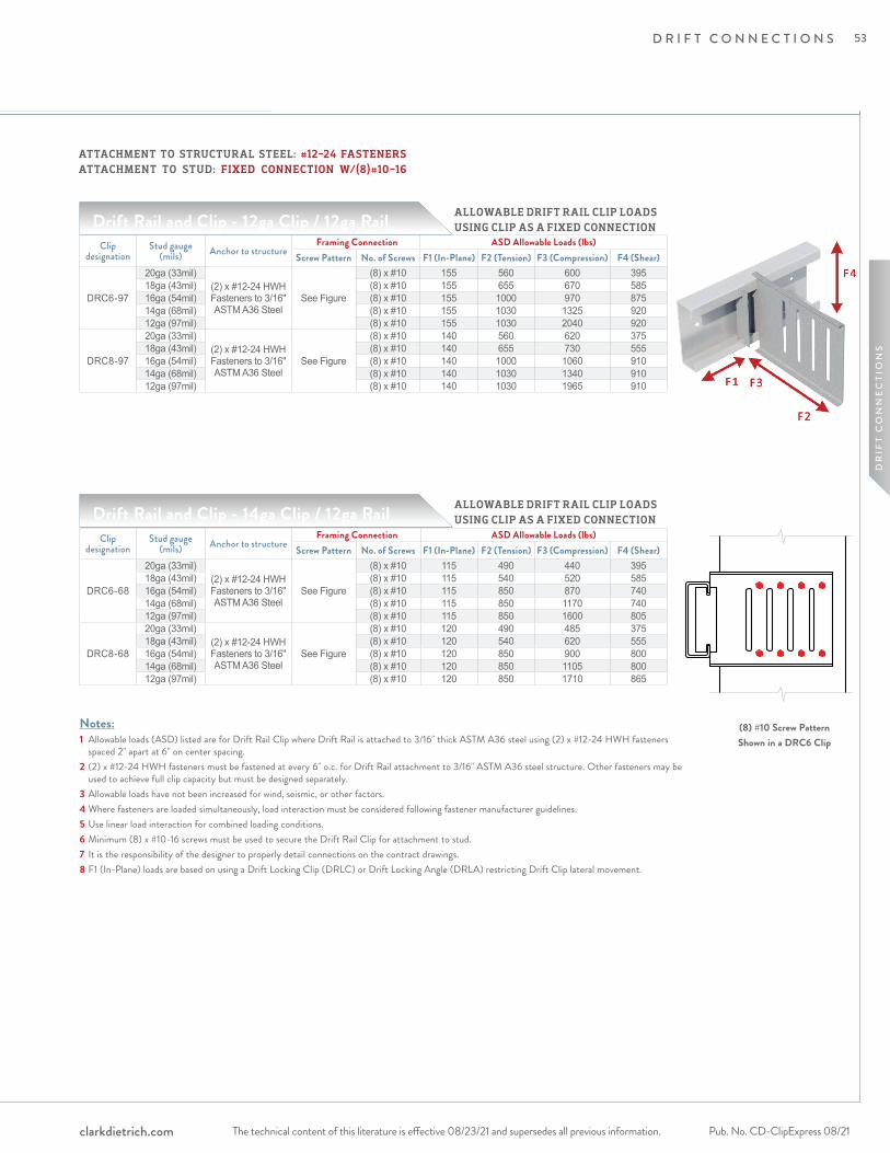
The technical content of this literature is effective 08/23/21 and supersedes all previous information. The technical content of this literature is effective 08/23/21 and supersedes all previous information. Pub. No. CD-ClipExpress 08/21clarkdietrich.com
D R I F T C O N N E C T I O N S
DR
IFT
CO
NN
EC
TIO
NS
Drift Rail and Clip - 12ga Clip / 12ga Rail
Drift Rail and Clip - 14ga Clip / 12ga Rail
Notes:1 Allowable loads (ASD) listed are for Drift Rail Clip where Drift Rail is attached to 3/16" thick ASTM A36 steel using (2) x #12-24 HWH fasteners spaced 2" apart at 6" on center spacing.2 (2) x #12-24 HWH fasteners must be fastened at every 6" o.c. for Drift Rail attachment to 3/16" ASTM A36 steel structure. Other fasteners may be used to achieve full clip capacity but must be designed separately.3 Allowable loads have not been increased for wind, seismic, or other factors.4 Where fasteners are loaded simultaneously, load interaction must be considered following fastener manufacturer guidelines.5 Use linear load interaction for combined loading conditions.6 Minimum (8) x #10-16 screws must be used to secure the Drift Rail Clip for attachment to stud.7 It is the responsibility of the designer to properly detail connections on the contract drawings.8 F1 (In-Plane) loads are based on using a Drift Locking Clip (DRLC) or Drift Locking Angle (DRLA) restricting Drift Clip lateral movement.
Clip designation
Stud gauge (mils) Anchor to structure
Framing Connection ASD Allowable Loads (lbs)Screw Pattern No. of Screws F1 (In-Plane) F2 (Tension) F3 (Compression) F4 (Shear)
DRC6-97
20ga (33mil)(2) x #12-24 HWH Fasteners to 3/16" ASTM A36 Steel
See Figure
(8) x #10 155 560 600 39518ga (43mil) (8) x #10 155 655 670 58516ga (54mil) (8) x #10 155 1000 970 87514ga (68mil) (8) x #10 155 1030 1325 92012ga (97mil) (8) x #10 155 1030 2040 920
DRC8-97
20ga (33mil)(2) x #12-24 HWH Fasteners to 3/16" ASTM A36 Steel
See Figure
(8) x #10 140 560 620 37518ga (43mil) (8) x #10 140 655 730 55516ga (54mil) (8) x #10 140 1000 1060 91014ga (68mil) (8) x #10 140 1030 1340 91012ga (97mil) (8) x #10 140 1030 1965 910
Clip designation
Stud gauge (mils) Anchor to structure
Framing Connection ASD Allowable Loads (lbs)Screw Pattern No. of Screws F1 (In-Plane) F2 (Tension) F3 (Compression) F4 (Shear)
DRC6-68
20ga (33mil)(2) x #12-24 HWH Fasteners to 3/16" ASTM A36 Steel
See Figure
(8) x #10 115 490 440 39518ga (43mil) (8) x #10 115 540 520 58516ga (54mil) (8) x #10 115 850 870 74014ga (68mil) (8) x #10 115 850 1170 74012ga (97mil) (8) x #10 115 850 1600 805
DRC8-68
20ga (33mil)(2) x #12-24 HWH Fasteners to 3/16" ASTM A36 Steel
See Figure
(8) x #10 120 490 485 37518ga (43mil) (8) x #10 120 540 620 55516ga (54mil) (8) x #10 120 850 900 80014ga (68mil) (8) x #10 120 850 1105 80012ga (97mil) (8) x #10 120 850 1710 865
ALLOWABLE DRIFT RAIL CLIP LOADS USING CLIP AS A FIXED CONNECTION
(8) #10 Screw PatternShown in a DRC6 Clip
ALLOWABLE DRIFT RAIL CLIP LOADS USING CLIP AS A FIXED CONNECTION
ATTACHMENT TO STRUCTURAL STEEL: #12-24 FASTENERSATTACHMENT TO STUD: FIXED CONNECTION W/(8)#10-16
53
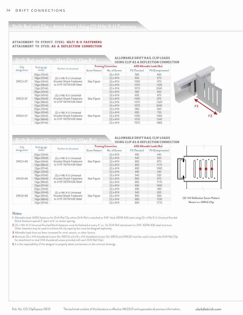
The technical content of this literature is effective 08/23/21 and supersedes all previous information.Pub. No. CD-ClipExpress 08/21 clarkdietrich.com
D R I F T C O N N E C T I O N S
Drift Rail and Clip - Attachment Using (2) Hilti X-U Fasteners
Drift Rail and Clip - 12ga Clip / 12ga Rail
Drift Rail and Clip - 14ga Clip / 12ga Rail ALLOWABLE DRIFT RAIL CLIP LOADS USING CLIP AS A DEFLECTION CONNECTION
(3) #14 Deflection Screw PatternShown in a DRC6 Clip
Notes:1 Allowable loads (ASD) listed are for Drift Rail Clip where Drift Rail is attached to 3/16" thick ASTM A36 steel using (2) x Hilti X-U Universal Knurled Shank fasteners spaced 2" apart at 6" on center spacing.2 (2) x Hilti X-U Universal Knurled Shank fasteners must be fastened at every 6" o.c. for Drift Rail attachment to 3/16" ASTM A36 steel structure. Other fasteners may be used to achieve full clip capacity but must be designed separately.3 Allowable loads have not been increased for wind, seismic, or other factors.4 Minimum (2) x #14 shouldered screws (for DRC3) and (3) x #14 shouldered screws (for DRC6 and DRC8) must be used to secure the Drift Rail Clip for attachment to stud (#14 shouldered screws provided with each Drift Rail Clip).5 It is the responsibility of the designer to properly detail connections on the contract drawings.
Clip designation
Stud gauge (mils) Anchor to structure
Framing Connection ASD Allowable Loads (lbs)Screw Pattern No. of Screws F2 (Tension) F3 (Compression)
DRC3-68
20ga (33mil)(2) x Hilti X-U Universal
Knurled Shank Fasteners to 3/16" ASTM A36 Steel
See Figure
(2) x #14 490 44018ga (43mil) (2) x #14 540 52016ga (54mil) (2) x #14 850 87014ga (68mil) (2) x #14 850 117012ga (97mil) (2) x #14 850 1600
DRC6-68
20ga (33mil)(2) x Hilti X-U Universal
Knurled Shank Fasteners to 3/16" ASTM A36 Steel
See Figure
(3) x #14 490 44018ga (43mil) (3) x #14 540 52016ga (54mil) (3) x #14 850 87014ga (68mil) (3) x #14 850 117012ga (97mil) (3) x #14 850 1600
DRC8-68
20ga (33mil)(2) x Hilti X-U Universal
Knurled Shank Fasteners to 3/16" ASTM A36 Steel
See Figure
(3) x #14 490 48518ga (43mil) (3) x #14 540 62016ga (54mil) (3) x #14 850 90014ga (68mil) (3) x #14 850 110512ga (97mil) (3) x #14 850 1710
ALLOWABLE DRIFT RAIL CLIP LOADS USING CLIP AS A DEFLECTION CONNECTION
Clip designation
Stud gauge (mils) Anchor to structure
Framing Connection ASD Allowable Loads (lbs)Screw Pattern No. of Screws F2 (Tension) F3 (Compression)
DRC3-97
20ga (33mil)(2) x Hilti X-U Universal
Knurled Shank Fasteners to 3/16" ASTM A36 Steel
See Figure
(2) x #14 560 60018ga (43mil) (2) x #14 655 67016ga (54mil) (2) x #14 1000 97014ga (68mil) (2) x #14 1070 132512ga (97mil) (2) x #14 1070 2040
DRC6-97
20ga (33mil)(2) x Hilti X-U Universal
Knurled Shank Fasteners to 3/16" ASTM A36 Steel
See Figure
(3) x #14 560 60018ga (43mil) (3) x #14 655 67016ga (54mil) (3) x #14 1000 97014ga (68mil) (3) x #14 1070 132512ga (97mil) (3) x #14 1070 2040
DRC8-97
20ga (33mil)(2) x Hilti X-U Universal
Knurled Shank Fasteners to 3/16" ASTM A36 Steel
See Figure
(3) x #14 560 62018ga (43mil) (3) x #14 655 73016ga (54mil) (3) x #14 1000 106014ga (68mil) (3) x #14 1070 134012ga (97mil) (3) x #14 1070 1965
ATTACHMENT TO STRUCT. STEEL: HILTI X-U FASTENERS ATTACHMENT TO STUD: AS A DEFLECTION CONNECTION
54

The technical content of this literature is effective 08/23/21 and supersedes all previous information. The technical content of this literature is effective 08/23/21 and supersedes all previous information. Pub. No. CD-ClipExpress 08/21clarkdietrich.com
D R I F T C O N N E C T I O N S
DR
IFT
CO
NN
EC
TIO
NS
Drift Rail and Clip - 12ga Clip / 12ga Rail
Drift Rail and Clip - 14ga Clip / 12ga Rail
Notes:1 Allowable loads (ASD) listed are for Drift Rail Clip where Drift Rail is attached to 3/16" thick ASTM A36 steel using (2) x Hilti X-U Universal Knurled Shank fasteners spaced 2" apart at 6" on center spacing.2 (2) x Hilti X-U Universal Knurled Shank fasteners must be fastened at every 6" o.c. for Drift Rail attachment to 3/16" ASTM A36 steel structure. Other fasteners may be used to achieve full clip capacity but must be designed separately.3 Allowable loads have not been increased for wind, seismic, or other factors.4 Where fasteners are loaded simultaneously, load interaction must be considered following fastener manufacturer guidelines.5 Use linear load interaction for combined loading conditions.6 Minimum (4) x #10-16 screws must be used to secure the Drift Rail Clip for attachment to stud.7 It is the responsibility of the designer to properly detail connections on the contract drawings.8 F1 (In-Plane) loads are based on using a Drift Locking Clip (DRLC) or Drift Locking Angle (DRLA) restricting Drift Clip lateral movement.
Clip designation
Stud gauge (mils) Anchor to structure
Framing Connection ASD Allowable Loads (lbs)Screw Pattern No. of Screws F1 (In-Plane) F2 (Tension) F3 (Compression) F4 (Shear)
DRC3-97
20ga (33mil) (2) x Hilti X-U Universal Knurled Shank Fasteners to 3/16" ASTM
A36 Steel
See Figure
(4) x #10 155 560 600 28018ga (43mil) (4) x #10 155 655 670 41516ga (54mil) (4) x #10 155 1000 970 84014ga (68mil) (4) x #10 155 1070 1325 86512ga (97mil) (4) x #10 155 1070 2040 865
DRC6-97
20ga (33mil) (2) x Hilti X-U Universal Knurled Shank Fasteners to 3/16" ASTM
A36 Steel
See Figure
(4) x #10 155 560 600 23518ga (43mil) (4) x #10 155 655 670 34516ga (54mil) (4) x #10 155 1000 970 70514ga (68mil) (4) x #10 155 1070 1325 72512ga (97mil) (4) x #10 155 1070 2040 725
DRC8-97
20ga (33mil) (2) x Hilti X-U Universal Knurled Shank Fasteners to 3/16" ASTM
A36 Steel
See Figure
(4) x #10 140 560 620 24018ga (43mil) (4) x #10 140 655 730 36016ga (54mil) (4) x #10 140 1000 1060 72514ga (68mil) (4) x #10 140 1070 1340 74512ga (97mil) (4) x #10 140 1070 1965 745
Clip designation
Stud gauge (mils) Anchor to structure
Framing Connection ASD Allowable Loads (lbs)Screw Pattern No. of Screws F1 (In-Plane) F2 (Tension) F3 (Compression) F4 (Shear)
DRC3-68
20ga (33mil) (2) x Hilti X-U Universal Knurled Shank Fasteners to 3/16" ASTM
A36 Steel
See Figure
(4) x #10 115 490 440 28018ga (43mil) (4) x #10 115 540 520 41516ga (54mil) (4) x #10 115 850 870 74014ga (68mil) (4) x #10 115 850 1170 74012ga (97mil) (4) x #10 115 850 1600 805
DRC6-68
20ga (33mil) (2) x Hilti X-U Universal Knurled Shank Fasteners to 3/16" ASTM
A36 Steel
See Figure
(4) x #10 115 490 440 23518ga (43mil) (4) x #10 115 540 520 34516ga (54mil) (4) x #10 115 850 870 70514ga (68mil) (4) x #10 115 850 1170 72512ga (97mil) (4) x #10 115 850 1600 725
DRC8-68
20ga (33mil) (2) x Hilti X-U Universal Knurled Shank Fasteners to 3/16" ASTM
A36 Steel
See Figure
(4) x #10 120 490 485 24018ga (43mil) (4) x #10 120 540 620 36016ga (54mil) (4) x #10 120 850 900 72514ga (68mil) (4) x #10 120 850 1105 74512ga (97mil) (4) x #10 120 850 1710 745
ALLOWABLE DRIFT RAIL CLIP LOADS USING CLIP AS A FIXED CONNECTION
(4) #10 Screw PatternShown in a DRC6 Clip
ALLOWABLE DRIFT RAIL CLIP LOADS USING CLIP AS A FIXED CONNECTION
ATTACHMENT TO STRUCT. STEEL: HILTI X-U FASTENERS ATTACHMENT TO STUD: FIXED CONNECTION W/(4)#10-16
55
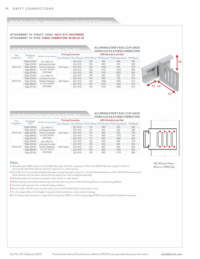
The technical content of this literature is effective 08/23/21 and supersedes all previous information.Pub. No. CD-ClipExpress 08/21 clarkdietrich.com
D R I F T C O N N E C T I O N S
Drift Rail and Clip - Attachment Using (2) Hilti X-U Fasteners
Drift Rail and Clip - 12ga Clip / 12ga Rail
Drift Rail and Clip - 14ga Clip / 12ga Rail
Notes:1 Allowable loads (ASD) listed are for Drift Rail Clip where Drift Rail is attached to 3/16" thick ASTM A36 steel using (2) x Hilti X-U Universal Knurled Shank fasteners spaced 2" apart at 6" on center spacing.2 (2) x Hilti X-U Universal Knurled Shank fasteners must be fastened at every 6" o.c. for Drift Rail attachment to 3/16" ASTM A36 steel structure. Other fasteners may be used to achieve full clip capacity but must be designed separately.3 Allowable loads have not been increased for wind, seismic, or other factors.4 Where fasteners are loaded simultaneously, load interaction must be considered following fastener manufacturer guidelines.5 Use linear load interaction for combined loading conditions.6 Minimum (8) x #10-16 screws must be used to secure the Drift Rail Clip for attachment to stud.7 It is the responsibility of the designer to properly detail connections on the contract drawings.8 F1 (In-Plane) loads are based on using a Drift Locking Clip (DRLC) or Drift Locking Angle (DRLA) restricting Drift Clip lateral movement.
Clip designation
Stud gauge (mils) Anchor to structure
Framing Connection ASD Allowable Loads (lbs)Screw Pattern No. of Screws F1 (In-Plane) F2 (Tension) F3 (Compression) F4 (Shear)
DRC6-97
20ga (33mil) (2) x Hilti X-U Universal Knurled Shank Fasteners to 3/16" ASTM
A36 Steel
See Figure
(8) x #10 155 560 600 39518ga (43mil) (8) x #10 155 655 670 58516ga (54mil) (8) x #10 155 1000 970 87514ga (68mil) (8) x #10 155 1070 1325 92012ga (97mil) (8) x #10 155 1070 2040 920
DRC8-97
20ga (33mil) (2) x Hilti X-U Universal Knurled Shank Fasteners to 3/16" ASTM
A36 Steel
See Figure
(8) x #10 140 560 620 37518ga (43mil) (8) x #10 140 655 730 55516ga (54mil) (8) x #10 140 1000 1060 91014ga (68mil) (8) x #10 140 1070 1340 91012ga (97mil) (8) x #10 140 1070 1965 910
Clip designation
Stud gauge (mils) Anchor to structure
Framing Connection ASD Allowable Loads (lbs)Screw Pattern No. of Screws F1 (In-Plane) F2 (Tension) F3 (Compression) F4 (Shear)
DRC6-68
20ga (33mil) (2) x Hilti X-U Universal Knurled Shank Fasteners to 3/16" ASTM
A36 Steel
See Figure
(8) x #10 115 490 440 39518ga (43mil) (8) x #10 115 540 520 58516ga (54mil) (8) x #10 115 850 870 74014ga (68mil) (8) x #10 115 850 1170 74012ga (97mil) (8) x #10 115 850 1600 805
DRC8-68
20ga (33mil) (2) x Hilti X-U Universal Knurled Shank Fasteners to 3/16" ASTM
A36 Steel
See Figure
(8) x #10 120 490 485 37518ga (43mil) (8) x #10 120 540 620 55516ga (54mil) (8) x #10 120 850 900 80014ga (68mil) (8) x #10 120 850 1105 80012ga (97mil) (8) x #10 120 850 1710 865
ALLOWABLE DRIFT RAIL CLIP LOADS USING CLIP AS A FIXED CONNECTION
(8) #10 Screw PatternShown in a DRC6 Clip
ALLOWABLE DRIFT RAIL CLIP LOADS USING CLIP AS A FIXED CONNECTION
ATTACHMENT TO STRUCT. STEEL: HILTI X-U FASTENERS ATTACHMENT TO STUD: FIXED CONNECTION W/(8)#10-16
56

The technical content of this literature is effective 08/23/21 and supersedes all previous information. The technical content of this literature is effective 08/23/21 and supersedes all previous information. Pub. No. CD-ClipExpress 08/21clarkdietrich.com
D R I F T C O N N E C T I O N S
DR
IFT
CO
NN
EC
TIO
NS
Drift Rail and Clip - Attachment Using (1) 1/4" Hilti KWIK HUS-EZ
Drift Rail and Clip - 12ga Clip / 12ga Rail
Drift Rail and Clip - 14ga Clip / 12ga Rail ALLOWABLE DRIFT RAIL CLIP LOADS USING CLIP AS A DEFLECTION CONNECTION
(3) #14 Deflection Screw PatternShown in a DRC6 Clip
Notes:1 Allowable loads (ASD) listed are for Drift Rail Clip where Drift Rail is attached to 3000psi uncracked concrete using (1) x 1/4" Hilti X KWIK HUS-EZ anchor only.2 (1) x 1/4" Hilti KWIK HUS-EZ anchors (nom. embedment depth of 2-1/2", 3000psi uncracked concrete) should be fastened at every 6" o.c. for Drift Rail attachment to structure. Other anchors may be used to achieve full clip capacity but must be designed separately.3 Allowable loads have not been increased for wind, seismic, or other factors.4 Minimum (2) x #14 shouldered screws (for DRC3) and (3) x #14 shouldered screws (for DRC6 and DRC8) must be used to secure the Drift Rail Clip for attachment to stud (#14 shouldered screws provided with each Drift Rail Clip).5 It is the responsibility of the designer to properly detail connections on the contract drawings.
Clip designation
Stud gauge (mils) Anchor to structure
Framing Connection ASD Allowable Loads (lbs)Screw Pattern No. of Screws F2 (Tension) F3 (Compression)
DRC3-97
20ga (33mil)(1) x 1/4" Hilti KWIK HUS-EZ @ 6" o.c.
(3000psi uncracked concrete)See Figure
(2) x #14 560 60018ga (43mil) (2) x #14 655 67016ga (54mil) (2) x #14 1000 97014ga (68mil) (2) x #14 1045 132512ga (97mil) (2) x #14 1045 2040
DRC6-97
20ga (33mil)(1) x 1/4" Hilti KWIK HUS-EZ @ 6" o.c.
(3000psi uncracked concrete)See Figure
(3) x #14 560 60018ga (43mil) (3) x #14 655 67016ga (54mil) (3) x #14 1000 97014ga (68mil) (3) x #14 1045 132512ga (97mil) (3) x #14 1045 2040
DRC8-97
20ga (33mil)(1) x 1/4" Hilti KWIK HUS-EZ @ 6" o.c.
(3000psi uncracked concrete)See Figure
(3) x #14 560 62018ga (43mil) (3) x #14 655 73016ga (54mil) (3) x #14 1000 106014ga (68mil) (3) x #14 1045 134012ga (97mil) (3) x #14 1045 1965
Clip designation
Stud gauge (mils) Anchor to structure
Framing Connection ASD Allowable Loads (lbs)Screw Pattern No. of Screws F2 (Tension) F3 (Compression)
DRC3-68
20ga (33mil)(1) x 1/4" Hilti KWIK HUS-EZ @ 6" o.c.
(3000psi uncracked concrete)See Figure
(2) x #14 490 44018ga (43mil) (2) x #14 540 52016ga (54mil) (2) x #14 850 87014ga (68mil) (2) x #14 850 117012ga (97mil) (2) x #14 850 1600
DRC6-68
20ga (33mil)(1) x 1/4" Hilti KWIK HUS-EZ @ 6" o.c.
(3000psi uncracked concrete)See Figure
(3) x #14 490 44018ga (43mil) (3) x #14 540 52016ga (54mil) (3) x #14 850 87014ga (68mil) (3) x #14 850 117012ga (97mil) (3) x #14 850 1600
DRC8-68
20ga (33mil)(1) x 1/4" Hilti KWIK HUS-EZ @ 6" o.c.
(3000psi uncracked concrete)See Figure
(3) x #14 490 48518ga (43mil) (3) x #14 540 62016ga (54mil) (3) x #14 850 90014ga (68mil) (3) x #14 850 110512ga (97mil) (3) x #14 850 1710
ALLOWABLE DRIFT RAIL CLIP LOADS USING CLIP AS A DEFLECTION CONNECTION
ATTACHMENT TO CONCRETE: 1/4" HILTI KWIK HUS-EZ ATTACHMENT TO STUD: AS A DEFLECTION CONNECTION
57
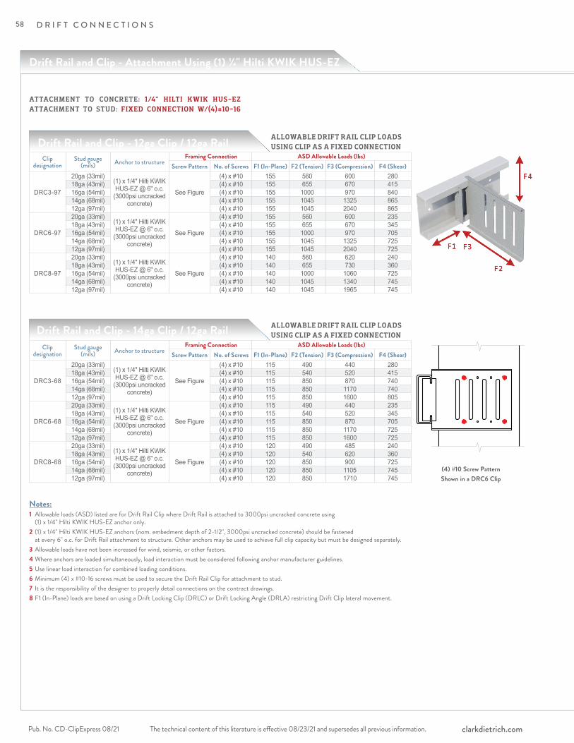
The technical content of this literature is effective 08/23/21 and supersedes all previous information.Pub. No. CD-ClipExpress 08/21 clarkdietrich.com
D R I F T C O N N E C T I O N S
Drift Rail and Clip - Attachment Using (1) 1/4" Hilti KWIK HUS-EZ
Drift Rail and Clip - 12ga Clip / 12ga Rail
Drift Rail and Clip - 14ga Clip / 12ga Rail
Notes:1 Allowable loads (ASD) listed are for Drift Rail Clip where Drift Rail is attached to 3000psi uncracked concrete using (1) x 1/4" Hilti KWIK HUS-EZ anchor only.2 (1) x 1/4" Hilti KWIK HUS-EZ anchors (nom. embedment depth of 2-1/2", 3000psi uncracked concrete) should be fastened at every 6" o.c. for Drift Rail attachment to structure. Other anchors may be used to achieve full clip capacity but must be designed separately.3 Allowable loads have not been increased for wind, seismic, or other factors.4 Where anchors are loaded simultaneously, load interaction must be considered following anchor manufacturer guidelines.5 Use linear load interaction for combined loading conditions.6 Minimum (4) x #10-16 screws must be used to secure the Drift Rail Clip for attachment to stud.7 It is the responsibility of the designer to properly detail connections on the contract drawings.8 F1 (In-Plane) loads are based on using a Drift Locking Clip (DRLC) or Drift Locking Angle (DRLA) restricting Drift Clip lateral movement.
Clip designation
Stud gauge (mils) Anchor to structure
Framing Connection ASD Allowable Loads (lbs)Screw Pattern No. of Screws F1 (In-Plane) F2 (Tension) F3 (Compression) F4 (Shear)
DRC3-97
20ga (33mil)(1) x 1/4" Hilti KWIK HUS-EZ @ 6" o.c.
(3000psi uncracked concrete)
See Figure
(4) x #10 155 560 600 28018ga (43mil) (4) x #10 155 655 670 41516ga (54mil) (4) x #10 155 1000 970 84014ga (68mil) (4) x #10 155 1045 1325 86512ga (97mil) (4) x #10 155 1045 2040 865
DRC6-97
20ga (33mil)(1) x 1/4" Hilti KWIK HUS-EZ @ 6" o.c.
(3000psi uncracked concrete)
See Figure
(4) x #10 155 560 600 23518ga (43mil) (4) x #10 155 655 670 34516ga (54mil) (4) x #10 155 1000 970 70514ga (68mil) (4) x #10 155 1045 1325 72512ga (97mil) (4) x #10 155 1045 2040 725
DRC8-97
20ga (33mil)(1) x 1/4" Hilti KWIK HUS-EZ @ 6" o.c.
(3000psi uncracked concrete)
See Figure
(4) x #10 140 560 620 24018ga (43mil) (4) x #10 140 655 730 36016ga (54mil) (4) x #10 140 1000 1060 72514ga (68mil) (4) x #10 140 1045 1340 74512ga (97mil) (4) x #10 140 1045 1965 745
Clip designation
Stud gauge (mils) Anchor to structure
Framing Connection ASD Allowable Loads (lbs)Screw Pattern No. of Screws F1 (In-Plane) F2 (Tension) F3 (Compression) F4 (Shear)
DRC3-68
20ga (33mil)(1) x 1/4" Hilti KWIK HUS-EZ @ 6" o.c.
(3000psi uncracked concrete)
See Figure
(4) x #10 115 490 440 28018ga (43mil) (4) x #10 115 540 520 41516ga (54mil) (4) x #10 115 850 870 74014ga (68mil) (4) x #10 115 850 1170 74012ga (97mil) (4) x #10 115 850 1600 805
DRC6-68
20ga (33mil)(1) x 1/4" Hilti KWIK HUS-EZ @ 6" o.c.
(3000psi uncracked concrete)
See Figure
(4) x #10 115 490 440 23518ga (43mil) (4) x #10 115 540 520 34516ga (54mil) (4) x #10 115 850 870 70514ga (68mil) (4) x #10 115 850 1170 72512ga (97mil) (4) x #10 115 850 1600 725
DRC8-68
20ga (33mil)(1) x 1/4" Hilti KWIK HUS-EZ @ 6" o.c.
(3000psi uncracked concrete)
See Figure
(4) x #10 120 490 485 24018ga (43mil) (4) x #10 120 540 620 36016ga (54mil) (4) x #10 120 850 900 72514ga (68mil) (4) x #10 120 850 1105 74512ga (97mil) (4) x #10 120 850 1710 745
ALLOWABLE DRIFT RAIL CLIP LOADS USING CLIP AS A FIXED CONNECTION
(4) #10 Screw PatternShown in a DRC6 Clip
ALLOWABLE DRIFT RAIL CLIP LOADS USING CLIP AS A FIXED CONNECTION
ATTACHMENT TO CONCRETE: 1/4" HILTI KWIK HUS-EZ ATTACHMENT TO STUD: FIXED CONNECTION W/(4)#10-16
58
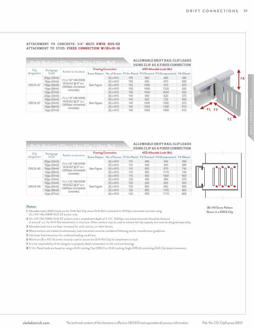
The technical content of this literature is effective 08/23/21 and supersedes all previous information. The technical content of this literature is effective 08/23/21 and supersedes all previous information. Pub. No. CD-ClipExpress 08/21clarkdietrich.com
D R I F T C O N N E C T I O N S
DR
IFT
CO
NN
EC
TIO
NS
Drift Rail and Clip - 12ga Clip / 12ga Rail
Drift Rail and Clip - 14ga Clip / 12ga Rail
Notes:1 Allowable loads (ASD) listed are for Drift Rail Clip where Drift Rail is attached to 3000psi uncracked concrete using (1) x 1/4" Hilti KWIK HUS-EZ anchor only.2 (1) x 1/4" Hilti KWIK HUS-EZ anchors (nom. embedment depth of 2-1/2", 3000psi uncracked concrete) should be fastened at every 6" o.c. for Drift Rail attachment to structure. Other anchors may be used to achieve full clip capacity but must be designed separately.3 Allowable loads have not been increased for wind, seismic, or other factors.4 Where anchors are loaded simultaneously, load interaction must be considered following anchor manufacturer guidelines.5 Use linear load interaction for combined loading conditions.6 Minimum (8) x #10-16 screws must be used to secure the Drift Rail Clip for attachment to stud.7 It is the responsibility of the designer to properly detail connections on the contract drawings.8 F1 (In-Plane) loads are based on using a Drift Locking Clip (DRLC) or Drift Locking Angle (DRLA) restricting Drift Clip lateral movement.
Clip designation
Stud gauge (mils) Anchor to structure
Framing Connection ASD Allowable Loads (lbs)Screw Pattern No. of Screws F1 (In-Plane) F2 (Tension) F3 (Compression) F4 (Shear)
DRC6-97
20ga (33mil)(1) x 1/4" Hilti KWIK HUS-EZ @ 6" o.c.
(3000psi uncracked concrete)
See Figure
(8) x #10 155 560 600 39518ga (43mil) (8) x #10 155 655 670 58516ga (54mil) (8) x #10 155 1000 970 87514ga (68mil) (8) x #10 155 1045 1325 92012ga (97mil) (8) x #10 155 1045 2040 920
DRC8-97
20ga (33mil)(1) x 1/4" Hilti KWIK HUS-EZ @ 6" o.c.
(3000psi uncracked concrete)
See Figure
(8) x #10 140 560 620 37518ga (43mil) (8) x #10 140 655 730 55516ga (54mil) (8) x #10 140 1000 1060 91014ga (68mil) (8) x #10 140 1045 1340 91012ga (97mil) (8) x #10 140 1045 1965 910
Clip designation
Stud gauge (mils) Anchor to structure
Framing Connection ASD Allowable Loads (lbs)Screw Pattern No. of Screws F1 (In-Plane) F2 (Tension) F3 (Compression) F4 (Shear)
DRC6-68
20ga (33mil)(1) x 1/4" Hilti KWIK HUS-EZ @ 6" o.c.
(3000psi uncracked concrete)
See Figure
(8) x #10 115 490 440 39518ga (43mil) (8) x #10 115 540 520 58516ga (54mil) (8) x #10 115 850 870 74014ga (68mil) (8) x #10 115 850 1170 74012ga (97mil) (8) x #10 115 850 1600 805
DRC8-68
20ga (33mil)(1) x 1/4" Hilti KWIK HUS-EZ @ 6" o.c.
(3000psi uncracked concrete)
See Figure
(8) x #10 120 490 485 37518ga (43mil) (8) x #10 120 540 620 55516ga (54mil) (8) x #10 120 850 900 80014ga (68mil) (8) x #10 120 850 1105 80012ga (97mil) (8) x #10 120 850 1710 865
ALLOWABLE DRIFT RAIL CLIP LOADS USING CLIP AS A FIXED CONNECTION
(8) #10 Screw PatternShown in a DRC6 Clip
ALLOWABLE DRIFT RAIL CLIP LOADS USING CLIP AS A FIXED CONNECTION
ATTACHMENT TO CONCRETE: 1/4" HILTI KWIK HUS-EZ ATTACHMENT TO STUD: FIXED CONNECTION W/(8)#10-16
59
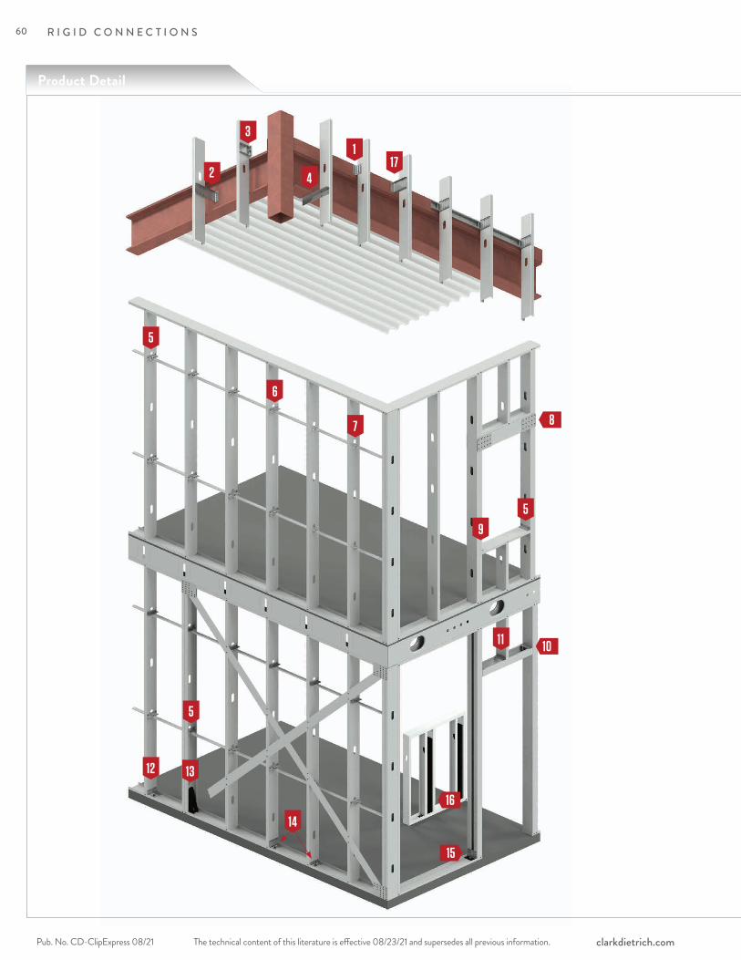
Product Detail
R I G I D C O N N E C T I O N S
The technical content of this literature is effective 08/23/21 and supersedes all previous information.Pub. No. CD-ClipExpress 08/21 clarkdietrich.com
2
13
4
7
12
5
8
15
6
13
9
16
1011
14
5
17
5
60

R I G I D C O N N E C T I O N S
The technical content of this literature is effective 08/23/21 and supersedes all previous information. The technical content of this literature is effective 08/23/21 and supersedes all previous information. Pub. No. CD-ClipExpress 08/21clarkdietrich.com
RIG
ID C
ON
NE
CTI
ON
S
EasyClip D- and T-Series™
Anchor Clips pages 80-81
ClarkDietrich Holdown pages 86-87
EasyClip S-Series™ Support Clip pages 76-77
EasyClip U-Series™ Clip Angle page 75
Uni-Clip™ End Clip pages 62–63
Extended SwiftClip™ LE-Series™page 74
1
3
4
5
6
9
10
11
13
FastBridge™ Clip pages 82-83
7
ClarkDietrich Moment Clip pages 88-89
12
Extended Uni-Clip™pages 64-65
2
ClarkDietrich Pony Wall (Heavy & Lite) pages 90-97
14
Extended Uni-Clip™ with Anchor Holespages 66-67
8
EasyClip™ A-Series™ End Clip pages 78-79
Header Cripple Stud Clip page 158
HDSC Header Bracket pages 146-149
SwiftClip™ L-Series™
Support Clippages 72-73
16
15
H-Series™ Universal Header Hanger pages 84-85
Universal Bypass Clip pages 68–71
17
61
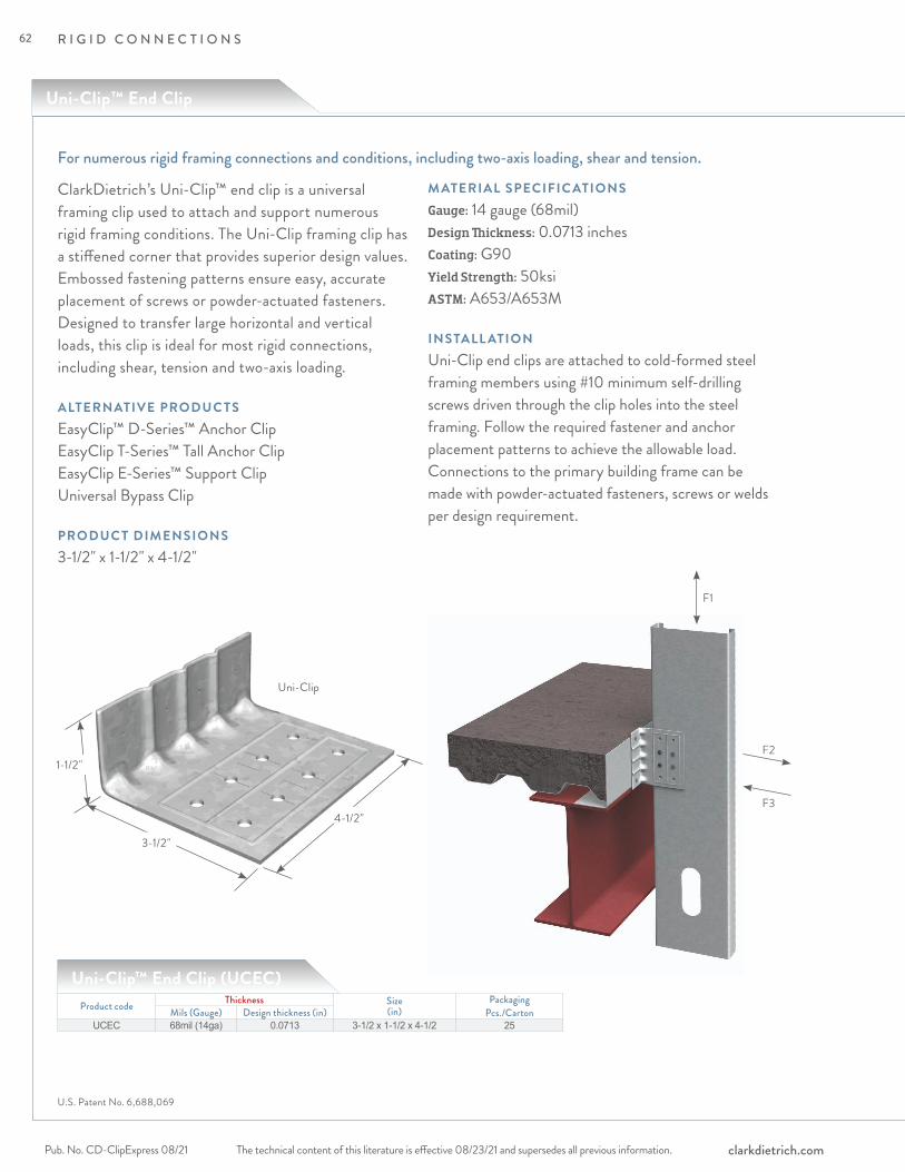
R I G I D C O N N E C T I O N S
The technical content of this literature is effective 08/23/21 and supersedes all previous information.Pub. No. CD-ClipExpress 08/21 clarkdietrich.com
F3
F2
F1
ClarkDietrich’s Uni-Clip™ end clip is a universal framing clip used to attach and support numerous rigid framing conditions. The Uni-Clip framing clip has a stiffened corner that provides superior design values. Embossed fastening patterns ensure easy, accurate placement of screws or powder-actuated fasteners. Designed to transfer large horizontal and vertical loads, this clip is ideal for most rigid connections, including shear, tension and two-axis loading.
ALTERNATIVE PRODUC TSEasyClip™ D-Series™ Anchor Clip EasyClip T-Series™ Tall Anchor Clip EasyClip E-Series™ Support Clip Universal Bypass Clip
PRODUC T DIMENSIONS3-1/2" x 1-1/2" x 4-1/2"
M ATERIAL SPECIFIC ATIONSGauge: 14 gauge (68mil)Design Thickness: 0.0713 inchesCoating: G90 Yield Strength: 50ksiASTM: A653/A653M
INSTALL ATIONUni-Clip end clips are attached to cold-formed steel framing members using #10 minimum self-drilling screws driven through the clip holes into the steel framing. Follow the required fastener and anchor placement patterns to achieve the allowable load. Connections to the primary building frame can be made with powder-actuated fasteners, screws or welds per design requirement.
Product code Thickness Size (in)
Packaging Pcs./CartonMils (Gauge) Design thickness (in)
UCEC 68mil (14ga) 0.0713 3-1/2 x 1-1/2 x 4-1/2 25
Uni-Clip™ End Clip (UCEC)
Uni-Clip
3-1/2"
1-1/2"
4-1/2"
For numerous rigid framing connections and conditions, including two-axis loading, shear and tension.
U.S. Patent No. 6,688,069
Uni-Clip™ End Clip
62
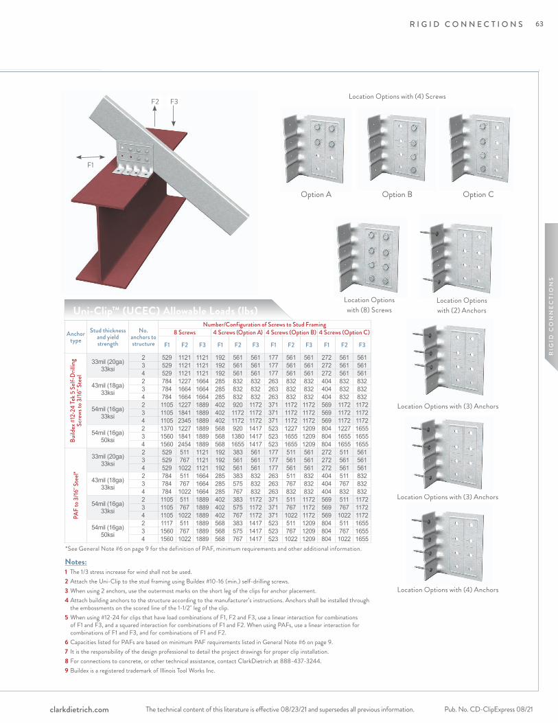
R I G I D C O N N E C T I O N S
The technical content of this literature is effective 08/23/21 and supersedes all previous information. The technical content of this literature is effective 08/23/21 and supersedes all previous information. Pub. No. CD-ClipExpress 08/21clarkdietrich.com
RIG
ID C
ON
NE
CTI
ON
S
Notes:1 The 1/3 stress increase for wind shall not be used.2 Attach the Uni-Clip to the stud framing using Buildex #10-16 (min.) self-drilling screws.3 When using 2 anchors, use the outermost marks on the short leg of the clips for anchor placement.4 Attach building anchors to the structure according to the manufacturer’s instructions. Anchors shall be installed through
the embossments on the scored line of the 1-1/2" leg of the clip.5 When using #12-24 for clips that have load combinations of F1, F2 and F3, use a linear interaction for combinations
of F1 and F3, and a squared interaction for combinations of F1 and F2. When using PAFs, use a linear interaction for combinations of F1 and F3, and for combinations of F1 and F2.
6 Capacities listed for PAFs are based on minimum PAF requirements listed in General Note #6 on page 9.7 It is the responsibility of the design professional to detail the project drawings for proper clip installation.8 For connections to concrete, or other technical assistance, contact ClarkDietrich at 888-437-3244.9 Buildex is a registered trademark of Illinois Tool Works Inc.
Uni-Clip™ (UCEC) Allowable Loads (lbs)
Location Options with (4) Screws
Option A Option B Option C
Location Options with (8) Screws
Location Options with (2) Anchors
Location Options with (4) Anchors
Anchor type
Stud thickness and yield strength
No. anchors to structure
Number/Configuration of Screws to Stud Framing8 Screws 4 Screws (Option A) 4 Screws (Option B) 4 Screws (Option C)
F1 F2 F3 F1 F2 F3 F1 F2 F3 F1 F2 F3
Build
ex #
12-2
4 Te
k 5 S
elf-D
rillin
g Sc
rews
to 3
/16" S
teel
33mil (20ga)33ksi
2 529 1121 1121 192 561 561 177 561 561 272 561 5613 529 1121 1121 192 561 561 177 561 561 272 561 5614 529 1121 1121 192 561 561 177 561 561 272 561 561
43mil (18ga)33ksi
2 784 1227 1664 285 832 832 263 832 832 404 832 8323 784 1664 1664 285 832 832 263 832 832 404 832 8324 784 1664 1664 285 832 832 263 832 832 404 832 832
54mil (16ga)33ksi
2 1105 1227 1889 402 920 1172 371 1172 1172 569 1172 11723 1105 1841 1889 402 1172 1172 371 1172 1172 569 1172 11724 1105 2345 1889 402 1172 1172 371 1172 1172 569 1172 1172
54mil (16ga)50ksi
2 1370 1227 1889 568 920 1417 523 1227 1209 804 1227 16553 1560 1841 1889 568 1380 1417 523 1655 1209 804 1655 16554 1560 2454 1889 568 1655 1417 523 1655 1209 804 1655 1655
PAF
to 3
/16" S
teel*
33mil (20ga)33ksi
2 529 511 1121 192 383 561 177 511 561 272 511 5613 529 767 1121 192 561 561 177 561 561 272 561 5614 529 1022 1121 192 561 561 177 561 561 272 561 561
43mil (18ga)33ksi
2 784 511 1664 285 383 832 263 511 832 404 511 8323 784 767 1664 285 575 832 263 767 832 404 767 8324 784 1022 1664 285 767 832 263 832 832 404 832 832
54mil (16ga) 33ksi
2 1105 511 1889 402 383 1172 371 511 1172 569 511 11723 1105 767 1889 402 575 1172 371 767 1172 569 767 11724 1105 1022 1889 402 767 1172 371 1022 1172 569 1022 1172
54mil (16ga)50ksi
2 1117 511 1889 568 383 1417 523 511 1209 804 511 16553 1560 767 1889 568 575 1417 523 767 1209 804 767 16554 1560 1022 1889 568 767 1417 523 1022 1209 804 1022 1655
Location Options with (3) Anchors
Location Options with (3) Anchors
F1
F2 F3
*See General Note #6 on page 9 for the definition of PAF, minimum requirements and other additional information.
63
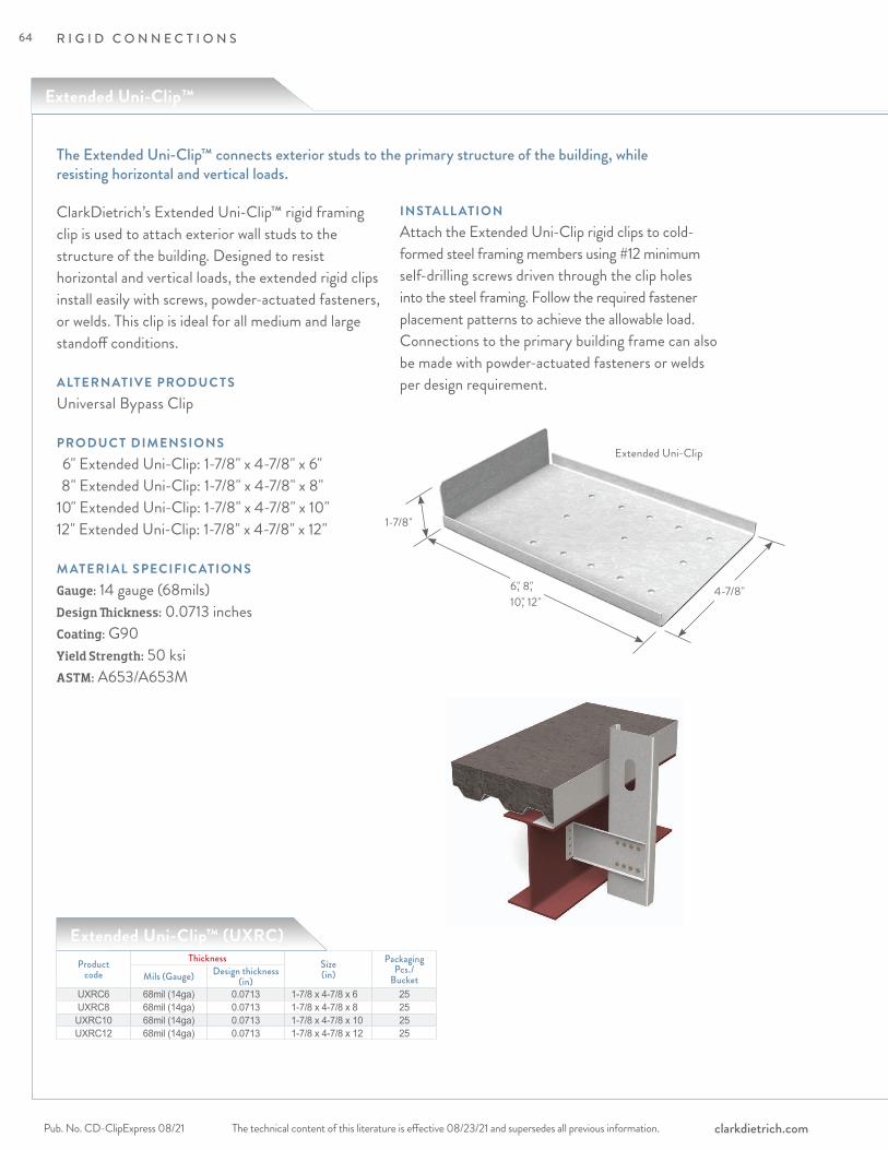
R I G I D C O N N E C T I O N S
The technical content of this literature is effective 08/23/21 and supersedes all previous information.Pub. No. CD-ClipExpress 08/21 clarkdietrich.com
ClarkDietrich’s Extended Uni-Clip™ rigid framing clip is used to attach exterior wall studs to the structure of the building. Designed to resist horizontal and vertical loads, the extended rigid clips install easily with screws, powder-actuated fasteners, or welds. This clip is ideal for all medium and large standoff conditions.
ALTERNATIVE PRODUC TSUniversal Bypass Clip
PRODUC T DIMENSIONS 6" Extended Uni-Clip: 1-7/8" x 4-7/8" x 6" 8" Extended Uni-Clip: 1-7/8" x 4-7/8" x 8"10" Extended Uni-Clip: 1-7/8" x 4-7/8" x 10" 12" Extended Uni-Clip: 1-7/8" x 4-7/8" x 12"
M ATERIAL SPECIFIC ATIONSGauge: 14 gauge (68mils)Design Thickness: 0.0713 inchesCoating: G90Yield Strength: 50 ksiASTM: A653/A653M
INSTALL ATIONAttach the Extended Uni-Clip rigid clips to cold-formed steel framing members using #12 minimum self-drilling screws driven through the clip holes into the steel framing. Follow the required fastener placement patterns to achieve the allowable load. Connections to the primary building frame can also be made with powder-actuated fasteners or welds per design requirement.
Extended Uni-Clip™ (UXRC)Product
codeThickness Size
(in)Packaging
Pcs./BucketMils (Gauge) Design thickness
(in)UXRC6 68mil (14ga) 0.0713 1-7/8 x 4-7/8 x 6 25UXRC8 68mil (14ga) 0.0713 1-7/8 x 4-7/8 x 8 25UXRC10 68mil (14ga) 0.0713 1-7/8 x 4-7/8 x 10 25UXRC12 68mil (14ga) 0.0713 1-7/8 x 4-7/8 x 12 25
The Extended Uni-Clip™ connects exterior studs to the primary structure of the building, while resisting horizontal and vertical loads.
6," 8," 10," 12"
1-7/8"
4-7/8"
Extended Uni-Clip
Extended Uni-Clip™
64

R I G I D C O N N E C T I O N S
The technical content of this literature is effective 08/23/21 and supersedes all previous information. The technical content of this literature is effective 08/23/21 and supersedes all previous information. Pub. No. CD-ClipExpress 08/21clarkdietrich.com
RIG
ID C
ON
NE
CTI
ON
S
F3
F2
F1
Base connection
Stud thickness
gauge (mils)
Stud Fy
(ksi)
8" Extended Uni-Clip2" Offset 4" Offset
F1 Load (kips) F2 Load (kips) F3 Load (kips) F3 Load (kips)4 screws 6 screws 8 screws 10 screws 4 screws 6 screws 8 screws 10 screws 4 screws 6 screws 8 screws 10 screws 4 screws 6 screws 8 screws
Weld (Fillet/Flare
Groove)
33mil (20ga) 33 0.381 0.453 0.453 0.453 0.754 1.131 1.508 1.884 0.310 0.435 0.572 0.686 0.214 0.306 0.36343mil (18ga) 33 0.453 0.453 0.453 0.453 1.122 1.683 2.243 2.278 0.462 0.647 0.851 1.022 0.318 0.456 0.54054mil (16ga) 33 0.453 0.453 0.453 0.453 1.577 2.278 2.278 2.278 0.649 0.909 1.196 1.436 0.447 0.640 0.75954mil (16ga) 50 0.453 0.453 0.453 0.453 2.278 2.278 2.278 2.278 0.938 1.313 1.728 2.075 0.645 0.925 1.09768mil (14ga) 50 0.453 0.453 0.453 0.453 2.278 2.278 2.278 2.278 1.098 1.538 2.022 2.278 0.756 1.083 1.28497mil (12ga) 50 0.453 0.453 0.453 0.453 2.278 2.278 2.278 2.278 1.098 1.538 2.022 2.278 0.756 1.083 1.284
(4) #12-24 (3/16" steel)
33mil (20ga) 33 0.301 0.301 0.301 0.301 0.754 1.131 1.256 1.256 0.310 0.435 0.572 0.686 0.214 0.306 0.36343mil (18ga) 33 0.301 0.301 0.301 0.301 1.122 1.256 1.256 1.256 0.462 0.647 0.851 1.022 0.318 0.456 0.54054mil (16ga) 33 0.301 0.301 0.301 0.301 1.256 1.256 1.256 1.256 0.649 0.909 1.196 1.436 0.447 0.640 0.75954mil (16ga) 50 0.301 0.301 0.301 0.301 1.256 1.256 1.256 1.256 0.938 1.313 1.728 1.864 0.645 0.925 1.09768mil (14ga) 50 0.301 0.301 0.301 0.301 1.256 1.256 1.256 1.256 1.098 1.538 1.864 1.864 0.756 1.083 1.28497mil (12ga) 50 0.301 0.301 0.301 0.301 1.256 1.256 1.256 1.256 1.098 1.538 1.864 1.864 0.756 1.083 1.284
(4) Hilti X-U (3/16" steel)
33mil (20ga) 33 0.301 0.301 0.301 0.301 0.754 0.875 0.875 0.875 0.310 0.435 0.572 0.686 0.214 0.306 0.36343mil (18ga) 33 0.301 0.301 0.301 0.301 0.875 0.875 0.875 0.875 0.462 0.647 0.851 1.022 0.318 0.456 0.54054mil (16ga) 33 0.301 0.301 0.301 0.301 0.875 0.875 0.875 0.875 0.649 0.909 1.196 1.436 0.447 0.640 0.75954mil (16ga) 50 0.301 0.301 0.301 0.301 0.875 0.875 0.875 0.875 0.938 1.313 1.728 1.864 0.645 0.925 1.09768mil (14ga) 50 0.301 0.301 0.301 0.301 0.875 0.875 0.875 0.875 1.098 1.538 1.864 1.864 0.756 1.083 1.28497mil (12ga) 50 0.301 0.301 0.301 0.301 0.875 0.875 0.875 0.875 1.098 1.538 1.864 1.864 0.756 1.083 1.284
(4) Hilti X-U (1" embedment
in 3000psi concrete)
33mil (20ga) 33 0.301 0.301 0.301 0.301 0.360 0.360 0.360 0.360 0.310 0.435 0.572 0.686 0.214 0.306 0.36343mil (18ga) 33 0.301 0.301 0.301 0.301 0.360 0.360 0.360 0.360 0.462 0.647 0.747 0.747 0.318 0.456 0.54054mil (16ga) 33 0.301 0.301 0.301 0.301 0.360 0.360 0.360 0.360 0.649 0.747 0.747 0.747 0.447 0.640 0.74754mil (16ga) 50 0.301 0.301 0.301 0.301 0.360 0.360 0.360 0.360 0.747 0.747 0.747 0.747 0.645 0.747 0.74768mil (14ga) 50 0.301 0.301 0.301 0.301 0.360 0.360 0.360 0.360 0.747 0.747 0.747 0.747 0.747 0.747 0.74797mil (12ga) 50 0.301 0.301 0.301 0.301 0.360 0.360 0.360 0.360 0.747 0.747 0.747 0.747 0.747 0.747 0.747
(2) Kwik-Cons II (1-3/4"
embedment in 3000psi concrete)
33mil (20ga) 33 0.301 0.301 0.301 0.301 0.754 0.922 0.922 0.922 0.310 0.435 0.572 0.686 0.214 0.306 0.36343mil (18ga) 33 0.301 0.301 0.301 0.301 0.922 0.922 0.922 0.922 0.462 0.647 0.851 1.022 0.318 0.456 0.54054mil (16ga) 33 0.301 0.301 0.301 0.301 0.922 0.922 0.922 0.922 0.649 0.909 1.160 1.160 0.447 0.640 0.75954mil (16ga) 50 0.301 0.301 0.301 0.301 0.922 0.922 0.922 0.922 0.938 1.160 1.160 1.160 0.645 0.925 1.09768mil (14ga) 50 0.301 0.301 0.301 0.301 0.922 0.922 0.922 0.922 1.098 1.160 1.160 1.160 0.756 1.083 1.16097mil (12ga) 50 0.301 0.301 0.301 0.301 0.922 0.922 0.922 0.922 1.098 1.160 1.160 1.160 0.756 1.083 1.160
Extended Uni-Clip™ (UXRC) Allowable Loads (KIPS)
Notes:1 Capacities listed in the table/notes assume that no load reductions are required for spacing or edge distance of Hilti X-U
pins in steel, Kwik-Cons, or screws. Load reductions are enforced for spacing or edge distance of Hilti X-U in concrete.2 Weld capacities are calculated for 2" long weld assuming 1" from the edges on the outer radius of the bend.3 Allowable loads have not been increased for wind, seismic, or other factors.4 The F1 values are calculated based on the moment capacity of the clip cross section.5 Capacities are based on the use of #12 screws to clip-stud interface.6 The embedment depth of Kwik-Cons in 3000psi normal weight concrete is 1-3/4." The embedment depth of Hilti X-U in
3000psi normal weight concrete is 1."7 The Hilti X-U pins and #12-24 screws are embedded in 3/16" structural steel.8 Torsional effects are considered on screw group for F3 allowable loads.9 Use a linear interaction equation for connections involving any combination of F1, F2, and F3.10 Hilti is a registered trademark of the Hilti Akfiengeseilchaft Corporation.11 Hilti X-U PAFs shown in table may not be substituted without prior approval from ClarkDietrich Engineering Services.
6," 10," and 12" tables are available at clarkdietrich.com.
Stru
ctur
al At
tach
men
t
4 Screw Pattern
4 Screw Pattern
6 Screw Pattern
6 Screw Pattern
8 Screw Pattern
8 Screw Pattern
10 Screw Pattern
Stru
ctur
al At
tach
men
t
Stru
ctur
al At
tach
men
t
Stru
ctur
al At
tach
men
t
Stru
ctur
al At
tach
men
t
Stru
ctur
al At
tach
men
t
Stru
ctur
al At
tach
men
t
8" UXRC Screw Pattern—4" Offset
8" UXRC Screw Pattern—2" Offset
Extended Uni-Clip™
65
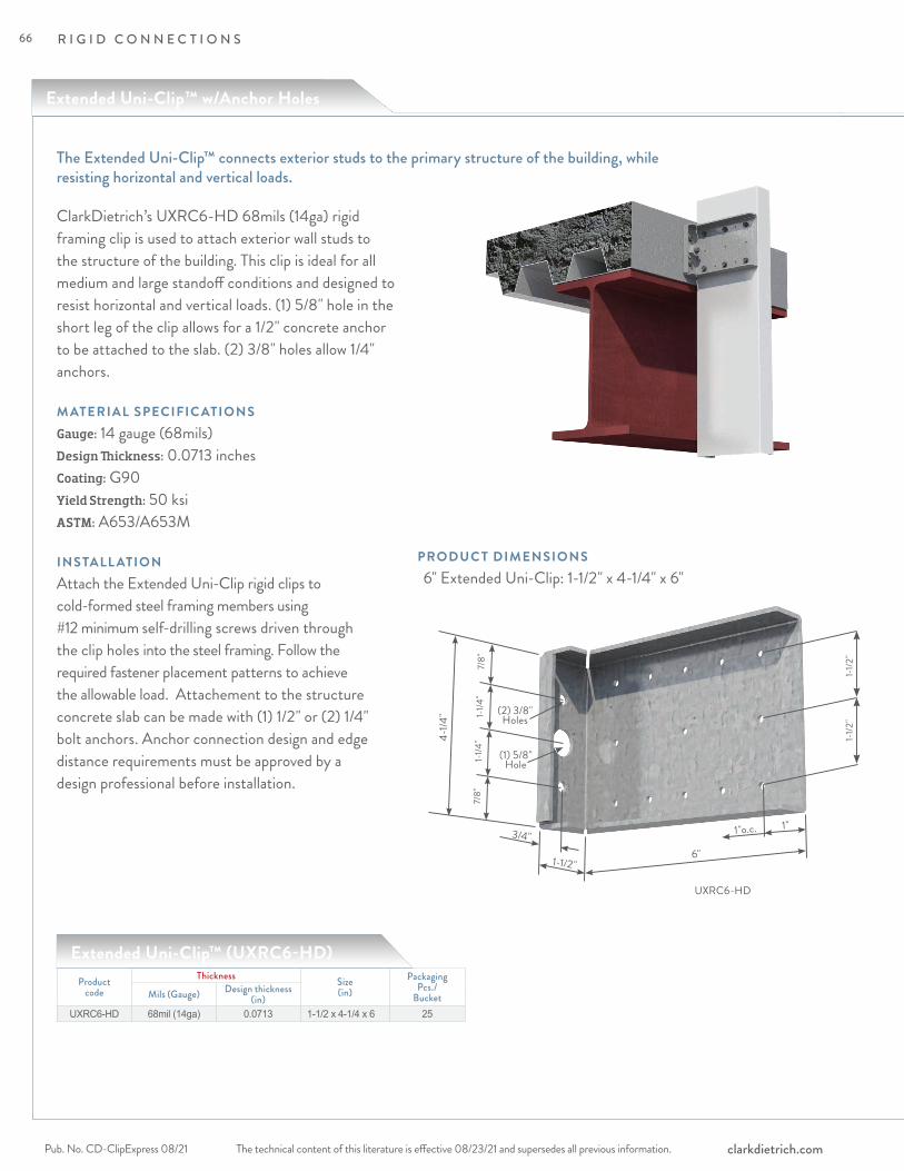
R I G I D C O N N E C T I O N S
The technical content of this literature is effective 08/23/21 and supersedes all previous information.Pub. No. CD-ClipExpress 08/21 clarkdietrich.com
UXRC6-HD
6"
7/8"
1-1/4
"1-
1/4"
7/8"
1-1/2"
3/4"
(1) 5/8"Hole
(2) 3/8"Holes
4-1/4
"
1-1/2
"1-
1/2"
1"o.c. 1"
ClarkDietrich’s UXRC6-HD 68mils (14ga) rigid framing clip is used to attach exterior wall studs to the structure of the building. This clip is ideal for all medium and large standoff conditions and designed to resist horizontal and vertical loads. (1) 5/8" hole in the short leg of the clip allows for a 1/2" concrete anchor to be attached to the slab. (2) 3/8" holes allow 1/4" anchors.
M ATERIAL SPECIFIC ATIONSGauge: 14 gauge (68mils)Design Thickness: 0.0713 inchesCoating: G90Yield Strength: 50 ksiASTM: A653/A653M
INSTALL ATIONAttach the Extended Uni-Clip rigid clips to cold-formed steel framing members using #12 minimum self-drilling screws driven through the clip holes into the steel framing. Follow the required fastener placement patterns to achieve the allowable load. Attachement to the structure concrete slab can be made with (1) 1/2" or (2) 1/4" bolt anchors. Anchor connection design and edge distance requirements must be approved by a design professional before installation.
Extended Uni-Clip™ (UXRC6-HD)Product
codeThickness Size
(in)Packaging
Pcs./BucketMils (Gauge) Design thickness
(in)UXRC6-HD 68mil (14ga) 0.0713 1-1/2 x 4-1/4 x 6 25
The Extended Uni-Clip™ connects exterior studs to the primary structure of the building, while resisting horizontal and vertical loads.
PRODUC T DIMENSIONS 6" Extended Uni-Clip: 1-1/2" x 4-1/4" x 6"
Extended Uni-Clip™ w/Anchor Holes
66
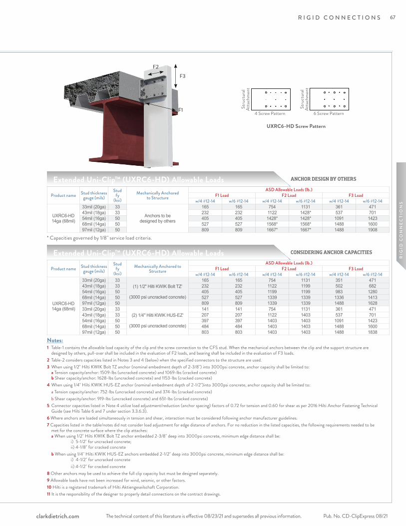
R I G I D C O N N E C T I O N S
The technical content of this literature is effective 08/23/21 and supersedes all previous information. The technical content of this literature is effective 08/23/21 and supersedes all previous information. Pub. No. CD-ClipExpress 08/21clarkdietrich.com
RIG
ID C
ON
NE
CTI
ON
S
CONSIDERING ANCHOR CAPACITIES
ANCHOR DESIGN BY OTHERS
F3
F1
Product name Stud thickness gauge (mils)
Stud fy
(ksi)Mechanically Anchored
to Structure
ASD Allowable Loads (lb.)F1 Load F2 Load F3 Load
w/4 #12-14 w/6 #12-14 w/4 #12-14 w/6 #12-14 w/4 #12-14 w/6 #12-14
UXRC6-HD 14ga (68mil)
33mil (20ga) 33
Anchors to be designed by others
165 165 754 1131 361 47143mil (18ga) 33 232 232 1122 1428* 537 70154mil (16ga) 50 405 405 1428* 1428* 1091 142368mil (14ga) 50 527 527 1568* 1568* 1488 160097mil (12ga) 50 809 809 1667* 1667* 1488 1908
Extended Uni-Clip™ (UXRC6-HD) Allowable Loads
Notes:1 Table-1 contains the allowable load capacity of the clip and the screw connection to the CFS stud. When the mechanical anchors between the clip and the support structure are
designed by others, pull-over shall be included in the evaluation of F2 loads, and bearing shall be included in the evaluation of F3 loads.2 Table-2 considers capacities listed in Notes 3 and 4 (below) when the specified connectors to the structure are used.3 When using 1/2" Hilti KWIK Bolt TZ anchor (nominal embedment depth of 2-3/8") into 3000psi concrete, anchor capacity shall be limited to:
a Tension capacity/anchor: 1509-lbs (uncracked concrete) and 1069-lbs (cracked concrete) b Shear capacity/anchor: 1628-lbs (uncracked concrete) and 1153-lbs (cracked concrete)
4 When using 1/4" Hilti KWIK HUS-EZ anchor (nominal embedment depth of 2-1/2")into 3000psi concrete, anchor capacity shall be limited to: a Tension capacity/anchor: 752-lbs (uncracked concrete) and 374-lbs (cracked concrete) b Shear capacity/anchor: 919-lbs (uncracked concrete) and 651-lbs (cracked concrete)5 Connector capacities listed in Note 4 utilize load adjustment/reduction (anchor spacing) factors of 0.72 for tension and 0.60 for shear as per 2016 Hilti Anchor Fastening Technical
Guide (see Hilti Table 6 and 7 under section 3.3.6.3).6 Where anchors are loaded simultaneously in tension and shear, interaction must be considered following anchor manufacturer guidelines.7 Capacities listed in the table/notes did not consider load adjustment for edge distance of anchors. For no reduction in the listed capacities, the following requirements needed to be met for the concrete surface where the clip attaches: a When using 1/2" Hilti KWIK Bolt TZ anchor embedded 2-3/8" deep into 3000psi concrete, minimum edge distance shall be: i) 5-1/2" for uncracked concrete; ii) 4-1/8" for cracked concrete b When using 1/4" Hilti KWIK HUS-EZ anchors embedded 2-1/2" deep into 3000psi concrete, minimum edge distance shall be: i) 4-1/2" for uncracked concrete ii) 4-1/2" for cracked concrete 8 Other anchors may be used to achieve the full clip capacity but must be designed separately. 9 Allowable loads have not been increased for wind, seismic, or other factors. 10 Hilti is a registered trademark of Hilti Aktiengeseilschaft Corporation. 11 It is the responsibility of the designer to properly detail connections on the contract drawings.
Stru
ctur
al At
tach
men
t
4 Screw Pattern 6 Screw Pattern
Stru
ctur
al At
tach
men
t
UXRC6-HD Screw Pattern
F2
Product name Stud thickness gauge (mils)
Stud fy
(ksi)Mechanically Anchored to
Structure
ASD Allowable Loads (lb.)F1 Load F2 Load F3 Load
w/4 #12-14 w/6 #12-14 w/4 #12-14 w/6 #12-14 w/4 #12-14 w/6 #12-14
UXRC6-HD 14ga (68mil)
33mil (20ga) 33(1) 1/2" Hilti KWIK Bolt TZ2
(3000 psi uncracked concrete)
165 165 754 1131 351 47143mil (18ga) 33 232 232 1122 1199 502 68254mil (16ga) 50 405 405 1199 1199 983 128068mil (14ga) 50 527 527 1339 1339 1336 141397mil (12ga) 50 809 809 1339 1339 1488 162833mil (20ga) 33
(2) 1/4" Hilti KWIK HUS-EZ3
(3000 psi uncracked concrete)
141 141 754 1131 361 47143mil (18ga) 33 207 207 1122 1403 537 70154mil (16ga) 50 397 397 1403 1403 1091 142368mil (14ga) 50 484 484 1403 1403 1488 160097mil (12ga) 50 803 803 1403 1403 1488 1838
Extended Uni-Clip™ (UXRC6-HD) Allowable Loads
* Capacities governed by 1/8" service load criteria.
67

R I G I D C O N N E C T I O N S
The technical content of this literature is effective 08/23/21 and supersedes all previous information.Pub. No. CD-ClipExpress 08/21 clarkdietrich.com
Universal Bypass Clip
Provides either a rigid connection or vertical building movement up to 3"
Universal Bypass Clips are used to attach exterior curtain wall studs to the building structure and provide either a rigid connection or deflecting connection for vertical building movement independent of the cold-formed steel framing.
The clips are available in standard lengths of 6", 8", 10" and 12" and are ideal for medium to larger standoff conditions. Universal Bypass Clips install quickly with screws, welds or powder-actuated fasteners, and provide adjustable standoff to ensure a plumb wall plane. For deflection application, proprietary deflection screws are provided with each clip to ensure friction-free sliding.
• Eliminates shims and scabs.
• Provides vertical movement up to 3" (1-1/2" up and 1-1/2"down) when installed as a deflection application.
• Specially designed to simplify welding installation.
• Fast, one-piece universal installation. No left or right handed clips.
• Proprietary deflection screws provide frictionless slip connections. One bag (80 screws) included.
Product code Mils (Gauge) Design thickness Size (in) Pcs/BucketUBC6-68 68mil (14ga) 0.0713 1-7/8" x 6" x 4-7/8" 25UBC8-68 68mil (14ga) 0.0713 1-7/8" x 8" x 4-7/8" 25UBC10-68 68mil (14ga) 0.0713 1-7/8" x 10" x 4-7/8" 25UBC12-68 68mil (14ga) 0.0713 1-7/8" x 12" x 4-7/8" 25UBC6-97 97mil (12ga) 0.1017 1-7/8" x 6" x 4-7/8" 25UBC8-97 97mil (12ga) 0.1017 1-7/8" x 8" x 4-7/8" 25UBC10-97 97mil (12ga) 0.1017 1-7/8" x 10" x 4-7/8" 25UBC12-97 97mil (12ga) 0.1017 1-7/8" x 12" x 4-7/8" 25
Universal Bypass Clip (UBC)
ALTERNATIVE PRODUC TSFastClip™ Slide Clip Extended FastClip™ Slide Clip Extended Uni-Clip™
M ATERIAL SPECIFIC ATIONSGauge: 14 gauge (68mil)Design Thickness: 0.0713 inches
Yield Strength: Structural Grade 50 Type H (ST50H), 50ksi (340 MPa)Coating: G90 (Z275) hot-dipped galvanized coatingASTM: A653, A1003
Gauge: 12 gauge (97mil)Design Thickness: 0.1017 inches
68
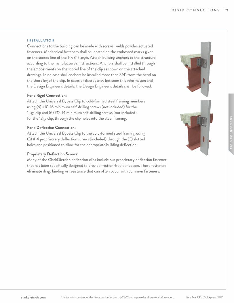
R I G I D C O N N E C T I O N S
The technical content of this literature is effective 08/23/21 and supersedes all previous information. The technical content of this literature is effective 08/23/21 and supersedes all previous information. Pub. No. CD-ClipExpress 08/21clarkdietrich.com
RIG
ID C
ON
NE
CTI
ON
S
INSTALL ATIONConnections to the building can be made with screws, welds powder-actuated fasteners. Mechanical fasteners shall be located on the embossed marks given on the scored line of the 1-7/8" flange. Attach building anchors to the structure according to the manufacture’s instructions. Anchors shall be installed through the embossments on the scored line of the clip as shown on the attached drawings. In no case shall anchors be installed more than 3/4" from the bend on the short leg of the clip. In cases of discrepancy between this information and the Design Engineer’s details, the Design Engineer’s details shall be followed.
For a Rigid Connection: Attach the Universal Bypass Clip to cold-formed steel framing members using (6) #10-16 minimum self-drilling screws (not included) for the 14ga clip and (6) #12-14 minimum self-drilling screws (not included) for the 12ga clip, through the clip holes into the steel framing.
For a Deflection Connection: Attach the Universal Bypass Clip to the cold-formed steel framing using (3) #14 proprietrary deflection screws (included) through the (3) slotted holes and positioned to allow for the appropriate building deflection.
Proprietary Deflection Screws: Many of the ClarkDietrich deflection clips include our proprietary deflection fastener that has been specifically designed to provide friction-free deflection. These fasteners eliminate drag, binding or resistance that can often occur with common fasteners.
69
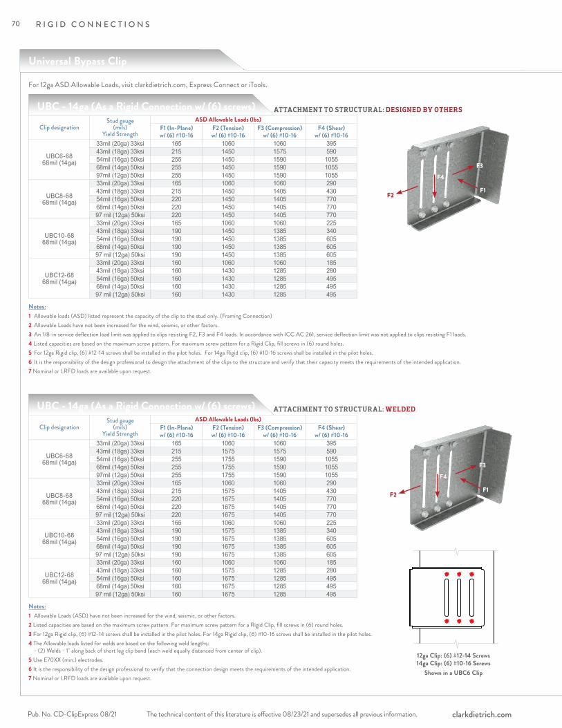
R I G I D C O N N E C T I O N S
The technical content of this literature is effective 08/23/21 and supersedes all previous information.Pub. No. CD-ClipExpress 08/21 clarkdietrich.com
Universal Bypass Clip
UBC - 14ga (As a Rigid Connection w/ (6) screws)
Notes:1 Allowable loads (ASD) listed represent the capacity of the clip to the stud only. (Framing Connection)2 Allowable Loads have not been increased for the wind, seismic, or other factors. 3 An 1/8-in service deflection load limit was applied to clips resisting F2, F3 and F4 loads. In accordance with ICC AC 261, service deflection limit was not applied to clips resisting F1 loads.4 Listed capacities are based on the maximum screw pattern. For maximum screw pattern for a Rigid Clip, fill screws in (6) round holes.5 For 12ga Rigid clip, (6) #12-14 screws shall be installed in the pilot holes. For 14ga Rigid clip, (6) #10-16 screws shall be installed in the pilot holes. 6 It is the responsibility of the design professional to design the attachment of the clips to the structure and verify that their capacity meets the requirements of the intended application.7 Nominal or LRFD loads are available upon request.
Clip designationStud gauge
(mils) Yield Strength
ASD Allowable Loads (lbs)F1 (In-Plane) w/ (6) #10-16
F2 (Tension) w/ (6) #10-16
F3 (Compression) w/ (6) #10-16
F4 (Shear) w/ (6) #10-16
UBC6-68 68mil (14ga)
33mil (20ga) 33ksi 165 1060 1060 39543mil (18ga) 33ksi 215 1450 1575 59054mil (16ga) 50ksi 255 1450 1590 105568mil (14ga) 50ksi 255 1450 1590 105597mil (12ga) 50ksi 255 1450 1590 1055
UBC8-68 68mil (14ga)
33mil (20ga) 33ksi 165 1060 1060 29043mil (18ga) 33ksi 215 1450 1405 43054mil (16ga) 50ksi 220 1450 1405 77068mil (14ga) 50ksi 220 1450 1405 77097 mil (12ga) 50ksi 220 1450 1405 770
UBC10-68 68mil (14ga)
33mil (20ga) 33ksi 165 1060 1060 22543mil (18ga) 33ksi 190 1450 1385 34054mil (16ga) 50ksi 190 1450 1385 60568mil (14ga) 50ksi 190 1450 1385 60597 mil (12ga) 50ksi 190 1450 1385 605
UBC12-68 68mil (14ga)
33mil (20ga) 33ksi 160 1060 1060 18543mil (18ga) 33ksi 160 1430 1285 28054mil (16ga) 50ksi 160 1430 1285 49568mil (14ga) 50ksi 160 1430 1285 49597 mil (12ga) 50ksi 160 1430 1285 495
ATTACHMENT TO STRUCTURAL: DESIGNED BY OTHERS
F3
F2F1
F4
UBC - 14ga (As a Rigid Connection w/ (6) screws)
Notes:1 Allowable Loads (ASD) have not been increased for the wind, seismic, or other factors. 2 Listed capacities are based on the maximum screw pattern. For maximum screw pattern for a Rigid Clip, fill screws in (6) round holes.3 For 12ga Rigid clip, (6) #12-14 screws shall be installed in the pilot holes. For 14ga Rigid clip, (6) #10-16 screws shall be installed in the pilot holes. 4 The Allowable loads listed for welds are based on the following weld lengths: - (2) Welds - 1" along back of short leg clip bend (each weld equally distanced from center of clip). 5 Use E70XX (min.) electrodes. 6 It is the responsibility of the design professional to verify that the connection design meets the requirements of the intended application.7 Nominal or LRFD loads are available upon request.
Clip designationStud gauge
(mils) Yield Strength
ASD Allowable Loads (lbs)F1 (In-Plane) w/ (6) #10-16
F2 (Tension) w/ (6) #10-16
F3 (Compression) w/ (6) #10-16
F4 (Shear) w/ (6) #10-16
UBC6-68 68mil (14ga)
33mil (20ga) 33ksi 165 1060 1060 39543mil (18ga) 33ksi 215 1575 1575 59054mil (16ga) 50ksi 255 1755 1590 105568mil (14ga) 50ksi 255 1755 1590 105597mil (12ga) 50ksi 255 1755 1590 1055
UBC8-68 68mil (14ga)
33mil (20ga) 33ksi 165 1060 1060 29043mil (18ga) 33ksi 215 1575 1405 43054mil (16ga) 50ksi 220 1675 1405 77068mil (14ga) 50ksi 220 1675 1405 77097 mil (12ga) 50ksi 220 1675 1405 770
UBC10-68 68mil (14ga)
33mil (20ga) 33ksi 165 1060 1060 22543mil (18ga) 33ksi 190 1575 1385 34054mil (16ga) 50ksi 190 1675 1385 60568mil (14ga) 50ksi 190 1675 1385 60597 mil (12ga) 50ksi 190 1675 1385 605
UBC12-68 68mil (14ga)
33mil (20ga) 33ksi 160 1060 1060 18543mil (18ga) 33ksi 160 1575 1285 28054mil (16ga) 50ksi 160 1675 1285 49568mil (14ga) 50ksi 160 1675 1285 49597 mil (12ga) 50ksi 160 1675 1285 495
F4
F3
F2F1
F4
12ga Clip: (6) #12-14 Screws 14ga Clip: (6) #10-16 Screws
Shown in a UBC6 Clip
ATTACHMENT TO STRUCTURAL: WELDED
For 12ga ASD Allowable Loads, visit clarkdietrich.com, Express Connect or iTools.
70

R I G I D C O N N E C T I O N S
The technical content of this literature is effective 08/23/21 and supersedes all previous information. The technical content of this literature is effective 08/23/21 and supersedes all previous information. Pub. No. CD-ClipExpress 08/21clarkdietrich.com
RIG
ID C
ON
NE
CTI
ON
S
UBC - 14ga (As a Rigid Connection w/ (6) screws)
Notes:1 Allowable Loads (ASD) have not been increased for the wind, seismic, or other factors. 2 An 1/8-in service deflection load limit was applied to clips resisting F2, F3 and F4 loads. In accordance with ICC AC 261, service deflection limit was not applied to clips resisting F1 loads.3 Listed capacities are based on the maximum screw pattern. For maximum screw pattern for a Rigid Clip, fill screws in (6) round holes.4 For 12ga Rigid clip, (6) #12-14 screws shall be installed in the pilot holes. For 14ga Rigid clip, (6) #10-16 screws shall be installed in the pilot holes. 5 #12-24 Fasteners shall be used for attachment to steel structure. (4) Fastener configuration shall be used. Screws should be placed at indentations scribed on the short leg of the UBC clip.6 The minimum edge distance for each fastener type shall comply with the fastener manufacturer’s recommendation.7 It is the responsibility of the design professional to verify that the connection design meets the requirements of the intended application.8 Nominal or LRFD loads are available upon request.
Clip designationStud gauge
(mils) Yield Strength
ASD Allowable Loads (lbs)F1 (In-Plane) w/ (6) #10-16
F2 (Tension) w/ (6) #10-16
F3 (Compression) w/ (6) #10-16
F4 (Shear) w/ (6) #10-16
UBC6-6868mil (14ga)
33mil (20ga) 33ksi 165 1060 1060 39543mil (18ga) 33ksi 215 1450 1575 59054mil (16ga) 50ksi 255 1450 1590 105568mil (14ga) 50ksi 255 1450 1590 105597mil (12ga) 50ksi 255 1450 1590 1055
UBC8-68 68mil (14ga)
33mil (20ga) 33ksi 165 1060 1060 29043mil (18ga) 33ksi 215 1450 1405 43054mil (16ga) 50ksi 220 1450 1405 77068mil (14ga) 50ksi 220 1450 1405 77097 mil (12ga) 50ksi 220 1450 1405 770
UBC10-68 68mil (14ga)
33mil (20ga) 33ksi 165 1060 1060 22543mil (18ga) 33ksi 190 1450 1385 34054mil (16ga) 50ksi 190 1450 1385 60568mil (14ga) 50ksi 190 1450 1385 60597 mil (12ga) 50ksi 190 1450 1385 605
UBC12-68 68mil (14ga)
33mil (20ga) 33ksi 160 1060 1060 18543mil (18ga) 33ksi 160 1430 1285 28054mil (16ga) 50ksi 160 1430 1285 49568mil (14ga) 50ksi 160 1430 1285 49597 mil (12ga) 50ksi 160 1430 1285 495
F3
F2F1
F4
ATTACHMENT TO STRUCTURAL: (4) #12-24 FASTENERS
UBC - 14ga (As a Rigid Connection w/ (6) screws)
Notes:1 Allowable Loads (ASD) have not been increased for the wind, seismic, or other factors. 2 Nominal or LRFD loads are available upon request.3 Listed capacities are based on the maximum screw pattern. For maximum screw pattern for a Rigid Clip, fill screws in (6) round holes.4 For 12ga Rigid clip, (6) #12-14 screws shall be installed in the pilot holes. For 14ga Rigid clip, (6) #10-16 screws shall be installed in the pilot holes. 5 0.157" Hilti X-U PAFs shall be used for attachment to steel structure. (4) Fastener configuration shall be used. PAFs should be placed at indentations scribed on the short leg of the UBC clip.6 Capacities considered for Hilti PAFs are based on fastener strengths listed in ICC ESR-2269.7 It is the responsibility of the design professional to verify that the connection design meets the requirements of the intended application.8 An 1/8-in service deflection load limit was applied to clips resisting F2, F3 and F4 loads. In accordance with ICC AC 261, service deflection limit was not applied to clips resisting F1 loads.
Clip designationStud gauge
(mils) Yield Strength
ASD Allowable Loads (lbs)F1 (In-Plane) w/ (6) #10-16
F2 (Tension) w/ (6) #10-16
F3 (Compression) w/ (6) #10-16
F4 (Shear) w/ (6) #10-16
UBC6-68 68mil (14ga)
33mil (20ga) 33ksi 165 1060 1060 39543mil (18ga) 33ksi 215 1450 1575 59054mil (16ga) 50ksi 255 1450 1590 105568mil (14ga) 50ksi 255 1450 1590 105597mil (12ga) 50ksi 255 1450 1590 1055
UBC8-68 68mil (14ga)
33mil (20ga) 33ksi 165 1060 1060 29043mil (18ga) 33ksi 215 1450 1405 43054mil (16ga) 50ksi 220 1450 1405 77068mil (14ga) 50ksi 220 1450 1405 77097 mil (12ga) 50ksi 220 1450 1405 770
UBC10-68 68mil (14ga)
33mil (20ga) 33ksi 165 1060 1060 22543mil (18ga) 33ksi 190 1450 1385 34054mil (16ga) 50ksi 190 1450 1385 60568mil (14ga) 50ksi 190 1450 1385 60597 mil (12ga) 50ksi 190 1450 1385 605
UBC12-68 68mil (14ga)
33mil (20ga) 33ksi 160 1060 1060 18543mil (18ga) 33ksi 160 1430 1285 28054mil (16ga) 50ksi 160 1430 1285 49568mil (14ga) 50ksi 160 1430 1285 49597 mil (12ga) 50ksi 160 1430 1285 495
F3
F2F1
F4
12ga Clip: (6) #12-14 Screws 14ga Clip: (6) #10-16 Screws
Shown in a UBC6 Clip
ATTACHMENT TO STRUCTURAL: (4) 0.157" PAFs
For 12ga ASD Allowable Loads, visit clarkdietrich.com, Express Connect or iTools.
71
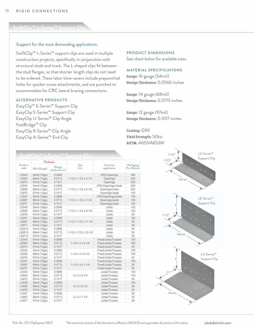
SwiftClip™ L-Series™ Support Clip
R I G I D C O N N E C T I O N S
The technical content of this literature is effective 08/23/21 and supersedes all previous information.Pub. No. CD-ClipExpress 08/21 clarkdietrich.com
SwiftClip™ L-Series™ support clips are used in multiple construction projects, specifically in conjunction with structural studs and track. The L-shaped clips fit between the stud flanges, so that shorter length clips do not need to be ordered. These labor time-savers include prepunched holes for quicker screw attachments, and are punched to accommodate for CRC lateral bracing connections.
ALTERNATIVE PRODUC TSEasyClip™ E-Series™ Support ClipEasyClip S-Series™ Support ClipEasyClip U-Series™ Clip AngleFastBridge™ ClipEasyClip X-Series™ Clip AngleEasyClip A-Series™ End Clip
PRODUC T DIMENSIONSSee chart below for available sizes.
M ATERIAL SPECIFIC ATIONSGauge: 16 gauge (54mil)Design Thickness: 0.0566 inches
Gauge: 14 gauge (68mil)Design Thickness: 0.0713 inches
Gauge: 12 gauge (97mil)Design Thickness: 0.1017 inches
Coating: G90Yield Strength: 50ksiASTM: A653/A653M
Support for the most demanding applications.
SwiftClip™ L-Series™ Support Clip
Product code
ThicknessSize(in)
Commonapplication
PackagingPcs./BucketMils (Gauge) Design
thickness (in)LS543 54mil (16ga) 0.0566
1-1/2 x 1-1/2 x 3-1/4CRC/Openings 300
LS683 68mil (14ga) 0.0713 Openings 300LS973 97mil (12ga) 0.1017 Openings 200LS545 54mil (16ga) 0.0566
1-1/2 x 1-1/2 x 5-1/2CRC/Openings/Joists 200
LS685 68mil (14ga) 0.0713 Openings/Joists 200LS975 97mil (12ga) 0.1017 Openings/Joists 100LS547 54mil (16ga) 0.0566
1-1/2 x 1-1/2 x 7-1/4CRC/Openings/Joists 150
LS687 68mil (14ga) 0.0713 Openings/Joists 100LS977 97mil (12ga) 0.1017 Openings/Joists 100LS549 54mil (16ga) 0.0566
1-1/2 x 1-1/2 x 9-1/4Joists 100
LS689 68mil (14ga) 0.0713 Joists 100LS979 97mil (12ga) 0.1017 Joists 50LS541 54mil (16ga) 0.0566
1-1/2 x 1-1/2 x 11-1/4Joists 100
LS681 68mil (14ga) 0.0713 Joists 50LS971 97mil (12ga) 0.1017 Joists 50LS5413 54mil (16ga) 0.0566
1-1/2 x 1-1/2 x 13-1/4Joists 50
LS6813 68mil (14ga) 0.0713 Joists 50LS9713 97mil (12ga) 0.1017 Joists 25LE543 54mil (16ga) 0.0566
1-1/2 x 3 x 3-1/4Fixed/Joists/Trusses 100
LE683 68mil (14ga) 0.0713 Fixed/Joists/Trusses 100LE973 97mil (12ga) 0.1017 Fixed/Joists/Trusses 50LE545 54mil (16ga) 0.0566
1-1/2 x 3 x 5-1/2Fixed/Joists/Trusses 100
LE685 68mil (14ga) 0.0713 Fixed/Joists/Trusses 100LE975 97mil (12ga) 0.1017 Fixed/Joists/Trusses 50LE547 54mil (16ga) 0.0566
1-1/2 x 3 x 7-1/4Fixed/Joists/Trusses 100
LE687 68mil (14ga) 0.0713 Fixed/Joists/Trusses 50LE977 97mil (12ga) 0.1017 Fixed/Joists/Trusses 50LA543 54mil (16ga) 0.0566
3 x 3 x 3-1/4Joists/Trusses 100
LA683 68mil (14ga) 0.0713 Joists/Trusses 100LA973 97mil (12ga) 0.1017 Joists/Trusses 50LA545 54mil (16ga) 0.0566
3 x 3 x 5-1/2Joists/Trusses 100
LA685 68mil (14ga) 0.0713 Joists/Trusses 50LA975 97mil (12ga) 0.1017 Joists/Trusses 50LA547 54mil (16ga) 0.0566
3 x 3 x 7-1/4Joists/Trusses 50
LA687 68mil (14ga) 0.0713 Joists/Trusses 50LA977 97mil (12ga) 0.1017 Joists/Trusses 50
1-1/2"
3"
3"
1-1/2"
1-1/2"
3"
Varies
Varies
Varies
LS-Series™ Support Clip
LE-Series™ Support Clip
LA-Series™ Support Clip
72
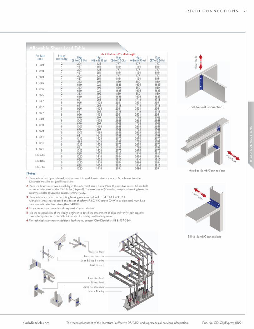
R I G I D C O N N E C T I O N S
The technical content of this literature is effective 08/23/21 and supersedes all previous information. The technical content of this literature is effective 08/23/21 and supersedes all previous information. Pub. No. CD-ClipExpress 08/21clarkdietrich.com
RIG
ID C
ON
NE
CTI
ON
S
shear loads
Sill-to-Jamb Connections
shear loads
Head-to-Jamb Connections
Joist-to-Joist Connections
shea
r loa
ds
1 Shear values for clips are based on attachment to cold-formed steel members. Attachment to other substrates must be designed separately.
2 Place the first two screws in each leg in the outermost screw holes. Place the next two screws (if needed) in center holes next to the CRC holes (diagonal). The next screws (if needed) are placed moving from the outermost holes toward the center, symmetrically.
3 Shear values are based on the tilting bearing modes of failure Eq. E4.3.1-1, E4.3.1-2.4 Allowable screw shear is based on a factor of safety of 3.0. #10 screws (0.19" min. diameter) must have minimum ultimate shear strength of 1400 lbs.
4 Screws must have three threads exposed after installation.5 It is the responsibility of the design engineer to detail the attachment of clips and verify their capacity
meets the application. This table is intended for use by qualified engineers.6 For technical assistance or additional load charts, contact ClarkDietrich at 888-437-3244.
Product code
No. ofscrews/leg
Stud Thickness (Yield Strength)20ga
(33mil) 33ksi18ga
(43mil) 33ksi16ga
(54mil) 50ksi14ga
(68mil) 50ksi12ga
(97mil) 50ksiLS543 2 294 438 777 777 777
4 437 651 1154 1154 1154LS683 2 294 438 777 777 777
4 437 651 1154 1154 1154LS973 2 294 438 777 777 777
4 437 651 1154 1154 1154LS545 2 333 496 880 880 880
4 619 921 1635 1635 1635LS685 2 333 496 880 880 880
4 619 921 1635 1635 1635LS975 2 333 496 880 880 880
4 619 921 1635 1635 1635LS547 4 651 968 1718 1718 1718
6 966 1438 2551 2551 2551LS687 4 651 968 1718 1718 1718
6 966 1438 2551 2551 2551LS977 4 651 968 1718 1718 1718
6 966 1438 2551 2551 2551LS549 4 670 997 1768 1768 1768
6 1007 1498 2658 2658 2658LS689 4 670 997 1768 1768 1768
6 1007 1498 2658 2658 2658LS979 4 670 997 1768 1768 1768
6 1007 1498 2658 2658 2658LS541 4 681 1013 1798 1798 1798
6 1013 1508 2675 2675 2675LS681 4 681 1013 1798 1798 1798
6 1013 1508 2675 2675 2675LS971 4 681 1013 1798 1798 1798
6 1013 1508 2675 2675 2675LS5413 4 688 1024 1816 1816 1816
6 1020 1518 2694 2694 2694LS6813 4 688 1024 1816 1816 1816
6 1020 1518 2694 2694 2694LS9713 4 688 1024 1816 1816 1816
6 1020 1518 2694 2694 2694
Notes:
Allowable Shear Load Table
Truss-to-TrussTruss-to-Structure
Joist & Stud BlockingJoist-to-Joist
Head-to-Jamb Sill-to-Jamb
Jamb-to-StructureLateral Bracing
73
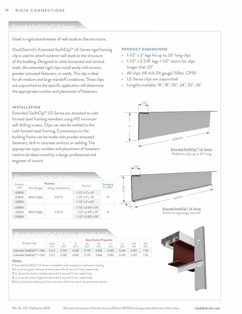
ClarkDietrich’s Extended SwiftClip™ LE-Series rigid framing clip is used to attach exterior wall studs to the structure of the building. Designed to resist horizontal and vertical loads, the extended rigid clips install easily with screws, powder-actuated fasteners, or welds. This clip is ideal for all medium and large standoff conditions. These clips are unpunched as the specific application will determine the appropriate number and placement of fasteners.
Used in rigid attachments of wall studs to the structure.
Extended SwiftClip™ LE-SeriesProduct
codeThickness
Size (in) Packaging Pcs./BoxMils (Gauge) Design thickness (in)
LE681668mil (14ga) 0.0713
1-1/2" x 3" x 16"10LE6818 1-1/2" x 3" x 18"
LE6820 1-1/2" x 3" x 20"
LE682468mil (14ga) 0.0713
1-1/2" x 2-5/8" x 24"10LE6830 1-1/2" x 2-5/8" x 30"
LE6836 1-1/2" x 2-5/8" x 36"
Extended SwiftClip™ LE-Series Profile for clips up to 20" long
LENGTH
3"
1-1/2" INSTALL ATIONExtended SwiftClip™ LE-Series are attached to cold-formed steel framing members using #10 minimum self-drilling screws. Clips can also be welded to the cold-formed steel framing. Connections to the building frame can be made with powder-actuated fasteners, drill-in concrete anchors or welding. The appropriate type, number and placement of fasteners need to be determined by a design professional and engineer of record.
• 1-1/2" x 3" legs for up to 20" long clips• 1-1/2" x 2-5/8" legs + 1/2" return for clips longer than 20"• All clips: 68 mils (14 gauge) 50ksi, CP90• LE-Series clips are unpunched• Lengths available: 16", 18", 20", 24", 30", 36"
PRODUC T DIMENSIONS
R I G I D C O N N E C T I O N S
The technical content of this literature is effective 08/23/21 and supersedes all previous information.Pub. No. CD-ClipExpress 08/21 clarkdietrich.com
1/2" Extended SwiftClip™ LE-Series Profile for clips longer than 20"
LENGTH
2-5/
8"
1-1/2"
Extended SwiftClip™ LE-Series
Product codeGross Section Properties
Area (in2)
lx (in4)
ly (in4)
Sx (in3)
Sy (in3)
rx (in)
ry (in)
x(c) (in)
y(c) (in)
Extended SwiftClip™ < 20in 0.311 0.304 0.056 0.155 0.046 0.988 0.424 0.281 1.04Extended SwiftClip™ > 20in 0.311 0.282 0.054 0.176 0.054 0.952 0.418 0.307 1.02
Extended SwiftClip™ LE-Series Allowable Loads
1 Extended SwiftClip™ LE-Series intended for axial compression and tension loading.2 lx, ly are the gross moment of inertia about the X-axis and Y-axis, respectively.3 Sx, Sy are the section modulus about the X-axis and Y-axis, respectively.4 rx, ry are the radius of gyration about the X-axis and Y-axis, respectively.5 x(c), y(c) are the distances of the centroid to the X-axis and Y-axis attachment planes.
Notes:
74

EasyClip™ U-Series™ Clip Angle
R I G I D C O N N E C T I O N S
The technical content of this literature is effective 08/23/21 and supersedes all previous information. The technical content of this literature is effective 08/23/21 and supersedes all previous information. Pub. No. CD-ClipExpress 08/21clarkdietrich.com
RIG
ID C
ON
NE
CTI
ON
S
ClarkDietrich EasyClip™ U-Series™ clip angles are used to secure U-channel to wall studs for lateral bridging or for miscellaneous rigid connections. U-channel is passed through the stud knockout and an EasyClip U-Series clip is screw-attached or welded to provide a rigid connection. Available in a variety of lengths and gauges, EasyClip U-Series clips are prepunched for faster and more accurate fastener placement. U-Series clip angles and U-channel should not be used in bridging applications when the stud width exceeds 6."
ALTERNATIVE PRODUC TSFastBridge™ ClipEasyClip™ X-Series™ Clip Angle SwiftClip™ LS-Series™ Support ClipSpazzer® 5400 and Spazzer® 9200 Spacer Bars
PRODUC T DIMENSIONS1-1/2" x 1-1/2" x 3-3/8" 1-1/2" x 1-1/2" x 5-3/4"1-1/2" x 1-1/2" x 7-3/4" 1-1/2" x 1-1/2" x 9-3/4"
M ATERIAL SPECIFIC ATIONSGauge: 16 gauge (54mil)Design Thickness: 0.0566 inches
Gauge: 14 gauge (68mil)Design Thickness: 0.0713 inches
Gauge: 12 gauge (97mil)Design Thickness: 0.1017 inches
Coating: G90Yield Strength: 50ksi ASTM: A653/A653M
INSTALL ATIONU-channel is inserted into the stud punchout (as specified by design) and rotated into place. U-Series clip angles are attached horizontally to the outside or hard side of the cold-formed steel (CFS) framing members. The clip must be firmly seated against the web of the U-channel. The clip should not be more than 1/4" less than the cold-formed framing member. U-Series clips are fastened using #10 minimum self-drilling screws driven through the clip holes into the steel framing. Clips may also be welded to the CFS framing.
Secures U-channel (cold-rolled channel) to framing members for lateral bridging, miscellaneous rigid connections, and multipurpose reinforcing supports.
EasyClip U-Series Clip Angle
1-1/2"
1-1/2"
3-3/8," 5-3/4," 7-3/4," 9-3/4"
EasyClip™ U-Series™ Clip Angles
Product code
Thickness
Size (in) Packaging Pcs./BucketMils (Gauge) Design thickness
(in)
U543 54mil (16ga) 0.0566 1-1/2 x 1-1/2 x 3-3/8 400U545 54mil (16ga) 0.0566 1-1/2 x 1-1/2 x 5-3/4 200U547 54mil (16ga) 0.0566 1-1/2 x 1-1/2 x 7-3/4 100U549 54mil (16ga) 0.0566 1-1/2 x 1-1/2 x 9-3/4 100U683 68mil (14ga) 0.0713 1-1/2 x 1-1/2 x 3-3/8 200U685 68mil (14ga) 0.0713 1-1/2 x 1-1/2 x 5-3/4 170U687 68mil (14ga) 0.0713 1-1/2 x 1-1/2 x 7-3/4 100U689 68mil (14ga) 0.0713 1-1/2 x 1-1/2 x 9-3/4 100U973 97mil (12ga) 0.1017 1-1/2 x 1-1/2 x 3-3/8 200U975 97mil (12ga) 0.1017 1-1/2 x 1-1/2 x 5-3/4 130U977 97mil (12ga) 0.1017 1-1/2 x 1-1/2 x 7-3/4 100U979 97mil (12ga) 0.1017 1-1/2 x 1-1/2 x 9-3/4 80
75

R I G I D C O N N E C T I O N S
The technical content of this literature is effective 08/23/21 and supersedes all previous information.Pub. No. CD-ClipExpress 08/21 clarkdietrich.com
F3
F2
F1
ClarkDietrich EasyClip™ S-Series™ support clips are commonly used for rigid connections in window and door framing, joist, bypass or other miscellaneous connections to secure one framing member to another, or to secure framing members to the structural frame. This high-performance, multi-use utility clip is ideal for corner reinforcements, stair openings, and numerous support applications. Available in a variety of lengths and gauges, EasyClip S-Series clips are prepunched for faster and more accurate fastener placement.
ALTERNATIVE PRODUC TSEasyClip™ U-Series™ Clip Angle EasyClip X-Series™ Clip Angle EasyClip D-Series™ Anchor Clip SwiftClip™ LS-Series™ Support Clip
PRODUC T DIMENSIONS1-1/2" x 1-1/2" x 3" 1-1/2" x 1-1/2" x 5" 1-1/2" x 1-1/2" x 7" 1-1/2" x 1-1/2" x 9" 1-1/2" x 1-1/2" x 11"
M ATERIAL SPECIFIC ATIONSGauge: 16 gauge (54mil)Design Thickness: 0.0566 inches
Gauge: 14 gauge (68mil)Design Thickness: 0.0713 inches
Gauge: 12 gauge (97mil)Design Thickness: 0.1017 inches
Coating: G90Yield Strength: 50ksi ASTM: A653/A653M
INSTALL ATIONEasyClip S-Series support clips are attached to the cold-formed steel (CFS) framing members using #10 minimum self-drilling screws driven through the clip holes into the steel framing. When not filling all holes, install fasteners symmetrically starting at the top and bottom edges and move toward the center of the clip. Clip can also be welded to the CFS framing. Connections to the building frame can be made with powder-actuated fasteners, drill-in concrete anchors or welding. When using the tabular values for a welded clip, provide a full weld to the structure, top to bottom, along the outside of the clip. A 3/4" minimum weld on the outside edge of the 1-1/2" leg is also required to control warping or to hold the clip in place before final welding.
For rigid connection applications not requiring a long leg.
EasyClip S-Series Support Clip
1-1/2"
1-1/2"
3," 5," 7," 9," 11"
F1
F1
Figure 1
EasyClip™ S-Series™ Support Clip
76
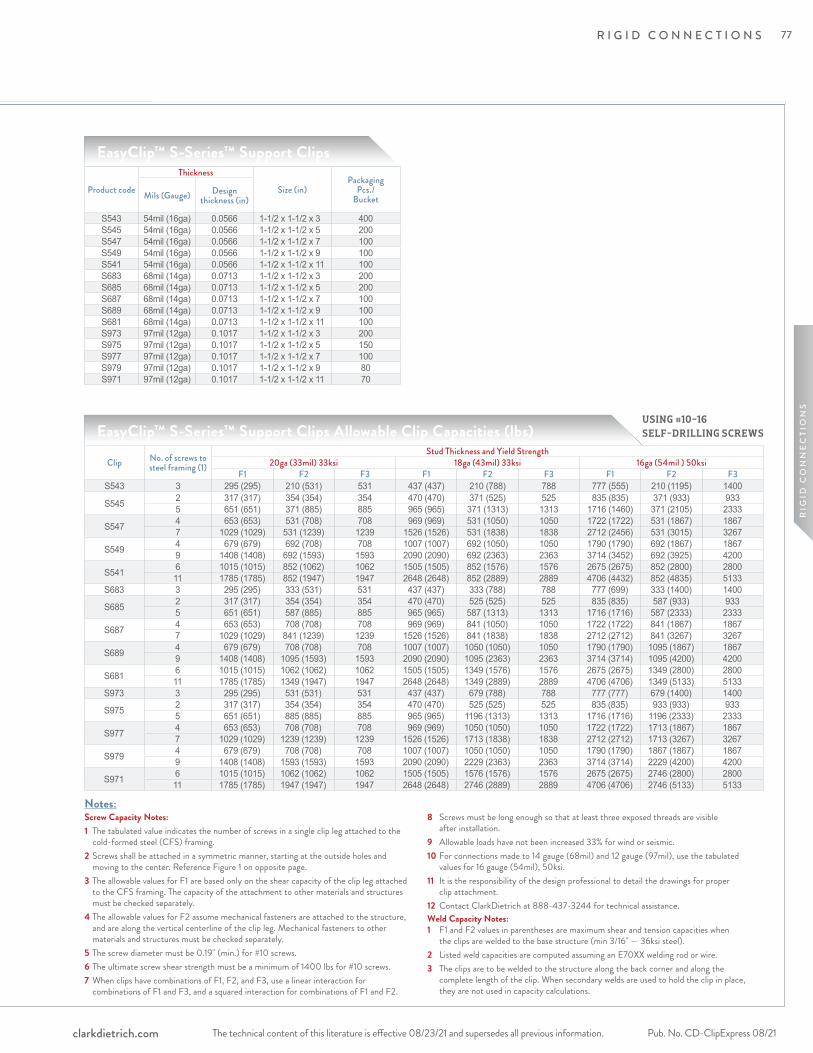
R I G I D C O N N E C T I O N S
The technical content of this literature is effective 08/23/21 and supersedes all previous information. The technical content of this literature is effective 08/23/21 and supersedes all previous information. Pub. No. CD-ClipExpress 08/21clarkdietrich.com
RIG
ID C
ON
NE
CTI
ON
SScrew Capacity Notes:1 The tabulated value indicates the number of screws in a single clip leg attached to the
cold-formed steel (CFS) framing.2 Screws shall be attached in a symmetric manner, starting at the outside holes and
moving to the center. Reference Figure 1 on opposite page.3 The allowable values for F1 are based only on the shear capacity of the clip leg attached
to the CFS framing. The capacity of the attachment to other materials and structures must be checked separately.
4 The allowable values for F2 assume mechanical fasteners are attached to the structure, and are along the vertical centerline of the clip leg. Mechanical fasteners to other materials and structures must be checked separately.
5 The screw diameter must be 0.19" (min.) for #10 screws.6 The ultimate screw shear strength must be a minimum of 1400 lbs for #10 screws.7 When clips have combinations of F1, F2, and F3, use a linear interaction for
combinations of F1 and F3, and a squared interaction for combinations of F1 and F2.
8 Screws must be long enough so that at least three exposed threads are visible after installation.
9 Allowable loads have not been increased 33% for wind or seismic. 10 For connections made to 14 gauge (68mil) and 12 gauge (97mil), use the tabulated
values for 16 gauge (54mil), 50ksi.11 It is the responsibility of the design professional to detail the drawings for proper
clip attachment.12 Contact ClarkDietrich at 888-437-3244 for technical assistance.Weld Capacity Notes:1 F1 and F2 values in parentheses are maximum shear and tension capacities when
the clips are welded to the base structure (min 3/16" — 36ksi steel).2 Listed weld capacities are computed assuming an E70XX welding rod or wire.3 The clips are to be welded to the structure along the back corner and along the
complete length of the clip. When secondary welds are used to hold the clip in place, they are not used in capacity calculations.
EasyClip™ S-Series™ Support Clips
EasyClip™ S-Series™ Support Clips Allowable Clip Capacities (lbs)
Clip No. of screws to steel framing (1)
Stud Thickness and Yield Strength20ga (33mil) 33ksi 18ga (43mil) 33ksi 16ga (54mil ) 50ksi
F1 F2 F3 F1 F2 F3 F1 F2 F3S543 3 295 (295) 210 (531) 531 437 (437) 210 (788) 788 777 (555) 210 (1195) 1400
S545 2 317 (317) 354 (354) 354 470 (470) 371 (525) 525 835 (835) 371 (933) 9335 651 (651) 371 (885) 885 965 (965) 371 (1313) 1313 1716 (1460) 371 (2105) 2333
S547 4 653 (653) 531 (708) 708 969 (969) 531 (1050) 1050 1722 (1722) 531 (1867) 18677 1029 (1029) 531 (1239) 1239 1526 (1526) 531 (1838) 1838 2712 (2456) 531 (3015) 3267
S549 4 679 (679) 692 (708) 708 1007 (1007) 692 (1050) 1050 1790 (1790) 692 (1867) 18679 1408 (1408) 692 (1593) 1593 2090 (2090) 692 (2363) 2363 3714 (3452) 692 (3925) 4200
S541 6 1015 (1015) 852 (1062) 1062 1505 (1505) 852 (1576) 1576 2675 (2675) 852 (2800) 280011 1785 (1785) 852 (1947) 1947 2648 (2648) 852 (2889) 2889 4706 (4432) 852 (4835) 5133
S683 3 295 (295) 333 (531) 531 437 (437) 333 (788) 788 777 (699) 333 (1400) 1400
S685 2 317 (317) 354 (354) 354 470 (470) 525 (525) 525 835 (835) 587 (933) 9335 651 (651) 587 (885) 885 965 (965) 587 (1313) 1313 1716 (1716) 587 (2333) 2333
S687 4 653 (653) 708 (708) 708 969 (969) 841 (1050) 1050 1722 (1722) 841 (1867) 18677 1029 (1029) 841 (1239) 1239 1526 (1526) 841 (1838) 1838 2712 (2712) 841 (3267) 3267
S689 4 679 (679) 708 (708) 708 1007 (1007) 1050 (1050) 1050 1790 (1790) 1095 (1867) 18679 1408 (1408) 1095 (1593) 1593 2090 (2090) 1095 (2363) 2363 3714 (3714) 1095 (4200) 4200
S681 6 1015 (1015) 1062 (1062) 1062 1505 (1505) 1349 (1576) 1576 2675 (2675) 1349 (2800) 280011 1785 (1785) 1349 (1947) 1947 2648 (2648) 1349 (2889) 2889 4706 (4706) 1349 (5133) 5133
S973 3 295 (295) 531 (531) 531 437 (437) 679 (788) 788 777 (777) 679 (1400) 1400
S975 2 317 (317) 354 (354) 354 470 (470) 525 (525) 525 835 (835) 933 (933) 9335 651 (651) 885 (885) 885 965 (965) 1196 (1313) 1313 1716 (1716) 1196 (2333) 2333
S977 4 653 (653) 708 (708) 708 969 (969) 1050 (1050) 1050 1722 (1722) 1713 (1867) 18677 1029 (1029) 1239 (1239) 1239 1526 (1526) 1713 (1838) 1838 2712 (2712) 1713 (3267) 3267
S979 4 679 (679) 708 (708) 708 1007 (1007) 1050 (1050) 1050 1790 (1790) 1867 (1867) 18679 1408 (1408) 1593 (1593) 1593 2090 (2090) 2229 (2363) 2363 3714 (3714) 2229 (4200) 4200
S971 6 1015 (1015) 1062 (1062) 1062 1505 (1505) 1576 (1576) 1576 2675 (2675) 2746 (2800) 280011 1785 (1785) 1947 (1947) 1947 2648 (2648) 2746 (2889) 2889 4706 (4706) 2746 (5133) 5133
Product code
Thickness
Size (in)Packaging
Pcs./BucketMils (Gauge) Design
thickness (in)
S543 54mil (16ga) 0.0566 1-1/2 x 1-1/2 x 3 400S545 54mil (16ga) 0.0566 1-1/2 x 1-1/2 x 5 200S547 54mil (16ga) 0.0566 1-1/2 x 1-1/2 x 7 100S549 54mil (16ga) 0.0566 1-1/2 x 1-1/2 x 9 100S541 54mil (16ga) 0.0566 1-1/2 x 1-1/2 x 11 100S683 68mil (14ga) 0.0713 1-1/2 x 1-1/2 x 3 200S685 68mil (14ga) 0.0713 1-1/2 x 1-1/2 x 5 200S687 68mil (14ga) 0.0713 1-1/2 x 1-1/2 x 7 100S689 68mil (14ga) 0.0713 1-1/2 x 1-1/2 x 9 100S681 68mil (14ga) 0.0713 1-1/2 x 1-1/2 x 11 100S973 97mil (12ga) 0.1017 1-1/2 x 1-1/2 x 3 200S975 97mil (12ga) 0.1017 1-1/2 x 1-1/2 x 5 150S977 97mil (12ga) 0.1017 1-1/2 x 1-1/2 x 7 100S979 97mil (12ga) 0.1017 1-1/2 x 1-1/2 x 9 80S971 97mil (12ga) 0.1017 1-1/2 x 1-1/2 x 11 70
Notes:
USING #10-16 SELF-DRILLING SCREWS
77
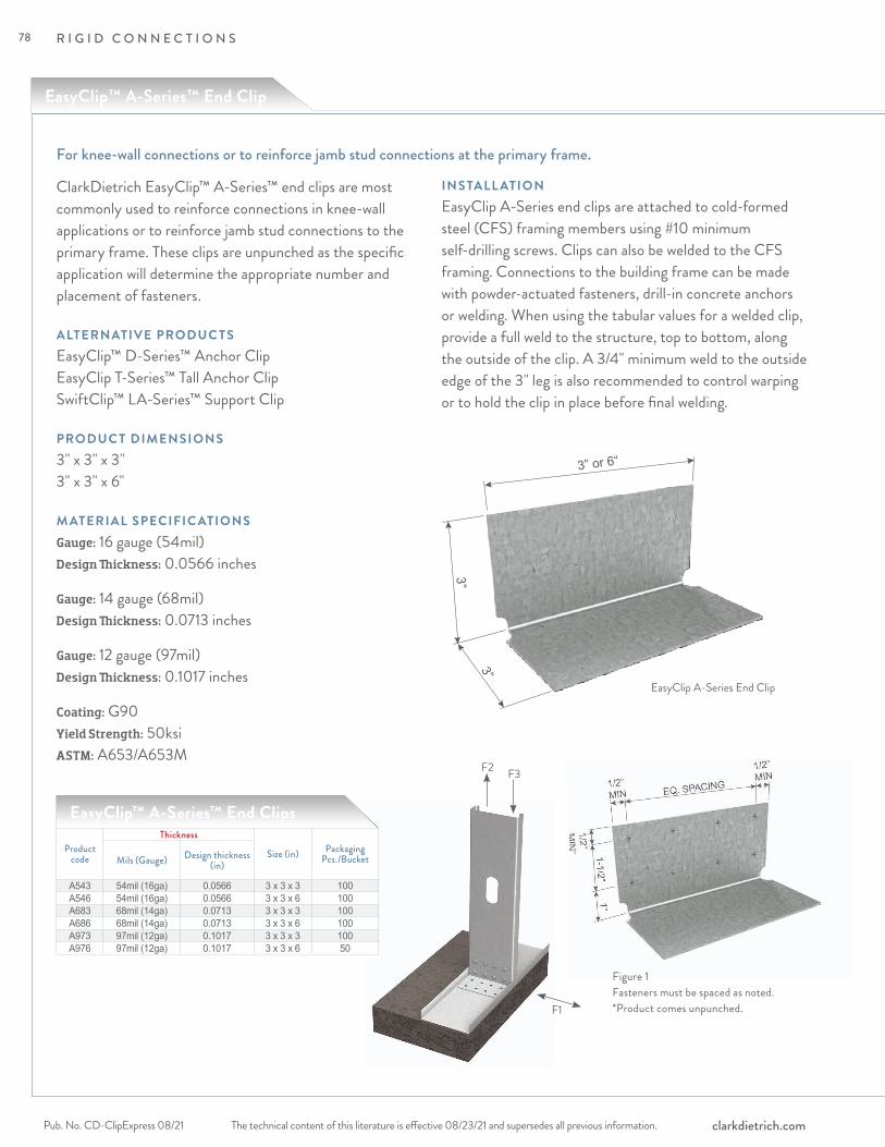
R I G I D C O N N E C T I O N S
The technical content of this literature is effective 08/23/21 and supersedes all previous information.Pub. No. CD-ClipExpress 08/21 clarkdietrich.com
F1
F2 F3
Figure 1Fasteners must be spaced as noted.*Product comes unpunched.
ClarkDietrich EasyClip™ A-Series™ end clips are most commonly used to reinforce connections in knee-wall applications or to reinforce jamb stud connections to the primary frame. These clips are unpunched as the specific application will determine the appropriate number and placement of fasteners.
ALTERNATIVE PRODUC TSEasyClip™ D-Series™ Anchor Clip EasyClip T-Series™ Tall Anchor Clip SwiftClip™ LA-Series™ Support Clip
PRODUC T DIMENSIONS3" x 3" x 3" 3" x 3" x 6"
M ATERIAL SPECIFIC ATIONSGauge: 16 gauge (54mil)Design Thickness: 0.0566 inches
Gauge: 14 gauge (68mil)Design Thickness: 0.0713 inches
Gauge: 12 gauge (97mil)Design Thickness: 0.1017 inches
Coating: G90Yield Strength: 50ksiASTM: A653/A653M
INSTALL ATIONEasyClip A-Series end clips are attached to cold-formed steel (CFS) framing members using #10 minimum self-drilling screws. Clips can also be welded to the CFS framing. Connections to the building frame can be made with powder-actuated fasteners, drill-in concrete anchors or welding. When using the tabular values for a welded clip, provide a full weld to the structure, top to bottom, along the outside of the clip. A 3/4" minimum weld to the outside edge of the 3" leg is also recommended to control warping or to hold the clip in place before final welding.
For knee-wall connections or to reinforce jamb stud connections at the primary frame.
EasyClip™ A-Series™ End Clips
EasyClip A-Series End Clip
Product code
Thickness
Size (in) Packaging Pcs./BucketMils (Gauge) Design thickness
(in)
A543 54mil (16ga) 0.0566 3 x 3 x 3 100A546 54mil (16ga) 0.0566 3 x 3 x 6 100A683 68mil (14ga) 0.0713 3 x 3 x 3 100A686 68mil (14ga) 0.0713 3 x 3 x 6 100A973 97mil (12ga) 0.1017 3 x 3 x 3 100A976 97mil (12ga) 0.1017 3 x 3 x 6 50
EasyClip™ A-Series™ End Clip
3” or 6“
3”
3”
78

R I G I D C O N N E C T I O N S
The technical content of this literature is effective 08/23/21 and supersedes all previous information. The technical content of this literature is effective 08/23/21 and supersedes all previous information. Pub. No. CD-ClipExpress 08/21clarkdietrich.com
RIG
ID C
ON
NE
CTI
ON
S
Notes:
EasyClip™ A-Series™ End Clips Allowable Clip Capacities (lbs)
Typical Construction Details
Visit our CAD Library at clarkdietrich.com to view or download construction details in .dwg, .dxf, and .pdf formats.
Clip No. of screws to steel framing (1)
Stud Thickness and Yield Strength20ga (33mil) 33ksi 18ga (43mil) 33ksi 16ga (54mil) 50ksi
F1 F2 F3 F1 F2 F3 F1 F2 F3
A543 4 354 (354) 120 (708) 708 525 (375) 120 (1050) 1050 775 (375) 120 (1365) 13816 531 (375) 120 (1062) 1062 775 (375) 120 (1365) 1381 775 (375) 120 (1365) 1381
A546
6 531 (531) 241 (1062) 1062 788 (788) 241 (1576) 1576 1400 (1355) 241 (2730) 28008 708 (708) 241 (1416) 1416 1050 (1050) 241 (2101) 2101 1867 (1355) 241 (2730) 345210 885 (885) 241 (1770) 1770 1313 (1313) 241 (2626) 2626 2333 (1355) 241 (2730) 345212 1062 (1062) 241 (2124) 2124 1576 (1355) 241 (2730) 3151 2634 (1355) 241 (2730) 3452
A683 4 354 (354) 190 (708) 708 525 (472) 190 (1050) 1050 933 (472) 190 (1718) 18676 531 (472) 190 (1062) 1062 788 (472) 190 (1576) 1576 1149 (472) 190 (1718) 2353
A686
6 531 (531) 381 (1062) 1062 788 (788) 381 (1576) 1576 1400 (1400) 381 (2800) 28008 708 (708) 381 (1416) 1416 1050 (1050) 381 (2101) 2101 1867 (1705) 381 (3436) 373310 885 (885) 381 (1770) 1770 1313 (1313) 381 (2626) 2626 2333 (1705) 381 (3436) 466712 1062 (1062) 381 (2124) 2124 1576 (1576) 381 (3151) 3151 2800 (1705) 381 (3436) 5600
A973 4 354 (354) 388 (708) 708 525 (525) 388 (1050) 1050 933 (673) 388 (1867) 18676 531 (531) 388 (1062) 1062 788 (673) 388 (1576) 1576 1400 (673) 388 (2451) 2800
A976
6 531 (531) 775 (1062) 1062 788 (788) 775 (1576) 1576 1400 (1400) 775 (2800) 28008 708 (708) 775 (1416) 1416 1050 (1050) 775 (2101) 2101 1867 (1867) 775 (3733) 373310 885 (885) 775 (1770) 1770 1313 (1313) 775 (2626) 2626 2333 (2333) 775 (4667) 466712 1062 (1062) 775 (2124) 2124 1576 (1576) 775 (3151) 3151 2800 (2432) 775 (4903) 5600
Screw Capacity Notes:1 The tabulated value indicates the number of screws in a single clip leg attached to the
cold-formed steel (CFS) framing.2 Screws shall be attached in a symmetric manner starting at the top and bottom moving to
the center, see Figure 1 opposite page.3 The allowable values for F1 are based only on the shear capacity of the clip leg attached to
the CFS framing. The capacity of the attachment to other materials and structures must be checked separately.
4 The allowable values for F2 assume mechanical fasteners are attached to the structure and are located no more than 1" away from the angle bend. Mechanical fasteners to other materials and structures must be checked separately.
5 This table is intended for use by qualified engineers only. It is the responsibility of the engineer to verify that the tabulated values apply to a specific connection application.
6 When clips have combinations of F1, F2 and F3, use a linear interaction for combinations of F1 and F3, and a squared interaction for combinations of F1 and F2.
7 Allowable loads have not been increased 33% for wind or seismic.8 For connections made to 14 gauge (68mil) and 12 gauge (97mil), use the tabulated values
for 16 gauge (54mil), 50ksi.9 It is the responsibility of the design professional to detail the drawings for proper clip
attachment.10 Contact ClarkDietrich at 888-437-3244 for technical assistance.Weld Capacity Notes:1 F1 and F2 values in parentheses are maximum shear and tension capacities when the clips
are welded to the base structure (min. 3/16" — 36ksi steel).2 Listed weld capacities are computed assuming an E70XX welding rod or wire.3 The clips are to be welded to the structure along the back corner along the complete
length of the clip. When secondary welds are used to hold the clip in place, they are not used in capacity calculations. 3/4" min. secondary weld as required to control warping or to hold clip in place before final welding.
USING #10-16 SELF-DRILLING SCREWS
79
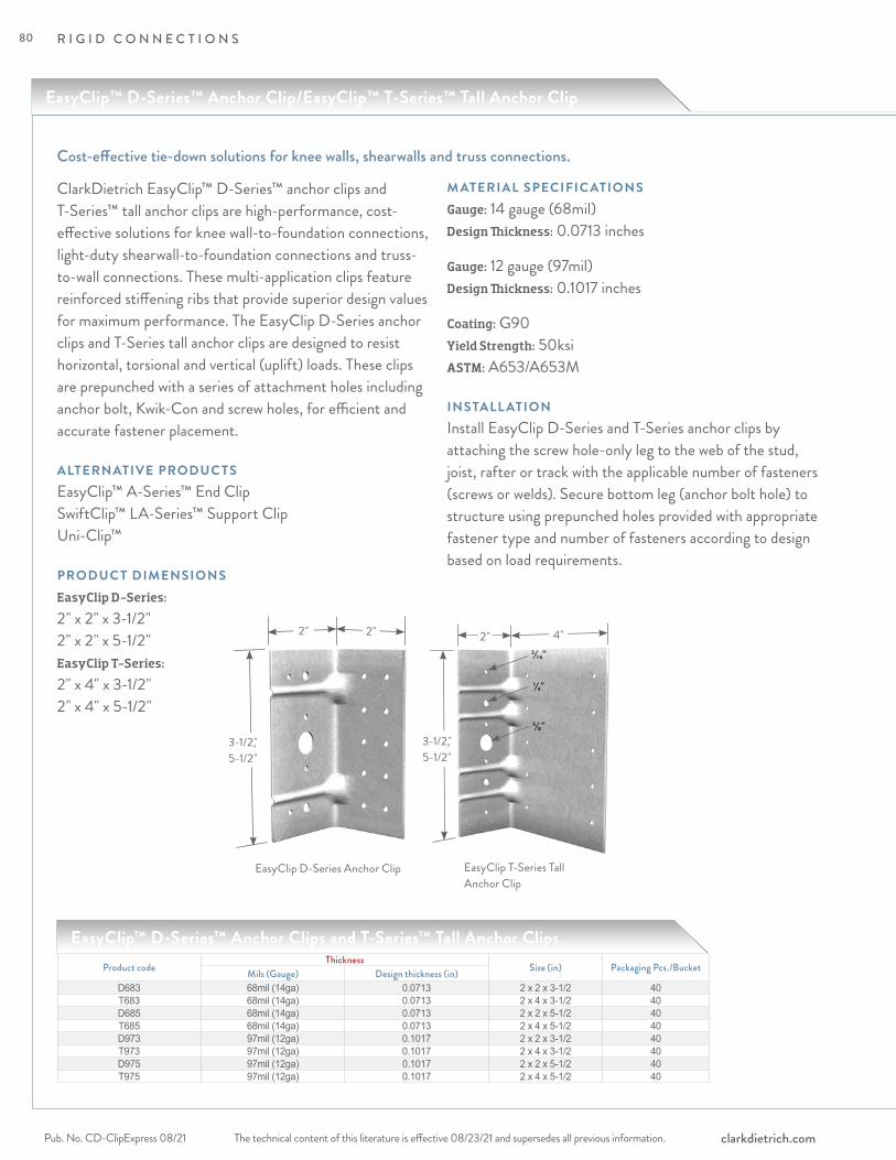
R I G I D C O N N E C T I O N S
The technical content of this literature is effective 08/23/21 and supersedes all previous information.Pub. No. CD-ClipExpress 08/21 clarkdietrich.com
EasyClip™ D-Series™ Anchor Clip/EasyClip™ T-Series™ Tall Anchor Clip
ClarkDietrich EasyClip™ D-Series™ anchor clips and T-Series™ tall anchor clips are high-performance, cost-effective solutions for knee wall-to-foundation connections, light-duty shearwall-to-foundation connections and truss-to-wall connections. These multi-application clips feature reinforced stiffening ribs that provide superior design values for maximum performance. The EasyClip D-Series anchor clips and T-Series tall anchor clips are designed to resist horizontal, torsional and vertical (uplift) loads. These clips are prepunched with a series of attachment holes including anchor bolt, Kwik-Con and screw holes, for efficient and accurate fastener placement.
ALTERNATIVE PRODUC TSEasyClip™ A-Series™ End Clip SwiftClip™ LA-Series™ Support Clip Uni-Clip™
PRODUC T DIMENSIONSEasyClip D-Series: 2" x 2" x 3-1/2" 2" x 2" x 5-1/2"EasyClip T-Series: 2" x 4" x 3-1/2" 2" x 4" x 5-1/2"
M ATERIAL SPECIFIC ATIONSGauge: 14 gauge (68mil)Design Thickness: 0.0713 inches
Gauge: 12 gauge (97mil)Design Thickness: 0.1017 inches
Coating: G90Yield Strength: 50ksi ASTM: A653/A653M
INSTALL ATIONInstall EasyClip D-Series and T-Series anchor clips by attaching the screw hole-only leg to the web of the stud, joist, rafter or track with the applicable number of fasteners (screws or welds). Secure bottom leg (anchor bolt hole) to structure using prepunched holes provided with appropriate fastener type and number of fasteners according to design based on load requirements.
Cost-effective tie-down solutions for knee walls, shearwalls and truss connections.
EasyClip™ D-Series™ Anchor Clips and T-Series™ Tall Anchor ClipsProduct code
ThicknessSize (in) Packaging Pcs./BucketMils (Gauge) Design thickness (in)
D683 68mil (14ga) 0.0713 2 x 2 x 3-1/2 40T683 68mil (14ga) 0.0713 2 x 4 x 3-1/2 40D685 68mil (14ga) 0.0713 2 x 2 x 5-1/2 40T685 68mil (14ga) 0.0713 2 x 4 x 5-1/2 40D973 97mil (12ga) 0.1017 2 x 2 x 3-1/2 40T973 97mil (12ga) 0.1017 2 x 4 x 3-1/2 40D975 97mil (12ga) 0.1017 2 x 2 x 5-1/2 40T975 97mil (12ga) 0.1017 2 x 4 x 5-1/2 40
2" 2"
3-1/2," 5-1/2"
2" 4"
3-1/2," 5-1/2"
EasyClip D-Series Anchor Clip EasyClip T-Series Tall Anchor Clip
3/16"
1/4"
5/8"
80
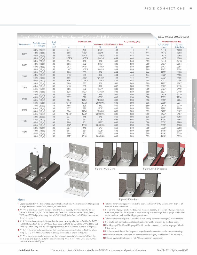
R I G I D C O N N E C T I O N S
The technical content of this literature is effective 08/23/21 and supersedes all previous information. The technical content of this literature is effective 08/23/21 and supersedes all previous information. Pub. No. CD-ClipExpress 08/21clarkdietrich.com
RIG
ID C
ON
NE
CTI
ON
S
Figure 2 #12-24 screws
Notes:1 Capacities listed in the table/notes assume that no load reductions are required for spacing
or edge distance of Kwik-Cons, screws, or Kwik-Bolts.2 An “ * ” in the shear column indicates that the shear capacity is limited to 642 lbs for
D683 and T683 clips, 917 lbs for D973 and T973 clips, and 994 lbs for D685, D975, T685, and T975 clips when using 1/4" x 1-3/4" Hilti® Kwik-Cons to 3000psi concrete as shown in Figure 1.
3 A “ # ” in the shear column indicates that the shear capacity is limited to 963 lbs for D683 and T683 clips, 1374 lbs for D973 and T973 clips, and 1816 lbs for D685, D975, T685, and T975 clips when using #12-24 self-tapping screws to 3/16" A36 steel as shown in Figure 2.
4 A “ % ” in the shear column indicates that the shear capacity is limited to 1970 lbs when using 1/2" x 2-1/4" Hilti Kwik-Bolts to 3000psi concrete as shown in Figure 3.
5 A “ * ” in the moment column indicates that moment capacity is limited to 1706 in.-lb. for 3" clips, and 2231 in.-lb. for 5" clips when using 1/4" x 1-3/4" Hilti-Cons to 3000psi concrete as shown in Figure 1.
6 Tabulated moment capacity is limited to a serviceability of 0.02 radians, or 1.1 degrees of rotation at the connection.
7 For 20 and 18 gauge studs, the tabulated moment capacity is based on 18 gauge minimum base track, with (1) #10-16 screw at each track leg to stud flange. For 16 gauge and heavier studs, the base track shall be 14 gauge minimum.
8 Tabulated moment capacity is based on a stud to clip connection using (6) #10-16 screws.9 For single-bolt connections, rotational restraint must be provided by the base track.10 For 14 gauge (68mil) and 12 gauge (97mil), use the tabulated values for 16 gauge (54mil),
50ksi studs.11 It is the responsibility of the designer to properly detail connections on the contract drawings.12 Use a linear interaction equation for connections involving any combination of F1, F2, and M.13 Hilti is a registered trademark of Hilti Aktiengeseilschaft Corporation.
EasyClip™ D-Series™ Anchor Clips and T-Series™ Tall Anchor Clips
F2
F1
M
Product code Stud thickness Mils (Gauge)
StudFy
(ksi)
F1 (Shear), (lbs) F2 (Tension), (lbs) M (Moment), (in-lbs)Number of #10-16 Screws to Stud Kwik-Cons/
screws1/2" Dia.
Kwik-Bolts4 6 10 4 6 10
D683
33mil (20ga) 33 374 466 664* 444 444 444 1418 106843mil (18ga) 33 556 692* 986*# 444 444 444 1675 106854mil (16ga) 33 783* 974*# 1389*# 444 444 444 1675 106854mil (16ga) 50 1107*# 1377*# 1962*# 444 444 444 1675 1068
D973
33mil (20ga) 33 374 466 664 560 840 889 1418 141843mil (18ga) 33 556 692 986* 832 889 889 2107* 205454mil (16ga) 33 783 974* 1389*# 889 889 889 2447* 205454mil (16ga) 50 1107* 1377*# 1962*# 889 889 889 2447* 2054
T683
33mil (20ga) 33 280 383 604 444 444 444 1787* 110643mil (18ga) 33 416 569 897 444 444 444 2072* 110654mil (16ga) 33 586 802* 1264*# 444 444 444 2072* 110654mil (16ga) 50 828* 1133*# 1786*# 444 444 444 2072* 1106
T973
33mil (20ga) 33 280 383 604 560 840 889 1787* 178743mil (18ga) 33 416 569 897 832 889 889 2527* 211054mil (16ga) 33 586 802 1264* 889 889 889 2527* 211054mil (16ga) 50 828 1133* 1786*# 889 889 889 2527* 2110
D685
33mil (20ga) 33 456 599 879 560 698 698 2019 201943mil (18ga) 33 677 890 1306* 698 698 698 2865* 223454mil (16ga) 33 954 1254* 1839*# 698 698 698 2865* 223454mil (16ga) 50 1348* 1772* 2599*#% 698 698 698 2865* 2234
D975
33mil (20ga) 33 456 599 879 560 840 889 2019 201943mil (18ga) 33 677 890 1306* 832 889 889 2999* 299954mil (16ga) 33 954 1254* 1839*# 889 889 889 3477* 316754mil (16ga) 50 1348* 1772* 2599*#% 889 889 889 3477* 3167
T685
33mil (20ga) 33 337 445 678 560 698 698 2298* 196843mil (18ga) 33 501 661 1008* 698 698 698 3415* 196854mil (16ga) 33 706 931 1420* 698 698 698 3509* 196854mil (16ga) 50 997* 1316* 2006*#% 698 698 698 3509* 1968
T975
33mil (20ga) 33 337 445 678 560 840 889 2298* 229843mil (18ga) 33 501 661 1008* 832 889 889 3415* 305954mil (16ga) 33 706 931 1420* 889 889 889 4416* 305954mil (16ga) 50 997* 1316* 2006*#% 889 889 889 4416* 3059
Figure 1 Kwik-Cons
Figure 3 Kwik-Bolts
ALLOWABLE LOADS (LBS)
81
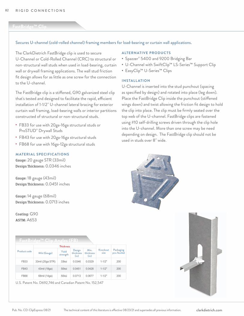
FastBridge™ Clip
R I G I D C O N N E C T I O N S
The technical content of this literature is effective 08/23/21 and supersedes all previous information.Pub. No. CD-ClipExpress 08/21 clarkdietrich.com
The ClarkDietrich FastBridge clip is used to secure U-Channel or Cold-Rolled Channel (CRC) to structural or non-structural wall studs when used in load-bearing, curtain wall or drywall framing applications. The wall stud friction fit design allows for as little as one screw for the connection to the U-channel.
The FastBridge clip is a stiffened, G90 galvanized steel clip that's tested and designed to facilitate the rapid, efficient installation of 1-1/2" U-channel lateral bracing for exterior curtain wall framing, load-bearing walls or interior partitions constructed of structural or non-structural studs.
M ATERIAL SPECIFIC ATIONSGauge: 20 gauge STR (33mil)Design Thickness: 0.0346 inches
Gauge: 18 gauge (43mil)Design Thickness: 0.0451 inches
Gauge: 14 gauge (68mil)Design Thickness: 0.0713 inches
Coating: G90ASTM: A653
ALTERNATIVE PRODUC TS• Spazzer® 5400 and 9200 Bridging Bar• U-Channel with SwiftClip™ LS-Series™ Support Clip• EasyClip™ U-Series™ Clips
Secures U-channel (cold-rolled channel) framing members for load-bearing or curtain wall applications.
FastBridge™ Clip Angles (FB)
Product codeThickness
Knockout size
Packaging pcs./bucketMils (Gauge) Yield
strengthDesign
thickness (in)
Min. thickness
(in)
FB33 33mil (20ga STR) 33ksi 0.0346 0.0329 1-1/2" 200
FB43 43mil (18ga) 50ksi 0.0451 0.0428 1-1/2" 200
FB68 68mil (14ga) 50ksi 0.0713 0.0677 1-1/2" 200
U.S. Patent No. D692,746 and Canadian Patent No. 152,547
INSTALL ATIONU-Channel is inserted into the stud punchout (spacing as specified by design) and rotated into place (leg down). Place the FastBridge Clip inside the punchout (stiffened wings down) and twist allowing the friction fit design to hold the clip into place. The clip must be firmly seated over the top web of the U-channel. FastBridge clips are fastened using #10 self-drilling screws driven through the clip hole into the U-channel. More than one screw may be need depending on design. The FastBridge clip should not be used in studs over 8" wide.
• FB33 for use with 20ga-16ga structural studs or ProSTUD® Drywall Studs• FB43 for use with 20ga-16ga structural studs• FB68 for use with 16ga-12ga structural studs
82

R I G I D C O N N E C T I O N S
The technical content of this literature is effective 08/23/21 and supersedes all previous information. The technical content of this literature is effective 08/23/21 and supersedes all previous information. Pub. No. CD-ClipExpress 08/21clarkdietrich.com
RIG
ID C
ON
NE
CTI
ON
S
Notes:1 Allowable loads are based on the use of cold-formed steel studs with a minimum yield strength
of Fy=33ksi and tensile strength of Fu=45ksi for 43mil (18ga) or thinner; and a minimum yield strength Fy=50ksi and tensile strength Fu=65ksi for 54mil (16ga) or thicker.
2 Allowable loads are based on 54mil (16ga) u-channel bridging with a minimum yield strength Fy=33ksi and tensile strength Fu=45ksi.
3 Allowable loads are for the bridging connection only. The strength and serviceability of the framing members is the responsibility of the designer.
4 Allowable loads are based on #10 self-drilling screws with a nominal diameter of 0.190 in. and a washer diameter of 0.375 in. Fasteners must have a minimum nominal shear strength of Pss=1718 lbs and a nominal tensile strength of Pts=2654 lbs.
5 Allowable loads may not be increased for wind or seismic load.6 Allowable loads are for use when using ASD design methodology. For LRFD loads,
multiply ASD allowable loads by 1.6.7 Allowable brace loads are based on ultimate test loads divided by a safety factor.
Serviceability limits are not considered. Brace stiffness requirements are detailed in AISI S100 Section D3.3.
8 Axial brace stiffness values apply to both ASD and LRFD designs.
FastBridge™ Clip Angles (FB68) Allowable Clip Capacities (lbs)
Product code No. of screws to steel framing Stud depth (in) Allowable connector capacity
Stud Thickness and Yield Strength
16ga (54mil) 14ga (68mil) 12ga (97mil )
FB68
1
3.625
Axial Brace Stiffness (lbs/in) 3410 4410 62702 4010 6880 75851 Axial Brace Strength (lbs) 465 520 5732 665 732 8231 Torsional Moment (in-lbs) 332 440 4352 735 894 1150
FB68
1
4.00
Axial Brace Stiffness (lbs/in) 3060 3440 67402 3710 4670 89601 Axial Brace Strength (lbs) 475 505 5052 676 752 8781 Torsional Moment (in-lbs) 382 462 5642 724 802 938
FB68
1
6.00
Axial Brace Stiffness (lbs/in) 2270 3240 32002 2710 3870 35301 Axial Brace Strength (lbs) 468 506 5152 682 788 8851 Torsional Moment (in-lbs) 294 412 6702 686 758 1004
FB68
1
8.00
Axial Brace Stiffness (lbs/in) 1940 2500 25302 1960 2810 30151 Axial Brace Strength (lbs) 463 510 5172 637 747 8981 Torsional Moment (in-lbs) 310 512 6742 682 788 963
Product code No. of screws to steel framing Stud depth (in) Allowable connector capacity
Stud Thickness and Yield Strength
20ga (33mil) 18ga (43mil) 16ga (54mil )
FB43
1
3.625
Axial Brace Stiffness (lbs/in) 1140 1330 22702 1220 1480 22701 Axial Brace Strength (lbs) 178 210 2732 275 318 4241 Torsional Moment (in-lbs) 148 182 2082 331 430 556
FB43
1
4.00
Axial Brace Stiffness (lbs/in) 1030 1460 21702 1190 1520 30301 Axial Brace Strength (lbs) 191 213 2632 283 321 4261 Torsional Moment (in-lbs) 137 182 2342 403 403 498
FB43
1
6.00
Axial Brace Stiffness (lbs/in) 790 990 17302 990 1160 19301 Axial Brace Strength (lbs) 107 214 2902 263 324 4501 Torsional Moment (in-lbs) 166 170 1722 296 406 567
FB43
1
8.00
Axial Brace Stiffness (lbs/in) — 750 19102 — 750 19601 Axial Brace Strength (lbs) — 212 2722 — 302 4381 Torsional Moment (in-lbs) — 152 3432 — 461 526
FastBridge™ Clip Angles (FB43) Allowable Clip Capacities (lbs)
83

R I G I D C O N N E C T I O N S
The technical content of this literature is effective 08/23/21 and supersedes all previous information.Pub. No. CD-ClipExpress 08/21 clarkdietrich.com
The H-Series™ universal header hanger is used to connect box headers to jambs or beams to columns and transfer large vertical loads. This universal hanger is designed so one part can be used for either side of the connection. The hanger also features a support tab for proper alignment and easy installation.
The H-Series hanger is also prepunched with a series of round, square and triangle holes to ensure proper fastener placement for specified loads.
ALTERNATIVE PRODUC TSHDS® Framing System, HDSC Header Bracket, GP-Series™ Unpunched Gusset Plate
PRODUC T DIMENSIONS6" x 8-1/2"
M ATERIAL SPECIFIC ATIONSGauge: 18 gauge (43mil)Design Thickness: 0.0451 inches
Gauge: 16 gauge (54mil)Design Thickness: 0.0566 inches
Gauge: 14 gauge (68mil)Design Thickness: 0.0713 inches
Coating: G90Yield Strength: 33ksi for 18 gauge
50ksi for 14 & 16 gaugeASTM: A653/A653M
INSTALL ATIONInstall the H-Series universal header hanger to the jamb studs with the required number of screws as needed to achieve required loading. Normally two connectors are required, one on each side of the header.
Position header on header support tabs and secure header to header hanger with number of fasteners required by design.
Connect box headers to jambs or beams to columns.
H-Series™ Universal Header Hangers
Product codeThickness
Size (in) Packaging Pcs./BucketMils (Gauge) Design thickness
(in)H436 43mil (18ga) 0.0451 6 x 8-1/2 50H546 54mil (16ga) 0.0566 6 x 8-1/2 50H686 68mil (14ga) 0.0713 6 x 8-1/2 50
H-Series Universal Header Hanger
6"
8-1/2"
2"
H-Series™ Universal Header Hanger
84
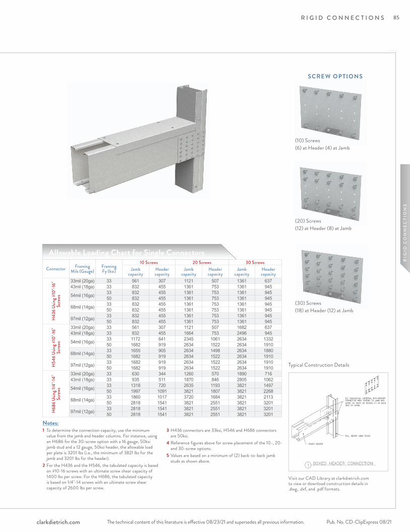
R I G I D C O N N E C T I O N S
The technical content of this literature is effective 08/23/21 and supersedes all previous information. The technical content of this literature is effective 08/23/21 and supersedes all previous information. Pub. No. CD-ClipExpress 08/21clarkdietrich.com
RIG
ID C
ON
NE
CTI
ON
S
Notes:1 To determine the connection capacity, use the minimum
value from the jamb and header columns. For instance, using an H686 for the 30-screw option with a 16 gauge, 50ksi jamb stud and a 12 gauge, 50ksi header, the allowable load per plate is 3201 lbs (i.e., the minimum of 3821 lbs for the jamb and 3201 lbs for the header).
2 For the H436 and the H546, the tabulated capacity is based on #10-16 screws with an ultimate screw shear capacity of 1400 lbs per screw. For the H686, the tabulated capacity is based on 1/4"-14 screws with an ultimate screw shear capacity of 2600 lbs per screw.
3 H436 connectors are 33ksi, H546 and H686 connectors are 50ksi.
4 Reference figures above for screw placement of the 10-, 20- and 30-screw options.
5 Values are based on a minimum of (2) back-to-back jamb studs as shown above.
Typical Construction Details
Allowable Loading Chart for Single Connectors
Visit our CAD Library at clarkdietrich.com to view or download construction details in .dwg, .dxf, and .pdf formats.
Connector Framing Mils (Gauge)
Framing Fy (ksi)
10 Screws 20 Screws 30 ScrewsJamb
capacityHeader capacity
Jamb capacity
Header capacity
Jamb capacity
Header capacity
H43
6 Us
ing #
10"-1
6"
Scre
ws
33mil (20ga) 33 561 307 1121 507 1361 63743mil (18ga) 33 832 455 1361 753 1361 945
54mil (16ga) 33 832 455 1361 753 1361 94550 832 455 1361 753 1361 945
68mil (14ga) 33 832 455 1361 753 1361 94550 832 455 1361 753 1361 945
97mil (12ga) 33 832 455 1361 753 1361 94550 832 455 1361 753 1361 945
H54
6 Us
ing #
10"-1
6"
Scre
ws
33mil (20ga) 33 561 307 1121 507 1682 63743mil (18ga) 33 832 455 1664 753 2496 945
54mil (16ga) 33 1172 641 2345 1061 2634 133250 1682 919 2634 1522 2634 1910
68mil (14ga) 33 1655 905 2634 1498 2634 188050 1682 919 2634 1522 2634 1910
97mil (12ga) 33 1682 919 2634 1522 2634 191050 1682 919 2634 1522 2634 1910
H68
6 Us
ing 1
/4"-1
4"
Scre
ws
33mil (20ga) 33 630 344 1260 570 1890 71643mil (18ga) 33 935 511 1870 846 2805 1062
54mil (16ga) 33 1318 720 2635 1193 3821 149750 1997 1091 3821 1807 3821 2268
68mil (14ga) 33 1860 1017 3720 1684 3821 211350 2818 1541 3821 2551 3821 3201
97mil (12ga) 33 2818 1541 3821 2551 3821 320150 2818 1541 3821 2551 3821 3201
SCREW OP TIONS
(10) Screws(6) at Header (4) at Jamb
(20) Screws(12) at Header (8) at Jamb
(30) Screws(18) at Header (12) at Jamb
85

R I G I D C O N N E C T I O N S
The technical content of this literature is effective 08/23/21 and supersedes all previous information.Pub. No. CD-ClipExpress 08/21 clarkdietrich.com
ClarkDietrich holdowns provide cost-effective shearwall attachment and are used to transfer tension loads between floors or from structural members to the foundation. Two-piece welded construction comes in three sizes for optimal performance. Installation is made easy with prepunched holes.
ALTERNATIVE PRODUC TSEasyClip™ T-Series™ Tall Anchor Clip Moment Clip
PRODUC T DIMENSIONSCD8: 2-5/8" x 11" CD10: 2-5/8" x 13-1/2"CD15: 2-5/8" x 19"
M ATERIAL SPECIFIC ATIONSGauge: 7 gauge (179mils) with 1/2" bearing plateSteel Thickness: 0.1793 inches ASTM: A36, A1011
Reference section R603.9.4.2 of the International Residential Code (IRC) for holdown requirements in residential applications. Consult the engineer of record for commercial applications.
INSTALL ATIONInstall the holdowns using anchor bolts or alternate anchorage calculated to resist the tension load for your specific application. Use steel nylon locking nuts or thread adhesive to minimize the chance of nut spin. Anchor bolt washer is not required. Secure the CD holdown to the steel framing member by filling all the prepunched holes with #14 screws to achieve listed capacities.
Boundary members (back-to-back studs) shall be designed by a qualified professional. To tie back-to-back stud members together, the designer must determine the fasteners required to bind members to act as one unit.
CD holdowns can be welded per designer's recommendation and specification. Welding procedures shall be qualified as specified in AWS D1.3. Welded connections used for cold-formed steel structural members in which the thickness of the thinnest connected part is 0.18 inch or less shall comply to AISI S100-2012 specification Section E2.
Secure and hold down shearwalls to the structure foundation.
ClarkDietrich Holdowns (CD Series)Product
codeSimpson reference
Thickness Size (in) PackagingMils (Gauge) Design thickness (in)CD8 S/HD8S 179mil (7ga) 0.188 2-5/8 x 11 Dependent on
Order QuantityCD10 S/HD10S 179mil (7ga) 0.188 2-5/8 x 13-1/2CD15 S/HD15S 179mil (7ga) 0.188 2-5/8 x 19
ClarkDietrich Holdown
CD8 = 11"CD10 = 13-1/2"CD15 = 19"
2-5/8"
3-7/16"
86
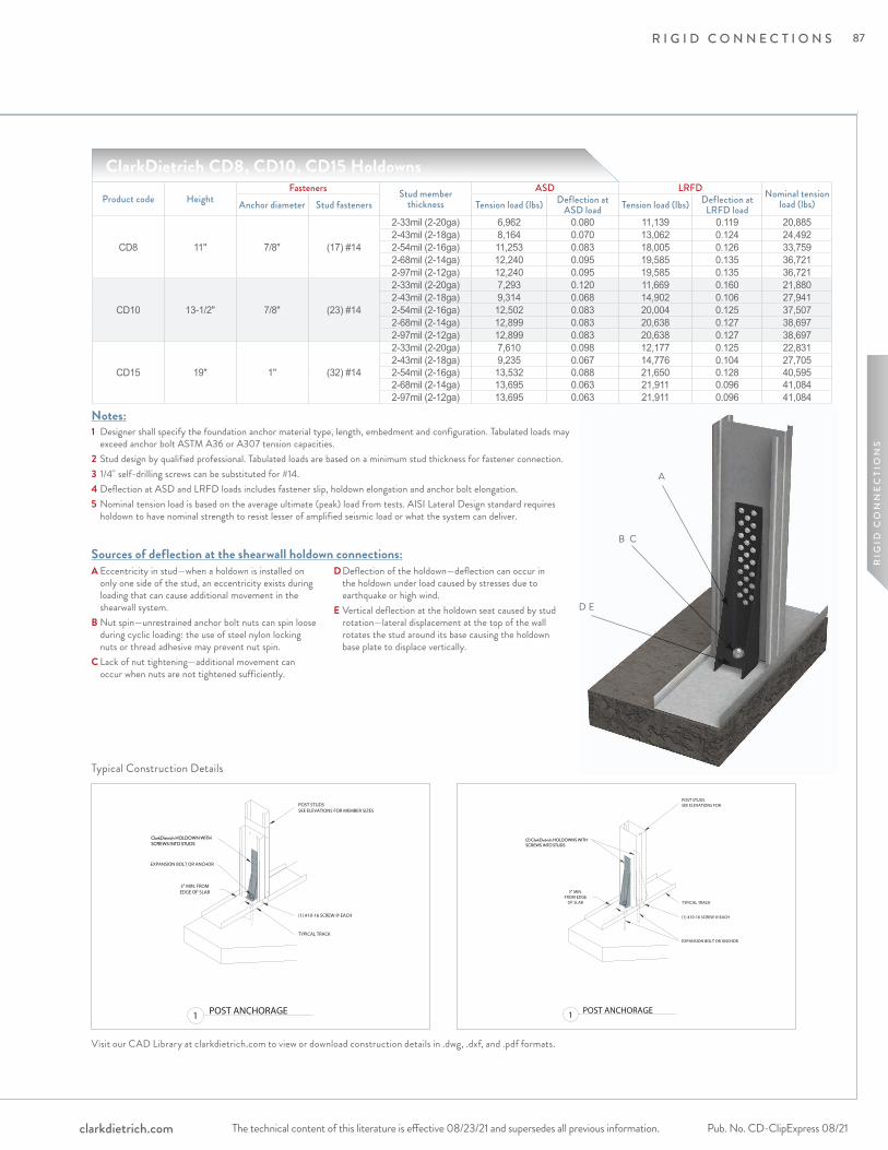
R I G I D C O N N E C T I O N S
The technical content of this literature is effective 08/23/21 and supersedes all previous information. The technical content of this literature is effective 08/23/21 and supersedes all previous information. Pub. No. CD-ClipExpress 08/21clarkdietrich.com
RIG
ID C
ON
NE
CTI
ON
S
Typical Construction Details
Visit our CAD Library at clarkdietrich.com to view or download construction details in .dwg, .dxf, and .pdf formats.
A
B C
D E
Sources of deflection at the shearwall holdown connections:A Eccentricity in stud—when a holdown is installed on
only one side of the stud, an eccentricity exists during loading that can cause additional movement in the shearwall system.
B Nut spin—unrestrained anchor bolt nuts can spin loose during cyclic loading: the use of steel nylon locking nuts or thread adhesive may prevent nut spin.
C Lack of nut tightening—additional movement can occur when nuts are not tightened sufficiently.
D Deflection of the holdown—deflection can occur in the holdown under load caused by stresses due to earthquake or high wind.
E Vertical deflection at the holdown seat caused by stud rotation—lateral displacement at the top of the wall rotates the stud around its base causing the holdown base plate to displace vertically.
Notes:1 Designer shall specify the foundation anchor material type, length, embedment and configuration. Tabulated loads may
exceed anchor bolt ASTM A36 or A307 tension capacities.2 Stud design by qualified professional. Tabulated loads are based on a minimum stud thickness for fastener connection.3 1/4" self-drilling screws can be substituted for #14.4 Deflection at ASD and LRFD loads includes fastener slip, holdown elongation and anchor bolt elongation.5 Nominal tension load is based on the average ultimate (peak) load from tests. AISI Lateral Design standard requires
holdown to have nominal strength to resist lesser of amplified seismic load or what the system can deliver.
ClarkDietrich CD8, CD10, CD15 HoldownsProduct code Height
Fasteners Stud member thickness
ASD LRFD Nominal tension load (lbs)Anchor diameter Stud fasteners Tension load (lbs) Deflection at
ASD load Tension load (lbs) Deflection at LRFD load
CD8 11" 7/8" (17) #14
2-33mil (2-20ga) 6,962 0.080 11,139 0.119 20,8852-43mil (2-18ga) 8,164 0.070 13,062 0.124 24,4922-54mil (2-16ga) 11,253 0.083 18,005 0.126 33,7592-68mil (2-14ga) 12,240 0.095 19,585 0.135 36,7212-97mil (2-12ga) 12,240 0.095 19,585 0.135 36,721
CD10 13-1/2" 7/8" (23) #14
2-33mil (2-20ga) 7,293 0.120 11,669 0.160 21,8802-43mil (2-18ga) 9,314 0.068 14,902 0.106 27,9412-54mil (2-16ga) 12,502 0.083 20,004 0.125 37,5072-68mil (2-14ga) 12,899 0.083 20,638 0.127 38,6972-97mil (2-12ga) 12,899 0.083 20,638 0.127 38,697
CD15 19" 1" (32) #14
2-33mil (2-20ga) 7,610 0.098 12,177 0.125 22,8312-43mil (2-18ga) 9,235 0.067 14,776 0.104 27,7052-54mil (2-16ga) 13,532 0.088 21,650 0.128 40,5952-68mil (2-14ga) 13,695 0.063 21,911 0.096 41,0842-97mil (2-12ga) 13,695 0.063 21,911 0.096 41,084
87
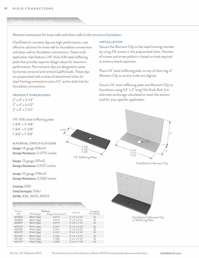
R I G I D C O N N E C T I O N S
The technical content of this literature is effective 08/23/21 and supersedes all previous information.Pub. No. CD-ClipExpress 08/21 clarkdietrich.com
ClarkDietrich moment clips are high-performance, cost effective solutions for knee wall-to-foundation connections and shear wall-to-foundation connections. These multi-application clips feature a 1/4" thick A36 steel stiffening plate that provides superior design values for maximum performance. The moment clips are designed to resist horizontal, torsional and vertical (uplift) loads. These clips are prepunched with a series of attachment holes for steel framing connections and a 1/2" anchor bolt hole for foundation connections.
PRODUC T DIMENSIONS2" x 4" x 3-1/2"2" x 4" x 5-1/2"2" x 4" x 7-1/2"
1/4" A36 steel stiffening plate 1-3/4" x 3-3/8"1-3/4" x 5-3/8"1-3/4" x 7-3/8"
M ATERIAL SPECIFIC ATIONSGauge: 14 gauge (68mil)Design Thickness: 0.0713 inches
Gauge: 12 gauge (97mil)Design Thickness: 0.1017 inches
Gauge: 10 gauge (118mil)Design Thickness: 0.1242 inches
Coating: G90Yield Strength: 50ksiASTM: A36, A653, A1003
INSTALL ATIONSecure the Moment Clip to the steel framing member by using #12 screws in the prepunched holes. Number of screws and screw pattern is based on load required to achieve listed capacities.
Place 1/4" steel stiffening plate on top of short leg of Moment Clip so anchor holes are aligned.
Secure 1/4" steel stiffening plate and Moment Clip to foundation using 1/2" x 2" long Hilti Kwik-Bolt 3 or alternate anchorage calculated to resist the tension load for your specific application.
Moment connection for knee walls and shear walls to the structure foundation.
ClarkDietrich Moment Clips (MC Series)Product
codeThickness Size (in) Packaging
Pcs./BucketMils (Gauge) Design thickness (in)MC683P 68mil (14ga) 0.0713 2" x 4" x 3-1/2" 25MC685P 68mil (14ga) 0.0713 2" x 4" x 5-1/2 25MC687P 68mil (14ga) 0.0713 2" x 4" x 7-1/2" 25MC973P 97mil (12ga) 0.1017 2" x 4" x 3-1/2" 25MC975P 97mil (12ga) 0.1017 2" x 4" x 5-1/2" 25MC977P 97mil (12ga) 0.1017 2" x 4" x 7-1/2" 25MC103P 68mil (14ga) 0.1242 2" x 4" x 3-1/2" 25MC105P 97mil (12ga) 0.1242 2" x 4" x 5-1/2" 25MC107P 118mil (10ga) 0.1242 2" x 4" x 7-1/2" 25
ClarkDietrich Moment Clip
2"
4"
3-1/2"5-1/2" 7-1/2"
3-3/8"5-3/8"7-3/8"
1-3/4"
1/4" Stiffening Plate
ClarkDietrich Moment Clip
ClarkDietrich Moment Clip w/ Stiffening Plate
5/8"
88
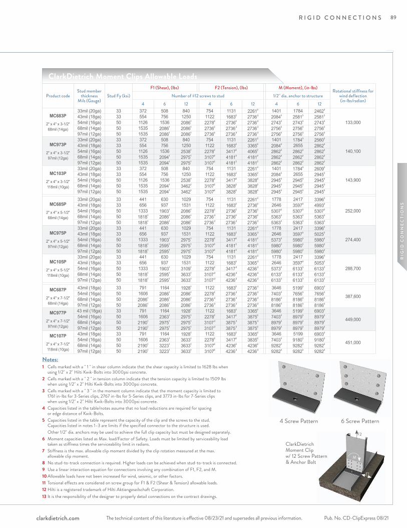
R I G I D C O N N E C T I O N S
The technical content of this literature is effective 08/23/21 and supersedes all previous information. The technical content of this literature is effective 08/23/21 and supersedes all previous information. Pub. No. CD-ClipExpress 08/21clarkdietrich.com
RIG
ID C
ON
NE
CTI
ON
S
F2
F1
M
ClarkDietrich Moment Clips Allowable Loads
Product codeStud member
thickness Mils (Gauge)
Stud Fy (ksi)F1 (Shear), (lbs) F2 (Tension), (lbs) M (Moment), (in-lbs)
Rotational stiffness for wind deflection (in-lbs/radian)
Number of #12 screws to stud 1/2" dia. anchor to structure4 6 12 4 6 12 4 6 12
MC683P
2" x 4" x 3-1/2" 68mil (14ga)
33mil (20ga) 33 372 508 840 754 1131 22612 1401 1784 24623
133,00043mil (18ga) 33 554 756 1250 1122 16832 2736 2 20843 25813 25813
54mil (16ga) 50 1126 1536 20861 22782 27362 2736 2 27433 27433 27433
68mil (14ga) 50 1535 20861 20861 27362 2736 2 2736 2 27563 27563 27563
97mil (12ga) 50 1535 20861 20861 27362 2736 2 2736 2 27563 27563 27563
MC973P 2" x 4" x 3-1/2" 97mil (12ga)
33mil (20ga) 33 372 508 840 754 1131 22612 1401 17843 25603
140,10043mil (18ga) 33 554 756 1250 1122 16832 33652 20843 2655 28623
54mil (16ga) 50 1126 1536 25381 22782 34172 40652 28623 28623 28623
68mil (14ga) 50 1535 20941 29751 31072 41812 41812 28623 28623 28623
97mil (12ga) 50 1535 20941 29751 31072 41812 41812 28623 28623 28623
MC103P 2" x 4" x 3-1/2" 118mil (10ga)
33mil (20ga) 33 372 508 840 754 1131 22612 1401 17843 26093
143,90043mil (18ga) 33 554 756 1250 1122 16832 33652 20843 2655 29453
54mil (16ga) 50 1126 1536 25381 22782 34172 38282 29453 29453 29453
68mil (14ga) 50 1535 20941 34621 31072 38282 38282 29453 29453 29453
97mil (12ga) 50 1535 20941 34621 31072 38282 38282 29453 29453 29453
MC685P
2" x 4" x 5-1/2" 68mil (14ga)
33mil (20ga) 33 441 630 1029 754 1131 22612 1778 2417 33963
252,00043mil (18ga) 33 656 937 1531 1122 16832 27362 2646 35973 49933
54mil (16ga) 50 1333 19031 20861 22782 27362 27362 53073 53073 53073
68mil (14ga) 50 18181 20861 20861 2736 2 27362 27362 53633 53633 53633
97mil (12ga) 50 18181 20861 20861 2736 2 2736 2 2736 2 53633 53633 53633
MC975P 2" x 4" x 5-1/2" 97mil (12ga)
33mil (20ga) 33 441 630 1029 754 1131 22612 1778 2417 33963
274,40043mil (18ga) 33 656 937 1531 1122 16832 3365 2 2646 35973 50253
54mil (16ga) 50 1333 19031 29751 22782 34172 41812 53733 59803 59803
68mil (14ga) 50 18181 25951 29751 31072 41812 41812 59803 59803 59803
97mil (12ga) 50 18181 25951 29751 31072 41812 41812 59803 59803 59803
MC105P2" x 4" x 5-1/2" 118mil (10ga)
33mil (20ga) 33 441 630 1029 754 1131 22612 1778 2417 33963
288,70043mil (18ga) 33 656 937 1531 1122 16832 3365 2 2646 35973 50533
54mil (16ga) 50 1333 19031 31091 22782 3417 2 4236 2 53733 61333 61333
68mil (14ga) 50 18181 25951 36331 3107 2 4236 2 4236 2 61333 61333 61333
97mil (12ga) 50 18181 25951 36331 3107 2 4236 2 4236 2 61333 61333 61333
MC687P2" x 4" x 7-1/2" 68mil (14ga)
43mil (18ga) 33 791 1164 19281 1122 16832 2736 2 3646 51993 69033
387,60054mil (16ga) 50 1606 20861 20861 22782 2736 2 2736 2 74033 76563 76563
68mil (14ga) 50 20861 20861 20861 2736 2 2736 2 2736 2 81863 81863 81863
97mil (12ga) 50 20861 20861 20861 2736 2 2736 2 2736 2 81863 81863 81863
MC977P 2" x 4" x 7-1/2" 97mil (12ga)
43 mil (18ga) 33 791 1164 19281 1122 16832 33652 3646 51993 69033
449,00054mil (16ga) 50 1606 23631 29751 22782 34172 38752 74033 89793 89793
68mil (14ga) 50 21901 29751 29751 3107 2 3875 2 3875 2 89793 89793 89793
97mil (12ga) 50 21901 29751 29751 3107 2 3875 2 38752 89793 89793 89793
MC107P2" x 4" x 7-1/2" 118mil (10ga)
43mil (18ga) 33 791 1164 19281 1122 16832 33652 3646 5199 69033
451,00054mil (16ga) 50 1606 23631 36331 22782 34172 38352 74033 91803 91803
68mil (14ga) 50 21901 32231 36331 31072 42362 42362 92823 92823 92823
97mil (12ga) 50 21901 32231 36331 31072 4236 2 4236 2 92823 92823 92823
4 Screw Pattern 6 Screw Pattern
Notes:1 Cells marked with a " 1 " in shear column indicate that the shear capacity is limited to 1628 lbs when using 1/2" x 2" Hilti Kwik-Bolts into 3000psi concrete.2 Cells marked with a " 2 " in tension column indicate that the tension capacity is limited to 1509 lbs when using 1/2" x 2" Hilti Kwik-Bolts into 3000psi concrete.3 Cells marked with a " 3 " in the moment column indicate that the moment capacity is limited to 1761 in-lbs for 3-Series clips, 2767 in-lbs for 5-Series clips, and 3773 in-lbs for 7-Series clips when using 1/2" x 2" Hilti Kwik-Bolts into 3000psi concrete.4 Capacities listed in the table/notes assume that no load reductions are required for spacing or edge distance of Kwik-Bolts.5 Capacities listed in the table represent the capacity of the clip and the screws to the stud. Capacities listed in notes 1–3 are limits if the specified connector to the structure is used. Other 1/2" dia. anchors may be used to achieve the full clip capacity but must be designed separately. 6 Moment capacities listed as Max. load/Factor of Safety. Loads must be limited by serviceability load taken as stiffness times the serviceability limit in radians.7 Stiffness is the max. allowable clip moment divided by the clip rotation measured at the max. allowable clip moment.8 No stud-to-track connection is required. Higher loads can be achieved when stud-to-track is connected.9 Use a linear interaction equation for connections involving any combination of F1, F2, and M.10 Allowable loads have not been increased for wind, seismic, or other factors.11 Torsional effects are considered on screw group for F1 & F2 (Shear & Tension) allowable loads. 12 Hilti is a registered trademark of Hilti Aktiengeseilschaft Corporation.13 It is the responsibility of the designer to properly detail connections on the contract drawings.
ClarkDietrich Moment Clip w/ 12 Screw Pattern & Anchor Bolt
89
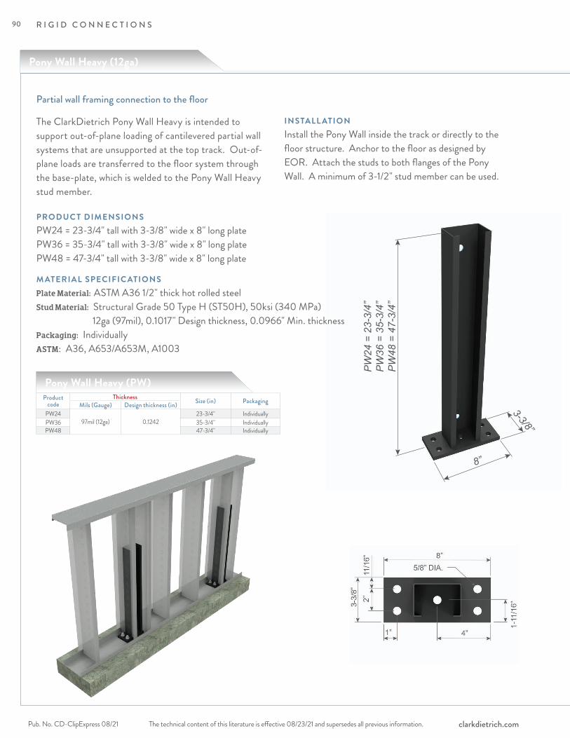
R I G I D C O N N E C T I O N S
The technical content of this literature is effective 08/23/21 and supersedes all previous information.Pub. No. CD-ClipExpress 08/21 clarkdietrich.com
PW
24 =
23-
3/4”
PW
36 =
35-
3/4”
PW
48 =
47-
3/4”
8”
3-3/8”
Partial wall framing connection to the floor
Pony Wall Heavy (12ga)
INSTALL ATIONInstall the Pony Wall inside the track or directly to the floor structure. Anchor to the floor as designed by EOR. Attach the studs to both flanges of the Pony Wall. A minimum of 3-1/2" stud member can be used.
M ATERIAL SPECIFIC ATIONSPlate Material: ASTM A36 1/2" thick hot rolled steelStud Material: Structural Grade 50 Type H (ST50H), 50ksi (340 MPa) 12ga (97mil), 0.1017" Design thickness, 0.0966" Min. thicknessPackaging: Individually ASTM: A36, A653/A653M, A1003
The ClarkDietrich Pony Wall Heavy is intended to support out-of-plane loading of cantilevered partial wall systems that are unsupported at the top track. Out-of-plane loads are transferred to the floor system through the base-plate, which is welded to the Pony Wall Heavy stud member.
PRODUC T DIMENSIONSPW24 = 23-3/4" tall with 3-3/8" wide x 8" long plate PW36 = 35-3/4" tall with 3-3/8" wide x 8" long plate PW48 = 47-3/4" tall with 3-3/8" wide x 8" long plate
Pony Wall Heavy (PW)Product
codeThickness Size (in) PackagingMils (Gauge) Design thickness (in)
PW2497mil (12ga) 0.1242
23-3/4" IndividuallyPW36 35-3/4" IndividuallyPW48 47-3/4" Individually
90
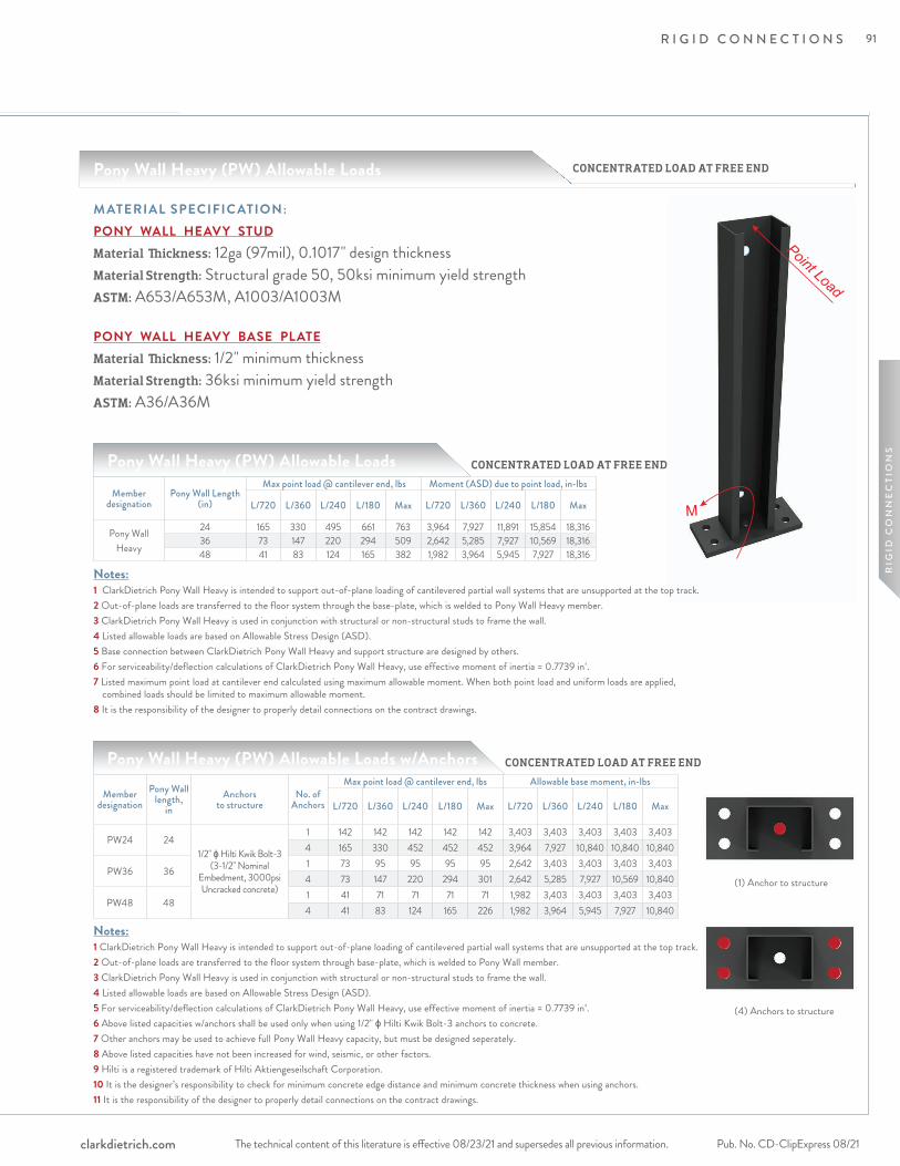
(1) Anchor to structure
(4) Anchors to structure
R I G I D C O N N E C T I O N S
The technical content of this literature is effective 08/23/21 and supersedes all previous information. The technical content of this literature is effective 08/23/21 and supersedes all previous information. Pub. No. CD-ClipExpress 08/21clarkdietrich.com
RIG
ID C
ON
NE
CTI
ON
S
Point Load
MMember
designationPony Wall Length
(in)
Max point load @ cantilever end, lbs Moment (ASD) due to point load, in-lbs
L/720 L/360 L/240 L/180 Max L/720 L/360 L/240 L/180 Max
Pony Wall Heavy
24 165 330 495 661 763 3,964 7,927 11,891 15,854 18,31636 73 147 220 294 509 2,642 5,285 7,927 10,569 18,31648 41 83 124 165 382 1,982 3,964 5,945 7,927 18,316
Notes:1 ClarkDietrich Pony Wall Heavy is intended to support out-of-plane loading of cantilevered partial wall systems that are unsupported at the top track.2 Out-of-plane loads are transferred to the floor system through the base-plate, which is welded to Pony Wall Heavy member.3 ClarkDietrich Pony Wall Heavy is used in conjunction with structural or non-structural studs to frame the wall.4 Listed allowable loads are based on Allowable Stress Design (ASD).5 Base connection between ClarkDietrich Pony Wall Heavy and support structure are designed by others.6 For serviceability/deflection calculations of ClarkDietrich Pony Wall Heavy, use effective moment of inertia = 0.7739 in4.7 Listed maximum point load at cantilever end calculated using maximum allowable moment. When both point load and uniform loads are applied, combined loads should be limited to maximum allowable moment.8 It is the responsibility of the designer to properly detail connections on the contract drawings.
Pony Wall Heavy (PW) Allowable Loads
M ATERIAL SPECIFIC ATION:PONY WALL HEAVY STUDMaterial Thickness: 12ga (97mil), 0.1017" design thickness Material Strength: Structural grade 50, 50ksi minimum yield strengthASTM: A653/A653M, A1003/A1003M
PONY WALL HEAVY BASE PLATEMaterial Thickness: 1/2" minimum thickness Material Strength: 36ksi minimum yield strengthASTM: A36/A36M
Member designation
Pony Wall length,
inAnchors
to structureNo. of
Anchors
Max point load @ cantilever end, lbs Allowable base moment, in-lbs
L/720 L/360 L/240 L/180 Max L/720 L/360 L/240 L/180 Max
PW24 241/2" ɸ Hilti Kwik Bolt-3
(3-1/2" Nominal Embedment, 3000psi Uncracked concrete)
1 142 142 142 142 142 3,403 3,403 3,403 3,403 3,4034 165 330 452 452 452 3,964 7,927 10,840 10,840 10,840
PW36 361 73 95 95 95 95 2,642 3,403 3,403 3,403 3,4034 73 147 220 294 301 2,642 5,285 7,927 10,569 10,840
PW48 481 41 71 71 71 71 1,982 3,403 3,403 3,403 3,4034 41 83 124 165 226 1,982 3,964 5,945 7,927 10,840
Notes:1 ClarkDietrich Pony Wall Heavy is intended to support out-of-plane loading of cantilevered partial wall systems that are unsupported at the top track.2 Out-of-plane loads are transferred to the floor system through base-plate, which is welded to Pony Wall member.3 ClarkDietrich Pony Wall Heavy is used in conjunction with structural or non-structural studs to frame the wall.4 Listed allowable loads are based on Allowable Stress Design (ASD).5 For serviceability/deflection calculations of ClarkDietrich Pony Wall Heavy, use effective moment of inertia = 0.7739 in4.6 Above listed capacities w/anchors shall be used only when using 1/2" ɸ Hilti Kwik Bolt-3 anchors to concrete. 7 Other anchors may be used to achieve full Pony Wall Heavy capacity, but must be designed seperately.8 Above listed capacities have not been increased for wind, seismic, or other factors.9 Hilti is a registered trademark of Hilti Aktiengeseilschaft Corporation.10 It is the designer’s responsibility to check for minimum concrete edge distance and minimum concrete thickness when using anchors.11 It is the responsibility of the designer to properly detail connections on the contract drawings.
CONCENTRATED LOAD AT FREE END
CONCENTRATED LOAD AT FREE END
CONCENTRATED LOAD AT FREE ENDPony Wall Heavy (PW) Allowable Loads
Pony Wall Heavy (PW) Allowable Loads w/Anchors
91
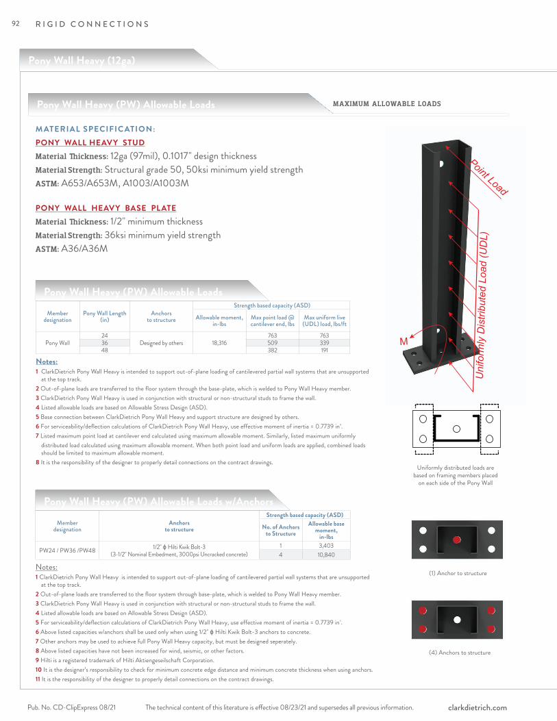
R I G I D C O N N E C T I O N S
The technical content of this literature is effective 08/23/21 and supersedes all previous information.Pub. No. CD-ClipExpress 08/21 clarkdietrich.com
Pony Wall Heavy (12ga)
Member designation
Pony Wall Length (in)
Anchors to structure
Strength based capacity (ASD)
Allowable moment, in-lbs
Max point load @ cantilever end, lbs
Max uniform live (UDL) load, lbs/ft
Pony Wall24
Designed by others 18,316763 763
36 509 33948 382 191
Notes:1 ClarkDietrich Pony Wall Heavy is intended to support out-of-plane loading of cantilevered partial wall systems that are unsupported at the top track.2 Out-of-plane loads are transferred to the floor system through the base-plate, which is welded to Pony Wall Heavy member.3 ClarkDietrich Pony Wall Heavy is used in conjunction with structural or non-structural studs to frame the wall.4 Listed allowable loads are based on Allowable Stress Design (ASD).5 Base connection between ClarkDietrich Pony Wall Heavy and support structure are designed by others.6 For serviceability/deflection calculations of ClarkDietrich Pony Wall Heavy, use effective moment of inertia = 0.7739 in4.7 Listed maximum point load at cantilever end calculated using maximum allowable moment. Similarly, listed maximum uniformly distributed load calculated using maximum allowable moment. When both point load and uniform loads are applied, combined loads should be limited to maximum allowable moment.8 It is the responsibility of the designer to properly detail connections on the contract drawings.
Pony Wall Heavy (PW) Allowable Loads
M ATERIAL SPECIFIC ATION:PONY WALL HEAVY STUDMaterial Thickness: 12ga (97mil), 0.1017" design thickness Material Strength: Structural grade 50, 50ksi minimum yield strengthASTM: A653/A653M, A1003/A1003M
PONY WALL HEAVY BASE PLATEMaterial Thickness: 1/2" minimum thickness Material Strength: 36ksi minimum yield strengthASTM: A36/A36M
Member designation
Anchors to structure
Strength based capacity (ASD)
No. of Anchors to Structure
Allowable base moment,
in-lbs
PW24 / PW36 /PW48 1/2" ɸ Hilti Kwik Bolt-3 (3-1/2" Nominal Embedment, 3000psi Uncracked concrete)
1 3,4034 10,840
Pony Wall Heavy (PW) Allowable Loads w/Anchors
Notes:1 ClarkDietrich Pony Wall Heavy is intended to support out-of-plane loading of cantilevered partial wall systems that are unsupported at the top track.2 Out-of-plane loads are transferred to the floor system through base-plate, which is welded to Pony Wall Heavy member.3 ClarkDietrich Pony Wall Heavy is used in conjunction with structural or non-structural studs to frame the wall.4 Listed allowable loads are based on Allowable Stress Design (ASD).5 For serviceability/deflection calculations of ClarkDietrich Pony Wall Heavy, use effective moment of inertia = 0.7739 in4.6 Above listed capacities w/anchors shall be used only when using 1/2" ɸ Hilti Kwik Bolt-3 anchors to concrete. 7 Other anchors may be used to achieve full Pony Wall Heavy capacity, but must be designed seperately.8 Above listed capacities have not been increased for wind, seismic, or other factors.9 Hilti is a registered trademark of Hilti Aktiengeseilschaft Corporation.10 It is the designer’s responsibility to check for minimum concrete edge distance and minimum concrete thickness when using anchors.11 It is the responsibility of the designer to properly detail connections on the contract drawings.
Uniformly distributed loads are based on framing members placed
on each side of the Pony Wall
Pony Wall Heavy (PW) Allowable Loads MAXIMUM ALLOWABLE LOADS
Uni
form
ly D
istri
bute
d Lo
ad (U
DL)
Point Load
M
(1) Anchor to structure
(4) Anchors to structure
92

R I G I D C O N N E C T I O N S
The technical content of this literature is effective 08/23/21 and supersedes all previous information. The technical content of this literature is effective 08/23/21 and supersedes all previous information. Pub. No. CD-ClipExpress 08/21clarkdietrich.com
RIG
ID C
ON
NE
CTI
ON
S
Uni
form
ly D
istri
bute
d Lo
ad (U
DL)
M
M ATERIAL SPECIFIC ATION:PONY WALL HEAVY STUDMaterial Thickness: 12ga (97mil), 0.1017" design thickness Material Strength: Structural grade 50, 50ksi minimum yield strengthASTM: A653/A653M, A1003/A1003M
PONY WALL HEAVY BASE PLATEMaterial Thickness: 1/2" minimum thickness Material Strength: 36ksi minimum yield strengthASTM: A36/A36M
Member designation
Pony Wall Length (in)
Uniformly distributed load, lbs/ft Moment (ASD) due to uniform load, in-lbs
L/720 L/360 L/240 L/180 Max L/720 L/360 L/240 L/180 Max
Pony Wall Heavy
24 220 440 661 763 763 5,285 10,569 15,854 18,316 18,31636 65 130 196 261 339 3,523 7,046 10,569 14,093 18,31648 28 55 83 110 191 2,642 5,285 7,927 10,569 18,316
Notes:1 ClarkDietrich Pony Wall Heavy is intended to support out-of-plane loading of cantilevered partial wall systems that are unsupported at the top track.2 Out-of-plane loads are transferred to the floor system through the base-plate, which is welded to Pony Wall member.3 ClarkDietrich Pony Wall Heavy is used in conjunction with structural or non-structural studs to frame the wall.4 Listed allowable loads are based on Allowable Stress Design (ASD).5 Base connection between ClarkDietrich Pony Wall Heavy and support structure are designed by others.6 For serviceability/deflection calculations of ClarkDietrich Pony Wall Heavy, use effective moment of inertia = 0.7739 in4.7 Listed maximum point load at cantilever end calculated using maximum allowable moment. When both point load and uniform loads are applied, combined loads should be limited to maximum allowable moment.8 It is the responsibility of the designer to properly detail connections on the contract drawings.
Pony Wall Heavy (PW) Allowable Loads
Member designation
Pony Wall length,
inAnchors
to structureNo. of
Anchors
Uniformly distributed loads, lbs/ft Allowable base moment, in-lbs
L/720 L/360 L/240 L/180 Max L/720 L/360 L/240 L/180 Max
PW24 241/2" ɸ Hilti Kwik Bolt-3
(3-1/2" Nominal Embedment, 3000psi Uncracked concrete)
1 142 142 142 142 142 3,403 3,403 3,403 3,403 3,4034 165 330 452 452 452 3,964 7,927 10,840 10,840 10,840
PW36 361 73 95 95 95 95 2,642 3,403 3,403 3,403 3,4034 73 147 220 294 301 2,642 5,285 7,927 10,569 10,840
PW48 481 41 71 71 71 71 1,982 3,403 3,403 3,403 3,4034 41 83 124 165 226 1,982 3,964 5,945 7,927 10,840
Pony Wall Heavy (PW) Allowable Loads w/Anchors
Notes:1 ClarkDietrich Pony Wall Heavy is intended to support out-of-plane loading of cantilevered partial wall systems that are unsupported at the top track.2 Out-of-plane loads are transferred to the floor system through base-plate, which is welded to Pony Wall Heavy member.3 ClarkDietrich Pony Wall Heavy is used in conjunction with structural or non-structural studs to frame the wall.4 Listed allowable loads are based on Allowable Stress Design (ASD).5 For serviceability/deflection calculations of ClarkDietrich Pony Wall Heavy, use effective moment of inertia = 0.7739 in4.6 Above listed capacities w/anchors shall be used only when using 1/2" ɸ Hilti Kwik Bolt-3 anchors to concrete. 7 Other anchors may be used to achieve full Pony Wall capacity, but must be designed seperately.8 Above listed capacities have not been increased for wind, seismic, or other factors.9 Hilti is a registered trademark of Hilti Aktiengeseilschaft Corporation.10 It is the designer’s responsibility to check for minimum concrete edge distance and minimum concrete thickness when using anchors.11 It is the responsibility of the designer to properly detail connections on the contract drawings.
UNIFORMLY DISTRIBUTED LOAD
UNIFORMLY DISTRIBUTED LOAD
UNIFORMLY DISTRIBUTED LOAD
Pony Wall Heavy (PW) Allowable Loads
Uniformly distributed loads are based on framing members placed
on each side of the Pony Wall
(1) Anchor to structure
(4) Anchors to structure
93
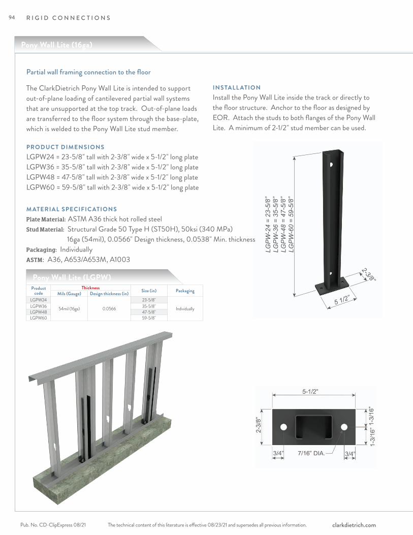
R I G I D C O N N E C T I O N S
The technical content of this literature is effective 08/23/21 and supersedes all previous information.Pub. No. CD-ClipExpress 08/21 clarkdietrich.com
LGP
W-2
4 =
23-5
/8”
LGP
W-3
6 =
35-5
/8”
LGP
W-4
8 =
47-5
/8”
LGP
W-6
0 =
59-5
/8”
5 1/2”
2-3/8”
Partial wall framing connection to the floor
Pony Wall Lite (16ga)
INSTALL ATIONInstall the Pony Wall Lite inside the track or directly to the floor structure. Anchor to the floor as designed by EOR. Attach the studs to both flanges of the Pony Wall Lite. A minimum of 2-1/2" stud member can be used.
M ATERIAL SPECIFIC ATIONSPlate Material: ASTM A36 thick hot rolled steelStud Material: Structural Grade 50 Type H (ST50H), 50ksi (340 MPa) 16ga (54mil), 0.0566" Design thickness, 0.0538" Min. thicknessPackaging: Individually ASTM: A36, A653/A653M, A1003
The ClarkDietrich Pony Wall Lite is intended to support out-of-plane loading of cantilevered partial wall systems that are unsupported at the top track. Out-of-plane loads are transferred to the floor system through the base-plate, which is welded to the Pony Wall Lite stud member.
PRODUC T DIMENSIONSLGPW24 = 23-5/8" tall with 2-3/8" wide x 5-1/2" long plate LGPW36 = 35-5/8" tall with 2-3/8" wide x 5-1/2" long plate LGPW48 = 47-5/8" tall with 2-3/8" wide x 5-1/2" long plate LGPW60 = 59-5/8" tall with 2-3/8" wide x 5-1/2" long plate
Pony Wall Lite (LGPW)Product
codeThickness Size (in) PackagingMils (Gauge) Design thickness (in)
LGPW24
54mil (16ga) 0.0566
23-5/8"
IndividuallyLGPW36 35-5/8"LGPW48 47-5/8"LGPW60 59-5/8"
94

R I G I D C O N N E C T I O N S
The technical content of this literature is effective 08/23/21 and supersedes all previous information. The technical content of this literature is effective 08/23/21 and supersedes all previous information. Pub. No. CD-ClipExpress 08/21clarkdietrich.com
RIG
ID C
ON
NE
CTI
ON
S
Member designation
Pony Wall Length (in)
Max point load @ cantilever end, lbs Moment (ASD) due to point load, in-lbs
L/240 L/180 Max L/240 L/180 Max
Pony Wall LIte
24 86 115 177 2074 2766 425336 38 51 118 1383 1844 425348 22 29 89 1037 1383 425360 14 18 71 830 1106 4253
Notes:1 Pony Wall Lite is intended to support out-of-plane loading of cantilevered partial wall systems that are unsupported at the top track.2 Out-of-plane loads are transferred to the floor system through the base-plate, which is welded to Pony Wall Lite member.3 Pony Wall Lite may be used in place of standard framing members, or in conjunction with them to frame the wall.4 Listed allowable loads are based on Allowable Stress Design (ASD).5 Base connection between Pony Wall Lite and support structure are designed by others.6 For serviceability/deflection calculations of Pony Wall Lite, use effective moment of inertia = 0.1350 in4 (54mil), 0.1626in4 (68mil)7 Listed maximum point load @ cantilever end calculated using maximum allowable moment. When both point load and uniform loads are applied, combined loads should be limited to maximum allowable moment.8 It is the responsibility of the designer to properly detail connections on the contract drawings.
Pony Wall Lite (LGPW) Allowable Loads
M ATERIAL SPECIFIC ATION:PONY WALL LITE STUDMaterial Thickness: 16ga (54mil), 0.0566" design thickness Material Strength: Structural grade 50, 50ksi minimum yield strengthASTM: A653/A653M, A1003/A1003M
PONY WALL LITE BASE PLATEMaterial Thickness: 3/8" minimum thickness Material Strength: 36ksi minimum yield strengthASTM: A36/A36M
Member designation
Pony Wall length,
in
Anchors to structure
No. of Anchors
Max point load @ cantilever end, lbs Allowable base moment, in-lbs
L/240 L/180 Max L/240 L/180 MaxLGPW24 24
3/8" ɸ Hilti Kwik Bolt-3 (2-3/8" Nominal Embedment, 3000psi Uncracked concrete)
2
83 83 83 1984 1984 1984LGPW36 36 38 51 55 1383 1844 1984LGPW48 48 22 29 41 1037 1383 1984LGPW60 60 14 18 33 830 1106 1984
Pony Wall Lite (LGPW) Allowable Loads w/Anchors
Notes:1 Pony Wall Lite is intended to support out-of-plane loading of cantilevered partial wall systems that are unsupported at the top track.2 Out-of-plane loads are transferred to the floor system through base-plate, which is welded to Pony Wall Lite member.3 Pony Wall Lite may be used in place of standard framing members, or in conjunction with them to frame the wall.4 Listed allowable loads are based on Allowable Stress Design (ASD).5 For serviceability/deflection calculations of Pony Wall Lite, use effective moment of inertia = 0.1350 in4 (54mil), 0.1626in4 (68mil)6 Above listed capacities w/anchors shall be used only when using 3/8" ɸ Hilti Kwik Bolt-3 anchors to concrete.7 Other anchors may be used to achieve full Pony Wall Lite capacity, but must be designed separately.8 Above listed capacities have not been increased for wind, seismic, or other factors.9 Hilti is a registered trademark of Hilti Aktiengeseilschaft Corporation.10 It is the designer’s responsibility to check for minimum concrete edge distance and minimum concrete thickness when using anchors.11 It is the responsibility of the designer to properly detail connections on the contract drawings.
CONCENTRATED LOAD AT FREE END
CONCENTRATED LOAD AT FREE END
CONCENTRATED LOAD AT FREE ENDPony Wall Lite (LGPW) Allowable Loads
(2) Anchors to structure
RIG
ID C
ON
NE
CTI
ON
S
95

R I G I D C O N N E C T I O N S
The technical content of this literature is effective 08/23/21 and supersedes all previous information.Pub. No. CD-ClipExpress 08/21 clarkdietrich.com
Pony Wall Lite (16ga)
Member designation
Pony Wall Length (in)
Anchors to structure
Strength based capacity (ASD)Allowable moment,
in-lbsMax point load
@ cantilever end, lbsMax uniform live
(UDL) load, lbs/ft
Pony Wall Lite
24Designed by others 4253
177 17736 118 7948 89 4460 71 28
Notes:1 Pony Wall Lite is intended to support out-of-plane loading of cantilevered partial wall systems that are unsupported at the top track.2 Out-of-plane loads are transferred to the floor system through the base-plate, which is welded to Pony Wall Lite member.3 Pony Wall Lite may be used in place of standard framing members, or in conjunction with them to frame the wall.4 Listed allowable loads are based on Allowable Stress Design (ASD).5 Base connection between Pony Wall Lite and support structure are designed by others.6 For serviceability/deflection calculations of Pony Wall Lite, use effective moment of inertia = 0.1350 in4 (54mil), 0.1626in4 (68mil)7 Listed maximum point load @ cantilever end calculated using maximum allowable moment. Similarly, listed maximum uniformly distributed load calculated using maximum allowable moment. When both point load and uniform loads are applied, combined loads should be limited to maximum allowable moment.8 It is the responsibility of the designer to properly detail connections on the contract drawings.
Pony Wall Lite (LGPW) Allowable Loads
M ATERIAL SPECIFIC ATION:PONY WALL LITE STUDMaterial Thickness: 16ga (54mil), 0.0566" design thickness Material Strength: Structural grade 50, 50ksi minimum yield strengthASTM: A653/A653M, A1003/A1003M
PONY WALL LITE BASE PLATEMaterial Thickness: 3/8" minimum thickness Material Strength: 36ksi minimum yield strengthASTM: A36/A36M
Member designation Anchors to structureStrength based capacity (ASD)
No. of Anchors to Structure
Allowable base moment, in-lbs
LGPW24, LGPW36, LGPW48, LGPW603/8" ɸ Hilti Kwik Bolt-3
(2-3/8" Nominal Embedment, 3000psi Uncracked concrete)
2 1984
Pony Wall Lite (LGPW) Allowable Loads w/Anchors
Notes:1 Pony Wall Lite is intended to support out-of-plane loading of cantilevered partial wall systems that are unsupported at the top track.2 Out-of-plane loads are transferred to the floor system through base-plate, which is welded to Pony Wall Lite member.3 Pony Wall Lite may be used in place of standard framing members, or in conjunction with them to frame the wall.4 Listed allowable loads are based on Allowable Stress Design (ASD).5 For serviceability/deflection calculations of Pony Wall Lite, use effective moment of inertia = 0.1350 in4 (54mil), 0.1626in4 (68mil)6 Above listed capacities w/anchors shall be used only when using 3/8" ɸ Hilti Kwik Bolt-3 anchors to concrete.7 Other anchors may be used to achieve full Pony Wall Lite capacity, but must be designed separately.8 Above listed capacities have not been increased for wind, seismic, or other factors.9 Hilti is a registered trademark of Hilti Aktiengeseilschaft Corporation.10 It is the designer’s responsibility to check for minimum concrete edge distance and minimum concrete thickness when using anchors.11 It is the responsibility of the designer to properly detail connections on the contract drawings.
Uniformly distributed loads are based on framing members placed
on each side of the Pony Wall
Pony Wall Lite (LGPW) Allowable Loads MAXIMUM ALLOWABLE LOADS
(2) Anchors to structure
96

R I G I D C O N N E C T I O N S
The technical content of this literature is effective 08/23/21 and supersedes all previous information. The technical content of this literature is effective 08/23/21 and supersedes all previous information. Pub. No. CD-ClipExpress 08/21clarkdietrich.com
RIG
ID C
ON
NE
CTI
ON
S
M ATERIAL SPECIFIC ATION:PONY WALL LITE STUDMaterial Thickness: 16ga (54mil), 0.0566" design thickness Material Strength: Structural grade 50, 50ksi minimum yield strengthASTM: A653/A653M, A1003/A1003M
PONY WALL LITE BASE PLATEMaterial Thickness: 3/8" minimum thickness Material Strength: 36ksi minimum yield strengthASTM: A36/A36M
Member designation
Pony Wall Length (in)
Uniformly distributed load, lbs/ft Moment (ASD) due to uniform load, in-lbs
L/240 L/180 Max L/240 L/180 Max
Pony Wall Lite
24 115 154 177 2766 3688 425336 34 46 79 1844 2458 425348 14 19 44 1383 1844 425360 7 10 28 1106 1475 4253
Notes:1 Pony Wall Lite is intended to support out-of-plane loading of cantilevered partial wall systems that are unsupported at the top track.2 Out-of-plane loads are transferred to the floor system through the base-plate, which is welded to Pony Wall Lite member.3 Pony Wall Lite may be used in place of standard framing members, or in conjunction with them to frame the wall.4 Listed allowable loads are based on Allowable Stress Design (ASD).5 Base connection between Pony Wall Lite and support structure are designed by others.6 For serviceability/deflection calculations of Pony Wall Lite, use effective moment of inertia = 0.1350 in4 (54mil), 0.1626in4 (68mil)7 Listed maximum uniformly distributed load calculated using maximum allowable moment. When both point load and uniform loads are applied, combined loads should be limited to maximum allowable moment.8 It is the responsibility of the designer to properly detail connections on the contract drawings.
Pony Wall Lite (LGPW) Allowable Loads
Member designation
Pony Wall length,
in
Anchors to structure
No. of Anchors
Uniformly distributed loads, lbs/ft Allowable base moment, in-lbs
L/240 L/180 Max L/240 L/180 MaxLGPW24 24
3/8" ɸ Hilti Kwik Bolt-3 (2-3/8" Nominal Embedment, 3000psi Uncracked concrete)
2
83 83 83 1984 1984 1984LGPW36 36 34 37 37 1844 1984 1984LGPW48 48 14 19 21 1383 1844 1984LGPW60 60 7 10 13 1106 1475 1984
Notes:1 Pony Wall Lite is intended to support out-of-plane loading of cantilevered partial wall systems that are unsupported at the top track.2 Out-of-plane loads are transferred to the floor system through base-plate, which is welded to Pony Wall Lite member.3 Pony Wall Lite may be used in place of standard framing members, or in conjunction with them to frame the wall.4 Listed allowable loads are based on Allowable Stress Design (ASD).5 For serviceability/deflection calculations of Pony Wall Lite, use effective moment of inertia = 0.1350 in4 (54mil), 0.1626in4 (68mil)6 Above listed capacities w/anchors shall be used only when using 3/8" ɸ Hilti Kwik Bolt-3 anchors to concrete.7 Other anchors may be used to achieve full Pony Wall Lite capacity, but must be designed separately.8 Above listed capacities have not been increased for wind, seismic, or other factors.9 Hilti is a registered trademark of Hilti Aktiengeseilschaft Corporation.10 It is the designer’s responsibility to check for minimum concrete edge distance and minimum concrete thickness when using anchors.11 It is the responsibility of the designer to properly detail connections on the contract drawings.
UNIFORMLY DISTRIBUTED LOAD
UNIFORMLY DISTRIBUTED LOAD
UNIFORMLY DISTRIBUTED LOAD
Pony Wall Lite (LGPW) Allowable Loads
Uniformly distributed loads are based on framing members placed
on each side of the Pony WallPony Wall Lite (LGPW) Allowable Loads w/Anchors
(2) Anchors to structure
RIG
ID C
ON
NE
CTI
ON
S
97
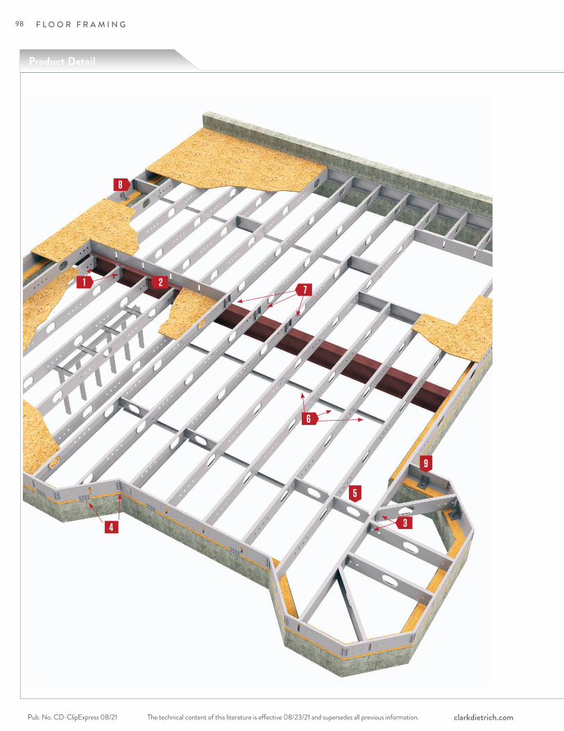
F L O O R F R A M I N G
The technical content of this literature is effective 08/23/21 and supersedes all previous information.Pub. No. CD-ClipExpress 08/21 clarkdietrich.com
6
27
3
Product Detail
4
1
5
9
8
98

F L O O R F R A M I N G
The technical content of this literature is effective 08/23/21 and supersedes all previous information. The technical content of this literature is effective 08/23/21 and supersedes all previous information. Pub. No. CD-ClipExpress 08/21clarkdietrich.com
FLO
OR
JO
IST
FR
AM
ING
CO
NN
EC
TIO
NS
Bridle Hangerpages 100-101
TradeReady® Rim Track Splice Platepages 106–107
EasyClip E-Series™ Support Clippages 112–113
Universal Joist Hangerpages 102–104
EasyClip™ QuickTwist™ Web Stiffenerpages 110–111
Skewable Anglepage 105
1 6
2 7
3 8
4
5 TradeReady® Floor Joist Blockingpage 108
9 Custom Fabricated Clips & Connectionspages 4–5
TradeReady® Structural Bridgingpage 109
99
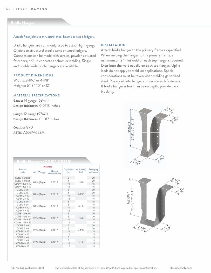
F L O O R F R A M I N G
The technical content of this literature is effective 08/23/21 and supersedes all previous information.Pub. No. CD-ClipExpress 08/21 clarkdietrich.com
Attach floor joists to structural steel beams or wood ledgers.
Bridle Hanger
Bridle hangers are commonly used to attach light-gauge C-joists to structural steel beams or wood ledgers. Connections can be made with screws, powder-actuated fasteners, drill-in concrete anchors or welding. Single- and double-wide bridle hangers are available.
PRODUC T DIMENSIONSWidths: 2-1/16" or 4-1/8" Heights: 6", 8", 10" or 12"
M ATERIAL SPECIFIC ATIONSGauge: 14 gauge (68mil) Design Thickness: 0.0713 inches
Gauge: 12 gauge (97mil)Design Thickness: 0.1017 inches
Coating: G90ASTM: A653/A653M
INSTALL ATIONAttach bridle hanger to the primary frame as specified. When welding the hanger to the primary frame, a minimum of 2" fillet weld on each top flange is required. Distribute the weld equally on both top flanges. Uplift loads do not apply to weld-on applications. Special considerations must be taken when welding galvanized steel. Place joist into hanger and secure with fasteners. If bridle hanger is less than beam depth, provide back blocking.
2 1/16”2 7/8”
6”, 8
”, 10
” &
12”
HE
IGH
T
2 1/2”
2 1/2”
4 1/8”2 7/8”
6”, 8
”, 10
” &
12”
HE
IGH
T
2 1/2”
2 1/2”
Bridle Hangers (CDBV, CDMB)
Product code
ThicknessDepth (H)
(in)Width (W)
(in)Packaging
Pcs./CartonMils (Gauge) Design thickness (in)
CDBV 1-5/8 x 6
68mil (14ga) 0.0713
6
1-5/8
20CDBV 1-5/8 x 8 8 20CDBV 1-5/8 x 10 10 15CDBV 1-5/8 x 12 12 15
CDBV 2 x 6
68mil (14ga) 0.0713
6
2-1/16
20CDBV 2 x 8 8 20CDBV 2 x 10 10 15CDBV 2 x 12 12 15CDBV 4 x 6
68mil (14ga) 0.0713
6
4-1/8
15CDBV 4 x 8 8 15CDBV 4 x 10 10 15CDBV 4 x 12 12 15
CDMB 1-5/8 x 6
97mil (12ga) 0.1017
6
1-5/8
20CDMB 1-5/8 x 8 8 20CDMB 1-5/8 x 10 10 15CDMB 1-5/8 x 12 12 15
CDMB 2 x 6
97mil (12ga) 0.1017
6
2-1/16
20CDMB 2 x 8 8 20CDMB 2 x 10 10 15CDMB 2 x 12 12 15CDMB 4 x 6
97mil (12ga) 0.1017
6
4-1/8
15CDMB 4 x 8 8 15CDMB 4 x 10 10 15CDMB 4 x 12 12 15
100

F L O O R F R A M I N G
The technical content of this literature is effective 08/23/21 and supersedes all previous information. The technical content of this literature is effective 08/23/21 and supersedes all previous information. Pub. No. CD-ClipExpress 08/21clarkdietrich.com
FLO
OR
JO
IST
FR
AM
ING
CO
NN
EC
TIO
NS
Product code
Member Designation (in) Screw Configuration / Hanger ASD Loads (lb)
Width HeightHeader Joist
Uplift DownFlange Web Web
CDBV 68mil (14ga)
1-11/16"
6 (6) #10 (4) #12 (2) #12 1146 14438 (6) #10 (6) #12 (3) #12 1929 219310 (6) #10 (8) #12 (4) #12 2314 262012 (6) #10 (10) #12 (5) #12 2873 33196
(4) x 2" fillet weld [each side of top flange]
(2) #12 ‒ 15548 (3) #12 ‒ 208910 (4) #12 ‒ 208912 (5) #12 ‒ 2089
2-1/16"
6 (6) #10 (4) #12 (2) #12 1146 14438 (6) #10 (6) #12 (3) #12 1929 219310 (6) #10 (8) #12 (4) #12 2314 262012 (6) #10 (10) #12 (5) #12 2873 33196
(4) x 2" fillet weld [each side of top flange]
(2) #12 ‒ 15548 (3) #12 ‒ 208910 (4) #12 ‒ 208912 (5) #12 ‒ 2089
4-1/8"
6 (6) #10 (4) #12 (4) #12 2293 28868 (6) #10 (6) #12 (6) #12 3699 419710 (6) #10 (8) #12 (8) #12 4629 523912 (6) #10 (10) #12 (10) #12 5025 60546
(4) x 2" fillet weld [each side of top flange]
(4) #12 ‒ 31088 (6) #12 ‒ 377110 (8) #12 ‒ 505512 (10) #12 ‒ 5104
CDMB 97mil (12ga)
1-11/16"
6 (6) #10 (4) #14 (2) #14 1545 20328 (6) #10 (6) #14 (3) #14 2370 268710 (6) #10 (8) #14 (4) #14 3166 347412 (6) #10 (10) #14 (5) #14 3927 49506
(4) x 2" fillet weld [each side of top flange]
(2) #14 ‒ 20328 (3) #14 ‒ 246210 (4) #14 ‒ 299312 (5) #14 ‒ 2993
2-1/16"
6 (6) #10 (4) #14 (2) #14 1545 20328 (6) #10 (6) #14 (3) #14 2370 268710 (6) #10 (8) #14 (4) #14 3166 347412 (6) #10 (10) #14 (5) #14 3927 49506
(4) x 2" fillet weld [each side of top flange]
(2) #14 ‒ 20328 (3) #14 ‒ 246210 (4) #14 ‒ 299312 (5) #14 ‒ 2993
4-1/8"
6 (6) #10 (4) #14 (4) #14 3090 40648 (6) #10 (6) #14 (6) #14 4332 555810 (6) #10 (8) #14 (8) #14 6332 694912 (6) #10 (10) #14 (10) #14 7771 89486
(4) x 2" fillet weld [each side of top flange]
(4) #14 ‒ 40648 (6) #14 ‒ 478910 (8) #14 ‒ 607812 (10) #14 ‒ 6489
Bridle Hangers (CDBV, CDMB)
Notes:1 Screws shall be installed through the pre-drilled holes in the hanger or as detailed by the designer.2 CFS joist shall be laterally braced per designer specification.3 An 1/8" gap shall be maintained between end of the joist and the supporting header.4 CFS header must be braced to prevent web crippling/buckling per designer specification.5 CFS header must have full bearing of 2-1/2" flange-depth.6 The ultimate screw shear strength for #12 screws shall be at least 2330 lbs. 7 The ultimate screw shear strength for #14 screws shall be at least 3048 lbs.8 The screw shear strength capacities are based on CFSEI Tech Note (F701-12).9 Allowable loads have not been increased for seismic or wind.10 Contact ClarkDietrich Engineering Services for technical assistance.
101
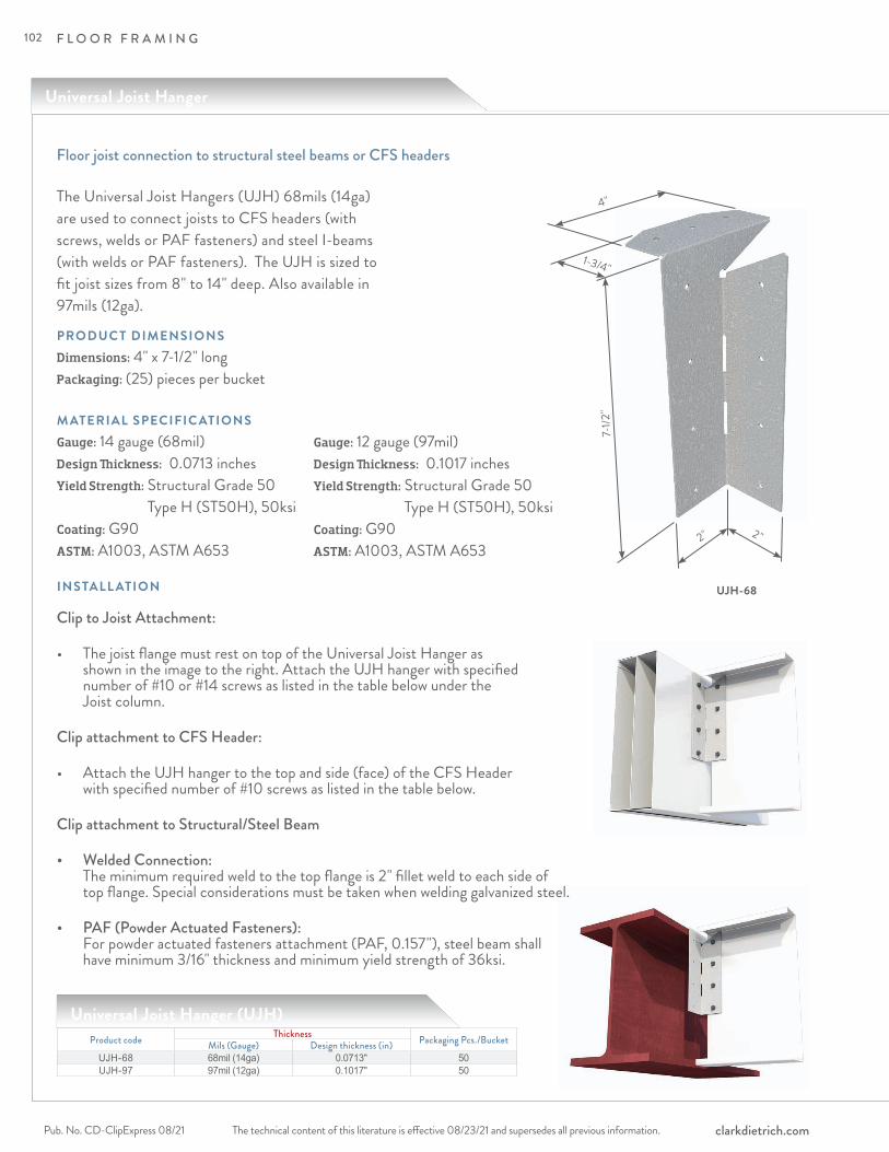
F L O O R F R A M I N G
The technical content of this literature is effective 08/23/21 and supersedes all previous information.Pub. No. CD-ClipExpress 08/21 clarkdietrich.com
Universal Joist Hanger
Floor joist connection to structural steel beams or CFS headers
INSTALL ATION Clip to Joist Attachment:
• The joist flange must rest on top of the Universal Joist Hanger as shown in the image to the right. Attach the UJH hanger with specified number of #10 or #14 screws as listed in the table below under the Joist column.
Clip attachment to CFS Header:
• Attach the UJH hanger to the top and side (face) of the CFS Header with specified number of #10 screws as listed in the table below.
Clip attachment to Structural/Steel Beam
• Welded Connection: The minimum required weld to the top flange is 2" fillet weld to each side of top flange. Special considerations must be taken when welding galvanized steel.
• PAF (Powder Actuated Fasteners): For powder actuated fasteners attachment (PAF, 0.157"), steel beam shall have minimum 3/16" thickness and minimum yield strength of 36ksi.
PRODUC T DIMENSIONSDimensions: 4" x 7-1/2" longPackaging: (25) pieces per bucket
M ATERIAL SPECIFIC ATIONSGauge: 14 gauge (68mil)Design Thickness: 0.0713 inchesYield Strength: Structural Grade 50
Type H (ST50H), 50ksiCoating: G90ASTM: A1003, ASTM A653
UJH-68
1-3/4"
7-1/2
"
4"
2" 2"
The Universal Joist Hangers (UJH) 68mils (14ga) are used to connect joists to CFS headers (with screws, welds or PAF fasteners) and steel I-beams (with welds or PAF fasteners). The UJH is sized to fit joist sizes from 8" to 14" deep. Also available in 97mils (12ga).
Gauge: 12 gauge (97mil)Design Thickness: 0.1017 inchesYield Strength: Structural Grade 50
Type H (ST50H), 50ksiCoating: G90ASTM: A1003, ASTM A653
Product code Thickness Packaging Pcs./BucketMils (Gauge) Design thickness (in)UJH-68 68mil (14ga) 0.0713" 50UJH-97 97mil (12ga) 0.1017" 50
Universal Joist Hanger (UJH)
102
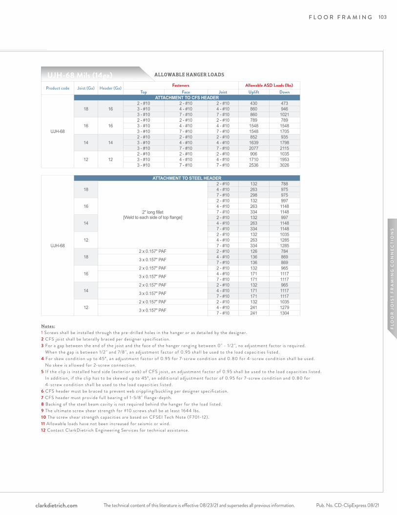
F L O O R F R A M I N G
The technical content of this literature is effective 08/23/21 and supersedes all previous information. The technical content of this literature is effective 08/23/21 and supersedes all previous information. Pub. No. CD-ClipExpress 08/21clarkdietrich.com
FLO
OR
JO
IST
FR
AM
ING
CO
NN
EC
TIO
NS
ALLOWABLE HANGER LOADS
Product code Joist (Ga) Header (Ga) Fasteners Allowable ASD Loads (lbs)Top Face Joist Uplift Down
UJH-68
ATTACHMENT TO CFS HEADER
18 162 - #10 2 - #10 2 - #10 430 4733 - #10 4 - #10 4 - #10 860 9463 - #10 7 - #10 7 - #10 860 1021
16 162 - #10 2 - #10 2 - #10 789 7893 - #10 4 - #10 4 - #10 1548 15483 - #10 7 - #10 7 - #10 1548 1705
14 142 - #10 2 - #10 2 - #10 852 9353 - #10 4 - #10 4 - #10 1639 17983 - #10 7 - #10 7 - #10 2077 2115
12 122 - #10 2 - #10 2 - #10 906 10353 - #10 4 - #10 4 - #10 1710 19533 - #10 7 - #10 7 - #10 2536 3026
UJH-68 Mils (14ga)
Notes:1 Screws shall be installed through the pre-drilled holes in the hanger or as detailed by the designer.2 CFS joist shall be laterally braced per designer specification.3 For a gap between the end of the joist and the face of the hanger ranging between 0" - 1/2 ", no adjustment factor is required. When the gap is between 1/2 " and 7/8", an adjustment factor of 0.95 shal l be used to the load capacit ies l isted.4 For skew condit ion up to 45°, an adjustment factor of 0.95 for 7-screw condit ion and 0.80 for 4-screw condit ion shal l be used. No skew is a l lowed for 2-screw connection. 5 If the cl ip is instal led hard s ide (exter ior web) of CFS joist , an adjustment factor of 0.95 shal l be used to the load capacit ies l isted. In addit ion, i f the cl ip has to be skewed up to 45°, an addit ional adjustment factor of 0.95 for 7-screw condit ion and 0.80 for 4-screw condit ion shal l be used to the load capacit ies l isted.6 CFS header must be braced to prevent web crippling/buckling per designer specification.7 CFS header must provide full bearing of 1-5/8" flange-depth.8 Backing of the steel beam cavity is not required behind the hanger for the load listed.9 The ultimate screw shear strength for #10 screws shall be at least 1644 lbs. 10 The screw shear strength capacities are based on CFSEI Tech Note (F701-12).11 Allowable loads have not been increased for seismic or wind.12 Contact ClarkDietrich Engineering Services for technical assistance.
UJH-68
ATTACHMENT TO STEEL HEADER
18
2" long fillet [Weld to each side of top flange]
2 - #10 132 7884 - #10 263 9757 - #10 298 975
162 - #10 132 9974 - #10 263 11487 - #10 334 1148
142 - #10 132 9974 - #10 263 11487 - #10 334 1148
122 - #10 132 10354 - #10 263 12857 - #10 334 1285
182 x 0.157" PAF 2 - #10 126 784
3 x 0.157" PAF 4 - #10 136 8697 - #10 136 869
162 x 0.157" PAF 2 - #10 132 965
3 x 0.157" PAF 4 - #10 171 11177 - #10 171 1117
142 x 0.157" PAF 2 - #10 132 965
3 x 0.157" PAF 4 - #10 171 11177 - #10 171 1117
122 x 0.157" PAF 2 - #10 132 1035
3 x 0.157" PAF 4 - #10 241 12797 - #10 241 1304
103
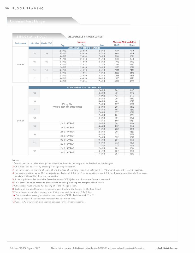
F L O O R F R A M I N G
The technical content of this literature is effective 08/23/21 and supersedes all previous information.Pub. No. CD-ClipExpress 08/21 clarkdietrich.com
ALLOWABLE HANGER LOADS
Product code Joist (Ga) Header (Ga) Fasteners Allowable ASD Loads (lbs)Top Face Joist Uplift Down
UJH-97
ATTACHMENT TO CFS HEADER
18 162 - #10 2 - #10 2 - #14 439 4893 - #10 4 - #10 4 - #14 860 9593 - #10 7 - #14 7 - #14 958 1021
16 162 - #10 2 - #10 2 - #14 940 9403 - #10 4 - #10 4 - #14 1773 17733 - #10 7 - #14 7 - #14 1773 1931
14 142 - #10 2 - #10 2 - #14 1123 13273 - #10 4 - #10 4 - #14 2041 24133 - #10 7 - #14 7 - #14 2388 2445
12 122 - #10 2 - #10 2 - #14 1238 18983 - #10 4 - #10 4 - #14 2135 32733 - #10 7 - #14 7 - #14 4092 4350
UJH-97 Mils (12ga)
Notes:1 Screws shall be installed through the pre-drilled holes in the hanger or as detailed by the designer.2 CFS joist shall be laterally braced per designer specification.3 For a gap between the end of the joist and the face of the hanger ranging between 0" - 7/8", no adjustment factor is required. 4 For skew condit ion up to 45°, an adjustment factor of 0.85 for 7-screw condit ion and 0.90 for 4-screw condit ion shal l be used. No skew is a l lowed for 2-screw connection. 5 If the cl ip is instal led hard s ide (exter ior web) of CFS joist , no adjustment factor is required.6 CFS header must be braced to prevent web crippling/buckling per designer specification.7 CFS header must provide full bearing of 1-5/8" flange-depth.8 Backing of the steel beam cavity is not required behind the hanger for the load listed.9 The ultimate screw shear strength for #14 screws shall be at least 3048 lbs. 10 The screw shear strength capacities are based on CFSEI Tech Note (F701-12).11 Allowable loads have not been increased for seismic or wind.12 Contact ClarkDietrich Engineering Services for technical assistance.
UJH-97
ATTACHMENT TO STEEL HEADER
18
2" long fillet [Weld to each side of top flange]
2 - #14 201 8374 - #14 401 9757 - #14 431 975
162 - #14 201 14724 - #14 401 15707 - #14 577 1696
142 - #14 201 14724 - #14 401 15707 - #14 577 1696
122 - #14 201 16514 - #14 401 17387 - #14 598 1761
182 x 0.157" PAF 2 - #14 201 890
3 x 0.157" PAF 4 - #14 252 8907 - #14 252 890
162 x 0.157" PAF 2 - #14 201 1380
3 x 0.157" PAF 4 - #14 332 16267 - #14 332 1626
142 x 0.157" PAF 2 - #14 201 1380
3 x 0.157" PAF 4 - #14 332 16267 - #14 332 1626
122 x 0.157" PAF 2 - #14 201 1644
3 x 0.157" PAF 4 - #14 367 17307 - #14 367 1812
Universal Joist Hanger
104
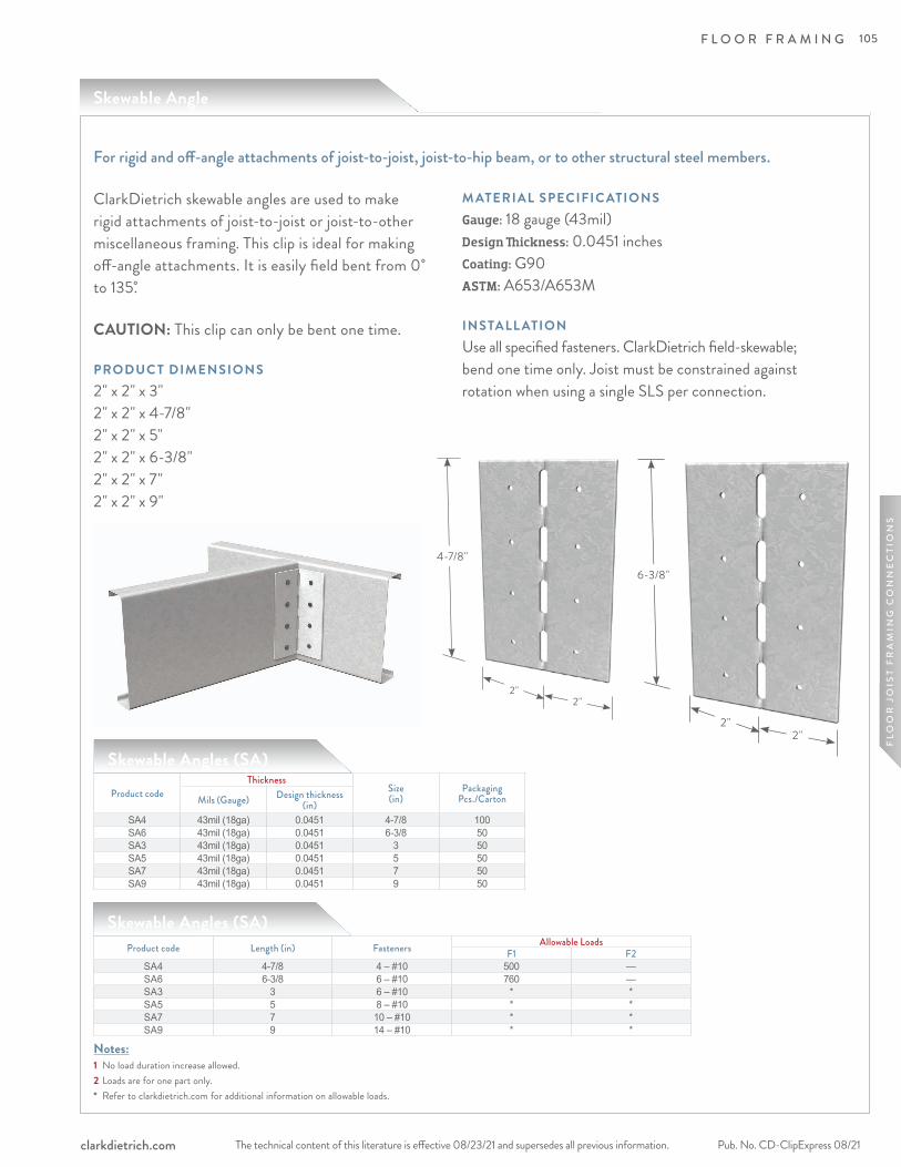
F L O O R F R A M I N G
The technical content of this literature is effective 08/23/21 and supersedes all previous information. The technical content of this literature is effective 08/23/21 and supersedes all previous information. Pub. No. CD-ClipExpress 08/21clarkdietrich.com
FLO
OR
JO
IST
FR
AM
ING
CO
NN
EC
TIO
NS
6-3/8"
2"2"
Skewable Angle
ClarkDietrich skewable angles are used to make rigid attachments of joist-to-joist or joist-to-other miscellaneous framing. This clip is ideal for making off-angle attachments. It is easily field bent from 0˚ to 135.̊
CAUTION: This clip can only be bent one time.
PRODUC T DIMENSIONS2" x 2" x 3"2" x 2" x 4-7/8" 2" x 2" x 5"2" x 2" x 6-3/8" 2" x 2" x 7"2" x 2" x 9"
M ATERIAL SPECIFIC ATIONSGauge: 18 gauge (43mil)Design Thickness: 0.0451 inches Coating: G90ASTM: A653/A653M
INSTALL ATIONUse all specified fasteners. ClarkDietrich field-skewable; bend one time only. Joist must be constrained against rotation when using a single SLS per connection.
Skewable Angles (SA)
Product codeThickness
Size(in)
Packaging Pcs./CartonMils (Gauge) Design thickness
(in)SA4 43mil (18ga) 0.0451 4-7/8 100SA6 43mil (18ga) 0.0451 6-3/8 50SA3 43mil (18ga) 0.0451 3 50SA5 43mil (18ga) 0.0451 5 50SA7 43mil (18ga) 0.0451 7 50SA9 43mil (18ga) 0.0451 9 50
For rigid and off-angle attachments of joist-to-joist, joist-to-hip beam, or to other structural steel members.
2"2"
4-7/8"
Notes:1 No load duration increase allowed.2 Loads are for one part only.* Refer to clarkdietrich.com for additional information on allowable loads.
Product code Length (in) Fasteners Allowable LoadsF1 F2
SA4 4-7/8 4 – #10 500 —SA6 6-3/8 6 – #10 760 —SA3 3 6 – #10 * *SA5 5 8 – #10 * *SA7 7 10 – #10 * *SA9 9 14 – #10 * *
Skewable Angles (SA)
105
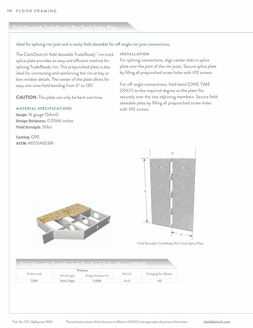
F L O O R F R A M I N G
The technical content of this literature is effective 08/23/21 and supersedes all previous information.Pub. No. CD-ClipExpress 08/21 clarkdietrich.com
The ClarkDietrich field skewable TradeReady® rim track splice plate provides an easy and efficient method for splicing TradeReady rim. This prepunched plate is also ideal for connecting and reinforcing the rim at bay or bow window details. The center of the plate allows for easy one-time field bending from 0˚ to 135.̊
CAUTION: This plate can only be bent one time.
M ATERIAL SPECIFIC ATIONSGauge: 16 gauge (54mil)Design Thickness: 0.0566 inchesYield Strength: 50ksi
Coating: G90 ASTM: A653/A653M
INSTALL ATIONFor splicing connections, align center slots in splice plate over the joint of the rim joists. Secure splice plate by filling all prepunched screw holes with #10 screws.
For off-angle connections, field bend (ONE TIME ONLY) to the required degree so the plate fits securely over the two adjoining members. Secure field skewable plate by filling all prepunched screw holes with #10 screws.
Ideal for splicing rim joist and is easily field skewable for off-angle rim joist connections.
Field Skewable TradeReady® Rim Track Splice Plates (TDSP)
Product codeThickness
Size (in) Packaging Pcs./BucketMils (Gauge) Design thickness (in)
TDSP 54mil (16ga) 0.0566 4 x 6 100
6"
4"
2"
Field Skewable TradeReady Rim Track Splice Plate
Field Skewable TradeReady® Rim Track Splice Plate
106

F L O O R F R A M I N G
The technical content of this literature is effective 08/23/21 and supersedes all previous information. The technical content of this literature is effective 08/23/21 and supersedes all previous information. Pub. No. CD-ClipExpress 08/21clarkdietrich.com
FLO
OR
JO
IST
FR
AM
ING
CO
NN
EC
TIO
NS
1 Screws shall be attached in the pre-drilled holes provided.2 The allowable values for F1 and F4 are to be used only when the clip leg is attached
to the CFS framing. The screw pattern must be as shown above. The capacity of the attachment to other materials and structures must be checked separately.
3 This table is intended for use by qualified engineers only. It is the responsibility of the engineer to verify that the tabulated values apply to a specific connection application.
4 The screw diameter must be 0.19" (min.) for #10 screws.5 The ultimate screw shear strength must be a minimum of 1400 lbs for #10 screws.
6 Screws must be long enough so that at least three exposed threads are visible after installation.
7 Allowable loads have not been increased 33% for wind or seismic.8 For connections made to 14 gauge (68mil), and 12 gauge (97mil), use the tabulated
values for 16 gauge (54mil), 50ksi, when using TDSP (16 gauge). Similarly when TDSP (18 gauge) is used with thicker base materials, the values for 18 gauge x 33ksi are to be used.
9 It is the responsibility of the design professional to detail the drawings for proper clip attachment.
10 Contact ClarkDietrich at 888-437-3244 for technical assistance.
Field Skewable TradeReady® Rim Track Splice Plates (TDSP)
Notes:
ALLOWABLE LOADS
Product code TDSP gauge Framing material gauge Framing material yield (ksi) Tension F4 (lbs) Shear F1 (lbs)
TDSP 18 20 33 560 43718 or thicker 33 832 650
TDSP 16
20 33 560 43718 33 832 650
16 or thicker 33 1172 91550 1680 1312
F4
F1
Visit our CAD Library at clarkdietrich.com to view or download construction details in .dwg, .dxf, and .pdf formats.
Typical Construction Details
107

F L O O R F R A M I N G
The technical content of this literature is effective 08/23/21 and supersedes all previous information.Pub. No. CD-ClipExpress 08/21 clarkdietrich.com
TradeReady Floor Joist Blocking is one of the primary components that make up the TradeReady floor bracing system. TradeReady Blocking features a large extruded hole to accommodate HVAC, mechanical, plumbing and sprinkler runs.
TradeReady Blocking is pre-cut and formed to fit securely between the floor joists to prevent joist rotation. Designed to be used with joist up to 3" legs. Pre-punched holes in the connection legs are added for quick attachment to each floor joist. Structural blocking is an economical alternative to Tension Bracing (CDTB) or Diagonal Tension Strapping.
Floor Joist Blocking is typically used in conjunction with a continuous row of TradeReady Structural Bridging (TDSB) that ties the floor system to the structure allowing bracing against lateral movement.
ALTERNATIVE PRODUC TSTension Bracing Diagonal Tension Strapping
M ATERIAL SPECIFIC ATIONSGauge: 16 gauge (54mil)Design Thickness: 0.0566 inches Coating: G90ASTM: A1003
INSTALL ATIONPlace the notched end of the TradeReady Blocking inside the open side of one floor joist. Attached each end of the TradeReady Blocking to each floor joist with (2) #10-16 screws in pre-punched holes.
Quick and efficient system that prevents joist rotation and accommodates mechanical passing
Product codeThickness Joist Size
(in)Hole Size
(in)Packaging Pcs./CtnMils (Gauge) Design thickness
(in)725JB12
54mil (16ga) 0.0566
7-1/4 4-1/2" x 7"
10
800JB12 8 4-1/2" x 7"925JB12 9-1/4 6-1/2" x 9"1000JB12 10 6-1/2" x 9"1125JB12 11-1/4 6-1/2" x 9"1200JB12 12 6-1/2" x 9"1400JB12 14 6-1/2" x 9"725JB16 7-1/4 4-1/2" x 7"800JB16 8 4-1/2" x 7"925JB16 9-1/4 6-1/2" x 9"1000JB16 10 6-1/2" x 9"1125JB16 11-1/4 6-1/2" x 9"1200JB16 12 6-1/2" x 9"1400JB16 14 6-1/2" x 9"725JB24 7-1/4 4-1/2" x 7"800JB24 8 4-1/2" x 7"925JB24 9-1/4 6-1/2" x 9"1000JB24 10 6-1/2" x 9"1125JB24 11-1/4 6-1/2" x 9"1200JB24 12 6-1/2" x 9"1400JB24 14 6-1/2" x 9"
TradeReady® Floor Joist Blocking
Floor Joist Blocking (JB)
108
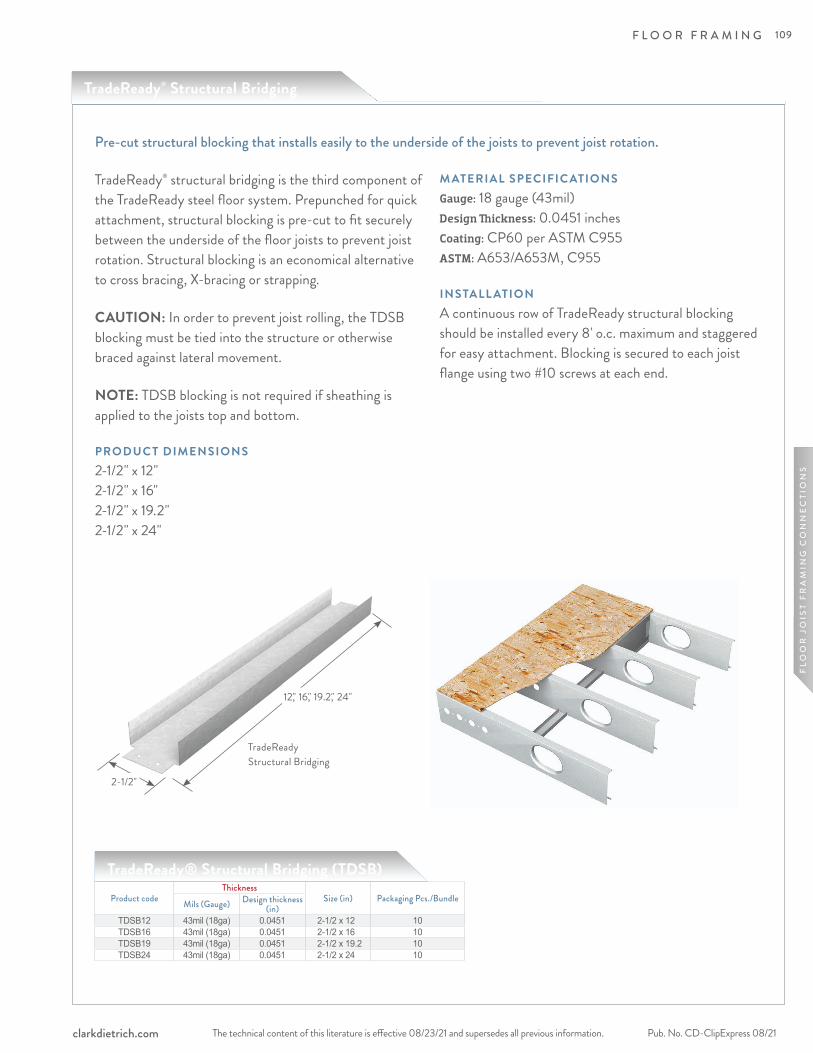
F L O O R F R A M I N G
The technical content of this literature is effective 08/23/21 and supersedes all previous information. The technical content of this literature is effective 08/23/21 and supersedes all previous information. Pub. No. CD-ClipExpress 08/21clarkdietrich.com
FLO
OR
JO
IST
FR
AM
ING
CO
NN
EC
TIO
NS
TradeReady® structural bridging is the third component of the TradeReady steel floor system. Prepunched for quick attachment, structural blocking is pre-cut to fit securely between the underside of the floor joists to prevent joist rotation. Structural blocking is an economical alternative to cross bracing, X-bracing or strapping.
CAUTION: In order to prevent joist rolling, the TDSB blocking must be tied into the structure or otherwise braced against lateral movement.
NOTE: TDSB blocking is not required if sheathing is applied to the joists top and bottom.
PRODUC T DIMENSIONS2-1/2" x 12" 2-1/2" x 16" 2-1/2" x 19.2" 2-1/2" x 24"
M ATERIAL SPECIFIC ATIONSGauge: 18 gauge (43mil)Design Thickness: 0.0451 inches Coating: CP60 per ASTM C955ASTM: A653/A653M, C955
INSTALL ATIONA continuous row of TradeReady structural blocking should be installed every 8' o.c. maximum and staggered for easy attachment. Blocking is secured to each joist flange using two #10 screws at each end.
Pre-cut structural blocking that installs easily to the underside of the joists to prevent joist rotation.
TradeReady® Structural Bridging (TDSB)Product code
ThicknessSize (in) Packaging Pcs./BundleMils (Gauge) Design thickness
(in)TDSB12 43mil (18ga) 0.0451 2-1/2 x 12 10TDSB16 43mil (18ga) 0.0451 2-1/2 x 16 10TDSB19 43mil (18ga) 0.0451 2-1/2 x 19.2 10TDSB24 43mil (18ga) 0.0451 2-1/2 x 24 10
12," 16," 19.2," 24"
2-1/2"
TradeReady Structural Bridging
TradeReady® Structural Bridging
109

F L O O R F R A M I N G
The technical content of this literature is effective 08/23/21 and supersedes all previous information.Pub. No. CD-ClipExpress 08/21 clarkdietrich.com
ClarkDietrich EasyClip™ QuickTwist™ web stiffeners are used to provide reinforcement of joist webs to prevent crippling. Web reinforcement is often required by design to enhance the load capacity of joists. The unique design of QTWS allows the installer to easily insert the stiffener on the inside of the joist after the joist is installed. This stiffener eliminates the need to pre-insert traditional web stiffeners prior to joist installation. The one-piece assembly is easily rotated in-place for a tight fit.
PRODUC T DIMENSIONS3-1/2" x 6"–14" x 1-1/4" 6" x 6"–14" x 1-1/4"
M ATERIAL SPECIFIC ATIONSGauge: 12 gauge (97mil)Design Thickness: 0.1017 inches Coating: G90Yield Strength: 50ksi ASTM: A653/A653M
INSTALL ATIONThe unique design of the EasyClip QuickTwist web stiffener allows it to be easily rotated in-place for a tight fit between flanges. The web stiffener shall be secured to the web of the joist with (3) #10-16 screws. Screws shall be driven through the top, bottom and middle prepunched holes as shown in the illustrations.
Excellent reinforcement at critical load points to prevent web crippling.
1-1/4"
3-1/2" or 6"
7-1/4" to 14"
Product code Size (in)width
ThicknessSize* (in)
length PackagingMils (Gauge) Design thickness (in)
QTWS 3-1/2 97mil (12ga) 0.1017
6
Dependent on order quantity
7-1/48
9-1/410
11-1/41214
QTWS 6 97mil (12ga) 0.1017
6
Dependent on order quantity
7-1/48
9-1/410
11-1/41214
EasyClip™ QuickTwist™ Web Stiffeners (QTWS)
*Dimension is nominal size. Actual product is shorter to fit inside joist.
EasyClip™ QuickTwist™ Web Stiffener
110
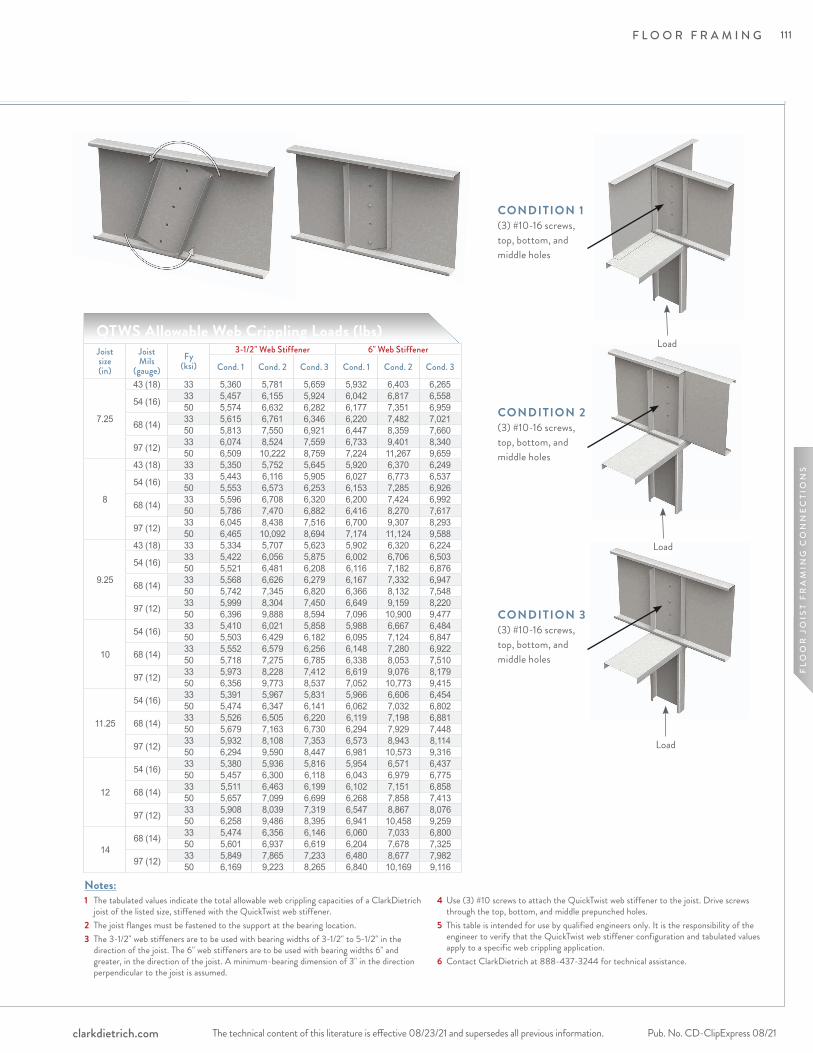
F L O O R F R A M I N G
The technical content of this literature is effective 08/23/21 and supersedes all previous information. The technical content of this literature is effective 08/23/21 and supersedes all previous information. Pub. No. CD-ClipExpress 08/21clarkdietrich.com
FLO
OR
JO
IST
FR
AM
ING
CO
NN
EC
TIO
NS
Notes:1 The tabulated values indicate the total allowable web crippling capacities of a ClarkDietrich
joist of the listed size, stiffened with the QuickTwist web stiffener. 2 The joist flanges must be fastened to the support at the bearing location.3 The 3-1/2" web stiffeners are to be used with bearing widths of 3-1/2" to 5-1/2" in the
direction of the joist. The 6" web stiffeners are to be used with bearing widths 6" and greater, in the direction of the joist. A minimum-bearing dimension of 3" in the direction perpendicular to the joist is assumed.
4 Use (3) #10 screws to attach the QuickTwist web stiffener to the joist. Drive screws through the top, bottom, and middle prepunched holes.
5 This table is intended for use by qualified engineers only. It is the responsibility of the engineer to verify that the QuickTwist web stiffener configuration and tabulated values apply to a specific web crippling application.
6 Contact ClarkDietrich at 888-437-3244 for technical assistance.
CONDITION 1(3) #10-16 screws,top, bottom, and middle holes
Load
Load
Load
CONDITION 2(3) #10-16 screws,top, bottom, and middle holes
CONDITION 3(3) #10-16 screws,top, bottom, and middle holes
QTWS Allowable Web Crippling Loads (lbs)Joistsize(in)
Joist Mils
(gauge)Fy
(ksi)
3-1/2" Web Stiffener 6" Web Stiffener
Cond. 1 Cond. 2 Cond. 3 Cond. 1 Cond. 2 Cond. 3
7.25
43 (18) 33 5,360 5,781 5,659 5,932 6,403 6,265
54 (16) 33 5,457 6,155 5,924 6,042 6,817 6,55850 5,574 6,632 6,282 6,177 7,351 6,959
68 (14) 33 5,615 6,761 6,346 6,220 7,482 7,02150 5,813 7,550 6,921 6,447 8,359 7,660
97 (12) 33 6,074 8,524 7,559 6,733 9,401 8,34050 6,509 10,222 8,759 7,224 11,267 9,659
8
43 (18) 33 5,350 5,752 5,645 5,920 6,370 6,249
54 (16) 33 5,443 6,116 5,905 6,027 6,773 6,53750 5,553 6,573 6,253 6,153 7,285 6,926
68 (14) 33 5,596 6,708 6,320 6,200 7,424 6,99250 5,786 7,470 6,882 6,416 8,270 7,617
97 (12) 33 6,045 8,438 7,516 6,700 9,307 8,29350 6,465 10,092 8,694 7,174 11,124 9,588
9.25
43 (18) 33 5,334 5,707 5,623 5,902 6,320 6,224
54 (16) 33 5,422 6,056 5,875 6,002 6,706 6,50350 5,521 6,481 6,208 6,116 7,182 6,876
68 (14) 33 5,568 6,626 6,279 6,167 7,332 6,94750 5,742 7,345 6,820 6,366 8,132 7,548
97 (12) 33 5,999 8,304 7,450 6,649 9,159 8,22050 6,396 9,888 8,594 7,096 10,900 9,477
10
54 (16) 33 5,410 6,021 5,858 5,988 6,667 6,48450 5,503 6,429 6,182 6,095 7,124 6,847
68 (14) 33 5,552 6,579 6,256 6,148 7,280 6,92250 5,718 7,275 6,785 6,338 8,053 7,510
97 (12) 33 5,973 8,228 7,412 6,619 9,076 8,17950 6,356 9,773 8,537 7,052 10,773 9,415
11.25
54 (16) 33 5,391 5,967 5,831 5,966 6,606 6,45450 5,474 6,347 6,141 6,062 7,032 6,802
68 (14) 33 5,526 6,505 6,220 6,119 7,198 6,88150 5,679 7,163 6,730 6,294 7,929 7,448
97 (12) 33 5,932 8,108 7,353 6,573 8,943 8,11450 6,294 9,590 8,447 6,981 10,573 9,316
12
54 (16) 33 5,380 5,936 5,816 5,954 6,571 6,43750 5,457 6,300 6,118 6,043 6,979 6,775
68 (14) 33 5,511 6,463 6,199 6,102 7,151 6,85850 5,657 7,099 6,699 6,268 7,858 7,413
97 (12) 33 5,908 8,039 7,319 6,547 8,867 8,07650 6,258 9,486 8,395 6,941 10,458 9,259
1468 (14) 33 5,474 6,356 6,146 6,060 7,033 6,800
50 5,601 6,937 6,619 6,204 7,678 7,325
97 (12) 33 5,849 7,865 7,233 6,480 8,677 7,98250 6,169 9,223 8,265 6,840 10,169 9,116
111
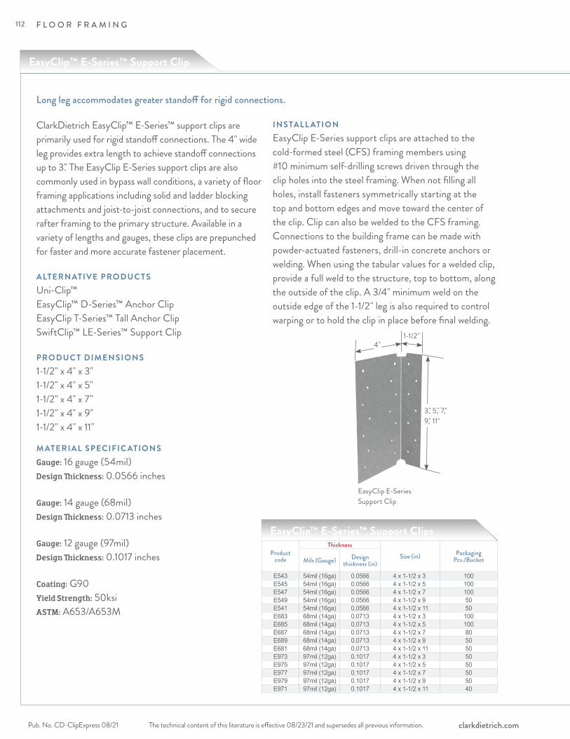
F L O O R F R A M I N G
The technical content of this literature is effective 08/23/21 and supersedes all previous information.Pub. No. CD-ClipExpress 08/21 clarkdietrich.com
ClarkDietrich EasyClip™ E-Series™ support clips are primarily used for rigid standoff connections. The 4" wide leg provides extra length to achieve standoff connections up to 3." The EasyClip E-Series support clips are also commonly used in bypass wall conditions, a variety of floor framing applications including solid and ladder blocking attachments and joist-to-joist connections, and to secure rafter framing to the primary structure. Available in a variety of lengths and gauges, these clips are prepunched for faster and more accurate fastener placement.
ALTERNATIVE PRODUC TSUni-Clip™ EasyClip™ D-Series™ Anchor Clip EasyClip T-Series™ Tall Anchor ClipSwiftClip™ LE-Series™ Support Clip
PRODUC T DIMENSIONS1-1/2" x 4" x 3"1-1/2" x 4" x 5"1-1/2" x 4" x 7"1-1/2" x 4" x 9"1-1/2" x 4" x 11"
M ATERIAL SPECIFIC ATIONSGauge: 16 gauge (54mil)Design Thickness: 0.0566 inches
Gauge: 14 gauge (68mil)Design Thickness: 0.0713 inches
Gauge: 12 gauge (97mil)Design Thickness: 0.1017 inches
Coating: G90Yield Strength: 50ksi ASTM: A653/A653M
INSTALL ATIONEasyClip E-Series support clips are attached to the cold-formed steel (CFS) framing members using #10 minimum self-drilling screws driven through the clip holes into the steel framing. When not filling all holes, install fasteners symmetrically starting at the top and bottom edges and move toward the center of the clip. Clip can also be welded to the CFS framing. Connections to the building frame can be made with powder-actuated fasteners, drill-in concrete anchors or welding. When using the tabular values for a welded clip, provide a full weld to the structure, top to bottom, along the outside of the clip. A 3/4" minimum weld on the outside edge of the 1-1/2" leg is also required to control warping or to hold the clip in place before final welding.
Long leg accommodates greater standoff for rigid connections.
EasyClip™ E-Series™ Support Clips
Productcode
Thickness
Size (in) PackagingPcs./BucketMils (Gauge) Design
thickness (in)
E543 54mil (16ga) 0.0566 4 x 1-1/2 x 3 100E545 54mil (16ga) 0.0566 4 x 1-1/2 x 5 100E547 54mil (16ga) 0.0566 4 x 1-1/2 x 7 100E549 54mil (16ga) 0.0566 4 x 1-1/2 x 9 50E541 54mil (16ga) 0.0566 4 x 1-1/2 x 11 50E683 68mil (14ga) 0.0713 4 x 1-1/2 x 3 100E685 68mil (14ga) 0.0713 4 x 1-1/2 x 5 100E687 68mil (14ga) 0.0713 4 x 1-1/2 x 7 80E689 68mil (14ga) 0.0713 4 x 1-1/2 x 9 50E681 68mil (14ga) 0.0713 4 x 1-1/2 x 11 50E973 97mil (12ga) 0.1017 4 x 1-1/2 x 3 50E975 97mil (12ga) 0.1017 4 x 1-1/2 x 5 50E977 97mil (12ga) 0.1017 4 x 1-1/2 x 7 50E979 97mil (12ga) 0.1017 4 x 1-1/2 x 9 50E971 97mil (12ga) 0.1017 4 x 1-1/2 x 11 40
EasyClip E-Series Support Clip
3," 5," 7," 9," 11"
4"1-1/2"
EasyClip™ E-Series™ Support Clip
112
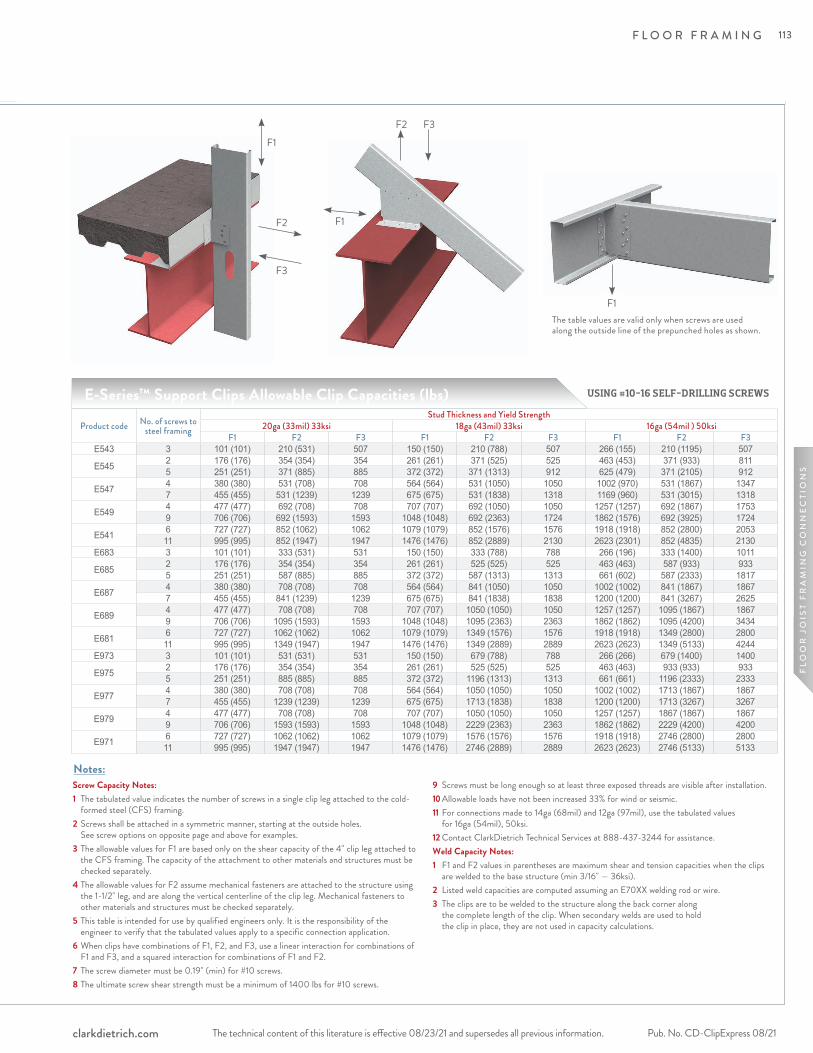
F L O O R F R A M I N G
The technical content of this literature is effective 08/23/21 and supersedes all previous information. The technical content of this literature is effective 08/23/21 and supersedes all previous information. Pub. No. CD-ClipExpress 08/21clarkdietrich.com
FLO
OR
JO
IST
FR
AM
ING
CO
NN
EC
TIO
NS
F3
F2
F1
F1
F2 F3
F1
Product code No. of screws to steel framing
Stud Thickness and Yield Strength20ga (33mil) 33ksi 18ga (43mil) 33ksi 16ga (54mil ) 50ksi
F1 F2 F3 F1 F2 F3 F1 F2 F3E543 3 101 (101) 210 (531) 507 150 (150) 210 (788) 507 266 (155) 210 (1195) 507
E545 2 176 (176) 354 (354) 354 261 (261) 371 (525) 525 463 (453) 371 (933) 8115 251 (251) 371 (885) 885 372 (372) 371 (1313) 912 625 (479) 371 (2105) 912
E547 4 380 (380) 531 (708) 708 564 (564) 531 (1050) 1050 1002 (970) 531 (1867) 13477 455 (455) 531 (1239) 1239 675 (675) 531 (1838) 1318 1169 (960) 531 (3015) 1318
E549 4 477 (477) 692 (708) 708 707 (707) 692 (1050) 1050 1257 (1257) 692 (1867) 17539 706 (706) 692 (1593) 1593 1048 (1048) 692 (2363) 1724 1862 (1576) 692 (3925) 1724
E541 6 727 (727) 852 (1062) 1062 1079 (1079) 852 (1576) 1576 1918 (1918) 852 (2800) 205311 995 (995) 852 (1947) 1947 1476 (1476) 852 (2889) 2130 2623 (2301) 852 (4835) 2130
E683 3 101 (101) 333 (531) 531 150 (150) 333 (788) 788 266 (196) 333 (1400) 1011
E685 2 176 (176) 354 (354) 354 261 (261) 525 (525) 525 463 (463) 587 (933) 9335 251 (251) 587 (885) 885 372 (372) 587 (1313) 1313 661 (602) 587 (2333) 1817
E687 4 380 (380) 708 (708) 708 564 (564) 841 (1050) 1050 1002 (1002) 841 (1867) 18677 455 (455) 841 (1239) 1239 675 (675) 841 (1838) 1838 1200 (1200) 841 (3267) 2625
E689 4 477 (477) 708 (708) 708 707 (707) 1050 (1050) 1050 1257 (1257) 1095 (1867) 18679 706 (706) 1095 (1593) 1593 1048 (1048) 1095 (2363) 2363 1862 (1862) 1095 (4200) 3434
E681 6 727 (727) 1062 (1062) 1062 1079 (1079) 1349 (1576) 1576 1918 (1918) 1349 (2800) 280011 995 (995) 1349 (1947) 1947 1476 (1476) 1349 (2889) 2889 2623 (2623) 1349 (5133) 4244
E973 3 101 (101) 531 (531) 531 150 (150) 679 (788) 788 266 (266) 679 (1400) 1400
E975 2 176 (176) 354 (354) 354 261 (261) 525 (525) 525 463 (463) 933 (933) 9335 251 (251) 885 (885) 885 372 (372) 1196 (1313) 1313 661 (661) 1196 (2333) 2333
E977 4 380 (380) 708 (708) 708 564 (564) 1050 (1050) 1050 1002 (1002) 1713 (1867) 18677 455 (455) 1239 (1239) 1239 675 (675) 1713 (1838) 1838 1200 (1200) 1713 (3267) 3267
E979 4 477 (477) 708 (708) 708 707 (707) 1050 (1050) 1050 1257 (1257) 1867 (1867) 18679 706 (706) 1593 (1593) 1593 1048 (1048) 2229 (2363) 2363 1862 (1862) 2229 (4200) 4200
E971 6 727 (727) 1062 (1062) 1062 1079 (1079) 1576 (1576) 1576 1918 (1918) 2746 (2800) 280011 995 (995) 1947 (1947) 1947 1476 (1476) 2746 (2889) 2889 2623 (2623) 2746 (5133) 5133
USING #10-16 SELF-DRILLING SCREWSE-Series™ Support Clips Allowable Clip Capacities (lbs)
Screw Capacity Notes:1 The tabulated value indicates the number of screws in a single clip leg attached to the cold-
formed steel (CFS) framing.2 Screws shall be attached in a symmetric manner, starting at the outside holes.
See screw options on opposite page and above for examples.3 The allowable values for F1 are based only on the shear capacity of the 4" clip leg attached to
the CFS framing. The capacity of the attachment to other materials and structures must be checked separately.
4 The allowable values for F2 assume mechanical fasteners are attached to the structure using the 1-1/2" leg, and are along the vertical centerline of the clip leg. Mechanical fasteners to other materials and structures must be checked separately.
5 This table is intended for use by qualified engineers only. It is the responsibility of the engineer to verify that the tabulated values apply to a specific connection application.
6 When clips have combinations of F1, F2, and F3, use a linear interaction for combinations of F1 and F3, and a squared interaction for combinations of F1 and F2.
7 The screw diameter must be 0.19" (min) for #10 screws.8 The ultimate screw shear strength must be a minimum of 1400 lbs for #10 screws.
9 Screws must be long enough so at least three exposed threads are visible after installation.10 Allowable loads have not been increased 33% for wind or seismic.11 For connections made to 14ga (68mil) and 12ga (97mil), use the tabulated values
for 16ga (54mil), 50ksi.12 Contact ClarkDietrich Technical Services at 888-437-3244 for assistance.Weld Capacity Notes:1 F1 and F2 values in parentheses are maximum shear and tension capacities when the clips
are welded to the base structure (min 3/16" — 36ksi).2 Listed weld capacities are computed assuming an E70XX welding rod or wire.3 The clips are to be welded to the structure along the back corner along
the complete length of the clip. When secondary welds are used to hold the clip in place, they are not used in capacity calculations.
The table values are valid only when screws are used along the outside line of the prepunched holes as shown.
Notes:
113
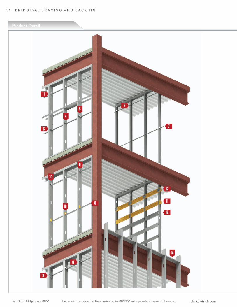
B R I D G I N G , B R A C I N G A N D B A C K I N G
The technical content of this literature is effective 08/23/21 and supersedes all previous information.Pub. No. CD-ClipExpress 08/21 clarkdietrich.com
8
9
12
6
Product Detail
7
1110
10
6
1
14
13
5
4
2
3
114
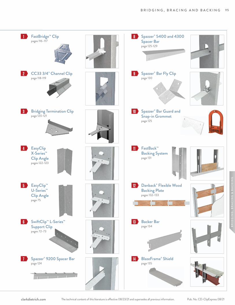
B R I D G I N G , B R A C I N G A N D B A C K I N G
The technical content of this literature is effective 08/23/21 and supersedes all previous information. The technical content of this literature is effective 08/23/21 and supersedes all previous information. Pub. No. CD-ClipExpress 08/21clarkdietrich.com
BR
IDG
ING
, B
RA
CIN
G &
BA
CK
ING
EasyClip™ U-Series™ Clip Anglepage 75
Spazzer® 9200 Spacer Barpage 124
FastBridge™ Clip pages 116–117
Spazzer® 5400 and 4300 Spacer Barpage 125-129
Spazzer® Bar Fly Clip page 130
FastBack™ Backing Systempage 131
Danback® Flexible Wood Backing Platepages 132–133
1 8
2 9
5
6
3
EasyClip X-Series™ Clip Anglepages 122–123
10
BlazeFrame® Shieldpage 135
11
Spazzer® Bar Guard and Snap-in Grommetpage 125
4
Backer Barpage 134
12
SwiftClip™ L-Series™ Support Clippages 72–73
7
CC33 3/4" Channel Clippage 118-119
13
Bridging Termination Clippage 120-121
14
115

FastBridge™ Clip
B R I D G I N G , B R A C I N G A N D B A C K I N G
The technical content of this literature is effective 08/23/21 and supersedes all previous information.Pub. No. CD-ClipExpress 08/21 clarkdietrich.com
The ClarkDietrich FastBridge clip is used to secure U-Channel or Cold-Rolled Channel (CRC) to structural or non-structural wall studs when used in load-bearing, curtain wall or drywall framing applications. The wall stud friction fit design allows for as little as one screw for the connection to the U-channel.
The FastBridge clip is a stiffened, G90 galvanized steel clip that's tested and designed to facilitate the rapid, efficient installation of 1-1/2" U-channel lateral bracing for exterior curtain wall framing, load-bearing walls or interior partitions constructed of structural or non-structural studs.
M ATERIAL SPECIFIC ATIONSGauge: 20 gauge STR (33mil)Design Thickness: 0.0346 inches
Gauge: 18 gauge (43mil)Design Thickness: 0.0451 inches
Gauge: 14 gauge (68mil)Design Thickness: 0.0713 inches
Coating: G90ASTM: A653
ALTERNATIVE PRODUC TS• Spazzer® 5400 and 9200 Bridging Bar• U-Channel with SwiftClip™ LS-Series™ Support Clip• EasyClip™ U-Series™ Clips
Secures U-channel (cold-rolled channel) framing members for load-bearing or curtain wall applications.
FastBridge™ Clip Angles (FB)
Product codeThickness
Knockout size
Packaging pcs./bucketMils (Gauge) Yield
strengthDesign
thickness (in)
Min. thickness
(in)
FB33 33mil (20ga STR) 33ksi 0.0346 0.0329 1-1/2" 200
FB43 43mil (18ga) 50ksi 0.0451 0.0428 1-1/2" 200
FB68 68mil (14ga) 50ksi 0.0713 0.0677 1-1/2" 200
U.S. Patent No. D692,746 and Canadian Patent No. 152,547
INSTALL ATIONU-Channel is inserted into the stud punchout (spacing as specified by design) and rotated into place (leg down). Place the FastBridge Clip inside the punchout (stiffened wings down) and twist allowing the friction fit design to hold the clip into place. The clip must be firmly seated over the top web of the U-channel. FastBridge clips are fastened using #10 self-drilling screws driven through the clip hole into the U-channel. More than one screw may be need depending on design. The FastBridge clip should not be used in studs over 8" wide.
• FB33 for use with 20ga-16ga structural studs or ProSTUD® Drywall Studs• FB43 for use with 20ga-16ga structural studs• FB68 for use with 16ga-12ga structural studs
116

B R I D G I N G , B R A C I N G A N D B A C K I N G
The technical content of this literature is effective 08/23/21 and supersedes all previous information. The technical content of this literature is effective 08/23/21 and supersedes all previous information. Pub. No. CD-ClipExpress 08/21clarkdietrich.com
BR
IDG
ING
, B
RA
CIN
G &
BA
CK
ING
Notes:1 Allowable loads are based on the use of cold-formed steel studs with a minimum yield strength
of Fy=33ksi and tensile strength of Fu=45ksi for 43mil (18ga) or thinner; and a minimum yield strength Fy=50ksi and tensile strength Fu=65ksi for 54mil (16ga) or thicker.
2 Allowable loads are based on 54mil (16ga) u-channel bridging with a minimum yield strength Fy=33ksi and tensile strength Fu=45ksi.
3 Allowable loads are for the bridging connection only. The strength and serviceability of the framing members is the responsibility of the designer.
4 Allowable loads are based on #10 self-drilling screws with a nominal diameter of 0.190 in. and a washer diameter of 0.375 in. Fasteners must have a minimum nominal shear strength of Pss=1718 lbs and a nominal tensile strength of Pts=2654 lbs.
5 Allowable loads may not be increased for wind or seismic load.6 Allowable loads are for use when using ASD design methodology. For LRFD loads,
multiply ASD allowable loads by 1.6.7 Allowable brace loads are based on ultimate test loads divided by a safety factor.
Serviceability limits are not considered. Brace stiffness requirements are detailed in AISI S100 Section D3.3.
8 Axial brace stiffness values apply to both ASD and LRFD designs.
FastBridge™ Clip Angles (FB68) Allowable Clip Capacities (lbs)
Product code No. of screws to steel framing Stud depth (in) Allowable connector capacity
Stud Thickness and Yield Strength
16ga (54mil) 14ga (68mil) 12ga (97mil )
FB68
1
3.625
Axial Brace Stiffness (lbs/in) 3410 4410 62702 4010 6880 75851 Axial Brace Strength (lbs) 465 520 5732 665 732 8231 Torsional Moment (in-lbs) 332 440 4352 735 894 1150
FB68
1
4.00
Axial Brace Stiffness (lbs/in) 3060 3440 67402 3710 4670 89601 Axial Brace Strength (lbs) 475 505 5052 676 752 8781 Torsional Moment (in-lbs) 382 462 5642 724 802 938
FB68
1
6.00
Axial Brace Stiffness (lbs/in) 2270 3240 32002 2710 3870 35301 Axial Brace Strength (lbs) 468 506 5152 682 788 8851 Torsional Moment (in-lbs) 294 412 6702 686 758 1004
FB68
1
8.00
Axial Brace Stiffness (lbs/in) 1940 2500 25302 1960 2810 30151 Axial Brace Strength (lbs) 463 510 5172 637 747 8981 Torsional Moment (in-lbs) 310 512 6742 682 788 963
Product code No. of screws to steel framing Stud depth (in) Allowable connector capacity
Stud Thickness and Yield Strength
20ga (33mil) 18ga (43mil) 16ga (54mil )
FB43
1
3.625
Axial Brace Stiffness (lbs/in) 1140 1330 22702 1220 1480 22701 Axial Brace Strength (lbs) 178 210 2732 275 318 4241 Torsional Moment (in-lbs) 148 182 2082 331 430 556
FB43
1
4.00
Axial Brace Stiffness (lbs/in) 1030 1460 21702 1190 1520 30301 Axial Brace Strength (lbs) 191 213 2632 283 321 4261 Torsional Moment (in-lbs) 137 182 2342 403 403 498
FB43
1
6.00
Axial Brace Stiffness (lbs/in) 790 990 17302 990 1160 19301 Axial Brace Strength (lbs) 107 214 2902 263 324 4501 Torsional Moment (in-lbs) 166 170 1722 296 406 567
FB43
1
8.00
Axial Brace Stiffness (lbs/in) — 750 19102 — 750 19601 Axial Brace Strength (lbs) — 212 2722 — 302 4381 Torsional Moment (in-lbs) — 152 3432 — 461 526
FastBridge™ Clip Angles (FB43) Allowable Clip Capacities (lbs)
117

B R I D G I N G , B R A C I N G A N D B A C K I N G
The technical content of this literature is effective 08/23/21 and supersedes all previous information.Pub. No. CD-ClipExpress 08/21 clarkdietrich.com
The ClarkDietrich CC33 clip is used to secure U-Channel or Cold-Rolled Channel (CRC) to non-structural wall studs. The wall stud friction fit design allows for as few as one screw for the connection to the U-Channel.
The CC33 clip is a stiffened, G90 galvanized steel clip that's tested and designed to facilitate the rapid, efficient installation of 3/4" U-Channel lateral bracing for non-structural interior wall framing constructed of ProSTUD® Drywall Framing or non-structural studs. The CC33 clip should not be used in studs over 6" wide.
PRODUC T DIMENSIONSMade to fit over 3/4" U-Channel and inside a drywall punchout. Packaging: (200) pieces per bucket Product weight: 0.12 lb/piece
M ATERIAL SPECIFIC ATIONSGauge: 20gauge (33mil)Design Thickness: 0.0346 inches Coating: G90 Yield Strength: 33ksi ASTM: C645, A1003
ALTERNATIVE PRODUC TS • U-Channel with SwiftClip™ LS-Series™ Support Clip • Spazzer® 9200 Bridging Bar
INSTALL ATIONCC33 clips are fastened using #8 self-drilling screws driven through the clip hole into the U-Channel. More than one screw may be needed depending on design. Design loads & tables can be found at clarkdietrich.com.
33mil (20 gauge) lateral bracing clip used to secure 3/4" U-channel (cold-rolled channel) to drywall studs.
CC33 3/4" Channel Clip (CC33)
Product codeThickness Packaging
Pcs./BucketMils (Gauge) Design thickness (in)CC33 33mil (20ga) 0.0346 200
CC33 3/4" Channel Clip
U.S. Patent No. D822,455
118

B R I D G I N G , B R A C I N G A N D B A C K I N G
The technical content of this literature is effective 08/23/21 and supersedes all previous information. The technical content of this literature is effective 08/23/21 and supersedes all previous information. Pub. No. CD-ClipExpress 08/21clarkdietrich.com
BR
IDG
ING
, B
RA
CIN
G &
BA
CK
ING
Product code Stud member Stud thickness (mils)
Allowable Torsional Moment (in-lbs)
1 - #8 Screw 2 - #8 Screw
CC33
362PDS125
PDS125-15 50 70PDS125-19 70 90PDS125-22 85 100PDS125-30 90 125PDS125-33 90 135
600PDS125
PDS125-15 70 85PDS125-19 95 100PDS125-22 95 100PDS125-30 100 125PDS125-33 100 140
CC33 3/4" Channel Clip
Notes:1 Allowable loads are based on cold-formed steel studs with a minimum yield strength specified for ProSTUD Members. 2 Allowable loads are based on 54 mil (16ga) u-channel bridging with a minimum yield strength, Fy=33ksi and tensile strength, Fu=45ksi. 3 Allowable loads consider the bridging connection only. It is the responsibility of the designer to verify the strength and serviceability of the framing members. 4 Allowable loads are based on #8 self-drilling screws with a nominal diameter of 0.164-in and a head diameter of 0.272-in. Fasteners must have a minimum nominal shear strength, Pss=1278-lbs and a nominal tensile strength, Pts=586-lbs.
5 Screw shear strength is the average value, and tension strength is the lowest value listed on CFSEI Tech Note (F701-12). 6 Allowable loads may not be increased for wind or seismic load. 7 Allowable loads are for use when utilizing ASD (Allowable Stress Design) methodology. For LRFD loads multiply the ASD tabulated values by 1.6.
DRYWALL BRIDGING CONNECTOR W/ PROSTUD DRYWALL STUDS
Stud spacing (in) Stud member Stud thickness (mils)
Lateral Stud Pressure (psf)5psf 10psf 5psf 10psf
1 - #8 Screw 1 - #8 Screw 2 - #8 Screw 2 - #8 Screw
12
362PDS125
PDS125-15 8 4 8 5PDS125-19 8 5 8 7PDS125-22 8 7 8 8PDS125-30 8 7 8 8PDS125-33 8 7 8 8
600PDS125
PDS125-15 8 6 8 8PDS125-19 8 8 8 8PDS125-22 8 8 8 8PDS125-30 8 8 8 8PDS125-33 8 8 8 8
16
362PDS125
PDS125-15 6 3 8 4PDS125-19 8 4 8 5PDS125-22 8 5 8 6PDS125-30 8 5 8 7PDS125-33 8 5 8 8
600PDS125
PDS125-15 8 5 8 6PDS125-19 8 6 8 6PDS125-22 8 7 8 7PDS125-30 8 7 8 8PDS125-33 8 7 8 8
24
362PDS125
PDS125-15 4 2 5 3PDS125-19 5 3 7 3PDS125-22 7 3 8 4PDS125-30 7 4 8 5PDS125-33 7 4 8 5
600PDS125
PDS125-15 6 3 8 4PDS125-19 8 4 8 4PDS125-22 8 4 8 5PDS125-30 8 5 8 6PDS125-33 8 5 8 7
CC33 Maximum Bridging Distance (ft.)
Notes:1 Tabulated maximum bridging distances are for ASD lateral pressures. 2 Tabulated maximum bridging distances are based on the CC33 tested connection strength.
3 Studs must be checked for unbraced length seperately. 4 Lateral pressures shall be determined based on the load combinations of the applicable building code.
119
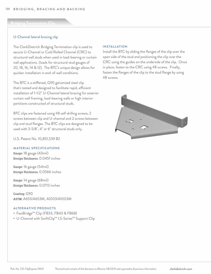
Bridging Termination Clip
B R I D G I N G , B R A C I N G A N D B A C K I N G
The technical content of this literature is effective 08/23/21 and supersedes all previous information.Pub. No. CD-ClipExpress 08/21 clarkdietrich.com
The ClarkDietrich Bridging Termination clip is used to secure U-Channel or Cold Rolled Channel (CRC) to structural wall studs when used in load-bearing or curtain wall applications. (loads for structural stud gauges of 20, 18, 16, 14 & 12). The BTC’s unique design allows for quicker installation in end-of-wall conditions.
The BTC is a stiffened, G90 galvanized steel clip that's tested and designed to facilitate rapid, efficient installation of 1-1/2" U-Channel lateral bracing for exterior curtain wall framing, load-bearing walls or high interior partitions constructed of structural studs.
BTC clips are fastened using #8 self-drilling screws; 2 screws between clip and U-channel and 2 screws between clip and stud flanges. The BTC clips are designed to be used with 3-5/8", 4" or 6" structural studs only.
U.S. Patent No. 10,851,539 B2
M ATERIAL SPECIFIC ATIONSGauge: 18 gauge (43mil)Design Thickness: 0.0451 inches
Gauge: 16 gauge (54mil)Design Thickness: 0.0566 inches
Gauge: 14 gauge (68mil)Design Thickness: 0.0713 inches
Coating: G90ASTM: A653/A653M, A1003/A1003M
ALTERNATIVE PRODUC TS• FastBridge™ Clip (FB33, FB43 & FB68)• U-Channel with SwiftClip™ LS-Series™ Support Clip
INSTALL ATIONInstall the BTC by sliding the flanges of the clip over the open side of the stud and positioning the clip over the CRC using the guides on the underside of the clip. Once in place, fasten to the CRC using #8 screws. Finally, fasten the flanges of the clip to the stud flange by using #8 screws.
U-Channel lateral bracing clip
120
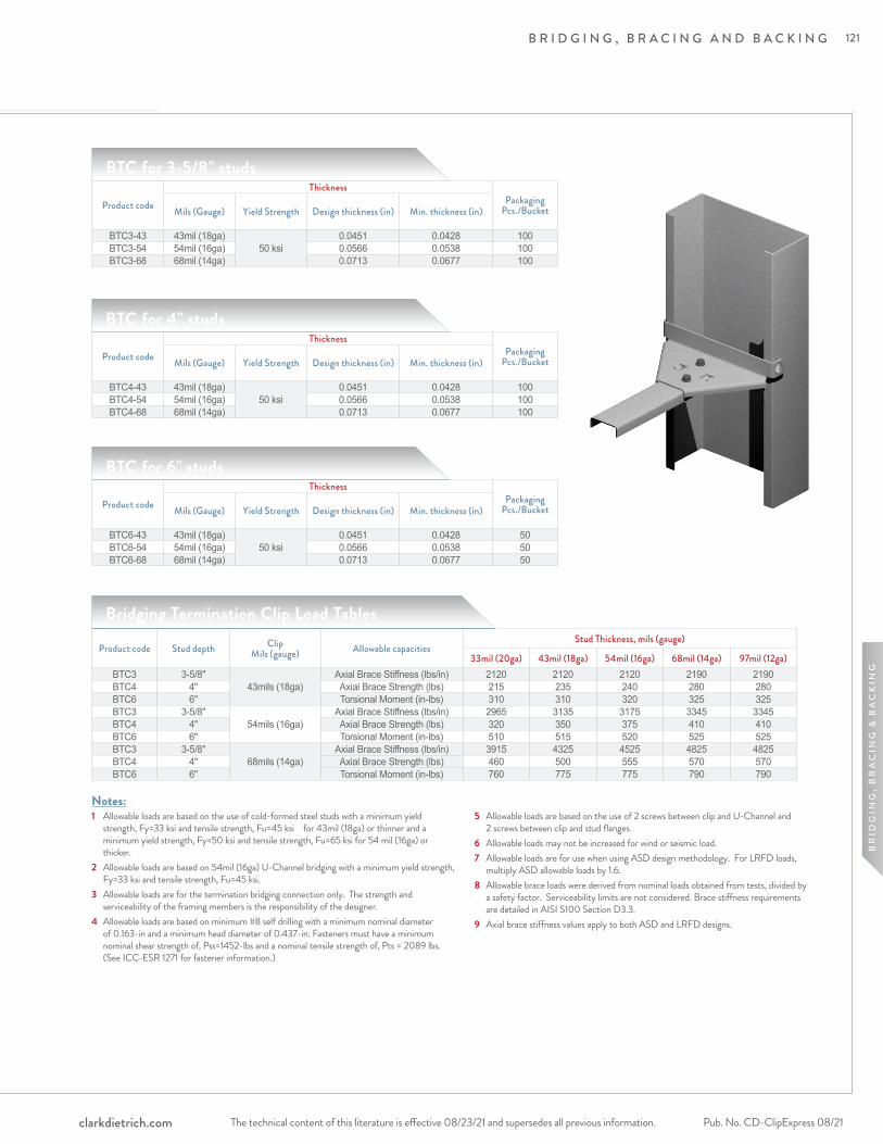
B R I D G I N G , B R A C I N G A N D B A C K I N G
The technical content of this literature is effective 08/23/21 and supersedes all previous information. The technical content of this literature is effective 08/23/21 and supersedes all previous information. Pub. No. CD-ClipExpress 08/21clarkdietrich.com
BR
IDG
ING
, B
RA
CIN
G &
BA
CK
ING
BTC for 3-5/8" studs
Product code
ThicknessPackaging
Pcs./BucketMils (Gauge) Yield Strength Design thickness (in) Min. thickness (in)
BTC3-43 43mil (18ga)50 ksi
0.0451 0.0428 100BTC3-54 54mil (16ga) 0.0566 0.0538 100BTC3-68 68mil (14ga) 0.0713 0.0677 100
BTC for 4" studs
Product code
ThicknessPackaging
Pcs./BucketMils (Gauge) Yield Strength Design thickness (in) Min. thickness (in)
BTC4-43 43mil (18ga)50 ksi
0.0451 0.0428 100BTC4-54 54mil (16ga) 0.0566 0.0538 100BTC4-68 68mil (14ga) 0.0713 0.0677 100
BTC for 6" studs
Product code
ThicknessPackaging
Pcs./BucketMils (Gauge) Yield Strength Design thickness (in) Min. thickness (in)
BTC6-43 43mil (18ga)50 ksi
0.0451 0.0428 50BTC6-54 54mil (16ga) 0.0566 0.0538 50BTC6-68 68mil (14ga) 0.0713 0.0677 50
Product code Stud depth Clip Mils (gauge) Allowable capacities
Stud Thickness, mils (gauge)
33mil (20ga) 43mil (18ga) 54mil (16ga) 68mil (14ga) 97mil (12ga)BTC3 3-5/8"
43mils (18ga)Axial Brace Stiffness (lbs/in) 2120 2120 2120 2190 2190
BTC4 4" Axial Brace Strength (lbs) 215 235 240 280 280BTC6 6" Torsional Moment (in-lbs) 310 310 320 325 325BTC3 3-5/8"
54mils (16ga)Axial Brace Stiffness (lbs/in) 2965 3135 3175 3345 3345
BTC4 4" Axial Brace Strength (lbs) 320 350 375 410 410BTC6 6" Torsional Moment (in-lbs) 510 515 520 525 525BTC3 3-5/8"
68mils (14ga)Axial Brace Stiffness (lbs/in) 3915 4325 4525 4825 4825
BTC4 4" Axial Brace Strength (lbs) 460 500 555 570 570BTC6 6" Torsional Moment (in-lbs) 760 775 775 790 790
Bridging Termination Clip Load Tables
Notes:1 Allowable loads are based on the use of cold-formed steel studs with a minimum yield
strength, Fy=33 ksi and tensile strength, Fu=45 ksi for 43mil (18ga) or thinner and a minimum yield strength, Fy=50 ksi and tensile strength, Fu=65 ksi for 54 mil (16ga) or thicker.
2 Allowable loads are based on 54mil (16ga) U-Channel bridging with a minimum yield strength, Fy=33 ksi and tensile strength, Fu=45 ksi.3 Allowable loads are for the termination bridging connection only. The strength and serviceability of the framing members is the responsibility of the designer.4 Allowable loads are based on minimum #8 self drilling with a minimum nominal diameter of 0.163-in and a minimum head diameter of 0.437-in. Fasteners must have a minimum nominal shear strength of, Pss=1452-lbs and a nominal tensile strength of, Pts = 2089 lbs. (See ICC-ESR 1271 for fastener information.)
5 Allowable loads are based on the use of 2 screws between clip and U-Channel and 2 screws between clip and stud flanges.6 Allowable loads may not be increased for wind or seismic load. 7 Allowable loads are for use when using ASD design methodology. For LRFD loads, multiply ASD allowable loads by 1.6.8 Allowable brace loads were derived from nominal loads obtained from tests, divided by a safety factor. Serviceability limits are not considered. Brace stiffness requirements are detailed in AISI S100 Section D3.3.9 Axial brace stiffness values apply to both ASD and LRFD designs.
121
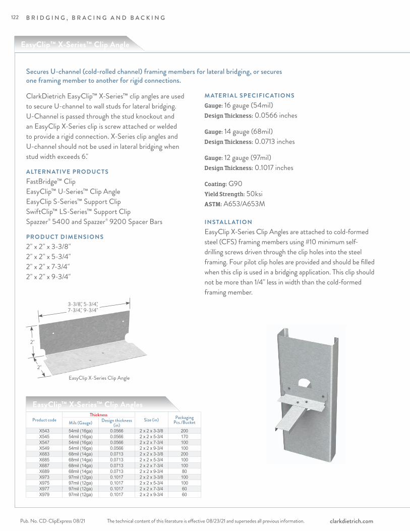
EasyClip™ X-Series™ Clip Angle
B R I D G I N G , B R A C I N G A N D B A C K I N G
The technical content of this literature is effective 08/23/21 and supersedes all previous information.Pub. No. CD-ClipExpress 08/21 clarkdietrich.com
ClarkDietrich EasyClip™ X-Series™ clip angles are used to secure U-channel to wall studs for lateral bridging. U-Channel is passed through the stud knockout and an EasyClip X-Series clip is screw attached or welded to provide a rigid connection. X-Series clip angles and U-channel should not be used in lateral bridging when stud width exceeds 6."
ALTERNATIVE PRODUC TSFastBridge™ ClipEasyClip™ U-Series™ Clip Angle EasyClip S-Series™ Support Clip SwiftClip™ LS-Series™ Support ClipSpazzer® 5400 and Spazzer® 9200 Spacer Bars
PRODUC T DIMENSIONS2" x 2" x 3-3/8" 2" x 2" x 5-3/4" 2" x 2" x 7-3/4" 2" x 2" x 9-3/4"
M ATERIAL SPECIFIC ATIONSGauge: 16 gauge (54mil)Design Thickness: 0.0566 inches
Gauge: 14 gauge (68mil)Design Thickness: 0.0713 inches
Gauge: 12 gauge (97mil)Design Thickness: 0.1017 inches
Coating: G90Yield Strength: 50ksiASTM: A653/A653M
INSTALL ATIONEasyClip X-Series Clip Angles are attached to cold-formed steel (CFS) framing members using #10 minimum self-drilling screws driven through the clip holes into the steel framing. Four pilot clip holes are provided and should be filled when this clip is used in a bridging application. This clip should not be more than 1/4" less in width than the cold-formed framing member.
Secures U-channel (cold-rolled channel) framing members for lateral bridging, or secures one framing member to another for rigid connections.
EasyClip™ X-Series™ Clip Angles
Product codeThickness
Size (in) Packaging Pcs./BucketMils (Gauge) Design thickness
(in)X543 54mil (16ga) 0.0566 2 x 2 x 3-3/8 200X545 54mil (16ga) 0.0566 2 x 2 x 5-3/4 170X547 54mil (16ga) 0.0566 2 x 2 x 7-3/4 100X549 54mil (16ga) 0.0566 2 x 2 x 9-3/4 100X683 68mil (14ga) 0.0713 2 x 2 x 3-3/8 200X685 68mil (14ga) 0.0713 2 x 2 x 5-3/4 100X687 68mil (14ga) 0.0713 2 x 2 x 7-3/4 100X689 68mil (14ga) 0.0713 2 x 2 x 9-3/4 80X973 97mil (12ga) 0.1017 2 x 2 x 3-3/8 100X975 97mil (12ga) 0.1017 2 x 2 x 5-3/4 100X977 97mil (12ga) 0.1017 2 x 2 x 7-3/4 60X979 97mil (12ga) 0.1017 2 x 2 x 9-3/4 60
2"
2"
3-3/8," 5-3/4," 7-3/4," 9-3/4"
EasyClip X-Series Clip Angle
122
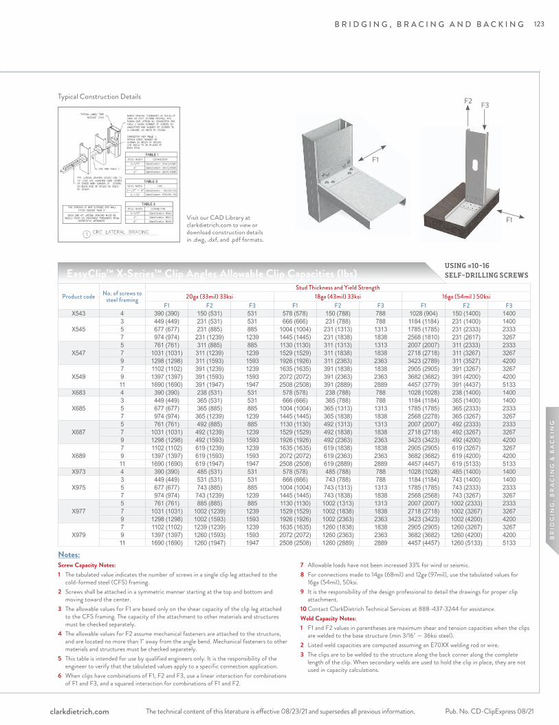
B R I D G I N G , B R A C I N G A N D B A C K I N G
The technical content of this literature is effective 08/23/21 and supersedes all previous information. The technical content of this literature is effective 08/23/21 and supersedes all previous information. Pub. No. CD-ClipExpress 08/21clarkdietrich.com
BR
IDG
ING
, B
RA
CIN
G &
BA
CK
ING
Notes:Screw Capacity Notes:1 The tabulated value indicates the number of screws in a single clip leg attached to the
cold-formed steel (CFS) framing.2 Screws shall be attached in a symmetric manner starting at the top and bottom and
moving toward the center.3 The allowable values for F1 are based only on the shear capacity of the clip leg attached
to the CFS framing. The capacity of the attachment to other materials and structures must be checked separately.
4 The allowable values for F2 assume mechanical fasteners are attached to the structure, and are located no more than 1" away from the angle bend. Mechanical fasteners to other materials and structures must be checked separately.
5 This table is intended for use by qualified engineers only. It is the responsibility of the engineer to verify that the tabulated values apply to a specific connection application.
6 When clips have combinations of F1, F2 and F3, use a linear interaction for combinations of F1 and F3, and a squared interaction for combinations of F1 and F2.
7 Allowable loads have not been increased 33% for wind or seismic.8 For connections made to 14ga (68mil) and 12ga (97mil), use the tabulated values for
16ga (54mil), 50ksi.9 It is the responsibility of the design professional to detail the drawings for proper clip
attachment.10 Contact ClarkDietrich Technical Services at 888-437-3244 for assistance.Weld Capacity Notes:1 F1 and F2 values in parentheses are maximum shear and tension capacities when the clips
are welded to the base structure (min 3/16" — 36ksi steel).2 Listed weld capacities are computed assuming an E70XX welding rod or wire.3 The clips are to be welded to the structure along the back corner along the complete
length of the clip. When secondary welds are used to hold the clip in place, they are not used in capacity calculations.
EasyClip™ X-Series™ Clip Angles Allowable Clip Capacities (lbs)
Product code No. of screws to steel framing
Stud Thickness and Yield Strength20ga (33mil) 33ksi 18ga (43mil) 33ksi 16ga (54mil ) 50ksi
F1 F2 F3 F1 F2 F3 F1 F2 F3X543 4 390 (390) 150 (531) 531 578 (578) 150 (788) 788 1028 (904) 150 (1400) 1400
X5453 449 (449) 231 (531) 531 666 (666) 231 (788) 788 1184 (1184) 231 (1400) 14005 677 (677) 231 (885) 885 1004 (1004) 231 (1313) 1313 1785 (1785) 231 (2333) 23337 974 (974) 231 (1239) 1239 1445 (1445) 231 (1838) 1838 2568 (1810) 231 (2617) 3267
X5475 761 (761) 311 (885) 885 1130 (1130) 311 (1313) 1313 2007 (2007) 311 (2333) 23337 1031 (1031) 311 (1239) 1239 1529 (1529) 311 (1838) 1838 2718 (2718) 311 (3267) 32679 1298 (1298) 311 (1593) 1593 1926 (1926) 311 (2363) 2363 3423 (2789) 311 (3527) 4200
X5497 1102 (1102) 391 (1239) 1239 1635 (1635) 391 (1838) 1838 2905 (2905) 391 (3267) 32679 1397 (1397) 391 (1593) 1593 2072 (2072) 391 (2363) 2363 3682 (3682) 391 (4200) 420011 1690 (1690) 391 (1947) 1947 2508 (2508) 391 (2889) 2889 4457 (3779) 391 (4437) 5133
X683 4 390 (390) 238 (531) 531 578 (578) 238 (788) 788 1028 (1028) 238 (1400) 1400
X6853 449 (449) 365 (531) 531 666 (666) 365 (788) 788 1184 (1184) 365 (1400) 14005 677 (677) 365 (885) 885 1004 (1004) 365 (1313) 1313 1785 (1785) 365 (2333) 23337 974 (974) 365 (1239) 1239 1445 (1445) 365 (1838) 1838 2568 (2278) 365 (3267) 3267
X6875 761 (761) 492 (885) 885 1130 (1130) 492 (1313) 1313 2007 (2007) 492 (2333) 23337 1031 (1031) 492 (1239) 1239 1529 (1529) 492 (1838) 1838 2718 (2718) 492 (3267) 32679 1298 (1298) 492 (1593) 1593 1926 (1926) 492 (2363) 2363 3423 (3423) 492 (4200) 4200
X6897 1102 (1102) 619 (1239) 1239 1635 (1635) 619 (1838) 1838 2905 (2905) 619 (3267) 32679 1397 (1397) 619 (1593) 1593 2072 (2072) 619 (2363) 2363 3682 (3682) 619 (4200) 420011 1690 (1690) 619 (1947) 1947 2508 (2508) 619 (2889) 2889 4457 (4457) 619 (5133) 5133
X973 4 390 (390) 485 (531) 531 578 (578) 485 (788) 788 1028 (1028) 485 (1400) 1400
X9753 449 (449) 531 (531) 531 666 (666) 743 (788) 788 1184 (1184) 743 (1400) 14005 677 (677) 743 (885) 885 1004 (1004) 743 (1313) 1313 1785 (1785) 743 (2333) 23337 974 (974) 743 (1239) 1239 1445 (1445) 743 (1838) 1838 2568 (2568) 743 (3267) 3267
X9775 761 (761) 885 (885) 885 1130 (1130) 1002 (1313) 1313 2007 (2007) 1002 (2333) 23337 1031 (1031) 1002 (1239) 1239 1529 (1529) 1002 (1838) 1838 2718 (2718) 1002 (3267) 32679 1298 (1298) 1002 (1593) 1593 1926 (1926) 1002 (2363) 2363 3423 (3423) 1002 (4200) 4200
X9797 1102 (1102) 1239 (1239) 1239 1635 (1635) 1260 (1838) 1838 2905 (2905) 1260 (3267) 32679 1397 (1397) 1260 (1593) 1593 2072 (2072) 1260 (2363) 2363 3682 (3682) 1260 (4200) 420011 1690 (1690) 1260 (1947) 1947 2508 (2508) 1260 (2889) 2889 4457 (4457) 1260 (5133) 5133
USING #10-16 SELF-DRILLING SCREWS
Visit our CAD Library at clarkdietrich.com to view or download construction details in .dwg, .dxf, and .pdf formats.
Typical Construction Details
F1
F2 F3
F1
123
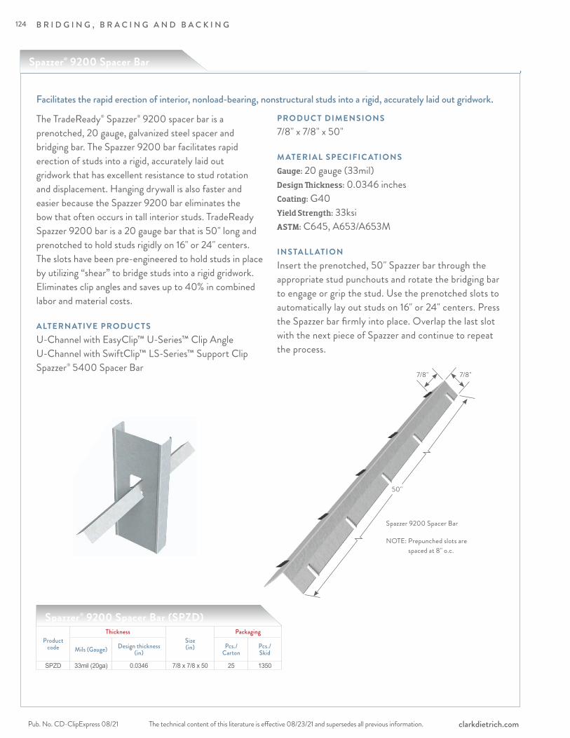
B R I D G I N G , B R A C I N G A N D B A C K I N G
The technical content of this literature is effective 08/23/21 and supersedes all previous information.Pub. No. CD-ClipExpress 08/21 clarkdietrich.com
Facilitates the rapid erection of interior, nonload-bearing, nonstructural studs into a rigid, accurately laid out gridwork.
Spazzer® 9200 Spacer Bar (SPZD)
The TradeReady® Spazzer® 9200 spacer bar is a prenotched, 20 gauge, galvanized steel spacer and bridging bar. The Spazzer 9200 bar facilitates rapid erection of studs into a rigid, accurately laid out gridwork that has excellent resistance to stud rotation and displacement. Hanging drywall is also faster and easier because the Spazzer 9200 bar eliminates the bow that often occurs in tall interior studs. TradeReady Spazzer 9200 bar is a 20 gauge bar that is 50" long and prenotched to hold studs rigidly on 16" or 24" centers. The slots have been pre-engineered to hold studs in place by utilizing “shear” to bridge studs into a rigid gridwork. Eliminates clip angles and saves up to 40% in combined labor and material costs.
ALTERNATIVE PRODUC TSU-Channel with EasyClip™ U-Series™ Clip Angle U-Channel with SwiftClip™ LS-Series™ Support Clip Spazzer® 5400 Spacer Bar
PRODUC T DIMENSIONS7/8" x 7/8" x 50"
M ATERIAL SPECIFIC ATIONSGauge: 20 gauge (33mil)Design Thickness: 0.0346 inches Coating: G40Yield Strength: 33ksiASTM: C645, A653/A653M
INSTALL ATIONInsert the prenotched, 50" Spazzer bar through the appropriate stud punchouts and rotate the bridging bar to engage or grip the stud. Use the prenotched slots to automatically lay out studs on 16" or 24" centers. Press the Spazzer bar firmly into place. Overlap the last slot with the next piece of Spazzer and continue to repeat the process.
Productcode
ThicknessSize(in)
Packaging
Mils (Gauge) Design thickness(in)
Pcs./Carton
Pcs./Skid
SPZD 33mil (20ga) 0.0346 7/8 x 7/8 x 50 25 1350
Spazzer® 9200 Spacer Bar
50"
7/8"7/8"
Spazzer 9200 Spacer Bar
NOTE: Prepunched slots are spaced at 8" o.c.
124
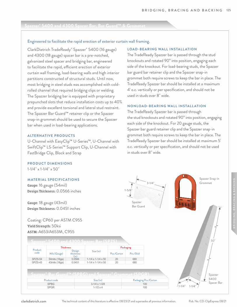
B R I D G I N G , B R A C I N G A N D B A C K I N G
The technical content of this literature is effective 08/23/21 and supersedes all previous information. The technical content of this literature is effective 08/23/21 and supersedes all previous information. Pub. No. CD-ClipExpress 08/21clarkdietrich.com
BR
IDG
ING
, B
RA
CIN
G &
BA
CK
ING
ClarkDietrich TradeReady® Spazzer® 5400 (16 gauge) and 4300 (18 gauge) spacer bar is a pre-notched, galvanized steel spacer and bridging bar, engineered to facilitate the rapid, efficient erection of exterior curtain wall framing, load-bearing walls and high interior partitions constructed of structural studs. Until now, most bridging in steel studs was accomplished with cold-rolled channel that required bridging clips or welding. The Spazzer bridging bar is equipped with proprietary prepunched slots that reduce installation costs up to 40% and provide excellent torsional and lateral stud restraint. The Spazzer Bar Guard™ retainer clip or the Spazzer snap-in grommet should be used to secure the Spazzer bar when used in load-bearing applications.
ALTERNATIVE PRODUC TSU-Channel with EasyClip™ U-Series™, U-Channel with SwiftClip™ LS-Series™ Support Clip, U-Channel with FastBridge Clip, Block and Strap
PRODUC T DIMENSIONS1-1/4" x 1-1/4" x 50"
M ATERIAL SPECIFIC ATIONSGauge: 16 gauge (54mil)Design Thickness: 0.0566 inches
Gauge: 18 gauge (43mil)Design Thickness: 0.0451 inches Coating: CP60 per ASTM C955Yield Strength: 50ksiASTM: A653/A653M, C955
LOAD -BE ARING WALL INSTALL ATIONThe TradeReady Spazzer bar is passed through the stud knockouts and rotated 90° into position, engaging each side of the knockout. For load-bearing studs, the Spazzer bar guard bar retainer clip and the Spazzer snap-in grommet both require screws to keep the bar in place. The TradeReady Spazzer bar should be installed at a maximum 4' o.c. vertically or per specification, and should not be used in studs over 8" wide.
NONLOAD -BE ARING WALL INSTALL ATION The TradeReady Spazzer bar is passed through the stud knockouts and rotated 90° into position, engaging each side of the knockout. For 20 gauge studs, the Spazzer bar guard retainer clip and the Spazzer snap-in grommet both require screws to keep the bar in place. The TradeReady Spazzer bar should be installed at maximum 5' o.c. vertically or per specification, and should not be used in studs over 8" wide.
Engineered to facilitate the rapid erection of exterior curtain wall framing.
Spazzer 5400 Spacer Bar
1-1/4" 1-1/4"
Spazzer Bar Guard
3-1/4"
1-5/8"
Product code Size (in) Packaging Pcs./CartonSPBG 3-1/4 x 1-5/8 100SPGR 1-1/2 x 4 100
Spazzer® Bar Guard™ (SPBG) and Spazzer® Grommet (SPGR)
Productcode
ThicknessSize (in)
Packaging
Mils (Gauge)Design
thickness(in)
Pcs./Carton Pcs./Skid
SPZS-54 54mils (16ga) 0.0566 1-1/4 x 1-1/4 x 50 20 680SPZS-43 43mils (18ga) 0.0451 1-1/4 x 1-1/4 x 50 20 680
Spazzer® 5400 and 4300 Spacer Bar (SPZS)
Spazzer Snap-in Grommet
50"
Spazzer® 5400 and 4300 Spacer Bar, Bar Guard™ & Grommet
125
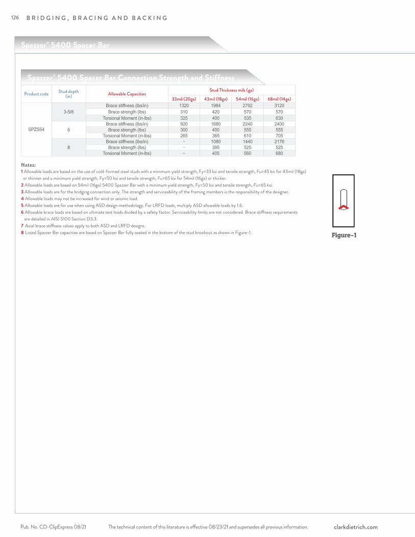
B R I D G I N G , B R A C I N G A N D B A C K I N G
The technical content of this literature is effective 08/23/21 and supersedes all previous information.Pub. No. CD-ClipExpress 08/21 clarkdietrich.com
Spazzer® 5400 Spacer Bar
Spazzer® 5400 Spacer Bar Connection Strength and Stiffness
Product code Stud depth (in) Allowable Capacities
Stud Thickness mils (ga)
33mil (20ga) 43mil (18ga) 54mil (16ga) 68mil (14ga)
SPZS54
3-5/8Brace stiffness (lbs/in) 1320 1984 2792 3120Brace strength (lbs) 310 420 570 570
Torsional Moment (in-lbs) 325 400 535 630
6Brace stiffness (lbs/in) 920 1680 2240 2400Brace strength (lbs) 300 400 555 555
Torsional Moment (in-lbs) 265 365 610 705
8Brace stiffness (lbs/in) − 1080 1440 2176Brace strength (lbs) − 395 525 525
Torsional Moment (in-lbs) − 405 560 680
Notes:1 Allowable loads are based on the use of cold-formed steel studs with a minimum yield strength, Fy=33 ksi and tensile strength, Fu=45 ksi for 43mil (18ga) or thinner and a minimum yield strength, Fy=50 ksi and tensile strength, Fu=65 ksi for 54mil (16ga) or thicker.2 Allowable loads are based on 54mil (16ga) 5400 Spazzer Bar with a minimum yield strength, Fy=50 ksi and tensile strength, Fu=65 ksi.3 Allowable loads are for the bridging connection only. The strength and serviceability of the framing members is the responsibility of the designer.4 Allowable loads may not be increased for wind or seismic load.5 Allowable loads are for use when using ASD design methodology. For LRFD loads, multiply ASD allowable loads by 1.6.6 Allowable brace loads are based on ultimate test loads divided by a safety factor. Serviceability limits are not considered. Brace stiffness requirements are detailed in AISI S100 Section D3.3.7 Axial brace stiffness values apply to both ASD and LRFD designs.8 Listed Spazzer Bar capacities are based on Spazzer Bar fully seated in the bottom of the stud knockout as shown in Figure-1. Figure-1
126
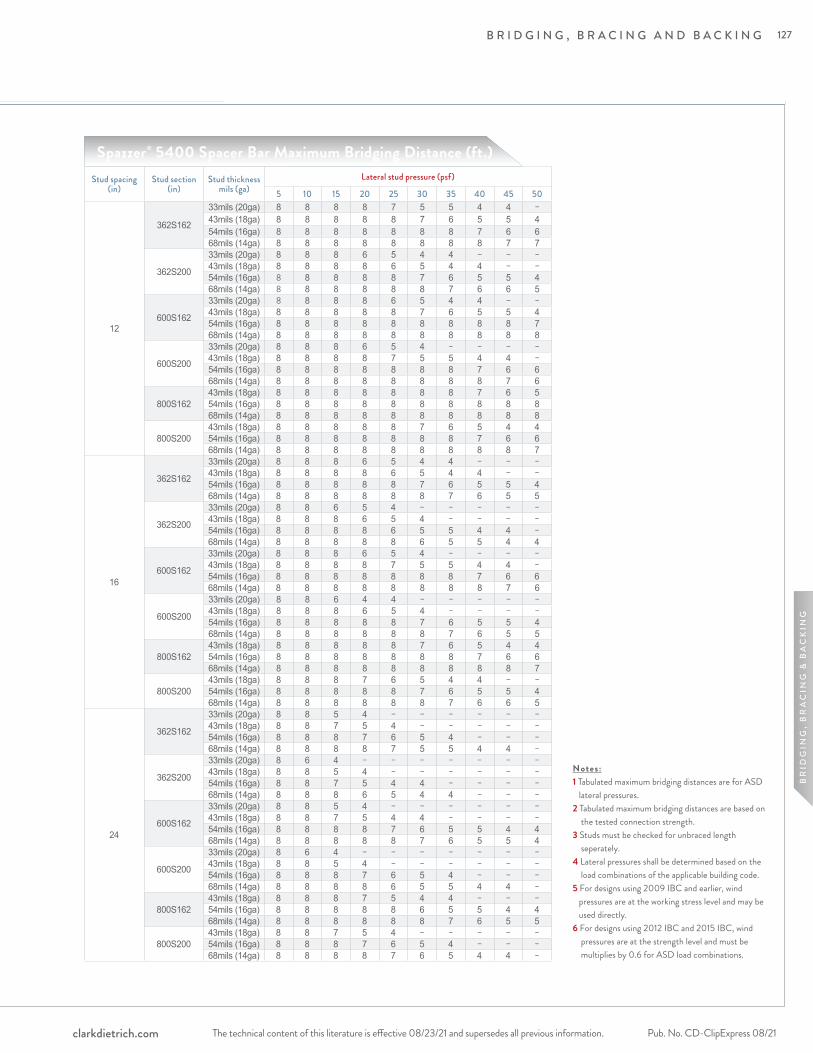
B R I D G I N G , B R A C I N G A N D B A C K I N G
The technical content of this literature is effective 08/23/21 and supersedes all previous information. The technical content of this literature is effective 08/23/21 and supersedes all previous information. Pub. No. CD-ClipExpress 08/21clarkdietrich.com
BR
IDG
ING
, B
RA
CIN
G &
BA
CK
ING
Spazzer® 5400 Spacer Bar Maximum Bridging Distance (ft.)Stud spacing
(in)Stud section
(in)Stud thickness
mils (ga)Lateral stud pressure (psf)
5 10 15 20 25 30 35 40 45 50
12
362S162
33mils (20ga) 8 8 8 8 7 5 5 4 4 −43mils (18ga) 8 8 8 8 8 7 6 5 5 454mils (16ga) 8 8 8 8 8 8 8 7 6 668mils (14ga) 8 8 8 8 8 8 8 8 7 7
362S200
33mils (20ga) 8 8 8 6 5 4 4 − − −43mils (18ga) 8 8 8 8 6 5 4 4 − −54mils (16ga) 8 8 8 8 8 7 6 5 5 468mils (14ga) 8 8 8 8 8 8 7 6 6 5
600S162
33mils (20ga) 8 8 8 8 6 5 4 4 − −43mils (18ga) 8 8 8 8 8 7 6 5 5 454mils (16ga) 8 8 8 8 8 8 8 8 8 768mils (14ga) 8 8 8 8 8 8 8 8 8 8
600S200
33mils (20ga) 8 8 8 6 5 4 − − − −43mils (18ga) 8 8 8 8 7 5 5 4 4 −54mils (16ga) 8 8 8 8 8 8 8 7 6 668mils (14ga) 8 8 8 8 8 8 8 8 7 6
800S16243mils (18ga) 8 8 8 8 8 8 8 7 6 554mils (16ga) 8 8 8 8 8 8 8 8 8 868mils (14ga) 8 8 8 8 8 8 8 8 8 8
800S20043mils (18ga) 8 8 8 8 8 7 6 5 4 454mils (16ga) 8 8 8 8 8 8 8 7 6 668mils (14ga) 8 8 8 8 8 8 8 8 8 7
16
362S162
33mils (20ga) 8 8 8 6 5 4 4 − − −43mils (18ga) 8 8 8 8 6 5 4 4 − −54mils (16ga) 8 8 8 8 8 7 6 5 5 468mils (14ga) 8 8 8 8 8 8 7 6 5 5
362S200
33mils (20ga) 8 8 6 5 4 − − − − −43mils (18ga) 8 8 8 6 5 4 − − − −54mils (16ga) 8 8 8 8 6 5 5 4 4 −68mils (14ga) 8 8 8 8 8 6 5 5 4 4
600S162
33mils (20ga) 8 8 8 6 5 4 − − − −43mils (18ga) 8 8 8 8 7 5 5 4 4 −54mils (16ga) 8 8 8 8 8 8 8 7 6 668mils (14ga) 8 8 8 8 8 8 8 8 7 6
600S200
33mils (20ga) 8 8 6 4 4 − − − − −43mils (18ga) 8 8 8 6 5 4 − − − −54mils (16ga) 8 8 8 8 8 7 6 5 5 468mils (14ga) 8 8 8 8 8 8 7 6 5 5
800S16243mils (18ga) 8 8 8 8 8 7 6 5 4 454mils (16ga) 8 8 8 8 8 8 8 7 6 668mils (14ga) 8 8 8 8 8 8 8 8 8 7
800S20043mils (18ga) 8 8 8 7 6 5 4 4 − −54mils (16ga) 8 8 8 8 8 7 6 5 5 468mils (14ga) 8 8 8 8 8 8 7 6 6 5
24
362S162
33mils (20ga) 8 8 5 4 − − − − − −43mils (18ga) 8 8 7 5 4 − − − − −54mils (16ga) 8 8 8 7 6 5 4 − − −68mils (14ga) 8 8 8 8 7 5 5 4 4 −
362S200
33mils (20ga) 8 6 4 − − − − − − −43mils (18ga) 8 8 5 4 − − − − − −54mils (16ga) 8 8 7 5 4 4 − − − −68mils (14ga) 8 8 8 6 5 4 4 − − −
600S162
33mils (20ga) 8 8 5 4 − − − − − −43mils (18ga) 8 8 7 5 4 4 − − − −54mils (16ga) 8 8 8 8 7 6 5 5 4 468mils (14ga) 8 8 8 8 8 7 6 5 5 4
600S200
33mils (20ga) 8 6 4 − − − − − − −43mils (18ga) 8 8 5 4 − − − − − −54mils (16ga) 8 8 8 7 6 5 4 − − −68mils (14ga) 8 8 8 8 6 5 5 4 4 −
800S16243mils (18ga) 8 8 8 7 5 4 4 − − −54mils (16ga) 8 8 8 8 8 6 5 5 4 468mils (14ga) 8 8 8 8 8 8 7 6 5 5
800S20043mils (18ga) 8 8 7 5 4 − − − − −54mils (16ga) 8 8 8 7 6 5 4 − − −68mils (14ga) 8 8 8 8 7 6 5 4 4 −
Notes:1 Tabulated maximum bridging distances are for ASD lateral pressures. 2 Tabulated maximum bridging distances are based on the tested connection strength. 3 Studs must be checked for unbraced length seperately. 4 Lateral pressures shall be determined based on the load combinations of the applicable building code.5 For designs using 2009 IBC and earlier, wind pressures are at the working stress level and may be used directly.6 For designs using 2012 IBC and 2015 IBC, wind pressures are at the strength level and must be multiplies by 0.6 for ASD load combinations.
127
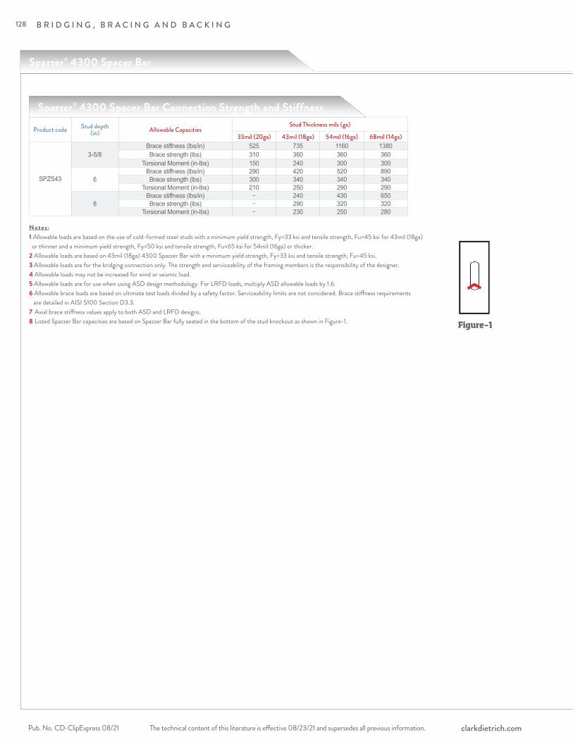
B R I D G I N G , B R A C I N G A N D B A C K I N G
The technical content of this literature is effective 08/23/21 and supersedes all previous information.Pub. No. CD-ClipExpress 08/21 clarkdietrich.com
Spazzer® 4300 Spacer Bar
Spazzer® 4300 Spacer Bar Connection Strength and Stiffness
Product code Stud depth (in) Allowable Capacities
Stud Thickness mils (ga)
33mil (20ga) 43mil (18ga) 54mil (16ga) 68mil (14ga)
SPZS43
3-5/8Brace stiffness (lbs/in) 525 735 1160 1380Brace strength (lbs) 310 360 360 360
Torsional Moment (in-lbs) 150 240 300 300
6Brace stiffness (lbs/in) 290 420 520 890Brace strength (lbs) 300 340 340 340
Torsional Moment (in-lbs) 210 250 290 290
8Brace stiffness (lbs/in) − 240 430 650Brace strength (lbs) − 290 320 320
Torsional Moment (in-lbs) − 230 250 280
Notes:1 Allowable loads are based on the use of cold-formed steel studs with a minimum yield strength, Fy=33 ksi and tensile strength, Fu=45 ksi for 43mil (18ga) or thinner and a minimum yield strength, Fy=50 ksi and tensile strength, Fu=65 ksi for 54mil (16ga) or thicker.2 Allowable loads are based on 43mil (18ga) 4300 Spazzer Bar with a minimum yield strength, Fy=33 ksi and tensile strength, Fu=45 ksi.3 Allowable loads are for the bridging connection only. The strength and serviceability of the framing members is the responsibility of the designer.4 Allowable loads may not be increased for wind or seismic load.5 Allowable loads are for use when using ASD design methodology. For LRFD loads, multiply ASD allowable loads by 1.6.6 Allowable brace loads are based on ultimate test loads divided by a safety factor. Serviceability limits are not considered. Brace stiffness requirements are detailed in AISI S100 Section D3.3.7 Axial brace stiffness values apply to both ASD and LRFD designs.8 Listed Spazzer Bar capacities are based on Spazzer Bar fully seated in the bottom of the stud knockout as shown in Figure-1. Figure-1
128

B R I D G I N G , B R A C I N G A N D B A C K I N G
The technical content of this literature is effective 08/23/21 and supersedes all previous information. The technical content of this literature is effective 08/23/21 and supersedes all previous information. Pub. No. CD-ClipExpress 08/21clarkdietrich.com
BR
IDG
ING
, B
RA
CIN
G &
BA
CK
ING
Spazzer® 4300 Spacer Bar Maximum Bridging Distance (ft.)Stud spacing
(in)Stud section
(in)Stud thickness
mils (ga)Lateral stud pressure (psf)
5 10 15 20 25 30 35 40 45 50
12
362S162
33mils (20ga) 8 8 5 4 − − − − − −43mils (18ga) 8 8 8 6 5 4 4 − − −54mils (16ga) 8 8 8 8 6 5 4 4 − −68mils (14ga) 8 8 8 8 6 5 4 4 − −
362S200
33mils (20ga) 8 6 4 − − − − − − −43mils (18ga) 8 8 6 5 4 − − − − −54mils (16ga) 8 8 8 6 5 4 − − − −68mils (14ga) 8 8 8 6 5 4 − − − −
600S162
33mils (20ga) 8 8 8 6 5 4 4 − − −43mils (18ga) 8 8 8 7 6 5 4 4 − −54mils (16ga) 8 8 8 8 7 6 5 4 4 −68mils (14ga) 8 8 8 8 7 6 5 4 4 4
600S200
33mils (20ga) 8 8 6 5 4 − − − − −43mils (18ga) 8 8 7 6 4 4 − − − −54mils (16ga) 8 8 8 7 5 4 4 − − −68mils (14ga) 8 8 8 7 5 4 4 − − −
800S16243mils (18ga) 8 8 8 8 6 5 4 4 − −54mils (16ga) 8 8 8 8 7 6 5 4 4 −68mils (14ga) 8 8 8 8 8 6 5 5 4 4
800S20043mils (18ga) 8 8 8 6 5 4 − − − −54mils (16ga) 8 8 8 6 5 4 4 − − −68mils (14ga) 8 8 8 7 6 5 4 4 − −
16
362S162
33mils (20ga) 8 6 4 − − − − − − −43mils (18ga) 8 8 6 5 4 − − − − −54mils (16ga) 8 8 8 6 5 4 − − − −68mils (14ga) 8 8 8 6 5 4 − − − −
362S200
33mils (20ga) 8 4 − − − − − − − −43mils (18ga) 8 7 5 4 − − − − − −54mils (16ga) 8 8 6 4 4 − − − − −68mils (14ga) 8 8 6 4 4 − − − − −
600S162
33mils (20ga) 8 8 6 5 4 − − − − −43mils (18ga) 8 8 7 6 4 4 − − − −54mils (16ga) 8 8 8 7 5 4 4 − − −68mils (14ga) 8 8 8 7 5 4 4 − − −
600S200
33mils (20ga) 8 7 5 − − − − − − −43mils (18ga) 8 8 6 4 − − − − − −54mils (16ga) 8 8 7 5 4 − − − − −68mils (14ga) 8 8 7 5 4 − − − − −
800S16243mils (18ga) 8 8 8 6 5 4 − − − −54mils (16ga) 8 8 8 6 5 4 4 − − −68mils (14ga) 8 8 8 7 6 5 4 4 − −
800S20043mils (18ga) 8 8 6 4 − − − − − −54mils (16ga) 8 8 6 5 4 − − − − −68mils (14ga) 8 8 7 5 4 4 − − − −
24
362S162
33mils (20ga) 8 4 − − − − − − − −43mils (18ga) 8 6 4 − − − − − − −54mils (16ga) 8 8 5 4 − − − − − −68mils (14ga) 8 8 5 4 − − − − − −
362S200
33mils (20ga) 6 − − − − − − − − −43mils (18ga) 8 5 − − − − − − − −54mils (16ga) 8 6 4 − − − − − − −68mils (14ga) 8 6 4 − − − − − − −
600S162
33mils (20ga) 8 6 4 − − − − − − −43mils (18ga) 8 7 5 4 − − − − − −54mils (16ga) 8 8 6 4 − − − − − −68mils (14ga) 8 8 6 4 4 − − − − −
600S200
33mils (20ga) 8 5 − − − − − − − −43mils (18ga) 8 6 4 − − − − − − −54mils (16ga) 8 7 4 − − − − − − −68mils (14ga) 8 7 4 − − − − − − −
800S16243mils (18ga) 8 8 5 4 − − − − − −54mils (16ga) 8 8 6 4 − − − − − −68mils (14ga) 8 8 6 5 4 − − − − −
800S20043mils (18ga) 8 6 4 − − − − − − −54mils (16ga) 8 6 4 − − − − − − −68mils (14ga) 8 7 5 4 − − − − − −
Notes:1 Tabulated maximum bridging distances are for ASD lateral pressures.2 Tabulated maximum bridging distances are based on the tested connection strength.3 Studs must be checked for unbraced length seperately.4 Lateral pressures shall be determined based on the load combinations of the applicable building code.5 For designs using 2009 IBC and earlier, wind pressures are at the working stress level and may be used directly.6 For designs using 2012 IBC and 2015 IBC, wind pressures are at the strength level and must be multiplies by 0.6 for ASD load combinations.
129

B R I D G I N G , B R A C I N G A N D B A C K I N G
The technical content of this literature is effective 08/23/21 and supersedes all previous information.Pub. No. CD-ClipExpress 08/21 clarkdietrich.com
A prepunched clip that eliminates the need for cutting and bending when using the Spazzer® 5400 Spacer Bar to facilitate rapid installation of exterior curtain wall framing.
The Spazzer bar fly clip is a secure, fast and efficient way to finish a wall section when using the TradeReady® Spazzer 5400 spacer bar to facilitate the rapid erection of curtain wall or load-bearing framing. Traditionally, at the end of a section, the Spazzer bar would need to be cut and bent to keep the bar in place. With the new Spazzer bar fly clip, installation is as easy as fastening the prepunched clip to the stud and the Spazzer bar. The excess Spazzer bar is cut and installation is complete.
The Spazzer fly clip is the perfect solution for installing off-module studs with the 5400 series Spazzer bar. Simply cut the Spazzer bar just short of the stud web, and use the Spazzer fly clip to quickly connect the Spazzer bar to the face of the stud with self-drilling framing screws.
ALTERNATIVE PRODUC TS Traditional cutting and bending
PRODUC T DIMENSIONS1" x 1-1/4" x 1"
M ATERIAL SPECIFIC ATIONSGauge: 18 gauge (43mil)Design Thickness: 0.0451 inchesCoating: G90 Yield Strength: 50ksiASTM: A653/A653M
LOAD -BE ARING WALL INSTALL ATIONThe TradeReady Spazzer 5400 spacer bar is passed through the stud knockouts and rotated 90º into position, engaging each side of the knockout. In load-bearing applications, some type of attachment is required to keep the bar in place—the Spazzer bar fly clip is an optimum solution. The TradeReady Spazzer 5400 bar should be installed at a maximum 4' o.c. vertically or per specifications. The Spazzer bar should not be used in studs over 6" wide.
Product code Size (in) Packaging Pcs./CartonSFLY 1 x 1-1/4 x 1 100
Spazzer® Bar Fly Clip (SFLY)
Spazzer Bar Fly Clip
13/16"
1"
1"
1-1/4"
Visit our CAD Library at clarkdietrich.com to view or download construction details in .dwg, .dxf, and .pdf formats.
Typical Construction Details
Spazzer® Bar Fly Clip
130

B R I D G I N G , B R A C I N G A N D B A C K I N G
The technical content of this literature is effective 08/23/21 and supersedes all previous information. The technical content of this literature is effective 08/23/21 and supersedes all previous information. Pub. No. CD-ClipExpress 08/21clarkdietrich.com
BR
IDG
ING
, B
RA
CIN
G &
BA
CK
INGProduct code Width (in) Length (in) Packaging Pcs./Skid
FBW 5-1/8 10-1/2 720FBW 5-1/8 14-1/2 540FBW 5-1/8 22-1/2 360FBW 10-1/4 10-1/2 720FBW 10-1/4 14-1/2 540FBW 10-1/4 22-1/2 360
FastBack™ Backing System (FBBC)
Dricon® Wood Backing
Reduces finishing time with no exposed fasteners on the face of the product.
The FastBack™ backing system features a universal design that works with studs in either direction—concealing fasteners on the face of the product. The system creates an interlocked design between the stud and track for baseboard backing installations; and a cutaway design allows backing and bracing to be installed all the way to the floor. Pre-cut and fire-rated, the Dricon® Wood Backing is sized to fit 12," 16" and 24" o.c. spacing. Available for overnight delivery.
PRODUC T DIMENSIONS1-1/4" x 5-1/8"1-1/4" x 10-1/4"
INSTALL ATIONRotate the FastBack clip over the flange of the stud until it sits flush. Fasten into place using drywall screws in the pre-drilled holes. Place wood onto tabs and fasten into place using standard drywall screws.
Product code Width (in) Length (in) Packaging Pcs./CartonFBBC 1-1/4 5-1/8 100FBBC 1-1/4 10-1/4 100
U.S. Patent No. 7,882,676 of Jeffrey Thomas EllisDricon is a registered trademark of Arch Wood Protection, Inc.
Dricon® FRT Wood complies with or has been granted the following:
FastBack™ Backing System
FlamePRO® Fire Retardant complies with or has been granted the following:• UL GREENGUARD Gold Certification – UL 2818• ICC ESR-4244• AWPA E12, AWPA M4, AWPA P50, AWPA T1 standard• Cal Fire Certified• American Institute of Architects Approved• ASTM 2768• ASTM D3201, D5516, D5664, E84, E119, 2768, D6305, D6841• AWPA T1• AWPA UC-1• Class A FRT wood• UL Recognized Component• NFPA 703, 101 Life Safety Code• City of Los Angeles Building Code• City of Los Angeles Residential Code• National Building Code of Canada• One & two hour tested wall assemblies• 50-year warranty• UL Classified with an FR-S Rating for flame spread and smoke development values of 25 or less(All are subject to revision, re-examination)
• AWPA T1 Section 8.8• AWPA P49 (FR-1), P25 (SBX)• AWPA U1 (UC1, UC2, UCFA) and former C9, C20, C27, C31• Flamespread and Smoke Development Rating of 25 or Less• Class A FRT wood• UL Recognized Component - UL 723• NFPA 703, 101 Life Safety Code• ICC-ES ESR-1626• EPA registration (62190-9)• NYC MEA 199-81-M, NYC MEA 200-81-M• Factory Mutual Class 1 Roof Deck• City of Los Angeles (RR 25122)• FHA Minimum Property Standard #2600• HUD Materials Release (1261)• ASTM D 5516, D5664, E84• Mil Spec. L-19140E• National Building Code of Canada• Truss warranty program with Structural Building Components Association• NFPA 255• Wisconsin Material Approval 960073-W(All are subject to revision, re-examination)
131
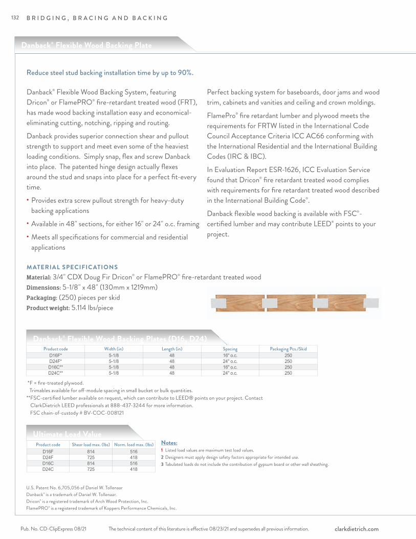
B R I D G I N G , B R A C I N G A N D B A C K I N G
The technical content of this literature is effective 08/23/21 and supersedes all previous information.Pub. No. CD-ClipExpress 08/21 clarkdietrich.com
Reduce steel stud backing installation time by up to 90%.
Danback® Flexible Wood Backing Plates (D16, D24)
Ultimate Load Value
U.S. Patent No. 6,705,056 of Daniel W. TollenaarDanback® is a trademark of Daniel W. Tollenaar.Dricon® is a registered trademark of Arch Wood Protection, Inc.FlamePRO® is a registered trademark of Koppers Performance Chemicals, Inc.
Product code Width (in) Length (in) Spacing Packaging Pcs./SkidD16F* 5-1/8 48 16" o.c. 250D24F* 5-1/8 48 24" o.c. 250D16C** 5-1/8 48 16" o.c. 250D24C** 5-1/8 48 24" o.c. 250
Product code Shear load max. (lbs) Norm. load max. (lbs)D16F 814 516D24F 725 418D16C 814 516D24C 725 418
Danback® Flexible Wood Backing System, featuring Dricon® or FlamePRO® fire-retardant treated wood (FRT), has made wood backing installation easy and economical-eliminating cutting, notching, ripping and routing.
Danback provides superior connection shear and pullout strength to support and meet even some of the heaviest loading conditions. Simply snap, flex and screw Danback into place. The patented hinge design actually flexes around the stud and snaps into place for a perfect fit-every time.• Provides extra screw pullout strength for heavy-duty backing applications• Available in 48" sections, for either 16" or 24" o.c. framing• Meets all specifications for commercial and residential applications
Perfect backing system for baseboards, door jams and wood trim, cabinets and vanities and ceiling and crown moldings.
FlamePro® fire retardant lumber and plywood meets the requirements for FRTW listed in the International Code Council Acceptance Criteria ICC AC66 conforming with the International Residential and the International Building Codes (IRC & IBC).
In Evaluation Report ESR-1626, ICC Evaluation Service found that Dricon® fire retardant treated wood complies with requirements for fire retardant treated wood described in the International Building Code®.
Danback flexible wood backing is available with FSC®-certified lumber and may contribute LEED® points to your project.
* F = fire-treated plywood. Trimables available for off-module spacing in small bucket or bulk quantities.
** FSC-certified lumber available on request, which can contribute to LEED® points on your project. Contact ClarkDietrich LEED professionals at 888-437-3244 for more information.
FSC chain-of-custody # BV-COC-008121
Notes:1 Listed load values are maximum test load values. 2 Designers must apply design safety factors appropriate for intended use. 3 Tabulated loads do not include the contribution of gypsum board or other wall sheathing.
Danback® Flexible Wood Backing Plate
M ATERIAL SPECIFIC ATIONSMaterial: 3/4" CDX Doug Fir Dricon® or FlamePRO® fire-retardant treated woodDimensions: 5-1/8" x 48" (130mm x 1219mm)Packaging: (250) pieces per skidProduct weight: 5.114 lbs/piece
132

B R I D G I N G , B R A C I N G A N D B A C K I N G
The technical content of this literature is effective 08/23/21 and supersedes all previous information. The technical content of this literature is effective 08/23/21 and supersedes all previous information. Pub. No. CD-ClipExpress 08/21clarkdietrich.com
BR
IDG
ING
, B
RA
CIN
G &
BA
CK
ING
Commonly used in: hospitals, medical centers, schools, hotels/motels, assisted living, condominiums, and others. The perfect backing solution for: cabinets, shelves, counters, sinks, handrails, chalkboards, towel and shower bars, or other wall-mounted fixtures that require heavy-duty backing.
Snap starter edge into the open side of the stud flange.
HINT: Start with the first full bay. Use Danback trimables for off-module bays.
Flex Danback flexible wood backing around stud flange using the flexible connector plate.
Repeat the process. Overlap connector plates when using in long backing runs.
Cut to required length. Secure connector plate to the trimmed edge. Leave 1-1 /4" extended over the trimmed edge. Fasten the plate to Danback using three small pan or wafer-head screws.
Secure each plate to the stud flange using two small pan or wafer-head screws.
Use Danback trimables for off-module bays:
Danback trimables for off-module backing.
Connector plates included with trimables.
Easy installation.
Dricon® FRT Wood complies with or has been granted the following:FlamePRO® Fire Retardant complies with or has been granted the following:• UL GREENGUARD Gold Certification – UL 2818• ICC ESR-4244• AWPA E12, AWPA M4, AWPA P50, AWPA T1 standard• Cal Fire Certified• American Institute of Architects Approved• ASTM 2768• ASTM D3201, D5516, D5664, E84, E119, 2768, D6305, D6841• AWPA T1• AWPA UC-1• Class A FRT wood• UL Recognized Component• NFPA 703, 101 Life Safety Code• City of Los Angeles Building Code• City of Los Angeles Residential Code• National Building Code of Canada• One & two hour tested wall assemblies• 50-year warranty• UL Classified with an FR-S Rating for flame spread and smoke development values of 25 or less(All are subject to revision, re-examination)
• AWPA T1 Section 8.8• AWPA P49 (FR-1), P25 (SBX)• AWPA U1 (UC1, UC2, UCFA) and former C9, C20, C27, C31• Flamespread and Smoke Development Rating of 25 or Less• Class A FRT wood• UL Recognized Component - UL 723• NFPA 703, 101 Life Safety Code• ICC-ES ESR-1626• EPA registration (62190-9)• NYC MEA 199-81-M, NYC MEA 200-81-M• Factory Mutual Class 1 Roof Deck• City of Los Angeles (RR 25122)• FHA Minimum Property Standard #2600• HUD Materials Release (1261)• ASTM D 5516, D5664, E84• Mil Spec. L-19140E• National Building Code of Canada• Truss warranty program with Structural Building Components Association• NFPA 255• Wisconsin Material Approval 960073-W(All are subject to revision, re-examination)
133

B R I D G I N G , B R A C I N G A N D B A C K I N G
The technical content of this literature is effective 08/23/21 and supersedes all previous information.Pub. No. CD-ClipExpress 08/21 clarkdietrich.com
Backer Bar
Provides superior connection shear and pullout strength for handrails, shelves and other wall fixtures
The Backer Bar was specifically designed to meet the demand for the attachment of multiple items and heavier items to interior partitions.
Today’s building professionals require solutions to allow the attachment of such products and accessories to the interior partition walls. Traditionally, backing systems have been costly, time-consuming and not necessarily performing to the required code specified load requirements. Backer Bar is designed for use on non-structural and structural studs.
T YPIC AL APPLIC ATIONS:
• Wall-Mounted Televisions
• Hospital Handrails
• Towel and Shower Bars
• Cabinets and Shelves
FE ATURES AND BENEFITS:
• Installs quickly and easily
• Available in 12", 16" and 24" spacing
• For use on non-structural and structural studs
Canada Patent Pending – 2,811,362 USA Patent – 9,062,455
PRODUC T DIMENSIONSLeg: 1-1/4" Width: 5" Lengths: For 12", 16" and 24" o.c. stud spacing
M ATERIAL SPECIFIC ATIONSGauge: 20 gauge STR (33mil)Design Thickness: 0.0346 inches Coating: G90Material: Grade 50ksi min. yield strength
SPACING
12”, 16 & 24”
5”
Backer Bar (BB12, BB16,BB24)
Product codeThickness
Size (in) Packaging Mils (Gauge) Design thickness (in)
BB12 33mil (20ga) 0.0346 1-1/4" x 5" x 12"IndividualBB16 33mil (20ga) 0.0346 1-1/4" x 5" x 16"
BB24 33mil (20ga) 0.0346 1-1/4" x 5" x 24"
134

B R I D G I N G , B R A C I N G A N D B A C K I N G
The technical content of this literature is effective 08/23/21 and supersedes all previous information. The technical content of this literature is effective 08/23/21 and supersedes all previous information. Pub. No. CD-ClipExpress 08/21clarkdietrich.com
BR
IDG
ING
, B
RA
CIN
G &
BA
CK
ING
33mil, 43mil or 54mil fire shield system
BlazeFrame® Shield
ClarkDietrich’s BlazeFrame Shield is specifically designed for use in conjunction with approved fireblocking materials per section 718 of the IBC. BlazeFrame Shield simply installs by twisting into stud flanges and screwing into stud webs. The one piece preformed assembly eliminates cutting, notching and attaching clips.
• Installs quickly and easily without clips
• Available for 16" and 24" stud spacing
• Three available widths
• Available in 33mil (20ga), 43mil (18ga) or 54mil (16ga)
• Pre-notched for use on structural studs (1-5/8" flange only)
PRODUC T DIMENSIONSHorizontal leg: 1" Connection Tabs: Top: 2", Bottom: 1-1/2" Width: 3-5/8", 4" or 6" Lengths: For 16" and 24" o.c. stud spacing
M ATERIAL SPECIFIC ATIONSGauge: 20 gauge STR (33mil)Design Thickness: 0.0346 inches
Gauge: 18 gauge (43mil)Design Thickness: 0.0451 inches Gauge: 16 gauge (54mil)Design Thickness: 0.0566 inches Coating: CP60Yield Strength: 33ksi for 33mil & 43mil 50ksi for 54milASTM: C955, A1003
BlazeFrame® Shield
Product codeThickness
Size (in)Mils (Gauge) Design thickness (in)
FS316-33 33mil (20ga) 0.0346 3-5/8" web 16" o.c.FS316-43 43mil (18ga) 0.0451 3-5/8" web 16" o.c.FS316-54 54mil (16ga) 0.0566 3-5/8" web 16" o.c.FS324-33 33mil (20ga) 0.0346 3-5/8" web 24" o.c.FS324-43 43mil (18ga) 0.0451 3-5/8" web 24" o.c.FS324-54 54mil (16ga) 0.0566 3-5/8" web 24" o.c.FS416-33 33mil (20ga) 0.0346 4" web 16" o.c.FS416-43 43mil (18ga) 0.0451 4" web 16" o.c.FS416-54 54mil (16ga) 0.0566 4" web 16" o.c.FS424-33 33mil (20ga) 0.0346 4" web 24" o.c.FS424-43 43mil (18ga) 0.0451 4" web 24" o.c.FS424-54 54mil (16ga) 0.0566 4" web 24" o.c.FS616-33 33mil (20ga) 0.0346 6" web 16" o.c.FS616-43 43mil (18ga) 0.0451 6" web 16" o.c.FS616-54 54mil (16ga) 0.0566 6" web 16" o.c.FS624-33 33mil (20ga) 0.0346 6" web 24" o.c.FS624-43 43mil (18ga) 0.0451 6" web 24" o.c.FS624-54 54mil (16ga) 0.0566 6" web 24" o.c.
135

R O O F A N D T R U S S C O N N E C T I O N S
The technical content of this literature is effective 08/23/21 and supersedes all previous information.Pub. No. CD-ClipExpress 08/21 clarkdietrich.com
1
4
2
3
Product Detail
5
6
136
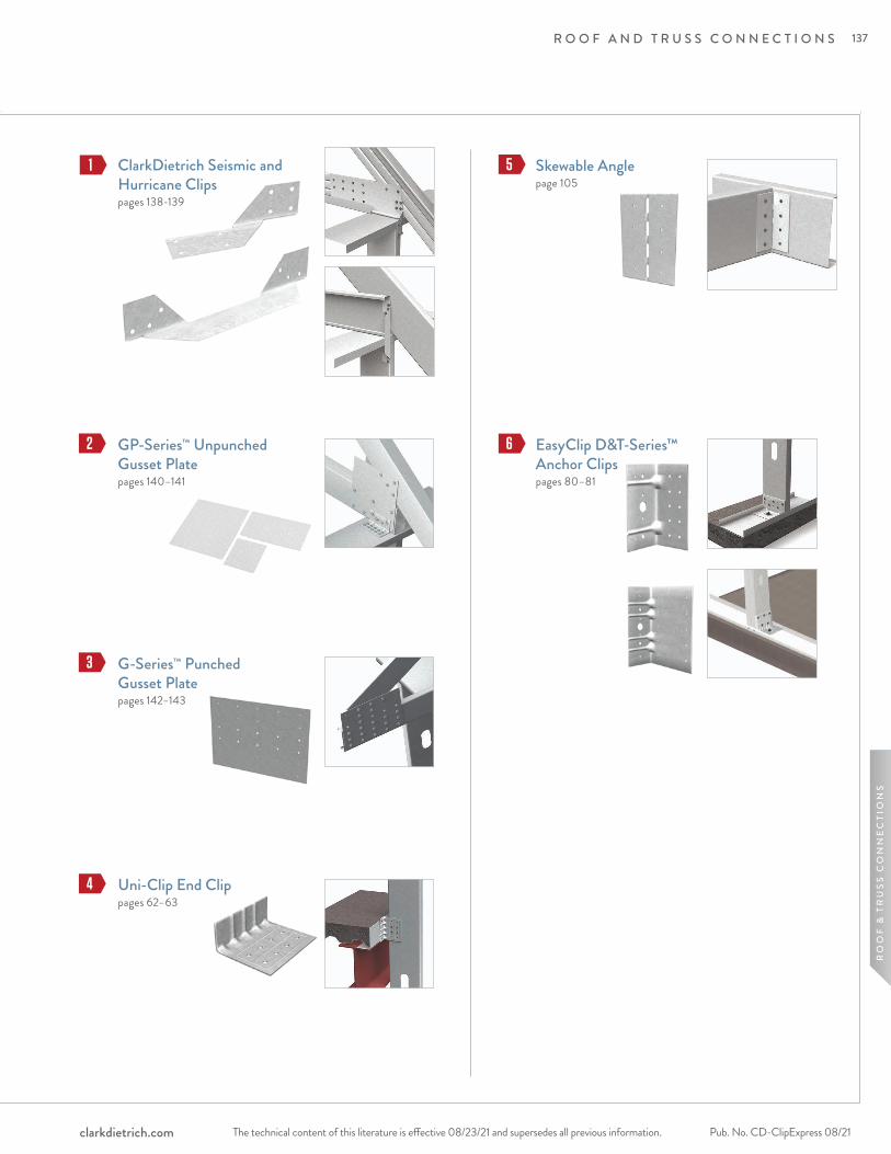
R O O F A N D T R U S S C O N N E C T I O N S
The technical content of this literature is effective 08/23/21 and supersedes all previous information. The technical content of this literature is effective 08/23/21 and supersedes all previous information. Pub. No. CD-ClipExpress 08/21clarkdietrich.com
RO
OF
& T
RU
SS
CO
NN
EC
TIO
NS
ClarkDietrich Seismic and Hurricane Clipspages 138-139
Uni-Clip End Clippages 62–63
GP-Series™ Unpunched Gusset Plate pages 140–141
G-Series™ Punched Gusset Platepages 142–143
1
2
3
4
5 Skewable Anglepage 105
6 EasyClip D&T-Series™ Anchor Clipspages 80–81
137

R O O F A N D T R U S S C O N N E C T I O N S
The technical content of this literature is effective 08/23/21 and supersedes all previous information.Pub. No. CD-ClipExpress 08/21 clarkdietrich.com
ClarkDietrich seismic and hurricane ties are designed to provide wind and seismic resistance for trusses and rafters. Quick and efficient, these versatile connectors can also be used for general tie-down purposes, strong back attachments and as all-purpose ties where one member crosses another. The H2 and H2A seismic and hurricane ties are formed from a flat plate into an A-shaped section. The plate has a right-angle bend along its longitudinal axis to permit straddling a top plate. The H2.5 and H3 are twisted strap ties that are used to attach a rafter to the side of the top plate.
ALTERNATIVE PRODUC TSEasyClip™ T-Series™ Tall Anchor Clip EasyClip E-Series™ Support Clip
M ATERIAL SPECIFIC ATIONSGauge: 18 gauge (43mil) Design Thickness: 0.0451 inches Coating: G90 Yield Strength: 50ksi ASTM: A653/A653M
ClarkDietrich Seismic and Hurricane Ties
Attach and secures trusses and rafters to the building structure.
Product codeThickness
Size (in) Packaging Pcs./CartonMils (Gauge) Design thickness (in)
H2 43mil (18ga) 0.0451 1-9/16 x 9-7/16 x 1-9/16 100 H2A 43mil (18ga) 0.0451 1-1/2 x 10-7/16 x 1-1/2 100 H2.5 43mil (18ga) 0.0451 1-9/16 x 5-7/16 x 1-9/16 100
H3 43mil (18ga) 0.0451 1-9/16 x 4-5/8 x 1-9/16 100
Seismic and Hurricane Ties
H2
9-7/16"
3-1/4"
1-9/16"
1-1/2"
H2A
10-7/16"
3-3/8"
1-1/2"
3-1/2"
H2.5
5-7/16"
2-3/8"
1-9/16"
1-9/16"
H3
4-5/8"1-9/16"
1-9/16"
1-1/2"
138
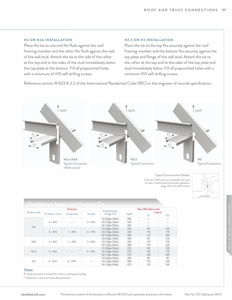
R O O F A N D T R U S S C O N N E C T I O N S
The technical content of this literature is effective 08/23/21 and supersedes all previous information. The technical content of this literature is effective 08/23/21 and supersedes all previous information. Pub. No. CD-ClipExpress 08/21clarkdietrich.com
RO
OF
& T
RU
SS
CO
NN
EC
TIO
NS
H2 OR H2A INSTALL ATIONPlace the tie so one end fits flush against the roof framing member and the other fits flush against the web of the wall stud. Attach the tie to the side of the rafter at the top and to the sides of the stud immediately below the top plate at the bottom. Fill all prepunched holes with a minimum of #10 self-drilling screws.
H2.5 OR H3 INSTALL ATIONPlace the tie so the top fits securely against the roof framing member and the bottom fits securely against the top plate and flange of the wall stud. Attach the tie to the rafter at the top and to the sides of the top plate and stud immediately below. Fill all prepunched holes with a minimum #10 self-drilling screws.
Notes:1 Loads have been increased for wind or earthquake loading.* Fasteners to top track must also penetrate.
Product codeFasteners
Stud thicknessmil (ga, ksi)
Max. Allowable Loads
To rafters / truss To top track To stud Uplift LateralF1 F2
H2
3 – #10 — 3 – #1033 (20ga 33ksi) 405 — —43 (18ga 33ksi) 445 — —54 (16ga 50ksi) 465 — —
3 – #10 1 – #10 3 – #1033 (20ga 33ksi) 405 90 12043 (18ga 33ksi) 445 110 17054 (16ga 50ksi) 465 110 225
H2A 3 – #10 1 – #10 3 – #1033 (20ga 33ksi) 405 90 12043 (18ga 33ksi) 445 110 17054 (16ga 50ksi) 465 110 225
H2.5 4 – #10 — 4 – #1033 (20ga 33ksi) 410 90 12043 (18ga 33ksi) 475 140 17054 (16ga 50ksi) 475 140 225
H3 2 – #10 2 – #10* —33 (20ga 33ksi) 340 80 8043 (18ga 33ksi) 465 110 14054 (16ga 50ksi) 475 110 195
H2 or H2A Typical Connection (H2A similar)
Visit our CAD Library at clarkdietrich.com to view or download construction details in
.dwg, .dxf, and .pdf formats.
Typical Construction Details
ClarkDietrich Seismic and Hurricane Ties
H2.5 Typical Connection
H3 Typical Connection
F1
F2
Uplift
F1
F2
Uplift
F1
F2
Uplift
Reference section R 603.8.3.2 of the International Residential Code (IRC) or the engineer of records specification.
139
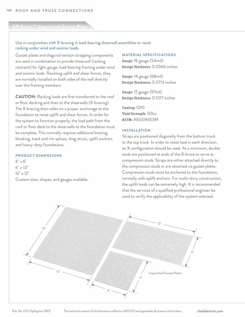
R O O F A N D T R U S S C O N N E C T I O N S
The technical content of this literature is effective 08/23/21 and supersedes all previous information.Pub. No. CD-ClipExpress 08/21 clarkdietrich.com
Use in conjunction with X-bracing in load-bearing shearwall assemblies to resist racking under wind and seismic loads.
Unpunched Gusset Plates
12"
12"
12"
6"
6"
6"
Gusset plates and diagonal tension strapping components are used in combination to provide shearwall (racking restraint) for light-gauge, load-bearing framing under wind and seismic loads. Resisting uplift and shear forces, they are normally installed on both sides of the wall directly over the framing members.
CAUTION: Racking loads are first transferred to the roof or floor decking and then to the shearwalls (X-bracing). The X-bracing then relies on a proper anchorage to the foundation to resist uplift and shear forces. In order for the system to function properly, the load path from the roof or floor deck to the shearwalls to the foundation must be complete. This normally requires additional bracing, blocking, track and rim splices, drag struts, uplift anchors and heavy-duty foundations.
PRODUC T DIMENSIONS6" x 6"6" x 12" 12" x 12" Custom sizes, shapes, and gauges available.
M ATERIAL SPECIFIC ATIONSGauge: 16 gauge (54mil)Design Thickness: 0.0566 inches
Gauge: 14 gauge (68mil)Design Thickness: 0.0713 inches
Gauge: 12 gauge (97mil)Design Thickness: 0.1017 inches
Coating: G90 Yield Strength: 50ksi ASTM: A653/A653M
INSTALL ATIONStraps are positioned diagonally from the bottom track to the top track. In order to resist load in each direction, an X-configuration should be used. At a minimum, double studs are positioned at ends of the X-brace to serve as compression studs. Straps are either attached directly to the compression studs or are attached via gusset plates. Compression studs must be anchored to the foundation, normally with uplift anchors. For multi-story construction, the uplift loads can be extremely high. It is recommended that the services of a qualified professional engineer be used to verify the applicability of the system selected.
GP-Series™ Unpunched Gusset Plate
140
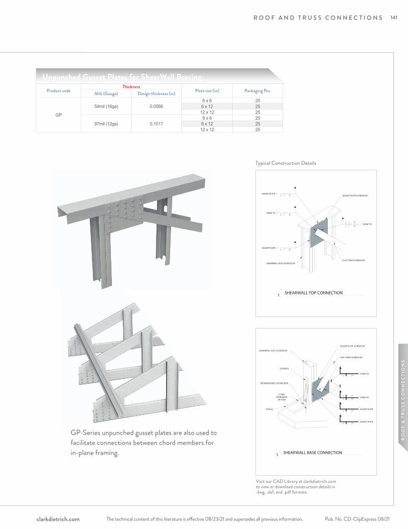
R O O F A N D T R U S S C O N N E C T I O N S
The technical content of this literature is effective 08/23/21 and supersedes all previous information. The technical content of this literature is effective 08/23/21 and supersedes all previous information. Pub. No. CD-ClipExpress 08/21clarkdietrich.com
RO
OF
& T
RU
SS
CO
NN
EC
TIO
NS
Typical Construction Details
Unpunched Gusset Plates for ShearWall Bracing
Visit our CAD Library at clarkdietrich.com to view or download construction details in .dwg, .dxf, and .pdf formats.
Product codeThickness
Plate size (in) Packaging Pcs.Mils (Gauge) Design thickness (in)
GP
54mil (16ga) 0.05666 x 6 256 x 12 2512 x 12 25
97mil (12ga) 0.10176 x 6 256 x 12 2512 x 12 25
GP-Series unpunched gusset plates are also used to facilitate connections between chord members for in-plane framing.
141
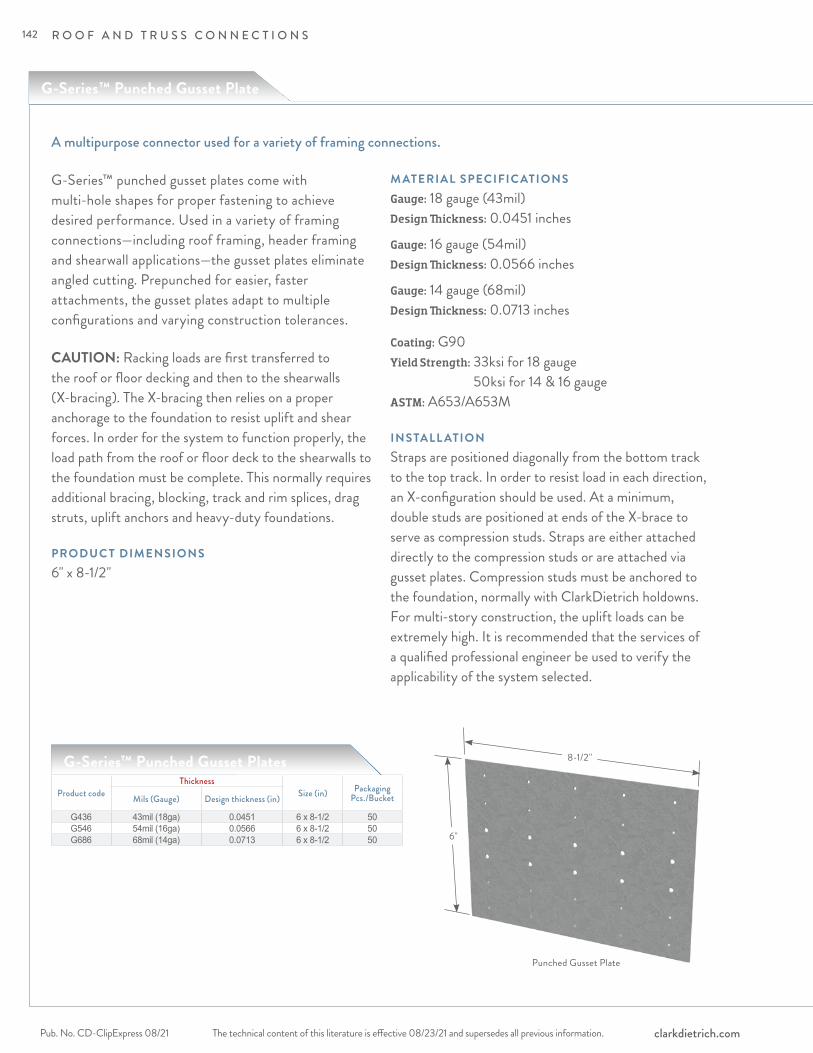
R O O F A N D T R U S S C O N N E C T I O N S
The technical content of this literature is effective 08/23/21 and supersedes all previous information.Pub. No. CD-ClipExpress 08/21 clarkdietrich.com
A multipurpose connector used for a variety of framing connections.
G-Series™ punched gusset plates come with multi-hole shapes for proper fastening to achieve desired performance. Used in a variety of framing connections—including roof framing, header framing and shearwall applications—the gusset plates eliminate angled cutting. Prepunched for easier, faster attachments, the gusset plates adapt to multiple configurations and varying construction tolerances.
CAUTION: Racking loads are first transferred to the roof or floor decking and then to the shearwalls (X-bracing). The X-bracing then relies on a proper anchorage to the foundation to resist uplift and shear forces. In order for the system to function properly, the load path from the roof or floor deck to the shearwalls to the foundation must be complete. This normally requires additional bracing, blocking, track and rim splices, drag struts, uplift anchors and heavy-duty foundations.
PRODUC T DIMENSIONS6" x 8-1/2"
M ATERIAL SPECIFIC ATIONSGauge: 18 gauge (43mil)Design Thickness: 0.0451 inches
Gauge: 16 gauge (54mil) Design Thickness: 0.0566 inches
Gauge: 14 gauge (68mil) Design Thickness: 0.0713 inches
Coating: G90Yield Strength: 33ksi for 18 gauge
50ksi for 14 & 16 gaugeASTM: A653/A653M
INSTALL ATIONStraps are positioned diagonally from the bottom track to the top track. In order to resist load in each direction, an X-configuration should be used. At a minimum, double studs are positioned at ends of the X-brace to serve as compression studs. Straps are either attached directly to the compression studs or are attached via gusset plates. Compression studs must be anchored to the foundation, normally with ClarkDietrich holdowns. For multi-story construction, the uplift loads can be extremely high. It is recommended that the services of a qualified professional engineer be used to verify the applicability of the system selected.
8-1/2"
6"
Punched Gusset Plate
G-Series™ Punched Gusset Plate
Product codeThickness
Size (in) Packaging Pcs./BucketMils (Gauge) Design thickness (in)
G436 43mil (18ga) 0.0451 6 x 8-1/2 50G546 54mil (16ga) 0.0566 6 x 8-1/2 50G686 68mil (14ga) 0.0713 6 x 8-1/2 50
G-Series™ Punched Gusset Plates
G-Series™ Punched Gusset Plate
142
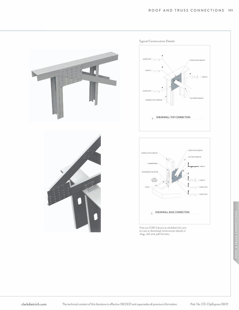
R O O F A N D T R U S S C O N N E C T I O N S
The technical content of this literature is effective 08/23/21 and supersedes all previous information. The technical content of this literature is effective 08/23/21 and supersedes all previous information. Pub. No. CD-ClipExpress 08/21clarkdietrich.com
RO
OF
& T
RU
SS
CO
NN
EC
TIO
NS
Typical Construction Details
Visit our CAD Library at clarkdietrich.com to view or download construction details in .dwg, .dxf, and .pdf formats.
CLARKDIETRICH
143

Product Detail
S P E C I A LT Y C L I P S A N D A C C E S S O R I E S
The technical content of this literature is effective 08/23/21 and supersedes all previous information.Pub. No. CD-ClipExpress 08/21 clarkdietrich.com
2
4
1
3
HDSC Header Bracket for RedHeader PRO™pages 146–149
Aluminum Burn Clippage 150
Grommets for Stud Knockoutspage 151
ClarkDietrich Sound Clippage 152-157
144

S P E C I A LT Y C L I P S A N D A C C E S S O R I E S
The technical content of this literature is effective 08/23/21 and supersedes all previous information. The technical content of this literature is effective 08/23/21 and supersedes all previous information. Pub. No. CD-ClipExpress 08/21clarkdietrich.com
SP
EC
IALT
Y &
DR
YW
ALL
5
Metal Furring Channel Clippage 159
6
Header Cripple Studpage 158
Panel Lift Clippages 160-161
7
Commercial Strappingpages 162-163
8
145

S P E C I A LT Y C L I P S A N D A C C E S S O R I E S
The technical content of this literature is effective 08/23/21 and supersedes all previous information.Pub. No. CD-ClipExpress 08/21 clarkdietrich.com
For use with the RedHeader PRO™ Rough Opening System.
HDSC Header Bracket
The HDSC Header Bracket is the perfect complement to the RedHeader PRO™ Framing system and HDS® Framing System. This simple, yet innovative header bracket turns curtain-wall header installation from a two-person job into a one-person job. This unique, pre-punched clip also eliminates surface head fastener buildup that can create finishing challenges. The HDSC is sized to be used with either 3" or 3-1/2" flanged member.
PRODUC T DIMENSIONS3-1/2" x 3-1/16" x 2" 3-7/8" x 3-1/16" x 2" 5-7/8" x 3-1/16" x 2" 7-7/8" x 3-1/16" x 2"
M ATERIAL SPECIFIC ATIONSGauge: 20 gauge (33mil) Design Thickness: 0.0346 inchesYield Strength: 33ksi
Gauge: 14 gauge (68mil) Design Thickness: 0.0713 inchesYield Strength: 50ksi
Gauge: 12 gauge (97mil) Design Thickness: 0.1017 inchesYield Strength: 50ksi
Coating: G90 ASTM: A653/A653M, A1003/A1003M
3-1/2, 3-7/8, 5-7/8, 7-7/8
3-1/1
6", 3
-9/16
"
2"
3-1/2" x 3-9/16" x 2" 3-7/8" x 3-9/16" x 2" 5-7/8" x 3-9/16" x 2" 7-7/8" x 3-9/16" x 2"
146
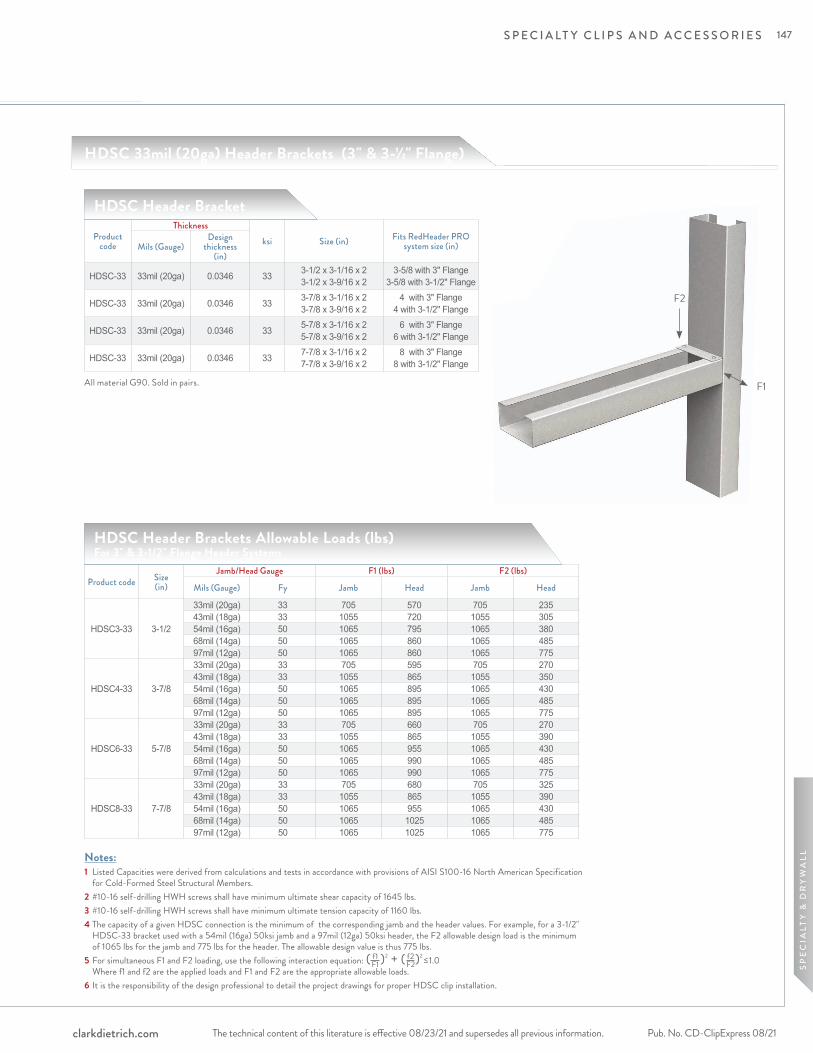
S P E C I A LT Y C L I P S A N D A C C E S S O R I E S
The technical content of this literature is effective 08/23/21 and supersedes all previous information. The technical content of this literature is effective 08/23/21 and supersedes all previous information. Pub. No. CD-ClipExpress 08/21clarkdietrich.com
SP
EC
IALT
Y &
DR
YW
ALL
F2
F1
Product code
Thicknessksi Size (in) Fits RedHeader PRO
system size (in)Mils (Gauge)Design
thickness (in)
HDSC-33 33mil (20ga) 0.0346 33 3-1/2 x 3-1/16 x 2 3-1/2 x 3-9/16 x 2
3-5/8 with 3" Flange 3-5/8 with 3-1/2" Flange
HDSC-33 33mil (20ga) 0.0346 33 3-7/8 x 3-1/16 x 2 3-7/8 x 3-9/16 x 2
4 with 3" Flange 4 with 3-1/2" Flange
HDSC-33 33mil (20ga) 0.0346 33 5-7/8 x 3-1/16 x 2 5-7/8 x 3-9/16 x 2
6 with 3" Flange 6 with 3-1/2" Flange
HDSC-33 33mil (20ga) 0.0346 33 7-7/8 x 3-1/16 x 2 7-7/8 x 3-9/16 x 2
8 with 3" Flange 8 with 3-1/2" Flange
All material G90. Sold in pairs.
HDSC Header Bracket
HDSC Header Brackets Allowable Loads (lbs) For 3" & 3-1/2" Flange Header Systems
Product code Size(in)
Jamb/Head Gauge F1 (lbs) F2 (lbs)
Mils (Gauge) Fy Jamb Head Jamb Head
HDSC3-33 3-1/2
33mil (20ga) 33 705 570 705 23543mil (18ga) 33 1055 720 1055 30554mil (16ga) 50 1065 795 1065 38068mil (14ga) 50 1065 860 1065 48597mil (12ga) 50 1065 860 1065 775
HDSC4-33 3-7/8
33mil (20ga) 33 705 595 705 27043mil (18ga) 33 1055 865 1055 35054mil (16ga) 50 1065 895 1065 43068mil (14ga) 50 1065 895 1065 48597mil (12ga) 50 1065 895 1065 775
HDSC6-33 5-7/8
33mil (20ga) 33 705 660 705 27043mil (18ga) 33 1055 865 1055 39054mil (16ga) 50 1065 955 1065 43068mil (14ga) 50 1065 990 1065 48597mil (12ga) 50 1065 990 1065 775
HDSC8-33 7-7/8
33mil (20ga) 33 705 680 705 32543mil (18ga) 33 1055 865 1055 39054mil (16ga) 50 1065 955 1065 43068mil (14ga) 50 1065 1025 1065 48597mil (12ga) 50 1065 1025 1065 775
HDSC 33mil (20ga) Header Brackets (3" & 3-1/2" Flange)
Notes:1 Listed Capacities were derived from calculations and tests in accordance with provisions of AISI S100-16 North American Specification
for Cold-Formed Steel Structural Members.2 #10-16 self-drilling HWH screws shall have minimum ultimate shear capacity of 1645 lbs.3 #10-16 self-drilling HWH screws shall have minimum ultimate tension capacity of 1160 lbs. 4 The capacity of a given HDSC connection is the minimum of the corresponding jamb and the header values. For example, for a 3-1/2" HDSC-33 bracket used with a 54mil (16ga) 50ksi jamb and a 97mil (12ga) 50ksi header, the F2 allowable design load is the minimum of 1065 lbs for the jamb and 775 lbs for the header. The allowable design value is thus 775 lbs.5 For simultaneous F1 and F2 loading, use the following interaction equation: ( )2 + ( )2 ≤ 1.0 Where f1 and f2 are the applied loads and F1 and F2 are the appropriate allowable loads.6 It is the responsibility of the design professional to detail the project drawings for proper HDSC clip installation.
f1 F1
f2 F2
147
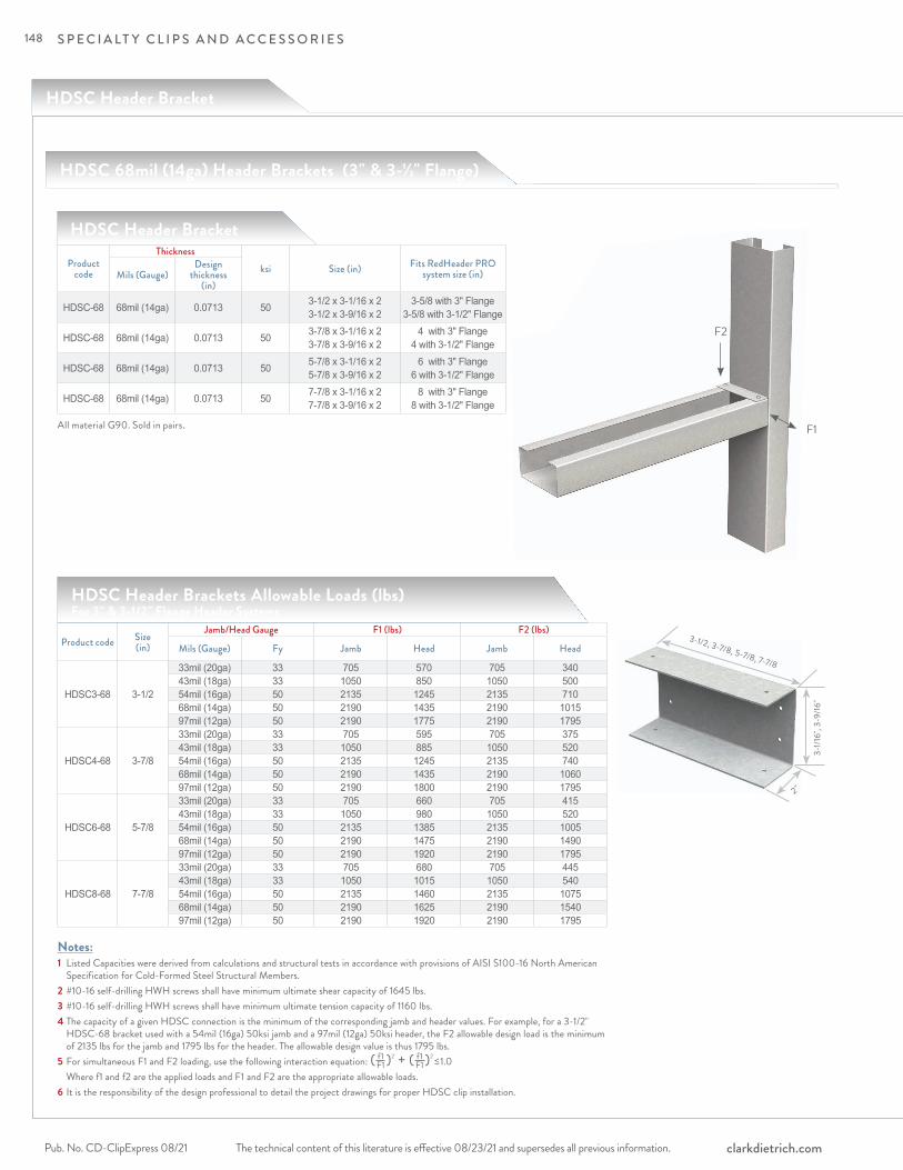
S P E C I A LT Y C L I P S A N D A C C E S S O R I E S
The technical content of this literature is effective 08/23/21 and supersedes all previous information.Pub. No. CD-ClipExpress 08/21 clarkdietrich.com
HDSC Header Bracket
F2
F1
Product code
Thicknessksi Size (in) Fits RedHeader PRO
system size (in)Mils (Gauge)Design
thickness (in)
HDSC-68 68mil (14ga) 0.0713 50 3-1/2 x 3-1/16 x 2 3-1/2 x 3-9/16 x 2
3-5/8 with 3" Flange 3-5/8 with 3-1/2" Flange
HDSC-68 68mil (14ga) 0.0713 50 3-7/8 x 3-1/16 x 2 3-7/8 x 3-9/16 x 2
4 with 3" Flange 4 with 3-1/2" Flange
HDSC-68 68mil (14ga) 0.0713 50 5-7/8 x 3-1/16 x 2 5-7/8 x 3-9/16 x 2
6 with 3" Flange 6 with 3-1/2" Flange
HDSC-68 68mil (14ga) 0.0713 50 7-7/8 x 3-1/16 x 2 7-7/8 x 3-9/16 x 2
8 with 3" Flange 8 with 3-1/2" Flange
All material G90. Sold in pairs.
HDSC Header Bracket
HDSC Header Brackets Allowable Loads (lbs) For 3" & 3-1/2" Flange Header Systems
Product code Size(in)
Jamb/Head Gauge F1 (lbs) F2 (lbs)
Mils (Gauge) Fy Jamb Head Jamb Head
HDSC3-68 3-1/2
33mil (20ga) 33 705 570 705 34043mil (18ga) 33 1050 850 1050 50054mil (16ga) 50 2135 1245 2135 71068mil (14ga) 50 2190 1435 2190 101597mil (12ga) 50 2190 1775 2190 1795
HDSC4-68 3-7/8
33mil (20ga) 33 705 595 705 37543mil (18ga) 33 1050 885 1050 52054mil (16ga) 50 2135 1245 2135 74068mil (14ga) 50 2190 1435 2190 106097mil (12ga) 50 2190 1800 2190 1795
HDSC6-68 5-7/8
33mil (20ga) 33 705 660 705 41543mil (18ga) 33 1050 980 1050 52054mil (16ga) 50 2135 1385 2135 100568mil (14ga) 50 2190 1475 2190 149097mil (12ga) 50 2190 1920 2190 1795
HDSC8-68 7-7/8
33mil (20ga) 33 705 680 705 44543mil (18ga) 33 1050 1015 1050 54054mil (16ga) 50 2135 1460 2135 107568mil (14ga) 50 2190 1625 2190 154097mil (12ga) 50 2190 1920 2190 1795
HDSC 68mil (14ga) Header Brackets (3" & 3-1/2" Flange)
3-1/2, 3-7/8, 5-7/8, 7-7/8
3-1/1
6", 3
-9/16
"
2"
Notes:1 Listed Capacities were derived from calculations and structural tests in accordance with provisions of AISI S100-16 North American Specification for Cold-Formed Steel Structural Members.2 #10-16 self-drilling HWH screws shall have minimum ultimate shear capacity of 1645 lbs.3 #10-16 self-drilling HWH screws shall have minimum ultimate tension capacity of 1160 lbs.4 The capacity of a given HDSC connection is the minimum of the corresponding jamb and header values. For example, for a 3-1/2" HDSC-68 bracket used with a 54mil (16ga) 50ksi jamb and a 97mil (12ga) 50ksi header, the F2 allowable design load is the minimum of 2135 lbs for the jamb and 1795 lbs for the header. The allowable design value is thus 1795 lbs.5 For simultaneous F1 and F2 loading, use the following interaction equation: ( )2 + ( )2 ≤ 1.0 Where f1 and f2 are the applied loads and F1 and F2 are the appropriate allowable loads.6 It is the responsibility of the design professional to detail the project drawings for proper HDSC clip installation.
f1 F1
f1 F1
148

S P E C I A LT Y C L I P S A N D A C C E S S O R I E S
The technical content of this literature is effective 08/23/21 and supersedes all previous information. The technical content of this literature is effective 08/23/21 and supersedes all previous information. Pub. No. CD-ClipExpress 08/21clarkdietrich.com
SP
EC
IALT
Y &
DR
YW
ALL
F2
F1
Product code
Thicknessksi Size (in) Fits RedHeader PRO
system size (in)Mils (Gauge)Design
thickness (in)
HDSC-97 97mil (12ga) 0.1017 50 3-1/2 x 3-1/16 x 2 3-1/2 x 3-9/16 x 2
3-5/8 with 3" Flange 3-5/8 with 3-1/2" Flange
HDSC-97 97mil (12ga) 0.1017 50 3-7/8 x 3-1/16 x 2 3-7/8 x 3-9/16 x 2
4 with 3" Flange 4 with 3-1/2" Flange
HDSC-97 97mil (12ga) 0.1017 50 5-7/8 x 3-1/16 x 2 5-7/8 x 3-9/16 x 2
6 with 3" Flange 6 with 3-1/2" Flange
HDSC-97 97mil (12ga) 0.1017 50 7-7/8 x 3-1/16 x 2 7-7/8 x 3-9/16 x 2
8 with 3" Flange 8 with 3-1/2" Flange
All material G90. Sold in pairs.
HDSC Header Bracket
HDSC Header Brackets Allowable Loads (lbs) For 3" & 3-1/2" Flange Header Systems
Product code Size(in)
Jamb/Head Gauge F1 (lbs) F2 (lbs)
Mils (Gauge) Fy Jamb Head Jamb Head
HDSC3-97 3-1/2
33mil (20ga) 33 755 610 755 45543mil (18ga) 33 1120 905 1120 59054mil (16ga) 50 2280 1310 2280 86568mil (14ga) 50 3105 1665 3105 127097mil (12ga) 50 3105 1900 3105 2430
HDSC4-97 3-7/8
33mil (20ga) 33 755 635 755 45543mil (18ga) 33 1120 945 1120 59054mil (16ga) 50 2280 1485 2280 88068mil (14ga) 50 3105 1735 3105 127597mil (12ga) 50 3105 1900 3105 2430
HDSC6-97 5-7/8
33mil (20ga) 33 755 700 755 48043mil (18ga) 33 1120 1045 1120 59054mil (16ga) 50 2280 1485 2280 102568mil (14ga) 50 3105 1735 3105 144097mil (12ga) 50 3105 1900 3105 2430
HDSC8-97 7-7/8
33mil (20ga) 33 755 725 755 49043mil (18ga) 33 1120 1080 1120 59054mil (16ga) 50 2280 1760 2280 110068mil (14ga) 50 3105 2075 3105 159097mil (12ga) 50 3105 2220 3105 2430
HDSC 97mil (12ga) Header Brackets (3" & 3-1/2" Flange)
3-1/2, 3-7/8, 5-7/8, 7-7/8
3-1/1
6", 3
-9/16
"
2"
Notes:1 Listed Capacities were derived from calculations and structural tests in accordance with provisions of AISI S100-16 North American Specification for Cold-Formed Steel Structural Members.2 #12-14 self-drilling HWH screws shall have minimum ultimate shear capacity of 2330 lbs.3 #12-14 self-drilling HWH screws shall have minimum ultimate tension capacity of 2325 lbs.5 The capacity of a given HDSC connection is the minimum of the corresponding jamb and header capacities. For example, for a 3-1/2" HDSC-97 bracket used with a 54mil (16ga) 50ksi jamb and a 97mil (12ga) 50ksi header, the F2 allowable design load is the minimum of 2280 lbs for the jamb and 2430 lbs for the header. The allowable design value is thus 2280 lbs.6 For simultaneous F1 and F2 loading, use the following interaction equation: ( )2 + ( )2 ≤ 1.0 Where f1 and f2 are the applied loads and F1 and F2 are the appropriate allowable loads.7 It is the responsibility of the design professional to detail the project drawings for proper HDSC clip installation.
f1 F1
f1 F1
149

S P E C I A LT Y C L I P S A N D A C C E S S O R I E S
The technical content of this literature is effective 08/23/21 and supersedes all previous information.Pub. No. CD-ClipExpress 08/21 clarkdietrich.com
2"
2"
4"
Aluminum Burn Clips (AB)
Melting away under intense heat, clips allow a fire-damaged structure to collapse while keeping the firewall barrier in place, protecting adjacent units.
Product code Thickness (in) Size (in) Packaging Pcs./BucketAB 0.050 2 x 2 x 2-1/2 500
AB63 0.063 2 x 2 x 2-1/2 500AB30 0.063 2 x 2 x 3 250AB35 0.063 2 x 2 x 3-1/2 250AB40* 0.063 2 x 2 x 4 250AB45 0.063 2 x 2 x 4-1/2 250
ClarkDietrich aluminum burn clips are used as part of the H-stud area separation wall assembly and are designed to melt and break away when exposed to fire. The clips are used to hold the area separation wall assembly in place at the floor roof and truss line between adjacent units.
Should a fire break out in one unit, the aluminum burn clips on the fire-ridden side of the area separation wall will melt, allowing the wall structure for that side to collapse. Without pulling the area separation wall down, the burn clips on the non-fire side will remain intact, and hold the area separation wall in place as a barrier to contain the fire within the unit of origin.
PRODUC T DIMENSIONS2" x 2" x 2-1/2" 2" x 2" x 3" 2" x 2" x 3-1/2" 2" x 2" x 4" 2" x 2" x 4-1/2"
M ATERIAL SPECIFIC ATIONSClips are manufactured using aluminum alloy.Standard product manufactured with .050 material.Extra-heavy duty product (AB63) manufactured with .063 material is available on request.
Note: AB63 meets requirements of ICC-ES Legacy Report 92-19. *AB40-For use with 3-hour Design Assembly based on GA file No. ASW 2600.
2-1/2", 3", 3-1/2", 4", 4-1/2"
2"
2"
Aluminum Burn Clip
INSTALL ATIONAttach an aluminum burn clip to the completed area separation wall assembly. One clip should be located at each H-stud on both sides of the wall. Attach the aluminum burn clip to the H-stud with screws, not nails. Attach to the adjacent framing with Type-W or Type-S screws.
AB40
AB AB63
150
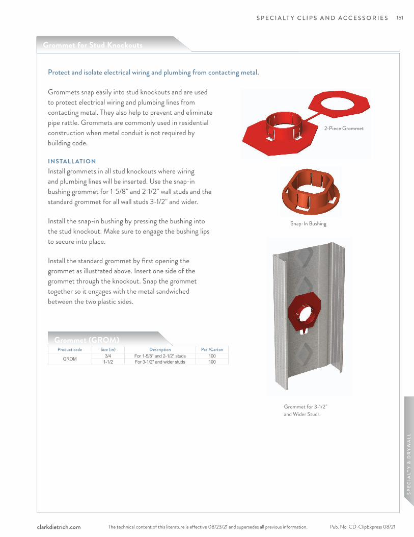
S P E C I A LT Y C L I P S A N D A C C E S S O R I E S
The technical content of this literature is effective 08/23/21 and supersedes all previous information. The technical content of this literature is effective 08/23/21 and supersedes all previous information. Pub. No. CD-ClipExpress 08/21clarkdietrich.com
SP
EC
IALT
Y &
DR
YW
ALL
Product code Size (in) Description Pcs./Carton
GROM 3/4 For 1-5/8" and 2-1/2" studs 1001-1/2 For 3-1/2" and wider studs 100
Grommets snap easily into stud knockouts and are used to protect electrical wiring and plumbing lines from contacting metal. They also help to prevent and eliminate pipe rattle. Grommets are commonly used in residential construction when metal conduit is not required by building code.
INSTALL ATIONInstall grommets in all stud knockouts where wiring and plumbing lines will be inserted. Use the snap-in bushing grommet for 1-5/8" and 2-1/2" wall studs and the standard grommet for all wall studs 3-1/2" and wider.
Install the snap-in bushing by pressing the bushing into the stud knockout. Make sure to engage the bushing lips to secure into place.
Install the standard grommet by first opening the grommet as illustrated above. Insert one side of the grommet through the knockout. Snap the grommet together so it engages with the metal sandwiched between the two plastic sides.
Grommet for 3-1/2" and Wider Studs
2-Piece Grommet
Snap-In Bushing
Protect and isolate electrical wiring and plumbing from contacting metal.
Grommet (GROM)
Grommet for Stud Knockouts
151

S P E C I A LT Y C L I P S A N D A C C E S S O R I E S
The technical content of this literature is effective 08/23/21 and supersedes all previous information.Pub. No. CD-ClipExpress 08/21 clarkdietrich.com
ClarkDietrich Sound Clip (CDSC)
The ClarkDietrich Sound Clip is used in conjunction with 18mil (25ga) 7/8" deep drywall furring channel. It is used to fasten gypsum wallboard in various wall and floor-ceiling applications, while simultaneously providing acoustical separation. This significantly reduces the amount of airborne sound filtering from room to room. The ClarkDietrich Sound Clip adds notable STC points to most assemblies while reducing sound transfer.
• Ideal for use in multi-family dwelling, hotels, theaters and hospitals • Used in conjunction with 7/8" 25 ga Furring Channel with a total standoff from stud of 1-5/8" • UL fire rated for most common assemblies • Complies to UL 263 test standards. • Max. spacing 48" o.c. (laterally) x 24" o.c. (vertically) • Maximum acoustical design load is 36 lbs. • Sound testing for Type X & Type C Boards
PRODUC T DIMENSIONS3" x 1-1/4" (Clip only) M ATERIAL SPECIFIC ATIONS Gauge: 18 gauge (43mil) Design Thickness: 0.0451 inches Yield Strength: 33ksiCoating: CP60
Sound isolation and dampening clip.
Product code Mils (Gauge) Size (in) Pcs./BucketCDSC 43mil (18ga) 3 x 1-1/4 100
ClarkDietrich Sound Clip
SOUND AND UL DESIGN:• Complies to UL 263 test standards. See full list of UL® design assemblies in UL R19331.• Wall Sound Assemblies are certified by Western Electro-Acoustical Laboratories.• Floor Sound Assemblies are certified by Intertek Building & Construction (B&C).• NVLAP Accredited for ASTM E90 & E413, ISO Certified
152
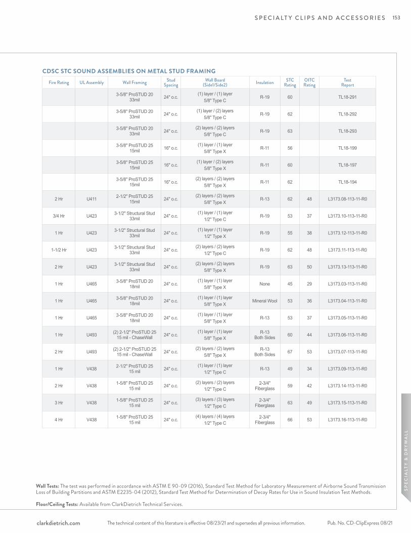
S P E C I A LT Y C L I P S A N D A C C E S S O R I E S
The technical content of this literature is effective 08/23/21 and supersedes all previous information. The technical content of this literature is effective 08/23/21 and supersedes all previous information. Pub. No. CD-ClipExpress 08/21clarkdietrich.com
SP
EC
IALT
Y &
DR
YW
ALL
Fire Rating UL Assembly Wall Framing Stud Spacing
Wall Board (Side1/Side2) Insulation STC
RatingOITC Rating
Test Report
3-5/8" ProSTUD 20 33mil 24" o.c.
(1) layer / (1) layer 5/8" Type C
R-19 60 TL18-291
3-5/8" ProSTUD 20 33mil 24" o.c.
(1) layer / (2) layers 5/8" Type C
R-19 62 TL18-292
3-5/8" ProSTUD 20 33mil 24" o.c.
(2) layers / (2) layers 5/8" Type C
R-19 63 TL18-293
3-5/8" ProSTUD 25 15mil 16" o.c.
(1) layer / (1) layer 5/8" Type X
R-11 56 TL18-199
3-5/8" ProSTUD 25 15mil 16" o.c.
(1) layer / (2) layers 5/8" Type X
R-11 60 TL18-197
3-5/8" ProSTUD 25 15mil 16" o.c.
(2) layers / (2) layers 5/8" Type X
R-11 62 TL18-194
2 Hr U411 2-1/2" ProSTUD 25 15mil 24" o.c.
(2) layers / (2) layers 5/8" Type X
R-13 62 48 L3173.08-113-11-R0
3/4 Hr U423 3-1/2" Structural Stud 33mil 24" o.c.
(1) layer / (1) layer 1/2" Type C
R-19 53 37 L3173.10-113-11-R0
1 Hr U423 3-1/2" Structural Stud 33mil 24" o.c.
(1) layer / (1) layer 1/2" Type X
R-19 55 38 L3173.12-113-11-R0
1-1/2 Hr U423 3-1/2" Structural Stud 33mil 24" o.c.
(2) layers / (2) layers 1/2" Type C
R-19 62 48 L3173.11-113-11-R0
2 Hr U423 3-1/2" Structural Stud 33mil 24" o.c.
(2) layers / (2) layers 5/8" Type X
R-19 63 50 L3173.13-113-11-R0
1 Hr U465 3-5/8" ProSTUD 20 18mil 24" o.c.
(1) layer / (1) layer 5/8" Type X
None 45 29 L3173.03-113-11-R0
1 Hr U465 3-5/8" ProSTUD 20 18mil 24" o.c.
(1) layer / (1) layer 5/8" Type X
Mineral Wool 53 36 L3173.04-113-11-R0
1 Hr U465 3-5/8" ProSTUD 20 18mil 24" o.c.
(1) layer / (1) layer 5/8" Type X
R-13 53 37 L3173.05-113-11-R0
1 Hr U493 (2) 2-1/2" ProSTUD 25 15 mil - ChaseWall 24" o.c.
(1) layer / (1) layer 5/8" Type X
R-13 Both Sides 60 44 L3173.06-113-11-R0
2 Hr U493 (2) 2-1/2" ProSTUD 25 15 mil - ChaseWall 24" o.c.
(2) layers / (2) layers 5/8" Type X
R-13 Both Sides 67 53 L3173.07-113-11-R0
1 Hr V438 2-1/2" ProSTUD 25 15 mil 24" o.c.
(1) layer / (1) layer 1/2" Type C
R-13 49 34 L3173.09-113-11-R0
2 Hr V438 1-5/8" ProSTUD 25 15 mil 24" o.c.
(2) layers / (2) layers 1/2" Type C
2-3/4" Fiberglass 59 42 L3173.14-113-11-R0
3 Hr V438 1-5/8" ProSTUD 25 15 mil 24" o.c.
(3) layers / (3) layers 1/2" Type C
2-3/4" Fiberglass 63 49 L3173.15-113-11-R0
4 Hr V438 1-5/8" ProSTUD 25 15 mil 24" o.c.
(4) layers / (4) layers 1/2" Type C
2-3/4" Fiberglass 66 53 L3173.16-113-11-R0
CDSC STC SOUND ASSEMBLIES ON METAL STUD FRAMING
Wall Tests: The test was performed in accordance with ASTM E 90-09 (2016), Standard Test Method for Laboratory Measurement of Airborne Sound Transmission Loss of Building Partitions and ASTM E2235-04 (2012), Standard Test Method for Determination of Decay Rates for Use in Sound Insulation Test Methods. Floor/Ceiling Tests: Available from ClarkDietrich Technical Services.
153
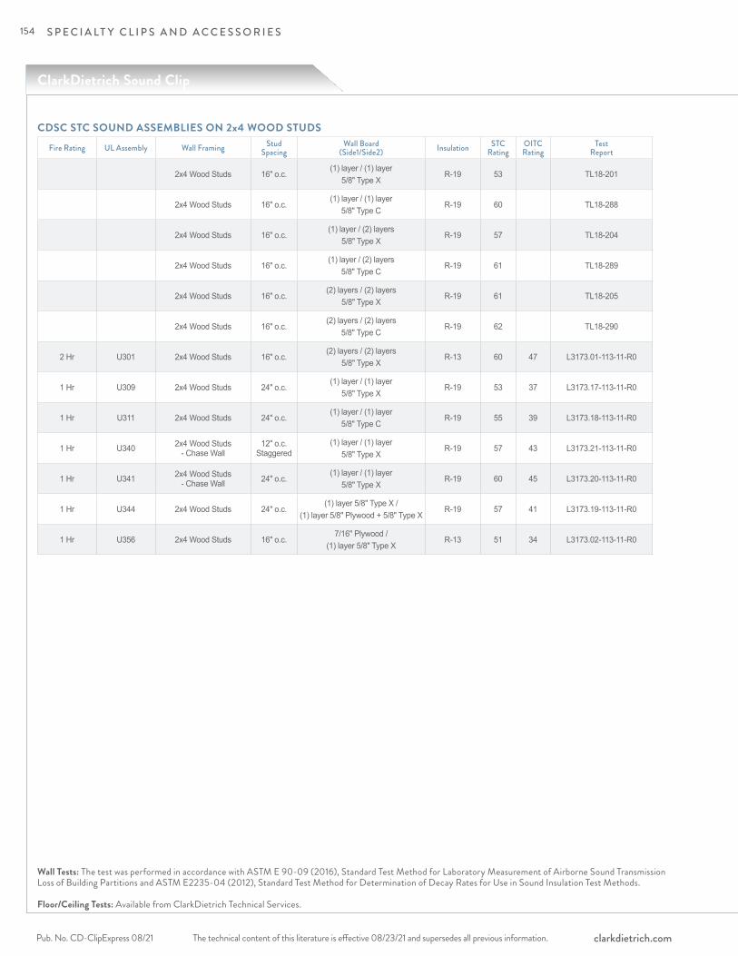
S P E C I A LT Y C L I P S A N D A C C E S S O R I E S
The technical content of this literature is effective 08/23/21 and supersedes all previous information.Pub. No. CD-ClipExpress 08/21 clarkdietrich.com
ClarkDietrich Sound Clip
Wall Tests: The test was performed in accordance with ASTM E 90-09 (2016), Standard Test Method for Laboratory Measurement of Airborne Sound Transmission Loss of Building Partitions and ASTM E2235-04 (2012), Standard Test Method for Determination of Decay Rates for Use in Sound Insulation Test Methods. Floor/Ceiling Tests: Available from ClarkDietrich Technical Services.
CDSC STC SOUND ASSEMBLIES ON 2x4 WOOD STUDS
Fire Rating UL Assembly Wall Framing Stud Spacing
Wall Board (Side1/Side2) Insulation STC
RatingOITC Rating
Test Report
2x4 Wood Studs 16" o.c.(1) layer / (1) layer
5/8" Type XR-19 53 TL18-201
2x4 Wood Studs 16" o.c.(1) layer / (1) layer
5/8" Type CR-19 60 TL18-288
2x4 Wood Studs 16" o.c.(1) layer / (2) layers
5/8" Type XR-19 57 TL18-204
2x4 Wood Studs 16" o.c.(1) layer / (2) layers
5/8" Type CR-19 61 TL18-289
2x4 Wood Studs 16" o.c.(2) layers / (2) layers
5/8" Type XR-19 61 TL18-205
2x4 Wood Studs 16" o.c.(2) layers / (2) layers
5/8" Type CR-19 62 TL18-290
2 Hr U301 2x4 Wood Studs 16" o.c.(2) layers / (2) layers
5/8" Type XR-13 60 47 L3173.01-113-11-R0
1 Hr U309 2x4 Wood Studs 24" o.c.(1) layer / (1) layer
5/8" Type XR-19 53 37 L3173.17-113-11-R0
1 Hr U311 2x4 Wood Studs 24" o.c.(1) layer / (1) layer
5/8" Type CR-19 55 39 L3173.18-113-11-R0
1 Hr U340 2x4 Wood Studs - Chase Wall
12" o.c. Staggered
(1) layer / (1) layer 5/8" Type X
R-19 57 43 L3173.21-113-11-R0
1 Hr U341 2x4 Wood Studs - Chase Wall 24" o.c.
(1) layer / (1) layer 5/8" Type X
R-19 60 45 L3173.20-113-11-R0
1 Hr U344 2x4 Wood Studs 24" o.c.(1) layer 5/8" Type X /
(1) layer 5/8" Plywood + 5/8" Type XR-19 57 41 L3173.19-113-11-R0
1 Hr U356 2x4 Wood Studs 16" o.c.7/16" Plywood /
(1) layer 5/8" Type XR-13 51 34 L3173.02-113-11-R0
154
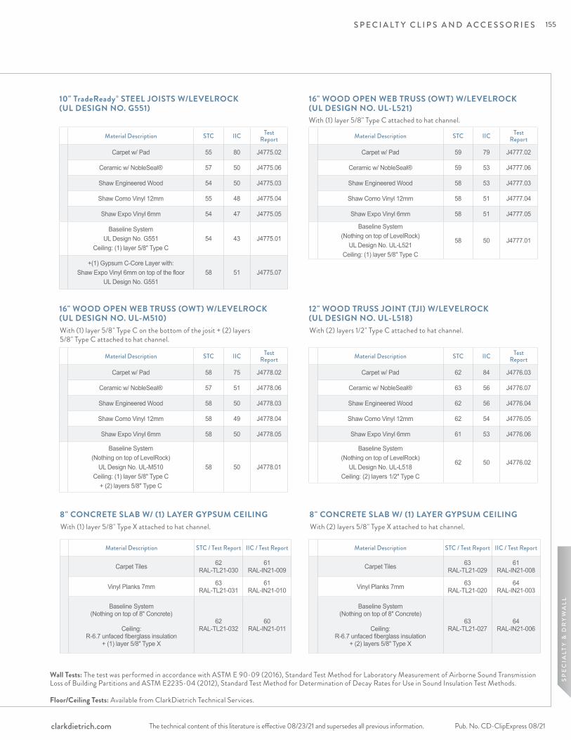
S P E C I A LT Y C L I P S A N D A C C E S S O R I E S
The technical content of this literature is effective 08/23/21 and supersedes all previous information. The technical content of this literature is effective 08/23/21 and supersedes all previous information. Pub. No. CD-ClipExpress 08/21clarkdietrich.com
SP
EC
IALT
Y &
DR
YW
ALL
Material Description STC IIC Test Report
Carpet w/ Pad 55 80 J4775.02
Ceramic w/ NobleSeal® 57 50 J4775.06
Shaw Engineered Wood 54 50 J4775.03
Shaw Como Vinyl 12mm 55 48 J4775.04
Shaw Expo Vinyl 6mm 54 47 J4775.05
Baseline SystemUL Design No. G551
Ceiling: (1) layer 5/8" Type C54 43 J4775.01
+(1) Gypsum C-Core Layer with:Shaw Expo Vinyl 6mm on top of the floor
UL Design No. G55158 51 J4775.07
10" TradeReady® STEEL JOISTS W/LEVELROCK (UL DESIGN NO. G551)
Material Description STC IIC Test Report
Carpet w/ Pad 59 79 J4777.02
Ceramic w/ NobleSeal® 59 53 J4777.06
Shaw Engineered Wood 58 53 J4777.03
Shaw Como Vinyl 12mm 58 51 J4777.04
Shaw Expo Vinyl 6mm 58 51 J4777.05
Baseline System(Nothing on top of LevelRock)
UL Design No. UL-L521 Ceiling: (1) layer 5/8" Type C
58 50 J4777.01
16" WOOD OPEN WEB TRUSS (OWT) W/LEVELROCK (UL DESIGN NO. UL-L521)
Material Description STC IIC Test Report
Carpet w/ Pad 58 75 J4778.02
Ceramic w/ NobleSeal® 57 51 J4778.06
Shaw Engineered Wood 58 50 J4778.03
Shaw Como Vinyl 12mm 58 49 J4778.04
Shaw Expo Vinyl 6mm 58 50 J4778.05
Baseline System(Nothing on top of LevelRock)
UL Design No. UL-M510 Ceiling: (1) layer 5/8" Type C
+ (2) layers 5/8" Type C
58 50 J4778.01
16" WOOD OPEN WEB TRUSS (OWT) W/LEVELROCK (UL DESIGN NO. UL-M510)
Material Description STC IIC Test Report
Carpet w/ Pad 62 84 J4776.03
Ceramic w/ NobleSeal® 63 56 J4776.07
Shaw Engineered Wood 62 56 J4776.04
Shaw Como Vinyl 12mm 62 54 J4776.05
Shaw Expo Vinyl 6mm 61 53 J4776.06
Baseline System (Nothing on top of LevelRock)
UL Design No. UL-L518 Ceiling: (2) layers 1/2" Type C
62 50 J4776.02
12" WOOD TRUSS JOINT (TJI) W/LEVELROCK (UL DESIGN NO. UL-L518)
With (1) layer 5/8" Type C on the bottom of the josit + (2) layers 5/8" Type C attached to hat channel.
With (2) layers 1/2" Type C attached to hat channel.
With (1) layer 5/8" Type C attached to hat channel.
Wall Tests: The test was performed in accordance with ASTM E 90-09 (2016), Standard Test Method for Laboratory Measurement of Airborne Sound Transmission Loss of Building Partitions and ASTM E2235-04 (2012), Standard Test Method for Determination of Decay Rates for Use in Sound Insulation Test Methods. Floor/Ceiling Tests: Available from ClarkDietrich Technical Services.
Material Description STC / Test Report IIC / Test Report
Carpet Tiles 62 RAL-TL21-030
61 RAL-IN21-009
Vinyl Planks 7mm 63 RAL-TL21-031
61 RAL-IN21-010
Baseline System (Nothing on top of 8" Concrete)
Ceiling:
R-6.7 unfaced fiberglass insulation + (1) layer 5/8" Type X
62 RAL-TL21-032
60 RAL-IN21-011
8" CONCRETE SLAB W/ (1) LAYER GYPSUM CEILING 8" CONCRETE SLAB W/ (1) LAYER GYPSUM CEILINGWith (1) layer 5/8" Type X attached to hat channel. With (2) layers 5/8" Type X attached to hat channel.
Material Description STC / Test Report IIC / Test Report
Carpet Tiles 63 RAL-TL21-029
61 RAL-IN21-008
Vinyl Planks 7mm 63 RAL-TL21-020
64 RAL-IN21-003
Baseline System (Nothing on top of 8" Concrete)
Ceiling:
R-6.7 unfaced fiberglass insulation + (2) layers 5/8" Type X
63 RAL-TL21-027
64 RAL-IN21-006
155

S P E C I A LT Y C L I P S A N D A C C E S S O R I E S
The technical content of this literature is effective 08/23/21 and supersedes all previous information.Pub. No. CD-ClipExpress 08/21 clarkdietrich.com
FASTENERS:• CDSC to Wood: 64mm (2-1/2") # 8 minimum size coarse thread screw. (Recommended #12 or #10 x 2-1/2" hex head)• CDSC to Steel: 38 mm (1-1/2") # 8 minimum size fine thread screw. (Recommended #12 or #10 x 1-5/8" hex head)• DO NOT attach CDSC to framing members with nails; use only approved screws.
FURRING CHANNEL: 7/8" 25-gauge hemmed furring channel (7/8" fur, 1-1/4" top & 2-23/32" bottom)
• When splicing, drywall furring channel should have 6 inch overlap in mid span (between two clips) secure with 18-gauge tie wire, or two 7/16" framing screws. If using in a fire rated/UL application; use only tie wire and no screws.
CL ARKDIETRICH SOUND CLIP: 3" x 1-1/4" (clip only) maximum spacing 48" o.c. and maximum design load is 36 lbs.
WALLS: ONE AND TWO LAYERS OF 5/8" GYPSUM BOARD• ClarkDietrich Sound Clip (CDSC) shall be 48" maximum o.c. (horizontal).• Fasten the CDSC to the substrate with a fastener approved for a minimum pull-out and shear of 120lbs.• Locate the first row of CDSC within 3-6 inches from the floor and within 3-6 inches from the top track, making sure the clip is attached to the studs and not the track.• Snap in the drywall furring channel into the CDSC clips (horizontal for walls). • Place 1/4" (minimum) shim on floor to fully support the gypsum board.• Install the gypsum board from the bottom up leaving a 1/4" minimum gap around the perimeter of the wall.• ONLY remove the shims after ALL the gypsum board is completely screwed to ALL the drywall furring channels. Make sure every screw (floor to-ceiling and wall-to-wall) is installed as required by the assembly design, in every layer of gypsum board before removing the shims at the floor. The shims are critical to ensure best results.• Caulk around the entire perimeter of the gypsum board. Use fire and smoke rated acoustical sealant where required.
CEILINGS: ONE AND TWO LAYERS OF 5/8" GYPSUM BOARD• CDSC shall be 48" maximum o.c.• Fasten the CDSC to the substrate with a fastener approved for a minimum pull-out and shear of 120lbs.• Locate the first row CDSC clips within 8" of the wall at each end of a run.• Snap in the drywall furring channel into the CDSC clips. Channel max spacing at 24" o.c. • Install the gypsum board from leaving a 1/4" min. gap around the perimeter of the ceiling.• Caulk around the entire perimeter of the gypsum board. Use fire and smoke rated acoustical sealant where required.
GENERAL INFORMATION:• Refer to www.UL.com, or www.clarkdietrich.com for complete installation details on all fire resistive assembly designs.• ClarkDietrich Sound Clips, furring channel and gypsum board shall not carry heavy loads such as cabinets or bookshelves.• Seal all potential air leaks with non-hardening acoustical caulking to achieve best noise control results. Use fire rated sealant where required.
FIRE TEST INFORMATION:Visit clarkdietrich.com for the latest fire testing approvals and updates.
ClarkDietrich Sound Clip Installation Guide
Soun
d C
lipFu
rrin
g/H
at C
hann
el
Hemmed legs (as shown) are only available in 18mil (25ga)
1-1/4"
2-23/32"
1/2"
7/8"
156
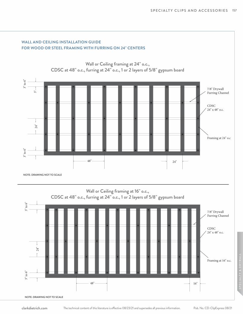
S P E C I A LT Y C L I P S A N D A C C E S S O R I E S
The technical content of this literature is effective 08/23/21 and supersedes all previous information. The technical content of this literature is effective 08/23/21 and supersedes all previous information. Pub. No. CD-ClipExpress 08/21clarkdietrich.com
SP
EC
IALT
Y &
DR
YW
ALL
WALL AND CEILING INSTALLATION GUIDE FOR WOOD OR STEEL FRAMING WITH FURRING ON 24" CENTERS
Wall or Ceiling framing at 24" o.c., CDSC at 48" o.c., furring at 24" o.c., 1 or 2 layers of 5/8" gypsum board
Wall or Ceiling framing at 16" o.c., CDSC at 48" o.c., furring at 24" o.c., 1 or 2 layers of 5/8" gypsum board
24"
Framing at 16" o.c.
7/8" DrywallFurring Channel
CDSC24" x 48" o.c.
3" to
6"
NOTE: DRAWING NOT TO SCALE
48" 16"
3" to
6"
48" 24"
24"
Framing at 24" o.c.
7/8" DrywallFurring Channel
CDSC24" x 48" o.c.
3"
3" to
6"
NOTE: DRAWING NOT TO SCALE
3" to
6"
157
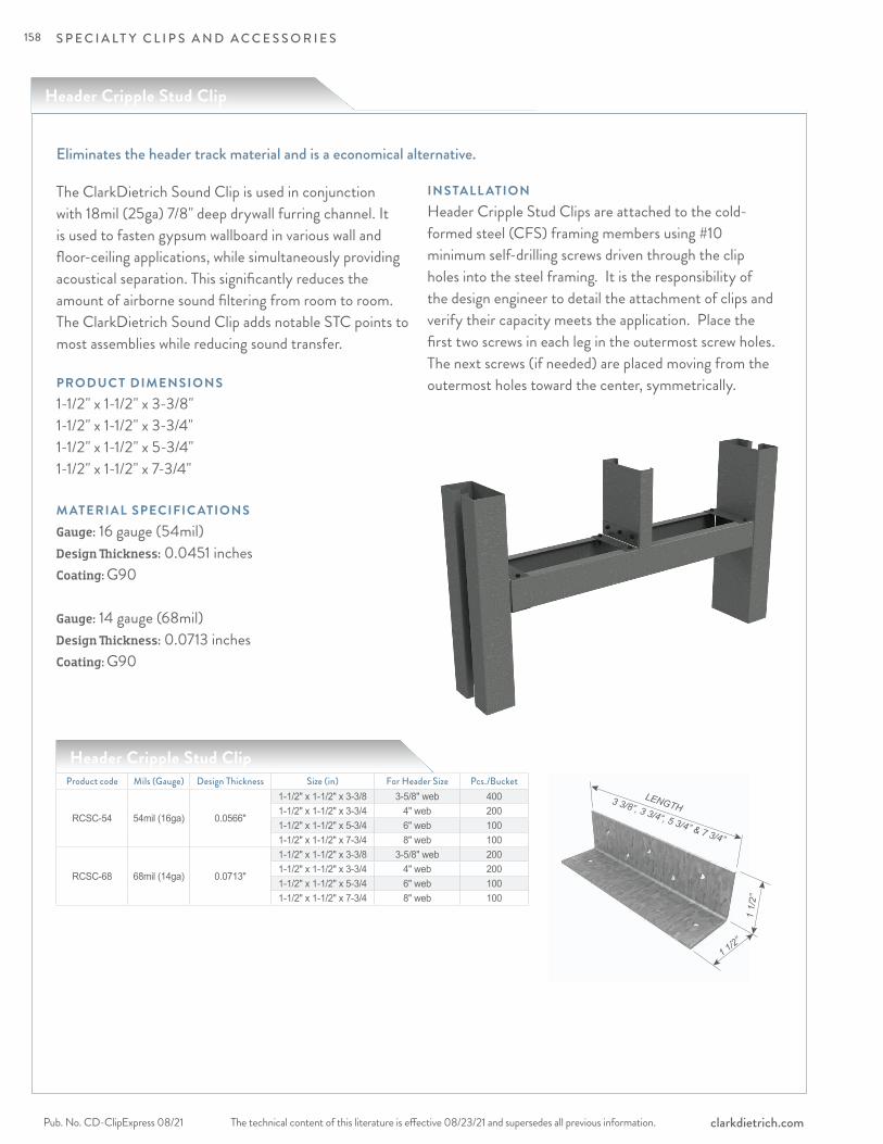
1 1/2”
3 3/8”, 3 3/4“, 5 3/4” & 7 3/4”
LENGTH
1 1/
2”
S P E C I A LT Y C L I P S A N D A C C E S S O R I E S
The technical content of this literature is effective 08/23/21 and supersedes all previous information.Pub. No. CD-ClipExpress 08/21 clarkdietrich.com
Header Cripple Stud Clip
The ClarkDietrich Sound Clip is used in conjunction with 18mil (25ga) 7/8" deep drywall furring channel. It is used to fasten gypsum wallboard in various wall and floor-ceiling applications, while simultaneously providing acoustical separation. This significantly reduces the amount of airborne sound filtering from room to room. The ClarkDietrich Sound Clip adds notable STC points to most assemblies while reducing sound transfer.
PRODUC T DIMENSIONS1-1/2" x 1-1/2" x 3-3/8"1-1/2" x 1-1/2" x 3-3/4"1-1/2" x 1-1/2" x 5-3/4"1-1/2" x 1-1/2" x 7-3/4" M ATERIAL SPECIFIC ATIONS Gauge: 16 gauge (54mil) Design Thickness: 0.0451 inches Coating: G90
Gauge: 14 gauge (68mil) Design Thickness: 0.0713 inchesCoating: G90
INSTALL ATIONHeader Cripple Stud Clips are attached to the cold-formed steel (CFS) framing members using #10 minimum self-drilling screws driven through the clip holes into the steel framing. It is the responsibility of the design engineer to detail the attachment of clips and verify their capacity meets the application. Place the first two screws in each leg in the outermost screw holes. The next screws (if needed) are placed moving from the outermost holes toward the center, symmetrically.
Eliminates the header track material and is a economical alternative.
Product code Mils (Gauge) Design Thickness Size (in) For Header Size Pcs./Bucket
RCSC-54 54mil (16ga) 0.0566"
1-1/2" x 1-1/2" x 3-3/8 3-5/8" web 4001-1/2" x 1-1/2" x 3-3/4 4" web 2001-1/2" x 1-1/2" x 5-3/4 6" web 1001-1/2" x 1-1/2" x 7-3/4 8" web 100
RCSC-68 68mil (14ga) 0.0713"
1-1/2" x 1-1/2" x 3-3/8 3-5/8" web 2001-1/2" x 1-1/2" x 3-3/4 4" web 2001-1/2" x 1-1/2" x 5-3/4 6" web 1001-1/2" x 1-1/2" x 7-3/4 8" web 100
Header Cripple Stud Clip
158
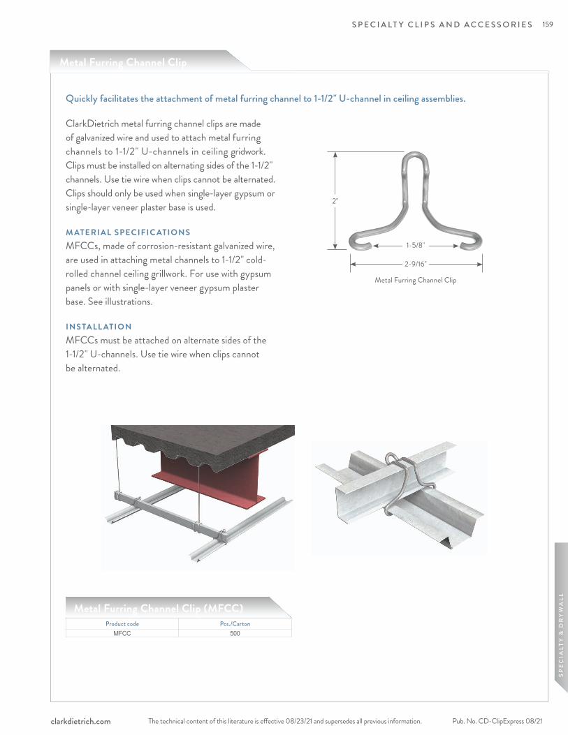
S P E C I A LT Y C L I P S A N D A C C E S S O R I E S
The technical content of this literature is effective 08/23/21 and supersedes all previous information. The technical content of this literature is effective 08/23/21 and supersedes all previous information. Pub. No. CD-ClipExpress 08/21clarkdietrich.com
SP
EC
IALT
Y &
DR
YW
ALL
Metal Furring Channel Clip (MFCC)
ClarkDietrich metal furring channel clips are made of galvanized wire and used to attach metal furring channels to 1-1/2" U-channels in ceiling gridwork. Clips must be installed on alternating sides of the 1-1/2" channels. Use tie wire when clips cannot be alternated. Clips should only be used when single-layer gypsum or single-layer veneer plaster base is used.
M ATERIAL SPECIFIC ATIONSMFCCs, made of corrosion-resistant galvanized wire, are used in attaching metal channels to 1-1/2" cold-rolled channel ceiling grillwork. For use with gypsum panels or with single-layer veneer gypsum plaster base. See illustrations.
INSTALL ATIONMFCCs must be attached on alternate sides of the 1-1/2" U-channels. Use tie wire when clips cannot be alternated.
Quickly facilitates the attachment of metal furring channel to 1-1/2" U-channel in ceiling assemblies.
2-9/16"
1-5/8"
2"
Product code Pcs./CartonMFCC 500
Metal Furring Channel Clip
Metal Furring Channel Clip
159
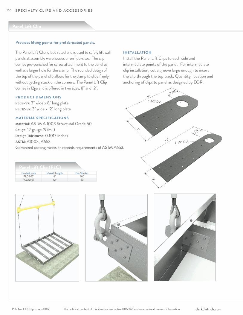
S P E C I A LT Y C L I P S A N D A C C E S S O R I E S
The technical content of this literature is effective 08/23/21 and supersedes all previous information.Pub. No. CD-ClipExpress 08/21 clarkdietrich.com
Panel Lift Clip
Provides lifting points for prefabricated panels.
The Panel Lift Clip is load rated and is used to safely lift wall panels at assembly warehouses or on job-sites. The clip comes pre-punched for screw attachment to the panel as well as a larger hole for the clamp. The rounded design of the top of the panel clip allows for the clamp to slide freely without getting stuck on the corners. The Panel Lift Clip comes in 12ga and is offered in two sizes, 8" and 12".
PRODUC T DIMENSIONSPLC8-97: 3" wide x 8" long plate PLC12-97: 3" wide x 12" long plate
M ATERIAL SPECIFIC ATIONS Material: ASTM A 1003 Structural Grade 50 Gauge: 12 gauge (97mil) Design Thickness: 0.1017 inches ASTM: A1003, A653
Product code Overall Length Pcs./BucketPLC8-97 8" 100PLC12-97 12" 50
Panel Lift Clip (PLC)
INSTALL ATIONInstall the Panel Lift Clips to each side and intermediate points of the panel. For intermediate clip installation, cut a groove large enough to insert the clip through the top track. Quantity, location and anchoring of clips to panel as designed by EOR.
Galvanized coating meets or exceeds requirements of ASTM A653.
160

S P E C I A LT Y C L I P S A N D A C C E S S O R I E S
The technical content of this literature is effective 08/23/21 and supersedes all previous information. The technical content of this literature is effective 08/23/21 and supersedes all previous information. Pub. No. CD-ClipExpress 08/21clarkdietrich.com
SP
EC
IALT
Y &
DR
YW
ALL
Product code
Stud thickness F3 (Panel Lifted from a Vertical Orientation) F2 (Panel Lifted from a Horizontal Orientation)
Mils (Gauge) Fy (ksi)
97mil (12ga) PLC 97mil (12ga) PLCw/3
#10 screwsw/5
#10 screwsw/6
#10 screwsw/3
#10 screwsw/5
#10 screwsw/6
#10 screws
PLC8-97
33mils (20ga) 33 530 884 1060 89 205 26033mils (20ga) 50 766 1276 1532 129 297 37543mils (18ga) 33 789 1315 1578 133 306 38743mils (18ga) 50 1140 1900 2279 192 442 55954mils (16ga) 33 1109 1849 2219 187 430 54454mils (16ga) 50 1602 2671 2775 270 621 78668mils (14ga) 50 1644 2740 2775 277 637 80697mils (12ga) 50 1644 2740 2775 277 637 806
Panel Lift Clip (PLC8, PLC12) Allowable Loads - Connection to Steel Framing, per Clip (lbs)
3 - Screw 5 - Screw 6 - Screw
Product code
Stud thickness F3 (Panel Lifted from a Vertical Orientation) F2 (Panel Lifted from a Horizontal Orientation)
Mils (Gauge) Fy (ksi)
97mil (12ga) PLC 97mil (12ga) PLCw/5
#10 screwsw/8
#10 screwsw/12
#10 screwsw/5
#10 screwsw/8
#10 screwsw/12
#10 screws
PLC12-97
33mils (20ga) 33 884 1414 2121 113 231 49133mils (20ga) 50 1276 2042 2775 163 333 71043mils (18ga) 33 1315 2104 2775 168 343 73143mils (18ga) 50 1900 2775 2775 243 496 105654mils (16ga) 33 1849 2775 2775 237 483 102854mils (16ga) 50 2671 2775 2775 342 697 108568mils (14ga) 50 2740 2775 2775 351 715 108597mils (12ga) 50 2740 2775 2775 351 715 1085
NOTES:1 Attachment to steel framing using #10 screws with a minimum shear capacity of 1644 lbs. 2 The use of load distribution spreader bar is assumed for multiple lift points.
5 - Screw 8 - Screw 12 - Screw
PLC8-97 PLC12-97
161
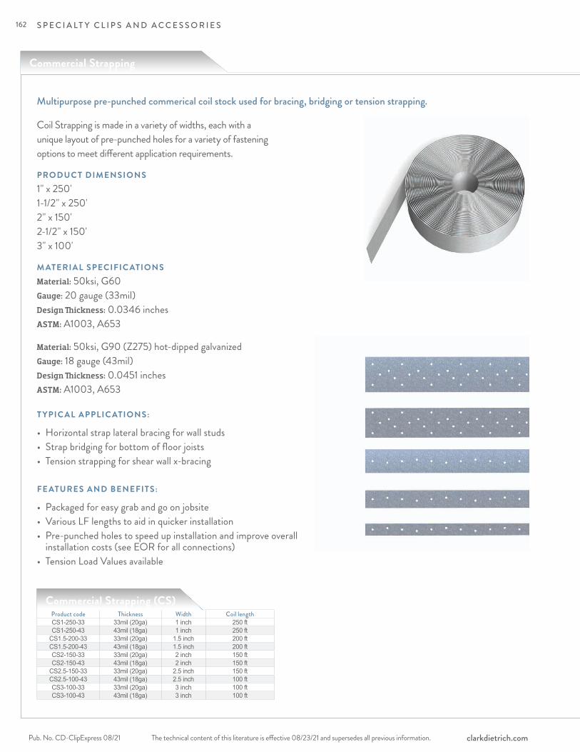
S P E C I A LT Y C L I P S A N D A C C E S S O R I E S
The technical content of this literature is effective 08/23/21 and supersedes all previous information.Pub. No. CD-ClipExpress 08/21 clarkdietrich.com
Commercial Strapping
Multipurpose pre-punched commerical coil stock used for bracing, bridging or tension strapping.
Coil Strapping is made in a variety of widths, each with a unique layout of pre-punched holes for a variety of fastening options to meet different application requirements.
PRODUC T DIMENSIONS1" x 250' 1-1/2" x 250' 2" x 150' 2-1/2" x 150' 3" x 100'
M ATERIAL SPECIFIC ATIONS Material: 50ksi, G60 Gauge: 20 gauge (33mil) Design Thickness: 0.0346 inches ASTM: A1003, A653
Material: 50ksi, G90 (Z275) hot-dipped galvanized Gauge: 18 gauge (43mil) Design Thickness: 0.0451 inches ASTM: A1003, A653
Product code Thickness Width Coil lengthCS1-250-33 33mil (20ga) 1 inch 250 ftCS1-250-43 43mil (18ga) 1 inch 250 ft
CS1.5-200-33 33mil (20ga) 1.5 inch 200 ftCS1.5-200-43 43mil (18ga) 1.5 inch 200 ftCS2-150-33 33mil (20ga) 2 inch 150 ftCS2-150-43 43mil (18ga) 2 inch 150 ft
CS2.5-150-33 33mil (20ga) 2.5 inch 150 ftCS2.5-100-43 43mil (18ga) 2.5 inch 100 ftCS3-100-33 33mil (20ga) 3 inch 100 ftCS3-100-43 43mil (18ga) 3 inch 100 ft
Commercial Strapping (CS)
T YPIC AL APPLIC ATIONS:
• Horizontal strap lateral bracing for wall studs• Strap bridging for bottom of floor joists• Tension strapping for shear wall x-bracing
FE ATURES AND BENEFITS:
• Packaged for easy grab and go on jobsite• Various LF lengths to aid in quicker installation• Pre-punched holes to speed up installation and improve overall installation costs (see EOR for all connections)• Tension Load Values available
162
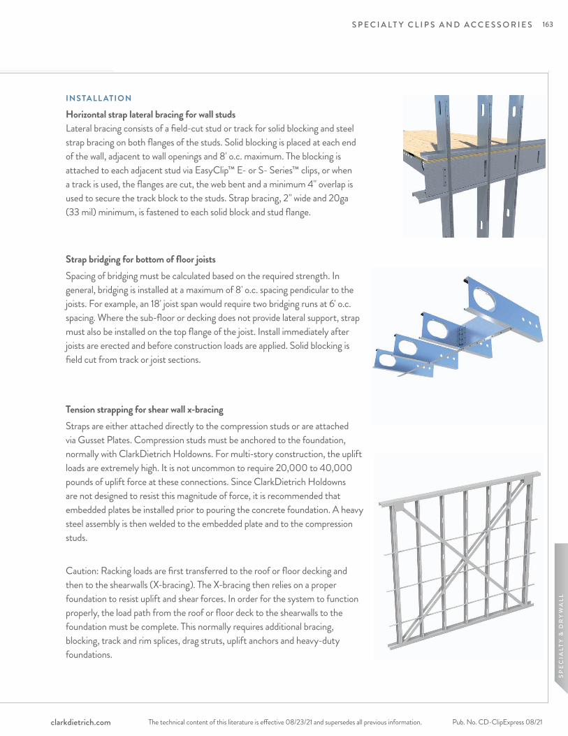
S P E C I A LT Y C L I P S A N D A C C E S S O R I E S
The technical content of this literature is effective 08/23/21 and supersedes all previous information. The technical content of this literature is effective 08/23/21 and supersedes all previous information. Pub. No. CD-ClipExpress 08/21clarkdietrich.com
SP
EC
IALT
Y &
DR
YW
ALL
INSTALL ATION
Horizontal strap lateral bracing for wall studs Lateral bracing consists of a field-cut stud or track for solid blocking and steel strap bracing on both flanges of the studs. Solid blocking is placed at each end of the wall, adjacent to wall openings and 8' o.c. maximum. The blocking is attached to each adjacent stud via EasyClip™ E- or S- Series™ clips, or when a track is used, the flanges are cut, the web bent and a minimum 4" overlap is used to secure the track block to the studs. Strap bracing, 2" wide and 20ga (33 mil) minimum, is fastened to each solid block and stud flange.
Strap bridging for bottom of floor joistsSpacing of bridging must be calculated based on the required strength. In general, bridging is installed at a maximum of 8' o.c. spacing pendicular to the joists. For example, an 18' joist span would require two bridging runs at 6' o.c. spacing. Where the sub-floor or decking does not provide lateral support, strap must also be installed on the top flange of the joist. Install immediately after joists are erected and before construction loads are applied. Solid blocking is field cut from track or joist sections.
Tension strapping for shear wall x-bracingStraps are either attached directly to the compression studs or are attached via Gusset Plates. Compression studs must be anchored to the foundation, normally with ClarkDietrich Holdowns. For multi-story construction, the uplift loads are extremely high. It is not uncommon to require 20,000 to 40,000 pounds of uplift force at these connections. Since ClarkDietrich Holdowns are not designed to resist this magnitude of force, it is recommended that embedded plates be installed prior to pouring the concrete foundation. A heavy steel assembly is then welded to the embedded plate and to the compression studs.
Caution: Racking loads are first transferred to the roof or floor decking and then to the shearwalls (X-bracing). The X-bracing then relies on a proper foundation to resist uplift and shear forces. In order for the system to function properly, the load path from the roof or floor deck to the shearwalls to the foundation must be complete. This normally requires additional bracing, blocking, track and rim splices, drag struts, uplift anchors and heavy-duty foundations.
163
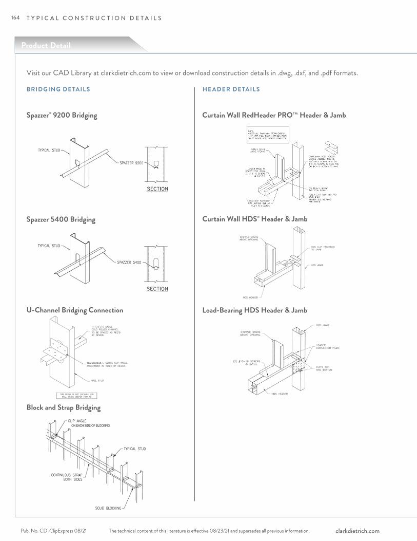
The technical content of this literature is effective 08/23/21 and supersedes all previous information.Pub. No. CD-ClipExpress 08/21 clarkdietrich.com
T Y P I C A L C O N S T R U C T I O N D E T A I L S
6"
BRIDGING DETAIL S HE ADER DETAIL S
Spazzer® 9200 Bridging
U-Channel Bridging Connection
Block and Strap Bridging
Visit our CAD Library at clarkdietrich.com to view or download construction details in .dwg, .dxf, and .pdf formats.
Curtain Wall HDS® Header & Jamb
Curtain Wall RedHeader PRO™ Header & Jamb
Load-Bearing HDS Header & Jamb
" o.c.
ON EACH SIDE OF BLOCKING
Product Detail
Spazzer 5400 Bridging
164
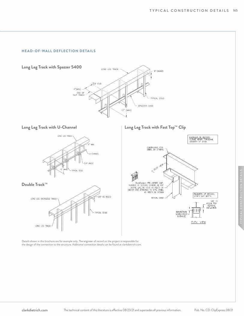
The technical content of this literature is effective 08/23/21 and supersedes all previous information. The technical content of this literature is effective 08/23/21 and supersedes all previous information. Pub. No. CD-ClipExpress 08/21clarkdietrich.com
12" MAX
"X" (MAX)
U-CHANNEL
CLIP ANGLE
TYPICAL STUD
LONG LEG TRACK
GAP AS REQ'D
TYPICAL STUD
DEEP LEGSTANDARD
TRACK
OVERSIZED SLIP TRACK
CONTINUOUS STRL. STEEL
TYPICAL STUD
CLARKDIETRICH FTC
3/4" MIN.SCREW EDGE
DISTANCE
X" GAP TOALLOW FOR
VERTICALDEFLECTION
ELEV. VIEW
ENGINEER OF RECORD:VERIFY GAP DEPTH.
ELEV. VIEW
CA
B
END OFSLOTTED
TRACK
4" (MIN)
TYPICAL STUD
SLOTTEDTRACK
X" (MAX)
TYPICAL STUD
X" (MAX)
C OF STUD
WALL INSIDE EDGE OF SLABSPAZZER® 5400
TYPICAL STUD
END OFLONG LEG
4"(MIN)
12" (MAX)
X" (MAX)
C
X" (MAX)
A
TYPICAL STUD
LONG LEGTRACK
B
COF STUD
WALL OUTSIDE EDGE OF BEAM
L
HE AD -OF-WALL DEFLEC TION DETAIL S
Long Leg Track with Spazzer 5400
Long Leg Track with U-Channel Long Leg Track with Fast Top™ Clip
Double Track™
Details shown in this brochure are for example only. The engineer of record on the project is responsible for the design of the connection to the structure. Additional connection details can be found at clarkdietrich.com.
MAINTAIN
T Y P I C A L C O N S T R U C T I O N D E T A I L S
TY
PIC
AL
CO
NS
TRU
CTI
ON
DE
TAIL
S
165
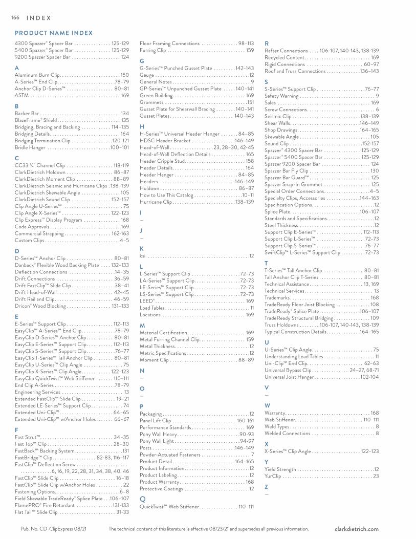
The technical content of this literature is effective 08/23/21 and supersedes all previous information.Pub. No. CD-ClipExpress 08/21 clarkdietrich.com
4300 Spazzer® Spacer Bar . . . . . . . . . . . . . . . 125-1295400 Spazzer® Spacer Bar . . . . . . . . . . . . . . . 125-1299200 Spazzer Spacer Bar . . . . . . . . . . . . . . . . . . . . 124
AAluminum Burn Clip. . . . . . . . . . . . . . . . . . . . . . . . . 150A-Series™ End Clip. . . . . . . . . . . . . . . . . . . . . . . .78–79Anchor Clip D-Series™ . . . . . . . . . . . . . . . . . . . 80–81ASTM . . . . . . . . . . . . . . . . . . . . . . . . . . . . . . . . . . . . . 169
BBacker Bar . . . . . . . . . . . . . . . . . . . . . . . . . . . . . . . . . 134BlazeFrame® Shield. . . . . . . . . . . . . . . . . . . . . . . . . . 135Bridging, Bracing and Backing . . . . . . . . . . . . 114–135Bridging Details. . . . . . . . . . . . . . . . . . . . . . . . . . . . . 164Bridging Termination Clip . . . . . . . . . . . . . . . . .120-121Bridle Hanger . . . . . . . . . . . . . . . . . . . . . . . . . . 100–101
CCC33 3/4" Channel Clip . . . . . . . . . . . . . . . . . . . 118-119ClarkDietrich Holdown . . . . . . . . . . . . . . . . . . . 86–87ClarkDietrich Moment Clip . . . . . . . . . . . . . . . 88–89ClarkDietrich Seismic and Hurricane Clips . 138–139ClarkDietrich Skewable Angle . . . . . . . . . . . . . . . . 105ClarkDietrich Sound Clip . . . . . . . . . . . . . . . . 152–157Clip Angle U-Series™ . . . . . . . . . . . . . . . . . . . . . . . . 75Clip Angle X-Series™ . . . . . . . . . . . . . . . . . . . . 122–123Clip ExpressSM Display Program . . . . . . . . . . . . . . . 168Code Approvals . . . . . . . . . . . . . . . . . . . . . . . . . . . . . 169Commercial Strapping . . . . . . . . . . . . . . . . . . . 162-163Custom Clips . . . . . . . . . . . . . . . . . . . . . . . . . . . . . . .4–5
DD-Series™ Anchor Clip . . . . . . . . . . . . . . . . . . . 80–81Danback® Flexible Wood Backing Plate . . . . 132–133Deflection Connections . . . . . . . . . . . . . . . . . . .14–35Drift Connections . . . . . . . . . . . . . . . . . . . . . . . 36–59Drift FastClip™ Slide Clip . . . . . . . . . . . . . . . . . .38–41Drift Head-of-Wall . . . . . . . . . . . . . . . . . . . . . . . 42–45Drift Rail and Clip. . . . . . . . . . . . . . . . . . . . . . . . 46–59Dricon® Wood Blocking . . . . . . . . . . . . . . . . . . 131–133
EE-Series™ Support Clip . . . . . . . . . . . . . . . . . . . 112–113EasyClip™ A-Series™ End Clip. . . . . . . . . . . . . .78–79EasyClip D-Series™ Anchor Clip . . . . . . . . . . . 80–81EasyClip E-Series™ Support Clip. . . . . . . . . . . 112–113EasyClip S-Series™ Support Clip. . . . . . . . . . . .76–77EasyClip T-Series™ Tall Anchor Clip . . . . . . . . 80–81EasyClip U-Series™ Clip Angle . . . . . . . . . . . . . . . . 75EasyClip X-Series™ Clip Angle. . . . . . . . . . . . 122–123EasyClip QuickTwist™ Web Stiffener . . . . . . . 110–111End Clip A-Series . . . . . . . . . . . . . . . . . . . . . . . . .78–79Engineering Services . . . . . . . . . . . . . . . . . . . . . . . . . 13Extended FastClip™ Slide Clip . . . . . . . . . . . . . . 19–21Extended LE-Series™ Support Clip . . . . . . . . . . . . . 74Extended Uni-Clip™. . . . . . . . . . . . . . . . . . . . . . 64–65Extended Uni-Clip™ w/Anchor Holes . . . . . . . 66–67
FFast Strut™. . . . . . . . . . . . . . . . . . . . . . . . . . . . . . 34–35Fast Top™ Clip . . . . . . . . . . . . . . . . . . . . . . . . . . . 28–30FastBack™ Backing System. . . . . . . . . . . . . . . . . . . . 131FastBridge™ Clip. . . . . . . . . . . . . . . . . . 82-83, 116–117FastClip™ Deflection Screw . . . . . . . . . . . . . . . . . . . . .
. . . . . . . . . . . . .6, 16, 19, 22, 28, 31, 34, 38, 40, 46FastClip™ Slide Clip . . . . . . . . . . . . . . . . . . . . . . . 16–18FastClip™ Slide Clip w/Anchor Holes . . . . . . . . . . . 22Fastening Options. . . . . . . . . . . . . . . . . . . . . . . . . . .6–8Field Skewable TradeReady® Splice Plate . . .106–107FlamePRO® Fire Retardant . . . . . . . . . . . . . . . 131-133Flat Tail™ Slide Clip . . . . . . . . . . . . . . . . . . . . . . . 31-33
Floor Framing Connections . . . . . . . . . . . . . . . 98–113Furring Clip . . . . . . . . . . . . . . . . . . . . . . . . . . . . . . . . 159
GG-Series™ Punched Gusset Plate . . . . . . . . . 142–143Gauge . . . . . . . . . . . . . . . . . . . . . . . . . . . . . . . . . . . . . . .12General Notes . . . . . . . . . . . . . . . . . . . . . . . . . . . . . . . . 9GP-Series™ Unpunched Gusset Plate . . . . . 140–141Green Building. . . . . . . . . . . . . . . . . . . . . . . . . . . . . . 169Grommets . . . . . . . . . . . . . . . . . . . . . . . . . . . . . . . . . . 151Gusset Plate for Shearwall Bracing . . . . . . . . 140–141Gusset Plates . . . . . . . . . . . . . . . . . . . . . . . . . . 140–143
HH-Series™ Universal Header Hanger . . . . . . . 84–85HDSC Header Bracket . . . . . . . . . . . . . . . . . .146–149Head-of-Wall . . . . . . . . . . . . . . . . . . 23, 28–30, 42-45Head-of-Wall Deflection Details . . . . . . . . . . . . . . 165Header Cripple Stud. . . . . . . . . . . . . . . . . . . . . . . . . 158Header Details. . . . . . . . . . . . . . . . . . . . . . . . . . . . . . 164Header Hanger . . . . . . . . . . . . . . . . . . . . . . . . . . 84–85Headers . . . . . . . . . . . . . . . . . . . . . . . . . . . . . . .146–149Holdown . . . . . . . . . . . . . . . . . . . . . . . . . . . . . . . . 86–87How to Use This Catalog . . . . . . . . . . . . . . . . . . . .10–11Hurricane Clip . . . . . . . . . . . . . . . . . . . . . . . . . . 138–139
I—
J—
Kksi . . . . . . . . . . . . . . . . . . . . . . . . . . . . . . . . . . . . . . . . . .12
LL-Series™ Support Clip . . . . . . . . . . . . . . . . . . . . 72–73LA-Series™ Support Clip. . . . . . . . . . . . . . . . . . . 72–73LE-Series™ Support Clip . . . . . . . . . . . . . . . . . . . 72–73LS-Series™ Support Clip . . . . . . . . . . . . . . . . . . . 72–73LEED® . . . . . . . . . . . . . . . . . . . . . . . . . . . . . . . . . . . . . 169Load Tables . . . . . . . . . . . . . . . . . . . . . . . . . . . . . . . . . . . 11Locations . . . . . . . . . . . . . . . . . . . . . . . . . . . . . . . . . . 169
MMaterial Certification. . . . . . . . . . . . . . . . . . . . . . . . 169Metal Furring Channel Clip. . . . . . . . . . . . . . . . . . . 159Metal Thickness. . . . . . . . . . . . . . . . . . . . . . . . . . . . . . .12Metric Specifications . . . . . . . . . . . . . . . . . . . . . . . . . .12Moment Clip . . . . . . . . . . . . . . . . . . . . . . . . . . . . 88–89
N—
O—
PPackaging . . . . . . . . . . . . . . . . . . . . . . . . . . . . . . . . . . . .12Panel Lift Clip . . . . . . . . . . . . . . . . . . . . . . . . . . 160-161Performance Standards . . . . . . . . . . . . . . . . . . . . . . 169Pony Wall Heavy. . . . . . . . . . . . . . . . . . . . . . . . . .90-93Pony Wall Light . . . . . . . . . . . . . . . . . . . . . . . . . . .94-97Posts . . . . . . . . . . . . . . . . . . . . . . . . . . . . . . . . . .146–149Powder-Actuated Fasteners . . . . . . . . . . . . . . . . . . . . 7Product Detail . . . . . . . . . . . . . . . . . . . . . . . . . .164–165Product Information. . . . . . . . . . . . . . . . . . . . . . . . . . .12Product Labeling . . . . . . . . . . . . . . . . . . . . . . . . . . . . . .12Product Warranty . . . . . . . . . . . . . . . . . . . . . . . . . . . 168Protective Coatings . . . . . . . . . . . . . . . . . . . . . . . . . . .12
QQuickTwist™ Web Stiffener. . . . . . . . . . . . . . . . 110–111
RRafter Connections . . . . 106-107, 140-143, 138-139Recycled Content. . . . . . . . . . . . . . . . . . . . . . . . . . . 169Rigid Connections . . . . . . . . . . . . . . . . . . . . . . . 60–97Roof and Truss Connections . . . . . . . . . . . . . . 136–143
SS-Series™ Support Clip . . . . . . . . . . . . . . . . . . . .76–77Safety Warning . . . . . . . . . . . . . . . . . . . . . . . . . . . . . . . 9Sales . . . . . . . . . . . . . . . . . . . . . . . . . . . . . . . . . . . . . . 169Screw Connections. . . . . . . . . . . . . . . . . . . . . . . . . . . . 6Seismic Clip . . . . . . . . . . . . . . . . . . . . . . . . . . . . 138–139Shear Walls. . . . . . . . . . . . . . . . . . . . . . . . . . . . .146–149Shop Drawings. . . . . . . . . . . . . . . . . . . . . . . . . .164–165Skewable Angle . . . . . . . . . . . . . . . . . . . . . . . . . . . . . 105Sound Clip . . . . . . . . . . . . . . . . . . . . . . . . . . . . . .152-157Spazzer® 4300 Spacer Bar . . . . . . . . . . . . . . . 125-129Spazzer® 5400 Spacer Bar . . . . . . . . . . . . . . . 125-129Spazzer 9200 Spacer Bar . . . . . . . . . . . . . . . . . . . . 124Spazzer Bar Fly Clip . . . . . . . . . . . . . . . . . . . . . . . . . 130Spazzer Bar Guard™ . . . . . . . . . . . . . . . . . . . . . . . . . 125Spazzer Snap-In Grommet . . . . . . . . . . . . . . . . . . . 125Special Order Connections. . . . . . . . . . . . . . . . . . .4–5Specialty Clips, Accessories . . . . . . . . . . . . . .144–163Specification Options. . . . . . . . . . . . . . . . . . . . . . . . . .12Splice Plate. . . . . . . . . . . . . . . . . . . . . . . . . . . . .106–107Standards and Specifications. . . . . . . . . . . . . . . . . . . .12Steel Thickness . . . . . . . . . . . . . . . . . . . . . . . . . . . . . . .12Support Clip E-Series™ . . . . . . . . . . . . . . . . . . . 112–113Support Clip L-Series™ . . . . . . . . . . . . . . . . . . . . 72–73Support Clip S-Series™ . . . . . . . . . . . . . . . . . . . .76–77SwiftClip™ L-Series™ Support Clip . . . . . . . . . . 72–73
TT-Series™ Tall Anchor Clip . . . . . . . . . . . . . . . . 80–81Tall Anchor Clip T-Series . . . . . . . . . . . . . . . . . . 80–81Technical Assistance . . . . . . . . . . . . . . . . . . . . . . 13, 169Technical Services . . . . . . . . . . . . . . . . . . . . . . . . . . . . 13Trademarks . . . . . . . . . . . . . . . . . . . . . . . . . . . . . . . . . 168TradeReady Floor Joist Blocking . . . . . . . . . . . . . . 108TradeReady® Splice Plate. . . . . . . . . . . . . . . . .106–107TradeReady Structural Bridging . . . . . . . . . . . . . . . 109Truss Holdowns . . . . . . . . 106-107, 140-143, 138-139Typical Construction Details. . . . . . . . . . . . . .164–165
UU-Series™ Clip Angle. . . . . . . . . . . . . . . . . . . . . . . . . 75Understanding Load Tables . . . . . . . . . . . . . . . . . . . . . 11Uni-Clip™ End Clip. . . . . . . . . . . . . . . . . . . . . . . 62–63Universal Bypass Clip . . . . . . . . . . . . . . . 24–27, 68-71Universal Joist Hanger . . . . . . . . . . . . . . . . . . . 102-104
V—
WWarranty. . . . . . . . . . . . . . . . . . . . . . . . . . . . . . . . . . . 168Web Stiffener. . . . . . . . . . . . . . . . . . . . . . . . . . . . 110–111Weld Types . . . . . . . . . . . . . . . . . . . . . . . . . . . . . . . . . . . 8Welded Connections . . . . . . . . . . . . . . . . . . . . . . . . . . 8
XX-Series™ Clip Angle . . . . . . . . . . . . . . . . . . . . 122–123
YYield Strength . . . . . . . . . . . . . . . . . . . . . . . . . . . . . . . .12YurClip . . . . . . . . . . . . . . . . . . . . . . . . . . . . . . . . . . . . . 23
Z—
PRODUC T NA ME INDEX
I N D E X166
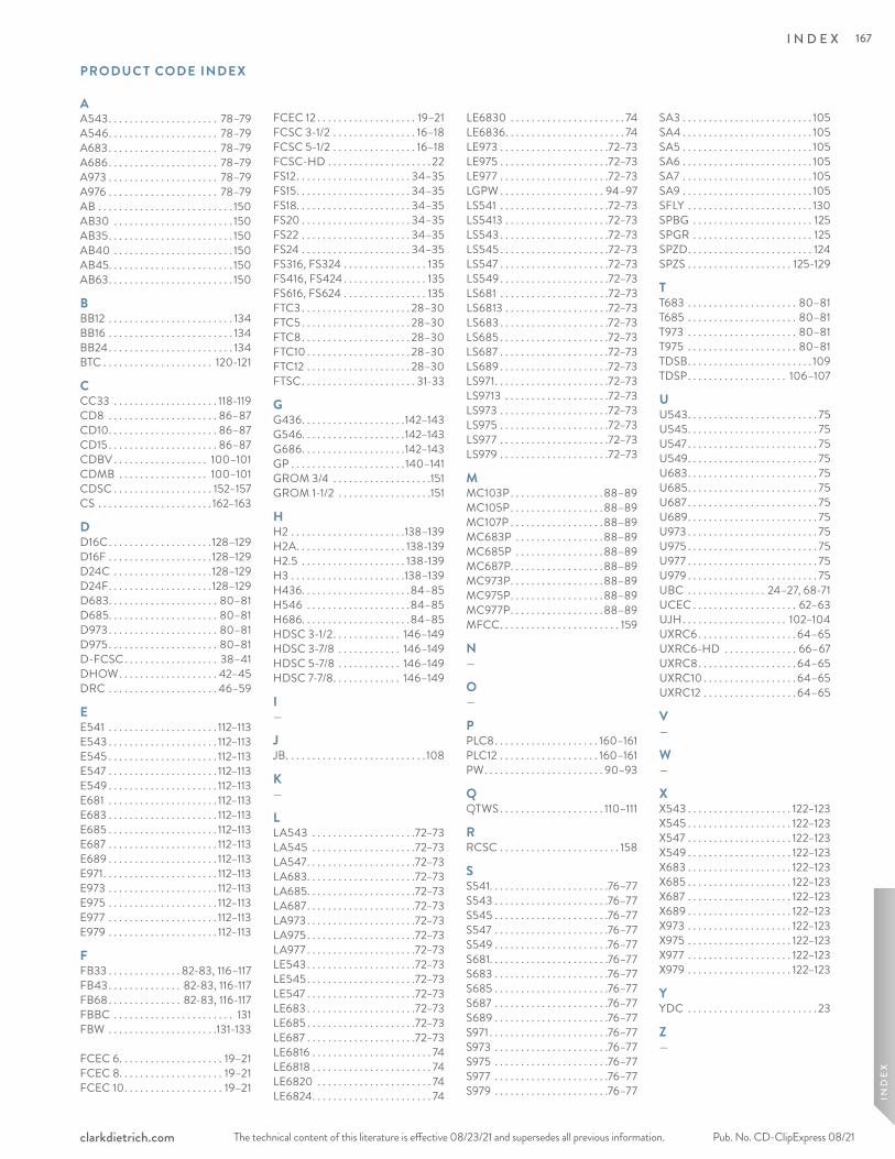
The technical content of this literature is effective 08/23/21 and supersedes all previous information. The technical content of this literature is effective 08/23/21 and supersedes all previous information. Pub. No. CD-ClipExpress 08/21clarkdietrich.com
AA543. . . . . . . . . . . . . . . . . . . . . 78–79A546. . . . . . . . . . . . . . . . . . . . . 78–79A683 . . . . . . . . . . . . . . . . . . . . . 78–79A686. . . . . . . . . . . . . . . . . . . . . 78–79A973 . . . . . . . . . . . . . . . . . . . . . 78–79A976 . . . . . . . . . . . . . . . . . . . . . 78–79AB . . . . . . . . . . . . . . . . . . . . . . . . . . 150AB30 . . . . . . . . . . . . . . . . . . . . . . . 150AB35. . . . . . . . . . . . . . . . . . . . . . . . 150AB40 . . . . . . . . . . . . . . . . . . . . . . . 150AB45. . . . . . . . . . . . . . . . . . . . . . . . 150AB63. . . . . . . . . . . . . . . . . . . . . . . . 150
BBB12 . . . . . . . . . . . . . . . . . . . . . . . . 134BB16 . . . . . . . . . . . . . . . . . . . . . . . . 134BB24. . . . . . . . . . . . . . . . . . . . . . . . 134BTC . . . . . . . . . . . . . . . . . . . . . 120-121
CCC33 . . . . . . . . . . . . . . . . . . . . 118-119CD8 . . . . . . . . . . . . . . . . . . . . . 86–87CD10. . . . . . . . . . . . . . . . . . . . . 86–87CD15 . . . . . . . . . . . . . . . . . . . . . 86–87CDBV . . . . . . . . . . . . . . . . . . 100–101CDMB . . . . . . . . . . . . . . . . . 100–101CDSC . . . . . . . . . . . . . . . . . . . 152–157CS . . . . . . . . . . . . . . . . . . . . . . 162–163
DD16C. . . . . . . . . . . . . . . . . . . .128–129D16F . . . . . . . . . . . . . . . . . . . .128–129D24C . . . . . . . . . . . . . . . . . . .128–129D24F. . . . . . . . . . . . . . . . . . . .128–129D683. . . . . . . . . . . . . . . . . . . . . 80–81D685. . . . . . . . . . . . . . . . . . . . . 80–81D973 . . . . . . . . . . . . . . . . . . . . . 80–81D975 . . . . . . . . . . . . . . . . . . . . . 80–81D-FCSC. . . . . . . . . . . . . . . . . . 38–41DHOW. . . . . . . . . . . . . . . . . . . 42–45DRC . . . . . . . . . . . . . . . . . . . . . 46–59
EE541 . . . . . . . . . . . . . . . . . . . . . 112–113E543 . . . . . . . . . . . . . . . . . . . . . 112–113E545 . . . . . . . . . . . . . . . . . . . . . 112–113E547 . . . . . . . . . . . . . . . . . . . . . 112–113E549 . . . . . . . . . . . . . . . . . . . . . 112–113E681 . . . . . . . . . . . . . . . . . . . . . 112–113E683 . . . . . . . . . . . . . . . . . . . . . 112–113E685 . . . . . . . . . . . . . . . . . . . . . 112–113E687 . . . . . . . . . . . . . . . . . . . . . 112–113E689 . . . . . . . . . . . . . . . . . . . . . 112–113E971. . . . . . . . . . . . . . . . . . . . . . 112–113E973 . . . . . . . . . . . . . . . . . . . . . 112–113E975 . . . . . . . . . . . . . . . . . . . . . 112–113E977 . . . . . . . . . . . . . . . . . . . . . 112–113E979 . . . . . . . . . . . . . . . . . . . . . 112–113
FFB33 . . . . . . . . . . . . . . 82-83, 116–117FB43 . . . . . . . . . . . . . . 82-83, 116-117FB68 . . . . . . . . . . . . . . 82-83, 116-117FBBC . . . . . . . . . . . . . . . . . . . . . . . 131FBW . . . . . . . . . . . . . . . . . . . . .131-133
FCEC 6. . . . . . . . . . . . . . . . . . . . 19–21FCEC 8. . . . . . . . . . . . . . . . . . . . 19–21FCEC 10. . . . . . . . . . . . . . . . . . . 19–21
FCEC 12 . . . . . . . . . . . . . . . . . . . 19–21FCSC 3-1/2 . . . . . . . . . . . . . . . . 16–18FCSC 5-1/2 . . . . . . . . . . . . . . . . 16–18FCSC-HD . . . . . . . . . . . . . . . . . . . . 22FS12. . . . . . . . . . . . . . . . . . . . . . 34–35FS15. . . . . . . . . . . . . . . . . . . . . . 34–35FS18. . . . . . . . . . . . . . . . . . . . . . 34–35FS20 . . . . . . . . . . . . . . . . . . . . . 34–35FS22 . . . . . . . . . . . . . . . . . . . . . 34–35FS24 . . . . . . . . . . . . . . . . . . . . . 34–35FS316, FS324 . . . . . . . . . . . . . . . . 135FS416, FS424 . . . . . . . . . . . . . . . . 135FS616, FS624 . . . . . . . . . . . . . . . . 135FTC3 . . . . . . . . . . . . . . . . . . . . . 28–30FTC5 . . . . . . . . . . . . . . . . . . . . . 28–30FTC8. . . . . . . . . . . . . . . . . . . . . 28–30FTC10 . . . . . . . . . . . . . . . . . . . . 28–30FTC12 . . . . . . . . . . . . . . . . . . . . 28–30FTSC. . . . . . . . . . . . . . . . . . . . . . 31-33
GG436. . . . . . . . . . . . . . . . . . . .142–143G546. . . . . . . . . . . . . . . . . . . .142–143G686. . . . . . . . . . . . . . . . . . . .142–143GP . . . . . . . . . . . . . . . . . . . . . . 140–141GROM 3/4 . . . . . . . . . . . . . . . . . . .151GROM 1-1/2 . . . . . . . . . . . . . . . . . .151
HH2 . . . . . . . . . . . . . . . . . . . . . .138–139H2A. . . . . . . . . . . . . . . . . . . . . 138-139H2.5 . . . . . . . . . . . . . . . . . . . . 138-139H3 . . . . . . . . . . . . . . . . . . . . . .138–139H436. . . . . . . . . . . . . . . . . . . . .84–85H546 . . . . . . . . . . . . . . . . . . . .84–85H686. . . . . . . . . . . . . . . . . . . . .84–85HDSC 3-1/2. . . . . . . . . . . . . 146–149HDSC 3-7/8 . . . . . . . . . . . . 146–149HDSC 5-7/8 . . . . . . . . . . . . 146–149HDSC 7-7/8. . . . . . . . . . . . . 146–149
I—
JJB. . . . . . . . . . . . . . . . . . . . . . . . . . . 108
K—
LLA543 . . . . . . . . . . . . . . . . . . . .72–73LA545 . . . . . . . . . . . . . . . . . . . .72–73LA547. . . . . . . . . . . . . . . . . . . . .72–73LA683. . . . . . . . . . . . . . . . . . . . .72–73LA685. . . . . . . . . . . . . . . . . . . . .72–73LA687. . . . . . . . . . . . . . . . . . . . .72–73LA973 . . . . . . . . . . . . . . . . . . . . .72–73LA975 . . . . . . . . . . . . . . . . . . . . .72–73LA977 . . . . . . . . . . . . . . . . . . . . .72–73LE543. . . . . . . . . . . . . . . . . . . . .72–73LE545. . . . . . . . . . . . . . . . . . . . .72–73LE547 . . . . . . . . . . . . . . . . . . . . .72–73LE683 . . . . . . . . . . . . . . . . . . . . .72–73LE685 . . . . . . . . . . . . . . . . . . . . .72–73LE687 . . . . . . . . . . . . . . . . . . . . .72–73LE6816 . . . . . . . . . . . . . . . . . . . . . . . 74LE6818 . . . . . . . . . . . . . . . . . . . . . . . 74LE6820 . . . . . . . . . . . . . . . . . . . . . . 74LE6824. . . . . . . . . . . . . . . . . . . . . . . 74
LE6830 . . . . . . . . . . . . . . . . . . . . . . 74LE6836. . . . . . . . . . . . . . . . . . . . . . . 74LE973 . . . . . . . . . . . . . . . . . . . . .72–73LE975 . . . . . . . . . . . . . . . . . . . . .72–73LE977 . . . . . . . . . . . . . . . . . . . . .72–73LGPW . . . . . . . . . . . . . . . . . . . . 94–97LS541 . . . . . . . . . . . . . . . . . . . . .72–73LS5413 . . . . . . . . . . . . . . . . . . . .72–73LS543 . . . . . . . . . . . . . . . . . . . . .72–73LS545 . . . . . . . . . . . . . . . . . . . . .72–73LS547 . . . . . . . . . . . . . . . . . . . . .72–73LS549 . . . . . . . . . . . . . . . . . . . . .72–73LS681 . . . . . . . . . . . . . . . . . . . . .72–73LS6813 . . . . . . . . . . . . . . . . . . . .72–73LS683 . . . . . . . . . . . . . . . . . . . . .72–73LS685 . . . . . . . . . . . . . . . . . . . . .72–73LS687 . . . . . . . . . . . . . . . . . . . . .72–73LS689 . . . . . . . . . . . . . . . . . . . . .72–73LS971. . . . . . . . . . . . . . . . . . . . . .72–73LS9713 . . . . . . . . . . . . . . . . . . . .72–73LS973 . . . . . . . . . . . . . . . . . . . . .72–73LS975 . . . . . . . . . . . . . . . . . . . . .72–73LS977 . . . . . . . . . . . . . . . . . . . . .72–73LS979 . . . . . . . . . . . . . . . . . . . . .72–73
MMC103P . . . . . . . . . . . . . . . . . . 88–89MC105P. . . . . . . . . . . . . . . . . . 88–89MC107P . . . . . . . . . . . . . . . . . . 88–89MC683P . . . . . . . . . . . . . . . . . 88–89MC685P . . . . . . . . . . . . . . . . . 88–89MC687P. . . . . . . . . . . . . . . . . . 88–89MC973P. . . . . . . . . . . . . . . . . . 88–89MC975P. . . . . . . . . . . . . . . . . . 88–89MC977P. . . . . . . . . . . . . . . . . . 88–89MFCC. . . . . . . . . . . . . . . . . . . . . . . 159
N—
O—
PPLC8. . . . . . . . . . . . . . . . . . . . 160–161PLC12 . . . . . . . . . . . . . . . . . . . 160–161PW. . . . . . . . . . . . . . . . . . . . . . . 90–93
QQTWS . . . . . . . . . . . . . . . . . . . . 110–111
RRCSC . . . . . . . . . . . . . . . . . . . . . . . 158
SS541. . . . . . . . . . . . . . . . . . . . . . .76–77S543 . . . . . . . . . . . . . . . . . . . . . .76–77S545 . . . . . . . . . . . . . . . . . . . . . .76–77S547 . . . . . . . . . . . . . . . . . . . . . .76–77S549 . . . . . . . . . . . . . . . . . . . . . .76–77S681. . . . . . . . . . . . . . . . . . . . . . .76–77S683 . . . . . . . . . . . . . . . . . . . . . .76–77S685 . . . . . . . . . . . . . . . . . . . . . .76–77S687 . . . . . . . . . . . . . . . . . . . . . .76–77S689 . . . . . . . . . . . . . . . . . . . . . .76–77S971 . . . . . . . . . . . . . . . . . . . . . . .76–77S973 . . . . . . . . . . . . . . . . . . . . . .76–77S975 . . . . . . . . . . . . . . . . . . . . . .76–77S977 . . . . . . . . . . . . . . . . . . . . . .76–77S979 . . . . . . . . . . . . . . . . . . . . . .76–77
SA3 . . . . . . . . . . . . . . . . . . . . . . . . . 105SA4 . . . . . . . . . . . . . . . . . . . . . . . . . 105SA5 . . . . . . . . . . . . . . . . . . . . . . . . . 105SA6 . . . . . . . . . . . . . . . . . . . . . . . . . 105SA7 . . . . . . . . . . . . . . . . . . . . . . . . . 105SA9 . . . . . . . . . . . . . . . . . . . . . . . . . 105SFLY . . . . . . . . . . . . . . . . . . . . . . . . 130SPBG . . . . . . . . . . . . . . . . . . . . . . . 125SPGR . . . . . . . . . . . . . . . . . . . . . . . 125SPZD. . . . . . . . . . . . . . . . . . . . . . . . 124SPZS . . . . . . . . . . . . . . . . . . . . 125-129
TT683 . . . . . . . . . . . . . . . . . . . . . 80–81T685 . . . . . . . . . . . . . . . . . . . . . 80–81T973 . . . . . . . . . . . . . . . . . . . . . 80–81T975 . . . . . . . . . . . . . . . . . . . . . 80–81TDSB. . . . . . . . . . . . . . . . . . . . . . . . 109TDSP. . . . . . . . . . . . . . . . . . . 106–107
UU543. . . . . . . . . . . . . . . . . . . . . . . . . 75U545. . . . . . . . . . . . . . . . . . . . . . . . . 75U547 . . . . . . . . . . . . . . . . . . . . . . . . . 75U549. . . . . . . . . . . . . . . . . . . . . . . . . 75U683. . . . . . . . . . . . . . . . . . . . . . . . . 75U685. . . . . . . . . . . . . . . . . . . . . . . . . 75U687 . . . . . . . . . . . . . . . . . . . . . . . . . 75U689. . . . . . . . . . . . . . . . . . . . . . . . . 75U973 . . . . . . . . . . . . . . . . . . . . . . . . . 75U975 . . . . . . . . . . . . . . . . . . . . . . . . . 75U977 . . . . . . . . . . . . . . . . . . . . . . . . . 75U979 . . . . . . . . . . . . . . . . . . . . . . . . . 75UBC . . . . . . . . . . . . . . . 24–27, 68-71UCEC . . . . . . . . . . . . . . . . . . . . 62–63UJH. . . . . . . . . . . . . . . . . . . . 102–104UXRC6 . . . . . . . . . . . . . . . . . . . 64–65UXRC6-HD . . . . . . . . . . . . . . 66–67UXRC8. . . . . . . . . . . . . . . . . . . 64–65UXRC10 . . . . . . . . . . . . . . . . . . 64–65UXRC12 . . . . . . . . . . . . . . . . . . 64–65
V—
W—
XX543 . . . . . . . . . . . . . . . . . . . . 122–123X545 . . . . . . . . . . . . . . . . . . . . 122–123X547 . . . . . . . . . . . . . . . . . . . . 122–123X549 . . . . . . . . . . . . . . . . . . . . 122–123X683 . . . . . . . . . . . . . . . . . . . . 122–123X685 . . . . . . . . . . . . . . . . . . . . 122–123X687 . . . . . . . . . . . . . . . . . . . . 122–123X689 . . . . . . . . . . . . . . . . . . . . 122–123X973 . . . . . . . . . . . . . . . . . . . . 122–123X975 . . . . . . . . . . . . . . . . . . . . 122–123X977 . . . . . . . . . . . . . . . . . . . . 122–123X979 . . . . . . . . . . . . . . . . . . . . 122–123
YYDC . . . . . . . . . . . . . . . . . . . . . . . . . 23
Z—
PRODUC T CODE INDEX
IND
EX
I N D E X 167
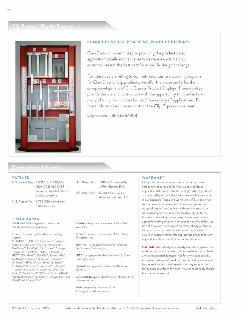
The technical content of this literature is effective 08/23/21 and supersedes all previous information.Pub. No. CD-ClipExpress 08/21 clarkdietrich.com
CL ARKDIETRICH CLIP EXPRESS SM PRODUC T DISPL AYS
ClarkDietrich is committed to providing the product data, application details and hands-on tools necessary to help our customers select the best part for a specific design challenge.
For those dealers willing to commit resources to a stocking program for ClarkDietrich clip products, we offer the opportunity for the co-op development of Clip Express Product Displays. These displays provide dealers and contractors with the opportunity to visualize how many of our products can be used in a variety of applications. For more information, please contact the Clip Express sales team:
Clip Express—866.638.1908
U.S. Patent Nos. 6,021,618; 6,688,069; D814,905; D822,455 are owned by ClarkDietrich Building Systems
U.S. Patent No. 6,705,056 is owned by Kathy Tollenaar
U.S. Patent No. 7,882,676 is owned by Jeffrey Thomas Ellis
U.S. Patent No. D820,664 owned by Allen Innovations, LLC
WARR ANT YOur products are manufactured in accordance with company standards and/or industry standards, as applicable. All ClarkDietrich Building Systems products are covered by our standard warranty which is contained in our Standard Terms and Conditions of Sale and which will be provided upon request. Generally, we warrant our products will be free from defects in material and workmanship at the time of shipment, subject to the limitations stated in the warranty. Unless specifically agreed in writing by us with respect to specific orders, we do not make any warranty of merchantability or fitness for a particular purpose. The buyer is responsible to assure that buyer orders the appropriate product for any applicable code or specification requirements.
NOTICE: Our liability is expressly limited to replacement of defective products. We shall not be liable for incidental and consequential damages, nor for any loss caused by misuse or misapplication of our products. Any claim shall be deemed waived unless made in writing to us within thirty (30) days from the date it was or reasonably should have been discovered.
Trademarks and Warranty
Clip ExpressSM Display Program
ClarkDietrich® is a registered trademark of ClarkDietrich Building Systems.
Owned trademarks by ClarkDietrich Building Systems:ProSTUD®, TRAKLOC®, TradeReady®, Spazzer®, FastClip™, EasyClip™, Fast Top™, Fast Strut™, FastBridge™, Uni-Clip™, Clip ExpressSM, Stronger Than SteelSM, FastBack™, HDS®, RedHeader PRO™, QuickTwist™, Slide Clip™, SubmittalPro®, SwiftClip™, A-Series™, D-Series™, E-Series™, G-Series™, GP-Series™, H-Series™, L-Series™, LS-Series™, LE-Series™, LA-Series™, S-Series™, T-Series™, U-Series™, X-Series™, MaxTrak®, Bar Guard™, DoubleTrack™ QC-Series™, BackerBead®, ClarkDietrich Wall Type Creator®, DiamondPlus® and ClarkDietrich Sound Clip™.
Buildex® is a registered trademark of Illinois Tool Works, Inc.
DriCon® is a registered trademark of Arch Wood Protection, Inc.
FlamePro® is a registered trademark of Koppers Performance Chemicals, Inc.
LEED® is a registered trademark of the U.S. Green Building Council.
Danback® is a registered trademark of Daniel W. Tollenaar.
UL® and UL Design® are trademarks of Underwriter’s Laboratories, Inc.
Hilti is a registered trademark of Hilti Aktiengeseilschaft Corporation.
PATENTS
TR ADEM ARKS
168
clarkdietrich.com
ClarkDietrich Manufacturing and Sales Locations: ClarkDietrich Engineering Services. A full spectrum of solutions.
CALIFORNIA Riverside P 951.360.3500
CALIFORNIA Sacramento P 951.360.3500
CONNECTICUT Bristol P 866.921.0023
FLORIDA Dade CityP 352.518.4400
TEXAS Pasadena P 281.383.1617
CLIP EXPRESS SM P
L O C A T I O N S
FLORIDA, MiamiP 305.477.6464
GEORGIA McDonough P 678.304.5500
ILLINOIS RochelleP 800.659.0745
MARYLAND BaltimoreP 410.477.4000
MISSOURI O'Fallon P 636.300.1411
OHIO Warren-East P 330.372.5564
OHIO Vienna P 330.372.4014
TEXAS Dallas P 214.350.1716
Toll-Free Phone: 877.832.3206Toll-Free Fax: 877.832.3208Technical Services: 888.437.3244Email: [email protected]
CENTRAL Crown Point, IN
NORTHEAST Bristol, CT
SOUTHEAST McDonough, GA
WEST Carlsbad, CA
The technical content of this literature is effective 08/23/21 and supersedes all previous information. Pub. No. CD-ClipExpress 08/21
Clip Express S M C O D E A P P R O VA L S A N D P E R F O R M A N C E S TA N D A R D SClarkDietrich Clip Express products meet or exceed these applicable performance standards.
LEED® Services BUILD GREEN with ClarkDietrich
ClarkDietrich is an active member of the U.S. Green Building Council and is committed to supplying quality products that are environmentally responsible. We are continually working to develop greener building products and sustainable business practices. ClarkDietrich steel framing helps contribute points toward LEED® certification. For more details contact Technical Services at 888-437-3244 or visit www.clarkdietrich.com/LEED.
ClarkDietrich has prepared this literature with the utmost diligence and care for accuracy and conformance to standards.
ClarkDietrich intends this information to be accurate, informative, and helpful as a selection guide for choosing ClarkDietrich products. However, this information is only to be used for guidance and is not intended to replace the design, drawings, specifications, and decisions of a professional architect or engineer.
ClarkDietrich or its affiliates shall not be responsible for incidental or consequential damages, directly or indirectly sustained, nor for loss caused by application of our products for other than their intended uses. Our liability is limited to replacement of defective products. Claims shall be deemed waived unless they are made to us in writing within thirty (30) days of the date a problem was or reasonably should have been discovered.
ClarkDietrich reserves the right to modify or change any information contained in this literature without notification.
AISI “North American Specification for the Design of Cold-Formed Steel Structural Members, AISI S-100-2007 with 2010 supplement”
ASTM American Society for Testing and Materials
Product specificationsASTM C645 Non-structural steel framing membersASTM C955 Load-bearing steel framingAISI S200 Standard for Cold-Formed Steel FramingAISI S220 Standard for Cold-Formed Steel Framing-Nonstructural MembersAISI S240 Standard for Cold-Formed Steel Framing-Structural Members
Material specificationsASTM A1003 (NS33, ST33H, ST50H)ASTM A653 Zinc-coated hot-dip process
Protective coating standardsASTM C645 Non-structural steel framing membersASTM C955 Load-bearing steel framingASTM A653 Zinc-coated hot-dip processAISI S200 Standard for Cold-Formed Steel FramingAISI S220 Standard for Cold-Formed Steel Framing-Nonstructural MembersAISI S240 Standard for Cold-Formed Steel Framing-Structural Members
UL® Underwriters Laboratories testing standardUL 263 "Fire Tests of Building Construction and Materials"
Additional code approvalsInternational Building Code
ClarkDietrich is a proud member of the Steel Framing Industry Association (SFIA). Check the updated list of Certified Production Facilities at Intertek's website at www.intertek.com.
USGBC and related logo is a trademark owned by the U.S. Green Building Council and is used by permission.
866.638.1908
Warren SacramentoDallas McDonough

CD-ClipExpress 08/21 © ClarkDietrich Building Systems. The technical content of this literature is effective 08/23/21 and supersedes all previous information.
Turn to ClarkDietrich for a complete lineup of steel construction products and services nationwide:
Interior Framing∙Exterior Framing∙Interior Finishing∙Exterior Finishing∙Clips/Connectors∙Engineering
9050 Centre Pointe Dr. Suite 400 West Chester, OH 45069
P 513.870.1100 F 513.870.1300
clarkdietrich.comClarkwestern Dietrich Building Systems LLC
CLIP EX
PRESS
SMpro
du
ct catalo
g
Online Version Update-8/23/2021: pgs. 88-89 Moment Clip Charts
Related Documents


