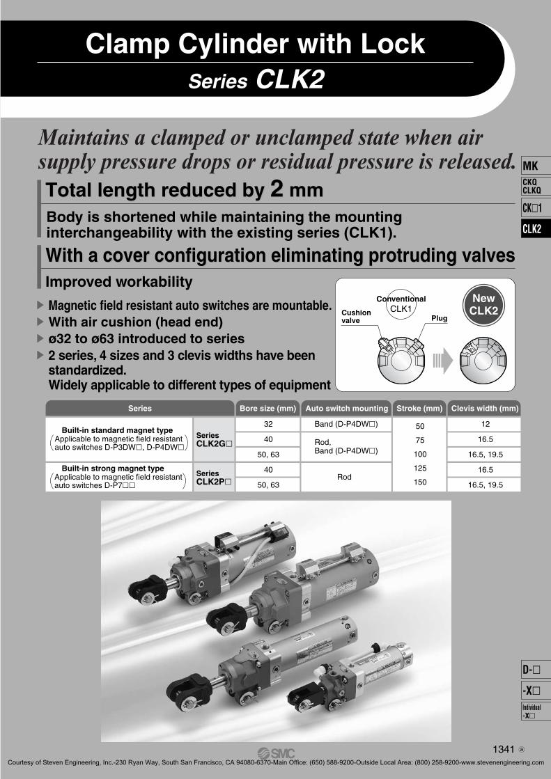
Series CLK2 Clamp Cylinder with Lock Body is shortened while maintaining the mounting interchangeability with the existing series (CLK1). Improved workability Total length reduced by 2 mm With a cover configuration eliminating protruding valve Total length reduced by 2 mm With a cover configuration eliminating protruding valves New CLK2 Maintains a clamped or unclamped state when air supply pressure drops or residual pressure is released. Magnetic field resistant auto switches are mountable. With air cushion (head end) ø32 to ø63 introduced to series 2 series, 4 sizes and 3 clevis widths have been standardized. Widely applicable to different types of equipment Cushion valve Plug Conventional CLK1 Conventional CLK1 Series Series CLK2G Series CLK2P Bore size (mm) 32 40 50, 63 40 50, 63 Band (D-P4DW) Rod, Band (D-P4DW) Rod Stroke (mm) 50 75 100 125 150 Clevis width (mm) 12 16.5 16.5, 19.5 16.5 16.5, 19.5 Built-in standard magnet type Applicable to magnetic field resistant auto switches D-P3DW, D-P4DW Built-in strong magnet type Applicable to magnetic field resistant auto switches D-P7 Auto switch mounting 1341 MK CK1 CLK2 CKQ CLKQ Individual -X D- -X Courtesy of Steven Engineering, Inc.-230 Ryan Way, South San Francisco, CA 94080-6370-Main Office: (650) 588-9200-Outside Local Area: (800) 258-9200-www.stevenengineering.com

Welcome message from author
This document is posted to help you gain knowledge. Please leave a comment to let me know what you think about it! Share it to your friends and learn new things together.
Transcript
Series CLK2Clamp Cylinder with Lock
Body is shortened while maintaining the mounting interchangeability with the existing series (CLK1).
Improved workability
Total length reduced by 2 mm
With a cover configuration eliminating protruding valve
Total length reduced by 2 mm
With a cover configuration eliminating protruding valves
NewCLK2
Maintains a clamped or unclamped state when air supply pressure drops or residual pressure is released.
Magnetic field resistant auto switches are mountable.With air cushion (head end)ø32 to ø63 introduced to series2 series, 4 sizes and 3 clevis widths have been standardized.Widely applicable to different types of equipment
Cushionvalve Plug
ConventionalCLK1
ConventionalCLK1
Series
SeriesCLK2G�
SeriesCLK2P�
Bore size (mm)
32
40
50, 63
40
50, 63
Band (D-P4DW�)
Rod,Band (D-P4DW�)
Rod
Stroke (mm)
50
75
100
125
150
Clevis width (mm)
12
16.5
16.5, 19.5
16.5
16.5, 19.5
Built-in standard magnet typeApplicable to magnetic field resistant auto switches D-P3DW�, D-P4DW�
Built-in strong magnet typeApplicable to magnetic field resistant auto switches D-P7��
Auto switch mounting
1341
MK
CK�1
CLK2
CKQCLKQ
Individual-X�
D-�
-X�
3-2-59-CLK2.qxd 09.9.30 4:17 PM Page 1
Courtesy of Steven Engineering, Inc.-230 Ryan Way, South San Francisco, CA 94080-6370-Main Office: (650) 588-9200-Outside Local Area: (800) 258-9200-www.stevenengineering.com

<Example>Holding a clamped statePrevents work piece slippage and dropping due to work piece weight.
Holding an unclamped statePrevents dislocation of home position due to weight of clamp arm.
Clamp Cylinder with Lock Series CLK2
Series CK1 clamp cylinder (without lock)
Extension locking
LOCK
B
A
LOCK
Bore size
ø40
ø50
ø63
Extended DimensionE
34
38.5
42
(mm)
� Extension locking
LOCK
Locked state Unlocked state Unlocked state
Supply Exhaust
By-pass piping
Un-locked
Operation
Retraction locking
LOCK
A
B
LOCK
� Retraction lockingOperating Principle
Retraction locking
ECK1
CLK2
When compressed air is completely exhausted from the unclamping port, the lock ring is tilted by the spring force, thereby locking the piston rod.
When compressed air is supplied to the unclamp-ing port, the lock ring stands up perpendicular to the piston rod and the lock is released. Then, the piston rod is retracted.
Air can be supplied to or exhausted from the cylin-der head end by providing by-pass piping.
Can be locked at any position within the entire stroke.Locking is possible at any desired position.Able to easily accommodate changes in work piece thickness.
A selection of retraction locking andextension locking is possible.
Compact lock mechanism minimizes extension of length dimension.Series CLK2 clamp cylinder with lock
(piston retracted)
Extension port
Retraction port
Unlocked ExhaustSupply
Operation
Retraction port
Locked
LOCK
Exhaust Supply
(piston extended)Extension port
1342
P1317-P1368-E.qxd 08.11.17 3:35 PM Page 1342
Courtesy of Steven Engineering, Inc.-230 Ryan Way, South San Francisco, CA 94080-6370-Main Office: (650) 588-9200-Outside Local Area: (800) 258-9200-www.stevenengineering.com

Retraction locking
Clamp cylinder with lock Cylinder with lock (Series CN�)
B
A
LOCK
SOL.C SOL.B SOL.A
W
LOCKExtension locking
Piping is not required for unlocking.Since a dedicated solenoid valve is not required for unlocking,reduction of initial costs and replacement of existing equipmentcan be easily accomplished.
Able to maintain an unlocked stateAssembly and maintenance simplified
The auto switch mounting and the piping position are available in three-way directions.The auto switch mounting position can be altered. Also, piping is possible in three-way directions regardless of the auto switch mounting position.Note) For port/bypass mounting positions, refer to pages 1345 and 1351.
Piping portStandard mounting position for the auto switch (switch mounting rod)
Piping portPiping port
By-pass piping
Piping port
Collar
Switch mounting rod
Hexagon socket head cap screw(M3 tightening torque: 0.5 to 0.7 N·m)
Auto switch
Auto switchmounting bracket
Auto switch mounting
bracket assemblyHexagon socket head cap screw
(M4 tightening torque: 1.0 to 1.2 N·m)
Hexagon socket head button bolt(M4 tighteningtorque: 1.0 to 1.2 N·m)
Switchmounting rod
assembly(Collar)
∗ Only used for ø63
Hexagon sockethead cap screw(M2.5 tightening torque: 0.2 to 0.3 N �m)
ProtrusionAuto switch mounting bracket
BMB8-050S
Auto switch
Hexagon sockethead cap screwtruncated cone point(M4 tightening torque:1 to 1.2 N �m)
Switch mounting rod
1343
MK
CK�1
CLK2
CKQCLKQ
Individual-X�
D-�
-X�
3-2-59-CLK2.qxd 09.9.30 4:17 PM Page 2
Courtesy of Steven Engineering, Inc.-230 Ryan Way, South San Francisco, CA 94080-6370-Main Office: (650) 588-9200-Outside Local Area: (800) 258-9200-www.stevenengineering.com

Clamp Cylinder with Lock with Magnetic Field Resistant Auto Switch Rod Mounting
ø40, ø50, ø63Series CLK2G/CLK2P
How to Order
CLK2G 50Built-in standardmagnet typewith magnetic fieldresistant auto switch
Clevis width405063
40 mm50 mm63 mm
Bore size
Cylinder stroke50, 75, 100, 125, 150
A Y100 P3DWSC
CLK2P 50Built-in strongmagnet typewith magnetic fieldresistant auto switch
A Y
B
B100 P79WSE
None
End bracket
IIAY
YA
NilSingle knuckle joint (M6 without tap)Single knuckle joint (M6 with tap)Double knuckle joint (M6 without tap)Double knuckle joint (M6 with tap)
Note) Pin (for knuckle), cotter pin and flat washer are provided as a standard for Y and YA.
NilBDL
K Note 2)
OptionNoneLimit switch mounting baseDog fitting Note 1)
FootPedestal (for 75, 100, 150 strokes only)
Note 1) When the dog bracket is selected, choose the rod end bracket IA or YA (M6 with tap).
Note 2) Clevis width 19.5 mm is not available with mounting base K.
D-P3DWSCD-P4DWSCD-P3DWSED-P4DWSE
D-P3DWD-P3DWLD-P4DWLD-P3DWZD-P4DWZ
D-P79WSED-P74LD-P74Z
TypeApplicable
cylinder seriesAuto switch
modelApplicable
magnetic fieldElectrical entry
AC magnetic field(Single-phaseAC welding
magnetic field)
DC / ACmagnetic field
Indicatorlight
Loadvoltage
2-wire (3–4)
2-wire (1–4)
2-wire
2-wire (1–4)
2-wire
24 VDC
24 VDC
24 VDC100 VAC
Relay,PLC Note 1)
Applicableload
Pre-wired connector
Grommet
Pre-wired connector
Grommet
2-colordisplay
2-colordisplay
1-colordisplay
Wiring(Pin no. in use)
Solid stateauto switch
Reed autoswitch
Series CLK2G
Series CLK2P
Lead wirelength
0.3 m
0.5 m
3 m
5 m
0.3 m
3 m
5 m
Note 1) PLC: Programmable Logic ControllerNote 2) There are other applicable auto switches other than the listed above. For details, refer to page 1359.Note 3) Refer to page 1360 when ordering the auto switch mounting bracket assembly or switch mounting rod assembly. Note 4) For D-P3DW�, auto switches and auto switch mounting brackets are shipped together (not assembled).
Applicable Magnetic Field Resistant Auto Switches (Refer to pages 1719 to 1827 for detailed auto switch specifications.)
Port/Bypass piping position∗ Refer to page 1345.
BF
Retraction lockingExtension locking
Locking direction
Number of auto switches
Sn
Nil 2 pcs.1 pc.“n” pcs. (n = 3, 4, 5···n)
Auto switch
P
Nil
Auto switchmodel
Without auto switch,Without switch mounting rod
Without auto switch,With switch mounting rod
With auto switch,With switch mounting rod
Note) Select applicable auto switch models from the table below.
LR
Nil TopLeftRight
Note 1) Viewed from the rod end.Note 2) When the auto switch D-P79WSE is
mounted, by-pass piping and a switch mounting rod cannot be place at the same position.
Switch mounting rod position
1) Built-in standard (strong) magnet type with-out auto switch and switch mounting rod
Symbol for the auto switch type is "Nil" as shown below.CLK2G: (Example) CLK2GA50-50YCLK2P: (Example) CLK2PA50-50Y
2) Built-in standard (strong) magnet type with-out auto switch, with switch mounting rod
Symbol for the auto switch type is "P" as shown below.CLK2G: (Example) CLK2GA50-50Y-PCLK2P: (Example) CLK2PA50-50Y-P
Built-in Standard (Strong) Magnet Cylinder Part No.
AB
16.5 mm19.5 mm
ø40, ø50, ø63ø50, ø63
NilTN
RcNPT
Port type
CLK2P
CLK2G
1344
3-2-59-CLK2.qxd 09.9.30 4:17 PM Page 3
Courtesy of Steven Engineering, Inc.-230 Ryan Way, South San Francisco, CA 94080-6370-Main Office: (650) 588-9200-Outside Local Area: (800) 258-9200-www.stevenengineering.com

CLK2P
CLK2G
Standard Stroke
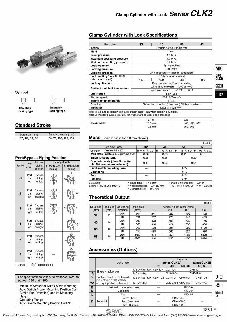
Bore sizeActionFluidProof pressureMaximum operating pressureMinimum operating pressureLocking actionLocking pressureLocking direction
Lock application
Ambient and fluid temperature
LubricationPiston speedStroke length toleranceCushionMounting
Lock holding force N Note 1)
(Max. static load)
Double acting, Single rodAir
1.5 MPa1.0 MPa0.2 MPa
Spring locking0.05 MPa
One direction (Retraction, Extension)0.5 MPa or equivalent
Drop prevention, Position holdingWithout auto switch: –10°C to 70°CWith auto switch : –10°C to 60°C
Non-lube50 to 500 mm/s
+1.0/0Retraction direction (Head end): With air cushion
Double clevis Note 2)
40
629 982 1559
50 63
Note 1) Be sure to comply with guidelines in page 1365 when selecting cylinders. Note 2) Pin (for clevis), cotter pin, flat washer are equipped as standard.
Clevis widthø40, ø50, ø63ø50, ø63
16.5 mm19.5 mm
Retractionlocking type
Extensionlocking type
Bore size (mm)40, 50, 63
Standard stroke (mm)50, 75, 100, 125, 150
Theoretical Output
Rod size(mm)
Piston area(mm2)
Operatingdirection
Bore size(mm)
40
50
63
16
20
20
OUTIN
OUTIN
OUTIN
126010601960165031202800
0.3378318588495934840
0.4 504 424 784 66012501120
0.5 630 530 980 82515601400
0.6 756 6361180 99018701680
Operating pressure (MPa)Unit: N
Accessories (Options)
Description
IIA
BDL
K
Y
YA
Single knuckle jointM6 without tapM6 with tap
M6 without tap
M6 with tap
CLK-I04CLK-IA04
CKB-I04CKB-IA04
CKB-Y04
CKB-YA04
CLK-Y04
CLK-YA04
CKA-Y04
CKA-YA04
CK-B04CK-D04CK-L04
CKA-K075CKA-K100CKA-K150
———
Limit switch mounting baseDog fitting
Foot
PedestalFor 75 strokeFor 100 strokeFor 150 stroke
Double knuckle joint (knucklepin, cotter pin, flat washer are equipped as a standard.)
Parts no.SeriesCLK2GA/CLK2PA
SeriesCLK2GB/CLK2PB
50, 63 50, 6340
Mass (Basic mass is for a 0 mm stroke.)
Unit: kg
Symbol
For specifications with auto switches, refer topages 1359 and 1360.
• Minimum Stroke for Auto Switch Mounting• Auto Switch Proper Mounting Position (for
Stroke End Detection) and its Mounting Height
• Operating Range• Auto Switch Mounting Bracket/Part No.
Clamp Cylinder with Lock Specifications
Bore size (mm)Cylinderbasic mass
Single knuckle joint
Limit switch mounting baseDog fittingFootPedestal
Series CLK2GSeries CLK2PAdditional mass per 25 mm stroke
63B: 1.96 F: 2.02B: 2.06 F: 2.08
0.13
50B: 1.48 F: 1.54B: 1.49 F: 1.55
0.110.20
0.34
0.220.120.242.04
40B: 1.05 F: 1.11B: 1.12 F: 1.18
0.080.25
0.36
Note) The above values do not include the mass of the auto switch and auto switch mounting bracket. CalculationExample) CLK2PB50-100Y-B
• Basic mass ··· 1.49 (ø50)• Additional mass ··· 0.11/25 mm• Cylinder stroke ··· 100 mm
• Double knuckle joint ··· 0.34 (Y)1.49 + 0.11 x 100 / 25 + 0.34 = 2.27 kg
Double knuckle joint (Pin, cotter pin, flat washer are included.)
Sym
bol
Port/Bypass Piping PositionLocking direction
B: Retractionlocking
F: Extensionlocking
Symbol
Nil
2
3
4
5
6
—
—
—
Bypasspiping
position
Bypasspipingon left
Bypasspiping
on right
Bypasspipingon left
Bypasspiping
on right
Bypasspipingon top
Bypasspipingon top
Portposition
Portontop
Portonleft
Porton
right
Portontop
Portonleft
Porton
right
Port Bypass piping
1345
Series CLK2G/CLK2PClamp Cylinder with Lock With Magnetic Field Resistant Auto Switch
MK
CK�1
CLK2
CKQCLKQ
Individual-X�
D-�
-X�
3-2-59-CLK2.qxd 09.9.30 4:17 PM Page 4
Courtesy of Steven Engineering, Inc.-230 Ryan Way, South San Francisco, CA 94080-6370-Main Office: (650) 588-9200-Outside Local Area: (800) 258-9200-www.stevenengineering.com
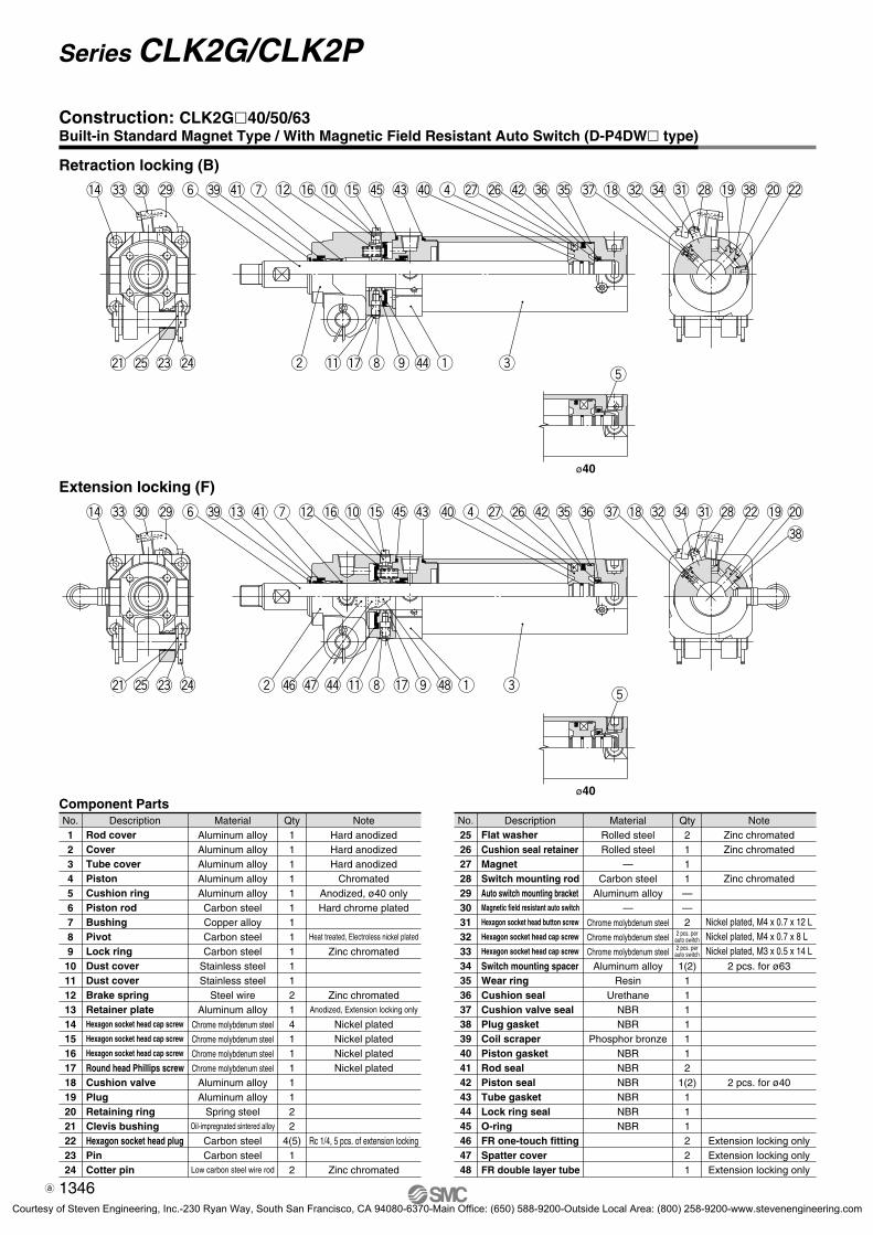
No.123456789101112131415161718192021222324
Rod coverCoverTube coverPistonCushion ringPiston rodBushingPivotLock ringDust coverDust coverBrake springRetainer plateHexagon socket head cap screw
Hexagon socket head cap screw
Hexagon socket head cap screw
Round head Phillips screwCushion valvePlugRetaining ringClevis bushingHexagon socket head plugPinCotter pin
Description
Component PartsMaterial
Aluminum alloyAluminum alloyAluminum alloyAluminum alloyAluminum alloyCarbon steelCopper alloyCarbon steelCarbon steel
Stainless steelStainless steel
Steel wireAluminum alloy
Chrome molybdenum steel
Chrome molybdenum steel
Chrome molybdenum steel
Chrome molybdenum steel
Aluminum alloyAluminum alloy
Spring steelOil-impregnated sintered alloy
Carbon steelCarbon steel
Low carbon steel wire rod
NoteHard anodizedHard anodizedHard anodized
ChromatedAnodized, ø40 onlyHard chrome plated
Heat treated, Electroless nickel plated
Zinc chromated
Zinc chromatedAnodized, Extension locking only
Nickel platedNickel platedNickel platedNickel plated
Rc 1/4, 5 pcs. of extension locking
Zinc chromated
Qty111111111112141111122
4(5)12
No.252627282930313233343536373839404142434445464748
Flat washerCushion seal retainerMagnetSwitch mounting rodAuto switch mounting bracketMagnetic field resistant auto switch
Hexagon socket head button screw
Hexagon socket head cap screw
Hexagon socket head cap screw
Switch mounting spacerWear ringCushion sealCushion valve sealPlug gasketCoil scraperPiston gasketRod sealPiston sealTube gasketLock ring sealO-ringFR one-touch fittingSpatter coverFR double layer tube
Description MaterialRolled steelRolled steel
—Carbon steel
Aluminum alloy—
Chrome molybdenum steel
Chrome molybdenum steel
Chrome molybdenum steel
Aluminum alloyResin
UrethaneNBRNBR
Phosphor bronzeNBRNBRNBRNBRNBRNBR
NoteZinc chromatedZinc chromated
Zinc chromated
2 pcs. for ø63
2 pcs. for ø40
Extension locking onlyExtension locking onlyExtension locking only
Nickel plated, M4 x 0.7 x 12 LNickel plated, M4 x 0.7 x 8 LNickel plated, M3 x 0.5 x 14 L
Qty2111——2
1(2)1111112
1(2)111221
2 pcs. perauto switch2 pcs. per
auto switch
t
ø40
ø40
t
#3 @9#0!4
@4@3@5@1
@2#7 !8 #4 #1 !9
#8
@0@8#2r$0 #5 #6$2@6@7!3 $5!5!0!6!2 $3u$1#9y
!7 e$6 $4 !1 oiw q$7 $8
#3 @9#0!4
@4@3@5@1
#2#7 !8 #4 !9 @0#8#1 @8 @2r$0 #6 #5$2@6@7$5!5!0!6!2 $3u$1#9y
!7 e!1 $4oiw q
Construction: CLK2G�40/50/63Built-in Standard Magnet Type / With Magnetic Field Resistant Auto Switch (D-P4DW� type)
Retraction locking (B)
Extension locking (F)
1346
Series CLK2G/CLK2P
3-2-59-CLK2.qxd 09.9.30 4:17 PM Page 5
Courtesy of Steven Engineering, Inc.-230 Ryan Way, South San Francisco, CA 94080-6370-Main Office: (650) 588-9200-Outside Local Area: (800) 258-9200-www.stevenengineering.com

No.
1
2
3
4
5
6
7
8
9
10
11
12
13
14
15
16
17
18
19
20
21
22
23
24
Rod cover
Cover
Tube cover
Piston
Piston rod
Bushing
Pivot
Lock ring
Dust cover
Dust cover
Brake spring
Retainer plate
Hexagon socket head cap screw
Hexagon socket head cap screw
Hexagon socket head cap screw
Round head Phillips screw
Cushion valve
Plug
Retaining ring
Magnet holder
Clevis bushing
Hexagon socket head plug
Pin
Cotter pin
Description
Component PartsMaterial
Aluminum alloy
Aluminum alloy
Aluminum alloy
Aluminum alloy
Carbon steel
Copper alloy
Carbon steel
Carbon steel
Stainless steel
Stainless steel
Steel wire
Aluminum alloy
Chrome molybdenum steel
Chrome molybdenum steel
Chrome molybdenum steel
Chrome molybdenum steel
Aluminum alloy
Aluminum alloy
Spring steel
Aluminum alloy
Oil-impregnated sintered alloy
Carbon steel
Carbon steel
Low carbon steel wire rod
Note
Hard anodized
Hard anodized
Hard anodized
Chromated
Hard chrome plated
Heat treated, Electroless nickel plated
Zinc chromated
Zinc chromated
Anodized, Extension locking only
Nickel plated
Nickel plated
Nickel plated
Nickel plated
Chromated
Rc 1/4, 5 pcs. of extension locking
Zinc chromated
Qty
1
1
1
1
1
1
1
1
1
1
2
1
4
1
1
1
1
1
2
1
2
4(5)
1
2
No.
25
26
27
28
29
30
31
32
33
34
35
36
37
38
39
40
41
42
43
44
45
46
47
Flat washer
Cushion seal retainer
Magnet
Switch mounting rod
Auto switch mounting bracket
Magnetic field resistant auto switch
Hexagon socket head button screw
Hexagon socket head cap screw
Hexagon socket head cap screw
Switch mounting spacer
Wear ring
Cushion seal
Cushion valve seal
Plug gasket
Coil scraper
Rod seal
Piston seal
Tube gasket
Lock ring seal
O-ring
FR one-touch fitting
Spatter cover
FR double layer tube
Description Material
Rolled steel
Rolled steel
—
Carbon steel
Aluminum alloy
—
Chrome molybdenum steel
Chrome molybdenum steel
Chrome molybdenum steel
Aluminum alloy
Resin
Urethane
NBR
NBR
Phosphor bronze
NBR
NBR
NBR
NBR
NBR
Note
Zinc chromated
Zinc chromated
Zinc chromated
2 pcs. for ø63
Extension locking only
Extension locking only
Extension locking only
Nickel plated, M4 x 0.7 x 12 L
Black zinc chromated, M4 x 0.7 x 8 L
Black zinc chromated, M3 x 0.5 x 16 L
Qty
2
1
1
1
—
—
2
1(2)
1
1
1
1
1
2
1
1
1
1
2
2
1
2 pcs. perswitch
2 pcs. perswitch
@7@0 #5 #6$1@6r
!6 iu e
!2
$5 !0$3
$4!4!5o!1
w
$2
q
y$0#9t
$6 $7
!6 e
@7@0 #6 #5$1@6r
!0
$4!4o!5!1
$3iuw
$2
q
y$0#9t
@2#7 !7 #4 @8 !8
#8
!9#1 #2
#7 !7 #4 @8 !8 !9#8 @2#1 #2
#3 @9#0!3
@4@3@5@1
#3!3 @9#0
@4@3@5@1
Construction: CLK2P�40/50/63Built-in Strong Magnet Type / With Magnetic Field Resistant Auto Switch (D-P7�� type)
Retraction locking (B)
Extension locking (F)
1347
Series CLK2G/CLK2PClamp Cylinder with LockWith Magnetic Field Resistant Auto Switch
MK
CK�1
CLK2
CKQCLKQ
Individual-X�
D-�
-X�
P1317-P1368-E.qxd 08.11.17 3:35 PM Page 1347
Courtesy of Steven Engineering, Inc.-230 Ryan Way, South San Francisco, CA 94080-6370-Main Office: (650) 588-9200-Outside Local Area: (800) 258-9200-www.stevenengineering.com

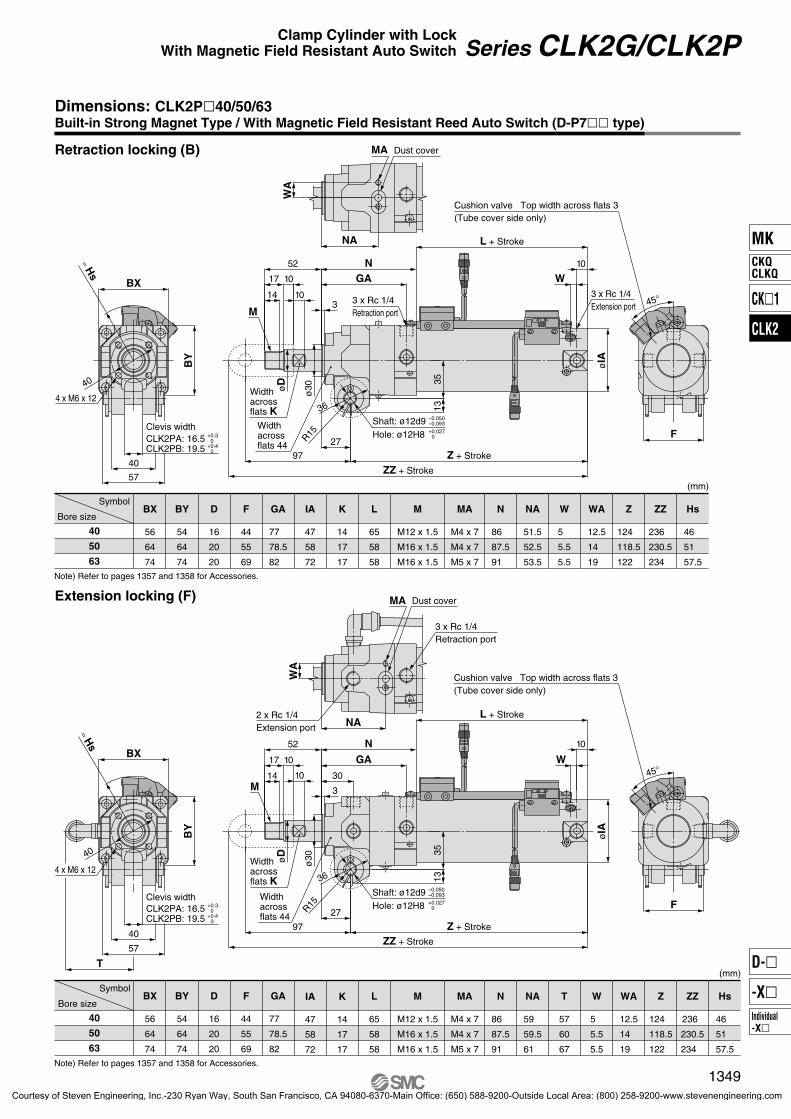
Bore size
SymbolBX
56
64
74
BY
54
64
74
D
16
20
20
F
44
55
69
GA
77
78.5
82
IA
47
58
72
K
14
17
17
L
55
58
58
N
86
87.5
91
T
57
60
67
Hs
45.5
51
58.5
WA
12.5
14
19
NA
59
59.5
61
Z
114
118.5
122
W
5
5.5
5.5
ZZ
226
230.5
234
M
M12 x 1.5
M16 x 1.5
M16 x 1.5
MA
M4 x 7
M4 x 7
M5 x 7
40
50
63
(mm)
Bore size
SymbolBX
56
64
74
BY
54
64
74
D
16
20
20
F
44
55
69
GA
77
78.5
82
IA
47
58
72
K
14
17
17
L
55
58
58
N
86
87.5
91
W
5
5.5
5.5
Hs
45.5
51
58.5
WA
12.5
14
19
NA
51.5
52.5
53.5
Z
114
118.5
122
ZZ
226
230.5
234
M
M12 x 1.5
M16 x 1.5
M16 x 1.5
MA
M4 x 7
M4 x 7
M5 x 7
40
50
63
(mm)
Note) Refer to pages 1357 and 1358 for Accessories.
Note) Refer to pages 1357 and 1358 for Accessories.
≈ Hs
CLK2GB: 19.5CLK2GA: 16.5
40
57
40
BY
BX
Clevis width
4 x M6 x 12
NA
WA
Dust coverMA
F
45°
Cushion valve Top width across flats 3(Tube cover side only)
52
øD
ø30
ZZ + Stroke
97
36
R15
Z + Stroke
2713
35
øIA
GA
310
1017
14
N L + Stroke
W10
3 x Rc 1/4Retraction port
Width across flats 44
Width across flats K
Hole: ø12H8Shaft: ø12d9
M
3 x Rc 1/4Extension port
≈ Hs
T
40
57
40
BY
BX
Clevis width
4 x M6 x 12
F
45°
Cushion valve Top width across flats 3(Tube cover side only)
WA
NA
MA Dust cover
3 x Rc 1/4Retraction port
2 x Rc 1/4Extension port
30
GA
3
10
1017
14
N52 L + Stroke
W10
øD
ø30
ZZ + Stroke
97
36
R15
Z + Stroke
27
1335
øIA
Width across flats 44
Width across flats K
M
+0.30
+0.40
CLK2GB: 19.5CLK2GA: 16.5 +0.3
0+0.4
0
–0.050–0.093
+0.0270
Hole: ø12H8Shaft: ø12d9 –0.050
–0.093
+0.0270
Dimensions: CLK2G�40/50/63Built-in Standard Magnet Type / With Magnetic Field Resistant Solid State Auto Switch (D-P4DW� type)
Retraction locking (B)
Extension locking (F)
1348
Series CLK2G/CLK2P
P1317-P1368-E.qxd 08.11.17 3:35 PM Page 1348
Courtesy of Steven Engineering, Inc.-230 Ryan Way, South San Francisco, CA 94080-6370-Main Office: (650) 588-9200-Outside Local Area: (800) 258-9200-www.stevenengineering.com
Bore size
SymbolBX
56
64
74
BY
54
64
74
D
16
20
20
F
44
55
69
GA
77
78.5
82
IA
47
58
72
K
14
17
17
L
65
58
58
N
86
87.5
91
NA
59
59.5
61
T
57
60
67
Hs
46
51
57.5
WA
12.5
14
19
Z
124
118.5
122
W
5
5.5
5.5
ZZ
236
230.5
234
M
M12 x 1.5
M16 x 1.5
M16 x 1.5
MA
M4 x 7
M4 x 7
M5 x 7
40
50
63
(mm)
Bore size
SymbolBX
56
64
74
BY
54
64
74
D
16
20
20
F
44
55
69
GA
77
78.5
82
IA
47
58
72
K
14
17
17
L
65
58
58
N
86
87.5
91
W
5
5.5
5.5
NA
51.5
52.5
53.5
Hs
46
51
57.5
WA
12.5
14
19
Z
124
118.5
122
ZZ
236
230.5
234
M
M12 x 1.5
M16 x 1.5
M16 x 1.5
MA
M4 x 7
M4 x 7
M5 x 7
40
50
63
(mm)
Note) Refer to pages 1357 and 1358 for Accessories.
Note) Refer to pages 1357 and 1358 for Accessories.
F
45°
Cushion valve Top width across flats 3(Tube cover side only)
≈ Hs
T
40
57
40
BY
BX
Clevis width
4 x M6 x 12
WA
NA
MA Dust cover
3 x Rc 1/4Retraction port
2 x Rc 1/4Extension port
30
øD
ø30
ZZ + Stroke
97
36
R15
Z + Stroke
27
1335
øIA
GA
3
10
1017
14
N52
L + Stroke
W
10
Width across flats 44
Width across flats K
M
≈ Hs
BX
40
57
40
BY
Clevis width
4 x M6 x 12
NA
WA
Dust coverMA
F
45°
Cushion valve Top width across flats 3(Tube cover side only)
Z + Stroke
øD
ø30
ZZ + Stroke
97
36
R15
2713
35
øIA
GA
310
1017
14
N52
L + Stroke
W10
Width across flats 44
Width across flats K
3 x Rc 1/4Retraction portM
3 x Rc 1/4Extension port
CLK2PB: 19.5CLK2PA: 16.5 +0.3
0+0.4
0
Hole: ø12H8Shaft: ø12d9 –0.050
–0.093
+0.0270
CLK2PB: 19.5CLK2PA: 16.5 +0.3
0+0.4
0
Hole: ø12H8Shaft: ø12d9 –0.050
–0.093
+0.0270
Dimensions: CLK2P�40/50/63Built-in Strong Magnet Type / With Magnetic Field Resistant Reed Auto Switch (D-P7�� type)
Retraction locking (B)
Extension locking (F)
1349
Series CLK2G/CLK2PClamp Cylinder with LockWith Magnetic Field Resistant Auto Switch
MK
CK�1
CLK2
CKQCLKQ
Individual-X�
D-�
-X�
P1317-P1368-E.qxd 08.11.17 3:35 PM Page 1349
Courtesy of Steven Engineering, Inc.-230 Ryan Way, South San Francisco, CA 94080-6370-Main Office: (650) 588-9200-Outside Local Area: (800) 258-9200-www.stevenengineering.com
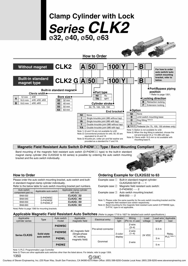
ø32, ø40, ø50, ø63Series CLK2Clamp Cylinder with Lock
Magnetic Field Resistant Auto Switch D-P4DW�� Type / Band Mounting CompliantBand mounting of the magnetic field resistant auto switch (D-P4DW�� type) to the built-in standard magnet clamp cylinder (the CLK2G32 to 63 series) is possible by ordering the auto switch mounting bracket and the auto switch individually.
How to Order
CLK2 50Without magnet
A
B
12 mm16.5 mm19.5 mm
ø32ø40, ø50, ø63ø50, ø63
Clevis width
32405063
32 mm40 mm50 mm63 mm
Bore size
Port type
Cylinder stroke50, 75, 100, 125, 150
A Y100
CLK2 50Built-in standardmagnet type AG Y
B
B100
None
End bracket
IIAY
YA
NilSingle knuckle joint (M6 without tap)Single knuckle joint (M6 with tap)Double knuckle joint (M6 without tap)Double knuckle joint (M6 with tap)
Note 1) IA and YA are not available for ø32.Note 2) Conventional products for ø40, 50, 63 are
equivalent to IA and YANote 3) Knuckle pin, cotter pin and flat washer are
provided as a standard for Y and YA.
For how to order auto switch/ auto switch mounting bracket, refer to below.
NilBDL
K Note 3)
OptionNoneLimit switch mounting baseDog fitting Note 2)
FootPedestal (for 75, 100, 150 strokes only)
Note 1) Option is not available for ø32.Note 2) When the dog fitting is selected, choose the
rod end bracket IA or YA (M6 with tap).Note 3) Clevis width 19.5 mm is not available with
mounting base K.
BF
Retraction lockingExtension locking
Locking direction
Built-in standard magnet Port/Bypass piping position∗ Refer to page 1351.Nil
TNRcNPT
Please order the auto switch mounting bracket, auto switch and built-in standard magnet clamp cylinder individually.Refer to the below table for auto switch mounting bracket part numbers.
How to OrderExample case q Built-in standard magnet cylinder:
CLK2GA50-50Y-B ····· 1Example case w Magnetic field resistant auto switch:
D-P4DWSC ····· 2Example case e Auto switch mounting bracket:
BA8-050 ····· 2
Note 1) Please order the same quantity for the auto switch mounting bracket and the magnetic field resistant auto switch respectively.
Note 2) Band mounting for the magnetic field resistant auto switch D-P79WSE type, D-P74� type is not applicable.
Ordering Example for CLK2G32 to 63
Note) Refer to page 1360 for mounting brackets.
Auto switchcomponent part no. Applicable auto switch Applicable clamp cylinder
with lockBA8-032BA8-040BA8-050BA8-063
D-P4DWSCD-P4DWSED-P4DWL/Z
CLK2G�32CLK2G�40CLK2G�50CLK2G�63
Applicable Magnetic Field Resistant Auto Switches (Refer to pages 1719 to 1827 for detailed auto switch specifications.)
Auto switchmodel
P4DWSC
P4DWSE
P4DWL
P4DWZ
Applicablemagnetic field
AC magnetic field(Single-phaseAC welding
magnetic field)
Loadvoltage
24 VDCRelay,
PLC Note 1)
ApplicableloadElectrical entry
Pre-wired connector
Grommet
Indicatorlight
2-colordisplay
2-wire(3–4)
2-wire(1–4)
2-wire
Wiring(Pin no. in use)Type
Solid stateauto switch
Applicablecylinder series
Series CLK2G
Lead wirelength
0.3 m
3 m
5 m
Note 1) PLC: Programmable Logic ControllerNote 2) There are other applicable auto switches other than the listed above. For details, refer to page 1359.
1350
P1317-P1368-E.qxd 08.11.17 3:35 PM Page 1350
Courtesy of Steven Engineering, Inc.-230 Ryan Way, South San Francisco, CA 94080-6370-Main Office: (650) 588-9200-Outside Local Area: (800) 258-9200-www.stevenengineering.com
Retractionlocking type
Symbol
Extensionlocking type
Clamp Cylinder with Lock Specifications
Bore sizeActionFluidProof pressureMaximum operating pressureMinimum operating pressureLocking actionLocking pressureLocking directionLock holding force N Note 1)
(Max. static load)Lock application
Ambient and fluid temperature
LubricationPiston speedStroke length toleranceCushionMounting
Double acting, Single rodAir
1.5 MPa1.0 MPa0.2 MPa
Spring locking0.05 MPa
One direction (Retraction, Extension)0.5 MPa or equivalent
Drop prevention, Position holdingWithout auto switch: –10°C to 70°CWith auto switch : –10°C to 60°C
Non-lube50 to 500 mm/s
+1.0/0Retraction direction (Head end): With air cushion
Double clevis Note 2)
1559
63
982
50
629
40
402
32
Note 1) Be sure to comply with guidelines in page 1365 when selecting cylinders. Note 2) Pin (for clevis), cotter pin, flat washer are equipped as a standard.
Clevis widthø32ø40, ø50, ø63ø50, ø63
12 mm16.5 mm19.5 mm
Mass (Basic mass is for a 0 mm stroke.)
CalculationExample) CLK2B50-100Y-B
• Basic mass ··· 1.48 (ø50)• Additional mass ··· 0.11/25 mm• Cylinder stroke ··· 100 mm
• Double knuckle joint ··· 0.34 (Y)1.48 + 0.11 x 100 / 25 + 0.34 = 2.26 kg
Bore size (mm)Cylinderbasic massSingle knuckle joint
Limit switch mounting baseDog fittingFootPedestal
Series CLK2�Additional mass per 25 mm stroke
63B: 1.96 F: 2.02
0.13
50B: 1.48 F: 1.54
0.110.20
0.34
32B: 0.51 F: 0.54
0.080.25
0.17
————
0.220.120.242.04
40B: 1.05 F: 1.11
0.080.25
0.36
Unit: kg
Double knuckle joint (Pin, cotter pin, flat washer are included.)
Theoretical Output
Rod size(mm)
Piston area(mm2)
Operatingdirection
Bore size(mm)
32
40
50
63
12
16
20
20
OUTIN
OUTIN
OUTIN
OUTIN
804 691126010601960165031202800
0.3241207378318588495934840
0.4 322 276 504 424 784 66012501120
0.5 402 346 630 530 980 82515601400
0.6 482 415 756 6361180 99018701680
Operating pressure (MPa)Unit: N
Accessories (Options)
Description
IIA
BDL
K
Y
YA
Single knuckle jointM6 without tapM6 with tap
M6 without tap
M6 with tap
CKB-I04CKB-IA04
CLK-I04CLK-IA04
CKA-Y04
CKA-YA04
CKB-Y04
CKB-YA04
CLK-Y04
CLK-YA04
CK-B04CK-D04CK-L04
———
Limit switch mounting baseDog fitting
Foot
PedestalFor 75 strokeFor 100 strokeFor 150 stroke
Double knuckle joint (knuckle pin, cotter pin, flat washer are equipped as a standard.)
Parts no.Series CLK2A Series CLK2B
40 50, 6350, 6332CLK-I03
——————
—
—
CKA-K075CKA-K100CKA-K150
CLK-Y03
Standard Stroke
Bore size (mm)32, 40, 50, 63
Standard stroke (mm)50, 75, 100, 125, 150
Port/Bypass Piping PositionLocking direction
B: Retractionlocking
F: Extensionlocking
Symbol
Nil
2
3
4
5
6
—
—
—
Bypasspiping
position
Bypasspipingon left
Bypasspiping
on right
Bypasspipingon left
Bypasspiping
on right
Bypasspipingon top
Bypasspipingon top
Portposition
Portontop
Portonleft
Porton
right
Portontop
Portonleft
Porton
right
Port Bypass piping
For specifications with auto switches, refer topages 1359 and 1360.
• Minimum Stroke for Auto Switch Mounting• Auto Switch Proper Mounting Position (for
Stroke End Detection) and its Mounting Height
• Operating Range• Auto Switch Mounting Bracket/Part No.
1351
Clamp Cylinder with Lock Series CLK2
MK
CK�1
CLK2
CKQCLKQ
Individual-X�
D-�
-X�
3-2-59-CLK2.qxd 09.9.30 4:17 PM Page 6
Courtesy of Steven Engineering, Inc.-230 Ryan Way, South San Francisco, CA 94080-6370-Main Office: (650) 588-9200-Outside Local Area: (800) 258-9200-www.stevenengineering.com

No.
1
2
3
4
5
6
7
8
9
10
11
12
13
14
15
16
17
18
Rod cover
Cover
Cylinder tube
Head cover
Piston
Piston rod
Bushing
Pivot
Lock ring
Dust cover
Brake spring
Hexagon socket head cap screw
Hexagon socket head cap screw
Hexagon socket head cap screw
Round head Phillips screw
Cushion valve
Plug
Clevis bushing
Description
Component PartsMaterial
Aluminum alloy
Aluminum alloy
Aluminum alloy
Aluminum alloy
Aluminum alloy
Carbon steel
Copper alloy
Carbon steel
Carbon steel
Stainless steel
Steel wire
Chrome molybdenum steel
Chrome molybdenum steel
Chrome molybdenum steel
Chrome molybdenum steel
Free-cutting brass
Free-cutting brass
Oil-impregnated sintered alloy
Note
Hard anodized
Hard anodized
Hard anodized
Chromated
Chromated
Hard chrome plated
Heat treated, Electroless nickel plated
Zinc chromated
Zinc chromated
Nickel plated
Nickel plated
Nickel plated
Nickel plated
Electroless nickel plated
Qty
1
1
1
1
1
1
1
1
1
2
2
4
1
1
1
1
1
2
No.
19
20
21
22
23
24
25
26
27
28
29
30
31
32
33
34
35
36
Hexagon socket head plug
Pin
Cotter pin
Flat washer
Magnet
Wear ring
Cushion seal
Cushion valve seal
Plug seal
Coil scraper
Rod seal
Piston seal
Tube gasket
Lock ring seal
O-ring
FR one-touch fitting
Spatter cover
FR double layer tube
Description Material
Carbon steel
Carbon steel
Low carbon steel wire rod
Rolled steel
—
Resin
NBR
NBR
NBR
Phosphor bronze
NBR
NBR
NBR
NBR
NBR
Note
Rc 1/8, 5 pcs. of extension locking
Zinc chromated
Zinc chromated
CLK2GA32 only
Extension locking only
Extension locking only
Extension locking only
Qty
4(5)
1
2
2
1
1
1
1
1
1
2
1
2
1
1
2
2
1
@3
!5
t@8 #3
#2
@5#1 #0@9 @4!4!3!1!0
oi
u
y
r
ew q@2@1@0
!2
!8
@7@6 !7!6 !9
@7@6 !7!6 !9
!5
@3t
#6#5 #4
o !1@8 #3
i
@5#1 #0@9 @4!3!4!0
#2
u
y
r
ew q@2@1@0
!2
!8
Construction: CLK2A32 Without Magnet / CLK2GA32 Built-in Standard Magnet Type
Retraction locking (B)
Extension locking (F)
1352
Series CLK2
P1317-P1368-E.qxd 08.11.17 3:35 PM Page 1352
Courtesy of Steven Engineering, Inc.-230 Ryan Way, South San Francisco, CA 94080-6370-Main Office: (650) 588-9200-Outside Local Area: (800) 258-9200-www.stevenengineering.com

No.
1
2
3
4
5
6
7
8
9
10
11
12
13
14
15
16
17
18
19
20
21
Rod cover
Cover
Tube cover
Piston
Cushion ring
Piston rod
Bushing
Pivot
Lock ring
Dust cover
Dust cover
Brake spring
Retainer plate
Hexagon socket head cap screw
Hexagon socket head cap screw
Hexagon socket head cap screw
Round head Phillips screw
Cushion valve
Plug
Retaining ring
Clevis bushing
Description
Component PartsMaterial
Aluminum alloy
Aluminum alloy
Aluminum alloy
Aluminum alloy
Copper alloy
Carbon steel
Copper alloy
Carbon steel
Carbon steel
Stainless steel
Stainless steel
Steel wire
Aluminum alloy
Chrome molybdenum steel
Chrome molybdenum steel
Chrome molybdenum steel
Chrome molybdenum steel
Aluminum alloy
Aluminum alloy
Spring steel
Oil-impregnated sintered alloy
Note
Hard anodized
Hard anodized
Hard anodized
Chromated
ø40 only
Hard chrome plated
Heat treated, Electroless nickel plated
Zinc chromated
Zinc chromated
Anodized, Extension locking only
Nickel plated
Nickel plated
Nickel plated
Nickel plated
Qty
1
1
1
1
1
1
1
1
1
1
1
2
1
4
1
1
1
1
1
2
2
No.
22
23
24
25
26
27
28
29
30
31
32
33
34
35
36
37
38
39
40
41
Hexagon socket head plug
Pin
Cotter pin
Flat washer
Cushion seal retainer
Magnet
Wear ring
Cushion seal
Cushion valve seal
Plug gasket
Coil scraper
Piston gasket
Rod seal
Piston seal
Tube gasket
Lock ring seal
O-ring
FR one-touch fitting
Spatter cover
FR double layer tube
Description Material
Carbon steel
Carbon steel
Low carbon steel wire rod
Rolled steel
Rolled steel
—
Resin
Urethane
NBR
NBR
Phosphor bronze
NBR
NBR
NBR
NBR
NBR
NBR
Note
Rc 1/4, 5 pcs. of extension locking
Zinc chromated
Zinc chromated
Zinc chromated
CLK2G only
2 pcs. for ø40
Extension locking only
Extension locking only
Extension locking only
Qty
4(5)
1
2
2
1
1
1
1
1
1
1
1(2)
2
1
1
1
1
2
2
1
ø40
!9 @0#1 @2!8#0
!7
!0
e!1
#8!6!5!2
#7oiw
@7#3 @6 @9@8#5r#6
q
u#4#2y!4
@4@3@5@1 t
!4
@4@3@5@1
@2 !9 @0#1!8 #0
!7
!0
e
!3
#9 #7
#8!6!5!2
!1 oiw
@7#3 @6 @9@8#5r#6
q
u#4#2y
$0 $1
ø40
t
Construction: CLK2�40/50/63 Without Magnet / CLK2G�40/50/63 Built-in Standard Magnet Type
Retraction locking (B)
Extension locking (F)
1353
Clamp Cylinder with Lock Series CLK2
MK
CK�1
CLK2
CKQCLKQ
Individual-X�
D-�
-X�
P1317-P1368-E.qxd 08.11.17 3:35 PM Page 1353
Courtesy of Steven Engineering, Inc.-230 Ryan Way, South San Francisco, CA 94080-6370-Main Office: (650) 588-9200-Outside Local Area: (800) 258-9200-www.stevenengineering.com

45°
Head end cushion valve
26
102 + Stroke
169 + Stroke
34 + Stroke
12
1026
ø12
9.5
56
12 534 12
206025
ø40
6
55
R12
3 x Rc 1/8Retraction port 3 x Rc 1/8
Extension port
+0.0220
Shaft: ø10d9Hole: ø10H8
–0.040–0.076
Width across flats 10 Width across
flats 36
M10 x 1.25
+0.0220
Shaft: ø10d9Hole: ø10H8
–0.040–0.076
26
102 + Stroke
169 + Stroke
34 + Stroke
19
12
1026
ø12
9.5
56
12 534 12
206025
ø40
6
55
R12
Width across flats 10
Width across flats 36
M10 x 1.2545°
Head end cushion valve
3111
393 x Rc 1/8Retraction port
Dust cover
M3 x 6
2 x Rc 1/8Extension port
11
47
47
41.2
26
12 +0.5+0.2
47
49
47
41.2
26
12 +0.5+0.2
Note) Refer to pages 1357 and 1358 for Accessories.
Note) Refer to pages 1357 and 1358 for Accessories.
Dust cover
M3 x 6
Dimensions: CLK2A32 Without Magnet / CLK2GA32 Built-in Standard Magnet Type
Retraction locking (B)
Extension locking (F)
1354
Series CLK2
P1317-P1368-E.qxd 08.11.17 3:35 PM Page 1354
Courtesy of Steven Engineering, Inc.-230 Ryan Way, South San Francisco, CA 94080-6370-Main Office: (650) 588-9200-Outside Local Area: (800) 258-9200-www.stevenengineering.com

NA
WA
MA
F
45°
Cushion valve Top width across flats 3(Tube cover side only)
GA
310
1017
14
N52 L + Stroke
W
10øD
ø30
ZZ + Stroke
97
36
R15
Z + Stroke
2713
35
øIA
Width across flats 44
Width across flats K
+0.0270
Shaft: ø12d9Hole: ø12H8
–0.050–0.093
3 x Rc 1/4Retraction portM
3 x Rc 1/4Extension port
40
57
40
BY
BX
4 x M6 x 12
Clevis widthCLK2GA: 16.5CLK2GB: 19.5
+0.30
+0.40
WA
NA
MADust cover
3 x Rc 1/4Retraction port
2 x Rc 1/4Extension port
Cushion valve Top width across flats 3(Tube cover side only)
F
45°
+0.0270
Shaft: ø12d9Hole: ø12H8
–0.050–0.093
3
30
GA10
1017
14
L + Stroke
W
10
øD
ø30
ZZ + Stroke
97
36
R15
Z + Stroke27
1335
øIA
Width across flats 44
Width across flats K
M
N52
T
40
57
40
BY
BX
4 x M6 x 12
Clevis widthCLK2GA: 16.5CLK2GB: 19.5
+0.30
+0.40
Bore size
SymbolBX
56
64
74
BY
54
64
74
D
16
20
20
F
44
55
69
GA
77
78.5
82
IA
47
58
72
K
14
17
17
L
55
58
58
N
86
87.5
91
T
57
60
67
WA
12.5
14
19
NA
59
59.5
61
Z
114
118.5
122
W
5
5.5
5.5
ZZ
226
230.5
234
M
M12 x 1.5
M16 x 1.5
M16 x 1.5
MA
M4 x 7
M4 x 7
M5 x 7
40
50
63
Note) Refer to pages 1357 and 1358 for Accessories.
(mm)
Bore size
Note) Refer to pages 1357 and 1358 for Accessories.
SymbolBX
56
64
74
BY
54
64
74
D
16
20
20
F
44
55
69
GA
77
78.5
82
IA
47
58
72
K
14
17
17
L
55
58
58
N
86
87.5
91
W
5
5.5
5.5
NA
51.5
52.5
53.5
WA
12.5
14
19
Z
114
118.5
122
M
M12 x 1.5
M16 x 1.5
M16 x 1.5
MA
M4 x 7
M4 x 7
M5 x 7
40
50
63
(mm)
ZZ
226
230.5
234
Dimensions: CLK2�40/50/63 Without Magnet / CLK2G�40/50/63 Built-in Standard Magnet Type
Retraction locking (B)
Extension locking (F)
1355
Clamp Cylinder with Lock Series CLK2
MK
CK�1
CLK2
CKQCLKQ
Individual-X�
D-�
-X�
P1317-P1368-E.qxd 08.11.17 3:35 PM Page 1355
Courtesy of Steven Engineering, Inc.-230 Ryan Way, South San Francisco, CA 94080-6370-Main Office: (650) 588-9200-Outside Local Area: (800) 258-9200-www.stevenengineering.com

Dimensions: CLK1GA32 Example:Built-in Standard Magnet Type + Magnetic Field Resistant Auto Switch D-P4DW�� Type (Band mounting)
Dimensions: CLK1G�40/50/63 Example:Built-in Standard Magnet Type + Magnetic Field Resistant Auto Switch D-P4DW�� Type (Band mounting)
Bore size
SymbolHs
43
48
55
Ht
46
51.5
58.5
θ
45° 36° 33°
40
50
63
(mm)
≈ Ht
≈ Hs
θ°θ°
45°45°
≈ 38
≈ 41.5
12
432
12
32 4
1356
Series CLK2
P1317-P1368-E.qxd 08.11.17 3:35 PM Page 1356
Courtesy of Steven Engineering, Inc.-230 Ryan Way, South San Francisco, CA 94080-6370-Main Office: (650) 588-9200-Outside Local Area: (800) 258-9200-www.stevenengineering.com

Series CLK2Accessories
Single Knuckle Joint
CLK-I03
For ø32 For ø32
For ø40, ø50, ø63 For ø40, ø50, ø63
Double Knuckle Joint
CLK-Y03
C7
24
1330
1226
41.2
48
36
26
Shaft: ø10d9
Press-fit spring pin hole
–0.040–0.076
Hole: ø10H8
ø3 x 22 lø3 x 22 l
+0.0220
+0.
5+
0.2
Part no. Rod end bracket symbol
I (M6 without tap)
IA (M6 with tap)
I (M6 without tap)
IA (M6 with tap)
Applicable clamp cylinder
Series CLK2�A40Series CLK2�B40
Series CLK2�A50 to 63Series CLK2�B50 to 63
CLK-I04
CLK-IA04
CKB-I04
CKB-IA04
Part no.
10
12
D L
41.2
57
Applicable clamp cylinder
Series CLK2�A32
Series CLK2��40 to 63
CLK-P03
CK-P04
–0.040–0.076–0.050–0.093
Pin (for Clevis/Double Knuckle Joint)
Part no. Rod end bracket symbol
Y (M6 without tap)
YA (M6 with tap)
Y (M6 without tap)
YA (M6 with tap)
Y (M6 without tap)
YA (M6 with tap)
Applicable clamp cylinder
Series CLK2�A40
Series CLK2�A50 to 63
Series CLK2�B50 to 63
CLK-Y04
CLK-YA04
CKA-Y04
CKA-YA04
CKB-Y04
CKB-YA04
20
17 ø30
15
20
17
35
1545
60
2 x M6 thread depth 11 (for YA type)
40
19
20
2 x M6 thread depth 11 (for YA type)
A
L4 4
18
Press-fit spring pin holeø3 x 38 l
Shaft: ø12d9 –0.050–0.093
øD
d92 x ø3
Hole: ø12H8 +0.0270
Note) The conventional model (the CLK1 series) is equivalent to the component part no. CLK-IA04, CKB-IA04 (rod end bracket symbol IA).
Note) Cotter pin and flat washer are provided as a standard.
20
17 ø30
15
20
17
15
4560
2 x M6 thread depth 11 (for IA type)
19 Press-fit spring pin holeø3 x 38 l
25
20
2 x M6 thread depth 11 (for IA type)
19.5
–0.2
–0.5
ø12H8+0.027
0
Press-fit spring pin hole
ø10H8 +0.0220
C7
48
36
18
2424
13
12–0
.1–0
.3
16.5
19.5
A
+0.30
+0.40
Note 1) Pin (for knuckle), cotter pin and flat washer are attached to the double knuckle joint as a standard.
Note 2) The conventional model (the CLK1 series) is equivalent to the component part no. CLK-YA04, CKA-YA04, CKB-YA04 (rod end bracket symbol YA).
1357
MK
CK�1
CLK2
CKQCLKQ
Individual-X�
D-�
-X�
3-2-59-CLK2.qxd 09.9.30 4:17 PM Page 7
Courtesy of Steven Engineering, Inc.-230 Ryan Way, South San Francisco, CA 94080-6370-Main Office: (650) 588-9200-Outside Local Area: (800) 258-9200-www.stevenengineering.com
17
75
58.75
45°
ø40
4517
9730
20
Dog fitting
Limit switch mounting base
Series CLK2Accessories
PedestalKZZ
KL2KS
KY
KQ 3545
95
8015
5030
KL15
KX 152550KCKZ57
34
16
604.
51520
50
30.2
42.5
4 x M5
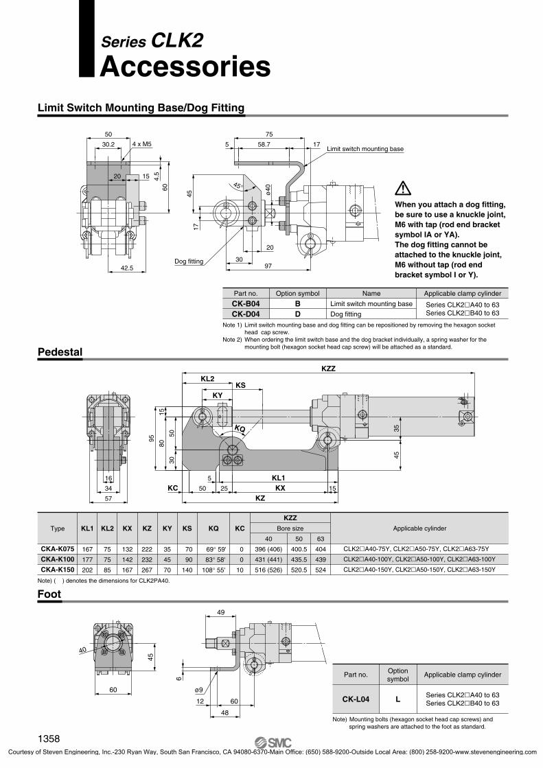
Limit Switch Mounting Base/Dog Fitting
When you attach a dog fitting, be sure to use a knuckle joint, M6 with tap (rod end bracket symbol IA or YA). The dog fitting cannot be attached to the knuckle joint, M6 without tap (rod end bracket symbol I or Y).
Note 1) Limit switch mounting base and dog fitting can be repositioned by removing the hexagon socket head cap screw.
Note 2) When ordering the limit switch base and the dog bracket individually, a spring washer for the mounting bolt (hexagon socket head cap screw) will be attached as a standard.
Part no. Name Applicable clamp cylinder
CK-B04CK-D04
Option symbol
BD
Series CLK2�A40 to 63Series CLK2�B40 to 63
Limit switch mounting base
Dog fitting
Foot
Type Applicable cylinder
CLK2�A40-75Y, CLK2�A50-75Y, CLK2�A63-75Y
CLK2�A40-100Y, CLK2�A50-100Y, CLK2�A63-100Y
CLK2�A40-150Y, CLK2�A50-150Y, CLK2�A63-150Y
CKA-K075
CKA-K100
CKA-K150
KL1
167
177
202
KL2
75
75
85
KX
132
142
167
KZ
222
232
267
KY
35
45
70
KS
70
90
140
KC
0
0
10
50
400.5
435.5
520.5
63
404
439
524
40
396 (406)
431 (441)
516 (526)
KQ
69° 59'
83° 58'
108° 55'
KZZ
Bore size
Note) Mounting bolts (hexagon socket head cap screws) and spring washers are attached to the foot as standard.
Part no. Applicable clamp cylinder
CK-L04 Series CLK2�A40 to 63Series CLK2�B40 to 63
Optionsymbol
L
Note) ( ) denotes the dimensions for CLK2PA40.
49
6
12 60
48
ø9
45
60
40
1358
P1317-P1368-E.qxd 08.11.17 3:35 PM Page 1358
Courtesy of Steven Engineering, Inc.-230 Ryan Way, South San Francisco, CA 94080-6370-Main Office: (650) 588-9200-Outside Local Area: (800) 258-9200-www.stevenengineering.com
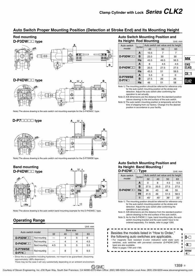
Auto Switch Proper Mounting Position (Detection at Stroke End) and Its Mounting Height
D-P4DW�� type
Rod mountingD-P3DW�� type
Note) The above drawing is the auto switch rod mounting example for the D-P4DWS� type.
Unit: mm
Auto switch model
Rod mounting
Rod mounting
Band mounting
Rod mounting
—
—
4.5
—
4
4
5
8
5
4
5
9
Bore size
D-P3DW��
D-P4DW��
D-P79WSED-P74�
32 40 50
6
4.5
5.5
9.5
63
Operating Range
Note) The above drawing is the auto switch rod mounting example for the D-P79WSE type.
Band mountingD-P4DW�� type
Note) The above drawing is the auto switch band mounting example for the D-P4DWS� type.
∗ Since this is a guideline including hysteresis, not meant to be guaranteed. (Assuming approximately ±30% dispersion.)There may be the case it will vary substantially depending on an ambient environment.
D-P7���� type
B
A
12
≅Ht
≅Hs
θ°θ°
32 4
B
532A
≅Hs
B432A
≅Hs
Besides the models listed in “How to Order,” the following auto switches are applicable.∗ For magnetic field resistant 2-color indication solid state auto
switches, auto switches with pre-wired connector (D-P4DW�DPC type) are also available.Refer to pages 1784 and 1785.
A
B
≅Hs
Note 1) The mounting position should be referred for reference only for the auto switch mounting position at the stroke end detection. Adjust the auto switch after confirming the operation to set actually.
Note 2) A/B dimensions are the distance from the standard position (above drawing) to the end surface of the auto switch.
Note 3) The auto switch mounting position is temporarily set at the time of shipping from our factory. Change it to the desired position in accordance to your facility.
Auto Switch Mounting Position and Its Height: Rod Mounting Unit: mm
Auto switchmodel
D-P4DW��
D-P3DW��
D-P79WSED-P74�
Symbol
AB
HsAB
HsAB
Hs
Auto switch set value and its height
63
7
30
56.5
4.5
27.5
58.5
0
26
58
50
7
30
49.5
4.5
27.5
51
0
26
51
40
10.5
23.5
43.5
8
20.5
45.5
5.5
27.5
46
Note 1) The mounting position should be referred for reference only for the auto switch mounting position at the stroke end detection. Adjust the auto switch after confirming the operation to set actually.
Note 2) A/B dimensions are the distance from the standard position (above drawing) to the end surface of the auto switch.
Note 3) As for the D-P4DW�� type, band mounting style, the auto switch mounting bracket and the auto switch have to be ordered separately. For details, refer to page 1350.
Auto Switch Mounting Position and Its Height: Band Mounting / D-P4DW�� Type Unit: mm
Auto switchmodel
D-P4DW��
Symbol
AB
HsHtθ
Auto switch set value and its height
50
4.5
27.5
48
51.5
36°
63
4.5
27.5
55
58.5
33°
40
8
20.5
43
46
45°
32
0
27.5
38
41.5
45°
1359
Clamp Cylinder with Lock Series CLK2
MK
CK�1
CLK2
CKQCLKQ
Individual-X�
D-�
-X�
3-2-59-CLK2.qxd 09.9.30 4:17 PM Page 8
Courtesy of Steven Engineering, Inc.-230 Ryan Way, South San Francisco, CA 94080-6370-Main Office: (650) 588-9200-Outside Local Area: (800) 258-9200-www.stevenengineering.com
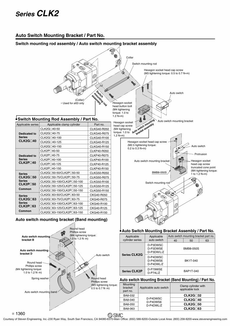
Auto Switch Mounting Bracket / Part No.
Switch Mounting Rod Assembly / Part No.
CLKG40-R050
CLKG40-R075
CLKG40-R100
CLKG40-R125
CLKG40-R150
CLKP40-R050
CLKP40-R075
CLKP40-R100
CLKP40-R125
CLKP40-R150
CLKG50-R050
CLKG50-R075
CLKG50-R100
CLKG50-R125
CLKG50-R150
CKG40-R050
CKG40-R075
CKG40-R100
CKG40-R125
CKG40-R150
Applicable clamp cylinderApplicable series Part no.
CLK2G�40-50
CLK2G�40-75
CLK2G�40-100
CLK2G�40-125
CLK2G�40-150
CLK2P�40-50
CLK2P�40-75
CLK2P�40-100
CLK2P�40-125
CLK2P�40-150
CLK2G�50-50/CLK2P�50-50
CLK2G�50-75/CLK2P�50-75
CLK2G�50-100/CLK2P�50-100
CLK2G�50-125/CLK2P�50-125
CLK2G�50-150/CLK2P�50-150
CLK2G�63-50/CLK2P�63-50
CLK2G�63-75/CLK2P�63-75
CLK2G�63-100/CLK2P�63-100
CLK2G�63-125/CLK2P�63-125
CLK2G�63-150/CLK2P�63-150
Dedicated toSeriesCLK2G�40
Dedicated toSeriesCLK2P�40
SeriesCLK2G�50SeriesCLK2P�50Common
SeriesCLK2G�63SeriesCLK2P�63Common
Switch mounting rod assembly / Auto switch mounting bracket assembly
Auto switch Mounting Bracket (Band Mounting) / Part No.Mountingbracketpart no.
Applicable auto switch Clamp cylinder withapplicable lock
BA8-032
BA8-040
BA8-050
BA8-063
D-P4DWSCD-P4DWSED-P4DWL/Z
CLK2G�32CLK2G�40CLK2G�50CLK2G�63
Auto switch mounting bracket (Band mounting)
(Collar)∗ Used for ø63 only
Switch
mounting rod
assembly Hexagon socket
head button bolt(M4 tighteningtorque: 1.0 to 1.2 N �m)
Hexagon socket head cap screw(M4 tightening torque: 1.0 to 1.2 N �m)
Auto switch mounting
bracket assemblyAuto switch mounting bracket
Auto switch
Hexagon socket head cap screw(M3 tightening torque: 0.5 to 0.7 N �m)
Switch mounting rod
Collar
Auto switch mounting band
Round headPhillips screw
(M4 tightening torque:1.0 to 1.2 N·m)
Auto switch mountingbracket D
Round headPhillips screw(M3 tightening torque:0.5 to 0.7 N·m)
Round headPhillips screw(M4 tightening torque:1.0 to 1.2 N·m)
Spring washer
Auto switch mountingbracket B
Auto switch
Auto Switch Mounting Bracket Assembly / Part No.Applicable
cylinder series
Series CLK2G
Applicableauto switch
Auto switch mounting bracket part no.
635040
BK1T-040D-P4DWSCD-P4DWSED-P4DWL/Z
BMB8-050SD-P3DWSCD-P3DWSED-P3DW/L/Z
Series CLK2P BAP1T-040D-P79WSED-P74L/Z
Hexagon socket head cap screw(M2.5 tightening torque: 0.2 to 0.3 N �m)
Protrusion
Auto switch mounting bracket
BMB8-050S
Auto switch
Hexagon socket head cap screwtruncated cone point(M4 tightening torque: 1 to 1.2 N �m)
Switch mounting rod
1360
Series CLK2
3-2-59-CLK2.qxd 09.9.30 4:17 PM Page 9
Courtesy of Steven Engineering, Inc.-230 Ryan Way, South San Francisco, CA 94080-6370-Main Office: (650) 588-9200-Outside Local Area: (800) 258-9200-www.stevenengineering.com

Series CLK2Made to Order Specifications 1Please contact SMC for detailed dimensions, specifications and lead times.
Minimum Stroke for Auto Switch Mounting Unit: mm
Autoswitch
D-M9BD-M9BWD-B54
D-A93
1 pc. 2 pcs.(Different surfaces)
50
50
50
50
50
75
2 pcs.(Same surface)
As for the precautions on the auto switches and product specifications, refer to pages 8 to 11 and 1719 to 1827.
Caution
D-A93/M9B(W)
D-B54
Mounting Allowable Auto Switch: Band Mounting / Standard Auto Switch/Refer to pages 1719 to 1827 for auto switch specifications.
Applicablecylinder series
Applicableload
Lead wire length (m)
Relay,PLC
—
TypeLoad voltage
Wiring(Output)
—
�
5(Z)
��
3(L)
��
100 V100 V200 V
0.5(Nil)
Auto switch model
Band mountingDC AC
12 V24 V2-wire
Indicatorlight
Yes
Electricalentry
GrommetReed auto switch
SeriesCLK2G
Note 1) Lead wire length symbol: 0.5 m ................ Nil M9BW 1 m ................ M M9BWM 3 m ................ L M9BWL 5 m ................ Z M9BWZ
Note 2) Auto switches marked with “�” are produced upon receipt of order.Note 3) PLC: Programmable Logic Controller
Auto Switch Mounting Position (Detection at Stroke End) and Its Mounting Height
Auto Switch Mounting Position and Its Height Unit: mm
Autoswitch
D-M9BD-M9BW
D-B54
D-A93
Symbol
AB
HsAB
HsAB
Hs
Auto switch set value and its height50
7.530.540 11.534.540
2 25 43.5
63 7.530.547 11.534.547 2
25 50.5
4011 23.534.515 27.534.5 5.518 38
32 3 30.530 7 34.530
0 25 33.5
BA
24.5
33
12
≅ Hs
BA
10.5
16.5
8.5
22≅ Hs
��
��
—
—
1(M)
—�
��
A93
B54
M9BM9BW
—5 V12 V24 V2-wireYesGrommet
Solid stateauto switch
Band Mounting / Standard Auto Switch
The built-in standard magnet clamp cylinder / the CLK2G series can be attached to the band mounting / standard auto switch as shown below.
1
The standard auto switch cannot be used in a magnetic field environment.For information on our cylinders that can be fitted with a magnetic field resistant auto switch, please refer to page 1350.
Caution
CLK2 G Enter the standard model no.Built-instandard magnet
2 pcs.1 pc.
NilS
Number of auto switches
Without auto switchNote) Select applicable auto switch models from the below table.
Nil
Auto switch type: Band mounting / Standard auto switchBuilt-in standard magnet
M9BW
Note 1) The mounting position should be referred for reference only for the auto switch mounting position at the stroke end detection. Adjust the auto switch after confirming the operation to set actually.
Note 2) A/B dimensions are the distance from the standard position (above drawing) to the end surface of the auto switch.
Note 3) The auto switch mounting position is temporarily set at the time of shipping from our factory. Change it to the desired position in accordance to your facility.
Unit: mm
Auto switchmodel
8459
8 3.5 5.510
8 4
6.510
Bore size
D-A93D-M9BD-M9BWD-B54
32 40 50 9 4 711
63
Operating Range
∗ Since this is a guideline including hysteresis, not meant to be guar-anteed. (Assuming approximately ±30% dispersion.)There may be the case it will vary substantially depending on an ambient environment.
Auto switch
Note) Note) Note) Note)
qBMA2-032wBJ3-1
qBMA2-040wBJ3-1
qBMA2-050wBJ3-1
qBMA2-063wBJ3-1
BA-32 BA-04 BA-05
Mounting bracket part no.
D-A93D-M9BD-M9BWD-B54
32
Auto Switch Mounting Bracket Assembly / Part No.
40 50
BA-06
63
Note) Two kinds of mounting brackets are required.
1361
MK
CK�1
CLK2
CKQCLKQ
Individual-X�
D-�
-X�
P1317-P1368-E.qxd 08.11.17 3:35 PM Page 1361
Courtesy of Steven Engineering, Inc.-230 Ryan Way, South San Francisco, CA 94080-6370-Main Office: (650) 588-9200-Outside Local Area: (800) 258-9200-www.stevenengineering.com

Series CLK2Made to Order Specifications 2Please contact SMC for detailed dimensions, specifications and lead times.
Unlock-port Separate Piping Type 2
Built-in standard magnet type with magnetic field resistant auto switch (D-P3DW� type, P4DW� type)
CLK2G A 50 100 Y B 2 L X1604P3DWSC
Clevis width: 16.5 mm
40 mm50 mm63 mm
405063
Bore size
50, 75, 100, 125, 150
Cylinder stroke
NoneDouble knuckle joint (M6 without tap)Double knuckle joint (M6 with tap)
NilY
YA
End bracket
Retraction lockingExtension locking
BF
Locking direction
Note 1) Unlock-port cannot be placed on the top of the cylinder when the retraction locking type is selected.
Note 2) The cylinder actuating port is mounted on the top of the cylinder at the time of shipment from the factory.Although the position of the cylinder actuating port can be changed from [top] to [left or right] in the extension locking type by changing the plug position, it cannot be changed from [top] in the retraction locking type.
Position(Viewed from rod side)
Top
Left
Right
Locking directionRetraction locking
—
�
�
�
�
�
Extension lockingSymbol
Nil
2
3
Unlock-port position
TopLeftRight
NilLR
Switch mounting rod position
2 pcs.1 pc.“n” pcs. (n = 3, 4, 5···n)
NilSn
Number of auto switches
Without auto switch,Without switch mounting rod
Without auto switch,With switch mounting rod
With auto switch,With switch mounting rod
Nil
Auto switchmodel
P
Auto switch
Unlock-port separate piping
Note) Pin (for knuckle), cotter pin and flat washer are provided as a standard for Y and YA.
∗ Please contact SMC representatives for details about piping the unlock-port separately.
3-position valves (closed center) can be used by piping the unlock- port separately.
Symbol
Unlock-port
Cylinderretractionport
Cylinderextensionport
Unlock-port
Cylinderretractionport
Cylinderextensionport
Retractionlocking type
Extensionlocking type
D-P3DWSCD-P4DWSCD-P3DWSED-P4DWSE
D-P3DWD-P3DWLD-P4DWLD-P3DWZD-P4DWZ
TypeApplicable
cylinder seriesAuto switch
modelApplicable
magnetic fieldElectrical entry
AC magnetic field(Single-phaseAC welding
magnetic field)
Indicatorlight
Loadvoltage
2-wire (3–4)
2-wire (1–4)
2-wire
24 VDCRelay,
PLC Note 1)
Applicableload
Pre-wired connector
Grommet
2-colordisplay
Wiring(Pin no. in use)
Solid stateauto switch
Series CLK2G
Lead wirelength
0.3 m
0.5 m
3 m
5 m
Note 1) PLC: Programmable Logic ControllerNote 2) There are other applicable auto switches other than the listed above. For details, refer to page 1359.Note 3) Refer to page 1360 when ordering the auto switch mounting bracket assembly or switch mounting rod assembly. Note 4) For D-P3DW�, auto switches and auto switch mounting brackets are shipped together (not assembled).
Applicable Magnetic Field Resistant Auto Switches (Refer to pages 1719 to 1827 for detailed auto switch specifications.)
1362
3-2-59-CLK2.qxd 09.9.30 4:17 PM Page 10
Courtesy of Steven Engineering, Inc.-230 Ryan Way, South San Francisco, CA 94080-6370-Main Office: (650) 588-9200-Outside Local Area: (800) 258-9200-www.stevenengineering.com

Bore size
SymbolBX
566474
BY
546474
D
162020
F
445569
GA
77 78.582
IA
475872
K
141717
L
555858
N
86 87.591
T
576067
Hs
45.551 58.5
WA
12.514 19
NA
59 59.561
Z
114 118.5122
W
5 5.55.5
ZZ
226 230.5234
M
M12 x 1.5M16 x 1.5M16 x 1.5
MA
M4 x 7M4 x 7M5 x 7
405063
(mm)
Bore size
SymbolBX
566474
BY
546474
D
162020
F
445569
GA
77 78.582
IA
475872
K
141717
L
555858
N
86 87.591
W
5 5.55.5
Hs
45.551 58.5
WA
12.514 19
NA
51.552.553.5
Z
114 118.5122
ZZ
226 230.5234
M
M12 x 1.5M16 x 1.5M16 x 1.5
MA
M4 x 7M4 x 7M5 x 7
405063
(mm)
Dimensions: CLK2G�40/50/63-X1604 / With Magnetic Field Resistant Solid State Auto Switch (D-P4DW� type)
Retraction locking (B)
Extension locking (F)
øD
ø30
ZZ + Stroke
97
36
R15
Z + Stroke27
1335
øIA
GA
310
1017
14
N52 L + Stroke
W10
3 x Rc 1/4Retraction port
Width across flats 44
Width across flats K
Shaft: ø12H8Hole: ø12d9
M
3 x Rc 1/4Extension port
NAW
A
Dust cover
MA
Rc 1/4 Unlock-portUnlocked when pressured
Rc 1/4 Unlock-portUnlocked when pressured
Rc 1/4Retraction port
F
45°
Cushion valve Top width across flats 3(Tube cover side only)
≈ Hs
40
57
40
BY
BX
Clevis widthCLK2GA: 16.5CLK2GB: 19.5
4 x M6 x 12
≈ Hs
40
57
40
BY
BX
4 x M6 x 12
WA
NA
MA
Dust cover
3 x Rc 1/4 Unlock-portUnlocked when pressured
3 x Rc 1/4Retraction port
F
45°
Cushion valve Top width across flats 3(Tube cover side only)
30
GA
3
10
1017
14
N52 L + Stroke
W10
øD
ø30
ZZ + Stroke
97
36
R15
Z + Stroke27
1335
øIA
Width across flats 44
Width across flats K
M
3 x Rc 1/4Extension port
+0.30
+0.40
Clevis widthCLK2GA: 16.5CLK2GB: 19.5
+0.30
+0.40
–0.050–0.093+0.027+0
Shaft: ø12H8Hole: ø12d9 –0.050
–0.093+0.027+0
1363
Clamp Cylinder with Lock Series CLK2
MK
CK�1
CLK2
CKQCLKQ
Individual-X�
D-�
-X�
P1317-P1368-E.qxd 08.11.17 3:35 PM Page 1363
Courtesy of Steven Engineering, Inc.-230 Ryan Way, South San Francisco, CA 94080-6370-Main Office: (650) 588-9200-Outside Local Area: (800) 258-9200-www.stevenengineering.com

Series CLK2Specific Product Precautions 1Be sure to read before handling.Refer to front matters 42 and 43 for Safety Instructions and pages 3 to 11 for Actuator and Auto Switch Precautions.
Marking Fully closed state(Non-adjustment range)
Adjustment range: 225°
Cushion valve in the head end
Fully closed stateFully opened state
Cushion AdjustmentThe CLK2 series has an integrated air cushion in the head end. The cushion is pre-adjusted at the time of shipping. However, please re-adjust the cushion valve in the tube cover, depending on operating speed and load before use.The diameter of throttle will be smaller when the cushion valve is turned clockwise, resulting in stronger cushion reaction.Shown below is the fully opened state, although the cushion valve can rotate 360 degrees.The adjustment range is about 225 degrees from the fully opened state. The range between 225 and 360 degrees is the fully closed state.
Cushion Adjustment
1364
P1317-P1368-E.qxd 08.11.17 3:35 PM Page 1364
Courtesy of Steven Engineering, Inc.-230 Ryan Way, South San Francisco, CA 94080-6370-Main Office: (650) 588-9200-Outside Local Area: (800) 258-9200-www.stevenengineering.com
1. Do not use 3 position valves.The lock may be released due to the inflow of the unlocking pressure. When 3-position valves are used, please use the un-lock-port separate-piping type shown on pages 1362 and 1363.
2. Install speed controllers for meter-out control.Malfunction may occur if meter-in control is used or speed controllers are not used.
3. Be careful of reverse exhaust pressure flow from a common exhaust type manifold.Since the lock may be released due to reverse exhaust pres-sure flow, use an individual exhaust type manifold or single type valve.
Selection
Warning
Pneumatic Circuits
Warning
1. When shipped from the factory, an unlocked condi-tion is maintained by the unlocking bolt. Be sure to remove this bolt before operating. (The unlocking bolt can be stored in tap A after it is removed.)Since the unlocking bolt is required to maintain the unlocked condition during maintenance, pay attention not to lose it. Step 1) With no air pressure in the cylinder, retraction locking
operates when the piston rod is retracted, and exten-sion locking operates when it is extended.
Step 2) Remove the dust proof cover 1.Step 3) Supply air pressure of 0.2 MPa or more to port 2 in the
figure below.Step 4) Remove the unlocking bolt 3 using a hexagon wrench.
Preparing for Operation
Warning
1. Be sure to connect the load to the rod end with the cylinder in an unlocked condition.If this is done when in a locked condition, it may cause dam-age to the lock mechanism.
Mounting
Caution
Preparing for Operation
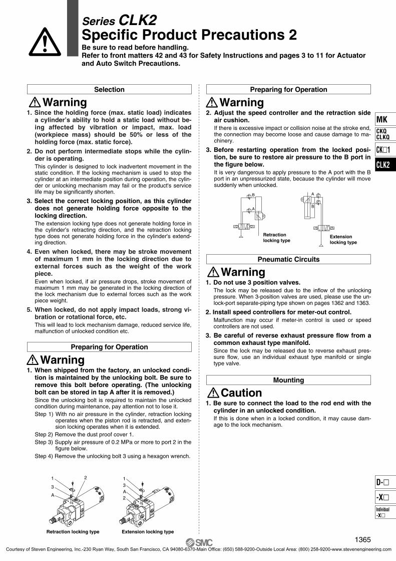
2. Adjust the speed controller and the retraction side air cushion.If there is excessive impact or collision noise at the stroke end, the connection may become loose and cause damage to ma-chinery.
3. Before restarting operation from the locked posi-tion, be sure to restore air pressure to the B port in the figure below.It is very dangerous to apply pressure to the A port with the B port in an unpressurized state, because the cylinder will move suddenly when unlocked.
Warning
A
B
Retractionlocking type
Extensionlocking type
B
A
1. Since the holding force (max. static load) indicates a cylinder’s ability to hold a static load without be-ing affected by vibration or impact, max. load (workpiece mass) should be 50% or less of the holding force (max. static force).
2. Do not perform intermediate stops while the cylin-der is operating. This cylinder is designed to lock inadvertent movement in the static condition. If the locking mechanism is used to stop the cylinder at an intermediate position during operation, the cylin-der or unlocking mechanism may fail or the product's service life may be significantly shorten.
3. Select the correct locking position, as this cylinder does not generate holding force opposite to the locking direction.The extension locking type does not generate holding force in the cylinder’s retracting direction, and the retraction locking type does not generate holding force in the cylinder's extend-ing direction.
4. Even when locked, there may be stroke movement of maximum 1 mm in the locking direction due to external forces such as the weight of the work piece.Even when locked, if air pressure drops, stroke movement of maximum 1 mm may be generated in the locking direction of the lock mechanism due to external forces such as the work piece weight.
5. When locked, do not apply impact loads, strong vi-bration or rotational force, etc.This will lead to lock mechanism damage, reduced service life, malfunction of unlocked condition etc.
Extension locking typeRetraction locking type
1 2
3
A
13
2A
Series CLK2Specific Product Precautions 2Be sure to read before handling.Refer to front matters 42 and 43 for Safety Instructions and pages 3 to 11 for Actuator and Auto Switch Precautions.
1365
MK
CK�1
CLK2
CKQCLKQ
Individual-X�
D-�
-X�
P1317-P1368-E.qxd 08.11.17 3:35 PM Page 1365
Courtesy of Steven Engineering, Inc.-230 Ryan Way, South San Francisco, CA 94080-6370-Main Office: (650) 588-9200-Outside Local Area: (800) 258-9200-www.stevenengineering.com
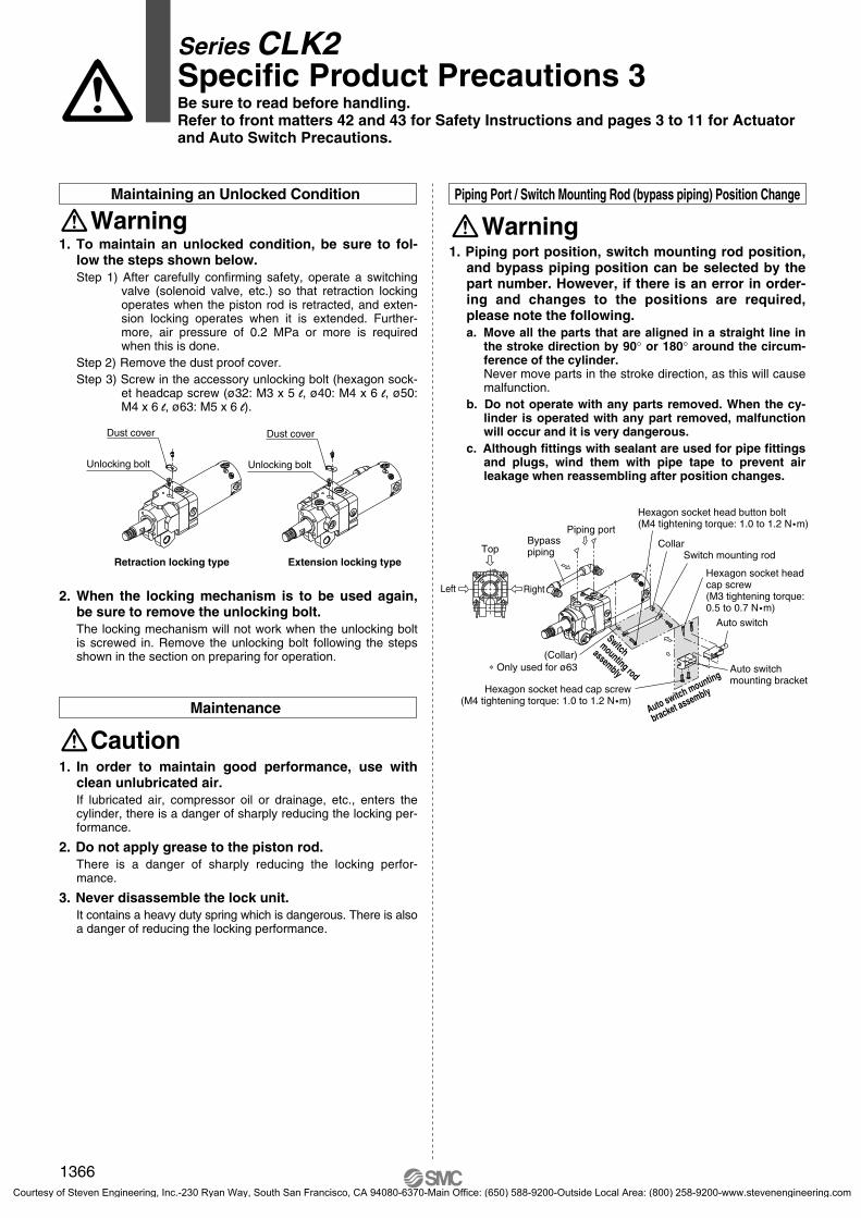
1. Piping port position, switch mounting rod position, and bypass piping position can be selected by the part number. However, if there is an error in order-ing and changes to the positions are required, please note the following.a. Move all the parts that are aligned in a straight line in
the stroke direction by 90° or 180° around the circum-ference of the cylinder.Never move parts in the stroke direction, as this will cause malfunction.
b. Do not operate with any parts removed. When the cy-linder is operated with any part removed, malfunction will occur and it is very dangerous.
c. Although fittings with sealant are used for pipe fittings and plugs, wind them with pipe tape to prevent air leakage when reassembling after position changes.
Piping Port / Switch Mounting Rod (bypass piping) Position Change
Warning
1. In order to maintain good performance, use with clean unlubricated air.If lubricated air, compressor oil or drainage, etc., enters the cylinder, there is a danger of sharply reducing the locking per-formance.
2. Do not apply grease to the piston rod.There is a danger of sharply reducing the locking perfor-mance.
3. Never disassemble the lock unit.It contains a heavy duty spring which is dangerous. There is also a danger of reducing the locking performance.
2. When the locking mechanism is to be used again, be sure to remove the unlocking bolt.The locking mechanism will not work when the unlocking bolt is screwed in. Remove the unlocking bolt following the steps shown in the section on preparing for operation.
Maintenance
Caution
1. To maintain an unlocked condition, be sure to fol-low the steps shown below.Step 1) After carefully confirming safety, operate a switching
valve (solenoid valve, etc.) so that retraction locking operates when the piston rod is retracted, and exten-sion locking operates when it is extended. Further-more, air pressure of 0.2 MPa or more is required when this is done.
Step 2) Remove the dust proof cover.Step 3) Screw in the accessory unlocking bolt (hexagon sock-
et headcap screw (ø32: M3 x 5 l, ø40: M4 x 6 l, ø50: M4 x 6 l, ø63: M5 x 6 l).
Maintaining an Unlocked Condition
Warning
Extension locking typeRetraction locking type
Unlocking bolt
Dust cover
Unlocking bolt
Dust cover
Top
Left Right
Bypasspiping
Piping portCollar
Switch mounting rod
Hexagon socket head cap screw(M3 tightening torque: 0.5 to 0.7 N �m)
Auto switch
Auto switch mounting bracket
Auto switch mounting
bracket assemblyHexagon socket head cap screw(M4 tightening torque: 1.0 to 1.2 N �m)
Hexagon socket head button bolt(M4 tightening torque: 1.0 to 1.2 N �m)
Switchmounting rod
assembly
(Collar)∗ Only used for ø63
Series CLK2Specific Product Precautions 3Be sure to read before handling.Refer to front matters 42 and 43 for Safety Instructions and pages 3 to 11 for Actuator and Auto Switch Precautions.
1366
P1317-P1368-E.qxd 08.11.17 3:35 PM Page 1366
Courtesy of Steven Engineering, Inc.-230 Ryan Way, South San Francisco, CA 94080-6370-Main Office: (650) 588-9200-Outside Local Area: (800) 258-9200-www.stevenengineering.com

Handling
Magnetic field resistant auto switches D-P79WSE/D-P74� type are specifically for use with magnetic field resistant cylinders and are not compatible with gener-al auto switches or cylinders. Magnetic field resistant cylinders are labeled as follows.
Mounting1. The minimum stroke for mounting magnetic field
resistant auto switches is 50 mm.2. In order to fully use the capacity of magnetic field
resistant auto switches, strictly observe the follow-ing precautions.1) Do not allow the magnetic field to occur when the cylinder
piston is moving.2) When a welding cable or welding gun electrodes are near
the cylinder, change the auto switch position to fall within the operational ranges shown in the graphs on page 1368, or move the welding cable away from the cylinder.
3) Cannot be used in an environment where welding cables surround the cylinder.
4) Please consult with SMC when a welding cable and weld-ing gun electrodes (something energized with secondary current) are near multiple switches.
3. In an environment where spatter directly hits the lead wire, cover the lead wire with protective tub-ing. Use protective tubing with a bore size of ø8 or more that has excellent heat resistance and flexibil-ity.
4. Be careful not to drop objects, make dents, or apply excessive impact force when handling.
5. When built-in strong magnet type cylinders are closely positioned to each other, please pay atten-tion to the following items. 1) When more than 2 pcs. cylinders with general purpose auto
switches are juxtaposed, leave the distance of 40 mm or more between the cylinder tubes.
2) Separate a reed magnetic field resistant auto switch from the tube surface of a closely mounted built-in strong mag-net type cylinder by 30 mm or more.
3) When a built-in strong magnet type cylinder and a cylinder with a general-purpose auto switch are closely positioned, separate the cylinder tubes 50 mm or more.
4) Separate a general-purpose auto switch from the tube sur-face of a closely mounted built-in strong magnet cylinder by 50 mm or more away.
6. Avoid wiring in a manner in which repeated bend-ing stress or tension is applied to lead wires.
7. Please consult with SMC regarding use in an envir-onment with constant water and coolant splashing.
8. Please be careful of the mounting direction of the magnetic field resistant auto switch D-P79WSE type.Be sure to face the molded surface with soft-resin to the auto switch mounting bracket side for mounting. (Please refer to page 1359 for mounting example and page 1804 for soft-resin mold surface.)
Wiring/Current and Voltage1. Always connect the auto switch to the power supply
after the load has been connected.2. Series connection
When auto switches are connected in series as shown below:Note that the voltage drop due to the internal resistance of the LED increases.
Magnetic field resistant cylinder with built-in magnet(For use with auto switch D-P7 type)
Load
Series CLK2Specific Product Precautions 4Be sure to read before handling.Refer to front matters 42 and 43 for Safety Instructions and pages 3 to 11 for Actuator and Auto Switch Precautions.
1367
MK
CK�1
CLK2
CKQCLKQ
Individual-X�
D-�
-X�
P1317-P1368-E.qxd 08.11.17 3:35 PM Page 1367
Courtesy of Steven Engineering, Inc.-230 Ryan Way, South San Francisco, CA 94080-6370-Main Office: (650) 588-9200-Outside Local Area: (800) 258-9200-www.stevenengineering.com
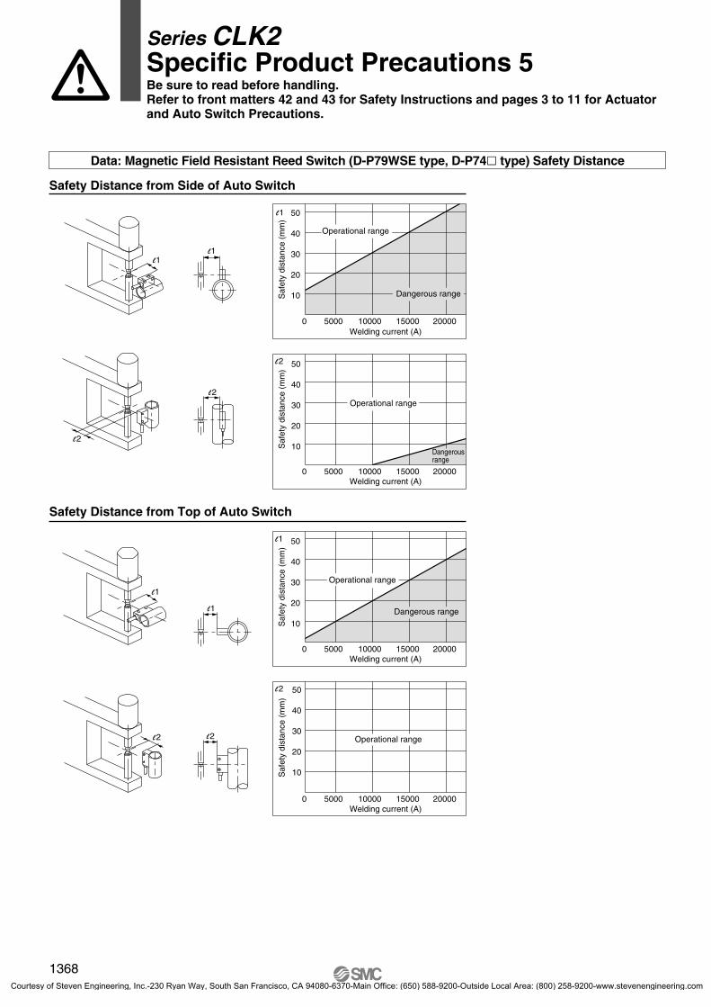
Safety Distance from Side of Auto Switch
Safety Distance from Top of Auto Switch
0 5000 10000 15000 20000
10
20
30
40
50
Welding current (A)
Saf
ety
dist
ance
(m
m)
l1
0 5000 10000 15000 20000
10
20
30
40
50
Welding current (A)
Saf
ety
dist
ance
(m
m)
l2
0 5000 10000 15000 20000
10
20
30
40
50
Welding current (A)
Saf
ety
dist
ance
(m
m)
l2
Dangerous range
0 5000 10000 15000 20000
10
20
30
40
50
Welding current (A)
Saf
ety
dist
ance
(m
m)
l1
l1
l2
l1
l1
l1
l2
l2l2
Data: Magnetic Field Resistant Reed Switch (D-P79WSE type, D-P74� type) Safety Distance
Operational range
Dangerous range
Operational range
Dangerous range
Operational range
Operational range
Series CLK2Specific Product Precautions 5Be sure to read before handling.Refer to front matters 42 and 43 for Safety Instructions and pages 3 to 11 for Actuator and Auto Switch Precautions.
1368
P1317-P1368-E.qxd 08.11.17 3:35 PM Page 1368
Courtesy of Steven Engineering, Inc.-230 Ryan Way, South San Francisco, CA 94080-6370-Main Office: (650) 588-9200-Outside Local Area: (800) 258-9200-www.stevenengineering.com
Related Documents


