81 Refrigerating type dryer Desiccant type dryer High polymer membrane type dryer Auto. drain / others F.R.L. (Module unit) F.R.L. (Separate) F.R.L. (Related products) Clean F.R. Air booster Air filter Compact F.R. Precise regulator Electro pneumatic regulator Speed control valve Check valve / others Magnetic spring buffer Contact / close contact conf. SW Pressure SW for coolant Small flow sensor Small flow controller Flow sensor for air Flow sensor for water Air sensor Joint / tube Suction plate Mechanical pressure SW Electronic pressure SW Total air system Total air system (Gamma) Silencer Vacuum regulator Ending Vacuum filter CKD refrigerating type dryer GT Main line unit CONTENTS Product Introduction 82 Option and accessory 101 Applicable circuit 84 System selection 85 Safety precautions 86 Air cooling type/Standard inlet air (40˚C) type (GT9000) 90 Water cooling type/Standard inlet air (40˚C) type (GT9000W) 94 Water cooling type/Standard inlet air (40˚C) type (GT9000WV) 98 Applicable air compressor: 90, 120, 150, 190, 240, 300, 380, 450, 710, 960kW Components for air preparation and pressure adjustment / main line unit / refrigerating type air dryer CKD refrigerating type dryer GT9000 Large to extra-large refrigerating type air dryer supporting energy saving and environmental problems with new equipment. Overview (1) New incorporated refrigerant R-407C New refrigerant without destroying ozone layer is installed to all GT Series. (2) Incorporated energy saving operation system For 300kW to 450kW units, energy consumption is reduced by 50% through multi-unit control. For 710kW and 960kW units, 60% energy conservation is realized with inverter control. (3) SUS heat exchanger vessel Oil-free stainless steel vessel is used for all models. (4) Easy maintenance The safe design allows the operation state to be confirmed in a glance. Central control in the factory is possible by signal exchanges. (5) Free installation in any area The 90 to 190kW units support various environments as the back, left or right faces of the 90 to 190kW units can be flush against a wall. The 250kW to 450kW save space with top face ventilation. Features

Welcome message from author
This document is posted to help you gain knowledge. Please leave a comment to let me know what you think about it! Share it to your friends and learn new things together.
Transcript

81
Refrigeratingtype dryer
Desiccanttype dryer
High polymermembranetype dryer
Auto. drain/ others
F.R.L.(Module unit)
F.R.L.(Separate)
F.R.L.(Relatedproducts)
CleanF.R.
Airbooster
Air filter
CompactF.R.
Preciseregulator
Electropneumaticregulator
Speedcontrol valve
Check valve/ others
Magneticspring buffer
Contact / closecontact conf.SW
Pressure SWfor coolant
Smallflow sensor
Smallflow controller
Flow sensorfor air
Flow sensorfor water
Air sensor
Joint/ tube
Suctionplate
Mechanicalpressure SW
Electronicpressure SW
Total airsystem
Total airsystem(Gamma)
Silencer
Vacuumregulator
Ending
Vacuumfilter
CK
D r
efrig
erat
ing
type
dry
er G
TM
ain
line
unit
C O N T E N T S
Product Introduction 82Option and accessory 101Applicable circuit 84System selection 85 Safety precautions 86
� Air cooling type/Standard inlet air (40˚C) type (GT9000) 90� Water cooling type/Standard inlet air (40˚C) type (GT9000W) 94� Water cooling type/Standard inlet air (40˚C) type (GT9000WV) 98
Applicable air compressor: 90, 120, 150, 190, 240, 300, 380, 450, 710, 960kW� Components for air preparation and pressure adjustment / main line unit / refrigerating type air dryer
CKD refrigerating type dryerGT9000
Large to extra-large refrigerating type air dryer supporting energy saving and environmental problems with new equipment.
Overview
(1) New incorporated refrigerant R-407C New refrigerant without destroying ozone layer is installed to all GT Series.
(2) Incorporated energy saving operation systemFor 300kW to 450kW units, energy consumption is reduced by 50% through multi-unit control. For 710kW and 960kW units, 60% energy conservation is realized with inverter control.
(3) SUS heat exchanger vesselOil-free stainless steel vessel is used for all models.
(4) Easy maintenanceThe safe design allows the operation state to be confirmed in a glance. Central control in the factory is possible by signal exchanges.
(5) Free installation in any areaThe 90 to 190kW units support various environments as the back, left or right faces of the 90 to 190kW units can be flush against a wall. The 250kW to 450kW save space with top face ventilation.
Features

Load rate (%)
Pow
er c
onsu
mpt
ion
rate
(%)
Promising high quality and hifh reliability
Energy saving
Stainless steel heat exchanger for oil free compressed airA heat exchanger incorporating the newly developed stainless steel vessel has been incorporated. This prevents dust generation from the heat exchanger.
No abnormal stop under high loads (GT9000WV Series)The self-protection control activated during high load operation to drop the compressor’s speed. This allows operation to be continued without abnormal stopping.
Outstanding weather resistanceThe refrigerating piping (copper pipes) in the heat exchanger are nickel-plated to improve corrosion resistance.Stainless steel piping specifications are also available. Contact CKD for information.
Advanced energy saving, ease-of-use, and environment performance.Advanced energy saving, ease-of-use, and environment performance.
Multi-unit control for 50% power reductions (GT9300 to 9450, GT9300W to 9450W)The 2-stage selection refrigerant system automatically switches to 1-stage energy-saving operation during low loads. Power consumption can be reduced by up to 50%.
Inverter control for 60% power reductions (GT9000WV Series)The compressor’s inverter control realizes optimum energy-saving operation which corresponds to the load.Power consumption can be reduced by up to 60%.
Linking dew point temperature to ambient temperature (GT9000WV Series)A function to link the pressure dew point to the ambient temperature and automatically control the link is provided. The dew point temperature is automatically adjusted to a temperature at which condensation does not occur. This eliminates the need to manually change the dew point setting, and realizes ideal energy saving operation.
Same performance at 50 and 60Hz (GT9000WV Series)The compressor inverter control allows the same performance to be attained in 50 and 60Hz districts.
Environment-friendly refrigerant R407C
The new refrigerant R407C has a zero ozone depletion potential. This type surpasses conventional models in terms of global warning.
Environment-friendly refrigerant
Relation of GT9000WV Series load rate and power consumption
Conventional system
When dew point10°C is selected
GT9000WV18°C is selected
Easy maintenanceEasy-to-read operation status
The electronic operation panel lets you read the dryer’s operation state, dew point and fault state in a glance.
Standard air pressure gaugeAn air pressure gauge has been mounted on the operation panel of all models.
Central control in the factoryRealize central control in the factory with remote operation, and output of run and abnormal signals.
Dust filter (GT9240 to GT9450)A dust filter has been mounted for the capacitor. Easily mount and remove the filter without tools.
New service port(GT9120 to GT9450, GT9120W to GT9450W, GT9000WV Series)
A service port (with check joint) has been added on the inlet and outlet pipes.Use this port when monitoring the pressure and dew point, etc.
Freely install at any placeFreely install flush against the wall (GT9090 to 9190, GT9090W to 9190W)
The drain trap and cooling water pipe can be attached to either the left or right side, allowing the unit back, left or right side to be installed flush against the wall.
Space-saving with top face exhaust (GT9240 to 9450)
Floor space is saved as the exhaust duct is installed on the top of the wall.
Top
Top
Front
Front
Wall
Wall
Wall
Drain
Drain
Wall
RefrigeratingType Dryer
(air-cooled)(water-cooled)
(water-cooled inverter)
Series variation
Series
Air-cooled
Water-cooled
Pressuredew point
(˚C)
Ambienttemperature
(˚C)
Inlet airtemperature
(˚C)
Cooling waterinlet temperature
(˚C)
Inlet airpressure
(MPa)
Applicable air compressor (kW)Rated conditions
Performance control 1/1 operation Multi-unit control(Automatic 1/2 operation) Inverter control
Refrigerating type air dryerLarge model series / 90 to 960kWThe large refrigerating air dryer GT Series with directly connected air compressor has been reborn into three different series with various features.
Configurable dew point (GT9000WV Series)Configurable pressure dew point in the range of 10 to 18°C. Power consumption can be reduced drastically by setting above 10°C when dew condensation is unlikely to occur such as during the summer.
82 83

Typical working circuit ■
For example, "Grade 3.6.3" shows the grade that●Solid particles 0.1 to 0.5µm are 10,000 particles●Pressure dew point +10°C or less.●Oil concentration 1mg/m3 or less
Filter P
Filter P
Filter PFilter P Filter M
Filter M
Filter P
Filter P
Filter P
Filter P Filter M
Filter M
Filter M
Filter X
Filter X
Refrigeratingtype air dryer
Note
To the liston the right
Lubrication typescrew
air compressor
Lubrication typereciprocating
air compressor
After cooler
Tank
Main line
Mai
n lin
eGX/GK series
GX/GK series
Refrigeratingtype air dryer
Compactheatless dryer
Oil-freereciprocating
air compressor
After cooler
Tank
HD series
SDM Series
High polymermembrane air dryer
Oil-freecompressor
Large heatlessair dryer
Lubricatedcompressor
End
of l
ine
End
of l
ine
Oil-freescrew
air compressor
Turbo typeair compressor
Filter X
Filter X
Filter X
SHD Series
Note: Install the X type shown in parentheses when the inlet oil vapor is 0.005mg/m3 (at 21˚C).The oil grade is "Class 2" when not installed.
a
b
c
d
e
f
84
GT Series
–––––––––
100100,000
–––––––
11,00010,000
––––––
010500
1,00020,000
––––
–––––540––
–––––510––
-70-40-20+3+7+10–––
––––––
Cw 0.50.5 Cw 55 Cw 10
0.010.115
–––––
Details have changed due to revision of JIS B 8392-1:2000 to JIS B 8392-1: 2003.
Conditions stricter than Class 1 to be determined by user or supplier.
Grade
Solid particles Temperature and moisture Oil
Particle diameter d mParticlediameter
µmConcentration
mg/m3
Pressuredew point
˚C
Waterconcentration
Cw g/m3
Total oilconcentration
mg/m3 d 0.10 0.10 d 0.5 0.5 d 1.0 1.0 d 5.0
Max. number of particles per 1m3
Compressed air quality grade JIS B 8392-1: 2003
0123456789

Air quality Applications Grade
a Water drip removal airCoarse dust removal air
Construction, Civil engineering machineAir blow for cleaning (dry air not required) 4.−.−
b General dry airGeneral-purpose pneumatic devices, General-purpose pneumatic tool, Labor saving mechanisms, Pneumatic jigs and tools, Air chuck, Air vice, Precision part cleaning air blow
3.6.3
3.5.3
c Dry air (oil free) Instrumentation, Measurement, Logic control, Luxury painting
2.6.1
2.5.1
d Dry air (odorless) Food processing industry (Where air is not directly blown onto food)Pharmaceutical industry, Agitation, Transportation, Dry, Package, Air for brewing
2.6.1
2.5.1
e Ultra dry air (oil free)Ozone generator, Powder transfer, Furnace gas dryDrying high tension generator insulation gas, Drying computer room, Central control instrumentation
2.3.1
2.2.1
2.2.1
f Ultra dry air (odorless) Food processing industry (Where air is not directly blown onto food)Pharmaceutical industry, Agitation, Transportation, Dry, Package, Air for brewing
2.3.1
2.2.1
2.2.1
Table of system selections ■Air compressor Refrigerating type air dryer Main line filter
P type(1µm or 3µm)
Main line filterM type
(0.01µm)
Main line filterX type
(deodorizing)Output
kWStandard treating flow rate
m3/min. (ANR)Air cooling type Water cooling type
90 14.8/17.5 GT9090 GT9090W AF2020P-50 AF4020S-50
AF2020M-50 AF4020M-50
AF2020X-50 AF4020X-50
120 18.7/22.0 GT9120 GT9120W AF2026P-65 AF2026M-65 AF2026X-65150 23.8/28.0 GT9150 GT9150W AF5032P-80 AF5032M-80 AF5032X-80190 27.5/32.4 GT9190 GT9190W AF5048P-100 AF5048M-100 AF5048X-100240 36.5/43.0 GT9240 GT9240W AF5048P-100 AF5048M-100 AF5048X-100300 44.2/52.0 GT9300 GT9300W AF5064P-100 AF5064M-100 AF5064X-100380 55.2/65.0 GT9380 GT9380W AF5080P-150 AF5080M-150 AF5080X-150450 70.3/82.8 GT9450 GT9450W AF5096P-150 AF5096M-150 AF5096X-150710 139.1 — GT9710WV AF5160P-200 AF5160M-200 AF5160X-200960 184.2 — GT9960WV AF5192P-200 AF5192M-200 AF5192X-200
85
Working circuitExample system selection list
GT Series
Rated (Ambient temperature: 32°C, inlet temperature: 40°C, pressure dew point: 10°C)

Manufacturer's LiabilityDANGER
The manufacturer cannot be held liable in the following cases: Serious errors in use occur due to the operator. ●Illegal modifications or repairs using nonstandard parts ●by user.
Refrigerating type dryer GT Series
General mattersCAUTION
TransportationWARNING
TransportationWARNING
Supporting plateThe supporting plate must be 100 mm longer than the dryer width (A). Provide protection between the supporting plate and dryer to prevent damage to the panel.
Safety precautionsAlways read this section before starting use. Refer to Intro 67 for general precautions.
86
DANGER Use for applications other than dehumidifying compressed air is prohibited.
This product must not be used for medical devices for caisson shields or breathing devices.
There is a risk of personal injury.
Do not mount and use this device onto transportation equipment such as vehicles or ships.
The internal devices could be damaged by vibration, etc.
This product is filled with refrigerant (R-407C). (GT9960WV has 12kg or more, other models have less than 12kg.)Always follow respective laws and ordinances when transporting this product (by land, sea or air).
Tilting, or applying vibration or impact during transportation is prohibited. Use a fork lift or suspend the unit when moving. When suspending the product, use suspension hooks and rope, etc.
Target models: GT9090 to 9190GT9090W to 9190W
Target models:GT9240 to 9450GT9240W to 9450WGT9710WV, GT9960WV
60° or more
60° or moreSupporting plate
(A)

Installation
CAUTION Do not use this product in a place exceeding the maximum working temperature.
Do not install this product where it will be subject to radiated heat.
If the maximum working temperature may be exceeded, install ventilation fans or provide an air inlet, etc.
Do not use this product where the temperature is lower than the minimum working temperature.
Ambient temperature
Location
CAUTION
Maintenance space
Floor
CAUTION Install the product on a vibration-free floor.
Install this product on a flat surface.
Provide foundation work if the ground is soft.
Refer to dimensions for anchor bolt positions and hole dimensions.
Vibration
CAUTION
CAUTION Select a well-ventilated place where maintenance and inspection can be performed easily.
Target models: GT9090 to 9190, GT9090W to 9190WApprox. 1000mm or more to front and on left or right side
Target models: GT9240 to 9450, GT9240W to 9450W, GT9710WV, 9960WV
600mm or more each at front, back and left side
Piping
CAUTION
Air pipe method
GT9000 Series
87
Intermittent operation: Install the by-pass piping for maintenance.
Install this product indoors.
Install the product in a well-ventilated place free of dirt and dust.
Do not install to a splashed location of rain water.
Do not install the product where high levels of humidity or dew could condense.
Avoid using this product where it may be subjected to direct sunlight, or where heat could be generated.
Avoid use in the area containing corrosive gas. (Refer to page 19)
When using a reciprocating compressor, use a flexible tube or high-pressure rubber hose in part of piping with the air dryer to absorb vibration.
For the GT9960WV, attach the two enclosed headers to the air inlet and outlet flanges using the enclosed gaskets, bolts and nuts.
Pipe the air dryer as shown below. 24 hour operation: A parallel installation for emergencies is rec-ommended. Use a unit for normal operation and the other as a spare.
Stainless steel or galvanized steel pipes (white pipes) are recommended for pipe materials. Flush pipes before connecting.
When piping is already laid, when using black pipes or when using an oil-free air compressor and large amount of dirt, etc., form in pipes, install a main line P type filter before the dryer.
From compressor
Gate valveTo end line
Dryer Dryer
From compressor To end line
By-pass pipingGate valve
Dryer

Drain piping method
CAUTION
Cooling water piping method
CAUTION Check the cooling water inlet and outlet when piping.
Provide a water discharge outlet or stop valve so maintenance can be done.
Design piping so that pipe weight is not applied on the product.
Use piping that withstands working pressure and temperature. Check that no water leaks from connections.
Use galvanized steel pipes, etc. for pipe materials. Flush pipes before connecting.
Provide insulation if the ambient temperature drops below 2°C when stopped during the winter.
The cooling water and replenishment water ’s quality must comply with the “Refrigerating and Air Conditioning Device Water Quality Guidelines” set forth by the Japan Society of Refrigerating and Air Conditioning Engineers (JRA-GL-02). Refer to page 19 for details.
Install an approx. 20 mesh strainer on the cooling water inlet.
Clean the condenser at least once or twice a year.
WiringCAUTION
GT9000 Series
88
If the air piping slopes upward from the compressor to the air dryer, the accumulated drainage could suddenly flow in and pass out of the end. If an upward slope is required, provide a drain trap, etc., so that the drainage does not accumulate.
Design piping so weight of pipes is not applied to the dryer.
Use piping that withstands working pressure and temperature. Check that no air leaks from connections.
Use this product within the power voltage range on specifications.
Install an overload protection and earth leakage breaker onto the main power supply.
A crankcase heater is bui l t in to protect the condenser. Always turn the power ON at least 12 hours before starting operation.
Correctly and securely connect power, signal, operation, and ground cables. Do not connect the ground cable to water pipe, gas pipe, or lightning rod.
Select wires with suitable capacities.
The drain trap is attached externally to the dryer. When connecting a tube to the drain trap, connect a 6mm or larger inner diameter tube and keep the length within 5m. Avoid laying the tube with an upward slope, and release the discharge end to the atmosphere.
(Target models: GT9090 to 9240, GT9090W to 9240W)
The drain trap is attached externally to the dryer. The drainage discharge interval time is set to 25 to 37 times/30 seconds (0.59MPa) as the default. Adjust the interval time with the drain trap needle valve so that the bowl does not fill up with water. Release the discharge end to the atmosphere.
(Target models: GT9300 to 9450, GT9300W to 9450W)
The drainage in the dryer is periodically discharged from the solenoid valve. Pipe the drain according to the port size of the drainage outlet on the dryer. If the drain piping slopes upward or if it is too long, a back pressure will be applied and drainage may be discharged. Pipe with a downward slope so that drainage is flows naturally.
(Target models: GT9710WV, 9960WV)
If oil enters drainage, it must be drained and treated. Contact an industrial waste specialist for treatment.
Securely fix the drain discharge tube, etc., so that it does not sway during drain discharge.
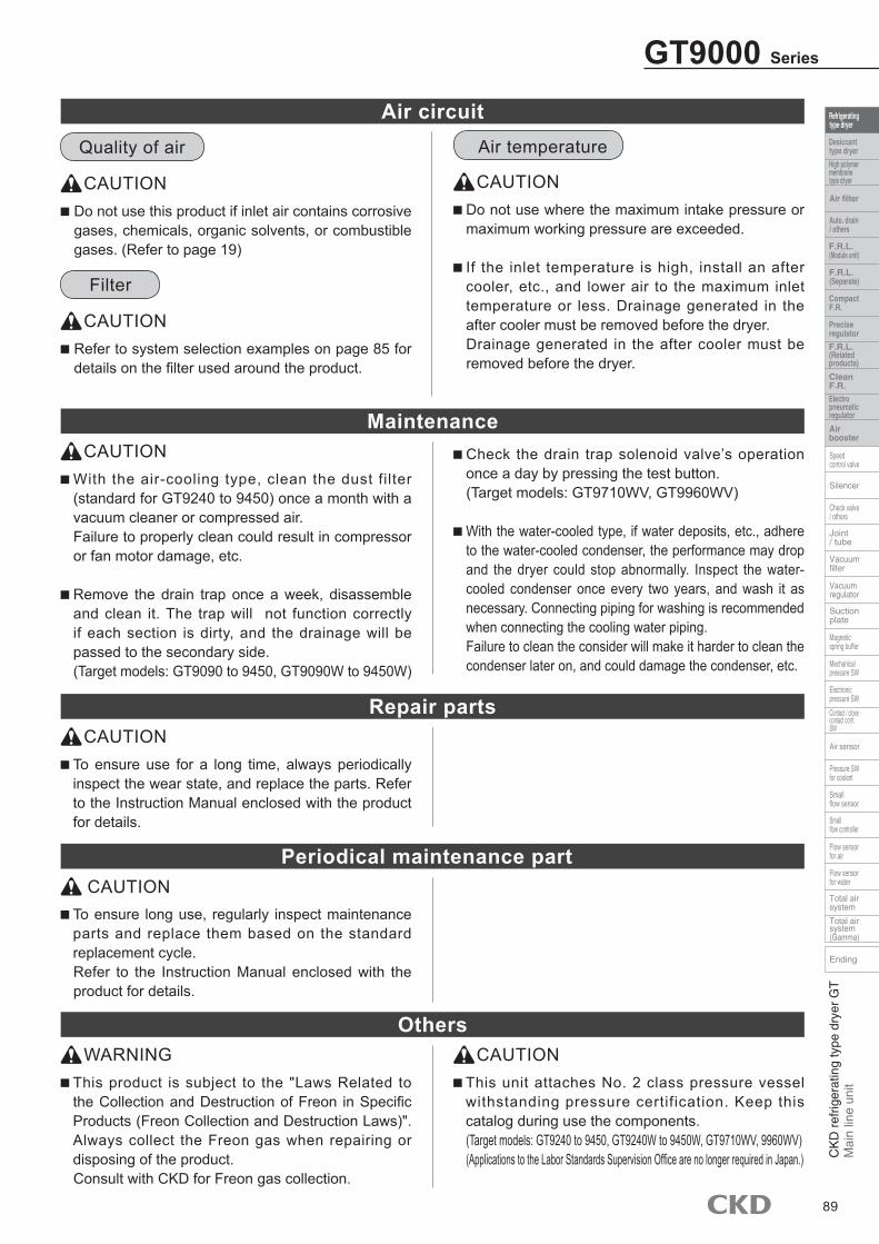
MaintenanceCAUTION
Repair partsCAUTION
To ensure use for a long time, always periodically inspect the wear state, and replace the parts. Refer to the Instruction Manual enclosed with the product for details.
Periodical maintenance partCAUTION
To ensure long use, regularly inspect maintenance parts and replace them based on the standard replacement cycle. Refer to the Instruction Manual enclosed with the product for details.
OthersWARNING
This product is subject to the "Laws Related to the Collection and Destruction of Freon in Specific Products (Freon Collection and Destruction Laws)". Always collect the Freon gas when repairing or disposing of the product. Consult with CKD for Freon gas collection.
CAUTION This unit attaches No. 2 class pressure vessel withstanding pressure certification. Keep this catalog during use the components. (Target models: GT9240 to 9450, GT9240W to 9450W, GT9710WV, 9960WV)(Applications to the Labor Standards Supervision Office are no longer required in Japan.)
Air temperature
CAUTION Do not use where the maximum intake pressure or maximum working pressure are exceeded.
If the inlet temperature is high, install an after cooler, etc., and lower air to the maximum inlet temperature or less. Drainage generated in the after cooler must be removed before the dryer. Drainage generated in the after cooler must be removed before the dryer.
Air circuit
CAUTION Do not use this product if inlet air contains corrosive gases, chemicals, organic solvents, or combustible gases. (Refer to page 19)
Quality of air
Filter
CAUTION Refer to system selection examples on page 85 for details on the filter used around the product.
GT9000 Series
89
With the air-cooling type, clean the dust filter (standard for GT9240 to 9450) once a month with a vacuum cleaner or compressed air. Failure to properly clean could result in compressor or fan motor damage, etc.
Remove the drain trap once a week, disassemble and clean it. The trap will not function correctly if each section is dirty, and the drainage will be passed to the secondary side. (Target models: GT9090 to 9450, GT9090W to 9450W)
Check the drain trap solenoid valve’s operation once a day by pressing the test button. (Target models: GT9710WV, GT9960WV)
With the water-cooled type, if water deposits, etc., adhere to the water-cooled condenser, the performance may drop and the dryer could stop abnormally. Inspect the water-cooled condenser once every two years, and wash it as necessary. Connecting piping for washing is recommended when connecting the cooling water piping.Failure to clean the consider will make it harder to clean the condenser later on, and could damage the condenser, etc.
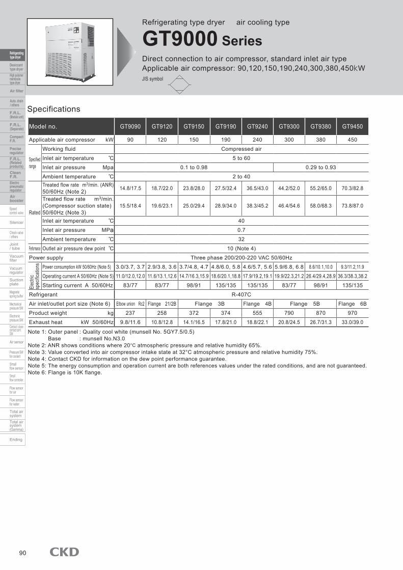
Refrigerating type dryer air cooling type
GT9000 SeriesDirect connection to air compressor, standard inlet air typeApplicable air compressor: 90,120,150,190,240,300,380,450kWJIS symbol
90
Specifications
Model no. GT9090 GT9120 GT9150 GT9190 GT9240 GT9300 GT9380 GT9450
Applicable air compressor kW 90 120 150 190 240 300 380 450
Specifiedrange
Working fluid Compressed air
Inlet air temperature 5 to 60
Inlet air pressure Mpa 0.1 to 0.98 0.29 to 0.93
Ambient temperature 2 to 40
Rated
Treated flow rate m3/min. (ANR)50/60Hz (Note 2) 14.8/17.5 18.7/22.0 23.8/28.0 27.5/32.4 36.5/43.0 44.2/52.0 55.2/65.0 70.3/82.8
Treated flow rate m3/min. (Compressor suction state) 50/60Hz (Note 3)
15.5/18.4 19.6/23.1 25.0/29.4 28.9/34.0 38.3/45.2 46.4/54.6 58.0/68.3 73.8/87.0
Inlet air temperature 40
Inlet air pressure MPa 0.7
Ambient temperature 32
Performance Outlet air pressure dew point 10 (Note 4)
Power supply Three phase 200/200-220 VAC 50/60Hz
Power consumption kW 50/60Hz (Note 5) 3.0/3.7, 3.7 2.9/3.8, 3.6 3.7/4.8, 4.7 4.8/6.0, 5.8 4.6/5.7, 5.6 5.9/6.8, 6.8 8.6/10.1,10.0 9.3/11.2,11.9
Operating current A 50/60Hz (Note 5) 11.0/12.0,12.0 11.6/13.1,12.6 14.7/16.3,15.9 18.6/20.1,18.8 17.9/19.2,19.1 19.9/22.3,21.2 26.4/29.4,28.9 36.3/38.3,38.2
Starting current A 50/60Hz 83/77 83/77 98/91 135/135 135/135 83/77 98/91 135/135
Refrigerant R-407C
Air inlet/outlet port size (Note 6) Elbow union Rc2 Flange 21/2B Flange 3B Flange 4B Flange 5B Flange 6B
Product weight kg 237 258 372 374 555 790 870 970
Exhaust heat kW 50/60Hz 9.8/11.6 10.8/12.8 14.1/16.5 17.8/21.0 18.8/22.1 20.8/24.5 26.7/31.3 33.0/39.0
Note 1: Outer panel : Quality cool white (munsell No. 5GY7.5/0.5)Base : munsell No.N3.0
Note 2: ANR shows conditions where 20°C atmospheric pressure and relative humidity 65%. Note 3: Value converted into air compressor intake state at 32°C atmospheric pressure and relative humidity 75%. Note 4: Contact CKD for information on the dew point performance guarantee. Note 5: The energy consumption and operation current are both references values under the rated conditions, and are not guaranteed. Note 6: Flange is 10K flange.
Elec
tric
spec
ificat
ions
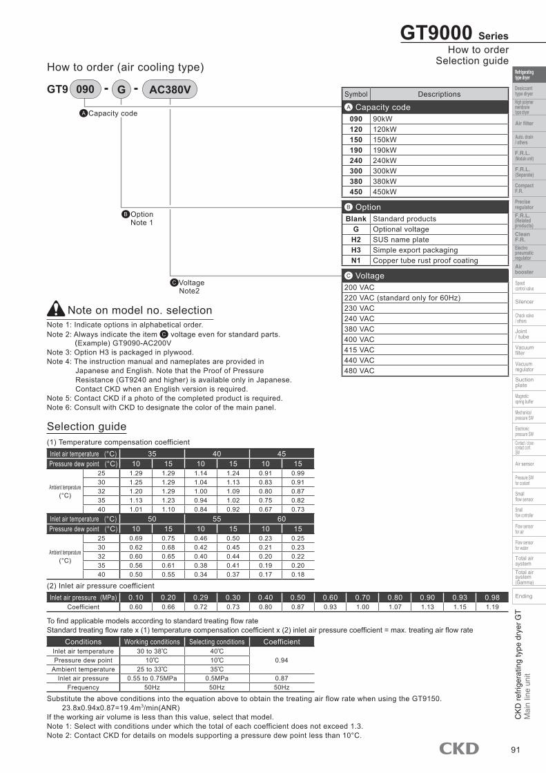
How to order (air cooling type)
B Option Note 1
A Capacity code
Note on model no. selectionNote 1: Indicate options in alphabetical order. Note 2: Always indicate the item C voltage even for standard parts.
(Example) GT9090-AC200VNote 3: Option H3 is packaged in plywood. Note 4: The instruction manual and nameplates are provided in
Japanese and English. Note that the Proof of Pressure Resistance (GT9240 and higher) is available only in Japanese. Contact CKD when an English version is required.
Note 5: Contact CKD if a photo of the completed product is required. Note 6: Consult with CKD to designate the color of the main panel.
Symbol Descriptions
A Capacity code090 90kW120 120kW150 150kW190 190kW240 240kW300 300kW380 380kW450 450kW
B OptionBlank Standard products
G Optional voltageH2 SUS name plateH3 Simple export packagingN1 Copper tube rust proof coating
C Voltage200 VAC220 VAC (standard only for 60Hz)230 VAC240 VAC380 VAC400 VAC415 VAC440 VAC480 VAC
C Voltage Note2
Selection guide
GT9000 SeriesHow to order
Selection guide
91
GT9 G AC380V090
(1) Temperature compensation coefficientInlet air temperature (°C) 35 40 45Pressure dew point (°C) 10 15 10 15 10 15
Ambient temperature(°C)
25 1.29 1.29 1.14 1.24 0.91 0.9930 1.25 1.29 1.04 1.13 0.83 0.9132 1.20 1.29 1.00 1.09 0.80 0.8735 1.13 1.23 0.94 1.02 0.75 0.8240 1.01 1.10 0.84 0.92 0.67 0.73
Inlet air temperature (°C) 50 55 60Pressure dew point (°C) 10 15 10 15 10 15
Ambient temperature(°C)
25 0.69 0.75 0.46 0.50 0.23 0.2530 0.62 0.68 0.42 0.45 0.21 0.2332 0.60 0.65 0.40 0.44 0.20 0.2235 0.56 0.61 0.38 0.41 0.19 0.2040 0.50 0.55 0.34 0.37 0.17 0.18
(2) Inlet air pressure coefficientInlet air pressure (MPa) 0.10 0.20 0.29 0.30 0.40 0.50 0.60 0.70 0.80 0.90 0.93 0.98
Coefficient 0.60 0.66 0.72 0.73 0.80 0.87 0.93 1.00 1.07 1.13 1.15 1.19
To find applicable models according to standard treating flow rateStandard treating flow rate x (1) temperature compensation coefficient x (2) inlet air pressure coefficient = max. treating air flow rate
Conditions Working conditions Selecting conditions CoefficientInlet air temperature 30 to 38 40
0.94Pressure dew point 10 10Ambient temperature 25 to 33 35
Inlet air pressure 0.55 to 0.75MPa 0.5MPa 0.87Frequency 50Hz 50Hz 50Hz
Substitute the above conditions into the equation above to obtain the treating air flow rate when using the GT9150. 23.8x0.94x0.87=19.4m3/min(ANR)If the working air volume is less than this value, select that model. Note 1: Select with conditions under which the total of each coefficient does not exceed 1.3. Note 2: Contact CKD for details on models supporting a pressure dew point less than 10°C.

Dimensions
GT9000 Series
92
GT9090 to GT9190
GT9240
Note 1: Select the left or right side of the exhaust outlet. Note 2: Select whether to attach the drain trap to the left or right side. The installation positions are symmetrical. Note 3: A dust filter is not mounted.
Model no. A B C D E F G H I J KGT9090 1276 672 1120 336 290 460 1411 (303) 780 712 752GT9120 1276 672 1260 336 403 655 1375 (221) 295 712 752GT9150 1332 950 1290 475 296 720 1432 (221) 260 990 1030GT9190 1332 950 1290 475 226 860 1432 (221) 260 990 1030
Model no. L M N O P Q RGT9090 130 700 Elbow union Rc2 870 120 1095 840GT9120 214 935 Flange 2 1/2B 1010 120 1235 840GT9150 245 935 Flange 3B 990 116 1265 896GT9190 245 935 Flange 3B 990 116 1265 896
Pneumatic pressuregauge
Steam pressure gauge
Power supply lightOperation light
Operation switchStop switch
Alarm light
Condensed pressure gaugeDetails of control section
Exhaust
(123)Drain trap
Intake
Drain portRc1/4
GA
BD
H
M L4-ø20
K JP
20
Power hole (for power conduit) with grommetGT9090,9120:ø26GT9150,9190:ø32.5
(20)
Air inlet N Air outlet N
Power hole with grommet2-ø30
40
CF E
R
Intake
Q
Pneumatic pressure gaugeSteam pressure gauge
Power supply lightOperation light Operation switch
Stop switchAlarm light
Condensed pressure gauge
Details of control section
1200
35
3864-ø20
1020
950
(35)
905425
8014
5
50 Power hole with grommet2-ø52
Drain portRc1/4
4-ø35for suspension
Drain trap(139)
Exhaust
Intake Intake Intake
(261
)
1489
Air inletFlange 4B
Air outletFlange 4B
1969900 272
1583
1695
I
Exhaust
Intake

Dimensions
Note 1: The dew point indicator value is a guide, and is not the actual dew point. To measure the actual dew point, measure the secondary air with a dew point gauge.
Note 1: The dew point indicator value is a guide, and is not the actual dew point. To measure the actual dew point, measure the secondary air with a dew point gauge.
GT9000 SeriesDimensions
93
GT9300, GT9380
GT9450
□□□□□□□□□□□□□□□□□□□E08:□□□□□□□□□□□□□□□□□□□
E10:□□□□□□□□□□□□□□□□□□□E11:□□□□□□□□□□□□□□□□□□□E20:□□□□□□□□□□□□□□□□□□□E21:□□□□□□□□□□□□□□□□□□□
E00:□□□□□□□□□□□□□□□□□□□E01:□□□□□□□□□□□□□□□□□□□E02:□□□□□□□□□□□□□□□□□□□ □□□□□□□□□□□□□□□□□□□E03:□□□□□□□□□□□□□□□□□□□E04:□□□□□□□□□□□□□□□□□□□E05:□□□□□□□□□□□□□□□□□□□E06:□□□□□□□□□□□□□□□□□□□ □□□□□□□□□□□□□□□□□□□E07:□□□□□□□□□□□□□□□□□□□ □□□□□□□□□□□□□□□□□□□
CONDENSER
SETRESET
LOCALREMOTE
AIR PRESSURE
COMP.1COMP.2
MODE
HEAT EXCHANGERCOMP.2COMP.1
ARARM
POWER SAVETEMP.
HOUR METERDEW POINT ALARM
POWER
CONTROLLER
STOP
START
℃h
RUN
AIR PRESSRE
AIR PRESSURE
DEW POINT ALARMHOUR METER
POWER SAVETEMP.
CONDENSER COMP.1
RESETSETREMOTELOCAL
HEAT EXCHANGERCOMP.2
ARARM
MODE
COMP.2COMP.1
h℃
POWER
CONTROLLER
STOP
RUN
START
□□□□□□□□□□□□□□□□□□□E07:□□□□□□□□□□□□□□□□□□□ □□□□□□□□□□□□□□□□□□□E06:□□□□□□□□□□□□□□□□□□□E05:□□□□□□□□□□□□□□□□□□□E04:□□□□□□□□□□□□□□□□□□□E03:□□□□□□□□□□□□□□□□□□□ □□□□□□□□□□□□□□□□□□□E02:□□□□□□□□□□□□□□□□□□□E01:□□□□□□□□□□□□□□□□□□□E00:□□□□□□□□□□□□□□□□□□□
E21:□□□□□□□□□□□□□□□□□□□E20:□□□□□□□□□□□□□□□□□□□E11:□□□□□□□□□□□□□□□□□□□E10:□□□□□□□□□□□□□□□□□□□ □□□□□□□□□□□□□□□□□□□E08:□□□□□□□□□□□□□□□□□□□
Pneumatic pressure gaugeDigital indicator (dew point temperature, etc.)
Operation lightOperation switchStop switch
Alarm lightDetails of control section
100
170
50Power hole with grommet2-ø52
Drain portø21.7
4-ø35for suspension
DrainDrain trap (235)
(284
)1100
543
1350
Exhaust
Intake Intake Intake
4-ø20 1310 280
3012
0511
45(3
0)
Air inletFlange 5B
Air outletFlange 5B
2020700 330
1650 18
25
Pneumatic pressure gaugeDigital indicator (dew point temperature, etc.)
Operation lightOperation switchStop switch
Alarm lightDetails of control section
4-ø20
3012
5011
90
Exhaust
Intake
(30)
Air inletFlange 6B
Air outletFlange 6B
Intake
2077700 359
1825
1703
1326 293
1145
Intake
565
Power hole with grommet2-ø52
Drain portø21.7
4-ø35for suspension
Drain trap(235)
(373
)100
170
50
683 708
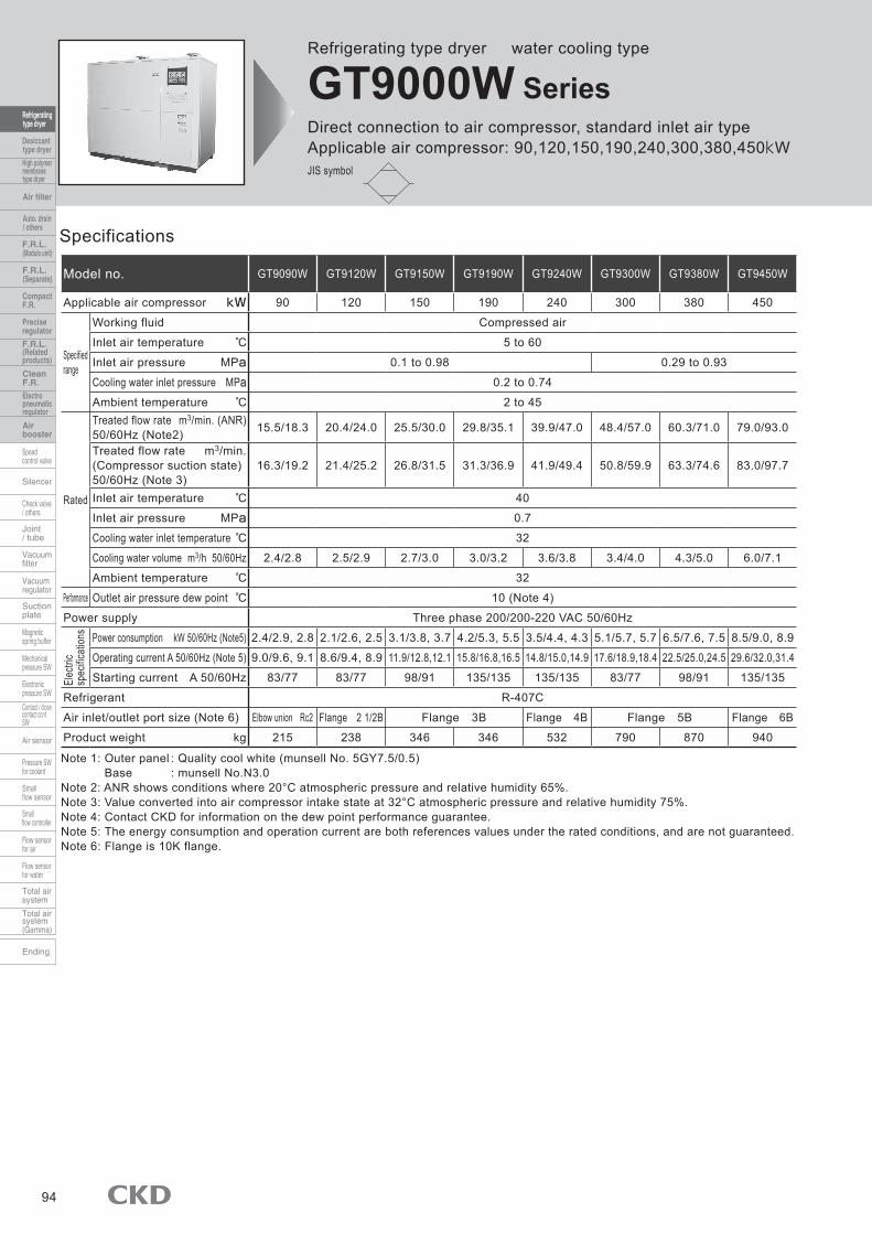
Refrigerating type dryer water cooling type
GT9000W SeriesDirect connection to air compressor, standard inlet air typeApplicable air compressor: 90,120,150,190,240,300,380,450kWJIS symbol
94
Specifications
Model no. GT9090W GT9120W GT9150W GT9190W GT9240W GT9300W GT9380W GT9450W
Applicable air compressor kW 90 120 150 190 240 300 380 450
Specified range
Working fluid Compressed air
Inlet air temperature 5 to 60
Inlet air pressure MPa 0.1 to 0.98 0.29 to 0.93
Cooling water inlet pressure MPa 0.2 to 0.74
Ambient temperature 2 to 45
Rated
Treated flow rate m3/min. (ANR)50/60Hz (Note2) 15.5/18.3 20.4/24.0 25.5/30.0 29.8/35.1 39.9/47.0 48.4/57.0 60.3/71.0 79.0/93.0
Treated flow rate m3/min.(Compressor suction state) 50/60Hz (Note 3)
16.3/19.2 21.4/25.2 26.8/31.5 31.3/36.9 41.9/49.4 50.8/59.9 63.3/74.6 83.0/97.7
Inlet air temperature 40
Inlet air pressure MPa 0.7
Cooling water inlet temperature 32
Cooling water volume m3/h 50/60Hz 2.4/2.8 2.5/2.9 2.7/3.0 3.0/3.2 3.6/3.8 3.4/4.0 4.3/5.0 6.0/7.1
Ambient temperature 32
Performance Outlet air pressure dew point 10 (Note 4)
Power supply Three phase 200/200-220 VAC 50/60Hz
Power consumption kW 50/60Hz (Note5) 2.4/2.9, 2.8 2.1/2.6, 2.5 3.1/3.8, 3.7 4.2/5.3, 5.5 3.5/4.4, 4.3 5.1/5.7, 5.7 6.5/7.6, 7.5 8.5/9.0, 8.9
Operating current A 50/60Hz (Note 5) 9.0/9.6, 9.1 8.6/9.4, 8.9 11.9/12.8,12.1 15.8/16.8,16.5 14.8/15.0,14.9 17.6/18.9,18.4 22.5/25.0,24.5 29.6/32.0,31.4
Starting current A 50/60Hz 83/77 83/77 98/91 135/135 135/135 83/77 98/91 135/135
Refrigerant R-407C
Air inlet/outlet port size (Note 6) Elbow union Rc2 Flange 2 1/2B Flange 3B Flange 4B Flange 5B Flange 6B
Product weight kg 215 238 346 346 532 790 870 940
Note 1: Outer panel : Quality cool white (munsell No. 5GY7.5/0.5)Base : munsell No.N3.0
Note 2: ANR shows conditions where 20°C atmospheric pressure and relative humidity 65%. Note 3: Value converted into air compressor intake state at 32°C atmospheric pressure and relative humidity 75%. Note 4: Contact CKD for information on the dew point performance guarantee. Note 5: The energy consumption and operation current are both references values under the rated conditions, and are not guaranteed. Note 6: Flange is 10K flange.
Elec
tric
spec
ificat
ions
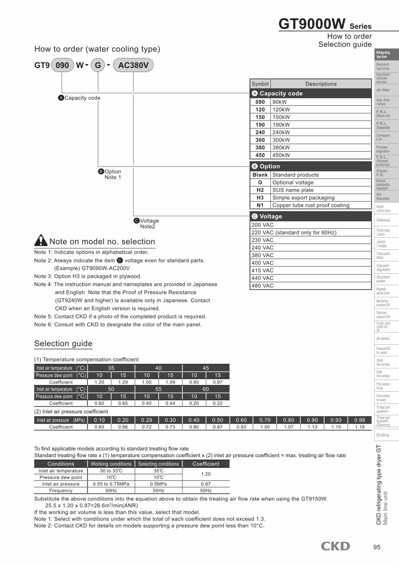
How to order (water cooling type)
B Option Note 1
A Capacity code
Note on model no. selectionNote 1: Indicate options in alphabetical order. Note 2: Always indicate the item C voltage even for standard parts.
(Example) GT9090W-AC200VNote 3: Option H3 is packaged in plywood. Note 4: The instruction manual and nameplates are provided in Japanese
and English. Note that the Proof of Pressure Resistance (GT9240W and higher) is available only in Japanese. Contact CKD when an English version is required.
Note 5: Contact CKD if a photo of the completed product is required. Note 6: Consult with CKD to designate the color of the main panel.
Symbol Descriptions
A Capacity code090 90kW120 120kW150 150kW190 190kW240 240kW300 300kW380 380kW450 450kW
B OptionBlank Standard products
G Optional voltageH2 SUS name plateH3 Simple export packagingN1 Copper tube rust proof coating
C Voltage200 VAC220 VAC (standard only for 60Hz)230 VAC240 VAC380 VAC400 VAC415 VAC440 VAC480 VAC
C Voltage Note2
Selection guide
GT9000W SeriesHow to order
Selection guide
95
GT9 W G AC380V090
(1) Temperature compensation coefficientInlet air temperature (°C) 35 40 45Pressure dew point (°C) 10 15 10 15 10 15
Coefficient 1.20 1.29 1.00 1.09 0.80 0.87Inlet air temperature (°C) 50 55 60Pressure dew point (°C) 10 15 10 15 10 15
Coefficient 0.60 0.65 0.40 0.44 0.20 0.22
(2) Inlet air pressure coefficientInlet air pressure (MPa) 0.10 0.20 0.29 0.30 0.40 0.50 0.60 0.70 0.80 0.90 0.93 0.98
Coefficient 0.60 0.66 0.72 0.73 0.80 0.87 0.93 1.00 1.07 1.13 1.15 1.19
To find applicable models according to standard treating flow rateStandard treating flow rate x (1) temperature compensation coefficient x (2) inlet air pressure coefficient = max. treating air flow rate
Conditions Working conditions Selecting conditions CoefficientInlet air temperature 30 to 33 35
1.20Pressure dew point 10 10
Inlet air pressure 0.55 to 0.75MPa 0.5MPa 0.87Frequency 50Hz 50Hz 50Hz
Substitute the above conditions into the equation above to obtain the treating air flow rate when using the GT9150W. 25.5 x 1.20 x 0.87=26.6m3/min(ANR)If the working air volume is less than this value, select that model. Note 1: Select with conditions under which the total of each coefficient does not exceed 1.3. Note 2: Contact CKD for details on models supporting a pressure dew point less than 10°C.

Dimensions
GT9000W Series
96
GT9090W to GT9190W
GT9240W
Note 1: Select whether to attach the cooling water pipe to the left or right side. Note 2: Select whether to attach the drain trap to the left or right side. The installation positions are symmetrical.
Model no. A B C D E F G H I J KGT9090W 1276 672 1120 336 290 460 1411 (303) 780 712 752GT9120W 1276 672 1260 336 403 655 1375 (221) 295 712 752GT9150W 1332 950 1290 475 296 720 1432 (221) 260 990 1030GT9190W 1332 950 1290 475 226 860 1432 (221) 260 990 1030
Model no. L M N O P Q R S TGT9090W 130 700 Elbow union Rc2 870 120 1095 840 107 310GT9120W 214 935 Flange 2 1/2B 1010 120 1235 840 107 445GT9150W 245 935 Flange 3B 990 116 1265 896 95 475GT9190W 245 935 Flange 3B 990 116 1265 896 95 475
Pneumatic pressure gauge
Steam pressure gauge
Power supply lightOperation light
Operation switchStop switch
Alarm light
Condensed pressure gauge
Details of control section
BD
(20) (20)
H
(123)Drain trap
Drain portRc1/4
GA
Power source inlet grommet2-ø30
Air inlet NCF E
Air outlet N
Cooling water inlet Rp3/4(Left or right mounting possible)
Cooling water outlet Rp3/4(Left or right mounting possible)
70
QT
R40
127
382
S
Cooling water drain outlet Rp1/4(With plug)
Power hole (for power conduit) with grommet GT9090W,9120W:ø26GT9150W, 9190W:ø32.5
4-ø20M L
(20)
K J20
P
Pneumatic pressure gaugeSteam pressure gauge
Power supply lightOperation light Operation switch
Stop switchAlarm light
Condensed pressure gauge
Details of control section
Cooling water outletRp1
Cooling water inletRp1
39
225
236
142
145
80
1489
50 Power hole with grommet2-ø52
Cooling water drain outletRp1/4 (with plug) Drain port
Rc1/44-ø35 for suspension
Drain trap(139)
905425
(261
)
Air inletFlange 4B
Air outletFlange 4B
1969900 272
1583
1695
(35)
1020
950
35
1200 3864-ø20
O
I

Dimensions
Note 1: The dew point indicator value is a guide, and is not the actual dew point. To measure the actual dew point, measure the secondary air with a dew point gauge.
Note 1: The dew point indicator value is a guide, and is not the actual dew point. To measure the actual dew point, measure the secondary air with a dew point gauge.
GT9000W SeriesDimensions
97
GT9300W, GT9380W
GT9450W
E08:□□□□□□□□□□□□□□□□□□□ □□□□□□□□□□□□□□□□□□□E10:□□□□□□□□□□□□□□□□□□□E11:□□□□□□□□□□□□□□□□□□□E20:□□□□□□□□□□□□□□□□□□□E21:□□□□□□□□□□□□□□□□□□□
E00:□□□□□□□□□□□□□□□□□□□E01:□□□□□□□□□□□□□□□□□□□E02:□□□□□□□□□□□□□□□□□□□ □□□□□□□□□□□□□□□□□□□E03:□□□□□□□□□□□□□□□□□□□E04:□□□□□□□□□□□□□□□□□□□E05:□□□□□□□□□□□□□□□□□□□E06:□□□□□□□□□□□□□□□□□□□ □□□□□□□□□□□□□□□□□□□E07:□□□□□□□□□□□□□□□□□□□ □□□□□□□□□□□□□□□□□□□
CONDENSER
SETRESET
LOCALREMOTE
AIR PRESSURE
COMP.1COMP.2
MODE
HEAT EXCHANGERCOMP.2COMP.1
ARARM
POWER SAVETEMP.
HOUR METERDEW POINT ALARM
POWER
CONTROLLER
STOP
START
℃h
RUN
AIR PRESSRE
E08:□□□□□□□□□□□□□□□□□□□ □□□□□□□□□□□□□□□□□□□E10:□□□□□□□□□□□□□□□□□□□E11:□□□□□□□□□□□□□□□□□□□E20:□□□□□□□□□□□□□□□□□□□E21:□□□□□□□□□□□□□□□□□□□
E00:□□□□□□□□□□□□□□□□□□□E01:□□□□□□□□□□□□□□□□□□□E02:□□□□□□□□□□□□□□□□□□□ □□□□□□□□□□□□□□□□□□□E03:□□□□□□□□□□□□□□□□□□□E04:□□□□□□□□□□□□□□□□□□□E05:□□□□□□□□□□□□□□□□□□□E06:□□□□□□□□□□□□□□□□□□□ □□□□□□□□□□□□□□□□□□□E07:□□□□□□□□□□□□□□□□□□□ □□□□□□□□□□□□□□□□□□□
CONDENSER
SETRESET
LOCALREMOTE
AIR PRESSURE
COMP.1COMP.2
MODE
HEAT EXCHANGERCOMP.2COMP.1
ARARM
POWER SAVETEMP.
HOUR METERDEW POINT ALARM
POWER
CONTROLLER
STOP
START
℃h
RUN
Pneumatic pressure gauge Operation lightOperation switchStop switch
Alarm lightDetails of control section
Digital indicator (dew point temperature, etc.)4-ø20 1310 280
1205
1145
(30)
1650 1825
330
Air outletFlange 5B2020
700
Air inletFlange 5B
1100543
4-ø35for suspensionDrain port
ø21.7
Drain trap
(235)
(284
)
210
170
49
78
152
Rc1 1/2Cooling water outlet
Rc1 1/2Cooling water inlet
Cooling water drain outletRp1/4 (with plug)
Power hole with grommet2-ø52
100
170
1350
5030
Pneumatic pressure gauge Operation lightOperation switchStop switch
Alarm lightDetails of control section
Digital indicator (dew point temperature, etc.) 4-ø20
30
1326 293
1250
1190
(30)
Air outletFlange 6B
Air inletFlange 6B
2077700 359
1703
1825
4-ø35for suspension
Drain portø21.7
Drain trap(235)
(373
)
Rc1 1/2Cooling water outlet
Rc1 1/2Cooling water inlet
Cooling water drain outletRp1/4 (with plug)
Power hole with grommet2-ø52
232
237.5
152
49
78
683 707
50
170
100
1145565
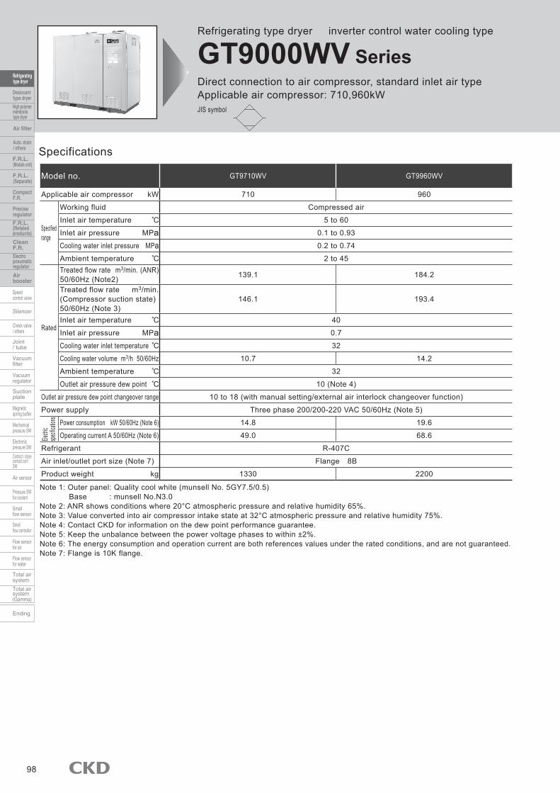
Refrigerating type dryer inverter control water cooling type
GT9000WV SeriesDirect connection to air compressor, standard inlet air typeApplicable air compressor: 710,960kWJIS symbol
98
Specifications
Model no. GT9710WV GT9960WV
Applicable air compressor kW 710 960
Specifiedrange
Working fluid Compressed air
Inlet air temperature 5 to 60
Inlet air pressure MPa 0.1 to 0.93
Cooling water inlet pressure MPa 0.2 to 0.74
Ambient temperature 2 to 45
Rated
Treated flow rate m3/min. (ANR)50/60Hz (Note2) 139.1 184.2
Treated flow rate m3/min. (Compressor suction state) 50/60Hz (Note 3)
146.1 193.4
Inlet air temperature 40
Inlet air pressure MPa 0.7
Cooling water inlet temperature 32
Cooling water volume m3/h 50/60Hz 10.7 14.2
Ambient temperature 32
Outlet air pressure dew point 10 (Note 4)
Outlet air pressure dew point changeover range 10 to 18 (with manual setting/external air interlock changeover function)
Power supply Three phase 200/200-220 VAC 50/60Hz (Note 5)
Power consumption kW 50/60Hz (Note 6) 14.8 19.6
Operating current A 50/60Hz (Note 6) 49.0 68.6
Refrigerant R-407C
Air inlet/outlet port size (Note 7) Flange 8B
Product weight kg 1330 2200
Note 1: Outer panel: Quality cool white (munsell No. 5GY7.5/0.5)Base : munsell No.N3.0
Note 2: ANR shows conditions where 20°C atmospheric pressure and relative humidity 65%. Note 3: Value converted into air compressor intake state at 32°C atmospheric pressure and relative humidity 75%. Note 4: Contact CKD for information on the dew point performance guarantee. Note 5: Keep the unbalance between the power voltage phases to within ±2%. Note 6: The energy consumption and operation current are both references values under the rated conditions, and are not guaranteed. Note 7: Flange is 10K flange.
Electri
cspe
cificat
ions

How to order (inverter control water cooling type)
B Option Note 1
A Capacity code
Note on model no. selectionNote 1: Indicate options in alphabetical order. Note 2: Always indicate the item C voltage even for standard parts.
(Example) GT9710WV-AC200VNote 3: Option H3 is packaged in plywood. Note 4: The instruction manual and nameplates are provided in
Japanese and English. Note that the Proof of Pressure Resistance is available only in Japanese. Contact CKD when an English version is required.
Note 5: Contact CKD if a photo of the completed product is required. Note 6: Consult with CKD to designate the color of the main panel.
Symbol Descriptions
A Capacity code710 710kW960 960kW
B OptionBlank Standard products
G Optional voltageH2 SUS name plateH3 Simple export packagingN1 Copper tube rust proof coating
C Voltage200 VAC220 VAC (standard only for 60Hz)230 VAC240 VAC380 VAC400 VAC415 VAC440 VAC480 VAC
C Voltage Note2
Selection guide
GT9000WV SeriesHow to order
Selection guide
99
GT9 G AC380V710 WV
(1) Temperature compensation coefficientInlet air temperature (°C) 35 40 45Pressure dew point (°C) 10 18 10 18 10 18
Coefficient 1.20 1.20 1.00 1.20 0.80 0.96Inlet air temperature (°C) 50 55 60Pressure dew point (°C) 10 18 10 18 10 18
Coefficient 0.60 0.72 0.40 0.48 0.20 0.24
(2) Inlet air pressure coefficientInlet air pressure (MPa) 0.10 0.20 0.30 0.40 0.50 0.60 0.70 0.80 0.90 0.93
Coefficient 0.60 0.66 0.73 0.80 0.87 0.93 1.00 1.07 1.13 1.15
To find applicable models according to standard treating flow rateStandard treating flow rate x (1) temperature compensation coefficient x (2) inlet air pressure coefficient = max. treating air flow rate
Conditions Working conditions Selecting conditions CoefficientInlet air temperature 38 to 43 45
0.80Pressure dew point 15 10
Inlet air pressure 0.55 to 0.75MPa 0.5MPa 0.87Frequency 50Hz 50Hz 50Hz
Substitute the above conditions into the equation above to obtain the treating air flow rate when using the GT9710WV. 139.1 x 0.80 x 0.87=96.8m3/min(ANR)If the working air volume is less than this value, select that model. Note: Select with conditions under which the total of each coefficient does not exceed 1.3.

Dimensions
Note 1: The dew point indicator value is a guide, and is not the actual dew point. To measure the actual dew point, measure the secondary air with a dew point gauge.
Note 2: The header, gasket and mounting bolts and nuts are enclosed. Note 3: The dew point indicator value is a guide, and is not the actual dew point.
To measure the actual dew point, measure the secondary air with a dew point gauge.
GT9000WV Series
100
Note1: The same details are displayed on the main controller and sub-controller.
GT9710WV
GT9960WV
SYNC75
5025
0 STOPSTART
▼ ▲
℃
ALARMRESETSET
MANUAL
7550
250
POWER
POWER
STOPSTART
▼ ▲
100
℃RUN
ALARMRESETSET
100 RUN
MODE
AIR PRESSURE
STOPREMOTERUN
1.5
0.5 1
MPa
.
0
100
100
POWER
025
50
75
POWER
025
50
75
1.5
STOP
RUN
SET RESETALARM▲▼
SET RESETALARM
℃
▲▼
STARTSTOP
MPa
RUNMODE
MANUAL
SYNC
REMOTE
RUN
℃STARTSTOP
0
. 150.
AIR PRESSURESUB CONTROLLER (REF.CIRCUIT 2)
MAIN CONTROLLER (REF.CIRCUIT 1)
SUB CONTROLLER (REF.CIRCUIT 2)
MAIN CONTROLLER (REF.CIRCUIT 1)
Pneumatic pressure gaugeOperation light
Operation / Stop switch
Details of control section
Digital indicator (dew point temperature, etc.)
800
Air outletFlange 8B
2090428
Air inletFlange 8B
Rc1 1/2Cooling water outlet
Rc1 1/2Cooling water inlet
Cooling water drain outletRp1/4 (with plug)
Power hole with grommet2-ø52
100
240
50
Compressor operation output displayDew point installation changeover switch
Reset switch
Setting switch
4-ø20
1407 374
1256
1196
(30)
30
1151523
2000
1850
152 50 Drain pan drain outlet
R3/860145
Drain portRc1/2
Manual drain port Rc1/4 (with valve)
4-ø35for suspension
60 140 40
237
340
Pneumatic pressure gauge
Operation light
Operation / stopRemote changeover switch
Details of control section
Digital indicator (dew point temperature, etc.)Compressor operation output display
Dew point installation changeover switch
Reset switchSetting switch
Sub-controller
Main controller
Manual operation switch 2126
296
205635
1500
(35)
4-ø25
2000
Rc2Cooling water outlet
Rc2Cooling water inlet
Power hole with grommetø40
4-ø35for suspension
Power hole with grommetø77
2 - Manual drain port2-Rc1/4 (with valve)
Drain portRc3/4
Drain pan drain portR3/8
2- cooling water drain outlet12-Rp 1/4 (with plug)
60
55
120
312
192
45 50 60 85
100
190 50
277
166
925Header
Air outletFlange 8B
Air inletFlange 8B
2077700 359
2728
1985
1763
49

Accessories (optional)
Anchor bolt ■
Companion flange ■Inserted welded flange, hexagon bolt, nut and gasket set
No. RD-KFL-436467 RD-KFL-436468 RD-KFL-436469 RD-KFL-436470 RD-KFL-436471 RD-KFL-436472
Applicable model Size Flange 2 1/2B Flange 3B Flange 4B Flange 5B Flange 6B Flange 8BGT9120 GT9120WGT9150 GT9150WGT9190 GT9190WGT9240 GT9240WGT9300 GT9300WGT9380 GT9380WGT9450 GT9450W
GT9710WVGT9960WV
Anchor bolt: 4 SUS bolts per set
No. RD-QFL-436465 RD-QFL-436466
Applicable model Size M16 x L100 M20 x L130GT9090 GT9090WGT9120 GT9120WGT9150 GT9150WGT9190 GT9190WGT9240 GT9240WGT9300 GT9300WGT9380 GT9380WGT9450 GT9450W
GT9710WVGT9960WV
AccessoriesGT9000 Series
101
Related Documents


