LabVIEW Tutorials T.1 Temperature Measurement and Cold Junction Compensation (CJC) LUMS School of Science and Engineering Umer Hassan & Muhammad Sabieh Anwar

Welcome message from author
This document is posted to help you gain knowledge. Please leave a comment to let me know what you think about it! Share it to your friends and learn new things together.
Transcript

LabVIEW
Tutorials
T.1 Temperature Measurement
and Cold Junction
Compensation (CJC)
LUMS School of Science and Engineering
Umer Hassan & Muhammad Sabieh Anwar

Introduction:
In this tutorial we shall learn how to measure temperature using NI DAQ Cards and LabVIEW while
employing cold junction compensation in real time. Thermocouples require some form of temperature
reference to compensate for the cold junctions. The most common method is to measure the
temperature at the reference junction with a direct‐reading temperature sensor. This process is called
cold‐junction compensation (CJC).
Procedure:
Follow the following illustrative step by step procedure to measure temperature using thermocouples.
Start Measurement & Automation Explorer.
Under Configuration, select My System then select Data Neighborhood, following dialog box appears.
Click NI‐DAQmx Global Virtual Channel
On the following window, click, Create New NI‐DAQmx Channel,

On clicking, Create New NI‐DAQmx Global Virtual Channel, a dialog box appears which asks you
whether you want to create or acquire a signal.
Select Acquire Signal, and then select Analog Input and then Voltage, as shown in the below picture.

On clicking Voltage, following dialog box appears which asks you which Physical Channel acts as virtual
channel.
Current SCC‐68 connections:
PIN 57 (AI 7) is connected to PIN 70 (CJC+)
PIN 56 (AI GND) to PIN 71 (AI GND).
Thus, on the following dialog box select AI 7 and click on Next.

The dialog box appears which asks you to write a desired name for the global virtual channel.
We named RT‐CJC and then click on Finish.

The following window appears.
Make the Terminal Configuration to RSE, under the Settings tab, set the signal Input Range to Max 10
and Min ‐10. And select Volts as Scaled Units.
Click on the Connection Diagram tab, at the lower bottom of the dialog box.
It shows you the connection diagram of the existing channel, which is shown below.
Make sure the connections on the diagram should be same as of the SCC‐68.

Now click on the NI‐DAQmx Global Channel again, and under the Voltage Input Setup, scroll down
Custom Scaling and select Create New.
Following Dialog box appears.

Click on Table, the following window asks you to enter the name of the scale, e.g. Steinhart‐calibration
Click Finish, following dialog box appears.

Click on Import, Now we have to import the calibration file (Steinhart.txt), the import file wizard shows
you the calibration table as follows,

Click Ok.
The table has been added as shown below.
Click OK, now the Custom Scaling should read as Steinhart‐calibration.
On the following dialog box, click Save.
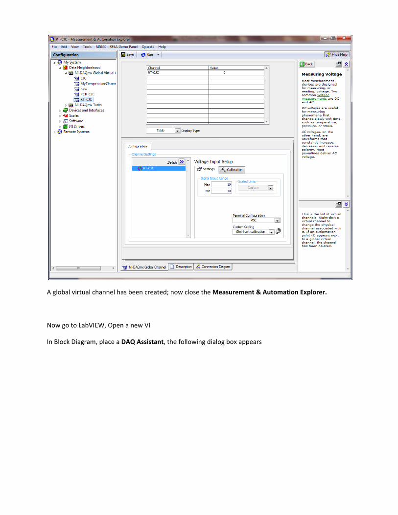
A global virtual channel has been created; now close the Measurement & Automation Explorer.
Now go to LabVIEW, Open a new VI
In Block Diagram, place a DAQ Assistant, the following dialog box appears

Select Acquire Signals, Analog Input, and Temperature and finally select Thermocouple.
Select the physical channel, at which you connected the thermocouple, let’s say AI 0
Select the channel and click on finish.
Following dialog box appears

Under the Thermocouple Setup, set the following parameters as,
Signal Input range: The range of the input temperature you are acquiring
Scaled Units: The different temperature units (C, F, K)
Thermocouple Type: Select the type of the thermocouple which you are using (identified using color
codes)
CJC Source: Define the CJC source as Constant, Channel, or Built in. For the real time cold junction
compensation measurements, define it to Channel.
CJC Channel: Select the RT‐CJC channel which we have just created
Acquisition Mode: Select this to Continuous samples.

Click Ok.
Place a Graph Indicator at the output i.e. Data of the DAQ assistant and click on Run button. Place a
while loop around it to continuously run the file, as shown,

Check the Front Panel.

Graph Indicator shows you the temperature while performing cold junction compensation in real time.
Find the average of the acquired temperature for eliminating noise.
Important Note:
Turn the switch ON labeled as SW1 on SCC‐68 Card. The light turned as the switch turns ON. This switch
provides the power to the thermistor circuit which is performing the real time cold junction
compensation.
Enjoy!!!!!!!!