Fundamentals of Engineering Civil Discipline Specific Exam Review Environmental Engineering Instructor Dr. R. Kommalapati, PE, BCEE School of PE ahmed youssef ([email protected]) This copy is given to the following student as part of School of PE course. Not allowed to distribute to others.

Civil Depth Notes for Mar 16th-EnVIROMNTAL
Dec 28, 2015
FE Exam Preparation Material
Welcome message from author
This document is posted to help you gain knowledge. Please leave a comment to let me know what you think about it! Share it to your friends and learn new things together.
Transcript

Fundamentals of Engineering Civil Discipline Specific Exam Review
Environmental Engineering
Instructor Dr. R. Kommalapati, PE, BCEE
School of PE
ahmed youssef ([email protected])
This copy is given to the following student as part of School of PE course. Not allowed to distribute to others.
Dr. R. Kommalapati, Ph.D., PE, BCEE FE-Civil(Environmental) Notes
ii ii
Fundamentals of Engineering Exam Review Civil Discipline Specific- Environmental Engineering Notes
Dr. R. Kommalapati, PE, BCEE
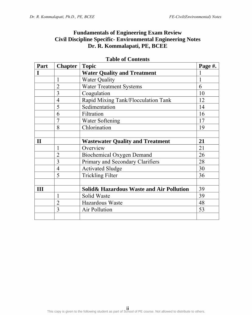
Table of Contents Part Chapter Topic Page #.I Water Quality and Treatment 1 1 Water Quality 1 2 Water Treatment Systems 6 3 Coagulation 10 4 Rapid Mixing Tank/Flocculation Tank 12 5 Sedimentation 14 6 Filtration 16 7 Water Softening 17 8 Chlorination 19 II Wastewater Quality and Treatment 21 1 Overview 21 2 Biochemical Oxygen Demand 26 3 Primary and Secondary Clarifiers 28 4 Activated Sludge 30 5 Trickling Filter 36 III Solid& Hazardous Waste and Air Pollution 39 1 Solid Waste 39 2 Hazardous Waste 48 3 Air Pollution 53
ahmed youssef ([email protected])
This copy is given to the following student as part of School of PE course. Not allowed to distribute to others.

Dr. R. Kommalapati, Ph.D., PE, BCEE FE-Civil(Environmental) Notes
iii iii
Fundamentals of Engineering Exam Review Civil Discipline Specific- Environmental Engineering Notes
Dr. R. Kommalapati, PE, BCEE
REFERENCES 1. Introduction to Environmental Engineering, 3rd ed., Davis and Cornwell,
McGraw-Hill, 1998. 2. Water Quality, Tchobanoglous and Schroeder, Addison-Wesley, 1985 3. Wastewater Engineering: Treatment and Reuse, Metcalf and Eddy
(Tchobanoglous, Burton and Stensel), McGraw Hill, Inc., 2003 4. Environmental Engineering FE Exam Preparation, B. J. Stuart, Kaplan AEC
Education, 2005 5. Environmental Engineering Reference Manual for PE Exam, 2nd Edition,
Michael R Lindeburg, Professional Publications, Inc, 2003. 6. Environmental Engineering PE License Review, P. J. Parker and B. J. Stuart,
Kaplan AEC Education, 2007 7. Environmental Engineering Problems and solutions, Harry Harbold, Kaplan
AEC Education, 2004 8. Environmental Engineering Practice PE Exams, 2nd ed, R Wane Schneiter,
Professional Publications, Inc, 1999. 9. Civil Engineering Reference Manual for PE Exam, 10th Edition, Michael R
Lindeburg, Professional Publications, Inc, 2006. 10. Practice Problem for the Civil Engineering PE Exam, Michael R Lindeburg,
Professional Publications, Inc, 200?. 11. PE Civil Engineering License Review, 16th ed, D. Newnan, Kaplan AEC
Education, 2005 12. PE Civil Engineering Problems and Solutions, 16th ed, D. Newnan, Kaplan AEC
Education, 2005 13. PE Civil Engineering Sample Exam, Kaplan AEC Education, 2006
ahmed youssef ([email protected])
This copy is given to the following student as part of School of PE course. Not allowed to distribute to others.
Dr. R. Kommalapati, Ph.D., PE, BCEE FE-Civil(Environmental) Notes
iv iv
Left Blank
ahmed youssef ([email protected])
This copy is given to the following student as part of School of PE course. Not allowed to distribute to others.
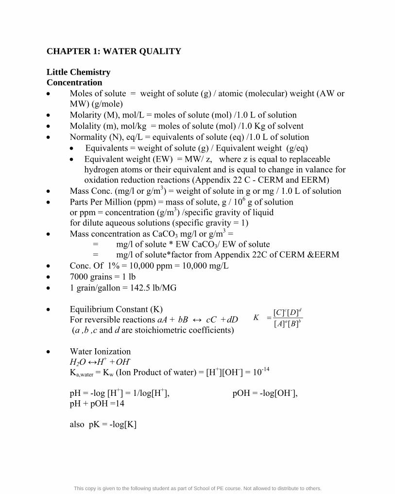
CHAPTER 1: WATER QUALITY Little Chemistry Concentration Moles of solute = weight of solute (g) / atomic (molecular) weight (AW or
MW) (g/mole) Molarity (M), mol/L = moles of solute (mol) /1.0 L of solution Molality (m), mol/kg = moles of solute (mol) /1.0 Kg of solvent Normality (N), eq/L = equivalents of solute (eq) /1.0 L of solution
Equivalents = weight of solute (g) / Equivalent weight (g/eq) Equivalent weight (EW) = MW/ z, where z is equal to replaceable
hydrogen atoms or their equivalent and is equal to change in valance for oxidation reduction reactions (Appendix 22 C - CERM and EERM)
Mass Conc. (mg/l or g/m3) = weight of solute in g or mg / 1.0 L of solution Parts Per Million (ppm) = mass of solute, g / 106 g of solution or ppm = concentration (g/m3) /specific gravity of liquid for dilute aqueous solutions (specific gravity = 1) Mass concentration as CaCO3 mg/l or g/m3 = = mg/l of solute * EW CaCO3/ EW of solute
= mg/l of solute*factor from Appendix 22C of CERM &EERM Conc. Of 1% = 10,000 ppm = 10,000 mg/L 7000 grains = 1 lb 1 grain/gallon = 142.5 lb/MG Equilibrium Constant (K) For reversible reactions aA + bB ↔ cC +dD (a ,b ,c and d are stoichiometric coefficients) Water Ionization H2O ↔H+ +OH-
Ka,water = Kw (Ion Product of water) = [H+][OH-] = 10-14
pH = -log [H+] = 1/log[H+], pOH = -log[OH-], pH + pOH =14
also pK = -log[K]
ba
dc
BA
DCK
][][
][][
ahmed youssef ([email protected])
This copy is given to the following student as part of School of PE course. Not allowed to distribute to others.
Dr. R. Kommalapati, Ph.D., PE, BCEE FE-Civil(Environmental) Notes
2 2
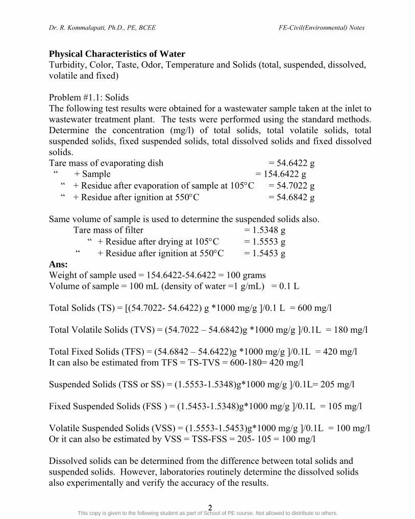
Physical Characteristics of Water Turbidity, Color, Taste, Odor, Temperature and Solids (total, suspended, dissolved, volatile and fixed) Problem #1.1: Solids The following test results were obtained for a wastewater sample taken at the inlet to wastewater treatment plant. The tests were performed using the standard methods. Determine the concentration (mg/l) of total solids, total volatile solids, total suspended solids, fixed suspended solids, total dissolved solids and fixed dissolved solids. Tare mass of evaporating dish = 54.6422 g “ + Sample = 154.6422 g “ + Residue after evaporation of sample at 105C = 54.7022 g “ + Residue after ignition at 550C = 54.6842 g Same volume of sample is used to determine the suspended solids also.
Tare mass of filter = 1.5348 g “ + Residue after drying at 105C = 1.5553 g
“ + Residue after ignition at 550C = 1.5453 g Ans: Weight of sample used = 154.6422-54.6422 = 100 grams Volume of sample = 100 mL (density of water =1 g/mL) = 0.1 L Total Solids (TS) = [(54.7022- 54.6422) g *1000 mg/g ]/0.1 L = 600 mg/l Total Volatile Solids (TVS) = (54.7022 – 54.6842)g *1000 mg/g ]/0.1L = 180 mg/l Total Fixed Solids (TFS) = (54.6842 – 54.6422)g *1000 mg/g ]/0.1L = 420 mg/l It can also be estimated from TFS = TS-TVS = 600-180= 420 mg/l Suspended Solids (TSS or SS) = (1.5553-1.5348)g*1000 mg/g ]/0.1L= 205 mg/l Fixed Suspended Solids (FSS ) = (1.5453-1.5348)g*1000 mg/g ]/0.1L = 105 mg/l Volatile Suspended Solids (VSS) = (1.5553-1.5453)g*1000 mg/g ]/0.1L = 100 mg/l Or it can also be estimated by VSS = TSS-FSS = 205- 105 = 100 mg/l Dissolved solids can be determined from the difference between total solids and suspended solids. However, laboratories routinely determine the dissolved solids also experimentally and verify the accuracy of the results.
ahmed youssef ([email protected])
This copy is given to the following student as part of School of PE course. Not allowed to distribute to others.

Dr. R. Kommalapati, Ph.D., PE, BCEE FE-Civil(Environmental) Notes
3 3
Chemical Characteristics of Water Major Ions present in the water Cations: Calcium, Magnesium, sodium, potassium Anions: Bicorabonate, sulfate, chloride Other ions present: Iron. Manganese, Fluoride, Aluminum, Phosphorous, nitrate, nitrites Acidity: Capacity to neutralize bases and is a measure of acids in water. Acidity is measured by titrating the sample using a standard base solution to raise to a pH of 8.3 Acidity (mg/l as CaCO3) = (Vtitrant, ml Ntitrant/Vsample, ml) 50 g/ eq *1,000 mg/g Alkalinity Ability of water to neutralize acids, caused mainly by bicarbonate, carbonate and hydroxyl ions. Alkalinity (eq/m3) = bicarbonate(eq/ m3) + carbonate (eq/ m3) + hydroxyl (eq/ m3) – hydrogen (eq/ m3) For all practical purposes the last two terms can be ignored for natural water samples. Even carbonate concentrations are very low in the natural pH range thus leaving mainly bicarbonate as the cause of alkalinity. Convert alkalinity from eq/m3 into mg/l as CaCO3 by multiplying with 50 (EW of CaCO3) Alkalinity is measured by titrating the sample with a standard acid to a pH of 4.5. However, this is done in two steps; First the pH is lowered to 8.3, then further lowered to 4.5 Alkalinity (mg/l as CaCO3) = (Vtitrant, ml Ntitrant/Vsample, ml) 50 g/ eq *1,000 mg/g If we use P to indicate the phenolphthalein alkalinity (to lower the pH to 8.3) and M the total alkalinity ( to lower the pH all the way to 4.5) then we can use the following relationships in sequence to determine the state of the sample. Hardness Caused by any polyvalent cations (mainly Calcium and Magnesium). Expressed as mg/l as CaCO3. Causes precipitates with soap (forms scum) and reduces the effectiveness of soap. Carbonate hardness (also known as temporary hardness) is the hardness associated with bicarbonate and carbonate ions (alkalinity) and the remaining hardness is termed non carbonate hardness (permanent hardness) and typically is associated
ahmed youssef ([email protected])
This copy is given to the following student as part of School of PE course. Not allowed to distribute to others.

Dr. R. Kommalapati, Ph.D., PE, BCEE FE-Civil(Environmental) Notes
4 4
with sulfate and chloride. Carbonate hardness can be removed by heating water. Hardness is removed by lime-soda softening process or ion exchange process (discussed later). Hardness is measured by titrating with EDTA (standard is chosen so that 1 ml titrant gives 1 mg/l as CaCO3 hardness) Hardness (mg/l as CaCO3) = (Vtitrant, ml CaCO3 equivalent of EDTA)/Vsample, ml) *1,000 mg/g Problem # 1.2: Water Quality A sample of water from Brazos River at Brenham was collected and analyzed for water quality characteristics and the data is presented in the table below(regular font). Estimate (i) total dissolved solids. (ii) alkalinity (iii) hardness (TH, CH and NCH) (Data is shown in Columns 1 and 2 other columns are part of solution)
Ion 1
Conc. g/m3 2
EW App 22C 3
Conc Eq/m3
(2/3)
Conc Eq/m3
(2/3) Ca+2 78 20 3.9 Mg+2 32 12.2 2.62 Na+ 78 23. 3.39 Fe+2 0.42 27.9 0.015 K+ 2.6 39.1 0.066 HCO3
- 292 61 4.79 SO4
-2 64 48 1.33 CO3
-2 6 30 0.2 Cl- 132 35.5 3.72 Sum→ 685.52 9.991 10.04
(i) Note that the sum of cations and anions should be roughly equal (in eq/m3) for a satisfactory analysis. Total dissolved solids (TDS) = sum of all the ions in column 2 = 685.52 g/m3
(ii) Alkalinity is caused by the presence of mainly CO3
-2 and HCO3- ions (For all
practical purposes the contribution of hydroxyl (OH-) and Hydrogen (H+ ) ions to alkalinity is negligible for natural waters) Alkalinity (eq/m3) = CO3
2- + HCO3- = 4.79 + 0.2 = 4.99 eq/m3
(also remember that 1 eq/m3 = 50 mg/l as CaCO3) (iii) Total Hardness, TH (add all the cations with a charge of 2 or more)
ahmed youssef ([email protected])
This copy is given to the following student as part of School of PE course. Not allowed to distribute to others.

Dr. R. Kommalapati, Ph.D., PE, BCEE FE-Civil(Environmental) Notes
5 5
TH = Ca+2 + Mg+2 + Fe+2 = 3.9 + 2.62 + 0.015 = 6.535 eq/m3 (or 327 mg/l as CaCO3)
If we only include the major ions (Ca+2 and Mg+2), TH = 6.52 (TH does not change significantly when we ignore other minor ions) Carbonate Hardness (CH) = bicarbonate + carbonate (However, CH can not be more than TH) = 4.79 +0.2 = 4.99 eq/m3 (250 mg/l as CaCO3) Non-Carbonate Hardness (NCH) = TH – CH = 6.52-4.99 = 1.53 eq/3 (To obtain values in mg/L as CaCO3 multiply eq/m3 with 50 or use the column with mg/L as CaCO3).
ahmed youssef ([email protected])
This copy is given to the following student as part of School of PE course. Not allowed to distribute to others.
Dr. R. Kommalapati, Ph.D., PE, BCEE FE-Civil(Environmental) Notes
6 6
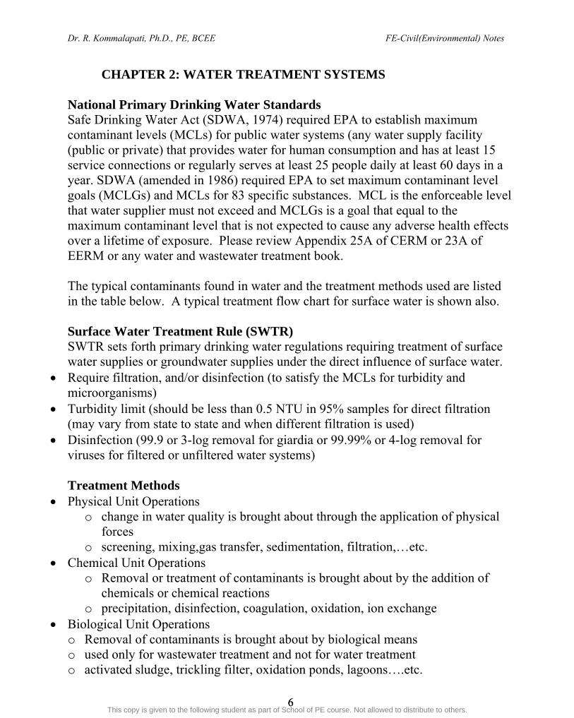
CHAPTER 2: WATER TREATMENT SYSTEMS National Primary Drinking Water Standards Safe Drinking Water Act (SDWA, 1974) required EPA to establish maximum contaminant levels (MCLs) for public water systems (any water supply facility (public or private) that provides water for human consumption and has at least 15 service connections or regularly serves at least 25 people daily at least 60 days in a year. SDWA (amended in 1986) required EPA to set maximum contaminant level goals (MCLGs) and MCLs for 83 specific substances. MCL is the enforceable level that water supplier must not exceed and MCLGs is a goal that equal to the maximum contaminant level that is not expected to cause any adverse health effects over a lifetime of exposure. Please review Appendix 25A of CERM or 23A of EERM or any water and wastewater treatment book. The typical contaminants found in water and the treatment methods used are listed in the table below. A typical treatment flow chart for surface water is shown also. Surface Water Treatment Rule (SWTR) SWTR sets forth primary drinking water regulations requiring treatment of surface water supplies or groundwater supplies under the direct influence of surface water.
Require filtration, and/or disinfection (to satisfy the MCLs for turbidity and microorganisms)
Turbidity limit (should be less than 0.5 NTU in 95% samples for direct filtration (may vary from state to state and when different filtration is used)
Disinfection (99.9 or 3-log removal for giardia or 99.99% or 4-log removal for viruses for filtered or unfiltered water systems) Treatment Methods
Physical Unit Operations o change in water quality is brought about through the application of physical
forces o screening, mixing,gas transfer, sedimentation, filtration,…etc.
Chemical Unit Operations o Removal or treatment of contaminants is brought about by the addition of
chemicals or chemical reactions o precipitation, disinfection, coagulation, oxidation, ion exchange
Biological Unit Operations o Removal of contaminants is brought about by biological means o used only for wastewater treatment and not for water treatment o activated sludge, trickling filter, oxidation ponds, lagoons….etc.
ahmed youssef ([email protected])
This copy is given to the following student as part of School of PE course. Not allowed to distribute to others.

Dr. R. Kommalapati, Ph.D., PE, BCEE FE-Civil(Environmental) Notes
7 7
These processes are usually combined in most treatment systems Design parameters Hydraulic detention time (days)
= volume (m3)/flow rate(m3 /d) Hydraulic surface loading rate or overflow rate (m3/d/m2)
= flow rate (m3/d) /surface area (m2) Mass surface loading rate (kg/day/ m2)
= mass of material applied (kg/d) / surface area (m2) Mass per volume loading rate (kg/day/ m3)
= mass of material applied (kg/d) / volume (m3) Mass per mass loading rate (kg/day/kg)
= mass of material applied (kg/d) /mass of material in system (kg)
ahmed youssef ([email protected])
This copy is given to the following student as part of School of PE course. Not allowed to distribute to others.

Dr. R. Kommalapati, Ph.D., PE, BCEE FE-Civil(Environmental) Notes
8 8
ahmed youssef ([email protected])
This copy is given to the following student as part of School of PE course. Not allowed to distribute to others.
Dr. R. Kommalapati, Ph.D., PE, BCEE FE-Civil(Environmental) Notes
9 9
ahmed youssef ([email protected])
This copy is given to the following student as part of School of PE course. Not allowed to distribute to others.
Dr. R. Kommalapati, Ph.D., PE, BCEE FE-Civil(Environmental) Notes
10 10
CHAPTER 3: COAGULATION
Surface waters must be treated to remove turbidity, color and bacteria The traditional sand filtration is not sufficient in removing bacteria, viruses, soil
particles and color Object of coagulation (and flocculation) is to turn the small particles of color,
turbidity, and bacteria into larger flocs either as precipitates or suspended particles which can then be removed
Typically coagulation is referred to a method to alter the colloids so that they will be able to approach each other and adhere to form larger floc Chemical Reactions
Consists of adding a floc forming chemical reagent to a water or wastewater to enmesh or combine with non-settleable colloidal solids and slow settling SS to produce a rapid settling floc (which is then removed by sedimentation)
Coagulation o the addition and rapid mixing of a coagulant, the resulting destabilization of
the colloidal and fine SS and the initial aggregation of the destabilized particles
Flocculation o the slow stirring or gentle agitation to aggregate the destabilized particles and
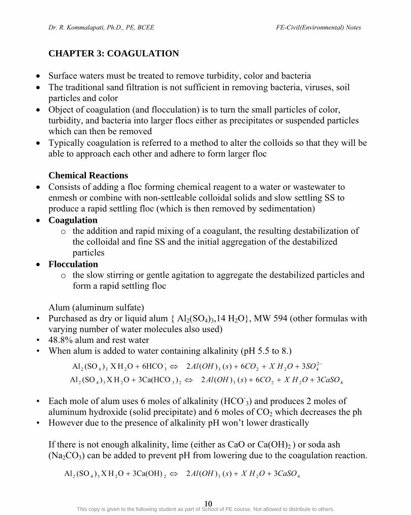
form a rapid settling floc Alum (aluminum sulfate)
• Purchased as dry or liquid alum { Al2(SO4)3,14 H2O}, MW 594 (other formulas with varying number of water molecules also used)
• 48.8% alum and rest water • When alum is added to water containing alkalinity (pH 5.5 to 8.)
• Each mole of alum uses 6 moles of alkalinity (HCO-3) and produces 2 moles of
aluminum hydroxide (solid precipitate) and 6 moles of CO2 which decreases the ph • However due to the presence of alkalinity pH won’t lower drastically
If there is not enough alkalinity, lime (either as CaO or Ca(OH)2 ) or soda ash (Na2CO3) can be added to prevent pH from lowering due to the coagulation reaction.
42322342 3)()(23Ca(OH)OHX)(SOAl CaSOOHXsOHAl
24223
-32342 36)()(26HCOOHX )(SOAl SOOHXCOsOHAl
4223232342 36)()(2)Ca(HCO3OHX)(SOAl CaSOOHXCOsOHAl
ahmed youssef ([email protected])
This copy is given to the following student as part of School of PE course. Not allowed to distribute to others.
Dr. R. Kommalapati, Ph.D., PE, BCEE FE-Civil(Environmental) Notes
11 11
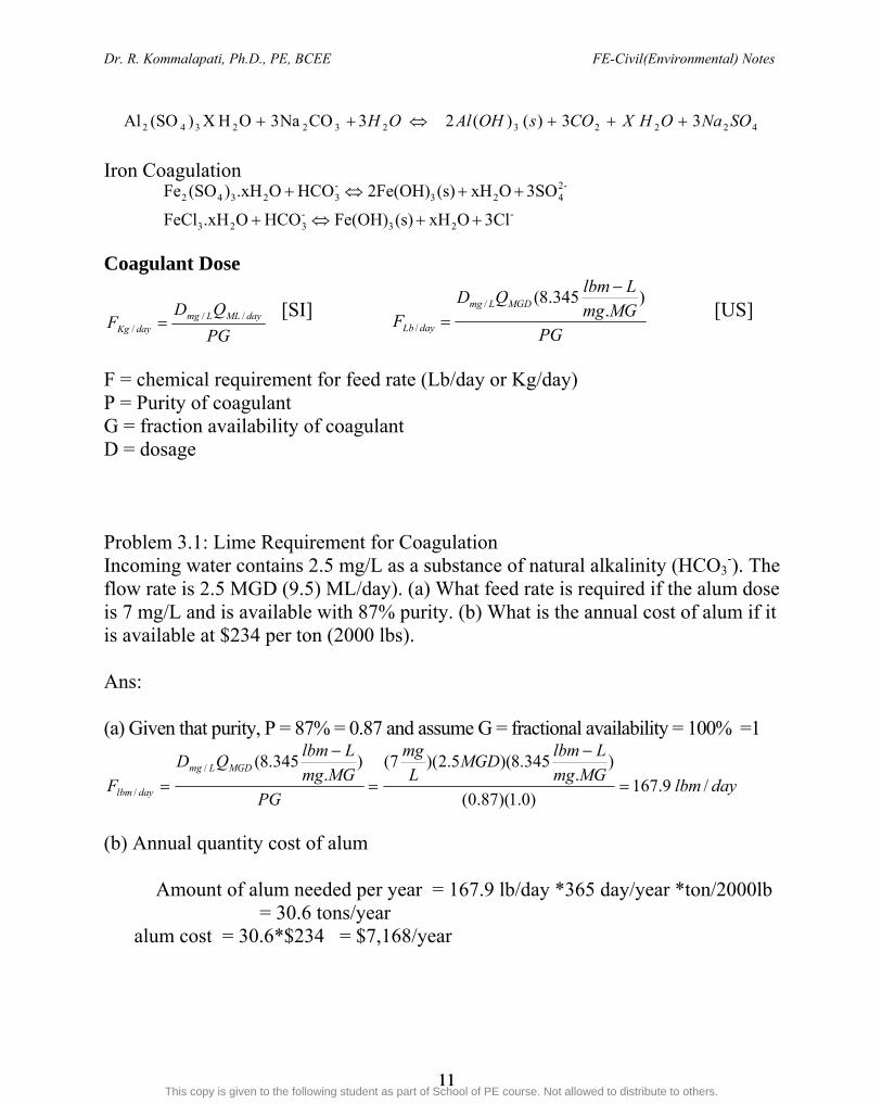
Iron Coagulation Coagulant Dose
[SI] [US]
F = chemical requirement for feed rate (Lb/day or Kg/day) P = Purity of coagulant G = fraction availability of coagulant D = dosage Problem 3.1: Lime Requirement for Coagulation Incoming water contains 2.5 mg/L as a substance of natural alkalinity (HCO3
-). The flow rate is 2.5 MGD (9.5) ML/day). (a) What feed rate is required if the alum dose is 7 mg/L and is available with 87% purity. (b) What is the annual cost of alum if it is available at $234 per ton (2000 lbs). Ans: (a) Given that purity, P = 87% = 0.87 and assume G = fractional availability = 100% =1
daylbmMGmg
LlbmMGD
L
mg
PG
MGmg
LlbmQD
FMGDLmg
daylbm /9.167)0.1)(87.0(
).
345.8)(5.2)(7().
345.8(/
/
(b) Annual quantity cost of alum Amount of alum needed per year = 167.9 lb/day *365 day/year *ton/2000lb = 30.6 tons/year alum cost = 30.6*$234 = $7,168/year
422232322342 33)()(23CONa3OHX)(SOAl SONaOHXCOsOHAlOH
-23
-323
-2423
-32342
3ClOxH(s)Fe(OH)HCO O.xHFeCl
3SOOxH(s)2Fe(OH)HCO O.xH)(SOFe
PGMGmg
LlbmQD
FMGDLmg
dayLb
).
345.8(/
/
PG
QDF dayMLLmg
dayKg//
/
ahmed youssef ([email protected])
This copy is given to the following student as part of School of PE course. Not allowed to distribute to others.

Dr. R. Kommalapati, Ph.D., PE, BCEE FE-Civil(Environmental) Notes
12 12
CHAPTER 4: RAPID MIXING TANK & FLOCCULATION BASIN
For the chemical reactions to occur, the chemicals must be mixed with water for both coagulation and softening we need mixing of chemical with water Mixing or rapid mixing is the process in which chemicals are quickly and uniformly
dispersed in water (instantaneously) for coagulation and softening processes precipitates form during the mixing the precipitates formed must be brought into contact with one another and colloids
so that they can agglomerate and form larger particles called flocs - this process is called flocculation and is accomplished by slow, gentle mixing (rapid mixing may break up the flocs)
Degree of mixing is measured by velocity gradient G (amount of shear taking place). Higher the G, the more violent the mixing Design Criteria Rapid Mix Volume = Flow rate (Q)*detention time Detention is in the oder of seconds 30-120 seconds Mixing basin is tyrpically a cube Flocculation
Most important factor effecting particle removal efficiency objective - to bring particles into contact so that they will collide, stick together and
grow to a size that will readily settle enough mixing to provide contact and prevent settling in the flocculation basin but
not too much to shear the floc particles making the floc small and dispersed Velocity gradient, G must be controlled in narrow range heavier the floc and SS Conc. the more mixing (high G) Softening floc is heavier and need more mixing (high G)
Detention time ≥ 30 minutes Flow through velocity = 0.5 to 1.5 fps Paddle area = 10 to 25% of tank c/s area G, mean velocity gradient = 5 to 100 /sec Gt (also Gt) = 30,000 – 150,000
ahmed youssef ([email protected])
This copy is given to the following student as part of School of PE course. Not allowed to distribute to others.

Dr. R. Kommalapati, Ph.D., PE, BCEE FE-Civil(Environmental) Notes
13 13
Power requirement
G = V
P or P = G2Vµ
P = power, N.m/s (lb-ft/sec), G = velocity gradient (s-1), µ = dynamic viscosity of water, N.s/m2 (lb-s/ft2) 1 horsepower (HP) = 550 lb-ft/sec 1 N-m/sec = 1 Joule/sec = 1W The Drag Force - Paddle Type P = CDAρv3/2
CD – coefficient of drag (usually 1.5-2) A – area of paddle ρ- density of water v – mixing velocity = relative tip speed = 0.75*Diameter* π*number of revolutions
ahmed youssef ([email protected])
This copy is given to the following student as part of School of PE course. Not allowed to distribute to others.

Dr. R. Kommalapati, Ph.D., PE, BCEE FE-Civil(Environmental) Notes
14 14
CHAPTER 5: SEDIMENTATION Sedimentation basin or clarifier is used to remove particles that will settle in a
reasonable time period Basins are usually rectangular or circular either a radial or upward water flow
pattern Four zones in a clarifier
o Inlet o Settling o Outlet o Sludge storage
Types of Sedimentation Type I
o Particles that settle discretely (settle as individual particles) o sand, grit o Pre-sedimentation for sand prior to coagulation
Type II o Particles that flocculate during sedimentation o Size constantly changing, thus settling velocity o Generally settling velocity increasing o Alum or Iron coagulation, in primary sedimentation
Type III or zone sedimentation o Particles or at high conc. (>1000 mg/l) o Particle settle as a mass and a distinct clear zone and sludge zone are
present o Lime softening sedimentation, activated sludge sedimentation and sludge
thickeners Design Criteria Surface Loading rate (flow rate/surface area, gpd/ft2 )= 600-1000 for Rectangular basins and 500-750 for Circular basins Detention time (Volume /Flow rate) = 2 to 6 hours Weir loading ( flow rate/length of weir) = 15,000 -20,000 gpd/ft Free Board = 1- 2ft, Depth = 8-18 ft Width 30-50 ft and length 100-200 ft with a L:W of 4:1 for rectangular basins and 50-100 ft diameter for circular tanks
ahmed youssef ([email protected])
This copy is given to the following student as part of School of PE course. Not allowed to distribute to others.

Dr. R. Kommalapati, Ph.D., PE, BCEE FE-Civil(Environmental) Notes
15 15
Problem 5.1: Sedimentation Tank Design A treatment plant upgrade calls for design of sedimentation basins to handle a flow rate of 8 MGD. The basins are for a Type I suspension with an overflow rate (q0) of 650 gpd/ft2 a length to width ratio of 4:1, a weir overflow rate (qw) of 20,000 gpd/ft, and a maximum settling zone length of 140 ft. The minimum settling zone depth is 8 ft and 1.5 ft is allowed for freeboard.
(a) If 3 tanks are chosen, what are the surface dimensions of each tank? (b) What is the required weir length for each tank?
Ans: (a) As = settling zone surface area, ft2 Q = flow rate = 8,000,000 gal/d
q0 = overflow rate =650 gpd/ft2
Surface area of settling tank o
s q
QA =
650
108 6x = 12307 ft2
As = L w and Given L = 4 w Since 3 tanks are used, As per tank = 12307 / 3 = 4102 ft2 = LW= (4W)W = 4W2 W = 3 2f t L = 4W = 128 ft Thus, L = 128 ft and w = 32 ft
(b) Overflow weir length w
w qk
Q
L tan
Lw = overflow weir length (ft) qw = weir overflow rate (gpd//ft) Q/tank = flow rate per tank (gpd) = 8MGD/3 = 2.67 MGD
ww q
k
Q
L tan = ftgpd
gpdx
/20000
1067.2 6
= 133.4 ft
ahmed youssef ([email protected])
This copy is given to the following student as part of School of PE course. Not allowed to distribute to others.

Dr. R. Kommalapati, Ph.D., PE, BCEE FE-Civil(Environmental) Notes
16 16
CHAPTER 6: FILTRATION Design Criteria Filtration rate = 2 gpm/ft2 for sand filters and 4 gpm/ft2 for dual media filters Minimum Number = 4 for Q > 100 gpm and 2 for Q< 100 gpm Filter design based on one unit backwashing L:W ratio is1.3 and max size of filter is 2100 ft2 Filter depth should be 8-10 ft. Backwash rate = 12-36 inches per min rise rate (10-20 gpm/ft2) Through-put = 350-3500 gpm Problem 6.1: Filter Unit Design a 10 unit rapid sand filter system for a flow of 6.3 MGD and estimate the backwash water required if the wash time is 10 minutes and the rise rate is 24 in/min. Design flow (Q) = 6.3 MGD = 6.3x10⁶ gpd = 4375 gpm Assume filtration rate of 2 gpm/ft2 Total filter area required = 4375 gpm/2 gpm/ft2 = 2187.5 ft2
Total of 10 filter units (but design is based on 9 filters being in operation and 1 in backwashing). In a problem you will be trying to match this with the answer Area required per each filter unit = 2187.5/9 = 243 ft 2 L:W ratio is 1.3 so LW = 1.3WxW = 1.3W2 = 243 --- this gives W = 13.7 ft and L = 17.8 ft. Backwash Water Volume of backwash water required per filter
= time of wash * filter area* rise of backwash water = 10 min * 243 ft2 * 24 inches/min*ft/12 inches = 4860 ft3 *7.48 gal/ft3 = 36,353 gal Total backwash water volume (assuming one back wash per day for each filter) = 36,353*10 filters = 363, 530 gallons
ahmed youssef ([email protected])
This copy is given to the following student as part of School of PE course. Not allowed to distribute to others.
Dr. R. Kommalapati, Ph.D., PE, BCEE FE-Civil(Environmental) Notes
17 17
CHAPTER 7: WATER SOFTENING Hardness Hardness is used to characterize a water that does not lather well, causes a scum
in the bath tub and leaves hard, white,crusty deposits when water is heated calcium or magnesium forms soap- Ca or Mg complex and prevents soap from
interacting with dirt Hardness- caused mainly by Calcium and Magnesium(actually all polyvalent
ions) Common units are meq/l or mg/l as CaCO3 Carbonate hardness (CH)
o Ca+2, Mg+2 combining with alkalinity (OH-, CO3-2, HCO3
-). If alkalinity is present in water the CH will be equal to alkalinity but can not exceed total hardness.
o temporary hardness (removed by heating the water) Non-carbonate hardness (NCH)
o Permanent Hardness , not removed by heating water o Ca+2, Mg+2 combining with ions outside of alkalinity such as Cl-1, NO3
-1, SO4
2- o NCH = TH-CH (if alkalinity is equal to or greater than TH, then NCH is
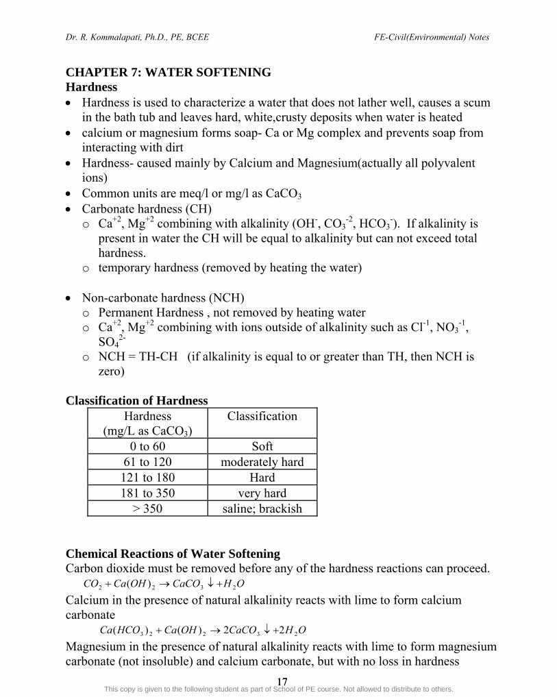
zero) Classification of Hardness
Hardness (mg/L as CaCO3)
Classification
0 to 60 Soft 61 to 120 moderately hard 121 to 180 Hard 181 to 350 very hard
> 350 saline; brackish Chemical Reactions of Water Softening Carbon dioxide must be removed before any of the hardness reactions can proceed.
OHCaCOOHCaCO 2322 )( Calcium in the presence of natural alkalinity reacts with lime to form calcium carbonate OHCaCOOHCaHCOCa 23223 22)()( Magnesium in the presence of natural alkalinity reacts with lime to form magnesium carbonate (not insoluble) and calcium carbonate, but with no loss in hardness
ahmed youssef ([email protected])
This copy is given to the following student as part of School of PE course. Not allowed to distribute to others.
Dr. R. Kommalapati, Ph.D., PE, BCEE FE-Civil(Environmental) Notes
18 18
OHCaCOMgCOOHCaHCOMg 233223 2)()( To remove magnesium carbonate above, additional lime must be added 2323 )()( OHMgCaCOOHCaMgCO Calcium non carbonate hardness requires lime and soda ash 423324 SONaCaCOCONaCaSO Magnesium non carbonate hardness requires lime and soda ash 2424 )()( OHMgCaSOOHCaMgSO 423324 SONaCaCOCONaCaSO Some Points
Hardness removal using lime and soda is based on the solubility reactions of calcium carbonate, CaCO3 and magnesium hydroxide, Mg(OH)2
Precipitate Ca+2 as CaCO3 and Mg+2 as Mg(OH)2 pH must be raised to 10.3 for Ca+2 removal and to about 11 for Mg+2 removal Remove Ca-CH, Mg-CH and Ca-NCH and Mg-NCH in that order because the cost
of removal increases in the same order Leave as much Mg hardness as possible and as much NCH as possible, but Mg
Conc. of above 40 mg/l as CaCO3 causes problems It is a common practice to use a minimum of 20 mg/l as CaCO3 of excess lime to
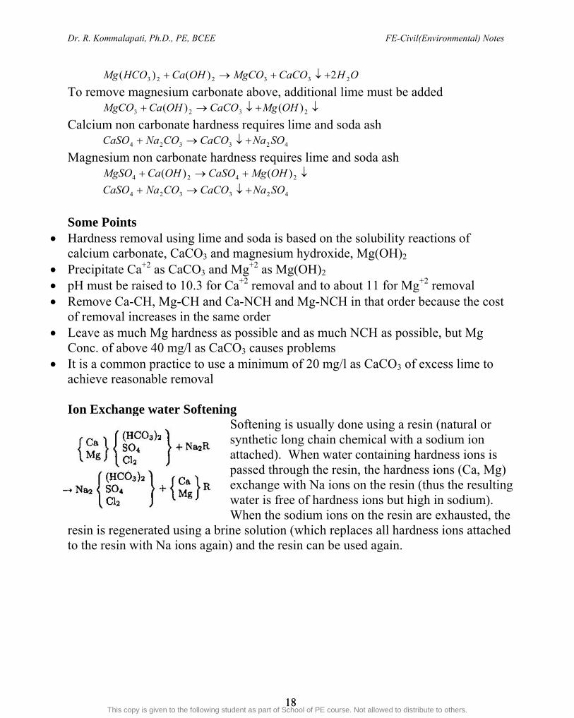
achieve reasonable removal Ion Exchange water Softening
Softening is usually done using a resin (natural or synthetic long chain chemical with a sodium ion attached). When water containing hardness ions is passed through the resin, the hardness ions (Ca, Mg) exchange with Na ions on the resin (thus the resulting water is free of hardness ions but high in sodium). When the sodium ions on the resin are exhausted, the
resin is regenerated using a brine solution (which replaces all hardness ions attached to the resin with Na ions again) and the resin can be used again.
ahmed youssef ([email protected])
This copy is given to the following student as part of School of PE course. Not allowed to distribute to others.

Dr. R. Kommalapati, Ph.D., PE, BCEE FE-Civil(Environmental) Notes
19 19
CHAPTER 8: CHLORINATION Chemical Reaction of Chlorination
(1) Breakpoint Chlorination
(2) Chemical Reactions
HOCL + NH3 → H2O + NH2Cl (monochloramine) HOCL + NH2 Cl→ H2O + NHCl2 (dichloramine) HOCL + NHCl2 → H2O + NCl3 (trichloramine)
(3) Chlorine Residuals Free Chlorine Residuals : Cl2, HOCl, OCl-
Combined Chlorine Residuals : Chloramines (mono, di and tri chloramines) The disinfecting ability of chloramines is much lower than that of free chlorine. Satisfactory results can be obtained if a free chlorine residual of 0.2 to 0.5 mg/L can be maintained in the distribution system. Also if approved by health authorities combined chlorine residuals in the range of 1 to 2 mg/L should maintained at distant points in the distribution system. Trihalomethanes (the following) which are formed as a result of chlorination are harmful and this must be avoided. CHCl3 trichloromethane (chloroform) CHBrCl2 bromodichloromethane CHBr2Cl dibromochloromethane CHBr3 tribromomethane (bromoform)
-9pH
9pH4pH
4pH22 OCl H HOCl HCl OH Cl
ahmed youssef ([email protected])
This copy is given to the following student as part of School of PE course. Not allowed to distribute to others.

Dr. R. Kommalapati, Ph.D., PE, BCEE FE-Civil(Environmental) Notes
20 20
(4) CT Concept Microorganism kill by disinfectants is assumed to follow the CT concept (product of conc.*contact time) and is used in surface water treatment rule (SWTR) EPA developed tables of required CT values for free chlorine under SWTR. The two classes of organisms considered in disinfection are Giardia and viruses. Design criteria from SWTR states that a 4 log removal of viruses and 3 log removal of Giardia is required. Typical removals obtained with various water treatment methods and additional removals required are listed below. Please see practice problem on this topic in the last section. Log removal (LR) = log (influent conc./effluent conc.) % removal = 100 – 100/10LR
Log Removal/inactivation requirements based on treatment technique
ahmed youssef ([email protected])
This copy is given to the following student as part of School of PE course. Not allowed to distribute to others.
Dr. R. Kommalapati, Ph.D., PE, BCEE FE-Civil(Environmental) Notes
21 21
PART II WASTEWATER CHAPTER 1: OVERVIEW The wastewater treatment processes that we design mimic the processes that occur in the nature (for example processes that occur in a flowing river). The designed processes increase the rate of removal and control the process variables so that the effluent standards can be met. Just like the water solids we need to deal with wastewater solids also. The wastewater solids are classified into inorganic or fixed solids and organic or volatile solids. The inorganic or fixed solids are removed through the screening and sedimentation during the primary sedimentation and the organic or volatile solids are stabilized through biochemical oxidation (activated sludge/trickling filter/other) and removed through sedimentation or clarification (secondary). The solids removed are further treated by a process called sludge digestion (which is mostly anaerobic (containing no oxygen)). Please refer to following Figure and Table for various treatment units included in the typical wastewater treatment. Pre-Treatment: to provide protection to the wastewater treatment equipment that follows. Removes mainly larger and inorganic solids (Equalizing basin optional) Primary Treatment: to remove the pollutants that float or settle. Typically 60% of suspended solids and 35% of BOD5 are removed. At one time this was the only treatment used by many cities. Now federal law requires the municipalities to provide secondary treatment. Secondary Treatment: to remove soluble BOD that escapes the primary treatment and to provide added removal of suspended solids. Biological processes (activated sludge (aeration) or trickling filter are the most common one chosen at larger plants). Typically same treatment is provided in the receiving waters but these treatment processes speed up the breakdown of degradable organic pollutants. Typically more than 85% of BOD and suspended solids are removed. However, it does not remove significant amounts of nitrogen, phosphorous or heavy metals or pathogenic bacteria and viruses. Typical Standards: 20 mg/l BOD5, 20 mg/l suspended solids (for discharges to rivers flowing south and flows into Gulf of Mexico). Tertiary Treatment: in cases where secondary treatment is not adequate (particularly if the discharges are into a sensitive water bodies), then additional treatment (biological and/or chemical treatment followed by filtration) known as tertiary treatment may be used. Typical Standards: 10 mg/l BOD5, 10 mg/l suspended solids, 1 mg/l Phosphorous (for effluent discharges into great lakes)
ahmed youssef ([email protected])
This copy is given to the following student as part of School of PE course. Not allowed to distribute to others.

Dr. R. Kommalapati, Ph.D., PE, BCEE FE-Civil(Environmental) Notes
22 22
Figure 1: Typical Wastewater Treatment Plant Units
ahmed youssef ([email protected])
This copy is given to the following student as part of School of PE course. Not allowed to distribute to others.

Dr. R. Kommalapati, Ph.D., PE, BCEE FE-Civil(Environmental) Notes
23 23
Table 1: Various Wastewater Pollutants and the Corresponding Treatment Options along with their Classification
ahmed youssef ([email protected])
This copy is given to the following student as part of School of PE course. Not allowed to distribute to others.

Dr. R. Kommalapati, Ph.D., PE, BCEE FE-Civil(Environmental) Notes
24 24
Ten States’ Standards (TSS) specifies that new sanitary sewers should be designed for an average flow of 100 gallons per capita per day (gpcd) or 380 Lpcd). Refer to Appendix 29A of CERM or Appendix 26A of EERM for Ten States Standards) Hydraulic loading: treatment plants serving populations of 10,000 or more or handling more than 1 MGD are referred to as majors (more than 75% of US treatment plants). Organic loading of a treatment unit is expressed in terms of pounds (kg) of BOD per day or pounds (or kg) of solids per day. Typical values for communities that use garbage disposals are 0.24 lbm (110g) of suspended solids and 0.17 to 0.2 lbm (77 to 90 g) of BOD per person per day. The average BOD of domestic wastewater is 0.2 lbm (90 g) per capita per day. Population Equivalent (Pequivalent, 1000s) = BOD (mg/l) *Q (ML/day)/90 g pcd) - SI Population Equivalent (Pequivalent, 1000s) (US units)= [BOD (mg/l) *Q (Million gallons /day)*8.345 lbm-L/MG-mg) ]/ [1000 persons* 0.2 lbm pcd] 1 gallon wastewater = 8.345 pounds 1 Cubic ft wastewater = 62.4 pounds Lb (of solids or other pollutants)/day = Million Gallons/day * mg/l * 8.345 Table 28.4 in the PE CERM or Table 25.4 in EERM for Typical Wastewater Characteristics Total Suspended Solids = 100 – 350 mg/L (200 mg/l is the typical value) BOD5 = 100-300 mg/L (200 mg/L is the typical value) 33% of the total solids (ST) are suspended (60% of these suspended solids are settleable and 40% are colloidal) and 67% are dissolved. Total Solids (ST) = Fixed or Inorganic Solids (SF or SI) + Organic or Volatile Solids (SV or SO) The solids removed during primary and secondary treatment are referred to as sludge (high solids concentration). Refer to Sludge chapter in the following pages.
ahmed youssef ([email protected])
This copy is given to the following student as part of School of PE course. Not allowed to distribute to others.

Dr. R. Kommalapati, Ph.D., PE, BCEE FE-Civil(Environmental) Notes
25 25
Problem 1.1: Wastewater Flows Solve the following problems related to Wastewater flow and densities (a) The volume of 896, 000 lb of wastewater is ? (b) The weight of 13,000 ft3 of wastewater is? (c) A flow of 6,000 gallons per second is how many MGD? (d) A flow of 1,000 ft3/min is equal to how many MGD? Ans
(a) The volume of 896, 000 lb of wastewater is ? 896,000 lbs/ 8.345 lbs/gal = 107,370 gallons
(b) The weight of 13,000 ft3 of wastewater is ? 13,000 ft3 * 62.4 lbs/ft3 = 811200 lbs
(c) A flow of 6,000 gallons per second is how many MGD?
MGDgal
MG
day
hours
hour
gal4.518
000,000,1*
24*
min60*
min
sec60*
sec
6000
(d) A flow of 1,000 ft3/min is equal to how many MGD?
MGDMG
ft
gal
day
hours
hour
ft77.10
000,000,1*
48.7*
24*
min60*
min
10003
3
ahmed youssef ([email protected])
This copy is given to the following student as part of School of PE course. Not allowed to distribute to others.
Dr. R. Kommalapati, Ph.D., PE, BCEE FE-Civil(Environmental) Notes
26 26
CHAPTER 2: BIOCHEMICAL OXYGEN DEMAND BOD Test without seed
BOD5 =
Dilutionsample
sample
fi
VV
V
DODO
Eq 25.28 of EERM or 28.28 of CERM
BOD Test with Seed (seeded BOD)
BOD5 =
Dilutionsample
sample
fifi
VV
V
BBxDODO
)( Eq 25.32 of EERM or 28.32 of CERM
Where x is the ratio of seed in the sample bottle to that in the blank
)1( ktut eBODBOD (most commonly used expression)
)101( )tKut
dBODBOD (Eq 25.29 of EERM or 28.29 of CERM -usually will say explicitly)
Where k = 2.303Kd Temperature correction kT = k20 θ
T-20 or KT = K20 θT-20
θ = 1.135 for temps 4-20°C and θ = 1.056 for temps 20-30°C (or default value suggested is 1.047) The approximate variation of BOD (first stage) with temperature is given by BOD T°C = BOD 20°C (0.02 T°C + 0.6) (Eq 25.31 of EERM 28.31 of CERM)
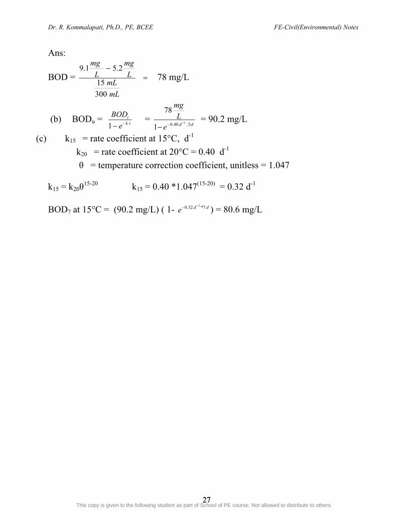
Problem 2.1: BOD Wastewater samples were prepared and incubated at C20 for 5 d for BOD analysis. Sample dilutions and initial and final dissolved oxygen concentrations are summarized in the following table.
Bottle Sample Volume
Initial DO mg/L
Final DO mg/L
1 15 9.1 5.2 The temperature correction coefficient is 1.047 and the reaction rate coefficient at 20°C is 0.40 d-1. (a). What is the BOD5 at 20°C? (b). What is the BODu? (c). What is the BOD 7 at 15°C?
ahmed youssef ([email protected])
This copy is given to the following student as part of School of PE course. Not allowed to distribute to others.
Dr. R. Kommalapati, Ph.D., PE, BCEE FE-Civil(Environmental) Notes
27 27
Ans:
BOD =
mL
mLL
mg
L
mg
300
15
2.51.978 mg/L
(b) BODu = tk
t
e
BOD1
= dde
L
mg
5.40.0 1
1
78
= 90.2 mg/L
(c) k15 = rate coefficient at 15°C, d-1
k20 = rate coefficient at 20°C = 0.40 d-1
θ = temperature correction coefficient, unitless = 1.047
k15 = k20θ15-20 k15 = 0.40 *1.047(15-20) = 0.32 d-1
BOD7 at 15°C = (90.2 mg/L) ( 1- dde 7*32.0 1 ) = 80.6 mg/L
ahmed youssef ([email protected])
This copy is given to the following student as part of School of PE course. Not allowed to distribute to others.

Dr. R. Kommalapati, Ph.D., PE, BCEE FE-Civil(Environmental) Notes
28 28
CHAPTER 3: PRIMRY AND SECONDARY CLARIFIER In a grit chamber, the wastewater is slowed, allowing the grit to settle out but let the lighter organic solids flow through. Horizontal flow grit chambers are designed to have flow velocity of 1 ft/sec (0.3 m/sec). Typical detention time is 2 -5 min at peak flow with 3 min being the most common value used (see Table 26.9 of EERM and 29.9 of CERM). Primary settling follows the bar screens and grit chamber and is designed to remove wastewater inorganic solids (though some organic solids are also removed). Secondary sedimentation tanks or clarifiers are designed to remove the stabilized organic (biomass) solids from the wastewater (typically the wastewater enters the secondary clarifier from an activated sludge or trickling filter or other biological process) Primary clarifiers are designed based on detention time (1.5 -2.5 hrs, 2 hrs typical), overflow rate ( 800-1200 gal/ft2-d (1000 typical) for average flow and 2000 -3000 gal/ft2-d (2500 typical) for peak flow) and weir loading rate (10,000-40,000 gal/ft-d, 20,000 typical). For more details see Table 26.10 Appendix 26A of EERM or 29.10 and Appendix 29A of CERM). Secondary clarifiers are also designed based on detention time (1.5 -2 hrs, 2 hrs typical), overflow rate (600- 800 gal/ft2-d (700 typical) for average flow and 1,000 -1,800 gal/ft2-d (1500 typical) for peak flow) and weir loading rate ( 10,000-40,000, gal/ft-d (20,000 typical). Overflow rate (OFR) or Hydraulic loading rate = Flow rate/ Area = ft3/hr-ft2 Hydraulic Detention Time (DT) = Volume/Flow rate = gal/gal/hr = ft3/ft3/hr = hr
Weir Loading (WL) = Flow Rate/Circumference or length of weir = gallons/hr/ft Solids Loading (SL) = Mass of solids per unit time/Surface Area = lb/day-ft2 Approach Velocity = Flow rate/ cross sectional area = gal/day-ft2
ahmed youssef ([email protected])
This copy is given to the following student as part of School of PE course. Not allowed to distribute to others.
Dr. R. Kommalapati, Ph.D., PE, BCEE FE-Civil(Environmental) Notes
29 29
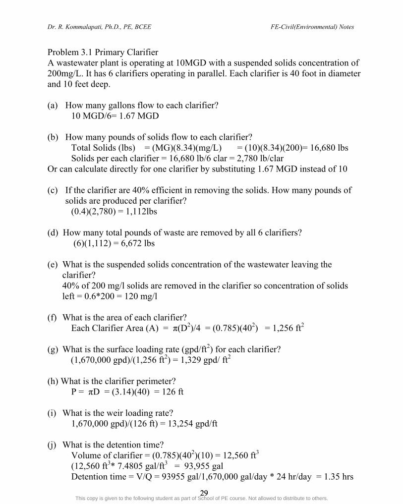
Problem 3.1 Primary Clarifier A wastewater plant is operating at 10MGD with a suspended solids concentration of 200mg/L. It has 6 clarifiers operating in parallel. Each clarifier is 40 foot in diameter and 10 feet deep. (a) How many gallons flow to each clarifier? 10 MGD/6= 1.67 MGD (b) How many pounds of solids flow to each clarifier? Total Solids (lbs) = (MG)(8.34)(mg/L) = (10)(8.34)(200)= 16,680 lbs
Solids per each clarifier = 16,680 lb/6 clar = 2,780 lb/clar Or can calculate directly for one clarifier by substituting 1.67 MGD instead of 10 (c) If the clarifier are 40% efficient in removing the solids. How many pounds of
solids are produced per clarifier? (0.4)(2,780) = 1,112lbs
(d) How many total pounds of waste are removed by all 6 clarifiers?
(6)(1,112) = 6,672 lbs (e) What is the suspended solids concentration of the wastewater leaving the
clarifier? 40% of 200 mg/l solids are removed in the clarifier so concentration of solids left = 0.6*200 = 120 mg/l
(f) What is the area of each clarifier?
Each Clarifier Area (A) = π(D2)/4 = (0.785)(402) = 1,256 ft2
(g) What is the surface loading rate (gpd/ft2) for each clarifier? (1,670,000 gpd)/(1,256 ft2) = 1,329 gpd/ ft2
(h) What is the clarifier perimeter?
P = πD = (3.14)(40) = 126 ft (i) What is the weir loading rate?
1,670,000 gpd)/(126 ft) = 13,254 gpd/ft (j) What is the detention time?
Volume of clarifier = (0.785)(402)(10) = 12,560 ft3 (12,560 ft3* 7.4805 gal/ft3 = 93,955 gal
Detention time = V/Q = 93955 gal/1,670,000 gal/day * 24 hr/day = 1.35 hrs
ahmed youssef ([email protected])
This copy is given to the following student as part of School of PE course. Not allowed to distribute to others.

Dr. R. Kommalapati, Ph.D., PE, BCEE FE-Civil(Environmental) Notes
30 30
CHAPTER 4: ACTIVITATED SLUDGE (AERATION TANK) The activated sludge treatment process is a biochemical oxidation process. Organic solids are stabilized through the oxidation process in the activated sludge basin. This basin is also referred as aeration tank and the process is known as suspended growth process. The incoming waste to the activated sludge basin is composed of inorganic and organic solids. The organic portion of the incoming waste is responsible for the BOD and it represents the Food (F) for the microorganisms in the activated sludge basin. The solids in the activated sludge basin are called mixed liquor suspended solids (MLSS). These solids are composed of an organic (MLVSS) and an inorganic part (MLFSS). The MLVSS is often considered to represent the microorganisms in the activated sludge basin. Refer to Table 27.1 of EERM or 30.1 of CERM for the characteristics. The stabilized organic solids are removed in the secondary sedimentation basin. Most of stabilized solids are returned or recycled to the activated sludge basin. Part of the stabilized solids are wasted each day. The wastewater from the aeration tank then flows over the secondary sedimentation basin (where the solids have been removed) and to the disinfection basin and then discharged to the receiving stream. There are several equations that must be mastered in the design of the activated sludge process using the BOD equations. The equation number used here is matched with that in CERM for easy reference the same equations in EERM are with a prefix of 27 as opposed to 30. These Equations must be mastered to design an activated sludge process. Food (F) to Microorganism (M) (F/M) ratio : F = OOQS 30.1 So is incoming BOD5 (usually), Qo is the incoming flow rate M = XVa 30.2 Va is volume of the aeration tank and X is concentration of microorganisms in the aeration tank
(a) F/M ratio (based on VSS)
ahmed youssef ([email protected])
This copy is given to the following student as part of School of PE course. Not allowed to distribute to others.
Dr. R. Kommalapati, Ph.D., PE, BCEE FE-Civil(Environmental) Notes
31 31
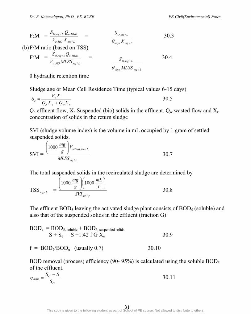
F:M = LmgMGa
MGDoLmgO
XV
QS
/,
,/, = 30.3
(b) F/M ratio (based on TSS)
F:M = LmgMGa
MGDoLmgO
MLSSV
QS
/,
,/, = 30.4
θ hydraulic retention time Sludge age or Mean Cell Residence Time (typical values 6-15 days)
rwee
ac XQXQ
XV
30.5
Qe effluent flow, Xe Suspended (bio) solids in the effluent, Qw wasted flow and Xr
concentration of solids in the return sludge SVI (sludge volume index) is the volume in mL occupied by 1 gram of settled suspended solids.
SVI = Lmg
LmLsettled
MLSS
Vg
mg
/
/,1000
30.7
The total suspended solids in the recirculated sludge are determined by
TSS Lmg / = gmLSVI
L
mL
g
mg
/
10001000
30.8
The effluent BOD5 leaving the activated sludge plant consists of BOD5 (soluble) and also that of the suspended solids in the effluent (fraction G) BODe = BOD5, soluble + BOD5, suspended solids
= S + Se = S +1.42 f G Xe 30.9
f = BOD5/BODu (usually 0.7) 30.10 BOD removal (process) efficiency (90- 95%) is calculated using the soluble BOD5 of the effluent.
O
OBOD S
SS 30.11
Lmgdays
LmgO
X
S
/
/,
Lmgdays
LmgO
MLSS
S
/
/,
ahmed youssef ([email protected])
This copy is given to the following student as part of School of PE course. Not allowed to distribute to others.

Dr. R. Kommalapati, Ph.D., PE, BCEE FE-Civil(Environmental) Notes
32 32
Though there are plug flow reactor (PFR) and continuous flow stirred tank reactors (CSTR or CFSTR) reactor models that could be used in the design. The CSTR model is more commonly used. Only formulas for CSTR are discussed below.
Specific Substrate utilization, U is the F:M ratio multiplied fractional process efficiency.
X
SS
XMFU o
):( 30.16
The relationship between MCRT or sludge age and F:M ratio and U is given by
ddc
kYUkMFY
):(1 30.17
Y is yield coefficient and kd is endogenous decay coefficient Based on the growth kinetics and mass balance, the effluent substrate concentration (soluble BODs) and the reactor volume (for a CSTR only) are given by
1)(
)1(
dmc
cds
k
kKS
30.18
)1(
))(
cd
oocoa kX
SSYQQV
30.19
Qo, So
Aeration Tank Va, X
Wastage Qw, X
Settling Tank Vs
Q-Qw, S, Xe
Qr, S, Xr
Wastage can be done either from here or above (at dotted line)
Typical Layout of Activated Sludge Unit
Qw, Xr
ahmed youssef ([email protected])
This copy is given to the following student as part of School of PE course. Not allowed to distribute to others.

Dr. R. Kommalapati, Ph.D., PE, BCEE FE-Civil(Environmental) Notes
33 33
Hydraulic retention time when (i) only the aeration tank is considered and (ii) the system (i.e. the aeration tank and the secondary clarifier are considered together are given by
o
a
Q
V (aeration tank only) 30.20
o
sa
Q
VV (aeration tank and the secondary clarifier are considered) 30.21
The average concentration of microorganisms, X in the aeration tank is
)1(
))(
cd
oc
k
SSYX
30.22
The observed yield is )1( cd
obs k
YY
30.23
A portion of the biomass produced (activated sludge) must be wasted each day
)/1000
))(
/1000
/,/,/,
3
kgg
SSQY
kgg
XQP ooobsLmgrdaymw
daykgx
30.24
Cell wastage rate (Qw) and the solids concentration in the return sludge line are used in calculating the mean cell residence time (θc) as given in eq 30.5 However, mass of cells in the effluent are so small compared to those in the waste line that they are sometimes ignored and Eq 30.5 is modified to
rw
ac XQ
XV 30.27
In some cases wastage is done directly from the aeration tank (Xr =X), then
w
ac Q
V 30.28
Return rate or Recycle Ratio (R, typical 0.2 to 0.3) R = Qr/Qo 30.41
X
X
Q r
ro
r
30.43
LmL
V
Q LmLsettled
ro
r
/1000/,
30.44
LmLsettled
LmLsettled
VLmL
VR
/,
/,
/1000 30.45
ahmed youssef ([email protected])
This copy is given to the following student as part of School of PE course. Not allowed to distribute to others.

Dr. R. Kommalapati, Ph.D., PE, BCEE FE-Civil(Environmental) Notes
34 34
Problem 4.1: Aeration Tank Design For a community of 100,000, determine the size and number of aeration basins in a municipal activated sludge treatment facility. The wastewater characteristics are: Average per-capita flow rate = 100gal/capita-day Peak factor = 2.2 Wastewater concentration BOD5 = 220mg/L SS = 220 mg/L Ans: Average flow rate = (100 gal/capita-day)(100.000pop)(106gal/Mgal)=10 Mgal/day The size of the aeration basin may be determined based on a typical value for hydraulic residence time of 6 hr for a conventional activated sludge process.
Volume = 33
6
200,334)/48.7)(/24(
)6)(/10)(/10(ft
ftgaldayhr
hrMgalgaldayMgal
Four parallel basins are recommended with dimensions of 15 ft (water depth), 30 ft (width), and 185 ft (length). An increased basin depth of several feet is recommended for freeboard. Problem 4.2: Food to Microorganism Ratio An activated sludge plant operates with a mean cell residence time of 10d to treat a flow of 18,925 m3/d with an influent biochemical oxygen demand (BOD) of 247 mg/L. The plant wastes sludge at 34 kg/d. What is most nearly the food-to-microorganism ratio for the plant? Ans: The wasted sludge mass is QwXu = 34 kg/d (Qw wasted solid flow rate, m3/d and Xu wasted solids concentration, mg/L)
θc mean cell residence time = uw XQ
VX
(V -reactor volume, m3 and X is biomass concentration in reactor, mg/L) The bioreactor sludge mass VX = θc (QwXu) = (10d) (34 kg/d) = 340 kg Q influent wastewater flow rate, m3/d and So is influent wastewater BOD, mg/L
1
63
3
7.13340
)10)(1000)(247)(18925(
dkg
mg
kg
m
L
L
mg
d
m
VX
QS
M
F o
ahmed youssef ([email protected])
This copy is given to the following student as part of School of PE course. Not allowed to distribute to others.

Dr. R. Kommalapati, Ph.D., PE, BCEE FE-Civil(Environmental) Notes
35 35
Problem 4.3: Sludge Volume Index (SVI) Two 1 L samples of mixed liquor are taken from a lagoon. After settling for 30 min in a graduated cylinder, 250 mL of solids have settled out in the first sample. The total suspended solids concentration in the second sample is found to be 2300 mg/L. (a) What is the sludge volume index? (b) What is the theoretical required sludge recycle rate? Ans:
(a) From eq 30.7, SVI = Lmg
LmLsettled
X
V
/
/,1000
= gmLLmg
Lmlgmg/109
/2300
)/250)(/1000(
(b) From Eq 30.45, R = LmLsettled
LmLsettled
V
V
/,
/,
1000 = 33.0
2501000
250
mLmL
mL
ahmed youssef ([email protected])
This copy is given to the following student as part of School of PE course. Not allowed to distribute to others.

Dr. R. Kommalapati, Ph.D., PE, BCEE FE-Civil(Environmental) Notes
36 36
CHAPTER 5: TRICKLING FILTER The trickling filter is an attached growth process (remember activated sludge is a suspended growth process) which oxidizes (stabilizes) the organic matter using microorganisms. As the wastewater passes over the trickling filter the organic waste is stabilized by microorganisms attached to the filter media. Part of the microorganisms will slough off the filter media with the flowing wastewater and thus needs clarification. The solids (mainly bio solids) are separated from the wastewater in the secondary clarifier. Part of the wastewater may be re-circulated back to the trickling filter (referred to as recirculation). The clarified wastewater passes over the weir and onto the disinfection process before being discharged into natural streams. The trickling filter design is based on hydraulic loading and solids loading. Trickling filters can remove 70-90% of the suspended solids and 65-85% of the BOD and 70-95% of the bacteria. These numbers vary little bit for standard rate and high rate filters (little lower for high rate filters). Low rate filters (also known as standard rate filters) use a depth of 6 ft. High rate filters (which are more common) uses a depth of 3-6 ft only. Much of the filter discharge is re-circulated. Hydraulic Loading (LH) = flow rate /plan area = (Qw+Qr)/A = (1+R)Qw/A = 25 to 100 gal/day-ft2 (1-4 m3/day-m2) - for standard rate filters
= 250 to 1000 gal/day-ft2 (10-40 m3/day-m2) - for high rate filters
Organic Loading, or Surface Loading (LBOD) = (lbs per 1000 ft3)
= [Qw(MGD) S(mg/L) *8.345 (lbm-L/MG-mg)*1000]/V (ft3) = 5 -25 lbm/1000 ft3-day (0.08 -0.4 kg/m3-day) for standard rate filters
= 25 - 110 lbm/1000 ft3-day (0.0.4 -1.8 kg/m3-day) for high rate filters
When hydraulic loading is calculated, recirculation flow rate must be added to the original flow rate. When calculating the solids loading however, do not include solids in the recirculation wastewater. The National Research Council (NRC) Equations are used in the design of Trickling filters.
ahmed youssef ([email protected])
This copy is given to the following student as part of School of PE course. Not allowed to distribute to others.

Dr. R. Kommalapati, Ph.D., PE, BCEE FE-Civil(Environmental) Notes
37 37
Single Stage Trickling Filter BOD Removal Efficiency, E or η = Sremoved/Sin = (Sin - Se)/Sin Sin is BOD entering the TF (same as the effluent of the primary settling tank) Se is the BOD of the trickling filter effluent
FV
daylbmLorE
ftac
BOD
/
0085.01
1
F is the effective number of passes of the organic material through a filter and depends on recirculation ratio (R) and weighing factor(w) which is usually 0.1 Two Stage Trickling Filter First Stage Second Stage L`
BOD is the BOD loading applied to the second stage
2)1(
1
wR
RF
FV
daylbmLorE
ftac
BOD
/
0085.01
111
FV
daylbmL
E
orE
ftac
BOD
'
/
1
0085.01
1`
1
22
ahmed youssef ([email protected])
This copy is given to the following student as part of School of PE course. Not allowed to distribute to others.
Dr. R. Kommalapati, Ph.D., PE, BCEE FE-Civil(Environmental) Notes
38 38
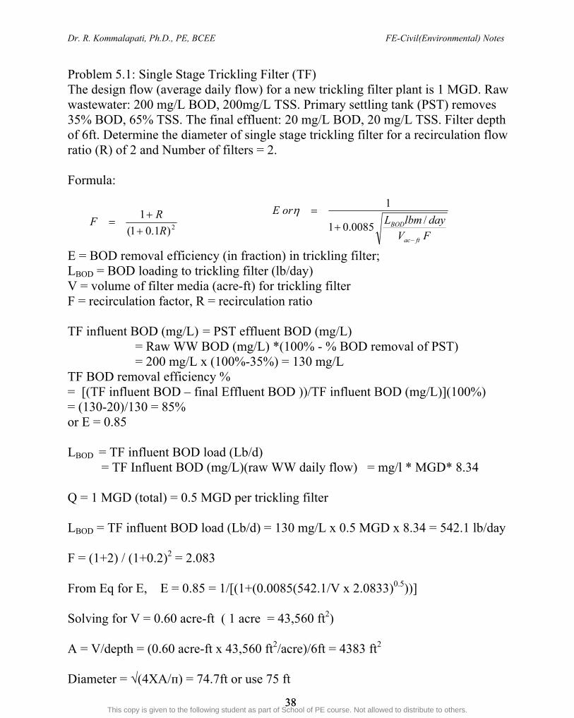
Problem 5.1: Single Stage Trickling Filter (TF) The design flow (average daily flow) for a new trickling filter plant is 1 MGD. Raw wastewater: 200 mg/L BOD, 200mg/L TSS. Primary settling tank (PST) removes 35% BOD, 65% TSS. The final effluent: 20 mg/L BOD, 20 mg/L TSS. Filter depth of 6ft. Determine the diameter of single stage trickling filter for a recirculation flow ratio (R) of 2 and Number of filters = 2. Formula:
E = BOD removal efficiency (in fraction) in trickling filter; LBOD = BOD loading to trickling filter (lb/day) V = volume of filter media (acre-ft) for trickling filter F = recirculation factor, R = recirculation ratio TF influent BOD (mg/L) = PST effluent BOD (mg/L)
= Raw WW BOD (mg/L) *(100% - % BOD removal of PST) = 200 mg/L x (100%-35%) = 130 mg/L
TF BOD removal efficiency % = [(TF influent BOD – final Effluent BOD ))/TF influent BOD (mg/L)](100%) = (130-20)/130 = 85% or E = 0.85 LBOD = TF influent BOD load (Lb/d)
= TF Influent BOD (mg/L)(raw WW daily flow) = mg/l * MGD* 8.34 Q = 1 MGD (total) = 0.5 MGD per trickling filter LBOD = TF influent BOD load (Lb/d) = 130 mg/L x 0.5 MGD x 8.34 = 542.1 lb/day F = (1+2) / (1+0.2)2 = 2.083 From Eq for E, E = 0.85 = 1/[(1+(0.0085(542.1/V x 2.0833)0.5))] Solving for V = 0.60 acre-ft ( 1 acre = 43,560 ft2) A = V/depth = (0.60 acre-ft x 43,560 ft2/acre)/6ft = 4383 ft2 Diameter = √(4XA/п) = 74.7ft or use 75 ft
2)1.01(
1
R
RF
FVdaylbmL
orE
ftac
BOD
/0085.01
1
ahmed youssef ([email protected])
This copy is given to the following student as part of School of PE course. Not allowed to distribute to others.

Dr. R. Kommalapati, Ph.D., PE, BCEE FE-Civil(Environmental) Notes
39 39
PART III: SOLID & HAZARDOUS WASTE MANAGEMENT AND AIR POLLUTION CHAPTER 1: SOLID WASTE Solid waste is a generic term used to describe the things we throw away. Solid waste disposal creates a problem primarily in highly populated areas. In
general, the more concentrated the population, the greater the problem becomes, although some very populated areas have developed creative solutions to minimize the problems.
Social customs result in significant variations in the mass of waste generated. Residential locations (including multifamily) generate approximately 55-65% of
all MSW (municipal solid waste).
Solid waste can be classified in several different ways. Putrescible waste – Animal and Vegetable waste From Cooking and
preparing food Municipal solid waste- Known to the lay audience as garbage ( durable goods,
yard trimmings, containers and packaging) The nature of the material may be important, so classification can be made on the
basis of organic, inorganic, combustible, noncombustible, putrescible, and non-putrescible.
The classification of solid waste is usually used for choosing the treatment, collection, recycling, and disposal options.
The density of solid waste is the mass of solid waste per unit volume.
Elements of a Solid waste Management System. 1. Solid waste Generation ( Varies by country and socioeconomic status) 2. Solid waste Handling and storage on site 3. Solid waste collection 4. Transfer to central storage facility 5. Processing facility 6. Product utilization 7. disposal
Collection Methods
Curbside or alley pickup Set-out, set-back collection Backyard pickup or tote barrel method
ahmed youssef ([email protected])
This copy is given to the following student as part of School of PE course. Not allowed to distribute to others.

Dr. R. Kommalapati, Ph.D., PE, BCEE FE-Civil(Environmental) Notes
40 40
Waste Reduction o Source Reduction o Reuse o Recycle
Landfill Consideration
o Site Selection o Site Preparation o Equipment o Operation o Environmental Considerations o Leachate o Landfill Design o Completed Sanitary Landfills
Typical Landfill
ahmed youssef ([email protected])
This copy is given to the following student as part of School of PE course. Not allowed to distribute to others.
Dr. R. Kommalapati, Ph.D., PE, BCEE FE-Civil(Environmental) Notes
41 41
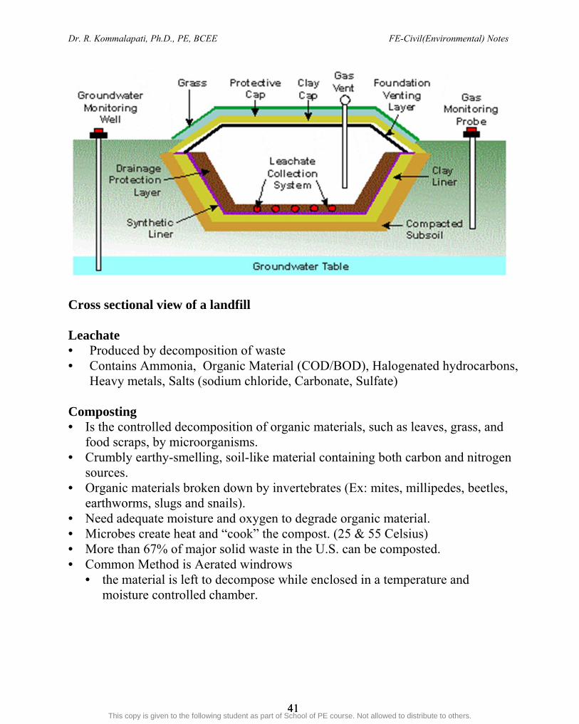
Cross sectional view of a landfill Leachate • Produced by decomposition of waste • Contains Ammonia, Organic Material (COD/BOD), Halogenated hydrocarbons,
Heavy metals, Salts (sodium chloride, Carbonate, Sulfate) Composting • Is the controlled decomposition of organic materials, such as leaves, grass, and
food scraps, by microorganisms. • Crumbly earthy-smelling, soil-like material containing both carbon and nitrogen
sources. • Organic materials broken down by invertebrates (Ex: mites, millipedes, beetles,
earthworms, slugs and snails). • Need adequate moisture and oxygen to degrade organic material. • Microbes create heat and “cook” the compost. (25 & 55 Celsius) • More than 67% of major solid waste in the U.S. can be composted. • Common Method is Aerated windrows
• the material is left to decompose while enclosed in a temperature and moisture controlled chamber.
ahmed youssef ([email protected])
This copy is given to the following student as part of School of PE course. Not allowed to distribute to others.

Dr. R. Kommalapati, Ph.D., PE, BCEE FE-Civil(Environmental) Notes
42 42
Combustion A chemical reaction in which the elements in fuel oxidize in presence of excess
oxygen C → CO2, H → H2O, S → SOx, N → NOx
Reactions are a function of Oxygen, Time, Temperature, and Turbulence Higher Temps means Higher NOx Emissions As temp increases, volatile materials burn off into gas, then organic components
“crack” and form gas, fixed carbon remains At 700°C, carbon is ignited to achieve “burn out” Heating Value of Waste is measure in kJ/kg and determined experimentally
using a bomb calorimeter Incinerators Conventional (Mass-Fired) Incineration
o most common form of municipal solid waste (MSW) incineration o can accept refuse that has little pretreatment other than the removal of
oversized items (i.e. kitchen stoves, mattresses) o auxiliary fuel is provided for the initial drying stages o electrostatic precipitators control the air pollution given off o 10% of the material incinerated remains and is carried to a landfill
Refuse-Derived Fuel Facilities
o combustible portion of solid waste that’s been separated from noncombustible portion through various processes (i.e. shredding, screening, air classifying)
o Typical process – MSW fed into trommel (rotating screen) to remove glass and dirt, then conveyed to shredder for size reduction. Shredded wastes pass through an air classifier to separate light fraction from heavy fraction.
o Light fraction is used for fuel after ferrous material is removed o Heavy fraction is also rendered of ferrous materials o remaining glass, ceramics, and nonmagnetic materials from heavy fraction are
then sent to a landfill
Fluidized-Bed Incinerators o sand is heated to 800C by oil or gas and blown around (fluidized) by a blower
that sends air from bottom upward o heated fluidized sand hits sludge, breaks it apart, and burns it o glass and metals must be removed from refuse to incinerated o able to burn wastes of widely variable moisture and heat content (i.e. paper
and wood) o very efficient and emissions are low
ahmed youssef ([email protected])
This copy is given to the following student as part of School of PE course. Not allowed to distribute to others.

Dr. R. Kommalapati, Ph.D., PE, BCEE FE-Civil(Environmental) Notes
43 43
o able to co-combust fuels (i.e. municipal waste with coal or propane) o more effective than small sized mass-burn incinerators
Modular Incinerators
o prefabricated units with capacities of 4.5 to 107 tons of solid waste/day o most use a system involving two combustion chambers o some units employ additional air pollution control equipment and control
emissions as effectively as mass-burn facilities o many units are being closed due to expenses from upgrading thus interest in
modular incinerators is decreasing
Environmental and Public Health Concerns o The combustion of MSW can result in the emission of particulate matter, acid
gases (SOx, HCl, HF), NOx (primarily NO andNO2). Carbon monoxide, organics, and heavy metals.
o Emission standards and guidelines have been promulgated for new and existing large municipal waste combustion (MWC) facilities, and proposed for small SWC facilities.
o EPA estimates that when full compliance with the MWC rules is attained, the annual emissions resulting from MSW incinerators will decline significantly.
Few Points to Note: Municipal solid waste (MSW) or garbage consists of solid waste discarded by a community and it includes food waste, paper waste, garden waste, cardboard, wood, household metal and plastic waste and several others. Approximate generation rate of MSW is 5 to 8 lb (2.3 to 3.6 kg) per capita per day with 5 lb (or 2,3 kg) being a typical value for design purposes. It should be noted that the mass of the waste remains the same from the generation point to the landfill however, the volume keeps getting smaller as we compact the waste in each step (density keeps increasing at each step i.e. from trash bins at home to truck to landfill). Important aspects of solid waste management are collection, transfer station (if needed) and disposal (landfill (including recovery of gases for energy) or incineration and recovery of energy)
ahmed youssef ([email protected])
This copy is given to the following student as part of School of PE course. Not allowed to distribute to others.

Dr. R. Kommalapati, Ph.D., PE, BCEE FE-Civil(Environmental) Notes
44 44
Problem 1.1: Solid Waste Quantity A municipal solid waste department plans to separate a portion of the ferrous metal, newsprint and cardboard from its MSW waste stream. The department operates 50 collection trucks, each having a volume capacity of 16 yd3 and a compaction capability of 600 lb/yd3. Each truck collects an average of 8 loads per week over the year, with allowances for partial loads and downtime. a) Using the data provided, calculate the amount of waste in lb and yd3 transported
to the landfill per year assuming the current generation rate remains the same and no recycling occurs.
b) Estimate the savings in the volume of waste to be landfilled per year if 25% (by weight) of the waste stream is recycled. Assume the density of waste in landfill after compaction is 1000 lb/yd3.
Ans: (a) Step 1. Waste Volume Collected 50 tucks * 16 yd3/load * 8 loads/wk * 52wk/yr = 332,800 yd3/yr Step 2. Waste to be landfilled (truck compaction 600 lb/yd3) 332,800 yd3/yr * 600 lb/yd3 = 199,680,000 lb/yr (b) Step 1. Recycling Volume 199,680,000 lb * 0.25 = 49,920,000 lb/yr recycled material 199,680,000 - 49,920,000 = 149,760,000 lb/yr to the landfill Step 2. Volume that would have been occupied by the recycled material will
the savings (remember the compacted density in the landfill is 1000 lb/yd3)
yrydydlb
lb/920,49
/000,1
000,920,49 33
Volume Savings = 49,920 yd3/yr
Note: Density of refuse in collection is different than in the landfill
ahmed youssef ([email protected])
This copy is given to the following student as part of School of PE course. Not allowed to distribute to others.

Dr. R. Kommalapati, Ph.D., PE, BCEE FE-Civil(Environmental) Notes
45 45
Problem 1.2: Solid Waste Density The per capita solid waste generation rate for the 175,000 residents of a city is 1.9 kg/d. The solid waste characteristics for the city are as follows. Component Mass
(%) Component Discarded
Moisture (%) Component discarded
Density (kg/m3)
Paper 31 6 85 Garden 29 60 105 Food 10 70 290 Cardboard 9 5 50 Wood 8 20 240 Plastic 7 2 65 misc. 6 8 480
What is the discarded (wet) density of the bulk waste? Ans Assume that a 100 kg sample of the waste for convenience in calculations. Although the number of residents and the generation rate can be used to calculate the total daily mass, it will not affect the waste density result Component Mass
Kg Component discarded
Density kg/m3 Component discarded
Volume m3
Col 2/Col 3
Paper 31 85 0.365 Garden 29 105 0.276 Food 10 290 0.034
Cardboard 9 50 0.18 Wood 8 240 0.033 Plastic 7 65 0.108 misc. 6 480 0.013
100 1 m component discarded mass kg V component discarded volume m3 ρ waste bulk wet density kg/m3 ρd component discarded density kg/m3
V = m/ ρd and 33
/10000.1
100mkg
m
kg
V
md
ahmed youssef ([email protected])
This copy is given to the following student as part of School of PE course. Not allowed to distribute to others.
Dr. R. Kommalapati, Ph.D., PE, BCEE FE-Civil(Environmental) Notes
46 46
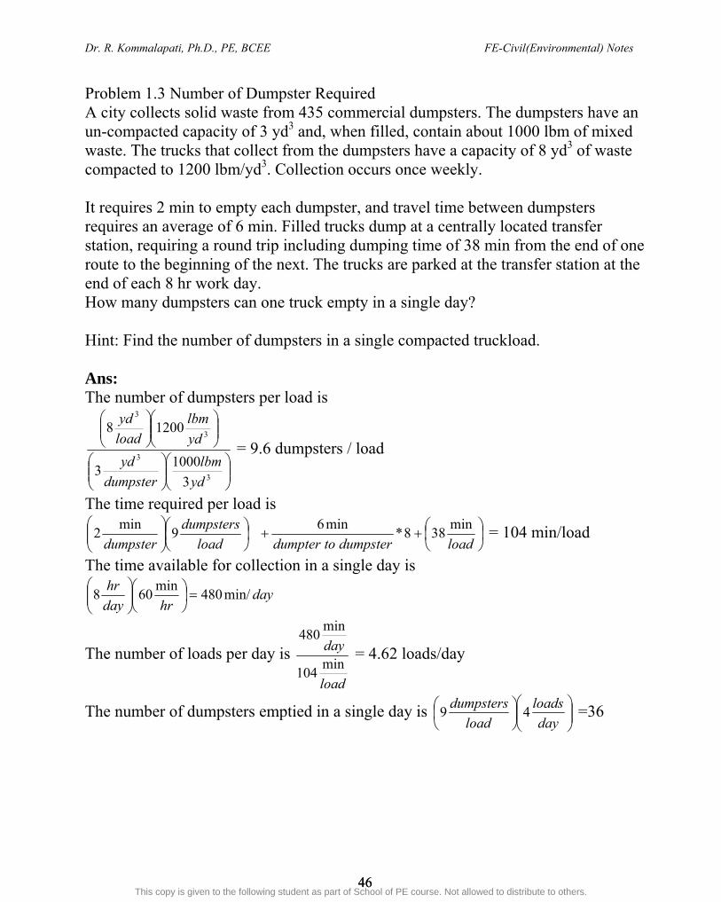
Problem 1.3 Number of Dumpster Required A city collects solid waste from 435 commercial dumpsters. The dumpsters have an un-compacted capacity of 3 yd3 and, when filled, contain about 1000 lbm of mixed waste. The trucks that collect from the dumpsters have a capacity of 8 yd3 of waste compacted to 1200 lbm/yd3. Collection occurs once weekly. It requires 2 min to empty each dumpster, and travel time between dumpsters requires an average of 6 min. Filled trucks dump at a centrally located transfer station, requiring a round trip including dumping time of 38 min from the end of one route to the beginning of the next. The trucks are parked at the transfer station at the end of each 8 hr work day. How many dumpsters can one truck empty in a single day? Hint: Find the number of dumpsters in a single compacted truckload. Ans: The number of dumpsters per load is
3
3
3
3
3
10003
12008
yd
lbm
dumpster
yd
yd
lbm
load
yd
= 9.6 dumpsters / load
The time required per load is
loaddumpstertodumpterload
dumpsters
dumpster
min388*
min69
min2 = 104 min/load
The time available for collection in a single day is
dayhrday
hrmin/480
min608
The number of loads per day is
load
daymin
104
min480
= 4.62 loads/day
The number of dumpsters emptied in a single day is
day
loads
load
dumpsters49 =36
ahmed youssef ([email protected])
This copy is given to the following student as part of School of PE course. Not allowed to distribute to others.

Dr. R. Kommalapati, Ph.D., PE, BCEE FE-Civil(Environmental) Notes
47 47
Problem 1.4: Operating Life of Landfill A municipality with a population of 215,000 is under state mandate to recycle 25% of the solid waste generated by its citizens. The remaining 75% will be landfilled. The per capita waste generation rate is 4.6 lbm/day. The landfilled waste in-place maximum compacted density is 50 lbm/ft3, and the soil-cover-to-compacted-waste ratio is 1:4.5 by volume. The landfill covers a rectangular area 1200 ft by 1600 ft. The maximum landfill height cannot exceed 80 feet with 1:1 side slopes. What is the operating life of the landfill? Hint: Be careful applying the cover-to-fill ratio and distinguishing between waste landfilled and the waste recycled Ans: The landfill volume (trapezoid)= ½ (b1 +b2)*h (0.5)[(1200ft – 80 ft - 80 ft) (1600 ft – 80 ft – 80 ft) + (1200 ft)(1600 ft)](80ft) = 1.4 x 108 ft3
The annual waste mass landfilled is
(0.75)(215,000 people)
year
day
daycapita
lbm3656.4 = 2.7 x 10⁸ lbm/yr
The annual in-place waste volume landfilled is yrftx
ft
lbmyr
lbmx
/104.550
107.236
3
8
The annual soil cover volume is yrftxyr
ftx
/102.15.4
104.536
36
The annual landfill total volume is yr
ftx
36104.5 +
yr
ftx
36102.1 =
yr
ftx
36106.6
The landfill operating life is
yr
ftx
ftx3
6
38
106.6
104.1= 21 yr
ahmed youssef ([email protected])
This copy is given to the following student as part of School of PE course. Not allowed to distribute to others.

Dr. R. Kommalapati, Ph.D., PE, BCEE FE-Civil(Environmental) Notes
48 48
CHAPTER 2: HAZARDOUS WASTE Hazardous Waste o any waste or combination of waste that poses a substantial danger now or future
to humans, plants, and animals without special precautions. o there are cases where waste has been declared safe or non-hazardous, but years
later cause a lot of hazardous problems o Waste material is considered to be hazardous if it is on the EPA developed lists
(F, K, P, U, etc.) or if it exhibits any of the following: Ignitability – is a liquid with flash point <60oC (some exceptions) – Not a liquid and capable of spontaneous and sustained combustion under
normal conditions – Ignitable compressed gas (DOT regulations) – is an oxidizer (DOT regulations) Corrosivity – Is aqueous and has a pH less than 2 or greater than 12.5 – Is liquid and corrodes steel at a rate greater than 0.25” per year at a test
temperature of 55oc
Reactivity – Undergoes violent Change w/o detonating – reacts violently with water – Forms potentially explosive mixtures with water – generates toxic gases, vapors or fumes when mixed with water – contains cyanide or sulfide and generates toxic gases, vapors or fumes – capable of detonation if heated under confinement – capable of detonation at std. Temp and Pr. – Is listed by DOT as a Class A or Class B explosive
Toxic characteristics – From the results of either – Extraction Procedure(EP) toxicity (prior to March 1990) or Toxicity
Characteristic Leaching Procedure (TCLP) – must have concentrations less than 100 times Primary Drinking water
Standards (PWDS) or is classified as hazardous
ahmed youssef ([email protected])
This copy is given to the following student as part of School of PE course. Not allowed to distribute to others.

Dr. R. Kommalapati, Ph.D., PE, BCEE FE-Civil(Environmental) Notes
49 49
Hazardous Waste Lists include – Priority Pollutants – K: Wastes generated in specific processes unique to specific industrial groups – F: Wastes generated by standard operation regardless of industry, i.e.,
nonspecific sources. – P and U: Particular commercial chemical products (off-specification and
container and spill residues). Comparison of Solid and Hazardous Wastes Some important Points The mixture rule prevents dilution of waste for the purposes of escaping RCRA
regulation. Mixtures of a listed hazardous waste and other solid wastes become hazardous wastes.
The “contained in” rule is a direct consequence of the mixture rule. In this policy media such as soil and water are treated as hazardous waste if they contained listed hazardous materials
The “derived from” rule tells us that any solid waste generated from the treatment, storage, or disposal of a hazard waste, including any sludge, spill residue, ash, emission-control dust, or leachate (but not precipitation run-off) is a hazardous waste.
The “waste-code carry through” principle is a consequence of both the “derived from” and “mixture” rules. It states that solid waste derived from a hazardous and nonhazardous waste contains all of the same waste codes as the original waste.
ahmed youssef ([email protected])
This copy is given to the following student as part of School of PE course. Not allowed to distribute to others.
Dr. R. Kommalapati, Ph.D., PE, BCEE FE-Civil(Environmental) Notes
50 50
Hazardous Waste Regulations RCRA and HSWA
o In 1976, Congress passed the Resource Conservation and Recovery Act (RCRA) and directed EPA to establish hazardous waste regulations
o In 1984, RCRA was amended into the Hazardous Solid Waste Amendments (HSWA).
o HSWA along with RCRA is used to regulate the generation and disposal of hazardous waste
o Did not address abandoned or closed waste disposal sites or spills o Cradle to Grave Concept
– EPA’s hazardous waste management system – Tracks hazardous waste from its generation point to its ultimate disposal
point – Requires generators to attach a itemized list describing the contents of
hazardous waste and track hazardous waste shipments – The Uniform Hazardous Waste Manifest is the key to cradle-to-grave
waste management. – Generators can track the movement of hazardous waste from the point of
generation to the ultimate treatment, storage, or disposal. – Transporter- Critical Link between be the generator and ultimate off site
treatment, storage and disposal of hazardous waste. – Follows regulations jointly developed by DOT and EPA – Defined as any person engaged in the off-site transportation of hazardous
waste with the United States – Treatment, storage and disposal (TSDs) facilities are the last link in the
cradle-to-grave system. – All TSDs handling hazardous waste must obtain an operating permit and
abide by regulations. – The owners or operators of TSDs must minimize the release of hazardous
waste into the environment.
CERCLA and SARA In 1980, the Comprehensive Environmental Response, Compensation, and
Liability Act (CERCLA) was enacted to address those problems. Commonly referred to as “Superfund” The provisions were extended by the Superfund Amendment and
Reauthorization Act (SARA) of 1986 Established to give EPA authority and funds to clean up abandoned waste
sites and respond to emergencies. This was greatly expanded by SARA.
ahmed youssef ([email protected])
This copy is given to the following student as part of School of PE course. Not allowed to distribute to others.

Dr. R. Kommalapati, Ph.D., PE, BCEE FE-Civil(Environmental) Notes
51 51
National Contingency Plan (NCP) – Provides detailed direction on the action to be taken at a hazardous waste
site, including emergency actions and a method to rank sites to establish future actions
– NCP describes the steps to be taken for the detailed evaluation of the risks associated with a site, termed a remedial investigation(RI). The process of selecting an appropriate remedy is termed the feasibility study(FS).
– Specifies the degree of cleanup to be selected in accordance with several criteria.
– There is no predetermined level of remediation that can be required or that must be achieved at a particular site.
– The degree of correction is established on a site-by-site basis. – Upon completion and approval of the RI/FS, the preparation of the
selected remedy is planned out in the remedial design. National Priorities List (NPL)
– Also known as superfund list – Identify sites that appear to present a significant risk to public health or the
environment (Through HRS score) – Currently there are over 1200 sites on the NPL. – Sites on NPL are eligible for Superfund money.
Hazard Ranking system (HRS) – A procedure for ranking uncontrolled hazardous waste sites in terms of the
potential threat based upon the containment of the hazardous substances, route of release, characteristics and amount of the substances, and likely targets.
– Represents the relative hazards posed by a site and potential for human and environmental exposure.
– The HRS score is based on the probability of contamination from four pathways – groundwater, surface water, soil and air.
EPCRA - Emergency Planning and Community Right-to-Know Act- major provision found in SARA – Established to let community know the amounts of chemicals and their
locations in facilities in their community, making it available to the public. – Each year those facilities must fill out and EPA-specified form called the
Toxic Release Inventory, which is a list of releases of chemicals produced by those facilities, either accidental or routine, as well as off-site shipments of waste.
ahmed youssef ([email protected])
This copy is given to the following student as part of School of PE course. Not allowed to distribute to others.

Dr. R. Kommalapati, Ph.D., PE, BCEE FE-Civil(Environmental) Notes
52 52
Hazardous Waste Treatment Technologies A comprehensive hazardous waste management program should include Waste Minimization (including source reduction, waste exchange and recycling) in addition to treatment and disposal methods Treatment and Disposal Methods Physical/Chemical Treatment Methods
Neutralization, Oxidation, Precipitation Carbon Adsorption, Distillation, Ion Exchange, Eltrodialysis Incineration
o Liquid injection o Rotary kiln
Biological Treatment Methods Land Disposal
Deep Weill Injection Land Treatment Landfill
o Siting, Permitting, Design, Construction, Closure o Maintenance and Operation
ahmed youssef ([email protected])
This copy is given to the following student as part of School of PE course. Not allowed to distribute to others.

Dr. R. Kommalapati, Ph.D., PE, BCEE FE-Civil(Environmental) Notes
53 53
CHAPTER 3: AIR POLLUTION Definition ….may be defined as the presence in the outdoor and/or indoor atmosphere of
one or more contaminants or combinations thereof in such quantities and of such duration as may be or may tend to be injurious to human, plant, or animal life or property or which unreasonably interferes with the comfortable enjoyment of life or property or the conduct of business
Increased quantities of the normal constituents of atmospheric air or other
materials that are present are then classified as pollutants if their presence results in damage to human beings, plants, animals, materials
Categories of Air Pollution Ambient Air Pollution
o Out door environment o Involves complex array of sources and pollutants, meteorological transport
of the pollutants to a receptor o US Environmental Protection Agency (EPA) is the regulatory authority
Indoor Air Pollution o Indoor environment in which people live o US EPA is the active agency o No Federal regulations as yet
Occupational (Industrial Hygiene) Air Pollution o Associated with exposure to a large range of pollutants (particles, mists,
acid vapors, and organic and inorganic gases) in the work place o Regulatory standards established by Occupational Safety and Health
Administration (OSHA) and developed by American Conference of Governmental and Industrial Hygienists (ACGIH) and the National Institute of Occupational Safety and Health (NIOSH)
Personal Exposure o Exposure to dust, fumes, gases, or mists to which an individual exposes
oneself Concentration of Pollutants
It is common to express pollutant conc. in the air as parts per million by volume(ppmv) - 0.0001% by volume = 1 ppmv
Similarly we can define ppmw Mass conc.
o Micrograms/cubic meter (μg/m3)
ahmed youssef ([email protected])
This copy is given to the following student as part of School of PE course. Not allowed to distribute to others.

Dr. R. Kommalapati, Ph.D., PE, BCEE FE-Civil(Environmental) Notes
54 54
C (μg/m3) = (ppmv*MW*103)/24.5 This equation is good for P = 1 atm and T = 25°C If pressure and temp are different, then a new constants should be used
o For example when P = 1 atm and T =0C or 273K, the constant is 22.4 o Constant at Other temps can be obtained using o
o Other units
ppb, pphm, ppt Composition of Air
Why do we need to control air pollution
o It causes harmful effects on human health, Materials and property, Plants and Animals, Visibility, Global climate and others
o Chronic Effects Long-term, low conc.
o Acute Effects Short-term, high conc. Typically during industrial accidents or air pollution emergency
episodes o Dosage = Conc. in breathed air * time
std
std
actual
actual
T
P
P
T * 22.41
ahmed youssef ([email protected])
This copy is given to the following student as part of School of PE course. Not allowed to distribute to others.
Dr. R. Kommalapati, Ph.D., PE, BCEE FE-Civil(Environmental) Notes
55 55
Typical Ambient Air Pollutants o Particulate matter o Sulfur containing compounds o Organic compounds o Nitrogen containing compounds o Carbon monoxide o Halogen compounds o Radioactive compounds o Photochemical compounds o Other inorganic compounds
National Ambient Air Quality Standards (NAAQSs) established six criteria Pollutants - five primary and one secondary pollutant
Primary pollutants –emitted directly o Particulate matter (<10μm) o Sulfur dioxide (SO2) o Nitrogen dioxide (NO2) o Carbon monoxide (CO) o Particulate lead (Pb)
Secondary pollutant- formed in the lower atmosphere by chemical reactions among primary pollutants
o Ozone (O3) Control of Air Pollution
Air belongs to everyone o Need it to treat air pollution as public problem
Air pollution is an inevitable concomitant of modern life o Conflict between economic and biological concerns o Systematic development of policies and programs to conserve the
atmosphere for its most fundamental biological function Public policy on pollution can be rationalized through scientific knowledge
o Develop effective control strategies including pollution prevention and minimization and continued improvement and application of control devices and technologies
Transfer of pollution from one sector to another is not pollution prevention or abatement
o Example transfer of air pollution to water pollution or soil contamination, etc.
ahmed youssef ([email protected])
This copy is given to the following student as part of School of PE course. Not allowed to distribute to others.

Dr. R. Kommalapati, Ph.D., PE, BCEE FE-Civil(Environmental) Notes
56 56
Clean Air Act and its major amendments provide the regulations related to air quality in the United States.
Atmospheric Dispersion Modeling
Dispersion model is a mathematical description of the meteorological transport and dispersion process that is quantified in terms of source and meteorological parameters during a particular period of time. The result is an estimate of concentrations of particular pollutant at specific locations and times.
Factors affecting the transport, dilution and dispersion of air pollutants are grouped in terms of (i) emission point characteristics, (ii) nature of the pollutant, (iii) meteorological conditions and (iv) effects of terrain and anthropogenic structures
ahmed youssef ([email protected])
This copy is given to the following student as part of School of PE course. Not allowed to distribute to others.
Related Documents


![arXiv:1703.03624v1 [cs.CV] 10 Mar 2017 · fmarco.venturelli, guido.borghi, roberto.vezzani, rita.cucchiarag@unimore.it Keywords: Head Pose Estimation, Deep Learning, Depth Maps, Automotive](https://static.cupdf.com/doc/110x72/5c72eb1409d3f2ad198c24e1/arxiv170303624v1-cscv-10-mar-2017-guidoborghi-robertovezzani-ritacucchiaragunimoreit.jpg)