Part 139 1 PNG Civil Aviation Rules 1/04/2019 CIVIL AVIATION SAFETY AUTHORITY OF PNG PNG Civil Aviation Rules Part 139 Aerodromes — Certification and Operation Applicable 1 April 2019

Welcome message from author
This document is posted to help you gain knowledge. Please leave a comment to let me know what you think about it! Share it to your friends and learn new things together.
Transcript
Part 139 1
PNG Civil Aviation Rules 1/04/2019
CIVIL AVIATION SAFETY AUTHORITY OF PNG
PNG
Civil Aviation Rules
Part 139
Aerodromes — Certification and Operation
Applicable 1 April 2019
Part 139 2
PNG Civil Aviation Rules 1/04/2019
DESCRIPTION
Part 139 provides the regulatory requirements relating to—
the certification and operation of aerodromes;
the security measures applicable to aerodromes;
the implementation of safety management systems.
the use of aerodromes by aircraft operators
Part 139 adopts the standard layout for the rule parts relating to the certification of organisations. The
layout prescribes specific requirements for the certification (entry standards), operation (continued
operations), and safety audit (surveillance) of aerodromes. Part 139 also details the requirements for
security measures to be complied with by the aerodrome certificate holder.
Part 139 aligns with:
Amendment 14 of Annex 14 Volume I and
Amendment 16 of Annex 17.
Part 139 3
PNG Civil Aviation Rules 1/04/2019
Bulletin
This Part first came into force on 1 January 2004 and now incorporates the following amendments:
Amendment Effective Date
Amendment 1 1 April 2015
Amendment 2 1 May 2017
Amendment 3 13 November 2018
Amendment 4 1 April 2019
Summary of amendments:
Amendment 4:
(Docket 18/06/CAR/139/36)
The proposed amendments will align the PNG rules with ICAO
Annex 17 (amendment 16), and enable the creation of a new rule part
107 that prescribes the requirements for an aerodrome security
program. The proposed changes include:
New rule 139.96 is inserted to prescribe the requirements for the
establishment, implementation and maintenance of an aerodrome
security program and an aviation security training program for
security designated aerodromes in accordance with a new rule part
107, approved by the Director; Update rule 139.97(a)(22) and
139.97(a)(23) to include the new aerodrome exposition references to
the new rule 107 and revised Subpart D; Security requirements
sections for security designated airports contained in 139.201,
139.203, 139.205, 139.207 and 139.211 including security measures
are removed from Subpart D of Part 139, transferred and
incorporated in proposed new Part 107; Rule 139.209 (non-security
designated aerodrome security requirements) is renumber 139.201
and is completely reworded to remove previous cross references; and
Part 139 is now updated to ICAO Annex 17, amendment 16
standards.
Part 139 4
PNG Civil Aviation Rules 1/04/2019
Schedule of Rules
Subpart A — General ............................................................................................................................. 8
139.1 Purpose ............................................................................................................................ 8
139.2 Definitions ....................................................................................................................... 8
139.3 Requirement for certificate ........................................................................................... 12
139.5 Application for certificate ............................................................................................. 12
139.7 Issue of certificate ......................................................................................................... 12
139.9 Duration of certificate ................................................................................................... 13
139.11 Renewal of certificate ................................................................................................... 13
139.13 Non-certificated aerodrome requirements .................................................................... 13
139.15 Exemptions ................................................................................................................... 13
Subpart B — Certification Requirements .......................................................................................... 13
139.51 Personnel requirements ................................................................................................. 13
139.53 Aerodrome design requirements ................................................................................... 14
139.55 Aerodrome limitations .................................................................................................. 14
139.57 Aerodrome emergency plan ........................................................................................... 14
139.59 Rescue and firefighting – category determination ........................................................ 15
139.61 Rescue and firefighting – extinguishing agents ............................................................ 15
139.63 Rescue and firefighting – vehicles ................................................................................ 15
139.65 Rescue and firefighting – personnel requirements ........................................................ 16
139.67 Rescue and firefighting – response capability .............................................................. 17
139.69 Rescue and firefighting – communication and alerting system .................................... 17
139.71 Public protection ........................................................................................................... 17
139.73 Wildlife hazard management ........................................................................................ 17
139.75 Notification of aerodrome data and information ........................................................... 17
139.77 Movement data reporting .............................................................................................. 18
139.79 Aerodrome maintenance programme ............................................................................ 18
139.81 Aerodrome inspection programme ................................................................................ 18
139.83 Visual aids for navigation – maintenance and checking ............................................... 18
139.85 Works on Aerodromes .................................................................................................. 18
139.87 Ground Vehicles ........................................................................................................... 19
139.89 Unsafe conditions .......................................................................................................... 19
139.91 Documentation .............................................................................................................. 19
139.93 Safety management system ........................................................................................... 20
139.95 Quality management system ......................................................................................... 20
139.96 Aerodrome Security Programme .................................................................................. 20
Part 139 5
PNG Civil Aviation Rules 1/04/2019
139.97 Aerodrome exposition ................................................................................................... 20
Subpart C — Operating Requirements .............................................................................................. 22
139.101 Continued compliance .................................................................................................. 22
139.103 Aerodrome emergency plan – maintenance .................................................................. 22
139.105 Rescue and firefighting – operational requirements ..................................................... 23
139.107 Aeronautical Study ........................................................................................................ 24
139.109 Aerodrome aircraft traffic management ........................................................................ 24
139.111 Aerodrome aircraft traffic services ............................................................................... 24
139.113 Apron management service .......................................................................................... 24
139.115 Protection of navigation aids & ATS facilities ............................................................. 24
139.117 Aerodrome condition notification ................................................................................ 24
139.119 Changes to certificate holder's organisation ................................................................. 25
139.121 Deviations ..................................................................................................................... 25
Subpart D — Aerodrome Security ...................................................................................................... 26
139.201 Non-security designated aerodrome security requirements .......................................... 26
Subpart E — Transition Provisions .................................................................................................... 27
139.301 – Reserved ............................................................................................................................. 27
Appendix A — Aerodrome Reference Code ...................................................................................... 28
Table A-1. Aerodrome reference code ................................................................................................ 28
Appendix B — Aerodrome Data ......................................................................................................... 29
B.1 Aeronautical data .......................................................................................................... 29
B.2 Aerodrome reference point ........................................................................................... 29
B.3 Aerodrome and runway elevations ............................................................................... 29
B.4 Aerodrome reference temperature ................................................................................ 29
B.5 Aerodrome dimensions and related information ........................................................... 29
B.6 Strength of pavements ................................................................................................... 30
B.7 Pre-flight altimeter check location ................................................................................ 32
B.8 Declared distances ........................................................................................................ 32
B.9 Condition of the movement area and related facilities ................................................. 32
B.10 Rescue and firefighting ................................................................................................. 33
B.11 Visual approach slope indicator systems ...................................................................... 33
B.12 Coordination between aeronautical information services and aerodrome authorities .. 34
Appendix C — Physical Characteristics ............................................................................................ 34
C.1 Runways ........................................................................................................................ 34
C.2 Runway turn pads .......................................................................................................... 35
C.3 Runway strips ................................................................................................................ 35
Part 139 6
PNG Civil Aviation Rules 1/04/2019
C.4 Runway end safety areas ............................................................................................... 36
C.5 Stopways ....................................................................................................................... 36
C.6 Taxiways ....................................................................................................................... 37
C.7 Taxiway strips ............................................................................................................... 37
C.8 Holding bays, runway-holding positions, intermediate holding positions and road
holding positions ................................................................................................................................. 37
C.9 Isolated aircraft parking position .................................................................................. 38
Appendix D — Obstacle Restriction and Removal ........................................................................... 39
D.1 Obstacle limitation surfaces .......................................................................................... 39
D.2 Obstacle limitation surfaces requirements .................................................................... 43
Appendix E — Visual Aids for Navigation ........................................................................................ 48
E.1 Indicators and signalling devices .................................................................................. 48
E.2 Markings ....................................................................................................................... 48
E.3 Lights ............................................................................................................................ 63
E.4 Signs ............................................................................................................................ 106
E.5 Markers ....................................................................................................................... 115
Appendix F — Visual Aids for Denoting Obstacles ........................................................................ 116
F.1 Objects to be marked and/or lighted ........................................................................... 116
F.2 Marking and/or lighting of objects.............................................................................. 116
Appendix G — Visual Aids for Denoting Restricted Use Areas .................................................... 123
G.1 Closed runways and taxiways, or part thereof ............................................................ 123
G.2 Non-load-bearing surfaces .......................................................................................... 124
G.3 Unserviceable areas..................................................................................................... 124
Appendix H — Electrical Systems .................................................................................................... 124
H.1 Electrical power supply systems for air navigation facilities ..................................... 124
H.2 System design ............................................................................................................. 125
H.3 Monitoring .................................................................................................................. 126
Appendix I — Aerodrome Operational Services, Equipment and Installations ......................... 126
I.2 Rescue and firefighting ............................................................................................... 127
I.3 Wildlife strike hazard reduction .................................................................................. 129
I.4 Apron management service ......................................................................................... 129
I.5 Ground servicing of aircraft ........................................................................................ 130
I.6 Aerodrome vehicle operations .................................................................................... 130
I.7 Surface movement guidance and control systems ...................................................... 130
I.8 Siting of equipment and installations on operational areas ......................................... 131
I.9 Fencing ........................................................................................................................ 132
I.10 Autonomous runway incursion warning system ......................................................... 132
Part 139 7
PNG Civil Aviation Rules 1/04/2019
Appendix J. Aerodrome Maintenance .............................................................................................. 132
J.1 General ........................................................................................................................ 132
J.2 Pavements ................................................................................................................... 133
J.3 Removal of contaminants ........................................................................................... 133
J.4 Runway pavement overlays ........................................................................................ 133
J.5 Visual aids ................................................................................................................... 133
Part 139 8
PNG Civil Aviation Rules 1/04/2019
Subpart A — General
139.1 Purpose
This Part prescribes: -
(1) rules governing the certification and operation of aerodromes; and
(2) rules for security at certified aerodromes.
139.2 Definitions
In rules made under the Act, unless the context otherwise requires—
Aerodrome beacon means an aeronautical beacon used to indicate the location of an aerodrome from
the air.
Aerodrome certificate means a certificate issued by the appropriate authority under applicable
regulations for the operation of an aerodrome.
Aerodrome elevation means the elevation of the highest point of the landing area.
Aerodrome identification sign means a sign placed on an aerodrome to aid in identifying the
aerodrome from the air.
Aerodrome reference point means the designated geographical location of an aerodrome.
Aerodrome traffic density has the following meaning:
(a) Light. Where the number of movements in the mean busy hour is not greater than 15 per
runway or typically less than 20 total aerodrome movements.
(b) Medium. Where the number of movements in the mean busy hour is of the order of 16 to 25
per runway or typically between 20 to 35 total aerodrome movements.
(c) Heavy. Where the number of movements in the mean busy hour is of the order of 26 or more
per runway or typically more than 35 total aerodrome movements.
Aeronautical beacon means an aeronautical ground light visible at all azimuths, either continuously or
intermittently, to designate a particular point on the surface of the earth. Aeronautical ground light means any light specially provided as an aid to air navigation, other than a light displayed on an aircraft.
Aeroplane reference field length means the minimum field length required for take-off at maximum
certificated take-off mass, sea level, standard atmospheric conditions, still air and zero runway slope, as
shown in the appropriate aeroplane flight manual prescribed by the certificating authority or
equivalent data from the aeroplane manufacturer. Field length means balanced field length for
aeroplanes, if applicable, or take-off distance in other cases.
Aircraft classification number (ACN) means a number expressing the relative effect of an aircraft on
a pavement for a specified standard subgrade category.
Aircraft stand means a designated area on an apron intended to be used for parking an aircraft.
Part 139 9
PNG Civil Aviation Rules 1/04/2019
Arresting system means a system designed to decelerate an aeroplane overrunning the runway.
Autonomous runway incursion warning system (ARIWS) means A system which provides
autonomous detection of a potential incursion or of the occupancy of an active runway and a direct
warning to a flight crew or a vehicle operator.
Balked landing means a landing manoeuvre that is unexpectedly discontinued at any point below the
obstacle clearance altitude/height (OCA/H).
Barrette means three or more aeronautical ground lights closely spaced in a transverse line so that from
a distance they appear as a short bar of light.
Cyclic redundancy check (CRC) means a mathematical algorithm applied to the digital expression of
data that provides a level of assurance against loss or alteration of data.
Dependent parallel approaches means simultaneous approaches to parallel or near-parallel instrument
runways where radar separation minima between aircraft on adjacent extended runway centre lines are
prescribed.
Displaced threshold means a threshold not located at the extremity of a runway.
Effective intensity means the effective intensity of a flashing light is equal to the intensity of a fixed
light of the same colour which will produce the same visual range under identical conditions of
observation.
Ellipsoid height (Geodetic height) means the height related to the reference ellipsoid, measured along
the ellipsoidal outer normal through the point in question.
Fixed light means a light having constant luminous intensity when observed from a fixed point.
Foreign object debris (FOD) means an inanimate object within the movement area which has no
operational or aeronautical function and which has the potential to be a hazard to aircraft operations.
Frangible object means an object of low mass designed to break, distort or yield on impact so as to
present the minimum hazard to aircraft.
Hazard beacon means an aeronautical beacon used to designate a danger to air navigation.
Holding bay means a defined area where aircraft can be held, or bypassed, to facilitate efficient surface
movement of aircraft.
Hot spot means a location on an aerodrome movement area with a history or potential risk of collision
or runway incursion, and where heightened attention by pilots/drivers is necessary.
Identification beacon means an aeronautical beacon emitting a coded signal by means of which a
particular point of reference can be identified.
Independent parallel approaches means simultaneous approaches to parallel or near-parallel
instrument runways where radar separation minima between aircraft on adjacent extended runway
centre lines are not prescribed.
Independent parallel departures means simultaneous departures from parallel or near-parallel
Part 139 10
PNG Civil Aviation Rules 1/04/2019
instrument runways.
Intermediate holding position means a designated position intended for traffic control at which taxiing
aircraft and vehicles must stop and hold until further cleared to proceed, when so instructed by the
aerodrome control tower.
Landing area means that part of a movement area intended for the landing or take-off of aircraft.
Landing direction indicator means a device to indicate visually the direction currently designated for
landing and for take-off.
Landside means those parts of an airport, adjacent terrain and buildings or portions thereof that are not
airside, identified under this Part as relevant in the applicant security programme.
Laser-beam critical flight zone (LCFZ) means airspace in the proximity of an aerodrome but beyond
the LFFZ where the irradiance is restricted to a level unlikely to cause glare effects.
Laser-beam free flight zone (LFFZ) means airspace in the immediate proximity of the aerodrome
where the irradiance is restricted to a level unlikely to cause any visual disruption.
Laser-beam sensitive flight zone (LSFZ) means airspace outside, and not necessarily contiguous with,
the LFFZ and LCFZ where the irradiance is restricted to a level unlikely to cause flash- blindness or
after-image effects.
Lighting system reliability means the probability that the complete installation operates within the
specified tolerances and that the system is operationally usable.
Marker means an object displayed above ground level in order to indicate an obstacle or delineate a
boundary.
Near-parallel runways means non-intersecting runways whose extended centre lines have an angle of
convergence/divergence of 15 degrees or less.
Non-instrument runway means a runway intended for the operation of aircraft using visual approach
procedures or an instrument approach procedure to a point beyond which the approach may continue in
visual meteorological conditions.
Normal flight zone (NFZ) means airspace not defined as LFFZ, LCFZ or LSFZ but which must be
protected from laser radiation capable of causing biological damage to the eye.
Obstacle. All fixed (whether temporary or permanent) and mobile objects, or parts thereof, that:
(a) are located on an area intended for the surface movement of aircraft; or
extend above a defined surface intended to protect aircraft in flight; or
(b) stand outside those defined surfaces and that have been assessed as being a hazard to air
navigation.
Obstacle free zone (OFZ) means the airspace above the inner approach surface, inner transitional
surfaces, and balked landing surface and that portion of the strip bounded by these surfaces, which is
not penetrated by any fixed obstacle other than a low-mass and frangibly mounted one required for air
navigation purposes.
Outer main gear wheel span (OMGWS) means the distance between the outside edges of the main
gear wheels.
Part 139 11
PNG Civil Aviation Rules 1/04/2019
Orthometric height means height of a point related to the geoid, generally presented as an MSL
elevation.
Pavement classification number (PCN) means a number expressing the bearing strength of a
pavement for unrestricted operations.
Precision approach runway, see Instrument runway.
Primary runway(s) means runway(s) used in preference to others whenever conditions permit.
Protected flight zones means airspace specifically designated to mitigate the hazardous effects of laser
radiation.
Road means an established surface route on the movement area meant for the exclusive use of vehicles.
Road-holding position means a designated position at which vehicles may be required to hold.
Runway guard lights means a light system intended to caution pilots or vehicle drivers that they are
about to enter an active runway.
Runway-holding position means a designated position intended to protect a runway, an obstacle
limitation surface, or an ILS/MLS critical/sensitive area at which taxiing aircraft and vehicles must stop
and hold, unless otherwise authorized by the aerodrome control tower.
Runway turn pad means a defined area on a land aerodrome adjacent to a runway for the purpose of
completing a 180-degree turn on a runway.
Segregated parallel operations means simultaneous operations on parallel or near-parallel instrument
runways in which one runway is used exclusively for approaches and the other runway is used
exclusively for departures.
Shoulder means an area adjacent to the edge of a pavement so prepared as to provide a transition
between the pavement and the adjacent surface.
Sign means;
(a) Fixed message sign. A sign presenting only one message.
(b) Variable message sign. A sign capable of presenting several predetermined messages or no
message, as applicable.
Signal area means an area on an aerodrome used for the display of ground signals.
Switch-over time (light) means the time required for the actual intensity of a light measured in a given
direction to fall from 50 per cent and recover to 50 per cent during a power supply changeover, when
the light is being operated at intensities of 25 per cent or above.
Take-off runway means a runway intended for take-off only.
Taxiway means a defined path on a land aerodrome established for the taxiing of aircraft and intended
to provide a link between one part of the aerodrome and another, including:
Part 139 12
PNG Civil Aviation Rules 1/04/2019
(a) Aircraft stand taxilane. A portion of an apron designated as a taxiway and intended to provide
access to aircraft stands only.
(b) Apron taxiway. A portion of a taxiway system located on an apron and intended to provide a
through taxi-route across the apron.
(c) Rapid exit taxiway. A taxiway connected to a runway at an acute angle and designed to allow
landing aeroplanes to turn off at higher speeds than are achieved on other exit taxiways thereby
minimizing runway occupancy times.
Taxiway intersection means a junction of two or more taxiways.
Taxiway strip means an area including a taxiway intended to protect an aircraft operating on the
taxiway and to reduce the risk of damage to an aircraft accidentally running off the taxiway.
Touchdown zone means the portion of a runway, beyond the threshold, where it is intended landing aeroplanes
first contact the runway.
Usability factor means the percentage of time during which the use of a runway or system of runways
is not restricted because of the crosswind component.
139.3 Requirement for certificate
(a) A person must not operate an aerodrome serving any aeroplane having a passenger seating
configuration of 20 seats or more, excluding any required flight crew member seat, that is engaged
in regular air operations for the carriage of passengers to, from or within Papua New Guinea except
under the authority of, an aerodrome operating certificate issued by the Director under the Act and
in accordance with this Part.
(b) A person operating an aerodrome who is not required to hold an aerodrome operating
certificate under paragraph (a), may apply for an aerodrome certificate under this Part or must meet
the minimum aerodrome standards acceptable to the Director required by rule 139.13.
139.5 Application for certificate
An applicant for the grant of an aerodrome operating certificate must complete form CA139/01 and
submit it to the Director with: -
(1) the exposition required by 139.97; and
(2) a payment of the appropriate application fee prescribed by regulations made under the
Act; and
(3) a plan of the aerodrome and its facilities certified by a registered surveyor; and
(4) evidence of lawful entitlement to use the place as an aerodrome.
139.7 Issue of certificate
An aerodrome operating certificate may be issued by the Director under the Act in accordance with
this Part if the Director is satisfied that: -
(1) the applicant meets the requirements of Subpart B; and
(2) the applicant, and the applicant’s senior person or persons required by 139.51(a)(1) and
Part 139 13
PNG Civil Aviation Rules 1/04/2019
(2) are fit and proper persons; and
(3) the granting of the certificate is not contrary to the interests of aviation safety.
139.9 Duration of certificate
(a) An aerodrome operating certificate may be granted or renewed for a period of up to 5 years.
(b) An aerodrome operating certificate remains in force until it expires or is suspended or revoked
(c) The holder of an aerodrome operating certificate that expires or is revoked must forthwith
surrender the certificate to the Director.
(d) The holder of an aerodrome operating certificate that is suspended must forthwith produce the
certificate to the Director for appropriate endorsement.
139.11 Renewal of certificate
(a) An application for the renewal of an aerodrome operating certificate must be made on form
CA139/01.
(b) The application must be submitted to the Director at least 30 days before the certificate expires.
139.13 Non-certificated aerodrome requirements
A person operating an aerodrome who is not required to hold an aerodrome operating certificate must
comply with the minimum aerodrome standards acceptable to the Director.
139.15 Exemptions
The Director may exempt any person from any requirement in Subpart A, B, C, or D.
Subpart B — Certification Requirements
139.51 Personnel requirements
(a) An applicant for the grant of an aerodrome operating certificate must engage, employ or
contract: -
(1) a senior person identified as the Chief Executive who has the authority within the
applicant’s organisation to ensure that all activities undertaken by the organisation can
be financed and carried out in accordance with the requirements and standards
prescribed by this Part; and
(2) a senior person designated as the Airport Manager or group of senior persons, who
are responsible for ensuring that the aerodrome and its operation comply with the
requirements of this Part; and
(3) sufficient personnel to operate and maintain the aerodrome and its services and facilities in accordance with the requirements of Subparts B, C, and D.
(b) An applicant for the grant of an aerodrome certificate must establish a procedure for initially
assessing and for maintaining the competence of personnel required to operate and maintain the
aerodrome and its services and facilities.
Part 139 14
PNG Civil Aviation Rules 1/04/2019
139.53 Aerodrome design requirements
(a) An applicant for the grant of an aerodrome operating certificate must ensure that the
physical characteristics of the aerodrome, the obstacle limitation surfaces, the visual aids for
navigation and denoting obstacles and restricted areas, and the equipment and installations for
the aerodrome are commensurate with: -
(1) the characteristics of the aircraft that the aerodrome is intended to serve; and
(2) the lowest meteorological minima intended for each runway; and
(3) the ambient light conditions intended for the operation of aircraft on each runway.
(b) The physical characteristics, obstacle limitation surfaces, visual aids, and equipment and
installations provided at the aerodrome must meet the applicable standards in Appendices C to
I.
(c) An applicant for the grant of an aerodrome certificate must ensure that a runway end safety
area that complies with the physical characteristics specified in Appendix C.4 is provided at
each end of a runway at the aerodrome if: -
(1) the runway is used for regular air operations for the carriage of passengers to and
from Papua New Guinea; or
(2) the runway is used for regular domestic air operations for the carriage of passengers
by aeroplanes that have ICAO Code 3 and 4 category; or
(3) the aerodrome is used for regular air operations for the carriage of passengers by
aeroplanes that have a certificated seating configuration of 20 seats or more
excluding any required crew member seat and a runway is upgraded to instrument
runway.
139.55 Aerodrome limitations
An applicant for the grant of an aerodrome operating certificate must, when necessary for the
safety of aircraft operations at their aerodrome, establish appropriate limitations on the use of the
aerodrome that arise from the aerodrome design or the facilities or services provided at the
aerodrome.
139.57 Aerodrome emergency plan
(a) An applicant for the grant of an aerodrome operating certificate must establish and
maintain an aerodrome emergency plan that complies with the requirements specified in
Appendix I.1.1, designed to minimise the possibility and extent of personal injury and property
damage at, or in the vicinity of, their aerodrome in an emergency.
(b) The aerodrome emergency plan required by paragraph (a) must include: -
(1) details of the types of emergencies planned for; and
(2) procedures for prompt response to the emergencies planned for; and
(3) sufficient detail to provide adequate guidance to each person who must carry out the
plan; and
Part 139 15
PNG Civil Aviation Rules 1/04/2019
(4) details of the agencies involved in the plan and the responsibility and role of each
agency; and
(5) for an aerodrome serving international air transport operations, provision for an
adequately equipped emergency operations centre and command post for each type of
emergency; and
(6) a description of equipment that is available for implementing the emergency plan
including medical equipment, and details of the location of the equipment; and
(7) information on names and telephone numbers of offices and persons to be contacted
in the case of a particular emergency; and
(8) a grid map of the aerodrome and its immediate vicinity; and
(9) procedures to maintain the aerodrome emergency plan in accordance with rule
139.103.
(c) The applicant must: -
(1) co-ordinate its aerodrome emergency plan with law enforcement agencies, security
providers, rescue and firefighting agencies, medical personnel and organisations, the
principal tenants of the aerodrome, and all other persons who have responsibilities
in the plan; and
(2) to the extent practicable, provide for participation by all agencies and personnel
specified in paragraph (c)(1) in the development of the aerodrome emergency plan.
139.59 Rescue and firefighting – category determination
An applicant for the grant of an aerodrome operating certificate must, for any International
aerodrome, and any other aerodrome when so required by the Director in the interest of safety,
provide rescue and firefighting capability at that aerodrome that complies with the requirements
specified in Appendix I.2.2.
139.61 Rescue and firefighting – extinguishing agents
An applicant for the grant of an aerodrome operating certificate must have the minimum
extinguishing agents in accordance with Appendix I.2.3 for the category determined under rule
139.59 and as specified in Appendix I.2.2, Table I-1.
139.63 Rescue and firefighting – vehicles
(a) Subject to paragraphs (b) and (d), an applicant for the grant of an aerodrome operating
certificate must have the minimum rescue and firefighting vehicles for the aerodrome category
determined under rule 139.59 and as specified in Appendix I.2.2.
(b) Subject to paragraph (c), each vehicle required by paragraph (a) must be equipped for two-
way voice radio communications with at least: -
(1) each of the other required rescue and firefighting vehicles required for the
aerodrome; and
Part 139 16
PNG Civil Aviation Rules 1/04/2019
(2) the aerodrome control service or aerodrome flight information service serving the
aerodrome; and
(3) other stations as specified in the applicant's aerodrome emergency plan.
(c) Where only 1 vehicle is required by paragraph (a) and there is no aerodrome control
service or aerodrome flight information service serving the aerodrome and the aerodrome
emergency plan does not provide for contact with other stations, the vehicle does not need to be
equipped for two-way voice radio communications.
(d) Each vehicle required by paragraph (a) must: -
(1) have a flashing or rotating beacon; and
(2) be marked in a single conspicuous colour of red or yellowish green.
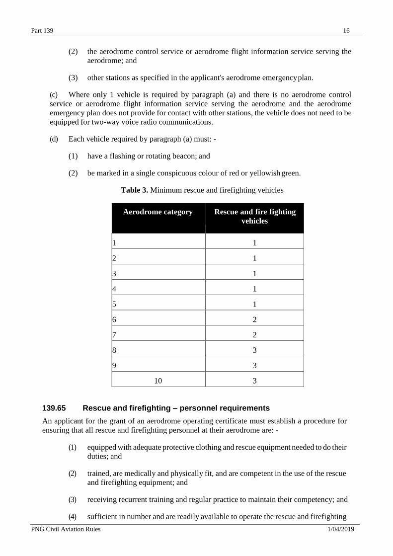
Table 3. Minimum rescue and firefighting vehicles
Aerodrome category Rescue and fire fighting
vehicles
1 1
2 1
3 1
4 1
5 1
6 2
7 2
8 3
9 3
10 3
139.65 Rescue and firefighting – personnel requirements
An applicant for the grant of an aerodrome operating certificate must establish a procedure for
ensuring that all rescue and firefighting personnel at their aerodrome are: -
(1) equipped with adequate protective clothing and rescue equipment needed to do their
duties; and
(2) trained, are medically and physically fit, and are competent in the use of the rescue
and firefighting equipment; and
(3) receiving recurrent training and regular practice to maintain their competency; and
(4) sufficient in number and are readily available to operate the rescue and firefighting
Part 139 17
PNG Civil Aviation Rules 1/04/2019
vehicle or vehicles and the equipment at maximum capacity; and
(5) alerted by siren, alarm, or other means to any existing or impending emergency
requiring their assistance.
139.67 Rescue and firefighting – response capability
An applicant for the grant of an aerodrome operating certificate must, when required by the
Director, demonstrate the following rescue and firefighting response capability in optimum
conditions of visibility and surface conditions that complies with the requirements in Appendix
I.2.4.
139.69 Rescue and firefighting – communication and alerting system
An applicant for the grant of an aerodrome operating certificate must provide a discrete
communication system linking a fire station with the control tower, any other fire station on the
aerodrome and the rescue and fire fighting vehicles.
139.71 Public protection
(a) An applicant for the grant of an aerodrome operating certificate must provide at their
aerodrome, fencing or other suitable barrier that complies with Appendix I.9.
(b) The safeguards required by paragraph (a)(1) must: -
(1) in areas adjacent to the aerodrome operational area to which the public has direct
vehicle or pedestrian access: -
(i) be continuous barriers that may include existing structures, gates and doors
with secured or controlled access; and
(ii) be at least 1200 millimetres in height; and
(2) in other areas, be of a construction and height appropriate to prevent incursion by
animals likely to endanger aircraft operations.
139.73 Wildlife hazard management
(a) An applicant for the grant of an aerodrome operating certificate must, where any wildlife
presents a hazard to aircraft operations at their aerodrome, establish an environment management
programme to minimise or eliminate the wildlife hazard and comply with Appendix I.3; and
(b) Where there is potential for domestic animals to intrude into the movement areas of the
aerodrome, an applicant for an aerodrome operating certificate must conduct an awareness
programme with residents and settlements in the vicinity of an aerodrome about the
consequences of allowing domestic animals in their care to enter the aerodrome.
139.75 Notification of aerodrome data and information
An applicant for the grant of an aerodrome operating certificate must establish a procedure that
comply with Appendix B, to notify aeronautical information service providers certificated under
Part 175: -
(1) of the aerodrome data and information; and
Part 139 18
PNG Civil Aviation Rules 1/04/2019
(2) of any limitation established under rule 139.55 on the use of the aerodrome; and
(3) as soon as practicable, of any change that affects the use of the aerodrome.
139.77 Movement data reporting
An applicant for the grant of an aerodrome operating certificate must establish procedures for
collecting and reporting traffic movement data at the aerodrome on a monthly basis and report
that movement quarterly to the Director.
139.79 Aerodrome maintenance programme
(a) An applicant for the grant of an aerodrome operating certificate must establish a maintenance
programme, including preventive maintenance where appropriate, for maintaining the aerodrome
facilities in a condition that does not impair the safety, security, regularity or efficiency of aircraft
operations that complies with Appendix J.
139.81 Aerodrome inspection programme
An applicant for the grant of an aerodrome operating certificate must: -
(1) establish an aerodrome inspection programme for ensuring that the aerodrome and
its facilities are maintained in accordance with the requirements and standards of this
Part; and
(2) provide appropriate equipment for use in conducting the aerodrome inspections in
accordance with the programme required by paragraph (1); and
(3) establish procedures for ensuring that qualified personnel to perform the aerodrome
inspections in accordance with the programme required by paragraph (1); and
(4) establish a reporting system for ensuring prompt correction of unsafe aerodrome
conditions that is noted during an aerodrome inspection.
139.83 Visual aids for navigation – maintenance and checking
(a) An applicant for the grant of an aerodrome operating certificate must establish a
maintenance programme for the visual aids for navigation that are installed on the aerodrome.
(b) The maintenance programme required by paragraph (a) must include: -
(1) procedures for ensuring that each visual aid for navigation provides reliable and
accurate guidance information to the users in accordance with the applicable
standards prescribed in Appendix J.5; and
(2) details on the number of lights that may be allowed to be unserviceable in each
lighting system to ensure continuity of guidance to the user; and
(3) procedures for restoring any unserviceable or deteriorated items back into service
without undue delay.
139.85 Works on Aerodromes
An applicant for the grant of an aerodrome operating certificate must establish procedures,
including precautions to be taken for ensuring that any works carried out on the aerodrome do
Part 139 19
PNG Civil Aviation Rules 1/04/2019
not endanger aircraft operations.
139.87 Ground Vehicles
(a) An applicant for the grant of an aerodrome operating certificate must establish
procedures for limiting and controlling access by ground vehicles to the operational areas of the
aerodrome.
(b) Under the procedures required by paragraph (a), ground vehicle access to the operational
areas of the aerodrome must be limited to those vehicles that are necessary for the operation of
the aerodrome and the operation of aircraft.
(c) When an aerodrome control service is in operation at the aerodrome, the procedures
required by paragraph (a) must: -
(1) provide for the safe and orderly access to, and operation on the aerodrome operational
area of ground vehicles; and
(2) require each ground vehicle operating on the operational area of the aerodrome to be
controlled by: -
(i) two-way radio communications between the vehicle and the aerodrome
control service; or
(ii) if the vehicle does not have radio communications, an accompanying escort
vehicle that has two-way communication with the aerodrome control service;
or
(iii) if it is not practical to have two-way radio communications or an accompanying
escort vehicle, by adequate measures such as signs, signals or guards for
controlling the vehicle; and
(d) When an aerodrome control service is not in operation at the aerodrome, the procedures
required by paragraph (a) must provide for ground vehicles operating on the operational area of
the aerodrome to be controlled by signs or prearranged signals.
(e) The procedures required by paragraph (a) must ensure that each employee, tenant, or
contractor who operates a ground vehicle on any portion of the aerodrome which has access to
the operational area of the aerodrome is familiar with, and complies with, the procedures
established by the certificate holder for the operation of ground vehicles on the aerodrome.
139.89 Unsafe conditions
An applicant for an aerodrome operating certificate must establish procedures for ensuring that
aircraft operations are restricted, or if necessary prohibited, on any part of the aerodrome where
an unsafe condition exists.
139.91 Documentation
An applicant for an aerodrome operating certificate must: -
(1) hold copies of relevant documents necessary for the provision and operation of the
aerodrome and the associated services and facilities; and
Part 139 20
PNG Civil Aviation Rules 1/04/2019
(2) establish a procedure for controlling the document required under paragraph (1) to
ensure that: -
(i) establish a procedure for controlling the document are available to personnel at
each location where personnel need access to the documentation; and
(ii) every obsolete document is promptly removed from every point of issue; and
(iii) the current version of each item of documentation can be identified to prevent
the use of superseded material.
139.93 Safety management system
(a) An applicant for the grant of an aerodrome operating certificate must establish and
implement a safety management system which meets the requirements of Part 100.
(b) The safety management system required by paragraph (a) must include a runway safety
programme.
(c) The safety management system required by paragraph (a) must oblige all users of the
aerodrome, including fixed-base operators, ground handling agencies and other organizations
that perform activities independently at the aerodrome in relation to flight or aircraft handling,
to comply with the requirements laid down by the aerodrome operator with regard to safety at
the aerodrome.
139.95 Quality management system
An applicant for the grant of an aerodrome operating certificate must establish and implement a
quality management system which meets the requirements of Part 100.
139.96 Aerodrome Security Programme
An applicant for the grant of an aerodrome operating certificate for a security designated airport
must establish, implement and maintain an aerodrome security programme which meets the requirements
of Part 107.
139.97 Aerodrome exposition
(a) An applicant for the grant of an aerodrome operating certificate must provide the Director
with an exposition that contains the following: -
(1) a statement signed by the Chief Executive on behalf of the applicant's organisation,
confirming that the exposition and any included manuals: -
(i) define the organisation and demonstrate its means and methods for
ensuring ongoing compliance with this Part; and
(ii) is to be complied with at all times; and
(2) the titles and names of the senior persons required by 139.51(a)(1) and (2); and
(3) the duties and responsibilities of the senior persons specified under paragraph(a)(2)
including matters for which they have responsibility to deal directly with the Director
on behalf of the organisation; and
Part 139 21
PNG Civil Aviation Rules 1/04/2019
(4) an organisation chart showing lines of responsibility of the senior person or persons
specified under paragraph (a)(2); and
(5) details of any limitations on the use of the aerodrome established under rule 139.55; and
(6) details of each current exemption granted to the applicant from any requirements
prescribed in Subparts A, B, C or D; and
(7) the aerodrome emergency plan required by rule139.57; and
(8) a statement of the rescue and firefighting category determined under 139.59 with a
description of the following:
(i) extinguishing agents required by rules 139.61; and
(ii) vehicles required by rule 139.63; and
(iii) procedure and personnel required by rule 139.65; and
(iv) details of the response capability required by rule 139.67; and
(v) discrete communication system required by 139.69.
(9) a description of the safeguards for public protection required by rule 139.71; and
(10) details of the environmental management programme when required by rule 139.73; and
(11) the procedures for the notification of aerodrome data and information required by
rule 139.75; and
(12) the procedures for the collection and reporting of traffic movement data required by
rule 139.77; and
(13) the aerodrome maintenance programme required by rule 139.79; and
(14) the aerodrome inspection programme, procedures and reporting system required by
rule 139.81; and
(15) the procedures for preventive maintenance and checking of the aerodrome visual
aids for navigation required by rule 139.83; and:
(16) the procedures and precautions for any works on the aerodrome required by rule
139.85; and
(17) the procedures for the control of ground vehicles required by rule 139.87; and
(18) the procedures for limiting aircraft operations if an unsafe aerodrome condition
occurs required by rule 139.89; and
(19) the procedures for management and control of documents necessary for the provision
and operation of the aerodrome and the associated services and facilities required by
rule 139.91; and
(20) details of the safety management system required by rule 139.93; and
Part 139 22
PNG Civil Aviation Rules 1/04/2019
(21) details of the quality management system required by rule 139.95; and
(22) a description of the measures taken to comply with the relevant security requirements
in rule part 107, including details of the security awareness programme and procedures
required by rule 107.101(d)(8) and (9); or
(23) the aerodrome security programme for a security designated airport which meets the
requirements of Part 107; and
(24) the procedures to control, amend, and distribute the exposition.
(b) The applicant’s exposition must be acceptable to the Director.
Subpart C — Operating Requirements
139.101 Continued compliance
A holder of an aerodrome operating certificate must: -
(1) hold at least one complete and current copy of the aerodrome exposition required by rule
139.97 on the aerodrome; and
(2) comply with all procedures, plans, systems and programmes detailed in the exposition; and
(3) make each applicable part of the exposition available to personnel who require those
parts to carry out their duties; and
(4) continue to meet the standards and comply with the requirements of Subpart B prescribed
for aerodrome certification under this Part; and
(5) notify the Director of any change of address for service, telephone number, or facsimile
number required by form CA 139/01 within 28 days of the change; and
(6) ensure the aerodrome exposition required by rule 139.97 remains acceptable to the Director.
139.103 Aerodrome emergency plan – maintenance
A holder of an aerodrome operating certificate must: -
(1) ensure that all aerodrome personnel having duties and aerodrome emergency
responsibilities under the holder's aerodrome emergency plan required by rule 139.57 are
familiar with their assignments and are properly trained; and
(2) test the aerodrome emergency plan required by rule 139.57 by conducting: -
(i) a full-scale aerodrome emergency exercise at intervals not exceeding 2 years; and
(ii) special emergency exercises in the intervening year to ensure that any deficiencies
found during the full-scale aerodrome emergency exercise have been corrected; and
(3) review the plan after each of the exercises specified in subparagraph (2) or after an actual
emergency, to correct any deficiency found; and
Part 139 23
PNG Civil Aviation Rules 1/04/2019
co-ordinate its aerodrome emergency plan required by rule 139.57 with law enforcement agencies, security
providers, rescue and firefighting agencies, medical personnel and organisations, the principal tenants of the
aerodrome, and all other persons who have responsibilities in the plan.
139.105 Rescue and firefighting – operational requirements
(a) Except as provided in paragraph (c), the holder of an aerodrome operating certificate must
provide on the aerodrome, during operations by aeroplanes having a certificated seating
configuration of 20 passengers’ seats or more, excluding any required flight crew member seat,
that are engaged in regular air operations for the carriage of passengers, the rescue and firefighting
capability meeting the minimum requirements of rules 139.61 and 139.63.
(b) Except as provided in paragraph (c), if an increase in the movements or a change in the
type of air transport aeroplanes using the aerodrome results in an increase in the rescue and
firefighting category of the aerodrome applicable under rule 139.59, the certificate holder must
increase the rescue and firefighting capability to the minimum required for that higher category
under rules139.61 and 139.63.
(c) Subject to paragraph (d), during any period of operations when the use of the aerodrome
is limited to aeroplanes having a lower specification than that normally applicable under rule
139.59, the certificate holder may reduce the rescue and firefighting capability to a lower level
required for the aerodrome category corresponding to the highest specification aeroplane
regularly using the aerodrome provided: -
(1) procedures for, and the persons having the authority to implement, the reductions
are included in the exposition required by rule 139.97:
(2) procedures for recall of the full aerodrome rescue and firefighting capability are
included in the exposition required by rule 139.97:
(3) information on the reduction is forwarded to the Aeronautical Information Service
for appropriate publication.
(d) Any reduction in the rescue and firefighting capability under paragraph (c) must not be
implemented until the information is promulgated by the Aeronautical Information Service for
appropriate publication.
(e) The holder of an aerodrome operating certificate must employ a system of preventive
maintenance of their rescue and firefighting vehicle or vehicles to ensure effectiveness of the
equipment and compliance with the required response time throughout the life of each vehicle.
(f) The holder of an aerodrome operating certificate must immediately replace any required
rescue and firefighting vehicle that becomes inoperative to the extent that the certificate holder
cannot meet the response capability required by rule 139.67, with a vehicle that enables the
certificate holder to meet that capability.
(g) If a replacement vehicle is not available immediately, the certificate holder must provide
the notification required by rule 139.117.
(h) If the required response capability is not restored within 72 hours, the certificate holder
must limit regular air operations on the aerodrome to those aeroplanes compatible with the
aerodrome category corresponding to the remaining operative rescue and firefighting vehicle or
vehicles.
Part 139 24
PNG Civil Aviation Rules 1/04/2019
(i) The holder of an aerodrome operating certificate must, with the rescue and firefighting
equipment required under this Part and the number of trained personnel who are required to assure
an effective operation, respond to each aircraft emergency during operations of the kind specified
in paragraph (a).
139.107 Aeronautical Study
(a) The holder of an aerodrome operating certificate must monitor operations and conduct an
aeronautical study when a significant change in aerodrome operations occurs that may affect the
safety of aircraft operations.
(b) For the purpose of paragraph (a), a significant change in aerodrome operations include a
change in aerodrome aircraft traffic, a change in aircraft operations type, a change in the
aerodrome physical characteristics, an increase in aerodrome accidents/incidents, or a change in
airspace designation.
139.109 Aerodrome aircraft traffic management
Each holder of an aerodrome operating certificate must ensure the provision of an aerodrome
control service at their aerodrome when so required by the Director in the interest of safety.
139.111 Aerodrome aircraft traffic services
When an ATS is required to be provided at the aerodrome the holder of the aerodrome operating
certificate must establish a written agreement with a holder of an air traffic service organisation
certificate issued in accordance with Part 172 for the provision of the ATS.
139.113 Apron management service
(a) The holder of an aerodrome operating certificate must ensure that the aerodrome is
provided with an appropriate apron traffic management service, when such service is warranted
by the volume of traffic and operating conditions.
(b) The holder of an aerodrome operating certificate for an aerodrome that has an aerodrome
control service and requires an apron management service must, ensure the coordination and
safe, transition of aerodrome traffic between the apron management service and the aerodrome
control service.
139.115 Protection of navigation aids & ATS facilities
A holder of an aerodrome operating certificate must: -
(1) prevent any construction or activity on the aerodrome, or surrounding area that the
certificate holder has authority over, that could have an adverse effect on the
operation of any electronic or visual navigation aid or air traffic service facility on
the aerodrome; and
(2) prevent, as far as it is within the certificate holder's authority, any interruption of
visual or electronic signals of navigation aids for the aerodrome.
139.117 Aerodrome condition notification
The holder of an aerodrome operating certificate must, in accordance with the procedure required
by rule 139.75, notify the Aeronautical Information Service, as soon as practicable (for the issue
Part 139 25
PNG Civil Aviation Rules 1/04/2019
of a NOTAM), of any aerodrome operational condition at the aerodrome that may affect the safe
operation of aircraft.
139.119 Changes to certificate holder's organisation
(a) The holder of an aerodrome operating certificate must ensure that the aerodrome
exposition required by rule 139.97 is amended to remain a current description of the aerodrome
and its associated plans, programmes, services, systems, procedures, and facilities.
(b) The certificate holder must ensure that any amendments made to the aerodrome
exposition meets the applicable requirements of this Part and comply with the amendment
procedures contained in the exposition.
(c) The certificate holder must provide the Director with a copy of each amendment to the
aerodrome exposition as soon as practicable after its incorporation into the exposition.
(d) If the holder of an aerodrome certificate proposes to change, or changes, the person
identified as the Chief Executive, or any of the senior persons required by rule 139.51(a)(2), the
certificate holder must notify the Director prior to the change or as soon as practicable after the
change if prior notification is not possible.
(e) The changes of persons referred to in paragraph (d) must be accepted by the Director after
satisfactory demonstration of the fit and proper person criteria required by Section 50 of the Act
before being incorporated into the certificate holder’s exposition.
(f) The Director may impose conditions under which the holder of an aerodrome operating
certificate may operate during or following any of the changes specified in paragraph (d) and (e).
(g) The holder of an aerodrome operating certificate must comply with any conditions
imposed by the Director under paragraph (f).
(h) If any of the changes under paragraph (d) and (e) require an amendment to the aerodrome
operating certificate, the holder of the certificate must forward the certificate to the Director as
soon as practicable for endorsement of the amendment.
(i) The holder of an aerodrome operating certificate must amend the holder's exposition as
the Director may consider necessary in the interests of safety.
139.121 Deviations The holder of an aerodrome operating certificate may deviate from any requirement of Subpart C, or D
if an emergency occurs requiring immediate action for the protection of life or property involving
carriage by air
(a) A certificate holder who deviates from a requirement of Subpart C, or D under paragraph
(a) must provide a written report to the Director as soon as practicable, but in any event not later
than 14 days after the emergency. The report must cover the nature, extent and duration of the
deviation.
Part 139 26
PNG Civil Aviation Rules 1/04/2019
Subpart D — Aerodrome Security 139.201 Non-security designated aerodrome security requirements
The holder of an aerodrome operating certificate that is not a security designated aerodrome must, in
addition to complying with the requirements of rule 139.71:
(a) have a contingency plan to provide, when so required by the Director: -
(1) areas at their aerodrome for the screening of passengers and baggage: -
(i) areas for the screening of international passengers, crew, and their baggage, prior
to aircraft boarding:
(ii) sterile areas where international passengers and crew subject to screening are
prevented from having access to unauthorised articles or contact with unscreened
persons:
(iii) areas for the separation of arriving passengers and crew from departing passengers
during international deplaning to prevent arriving, transit, and transfer passengers
and crew having contact with any person who has been subject to screening; and
(2) measures to subject vehicles entering the aerodrome, and the items contained within
them, to screening and other appropriate security controls.
(b) comply with the following rules
(1) designate an isolated aircraft parking position at their aerodrome that complies with
appendix C.9; and
(2) provide and maintain lighting, and emergency lighting in the event of failure of the
normal lighting system, on any parking areas at their aerodrome used at night by
aeroplanes having a certificated seating configuration of 20 seats or more passengers,
excluding any required flight crew member seat, that are engaged in scheduled air
transport operations for the carriage of passengers; and
(3) provide lighting, or have portable lighting available within 30 minutes, on any
designated isolated aircraft parking area at their aerodrome intended to be used at night;
and
(4) ensure that personnel engaged, employed or contracted by the certificate holder undergo
a security awareness programme, and that each person required to carry out specific
security tasks is trained for those tasks; and
(5) establish procedures for identifying, reporting to the Director, and dealing with, breaches
of and deficiencies in, any security procedures established by the holder and any
provisions of any enactment relating to security at the aerodrome; and
(c) establish and facilitate a security awareness group in order to ensure sufficient
information is given to other organisations at the aerodrome to motivate security
awareness on the part of all personnel; and
Part 139 27
PNG Civil Aviation Rules 1/04/2019
(d) convene, chair, and minute meetings of the security awareness group established
under paragraph (c) at regular intervals not exceeding 12 months.
Subpart E — Transition Provisions
139.301 – Reserved
Part 139 28
PNG Civil Aviation Rules 1/04/2019
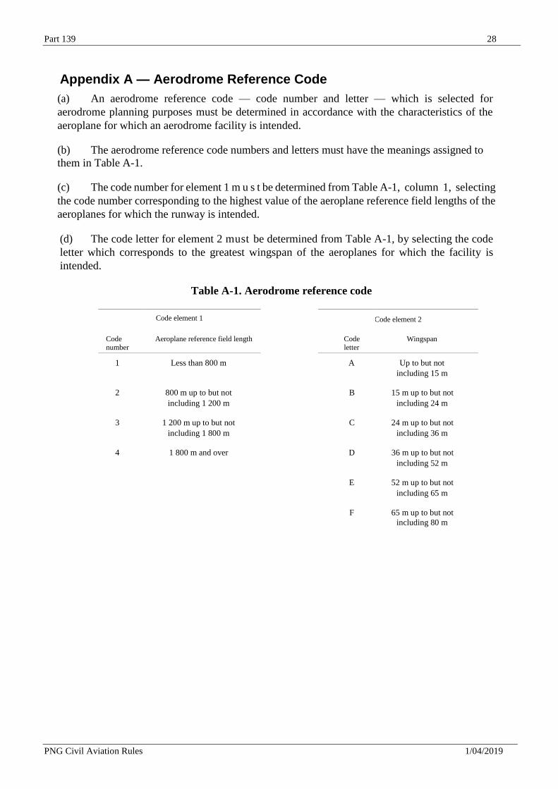
Appendix A — Aerodrome Reference Code
(a) An aerodrome reference code — code number and letter — which is selected for
aerodrome planning purposes must be determined in accordance with the characteristics of the
aeroplane for which an aerodrome facility is intended.
(b) The aerodrome reference code numbers and letters must have the meanings assigned to
them in Table A-1.
(c) The code number for element 1 m u s t be determined from Table A-1, column 1, selecting
the code number corresponding to the highest value of the aeroplane reference field lengths of the
aeroplanes for which the runway is intended.
(d) The code letter for element 2 must be determined from Table A-1, by selecting the code
letter which corresponds to the greatest wingspan of the aeroplanes for which the facility is
intended.
Table A-1. Aerodrome reference code
Code element 1 Code element 2
Code number
Aeroplane reference field length Code letter
Wingspan
1 Less than 800 m A Up to but not
including 15 m
2 800 m up to but not B 15 m up to but not
including 1 200 m including 24 m
3 1 200 m up to but not C 24 m up to but not
including 1 800 m including 36 m
4 1 800 m and over D 36 m up to but not
including 52 m
E 52 m up to but not
including 65 m
F 65 m up to but not including 80 m
Part 139 29
PNG Civil Aviation Rules 1/04/2019
Appendix B — Aerodrome Data
B.1 Aeronautical data
(a) Determination and reporting of aerodrome-related aeronautical data must be in accordance
with the accuracy and integrity classification required to meet the needs of the end-users of
aeronautical data.
(b) Where aerodrome mapping data is made available, the selection of the aerodrome mapping
data features to be collected must be made with consideration of the intended applications.
(c) Digital data error detection techniques must be used during the transmission and/or storage of
aeronautical data and digital data sets.
B.2 Aerodrome reference point
(a) An aerodrome reference point must be established for an aerodrome.
(b) The aerodrome reference point must be located near the initial or planned geometric centre
of the aerodrome and must normally remain where first established.
(c) The position of the aerodrome reference point must be measured and reported to the
aeronautical information services authority in degrees, minutes and seconds.
B.3 Aerodrome and runway elevations
(a) The aerodrome elevation and geoid undulation at the aerodrome elevation position m u s t be
measured to the accuracy of one-half metre or foot and reported to the aeronautical information
services authority.
(b) For an aerodrome used by international civil aviation for non-precision approaches, the
elevation and geoid undulation of each threshold, the elevation of the runway end and any
significant high and low intermediate points along the runway must be measured to the accuracy
of one-half metre or foot and reported to the aeronautical information services authority.
(c) For precision approach runway, the elevation and geoid undulation of the threshold, the
elevation of the runway end and the highest elevation of the touchdown zone must be measured
to the accuracy of one-quarter metre or foot and reported to the aeronautical information services
authority.
B.4 Aerodrome reference temperature
An aerodrome reference temperature must be determined for an aerodrome in degrees Celsius.
B.5 Aerodrome dimensions and related information
(a) The following data must be measured or described, as appropriate, for each facility provided
on an aerodrome:
(1) runway — true bearing to one-hundredth of a degree, designation number, length,
width, displaced threshold location to the nearest metre or foot, slope, surface type, type
of runway and, for a precision approach runway category I, the existence of an obstacle
free zone when provided;
Part 139 30
PNG Civil Aviation Rules 1/04/2019
(2) Strip, RESA, Stopway length width to the nearest metre or foot, surface type and
arresting system – location (which runway end) and description
(3) taxiway — designation, width, surface type;
(4) apron — surface type, aircraft stands;
(5) the boundaries of the air traffic control service;
(6) clearway — length to the nearest metre or foot, ground profile;
(7) visual aids for approach procedures, marking and lighting of runways, taxiways and
aprons, other visual guidance and control aids on taxiways and aprons, including taxi-
holding positions and stopbars, and location and type of visual docking guidance
systems;
(8) location and radio frequency of any VOR aerodrome checkpoint;
(9) location and designation of standard taxi-routes; and
(10) distances to the nearest metre or foot of localizer and glide path elements comprising an
instrument landing system (ILS) or azimuth and elevation antenna of a microwave
landing system (MLS) in relation to the associated runway extremities.
(b) The geographical coordinates of each threshold must be measured and reported to the
aeronautical information services authority in degrees, minutes, seconds and hundredths of
seconds.
(c) The geographical coordinates of appropriate taxiway centre line points must be measured
and reported to the aeronautical information services authority in degrees, minutes, seconds and
hundredths of seconds.
(d) The geographical coordinates of each aircraft stand must be measured and reported to the
aeronautical information services authority in degrees, minutes, seconds and hundredths of
seconds.
(e) The geographical coordinates of obstacles in Area 2 (the part within the aerodrome boundary)
and in Area 3 must be measured and reported to the aeronautical information services authority
in degrees, minutes, seconds and tenths of seconds. In addition, the top elevation, type, marking
and lighting (if any) of obstacles must be reported to the aeronautical information services
authority.
B.6 Strength of pavements
(a) The bearing strength of a pavement must be determined.
(b) The bearing strength of a pavement intended for aircraft of apron (ramp) mass greater than
5700 kg must be made available using the aircraft classification number — pavement
classification number (ACN-PCN) method by reporting all of the following information:
(1) the pavement classification number (PCN);
(2) pavement type for ACN-PCN determination;
Part 139 31
PNG Civil Aviation Rules 1/04/2019
(3) subgrade strength category;
(4) maximum allowable tire pressure category or maximum allowable tire pressure value;
(5) evaluation method.
(c) The pavement classification number (PCN) reported must indicate that an aircraft with an
aircraft classification number (ACN) equal to or less than the reported PCN can operate on the
pavement subject to any limitation on the tire pressure, or aircraft all-up mass for specified aircraft
type(s).
(d) The ACN of an aircraft m u s t be determined in accordance with the standard procedures
associated with the ACN-PCN method.
(e) For the purposes of determining the ACN, the behaviour of a pavement must be classified as
equivalent to a rigid or flexible construction.
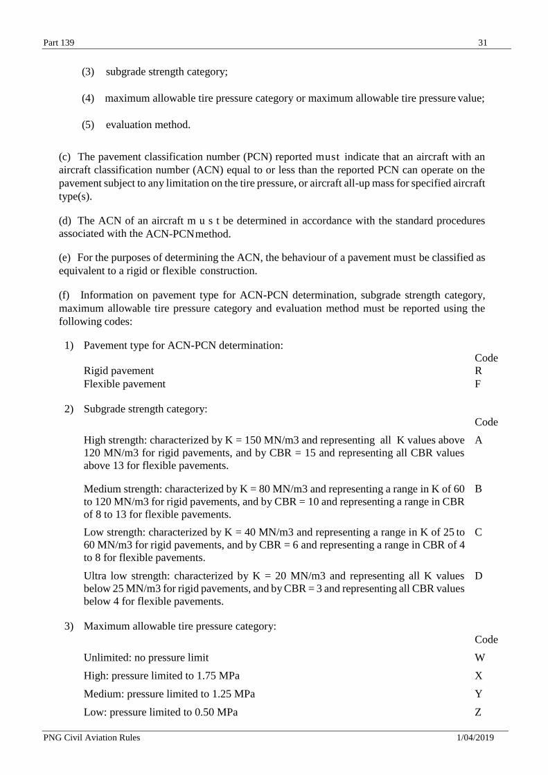
(f) Information on pavement type for ACN-PCN determination, subgrade strength category,
maximum allowable tire pressure category and evaluation method must be reported using the
following codes:
1) Pavement type for ACN-PCN determination:
Code Rigid pavement R Flexible pavement F
2) Subgrade strength category:
Code
High strength: characterized by K = 150 MN/m3 and representing all K values above
120 MN/m3 for rigid pavements, and by CBR = 15 and representing all CBR values
above 13 for flexible pavements.
A
Medium strength: characterized by K = 80 MN/m3 and representing a range in K of 60
to 120 MN/m3 for rigid pavements, and by CBR = 10 and representing a range in CBR
of 8 to 13 for flexible pavements.
B
Low strength: characterized by K = 40 MN/m3 and representing a range in K of 25 to
60 MN/m3 for rigid pavements, and by CBR = 6 and representing a range in CBR of 4
to 8 for flexible pavements.
C
Ultra low strength: characterized by K = 20 MN/m3 and representing all K values
below 25 MN/m3 for rigid pavements, and by CBR = 3 and representing all CBR values
below 4 for flexible pavements.
D
3) Maximum allowable tire pressure category:
Code
Unlimited: no pressure limit W
High: pressure limited to 1.75 MPa X
Medium: pressure limited to 1.25 MPa Y
Low: pressure limited to 0.50 MPa Z
Part 139 32
PNG Civil Aviation Rules 1/04/2019
4) Evaluation method:
Code
Technical evaluation: representing a specific study of the pavement characteristics
and application of pavement behaviour technology.
T
Using aircraft experience: representing a knowledge of the specific type and mass of
aircraft satisfactorily being supported under regular use.
U
(g) The bearing strength of a pavement intended for aircraft of apron (ramp) mass equal to or
less than 5 700 kg must be made available by reporting the following information:
(1) maximum allowable aircraft mass;
and ( 2 ) maximum allowable tire
pressure.
B.7 Pre-flight altimeter check location
(a) One or more pre-flight altimeter check locations must be established for an aerodrome.
(b) The elevation of a pre-flight altimeter check location m u s t be given as the average elevation,
rounded to the nearest metre or foot, of the area on which it is located. The elevation of any
portion of a pre-flight altimeter check location must be within 3 m (10 ft) of the average elevation
for that location.
B.8 Declared distances
The following distances m u s t be calculated to the nearest metre or foot for a runway
intended for use by international commercial air transport:
(1) take-off run available;
(2) take-off distance available;
(3) accelerate-stop distance available; and
(4) landing distance available.
B.9 Condition of the movement area and related facilities
B.9.1 Condition of the movement area
(a) Information on the condition of the movement area and the operational status of related
facilities m u s t be provided to the appropriate aeronautical information services units, and similar
information of operational significance to the air traffic services units, to enable those units to
provide the necessary information to arriving and departing aircraft. The information must be
kept up to date and changes in conditions reported without delay.
(b) The condition of the movement area and the operational status of related facilities must be
monitored, and reports on matters of operational significance affecting aircraft and aerodrome
operations must be provided in order to take appropriate action, particularly in respect of the
following:
(1) construction or maintenance work;
Part 139 33
PNG Civil Aviation Rules 1/04/2019
(2) rough or broken surfaces on a runway, a taxiway or an apron;
(3) water on a runway, a taxiway or an apron;
(4) other contaminants on a runway, taxiway or apron;
(5) other temporary hazards, including parked aircraft;
(6) failure or irregular operation of part or all of the aerodrome visual aids; and
(7) failure of the normal or secondary power supply.
(c) To facilitate compliance with B.9.1(a) and (b), inspections of the movement area must be
carried out each day at least once where the code number is 1 or 2 and at least twice where the
code number is 3 or 4.
B.9.2 Water on a runway
(a) Information that a runway or portion thereof may be slippery when wet must be made available.
(b) Notification must be given to aerodrome users when the friction level of a paved runway or
portion thereof is less than that specified by the Director in accordance with J.2(c), (d) and (e).
B.10 Rescue and firefighting
(a) Information concerning the level of protection provided at an aerodrome for aircraft rescue
and firefighting purposes must be made available.
(b) Changes in the level of protection normally available at an aerodrome for rescue and
firefighting m u s t be notified to the appropriate air traffic services units and aeronautical
information services units to enable those units to provide the necessary information to arriving
and departing aircraft. When such a change has been corrected, the above units must be advised
accordingly.
B.11 Visual approach slope indicator systems
The following information concerning a visual approach slope indicator system installation must
be made available:
(1) associated runway designation number;
(2) type of system according to E.3.13(b). For an AT-VASIS, PAPI or APAPI installation,
the side of the runway on which the lights are installed, i.e. left or right, must be given;
(3) where the axis of the system is not parallel to the runway centre line, the angle of
displacement and the direction of displacement, i.e. left or right, must be indicated;
(4) nominal approach slope angle(s). For a T-VASIS or an AT-VASIS this must be angle
Ɵ according to the formula in Figure E-18 and for a PAPI and an APAPI this must be
angle (B + C) ÷ 2 and (A + B) ÷ 2, respectively as in Figure E-20; and
(5) minimum eye height(s) over the threshold of the on-slope signal(s). For a T-VASIS or
an AT-VASIS this must be the lowest height at which only the wing bar(s) are visible;
however, the additional heights at which the wing bar(s) plus one, two or three fly-down
light units come into view may also be reported if such information would be of benefit
Part 139 34
PNG Civil Aviation Rules 1/04/2019
to aircraft using the approach. For a PAPI this must be the setting angle of the third unit
from the runway minus 2, i.e. angle B minus 2, and for an APAPI this must be the
setting angle of the unit farther from the runway minus 2, i.e. angle A minus 2.
B.12 Coordination between aeronautical information services and aerodrome
authorities
(a) To ensure that aeronautical information services units obtain information to enable them to
provide up-to-date pre-flight information and to meet the need for in-flight information,
arrangements must be made between aeronautical information services and aerodrome authorities
responsible for aerodrome services to report to the responsible aeronautical information services
unit, with a minimum of delay:
(1) information on the status of certification of aerodromes and aerodrome conditions (ref. B.9,
B.10 and B.11);
(2) the operational status of associated facilities, services and navigation aids within their
area of responsibility;
(3) any other information considered to be of operational significance.
(b) Before introducing changes to the air navigation system, due account must be taken by the
services responsible for such changes of the time needed by aeronautical information services for
the preparation, production and issue of relevant material for promulgation. To ensure timely
provision of the information to aeronautical information services, close coordination between
those services concerned is therefore required.
(c) Of a particular importance are changes to aeronautical information that affect charts and/or
computer-based navigation systems which qualify to be notified by the aeronautical information
regulation and control (AIRAC) system. The predetermined, internationally agreed AIRAC
effective dates in addition to 14 days postage time must be observed by the responsible aerodrome
services when submitting the raw information/data to aeronautical information services.
(d) The aerodrome services responsible for the provision of raw aeronautical information/data to
the aeronautical information services must do that while taking into account accuracy and
integrity requirements required to meet the needs of the end-user of aeronautical data.
Appendix C — Physical Characteristics
C.1 Runways
C.1.1 Surface of runways
(a) The surface of a runway must be constructed without irregularities that would impair the
runway surface friction characteristics or otherwise adversely affect the take-off or landing of
an aeroplane.
(b) A paved runway must be so constructed or resurfaced as to provide surface friction
characteristics at or above the minimum friction level prescribed under this Part.
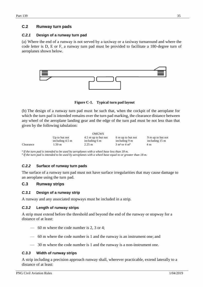
Part 139 35
PNG Civil Aviation Rules 1/04/2019
C.2 Runway turn pads
C.2.1 Design of a runway turn pad
(a) Where the end of a runway is not served by a taxiway or a taxiway turnaround and where the
code letter is D, E or F, a runway turn pad must be provided to facilitate a 180-degree turn of
aeroplanes shown below.
Figure C-1. Typical turn pad layout
(b) The design of a runway turn pad must be such that, when the cockpit of the aeroplane for
which the turn pad is intended remains over the turn pad marking, the clearance distance between
any wheel of the aeroplane landing gear and the edge of the turn pad must be not less than that
given by the following tabulation:
OMGWS
Up to but not including 4.5 m
4.5 m up to but not including 6 m
6 m up to but not including 9 m
9 m up to but not including 15 m
Clearance 1.50 m 2.25 m 3 ma or 4 mb 4 m
a If the turn pad is intended to be used by aeroplanes with a wheel base less than 18 m. b If the turn pad is intended to be used by aeroplanes with a wheel base equal to or greater than 18 m.
C.2.2 Surface of runway turn pads
The surface of a runway turn pad must not have surface irregularities that may cause damage to
an aeroplane using the turn pad.
C.3 Runway strips
C.3.1 Design of a runway strip
A runway and any associated stopways must be included in a strip.
C.3.2 Length of runway strips
A strip must extend before the threshold and beyond the end of the runway or stopway for a
distance of at least:
— 60 m where the code number is 2, 3 or 4;
— 60 m where the code number is 1 and the runway is an instrument one; and
— 30 m where the code number is 1 and the runway is a non-instrument one.
C.3.3 Width of runway strips
A strip including a precision approach runway shall, wherever practicable, extend laterally to a
distance of at least:
Part 139 36
PNG Civil Aviation Rules 1/04/2019
— 140 m where the code number is 3 or 4; and
— 70 m where the code number is 1 or 2;
on each side of the centre line of the runway and its extended centre line throughout the length of
the strip.
C.3.4 Objects on runway strips
(a) No fixed object, other than visual aids required for air navigation or those required for aircraft
safety purposes and which must be sited on the runway strip, and satisfying the relevant frangibility
requirements in Appendix E must be permitted on a runway strip:-
(1) within 77.5 m of the runway centre line of a precision approach runway category I, II
or III where the code number is 4 and the code letter is F; or
(2) within 60 m of the runway centre line of a precision approach runway category I, II
or III where the code number is 3 or 4; or
(3) within 45 m of the runway centre line of a precision approach runway category I where
the code number is 1 or 2.
(b) No mobile object must be permitted on those parts of the runway strip as defined in paragraph
(a) during the use of the runway for landing or take-off.
C.3.5 Grading of runway strips
The surface of that portion of a strip that abuts a runway, shoulder or stopway must be flush with
the surface of the runway, shoulder or stopway.
C.4 Runway end safety areas
C.4.1 Design of a runway end safety areas
A runway end safety area must be provided at each end of a runway strip where:
— the code number is 3 or 4; and
— the code number is 1 or 2 and the runway is an instrument one.
C.4.2 Dimensions of runway end safety areas
(a) A runway end safety area must extend from the end of a runway strip to a distance of at least
90 metres where:
— the code number is 3 or 4; and
— the code number is 1 or 2 and the runway is an instrument one.
(b) If an arresting system is installed, the above length may be reduced, based on the design
specification of the system, subject to acceptance by the Director.
(c) The width of a runway end safety area must be at least twice that of the associated runway.
C.5 Stopways
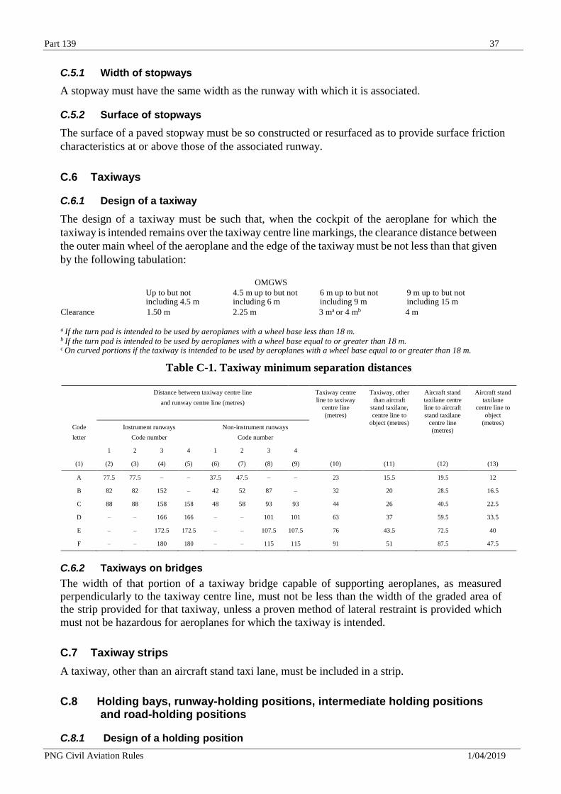
Part 139 37
PNG Civil Aviation Rules 1/04/2019
C.5.1 Width of stopways
A stopway must have the same width as the runway with which it is associated.
C.5.2 Surface of stopways
The surface of a paved stopway must be so constructed or resurfaced as to provide surface friction
characteristics at or above those of the associated runway.
C.6 Taxiways
C.6.1 Design of a taxiway
The design of a taxiway must be such that, when the cockpit of the aeroplane for which the
taxiway is intended remains over the taxiway centre line markings, the clearance distance between
the outer main wheel of the aeroplane and the edge of the taxiway must be not less than that given
by the following tabulation:
OMGWS
Up to but not including 4.5 m
4.5 m up to but not including 6 m
6 m up to but not including 9 m
9 m up to but not including 15 m
Clearance 1.50 m 2.25 m 3 ma or 4 mb 4 m
a If the turn pad is intended to be used by aeroplanes with a wheel base less than 18 m. b If the turn pad is intended to be used by aeroplanes with a wheel base equal to or greater than 18 m. c On curved portions if the taxiway is intended to be used by aeroplanes with a wheel base equal to or greater than 18 m.
Table C-1. Taxiway minimum separation distances
Distance between taxiway centre line
and runway centre line (metres)
Taxiway centre
line to taxiway
centre line
(metres)
Taxiway, other
than aircraft
stand taxilane,
centre line to
object (metres)
Aircraft stand
taxilane centre
line to aircraft
stand taxilane
centre line
(metres)
Aircraft stand
taxilane
centre line to
object
(metres) Code
letter
Instrument runways
Code number
Non-instrument runways
Code number
1 2 3 4 1 2 3 4
(1) (2) (3) (4) (5) (6) (7) (8) (9) (10) (11) (12) (13)
A 77.5 77.5 – – 37.5 47.5 – – 23 15.5 19.5 12
B 82 82 152 – 42 52 87 – 32 20 28.5 16.5
C 88 88 158 158 48 58 93 93 44 26 40.5 22.5
D – – 166 166 – – 101 101 63 37 59.5 33.5
E – – 172.5 172.5 – – 107.5 107.5 76 43.5 72.5 40
F – – 180 180 – – 115 115 91 51 87.5 47.5
C.6.2 Taxiways on bridges
The width of that portion of a taxiway bridge capable of supporting aeroplanes, as measured
perpendicularly to the taxiway centre line, must not be less than the width of the graded area of
the strip provided for that taxiway, unless a proven method of lateral restraint is provided which
must not be hazardous for aeroplanes for which the taxiway is intended.
C.7 Taxiway strips
A taxiway, other than an aircraft stand taxi lane, must be included in a strip.
C.8 Holding bays, runway-holding positions, intermediate holding positions
and road-holding positions
C.8.1 Design of a holding position
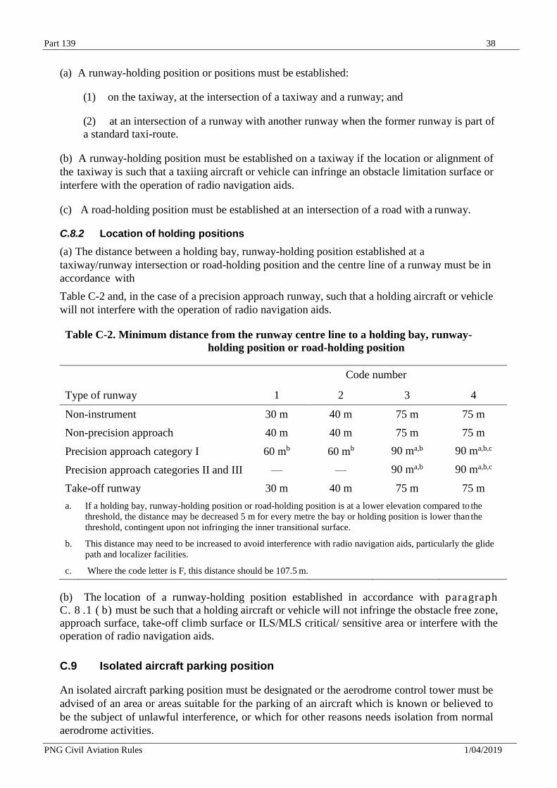
Part 139 38
PNG Civil Aviation Rules 1/04/2019
(a) A runway-holding position or positions must be established:
(1) on the taxiway, at the intersection of a taxiway and a runway; and
(2) at an intersection of a runway with another runway when the former runway is part of
a standard taxi-route.
(b) A runway-holding position must be established on a taxiway if the location or alignment of
the taxiway is such that a taxiing aircraft or vehicle can infringe an obstacle limitation surface or
interfere with the operation of radio navigation aids.
(c) A road-holding position must be established at an intersection of a road with a runway.
C.8.2 Location of holding positions
(a) The distance between a holding bay, runway-holding position established at a
taxiway/runway intersection or road-holding position and the centre line of a runway must be in
accordance with
Table C-2 and, in the case of a precision approach runway, such that a holding aircraft or vehicle
will not interfere with the operation of radio navigation aids.
Table C-2. Minimum distance from the runway centre line to a holding bay, runway-
holding position or road-holding position
Code number
Type of runway 1 2 3 4
Non-instrument 30 m 40 m 75 m 75 m
Non-precision approach 40 m 40 m 75 m 75 m
Precision approach category I 60 mb 60 mb
90 ma,b 90 ma,b,c
Precision approach categories II and III — — 90 ma,b 90 ma,b,c
Take-off runway 30 m 40 m 75 m 75 m
a. If a holding bay, runway-holding position or road-holding position is at a lower elevation compared to the
threshold, the distance may be decreased 5 m for every metre the bay or holding position is lower than the
threshold, contingent upon not infringing the inner transitional surface.
b. This distance may need to be increased to avoid interference with radio navigation aids, particularly the glide
path and localizer facilities.
c. Where the code letter is F, this distance should be 107.5 m.
(b) The location of a runway-holding position established in accordance with paragraph
C. 8 .1 ( b) must be such that a holding aircraft or vehicle will not infringe the obstacle free zone,
approach surface, take-off climb surface or ILS/MLS critical/ sensitive area or interfere with the
operation of radio navigation aids.
C.9 Isolated aircraft parking position
An isolated aircraft parking position must be designated or the aerodrome control tower must be
advised of an area or areas suitable for the parking of an aircraft which is known or believed to
be the subject of unlawful interference, or which for other reasons needs isolation from normal
aerodrome activities.
Part 139 39
PNG Civil Aviation Rules 1/04/2019
Appendix D — Obstacle Restriction and Removal
D.1 Obstacle limitation surfaces
D.1.1 Conical surface
(a) Description. — Conical surface: A surface sloping upwards and outwards from the
periphery of the inner horizontal surface.
(b) Characteristics: — The limits of the conical surface must comprise:
(1) a lower edge coincident with the periphery of the inner horizontal surface; and
(2) an upper edge located at a specified height above the inner horizontal surface.
(c) The slope of the conical surface must be measured in a vertical plane perpendicular to the
periphery of the inner horizontal surface.
D.1.2 Inner Horizontal surface
(a) Description. — Inner horizontal surface: A surface located in a horizontal plane above an
aerodrome and its environs.
(b) Characteristics. — The radius or outer limits of the inner horizontal surface must be
measured from a reference point or points established for such purpose.
(c) The height of the inner horizontal surface must be measured above an elevation datum
established for such purpose.
D.1.3 Approach surface
(a) Description. — Approach surface: An inclined plane or combination of planes preceding the
threshold.
(b) Characteristics. — The limits of the approach surface must comprise:
(1) an inner edge of specified length, horizontal and perpendicular to the extended centre
line of the runway and located at a specified distance before the threshold;
(2) two sides originating at the ends of the inner edge and diverging uniformly at a specified
rate from the extended centre line of the runway;
(3) an outer edge parallel to the inner edge; and
(4) the above surfaces must be varied when lateral offset, offset or curved approaches are
utilized, specifically, two sides originating at the ends of the inner edge and diverging
uniformly at a specified rate from the extended centre line of the lateral offset, offset or
curved ground track.
(c) The elevation of the inner edge must be equal to the elevation of the midpoint of the threshold.
(d) The slope(s) of the approach surface must be measured in the vertical plane containing the
centre line of the runway and must continue containing the centre line of any lateral offset or
curved ground track.
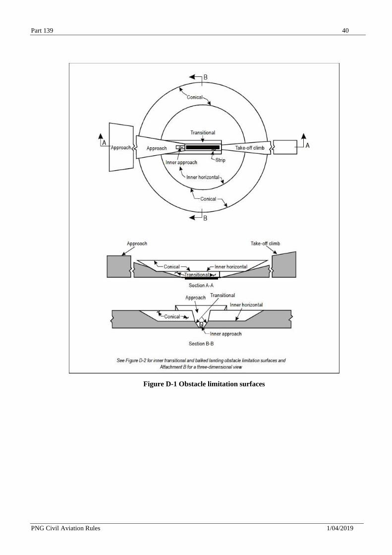
Part 139 40
PNG Civil Aviation Rules 1/04/2019
Figure D-1 Obstacle limitation surfaces
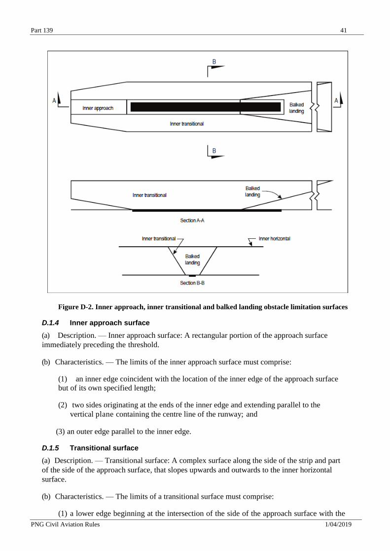
Part 139 41
PNG Civil Aviation Rules 1/04/2019
Figure D-2. Inner approach, inner transitional and balked landing obstacle limitation surfaces
D.1.4 Inner approach surface
(a) Description. — Inner approach surface: A rectangular portion of the approach surface
immediately preceding the threshold.
(b) Characteristics. — The limits of the inner approach surface must comprise:
(1) an inner edge coincident with the location of the inner edge of the approach surface
but of its own specified length;
(2) two sides originating at the ends of the inner edge and extending parallel to the
vertical plane containing the centre line of the runway; and
(3) an outer edge parallel to the inner edge.
D.1.5 Transitional surface
(a) Description. — Transitional surface: A complex surface along the side of the strip and part
of the side of the approach surface, that slopes upwards and outwards to the inner horizontal
surface.
(b) Characteristics. — The limits of a transitional surface must comprise:
(1) a lower edge beginning at the intersection of the side of the approach surface with the
Part 139 42
PNG Civil Aviation Rules 1/04/2019
inner horizontal surface and extending down the side of the approach surface to the inner
edge of the approach surface and from there along the length of the strip parallel to the
runway centre line; and
(2) an upper edge located in the plane of the inner horizontal surface.
(c) The elevation of a point on the lower edge must be:
(1) along the side of the approach surface — equal to the elevation of the approach surface at that point; and
(2) along the strip — equal to the elevation of the nearest point on the centre line of the
runway or its extension.
(d) The slope of the transitional surface must be measured in a vertical plane at right angles to
the centre line of the runway.
D.1.6 Inner transitional surface
(a) Description. — Inner transitional surface: A surface similar to the transitional surface but
closer to the runway.
(b) Characteristics. — The limits of an inner transitional surface must comprise:
(1) a lower edge beginning at the end of the inner approach surface and extending down the
side of the inner approach surface to the inner edge of that surface, from there along the
strip parallel to the runway centre line to the inner edge of the balked landing surface
and from there up the side of the balked landing surface to the point where the side
intersects the inner horizontal surface; and
(2) an upper edge located in the plane of the inner horizontal surface.
(c) The elevation of a point on the lower edge must be:
(1) along the side of the inner approach surface and balked landing surface — equal to the
elevation of the particular surface at that point; and
(2) along the strip — equal to the elevation of the nearest point on the centre line of the
runway or its extension.
(d) The slope of the inner transitional surface must be measured in a vertical plane at right
angles to the centre line of the runway.
D.1.7 Balked landing surface
(a) Description. — Balked landing surface: An inclined plane located at a specified distance
after the threshold, extending between the inner transitional surface.
(b) Characteristics. — The limits of the balked landing surface must comprise:
(1) an inner edge horizontal and perpendicular to the centre line of the runway and located
at a specified distance after the threshold;
(2) two sides originating at the ends of the inner edge and diverging uniformly at a
specified rate from the vertical plane containing the centre line of the runway; and
Part 139 43
PNG Civil Aviation Rules 1/04/2019
(3) an outer edge parallel to the inner edge and located in the plane of the inner
horizontal surface.
(c) The elevation of the inner edge must be equal to the elevation of the runway centre line at
the location of the inner edge.
(d) The slope of the balked landing surface must be measured in the vertical plane containing
the centre line of the runway.
D.1.8 Take-off climb surface
(a) Description. — Take-off climb surface: An inclined plane or other specified surface beyond
the end of a runway or clearway.
(b) Characteristics. — The limits of the take-off climb surface must comprise:
1) an inner edge horizontal and perpendicular to the centre line of the runway and located
either at a specified distance beyond the end of the runway or at the end of the clearway
when such is provided and its length exceeds the specified distance;
2) two sides originating at the ends of the inner edge, diverging uniformly at a specified
rate from the take-off track to a specified final width and continuing thereafter at that
width for the remainder of the length of the take-off climb surface; and
3) an outer edge horizontal and perpendicular to the specified take-off track.
(c) The elevation of the inner edge must be equal to the highest point on the extended runway
centre line between the end of the runway and the inner edge, except that when a clearway is
provided the elevation must be equal to the highest point on the ground on the centre line of the
clearway.
(d) In the case of a straight take-off flight path, the slope of the take-off climb surface must be
measured in the vertical plane containing the centre line of the runway.
(e) In the case of a take-off flight path involving a turn, the take-off climb surface must be a
complex surface containing the horizontal normal to its centre line, and the slope of the centre
line must be the same as that for a straight take-off flight path.
D.2 Obstacle limitation surfaces requirements
D.2.1 Non-instrument runways
(a) The following obstacle limitation surfaces must be established for a non-instrument runway:
(1) conical surface;
(2) inner horizontal surface;
(3) approach surface; and
(4) transitional surfaces.
(b) The heights and slopes of the surfaces must not be greater than, and their other dimensions
not less than, those specified in Table D-1.
Part 139 44
PNG Civil Aviation Rules 1/04/2019
(c) New objects or extensions of existing objects must not be permitted above an approach or
transitional surface except when, in the opinion of the appropriate authority, the new object or
extension would be shielded by an existing immovable object.
D.2.2 Non-precision approach runways
(a) The following obstacle limitation surfaces must be established for a non-precision approach
runway:
(1) conical surface;
(2) inner horizontal surface;
(3) approach surface; and
(4) transitional surfaces.
(b) The heights and slopes of the surfaces must not be greater than, and their other dimensions
not less than, those specified in Table D-1, except in the case of the horizontal section of the
approach surface described in paragraph (c) below.
(c) The approach surface must be horizontal beyond the point at which the 2.5 per cent slope intersects:
(1) a horizontal plane 150 m above the threshold elevation; or
(2) the horizontal plane passing through the top of any object that governs the obstacle
clearance altitude/height (OCA/H); whichever is the higher.
(d) New objects or extensions of existing objects must not be permitted above an approach surface
within 3 000 m of the inner edge or above a transitional surface except when, in the opinion of the
appropriate authority, the new object or extension would be shielded by an existing immovable
object.
D.2.3 Precision approach runway
(a) The following obstacle limitation surfaces must be established for a precision approach runway
category I:
(1) conical surface;
(2) inner horizontal surface;
(3) approach surface; and
(4) transitional surfaces.
(b) The following obstacle limitation surfaces must be established for a precision approach runway
category II or III:
(1) conical surface;
(2) inner horizontal surface;
(3) approach surface and inner approach surface;
(4) transitional surfaces;
Part 139 45
PNG Civil Aviation Rules 1/04/2019
(5) inner transitional surfaces; and
(6) balked landing surface.
(c) The heights and slopes of the surfaces must not be greater than, and their other dimensions
not less than, those specified in Table D-1, except in the case of the horizontal section of the
approach surface described in paragraph (d) below.
(d) The approach surface must be horizontal beyond the point at which the 2.5 per cent slope
intersects:
(1) a horizontal plane 150 m above the threshold elevation; or
(2) the horizontal plane passing through the top of any object that governs the obstacle
clearance limit; whichever is the higher.
(e) Fixed objects must not be permitted above the inner approach surface, the inner transitional
surface or the balked landing surface, except for frangible objects which because of their function
must be located on the strip. Mobile objects must not be permitted above these surfaces during
the use of the runway for landing.
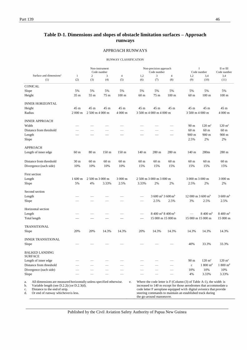
Published by the Civil Aviation Safety Authority of Papua New Guinea
Part 139 46
Table D-1. Dimensions and slopes of obstacle limitation surfaces – Approach
runways
APPROACH RUNWAYS
RUNWAY CLASSIFICATION
Non-instrument
Code number Non-precision approach
Code number
I
Code number
II or III
Code number
Surface and dimensionsa 1 2 3 4 1,2 3 4 1,2 3,4 3,4
(1) (2) (3) (4) (5) (6) (7) (8) (9) (10) (11)
CONICAL
Slope 5%
5% 5%
5%
5% 5% 5%
5% 5%
5%
Height 35 m 55 m 75 m 100 m 60 m 75 m 100 m 60 m 100 m 100 m
INNER HORIZONTAL
Height 45 m 45 m 45 m 45 m 45 m 45 m 45 m 45 m 45 m 45 m
Radius 2 000 m 2 500 m 4 000 m 4 000 m 3 500 m 4 000 m 4 000 m 3 500 m 4 000 m 4 000 m
INNER APPROACH
Width — — — — — — — 90 m 120 me 120 me
Distance from threshold — — — — — — — 60 m 60 m 60 m
Length — — — — — — — 900 m 900 m 900 m
Slope 2.5% 2% 2%
APPROACH
Length of inner edge 60 m 80 m 150 m 150 m 140 m 280 m 280 m 140 m 280m 280 m
Distance from threshold 30 m 60 m 60 m 60 m 60 m 60 m 60 m 60 m 60 m 60 m
Divergence (each side) 10% 10% 10% 10% 15% 15% 15% 15% 15% 15%
First section
Length 1 600 m 2 500 m 3 000 m 3 000 m 2 500 m 3 000 m 3 000 m 3 000 m 3 000 m 3 000 m
Slope 5% 4% 3.33% 2.5% 3.33% 2% 2% 2.5% 2% 2%
Second section
Length — — — — — 3 600 mb 3 600 mb 12 000 m 3 600 mb 3 600 mb
Slope — — — — — 2.5% 2.5% 3% 2.5% 2.5%
Horizontal section
Length — — — — — 8 400 mb 8 400 mb — 8 400 mb 8 400 mb
Total length — — — — — 15 000 m 15 000 m 15 000 m 15 000 m 15 000 m
TRANSITIONAL
Slope 20% 20% 14.3% 14.3% 20% 14.3% 14.3% 14.3% 14.3% 14.3%
INNER TRANSITIONAL
Slope — — — — — — — 40% 33.3% 33.3%
BALKED LANDING SURFACE
Length of inner edge — — — — — — — 90 m 120 me 120 me
Distance from threshold — — — — — — — c 1 800 md 1 800 md
Divergence (each side) — — — — — — — 10% 10% 10%
Slope — — — — — — — 4% 3.33% 3.33%
a. All dimensions are measured horizontally unless specified otherwise. e. Where the code letter is F (Column (3) of Table A-1), the width is b. Variable length (see D.2.2(c) or D.2.3(d). increased to 140 m except for those aerodromes that accommodate a c. Distance to the end of strip. code letter F aeroplane equipped with digital avionics that provide d. Or end of runway whichever is less. steering commands to maintain an established track during
the go-around manoeuvre.

Part 139 47
PNG Civil Aviation Rules 1/04/2019
(f) New objects or extensions of existing objects must not be permitted above an approach
surface or a transitional surface except when, in the opinion of the appropriate authority, the new
object or extension would be shielded by an existing immovable object.
D.2.4 Runways meant for take-off
(a) The following obstacle limitation surface must be established for a runway meant for take-off:
— take-off climb surface.
(b) The dimensions of the surface must be not less than the dimensions specified in Table D-2,
except that a lesser length may be adopted for the take-off climb surface where such lesser length
would be consistent with procedural measures adopted to govern the outward flight of aeroplanes.
(c) New objects or extensions of existing objects must not be permitted above a take-off climb
surface except when, in the opinion of the appropriate authority, the new object or extension
would be shielded by an existing immovable object.
Table D-2. Dimensions and slopes of obstacle limitation surfaces
RUNWAYS MEANT FOR TAKE-OFF
Surface and dimensionsa
1
Code number
2
3 or 4
(1) (2) (3) (4)
TAKE-OFF CLIMB
Length of inner edge 60 m 80 m 180 m
Distance from runway endb 30 m 60 m 60 m
Divergence (each side) 10% 10% 12.5%
Final width 380 m 580 m 1 200 m
1 800 mc
Length 1 600 m 2 500 m 15 000 m
Slope 5% 4% 2%d
a. All dimensions are measured horizontally unless specified otherwise.
b. The take-off climb surface starts at the end of the clearway if the clearway length exceeds the specified
distance.
c. 1 800 m when the intended track includes changes of heading greater than 15° for operations conducted in IMC, VMC by night.
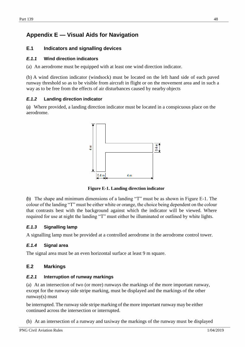
Part 139 48
PNG Civil Aviation Rules 1/04/2019
Appendix E — Visual Aids for Navigation
E.1 Indicators and signalling devices
E.1.1 Wind direction indicators
(a) An aerodrome must be equipped with at least one wind direction indicator.
(b) A wind direction indicator (windsock) must be located on the left hand side of each paved
runway threshold so as to be visible from aircraft in flight or on the movement area and in such a
way as to be free from the effects of air disturbances caused by nearby objects
E.1.2 Landing direction indicator
(a) Where provided, a landing direction indicator must be located in a conspicuous place on the
aerodrome.
Figure E-1. Landing direction indicator
(b) The shape and minimum dimensions of a landing “T” must be as shown in Figure E-1. The
colour of the landing “T” must be either white or orange, the choice being dependent on the colour
that contrasts best with the background against which the indicator will be viewed. Where
required for use at night the landing “T” must either be illuminated or outlined by white lights.
E.1.3 Signalling lamp
A signalling lamp must be provided at a controlled aerodrome in the aerodrome control tower.
E.1.4 Signal area
The signal area must be an even horizontal surface at least 9 m square.
E.2 Markings
E.2.1 Interruption of runway markings
(a) At an intersection of two (or more) runways the markings of the more important runway,
except for the runway side stripe marking, must be displayed and the markings of the other
runway(s) must
be interrupted. The runway side stripe marking of the more important runway may be either
continued across the intersection or interrupted.
(b) At an intersection of a runway and taxiway the markings of the runway must be displayed
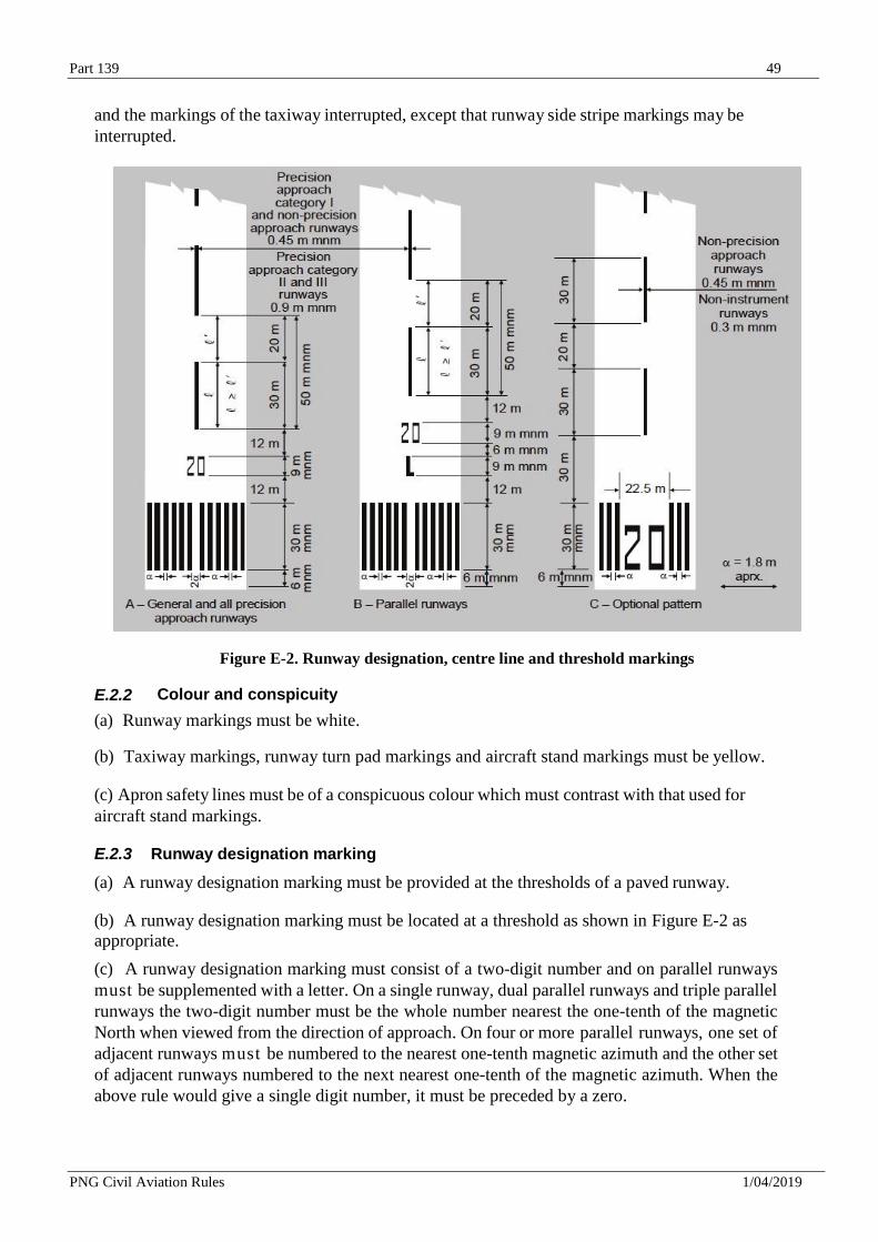
Part 139 49
PNG Civil Aviation Rules 1/04/2019
and the markings of the taxiway interrupted, except that runway side stripe markings may be
interrupted.
Figure E-2. Runway designation, centre line and threshold markings
E.2.2 Colour and conspicuity
(a) Runway markings must be white.
(b) Taxiway markings, runway turn pad markings and aircraft stand markings must be yellow.
(c) Apron safety lines must be of a conspicuous colour which must contrast with that used for
aircraft stand markings.
E.2.3 Runway designation marking
(a) A runway designation marking must be provided at the thresholds of a paved runway.
(b) A runway designation marking must be located at a threshold as shown in Figure E-2 as
appropriate.
(c) A runway designation marking must consist of a two-digit number and on parallel runways
must be supplemented with a letter. On a single runway, dual parallel runways and triple parallel
runways the two-digit number must be the whole number nearest the one-tenth of the magnetic
North when viewed from the direction of approach. On four or more parallel runways, one set of
adjacent runways must be numbered to the nearest one-tenth magnetic azimuth and the other set
of adjacent runways numbered to the next nearest one-tenth of the magnetic azimuth. When the
above rule would give a single digit number, it must be preceded by a zero.
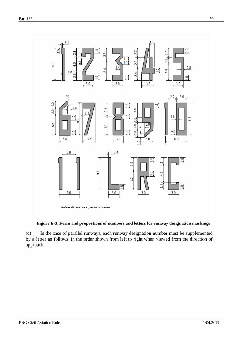
Part 139 50
PNG Civil Aviation Rules 1/04/2019
Figure E-3. Form and proportions of numbers and letters for runway designation markings
(d) In the case of parallel runways, each runway designation number must be supplemented
by a letter as follows, in the order shown from left to right when viewed from the direction of
approach:
Part 139 51
PNG Civil Aviation Rules 1/04/2019
— for two parallel runways: “L” “R”;
— for three parallel runways: “L” “C” “R”;
— for four parallel runways: “L” “R” “L” “R”;
— for five parallel runways: “L” “C” “R” “L” “R” or “L” “R” “L” “C” “R”; and
— for six parallel runways: “L” “C” “R” “L” “C” “R”.
(e) The numbers and letters must be in the form and proportion shown in Figure E-3. The
dimensions must be not less than those shown in Figure E-3, but where the numbers are
incorporated in the threshold marking, larger dimensions must be used in order to fill
adequately the gap between the stripes of the threshold marking.
E.2.4 Runway centre line marking
(a) A runway centre line marking must be provided on a paved runway.
(b) A runway centre line marking must be located along the centre line of the runway between
the runway designation markings as shown in Figure E-2, except when interrupted in compliance
with E.2.1.(a)
(c) A runway centre line marking must consist of a line of uniformly spaced stripes and gaps. The
length of a stripe plus a gap must be not less than 50 m or more than 75 m. The length of each
stripe must be at least equal to the length of the gap or 30 m, whichever is greater.
(d) The width of the stripes must be not less than:
— 0.90m on precision approach category II and III runways;
— 0.45 m on non-precision approach runways where the code number is 3 or 4, and
precision approach category I runways; and
— 0.30 m on non-precision approach runways where the code number is 1 or 2, and on
non- instrument runways.
E.2.5 Threshold marking
(a) A threshold marking must be provided at the threshold of a paved instrument runway, and
of a paved non- instrument runway where the code number is 3 or 4 and the runway is intended
for use by international commercial air transport.
(b) The stripes of the threshold marking must commence 6 m from the threshold.
(c) A runway threshold marking must consist of a pattern of longitudinal stripes of uniform
dimensions disposed symmetrically about the centre line of a runway as shown in Figure E-2 (A)
and
(B) for a runway width of 45 m. The number of stripes must be in accordance with the runway
width as follows:
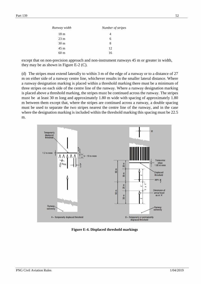
Part 139 52
PNG Civil Aviation Rules 1/04/2019
Runway width Number of stripes
18 m 4
23 m 6
30 m 8
45 m 12
60 m 16
except that on non-precision approach and non-instrument runways 45 m or greater in width,
they may be as shown in Figure E-2 (C).
(d) The stripes must extend laterally to within 3 m of the edge of a runway or to a distance of 27
m on either side of a runway centre line, whichever results in the smaller lateral distance. Where
a runway designation marking is placed within a threshold marking there must be a minimum of
three stripes on each side of the centre line of the runway. Where a runway designation marking
is placed above a threshold marking, the stripes must be continued across the runway. The stripes
must be at least 30 m long and approximately 1.80 m wide with spacing of approximately 1.80
m between them except that, where the stripes are continued across a runway, a double spacing
must be used to separate the two stripes nearest the centre line of the runway, and in the case
where the designation marking is included within the threshold marking this spacing must be 22.5
m.
Figure E-4. Displaced threshold markings
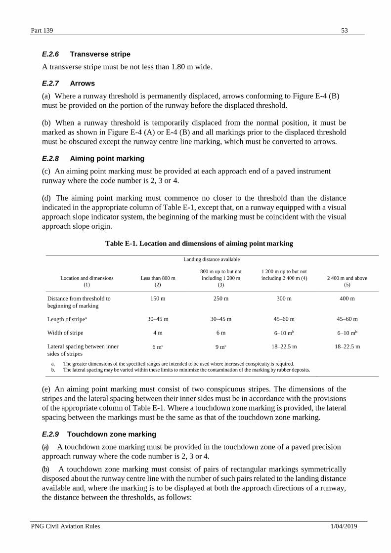
Part 139 53
PNG Civil Aviation Rules 1/04/2019
E.2.6 Transverse stripe
A transverse stripe must be not less than 1.80 m wide.
E.2.7 Arrows
(a) Where a runway threshold is permanently displaced, arrows conforming to Figure E-4 (B)
must be provided on the portion of the runway before the displaced threshold.
(b) When a runway threshold is temporarily displaced from the normal position, it must be
marked as shown in Figure E-4 (A) or E-4 (B) and all markings prior to the displaced threshold
must be obscured except the runway centre line marking, which must be converted to arrows.
E.2.8 Aiming point marking
(c) An aiming point marking must be provided at each approach end of a paved instrument
runway where the code number is 2, 3 or 4.
(d) The aiming point marking must commence no closer to the threshold than the distance
indicated in the appropriate column of Table E-1, except that, on a runway equipped with a visual
approach slope indicator system, the beginning of the marking must be coincident with the visual
approach slope origin.
Table E-1. Location and dimensions of aiming point marking
Landing distance available
Location and dimensions
(1)
Less than 800 m
(2)
800 m up to but not
including 1 200 m
(3)
1 200 m up to but not
including 2 400 m (4)
2 400 m and above
(5)
Distance from threshold to
beginning of marking
150 m 250 m 300 m 400 m
Length of stripea 30–45 m 30–45 m 45–60 m 45–60 m
Width of stripe 4 m 6 m 6–10 mb 6–10 mb
Lateral spacing between inner
sides of stripes
6 mc 9 mc 18–22.5 m 18–22.5 m
a. The greater dimensions of the specified ranges are intended to be used where increased conspicuity is required. b. The lateral spacing may be varied within these limits to minimize the contamination of the marking by rubber deposits.
(e) An aiming point marking must consist of two conspicuous stripes. The dimensions of the
stripes and the lateral spacing between their inner sides must be in accordance with the provisions
of the appropriate column of Table E-1. Where a touchdown zone marking is provided, the lateral
spacing between the markings must be the same as that of the touchdown zone marking.
E.2.9 Touchdown zone marking
(a) A touchdown zone marking must be provided in the touchdown zone of a paved precision
approach runway where the code number is 2, 3 or 4.
(b) A touchdown zone marking must consist of pairs of rectangular markings symmetrically
disposed about the runway centre line with the number of such pairs related to the landing distance
available and, where the marking is to be displayed at both the approach directions of a runway,
the distance between the thresholds, as follows:
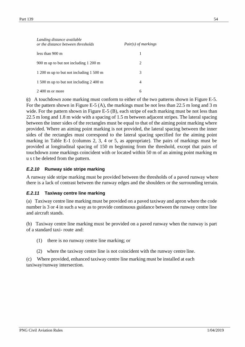
Part 139 54
PNG Civil Aviation Rules 1/04/2019
Landing distance available or the distance between thresholds
Pair(s) of markings
less than 900 m 1
900 m up to but not including 1 200 m 2
1 200 m up to but not including 1 500 m 3
1 500 m up to but not including 2 400 m 4
2 400 m or more 6
(c) A touchdown zone marking must conform to either of the two patterns shown in Figure E-5.
For the pattern shown in Figure E-5 (A), the markings must be not less than 22.5 m long and 3 m
wide. For the pattern shown in Figure E-5 (B), each stripe of each marking must be not less than
22.5 m long and 1.8 m wide with a spacing of 1.5 m between adjacent stripes. The lateral spacing
between the inner sides of the rectangles must be equal to that of the aiming point marking where
provided. Where an aiming point marking is not provided, the lateral spacing between the inner
sides of the rectangles must correspond to the lateral spacing specified for the aiming point
marking in Table E-1 (columns 2, 3, 4 or 5, as appropriate). The pairs of markings must be
provided at longitudinal spacing of 150 m beginning from the threshold, except that pairs of
touchdown zone markings coincident with or located within 50 m of an aiming point marking m
u s t be deleted from the pattern.
E.2.10 Runway side stripe marking
A runway side stripe marking must be provided between the thresholds of a paved runway where
there is a lack of contrast between the runway edges and the shoulders or the surrounding terrain.
E.2.11 Taxiway centre line marking
(a) Taxiway centre line marking must be provided on a paved taxiway and apron where the code
number is 3 or 4 in such a way as to provide continuous guidance between the runway centre line
and aircraft stands.
(b) Taxiway centre line marking must be provided on a paved runway when the runway is part
of a standard taxi- route and:
(1) there is no runway centre line marking; or
(2) where the taxiway centre line is not coincident with the runway centre line.
(c) Where provided, enhanced taxiway centre line marking must be installed at each
taxiway/runway intersection.
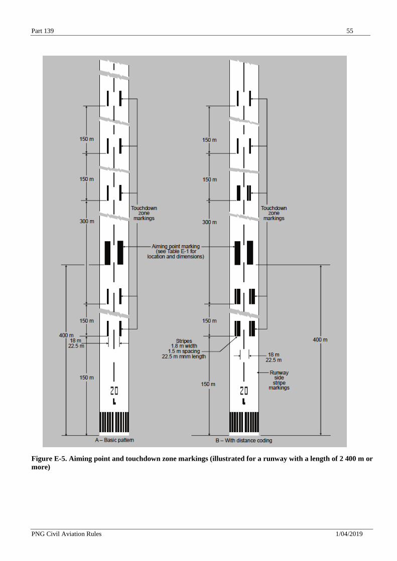
Part 139 55
PNG Civil Aviation Rules 1/04/2019
Figure E-5. Aiming point and touchdown zone markings (illustrated for a runway with a length of 2 400 m or
more)
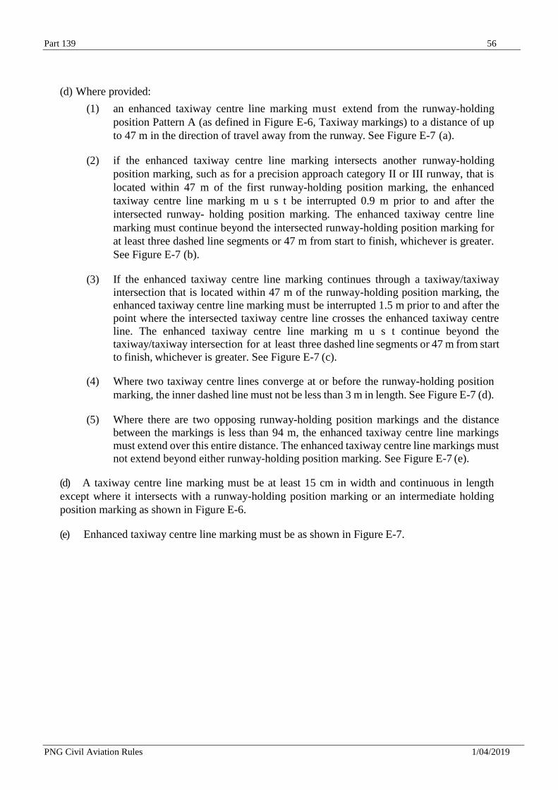
Part 139 56
PNG Civil Aviation Rules 1/04/2019
(d) Where provided:
(1) an enhanced taxiway centre line marking must extend from the runway-holding
position Pattern A (as defined in Figure E-6, Taxiway markings) to a distance of up
to 47 m in the direction of travel away from the runway. See Figure E-7 (a).
(2) if the enhanced taxiway centre line marking intersects another runway-holding
position marking, such as for a precision approach category II or III runway, that is
located within 47 m of the first runway-holding position marking, the enhanced
taxiway centre line marking m u s t be interrupted 0.9 m prior to and after the
intersected runway- holding position marking. The enhanced taxiway centre line
marking must continue beyond the intersected runway-holding position marking for
at least three dashed line segments or 47 m from start to finish, whichever is greater.
See Figure E-7 (b).
(3) If the enhanced taxiway centre line marking continues through a taxiway/taxiway
intersection that is located within 47 m of the runway-holding position marking, the
enhanced taxiway centre line marking must be interrupted 1.5 m prior to and after the
point where the intersected taxiway centre line crosses the enhanced taxiway centre
line. The enhanced taxiway centre line marking m u s t continue beyond the
taxiway/taxiway intersection for at least three dashed line segments or 47 m from start
to finish, whichever is greater. See Figure E-7 (c).
(4) Where two taxiway centre lines converge at or before the runway-holding position
marking, the inner dashed line must not be less than 3 m in length. See Figure E-7 (d).
(5) Where there are two opposing runway-holding position markings and the distance
between the markings is less than 94 m, the enhanced taxiway centre line markings
must extend over this entire distance. The enhanced taxiway centre line markings must
not extend beyond either runway-holding position marking. See Figure E-7 (e).
(d) A taxiway centre line marking must be at least 15 cm in width and continuous in length
except where it intersects with a runway-holding position marking or an intermediate holding
position marking as shown in Figure E-6.
(e) Enhanced taxiway centre line marking must be as shown in Figure E-7.
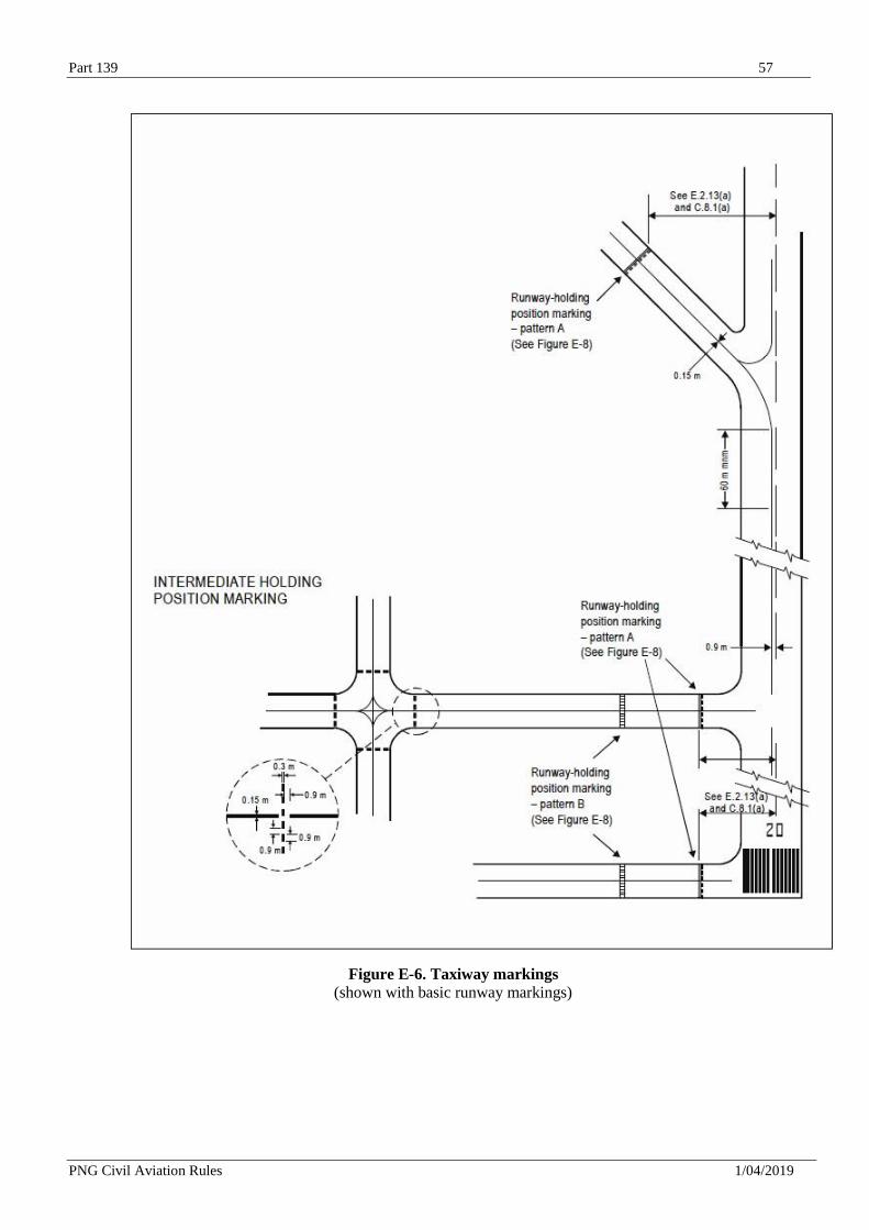
Part 139 57
PNG Civil Aviation Rules 1/04/2019
Figure E-6. Taxiway markings
(shown with basic runway markings)
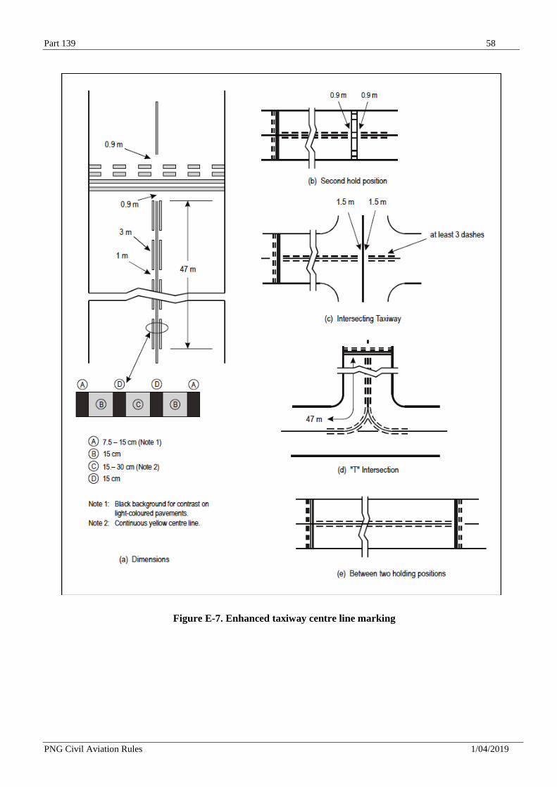
Part 139 58
PNG Civil Aviation Rules 1/04/2019
Figure E-7. Enhanced taxiway centre line marking
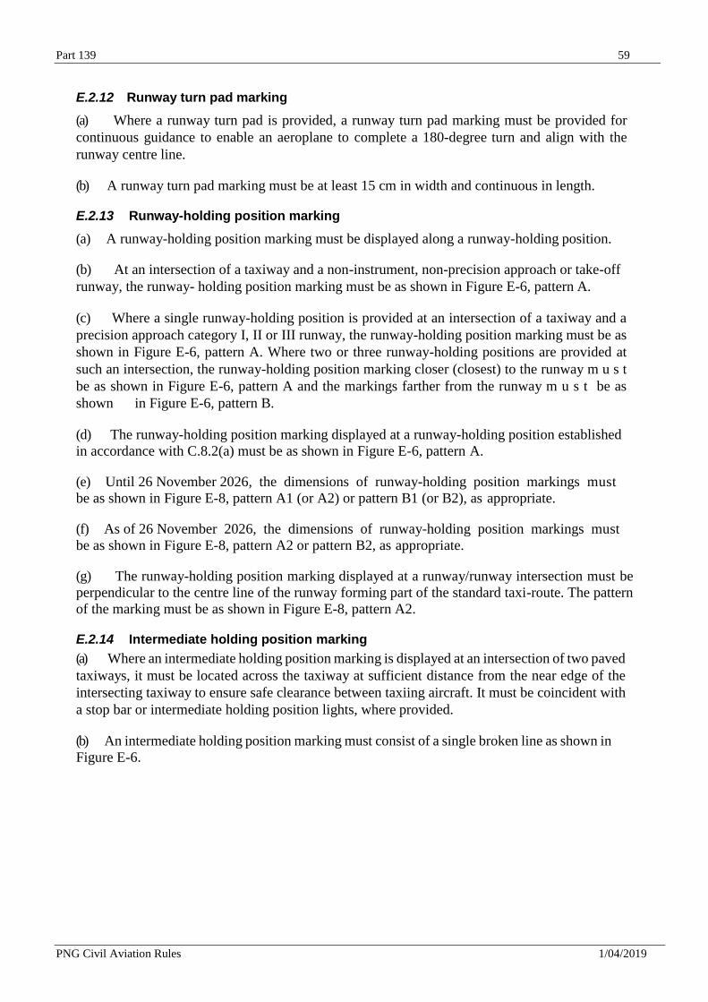
Part 139 59
PNG Civil Aviation Rules 1/04/2019
E.2.12 Runway turn pad marking
(a) Where a runway turn pad is provided, a runway turn pad marking must be provided for
continuous guidance to enable an aeroplane to complete a 180-degree turn and align with the
runway centre line.
(b) A runway turn pad marking must be at least 15 cm in width and continuous in length.
E.2.13 Runway-holding position marking
(a) A runway-holding position marking must be displayed along a runway-holding position.
(b) At an intersection of a taxiway and a non-instrument, non-precision approach or take-off
runway, the runway- holding position marking must be as shown in Figure E-6, pattern A.
(c) Where a single runway-holding position is provided at an intersection of a taxiway and a
precision approach category I, II or III runway, the runway-holding position marking must be as
shown in Figure E-6, pattern A. Where two or three runway-holding positions are provided at
such an intersection, the runway-holding position marking closer (closest) to the runway m u s t
be as shown in Figure E-6, pattern A and the markings farther from the runway m u s t be as
shown in Figure E-6, pattern B.
(d) The runway-holding position marking displayed at a runway-holding position established
in accordance with C.8.2(a) must be as shown in Figure E-6, pattern A.
(e) Until 26 November 2026, the dimensions of runway-holding position markings must
be as shown in Figure E-8, pattern A1 (or A2) or pattern B1 (or B2), as appropriate.
(f) As of 26 November 2026, the dimensions of runway-holding position markings must
be as shown in Figure E-8, pattern A2 or pattern B2, as appropriate.
(g) The runway-holding position marking displayed at a runway/runway intersection must be
perpendicular to the centre line of the runway forming part of the standard taxi-route. The pattern
of the marking must be as shown in Figure E-8, pattern A2.
E.2.14 Intermediate holding position marking
(a) Where an intermediate holding position marking is displayed at an intersection of two paved
taxiways, it must be located across the taxiway at sufficient distance from the near edge of the
intersecting taxiway to ensure safe clearance between taxiing aircraft. It must be coincident with
a stop bar or intermediate holding position lights, where provided.
(b) An intermediate holding position marking must consist of a single broken line as shown in
Figure E-6.
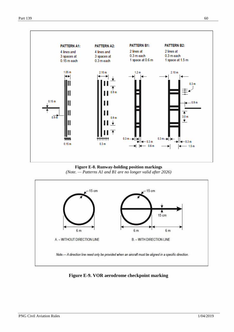
Part 139 60
PNG Civil Aviation Rules 1/04/2019
Figure E-8. Runway-holding position markings
(Note. — Patterns A1 and B1 are no longer valid after 2026)
Figure E-9. VOR aerodrome checkpoint marking
Part 139 61
PNG Civil Aviation Rules 1/04/2019
E.2.15 VOR aerodrome checkpoint marking
(a) When a VOR aerodrome checkpoint is established, it must be indicated by a VOR
aerodrome checkpoint marking and sign.
(b) A VOR aerodrome checkpoint marking must be centred on the spot at which an aircraft
is to be parked to receive the correct VOR signal.
(c) A VOR aerodrome checkpoint marking must consist of a circle 6 m in diameter and have
a line width of 15 cm (see Figure E-9 (A)).
E.2.16 Apron safety lines
Apron safety lines must be located so as to define the areas intended for use by ground vehicles
and other aircraft servicing equipment, etc., to provide safe separation from aircraft.
E.2.17 Road-holding position marking
(a) A road-holding position marking must be provided at all road entrances to a runway.
(b) The road-holding position marking must be located across the road at the holding position.
(c) The road-holding position marking must be in accordance with the local road traffic regulations.
E.2.18 Mandatory instruction marking
(a) Where it is impracticable to install a mandatory instruction sign in accordance with
E.4.2(a), a mandatory instruction marking must be provided on the surface of the pavement.
(b) The mandatory instruction marking on taxiways where the code letter is A, B, C or D must
be located across the taxiway equally placed about the taxiway centre line and on the holding side
of the runway-holding position marking as shown in Figure E-10 (A). The distance between the
nearest edge of the marking and the runway-holding position marking or the taxiway centre line
marking must be not less than 1 m.
(c) The mandatory instruction marking on taxiways where the code letter is E or F must be
located on both sides of the taxiway centre line marking and on the holding side of the runway-
holding position marking as shown in Figure E-10 (B). The distance between the nearest edge
of the marking and the runway-holding position marking or the taxiway centre line marking must
be not less than 1 m.
(d) A mandatory instruction marking must consist of an inscription in white on a red
background. Except for a NO ENTRY marking, the inscription must provide information identical
to that of the associated mandatory instruction sign.
(e) A NO ENTRY marking must consist of an inscription in white reading NO ENTRY on a
red background.
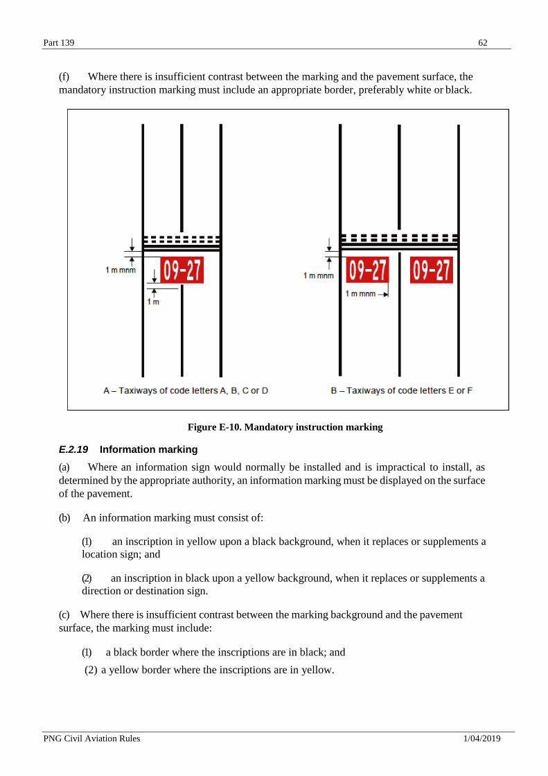
Part 139 62
PNG Civil Aviation Rules 1/04/2019
(f) Where there is insufficient contrast between the marking and the pavement surface, the
mandatory instruction marking must include an appropriate border, preferably white or black.
Figure E-10. Mandatory instruction marking
E.2.19 Information marking
(a) Where an information sign would normally be installed and is impractical to install, as
determined by the appropriate authority, an information marking must be displayed on the surface
of the pavement.
(b) An information marking must consist of:
(1) an inscription in yellow upon a black background, when it replaces or supplements a
location sign; and
(2) an inscription in black upon a yellow background, when it replaces or supplements a
direction or destination sign.
(c) Where there is insufficient contrast between the marking background and the pavement
surface, the marking must include:
(1) a black border where the inscriptions are in black; and
(2) a yellow border where the inscriptions are in yellow.
Part 139 63
PNG Civil Aviation Rules 1/04/2019
E.3 Lights
E.3.1 Lights which may endanger the safety of aircraft
A non-aeronautical ground light near an aerodrome which might endanger the safety of aircraft
must be extinguished, screened or otherwise modified so as to eliminate the source of danger.
E.3.2 Elevated approach lights
(a) Elevated approach lights and their supporting structures must be frangible except that, in
that portion of the approach lighting system beyond 300 m from the threshold:
(1) where the height of a supporting structure exceeds 12 m, the frangibility requirement
m u s t apply to the top 12 m only; and
(2) where a supporting structure is surrounded by non-frangible objects, only that part of
the structure that extends above the surrounding objects must be frangible.
(b) When an approach light fixture or supporting structure is not in itself sufficiently
conspicuous, it m u s t be suitably marked.
E.3.3 Elevated lights
Elevated runway, stopway and taxiway lights m u s t be frangible. Their height m u s t be
sufficiently low to preserve clearance for propellers and for the engine pods of jet aircraft.
E.3.4 Surface lights
Light fixtures inset in the surface of runways, stopways, taxiways and aprons must be so designed
and fitted as to withstand being run over by the wheels of an aircraft without damage either to the
aircraft or to the lights themselves.
E.3.5 Light intensity and control
(a) The intensity of runway lighting must be adequate for the minimum conditions of visibility
and ambient light in which use of the runway is intended, and compatible with that of the nearest
section of the approach lighting system when provided.
(b) Where a high-intensity lighting system is provided, a suitable intensity control must be
incorporated to allow for adjustment of the light intensity to meet the prevailing conditions.
Separate intensity controls or other suitable methods must be provided to ensure that the following
systems, when installed, can be operated at compatible intensities:
(1) approach lighting system;
(2) runway edge lights;
(3) runway threshold lights;
(4) runway end lights;
(5) runway centre line lights;
(6) runway touchdown zone lights; and
(7) taxiway centre line lights.
Part 139 64
PNG Civil Aviation Rules 1/04/2019
(c) On the perimeter of and within the ellipse defining the main beam in CASA Advisory
Circulars in the 139 series, the maximum light intensity value must not be greater than three times
the minimum light intensity value measured in accordance with CASA Advisory Circulars in the
139 series.
(d) On the perimeter of and within the rectangle defining the main beam in CASA Advisory
Circulars in the 139 series, the maximum light intensity value must not be greater than three times
the minimum light intensity value measured in accordance with CASA Advisory Circulars in the
139 series.
E.3.6 Aeronautical beacons
(a) Where operationally necessary an aerodrome beacon or an identification beacon must be
provided at each aerodrome intended for use at night.
(b) The operational requirement must be determined having regard to the requirements of the
air traffic using the aerodrome, the conspicuity of the aerodrome features in relation to its
surroundings and the installation of other visual and non-visual aids useful in locating the
aerodrome.
E.3.7 Aerodrome beacons
An aerodrome beacon must be provided at an aerodrome intended for use at night if one or more of the
following conditions exist:
(1) aircraft navigate predominantly by visual means;
(2) reduced visibilities are frequent; or
(3) it is difficult to locate the aerodrome from the air due to surrounding lights or terrain.
(b) The aerodrome beacon must be located on or adjacent to the aerodrome in an area of low
ambient background lighting.
(c) The aerodrome beacon must show either coloured flashes alternating with white flashes, or
white flashes only. The frequency of total flashes must be from 20 to 30 per minute. Where used,
the coloured flashes emitted by beacons at land aerodromes must be green, and coloured flashes
emitted by beacons at water aerodromes must be yellow. In the case of a combined water and
land aerodrome, coloured flashes, if used, must have the colour characteristics of whichever
section of the aerodrome is designated as the principal facility.
(d) The light from the beacon must show at all angles of azimuth. The vertical light distribution
m u s t extend upwards from an elevation of not more than 1° to an elevation determined by the
appropriate authority to be sufficient to provide guidance at the maximum elevation at which the
beacon is intended to be used, and the effective intensity of the flash must be not less than 2 000
cd.
E.3.8 Identification beacon
(a) An identification beacon must be provided at an aerodrome which is intended for use at
night and cannot be easily identified from the air by other means.
(b) The identification beacon must be located on the aerodrome in an area of low ambient
background lighting.
Part 139 65
PNG Civil Aviation Rules 1/04/2019
(c) An identification beacon at a land aerodrome must show at all angles of azimuth. The
vertical light distribution must extend upwards from an elevation of not more than 1° to an
elevation determined by the appropriate authority to be sufficient to provide guidance at the
maximum elevation at which the beacon is intended to be used, and the effective intensity of the
flash must be not less than 2 000 cd.
(d) An identification beacon must show flashing-green at a land aerodrome and flashing-
yellow at a water aerodrome.
(e) The identification characters must be transmitted in the International Morse Code.
E.3.9 Approach lighting systems
(a) Non-precision approach runway – where physically practicable, a simple approach lighting
system as specified in E.3.5 must be provided to serve a non-precision approach runway, except
when the runway is used only in conditions of good visibility or sufficient guidance is provided by
other visual aids.
(b) Precision approach runway category I – where physically practicable, a precision approach
category I lighting system as specified in E.3.11 must be provided to serve a precision approach
runway category I.
(c) Precision approach runway categories II and III – a precision approach category II and III
lighting system as specified in E.3.12 must be provided to serve a precision approach runway
category II or III.
E.3.10 Simple approach lighting systems
(a) A simple approach lighting system must consist of a row of lights on the extended centre
line of the runway extending, whenever possible, over a distance of not less than 420 m from the
threshold with a row of lights forming a crossbar 18 m or 30 m in length at a distance of 300 m
from the threshold.
(b) The lights forming the crossbar must be as nearly as practicable in a horizontal straight
line at right angles to, and bisected by, the line of the centre line lights. The lights of the
crossbar must
be spaced so as to produce a linear effect, except that, when a crossbar of 30 m is used, gaps may
be left on each side of the centre line. These gaps must be kept to a minimum to meet local
requirements and each must not exceed 6 m.
(c) The lights forming the centre line must be placed at longitudinal intervals of 60 m, except
that, when it is desired to improve the guidance, an interval of 30 m may be used. The innermost
light must be located either 60 m or 30 m from the threshold, depending on the longitudinal
interval selected for the centre line lights.
(d) The system must lie as nearly as practicable in the horizontal plane passing through the
threshold, provided that:
(1) no object other than an ILS or MLS azimuth antenna must protrude through the plane
of the approach lights within a distance of 60 m from the centre line of the system; and
(2) no light other than a light located within the central part of a crossbar or a centre line
barrette (not their extremities) must be screened from an approaching aircraft.
Part 139 66
PNG Civil Aviation Rules 1/04/2019
Any ILS or MLS azimuth antenna protruding through the plane of the lights must be treated
as an obstacle and marked and lighted accordingly.
(e) The lights of a simple approach lighting system must be fixed lights and the colour of the
lights must be such as to ensure that the system is readily distinguishable from other aeronautical
ground lights, and from extraneous lighting if present. Each centre line light must consist of
either:
(1) a single source; or
(2) a barrette at least 3 m in length.
E.3.11 Precision approach category I lighting system
(a) A precision approach category I lighting system must consist of a row of lights on the
extended centre line of the runway extending, wherever possible, over a distance of 900 m from
the runway threshold with a row of lights forming a crossbar 30 m in length at a distance of 300
m from the runway threshold.
(b) The lights forming the crossbar must be as nearly as practicable in a horizontal straight line
at right angles to, and bisected by, the line of the centre line lights. The lights of the crossbar must
be spaced so as to produce a linear effect, except that gaps may be left on each side of the centre
line. These gaps must be kept to a minimum to meet local requirements and each must not exceed
6 m.
(c) The lights forming the centre line must be placed at longitudinal intervals of 30 m with the
innermost light located 30 m from the threshold.
(d) The system must lie as nearly as practicable in the horizontal plane passing through the
threshold, provided that:
(1) no object other than an ILS or MLS azimuth antenna must protrude through the plane
of the approach lights within a distance of 60 m from the centre line of the system; and
(2) no light other than a light located within the central part of a crossbar or a centre line
barrette (not their extremities) must be screened from an approaching aircraft.
Any ILS or MLS azimuth antenna protruding through the plane of the lights must be treated as
an obstacle and marked and lighted accordingly.
(e) The centre line and crossbar lights of a precision approach category I lighting system must
be fixed lights showing variable white. Each centre line light position must consist of either:
(1) a single light source in the innermost 300 m of the centre line, two light sources in the
central 300 m of the centre line and three light sources in the outer 300 m of the centre
line to provide distance information; or
(2) a barrette.
(f) Where the serviceability level of the approach lights specified as a maintenance objective
in J.5.(f) can be demonstrated, each centre line light position may consist of either:
(1) a single light source; or
(2) a barrette.
Part 139 67
PNG Civil Aviation Rules 1/04/2019
(g) The barrettes must be at least 4 m in length. When barrettes are composed of lights
approximating to point sources, the lights must be uniformly spaced at intervals of not more than
1.5 m.
(h) If provided, each barrette flashing light must be flashed twice a second in sequence,
beginning with the outermost light and progressing toward the threshold to the innermost light of
the system. The design of the electrical circuit must be such that these lights can be operated
independently of the other lights of the approach lighting system.
(i) If the centre line consists of lights as described in (e)(1) or (e)(2), additional crossbars of
lights to the crossbar provided at 300 m from the threshold must be provided at 150 m, 450 m,
600 m and 750 m from the threshold. The lights forming each crossbar must be as nearly as
practicable in a horizontal straight line at right angles to, and bisected by, the line of the centre
line lights. The lights must be spaced so as to produce a linear effect, except that gaps may be left
on each side of the centre line. These gaps must be kept to a minimum to meet local requirements
and each must not exceed 6 m.
(j) Where the additional crossbars described in (i) are incorporated in the system, the outer ends
of the crossbars must lie on two straight lines that either are parallel to the line of the centre line
lights or converge to meet the runway centre line 300 m from threshold.
(k) The lights must be in accordance with the specifications of CASA Advisory Circulars in
the 139 series.
E.3.12 Precision approach category II and III lighting system
(a) The approach lighting system must consist of a row of lights on the extended centre line of
the runway, extending, wherever possible, over a distance of 900 m from the runway threshold.
In addition, the system must have two side rows of lights, extending 270 m from the threshold,
and two crossbars, one at 150 m and one at 300 m from the threshold, all as shown in Figure E-
14. Where the serviceability level of the approach lights specified as maintenance objectives in
J.5.(c) can be demonstrated, the system may have two side rows of lights, extending 240 m from
the threshold, and two crossbars, one at 150 m and one at 300 m from the threshold, all as shown
in Figure E-15.
(b) The lights forming the centre line must be placed at longitudinal intervals of 30 m with the
innermost lights located 30 m from the threshold.
(c) The lights forming the side rows must be placed on each side of the centre line, at a
longitudinal spacing equal to that of the centre line lights and with the first light located 30 m from
the threshold. Where the serviceability level of the approach lights specified as maintenance
objectives in J.5(c) can be demonstrated, lights forming the side rows may be placed on each side
of the centre line, at a longitudinal spacing of 60 m with the first light located 60 m from the
threshold. The lateral spacing (or gauge) between the innermost lights of the side rows must be
not less than 18 m nor more than 22.5 m, and preferably 18 m, but in any event must be equal to
that of the touchdown zone lights.
(d) The crossbar provided at 150 m from the threshold must fill in the gaps between the centre
line and side row lights.
(e) The crossbar provided at 300 m from the threshold must extend on both sides of the centre
line lights to a distance of 15 m from the centre line.
Part 139 68
PNG Civil Aviation Rules 1/04/2019
(f) If the centre line beyond a distance of 300 m from the threshold consists of lights as described
in (j)(1) or (j)(2), additional crossbars of lights must be provided at 450 m, 600 m and 750 m from
the threshold.
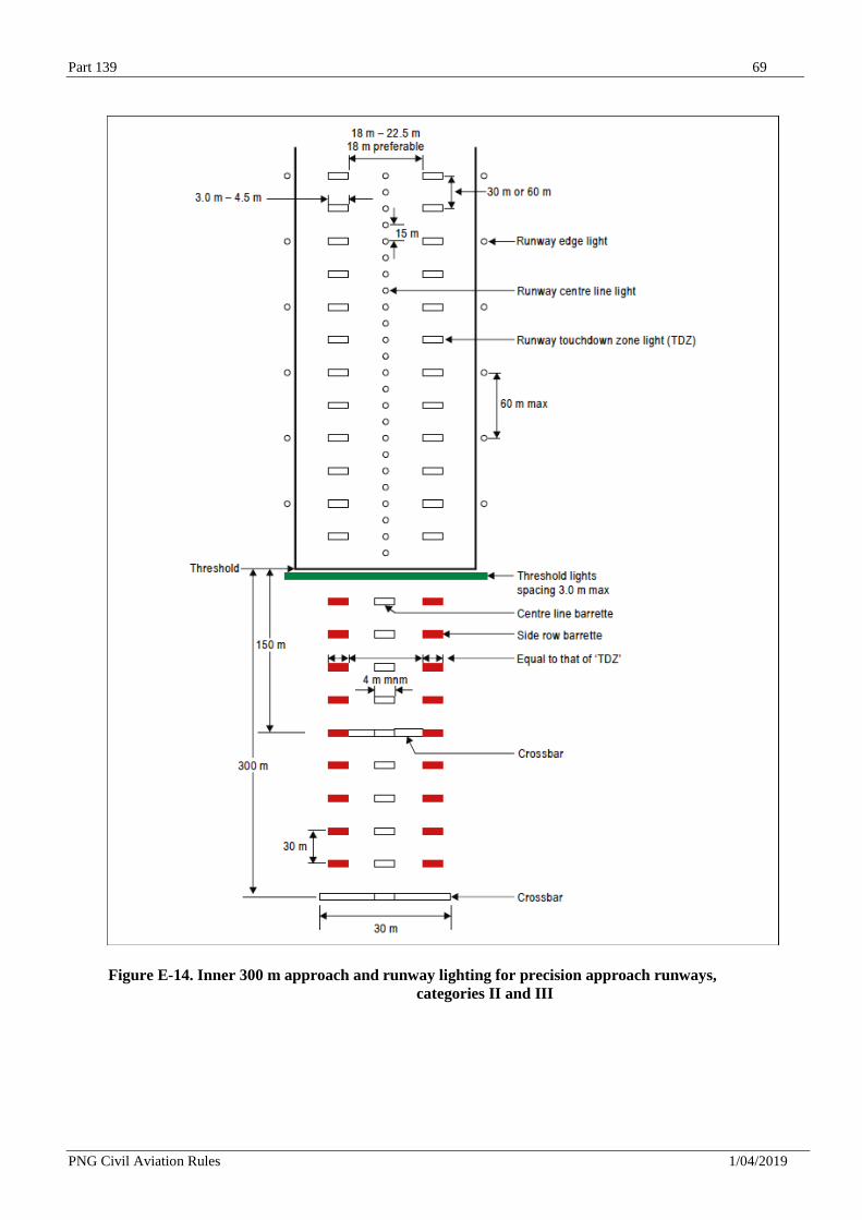
Part 139 69
PNG Civil Aviation Rules 1/04/2019
Figure E-14. Inner 300 m approach and runway lighting for precision approach runways,
categories II and III
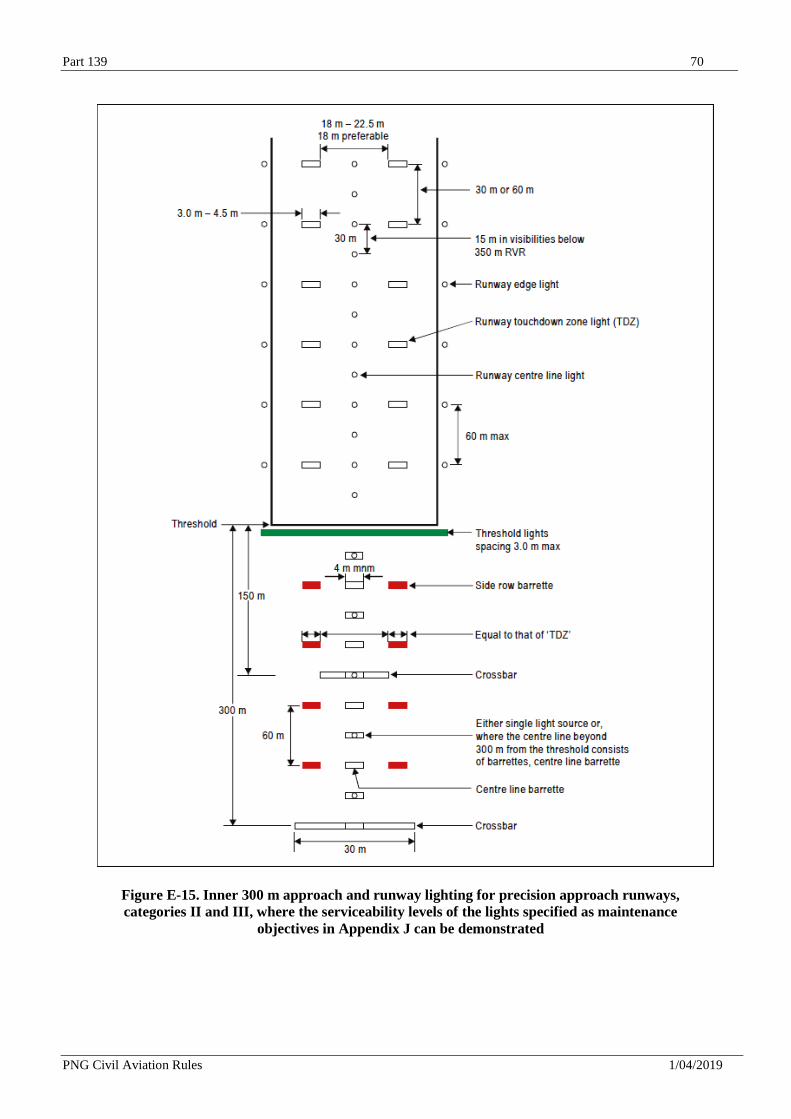
Part 139 70
PNG Civil Aviation Rules 1/04/2019
Figure E-15. Inner 300 m approach and runway lighting for precision approach runways,
categories II and III, where the serviceability levels of the lights specified as maintenance
objectives in Appendix J can be demonstrated
Part 139 71
PNG Civil Aviation Rules 1/04/2019
(g) Where the additional crossbars described in (e) are incorporated in the system, the outer ends
of these crossbars must lie on two straight lines that either are parallel to the centre line or
converge to meet the runway centre line 300 m from the threshold.
(h) The system must lie as nearly as practicable in the horizontal plane passing through the
threshold, provided that:
(1) no object other than an ILS or MLS azimuth antenna must protrude through the plane
of the approach lights within a distance of 60 m from the centre line of the system;
and
(2) no light other than a light located within the central part of a crossbar or a centre line
barrette (not their extremities) must be screened from an approaching aircraft.
Any ILS or MLS azimuth antenna protruding through the plane of the lights must be treated as
an obstacle and marked and lighted accordingly.
(i) The centre line of a precision approach category II and III lighting system for the first 300
m from the threshold must consist of barrettes showing variable white, except that, where the
threshold is displaced 300 m or more, the centre line may consist of single light sources showing
variable white. Where the serviceability level of the approach lights specified as maintenance
objectives in J.5(c) can be demonstrated, the centre line of a precision approach category II and
III lighting system for the first 300 m from the threshold may consist of either:
(1) barrettes, where the centre line beyond 300 m from the threshold consists of barrettes
as described in (k)(2); or
(2) alternate single light sources and barrettes, where the centre line beyond 300 m from
the threshold consists of single light sources as described in ( k ) ( 2 ) , with the
innermost single light source located 30 m and the innermost barrette located 60 m
from the threshold; or
(3) single light sources where the threshold is displaced 300 m or
more; all of which must show variable white.
(j) Beyond 300 m from the threshold each centre line light position must consist of either:
(1) a barrette as used on the inner 300 m; or
(2) two light sources in the central 300 m of the centre line and three light sources in the
outer 300 m of the centre line;
all of which must show variable white.
(k) Where the serviceability level of the approach lights specified as maintenance objectives in
J.5(c) can be demonstrated, beyond 300 m from the threshold each centre line light position may
consist of either:
(1) a barrette; or
(2) a single light source;
Part 139 72
PNG Civil Aviation Rules 1/04/2019
all of which must show variable white.
(l) The barrettes must be at least 4 m in length. When barrettes are composed of lights
approximating to point sources, the lights must be uniformly spaced at intervals of not more than
1.5 m.
(m) If provided, each barrette flashing light must be flashed twice a second in sequence,
beginning with the outermost light and progressing toward the threshold to the innermost light of
the system. The design of the electrical circuit must be such that these lights can be operated
independently of the other lights of the approach lighting system.
(n) The side row must consist of barrettes showing red. The length of a side row barrette and
the spacing of its lights must be equal to those of the touchdown zone light barrettes.
(o) The lights forming the crossbars must be fixed lights showing variable white. The lights
must be uniformly spaced at intervals of not more than 2.7 m.
(p) The intensity of the red lights must be compatible with the intensity of the white lights.
(q) The lights must be in accordance with the specifications of CASA Advisory Circulars in the
139 series.
E.3.13 Visual approach slope indicator systems
(a) A visual approach slope indicator system must be provided to serve the approach to a runway
whether or not the runway is served by other visual approach aids or by non-visual aids, where
one or more of the following conditions exist:
(1) the runway is used by turbojet or other aeroplanes with similar approach guidance
requirements;
(2) the pilot of any type of aeroplane may have difficulty in judging the approach due to:
(i) inadequate visual guidance such as is experienced during an approach over water
or featureless terrain by day or in the absence of sufficient extraneous lights in the
approach area by night; or
(ii) misleading information such as is produced by deceptive
surrounding terrain or runway slopes;
(3) the presence of objects in the approach area may involve serious hazard if an aeroplane
descends below the normal approach path, particularly if there are no non-visual or other
visual aids to give warning of such objects;
(4) physical conditions at either end of the runway present a serious hazard in the event of
an aeroplane undershooting or overrunning the runway; and
(5) terrain or prevalent meteorological conditions are such that the aeroplane may be
subjected to unusual turbulence during approach.
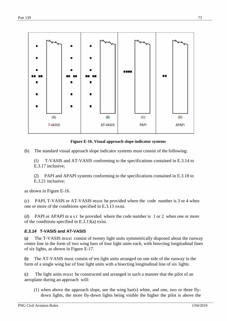
Part 139 73
PNG Civil Aviation Rules 1/04/2019
Figure E-16. Visual approach slope indicator systems
(b) The standard visual approach slope indicator systems must consist of the following:
(1) T-VASIS and AT-VASIS conforming to the specifications contained in E.3.14 to
E.3.17 inclusive;
(2) PAPI and APAPI systems conforming to the specifications contained in E.3.18 to
E.3.21 inclusive;
as shown in Figure E-16.
(c) PAPI, T-VASIS or AT-VASIS must be provided where the code number is 3 or 4 when
one or more of the conditions specified in E.3.13 exist.
(d) PAPI or APAPI m u s t be provided where the code number is 1 or 2 when one or more
of the conditions specified in E.3.13(a) exist.
E.3.14 T-VASIS and AT-VASIS
(a) The T-VASIS must consist of twenty light units symmetrically disposed about the runway
centre line in the form of two wing bars of four light units each, with bisecting longitudinal lines
of six lights, as shown in Figure E-17.
(b) The AT-VASIS must consist of ten light units arranged on one side of the runway in the
form of a single wing bar of four light units with a bisecting longitudinal line of six lights.
(c) The light units must be constructed and arranged in such a manner that the pilot of an
aeroplane during an approach will:
(1) when above the approach slope, see the wing bar(s) white, and one, two or three fly-
down lights, the more fly-down lights being visible the higher the pilot is above the
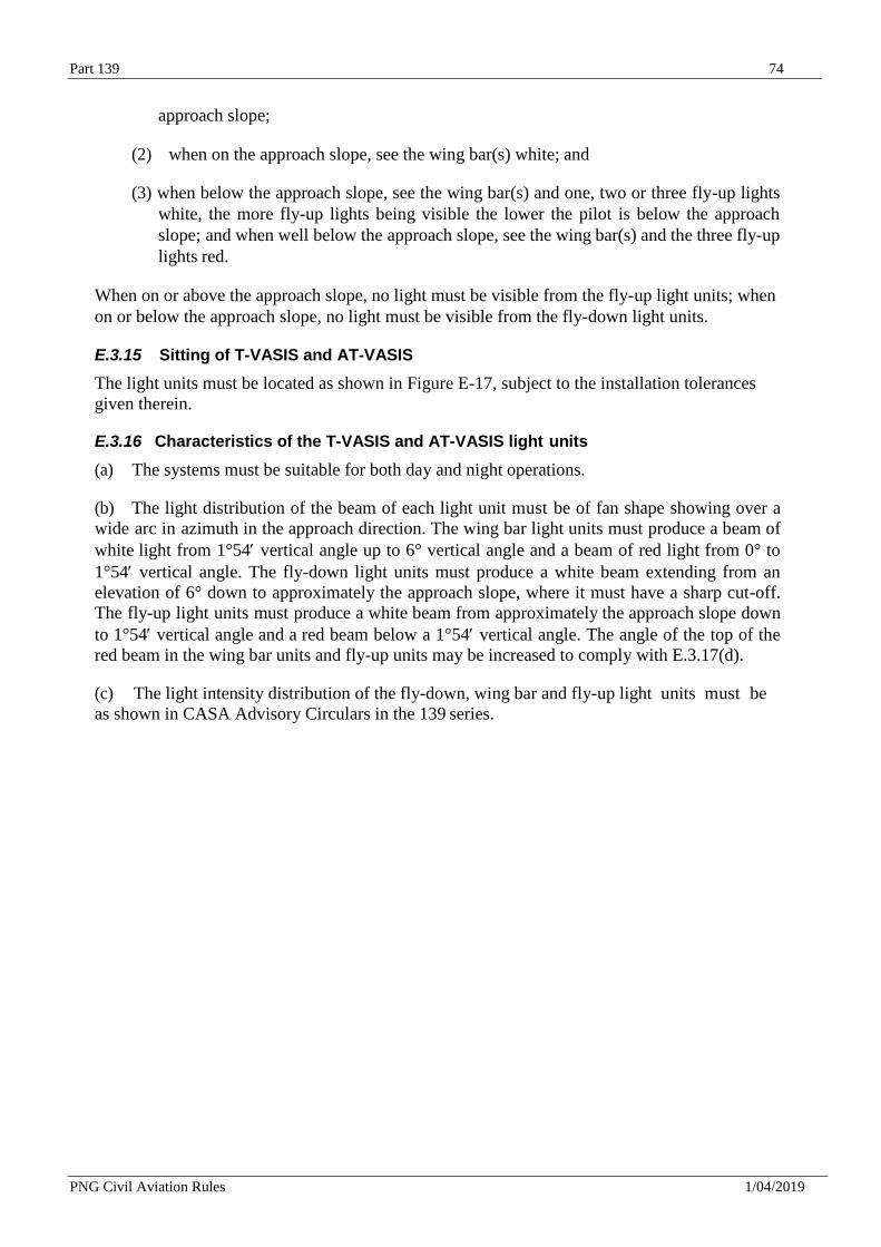
Part 139 74
PNG Civil Aviation Rules 1/04/2019
approach slope;
(2) when on the approach slope, see the wing bar(s) white; and
(3) when below the approach slope, see the wing bar(s) and one, two or three fly-up lights
white, the more fly-up lights being visible the lower the pilot is below the approach
slope; and when well below the approach slope, see the wing bar(s) and the three fly-up
lights red.
When on or above the approach slope, no light must be visible from the fly-up light units; when
on or below the approach slope, no light must be visible from the fly-down light units.
E.3.15 Sitting of T-VASIS and AT-VASIS
The light units must be located as shown in Figure E-17, subject to the installation tolerances
given therein.
E.3.16 Characteristics of the T-VASIS and AT-VASIS light units
(a) The systems must be suitable for both day and night operations.
(b) The light distribution of the beam of each light unit must be of fan shape showing over a
wide arc in azimuth in the approach direction. The wing bar light units must produce a beam of
white light from 1°54 vertical angle up to 6° vertical angle and a beam of red light from 0° to
1°54 vertical angle. The fly-down light units must produce a white beam extending from an
elevation of 6° down to approximately the approach slope, where it must have a sharp cut-off.
The fly-up light units must produce a white beam from approximately the approach slope down
to 1°54 vertical angle and a red beam below a 1°54 vertical angle. The angle of the top of the
red beam in the wing bar units and fly-up units may be increased to comply with E.3.17(d).
(c) The light intensity distribution of the fly-down, wing bar and fly-up light units must be
as shown in CASA Advisory Circulars in the 139 series.
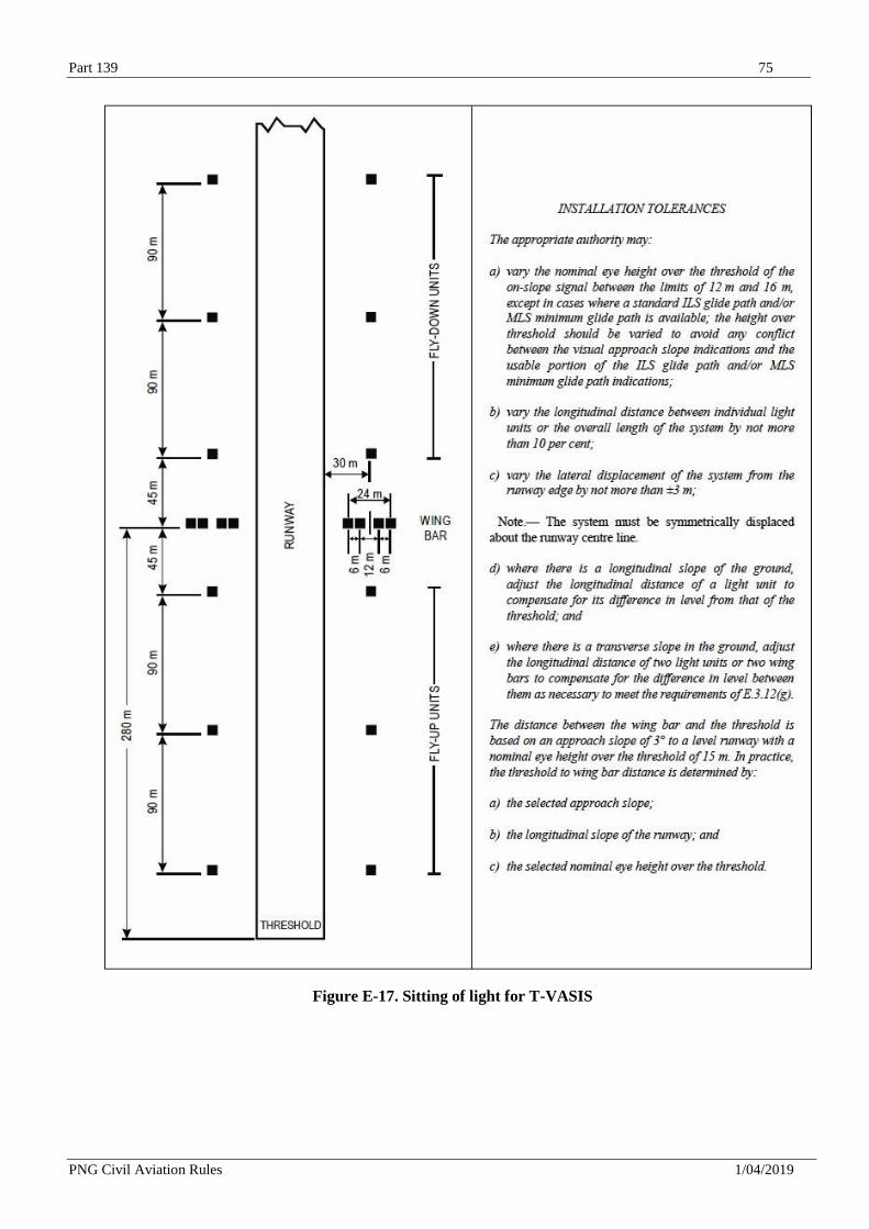
Part 139 75
PNG Civil Aviation Rules 1/04/2019
Figure E-17. Sitting of light for T-VASIS
Part 139 76
PNG Civil Aviation Rules 1/04/2019
(d) The colour transition from red to white in the vertical plane must be such as to appear to an observer, at a distance of not less than 300 m, to occur over a vertical angle of not more than 15.
(e) At full intensity the red light must have a Y coordinate not exceeding 0.320.
(f) A suitable intensity control must be provided to allow adjustments to meet the prevailing
conditions and to avoid dazzling the pilot during approach and landing.
(g) The light units forming the wing bars, or the light units forming a fly-down or a fly-up
matched pair, must be mounted so as to appear to the pilot of an approaching aeroplane to be
substantially in a horizontal line. The light units must be mounted as low as possible and must be
frangible.
(h) The light units must be so designed that deposits of condensation, dirt, etc., on optically
transmitting or reflecting surfaces must interfere to the least possible extent with the light signals
and must in no way affect the elevation of the beams or the contrast between the red and white
signals. The construction of the light units must be such as to minimize the probability of the slots
being wholly or partially blocked by snow or ice where these conditions are likely to be
encountered.
E.3.17 Approach slope and elevation setting of T-VASIS and AT-VASIS light beams
(a) The approach slope must be appropriate for use by the aeroplanes using the approach.
(b) When the runway on which a T-VASIS is provided is equipped with an ILS and/or MLS,
the siting and elevations of the light units must be such that the visual approach slope conforms as
closely as possible with the glide path of the ILS and/or the minimum glide path of the MLS, as
appropriate.
(c) The elevation of the beams of the wing bar light units on both sides of the runway must be
the same. The elevation of the top of the beam of the fly-up light unit nearest to each wing bar,
and that of the bottom of the beam of the fly- down light unit nearest to each wing bar, must be
equal and must correspond to the approach slope. The cut-off angle of the top of the beams of
successive fly-up light units must decrease by 5 of arc in angle of elevation at each successive
unit away from the wing bar. The cut-in angle of the bottom of the beam of the fly-down light
units must increase by 7 of arc at each successive unit away from the wing bar (see Figure E-18).
(d) The elevation setting of the top of the red light beams of the wing bar and fly-up light units
must be such that, during an approach, the pilot of an aeroplane to whom the wing bar and three
fly- up light units are visible would clear all objects in the approach area by a safe margin if any
such light did not appear red.
(e) The azimuth spread of the light beam must be suitably restricted where an object located
outside the obstacle protection surface of the system, but within the lateral limits of its light beam,
is found to extend above the plane of the obstacle protection surface and an aeronautical study
indicates that the object could adversely affect the safety of operations. The extent of the
restriction must be such that the object remains outside the confines of the light beam.
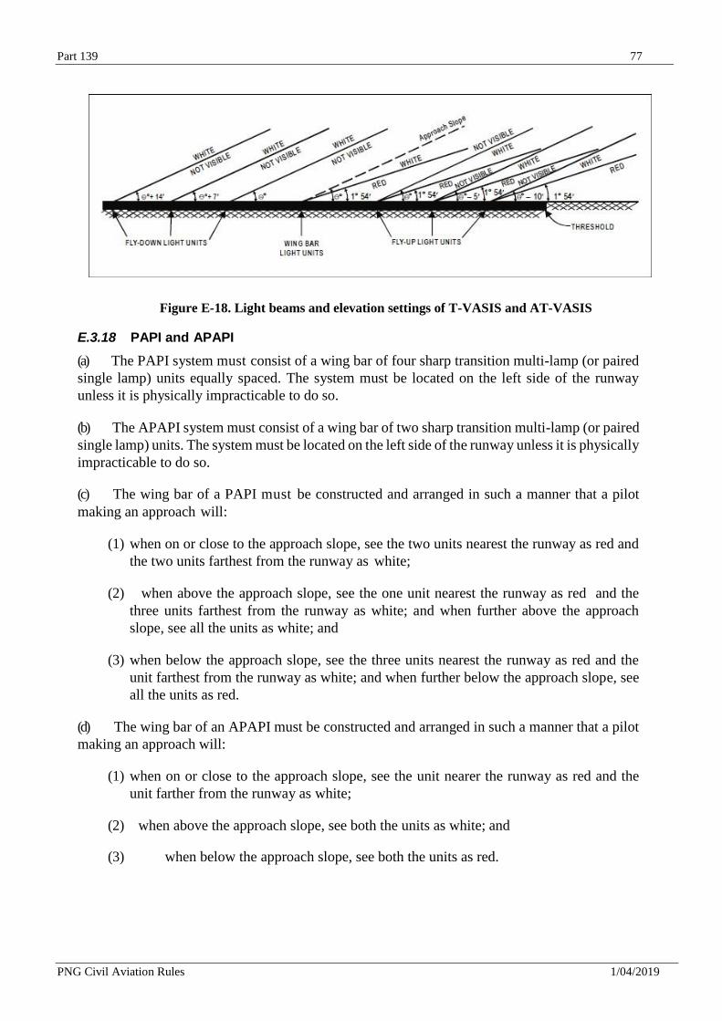
Part 139 77
PNG Civil Aviation Rules 1/04/2019
Figure E-18. Light beams and elevation settings of T-VASIS and AT-VASIS
E.3.18 PAPI and APAPI
(a) The PAPI system must consist of a wing bar of four sharp transition multi-lamp (or paired
single lamp) units equally spaced. The system must be located on the left side of the runway
unless it is physically impracticable to do so.
(b) The APAPI system must consist of a wing bar of two sharp transition multi-lamp (or paired
single lamp) units. The system must be located on the left side of the runway unless it is physically
impracticable to do so.
(c) The wing bar of a PAPI must be constructed and arranged in such a manner that a pilot
making an approach will:
(1) when on or close to the approach slope, see the two units nearest the runway as red and
the two units farthest from the runway as white;
(2) when above the approach slope, see the one unit nearest the runway as red and the
three units farthest from the runway as white; and when further above the approach
slope, see all the units as white; and
(3) when below the approach slope, see the three units nearest the runway as red and the
unit farthest from the runway as white; and when further below the approach slope, see
all the units as red.
(d) The wing bar of an APAPI must be constructed and arranged in such a manner that a pilot
making an approach will:
(1) when on or close to the approach slope, see the unit nearer the runway as red and the
unit farther from the runway as white;
(2) when above the approach slope, see both the units as white; and
(3) when below the approach slope, see both the units as red.
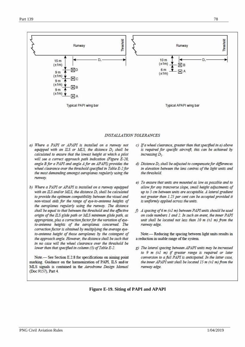
Part 139 78
PNG Civil Aviation Rules 1/04/2019
Figure E-19. Siting of PAPI and APAPI
Part 139 79
PNG Civil Aviation Rules 1/04/2019
E.3.19 Sitting of PAPI and APAPI
The light units must be located as in the basic configuration illustrated in Figure 5-19,
subject to the installation tolerances given therein. The units forming a wing bar must be mounted
so as to appear to the pilot of an approaching aeroplane to be substantially in a horizontal line.
The light units must be mounted as low as possible and must be frangible.
E.3.20 Characteristics of the PAPI and APAPI light units
(a) The system must be suitable for both day and night operations.
(b) The colour transition from red to white in the vertical plane must be such as to appear to an observer, at a distance of not less than 300 m, to occur within a vertical angle of not more than 3.
(c) At full intensity the red light must have a Y coordinate not exceeding 0.320.
(d) The light intensity distribution of the light units must be as shown in Advisory Circular
139 Series.
(e) Suitable intensity control must be provided so as to allow adjustment to meet the prevailing
conditions and to avoid dazzling the pilot during approach and landing.
(f) Each light unit must be capable of adjustment in elevation so that the lower limit of the white part of the beam may be fixed at any desired angle of elevation between 1°30 and at least 4°30 above the horizontal.
(g) The light units must be so designed that deposits of condensation and dirt on optically
transmitting or reflecting surfaces must interfere to the least possible extent with the light signals
and must not affect the contrast between the red and white signals and the elevation of the transition
sector.
E.3.21 Approach slope and elevation setting of PAPI and APAPI light beams
(a) The approach slope as defined in Figure E-20 must be appropriate for use by the aeroplanes
using the approach.
(b) When the runway is equipped with an ILS and/or MLS, the siting and the angle of elevation
of the light units must be such that the visual approach slope conforms as closely as possible with
the glide path of the ILS and/or the minimum glide path of the MLS, as appropriate.
(c) The angle of elevation settings of the light units in a PAPI wing bar must be such that, during
an approach, the pilot of an aeroplane observing a signal of one white and three reds will clear
all objects in the approach area by a safe margin (see Table E-2).
(d) The angle of elevation settings of the light units in an APAPI wing bar must be such that,
during an approach, the pilot of an aeroplane observing the lowest on slope signal, i.e. one white
and one red, will clear all objects in the approach area by a safe margin (see Table E-2).
(e) The azimuth spread of the light beam must be suitably restricted where an object located
outside the obstacle protection surface of the PAPI or APAPI system, but within the lateral limits
of
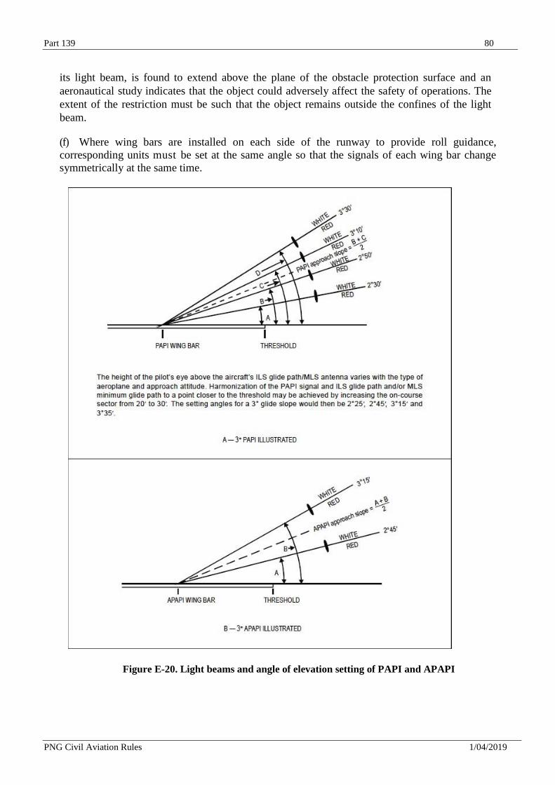
Part 139 80
PNG Civil Aviation Rules 1/04/2019
its light beam, is found to extend above the plane of the obstacle protection surface and an
aeronautical study indicates that the object could adversely affect the safety of operations. The
extent of the restriction must be such that the object remains outside the confines of the light
beam.
(f) Where wing bars are installed on each side of the runway to provide roll guidance,
corresponding units must be set at the same angle so that the signals of each wing bar change
symmetrically at the same time.
Figure E-20. Light beams and angle of elevation setting of PAPI and APAPI
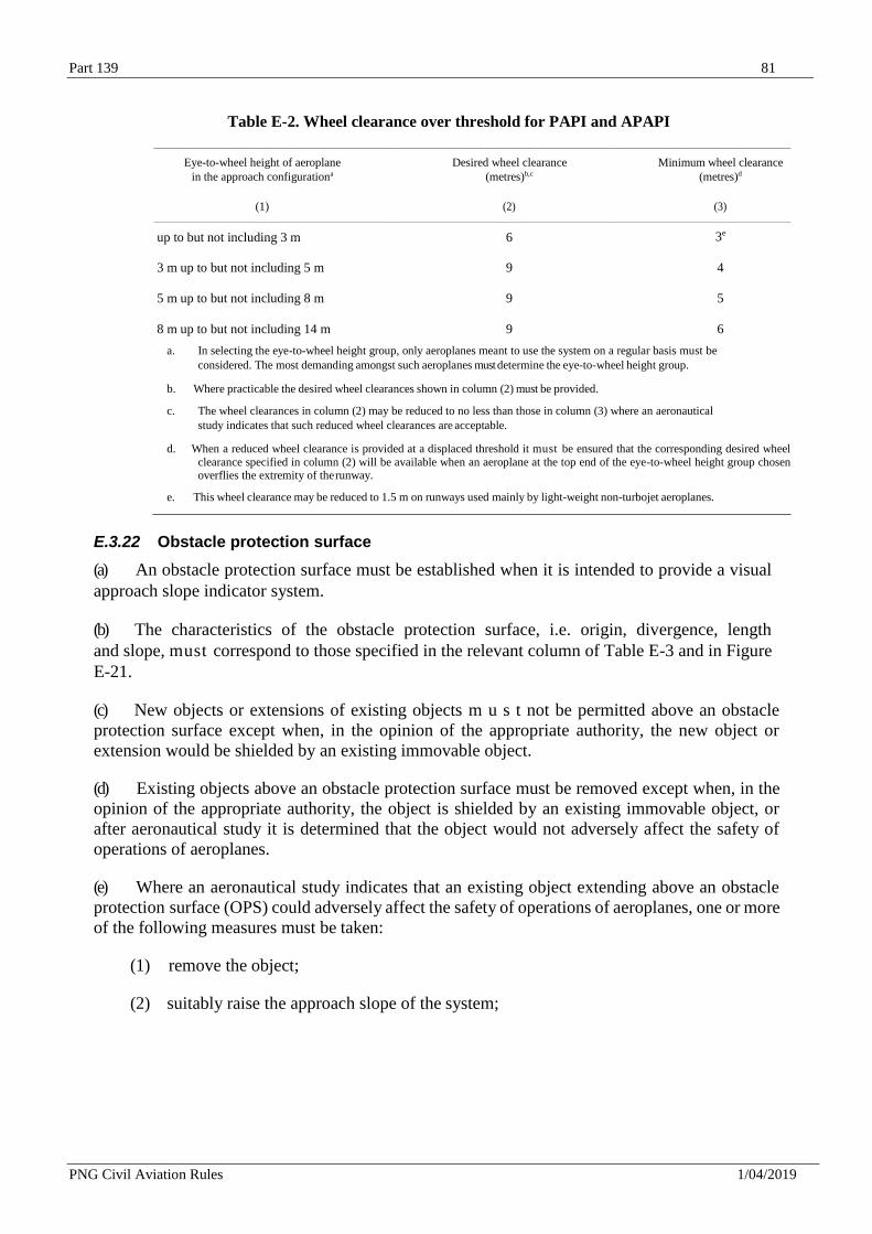
Part 139 81
PNG Civil Aviation Rules 1/04/2019
Table E-2. Wheel clearance over threshold for PAPI and APAPI
Eye-to-wheel height of aeroplane
in the approach configurationa
Desired wheel clearance
(metres)b,c
Minimum wheel clearance
(metres)d
(1) (2) (3)
up to but not including 3 m 6 3e
3 m up to but not including 5 m 9 4
5 m up to but not including 8 m 9 5
8 m up to but not including 14 m 9 6
a. In selecting the eye-to-wheel height group, only aeroplanes meant to use the system on a regular basis must be
considered. The most demanding amongst such aeroplanes must determine the eye-to-wheel height group.
b. Where practicable the desired wheel clearances shown in column (2) must be provided.
c. The wheel clearances in column (2) may be reduced to no less than those in column (3) where an aeronautical
study indicates that such reduced wheel clearances are acceptable.
d. When a reduced wheel clearance is provided at a displaced threshold it must be ensured that the corresponding desired wheel clearance specified in column (2) will be available when an aeroplane at the top end of the eye-to-wheel height group chosen overflies the extremity of the runway.
e. This wheel clearance may be reduced to 1.5 m on runways used mainly by light-weight non-turbojet aeroplanes.
E.3.22 Obstacle protection surface
(a) An obstacle protection surface must be established when it is intended to provide a visual
approach slope indicator system.
(b) The characteristics of the obstacle protection surface, i.e. origin, divergence, length
and slope, must correspond to those specified in the relevant column of Table E-3 and in Figure
E-21.
(c) New objects or extensions of existing objects m u s t not be permitted above an obstacle
protection surface except when, in the opinion of the appropriate authority, the new object or
extension would be shielded by an existing immovable object.
(d) Existing objects above an obstacle protection surface must be removed except when, in the
opinion of the appropriate authority, the object is shielded by an existing immovable object, or
after aeronautical study it is determined that the object would not adversely affect the safety of
operations of aeroplanes.
(e) Where an aeronautical study indicates that an existing object extending above an obstacle
protection surface (OPS) could adversely affect the safety of operations of aeroplanes, one or more
of the following measures must be taken:
(1) remove the object;
(2) suitably raise the approach slope of the system;
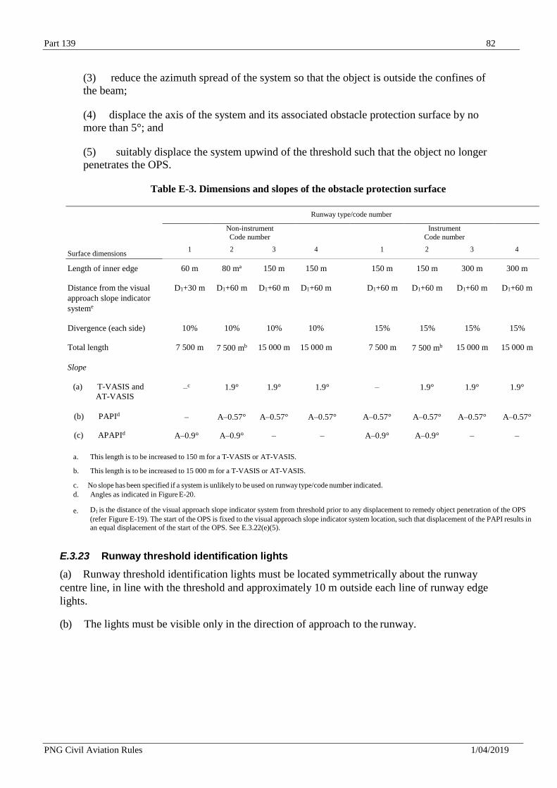
Part 139 82
PNG Civil Aviation Rules 1/04/2019
(3) reduce the azimuth spread of the system so that the object is outside the confines of
the beam;
(4) displace the axis of the system and its associated obstacle protection surface by no
more than 5°; and
(5) suitably displace the system upwind of the threshold such that the object no longer
penetrates the OPS.
Table E-3. Dimensions and slopes of the obstacle protection surface
Runway type/code number
Non-instrument
Code number Instrument
Code number
Surface dimensions 1 2 3 4 1 2 3 4
Length of inner edge 60 m 80 ma 150 m 150 m 150 m 150 m 300 m 300 m
Distance from the visual D1+30 m D1+60 m D1+60 m D1+60 m D1+60 m D1+60 m D1+60 m D1+60 m
approach slope indicator
systeme
Divergence (each side) 10% 10% 10% 10% 15% 15% 15% 15%
Total length 7 500 m 7 500 mb 15 000 m 15 000 m 7 500 m 7 500 mb 15 000 m 15 000 m
Slope
(a) T-VASIS and
AT-VASIS –c 1.9° 1.9° 1.9° – 1.9° 1.9° 1.9°
(b) PAPId – A–0.57° A–0.57° A–0.57° A–0.57° A–0.57° A–0.57° A–0.57°
(c) APAPId A–0.9° A–0.9° – – A–0.9° A–0.9° – –
a. This length is to be increased to 150 m for a T-VASIS or AT-VASIS.
b. This length is to be increased to 15 000 m for a T-VASIS or AT-VASIS.
c. No slope has been specified if a system is unlikely to be used on runway type/code number indicated.
d. Angles as indicated in Figure E-20.
e. D1 is the distance of the visual approach slope indicator system from threshold prior to any displacement to remedy object penetration of the OPS (refer Figure E-19). The start of the OPS is fixed to the visual approach slope indicator system location, such that displacement of the PAPI results in an equal displacement of the start of the OPS. See E.3.22(e)(5).
E.3.23 Runway threshold identification lights
(a) Runway threshold identification lights must be located symmetrically about the runway
centre line, in line with the threshold and approximately 10 m outside each line of runway edge
lights.
(b) The lights must be visible only in the direction of approach to the runway.
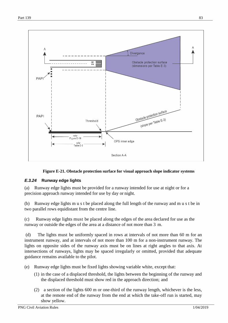
Part 139 83
PNG Civil Aviation Rules 1/04/2019
Figure E-21. Obstacle protection surface for visual approach slope indicator systems
E.3.24 Runway edge lights
(a) Runway edge lights must be provided for a runway intended for use at night or for a
precision approach runway intended for use by day or night.
(b) Runway edge lights m u s t be placed along the full length of the runway and m u s t be in
two parallel rows equidistant from the centre line.
(c) Runway edge lights must be placed along the edges of the area declared for use as the
runway or outside the edges of the area at a distance of not more than 3 m.
(d) The lights must be uniformly spaced in rows at intervals of not more than 60 m for an
instrument runway, and at intervals of not more than 100 m for a non-instrument runway. The
lights on opposite sides of the runway axis must be on lines at right angles to that axis. At
intersections of runways, lights may be spaced irregularly or omitted, provided that adequate
guidance remains available to the pilot.
(e) Runway edge lights must be fixed lights showing variable white, except that:
(1) in the case of a displaced threshold, the lights between the beginning of the runway and
the displaced threshold must show red in the approach direction; and
(2) a section of the lights 600 m or one-third of the runway length, whichever is the less,
at the remote end of the runway from the end at which the take-off run is started, may
show yellow.
Part 139 84
PNG Civil Aviation Rules 1/04/2019
(f) The runway edge lights must show at all angles in azimuth necessary to provide guidance
to a pilot landing or taking off in either direction. When the runway edge lights are intended to
provide circling guidance, they must show at all angles in azimuth.
(g) In all angles of azimuth required in (f), runway edge lights must show at angles up to 15°
above the horizontal with an intensity adequate for the conditions of visibility and ambient light
in which use of the runway for take-off or landing is intended. In any case, the intensity m u s t
be at least 50 cd except that at an aerodrome without extraneous lighting, the intensity of the
lights may be reduced to not less than 25 cd to avoid dazzling the pilot.
(h) Runway edge lights on a precision approach runway must be in accordance with the
specifications of CASA Advisory Circulars in the 139 series.
E.3.25 Runway threshold and wing bar lights
(a) Runway threshold lights must be provided for a runway equipped with runway edge lights,
except on a non- instrument or non-precision approach runway where the threshold is displaced
and wing bar lights are provided.
(b) When a threshold is at the extremity of a runway, the threshold lights must be placed in a
row at right angles to the runway axis as near to the extremity of the runway as possible and, in
any case, not more than 3 m outside the extremity.
(c) When a threshold is displaced from the extremity of a runway, threshold lights must be
placed in a row at right angles to the runway axis at the displaced threshold.
(d) Threshold lighting must consist of:
(1) on a non-instrument or non-precision approach runway, at least six lights;
(2) on a precision approach runway category, I, at least the number of lights that would
be required if the lights were uniformly spaced at intervals of 3 m between the rows of
runway edge lights; and
(3) on a precision approach runway category II or III, lights uniformly spaced between the
rows of runway edge lights at intervals of not more than 3 m.
(e) Wing bar lights must be provided on a non-instrument or non-precision approach runway
where the threshold is displaced and runway threshold lights are required, but are not provided..
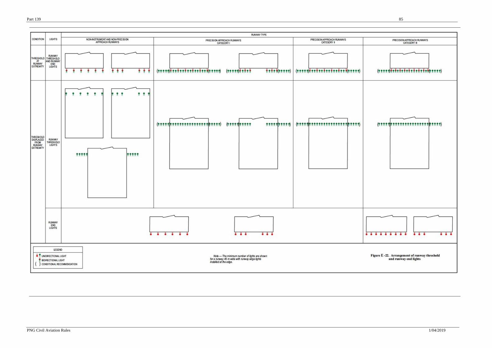
Part 139 85
PNG Civil Aviation Rules 1/04/2019
Part 139 86
PNG Civil Aviation Rules 1/04/2019
(f) Wing bar lights must be symmetrically disposed about the runway centre line at the
threshold in two groups, i.e. wing bars. Each wing bar must be formed by at least five lights
extending at least 10 m outward from, and at right angles to, the line of the runway edge lights,
with the innermost light of each wing bar in the line of the runway edge lights.
(g) Runway threshold and wing bar lights must be fixed unidirectional lights showing green in
the direction of approach to the runway. The intensity and beam spread of the lights must be
adequate for the conditions of visibility and ambient light in which use of the runway is intended.
(h) Runway threshold lights on a precision approach runway must be in accordance with the
specifications of CASA Advisory Circulars in the 139 series.
(i) Threshold wing bar lights on a precision approach runway must be in accordance with the
specifications of CASA Advisory Circulars in the 139 series
E.3.26 Runway end lights
(a) Runway end lights must be provided for a runway equipped with runway edge lights.
(b) Runway end lights must be placed on a line at right angles to the runway axis as near to the
end of the runway as possible and, in any case, not more than 3 m outside the end.
(c) Runway end lights m u s t be fixed unidirectional lights showing red in the direction of
the runway. The intensity and beam spread of the lights must be adequate for the conditions of
visibility and ambient light in which use of the runway is intended.
(d) Runway end lights on a precision approach runway must be in accordance with the
specifications of CASA Advisory Circulars in the 139 series.
E.3.27 Runway centre line lights
(a) Runway centre line lights must be provided on a precision approach runway category II or
III.
(b) Runway centre line lights must be provided on a runway intended to be used for take-
off with an operating minimum below an RVR of the order of 400 m.
(c) Runway centre line lights must be located along the centre line of the runway, except that
the lights may be uniformly offset to the same side of the runway centre line by not more than 60
cm where it is not practicable to locate them along the centre line. The lights must be located
from the threshold to the end at longitudinal spacing of approximately 15 m. Where the
serviceability level of the runway centre line lights specified as maintenance objectives in J.5(c)
or J.5(g), as appropriate, can be demonstrated and the runway is intended for use in runway visual
range conditions of 350 m or greater, the longitudinal spacing may be approximately 30 m.
(d) Runway centre line lights must be fixed lights showing variable white from the threshold to
the point 900 m from the runway end; alternate red and variable white from 900 m to 300 m from
the runway end; and red from 300 m to the runway end, except that for runways less than 1 800 m
in length, the alternate red and variable white lights must extend from the midpoint of the runway
usable for landing to 300 m from the runway end.
Part 139 87
PNG Civil Aviation Rules 1/04/2019
(e) Runway centre line lights must be in accordance with the specifications of CASA Advisory Circulars in the 139 series.
E.3.28 Runway touchdown zone lights
(a) Touchdown zone (TDZ) lights m u s t be provided in the touchdown zone of a precision
approach runway category II or III.
(b) Touchdown zone lights must extend from the threshold for a longitudinal distance of 900
m, except that, on runways less than 1 800 m in length, the system must be shortened so that it
does not extend beyond the midpoint of the runway. The pattern must be formed by pairs of
barrettes symmetrically located about the runway centre line. The lateral spacing between the
innermost lights of a pair of barrettes must be equal to the lateral spacing selected for the
touchdown zone marking. The longitudinal spacing between pairs of barrettes must be either 30
m or 60 m.
(c) A barrette must be composed of at least three lights with a spacing between the lights of not
more than 1.5 m.
(d) Touchdown zone lights must be fixed unidirectional lights showing variable white.
(e) Touchdown zone lights must be in accordance with the specifications of CASA Advisory
Circulars in the 139 series.
E.3.29 Simple touchdown zone lights
(a) Simple touchdown zone lights must be a pair of lights located on each side of the runway
centre line 0.3 m beyond the upwind edge of the final touchdown zone marking. The lateral spacing
between the inner lights of the two pairs of lights must be equal to the lateral spacing selected for
the touchdown zone marking. The spacing between the lights of the same pair m u s t not be more
than 1.5 m or half the width of the touchdown zone marking, whichever is greater. (See Figure
E-24.)
(b) Simple touchdown zone lights must be fixed unidirectional lights showing variable white,
aligned so as to be visible to the pilot of a landing aeroplane in the direction of approach to the
runway.
(c) Simple touchdown zone lights must be in accordance with the specifications in CASA
Advisory Circulars in the 139 series.
E.3.30 Rapid exit taxiway indicator lights
(a) Rapid exit taxiway indicator lights must not be displayed in the event of any lamp failure
or other failure that prevents the display of the light pattern depicted in Figure E-25, in full.
(b) A set of rapid exit taxiway indicator lights must be located on the runway on the same side
of the runway centre line as the associated rapid exit taxiway, in the configuration shown in Figure
E-25. In each set, the lights must be located 2 m apart and the light nearest to the runway centre
line must be displaced 2 m from the runway centre line.
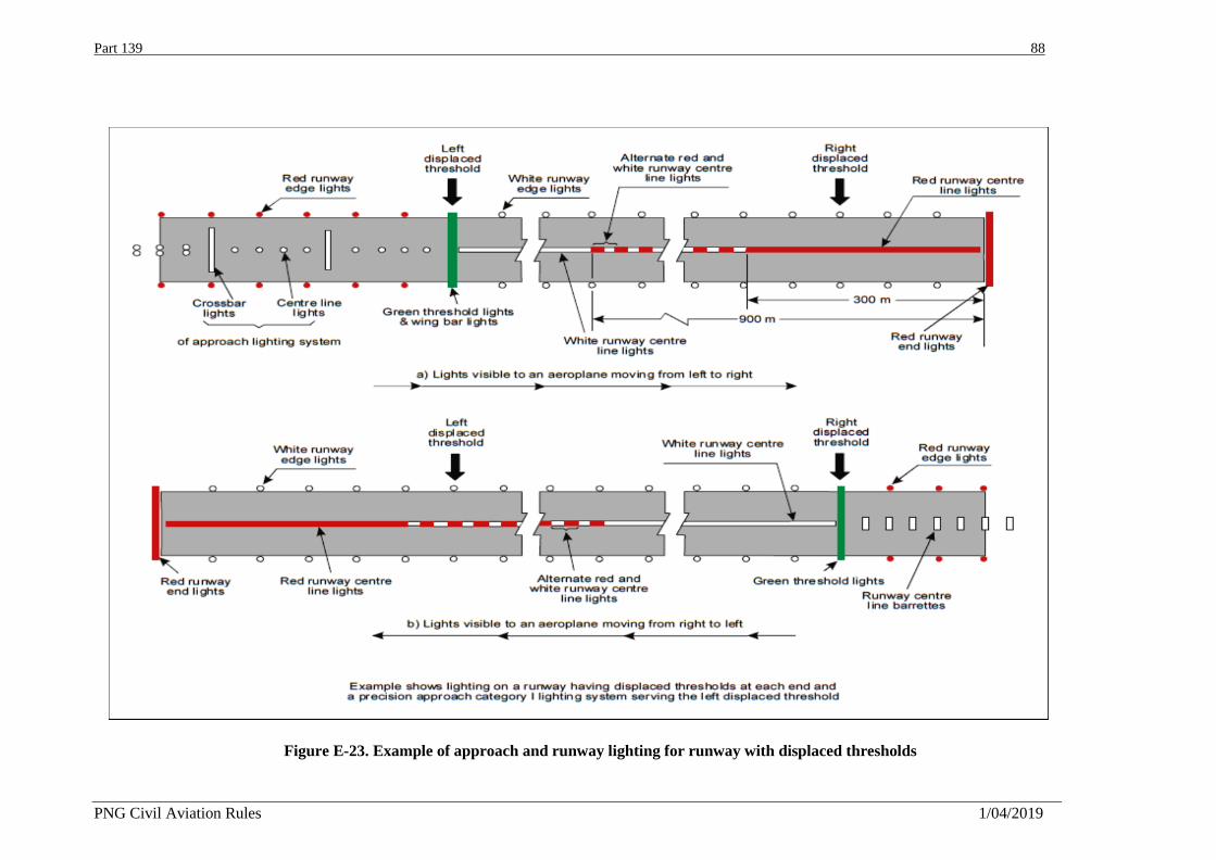
Part 139 88
PNG Civil Aviation Rules 1/04/2019
Figure E-23. Example of approach and runway lighting for runway with displaced thresholds
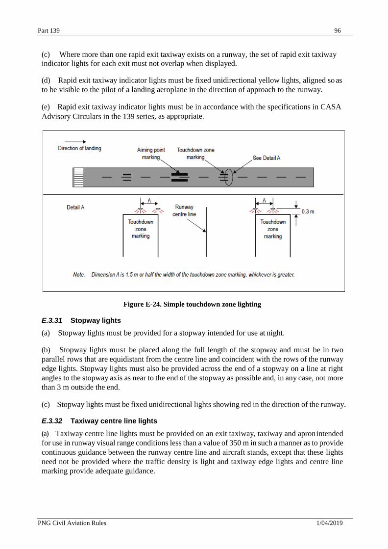
Part 139 96
PNG Civil Aviation Rules 1/04/2019
(c) Where more than one rapid exit taxiway exists on a runway, the set of rapid exit taxiway
indicator lights for each exit must not overlap when displayed.
(d) Rapid exit taxiway indicator lights must be fixed unidirectional yellow lights, aligned so as
to be visible to the pilot of a landing aeroplane in the direction of approach to the runway.
(e) Rapid exit taxiway indicator lights must be in accordance with the specifications in CASA
Advisory Circulars in the 139 series, as appropriate.
Figure E-24. Simple touchdown zone lighting
E.3.31 Stopway lights
(a) Stopway lights must be provided for a stopway intended for use at night.
(b) Stopway lights must be placed along the full length of the stopway and must be in two
parallel rows that are equidistant from the centre line and coincident with the rows of the runway
edge lights. Stopway lights must also be provided across the end of a stopway on a line at right
angles to the stopway axis as near to the end of the stopway as possible and, in any case, not more
than 3 m outside the end.
(c) Stopway lights must be fixed unidirectional lights showing red in the direction of the runway.
E.3.32 Taxiway centre line lights
(a) Taxiway centre line lights must be provided on an exit taxiway, taxiway and apron intended
for use in runway visual range conditions less than a value of 350 m in such a manner as to provide
continuous guidance between the runway centre line and aircraft stands, except that these lights
need not be provided where the traffic density is light and taxiway edge lights and centre line
marking provide adequate guidance.
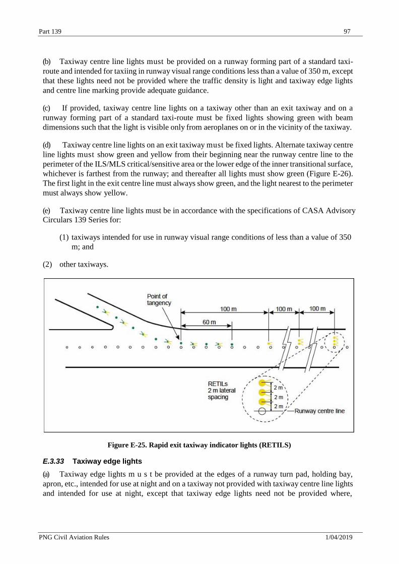
Part 139 97
PNG Civil Aviation Rules 1/04/2019
(b) Taxiway centre line lights must be provided on a runway forming part of a standard taxi-
route and intended for taxiing in runway visual range conditions less than a value of 350 m, except
that these lights need not be provided where the traffic density is light and taxiway edge lights
and centre line marking provide adequate guidance.
(c) If provided, taxiway centre line lights on a taxiway other than an exit taxiway and on a
runway forming part of a standard taxi-route must be fixed lights showing green with beam
dimensions such that the light is visible only from aeroplanes on or in the vicinity of the taxiway.
(d) Taxiway centre line lights on an exit taxiway must be fixed lights. Alternate taxiway centre
line lights must show green and yellow from their beginning near the runway centre line to the
perimeter of the ILS/MLS critical/sensitive area or the lower edge of the inner transitional surface,
whichever is farthest from the runway; and thereafter all lights must show green (Figure E-26).
The first light in the exit centre line must always show green, and the light nearest to the perimeter
must always show yellow.
(e) Taxiway centre line lights must be in accordance with the specifications of CASA Advisory
Circulars 139 Series for:
(1) taxiways intended for use in runway visual range conditions of less than a value of 350
m; and
(2) other taxiways.
Figure E-25. Rapid exit taxiway indicator lights (RETILS)
E.3.33 Taxiway edge lights
(a) Taxiway edge lights m u s t be provided at the edges of a runway turn pad, holding bay,
apron, etc., intended for use at night and on a taxiway not provided with taxiway centre line lights
and intended for use at night, except that taxiway edge lights need not be provided where,
Part 139 98
PNG Civil Aviation Rules 1/04/2019
considering the nature of the operations, adequate guidance can be achieved by surface
illumination or other means.
(b) Taxiway edge lights must be provided on a runway forming part of a standard taxi- route
and intended for taxiing at night where the runway is not provided with taxiway centre line lights.
(c) Taxiway edge lights must be fixed lights showing blue. The lights must show up to at least
75° above the horizontal and at all angles in azimuth necessary to provide guidance to a pilot
taxiing in either direction. At an intersection, exit or curve the lights must be shielded as far as
practicable so that they cannot be seen in angles of azimuth in which they may be confused with
other lights.
(d) The intensity of taxiway edge lights must be at least 2 cd from 0° to 6° vertical, and 0.2 cd
at any vertical angles between 6° and 75°.
E.3.34 Runway turn pad lights
(a) Runway turn pad lights must be provided for continuous guidance on a runway turn pad
intended for use in runway visual range conditions less than a value of 350 m, to enable an
aeroplane to complete a 180-degree turn and align with the runway centre line.
(b) Runway turn pad lights must be unidirectional fixed lights showing green with beam
dimensions such that the light is visible only from aeroplanes on or approaching the runway turn
pad.
(c) Runway turn pad lights must be in accordance with the specifications of CASA Advisory
Circulars in the 139 series, as appropriate.
E.3.35 Stop bars
(a) A stop bar must be provided at every runway-holding position serving a runway when it is
intended that the runway will be used in runway visual range conditions less than a value of 350
m, except where:
(1) appropriate aids and procedures are available to assist in preventing inadvertent
incursions of traffic onto the runway; or
(2) operational procedures exist to limit, in runway visual range conditions less than a value
of 550 m, the number of:
(i) aircraft on the manoeuvring area to one at a time; and
(ii) vehicles on the manoeuvring area to the essential minimum.
(b) A stop bar must be provided at every runway-holding position serving a runway when it is
intended that the runway will be used in runway visual range conditions of values between 350
m and 550 m, except where:
(1) appropriate aids and procedures are available to assist in preventing inadvertent
incursions of traffic onto the runway; or
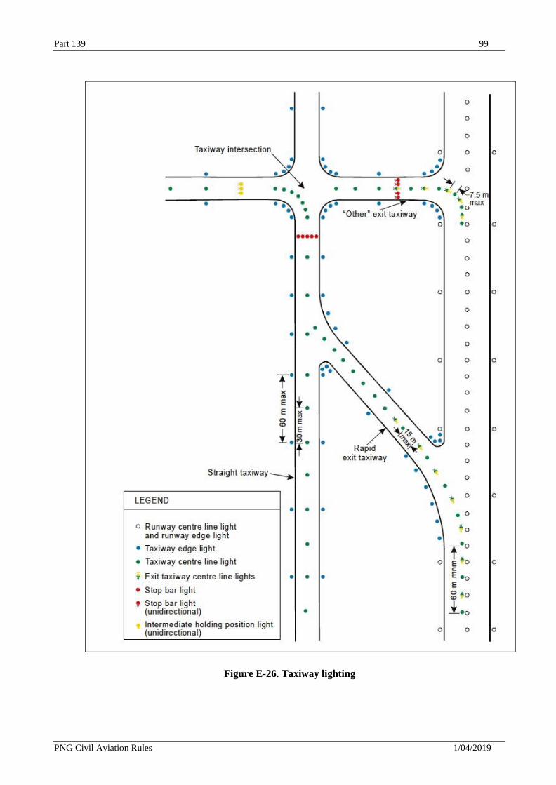
Part 139 99
PNG Civil Aviation Rules 1/04/2019
Figure E-26. Taxiway lighting
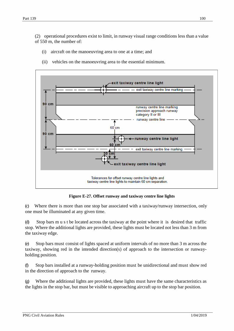
Part 139 100
PNG Civil Aviation Rules 1/04/2019
(2) operational procedures exist to limit, in runway visual range conditions less than a value
of 550 m, the number of:
(i) aircraft on the manoeuvring area to one at a time; and
(ii) vehicles on the manoeuvring area to the essential minimum.
Figure E-27. Offset runway and taxiway centre line lights
(c) Where there is more than one stop bar associated with a taxiway/runway intersection, only
one must be illuminated at any given time.
(d) Stop bars m u s t be located across the taxiway at the point where it is desired that traffic
stop. Where the additional lights are provided, these lights must be located not less than 3 m from
the taxiway edge.
(e) Stop bars must consist of lights spaced at uniform intervals of no more than 3 m across the
taxiway, showing red in the intended direction(s) of approach to the intersection or runway-
holding position.
(f) Stop bars installed at a runway-holding position must be unidirectional and must show red
in the direction of approach to the runway.
(g) Where the additional lights are provided, these lights must have the same characteristics as
the lights in the stop bar, but must be visible to approaching aircraft up to the stop bar position.
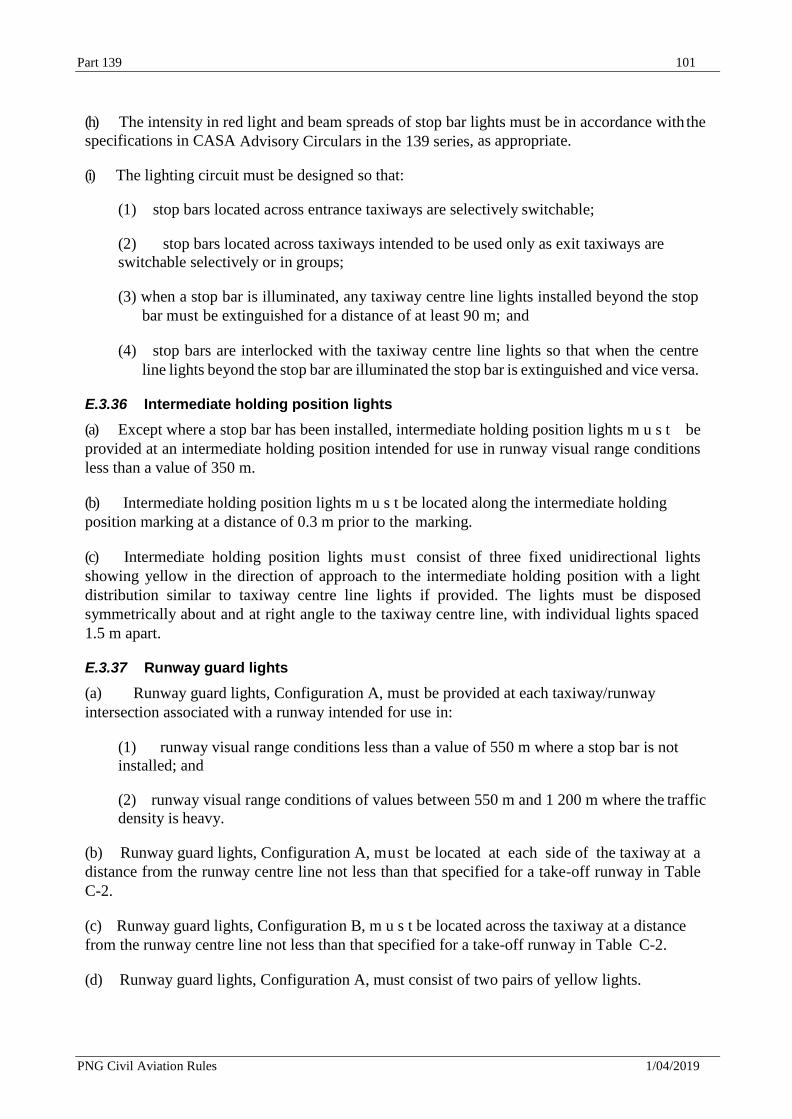
Part 139 101
PNG Civil Aviation Rules 1/04/2019
(h) The intensity in red light and beam spreads of stop bar lights must be in accordance with the
specifications in CASA Advisory Circulars in the 139 series, as appropriate.
(i) The lighting circuit must be designed so that:
(1) stop bars located across entrance taxiways are selectively switchable;
(2) stop bars located across taxiways intended to be used only as exit taxiways are
switchable selectively or in groups;
(3) when a stop bar is illuminated, any taxiway centre line lights installed beyond the stop
bar must be extinguished for a distance of at least 90 m; and
(4) stop bars are interlocked with the taxiway centre line lights so that when the centre
line lights beyond the stop bar are illuminated the stop bar is extinguished and vice versa.
E.3.36 Intermediate holding position lights
(a) Except where a stop bar has been installed, intermediate holding position lights m u s t be
provided at an intermediate holding position intended for use in runway visual range conditions
less than a value of 350 m.
(b) Intermediate holding position lights m u s t be located along the intermediate holding
position marking at a distance of 0.3 m prior to the marking.
(c) Intermediate holding position lights must consist of three fixed unidirectional lights
showing yellow in the direction of approach to the intermediate holding position with a light
distribution similar to taxiway centre line lights if provided. The lights must be disposed
symmetrically about and at right angle to the taxiway centre line, with individual lights spaced
1.5 m apart.
E.3.37 Runway guard lights
(a) Runway guard lights, Configuration A, must be provided at each taxiway/runway
intersection associated with a runway intended for use in:
(1) runway visual range conditions less than a value of 550 m where a stop bar is not
installed; and
(2) runway visual range conditions of values between 550 m and 1 200 m where the traffic
density is heavy.
(b) Runway guard lights, Configuration A, must be located at each side of the taxiway at a
distance from the runway centre line not less than that specified for a take-off runway in Table
C-2.
(c) Runway guard lights, Configuration B, m u s t be located across the taxiway at a distance
from the runway centre line not less than that specified for a take-off runway in Table C-2.
(d) Runway guard lights, Configuration A, must consist of two pairs of yellow lights.
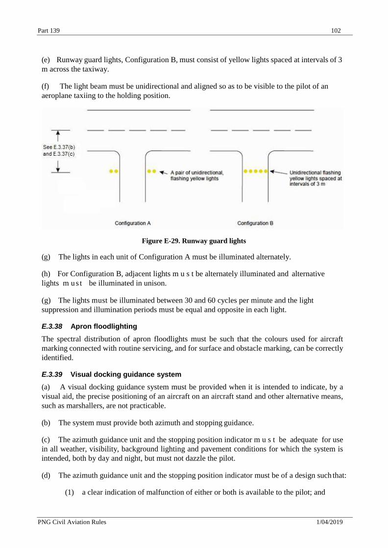
Part 139 102
PNG Civil Aviation Rules 1/04/2019
(e) Runway guard lights, Configuration B, must consist of yellow lights spaced at intervals of 3
m across the taxiway.
(f) The light beam must be unidirectional and aligned so as to be visible to the pilot of an
aeroplane taxiing to the holding position.
Figure E-29. Runway guard lights
(g) The lights in each unit of Configuration A must be illuminated alternately.
(h) For Configuration B, adjacent lights m u s t be alternately illuminated and alternative
lights m u s t be illuminated in unison.
(g) The lights must be illuminated between 30 and 60 cycles per minute and the light
suppression and illumination periods must be equal and opposite in each light.
E.3.38 Apron floodlighting
The spectral distribution of apron floodlights must be such that the colours used for aircraft
marking connected with routine servicing, and for surface and obstacle marking, can be correctly
identified.
E.3.39 Visual docking guidance system
(a) A visual docking guidance system must be provided when it is intended to indicate, by a
visual aid, the precise positioning of an aircraft on an aircraft stand and other alternative means,
such as marshallers, are not practicable.
(b) The system must provide both azimuth and stopping guidance.
(c) The azimuth guidance unit and the stopping position indicator m u s t be adequate for use
in all weather, visibility, background lighting and pavement conditions for which the system is
intended, both by day and night, but must not dazzle the pilot.
(d) The azimuth guidance unit and the stopping position indicator must be of a design such that:
(1) a clear indication of malfunction of either or both is available to the pilot; and
NPRM 18/06-36 Docket18/06/CAR139/36 103
PNG Civil Aviation Rules 1/04/2019
(2) they can be turned off.
(e) The azimuth guidance unit and the stopping position indicator must be located in such a
way that there is continuity of guidance between the aircraft stand markings, the aircraft stand
manoeuvring guidance lights, if present, and the visual docking guidance system.
(f) The accuracy of the system m u s t be adequate for the type of loading bridge and fixed
aircraft servicing installations with which it is to be used.
(g) If selective operation is required to prepare the system for use by a particular type of
aircraft, then the system must provide an identification of the selected aircraft type to both the
pilot and the system operator as a means of ensuring that the system has been set properly.
(h) The azimuth guidance unit must be located on or close to the extension of the stand centre
line ahead of the aircraft so that its signals are visible from the cockpit of an aircraft throughout
the docking manoeuvre and aligned for use at least by the pilot occupying the left seat.
(i) The azimuth guidance unit must provide unambiguous left/right guidance which enables the
pilot to acquire and maintain the lead-in line without over-controlling.
(j) When azimuth guidance is indicated by colour change, green must be used to identify the
centre line and red for deviations from the centre line.
(k) The stopping position indicator must be located in conjunction with, or sufficiently close
to, the azimuth guidance unit so that a pilot can observe both the azimuth and stop signals without
turning the head.
(l) The stopping position indicator must be usable at least by the pilot occupying the left seat.
(m) The stopping position information provided by the indicator for a particular aircraft type
must account for the anticipated range of variations in pilot eye height and/or viewing angle.
(n) The stopping position indicator must show the stopping position for the aircraft for which
guidance is being provided and must provide closing rate information to enable the pilot to
gradually decelerate the aircraft to a full stop at the intended stopping position.
(o) When stopping guidance is indicated by colour change, green must be used to show that the
aircraft can proceed and red to show that the stop point has been reached ,except that for a short
distance prior to the stop point a third colour may be used to warn that the stopping point is close.
E.3.40 Advanced visual docking guidance system
(a) The A-VDGS must be suitable for use by all types of aircraft for which the aircraft stand is
intended.
(b) The A-VDGS must be used only in conditions in which its operational performance is
specified.
(c) The docking guidance information provided by an A-VDGS must not conflict with that
provided by a conventional visual docking guidance system on an aircraft stand if both
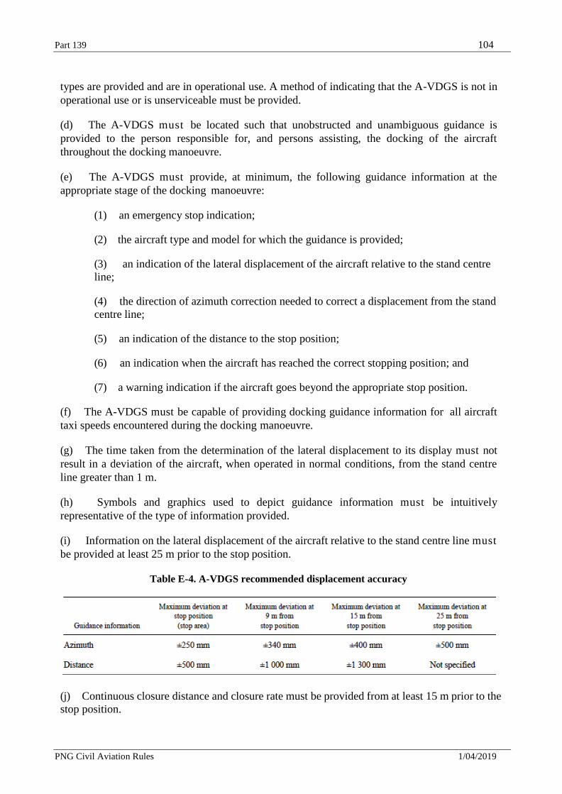
Part 139 104
PNG Civil Aviation Rules 1/04/2019
types are provided and are in operational use. A method of indicating that the A-VDGS is not in
operational use or is unserviceable must be provided.
(d) The A-VDGS must be located such that unobstructed and unambiguous guidance is
provided to the person responsible for, and persons assisting, the docking of the aircraft
throughout the docking manoeuvre.
(e) The A-VDGS must provide, at minimum, the following guidance information at the
appropriate stage of the docking manoeuvre:
(1) an emergency stop indication;
(2) the aircraft type and model for which the guidance is provided;
(3) an indication of the lateral displacement of the aircraft relative to the stand centre
line;
(4) the direction of azimuth correction needed to correct a displacement from the stand
centre line;
(5) an indication of the distance to the stop position;
(6) an indication when the aircraft has reached the correct stopping position; and
(7) a warning indication if the aircraft goes beyond the appropriate stop position.
(f) The A-VDGS must be capable of providing docking guidance information for all aircraft
taxi speeds encountered during the docking manoeuvre.
(g) The time taken from the determination of the lateral displacement to its display must not
result in a deviation of the aircraft, when operated in normal conditions, from the stand centre
line greater than 1 m.
(h) Symbols and graphics used to depict guidance information must be intuitively
representative of the type of information provided.
(i) Information on the lateral displacement of the aircraft relative to the stand centre line must
be provided at least 25 m prior to the stop position.
Table E-4. A-VDGS recommended displacement accuracy
(j) Continuous closure distance and closure rate must be provided from at least 15 m prior to the
stop position.
Part 139 105
PNG Civil Aviation Rules 1/04/2019
(k) Throughout the docking manoeuvre, an appropriate means must be provided on the A-VDGS
to indicate the need to bring the aircraft to an immediate halt. In such an event, which includes
a failure of the A-VDGS, no other information must be displayed.
(l) Provision to initiate an immediate halt to the docking procedure must be made available to
personnel responsible for the operational safety of the stand.
E.3.41 Aircraft stand manoeuvring guidance lights
(a) Aircraft stand manoeuvring guidance lights must be collocated with the aircraft stand
markings.
(b) Aircraft stand manoeuvring guidance lights, other than those indicating a stop position,
must be fixed yellow lights, visible throughout the segments within which they are intended to
provide guidance.
(c) The lights indicating a stop position must be fixed unidirectional lights showing red.
E.3.42 Road-holding position light
(a) A road-holding position light must be provided at each road-holding position serving a
runway when it is intended that the runway will be used in runway visual range conditions less
than a value of 350 m.
(b) A road-holding position light must be located adjacent to the holding position marking
1.5 m (±0.5 m) from one edge of the road, i.e. left or right as appropriate to the local traffic
regulations.
(c) The road-holding position light must comprise:
(1) a controllable red (stop)/green (go) traffic light; or
(2) a flashing-red light.
(d) The road-holding position light beam must be unidirectional and aligned so as to be visible
to the driver of a vehicle approaching the holding position.
(e) The intensity of the light beam must be adequate for the conditions of visibility and ambient
light in which the use of the holding position is intended, but must not dazzle the driver.
(f) The flash frequency of the flashing-red light must be between 30 and 60 flashes per minute.
E.3.43 No-entry bar
(a) The intensity in red light and beam spreads of no-entry bar lights must be in accordance with
the specifications in CASA Advisory Circulars in the 139 series, as appropriate.
(b) The lighting circuit must be designed so that:
(1) no-entry bars are switchable selectively or in groups;
Part 139 106
PNG Civil Aviation Rules 1/04/2019
(2) when a no-entry bar is illuminated, any taxiway centre line lights installed beyond the
no-entry bar, when viewed towards the runway, must be extinguished for a distance of
at least 90 m; and
(3) when a no-entry bar is illuminated, any stop bar installed between the no-entry bar and
the runway m u s t be extinguished.
E.3.44 Runway status lights
(a) Where provided, RELs must be offset 0.6 m from the taxiway centre line on the opposite
side to the taxiway centre line lights and begin 0.6 m before the runway-holding position
extending to the edge of the runway. An additional single light must be placed on the runway 0.6
m from the runway centre line and aligned with the last two taxiway RELs.
(b) RELs must consist of at least five light units and must be spaced at a minimum of 3.8 m and
a maximum of 15.2 m longitudinally, depending upon the taxiway length involved, except for a
single light installed near the runway centre line.
(c) Where provided, THLs must be offset 1.8 m on each side of the runway centre line lights
and extend, in pairs, starting at a point 115 m from the beginning of the runway and, thereafter,
every 30 m for at least 450 m.
(d) Where provided, RELs must consist of a single line of fixed in pavement lights showing red
in the direction of aircraft approaching the runway.
(e) RELs m u s t illuminate as an array at each taxiway/runway intersection where they are
installed less than two seconds after the system determines a warning is needed.
(f) Intensity and beam spread of RELs must be in accordance with the specifications of
CASA Advisory Circulars in the 139 series.
(g) Where provided, THLs must consist of two rows of fixed in pavement lights sh owing red
facing the aircraft taking off.
(h) THLs must illuminate as an array on the runway less than two seconds after the system
determines a warning is needed.
(i) Intensity and beam spread of THLs must be in accordance with the specifications of CASA
Advisory Circulars in the 139 series.
E.4 Signs
E.4.1 General
(a) Signs must be provided to convey a mandatory instruction, information on a specific
location or destination on a movement area or to provide other information to meet the
requirements of I.7(a).
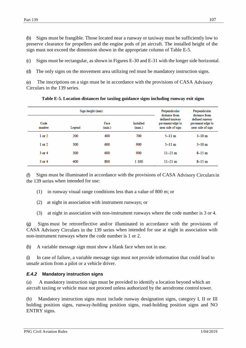
Part 139 107
PNG Civil Aviation Rules 1/04/2019
(b) Signs must be frangible. Those located near a runway or taxiway must be sufficiently low to
preserve clearance for propellers and the engine pods of jet aircraft. The installed height of the
sign must not exceed the dimension shown in the appropriate column of Table E-5.
(c) Signs must be rectangular, as shown in Figures E-30 and E-31 with the longer side horizontal.
(d) The only signs on the movement area utilizing red must be mandatory instruction signs.
(e) The inscriptions on a sign must be in accordance with the provisions of CASA Advisory
Circulars in the 139 series.
Table E-5. Location distances for taxiing guidance signs including runway exit signs
(f) Signs must be illuminated in accordance with the provisions of CASA Advisory Circulars in
the 139 series when intended for use:
(1) in runway visual range conditions less than a value of 800 m; or
(2) at night in association with instrument runways; or
(3) at night in association with non-instrument runways where the code number is 3 or 4.
(g) Signs must be retroreflective and/or illuminated in accordance with the provisions of
CASA Advisory Circulars in the 139 series when intended for use at night in association with
non-instrument runways where the code number is 1 or 2.
(h) A variable message sign must show a blank face when not in use.
(i) In case of failure, a variable message sign must not provide information that could lead to
unsafe action from a pilot or a vehicle driver.
E.4.2 Mandatory instruction signs
(a) A mandatory instruction sign must be provided to identify a location beyond which an
aircraft taxiing or vehicle must not proceed unless authorized by the aerodrome control tower.
(b) Mandatory instruction signs must include runway designation signs, category I, II or III
holding position signs, runway-holding position signs, road-holding position signs and NO
ENTRY signs.
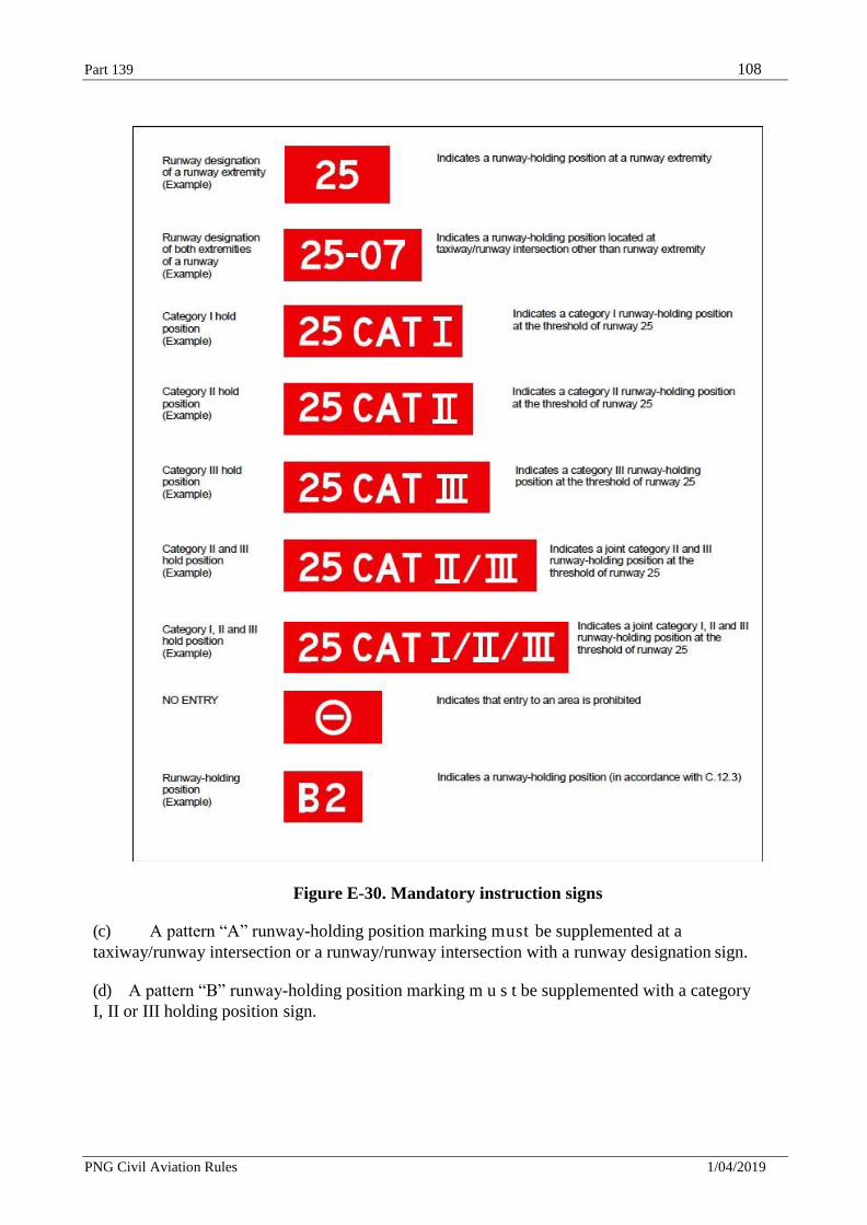
Part 139 108
PNG Civil Aviation Rules 1/04/2019
Figure E-30. Mandatory instruction signs
(c) A pattern “A” runway-holding position marking must be supplemented at a
taxiway/runway intersection or a runway/runway intersection with a runway designation sign.
(d) A pattern “B” runway-holding position marking m u s t be supplemented with a category
I, II or III holding position sign.
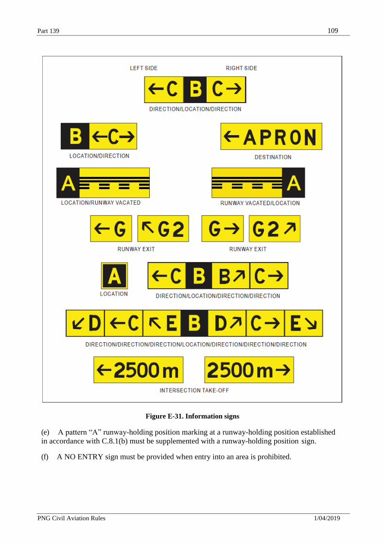
Part 139 109
PNG Civil Aviation Rules 1/04/2019
Figure E-31. Information signs
(e) A pattern “A” runway-holding position marking at a runway-holding position established
in accordance with C.8.1(b) must be supplemented with a runway-holding position sign.
(f) A NO ENTRY sign must be provided when entry into an area is prohibited.
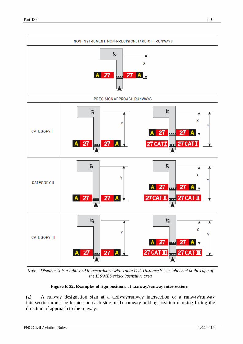
Part 139 110
PNG Civil Aviation Rules 1/04/2019
Note – Distance X is established in accordance with Table C-2. Distance Y is established at the edge of
the ILS/MLS critical/sensitive area
Figure E-32. Examples of sign positions at taxiway/runway intersections
(g) A runway designation sign at a taxiway/runway intersection or a runway/runway
intersection must be located on each side of the runway-holding position marking facing the
direction of approach to the runway.
Part 139 111
PNG Civil Aviation Rules 1/04/2019
(h) A category I, II or III holding position sign must be located on each side of the runway-
holding position marking facing the direction of the approach to the critical area.
(i) A NO ENTRY sign must be located at the beginning of the area to which entrance is
prohibited on each side of the taxiway as viewed by the pilot.
(j) A runway-holding position sign must be located on each side of the runway-holding
position established in accordance with C.8.1(b), facing the approach to the obstacle limitation
surface or ILS/MLS critical/sensitive area, as appropriate.
(k) A mandatory instruction sign must consist of an inscription in white on a red background.
(l) The inscription on a runway designation sign must consist of the runway designations of the
intersecting runway properly oriented with respect to the viewing position of the sign, except that
a runway designation sign installed in the vicinity of a runway extremity may show the runway
designation of the concerned runway extremity only.
(m) The inscription on a category I, II, III, joint II/III or joint I/II/III holding position sign must
consist of the runway designator followed by CAT I, CAT II, CAT III, CAT II/III or CAT I/II/III,
as appropriate.
(n) The inscription on a NO ENTRY sign must be in accordance with Figure E-30.
(o) The inscription on a runway-holding position sign at a runway-holding position established
in accordance with C.8.1(b) must consist of the taxiway designation and a number.
(p) Where installed, the inscriptions/symbol of Figure E-30 must be used.
E.4.3 Information signs
(a) An information sign must be provided where there is an operational need to identify by a
sign, a specific location, or routing (direction or destination) information.
(b) Information signs must include: direction signs, location signs, destination signs, runway exit
signs, runway vacated signs and intersection take-off signs.
(c) A runway exit sign must be provided where there is an operational need to identify a runway
exit.
(d) A runway vacated sign must be provided where the exit taxiway is not provided with taxiway
centre line lights and there is a need to indicate to a pilot leaving a runway the perimeter of the
ILS/MLS critical/sensitive area or the lower edge of the inner transitional surface, whichever is
farther from the runway centre line.
(e) A combined location and direction sign must be provided when it is intended to indicate
routing information prior to a taxiway intersection.
(f) A direction sign must be provided when there is an operational need to identify the
designation and direction of taxiways at an intersection.
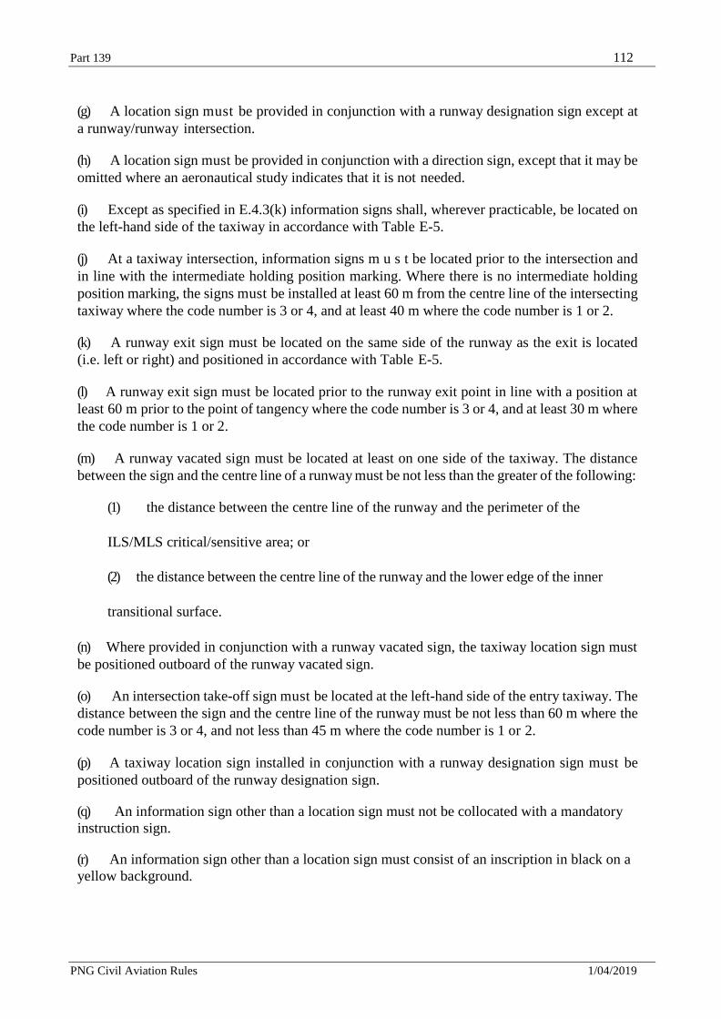
Part 139 112
PNG Civil Aviation Rules 1/04/2019
(g) A location sign must be provided in conjunction with a runway designation sign except at
a runway/runway intersection.
(h) A location sign must be provided in conjunction with a direction sign, except that it may be
omitted where an aeronautical study indicates that it is not needed.
(i) Except as specified in E.4.3(k) information signs shall, wherever practicable, be located on
the left-hand side of the taxiway in accordance with Table E-5.
(j) At a taxiway intersection, information signs m u s t be located prior to the intersection and
in line with the intermediate holding position marking. Where there is no intermediate holding
position marking, the signs must be installed at least 60 m from the centre line of the intersecting
taxiway where the code number is 3 or 4, and at least 40 m where the code number is 1 or 2.
(k) A runway exit sign must be located on the same side of the runway as the exit is located
(i.e. left or right) and positioned in accordance with Table E-5.
(l) A runway exit sign must be located prior to the runway exit point in line with a position at
least 60 m prior to the point of tangency where the code number is 3 or 4, and at least 30 m where
the code number is 1 or 2.
(m) A runway vacated sign must be located at least on one side of the taxiway. The distance
between the sign and the centre line of a runway must be not less than the greater of the following:
(1) the distance between the centre line of the runway and the perimeter of the
ILS/MLS critical/sensitive area; or
(2) the distance between the centre line of the runway and the lower edge of the inner
transitional surface.
(n) Where provided in conjunction with a runway vacated sign, the taxiway location sign must
be positioned outboard of the runway vacated sign.
(o) An intersection take-off sign must be located at the left-hand side of the entry taxiway. The
distance between the sign and the centre line of the runway must be not less than 60 m where the
code number is 3 or 4, and not less than 45 m where the code number is 1 or 2.
(p) A taxiway location sign installed in conjunction with a runway designation sign must be
positioned outboard of the runway designation sign.
(q) An information sign other than a location sign must not be collocated with a mandatory
instruction sign.
(r) An information sign other than a location sign must consist of an inscription in black on a
yellow background.
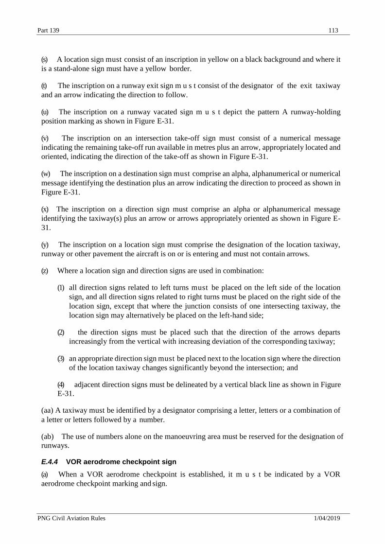
Part 139 113
PNG Civil Aviation Rules 1/04/2019
(s) A location sign must consist of an inscription in yellow on a black background and where it
is a stand-alone sign must have a yellow border.
(t) The inscription on a runway exit sign m u s t consist of the designator of the exit taxiway
and an arrow indicating the direction to follow.
(u) The inscription on a runway vacated sign m u s t depict the pattern A runway-holding
position marking as shown in Figure E-31.
(v) The inscription on an intersection take-off sign must consist of a numerical message
indicating the remaining take-off run available in metres plus an arrow, appropriately located and
oriented, indicating the direction of the take-off as shown in Figure E-31.
(w) The inscription on a destination sign must comprise an alpha, alphanumerical or numerical
message identifying the destination plus an arrow indicating the direction to proceed as shown in
Figure E-31.
(x) The inscription on a direction sign must comprise an alpha or alphanumerical message
identifying the taxiway(s) plus an arrow or arrows appropriately oriented as shown in Figure E-
31.
(y) The inscription on a location sign must comprise the designation of the location taxiway,
runway or other pavement the aircraft is on or is entering and must not contain arrows.
(z) Where a location sign and direction signs are used in combination:
(1) all direction signs related to left turns must be placed on the left side of the location
sign, and all direction signs related to right turns must be placed on the right side of the
location sign, except that where the junction consists of one intersecting taxiway, the
location sign may alternatively be placed on the left-hand side;
(2) the direction signs must be placed such that the direction of the arrows departs
increasingly from the vertical with increasing deviation of the corresponding taxiway;
(3) an appropriate direction sign must be placed next to the location sign where the direction
of the location taxiway changes significantly beyond the intersection; and
(4) adjacent direction signs must be delineated by a vertical black line as shown in Figure
E-31.
(aa) A taxiway must be identified by a designator comprising a letter, letters or a combination of
a letter or letters followed by a number.
(ab) The use of numbers alone on the manoeuvring area must be reserved for the designation of
runways.
E.4.4 VOR aerodrome checkpoint sign
(a) When a VOR aerodrome checkpoint is established, it m u s t be indicated by a VOR
aerodrome checkpoint marking and sign.
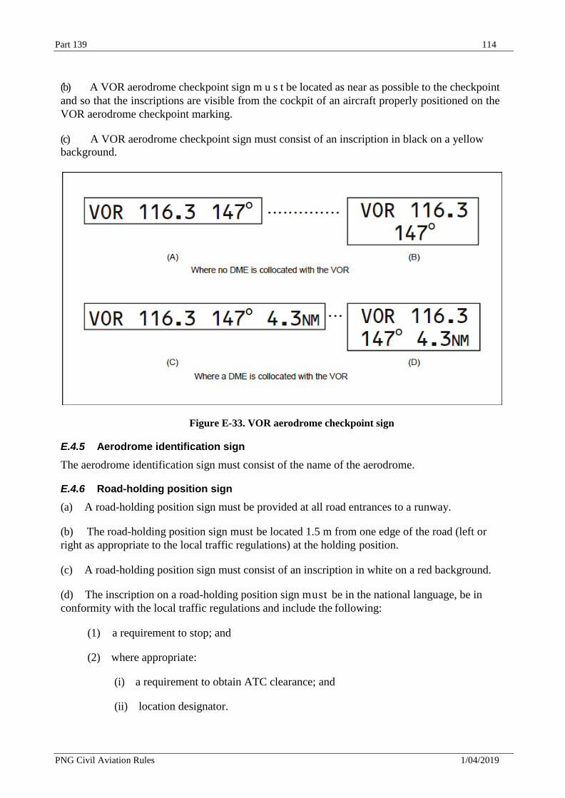
Part 139 114
PNG Civil Aviation Rules 1/04/2019
(b) A VOR aerodrome checkpoint sign m u s t be located as near as possible to the checkpoint
and so that the inscriptions are visible from the cockpit of an aircraft properly positioned on the
VOR aerodrome checkpoint marking.
(c) A VOR aerodrome checkpoint sign must consist of an inscription in black on a yellow
background.
Figure E-33. VOR aerodrome checkpoint sign
E.4.5 Aerodrome identification sign
The aerodrome identification sign must consist of the name of the aerodrome.
E.4.6 Road-holding position sign
(a) A road-holding position sign must be provided at all road entrances to a runway.
(b) The road-holding position sign must be located 1.5 m from one edge of the road (left or
right as appropriate to the local traffic regulations) at the holding position.
(c) A road-holding position sign must consist of an inscription in white on a red background.
(d) The inscription on a road-holding position sign must be in the national language, be in
conformity with the local traffic regulations and include the following:
(1) a requirement to stop; and
(2) where appropriate:
(i) a requirement to obtain ATC clearance; and
(ii) location designator.
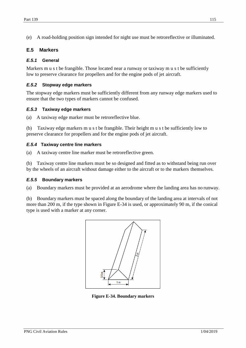
Part 139 115
PNG Civil Aviation Rules 1/04/2019
(e) A road-holding position sign intended for night use must be retroreflective or illuminated.
E.5 Markers
E.5.1 General
Markers m u s t be frangible. Those located near a runway or taxiway m u s t be sufficiently
low to preserve clearance for propellers and for the engine pods of jet aircraft.
E.5.2 Stopway edge markers
The stopway edge markers must be sufficiently different from any runway edge markers used to
ensure that the two types of markers cannot be confused.
E.5.3 Taxiway edge markers
(a) A taxiway edge marker must be retroreflective blue.
(b) Taxiway edge markers m u s t be frangible. Their height m u s t be sufficiently low to
preserve clearance for propellers and for the engine pods of jet aircraft.
E.5.4 Taxiway centre line markers
(a) A taxiway centre line marker must be retroreflective green.
(b) Taxiway centre line markers must be so designed and fitted as to withstand being run over
by the wheels of an aircraft without damage either to the aircraft or to the markers themselves.
E.5.5 Boundary markers
(a) Boundary markers must be provided at an aerodrome where the landing area has no runway.
(b) Boundary markers must be spaced along the boundary of the landing area at intervals of not
more than 200 m, if the type shown in Figure E-34 is used, or approximately 90 m, if the conical
type is used with a marker at any corner.
Figure E-34. Boundary markers
Part 139 116
PNG Civil Aviation Rules 1/04/2019
Appendix F — Visual Aids for Denoting Obstacles
F.1 Objects to be marked and/or lighted
F.1.1 Objects within the lateral boundaries of the obstacle limitation surfaces
(a) Vehicles and other mobile objects, excluding aircraft, on the movement area of an aerodrome
are obstacles and must be marked and, if the vehicles and aerodrome are used at night or in
conditions of low visibility, lighted, except that aircraft servicing equipment and vehicles
used only on aprons may be exempt.
(b) Elevated aeronautical ground lights within the movement area must be marked so as to be
conspicuous by day. Obstacle lights must not be installed on elevated ground lights or signs
in the movement area.
(c) All obstacles within the distance specified in the following Table C-1, column 11 or 12, from
the centre line of a taxiway, an apron taxiway or aircraft stand taxi lane must be marked and,
if the taxiway, apron taxiway or aircraft stand taxi lane is used at night, lighted.
(d) A fixed obstacle that extends above an approach surface within 3 000 m of the inner edge
or above a transitional surface must be marked and, if the runway is used at night, lighted, except
that:
(1) such marking and lighting may be omitted when the obstacle is shielded by another fixed obstacle;
(2) the marking may be omitted when the obstacle is lighted by medium-intensity obstacle
lights, Type A, by day and its height above the level of the surrounding ground does not
exceed 150 m;
(3) the marking may be omitted when the obstacle is lighted by high-intensity obstacle
lights by day; and
(4) the lighting may be omitted where the obstacle is a lighthouse and an aeronautical
study indicates the lighthouse light to be sufficient.
(e) A fixed object that extends above an obstacle protection surface must be marked and, if
the runway is used at night, lighted.
F.2 Marking and/or lighting of objects
F.2.1 General
(a) The presence of objects which must be lighted, as specified in F.1, must be indicated by
low-, medium- or high- intensity obstacle lights, or a combination of such lights.
(b) Low-intensity obstacle lights, Types A B, C, D and E, medium-intensity obstacle lights,
Types A, B and C, high-intensity obstacle lights Type A and B, must be in accordance with the
specifications in Table F-1 and CASA Advisory Circulars in the 139 series.
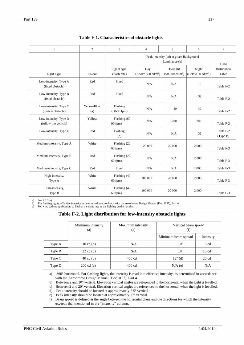
Part 139 117
PNG Civil Aviation Rules 1/04/2019
Table F-1. Characteristics of obstacle lights
1 2 3 4 5 6 7
Light Type
Colour
Signal type/
(flash rate)
Peak intensity (cd) at given Background
Luminance (b)
Light
Distribution
Table
Day
(Above 500 cd/m2)
Twilight
(50-500 cd/m2)
Night
(Below 50 cd/m2)
Low-intensity, Type A
(fixed obstacle)
Red Fixed N/A
N/A
10
Table F-2
Low-intensity, Type B
(fixed obstacle)
Red Fixed N/A
N/A
32
Table F-2
Low-intensity, Type C
(mobile obstacle)
Yellow/Blue
(a)
Flashing
(60-90 fpm)
N/A
40
40
Table F-2
Low-intensity, Type D
(follow-me vehicle)
Yellow Flashing (60–
90 fpm)
N/A
200
200
Table F-2
Low-intensity, Type E Red Flashing
(c)
N/A
N/A
32
Table F-2
(Type B)
Medium-intensity, Type A White Flashing (20–
60 fpm)
20 000
20 000
2 000
Table F-3
Medium-intensity, Type B Red Flashing (20–
60 fpm)
N/A
N/A
2 000
Table F-3
Medium-intensity, Type C Red Fixed N/A N/A 2 000 Table F-3
High-intensity,
Type A
White Flashing (40–
60 fpm)
200 000
20 000
2 000
Table F-3
High-intensity,
Type B
White Flashing (40–
60 fpm)
100 000
20 000
2 000
Table F-3
a) See F.2.2(e) b) For flashing lights, effective intensity as determined in accordance with the Aerodrome Design Manual (Doc 9157), Part 4. c) For wind turbine application, to flash at the same rate as the lighting on the nacelle.
Table F-2. Light distribution for low-intensity obstacle lights
Minimum intensity
(a)
Maximum intensity
(a)
Vertical beam spread
(f)
Minimum beam spread Intensity
Type A 10 cd (b) N/A 10° 5 cd
Type B 32 cd (b) N/A 10° 16 cd
Type C 40 cd (b) 400 cd 12° (d) 20 cd
Type D 200 cd (c) 400 cd N/A (e) N/A
a) 360° horizontal. For flashing lights, the intensity is read into effective intensity, as determined in accordance
with the Aerodrome Design Manual (Doc 9157), Part 4.
b) Between 2 and 10° vertical. Elevation vertical angles are referenced to the horizontal when the light is levelled.
c) Between 2 and 20° vertical. Elevation vertical angles are referenced to the horizontal when the light is levelled.
d) Peak intensity should be located at approximately 2.5° vertical. e) Peak intensity should be located at approximately 17° vertical.
f) Beam spread is defined as the angle between the horizontal plane and the directions for which the intensity
exceeds that mentioned in the “intensity” column.
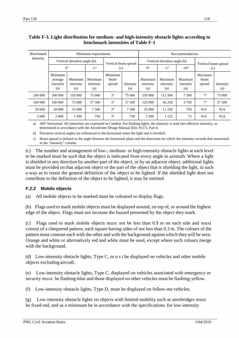
Part 139 118
PNG Civil Aviation Rules 1/04/2019
Table F-3. Light distribution for medium- and high-intensity obstacle lights according to
benchmark intensities of Table F-1
Benchmark
intensity
Minimum requirements Recommendations
Vertical elevation angle (b)
Vertical beam spread
(c)
Vertical elevation angle (b)
Vertical beam spread
(c) 0° -1° 0° -1° -10°
Minimum
average
intensity
(a)
Minimum
intensity
(a)
Minimum
intensity
(a)
Minimum
beam
spread
Intensity
(a)
Maximum
intensity
(a)
Maximum
intensity
(a)
Maximum
intensity
(a)
Maximum
beam
spread
Intensity
(a)
200 000 200 000 150 000 75 000 3° 75 000 250 000 112 500 7 500 7° 75 000
100 000 100 000 75 000 37 500 3° 37 500 125 000 56 250 3 750 7° 37 500
20 000 20 000 15 000 7 500 3° 7 500 25 000 11 250 750 N/A N/A
2 000 2 000 1 500 750 3° 750 2 500 1 125 75 N/A N/A
a) 360° horizontal. All intensities are expressed in Candela. For flashing lights, the intensity is read into effective intensity, as
determined in accordance with the Aerodrome Design Manual (Doc 9157), Part 4.
b) Elevation vertical angles are referenced to the horizontal when the light unit is levelled.
c) Beam spread is defined as the angle between the horizontal plane and the directions for which the intensity exceeds that mentioned
in the “intensity” column.
(c) The number and arrangement of low-, medium- or high-intensity obstacle lights at each level
to be marked must be such that the object is indicated from every angle in azimuth. Where a light
is shielded in any direction by another part of the object, or by an adjacent object, additional lights
must be provided on that adjacent object or the part of the object that is shielding the light, in such
a way as to retain the general definition of the object to be lighted. If the shielded light does not
contribute to the definition of the object to be lighted, it may be omitted.
F.2.2 Mobile objects
(a) All mobile objects to be marked must be coloured or display flags.
(b) Flags used to mark mobile objects must be displayed around, on top of, or around the highest
edge of the object. Flags must not increase the hazard presented by the object they mark.
(c) Flags used to mark mobile objects must not be less than 0.9 m on each side and must
consist of a chequered pattern, each square having sides of not less than 0.3 m. The colours of the
pattern must contrast each with the other and with the background against which they will be seen.
Orange and white or alternatively red and white must be used, except where such colours merge
with the background.
(d) Low-intensity obstacle lights, Type C, m u s t be displayed on vehicles and other mobile
objects excluding aircraft.
(e) Low-intensity obstacle lights, Type C, displayed on vehicles associated with emergency or
security must be flashing-blue and those displayed on other vehicles must be flashing-yellow.
(f) Low-intensity obstacle lights, Type D, must be displayed on follow-me vehicles.
(g) Low-intensity obstacle lights on objects with limited mobility such as aerobridges must
be fixed-red, and as a minimum be in accordance with the specifications for low-intensity
Part 139 119
PNG Civil Aviation Rules 1/04/2019
obstacle lights, Type A, in Table F-1. The intensity of the lights must be sufficient to ensure
conspicuity considering the intensity of the adjacent lights and the general levels of illumination
against which they would normally be viewed.
F.2.3 Fixed objects
(a) All fixed objects to be marked shall, whenever practicable, be coloured, but if this is not
practicable, markers or flags must be displayed on or above them, except that objects that are
sufficiently conspicuous by their shape, size or colour need not be otherwise marked.
(b) Flags used to mark fixed objects must be displayed around, on top of, or around the highest
edge of, the object. When flags are used to mark extensive objects or groups of closely spaced
objects, they must be displayed at least every 15 m. Flags must not increase the hazard presented
by the object they mark.
(c) Flags used to mark fixed objects must not be less than 0.6 m on each side.
(d) Markers displayed on or adjacent to objects must be located in conspicuous positions so as
to retain the general definition of the object and must be recognizable in clear weather from a
distance of at least 1 000 m for an object to be viewed from the air and 300 m for an object to be
viewed from the ground in all directions in which an aircraft is likely to approach the object. The
shape of markers must be distinctive to the extent necessary to ensure that they are not mistaken
for markers employed to convey other information, and they must be such that the hazard
presented by the object they mark is not increased.
(e) In the case of an object to be lighted, one or more low-, medium- or high-intensity obstacle
lights must be located as close as practicable to the top of the object.
(f) In the case of a tower or antenna structure indicated by high-intensity obstacle lights by day
with an appurtenance, such as a rod or an antenna, greater than 12 m where it is not practicable to
locate a high-intensity obstacle light on the top of the appurtenance, such a light m u s t be located
at the highest practicable point and, if practicable, a medium-intensity obstacle light, Type A,
mounted on the top.
(g) In the case of an extensive object or of a group of closely spaced objects to be lighted that
are:
(1) penetrating a horizontal obstacle limitation surface (OLS) or located outside an OLS, the
top lights m u s t be so arranged as to at least indicate the points or edges of the object
highest in relation to the obstacle limitation surface or above the ground, and so as to
indicate the general definition and the extent of the objects; and
(2) penetrating a sloping OLS, the top lights must be so arranged as to at least indicate the
points or edges of the object highest in relation to the OLS, and so as to indicate the general
definition and the extent of the objects. If two or more edges are of the same height, the edge
nearest the landing area must be marked.
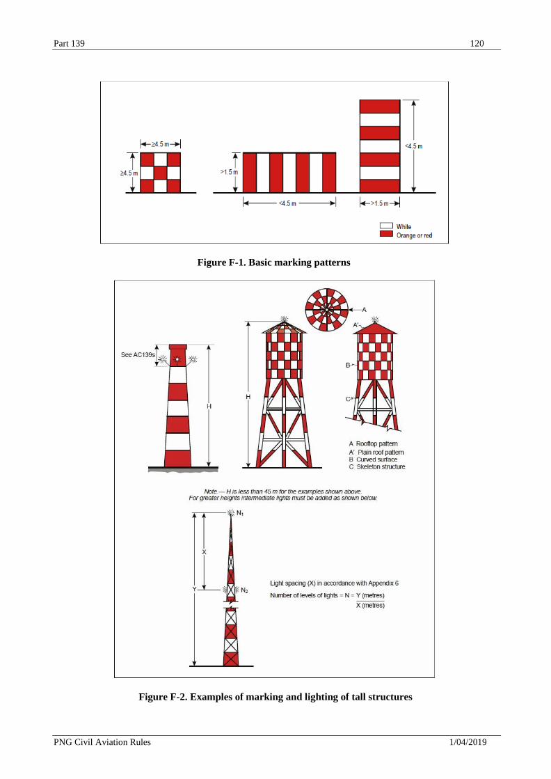
Part 139 120
PNG Civil Aviation Rules 1/04/2019
Figure F-1. Basic marking patterns
Figure F-2. Examples of marking and lighting of tall structures
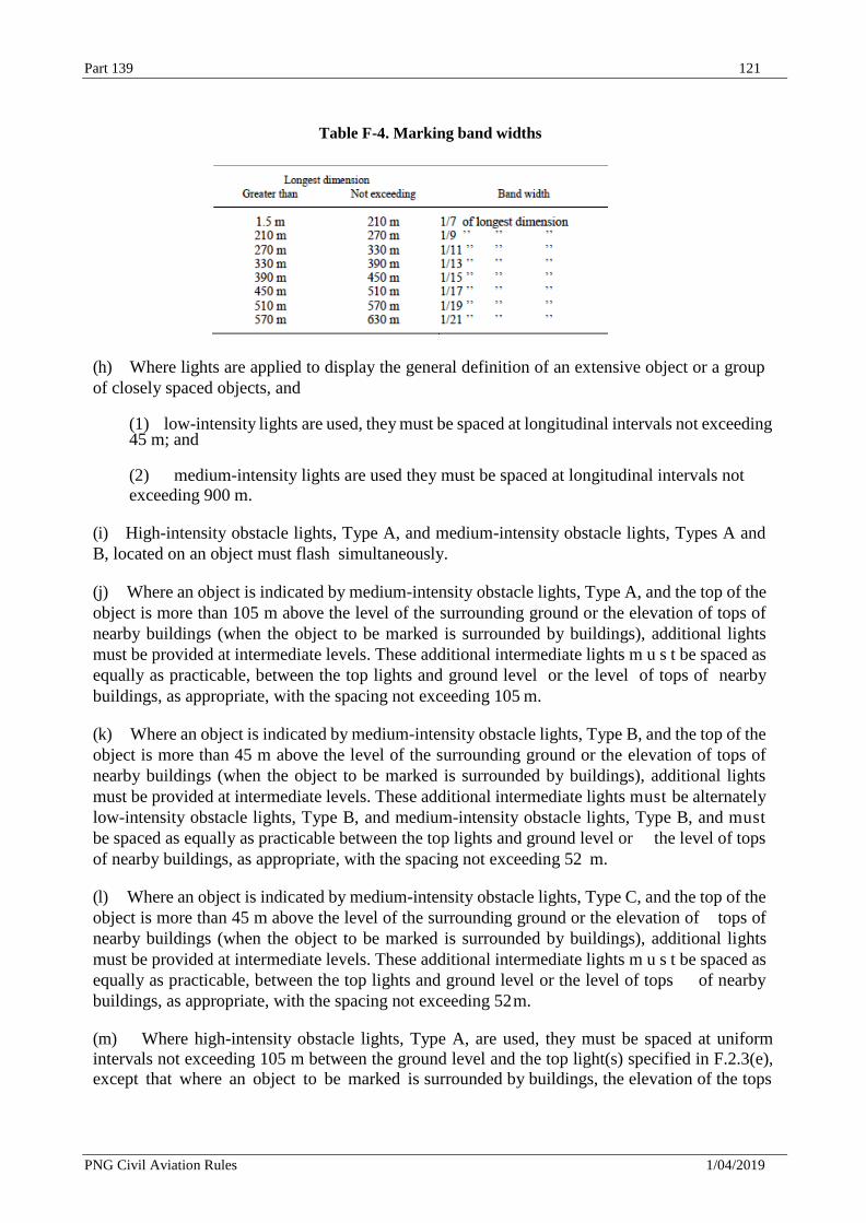
Part 139 121
PNG Civil Aviation Rules 1/04/2019
Table F-4. Marking band widths
(h) Where lights are applied to display the general definition of an extensive object or a group
of closely spaced objects, and
(1) low-intensity lights are used, they must be spaced at longitudinal intervals not exceeding 45 m; and
(2) medium-intensity lights are used they must be spaced at longitudinal intervals not
exceeding 900 m.
(i) High-intensity obstacle lights, Type A, and medium-intensity obstacle lights, Types A and
B, located on an object must flash simultaneously.
(j) Where an object is indicated by medium-intensity obstacle lights, Type A, and the top of the
object is more than 105 m above the level of the surrounding ground or the elevation of tops of
nearby buildings (when the object to be marked is surrounded by buildings), additional lights
must be provided at intermediate levels. These additional intermediate lights m u s t be spaced as
equally as practicable, between the top lights and ground level or the level of tops of nearby
buildings, as appropriate, with the spacing not exceeding 105 m.
(k) Where an object is indicated by medium-intensity obstacle lights, Type B, and the top of the
object is more than 45 m above the level of the surrounding ground or the elevation of tops of
nearby buildings (when the object to be marked is surrounded by buildings), additional lights
must be provided at intermediate levels. These additional intermediate lights must be alternately
low-intensity obstacle lights, Type B, and medium-intensity obstacle lights, Type B, and must
be spaced as equally as practicable between the top lights and ground level or the level of tops
of nearby buildings, as appropriate, with the spacing not exceeding 52 m.
(l) Where an object is indicated by medium-intensity obstacle lights, Type C, and the top of the
object is more than 45 m above the level of the surrounding ground or the elevation of tops of
nearby buildings (when the object to be marked is surrounded by buildings), additional lights
must be provided at intermediate levels. These additional intermediate lights m u s t be spaced as
equally as practicable, between the top lights and ground level or the level of tops of nearby
buildings, as appropriate, with the spacing not exceeding 52 m.
(m) Where high-intensity obstacle lights, Type A, are used, they must be spaced at uniform
intervals not exceeding 105 m between the ground level and the top light(s) specified in F.2.3(e),
except that where an object to be marked is surrounded by buildings, the elevation of the tops
Part 139 122
PNG Civil Aviation Rules 1/04/2019
of the buildings may be used as the equivalent of the ground level when determining the number
of light levels.
(n) Where high-intensity obstacle lights, Type A, are used, they must be spaced at uniform
intervals not exceeding 105 m between the ground level and the top light(s) specified in F.2.3(e),
except that where an object to be marked is surrounded by buildings, the elevation of the tops of
the buildings may be used as the equivalent of the ground level when determining the number of
light levels.
(o) Where an object is indicated by medium-intensity obstacle lights, Type A, additional lights
must be provided at intermediate levels. These additional intermediate lights must be spaced as
equally as practicable, between the top lights and ground level or the level of tops of nearby
buildings, as appropriate, with the spacing not exceeding 105 m.
(p) Where an object is indicated by medium-intensity obstacle lights, Type B, additional lights
must be provided at intermediate levels. These additional intermediate lights must be alternately
low-intensity obstacle lights, Type B, and medium-intensity obstacle lights, Type B, and must
be spaced as equally as practicable between the top lights and ground level or the level of tops of
nearby buildings, as appropriate, with the spacing not exceeding 52 m.
(q) Where an object is indicated by medium-intensity obstacle lights, Type C, additional lights
must be provided at intermediate levels. These additional intermediate lights must be spaced as
equally as practicable, between the top lights and ground level or the level of tops of nearby
buildings, as appropriate, with the spacing not exceeding 52 m.
F.2.4 Wind turbines
A wind turbine must be marked and/or lighted if it is determined to be an obstacle.
F.2.5 Overhead wires, cables, etc., and supporting towers
(a) Markers displayed on or adjacent to objects must be located in conspicuous positions so as
to retain the general definition of the object and must be recognizable in clear weather from a
distance of at least 1 000 m for an object to be viewed from the air and 300 m for an object to be
viewed from the ground in all directions in which an aircraft is likely to approach the object. The
shape of markers must be distinctive to the extent necessary to ensure that they are not mistaken
for markers employed to convey other information, and they must be such that the hazard
presented by the object they mark is not increased.
(b) Where high-intensity obstacle lights, Type B, are used, they must be located at three levels:
(1) at the top of the tower;
(2) at the lowest level of the catenary of the wires or cables; and
(3) at approximately midway between these two levels.
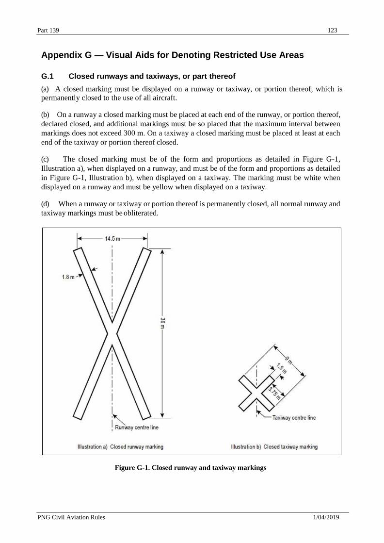
Part 139 123
PNG Civil Aviation Rules 1/04/2019
Appendix G — Visual Aids for Denoting Restricted Use Areas
G.1 Closed runways and taxiways, or part thereof
(a) A closed marking must be displayed on a runway or taxiway, or portion thereof, which is
permanently closed to the use of all aircraft.
(b) On a runway a closed marking must be placed at each end of the runway, or portion thereof,
declared closed, and additional markings must be so placed that the maximum interval between
markings does not exceed 300 m. On a taxiway a closed marking must be placed at least at each
end of the taxiway or portion thereof closed.
(c) The closed marking must be of the form and proportions as detailed in Figure G-1,
Illustration a), when displayed on a runway, and must be of the form and proportions as detailed
in Figure G-1, Illustration b), when displayed on a taxiway. The marking must be white when
displayed on a runway and must be yellow when displayed on a taxiway.
(d) When a runway or taxiway or portion thereof is permanently closed, all normal runway and
taxiway markings must be obliterated.
Figure G-1. Closed runway and taxiway markings
Part 139 124
PNG Civil Aviation Rules 1/04/2019
(e) Lighting on a closed runway or taxiway or portion thereof must not be operated, except
as required for maintenance purposes.
(f) In addition to closed markings, when the runway or taxiway or portion thereof closed is
intercepted by a usable runway or taxiway which is used at night, unserviceability lights must be
placed across the entrance to the closed area at intervals not exceeding 3 m (see G.4(d)).
G.2 Non-load-bearing surfaces
Shoulders for taxiways, runway turn pads, holding bays and aprons and other non-load-bearing
surfaces which cannot readily be distinguished from load-bearing surfaces and which, if used by
aircraft, might result in damage to the aircraft must have the boundary between such areas and
the load-bearing surface marked by a taxi side stripe marking.
G.3 Unserviceable areas
(a) Unserviceability markers must be displayed wherever any portion of a taxiway, apron or
holding bay is unfit for the movement of aircraft but it is still possible for aircraft to bypass the
area safely. On a movement area used at night, unserviceability lights must be used.
(b) Unserviceability markers and lights must be placed at intervals sufficiently close so as
to delineate the unserviceable area.
(c) Unserviceability markers must consist of conspicuous upstanding devices such as flags, cones
or marker boards.
(d) An unserviceability light must consist of a red fixed light. The light must have an intensity
sufficient to ensure conspicuity considering the intensity of the adjacent lights and the general
level of illumination against which it would normally be viewed. In no case must the intensity be
less than 10 cd of red light.
Appendix H — Electrical Systems
H.1 Electrical power supply systems for air navigation facilities
(a) Adequate primary power supply must be available at aerodromes for the safe functioning of
air navigation facilities.
(b) The design and provision of electrical power systems for aerodrome visual and radio
navigation aids must be such that an equipment failure will not leave the pilot with inadequate
visual and non-visual guidance or misleading information.
(c) The provision of a definition of switch-over time m u s t not require the replacement of an
existing secondary power supply before 1 January 2010. However, for a secondary power supply
installed after 4 November 1999, the electric power supply connections to those facilities for
which secondary power is required must be so arranged that the facilities are capable of meeting
the requirements of Table H-1 for maximum switch-over times.
(d) For a precision approach runway, a secondary power supply capable of meeting the
requirements of Table H-1 for the appropriate category of precision approach runway must be
provided. Electric power supply connections to those facilities for which secondary power is
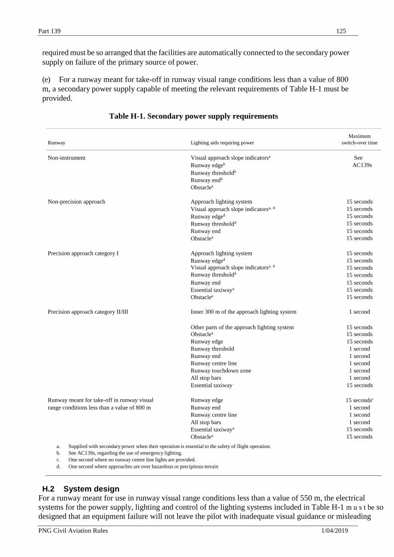
Part 139 125
PNG Civil Aviation Rules 1/04/2019
required must be so arranged that the facilities are automatically connected to the secondary power
supply on failure of the primary source of power.
(e) For a runway meant for take-off in runway visual range conditions less than a value of 800
m, a secondary power supply capable of meeting the relevant requirements of Table H-1 must be
provided.
Table H-1. Secondary power supply requirements
Runway
Lighting aids requiring power
Maximum
switch-over time
Non-instrument Visual approach slope indicatorsa
Runway edgeb
Runway thresholdb
Runway endb
Obstaclea
See
AC139s
Non-precision approach Approach lighting system
Visual approach slope indicatorsa, d
Runway edged
Runway thresholdd
15 seconds
15 seconds
15 seconds
15 seconds
Runway end
Obstaclea
15 seconds
15 seconds
Precision approach category I Approach lighting system
Runway edged Visual approach slope indicatorsa, d
Runway thresholdd
15 seconds
15 seconds
15 seconds
15 seconds
Runway end
Essential taxiwaya
Obstaclea
15 seconds
15 seconds
15 seconds
Precision approach category II/III Inner 300 m of the approach lighting system 1 second
Other parts of the approach lighting system
Obstaclea
15 seconds
15 seconds Runway edge 15 seconds Runway threshold 1 second Runway end 1 second Runway centre line 1 second Runway touchdown zone 1 second All stop bars 1 second
Essential taxiway 15 seconds
Runway meant for take-off in runway visual Runway edge 15 secondsc
range conditions less than a value of 800 m Runway end 1 second Runway centre line 1 second
All stop bars
Essential taxiwaya
Obstaclea
1 second
15 seconds
15 seconds
a. Supplied with secondary power when their operation is essential to the safety of flight operation.
b. See AC139s, regarding the use of emergency lighting.
c. One second where no runway centre line lights are provided.
d. One second where approaches are over hazardous or precipitous terrain
H.2 System design For a runway meant for use in runway visual range conditions less than a value of 550 m, the electrical
systems for the power supply, lighting and control of the lighting systems included in Table H-1 m u s t be so
designed that an equipment failure will not leave the pilot with inadequate visual guidance or misleading
Part 139 126
PNG Civil Aviation Rules 1/04/2019
information.
(a) Where the secondary power supply of an aerodrome is provided by the use of duplicate
feeders, such supplies must be physically and electrically separate so as to ensure the required
level of availability and independence.
(b) Where a runway forming part of a standard taxi-route is provided with runway lighting and
taxiway lighting, the lighting systems must be interlocked to preclude the possibility of
simultaneous operation of both forms of lighting.
H.3 Monitoring
Where lighting systems are used for aircraft control purposes, such systems must be monitored
automatically so as to provide an indication of any fault which may affect the control functions.
This information m u s t be automatically relayed to the air traffic services unit.
Appendix I. Aerodrome Operational Services, Equipment and Installations
I.1 .1 General
(a) An aerodrome emergency plan must be established at an aerodrome, commensurate with
the aircraft operations and other activities conducted at the aerodrome.
(b) The aerodrome emergency plan must provide for the coordination of the actions to be
taken in an emergency occurring at an aerodrome or in its vicinity.
(c) The plan must coordinate the response or participation of all existing agencies which, in
the opinion of the appropriate authority, could be of assistance in responding to an emergency.
(d) The plan must observe Human Factors principles to ensure optimum response by all
existing agencies participating in emergency operations.
I.1 .2 Aerodrome emergency exercise
(a) The plan must contain procedures for periodic testing of the adequacy of the plan and for
reviewing the results in order to improve its effectiveness.
(b) The plan must be tested by conducting:
(1) a full-scale aerodrome emergency exercise at intervals not exceeding two years and
partial emergency exercises in the intervening year to ensure that any deficiencies found
during the full-scale aerodrome emergency exercise have been corrected; or
(2) a series of modular tests commencing in the first year and concluding in a full-scale
aerodrome emergency exercise at intervals not exceeding three years;
and reviewed thereafter, or after an actual emergency, so as to correct any deficiency found
during such exercises or actual emergency.
I.1.3 Emergencies in difficult environments
The plan must include the ready availability of, and coordination with, appropriate specialist
rescue services to be able to respond to emergencies where an aerodrome is located close to water
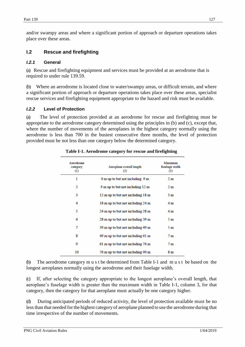
Part 139 127
PNG Civil Aviation Rules 1/04/2019
and/or swampy areas and where a significant portion of approach or departure operations takes
place over these areas.
I.2 Rescue and firefighting
I.2.1 General
(a) Rescue and firefighting equipment and services must be provided at an aerodrome that is
required to under rule 139.59.
(b) Where an aerodrome is located close to water/swampy areas, or difficult terrain, and where
a significant portion of approach or departure operations takes place over these areas, specialist
rescue services and firefighting equipment appropriate to the hazard and risk must be available.
I.2.2 Level of Protection
(a) The level of protection provided at an aerodrome for rescue and firefighting must be
appropriate to the aerodrome category determined using the principles in (b) and (c), except that,
where the number of movements of the aeroplanes in the highest category normally using the
aerodrome is less than 700 in the busiest consecutive three months, the level of protection
provided must be not less than one category below the determined category.
Table I-1. Aerodrome category for rescue and firefighting
(b) The aerodrome category m u s t be determined from Table I-1 and m u s t be based on the
longest aeroplanes normally using the aerodrome and their fuselage width.
(c) If, after selecting the category appropriate to the longest aeroplane’s overall length, that
aeroplane’s fuselage width is greater than the maximum width in Table I-1, column 3, for that
category, then the category for that aeroplane must actually be one category higher.
(d) During anticipated periods of reduced activity, the level of protection available must be no
less than that needed for the highest category of aeroplane planned to use the aerodrome during that
time irrespective of the number of movements.
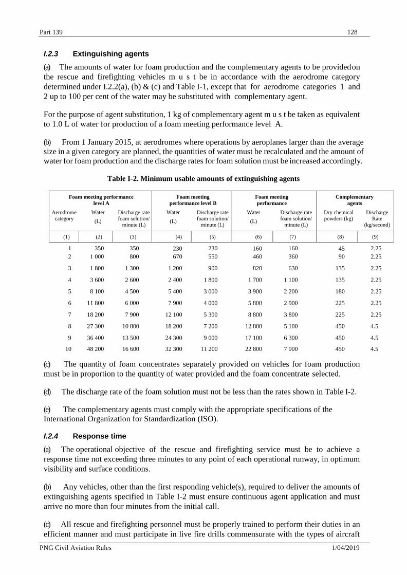
Part 139 128
PNG Civil Aviation Rules 1/04/2019
I.2.3 Extinguishing agents
(a) The amounts of water for foam production and the complementary agents to be provided on
the rescue and firefighting vehicles m u s t be in accordance with the aerodrome category
determined under I.2.2(a), (b) & (c) and Table I-1, except that for aerodrome categories 1 and
2 up to 100 per cent of the water may be substituted with complementary agent.
For the purpose of agent substitution, 1 kg of complementary agent m u s t be taken as equivalent
to 1.0 L of water for production of a foam meeting performance level A.
(b) From 1 January 2015, at aerodromes where operations by aeroplanes larger than the average
size in a given category are planned, the quantities of water must be recalculated and the amount of
water for foam production and the discharge rates for foam solution must be increased accordingly.
Table I-2. Minimum usable amounts of extinguishing agents
Foam meeting performance
level A
Foam meeting
performance level B
Foam meeting
performance
Complementary
agents
Aerodrome category
Water
(L)
Discharge rate foam solution/
minute (L)
Water
(L)
Discharge rate foam solution/
minute (L)
Water
(L)
Discharge rate foam solution/
minute (L)
Dry chemical powders (kg)
Discharge Rate
(kg/second)
(1) (2) (3) (4) (5) (6) (7) (8) (9)
1 350 350 230 230 160 160 45 2.25
2 1 000 800 670 550 460 360 90 2.25
3 1 800 1 300 1 200 900 820 630 135 2.25
4 3 600 2 600 2 400 1 800 1 700 1 100 135 2.25
5 8 100 4 500 5 400 3 000 3 900 2 200 180 2.25
6 11 800 6 000 7 900 4 000 5 800 2 900 225 2.25
7 18 200 7 900 12 100 5 300 8 800 3 800 225 2.25
8 27 300 10 800 18 200 7 200 12 800 5 100 450 4.5
9 36 400 13 500 24 300 9 000 17 100 6 300 450 4.5
10 48 200 16 600 32 300 11 200 22 800 7 900 450 4.5
(c) The quantity of foam concentrates separately provided on vehicles for foam production
must be in proportion to the quantity of water provided and the foam concentrate selected.
(d) The discharge rate of the foam solution must not be less than the rates shown in Table I-2.
(e) The complementary agents must comply with the appropriate specifications of the
International Organization for Standardization (ISO).
I.2.4 Response time
(a) The operational objective of the rescue and firefighting service must be to achieve a
response time not exceeding three minutes to any point of each operational runway, in optimum
visibility and surface conditions.
(b) Any vehicles, other than the first responding vehicle(s), required to deliver the amounts of
extinguishing agents specified in Table I-2 must ensure continuous agent application and must
arrive no more than four minutes from the initial call.
(c) All rescue and firefighting personnel must be properly trained to perform their duties in an
efficient manner and must participate in live fire drills commensurate with the types of aircraft
Part 139 129
PNG Civil Aviation Rules 1/04/2019
and type of rescue and firefighting equipment in use at the aerodrome, including pressure-fed fuel
fires.
(d) The rescue and firefighting personnel training programme must include training in human
performance, including team coordination.
I.2.5 Personnel
All responding rescue and firefighting personnel must be provided with protective clothing and
respiratory equipment to enable them to perform their duties in an effective manner.
I.3 Wildlife strike hazard reduction
(a) The wildlife strike hazard on, or in the vicinity of, an aerodrome must be assessed through:
(1) the establishment of a national procedure for recording and reporting wildlife strikes to
aircraft;
(2) the collection of information from aircraft operators, aerodrome personnel and other
sources on the presence of wildlife on or around the aerodrome constituting a potential
hazard to aircraft operations; and
(3) an ongoing evaluation of the wildlife hazard by competent personnel.
(b) Wildlife strike reports must be collected and forwarded to CASA for inclusion in the
ICAO Bird Strike Information System (IBIS) database.
(c) Action must be taken to decrease the risk to aircraft operations by adopting measures to
minimize the likelihood of collisions between wildlife and aircraft.
(d) The appropriate authority must take action to eliminate or to prevent the establishment of
garbage disposal dumps or any other source which may attract wildlife to the aerodrome, or its
vicinity, unless an appropriate wildlife assessment indicates that they are unlikely to create
conditions conducive to a wildlife hazard problem. Where the elimination of existing sites is not
possible, the appropriate authority must ensure that any risk to aircraft posed by these sites is
assessed and reduced to as low as reasonably practicable.
I.4 Apron management service
(a) An apron management service must be provided with radiotelephony communications
facilities.
(b) Where low visibility procedures are in effect, persons and vehicles operating on an apron
must be restricted to the essential minimum.
(c) An emergency vehicle responding to an emergency must be given priority over all other
surface movement traffic.
(d) A vehicle operating on an apron shall:
(1) give way to an emergency vehicle; an aircraft taxiing, about to taxi, or being pushed
or towed; and
(2) give way to other vehicles in accordance with local regulations.
Part 139 130
PNG Civil Aviation Rules 1/04/2019
(e) An aircraft stand must be visually monitored to ensure that the recommended clearance
distances are provided to an aircraft using the stand.
I.5 Ground servicing of aircraft
(a) Fire extinguishing equipment suitable for at least initial intervention in the event of a fuel
fire and personnel trained in its use must be readily available during the ground servicing of an
aircraft, and there must be a means of quickly summoning the rescue and firefighting service in
the event of a fire or major fuel spill.
(b) When aircraft refuelling operations take place while passengers are embarking, on board or
disembarking, ground equipment must be positioned so as to allow:
(1) the use of a sufficient number of exits for expeditious evacuation; and
(2) a ready escape route from each of the exits to be used in an emergency.
I.6 Aerodrome vehicle operations
(a) A vehicle must be operated:
(1) on a manoeuvring area only as authorized by the aerodrome control tower; and
(2) on an apron only as authorized by the appropriate designated authority.
(b) The driver of a vehicle on the movement area m u s t comply with all mandatory
instructions conveyed by markings and signs unless otherwise authorized by:
(1) the aerodrome control tower when on the manoeuvring area; or
(2) the appropriate designated authority when on the apron.
(c) The driver of a vehicle on the movement area must comply with all mandatory instructions
conveyed by lights.
(d) The driver of a vehicle on the movement area must be appropriately trained for the tasks
to be performed and must comply with the instructions issued by:
(1) the aerodrome control tower, when on the manoeuvring area; and
(2) the appropriate designated authority, when on the apron.
(e) The driver of a radio-equipped vehicle must establish satisfactory two-way radio
communication with the aerodrome control tower before entering the manoeuvring area and with
the appropriate designated authority before entering the apron. The driver must maintain a
continuous listening watch on the assigned frequency when on the movement area.
I.7 Surface movement guidance and control systems
(a) A surface movement guidance and control system (SMGCS) must be provided at an
aerodrome.
(b) Where an SMGCS is provided by selective switching of stop bars and taxiway centre line
lights, the following requirements must be met:
Part 139 131
PNG Civil Aviation Rules 1/04/2019
(1) taxiway routes which are indicated by illuminated taxiway centre line lights must be
capable of being terminated by an illuminated stop bar;
(2) the control circuits must be so arranged that when a stop bar located ahead of an aircraft
is illuminated, the appropriate section of taxiway centre line lights beyond it is
suppressed; and
(3) the taxiway centre line lights are activated ahead of an aircraft when the stop bar is
suppressed.
I.8 Siting of equipment and installations on operational areas
(a) Unless its function requires it to be there for air navigation or for aircraft safety purposes,
no equipment or installation must be:
(3) on a runway strip, a runway end safety area, a taxiway strip or within the distances
specified in Table C-1, column 11, if it would endanger an aircraft; or
(2) on a clearway if it would endanger an aircraft in the air.
(b) Any equipment or installation required for air navigation or for aircraft safety purposes which
must be located:
(1) on that portion of a runway strip within:
(i) 75 m of the runway centre line where the code number is 3 or 4; or
(ii) 45 m of the runway centre line where the code number is 1 or 2; or
(2) on a runway end safety area, a taxiway strip or within the distances specified in Table C- 1;
or c) on a clearway and which would endanger an aircraft in the air; must be frangible and
mounted as low as possible.
(c) Unless its function requires it to be there for air navigation or for aircraft safety purposes,
no equipment or installation must be located within 240 m from the end of the strip and within:
(1) 60 m of the extended centre line where the code number is 3 or 4; or
(2) 45 m of the extended centre line where the code number is 1 or 2; of a precision
approach runway category I, II or III.
(d) Any equipment or installation required for air navigation or for aircraft safety purposes
which must be located on or near a strip of a precision approach runway category I, II or III and
which:
(1) is situated on that portion of the strip within 77.5 m of the runway centre line
where the code number is 4 and the code letter is F; or
(2) is situated within 240 m from the end of the strip and within:
(i) 60 m of the extended runway centre line where the code number is 3 or 4; or
Part 139 132
PNG Civil Aviation Rules 1/04/2019
(ii) 45 m of the extended runway centre line where the code number is 1 or 2; or
(3) penetrates the inner approach surface, the inner transitional surface or the balked
landing surface; must be frangible and mounted as low as possible.
I.9 Fencing
(a) A fence or other suitable barrier must be provided on an aerodrome to prevent the entrance
to the movement area of animals large enough to be a hazard to aircraft.
(b) A fence or other suitable barrier must be provided on an aerodrome to deter the inadvertent
or premeditated access of an unauthorized person onto a non-public area of the aerodrome.
(c) Suitable means of protection must be provided to deter the inadvertent or premeditated
access of unauthorized persons into ground installations and facilities essential for the safety of
civil aviation located off the aerodrome.
(d) The fence or barrier must be located so as to separate the movement area and other
facilities or zones on the aerodrome vital to the safe operation of aircraft from areas open to public
access.
I.10 Autonomous runway incursion warning system
(a) Where an ARIWS is installed at an aerodrome:
(1) it must provide autonomous detection of a potential incursion or of the occupancy
of an active runway and a direct warning to a flight crew or vehicle operator;
(2) it must function and be controlled independently of any other visual system on the
aerodrome;
(3) its visual aid components, i.e. lights, must be designed to conform with the relevant
specifications in E.3; and
(4) failure of part or all of it must not interfere with normal aerodrome operations. To
this end, provision must be made to allow the ATC unit to partially or entirely shut
down the system.
(b) Where an ARIWS is installed at an aerodrome, information on its characteristics and status
must be provided to the appropriate aeronautical information services for promulgation in the
AIP with the description of the aerodrome surface movement guidance and control system and
markings.
Appendix J. Aerodrome Maintenance
J.1 General
A maintenance programme, including preventive maintenance where appropriate, m u s t be
established at an aerodrome to maintain facilities in a condition which does not impair the safety,
regularity or efficiency of air navigation.
Part 139 133
PNG Civil Aviation Rules 1/04/2019
J.2 Pavements
(a) The surfaces of all movement areas including pavements (runways, taxiways and aprons)
and adjacent areas must be inspected and their conditions monitored regularly as part of an
aerodrome preventive and corrective maintenance programme with the objective of avoiding and
eliminating any foreign object debris (FOD) that might cause damage to aircraft or impair the
operation of aircraft systems.
(b) The surface of a runway must be maintained in a condition such as to prevent formation of
harmful irregularities.
(c) A paved runway must be maintained in a condition so as to provide surface friction
characteristics at or above the minimum friction level specified by the Director.
(d) Runway surface friction characteristics for maintenance purposes must be periodically
measured with a continuous friction measuring device using self-wetting features and
documented. The frequency of these measurements must be sufficient to determine the trend of
the surface friction characteristics of the runway.
(e) Corrective maintenance action must be taken to prevent the runway surface friction
characteristics for either the entire runway or a portion thereof from falling below a minimum
friction level specified by the Director.
J.3 Removal of contaminants
(a) Standing water, mud, dust, sand, oil, rubber deposits and other contaminants must be
removed from the surface of runways in use as rapidly and completely as possible to minimize
accumulation.
(b) Chemicals which may have harmful effects on aircraft or pavements, or chemicals which
may have toxic effects on the aerodrome environment, must not be used.
J.4 Runway pavement overlays
(a) The longitudinal slope of the temporary ramp, measured with reference to the existing
runway surface or previous overlay course, must be:
(1) 0.5 to 1.0 per cent for overlays up to and including 5 cm in thickness; and
(2) not more than 0.5 per cent for overlays more than 5 cm in thickness.
J.5 Visual aids
(a) A light must be deemed to be unserviceable when the main beam average intensity is less
than 50 per cent of the value specified in the appropriate figure in CASA Advisory Circulars in
the 139 series. For light units where the designed main beam average intensity is above the value
shown in CASA Advisory Circulars in the 139 series, the 50 per cent value must be related to
that design value.
(b) A system of preventive maintenance of visual aids must be employed to ensure lighting
and marking system reliability.
(c) The system of preventive maintenance employed for a precision approach runway category
II or III must have as its objective that, during any period of category II or III operations, all
Part 139 134
PNG Civil Aviation Rules 1/04/2019
approach and runway lights are serviceable and that, in any event, at least:
(1) 95 per cent of the lights are serviceable in each of the following particular significant
elements:
(i) precision approach category II and III lighting system, the inner 450 m;
(ii) runway centre line lights;
(iii) runway threshold lights; and
(iv) runway edge lights;
(2) 90 per cent of the lights are serviceable in the touchdown zone lights;
(3) 85 per cent of the lights are serviceable in the approach lighting system beyond 450 m;
and
(4) 75 per cent of the lights are serviceable in the runway end lights.
In order to provide continuity of guidance, the allowable percentage of unserviceable lights must
not be permitted in such a way as to alter the basic pattern of the lighting system. Additionally,
an unserviceable light must not be permitted adjacent to another unserviceable light, except in
a barrette or a crossbar where two adjacent unserviceable lights may be permitted.
(d) The system of preventive maintenance employed for a stop bar provided at a runway-
holding position used in conjunction with a runway intended for operations in runway visual
range conditions less than a value of 350 m must have the following objectives:
(1) no more than two lights will remain unserviceable; and
(2) two adjacent lights will not remain unserviceable unless the light spacing is
significantly less than that specified.
(e) The system of preventive maintenance employed for a taxiway intended for use in runway
visual range conditions less than a value of 350 m must have as its objective that no two
adjacent taxiway centre line lights be unserviceable.
(f) The system of preventive maintenance employed for a precision approach runway category
I must have as its objective that, during any period of category I operations, all approach and
runway lights are serviceable and that, in any event, at least 85 per cent of the lights are
serviceable in each of the following:
(1) precision approach category I lighting system;
(2) runway threshold lights;
(3) runway edge lights; and
(4) runway end lights.
In order to provide continuity of guidance an unserviceable light must not be permitted adjacent
to another unserviceable light unless the light spacing is significantly less than that specified.
Part 139 135
PNG Civil Aviation Rules 1/04/2019
(g) The system of preventive maintenance employed for a runway meant for take-off in runway
visual range conditions less than a value of 550 m must have as its objective that, during any
period of operations, all runway lights are serviceable and that in any event:
(1) at least 95 per cent of the lights are serviceable in the runway centre line lights (where
provided) and in the runway edge lights; and
(2) at least 75 per cent of the lights are serviceable in the runway end lights.
In order to provide continuity of guidance, an unserviceable light must not be permitted
adjacent to another unserviceable light.
(h) The system of preventive maintenance employed for a runway meant for take-off in runway
visual range conditions of a value of 550 m or greater must have as its objective that, during any
period of operations, all runway lights are serviceable and that, in any event, at least 85 per cent
of the lights are serviceable in the runway edge lights and runway end lights. In order to provide
continuity of guidance, an unserviceable light must not be permitted adjacent to another
unserviceable light.
Related Documents