CIV 104 COMPUTER AIDED TECHNICAL DRAWING CHAPTER 2 Creating Basic Drawings 1

CIV 104 COMPUTER AIDED TECHNICAL DRAWING CHAPTER 2 Creating Basic Drawings 1.
Dec 27, 2015
Welcome message from author
This document is posted to help you gain knowledge. Please leave a comment to let me know what you think about it! Share it to your friends and learn new things together.
Transcript

1
CIV 104COMPUTER AIDED
TECHNICAL DRAWING
CHAPTER 2Creating Basic Drawings

2

3
The Coordinate System
Every object you draw is placed in either the world coordinate system (WCS) or a user coordinate system (UCS).
When you create 2D geometry, data input is ultimately passed to the software in the form of Cartesian (x,y) or polar coordinates (distance, angle). You can either manually enter these coordinates or infer them by picking a point in the drawing window.

4
The Coordinate SystemThe Cartesian coordinate system is used to determine points in space that are a specified distance from a set of perpendicular axes that intersect at the origin of the system. In the World coordinate system, the X axis represents the horizontal direction, the Y axis represents the vertical direction and the origin is located at 0,0. Positive X moves to the right, positive Y moves up, and the Z axis moves in the positive direction directly towards you, the viewer.
Note that for this course we will only be concerned with the X & Y coordinates since we are working in 2D. The Z coordinate will always be zero and need not be specified.

5
The Coordinate System
A polar coordinate is a point in the coordinate system that is determined by a distance and an angle. The following illustration shows a line drawn from the origin of the coordinate system with a length of 7 units and an angle of 45 degrees.
To specify a polar coordinate, type the distance < angle, example 5<45, where Distance equals the distance traveled from the specified origin point and Angle equals the angle from the X axis.

6
The Coordinate System
Polar AngleThe default polar angle is measured counterclockwise from the zero angle position. The default zero angle is in the East compass direction.

7
The Coordinate System
Absolute and Relative CoordinatesWhen you type coordinates, they can be in the form of an absolute or a relative coordinate.An absolute coordinate represents a specific point in the current
coordinate system relative to the origin point (0,0). To enter an absolute coordinate, type the values as a Cartesian coordinate (x,y) or Polar coordinate (distance angle).
A relative coordinate is a point located from a previously selected point. To enter a relative coordinate, select your first point, then precede the next coordinate point with the @ symbol. For example @5<45 would mean 5 units at 45 degrees from the last point selected, and @3,5 would mean 3 units in the positive x direction and 5 units in the positive y direction from the last point selected.
8
The Coordinate System

9
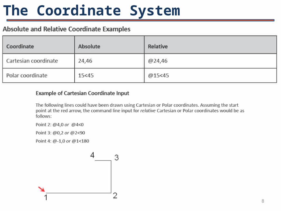
Dynamic Input

10
Dynamic Input

11
Dynamic Input
12
Dynamic Input

13

14
Creating Basic Objects

15
For metric templete

16

17

18

19

20

21
Related Documents