MISCELLANEOUS CONSTUCTION STANDARDS TABLE OF CONTENTS DIVISION III - CONCRETE & CONCRETE STRUCTURES 300 Concrete 301 Reinforcing Steel 302 Metal For Structures 303 Welded Wire Flat Sheets 306 Structural Excavation 307 Concrete Structures 308 Drilled Shafts and Under-Reamed Foundations 309 Precast Reinforced Concrete Box Culverts 310 Precast, Prestressed Bridge Beams 311 Concrete Surface Finish DIVISION IV - STORM SEWERS 400 Excavation, Trenching and Backfilling 401 Reinforced Concrete Pipe 402 High Density Corrugated Polyethylene Pipe 403 Storm Sewer Junction Boxes and Inlets 404 Corrugated Metal Pipe 405 Fiber Reinforced Concrete Pipe 406 Jacking, Boring, or Tunneling Pipe 407 Concrete Encasement, Cradles, Saddles, and Collars 409 Cast Iron Castings 410 Subgrade Filler 411 Glass Cullet Use for Utility Bedding and Backfill 412 Cement Stabilized Sand 413 Flowable Fill 414 Flexible Pipe-To-Manhole Connector DIVISION V - INCIDENTAL CONSTRUCTION 504 Concrete Medians and Islands 505 Concrete Riprap 506 Concrete Retaining Wall – Combination Type 509 Metal Beam Guard Rail 510 Timber Guard Posts 517 Bridge Railing 522 Sidewalk Pipe Railing 524 Concrete Steps 525 Concrete Traffic Barriers (Portable) 530 Barricades, Signs, and Traffic Handling 531 Signs 535 Hot Applied Thermoplastic Pavement Markings 536 Preformed Pavement Markings 537 Raised Pavement Markers 539 Intersection Grade Pavement Tape 556 Cast In Place Detectable Warning Surface Tiles

Welcome message from author
This document is posted to help you gain knowledge. Please leave a comment to let me know what you think about it! Share it to your friends and learn new things together.
Transcript
MISCELLANEOUS CONSTUCTION STANDARDS
TABLE OF CONTENTS
DIVISION III - CONCRETE & CONCRETE STRUCTURES 300 Concrete 301 Reinforcing Steel 302 Metal For Structures 303 Welded Wire Flat Sheets 306 Structural Excavation 307 Concrete Structures 308 Drilled Shafts and Under-Reamed Foundations 309 Precast Reinforced Concrete Box Culverts 310 Precast, Prestressed Bridge Beams 311 Concrete Surface Finish
DIVISION IV - STORM SEWERS
400 Excavation, Trenching and Backfilling 401 Reinforced Concrete Pipe 402 High Density Corrugated Polyethylene Pipe 403 Storm Sewer Junction Boxes and Inlets 404 Corrugated Metal Pipe 405 Fiber Reinforced Concrete Pipe 406 Jacking, Boring, or Tunneling Pipe 407 Concrete Encasement, Cradles, Saddles, and Collars 409 Cast Iron Castings 410 Subgrade Filler 411 Glass Cullet Use for Utility Bedding and Backfill 412 Cement Stabilized Sand 413 Flowable Fill 414 Flexible Pipe-To-Manhole Connector
DIVISION V - INCIDENTAL CONSTRUCTION 504 Concrete Medians and Islands 505 Concrete Riprap 506 Concrete Retaining Wall – Combination Type 509 Metal Beam Guard Rail 510 Timber Guard Posts 517 Bridge Railing 522 Sidewalk Pipe Railing 524 Concrete Steps 525 Concrete Traffic Barriers (Portable) 530 Barricades, Signs, and Traffic Handling 531 Signs 535 Hot Applied Thermoplastic Pavement Markings 536 Preformed Pavement Markings 537 Raised Pavement Markers 539 Intersection Grade Pavement Tape 556 Cast In Place Detectable Warning Surface Tiles
DIVISION III - CONCRETE & CONCRETE STRUCTURES
300 CONCRETE
300.1. DESCRIPTION: Furnish hydraulic cement concrete for concrete pavements, concrete structures, and other concrete construction.
300.2. MATERIALS:
A. Cement. Furnish cement conforming to TxDOT’s DMS-4600, “Hydraulic Cement.”
B. Supplementary Cementing Materials (SCM).
1. Fly Ash. Furnish fly ash conforming to TxDOT’s DMS-4610, “Fly Ash.”
2. Ultra-Fine Fly Ash (UFFA). Furnish UFFA, per TxDOT’s DMS-4610, “Fly Ash.”
3. Ground Granulated Blast-Furnace Slag (GGBFS). Furnish GGBFS conforming to
TxDOT’s DMS-4620, “Ground Granulated Blast-Furnace Slag,” Grade 100 or 120.
4. Silica Fume. Furnish silica fume conforming to TxDOT’s DMS-4630, “Silica Fume.”
5. Metakaolin. Furnish metakaolin conforming to TxDOT’s DMS-4635, “Metakaolin.”
C. Chemical Admixtures. Furnish admixtures conforming to TxDOT’s DMS-4640, “Chemical Admixtures for Concrete.” Do not use calcium chloride.
D. Water. Furnish mixing and curing water that is free from oils, acids, organic matter, or other
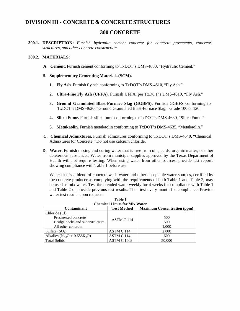
deleterious substances. Water from municipal supplies approved by the Texas Department of Health will not require testing. When using water from other sources, provide test reports showing compliance with Table 1 before use.
Water that is a blend of concrete wash water and other acceptable water sources, certified by the concrete producer as complying with the requirements of both Table 1 and Table 2, may be used as mix water. Test the blended water weekly for 4 weeks for compliance with Table 1 and Table 2 or provide previous test results. Then test every month for compliance. Provide water test results upon request.
Table 1 Chemical Limits for Mix Water
Contaminant Test Method Maximum Concentration (ppm) Chloride (Cl)
Prestressed concrete Bridge decks and superstructure All other concrete
ASTM C 114
500 500
1,000 Sulfate (SO4) ASTM C 114 2,000 Alkalies (NA2O + 0.658K2O) ASTM C 114 600 Total Solids ASTM C 1603 50,000
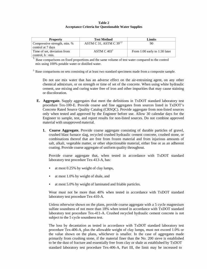
Property Test Method Limits Compressive strength, min. % control at 7 days
ASTM C 31, ASTM C 391,2 90
Time of set, deviation from control, h : min.
ASTM C 4031 From 1:00 early to 1:30 later
Table 2
Acceptance Criteria for Questionable Water Supplies
1. Base comparisons on fixed proportions and the same volume of test water compared to the control mix using 100% potable water or distilled water.
2. Base comparisons on sets consisting of at least two standard specimens made from a composite sample.
Do not use mix water that has an adverse effect on the air-entraining agent, on any other chemical admixture, or on strength or time of set of the concrete. When using white hydraulic cement, use mixing and curing water free of iron and other impurities that may cause staining or discoloration.
E. Aggregate. Supply aggregates that meet the definitions in TxDOT standard laboratory test
procedure Tex-100-E. Provide coarse and fine aggregates from sources listed in TxDOT’s Concrete Rated Source Quality Catalog (CRSQC). Provide aggregate from non-listed sources only when tested and approved by the Engineer before use. Allow 30 calendar days for the Engineer to sample, test, and report results for non-listed sources. Do not combine approved material with unapproved material.
1. Coarse Aggregate. Provide coarse aggregate consisting of durable particles of gravel,
crushed blast furnace slag, recycled crushed hydraulic cement concrete, crushed stone, or combinations thereof that are free from frozen material and from injurious amounts of salt, alkali, vegetable matter, or other objectionable material, either free or as an adherent coating. Provide coarse aggregate of uniform quality throughout.
Provide coarse aggregate that, when tested in accordance with TxDOT standard laboratory test procedure Tex-413-A, has:
• at most 0.25% by weight of clay lumps,
• at most 1.0% by weight of shale, and
• at most 5.0% by weight of laminated and friable particles.
Wear must not be more than 40% when tested in accordance with TxDOT standard laboratory test procedure Tex-410-A.
Unless otherwise shown on the plans, provide coarse aggregate with a 5 cycle magnesium sulfate soundness of not more than 18% when tested in accordance with TxDOT standard laboratory test procedure Tex-411-A. Crushed recycled hydraulic cement concrete is not subject to the 5 cycle soundness test.
The loss by decantation as tested in accordance with TxDOT standard laboratory test procedure Tex-406-A, plus the allowable weight of clay lumps, must not exceed 1.0% or the value shown on the plans, whichever is smaller. In the case of aggregates made primarily from crushing stone, if the material finer than the No. 200 sieve is established to be the dust of fracture and essentially free from clay or shale as established by TxDOT standard laboratory test procedure Tex-406-A, Part III, the limit may be increased to
1.5%. When crushed limestone coarse aggregate is used in concrete pavements, the decant may exceed 1.0% but not more than 3.0% if the material finer than the No. 200 sieve is determined to be at least 67% calcium carbonate in accordance with TxDOT standard laboratory test procedure Tex-406-A, Part III.
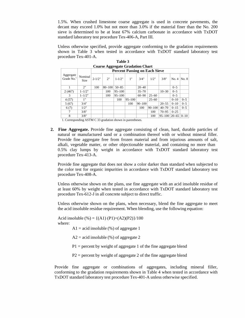
Unless otherwise specified, provide aggregate conforming to the gradation requirements shown in Table 3 when tested in accordance with TxDOT standard laboratory test procedure Tex-401-A.
Table 3 Coarse Aggregate Gradation Chart
Aggregate Grade No.1
Nominal
Size
Percent Passing on Each Sieve 2-1/2"
2"
1-1/2"
1"
3/4"
1/2"
3/8"
No. 4
No. 8
1 2" 100 80–100 50–85 20–40 0–5 2 (467) 1–1/2" 100 95–100 35–70 10–30 0–5
3 1–1/2" 100 95–100 60–90 25–60 0–5 4 (57) 1" 100 95–100 25–60 0–10 0–5 5 (67) 3/4" 100 90–100 20–55 0–10 0–5 6 (7) 1/2" 100 90–100 40–70 0–15 0–5
7 3/8" 100 70–95 0–25 8 3/8" 100 95–100 20–65 0–10
1. Corresponding ASTM C 33 gradation shown in parentheses.
2. Fine Aggregate. Provide fine aggregate consisting of clean, hard, durable particles of natural or manufactured sand or a combination thereof with or without mineral filler. Provide fine aggregate free from frozen material and from injurious amounts of salt, alkali, vegetable matter, or other objectionable material, and containing no more than 0.5% clay lumps by weight in accordance with TxDOT standard laboratory test procedure Tex-413-A.
Provide fine aggregate that does not show a color darker than standard when subjected to the color test for organic impurities in accordance with TxDOT standard laboratory test procedure Tex-408-A.
Unless otherwise shown on the plans, use fine aggregate with an acid insoluble residue of at least 60% by weight when tested in accordance with TxDOT standard laboratory test procedure Tex-612-J in all concrete subject to direct traffic.
Unless otherwise shown on the plans, when necessary, blend the fine aggregate to meet the acid insoluble residue requirement. When blending, use the following equation:
Acid insoluble (%) = {(A1) (P1)+(A2)(P2)}/100 where:
A1 = acid insoluble (%) of aggregate 1
A2 = acid insoluble (%) of aggregate 2
P1 = percent by weight of aggregate 1 of the fine aggregate blend
P2 = percent by weight of aggregate 2 of the fine aggregate blend
Provide fine aggregate or combinations of aggregates, including mineral filler, conforming to the gradation requirements shown in Table 4 when tested in accordance with TxDOT standard laboratory test procedure Tex-401-A unless otherwise specified.
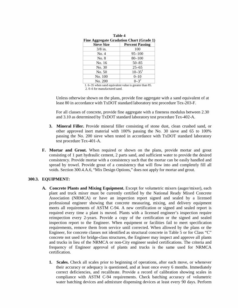
Table 4
Fine Aggregate Gradation Chart (Grade 1) Sieve Size Percent Passing
3/8 in. 100 No. 4 95–100 No. 8 80–100
No. 16 50–85 No. 30 25–65 No. 50 10–351
No. 100 0–10 No. 200 0–32
1. 6–35 when sand equivalent value is greater than 85. 2. 0–6 for manufactured sand.
Unless otherwise shown on the plans, provide fine aggregate with a sand equivalent of at least 80 in accordance with TxDOT standard laboratory test procedure Tex-203-F.
For all classes of concrete, provide fine aggregate with a fineness modulus between 2.30 and 3.10 as determined by TxDOT standard laboratory test procedure Tex-402-A.
3. Mineral Filler. Provide mineral filler consisting of stone dust, clean crushed sand, or
other approved inert material with 100% passing the No. 30 sieve and 65 to 100% passing the No. 200 sieve when tested in accordance with TxDOT standard laboratory test procedure Tex-401-A.
F. Mortar and Grout. When required or shown on the plans, provide mortar and grout
consisting of 1 part hydraulic cement, 2 parts sand, and sufficient water to provide the desired consistency. Provide mortar with a consistency such that the mortar can be easily handled and spread by trowel. Provide grout of a consistency that will flow into and completely fill all voids. Section 300.4.A.6, “Mix Design Options,” does not apply for mortar and grout.
300.3. EQUIPMENT:
A. Concrete Plants and Mixing Equipment. Except for volumetric mixers (auger/mixer), each
plant and truck mixer must be currently certified by the National Ready Mixed Concrete Association (NRMCA) or have an inspection report signed and sealed by a licensed professional engineer showing that concrete measuring, mixing, and delivery equipment meets all requirements of ASTM C-94. A new certification or signed and sealed report is required every time a plant is moved. Plants with a licensed engineer’s inspection require reinspection every 2-years. Provide a copy of the certification or the signed and sealed inspection report to the Engineer. When equipment or facilities fail to meet specification requirements, remove them from service until corrected. When allowed by the plans or the Engineer, for concrete classes not identified as structural concrete in Table 5 or for Class “C” concrete not used for bridge-class structures, the Engineer may inspect and approve all plants and trucks in lieu of the NRMCA or non-City engineer sealed certifications. The criteria and frequency of Engineer approval of plants and trucks is the same used for NRMCA certification.
1. Scales. Check all scales prior to beginning of operations, after each move, or whenever their accuracy or adequacy is questioned, and at least once every 6 months. Immediately correct deficiencies, and recalibrate. Provide a record of calibration showing scales in compliance with ASTM C-94 requirements. Check batching accuracy of volumetric water batching devices and admixture dispensing devices at least every 90 days. Perform
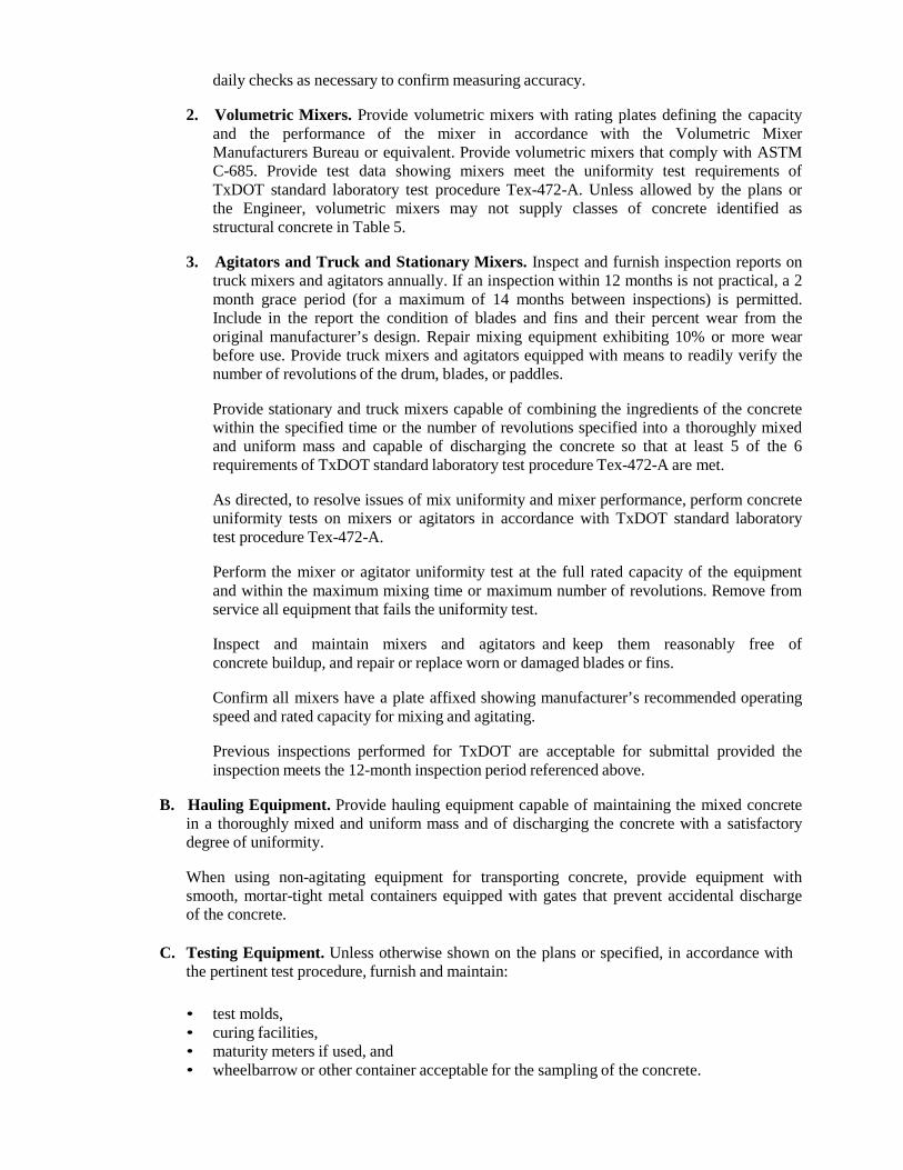
daily checks as necessary to confirm measuring accuracy.
2. Volumetric Mixers. Provide volumetric mixers with rating plates defining the capacity and the performance of the mixer in accordance with the Volumetric Mixer Manufacturers Bureau or equivalent. Provide volumetric mixers that comply with ASTM C-685. Provide test data showing mixers meet the uniformity test requirements of TxDOT standard laboratory test procedure Tex-472-A. Unless allowed by the plans or the Engineer, volumetric mixers may not supply classes of concrete identified as structural concrete in Table 5.
3. Agitators and Truck and Stationary Mixers. Inspect and furnish inspection reports on
truck mixers and agitators annually. If an inspection within 12 months is not practical, a 2 month grace period (for a maximum of 14 months between inspections) is permitted. Include in the report the condition of blades and fins and their percent wear from the original manufacturer’s design. Repair mixing equipment exhibiting 10% or more wear before use. Provide truck mixers and agitators equipped with means to readily verify the number of revolutions of the drum, blades, or paddles.
Provide stationary and truck mixers capable of combining the ingredients of the concrete within the specified time or the number of revolutions specified into a thoroughly mixed and uniform mass and capable of discharging the concrete so that at least 5 of the 6 requirements of TxDOT standard laboratory test procedure Tex-472-A are met.
As directed, to resolve issues of mix uniformity and mixer performance, perform concrete uniformity tests on mixers or agitators in accordance with TxDOT standard laboratory test procedure Tex-472-A.
Perform the mixer or agitator uniformity test at the full rated capacity of the equipment and within the maximum mixing time or maximum number of revolutions. Remove from service all equipment that fails the uniformity test.
Inspect and maintain mixers and agitators and keep them reasonably free of concrete buildup, and repair or replace worn or damaged blades or fins.
Confirm all mixers have a plate affixed showing manufacturer’s recommended operating speed and rated capacity for mixing and agitating.
Previous inspections performed for TxDOT are acceptable for submittal provided the inspection meets the 12-month inspection period referenced above.
B. Hauling Equipment. Provide hauling equipment capable of maintaining the mixed concrete
in a thoroughly mixed and uniform mass and of discharging the concrete with a satisfactory degree of uniformity.
When using non-agitating equipment for transporting concrete, provide equipment with smooth, mortar-tight metal containers equipped with gates that prevent accidental discharge of the concrete.
C. Testing Equipment. Unless otherwise shown on the plans or specified, in accordance with the pertinent test procedure, furnish and maintain:
• test molds, • curing facilities, • maturity meters if used, and • wheelbarrow or other container acceptable for the sampling of the concrete.
Provide strength-testing equipment in accordance with the Contract controlling test unless shown otherwise.
300.4. CONSTRUCTION:
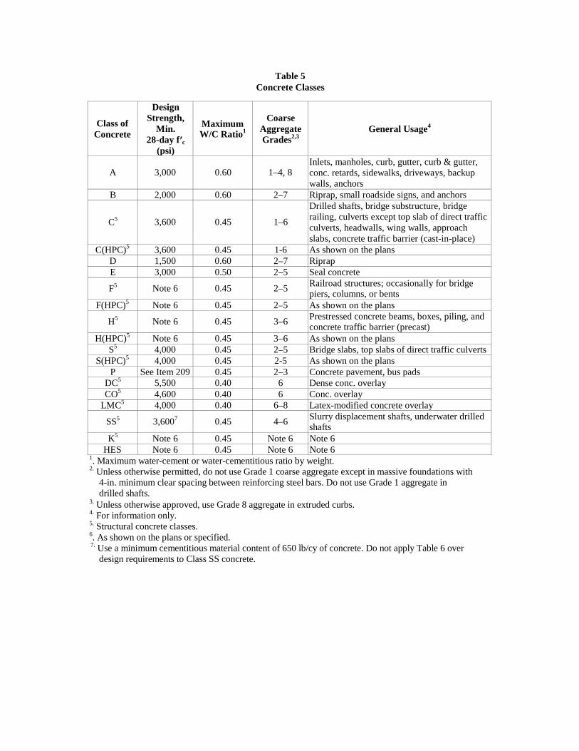
A. Classification and Mix Design. Furnish mix designs using ACI 211, “Standard Practice for
Selecting Proportions for Normal, Heavy Weight, and Mass Concrete,” or other approved procedures for the classes of concrete required in accordance with Table 5. Do not exceed the maximum water-to-cementitious-material ratio. Perform mix design and cement replacement using the design by weight method unless otherwise approved.
A higher-strength class of concrete with equal or lower water-to-cementitious-material ratio may be substituted for the specified class of concrete.
To account for production variability and confirm minimum compressive strength requirements are met, over-design the mix in accordance with Table 6.
1. Cementitious Materials. Use cementitious materials from TxDOT prequalified sources;
otherwise, request sampling and testing for approval before use. Unless otherwise specified or approved, limit cementitious material content to no more than 700 pounds per cubic yard. When supplementary cementing materials are used, “cement” is defined as “cement plus supplementary cementing material.”
Use Type III cement only in precast concrete or when specified or permitted.
For monolithic placements, use cement of the same type and from the same source.
When sulfate-resistant concrete is required, use mix design options 1, 2, 3, or 4 given in Section 300.4.A.6, “Mix Design Options,” using Type I/II, II, V, IP, or IS cement. Do not use Class C fly ash in sulfate-resistant concrete.
Do not use supplementary cementing materials when white hydraulic cement is specified.
The upper limit of 35% replacement of cement with Class F fly ash specified by mix design options 1 and 3 may be increased to a maximum of 45% for mass placements, high performance concrete, and precast members when approved.
Class of Concrete
Design Strength,
Min. 28-day f′c
(psi)
Maximum W/C Ratio1
Coarse
Aggregate Grades2,3
4 General Usage
A
3,000
0.60
1–4, 8
Inlets, manholes, curb, gutter, curb & gutter, conc. retards, sidewalks, driveways, backup walls, anchors
B 2,000 0.60 2–7 Riprap, small roadside signs, and anchors
C5
3,600
0.45
1–6
Drilled shafts, bridge substructure, bridge railing, culverts except top slab of direct traffic culverts, headwalls, wing walls, approach slabs, concrete traffic barrier (cast-in-place)
C(HPC)5 3,600 0.45 1-6 As shown on the plans
D 1,500 0.60 2–7 Riprap E 3,000 0.50 2–5 Seal concrete
F5
Note 6
0.45
2–5 Railroad structures; occasionally for bridge piers, columns, or bents
F(HPC)5 Note 6 0.45 2–5 As shown on the plans
H5
Note 6
0.45
3–6 Prestressed concrete beams, boxes, piling, and concrete traffic barrier (precast)
H(HPC)5 Note 6 0.45 3–6 As shown on the plans
S5 4,000 0.45 2–5 Bridge slabs, top slabs of direct traffic culverts
S(HPC)5 4,000 0.45 2-5 As shown on the plans
P See Item 209 0.45 2–3 Concrete pavement, bus pads DC5
5,500 0.40 6 Dense conc. overlay CO5
4,600 0.40 6 Conc. overlay LMC5
4,000 0.40 6–8 Latex-modified concrete overlay
SS5 3,6007
0.45
4–6 Slurry displacement shafts, underwater drilled shafts
K5 Note 6 0.45 Note 6 Note 6
HES Note 6 0.45 Note 6 Note 6
Table 5 Concrete Classes
1. Maximum water-cement or water-cementitious ratio by weight. 2. Unless otherwise permitted, do not use Grade 1 coarse aggregate except in massive foundations with
4-in. minimum clear spacing between reinforcing steel bars. Do not use Grade 1 aggregate in drilled shafts.
3. Unless otherwise approved, use Grade 8 aggregate in extruded curbs. 4. For information only. 5. Structural concrete classes. 6. As shown on the plans or specified. 7. Use a minimum cementitious material content of 650 lb/cy of concrete. Do not apply Table 6 over
design requirements to Class SS concrete.
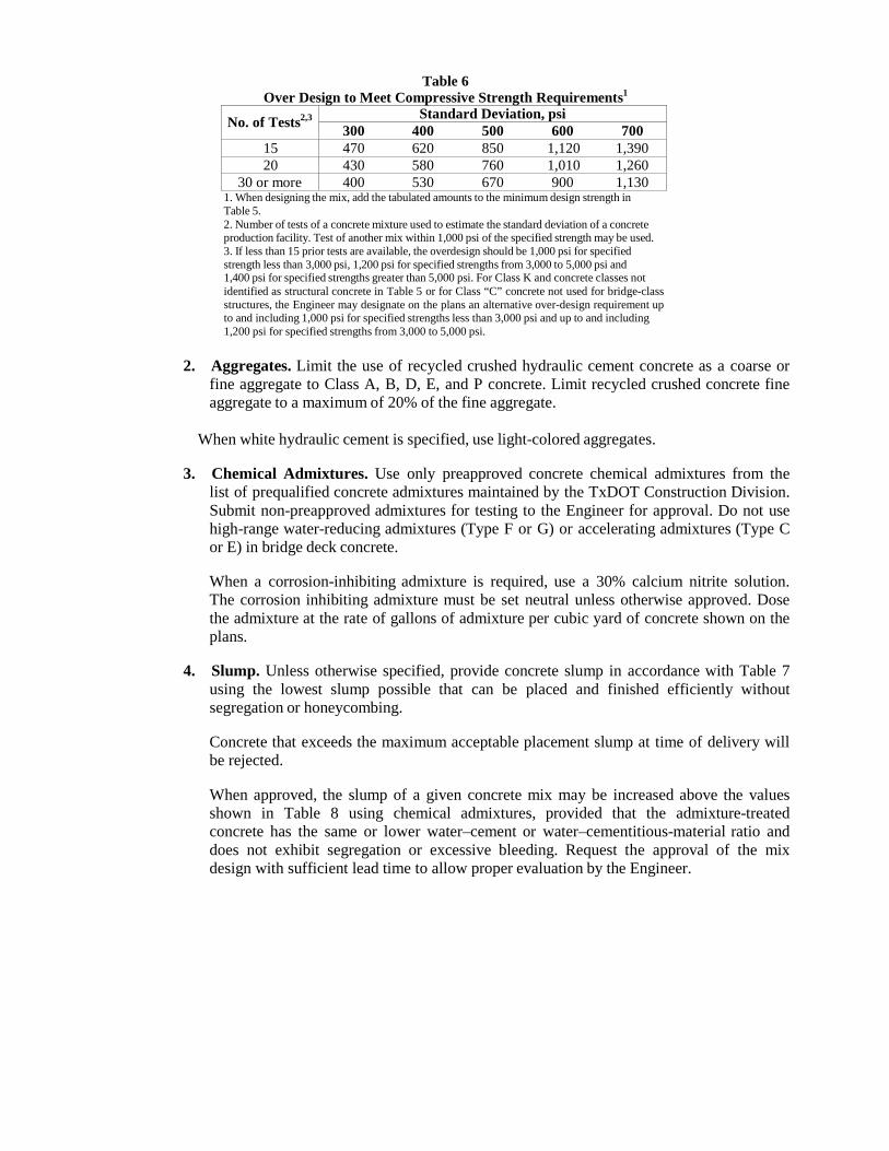
Table 6 Over Design to Meet Compressive Strength Requirements1
No. of Tests2,3
Standard Deviation, psi 300 400 500 600 700
15 470 620 850 1,120 1,390 20 430 580 760 1,010 1,260
30 or more 400 530 670 900 1,130 1. When designing the mix, add the tabulated amounts to the minimum design strength in Table 5. 2. Number of tests of a concrete mixture used to estimate the standard deviation of a concrete production facility. Test of another mix within 1,000 psi of the specified strength may be used. 3. If less than 15 prior tests are available, the overdesign should be 1,000 psi for specified strength less than 3,000 psi, 1,200 psi for specified strengths from 3,000 to 5,000 psi and 1,400 psi for specified strengths greater than 5,000 psi. For Class K and concrete classes not identified as structural concrete in Table 5 or for Class “C” concrete not used for bridge-class structures, the Engineer may designate on the plans an alternative over-design requirement up to and including 1,000 psi for specified strengths less than 3,000 psi and up to and including 1,200 psi for specified strengths from 3,000 to 5,000 psi.
2. Aggregates. Limit the use of recycled crushed hydraulic cement concrete as a coarse or
fine aggregate to Class A, B, D, E, and P concrete. Limit recycled crushed concrete fine aggregate to a maximum of 20% of the fine aggregate.
When white hydraulic cement is specified, use light-colored aggregates.
3. Chemical Admixtures. Use only preapproved concrete chemical admixtures from the
list of prequalified concrete admixtures maintained by the TxDOT Construction Division. Submit non-preapproved admixtures for testing to the Engineer for approval. Do not use high-range water-reducing admixtures (Type F or G) or accelerating admixtures (Type C or E) in bridge deck concrete.
When a corrosion-inhibiting admixture is required, use a 30% calcium nitrite solution. The corrosion inhibiting admixture must be set neutral unless otherwise approved. Dose the admixture at the rate of gallons of admixture per cubic yard of concrete shown on the plans.
4. Slump. Unless otherwise specified, provide concrete slump in accordance with Table 7
using the lowest slump possible that can be placed and finished efficiently without segregation or honeycombing.
Concrete that exceeds the maximum acceptable placement slump at time of delivery will be rejected.
When approved, the slump of a given concrete mix may be increased above the values shown in Table 8 using chemical admixtures, provided that the admixture-treated concrete has the same or lower water–cement or water–cementitious-material ratio and does not exhibit segregation or excessive bleeding. Request the approval of the mix design with sufficient lead time to allow proper evaluation by the Engineer.
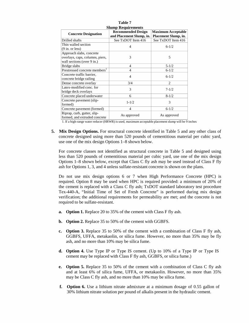
Table 7 Slump Requirements
Concrete Designation Recommended Design and Placement Slump, in.
Maximum Acceptable Placement Slump, in.
Drilled shafts See TxDOT Item 416 See TxDOT Item 416 Thin walled section (9 in. or less) 4 6-1/2
Approach slabs, concrete overlays, caps, columns, piers, wall sections (over 9 in.)
3
5
Bridge slabs 4 5-1/2 Prestressed concrete members1
4 6-1/2 Concrete traffic barrier, concrete bridge railing 4 6-1/2
Dense concrete overlay 3/4 2 Latex-modified conc. for bridge deck overlays 3 7-1/2
Concrete placed underwater 6 8-1/2 Concrete pavement (slip- formed) 1-1/2 3
Concrete pavement (formed) 4 6-1/2 Riprap, curb, gutter, slip- formed, and extruded concrete As approved As approved
1. If a high-range water reducer (HRWR) is used, maximum acceptable placement slump will be 9 inches
5. Mix Design Options. For structural concrete identified in Table 5 and any other class of concrete designed using more than 520 pounds of cementitious material per cubic yard, use one of the mix design Options 1–8 shown below.
For concrete classes not identified as structural concrete in Table 5 and designed using less than 520 pounds of cementitious material per cubic yard, use one of the mix design Options 1–8 shown below, except that Class C fly ash may be used instead of Class F fly ash for Options 1, 3, and 4 unless sulfate-resistant concrete is shown on the plans.
Do not use mix design options 6 or 7 when High Performance Concrete (HPC) is required. Option 8 may be used when HPC is required provided: a minimum of 20% of the cement is replaced with a Class C fly ash; TxDOT standard laboratory test procedure Tex-440-A, “Initial Time of Set of Fresh Concrete” is performed during mix design verification; the additional requirements for permeability are met; and the concrete is not required to be sulfate-resistant.
a. Option 1. Replace 20 to 35% of the cement with Class F fly ash.
b. Option 2. Replace 35 to 50% of the cement with GGBFS.
c. Option 3. Replace 35 to 50% of the cement with a combination of Class F fly ash,
GGBFS, UFFA, metakaolin, or silica fume. However, no more than 35% may be fly ash, and no more than 10% may be silica fume.
d. Option 4. Use Type IP or Type IS cement. (Up to 10% of a Type IP or Type IS
cement may be replaced with Class F fly ash, GGBFS, or silica fume.)
e. Option 5. Replace 35 to 50% of the cement with a combination of Class C fly ash and at least 6% of silica fume, UFFA, or metakaolin. However, no more than 35% may be Class C fly ash, and no more than 10% may be silica fume.
f. Option 6. Use a lithium nitrate admixture at a minimum dosage of 0.55 gallon of 30% lithium nitrate solution per pound of alkalis present in the hydraulic cement.
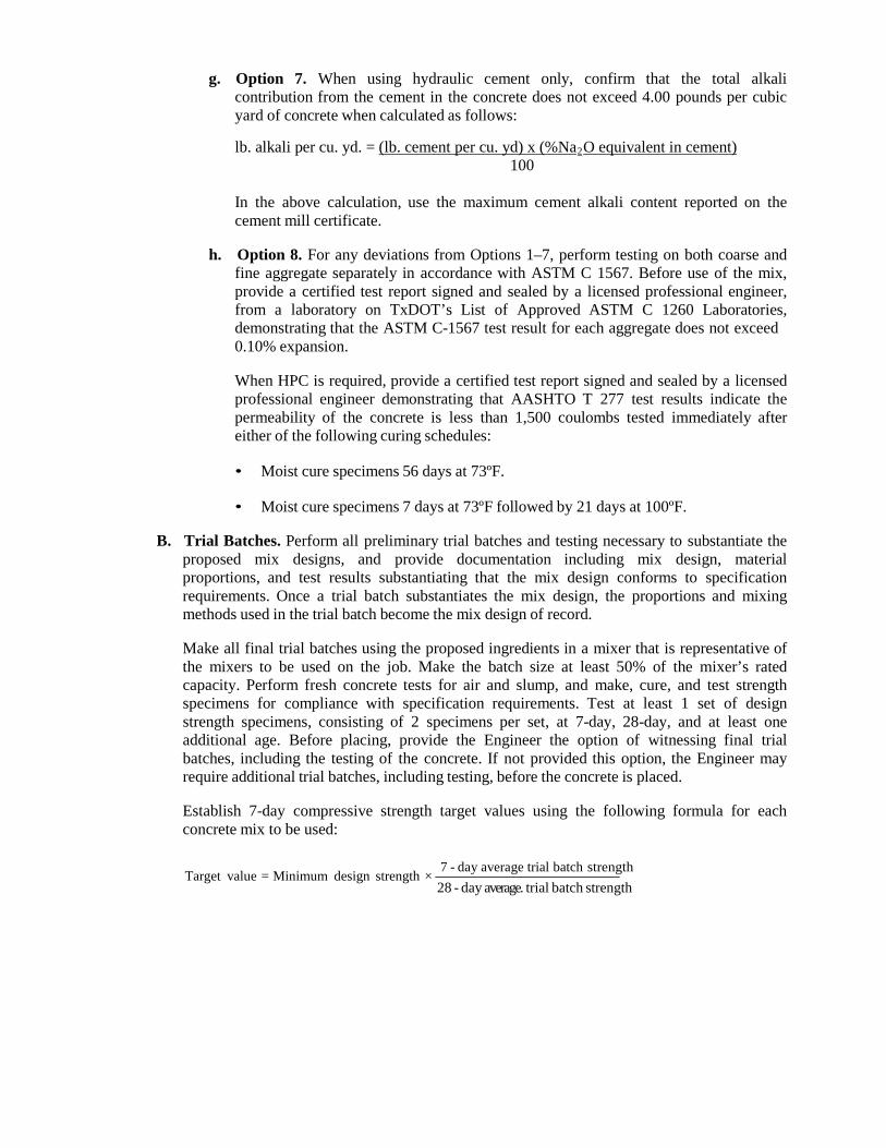
g. Option 7. When using hydraulic cement only, confirm that the total alkali contribution from the cement in the concrete does not exceed 4.00 pounds per cubic yard of concrete when calculated as follows:
lb. alkali per cu. yd. = (lb. cement per cu. yd) x (%Na2O equivalent in cement)
100
In the above calculation, use the maximum cement alkali content reported on the cement mill certificate.
h. Option 8. For any deviations from Options 1–7, perform testing on both coarse and
fine aggregate separately in accordance with ASTM C 1567. Before use of the mix, provide a certified test report signed and sealed by a licensed professional engineer, from a laboratory on TxDOT’s List of Approved ASTM C 1260 Laboratories, demonstrating that the ASTM C-1567 test result for each aggregate does not exceed 0.10% expansion.
When HPC is required, provide a certified test report signed and sealed by a licensed professional engineer demonstrating that AASHTO T 277 test results indicate the permeability of the concrete is less than 1,500 coulombs tested immediately after either of the following curing schedules:
• Moist cure specimens 56 days at 73ºF.
• Moist cure specimens 7 days at 73ºF followed by 21 days at 100ºF.
B. Trial Batches. Perform all preliminary trial batches and testing necessary to substantiate the
proposed mix designs, and provide documentation including mix design, material proportions, and test results substantiating that the mix design conforms to specification requirements. Once a trial batch substantiates the mix design, the proportions and mixing methods used in the trial batch become the mix design of record.
Make all final trial batches using the proposed ingredients in a mixer that is representative of the mixers to be used on the job. Make the batch size at least 50% of the mixer’s rated capacity. Perform fresh concrete tests for air and slump, and make, cure, and test strength specimens for compliance with specification requirements. Test at least 1 set of design strength specimens, consisting of 2 specimens per set, at 7-day, 28-day, and at least one additional age. Before placing, provide the Engineer the option of witnessing final trial batches, including the testing of the concrete. If not provided this option, the Engineer may require additional trial batches, including testing, before the concrete is placed.
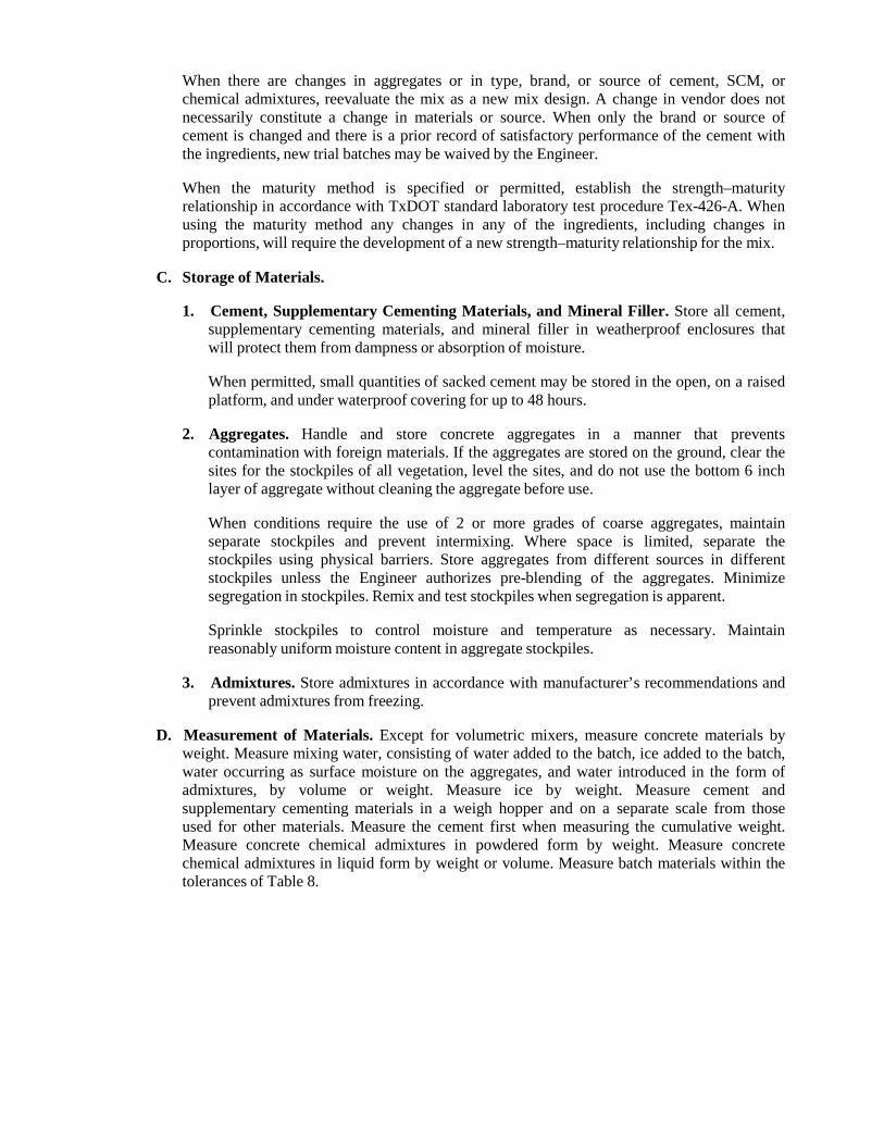
Establish 7-day compressive strength target values using the following formula for each concrete mix to be used:
Target value = Minimum design strength ×
7 - day average trial batch strength 28 - day average. trial batch strength
When there are changes in aggregates or in type, brand, or source of cement, SCM, or chemical admixtures, reevaluate the mix as a new mix design. A change in vendor does not necessarily constitute a change in materials or source. When only the brand or source of cement is changed and there is a prior record of satisfactory performance of the cement with the ingredients, new trial batches may be waived by the Engineer.
When the maturity method is specified or permitted, establish the strength–maturity relationship in accordance with TxDOT standard laboratory test procedure Tex-426-A. When using the maturity method any changes in any of the ingredients, including changes in proportions, will require the development of a new strength–maturity relationship for the mix.
C. Storage of Materials.
1. Cement, Supplementary Cementing Materials, and Mineral Filler. Store all cement,
supplementary cementing materials, and mineral filler in weatherproof enclosures that will protect them from dampness or absorption of moisture.
When permitted, small quantities of sacked cement may be stored in the open, on a raised platform, and under waterproof covering for up to 48 hours.
2. Aggregates. Handle and store concrete aggregates in a manner that prevents
contamination with foreign materials. If the aggregates are stored on the ground, clear the sites for the stockpiles of all vegetation, level the sites, and do not use the bottom 6 inch layer of aggregate without cleaning the aggregate before use.
When conditions require the use of 2 or more grades of coarse aggregates, maintain separate stockpiles and prevent intermixing. Where space is limited, separate the stockpiles using physical barriers. Store aggregates from different sources in different stockpiles unless the Engineer authorizes pre-blending of the aggregates. Minimize segregation in stockpiles. Remix and test stockpiles when segregation is apparent.
Sprinkle stockpiles to control moisture and temperature as necessary. Maintain reasonably uniform moisture content in aggregate stockpiles.
3. Admixtures. Store admixtures in accordance with manufacturer’s recommendations and
prevent admixtures from freezing.
D. Measurement of Materials. Except for volumetric mixers, measure concrete materials by weight. Measure mixing water, consisting of water added to the batch, ice added to the batch, water occurring as surface moisture on the aggregates, and water introduced in the form of admixtures, by volume or weight. Measure ice by weight. Measure cement and supplementary cementing materials in a weigh hopper and on a separate scale from those used for other materials. Measure the cement first when measuring the cumulative weight. Measure concrete chemical admixtures in powdered form by weight. Measure concrete chemical admixtures in liquid form by weight or volume. Measure batch materials within the tolerances of Table 8.
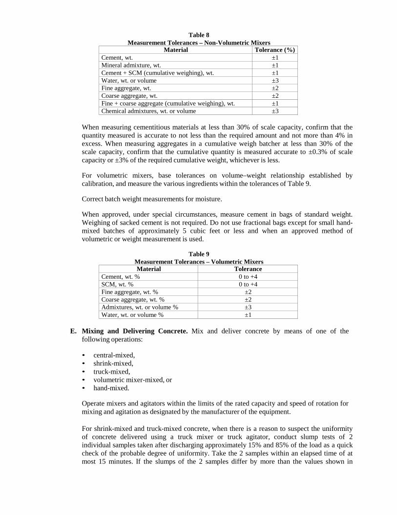
Table 8 Measurement Tolerances – Non-Volumetric Mixers
Material Tolerance (%) Cement, wt. ±1 Mineral admixture, wt. ±1 Cement + SCM (cumulative weighing), wt. ±1 Water, wt. or volume ±3 Fine aggregate, wt. ±2 Coarse aggregate, wt. ±2 Fine + coarse aggregate (cumulative weighing), wt. ±1 Chemical admixtures, wt. or volume ±3
When measuring cementitious materials at less than 30% of scale capacity, confirm that the quantity measured is accurate to not less than the required amount and not more than 4% in excess. When measuring aggregates in a cumulative weigh batcher at less than 30% of the scale capacity, confirm that the cumulative quantity is measured accurate to ±0.3% of scale capacity or ±3% of the required cumulative weight, whichever is less.
For volumetric mixers, base tolerances on volume–weight relationship established by calibration, and measure the various ingredients within the tolerances of Table 9.
Correct batch weight measurements for moisture.
When approved, under special circumstances, measure cement in bags of standard weight. Weighing of sacked cement is not required. Do not use fractional bags except for small hand- mixed batches of approximately 5 cubic feet or less and when an approved method of volumetric or weight measurement is used.
Table 9
Measurement Tolerances – Volumetric Mixers Material Tolerance
Cement, wt. % 0 to +4 SCM, wt. % 0 to +4 Fine aggregate, wt. % ±2 Coarse aggregate, wt. % ±2 Admixtures, wt. or volume % ±3 Water, wt. or volume % ±1
E. Mixing and Delivering Concrete. Mix and deliver concrete by means of one of the
following operations:
• central-mixed, • shrink-mixed, • truck-mixed, • volumetric mixer-mixed, or • hand-mixed.
Operate mixers and agitators within the limits of the rated capacity and speed of rotation for mixing and agitation as designated by the manufacturer of the equipment.
For shrink-mixed and truck-mixed concrete, when there is a reason to suspect the uniformity of concrete delivered using a truck mixer or truck agitator, conduct slump tests of 2 individual samples taken after discharging approximately 15% and 85% of the load as a quick check of the probable degree of uniformity. Take the 2 samples within an elapsed time of at most 15 minutes. If the slumps of the 2 samples differ by more than the values shown in
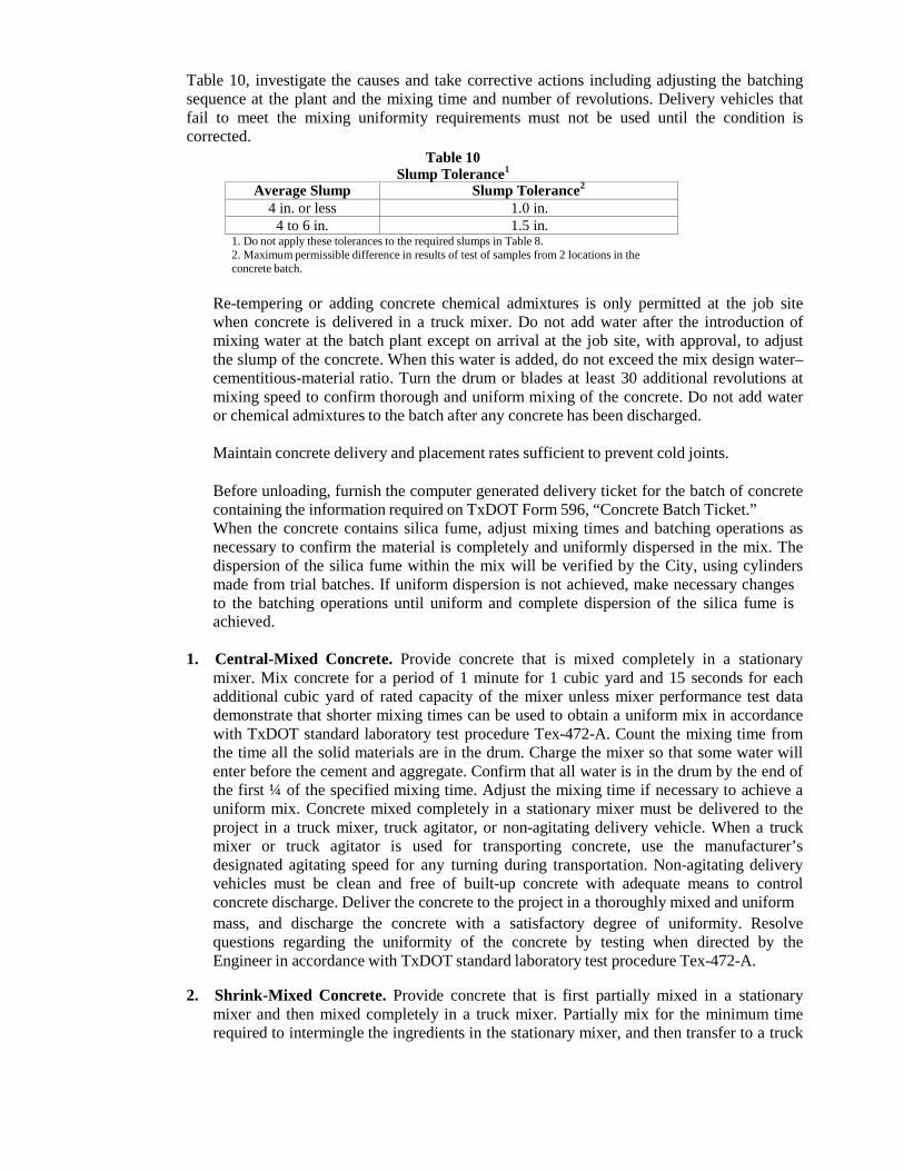
Table 10, investigate the causes and take corrective actions including adjusting the batching sequence at the plant and the mixing time and number of revolutions. Delivery vehicles that fail to meet the mixing uniformity requirements must not be used until the condition is corrected.
Table 10 Slump Tolerance1
Average Slump Slump Tolerance2
4 in. or less 1.0 in. 4 to 6 in. 1.5 in.
1. Do not apply these tolerances to the required slumps in Table 8. 2. Maximum permissible difference in results of test of samples from 2 locations in the concrete batch.
Re-tempering or adding concrete chemical admixtures is only permitted at the job site when concrete is delivered in a truck mixer. Do not add water after the introduction of mixing water at the batch plant except on arrival at the job site, with approval, to adjust the slump of the concrete. When this water is added, do not exceed the mix design water– cementitious-material ratio. Turn the drum or blades at least 30 additional revolutions at mixing speed to confirm thorough and uniform mixing of the concrete. Do not add water or chemical admixtures to the batch after any concrete has been discharged.
Maintain concrete delivery and placement rates sufficient to prevent cold joints.
Before unloading, furnish the computer generated delivery ticket for the batch of concrete containing the information required on TxDOT Form 596, “Concrete Batch Ticket.” When the concrete contains silica fume, adjust mixing times and batching operations as necessary to confirm the material is completely and uniformly dispersed in the mix. The dispersion of the silica fume within the mix will be verified by the City, using cylinders made from trial batches. If uniform dispersion is not achieved, make necessary changes to the batching operations until uniform and complete dispersion of the silica fume is achieved.
1. Central-Mixed Concrete. Provide concrete that is mixed completely in a stationary
mixer. Mix concrete for a period of 1 minute for 1 cubic yard and 15 seconds for each additional cubic yard of rated capacity of the mixer unless mixer performance test data demonstrate that shorter mixing times can be used to obtain a uniform mix in accordance with TxDOT standard laboratory test procedure Tex-472-A. Count the mixing time from the time all the solid materials are in the drum. Charge the mixer so that some water will enter before the cement and aggregate. Confirm that all water is in the drum by the end of the first ¼ of the specified mixing time. Adjust the mixing time if necessary to achieve a uniform mix. Concrete mixed completely in a stationary mixer must be delivered to the project in a truck mixer, truck agitator, or non-agitating delivery vehicle. When a truck mixer or truck agitator is used for transporting concrete, use the manufacturer’s designated agitating speed for any turning during transportation. Non-agitating delivery vehicles must be clean and free of built-up concrete with adequate means to control concrete discharge. Deliver the concrete to the project in a thoroughly mixed and uniform mass, and discharge the concrete with a satisfactory degree of uniformity. Resolve questions regarding the uniformity of the concrete by testing when directed by the Engineer in accordance with TxDOT standard laboratory test procedure Tex-472-A.
2. Shrink-Mixed Concrete. Provide concrete that is first partially mixed in a stationary
mixer and then mixed completely in a truck mixer. Partially mix for the minimum time required to intermingle the ingredients in the stationary mixer, and then transfer to a truck
mixer and mix the concrete at the manufacturer’s designated mixing speed for an adequate amount of time to produce thoroughly mixed concrete. Deliver the concrete to the project in a thoroughly mixed and uniform mass, and discharge the concrete with a satisfactory degree of uniformity.
3. Truck-Mixed Concrete. Mix the concrete in a truck mixer from 70 to 100 revolutions at
the mixing speed designated by the manufacturer to produce a uniform concrete mix. Deliver the concrete to the project in a thoroughly mixed and uniform mass and discharge the concrete with a satisfactory degree of uniformity. Additional mixing at the job site at the mixing speed designated by the manufacturer is allowed as long as concrete is discharged before the drum has revolved a total of 300 revolutions after the introduction of the mixing water to the cement and the aggregates.
4. Volumetric Mixer-Mixed Concrete. Unless otherwise specified or permitted, perform
all mixing operations in accordance with manufacturer’s recommended procedures. Provide an accurate method of measuring all ingredients by volume, and calibrate equipment to assure correct measurement of materials within the specified tolerances.
5. Hand-Mixed Concrete. When permitted, for small placements of less than 2 cubic
yards, mix up to a 2 sack batch of concrete by hand methods or in a small motor-driven mixer. For such placements, proportion the mix by volume or weight.
F. Placing, Finishing, and Curing Concrete. Place, finish, and cure concrete in accordance
with the pertinent Items.
G. Sampling and Testing of Concrete. Unless otherwise specified, all fresh and hardened concrete is subject to testing as follows:
1. Sampling Fresh Concrete. Provide all material to be tested. Fresh concrete will be
sampled for testing at the discharge end if using belt conveyors or pumps. When it is impractical to sample at the discharge end, a sample will be taken at the time of discharge from the delivery equipment and correlation testing will be performed and documented to confirm specification requirements are met at the discharge end.
2. Testing of Fresh Concrete.
a. Air Content. TxDOT standard laboratory test procedure Tex-414-A or Tex-416-A.
b. Slump. TxDOT standard laboratory test procedure Tex-415-A.
c. Temperature. TxDOT standard laboratory test procedure Tex-422-A.
d. Making and Curing Strength Specimens. TxDOT standard laboratory test
procedure Tex-447-A.
3. Testing of Hardened Concrete. Only compressive strength testing will be used unless otherwise specified or shown on the plans.
a. Compressive Strength. TxDOT standard laboratory test procedure Tex-418-A.
b. Flexural Strength. TxDOT standard laboratory test procedure Tex-448-A.
c. Maturity. TxDOT standard laboratory test procedure Tex-426-A.
4. Certification of Testing Personnel. Contractor personnel performing testing must be ACI-certified for the tests being performed. Personnel performing these tests are subject to City approval. Use of a commercial laboratory is permitted. All personnel performing testing using the maturity method must be qualified by a training program recognized by TxDOT before using this method on the job.
5. Adequacy and Acceptance of Concrete. The Engineer will sample and test the fresh
and hardened concrete for acceptance. The test results will be reported to the Contractor and the concrete supplier. For any concrete that fails to meet the required strengths as outlined below, investigate the quality of the materials, the concrete production operations, and other possible problem areas to determine the cause. Take necessary actions to correct the problem including redesign of the concrete mix. The Engineer may suspend all concrete operations under the pertinent Items if the Contractor is unable to identify, document, and correct the cause of the low strengths in a timely manner. Resume concrete operations only after obtaining approval for any proposed corrective actions.
a. Structural Concrete. For concrete classes identified as structural concrete in Table
5, the Engineer will make and test 7 day and 28 day specimens. Acceptance will be based on the design strength given in Table 5.
The Engineer will evaluate the adequacy of the concrete by comparing 7 day test results to the target value established in accordance with Section 300.4.B, “Trial Batches.”
b. All Other Concrete. For concrete classes not identified as structural concrete in
Table 5, the Engineer will make and test 7-day specimens. The Engineer will base acceptance on the 7 day target value established in accordance with Section 300.4.B, “Trial Batches.”
6. Test Sample Handling. Unless otherwise shown on the plans or directed, remove forms
and deliver department test specimens to curing facilities, in accordance with pertinent test procedures. Clean and prepare forms for reuse.
301 REINFORCING STEEL
301.1. DESCRIPTION: Furnish and place reinforcing steel of the sizes and details shown on the plans.
301.2. MATERIALS:
A. Approved Mills. Before furnishing steel, producing mills of reinforcing steel for the City
must be pre-approved in accordance with TxDOT’s DMS-7320, “Qualification Procedure for Reinforcing Steel Mills,” by the TxDOT’s Construction Division, which maintains a list of approved producing mills. Reinforcing steel obtained from unapproved sources will not be accepted.
B. Deformed Bar and Wire Reinforcement. Unless otherwise shown on the plans, reinforcing
steel must be Grade 60, and bar reinforcement must be deformed. Reinforcing steel must conform to one of the following:
• ASTM A 615, Grades 40 or 60;
• ASTM A 996, Type A, Grades 40 or 60;
• ASTM A 996, Type R, Grade 60, permitted in concrete pavement only (Furnish ASTM A
996, Type R bars as straight bars only and do not bend them. Bend tests are not required.); or
• ASTM A 706.
The provisions of this Item take precedence over ASTM provisions.
The nominal size, area, and weight of reinforcing steel bars covered by this Item are shown in Table 1. Designate smooth bars up to No. 4 by size number and above No. 4 by diameter in inches.
C. Smooth Bar and Spiral Reinforcement. Smooth bars and dowels for concrete pavement
must have a minimum yield strength of 60 ksi and meet ASTM A 615. For smooth bars that are larger than No. 3, provide steel conforming to ASTM A 615 or meet the physical requirements of ASTM A 36.
Spiral reinforcement may be smooth or deformed bars or wire of the minimum size or gauge shown on the plans. Bars for spiral reinforcement must comply with ASTM A 615, Grade 40; ASTM A 996, Type A, Grade 40; or ASTM A 675, Grade 80, meeting dimensional requirements of ASTM A 615. Smooth wire must comply with ASTM A 82, and deformed wire must comply with ASTM A 496.
D. Weldable Reinforcing Steel. Reinforcing steel to be welded must comply with ASTM A 706
or have a carbon equivalent (C.E.) of at most 0.55%. A report of chemical analysis showing the percentages of elements necessary to establish C.E. is required for reinforcing steel that does not meet ASTM A 706 to be structurally welded. These requirements do not pertain to miscellaneous welds on reinforcing steel as defined in TxDOT’s Section 448.4.B.1.a, “Miscellaneous Welding Applications.” Calculate C.E. using the following formula:
C.E. = %C + %Mn
6 %Cu
+ 40
% Ni +
20
%Cr +
10
%Mo %V − −
50 10
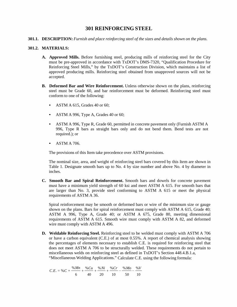
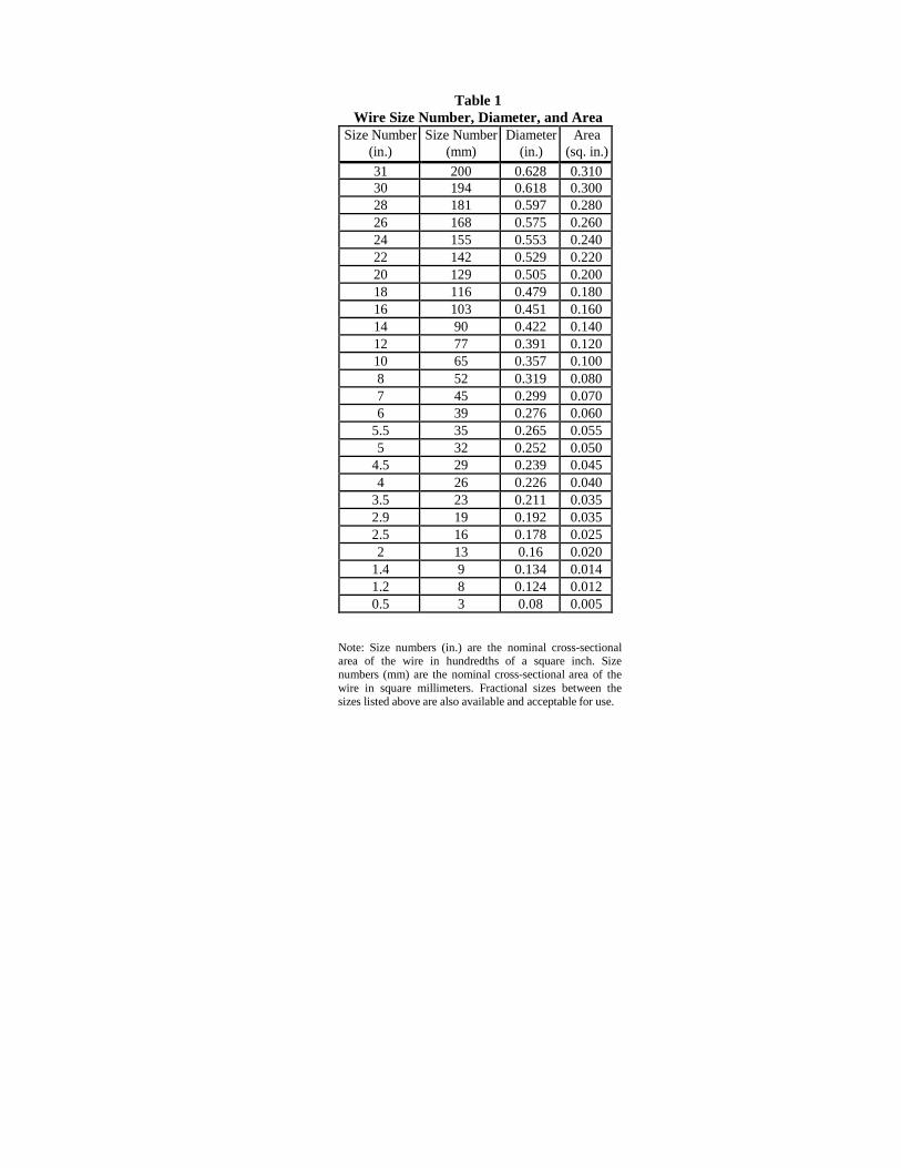
E. Welded Wire Fabric. For fabric reinforcement, use wire that conforms to ASTM A 82 or A
496. Use wire fabric that conforms to ASTM A 185 or A 497. Observe the relations shown in Table 2 among size number, diameter in inches, and area when ordering wire by size numbers, unless otherwise specified. Precede the size number for deformed wire with “D” and for smooth wire with “W.”
Designate welded wire fabric as shown in the following example: 6 × 12 – W16 × W8 (indicating 6 in. longitudinal wire spacing and 12 in. transverse wire spacing with smooth No. 16 wire longitudinally and smooth No. 8 wire transversely).
Table 2
Wire Size Number, Diameter, and Area Size Number
(in.) Size Number
(mm)
Diameter (in.)
Area (sq. in.)
31 200 0.628 0.310 30 194 0.618 0.300 28 181 0.597 0.280 26 168 0.575 0.260 24 155 0.553 0.240 22 142 0.529 0.220 20 129 0.505 0.200 18 116 0.479 0.180 16 103 0.451 0.160 14 90 0.422 0.140 12 77 0.391 0.120 10 65 0.357 0.100 8 52 0.319 0.080 7 45 0.299 0.070 6 39 0.276 0.060
5.5 35 0.265 0.055 5 32 0.252 0.050
4.5 29 0.239 0.045 4 26 0.226 0.040
3.5 23 0.211 0.035 2.9 19 0.192 0.035 2.5 16 0.178 0.025 2 13 0.160 0.020
1.4 9 0.134 0.014 1.2 8 0.124 0.012 0.5 3 0.080 0.005
Note: Size numbers (in.) are the nominal cross-sectional area of the wire in hundredths of a square inch. Size numbers (mm) are the nominal cross-sectional area of the wire in square millimeters. Fractional sizes between the sizes listed above are also available and acceptable for use.
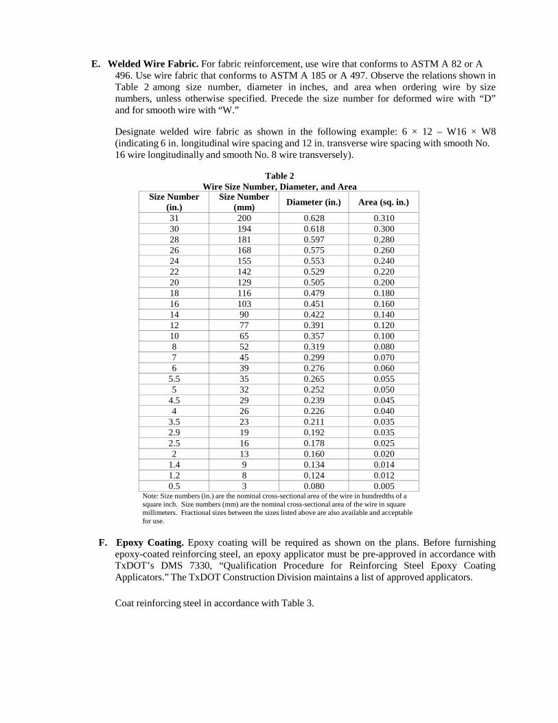
F. Epoxy Coating. Epoxy coating will be required as shown on the plans. Before furnishing epoxy-coated reinforcing steel, an epoxy applicator must be pre-approved in accordance with TxDOT’s DMS 7330, “Qualification Procedure for Reinforcing Steel Epoxy Coating Applicators.” The TxDOT Construction Division maintains a list of approved applicators. Coat reinforcing steel in accordance with Table 3.
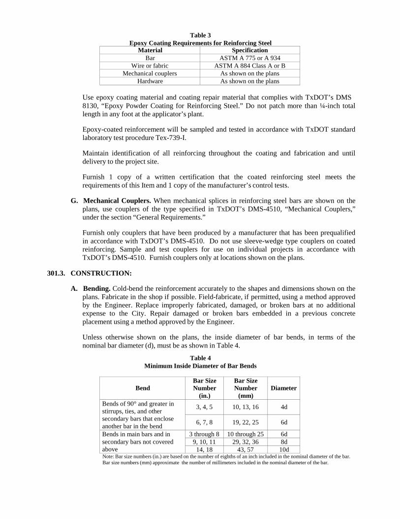
Table 3 Epoxy Coating Requirements for Reinforcing Steel
Material Specification Bar ASTM A 775 or A 934
Wire or fabric ASTM A 884 Class A or B Mechanical couplers As shown on the plans
Hardware As shown on the plans
Use epoxy coating material and coating repair material that complies with TxDOT’s DMS 8130, “Epoxy Powder Coating for Reinforcing Steel.” Do not patch more than ¼-inch total length in any foot at the applicator’s plant.
Epoxy-coated reinforcement will be sampled and tested in accordance with TxDOT standard laboratory test procedure Tex-739-I.
Maintain identification of all reinforcing throughout the coating and fabrication and until delivery to the project site.
Furnish 1 copy of a written certification that the coated reinforcing steel meets the requirements of this Item and 1 copy of the manufacturer’s control tests.
G. Mechanical Couplers. When mechanical splices in reinforcing steel bars are shown on the
plans, use couplers of the type specified in TxDOT’s DMS-4510, “Mechanical Couplers,” under the section “General Requirements.”
Furnish only couplers that have been produced by a manufacturer that has been prequalified in accordance with TxDOT’s DMS-4510. Do not use sleeve-wedge type couplers on coated reinforcing. Sample and test couplers for use on individual projects in accordance with TxDOT’s DMS-4510. Furnish couplers only at locations shown on the plans.
301.3. CONSTRUCTION:
A. Bending. Cold-bend the reinforcement accurately to the shapes and dimensions shown on the
plans. Fabricate in the shop if possible. Field-fabricate, if permitted, using a method approved by the Engineer. Replace improperly fabricated, damaged, or broken bars at no additional expense to the City. Repair damaged or broken bars embedded in a previous concrete placement using a method approved by the Engineer.
Unless otherwise shown on the plans, the inside diameter of bar bends, in terms of the nominal bar diameter (d), must be as shown in Table 4.
Table 4
Minimum Inside Diameter of Bar Bends
Bend
Bar Size Number
(in.)
Bar Size Number
(mm)
Diameter
Bends of 90° and greater in stirrups, ties, and other secondary bars that enclose another bar in the bend
3, 4, 5
10, 13, 16
4d
6, 7, 8
19, 22, 25
6d
Bends in main bars and in secondary bars not covered above
3 through 8 10 through 25 6d 9, 10, 11 29, 32, 36 8d
14, 18 43, 57 10d Note: Bar size numbers (in.) are based on the number of eighths of an inch included in the nominal diameter of the bar. Bar size numbers (mm) approximate the number of millimeters included in the nominal diameter of the bar.
Where bending No. 14 or No. 18 Grade 60 bars is required, bend-test representative specimens as described for smaller bars in the applicable ASTM specification. Make the required 90° bend around a pin with a diameter of 10 times the nominal diameter of the bar.
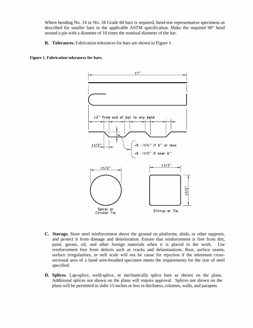
B. Tolerances. Fabrication tolerances for bars are shown in Figure 1.
Figure 1. Fabrication tolerances for bars.
C. Storage. Store steel reinforcement above the ground on platforms, skids, or other supports,
and protect it from damage and deterioration. Ensure that reinforcement is free from dirt, paint, grease, oil, and other foreign materials when it is placed in the work. Use reinforcement free from defects such as cracks and delaminations. Rust, surface seams, surface irregularities, or mill scale will not be cause for rejection if the minimum cross- sectional area of a hand wire-brushed specimen meets the requirements for the size of steel specified.
D. Splices. Lap-splice, weld-splice, or mechanically splice bars as shown on the plans.
Additional splices not shown on the plans will require approval. Splices not shown on the plans will be permitted in slabs 15-inches or less in thickness, columns, walls, and parapets.
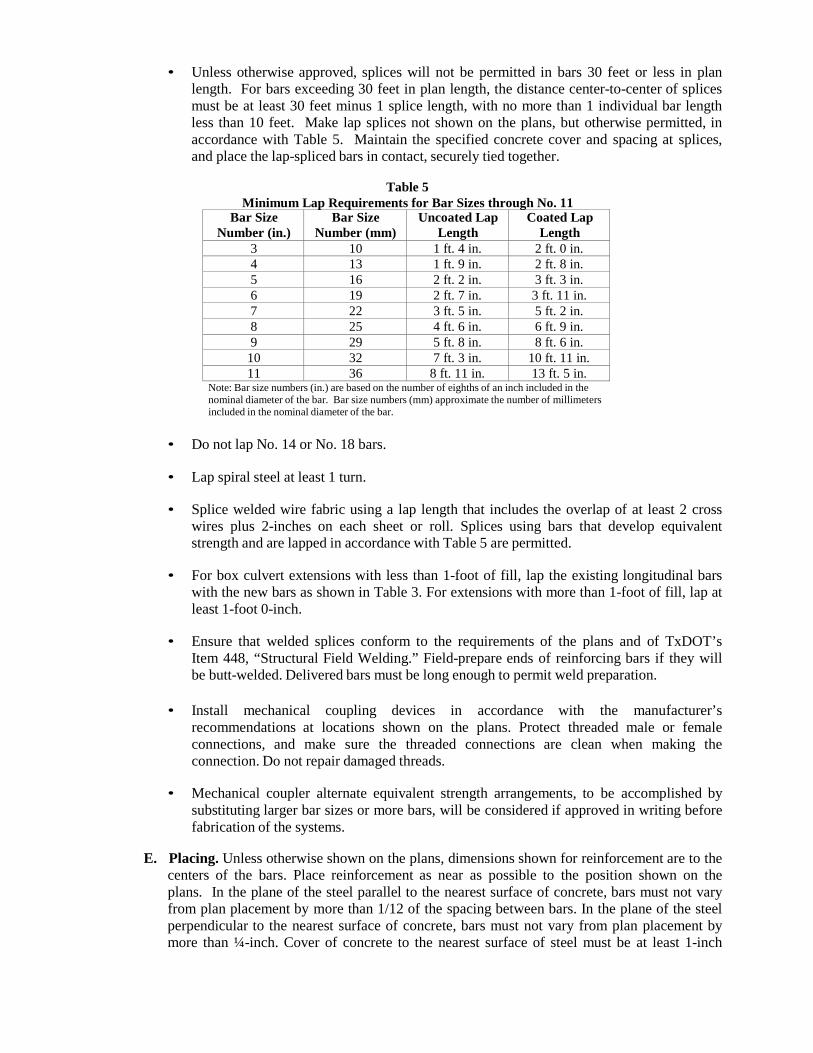
• Unless otherwise approved, splices will not be permitted in bars 30 feet or less in plan length. For bars exceeding 30 feet in plan length, the distance center-to-center of splices must be at least 30 feet minus 1 splice length, with no more than 1 individual bar length less than 10 feet. Make lap splices not shown on the plans, but otherwise permitted, in accordance with Table 5. Maintain the specified concrete cover and spacing at splices, and place the lap-spliced bars in contact, securely tied together.
Table 5
Minimum Lap Requirements for Bar Sizes through No. 11 Bar Size
Number (in.) Bar Size
Number (mm) Uncoated Lap
Length Coated Lap
Length 3 10 1 ft. 4 in. 2 ft. 0 in. 4 13 1 ft. 9 in. 2 ft. 8 in. 5 16 2 ft. 2 in. 3 ft. 3 in. 6 19 2 ft. 7 in. 3 ft. 11 in. 7 22 3 ft. 5 in. 5 ft. 2 in. 8 25 4 ft. 6 in. 6 ft. 9 in. 9 29 5 ft. 8 in. 8 ft. 6 in.
10 32 7 ft. 3 in. 10 ft. 11 in. 11 36 8 ft. 11 in. 13 ft. 5 in.
Note: Bar size numbers (in.) are based on the number of eighths of an inch included in the nominal diameter of the bar. Bar size numbers (mm) approximate the number of millimeters included in the nominal diameter of the bar.
• Do not lap No. 14 or No. 18 bars.
• Lap spiral steel at least 1 turn.
• Splice welded wire fabric using a lap length that includes the overlap of at least 2 cross wires plus 2-inches on each sheet or roll. Splices using bars that develop equivalent strength and are lapped in accordance with Table 5 are permitted.
• For box culvert extensions with less than 1-foot of fill, lap the existing longitudinal bars
with the new bars as shown in Table 3. For extensions with more than 1-foot of fill, lap at least 1-foot 0-inch.
• Ensure that welded splices conform to the requirements of the plans and of TxDOT’s
Item 448, “Structural Field Welding.” Field-prepare ends of reinforcing bars if they will be butt-welded. Delivered bars must be long enough to permit weld preparation.
• Install mechanical coupling devices in accordance with the manufacturer’s recommendations at locations shown on the plans. Protect threaded male or female connections, and make sure the threaded connections are clean when making the connection. Do not repair damaged threads.
• Mechanical coupler alternate equivalent strength arrangements, to be accomplished by substituting larger bar sizes or more bars, will be considered if approved in writing before fabrication of the systems.
E. Placing. Unless otherwise shown on the plans, dimensions shown for reinforcement are to the
centers of the bars. Place reinforcement as near as possible to the position shown on the plans. In the plane of the steel parallel to the nearest surface of concrete, bars must not vary from plan placement by more than 1/12 of the spacing between bars. In the plane of the steel perpendicular to the nearest surface of concrete, bars must not vary from plan placement by more than ¼-inch. Cover of concrete to the nearest surface of steel must be at least 1-inch

unless otherwise shown on the plans.
For bridge slabs, the clear cover tolerance for the top mat of reinforcement is −0, +½-inch.
Locate the reinforcement accurately in the forms, and hold it firmly in place before and during concrete placement by means of bar supports that are adequate in strength and number to prevent displacement and to keep the steel at the proper distance from the forms. Support bars by standard bar supports with plastic tips, approved plastic bar supports, or precast mortar or concrete blocks when supports are in contact with removable or stay-in-place forms. Use bright basic bar supports to support reinforcing steel placed in slab overlays on concrete panels or on existing concrete slabs. Bar supports in contact with soil or subgrade must be approved.
For bar supports with plastic tips, the plastic protection must be at least 3/32-inch thick and extend upward on the wire to a point at least ½-inch above the formwork.
All accessories such as tie wires, bar chairs, supports, or clips used with epoxy-coated reinforcement must be of steel, fully coated with epoxy or plastic. Plastic supports approved by the Engineer may also be used with epoxy-coated reinforcement.
Cast mortar or concrete blocks to uniform dimensions with adequate bearing area. Provide a suitable tie wire in each block for anchoring to the steel. Cast the blocks to the thickness required in approved molds. The surface placed adjacent to the form must be a true plane, free of surface imperfections. Cure the blocks by covering them with wet burlap or mats for a period of 72-hours. Mortar for blocks should contain approximately 1 part hydraulic cement to 3 parts sand. Concrete for blocks should contain 850 lb. of hydraulic cement per cubic yard of concrete.
Place individual bar supports in rows at 4 feet maximum spacing in each direction. Place continuous type bar supports at 4 feet maximum spacing. Use continuous bar supports with permanent metal deck forms.
The exposure of the ends of longitudinals, stirrups, and spacers used to position the reinforcement in concrete pipe and in precast box culverts or storm drains is not cause for rejection.
Tie reinforcing steel for bridge slabs, top slabs of direct traffic culverts, and top slabs of prestressed box beams at all intersections, except tie only alternate intersections where spacing is less than 1 foot in each direction. For reinforcing steel cages for other structural members, tie the steel at enough intersections to provide a rigid cage of steel. Fasten mats of wire fabric securely at the ends and edges.
Before concrete placement, clean mortar, mud, dirt, debris, oil, and other foreign material from the reinforcement. Do not place concrete until authorized.
If reinforcement is not adequately supported or tied to resist settlement, reinforcement is floating upward, truss bars are overturning, or movement is detected in any direction during concrete placement, stop placement until corrective measures are taken.
F. Handling, Placement, and Repair of Epoxy-Coated Reinforcing Steel.
1. Handling. Provide systems for handling coated reinforcement with padded contact areas.
Pad bundling bands or use suitable banding to prevent damage to the coating. Lift bundles of coated reinforcement with a strongback, spreader bar, multiple supports, or a
platform bridge. Transport the bundled reinforcement carefully, and store it on protective cribbing. Do not drop or drag the coated reinforcement.
2. Construction Methods. Do not flame-cut coated reinforcement. Saw or shear-cut only
when approved. Coat cut ends as specified in Section 301.3.F.3, “Repair of Coating.”
Do not weld or mechanically couple coated reinforcing steel except where specifically shown on the plans. Remove the epoxy coating at least 6-inches beyond the weld limits before welding and 2-inches beyond the limits of the coupler before assembly. After welding or coupling, clean the steel of oil, grease, moisture, dirt, welding contamination (slag or acid residue), and rust to a near-white finish. Check the existing epoxy for damage. Remove any damaged or loose epoxy back to sound epoxy coating.
After cleaning, coat the splice area with epoxy repair material to a thickness of 7 to 17- mils after curing. Apply a second application of repair material to the bar and coupler interface to ensure complete sealing of the joint.
3. Repair of Coating. For repair of the coating, use material that complies with the
requirements of this Item and ASTM D 3963. Repairs should be made in accordance with procedures recommended by the manufacturer of the epoxy coating powder. For areas to be patched, apply at least the same coating thickness as required for the original coating. Repair all visible damage to the coating.
Repair sawed and sheared ends, cuts, breaks, and other damage promptly before additional oxidation occurs. Clean areas to be repaired to ensure that they are free from surface contaminants. Make repairs in the shop or in the field as required.
302 METAL FOR STRUCTURES
302.1. DESCRIPTION: This item shall govern for materials, such as structural steels, alloy steels, rivet steel, high strength bolts, forgings, steel casting, iron castings, wrought iron, bronze, steel pipe and tubing, aluminum castings and tubing, and other metals used in structures, except reinforcing steel and metal culvert pipe, and for the fabrication and erection of structural steel and other metals, except reinforcing steel, which are used for steel or steel portions of structures.
302.2. MATERIALS: Provide materials that meet the requirements as set forth below:
A. Metal for Structures. Metal for structures shall comply with the requirements as set forth
under the Texas Department of Transportation Standard Specifications Item 442, “Metal for Structures,” Subsection 442.2, “Materials” including requirements for materials stated in the latest Special Provision dictated by TxDOT for Statewide use.
B. Paint. Paint shall comply with the requirements as set forth under Item 514, “Paint and
Painting.”
302.3. EQUIPMENT: Provide the machinery, tools and equipment necessary for proper prosecution of the work. All machinery, tools and equipment used shall be maintained in a satisfactory and workmanlike manner.
302.4. CONSTRUCTION: Construction of “Metal for Structures” shall comply with the requirements
as set forth under the Texas Department of Transportation Standard Specifications Item 441, “Steel Structures,” Subsection 441.3, “Construction” including requirements for construction stated in the latest Special Provision dictated by TxDOT for Statewide use. Contact the local District office of the Texas Department of Transportation for information pertaining to Subsection 441.3.A.5, “Qualification of Plant, Laboratories, and Personnel.” Submit documentation required by Subsection 441.3.A.7, “Welding and Fabrication Procedures” to the City Engineer. Other references to the “Department” and “Engineer” in TxDOT Item 441 shall be deemed to mean the appropriate City Department and the City Engineer or their representative.
303 WELDED WIRE FLAT SHEETS
303.1. DESCRIPTION: This item shall govern the furnishing of the various sizes of welded wire flat sheets as indicated on the plans or as directed by the Engineer.
303.2. MATERIALS: For fabric reinforcement, use wire that conforms to ASTM A 82 or A 496. Use
wire fabric that conforms to ASTM A 185 or A 497. Observe the relations shown in Table 1 among size number, diameter in inches, and area when ordering wire by size numbers, unless otherwise specified. Precede the size number for deformed wire with “D” and for smooth wire with “W.” Designate welded wire fabric as shown in the following example:
6 × 12 – W16 × W8 (indicating 6-in. longitudinal wire spacing and 12-in. transverse wire spacing with smooth No. 16 wire longitudinally and smooth No. 8 wire transversely).
Welded wire rolls shall not be used.
303.3. EQUIPMENT: Provide the machinery, tools and equipment necessary for proper prosecution of
the work. All machinery, tools and equipment used shall be maintained in a satisfactory and workmanlike manner.
303.4. CONSTRUCTION: Splice welded wire fabric using a lap length that includes the overlap of at
least 2 cross wires plus 2 in. on each sheet.
Distances from forms or concrete surfaces shall be maintained by means of stays, precast blocks, ties, hangers, metal chairs or other approved supports. The use of pebbles, pieces of broken stones or brick, metal pipe and wooden blocks shall not be permitted.
At the edge of the construction, the wire fabric shall not be less than 1 inch nor more than 3 inches from the edge of the concrete and shall have no wires projecting beyond the last member parallel to the edge of the concrete.
Size Number (in.)
Size Number (mm)
Diameter (in.)
Area (sq. in.)
31 200 0.628 0.310 30 194 0.618 0.300 28 181 0.597 0.280 26 168 0.575 0.260 24 155 0.553 0.240 22 142 0.529 0.220 20 129 0.505 0.200 18 116 0.479 0.180 16 103 0.451 0.160 14 90 0.422 0.140 12 77 0.391 0.120 10 65 0.357 0.100 8 52 0.319 0.080 7 45 0.299 0.070 6 39 0.276 0.060
5.5 35 0.265 0.055 5 32 0.252 0.050
4.5 29 0.239 0.045 4 26 0.226 0.040
3.5 23 0.211 0.035 2.9 19 0.192 0.035 2.5 16 0.178 0.025 2 13 0.16 0.020
1.4 9 0.134 0.014 1.2 8 0.124 0.012 0.5 3 0.08 0.005
Table 1
Wire Size Number, Diameter, and Area
Note: Size numbers (in.) are the nominal cross-sectional area of the wire in hundredths of a square inch. Size numbers (mm) are the nominal cross-sectional area of the wire in square millimeters. Fractional sizes between the sizes listed above are also available and acceptable for use.
306 STRUCTURAL EXCAVATION
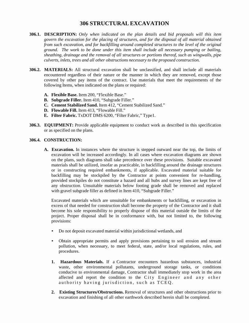
306.1. DESCRIPTION: Only when indicated on the plan details and bid proposals will this item govern the excavation for the placing of structures, and for the disposal of all material obtained from such excavation, and for backfilling around completed structures to the level of the original ground. The work to be done under this item shall include all necessary pumping or bailing, sheathing, drainage and the removal of all structures or portions thereof, such as wingwalls, pipe culverts, inlets, trees and all other obstructions necessary to the proposed construction.
306.2. MATERIALS: All structural excavation shall be unclassified, and shall include all materials
encountered regardless of their nature or the manner in which they are removed, except those covered by other pay items of the contract. Use materials that meet the requirements of the following Items, when indicated on the plans or required:
A. Flexible Base. Item 200, “Flexible Base.” B. Subgrade Filler. Item 410, “Subgrade Filler.” C. Cement Stabilized Sand. Item 412, “Cement Stabilized Sand.” D. Flowable Fill. Item 413, “Flowable Fill.” E. Filter Fabric. TxDOT DMS 6200, “Filter Fabric,” Type1.
306.3. EQUIPMENT: Provide applicable equipment to conduct work as described in this specification
or as specified on the plans.
306.4. CONSTRUCTION:
A. Excavation. In instances where the structure is stepped outward near the top, the limits of excavation will be increased accordingly. In all cases where excavation diagrams are shown on the plans, such diagrams shall take precedence over these provisions. Suitable excavated materials shall be utilized, insofar as practicable, in backfilling around the drainage structures or in constructing required embankments, if applicable. Excavated material suitable for backfilling may be stockpiled by the Contractor at points convenient for re-handling, provided stockpiles do not constitute a hazard and all hubs and survey lines are kept free of any obstruction. Unsuitable materials below footing grade shall be removed and replaced with gravel subgrade filler as defined in Item 410, “Subgrade Filler.”
Excavated materials which are unsuitable for embankments or backfilling, or excavation in excess of that needed for construction shall become the property of the Contractor and it shall become his sole responsibility to properly dispose of this material outside the limits of the project. Proper disposal shall be in conformance with, but not limited to, the following provisions:
• Do not deposit excavated material within jurisdictional wetlands, and
• Obtain appropriate permits and apply provisions pertaining to soil erosion and stream
pollution, when necessary, to meet federal, state, and/or local regulations, rules, and procedures.
1. Hazardous Materials. If a Contractor encounters hazardous substances, industrial
waste, other environmental pollutants, underground storage tanks, or conditions conducive to environmental damage, Contractor shall immediately stop work in the area affected and report the condition to the C i t y E n g i n e e r a n d a n y o t h e r a u t h o r i t y h a v i n g j u r i s d i c t i o n , s u c h a s T C E Q .
2. Existing Structures/Obstructions. Removal of structures and other obstructions prior to
excavation and finishing of all other earthwork described herein shall be completed.
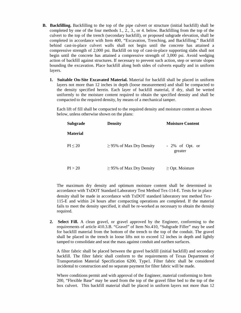
B. Backfilling. Backfilling to the top of the pipe culvert or structure (initial backfill) shall be
completed by one of the four methods 1., 2., 3., or 4. below. Backfilling from the top of the culvert to the top of the trench (secondary backfill), or proposed subgrade elevation, shall be completed in accordance with Item 400, “Excavation, Trenching, and Backfilling.” Backfill behind cast-in-place culvert walls shall not begin until the concrete has attained a compressive strength of 2,000 psi. Backfill on top of cast-in-place supporting slabs shall not begin until the concrete has attained a compressive strength of 3,000 psi. Avoid wedging action of backfill against structures. If necessary to prevent such action, step or serrate slopes bounding the excavation. Place backfill along both sides of culverts equally and in uniform layers.
1. Suitable On-Site Excavated Material. Material for backfill shall be placed in uniform
layers not more than 12 inches in depth (loose measurement) and shall be compacted to the density specified herein. Each layer of backfill material, if dry, shall be wetted uniformly to the moisture content required to obtain the specified density and shall be compacted to the required density, by means of a mechanical tamper.
Each lift of fill shall be compacted to the required density and moisture content as shown below, unless otherwise shown on the plans:
Subgrade
Material
Density Moisture Content
PI ≤ 20
≥ 95% of Max Dry Density
- 2% of Opt. or greater
PI > 20
≥ 95% of Max Dry Density
≥ Opt. Moisture
The maximum dry density and optimum moisture content shall be determined in accordance with TxDOT Standard Laboratory Test Method Tex-114-E. Tests for in place density shall be made in accordance with TxDOT standard laboratory test method Tex- 115-E and within 24 hours after compacting operations are completed. If the material fails to meet the density specified, it shall be re-worked as necessary to obtain the density required.
2. Select Fill. A clean gravel, or gravel approved by the Engineer, conforming to the requirements of article 410.3.B. “Gravel” of Item No.410, “Subgrade Filler” may be used for backfill material from the bottom of the trench to the top of the conduit. The gravel shall be placed in the trench in loose lifts not to exceed 12 inches in depth and lightly tamped to consolidate and seat the mass against conduit and earthen surfaces.
A filter fabric shall be placed between the gravel backfill (initial backfill) and secondary backfill. The filter fabric shall conform to the requirements of Texas Department of Transportation Material Specification 6200, Type1. Filter fabric shall be considered incidental to construction and no separate payment for filter fabric will be made.
Where conditions permit and with approval of the Engineer, material conforming to Item 200, “Flexible Base” may be used from the top of the gravel filter bed to the top of the box culvert. This backfill material shall be placed in uniform layers not more than 12
inches in depth (loose measurement) and shall be compacted to the required density. Each layer of material, if dry, shall be wetted uniformly to the moisture content required to obtain the specified density and shall be compacted to the required density by means of a mechanical tamper.
Compaction of the Flexible Base shall be such that the density of each layer shall be not less than 95% of the maximum dry density as determined by TxDOT Standard Laboratory Test Method TEX-113-E, unless otherwise shown on the plans.
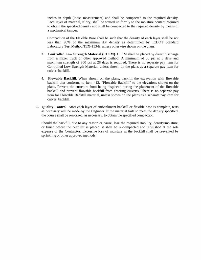
3. Controlled Low Strength Material (CLSM). CLSM shall be placed by direct discharge
from a mixer truck or other approved method. A minimum of 30 psi at 3 days and maximum strength of 800 psi at 28 days is required. There is no separate pay item for Controlled Low Strength Material, unless shown on the plans as a separate pay item for culvert backfill.
4. Flowable Backfill. When shown on the plans, backfill the excavation with flowable
backfill that conforms to Item 413, “Flowable Backfill” to the elevations shown on the plans. Prevent the structure from being displaced during the placement of the flowable backfill and prevent flowable backfill from entering culverts. There is no separate pay item for Flowable Backfill material, unless shown on the plans as a separate pay item for culvert backfill.
C. Quality Control. After each layer of embankment backfill or flexible base is complete, tests
as necessary will be made by the Engineer. If the material fails to meet the density specified, the course shall be reworked, as necessary, to obtain the specified compaction.
Should the backfill, due to any reason or cause, lose the required stability, density/moisture, or finish before the next lift is placed, it shall be re-compacted and refinished at the sole expense of the Contractor. Excessive loss of moisture in the backfill shall be prevented by sprinkling or other approved methods.
307 CONCRETE STRUCTURES
307.1. DESCRIPTION: Construct concrete structures.
307.2. MATERIALS:
A. Concrete. Provide concrete conforming to Item 300, “Concrete.” For each type of structure or unit, provide the class of concrete shown on the plans or in pertinent governing specifications.
B. Grout or Mortar. Provide grout or mortar conforming to Section 300.2.F, “Mortar and
Grout.”
C. Latex. Provide an acrylic-polymer latex admixture (acrylic resin emulsion per TxDOT’s DMS-4640, “Chemical Admixtures for Concrete”) suitable for producing polymer-modified concrete or mortar. Do not allow latex to freeze.
D. Reinforcing Steel. Provide reinforcing steel conforming to Item 301, “Reinforcing Steel.”
E. Expansion Joint Material. Provide materials that conform to the requirements of TxDOT’s
DMS-6310, “Joint Sealants and Fillers”:
• Provide preformed fiber expansion joint material that conforms to the dimensions shown on the plans. Provide preformed bituminous fiber material unless otherwise specified.
• Provide a Class 4, 5, or 7 low-modulus silicone sealant unless otherwise directed.
• Provide asphalt board that conforms to dimensions shown on the plans.
• Provide re-bonded neoprene filler that conforms to the dimensions shown on the plans.
F. Waterstop. Provide rubber or polyvinyl chloride (PVC) waterstops that conform to TxDOT’s
DMS-6160, “Waterstops, Nylon Reinforced Neoprene Sheet, and Elastomeric Pads,” unless otherwise shown on the plans.
G. Evaporation Retardants. Provide evaporation retardants that conform to the requirements of
TxDOT’s DMS-4650, “Hydraulic Cement Concrete Curing Materials and Evaporation Retardants.”
H. Curing Materials. Provide membrane curing compounds that conform to the requirements of
TxDOT’s DMS-4650, “Hydraulic Cement Concrete Curing Materials and Evaporation Retardants.”
Provide cotton mats that consist of a filling material of cotton “bat” or “bats” (at least 12 ounces per square yard) completely covered with unsized cloth (at least 6 oz. per square yard) stitched longitudinally with continuous parallel rows of stitching spaced at less than 4 inches, or tuft both longitudinally and transversely at intervals less than 3 inches. Provide cotton mats that are free from tears and in good general condition. Provide a flap at least 6 inches wide consisting of 2 thicknesses of the covering and extending along 1 side of the mat.
Provide polyethylene sheeting that is at least 4 mils thick and free from visible defects. Provide only clear or opaque white sheeting when the ambient temperature during curing exceeds 60°F or when applicable to control temperature during mass pours.
Provide burlap-polyethylene mats made from burlap impregnated on 1 side with a film of
opaque white pigmented polyethylene, free from visible defects. Provide laminated mats that have at least 1 layer of an impervious material such as polyethylene, vinyl plastic, or other acceptable material (either as a solid sheet or impregnated into another fabric) and are free of visible defects.
I. Epoxy. Unless otherwise specified, provide epoxy materials that conform to TxDOT’s DMS-
6100, “Epoxy and Adhesives.”
J. Cast Iron Castings. Provide cast iron castings that conform to Item 409, “Cast Iron Castings.”
K. Metal for Structures. Provide metal for structures that conform to Item 302, “Metal for
Structures.”
307.3. EQUIPMENT:
A. Fogging Equipment. Use fogging equipment that can apply water in a fine mist, not a spray. Produce the fog using equipment that pumps water or water and air under high pressure through a suitable atomizing nozzle. Use hand-held mechanical equipment portable enough to use in the direction of any prevailing wind and adaptable for intermittent use to prevent excessive wetting of the concrete.
B. Transporting and Placing Equipment. Use appropriate transporting and placing equipment
such as buckets, chutes, buggies, belt conveyors, pumps, or other equipment as necessary. Do not transport or convey concrete through equipment made of aluminum. Use carts with pneumatic tires for carting or wheeling concrete over newly placed slabs.
Use tremies to control the fall of concrete or for underwater placement. Use tremies that are watertight and of large enough diameter to allow the placement of the concrete but less than 14 inches in diameter. For underwater placements, construct the tremie so that the bottom can be sealed and opened once the tremie has been fully charged with concrete.
Use pumps with lines at least 5 inches I.D. where Grade 2 or smaller coarse aggregate is used and at least 8 inches I.D. for Grade 1 coarse aggregate.
C. Vibrators. Use immersion-type vibrators that maintain a speed of 6,000 impulses per minute
for consolidation of concrete. Provide at least 1 standby vibrator for emergency use.
D. Screeds and Work Bridges for Bridge Slabs. For bridge slabs use a self-propelled transverse screed or a mechanical longitudinal screed. Use transverse screeds that are able to follow the skew of the bridge for skews greater than 15° unless otherwise approved. Equip transverse screeds with a pan float. Manually operated screeding equipment may be used if approved for top slabs of culverts, small placements, or unusual conditions. Use screeds that are rigid and heavy enough to hold true to shape and have sufficient adjustments to provide for the required camber or section. Equip the screeds, except those of the roller drum type, with metal cutting edges.
For bridge slabs, use sufficient work bridges for finishing operations. Mount a carpet drag to a work bridge or a moveable support system that can vary the area of carpet in contact with the concrete. Use carpet pieces long enough to cover the entire width of the placement. Splice or overlap the carpet as necessary. Confirm that enough carpet is in contact longitudinally with the concrete being placed to provide the desired surface finish. Use artificial grass-type carpeting having a molded polyethylene pile face with a blade length between 5/8 and 1 inch and with a minimum weight of 70 oz. per square yard. Confirm that the carpet has a strong, durable backing not subject to rot and that the facing is adequately bonded to the backing to
withstand the intended use. A burlap drag, attached to the pan float on a transverse screed, may be used instead of the carpet drag.
E. Temperature Recording Equipment. For mass concrete operations or as otherwise
specified, use strip chart temperature recording devices, recording maturity meters in accordance with TxDOT standard laboratory test procedure Tex-426-A, or other approved devices that are accurate to within ±2°F within the range of 32 to 212°F.
F. Artificial Heating Equipment. Use artificial heating equipment as necessary for maintaining
the concrete temperatures as specified in Section 307.4.G.11, “Placing Concrete in Cold Weather.”
G. Sawing Equipment. Use sawing equipment capable of cutting grooves in completed bridge
slabs and top slabs of direct-traffic culverts. Provide grooves that are 1/8 to 3/16 inch deep and nominally 1/8 inch wide. Groove spacing may range from 5/8 to 1 inch. Use sawing equipment capable of cutting grooves in hardened concrete to within 18 inches of the barrier rail or curb.
H. Spraying Equipment. Use mechanically powered pressure sprayers, either air or airless,
with appropriate atomizing nozzles for the application of membrane curing. Mechanically driven spraying equipment, adaptable to the rail system used by the screeds, may be used for applying membrane curing to bridge slabs. If approved, use hand-pressurized spray equipment equipped with 2 or 3 fan-spray nozzles. Confirm that the spray from each nozzle overlaps the spray from adjacent nozzles by approximately 50%.
I. Concrete Testing Equipment. Provide testing equipment for use by the Engineer in
accordance with Section 300.3.C, “Testing Equipment.”
307.4. CONSTRUCTION: Before starting work, obtain approval for proposed construction methods. Approval of construction methods and equipment does not relieve the Contractor’s responsibility for safety or correctness of methods, adequacy of equipment, or completion of work in full accordance with the Contract.
Unless otherwise shown on the plans, it is the Contractor’s option to perform testing on structural concrete (structural classes of concrete are identified in Table 5 of Section 300.4.A, “Classification and Mix Design”) to determine the in-situ strength to address the schedule restrictions in Section 307.4.A, “Schedule Restrictions.” The Engineer may require the Contractor to perform this testing for concrete placed in cold weather. For Contractor-performed testing, make enough test specimens to confirm that strength requirements are met for the operations listed in Section 307.4.A. Make at least 1 set of test specimens for each element cast each day. Cure these specimens under the same conditions as the portion of the structure involved for all stages of construction. Confirm safe handling, curing, and storage of all test specimens. Provide testing personnel, and sample and test the hardened concrete in accordance with Section 300.4.G, “Sampling and Testing of Concrete.” The maturity method, TxDOT standard laboratory test procedure Tex-426-A, may be used for in-situ strength determination for schedule restrictions if approved. Coring will not be allowed for in-situ strength determination for schedule restrictions. Provide the Engineer the opportunity to witness all testing operations. Report all test results to the Engineer.
If the Contractor does not wish to perform schedule restriction testing, the Engineer’s 7 day lab- cured tests, performed in accordance with Section 300.4.G.5, “Adequacy and Acceptance of Concrete,” will be used for schedule restriction determinations. The Engineer may require additional time for strength gain to account for field curing conditions such as cold weather.
A. Schedule Restrictions. Unless otherwise shown on the plans, construct and open completed
structures to traffic with the following limitations:
1. Setting Forms. Attain at least 2,500 psi compressive strength before erecting forms on concrete footings supported by piling or drilled shafts, or on individual drilled shafts. Erect forms on spread footings and culvert footings after the footing concrete has aged at least 2 curing days as defined in Section 307.4.J, “Curing Concrete.” Place concrete only after the forms and reinforcing steel have been inspected by the Engineer.
Support tie beam or cap forms by falsework on previously placed tie beams only if the tie beam concrete has attained a compressive strength of 2,500 psi and the member is properly supported to eliminate stresses not provided for in the design. Maintain curing as required until completion of the curing period.
Place superstructure forms or falsework on the substructure only if the substructure concrete has attained a compressive strength of 3,000 psi.
2. Removal of Forms and Falsework. Keep in place weight-supporting forms and
falsework for bridge components and culvert slabs until the concrete has attained a compressive strength of 2,500 psi in accordance with Section 307.4.K, “Removal of Forms and Falsework.” Keep all forms for mass placements defined in Section 307.4.G.14, “Mass Placements,” in place for 4 days following concrete placement.
3. Placement of Superstructure Members. Do not place superstructure members before
the substructure concrete has attained a compressive strength of 3,000 psi.
4. Longitudinal Screeding of Bridge Slabs. Place a longitudinal screed directly on previously placed concrete slabs to check and grade an adjacent slab only after the previously placed slab has aged at least 24 hours. Place and screed the concrete after the previously placed slabs have aged at least 48 hours. Maintain curing of the previously placed slabs during placement.
5. Staged Placement of Bridge Slabs on Continuous Steel Units. When staged placement
of a slab is required, confirm that the previously placed concrete attains a compressive strength of 3,000 psi before placing the next stage placement. Multiple stages may be placed in a single day if approved.
6. Storage of Materials on the Structure. Obtain approval to store materials on completed
portions of a structure once a compressive strength of 3,000 psi has been attained. Maintain proper curing if materials will be stored on structures before completion of curing.
7. Placement of Equipment and Machinery. Do not place erection equipment or machinery on the structure until the concrete has attained the design strength specified in Section 300.4.A, “Classification and Mix Design,” unless otherwise approved.
8. Carting of Concrete. Once the concrete has attained a compressive strength of 3,000 psi,
it may be carted, wheeled, or pumped over completed slabs. Maintain curing during these operations.
9. Placing Bridge Rails. Reinforcing steel and concrete for bridge rails may be placed on
bridge slabs once the slab concrete has attained a compressive strength of 3,000 psi. If slipforming methods are used for railing concrete, confirm the slab concrete has attained its design strength specified in Section 300.4.A, “Classification and Mix Design,” before placing railing concrete.
10. Opening to Construction Traffic. Bridges and direct-traffic culverts may be opened to
all construction traffic when the design strength specified in Section 300.4.A, “Classification and Mix Design,” has been attained if curing is maintained.
11. Opening to Full Traffic. Bridges and direct-traffic culverts may be opened to the traveling public when the design strength specified in Section 300.4.A, “Classification and Mix Design,” has been attained for all structural elements including railing subject to impact from traffic, when curing has been completed for all slabs, and when the concrete surface treatment has been applied in accordance with TxDOT’s Item 428, “Concrete Surface Treatment.” Obtain approval before opening bridges and direct-traffic culverts to the traveling public. Other noncritical structural and nonstructural concrete may be opened for service upon the completion of curing unless otherwise specified or directed.
12. Post-Tensioned Construction. For structural elements designed to be post-tensioned
confirm that strength requirements on the plans are met for stressing and staged loading of structural elements.
13. Backfilling. Backfill in accordance with TxDOT’s Section 400.3.C, “Backfill.”
B. Plans for Falsework and Forms. Submit 2 copies of plans for falsework and forms for piers,
superstructure spans over 20 feet long, bracing systems for girders when the overhang exceeds 3 feet 6 inches, and bridge widening details. Submit similar plans for other units of the structure as directed. Show all essential details of proposed forms, falsework, and bracing. Have a licensed professional engineer design, seal, and sign these plans. City approval is not required, but the City reserves the right to request modifications to the plans. The Contractor is responsible for the adequacy of these plans.
C. Falsework. Design and construct falsework to carry the maximum anticipated loads safely,
including wind loads, and to provide the necessary rigidity. Submit details in accordance with Section 307.4.B, “Plans for Falsework and Forms.”
Design job-fabricated falsework assuming a weight of 150 pcf for concrete, and include a liveload allowance of 50 psf of horizontal surface of the form. Do not exceed 125% of the allowable stresses used by the City for the design of structures.
For commercially produced structural units used in falsework, do not exceed the manufacturer’s maximum allowable working loads for moment and shear or end reaction.
Include a liveload allowance of 35 psf of horizontal form surface in determining the maximum allowable working load for commercially produced structural units.
Provide timber that is sound, in good condition, and free from defects that would impair its strength. Provide timber that meets or exceeds the species, size, and grade requirements in the submitted falsework plans.
Provide wedges made of hardwood or metal in pairs to adjust falsework to desired elevations to confirm even bearing. Do not use wedges to compensate for incorrectly cut bearing surfaces.
Use sills or grillages that are large enough to support the superimposed load without settlement. Take precautions to prevent settling of the supporting material unless the sills or grillages are founded on solid rock, shale, or other hard materials.
Place falsework that cannot be founded on a satisfactory spread footing on piling or drilled shafts with enough bearing capacity to support the superimposed load without settlement. Drive falsework piling to the required resistance determined by the applicable formula in TxDOT Item 404, “Driving Piling.” Design drilled shafts for falsework to carry the
superimposed load using both skin friction and point bearing.
Weld in conformance with TxDOT Item 448, “Structural Field Welding.” Securely brace each falsework bent to provide the stiffness required, and securely fasten the bracing to each pile or column it crosses.
Remove falsework when it is no longer required or as indicated on the submitted falsework plan. Pull or cut off foundations for falsework at least 2 feet below finished ground level. Completely remove falsework, piling, or drilled shafts in a stream, lake, or bay to the approved limits to prevent obstruction to the waterway.
D. Forms. Submit formwork plans in accordance with Section 307.4.B, “Plans for Falsework
and Forms.”
1. General. Except where otherwise specified or permitted, provide forms of either timber or metal.
Design forms for the pressure exerted by a liquid weighing 150 pcf. Take the rate of concrete placement into consideration in determining the depth of the equivalent liquid. Include a liveload allowance of 50 psf of horizontal surface for job-fabricated forms. Do not exceed 125% of the allowable stresses used by the City for the design of structures.
For commercially produced structural units used for forms, do not exceed the manufacturer’s maximum allowable working loads for moment and shear or end reaction. Include a liveload allowance of 35 psf of horizontal form surface in determining the maximum allowable working load for commercially produced structural units.
Provide steel forms for round columns unless otherwise approved. Refer to Item 311, “Concrete Surface Finish,” for additional requirements for off-the-form finishes.
Provide commercial form liners for imprinting a pattern or texture on the concrete surface as shown on the plans and specified in TxDOT’s Section 427.4.B.2.d, “Form Liner Finish.”
Provide forming systems that are practically mortar-tight, rigidly braced, and strong enough to prevent bulging between supports, and maintain them to the proper line and grade during concrete placement. Maintain forms in a manner that prevents warping and shrinkage. Do not allow offsets at form joints to exceed 1/16 inch.
For forms to be left in place, use only material that is inert, non-biodegradable, and non- absorptive.
Attachment of forms or screed supports for bridge slabs to steel I beams or girders may be by welding subject to the following requirements:
• Do not weld to tension flanges or to areas indicated on the plans.
• Weld in accordance with Item 448, “Structural Field Welding.”
Take into account:
• deflections due to cast-in-place slab concrete and railing shown in the dead load deflection diagram in the setting of slab forms,
• differential beam or girder deflections due to skew angles and the use of certain stay-
in-place slab forming systems, and
• deflection of the forming system due to the wet concrete.
For bridge approach slabs, securely stake forms to line and grade and maintain in position. Rigidly attach inside forms for curbs to the outside forms.
Construct all forms to permit their removal without marring or damaging the concrete. Clean all forms and footing areas of any extraneous matter before placing concrete. Provide openings in forms if needed for the removal of laitance or foreign matter
Treat the facing of all forms with bond-breaking coating of composition that will not discolor or injuriously affect the concrete surface. Take care to prevent coating of the reinforcing steel.
Complete all preparatory work before requesting permission to place concrete.
If the forms show signs of bulging or sagging at any stage of the placement, cease placement and remove the portion of the concrete causing this condition immediately if necessary. Reset the forms and securely brace them against further movement before continuing the placement.
2. Timber Forms. Provide properly seasoned good-quality lumber that is free from
imperfections that would affect its strength or impair the finished surface of the concrete. Provide timber or lumber that meets or exceeds the requirements for species and grade in the submitted formwork plans.
Maintain forms or form lumber that will be reused so that it stays clean and in good condition. Do not use any lumber that is split, warped, bulged, or marred or that has defects that will produce inferior work, and promptly remove such lumber from the work.
Provide form lining for all formed surfaces except:
• the inside of culvert barrels, inlets, manholes, and box girders;
• the bottom of bridge slabs between beams or girders;
• surfaces that are subsequently covered by backfill material or are completely
enclosed; and
• any surface formed by a single finished board or by plywood.
Provide form lining of an approved type such as masonite or plywood. Do not provide thin membrane sheeting such as polyethylene sheets for form lining.
Use plywood at least ¾ inch thick. Place the grain of the face plies on plywood forms parallel to the span between the supporting studs or joists unless otherwise indicated on the submitted form drawings.
Use plywood for forming surfaces that remain exposed that meets the requirements for B- B Plyform Class I or Class II Exterior of the U.S. Department of Commerce Voluntary Product Standard PS 1.
Space studs and joists so that the facing form material remains in true alignment under the imposed loads.
Space wales closely enough to hold forms securely to the designated lines, scabbed at
least 4 feet on each side of joints to provide continuity. Place a row of wales near the bottom of each placement.
Place facing material with parallel and square joints, securely fastened to supporting studs.
For surfaces exposed to view and receiving only an ordinary surface finish as defined in Section 307.4.M, “Ordinary Surface Finish,” place forms with the form panels symmetrical (long dimensions set in the same direction). Make horizontal joints continuous.
Make molding for chamfer strips or other uses of materials of a grade that will not split when nailed and that can be maintained to a true line without warping. Dress wood molding on all faces. Unless otherwise shown on the plans, fill forms at all sharp corners and edges with triangular chamfer strips measuring 3/4 inch on the sides.
To hold forms in place, use metal form ties of an approved type or a satisfactory substitute of a type that permits ease of removal of the metal. Cut back wire ties at least ½ inch from the face of the concrete.
Use devices to hold metal ties in place that are able to develop the strength of the tie and adjust to allow for proper alignment.
Entirely remove metal and wooden spreaders that separate the forms as the concrete is being placed.
Provide adequate clean-out openings for narrow walls and other locations where access to the bottom of the forms is not readily attainable.
3. Metal Forms. Requirements for timber forms regarding design, mortar-tightness, filleted
corners, beveled projections, bracing, alignment, removal, reuse, and wetting also apply to metal forms except that metal forms do not require lining unless specifically noted on the plans.
Use form metal thick enough to maintain the true shape without warping or bulging. Countersink all bolt and rivet heads on the facing sides. Design clamps, pins, or other connecting devices to hold the forms rigidly together and to allow removal without damage to the concrete. Use metal forms that present a smooth surface and that line up properly. Keep metal free from rust, grease, and other foreign materials.
4. Form Supports for Overhang Slabs. Form supports that transmit a horizontal force to a
steel girder or beam or to a prestressed concrete beam are permitted provided a satisfactory structural analysis has been made of the effect on the girder or beam as indicated in the submitted formwork plans.
When overhang brackets are used on prestressed concrete beam spans with slab overhangs not exceeding 3 feet 6 inches, use beam bracing as indicated in the plans. For spans with overhangs exceeding this amount, use additional support for the outside beams regardless of the type of beam used. Submit details of the proposed bracing system in accordance with Section 307.4.B, “Plans for Falsework and Forms.”
Punch or drill holes full size in the webs of steel members for support of overhang brackets, or torch-cut them to 1/4 inch under size and ream them full size. Do not burn the holes full size. Leave the holes open unless otherwise shown on the plans. Never fill the holes by welding.
E. Drains. Install and construct weep holes and roadway drains as shown on the plans.
F. Placing Reinforcement. Place reinforcement as provided in Item 301, “Reinforcing Steel.” Do not weld reinforcing steel supports to I beams or girders or to reinforcing steel except where shown on the plans.
Place post-tensioning ducts in accordance with the approved prestressing details and in accordance with TxDOT’s Item 426, “Prestressing.” Keep ducts free of obstructions until all post-tensioning operations are complete.
G. Placing Concrete. Give the Engineer sufficient advance notice before placing concrete in
any unit of the structure to permit the inspection of forms, reinforcing steel placement, and other preparations.
Follow the sequence of placing concrete shown on the plans or specified.
Do not place concrete when impending weather conditions would impair the quality of the finished work. If conditions of wind, humidity, and temperature are such that concrete cannot be placed without the potential for shrinkage cracking, place concrete in early morning or at night or adjust the placement schedule for more favorable weather. Consult the evaporation rate nomograph in the Portland Cement Association’s Design and Control of Concrete Mixtures for shrinkage cracking potential. When mixing, placing, and finishing concrete in non-daylight hours, adequately illuminate the entire placement site as approved.
If changes in weather conditions require protective measures after work starts, furnish adequate shelter to protect the concrete against damage from rainfall or from freezing temperatures as outlined in this Item. Continue operations during rainfall only if approved. Use protective coverings for the material stockpiles. Cover aggregate stockpiles only to the extent necessary to control the moisture conditions in the aggregates.
Allow at least 1 curing day after the concrete has achieved initial set before placing strain on projecting reinforcement to prevent damage to the concrete.
1. Placing Temperature. Place concrete according to the following temperature limits for
the classes of concrete defined in Section 300.4.A, “Classification and Mix Design”:
• Place Class C, F, H, K, or SS concrete only when its temperature at time of placement is between 50 and 95°F. Increase the minimum placement temperature to 60°F if ground-granulated blast furnace (GGBF) slag is used in the concrete.
• When used in a bridge slab or in the top slab of a direct-traffic culvert, place Class
CO, DC, or S concrete only when its temperature at the time of placement is between 50 and 85°F. Increase the minimum placement temperature to 60°F if GGBF slag is used in the concrete. The maximum temperature increases to 95°F if these classes are used for other applications.
• Place Class A, B, and D concrete only when its temperature at the time of placement
is greater than 50°F.
• Place mass concrete, defined by Section 307.4.G.14, “Mass Placements,” only when its temperature at the time of placement is between 50 and 75°F.
2. Transporting Time. Place concrete delivered in agitating trucks within 60 minutes after
batching. Place concrete delivered in non-agitating equipment within 45 minutes after batching. Revise the concrete mix design as necessary for hot weather or other conditions
that contribute to quick setting of the concrete. Submit for approval a plan to demonstrate that these time limitations can be extended while ensuring the concrete can be properly placed, consolidated, and finished without the use of additional water.
3. Workability of Concrete. Place concrete with a slump as specified in Section 300.4.A.5,
“Slump.” Concrete that exceeds the maximum slump will be rejected. Water may be added to the concrete before discharging any concrete from the truck to adjust for low slump provided that the maximum mix design water–cement ratio is not exceeded. After introduction of any additional water or chemical admixtures, mix concrete in accordance with Section 300.4.E, “Mixing and Delivering Concrete.” Do not add water or chemical admixtures after any concrete has been discharged.
4. Transporting Concrete. Use a method and equipment capable of maintaining the rate of
placement shown on the plans or required by this Item to transport concrete to the forms. Transport concrete by buckets, chutes, buggies, belt conveyors, pumps, or other methods.
Protect concrete transported by conveyors from sun and wind to prevent loss of slump and workability. Shade or wrap with wet burlap pipes through which concrete is pumped as necessary to prevent loss of slump and workability.
Arrange and use chutes, troughs, conveyors, or pipes so that the concrete ingredients will not be separated. When necessary to prevent segregation, terminate such equipment in vertical downspouts. Extend open troughs and chutes, if necessary, down inside the forms or through holes left in the forms.
Keep all transporting equipment clean and free from hardened concrete coatings. Discharge water used for cleaning clear of the concrete.
5. Preparation of Surfaces. Thoroughly wet all forms, prestressed concrete panels, T
beams, and concrete box beams on which concrete is to be placed before placing concrete on them. Remove any remaining puddles of excess water before placing concrete. Provide surfaces that are in a moist, saturated surface-dry condition when concrete is placed on them.
Confirm that the subgrade or foundation is moist before placing concrete for bridge approach slabs or other concrete placed on grade. Lightly sprinkle the subgrade if dry.
6. Expansion Joints. Construct joints and devices to provide for expansion and contraction
in accordance with plan details and the requirements of this Section and TxDOT’s Item 454, “Bridge Expansion Joints.”
Prevent bridging of concrete or mortar around expansion joint material in bearings and expansion joints.
Use forms adaptable to loosening or early removal in construction of all open joints and joints to be filled with expansion joint material. To avoid expansion or contraction damage to the adjacent concrete, loosen these forms as soon as possible after final concrete set to permit free movement of the span without requiring full form removal.
When the plans show a Type A joint, provide preformed fiber joint material in the vertical joints of the roadway slab, curb, median, or sidewalk, and fill the top 1 inch with the specified joint sealing material unless noted otherwise. Install the sealer in accordance with TxDOT’s Item 438, “Cleaning and Sealing Joints and Cracks (Rigid Pavement and Bridge Decks),” and the manufacturer’s recommendations.
Use light wire or nails to anchor any preformed fiber joint material to the concrete on 1
side of the joint.
Confirm that finished joints conform to the plan details with the concrete sections completely separated by the specified opening or joint material.
Remove all concrete within the joint opening soon after form removal and again where necessary after surface finishing to confirm full effectiveness of the expansion joint.
7. Construction Joints. A construction joint is the joint formed by placing plastic concrete
in direct contact with concrete that has attained its initial set. Monolithic placement means that the manner and sequence of concrete placing does not create a construction joint.
Make construction joints of the type and at the locations shown on the plans. Do not make joints in bridge slabs not shown on the plans unless approved. Additional joints in other members are not permitted without approval. Place authorized additional joints using details equivalent to those shown on the plans for joints in similar locations.
Unless otherwise required, make construction joints square and normal to the forms. Use bulkheads in the forms for all vertical joints.
Thoroughly roughen the top surface of a concrete placement terminating at a horizontal construction joint as soon as practical after initial set is attained.
Thoroughly clean the hardened concrete surface of all loose material, laitance, dirt, and foreign matter, and saturate it with water. Remove all free water and moisten the surface before concrete or bonding grout is placed against it.
Draw forms tight against the existing concrete to avoid mortar loss and offsets at joints.
Coat the joint surface with bonding mortar, grout, epoxy, or other material as indicated in the plans or other Items. Provide Type V epoxy per TxDOT’s DMS-6100, “Epoxies and Adhesives,” for bonding fresh concrete to hardened concrete. Place the bonding epoxy on a clean, dry surface, and place the fresh concrete while the epoxy is still tacky. Place bonding mortar or grout on a surface that is saturated surface-dry, and place the concrete before the bonding mortar or grout dries. Place other bonding agents in accordance with the manufacturer’s recommendations.
8. Handling and Placing. Minimize segregation of the concrete and displacement of the
reinforcement when handling and placing concrete. Produce a uniform dense compact mass.
Do not allow concrete to free-fall more than 5 feet except in the case of drilled shafts, thin walls such as in culverts, or as allowed by other Items. Remove any hardened concrete splatter ahead of the plastic concrete.
Fill each part of the forms by depositing concrete as near its final position as possible. Do not deposit large quantities at 1 point and run or work the concrete along the forms.
Deposit concrete in the forms in layers of suitable depth but not more than 36 inches deep unless otherwise permitted.
Avoid cold joints in a monolithic placement. Sequence successive layers or adjacent portions of concrete so that they can be vibrated into a homogeneous mass with the previously placed concrete before it sets. When re-vibration of the concrete is shown on the plans, allow at most 1 hour to elapse between adjacent or successive placements of
concrete except as otherwise allowed by an approved placing procedure. This time limit may be extended by ½ hour if the concrete contains at least a normal dosage of retarding admixture.
Use an approved retarding agent to control stress cracks and cold joints in placements where differential settlement and setting time may induce cracking.
9. Consolidation. Carefully consolidate concrete and flush mortar to the form surfaces with
immersion type vibrators. Do not use vibrators that operate by attachment to forms or reinforcement except where approved on steel forms.
Vibrate the concrete immediately after deposit. Systematically space points of vibration to confirm complete consolidation and thorough working of the concrete around the reinforcement, embedded fixtures, and into the corners and angles of the forms. Insert the vibrator vertically where possible except for slabs where it may be inserted in a sloping or horizontal position. Vibrate the entire depth of each lift, allowing the vibrator to penetrate several inches into the preceding lift. Do not use the vibrator to move the concrete to other locations in the forms. Do not drag the vibrator through the concrete. Thoroughly consolidate concrete along construction joints by operating the vibrator along and close to but not against the joint surface. Continue the vibration until the concrete surrounding reinforcements and fixtures is completely consolidated. Hand-spade or rod the concrete if necessary to confirm flushing of mortar to the surface of all forms.
10. Installation of Dowels and Anchor Bolts. Install dowels and anchor bolts by casting
them in-place or by grouting with grout, epoxy, or epoxy mortar unless noted otherwise. Form or drill holes for grouting.
Drill holes for anchor bolts to accommodate the bolt embedment required by the plans. Make holes for dowels at least 12 inches deep unless otherwise shown on the plans. When using grout or epoxy mortar, make the diameter of the hole at least twice the dowel or bolt diameter, but the hole need not exceed the dowel or bolt diameter plus 1 1/2 inches. When using epoxy, make the hole diameter 1/16 to 1/4 inch greater than the dowel or bolt diameter.
Thoroughly clean holes of all loose material, oil, grease, or other bond-breaking substance, and blow them clean with filtered compressed air. Confirm that holes are in a surface dry condition when epoxy type material is used and in a surface moist condition when hydraulic cement grout is used. Develop and demonstrate for approval a procedure for cleaning and preparing the holes for installation of the dowels and anchor bolts. Completely fill the void between the hole and dowel or bolt with grouting material. Follow exactly the requirements for cleaning outlined in the product specifications for prepackaged systems.
For cast-in-place or grouted systems, provide hydraulic cement grout in accordance with Section 300.2.F, “Mortar and Grout,” epoxy, epoxy mortar, or other prepackaged grouts as approved. Provide a Type III epoxy per TxDOT’s DMS-6100, “Epoxies and Adhesives,” when neat epoxy is used for anchor bolts or dowels. Provide Type VIII epoxy per TxDOT’s DMS-6100 when an epoxy grout is used. Provide grout, epoxy, or epoxy mortar as the binding agent unless otherwise indicated on the plans.
Provide other anchor systems as required in the plans.
11. Placing Concrete in Cold Weather. Protect concrete placed under weather conditions
where weather may adversely affect results. Permission given by the Engineer for placing during cold weather does not relieve the Contractor of responsibility for producing
concrete equal in quality to that placed under normal conditions. If concrete placed under poor conditions is unsatisfactory, remove and replace it as directed at Contractor’s expense.
Do not place concrete in contact with any material coated with frost or having a temperature of 32°F or lower. Do not place concrete when the ambient temperature in the shade is below 40°F and falling unless approved. Concrete may be placed when the ambient temperature in the shade is 35°F and rising or above 40°F.
Provide and install recording thermometers, maturity meters, or other suitable temperature measuring devices to verify that all concrete is effectively protected as follows:
• Maintain the temperature of the top surface of bridge slabs and top slabs of direct-
traffic culverts at 50°F or above for 72 hours from the time of placement and above 40°F for an additional 72 hours.
• Maintain the temperature at all surfaces of concrete in bents, piers, culvert walls,
retaining walls, parapets, wingwalls, bottoms of bridge slab or culvert top slabs, and other similar formed concrete at 40°F or above for 72 hours from the time of placement.
• Maintain the temperature of all other concrete, including the bottom slabs (footings)
of culverts, placed on or in the ground above 32°F for 72 hours from the time of placement.
Use additional covering, insulated forms, or other means and, if necessary, supplement the covering with artificial heating. Avoid applying heat directly to concrete surfaces. Cure as specified in Section 307.4.J, “Curing Concrete,” during this period until all requirements for curing have been satisfied.
When impending weather conditions indicate the possible need for temperature protection, have on hand all necessary heating and covering material, ready for use, before permission is granted to begin placement.
12. Placing Concrete in Hot Weather. Use an approved retarding agent in all concrete for
superstructures and top slabs of direct-traffic culverts, except concrete containing GGBF slag, when the temperature of the air is above 85°F unless otherwise directed.
Keep the concrete at or below the maximum temperature at time of placement as specified in Section 307.4.G.1, “Placing Temperature.” Sprinkle and shade aggregate stockpiles or use ice, liquid nitrogen systems, or other approved methods as necessary to control the concrete temperature.
13. Placing Concrete in Water. Deposit concrete in water only when shown on the plans or
with approval. Make forms or cofferdams tight enough to prevent any water current passing through the space in which the concrete is being deposited. Do not pump water during the concrete placing or until the concrete has set for at least 36 hours.
Place the concrete with a tremie or pump, or use another approved method, and do not allow it to fall freely through the water or disturb it after it is placed. Keep the concrete surface approximately level during placement.
Support the tremie or operate the pump so that it can be easily moved horizontally to cover all the work area and vertically to control the concrete flow. Submerge the lower
end of the tremie or pump hose in the concrete at all times. Use continuous placing operations until the work is complete.
For concrete to be placed under water, design the concrete mix in accordance with Item 300, “Concrete,” with a minimum cement content of 650 pounds per cubic yard. Include an anti-washout admixture in the mix design as necessary to produce a satisfactory finished product.
14. Mass Placements. Mass placements are defined as placements with a least dimension
greater than or equal to 5 feet, or designated on the plans. For monolithic mass placements, develop and obtain approval for a plan to confirm the following during the heat dissipation period:
• the temperature differential between the central core of the placement and the
exposed concrete surface does not exceed 35°F and
• the temperature at the central core of the placement does not exceed 160°F.
Base this plan on the equations given in the Portland Cement Association’s Design and Control of Concrete Mixtures. Cease all mass placement operations and revise the plan as necessary if either of the above limitations is exceeded.
Include a combination of the following elements in this plan:
• selection of concrete ingredients including aggregates, gradation, and cement types,
to minimize heat of hydration;
• use of ice or other concrete cooling ingredients;
• use of liquid nitrogen dosing systems;
• controlling rate or time of concrete placement;
• use of insulation or supplemental external heat to control heat loss;
• use of supplementary cementing materials; or
• use of a cooling system to control the core temperature.
Furnish and install 2 sets of temperature recording devices, maturity meters, or other approved equivalent devices at designated locations. Use these devices to simultaneously measure the temperature of the concrete at the core and the surface. Maintain temperature control methods for 4 days unless otherwise approved. Maturity meters may not be used to predict strength of mass concrete.
15. Placing Concrete in Foundation and Substructure. Do not place concrete in footings
until the depth and character of the foundation has been inspected and permission has been given to proceed by the Engineer.
Placing of concrete footings upon seal concrete is permitted after the cofferdams are free from water and the seal concrete cleaned. Perform any necessary pumping or bailing during the concreting from a suitable sump located outside the forms.
Construct or adjust all temporary wales or braces inside cofferdams as the work proceeds to prevent unauthorized construction joints.
When footings can be placed in a dry excavation without the use of cofferdams, omit forms if approved, and fill the entire excavation with concrete to the elevation of the top of footing.
Place concrete in columns monolithically between construction joints unless otherwise directed. Columns and caps or tie beams supported on them may be placed in the same operation or separately. If placed in the same operation, allow for settlement and shrinkage of the column concrete by placing it to the lower level of the cap or tie beam, and delay placement between 1 and 2 hours before proceeding with the cap or tie beam placement.
16. Placing Concrete in Box Culverts. Where the top slab and walls are placed
monolithically in culverts more than 4 feet in clear height, allow between 1 and 2 hours to elapse before placing the top slab to allow for settlement and shrinkage in the wall concrete.
Accurately finish the footing slab at the proper time to provide a smooth uniform surface. Finish top slabs that carry direct-traffic as specified in this Item. Give top slabs of fill type culverts a float finish.
17. Placing Concrete in Superstructure. Unless otherwise shown on the plans, place simple
span bridge slabs without transverse construction joints by using either a self-propelled transverse finishing machine or a mechanical longitudinal screed. For small placements or for unusual conditions such as narrow widening, variable cross slopes, or transitions, use of manually operated screeding equipment may be permitted. Support the screed adequately on a header or rail system stable enough to withstand the longitudinal or lateral thrust of the equipment. Adjust the profile grade line as necessary to account for variations in beam camber and other factors to obtain the required slab thickness and concrete cover over the slab reinforcement. Set beams and verify their surface elevations in a sufficient number of spans so that when adjustment is necessary, the profile grade line can be adjusted over suitable increments to produce a smooth riding surface. Take dead load deflection into account in setting the grades of headers and rail systems. Use construction joints, when required or permitted for slab placements on steel or prestressed concrete beams, as shown on the plans. Before placing concrete on steel girder or truss spans, release falsework under the spans and swing the spans free on their permanent supports.
Make 1 or more passes with the screed over the bridge slab segment before placing concrete on it to confirm proper operation and maintenance of grades and clearances. Use an approved system of checking to detect any vertical movement of the forms or falsework. Maintain forms for the bottom surface of concrete slabs, girders, and overhangs to the required vertical alignment during concrete placing.
Fog unformed surfaces of slab concrete in bridge slabs and in top slabs of direct-traffic culverts from the time of initial strikeoff of the concrete until finishing is completed and required interim curing is in place. Do not use fogging as a means to add finishing water, and do not work moisture from the fog spray into the fresh concrete.
For simple spans, retard the concrete only if necessary to complete finishing operations or as required by this Section. When filling curb forms, bring the top of curb and sidewalk section to the correct camber and alignment, and finish them as described in this Item.
a. Transverse Screeding. Install rails for transverse finishing machines that are
supported from the beams or girders so that the supports may be removed without damage to the slab. Prevent bonding between removable supports and the concrete in an acceptable manner. Do not allow rail support parts that remain embedded in the slab to project above the upper mat of reinforcing steel. Rail or screed supports attached to I beams or girders are subject to the requirements of this Item. Unless otherwise shown on the plans, for transverse screeding the minimum rate of concrete placement is 30 linear feet of bridge slab per hour. Deposit concrete parallel to the skew of the bridge so that all girders are loaded uniformly along their length. Deposit slab concrete between the exterior beam and the adjacent beam before placing concrete in the overhang portion of the slab. Furnish personnel and equipment capable of placing, finishing, and curing the slab at an acceptable rate to confirm compliance with the specifications. Place concrete in transverse strips. On profile grades greater than 1½%, start placement at the lowest end.
b. Longitudinal Screeding. Unless otherwise shown on the plans, use of temporary
intermediate headers will be permitted for placements over 50 feet long if the rate of placement is rapid enough to prevent a cold joint and if these headers are designed for easy removal to permit satisfactory consolidation and finish of the concrete at their locations. Deposit slab concrete between the exterior beam and the adjacent beam before placing concrete in the overhang portion of the slab. Place concrete in longitudinal strips starting at a point in the center of the segment adjacent to 1 side except as this Section indicates, and complete the strip by placing uniformly in both directions toward the ends. For spans on a profile grade of 1½% or more, start placing at the lowest end. Use strips wide enough that the concrete within each strip remains plastic until placement of the adjacent strip. Where monolithic curb construction is specified, place the concrete in proper sequence to be monolithic with the adjacent longitudinal strips of the slabs.
c. Placements on Continuous Steel Units. Unless otherwise shown on the plans, place
slabs on continuous steel units in a single continuous operation without transverse construction joints using a self-propelled transverse finishing machine or a mechanical longitudinal screed. Retard the initial set of the concrete sufficiently to confirm that concrete remains plastic in at least 3 spans immediately preceding the slab being placed. Use construction joints, when required for slab placements on steel beams or girders, as shown on the plans. When staged placement of a slab is required in the plans, confirm that the previously placed concrete attains a compressive strength of 3,000 psi before placing the next stage concrete. Multiple stages may be placed in a single day if approved. Where plans permit staged placing without specifying a particular order of placement, use an approved placing sequence that will not overstress of any of the supporting members.
d. Slab and Girder Units. Unless otherwise shown on the plans, place girders, slab,
and curbs of slab and girder spans monolithically. Fill concrete girder stems first, and place the slab concrete within the time limits specified in this Item. If using a transverse screed, place concrete in the stems for a short distance and then place the concrete in transverse strips. If using a longitudinal screed, fill the outside girder stem first, beginning at the low end or side, and continue placement in longitudinal strips.
H. Treatment and Finishing of Horizontal Surfaces Other Than Bridge Slabs. Strike off to
grade and finish all unformed upper surfaces. Do not use mortar topping for surfaces constructed under this Section.
After the concrete has been struck off, float the surface with a suitable float. Give bridge
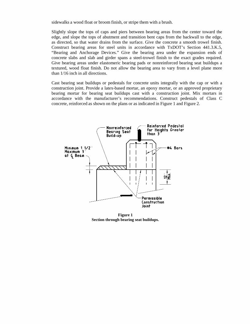
sidewalks a wood float or broom finish, or stripe them with a brush.
Slightly slope the tops of caps and piers between bearing areas from the center toward the edge, and slope the tops of abutment and transition bent caps from the backwall to the edge, as directed, so that water drains from the surface. Give the concrete a smooth trowel finish. Construct bearing areas for steel units in accordance with TxDOT’s Section 441.3.K.5, “Bearing and Anchorage Devices.” Give the bearing area under the expansion ends of concrete slabs and slab and girder spans a steel-trowel finish to the exact grades required. Give bearing areas under elastomeric bearing pads or nonreinforced bearing seat buildups a textured, wood float finish. Do not allow the bearing area to vary from a level plane more than 1/16 inch in all directions.
Cast bearing seat buildups or pedestals for concrete units integrally with the cap or with a construction joint. Provide a latex-based mortar, an epoxy mortar, or an approved proprietary bearing mortar for bearing seat buildups cast with a construction joint. Mix mortars in accordance with the manufacturer’s recommendations. Construct pedestals of Class C concrete, reinforced as shown on the plans or as indicated in Figure 1 and Figure 2.
Figure 1 Section through bearing seat buildups.
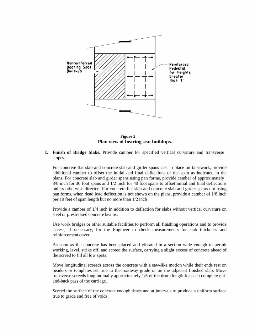
Figure 2 Plan view of bearing seat buildups.
I. Finish of Bridge Slabs. Provide camber for specified vertical curvature and transverse
slopes.
For concrete flat slab and concrete slab and girder spans cast in place on falsework, provide additional camber to offset the initial and final deflections of the span as indicated in the plans. For concrete slab and girder spans using pan forms, provide camber of approximately 3/8 inch for 30 foot spans and 1/2 inch for 40 foot spans to offset initial and final deflections unless otherwise directed. For concrete flat slab and concrete slab and girder spans not using pan forms, when dead load deflection is not shown on the plans, provide a camber of 1/8 inch per 10 feet of span length but no more than 1/2 inch
Provide a camber of 1/4 inch in addition to deflection for slabs without vertical curvature on steel or prestressed concrete beams.
Use work bridges or other suitable facilities to perform all finishing operations and to provide access, if necessary, for the Engineer to check measurements for slab thickness and reinforcement cover.
As soon as the concrete has been placed and vibrated in a section wide enough to permit working, level, strike off, and screed the surface, carrying a slight excess of concrete ahead of the screed to fill all low spots.
Move longitudinal screeds across the concrete with a saw-like motion while their ends rest on headers or templates set true to the roadway grade or on the adjacent finished slab. Move transverse screeds longitudinally approximately 1/5 of the drum length for each complete out- and-back pass of the carriage.
Screed the surface of the concrete enough times and at intervals to produce a uniform surface true to grade and free of voids.
Work the screeded surface to a smooth finish with a long-handled wood or metal float or hand-float it from work bridges over the slab. Floating may not be necessary if the pan float attached to a transverse screed produces an acceptable finish. Avoid overworking the surface of the concrete. Avoid overuse of finish water.
Perform sufficient checks, witnessed by the Engineer, with a long-handled 16 foot straightedge on the plastic concrete to confirm that the final surface will be within specified tolerances. Make the check with the straightedge parallel to the centerline. Lap each pass half over the preceding pass. Remove all high spots, and fill and float all depressions over 1/16 inch deep with fresh concrete. Continue checking and floating until the surface is true to grade and free of depressions, high spots, voids, or rough spots. Fill screed-rail support holes with concrete, and finish them to match the top of the slab.
Finish the concrete surface to a uniform texture using a carpet drag, burlap drag, or broom finish. Finish the surface to a smooth sandy texture without blemishes, marks, or scratches deeper than 1/16 inch. Apply the surface texturing using a work bridge or platform immediately after completing the straightedge checks. Draw the carpet or burlap drag longitudinally along the concrete surface, adjusting the surface contact area or pressure to provide a satisfactory coarsely textured surface. A broom finish may be performed using a fine bristle broom transversely. For bridge approach slabs the carpet drag, burlap drag, or broom finish may be applied either longitudinally or transversely.
Coat the concrete surface immediately after the carpet or burlap drag, or broom finish with a single application of evaporation retardant at a rate recommended by the manufacturer. Do not allow more than 10 minutes to elapse between the texturing at any location and application of evaporation retardant. The evaporation retardant may be applied using the same work bridge used for surface texturing. Do not work the concrete surface once the evaporation retardant has been applied.
Apply interim and final curing in accordance with Section 307.4.J, “Curing Concrete.”
The Contractor is responsible for the ride quality of the finished bridge slab. The Engineer will use a 10 foot straightedge (1/8 inch in 10 feet) to verify ride quality and to determine locations where corrections are needed. If the Engineer determines that the ride quality is unacceptable, submit a plan for approval to produce a ride of acceptable quality. Make all corrections for ride before saw-cutting grooves.
Unless noted otherwise, saw-cut grooves in the hardened concrete of bridge slabs, bridge approach slabs, and direct-traffic culverts to produce the final texturing after completion of the required curing period. Cut grooves perpendicular to the structure centerline. Cut grooves continuously across the slab to within 18 inches of the barrier rail, curb, or median divider. At skewed metal expansion joints in bridge slabs, adjust groove cutting by using narrow-width cutting heads so that all grooves end within 6 inches of the joint, measured perpendicular to the centerline of the metal joint. Leave no ungrooved surface wider than 6 inches adjacent to either side of the joint. Confirm that the minimum distance to the first groove, measured perpendicular to the edge of the concrete joint or from the junction between the concrete and the metal leg of the joint, is 1 inch Cut grooves continuously across construction joints or other joints in the concrete that are less than 1/2 inch wide. Apply the same procedure described above where barrier rails, curbs, or median dividers are not parallel to the structure centerline to maintain the 18 inches maximum dimension from the end of the grooves to the gutter line. Cut grooves continuously across formed concrete joints.
When saw-cut grooves are not required in the plans, provide either a carpet drag or broom finish for micro-texture. In this case insure that an adequate and consistent micro-texture is achieved by applying sufficient weight to the carpet and keeping the carpet or broom from
getting plugged with grout. For surfaces that do not have adequate texture, the Engineer may require corrective action including diamond grinding or shot blasting.
When the plans call for a concrete overlay to be placed on the slab (new construction) or on prestressed concrete box beams or other precast elements, give a carpet drag, burlap drag, or broom finish to all concrete surfaces to be overlaid. Saw-grooving is not required in this case. Provide an average texture depth for the finish of approximately 0.035 inch with no individual test falling below 0.020 inch, unless otherwise shown on the plans, when tested in accordance with TxDOT standard laboratory test procedure Tex-436 A. If the texture depth falls below what is intended, revise finishing procedures to produce the desired texture.
When the plans require an asphalt seal, with or without overlay, on the slab (new construction), on prestressed concrete box beams, or on other precast elements, give all concrete surfaces to be covered a lightly textured broom or carpet drag finish. Provide an average texture depth of approximately 0.025 inch when tested in accordance with TxDOT standard laboratory test procedure Tex-436-A.
J. Curing Concrete. Obtain approval of the proposed curing methods, equipment, and
materials before placing concrete. The Engineer may require the same curing methods for like portions of a single structure. Inadequate curing or facilities may delay all concrete placement on the job until remedial action is taken.
A curing day is a calendar day when the temperature, taken in the shade away from artificial heat, is above 50°F for at least 19 hours or, on colder days if the temperature of all surfaces of the concrete is maintained above 40°F, for the entire 24 hours. The required curing period begins when all concrete has attained its initial set. TxDOT standard laboratory test procedure Tex-440-A may be used to determine when the concrete has attained its initial set.
Cure all concrete for 4 consecutive days except as noted in Table 1.
Table 1
Exceptions to 4-Day Curing Description Type of Cement Required Curing Days
Upper surfaces of bridge slabs, top slab of direct-traffic culverts, and concrete overlays
I or III 8 II or I/II 10
All types with supplementary
cementing materials
10
Concrete piling buildups All 6
For upper surfaces of bridge slabs, bridge approach slabs, median and sidewalk slabs, and culvert top slabs constructed using Class S concrete, apply interim curing using a Type 1-D curing compound before the water sheen disappears but no more than 45 minutes after application of the evaporation retardant. Do not allow the concrete surface to dry before applying the interim cure, and do not place the interim cure over standing water. Apply membrane interim curing using a work bridge or other approved apparatus to confirm a uniform application. Water-cure for final curing in accordance with this Section, starting as soon as possible without damaging the surface finish. Maintain the water curing for the duration noted in Table 1. Place polyethylene sheeting, burlap-polyethylene blankets, laminated mats, or insulating curing mats in direct contact with the slab when the air temperature is expected to drop below 40°F during the first 72 hours of the curing period. Weigh down these curing materials with dry mats to maintain direct contact with the concrete and to provide insulation against cold weather. Supplemental heating or insulation may be required in cold and wet weather if the insulating cotton mats become wet or if the concrete drops below the specified curing temperature. Avoid applying heat directly to concrete surfaces.
For the top surface of any concrete unit upon which concrete is to be placed and bonded at a later interval (stub walls, risers, etc.) and other superstructure concrete (curbs, wingwalls, parapet walls, etc.), use only water curing in accordance with this Section.
Cure all other concrete as specified in the pertinent Items. Use the following methods for curing concrete, subject to the requirements of this Item.
1. Form Curing. When forms are left in intimate contact with the concrete, other curing
methods are not required except for exposed surfaces and for cold weather protection. If forms are removed before the 4 day required curing period, use another approved curing method.
2. Water Curing. Keep all exposed surfaces of the concrete wet continuously for the
required curing time. Use water curing that meets the requirements for concrete mixing water in Section 300.2.D, “Water.” Do not use seawater or water that stains or leaves an unsightly residue.
a. Wet Mats. Keep the concrete continuously wet by maintaining wet cotton mats in
direct contact with the concrete for the required curing time. If needed, place damp burlap blankets made from 9 ounce stock on the damp concrete surface for temporary protection before applying cotton mats. Then place the dry mats and wet them immediately after they are placed. Weight the mats adequately to provide continuous contact with all concrete. Cover surfaces that cannot be cured by direct contact with mats, forming an enclosure well anchored to the forms or ground so that outside air cannot enter the enclosure. Provide sufficient moisture inside the enclosure to keep all surfaces of the concrete wet.
b. Water Spray. Overlap sprays or sprinklers to keep all unformed surfaces
continuously wet.
c. Ponding. Cover the surfaces with at least 2 inches of clean granular material, kept wet at all times, or at least 1 inch deep water. Use a dam to retain the water or saturated granular material.
3. Membrane Curing. Unless otherwise shown on the plans, choose either Type 1-D or
Type 2 membrane-curing compound when membrane curing is permitted. Type 1-D (Resin Base Only) is required for interim curing bridge slabs and top slabs of direct- traffic culverts and all other surfaces that require a higher grade of surface finish. For substructure concrete provide only 1 type of curing compound on any 1 structure.
Apply membrane curing just after free moisture has disappeared at a rate of approximately 180 square feet per gallon. Do not spray curing compound on projecting reinforcing steel or concrete that will later form a construction joint. Do not apply membrane curing to dry surfaces. Dampen formed surfaces and surfaces that have been given a first rub so that they are moist at the time of application of the membrane.
When membrane is used for complete curing, leave the film unbroken for the minimum curing period specified. Correct damaged membrane immediately by reapplication of membrane. Polyethylene sheeting, burlap-polyethylene mats, or laminated mats in close contact with the concrete surfaces are equivalent to membrane curing.
K. Removal of Forms and Falsework. Unless otherwise directed, forms for vertical surfaces
may be removed after the concrete has aged 12 hours after initial set provided the removal can be done without damage to the concrete. Keep forms for mass placements, defined in Section 307.4.G.14, “Mass Placements,” in place for 4 days following concrete placement.
Remove forms for inside curb faces and for bridge rails whenever removal can be done without damage to the curb or railing.
Leave in place weight-supporting forms and falsework spanning more than 1 foot for all bridge components and culvert slabs except as directed otherwise until the concrete has attained a compressive strength of 2,500 psi. Remove forms for other structural components as necessary.
Remove inside forms (walls and top slabs) for box culverts and sewers after concrete has attained a compressive strength of 1,800 psi if an approved overhead support system is used to transfer the weight of the top slab to the walls of the box culvert or sewer before removal of the support provided by the forms.
Forms or parts of forms may be removed only if constructed to permit removal without disturbing forms or falsework required to be left in place for a longer period on other portions of the structure.
Remove all metal appliances used inside forms for alignment to a depth of at least 1/2 inch from the concrete surface. Make the appliances so that metal may be removed without undue chipping or spalling of the concrete, and so that it leaves a smooth opening in the concrete surface when removed. Do not burn off rods, bolts, or ties.
Remove all forms and falsework unless otherwise directed.
L. Defective Work. Repair defective work as soon as possible. Remove and replace any
defect that cannot be repaired to the satisfaction of the Engineer.
M. Ordinary Surface Finish. Apply an ordinary surface finish to all concrete surfaces as follows:
• Chip away all loose or broken material to sound concrete where porous, spalled, or
honeycombed areas are visible after form removal.
• Repair spalls by saw-cutting and chipping at least 1/2 inch deep, perpendicular to the surface to eliminate feather edges. Repair shallow cavities using a latex adhesive grout, cement mortar, or epoxy mortar as approved. Repair large areas using concrete as directed or approved.
• Clean and fill holes or spalls caused by the removal of form ties, etc., with latex grout,
cement grout, or epoxy grout as approved. Fill only the holes. Do not blend the patch with the surrounding concrete. On surfaces to receive a rub finish in accordance with Item 311, “Concrete Surface Finish,” chip out exposed parts of metals chairs to a depth of 1/2 inch and repair the surface.
• Remove all fins, runs, drips, or mortar from surfaces that will be exposed. Smooth all
form marks and chamfer edges by grinding or dry-rubbing.
• Confirm that all repairs are dense, well bonded, and properly cured. Finish exposed large repairs to blend with the surrounding concrete where a higher class of finish is not specified.
Unless noted otherwise, apply an ordinary surface finish as the final finish to the following exposed surfaces:
• inside and top of inlets,

• inside and top of manholes,
• inside of sewer appurtenances,
• inside of culvert barrels,
• bottom of bridge slabs between girders or beams, and
• vertical and bottom surfaces of interior concrete beams or girders.
Form marks and chamfer edges do not need to be smoothed for the inside of culvert barrels and the bottom of bridge slabs between girders or beams.
308 DRILLED SHAFTS AND UNDER-REAMED FOUNDATIONS
308.1. DESCRIPTION: This item shall govern for the construction of foundations consisting of reinforced concrete shafts with or without bell type concrete footings. Concrete shafts shall be placed in drilled excavation when the shafts are without bell type footings and in drilled and under-reamed excavation when shafts are with bell type footings. Such foundations shall be constructed in conformance with the details and governing dimensions shown on the plans.
TEST HOLE INFORMATION: Logs of test holes dug at the sites are shown in the plans. Test holes have been shown for the purpose of establishing bottom of drilled shaft foundations and determining elevation of ground water, or other soil characteristics, and shall in no way guarantee, either explicit or implied, the actual soil condition encountered at each particular drilled shaft location. The Engineer reserves the right to either lengthen or shorten the depth of drilled shaft shown on the plans, due to actual soil conditions encountered in the field.
308.2. MATERIALS: Provide materials that meet the requirements as shown below:
A. Concrete. All concrete shall conform to the provisions of Item 300, “Concrete.”
Unless otherwise shown on the plans, use concrete for drilled shafts that meets the requirements of Table 1.
Table 1
Concrete for Drilled Shafts Drilled Shaft Type Concrete
Non-reinforced Class A Reinforced Class C
Slurry and underwater concrete placement Class SS
Use coarse aggregate Grade 4, 5, or 6 for drilled shaft concrete in reinforced drilled shafts. Grade 2 or 3 may be used if the shaft is dry and reinforcing steel has a 5-in. minimum clear spacing. Use a water-reducing, retarding admixture in accordance with TxDOT DMS-4640, “Chemical Admixtures for Concrete,” in all concrete when using casing that will be pulled or when placing shafts underwater or under slurry.
Use concrete with slump that meets the requirements of Table 2 as determined by TxDOT Test Method Tex-415-A.
Table 2 Slump Requirements
Placement Type Minimum Acceptable Placement Slump, in.
Recommended Design and Placement Slump, in.
Maximum Acceptable Placement Slump, in.
Dry 5½ 6½ 7½ Under water and under slurry 7 8 9
When casing is to be pulled or when concrete is to be placed underwater or under slurry, perform a slump loss test in accordance with TxDOT Test Method Tex-430-A before beginning work. Provide concrete that will maintain a slump of at least 4 in. throughout the entire anticipated time of concrete placement. Time of concrete placement is described in Sections 308.3.F, “Concrete,” and 308.3.G, “Additional Requirements for Slurry Displacement or Underwater Concrete Placement Methods.” Note the temperature of the concrete mix at the beginning of the slump loss test. If concrete temperature at the time of placement into the drilled shaft is more than 10° higher than the slump loss test temperature, do not place the concrete. Use ice or other concrete cooling ingredients to lower concrete
temperature, or run additional slump loss tests at the higher temperatures. Slump loss testing will be waived if anticipated time of concrete placement is less than 90 minutes.
B. Slurry for Drilling. Use drilling slurry that meets the requirements of Table 3, as determined
by Tex-130-E.
Table 3 Slurry Requirements
Before Introduction into the Excavation
Sampled from the Bottom of the Excavation before Concreting
Specific Gravity Sand Content Specific Gravity Viscosity (seconds) Sand Content ≤ 1.10 ≤ 1% ≤ 1.15 ≤ 45 ≤ 6%
Use mineral slurry consisting of processed bentonite or attapulgite clays mixed with clean fresh water. Do not use PHPA (partially hydrolyzed polyacrylamide) polymeric slurry or any other fluid composed primarily of a polymer solution.
Before placing concrete, sample slurry from the bottom of the hole, and test it in accordance with Tex-130-E. Use a pump or air lift to remove slurry that does not meet the requirements of Table 3 while adding fresh clean slurry to the top of the hole to maintain the slurry level. Continue this operation until the slurry sampled from the bottom of the hole meets the requirements.
C. Reinforcing Steel. All reinforcing steel shall conform to the provisions of Item 301,
“Reinforcing Steel.”
D. Welds. All field welds shall conform to Texas Department of Transportation Standard Specification Item 448, “Structural Field Welding.”
308.3. EQUIPMENT: Provide the machinery, tools and equipment necessary for proper prosecution of
the work. All machinery, tools and equipment used shall be maintained in a satisfactory and workmanlike manner.
308.4. CONSTRUCTION: Place the shaft to within the following tolerances.
• Vertical plumbness - 1 in. per 10 ft. of depth. • Center of shaft located under column - 1 in. of horizontal plan position. • Center of shaft located under footing - 3 in. of horizontal plan position.
Complete the embankment at bridge ends before installing drilled shafts that pass through the fill. Refer to Texas Department of Transportation Standard Specification Item 423, “Retaining Walls,” for provisions for drilled shafts passing through the structural volume of retaining walls.
A. Excavation. The plans indicate the expected depths and elevations for encountering
satisfactory bearing material. Excavate as required for the shafts and bell footings through all materials encountered to the dimensions and elevations shown on the plans or required by the site conditions. Removal of man-made obstructions not shown on the plans will be paid for in accordance with Item 306, “Structural Excavation.”
If satisfactory founding material is not encountered at plan elevation, adjust the bottom of the shaft or alter the foundation, as determined by the Engineer, to satisfactorily comply with design requirements. Blasting is not allowed for excavations.
If caving conditions are encountered, stop drilling and adopt a construction method that stabilizes the shaft walls. Do not excavate a shaft within 2 shaft diameters (clear) of an open shaft excavation, or one in which concrete has been placed in the preceding 24 hours.
Dispose of material excavated from shafts and bells and not incorporated into the finished project. Dispose of excavated material in accordance with the plans and with federal, state, and local laws.
Provide suitable access, lighting, and equipment for proper inspection of the completed excavation and for checking the dimensions and alignment of shafts and bell excavation.
B. Core Holes. If directed, take cores to determine the character of the supporting materials. Use
a method that will result in recovery of an intact sample adequate for judging the character of the founding material. Such cores should be at least 5 ft. deeper than the proposed founding grade or a depth equal to the diameter of the shaft, whichever is greater. Take these cores when the excavation is approximately complete.
C. Casing. Use casing when necessary to prevent caving of the material or to exclude ground
water. Provide casing with an outside diameter not less than the specified diameter of the shaft. Use casing strong enough to withstand handling stresses and pressures of concrete and of the surrounding earth or water, and that is watertight, smooth, clean, and free of accumulations of hardened concrete.
Drill the portion of the shaft below the casing as close as possible to the specified shaft diameter. The portion of shaft below the casing may be as much as 2 in. smaller than the specified shaft diameter.
Use construction methods that result in a minimal amount of disturbed soil being trapped outside the casing. This does not apply to temporary undersized casings used to protect workers inside shafts or to drilled shafts designed for point bearing only. Do not leave any casing in place unless authorized or shown on the plans.
Do not extract casing until after placing the concrete to an appropriate level. Maintain sufficient concrete in the casing at all times to counteract soil and water pressure. Before and during concrete placement, rotate or move the casing up or down a few inches if necessary to facilitate extraction of the casing.
D. Requirements for Slurry Displacement Method. Unless otherwise shown on the plans, the
slurry displacement method may be used to construct drilled shafts. Use this method to support the sides of the excavation with processed mineral slurry that is then displaced by concrete to form a continuous concrete shaft.
Do not use casing other than surface casing. Do not use surface casing longer than 20 ft. without approval. Do not extract the surface casing until after placing the concrete.
For slurry mixed at the project site, pre-mix it in a reservoir of sufficient capacity to fill the excavation and for recovery of the slurry during concrete placement. Do not mix slurry in the shaft excavation or other hole. Allow adequate time for hydration of the slurry prior to introduction into the excavation.
During and after drilling maintain a head of slurry in the shaft excavation at or near ground level or higher as necessary to counteract ground water pressure.
Just before placing reinforcing steel, use an air lift or proper size cleanout bucket to remove any material that may have fallen from the sides of the excavation or accumulated on the bottom after the completion of drilling. Use a cleanout bucket if material is too large to be picked up with an air lift.
If concrete placement is not started within 4 hours of the completion of the shaft excavation, reprocess the hole with the auger as directed. Then clean the bottom with an air lift or
cleanout bucket, and check the slurry at the bottom of the hole for compliance with the slurry requirements of Article 416.2, “Materials.”
If the slurry forms a gel before concrete placement, agitate the congealed slurry to liquefaction just before concrete placement and whenever directed.
Recover and dispose of all slurry as approved by the Engineer, and in accordance with all federal, state, and local laws. Do not discharge slurry into or in close proximity to streams or other bodies of water.
E. Reinforcing Steel. Completely assemble the cage of reinforcing steel, and place it as a unit
immediately before concrete placement. The cage consists of longitudinal bars and lateral reinforcement (spiral reinforcement, lateral ties, or horizontal bands). If overhead obstacles prevent placement of the cage as a single unit, connect individual segments with couplers or by lapping steel as approved.
If the shaft is lengthened beyond plan length, extend the reinforcing steel cage as follows, unless directed otherwise:
• For shafts supporting structures other than bridges, extend the cage to the bottom. • For bridge shafts with plan lengths of less than 25 ft., extend the cage to 25 ft. or to the
bottom, whichever is shorter. • For bridge shafts with plan lengths at least 25 ft. that are lengthened less than 33% of
plan length, extending the cage is not necessary. • For bridge shafts with plan lengths at least 25 ft. that are lengthened more than 33% of
plan length, extend the cage as directed.
If the cage does not reach the bottom of the shaft, it may be suspended, or a portion of the longitudinal steel may be extended to support the cage on the bottom of the shaft. Bars used to extend or support the cage may be lap spliced or welded by a qualified welder. Place the extension at the bottom of the shaft.
If using spiral reinforcement, tie it to the longitudinal bars at a spacing of at most 24 in., or as required for a stable cage. Do not weld lateral reinforcement to longitudinal bars unless otherwise shown on the plans.
Center the reinforcing steel cage in the excavation using approved centering devices. Use enough devices to hold the cage in position along its entire length. Do not use square concrete spacer blocks in cased shafts.
Support or hold down the cage to control vertical displacement during concrete placement or extraction of the casing. Use support that is concentric with the cage to prevent racking and distortion of the steel.
Check the elevation of the top of the steel cage before and after concrete placement or after casing extraction when casing is used. Downward movement of the steel up to 6 in. per 20 ft. of shaft length and upward movement of the steel up to 6 in. total are acceptable.
Maintain the minimum length of steel required for lap with column steel. Use dowel bars if the proper lap length is provided both into the shaft and into the column.
Locate and tie all dowel bars into the cage before placing concrete or insert dowel bars into fresh, workable concrete. Locate and tie anchor bolts when required prior to placement of concrete. Use templates or other devices to assure accurate placement of anchor bolts.
F. Concrete. Perform all work in accordance with requirements of Item 307, “Concrete
Structures.” Mass concrete placement requirements do not apply to drilled shafts.
Form portions of drilled shaft that project above natural ground.
Remove loose material and accumulated seep water from the bottom of the excavation before placing concrete. If water cannot be removed, place concrete using underwater placement methods.
Place concrete as soon as possible after all excavation is complete and reinforcing steel is placed. Provide workable concrete that does not require vibrating or rodding. Vibrate formed portions of drilled shafts.
Place concrete continuously for the entire length of the shaft. For dry shafts of 24 in. or smaller diameter, limit free fall of concrete to 25 ft. Use a suitable tube or tremie to prevent segregation of materials. Use a tube or tremie in sections to provide proper discharge and to permit raising as the placement progresses. For dry shafts over 24 in. diameter, concrete can be allowed to free fall an unlimited distance if it does not strike the reinforcing cage or sides of the hole during placement. When free fall is used, provide a hopper with a minimum 3-ft.- long drop tube at the top of the shaft to direct concrete vertically down the center of the shaft. Do not use a shovel or other means to simply deflect the concrete discharge from the truck.
For cased shafts, maintain a sufficient head of concrete at all times above the bottom of the casing to overcome hydrostatic pressure. Extract casing at a slow, uniform rate with the pull in line with the axis of the shaft. Monitor the concrete level in the casing during extraction. Stop the extraction and add concrete to the casing as required to ensure a completely full hole upon casing removal. The elapsed time from the mixing of the first concrete placed into the cased portion of the shaft until the completion of extraction of the casing must not exceed the time for which the concrete maintains a slump of over 4 in. in accordance with Article 308.2, “Materials.” If the elapsed time is exceeded, modify the concrete mix, the construction procedures, or both for subsequent shafts.
Cure the top surface and treat any construction joint area in accordance with Item 307, “Concrete Structures.”
G. Additional Requirements for Slurry Displacement or Underwater Concrete Placement
Methods. Place concrete on the same day that the shaft is excavated and as soon as possible after all excavation is complete and reinforcing steel is placed. Use an air lift or cleanout bucket of the proper size to clean the bottom of the excavation prior to placing the reinforcing steel cage and concrete. Place concrete through a closed tremie or pump it to the bottom of the excavation. Initially seal the tremie or pump line to positively separate the concrete from the slurry or water. Place concrete continuously from the beginning of placement until the shaft is completed. If using a tremie, keep it full of concrete and well submerged in the previously placed concrete at all times. Raise the tremie as necessary to maintain the free flow of concrete and the stability of any casing used. If using a pump, keep the discharge tube submerged in the previously placed concrete at all times. Place additional concrete to ensure the removal of any contaminated concrete at the top of the shaft. At the completion of the pour, allow the top portion of concrete to flush completely from the hole until there is no evidence of slurry or water contamination. Do not attempt to remove this concrete with shovels, pumps or other means. Level the top of shaft with hand tools as necessary.
Use a sump or other approved method to channel displaced fluid and concrete away from the shaft excavation. Recover slurry and dispose of it as approved. Do not discharge displaced fluids into or in close proximity to streams or other bodies of water. For pours over water, provide a collar or other means of capturing slurry and the top portion of concrete flushed from the shaft.

If concrete placement is interrupted due to withdrawal of the submerged end of the tremie or pump discharge tube before completion, remove the tube, reseal it at the bottom, penetrate with the tube into the concrete already placed by at least 5 ft., and recharge it before continuing.
The elapsed time from the mixing of the first concrete placed until the completion of concrete placement, including extraction of the casing, must not exceed the time for which the concrete maintains a slump of over 4 in. in accordance with Article 416.2, “Materials.” If the elapsed time is exceeded, modify the concrete mix, the construction procedures, or both for subsequent shafts.
H. Test Load. If required, test load shafts in accordance with TxDOT Standard Specification
Item 405, “Foundation Test Load.”
309 PRECAST REINFORCED CONCRETE BOX CULVERTS
309.1. DESCRIPTION: This item shall govern for the fabrication and placing of precast reinforced concrete box culverts. The boxes shall be placed in accordance with the lines and grades shown on the plans and as staked in the field.
309.2. MATERIALS: Materials shall conform to the following:
A. Precast Reinforced Concrete Box Culverts. Precast Reinforced Concrete Box Culverts
shall be fabricated in accordance with one of the following design criteria:
1. ASTM Designation C 1433 per Texas Department of Transportation Item 462.
2. Texas Department of Transportation Item 424, “Precast Concrete Structures (Fabrication).”
3. Precast Design prepared by Registered Professional Engineer. Design plans covering the
structural requirements of the precast section shall be prepared, signed and sealed by a Registered Professional Engineer. The precast box design shall be made at the Contractor's expense and must be approved by the Engineer.
B. Joint Material. Joint material for precast reinforced concrete box culverts of all kinds shall
meet the requirements for cold applied, plastic asphalt sewer joint compound or cold applied pre-formed plastic gaskets as specified in Item 401, “Storm Drainage Pipe.”
C. Bedding. Under any and all ground conditions encountered, clean gravel subgrade filler in
conformance with Item 410, “Subgrade Filler” shall be used as bedding material.
D. Lifting Holes. For precast boxes, provide no more than 4 lifting holes in each section. Lifting holes may be cast, cut into fresh concrete after form removal, or drilled. Provide lifting holes of sufficient size for adequate lifting devices based on the size and weight of the box section. Do not use lifting holes larger than 3 in. in diameter. Do not cut more than 1 longitudinal wire or 2 circumferential wires per layer of reinforcing steel when locating lift holes. Repair spalled areas around lifting holes.
E. Marking. Mark precast boxes with the following:
• name or trademark of the producer; • date of manufacture; • box size; • minimum and maximum fill heights; and • match marks for proper installation, when required, under Section 309.2.F, “Tolerances.”
For boxes without lifting holes, mark 1 end of each box section on the inside and outside walls to indicate the top or bottom as it will be installed. Indent markings into the box section or paint them on each box with waterproof paint.
F. Tolerances. Ensure that precast sections of either type meet the following requirements:
• The inside vertical and horizontal dimensions do not vary from plan requirements by more than ½ in. or 1%, whichever is greater.
• The horizontal or vertical plane at each end of the box section does not vary from perpendicular by more than ½ in. or 1%, whichever is greater, measured on the inside faces of the section.
• The sides of a section at each end do not vary from being perpendicular to the top and bottom by more than ½ in. or 1%, whichever is greater, when measured diagonally between opposite interior corners.
Ensure that wall and slab thicknesses are not less than shown on the plans except for occasional deficiencies not greater than ¼ in. or 5%, whichever is greater. If proper jointing is not affected, thicknesses in excess of plan requirements are acceptable.
Deviations from the above tolerances will be acceptable if the sections can be fitted at the plant or job site and the joint opening at any point does not exceed 1 in. Use match marks for proper installation on sections that have been accepted in this manner.
G. Defects and Repair. Fine cracks on the surface of the member that do not extend to the plane
of the nearest reinforcement are acceptable unless the cracks are numerous and extensive. Repair cracks that extend into the plane of the reinforcing steel in an approved manner. Excessive damage, honeycomb, or cracking will be subject to structural review. The Engineer may accept boxes with repairs that are sound, properly finished, and cured in conformance with pertinent specifications. When fine cracks on the surface indicate poor curing practices, discontinue further production of precast sections until corrections are made and proper curing is provided.
H. Storage and Shipment. Store precast sections on a level surface. Do not place any load on
the sections until design strength is reached and curing is complete. Shipment of sections is permissible when the design strength and curing requirements have been met.
309.3. EQUIPMENT: Provide the machinery, tools and equipment necessary for proper prosecution of
the work. All machinery, tools and equipment used shall be maintained in a satisfactory and workmanlike manner.
309.4. CONSTRUCTION:
A. Excavation, Trenching and Backfilling. All excavation, trenching and backfilling shall be
in accordance with Item 106, “Box Culvert Excavation and Backfilling.” For all box structures where joints consist of materials other than mortar, immediate backfilling is permitted. Take precautions in placing and compacting the backfill to avoid any movement of the boxes or damage to the joints. Remove and replace boxes damaged by the Contractor at no expense to the City.
B. Bedding. The soil shall be excavated to a minimum depth of 4 inches below the established
grade of the bottom of the box culvert for the full width of the culvert and replaced with graded-gravel conforming to Item 410, “Gravel Subgrade Filler.” Additional excavation may be required by the presence of ground water, or other objectionable material. Such extra excavation shall be performed and replaced with graded gravel only upon approval of the Engineer.
C. Installation. Unless otherwise authorized by the Engineer, the laying of box culverts on the
prepared foundation shall start at the outlet end. Box culverts shall be laid with the tongue end pointing downstream and shall proceed toward the inlet end with the abutting sections
properly matched, true to the established lines and grades. For trench installations, lower the box sections into the trench without damaging the box or disturbing the bedding and the sides of the trench. Carefully clean the ends of the box before it is placed. Prevent the earth or bedding material from entering the box as it is laid. Remove and re-lay, without extra compensation, boxes that are not in alignment or that show excessive settlement after laying.
Multiple box sections shall be placed leaving a space of a minimum of 1 inch and a maximum of 2 inches between the outside face of adjacent walls of the boxes. After the boxes have been placed and jointed, this space shall be filled with a grout composed of one (1) part Portland Cement and two (2) parts of sand.
D. Jointing. All preparation and priming of joints, application of joint compound, and
construction methods shall be in strict adherence to the manufacturer's recommendations.
E. Connections and Stub Ends. Make connections of boxes to existing boxes as shown on the plans. Mortar or concrete the bottom of existing structures if necessary to eliminate any drainage pockets created by the connections. Connect boxes to any required headwalls, wingwalls, safety end treatments or riprap, or other structures as shown on the plans or as directed. Repair any damage to the existing structure resulting from making the connections. Finish stub ends for connections to future work not shown on the plans by installing watertight plugs into the free end of the box. Fill lifting holes with mortar or concrete and cure. Precast concrete or mortar plugs may be used.
310 PRECAST, PRESTRESSED BRIDGE BEAMS
310.1. DESCRIPTION: This item shall govern for the completed construction, prestressing, and erection of precast, prestressed concrete beams, and for the furnishing, storing, and handling of materials for prestressing of the beams, except as otherwise noted on the plans.
310.2. MATERIALS: The general requirements for fabrication, for materials shall conform to the
following:
A. Hydraulic Cement Concrete. Item 300, “Concrete.” B. Reinforcing Steel. Item 301, “Reinforcing Steel.” C. Structural Steel. Item 302, “Metal For Structures.” D. Precast Prestressed Concrete Structural Members. Texas Department of Transportation
Item 425, “Precast Prestressed Concrete Structural Members.” E. Prestressing. Texas Department of Transportation Item 426, “Prestressing.” F. Elastomeric Materials. Texas Department of Transportation Item 434, “Elastomeric Bridge
Bearings.” G. Concrete Curing Compound and Evaporation Retardants. Texas Department of
Transportation DMS-4650, “Hydraulic Cement Concrete Curing Materials and Evaporation Retardants”
H. Epoxies and Adhesives. Texas Department of Transportation DMS-6100, “Epoxies and Adhesives.”
310.3. EQUIPMENT: Provide the machinery, tools and equipment necessary for proper prosecution of
the work. All machinery, tools and equipment used shall be maintained in a satisfactory and workmanlike manner.
310.4. CONSTRUCTION: The general requirements for construction methods of precast, prestressed
bridge beams shall be in accordance with the appropriate articles of TxDOT Standard Specification Item 425, “Precast Prestressed Concrete Structural Members,” Item 426, “Prestressing,” and Item 434, “Elastomeric Bridge Bearings.”
311 CONCRETE SURFACE FINISH
311.1. DESCRIPTION: Finish concrete surface as specified.
311.2. MATERIALS: Furnish materials in accordance with this Article for the type of surface finish specified.
A. Coatings.
1. Adhesive Grout and Concrete Paint. Provide coatings in accordance with TxDOT’s
DMS 8110, “Coatings for Concrete.” Match color of coating with Federal Standard 595B color 35630, concrete gray, unless otherwise shown on the plans.
2. Opaque Sealer. Provide penetrating-type sealer in accordance with TxDOT’s DMS
8110, “Coatings for Concrete.” Match color of coating with Federal Standard 595B color 35630, concrete gray, unless otherwise shown on the plans.
3. 742 Appearance Coating. Provide #742 gray appearance coating (Federal Standard
595B color 35630) in accordance with TxDOT’s DMS 8100, “Structural Steel Paints- Formula.”
4. Epoxy Paint. Provide Type X epoxy coating in accordance with TxDOT’s DMS 6100,
“Epoxies and Adhesives.”
B. Exposed Aggregate Finish. Provide approved aggregates meeting the grading requirements shown on the plans. Unless otherwise shown on the plans, provide gravel consisting of predominantly rounded particles. When a bush-hammered finish is desired, use crushed stone. Provide a concrete surface retardant. Provide clear acrylic resin sealer in accordance with TxDOT’s DMS 8110, “Coatings for Concrete,” or clear Type II permanent anti-graffiti coating in accordance with TxDOT’s DMS 8111, “Anti-Graffiti Coatings.”
311.3. EQUIPMENT: The Engineer may require demonstration of the equipment’s capabilities.
A. Low-Pressure Water Blasting. Use equipment capable of supplying a minimum pressure at
the nozzle end of 3,000 psi at a minimum flow rate of 3 gpm. Use a 0° rotary, vibratory, or wobble-type nozzle. Use equipment capable of including abrasives in the water stream when specified on the plans.
B. Abrasive Blasting. Use equipment equipped with filters to produce oil-free air and also
water-free air when dry air is required.
C. Slurry Blasting. Use equipment capable of combining air and abrasives with water to form a wet blast media capable of cleaning and preparing surface without creating dust.
D. Spraying. For spray applications, use equipment with fluid and air pressure regulators and
gauges to allow for adjustment to produce a uniform spray pattern.
E. Off-the-Form Finish Forms. Use non-staining, nonporous, high-quality forming materials (e.g., steel or medium-density and high-density overlaid plywood forms). Use steel or high- density overlaid plywood forms when the same form will be used more than twice.
F. Form Liners. Provide form liners capable of producing a patterned finish as shown on the plans. Use form liners that provide a clean release from the concrete surface without pulling or breaking the textured concrete.
311.4. CONSTRUCTION: Provide the finish specified on the plans for the specific surface areas.
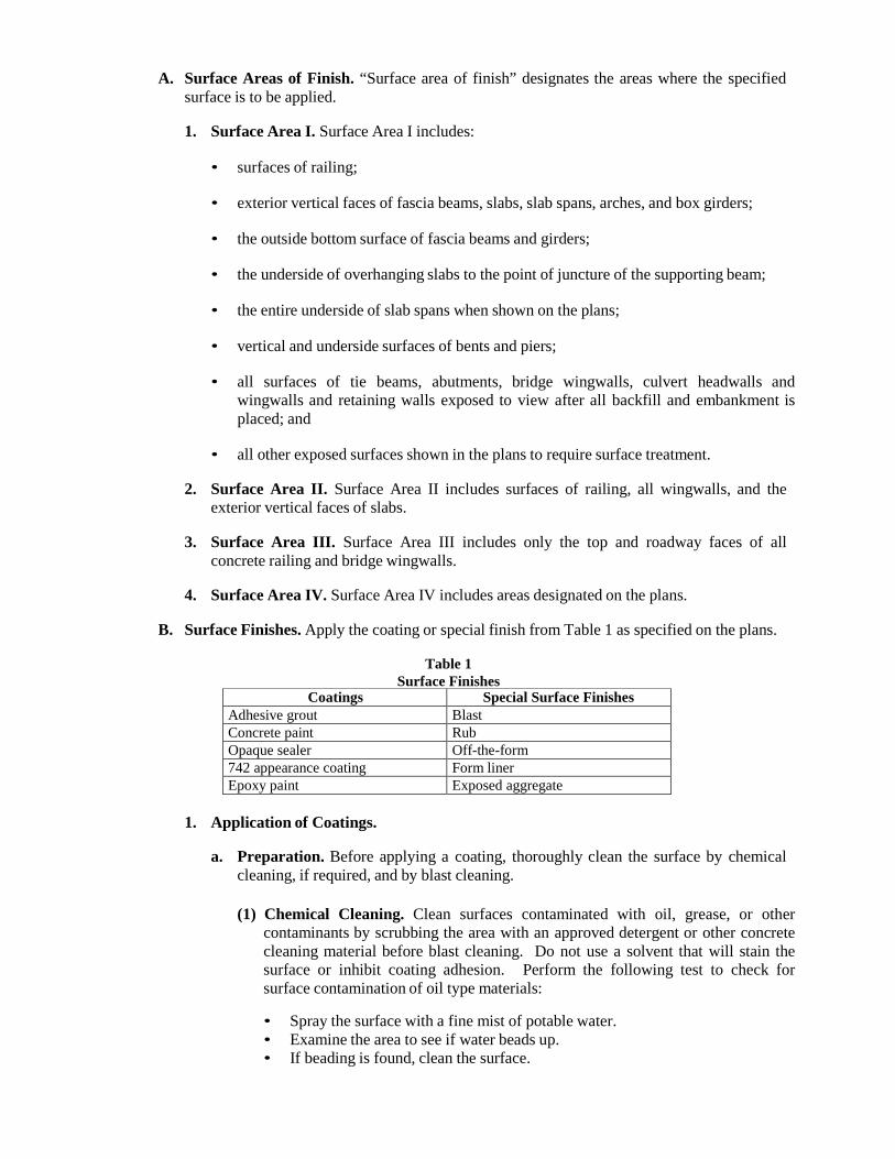
A. Surface Areas of Finish. “Surface area of finish” designates the areas where the specified surface is to be applied.
1. Surface Area I. Surface Area I includes:
• surfaces of railing;
• exterior vertical faces of fascia beams, slabs, slab spans, arches, and box girders;
• the outside bottom surface of fascia beams and girders;
• the underside of overhanging slabs to the point of juncture of the supporting beam;
• the entire underside of slab spans when shown on the plans;
• vertical and underside surfaces of bents and piers;
• all surfaces of tie beams, abutments, bridge wingwalls, culvert headwalls and
wingwalls and retaining walls exposed to view after all backfill and embankment is placed; and
• all other exposed surfaces shown in the plans to require surface treatment.
2. Surface Area II. Surface Area II includes surfaces of railing, all wingwalls, and the
exterior vertical faces of slabs.
3. Surface Area III. Surface Area III includes only the top and roadway faces of all concrete railing and bridge wingwalls.
4. Surface Area IV. Surface Area IV includes areas designated on the plans.
B. Surface Finishes. Apply the coating or special finish from Table 1 as specified on the plans.
Table 1
Surface Finishes Coatings Special Surface Finishes
Adhesive grout Blast Concrete paint Rub Opaque sealer Off-the-form 742 appearance coating Form liner Epoxy paint Exposed aggregate
1. Application of Coatings.
a. Preparation. Before applying a coating, thoroughly clean the surface by chemical
cleaning, if required, and by blast cleaning.
(1) Chemical Cleaning. Clean surfaces contaminated with oil, grease, or other contaminants by scrubbing the area with an approved detergent or other concrete cleaning material before blast cleaning. Do not use a solvent that will stain the surface or inhibit coating adhesion. Perform the following test to check for surface contamination of oil type materials:
• Spray the surface with a fine mist of potable water. • Examine the area to see if water beads up. • If beading is found, clean the surface.
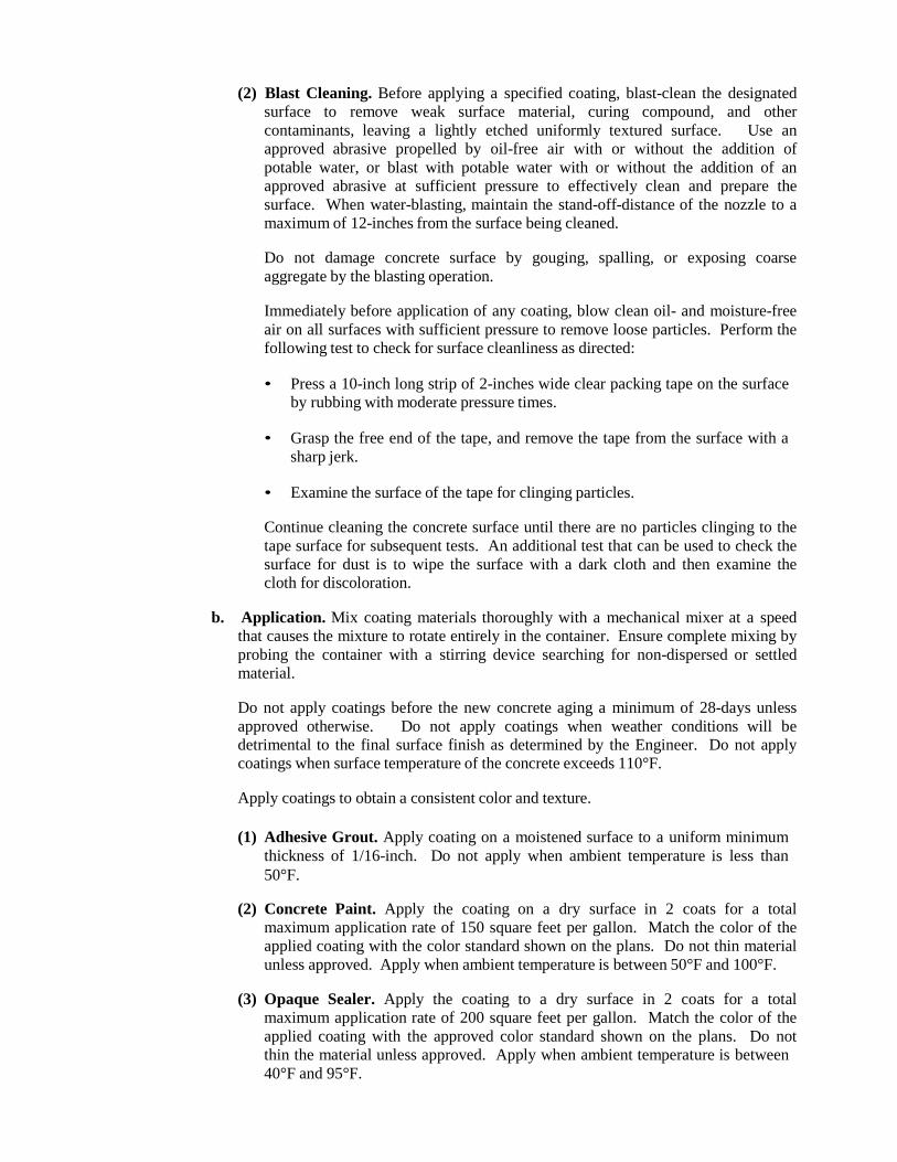
(2) Blast Cleaning. Before applying a specified coating, blast-clean the designated
surface to remove weak surface material, curing compound, and other contaminants, leaving a lightly etched uniformly textured surface. Use an approved abrasive propelled by oil-free air with or without the addition of potable water, or blast with potable water with or without the addition of an approved abrasive at sufficient pressure to effectively clean and prepare the surface. When water-blasting, maintain the stand-off-distance of the nozzle to a maximum of 12-inches from the surface being cleaned.
Do not damage concrete surface by gouging, spalling, or exposing coarse aggregate by the blasting operation.
Immediately before application of any coating, blow clean oil- and moisture-free air on all surfaces with sufficient pressure to remove loose particles. Perform the following test to check for surface cleanliness as directed:
• Press a 10-inch long strip of 2-inches wide clear packing tape on the surface
by rubbing with moderate pressure times.
• Grasp the free end of the tape, and remove the tape from the surface with a sharp jerk.
• Examine the surface of the tape for clinging particles.
Continue cleaning the concrete surface until there are no particles clinging to the tape surface for subsequent tests. An additional test that can be used to check the surface for dust is to wipe the surface with a dark cloth and then examine the cloth for discoloration.
b. Application. Mix coating materials thoroughly with a mechanical mixer at a speed
that causes the mixture to rotate entirely in the container. Ensure complete mixing by probing the container with a stirring device searching for non-dispersed or settled material.
Do not apply coatings before the new concrete aging a minimum of 28-days unless approved otherwise. Do not apply coatings when weather conditions will be detrimental to the final surface finish as determined by the Engineer. Do not apply coatings when surface temperature of the concrete exceeds 110°F.
Apply coatings to obtain a consistent color and texture.
(1) Adhesive Grout. Apply coating on a moistened surface to a uniform minimum
thickness of 1/16-inch. Do not apply when ambient temperature is less than 50°F.
(2) Concrete Paint. Apply the coating on a dry surface in 2 coats for a total
maximum application rate of 150 square feet per gallon. Match the color of the applied coating with the color standard shown on the plans. Do not thin material unless approved. Apply when ambient temperature is between 50°F and 100°F.
(3) Opaque Sealer. Apply the coating to a dry surface in 2 coats for a total
maximum application rate of 200 square feet per gallon. Match the color of the applied coating with the approved color standard shown on the plans. Do not thin the material unless approved. Apply when ambient temperature is between 40°F and 95°F.
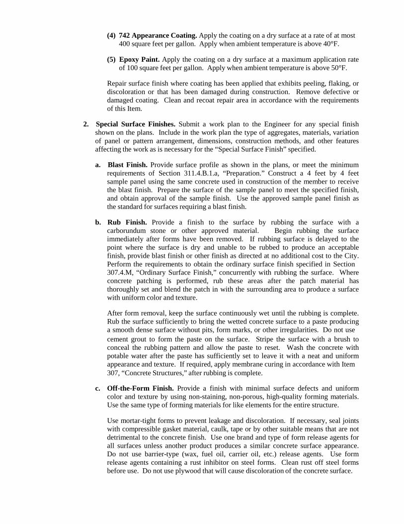
(4) 742 Appearance Coating. Apply the coating on a dry surface at a rate of at most 400 square feet per gallon. Apply when ambient temperature is above 40°F.
(5) Epoxy Paint. Apply the coating on a dry surface at a maximum application rate
of 100 square feet per gallon. Apply when ambient temperature is above 50°F.
Repair surface finish where coating has been applied that exhibits peeling, flaking, or discoloration or that has been damaged during construction. Remove defective or damaged coating. Clean and recoat repair area in accordance with the requirements of this Item.
2. Special Surface Finishes. Submit a work plan to the Engineer for any special finish
shown on the plans. Include in the work plan the type of aggregates, materials, variation of panel or pattern arrangement, dimensions, construction methods, and other features affecting the work as is necessary for the “Special Surface Finish” specified.
a. Blast Finish. Provide surface profile as shown in the plans, or meet the minimum
requirements of Section 311.4.B.1.a, “Preparation.” Construct a 4 feet by 4 feet sample panel using the same concrete used in construction of the member to receive the blast finish. Prepare the surface of the sample panel to meet the specified finish, and obtain approval of the sample finish. Use the approved sample panel finish as the standard for surfaces requiring a blast finish.
b. Rub Finish. Provide a finish to the surface by rubbing the surface with a
carborundum stone or other approved material. Begin rubbing the surface immediately after forms have been removed. If rubbing surface is delayed to the point where the surface is dry and unable to be rubbed to produce an acceptable finish, provide blast finish or other finish as directed at no additional cost to the City. Perform the requirements to obtain the ordinary surface finish specified in Section 307.4.M, “Ordinary Surface Finish,” concurrently with rubbing the surface. Where concrete patching is performed, rub these areas after the patch material has thoroughly set and blend the patch in with the surrounding area to produce a surface with uniform color and texture.
After form removal, keep the surface continuously wet until the rubbing is complete. Rub the surface sufficiently to bring the wetted concrete surface to a paste producing a smooth dense surface without pits, form marks, or other irregularities. Do not use cement grout to form the paste on the surface. Stripe the surface with a brush to conceal the rubbing pattern and allow the paste to reset. Wash the concrete with potable water after the paste has sufficiently set to leave it with a neat and uniform appearance and texture. If required, apply membrane curing in accordance with Item 307, “Concrete Structures,” after rubbing is complete.
c. Off-the-Form Finish. Provide a finish with minimal surface defects and uniform
color and texture by using non-staining, non-porous, high-quality forming materials. Use the same type of forming materials for like elements for the entire structure.
Use mortar-tight forms to prevent leakage and discoloration. If necessary, seal joints with compressible gasket material, caulk, tape or by other suitable means that are not detrimental to the concrete finish. Use one brand and type of form release agents for all surfaces unless another product produces a similar concrete surface appearance. Do not use barrier-type (wax, fuel oil, carrier oil, etc.) release agents. Use form release agents containing a rust inhibitor on steel forms. Clean rust off steel forms before use. Do not use plywood that will cause discoloration of the concrete surface.
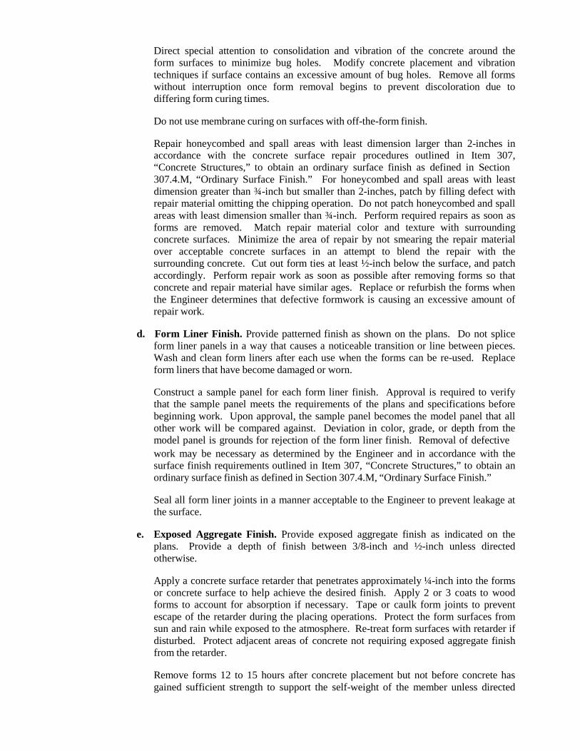
Direct special attention to consolidation and vibration of the concrete around the form surfaces to minimize bug holes. Modify concrete placement and vibration techniques if surface contains an excessive amount of bug holes. Remove all forms without interruption once form removal begins to prevent discoloration due to differing form curing times.
Do not use membrane curing on surfaces with off-the-form finish.
Repair honeycombed and spall areas with least dimension larger than 2-inches in accordance with the concrete surface repair procedures outlined in Item 307, “Concrete Structures,” to obtain an ordinary surface finish as defined in Section 307.4.M, “Ordinary Surface Finish.” For honeycombed and spall areas with least dimension greater than ¾-inch but smaller than 2-inches, patch by filling defect with repair material omitting the chipping operation. Do not patch honeycombed and spall areas with least dimension smaller than ¾-inch. Perform required repairs as soon as forms are removed. Match repair material color and texture with surrounding concrete surfaces. Minimize the area of repair by not smearing the repair material over acceptable concrete surfaces in an attempt to blend the repair with the surrounding concrete. Cut out form ties at least ½-inch below the surface, and patch accordingly. Perform repair work as soon as possible after removing forms so that concrete and repair material have similar ages. Replace or refurbish the forms when the Engineer determines that defective formwork is causing an excessive amount of repair work.
d. Form Liner Finish. Provide patterned finish as shown on the plans. Do not splice
form liner panels in a way that causes a noticeable transition or line between pieces. Wash and clean form liners after each use when the forms can be re-used. Replace form liners that have become damaged or worn.
Construct a sample panel for each form liner finish. Approval is required to verify that the sample panel meets the requirements of the plans and specifications before beginning work. Upon approval, the sample panel becomes the model panel that all other work will be compared against. Deviation in color, grade, or depth from the model panel is grounds for rejection of the form liner finish. Removal of defective work may be necessary as determined by the Engineer and in accordance with the surface finish requirements outlined in Item 307, “Concrete Structures,” to obtain an ordinary surface finish as defined in Section 307.4.M, “Ordinary Surface Finish.”
Seal all form liner joints in a manner acceptable to the Engineer to prevent leakage at the surface.
e. Exposed Aggregate Finish. Provide exposed aggregate finish as indicated on the
plans. Provide a depth of finish between 3/8-inch and ½-inch unless directed otherwise.
Apply a concrete surface retarder that penetrates approximately ¼-inch into the forms or concrete surface to help achieve the desired finish. Apply 2 or 3 coats to wood forms to account for absorption if necessary. Tape or caulk form joints to prevent escape of the retarder during the placing operations. Protect the form surfaces from sun and rain while exposed to the atmosphere. Re-treat form surfaces with retarder if disturbed. Protect adjacent areas of concrete not requiring exposed aggregate finish from the retarder.
Remove forms 12 to 15 hours after concrete placement but not before concrete has gained sufficient strength to support the self-weight of the member unless directed
otherwise. Expose the aggregate for the finish immediately after form removal. Remove the grout paste covering the aggregate to be exposed by an approved method. Do not loosen the aggregate by the grout removal operation. Maintain required curing on all surfaces except for the time while the aggregate is being exposed. Cure using wet mats or membrane after the aggregate is exposed.
Repair defective areas as determined by the Engineer.
Re-clean exposed aggregate surfaces by an approved method. Apply a coat of acrylic resin sealer or clear Type II permanent anti-graffiti coating to cleaned exposed aggregate surface. Apply a single coat or multiple coats for a total maximum application rate of 250 square feet per gallon.
DIVISION IV - STORM SEWERS
400 EXCAVATION, TRENCHING AND BACKFILLING
400.1. DESCRIPTION: Excavate, trench, and backfill storm drainage pipe, and pipe culverts, unless otherwise noted on the plans, details and the specifications. The work shall include all necessary pumping or bailing, sheeting, drainage and the construction and removal of any required cofferdams. All existing utilities shall be protected from damage during the excavation and backfilling of trenches, and if damaged, shall be replaced or repaired by the Contractor at his expense. Unless otherwise shown on the plans and bid proposal all excavation shall be unclassified, and shall include all materials encountered regardless of their nature or the manner in which they are removed.
400.2. MATERIALS: Use materials that meet the requirements of the following Items:
A. Aggregate. Item 200, “Flexible Base.” B. Gravel. Item 410, “Subgrade Filler.” C. Cement Stabilized Sand. Item 412, “Cement Stabilized Sand.” D. Glass Cullet. Item 411, “Glass Cullet use for Utility Bedding and Backfill.” E. Flowable Fill. Item 413, “Flowable Fill.” F. Filter Fabric. TxDOT DMS 6200, “Filter Fabric,” Type1.
400.3. CONSTRUCTION:
A. Excavation.
1. General. The Contractor shall perform all excavation of every description and of whatever substances encountered, to the lines and grades shown on the plans or determined by the Engineer. Unless otherwise indicated, excavation shall be by open cut except that short sections may be tunneled, if in the opinion of the Engineer, the pipe or structure can be safely and properly installed or constructed, and backfill can be properly tamped in such tunnel sections.
2. Safety. Provide slopes, benching, sheeting, bracing, pumping, and bailing as necessary to
maintain the stability and safety of excavations. Excavation protection is governed by Item 550, “Trench Excavation Safety Protection,” and Item 551, “Special Shoring.”
3. Excavated Materials. During excavation, material suitable for backfilling shall be
stockpiled in an orderly manner a sufficient distance from the banks of the trench to avoid overloading and to prevent slides or cave-ins. All excavated materials not required or not suitable for backfill shall be removed and properly disposed of by the Contractor or as directed by the Engineer. Proper disposal shall be in conformance with, but not limited to, the following provisions:
a. Do not deposit excavated material within jurisdictional wetlands, and
b. Obtain appropriate permits and apply provisions pertaining to soil erosion and stream pollution, when necessary, to meet federal, state, and/or local regulations, rules, and procedures.
4. Hazardous Materials. If the Contractor encounters hazardous substances, industrial waste, environmental damage, underground storage tanks, or conditions conducive to environmental damage, Contractor shall immediately stop work in the area affected and report the condition to the Owner's representative in writing. Contractor shall not be responsible for or required to conduct any investigation, site monitoring, containment,
cleanup, removal, restoration or other remedial work of any kind or nature (the “remedial work”) under any applicable level, state or federal law, regulation or ordinance, or any judicial order. If the Contractor agrees in writing to commence and/or prosecute some or all of the remedial work, all costs and expenses, to include any extension of the contract time, of such remedial work shall be paid by Owner to Contractor.
5. Existing Structures/Obstructions. Unless otherwise stated on the plans, remove
structures and other obstructions over the width of the excavation to a depth of 1 ft. below the bottom of excavation. If abandoned storm drains, sewers, or other drainage systems are encountered, remove as required to clear the new structure, and plug in an approved manner. After removing obstructions, restore the bottom of the excavation to grade by backfilling in accordance with this Item. Dispose of surplus materials in accordance with federal, state, and local regulations.
6. Existing Asphaltic Materials. All asphaltic material shall be disposed of or recycled at a
facility authorized to accept the material for such purposes.
7. Excavation in Streets. When structures are installed in streets, highways, or other paved areas, cut pavement and base in accordance with Item 230, “Base and Pavement Replacement.” Restore pavement structure after completion of excavation and backfilling in accordance with Item 230, “Base and Pavement Replacement.”
Unless otherwise shown on the plans, maintain and control traffic in accordance with the approved traffic control plan or in conformance with the Texas MUTCD.
8. Utilities. Conduct work with minimum disturbance of existing utilities, and coordinate
work in or near utilities with the utility owners. Inform utility owners sufficiently before work begins to allow them time to identify, locate, reroute, or make other adjustments to utility lines.
Avoid cutting or damaging underground utility lines that are to remain in place. If damage occurs, promptly notify the utility company. If an active sanitary sewer line is damaged during excavation, provide temporary flumes across the excavation while open, and restore the lines when backfilling has progressed to the original bedding lines of the cut sewer.
9. De-Watering. Do not construct or place structures in the presence of water unless
approved. Place precast units or pour structural concrete only on a dry, firm surface. Remove water by bailing, pumping, well-point installation, deep wells, underdrains, or other approved method.
Do not pump or bail while placing structural concrete or for a period of at least 36 hr. thereafter unless from a suitable sump separated from the concrete work. Pump or bail during placement of seal concrete only to the extent necessary to maintain a static head of water within the cofferdam. Do not pump or bail to de-water inside a sealed cofferdam until the seal has aged at least 36 hours.
If the bottom of an excavation cannot be de-watered to the point that the subgrade is free of mud or it is difficult to keep reinforcing steel clean, place a stabilizing material in the bottom of the excavation. Stabilizing material may be controlled low strength material, flowable backfill, or other material approved by the Engineer. Stabilizing material placed for the convenience of the Contractor will be at the Contractor’s expense.
B. Trenching.
1. General. Trench walls shall be vertical in excavations through stable rock, as classified and substantiated during construction by a competent professional as defined by OSHA, and the practice of undercutting at the bottom or flaring at the top will not be permitted unless approved by the Engineer. In special cases where trench flaring is permitted and directed by the Engineer, the trench walls shall remain vertical to a depth of at least 1 foot above the top of the pipe. The bottom of the trenches shall be accurately graded to provide uniform bearing and support for each section of pipe on the undisturbed soil at every point along its entire length, except for the portions of pipe sections where it is necessary for bells and for the proper sealing of pipe joints. Bell holes and depressions for joints shall be dug after the trench bottom has been graded in order that the pipe may rest upon the prepared bottom for as much of its full length as practicable.
2. Depth of Cut. The depth of cut shall be measured from the offset or cut hub elevation to
the invert of the pipe and shall be determined by the Contractor. The width of the trench shall be at least the outside diameter of the pipe plus 6 inches on each side of the pipe for pipe sizes less than 42 inches in diameter.
It shall be understood that the depth of cut as initially indicated may be more or less than the actual excavated depth due to ground conditions existing at the site. For this reason the Engineer shall determine the depth for pay purposes based on the surface elevation prior to the Contractor’s operation and the invert of the sewer line. The Engineer’s decision shall be final.
3. Working Space. The maximum working room for pipe 42 inches in diameter and under
shall not exceed ½ of the outside diameter of the pipe or 12 inches whichever is greater, from the edge of the pipe to the face of the trench walls, or inside face of the shoring protection.
For pipe over 42 inches in diameter the maximum width of the trench shall be such that the working space from the pipe to the trench wall, or shoring protection as the case may be, will be a minimum of 12 inches, and a maximum of 24 inches. If allowable trench widths are exceeded through over-shooting of rock, caving of earth trenches or over- excavation, the Contractor shall employ corrective measures or alternative designs as determined by the Engineer.
C. Over Excavation.
1. Unstable Material. Whenever wet or otherwise unstable soil that is incapable of properly supporting the structure or pipe, as determined by the Engineer, is encountered in the bottom of the excavation or trench, such soil shall be removed to the depth shown on the plans or determined by the Engineer and the excavation or trench backfilled to the proper grade with a gravel subgrade filler as specified in Item No. 410, “Subgrade Filler” or other suitable bedding material.
2. Incompressible Material. Where trash, debris, rock, boulder or coarse gravel with a
particle size larger than 1 ¾ inch is encountered at the bearing level, the Contractor shall, as directed by the Inspector, over-excavate and remove such materials to a depth not less than 4 inches below the bottom of the pipe and replace with a gravel material conforming to the requirements of Item 410, “Subgrade Filler” or other suitable bedding material.
3. Unauthorized Excessive Excavation. Whenever over-excavation occurs that is not a
result of unstable or incompressible material as defined above, the under-cut trench shall be restored to grade, to the satisfaction of the Inspector, by replacement of excavated material compacted to the same density as the surrounding natural ground.
D. Bedding. When bedding material is required by the plans, place the material to the depth specified and in the manner described herein.
1. Bedding material may consist of lean clay, gravel, clean sand, cement stabilized sand,
glass cullet that conforms to the requirements of Item 411, “Glass Cullet use for Utility Bedding and Backfill,” or other materials approved by the Engineer.
2. Remove loose, sloughing, or caving soil from the bottom and sidewall of trenches
immediately prior to placement of bedding materials. Place bedding to the depths shown on the Standard Details or project plans.
3. For pipe installation, manually spread bedding materials around pipe to provide uniform
bearing and side support when compacted. Protect flexible pipe from damage during placing of pipe zone bedding material. Perform placement and compaction directly against undisturbed soils in trench sidewalls, or against sheeting which is to remain in place.
4. Do not place trench shields or shoring within the height of the bedding zone unless means
to maintain density of compacted bedding material are used. If moveable supports are used in the bedding zone, lift supports incrementally to allow placement and compaction of material against undisturbed soil.
5. If shown on the plans or directed by the Engineer, place geotextile on the bottom of the
excavated trench prior to the placement of any sand, glass cullet, or granular bedding to prevent particle migration from in-situ soil into open-graded bedding materials or drainage layers, when used.
6. Compact bedding material to its specific compaction requirements using pneumatic
tampers in restricted areas, and vibratory-plate compactors or engine-powered jumping jacks in unrestricted areas. Compact each lift before proceeding with placement of next lift. Water tamping is not allowed.
E. Backfilling.
1. General. Trench shall not be backfilled until the constructed structures or appurtenances as installed conform to the requirements specified. The trench shall be carefully backfilled with the materials approved for backfilling as described in 400.3.E.2. “Pipe Backfilling” or other materials approved by the Engineer.
Where pipe is specially coated for protection against corrosion, care shall be taken not to damage the coating.
Any trench improperly backfilled, or where settlement occurs, shall be reopened to the depth required for proper compaction, then refilled and compacted with the surface restored to the required grade and compaction.
2. Pipe Backfilling. Initial backfill that is defined as backfilling to a point 12 inches above
the top of the pipe shall be done by either method a., b., c., or d. below. Secondary backfill that is defined as backfilling from a point 12 inches above the top of the pipe to the top of the trench or proposed subgrade elevation shall be completed in accordance with 400.3.E.2.e. “Secondary Backfill.”
a. Suitable Excavated Material. Fine compactable soil material may be used as the
initial backfill; examples would include loam, sandy clay, sand and gravel, or soft shale, all of which shall be free from large clods of earth or stones. It shall be placed in uniform layers not more than 6 inches in depth (loose measurement) and shall be
compacted to the density specified herein. Each layer of backfill material, if dry, shall be wetted uniformly to the moisture content required to obtain the specified density and shall be compacted to the required density, by means of a hand or mechanical tamper.
The maximum dry density and optimum moisture content shall be determined in accordance with TxDOT Test Method Tex-114-E. Tests for in place density shall be made in accordance with TxDOT Test Method Tex-115-E and within 24 hours after compacting operations are completed. If the material fails to meet the density specified, it shall be re-worked as necessary to obtain the density required.
Care shall be exercised to thoroughly compact the backfill under the haunches of the pipe and to insure that the backfill soil is in intimate contact with the sides of the pipe. Backfill material shall be kept at the same elevation on both sides of pipe.
Each lift of fill shall be compacted to the required density and moisture content as shown below, unless otherwise shown on the plans:
Subgrade Material Density Moisture Content PI ≤ 20 ≥ 95% of Max Dry Density - 2% of Opt. or greater PI > 20 ≥ 95% of Max Dry Density ≥ Opt. Moisture
b. Cement Stabilized Sand. When shown on the plans, backfill the excavation with cement stabilized sand backfill that conforms to Item 412, “Cement Stabilized Sand” to the elevations shown on the plans. Prevent the structure from being displaced during the placement of the cement stabilized sand and prevent the backfill from entering pipes. There is no separate pay item for Cement Stabilized Sand material, unless shown on the plans as a separate pay item for pipe backfill.
Before placing cement stabilized sand, the trench shall be cleaned of any extraneous material and thoroughly wet. All surplus dirt excavated from the trench shall be removed from the site.
c. Flowable Backfill. When shown on the plans, backfill the excavation with flowable
backfill that conforms to Item 413, “Flowable Backfill” to the elevations shown on the plans. Prevent the structure from being displaced during the placement of the flowable backfill and prevent flowable backfill from entering pipes. Before placing flowable backfill, the trench shall be cleaned of any extraneous material and thoroughly wet. All surplus dirt excavated from the trench shall be removed from the site.
d. Select Fill or Flexible Base. A clean gravel, or gravel approved by the Engineer,
conforming to the requirements of article 410.3.B. “Gravel” of Item No.410, “Subgrade Filler” may be used for backfill material from the bottom of the trench to the top of the pipe. The gravel shall be placed in the trench in loose lifts not to exceed 10 inches in depth and lightly tamped to consolidate and seat the mass against conduit and earthen surfaces. Backfill material shall be kept at the same elevation on both sides of pipe.
A filter fabric shall be placed between the gravel backfill (initial backfill) and secondary backfill completely covering the top and sides of the gravel backfill. The filter material shall have an apparent opening size of U.S. Sieve No. 40.The filter fabric shall conform to the requirements of TxDOT DMS 6200, “Filter Fabric,” Type1.
Where conditions permit and with approval of the Engineer, a gravel material conforming to Item 200 “Flexible Base” may be used from the top of the gravel filter bed to the top of the pipe. This backfill material shall be placed in uniform layers not more than 10 inches in depth (loose measurement) and shall be compacted to the required density. Each layer of material, if dry, shall be wetted uniformly to the moisture content required to obtain the specified density and shall be compacted to the required density by means of a mechanical tamper.
Compaction of the Flexible Base shall be such that the density of each layer shall be not less than 95% of the maximum dry density as determined by TxDOT Test Method TEX-114-E, unless otherwise shown on the plans.
e. Glass Cullet. Glass cullet approved by the engineer, conforming to the requirements
Item 411, “Glass Cullet use for Utility Bedding and Backfill,” may be used for initial backfill. The glass cullet shall be placed in the trench and lightly tamped to consolidate and seat the mass against the conduit and earthen surfaces. Backfill material shall be kept at the same elevation on both sides of pipe.
A filter fabric shall be placed at the bottom of the trench directly on top of the exposed soil when bedding material is not used as well as between the top of the glass cullet (initial backfill) and the secondary backfill for the entire length and width of the trench. The filter fabric shall conform to the requirements of TxDOT DMS 6200, “Filter Fabric,” Type1.
f. Secondary Backfill. After the initial backfill has been completed to a point 12 inches above the top of the pipe by one of the methods outlined above, suitable rolling equipment may be used on these portions which are accessible to such equipment to obtain the compaction effect. Material for backfill shall be placed in uniform layers no more than 10 inches in depth (loose measurement) and shall be compacted to the density specified herein. Each layer of backfill material, if dry, shall be wetted uniformly prior to placement in the trench to the moisture content required to obtain the specified density, and shall be compacted to the required density by means of rolling equipment or other suitable mechanical method. No rolling equipment shall be used which may damage the pipe.
Each lift of fill shall be compacted to the required density and moisture content as shown below, unless otherwise shown on the plans:
Subgrade Material Density Moisture Content PI ≤ 20 ≥ 95% of Max Dry Density - 2% of Opt. or greater PI > 20 ≥ 95% of Max Dry Density ≥ Opt. Moisture
3. Quality Control. In-place density tests shall be conducted by Engineer. The frequency and location of testing shall be in accordance with the following table:
Secondary Backfill Depth (Ft) Number of Tests per 400 Linear Feet
0 – 6 3 6 – 12 5 > 12 7 or as directed by the Engineer
The number of tests shown above are minimums. The Engineer may require more tests if necessary. Any failed test shall require the Contractor to remove/replace/rework as required the layer of backfill to points halfway to the next test location. Retests of these areas shall be at the Contractor’s expense. The Contractor shall provide access to the test area, associated trench excavation safety protection, and backfilling of the test areas.
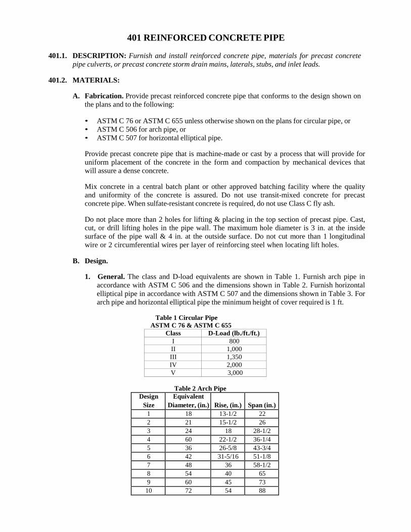
401 REINFORCED CONCRETE PIPE
401.1. DESCRIPTION: Furnish and install reinforced concrete pipe, materials for precast concrete pipe culverts, or precast concrete storm drain mains, laterals, stubs, and inlet leads.
401.2. MATERIALS:
A. Fabrication. Provide precast reinforced concrete pipe that conforms to the design shown on
the plans and to the following:
• ASTM C 76 or ASTM C 655 unless otherwise shown on the plans for circular pipe, or • ASTM C 506 for arch pipe, or • ASTM C 507 for horizontal elliptical pipe.
Provide precast concrete pipe that is machine-made or cast by a process that will provide for uniform placement of the concrete in the form and compaction by mechanical devices that will assure a dense concrete.
Mix concrete in a central batch plant or other approved batching facility where the quality and uniformity of the concrete is assured. Do not use transit-mixed concrete for precast concrete pipe. When sulfate-resistant concrete is required, do not use Class C fly ash.
Do not place more than 2 holes for lifting & placing in the top section of precast pipe. Cast, cut, or drill lifting holes in the pipe wall. The maximum hole diameter is 3 in. at the inside surface of the pipe wall & 4 in. at the outside surface. Do not cut more than 1 longitudinal wire or 2 circumferential wires per layer of reinforcing steel when locating lift holes.
B. Design.
1. General. The class and D-load equivalents are shown in Table 1. Furnish arch pipe in
accordance with ASTM C 506 and the dimensions shown in Table 2. Furnish horizontal elliptical pipe in accordance with ASTM C 507 and the dimensions shown in Table 3. For arch pipe and horizontal elliptical pipe the minimum height of cover required is 1 ft.
Table 1 Circular Pipe
ASTM C 76 & ASTM C 655 Class D-Load (lb./ft./ft.)
I 800 II 1,000 III 1,350 IV 2,000 V 3,000
Table 2 Arch Pipe Design
Size Equivalent
Diameter, (in.) Rise, (in.)
Span (in.)
1 18 13-1/2 22 2 21 15-1/2 26 3 24 18 28-1/2 4 60 22-1/2 36-1/4 5 36 26-5/8 43-3/4 6 42 31-5/16 51-1/8 7 48 36 58-1/2 8 54 40 65 9 60 45 73
10 72 54 88
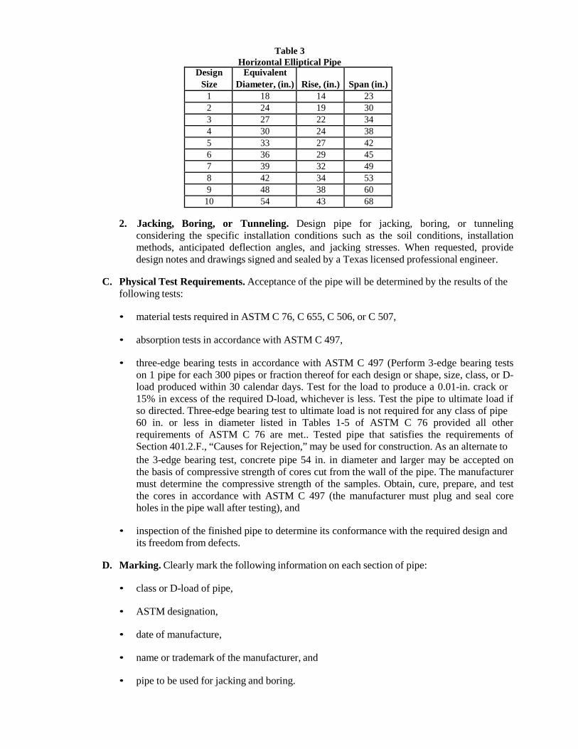
Table 3 Horizontal Elliptical Pipe
Design Size
Equivalent Diameter, (in.)
Rise, (in.)
Span (in.)
1 18 14 23 2 24 19 30 3 27 22 34 4 30 24 38 5 33 27 42 6 36 29 45 7 39 32 49 8 42 34 53 9 48 38 60
10 54 43 68
2. Jacking, Boring, or Tunneling. Design pipe for jacking, boring, or tunneling considering the specific installation conditions such as the soil conditions, installation methods, anticipated deflection angles, and jacking stresses. When requested, provide design notes and drawings signed and sealed by a Texas licensed professional engineer.
C. Physical Test Requirements. Acceptance of the pipe will be determined by the results of the
following tests:
• material tests required in ASTM C 76, C 655, C 506, or C 507,
• absorption tests in accordance with ASTM C 497,
• three-edge bearing tests in accordance with ASTM C 497 (Perform 3-edge bearing tests on 1 pipe for each 300 pipes or fraction thereof for each design or shape, size, class, or D- load produced within 30 calendar days. Test for the load to produce a 0.01-in. crack or 15% in excess of the required D-load, whichever is less. Test the pipe to ultimate load if so directed. Three-edge bearing test to ultimate load is not required for any class of pipe 60 in. or less in diameter listed in Tables 1-5 of ASTM C 76 provided all other requirements of ASTM C 76 are met.. Tested pipe that satisfies the requirements of Section 401.2.F., “Causes for Rejection,” may be used for construction. As an alternate to the 3-edge bearing test, concrete pipe 54 in. in diameter and larger may be accepted on the basis of compressive strength of cores cut from the wall of the pipe. The manufacturer must determine the compressive strength of the samples. Obtain, cure, prepare, and test the cores in accordance with ASTM C 497 (the manufacturer must plug and seal core holes in the pipe wall after testing), and
• inspection of the finished pipe to determine its conformance with the required design and
its freedom from defects.
D. Marking. Clearly mark the following information on each section of pipe:
• class or D-load of pipe,
• ASTM designation,
• date of manufacture,
• name or trademark of the manufacturer, and
• pipe to be used for jacking and boring.
For pipe with elliptical reinforcement, clearly mark 1 end of each section during the process of manufacture or immediately thereafter. Mark the pipe on the inside and the outside of opposite walls to show the location of the top or bottom of the pipe as it should be installed unless the external shape of the pipe is such that the correct position of the top and bottom is obvious. Mark the pipe section by indenting or painting with waterproof paint.
E. Inspection. Provide facilities and access to allow for inspection regarding the quality of
materials, the process of manufacture, and the finished pipe at the pipe manufacturing plant. In addition, provide access for inspection of the finished pipe at the project site before and during installation.
F. Causes for Rejection. Individual sections of pipe may be rejected for any of the following:
• fractures or cracks passing through the shell (wall), with the exception of a single end
crack that does not exceed the depth of the joint;
• defects that indicate proportioning, mixing, and molding, not in compliance with the appropriate Section of ASTM C76, C655, C506, or C507;
• Surface defects indicating honeycombed or open texture that would adversely affect the
function of the pipe;
• damaged ends where such damage would prevent making a satisfactory joint;
• any continuous crack having a surface width of 0.01 in. or more and extending for a length of 12 in. or more.
G. Repairs. Make repairs if necessary because of occasional imperfections in manufacture or
accidental damage during handling. The Engineer may accept pipe with repairs that are sound, properly finished, and cured in conformance with pertinent specifications.
H. Rejections. Allow access for the marking of rejected pipe. Rejected pipe will be plainly marked by the Engineer by painting colored spots over the City monogram on the inside wall of the pipe and on the top outside wall of the pipe. The painted spots will be no larger than 4 in. in diameter. The rejected pipe will not be defaced in any other manner. Remove the rejected pipe from the project and replace with pipe meeting the requirements of this Item.
I. Jointing Materials. Use any of the materials described herein for the making of joints, unless
otherwise shown on the plans. Furnish a manufacturer’s certificate of compliance for all jointing materials except mortar.
1. Mortar. Provide mortar for joints that meets the requirements of Section 401.4.C,
“Jointing.”
2. Cold-Applied, Plastic Asphalt Sewer Joint Compound. Provide a material that consists of natural or processed asphalt base, suitable volatile solvents, and inert filler. The consistency is to be such that the ends of the pipe can be coated with a layer of the compound up to ½ in. thick by means of a trowel. Provide a joint compound that cures to a firm, stiff plastic condition after application. Provide a material of a uniform mixture. If any small separation occurs in the container, stir to a uniform mix before using.
Provide a material that meets the requirements of Table 4 when tested in accordance with TxDOT Standard Test Method Tex-526-C.
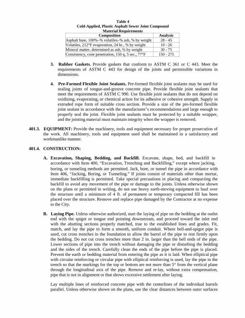
Table 4 Cold-Applied, Plastic Asphalt Sewer Joint Compound
Material Requirements Composition Analysis
Asphalt base, 100%–% volatiles–% ash, % by weight 28 - 45 Volatiles, 212°F evaporation, 24 hr., % by weight 10 - 26 Mineral matter, determined as ash, % by weight 30 - 75 Consistency, cone penetration, 150 q, 5 sec., 77°F 150 - 275
3. Rubber Gaskets. Provide gaskets that conform to ASTM C 361 or C 443. Meet the
requirements of ASTM C 443 for design of the joints and permissible variations in dimensions.
4. Pre-Formed Flexible Joint Sealants. Pre-formed flexible joint sealants may be used for
sealing joints of tongue-and-groove concrete pipe. Provide flexible joint sealants that meet the requirements of ASTM C 990. Use flexible joint sealants that do not depend on oxidizing, evaporating, or chemical action for its adhesive or cohesive strength. Supply in extruded rope form of suitable cross section. Provide a size of the pre-formed flexible joint sealant in accordance with the manufacturer’s recommendations and large enough to properly seal the joint. Flexible joint sealants must be protected by a suitable wrapper, and the jointing material must maintain integrity when the wrapper is removed.
401.3. EQUIPMENT: Provide the machinery, tools and equipment necessary for proper prosecution of
the work. All machinery, tools and equipment used shall be maintained in a satisfactory and workmanlike manner.
401.4. CONSTRUCTION:
A. Excavation, Shaping, Bedding, and Backfill. Excavate, shape, bed, and backfill in
accordance with Item 400, “Excavation, Trenching and Backfilling,” except where jacking, boring, or tunneling methods are permitted. Jack, bore, or tunnel the pipe in accordance with Item 406, “Jacking, Boring, or Tunneling.” If joints consist of materials other than mortar, immediate backfilling is permitted. Take special precautions in placing and compacting the backfill to avoid any movement of the pipe or damage to the joints. Unless otherwise shown on the plans or permitted in writing, do not use heavy earth-moving equipment to haul over the structure until a minimum of 4 ft. of permanent or temporary compacted fill has been placed over the structure. Remove and replace pipe damaged by the Contractor at no expense to the City.
B. Laying Pipe. Unless otherwise authorized, start the laying of pipe on the bedding at the outlet
end with the spigot or tongue end pointing downstream, and proceed toward the inlet end with the abutting sections properly matched, true to the established lines and grades. Fit, match, and lay the pipe to form a smooth, uniform conduit. Where bell-and-spigot pipe is used, cut cross trenches in the foundation to allow the barrel of the pipe to rest firmly upon the bedding. Do not cut cross trenches more than 2 in. larger than the bell ends of the pipe. Lower sections of pipe into the trench without damaging the pipe or disturbing the bedding and the sides of the trench. Carefully clean the ends of the pipe before the pipe is placed. Prevent the earth or bedding material from entering the pipe as it is laid. When elliptical pipe with circular reinforcing or circular pipe with elliptical reinforcing is used, lay the pipe in the trench so that the markings for the top or bottom are not more than 5° from the vertical plane through the longitudinal axis of the pipe. Remove and re-lay, without extra compensation, pipe that is not in alignment or that shows excessive settlement after laying.
Lay multiple lines of reinforced concrete pipe with the centerlines of the individual barrels parallel. Unless otherwise shown on the plans, use the clear distances between outer surfaces
of adjacent pipes shown in Table 5. For arch pipe or horizontal elliptical pipe use the equivalent diameter from Table 2 or Table 3 to determine the clear distance requirement in Table 5.
Table 5 Minimum Clear Distance between Pipes
Equivalent Diameter Min. Clear Distance 18 in. 9 in. 24 in. 11 in. 30 in. 1 ft. 1 in. 36 in. 1 ft. 3 in. 42 in. 1 ft. 5 in. 48 in. 1 ft. 7 in. 54 in. 1 ft. 11 in.
60 to 84 in. 2 ft.
C. Jointing. Make available an appropriate rolling device similar to an automobile mechanic’s “creeper” for conveyance through small-size pipe structures.
1. Joints Sealed with Hydraulic Cement Mortar. Use mortar consisting of 1 part cement,
2 parts sand, and enough water to make a plastic mix. Clean and wet the pipe ends before making the joint. Plaster the lower half of the bell or groove and the upper half of the tongue or spigot with mortar. After the pipes are tightly jointed, pack mortar into the joint from both inside and outside the pipe. Finish the inside smooth and flush with adjacent joints of pipe. For tongue-and-groove joints, form a bead of semicircular cross section over the joint outside the pipe, extending at least 1 in. on each side of the joint. For bell- and-spigot joints, form the mortar to a 45° fillet between the outer edge of the bell and the spigot. Cure mortar joints by keeping the joints wet for at least 48 hr. or until the backfill has been completed, whichever comes first. When mortar joints are used, do not place fill or backfill until the jointing material has cured for at least 6 hr. Do not conduct jointing when the atmospheric temperature is at or below 40°F. Protect mortared joints against freezing by backfilling or other approved methods for at least 24 hr.
Driveway culverts do not require mortar banding on the outside of the pipe.
With approval, pipes that are large enough for a person to enter may be furnished with the groove between ½ in. and ¾ in. longer than the tongue. Such pipe may be laid and backfilled without mortar joints. After the backfilling has been completed, clean the space on the interior of the pipe between the end of the tongue and the groove of all foreign material, thoroughly wet and fill with mortar around the entire circumference of the pipe, and finish flush.
2. Joints Using Cold-Applied, Plastic Asphalt Sewer Joint Compound. Ensure that both
ends of the pipes are clean and dry. Trowel or otherwise place a ½-in.-thick layer of the compound in the groove end of the pipe covering at least ⅔ of the joint face around the entire circumference. Next, shove home the tongue end of the next pipe with enough pressure to make a tight joint. After the joint is made, remove any excess mastic projecting into the pipe. Backfill after the joint has been inspected and approved.
3. Joints Using Rubber Gaskets. Make the joint assembly according to the
recommendations of the gasket manufacturer. When using rubber gaskets, make joints watertight. Backfill after the joint has been inspected and approved.
4. Joints Using Pre-Formed Flexible Joint Sealants. Install pre-formed flexible joint
sealants in accordance with the manufacturer’s recommendations. Place the joint sealer so that no dirt or other deleterious materials come in contact with the joint sealing
material. Pull or push home the pipe with enough force to properly seal the joint. Remove any joint material pushed out into the interior of the pipe that would tend to obstruct the flow. When the atmospheric temperature is below 60°F, store pre-formed flexible joint sealants in an area warmed to above 70°F or artificially warm to this temperature in an approved manner. Apply flexible joint sealants to pipe joints immediately before placing pipe in trench, and then connect pipe to previously laid pipe. Backfill after the joint has been inspected and approved.
D. Connections and Stub Ends. Make connections of concrete pipe to existing pipes, pipe
storm drains, or storm drain appurtenances as shown on the plans.
Mortar or concrete the bottom of existing structures if necessary to eliminate any drainage pockets created by the connections. Repair any damage to the existing structure resulting from making the connections.
Unless otherwise shown in the plans, make connections between concrete pipe and corrugated metal pipe with a suitable concrete collar having a minimum thickness of 4 in.
Finish stub ends for connections to future work not shown on the plans by installing watertight plugs into the free end of the pipe.
Fill lift holes with concrete, mortar, or precast concrete plugs after the pipe is in place.
402 HIGH DENSITY CURROGATED POLYETHYLENE PIPE
402.1. DESCRIPTION: This Item shall govern the furnishing and installing of all 18 inch to 60 inch High Density Corrugated Polyethylene pipe for constructing culverts and storm sewer mains, laterals, and stubs. The pipes shall be of the sizes, types, design and dimensions shown on the plans and shall include all connections and joints to new or existing pipes, manholes, inlets, headwalls and other appurtenances as may be required to complete the work.
402.2. MATERIALS: Unless otherwise specified on the plans or herein, High Density Corrugated
Polyethylene (HDPE) pipe and joint fittings shall conform to the following:
A. HDPE pipe and fittings shall be manufactured in accordance with requirements of ASTM F 2306, latest edition. The pipe shall have a full circular cross section, with an outer corrugated pipe wall and a smooth inner wall.
B. Virgin material for pipe and fitting production shall be used and be high density polyethylene
conforming with the minimum requirements of cell classification, as defined and described in the latest version of ASTM D3350, except that carbon black content should not exceed 4%.
C. Minimum Pipe Stiffness (PS) at five percent deflection shall be as described in ASTM F
2306, Section 6.3 when tested in accordance with ASTM D 2412.
D. All HDPE Corrugated and Smooth Lined Pipe shall be certified through the Plastics Pipe Institute (PPI) Third Party Certification program. All HDPE pipe delivered and used shall bear the Third Party Administered PPI seal.
402.3. MARKING: All pipe shall be clearly marked at intervals of not more than 10 ft, and fittings and
couplings shall be clearly marked as follows:
A. Manufacturer’s name, trade name, or trademark
B. Nominal size
C. Specification designation (e.g. ASTM F 2306)
D. Plant location
E. Date of manufacture
F. Legend polyethylene (PE)
402.4. JOINTS: Joints shall be installed such that the connection of pipe sections will form a continuous line free from irregularities in the flow line. Joints shall conform to one of the following:
A. Integral Bell and Spigot. The bell shall overlap a minimum of two corrugations of the spigot
end when fully engaged. The spigot end shall have an O-ring gasket that meets ASTM F 477 “Specification for Elastomeric Seals (Gaskets) for Joining Plastic Pipe.”
B. Exterior Bell and Spigot. The bell shall be fully welded to the exterior of the pipe and
overlap the spigot end so that the flow lines and ends match when fully engaged. The spigot end shall have an O-ring gasket that meets ASTM F 477 “Specification for Elastomeric Seals (Gaskets) for Joining Plastic Pipe.”
C. Watertight Joints. When required, watertight joints shall be in accordance with the
requirements of ASTM 3212.
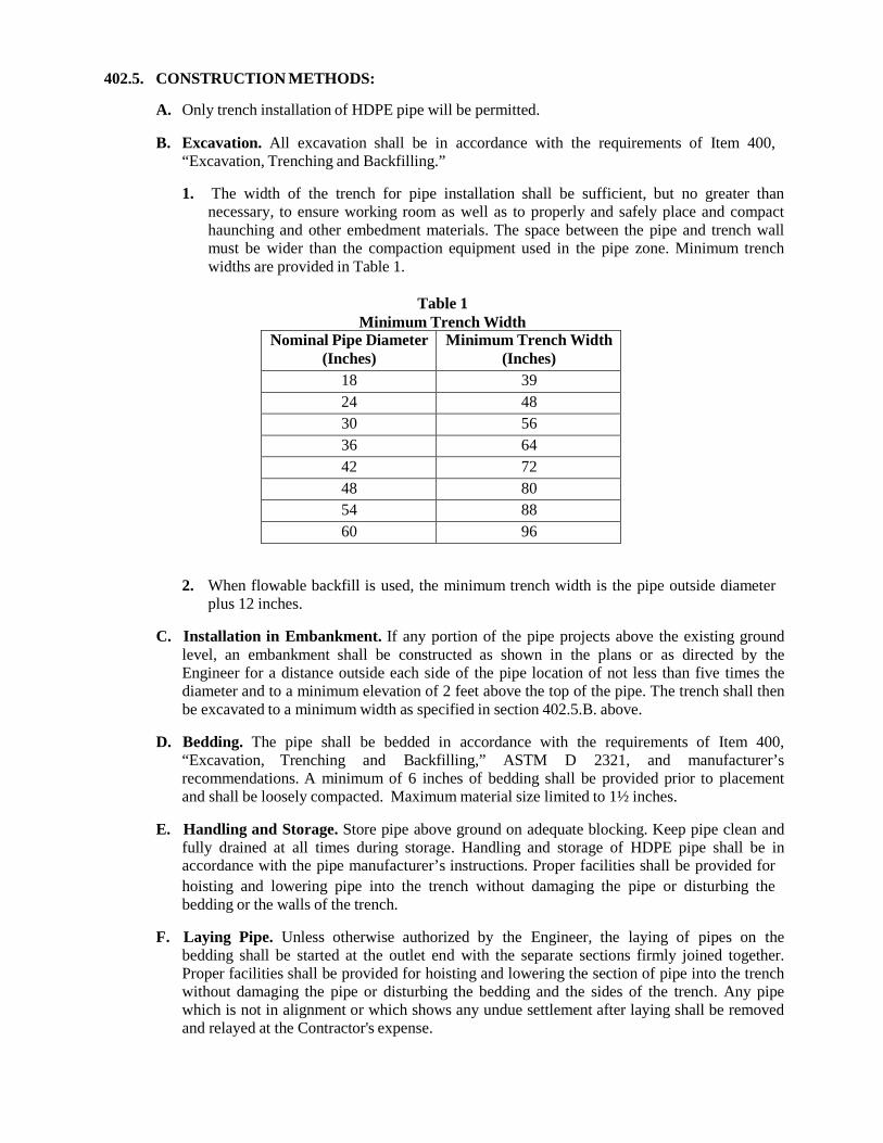
402.5. CONSTRUCTION METHODS:
A. Only trench installation of HDPE pipe will be permitted.
B. Excavation. All excavation shall be in accordance with the requirements of Item 400, “Excavation, Trenching and Backfilling.”
1. The width of the trench for pipe installation shall be sufficient, but no greater than
necessary, to ensure working room as well as to properly and safely place and compact haunching and other embedment materials. The space between the pipe and trench wall must be wider than the compaction equipment used in the pipe zone. Minimum trench widths are provided in Table 1.
Table 1
Minimum Trench Width Nominal Pipe Diameter
(Inches) Minimum Trench Width
(Inches) 18 39 24 48 30 56 36 64 42 72 48 80 54 88 60 96
2. When flowable backfill is used, the minimum trench width is the pipe outside diameter plus 12 inches.
C. Installation in Embankment. If any portion of the pipe projects above the existing ground
level, an embankment shall be constructed as shown in the plans or as directed by the Engineer for a distance outside each side of the pipe location of not less than five times the diameter and to a minimum elevation of 2 feet above the top of the pipe. The trench shall then be excavated to a minimum width as specified in section 402.5.B. above.
D. Bedding. The pipe shall be bedded in accordance with the requirements of Item 400,
“Excavation, Trenching and Backfilling,” ASTM D 2321, and manufacturer’s recommendations. A minimum of 6 inches of bedding shall be provided prior to placement and shall be loosely compacted. Maximum material size limited to 1½ inches.
E. Handling and Storage. Store pipe above ground on adequate blocking. Keep pipe clean and
fully drained at all times during storage. Handling and storage of HDPE pipe shall be in accordance with the pipe manufacturer’s instructions. Proper facilities shall be provided for hoisting and lowering pipe into the trench without damaging the pipe or disturbing the bedding or the walls of the trench.
F. Laying Pipe. Unless otherwise authorized by the Engineer, the laying of pipes on the
bedding shall be started at the outlet end with the separate sections firmly joined together. Proper facilities shall be provided for hoisting and lowering the section of pipe into the trench without damaging the pipe or disturbing the bedding and the sides of the trench. Any pipe which is not in alignment or which shows any undue settlement after laying shall be removed and relayed at the Contractor's expense.
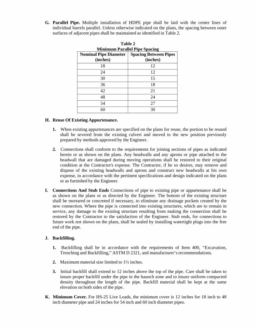
G. Parallel Pipe. Multiple installation of HDPE pipe shall be laid with the center lines of individual barrels parallel. Unless otherwise indicated on the plans, the spacing between outer surfaces of adjacent pipes shall be maintained as identified in Table 2.
Table 2
Minimum Parallel Pipe Spacing Nominal Pipe Diameter
(inches) Spacing Between Pipes
(inches) 18 12 24 12 30 15 36 18 42 21 48 24 54 27 60 30
H. Reuse Of Existing Appurtenance.
1. When existing appurtenances are specified on the plans for reuse, the portion to be reused shall be severed from the existing culvert and moved to the new position previously prepared by methods approved by the Engineer.
2. Connections shall conform to the requirements for joining sections of pipes as indicated
herein or as shown on the plans. Any headwalls and any aprons or pipe attached to the headwall that are damaged during moving operations shall be restored to their original condition at the Contractor's expense. The Contractor, if he so desires, may remove and dispose of the existing headwalls and aprons and construct new headwalls at his own expense, in accordance with the pertinent specifications and design indicated on the plans or as furnished by the Engineer.
I. Connections And Stub Ends Connections of pipe to existing pipe or appurtenance shall be
as shown on the plans or as directed by the Engineer. The bottom of the existing structure shall be mortared or concreted if necessary, to eliminate any drainage pockets created by the new connection. Where the pipe is connected into existing structures, which are to remain in service, any damage to the existing structure resulting from making the connection shall be restored by the Contractor to the satisfaction of the Engineer. Stub ends, for connections to future work not shown on the plans, shall be sealed by installing watertight plugs into the free end of the pipe.
J. Backfilling.
1. Backfilling shall be in accordance with the requirements of Item 400, “Excavation,
Trenching and Backfilling,” ASTM D 2321, and manufacturer’s recommendations.
2. Maximum material size limited to 1½ inches.
3. Initial backfill shall extend to 12 inches above the top of the pipe. Care shall be taken to insure proper backfill under the pipe in the haunch zone and to insure uniform compacted density throughout the length of the pipe. Backfill material shall be kept at the same elevation on both sides of the pipe.
K. Minimum Cover. For HS-25 Live Loads, the minimum cover is 12 inches for 18 inch to 48
inch diameter pipe and 24 inches for 54 inch and 60 inch diameter pipes.
L. Protection Of The Pipe.
1. Unless otherwise shown on the plans or permitted in writing by the Engineer, no heavy
earth moving equipment will be permitted over the structure until a minimum of 3 feet of compacted fill (permanent or temporary) has been placed over the top of the structure.
2. Prior to adding each new layer of loose backfill material, until a minimum of 12 inches of
cover is obtained, an inspection will be made of the inside periphery of the structure for local or unequal deformation caused by improper construction methods. Evidence of such will be reason for such corrective measures as may be directed by the Engineer.
3. Pipe damaged by the Contractor shall be removed and replaced by the Contractor at no
additional cost to the City.
403 STORM SEWER JUNCTION BOXES AND INLETS
403.1. DESCRIPTION: Construct junction boxes and inlets, complete in place or to the stage detailed, including excavation and backfilling; furnishing and installing frames, grates, rings and covers. Storm sewer (drainage) junction boxes are classified as junction boxes.
403.2. MATERIALS: Furnish materials in accordance with the following:
• Item 300, “Concrete” • Item 301, “Reinforcing Steel” • Item 307, “Concrete Structures” • Item 407, “Frames, Grates, Rings, and Covers.”
Precast junction boxes, inlets, risers, and appurtenances are acceptable unless otherwise shown. Alternate designs for precast items must be acceptable to the Engineer and not deviate from the functional dimensions given. Alternate designs are to be designed and sealed by a licensed professional engineer.
A. Concrete. Furnish Class A concrete for cast-in-place junction boxes and inlets unless
otherwise shown on the plans. Furnish Class A concrete or concrete meeting ASTM C 478 for precast junction boxes and inlets. Air-entrained concrete will not be required in precast concrete members.
B. Mortar. Furnish mortar composed of 1 part hydraulic cement and 2 parts clean sand.
Hydrated lime or lime putty may be added to the mix to a maximum of 10% by weight of the total dry mix.
C. Bricks. Furnish first-quality, sound, properly shaped bricks. Provide clay or shale bricks that
are homogeneous and thoroughly and uniformly hard-burned and that meet ASTM C 32, Grade MS or MM. Provide concrete bricks meeting ASTM C 55, Type I (Grade S-I). The maximum allowable water absorption of completely dry bricks is 16% by weight when submerged in water for 24-hours.
D. Concrete Blocks. Provide concrete blocks that meet ASTM C 139.
E. Cast Iron or Aluminum. Provide supports and steps conforming to the shape and
dimensions shown on the plans that meet the requirements of ASTM A 48, Class 35B, for gray iron castings or ASTM A 536, Grade 65-45-12, for ductile iron castings. Steps may also be aluminum meeting ASTM B 221, Alloy 6005-T5. Provide steps in accordance with ASTM C 478, Section 16, “Steps and Ladders.”
F. Timber. Provide sound timber for temporary covers when used with Stage I construction (see
Section 403.3, “Construction”) that is a minimum of 3 inches nominal thickness and reasonably free of knots and warps.
G. Other Materials. Commercial-type hardware of other materials may be used with prior
approval.
403.3. CONSTRUCTION:
A. General. All types of junction boxes and inlets may be built either in 1 stage or in 2 stages, described as Stage I and Stage II. Build junction boxes and inlets designed to match the final roadway surface in stages. Construct Stage II after the pavement structure is substantially complete unless otherwise approved by the Engineer.
Construct the Stage I portion of junction boxes and inlets as shown on the plans or as specified in this Item. Furnish and install a temporary cover as approved by the Engineer.
For Stage I construction of cast iron or steel inlet units, furnish and install the sewer pipe and a temporary plug for the exposed end of the sewer pipe from the storm sewer to a point below the top of curb indicated on the plans.
For Stage II, construct the remaining wall height and top of junction boxes or inlet and furnish and install any frames, grates, rings and covers, junction boxes steps, curb beams, or collecting basins required.
Construct precast junction boxes and inlets in accordance with Item 307, “Concrete Structures,” or ASTM C 478. Construct cast-in-place junction boxes and inlets in accordance with Item 307. Forms will be required for all concrete walls. Multi-project fabrication plants (as defined in TxDOT Item 424, “Precast Concrete Structures (Fabrication)”) that produce junction boxes and inlets will be approved by the TxDOT Construction Division in accordance with TxDOT DMS 7340, “Qualification Procedure for Multi-Project Fabrication Plants of Precast Concrete Junction boxes and Inlets.” The TxDOT Construction Division maintains a list of approved multi-project plants. Outside wall forms for cast-in-place concrete may be omitted with the approval of the Engineer if the surrounding material can be trimmed to a smooth vertical face. The outside form for concrete bases supporting brick walls may be omitted. Cast steps into the concrete walls when the concrete is placed, or drill and grout steps in place after concrete placement. Mortar steps into joints for brick walls. Use a full bed of mortar for brick work so the brick will thoroughly bond to the mortar. Construct full mortar joints no more than ½-inch wide for brick walls. Furnish a header course or bond course (laid perpendicular to the preceding courses) every fifth course of brick.
B. Junction boxes and Inlets for Precast Concrete Pipe Sewers. Construct junction boxes and
inlets for precast concrete pipe sewers as soon as is practicable after sewer lines into or through the junction box or inlet locations are completed. Neatly cut all sewers at the inside face of the walls of the junction box or inlet and point up with mortar.
C. Junction boxes and Inlets for Monolithic Pipe Sewers. Construct bases for junction boxes
and inlets on monolithic pipe sewers either monolithically with the sewer or after the sewer is constructed.
D. Junction boxes for Box Sewers. Cast bases for junction boxes for box sewers as an integral
part of the sewer. Construct junction boxes before backfilling, or cover the junction box opening temporarily and backfill the sewer as a whole.
E. Inverts. Shape and route floor inverts passing out or through the junction box or inlet as
shown on the plans. Shape by adding and shaping mortar or concrete after the base is cast or by placing the required additional material with the base.
F. Finishing Complete Junction boxes and Inlets. Complete junction boxes and inlets in
accordance with the plans. Backfill to original ground elevation in accordance with Item 106, “Box Culvert Excavation and Backfilling.”
G. Finishing Stage I Construction. Complete Stage I construction by constructing the walls to
the elevations shown on the plans and backfilling to required elevations in accordance with Item 106, “Box Culvert Excavation and Backfilling.”
H. Stage II Construction. Construct subgrade and base course or concrete pavement
construction over Stage I junction box or inlet construction, unless otherwise approved by the Engineer. Excavate to expose the top of Stage I construction and complete the junction box or

inlet in accordance with the plans and these Specifications, including backfill and cleaning of all debris from the bottom of the junction box or inlet.
I. Inlet Units. Install cast iron or steel inlet units in conjunction with the construction of
concrete curb and gutter. Set the inlet units securely in position before placing concrete for curb and gutter. Form openings for the inlets and recesses in curb and gutter as shown on the plans. Place and thoroughly consolidate concrete for curb and gutter adjacent to inlets and around the inlet castings and formed openings and recesses without displacing the inlet units.
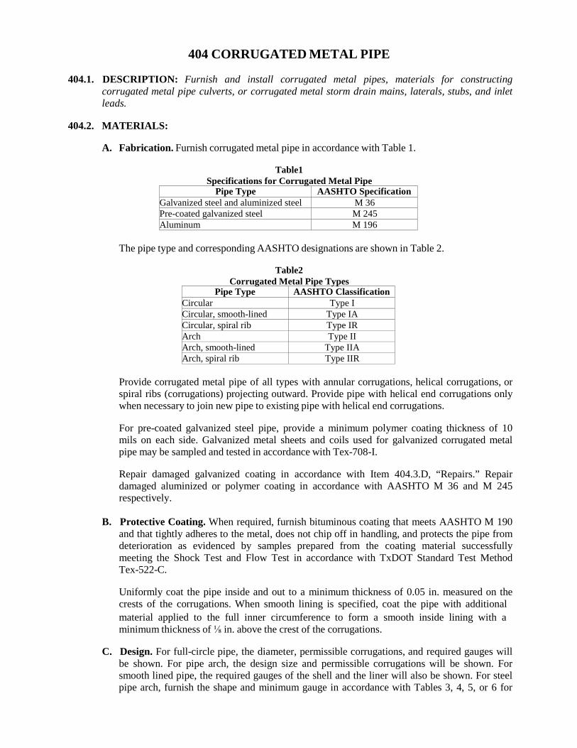
404 CORRUGATED METAL PIPE
404.1. DESCRIPTION: Furnish and install corrugated metal pipes, materials for constructing corrugated metal pipe culverts, or corrugated metal storm drain mains, laterals, stubs, and inlet leads.
404.2. MATERIALS:
A. Fabrication. Furnish corrugated metal pipe in accordance with Table 1.
Table1
Specifications for Corrugated Metal Pipe Pipe Type AASHTO Specification
Galvanized steel and aluminized steel M 36 Pre-coated galvanized steel M 245 Aluminum M 196
The pipe type and corresponding AASHTO designations are shown in Table 2.
Table2
Corrugated Metal Pipe Types Pipe Type AASHTO Classification
Circular Type I Circular, smooth-lined Type IA Circular, spiral rib Type IR Arch Type II Arch, smooth-lined Type IIA Arch, spiral rib Type IIR
Provide corrugated metal pipe of all types with annular corrugations, helical corrugations, or spiral ribs (corrugations) projecting outward. Provide pipe with helical end corrugations only when necessary to join new pipe to existing pipe with helical end corrugations.
For pre-coated galvanized steel pipe, provide a minimum polymer coating thickness of 10 mils on each side. Galvanized metal sheets and coils used for galvanized corrugated metal pipe may be sampled and tested in accordance with Tex-708-I.
Repair damaged galvanized coating in accordance with Item 404.3.D, “Repairs.” Repair damaged aluminized or polymer coating in accordance with AASHTO M 36 and M 245 respectively.
B. Protective Coating. When required, furnish bituminous coating that meets AASHTO M 190
and that tightly adheres to the metal, does not chip off in handling, and protects the pipe from deterioration as evidenced by samples prepared from the coating material successfully meeting the Shock Test and Flow Test in accordance with TxDOT Standard Test Method Tex-522-C.
Uniformly coat the pipe inside and out to a minimum thickness of 0.05 in. measured on the crests of the corrugations. When smooth lining is specified, coat the pipe with additional material applied to the full inner circumference to form a smooth inside lining with a minimum thickness of ⅛ in. above the crest of the corrugations.
C. Design. For full-circle pipe, the diameter, permissible corrugations, and required gauges will
be shown. For pipe arch, the design size and permissible corrugations will be shown. For smooth lined pipe, the required gauges of the shell and the liner will also be shown. For steel pipe arch, furnish the shape and minimum gauge in accordance with Tables 3, 4, 5, or 6 for
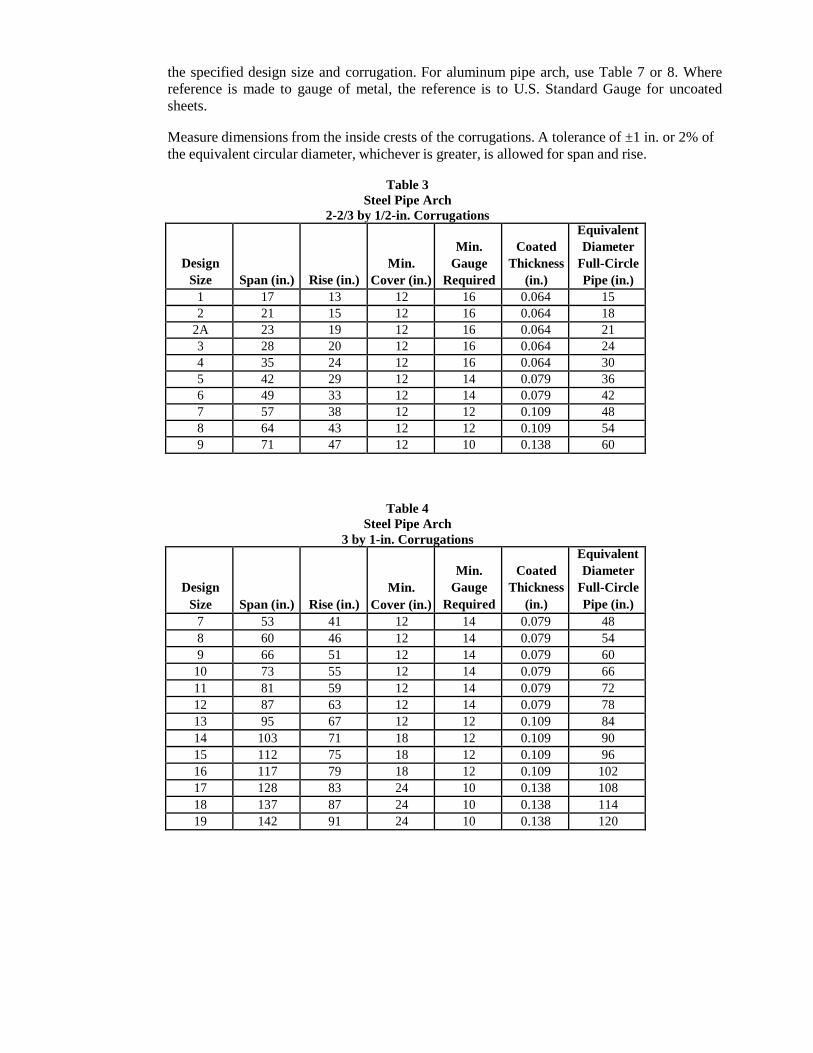
the specified design size and corrugation. For aluminum pipe arch, use Table 7 or 8. Where reference is made to gauge of metal, the reference is to U.S. Standard Gauge for uncoated sheets.
Measure dimensions from the inside crests of the corrugations. A tolerance of ±1 in. or 2% of the equivalent circular diameter, whichever is greater, is allowed for span and rise.
Table 3
Steel Pipe Arch 2-2/3 by 1/2-in. Corrugations
Design Size
Span (in.)
Rise (in.)
Min. Cover (in.)
Min.
Gauge Required
Coated
Thickness (in.)
Equivalent Diameter
Full-Circle Pipe (in.)
1 17 13 12 16 0.064 15 2 21 15 12 16 0.064 18
2A 23 19 12 16 0.064 21 3 28 20 12 16 0.064 24 4 35 24 12 16 0.064 30 5 42 29 12 14 0.079 36 6 49 33 12 14 0.079 42 7 57 38 12 12 0.109 48 8 64 43 12 12 0.109 54 9 71 47 12 10 0.138 60
Table 4 Steel Pipe Arch
3 by 1-in. Corrugations
Design Size
Span (in.)
Rise (in.)
Min. Cover (in.)
Min.
Gauge Required
Coated
Thickness (in.)
Equivalent Diameter
Full-Circle Pipe (in.)
7 53 41 12 14 0.079 48 8 60 46 12 14 0.079 54 9 66 51 12 14 0.079 60
10 73 55 12 14 0.079 66 11 81 59 12 14 0.079 72 12 87 63 12 14 0.079 78 13 95 67 12 12 0.109 84 14 103 71 18 12 0.109 90 15 112 75 18 12 0.109 96 16 117 79 18 12 0.109 102 17 128 83 24 10 0.138 108 18 137 87 24 10 0.138 114 19 142 91 24 10 0.138 120
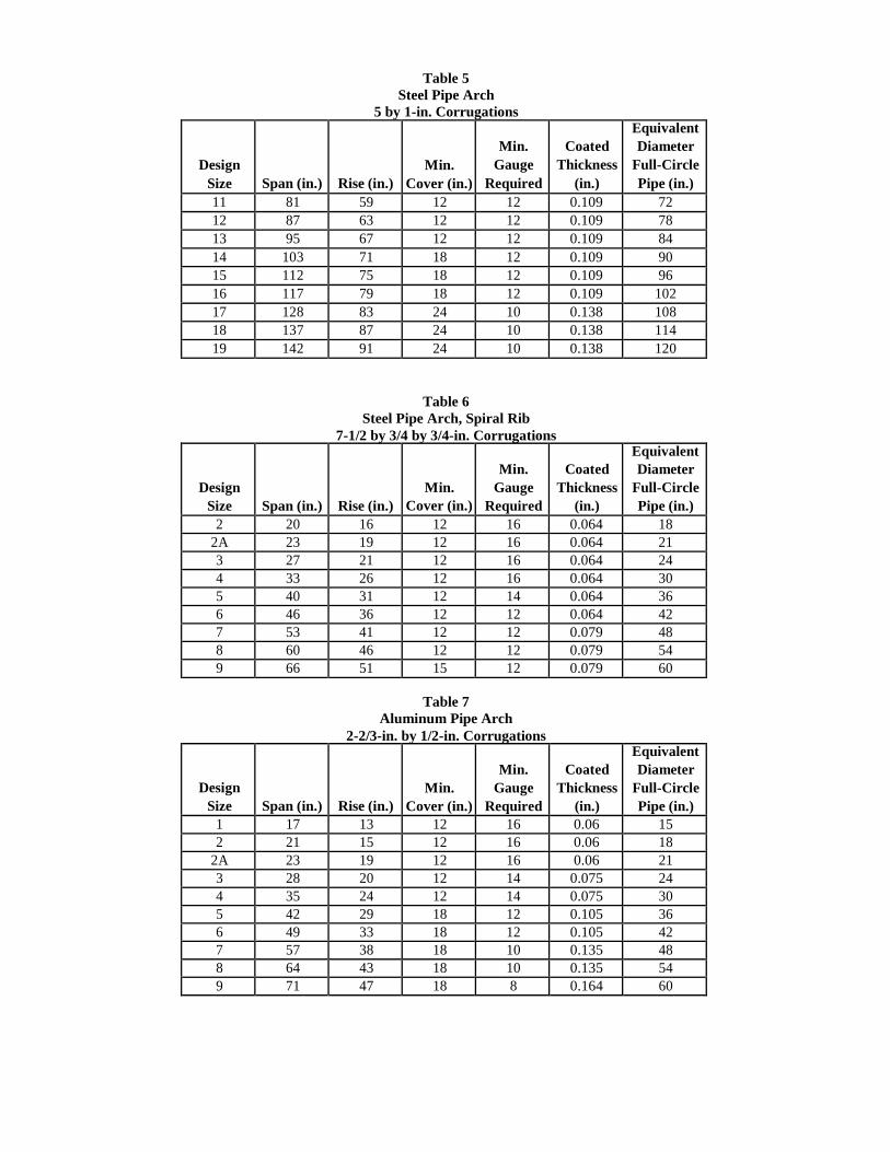
Table 5 Steel Pipe Arch
5 by 1-in. Corrugations
Design Size
Span (in.)
Rise (in.)
Min. Cover (in.)
Min.
Gauge Required
Coated
Thickness (in.)
Equivalent Diameter
Full-Circle Pipe (in.)
11 81 59 12 12 0.109 72 12 87 63 12 12 0.109 78 13 95 67 12 12 0.109 84 14 103 71 18 12 0.109 90 15 112 75 18 12 0.109 96 16 117 79 18 12 0.109 102 17 128 83 24 10 0.138 108 18 137 87 24 10 0.138 114 19 142 91 24 10 0.138 120
Table 6 Steel Pipe Arch, Spiral Rib
7-1/2 by 3/4 by 3/4-in. Corrugations
Design Size
Span (in.)
Rise (in.)
Min. Cover (in.)
Min.
Gauge Required
Coated
Thickness (in.)
Equivalent Diameter
Full-Circle Pipe (in.)
2 20 16 12 16 0.064 18 2A 23 19 12 16 0.064 21 3 27 21 12 16 0.064 24 4 33 26 12 16 0.064 30 5 40 31 12 14 0.064 36 6 46 36 12 12 0.064 42 7 53 41 12 12 0.079 48 8 60 46 12 12 0.079 54 9 66 51 15 12 0.079 60
Table 7
Aluminum Pipe Arch 2-2/3-in. by 1/2-in. Corrugations
Design Size
Span (in.)
Rise (in.)
Min. Cover (in.)
Min.
Gauge Required
Coated
Thickness (in.)
Equivalent Diameter
Full-Circle Pipe (in.)
1 17 13 12 16 0.06 15 2 21 15 12 16 0.06 18
2A 23 19 12 16 0.06 21 3 28 20 12 14 0.075 24 4 35 24 12 14 0.075 30 5 42 29 18 12 0.105 36 6 49 33 18 12 0.105 42 7 57 38 18 10 0.135 48 8 64 43 18 10 0.135 54 9 71 47 18 8 0.164 60
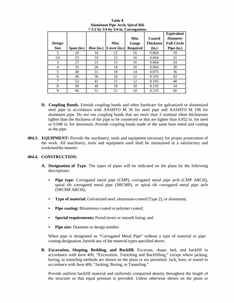
Table 8 Aluminum Pipe Arch, Spiral Rib
7-1/2 by 3/4 by 3/4-in. Corrugations
Design Size
Span (in.)
Rise (in.)
Min. Cover (in.)
Min.
Gauge Required
Coated
Thickness (in.)
Equivalent Diameter
Full-Circle Pipe (in.)
2 20 16 12 16 0.064 18 2A 23 19 12 16 0.064 21 3 27 21 15 16 0.064 24 4 33 26 18 16 0.064 30 5 40 31 18 14 0.075 36 6 46 36 18 12 0.105 42 7 53 41 21 12 0.105 48 8 60 46 18 10 0.135 54 9 66 51 21 10 0.135 60
D. Coupling Bands. Furnish coupling bands and other hardware for galvanized or aluminized steel pipe in accordance with AASHTO M 36 for steel pipe and AASHTO M 196 for aluminum pipe. Do not use coupling bands that are more than 3 nominal sheet thicknesses lighter than the thickness of the pipe to be connected or that are lighter than 0.052 in. for steel or 0.048 in. for aluminum. Provide coupling bands made of the same base metal and coating as the pipe.
404.3. EQUIPMENT: Provide the machinery, tools and equipment necessary for proper prosecution of
the work. All machinery, tools and equipment used shall be maintained in a satisfactory and workmanlike manner.
404.4. CONSTRUCTION:
A. Designation of Type. The types of pipes will be indicated on the plans by the following
descriptions:
• Pipe type: Corrugated metal pipe (CMP), corrugated metal pipe arch (CMP ARCH), spiral rib corrugated metal pipe (SRCMP), or spiral rib corrugated metal pipe arch (SRCMP ARCH);
• Type of material: Galvanized steel, aluminum-coated (Type 2), or aluminum;
• Pipe coating: Bituminous coated or polymer coated;
• Special requirements: Paved invert or smooth lining; and
• Pipe size: Diameter or design number.
When pipe is designated as “Corrugated Metal Pipe” without a type of material or pipe coating designation, furnish any of the material types specified above.
B. Excavation, Shaping, Bedding, and Backfill. Excavate, shape, bed, and backfill in
accordance with Item 400, “Excavation, Trenching and Backfilling,” except where jacking, boring, or tunneling methods are shown on the plans or are permitted. Jack, bore, or tunnel in accordance with Item 406, “Jacking, Boring, or Tunneling.”
Provide uniform backfill material and uniformly compacted density throughout the length of the structure so that equal pressure is provided. Unless otherwise shown on the plans or
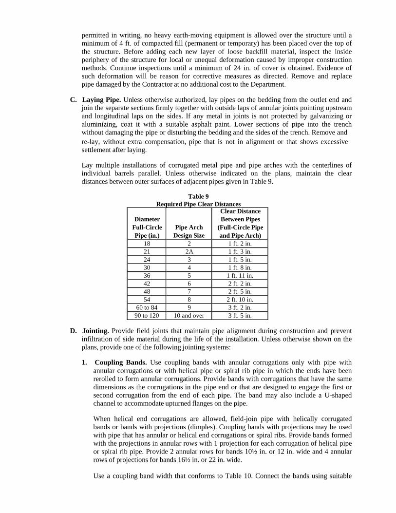
permitted in writing, no heavy earth-moving equipment is allowed over the structure until a minimum of 4 ft. of compacted fill (permanent or temporary) has been placed over the top of the structure. Before adding each new layer of loose backfill material, inspect the inside periphery of the structure for local or unequal deformation caused by improper construction methods. Continue inspections until a minimum of 24 in. of cover is obtained. Evidence of such deformation will be reason for corrective measures as directed. Remove and replace pipe damaged by the Contractor at no additional cost to the Department.
C. Laying Pipe. Unless otherwise authorized, lay pipes on the bedding from the outlet end and
join the separate sections firmly together with outside laps of annular joints pointing upstream and longitudinal laps on the sides. If any metal in joints is not protected by galvanizing or aluminizing, coat it with a suitable asphalt paint. Lower sections of pipe into the trench without damaging the pipe or disturbing the bedding and the sides of the trench. Remove and re-lay, without extra compensation, pipe that is not in alignment or that shows excessive settlement after laying.
Lay multiple installations of corrugated metal pipe and pipe arches with the centerlines of individual barrels parallel. Unless otherwise indicated on the plans, maintain the clear distances between outer surfaces of adjacent pipes given in Table 9.
Table 9
Required Pipe Clear Distances
Diameter Full-Circle Pipe (in.)
Pipe Arch Design Size
Clear Distance Between Pipes
(Full-Circle Pipe and Pipe Arch)
18 2 1 ft. 2 in. 21 2A 1 ft. 3 in. 24 3 1 ft. 5 in. 30 4 1 ft. 8 in. 36 5 1 ft. 11 in. 42 6 2 ft. 2 in. 48 7 2 ft. 5 in. 54 8 2 ft. 10 in.
60 to 84 9 3 ft. 2 in. 90 to 120 10 and over 3 ft. 5 in.
D. Jointing. Provide field joints that maintain pipe alignment during construction and prevent
infiltration of side material during the life of the installation. Unless otherwise shown on the plans, provide one of the following jointing systems:
1. Coupling Bands. Use coupling bands with annular corrugations only with pipe with
annular corrugations or with helical pipe or spiral rib pipe in which the ends have been rerolled to form annular corrugations. Provide bands with corrugations that have the same dimensions as the corrugations in the pipe end or that are designed to engage the first or second corrugation from the end of each pipe. The band may also include a U-shaped channel to accommodate upturned flanges on the pipe.
When helical end corrugations are allowed, field-join pipe with helically corrugated bands or bands with projections (dimples). Coupling bands with projections may be used with pipe that has annular or helical end corrugations or spiral ribs. Provide bands formed with the projections in annular rows with 1 projection for each corrugation of helical pipe or spiral rib pipe. Provide 2 annular rows for bands 10½ in. or 12 in. wide and 4 annular rows of projections for bands 16½ in. or 22 in. wide. Use a coupling band width that conforms to Table 10. Connect the bands using suitable
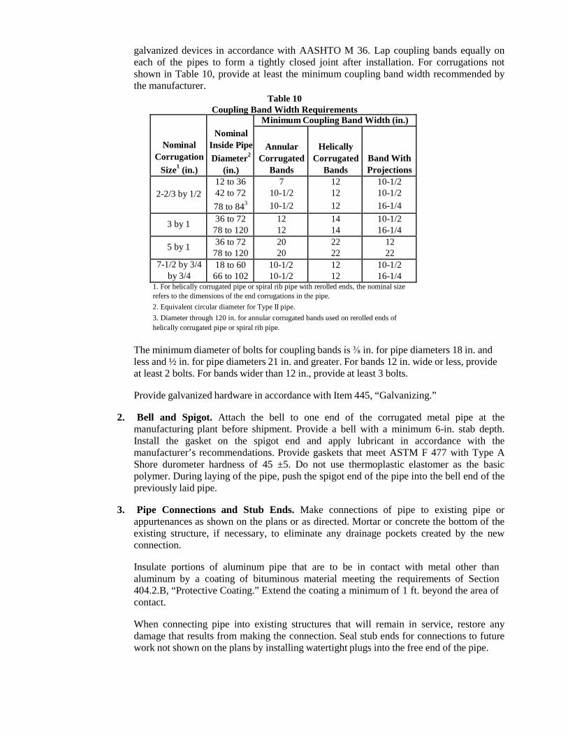
galvanized devices in accordance with AASHTO M 36. Lap coupling bands equally on each of the pipes to form a tightly closed joint after installation. For corrugations not shown in Table 10, provide at least the minimum coupling band width recommended by the manufacturer.
Table 10 Coupling Band Width Requirements
Nominal Corrugation
Size1 (in.)
Nominal
Inside Pipe Diameter2
(in.)
Minimum Coupling Band Width (in.)
Annular
Corrugated Bands
Helically
Corrugated Bands
Band With Projections
2-2/3 by 1/2
12 to 36 42 to 72 78 to 843
7 10-1/2 10-1/2
12 12 12
10-1/2 10-1/2 16-1/4
3 by 1 36 to 72 78 to 120
12 12
14 14
10-1/2 16-1/4
5 by 1 36 to 72 78 to 120
20 20
22 22
12 22
7-1/2 by 3/4 by 3/4
18 to 60 66 to 102
10-1/2 10-1/2
12 12
10-1/2 16-1/4
1. For helically corrugated pipe or spiral rib pipe with rerolled ends, the nominal size refers to the dimensions of the end corrugations in the pipe. 2. Equivalent circular diameter for Type II pipe. 3. Diameter through 120 in. for annular corrugated bands used on rerolled ends of helically corrugated pipe or spiral rib pipe.
The minimum diameter of bolts for coupling bands is ⅜ in. for pipe diameters 18 in. and less and ½ in. for pipe diameters 21 in. and greater. For bands 12 in. wide or less, provide at least 2 bolts. For bands wider than 12 in., provide at least 3 bolts.
Provide galvanized hardware in accordance with Item 445, “Galvanizing.”
2. Bell and Spigot. Attach the bell to one end of the corrugated metal pipe at the
manufacturing plant before shipment. Provide a bell with a minimum 6-in. stab depth. Install the gasket on the spigot end and apply lubricant in accordance with the manufacturer’s recommendations. Provide gaskets that meet ASTM F 477 with Type A Shore durometer hardness of 45 ±5. Do not use thermoplastic elastomer as the basic polymer. During laying of the pipe, push the spigot end of the pipe into the bell end of the previously laid pipe.
3. Pipe Connections and Stub Ends. Make connections of pipe to existing pipe or
appurtenances as shown on the plans or as directed. Mortar or concrete the bottom of the existing structure, if necessary, to eliminate any drainage pockets created by the new connection.
Insulate portions of aluminum pipe that are to be in contact with metal other than aluminum by a coating of bituminous material meeting the requirements of Section 404.2.B, “Protective Coating.” Extend the coating a minimum of 1 ft. beyond the area of contact.
When connecting pipe into existing structures that will remain in service, restore any damage that results from making the connection. Seal stub ends for connections to future work not shown on the plans by installing watertight plugs into the free end of the pipe.
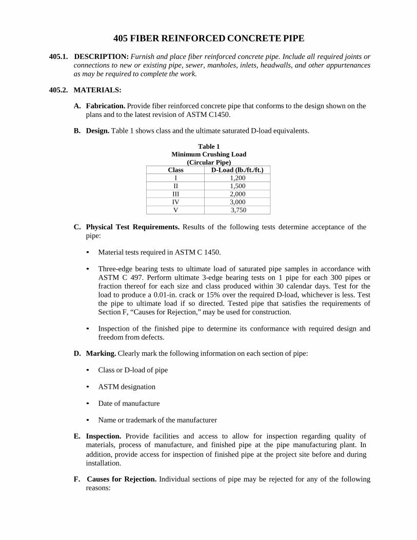
405 FIBER REINFORCED CONCRETE PIPE
405.1. DESCRIPTION: Furnish and place fiber reinforced concrete pipe. Include all required joints or connections to new or existing pipe, sewer, manholes, inlets, headwalls, and other appurtenances as may be required to complete the work.
405.2. MATERIALS:
A. Fabrication. Provide fiber reinforced concrete pipe that conforms to the design shown on the
plans and to the latest revision of ASTM C1450.
B. Design. Table 1 shows class and the ultimate saturated D-load equivalents.
Table 1 Minimum Crushing Load
(Circular Pipe) Class D-Load (lb./ft./ft.)
I 1,200 II 1,500 III 2,000 IV 3,000 V 3,750
C. Physical Test Requirements. Results of the following tests determine acceptance of the
pipe:
• Material tests required in ASTM C 1450.
• Three-edge bearing tests to ultimate load of saturated pipe samples in accordance with ASTM C 497. Perform ultimate 3-edge bearing tests on 1 pipe for each 300 pipes or fraction thereof for each size and class produced within 30 calendar days. Test for the load to produce a 0.01-in. crack or 15% over the required D-load, whichever is less. Test the pipe to ultimate load if so directed. Tested pipe that satisfies the requirements of Section F, “Causes for Rejection,” may be used for construction.
• Inspection of the finished pipe to determine its conformance with required design and
freedom from defects.
D. Marking. Clearly mark the following information on each section of pipe:
• Class or D-load of pipe
• ASTM designation
• Date of manufacture
• Name or trademark of the manufacturer
E. Inspection. Provide facilities and access to allow for inspection regarding quality of materials, process of manufacture, and finished pipe at the pipe manufacturing plant. In addition, provide access for inspection of finished pipe at the project site before and during installation.
F. Causes for Rejection. Individual sections of pipe may be rejected for any of the following
reasons:
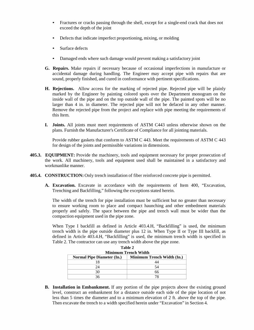
• Fractures or cracks passing through the shell, except for a single-end crack that does not exceed the depth of the joint
• Defects that indicate imperfect proportioning, mixing, or molding
• Surface defects
• Damaged ends where such damage would prevent making a satisfactory joint
G. Repairs. Make repairs if necessary because of occasional imperfections in manufacture or
accidental damage during handling. The Engineer may accept pipe with repairs that are sound, properly finished, and cured in conformance with pertinent specifications.
H. Rejections. Allow access for the marking of rejected pipe. Rejected pipe will be plainly
marked by the Engineer by painting colored spots over the Department monogram on the inside wall of the pipe and on the top outside wall of the pipe. The painted spots will be no larger than 4 in. in diameter. The rejected pipe will not be defaced in any other manner. Remove the rejected pipe from the project and replace with pipe meeting the requirements of this Item.
I. Joints. All joints must meet requirements of ASTM C443 unless otherwise shown on the
plans. Furnish the Manufacturer's Certificate of Compliance for all jointing materials.
Provide rubber gaskets that conform to ASTM C 443. Meet the requirements of ASTM C 443 for design of the joints and permissible variations in dimensions.
405.3. EQUIPMENT: Provide the machinery, tools and equipment necessary for proper prosecution of
the work. All machinery, tools and equipment used shall be maintained in a satisfactory and workmanlike manner.
405.4. CONSTRUCTION: Only trench installation of fiber reinforced concrete pipe is permitted.
A. Excavation. Excavate in accordance with the requirements of Item 400, “Excavation,
Trenching and Backfilling,” following the exceptions stated herein.
The width of the trench for pipe installation must be sufficient but no greater than necessary to ensure working room to place and compact haunching and other embedment materials properly and safely. The space between the pipe and trench wall must be wider than the compaction equipment used in the pipe zone.
When Type I backfill as defined in Article 403.4.H, “Backfilling” is used, the minimum trench width is the pipe outside diameter plus 12 in. When Type II or Type III backfill, as defined in Article 403.4.H, “Backfilling” is used, the minimum trench width is specified in Table 2. The contractor can use any trench width above the pipe zone.
Table 2 Minimum Trench Width
Normal Pipe Diameter (In.) Minimum Trench Width (In.) 18 44 24 54 30 66 36 78
B. Installation in Embankment. If any portion of the pipe projects above the existing ground
level, construct an embankment for a distance outside each side of the pipe location of not less than 5 times the diameter and to a minimum elevation of 2 ft. above the top of the pipe. Then excavate the trench to a width specified herein under “Excavation” in Section 4.
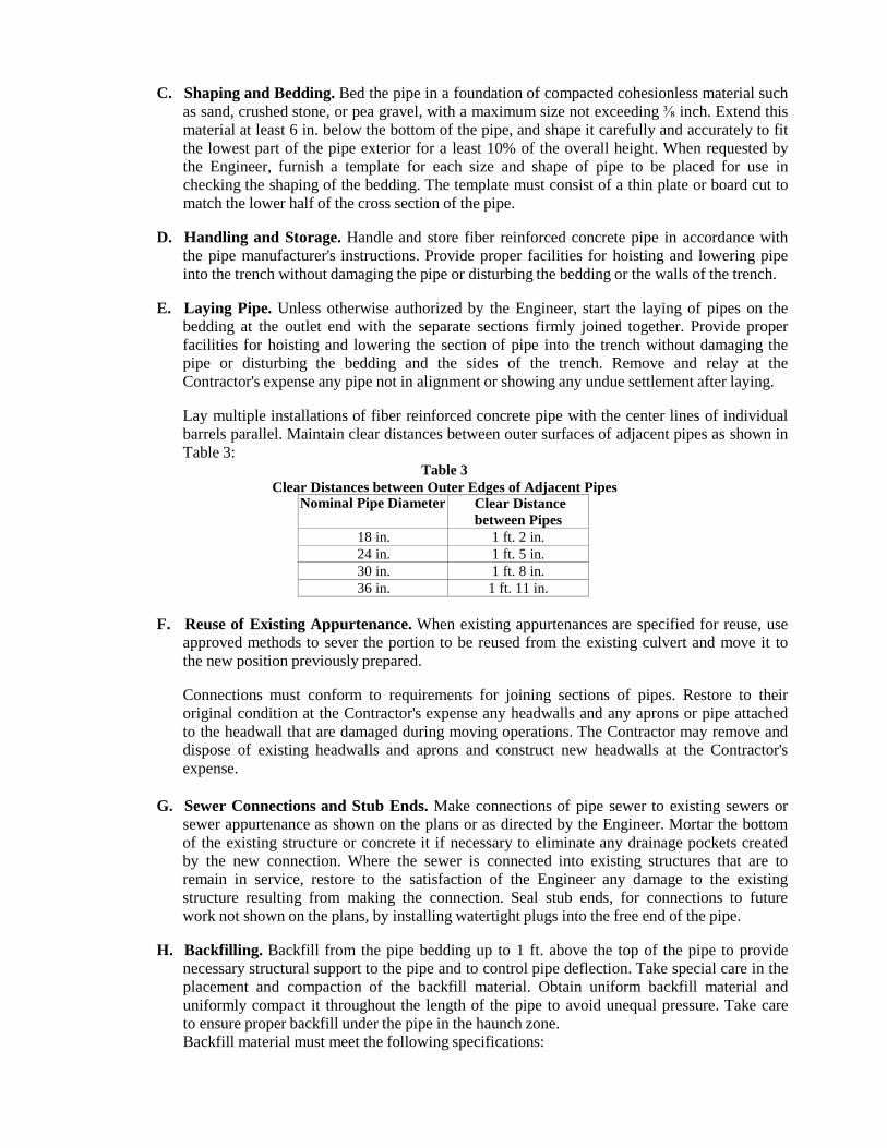
C. Shaping and Bedding. Bed the pipe in a foundation of compacted cohesionless material such
as sand, crushed stone, or pea gravel, with a maximum size not exceeding ⅜ inch. Extend this material at least 6 in. below the bottom of the pipe, and shape it carefully and accurately to fit the lowest part of the pipe exterior for a least 10% of the overall height. When requested by the Engineer, furnish a template for each size and shape of pipe to be placed for use in checking the shaping of the bedding. The template must consist of a thin plate or board cut to match the lower half of the cross section of the pipe.
D. Handling and Storage. Handle and store fiber reinforced concrete pipe in accordance with
the pipe manufacturer's instructions. Provide proper facilities for hoisting and lowering pipe into the trench without damaging the pipe or disturbing the bedding or the walls of the trench.
E. Laying Pipe. Unless otherwise authorized by the Engineer, start the laying of pipes on the
bedding at the outlet end with the separate sections firmly joined together. Provide proper facilities for hoisting and lowering the section of pipe into the trench without damaging the pipe or disturbing the bedding and the sides of the trench. Remove and relay at the Contractor's expense any pipe not in alignment or showing any undue settlement after laying.
Lay multiple installations of fiber reinforced concrete pipe with the center lines of individual barrels parallel. Maintain clear distances between outer surfaces of adjacent pipes as shown in Table 3:
Table 3 Clear Distances between Outer Edges of Adjacent Pipes
Nominal Pipe Diameter Clear Distance between Pipes
18 in. 1 ft. 2 in. 24 in. 1 ft. 5 in. 30 in. 1 ft. 8 in. 36 in. 1 ft. 11 in.
F. Reuse of Existing Appurtenance. When existing appurtenances are specified for reuse, use
approved methods to sever the portion to be reused from the existing culvert and move it to the new position previously prepared.
Connections must conform to requirements for joining sections of pipes. Restore to their original condition at the Contractor's expense any headwalls and any aprons or pipe attached to the headwall that are damaged during moving operations. The Contractor may remove and dispose of existing headwalls and aprons and construct new headwalls at the Contractor's expense.
G. Sewer Connections and Stub Ends. Make connections of pipe sewer to existing sewers or
sewer appurtenance as shown on the plans or as directed by the Engineer. Mortar the bottom of the existing structure or concrete it if necessary to eliminate any drainage pockets created by the new connection. Where the sewer is connected into existing structures that are to remain in service, restore to the satisfaction of the Engineer any damage to the existing structure resulting from making the connection. Seal stub ends, for connections to future work not shown on the plans, by installing watertight plugs into the free end of the pipe.
H. Backfilling. Backfill from the pipe bedding up to 1 ft. above the top of the pipe to provide
necessary structural support to the pipe and to control pipe deflection. Take special care in the placement and compaction of the backfill material. Obtain uniform backfill material and uniformly compact it throughout the length of the pipe to avoid unequal pressure. Take care to ensure proper backfill under the pipe in the haunch zone. Backfill material must meet the following specifications:
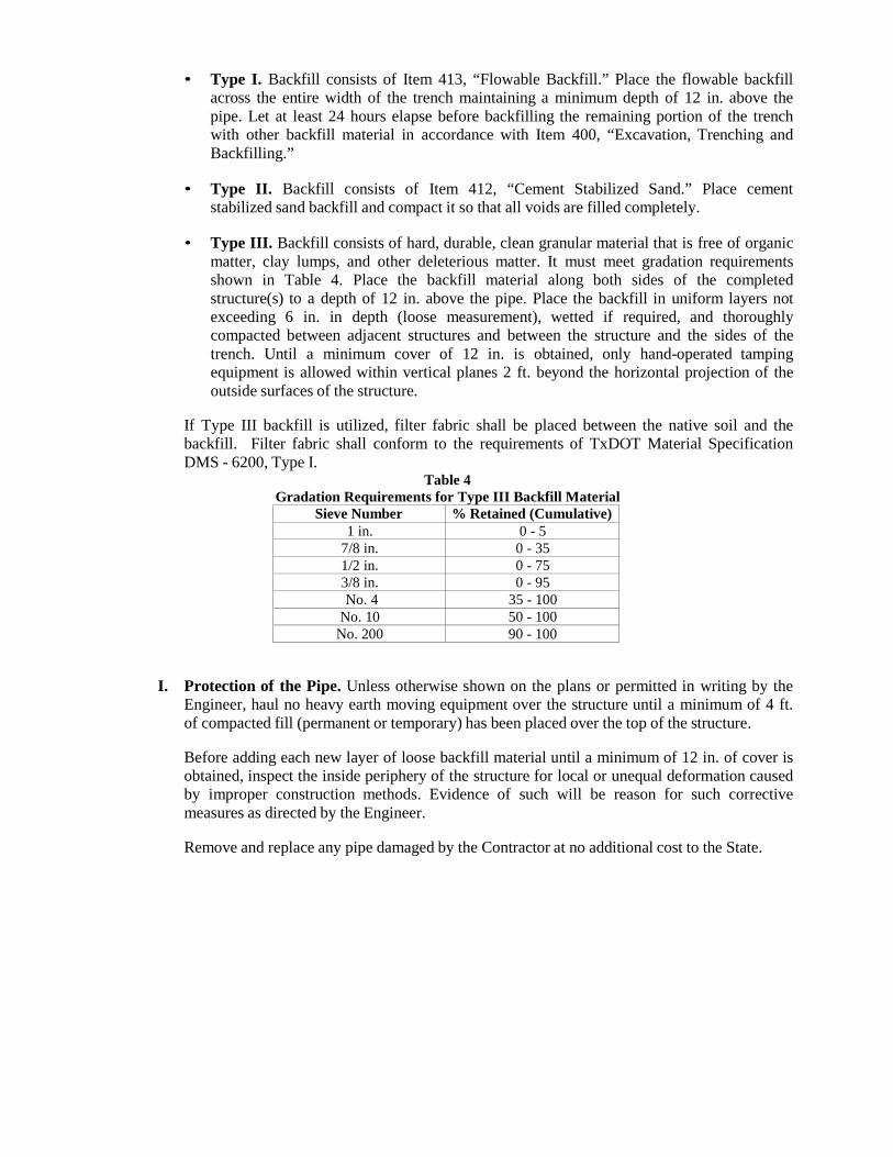
• Type I. Backfill consists of Item 413, “Flowable Backfill.” Place the flowable backfill across the entire width of the trench maintaining a minimum depth of 12 in. above the pipe. Let at least 24 hours elapse before backfilling the remaining portion of the trench with other backfill material in accordance with Item 400, “Excavation, Trenching and Backfilling.”
• Type II. Backfill consists of Item 412, “Cement Stabilized Sand.” Place cement
stabilized sand backfill and compact it so that all voids are filled completely.
• Type III. Backfill consists of hard, durable, clean granular material that is free of organic matter, clay lumps, and other deleterious matter. It must meet gradation requirements shown in Table 4. Place the backfill material along both sides of the completed structure(s) to a depth of 12 in. above the pipe. Place the backfill in uniform layers not exceeding 6 in. in depth (loose measurement), wetted if required, and thoroughly compacted between adjacent structures and between the structure and the sides of the trench. Until a minimum cover of 12 in. is obtained, only hand-operated tamping equipment is allowed within vertical planes 2 ft. beyond the horizontal projection of the outside surfaces of the structure.
If Type III backfill is utilized, filter fabric shall be placed between the native soil and the backfill. Filter fabric shall conform to the requirements of TxDOT Material Specification DMS - 6200, Type I.
Table 4 Gradation Requirements for Type III Backfill Material
Sieve Number % Retained (Cumulative) 1 in. 0 - 5
7/8 in. 0 - 35 1/2 in. 0 - 75 3/8 in. 0 - 95 No. 4 35 - 100
No. 10 50 - 100 No. 200 90 - 100
I. Protection of the Pipe. Unless otherwise shown on the plans or permitted in writing by the Engineer, haul no heavy earth moving equipment over the structure until a minimum of 4 ft. of compacted fill (permanent or temporary) has been placed over the top of the structure.
Before adding each new layer of loose backfill material until a minimum of 12 in. of cover is obtained, inspect the inside periphery of the structure for local or unequal deformation caused by improper construction methods. Evidence of such will be reason for such corrective measures as directed by the Engineer.
Remove and replace any pipe damaged by the Contractor at no additional cost to the State.
406 JACKING, BORING, OR TUNNELING PIPE
406.1. DESCRIPTION: Furnish and install pipe or box by jacking, boring, or tunneling.
406.2. MATERIALS: Use the following types of pipe or box:
A. Reinforced Concrete Pipe. Reinforced concrete pipe meeting the special requirements for jacking, boring, or tunneling of Item 401, “Storm Drainage Pipe,” of the size, strength, and dimension shown on the plans.
B. Reinforced Concrete Box. Reinforced concrete box meeting Item 307, “Concrete
Structures” and Item 309, “Precast Reinforced Concrete Box Culverts,” of the size and type shown on the plans.
C. Other. Other types specified by the plans.
406.3. CONSTRUCTION: Excavate suitable shafts or trenches for conducting the jacking, boring, or
tunneling operations and for placing end joints of the pipe or box if the grade at the jacking, boring, or tunneling end is below the ground surface. Protect excavations deeper than 5-feet as specified in Item 550, “Trench Excavation Safety Protection” or Item 551, “Special Shoring.”
Install pipe or box so there is no interference with the operation of street, highway, railroad, or other facility and no embankment or structure is weakened or damaged.
Repair any pipe or box damaged in jacking, boring, or tunneling. Remove and replace any pipe or box damaged beyond repair at the Contractor’s expense.
Immediately after installation of pipe or box, backfill shafts or trenches excavated to facilitate jacking, boring, or tunneling. When the excavated shaft or trench lies within the boundaries of the roadbed, backfill the shaft or trench in accordance with Item 306, “Structural Excavation,” Section 3, Subpart B. “Backfilling.” Backfilling will not be paid for separately but will be considered subsidiary to the work described in this item.
A. Jacking. Provide jacks suitable for forcing the pipe or box through the embankment. Use
even pressure to all jacks during operation. Provide a suitable jacking head and suitable bracing between the jacks and the jacking head to apply uniform pressure around the ring of the pipe or circumference of the box. Use joint cushioning of plywood or other approved material. For plywood cushioning material, use ½ inch minimum thickness for pipe diameter 30-inches or less, and use ¾ inch minimum thickness for pipe diameter greater than 30- inches. Use ¾ inch minimum thickness for all boxes. Use cushioning rings of single or multiple pieces. Provide a suitable jacking frame or backstop. Set the pipe or box to be jacked on guides that support the section of the pipe or box, and direct it on the proper line and grade. Place the entire jacking assembly in line with the direction and grade of the pipe or box. In general, excavate the embankment material just ahead of the pipe or box, remove the material through the pipe or box, and force the pipe or box through the embankment with jacks into the space provided.
Furnish a plan showing the proposed method of jacking for approval. Include the design for the jacking head, jacking support or backstop, arrangement and position of jacks, and guides in the plan.
Confirm that excavation for the underside of the pipe for at least ⅓ of the circumference of the pipe conforms to the contour and grade of the pipe. Confirm that the excavation for the bottom slab of the box conforms to the grade of the box. If desired, over excavate to provide not more than 2 inches of clearance for the upper portion of the pipe or box. Taper this
clearance to zero at the point where the excavation conforms to the contour of the pipe or box. Pressure-grout any over excavation of more than 1-inch.
The distance that the excavation extends beyond the end of the pipe or box must not exceed 2-feet. Decrease this distance as necessary to maintain stability of the material being excavated.
Jack the pipe or box from the low or downstream end. The final position of the pipe or box must not vary from the line and grade shown on the plans by more than 1 inch in 10 feet. Variation must be regular and in 1 direction, and the final flow line must be in the direction shown on the plans.
If desired, use a cutting edge of steel plate around the head end of the pipe or box extending a short distance beyond the end.
B. Boring. Bore from a shaft in an approved location provided for the boring equipment and
workmen.
Dispose of excavated material using a method approved by the Engineer. Use water or other fluids in connection with the boring operation only as necessary to lubricate cuttings; do not use jetting.
In unconsolidated soil formations, use a gel-forming colloidal drilling fluid consisting of high-grade, carefully processed bentonite to consolidate cuttings of the bit, seal the walls of the hole, and furnish lubrication for subsequent removal of cuttings and immediate installation of the pipe.
Allowable variations from line and grade are specified in Section 406.3.A, “Jacking.” Pressure-grout any over excavation of more than 1 inch.
Use a pilot hole or auger method for the boring.
1. Pilot Hole Method. Bore a 2 inch pilot hole the entire length of the crossing, and check it
for line and grade on the opposite end of the bore from the work shaft. This pilot hole will serve as centerline for the larger diameter hole to be bored.
2. Auger Method. Use a steel encasement pipe of the appropriate diameter equipped with a
cutter head to mechanically perform the excavation. Use augers of sufficient diameter to convey the excavated material to the work shaft.
C. Tunneling. Use an approved tunneling method where the characteristics of the soil, the size
of the proposed pipe, or the use of monolithic pipe would make the use of tunneling more satisfactory than jacking or boring or when shown on the plans.
When tunneling is permitted, confirm that the lining of the tunnel is of sufficient strength to support the overburden. Submit the proposed liner method for approval. Approval does not relieve the Contractor of the responsibility for the adequacy of the liner method.
Pressure-grout the space between the liner plate and the limits of excavation.
D. Joints. If corrugated metal pipe is used, make joints by field bolting or by connecting bands,
whichever is feasible. If reinforced concrete pipe is used, make the joints in accordance with Item 401, “Storm Drainage Pipe.” If reinforced concrete box is used, make the joints in accordance with Item 307, “Concrete Structures” and Item 309, “Precast Reinforced Concrete Box Culverts.”
407 CONCRETE ENCASEMENT, CRADLES, SADDLES, AND COLLARS
407.1. DESCRIPTION: Place concrete encasements, cradles, saddles and collars, when called for by the plans or as directed by the Engineer.
407.2. MATERIALS: All concrete shall conform to the provisions as shown below or as directed by the
Engineer
A. Concrete. Item No. 300, “Concrete (Class B)” or shall be of the class as noted on the plans.
407.3. EQUIPMENT: Provide equipment as required to complete the work specified herein or as directed by the Engineer.
407.4. CONSTRUCTION:
A. Concrete Encasement. When concrete encasement is shown on the plans or when directed
by the Engineer, the trench shall be excavated and fine graded to a depth conforming to the details and sections shown on the plans. The pipe shall be supported by precast concrete blocks of the same strength as the concrete for encasement and securely tied down to prevent floatation. Encasement shall then be placed to a depth and width conforming to the details and sections shown on the plans.
B. Concrete Cradles. When concrete cradles are shown on the plans or when called for by the
Engineer the trench shall be prepared and the pipe supported in the same manner as described in concrete encasement of this specification and shall be constructed in accordance with details and sections shown on the plans.
C. Concrete Saddles. When shown on the plans or when directed by the Engineer, pipe to
receive concrete saddles shall be backfilled in accordance with Item No. 400, “Excavation, Trenching, and Backfill” to the spring line and concrete placed for a depth and width conforming to the details and sections shown on the plans.
D. Concrete Collars. When shown on the plans or when directed by the Engineer concrete
collars shall be constructed in accordance with details and sections shown on the plans.
409 CAST IRON CASTINGS
409.1. DESCRIPTION: Furnish and install frames, grates, rings and covers for inlets, manholes, and other structures.
409.2. MATERIALS:
A. Welded Steel Grates and Frames. Provide welded steel grates and frames as an assembly
conforming to the member size, dimensions, and details shown on the plans. Fabricate these assemblies in accordance with TxDOT Item 441, “Steel Structures.” Use steel that meets ASTM A 36 or equal.
B. Frame, Grate, Ring, and Cover Castings. Provide clean castings conforming to the shape
and dimensions shown on the plans. Ensure that the castings are free from sand and blow holes or other defects and that surfaces of the castings are reasonably smooth. Remove runners, risers, fins, and other cast-on pieces from the castings, and grind these areas smooth. Cast or machine the bearing surfaces between manhole rings and covers and between grates and frames with such precision that uniform bearing is provided throughout the perimeter area of contact. Matchmark pairs of machined castings for proper identification at installation.
Provide steel castings conforming to ASTM A 27. Furnish Grade 70 36 unless otherwise specified. Provide gray iron castings conforming to ASTM A 48, Class 35B. Provide ductile iron castings conforming to ASTM A 536. Use Grade 65 45 12 unless otherwise specified. Frame, grate, ring, and cover castings must meet the proof-load testing requirements of AASHTO M 306. Use commercial type frames, rings, risers or appurtenances only with prior approval of the Engineer.
C. Documentation. Furnish mill test reports or manufacturer’s certification to the Engineer for
each lot or shipment of steel and iron materials. For castings, also furnish a manufacturer’s certification stating that the casting meets the proof-load testing requirements of AASHTO M 306.
409.3. CONSTRUCTION: Construct and install frames, grates, rings, and covers in accordance with
the details shown on the plans. Weld in accordance with TxDOT Item 448, “Structural Field Welding.” Tack-weld grates and covers to the frame or ring when directed by the Engineer.
Galvanize steel castings and welded steel grates and frames in accordance with TxDOT Item 445, “Galvanizing.” Galvanizing is not required for iron castings unless used in conjunction with structural steel shapes or shown on the plans.
Provide galvanized bolts and nuts in accordance with TxDOT Item 445, “Galvanizing.”
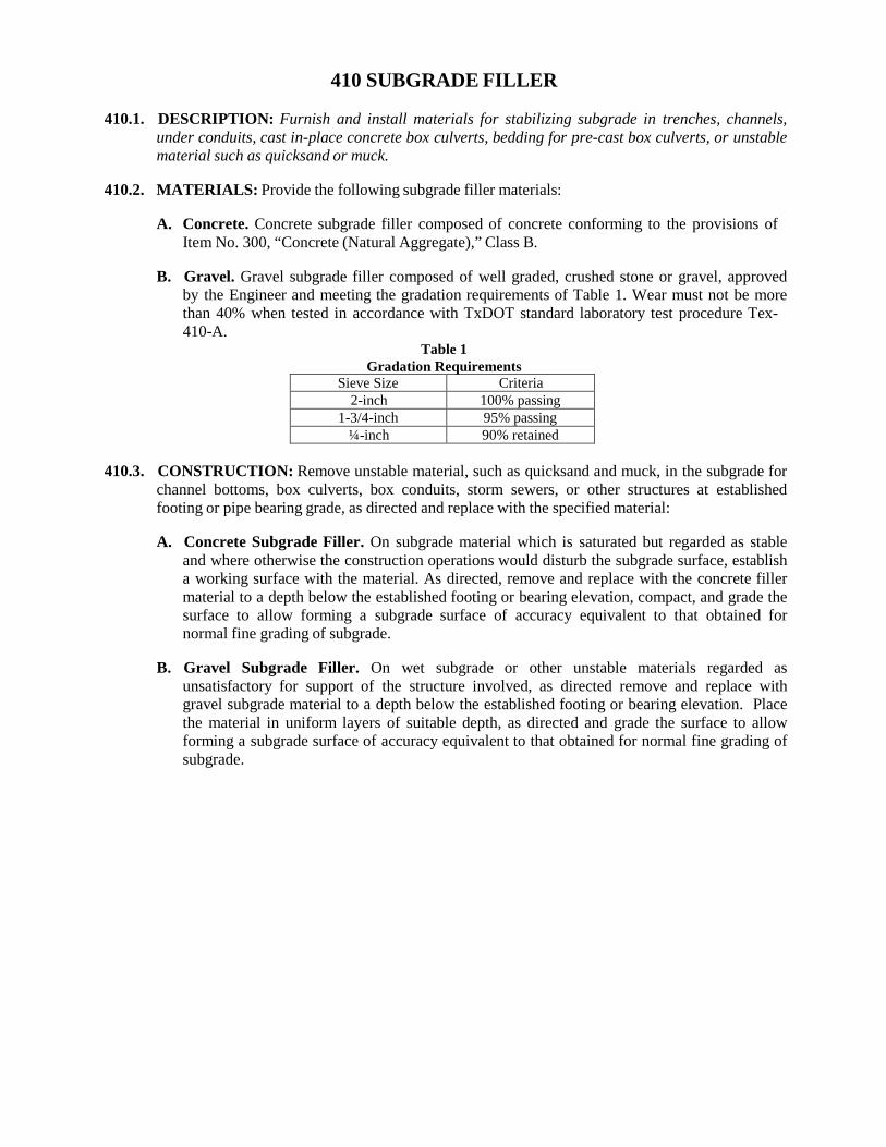
410 SUBGRADE FILLER
410.1. DESCRIPTION: Furnish and install materials for stabilizing subgrade in trenches, channels, under conduits, cast in-place concrete box culverts, bedding for pre-cast box culverts, or unstable material such as quicksand or muck.
410.2. MATERIALS: Provide the following subgrade filler materials:
A. Concrete. Concrete subgrade filler composed of concrete conforming to the provisions of
Item No. 300, “Concrete (Natural Aggregate),” Class B.
B. Gravel. Gravel subgrade filler composed of well graded, crushed stone or gravel, approved by the Engineer and meeting the gradation requirements of Table 1. Wear must not be more than 40% when tested in accordance with TxDOT standard laboratory test procedure Tex- 410-A.
Table 1 Gradation Requirements
Sieve Size Criteria 2-inch 100% passing
1-3/4-inch 95% passing ¼-inch 90% retained
410.3. CONSTRUCTION: Remove unstable material, such as quicksand and muck, in the subgrade for
channel bottoms, box culverts, box conduits, storm sewers, or other structures at established footing or pipe bearing grade, as directed and replace with the specified material:
A. Concrete Subgrade Filler. On subgrade material which is saturated but regarded as stable
and where otherwise the construction operations would disturb the subgrade surface, establish a working surface with the material. As directed, remove and replace with the concrete filler material to a depth below the established footing or bearing elevation, compact, and grade the surface to allow forming a subgrade surface of accuracy equivalent to that obtained for normal fine grading of subgrade.
B. Gravel Subgrade Filler. On wet subgrade or other unstable materials regarded as
unsatisfactory for support of the structure involved, as directed remove and replace with gravel subgrade material to a depth below the established footing or bearing elevation. Place the material in uniform layers of suitable depth, as directed and grade the surface to allow forming a subgrade surface of accuracy equivalent to that obtained for normal fine grading of subgrade.
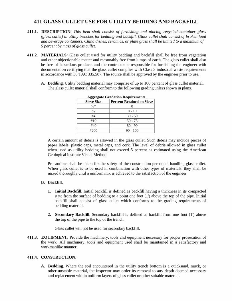
411 GLASS CULLET USE FOR UTILITY BEDDING AND BACKFILL
411.1. DESCRIPTION: This item shall consist of furnishing and placing recycled container glass (glass cullet) in utility trenches for bedding and backfill. Glass cullet shall consist of broken food and beverage containers. China dishes, ceramics, or plate glass shall be limited to a maximum of 5 percent by mass of glass cullet.
411.2. MATERIALS: Glass cullet used for utility bedding and backfill shall be free from vegetation
and other objectionable matter and reasonably free from lumps of earth. The glass cullet shall also be free of hazardous products and the contractor is responsible for furnishing the engineer with documentation certifying that the glass cullet complies with Class 3 industrial waste requirements in accordance with 30 TAC 335.507. The source shall be approved by the engineer prior to use.
A. Bedding. Utility bedding material may comprise of up to 100 percent of glass cullet material.
The glass cullet material shall conform to the following grading unless shown in plans.
Aggregate Gradation Requirements Sieve Size Percent Retained on Sieve
⅝” 0 ⅜ 0 - 10 #4 30 - 50 #10 50 - 75 #40 80 - 90
#200 90 - 100
A certain amount of debris is allowed in the glass cullet. Such debris may include pieces of paper labels, plastic caps, metal caps, and cork. The level of debris allowed in glass cullet when used as utility bedding shall not exceed 5 percent as estimated using the American Geological Institute Visual Method.
Precautions shall be taken for the safety of the construction personnel handling glass cullet. When glass cullet is to be used in combination with other types of materials, they shall be mixed thoroughly until a uniform mix is achieved to the satisfaction of the engineer.
B. Backfill.
1. Initial Backfill. Initial backfill is defined as backfill having a thickness in its compacted
state from the surface of bedding to a point one foot (1') above the top of the pipe. Initial backfill shall consist of glass cullet which conforms to the grading requirements of bedding material.
2. Secondary Backfill. Secondary backfill is defined as backfill from one foot (1') above
the top of the pipe to the top of the trench.
Glass cullet will not be used for secondary backfill.
411.3. EQUIPMENT: Provide the machinery, tools and equipment necessary for proper prosecution of the work. All machinery, tools and equipment used shall be maintained in a satisfactory and workmanlike manner.
411.4. CONSTRUCTION:
A. Bedding. Where the soil encountered in the utility trench bottom is a quicksand, muck, or
other unstable material, the inspector may order its removal to any depth deemed necessary and replacement within uniform layers of glass cullet or other suitable material.

B. Backfill. Glass cullet approved by the engineer, conforming to the requirements set above,
may be used for initial backfill. The glass cullet shall be placed in the trench and lightly tamped to consolidate and seat the mass against the conduit and earthen surfaces. Backfill material shall be kept at the same elevation on both sides of pipe.
A filter fabric shall be placed between the top of the glass cullet (initial backfill) and the secondary backfill for the entire length and width of the trench. The filter fabric shall conform to the requirements of Texas Department of Transportation Material Specification 6200, Type1.
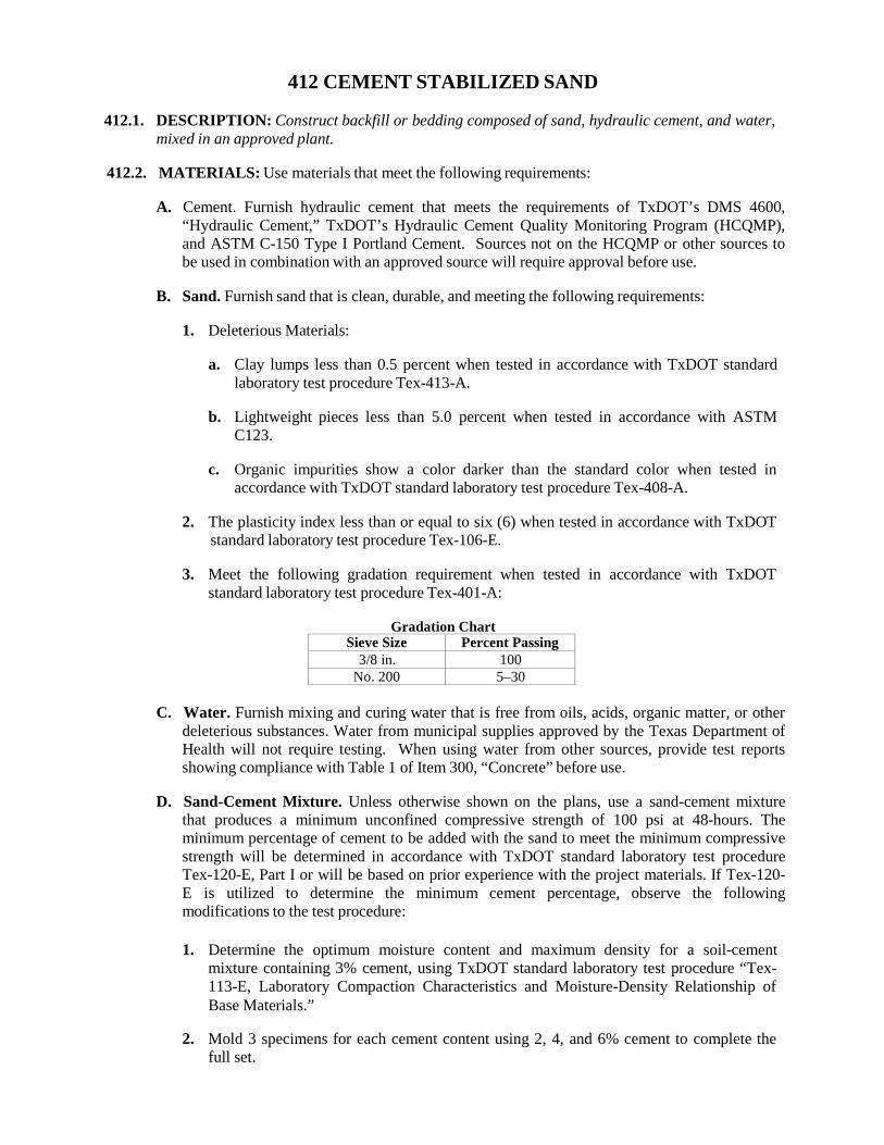
412 CEMENT STABILIZED SAND
412.1. DESCRIPTION: Construct backfill or bedding composed of sand, hydraulic cement, and water, mixed in an approved plant.
412.2. MATERIALS: Use materials that meet the following requirements:
A. Cement. Furnish hydraulic cement that meets the requirements of TxDOT’s DMS 4600,
“Hydraulic Cement,” TxDOT’s Hydraulic Cement Quality Monitoring Program (HCQMP), and ASTM C-150 Type I Portland Cement. Sources not on the HCQMP or other sources to be used in combination with an approved source will require approval before use.
B. Sand. Furnish sand that is clean, durable, and meeting the following requirements:
1. Deleterious Materials:
a. Clay lumps less than 0.5 percent when tested in accordance with TxDOT standard
laboratory test procedure Tex-413-A.
b. Lightweight pieces less than 5.0 percent when tested in accordance with ASTM C123.
c. Organic impurities show a color darker than the standard color when tested in
accordance with TxDOT standard laboratory test procedure Tex-408-A.
2. The plasticity index less than or equal to six (6) when tested in accordance with TxDOT standard laboratory test procedure Tex-106-E.
3. Meet the following gradation requirement when tested in accordance with TxDOT
standard laboratory test procedure Tex-401-A:
Gradation Chart Sieve Size Percent Passing
3/8 in. 100 No. 200 5–30
C. Water. Furnish mixing and curing water that is free from oils, acids, organic matter, or other
deleterious substances. Water from municipal supplies approved by the Texas Department of Health will not require testing. When using water from other sources, provide test reports showing compliance with Table 1 of Item 300, “Concrete” before use.
D. Sand-Cement Mixture. Unless otherwise shown on the plans, use a sand-cement mixture
that produces a minimum unconfined compressive strength of 100 psi at 48-hours. The minimum percentage of cement to be added with the sand to meet the minimum compressive strength will be determined in accordance with TxDOT standard laboratory test procedure Tex-120-E, Part I or will be based on prior experience with the project materials. If Tex-120- E is utilized to determine the minimum cement percentage, observe the following modifications to the test procedure:
1. Determine the optimum moisture content and maximum density for a soil-cement
mixture containing 3% cement, using TxDOT standard laboratory test procedure “Tex- 113-E, Laboratory Compaction Characteristics and Moisture-Density Relationship of Base Materials.”
2. Mold 3 specimens for each cement content using 2, 4, and 6% cement to complete the
full set.
3. Store test specimens the same day they are molded, with top and bottom porous stones, in
the damp room for 48 hours.
Use no less than 1.0 sack of Portland cement per ton of material mixture. Add sufficient water to the mixture to hydrate the cement.
412.3. EQUIPMENT: Provide machinery, tools, and equipment necessary for proper execution of the
work.
412.4. CONSTRUCTION: Unless otherwise shown on the plans or directed by the Engineer, mix, place, compact, and accept the cement stabilized sand as described below:
A. Mixing. Mix the cement, sand and water in a pugmill type mixer, which meets the approval
of the Engineer. Mix for a minimum period of two minutes per batch.
B. Placing. Place the sand cement mixture in maximum 8 inch thick lifts, loose measure, and thoroughly compact into place around the structure. Perform the placement and compaction in a manner that thoroughly fills all voids without placing undue strain on or displacement of the structure.
Place the cement stabilized sand backfill below the top of sewers, manholes, inlets or other structures equally along all sides of the structure. Place the cement stabilized sand for bedding and/or backfill in a manner that fills all voids in the trench. Should compaction be required to fill all voids in the areas described, hand operated tampers may be used.
C. Compaction. Compact the cement stabilized sand bedding or backfill that is placed in trench
bottoms or as initial backfill to a minimum of 95% of the maximum density determined from TxDOT standard laboratory test procedure Tex-120-E, Part II. Refer to the appropriate construction standard specification or project plans for specific details regarding other compaction requirements.
D. Quality Acceptance. Perform in-place density tests at each location, each day, on the
placement of bedding and/or backfill materials. The Engineer will perform a minimum of one (1) in-place density on the bedding and two (2) in-place densities on backfill per 50 tons or less per day. For placements greater than 50 tons per day, the Engineer will perform at each location the frequency of one (1) in-place density test per 200 linear feet of bedding and one (1) in-place density test per 100 linear feet of backfill per lift placed above the top of pipe. In- place density tests will be determined in accordance with TxDOT standard test procedure Tex-115-A.
413 FLOWABLE FILL
413.1. DESCRIPTION: Furnish, mix, test and install flowable fill. Flowable fill is a concrete material suitable as a backfill for utility trenches, abandoned pipes, manholes and valves. It is a heavy material and will exert a high fluid pressure against any forms, embankment, or wall used to contain the backfill.
413.2. MATERIALS:
A. Cement. Furnish hydraulic cement that meets the requirements of TxDOT’s DMS-4600,
“Hydraulic Cement,” TxDOT’s Hydraulic Cement Quality Monitoring Program (HCQMP), and ASTM C-150 Type I Portland Cement. Sources not on the HCQMP or other sources to be used in combination with an approved source will require approval before use.
B. Fly Ash. Furnish fly ash conforming to TxDOT DMS-4610, “Fly Ash.”
C. Chemical Admixtures. Furnish chemical admixtures conforming to TxDOT DMS-4640,
“Chemical Admixtures for Concrete.”
D. Fine Aggregate. Provide fine aggregate that will stay in suspension in the mortar to the extent required for proper flow and that meets the gradation requirements of Table 1. Test fine aggregate gradation in accordance with TxDOT standard laboratory test procedure Tex- 401-A. Plasticity Index (PI) must not exceed 6 when tested in accordance with TxDOT standard laboratory test procedure Tex-106-A.
Table 1
Aggregate Gradation Chart Sieve Size Percent Passing
¾ in. 100 No. 200 0–30
E. Mixing Water. Use mixing water conforming to the requirements of Item 300, “Concrete.”
413.3. CONSTRUCTION: Submit a construction method and plan, including mix design and shrinkage
characteristics of the mix, for approval. Provide a means of filling the entire void area, and be able to demonstrate that this has been accomplished. Prevent the movement of any inserted structure from its designated location. If voids are found in the fill or if any of the requirements are not met as shown on the plans, remove and replace or correct the problem without additional cost to the City.
Unless otherwise shown on the plans, furnish a mix meeting the requirements of Sections 413.3.A, “Strength,” and 413.3.B, “Consistency.”
A. Strength. The compressive strength range, when tested in accordance with TxDOT standard
laboratory test procedure Tex-418-A, must be between the following strength values unless otherwise directed by the Engineer or shown on the plans:
1. Low Strength. Between 80 psi and 150 psi at 28 days,
2. High Strength. Greater than 500 psi at 28 days. For emergency repairs, strength shall be
greater than 50 psi at 2 hours.
Two specimens are required for a strength test, and the compressive strength is defined as the average of the breaking strength of the 2 cylinders.
B. Consistency. Design the mix to be placed without consolidation and to fill all intended voids.
Fill an open-ended, 3 inch diameter by 6 inch high cylinder to the top to test the consistency. Immediately pull the cylinder straight up. The correct consistency of the mix must produce a minimum 8 inch diameter circular spread with no segregation.
When necessary, use specialty type admixtures to enhance the flowability, reduce shrinkage, and reduce segregation by maintaining solids in suspension. All admixtures must be used and proportioned in accordance with the manufacturer’s recommendations.
Mix the flowable fill using a central-mixed concrete plant, ready-mix concrete truck, pug mill, or other approved method.
Furnish all labor, equipment, tools, containers, and molds required for sampling, making, transporting, curing, removal, and disposal of test specimens. Furnish test molds meeting the requirements of TxDOT standard laboratory test procedure Tex-447-A. Transport, strip, and cure the test specimens as scheduled at the designated location. Cure test specimens in accordance with TxDOT standard laboratory test procedure Tex-447-A. The Engineer will sample, make, and test all specimens. Dispose of used, broken specimens in an approved location and manner. The frequency of job control testing will be at the direction of the Engineer.
C. Shrinkage and Bleeding. Limit shrinkage to 0.5% or less based upon the results from ASTM
C 827, “Change in Height at Early Ages of Cylindrical Specimens from Cementitious Mixtures.”
414 FLEXIBLE PIPE-TO-MANHOLE CONNECTOR
414.1. DESCRIPTION: This item shall govern for the furnishing and installation of flexible pipe to manhole connector in accordance with the plans and specifications.
414.2. MATERIALS: A flexible Pipe-to-Manhole connector shall be employed in the connection of the
sanitary and drain sewer pipe to precast manholes.
A. Connector Assembly. The connector assembly shall be the sole element relied on to assure a flexible watertight seal of the pipe to the manhole. The connector shall consist of a rubber gasket, an internal expansion sleeve, and one or more external compression take-up clamps.
1. Rubber Gasket. The rubber gasket element shall be constructed solely of poly-isoprene
or natural rubber, and shall meet/exceed the requirements of ASTM C-923, and shall have a minimum tensile strength of 1600 PSI. Minimum thickness of the cross-section shall be 0.275 inches.
2. Internal Expansion Sleeve. If metal, the internal expansion sleeve shall be made of 11-
gauge non-magnetic stainless steel and shall utilize no welds in its construction. Installation shall be performed using either a hydraulic or mechanical insertion tool available from the connector manufacturer.
3. External Compression Take-Up Clamp. The external compression take-up clamp(s)
shall be constructed of non-magnetic stainless steel and shall utilize no welds in its construction. The clamp(s) shall be installed by torqueing the adjusting screw using a torque-setting wrench available from the connector manufacturer.
414.3. EQUIPMENT: Provide the machinery, tools and equipment necessary for proper prosecution of
the work. All machinery, tools and equipment used shall be maintained in a satisfactory and workmanlike manner.
414.4. CONSTRUCTION: Selection of the proper size connector for the manhole and pipe
requirement, and installation thereof, shall be in strict conformance with the recommendations of the connector manufacturer.
Any dead end pipe stubs installed in connectors shall be restrained from movement per ASTM C- 923.
The finished connection shall provide sealing to 13 psi (minimum), and shall accommodate deflection of pipe to 7 degrees (minimum) without loss of seal.
Testing of complete joints, if required, shall be conducted in strict conformance with the requirements of the connector manufacturer.
DIVISION V - INCIDENTAL CONSTRUCTION
504 CONCRETE MEDIANS AND ISLANDS
504.1. DESCRIPTION: Construct cast-in-place concrete medians and directional islands.
504.2. MATERIALS: Furnish materials in accordance with the following:
A. Hydraulic Cement Concrete. Item 300, “Concrete.” Use Class A concrete or other concrete as specified. Use other grades if approved by the Engineer.
B. Reinforcing Steel. Item 301, “Reinforcing Steel.”
C. Wire Mesh. Item 303, Welded Wire Flat Sheets.”
D. Concrete Structures. Item 307, “Concrete Structures.”
504.3. EQUIPMENT: Furnish equipment as required and/or in accordance with the pertinent Items.
504.4. CONSTRUCTION: When shown on the plans, install root barriers behind the curbs of the
median or island to reduce potential future damage to the adjoining pavement in accordance with the locations and depths shown on the plans. Unless otherwise shown on the plans, the root barrier shall be thermoplastic panels or sheets.
Provide wood or metal forms securely held in place. Properly position and secure reinforcing steel and dowels. Place concrete for each section on the prepared foundation to line, grade, and cross-section, in accordance with Item 307, “Concrete Structures.” Separate sections from adjacent curbs or adjoining sections using expansion or contraction joints of the type and size specified on the plans. A curb section may be used for the perimeter of the median or island when shown. Construct curbs in conformance with Item 500, “Concrete Curb, Gutter, and Combined Curb and Gutter.”
Finish exposed surfaces with a wood float after sufficient concrete set. Round exposed edges as shown on the plans.
Remove forms after concrete has set. Point up exposed surfaces. Provide an ordinary surface finish in accordance with Item 307, “Concrete Structures.” Use mortar consisting of 1 part hydraulic cement and 2 parts fine aggregate to plaster exposed formed surfaces when required. Apply the mortar with a template made to conform to the cross-section shown on the plans.
Cure at least 72-hours using a method specified in Item 307, “Concrete Structures.”
505 CONCRETE RIPRAP
505.1. DESCRIPTION: This item shall govern for cast in place concrete riprap, furnished in accordance with the details, sections, lines and grades shown on the plans, reinforced as shown thereon, complete with respect to all materials and workmanship in accordance with these specifications.
505.2. MATERIALS: Materials shall conform to the provisions of the following Items:
A. Concrete. Item 300, “Concrete,” Class “B” or shall be of the class as noted on the plans.
B. Reinforcing Steel. Item 301, “Reinforcing Steel”
C. Welded Wire-Flat Sheets. Item 303, “Welded Wire Flat Sheets”
D. Expansion Joint Materials. Item 307.2.E, “Expansion Joint Materials”
E. Membrane Curing Compound. Item 307.2.H, “Curing Materials”
505.3. EQUIPMENT: Provide the machinery, tools and equipment necessary for proper prosecution of
the work. All machinery, tools and equipment used shall be maintained in a satisfactory and workmanlike manner.
505.4. CONSTRUCTION:
A. Concrete Reinforcement. Unless otherwise shown on the plans, reinforce concrete riprap
with 6 × 6 – W2.9 × W2.9 welded wire fabric or with No. 3 reinforcing bars spaced at a maximum of 18 in. in each direction unless otherwise shown. Alternative styles of welded wire fabric that provide at least 0.058 sq. in. of steel per foot in both directions may be used if approved. A combination of welded wire fabric and reinforcing bars may be provided when both are permitted. Provide a minimum 6-in. lap at all splices. At the edge of the riprap, provide a minimum horizontal cover of 1 in. and a maximum cover of 3 in. Place the first parallel bar at most 6 in. from the edge of concrete. Use approved supports to hold the reinforcement approximately equidistant from the top and bottom surface of the slab. Adjust reinforcement during concrete placement to maintain correct position. Reinforcement protruding from existing riprap shall be thoroughly cleaned.
B. Excavation and Placement Surface. All earthen surfaces on which the riprap is to rest shall
be accurately excavated and graded to provide firm bedding for the riprap. As directed, sprinkle or sprinkle and consolidate the subgrade before the concrete is placed. All surfaces must be moist when concrete is placed. It is the intent that the finished surface of the riprap be a continuation of the finished surface of the channel or embankment which it is to protect. All excavation for toe walls shall be, to the extent practicable, made to the neat lines of the concrete sections.
C. Dowels. The new riprap shall be doweled into all concrete that abuts it, both new and
existing.
D. Weep Holes. Weep holes and graded fill shall be constructed as shown on the plans or as directed by the Engineer.
E. Expansion Joints. Expansion joint material, ½ inch thick, shall be provided where the new
construction abuts existing construction as the Engineer deems it necessary. The expansion joint material shall be placed vertically and shall extend the full depth of the concrete. Similar expansion material shall be placed around all obstructions protruding through the concrete riprap.

F. Finish and Curing. After the concrete has set sufficiently to avoid slumping, compact and
shape it to conform to the dimensions shown on plans. After it has set sufficiently to avoid slumping, finish the surface with a wood float to secure a smooth surface or broom finish as approved by the Engineer. Immediately after the finishing operation, cure the riprap according to Item 307, “Concrete Structures.”
G. Air Entrainment. If the Contractor so elects, an air entraining admixture, approved as to
brand and quality by the Engineer, may be employed to facilitate the placement and finish of the riprap. The entrained air range shall be from 3 to 6 percent.
506 CONCRETE RETAINING WALL – COMBINATION TYPE
506.1. DESCRIPTION: This item shall govern for retaining walls composed of Portland Cement Concrete, constructed on a specially doweled sidewalk as herein specified, in conformity with the lines, grades and details shown on the plans or as established by the Engineer.
NOTE: Item 502, “Concrete Sidewalks” is hereby referenced and made a part of this specification.
506.2. MATERIALS: Materials shall conform to the provisions of the following Items:
A. Concrete. Item 300, “Concrete,” Class “A” or shall be of the class as noted on the plans.
B. Reinforcing Steel. Item 301, “Reinforcing Steel”
C. Expansion Joint Materials. Item 307.2.E, “Expansion Joint Materials”
D. Membrane Curing Compound. Item 307.2.H, “Curing Materials”
E. Exposed Aggregate Retaining Walls (Natural Aggregate). All natural aggregate (fine and
coarse) shall be obtained from a “Medina River Source” or other similar source. These aggregates shall be of a tan to brown color so as to impart an “earth-tone” color. Samples of the aggregates shall be submitted prior to construction for approval by the Engineer.
506.3. EQUIPMENT: Provide the machinery, tools and equipment necessary for proper prosecution of
the work. All machinery, tools and equipment used shall be maintained in a satisfactory and workmanlike manner.
506.4. CONSTRUCTION:
A. Excavation. All excavation shall be performed in accordance with Item 502, “Concrete
Sidewalks” and no direct payment shall be made.
B. Placement. All forms and forming, placement of reinforcement, placement of concrete, form removal, finishing and curing shall conform to the provisions of Item 307, “Concrete Structures.”
C. Wall Height. The height of the wall will be determined by conditions on the ground, and
shall be such that water will not be trapped on private or public property.
D. Reinforcement. Reinforcement for the wall shall be as shown on the plans.
E. Expansion Joints. All expansion joints shall extend the full height and width of the wall.
F. Dowels. The contractor shall provide dowel bars of the proper size, shape and spacing to tie the walk and wall together, as shown on the plans.
G. Walkway. The walk shall also be widened sufficiently so that the wall can be poured on the
widened portion of the walk.
H. Exposed Aggregate Finish. Finish for exposed aggregate retaining walls shall conform to the requirements of Item 502, “Concrete Sidewalks.”
509 METAL BEAM GUARD RAIL
509.1. DESCRIPTION: This item shall govern for the installation of one line of metal beam rail element supported on timber posts. Metal beam guard rail shall be constructed of materials and workmanship as prescribed by these specifications, at such places as shown on the plans or as designated by the Engineer, and in conformity with the plans and typical details shown.
509.2. MATERIALS: When directed, provide samples of metal beam rail elements, terminal sections,
bolts, and nuts for testing for compliance with the physical and chemical property requirements of AASHTO M 180 in accordance with Texas Department of Transportation (TxDOT) Test Methods Tex-708-I and Tex-713-I.
A. Metal Beam Rail Elements. Furnish new metal beam rail elements for rail and terminal
anchor sections that meet the requirements of Table 1. Type I or II is allowed unless otherwise shown on the plans. Base metal for metal beam rail elements must not contain more than 0.04% phosphorous nor more than 0.05% sulfur.
Furnish metal beam rail elements from TxDOT approved manufacturers. A list of approved manufacturers is maintained by the Construction Division of TxDOT.
Table 1
Post Spacing and Placement Specification AASHTO M 180
Class A – Base metal nominal thickness 0.105 in. ±0.008 in., or B – Base metal nominal thickness 0.135 in. ±0.008 in.
Type
I – Zinc-coated 1.80 ounces per square foot minimum single-spot, or II – Zinc-coated 3.60 ounces per square foot minimum single-spot. IV – Weathering Steel (required when shown on the plans).
Shape W-beam or thrie beam or W-beam-to-thrie-beam transition.
Markings
Permanently mark each metal beam rail element with the information required in AASHTO M 180. Permanently mark all curved sections of metal beam rail element with the radius of the curved section in the format “R = xx ft.” Markings (die-imprinted letters and numerals no more than ½ in. high) must be on the back of the metal beam rail section away from traffic and visible after erection.
Where painting and/or striping is expressly required on the plans, the rail elements need not be galvanized, but shall be painted in accordance with Item 514, “Paint and Painting.”
B. Posts. Furnish new round timber, rectangular timber, or rolled steel section posts in
accordance with details shown in the plans and the following requirements:
1. Timber Posts. Meet the requirements of TxDOT DMS-7200, “Timber Posts and Blocks for Metal Beam Guard Fence.”
2. Steel Posts. Provide rolled sections conforming to the material requirements of ASTM A
36. Drill or punch posts for rail attachment as shown on the plans. Galvanize in accordance with TxDOT Standard Specification Item 445, “Galvanizing.”
C. Blocks. Furnish new rectangular timber or composite blocks in accordance with details
shown in the plans and the following requirements:
1. Timber. Meet the requirements of TxDOT DMS-7200, “Timber Posts and Blocks for Metal Beam Guard Fence.”
2. Composite. Meet the requirements of TxDOT DMS-7210, “Composite Material Posts
and Blocks for Metal Beam Guard Fence.”
D. Fittings. Furnish new fittings (bolts, nuts, and washers) in accordance with the details shown on the plans and galvanized in accordance with TxDOT Standard Specification Item 445, “Galvanizing.”
E. Terminal Connectors. Furnish new terminal connectors, where required, meeting the
material and galvanizing requirements specified for metal beam rail elements.
F. Concrete. Furnish concrete for terminal anchor posts meeting the requirements for Class A concrete as required in Item 300, “Concrete.”
G. Curb. If indicated in the details, furnish the curb shown with metal beam guard fence
transition as required by Item 500, “Concrete Curb, Gutter, And Concrete Curb And Gutter.”
509.3. EQUIPMENT: Provide the machinery, tools and equipment necessary for proper prosecution of the work. All machinery, tools and equipment used shall be maintained in a satisfactory and workmanlike manner.
509.4. CONSTRUCTION: Install posts and rail elements in accordance with the details shown on the
plans.
A. Posts. Install posts by either drilling or driving.
1. Drilling. Drill holes and set posts plumb and firm to the line and grade shown. Backfill posts by thoroughly tamping the fill material in 4 in. layers.
2. Driving. Drive posts plumb with approved power hammers (steam, compressed air,
vibratory, or diesel) or gravity hammers to the line and grade shown. Use a structural steel driving head suitable for the type and size of post being driven with wood cushion blocks as necessary to prevent damage to the post. Rope mat, belting, or other similar cushioning material may be used in addition to wood cushion blocks. Use pilot holes when required or permitted. Determine the size and depth of pilot holes with the approval of the Engineer based on results of trial operations of the first few posts driven. Thoroughly tamp loosened soil around the post, fill with suitable material any void between the soil and the post resulting from the driving, and thoroughly compact to the density of adjacent undisturbed material.
B. Rail Elements. Erect metal beam rail elements to produce a smooth, continuous rail
paralleling the line and grade of the roadway surface or as shown on the plans. Bolt rail elements end to end and lap in the direction of traffic in the lane adjacent to the guard fence. Curve metal beam rail elements during fabrication, to the radius shown. Field-drill or punch holes in rail elements for special details only when approved.
C. Terminal Anchor Posts. Embed terminal anchor posts in concrete unless otherwise shown
on the plans.
D. Galvanizing Repair. After erection, repair all parts of galvanized steel posts, washers, bolts, and rail elements on which the galvanizing has become scratched, chipped, or otherwise damaged. Repair in accordance with TxDOT Item 445, Section 445.3.D, “Repairs.”
E. Guard Rail Adjustment. Work includes vertical adjustment of the rail element. Perform
work in accordance with details shown on the plans. Materials provided by the Department will be as shown on the plans.
F. Curb. If indicated in the details, construct the curb shown with metal beam guard fence

transition as required by Item 500, “Concrete Curb, Gutter, And Concrete Curb And Gutter.”
G. Painting. Where painting is specified, after erection all parts of painted steel rail elements on which the primer coat has been scratched or chipped shall be thoroughly cleaned and spot painted with the paint specified for the first field coat. The spot coat shall be allowed to dry for at least 12 hours, after which the beam and posts shall be painted with the first field coat. After the first field coat has dried for at least 48 hours, the second field coat shall be applied.
510 TIMBER GUARD POSTS
510.1. DESCRIPTION: This item shall govern for installation of posts only and shall be constructed of materials and workmanship as prescribed by these specifications, at such places as shown on the plans or as designated by the Engineer, and in conformity with the designated plan and typical details shown.
510.2. MATERIALS:
A. Timber Guard Posts. Meet the requirements of TxDOT DMS-7200, “Timber Posts and
Blocks for Metal Beam Guard Fence.” Timber Guard Posts shall consist of “Round Posts” only. Posts shall not be less than 7 inches in diameter at any point and shall be a minimum of 6 feet long. The bottom shall be sawed off square. All posts shall have two (2) strips of reflective sheeting as specified and shown on the plans.
B. Paint. All paint and painting if required shall conform to the requirements specified in Item
514, “Paint and Painting.”
510.3. EQUIPMENT: Provide the machinery, tools and equipment necessary for proper prosecution of the work. All machinery, tools and equipment used shall be maintained in a satisfactory and workmanlike manner.
510.4. CONSTRUCTION: Posts shall be set in holes with 3 feet exposed above ground, as shown in
the plans. The posts shall be set plumb and firm to the line and grade, shown on the plans. Backfilling shall be thoroughly tamped in 4 inch layers.
517 BRIDGE RAILING
517.1. DESCRIPTION: This item shall govern for the construction of railing comprised of concrete, steel, aluminum, or a combination of these materials, including necessary anchorage for the railing on bridges, culverts, walls, or other structures complete on the structures and in conformity with the lines, dimensions and details shown an the plans and with the provisions of these specifications.
517.2. MATERIALS: This item shall include all posts, connections, parts and accessories, all required
anchorage in the structures, headwalls, wingwalls, and parapet walls for proper anchorage of the post. Use materials that conform to requirements of the following Items:
A. Hydraulic Cement Concrete. Item 300, “Concrete.”
B. Reinforcing Steel. Item 301, “Reinforcing Steel.”
C. Structural Metal. Item 302, “Metal for Structures.”
D. Railing. Item 509, “Metal Beam Guard Rail.”
E. Paint. Item 514, “Paint and Painting.”
F. Galvanizing. Texas Department of Transportation (TxDOT) Standard Specification Item
445, “Galvanizing.”
517.3. EQUIPMENT: Provide the machinery, tools & equipment necessary for proper prosecution of the work. All equipment used shall be maintained in a satisfactory and workmanlike manner.
517.4. CONSTRUCTION: Construct railing in accordance with details, alignment, and grade
designated on the plans. Unless otherwise directed, do not place railing until falsework or formwork, if any, for the span has been released. During construction, ensure that expansion joints in the railing will function properly after the railing is installed. If the plans allow either steel or aluminum options for a particular railing type, furnish either steel or aluminum but not both for the entire Contract.
A. Metal Railing.
1. General. Furnish metal beam rail elements in accordance with Item 509, “Metal Beam
Guard Rail.”
Fabricate and erect metal railing according to the pertinent provisions of TxDOT Standard Specification Item 441, “Steel Structures,” and the requirements of this Item.
When required by the plans, prepare and submit for approval the required shop or erection drawings in accordance with TxDOT Item 441. Show all splice locations and details on the shop or erection drawings. Splice members only as provided on the plans.
Field weld when required in accordance with TxDOT Standard Specification Item 448, “Structural Field Welding.”
2. Fabrication. Fabricate metal railing and post panels in sections conforming to the details shown in the plans and field-verified lines and grades. Fabricate adjacent sections so that they will accurately engage each other in the field. Match mark each pair of sections so they can be erected in the same position in which they were fabricated.
Fabricate metal rail elements included as part of the railing system to the dimensions and
cross-sections shown on the plans and within a tolerance of ¼ in. per 10 ft. in the straightness of either edge. Joint and connect metal rail elements to the rail posts as shown on the plans, lapping metal rail elements in the direction of traffic in the adjacent lane. Unless otherwise shown on the plans, bolts and nuts for metal railing should meet requirements of ASTM A 307 and be galvanized in accordance with TxDOT Standard Specification Item 445, “Galvanizing.”
Fabricate aluminum in accordance with AWS D1.2, Structural Welding Code - Aluminum.
To facilitate bending or straightening, aluminum materials other than castings may be heated to a temperature up to 400°F for no more than 30 min.
3. Castings. Provide permanent mold castings of the materials specified that are true to
pattern in form and dimensions and of uniform quality and condition. Castings must be free from cracks and defects such as blowholes, porosity, hard-spots, or shrinkage that could affect their suitability for use. Repair minor defects in aluminum castings by an approved inert gas-welding process. Ensure that finished castings are free of burrs, fins, discoloration, and mold marks and that they have a uniform appearance and texture.
Produce castings under radiographic control sufficient to establish and verify a product free from harmful internal defects. When heat-treating is required, heat-treat the entire lot of castings to the specified temper.
Permanently mark the heat or lot number on the web or top of the base of all castings. Furnish mill test reports showing the heat or lot number, chemical composition, tensile strength, elongation, and number of pieces for each casting heat or lot. For aluminum castings, a heat or lot should consist of not more than 1,000 lb. of trimmed castings when produced from batch type furnaces, or 2,000 lb. when produced from a continuous furnace during a period of no more than 8 consecutive hours. Furnish the entire number of acceptable posts cast from each heat or lot except when a portion is required to complete a project.
4. Corrosion Protection. Provide protective coating for all metal railing unless otherwise
noted on the plans. Galvanize all portions of steel railing after fabrication in accordance with TxDOT Standard Specification Item 445, “Galvanizing,” unless otherwise noted on the plans. When painting is specified on the plans, provide the paint system shown on the plans. Apply paint in accordance with Item 514, “Paint and Painting.” Repair any damaged galvanizing after erection in accordance with TxDOT Standard Specification Item 445, “Galvanizing.”
Aluminum railing and galvanized steel railing do not require field painting. Before final acceptance, clean extrusion marks, grease, and dirt from the railing.
5. Storage. Store railing materials above the ground on platforms, skids, or other supports,
and keep them free from grease, dirt, and contact with dissimilar metals. Avoid scratching, marring, denting, discoloring, or otherwise damaging the railing.
B. Concrete Railing. Provide concrete portions of railing in accordance with the requirements
of Item 307, “Concrete Structures,” and requirements of this Item. Construct forms so that the railing line and grade can be checked after the concrete has been placed but before initial set. Do not disturb the form alignment during finish floating of the railing tops. Exercise particular care in other construction to avoid disturbing or vibrating the span with the newly placed railing.
Provide precast members conforming to TxDOT Standard Specification Item 424, “Precast Concrete Structures (Fabrication).”

Concrete railing may be constructed using approved slip-form equipment. Provide sensor control for both line and grade.
C. Tests. The Engineer will sample cast aluminum posts for testing in accordance with TxDOT
Standard Test Method Tex-731-I to verify the material requirements of Item 302, “Metal for Structures.” Metal beam rail elements may be sampled in accordance with TxDOT Standard Test Method Tex-713-I. The Engineer may sample bolts and nuts in accordance with TxDOT Standard Test Method Tex-708-I for galvanized coating testing.
522 SIDEWALK PIPE RAILING
522.1. DESCRIPTION: This item shall govern for furnishing and installation of railings for structures, in conformity with the lines, dimensions and details shown on the plans, and with the conditions of these specifications. This item shall include all connections, parts, and accessories, all required anchorage in the structures, headwalls, and wingwalls for proper anchorage of the post.
522.2. MATERIALS:
A. Sidewalk Pipe Railing. Sidewalk pipe railing shall consist of two (2) horizontal steel pipe
rails and vertical posts furnished and installed, complete on structures in conformity with the lines, diameters, dimensions and details shown on the plans and with the conditions of these specifications. This item shall include all connections, parts and accessories, all required anchorage in the structure concrete required for proper anchorage of the post. The pipe shall be of structural steel conforming to the requirements of the Standard Specifications for Steel for Bridges and Buildings, ASTM A 36, or approved equal.
B. Paint. Sidewalk pipe railing shall be painted with one (1) shop coat of primer, and two (2)
field coats of aluminum paint. All paints and painting done under this item shall comply with the requirements as set forth under Item 514, “Paint and Painting.”
522.3. EQUIPMENT: Provide the machinery, tools and equipment necessary for proper prosecution of
the work. All machinery, tools and equipment used shall be maintained in a satisfactory and workmanlike manner.
522.4. CONSTRUCTION: Railing shall be constructed of the type specified, in accordance with details
shown on the plans, and in conformance with the requirements herein specified. It shall be constructed to the alignment, grade and camber as designated on the plans. Shop fabricated railing shall be of such uniformity as to insure good joints and continuous lines after the falsework for the span has been released. The finished railing shall be rigidly fixed in position and true to line and free of scratches and other defects which would mar the appearance.
524 CONCRETE STEPS
524.1. DESCRIPTION: This item shall govern the installation of concrete steps composed of Portland Cement concrete, constructed as herein specified on an approved subgrade, in conformity to the lines, grades and details shown on the plans or as established by the Engineer.
524.2. MATERIALS: Materials shall conform to the provisions of the following Items:
A. Concrete. Item 300, “Concrete,” Class “A” or shall be of the class as noted on the plans.
B. Reinforcing Steel. Item 301, “Reinforcing Steel”
C. Welded Wire-Flat Sheets. Item 303, “Welded Wire Flat Sheets”
D. Expansion Joint Materials. Item 307.2.E, “Expansion Joint Materials”
E. Membrane Curing Compound. Item 307.2.H, “Curing Materials”
524.3. EQUIPMENT: Provide the machinery, tools and equipment necessary for proper prosecution of
the work. All machinery, tools and equipment used shall be maintained in a satisfactory and workmanlike manner.
524.4. CONSTRUCTION:
A. Subgrade Preparation. The subgrade shall be excavated and shaped to the lines, grades and
cross section shown on the plans, or as directed by the Engineer, and shall be sprinkled and thoroughly compacted.
B. Subbase Placement. A cushion, 2 inches minimum thickness, of crusher screenings, gravel,
crushed rock or flex base material shall be spread, thoroughly, tamped and leveled. The cushion shall be moist at the time the concrete is placed. Where the subgrade is rock or gravel, 70% percent of which rock, the 2 inch cushion need not be used. The Inspector will determine if the subgrade meets the above requirement.
If the subgrade is undercut, or the natural ground is below “top of subgrade,” then necessary backfill shall be made with an approved material and compacted with a mechanical tamper. Hand tamping will not be permitted.
The foundation shall be level and uniformly compacted to prevent future settlement.
C. Concrete Forms. Forms shall be of metal or well-seasoned wood of a section satisfactory to
the Inspector; clean, straight, free from warp, and of a depth equal to the thickness of the finished work. All forms shall be securely staked to line and grade and maintained in a true position during the depositing of concrete. Before concrete is placed, forms shall be thoroughly oiled with a light form oil.
D. Expansion Joints. Expansion joint material, ½ inch thick, shall be provided where the new
construction abuts the existing sidewalks if the Engineer deems it necessary or if shown on the plans. The expansion joint material shall be placed vertically and shall extend the full depth of the concrete. Similar expansion material shall be placed around all obstructions protruding through the steps.
E. Reinforcement. Concrete steps shall be reinforced as shown on the plans. Care shall be
exercised to keep all steel in its proper position during the depositing of concrete. Splices in the No. 3 bars shall have a minimum lap of 12 inches.
F. Concrete Placement and Finishing. Concrete shall be placed in the forms and spaded, tamped and thoroughly compacted until mortar entirely covers the surface and has a monolithic finish. The top surface shall be floated and troweled to a uniform smooth surface, then finished with a camel hair brush or wood float to a gritty texture. The outer edges and joints shall be rounded with approved tools to the radii shown on the plans.
G. Curing. Immediately after finishing, the surface shall be protected by a membrane-compound
curing agent, or by wetted cotton or burlap mats. Either method shall be subject to approval by the Inspector.
H. Filling and Grading. Complete all necessary excavation, filling and grading of the slopes,
adjacent to the completed concrete steps. The adjacent excavation and grading of the slopes shall be done in a manner acceptable to the Engineer.
525 CONCRETE TRAFFIC BARRIERS (PORTABLE)
525.1. DESCRIPTION: This item shall govern for furnishing and placing precast concrete traffic barrier at the locations designated in the plans.
525.2. MATERIALS: All materials used in the construction of precast concrete traffic barrier shall
conform to the requirements of Item 307, “Concrete Structures.”
When temporary barrier is to be furnished and retained by the Contractor, products from non- approved sources or previously used product may be provided if the Contractor submits written certification that the barrier sections and materials substantially conform to the requirements of this Item. The Engineer may approve the use of the product if:
• the barrier sections substantially meet typical cross-sectional dimension requirements, • there is no evidence of structural damage such as major spalling or cracking, and • the general condition of both the barrier sections and their connectors is acceptable.
525.3. EQUIPMENT: Provide the machinery, tools & equipment necessary for proper prosecution of
the work. All equipment used shall be maintained in a satisfactory and workmanlike manner.
525.4. CONSTRUCTION:
A. General. Precast barrier furnished by the Contractor shall be constructed in accordance with this item and as discussed below the most current standards of the Texas State Department of Transportation (TxDOT), as may be amended from time to time.
B. Fabrication. Notify the Engineer of the location of the casting site and the date on which the
work will begin. Multi-project fabrication plants (as defined in TxDOT Standard Specification Item 424, “Precast Concrete Structures (Fabrication)”) that produce concrete traffic barrier must be approved in accordance with TxDOT DMS-7350, “Qualification Procedure for Multi-Project Fabrication Plants of Precast Concrete Traffic Barrier.” The TxDOT Construction Division maintains a list of approved multi-project plants. Construct barrier in accordance with Item 307, “Concrete Structures,” to the dimensions and cross- sections shown on the plans. Provide forms and cure concrete in accordance with TxDOT Item 424, “Precast Concrete Structures (Fabrication).”
Provide a rough texture to the bottom surface of Single Slope, F Shape, or Safety Shape barriers and to the top of Low Profile barriers similar to a wood float finish.
Remove formwork after the concrete has reached sufficient strength to prevent physical damage to the member. When the barrier sections have attained sufficient strength to permit handling without causing visible damage, move the barrier sections to a storage area and place them on blocking to prevent damage.
Produce precast barrier to the tolerances given in Table 1 unless otherwise shown on the plans.
Table 1 Precast Barrier Tolerances
Dimension Tolerance Length ±1”
Insert Placement ±½” Horizontal Alignment ±⅛” per 10 ft. of length
Deviation of Ends: Horizontal Skew ±¼” Vertical Batter ±⅛” per foot of depth
C. Installation. When shown on the plans, install the barrier sections in accordance with the details shown otherwise concrete traffic barriers shall be installed at the edge of the roadway where the drop off to excavation exceeds a three feet differential from top of roadway surface. The interface between adjacent barriers shall be interlocking. Installation shall be performed such that an impact by a vehicle typically traversing that stretch of roadway shall not cause the barrier to be moved. The ends of the concrete barrier system must be flared or for no direct payment approved guardrail terminal section or crash cushions may be used. No action associated with the concrete traffic barriers shall violate any portion of the Texas Manual on Uniform Traffic Control Devices.
D. Removal and Storage. Stockpile portable barriers no longer required on the project and to be
retained by the City, not designated for permanent use, at a site shown on the plans or as directed by the Engineer. Haul City-owned connection hardware after use to the location directed by the Engineer unless otherwise shown on the plans.
E. Defects and Breakage. Concrete traffic barrier, including any required hardware, damaged
or lost in the process of fabricating, curing, handling, or placing shall be repaired or replaced as directed by the Traffic Engineer. All replacements and repairs shall be made at the Contractor's expense.
530 BARRICADES, SIGNS, AND TRAFFIC HANDLING
530.1. DESCRIPTION: This item shall govern for providing, installing, moving, repairing, maintaining, cleaning and removing upon completion of work, all barricades, signs, cones, lights and other such type devices and of handling traffic as indicated on the plans or as directed by the Engineer.
530.2. GUIDELINES FOR BARRICADING ON CITY RIGHT-OF-WAY: The barricade contractor
must locally maintain sufficient materials in stock to accommodate three or more construction phases per project. These will include all applicable traffic control sign types, trucks, trailers, arrow boards, and all other traffic control devices assigned to the Contractor’s barricading operation.
The Texas Manual on Uniform Traffic Control Devices (TMUTCD), Section 6A-6, requires the appropriate training for all personnel who are involved in the selection, placement, and maintenance of traffic control devices on construction projects. The City of San Antonio requires that all personnel associated with barricading operations and traffic handling possess certificates from either of the two groups listed in Table 1 below. Each certificate will be valid for four years.
Table 1
Barricading Training Texas Engineering Extension Service American Traffic Safety Service Association
Work Zone Traffic Control Training Course for Worksite Traffic Supervisors
The Contractor shall have a minimum of one barricade supervisor and three persons who are responsible for construction work zone traffic control. These persons shall be based in the San Antonio metropolitan area and their sole tasks shall be implementing and maintaining construction work zone traffic control devices.
The Contractor shall have a commercial telephone answering service during non-working hours. The Contractor shall provide the City during working hours with an office telephone number, pager number, and cellular telephone number to contact the barricading supervisor. The contractor must be able to respond to any call within two hours. The barricading contractor or General Contractor must possess liability insurance in the minimum amount of one million dollars. A copy of the liability policy must be sent to the City for approval 48 hours prior to starting barricading operations.
The contractor shall comply with all standards set forth in the plan barricade detail sheets. One noncompliance letter issued by the City to the Contractor in regard to construction work zone traffic control, and not corrected within 48 hours, will be cause for delay of payment for this item.
If the general contractor elects to do his own barricading, he must comply with all the foregoing requirements. Additionally, a general contractor will be required to submit a traffic control plan (TCP) at least 72 hours in advance (excluding weekends and holidays) of starting work in each construction phase. Upon satisfactory evidence of competent barricading expertise, this requirement for a traffic control plan may be waived by the City Engineer.
530.3. EQUIPMENT: Provide the machinery, tools and equipment necessary for proper prosecution of
the work. All machinery, tools and equipment used shall be maintained in a satisfactory and workmanlike manner.
530.4. CONSTRUCTION: All barricades, signs, and other types of devices listed above shall conform
to the requirements of the TMUTCD. It is the contractor’s responsibility to see that all traffic control devices are properly installed and maintained at the job site. If it is determined by the Traffic Engineering Representative that the traffic control devices do not conform to the

established standards, or are incorrectly placed to protect the general public, the Traffic Engineer shall have the option to stop the work, at no expense to the City, until the situation is corrected by the Contractor. If it is determined that additional temporary traffic control devices, special directional devices, and/or business name signs are required, they will be provided by the contractor at no additional cost. As work progresses, the location of temporary traffic control devices will be adjusted and modified as necessary by the Contractor.
All retro reflective traffic control devices such as barricades, vertical panels, signs, etc., shall be maintained by cleaning, replacing or a combination thereof such that during darkness and rain, the retro reflective characteristics shall equal or exceed the retro reflective characteristics of the standard reflective panels in the Inspector’s possession.
The contractor shall contact the City prior to removing any traffic signs or traffic signals. Prior to completion of the contract and removal of barricades, all applicable permanent traffic signs and signals must be in place and functioning properly. All permanent signs or traffic control devices missing or damaged during construction shall be replaced at the contractor’s expense. Permanent pavement marking shall be applied prior to the opening of any street to traffic. Temporary short-term expendable pavement markings may be provided prior to application of permanent markings.
The contractor must maintain all streets open to through traffic by repairing trenches, potholes, etc., at no direct payment. The contractor shall provide reasonable access to residences and all businesses within all phases of the work, as well as providing suitable access accommodations for school children, pedestrians, garbage pick-up and mail delivery by the US Postal Service. Temporary pedestrian crossing will be determined in the field by the Police Department School Services Unit. Temporary pedestrian crossings shall be 4 feet wide by 4 inches thick asphalt treated base or asphaltic concrete and will be paid for under Item 206, “Asphalt Treated Base” or Item 205, “Hot Mix Asphaltic Concrete Pavement,” respectively.
When flagging is required by the plans or Traffic Control Plan, provide a Contractor representative who has been certified as a flagging instructor through courses offered by the Texas Engineering Extension Service, the American Traffic Safety Services Association, the National Safety Council, or other approved organizations. Provide the certificate indicating course completion when requested. This representative is responsible for training and assuring that all flaggers are qualified to perform flagging duties. A qualified flagger must be independently certified by one of the organizations listed above or trained by the Contractor’s certified flagging instructor. Provide the Engineer with a current list of qualified flaggers before beginning flagging activities. Use only flaggers on the qualified list.
Flaggers must be courteous and able to effectively communicate with the public. When directing traffic, flaggers must use standard attire, flags, signs, and signals and follow the flagging procedures set forth in the TMUTCD.
531 SIGNS
531.1. DESCRIPTION: Furnish retroreflective and nonretroreflective signs constructed of aluminum substrate to the dimensions specified and install signs of varying sizes and legends as shown on the plans or as specified by the Engineer.
531.2. MATERIALS: The following ASTM Standards and documents, of the issue in effect on the date
of Invitation for Bid, form a part of this specification to the extent herein.
A. ASTM B 209 Specification for Aluminum and Aluminum Alloy Sheet and Plate
B. ASTM D 523 Standard Method for Test for Specular Gloss
C. ASTM D 4956 Standard Specification for Retroreflective Sheeting for Traffic Control
D. ASTM E 284 Standard Definition of Terms Relating to Appearance of Materials
E. ASTM E 308 Computing the Colors of Objects by Using the CIE System
F. ASTM E 810 Standard Test Method for Coefficient of Retroreflection of Retroreflective Sheeting
G. ASTM E 1164 Standard Practice for Obtaining Spectrophotometric Data for Object-Color
Evaluation
H. CIE Publication Number 39-2, Recommendation for Surface Colors for Visual Signaling
I. FP-92 Standard Specifications for Construction of Roads &Bridges on Federal Highway Project
J. Substrate. This shall be aluminum alloy 5052-H38 and otherwise in conformance with
ASTM B-209 and have gold chromate finish. The size, shape and thickness of the sign blanks are as indicated on the standard detail sheet in the plans or as specified by the Engineer.
1. Metal working. The aluminum shall be free of burrs and pits on both sides, including
edges and holes, and shall be made ready for applications of the sheeting.
2. Surface Preparation. The aluminum shall be thoroughly cleaned and degreased with solvent and alkaline emulsions cleaner by immersion, spray, or vapor degreasing and dried prior to application of the gold chromate sheeting coat.
The aluminum shall be new and corrosion-free with holes drilled or punched, corners rounded to the radii shown in the standard detail sheet, and all edges smoothed prior to application of sheeting. The heavy or medium chromate coating shall conform in color and corrosion resistance to that imparted by the Alodine 1200F treatment.
3. Size. The dimensions of substrate applications for regulatory, warning, and guide signs
shall be as specified by the Engineer and as shown on the plans.
K. Background, Legends, Symbols, and Colors. These shall be in accordance with the Standard Highway Sign Designs (SHSD) for Texas and with the Texas Manual of Uniform Traffic Control Devices (TMUTCD).
1. Retroreflective Materials. Retroreflective materials shall comply with "Standard Specifications for construction of Roads and Bridges on Federal Highway Projects", FP- 85 and Federal Specifications L-S-300C. The Contractor shall furnish a certification that
the materials comply with the requirements of FP- 85 and L-S-300C.
a. Retroreflective Sheeting. Type III (High Intensity): The materials as listed in these specifications shall comply with FP-85, Section 718 and L-S-300C. Colors shall be as specified in specifications for Standard Highway Sign Colors (FHWA, HTO-21).
b. Retroreflective Sheeting. Type IX (Diamond Grade Fluorescent yellow green, VIP
Reflective Sheeting): The materials shall comply with ASTM 4956. Designed to provide higher nighttime sign brightness in the legibility distance and brightness at high entrance angles, the minimum fluorescence luminance factor (YF) for new sheeting shall be 35%.
2. Electronically Cuttable Film. Electronically cuttable film shall consist of flexible,
transparent, durable acrylic colored films coated with a transparent pressure sensitive adhesive protected by a clear removable liner. These films are designed to be applied to retroreflective materials for the creation of traffic control signs and devices by either cutting by knife over roll (sprocket fed or friction fed) and flat bed electronic cutting machines. The films shall be available in standard traffic colors, be dimensionally stable, and be designed to optimally cut, weed, lift, and transfer. Use of electronic cuttable films will not require the release of any volatile organic compounds.
When electronic cuttable film is applied to retroreflective sheeting, the resulting color of the composite sheeting will conform to Federal Specification FP-92, Section 718.01 and ASTM D 4956 or to the using agency specification for the appropriate retroreflective sheeting to which it is applied.
Only signage utilizing electronically cuttable film will be allowed. Silk screened sign faces will not be accepted.
a. Color Test. Conformance to color requirements shall be determined by instrumental
method in accordance with ASTM E 1164 on sheeting applied to aluminum test panels. The values shall be determined on a HunterLab Labscan 6000 0/45 Spectrocolorimeter with option CMR 559 [or approved equal 0/45 (45/0) instrument with circumferential viewing (illumination)]. Computations shall be done in accordance with ASTM E 308 for the 2° observer.
b. Coefficient of Retroreflection R^. When electronic cuttable film is applied to
retroreflective sheeting, the composite will conform to the percentage retained of the minimum coefficient of retroreflection specified by the using agency and the manufacturer for the retroreflective sheeting when the retroreflective sheeting is screen processed. The coefficient of retroreflection shall be determined in accordance with ASTM E 810. Coefficients of retroreflection R^ shall be specified in units of candelas as per foot candle per square foot (candelas per lux per square meter). The observation angles shall be 0.2 and 0.5 degrees unless otherwise specified. The entrance angles shall be –4 and 30 degrees unless otherwise specified. The electronic cuttable film shall have and 85° specular gloss of not less than 50 when tested in accordance with ASTM D 523.
c. Processing and Cuttability. The electronic cuttable film shall permit cutting, weeding, masking with transfer tape, lifting, and application to retroreflective sheeting when used in accordance with manufacturer’s recommendations at temperatures between 65° and 95° F and relative humidifies between 30% and 70%. The film shall lay flat with minimal edge curl and be dimensionally stable.
d. Adhesive Liner. The protective liner attached to the adhesive shall be removable by
peeling without soaking in water or other solutions, without breaking, tearing, or
removing any adhesive from the electronic cuttable film. The liner shall have a controlled release from the adhesive coated film sufficient to allow cutting without the film popping off from the liner while still allowing the liner to easily be peeled from the film.
e. Film. Film with punched edges for use on sprocket fed knife over roll cutters shall be
edge scored and weeded to remove film in the punched area as a means of eliminating adhesive build up on the sprockets.
f. Resistance to Accelerated Outdoor Weathering. When electronic cuttable film is
applied to retroreflective sheeting, the surface of the film shall be weather resistant and show no appreciable cracking, blistering, crazing, or dimensional change after 2 years unprotected outdoor exposure, facing the equator and inclined 45° from the vertical. Following weather exposure, panels shall be washed in a 5% HCI solution for 45 seconds, rinsed thoroughly with clean water, blotted dry with a soft cloth and brought to equilibrium at standard conditions.
After cleaning, the coefficient of retroreflection shall not be less than the value specified by the using agency for the retroreflective sheeting when the retroreflective sheeting is screen processed. Show no appreciable evidence of cracking, scaling, pitting, blistering, edge lifting or curling or more than 1/32 inch shrinkage or expansion. Show good color fastness or better when tested. The electronic cuttable film shall not be removable from the retroreflective sheeting without damage.
g. Sign Face. The sign face, made of electronic film and retroreflective sheeting shall
comply with the appearance, specification, and good workmanship designated by the using agency for sign faces constructed of screen processed retroreflective sheeting of the same type.
3. Non-Retroreflective Sheeting. All letters, numerals, and symbols shall be as prescribed
in this specification.
4. Application Methods. The method of application of sheeting, letters, numbers, and symbols shall be precisely as prescribed in writing by the manufacturer.
a. Legend Spacing and Layout. Spacing and layout for all traffic control signs shall
conform to the SHSD.
b. Tolerance for Horizontal Alignment. Letters, numerals, & symbols shall be horizontally aligned to a tolerance of 1/16 inch. Test of each sign shall be as follows:
(1) Place a metal straight edge along the bottom of a series of letters forming each
line of the sign. In each line, letters shall not vary more than 1/16 inch from that line.
c. Tolerance for Vertical Alignment. Letters, numerals, and symbols shall be
vertically aligned to a tolerance of 1/16 on each letter in each line:
(1) Place a metal straight edge along the bottom edge of a series of letters forming each line of the sign. Place a square along the straight edge and test the trueness of the vertical faces of individual letters. Letters shall be normal to the square within 1/16 inch.
L. Sign Posts. Steel post shall conform to the standard specification for hot rolled carbon sheet
steel, structural quality, ASTM designation A570, Grade 50. Average minimum yield strength after cold forming is 60,000 psi. The cross section of the post shall be square tube
formed steel, carefully rolled to size and shall be welded directly in the corner by high frequency resistance welding or equivalent process and externally scarified to agree with corner radii. Sign posts shall be hot dipped galvanized conforming to ASTM A653, G90.
1. Sizes. Perforated sign posts, anchors and sleeves shall be of the following size:
Size USS Gauge Weight 1½” X 1½” 14 1.71 1¾” X 1¾” 14 1.71 2” X 2” 12 2.42 2¼” X 2¼” 12 2.77
Holes shall be 7/16 ± 1/64 inches in diameter on one inch centers on all four sides down the entire length of the post. On square tubing, holes shall be on centerline of each side in true alignment and opposite each other directly and diagonally. The length of each post shall have a permissible length tolerance of ± ¼”.
The finished posts shall be straight and have a smooth, uniform finish. It shall be possible to telescope all consecutive sizes of square tubes freely and for not less than ten feet of their length without the necessity of matching any particular face to any other face. All holes and ends shall be free from burrs and ends shall be cut square.
a. Tolerance on Outside Sizes.
Nominal Outside Dimension Outside Tolerances at Corners 1½” X 1½” ±0.006” 1¾” X 1¾” ±0.008” 2” x 2” ±0.008” 2¼” X 2¼” ±0.010”
Note: Measurement from outside dimensions shall be made at least 2 inches from the end of the tube.
Permissible variation in wall thickness is +0.011”, -0.005”.
Convexity and concavity shall be measured in the center of the flat sides, tolerance in ±0.010”, determined at the corner.
b. Squareness of Sides and Twist Permissible in 3” Length.
Nominal Outside Dimension Squareness Tolerance Twist 1½” x 1½” ±0.009” 0.050” 1¾” x 1¾” ±0.010” 0.062” 2” X 2” ±0.012” 0.062” 2¼” X 2¼” ±0.014” 0.062”
Permissible variation in straightness is 1/16 of an inch in 3 feet. The standard outside corner radius shall be 5/32 of an inch ±1/64 inch.
2. Installation. The square end of the post shall not be modified or pointed.
a. Flange. When sign post installation is required over building basements, bridges and
cavities, a galvanized cast iron pipe flange shall be used. The base shall be 8 inches in diameter with six 5/16 inch holes drilled equidistant around the circumference, ⅝ inch from the outer edge. The neck of the flange shall be 3inches in diameter, drilled and threaded to receive a 2 inch diameter galvanized post.
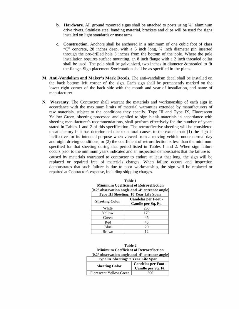
b. Hardware. All ground mounted signs shall be attached to posts using ⅜” aluminum
drive rivets. Stainless steel banding material, brackets and clips will be used for signs installed on light standards or mast arms.
c. Construction. Anchors shall be anchored in a minimum of one cubic foot of class
“C” concrete, 28 inches deep, with a 6 inch long, ⅜ inch diameter pin inserted through the pre-drilled hole 3 inches from the bottom of the pole. Where the pole installation requires surface mounting, an 8 inch flange with a 2 inch threaded collar shall be used. The pole shall be galvanized, two inches in diameter &threaded to fit the flange. Sign placement &orientation shall be as specified in the plans.
M. Anti-Vandalism and Maker’s Mark Decals. The anti-vandalism decal shall be installed on
the back bottom left corner of the sign. Each sign shall be permanently marked on the lower right corner of the back side with the month and year of installation, and name of manufacturer.
N. Warranty. The Contractor shall warrant the materials and workmanship of each sign in
accordance with the maximum limits of material warranties extended by manufacturers of raw materials, subject to the conditions they specify. Type III and Type IX, Fluorescent Yellow Green, sheeting processed and applied to sign blank materials in accordance with sheeting manufacturer's recommendations, shall perform effectively for the number of years stated in Tables 1 and 2 of this specification. The retroreflective sheeting will be considered unsatisfactory if it has deteriorated due to natural causes to the extent that: (1) the sign is ineffective for its intended purpose when viewed from a moving vehicle under normal day and night driving conditions; or (2) the coefficient of retroreflection is less than the minimum specified for that sheeting during that period listed in Tables 1 and 2. When sign failure occurs prior to the minimum years indicated and an inspection demonstrates that the failure is caused by materials warranted to contractor to endure at least that long, the sign will be replaced or repaired free of materials charges. When failure occurs and inspection demonstrates that such failure is due to poor workmanship, the sign will be replaced or repaired at Contractor's expense, including shipping charges.
Table 1
Minimum Coefficient of Retroreflection [0.2° observation angle and -4° entrance angle]
Type III Sheeting: 10 Year Life Span
Sheeting Color Candelas per Foot - Candle per Sq. Ft.
White 250 Yellow 170 Green 45 Red 45 Blue 20
Brown 12
Table 2 Minimum Coefficient of Retroreflection
[0.2° observation angle and -4° entrance angle] Type IX Sheeting: 7 Year Life Span
Sheeting Color Candelas per Foot - Candle per Sq. Ft.
Florescent Yellow Green 300
531.3. EQUIPMENT: Provide machinery & equipment necessary for proper execution of the work.
531.4. CONSTRUCTION: Construction shall be high quality with no visible defects in the finished product. Fabrication shall be in accordance with these specifications. Street name signs shall always be supplied and installed at each project intersection whether signs previously existed.
A. Unsignalized Intersection. At unsignalized intersections, ground-mounted street name signs
of 9 inch heights with 6 inch letters and 1-½ inch block numbers are required.
B. Signalized Intersection.
1. Ground Mounted Street Signs. If a signalized intersection has either mast arms or span- wire on which overhead street name signs can be attached, no ground mounted streets name signs are required at that intersection.
2. Overhead Street Signs. Signs shall be bolted or strapped to the mast arm or span wire.
Attachments to mast arms shall be by means of a ⅝ inch stainless steel strap and a stainless steel flared strap bracket.
a. Signs Outside Central Business District. Overhead street name signs installed
outside of the Central Business District shall be 15 inches high with 6½ inch letters and 4½ inch block numbers.
b. Signs Within Central Business District. Overhead street name signs installed inside the Central Business District shall be 18 inches high with 8 inch letters and 4 ½ inch block numbers. Overhead street name signs shall be installed on all approaches.
C. Existing Signs. The removal of existing signs shall be coordinated with the Traffic Division
to assure required signage is in place during all construction phases. When existing signs are to be removed, they will be unbolted from their post by hand and delivered to the Ci ty .
535 HOT APPLIED THERMOPLASTIC PAVEMENT MARKINGS
535.1. DESCRIPTION: Apply thermoplastic pavement markings, in conformance with the minimum optical and physical properties required for a thermoplastic road marking compound described herein, in a molten state, onto a pavement surface.
535.2. MATERIALS: All materials shall conform to the requirements of TxDOT DMS-8220 “Hot
Applied Thermoplastic.” Thermoplastic materials shall be stored in a dry environment to minimize the amount of moisture retained during storage.
535.3. EQUIPMENT: Provide the necessary equipment to conduct the work specified herein. All
equipment shall be maintained in good working order such that neat and clean thermoplastic markings are applied at the proper thicknesses and glass beads are placed at the correct rate. Equipment that is deemed deficient by the Engineer shall be replaced immediately.
535.4. CONSTRUCTION: The appearance of the finished markings shall have a uniform surface, crisp
edges with a minimum over-spray, clean cut-off, meet straightness requirements and conform to the design drawings and/or engineer instructions.
The contractor shall provide the Engineer with certification from the marking manufacturer that contractor has been adequately trained and certified to apply the manufacturer's material. This certification shall be considered current if the certification date provided by the manufacturer is within two years of the date of marking application.
All striping and pavement markings shall be placed in accordance with the requirements of this specification, the detailed plans, and the current edition of the Texas Manual on Uniform Traffic Control Devices (TMUTCD). The Contractor shall provide all other engineering services necessary for pre-marking of all proposed stripe within the limits of the designated work.
Unless authorized otherwise in writing by the Engineer, striping shall be accomplished during daylight hours. Approved lighting arrangements will be required for night time operations when allowed.
The Contractor may be required to place markings over existing markings, as determined by the Engineer. The contractor shall adjust the operation of the thermoplastic screed shoe to match the previous lengths of stripes and skips, when necessary.
Failure of the striping material to adhere to the pavement surface during the life of the contract shall be prima facie evidence that the materials, even though complying with these specifications, or the application thereof, was inconsistent with the intent of the requirements for the work under the latest City specifications and shall be cause for ordering corrective action or replacement of the marking without additional cost to the City.
Unless otherwise approved by the Engineer, permanent pavement markings on newly constructed pavements surfaced with asphaltic concrete or bituminous seals shall not be applied for a minimum of 14 days or a maximum 35 days. Temporary pavement marking shall be provided during the 14 to 35 day period.
A. Surface Preparation.
1. Moisture. All surfaces shall be inspected for moisture content prior to application of
thermoplastic. Approximately two square feet of a clear plastic or tar paper shall be laid on the road surface and held in place for 15 to 20 minutes. The underside of the plastic or tar paper shall then be inspected for a buildup of condensed moisture from the road surface. Pavement is considered dry if there is no condensation on the underside of the
plastic or tarpaper. In the event of moisture, this test shall be repeated until there is no moisture on the underside of the plastic or tar paper.
2. Cleaning. All surfaces shall be clean and dry, as defined in Section 535.4.A.1, before
thermoplastic can be applied. Loose dirt and debris shall be removed by thoroughly blowing compressed air over the area to be striped. If the thermoplastic is to be applied over existing paint lines, the paint line shall be swept with a mechanical sweeper or wire brush to remove poorly adhered paint and dirt that would interfere with the proper bonding or the thermoplastic. Additional cleaning through the use of compressed air may be required to remove embedded dirt and debris after sweeping. Latence and curing compound shall be removed from all new portland cement concrete surfaces in accordance with Item 533, “Removal of Pavement Markings and Markers.”
3. Layout. The pavement markings shall be placed in proper alignment with guidelines
established on the roadway. Deviation from the alignment established shall not exceed 2 inches and, in addition, the deviation in alignment of the marking being placed shall not exceed 1 inch per 200 feet of roadway nor shall any deviation be abrupt.
No striping material shall be applied over a guide cord; only longitudinal joints, existing stripes, primer, or other approved type guides will be permitted. In the absence of a longitudinal joint or existing stripe, the Contractor shall mark the points necessary for the placing of the proposed stripe. Edge striping shall be adjusted as necessary so that the edge stripe will be parallel to the centerline and shall not be placed off the edge of the pavement.
Longitudinal markings shall be offset at least 2-inches from construction joints of Portland cement concrete surfaces and joints and shoulder breaks of asphalt surfaces.
4. Primer Sealer. Primer sealer shall be used on all portland cement concrete surfaces. A
primer sealer shall be used on asphalt surfaces that are over two years old and/or on asphalt surfaces that are worn or oxidized to a condition where 50 percent or more of the wearing surface is exposed aggregate. Existing pavement markings may act as the primer sealer if, after cleaning, more than 70 percent of the existing pavement marking is still properly bonded to the asphalt surface (see coverage check procedure in Appendix A to estimate percent of marking remaining).
5. Primer Sealer Application. When required as described, the primer-sealer shall be
applied to the road surface in a continuous film at a minimum thickness of 3 to 5 mils. Before the Thermoplastic is applied, the primer-sealer shall be allowed to dry to a tacky state. The thermoplastic shall be applied within 4 hours after the primer application.
B. Temperature Requirements.
1. Ambient Conditions. The ambient air and road surface shall be 55ºF and rising before
application of thermoplastic can begin.
2. Material Requirements. Unless otherwise specified by the material manufacturer, the thermoplastic compound shall be heated from 400ºF to 450ºF and shall be a minimum of 400ºF as it makes contact with road surface during application. An infrared temperature gun shall be used to determine the temperature of the thermoplastic as it is being applied to the road surface.
C. Drop-on Glass Sphere Application.
1. Application Rate. Retro-reflective glass spheres shall be applied at the rate of 10 pounds
per 100 square feet of applied markings. This application rate shall be determined by
confirming the following consumption rates:
a. 200 pounds of drop on glass spheres per ton of applied thermoplastic when the thermoplastic is being applied at 0.090 inch film thickness.
b. 150 pounds of drop on glass spheres per ton of applied thermoplastic when the
thermoplastic is being applied at 0.125 inch thickness.
2. Application Method. Retro-reflective glass spheres shall be applied by a mechanical dispenser property calibrated and adjusted to provide proper application rates and uniform distribution of the spheres across the cross section of the entire width of the line. To enable the spheres to embed themselves into the hot thermoplastic, the sphere dispenser shall be positioned immediately behind the thermoplastic application device. This insures that the spheres are applied to the thermoplastic material while it is still in the molten state.
D. Application Thickness.
1. Longitudinal and Transverse Markings. On previously unmarked pavements or
pavements where markings have been effectively removed, all lane lines, center lines, transverse markings and pavement markings in traffic areas with ≤1,000 vehicles per day per lane shall have a minimum film thickness of 0.090 inch at the edges and a maximum of 0.145 inch at the center. A minimum average film thickness of 0.090 inch shall be maintained. On pavements with existing markings, meeting the traffic requirements stated above, all lane lines, center lines, transverse markings and pavement markings shall have a minimum film thickness of 0.060 inch for re-application over existing strip line.
2. High Wear Longitudinal and Transverse Marking. On previously unmarked
pavements or pavements where markings have been effectively removed, all lane lines, center lines, transverse markings and pavement markings in high traffic areas (>1,000 vehicles per day per lane) shall have a minimum film thickness of 0.125 inch at the edges and a maximum of 0.188 inch at the center. A minimum average film thickness of 0.125 inch shall be maintained. On pavements with existing markings, meeting the traffic requirements stated above, all lane lines, center lines, transverse markings and pavement markings shall have a minimum film thickness of 0.090 inch for re-application over existing strip line.
E. Packaging.
1. Containers. The thermoplastic material shall be delivered in 50 pound containers or bags
of sufficient strength to permit normal handling during shipment and handling on the job without loss of material.
2. Labeling. Each container shall be clearly marked to indicate the color of the material, the
process batch number and/or manufacturer’s formulation number, the manufacturer's name and address and the date of manufacture.
F. Acceptance.
1. Sampling Procedure. Random samples may be taken at the job site at the discretion of
the City Engineer for quality assurance. The City reserves the right to conduct the tests deemed necessary to identify component materials and verify results of specific tests indicated in conjunction with the specification requirements.
The sample(s) shall be labeled as to the shipment number, lot number, date, quantity, and
any other pertinent information. At least three randomly selected bags shall be obtained from each lot. A 10 pound) sample from the three bags shall be submitted for testing and acceptance. The lot size shall be approximately 44,000 pounds unless the total order is less than this amount.
2. Manufacturer’s Responsibility.
a. Sampling and Testing. The manufacturer shall submit test results from an approved
independent laboratory. All material samples shall be obtained 20 days in advance of the pavement marking operations. The cost of testing shall be included in the price of thermoplastic material. The approved independent laboratory's test results shall be submitted to the City Traffic Engineer in the form of a certified test report.
b. Bill of Lading. The manufacturer shall furnish the Material and Tests Laboratory
with copies of Bills of Lading for all materials inspected. Bill of lading shall indicate the consignee and the destination, date of shipment, lot numbers, quantity, type of material, and location of source.
c. Material Acceptance. Final acceptance of a particular lot of thermoplastic will be
based on the following.
(1) Compliance with the specification for material composition requirements verified by approved independent laboratory with tests results.
(2) Compliance with the specification for the physical properties required and
verified by an approved independent laboratory with test results.
(3) Manufacturer's test results for each lot thermoplastic have been received.
(4) Identification requirements are satisfactory.
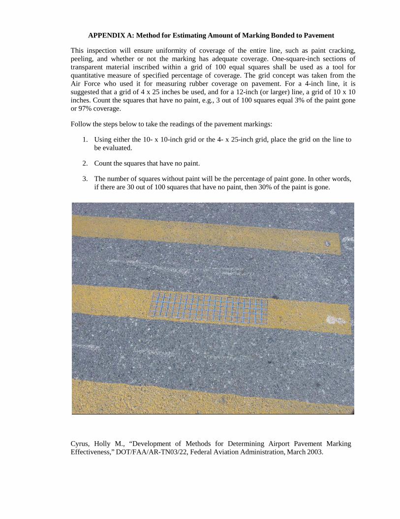
APPENDIX A: Method for Estimating Amount of Marking Bonded to Pavement
This inspection will ensure uniformity of coverage of the entire line, such as paint cracking, peeling, and whether or not the marking has adequate coverage. One-square-inch sections of transparent material inscribed within a grid of 100 equal squares shall be used as a tool for quantitative measure of specified percentage of coverage. The grid concept was taken from the Air Force who used it for measuring rubber coverage on pavement. For a 4-inch line, it is suggested that a grid of 4 x 25 inches be used, and for a 12-inch (or larger) line, a grid of 10 x 10 inches. Count the squares that have no paint, e.g., 3 out of 100 squares equal 3% of the paint gone or 97% coverage.
Follow the steps below to take the readings of the pavement markings:
1. Using either the 10- x 10-inch grid or the 4- x 25-inch grid, place the grid on the line to
be evaluated.
2. Count the squares that have no paint.
3. The number of squares without paint will be the percentage of paint gone. In other words, if there are 30 out of 100 squares that have no paint, then 30% of the paint is gone.
Cyrus, Holly M., “Development of Methods for Determining Airport Pavement Marking Effectiveness,” DOT/FAA/AR-TN03/22, Federal Aviation Administration, March 2003.
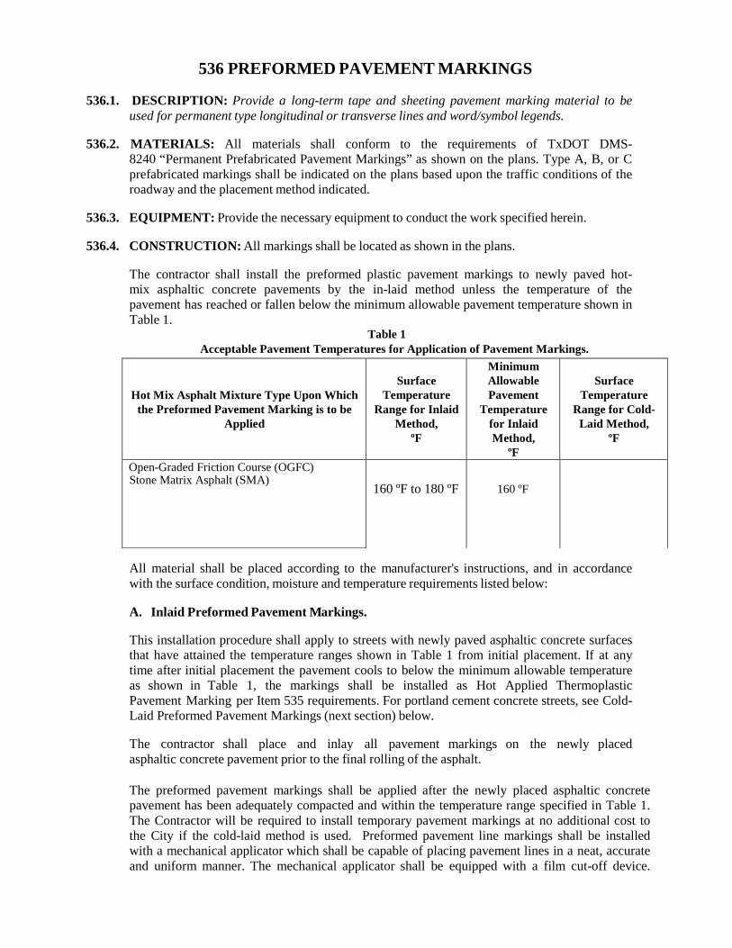
Hot Mix Asphalt Mixture Type Upon Which the Preformed Pavement Marking is to be
Applied
Surface
Temperature Range for Inlaid
Method, ºF
Minimum Allowable Pavement
Temperature for Inlaid Method,
ºF
Surface
Temperature Range for Cold-
Laid Method, ºF
Open-Graded Friction Course (OGFC)
160 ºF to 180 ºF
160 ºF
536 PREFORMED PAVEMENT MARKINGS
536.1. DESCRIPTION: Provide a long-term tape and sheeting pavement marking material to be used for permanent type longitudinal or transverse lines and word/symbol legends.
536.2. MATERIALS: All materials shall conform to the requirements of TxDOT DMS-
8240 “Permanent Prefabricated Pavement Markings” as shown on the plans. Type A, B, or C prefabricated markings shall be indicated on the plans based upon the traffic conditions of the roadway and the placement method indicated.
536.3. EQUIPMENT: Provide the necessary equipment to conduct the work specified herein.
536.4. CONSTRUCTION: All markings shall be located as shown in the plans.
The contractor shall install the preformed plastic pavement markings to newly paved hot-mix asphaltic concrete pavements by the in-laid method unless the temperature of the pavement has reached or fallen below the minimum allowable pavement temperature shown in Table 1.
Table 1 Acceptable Pavement Temperatures for Application of Pavement Markings.
Stone Matrix Asphalt (SMA)
All material shall be placed according to the manufacturer's instructions, and in accordance with the surface condition, moisture and temperature requirements listed below:
A. Inlaid Preformed Pavement Markings.
This installation procedure shall apply to streets with newly paved asphaltic concrete surfaces that have attained the temperature ranges shown in Table 1 from initial placement. If at any time after initial placement the pavement cools to below the minimum allowable temperature as shown in Table 1, the markings shall be installed as Hot Applied Thermoplastic Pavement Marking per Item 535 requirements. For portland cement concrete streets, see Cold-Laid Preformed Pavement Markings (next section) below.
The contractor shall place and inlay all pavement markings on the newly placed asphaltic concrete pavement prior to the final rolling of the asphalt.
The preformed pavement markings shall be applied after the newly placed asphaltic concrete pavement has been adequately compacted and within the temperature range specified in Table 1. The Contractor will be required to install temporary pavement markings at no additional cost to the City if the cold-laid method is used. Preformed pavement line markings shall be installed with a mechanical applicator which shall be capable of placing pavement lines in a neat, accurate and uniform manner. The mechanical applicator shall be equipped with a film cut-off device.
Word legends and arrows shall be installed by hand and result in neat, accurate and uniform words and arrows.
The preformed pavement markings shall be inlaid into the asphaltic concrete surface by means of a mechanical roller. The roller shall be of sufficient weight capacity to inlay the pavement marking to a minimum depth of 65% of the material thickness, and to not more than 80% of the material thickness while the temperature range of the pavement surface is within the ranges specified in Table 1. In the event the inlaid markings are distorted or discolored to the point that cleaning does not restore its initial appearance by the contractor's operations, fail to provide a uniform appearance, or are installed improperly, such markings shall be removed and replaced in the finished surface of the pavement as Hot Applied Thermoplastic Pavement Marking per Item 535 requirements.
B. Cold-Laid Preformed Pavement Markings.
This installation procedure applies to all portland cement concrete pavements, existing asphaltic concrete pavement, and newly placed asphaltic concrete that at any time has fallen below the minimum allowable temperature specified in Table 1 after initial placement.
Pavement on which pavement markings are to be placed shall be cleaned and prepared prior to placement of markings. Cleaning shall be in conformance with Item 533, “Cleaning and Removal of Pavement Markings and Markers” such that contaminants, loose materials, and conditions deleterious to proper adhesion are removed. When blast cleaning is required, it shall be done to the extent that a sound pavement surface is exposed. Surfaces shall be further prepared after cleaning by sealing or priming, as recommended by the manufacturer.
Pavement to which materials to be applied shall be completely dry. Materials shall not be applied until concrete pavement has appeared to be dry for a minimum of four hours and until asphaltic concrete pavement has appeared to be dry for a minimum of two hours.
Pavement and ambient air temperature requirements recommended by the manufacturer shall be observed. If no temperature requirements are established by the manufacturer, material shall not be placed if the surface temperature is outside the acceptable range shown in Table 1 (see column 4 of this table).
537 RAISED PAVEMENT MARKERS
537.1. DESCRIPTION: Provide raised pavement markers which include reflectorized and non- reflectorized traffic buttons, pavement markers and jiggle bars all of which are capable of being attached to a roadway surface by an adhesive.
537.2. MATERIALS: Materials shall conform to the following requirements:
A. Jiggle Bar Tiles. TxDOT DMS-4100, “Jiggle Bar Tiles.”
B. Raised Pavement Markers. TxDOT DMS-4200, “Pavement Markers (Reflectorized).”
C. Traffic Buttons. TxDOT DMS-4300, “Traffic Buttons.”
D. Testing. The Engineer reserves the right to perform any or all tests required by this item as a
check on the tests reported by the manufacturer. Upon request, the Contractor shall furnish, free of charge, samples of the material of the size and in the amount determined by the Engineer for test purposes. In case of any variance, the Engineer’s tests will govern.
537.3. EQUIPMENT: Provide all equipment necessary to perform the work specified herein.
537.4. CONSTRUCTION: The Contractor shall establish guides to mark the lateral location of
pavement markings as shown on the plans or as directed by the Engineer. The Engineer shall approve locations of these markings and may authorize necessary adjustments from the plans.
The reflective faces of all Type II markers shall be positioned so that the direction of reflection of one (1) face shall be directly opposite to the direction of reflection of the other face.
Raised Pavement markers Type I-C shall have clear reflector face towards traffic. Raised pavement markers Type II C-R, shall have the clear face toward the normal traffic flow and the red face toward wrong-way traffic.
Unless otherwise shown on the plans or specified by the Engineer, all raised pavement markers placed in broken lines shall be placed in line with and midway between the stripes. The first and last raised pavement marker in a no-passing line shall be a reflective marker. Buttons used to simulate a 10 feet skip lane lines shall be spaced at 40 inches.
The pavement markers not placed in accordance with the plans or as directed by the Engineer shall be removed by the Contractor at the Contractor’s expense.
Removal of existing pavement markers or residual adhesive from a missing pavement marker prior to placement of new or replacement marker(s) shall be in conformance with Item 533, “Cleaning or Removal of Pavement Markings or Markers.” The portion of the highway surface to which the raised pavement marker is attached by the adhesive shall be clean and free of dirt, grease, oil, and moisture at the time of installation. Surface preparation for installation of raised pavement markers will not be paid for directly, but shall be considered subsidiary to this item. Unsound pavement or other materials that would adversely affect the bond of the adhesive shall not be an acceptable surface.
The hot epoxy adhesive shall be applied so that 100 percent of the bonding area of the raised pavement marker will be in contact and shall be of sufficient thickness so that excess adhesive shall be forced out around the perimeter of the raised pavement marker but without impairing the functional capability of the reflectivity of the pavement marker. When the project is complete, the raised pavement marker shall be firmly bonded to the pavement; lines formed by the raised pavement markers shall be true, and the entire installation shall present a neat appearance.

Where required by the Engineer, pavement markings outside the limits of this project will be removed or adjusted to provide for a proper tie into this project. The old markings shall be removed or defaced in such a manner that they do not give the appearance of traffic pavement markings.
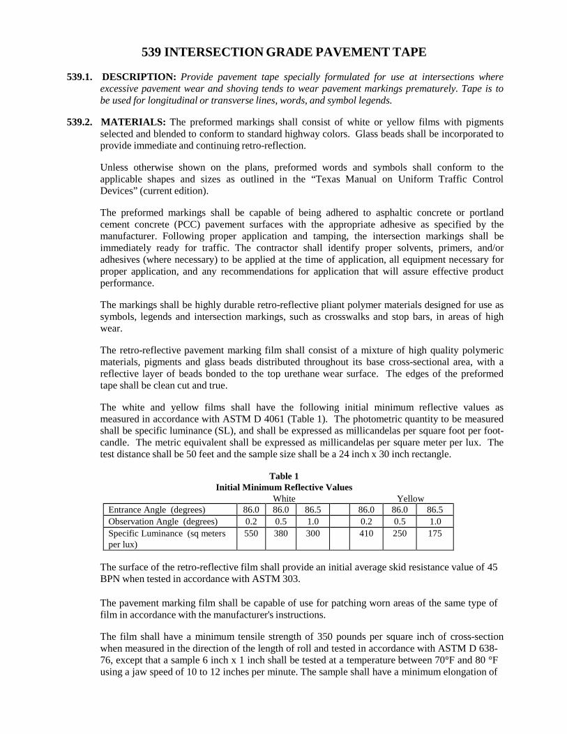
539 INTERSECTION GRADE PAVEMENT TAPE
539.1. DESCRIPTION: Provide pavement tape specially formulated for use at intersections where excessive pavement wear and shoving tends to wear pavement markings prematurely. Tape is to be used for longitudinal or transverse lines, words, and symbol legends.
539.2. MATERIALS: The preformed markings shall consist of white or yellow films with pigments
selected and blended to conform to standard highway colors. Glass beads shall be incorporated to provide immediate and continuing retro-reflection.
Unless otherwise shown on the plans, preformed words and symbols shall conform to the applicable shapes and sizes as outlined in the “Texas Manual on Uniform Traffic Control Devices” (current edition).
The preformed markings shall be capable of being adhered to asphaltic concrete or portland cement concrete (PCC) pavement surfaces with the appropriate adhesive as specified by the manufacturer. Following proper application and tamping, the intersection markings shall be immediately ready for traffic. The contractor shall identify proper solvents, primers, and/or adhesives (where necessary) to be applied at the time of application, all equipment necessary for proper application, and any recommendations for application that will assure effective product performance.
The markings shall be highly durable retro-reflective pliant polymer materials designed for use as symbols, legends and intersection markings, such as crosswalks and stop bars, in areas of high wear.
The retro-reflective pavement marking film shall consist of a mixture of high quality polymeric materials, pigments and glass beads distributed throughout its base cross-sectional area, with a reflective layer of beads bonded to the top urethane wear surface. The edges of the preformed tape shall be clean cut and true.
The white and yellow films shall have the following initial minimum reflective values as measured in accordance with ASTM D 4061 (Table 1). The photometric quantity to be measured shall be specific luminance (SL), and shall be expressed as millicandelas per square foot per foot- candle. The metric equivalent shall be expressed as millicandelas per square meter per lux. The test distance shall be 50 feet and the sample size shall be a 24 inch x 30 inch rectangle.
Table 1
Initial Minimum Reflective Values White Yellow
Entrance Angle (degrees) 86.0 86.0 86.5 86.0 86.0 86.5 Observation Angle (degrees) 0.2 0.5 1.0 0.2 0.5 1.0 Specific Luminance (sq meters per lux)
550 380 300 410 250 175
The surface of the retro-reflective film shall provide an initial average skid resistance value of 45 BPN when tested in accordance with ASTM 303.
The pavement marking film shall be capable of use for patching worn areas of the same type of film in accordance with the manufacturer's instructions.
The film shall have a minimum tensile strength of 350 pounds per square inch of cross-section when measured in the direction of the length of roll and tested in accordance with ASTM D 638- 76, except that a sample 6 inch x 1 inch shall be tested at a temperature between 70°F and 80 °F using a jaw speed of 10 to 12 inches per minute. The sample shall have a minimum elongation of
50% at break when tested by this method.
To ensure an effective performance life, the glass beads must be strongly bonded and not easily removed by traffic wear.
The following test shall be employed to measure reflectivity retention:
Taber Abraser Simulation Test
Using Taber Abraser with an H-18 wheel and a 125 gram load, the sample shall be inspected at 200 cycles, under a microscope, to observe the extent and type of bead failure.
No more than 15% of the beads shall be lost due to popout and the predominant mode of failure shall be “wear down” of the beads.
The size, quality and refractive index of the glass beads shall be such that the performance requirements for the markings shall be met. The bead adhesion shall be such that beads are not easily removed when the material surface is scratched with a thumbnail.
The film shall have glass bead retention qualities such that when a 2 inch x 6 inch is bent over a ½ inch diameter mandrel, with the 2 inch dimension perpendicular to the mandrel axis, microscopic examination of the area on the mandrel shall show no more than 10% of the beads with entrapment by the binder of less than 40%.
The film, without adhesive, shall have a minimum thickness of 0.060 inch.
The film, when applied according to the manufacturer's instructions, shall provide a neat, durable marking that will not flow or distort due to temperature if the pavement surface remains stable. The film shall be weather resistant and, through normal traffic wear, shall show no facing, lifting, or shrinkage which will significantly impair the intended usage of the marking throughout its useful life and shall show no significant tearing, roll back or other signs or poor adhesion.
The contractor shall be responsible for supplying and installing at no expense to the City replacement material for any markings which exhibit loss of adhesion or wear through to bare pavement due to traffic wear for a period of two years.
539.3. EQUIPMENT: Provide all necessary equipment required to perform the work specified herein.
539.4. CONSTRUCTION: The markings shall be applied and tamped in accordance with Item 536,
“Preformed Pavement Markings” as described for Cold-Laid markings.
556 CAST IN PLACE DETECTABLE WARNING SURFACE TILES
556.1. DESCRIPTION: This item shall govern the furnishing and installation of Cast In Place Detectable Warning Surface Tiles as shown on the plans and in accordance with these specifications. The work shall include all materials, equipment, surface preparation, labor, and other incidentals.
556.2. MATERIALS:
A. Cast In Place Detectable Warning Surface Tiles. The Cast In Place Detectable Warning
Surface Tiles shall comply with the detectable warnings on walking surfaces section of the Americans with Disabilities Act (Title III Regulations, 28 CFR Part 36, Appendix A, “ADA Accessibility Guidelines for Buildings and Facilities”, Section 4.29.2, “Detectable Warnings on Walking Surfaces”).
The Cast In Place Detectable Warning Surface Tile shall be an epoxy polymer or a homogenous glass and carbon reinforced composite which is colorfast and ultra-violet stable. The tile shall incorporate an in-line pattern of truncated domes measuring nominal 0.2 inch height, 0.9 inch base diameter, and 0.45 inch top diameter with a center-to-center spacing of 1.67 inches minimum and 2.35 inches maximum as measured between the most adjacent domes. For wheelchair safety the field area shall consist of a non-slip surface with a minimum of 36 - 90° raised points, 0.045 inch high, per square inch.
B. Color. The color of the tile shall be uniform throughout and shall not use any type of paint
coating to achieve color stability. The tiles shall contrast visually with adjoining surfaces by using brick red on light surfaces and yellow on dark surfaces.
C. Packaging. Tiles shall be suitably packaged or crated to prevent damage in shipment or
handling. Finished surfaces shall be protected by sturdy plastic wrappings to protect tile from concrete residue during installation and tile type shall be identified by part number.
D. Certification. All material shall conform to Table 1 below. A written certification shall be
supplied to the City verifying that the proposed materials meet these specifications.
E. Warranty. All materials, workmanship, and labor shall be covered by a manufacturer's guarantee and/or warranty for a period of five (5) years from the date of field application. If failures such as defective work, breakage, deformation, fading, and loosening of the tiles occur during this 5 year period, the Contractor shall bear the cost of removal and reinstallation of said materials to the satisfaction of the City.
556.3. EQUIPMENT: Provide the machinery, tools and equipment necessary for proper prosecution of
the work. All machinery, tools and equipment used shall be maintained in a satisfactory and workmanlike manner.
556.4. CONSTRUCTION: All material shall be placed according to the manufacturer's instructions,
and in accordance with the surface condition requirements.
A. Temperature. The Contractor shall maintain a minimum temperature of 40°F in spaces to receive tiles for at least 24 hours prior to installation, during installation, and for not less than 24 hours after installation.
B. Water. The use of water for work, cleaning or dust control, etc. shall be contained and
controlled and shall not be allowed to come into contact with the general public. Provide barricades or screens to protect the general public
C. Installation. Prior to placement of the Cast In Place Detectable Warning Surface Tile system, the Contractor shall review the manufacturer and contract drawings and refer any and all discrepancies to the Engineer.
1. Safety. During Cast In Place Detectable Warning Surface Tile installation procedures,
ensure adequate safety guidelines are in place and that they are in accordance with the applicable industry and government standards.
2. Flange System. The specifications of the structural embedment flange system and related
materials shall be in strict accordance with the guidelines set by the manufacturer.
3. Concrete and Placement of Tile System. The physical characteristics of the concrete shall be consistent with the contract specifications while maintaining a slump range of 4 - 7 to permit solid placement of the Cast In Place Detectable Warning Surface Tile system. An overly wet mix will cause the tile to float. Under these conditions, suitable weights such as 2 concrete blocks or sandbags (25 lb) shall be placed on each tile.
The concrete pouring and finishing operations require typical mason’s tools, however, a 4’ long level with electronic slope readout, 25 lb. weights, and a large non-marring rubber mallet are specific to the installation of the Cast In Place Detectable Warning Surface Tile system. If desired, a vibrating mechanism can be employed. The vibrating unit should be fixed to a soft base such as wood, at least 1 foot square.
The factory installed plastic sheeting must remain in place during the entire installation process to prevent the splashing of concrete onto the finished surface of the tile.
When preparing to set the tile, it is important that no concrete be removed in the area to accept the tile. It is imperative that the installation technique eliminates any air voids under the tile. Holes in the tile perimeter allow air to escape during the installation process. Concrete will flow through the large holes in each embedment flange on the underside of the tile. This will lock the tile solidly into the cured concrete.
The concrete shall be poured and finished true and smooth to the required dimensions and slope prior to the tile placement. Immediately after finishing concrete, an electronic level shall be used to check that the required slope is achieved. The tile shall be placed true and square to the curb edge in accordance with the contract drawings. The Cast In Place Detectable Warning Surface Tiles shall be tamped (or vibrated) into the fresh concrete to ensure that the field level of the tile is flush to the adjacent concrete surface. The embedment process should not be accomplished by stepping on the tile as this may cause uneven setting which can result in air voids under the tile surface. The tile field level (base of truncated dome) shall be flush to the adjacent surfaces to permit proper water drainage and eliminate tripping hazards between adjacent finishes.
Immediately after placement, the tile elevation shall be checked in relation to the adjacent concrete. The elevation and slope should be set consistent with contract drawings to permit water to drain into the street gutter or as the design dictates. Ensure that the field surface of the tile is flush with the surrounding concrete and back of curb so that no ponding is possible on the tile at the back side of curb.
While concrete is workable, a 3/8 inch radius edging tool shall be used to create a finished edge of concrete, then a steel trowel shall be used to finish the concrete around the tile’s perimeter, flush to the field level of the tile.
During and after the tile installation and the concrete curing stage, there shall be no walking, leaning or exerting any other force on the tile that may rock the tile and create a
void between the underside of tile and concrete.
D. Placement Tolerances. Following tile placement, the Contractor shall compare installation tolerances to these specifications and adjust the tile before the concrete sets. Two suitable weights of 25 lb each may be required to be placed on each tile as necessary to ensure solid contact of the underside of tile to concrete.
E. Removal of Plastic Sheeting. Following the concrete curing stage, the protective plastic
wrap shall be removed from the tile surface by cutting the plastic with a sharp knife, tight to the concrete/tile interface. If concrete has bled under the plastic, a soft brass wire brush shall be used to clean the residue without damage to the tile surface.
F. Bolting. If more than one tile is required, individual tiles can be bolted together using ¼ inch
or equivalent hardware. This can help to ensure that adjacent tiles are flush to each other during the installation process. Tape or caulking can be placed on the underside of the bolted butt joint to ensure that concrete does not rise up between the tiles during installation. Any protective plastic wrap which was peeled back to facilitate bolting or cutting, should be replaced and taped to ensure that the tile surface remains free of concrete during the installation process.
G. Cutting/Trimming. If required, tiles can be cut to custom sizes or radial shapes using a
continuous rim diamond blade in a circular saw or mini-grinder. Use of a straightedge to guide the cut is advisable where appropriate.
H. Sound Plates. Any sound-amplifying plates on the underside of the tile, which are dislodged
during handling or cutting, should be replaced and secured with construction adhesive. The air gap created between these plates and the bottom of the tile is important in preserving the sound-on-cane audible properties of the tile.
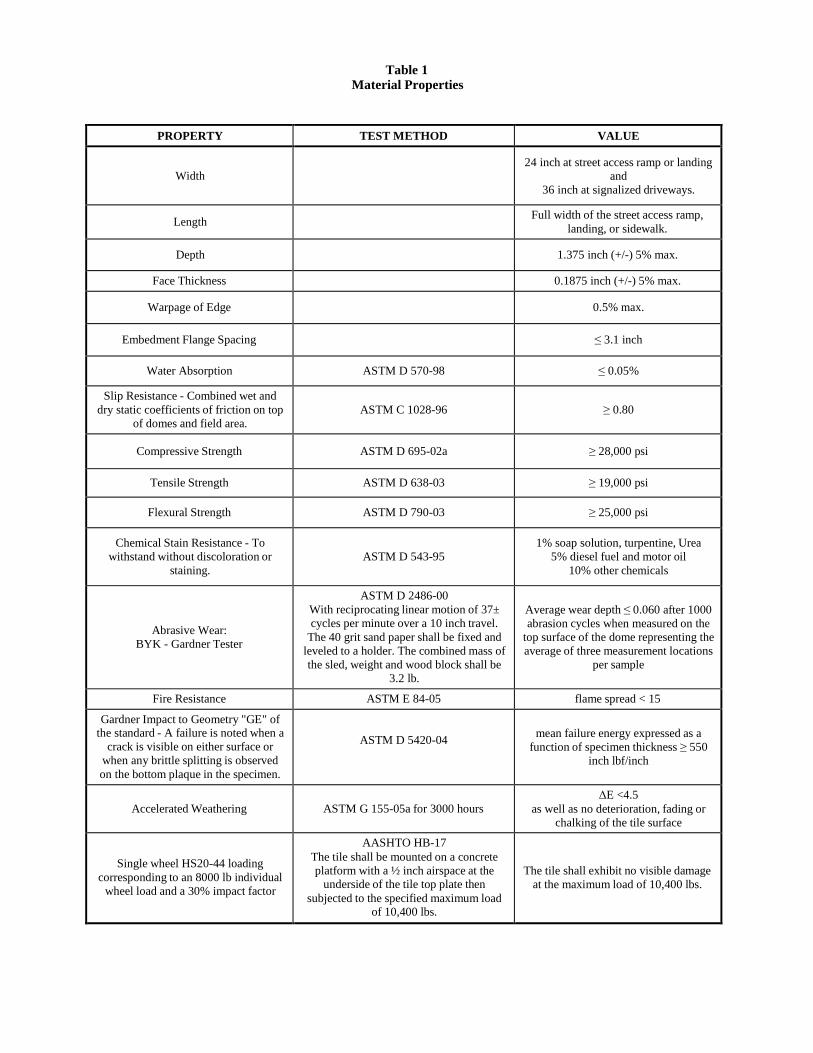
PROPERTY TEST METHOD VALUE
Width
24 inch at street access ramp or landing and
36 inch at signalized driveways.
Length Full width of the street access ramp, landing, or sidewalk.
Depth
1.375 inch (+/-) 5% max.
Face Thickness 0.1875 inch (+/-) 5% max.
Warpage of Edge 0.5% max.
Embedment Flange Spacing
≤ 3.1 inch
Water Absorption
ASTM D 570-98
≤ 0.05%
Slip Resistance - Combined wet and dry static coefficients of friction on top
of domes and field area.
ASTM C 1028-96
≥ 0.80
Compressive Strength
ASTM D 695-02a
≥ 28,000 psi
Tensile Strength ASTM D 638-03 ≥ 19,000 psi
Flexural Strength
ASTM D 790-03
≥ 25,000 psi
Chemical Stain Resistance - To withstand without discoloration or
staining.
ASTM D 543-95
1% soap solution, turpentine, Urea 5% diesel fuel and motor oil
10% other chemicals
Abrasive Wear: BYK - Gardner Tester
ASTM D 2486-00 With reciprocating linear motion of 37± cycles per minute over a 10 inch travel.
The 40 grit sand paper shall be fixed and leveled to a holder. The combined mass of the sled, weight and wood block shall be
3.2 lb.
Average wear depth ≤ 0.060 after 1000 abrasion cycles when measured on the
top surface of the dome representing the average of three measurement locations
per sample
Fire Resistance ASTM E 84-05 flame spread < 15
Gardner Impact to Geometry "GE" of the standard - A failure is noted when a
crack is visible on either surface or when any brittle splitting is observed on the bottom plaque in the specimen.
ASTM D 5420-04
mean failure energy expressed as a
function of specimen thickness ≥ 550 inch lbf/inch
Accelerated Weathering
ASTM G 155-05a for 3000 hours
ΔE <4.5 as well as no deterioration, fading or
chalking of the tile surface
Single wheel HS20-44 loading corresponding to an 8000 lb individual
wheel load and a 30% impact factor
AASHTO HB-17 The tile shall be mounted on a concrete platform with a ½ inch airspace at the
underside of the tile top plate then subjected to the specified maximum load
of 10,400 lbs.
The tile shall exhibit no visible damage at the maximum load of 10,400 lbs.
Table 1 Material Properties

Related Documents