STATE OF CALIFORNIA CITY OF PLACERVILLE ENGINEERING DIVISION ________________________________________________________ SPECIAL PROVISIONS BOOK 2 OF 2 FOR CONSTRUCTION OF WESTERN PLACERVILLE INTERCHANGES PROJECT PHASE 2 IN THE CITY OF PLACERVILLE PROJECT NO. 41828 __________________________________________________ For use in connection with California Department of Transportation, Standard Specifications Dated 2015, Caltrans Revised Standard Specifications, Caltrans Standard Plans Dated 2015, Caltrans Revised Standard Plans, City of Placerville Standard Plans, Labor Surcharge And Equipment Rental Rates, and the Director of Industrial Relations General Prevailing Wage Rates. __________________________________________________ Bids Open: December 07, 2017 Location: City Hall @ 2:00 p.m. Engineering Division 3101 Center Street, 3 rd Floor Placerville, CA 95667

Welcome message from author
This document is posted to help you gain knowledge. Please leave a comment to let me know what you think about it! Share it to your friends and learn new things together.
Transcript

STATE OF CALIFORNIA
CITY OF PLACERVILLE ENGINEERING DIVISION
________________________________________________________
SPECIAL PROVISIONS
BOOK 2 OF 2
FOR CONSTRUCTION OF
WESTERN PLACERVILLE INTERCHANGES PROJECT PHASE 2
IN THE
CITY OF PLACERVILLE PROJECT NO. 41828
__________________________________________________ For use in connection with California Department of Transportation, Standard Specifications Dated 2015, Caltrans Revised Standard Specifications, Caltrans Standard Plans Dated 2015, Caltrans Revised Standard Plans, City of Placerville Standard Plans, Labor Surcharge And Equipment Rental Rates, and the Director of Industrial Relations General Prevailing Wage Rates.
__________________________________________________
Bids Open: December 07, 2017 Location: City Hall @ 2:00 p.m. Engineering Division 3101 Center Street, 3rd Floor Placerville, CA 95667


CITY OF PLACERVILLE
WESTERN PLACERVILLE INTERCHANGES PROJECT PHASE 2
PROJECT NO. 41828
November 7, 2017
The Special Provisions contained herein has been prepared by or under the direction of the following Registered Persons.
HIGHWAY
MATTHEW
J. ATKINSON
82099
3-31-18
REGISTERED CIVIL ENGINEER
ELECTRICAL
KIN Y. CHAN
55319
12-31-18
REGISTERED CIVIL ENGINEER
STRUCTURAL
MOLLY A. ILEY
50995
9-30-19


CITY OF PLACERVILLE
WESTERN PLACERVILLE INTERCHANGES PROJECT PHASE 2
PROJECT NO. 41828
TABLE OF CONTENTS
ORGANIZATION ........................................................................................................................................... 3
DIVISION I GENERAL PROVISIONS ........................................................................................................ 11
1 GENERAL ............................................................................................................................................... 11
2 BIDDING ................................................................................................................................................. 12
4 SCOPE OF WORK ................................................................................................................................. 12
5 CONTROL OF WORK ............................................................................................................................ 12
6 CONTROL OF MATERIALS ................................................................................................................... 15
7 LEGAL RELATIONS AND RESPONSIBILITY TO THE PUBLIC ........................................................... 15
8 PROSECUTION AND PROGRESS ........................................................................................................ 16
9 PAYMENT ............................................................................................................................................... 16
DIVISION II GENERAL CONSTRUCTION ................................................................................................ 17
10 GENERAL ............................................................................................................................................. 17
12 TEMPORARY TRAFFIC CONTROL .................................................................................................... 17
13 WATER POLLUTION CONTROL ......................................................................................................... 21
14 ENVIRONMENTAL STEWARDSHIP .................................................................................................... 22
15 EXISTING FACILITIES ......................................................................................................................... 26
DIVISION III EARTHWORK AND LANDSCAPE ....................................................................................... 27
19 EARTHWORK ....................................................................................................................................... 27
20 LANDSCAPE ........................................................................................................................................ 30
21 EROSION CONTROL ........................................................................................................................... 33
DIVISION V SURFACINGS AND PAVEMENTS ....................................................................................... 34
36 GENERAL ............................................................................................................................................. 34
39 ASPHALT CONCRETE......................................................................................................................... 34
DIVISION VI STRUCTURES ..................................................................................................................... 37
49 PILING................................................................................................................................................... 37
51 CONCRETE STRUCTURES ................................................................................................................ 40
56 OVERHEAD SIGN STRUCTURES, STANDARDS, AND POLES ....................................................... 40
DIVISION VIII MISCELLANEOUS CONSTRUCTION ............................................................................... 41
72 SLOPE PROTECTION .......................................................................................................................... 41
73 CONCRETE CURBS AND SIDEWALKS .............................................................................................. 41
77 LOCAL INFRASTRUCTURE ................................................................................................................ 41
78 INCIDENTAL CONSTRUCTION ........................................................................................................... 48
DIVISION IX TRAFFIC CONTROL DEVICES ........................................................................................... 49
81 MISCELLANEOUS TRAFFIC CONTROL DEVICES ............................................................................ 49
82 SIGNS AND MARKERS........................................................................................................................ 49
83 RAILINGS AND BARRIERS ................................................................................................................. 49
DIVISION X ELECTRICAL WORK ............................................................................................................ 53
86 GENERAL .............................................................................................................................................. 53
87 GENERAL .............................................................................................................................................. 59
APPENDEX A – WATER SPECS ............................................................................................................... 63

Western Placerville Interchanges, Phase 2 Special Provisions Project No. 41828 3
ORGANIZATION Special provisions are under headings that correspond with the main-section headings of the Standard Specifications. A main-section heading is a heading shown in the table of contents of the Standard Specifications.
Each special provision begins with a revision clause that describes or introduces a revision to the Standard Specifications as revised by any revised standard specification.
Any paragraph added or deleted by a revision clause does not change the paragraph numbering of the Standard Specifications for any other reference to a paragraph of the Standard Specifications.
STANDARD PLANS LIST
The standard plan sheets applicable to this Contract include those listed below. The applicable revised standard plans (RSPs) listed below are included in the project plans.
ABBREVIATIONS, LINES, SYMBOLS, AND LEGEND A3A Abbreviations (Sheet 1 of 3) A3B Abbreviations (Sheet 2 of 3) A3C Abbreviations (Sheet 3 of 3) A10A Legend - Lines and Symbols (Sheet 1 of 5) RSP A10B Legend - Lines and Symbols (Sheet 2 of 5) A10C Legend - Lines and Symbols (Sheet 3 of 5) A10D Legend - Lines and Symbols (Sheet 4 of 5) A10E Legend - Lines and Symbols (Sheet 5 of 5)
PAVEMENT MARKERS, TRAFFIC LINES, AND PAVEMENT MARKINGS A20A Pavement Markers and Traffic Lines - Typical Details A20B Pavement Markers and Traffic Lines - Typical Details A20C Pavement Markers and Traffic Lines - Typical Details A20D Pavement Markers and Traffic Lines - Typical Details RSP A20E Pavement Markers and Traffic Lines - Typical Details for Contrast Striping A24A Pavement Markings - Arrows A24B Pavement Markings - Arrows and Symbols A24C Pavement Markings - Symbols and Numerals A24D Pavement Markings - Words A24E Pavement Markings - Words, Limit and Yield Lines A24F Pavement Markings - Crosswalks
EXCAVATION AND BACKFILL A62A Excavation and Backfill - Miscellaneous Details A62D Excavation and Backfill - Concrete Pipe Culverts A62DA Excavation and Backfill - Concrete Pipe Culverts - Indirect Design Method A62F Excavation and Backfill - Metal and Plastic Culverts
OBJECT MARKERS, DELINEATORS, CHANNELIZERS, AND BARRICADES A73A Object Markers A73B Markers

Western Placerville Interchanges, Phase 2 Special Provisions Project No. 41828 4
A73C Delineators, Channelizers and Barricades SURVEY MONUMENTS
A74 Survey Monuments MIDWEST GUARDRAIL SYSTEM - STANDARD RAILING SECTIONS
RSP A77L1 Midwest Guardrail System - Standard Railing Section (Wood Post with Wood Block)
A77M1 Midwest Guardrail System - Standard Hardware RSP A77N1 Midwest Guardrail System - Wood Post and Wood Block Details RSP A77N3 Midwest Guardrail System - Typical Line Post Embedment and Hinge Point
Offset Details A77N4 Midwest Guardrail System - Typical Railing Delineation and Dike Positioning
Details MIDWEST GUARDRAIL SYSTEM - TYPICAL VEGETATION CONTROL
A77N5 Midwest Guardrail System - Typical Vegetation Control Standard Railing Section
RSP A77N6 Midwest Guardrail System - Typical Vegetation Control for Terminal System End Treatments
A77N7 Midwest Guardrail System - Typical Vegetation Control at Structure Approach A77N8 Midwest Guardrail System - Typical Vegetation Control at Fixed Object A77N9 Midwest Guardrail System - Typical Vegetation Control at Fixed Object A77N10 Midwest Guardrail System - Typical Vegetation Control at Fixed Object
MIDWEST GUARDRAIL SYSTEM - TYPICAL LAYOUTS FOR EMBANKMENTS RSP A77P1 Midwest Guardrail System - Typical Layouts for Embankments RSP A77P2 Midwest Guardrail System - Typical Layouts for Embankments RSP A77P3 Midwest Guardrail System - Typical Layouts for Embankments RSP A77P4 Midwest Guardrail System - Typical Layouts for Embankments RSP A77P5 Midwest Guardrail System - Typical Layouts for Embankments RSP A77P6 Midwest Guardrail System - Typical Layouts for Embankments
MIDWEST GUARDRAIL SYSTEM - TYPICAL LAYOUTS FOR STRUCTURES RSP A77Q1 Midwest Guardrail System - Typical Layouts for Structure Approach RSP A77Q2 Midwest Guardrail System - Typical Layouts for Structure Approach and
Between Structures RSP A77Q3 Midwest Guardrail System - Typical Layouts for Structure Approach RSP A77Q4 Midwest Guardrail System - Typical Layouts for Structure Departure A77Q5 Midwest Guardrail System - Typical Layouts for Structure Departure
MIDWEST GUARDRAIL SYSTEM - TYPICAL LAYOUTS FOR FIXED OBJECTS RSP A77R1 Midwest Guardrail System - Typical Layouts for Fixed Objects Between
Separate Roadbeds (Two-Way Traffic) RSP A77R2 Midwest Guardrail System - Typical Layouts for Fixed Objects Between
Separate Roadbeds (One-Way Traffic) RSP A77R3 Midwest Guardrail System - Typical Layouts for Roadside Fixed Objects RSP A77R4 Midwest Guardrail System - Typical Layouts for Roadside Fixed Objects RSP A77R5 Midwest Guardrail System - Typical Layouts for Roadside Fixed Objects RSP A77R6 Midwest Guardrail System - Typical Layouts for Roadside Fixed Objects RSP A77R7 Midwest Guardrail System - Typical Layouts for Roadside Fixed Objects RSP A77R8 Midwest Guardrail System - Typical Layouts for Roadside Fixed Objects

Western Placerville Interchanges, Phase 2 Special Provisions Project No. 41828 5
MIDWEST GUARDRAIL SYSTEM - END ANCHORAGE AND RAIL TENSIONING ASSEMBLY
A77S1 Midwest Guardrail System - End Anchor Assembly (Type SFT) A77S2 Midwest Guardrail System - Rail Tensioning Assembly A77S3 Metal Railing Anchor Cable and Anchor Plate Details RSP A77T2 Midwest Guardrail System - Buried Post End Anchor
MIDWEST GUARDRAIL SYSTEM - CONNECTION DETAILS AND TRANSITION RAILING TO BRIDGE RAILINGS, ABUTMENTS AND WALLS
A77U1 Midwest Guardrail System - Connections to Bridge Railings without Sidewalks Details No. 1
A77U2 Midwest Guardrail System - Connections to Bridge Railings without Sidewalks Details No. 2
A77U3 Midwest Guardrail System - Connections to Abutments and Walls A77U4 Midwest Guardrail System - Transition Railing (Type WB-31) A77U5 Midwest Guardrail System - Transition to Metal Beam Guardrail
CRASH CUSHIONS A81A Crash Cushion, Sand Filled (Unidirectional)
FENCES RSP A85 Chain Link Fence RSP A85A Chain Link Fence Details A85B Chain Link Fence Details
CURBS, DRIVEWAYS, DIKES, CURB RAMPS, AND ACCESSIBLE PARKING A87A Curbs and Driveways RSP A87B Hot Mix Asphalt Dikes RSP A88A Curb Ramp Details RSP A88B Curb Ramp and Island Passageway Details A90A Accessible Parking Off-Street
PAVEMENTS P70 Hot Mix Asphalt Paving (Longitudinal Tapered Notched Wedge Joint) P74 Pavement Edge Treatments P75 Pavement Edge Treatments - Overlays P76 Pavement Edge Treatments - New Construction
DRAINAGE INLETS, PIPE INLETS AND GRATES D71 Drainage Inlet Markers RSP D72B CIP Drainage Inlets - Types G1, G2, G3, G4, G5 and G6 RSP D72C CIP Drainage Inlets - Types G1, G2, G3, G4, G5 and G6 RSP D72D CIP Drainage Inlets - Types GT1, GT2, GT3 and GT4 RSP D72E CIP Drainage Inlets - Types GO and GDO RSP D72F CIP Drainage Inlets Notes RSP D72G CIP Drainage Inlets Tables RSP D73B Precast Drainage Inlets - Types G1, G2, G3, G4, G5 and G6 RSP D73C Precast Drainage Inlets - Types G2 and G4 RSP D73D Precast Drainage Inlets - Types GT1, GT2, GT3 and GT4 RSP D73E Precast Drainage Inlets - Types GO and GDO RSP D73F Precast Drainage Inlets Notes RSP D73G Precast Drainage Inlets Tables

Western Placerville Interchanges, Phase 2 Special Provisions Project No. 41828 6
RSP D74 Drainage Inlet Details D75A Steel Pipe Inlets D75B Concrete Pipe Inlets D75C Pipe Inlets - Ladder and Trash Rack Details D77A Grate Details No. 1 D77B Grate Details No. 2
CONCRETE PIPE - DIRECT DESIGN METHOD D79 Precast Reinforced Concrete Pipe - Direct Design Method D79A Precast Reinforced Concrete Pipe - Direct Design Method
PIPE DOWNDRAINS, ANCHORAGE SYSTEMS AND OVERSIDE DRAINS D87A Corrugated Metal Pipe Downdrain Details
CONSTRUCTION LOADS ON CULVERTS AND STRUT DETAILS D88 Construction Loads on Culverts
FLARED END SECTIONS D94A Metal and Plastic Flared End Sections D94B Concrete Flared End Sections
PIPE COUPLING AND JOINT DETAILS D97H Reinforced Concrete Pipe or Non-Reinforced Concrete Pipe - Standard and
Positive Joints D97I Corrugated Polyvinyl Chloride Pipe with Smooth Interior - Standard and
Positive Joints GABIONS AND UNDERDRAINS
D102 Underdrains LANDSCAPE AND EROSION CONTROL
RSP H1 Landscape and Erosion Control Symbols H2 Landscape Details H3 Landscape Details RSP H4 Landscape Details (Riser Sprinkler Assembly) RSP H5 Landscape Details (Swing Joint and Protector) H6 Landscape Details H7 Landscape Details RSP H8 Landscape Details H9 Landscape Details RSP H10 Irrigation Controller Enclosure Cabinet H51 Erosion Control Details - Fiber Roll and Compost Sock H52 Rolled Erosion Control Product
TEMPORARY CRASH CUSHIONS, RAILING AND TRAFFIC SCREEN T1A Temporary Crash Cushion, Sand Filled (Unidirectional) T1B Temporary Crash Cushion, Sand Filled (Bidirectional) T2 Temporary Crash Cushion, Sand Filled (Shoulder Installations) T3A Temporary Railing (Type K) T3B Temporary Railing (Type K)
TEMPORARY TRAFFIC CONTROL SYSTEMS RSP T9 Traffic Control System Tables for Lane and Ramp Closures RSP T10 Traffic Control System for Lane Closure on Freeways and Expressways T10A Traffic Control System for Lane Closure on Freeways and Expressways

Western Placerville Interchanges, Phase 2 Special Provisions Project No. 41828 7
T11 Traffic Control System for Lane Closure on Multilane Conventional Highways T12 Traffic Control System for Half Road Closure on Multilane Conventional
Highways and Expressways T13 Traffic Control System for Lane Closure on Two Lane Conventional Highways T14 Traffic Control System for Ramp Closure T15 Traffic Control System for Moving Lane Closure on Multilane Highways T16 Traffic Control System for Moving Lane Closure on Multilane Highways T17 Traffic Control System for Moving Lane Closure on Two Lane Highways
TEMPORARY WATER POLLUTION CONTROL T51 Temporary Water Pollution Control Details (Temporary Silt Fence) T53 Temporary Water Pollution Control Details (Temporary Cover) T56 Temporary Water Pollution Control Details (Temporary Fiber Roll) T57 Temporary Water Pollution Control Details (Temporary Check Dam) T58 Temporary Water Pollution Control Details (Temporary Construction Entrance) T59 Temporary Water Pollution Control Details (Temporary Concrete Washout
Facility) T60 Temporary Water Pollution Control Details (Temporary Reinforced Silt Fence) T61 Temporary Water Pollution Control Details (Temporary Drainage Inlet
Protection) T62 Temporary Water Pollution Control Details (Temporary Drainage Inlet
Protection) T63 Temporary Water Pollution Control Details (Temporary Drainage Inlet
Protection) T64 Temporary Water Pollution Control Details (Temporary Drainage Inlet
Protection) BRIDGE DETAILS
B0-3 Bridge Details RETAINING WALLS
B3-4A Retaining Wall Type 5 (Case 1) B3-5 Retaining Wall Details No. 1
UTILITY OPENING RSP B7-11 Utility Details RSP B11-51 Tubular Handrailing
BRIDGE CONCRETE BARRIERS RSP B11-55 Concrete Barrier Type 732
ROADSIDE SIGNS RS1 Roadside Signs - Typical Installation Details No. 1 RS2 Roadside Signs - Wood Post - Typical Installation Details No. 2 RS4 Roadside Signs - Typical Installation Details No. 4
OVERHEAD SIGNS (TRUSS) S1 Overhead Signs - Truss, Instructions and Examples S2 Overhead Signs - Truss, Single Post Type - Post Types II thru IX S3 Overhead Signs - Truss, Single Post Type - Base Plate and Anchorage Details S4 Overhead Signs - Truss, Single Post Type - Structural Frame Members Details
No. 1 S5 Overhead Signs - Truss, Single Post Type - Structural Frame Members Details
No. 2
Western Placerville Interchanges, Phase 2 Special Provisions Project No. 41828 8
S6 Overhead Signs - Truss, Gusset Plate Details S8 Overhead Signs - Truss, Single Post Type - Round Pedestal Pile Foundation S9 Overhead Signs - Truss, Two Post Type - Post Types I-S Through VII-S S10 Overhead Signs - Truss, Two Post Type - Base Plate and Anchorage Details S11 Overhead Signs - Truss, Two Post Type - Structural Frame Members S12 Overhead Signs - Truss, Structural Frame Details S13 Overhead Signs - Truss, Frame Juncture Details S15 Overhead Signs - Truss, Two Post Type - Round Pedestal Pile Foundation S16 Overhead Signs - Walkway Details No. 1 S17 Overhead Signs - Walkway Details No. 2 S17A Overhead Signs - Walkway Details No. 3 S18 Overhead Signs - Walkway Safety Railing Details S19 Overhead Signs - Truss, Sign Mounting Details - Laminated Panel - Type A S20 Overhead Signs - Steel Frames - Removable Sign Panel Frames S21 Overhead Signs - Removable Sign Panel Frames Mounting Details S22 Overhead Signs - Truss, Removable Sign Panel Frames - 110" and 120" Sign
Panels OVERHEAD AND ROADSIDE SIGNS PANELS
S81 Overhead Laminated Sign - Single or Multiple Panel (Type A, 1" Thick) S82 Roadside Laminated Sign - Single or Multiple Panel (Type B, 1" Thick) S83 Roadside Laminated Sign - Single or Multiple Panel (Type B, 2-1/2" Thick) S84 Roadside Laminated Sign - Single or Multiple Panel (Type H, 2-1/2" Thick) S85 Seam Closure, "H" Section Extrusion and Post Spacing Tables (Multi-
Horizontal Laminated Panel Aluminum Signs) S86 Laminated Panel Details (Extrusions for Type A, B and H Panels) S87 Type A-1 Mounting Hardware for Overhead Laminated Type A Panel (Truss and
Lightweight Sign Structures) S88 Type A-2 Mounting Hardware for Overhead Laminated Type A Panel (Bridge
Mounted and Tubular Sign Structures) S89 Roadside Sign - Formed Single Sheet Aluminum Panel S90 Channel and Bolt Hole Location for Overhead Formed Sign Panel S91 Overhead Sign - Formed Sign Panel, Type A-3 Mounting Hardware S92 Overhead Sign - Formed Sign Panel S93 Framing Details for Framed Single Sheet Aluminum Signs, Rectangular Shape S94 Roadside Framed Single Sheet Aluminum Signs, Rectangular Shape S95 Roadside Single Sheet Aluminum Signs, Diamond Shape
ELECTRICAL SYSTEMS - LEGEND AND ABBREVIATIONS RSP ES-1A Electrical Systems (Legend) RSP ES-1B Electrical Systems (Legend) RSP ES-1C Electrical Systems (Legend and Abbreviations)
ELECTRICAL SYSTEMS - SERVICE EQUIPMENT AND WIRING DIAGRAMS ES-2A Electrical Systems (Service Equipment) ES-2C Electrical Systems (Service Equipment Enclosure Notes, Type III Series) RSP ES-2D Electrical Systems (Service Equipment Enclosure and Typical Wiring Diagram,
Type III - A Series)

Western Placerville Interchanges, Phase 2 Special Provisions Project No. 41828 9
ELECTRICAL SYSTEMS - TELEPHONE DEMARCATION CABINETS RSP ES-3E Electrical Systems (Telephone Demarcation Cabinet, Type B)
ELECTRICAL SYSTEMS - ELECTRONICS ASSEMBLY CONNECTION DIAGRAMS
RSP ES-3I Electrical Systems (Electronics Assembly Connection Diagram, with Bypass Control Line)
ELECTRICAL SYSTEMS - SIGNAL HEADS, SIGNAL FACES AND MOUNTINGS ES-4A Electrical Systems (Signal Heads and Mountings) ES-4B Electrical Systems (Pedestrian Signal Heads) RSP ES-4C Electrical Systems (Signal Heads and Mountings) RSP ES-4D Electrical Systems (Signal Head Mounting) ES-4E Electrical Systems (Signal Heads and Optical Detector Mounting)
ELECTRICAL SYSTEMS - DETECTORS RSP ES-5A Electrical Systems (Loop Detectors) RSP ES-5B Electrical Systems (Detectors) ES-5C Electrical Systems (Accessible Pedestrian Signal and Push Button Assemblies) ES-5D Electrical Systems (Curb and Shoulder Termination, Trench, and Handhole
Details) ELECTRICAL SYSTEMS - LIGHTING STANDARDS
RSP ES-6E Electrical Systems (Lighting Standard, Types 30 and 31) ES-6F Electrical Systems (Lighting Standard, Slip Base Plate)
ELECTRICAL SYSTEMS - SIGNAL AND LIGHTING STANDARD, TYPE TS, AND PUSH BUTTON ASSEMBLY POST
RSP ES-7A Electrical Systems (Signal and Lighting Standard, Type TS, and Push Button Assembly Post)
ELECTRICAL SYSTEMS - SIGNAL AND LIGHTING STANDARDS RSP ES-7B Electrical Systems (Signal and Lighting Standard, Type 1 and Equipment
Identification Characters) RSP ES-7C Electrical Systems (Signal and Lighting Standard, Case 1 Signal Mast Arm
Loading, Wind Velocity = 100 mph and Signal Mast Arm Lengths 15' to 30') RSP ES-7E Electrical Systems (Signal and Lighting Standard, Case 3 Signal Mast Arm
Loading, Wind Velocity = 100 mph and Signal Mast Arm Lengths 15' to 45') RSP ES-7F Electrical Systems (Signal and Lighting Standard, Case 4 Signal Mast Arm
Loading, Wind Velocity = 100 mph and Signal Mast Arm Lengths 25' to 45') RSP ES-7G Electrical Systems (Signal And Lighting Standard, Case 5 Signal Mast Arm
Loading, Wind Velocity = 100 mph and Signal Mast Arm Lengths 50' to 55') ELECTRICAL SYSTEMS - SIGNAL AND LIGHTING STANDARD DETAILS
RSP ES-7M Electrical Systems (Signal and Lighting Standard - Detail No. 1) RSP ES-7N Electrical Systems (Signal and Lighting Standard - Detail No. 2) ES-7O Electrical Systems (Signal and Lighting Standard - Detail No. 3)
ELECTRICAL SYSTEMS - PULL BOX RSP ES-8A Electrical Systems (Non-Traffic Pull Box) RSP ES-8B Electrical Systems (Traffic Pull Box)
ELECTRICAL SYSTEMS - ISOFOOTCANDLE CURVES AND FOUNDATION DETAILS
RSP ES-10A Electrical Systems (Isofootcandle Curves) RSP ES-11 Electrical Systems (Foundation Installations)
Western Placerville Interchanges, Phase 2 Special Provisions Project No. 41828 10
ELECTRICAL SYSTEMS - SPLICE INSULATION METHODS, FUSE RATING, KINKING AND BANDING DETAILS
RSP ES-13A Electrical Systems (Splice Insulation Methods Details) RSP ES-13B Electrical Systems (Fuse Rating, Kinking, and Banding Detail)
^^^^^^^^^^^^^^^^^^^^^^^^^^^^^^^^^^^^^^^^

Western Placerville Interchanges, Phase 2 Special Provisions Project No. 41828 11
DIVISION I GENERAL PROVISIONS 1 GENERAL
Add to section 1-1.01:
Bid Items and Applicable Sections Item code
Item description Applicable section
050100A Construction Staking 5 129110A Alternative Temporary Crash Cushion (Type TL-2) 12 130300A Prepare and Implement Storm Water Pollution Prevention Plan 13 170104A Tree Removal 17 204100A Landscaping 20 650026A 36" RCP Pipe Inlet 65 690118A 18" CSP TEE 69 700639A CMP Riser 70 710224A Remove Utility Box 71 731502A Minor Concrete (Utility Vault) 73 731516A Minor Concrete (Bus Pad) 73 770011A Emergency Vehicle Preemption System 77 770091A Lighting (Parking Lot) (City) 77 770201A 2" Service Line (AWWA C901) 77 770202A 8" Ductile Iron Pipe (Class 350) 77 770203A 10" Ductile Iron Pipe (Class 350) 77 770204A 12" Ductile Iron Pipe (Class 350) 77 770205A 12" PVC 77 770206A 12" Butterfly Valve 77 770207A 8" Gate Valve 77 770208A 2" Combination Air/Vacuum Valve 77 770209A Fire Hydrant 77 770210A Remove Pipe (Ductile Iron Pipe) 77 770211A Remove Pipe (Asbestos Concrete) 77 770212A Abandon Pipe (Ductile Iron Pipe) 77 770301A 4" Fiber Optics Conduit 77 770302A Relocate Fiber Optic Vault 77 770303A Remove Fiber Optic Vault 77
Add to section 1-1.09: This project is in a freeze-thaw area.

Western Placerville Interchanges, Phase 2 Special Provisions Project No. 41828 12
^^^^^^^^^^^^^^^^^^^^^^^^^^^^^^^^^^^^^^^^
2 BIDDING
Add between the 1st and 2nd paragraphs of section 2-1.06B: The Department makes the following supplemental project information available:
Supplemental Project Information Means Description
Included in the Information Handout Cross sections Geotechnical Report Drainage Report SWPPP
^^^^^^^^^^^^^^^^^^^^^^^^^^^^^^^^^^^^^^^^
4 SCOPE OF WORK Add to the end of section 4-1.05A:
Work from other stages may be perform simultaneously if there is no conflict with other stages.
^^^^^^^^^^^^^^^^^^^^^^^^^^^^^^^^^^^^^^^^
5 CONTROL OF WORK
Add to the end of section 5-1.20A: During the progress of the work under this Contract, work under the following contracts may be in progress at or near the job site of this Contract:
Coincident or Adjacent Contracts Contract no. County–Route–Post Mile Location Type of work
03-0G5404 EL-50-15.4-18.8 Along SR 50 Grind and Overlay of Mainline
Add to the end of section 5-1.20E: The local water authority is El Dorado Irrigation District.
The charges are as shown in the following table

Western Placerville Interchanges, Phase 2 Special Provisions Project No. 41828 13
Water Meter Charges Meter size Quantity Charge per meter
($) 2” 1 2500
Replace the paragraphs of section 5-1.20E with: The local water authority will install the water meters.
Upon your request, the Engineer arranges with the servicing utility to install the water meters. The Department pays the utility the charges for the installation.
Replace Reserved in section 5-1.20F with: Contact the local water authority to arrange a start date for water service and pay for the service until Contract acceptance.
The local water authority is El Dorado Irrigation District.
The charge for water service from the water authority is $150/mo plus the charges shown in the following table:
Water Service Charges Meter size Amount of water
(CF) Charge ($)
2” 1 $0.03462
Submit a copy of each monthly water bill.
Notify the Engineer upon paying your final bill.
If the local water authority's charges are changed, the Department adjusts the lump sum price based on the difference between the specified charges and the changed charges.
Replace Section 5-1.26 with:
5-1.26 CONSTRUCTION SURVEYS You must set construction stakes and markers to establish the lines and grades required for the completion of the work on the plans and as specified in the Standard Specifications and these special provisions and as necessary for the Engineer to check lines, grades, alignment and elevations.
All procedures, methods, and typical stake markings shall be in accordance with Chapter 12, Construction Surveys, of the Caltrans “Survey Manual.” Copies of the “Survey Manual” may be purchased from Caltrans Publications Unit, 1900 Royal Oaks Drive, Sacramento, and California 95815, (916) 445-3520.
Staking must be performed under the direction of a licensed surveyor or registered civil engineer with the authority to perform land surveying.
Western Placerville Interchanges, Phase 2 Special Provisions Project No. 41828 14
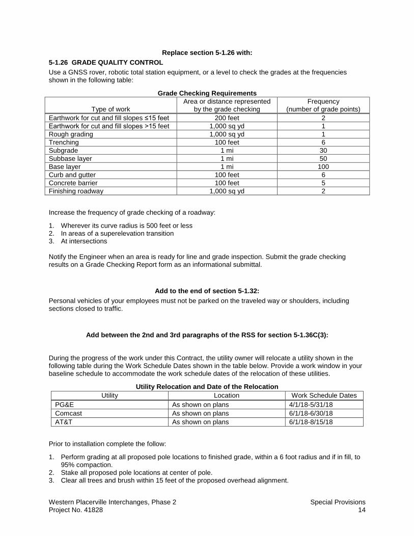
Replace section 5-1.26 with: 5-1.26 GRADE QUALITY CONTROL Use a GNSS rover, robotic total station equipment, or a level to check the grades at the frequencies shown in the following table:
Grade Checking Requirements
Type of work Area or distance represented
by the grade checking Frequency
(number of grade points) Earthwork for cut and fill slopes ≤15 feet 200 feet 2 Earthwork for cut and fill slopes ˃15 feet 1,000 sq yd 1 Rough grading 1,000 sq yd 1 Trenching 100 feet 6 Subgrade 1 mi 30 Subbase layer 1 mi 50 Base layer 1 mi 100 Curb and gutter 100 feet 6 Concrete barrier 100 feet 5 Finishing roadway 1,000 sq yd 2
Increase the frequency of grade checking of a roadway:
1. Wherever its curve radius is 500 feet or less 2. In areas of a superelevation transition 3. At intersections Notify the Engineer when an area is ready for line and grade inspection. Submit the grade checking results on a Grade Checking Report form as an informational submittal.
Add to the end of section 5-1.32: Personal vehicles of your employees must not be parked on the traveled way or shoulders, including sections closed to traffic.
Add between the 2nd and 3rd paragraphs of the RSS for section 5-1.36C(3):
During the progress of the work under this Contract, the utility owner will relocate a utility shown in the following table during the Work Schedule Dates shown in the table below. Provide a work window in your baseline schedule to accommodate the work schedule dates of the relocation of these utilities.
Utility Relocation and Date of the Relocation Utility Location Work Schedule Dates
PG&E As shown on plans 4/1/18-5/31/18 Comcast As shown on plans 6/1/18-6/30/18 AT&T As shown on plans 6/1/18-8/15/18
Prior to installation complete the follow:
1. Perform grading at all proposed pole locations to finished grade, within a 6 foot radius and if in fill, to 95% compaction.
2. Stake all proposed pole locations at center of pole. 3. Clear all trees and brush within 15 feet of the proposed overhead alignment.
Western Placerville Interchanges, Phase 2 Special Provisions Project No. 41828 15
4. Construct Fiber Optic Utility Vault along Ray Lawyer Drive.
^^^^^^^^^^^^^^^^^^^^^^^^^^^^^^^^^^^^^^^^
6 CONTROL OF MATERIALS
Add to the beginning of section 6-1.02: The Department furnishes you with:
• • Model 2070 controller assembly, including controller unit, completely wired controller cabinet, and detector sensor units
• Components of battery backup system as follows: Inverter/charger unit Power transfer relay Manually-operated bypass switch Battery harness Utility interconnect wires Battery temperature probe Relay contact wires
The Department furnishes you with completely wired controller cabinets with auxiliary equipment but without controller unit at 11325 Sanders Drive, Rancho Cordova, CA 95742.. At least 48 hours before you pick up the materials, inform the Engineer of what you will pick up and when you will pick it up.
^^^^^^^^^^^^^^^^^^^^^^^^^^^^^^^^^^^^^^^^
7 LEGAL RELATIONS AND RESPONSIBILITY TO THE PUBLIC
Replace Reserved in section 7-1.02K(6)(j)(iii) with: Section 7-1.02K(6)(j)(iii) includes specifications for handling, removing, and disposing of earth material containing lead.
Lead is present in earth material on the job site. Management of this material exposes workers to health hazards that must be addressed in your lead compliance plan. The average lead concentrations are below 1,000 mg/kg total lead and below 5 mg/L soluble lead. The material on the job site:
1. Is not a hazardous waste 2. Does not require disposal at a permitted landfill or solid waste disposal facility

Western Placerville Interchanges, Phase 2 Special Provisions Project No. 41828 16
Lead is typically found within the top 2 feet of material in unpaved areas of the highway. Reuse all of the excavated material on the right-of-way.
Handle the material under all applicable laws, rules, and regulations, including those of the following agencies:
1. Cal/OSHA 2. CA RWQCB, Region 5S 3. CA Department of Toxic Substances Control
^^^^^^^^^^^^^^^^^^^^^^^^^^^^^^^^^^^^^^^^
8 PROSECUTION AND PROGRESS
Replace Reserved in section 8-1.04D with:
The 1st and 2nd paragraphs of section 8-1.04B do not apply. Start job site activities within 5 days after receiving notice that the Contract has been approved by the Attorney General or the attorney appointed and authorized to represent the Department. Submit a notice 24 hours before starting job site activities.
Replace Reserved in section 8-1.04C with: Do not start tree removal activities the Department authorizes or accepts your submittal for:
1. Temporary traffic control plan 2. SWPPP
You may enter the job site only to measure controlling field dimensions and locate utilities.
Add to section 8-1.10C: You will receive the Notice to Proceed no later than January 22, 2018. Complete the following prior to February 15, 2018:
1. Clearing of trees, to be removed before nesting season
^^^^^^^^^^^^^^^^^^^^^^^^^^^^^^^^^^^^^^^^
9 PAYMENT Add to the end of section 9-1.16C:
The following items are eligible for progress payment even if they are not incorporated into the work:
1. Bar Reinforcing Steel (Retaining Wall)
Western Placerville Interchanges, Phase 2 Special Provisions Project No. 41828 17
DIVISION II GENERAL CONSTRUCTION 10 GENERAL
Add to the end of the RSS for section 10-1.02B: Install loop detectors in the uppermost layer of the new pavement.
Replace Reserved in section 10-1.02C(3) with: Transplant any plant to be transplanted before performing any other construction activity in the area.
Add to the beginning of section 10-1.02E: Construct the new pavement structure adjacent to the existing traveled way by successively excavating, preparing subgrade, placing base materials, and paving. Perform these activities concurrently after you start paving. Excavation within 8 feet of the existing traveled way must not precede the paving operation by more than 5 working days unless:
1. Authorized 2. Material is placed and compacted against the vertical cuts within 8 feet of the existing traveled way.
During excavation, you may use native material for this purpose except you must use structural material once you start placing the pavement structure. Place the material to the top of the existing pavement and taper at a slope of 4:1 (horizontal:vertical) or flatter to the bottom of the excavation. Do not use treated base for the taper.
Replace Reserved in section 10-1.03 with: Complete clearing of trees, to be removed before nesting season, Feb. 15th, 2018.
^^^^^^^^^^^^^^^^^^^^^^^^^^^^^^^^^^^^^^^^
12 TEMPORARY TRAFFIC CONTROL
Replace Payment section 12-1.04 with: Flagging costs are included in payment for traffic control system.
Replace Reserved in section 12-3.11B(5) with: A construction project funding sign must comply with the details shown on the Department's Traffic Operations website.
The sign must be a wood-post sign complying with section 82-3.
The sign panels must be framed, single-sheet aluminum panels complying with section 82-2.
The background on the sign must be Type II retroreflective sheeting. The Type II retroreflective sheeting must be on the Authorized Material List for signing and delineation materials.
The legend must be retroreflective except for nonreflective black letters and numerals. The blue must match PR color no. 3 on FHWA's Color Tolerance Chart. The orange must match PR color no. 6 on FHWA's Color Tolerance Chart.

Western Placerville Interchanges, Phase 2 Special Provisions Project No. 41828 18
The legend for the type of project must read as follows:
CONSTRUCT HIGHWAY OFF RAMP AND PARK AND RIDE
The legend for the types of funding on a construction project funding sign must read as follows and in the following order:
STATE HIGHWAY FUNDS
The Engineer provides the year of completion for the legend on the sign. Install a sign overlay for the year of completion within 15 days of notification.
The legend for the year of completion on a construction project funding sign must read as follows:
YEAR OF COMPLETION 2019
Do not add information to the construction project funding sign unless authorized.
Replace the first paragraph in section 12-3.11B(1) with: Construction area signs with rigid substrate must be the product of a commercial sign manufacturer and have Type VIII or higher grade retroreflective sheeting.
Replace Reserved in section 12-3.11C(3) with: Install 1 Type 2 construction project funding sign at the location determined by the Engineer before starting major work activities visible to highway users.
Dispose of construction project funding signs upon completion of the project if authorized.
Add to the end of section 12-4.02C(3)(a): If you use an impact attenuator vehicle as a shadow vehicle, you are not required to close the adjacent traffic lane for the following activities:
1. Grinding 2. Grooving 3. Saw cutting of concrete slabs 4. Installing loop detectors
Replace Reserved in section 12-4.02C(3)(d) with: Do not perform work on city streets that interferes with access to County Jail.
You may completely close Forni Road, however there must be access to the County Jail at all times.. When Forni Road is completely closed, detour traffic as shown on the traffic handling plans.

Western Placerville Interchanges, Phase 2 Special Provisions Project No. 41828 19
Replace Reserved in section 12-4.02C(3)(g) with: Freeway lane closures must comply with the requirements shown in the following chart:
Chart No. G1 Freeway Lane Requirements
County: ED Route/Direction: 50/EB Post Mile: 16.0/16.6 Closure limits: 16.0/16.6
Hour 24 1 2 3 4 5 6 7 8 9 10 11 12 13 14 15 16 17 18 19 20 21 22 23 24 Mon –Thu
1 1 1 1 1 1 1 1 1 1
Fri 1 1 1 1 1 1 1 1 1 1
Sat 1 1 1 1 1 1 1 1 1 1 1 1
Sun 1 1 1 1 1 1 1 1 1 1 1 1 1 1
Legend:
1 Provide at least 1 through freeway lane open in the direction of travel. Work is allowed within the highway where a shoulder or lane closure is not required.
REMARKS: The number of through traffic lanes in the direction of travel is 2.
Replace Reserved in section 12-4.02C(3)(l) with: Comply with the requirements for the complete closure on a conventional highway shown in the following chart:
Chart No. L1 Complete Conventional Highway Closure Hours
County: ED Route/Direction: 50 Post Mile: 16.5
Closure limits: Ray Lawyer Drive
Hour 24 1 2 3 4 5 6 7 8 9 10 11 12 13 14 15 16 17 18 19 20 21 22 23 24 Mon–Thu
C C C C C C C C C C C C C C C C C C C C C C C C
Fri C C C C C C C C C C C C C C C C C C C C C C C C
Sat C C C C C C C C C C C C C C C C C C C C C C C C
Sun C C C C C C C C C C C C C C C C C C C C C C C C
Legend: C Conventional highway may be closed completely.
REMARKS: 1. Before closing Ray Lawyer Drive, public traffic shall be detoured in accordance with the detour
plans, and the detour must be available and in place. 2. Coordinate full closure with the City of Placerville before closing Ray Lawyer Drive.

Western Placerville Interchanges, Phase 2 Special Provisions Project No. 41828 20
Replace Reserved in section 12-4.02C(3)(m) with: Comply with the requirements for a Complete City Street Closure shown in the following chart:
Chart No. M1 Complete City Street Closure Hours
Location: ED 50 Direction: EB
Closure limits: Forni Road
Hour 24 1 2 3 4 5 6 7 8 9 10 11 12 13 14 15 16 17 18 19 20 21 22 23 24 Mon–Thu
C C C C C C C C C C C C C C C C C C C C C C C C
Fri C C C C C C C C C C C C C C C C C C C C C C C C
Sat C C C C C C C C C C C C C C C C C C C C C C C C
Sun C C C C C C C C C C C C C C C C C C C C C C C C
Legend:
C Street may be closed.
REMARKS: 1. The number of through traffic lanes in each direction of travel is 1. 2. Before closing Forni Road, public traffic shall be detoured in accordance with the detour plans,
and the detour shall be available and in place. 3. Coordinate full closure with the City of Placerville before closing Forni Road.
Add to the end of the 1st paragraph of section 12-4.02C(7)(a): except you may use a moving closure during traffic striping and pavement marker placement using a bituminous adhesive. Do not use a moving lane closure when grinding for recessed striping and recessed markers.
^^^^^^^^^^^^^^^^^^^^^^^^^^^^^^^^^^^^^^^^

Western Placerville Interchanges, Phase 2 Special Provisions Project No. 41828 21
13 WATER POLLUTION CONTROL Add between the 4th and 5th paragraphs of section 13-1.01D(5)(b):
Test the receiving water under the test methods for the WQOs shown in the following table:
Water Quality Objectives
Quality characteristic Test method Detection limit (min) Requirement
Turbidity during activities for in-water work (NTU)
Field test with a calibrated portable instrument
(Measured at downstream sampling location)
1 15 above natural background
Turbidity during activities excluding in-water work (NTU)
Field test with a calibrated portable instrument
(Measured at downstream sampling location)
1
1. Where natural turbidity is less than 1 NTU, increases must not exceed 2 NTU.
2. Where natural turbidity is from 1 to 5 NTUs, increases must not exceed 1 NTU.
3. Where natural turbidity is from 5 to 50 NTUs, increases must not exceed 20 percent.
4. Where natural turbidity is from 50 to 100 NTUs, increases must not exceed 10 NTUs.
5. Where natural turbidity is greater than 100 NTUs, increases must not exceed 10 percent.
Settleable material (ml/L) Observed -- Greater than 0.1 ml/L
• Establish locations for water quality sampling: 1.1. Upstream of the effluent discharge point or location of in-water work by no more than 50 feet
1.2. At the effluent discharge point, including the location of in-water work
1.3. Downstream of the effluent discharge point or location of in-water work between 35 and 50 feet
Add to the end of section 13-3.01A: This project's risk level is 2.
Replace first sentence of section 13-3.01C(2)(a) with:
Within 15 days of Contract approval, submit 3 copies of your SWPPP to amend the draft SWPPP within the SMARTS system.
Add between the 4th and 5th paragraphs of section 13-3.01C(2)(a):

Western Placerville Interchanges, Phase 2 Special Provisions Project No. 41828 22
The Central Valley RWQCB will review the authorized SWPPP.
Add to section 13-3.04 PAYMENT:
Bid Item Prepare and Implement Storm Water Pollution Prevention Plan pays for the preparation and implementation of the SWPPP, including any BMP items that differ from the Draft SWPPP to the SWPPP prepared by the contractor and approved by the Central Valley RWQCB.
Add to section 13-4.03G:
Dewatering must comply with the provisions of Order No. 2003-0003-DWQ adopted by the State Water Resource Control Board (Statewide General Waste Discharge Requirement for Discharges To Land With A Low Threat To Water Quality) or Resolution R5-2013-0145 adopted by the Central Valley RWQCB (Waiver Of Reports Of Waste Discharge And Waste Discharge Requirements For Specific Types Of Discharge Within The Central Valley Region), whichever is applicable. This permit or resolution is available at the State Water Resource Control Board or Central Valley RWQCB Web site.
^^^^^^^^^^^^^^^^^^^^^^^^^^^^^^^^^^^^^^^^
14 ENVIRONMENTAL STEWARDSHIP
Add to section 14-1.01:
The follow measures have been identified to be performed and pay for by the contractor from the Environmental Commitments Record, attached to these specifications:
Measure BIO-2: All native oak trees to remain in place and located within 25 ft of ground disturbances shall be temporarily fenced with orange plastic construction (exclusion) fencing throughout all grading and construction activities. The exclusion fencing shall be installed 6 ft outside the dripline of each specimen tree, and shall be staked a minimum of every 6 ft. The fencing is intended to prevent equipment operations in the proximity of protected trees that may compact soil, crush roots, or collide with the tree trunk and/or overhanging branches (Shown in the plans).
Measure AC-1: During clearing, grading, earth-moving, and excavation operations, fugitive dust emissions shall be controlled by regular watering, paving of construction roads, or other dust-preventive measures.
Measure AC-2: All material excavated or graded shall be sufficiently watered to prevent excessive amounts of dust. Watering, with complete coverage, shall occur at least twice daily, preferably in the late morning and after work is done for the day.
Measure AC-3: When sustained wind speeds result in visible dust emissions in excess of the criteria specified at EDCAQMD Rule 223-1.4(A), despite the application of dust control measures, grading and use of water trucks shall be suspended.
Measure AC-4: All trucks hauling dirt, sand, soil, or other loose materials shall be covered or shall maintain at least 2 feet of freeboard (i.e., the minimum vertical distance between top of the load and the trailer in accordance with the requirements of California Vehicle Code Section 23114).
Measure AC-5: The area disturbed by demolition, clearing, grading, earth-moving, and excavation operations shall be minimized at all times.
Measure AC-6: Nontoxic soil stabilizers shall be applied according to manufacturer's specifications to all inactive construction areas (if previously graded areas inactive for 10 days or more).
Measure AC-7: All operators shall limit the speed of construction vehicles as necessary to prevent visible dust emissions in excess of the criteria specified at EDCAQMD Rule 223-1.4(A).

Western Placerville Interchanges, Phase 2 Special Provisions Project No. 41828 23
Measure AC-8: Paved streets adjacent to construction areas shall be swept or washed at least once a day to remove accumulated dust.
Measure AC-9: Heavy-duty earth-moving, stationary, and mobile equipment shall be maintained in optimum running conditions, which can result in 5 percent fewer emissions.
Measure AC-10: The prime contractor shall provide a plan for approval by EDCAQMD, demonstrating that heavy-duty (i.e., greater than 50 horsepower) vehicles to be used on the project site and operated by either the prime contractor or any subcontractor achieve, at a minimum, a fleet-averaged 20 percent nitrogen oxide (NOx) reduction and 45 percent particulate reduction compared to the most recent CARB fleet average at time of construction.
Measure AC-11: The prime contractor shall ensure that emissions from all diesel-powered equipment used on the project site do not exceed 40 percent opacity for more than 3 minutes in any 1-hour period. Any equipment found to exceed 40 percent opacity (or Ringelmann 2.0) shall be repaired immediately, and EDCAQMD shall be notified within 48 hours of identification of non-compliant equipment. As an enforcement component of the measure, the prime contractor shall agree to periodic visual inspections of all in-operation equipment by the City or its agents.
Measure AC-12: At least 48 hours prior to the use of subject heavy-duty off-road equipment, the City shall provide EDCAQMD with the anticipated construction timeline including start date, and name and phone number of the project manager and on-site foreman.
Measure AC-13: The prime contractor shall use aqueous emulsified fuel, which the CARB has verified to have the greatest NOx and PM10 reduction benefit available.
Measure NOI-1: Construction noise levels shall comply with applicable local, state and federal regulations and all equipment shall be fitted with adequate mufflers according to the manufacturer’s specifications.
Measure HAZ-7: In the event that NOA is found to be present, the City’s contractors shall be required to comply with El Dorado County’s Naturally Occurring Asbestos & Dust Protection Ordinance and associated control measures enforced in El Dorado County at the time the project undergoes construction. The City shall prepare an Asbestos Hazard Dust Mitigation Plan (HDMP) to protect the public’s health by minimizing the potential for release of asbestos dust emissions during and after construction activities.
Measure HAZ-8: The City shall require that all construction contractors make efforts to reduce the production of hazardous wastes during construction, such as using nonhazardous substances when available, minimizing the amount of hazardous materials used for the project, and recycling and filtering hazardous materials.
Measure BIO-4: To the extent feasible, topsoil containing native seed stock shall be stockpiled separately from subsoils. The soils shall be used during revegetation upon completion of construction activities.
Measure BIO-13: During project activities, all trash that may attract predators shall be properly contained, removed from the work site, and disposed of regularly.
Measure BIO-14: All refueling, maintenance, and staging of equipment and vehicles shall occur at least 60 feet from riparian habitat or water bodies and not in a location from where a spill would drain directly toward aquatic habitat. The monitor shall ensure contamination of habitat does not occur during such operations. Prior to the onset of work, the City will ensure that a plan is in place for prompt and effective response to any accidental spills. All workers shall be informed of the importance of preventing spills and of the appropriate measures to take should a spill occur.
Measure BIO-24: The City and its contractor(s) shall avoid introduction of invasive species into the project area through implementation of the following measures:
• Educate construction supervisors on weed identification and the importance of controlling and preventing the spread of invasive species;

Western Placerville Interchanges, Phase 2 Special Provisions Project No. 41828 24
• Locally collected plant materials and certified weed-free native seed mixes will be used to the extent practicable;
• Invasive, exotic plants will be controlled to the maximum extent practicable;. • Plants selected for revegetation shall be appropriate for the BSA and will not include any noxious
or invasive weeds; and • Regular inspection and cleaning of construction equipment.
Measure CR-1: Any and all potential archaeological resources discovered during construction shall be examined by a qualified archaeologist, who shall examine the findings, assess their significance, and offer recommendations for appropriate handling procedures.
Measure CR-2: In the event that unanticipated cultural or paleontological resources (including structural features, unusual amounts of bone or shell, artifacts, human remains, or architectural remains) are encountered during construction, all earthmoving activity shall cease until the City retains the services of a qualified archaeologist. The archaeologist or paleontologist shall examine the findings, assess their significance, and offer recommendations for procedures deemed appropriate to either further investigate or mitigate adverse impacts to those cultural or paleontological archaeological resources that have been encountered (e.g., excavate the significant resource).
Measure CR-3: If human bone, or bones of unknown origin, is found during project construction, all work shall stop in the vicinity of the find and the El Dorado County Coroner shall be contacted immediately. If the remains are determined to be Native American, the Coroner shall notify the Native American Heritage Commission, who shall notify the person it believes to be the most likely descendant. The most likely descendant shall work with the City to develop a program for reinternment of the human remains and any associated artifacts. No additional work shall take place within the immediate vicinity of the find until the identified appropriate actions have been completed.
Measure VR-1: The City shall require that the construction contractor maintain and utilize designated staging areas for all materials and equipment storage when not in use. Project construction personnel shall be required to park in designated areas. All construction debris shall be collected on a daily basis and stored in an appropriate and less visible area within each staging area or other designated area.
Measure VR-2: Project landscaping shall be installed immediately upon completion of facilities installation. For areas in which ultimate project landscaping would require a period of greater than three years to mature and provide adequate coverage of disturbed areas, an interim landscaping plan shall be developed and implemented which, at a minimum, establishes low-lying vegetative coverage of all disturbed areas.
Add to the end of section 14-1.02: An ESA exists on this project.
Before starting job site activities, install Temporary Fencing (type ESA) to protect the ESA and mark its boundaries.
Limited access to the ESA is allowed for activities that do not involve heavy machinery. Notify the Engineer 2 business days or less before the planned entry date. Any other access to the ESA is prohibited.
Access to an ESA other than that described is prohibited.
Add after the 2nd paragraph of section 14-11.12A: This project includes removal of Yellow Thermoplastic Traffic Stripe that will produce hazardous waste residue.

Western Placerville Interchanges, Phase 2 Special Provisions Project No. 41828 25
Add after the 1st paragraph of 14-11.12E: After the Engineer accepts the analytical test results, dispose of yellow thermoplastic and yellow paint hazardous waste residue at a Class 1 disposal facility located in California 60 days after accumulating 220 lb of residue.
If less than 220 lb of hazardous waste residue and dust is generated in total, dispose of it within 90 days after the start of accumulation of the residue.
Add to the 1st paragraph of section 14-11.14A: Wood removed from guardrail, roadside signs and power poles is treated wood waste.
Replace "Reserved" in section 14-11.15 with: 14-11.15A General Section 14-11.15 includes specifications for disposing of electrical equipment containing hazardous materials.
14-11.15B Submittals 14-11.15B(1) General Reserved
14-11.15B(2) Identification of Disposal Facilities Thirty days before starting work submit the name and address of the appropriately permitted facility where universal waste will be taken to dispose of it.
14-11.15C Waste Management 14-11.15C(1) Universal Waste Batteries, light bulbs, mercury lamps, and fluorescent tubes, bulbs, and lamps are universal waste. Manage universal waste under 22 CA Code Regs § 66261.9.
Vehicle sensor nodes (VSN) contain lithium thionyl chloride (LTC) batteries. Thionyl chloride is designated as an extremely hazardous waste under 22 CA Code of Regs, Div 4.5, Ch 11, Art 5, App 10. Each VSN includes 1 integral LTC battery.
Package removed VSNs containing undamaged LTC batteries and place the packages in USDOT approved sealed shipping containers. Transport the containers to a recycling or disposal facility. Notify the receiving facility 48 hours before delivery. Affix a label to containers of intact VSNs identifying the contents as "Universal Waste: Lithium Thionyl Chloride Batteries."
Ship VSN batteries that are separated from a VSN to a recycling or disposal facility under 49 CFR 173.185. Package the batteries such that contact between them and resulting short circuits are avoided. Prevent accidental contact between batteries by:
1. Covering terminal ends to prevent them from touching each other 2. Placing batteries in a sealed plastic bag packed with loose fill, such as vermiculite http://www.calrecycle.ca.gov/Electronics/Recovery/Approved/Default.htm14-11.15C(2) Fluorescent Light Ballasts Containing PCBs Not Used

Western Placerville Interchanges, Phase 2 Special Provisions Project No. 41828 26
14-11.15D Damaged Electrical Equipment The exemptions under 22 CA Code of Regs § 66261.9 do not apply to damaged electrical equipment containing thionyl chloride. Electrical equipment containing thionyl chloride found damaged is a Department-generated hazardous waste under section 14-11.07. Use a hazardous waste manifest to transport damaged equipment to an appropriately permitted disposal facility. Management of damaged electrical equipment containing thionyl chloride is change order work.
Damaged electrical equipment containing thionyl chloride, is designated as extremely hazardous waste.
You are the generator of hazardous waste produced by damage of electrical equipment through your own mishandling. You are responsible for cleanup, management, and disposal of this hazardous waste and the associated costs for this work.
^^^^^^^^^^^^^^^^^^^^^^^^^^^^^^^^^^^^^^^^
15 EXISTING FACILITIES
Add to the end of section 15-1.03C: At least 2 business days before hauling the material to the salvaged material stockpile location, notify the Engineer.
The stockpile location is:
11325 Sanders Drive, Rancho Cordova, CA 95742 Phone: (916) 859-7803
The stockpile locations are as shown in the following table:
Stockpile Locations Material Location
City street lights City Corporation Yard at 3231 Bigcut Road, Placerville, CA 95667. Phone (530) 417-4700
^^^^^^^^^^^^^^^^^^^^^^^^^^^^^^^^^^^^^^^^
Western Placerville Interchanges, Phase 2 Special Provisions Project No. 41828 27
DIVISION III EARTHWORK AND LANDSCAPE
19 EARTHWORK
Replace section 19-4 with: 19-4 ROCK EXCAVATION
19-4.01 GENERAL 19-4.01A Summary Section 19-4 includes specifications for performing rock excavation and presplitting rock to form rock excavation slopes.
You may use hydraulic splitters, pneumatic hammers, blasting, or other authorized roadway excavation techniques to fracture rock and construct stable final rock cut faces.
Comply with section 12.
If you choose to use blasting, comply with federal, state, and local blasting regulations. Regulations containing specific Cal-OSHA requirements for blasting activities include 8 CA Code of Regs, Ch 4, Subchapter 7, Group 18, "Explosive Materials." You must also prepare and implement detour routes and vibration monitoring plans.
You are liable for damages resulting from blasting activities.
19-4.01B Definitions presplitting: Establishment of a free surface or shear plane in rock along the specified excavation slope
by the controlled use of explosives and blasting accessories in appropriately aligned and spaced drill holes.
19-4.01C Submittals Submit 3 copies of a blasting safety plan for review. The plan must include:
1. References to applicable federal, state, and local codes and regulations 2. Copies of permits required for blasting activities 3. Business name, contractor license number, address, and telephone number of the blasting
subcontractor 4. Proof of current liability insurance and bonding 5. Name, address, telephone number, copies of applicable licenses, and resume of:
5.1. Blaster-in-charge 5.2. Personnel responsible for blast design, loading, and conducting blasting operations 5.3. Safety officer for blasting subcontractor
6. Name, address, and telephone number of the local fire station and law enforcement agencies 7. Detailed description of:
7.1. Location where explosives will be stored 7.2. Security measures to protect and limit access to the explosives 7.3. Transportation means for explosives 7.4. List of personnel permitted to handle the explosives
8. Exclusion zone and limited-entry zone for nonblast related operations and personnel surrounding loading and blasting operations
9. Details of warning signals used to alert employees on the job site of an impending blast and to indicate the blast is completed and the area is safe to enter
10. How blasting operations will be conducted 11. Measures to protect blasting operations and personnel from lightning
Western Placerville Interchanges, Phase 2 Special Provisions Project No. 41828 28
12. Emergency evacuation procedures for areas where explosives may be present 13. How misfires will be recognized, handled, and resolved including:
13.1. Who will be notified 13.2. How blast zone will be secured until misfire is resolved 13.3. Identification of equipment that may be needed to resolve misfires
14. Details of signs to be used around blasting zones including: 14.1. Timing of when signs will be posted relative to a specific blast 14.2. Name and telephone number of person responsible for placing signs 14.3. Roadway signs for compliance with Chapter 6, Typical Application 2, of the California MUTCD
15. Traffic control details for: 15.1. Loading and blasting operations 15.2. Misfire event or other blast related phenomenon that causes a transportation corridor to remain
closed to the public 16. Description of possible noxious gas generation and details of safeguards to be used to protect
employees, work zones adjacent to the shot, private property, and the public 17. Procedure to report and resolve complaints for blast related accidents 18. Copies of each MSDS and manufacturer data sheets of explosives, caps, primers, initiators, and
other compounds After the plan is authorized, submit 3 additional copies of the authorized plan.
19-4.02 MATERIALS The maximum diameter of explosives used in presplit holes must not be greater than 50 percent of the diameter of the presplit hole.
Only standard cartridge explosives prepared and packaged by explosive manufacturing firms must be used in the presplit holes. These must consist of one of the following:
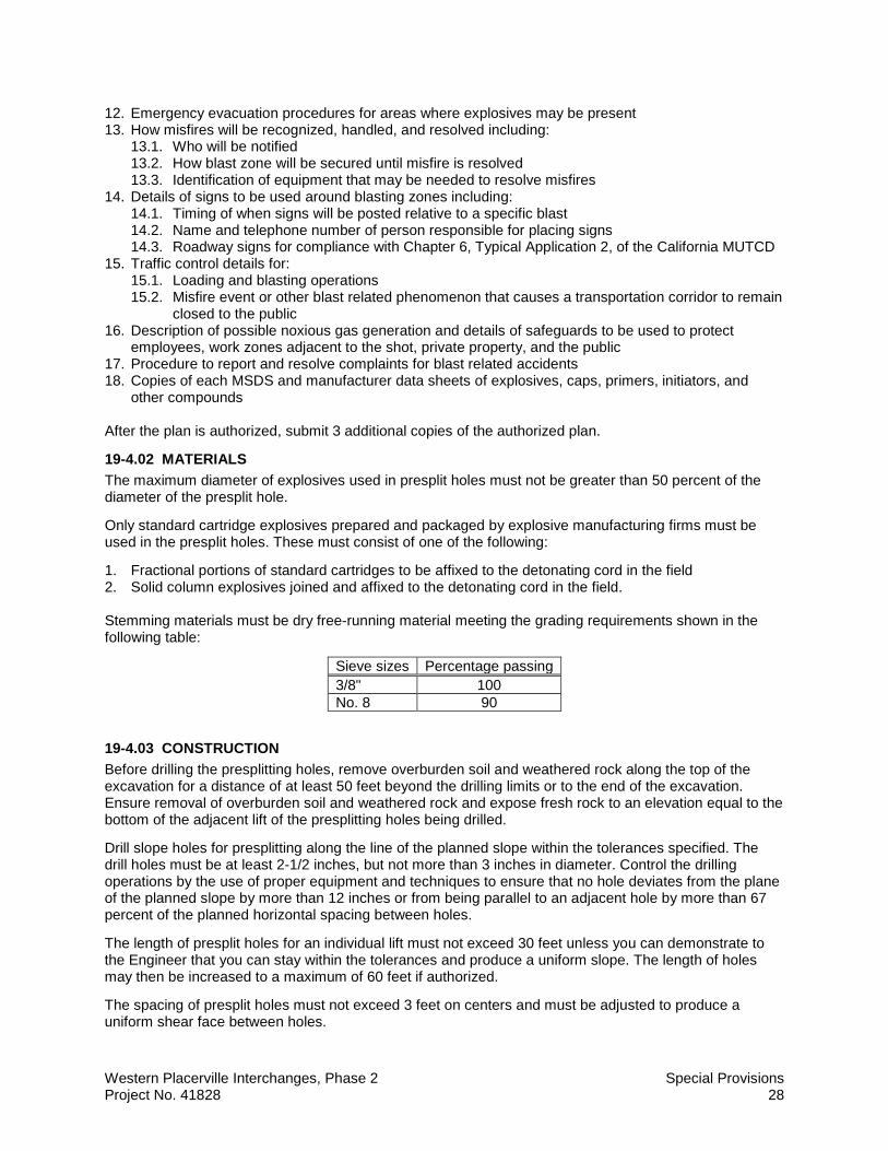
1. Fractional portions of standard cartridges to be affixed to the detonating cord in the field 2. Solid column explosives joined and affixed to the detonating cord in the field. Stemming materials must be dry free-running material meeting the grading requirements shown in the following table:
Sieve sizes Percentage passing 3/8" 100 No. 8 90
19-4.03 CONSTRUCTION Before drilling the presplitting holes, remove overburden soil and weathered rock along the top of the excavation for a distance of at least 50 feet beyond the drilling limits or to the end of the excavation. Ensure removal of overburden soil and weathered rock and expose fresh rock to an elevation equal to the bottom of the adjacent lift of the presplitting holes being drilled.
Drill slope holes for presplitting along the line of the planned slope within the tolerances specified. The drill holes must be at least 2-1/2 inches, but not more than 3 inches in diameter. Control the drilling operations by the use of proper equipment and techniques to ensure that no hole deviates from the plane of the planned slope by more than 12 inches or from being parallel to an adjacent hole by more than 67 percent of the planned horizontal spacing between holes.
The length of presplit holes for an individual lift must not exceed 30 feet unless you can demonstrate to the Engineer that you can stay within the tolerances and produce a uniform slope. The length of holes may then be increased to a maximum of 60 feet if authorized.
The spacing of presplit holes must not exceed 3 feet on centers and must be adjusted to produce a uniform shear face between holes.

Western Placerville Interchanges, Phase 2 Special Provisions Project No. 41828 29
The Engineer may order you to drill auxiliary holes along the presplit line. These holes must not be loaded or stemmed. Except for spacing, auxiliary drill holes must comply with the specifications for presplit holes. Drilling auxiliary drill holes along the presplit line is change order work.
Place the adjacent line of production holes inside the presplit lines in such a manner that avoids damage to the presplit face.
If necessary to reduce shatter and overbreak of the presplit surface, the 1st line of production holes must be drilled parallel to the slope line at the top of the cut and at each bench level thereafter.
Blasting techniques that result in damage to the presplit surface must be immediately discontinued.
No portion of the production holes may be drilled within 8 feet of a presplit plane unless authorized. The bottom of the production holes must not be lower than the bottom of the presplit holes.
A maximum offset of 24 inches will be permitted for a construction working bench at the bottom of each lift for use in drilling the next lower presplitting pattern.
Adjust the drilling operations to compensate for drift of previous levels and for the offset at the start of a new level to maintain the specified slope plane.
If the methods of drilling and blasting do not produce a uniform slope and shear face without overbreak and within the tolerances specified, then drill, blast, and excavate in short sections, up to 100 feet, until a technique produces the desired results.
If a fractional portion of a standard explosive cartridge is used, the cartridge must be firmly affixed to a length of detonating cord. The cord must be equal to the depth of the drill hole so that the cartridge does not slip down the detonating cord nor cock across the hole and bridge the flow of stemming material. Spacing of cartridges along the length of the detonating cord must not exceed 30 inches center to center and must be adjusted to give the desired results.
If a solid column type explosive is used, the column must be assembled and affixed to the detonating cord complying with the explosive manufacturer's instructions. Submit as an informational submittal a copy of the explosive manufacturer's instructions before using the column type explosive.
The bottom charge of a presplit hole may be larger than the line charges but must not cause overbreak. The top charge of the presplitting hole must be placed far enough below the collar to avoid overbreaking the surface.
Before placing the charge, the hole must be free of obstructions for the hole's entire depth. Ensure placing of the charge does not cause caving of material from the walls of the holes.
The Engineer may order the use of stemming materials as necessary to achieve a satisfactory presplit face. Stemmed presplit holes must be completely filled to the collar.
Detonate charges in each presplitting pattern simultaneously.
The tolerances in section 19-2.03G do not apply to presplit surfaces of excavation slopes where presplitting is required. The presplit face must not deviate more than 1 foot from the plane passing through adjacent drill holes except where the character of the rock has irregularities that are unavoidable. The average plane of the completed slopes must not deviate more than 1 foot from the plan slopes measured perpendicular to the plane of the slope. No portion of the slope may encroach on the roadbed.
If equally satisfactory presplit slopes are obtained, you may either presplit the slope face before drilling for production blasting or presplit the slope face and production blast at the same time, provided that the presplitting drill holes are fired with zero delay. The production holes must be delayed by at least 50 milliseconds starting at the row of holes farthest from the slope and progressing in steps to the row of holes nearest the presplit line. The presplitting holes must extend either to the end of the excavation or for a distance of not less than 50 feet beyond the limits of the production holes to be detonated.

Western Placerville Interchanges, Phase 2 Special Provisions Project No. 41828 30
19-4.04 PAYMENT Rock excavation is measured as specified for roadway excavation in section 19-2.04.
Add between the 8th and 9th paragraphs of section 19-2.03G: Roughen embankment slopes to receive erosion control materials by either track-walking or rolling with a sheepsfoot roller. Track-walk slopes by running track-mounted equipment perpendicular to the slope contours.
Replace Reserved in section 19-7.02B with: In addition to the locations described for excavation, obtain local borrow from:
1. Local Borrow Site shown on the plans. After you obtain local borrow, grade the borrow site such that it drains and blends in with the surrounding area.
Add to section 19-7.02C: Imported borrow placed within 4 feet of the finished grade must have an R-value of at least 40.
Process the imported borrow to comply with the grading requirements. Strip materials that adversely affect the imported borrow properties.
^^^^^^^^^^^^^^^^^^^^^^^^^^^^^^^^^^^^^^^^
20 LANDSCAPE
Add to section 20-2.01A(3)(a) 5. City Standards: Install irrigation per the most current Standards including but not limited to:
5.1. City of Placerville Development Guide 5.2 EDCTA Transit Design Manual 5.3 El Dorado Irrigation District Design and Construction Standards
Add to section 20-2.01A(3)(b) 9. Bubblers 10. Irrigation Controller including enclosure 11. Master Valve 12. Check Valve
Add section 20-2.01A(4)(f) Irrigation System Audit

Western Placerville Interchanges, Phase 2 Special Provisions Project No. 41828 31
Contractor shall coordinate and provide assistance of a certified irrigation auditor to complete the irrigation audit. The Contractor shall schedule the audits once the irrigation system is in operation. Provide a two week (14 day) notice for scheduling the audit. Contractor shall anticipate providing staff to assist auditor during the process, allow up to two (2) days at site.
Add Section 20-2.01A(4)(g) Record Drawing
A. Contractor shall regularly update a print of the system and any changes made to the system throughout the project. Features below ground shall be indicated with at least two measurements from surface features such as walks, curbs, or sprinkler heads. All changes shall be recorded on this plan before trenches are backfilled. The record drawing shall be completed and submitted to the City before final payment shall be made for work installed.
B. The contractor shall furnish two complete color coded irrigation charts. Charts shall identify individual RCV sections with a different color for each RCV. Charts are to be presented on fully laminated 11”X17” As-Built plans.
Add to the list in the 1st paragraph of section 20-2.06B(2)(a): 17. Be EPA WaterSense® approved.
Add after the 1st paragraph of section 20-2.06B(2)(a): Before the irrigation system functional test begins, furnish 2 remote access devices.
Add to section 20-2.06B(2)(a): The irrigation controllers within Department highway areas must be Smart Controllers with weather sensor technology and must have 2-way communication by radio/ telephone. The vendor must install any necessary software and conduct any initial software or proprietary website setup configuration for communications between controller and any web-enabled device.
You may obtain specified equipment listed below from:
Company: Rainbird Corporation Address:970 West Sierra Madre Avenue, Azusa, CA 91702 Business phone number:626-812-3400 Mobile phone number: Email address: The Department has obtained quoted prices, not including sales tax and delivery, for the equipment shown in the following table:
Equipment description Quoted price (EA)
Quantity Extended price
Controller identification
ESP-SMTe with 2-ESPSM6 modules and LXMMSSPED
$ 1 $ Controller 1
ESP-SMTe with ESPSM6 module and LXMMSSPED
$ 1 $ Controller 2
These prices are good until___________.

Western Placerville Interchanges, Phase 2 Special Provisions Project No. 41828 32
Replace item 1 in the list in the 1st paragraph of section 20-2.06B(3) with: 1. Be cold-rolled steel or aluminum. The finish color of the irrigation controller enclosure cabinets must
match color no. 20450 of FED-STD-595.
Delete items 2.___ in the list in the 1st paragraph of section 20-2.06B(3).
Replace item 6 in the list in the 1st paragraph of section 20-2.06B(3) with: 6. Have door locks with a removable-core mortise cam cylinder door lock compatible with the
Department's lock core. The Department's lock core is a Best construction core. Keys must be removable from the locks in the locked position only.
Add to section 20-2.06B(3): A single irrigation controller enclosure cabinet must be 28 inches high by 14 1/4 inches wide by 7 1/4 inches deep.
Add to section 20-2.06C: Install door locks under the manufacturer's instructions. Furnish 2 keys for each door lock before Contract acceptance.
Add Section 20-2.08C(5) Bubblers
Install per manufacturer’s instructions and per plans.
Install a flush valve per manufacturer’s instructions and per plans.
Install an indicator at each section per manufacturer’s instructions and per plans.
Add section 20-3.01A(3)(d) Soil Samples
Soil Samples: Contractor shall provide a one-quart sample of the native or import topsoil to Waypoint Analytical, Inc. of San Jose, (408) 727-0330, for their testing for conformance to this specification. No material shall be delivered to the site, graded on-site, or otherwise modified until the Owner’s Representative approves the material. All testing costs shall be paid for by the Contractor. Testing costs for the initial samples and costs for any additional samples due to non-compliance shall be paid for by the Contractor.
Add section 20-3.01A(3)(e) Amendment Samples
Amendment Samples: Contractor shall provide a one-quart sample of each proposed amendment to Waypoint Analytical, Inc. of San Jose, (408) 727-0330, for their testing for conformance to this specification. No material shall be delivered to the site until the Owner’s Representative approves the samples. Testing costs shall be paid for by the Contractor.

Western Placerville Interchanges, Phase 2 Special Provisions Project No. 41828 33
^^^^^^^^^^^^^^^^^^^^^^^^^^^^^^^^^^^^^^^^
21 EROSION CONTROL
Add to section 21-2.02H: Straw must be certified weed free under the Department of Food and Agriculture.
Add to section 21-2.02P: Straw for fiber roll must be certified weed free under the Department of Food and Agriculture.
^^^^^^^^^^^^^^^^^^^^^^^^^^^^^^^^^^^^^^^^

Western Placerville Interchanges, Phase 2 Special Provisions Project No. 41828 34
DIVISION V SURFACINGS AND PAVEMENTS 36 GENERAL
Replace Reserved in section 36-4 with: 36-4.01 GENERAL Section 36-4 includes specifications for performing work involving residue from grinding and cold planing that contains lead from paint and thermoplastic.
36-4.02 MATERIALS Not Used
36-4.03 CONSTRUCTION The residue from grinding or cold planing contains lead from paint and thermoplastic. The average lead concentrations are less than 1,000 mg/kg total lead and 5 mg/L soluble lead. This residue:
1. Is a nonhazardous waste 2. Does not contain heavy metals in concentrations that exceed thresholds established by the Health
and Safety Code and 22 CA Code of Regs 3. Is not regulated by the Federal Resource Conservation and Recovery Act, 42 USC § 6901 et seq. Management of this material exposes workers to health hazards that must be addressed in your lead compliance plan.
36-4.04 PAYMENT Not Used
^^^^^^^^^^^^^^^^^^^^^^^^^^^^^^^^^^^^^^^^
39 ASPHALT CONCRETE
Add to the list in the definition of miscellaneous areas in section 39-2.01A(2): 1. HMA Ditches 2. HMA (Stamped Paving)
Replace "Reserved" in section 39-2.01:
39-2.01A General For HMA (Stamped Paving) place hot mix asphalt (stamped paving) at the locations shown.
39-2.01B Materials For HMA (Stamped Paving) use an 8” x 8” stamp pattern.
The color coating must be an integrally colored, polymer modified cementitious coating. The color must closely conform to the Federal Standard 595B, Color #30166.

Western Placerville Interchanges, Phase 2 Special Provisions Project No. 41828 35
Complete a test plot of 2 feet x 2 feet for approval prior to constructing the stamped paving. The test plot must demonstrate the stamped pattern, color coating and sealer/hardener, and be inspected by the Engineer.
In the event more than three test plots are required by the Engineer, each additional test slab will be paid for as extra work.
39-2.01C Construction 39-2.01C(1) Site Preparation Earthwork for stamped paving areas must comply with section 19.
Areas to receive stamped paving must be cleared, excavated to the depth shown, graded to a smooth surface, and compacted to not less than 90% relative compaction.
Prior to placing stamped paving, the aggregate base must be smooth, firm, stable and free of rocks, clods, foliage, roots, or other material greater than 1 inch in diameter.
39-1.30C(2) Application Spread the hot mix asphalt at a temperature not less than 250°F. Spread using methods that will produce a surfacing of uniform smoothness, texture and density.
Compact the hot mix asphalt using power rollers. When power rollers cannot be operated in certain areas due to the size or shape of the area, compact the asphalt using hand rollers, impactors, or other approved methods.
When asphalt is not applied adjacent to pavement, curbs or dikes, the free edge of the asphalt should be tamped at a neat 45 degree angle. The free edge must be neat and follow predefined lines.
Immediately after compaction of asphalt to 96% relative density, apply the pattern while the asphalt is still in a warm to hot pliable state. Achieve consistent patterning using steel rollers and/or vibratory plate compactors to the desired pattern and depth. Remove the template once the desired pattern and depth are achieved.
Double printing caused by template misalignment or due to movement during printing is not acceptable and must be repaired prior to coating.
Gaps in grout lines that butt between two templates or between printed areas and non-printed areas will not be accepted and must be repaired prior to coating.
Color and seal the asphalt in a 2 step process in the following sequence:
A. Colored surface coating must be evenly applied to the asphalt when it has cooled sufficiently per manufacturer’s application instructions. The coating must be an integrally colored, polymer modified cementitious coating and be applied a minimum of 1/32 inch thick. The color coat must be applied when the air temperature is above 45 degrees F and precipitation is not expected within 24 hours.
B. Color coat hardener must be diluted per manufacturer’s recommendations and evenly applied by a spray method after the color coat surface has dried. After spray application, the surface may be lightly broomed to ensure an even application. A second coat of hardener must be applied after the first has dried.
Replace section 39-2.01C(3)(c) with: 39-2.01C(3)(c) Prime Coat Apply a slow-setting asphaltic emulsion as a prime coat to AB areas designated by the Engineer and at a spread rate from 0.15 to 0.40 gal/sq yd. Do not apply more prime coat than can be absorbed completely by the AB in 24 hours.

Western Placerville Interchanges, Phase 2 Special Provisions Project No. 41828 36
You may modify the prime coat application rates if authorized.
Close areas receiving prime coat to traffic. Do not allow tracking the prime coat onto pavement surfaces beyond the job site.
^^^^^^^^^^^^^^^^^^^^^^^^^^^^^^^^^^^^^^^^

Western Placerville Interchanges, Phase 2 Special Provisions Project No. 41828 37
DIVISION VI STRUCTURES
49 PILING
Add to section 49-3.02B(6)(c): The synthetic slurry must be one of the materials shown in the following table:
Material Manufacturer SlurryPro CDP KB INTERNATIONAL LLC
735 BOARD ST STE 209 CHATTANOOGA TN 37402 (423) 266-6964
Super Mud PDS CO INC 105 W SHARP ST EL DORADO AR 71731 (870) 863-5707
Shore Pac GCV CETCO CONSTRUCTION DRILLING PRODUCTS 2870 FORBS AVE HOFFMAN ESTATES IL 60192 (800) 527-9948
Terragel or Novagel Polymer
GEO-TECH SERVICES LLC 220 N. ZAPATA HWY STE 11A-449A LAREDO TX 78043 (210) 259-6386
Use synthetic slurries in compliance with the manufacturer's instructions. Synthetic slurries shown in the above table may not be appropriate for a given job site.
Synthetic slurries must comply with the Department's requirements for synthetic slurries to be included in the above table. The requirements are available from the Offices of Structure Design, P.O. Box 168041, MS# 9-4/11G, Sacramento, CA 95816-8041.
SlurryPro CDP synthetic slurry must comply with the requirements shown in the following table:

Western Placerville Interchanges, Phase 2 Special Provisions Project No. 41828 38
SlurryPro CDP Quality characteristic Test method Requirement
Density Mud weight (density), API RP 13B-1,
section 4
During drilling (pcf)
≤ 67.0a
Before final cleaning and immediately before placing concrete (pcf)
≤ 64.0a
Viscosity Marsh funnel and cup. API RP 13B-1, section 6.2
During drilling (sec/qt) 50–120
Before final cleaning and immediately before placing concrete (sec/qt)
≤ 70
pH Glass electrode pH meter or pH paper
6.0–11.5
Sand content, percent by volume Sand, API RP 13B-1, section 9
Before final cleaning and immediately before placing concrete (%)
≤ 0.5
NOTE: Slurry temperature must be at least 40 °F when tested. aIf authorized, you may use slurry in salt water. The allowable density of slurry in salt water may be increased by 2 pcf.
Super Mud synthetic slurry must comply with the requirements shown in the following table:
Super Mud Quality characteristic Test method Requirement
Density Mud weight (density), API RP 13B-1,
section 4
During drilling (pcf)
≤ 64.0a
Before final cleaning and immediately before placing concrete (pcf)
≤ 64.0a
Viscosity Marsh funnel and cup. API RP 13B-1, section 6.2
During drilling (sec/qt) 32–60
Before final cleaning and immediately before placing concrete (sec/qt)
≤ 60
pH Glass electrode pH meter or pH paper
8.0–10.0
Sand content, percent by volume Sand, API RP 13B-1, section 9
Before final cleaning and immediately before placing concrete (%)
≤ 0.5
NOTE: Slurry temperature must be at least 40 °F when tested. aIf authorized, you may use slurry in salt water. The allowable density of slurry in salt water may be increased by 2 pcf.

Western Placerville Interchanges, Phase 2 Special Provisions Project No. 41828 39
Shore Pac GCV synthetic slurry must comply with the requirements shown in the following table:
Shore Pac GCV Quality characteristic Test method Requirement
Density Mud weight (density), API RP 13B-1,
section 4
During drilling (pcf)
≤ 64.0a
Before final cleaning and immediately before placing concrete (pcf)
≤ 64.0a
Viscosity Marsh funnel and cup. API RP 13B-1, section 6.2
During drilling (sec/qt) 33–74
Before final cleaning and immediately before placing concrete (sec/qt)
≤ 57
pH Glass electrode pH meter or pH paper
8.0–11.0
Sand content, percent by volume Sand, API RP 13B-1, section 9
Before final cleaning and immediately before placing concrete (%)
≤ 0.5
NOTE: Slurry temperature must be at least 40 °F when tested. aIf authorized, you may use slurry in salt water. The allowable density of slurry in salt water may be increased by 2 pcf.
Terragel or Novagel Polymer synthetic slurry must comply with the requirements shown in the following table:
Terragel or Novagel Polymer Quality characteristic Test method Requirement
Density Mud weight (density), API RP 13B-1,
section 4
During drilling (pcf)
≤ 67.0a
Before final cleaning and immediately before placing concrete (pcf)
≤ 64.0a
Viscosity Marsh funnel and cup. API RP 13B-1, section 6.2
During drilling (sec/qt) 45–104
Before final cleaning and immediately before placing concrete (sec/qt)
≤ 104
pH Glass electrode pH meter or pH paper
6.0–11.5
Sand content, percent by volume Sand, API RP 13B-1, section 9
Before final cleaning and immediately before placing concrete (%)
≤ 0.5
NOTE: Slurry temperature must be at least 40 °F when tested. aIf authorized, you may use slurry in salt water. The allowable density of slurry in salt water may be increased by 2 pcf.
^^^^^^^^^^^^^^^^^^^^^^^^^^^^^^^^^^^^^^^^

Western Placerville Interchanges, Phase 2 Special Provisions Project No. 41828 40
51 CONCRETE STRUCTURES
Add to section 51-1.02E: Test panel and concrete color to follow pattern in the plans and the pattern on existing wall along US50 westbound on ramp at Ray Lawyer Drive.
^^^^^^^^^^^^^^^^^^^^^^^^^^^^^^^^^^^^^^^^
56 OVERHEAD SIGN STRUCTURES, STANDARDS, AND POLES
Add to section 56-3.01C(1): The sign mounting hardware must be installed at the locations shown.
Set the Type 1 standards with the handhole on the downstream side of the pole in relation to traffic or as shown.
^^^^^^^^^^^^^^^^^^^^^^^^^^^^^^^^^^^^^^^^

Western Placerville Interchanges, Phase 2 Special Provisions Project No. 41828 41
DIVISION VIII MISCELLANEOUS CONSTRUCTION 72 SLOPE PROTECTION
^^^^^^^^^^^^^^^^^^^^^^^^^^^^^^^^^^^^^^^^
73 CONCRETE CURBS AND SIDEWALKS
Add to section 73-1.02A: Concrete must be minor concrete complying with section 90-2 and may contain returned plastic concrete complying with section 90-9.
Add to section 73-3.01C: Within 2 business days of performing the surveys, submit preconstruction and post-construction surveys sealed and signed by one of the following:
1. Land surveyor licensed in the State 2. Civil engineer licensed in the State before January 1, 1982
Replace Reserved in section 73-3.01D(3) with: For locations shown, perform a preconstruction survey to verify that forms and site constraints will allow the design dimensioning and slope requirements to be achieved. Upon completing construction of these facilities, perform a post-construction survey and verify that design dimensioning and slope requirements were achieved. The post-construction survey must include a minimum of 3 measurements for each dimension and slope requirement shown. Individual measurements must be equally distributed across the specified slope or dimensional surface.
Add to the beginning of section 73-3.03: Before placing concrete, verify that forms and site constraints allow the required dimensioning and slopes shown. Immediately notify the Engineer if you encounter site conditions that will not accommodate the design details. Modifications ordered by the Engineer are change order work.
^^^^^^^^^^^^^^^^^^^^^^^^^^^^^^^^^^^^^^^^
77 LOCAL INFRASTRUCTURE
Add section 77-1 with: 77-1.01 GENERAL Each traffic signal must have an emergency vehicle detector system that must comply with the details shown and the special provisions.
Western Placerville Interchanges, Phase 2 Special Provisions Project No. 41828 42
Each emergency vehicle detector system must consist of an optical emitter assembly or assemblies located on the appropriate vehicle and an optical detector/discriminator assembly or assemblies located at the traffic signal.
Emitter assemblies are not required for this project except units for testing purposes to demonstrate that the systems perform as specified. Tests must be conducted in the presence of the Engineer as described in section 77-1(4) during the signal test period. The Engineer must be provided a minimum of 2 business days notice before performing the tests.
Each system must allow detection of 2 classes of authorized vehicles. Class I (mass transit) vehicles must be detected at ranges of up to 1,000 feet from the optical detector. Class II (emergency) vehicles must be detected at ranges up to 1,800 feet from the optical detector.
Class I signals (those emitted by Class I vehicles) must be distinguished from Class II signals (those emitted by Class II vehicles) on the basis of the modulation frequency of the light from the respective emitter. The modulation frequency for Class I signal emitters must be 9.639 Hz ± 0.110 Hz. The modulation frequency for Class II signal emitters must be 14.035 Hz ± 0.250 Hz.
A system must establish a priority of Class II vehicle signals over Class I vehicle signals and must comply with the requirements in section 25352 of the California Vehicle Code.
77-1.02 MATERILA 77-1.02(A) Emitter Assembly 77-1.02(A)(i) General Each emitter assembly provided for testing purposes must consist of an emitter unit, an emitter control unit, and connecting cables.
Each emitter assembly, including lamp, must operate over an ambient temperature range of -34 to +60 degrees C at both modulation frequencies and operate continuously at the higher frequency for a minimum of 3,000 hours at 25 degrees C ambient temperature before failure of the lamp or other components.
Each emitter unit must be controlled by a single, maintained-contact switch on the respective emitter control unit. The switch must be located to be readily accessible to the vehicle driver. The control unit must contain a pilot light to indicate that the emitter power circuit is energized and must generate only 1 modulating code, either that for Class I vehicles or that for Class II vehicles.
77-1.02(A)(ii) Functional Each emitter unit must transmit optical energy in 1 direction only.
The signal from each Class I signal emitter unit must be detectable at a distance of 1,000 feet when used with a standard optical detection/discriminator assembly and filter to eliminate visible light. Visible light must be considered eliminated when the output of the emitter unit with the filter is less than an average of 0.0003 candela per energy pulse in the wavelength range of 380 nm to 750 nm when measured at a distance of 10 feet. Submit a certificate of compliance for each Class I emitter unit.
The signal from each Class II signal emitter unit must be detectable at a distance of 1,800 feet when used with a standard optical detection/discriminator assembly.
The standard optical detection/discriminator assembly to be used in making the range tests must be available from the manufacturer of the system. A certified performance report must be furnished with each assembly.
77-1.02(A)(iii) Electrical Each emitter assembly must provide full light output with input voltages of between 12.5 V (dc) and 17.5 V (dc). An emitter assembly must not be damaged by input voltages up to 7.5 V (dc) above supply voltage. The emitter assembly must not generate voltage transients, on the input supply, that exceed the supply voltage by more than 4 volts.

Western Placerville Interchanges, Phase 2 Special Provisions Project No. 41828 43
Each emitter assembly must consume not more than 100 W at 17.5 V (dc) and must have a power input circuit breaker rated at 10 A to 12 A, 12 V (dc).
The design and circuitry of each emitter must allow its use on vehicles with either negative or positive ground without disassembling or rewiring of the unit.
77-1.02(A)(iv) Mechanical Each emitter unit must be housed in a weatherproof corrosion-resistant housing. The housing must be provided with facilities to allow mounting on various types of vehicles and must have provision for aligning the emitter unit properly and for locking the emitter unit into this alignment.
Each emitter control unit must be provided with hardware to allow the unit to be mounted in or on an emergency vehicle or mass transit vehicle. Where required for certain emergency vehicles, the emitter control unit and exposed controls must be weatherproof.
77-1.02(B) Optical Detection/Discriminator Assembly 77-1.02(B)(i) General Each optical detection/discriminator assembly must consist of 1 or more optical detectors, connecting cable and a discriminator module.
Each assembly, when used with standard emitters, must have a range of at least 1,000 feet for Class I signals and 1,800 feet for Class II signals. Standard emitters for both classes of signals must be available from the manufacturer of the system. Range measurements must be taken with all range adjustments on the discriminator module set to "maximum".
77-1.02(B)(ii) Optical Detector Each optical detector must be a waterproof unit capable of receiving optical energy from 2 horizontal directions.
The reception angle for each photocell assembly must be a maximum of 8 degrees in all directions about the aiming axis of the assembly. Measurements of reception angle will be taken at a range of 1,000 feet for a Type I emitter and at a range of 1,800 feet for a Type II emitter.
Internal circuitry must be solid state and electrical power must be provided by the associated discriminator module.
Each optical detector must be contained in a housing, which must include 2 photocell assemblies, an electronic assembly and a base. The base must have an opening to allow mounting on a mast arm or a vertical pipe nipple, or suspension from a span wire. The mounting opening must have female threads for 3/4 inch conduit. A cable entrance must be provided which must have male threads and gasketing to allow a waterproof cable connection. Each detector must have weight of less than 2.5 pounds and must present a maximum wind load area of 36 square inches. The housing must be provided with weep holes to allow drainage of condensed moisture.
Each optical detector must be installed, wired and aimed as specified by the manufacturer.
77-1.02(C) Cable Optical detector cable (EV-C) must comply with the requirements of IPCEA-S-61-402/NEMA WC 5, section 7.4, 600-V (ac) control cable, 75 degrees C, Type B, and the following:
1. The cable must contain 3 conductors, each of which must be No. 20 (7 x 28) stranded, tinned copper with low-density polyethylene insulation. Minimum average insulation thickness must be 25 mils. Insulation of individual conductors must be color coded: 1-yellow, 1-blue, 1-orange.
2. The shield must be either tinned copper braid or aluminized polyester film with a nominal 20 percent overlap. Where film is used, a No. 20 (7 x 28) stranded, tinned, bare drain wire must be placed between the insulated conductors and the shield and in contact with the conductive surface of the shield.

Western Placerville Interchanges, Phase 2 Special Provisions Project No. 41828 44
3. The jacket must be black polyvinyl chloride with minimum ratings of 600 V (ac) and 80 degrees C and a minimum average thickness of 43 mils. The jacket must be marked as required by IPCEA/NEMA.
4. The finished outside diameter of the cable must not exceed 0.35-inch. 5. The capacitance, as measured between any conductor and the other conductors and the shield, must
not exceed 48 pf per foot at 1000 Hz. 6. The cable run between each detector and the controller cabinet must be continuous without splices or
must be spliced only as directed by the detector manufacturer. 77-1.02(D) Discriminator Module Each discriminator module must be designed to be compatible and usable with a Model 170E/2070E controller unit and to be mounted in the input file of a Model 332L or Model 336L controller cabinet, and must comply with the requirements in chapter 1 of TEES.
Each discriminator module must be capable of operating 2 channels, each of which must provide an independent output for each separate input.
Each discriminator module, when used with its associated detectors, must perform the following:
1. Receive Class I signals at a range of up to 1,000 feet and Class II signals at a range of up to 1,800 feet.
2. Decode the signals, on the basis of frequency, at 9.639 Hz ± 0.119 Hz for Class I signals and 14.035 Hz ± 0.255 Hz for Class II signals.
3. Establish the validity of received signals on the basis of frequency and length of time received. A signal must be considered valid only when received for more than 0.50-second. No combination of Class I signals must be recognized as a Class II signal regardless of the number of signals being received, up to a maximum of 10 signals. Once a valid signal has been recognized, the effect must be held by the module in the event of temporary loss of the signal for a period adjustable from 4.5 seconds to 11 seconds in at least 2 steps at 5 seconds ± 0.5 second and 10 seconds ± 0.5 second.
4. Provide an output for each channel that will result in a "low" or grounded condition of the appropriate input of a Model 170E controller unit. For Class I signals the output must be a 6.25 Hz ± 0.1 percent, rectangular waveform with a 50 percent duty cycle. For Class II signals the output must be steady.
Each discriminator module must receive electric power from the controller cabinet at either 24 V (dc) or 120 V (ac).
Each channel together with the channel's associated detectors must draw not more than 100 mA at 24 V (dc) or more than 100 mA at 120 V (ac). Electric power, 1 detector input for each channel and 1 output for each channel must terminate at the printed circuit board edge connector pins shown in the following table:

Western Placerville Interchanges, Phase 2 Special Provisions Project No. 41828 45
Board Edge Connector Pin Assignment A DC ground B +24 V (dc) P (NC) C (NC) D Detector input, Channel A R (NC) E +24V (dc) to detectors S (NC) F Channel A output (C) T (NC) U (NC)
H Channel A output (E) V (NC) J Detector input, Channel B W Channel B output (C) K DC ground to detectors X Channel B output (E) L Chassis ground Y (NC) M AC- Z (NC) N AC+
(C) Collector, slotted for keying (E) Emitter, slotted for keying (NC) Not connected, cannot be used by manufacturer for any purpose.
Two auxiliary inputs for each channel must enter each module through the front panel connector. Pin assignment for the connector must be as follows:
1. Auxiliary detector 1 input, Channel A 2. Auxiliary detector 2 input, Channel A 3. Auxiliary detector 1 input, Channel B 4. Auxiliary detector 2 input, Channel B Each channel output must be an optically isolated NPN open collector transistor capable of sinking 50 mA at 30 V (ac) and must be compatible with the Model 170E controller unit inputs.
Each discriminator module must be provided with means of preventing transients received by the detector from affecting the Model 170E/2070E controller assembly.
Each discriminator module must have a single connector board and must occupy 1 slot width of the input file. The front panel of each module must have a handle to facilitate withdrawal and the following controls and indicators for each channel:
1. Three separate range adjustments each for both Class I and Class II signals. 2. A 3-position, center-off, momentary contact switch, 1 position (down) labeled for test operation of
Class I signals, and 1 position (up) labeled for test operation of Class II signals. 3. A "signal" indication and a "call" indication each for Class I and for Class II signals. The "signal"
indication denotes that a signal above the threshold level has been received. A "call" indication denotes that a steady, validly coded signal has been received. These 2 indications may be accomplished with a single indication lamp; "signal" being denoted by a flashing indication and "call" with a steady indication.
In addition, the front panel must be provided with a single circular, bayonet-captured, multi-pin connector for 2 auxiliary detector inputs for each channel. Connector must be a mechanical configuration complying with the requirements in Military Specification MIL-C-26482 with 10-4 insert arrangement, consisting of the following:
1. Wall mounting receptacle, with gold plated pins. 2. Plug with gold plated sockets, cable clamp and strain relief that must provide for a right angle turn
within 2-1/2 inches maximum from the front panel surface of the discriminator module.

Western Placerville Interchanges, Phase 2 Special Provisions Project No. 41828 46
77-1.02(E) Cabinet Wiring The Model 332L cabinet has provisions for connections between the optical detectors, the discriminator module and the Model 170E/2070E controller unit.
Wiring for a Model 332L cabinet must comply with the following:
1. Slots 12 and 13 of input file "J" have each been wired to accept a 2-channel module. 2. Field wiring for the primary detectors, except 24-V (dc) power, must terminate on either terminal
board TB-9 in the controller cabinet or on the rear of input file "J," depending on cabinet configuration. Where TB-9 is used, position assignments must be as shown in the following table:
Position Assignment
4 Channel A detector input, 1st module (Slot J-12) 5 Channel B detector input, 1st module (Slot J-12) 7 Channel A detector input, 2nd module (Slot J-13) 8 Channel B detector input, 2nd module (Slot J-13)
The 24-V (dc) cabinet power will be available at Position 1 of terminal board TB-1 in the controller cabinet.
Field wiring for the auxiliary detectors must terminate on terminal board TB-O in the controller cabinet. Position assignments are as shown in the following table:
For module 1 (J-12) For module 2 (J-13) Position Assignment Position Assignment
1 +24V (dc) from (J-12E) 7 +24V (dc) from (J-13E) 2 Detector ground From (J-12K) 8 Detector ground from (J-13K) 3 Channel A auxiliary detector input 1 9 Channel A auxiliary detector input 1 4 Channel A auxiliary detector input 2 10 Channel A auxiliary detector input 2 5 Channel B auxiliary detector input 1 11 Channel B auxiliary detector input 1 6 Channel B auxiliary detector input 2 12 Channel B auxiliary detector input 2
77-1.03 CONSTRUCTION 77-1.03(A) General 77-1.03(A)(i) System Operation The Contractor must demonstrate that the components of each system are compatible and will perform satisfactorily as a system. Satisfactory performance must be determined using the following test procedure during the functional test period:
1. Each system to be used for testing must consist of an optical emitter assembly, an optical detector, an optical detector cable and a discriminator module.
2. The discriminator modules must be installed in the proper input file slot of the Model 170E/2070E controller assembly.
3. Two tests must be conducted: 1 using a Class I signal emitter and a distance of 1,000 feet between the emitter and the detector, the other using a Class II signal emitter and a distance of 1,800 feet between the emitter and the detector. Range adjustments on the module must be set to "Maximum" for each test.
4. Each test must be conducted for a period of 1 hour, during which the emitter must be operated for 30 cycles, each consisting of a 1 minute "on" interval and a 1 minute "off" interval. During the total test period, the emitter signal must cause the proper response from the Model 170E controller unit during each "on" interval and there must be no improper operation of either the Model 170E/2070E controller unit or the monitor during each "off" interval.

Western Placerville Interchanges, Phase 2 Special Provisions Project No. 41828 47
Add section 77-2 with: 77-2.01 GENERAL Section 77-2 includes specifications for performing work involving water line.
77-2.02 MATERIAL Refer to Appendix A – Water Specs. 77-2.03 CONSTRUCTION Refer to Appendix A – Water Specs. 77-2.04 PAYMENT Per linear foot includes all work necessary to install the waterline, including but not limited – traffic control, saw cutting, excavation, pipe and fittings, backfill materials, asphalt paving, dewatering, subgrade preparation, backfill and compaction, temporary connections and providing temporary water supplies/service to Raley’s, Juvenile Hall, and County Jail.
Add section 77-3 with: 77-3.01 GENERAL Section 77-3 includes specifications for performing work involving fiber optic work.
77-3.02 MATERIAL The contractor must test the existing fiber optic and replace in kind, TYPE SINGLE MODE – 24 STRAIN. 77-3.03 CONSTRUCTION Contractor must maintain fiber optic connection, and phone and internet access, to the County Jail at all
times. The fiber optic must be spliced one strain at a time or a temporary wireless system must be installed without interruption.
77-3.03A CONSTRUCTION – TEMPORARY WIRELESS SYSTEM Parts QTY 4 - AF-24HD 24 GHz frequencies 24.05 - 24.25 GHz Setup Requirements • Vendor to provide wireless bridging equipment above • Vendor to mount equipment to county specified buildings and run applicable cabling to the MDF
locations in each facility and provide ethernet handoff to the County IT an Sheriff IT network staff • Vendor to configure/connect wireless bridges and ready them for use on the county network • Vendor to work with County IT and Sheriff IT to configure bridging equipment for network use on both
separate network 77-3.04 PAYMENT Per linear foot includes all work necessary to install the fiber optic, including but not limited – traffic control, saw cutting, excavation, pipe and fittings, backfill materials, asphalt paving, dewatering, subgrade preparation, backfill and compaction, and temporary wireless system.
^^^^^^^^^^^^^^^^^^^^^^^^^^^^^^^^^^^^^^^^

Western Placerville Interchanges, Phase 2 Special Provisions Project No. 41828 48
78 INCIDENTAL CONSTRUCTION
Replace stain in the 1st paragraph of section 78-4.04A(1)(c) with: stain and sealer
Add to the end of section 78-4.04A(2)(b): Completed stained surfaces must closely resemble the referee sample located at: US50 in the City of Placerville at the intersection with Missouri Flat Road.
The stain must consist of 1 base stain color and at least 2 accent stain colors. The base and accent stain colors must be from the same manufacturer.
Replace Reserved in section 78-4.04A(2)(c) with: Sealer must be:
1. From the same manufacturer as that of the stain 2. Compatible with the stain and the surfaces 3. Clear and colorless and have a matte finish when dry
Add to the end of section 78-4.04A(3)(c): Before sealing the stained surface, the surface must be exposed to sunlight for at least 7 days after staining.
After the stained surface is authorized, prepare the surface and apply the sealer under the manufacturer's instructions. Uniformly apply at least 2 coats of sealer unless otherwise instructed by the manufacturer.
Replace preparing and staining in the 2nd sentence of the 1st paragraph of section 78-4.04B(1)(c)(iii) with:
preparing, staining, and sealing
Add to the list in the 1st paragraph of section 78-4.04B(1)(c)(iii): 5. Manufacturer and finish of the sealer that will be applied
Replace Not Used in section 78-4.04B(3) with: Apply the stain in at least 3 separate applications. The 1st and 2nd applications must be by air or airless sprayer.
^^^^^^^^^^^^^^^^^^^^^^^^^^^^^^^^^^^^^^^^

Western Placerville Interchanges, Phase 2 Special Provisions Project No. 41828 49
DIVISION IX TRAFFIC CONTROL DEVICES 81 MISCELLANEOUS TRAFFIC CONTROL DEVICES
^^^^^^^^^^^^^^^^^^^^^^^^^^^^^^^^^^^^^^^^
82 SIGNS AND MARKERS
Add to section 82-2.02A: The protective-overlay film must be from the same manufacturer as the retroreflective sheeting used.
^^^^^^^^^^^^^^^^^^^^^^^^^^^^^^^^^^^^^^^^
83 RAILINGS AND BARRIERS
Replace Reserved in section 83-2.02C(3) with: The offset from the face of the Type WB-31 transition railing to the hinge point must be at least 3'-6".
The offset from the face of the adjacent midwest guardrail system to the hinge point must be transitioned from the offset at the Type WB-31 transition railing to 4'-0" using a ratio of 6:1.
Replace Reserved in section 83-2.04C with: 83-2.04C(1) General 83-2.04C(1)(a) Summary Section 83-2.04C includes specifications for constructing alternative flared terminal systems.
83-2.04C(1)(b) Definitions Not Used
83-2.04C(1)(c) Submittals Submit a certificate of compliance for alternative flared terminal systems.
83-2.04C(1)(d) Quality Assurance Not Used
83-2.04C(2) Materials Alternative flared terminal systems must be one of the following or a Department-authorized equal:
1. Type FLEAT terminal system. Type FLEAT terminal system must be a FLEAT-350 manufactured by Road Systems, Inc., located in Big Spring, Texas, and must include the connection components. The FLEAT-350 can be obtained from the following distributors:
Western Placerville Interchanges, Phase 2 Special Provisions Project No. 41828 50
Address Telephone no. UNIVERSAL INDUSTRIAL SALES PO BOX 699 PLEASANT GROVE UT 84062
(801) 785-0505
GREGORY INDUSTRIES INC 4100 13TH ST SW CANTON OH 44708
(330) 477-4800
2. Type SRT terminal system. Type SRT terminal system must be an SRT-350 Slotted Rail Terminal (8-
post system) manufactured by Trinity Highway Products, LLC, and must include the connection components. The SRT-350 Slotted Rail Terminal (8-post system) can be obtained from the manufacturer:
Address Telephone no.
TRINITY HIGHWAY PRODUCTS LLC PO BOX 99 CENTERVILLE UT 84012
(800) 772-7976
83-2.04C(3) Construction Install alternative flared terminal systems under the manufacturer's installation instructions.
Identify each terminal system by painting the type of terminal system in 2-inch-high, neat, black letters and figures on the backside of the rail element between system posts number 4 and 5.
For Type SRT terminal systems, drive the steel foundation tubes with soil plates attached with or without pilot holes, or place them in drilled holes. Backfill the space around the foundation tubes with selected earth that is free of rock. Place the earth in 4-inch-thick layers. Moisten and thoroughly compact each layer. Coat the inside surfaces of the foundation tubes to receive wood terminal posts with grease. Insert the posts into the tubes by hand. Do not drive the posts. You may slightly round the post edges to facilitate insertion.
For Type FLEAT terminal systems, drive the steel foundation tubes with or without pilot holes, or place them in drilled holes. Backfill the space around the foundation tubes with selected earth that is free of rock. Place the earth in 4-inch-thick layers. Moisten and thoroughly compact each layer. Coat the inside surfaces of the foundation tubes to receive wood terminal posts with grease. Insert the posts into the tubes by hand. Do not drive the posts. You may slightly round the post edges to facilitate insertion.
83-2.04C(4) Payment Not Used
Replace section 83-4.05 with: 83-4.05 SAND-FILLED CRASH CUSHIONS 83-4.05A General 83-4.05A(1) Summary Section 83-4.05 includes specifications for constructing sand-filled crash cushions.
83-4.05A(2) Definitions Not Used
83-4.05A(3) Submittals Submit a certificate of compliance for sand-filled crash cushions.

Western Placerville Interchanges, Phase 2 Special Provisions Project No. 41828 51
83-4.05A(4) Quality Assurance Not Used
83-4.05B Materials The modules making up the sand-filled crash cushions must be one of the modules shown in the following table:
Module Manufacturer Distributors Energite III Crash Cushion
ENERGY ABSORPTION SYSTEMS INC 70 W MADISON ST STE 2350 CHICAGO IL 60602
TRAFFIC CONTROL SERVICE INC 8585 THYS CT SACRAMENTO CA 95828 Telephone: (916) 387-9733 Fax: (916) 387-9734
TRAFFIC CONTROL SERVICE INC 1818 E ORANGETHORPE FULLERTON CA 92831-5324 Telephone: (714) 526-9500 Fax: (714) 526-9561
Fitch Universal Modules
TrafFix Sand Barrels
TRAFFIX DEVICES INC 220 CALLE PINTORESCO SAN CLEMENTE CA 92672 Telephone: (949) 361-5663 Fax: (949) 361-9205
UNITED RENTALS INC 1533 BERGER DR SAN JOSE CA 95112 Telephone: (408) 287-4303 Fax: (408) 287-1929
STATEWIDE SAFETY & SIGN PO BOX 1440 PISMO BEACH CA 93448 Telephone: (805) 929-5070 Fax: (805) 929-5786
CrashGard Model CC-48 Sand Barrels
PLASTIC SAFETY SYSTEMS INC 2444 BALDWIN RD CLEVELAND OH 44104
CAPITOL BARRICADE INC 6001 ELVAS AVE SACRAMENTO CA 95819 Telephone: (916) 451-5176 Fax: (916) 451-5388
CAPITOL BARRICADE INC 1661 EAST MINER AVE STOCKTON CA 95205 Telephone: (209) 469-2663 Fax: (916) 451-5388
SIERRA SAFETY 9093 OLD STATE HWY NEWCASTLE CA 95658 Telephone: (916) 663-2026 Fax: (916) 663-1858
ALERT O LITE 2020 N WINERY RD
Western Placerville Interchanges, Phase 2 Special Provisions Project No. 41828 52
FRESNO CA 93703 Telephone: (559) 486-4570
STEVENSON SUPPLY 3601 REGIONAL PKWY SANTA ROSA CA 95403 Telephone: (707) 575-3335
HI WAY SAFETY INC 13310 5TH ST CHINO CA 91710 Telephone: (909) 591-1781 Fax: (909) 627-0999
Use only 1 type of module at any 1 location.
The modules must:
1. Be the standard yellow color furnished by the manufacturer 2. Have black lids 3. Have exterior components that are formulated or processed to resist deterioration from ambient UV
rays 4. Be free from structural flaws and surface defects 5. Have been manufactured after March 31, 1997 Sand used to fill the modules must be clean, washed, commercial-quality concrete sand. When placed in the modules, the sand must contain no more than 7 percent water when tested under California Test 226.
83-4.05C Construction Under the manufacturer's instructions, fill the modules with sand and securely attach the lids.
Attach a Type R or Type P marker panel to the front of the crash cushion if the closest point of the crash cushion array is within 12 feet of the traveled way. Fasten the marker panel to the crash cushion using commercial-quality hardware or by other authorized methods. Place the top of Type R marker panels 1 inch below the module lid. Place Type P marker panels such that the bottom of the panel is at the bottom of the module.
83-4.05D Payment Not Used
^^^^^^^^^^^^^^^^^^^^^^^^^^^^^^^^^^^^^^^^

Western Placerville Interchanges, Phase 2 Special Provisions Project No. 41828 53
DIVISION X ELECTRICAL WORK 86 GENERAL
Replace the 1st paragraph in 86-1.01D(3) of the RSS for section 86 with: Deliver the material and equipment for testing to the following location:
11325 Sanders Drive,
Rancho Cordova, CA 95742.
Add to the end of section 86-1.02B(1) of the RSS for section 86: High density polyethylene conduit must be Type IPS, DR 9 and comply with ASTM F714. The conduit material must comply with ASTM D3350.
Add to the list in the 2nd paragraph of section 86-1.02C(1) of the RSS for section 86: 14. STREET LIGHTING for City street lighting system
Add to the end of section 86-1.02C(3) of the RSS for section 86: Hold-down bolts must be a Penta Head 1/2-13UNC and must have a thread lock material.
Replace section 86-1.02F of the RSS for section 86 with: 86-1.02F Conductors and Cables 86-1.02F(1) General Conductors and cables must be clearly and permanently marked the entire length of their outer surface with:
1. Manufacturer's name or trademark 2. Insulation-type letter designation 3. Conductor size 4. Voltage 5. Temperature rating 6. Number of conductors for a cable The minimum insulation thickness and color code requirements must comply with NEC.
86-1.02F(2) Conductors 86-1.02F(2)(a) General A conductor must be UL listed or NRTL certified and rated for 600 V(ac).
Conductors must be identified as shown in the following table:

Western Placerville Interchanges, Phase 2 Special Provisions Project No. 41828 54
Conductor Identification
Circuit Signal phase or function
Identification Copper
Size Insulation colord
Band symbols Base Stripea
Signals (vehicle)a, b
2, 6 Red, yel, brn Blk 2, 6 14 4, 8 Red, yel, brn Ora 4, 8 14 1, 5 Red, yel, brn None 1, 5 14 3, 7 Red, yel, brn Pur 3, 7 14
Ramp meter 1 Red, yel, brn None NBR 14 Ramp meter 2 Red, yel, brn Blk NBR 14
Pedestrian signals
2p, 6p Red, brn Blk 2p, 6p 14 4p, 8p Red, brn Ora 4p, 8p 14 1p, 5p Red, brn None 1p, 5p 14 3p, 7p Red, brn Pur 3p, 7p 14
Push button assembly or accessible pedestrian
signal
2p, 6p Blu Blk P-2, P-6 14 4p, 8p Blu Ora P-4, P-8 14 1p, 5p Blu None P-1, P-5 14
3p, 7p Blu Pur P-3, P-7 14
Traffic signal controller cabinet
Ungrounded circuit conductor Blk None CON-1 6
Grounded circuit conductor Wht None CON-2 6
Highway lighting pull box
to luminaire
Ungrounded - line 1 Blk None NBR 14 Ungrounded - line 2 Red None NBR 14
Grounded Wht None NBR 14 Multiple highway lighting
Ungrounded - line 1 Blk None ML1 10
Ungrounded - line 2 Red None ML2 10
Lighting control Ungrounded - PEU Blk None C1 14
Switching leg from PEU unit or SM transformer Red None C2 14
Service
Ungrounded - line 1 (signals) Blk None NBR 6
Ungrounded - line 2 (lighting) Red None NBR 8
Sign lighting Ungrounded - line 1 Blk None SL-1 10 Ungrounded - line 2 Red None SL-2 10
Flashing beacons
Ungrounded between flasher and beacons Red or yel None F-Loc.c 14
Grounded circuit
conductor
Push button assembly or accessible pedestrian
signal Wht Blk NBR 14 Signals and multiple
lighting Wht None NBR 10 Flashing beacons and
sign lighting Wht None NBR 12 Lighting control Wht None C-3 14
Service Wht None NBR 14 Railroad
preemption Blk None R 14 Spares Blk None NBR 14

Western Placerville Interchanges, Phase 2 Special Provisions Project No. 41828 55
NBR = No band required PEU=Photoelectric unit aOn overlaps, the insulation is striped for the 1st phase in the designation, e.g., phase (2+3) conductor is striped as for phase 2. bBand for overlap and special phases as required cFlashing beacons having separate service do not require banding. dColor Code: Yel-Yellow, Brn-Brown, Blu-Blue, Blk-Black, Wht-White, Ora-Orange, Pur-Purple
The insulation color must be homogeneous throughout the full depth of the insulation. The identification stripe must be continuous throughout the length of the conductor.
86-1.02F(2)(c) Copper Conductors 86-1.02F(2)(c)(i) General Copper wire must comply with ASTM B3 and B8.
Insulation for no. 14 to no. 4 conductors must be one of the following:
1. Type TW PVC under ASTM D2219 2. Type THW PVC 3. Type USE, RHH, or RHW cross-linked polyethylene The insulation for no. 2 and larger conductors must be one of the above or THWN.
86-1.02F(2)(c)(ii) Bonding Jumpers and Equipment Grounding Conductors A bonding jumper must be copper wire or copper braid of the same cross-sectional area as a no. 8 conductor or larger.
An equipment grounding conductor may be bare or insulated.
86-1.02F(2)(c)(iii) Inductive Loop Conductors An inductive loop conductor must comply with the requirements shown in the following table:
Conductor Requirements for Inductive Loop Detectors Loop wire Requirement
Type 1 Type RHW-USE neoprene-jacketed or Type USE cross-linked polyethylene, insulated, no. 12, stranded copper wire with a minimum 40-mils insulation thickness at any point.
Type 2
Type THWN or Type XHHW, no. 14, stranded copper wire in a plastic tubing. The plastic tubing must be polyethylene or vinyl rated for use at 105 °C and resistant to oil and gasoline. The outside diameter of the tubing must be at most 0.27 inch with a wall thickness of at least 0.028 inch.
86-1.02F(2)(d) Reserved 86-1.02F(3) Cables 86-1.02F(3)(a) General Reserved
Reserved
86-1.02F(3)(c) Reserved 86-1.02F(3)(d) Copper Cables 86-1.02F(3)(d)(i) General Reserved

Western Placerville Interchanges, Phase 2 Special Provisions Project No. 41828 56
86-1.02F(3)(d)(ii) Conductor Signal Cables A conductor signal cable must have a black polyethylene jacket with an inner polyester binder sheath. The cable jacket must be rated for 600 V(ac) and 75 degrees C. Filler material, if used, must be polyethylene.
The individual conductors in the cable must be solid copper complying with ASTM B286 with Type THWN insulation. The minimum thickness of insulation must comply with NEC for conductor sizes no. 14 to no.10. The minimum thickness of the nylon jacket must be 4 mils.
Cable must comply with the requirements shown in the following table:

Western Placerville Interchanges, Phase 2 Special Provisions Project No. 41828 57
Cable typea
Conductor quantity and
type
Cable jacket thickness (mils)
Maximum nominal outside
diameter (inch)
Conductor color code
Average Minimum
3CSC 3 no. 14 44 36 0.40 Blue/black, blue/orange, white/black stripe
5CSC 5 no. 14 44 36 0.50 Red, yellow, brown, black, white
9CSC 8 no. 14 1 no. 12
60 48 0.65 No. 12 - white, no. 14 - red, yellow, brown, black, and red/black, yellow/black, brown/black, white/black stripe
12CSC 11 no. 14 1 no. 12
60 48 0.80 No. 12 - white, no. 14 - red, yellow, brown, red/black stripe, yellow/black stripe, brown/black stripe, black/red stripe, black/white stripe, black, red/white stripe, brown/white stripe
28CSC 27 no. 14 1 no. 10
80 64 0.90 No. 10 - white no. 14 - red/black stripe, yellow/black stripe, brown/black stripe, red/orange stripe, yellow/orange stripe, brown/orange stripe, red/silver stripe, yellow/silver stripe, brown/silver stripe, red/purple stripe, yellow/purple stripe, brown/purple stripe, red/2 black stripes, brown/2 black stripes, red/2 orange stripes, brown/2 orange stripes, red/2 silver stripes, brown/2 silver stripes, red/2 purple stripes, brown/2 purple stripes, blue/black stripe, blue/orange stripe, blue/silver stripe, blue/purple stripe, white/black stripe, black/red stripe, black
86-1.02F(3)(d)(iii) Detector Lead-in Cables Conductors for a loop detector lead-in cable must be two no. 16, 19-by-29, stranded, tinned copper wires with calculated cross-sectional areas complying with ASTM B286, Table 1 and the requirements shown in the following table:

Western Placerville Interchanges, Phase 2 Special Provisions Project No. 41828 58
Conductor Requirements for Loop Detector Lead-In Cables Lead-in cable Requirement
Type B Insulated with 20 mils of high-density polyethylene. Conductors must be twisted together with at least 2 turns per foot, and the twisted pair must be protected with a copper or aluminum polyester shield. A minimum no. 20 copper drain wire must be connected to the equipment ground within the cabinet. Cable must have a high-density polyethylene or high-density polypropylene outer jacket with a nominal thickness of 32 mils. Include an amorphous, interior, moisture penetration barrier of nonhydroscopic polyethylene or polypropylene fillers.
Type C Comply with International Municipal Signal Association Specification no. 50-2. A minimum no. 20 copper drain wire must be connected to the equipment ground within the cabinet.
86-1.02F(3)(d)(iv) Reserved 86-1.02F(3)(d)(vi) Communication Cables 86-1.02F(3)(d)(vi)(a) General Reserved
86-1.02F(3)(d)(vi)(d) Telephone Cables A telephone cable must be a 6-pair type with solid, tinned, copper no. 22 conductors and comply with RUS Bulletin 1735F-205 (PE-39).
Replace section 86-1.02I of the RSS for section 86 with: 86-1.02I Connectors and Terminals 86-1.02I(1) General Reserved
86-1.02I(2) Power All connectors must comply with UL-486A and/or UL-486 B.
Connectors and terminals must be rated for the conductors’ size and material type and be prefilled with oxide-inhibiting compound.
Connectors and terminals for copper conductors must be a compression or crimp type.
Connectors and terminals for aluminum conductors must be a compression type.
Replace the 1st sentence of the 15th paragraph of section 86-1.02P(2) of the RSS for section 86 with:
The interior of the enclosure must accept cable-in/cable-out circuit breakers. The circuit breakers must be mounted on nonenergized clips and vertically with the up position of the handle being the ON position.
Add to the list in the 2nd paragraph of section 86-1.02R(4) of the RSS for section 86: 4. Be made of metal

Western Placerville Interchanges, Phase 2 Special Provisions Project No. 41828 59
^^^^^^^^^^^^^^^^^^^^^^^^^^^^^^^^^^^^^^^^^^^^^^^^^^^^^^^^^^^^ 87 GENERAL
Add between the 1st and 2nd paragraphs of section 87-1.03B(1) of the RSS for section 87: Notify the Engineer at least 2 business days before starting horizontal directional drilling method or jack and drill activities.
Add to the beginning of section 87-1.03B(3)(a) of the RSS for section 87: Use Type 3 conduit for underground installation.
The steel lid for a traffic pull box must be welded to a Z-bar frame
Add to the end of section 87-1.03B(3)(a) of the RSS for section 87: Use high-density, polyurethane DR 9 conduit for installations by the horizontal directional drilling method.
Replace section 87-1.03B(4) of the RSS for section 87 with: 87-1.03B(4) Conduit Installation by Horizontal Directional Drilling Method You must install a conduit to a minimum depth of 4 feetand maximum depth of 6 feet. If you must install a conduit less than 4 feet in depth or greater than 6 feet in depth, the installation must be authorized.
The diameter of the bore hole must be no larger than 1.5 times the outside diameter of the conduit.
Water-based mineral slurry or wetting solution may be used to lubricate the boring tool and stabilize the soil surrounding the boring path.
Disposal of residue must comply with section 13-4.03D.
The horizontal directional drilling equipment must have directional control of the boring tool and have an electronic boring tool location detection system. During operation, the equipment must be able to determine the location of the tool both horizontally and vertically.
Do not use slurry cement backfill.
Use a mandrel to prove the conduit is free and clear of dirt, rocks, and other debris after installation.
Replace the 3rd paragraph of section 87-1.03C(1) of the RSS for section 87 with: Install a pull box on a bed of crushed rock.
Replace section 87-1.03F(2)(b) of the RSS for section 87 with: 87-1.03F(2)(b) Communication Cables 87-1.03F(2)(b)(i) General Terminate the ends of the communication cables as shown.
87-1.03F(2)(b)(iii) Telephone Cables Do not splice telephone cables between the telephone demarcation point and the controller cabinet.
Provide a minimum of 6 feet of slack at each cabinet, including the telephone demarcation cabinet.
Replace the 1st paragraph of section 87-1.03F(2)(c)(ii) of the RSS for section 87 with: Install a Type B loop detector lead-in cable in conduit.
Replace the 1st paragraph of section 87-1.03F(3)(c)(ii) of the RSS for section 87 with: Use a Type 2 loop wire. Use only Type 2 loop wire for Type E loop detectors.

Western Placerville Interchanges, Phase 2 Special Provisions Project No. 41828 60
Replace the 2nd paragraph of section 87-1.03H(2) of the RSS for section 87 with: Use Method B to insulate a splice.
Add to the end of section 87-1.03T of the RSS for section 87:
A manufacturer's representative must program the accessible pedestrian signals at the following intersections:
1. Intersection of Forni Road and US 50 Eastbound Off-ramp When the extended pushbutton press is used, program the signals with messages for each street as follows:
1. During the pedestrian clearance interval, the message heard must be Wait to cross <name of street>_______. Wait.
2. During the pedestrian clearance interval, the message heard must be Wait to cross <name of street>_______. Wait.
Add between the 11th and 12th paragraphs of section 87-1.03V(2) of the RSS for section 87:
Use hot-melt rubberized sealant to fill slots.
Replace the paragraphs of section 87-4.03B of the RSS for section 87 with:Install the battery backup system cabinet on the right side of the Model 342 LX cabinet.
Add to the end of section 87-21.03C of the RSS for section 87: Modifying a lighting system includes removing, adjusting, or adding:
1. Foundations 2. Pull boxes 3. Conduit 4. Conductors 5. Standards 6. Luminaires 7. Service equipment enclosure 8. Photoelectric control 9. Fuse splice connectors Modifying a highway advisory radio system includes removing, adjusting, or adding:
1. Foundations 2. Pull boxes 3. Conduit 4. Conductors 5. Cables 6. Wood posts
Modifying a vehicle sensor node (VSN) includes removing, adjusting, or adding:
1. In-ground sensors 2. Relocating WVDS pole and equipment 3. Foundation

Western Placerville Interchanges, Phase 2 Special Provisions Project No. 41828 61
87-21.03C(2) VSN The VSN replacement includes VSN, epoxy sealant, testing, calibration with the existing WVDS and salvaging the existing VSN. Remove existing VSN. Comply with section 14-11.15. Procure VSN components directly from manufacturer. Provide the following: 1. All equipment, documentation, materials and special tools required for acceptance testing of the
system. 2. All software required to program, reconfigure and support the VSN installed at the time of
acceptance testing. 3. Arrange for manufacturer representative to be present during installation and calibration of VSN. Comply with the manufacturer’s instructions and these special provisions for the installation and materials used. Before the installation of any VSN component:
1. Obtain the Engineer's approval for the exact location. 2. Demonstrate that components will operate independently and will not interfere with other
components at any other site or other equipment in the vicinity. 3. Demonstrate that each VSN will be installed within range of its corresponding AP and is located
with a 60-degree horizontal cone, measured from perpendicular. 4. Test all VSNs and demonstrate proper operation and communication between the VSN and the AP. Keep the maximum distance between a VSN and the AP as follows:
AP mounting height Maximum distance from VSN to AP 12 feet 75 feet 18 feet 105 feet 24 feet 150 feet
Clear the surface to be bonded and remove debris, moisture and anything else that interferes with the sealant bond. Install new VSN in the roadway. Clean holes cored in the pavement and thoroughly dry before installing VSN. Do not allow residue resulting from core drilling to flow across shoulders or lanes occupied by traffic. Remove residue from the pavement surface by vacuuming or other approved method before any reside flows off of the pavement surface. Dispose of residue from core drilling. Backfill the cored pavement per manufacturer’s instructions. Remove any excess epoxy sealant from the roadway without the use of solvents. Reconfigure and demonstrate successful communication between each VSN, and the AP after installation of all components. Program the VSN and include a minimum of 16 channels per location to avoid interference from other users of the communication band during reconfiguration. Install and orient the video camera so that traffic is visible in all lanes. The video field of view must totally encompass the area in which vehicles are detected. Verify the performance of each site. The accuracy of each site must be determined and documented so that each site may be approved or rejected separately. Failure to submit the recorded medium and

Western Placerville Interchanges, Phase 2 Special Provisions Project No. 41828 62
materials at the conclusion of testing invalidates the test. The recorded medium serves as acceptance evidence and must not be used for calibration. The calibration must have been completed prior to testing and verification. The department does not pay for repairing, replacing, and retesting of VSN components due to failure or rejection.
^^^^^^^^^^^^^^^^^^^^^^^^^^^^^^^^^^^^^^^^^^^^^^^^^^^^^^^^^^^^

Western Placerville Interchanges, Phase 2 Special Provisions Project No. 41828 63
APPENDEX A – WATER SPECS

03 30 00 - 64 Cast-In-Place Concrete

03 30 00 - 65 Cast-In-Place Concrete
DIVISION 03 CONCRETE
SECTION 03 34 00.13
CONTROLLED LOW STRENGTH MATERIAL
PART 1 – GENERAL
1.01 SECTION INCLUDES A. Requirements for controlled low strength material (CLSM) as backfill material
in specific locations.
B. CLSM shall be used as backfill material for all water mainline and service crossing under existing non-potable water laterals and mainlines.
1.02 DEFINITION A. Controlled Low Strength Material (CLSM): A highly flowable, lean concrete
mix consisting of a mixture of cement, fly ash, densely graded mineral aggregates, water and admixtures. Characteristics include:
Capable of freely flowing to fill excavations and voids without compaction or other additional effort.
Used in trenches and backfill adjacent to structures where clearance is limited, and in other areas specifically identified on the Drawings or specified.
Low permeability to prevent migration of adjacent fines into the set mix.
Easily excavated after curing with minimum risk of damage to buried utility.
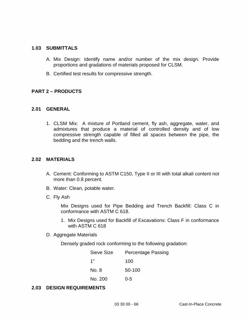
03 30 00 - 66 Cast-In-Place Concrete
1.03 SUBMITTALS A. Mix Design: Identify name and/or number of the mix design. Provide
proportions and gradations of materials proposed for CLSM.
B. Certified test results for compressive strength.
PART 2 – PRODUCTS
2.01 GENERAL
1. CLSM Mix: A mixture of Portland cement, fly ash, aggregate, water, and
admixtures that produce a material of controlled density and of low compressive strength capable of filled all spaces between the pipe, the bedding and the trench walls.
2.02 MATERIALS
A. Cement: Conforming to ASTM C150, Type II or III with total alkali content not
more than 0.8 percent.
B. Water: Clean, potable water.
C. Fly Ash
Mix Designs used for Pipe Bedding and Trench Backfill: Class C in conformance with ASTM C 618.
1. Mix Designs used for Backfill of Excavations: Class F in conformance with ASTM C 618
D. Aggregate Materials
Densely graded rock conforming to the following gradation:
Sieve Size Percentage Passing
1”
No. 8
100
50-100
No. 200 0-5
2.03 DESIGN REQUIREMENTS

03 30 00 - 67 Cast-In-Place Concrete
A. Minimum Cement Content: 50 pounds per cubic yard.
B. Use fly ash to improve flow-ability of the fresh CLSM and to regulate the strength. Do not use more than 300 pounds per cubic yard.
C. Unit Weight Requirements
Density of CLSM when used as backfill of excavations: Between 100 pounds per cubic foot and 130 pounds per cubic foot in the as-placed condition as determined by AST D 6023.
D. Compressive Strength Requirements
Mix Designs used for Pipe Bedding and Trench Backfill: Compressive strength at 28 days between 50 psi and 100 psi as determined in accordance with ASTM D 4832.
2.04 CONSISTENCY AND MIXING
A. Consistency: Similar to that of a thick liquid so that it flows readily and fills
spaces and voids around pipes and structures.
B. Slump: Between 6 inches and 8 inches when tested in accordance with ASTM C143.
C. Uniform consistency and appearance.
D. Mixing Method and Time: As required to produce a uniform mixture of cement, fly ash, aggregate, admixtures, and water.

03 30 00 - 68 Cast-In-Place Concrete
2.05 MEASUREMENT OF MATERIALS
A. Use weighing equipment to determine the amount of cement, fly ash, and
aggregate entering into each patch. Where batches are proportioned to contain an integral number of conventional sacks of cement, the cement is delivered at the mixer in the original unbroken sacks, the weight of the cement contained in each sack may be taken without weighing as 94 lbs.
B. Use a suitable water meter or other acceptable method of measuring the quantity of water entering the mixer.
PART 3 – EXECUTION
3.01 PLACEMENT
A. CLSM shall be placed as backfill for the water main/water service and
between the water pipeline and non-potable lateral/main up to a minimum of 6-inches over the non-potable pipeline. The backfill over the non-potable pipe shall take the road sub-grade and asphalt into consideration; Contractor shall get EID approval prior to placing CLSM.
B. Thoroughly settle and consolidate CLSM as the material is placed in excavations. Fill the entire depth of the layer that is being consolidated, into a dense, homogeneous mass, filling all spaces and voids and bringing only a slight excess of water to the exposed surface. Place and consolidate CLSM by means that will not cause segregation of the mix.
C. Do not place CLSM under the following conditions:
When the air temperature is below 40 degrees Fahrenheit.
When the excavation contains water or when the bottom or walls of the excavation are frozen or contain frozen material.
D. Prevent flotation of pipes by placing CLSM in two or more lifts, with each lift reaching an initial set before the succeeding lift is placed.

03 30 00 - 69 Cast-In-Place Concrete
3.02 PROTECTION OF CLSM
A. Protect CLSM from equipment, traffic, and backfilling operations until the
surface has achieved an initial set and has hardened enough to develop a minimum penetration number of 650 when tested in accordance with ASTM C 403.
B. If the trench backfill is not to be placed over the CLSM within eight hours after CLSM placement, place a 6-inch layer of moist backfill over the CLSM.
END OF SECTION

03 40 00 - 1 Precast Concrete
DIVISION 03 CONCRETE
SECTION 03 40 0
PRECAST CONCRETE
PART 1 – GENERAL
1.01 SCOPE
The work covered by this section shall consist of furnishing all materials, accessories, equipment, tools, transportation, service, labor and performing all operations to furnish and install the precast concrete vaults in accordance with this section of the specifications and applicable drawings. Excavation and backfill to be in accordance with Section 02220.
Precast concrete vaults and covers shall be manufactured in a plant especially designed for that purpose and shall conform to the shapes and dimensions indicated on the plans.
1.02 SUBMITTALS
Prior to installation the following is to be submitted:
A. Submit manufacturer's catalog data on precast items. Show
dimensions of vault, thickness of walls, and top slab. Show reinforcing. Show materials of construction by ASTM reference and grade.
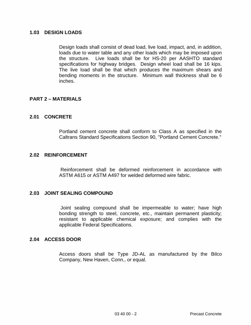
03 40 00 - 2 Precast Concrete
1.03 DESIGN LOADS
Design loads shall consist of dead load, live load, impact, and, in addition, loads due to water table and any other loads which may be imposed upon the structure. Live loads shall be for HS-20 per AASHTO standard specifications for highway bridges. Design wheel load shall be 16 kips. The live load shall be that which produces the maximum shears and bending moments in the structure. Minimum wall thickness shall be 6 inches.
PART 2 – MATERIALS
2.01 CONCRETE
Portland cement concrete shall conform to Class A as specified in the Caltrans Standard Specifications Section 90, "Portland Cement Concrete."
2.02 REINFORCEMENT
Reinforcement shall be deformed reinforcement in accordance with ASTM A615 or ASTM A497 for welded deformed wire fabric.
2.03 JOINT SEALING COMPOUND
Joint sealing compound shall be impermeable to water; have high bonding strength to steel, concrete, etc., maintain permanent plasticity; resistant to applicable chemical exposure; and complies with the applicable Federal Specifications.
2.04 ACCESS DOOR
Access doors shall be Type JD-AL as manufactured by the Bilco Company, New Haven, Conn., or equal.

03 40 00 - 3 Precast Concrete
2.05 VENTS
Vents shall be constructed from 6-inch C-900 PVC pipe and fittings. Fittings shall be socket-welded type.
Each vault shall have 2 vents, one upper and one lower.
Install 304 stainless steel insect screen over vent openings above ground.
PART 3 – EXECUTION
3.01 INSTALLATION
Openings or "knockouts" in precast concrete vaults shall be located as shown on the drawings and shall be sized sufficiently to permit passage of the largest dimension of pipe and/or flange. Upon completion of installation, all voids or openings in the vault walls around pipes shall be filled with 3,000 psi non-shrink grout. All joints between precast concrete vault sections shall be made watertight. The joint sealing compound shall be installed according to the manufacturer's recommendations to provide a watertight joint, which remains impermeable throughout the design life of the structure.
Access doors shall be built up so that the hatch is flush with the surrounding surface unless otherwise specified on the drawings or by the District. The Contractor is responsible for placing the cover at the proper elevation where paving is to be installed and shall make all necessary adjustments so that the cover meets these requirements.
The vault floor shall contain an 18-inch diameter hole for installation of a gravity drain or sump. The vault floor shall be constructed so that there is a positive slope to the sump.
3.02 EXTERIOR COATING
All exterior surfaces shall be coated with a minimum 30 mil (wft) of bitumastic 30 mil.
END OF SECTION

09 90 00 - 1 Painting and Coating
DIVISION 09 FINISHES
SECTION 09 90 00
PAINTING AND COATING
PART 1 – GENERAL
1.01 SCOPE
This section governs materials and application of painting and coating for exposed pipe and appurtenances.
1.02 SUBMITTALS
Prior to application, the following shall be submitted:
A. Paint or coating manufacturer's product data sheet showing
suitability of material for intended use including instruction on surface preparation and application.
1.03 COLOR SCHEDULE
Above-ground or exposed facilities shall be color coded to differentiate from potable water, reclaimed water, and wastewater facilities as follows:
Potable Water: Medium Blue
Reclaimed Water: OSHA Safety Purple
Wastewater: OSHA Safety Green

09 90 00 - 2 Painting and Coating
PART 2 – MATERIALS
2.01 ALKYD PRIMER
All primer shall be lead free and rust-inhibitive synthetic-alkyd based. It shall be designed for use with an alkyd enamel finish coat.
2.02 ALKYD ENAMEL
Enamel shall be a high gloss industrial type, lead free, synthetic-alkyd based, intended for use on exterior metal surfaces.
2.03 BITUMINOUS MASTIC
Bituminous mastic shall be coal-tar pitch based and shall have a minimum of 68% solids by volume.
2.04 EPOXY PAINT
Epoxy shall be a colored polyamide cured epoxy with not less than 49%
solids by volume.
All coatings and pigments to be used on potable water services shall have FDA approval for use with potable water.
PART 3 – EXECUTION
3.01 GENERAL
The requirements for painting and coating ferrous surfaces shall generally conform to the SSPC (Steel Structures Painting Council) and to the manufacturer's recommendations. Application of the paint or coating system shall not be permitted if, in the opinion of the District, the equipment, climate, or safety conditions do not meet the above recommendations.

09 90 00 - 3 Painting and Coating
The Contractor shall stir, strain, and keep coating materials at a uniform consistency during application. Each coating shall be applied evenly, free of brush marks, sags, runs and other evidence of poor workmanship. Finished surfaces shall be free from defects and blemishes.
The Contractor shall not use thinners unless permitted by the District. If thinning is allowed, the maximum allowable amount of thinner per gallon of coating material as recommended by the manufacturer shall be used. Coating materials shall be stirred at all times when adding thinner and the coating material surface shall not be flooded with thinner prior to mixing. The Contractor shall not reduce coating materials more than is absolutely necessary to obtain the proper application characteristics and to obtain the specified dry film thickness.
Deliver all paints to the job site in the original, unopened containers.
3.02 SURFACES NOT TO BE COATED
The following surfaces shall not be painted and shall be protected during the painting of adjacent areas:
A. Mortar-coated pipe and fittings
B. Concrete surfaces (i.e. vaults)
C. Stainless steel
D. Anodized aluminum
E. Nameplates
F. Manhole frames and covers
G. Grease fittings
H. Glass
I. Brass, copper or bronze
J. Platform gratings
K. Buried pipe, unless specifically required in the piping specifications

09 90 00 - 4 Painting and Coating
3.03 SURFACE PREPARATION
The Contractor shall not prepare more surface area than can be coated in one day. Pipe that has already been factory primed or painted shall not be sandblasted. All surfaces shall be prepared in accordance with the manufacturer's recommendations.
Wherever the words "solvent cleaning", "hand tool cleaning", "wire brushing", or "blast cleaning", or similar words are used in these specifications or in paint manufacturer's specifications, they shall be understood to refer to the applicable SSPC (Steel Structure Painting Council).
3.04 SHOP APPLIED PRIMER
Surfaces that are shop primed shall receive a field touchup of primer to cover all scratches or abraded areas.
3.05 ALKYD ENAMEL
All above-ground or exposed piping, fire hydrants, and exposed metalwork shall be painted using an alkyd system.
A. Surface Preparation:
1. All rust, mill scale, or weld splatter shall be removed by sandblasting or power tool cleaning.
2. All unpainted surfaces shall be solvent cleaned.
3. All abraded or scratched enamel coatings shall be sanded smooth or receive power tool cleaning.
4. All failures in the existing coating shall be sandblasted.
5. All existing surfaces to be repainted shall be washed with TSP and stiff bristle brush.
B. Primer - All unpainted or damaged surfaces shall be coated with primer to a dry-film thickness or not less than 2 mils.
C. Finish Coat - The finish coats shall be two or more coats of alkyd enamel applied to a dry-film thickness of 3 mils, providing a total painted dry film thickness of not less than 5 mils.

09 90 00 - 5 Painting and Coating
3.06 BITUMINOUS MASTIC
Buried metal (flanges, non-stainless steel nuts and bolts, flexible couplings, exposed reinforcing steel, etc.) shall be coated with a minimum of 20 mils of bituminous mastic.
All surfaces coated with bituminous mastic shall be covered with 8 mil polyethylene wrap.
3.07 EPOXY COATING
Only those metal surfaces specifically called out, shall be epoxy coated and applied as follows:
A. Surfaces to be epoxy coated shall be sandblasted.
B. Sandblasted surfaces shall be coated with primer to a dry film thickness of 3 mils.
C. Two coats of epoxy paint shall be applied (4 mils each) to the primed surface. The manufacturer's recommended drying time between coats shall be followed.
D. The Contractor shall prepare multiple-component coatings using all of the contents of the container for each component as packaged by the paint manufacturer. Partial batches and multiple component coatings that have been mixed beyond their pot life shall not be used. Touchup paint shall be provided. The Contractor shall mix only the components specified and furnished by the paint manufacturer. The Contractor shall not intermix additional components for reasons of color or otherwise, even within the same generic type of coating.
3.08 APPLICATION LIMITATION
Paint or coating shall not be applied under the following conditions:
A. When the surrounding air temperature or the temperature of the surface to be coated is below 40° F or as recommended by the manufacturer of the specified coating system.
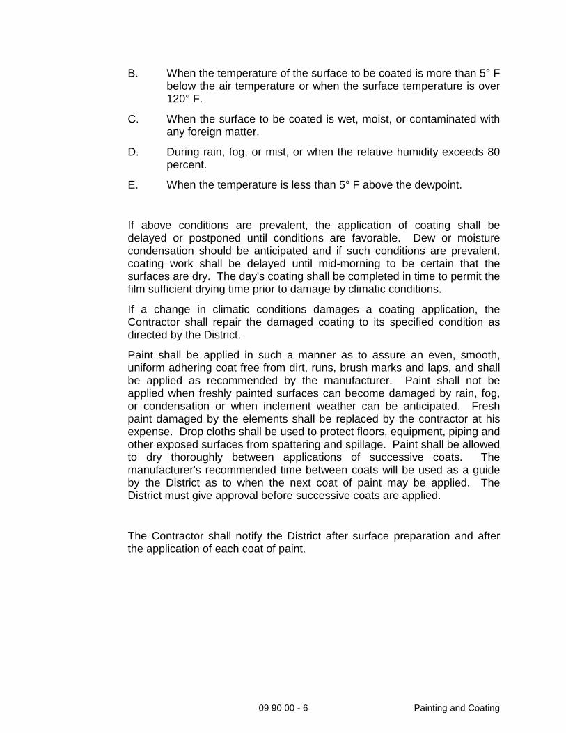
09 90 00 - 6 Painting and Coating
B. When the temperature of the surface to be coated is more than 5° F below the air temperature or when the surface temperature is over 120° F.
C. When the surface to be coated is wet, moist, or contaminated with any foreign matter.
D. During rain, fog, or mist, or when the relative humidity exceeds 80 percent.
E. When the temperature is less than 5° F above the dewpoint.
If above conditions are prevalent, the application of coating shall be delayed or postponed until conditions are favorable. Dew or moisture condensation should be anticipated and if such conditions are prevalent, coating work shall be delayed until mid-morning to be certain that the surfaces are dry. The day's coating shall be completed in time to permit the film sufficient drying time prior to damage by climatic conditions.
If a change in climatic conditions damages a coating application, the Contractor shall repair the damaged coating to its specified condition as directed by the District.
Paint shall be applied in such a manner as to assure an even, smooth, uniform adhering coat free from dirt, runs, brush marks and laps, and shall be applied as recommended by the manufacturer. Paint shall not be applied when freshly painted surfaces can become damaged by rain, fog, or condensation or when inclement weather can be anticipated. Fresh paint damaged by the elements shall be replaced by the contractor at his expense. Drop cloths shall be used to protect floors, equipment, piping and other exposed surfaces from spattering and spillage. Paint shall be allowed to dry thoroughly between applications of successive coats. The manufacturer's recommended time between coats will be used as a guide by the District as to when the next coat of paint may be applied. The District must give approval before successive coats are applied.
The Contractor shall notify the District after surface preparation and after the application of each coat of paint.

09 90 00 - 7 Painting and Coating
PART 4 – TESTING
4.01 GENERAL
The District will perform such tests as are required to ensure compliance with all phases of the work including surface preparation, abrasive blast cleaning, and the application of the coating systems.
If the item has an improper finish color or insufficient film thickness, the surface shall be cleaned and topcoated with the specified paint material to obtain the specified color and coverage. Visible areas of chipped, peeled, or abraded paint shall be hand or power-sanded, feathering the edges. The areas shall then be primed and finish coated in accordance with the specifications. Work shall be free of runs, bridges, shiners, laps, or other imperfections.
END OF SECTION

31 23 16 - 1 Structure Excavation and Backfill
DIVISION 31 EARTHWORK
SECTION 31 23 16
STRUCTURE EXCAVATION AND BACKFILL
PART 1 – GENERAL
1.01 SCOPE
A. This Section shall govern the work for structure excavation and backfill.
Structure excavation shall consist of the removal of material for the construction of foundations for vaults, manholes, or other structures, and other excavation designated on the Plans or in the Specifications as structure excavation. Trenching and backfill shall be in accordance with Section 31 23 33.
B. Structure excavation and structure backfill shall include the furnishing of all materials and equipment; the construction or installation of all facilities which may be necessary to perform the excavations and to place and compact the backfill; and the subsequent removal of such facilities, except where they are required or permitted by the Plans or Specifications to remain in place.
1.02 SUBMITTALS
A. Upon request, the following items shall be submitted and approved by the
District.
I. Test results showing gradation, durability and sand equivalent of import material.
II. Permit and notification form for excavations 5 feet or more in depth as required by Cal-OSHA, including any trench excavation or shoring plans.

31 23 16 - 2 Structure Excavation and Backfill
PART 2 – MATERIALS
2.01 EXCAVATION
Excavation is unclassified. The Contractor shall complete all excavations regardless of the type of materials encountered. The Contractor shall make his own estimate of the kind and extent of the various materials which will be encountered in the excavation.
2.02 FOUNDATION
Material for structural foundation shall conform to one of the following:
A. Sand/Decomposed Granite – Sand shall be free from organic matter, clay,
debris, or any other material that, in the opinion of the Engineer, is objectionable or deleterious. Sand shall not have more than 13 percent passing a 200-mesh screen. Minor amounts of gravel up to ½ inch in size will be permitted. The sand equivalent shall not be less than 30 and a durability index of not less than 35.
B. Aggregate Base – Base shall be ¾ inch and minus or ½ inch and minus. The aggregate size gradation shall comply with Caltrans Specifications for Class 2 road base. The sand equivalent shall be 30 minimum. The durability index shall be 35 minimum.
C. Crushed Rock – Crushed rock shall be granular material 1 ½ inch and minus. At least 90 percent shall be retained on the No. 4 sieve and less than 5 percent retained on the No. 200 sieve. Compact with vibratory plate compactor.

31 23 16 - 3 Structure Excavation and Backfill
2.03 BACKFILL
A. Native earth backfill and imported backfill material shall conform to the requirements of Section 31 23 33.
PART 3 – EXECUTION
3.01 PAVEMENT
A. Bituminous or concrete pavements regardless of their thickness, and curbs and sidewalks shall be cut prior to excavation for the structure in accordance with the requirements of the encroachment permit or the District.
B. Pavement and concrete materials shall be removed from the site.
3.02 EXCAVATION
A. The sides of excavations for structures shall be sufficient to leave at least 1.5 feet clear as measured from the extreme outside of form work on the structure as the case may be. Where excavation is inadvertently carried below designated elevations, suitable provision shall be made at the expense of the Contractor for adjustment of construction, as directed by the Engineer to meet requirements incurred by the deeper excavation. No earth backfill will be permitted to correct overdepth excavation beneath structures, and overdepth excavation in such locations shall be rectified by backfilling with sand, graded gravel, or concrete as directed by the District.
3.03 BRACING
A. The Contractor's design and installation of bracing and sheeting shall take the necessary precautions to be consistent with the rules, orders, and regulations of the State of California Construction Safety Orders.
B. Excavations shall be so braced, sheeted, and supported that they will be safe, such that the walls of the excavation will not slide or settle and all existing improvements of any kind, either on public or private property, will be fully protected from damage.

31 23 16 - 4 Structure Excavation and Backfill
C. The sheeting, shoring, and bracing shall be arranged so as not to place any stress on portions of the completed work.
D. The Contractor shall carefully remove sheeting, shoring, bracing, and timbering to prevent the caving or collapse of the excavation faces being supported.
3.04 DEWATERING
A. The Contractor shall provide and maintain means and devices to continuously remove and dispose of all water entering the excavation during construction of the structure and during backfill operations.
B. Water shall be disposed of in a manner that will prevent damage to adjacent property and pipe trenches.
C. The Contractor shall not allow water to rise in the excavation until backfilling around and above the structure is completed.
3.05 BACKFILL
A. After structures and foundations are in place, backfill shall be placed to the original groundline or to the limits designated on the plans.
B. No material shall be deposited against cast in place concrete structures until the concrete has reached a compressive strength of at least 2,500 pounds per square inch.
C. Backfill material shall be placed in horizontal layers not exceeding 8 inches in depth.
3.06 COMPACTION
A. Compaction requirements shall be as follows:
B. Backfill within 5 feet of structure: 95% relative compaction.
C. Structural Backfill beyond 5 feet of structure: 90% relative compaction.
D. Foundation: 95% relative compaction.
E. Each layer of backfill material shall be moistened and thoroughly tamped, rolled, or otherwise compacted to the specified relative density.
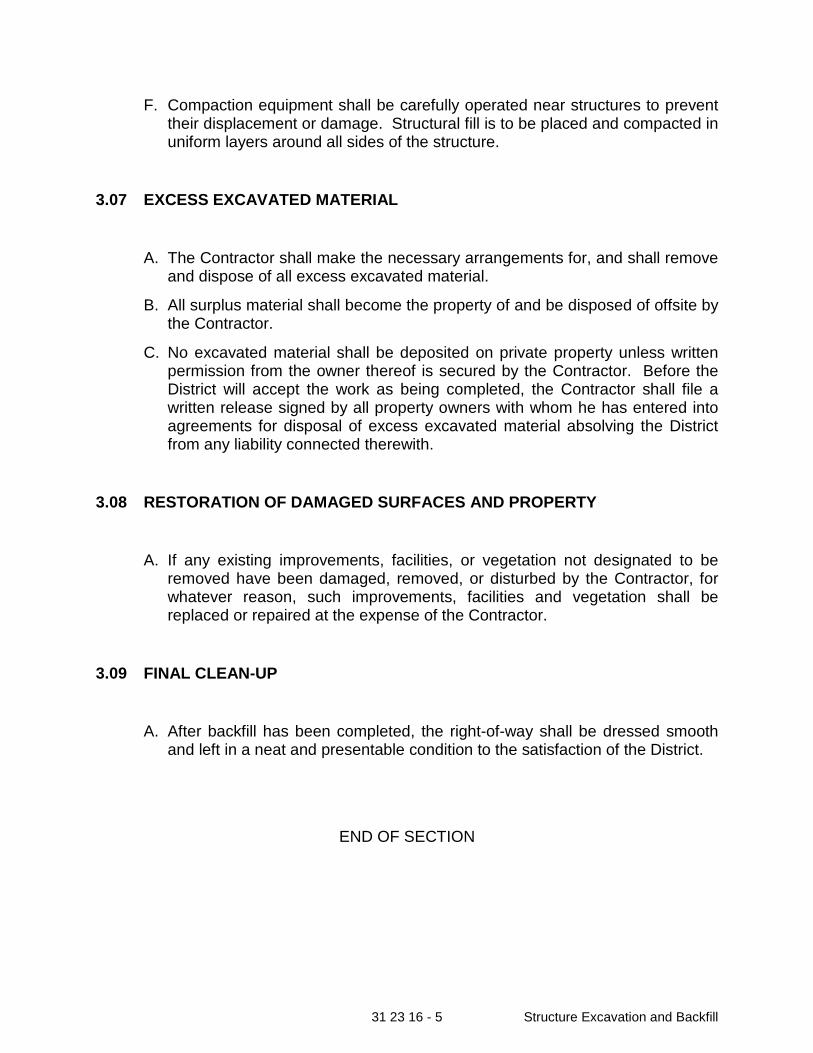
31 23 16 - 5 Structure Excavation and Backfill
F. Compaction equipment shall be carefully operated near structures to prevent their displacement or damage. Structural fill is to be placed and compacted in uniform layers around all sides of the structure.
3.07 EXCESS EXCAVATED MATERIAL
A. The Contractor shall make the necessary arrangements for, and shall remove and dispose of all excess excavated material.
B. All surplus material shall become the property of and be disposed of offsite by the Contractor.
C. No excavated material shall be deposited on private property unless written permission from the owner thereof is secured by the Contractor. Before the District will accept the work as being completed, the Contractor shall file a written release signed by all property owners with whom he has entered into agreements for disposal of excess excavated material absolving the District from any liability connected therewith.
3.08 RESTORATION OF DAMAGED SURFACES AND PROPERTY
A. If any existing improvements, facilities, or vegetation not designated to be removed have been damaged, removed, or disturbed by the Contractor, for whatever reason, such improvements, facilities and vegetation shall be replaced or repaired at the expense of the Contractor.
3.09 FINAL CLEAN-UP
A. After backfill has been completed, the right-of-way shall be dressed smooth and left in a neat and presentable condition to the satisfaction of the District.
END OF SECTION

31 23 16 - 1 Structure Excavation and Backfill
DIVISION 31 EARTHWORK
SECTION 31 23 33
TRENCH EXCAVATION, BACKFILL AND COMPACTION
PART 1 – GENERAL
1.01 SCOPE
A. This Section governs the work for trench excavation, backfill and compaction for underground pipeline work.
1.02 SUBMITTALS
A. Upon request, the following items shall be submitted and approved by the District.
Test results showing gradation, durability and sand equivalent of pipe zone material.
Permit and notification form for excavations 5 feet or more in depth as required by Cal-OSHA, including any trench excavation or shoring plans.
1.03 TESTING
A. Testing frequency and location shall be approved by the District.
1.04 POTHOLING
A. The Contractor shall pothole all known utility crossings within the proposed alignment prior to the installation of any new mainline or service laterals. An extensive effort will be required to pothole all utility crossings a minimum of

31 23 16 - 2 Structure Excavation and Backfill
two weeks in advance of any work. The project shall remain within the required time frames specified in Section 00800 and document depth and location versus the signed plans. Contractor to provide a marked up drawing, two weeks in advance of any work occurring, highlighting any differences in elevation or location of existing utilities. This may require a full time potholing crew working in parallel with the pipe installation. Costs associated with any utility conflicts resulting from inadequate potholing effort shall be the responsibility of the Contractor.
B. Pothole data, where available, at the proposed tie-in locations has been provided for the Contractor’s information and use. The District makes no guarantee as to the completeness or accuracy of the data. The Contractor is responsible to verify all utilities and pothole as necessary to locate the tie-in point and complete the tie-in connection.
C. The Contractor shall, prior to any pipeline installation, mark with white paint the proposed alignment of the new pipeline, the limits of pavement removal, and the depth of all utilities crossing the proposed alignment.
PART 2 – MATERIALS
2.01 TRENCH EXCAVATION
Excavation is unclassified. A geotechnical report was not prepared as part of this Project. EID does not have any geotechnical reports for the Project area. Rock excavation is expected as part of the pipeline installation work. The Contractor shall perform a thorough investigation of the site. The Contractor shall complete all excavations regardless of the type of materials encountered. The Contractor shall make his own estimate of the kind and extent of the various materials which will be encountered in the excavation.
2.02 PIPE ZONE
A. Material for the pipe zone shall conform to one of the following:
Sand/Decomposed Granite - Sand shall be free from organic matter, clay, debris, or any other material that, in the opinion of the Engineer, is objectionable or deleterious. Sand shall not have more than 13 percent passing a 200-mesh screen. Minor amounts of gravel up to ½

31 23 16 - 3 Structure Excavation and Backfill
inch in size will be permitted. The sand equivalent shall not be less than 30 and a durability index of not less than 35.
Aggregate Base - Base shall be ¾ inch and minus or ½ inch and minus. The aggregate size gradation shall comply with Caltrans Specifications for Class 2 road base. The sand equivalent shall be 30 minimum. The durability index shall be 35 minimum.
Plug and Drain Material – When a plug and drain system has been approved by EID and El Dorado County DOT, pipe zone material shall be Caltrans Standard permeable material designed for the specific condition.
2.03 BACKFILL
A. Outside Asphalt Road Sections
Material for backfill from 12 inches above the top of the pipe to subgrade, shall be free from organic matter, debris, and rocks larger than 6 inches in diameter or length. The District shall be the sole judge of conformance of backfill material to this specification.
Backfill material shall generally conform to the following gradation:
Sieve Size Percent Passing
6” 100
3” 50
#4 35 - 100
#30 20 - 100
B. Within Asphalt Road Sections
Trench shall be backfilled with Class II AB or controlled low strength material (CLSM) as approved by the Engineer.

31 23 16 - 4 Structure Excavation and Backfill
PART 3 – EXECUTION
3.01 EXCAVATION
A. Excavation for pipelines, fittings, and appurtenances shall be open trench to the depth and in the direction necessary for the proper installation of the same as shown on the contract drawings or as otherwise approved by the Engineer. Excavation shall only proceed when the necessary materials have been delivered to the site.
B. The Contractor shall bear all costs of disposing of roots and all other waste materials from the excavation. Material shall be disposed of in such a manner as to meet all requirements of the state, county, and local regulations regarding health, safety, and public welfare. Non-flammable material and flammable material, when burning is not permitted, shall be disposed of off the construction site in an approved location at the Contractor's expense.
C. The Contractor shall remove obstructions within the trench area or adjacent thereto, such as abandoned concrete structures, logs, and debris of all types, without additional compensation. The Engineer may, if requested, make changes in the trench alignment to avoid major obstructions, if such alignment can be made without adversely affecting the intended function of the facility.
Existing Pavement Removal - Pavement to be removed shall be removed and replaced in the manner prescribed by El Dorado County encroachment permit.
Existing pavement, curbs, gutters, sidewalks and driveways to be removed in connection with construction shall be neatly saw cut prior to removal. Saw cuts shall have a minimum depth of one inch in concrete sidewalk.
Concrete sidewalks or driveways shall be removed so that a minimum 30-inch square is replaced. If the saw cut in a sidewalk or driveway would fall within 30 inches of a construction joint, expansion joint, or edge, the concrete shall be removed and replaced to the joint or edge. If the saw cut would fall within 12 inches of a score mark, the concrete shall be removed and replaced to the score mark. Concrete shall be removed by jackhammer.
Grading and Stockpiling - The Contractor shall control grading in a manner to prevent water running into excavations. Obstructions of surface drainage shall be avoided and means shall be provided whereby storm and wastewater can be uninterrupted in existing gutters, other surface drains or temporary drains. Material for backfill or for protection of excavation in public roads from surface drainage shall be neatly placed and kept shaped so as to cause the least possible interference with public

31 23 16 - 5 Structure Excavation and Backfill
travel. Free access must be provided to all fire hydrants, water valves, meters and private drives.
Line and Grade - The Contractor shall excavate the trench to the lines and grades shown on the plans. Any deviations shall first be approved by the Engineer.
The trench shall be excavated to a minimum depth of 6 inches below the bottom of the pipe. The sides of the trench shall be excavated and maintained as nearly vertical as is practical.
Trench Support - The trench shall be adequately supported and the safety of workers provided for as required by the standard of the appropriate regulatory agency.
All shoring for open excavations shall conform to the State of California, Department of Industrial Relations, and Division of Industrial Safety "Construction Safety Orders."
The Contractor shall be responsible for adequately shored and braced excavations so that the earth will not slide, move or settle, and so that all existing improvements of any kind will be fully protected from damage.
No shoring once installed, shall be removed until the trench has been approved for backfill operations. Removal of shoring shall only be accomplished during backfill operations and in such a manner as to prevent any movement of the ground or damage to the pipe or other structures.
The Contractor shall obtain all permits for any excavations over five feet in depth into which a person is required to descend or any excavation less than five feet in depth in soils where hazardous ground movement may be expected and into which a person is required to descend.
Excavated material shall not be placed closer than two feet from the top edge of the trench. Heavy equipment should not be used or placed near the sides of the trench unless the trench is adequately braced.
Use of Explosives – Blasting by any means shall not be allowed as part of this project.
Preservation of Trees - Excavation within the dripline of any tree shall conform to the following and to encroachment permits. Trees shall not be removed outside of fill or excavated areas, except as authorized by the District.
Tree roots larger than 2 inches in diameter, shall not be cut and shall be kept moist during exposure. For damaged or severed root systems, trees shall be trimmed to compensate for the decreased root system. Trimming shall be done to the satisfaction of the Inspector. All roots shall be neatly cut with saw or sharp cutter.

31 23 16 - 6 Structure Excavation and Backfill
Dewatering - The Contractor shall provide and maintain, at all times during construction, ample means and devices with which to promptly remove and properly dispose of all water from any source entering the excavations or other parts of the work. Dewatering shall be accomplished by methods which will ensure a dry excavation and preservation of the final lines and grades of the bottoms of excavations. Said methods may include well points, sump pumps, suitable rock or gravel placed below the required bedding for drainage and pumping purposes, temporary pipelines and other means, all subject to the approval of the Engineer.
Dewatering for the structures and pipelines shall commence when groundwater is first encountered and shall continue until the backfill at the pipe zone has been completed.
The Contractor shall dispose of the water from the work in a suitable manner without damage to adjacent property. No water shall be drained into work built or under construction without prior consent of the Engineer. Water shall be disposed in such a manner as not to be a menace to public health.
The Contractor shall be responsible to obtain all required Local and State Permits and comply with all applicable regulatory requirements. The Contractor shall provide EID with a dewatering plan clearly showing compliance prior to any dewatering activities.
Correction of Faulty Grades - Any over-excavation carried below the grade as specified or shown, shall be rectified by backfilling with approved sand and/or graded gravel, and shall be compacted to provide a firm and unyielding subgrade and/or foundation, as directed by the Engineer.
Structure Protection - Temporary support, adequate protection and maintenance of all underground and surface structures, drains, sewers and other obstructions encountered in the progress of the work shall be furnished by the Contractor at his expense and subject to the approval of the Engineer. Any structure that has been disturbed shall be restored upon completion of the work.
Protection of Property and Surface Structures - Trees, shrubbery, fences, and poles and all other property and surface structures shall be protected unless their removal is shown on the drawings or authorized by the Engineer.
Trench Width and Grade - The width of the trench within the pipe zone shall be such that the clear space between the barrel of the pipe and the trench wall shall not exceed the amount shown in the standard details. In general, the following shall be adhered to:

31 23 16 - 7 Structure Excavation and Backfill
Nominal Pipe Diameter
Trench Width
Minimum
Maximum
4"-12" O.D. + 12" O.D. + 18"
14"-18" O.D. + 18" O.D. + 24"
Trench widths in excess of those specified must have prior written approval.
Maximum Length of Open Trench - Unless otherwise specified or directed by the District or Caltrans, the maximum length of open trench shall be 500 feet, or the distance necessary to accommodate the amount of pipe installed in a single day, whichever is greater. The distance is the collective length of any location, including open excavation, pipe laying and appurtenant construction and backfill which has not been temporarily resurfaced. Failure by the Contractor to comply with the limitations specified herein may result in an order to halt progress of the work until compliance has been achieved. The Contractor shall provide proper barricades for excavated areas.
3.02 TRENCH FOUNDATION
A. The trench bottom shall be graded to provide a smooth, firm and stable foundation at every point throughout the length of the pipe. Should large gravel and cobbles be encountered at the trench bottom or pipe subgrade, they shall be removed from beneath the pipe and replaced with clean imported sand which shall be compacted to provide uniform support and a firm foundation.
B. Foundations in Poor Soil - If excessively wet, soft, spongy, unstable or similarly unsuitable material is encountered at the surface upon which the bedding material is to be placed, the unsuitable material shall be removed to a depth as determined in the field by the Engineer. The Contractor's attention is called to Section 3.1 Item 7, regarding his responsibilities in maintaining adequate dewatering procedures to ensure that an otherwise stable foundation will not be rendered unfit due to accumulation of water.

31 23 16 - 8 Structure Excavation and Backfill
3.03 BACKFILL AND COMPACTION
A. Backfill shall be completed within the shortest possible time so that the construction area or street can be opened to traffic. If for any reason construction of the pipeline or appurtenances thereto is delayed, the District may require that the trench be backfilled and such areas or streets opened to traffic.
B. Pipe Zone - After completion of the trench excavation and proper preparation of the foundation, 6 inches of bedding material shall be placed on the trench bottom for support under the pipe. Bell holes shall be dug to provide adequate clearance between the pipe bell and the bedding material. All pipe shall be installed in such a manner as to insure full support of the pipe barrel over its entire length. After the pipe is adjusted for line and grade and the joint is made, the remainder of the pipe bedding shall be placed to the limits as shown on the Drawings. All bedding material shall be compacted 90 percent as measured by Test Method California 231, prior to placement of subsequent backfill.
C. When bedding material is selected material or imported sand, the pipe bedding backfill shall be brought to optimum moisture content and shall be placed by hand in layers not exceeding 3 inches in thickness to the centerline (springline) of the pipe and each layer shall be solidly tamped with the proper tools so as not to injure, damage, or disturb the pipe. Backfilling shall be carried on simultaneously on each side of the pipe to assure proper protection of the pipe.
D. Each lift shall be "walked in" and supplemented by slicing with a shovel to ensure that all voids around the pipe have been completely filled. Mechanical compaction such as "pogo sticks" or "wackers", as approved, shall be used for compaction of pipe zone.
E. Initial Backfill - The remaining portion of the trench shall be backfilled, compacted and/or consolidated by approved methods to obtain a 90% compaction as measured by Test Method 231F. Backfill shall be good sound earth, sand or gravel. Bituminous pavement, concrete, rock, or other lumpy material shall not be used in the backfill unless these materials are scattered and do not exceed 6 inches in any dimension and are not placed within 1½ feet of the surface. Material of perishable, organic matter, spongy or otherwise improper nature, shall not be used.
F. When backfill is placed mechanically, the backfill material shall be pushed onto the slope of the backfill previously placed and allowed to slide down into the trench. The Contractor shall not push backfill into the trench in such a way as to permit free fall of the material until at least 18 inches of cover is provided over the top of the pipe. Under no circumstances shall sharp, heavy pieces of materials be allowed to be dropped directly onto the pipe or the

31 23 16 - 9 Structure Excavation and Backfill
tamped material around the pipe. Backfill shall be placed in layers not exceeding 8 inches and compacted by an approved method.
G. Heavy duty compacting equipment having an overall weight in excess of 125 pounds shall not be used until backfill has been completed to a depth of 2 feet over the top of the pipe.
H. If hydro-hammer is used for compaction of overlying materials, at least 4 feet of backfill must be placed over the top of pipe prior to its use. This is required to insure that the pipe is not damaged.
I. Final Backfill - Final backfill placed in trenches below roadways or below shoulders of roadways, shall be compacted to a density of not less than 95% or as directed by the encroachment permit. Backfill outside of roadways shall be compacted to 90%.
J. Backfill shall be placed in layers not exceeding 8 inches, compacted and brought up to the subgrade of the roadway.
3.04 HARD ROCK EXCAVATION
A. The Contractor is responsible to review any geotechnical information available and perform any additional investigations necessary to determine the amount of rock excavation which may be encountered.
B. Rock Excavation: The Rock Excavation Allowance shall be used for rock excavation beyond that excavation that can be accomplished using and medium size excavator (e.g. Cat 326F or equal) with digging bucket. This item will be monitored by the District’s Inspector, and invoicing shall be on a unit cost basis. Quantities over the estimated amount as shown on the Bid Schedule will be added through a change order using the per-unit basis.
C. Definition of Rock: Rock encountered during the course of excavation which is sufficiently hard to cause refusal to equipment specified below shall be deemed inexcavatable. Rock deemed inexcavatable shall be removed by substantial means such as reciprocating hydraulic hammers and shall conform to this specification.
D. Refusal to be considered as the inability of the following equipment to excavate rock as caused by the hardness of the rock: Tractor mounted excavator with rock teeth on narrow bucket, Caterpillar 330, or equal. Refusal shall be demonstrated to Engineer prior to rock being deemed inexcavatable.
E. All rock excavation shall be under one classification. This classification shall include solid ledge rock in its natural location that requires systematic quarrying, drilling and/or blasting for its removal and also boulders that exceed 0.25 CY in volume.
31 23 16 - 10 Structure Excavation and Backfill
F. When rock is encountered, strip free of earth. After verification by a representative of the Owner and/or Engineer that the material encountered is rock (as defined above), Contractor shall employ an independent surveyor to determine rock quantities before removal operation begins. In computing the volumetric content of rock excavation for payment, the pay lines shall be taken as follows:
For structures (including air/vacuum manholes): 2 feet outside the exterior limits of foundations and from rock surface to 6 inches below bottom of foundations.
For piping and utilities: A width 18 inches wider than the outside diameter of the pipe or conduit and from rock surface to 4 inches below bottom exterior surface of the pipe or conduit.
G. Hydraulic hammering or alternative means approved by the Engineer shall be employed where refusal has been demonstrated and normal excavation procedures are not feasible.
3.05 EXCESS EXCAVATED MATERIAL
A. The Contractor shall make the necessary arrangements for, and shall remove and dispose of all excess excavated material. It is the intent of these specifications that all surplus material not required for backfill or fill shall be disposed of by the Contractor outside the limits of the public right-of-way and/or easements at no liability to the District.
B. No excavated material shall be deposited on private property unless written permission from the owner thereof is secured by the Contractor. Before the District will accept the work as being completed, the Contractor shall file a written release signed by all property owners with whom he has entered into agreements for disposal of excess excavated material absolving the District from any liability connected therewith.
3.06 RESTORATION OF DAMAGED SURFACES AND PROPERTY
A. If any pavement, trees, shrubbery, fences, poles or other property and surface structures have been damaged, removed, or disturbed by the Contractor, whether deliberately or through failure to carry out the requirements of the contract documents, state laws, municipal ordinances, or the specific direction of the District, or through failure to employ usual and reasonable safeguards, such property and surface structures shall be replaced or repaired at the expense of the Contractor.

31 23 16 - 11 Structure Excavation and Backfill
3.07 FINAL CLEAN-UP
A. After backfill has been completed, the right-of-way shall be dressed smooth and left in a neat and presentable condition to the satisfaction of the District and El Dorado County.
END OF SECTION

33 11 13.13 - 1 Ductile Iron Pipe, Fittings, and Couplings
DIVISION 33 UTILITIES
SECTION 33 11 13.13
DUCTILE IRON PIPE, FITTINGS AND COUPLINGS
PART 1 – GENERAL
1.01 SCOPE
A. This specification governs the furnishing and installation of ductile iron pipe material and main line fittings including laying, joining, bedding and approvals. All incidentals and appurtenant operations necessary for the construction of pipelines shall be accomplished in strict accordance with the drawings and other terms and conditions of the contract.
B. Fitting types covered under this Section include bends, tees, crosses, reducers, couplings, caps, plugs, adapters and all other fittings necessary for a complete pipeline installation.
C. The Contractor shall also furnish all equipment, tools, labor and materials required to relocate water pipes, or other structures as may be necessary to complete the installation as shown and specified.
D. All standard specifications, i.e., AWWA, ASTM, etc., made a portion of these specifications by reference shall be the latest edition and revision thereof.
E. The Contractor shall be responsible for all material furnished by him, and shall replace at his own expense, all material found defective in manufacture or damaged in handling after delivery by the manufacturer. This shall include the furnishings of all material and labor required to replace defective material discovered prior to final acceptance of the work.
F. The Contractor shall be responsible for the safe storage of material until it has been incorporated into the completed project. The interior of all pipe and fittings shall be kept free from dirt and foreign matter at all times.
G. Pipe surfaces shall be free from nicks, scratches and other blemishes. The joining surfaces of pipe spigots and bell sockets shall be free from gouges or other imperfections that might cause leakage.

33 11 13.13 - 2 Ductile Iron Pipe, Fittings, and Couplings
H. The Contractor shall be responsible for locating existing water lines at tie-in locations for vertical and horizontal location.
1.02 SUBMITTALS
A. Submittals shall be provided for the following items plus all additional items required in the specifications for the particular type of pipe:
1. Pipe and joint material
2. Fittings
3. Specialties
PART 2 – MATERIALS
2.01 DUCTILE IRON PIPE (DI)
A. Ductile iron pipe shall conform to the quality and strength requirements of AWWA C-151 and shall be an approved manufacture by the District.
Markings – Each standard or random length of pipe shall be clearly marked with the following:
I. The letters "DI" or "Ductile" II. Nominal size and class
III. Year produced IV. Manufacturer's trade name and country where cast V. Seal (mark) of testing agency
Pressure Class – Where the class is not indicated on the plans, the pipe shall be Class 350.
Laying Length – Standard laying lengths of 18- or 20-foot are acceptable.
Joint Type – Unless otherwise shown or specified, pipe joints shall be rubber gasket push-on type joint conforming to AWWA C-111.
VI. Flanged Joint – Where flanged joints are specified, pipe barrel shall be threaded and fitted with flanges in accordance to AWWA C-115 "Flanged Ductile Iron Pipe with Threaded Flanges."

33 11 13.13 - 3 Ductile Iron Pipe, Fittings, and Couplings
Physical Test Requirements – Hydrostatic, tension test, and impact test shall be conducted at the factory in accordance with ASTM A 746. All testing shall be performed by a recognized testing laboratory with such testing available for inspection by the District. If required, the manufacturer shall supply a letter of certification attesting to their pipe meeting these specifications.
Lining and Coating – The inside surfaces shall be cement mortar lined in accordance with ANSI/AWWA C-104/A21.4. The outside coating shall be an asphaltic coating per AWWA C-151.
Polyethylene Encasement – Pipe and fittings shall be wrapped in polyethylene. Polyethylene wrapping shall be in accordance to AWWA C-105, latest revision. Minimum thickness shall be 0.008 inch (8 mils).
Warning Tape - Two-inch-wide non-metallic tape marked "water main."
2.02 FITTINGS
A. All ductile iron fittings shall be manufactured in accordance with the following AWWA Standards: C-104, "Cement-Mortar Lining for Ductile-Iron Pipe and Gray-Iron and Fittings for Water", C-110, "Gray-Iron and Ductile-Iron Fittings, 3 inches through 48 inches for Water and Other Liquids," C-111, “Rubber Gasket Joints for Ductile-Iron and Gray-Iron Pressure Pipe and Fittings,” with the following additional requirements or exceptions. All fittings shall be furnished with a cement-mortar lining of standard thickness as defined in referenced specifications.
B. All fittings shall be rated equally to the class of pipe. End connections may be push-on, mechanical, or flanged joints.
C. Ductile iron compact fittings, per AWWA C-153, are allowed.
Flanges, Bolts and Gaskets - Flanges shall be flat-faced and meet either the requirements of AWWA C-207 for steel hub flange fittings, or AWWA C-110 Section 10-18 for ductile iron fittings. The flanges shall be marked with the size, name or trademark of manufacturer and with the AWWA Class; i.e., "E", or pressure rating.
Bolts and nuts shall be cadmium plated, A307, Grade B of domestic origin. Cadmium plating shall conform to Federal Specification QQ-P-415-1956, Type 1, Class 1.
Gaskets shall be 1/8-inch thick and be of the full-face self-centered type. The following table shows the bolt pattern for ASME/ANSI 16.1 Class 125 flange. This pattern is rated at 275 psi for Class E steel pipe flanges and 250 psi for ductile iron pipe fittings.

33 11 13.13 - 4 Ductile Iron Pipe, Fittings, and Couplings
Bolt Hole
Pipe Size
Bolt Hole Diameter
(Inches)
Bolt Diameter & Length (Inches)
Number of Bolts
4” ¾ 5/8 x 3½ 8
6" 7/8 ¾ x 3½ 8
8" 7/8 ¾ x 3½ 8
The Contractor shall uniformly tighten the bolts and prevent bending or torsional strains. Proper anchorage shall be provided.
Mechanical Joint Fittings - The mechanical joints shall meet AWWA C111. That standard covers the joint as well as gaskets and bolts. T-bolts and nuts shall be manufactured of corrosion-resistant high-strength low-alloy Cor-Ten steel or equal. Number and length of bolts shall be as follows:
Pipe Size Number of Bolts Bolt Diameter & Length (Inches)
4" 4 5/8 x 3½
6" 6 ¾ x 3½
8" 6 ¾ x 4
Restrained Joints - Restrained joint pipe and fittings shall be U.S. Pipe TR FLEX or approved equal.
Coatings and Linings – Ductile iron fittings shall be cement mortar lined per AWWA C-104 and receive a bituminous coating per AWWA C110.
Threaded holes and mating surfaces shall not be coated. Flange faces shall be coated with asphaltic varnish only. There shall be no coating of materials, or mortar on gasket grooves.
Mechanical Couplings - Couplings include transition couplings, flanged coupling adapters, high deflection couplings, and flexible and insulated couplings.

33 11 13.13 - 5 Ductile Iron Pipe, Fittings, and Couplings
I. Coupling Sleeves and Flanges - Coupling sleeves and flanges may be of gray iron or carbon steel.
II. Bolts and Nuts for Flanges - Bolts and nuts for buried and submerged flanges, flanges in underground vaults and structures, and flanges located outdoors above ground shall be cadmium plated, A307, Grade B. Provide one washer for each nut. Each washer shall be of the same material as the nut.
2.03 TRANSITION COUPLING
A. Scope: The following governs the furnishing and installation of transition couplings.
B. Manufacturers: Transition couplings shall be Krausz - Hymax Couplings, Romac 501, Smith-Blair Omni 441, Rockwell 433, or Ford FC1.
2.04 FLEXIBLE COUPLINGS
A. Scope: The following governs the furnishing and installation of flexible couplings.
B. Manufacturers: Flexible couplings shall be APAC, Baker 200 series, JCM, Rockwell 400 series or Romac.
2.05 FLANGED COUPLING ADAPTORS
A. Scope: The following governs the furnishing and installation of flange coupling adapters.
B. Manufacturers: Flanged coupling adapters shall be Romac FC400 Series, APAC, Baker, JCM, or Rockwell equal. Pipe restraining systems shall be Romac 600 Series, APAC, Baker, JCM, or Rockwell equal.
33 11 13.13 - 6 Ductile Iron Pipe, Fittings, and Couplings
PART 3 – EXECUTION
3.01 HANDLING AND TRANSPORTATION
A. Handling and transportation of pipe shall be in accordance with the pipe manufacturer's published instructions.
Heavy canvas, or nylon slings of suitable strength shall be used for lifting and supporting materials. Chains or cables shall not be used.
B. Pipe and fittings shall not be stored on rocks or gravel, or other hard material which might damage the pipe.
Rubber Gasket Storage - All rubber gaskets shall be stored in a cool, well ventilated place and not exposed to the direct rays of the sun. Gaskets shall not be allowed in contact with oils, fuels, petroleum, or solvents.
3.02 PIPE LAYING
A. Pipe shall be laid in accordance with the pipe manufacturer's published instructions, as complimented and modified herein.
Cleanliness - The interior of pipes shall be clean of foreign materials before sections of pipe are installed and shall be protected to prevent entry of foreign materials after installation.
Open ends of installed pipe shall be sealed with watertight plugs or other approved means at times when pipe installation is not in progress.
Ground water shall not be allowed to enter the pipe.
Inspection Before Installation - All pipe and fittings shall be carefully examined for cracks and other defects while suspended and before installation. Spigot ends shall be examined with particular care as this area is the most vulnerable to damage from handling. Defective pipe or fittings shall be laid aside for inspection by the District, who will prescribe corrective repairs or rejection.
Lowering of Pipe Material into Trench - Proper implements, tools, and equipment, satisfactory to the District, shall be provided and used by the Contractor for the safe and convenient performance of the work. All pipe, fittings, valves, and hydrants shall be carefully lowered into the trench piece by piece in such a manner as to prevent damage to the water main materials and protective coatings and linings. Under no circumstances shall water main materials be dropped or dumped into the trench.
33 11 13.13 - 7 Ductile Iron Pipe, Fittings, and Couplings
If damage occurs to any pipe, fittings, valves, hydrants or water main accessories in handling, the damage shall be immediately brought to the District's attention.
Laying of Pipe - Pipe shall be laid in trenches to the line and grade indicated on the plans and as specified.
Every precaution shall be taken to prevent foreign material from entering the pipe while it is being placed in the trench. If the pipe laying crew cannot install the pipe into the trench without getting earth into it, the District's Inspector may require a heavy tightly woven canvas bag of suitable size, or plastic caps, be placed over each end of the pipe prior to installation and left there until the connection is made to the adjacent pipe. During laying operations, no debris, tools, clothing or other material shall be placed in the pipe.
As each length of pipe is placed in the trench, the spigot end shall be centered in the bell or coupling, and the pipe forced home and brought to correct line and grade. The pipe shall be secured in place with approved backfill material tamped under it, except at the bells or couplings. Precautions shall be taken to prevent dirt from entering the joint space.
Joints shall be assembled in accordance with the manufacturer's instructions. Each joint shall be checked with a feeler gauge to assure proper seating of the gasket.
Cutting of Pipe - Field cuts and connections shall be in accordance with the pipe manufacturer's published instructions.
The cutting of pipe for inserting valves, fittings, or closure pieces, shall be done in a neat and workmanlike manner without damage to the pipe so as to leave a smooth end at right angles to the axis of the pipe.
Allowable Deflection - The maximum allowable angular deflection at the joints shall be 80 percent of manufacturer's recommendation for push-on and mechanical joints.
3.03 FITTINGS
A. Fittings shall be installed in the manner specified herein
Anchorage for Fittings - All fittings shall be provided with a thrust block constructed against undisturbed soil as shown on the Standard Drawings.
Thrust Blocks - Thrust blocks shall be constructed of Class B concrete. Care shall be taken not to obstruct the outlets of tees or crosses, which are intended for future connections. A waterproof paper or plastic bond-breaker shall be placed between plugs and caps and the concrete thrust

33 11 13.13 - 8 Ductile Iron Pipe, Fittings, and Couplings
block to facilitate their removal in the future. Thrust blocks shall be poured against undisturbed earth and shall have at least the minimum dimensions shown in the details on the Standard Drawings.
Mechanical Couplings - Oil, scale, rust, and dirt shall be cleaned from pipe ends. The Contractor shall clean gaskets in couplings prior to installing the coupling in accordance with the manufacturer's recommendations.
Bolt threads shall be lubricated with graphite and oil prior to installation.
B. Painting and Coating
1) The Contractor shall coat buried flexible pipe couplings, transition couplings, and flanged coupling adapters with 20 mils (minimum) of bituminous mastic, per Section 09 90 00, and then wrap the couplings with polyethylene wrap per AWWA C-105.
2) The Contractor shall coat flexible pipe couplings (including joint harness assemblies), transition couplings, and flanged coupling adapters located indoors, in vaults and structures, and above-ground with the same coating system as specified for the adjacent pipe. A prime coat shall be applied at the factory.
3.04 POLYETHYLENE ENCASEMENT
A. The polyethylene encasement shall prevent contact between the pipe and the surrounding backfill and bedding materials, but is not intended to be a completely airtight or watertight enclosure. All lumps of clay, mud, cinders, etc. on the pipe surface shall be removed prior to installation of the polyethylene encasement. During installation, care shall be exercised to prevent soil or embedment material from becoming trapped between the pipe and the polyethylene.
B. The polyethylene film shall be fitted to the contour of the pipe to effect a snug, but not tight, encasement with a minimum space between the polyethylene and the pipe. Sufficient slack shall be provided in contouring to prevent stretching the polyethylene where it bridges irregular surfaces, such as bell-spigot interfaces, bolted joints, or fittings, and to prevent damage to the polyethylene due to backfilling operations. Overlaps and ends shall be secured with adhesive tape.
C. For installations below the water table, both ends of the polyethylene tube shall be sealed as thoroughly as possible with adhesive tape at the joint overlap.
Installation of polyethylene encasement shall be in accordance with the Standard Drawings and AWWA C-105, Method A. The following summarizes this method.

33 11 13.13 - 9 Ductile Iron Pipe, Fittings, and Couplings
Installation of Polyethylene Encasement for Pipe - Cut polyethylene tube to a length approximately 2 feet longer than the pipe section. Slip the tube around the pipe, centering it to provide a 1-foot overlap on each adjacent pipe section, and bunching it accordion fashion lengthwise until it clears the pipe ends.
Lower the pipe into the trench and make up the pipe joint with the preceding section of pipe. A shallow bell hole must be made at the joints to facilitate installation of the polyethylene tube.
After assembling the pipe joint, make the overlap of the polyethylene tube. Pull the bunched polyethylene from the preceding length of pipe, slip it over the end of the new length of pipe, and secure it in place. Then slip the end of the polyethylene from the new pipe section over the end of the first wrap until it overlaps the joint at the end of the preceding length of pipe. Secure the overlap in place. Take up the slack width at the top of the pipe to make a snug, but not tight, fit along the barrel of the pipe, securing the fold at quarter points.
Any cuts, tears, punctures, or other damage to the polyethylene, shall be repaired as described below. Proceed with installation of the next section of pipe in the same manner.
Installation of Polyethylene Encasement for Appurtenances - Cover bends, reducers, offsets, and other pipe-shaped appurtenances with polyethylene in the same manner as the pipe. When it is not practical to wrap tees, crosses, and other odd-shaped pieces in a tube, the items shall be wrapped with a flat sheet or split length of polyethylene tube by passing the sheet under the appurtenance and bringing it up around the body. Seams shall be made by bringing the edges together, folding over twice, and taping down. Polyethylene shall be taped securely in place.
Repairs of Polyethylene Encasement - Repair any cuts, tears, punctures, or damage to polyethylene with adhesive tape, or with a short length of polyethylene sheet or a tube cut open, wrapped around the pipe to cover the damaged area, and secured in place.
Openings in Polyethylene Encasement - Provide openings for branches, service taps, blowoffs, air valves, and similar appurtenances by making an X-shaped cut in the polyethylene and temporarily folding back the fill. After the appurtenance is installed, tape the slack securely to the appurtenance and repair the cut, as well as, any other damaged areas in the polyethylene, with any resulting damaged areas being repaired, as described above.
Junctions with Unwrapped Pipe - Where polyethylene-wrapped pipe joins an adjacent pipe that is not wrapped, extend the polyethylene wrap, to cover the adjacent pipe for a distance of at least 3 feet away from the ductile iron pipe. Service lines of dissimilar metals shall be wrapped with

33 11 13.13 - 10 Ductile Iron Pipe, Fittings, and Couplings
polyethylene or a suitable dielectric tape for a minimum clear distance of 3 feet away from the ductile iron pipe.
3.05 TESTING AND DISINFECTION
A. Testing and disinfection shall be performed on all pipelines, in accordance with Section 33 13 00.
END OF SECTION

33 11 13.23 - 1 Polyvinyl Chloride Pipe and Fittings (PVC)
DIVISION 33 UTILITIES
SECTION 33 11 13.23
POLYVINYL CHLORIDE PIPE AND FITTINGS (PVC)
(PRESSURE FLOW)
PART 1- GENERAL
1.01 SCOPE
This specification governs the furnishing and installation of PVC pipe material and main line fittings including laying, jointing, bedding, and approvals. All incidentals and appurtenant operations necessary for the construction of water mains shall be done in strict accordance with the drawings and other terms and conditions of the contract. Fitting types covered under this section include bends, tees, crosses, reducers, couplings, caps, plugs, adapters and all other fittings necessary for a complete pipeline installation.
The Contractor shall also furnish all equipment, tools, labor and materials required to relocate sewers, conduits, ducts, pipes, or other structures as may be necessary to complete the installation as shown and specified.
All standard specifications; i.e., AWWA, ASTM, etc., made a portion of these specifications by reference shall be the latest edition and revision thereof.
The Contractor shall be responsible for all material furnished by him and shall replace at his own expense, all material found defective in manufacture or damaged in handling after delivery by the manufacturer. This shall include the furnishings of all material and labor required to replace defective material discovered prior to final acceptance of the work.
Pipe surfaces shall be free from nicks, scratches and other blemishes. The joining surfaces of pipe spigots and of integral bell and sleeve reinforced bell sockets shall be free from gouges or other imperfections that might cause leakage.

33 11 13.23 - 2 Polyvinyl Chloride Pipe and Fittings (PVC)
All pipe shall be installed using survey stakes to be installed by the Contractor’s surveyor at the Contractor’s expense. The stakes shall be placed at the beginning of radius curves, midpoint of radius curves, end of radius curves, fittings, valves, services, or any other appurtenances to be installed along the new mainline. These stakes shall be set a minimum of two weeks in advance of any pipeline installation.
1.02 STORAGE AND CARE
The Contractor shall be responsible for the safe storage of material until it has been incorporated into the completed project. The interior of all pipe and fittings shall be kept free from dirt and foreign matter at all times.
Pipe shall be stored at the job site in unit packages provided by the manufacturer. Caution shall be exercised to avoid compression, damage or deformation to bell ends of the pipe. If pipe is to be exposed to direct sunlight for more than 14 days, pipe must be covered with an opaque material while permitting adequate air circulation above and around the pipe to prevent excessive heat accumulation. Gaskets shall be protected from excessive exposure to heat, direct sunlight, ozone, oil and grease. Solvent cement when used shall be stored in tightly sealed containers from excessive heat.
1.02 SUBMITTALS
Submittals shall be provided for the following items plus all additional items required in the specifications for the particular type of pipe:
1. Pipe and jointing material
2. Fittings
3. Specialties
PART 2 MATERIALS
2.01 POLYVINYL CHLORIDE PIPE (PVC)
PVC pipe shall conform to AWWA C-900, titled "Polyvinyl Chloride Pipe (PVC) Pressure Pipe 4 Inches through 12 Inches for Water" and shall

33 11 13.23 - 3 Polyvinyl Chloride Pipe and Fittings (PVC)
have the same outside diameter (O.D.) as that of cast iron pipe (C.I.P.O.D.) in the sizes furnished.
A. Markings - Each standard or random length of pipe shall be clearly marked with the following:
• Nominal size and O.D. base; i.e., 6 inch cast iron pipe size
• Material code "PVC 1120"
• Dimensional ratio; i.e., DR 18 where DR is equal to thickness
"divided by" diameter
• AWWA pressure class; i.e., PC 150
• AWWA designation "AWWA C-900"
• Manufacturer's trade name and production record code
• Seal (mark) of testing agency
B. Pressure Class - Where the class is not indicated on the plans, the pipe shall be Class 150.
C. Laying Length - The standard laying length shall be 20 feet (plus or minus 1 inch) in all classes. A maximum of 15 percent may be furnished in random lengths of not less than 10 feet each.
D. Joint Type - Pipe joints shall be made using an integral bell with an elastomeric gasket push-on type joint or using machined couplings of a sleeve type with rubber ring gaskets and machined pipe ends to form a push-on type joint.
Solvent cement joints are strictly prohibited.
One coupling complete with one gasket each shall be factory assembled to each length of standard length pipe furnished. The companion gasket for each coupling will be packaged separately for shipment. Couplings shall be the same class as the pipe. Manufacturer shall furnish gasket lubricant for each quantity of pipe furnished. When additional couplings are furnished as separate items, two gaskets shall be furnished and installed in the gasket recess of each coupling.
1 Couplings - Where couplings are used, they shall meet the requirements of AWWA C-900. Couplings shall be as furnished by the manufacturer. Couplings shall be marked with same information as the pipe.

33 11 13.23 - 4 Polyvinyl Chloride Pipe and Fittings (PVC)
E. Physical Test Requirements - Hydrostatic burst and sustained pressure and crushing tests shall be conducted at the factory in accordance with AWWA C-900. All testing shall be subject to inspection by the District. If required, the manufacturer shall supply a letter of certification attesting to their pipe meeting these specifications.
F. Locating Wire - Locating wire shall be single strand, 10-gauge copper wire, with solid thermoplastic insulation.
G. Warning Tape - Warning tape shall be 2-inch-wide non-metallic tape marked "waterline."
2.02 Fittings
All cast and ductile iron fittings shall be manufactured in accordance with the following AWWA Standards: C104, "Cement-Mortar Lining for Ductile-Iron Pipe and Gray-Iron and Fittings for Water," C110, "Gray-Iron and Ductile-Iron Fittings, 3 Inches through 48 Inches for Water and Other Liquids". C111, "Rubber-Gasket Joints for Ductile-Iron and Gray-Iron Pressure Pipe and Fittings," with the following additional requirements or exceptions. All fittings shall be furnished with a cement-mortar lining of standard thickness as defined in referenced specifications.
All fittings shall be rated equally to the class of pipe. End connections may be push-on, mechanical, or flanged joints except where specifically shown otherwise on the plans or Standard Drawings.
Ductile iron compact fittings, per AWWA C153, are allowed.
A. Flanges, Bolts and Gaskets - Flanges shall be flat-faced and meet either the requirements of AWWA C-207 for steel hub type flange fittings, or AWWA C-110 Section 10-18 for ductile iron fittings. The flanges shall be marked with the size, name or trademark of the manufacturer and with the AWWA Class; i.e., "E", or pressure rating.
Bolts and nuts shall be cadmium plated, A307, Grade B of domestic origin. Cadmium plating shall conform to Federal Specification QQ-P-415-1956, Type 1, Class 1.

33 11 13.23 - 5 Polyvinyl Chloride Pipe and Fittings (PVC)
Gaskets shall be 1/8-inch thick and be of the full face self centered cloth impregnated type. The following table shows the bolt pattern for ASME/ANSI 16.1 Class 125 cast iron flange. This pattern is rated at 275 psi for Class E steel pipe flanges and 250 psi for ductile iron pipe fittings.
Bolt Hole
Pipe Diameter Bolt Diameter & Number
Size (Inches) Length (Inches) of Bolts
6" 7/8 ¾ x 3½ 8
8" 7/8 ¾ x 3½ 8
10" 1 7/8 x 4 12
12" 1 7/8 x 4 12
14" 11/8 1 x 4½ 12
16" 11/8 1 x 4½ 16
18" 1¼ 11/8 x 5 16
The contractor shall uniformly tighten the bolts and prevent bending or torsional strains. Proper anchorage shall be provided.
B. Mechanical Joint Fittings - The mechanical joints shall meet AWWA C111. That standard covers the joint as well as gaskets and bolts.
T-bolts and nuts shall be manufactured of corrosion-resistant high- strength low-alloy Cor-Ten steel or equal. Number and length of bolts shall be as follows:

33 11 13.23 - 6 Polyvinyl Chloride Pipe and Fittings (PVC)
Pipe Number of Bolt Diameter &
Size Bolts Length (Inches)
6" 6 ¾ x 3½
8" 6 ¾ x 4
10" 8 ¾ x 4
12" 8 ¾ x 4
14" 10 ¾ x 4
16" 12 ¾ x 4½
18" 12 ¾ x 4½
C. Coatings and Linings - Cast iron fittings shall be cement mortar lined per AWWA C-104 and receive a bituminous coating per AWWA C110.
Threaded holes and mating surfaces shall not be coated. Flange faces shall be coated with asphaltic varnish only. There shall be no coating materials or mortar in gasket grooves.
D. Mechanical Couplings - Couplings include transition couplings, flanged coupling adapters, flexible and insulated couplings.
1. Coupling Sleeves and Flanges - Coupling sleeves and flanges may be of gray iron or carbon steel.
2. Bolts and Nuts for Flanges - Bolts and nuts for buried and submerged flanges, flanges in underground vaults and structures, and flanges located outdoors above ground shall be cadmium plated, A307, Grade B. Provide one washer for each nut. Each washer shall be of the same material as the nut.
PART 3 – EXECUTION
3.01 HANDLING AND TRANSPORTATION
Handling and transportation of pipe shall be in accordance with the pipe manufacturer's published instructions.
33 11 13.23 - 7 Polyvinyl Chloride Pipe and Fittings (PVC)
Heavy canvas, or nylon slings of suitable strength shall be used for lifting and supporting materials. Chains or cables shall not be used.
Pipe and fittings shall not be stored on rocks or gravel, or other hard material which might damage the pipe.
A. Rubber Gasket Storage - All rubber gaskets shall be stored in a cool, well-ventilated place and should not be exposed to the direct rays of the sun. Gaskets shall not be allowed in contact with oils, fuels, petroleum, or solvents.
3.02 PIPE LAYING
Pipe shall be laid in accordance with the pipe manufacturer's published instructions, as complimented and modified herein and in the plans.
A. Cleanliness - The interior of pipes shall be clean of foreign materials before sections of pipe are installed and shall be protected to prevent entry of foreign materials after installation.
Open ends of installed pipe shall be sealed with watertight plugs or other approved means at times when pipe installation is not in progress.
Ground water shall not be allowed to enter the pipe.
B. Inspection Before Installation - All pipe and fittings shall be carefully examined for cracks and other defects just prior to installation. Spigot ends shall be examined with particular care as this area is the most vulnerable to damage from handling. Defective pipe or fittings shall be laid aside for inspection by the District, who will prescribe corrective repairs or rejection.
C. Lowering of Pipe Material into Trench - Proper implements, tools, and equipment, satisfactory to the District, shall be provided and used by the Contractor, for the safe and convenient performance of the work. All pipe, fittings, valves, and hydrants shall be carefully lowered into the trench piece by piece in such a manner as to prevent damage to the water main materials and protective coatings and linings. Under no circumstances shall water main materials be dropped or dumped into the trench.
If damage occurs to any pipe, fittings, valves, hydrants or water main accessories in handling, the damage shall be immediately brought to the Districts' attention.
D. Laying of Pipe - Pipe shall be laid in trenches to the line and grade indicated on the plans and as specified.
33 11 13.23 - 8 Polyvinyl Chloride Pipe and Fittings (PVC)
Every precaution shall be taken to prevent foreign material from entering the pipe while it is being placed in the trench. If the pipe laying crew cannot install the pipe into the trench without getting earth into it, the District Inspector may require a heavy tightly-woven-canvas bag of suitable size, or plastic caps to be placed over each end of the pipe prior to installation and left there until the connection is made to the adjacent pipe. During laying operations, no debris, tools, clothing or other material shall be placed in the pipe.
As each length of pipe is placed in the trench, the spigot end shall be centered in the bell or coupling, and the pipe forced home and brought to correct line and grade. The pipe shall be secured in place with approved backfill material tamped under it, except at the bells or couplings. Precautions shall be taken to prevent dirt from entering the joint space.
Joints shall be assembled in accordance with the manufacturer's instructions. Rubber rings and ring grooves shall not be lubricated. Each joint shall be checked with a feeler gauge to assure proper seating of the gasket.
E. Cutting of Pipe - Field cuts and connections shall be in accordance with the pipe manufacturer's published instructions.
The cutting of pipe for inserting valves, fittings, or closure pieces shall be done in a neat and workmanlike manner without damage to the pipe so as to leave a smooth end at right angles to the axis of the pipe. The pipe shall be marked around its entire circumference prior to cutting to assure a square cut. A factory-finished beveled end shall be used as a guide for proper bevel angle (15 degrees) and depth of bevel plus the distance to the insertion reference mark. The end shall be beveled using a PVC pipe beveling tool. Round off any sharp edges on the leading edge of the bevel with a pocket knife or a file.
When installing 8, 10 and 12-inch PVC pipe, mechanical joint or push-on type fittings designed for ductile iron pipe shall be used. When connecting PVC pipe into the bell end of cast iron pipe or into push-on type fittings, the end should be rebeveled, similar to the bevel on ductile iron pipe. When connecting to mechanical joint fittings, the end of the PVC pipe should not be beveled.
F. Allowable Deflection - No deflection shall be allowed at the joints.
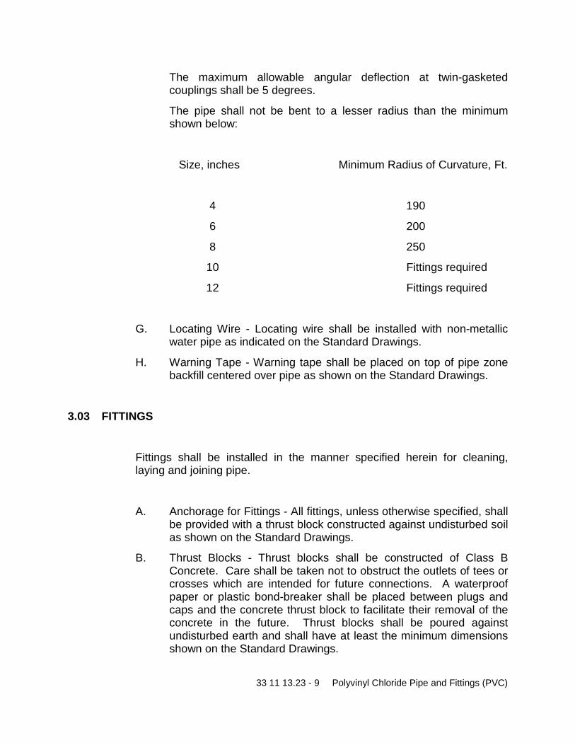
33 11 13.23 - 9 Polyvinyl Chloride Pipe and Fittings (PVC)
The maximum allowable angular deflection at twin-gasketed couplings shall be 5 degrees.
The pipe shall not be bent to a lesser radius than the minimum shown below:
Size, inches Minimum Radius of Curvature, Ft.
4 190
6 200
8 250
10 Fittings required
12 Fittings required
G. Locating Wire - Locating wire shall be installed with non-metallic water pipe as indicated on the Standard Drawings.
H. Warning Tape - Warning tape shall be placed on top of pipe zone backfill centered over pipe as shown on the Standard Drawings.
3.03 FITTINGS
Fittings shall be installed in the manner specified herein for cleaning, laying and joining pipe.
A. Anchorage for Fittings - All fittings, unless otherwise specified, shall be provided with a thrust block constructed against undisturbed soil as shown on the Standard Drawings.
B. Thrust Blocks - Thrust blocks shall be constructed of Class B Concrete. Care shall be taken not to obstruct the outlets of tees or crosses which are intended for future connections. A waterproof paper or plastic bond-breaker shall be placed between plugs and caps and the concrete thrust block to facilitate their removal of the concrete in the future. Thrust blocks shall be poured against undisturbed earth and shall have at least the minimum dimensions shown on the Standard Drawings.

33 11 13.23 - 10 Polyvinyl Chloride Pipe and Fittings (PVC)
C. Mechanical Couplings - Oil, scale, rust, and dirt shall be cleaned from pipe ends. The Contractor shall clean gaskets in couplings prior to installing the coupling in accordance with the manufacturer's recommendations:
Bolt threads shall be lubricated with graphite and oil prior to installation.
1. Painting and Coating -
a. The Contractor shall coat buried flexible pipe couplings, transition couplings, and flanged coupling adapters per Section 09900 and then wrap the couplings with polyethylene wrap per AWWA C-105.
b. The Contractor shall coat flexible pipe couplings (including joint harness assemblies), transition couplings, and flanged coupling adapters located indoors, in vaults and structures, and above-ground with the same coating system as specified for the adjacent pipe. A prime coat shall be applied at the factory.
D. Polyethylene Wrap - All ferrous metal shall be protected with polyethylene wrap. When it is not practical to wrap tees, crosses, and other odd-shaped pieces in a tube the item shall be wrapped with a flat sheet or split length of polyethylene tube by passing the sheet under the appurtenance and bringing it up around the body. Seams shall be made by bringing the edges together, folding over twice, and taping down. Polyethylene shall be taped securely in place.
Cuts, tears, punctures, or damage to polyethylene shall be repaired with adhesive tape, or with polyethylene sheet secured in place with adhesive tape.
3.04 TESTING AND DISINFECTION
Testing and disinfection shall be performed on all pipelines in accordance with Section 02660.
END OF SECTION

33 12 00.13 - 1 Abandonment of Facilities
DIVISION 33 UTILITIES
SECTION 33 12 00.13
ABANDONMENT OF FACILITIES
PART 1 – GENERAL
1.01 SCOPE
A. This Section governs abandonment of pipelines, services, valve and meter, and other existing structures.
1.02 SUBMITTALS
A. Upon request, schedules and method of abandonment shall be submitted to the District for approval.
B. 1-Sack Slurry Mix design and compressive strength test results.
C. Contractor shall submit for review their abandonment plan for filling the waterlines.
PART 2 – MATERIALS
2.01 GENERAL
A. Concrete, fittings, backfill material and other material used for abandonment shall comply with Specification 03 30 00 – Cast in Place Concrete and 03 34 00.13 – CLSM.
33 12 00.13 - 2 Abandonment of Facilities
2.02 FACILITY ABANDONMENT
A. 4-Inch, 6-Inch, and 8-inch Pipe being abandoned shall be entirely filled with 1-sack slurry cement in accordance with District Standards.
1-sack slurry backfill shall be used on abandoned lines that will no longer be in service or be under any pressure.
B. Blind flanges shall be used on any lines remaining in service or under pressure.
Thrust blocks shall be placed behind blind flange in accordance with District Standards.
PART 3 – EXECUTION
3.01 PIPELINES
A. Procedures (Pipe Abandonment)
All existing pipelines no longer in service or under pressure shall be abandoned in place. The entire pipeline shall be filled with an approved 1-sack slurry to the District Inspector satisfaction. No pipeline shall be abandoned until the new pipeline system and all services are installed, tested, and in service. An abandonment plan must be prepared by the Contractor and approved by the District prior to abandonment of any facilities.
Contractor shall be responsible for the cutting, removal and disposal of pipe, and for the dismantling of any fittings and valves necessary to perform the abandonment. Contractor is made aware that multiple slurry insertion and monitoring locations will be required to ensure adequate abandonment.
Structures to be abandoned shall have all openings, inlets, and outlets sealed off and the structure shall be removed to a point 3 feet below the proposed street grade or ground surface and filled with backfill (compacted as directed) or concrete.

33 12 00.13 - 3 Abandonment of Facilities
3.02 SERVICE LATERALS
A. Laterals will be abandoned in place. No portion of the previous service lateral shall be present inside the meter box after abandonment. Service shall be cut and capped below grade to avoid accidental reconnection. All caps shall be approved by the District Inspector.
3.03 STRUCTURES (VALVE BOXES)
A. Valve boxes to be abandoned shall be removed to a point 12-inches below the proposed street grade or ground surface and filled with ¾-inch crushed rock or cement slurry when in the street and filled with top soil when in unpaved or landscape areas.
3.04 DISPOSAL OF MATERIALS
A. ASBESTOS MATERIALS
It is the specific intent of these Contract Documents to exclude from the Work any and all products or materials containing asbestos. No new products containing asbestos shall be incorporated in the Work.
The Contractor is made aware that the existing water pipelines in the project area are made of Asbestos Concrete (AC). The Contractor shall anticipate the need for removal of sections of the existing pipeline during tie-ins to the existing system and abandonment of the existing pipelines where indicated on the plans.
All Asbestos Concrete (AC) Pipe shall be handled and disposed of according to California Code of Regulations (CCR) Tile 8, Section 1529; or most current regulations. Contractor shall provide a plan for disposal of the AC pipe and provide evidence of proper disposal to the Construction Manager.
END OF SECTION

33 12 13 - 1 Service Lines and Appurtenances
DIVISION 33 UTILITIES
SECTION 33 12 13
SERVICE LINES AND APPURTENANCES
PART 1 – GENERAL
1.01 SCOPE
A. This specification governs materials and installation for service line materials and fittings associated with the following:
Service line materials and fittings
Meter Boxes
B. Interruption of Water Supply
General Requirements
The Work shall be bid, scheduled and constructed in such a manner as to result in the least possible disruption to the existing customers. No customer shall have their water service disrupted for more than four (4) hours a day and for no more than two (2) consecutive days or two (2) total days. Water service shall be restored to all customers by the end of each work day. Modifications that affect or may affect the water supply to the existing customers shall not be made without first obtaining written or explicit verbal permission from the District.
In the event the Contractor’s efforts to re-establish permanent potable water service to a property exceed the time constraints above, the contractor shall be responsible for providing a reliable potable water source to that property at no additional cost to the District or the property owner until the permanent potable water service can be re-established.
The Contractor shall provide adequate temporary pumping and piping facilities to properly clear the work areas in the event of a main break. The Contractor shall clean the work areas as required to perform the work.

33 12 13 - 2 Service Lines and Appurtenances
Shutdown and isolation of existing facilities by closing existing valves/gates, or as specifically provided for in the Contract Documents, will be performed by District personnel only. All shutdown and/or isolation of existing facilities shall be scheduled a minimum of two (2) business days in advance of needing the District’s assistance. Note that 100% shut off may not be possible due to the age of existing valves. Contractor shall provide adequate temporary pumping, storage, piping, and disposal of such water in order to complete the work.
Prior to any shutdown all materials, fittings, supports, equipment and tools shall be on the site and all necessary skilled labor scheduled prior to starting any connection work.
Planned utility service shutdowns to any service shall be accomplished during periods of minimum use. In some cases, this will require night or weekend work, which shall be at no additional cost to the District. The Contractor shall program work so that service will be restored in the minimum possible time and shall cooperate with the District and utility owner in reducing shutdowns of the utility to a minimum. No utility shall be disconnected without prior written approval from the utility Owner and District. When it is necessary to disconnect a utility, the Contractor shall give at least two (2) weeks' notice to the utility Owner and to the District Representative for approval of the proposed schedule.
The Contractor shall note that only certain structures, tie-ins and constraints are addressed in this Section. All work, whether or not addressed here, shall be governed by applicable parts of this Section, and schedules and procedures further submitted for approval.
Outage Submittal Requirements
The Contractor shall submit to the District a detailed outage plan and time schedule for operations at least two (2) weeks prior to the need for outage. Note that this will require a significant effort, including meeting with each affected customer and the District inspector to discuss the planned outage time frames and their individual meter re-installation details. It will also include analyzing the number of connections on each street to manage the work within the outage limitations described in Section 2.1 above.
The detailed plan shall meet the restrictions and conditions found in the Contract Documents. The outage plans shall be coordinated with the construction schedule and shall meet the Contractor's planned method; the length of time required to complete said operation. In addition, the outage plan shall describe the Contractor's contingency plan that shall be initiated in the event that

33 12 13 - 3 Service Lines and Appurtenances
its temporary facilities fail or it becomes apparent that the time constraints described in the approved outage plan cannot be met. The contingency plan shall conform to all specified outage requirements. All costs for preparing and implementing both the outage and contingency plans shall be borne by the Contractor.
The Contractor shall attend a meeting with the District Representative and any Utility Owner one (1) week before the scheduled outage to review the plan. Any changes to the plan must be approved by the District Representative prior to the outage.
Property Owner Notification
The Contractor shall produce, print, and distribute door hangers and/or mailers a minimum of ten (10) working days and again twenty-four (24) hours in advance of performing the water service line cross-over to the new service line. Contractor shall submit samples of the notifications to the District for approval. At a minimum, the notification shall be printed on the Contractor’s letter head, include the Contractor Foreman’s contact number, the schedule (days and hours) when the work will be performed and water service outage will occur, and possible expectations when the new service is activated (e.g. higher pressure and need to clean facet screens). No additional compensation will be made for notification reproduction and distribution cost should the Contractor’s schedule change.
1.02 SUBMITTALS
A. The following items shall be submitted and approved by the District
Detailed outage plan and time schedule for operations at least two (2) weeks prior to the need for outage.
Contractor shall submit samples of the customer notifications to the District for approval.
Manufacturer's catalog data showing model, part number, diameter, connection type, pressure ratings and materials of construction.

33 12 13 - 4 Service Lines and Appurtenances
PART 2 – MATERIALS
2.01 SERVICE LINE MATERIALS AND FITTINGS
A. Service line materials and fittings include service line pipe, service saddles, service fittings, meter stops, corporation stops, curb stops, and gate valves. All material shall be in compliance with the District’s standards and detail drawings most recent version.
Polyethylene Tubing (PE) – PE tubing shall be in accordance with AWWA C901 and correspond to copper tubing size (CTS). The tubing shall be marked with the following:
• Nominal size • Materials code; i.e. PE 3406 • The word “Tubing” and dimension ratio • AWWA pressure class, i.e., PC 160 • AWWA designation AWWA C901 • Manufacturer’s name or trademark • Seal of testing agency
i. The polyethylene material shall be type “4710” conforming to ASTM D3350. The pressure class shall be a minimum of 200psi.
ii. Stainless steel liners or inserts shall be used with PE tubing when compression type connections are specified or shown.
Service Saddles – Service saddles shall be constructed of bronze, have AWWA iron pipe thread outlet taps, comply with AWWA C-800 "Threads for Underground Service Line Fittings" and have suitable means for attachment and sealing to a water main. The body shall be made to conform to outside configuration of the main. The service saddle shall be designed to provide a drip-tight connection when used as a service connection to the main. Saddles for ductile iron pipe shall be double strap. Straps for PVC pipe may also be stainless and shall provide full support around the circumference of the pipe and have a bearing area of sufficient width so that the pipe will not be distorted when the saddle is tightened.
Corporation Stops – Corporation stops shall be constructed of bronze, have AWWA iron pipe inlet threads, and shall comply with the requirements of AWWA C-800, "Threads for Underground Service Line Fittings." Male iron pipe threads shall be provided on both the inlet and the outlet side of 1-inch, 1½-inch and 2-inch corporation stops.

33 12 13 - 5 Service Lines and Appurtenances
Fittings – Fittings including PE tubing couplings, bends, unions, and adapters shall be constructed of bronze and shall be designed to join to CTS polyethylene tubing using a “stab type” connection (Mueller or approved equal) in ¾-inch and 1-inch sizes and compression type connections in 1-1/2 inch and 2-inch sizes. Fittings shall also have male or female iron pipe-size-threaded ends and/or meter coupling nut or meter flange as required.
Angle Meter Stops – Angle meter stops shall be constructed of bronze, have lock wings and be suitable for joining to CTS polyethylene using a “stab type” connection for ¾-inch and 1-inch angle meter stops and a female iron pipe (FIP) thread type connection for 1-1/2 inch and 2-inch angle meter stops. Outlets for ¾-inch and 1-inch angle meter stops shall consist of a meter coupling nut. One-and-a-half inch and 2-inch angle meter stops shall have meter flange outlets.
Gate Valve – The gate valve shall be constructed of brass, full ported with threaded end connections conforming to ANSI Standards B2.1, threaded bonnet with a non-rising stem. Valve material shall be NSF-61 approved.
2.02 METERS AND METER BOXES
A. The District will purchase and provide the meters and transponders that need to be upgraded or replaced; otherwise all existing meters shall be reused. The Contractor shall coordinate with the District regarding the scheduling and procurement of the meters to correspond with the Contractor’s schedule. The District will store the meters and transponders at the District’s yard located at 2890 Mosquito Road. The Contractor will be responsible for signing out the meters from the yard as needed, transporting them to the site, and installing them as needed. This work shall be accounted for in the Contractor’s bid schedule. Meters not installed the day they are signed out shall be stored in a secure place by the Contractor. Upon completing the meter and transponder installation, the Contractor shall complete the meter/transponder data sheet for each property located at the end of this specification, and return the completed forms to the District’s inspector by the end of each week.
B. The meter boxes for ¾-inch, 1-inch, 1-1/2 inch and 2-inch meters shall be concrete with steel lids in traffic areas. Plastic boxes and lids shall be used in non-traffic areas, according to the following. The Contractor shall be responsible for purchasing and furnishing the meter boxes:

33 12 13 - 6 Service Lines and Appurtenances
Meter Size Box Inside Dimensions (Min)
¾-inch and 1-inch 10 x 17-inches
1-1/2 inch and 2-inch 13 x 24-inches
PART3 – EXECUTION
3.01 INSTALLATION
A. Polyethylene Tubing – Tubing and fittings should be stored in a way that prevents damage due to crushing or piercing, excessive heat, harmful chemicals, or exposure for prolonged periods. The manufacturer’s recommendations regarding storage should be followed.
Handling operations and trench installation and backfill shall be performed with reasonable care to prevent scratches, nicks, and gouges in the conduit.
Pipe excessively cut or kinked shall not be used.
Bends in PE tubing shall not occur closer than 10 diameters from any fitting or valve. The minimum radius of curvature is 30 diameters or the coil radius when bending with the coil. Bending of coiled tubing against the coil shall not go beyond straight. Polyethylene tubing that becomes kinked during handling or installation shall not be used and care should be taken to ensure that kinking does not develop after installation. Service line from the main line tap to the angle meter stop shall be one continuous length of tubing.
PE tubing shall be installed in trench bottoms with 6-inches of bedding material to provide continuous and uniform support. The initial backfill shall be 6-inches above the tubing and shall be materials free from rock, stones and debris.
B. Service Saddles - The service saddle shall be no closer than 24 inches to a valve, coupling, joint, or fitting, unless it is at the end of the main.
The surface of the pipe shall be free of all loose material and have a hard, clean surface before placing the service saddle.
The service saddle shall be tightened firmly to ensure a tight seal, however, care shall be used to prevent damage or distortion of either the pipe, corporation stop or service saddle by overtightening.
The drilling of the pipe shall be performed in accordance with the pipe manufacturer's recommendation.

33 12 13 - 7 Service Lines and Appurtenances
3.02 FITTINGS, ANGLE METER STOPS, AND BOXES
A. Installation of fittings, meter stops, and boxes shall be as recommended by the manufacturer. Pipe or fittings made of nonferrous metals (bronze) shall be isolated from ferrous metals with insulating unions or couplings.
B. Contractor shall furnish and install the meter in accordance with the District Standards. Contractor shall record the installation date, address and location (dimensions north/south or east/west from the closest property line and dimension north/south or east/west of permanent County road features (e.g. road centerline, back of walk, back of curb), serial number of meter and transponder, make of meter and transponder for submittal to the District. Submittal shall be made within two (2) working days for residential properties.
3.03 HYDROSTATIC TESTING
A. The Contractor shall hydrostatic test all appurtenances in place with the pipe being tested.
B. Contractor shall record and report to the District the hydrostatic pressure at each property before and after installing the new service line and appurtenances.
3.04 LOCATING EXISTING SERVICES
A. The existing services shown on the plans have been surveyed or are shown in their approximate location. The existing service line material connected to mainlines to be abandoned are typically polyethylene tubing. In-tract pipe between the house and the existing meter is typically PVC or galvanized pipe.
B. The Contractor shall be responsible for locating and exposing the existing service line and in-tract pipe and for all material, labor, and equipment to make the new service connection and abandonment of the existing service line.

33 12 13 - 8 Service Lines and Appurtenances
3.05 MAKING SERVICE CONNECTION
A. All services shall be at their existing location unless otherwise shown on the plans or determined by the District. The service line from the water main to the meter box shall be constructed after the construction of the new main. Prior to making the final service connection to the existing in-tract pipe and/or downstream of the new meter/meter box, the water main and service line shall be pressure tested, disinfected and shall pass bacteriological testing.
B. Service Connection and Cross-over Procedure:
The new service line from the main to the new or existing meter location shall be installed, tested and disinfected prior to making the new service connection and cross-over.
Contractor shall locate, expose and identify material of the existing in-tract piping, and located and close the customer shut-off valve at the house.
Contractor shall record the static pressure at the hose bib that will be used for flushing in the proceeding steps, and shall request that the resident operate their irrigation system (if one exist) and document its condition.
When a new meter and meter box is to be installed and/or reconnected to an existing pressure regulating valve, the Contractor shall notify the District upon exposing the existing in-tract pipe to evaluate the in-tract existing condition. If the District Inspector determines that the existing in-tract pipe is in poor condition, the Contractor shall be responsible for exposing and replacing up to five (5) feet of in-tract pipe to make a connection to pipe in good condition.
Contractor shall excavate and set the new meter box and install the necessary piping, meter, and appurtenances in accordance with the Plans and Specifications, and connect the new service line to the new meter assembly.
Contractor shall close the existing meter valves and cut the existing in-tract pipe at the location agreed upon with the District. The Contractor shall be responsible for furnishing and installing all piping, fittings, and approved transition coupling between the existing in-tract pipe and the new in-tract pipe and/or customer valve downstream to restore service to the property.
I. Contractor shall take preventative measures from introducing any new pipe and appurtenances to contamination, and shall disinfect and flush such pipe prior to connecting to the existing in-tract pipe.
II. All properties require pressure regulating valves. The Contractor shall be responsible for furnishing and installing or re-connecting these features in with the new water service.

33 12 13 - 9 Service Lines and Appurtenances
Upon connecting the new service to the existing in-tract pipe, the Contractor shall slowly open the District’s angle valve and allow the in-tract pipe to recharge. Contractor shall check for leaks and tighten fittings as needed.
Contractor shall open the outside residence/parcel hose bid closet to the meter box and/or house shutoff valve. Contractor shall slowly open the customer’s meter angle valve and allow water to flow through the hose bib for 1 to 2 minutes or until all entrapped air and/or cloudiness has been expelled from the line.
Contractor shall contact the property owner prior to re-activating their service into their house or commercial property, and shall slowly open the customer valve to the house/commercial property.
III. Water service to a house/commercial property shall not be re-activated without notifying the property owner in the event that a failure to their existing system occur and goes undetected.
Caution: Introducing water too quickly into the meter and new and old pipe can damage the meter’s internal components and send a pressure surge through pipes that can cause damage, Contractor responsible for repairs.
Contractor shall notify the District when the work is complete and shall record and report the static pressure at the hose bib and the meter serial number.
C. Where in-tract pipe is required to be installed, the diameters of new in-tract pipe shall be in accordance with the size listed in the Plans unless approved otherwise by the Engineer. Lengths shall be measured from the new meter box to the point of connection at the existing in-tract water pipe as shown on the meter location sheet. Contractor shall follow the steps listed above when installing, disinfecting, flushing, and making the final connection to the property.
D. Excavated materials shall be replaced and repaired to existing or better condition as they were in prior to excavation. This includes sub-grade materials and compaction, surface repairs, and any other repairs required.
E. Contractor shall make every effort to minimize damage to customer’s property during installation of the new water service line. Excavations shall be the minimum necessary to satisfactorily complete the work.
F. All existing facilities and structures broken or damaged shall be replaced or repaired to their original or better condition at the Contractor’s expense.

33 12 13 - 10 Service Lines and Appurtenances
G. Existing underground service are shown as accurately as available data permits. Locations are approximate and may not show all lines to be encountered in the excavation for this Project. Contractor shall be responsible for verifying the location of all existing underground facilities prior to starting excavation and shall be responsible for repair or replacement of all facilities damaged due to work on this project.
H. Provide an as-built plan of the in-tract service line noting property address with adequate dimension to identify the in-tract line location in the future. Contractor shall record the as-built markings on the Plans and provided meter locations sheets.
3.06 EXISTING SERVICE ABANDONMENT
A. The abandonment of the existing service line shall follow under the following conditions. All existing services are to remain active until the Contractor is ready to cross over to the new service and abandon the existing service.
Existing Service Abandonment (Type 1) – Existing Mainline to Remain In Service
Shut off the pipeline at the appropriate mainline valve. Remove the existing service saddle and replace with a new full circle band. Cut and cap the existing service line near the location of the new service line. Abandon in place all existing service line between the new full circle band and the point of connection to the new service line. Remove existing curb stop and valve box and salvage.
Existing Service Abandonment (Type 2–Existing Mainline to be Abandoned In Place)
Shut the existing service line corporation stop at the existing mainline. Disconnect the existing service line from the existing corporation stop. Abandon in place all service line between the existing corporation stop and the point of the new service line. Remove existing curb stop and valve box and salvage.
I. If a new in-tract line connects to the property other than reconnecting to the existing in-tract line a ¾-inch hose bib shall be installed on the remaining active in-tract line. The hose bib is to be located at a location agreeable to the District and the property owner.
B. Existing meters and transponders shall be removed, cleaned, and returned to the District corporation yard. All evidence of the valve box shall be demolished and removed and the area finished to match the surrounding area.

33 12 13 - 11 Service Lines and Appurtenances
END OF SECTION

33 12 13.16 - 1 Tie-In Sequencing
DIVISION 33 UTILITIES
SECTION 33 12 13.16
TIE-IN SEQUENCING
PART 1 – GENERAL
1.01 SCOPE OF WORK
A. This Section describes the procedures for tie-ins to the existing water main line and at the designated tie-ins to the existing water services.
PART 2 - MATERIALS (NOT USED)
PART 3 – EXECUTION
3.01 TIE-IN TO EXISTING SYSTEM REQUIREMENTS
A. The Contractor is made aware that the majority of existing buried EID facilities are asbestos concrete (AC) material (8-inch diameter and smaller) which is considered a hazardous material if removed or disturbed. The Contractor shall ensure that any AC pipe removed as part of any tie-in to the existing system or abandonment of any facility is properly removed and disposed of in accordance with all applicable regulatory requirements. Copies of all disposal records shall be provided to EID by substantial completion of the project.
B. Existing Water System: In order to prevent unnecessary interruption of the water main line, a controlled scheduling and sequence of the Contractor's work is necessary. The Contractor shall work in cooperation with District Operations and Maintenance personnel to maintain continuous operation of the system. The Contractor is required to submit a schedule and tie-in plan for District approval within fifteen (15) working days prior to starting any of the tie-in work. The plan shall include an emergency response measures and temporary water supply to the County Jail, Juvenile Hall and Dispatch
33 12 13.16 - 2 Tie-In Sequencing
facilities. The County Jail and Juvenile Hall will require a water truck each and Dispatch will require water bottles and a porta potty, approved by EID. Outages are to be limited to week days between the hours of 11pm-4am.
C. The Contractor shall not operate any District valve or other water appurtenances.
D. Connections to Existing Facilities:
The existing water main must remain in service until the new water main is tied in, tested, accepted, and all water services are moved over to the new water line. The tie-ins have been designed to keep both the new and existing system active during the installation of services. The new lines shall be extended as close as possible to the tie-in points. The new lines must be completely tested and accepted before tying into the existing lines.
New services shall be installed prior to testing of the new water main unless the existing service is to be re-used.
The cost of temporary facilities and other items necessary for successful completion of the project shall be included in the bid.
The Contractor shall be fully prepared to complete the connection in the time allotted and shall not stop work until the facilities are restored to service or until otherwise directed so by the District. All possible preparatory work shall be completed to the satisfaction of the District prior to connection to the existing system. The District reserves the right to cancel or delay the tie-ins due to weather, equipment or man-power concerns.
E. Exposing Existing Facilities: When connections are to be made to any existing pipe or other appurtenances, a minimum of 24-hours before the tie-in the Contractor shall excavate and expose the existing facility before the connection is made to determine the actual size, elevation, or position of the facility.
AC pipe is known to have varying outside diameters. Contractor shall verify the proposed fitting are compatible with the existing pipe.
F. Tie-in Sequencing
After successful testing of the new water main line, the new water main line shall be connected to the existing waterline as shown on the plans.
Once the new water main line is connected to the existing system, meters are to be switched over to the new services laterals in a systematic way to minimize the number and duration of outages for any individual customers.
Existing service lines will need to be capped and remain water tight until existing system is abandoned.

33 12 13.16 - 3 Tie-In Sequencing
Contractor is required to employ adequate resources to ensure that no customer shall be out of service for more then 4-hours at a time.
The Contractor shall notify the District a minimum of 48-hours prior to any shut-downs. The Contractor will be responsible for notifying and coordinating with customers. The Contractor is responsible for any de-watering required to complete the tie-in and shall be included in their bid.
Only after all services in a phase are connected to the new system will final abandonment of the existing system be performed. Contractor shall provide an abandonment plan in advance of final abandonment.
END OF SECTION

40 05 61.23 - 1 Gate Valves
DIVISION 33 UTILITIES
SECTION 33 13 00
TESTING AND DISINFECTING WATER MAINS
PART 1 – GENERAL
1.01 SCOPE
A. All completed pipelines, as well as the air-release assemblies and appurtenant structures, will be tested by the Contractor in the Inspector's presence prior to field acceptance of the work. The Contractor shall correct all defects in workmanship or materials which become evident by inspection or testing at any time during the work. Testing shall be done after the complete installation and compaction of all underground utilities, except as modified below.
B. The Contractor shall furnish all pipe and fittings for connection to the main, pumps, pressure regulator, a calibrated water storage tank, and all other materials, fittings and pipelines required to perform the tests and make the necessary repairs.
C. When lines to be tested are in areas that will be paved, testing shall be done after the rock subgrade is placed and compacted. No lines shall be accepted as passing until all underground construction that may disturb the waterline is compacted.
D. The pressure test and the test for allowable leakage shall be performed simultaneously. Testing shall not commence until the main and all appurtenances have been completely installed. The Contractor may, at any time and at his expense, perform his own pressure and leak test; however these tests will in no way offset the requirement for a final pressure and leak test.
E. After successfully testing the water main and appurtenances, they shall be flushed and disinfected.
F. After having been successfully tested and disinfected, the water main may be connected to the District's water system.
40 05 61.23 - 2 Gate Valves
1.02 SUBMITTALS
A. The Contractor shall notify the District a minimum of 3 business days in advance of its proposed testing schedule for review and concurrence. If requested, the Contractor's proposed plans for water conveyance, disinfection, control, and disposal, shall also be submitted in writing.
PART 2 – MATERIALS
2.01 GENERAL
A. All test equipment, temporary valves, bulkheads, or other water control equipment and materials shall be determined and furnished by the Contractor, subject to the District's review. No materials shall be used which would be injurious to the construction or its future function.
2.02 HYDROSTATIC TESTING EQUIPMENT
A. The Contractor shall be responsible for supplying and operating all testing equipment. In general, the testing equipment configuration shall consist of a pump receiving water from a calibrated storage tank. The pump discharge shall enter the water main through a tap or appurtenance. A pressure sustaining valve shall be placed on a tee located in the pump discharge line. Discharge from the pressure sustaining valve shall return to the calibrated storage tank. Other types or configurations of testing equipment shall be subject to District approval. The pressure pump shall operate continuous throughout the testing period. If the pump is stopped, the pressure shall not be allowed to drop more than 2 psi below test pressure before starting the pump.
2.03 CHLORINE
A. Chlorine for disinfection shall be in the form of liquid chlorine, sodium hypochlorite solution, or calcium hypochlorite granules or 5-g tablets.
40 05 61.23 - 3 Gate Valves
Liquid chlorine shall be in accordance with requirements of AWWA-B 301. Liquid chlorine shall be used only:
i. In combination with appropriate gas flow chlorinators and ejectors.
ii. Under the direct supervision of an experienced technician. iii. When appropriate safety practices are observed.
Sodium hypochlorite and calcium hypochlorite shall be in accordance with the requirements of AWWA-B 300, and containing approximately 65 percent available chlorine by weight.
PART 3 – EXECUTION
3.01 GENERAL
A. The Contractor shall make all necessary provisions for securing a water source to perform the pressure test.
B. All pressure pipelines shall be tested. Release of water from pipelines, shall be in accordance with a written disposal plan reviewed by the Engineer.
C. Disinfection operations shall be scheduled by the Contractor as late as possible during the contract time period so as to assure the maximum degree of sterility of the facilities before the Work is accepted by the District. Bacteriological testing shall be performed by the District.
D. Release water from pipelines, after testing and disinfecting have been completed, shall be in accordance with a written disposal plan reviewed by the Engineer.
3.02 HYDROSTATIC TESTING
A. The purpose of the hydrostatic test is both to test the ability of the pipeline to withstand pressure and test for allowable leakage. These tests shall run simultaneously.
Preparation - Prior to testing, the main shall be slowly and carefully filled with water. All air shall be expelled slowly from the pipe and appurtenances in a manner so as not to create excessive surge

40 05 61.23 - 4 Gate Valves
:7400
WHEREPNDW =
pressures. All appurtenances shall be left on during the testing procedure. The line shall be filled with water at least twenty-four hours prior to testing when the pipeline has a mortar lining, thus allowing the lining material to become saturated. Water for testing shall be introduced at the low end of the section being tested to facilitate the elimination of air in the pipeline prior to testing. Where air valves or other suitable outlets are not available for releasing air before applying the test, approved taps and fittings shall be installed and later securely plugged.
Test Section Length - The length of pipe being tested at any one time shall not exceed 2,000 feet unless otherwise approved by the District.
Test Pressure - The test pressure shall be 200 psi or 50 psi greater than design pressure of the system, whichever is greater, measured at the lowest point of the section of the pressure zone being tested.
Test Duration - The test duration shall be two hours. Pressure in the water main shall be maintained within 2 psi of the calculated test pressure for the full two-hour duration. The individual testing of the valves may be of a shorter duration as approved by the District.
Allowable Leakage – The allowable leakage per test section shall be calculated from the formula contained in this subsection. Different sized mains and different main materials that might be contained within the same test section shall be calculated separately and then added together.
W = Allowable leakage in gal/hr.
N = Number of joints in the length of pipeline tested
D = Normal diameter in inches
P = Average test pressure in psi
Repairs - During the pressure and leakage test, all accessible appurtenances shall be inspected for visual signs of leakage. All visual leaks shall be corrected immediately, regardless of the amount of leakage and the test shall be run again for its full duration. All leaks detected shall be repaired to a water tight condition. All repairs made shall be retested in accordance with the specifications.

40 05 61.23 - 5 Gate Valves
3.03 DISINFECTING
A. After completion of testing operations, the Contractor shall sterilize all water mains, services and appurtenances. Sterilization shall be accomplished in accordance with the latest revision of AWWA C-651-14.
B. The basic disinfection procedure consists of:
i. Preventing contamination materials from entering the water main during storage, construction, or repair.
ii. Removing, by flushing or other means, those materials that may have entered the water main.
iii. Chlorinating any residual contamination that may remain, and flushing the chlorinated water from the main.
iv. Determining the bacteriological quality by laboratory test after disinfection.
C. The District only allows the following two methods of chlorination: continuous feed or slug per AWWA C-651-14.
D. Final Flushing – After the applicable retention period, heavily chlorinated water should not remain in ·prolonged contact with pipe. In order to prevent damage to the pipe lining or corrosion damage to the pipe itself, the heavily chlorinated water shall be flushed from the main until chlorine measurements show that the concentration in the water leaving the main is no higher than that which is generally prevailing in the system or is acceptable for domestic use.
E. Disposal of testing and disinfection water shall be per the Contractor obtained dewatering permit.
F. Bacteriological Tests – After completion of testing and sterilization, prior to final acceptance, the District will take water samples for bacteriological examination. Should any of the samples fail to meet minimum State of California requirements, the Contractor will continue to chlorinate and flush the system, as directed, until a satisfactory sample is obtained.
G. Redisinfection – If the initial disinfection fails to produce satisfactory bacteriological samples, the main may be reflushed and shall be resampled. If check samples show the presence of coliform organisms, then the main shall be rechlorinated by the continuous-feed or slug method of chlorination until satisfactory results are obtained.
NOTE: High velocities in the existing system, resulting from flushing the new main, may disturb sediment that has accumulated in the existing mains. When check samples are taken, it is well to also sample water entering the new main.
END OF SECTION

40 05 61.23 - 6 Gate Valves
DIVISION 40 PROCESS INTERCONNECTIONS
SECTION 40 05 61.23
GATE VALVES
PART 1 – GENERAL
1.01 SCOPE
A. This specification governs materials and installation for the installation of valves as shown on the plans and in accordance with the District’s Standard and Details latest version.
1.02 SUBMITTALS
A. Prior to the purchase of valves to be used in the District system, the following items shall be submitted and approved by the District:
1. Manufacturer's catalog data showing valve type and size to be used, valve dimensions, pressure rating and materials of construction.
2. Manufacturer’s data and NSF certification seal on the lining to be used.
PART 2 – MATERIALS
2.01 GATE VALVES
A. Gate valves 3 inches and larger, shall be resilient seated suitable for buried service and meet the requirements of AWWA C-509, manually operated. All such valves shall be of the non-rising stem type, with double o-ring seal and shall tum to the left in a counter-clockwise direction to open the valve.

40 05 61.23 - 7 Gate Valves
B. All valves shall be suitable for frequent operation as well as service involving long periods of inactivity. Valves shall be capable of operating satisfactorily with flows in either direction and shall provide zero leakage past the seat.
C. Valve Body – Body, bonnet, operating nut, and stuffing box shall be of iron with internal working parts of solid bronze. Exposed capscrews, bolts and nuts shall be stainless steel type 304.
The word "open" and an arrow indicating the direction to open, shall be cast on each valve body or operator.
D. Valve Operator – Valve operators shall be equipped with a 2-inch AWWA square operating nut. They shall be sealed and gasketed and lubricated for underground service. The operator shall be capable of withstanding an input torque of 450 ft. lbs. at extreme operator position without damage.
E. Coating and Lining - Interior surfaces, excluding seating areas, bronze, and stainless steel pieces, shall be epoxy lined to a dry film thickness of 12 mils.
Liquid epoxy linings shall be applied in two coats. Liquid epoxy coating materials shall be listed in the NSF Listing for Drinking Water Additives, Standard 61, as certified for use in contact with potable water. Powder epoxy coating materials shall contain 100 percent solids. Surface preparation shall include White Metal Blast Cleaning.
Exterior surfaces shall be shop coated with two coats of asphalt varnish conforming to AWWA C-509. Flange faces shall be coated with a rust preventive compound.
F. Marking – The manufacturer shall show on the valve the size, manufacturer,
class and year.
G. Gate – Gate shall be cast or ductile iron encapsulated in Buna-N rubber or nitrite elastomer.
H. Types of End Connection – End connections may be either flanged, push-on, or mechanical joint type per Section 33 11 13.13.
PART 3 –EXECUTION
3.01 STORAGE
A. Valves shall be delivered and stored in the field with the port openings covered with plastic, cardboard or wood. These covers shall remain in place until the valve is ready to be installed. Valves shall not be stored in contact with bare ground. Valves shall not be stacked on top of one another.

40 05 61.23 - 8 Gate Valves
3.02 INSTALLATION
A. The weight of the valve shall be supported by firm ground or concrete blocking and not by the pipe. Buried valves having the top of the operating nut greater than three feet below the finished surface shall be provided with shaft extensions.
B. Flanged Connection – Bolt holes of flanged valves shall straddle the horizontal and vertical axis of the pipe to which the valves are attached. Flanges, bolts and nuts shall be cleaned by wire brushing before installing flanged valves. Threads on nuts and bolts shall be lubricated with oil and graphite. Nuts and bolts shall be tightened uniformly and progressively. If flanges leak under pressure testing, the Contractor shall loosen or remove the nuts and bolts, reseat or replace the gasket, reinstall or retighten the bolts, and retest the joints. Joints shall be watertight. Bolts shall be tightened in an even manner by a series of steps until the torque required by the manufacturer is reached.
C. Threaded Connection – Threaded joints shall be cleaned by wire brushing or swabbing. Teflon joint compound or Teflon tape shall be applied to pipe threads before installing threaded valves. Joints shall be watertight.
D. Push-on Connection – Rubber ring grooves of joints shall be inspected before installation by the Contractor for ridges or holes that would interfere with the rubber ring. Interferences with the rubber rings shall be corrected to a satisfactory condition or the valve replaced, as required by the District.
The pipe to be stabbed into the valve shall be beveled. Pipe shall be stabbed into the valve to the "Insertion Depth" as specified by the manufacturer.
E. Mechanical Joint – Valve socket, gland, and pipe plain end shall be wiped clean of all sand, dirt and other foreign material prior to valve installation. Bolts shall be tightened in a manner by a series of steps until the torque required by the manufacturer is reached.
F. Polyethylene Encasement – Valves and all bolted connections shall be encased with 10 mil polyethylene plastic film wrap installed as follows: The valves shall be wrapped by passing the flat sheet of film under the valve bottom and bringing the ends up around the body to the stem and securing it in place with 2-inch strips of the plastic adhesive tape. The polyethylene shall be secured around the valve stem in such a manner as to leave the stem free to operate. The film shall be brought completely around the flanges and secured to the pipe with a plastic adhesive tape on either side of the valve, flange or fitting.

40 05 61.23 - 9 Gate Valves
3.03 OPERATION
A. Immediately before installation, each valve shall be operated through one complete open-close cycle and visually checked for proper operation. Boxing of valves shall begin immediately after pipe sections containing the valve have been installed. All valve boxes, paving rings, and lids shall be brought to grade after pavement has been constructed.
END OF SECTION

40 05 64 - 1 Butterfly Valves
DIVISION 40 PROCESS INTERCONNECTIONS
SECTION 40 05 64
BUTTERFLY VALVES
PART 1 –GENERAL
1.01 SCOPE
This specification governs materials and installation of butterfly valves. Valves greater than 12 inches shall be butterfly valves.
Valves shall be furnished and installed by the Contractor at the locations shown on the approved plans, or as required by the District.
1.02 SUBMITTALS
Prior to the purchase of butterfly valves to be used in the District system, the following items shall be submitted and approved by the District.
A. Manufacturer's catalog data and detail construction sheets showing the size to be used, valve dimensions, pressure rating and materials of construction.
B. Actuator manufacturer's catalog data and detail construction sheets showing the dimensions, materials, number of turns, and required torque input of the actuator to be used.
C. Manufacturer's catalog data and NSF certification seal on the lining to be used.
40 05 64 - 2 Butterfly Valves
PART 2 –MATERIALS
2.01 GENERAL
Butterfly valves shall be tightly closing, rubber seated valves conforming to AWWA C-504 suitable for buried service. Valves shall be Class 150-B designed for tight shut-off up to 150 psi in both directions. Valve disc shall rotate 90 degrees from fully open to tightly closed position.
A. Valve body - Valve bodies shall be cast iron with integrally cast mechanical joints or flanged ends. Exposed capscrews, bolts, and nuts shall be stainless steel type 304.
B. Valve operators - Shall be of the manual traveling nut type. Operators shall be equipped with a 2-inch AWWA square operating nut. They shall be sealed and gasketed and lubricated for underground service. The operator shall be capable of withstanding an input torque of 450 ft. lbs. at extreme operator position without damage.
Gear operators for valves located above ground or in vaults and structures shall have handwheels. The handwheel shall have a minimum diameter of 12 inches. The actuator shall contain a dial indicator which shows the position of the valve disc.
C. Coating and Lining - Interior surfaces, excluding seating areas, bronze, and stainless steel pieces, shall be epoxy lined to a dry film thickness of 12 mils. Liquid epoxy linings shall be applied in two coats. Lining of interior valve surfaces shall be performed in a facility with qualified personnel and where the environment can be controlled. Epoxy lining of valves shall not be permitted in the field. Liquid epoxy coating materials shall be listed in the NSF Listing for Drinking Water Additives, Standard 61, as certified for use in contact with potable water. Powder epoxy coating materials shall contain 100 percent solids. Surface preparation shall include White Metal Blast Cleaning.
Exterior surfaces shall be shop coated with two coats of asphalt varnish conforming to AWWA C-504. Flange faces shall be coated with a rust preventive compound.
D. Marking - The manufacturer shall show on the valve the valve size, manufacturer, class and year of manufacture.
E. Valve Disc and Shaft - Discs shall be cast iron with a stainless steel edge. Shafts shall be type 304 stainless steel.

40 05 64 - 3 Butterfly Valves
F. Types of End Connections - End connections may be either flanged or mechanical joint type per Section 02615 or Section 02622.
PART 3 –EXECUTION
3.01 STORAGE
Valves shall be delivered and stored in the field with the port openings covered with plastic, cardboard or wood. These covers shall remain in place until the valves are ready to be installed. Valves shall not be stored in contact with bare ground. Valves shall not be stacked on top of one another.
3.2 INSTALLATION
The weight of the valve shall be supported by firm ground or blocking and not the pipe.
A. Flanged Connection - Valves shall be installed with the operating nut in the vertical position. Flanges, bolts and nuts shall be cleaned by wire brushing before installing flanged valves. Threads of bolts and nuts shall be cleaned by wire brushing, and threads shall be lubricated with oil and graphite. Nuts and bolts shall be tightened uniformly and progressively. If flanges leak under pressure testing, the Contractor shall loosen or remove the nuts and bolts, reseat or replace the gasket, reinstall or retighten the bolts and nuts, and retest the joints. Joints shall be watertight.
Bolts shall be tightened in an even manner by a series of steps until the torque required by the manufacturer is reached.
B. Mechanical Joint - Valve socket, gland, and pipe plain end shall be wiped clean of all sand, dirt and foreign material prior to valve installation. Bolts shall be tightened in a manner by a series of steps until the torque required by the manufacturer is reached.
C. Polyethylene Encasement - Valves and all bolted connections shall be encased with 10 mil polyethylene plastic film wrap installed as follows: The valves shall be wrapped by passing the flat sheet of film under the valve bottom and bringing the ends around the body to the stem and securing it in place with 2-inch strips of adhesive tape. The polyethylene shall be secured around the valve in such a manner as to leave the stem free to operate. The film shall be brought completely around the flanges and secured to the pipe with a plastic adhesive tape on either side of the valve flange.
40 05 64 - 4 Butterfly Valves
D. Operation - Immediately before installation, each valve shall be operated through one complete open-close cycle and visually checked for proper operation. Boxing of valves shall begin immediately after pipe sections containing the valves have been installed. All valve boxes, paving rings, and lids shall be brought to grade after pavement has been constructed.
END OF SECTION

40 05 76.13 - 1 Tapping Valves and Sleeves
DIVISION 40 PROCESS INTERCONNECTIONS
SECTION 40 05 76.13
TAPPING VALVES AND SLEEVES
PART 1 –GENERAL
1.01 SCOPE
This section governs materials and installation of tapping valves and sleeves. Valves shall be furnished and installed by the Contractor at the locations shown on the Approved Plans, or as required by the District.
1.02 SUBMITTALS
Prior to the purchase of tapping valves and sleeves to be used in the District system, the following items shall be submitted to and approved by the District:
A. Manufacturer's catalog data and detail construction sheets showing the size to be used, valve and sleeve dimensions, pressure rating and materials of construction.
B. Manufacturer's catalog data and NSF certification seal on the lining to be used.
PART 2 –MATERIALS
2.01 TAPPING VALVES
Tapping valves shall be of the double disc or resilient seat type conforming with all requirements for gate valves in Section 02640. Valves shall be furnished with a flanged end with centering ring on the tapping sleeve side. The outlet side of valve shall have a mechanical joint, except as otherwise approved. Seat rings shall be oversized to permit the use of full-size cutters.

40 05 76.13 - 2 Tapping Valves and Sleeves
2.02 TAPPING SLEEVES
Sleeves shall be 304 stainless steel or cast iron conforming to ASTM-A-126 Class B. Bolts, nuts, and washers shall be type 304 Stainless Steel. Gaskets shall be Buna-N rubber at each end of the sleeve. Sleeves shall have a ¾-inch NPT plug for air test.
2.03 COATING AND LININGS
Valves shall be coated and lined per Section 02640. Cast iron sleeves shall be coated with two coats of asphalt varnish conforming to AWWA C504, except for face of flanges, bolts and nuts. Face of flanges shall be shop coated with a rust preventive compound.
PART 3 –EXECUTION
3.01 INSTALLATION
Surface preparation, sleeve placement, and connection of valve shall be in accordance with manufacturer's recommendations. Method of installation may vary depending on type of pipe being tapped.
3.02 TESTING
Valve and sleeve shall be air tested prior to pipe cutting. Valve and sleeve shall sustain an air pressure of 30 psi for 5 minutes. After acceptance of the air test the pipe can be tapped.
3.03 TAPPING
Tapping shall only be done in the presence of the Inspector. The tapping mechanism shall be of the self-purging type so that cutting chips are removed from the tapping machine and do not enter the pipeline.
3.04 SIZE
The diameter of the tap shall be less than the diameter of the main being tapped.
END OF SECTION

40 05 78.11 - 1 Air and Vacuum Assemblies
DIVISION 40 PROCESS INTERCONNECTIONS
SECTION 40 05 78.11
AIR AND VACUUM VALVE ASSEMBLIES
PART 1 – GENERAL
1.01 SCOPE
A. This specification governs materials and installation for air release, air and vacuum, or combination air-vacuum and air release valve assemblies. The type of air valve to be installed shall be as indicated on the plans and in accordance with District’s Standards and Details latest version. Valve assemblies include all items from the main pipeline to the valve vent as shown on the Standard Drawing W16.
1.02 SUBMITTALS
A. Prior to the purchase of valves to be used in the District system, the following items shall be submitted and approved by the District:
1. Manufacturer's catalog data showing valve type and size to be used, valve dimensions, pressure rating and materials of construction.
2. Manufacturer's catalog data showing above ground enclosure to be used, and materials for anchoring enclosure.
40 05 78.11 - 2 Air and Vacuum Assemblies
PART 2 – MATERIALS
2.01 VALVES
A. Valve bodies shall be of high strength cast iron. The float, seal, and all moving parts shall be of Type 316 stainless steel. Seat washers and gaskets shall be of Buna-N, Nutrile Rubber. Valves shall be designed for a minimum pressure of 150 psi unless otherwise shown. Valves shall be designed to perform the following function:
Air Release Valve - Air release valves shall be designed to release small amounts of air that can accumulate at high points in systems once they are filled and under pressure.
Air and Vacuum Valves - Air and vacuum valves shall be designed to: (1) expel large amounts of air from a system when it is being filled, (2) remain closed when the system is in operation and under pressure, and (3) open to allow air to enter when the line begins to drain and the internal pressure reverts to atmosphere.
Combination Air-Vacuum and Air Release Valves - These valves combine the features of the air release, and the air and vacuum valves.
2.02 APPURTENANCES
A. Air and Vacuum valve assembly include ARV line materials and fittings include pipe, service saddles, fittings, enclosure, corporation stops, ARV or CAV. Materials shall comply with the District Standards.
Pipe material between the mainline and the ARV shall be Sch. 40 brass, double wrapped with PVC tape in accordance with the Standards.
Pipe material from the ARV into the enclosure shall be Sch. 80 PVC. Connections between pipe and fitting shall be threaded connections unless approved otherwise by the District. Teflon tape shall be used at all threaded connections.
Service saddle shall be constructed of bronze with double strap, have AWWA iron pipe thread outlet taps, comply with AWWA C-800 "Threads for Underground Service Line Fittings" and have suitable means for attachment and sealing to a water main.
Corporation stops, unions, vault, fittings shall be in accordance with the District Standard.

40 05 78.11 - 3 Air and Vacuum Assemblies
ARV and CAV shall be in accordance with the District Standard and per the size and type as specified on the plans.
B. Materials for gate valves, piping, boxes, and fittings shall conform to the requirements of Technical Specifications 33 12 13 and as shown on the Standard Drawings.
C. Enclosure: Air release valve enclosure shall be by Placer Waterworks, Inc. No equal.
PART 3 – EXECUTION
3.01 INSTALLATION
A. The tap for the air valves shall be made in a level section of pipe no closer than 24 inches to a bell, coupling, joint, or fitting.
The surface of the pipe shall be free of all loose material and have a hard, clean surface before placing the service saddle.
The service saddle shall be tightened firmly to ensure a tight seal, however, care shall be used to prevent damage or distortion of either the pipe, corporation stop or service saddle by overtightening.
The drilling of the pipe shall be performed in accordance with the pipe manufacturer's recommendation.
B. Tapping mains shall conform to the standard procedures for house services.
C. Air valve assemblies shall be installed in accordance with the Standard Drawing W16.
D. Threaded joints shall be cleaned by wire brushing or swabbing. Teflon joint compound or Teflon tape shall be applied to pipe threads before installing threaded valves. Joints shall be watertight.
E. Dielectric connections with PVC tape wrap shall be provided at all connections between steel or iron and brass or bronze. Copper, brass, and other nonferrous metal pipe shall be isolated from steel or cast iron by insulated couplings or unions
F. The Contractor shall also isolate nonferrous pipe from steel supports and pipe straps by means of insulating sleeves or tape wrapped around the pipe.
G. ARV Piping – The piping and fittings should be stored in a way that prevents damage to the pipe and the coating due to due to crushing or piercing,

40 05 78.11 - 4 Air and Vacuum Assemblies
excessive heat, harmful chemicals, or exposure for prolonged periods. Material shall be stored and installed in accordance with manufactures recommendation.
3.02 TESTING
A. Air valve assemblies shall be tested at the same time that the connecting pipelines are pressure tested.
END OF SECTION

40 05 81.12 - 5 Fire Hydrant Assemblies
DIVISION 40 PROCESS INTERCONNECTIONS
SECTION 40 05 81.13
FIRE HYDRANT ASSEMBLIES
PART 1 – GENERAL
1.01 SCOPE
A. This specification governs materials and installation for the installation for fire hydrant assemblies as shown on the plans and in accordance with the Standards. Fire hydrant assemblies includes all items from the main line tee to the fire hydrant as shown on the plans.
1.02 SUBMITTALS
A. Prior to the purchase of fire hydrants to be used in the District system, the following items shall be submitted and approved by the District:
1. Manufacturer's catalog data showing hydrant type and size to be used, hydrant dimensions, pressure rating and materials of construction.
2. Manufacturer's catalog data showing valve type and size to be used, valve dimensions, pressure rating and materials of construction.
3. Manufacturer's catalog data showing hydrant lateral pipe, shoe, and bury spool type and size to be used, pressure rating and materials of construction.
PART 2 – MATERIALS
2.01 FIRE HYDRANTS
A. Existing fire hydrants shall be removed and replaced with new fire hydrants per District Standard.
40 05 81.12 - 6 Fire Hydrant Assemblies
B. Fire hydrants shall be dry barrel type meeting AWWA C502 and have a 6-inch bell inlet, 5-1/2-inch main valve with two 2-1/2-inch hose outlets and one 4-1/2-inch pumper connection. Threads on the pumper and hose connections shall conform to the requirements of the fire department equipment of the area which they are to serve or if no standards exist, they shall conform to the "National Standard Screw Threads for Fire Hose Couplings and Fittings" published by the National Board of Fire Underwriters. Hydrants shall be designed to operate at a minimum of 200 psi working pressure and shall be tested hydrostatically to 400 psi. Fire hydrants shall open to the left (counterclockwise). The hydrant shall be cast iron and bronze mounted. Hydrants shall have a main valve opening size of four and one- half inches. The outlets shall be protected with caps attached to the hydrant head with a chain. Other specific requirements are:
Hydrant materials shall comply with AWWA C502.
Hydrant flanges shall contain six equally spaced bolt holes of 7/8-inch diameter on a 9 and 3/5-inch diameter.
All hydrants shall be permanently marked with the manufacturer's name and the year of the manufacture.
Caps shall be metal-type.
Hydrant Coating:
The fire hydrant shall be factory epoxy coated.
Hydrant color to be District standard.
2.02 HYDRANT LATERALS
A. Ductile Iron (DI) pipe shall be used. Hydrant laterals shall be six (6) inch unless otherwise shown on the plans and be pressure rated appropriately. All fire hydrant runs shall be restrained by approved methods by the District. Thrust block sizes shall be as shown in the Standard Drawings W17 and can be used in confirmation with pipe restraints, but is not an acceptable substitute to pipe restraints.
B. Hydrant lateral shall be lined in accordance with AWWA C104 and polyethylene encased in accordance with C105.
40 05 81.12 - 7 Fire Hydrant Assemblies
2.03 HYDRANT LATERAL VALVE
A. The lateral valve shall be a 6-inch gate valve. The valve extension shall be provided and installed if valve operating nut is 36-inch or more below the final surface.
2.04 SHOE AND BURY
A. Hydrant shoe and burys shall be 6-inches inside diameters and made of cast iron conforming to ASTM A-126. The shoes shall be one piece have a 90-degree bend with the top having a flange drilled with six holes to receive the extension bury or hydrant. The bottom shall have a 90 degree bend. The bury end shall be a mechanical joint.
2.05 BOLTS
A. Alloy steel break-off bolts shall be used to attach the fire hydrant to the extension spool.
PART 3 – EXECUTION
3.01 EXAMINATION OF MATERIAL
A. Prior to installation, all hydrants shall be inspected for direction of opening, nozzle threading, operating-nut and cap-nut dimensions, tightness of pressure-containing bolting, cleanliness of inlet elbow, handling damage, and cracks. Defective hydrants shall be corrected or held for inspection by the District.
3.02 PLACEMENT OF HYDRANT
A. All hydrants shall stand plumb and shall have their nozzles parallel with or at right angles to the curb, with pumper nozzle facing the curb.

40 05 81.12 - 8 Fire Hydrant Assemblies
3.03 ASSEMBLY INSTALLATION
A. The shoe of the fire hydrant bury must be anchored on a concrete thrust block.
B. The fire hydrant shall be positioned so that the bolts between the extension piece and the hydrant are accessible, both top and bottom, within the limits shown on the Standard Drawing. If the hydrant is either too low or too high, it shall be corrected.
C. Fire hydrant assembly coating shall be factory applied. All metal surfaces above ground being painted with an approved epoxy paint, including any extensions. The extension piece shall be painted before installation. Color of hydrant will be determined by the local fire department.
D. All underground iron fittings shall be wrapped with polyethylene.
3.04 TESTING
A. Hydrants are to be tested at same time with the main. Dry-barrel hydrants shall have the drain valves tested in the following manner:
Following the pressure test, open fire hydrant valve a few turns and allow hydrant to fill until water is at bottom of nozzle.
Close hydrant valve and observe water level drop. If drop in water level is not visible, place palm of hand over open nozzle to feel a noticeable suction. If water level drop is not detectable, the hydrant has failed the drainage test.
If the hydrant fails the drainage test, the drain valve may be clogged or backfill material does not permit free drainage. The Contractor shall make the necessary corrections and repairs to correct improper drainage.
END OF SECTION
Related Documents