Cisco Virtualized Infrastructure Manager Installation Guide, 2.0 First Published: 2017-05-23 Americas Headquarters Cisco Systems, Inc. 170 West Tasman Drive San Jose, CA 95134-1706 USA http://www.cisco.com Tel: 408 526-4000 800 553-NETS (6387) Fax: 408 527-0883

Welcome message from author
This document is posted to help you gain knowledge. Please leave a comment to let me know what you think about it! Share it to your friends and learn new things together.
Transcript

Cisco Virtualized Infrastructure Manager Installation Guide, 2.0First Published: 2017-05-23
Americas HeadquartersCisco Systems, Inc.170 West Tasman DriveSan Jose, CA 95134-1706USAhttp://www.cisco.comTel: 408 526-4000
800 553-NETS (6387)Fax: 408 527-0883

THE SPECIFICATIONS AND INFORMATION REGARDING THE PRODUCTS IN THIS MANUAL ARE SUBJECT TO CHANGE WITHOUT NOTICE. ALL STATEMENTS,INFORMATION, AND RECOMMENDATIONS IN THIS MANUAL ARE BELIEVED TO BE ACCURATE BUT ARE PRESENTED WITHOUT WARRANTY OF ANY KIND,EXPRESS OR IMPLIED. USERS MUST TAKE FULL RESPONSIBILITY FOR THEIR APPLICATION OF ANY PRODUCTS.
THE SOFTWARE LICENSE AND LIMITED WARRANTY FOR THE ACCOMPANYING PRODUCT ARE SET FORTH IN THE INFORMATION PACKET THAT SHIPPED WITHTHE PRODUCT AND ARE INCORPORATED HEREIN BY THIS REFERENCE. IF YOU ARE UNABLE TO LOCATE THE SOFTWARE LICENSE OR LIMITED WARRANTY,CONTACT YOUR CISCO REPRESENTATIVE FOR A COPY.
The Cisco implementation of TCP header compression is an adaptation of a program developed by the University of California, Berkeley (UCB) as part of UCB's public domain version ofthe UNIX operating system. All rights reserved. Copyright © 1981, Regents of the University of California.
NOTWITHSTANDING ANY OTHERWARRANTY HEREIN, ALL DOCUMENT FILES AND SOFTWARE OF THESE SUPPLIERS ARE PROVIDED “AS IS" WITH ALL FAULTS.CISCO AND THE ABOVE-NAMED SUPPLIERS DISCLAIM ALL WARRANTIES, EXPRESSED OR IMPLIED, INCLUDING, WITHOUT LIMITATION, THOSE OFMERCHANTABILITY, FITNESS FOR A PARTICULAR PURPOSE AND NONINFRINGEMENT OR ARISING FROM A COURSE OF DEALING, USAGE, OR TRADE PRACTICE.
IN NO EVENT SHALL CISCO OR ITS SUPPLIERS BE LIABLE FOR ANY INDIRECT, SPECIAL, CONSEQUENTIAL, OR INCIDENTAL DAMAGES, INCLUDING, WITHOUTLIMITATION, LOST PROFITS OR LOSS OR DAMAGE TO DATA ARISING OUT OF THE USE OR INABILITY TO USE THIS MANUAL, EVEN IF CISCO OR ITS SUPPLIERSHAVE BEEN ADVISED OF THE POSSIBILITY OF SUCH DAMAGES.
Any Internet Protocol (IP) addresses and phone numbers used in this document are not intended to be actual addresses and phone numbers. Any examples, command display output, networktopology diagrams, and other figures included in the document are shown for illustrative purposes only. Any use of actual IP addresses or phone numbers in illustrative content is unintentionaland coincidental.
Cisco and the Cisco logo are trademarks or registered trademarks of Cisco and/or its affiliates in the U.S. and other countries. To view a list of Cisco trademarks, go to this URL:http://www.cisco.com/go/trademarks. Third-party trademarks mentioned are the property of their respective owners. The use of the word partner does not imply a partnership relationshipbetween Cisco and any other company. (1110R)
© 2017 Cisco Systems, Inc. All rights reserved.

C O N T E N T S
Overview to Cisco NFVI 1C H A P T E R 1
Overview to Cisco NFVI Infrastructure 1
Overview to Cisco Virtual Infrastructure Manager 6
Features of Cisco VIM 7
Cisco NFVI Networking Overview 8
UCS C-Series Network Topologies 14
Cisco VIM Management Node Networking 19
UCS C-Series and B-Series Topologies 21
Cisco NFVI High Availability 23
Cisco NFVI Storage Node Overview 25
Overview to Cisco Virtual Topology System 26
Overview to Cisco NFVIMON 28
Overview to Cisco VIM Insight 30
Overview to NFVBench 31
Cisco NFVI Installation Overview 33C H A P T E R 2
Overview to Cisco NFVI Installation 33
Preparing for Installation on Servers Without Internet Access 37C H A P T E R 3
Preparing to Install Cisco NFVI on Management Nodes Without Internet Access 37
Preparing for Cisco NFVI Installation 41C H A P T E R 4
Installing the Cisco NFVI Hardware 41
Configuring ToR Switches for C-Series Pods 43
Configuring ToR Switches for UCS B-Series Pods 47
Preparing Cisco IMC and Cisco UCS Manager 49
Cisco Virtualized Infrastructure Manager Installation Guide, 2.0iii

Installing the Management Node 49
Setting Up the UCS C-Series Pod 51
Setting Up the UCS B-Series Pod 53
Configuring the Out-of-Band Management Switch 55
Cisco VIM Configurations for ML2/VPP Installation 55
Cisco VIM Configurations for Cisco VTS Installation 55
Installing Cisco VTS 57C H A P T E R 5
Overview to Cisco VTS Installation in Cisco NFVI 57
Cisco VTS Usernames and Passwords in Cisco NFVI 60
System Requirements for VTC VM 60
System Requirements for IOS XRv VM 61
System Requirements for VTF 61
Supported Virtual Machine Managers 62
Supported Platforms 62
Installing Cisco VTS in a Cisco NFVI Environment 64
Installing VTC VM - Automatic Configuration Using ISO File 64
Installing VTC VM - Manual Configuration Using virt-manager 66
Installing VTC VM - Manual Configuration using VNC 67
Installing the XRNC and XRv VMs 68
Creating an IOS XRv VM 68
Setting up Nested VM in RedHat 69
Bringing up the KVM-based IOS XRv VM 69
Deploying the vCenter-based IOS XRv VM 69
Running the Setup Script 70
Creating an ISO for IOS XRv 70
Verifying Cisco VTS Installation in Cisco NFVI 71
Verifying VTC VM Installation 71
Verifying IOS XRv VM Installation 72
Troubleshooting VTF Registration 73
Configuring Cisco VTS and XRVR After Installation 73
Installing VTS in an HA Configuration 75
Completing the XRNC HA Configuration 78
Uninstalling VTC HA 79
Cisco Virtualized Infrastructure Manager Installation Guide, 2.0iv
Contents

Sample Cisco VTS Configurations for Cisco NFVI 79
Installing Cisco VIM 83C H A P T E R 6
Cisco VIM Installation Overview 83
Installing Cisco VIM 84
Cisco VIM Client Details 85
Cisco VIM Configuration Overview 89
Configuring ToR Automatically 89
Setting Up the Cisco VIM Data Configurations 89
Setting Up the ToR Configurations for B-series and C-series 89
Support for Custom Configuration 92
Setting Up the Cisco VIM OpenStack Configurations 98
Enabling NFVBench on Cisco VIM 106
NFV Host Configuration 107
Install Mode 108
Enabling NFVIMON on Cisco VIM 108
Installation of NFVIMON Dispatcher 109
Enabling collectd for Performance Monitoring 110
Enabling or Disabling Autobackup of Management Node 110
Forwarding ELK logs to External Syslog Server 111
Updating Cisco NFVI Software 111
Installing Cisco VIM Insight (Tech Preview) 113C H A P T E R 7
Cisco VIM Insight with Internet Access 113
Installing Cisco VIM Insight without Internet Access 117
Cisco VIM Insight Post Bootstrap Validation Checks 119
VIM Insight UI Admin Login for Standalone Setup 122
VIM Insight Pod Admin Login for Standalone Setup 123
Installing Cisco VIM through Cisco VIM Insight (Tech Preview) 125C H A P T E R 8
Registering New Pod to Insight 125
Login to Insight as Pod Admin 126
The VIM Insight UI 126
Context Switching within Insight 132
Cisco Virtualized Infrastructure Manager Installation Guide, 2.0v
Contents

Configuring OpenStack Installation 133
Post Installation Features for Active Blueprint 154
Monitoring the Pod 154
Cross Launching Horizon 154
Run VMTP 155
Run CloudPulse 155
POD Management 155
System Update 156
Reconfigure Password 156
Reconfigure Openstack Services, TLS certs and ELK configurations 156
Reconfigure Optional Services 157
Verifying the Cisco NFVI Installation 159C H A P T E R 9
Displaying Cisco NFVI Node IP Addresses 159
Verifying Cisco VIM Client CLI Availability 160
Displaying Cisco NFVI Logs 161
Accessing OpenStack API Endpoints 161
Assessing Cisco NFVI Health with CloudPulse 162
Displaying HAProxy Dashboard and ELK Stack Logs 164
Checking Cisco NFVI Pod and Cloud Infrastructure 164
Cisco Virtualized Infrastructure Manager Installation Guide, 2.0vi
Contents

C H A P T E R 1Overview to Cisco NFVI
This section contains the following topics:
• Overview to Cisco NFV Infrastructure, on page 1• Overview to Cisco Virtual Infrastructure Manager, on page 6• Cisco NFVI Networking Overview, on page 8• UCS C-Series Network Topologies, on page 14• Cisco VIM Management Node Networking, on page 19• UCS C-Series and B-Series Topologies, on page 21• Cisco NFVI High Availability, on page 23• Cisco NFVI Storage Node Overview, on page 25• Overview to Cisco Virtual Topology System, on page 26• Overview to Cisco NFVIMON, on page 28• Overview to Cisco VIM Insight, on page 30• Overview to NFVBench, on page 31
Overview to Cisco NFV InfrastructureCisco Network Function Virtualization Infrastructure (NFVI) provides the virtual layer and hardwareenvironment in which virtual network functions (VNFs) can operate. VNFs provide well-defined networkfunctions such as routing, intrusion detection, domain name service (DNS), caching, network address translation(NAT) and other network functions.While these network functions require a tight integration between networksoftware and hardware in the past, the introduction to VNFs have helped decouple (losely couple) the softwarefrom the underlying hardware. The following figure shows the high-level NFVI architecture.
Cisco Virtualized Infrastructure Manager Installation Guide, 2.01

Figure 1: General NFV Infrastructure
Cisco NFVI features a virtual infrastructure layer (Cisco VIM) that embeds the Red Hat OpenStack Platform(OSP).Cisco VIM includes the Newton release of OpenStack, the open source cloud operating system thatcontrols large pools of compute, storage, and networking resources. Cisco VIM manages the OpenStackcompute, network, and storage services, and all NFVI management and control functions. Key Cisco NFVIroles include:
• Control (including Networking)
• Compute
• Storage
• Management (including logging, and monitoring)
Hardware used to create the Cisco NFVI pods include:
• Cisco UCS® C240 M4—Performs management and storage functions and services. Includes dedicatedCeph (UCS 240-M4) distributed object store and file system. (Only Red Hat Ceph is supported).
• Cisco UCS C220/240 M4—Performs control and compute services.
• Cisco UCS B200 M4 blades—Can be used instead of the UCS C220 for compute and control services.The B200 blades and C240 Ceph server are connected with redundant Cisco Fabric Interconnects managedby UCS Manager.
The UCS C240 and C220 servers are M4 Small Form Factor (SFF) models with Cisco FlexFlash 64 GBSecure Digital cards and two 24 solid state storage disks (SSDs). Each UCS C240, C220, and B200 has two10 GE Cisco UCS Virtual Interface Cards.
The B-Series pod consists of Cisco UCS B200 M4 blades for the Cisco NFVI compute and controller nodeswith dedicated Ceph on a UCS C240 M4. The blades and the Ceph server are connected to redundant fabricinterconnects (FIs) managed by Cisco UCS Manager. When you install Cisco VIM on a B-Series pod, youcan dynamically allocate VLANs on the provider networks for both Virtio and SRIOV using the optional
Cisco Virtualized Infrastructure Manager Installation Guide, 2.02
Overview to Cisco NFVIOverview to Cisco NFV Infrastructure

Cisco UCSManager plugin. The Cisco VIM installer performs bare metal installation and deploys OpenStackservices using Docker™ containers to allow for OpenStack services and pod management software updates.
The following table shows the functions, hardware, and services performed by Cisco NFVI nodes.
Table 1: Cisco NFVI Node Functions
ServicesHardwareNumberFunction
• Cisco VIM Installer
• Cobbler server
• Docker Registry
• ELK server
UCS C240 M4 SFF with 8, 16, or 24 1.2TB HDDs (24 is recommended)
1Management
• Maria Database/Galera
• RabbitMQ
• HA Proxy/Keepalive
• Identity Service
• Image Service
• Compute management
• Network service
• Storage service
• Horizon dashboard
• Logstash forwarder
• UCS C220 M4 with two 1.2 TBHDDs, or
• UCS B200 with two 1.2 TB HDDs
3Control
• Virtual Networking Service
• Compute service
• Logstash forwarder
• UCS C220 M4 with two 1.2 TBHDDs, or
• UCS B200 with two 1.2 TB HDDs
2+Compute
• Storage serviceSSD and HDD drives must be in a 1:5ratio per storage node. Storage nodeconfiguration options:
• UCS C240 M4 with two internalSSDs*, one external SSDs, and five1.2 TB HDDs, or
• UCS C240 M4, with two internalSSDs*, four SSDs and 20 1.2 TBHDDs
3 ormore
Storage
Cisco Virtualized Infrastructure Manager Installation Guide, 2.03
Overview to Cisco NFVIOverview to Cisco NFV Infrastructure

ServicesHardwareNumberFunction
• Top of Rack servicesRecommended N9K switch softwareversion:
• OVS/VLAN, LB/VXLAN andML2/VPP
• 7.0(3)I4(6)
• 7.0(3)I6(1).
VTS based installation:
• 7.0(3)I2(2a)
• 7.0(3)I2(2c)
2ToR
Internal SSD is the boot device for storage node.Note
Users can use any ToR that supports virtual port channel. We recommend you to use N9K SKUs as TOR, sothat they can take advantage of automated ToR configuration feature which is released as part of Cisco VIM.
Note
Software applications that manage Cisco NFVI hosts and services include:
• Red Hat Enterprise Linux 7.3 with OpenStack Platform 10.0—Provides the core operating system withOpenStack capability. RHEL 7.3 and OPS 10.0 are installed on all Cisco NFVI UCS servers.
• Cisco Virtual Infrastructure Manager (VIM)—An OpenStack orchestration system that helps to deployand manage an OpenStack cloud offering from bare metal installation to OpenStack services, taking intoaccount hardware and software redundancy, security andmonitoring. Cisco VIM includes the OpenStackNewton release with additional features and usability enhancements tested for functionality, scale, andperformance.
• Cisco Insight—Deploys, provisions, and manages Cisco VIM on Cisco UCS servers.
• Cisco UCS Manager—Used to perform certain management functions when UCS B200 blades areinstalled. Supported UCS Manager firmware versions are 2.2(5a) and above.
• Cisco Integrated Management Controller (IMC)—Provides embedded server management for CiscoUCS C-Series Rack Servers. Supported Cisco IMC firmware versions for fresh install of Cisco VIM 2.0is: 2.0(13i) or above. Pods running VIM 1.0 release will continue to work with2.0(3i), 2.0(6d), 2.0(6f),2.0(8d), 2.0(8g), 2.0(9c), 2.0(9e), 2.0(10d), and 2.0(10e). 2.0(10e) is going through the upgrade. If thebox is running with Intel NIC, Cisco IMC firmware versions of 2.0(13e) or above is recommended.Under no circumstances can the Cisco IMC version be running 3.0 series.
• Cisco Virtual Topology System (VTS)—is a standards-based, open, overlaymanagement and provisioningsystem for data center networks. It automates DC overlay fabric provisioning for physical and virtualworkloads. This is an optional service that is available through Cisco VIM.
Cisco Virtualized Infrastructure Manager Installation Guide, 2.04
Overview to Cisco NFVIOverview to Cisco NFV Infrastructure

• CiscoVirtual Topology Forwarder (VTF)—Includedwith VTS, VTF leverages Vector Packet Processing(VPP) to provide high performance Layer 2 and Layer 3 VXLAN packet forwarding.
Two Cisco VNF orchestration and management applications used with Cisco NFVI include:
• Cisco Network Services Orchestrator, enabled by Tail-f—Provides end-to-end orchestration spanningmultiple network domains to address NFVmanagement and orchestration (MANO) and software-definednetworking (SDN). (For information about Cisco NSO, see Network Services Orchestrator Solutions.)
• Cisco Elastic Services Controller—Provides a single point of control to manage all aspects of the NFVlife cycle for VNFs. ESC allows you to automatically instantiate, monitor, and elastically scale VNFsend-to-end. (For information about Cisco ESC, see the Cisco Elastic Services Controller Data Sheet.)
Figure 2: NFVI Architecture With Cisco NFVI, Cisco NSO, and Cisco ESC
At a high level the NFVI architecture includes a VNF Manager and the NFV Infrastructure.
• Cisco Network Services Orchestrator
• Cisco Elastic Services Controller
1
Cisco NFVI:
• Cisco VIM +
• Cisco UCS and Cisco Nexus Hardware +
• Logging and Monitoring Software +
• Cisco Virtual Topology Services (optional) +
• Cisco Insight (optional)
2
Cisco Virtualized Infrastructure Manager Installation Guide, 2.05
Overview to Cisco NFVIOverview to Cisco NFV Infrastructure

For cloud networking, Cisco NFVI supports either Linux bridge over Virtual Extensible LAN (VXLAN) orOpen vSwitch over VLAN as the cloud network solution for both UCS B- and C-Series pods. However, theUCS B-Series pods using the Cisco UCS Manager plugin supports only OVS/VLAN as a tenant network.Both B-Series and C-Series deployments support provider networks over VLAN. In addition, in a C-seriespod, you can choose to run with augmented performance mechanism by replacing OVS/LB with ML2/VPP(virtual packet processor). Also, in a C-series pod, you can choose to have the cloud integrated with VTC(virtual topology system), which is an SDN controller option.
The CiscoNFVI uses OpenStack services running inside containers with HAProxy load balancing and providinghigh availability to API and management network messaging. Transport Layer Security (TLS) protects theAPI network from external clients to the HAProxy. Cisco VIM installation also includes service assurance,OpenStack CloudPulse, built-in control, and data plane validation. Day two pod management allows you toadd and remove compute and Ceph nodes, and replace controller nodes. The Cisco VIM installation embedsall necessary RHEL licenses as long as you use the Cisco VIM BOM and the corresponding release artifacts.
The following illustration shows a detailed view of the Cisco NFVI architecture and the Cisco NFVI Installationflow.Figure 3: Detailed Cisco NFVI Architecture View
Overview to Cisco Virtual Infrastructure ManagerCisco Virtual Infrastructure Manager (VIM) 2.0 is a fully automated cloud lifecycle management system.VIM helps to bring up a fully functional cloud in hours, with integrated end-to-end control and data planeverification in place. Beyond day 0 cloud bring up and deployment, VIM offers fully automated day 1 to dayn cloud lifecycle management. These include capabilities such as pod scaling (expansion), software update,upgrade, or reconfigure parameters, consolidated logging with rotation and export, software update andupgrade. These have been implemented in line with the operational and security best practices of serviceproviders and enterprises.
The following figure provides the high-level overview of all day-0 and day-n items of Cisco VIM.
Cisco Virtualized Infrastructure Manager Installation Guide, 2.06
Overview to Cisco NFVIOverview to Cisco Virtual Infrastructure Manager

Figure 4: Cisco VIM Capability Overview
Features of Cisco VIMCisco VIM 2.0 is a only standalone fully automated cloud lifecycle manager offering from Cisco for privatecloud. The current version of VIM, integrates with Cisco C or B-series UCS servers and Cisco or Intel NIC.This document and its accompanying admin guide will guide the cloud administrators to setup and managethe private cloud. Listed in table is the summary of the feature set that is offered.
CommentsFeature Name
RHEL 7.3 with OSP 10 (Newton).OpenStack Version
1. UCS C220/B200 M4 controller or compute with Intel V3(Haswell).
2. UCSC240M4 controller or compute + Intel V4 (Broadwell).
Hardware Support Matrix
1. Cisco VIC: VIC 1227, 1240, 1340, 1380.2. Intel NIC: X710.
NIC support
1. For VTS based installation, use the following Nexusversion-7.0(3)I2(2a) and 7.0(3)I2(2c)
2. For mechanism driver other than VTS, use the followingNexus software version 7.0(3)I4(6) 7.0(3)I6(1)
3. UCS-FI-6296
ToR and FI support
OVS/VLAN,Linuxbridge/VXLAN,ML2VPP (FastNetworking,Fast Data FD.io > ML2/VPP/VLAN, based on the FD.io VPPfast virtual switch)
Mechanism Drivers
VTS; ACI (ships in the night).SDN Controller Integration
Fully automated online or offline.Install Methodology
Cisco Virtualized Infrastructure Manager Installation Guide, 2.07
Overview to Cisco NFVIFeatures of Cisco VIM

1. Compute: 40 hosts2. Ceph OSD: 20 hosts
Scale
1. Add or remove compute and Ceph nodes and replacecontroller.
2. Reconfiguration of passwords and selected optional services.3. Automated software update.
Automated Pod Life Cycle Management
Secure OS, RBAC, Network isolation, TLS, Source IP filtering,Keystone v3, Bandit, CSDL compliant, hardened OS, SELinux.
Platform security
NUMA, CPU pinning, huge pages, SRIOV with Intel NIC.EPA
1. Redundancy at hardware and software level.2. Automated backup and restore of management node.
HA and Reliability
Single pane of glass in a single or multi instance (HA) mode:Supports multi-tenancy and manages multiple pods from oneinstance.
Unified Management Support
ELK integrated with external syslog for log offload.Central Logging
Cold migration and resizing.VM Migration
Object store with SwiftStack, Block storage with Ceph.Storage
"Collectd" (system statistics collection daemon) , or third partyintegration with Zenoss (Called NFVIMON).
Monitoring
1. Open Source Data-plane Performance Benchmarking:VMTP, NFVBench.
2. Services Health Checks Integration: Cloudpulse andCloudsanity.
Integrated Test Tools
1. Dedicated controller, compute and storage node.2. Micro pod: Integrated controller, compute and storage node.3. VMTP: An open source data plane VM to VM performance
benchmarking tool.4. NFVBench: An open source NFVI data plane and service
chain performance benchmarking tool.5. CloudPulse and CloudSanity: Platform services integrated
health check tools.
POD Type
Cisco NFVI Networking OverviewCisco VIM supports installation on two different type of pods. The B-series and C-series offering supportsNICs that are from Cisco (called as Cisco VIC). You can choose the C-series pod to run in a pure Intel NICenvironment, and thereby obtain SRIOV support on the C-series pod. This section calls out the differencesin networking between the Intel NIC and Cisco VIC installations.
Cisco Virtualized Infrastructure Manager Installation Guide, 2.08
Overview to Cisco NFVICisco NFVI Networking Overview

To achieve network level security and isolation of tenant traffic, Cisco VIM segments the various OpenStacknetworks. The Cisco NFVI network includes six different segments in the physical infrastructure (underlay).These segments are presented as VLANs on the Top-of-Rack (ToR) Nexus switches (except for the providernetwork) and as vNIC VLANs on Cisco UCS servers. You must allocate subnets and IP addresses to eachsegment. Cisco NFVI network segments include: API, external, management and provisioning, storage, tenantand provider.
API Segment
The API segment needs one VLAN and two IPv4 addresses (four if you are installing Cisco VTS) (not a fullsubnet) in an externally accessible subnet different from the subnets assigned to other Cisco NFVI segments.These IP addresses are used for:
• OpenStack API end points. These are configured within the control node HAProxy load balancer.
• Management node external connectivity.
• The Cisco Virtual Topology Services (VTS) (if included in your Cisco NFVI package) Virtual TopologyController (VTC) node (optional for VTS).
• VTC (optional for VTS).
External Segment
The external segment needs one VLAN to configure the OpenStack external network. Provide the VLANduring installation in the the Cisco NFVI setup_data.yaml file, but configure the actual subnet using theOpenStack API after the installation. Then use the external network to assign OpenStack floating IP addressesto VMs running on Cisco NFVI.
Management and Provisioning Segment
The management and provisioning segment needs one VLAN and one subnet with an address pool largeenough to accommodate all the current and future servers planned for the pod for initial provisioning (PXEboot Linux) and, thereafter, for all OpenStack internal communication. This VLAN and subnet can be localto Cisco NFVI for C-Series deployments. For B-Series pods, the UCS Manager IP and management networkmust be routable. You must statically configure Management IP addresses of Nexus switches and Cisco UCSserver Cisco IMC IP addresses, redundant0 , not DHCP. They must be through the API segment. Themanagement/provisioning subnet can be either internal to Cisco NFVI (that is, in a lab it can be a non-routablesubnet limited to Cisco NFVI only for C-Series pods), or it can be an externally accessible and routable subnet.All Cisco NFVI nodes (including the Cisco VTC node) need an IP address from this subnet.
Storage Segment
Cisco VIM has a dedicated storage network used for Ceph monitoring between controllers, data replicationbetween storage nodes, and data transfer between compute and storage nodes. The storage segment needs oneVLAN and /29 or larger subnet internal to Cisco NFVI to carry all Ceph replication traffic. All the participatingnodes in the pod, have IP addresses on this subnet.
Tenant Segment
The tenant segment needs one VLAN and a subnet large enough to manage pod tenant capacity internal toCisco NFVI to carry all tenant virtual network traffic. Only Cisco NFVI control and compute nodes have IPaddresses on this subnet. The VLAN/subnet can be local to Cisco NFVI.
Provider Segment
Provider networks are optional for Cisco NFVI operations but are often used for real VNF traffic. You canallocate one or more VLANs for provider networks after installation is completed from OpenStack.
Cisco Virtualized Infrastructure Manager Installation Guide, 2.09
Overview to Cisco NFVICisco NFVI Networking Overview

Cisco NFVI renames interfaces based on the network type it serves. The segment Virtual IP (VIP) name isthe first letter of the segment name. Combined segments use the first character from each segment for theVIP, with the exception of provisioning whose interface VIP name is mx instead of mp to avoid ambiguitywith the provider network. The following table shows Cisco NFVI network segments, usage, and networkand VIP names.
Table 2: Cisco NFVI Networks
VIPName
Network NameUsageNetwork
mxManagement andprovisioning
• OpenStack control plane traffic.
• Application package downloads.
• Servermanagement;management node connectto servers on this network.
• Host default route.
• PXE booting servers during bare metalinstallations.
Management/Provisioning
aapi• Clients connect to API network to interfacewith OpenStack APIs.
• OpenStack Horizon dashboard.
• Default gateway for HAProxy container.
• Integrationwith endpoints served by SwiftStackcluster for native object storage, cinder backupservice or Identity service with LDAP.
API
ttenantVM to VM traffic. For example, VXLAN traffic.Tenant
eexternalAccess to VMs using floating IP addresses.External
sstorageTransit network for storage back-end.
Storage traffic between VMs and Ceph nodes.
Storage
pproviderDirect access to existing network infrastructure.Provider Network
br_apiVIM installerAPI
• Administrator uses installer API network to sshto the management node.
• Administrator connects to installer API tointerface with secured services. Example:Kibana on the management node.
Installer API
For each C-series pod node, two vNICs are created using different ports and bonded for redundancy for eachnetwork. Each network is defined in setup_data.yaml using the naming conventions listed in the precedingtable. The VIP Name column provides the bonded interface name (for example, mx or a) while each vNICname has a 0 or 1 appended to the bonded interface name (for example, mx0, mx1, a0, a1).
Cisco Virtualized Infrastructure Manager Installation Guide, 2.010
Overview to Cisco NFVICisco NFVI Networking Overview

The Cisco NFVI installer creates the required vNICs, host interfaces, bonds, and bridges with mappingscreated between all elements. The number and type of created vNICs, interfaces, bonds, and bridges dependon the Cisco NFVI role assigned to the UCS server. For example, the controller node has more interfaces thanthe compute or storage nodes. The following table shows the networks that are associated with each CiscoNFVI server role.
Table 3: Cisco NFVI Network-to-Server Role Mapping
Storage NodeCompute NodeController NodeManagement Node
++++Management/Provisioning
+API
++Tenant
+++Storage
+Provider
+External
In the initial Cisco NFVI deployment, two bridges are created on the controller nodes, and interfaces andbonds are attached to these bridges. The br_api bridge connects the API (a) interface to the HAProxy. TheHAProxy and Keepalive container has VIPs running for each OpenStack API endpoint. The br_mgmt bridgeconnects the Management and Provisioning (mx) interface to the HAProxy container as well.
The following diagram shows the connectivity between Cisco NFVI nodes and networks.Figure 5: Cisco NFVI Network Connectivity
Supported Layer 2 networking protocols include:
Cisco Virtualized Infrastructure Manager Installation Guide, 2.011
Overview to Cisco NFVICisco NFVI Networking Overview

• Virtual extensible LAN (VXLAN) over a Linux bridge.
• VLAN over Open vSwitch(SRIOV with Intel 710NIC).
• VLAN over ML2/VPP for C-series Only.
• For UCS B-Series pods, Single Root Input/Output Virtualization (SRIOV). SRIOV allows a singlephysical PCI Express to be shared on a different virtual environment. The SRIOV offers different virtualfunctions to different virtual components, for example, network adapters, on a physical server.
Any connection protocol can be used unless you install UCS B200 blades with the UCS Manager plugin, inwhich case, only OVS over VLAN can be used. The following table shows the available Cisco NFVI datapath deployment combinations.
Table 4: Cisco NFVI Data Path Deployment Combinations
MTU ValuesPCIPassthroughPorts
SRIOV forVM
ProviderVirtualNetworkEncapsulation
Tenant VirtualNetworkEncapsulation
MechanismDriver
NFVI Pod Type
90001500VLANVxLANVLAN
NoYesNoNoYesYesNoLinuxBridgeUCS C-series
YesYesNoYes*YesNoYesOpenvswitchUCS C-series
YesYesNoNoYesNoYesML2/VPP(L2)UCS C-series
YesYesNoNoYesNoYesML2/VPP(L3)**UCS C-series
YesYesNo (exceptthroughDPDK)
NoYesYesNoVTF withVTC***
UCS C-series
YesYesNoYesYesNoYesOpenvswitchUCS C-series
** Tech Preview feature.Note
*** VTF with VTC is only supported on C-series Cisco VIC.Note
SRIOV is supported on C-series with Intel NIC over Provider NetworkNote
Pod with Intel NICs In case of the pod having Intel NICs (X710), the networking is slightly different. Firstof all, the requirement is to have atleast two NICs (4x10G) single server, so that we can support NIC levelredundancy. Each NIC is connected to each ToR (connections explained later in the chapter). Since vNICsare not supported in the Intel card, the idea is to bond the physical interfaces at the host and then create
Cisco Virtualized Infrastructure Manager Installation Guide, 2.012
Overview to Cisco NFVICisco NFVI Networking Overview

sub-interfaces based on the segment VLAN. Lets call the two NIC cards as NIC_1 and NIC_2 and call theirfour ports as A, B, C, D. Unlike Cisco VIC based pod, the traffic here is classified into the following.
1. Control Plane.
2. Data plane (external, tenant and non-SRIOV provider network).3. SRIOV (optional for provider network); if SRIOV is used the Data plane network only carries external
and tenant network traffic.
Control Plane.
The control plane is responsible for carrying all the control and management traffic of the cloud. The trafficthat flows through control plane are:
1. Management/Provision.2. Storage
3. API
The control plane interface is created by bonding the NIC_1 A port with NIC_2 A port. The bonded interfacename is called as samx, indicating that it is carrying Storage, API, Management/Provision traffic (namingconvention is similar to Cisco VIC pod). The slave interfaces (physical interfaces) of the bonded interface arerenamed as samx0 and samx1. samx0 belongs to NIC_1 and samx1 belongs to NIC_2. Sub interfaces are thencarved out of this samx interface based on the Storage, API VLANs. The management/provision traffic willbe untagged/native VLAN in order to support pxe booting.
Data Plane
The data plane is responsible for carrying all the VM data traffic. The traffic that flows through the data planeare
• Tenant• Provider
• External
The data plane is created by bonding the NIC_1 B port with NIC_2 B port. The bonded interface name herewould be pet, indicating that it is carrying Provider, External and Tenant traffic. The slave interfaces of thisbonded interface would be visible as pet0 and pet1. pet0 belongs to the NIC_1 and pet1 belongs to NIC_2.
In case of OVS/VLAN, the "pet" interface is used as it is (trunked to carry all the data VLANs) to the Openstackcloud, as all the tagging and untagging happens at the Openstack level. In case of Linux Bridge/VXLAN,there will be sub-interface for tenant VLAN to act as the VXLAN tunnel endpoint.
SRIOV
In case of Intel NIC pod, the third port from each NIC can be used for SRIOV traffic. This is optional and isset/unset through a setup_data.yaml parameter. Unlike the control and data plane interfaces, these interfacesare not bonded and hence there is no redundancy. Each SRIOV port can havemaximum of 32 Virtual Functionsand the number of virtual function to be created are configurable through the setup_data.yaml. The interfacenames of the sriov will show up as sriov0 and sriov1 on each host, indicating that sriov0 belongs to NIC_1C port and sriov1 belongs to NIC_2 C port.
In the case of Intel NIC testbeds, the following table summarizes the above discussion
Cisco Virtualized Infrastructure Manager Installation Guide, 2.013
Overview to Cisco NFVICisco NFVI Networking Overview

Interface nameType of trafficUsageNetwork
samxStorage, API,Management/Provision
To carrycontrol/managementtraffic
Control Plane
petProvider, External, TenantTo carry data trafficData Plane
sriov0, sriov1SRIOVTo carry SRIOV trafficSRIOV
The following table shows the interfaces that are present on each type of server (role based).
Storage NodeCompute NodeController NodeManagement Node
+Installer API
++++Control plane
++Data plane
+SRIOV
On an Intel testbed, all kind of OpenStack networks should be created using physnet1 as the physnet name.Note
UCS C-Series Network TopologiesCisco NFVI UCS servers connect to the ToR switches using Cisco UCS dual-port Virtual Interface Cards(VICs). The VIC is an Enhanced Small Form-Factor Pluggable (SFP+) 10 Gigabit Ethernet and Fibre Channelover Ethernet (FCoE)-capable PCI Express (PCIe) card designed for Cisco UCS C-Series Rack Servers. Eachport connects to a different ToR using a Virtual Port Channel (VPC). Each VIC is configured with multiplevNICs that correspond to specific CiscoVIM networks. TheUCSCisco IMC port is connected to an out-of-band(OOB) Cisco management switch. The following figure shows the UCS C-Series pod Cisco NFVI host toToR topology.
Cisco Virtualized Infrastructure Manager Installation Guide, 2.014
Overview to Cisco NFVIUCS C-Series Network Topologies

Figure 6: UCS C-Series Host to ToR Topology
In the case of Intel NIC, a single two port Cisco VIC in the preceding diagram, is replaced with two 4-port710 Intel NIC. The addition of an extra Intel NIC has been done to incorporate the user request of providingcard level redundancy which the Cisco VIC solution does not have.
Cisco Virtualized Infrastructure Manager Installation Guide, 2.015
Overview to Cisco NFVIUCS C-Series Network Topologies

Figure 7: UCS C-Series Intel NIC Details
Of the four ports that are available in each NIC card, port A is used for management traffic (provision, API,storage, etc), whereas the port B is used for data plane (tenant and provider network) traffic. Port C is dedicatedfor SRIOV (configured optionally based on setup_data.yaml). Sub-interfaces are carved out of the data andcontrol plane interfaces to provide separate traffic based on specific roles. While port A and B from each NIChelp in forming bonded interface, port C, over which SRIOV traffic for provider network flows is not bonded.Extreme care should be taken during pod setup, so that ports A, B and C for the Intel NIC is connected to theToRs. In the current offering Port D is not used.
The Cisco NFVI controller node has four bonds: mx, a, t, and e. Each has a slave interface that is named withthe network name association and a mapped number. For example, the management and provisioning network,mx, maps to mx0 and mx1, the API network, a, to a0 and a1, and so on. The bonds map directly to the vNICsthat are automatically created on the controller node when it is deployed. The following figure shows thecontroller node network-to-bond-to-vNIC interface mapping.
Cisco Virtualized Infrastructure Manager Installation Guide, 2.016
Overview to Cisco NFVIUCS C-Series Network Topologies

Figure 8: Controller Node Network to Bond Mapping
The Cisco NFVI compute node has three bonds: mx, t, and p. Each has a slave interface that is named withthe network name association and a mapped number. For example, the provider network, p, maps to p0 andp1. The bonds map directly to the vNICs that are automatically created on the compute node when it isdeployed. The following figure shows the compute node network-to-bond-to-vNIC interfaces mapping.Figure 9: Compute Node Network to Bond Mapping
The Cisco NFVI storage node has two bonds: mx and s. Each has a slave interface that is named with thenetwork name association and a mapped number. For example, the storage network, s, maps to s0 and s1.Storage nodes communicate with other storage nodes over the mx network. The storage network is only usedfor Ceph backend traffic. The bonds map directly to the vNICs that are automatically created on the storagenode when it is deployed. The following figure shows the network-to-bond-to-vNIC interfaces mapping fora Cisco NFVI storage node.
Cisco Virtualized Infrastructure Manager Installation Guide, 2.017
Overview to Cisco NFVIUCS C-Series Network Topologies

Figure 10: Storage Node Networking to Bond Mapping
The initial Cisco NFVI installation creates two bridges on the controller nodes and interfaces and bonds areattached to the bridges. The br_api bridge connects the API (a) interface to the HAProxy container. TheHAProxy and Keepalive container has VIPs running for each OpenStack API endpoint. The br_mgmt bridgeconnects the Management and Provisioning (mx) interface to the HAProxy container as well.
The figure below shows the connectivity between the mx interface and the br_mgmt bridge. It also shows theconnectivity between the br_mgmt and theHAProxy container/namespace usingmgmt_out andmgmt interfaces.The figure shows the connectivity between the api interface and the br_api bridge as well as the link betweenthe br_mgmt bridge and the HAProxy container using api_out and mgmt_out interfaces.
Cisco Virtualized Infrastructure Manager Installation Guide, 2.018
Overview to Cisco NFVIUCS C-Series Network Topologies

Figure 11: Bridge and Network Namespace Layout
A sample routing table is shown below. br_api is the default route and br_mgmt is local to the pod.[root@c43-bot-mgmt ~]# ip routedefault via 172.26.233.193 dev br_api proto static metric 425172.26.233.0/25 dev br_mgmt proto kernel scope link src 172.26.233.104 metric 425172.26.233.192/26 dev br_api proto kernel scope link src 172.26.233.230 metric 425
[root@c43-bot-mgmt ~]# ip addr show br_api6: br_api: <BROADCAST,MULTICAST,UP,LOWER_UP> mtu 1500 qdisc noqueue state UP
link/ether 58:ac:78:5c:91:e0 brd ff:ff:ff:ff:ff:ffinet 172.26.233.230/26 brd 172.26.233.255 scope global br_api
valid_lft forever preferred_lft foreverinet6 fe80::2c1a:f6ff:feb4:656a/64 scope link
valid_lft forever preferred_lft forever
[root@c43-bot-mgmt ~]# ip addr show br_mgmt7: br_mgmt: <BROADCAST,MULTICAST,UP,LOWER_UP> mtu 1500 qdisc noqueue state UP
link/ether 58:ac:78:5c:e4:95 brd ff:ff:ff:ff:ff:ffinet 172.26.233.104/25 brd 172.26.233.127 scope global br_mgmt
valid_lft forever preferred_lft foreverinet6 fe80::403:14ff:fef4:10c5/64 scope link
valid_lft forever preferred_lft forever
Cisco VIM Management Node NetworkingIn Cisco VIM, the management node has two interfaces. One for API and the other for provisioning. Thiswas primarily done for security reasons so that internal podmanagement or control planemessages (RabbitMQ,Maria DB and so on) do not leak out, and hence reduce the attack vector to the pod. As the name indicates,the API interface is to access the VIM installer API and also is used to SSH to the management node. All
Cisco Virtualized Infrastructure Manager Installation Guide, 2.019
Overview to Cisco NFVICisco VIM Management Node Networking

external services (installer API, Insight, ELK and so on) are password protected and hangs off the API interface.Default route of the management node points to the API interface.
The second interface, also called the provisioning interface is used to PXE boot the various nodes that constitutethe OpenStack pod. Typically, this is a non-routable interface reserved for OpenStack management traffic.
In the case of B-series pod, the networks between provisioning and the UCSM IP need to be routable. ProperACL should be applied in the upstream router so that other networks does not interfere with the provisioningnetwork. Depending on the overall deployment, the management node will also act as a jump-server to theOpenStack nodes. Listed figure is the high level layout of the Cisco VIM pod, along with the management-nodenetworking design.Figure 12: Cisco VIM Management Node Networking
Cisco NFVI UCS C-Series management node physically connects to the network. Unlike other nodes, themanagement node does not use multiple vNICs corresponding to specific Cisco NFVI networks. Instead, itconnects to the management and API networks using two different physical connections. The managementnode connects to themanagement network using a Cisco two-port VICwith each port connecting to a differentToR switch in a VPC configuration. The Cisco VIC card utilizes the default vNICs, but requires the vNICsto be in trunk mode and the default VLAN set to the management network VLAN. The management nodeconnects to the API network using both one Gbps LAN On Motherboard (LOM) ports connected in a portchannel configuration. These ports can either connect to the Nexus 9000 Series switch in a VPC configuration,or to an operator-managed switch(es), depending on how the operator wants to segment their network. TheCisco IMC port can optionally be connected to an out-of-band management Catalyst switch.
Management node services, which are required to start the other topology nodes, listen on the managementnetwork and the traffic flowing over the vNICs. These services, as well as many of the other managementnetwork services, are unsecured. Secure management node services listen on the management node APInetwork, and their traffic flows over the LOM ports. This service division allows tenants to utilize tighter
Cisco Virtualized Infrastructure Manager Installation Guide, 2.020
Overview to Cisco NFVICisco VIM Management Node Networking

network access control to the management network than the management node API network. The followingfigure shows the Cisco NFVI management node (UCS C-Series) API network connections.
Connecting Cisco IMC port to a Cisco OOB management switch is optional.Note
Figure 13: Management Node API Network Connections
UCS C-Series and B-Series TopologiesYou can deploy Cisco NFVI using a combination of Cisco C-Series and B-Series servers. The figure belowshows a high-level view of Cisco UCS C-Series and B-Series servers used in a Cisco NFVI deployment. TheC-Series management node is connected to the Nexus 9000 Series ToRs through the Cisco VIC in a VPCconfiguration. The UCS Fabric Interconnects (FIs) are connected to the ToRs and the UCS B-Series bladechassis is connected to the FIs. The C-Series storage nodes are connected to the ToRs as well. The networkingsegment layout discussed in Cisco NFVI Networking Overview, on page 8 is the same for a C-Series-onlyimplementation or the C-Series and B-Series design shown below with two exceptions:
• For the UCS B-Series, the Cisco UCS Manager IP address must be available to the Cisco NFVImanagement network. For UCS C-Series, this requirement is optional.
• The UCSManager cluster and VIP connections are usually not attached to one of the Cisco NFVI networksegments.
Cisco Virtualized Infrastructure Manager Installation Guide, 2.021
Overview to Cisco NFVIUCS C-Series and B-Series Topologies

Figure 14: UCS B-Series Topology
For C-Series pods, each host has a 2x10 GE Cisco network card 1227 from which the installer creates twovNICs for each network to ensure the network topology has built-in redundancy. The provider network, ifneeded, is also created from the same network card. Each link of a given network type terminates to a uniqueNexus 9000 switch, which acts as the ToR. The Nexus 9000s are configured in VPC mode to ensure networkredundancy is built into the design from the beginning. The networking redundancy is extended to themanagement node, which has a redundant vNIC for the installer API andmanagement or provisioning networks.The figure shows the C-Series topology.Figure 15: Cisco NFVI C-Series Topology
Cisco Virtualized Infrastructure Manager Installation Guide, 2.022
Overview to Cisco NFVIUCS C-Series and B-Series Topologies

While the figure depicts UCS 220 M4s as controller and compute, it also supports UCS 240 M4s as controland compute nodes.
Cisco NFVI uses multiple networks and VLANs to isolate network segments. For the UCS C-Seriesmanagement and storage nodes, VLANs are trunked between the ToR switches and the Cisco VICs on theC-Series nodes. For the UCS B-Series controllers and compute nodes, VLANs are trunked between the ToRswitches, the UCS Fabric Interconnects, and the B-Series blades. The figure shows the network segments andhow each node is attaches to them. The network segments are VLANs that are trunked between the respectiveupstream switch/FI and the C-Series or B-Series node.
Note
Figure 16: Network and VLAN Layout for Combined C-Series and B-Series Installation
Cisco NFVI High AvailabilityCisco NFVI high availability (HA) is provided by HAProxy, a single-threaded, event-driven, non-blockingengine combining a very fast I/O layer with a priority-based scheduler. HAProxy architecture is layered withbypass mechanisms at each level to ensure data does not reach higher levels than needed. Most processing isperformed in the kernel.
The following figure shows a detailed view of Cisco NFVI controllers connecting to the API andManagementand Provisioning network. It also shows how the bridges are configured and the roles of the HAProxy containerand network namespace. The dedicated HAProxy container network namespace was created to avoid splitdefault gateway problems. The namespace allows API segment ingress and egress traffic to have a differentdefault gateway than the one configured on each controller host for non-API traffic. In the illustration, twoof the three Cisco NFVI controllers have HAProxy containers as well as a dedicated Linux network namespace.(Cisco NFVI supports three HAProxy containers.)
In the figure, Control Node 1 is attached to the API network segment through the br_api bridge. The br_apibridge connects to the Linux network namespace where the HAProxy container has an interface mappedthrough the api < > api_out interface mapping shown in the previous figure. The HAProxy container has adefault gateway configured that points to the upstream API Layer 3 First Hop Redundancy Protocol (FHRP)VIP. This gateway is used for HAProxy container incoming and outgoing API traffic.
Outside traffic coming in through the API interface is routed into the API network. The traffic traverses thebr_api bridge, goes into the Linux network namespace and then the API VIP (based on IP address/port) thatis listening on the HAProxy container. The HAProxy container establishes a connection with the backend
Cisco Virtualized Infrastructure Manager Installation Guide, 2.023
Overview to Cisco NFVICisco NFVI High Availability

API endpoint (for example, the OpenStack Horizon dashboard) and the return traffic will pass back throughthe container and back out the API network following the default gateway for the container on the API network.All other non-API traffic such as the management access over SSH to the Cisco VIM controller will comeinto the management/provisioning network and access the node directly. Return traffic will use the host-leveldefault gateway configured on the Linux (RHEL) operating system.Figure 17: HAProxy Control Node Flow
If an HA event occurs in a Cisco NFVI pod, Cisco VIM automatically shuts down machines by failing overservices. Examples include:
• For API servers, HAProxy automatically ensures that other redundant control services handle requests,avoiding the shutdown/terminated/non-responding one.
• For quorum services, such as Galera, the remaining members of the quorum continue to provide serviceand HAProxy ensures that new requests go to the remaining processes.
• For an active/standby process such as HAProxy, the system moves the endpoint IP to a standby copyand continues to operate.
All of these behaviors are automatic and do not require manual intervention. When the server is restarted, theservices automatically come into service and are added to the load balancing pool, joining their quorums orare added as backup services, depending on the service type.
While manual intervention is generally not needed, some specific failure scenarios (for example, Mariadb,rabbit ) can cause problems that require manual intervention. For example, if a complete network failureoccurs, the Galera and RabbitMQ clusters can go into three-way partition.While Cisco NFVI cluster is resilientto single-point failures, two switches failing simultaneously—something highly unlikely in long-runningsystems—can sometimes happen due to administrative error, in which case, manual intervention is needed.To repair the pod, the management node must be up and running and all the nodes accessible throughpassword-less SSH from the management node. From the installer-<tagid> dir, execute:cd installer-<tagid>/./ciscovimclient/ciscovim cluster-recovery
Control nodes will recover after the network partitions are resolved. After executing this command, controlnodes services should come back to working state. To make sure Nova services are good across the computenodes, execute the following command after sourcing /root/openstack-configs/openrc:# nova service-list
To check for the overall cloud status, execute the following:
Cisco Virtualized Infrastructure Manager Installation Guide, 2.024
Overview to Cisco NFVICisco NFVI High Availability

# cd installer-<tagid>/tools# ./cloud_sanity.py -c all
Cisco NFVI Storage Node OverviewBlock Storage
Cisco NFVI storage nodes utilize Ceph, an open source software for creating redundant, scalable data storageusing clusters of standardized servers to store petabytes of accessible data. OpenStack Object Storage is along-term storage system for large amounts of static data that can be retrieved, leveraged, and updated. It usesa distributed architecture with no central point of control, providing greater scalability, redundancy, andpermanence. Objects are written to multiple hardware devices, with the OpenStack software responsible forensuring data replication and integrity across the cluster. Storage clusters scale horizontally by adding newnodes. if a node fail, OpenStack replicates its content across other active storage nodes. Because Ceph usessoftware logic to ensure data replication and distribution across different devices, inexpensive commodityhard drives and servers can be used in lieu of more expensive equipment.
Cisco NFVI storage nodes include object storage devices (OSDs), hard disk drives (HDDs), and solid statedrives (SSDs). OSDs organize data into containers called objects that a user or application determines arerelated. The objects reside in a flat address space where they all exist at the same level and cannot be placedinside one another. Each OSD has a unique object identifier (OID) that allows the Cisco NFVI control nodeto retrieve it without knowing the physical location of the data it contains.
HDDs store and retrieve digital information using one or more rigid rapidly rotating disks coated with magneticmaterial. The disks are paired with magnetic heads arranged on a moving actuator arm, which read and writedata to the disk surfaces. Data is accessed in a random-access manner; individual data blocks can be storedor retrieved in any order and not only sequentially. HDDs are a type of non-volatile memory, retaining storeddata even when powered off.
SSDs are solid-state storage devices that use integrated circuit assemblies as memory to store data persistently.SSDs primarily use electronic interfaces compatible with traditional block input/output (I/O) hard disk drives,which permit simple replacements in common applications.
Cisco NFVI storage nodes are managed by the control node applications including Cephmonitoring dashboard,Glance, and Cinder. The Ceph monitoring dashboard provides a view into the overall storage node health.Glance virtualizes pools of block storage devices and provides a self-storage API to request and consumethose resources. Cinder is an OpenStack block storage service designed to present storage resources to theOpenStack compute node.
In 2.0 release of Cisco VIM, depending on the customer needs, the number of OSDs a pod can have is between3 and 20.
Object Storage
Cisco VIM provides an integration with SwiftStack, an object storage solution. In this case, the SwiftStackis installed and managed outside the Cisco VIM ahead of time, and the VIM orchestrator adds the relevantKeystone configuration to access the SwiftStack endpoint. In addition to Keystone integration, the Cinderservice is also configured to support backup of the volumes to SwiftStack object store. In the current integration,the SwiftStack endpoint has to be in a network routable to/from the CiscoVIM API network (as the VIM APIis the same as the Keystone public endpoint network). In the current release, because of limitations inSwiftStack, Cisco VIM is integrated only with KeystoneV2.
Cisco Virtualized Infrastructure Manager Installation Guide, 2.025
Overview to Cisco NFVICisco NFVI Storage Node Overview

Overview to Cisco Virtual Topology SystemThe Cisco Virtual Topology System (VTS) is a standards-based, open, overlay management and provisioningsystem for data center networks. It automates data center overlay fabric provisioning for both physical andvirtual workloads.
Cisco VTS provides a network virtualization architecture and software-defined networking (SDN) frameworkthat meets multitenant data center cloud service requirements. It enables a policy-based approach for overlayprovisioning.
Cisco VTS automates network overlay provisioning and management tasks, integrates with OpenStack andsimplifies the management of heterogeneous network environments. Cisco VTS provides an embedded CiscoVTS GUI and a set of northbound Representational State Transfer (REST) APIs that can be consumed byorchestration and cloud management systems.
Cisco VTS architecture has two main components: the Policy Plane and the Control Plane. These performcore functions such as SDN control, resource allocation, and core management function.
• Policy Plane—Enables Cisco VTS to implement a declarative policy model that captures user intent andconverts it into specific device-level constructs. Cisco VTS includes a set of modular policy constructsthat can be organized into user-defined services for use cases across service provider and cloudenvironments. The policy constructs are exposed through REST APIs that can be consumed byorchestrators and applications to express user intent, or instantiated through the Cisco VTS GUI. Policymodels are exposed as system policies or service policies.
• Control Plane—Serves as the SDN control subsystem that programs the various data planes includingthe VTFs residing on the x86 servers, hardware leafs, DCI gateways. The control plane hosts the CiscoIOS XRv Software instance that provides route peering capabilities between the DCI gateways or to aBGP route reflector. (Cisco IOS XRv is the virtualized version of Cisco IOS XR Software.) The controlplane enables an MP-BGP EVPN-based control plane for VXLAN overlays originating from leafs orsoftware VXLAN tunnel endpoints (VTEPs)
The Cisco NFVI implementation of Cisco VTS includes the VTS Virtual Topology Forwarder (VTF). VTFprovides a Layer 2/Layer 3 (L2/L3) software switch that can act as a software VXLAN terminal endpoint(VTEP). VTF is a lightweight, multitenant software data plane designed for high performance packet processingon x86 servers. VTF uses Vector Packet Processing (VPP). VPP is a full-featured networking stack with asoftware forwarding engine. VTF leverages VPP and the Intel Data Path Development Kit (DPDK) for highperformance L2, L3, and VXLAN packet forwarding.
VTF allows Cisco VTS to terminate VXLAN tunnels on host servers by using the VTF as a software VXLANTunnel Endpoint (VTEP). Cisco VTS also supports hybrid overlays by stitching together physical and virtualendpoints into a single VXLAN segment.
The figure below shows the Cisco VTS architecture and high-level flow when installed in Cisco NFVI. CiscoVTS is installed on separate UCS servers, the Virtual Topology Controller plugin is installed on the controlnode, and the VTF is installed on the compute node.
1. The OpenStack user invokes the OpenStack Neutron API.
2. Neutron uses the VTS plugin and driver to make calls to the VTC REST API.
3. VTS control components interact with the VTF agent to carry out the corresponding dataplane setup.
Cisco Virtualized Infrastructure Manager Installation Guide, 2.026
Overview to Cisco NFVIOverview to Cisco Virtual Topology System

4. During Cisco NFVI installation, the Cisco NFVI Installer installs the OpenStack Neutron VTC pluginand driver on the Cisco NFVI controller node, and installs the VTF component (including VPP) on theCisco NFVI compute node.
Figure 18: Cisco VTS in Cisco NFVI
The following illustration shows the Cisco NFVI networking after Cisco VTS is installed. The SDN controllernodes are an addition to the existing Cisco NFVI pod.
Cisco Virtualized Infrastructure Manager Installation Guide, 2.027
Overview to Cisco NFVIOverview to Cisco Virtual Topology System

Figure 19: Cisco VTS Networking Inside Cisco NFVI
Overview to Cisco NFVIMONCisco VIM solution uses Cisco NFVI Monitor (NFVIMON) to monitor the health and performance of theNFVI. This includes monitoring both the physical and logical components of one or multiple NFVI pods. TheNFVIMON feature is enabled by Zenoss which provides for extensivemonitoring and collection of performancedata for various components of the cloud infrastructure including Cisco UCS blade and rack servers, serviceprofiles, Nexus top of rack switches, fabric interconnects, and also the OpenStack instances. The monitoringsystem is designed such that it can monitor single or multiple pods from a single management system.NFVIMON is integrated into Cisco VIM as an optional component. NFVIMON is enabled by extending thesetup_data.yaml file with relevant information. To enable NFVIMON refer to Enabling NFVIMON onCisco VIM, on page 108. Also, NFVIMON can be enabled on an existing pod, through the reconfigure option.To reconfigure through Insight UI, refer Reconfigure Optional Services, on page 157. Then, the pod is addedas a new VIM resource to be monitored in the Monitoring UI.
Cisco Virtualized Infrastructure Manager Installation Guide, 2.028
Overview to Cisco NFVIOverview to Cisco NFVIMON

Figure 20: NFVIMON Architecture
The NFVIMON architecture supports monitoring of one or more Cisco VIM pods. There is no limit on thenumber of pods, but note that the setup supports up to 2600managed resources across pods, where a managedresource is a physical device, network device or virtual machine tracked from a monitoring perspective.
NFVIMON consists of four components: dispatcher, collector, resource manager (RM) and control-center(CC) with Cisco Zenpacks. As NVIFMON is a third party software, make sure its integration into VIM isloosely coupled and the VIM automation only deals with installing the minimal software piece (dispatcher)needed to monitor the pod. The installing of the other NFVIMON components (collector, resource manager(RM) and control-center (CC) with Cisco NFVI Zenpacks) are Cisco Advance Services led activity and thosesteps are outside the scope of the current install guide. Make sure that you have engaged with Cisco AdvanceServices on the planning, image information (of collector(CC) with Cisco NFVI Zenpacks and RM), andinstallation of the NFVIMON accessories along with its network requirements. You can start with one CiscoVIM pod (pod A in the picture) and two external nodes (one to host 2 Collector VMs and one for remotemanagement to host 1 control-center with Cisco Zenpacks and 2 RM VMs) of multiple pods.
Cisco VIM pods can be monitored at the time of installing with NFVIMON enabled, or by adding NFVIMONas a post install feature. Install the collectors manually in the external collector node, and now the pod is addedfor monitoring in the control center. Also, it should be noted that NFVIMON is only supported on a podrunning Keystone v2.
Cisco Virtualized Infrastructure Manager Installation Guide, 2.029
Overview to Cisco NFVIOverview to Cisco NFVIMON

Overview to Cisco VIM InsightCiscoVIM Insight, a light-weight UI, is introduced in Cisco VIM to ease the deployment and managementof the NFVI platform. Also, Cisco VIM Insight offers a single pane of glass service to provide deploymentvisualization and to manage multiple Cisco VIM pods thereby reducing user-errors.
Cisco VIM Insight supports multi-tenancywith local RBAC support and is easily integrated with the CiscoVIMREST layer. The container based UI platform is loosely coupled, and can help manage multiple CiscoVIMpods right from day-0, or later in the lifecycle of the cloud.Figure 21: Cisco VIM Insight Interaction with a Pod
The architecture of the CiscoVIM Insight is light-weight, hierarchical and scalable. While it introduces anease of management from the global UI, each local site is autonomous with localized toolsets. The GlobalUnified Management UI, provides ease of management with multi-site multi-pod capability for distributedNFV deployment at scale. Also, CiscoVIM Insight is designed to operate in HA as an option. The platformis a modular, loosely coupled architecture, that will provide the capability to manage multiple pods, withRBAC support as shown in the figure .
Cisco Virtualized Infrastructure Manager Installation Guide, 2.030
Overview to Cisco NFVIOverview to Cisco VIM Insight

Figure 22: Cisco VIM Insight Architecture
Overview to NFVBenchNFVBench is a containerized network benchmarking tool introduced in Cisco VIM, to bring consistentmethodology to measure network performance of the cloud. NFVBench is offered in a container that ispre-installed on the management node.Figure 23: Order of steps performed in nfvbench test
The main goal of NFVBench is to measure cloud performance based on real cloud deployments and not onsynthetic, hypothetical lab test environment. Therefore, during the test, the packet path must traverse throughevery network element that participates in the production environment; that is traffic flows through switch(ToR) to v-switch on compute node, continues to VM representing any basic VNF in NFV deployment andcomes back similar way on different ports. Network performance or throughput is computed based on sentand received traffic.
Cisco Virtualized Infrastructure Manager Installation Guide, 2.031
Overview to Cisco NFVIOverview to NFVBench

Figure 24: Packet path with two VNFs
Also it helps to verify network configuration and possible bottlenecks. Reports from NFVBench show datameasurements from every element in path, which makes it easier to detect configuration errors or potentialbottlenecks. NFVBench sends Layer2 or Layer3 packets generated by open-source traffic generator (TRex)already included in container. Advanced testing using NFVBench allows to conduct multi-chaining andmulti-flow testing. The multi-chaining testing enables to run multiple parallel independent packet paths at thesame time, while the multi-flow testing performs IP ranging in packet headers within every chain.Figure 25: Multi-chaining example with two chains
NDR/PDR and Fixed Rate Tests
NDR/PDR Test: NFVBench offers a more advanced test (called the NDR/PDR test), provides informationabout network throughput using any of the standard defined packet sizes - 64B, IMIX, 1518B. NDR (No DropRate) value represents throughput at which no packets are dropped (this is in reality satisfied by less than0.001 % of packets being dropped). Similarly, PDR (Partial Drop Rate) represents throughput at which onlysmall number of packets is dropped (usually less than 0.1 % of packets sent).
Fixed Rate Test: NFVBench offers a simple test to run traffic at fixed rate, which verifies that every networkcomponent of packet path works properly. It is also very useful for identifying bottlenecks in the testenvironment. Traffic generator generates packets at fixed rate for period of time specified by user. From thestatistics collected, drop rates and latencies are computed and displayed.
Both the NDR/PDRTest and Fixed Rate Test types of test provide good way of verifying network performanceof NFV solution.
Cisco Virtualized Infrastructure Manager Installation Guide, 2.032
Overview to Cisco NFVIOverview to NFVBench

C H A P T E R 2Cisco NFVI Installation Overview
The Cisco NFVI installation overview topic provides an installation map to guide you through the proceduresneeded to complete Cisco NFVI installation.
• Overview to Cisco NFVI Installation, on page 33
Overview to Cisco NFVI InstallationCisco NFVI installation is divided into two processes:
• Preparation—Preparing the Cisco NFVI pod hardware and configuring all supporting applicationsincluding the Cisco Integrated Management Controller (IMC) and the Cisco UCS Manager.
• Installation—Installing the Cisco NFVI component applications includes: Cisco Virtual InfrastructureManager (VIM), Cisco Insight (UnifiedManagement) and CiscoVirtual Topology System (VTS) includingVirtual Topology Forwarder (VTF). The applications you install depend on your Cisco NFVI package.
The sequence in which you perform Cisco NFVI installations depends on the component applications youinstall. For example, if you are installing Cisco VTS, you will install VTC, before you install Cisco VIM orCisco Insight. If you are installing Cisco VIM Insight, you will begin the Cisco VIM Management Nodeinstallation, then install Insight and complete the Cisco VIM installation through Cisco VIM Insight. If youhave Cisco VIMwithout other Cisco NFVI applications, you only need to complete the Cisco VIM installationprocedure.
In addition to the sequence of Cisco NFVI component installations, two other considerations are important:
• Internet Access—Internet access is required to download the Cisco NFVI installation files from theCisco NFVI download site (cvim-registry.com). If your management node has Internet access, you candownload the files directly to it. If you do not have Internet access, you need an alternate server withinternet access so that you can download the installation files to a USB stick. You will then use the USBstick to copy the installation files to the management node.
• Cisco NFVI Configurations—Before you begin the Cisco NFVI installation, take time to familiarizeyourself with the parameters you will provision either during or immediately following Cisco NFVIinstallation. Configurations are provided in the setup_data.yaml file. If you are installing Cisco VIM andnot Cisco VIM Insight, you enter the configurations directly into the setup_data.yaml file with a yamleditor. Examples of setup_data file (for C and B-series) are available at the openstack-configs directoryin the target install directory in the management node. To see the Cisco NFVI data and OpenStackparameters you must run Setting Up the Cisco VIM Data Configurations, on page 89and Setting Up theCisco VIM OpenStack Configurations, on page 98 . If you are installing Cisco VIM Insight, you can
Cisco Virtualized Infrastructure Manager Installation Guide, 2.033

run Cisco NFVI using Insight UI wizard. For information, see Installing Cisco VIM Insight (Tech Preview), on page 113
Installation procedures in this guide are designed for one of several Cisco NFVI license options:
• Cisco NFVI Basic—Includes Cisco Virtual Infrastructure Manager (VIM). Cisco VIM is an OpenStackNewton release software solution with additional features and usability enhancements tested forfunctionality, scale, and performance.
• Cisco NFVI Standard—Includes Cisco VIM and Cisco VIM Insight. Cisco VIM Insight deploys,provisions, and manages Cisco NFVI on Cisco UCS servers.
• Cisco NFVI with third party monitoring - Includes Cisco VIM with or without Cisco VIM Insight basedon the preceding choice with monitoring of the pod through Zenoss.
• Optional Cisco NFVI Applications—Cisco Virtual Topology System(VTS) is an optional applicationthat can be installed with Cisco VIM by itself and with Cisco VIM Insight. Cisco VTS is a standards-based,open software-overlay management and provisioning system. It automates data center network fabricprovisioning for virtual and physical infrastructure.
The following table lists the procedures you will complete for each option. If you have purchased Cisco VIM,you need to perform additional manual installation procedures. If you purchased Cisco VIM and Insight, youcan performmany of the CiscoVIMmanual setup and configuration procedures though theUnifiedmanagementsystem also called VIM Insight. It should be noted that a cloud installed through Cisco VIM 2.0 from CLI,can be managed through Cisco VIM Insight later in the life-cycle. However, once the VIM Insight startsmanaging a cloud, we recommend you to continue using it to manage the cloud subsequently. Review thetable to make sure you fully understand the installation sequence before you begin.
NotesAudienceChapter Title#
Understanding the Cisco NFVI architecture andnetworking helps ensure a successful installation.
PodAdministrator
Overview to Cisco NFVI, onpage 1
1
Provides amap through the InstallationGuide chapters.PodAdministrator
Cisco NFVI InstallationOverview, on page 33
2
You must complete procedures in this chapter beforestarting Cisco NFVI installation.
PodAdministrator
Preparing for Cisco NFVIInstallation, on page 41
3
Complete this chapter only if your management nodedoes not have Internet access.
End usersPreparing for Installation onServers Without InternetAccess, on page 37
4
Complete only if your implementation includes CiscoVirtual Topology System. If yes, you install CiscoVTS before you install other Cisco NFVI applications.
End usersInstalling Cisco VTS, on page57
5
All users complete a portion of the Installing CiscoVIM procedure. Users with Cisco VIM Insight willproceed to the Cisco VIM Insight installation, whileusers with only Cisco VIM will complete the fullprocedure.
PodAdministrator
Installing Cisco VIM, on page83
6
Complete only if your implementation includes CiscoVIM Insight.
End usersInstalling Cisco VIM Insight(Tech Preview) , on page 113
7
Cisco Virtualized Infrastructure Manager Installation Guide, 2.034
Cisco NFVI Installation OverviewOverview to Cisco NFVI Installation

NotesAudienceChapter Title#
Complete only if you have Cisco VIM Insight. In thisprocedure you will install and configure Cisco VIM.
End usersInstalling Cisco VIM throughCisco VIM Insight (TechPreview) , on page 125
8
Provides methods that you can use to verify the CiscoNFVI installation.
PodAdministrator
Verifying the Cisco NFVIInstallation, on page 159
9
Cisco Virtualized Infrastructure Manager Installation Guide, 2.035
Cisco NFVI Installation OverviewOverview to Cisco NFVI Installation

Cisco Virtualized Infrastructure Manager Installation Guide, 2.036
Cisco NFVI Installation OverviewOverview to Cisco NFVI Installation

C H A P T E R 3Preparing for Installation on Servers WithoutInternet Access
Complete the following procedure if your monitoring node does not have access to the Internet. In this case,you must download the Cisco NFVI installation files to a 64 GB (minimum) USB 2.0 stick on a staging serverthat has Internet access, then use the USB stick to copy the files to the management node. If your managementnode has Internet access, you can skip this chapter.
• Preparing to Install Cisco NFVI on Management Nodes Without Internet Access, on page 37
Preparing to Install Cisco NFVI on Management Nodes WithoutInternet Access
The following procedure tells you how to download the Cisco NFVI installation files onto a USB stickmountedon a staging server with Internet access. You will then use the USB to load the Cisco NFVI installation filesonto the management node that does not have Internet access.
We recommend you to use Virtual Network Computing (VNC), other terminal multiplexer, or similar screensessions to complete these steps.
Note
Before you begin
This procedure requires a CentOS 7 staging server (VM, laptop, or UCS server) with a 64 GB USB 2.0 stick.The staging server must have Internet access (wired access is recommended) to download the Cisco VIMinstallation files, which you will load onto the USB stick. You will then use the USB stick to load the installationfiles onto the management node. The installation files are over 25 GB in size; downloading them to the USBstick might take several hours depending on the speed of your Internet connection, so plan accordingly. Beforeyou begin, disable the CentOS sleep mode.
Step 1 On the staging server, use yum to install the following packages:
• PyYAML (yum install PyYAML)
• python-requests (yum install python-requests)
Cisco Virtualized Infrastructure Manager Installation Guide, 2.037

Step 2 Connect to the Cisco VIM software download site using a web browser and login credentials provided by the accountrepresentative and download the getartifacts.py script from external registry:# download the new getartifacts.py file (see example below)curl -o getartifacts.pyhttps://username:[email protected]/mercury-releases/mercury-rhel7-osp10/releases/<2.0.n>/getartifacts.py
curl -o getartifacts.py-checksum.txthttps://username:passwordcvim-registry.com/mercury-releases/mercury-rhel7-osp10/releases/<2.0.n>//getartifacts.py-checksum.txt
# calculate the checksum and verify that with one in getartifacts.py-checksum.txtsha512sum getartifacts.py
# Change the permission of getartificats.pychmod +x getartifacts.py
Step 3 Run getartifacts.py. The script formats the USB 2.0 stick and downloads the installation files. You must provide theregistry username and password, tag ID, and USB partition on the staging server.# cd <installer-xxx>/tools/# ./getartifacts.py -husage: getartifacts.py [-h] -t TAG -u USERNAME -p PASSWORD -d DRIVE
[--proxy PROXY] [--retry][--artifacts [ARTIFACTS [ARTIFACTS ...]]]
Script to pull container images en masse.
optional arguments:-h, --help show this help message and exit-t TAG, --tag TAG installer version to pull-u USERNAME, --username USERNAME
Registry username-p PASSWORD, --password PASSWORD
Registry password-d DRIVE, --drive DRIVE
Provide usb drive path--proxy PROXY https_proxy if needed--retry Try to complete a previous fetch--artifacts [ARTIFACTS [ARTIFACTS ...]]
Artifact List values(space separated): core insightall
This script pulls images from remote registry and copies the contents to usb drive
To identify the USB drive, execute the lsblk command before and after inserting the USB stick. The command displaysa list of available block devices. The output data will help you to find the USB drive location. Provide the entire drivepath in the –d option instead of any partition.
For example:
sudo ./getartifacts.py -t <tag_id> -u <username> -p <password> -d </dev/sdc> [--artifacts …] [--proxyproxy.example.com] –
For example: To download only the insight artifacts, execute the following command:
sudo ./getartifacts.py -t <tag_id> -u <username> -p <password> -d </dev/sdy/>-- artifacts insight
We recommend you not to remove the USB stick, while the synchronization is under way.Note
Cisco Virtualized Infrastructure Manager Installation Guide, 2.038
Preparing for Installation on Servers Without Internet AccessPreparing to Install Cisco NFVI on Management Nodes Without Internet Access

Sometimes executing getartifacts.py errors out with the following message: stderr: mount: wrong fs type, badoption, bad superblock on /dev/sdy1, missing codepage or helper program, or other error. This typically pointsto a bad superblock and the mount fails. Reformatting the drive might help in this case, use the fsck commandto recover the drive: fsck.ext4 -pv /dev/sdc .
Note
Given the size of the artificats (>25G) we recommend you to execute this step over a wired internet connection.This step typically takes few hours to download and populate data on USB stick, depending on the internetconnectivity.
Note
The getartifacts.py script downloads the following:
• Core Packages
• buildnode-K9.iso• mercury-installer.tar.gz• registry-2.3.1.tar.gz
• Optional: Unified Management Package called Insight
• insight-K9.tar.gz• mariadb-app-K9.tar.gz• haproxy-K9.tar.gz
• Respective checksums
Step 4 Verify the integrity of the downloaded artifacts and the container images by running the following command:# create a directorysudo mkdir -p /mnt/Cisco
# /dev/sdc is the USB drive, same as supplied in getartifacts.py python scriptsudo mount /dev/sdc1 /mnt/Ciscocd /mnt/Cisco
# execute the test-usb help to look at the options./test-usb -h
usage: ./test-usb [-h] -- Show this program to check integrity of artifacts in this USB stick[-c] -- Check integrity of only core artifacts in this USB stick[-i] -- Check integrity of only insight artifacts in this USB stick[-a] -- Check integrity of all (core and insight) artifacts in this USB stick[-l] -- Location of artifacts
# execute the verification script./test-usb
# failures will be explicitly displayed on screen, sample success output below# sample output of ./test-usb execution with 2.0.x release#./test-usbINFO: Checking the integrity of this USB stickINFO: Checking artifact buildnode-K9.isoINFO: Checking artifact registry-2.3.1.tar.gzINFO: Checking required layers:INFO: 548 layer files passed checksum.
Following output shows the result when using –a option# ./test-usb -aINFO: Checking the integrity of this USB stickINFO: Checking artifact buildnode-K9.isoINFO: Checking artifact registry-2.3.1.tar.gz
Cisco Virtualized Infrastructure Manager Installation Guide, 2.039
Preparing for Installation on Servers Without Internet AccessPreparing to Install Cisco NFVI on Management Nodes Without Internet Access

INFO: Checking artifact mariadb-app-K9.tar.gzINFO: Checking artifact haproxy-K9.tar.gzINFO: Checking artifact insight-K9.tar.gzINFO: Checking required layers:INFO: 548 layer files passed checksum.
If a failure occurs, an error message is displayed.
For example:# ./test-usbINFO: Checking the integrity of this USB stickINFO: Checking artifact buildnode-K9.isoERROR: Checksum for artifact buildnode-K9.iso does not match ('SHA512 (buildnode-K9.iso) =96ec62a0932a0d69daf60acc6b8af2dc4e5eca132cd3781fc17a494592feb52a7f171eda25e59c0d326fbb09194eeda66036cbdc3870dafe74f59cf1f2dce225'!= 'SHA512 (buildnode-K9.iso) =a6a9e79fa08254e720a80868555679baeea2dd8f26a0360ad47540eda831617bea0514a117b12ee5f36415b7540afa112a1c904cd69e40d704a8f25d78867acf')INFO: Checking artifact registry-2.3.1.tar.gzERROR: Artifact registry-2.3.1.tar.gz is not presentINFO: Checking required layers:ERROR: Layer file sha256:002aa1f0fbdaea7ea25da1d906e732fe9a9b7458d45f8ef7216d1b4314e05207 has a badchecksumERROR: Layer file sha256:5be3293a81773938cdb18f7174bf595fe7323fdc018c715914ad41434d995799 has a badchecksumERROR: Layer file sha256:8009d9e798d9acea2d5a3005be39bcbfe77b9a928e8d6c84374768ed19c97059 has a badchecksumERROR: Layer file sha256:ea55b2fc29b95d835d16d7eeac42fa82f17e985161ca94a0f61846defff1a9c8 has a badchecksumINFO: 544 layer files passed checksum.
Step 5 To resolve download artifact failures, unmount the USB and run the getartifacts command again with the --retry option.sudo ./getartifacts.py -t <tag_id> -u <username> -p <password> -d </dev/sdc> --retry
Step 6 Mount the USB and then run the test-usb command to validate if all the files are downloaded:# /dev/sdc is the USB drive, same as supplied in get artifacts.py python scriptsudo mount /dev/sda1 /mnt/Ciscocd /mnt/Cisco
# execute the verification script./test-usb
# In case of failures the out of the above command will explicitly display the same on the screen
Step 7 After the USB integrity test finishes, unmount the USB stick by running the following command:sudo umount /mnt/Cisco
Cisco Virtualized Infrastructure Manager Installation Guide, 2.040
Preparing for Installation on Servers Without Internet AccessPreparing to Install Cisco NFVI on Management Nodes Without Internet Access

C H A P T E R 4Preparing for Cisco NFVI Installation
Before you can install and configure Cisco NFVI, you must complete the following hardware and applicationpreparation procedures provided in the following topics.
• Installing the Cisco NFVI Hardware, on page 41• Configuring ToR Switches for C-Series Pods, on page 43• Configuring ToR Switches for UCS B-Series Pods , on page 47• Preparing Cisco IMC and Cisco UCS Manager, on page 49• Installing the Management Node, on page 49• Setting Up the UCS C-Series Pod, on page 51• Setting Up the UCS B-Series Pod, on page 53• Configuring the Out-of-Band Management Switch, on page 55• Cisco VIM Configurations for ML2/VPP Installation, on page 55• Cisco VIM Configurations for Cisco VTS Installation , on page 55
Installing the Cisco NFVI HardwareThe Cisco UCS C-Series or B-Series hardware must be powered up, before you can install the CiscoVirtualization Infrastructure Manager (VIM). Depending upon the pod type, the CIMC connection or UCSMIP has to be configured ahead of time.The following table lists the UCS hardware options and networkconnectivity protocol that can be used with each, either virtual extensible LAN (VXLAN) over a Linux bridge,VLAN over OVS or VLAN over VPP. If Cisco Virtual Topology Services, an optional Cisco NFVI application,is installed, Virtual Topology Forwarder (VTF) can be used with VXLAN for tenants, and VLANs for providerson C-Series pods.
Table 5: Cisco NFVI Hardware and Network Connectivity Protocol
Network Connectivity ProtocolStorage NodeCompute andController Node
UCS Pod Type
VXLAN/Linux Bridge orOVS/VLAN or VPP/VLAN.
UCS C240 M4 (SFF) with twointernal SSDs.
UCS C220/240 M4.C-Series
For tenants: VTFwithVXLAN.
For providers: VLAN
UCS C240 M4 (SFF) with twointernal SSDs.
UCS C220/240 M4.C-Series with CiscoVTS
Cisco Virtualized Infrastructure Manager Installation Guide, 2.041

Network Connectivity ProtocolStorage NodeCompute andController Node
UCS Pod Type
OVS/VLANNot Applicable as its integratedwith Compute and Controller.
UCS 240 M4 with12 HDD and 2external SSDs.
C-Series Micro Pod
VXLAN/Linux Bridge orOVS/VLAN.
UCS C240 M4 (SFF) with twointernal SSDs.
UCS B200 M4.B-Series
OVS/VLANUCS C240 M4 (SFF) with twointernal SSDs.
UCS B200 M4sB-Series with UCSManager Plugin
The storage nodes boot off two internal SSDs. It also has four external solid state drives (SSDs) for journaling,which gives a 1:5 SSD-to-disk ratio (assuming a chassis filled with 20 spinning disks). Each C-Series podhas either a 2 port 10 GE Cisco vNIC 1227 card or 2 of 4 port Intel 710 X card. UCS M4 blades only supportCisco 1340 and 1380 NICs. For more information about Cisco vNICs, see LAN and SAN Connectivity for aCisco UCS Blade. Cisco VIM has a micro pod which works on Cisco VIC 1227 with OVS/VLAN as thevirtual network protocol. The micro pod supports customers with a small, functional, but redundant cloud.The first manifestation of the micro-pod will work on Cisco VIC (1227) with OVS/VLAN as the virtualnetwork protocol.
Note
In addition, the Cisco Nexus 9372 or 93180YC, or 9396PX must be available to serve the Cisco NFVI ToRfunction .
After verifying that you have the required Cisco UCS servers and blades and the Nexus 93xx, install thehardware following procedures at the following links:
• Cisco UCS C220 M4 Server Installation and Service Guide
• Cisco UCS C240 M4 Server Installation and Service Guide
• Cisco UCS B200 Blade Server and Installation Note
• Cisco Nexus 93180YC,9396PX, 9372PS and 9372PX-E NX-OS Mode Switches Hardware InstallationGuide
The figure below shows a C-Series Cisco NFVI pod. Although the figure shows a full complement of UCSC220 compute nodes, the number of compute nodes can vary, depending on your implementation requirements.The UCS C220 control and compute nodes can be replaced with UCS 240 series. However in that case thenumber of computes fitting in one chassis system will be reduced by half.
Cisco Virtualized Infrastructure Manager Installation Guide, 2.042
Preparing for Cisco NFVI InstallationInstalling the Cisco NFVI Hardware

Figure 26: Cisco NFVI C-Series Pod
The combination of UCS-220 and 240 within the compute and control nodes is not supported.Note
Configuring ToR Switches for C-Series PodsDuring installation, the Cisco VIM installer creates vNIC's on each of the two physical interfaces and createsa bond for the UCS C-Series pod. Before this occurs, you must manually configure the ToR switches to createa vPC with the two interfaces connected to each server. Use identical Cisco Nexus 9372 , or 93180YC, or9396PX switches for the ToRs. The recommended N9K TOR software versions for setup with mechanismdriver as OVS/VLAN,ML2/VPP or LB/VXLAN: 7.0(3)I4(6) 7.0(3)I6(1) and the recommendedN9K softwareversion for setup with mechanism driver as VTS: 7.0(3)I2(2a) 7.0(3)I2(2c)
Complete the following steps to create a vPC on a pair of Cisco Nexus ToR switches. The steps will use thefollowing topology as an example. Modify the configuration as it applies to your environment. In Cisco VIM,we have introduced a feature called auto-configuration of ToR (for N9K series only). This is an optionalfeature, and if you decide to take this route, the following steps can be skipped.
Cisco Virtualized Infrastructure Manager Installation Guide, 2.043
Preparing for Cisco NFVI InstallationConfiguring ToR Switches for C-Series Pods

Figure 27: ToR Configuration Sample
Step 1 Change the vPC domain ID for your configuration. The vPC domain ID can be any number as long as it is unique. TheIP address on the other switch mgmt0 port is used for the keepalive IP. Change it to the IP used for your network.
For the preceding example, the configuration would be:
ToR-A (mgmt0 is 172.18.116.185)feature vpcvpc domain 116peer-keepalive destination 172.18.116.186ToR-B (mgmt0 is 172.18.116.186)feature vpcvpc domain 116peer-keepalive destination 172.18.116.185
Because both switches are cabled identically, the remaining configuration is identical on both switches. In this example,topology Eth2/3 and Eth2/4 are connected to each other and combined into a port channel that functions as the vPC peerlink.
feature lacpinterface Ethernet2/3-4channel-group 116 mode activeinterface port-channel116switchport mode trunkvpc peer-link
Step 2 For each VLAN type, (mgmt_vlan, tenant_vlan_range, storage, api, external, provider), execute the following on eachToR:
Cisco Virtualized Infrastructure Manager Installation Guide, 2.044
Preparing for Cisco NFVI InstallationConfiguring ToR Switches for C-Series Pods

vlan <vlan_type>no shut
Step 3 Configure all the interfaces connected to the servers to be members of the port channels. In the example, only ten interfacesare shown. But you must configure all interfaces connected to the server.
If interfaces have configurations from previous deployments, you can remove them by entering default interfaceEth1/1-10, then no interface Po1-10.
Note
1. For deployment with any mechanism driver on Cisco VIC
There will be no configuration differences among different roles (controllers/computes/storages). The sameconfiguration will apply to all interfaces.interface Ethernet 1/1channel-group 1 mode activeinterface Ethernet 1/2channel-group 2 mode activeinterface Ethernet 1/3channel-group 3 mode activeinterface Ethernet 1/4channel-group 4 mode activeinterface Ethernet 1/5channel-group 5 mode activeinterface Ethernet 1/6channel-group 6 mode activeinterface Ethernet 1/7channel-group 7 mode activeinterface Ethernet 1/8channel-group 8 mode activeinterface Ethernet 1/9channel-group 9 mode activeinterface Ethernet 1/10channel-group 10 mode active
2. For deployment with OVS/VLAN or LinuxBridge on Intel VIC
The interface configuration will be the same as Cisco VIC case as shown in the preceding section. However, numberof switch interfaces configured will be more in the case of Intel NIC as we have dedicated control, and data physicalports participating in the case of Intel NIC. Also for SRIOV switchport, no port channel is configured, and theparticipating VLAN will be in trunk mode.
3. For deployment with ML2/VPP or VTS on Intel VIC (tech preview feature)
In this case ML2/VPP or VTS is used as the mechanism driver. The interface configuration varies based on the serverroles. Assume Ethernet1/1 to Ethernet1/3 are controller interfaces, Ethernet1/4 to Ethernet1/6 are storage interfaces,and Ethernet1/7 to Ethernet1/10 are compute interfaces. The sample configurations will look like:interface Ethernet 1/1channel-group 1 mode activeinterface Ethernet 1/2channel-group 2 mode activeinterface Ethernet 1/3channel-group 3 mode activeinterface Ethernet 1/4channel-group 4 mode activeinterface Ethernet 1/5channel-group 5 mode activeinterface Ethernet 1/6channel-group 6 mode activeinterface Ethernet 1/7channel-group 7
Cisco Virtualized Infrastructure Manager Installation Guide, 2.045
Preparing for Cisco NFVI InstallationConfiguring ToR Switches for C-Series Pods

interface Ethernet 1/8channel-group 8interface Ethernet 1/9channel-group 9interface Ethernet 1/10channel-group 10
Step 4 Configure the port channel interface to be vPC, and trunk all VLANs. Skip the listen/learn in spanning tree transitions,and do not suspend the ports if they do not receive LACP packets. Also, configure it with large MTU of 9216 (this isimportant or else Ceph install will hang).The last configuration allows you to start the servers before the bonding is setup.
interface port-channel1-9shutdownspanning-tree port type edge trunkswitchport mode trunkswitchport trunk allowed vlan <mgmt_vlan, tenant_vlan_range, storage, api, external, provider>no lacp suspend-individualmtu 9216vpc <1-9>no shutdown
Step 5 Identify the port channel interface that connects to the management node on the ToR:interface port-channel10shutdownspanning-tree port type edge trunkswitchport mode trunkswitchport trunk allowed vlan <mgmt_vlan>no lacp suspend-individualvpc 10no shutdown
Step 6 Check the port channel summary status. The ports connected to the neighbor switch should be in (P) state. Before theserver installation, the server facing interfaces should be in (I) state. After installation, they should be in (P) state, whichmeans they are up and in port channel mode.gen-leaf-1# show port-channel summaryFlags: D - Down P - Up in port-channel (members)I - Individual H - Hot-standby (LACP only)s - Suspended r - Module-removedS - Switched R - RoutedU - Up (port-channel)M - Not in use. Min-links not met--------------------------------------------------------------------------------Group Port- Type Protocol Member PortsChannel--------------------------------------------------------------------------------1 Po1(SD) Eth LACP Eth1/1(I)2 Po2(SD) Eth LACP Eth1/2(I)3 Po3(SD) Eth LACP Eth1/3(I)4 Po4(SD) Eth LACP Eth1/4(I)5 Po5(SD) Eth LACP Eth1/5(I)6 Po6(SD) Eth LACP Eth1/6(I)7 Po7(SD) Eth LACP Eth1/7(I)8 Po8(SD) Eth LACP Eth1/8(I)9 Po9(SD) Eth LACP Eth1/9(I)10 Po10(SD) Eth LACP Eth1/10(I)116 Po116(SU) Eth LACP Eth2/3(P) Eth2/4(P)
Step 7 Enable automatic Cisco NX-OS errdisable state recovery:
Cisco Virtualized Infrastructure Manager Installation Guide, 2.046
Preparing for Cisco NFVI InstallationConfiguring ToR Switches for C-Series Pods

errdisable recovery cause link-flaperrdisable recovery interval 30
Cisco NX-OS places links that flap repeatedly into errdisable state to prevent spanning tree convergence problems causedby non-functioning hardware. During Cisco VIM installation, the server occasionally triggers the link flap threshold, soenabling automatic recovery from this error is recommended.errdisable recovery cause link-flaperrdisable recovery interval 30
Step 8 If you are installing Cisco Virtual Topology Systems, an optional Cisco NFVI application, enable jumbo packets andconfigure 9216 MTU on the port channel or Ethernet interfaces. For example:
Port channel:interface port-channel10
switchport mode trunkswitchport trunk allowed vlan 80,323,680,860,2680,3122-3250mtu 9216vpc 10
Ethernet:interface Ethernet1/25
switchport mode trunkswitchport trunk allowed vlan 80,323,680,860,2680,3122-3250mtu 9216
Configuring ToR Switches for UCS B-Series PodsComplete the following steps to create a vPC on a pair of Cisco Nexus ToR switches for a UCS B-Series pod.The steps are similar to configuring ToR switches for C-Series pods, with some differences. In the steps, thetwo ToR switches are Storm-tor-1 (mgmt0 is 172.18.116.185), and Storm-tor-2 (mgmt0 is 172.18.116.186).Modify the configuration as it applies to your environment. If no multicast or QOS configuration is required,and Auto-configuration of TOR is chosen as an option, the steps listed below can be skipped.
Before you begin
Step 1 Change the vPC domain ID for your configuration. The vPC domain ID can be any number as long as it is unique. TheIP address on the other switch mgmt0 port is used for the keepalive IP. Please change it to the IP used for your network.Storm-tor-1 (mgmt0 is 172.18.116.185)a)feature vpcvpc domain 116
peer-keepalive destination 172.18.116.186for each vlan_type (mgmt_vlan, tenant_vlan_range, storage, api, external, provider); # execute thefollowing for each vlan
vlan <vlan_type>no shut
vrf context managementip route 0.0.0.0/0 172.18.116.1
Cisco Virtualized Infrastructure Manager Installation Guide, 2.047
Preparing for Cisco NFVI InstallationConfiguring ToR Switches for UCS B-Series Pods

interface mgmt0vrf member managementip address 172.18.116.185/24
Storm-tor-2 (mgmt0 is 172.18.116.186)feature vpcvpc domain 116
peer-keepalive destination 172.18.116.185for each vlan_type (mgmt_vlan, tenant_vlan_range, storage, api, external, provider); # execute thefollowing for each vlan
vlan <vlan_type>no shut
vrf context managementip route 0.0.0.0/0 172.18.116.1
interface mgmt0vrf member managementip address 172.18.116.186/24
Step 2 Since both switches are cabled identically, the rest of the configuration is identical on both switches. Configure all theinterfaces connected to the fabric interconnects to be in the VPC as well.feature lacpinterface port-channel1
description “to fabric interconnect 1”switchport mode trunkvpc 1
interface port-channel2description “to fabric interconnect 2”switchport mode trunkvpc 2
interface Ethernet1/43description "to fabric interconnect 1"switchport mode trunkchannel-group 1 mode active
interface Ethernet1/44description "to fabric interconnect 2"switchport mode trunkchannel-group 2 mode active
Step 3 Create the port-channel interface on the ToR that is connecting to the management node:interface port-channel3
description “to management node”spanning-tree port type edge trunkswitchport mode trunkswitchport trunk allowed vlan <mgmt_vlan>no lacp suspend-individualvpc 3
interface Ethernet1/2description "to management node"switchport mode trunkchannel-group 3 mode active
Step 4 Enable jumbo frames for each ToR port-channel that connects to the Fabric Interconnects:interface port-channel<number>
mtu 9216
Cisco Virtualized Infrastructure Manager Installation Guide, 2.048
Preparing for Cisco NFVI InstallationConfiguring ToR Switches for UCS B-Series Pods

You must also enable jumbo frames in the setup_data.yaml file. See the UCS Manager Common AccessInformation for B-Series Pods topic in Setting Up the Cisco VIM Data Configurations, on page 89
Note
Preparing Cisco IMC and Cisco UCS ManagerCisco NFVI requires specific Cisco Integrated Management Controller (IMC) and Cisco UCS Managerfirmware versions and parameters. The Cisco VIM bare metal installation uses the Cisco IMC credentials toaccess the server Cisco IMC interface, which you will use to delete and create vNICS and to create bonds.Complete the following steps to verify Cisco IMC and UCS Manager are ready for Cisco NFVI installation:
Step 1 Verify that each Cisco UCS server has one of the following Cisco IMC firmware versions: 2.0(3i), 2.0(6d), 2.0(6f),2.0(8d), 2.0(8g), 2.0(9c), 2.0(9e), 2.0(10d), 2.0(10e). 2.0(13i) is recommended. For pods running on Intel NIC, CIMC2.0(13i) or above is recommended. Cisco IMC version cannot be 3.0 series. Though other versions of Cisco IMC works,but they have not been validated. The latest Cisco IMC ISO image can be downloaded from the Cisco Software Downloadsite. For upgrade procedures, see the Cisco UCS C-Series Rack-Mount Server BIOS Upgrade Guide.
Step 2 For UCS B-Series pods, verify that the Cisco UCS Manager version is one of the following: 2.2(5a), 2.2(5b), 2.2(6c),2.2(6e), 3.1(c).
Step 3 For UCS C-Series pods, verify the following Cisco IMC information is added: IP address, username, and password.Step 4 For UCS B-Series pods, verify the following UCS Manager information is added: username, password, IP address, and
resource prefix. The resource prefix maximum length is 6. The provisioning network and the UCS Manager IP addressmust be connected.
Step 5 Verify that no legacy DHCP/Cobbler/PXE servers are connected to your UCS servers. If so, disconnect or disable theinterface connected to legacy DHCP, Cobbler, or PXE server. Also, delete the system from the legacy cobbler server.
Step 6 Verify Cisco IMC has NTP enabled and is set to the same NTP server and time zone as the operating system.
Installing the Management NodeThis procedures installs RHEL 7.3 with the following modifications:
• Hard disk drives are setup in RAID 6 configuration with one spare HDD for eight HDDs deployment,two spare HDDs for 9 to 16 HDDs deployment, or four spare HDDs for 17 to 24 HDDs deployment
• Networking—Two bridge interfaces are created, one for the installer API and one for provisioning. Eachbridge interface has underlying interfaces bonded together with 802.3ad. Provision interfaces are 10 GECisco VICs. API interfaces are 1 GE LOMs. If the NFVIBENCH, is palnned to be used, another 2xIntel520 or 4xIntel710 X is needed.
• The installer code is placed in /root/.
• SELinux is enabled on the management node for security.
Cisco Virtualized Infrastructure Manager Installation Guide, 2.049
Preparing for Cisco NFVI InstallationPreparing Cisco IMC and Cisco UCS Manager

Before you begin
Verify that the Cisco NFVI management node where you plan to install the Red Hat for Enterprise Linux(RHEL) operating system is a Cisco UCS C240 M4 Small Form Factor (SFF) with ) with 8, 16 or 24 harddisk drives (HDDs). In addition, the management node must be connected to your enterprise NTP and DNSservers. If your management node server does not meet these requirements, do not continue until you installa qualified UCS C240 server. Also, verify that the pod has MRAID card.
Step 1 Log into the Cisco NFVI management node.Step 2 Follow steps in Configuring the Server Boot Order to set the boot order to boot from Local HDD.Step 3 Follow steps in Cisco UCS Configure BIOS Parameters to set the following advanced BIOS settings:
• PCI ROM CLP—Disabled
• PCH SATA Mode—AHCI
• All Onboard LOM Ports—Enabled
• LOM Port 1 OptionROM—Disabled
• LOM Port 2 OptionROM—Disabled
• All PCIe Slots OptionROM—Enabled
• PCIe Slot:1 OptionROM—Enabled
• PCIe Slot:2 OptionROM—Enabled
• PCIe Slot: MLOM OptionROM—Disabled
• PCIe Slot:HBA OptionROM—Enabled
• PCIe Slot:FrontPcie1 OptionROM—Enabled
• PCIe Slot:MLOM Link Speed—GEN3
• PCIe Slot:Riser1 Link Speed—GEN3
• PCIe Slot:Riser2 Link Speed—GEN3
Step 4 Click Save Changes.Step 5 Add the management node vNICs to the provisioning VLAN to provide the management node with access to the
provisioning network:a) In the CIMC navigation area, click the Server tab and select Inventory.b) In the main window, click the Cisco VIC Adapters tab.c) Under Adapter Card, click the vNICs tab.d) Click the first vNIC and choose Properties.e) In the vNIC Properties dialog box, enter the provisioning VLAN in the Default VLAN field and click Save Changes.f) Repeat Steps a through e for the second vNIC.
Delete any additional vNICs configured on the UCS server beyond the two default ones.Note
Step 6 Download the Cisco VIM ISO image to your computer from the location provided to you by the account team.Step 7 In CIMC, launch the KVM console.
Cisco Virtualized Infrastructure Manager Installation Guide, 2.050
Preparing for Cisco NFVI InstallationInstalling the Management Node

Step 8 Mount the Cisco VIM ISO image as a virtual DVD.Step 9 Reboot the UCS server, then press F6 to enter the boot menu.Step 10 Select the KVM-mapped DVD to boot the Cisco VIM ISO image supplied with the install artifacts.Step 11 When the boot menu appears, select Install Cisco VIMManagement Node. This is the default selection, and will
automatically be chosen after the timeout.Step 12 At the prompts, enter the following parameters:
• Hostname—Enter the management node hostname (The hostname length must be 32 or less characters).
• API address—Enter the management node API address in CIDR (Classless Inter-Domain Routing) format, forexample, 172.29.86.62/26.
• Gateway—Enter the API network default gateway IP address.
• DNS server—Enter the DNS server IP address.
• Management IP address—Enter the management node IP address in CIDR format, for example, 10.30.118.69/26.After you enter the management node IP address, the Installation options menu appears. Be careful when enteringoptions, below. In the installation menu, there are more options, only fill in the options listed below (option 8 and2) and leave everything else as it is. If there is problem to start the installation, enter "r" to refresh the Installationmenu.
Step 13 In the Installation menu, select option 8 to enter the root password.Step 14 At the password prompts, enter the root password, then enter it again to confirm.Step 15 At the Installation Menu, select option 2 to enter the time zone.Step 16 At the Timezone settings prompt, enter the number corresponding to your time zone.Step 17 At the next prompt, enter the number for your region.Step 18 At the next prompt, choose the city, then confirm the time zone settings.Step 19 After confirming your time zone settings, enter b to start the installation.Step 20 After the installation is complete, press Return to reboot the server.Step 21 After the reboot, check the management node clock using the Linux date command to ensure the TLS certificates are
valid, for example:#dateMon Aug 22 05:36:39 PDT 2016
To set date:#date -s '2016-08-21 22:40:00'Sun Aug 21 22:40:00 PDT 2016
To check for date:#dateSun Aug 21 22:40:02 PDT 2016
Setting Up the UCS C-Series PodAfter you install the RHEL OS on the management node, perform the following steps to set up the Cisco UCSC-Series servers:
Cisco Virtualized Infrastructure Manager Installation Guide, 2.051
Preparing for Cisco NFVI InstallationSetting Up the UCS C-Series Pod

Step 1 Follow steps in Configuring the Server Boot Order to set the boot order to boot from Local HDD.Step 2 Follow steps in Configure BIOS Parameters to set the LOM, HBA, and PCIe slots to the following settings:
• CDN Support for VIC—Disabled
• PCI ROM CLP—Disabled
• PCH SATA Mode—AHCI
• All Onboard LOM Ports—Enabled
• LOM Port 1 OptionROM—Disabled
• LOM Port 2 OptionROM—Disabled
• All PCIe Slots OptionROM—Enabled
• PCIe Slot:1 OptionROM—Enabled
• PCIe Slot:2 OptionROM—Enabled
• PCIe Slot: MLOM OptionROM—Enabled
• PCIe Slot:HBA OptionROM—Enabled
• PCIe Slot:N1 OptionROM—Enabled
• PCIe Slot:N2 OptionROM—Enabled
• PCIe Slot:HBA Link Speed—GEN3
• Additional steps need to be taken to setup C-series pod with Intel NIC. In the Intel NIC testbed, each C-series serverhas 2, 4-port Intel 710 NIC cards. Ports A, B and C for each Intel NIC card should be connected to the respectiveTOR. Also, ensure that the PCI slot in which the Intel NIC cards are inserted are enabled in the BIOS setting (BIOS> Configure BIOS >Advanced > LOM and PCI Slot Configuration -> All PCIe Slots OptionROM-Enabled andenable respective slots). To identify the slots, check the slot-id information under the Network-Adapter tab listedunder the Inventory link on the CIMC pane. All the Intel NIC ports should be displayed in the BIOS summary pageunder the Actual Boot Order pane, as IBA 40G Slot xyza with Device Type is set to PXE.
Cisco Virtualized Infrastructure Manager Installation Guide, 2.052
Preparing for Cisco NFVI InstallationSetting Up the UCS C-Series Pod

In case, the boot-order for the Intel NICs are not listed as above, the following one-time manual step needs to beexecuted to flash the Intel NIC x710 to enable PXE.
1. Boot each server with a CentOS image.2. Download Intel Ethernet Flash Firmware Utility (Preboot.tar.gz) for X710 from the above link for Linux platform:
https://www.intel.com/content/www/us/en/support/software/manageability-products/000005790.html.3. Copy downloaded PREBOOT.tar to UCS server having X710 card.mkdir -p /tmp/Intel/tar xvf PREBOOT.tar -C /tmp/Intel/cd /tmp/Intel/cd APPS/BootUtil/Linux_x64chmod a+x bootutili64e./bootutili64e –h # help./bootutili64e # list out the current settings for NIC./bootutili64e -bootenable=pxe -allshutdown -r now# now go with PXE# Check result of the flash utility (watch out for PXE Enabled on 40GbE interface)
#./bootutil64e
Intel(R) Ethernet Flash Firmware UtilityBootUtil version 1.6.20.1Copyright (C) 2003-2016 Intel Corporation
Type BootUtil -? for help
Port Network Address Location Series WOL Flash Firmware Version==== =============== ======== ======= === ============================= =======1 006BF10829A8 18:00.0 Gigabit YES UEFI,CLP,PXE Enabled,iSCSI 1.5.532 006BF10829A8 18:00.1 Gigabit YES UEFI,CLP,PXE Enabled,iSCSI 1.5.533 3CFDFEA471F0 10:00.0 40GbE N/A UEFI,CLP,PXE Enabled,iSCSI 1.0.314 3CFDFEA471F1 10:00.1 40GbE N/A UEFI,CLP,PXE Enabled,iSCSI 1.0.315 3CFDFEA471F2 10:00.2 40GbE N/A UEFI,CLP,PXE,iSCSI -------6 3CFDFEA471F3 10:00.3 40GbE N/A UEFI,CLP,PXE,iSCSI -------7 3CFDFEA47130 14:00.0 40GbE N/A UEFI,CLP,PXE Enabled,iSCSI 1.0.318 3CFDFEA47131 14:00.1 40GbE N/A UEFI,CLP,PXE Enabled,iSCSI 1.0.319 3CFDFEA47132 14:00.2 40GbE N/A UEFI,CLP,PXE,iSCSI -------
10 3CFDFEA47133 14:00.3 40GbE N/A UEFI,CLP,PXE,iSCSI -------#
Setting Up the UCS B-Series PodAfter you install the RHEL OS on the management node, complete the following steps to configure a CiscoNFVI B-Series pod:
Step 1 Log in to Cisco UCS Manager, connect to the console of both fabrics and execute the following commands:Step 2 # connect local-mgmt
# erase configAll UCS configurations will be erased and system will reboot. Are you sure? (yes/no): yesRemoving all the configuration. Please wait….
Step 3 Go through the management connection and clustering wizards to configure Fabric A and Fabric B:
Cisco Virtualized Infrastructure Manager Installation Guide, 2.053
Preparing for Cisco NFVI InstallationSetting Up the UCS B-Series Pod

Fabric Interconnect A# connect local-mgmt# erase configEnter the configuration method. (console/gui) consoleEnter the setup mode; setup newly or restore from backup. (setup/restore) ? setupYou have chosen to setup a new Fabric interconnect. Continue? (y/n): yEnforce strong password? (y/n) [y]: nEnter the password for "admin":Confirm the password for "admin":Is this Fabric interconnect part of a cluster(select 'no' for standalone)? (yes/no) [n]: yesEnter the switch fabric (A/B) []: AEnter the system name: skull-fabricPhysical Switch Mgmt0 IPv4 address : 10.30.119.58Physical Switch Mgmt0 IPv4 netmask : 255.255.255.0IPv4 address of the default gateway : 10.30.119.1Cluster IPv4 address : 10.30.119.60Configure the DNS Server IPv4 address? (yes/no) [n]: yDNS IPv4 address : 172.29.74.154Configure the default domain name? (yes/no) [n]: yDefault domain name : ctocllab.cisco.com
Join centralized management environment (UCS Central)? (yes/no) [n]: n
Following configurations will be applied:Switch Fabric=ASystem Name=skull-fabricEnforced Strong Password=noPhysical Switch Mgmt0 IP Address=10.30.119.58Physical Switch Mgmt0 IP Netmask=255.255.255.0Default Gateway=10.30.119.1DNS Server=172.29.74.154Domain Name=ctocllab.cisco.comCluster Enabled=yesCluster IP Address=10.30.119.60NOTE: Cluster IP will be configured only after both Fabric Interconnects are initialized
Apply and save the configuration (select 'no' if you want to re-enter)? (yes/no): yesApplying configuration. Please wait..
Fabric Interconnect BEnter the configuration method. (console/gui) ? console
Installer has detected the presence of a peer Fabric interconnect. This Fabric interconnect will beadded to the cluster. Continue (y/n) ? y
Enter the admin password of the peer Fabric interconnect:Connecting to peer Fabric interconnect... doneRetrieving config from peer Fabric interconnect... donePeer Fabric interconnect Mgmt0 IP Address: 10.30.119.58Peer Fabric interconnect Mgmt0 IP Netmask: 255.255.255.0Cluster IP address : 10.30.119.60Physical Switch Mgmt0 IPv4 address : 10.30.119.59Apply and save the configuration (select 'no' if you want to re-enter)? (yes/no): yesApplying configuration. Please wait.
Step 4 Configure the NTP:a) In UCS Manager navigation area, click the Admin tab.b) In the Filter drop-down list, choose Time Zone Management.c) In the main window under Actions, click Add NTP Server.
Cisco Virtualized Infrastructure Manager Installation Guide, 2.054
Preparing for Cisco NFVI InstallationSetting Up the UCS B-Series Pod

d) In the Add NTP Server dialog box, enter the NTP hostname or IP address, then click OK.
Step 5 Following instructions in Cisco UCS Manager GUI Configuration Guide, Release 2.0, "Configuring Server Ports withthe Internal Fabric Manager" section, configure the Fabric Interconnect A and Fabric Interconnect B uplinks to the CiscoNFVI top of rack (ToR) switches as Uplink Ports, Server Ports, and Port Channels.
Step 6 Configure the downlinks to the B-Series server chassis as Server Ports.Step 7 Acknowledge all chassis.
Configuring the Out-of-Band Management SwitchThe Cisco VIM installer API and SSH bonded interface occurs on 1 GB Intel NICs that connect the CiscoNFVI management node and the Cisco Catalyst switch. Following is a sample configuration for creating aport channel on a Catalyst switch. Modify the configuration for your environment:interface GigabitEthernet0/39channel-group 2 mode activespeed 1000
interface GigabitEthernet0/40channel-group 2 mode activespeed 1000
interface Port-channel2switchport access vlan 165switchport mode access
Cisco VIM Configurations for ML2/VPP InstallationIf you are installing Cisco VIM with ML2/VPP, the mechanism driver in the setup_yaml file should reflectthe same.
Cisco ML2/VPP Mechanism Driver ConfigurationMECHANISM_DRIVERS: vppTENANT_NETWORK_TYPES: "VLAN"TENANT_VLAN_RANGES: <START>:<END> # arbitrary VLAN range***NFV_HOSTS: ALL
Cisco VIM Configurations for Cisco VTS InstallationIf you are installing Cisco VIMwith Cisco Virtual Topology Systems, youmust enter the Cisco VTS parametersin Cisco VIM the setup_yaml file.
Cisco VTS Mechanism Driver ConfigurationMECHANISM_DRIVERS: vtsTENANT_NETWORK_TYPES: "VLAN"TENANT_VLAN_RANGES: <START>:<END> # arbitrary VLAN range***ENABLE_JUMBO_FRAMES: True
Cisco Virtualized Infrastructure Manager Installation Guide, 2.055
Preparing for Cisco NFVI InstallationConfiguring the Out-of-Band Management Switch
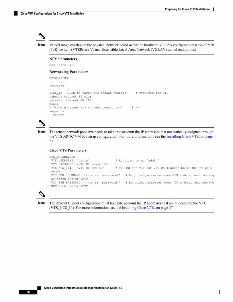
VLAN range overlap on the physical network could occur if a hardware VTEP is configured on a top of rack(ToR) switch. (VTEPs are Virtual Extensible Local Area Network (VXLAN) tunnel end points.)
Note
NFV ParametersNFV_HOSTS: ALL
Networking ParametersNETWORKING:
...networks:... -vlan_id: <VLAN to carry VTS tenant traffic> # required for VTSsubnet: <subnet IP cidr>gateway: <tenant GW IP>pool:- "<begin tenant IP> to <end tenant IP>" # ***segments:- tenant
The tenant network pool size needs to take into account the IP addresses that are statically assigned throughthe VTS XRNC VM bootstrap configuration. For more information , see the Installing Cisco VTS, on page57
Note
Cisco VTS ParametersVTS_PARAMETERS:VTS_USERNAME: 'admin' # Required to be 'admin'VTS_PASSWORD: <VTC UI password>VTS_NCS_IP: <VTC mx-net IP> # VTC mx-net VIP for VTC HA (cannot be in mx-net poolrange)VTC_SSH_USERNAME: '<vtc_ssh_username>' # Required parameter when VTS enabled and runningNFVbench and/or VMTPVTC_SSH_PASSWORD: '<vtc_ssh_password>' # Required parameter when VTS enabled and runningNFVbench and/or VMTP
The mx-net IP pool configuration must take into account the IP addresses that are allocated to the VTC(VTS_NCS_IP). For more information, see the Installing Cisco VTS, on page 57
Note
Cisco Virtualized Infrastructure Manager Installation Guide, 2.056
Preparing for Cisco NFVI InstallationCisco VIM Configurations for Cisco VTS Installation

C H A P T E R 5Installing Cisco VTS
If your Cisco NFVI package includes Cisco Virtual Topology System, the following topics tell you how toinstall Cisco VTS for use with Cisco NFVI. The Cisco VTS installation procedures are customized for CiscoNFVI from the standard Cisco VTS 2.3 installation procedures located on the Cisco VTS product site. Youmust install Cisco VTS before you install Cisco VIM.
• Overview to Cisco VTS Installation in Cisco NFVI, on page 57• System Requirements for VTC VM, on page 60• System Requirements for IOS XRv VM, on page 61• System Requirements for VTF, on page 61• Supported Virtual Machine Managers, on page 62• Supported Platforms, on page 62• Installing Cisco VTS in a Cisco NFVI Environment, on page 64• Installing the XRNC and XRv VMs, on page 68• Verifying Cisco VTS Installation in Cisco NFVI, on page 71• Configuring Cisco VTS and XRVR After Installation, on page 73• Installing VTS in an HA Configuration, on page 75• Sample Cisco VTS Configurations for Cisco NFVI, on page 79
Overview to Cisco VTS Installation in Cisco NFVIThe Cisco Virtual Topology System (VTS) is an overlay management and provisioning system for data centernetworks. It automates data center overlay fabric provisioning for both physical and virtual workloads. Itprovides a policy-based approach for overlay provisioning, and can be used for multitenant data centers forcloud services, including Cisco NFVI.
To install Cisco VTS with Cisco NFVI, you must manually install the Cisco VTS Virtual Topology Controller(VTC) and its XRNC and XRVR VMs before you start the Cisco VIM installation. The VTC and XRNCVMs must be run on an independent pair of servers, that is, not on a Cisco NFVI control, compute, storage,or management node. You set up the networking on those servers as described below and outlined in theinstallation procedures. When you run the Cisco VIM installer, you will provide the VTCVIP and appropriateVTS credentials.
The following figure shows how Cisco VTS Virtual Topology Controller (VTC) and the IOS XRv (XRNCand XRVR) virtual machines (VMs) connect to the Cisco NFVI networks.
Cisco Virtualized Infrastructure Manager Installation Guide, 2.057

Figure 28: Cisco VTS Connectivity to Cisco NFVI
The following table maps Cisco VTS network names to Cisco VIM network names.
Table 6: Cisco VTS to Cisco VIM Network Name Mapping
Cisco VIM Network NameCisco VTS Network NameCisco VTS VM
API (a)Management NetworkVTC
Management/Provision (mx)Underlay NetworkVTC
Management/Provision (mx)Management NetworkXRNC/XRVR
Tenant (t)Underlay NetworkXRNC/XRVR
The following table describes the required IP address allocations for VTS components.
Table 7: Cisco VTS IP Address Allocations
DescriptionRequired Cisco VTS IP AddressesCisco VIM Network
Set up in the VTC config.iso andcluster.conf
3 total (1 VIP + 1 IP per VTC VM)API (a)
Cisco Virtualized Infrastructure Manager Installation Guide, 2.058
Installing Cisco VTSOverview to Cisco VTS Installation in Cisco NFVI

DescriptionRequired Cisco VTS IP AddressesCisco VIM Network
Set up in XRNC config.iso andXRNC_HA.sh
Note: VTS component IP addressescannot overlap with the pool rangesconfigured in the Cisco VIMsetup_data.yaml.
• 7 total—Three for VTC (oneVTCVIP and one IP per VTCVM)
• Four for XRNC: one IPaddress pair perXRNC/XRVR VM, one IPaddress for XRVR and theother to XRNC
Management/Provisioning (mx)
Set up in XRNC config.iso
Note: The VTS component IPscannot overlap with pool rangesconfigured in the Cisco VIMsetup_data.yaml.
4 total—(one IP address pair perXRNC/XRVRVM, one IP addressgoes to the XRVR tenant interfaceand other to XRNC tenant interface
Tenant (t)
The VTS IP distribution and setup mechanism are listed below.
VIM API network
• VTC1—api (a) network IP1 (associated through the VTC1 config ISO)
• VTC2—api (a) network IP2 (associated through the VTC2 config ISO)
• VTC VIP—api (a) network IP3 (associated through the HA step cluster.conf)
VIMManagement/Provisioning network
• VTC1—management/provisioning (mx) network IP1 (associated through the VTC1 config ISO)
• VTC2—management/provisioning (mx) network IP2 (associated through the VTC2 config ISO)
• VTC VIP—management/provisioning (mx) network IP3 (associated through the HA step cluster.conf)
• XRNC/XRv 1—management/provisioning (mx) network IP4 (associated through the XRNC-1 configISO)
• XRNC/XRv 2—management/provisioning (mx) network IP5 (associated through the XRNC-2 configISO)
• XRNC/XRv VIP—management/provisioning (mx) network IP6 (associated through the XRNC-1 & 2config ISOs)
VIM Tenant network:
• XRNC/XRv 1—tenant (t) network IP1 (associated through the XRNC-1 config ISO)
• XRNC/XRv 2—tenant (t) network IP2 (associated through the XRNC-2 config ISO)
• XRNC/XRv VIP—tenant (t) network IP3 (associated through the XRNC-1 & 2 config ISOs)
Cisco Virtualized Infrastructure Manager Installation Guide, 2.059
Installing Cisco VTSOverview to Cisco VTS Installation in Cisco NFVI

Cisco VTS Usernames and Passwords in Cisco NFVIThe following table lists the Cisco VTS usernames and passwords that are employed after you install CiscoVTS in Cisco NFVI.
Table 8: Cisco VTS Usernames and Passwords in Cisco NFVI
Description/CommentsValue RequirementsConfiguration Location
Used by VTF to register with theVTC / XRNC.
VTS_USERNAMEmust be admin
VTS_PASSWORD must matchVTC UI login password for theadmin user. Password must have aminimum of 8 characters and atleast one uppercase letter, one digit,and one special character.
mercury:openstack-configs/setup_data.yaml
VTS_PARAMETERS:
VTS_USERNAME
VTS_PASSWORD
Configures VTC admin user initialpassword.
Must match the Cisco VIMsetup_data.yamlVTS_PASSWORD parameter.
VTC ISO config.txt :vts-adminPassword
SSH username/password for VTCVM
SSH username/password for VTCVM
VTC ISO config.txt :
AdministrativeUser
AdministrativePassword
XRNCVMssh username/passwordusername cannot matchXRVR_USERNAME
PASSWORD_HASH must begenerated from: openssl passwd -1-salt xxx <password>
XRNC ISO:
USERNAME
PASSWORD_HASH
XRVR VM SSHusername/password
The XRVR adds this in VTSInventory > Authorization Group> vtsgroup3 Device User Nameassociated with VTC admin user
username cannot matchUSERNAME
XRNC ISO:
XRVR_USERNAME
XRVR_PASSWORD_HASH
System Requirements for VTC VMThe following table provides information about theminimum system requirements for the VTC virtual machine:
DetailsRequirement
48 GBDisk space
8CPU
16 GBMemory
Cisco Virtualized Infrastructure Manager Installation Guide, 2.060
Installing Cisco VTSCisco VTS Usernames and Passwords in Cisco NFVI

DetailsRequirement
Certified with Cisco UCS B-series, Cisco UCSC-series Rack Servers
Computing Host
• VMware ESXi 5.5• VMware ESXi 6.0U1 or later
• Red Hat Enterprise Linux 7.1 with KVM
Hypervisor
System Requirements for IOS XRv VMThe following table gives details about the minimum system requirements for the IOS XRv virtual machine:
The IOS XRv VM serves two purposes. It is required to enable VTS High Availability. It also acts as thecontrol plane for the VTF. You need to install IOS XRv only if you consider enabling High Availability orif you plan to have a VTF in your set up.
Note
DetailsRequirement
Primary disk must be 2 GB.Disk Space
6CPUs
32 GB RAMMemory
Certified with Cisco UCS B-series,Cisco UCS C-series Rack Servers
Computing Host
• VMware ESXi 5.5 orVMwareESXi 6.0
• Red Hat Enterprise Linux 7.1with KVM
Hypervisor
System Requirements for VTFThe following table gives details about the minimum system requirements for the VTF virtual machine:
This section is applicable only if you have VTFs in your setup.Note
DetailsRequirement
8 GBDisk Space
Cisco Virtualized Infrastructure Manager Installation Guide, 2.061
Installing Cisco VTSSystem Requirements for IOS XRv VM

2CPU Cores
16 GB RAMMemory
• VMware ESXi 5.5 orVMwareESXi 6.0
• Red Hat Enterprise Linux 7.1with KVM
Hypervisor
Intel DPDK-supported NICServer network interface card (NIC)
For details about the requirements to install VTF in vhost mode, you must have Red Hat Enterprise Linux 7.2running on the host machine. Additional requirements are: VICDetails-CiscoUCSVIC 1225,1227, and 1385.
Supported Virtual Machine ManagersCisco VTS can be installed on the following supported versions of VMMs:
• OpenStack
• VMware vCenter
Supported PlatformsThe following tables provide information about the platforms that Cisco VTS support, and their roles.
VTS supports VXLAN overlays using the BGP EVPN control plane.Note
Platform SupportedRole
• Cisco Nexus 9300TX and 9300PX platformswitches
• Cisco Nexus 9332PQ and 93128TX switches
• Cisco Nexus 9200 platform switches
• Cisco Nexus 5600 platform switches
• Cisco Nexus 9500 platform switches
• Cisco Nexus 7x00 platform switches
Top-of-rack (ToR) leaf switch
Cisco Virtualized Infrastructure Manager Installation Guide, 2.062
Installing Cisco VTSSupported Virtual Machine Managers

• Cisco Nexus 9300TX and 9300PX platformswitches
• Cisco Nexus 9500 platform switches
• Cisco Nexus 9200 platform switches
• Cisco Nexus 7x00 Series switches
• Cisco Nexus 5600 platform switches
Data center spine
• Cisco Nexus 9300TX and 9300PX platformswitches
• Cisco Nexus 9500 platform switches
• Cisco Nexus 9200 platform switches
• Cisco Nexus 5600 platform switches
• Cisco Nexus 7x00 platform switches
Border leaf
• Cisco ASR 9000 Series Aggregation Servicesrouters
• Cisco Nexus 7x00 Series switches
• Cisco Nexus 9300 platform switches
Data center interconnect (DCI)
• Cisco Nexus C2248TP-E9500
• Cisco Nexus C2232PP
FEX support is available for Cisco Nexus 9300, CiscoNexus 5600, CiscoNexus 9500 and CiscoNexus 7x00switches.
Fabric Extenders (FEX)
• VMware ESXi 5.5; VMware ESXi 6.0
• Red Hat Enterprise Linux 7.1 with KVM
Hypervisor
Cisco Nexus 5672 does not interoperate with Cisco Nexus 93xx or 95xx.Note
The following table lists the software images supported for the different devices.
Table 9: Software Images Supported
NX OS Release 7.0(3)I2(2a) or 7.0(3)I2(2c)Cisco Nexus 93xx
NX OS Release 7.0(3)I1(1b).Cisco Nexus 95xx
Cisco Virtualized Infrastructure Manager Installation Guide, 2.063
Installing Cisco VTSSupported Platforms

• Data center spine —For Cisco Nexus 7000—7.3(0)D1(1); For CiscoNexus 7700—7.3(0)DX(1)
• Data center interconnect (DCI):
• VRF Peering mode—NX OS Release 7.3.1 and later.• Integrated DCI mode—NX OS Release 7.3.1 and later.
Cisco Nexus 7x00
NX OS Release 7.3(0)N1(1) and later.Cisco Nexus 5600
Cisco IOS XR Software Release 5.3.2 and later.Cisco ASR 9000
The following table lists the VPC modes supported for the different devices.
If Cisco Nexus 9000 series ToR is not configured with vPC related configuration, including peer-link,also known as a multichassis etherChannel trunk (MCT), you must not configure feature vpc on theToR. This may bring loopback interface used for NVE to admin down state.
Note
Table 10: VPC Modes Supported
Server VPCCisco Nexus 93xx
Server VPCCisco Nexus 95xx
Server VPC, FEX VPC, Enhanced VPCCisco Nexus 5600
Host VPC and single-homed host in port channel mode.Cisco Nexus 7000
Installing Cisco VTS in a Cisco NFVI EnvironmentInstalling Cisco VTS inside Cisco NFVI involves installing the Virtual Topology Controller (VTC) VM. Youcan install the VTC VM using either the automatic or manual configuration options.
• To install the VTC VM using an ISO file (auto configuration), see Installing VTC VM - AutomaticConfiguration Using ISO File, on page 64.
• To install the VTC VM using the virt-manager application (manual configuration), see Installing VTCVM - Manual Configuration Using virt-manager, on page 66.
• To install the VTC VM using VNC (manual configuration), see Installing VTC VM - ManualConfiguration using VNC, on page 67
Installing VTC VM - Automatic Configuration Using ISO FileTo install a VTC VM and enable configuration using an ISO file, create a text file with the VM settings, wrapthe text file in an ISO file, and then attach the ISO file to the VM CD drive.
Step 1 Connect to the controller node via SSH, and copy the vtc.qcow2 file to /var/lib/libvirt/images/ folder.Step 2 Copy the vtc.sample.xml file to your controller. The Sample Cisco VTS Configurations for Cisco NFVI, on page 79
topic provides the file contents.
Cisco Virtualized Infrastructure Manager Installation Guide, 2.064
Installing Cisco VTSInstalling Cisco VTS in a Cisco NFVI Environment

Step 3 Create a config.txt file containing the following parameters:
Hostname=vtcManagementIPv4Method=StaticManagementIPv4Address= <VM's a-net IP address in a.b.c.d form>ManagementIPv4Netmask= <a-net IP mask in a.b.c.d form>ManagementIPv4Gateway= <a-net gateway IP address in a.b.c.d form>UnderlayIPv4Method=StaticUnderlayIPv4Address= <VM's mx-net IP address in a.b.c.d form>UnderlayIPv4Netmask=<mx-net IP mask in a.b.c.d form>DNSv4=<DNS server--ie. setup_data.yaml::NETWORKING['domain_name_servers'][0]>Domain=<domain name--ie. setup_data.yaml::NETWORKING['domain_name']>NTPv4=<NTP server--ie. setup_data.yaml::NETWORKING['ntp_servers'][0]>vts-adminPassword=<password for user 'admin'--setup_data.yaml::VTS_PARAMETERS['VTS_PASSWORD']>AdministrativeUser=<VM ssh login user--can be setup_data.yaml::VTS_PARAMETERS['VTS_USERNAME']>AdministrativePassword=<VM ssh login user--can be setup_data.yaml::VTS_PARAMETERS['VTS_PASSWORD']>
The config.txt file must have a blank line at the end.Note
Before entering the VTS_PASSWORD, review Cisco VTS Usernames and Passwords in Cisco NFVI, on page60.
Note
Parameter descriptions:
• Hostname—The VM hostname.
• ManagementPv4Method—Whether to use DHCP or static addressing for the Cisco NFVI API network (a-net)interface (eth0).
• ManagementIPv4Address—The api (a) network IPv4 address of the VM (required only for static addressing).
• ManagementIPv4Netmask—The a network IPv4 netmask of the VM (required only for static addressing).
• ManagementIPv4Gateway—The a network API IPv4 gateway of the VM (required only for static addressing).
• UnderlayIPv4Method—Whether to use DHCP or static addressing for the Cisco NFVI management/provisioning(mx) network interface (eth1).
• UnderlayIPv4Address—The mx network IPv4 address of the VM (required only for static addressing).
• UnderlayIPv4Netmask—The mx network IPv4 netmask of the VM (required only for static addressing).
• DNSv4—DNS IPv4 address (required only for static addressing).
• Domain—DNS search domain (required only for static addressing).
• NTPv4—NTP IPv4 address or FQDN (required only for static addressing).
• vts-adminPassword—Password for the vts-admin user. This should match the value insetup_data.yaml::VTS_PARAMETERS['VTS_PASSWORD'] or subsequently changed through the VTC UI tomatch the value in setup_data.yaml::VTS_PARAMETERS['VTS_PASSWORD']
• AdministrativeUser—New administrative user for login using SSH.
• AdministrativePassword—Password for the new administrative user.
Step 4 Use mkisofs to create an ISO file, for example:mkisofs -o config.iso config.txt
Cisco Virtualized Infrastructure Manager Installation Guide, 2.065
Installing Cisco VTSInstalling VTC VM - Automatic Configuration Using ISO File

Step 5 Create the VTC VM using following command:virsh create vtc.sample.xml
Installing VTC VM - Manual Configuration Using virt-managerTo install the VTC VM configuring it manually using the virt-manager application:
Step 1 Connect to the controller node via SSH, and copy the vtc.qcow2 file to /var/lib/libvirt/images/ folder.Step 2 Copy the Cisco NFVI vtc.sample.xml file to your controller. Modify it as per your setup. See Sample Cisco VTS
Configurations for Cisco NFVI, on page 79 for examples.Step 3 Create the VTC VM using following command:
virsh create vtc.sample.xml
Step 4 Run the command:virsh list --all
It should display:Id Name State--------------------------------------------------2 VTC running
Step 5 Start virt-manager. Run:virt-manager
Step 6 After the virt-manager window opens, click the VTC VM to open up the VTC VM console.
The console displays an installation wizard that takes you through the initial VTC VM configuration.
Step 7 Enter the following:
For items that take multiple values, such as DNS and NTP, each value must be separated by a space.Note
• VTS Hostname
• DHCP / Static IP configuration for static IP
• Management IP address for VTC—This is the Cisco NFVI api (a) network IP address.
• Management IP Netmask (api network)
• Management Gateway address (api network)
• DNS Address—One of the DNS servers in setup_data.yaml::NETWORKING['domain_name_servers'
• DNS Search domain—-- setup_data.yaml::NETWORKING['domain_name']
• Underlay IP address—This is the IP address for Cisco NFVI management/provisioning (mx) network.
• Underlay IP Netmask (mx network)
• NTP address—One of the setup_data.yaml::NETWORKING['ntp_servers'] addresses
Cisco Virtualized Infrastructure Manager Installation Guide, 2.066
Installing Cisco VTSInstalling VTC VM - Manual Configuration Using virt-manager

• Password change for user vts-admin—Enter the default user vts-admin password. The vts-admin user is used forpassword recovery and to revisit a configuration screen if you make a mistake or need to change the information.If you log in to the VTC VM using vts-admin username and password again, you will get the same dialog to gothrough the VTC VM setup again. The password must match the value insetup_data.yaml::VTS_PARAMETERS['VTS_PASSWORD'] or subsequently changed through the VTC UI tomatch the value in setup_data.yaml::VTS_PARAMETERS['VTS_PASSWORD']
Before entering the VTS_PASSWORD, reviewing Cisco VTS Usernames and Passwords in Cisco NFVI, on page60 is recommended.
• Administrator User—Enter administrative username and password. This username and password are used to loginto the VM via SSH.
• Password for administrator user
VTC VM reboots at this time. Wait for two minutes for the VTC VM to be up. You can ping the IP address given forVTC VM in the setup process to verify whether the VTC VM is up.
Step 8 SSH into VTC VM using the IP address, administrative username/password given in the setup process (not vts-adminuser).
Installing VTC VM - Manual Configuration using VNCIf the server where you will install VTC is in a remote location with network latency or low bandwidth, youcan use VNC to access the VTC VM and manually configure it using the CTC VM graphic console. To dothis:
Step 1 Connect to the controller node via SSH, and copy the vtc.qcow2 file to /var/lib/libvirt/images/ folder.Step 2 Copy the vtc.sample.xml file to your controller. Modify it as per your setup. The sample VTCXML file output is provided
in Sample Cisco VTS Configurations for Cisco NFVI, on page 79.Step 3 Replace the following sections of the vtc.sample.xml file:
<graphics type='spice' port='5900' autoport='yes' listen='127.0.0.1'><listen type='address' address='127.0.0.1'/>
</graphics>
with the following:<graphics type='vnc' port='5900' autoport='yes' listen='0.0.0.0'>
<listen type='address' address='0.0.0.0'/></graphics>
Setting the listen address to 0.0.0.0 allows external clients to connect to the VNC port (5900). You will alsoneed to make sure that iptables configuration (if any) allows inbound TCP port 5900 connections.
Note
Step 4 Create the VTC VM using following command:virsh create vtc.sample.xml
You should now be able to use a VNC client to connect to the VTC VM graphic console and continue the setup.
Step 5 Enter the following:
For items that take multiple values, such as DNS and NTP, use a space to separate each value.Note
Cisco Virtualized Infrastructure Manager Installation Guide, 2.067
Installing Cisco VTSInstalling VTC VM - Manual Configuration using VNC

• VTS Hostname
• DHCP/Static IP configuration for static IP
• Management IP address for VTC—This is the Cisco NFVI api (a) network IP address.
• Management IP Netmask (api network)
• Management Gateway address (api network)
• DNS Address—One of the DNS servers in setup_data.yaml::NETWORKING['domain_name_servers'
• DNS Search domain—-- setup_data.yaml::NETWORKING['domain_name']
• Underlay IP address—This is the IP address for Cisco NFVI management/provisioning (mx) network.
• Underlay IP Netmask (mx network)
• NTP address—One of the setup_data.yaml::NETWORKING['ntp_servers'] addresses
• Password change for user vts-admin—Enter the default user vts-admin password. The vts-admin user is used forpassword recovery and to revisit a configuration screen if you make a mistake or need to change the information.If you log into the VTC VM using vts-admin username and password again, you will get the same dialog to gothrough the VTC VM setup again. This should match the value insetup_data.yaml::VTS_PARAMETERS['VTS_PASSWORD'] or subsequently changed through the VTC UI tomatch the value in setup_data.yaml::VTS_PARAMETERS['VTS_PASSWORD']
• Administrator User—Enter administrative username and password. This username and password are used to loginto the VM via SSH.
• Password for administrator user.
VTC VM reboots at this time. Wait for two minutes for the VTC VM to come up. You can ping the IP address given forVTC VM in the setup process to verify whether the VTC VM is up.
Step 6 SSH into VTC VM using the IP address, administrative username/password given in the setup process (not vts-adminuser).
Installing the XRNC and XRv VMsBefore you can install Cisco VTS for Cisco NFVI, you must install the IOS XRv VM and register it to VTS.IOS XRv VM is the control plane VM. Installing and registering the IOS XRv VM requires you to completethe following procedures:
• Creating an IOS XRv VM , on page 68
• Creating an ISO for IOS XRv, on page 70
Creating an IOS XRv VMThe IOS XRv VM is essential to the Virtual VTEP topology. The IOS XRv VM contains a nested VM so IOSXRv must enable nesting.
Cisco Virtualized Infrastructure Manager Installation Guide, 2.068
Installing Cisco VTSInstalling the XRNC and XRv VMs

Before you begin
Youmust complete a VTS VM installation, and the VTCUI initial password must be changed to the passwordthat you will enter for Cisco VIM when you install Cisco VIM. This password is set in setup_data.yaml orthe Cisco VIM Insight.
Setting up Nested VM in RedHatThis has been verified with RedHat 7.1 OSP.
Step 1 Run cat /sys/module/kvm_intel/parameters/nested.Step 2 If the output is N, shut down all active VMs, then enable the nested KVM feature:
echo "options kvm-intel nested=1" | sudo tee /etc/modprobe.d/kvm-intel.confrmmod kvm_intelmodprobe kvm_intel
Step 3 Run cat /sys/module/kvm_intel/parameters/nested and verify that it gives Y.
Bringing up the KVM-based IOS XRv VM
Step 1 Create the IOS XRv VM XML referring the Cisco NFVI sample (XRNC.XML).Step 2 Generate an ISO file for the IOS XRv. See Creating an ISO for IOS XRv, on page 70.Step 3 Create the VM using the XML.
virsh create XRNC.xml
Deploying the vCenter-based IOS XRv VM
Step 1 Generate an ISO file for the IOS XRv VM. See Creating an ISO for IOS XRv, on page 70.Step 2 In the vSphere Client, select File > Deploy OVF Template. The Deploy OVF Template wizard appears.Step 3 Select XRNC.ova from the source location, and click Next. The OVF template details are displayed.Step 4 Click Next to specify the destination. Enter the following details:
• Name for the VM.
• Folder or datacenter where the VM will reside.
Step 5 Click Next to select the storage location to store the template files. You do not need to change the default values forvirtual disk format and VM Storage Policy.
Step 6 ClickNext to set up the networks. Specify the first network as the Underlay (Cisco NFVI t-net) Network and the secondnetwork as the Management (Cisco NFVI mx-net) Network.
Step 7 Click Next. Review the settings selections.Step 8 Click Finish to start the deployment.
Cisco Virtualized Infrastructure Manager Installation Guide, 2.069
Installing Cisco VTSSetting up Nested VM in RedHat

Step 9 After the deployment is complete, edit the VM settings. Add a CD/DVD Drive selecting Datastore ISO file and pointto the XRNC.iso file that was generated and uploaded to the host.
Step 10 Power on the VM.
Running the Setup ScriptRun the setup script on the IOS XRv to complete the configuration:
Before you begin
Ensure the tenant network (t) gateway and management network (mx) gateway are reachable from the XRNCserver.
SSH into your IOS XRv.
• If you do not want to run in High Availability mode, run the setup script as in the below example:cisco@XRVR-DL1:~$ sudo /opt/cisco/package/sr/bin/setupXRNC_HA.sh 0.0.0.0
• If you do want to run in HA mode, see the Installing VTS in an HA Configuration, on page 75 procedure.
Creating an ISO for IOS XRvTo create an ISO file for IOS XRv:
Step 1 Create the system.cfg file based on the sample below.
Verify that the configuration files has no spaces or extra characters.Note
Before you enter the VTS_USERNAME andVTS_PASSWORD, reviewCisco VTSUsernames and Passwordsin Cisco NFVI, on page 60.
Note
# This is a sample day0 configuration file# Copyright (c) 2015 cisco Systems
# VTS InformationVTS_ADDRESS=" <VTC's mx-net VIP address in a.b.c.d form>"VTS_REGISTRATION_USERNAME=" < must match VTS_PARAMETERS.VTS_USERNAME >"VTS_REGISTRATION_PASSWORD=" <must match VTS_PARAMETERS.VTS_PASSWORD >!"
# VTC/VTF Network ConfigurationHOSTNAME="DL-XRVR6"NTP_SERVER=" <NTP server--ie. setup_data.yaml::NETWORKING['ntp_servers'][0]>"NETWORK_CONFIG_METHOD="static"NETWORK_NAMESERVER_IP=" <DNS server--ie. setup_data.yaml::NETWORKING['domain_name_servers'][0]>"UNDERLAY_NETWORK_CONFIG_METHOD="static"UNDERLAY_NETWORK_IP_ADDRESS=" <VM's t-net IP address in a.b.c.d form>"UNDERLAY_NETWORK_IP_NETMASK=" <t-net IP mask in a.b.c.d form>"#NETWORK_IP_NETMASK=24UNDERLAY_NETWORK_IP_GATEWAY=" t-net gateway IP address in a.b.c.d form>"
MGMT_NETWORK_CONFIG_METHOD="static"
Cisco Virtualized Infrastructure Manager Installation Guide, 2.070
Installing Cisco VTSRunning the Setup Script

MGMT_NETWORK_IP_ADDRESS=" <VM's mx-net IP address in a.b.c.d form>"MGMT_NETWORK_IP_NETMASK=" <mx-net IP mask in a.b.c.d form>"MGMT_NETWORK_IP_GATEWAY=" <mx-net gateway IP address in a.b.c.d form>"
ALL_VTFS_MODE="vhost"
# VTC/VTF Admin user/password hash# Generate with openssl passwd -1 -salt <salt> <password># cisco/cisco123 PASSWORD_HASH='$1$xxx$J3aa90XAPYg6HSNUUUD2o1'USERNAME='cisco'PASSWORD_HASH='$1$xxx$J3aa90XAPYg6HSNUUUD2o1'
# XRVR Specific Settings (VTC only)XRVR_USERNAME="admin"XRVR_PASSWORD="cisco123"XRVR_STATIC_MGMT_IP=" <XRVR's mx-net VIP address in a.b.c.d/prefixlen form>"XRVR_STATIC_UNDERLAY_IP=" <XRVR's t-net VIP address in a.b.c.d/prefixlen form>"XRVR_NAME=" <XRVR VM instance's hostname>"XRVR_BGP_COMMUNITY=" <VNI range for VTS to use>"
The IOS XRv login/password is hard coded to admin/cisco123.Note
Step 2 Copy your IOS XRv system.cfg files to the same path where the script resides. For example:admin:/opt/cisco/package/vts/bin$ ls -ltotal 1432-rwxr-xr-x 1 vts-admin vts-admin 4767 Sep 29 16:40 build_vts_config_iso.sh-rw-r--r-- 1 root root 1242 Sep 29 23:54 system.cfg
Step 3 Create the ISO file as shown below (you need to log in as root):root:/opt/cisco/package/vts/bin# ./build_vts_config_iso.sh xrnc system.cfgValidating input.Generating ISO File.Done!
Step 4 Spawn the IOS XRv VM with the ISO connected to it.Step 5 Power on the VM.
In case you spawn a new IOS XRv VM later, it will come up with IOS XRv Day Zero configuration and get reregisteredwith the VTC. Use the sync-to option available in the Config Sync feature to synchronize the configuration with thelatest VTC configuration. See the Synchronizing Configuration section in theCisco VTSUser Guide for more informationon this feature.
Verifying Cisco VTS Installation in Cisco NFVIThe following procedures provide information about how to verify the Cisco VTS installation in Cisco NFVI.
Verifying VTC VM InstallationTo verify VTC VM installation:
Cisco Virtualized Infrastructure Manager Installation Guide, 2.071
Installing Cisco VTSVerifying Cisco VTS Installation in Cisco NFVI

Step 1 Log into the VTC VM just created using the VTC VM console.
• If you installed the VTC VM in a VMware environment, use the VM console.• If you installed the VTC VM in an RedHat KVM based-OpenStack environment, - telnet 0 <console-port> (Theconsole port is the Telnet port in the VTC.xml file.)
Step 2 Ping the Cisco NFVI api network gateway.
If ping fails, verify the VM networking to the Cisco NFVI api network.
Step 3 For the VTC VM CLI, ping the Cisco NFVI management/provisioning (mx) network gateway.
If ping fails, verify VM networking to the mx network.
Underlay network gateway is the switched virtual interface (SVI) created for IOSXRv and VTF on the leafwhere the controller is connected.
Note
Step 4 After a few minutes, verify whether the VTS UI is reachable by typing in the VTS api network IP in the browser.
Verifying IOS XRv VM InstallationTo verify ISO XRv VM installation:
Before you begin
Ensure the tenant network (t) gateway and management network (mx) gateway are reachable from the XRNCserver.
Step 1 Log into the IOS XRv VM using the VTC VM console.
• If you installed the VTC VM in a VMware environment, use the VM console.• If you installed the VTC VM in an RedHat KVM based-OpenStack environment, use virt-manager or VNC consoleto log into the VM. See Installing VTC VM - Manual Configuration using VNC, on page 67
Step 2 Ping the Cisco NFVI tenant (t) network gateway IP address.
In case ping fails, verify Cisco NFVI tenant network.
Step 3 Ping the VTC Cisco NFVI management/provisioning (mx) network IP address.
In case ping fails, verify the mx network.
You should be able to ping the gateway IP address for both Cisco NFVI mx and t networks, as XRv registersto the VTC using the VTC mx network IP address.
Note
Step 4 Run virsh list to make sure the nested VM is running.Step 5 Verify whether the nested IOS XRv is booting up. To do this, run:
telnet 0 5087
If the o/p command fails, verify whether nested virtualization on the host where IOSXRv is booted is turned on.
Also, verify that another Telnet session is not using this session.
Cisco Virtualized Infrastructure Manager Installation Guide, 2.072
Installing Cisco VTSVerifying IOS XRv VM Installation

Step 6 Verify whether the Virtual Forwarding Group (VFG) group is created on the VTS GUI and IOSXRv is part of the VFGgroup.
Step 7 On the XRv shell, run the setup command:sudo /opt/cisco/package/sr/bin/setupXRNC_HA.sh 0.0.0.0
For HA installations, replace 0.0.0.0 with the underlay IP address of the second IOSXRv.
Troubleshooting VTF RegistrationIf VTF registration issues arise, you can use the following commands to find the VTF registration logs oneach Cisco NFVI compute node:[root@devstack-71 neutron]# docker exec -it neutron_vtf_4269 bash[root@devstack-71 /]# cd /var/log/vpfa[root@devstack-71 vpfa]# lsvpfa_err.log vpfa_med.log vpfa_server.log vpfa_server_frequent.log vpfa_stdout.log
vpfa_freq.log vpfa_reg.log vpfa_server_errors.log vpfa_server_slow.log[root@devstack-71 vpfa]# tail vpfa_reg.log2016-06-23 02:47:22,860:INFO:VTF-REG: Sent PATCH {"vtf": {"username": "admin","vpp-client-name": "devstack-71", "ip": "34.34.34.5", "binding-host-name": "devstack-71","gateway-ip": "34.34.34.1", "local-mac": "00:3a:7d:6a:13:c9"}} tohttps://172.18.96.15:8888/api/running/cisco-vts/vtfs/vtf2016-06-23 02:47:23,050:INFO:VTF-REG-ERR: Failure:400!!!
A successful log example is shown below:[root@devstack-71 vpfa]# tail vpfa_reg.log2016-06-23 15:27:57,338:INFO:AUTH: Successful Login - User: adminURI:/yang-api/datastore/interfaces Host:IPv4Address(TCP, '34.34.34.5', 21345) Method:GET2016-06-23 15:28:07,340:INFO:AUTH: Successful Login - User: adminURI:/yang-api/datastore/interfaces Host:IPv4Address(TCP, '34.34.34.5', 21345) Method:GET
If a VTF registration fails, check the following:
• IP network connectivity between the compute nodes and the VTC and XRNC/XRVR VMs (Cisco NFVItenant and management/provisioning networks)
• VTS_PARAMETERS—The VTS_USERNAME must be admin.
• The VTC and XRNC/XRVR must be up and the VTS configurations (described in Configuring CiscoVTS and XRVR After Installation, on page 73) must be applied. The XRVR must be registered withVTC.
• Check that the VTS UI shows "vtsgroup3" in Inventory->Authorization Groups.
• Check that the VTC Admin Username is admin and Device Username is what was set forXRVR_USERNAME in the XRNC config ISO.
Configuring Cisco VTS and XRVR After InstallationThe following steps cover the Cisco VTS configurations you need to provision after installation.
Cisco Virtualized Infrastructure Manager Installation Guide, 2.073
Installing Cisco VTSTroubleshooting VTF Registration

Step 1 If you changed the Cisco VTS username/password when you configured the VTS HA configuration, continue with Step3. If not, log into the Cisco VTS GUI using the default username/password admin/admin.
Step 2 Change the Cisco VTS password using the UI Change Password tab.
Before you enter the Cisco VTS password, review Cisco VTS Usernames and Passwords in Cisco NFVI, onpage 60.
Note
Step 3 Log into the Linux CLI using SSH then use the ncs_cli to set the following parameters:configureset resource-pools vni-pool vnipool range 4096 65535set devices device <XRVR-NAME> asr9k-extension:device-info device-use leafset devices device <XRVR-NAME> asr9k-extension:device-info bgp-peering-info bgp-asn 23set devices device <XRVR-NAME> asr9k-extension:device-info bgp-peering-info loopback-if-num 0
Step 4 After the VTF registers, add the following configurations:set cisco-vts infra-policy admin-domains admin-domain D1 l2-gateway-groups l2-gateway-group L2GW-0devices
device <XRVR-NAME>set cisco-vts infra-policy admin-domains admin-domain D1 l2-gateway-groups l2-gateway-group L2GW-0policy-parameters
distribution-mode decentralized-l2set cisco-vts infra-policy admin-domains admin-domain D1 l2-gateway-groups l2-gateway-group L2GW-0policy-parameters
control-plane-protocol bgp-evpnset cisco-vts infra-policy admin-domains admin-domain D1 l2-gateway-groups l2-gateway-group L2GW-0policy-parameters
arp-suppressionset cisco-vts infra-policy admin-domains admin-domain D1 l2-gateway-groups l2-gateway-group L2GW-0policy-parameters
packet-replication ingress-replicationset cisco-vts infra-policy admin-domains admin-domain D1 l3-gateway-groups l3-gateway-group L3GW-0policy-parameters
distribution-mode decentralized-l3set cisco-vts infra-policy admin-domains admin-domain D1 l3-gateway-groups l3-gateway-group L3GW-0policy-parameters
control-plane-protocol bgp-evpnset cisco-vts infra-policy admin-domains admin-domain D1 l3-gateway-groups l3-gateway-group L3GW-0policy-parameters
arp-suppressionset cisco-vts infra-policy admin-domains admin-domain D1 l3-gateway-groups l3-gateway-group L3GW-0policy-parameters
packet-replication ingress-replicationset cisco-vts infra-policy admin-domains admin-domain D1 l2-gateway-groups l2-gateway-group L2GW-0ad-l3-gw-parent L3GW-0
Step 5 Enter the BGP configuration for XRVI:some IGPouter ospf 100router-id 18.18.18.18address-family ipv4 unicastarea 0.0.0.0default-cost 10interface Loopback0!interface GigabitEthernet0/0/0/0!
Cisco Virtualized Infrastructure Manager Installation Guide, 2.074
Installing Cisco VTSConfiguring Cisco VTS and XRVR After Installation

!!interface Loopback0ipv4 address 8.8.8.8 255.255.255.255!
router bgp 23bgp router-id 8.8.8.8address-family ipv4 unicast!address-family l2vpn evpnretain route-target all
!After you add this BGP info in the XRVR you will need to sync the devices via the ncs_cli
ncs_cli > request devices device <XRVR-NAME> sync-from
Installing VTS in an HA ConfigurationComplete the following steps to install Cisco VTS in a Layer 2 HA configuration.
Step 1 Create two VTC VMs. (In the following steps, these will be referred to as VTC1 and VTC2.) When you create the VMs,reserve three IP addresses for each Cisco VIM network to which the VTCVMwill be connected as described in Overviewto Cisco VTS Installation in Cisco NFVI, on page 57.
Step 2 If you changed the initial VTC password in a previous installation step, proceed to Step 4. If not, log into the VTC GUIusing the default username/password admin/admin.
Step 3 Change the VTC password using the UI Change Password tab. See Cisco VTS Usernames and Passwords in Cisco NFVI,on page 60 for information about Cisco VTS usernames and passwords.
Step 4 Edit the cluster.conf file on VTC1 and VTC2 located in /opt/cisco/package/vtc/bin/. Both VTCs must have identicalinformation in the cluster.conf file. Parameters you will enter include:
• vip_public—VIP address used for the Cisco VIM API (a) network.
• vip_private—VIP address used for VTS on the Cisco VIM management/provisioning (mx) network. Cisco VIMuses VTFs, so this field must be entered. The vip_private field is the VIP for the VTS master private interface
• private_network_interface—The VIP interface name used for the Cisco NFVI management/provisioning network.It is the VTC1 and VTC2 secondary interface names on the same private network as XRVR. This must be completed.
• master_name—Enter the name of the VTC you want to be the primary one in the HA configuration.
• master_ip—The master VTC IP address used for the Cisco NFVI API network.
• master_network_interface—The master VTC interface name used for the Cisco NFVI API network. Themaster_network_interface and slave_network_interface are the interface names of VTC1 and VTC2 where the realIP addresses reside. The interface names must be identical.
• slave_name—Enter the name of the VTC you want to be the secondary one in the HA configuration.
• slave_ip—The secondary VTC IP address used for the Cisco NFVI API network.
Cisco Virtualized Infrastructure Manager Installation Guide, 2.075
Installing Cisco VTSInstalling VTS in an HA Configuration

• slave_network_interface—The secondary VTC interface name used for the Cisco NFVI API network. Themaster_network_interface and slave_network_interface are the interface names of VTC1 and VTC2 where the realIP addresses reside. The interface names must be identical.
• private_gateway—The Cisco VIM management/provisioning gateway IP address from setup.yaml. This will comefrom the Cisco VIM setup_data.yaml file after you complete the Cisco VIM installation and the Cisco VIMConfigurations for Cisco VTS Installation , on page 55procedure.
• external_ip—The external IP address. This will come from the Cisco VIM setup_data.yaml file after you completethe Cisco VIM installation and the Cisco VIM Configurations for Cisco VTS Installation , on page 55 procedure.
###Virtual IP of VTC Master on the public interface.# In case of Cisco VIM this is the VTC VIP on "api" networkvip_public=<VIP on a-net>
vip_private=<VIP on mx-net>private_network_interface=eth1 # fixed value
master_name=vtc1master_ip=<IP on a-net>master_network_interface=eth0 # fixed value
slave_name=vtc2slave_ip=<IP on a-net>slave_network_interface=eth0 # fixed value
#Note this should be reachable all the time as this is used for management network VIP monitoringprivate_gateway=<mx-net gateway IP from setup_data.yaml>
###In the event that a network failure occurs evenly between the two routers, the cluster needs anoutside ip to determine where the failure lies###This can be any external ip such as your vmm ip or a dns but it is recommended to be a stable ipwithin your environmentexternal_ip=<external_lb_vip_address from setup_data.yaml>
#--------------------------------------------------------# For Cisco VIM the below values should be left blank#--------------------------------------------------------
###If you have your vtc's in different subnets, xrvr will need to be configured to route traffic andthe below section needs to be filled in###If you have your vtc's on the same subnet, the below section can be skipped
###Name of your vrf. Example: VTS_VIPvrf_name=
###Ip of your first Xrvr. Example: 11.1.1.5xrvr1_mgmt_ip=
###List of neighbors for xrvr1, separated by comma. Example: 11.1.1.1,11.1.1.2xrvr1_bgp_neighbors=
###Ip of your second Xrvr. Example: 12.1.1.5xrvr2_mgmt_ip=
###List of neighbors for xrvr2, separated by comma. Example: 12.1.1.1,12.1.1.2xrvr2_bgp_neighbors=
###Credentials for Xrvrxrvr_user=
Cisco Virtualized Infrastructure Manager Installation Guide, 2.076
Installing Cisco VTSInstalling VTS in an HA Configuration

xrvr_pass=
###Xrvr ASN informationremote_ASN=local_ASN=
###Xrvr BGP informationbgp_keepalive=bgp_hold=
Step 5 After modifying the cluster.conf files on VTC1 and VTC2 execute the 'modify_host_vtc.sh script located in/opt/cisco/package/vtc/bin'. The script will execute the following:
On VTC1127.0.0.1 localhost127.0.1.1 vtc111.1.1.4 vtc111.1.1.14 vtc2
On VTC2127.0.0.1 localhost127.0.1.1 vtc111.1.1.4 vtc111.1.1.14 vtc2
11.1.1.4 is the VTC1 real IP address, and 11.1.1.14 if the VTC2 real IP address. You might see the hostname in the promptfail to change after running the script. The prompt will change to the hostname that is defined in cluster.conf after youlog out or reboot.
Step 6 Execute the cluster installer script, cluster_install.sh, located in /opt/cisco/package/vtc/bin/ on VTC1 and VTC2. Do notrun the script until have completed Steps 1-5.admin@vtc1:/opt/cisco/package/vtc/bin$ sudo ./cluster_install.sh[sudo] password for admin:Change made to ncs.conf file. Need to restart ncsncs stop/waitingncs start/runningcorosync stop/waitingcorosync start/running, process 5220HA cluster is installed
Step 7 Execute the master_node_install.sh script located in /opt/cisco/package/vtc/bin/, on the VTC that you want to be themaster. Run this script only on the master VTC. Do not run it on the slave VTS.admin@vtc1:/opt/cisco/package/vtc/bin$ sudo ./master_node_install.shMaster node install finished
When the master_node_install script finishes, you can use the ip addr command to see the public and private VIPs. Ifyou use VTF, with the VIP up, both XRVRs automatically complete their auto-registration.
Step 8 Verify the HA Status:admin@vtc1:/opt/cisco/package/vtc/bin$ sudo crm statusLast updated: Wed May 4 00:00:28 2016Last change: Wed May 4 00:00:10 2016 via crm_attribute on vtc2Stack: corosyncCurrent DC: vtc2 (739533872) - partition with quorumVersion: 1.1.10-42f20632 Nodes configured4 Resources configured
Cisco Virtualized Infrastructure Manager Installation Guide, 2.077
Installing Cisco VTSInstalling VTS in an HA Configuration

Online: [ vtc1 vtc2 ]
ClusterIP (ocf::heartbeat:IPaddr2): Started vtc1Master/Slave Set: ms_vtc_ha [vtc_ha]
Masters: [ vtc1 ]Slaves: [ vtc2 ]
ClusterIP2 (ocf::heartbeat:IPaddr2): Started vtc1
admin@vtc1:/opt/cisco/package/vtc/bin$ sudo ip addr1: lo: <LOOPBACK,UP,LOWER_UP> mtu 65536 qdisc noqueue state UNKNOWN group default
link/loopback 00:00:00:00:00:00 brd 00:00:00:00:00:00inet 127.0.0.1/8 scope host lo
valid_lft forever preferred_lft foreverinet6 ::1/128 scope host
valid_lft forever preferred_lft forever2: eth0: <BROADCAST,MULTICAST,UP,LOWER_UP> mtu 1500 qdisc pfifo_fast state UP group default qlen 1000
link/ether 52:54:00:00:bd:0f brd ff:ff:ff:ff:ff:ffinet 11.1.1.4/24 brd 11.1.1.255 scope global eth0
valid_lft forever preferred_lft foreverinet 11.1.1.2/32 brd 11.1.1.2 scope global eth0
valid_lft forever preferred_lft foreverinet6 2001:420:10e:2010:5054:ff:fe00:bd0f/64 scope global dynamic
valid_lft 2591955sec preferred_lft 604755secinet6 fe80::5054:ff:fe00:bd0f/64 scope link
valid_lft forever preferred_lft forever3: eth1: <BROADCAST,MULTICAST,UP,LOWER_UP> mtu 1500 qdisc pfifo_fast state UP group default qlen 1000
link/ether 52:54:00:4c:11:13 brd ff:ff:ff:ff:ff:ffinet 15.15.15.4/24 brd 11.1.1.255 scope global eth1
valid_lft forever preferred_lft foreverinet 15.15.15.20/32 brd 11.1.1.20 scope global eth1
Completing the XRNC HA ConfigurationComplete the following steps to set up the XRNC HA configuration:
Before you begin
Ensure the tenant network (t) gateway and management network (mx) gateway are reachable from the XRNCserver.
Step 1 log into each DL and navigate to /opt/cisco/package/sr/bin, using SSH.Step 2 Edit the DL hostnames as XRDL1 and XRDL2.Step 3 Run the following commands to set up the XRNC HA:
On the active XRNC:sudo /opt/cisco/package/sr/bin/setupXRNC_HA.sh < IP address of br-underlay XRNC2>
On the standby XRNC:sudo /opt/cisco/package/sr/bin/setupXRNC_HA.sh -s < IP address of br-underlay XRNC1>
Cisco Virtualized Infrastructure Manager Installation Guide, 2.078
Installing Cisco VTSCompleting the XRNC HA Configuration

Uninstalling VTC HATomove VTC back to it's original pre-HA state, run the following script on both the active and standby nodes.sudo /opt/cisco/package/vtc/bin/uninstallHA.sh
Sample Cisco VTS Configurations for Cisco NFVISample VTC VM libvert Domain Configuration<domain type='kvm' id='254'><name>VTC</name><uuid>5789b2c3-df39-4154-a1d3-e38cefc856a3</uuid><memory unit='KiB'>8388608</memory><currentMemory unit='KiB'>8388608</currentMemory><vcpu placement='static'>8</vcpu><resource><partition>/machine</partition>
</resource><os><type arch='x86_64' machine='pc-i440fx-rhel7.0.0'>hvm</type><boot dev='hd'/>
</os><features><acpi/><apic/><pae/>
</features><cpu mode='custom' match='exact'><model fallback='allow'>Westmere</model><feature policy='require' name='vmx'/>
</cpu><clock offset='utc'/><on_poweroff>destroy</on_poweroff><on_reboot>restart</on_reboot><on_crash>restart</on_crash><devices><emulator>/usr/libexec/qemu-kvm</emulator><disk type='file' device='disk'><driver name='qemu' type='qcow2' cache='none'/><source file='/opt/neutron-vts/vtc/vtc.qcow2'/><backingStore/><target dev='vda' bus='virtio'/><alias name='virtio-disk0'/><address type='pci' domain='0x0000' bus='0x00' slot='0x06' function='0x0'/>
</disk><disk type='file' device='cdrom'><driver name='qemu' type='raw'/><source file='/opt/neutron-vts/config.iso'/><backingStore/><target dev='hdc' bus='ide'/><readonly/><alias name='ide0-1-0'/><address type='drive' controller='0' bus='1' target='0' unit='0'/>
</disk><controller type='usb' index='0'><alias name='usb'/><address type='pci' domain='0x0000' bus='0x00' slot='0x01' function='0x2'/>
</controller><controller type='pci' index='0' model='pci-root'><alias name='pci.0'/>
Cisco Virtualized Infrastructure Manager Installation Guide, 2.079
Installing Cisco VTSUninstalling VTC HA

</controller><controller type='virtio-serial' index='0'><alias name='virtio-serial0'/><address type='pci' domain='0x0000' bus='0x00' slot='0x05' function='0x0'/>
</controller><controller type='ide' index='0'><alias name='ide'/><address type='pci' domain='0x0000' bus='0x00' slot='0x01' function='0x1'/>
</controller><interface type='bridge'><source bridge='br_api'/><model type='virtio'/><address type='pci' domain='0x0000' bus='0x00' slot='0x03' function='0x0'/>
</interface><interface type='bridge'><source bridge='br_mgmt'/><model type='virtio'/><address type='pci' domain='0x0000' bus='0x00' slot='0x0b' function='0x0'/>
</interface><serial type='tcp'><source mode='bind' host='127.0.0.1' service='4799'/><protocol type='telnet'/><target port='0'/><alias name='serial0'/>
</serial><console type='tcp'><source mode='bind' host='127.0.0.1' service='4799'/><protocol type='telnet'/><target type='serial' port='0'/><alias name='serial0'/>
</console><channel type='spicevmc'><target type='virtio' name='com.redhat.spice.0' state='disconnected'/><alias name='channel0'/><address type='virtio-serial' controller='0' bus='0' port='1'/>
</channel><input type='mouse' bus='ps2'/><input type='keyboard' bus='ps2'/><graphics type='vnc' port='5900' autoport='yes' listen='0.0.0.0'><listen type='address' address='0.0.0.0'/>
</graphics><sound model='ich6'><alias name='sound0'/><address type='pci' domain='0x0000' bus='0x00' slot='0x04' function='0x0'/>
</sound><video><model type='qxl' ram='65536' vram='65536' vgamem='16384' heads='1'/><alias name='video0'/><address type='pci' domain='0x0000' bus='0x00' slot='0x02' function='0x0'/>
</video><memballoon model='virtio'><alias name='balloon0'/><address type='pci' domain='0x0000' bus='0x00' slot='0x07' function='0x0'/>
</memballoon></devices>
</domain>
Sample XRNC VM libvirt Domain Configuration<domain type='kvm'><name>XRVR</name><uuid>0b84e257-61bc-4e6e-8721-8528487e4d69</uuid><memory unit='KiB'>32389120</memory><currentMemory unit='KiB'>32388608</currentMemory>
Cisco Virtualized Infrastructure Manager Installation Guide, 2.080
Installing Cisco VTSSample Cisco VTS Configurations for Cisco NFVI

<vcpu placement='static'>6</vcpu><resource><partition>/machine</partition>
</resource><os><type arch='x86_64' machine='pc-i440fx-rhel7.0.0'>hvm</type><boot dev='hd'/>
</os><features><acpi/><apic/><pae/>
</features><cpu mode='custom' match='exact'><model fallback='allow'>Westmere</model><feature policy='require' name='vmx'/>
</cpu><clock offset='utc'/><on_poweroff>destroy</on_poweroff><on_reboot>restart</on_reboot><on_crash>restart</on_crash><devices><emulator>/usr/libexec/qemu-kvm</emulator><disk type='file' device='disk'><driver name='qemu' type='qcow2' cache='none'/><source file='/opt/neutron-vts/xrnc/xrnc.qcow2'/><target dev='vda' bus='virtio'/><address type='pci' domain='0x0000' bus='0x00' slot='0x06' function='0x0'/>
</disk><disk type='file' device='cdrom'><driver name='qemu' type='raw'/><source file='/opt/neutron-vts/xrnc_cfg.iso'/><target dev='hdc' bus='ide'/><readonly/><address type='drive' controller='0' bus='1' target='0' unit='0'/>
</disk><controller type='usb' index='0'><address type='pci' domain='0x0000' bus='0x00' slot='0x01' function='0x2'/>
</controller><controller type='pci' index='0' model='pci-root'/><controller type='virtio-serial' index='0'><address type='pci' domain='0x0000' bus='0x00' slot='0x05' function='0x0'/>
</controller><controller type='ide' index='0'><address type='pci' domain='0x0000' bus='0x00' slot='0x01' function='0x1'/>
</controller><interface type='bridge'><source bridge='br_mgmt'/><model type='virtio'/><address type='pci' domain='0x0000' bus='0x00' slot='0x0c' function='0x0'/>
</interface><interface type='bridge'><source bridge='br_tenant'/><model type='virtio'/><address type='pci' domain='0x0000' bus='0x00' slot='0x03' function='0x0'/>
</interface><serial type='tcp'><source mode='bind' host='127.0.0.1' service='9099'/><protocol type='telnet'/><target port='0'/>
</serial><console type='tcp'><source mode='bind' host='127.0.0.1' service='9099'/><protocol type='telnet'/>
Cisco Virtualized Infrastructure Manager Installation Guide, 2.081
Installing Cisco VTSSample Cisco VTS Configurations for Cisco NFVI

<target type='serial' port='0'/></console><graphics type='vnc' port='5901' autoport='yes' listen='0.0.0.0'><listen type='address' address='0.0.0.0'/></graphics><input type='mouse' bus='ps2'/><input type='keyboard' bus='ps2'/><sound model='ich6'><address type='pci' domain='0x0000' bus='0x00' slot='0x04' function='0x0'/>
</sound><video><model type='vga' vram='16384' heads='1'/><address type='pci' domain='0x0000' bus='0x00' slot='0x02' function='0x0'/>
</video><memballoon model='virtio'><address type='pci' domain='0x0000' bus='0x00' slot='0x07' function='0x0'/>
</memballoon></devices>
</domain>
Cisco Virtualized Infrastructure Manager Installation Guide, 2.082
Installing Cisco VTSSample Cisco VTS Configurations for Cisco NFVI

C H A P T E R 6Installing Cisco VIM
The following topics tell you how to configure and install Cisco VIM:
• Cisco VIM Installation Overview, on page 83• Installing Cisco VIM, on page 84• Cisco VIM Client Details, on page 85• Cisco VIM Configuration Overview, on page 89• Updating Cisco NFVI Software, on page 111
Cisco VIM Installation OverviewBefore you can install Cisco Virtual Infrastructure Manager, complete the procedures in Preparing for CiscoNFVI Installation, on page 41. If your management node does not have Internet access, complete the Preparingto Install Cisco NFVI on Management Nodes Without Internet Access, on page 37procedure. The Cisco VIMinstallation procedure provides two methods for downloading and installing the Cisco VIM installation files,from USB stick prepared for installation, or from the Internet.
Completing these procedures ensures the Cisco NFVI network infrastructure is set up before the Cisco VIMinstallation. The bootstrap script is then kicked off, which downloads installer repository, installs Docker anddependencies and starts installer web service,
The Cisco VIM installer can then be launched. It validates the testbed configuration file (setup_data.yaml),creates new vNICs on the controller, compute, and dedicated storage nodes based on the configuration providedin the setup_data.yaml file. This is followed by the Preboot Execution Environment (PXE) boot of RHEL7.2onto the target nodes (control, compute and storage) through the Cobbler server set up on the managementnode. After the installation, the Cisco VIM installer performs common steps across all the Cisco NFVI nodes.
Next, Ceph related packages required for managing the cluster and creating OSD and monitor nodes areinstalled on the control and storage nodes. By default, the minimum three Ceph monitor nodes are installedat the host level on the control nodes. These serve as management nodes and have the administration keyring.Ceph configurations, such as ceph.conf and Ceph client keyrings files, are stored under /etc/ceph on eachcontroller. Each Ceph storage node associates an Object Storage Daemon (OSD) to a physical hard drive witha write journal on a separate SSD to support small block random I/O.
The following illustration provides an overview to the Cisco VIM installation.
Cisco Virtualized Infrastructure Manager Installation Guide, 2.083

Figure 29: Cisco VIM Installation Flow
If you have Cisco Insight, you will complete only part of the Cisco VIM installation procedure and proceedto the Installing Cisco VIM Insight (Tech Preview) on page procedure followed by Installing Cisco VIMthrough Cisco VIM Insight (Tech Preview) , on page 125 to complete the configuration and setup of CiscoVIM using the Cisco VIM Insight. If you do not have Cisco VIM Insight, you will configure Cisco VIM byediting the data_setup.yaml as described in the Cisco VIM installation.
Installing Cisco VIMThis procedure allows you to install Cisco VIM on a Cisco NFVI management node:
Cisco Virtualized Infrastructure Manager Installation Guide, 2.084
Installing Cisco VIMInstalling Cisco VIM

Before you begin
• You need Cisco NFVI installation files download site credentials from your Cisco account representative.
• For Management nodes with NO Internet access, you need USB stick containing the Cisco NFVIinstallation files. To prepare the USB stick, see the Preparing to Install Cisco NFVI on ManagementNodes Without Internet Access, on page 37.
Step 1 If your management node does not have Internet access and you prepared a USB stick in Preparing to Install Cisco NFVIon Management Nodes Without Internet Access, on page 37, complete the following steps:a) Insert the USB stick into the management node drive.b) Run the import_artifacts.sh script to copy all artifacts onto the management node, for example:
cd ~/installer-<tag_id>/tools
./import_artifacts.sh
All the installation artifacts are copied to /var/cisco/artifacts/ on the management node
Step 2 If you are installing Cisco VIM Insight, navigate to Installing Cisco VIM Insight (Tech Preview) , on page 113 andcomplete the Cisco VIM Insight installation.
If you are not installing Cisco VIM Insight, complete the following steps.
Step 3 Change to the installer directory by running the following command:cd ~/installer-<tag_id>
Step 4 Create a dir (for example, ~/Save/) to contain a copy of the setup_data.yaml file, the file that will configure Cisco NFVIfor your particular implementation.
Step 5 Change to the openstack-configs directory and copy the example Cisco VIM setup_data.yaml file into the directory youjust created:cd openstack-configs/cp setup_data.yaml.<C_or_B>_Series_EXAMPLE setup_data.yaml~/Save/setup_data.yaml
Step 6 With a yaml editor, modify the copied example setup_data.yaml file as the data setup file for your implementation. Thisincludes both Cisco NFVI data and OpenStack parameters. For details, see Cisco VIM Configuration Overview, on page89.
Step 7 Run the installation:./ciscovimclient/ciscovim --setupfile ~/Save/setup_data.yaml run
After the installation is complete, you can view the installation logs at /var/log/mercury.
Cisco VIM Client DetailsCisco VIM combines the CLI and API so that you can use the CLI or API installer transparently.
Cisco Virtualized Infrastructure Manager Installation Guide, 2.085
Installing Cisco VIMCisco VIM Client Details

For a complete list of Cisco VIM REST API commands, see the Cisco NFVI Administrator Guide.Note
Before you use the Cisco VIMCLI, check that the API server is up and pointing to the right installer directory.You can execute the following command to validate the state of the API server and the installer directory itis referencing:# cd installer-<tagid>/tools#./restapi.py -a statusStatus of the REST API Server: active (running) since Thu 2016-08-18 09:15:39 UTC; 9h agoREST API launch directory: /root/installer-<tagid>/
Verify the server status is active and the restapi launch directory is the same the directory from where theinstallation is launched. If the installer directory, or the REST API state is not correct, go to the target installerdirectory and execute the following:# cd new-installer-<tagid>/tools#./restapi.py -a setup
Check if the REST API server is running from the correct target directory#./restapi.py -a statusStatus of the REST API Server: active (running) since Thu 2016-08-18 09:15:39 UTC; 9h agoREST API launch directory: /root/new-installer-<tagid>/
The RESTAPI tool also provides the options to restart, tear down and reset password for the RESTAPI serveras listed:# ./restapi.py -husage: restapi.py [-h] --action ACTION [--yes] [--verbose]
REST API setup helper
optional arguments:-h, --help show this help message and exit--action ACTION, -a ACTION
setup - Install and Start the REST API server.teardown - Stop and Uninstall the REST API
server.restart - Restart the REST API server.regenerate-password - Regenerate the password for
REST API server.reset-password - Reset the REST API password with
user given password.status - Check the status of the REST API server
--yes, -y Skip the dialog. Yes to the action.--verbose, -v Perform the action in verbose mode.
If the REST API server is not running, executing ./ciscovimclinet/ciscovim will show the following errormessage:#./ciscovimclient/ciscovim –setupfile ~/Save/<setup_data.yaml> runERROR: Error communicating with https://<api_ip:8445> [Errno 111] Connection refused
If the installer directory, or the REST API state is not correct or it is pointing to an incorrect REST API launchdirectory, go to the installer-<tagid>/tools dir and execute:# ./restapi.py -–action setup
Cisco Virtualized Infrastructure Manager Installation Guide, 2.086
Installing Cisco VIMCisco VIM Client Details

To confirm that the Rest API server state and launch directory is correct, execute:# ./restapi.py -–action status
If you ran the REST API recovery step on an existing pod, run the following command to ensure that theREST API server continues to manage the existing pod:# cd installer-<tagid>/#./ciscovimclient/ciscovim --setup_file <setup_data_file_path> --perform 7 -y
For an overview to the commands you can execute from the CLI, enter the following command:./ciscovimclient/ciscovim --helpusage: ciscovim [--setupfile <setupdata_file>] <subcommand> ...
Command-line interface to the Cisco Virtualized manager
Positional arguments:<subcommand>add-computes Add Computes to the OpenStack cloud; to add multiple compute nodes,
enter# cd installer-<tagid>/ #./ciscovimclient/ciscovim --setup_file<setup_data_file_path> --perform 7 -y
add-storage Add storage to the systemcheck-fernet-keys Check whether the fernet keys are successfully
synchronized across keystone nodescommit Commit an updateinstall-status Install status of the OpenStack cloudlist-nodes List of nodes in the OpenStack cloudlist-steps List stepspartition-recovery Control nodes recovery after network partition have
been resolvedperiod-rotate-fernet-keys
Set the frequency of fernet keys rotation on Keystonereconfigure Reconfigure your OpenStack cloudremove-computes Remove Computes to the systemremove-storage Remove storage to the systemreplace-controller Replace Controller from the systemresync-fernet-keys Resynchronize the fernet keys across all the keystone
nodes if neededrollback Rollback an updaterotate-fernet-keys Trigger rotation of the fernet keys on Keystonerun Perform a install operationupdate Do an update on the systemupdate-status See the status of an update Operationupgrade Upgrade your OpenStack cloudhelp Display help about this program or one of its
subcommands.
Optional arguments:--setupfile <setupdata_file>
See "ciscovim help COMMAND" for help on a specific command.
To look at the help for a sub-command (e.g. run) execute the following:./ciscovimclient/ciscovim help runusage: ciscovim run [--join] [--perform <perform>] [--skip <skip>] [-y]
Perform a install operation
Optional arguments:--join Join the installation process--perform <perform> Perform the following steps.
Cisco Virtualized Infrastructure Manager Installation Guide, 2.087
Installing Cisco VIMCisco VIM Client Details

--skip <skip> Skip the following steps.-y, --yes Yes option to skip steps without prompt
[root@MercRegTB1 installer]#
You can also run the installer in multiple smaller steps. To understand the steps involved during installationexecute the following command:# ./ciscovimclient/ciscovim list-stepsVirtualized Infrastructure Manager:===================================+-------------------------+--------------+| Operations | Operation ID |+-------------------------+--------------+| INPUT_VALIDATION | 1 || BUILDNODE_ORCHESTRATION | 2 || VALIDATION | 3 || BAREMETAL | 4 || COMMONSETUP | 5 || CEPH | 6 || ORCHESTRATION | 7 || VMTP | 8 |+-------------------------+--------------+
To execute the installer in steps, include specific steps from above. For example:$ ./ciscovimclient/ciscovim run --perform 1,3 –y
Similarly, you can execute the installation using the skip option, where you explicitly indicate which optionsto skip. For example$ ./ciscovimclient/ciscovim run --skip 1,3 –y
When using the step-by-step installation, keep a track of what steps are already completed, or unpredictableresults might occur.
Note
While the install time varies from pod to pod, typical installation times through the Internet for a UCSC-serieswith three controller, nine compute, and three storage are listed in the following table.
Table 11:
Estimated TimeOperationOperation ID
6 minutesInput validation1
40 minutesManagement node orchestration2
30 secondsValidation (software and hardware)3
60 minutesBare metal install4
10 minutesCommon setup5
5 minutesCeph6
25 minutesOrchestration7
14 minutesVMTP (external and providernetworks)
8
Cisco Virtualized Infrastructure Manager Installation Guide, 2.088
Installing Cisco VIMCisco VIM Client Details

Cisco VIM Configuration OverviewThe following topics provide a list of Cisco NFVI configurations you must enter in setup_data.yaml with ayaml editor. These configurations must be performed prior to running the Cisco VIM installation. If you areinstalling Cisco Insight, you will complete the Cisco VIM data and OpenStack configurations using VIMInsight as described in Installing Cisco VIM through Cisco VIM Insight (Tech Preview) , on page 125 .
Configuring ToR AutomaticallyCisco VIM 2.0, provides a complete automation of the cloud deployment. Cisco VIM, of this feature is toautomate day-0 configuration of N9xxx series Top of Rack(ToR ) switches. The purpose is to automatePower-On Auto Provisioning (post-POAP) configuration on ToR offering of Cisco VIM, which constitutesof one or more pair of identical Cisco N9300 series switches. The day-0 ToR automation configures theinterfaces connected to themanagement (br_mgmt), control, compute, and storage nodes of the pod. In addition,it configures the VPC peer link interfaces for ToR pairs. The automation handles both B and C-series pods.The automation includes configuration of the edge ports in the leaf switches off which the hosts hang-out andthe VPC peer link between the switches. The Auto-Configuration feature does not include the configurationof the spine switches, and the connectivity between the leaf and the spine; that is the upstream link of thespine switches that carry the external VLAN connectivity.
As the feature is a post-POAP automation provisioning, the management interface, vrf, and admin user needsto be pre-provisioned on each of the ToR switch. Also, ssh needs to be enabled in each ToRs. The recommendedN9K switch software version for OVS/VLAN, LB/VXLAN and ML2/VPP based setup are 7.0(3)I4(6) and7.0(3)I6(1). The recommended N9K switch software version for VTS based installation are 7.0(3)I2(2a) and7.0(3)I2(2c) has to be running on the ToRs. Bootstraping the ToR image is still a manual process. The installerAPI interface (br_api) on the management node needs to be up and running, and the ssh to the managementnode through SSH must be working. You should be able to access each of the ToRs through its managementinterface from the Cisco VIM management node using SSH.
Setting Up the Cisco VIM Data ConfigurationsThe Cisco VIM configuration file, setup_data.yaml, installs and configures the VIM deployment. Whencreating this file, take extreme care. Any change to this configuration after deployment, with the exception(example: NFVIMON, of adding and removing nodes etc) will cause a stack redeployment. Pay particularattention to the pod networking layout plan configured in setup_data.yaml because any future changes to itwill require the pod to be reinstalled.
If your configurations are correct, the installation will go smoothly. Cisco recommends using a YAML editoron Linux (PyCharm, Komodo or vi/vim with YAML plugin) to edit this file. Items shown in brown must bechanged to your specific testbed. Do not copy the examples shown below into your YAML file, because yourbrowser might render the characters differently. If you are using the Cisco VIM installer, you will not be ableto update the OpenStack config files (for example, ml2_conf.ini, and other files) directly. All OpenStackconfigurations must be in the setup_data.yaml file. This ensures that the installer has a view of the OpenStackdeployment, so that it can reliably perform later software updates and upgrades. This ensures a consistent andrepeatable installation, which is important. Key setup file parts are shown in the following sections.
Setting Up the ToR Configurations for B-series and C-seriesThe ToR configuration is driven through the mercury setup_data.yaml configuration. The information forautomated TOR configuration is provided in two parts in the setup_data.yaml file. The common information
Cisco Virtualized Infrastructure Manager Installation Guide, 2.089
Installing Cisco VIMCisco VIM Configuration Overview

is in the TORSWITCHINFO section, whereas the information on individual switch ports connected to specificnodes are under SERVERS section for C-seires, and UCSM-COMMON section for B-series., if the entireTORSWITCHINFO section is not provided or CONFIGURE_TORS attribute under TORSWITCHINFOthen all the ToR provisioning related steps will be skipped. The general ToR section contains attributes relatedto ToR connection, configuration for the management interface for the management node, and vPC peer detailsin case of ToR pairs.
The port-channel number for the vPC peer link interfaces, is derived from the Vpc domain. The ToRs arepaired with each other based on their corresponding vpc_peer_link addresses.
Note
TORSWITCHINFO:CONFIGURE_TORS: True
SWITCHDETAILS:-
hostname: K09-n9k-a # mandatory for NFVbenchusername: admin # mandatory for NFVbenchpassword: <redacted> # mandatory for NFVbenchssh_ip: <a.b.c.d> # mandatory for NFVbenchssn_num: <xyz>vpc_peer_keepalive: <f.g.h.i>vpc_domain: <int>vpc_peer_port_info: <'eth1/45,eth1/46,eth1/47’>vpc_peer_vlan_info: <’NNNN,NNNN-NNNN’>br_mgmt_port_info: 'eth1/19'br_mgmt_po_info: <'NN'>br_mgmt_vlan_info: <’NNNN’>
-hostname: K09-n9k-b # mandatory for NFVbenchusername: admin # mandatory for NFVbenchpassword: <redacted> # mandatory for NFVbenchssh_ip: <f.g.h.i> # mandatory for NFVbenchssn_num: < xyz>vpc_peer_keepalive: < a.b.c.d>vpc_domain: <int>vpc_peer_port_info: <'eth1/45,eth1/46,eth1/47’>vpc_peer_vlan_info: <’NNNN,NNNN-NNNN’>br_mgmt_port_info: 'eth1/19'br_mgmt_po_info: <'NN'>br_mgmt_vlan_info: <’NNNN’>
The attributes for vpc_peer_vlan_info, vpc_domain, br_mgmt_po_info, and br_mgmt_vlan_info have tomatch across the ToRs, and should only be defined in only two of the TORs, where the management node ishanging off. The attribute for vpc_peer_vlan_info is optional. If it is not specified, it will derive a list of VLANids from the host/FI facing interfaces and br_mgmt interface. Also, the attribute for ssn_numwhich representsthe chassis serial number is optional.
The chassis serial number can be obtained by executing the following command on each of the ToRs:show license host-id
In the case of B-series, Cisco VIM configures the UCSMCOMMON section to declare the interfaceconfiguration under tor_info_fi and tor_info_fi_redundant for the FI.
ToR names need to match with names provided in the TORSWITCHINFO section.Note
Cisco Virtualized Infrastructure Manager Installation Guide, 2.090
Installing Cisco VIMSetting Up the ToR Configurations for B-series and C-series

UCSMCOMMON:ENABLE_QOS_FOR_PORT_PROFILE: true,ENABLE_QOS_POLICY: true,ENABLE_UCSM_PLUGIN: true,ucsm_ip: <p.q.r.s>,ucsm_password: <redacted>,ucsm_resource_prefix: c43b,ucsm_username: admin,
tor_info_fi: {po: 18, K09-n9k-a: eth1/17, K09-n9k-b: eth1/17}tor_info_fi_redundant: {po: 19, K09-n9k-a: eth1/19, K09-n9k-b: eth1/19}
In this example of B-Series, tor_info is not declared in the SERVERES section as all connectivity is throughthe FI (controller, compute, and storage) declared in the UCSCOMMON section. VLANs for the FI facinginterfaces are derived from the NETWORK segment ROLES for controller, compute, and storage nodes.
The SERVERS section declares the interface configurations for each of the controller, compute, and storagenodes under tor_info.SERVERS:controller-1:rack_info: {rack_id: rack43X}cimc_info: {cimc_ip: <ip_addr>}tor_info: {po: 5, B9-TOR-9K-1: eth1/5, B9-TOR-9K-2: eth1/5}
controller-2:rack_info: {rack_id: rack43Y}cimc_info: {cimc_ip: <ip_addr>}tor_info: {po: 7, B9-TOR-9K-1: eth1/7, B9-TOR-9K-2: eth1/7}
controller-3:rack_info: {rack_id: rack43Z}cimc_info: {cimc_ip: <ip_addr>}tor_info: {po: 9, B9-TOR-9K-1: eth1/9, B9-TOR-9K-2: eth1/9}
compute-1:rack_info: {rack_id: rack43}cimc_info: {cimc_ip: <ip_addr>}tor_info: {po: 11, B9-TOR-9K-1: eth1/11, B9-TOR-9K-2: eth1/11}
compute-2:rack_info: {rack_id: rack43}cimc_info: {cimc_ip: <ip_addr>}tor_info: {po: 13, B9-TOR-9K-1: eth1/13, B9-TOR-9K-2: eth1/13}
storage-1:rack_info: {rack_id: rack43}cimc_info: {cimc_ip: <ip_addr>}tor_info: {po: 14, B9-TOR-9K-1: eth1/14, B9-TOR-9K-2: eth1/14}
storage-2:rack_info: {rack_id: rack43}cimc_info: {cimc_ip: <ip_addr>}tor_info: {po: 15, B9-TOR-9K-1: eth1/15, B9-TOR-9K-2: eth1/15}
storage-3:rack_info: {rack_id: rack43}cimc_info: {cimc_ip: <ip_addr>}tor_info: {po: 16, B9-TOR-9K-1: eth1/16, B9-TOR-9K-2: eth1/16}
VLANS for host facing interfaces are derived fromNETWORK section based on the server ROLES definitionof each of the servers and their corresponding network profile roles assigned for each of the segments.
Setting Up Server Level information for C-series with Intel NIC
When the C-series pod is configured to run in a complete Intel NIC environment, the ToR configurations havean additional configuration ,that is, dp_tor_info section. Control plane and data plane traffic are broken outinto two separate interfaces with VLAN limiting applied on each of the control and data interfaces facingeach for the controller and compute nodes.
Cisco Virtualized Infrastructure Manager Installation Guide, 2.091
Installing Cisco VIMSetting Up Server Level information for C-series with Intel NIC

c43b-control-1:rack_info: {rack_id: rack43}
cimc_info: {cimc_ip: <ip_addr>}tor_info: {po: 9, K09-n9k-a: ‘eth1/9, eth1/12’}dp_tor_info: {po: 12, K09-n9k-a: ‘eth1/12, eth1/12’}
c43b-compute-1:rack_info: {rack_id: rack43}
cimc_info: {cimc_ip: <ip_addr>}tor_info: {po: 10, K09-n9k-a: ‘eth1/10, eth1/13’}dp_tor_info: {po: 13, K09-n9k-a: ‘eth1/13, eth1/13’}
Server Level Setup_data info for C-series with Intel NIC with SRIOV
When the C-series pod is configured to support SRIOVwith Intel NIC, a third interface is configured to allowSRIOV traffic for the compute nodes. Switchports configured for SRIOV are not placed in a port-channel.VLAN limiting is applied to this interface for all the data plane related VLAN IDs.c43b-compute-1:
rack_info: {rack_id: rack43}cimc_info: {cimc_ip: <ip_addr>}
tor_info: {po: 10, K09-n9k-a: ‘eth1/10, eth1/13’}dp_tor_info: {po: 13, K09-n9k-a: ‘eth1/13, eth1/13’}
sriov_tor_info: { K09-n9k-a: eth1/33, K09-n9k-b: eth1/33}
Support for Custom ConfigurationCustom Configuration is an optional procedure. The setup_data.yaml file has a section calledCUSTOM_CONFIG to support custom configuration. Under the CUSTOM_CONFIG section, raw CLIcommands can be provided at the global, port channel, and switchport level. CUSTOM_CONFIG is appliedat the time of bootstrap and add-interfaces workflow steps.
For example: setup_data.yamlTORSWITCHINFO:CONFIGURE_TORS: trueCUSTOM_CONFIG:GLOBAL:[<’cli line 1’>,<’cli line 2’>,]
PORTCHANNEL:[<’cli line 1’>]
SWITCHPORT:[<’cli line 1’>,<’cli line 2’>,]
Intel NIC Support
Cisco VIM supports C-series pod running with either all Intel 710X NICs or Cisco VICs. In the case of IntelNIC, each server needs to have 2 of 4 port 710X cards. The orchestrator identifies the NIC support based onthe following INTEL_NIC_SUPPORT values:
• False-This is the default value. The orchestrator assumes that all the servers have Cisco VIC
• True-The orchestrator assumes that all the servers have Intel NIC.
To define the value, run the following command# INTEL_NIC_SUPPORT: <True or False>
A C-series pod, running Intel NIC, also supports SRIOV. By Default, SRIOV is not supported. To enable,define a value in the range 1-32 (32 is maximum) # INTEL_SRIOV_VFS: <integer>
Cisco Virtualized Infrastructure Manager Installation Guide, 2.092
Installing Cisco VIMServer Level Setup_data info for C-series with Intel NIC with SRIOV

Remote Registry CredentialsREGISTRY_USERNAME: '<username>'REGISTRY_PASSWORD: '<password>'REGISTRY_EMAIL: '<[email protected]>'
Common CIMC Access Information for C-series PODCIMC-COMMON:cimc_username: "admin"cimc_password: <"cisco123">
UCSM Common Access Information for B-series PODUCSMCOMMON:ucsm_username: "admin"ucsm_password: <"cisco123">ucsm_ip: <"a.b.c.d">ucsm_resource_prefix: <"skull"> # max of 6 charsENABLE_UCSM_PLUGIN: <True> #optional; if True, Cisco-UCSM will be used, if not defined,default is FalseMRAID_CARD: <True or False>ENABLE_QOS_POLICY: True or False # only allowed if ENABLE_UCSM_PLUGIN is TrueENABLE_QOS_FOR_PORT_PROFILE: <True or False>
When you use Cisco UCSManager to enable QOS Policy, remember that in certain NFV solutions guest VM(SRIOV) traffic must have heartbeat messages moving across the VMs at a higher priority. In this case theUCSManager plugin uses a predefined QOS policy name, created by the installer, to attach to the port profile.Cisco VIM does not change the QOS flags that UCS Manager provides by default. You can configure twotypes of QOS profiles: nfvi (default) or media. For NFV, VM heartbeat messages will have a higher priority.For media, multicast traffic is prioritized on the tenant/provider network over other types of traffic such asSSH and HTTP. The QOS policy with UCS Manager is an optional feature. By default this feature is notenabled.
Note
Configure Cobbler## Cobbler specific information.## kickstart: static values as listed below## cobbler_username: cobbler #username to access cobbler server; static value of Cobbler;not user configurable## admin_username: root # static value of root; not user configurable## admin_ssh_keys: This is a generated key which will be put on the hosts.## This is needed for the next install step, using Ansible.COBBLER:pxe_timeout: 45 # Optional parameter (in minutes); min of 30and max of 120, defaults to 45 minscobbler_username: cobbler # cobbler UI user; currently statically mapped to cobbler;
not user configurableadmin_username: root # cobbler admin user; currently statically mapped to root;
not user configurable#admin_password_hash should be the output from:# python -c "import crypt; print crypt.crypt('<plaintext password>')"admin_password_hash: <Please generate the admin pwd hash using the step above; verify theoutput starts with $6>admin_ssh_keys: # Optional parameter- ssh-rsa
AAAAB3NzaC1yc2EAAAABIwAAAQEAoMrVHLwpDJX8j2DiE55WtJ5NWdiryP5+FjvPEZcjLdtdWaWA7WlevwDNfvsmByxdP6EBaeskmyyU9B8ZJr1uClIN/sT6yD3gw6IkQ73Y6bl1kZxu/ZlcUUSNY4RVjSAz52/oLKs6n3wqKnn7rQuLGEZDvXnyLbqMoxHdc4PDFWiGXdlg5DIVGigO9KUncPKcisco@cisco-serverkickstart: # not user configurable
Cisco Virtualized Infrastructure Manager Installation Guide, 2.093
Installing Cisco VIMIntel NIC Support

control: ucs-b-and-c-series.kscompute: ucs-b-and-c-series.ksblock_storage: ucs-b-and-c-series.ks
Configure NetworkNETWORKING:domain_name: domain.example.com
#max of 4 NTP serversntp_servers:- <1.ntp.example.com>- <2.ntp.example2.com >
#max of 3 DNS serversdomain_name_servers:- <a.b.c.d>
http_proxy_server: <a.b.c.d:port> # optional, needed if install is through internet, andthe pod is behind a proxyhttps_proxy_server: <a.b.c.d:port> # optional, needed if install is through internet, andthe pod is behind a proxyadmin_source_networks: # optional, host based firewall to white list admin's source IP- 10.0.0.0/8- 172.16.0.0/12
External access to the management node is made through the IP address configured on the br_api interface.To provide additional security for this connection, the optional admin_source_networks parameter is provided.When specified, access to administrator services is only allowed from the IP addresses specified on this list.Use this setting with care, since a misconfiguration can lock out an administrator from accessing themanagement node through the network. Recovery can be made by logging in through the console andreconfiguring this setting.
Note
Define Network Segmentsnetworks:- # CIMC network section is applicable only for B-series
vlan_id: <107>subnet: <10.30.115.192/28> # true routable networkgateway: <10.30.115.193>pool:
- 10.30.115.194 to 10.30.115.206segments:
- cimcvlan_id: <108>
subnet: <10.30.116.192/28> # true routable networkgateway: <10.30.116.193>segments:
- api-
vlan_id: 3000subnet: 13.13.1.0/24gateway: 13.13.1.1pool:# specify the pool range in form of <start_ip> to <end_ip>, IPs without the "to"# will be treated as an individual IP and will be used for configuring
- 13.13.1.11 to 13.13.1.200segments: #management and provisioning will always be the same
- management- provision
# OVS-VLAN requires VLAN-id as "None"# LinuxBridge-VXLAN requires valid VLAN-id
Cisco Virtualized Infrastructure Manager Installation Guide, 2.094
Installing Cisco VIMIntel NIC Support

-vlan_id: <vlan_id or None>subnet: 14.13.1.0/24gateway: 14.13.1.1pool:- 14.13.1.11 to 14.13.1.254
segments:- tenant
-vlan_id: 3005subnet: 15.13.1.0/24gateway: 15.13.1.1pool:- 15.13.1.11 to 15.13.1.254
segments:- storage
# optional network "external"-vlan_id: <108>
segments:- external
# optional network "provider"; None for C-series, vlan range for B-series-vlan_id: "<None or 3200-3210>"
segments:- provider
Define Server Roles
In the Roles section, add the hostname of the servers and their corresponding roles. In the case of micro-pod,specify the same server names under control, compute, and ceph. Also, the number of servers under each rolehas to be three for micro-pod.ROLES: - for PODTYPE: fulloncontrol:- Your_Controller_Server-1_HostName- Your_Controller_Server-2_HostName- Your_Controller_Server-3_HostName
compute:- Your_Compute_Server-1_HostName- Your_Compute_Server-2_HostName- ……- Your_Compute_Server-n_HostName
block_storage:- Your_Ceph_Server-1_HostName- Your_Ceph_Server-2_HostName- Your_Ceph_Server-3_HostName
object_storage:networker:ROLES: - for PODTYPE: microcontrol:- Your_Server-1_HostName- Your_Server-2_HostName- Your_Server-3_HostName
compute:- Your_Server-1_HostName- Your_Server-2_HostName- Your_Server-3_HostName
block_storage:- Your_Server-1_HostName- Your_Server-2_HostName
Cisco Virtualized Infrastructure Manager Installation Guide, 2.095
Installing Cisco VIMIntel NIC Support

- Your_Server-3_HostNameobject_storage:networker:
# Server common# Provide the username (default: root)SERVER_COMMON:
server_username: root
The maximum length of non-FQDN hostname is 32 characters. In this example, the length ofYour_Controller_Server-1_HostName hostname is 33 characters. So, change the hostname length to 32 orless characters in both the ROLES and SERVERS section.
Note
Cisco VIM introduces a new topology type called micro-pod to address solutions that have requirements ofhigh availability, but with limited compute and storage needs. In this deployment model, the control, compute,and storage services reside on each of the three nodes that constitute the pod. Cisco VIM does not support theexpansion of the micro-pod to accommodate larger storage or compute node. Each cloud application candecide the type of pod needed based on their resource (mem, storage consumption) requirements. In CiscoVIMRelease 2.0, the micro-pod option supports only OVS/VLAN with Cisco-VIC on a specific BOM.
To enable the micro-pod option, update the setup_data as follows:POD_TYPE: micro
Define Servers - C-Series Pod Example
The UCS C-Series maximum host name length is 32 characters.Note
SERVERS:Your_Controller_Server-1_HostName:cimc_info: {'cimc_ip': '172.22.191.36'}rack_info: {'rack_id': 'RackA'}#hardware_info: {'VIC_slot': '7'} # optional; only needed if vNICs need to be created on aspecific slot, e.g. slot 7#management_ip: <static_ip from management pool> #optional, if defined for one server, hasto be defined for all nodes#cimc username, password at a server level is only needed if it is different from the onedefined in the CIMC-COMMON sectionYour_Controller_Server-2_HostName:cimc_info: {'cimc_ip': '172.22.191.37', 'cimc_username': 'admin','cimc_password': 'abc123'}rack_info: {'rack_id': 'RackB'}
Your_Controller_Server-3_HostName:cimc_info: {'cimc_ip': '172.22.191.38'}rack_info: {'rack_id': 'RackC'}hardware_info: {'VIC_slot': '7'} # optional only if the user wants a specific VNIC to bechosen
Your_Storage_or_Compute-1_HostName:cimc_info: {'cimc_ip': '172.22.191.40'}rack_info: {'rack_id': 'RackA'}hardware_info: {'VIC_slot': '3'} # optional only if the user wants a specific VNIC to bechosen
.. .. similarly add more computes and 3 storage info
Cisco Virtualized Infrastructure Manager Installation Guide, 2.096
Installing Cisco VIMIntel NIC Support

Cisco VIM installation requires that controller node Rack IDs be unique. The intent it to indicates the physicalrack location so physical redundancy is provided within the controllers. If controller nodes are installed all inthe same rack, you must assign a unique rack ID to prepare for future Cisco NFVI releases that include rackredundancy. However, compute and storage nodes to not have rack ID restrictions.
Note
Define Servers - B-Series Pod Example
For UCS B-Series servers, the maximum host name length is 16 characters.Note
SERVERS:Your_Controller_Server-1_HostName:rack_info: {'rack_id': 'rack2'}ucsm_info: {'server_type': 'blade','chassis_id': 1,'blade_id' : 1}Your_Controller_Server-2_HostName:rack_info: {'rack_id': 'rack3'}ucsm_info: {'server_type': 'blade','chassis_id': 2,'blade_id' : 1}Your_Controller_Server-3_HostName:rack_info: {'rack_id': 'rack4'}ucsm_info: {'server_type': 'blade','chassis_id': 2,'blade_id' : 4}#management_ip: <static_ip from management pool> #optional, if defined for one server,has to be defined for all nodesYour_Compute-1_HostName:rack_info: {'rack_id': 'rack2'}ucsm_info: {'server_type': 'blade','chassis_id': 2,'blade_id' : 2}.. add more computes as needed
Your_Storage-1_HostName:rack_info: {'rack_id': 'rack2'}ucsm_info: {'server_type': 'rack','rack-unit_id': 1}Your_Storage-2_HostName:rack_info: {'rack_id': 'rack3'}ucsm_info: {'server_type': 'rack','rack-unit_id': 2}Your_Storage-3_HostName:rack_info: {'rack_id': 'rack4'}ucsm_info: {'server_type': 'rack','rack-unit_id': 3}
# max # of chassis id: 24# max # of blade id: 8#max # of rack-unit_id: 96
Cisco Virtualized Infrastructure Manager Installation Guide, 2.097
Installing Cisco VIMIntel NIC Support

Cisco VIM requires that controller Rack IDs be unique to indicate the physical rack location and providephysical redundancy for controllers. If your controllers are all in the same rack, you must still assign a uniquerack ID to controllers to provide for future rack redundancy. Compute and storage nodes have no Rack IDrestrictions.
Note
Multiple VLAN Trunking with SRIOV using UCSM for UCS B-Series Pods
Some NFV solutions require the guest VM single root I/O virtualization (SRIOV) to send and receive VLANtagged packets. Because the UCSM plugin in Cisco VIM creates the SR-IOV ports and attaches them to theguest VM, the port must be brought up in trunk mode. To support this, special network names are providedto the UCSM plugin at initialization. Each network supports a different set of application VLANs, which areincluded in the Cisco VIM configuration. When the port profile is created in UCSM, it checks to see if theport is created on one of the special neutron networks. If so, it adds the VLANs provided in the setup_data.yamlto the UCSM port profile. In effect, this allows the VM-FEX port to trunk all of the VLANs. A typicalconfiguration example in setup_data is shown below. This is an optional feature which, by default, is notenabled. If it is not enabled, the section shown below is absent. SRIOV with Multi-VLAN trunking is onlyavailable in the UCS B-Series pod enabled with UCSM plugin.SRIOV_MULTIVLAN_TRUNK:
- network_name1: 124, 2:3,9:13- network_name2: 4, 5:7, 8
#all the vlans listed are unique in the entire setup_data.yaml
Setting Up the Cisco VIM OpenStack ConfigurationsThe following sections provide examples of Cisco VIM OpenStack configurations in the setup_data.yamlfile. OpenStack Admin CredentialsADMIN_USER: <admin>ADMIN_TENANT_NAME: <admin tenant>
OpenStack HAProxy and Virtual Router Redundancy Protocol Configurationexternal_lb_vip_address: An externally routable ip address in API neworkVIRTUAL_ROUTER_ID: vrrp_router_id #eg: 49 (range of 1-255)internal_lb_vip_address: <Internal IP address on mgmt network>
OpenStack DNS Name Configuration
For web and REST interfaces, names are commonly used instead of IP addresses. You can set the optionalexternal_lb_vip_fqdn parameter to assign a name that resolves to the external_lb_vip_address. You mustconfigure the services to ensure the name and address match. Resolution can be made through DNS and theLinux /etc/hosts files, or through other options supported on your hosts. The Cisco VIM installer adds an entryto /etc/hosts on the management and other Cisco NFVI nodes to ensure that this resolution can be made fromwithin the pod. You must ensure the resolution can be made from any desired host outside the pod.external_lb_vip_fqdn: host or DNS name matching external_lb_vip_address
OpenStack TLS and HTTPS Configuration
Enabling TLS is important to ensure the Cisco VIM network is secure. TLS encrypts and authenticatescommunication to the cloud endpoints. When TLS is enabled, two additional pieces of information must beprovided to the installer: haproxy.pem and haproxy-ca-crt. These must be placed in the~/installer-xxxx/openstack-configs directory.
Cisco Virtualized Infrastructure Manager Installation Guide, 2.098
Installing Cisco VIMSetting Up the Cisco VIM OpenStack Configurations

haproxy.pem is the server side certificate file in PEM format. It must include the server certificate, anyintermediate certificates, and the private key for the server. The common name of the certificate must matchthe external_lb_vip_address and/or the external_lb_vip_fqdn as configured in the setup_data.yaml file.haproxy-ca.crt is the certificate of the trusted certificate authority that signed the server side.
For production clouds, these certificates should be provided by a trusted third party CA according to yourcompany IT policy. For test or evaluation clouds, self-signed certificates can be used quickly enable TLS.For convenience, the installer includes a script that will create and install self-signed certificates
Do not use the certificates generated by this tool for production. They are for test purposes only.Note
To use this tool, make the following changes to the setup data file, then run the tool:external_lb_vip_address: <IP address on external network>external_lb_vip_tls: Trueexternal_lb_vip_fqdn: host or DNS name matching external_lb_vip_address (if FQDN is needed)
To run the tool, from the /working_dir/ directory, execute ./tools/tls_cert_gen.sh -fopenstack-configs/setup_data.yaml.
OpenStack Glance Configuration with Dedicated Ceph
For OpenStack Glance, the OpenStack image service, the dedicated Ceph object storage configuration is showbelow. Do not change it. The Ceph and Glance keys are generated during the Ceph installation step, so youdo not need to specify the keys in the setup_data.yaml file.STORE_BACKEND: ceph #supported as ‘ceph’ for ceph backend store; don’t change
OpenStack Glance ConfigurationSTORE_BACKEND: <set to ‘file’ for local filesystem store>
OpenStack Cinder Configuration with Dedicated Ceph
For OpenStack Cinder, the OpenStack storage service, the dedicated Ceph object storage configuration isshow below. Do not change it. The Ceph and Cinder keys are generated during the Ceph installation step, soyou do not need to specify the keys in setup_data.yaml file. Use the vgs command to check your volumegroups available on your controller nodes. The controller nodes run the Cinder volume containers and holdthe volume groups for use by Cinder. If you have available disks and want to create a new volume group forCinder use the vgcreate command.VOLUME_DRIVER: ceph
OpenStack Nova Configuration
To reduce the boot time, the NOVA_BOOT_FROM parameter is set to local for Cisco VIM in the OpenStackNewton release.While this reduces the boot time, it does not provide Ceph back end redundancy. To overwriteit, you can set NOVA_BOOT_FROM to ceph.# Nova boot from CEPHNOVA_BOOT_FROM: <ceph> #optional
OpenStack Neutron Configuration
OpenStack Neutron configuration is shown below.# ML2 Conf – choose from either option 1 or option 2# option 1: LinuxBridge-VXLANMECHANISM_DRIVERS: linuxbridge
Cisco Virtualized Infrastructure Manager Installation Guide, 2.099
Installing Cisco VIMSetting Up the Cisco VIM OpenStack Configurations

TENANT_NETWORK_TYPES: "VXLAN"Or## option 2: OVS VLANMECHANISM_DRIVERS: openvswitchTENANT_NETWORK_TYPES: "VLAN"# VLAN ranges can be one continuous range or comma separated discontinuous rangesTENANT_VLAN_RANGES: 3001:3100,3350:3400# Jumbo MTU functionality. Only in B series, OVS-VLAN# more info here [Mercury] Jumbo MTU feature in Mercury (B Series)# ENABLE_JUMBO_FRAMES: True
# for Provider networks, just specifying the provider in the segments under# the NETWORKING section is enough.# Note : use phys_prov as physical_network name when creating a provider network
When creating an external or provider network, use physical_network=phys_ext (need to be specified) orphysical_network=phys_prov (need to be specified), respectively.
Note
The JUMBO_MTU functionality is available only for OVS over VLAN in a UCS B-Series pod. In a VLANsetup, by default the MTU size is set to 1500 (1450 for VXLAN) and 8972 bytes. When JUMBO_MTU isenabled (with 28 bytes left for the header), the VLAN MTU will be 9000 and VXLAN will be 8950.
Cisco VIM also supports the installation of a handful of optional services, namely, Keystone v3 and Heat.OpenStack Heat is an orchestration service that allows you to spin up multiple instances, logical networks,and other cloud services in an automated fashion. To enable Heat, add the following Optional Services sectionin the setup_data.yaml file:# Optional Services:OPTIONAL_SERVICE_LIST:- heat
To disable Heat, remove the Optional Services section from the setup_data.yaml file. The Optional Servicessupport provides an infrastructure to support additional services in the future.
Auto-scaling is not supported in Cisco VIM, release 2.0.Note
To enhance the security portfolio andmulti-tenancy with the use of domains, the Keystone v3 support is addedin Cisco VIM release 2.0 from an authentication end-point. Keystone v2 and Keystone v3 are mutuallyexclusive; an administrator has to decide the authentication end-point during installation. By default, the VIMorchestrator picks keystone v2 as the authentication end-point.
To enable Keystone v3, add the following line under the optional services section.# Optional Services:OPTIONAL_SERVICE_LIST:- keystonev3
LDAP support with Keystone v3
With the introduction of Keystone v3, the OpenStack service authentication can now be delegated to anexternal LDAP server. In Cisco VIM 2.0, this feature has been introduced optionally if the authorization isdone by Keystone v3.
The pre-requisite for enabling LDAP integration is that the LDAP endpoint should be reachable from all theController nodes that run OpenStack Keystone Identity Service.
Cisco Virtualized Infrastructure Manager Installation Guide, 2.0100
Installing Cisco VIMSetting Up the Cisco VIM OpenStack Configurations

To avail the LDAP support with Keystone v3 feature, add the following section to the setup_data during theinstallation of the pod:LDAP:domain: <Domain specific name>user_objectclass: <objectClass for Users> # e.g organizationalPersongroup_objectclass: <objectClass for Groups> # e.g. groupOfNamesuser_tree_dn: '<DN tree for Users>' # e.g. 'ou=Users,dc=cisco,dc=com'group_tree_dn: '<DN tree for Groups>' # e.g. 'ou=Groups,dc=cisco,dc=com'suffix: '<suffix for DN>' # e.g. 'dc=cisco,dc=com'url: '<ldap:// host:port>' # e.g. 'ldap://172.26.233.104:389'user: '<DN of bind user>' # e.g. 'dc=admin,dc=cisco,dc=com'password: <password> # e.g. password of bind user
The parameter values differ based on the Directory Service provider. For Example, OpenLDAP or MicrosoftActive Directory.
Note
Integrating identity with LDAP over TLS: The automation supports keystone integration with LDAP overTLS. In order to enable TLS, the CA root certificate must be presented as part of the/root/openstack-configs/haproxy-ca.crt file. The url parameter within the LDAP stanza must be set to ldaps.
The url parameter supports the following format:url: '<ldaps | ldap>://<FQDN | IP-Address>:[port]’
The protocol can be one of the following: ldap for non-ssl and ldaps when TLS has to be enabled.
The ldap host can be a fully-qualified domain name (FQDN) or an IP Address depending on how the SSLcertificates are generated.
The port number is optional. If the port number is not provided, the ldap services are assumed to be runningon the default ports. For example, 389 for non-ssl and 636 for ssl. However, if these ports are not the defaultports, then the non-standard port numbers must be provided.
OpenStack Object Storage integration with Cisco VIM
Cisco VIM supports automated integration with a customer-managed object storage solution. The integrationpoints reside primarily in the OpenStack Identity (Keystone) component of Cisco VIM. In the Cisco VIM2.0, this integration is restricted to Keystone v2 only. It currently integrates with SwiftStack as the choice ofobject storage solution. The deployment assumes a customer-managed SwiftStack solution. Installation ofthe SwiftStack Controller/PACO cluster is out of scope of this document and customer should reach out tothe SwiftStack team for license and installation details. While OpenStack can support multiple endpoints fora given object-store service, the current setup in the context of automation supports a single Keystoneobject-store service per SwiftStack PACO cluster endpoint.
The current automation uses the admin role for authentication and authorization of SwiftStack users betweenthe Keystone SwiftStack tenant and SwiftStack account.
Pre-requisites
For a customer-managed deployment model, the minimum pre-requisites are:
• Youmust have a SwiftStack controller, Cluster deployedwith appropriate PAC (Proxy/Account/Container)and Object configured ahead of time.
• You must know the Swift endpoint of the PAC outward facing IP address, the corresponding admin user,password and service tenant information at the time of configuring Keystone integration.
Cisco Virtualized Infrastructure Manager Installation Guide, 2.0101
Installing Cisco VIMSetting Up the Cisco VIM OpenStack Configurations

• The networking should be configured in such a way that the PAC outward facing IP address and the podAPI network can talk to each other.The Keystone Auth and Keystone Auth Token middleware must bepre-configured in SwiftStack (see Keystone Configuration Requirements in SwiftStack, on page 102)
The OpenStack controllers must have network reachability to the SwiftStack API endpoints, so that the Horizonand Cinder Backup service can talk to the SwiftStack endpoints.
Keystone Configuration Requirements in SwiftStack
To configure Keystone authorization, from the SwiftStack controller, choose the Cluster >Manage >Middleware > Keystone Auth option.
The reseller_prefix setting enables the Keystone Auth middleware invocation at the time of authentication.Note
Figure 30: Configuring Keystone
To configure Keystone Auth Token Support, from the SwiftStack controller, choose the Cluster >Manage>Middleware > Keystone Auth Token Support option.
auth_uri is deprecated.Note
Cisco Virtualized Infrastructure Manager Installation Guide, 2.0102
Installing Cisco VIMSetting Up the Cisco VIM OpenStack Configurations

Figure 31: Keystone Auth
Usage in Cisco VIM
In order to support SwiftStack endpoint configuration, the following section needs to be configured in thesetup_data.yaml file.########################################### Optional Swift configuration section########################################### SWIFTSTACK: # Identifies the objectstore provider by name# cluster_api_endpoint: <IP address of PAC (proxy-account-container) endpoint># reseller_prefix: <Reseller_prefix configured in Swiftstack Keystone middleware E.g KEY_># admin_user: <admin user for swift to authenticate in keystone># admin_password: <swiftstack_admin_password># admin_tenant: <The service tenant corresponding to the Account-Container used bySwiftstack># protocol: <http or https> # protocol that swiftstack is running on top
The automation supports two modes of Integration with SwiftStack- Integration during fresh installation ofthe pod and a reconfigure option to add a SwiftStack endpoint to an existing pod running Cisco VIM 2.0.
In the fresh installation mode, the addition of the Optional Swift configuration section in the setup_data.yamlfile will automatically provision the following in Keystone:
• Keystone service for Object Store.
• Keystone endpoints for the Object Store service.
• A SwiftStack admin user with admin role in a SwiftStack tenant.
Integration Testing: In order to test if the Keystone integration has been successful, request a token for theconfigured swift user and tenant.
The output must contain a properly generated endpoint for the object-store service that points to the SwiftStackPAC cluster endpoint with the expected "reseller_prefix".
For example:
Cisco Virtualized Infrastructure Manager Installation Guide, 2.0103
Installing Cisco VIMSetting Up the Cisco VIM OpenStack Configurations

KEY_curl -d '{"auth":{"passwordCredentials":{"username": "<username>", "password":"<password>"},"tenantName":"<swift-tenant>"}}' -H "Content-type: application/json" < OS_AUTH_URL>/tokens
The output should list endpoints generated by Keystone for the object-store cluster endpoint of SwiftStackfor the user tenant (SwiftStack account).
A sample output snippet (all IP and Keys are just examples, they will vary from pod to pod):{
"access": {"metadata": {
"is_admin": 0,"roles": [
"33f4479e42eb43529ec14d3d744159e7"]
},"serviceCatalog": [{
"endpoints": [{
"adminURL": "http://10.30.116.252/v1","id": "3ca0f1fee75d4e2091c5a8e15138f78a","internalURL":
"http://10.30.116.252/v1/KEY_8cc56cbe99ae40b7b1eaeabb7984c77d","publicURL":
"http://10.30.116.252/v1/KEY_8cc56cbe99ae40b7b1eaeabb7984c77d","region": "RegionOne"
}],"endpoints_links": [],"name": "object-store","type": "object-store"
},......
Verify that the Keystone user has access to the SwiftStack cluster. Using the token generated preceding forthe swiftstack user and tenant, make a request to the SwiftStack cluster:curl -v -H "x-auth-token: <auth-token>"http://10.30.116.252/v1/KEY_8cc56cbe99ae40b7b1eaeabb7984c77d
This command displays all the containers (if present) for the SwiftStack tenant (account).
Integrating SwiftStack over TLS
Integrating SwiftStack over TLS: The automation supports SwiftStack integration over TLS. To enableTLS, the CA root certificate must be presented as part of the /root/openstack-configs/haproxy-ca.crt file. Theprotocol parameter within the SWIFTSTACK stanza must be set to https. As a pre-requisite, the SwiftStackcluster has to be configured to enable HTTPS connections for the SwiftStack APIs with termination at theproxy servers.
Cinder Volume Backup on SwiftStack
Cisco VIM, enables cinder service to be configured to backup its block storage volumes to the SwiftStackobject store. This feature is automatically configured if the SWIFTSTACK stanza is present in thesetup_data.yaml file. The mechanism to authenticate against SwiftStack during volume backups leveragesthe same keystone SwiftStack endpoint configured for use to manage objects. The default SwiftStack containerto manage cinder volumes within the Account (Keystone Tenant as specified by "admin_tenant") is currentlydefaulted to volumebackups
Cisco Virtualized Infrastructure Manager Installation Guide, 2.0104
Installing Cisco VIMSetting Up the Cisco VIM OpenStack Configurations

Once configured, cinder backup service is enabled automatically as follows:cinder service-list+------------------+----------------+------+---------+-------+----------------------------+-----------------+| Binary | Host | Zone | Status | State | Updated_at| Disabled Reason |+------------------+----------------+------+---------+-------+----------------------------+-----------------+| cinder-backup | c43b-control-1 | nova | enabled | up | 2017-03-27T18:42:29.000000| - || cinder-backup | c43b-control-2 | nova | enabled | up | 2017-03-27T18:42:35.000000| - || cinder-backup | c43b-control-3 | nova | enabled | up | 2017-03-27T18:42:33.000000| - || cinder-scheduler | c43b-control-1 | nova | enabled | up | 2017-03-27T18:42:32.000000| - || cinder-scheduler | c43b-control-2 | nova | enabled | up | 2017-03-27T18:42:32.000000| - || cinder-scheduler | c43b-control-3 | nova | enabled | up | 2017-03-27T18:42:31.000000| - || cinder-volume | c43b-control-1 | nova | enabled | up | 2017-03-27T18:42:35.000000| - || cinder-volume | c43b-control-2 | nova | enabled | up | 2017-03-27T18:42:30.000000| - || cinder-volume | c43b-control-3 | nova | enabled | up | 2017-03-27T18:42:32.000000| - |+------------------+----------------+------+---------+-------+----------------------------+-----------------+
Backing up of an existing cinder volume.openstack volume list+--------------------------------------+--------------+-----------+------+-------------+| ID | Display Name | Status | Size | Attached to |+--------------------------------------+--------------+-----------+------+-------------+| f046ed43-7f5e-49df-bc5d-66de6822d48d | ss-vol-1 | available | 1 | |+--------------------------------------+--------------+-----------+------+-------------+
openstack volume backup create f046ed43-7f5e-49df-bc5d-66de6822d48d+-------+--------------------------------------+| Field | Value |+-------+--------------------------------------+| id | 42a20bd1-4019-4571-a2c0-06b0cd6a56fc || name | None |+-------+--------------------------------------+
openstack container show volumebackups+--------------+--------------------------------------+| Field | Value |+--------------+--------------------------------------+| account | KEY_9d00fa19a8864db1a5e609772a008e94 || bytes_used | 3443944 || container | volumebackups || object_count | 23 |+--------------+--------------------------------------+
swift list volumebackups
volume_f046ed43-7f5e-49df-bc5d-66de6822d48d/20170327185518/az_nova_backup_42a20bd1-4019-4571-a2c0-06b0cd6a56fc-00001volume_f046ed43-7f5e-49df-bc5d-66de6822d48d/20170327185518/az_nova_backup_42a20bd1-4019-4571-a2c0-06b0cd6a56fc-00002volume_f046ed43-7f5e-49df-bc5d-66de6822d48d/20170327185518/az_nova_backup_42a20bd1-4019-4571-a2c0-06b0cd6a56fc-00003volume_f046ed43-7f5e-49df-bc5d-66de6822d48d/20170327185518/az_nova_backup_42a20bd1-4019-4571-a2c0-06b0cd6a56fc-00004volume_f046ed43-7f5e-49df-bc5d-66de6822d48d/20170327185518/az_nova_backup_42a20bd1-4019-4571-a2c0-06b0cd6a56fc-00005volume_f046ed43-7f5e-49df-bc5d-66de6822d48d/20170327185518/az_nova_backup_42a20bd1-4019-4571-a2c0-06b0cd6a56fc-00006volume_f046ed43-7f5e-49df-bc5d-66de6822d48d/20170327185518/az_nova_backup_42a20bd1-4019-4571-a2c0-06b0cd6a56fc-00007volume_f046ed43-7f5e-49df-bc5d-66de6822d48d/20170327185518/az_nova_backup_42a20bd1-4019-4571-a2c0-06b0cd6a56fc-00008
Cisco Virtualized Infrastructure Manager Installation Guide, 2.0105
Installing Cisco VIMSetting Up the Cisco VIM OpenStack Configurations

volume_f046ed43-7f5e-49df-bc5d-66de6822d48d/20170327185518/az_nova_backup_42a20bd1-4019-4571-a2c0-06b0cd6a56fc-00009volume_f046ed43-7f5e-49df-bc5d-66de6822d48d/20170327185518/az_nova_backup_42a20bd1-4019-4571-a2c0-06b0cd6a56fc-00010volume_f046ed43-7f5e-49df-bc5d-66de6822d48d/20170327185518/az_nova_backup_42a20bd1-4019-4571-a2c0-06b0cd6a56fc-00011volume_f046ed43-7f5e-49df-bc5d-66de6822d48d/20170327185518/az_nova_backup_42a20bd1-4019-4571-a2c0-06b0cd6a56fc-00012volume_f046ed43-7f5e-49df-bc5d-66de6822d48d/20170327185518/az_nova_backup_42a20bd1-4019-4571-a2c0-06b0cd6a56fc-00013volume_f046ed43-7f5e-49df-bc5d-66de6822d48d/20170327185518/az_nova_backup_42a20bd1-4019-4571-a2c0-06b0cd6a56fc-00014volume_f046ed43-7f5e-49df-bc5d-66de6822d48d/20170327185518/az_nova_backup_42a20bd1-4019-4571-a2c0-06b0cd6a56fc-00015volume_f046ed43-7f5e-49df-bc5d-66de6822d48d/20170327185518/az_nova_backup_42a20bd1-4019-4571-a2c0-06b0cd6a56fc-00016volume_f046ed43-7f5e-49df-bc5d-66de6822d48d/20170327185518/az_nova_backup_42a20bd1-4019-4571-a2c0-06b0cd6a56fc-00017volume_f046ed43-7f5e-49df-bc5d-66de6822d48d/20170327185518/az_nova_backup_42a20bd1-4019-4571-a2c0-06b0cd6a56fc-00018volume_f046ed43-7f5e-49df-bc5d-66de6822d48d/20170327185518/az_nova_backup_42a20bd1-4019-4571-a2c0-06b0cd6a56fc-00019volume_f046ed43-7f5e-49df-bc5d-66de6822d48d/20170327185518/az_nova_backup_42a20bd1-4019-4571-a2c0-06b0cd6a56fc-00020volume_f046ed43-7f5e-49df-bc5d-66de6822d48d/20170327185518/az_nova_backup_42a20bd1-4019-4571-a2c0-06b0cd6a56fc-00021volume_f046ed43-7f5e-49df-bc5d-66de6822d48d/20170327185518/az_nova_backup_42a20bd1-4019-4571-a2c0-06b0cd6a56fc_metadatavolume_f046ed43-7f5e-49df-bc5d-66de6822d48d/20170327185518/az_nova_backup_42a20bd1-4019-4571-a2c0-06b0cd6a56fc_sha256file
Enabling NFVBench on Cisco VIMThis section describes how to setup and use NFVBench with Cisco VIM.
Once the pre-requisites for the management node hardware (Intel NIC) are met, add the NFVBenchconfigurations in the setup_data.yaml. By default, NFVBench configuration is not enabled in Cisco VIM 2.0.
Before you begin
• NFVBench offering in Cisco VIM, requires a 10GE Intel NIC (Intel X710 NIC (4 x 10G) or Intel-520(2x10G)) to be installed on the management node.
• To interact with Intel NIC, TRex traffic generator uses DPDK interface, and makes use of hardwareinstead of just software to generate packets. This approach is more scalable and enables NFVBench toperform tests without software limitations.
If your NIC has more than two ports, use the first two ports only. Connect the first port to the first ToR switch(order is given by setup_data.yaml) and the second port to the second TOR switch. In case of only one ToRswitch connect the first two ports to it as shown in the NFVBench Topology figure.Figure 32: NFVBench topology setup
Step 1 To enable the NFVBench, set the following command:
Cisco Virtualized Infrastructure Manager Installation Guide, 2.0106
Installing Cisco VIMEnabling NFVBench on Cisco VIM

NFVBENCH:enabled: True # True or Falsetor_info: {switch_a_hostname: ethx/y, switch_b_hostname: ethx/y} # mandatory
# tor_info: {switch_c_hostname: 'etha/b,ethx/y'} # use if there is only one TOR switchvtep_vlans: vlan_id1,vlan_id2 # mandatory only when mechanism driver is VTS, or tenant type is
VXLAN# nic_ports: int1,int2 # Optional input, indicates which 2 of the 4 ports in the 10 Gintel NIC ports on the on the management node is the NFVBENCH tool using to send and receivetraffic. If nothing is specified, the tool assumes its Port 1,2 i.e. the first 2 ports that will beus# Please refer to the VTS_PARAMETERS and TORSWITCHINFO if NFVbench is enabled# Required when mechanism driver is VTSVTS_PARAMETERS:
…VTS_NCS_IP: '<vtc_ssh_username>' # Required parameter when VTS enabledVTC_SSH_USERNAME: '<vtc_ssh_username>' # mandatory for NFVbenchVTC_SSH_PASSWORD: '<vtc_ssh_password>' # mandatory for NFVbench
# Minimal settings always required with NFVbenchTORSWITCHINFO:
CONFIGURE_TORS: True…SWITCHDETAILS:- hostname: <switch_a_hostname>username: adminpassword: <password>ssh_ip: <ssh access to the switch a
- hostname: <switch_b_hostname>username: adminpassword: <password>ssh_ip: <ssh access to the switch b
The tor_info provides the information to configure the TOR switches. Two ports specified by interfaces will be configuredin trunk mode in the same port-channel po. NFVBench needs the login details to access ToR details and retrieve TX/RXcounters. Manual configuration is required if the 'CONFIGURE_TORS' is set to 'True'.
With VTS as mechanism driver additional settings are needed. NFVBench needs access to VTS NCS to perform cleanupafter it detaches traffic generator port fromVTS. Also a pair of VTEP VLANs is required for VLAN to VxLANmapping.Value can be any random VLAN ID. Note that vtep_vlans field is required if VxLAN is used as encapsulation withoutVTS.
Step 2 To do manual configuration on the ToRs, we recommend you to perform the following configurations:interface <port-channela>switchport mode trunkswitchport trunk allowed vlan <3000-3049>
interface Ethernetx/yswitchport mode trunkswitchport trunk allowed vlan <3000-3049>channel-group <a>
NFV Host ConfigurationNFV Host configuration describes how to configure NFV hosts and Cisco VIM monitoring.
Cisco VIM supports CPU pinning and huge page on the compute nodes. To enable non-uniform memoryaccess (NUMA), you can use ALL (case insensitive) to configure all compute nodes. For VTS andML2/VPP,only the value of ALL is allowed. For OVS/VLAN, alternatively, you can list the compute nodes whereNUMA must be enabled.
Cisco Virtualized Infrastructure Manager Installation Guide, 2.0107
Installing Cisco VIMNFV Host Configuration

# For VPP and VTS, only NFV_HOSTS: ALL is allowedNFV_HOSTS: ALLorNFV_HOSTS: ['compute-server-1']
Cisco VIM allows you to collect host monitoring information by enabling collectd, a daemon that collectssystem performance statistics periodically and provides mechanisms to store the values in different ways. Forinformation about enabling collectd, see Enabling collectd for Performance Monitoring, on page 110
By default, hyper-threading is enabled across compute nodes in Cisco VIM. Based on certain VNFcharacteristics, Cisco VIM offers user the capability to disable hyper-threading across the pod on day-0. Youcan also disable it on a single compute node on day-n, updating the setup_data and doing remove or add ofcompute nodes (see Utilizing NUMA features in Cisco NFV Infrastructure section in the Cisco VIM 2.0Admin Guide for details on day-n operation). To disable hyper-threading, update the setup_data with thefollowing name or value pair before starting the installation.DISABLE_HYPERTHREADING: True or False; this is optional and default value is false.
NFV Host configuration does not support micro-pod.Note
Install ModeCisco VIM can be deployed on the setup in one of the following install modes:
1. Connected-In this mode, the setup must be connected to Internet to fetch artifacts and docker images.2. Dis-connected: In this mode, Cisco VIM is not connected to Internet. The artifacts and docker images are
loaded from USB device.
Based on the deployment type, select the install mode as connected or disconnected.# Install Mode: connected/disconnectedINSTALL_MODE: connected
Enabling NFVIMON on Cisco VIMThe Cisco VIM solution uses Cisco NFVI Monitor (NFVIMON) to monitor the health and performance ofthe NFVI. This includes monitoring both the physical and logical components of one or multiple NFVI pods.TheNFVIMON feature enables extensivemonitoring and collection of performance data for various componentsof the cloud infrastructure including Cisco UCS blade and rack servers, service profiles, Nexus top of rackswitches, fabric connections, and also the OpenStack instances. The monitoring system is designed such thatit can monitor single or multiple pods from a single management system. NFVIMON is enabled by extendingthe setup_data.yaml file with relevant information. Also, NFVIMON can be enabled on an existing pod,through the reconfigure option. Then, the pod is added as a VIM resource to be monitored in a Control Center.
NFVIMON consists of four components: dispatcher, collector, resource manager (RM), and control-centerwith Cisco Zenpacks (CZ). Integration of NFVIMON into VIM is loosely coupled and the VIM automationonly deals with installing the minimal software piece (dispatcher) needed to monitor the pod. The installingof the other NFVIMON components (collector, resourcemanager (RM) and control-center with Cisco Zenpacks(CZ), are outside the scope of the current install guide.
Before you Begin
Cisco Virtualized Infrastructure Manager Installation Guide, 2.0108
Installing Cisco VIMInstall Mode

Ensure that you have engaged with the account team for services engagement on the planning and installationof the NFVIMON accessories along with its network requirements. The image information of collector,ResourceManager (RM) and control-center with Cisco Zenpacks (CZ) is available only through Cisco AdvanceServices. At a high level, have a node designated to host a pair of collector VM for each pod, and a commonnode to host CC and RM VMs, which can aggregate and display monitoring information from multiple pods.
In terms of networking, the collectors VMs need to have two interfaces: an interface in br_mgmt of the VIM,and another interface that is routable, which can reach the VIM Installer REST API and the RM VMs. As thecollector VM is in an independent node, four IPs from the management network of the pod should bepre-planned and reserved. Install steps of the collector, resource manager (RM) and control-center with CiscoZenpacks (CZ) are Cisco advance services activities.
Installation of NFVIMON DispatcherThe dispatcher is the only component in NFVIMON that is managed by VIM orchestrator.While the dispatcheracts as a conduit to pass OpenStack information of the pod to the collectors, it is the Cisco Zenpack sitting inthe controller node, that gathers the node level information.
To enable dispatcher as part of the VIM Install, update the setup_data with the following information:
#Define the PODNAMEPODNAME: <PODNAME with no space>; ensure that this is unique across all the podsNFVIMON:MASTER: # Master Sectionadmin_ip: <IP address of Control Centre VM>
COLLECTOR: # Collector Sectionmanagement_vip: <VIP for ceilometer/dispatcher to use> #Should be unique across the VIM
Pod; Should be part of br_mgmt networkCollector_VM_Info:-hostname: <hostname of Collector VM 1>password: <password_for_collector_vm1> # max length of 32
ccuser_password: <password from master for 'ccuser' (to be used for self monitoring)># max length of 32
admin_ip: <ssh_ip_collector_vm1> # Should be part of br_api networkmanagement_ip: <mgmt_ip_collector_vm1> # Should be part of br_mgmt network
-hostname: <hostname of Collector VM 2>password: <password_for_collector_vm2> # max length of 32
ccuser_password: <password from master for 'ccuser' (to be used for self monitoring)># max length of 32
admin_ip: <ssh_ip_collector_vm2> # Should be part of br_api networkmanagement_ip: <mgmt_ip_collector_vm2> # Should be part of br_mgmt network
DISPATCHER:rabbitmq_username: admin # Pod specific user for dispatcher module in
ceilometer-collector
To monitor ToR, ensure that the following TORSWITCHINFO sections are defined in the setup_data.yamlfile.TORSWITHCINFO:SWITCHDETAILS:-
hostname: <switch_a_hostname>: # Mandatory for NFVIMON if switch monitoring isneeded
username: <TOR switch username> # Mandatory for NFVIMON if switch monitoring isneeded
password: <TOR switch password> # Mandatory for NFVBENCH; Mandatory for NFVIMONif switch monitoring is needed
ssh_ip: <TOR switch ssh ip> # Mandatory for NFVIMON if switch monitoring isneeded
Cisco Virtualized Infrastructure Manager Installation Guide, 2.0109
Installing Cisco VIMInstallation of NFVIMON Dispatcher

....-
hostname: <switch_b_hostname>: # Mandatory for NFVIMON if switch monitoring isneeded
username: <TOR switch username> # Mandatory for NFVIMON if switch monitoring isneeded
password: <TOR switch password> # Mandatory for NFVIMON if switch monitoring isneeded
ssh_ip: <TOR switch ssh ip> # Mandatory for NFVIMON if switch monitoring isneeded
....
Enabling collectd for Performance MonitoringCisco VIM uses collectd to periodically collect system performance statistics from the management, controller,and compute nodes, the containers and VMs. By default, collectd is not enabled. To enable collectd, completethe following steps so that collectd will be enabled after installation is complete.
Step 1 Use a terminal client to log into to your management node using SSH. In the example below, the management node hasan IP address of 10.10.10.2.# ssh [email protected]@10.10.10.2 password
Step 2 Edit mercury/installer/openstack-configs/setup_data.yaml.[root@build1 ~]# vi mercury/installer/openstack-configs/setup_data.yaml
Step 3 Make the following changes to cnable collectd:##################################### Collectd###################################COLLECTD:enabled: True # True or False (case-sensitive)
With this configuration, you should now be able to use collectd to gather system performance metrics. By default, thecollectd data collection frequency is every 30 secs. You can change the frequency of collecting system performance datapost-install. See the “Reconfiguring Passwords, Debugs, TLS, ELK and collectd” section of the Cisco NFVI AdministratorGuide for information on how to change the collectd “interval” under the COLLECTD_RECONFIGURE entry in theopenstack_config.yaml file after Cisco VIM is installed.
Enabling or Disabling Autobackup of Management NodeCisco VIM 2.0 introduces the backup and recovery of the management node. By default, the feature is enabled.Auto-snapshots of the management node happens during pod management operation. You can disable theautobackup of the management node.
To enable or disable the management node, update the setup_data.yaml file as follows:# AutoBackup Configuration# Default is True#autobackup: <True or False>
Cisco Virtualized Infrastructure Manager Installation Guide, 2.0110
Installing Cisco VIMEnabling collectd for Performance Monitoring

Forwarding ELK logs to External Syslog ServerCisco VIM supports backup and recovery of the management node, to keep the process predictable and avoidloss of logs. The software supports the capability of forwarding the ELK logs to an external syslog server.
Before launching the installation, update the setup_data.yaml file with the following information:##################################### SYSLOG EXPORT SETTINGS###################################SYSLOG_EXPORT_SETTINGS:remote_host: <Syslog_ip_addr> # requiredprotocol: udp # optional; defaults to udpfacility: <string> # optional; defaults to local5severity: <string; suggested value: debug>port: <int>; # defaults to 514 (optional)clients: 'ELK' # defaults to ELK; optional
# Please note other than the remote host info, most of the other info is not needed; Alsothe client list in 2.0 is restricted to ELK only.
With this configuration, the ELK logs are exported to an external syslog server. You can add this configurationto a pod that is already up and running. For more details, refer to Forwarding ELK logs to External SyslogServer section in the admin guide.
Updating Cisco NFVI SoftwareThe Cisco VIM installer provides a mechanism to update all OpenStack services and some infrastructureservices such as RabbitMQ, MariaDB, HAProxy, and VMTP. Updating host-level packages and managementnode ELK and Cobbler containers are not supported. Updating Cisco NFVI software has minimal serviceimpact because the update runs serially, component-by-component, one node at a time. If errors occur duringan update, an automatic rollback will bring the cloud back to its previous state. After an update is completed,check for any functional cloud impacts. If everything is fine, you can then commit the update which clearsthe old containers from the system. Cisco recommends that you commit the update before you perform anyother pod management functions. Skipping the commit option might lead to double faults. If you see anyfunctional impact on the cloud, perform a manual rollback to start the old containers again.
Cisco NFVI software updates are not supported for registry related containers and authorized_keys. Also,after the management node repo containers are updated, they cannot be rolled back to the older versionsbecause this requires node packages to be deleted, which might destabilize the cloud.
Note
To prevent double faults, a cloud sanity check is done before the update is started, and another cloud sanitycheck is performed at the end of the update.
To complete the software update, perform the Installing Cisco VIM. If your management node does not haveInternet, complete the Preparing to Install Cisco NFVI on Management Nodes Without Internet Access, onpage 37 procedure first, then follow the Cisco VIM installation instructions. Differences between a softwareupdate and regular Cisco VIM installation:
• You do not need to modify setup_data.yaml like you did during the first installation. In most cases, nomodifications are needed.
• You do not need to repeat the Cisco VIM Insight installation.
Cisco Virtualized Infrastructure Manager Installation Guide, 2.0111
Installing Cisco VIMForwarding ELK logs to External Syslog Server

• Minor differences between NFVI software installation and updates are listed in the installation procedure.
After you complete the software update, you must commit it before you can perform any pod managementoperations. During software updates the following operations are locked: add/remove compute/storage node,replace controllers, and rotate fernet key. Before you commit, you can roll back the update to return the nodeto its previous software version.
Note
For information about updating the Cisco NFVI software, see the "Managing Cisco NFVI" chapter in theCisco NFV Infrastructure Administrator Guide, Release 2.0
Cisco Virtualized Infrastructure Manager Installation Guide, 2.0112
Installing Cisco VIMUpdating Cisco NFVI Software

C H A P T E R 7Installing Cisco VIM Insight (Tech Preview)
Cisco VIM 2.0 offers a unified management solution which will be available in the subsequent releases.
Cisco VIM Insight can be installed on two modes:
• Standalone/non-HA mode
• HA mode (in future release)
You can start installing in a Standalone/non-HA mode initially (on the management node of the pod) or astandalone (BOM) server and eventually move to a three-node system (BOM) that will provide a HA of theUI system in future release. Rendition and migration from one install mode to another is easy because the UIinteracts to each pod through REST API and very little RBAC information of the admin and user is kept inthe database.
Also, the UI has two types of Admin: UI Admin and Pod Admin. UI Admin is for the administrators who canadd more folks as UI Admin or Pod admin. Pod Admin has privileges only at the pod level, where as an UIAdmin has privileges both at UI and pod level.
Complete the following procedure to install Cisco VIM Insight on the Cisco NFVI management node.
• Cisco VIM Insight with Internet Access, on page 113• Installing Cisco VIM Insight without Internet Access , on page 117• VIM Insight UI Admin Login for Standalone Setup, on page 122• VIM Insight Pod Admin Login for Standalone Setup, on page 123
Cisco VIM Insight with Internet AccessComplete the following steps to install Cisco VIM Insight on the Cisco NFVI management node.
Since security is paramount to pod management, the web-service hosting the single pane of glass is protectedthrough TLS. Following are the steps to get the TLS certificate setup going.
You can select one of the following approaches for the TLS certificate configurations:
1. Providing your own certificate: You can bring in your certificate on the management node and providethe absolute path of .pem and cacert files in the insight_setup_data.yaml file. The path must be providedas a value for the key 'PEM_PATH' in the insight_setup_data.yaml file.
2. Generating a new certificate on the node:
You can create a new certificate on the node using following command:
Cisco Virtualized Infrastructure Manager Installation Guide, 2.0113

#./tls_insight_cert_gen.py -f <path_to_insight_setup_data.yaml>/insight_setup_data.yaml
This script will search for the 'PEM_PATH' inside the insight_setup_data.yaml. As the path is not providedit will create a new certificate inside install-dir/openstack-configs.
Before you begin
You must complete all Cisco NFVI preparation tasks described in Preparing for Cisco NFVI Installation, onpage 41 and also the management node has to be installed as described Cisco VIM Management NodeNetworking.
Step 1 Enter ip a to verify the br_mgmt and br_api interfaces are up and are bound to bond1 and bond0 respectively.
For example:$ ip a6: br_api: <BROADCAST,MULTICAST,UP,LOWER_UP> mtu 1500 qdisc noqueue state UP
link/ether 00:42:68:6f:79:f2 brd ff:ff:ff:ff:ff:ffinet nnn.nnn.nnn.nnn/25 brd nnn.nnn.nnn.nnn scope global br_api
valid_lft forever preferred_lft foreverinet6 fe80::3c67:7aff:fef9:6035/64 scope link
valid_lft forever preferred_lft forever7: bond1: <BROADCAST,MULTICAST,MASTER,UP,LOWER_UP> mtu 1500 qdisc noqueue master br_api state UP
link/ether 00:42:68:6f:79:f2 brd ff:ff:ff:ff:ff:ff8: br_mgmt: <BROADCAST,MULTICAST,UP,LOWER_UP> mtu 1500 qdisc noqueue state UP
link/ether 00:78:88:46:ee:6e brd ff:ff:ff:ff:ff:ffinet nnn.nnn.nnn.nnn/24 brd nnn.nnn.nnn.nnn scope global br_mgmt
valid_lft forever preferred_lft foreverinet6 fe80::278:88ff:fe46:ee6e/64 scope link
valid_lft forever preferred_lft forever9: bond0: <BROADCAST,MULTICAST,MASTER,UP,LOWER_UP> mtu 1500 qdisc noqueue master br_mgmt state UP
link/ether 00:78:88:46:ee:6e brd ff:ff:ff:ff:ff:ff
The br_mgmt and br_api interfaces are created when you install RHEL on the management node in Installingthe Management Node, on page 49
Note
Step 2 Copy the Standalone insight_setup_data.yaml.Standalone_EXAMPLE file from the/root/installer-<tag_id>/openstack-configs to any other location on the management node or the BOM.# cp /root/installer-<tag_id>/openstack-configs/insight_setup_data.yaml.Standalone_EXAMPLE/root/insight_setup_data.yaml
Step 3 Modify the insight setup data according to your requirements.## Configuration File:
########################################################## User Defined Configuration File.# Information in this file is specific to the user setup.########################################################
# This file is used as an inventory file to setup Insight Container.
######################################################## Registry credentials#######################################################REGISTRY_USERNAME: '<username>'REGISTRY_PASSWORD: '<password>'
# Install Mode: connected/disconnected, Optional parameter; default is connected
Cisco Virtualized Infrastructure Manager Installation Guide, 2.0114
Installing Cisco VIM Insight (Tech Preview)Cisco VIM Insight with Internet Access

INSTALL_MODE: connected
# https_proxy: <Name of the proxy server without https://> ; Optional Parameter for INSTALL_MODE:# Needed for connected install only and not required for disconnected mode.https_proxy_server: <proxy.domain.com:port_no>
##################################################### Super Admin Username Password###################################################
# This User will be the default Super Admin of the System and can Grant Access to all other Usersgetting registered to PODs.# This is a mandatory field and is required to be filled every time.UI_ADMIN_USERNAME: '<username>'UI_ADMIN_EMAIL_ID: '<[email protected]>'
# Please define the mail server off which the Insight email alias works;# For example, outbound.cisco.com# Mandatory: Valid SMTP Server is required for sending mails to the customers.INSIGHT_SMTP_SERVER: <smtp.domain.com>
# for Insight UI, customer needs to create a mailer, so that automated mails come from that alias;# For example, [email protected]# Mandatory: You need to create a valid email alias that would be responsible for sending emailnotification for Users and UI Admin.INSIGHT_EMAIL_ALIAS: <[email protected]>
#TLS certificate path;#Absolute TLS certificate path, can also be generated using the script tls_insight_cert_gen.py locatedat# installer-<tagid>/insight/; if generated by: tls_insight_cert_gen.py, then entry of the info isoptional;# the script will copy the certs to installer-<tagid>/openstack-configs/ dirPEM_PATH: <abs_location_for_cert_path>
#If using tls_insight_cert_gen.py to create the cert, please define the following:CERT_IP_ADDR: <br_api of the insight node>
# MandatoryCERT_HOSTNAME: <Domain name for Cert>
# Optional
Step 4 Save the edited insight_setup_data.yaml file.Step 5 Start the insight Standalone installation process (multimode is not yet supported).
$ cd /root/installer-<tag_id>/insight/$ ./bootstrap_insight.py --helpoptional arguments:-h, --help show this help message and exit--option OPTION, -o OPTION
standalone - Install Insight on Single Node.multinode - Install Insight on a 3 node Cluster.
--action ACTION, -a ACTIONinstall - Initiate Installation.uninstall - Uninstall Insight.
--file INSIGHTSETUPDATA, -f INSIGHTSETUPDATA
$ ./bootstrap_insight.py –a install –o standalone –f </root/insight_setup_data.yaml>Insight Schema Validation would be initiated:
VIM Insight install logs are at: / var/log/insight/<Bootstrap_insight_<date>_<time>.log
Cisco Virtualized Infrastructure Manager Installation Guide, 2.0115
Installing Cisco VIM Insight (Tech Preview)Cisco VIM Insight with Internet Access

Management Node Validations!+-------------------------------+--------+-------+| Rule | Status | Error |+-------------------------------+--------+-------+| Check Kernel Version | PASS | None || Check Docker Version | PASS | None || Check Management Node Tag | PASS | None || Check Bond Intf. Settings | PASS | None || Root Password Check | PASS | None || Check Boot Partition Settings | PASS | None || Check LV Swap Settings | PASS | None || Check Docker Pool Settings | PASS | None || Check Home Dir Partition | PASS | None || Check Root Dir Partition | PASS | None || Check /var Partition | PASS | None || Check LVM partition | PASS | None || Check RHEL Pkgs Install State | PASS | None |+-------------------------------+--------+-------+
Insight standalone Input Validations!+--------------------------------------+--------+-------+| Rule | Status | Error |+--------------------------------------+--------+-------+| Insight standalone Schema Validation | PASS | None || Check for Valid Keys | PASS | None || Check for duplicate keys | PASS | None |+--------------------------------------+--------+-------+
Downloading VIM Insight Artifacts, will take time!!!
Cisco VIM Insight Installed successfully!+-----------------------+--------+----------------------------------------------------+| Description | Status | Details |+-----------------------+--------+----------------------------------------------------+| VIM Insight UI URL | PASS | https://ip_addr:9000 || VIM UI Admin Email ID | PASS | Check for info @: ../openstack- || | | configs/insight_setup_data.yaml || VIM UI Admin Password | PASS | Check for info @ /opt/cisco/insight/secrets.yaml |+-----------------------+--------+----------------------------------------------------+
Done with VIM Insight install!VIM Insight install logs are at: "/var/log/insight/bootstrap_insight/"
Logs of Insight Bootstrap will be generated at : /var/log/insight/bootstrap_insight/ on the management node. Log filename for Insight Bootstrap will be in the following format : Bootstrap_insight_<date>_<time>.log. Only ten bootstrapInsight log files are displayed at a time. Once the bootstrap process is completed a summary table preceding provides theinformation of the UI URL and the corresponding login credentials. After first login, for security reasons, we recommendyou to change the Password.
To add a new UI Admin in a setup that just got created, login to VIM insight and add a new UI admin user from theManage UI Admin Usersmenu. Without doing a fresh install (that is un-bootstrap, followed by bootstrap) of the insightapplication, the UI admin that was bootstrapped cannot be changed.
Cisco Virtualized Infrastructure Manager Installation Guide, 2.0116
Installing Cisco VIM Insight (Tech Preview)Cisco VIM Insight with Internet Access

Refer Cisco VIM Insight Post Bootstrap Validation Checks , on page 119 to verify the bootstrap status of Cisco VIMInsight.
Installing Cisco VIM Insight without Internet AccessComplete the following steps to install Cisco VIM Insight on the Cisco NFVI management node.
Management Node setup (without Internet):
For many service providers, the infrastructure on which Management Node setup is run is air-gapped. Thispresents an additional dimension for the orchestrator to handle. To support install that is air-gapped, refer tothe section Preparing for Installation on Servers Without Internet Access, on page 37 and follow the steps toprepare 64G USB 2.0.
Before you begin
You must complete all Cisco NFVI preparation tasks described in Preparing for Cisco NFVI Installation, onpage 41 and the management node as described in Cisco VIM Management Node Networking, on page 19
Step 1 Enter ip a to verify the br_mgmt and br_api interfaces are up and are bound to bond1 and bond0.
For example:$ ip a6: br_api: <BROADCAST,MULTICAST,UP,LOWER_UP> mtu 1500 qdisc noqueue state UP
link/ether 00:42:68:6f:79:f2 brd ff:ff:ff:ff:ff:ffinet nnn.nnn.nnn.nnn/25 brd nnn.nnn.nnn.nnn scope global br_api
valid_lft forever preferred_lft foreverinet6 fe80::3c67:7aff:fef9:6035/64 scope link
valid_lft forever preferred_lft forever7: bond1: <BROADCAST,MULTICAST,MASTER,UP,LOWER_UP> mtu 1500 qdisc noqueue master br_api state UP
link/ether 00:42:68:6f:79:f2 brd ff:ff:ff:ff:ff:ff8: br_mgmt: <BROADCAST,MULTICAST,UP,LOWER_UP> mtu 1500 qdisc noqueue state UP
link/ether 00:78:88:46:ee:6e brd ff:ff:ff:ff:ff:ffinet nnn.nnn.nnn.nnn/24 brd nnn.nnn.nnn.nnn scope global br_mgmt
valid_lft forever preferred_lft foreverinet6 fe80::278:88ff:fe46:ee6e/64 scope link
valid_lft forever preferred_lft forever9: bond0: <BROADCAST,MULTICAST,MASTER,UP,LOWER_UP> mtu 1500 qdisc noqueue master br_mgmt state UP
link/ether 00:78:88:46:ee:6e brd ff:ff:ff:ff:ff:ff
The br_mgmt and br_api interfaces are created when you install RHEL on the management node in Installingthe Management Node, on page 49.
Note
Step 2 Copy the Standalone insight_setup_data.yaml.Standalone_EXAMPLE file from /root/installer-<tag_id>/openstack-configsto any other location on the management node or the BOM.# cp /root/installer-<tag_id>/openstack-configs/insight_setup_data.yaml.Standalone_EXAMPLE/root/insight_setup_data.yaml
Step 3 Modify the insight setup data according to the requirements. Refer to the insight_setup_data.yaml as listed in step 5 ofthe preceding section).
Step 4 Save the edited insight_setup_data.yaml file.Step 5 Run Import Artifacts :
Cisco Virtualized Infrastructure Manager Installation Guide, 2.0117
Installing Cisco VIM Insight (Tech Preview)Installing Cisco VIM Insight without Internet Access

$ cd /root/installer-<tag_id>/tools
./import_artifacts.sh
To verify that /var/cisco/artifcats on the management node has the following Insight artifacts, along with the othercomponents 'insight-K9.tar', 'mariadb-app-K9.tar','haproxy-K9.tar'
Step 6 Start the insight Standalone installation process (multimode is not yet supported).$ cd to /root/<Install-Dir>/insight/$ ./bootstrap_insight.py --help
optional arguments:-h, --help show this help message and exit--option OPTION, -o OPTION
standalone - Install Insight on Single Node.multinode - Install Insight on a 3 node Cluster.
--action ACTION, -a ACTIONinstall - Initiate Installation.uninstall - Uninstall Insight.
--file INSIGHTSETUPDATA, -f INSIGHTSETUPDATA
$ ./bootstrap_insight.py – a install –o standalone –f /root/insight_setup_data.yamlInsight Schema Validation would be initiated:
VIM Insight install logs are at: /var/log/mercury/<Bootstrap_insight_<date>_<time>.log
Management Node Validations!+-------------------------------+--------+-------+| Rule | Status | Error |+-------------------------------+--------+-------+| Check Kernel Version | PASS | None || Check Docker Version | PASS | None || Check Management Node Tag | PASS | None || Check Bond Intf. Settings | PASS | None || Root Password Check | PASS | None || Check Boot Partition Settings | PASS | None || Check LV Swap Settings | PASS | None || Check Docker Pool Settings | PASS | None || Check Home Dir Partition | PASS | None || Check Root Dir Partition | PASS | None || Check /var Partition | PASS | None || Check LVM partition | PASS | None || Check RHEL Pkgs Install State | PASS | None |+-------------------------------+--------+-------+
Insight standalone Input Validations!+--------------------------------------+--------+-------+| Rule | Status | Error |+--------------------------------------+--------+-------+| Insight standalone Schema Validation | PASS | None || Check for Valid Keys | PASS | None || Check for duplicate keys | PASS | None |+--------------------------------------+--------+-------+
Downloading VIM Insight Artifacts, will take time!!!
Cisco VIM Insight Installed successfully!+-----------------------+--------+----------------------------------------------------+
Cisco Virtualized Infrastructure Manager Installation Guide, 2.0118
Installing Cisco VIM Insight (Tech Preview)Installing Cisco VIM Insight without Internet Access

| Description | Status | Details |+-----------------------+--------+----------------------------------------------------+| VIM Insight UI URL | PASS | https://172.26.232.144:9000 || VIM UI Admin Email ID | PASS | Check for info @: ../openstack- || | | configs/insight_setup_data.yaml || VIM UI Admin Password | PASS | Check for info @ /opt/cisco/insight/secrets.yaml |+-----------------------+--------+----------------------------------------------------+
Done with VIM Insight install!VIM Insight install logs are at: /var/log/insight/bootstrap_insight/
Logs of Insight Bootstrap will be generated at : /var/log/insight/bootstrap_insight/ on the management node. Log filename for Insight Bootstrap will be in the following format : Bootstrap_insight_<date>_<time>.log. Only ten bootstrapInsight log files are displayed at a time. Once the bootstrap process is completed a summary table preceding provides theinformation of the UI URL and the corresponding login credentials. After first login, for security reasons, we recommendyou to change the Password.
To add a new UI Admin in a setup that just got created, login to VIM insight and add a new UI admin user from theManage UI Admin Usersmenu. Without doing a fresh install (that is un-bootstrap, followed by bootstrap) of the insightapplication, the UI admin that was bootstrapped with cannot be changed.
Refer Cisco VIM Insight Post Bootstrap Validation Checks , on page 119 to verify the bootstrap status of Cisco VIMInsight.
Cisco VIM Insight Post Bootstrap Validation Checks1. After the VIM Insight bootstrap, you can view if the Insight andMysql containers are up or not by running
the following command:$ docker ps -aCONTAINER ID IMAGE
COMMAND CREATED STATUSNAMES
cbe582706e50 cvim-registry.com/mercury-rhel7-osp10/insight:7434"/start.sh" 10 hours ago Up 10 hours insight_732168e3c3a19339 cvim-registry.com/mercury-rhel7-osp10/mariadb-app:7434"/usr/bin/my_init /ma" 10 hours ago
2. Check the status of Insight by running the following command :$ systemctl status docker-insightdocker-insight.service - Insight Docker ServiceLoaded: loaded (/usr/lib/systemd/system/docker-insight.service; enabled; vendor preset:
disabled)Active: active (running) since Fri 2017-04-07 13:09:25 PDT; 36s ago
Main PID: 30768 (docker-current)Memory: 15.2MCGroup: /system.slice/docker-insight.service
└─30768 /usr/bin/docker-current start -a insight_7434
Apr 07 13:09:26 i11-tb2-ins-3 docker[30768]: Tables_in_rbacApr 07 13:09:26 i11-tb2-ins-3 docker[30768]: buildnode_masterApr 07 13:09:26 i11-tb2-ins-3 docker[30768]: permission_masterApr 07 13:09:26 i11-tb2-ins-3 docker[30768]: role_masterApr 07 13:09:26 i11-tb2-ins-3 docker[30768]: role_permissionApr 07 13:09:26 i11-tb2-ins-3 docker[30768]: user_masterApr 07 13:09:26 i11-tb2-ins-3 docker[30768]: user_role
Cisco Virtualized Infrastructure Manager Installation Guide, 2.0119
Installing Cisco VIM Insight (Tech Preview)Cisco VIM Insight Post Bootstrap Validation Checks

Apr 07 13:09:26 i11-tb2-ins-3 docker[30768]: user_sessionApr 07 13:09:26 i11-tb2-ins-3 docker[30768]: Starting the apache httpdApr 07 13:09:26 i11-tb2-ins-3 docker[30768]: AH00558: httpd: Could not reliably determinethe server's fully qualified domain name, using 2.2.2.6. Set the 'ServerName' directivegl... this messageHint: Some lines were ellipsized, use -l to show in full.
3. Check if the Insight is up by running the following command:$curl https://br_api:9000 -k (or --insecure)Your response of curl should show the DOCTYPE HTML:<!DOCTYPE html><!--[if lt IE 7]> <html lang="en" ng-app="myApp" class="no-js lt-ie9 lt-ie8 lt-ie7"><![endif]--><!--[if IE 7]> <html lang="en" ng-app="myApp" class="no-js lt-ie9 lt-ie8"><![endif]--><!--[if IE 8]> <html lang="en" ng-app="myApp" class="no-js lt-ie9"> <![endif]--><!--[if gt IE 8]><!--> <html lang="en" ng-app="mercuryInstaller" class="no-js"><!--<![endif]-->
<head><meta charset="utf-8"><meta http-equiv="X-UA-Compatible" content="IE=edge"><title>Cisco VIM Installer</title><meta name="description" content=""><meta name="viewport" content="width=device-width, initial-scale=1,
maximum-scale=1, user-scalable=0"/><link rel="stylesheet"
href="../static/lib/html5-boilerplate/dist/css/normalize.css"><link rel="stylesheet" href="../static/lib/html5-boilerplate/dist/css/main.css">
<link rel="stylesheet" href="../static/lib/bootstrap/bootstrap.min.css"><link rel="stylesheet" href="../static/lib/font-awesome/font-awesome.min.css"><!--<link
href="http://maxcdn.bootstrapcdn.com/font-awesome/4.1.0/css/font-awesome.min.css"rel="stylesheet">-->
<link rel="stylesheet" href="../static/lib/bootstrap/bootstrap-theme.min.css"><link rel="stylesheet" href="../static/lib/uigrid/ui-grid.min.css"><link rel="stylesheet" href="../static/lib/chart/angular-chart.min.css"><script
src="../static/lib/html5-boilerplate/dist/js/vendor/modernizr-2.8.3.min.js"></script><link rel="stylesheet" href="../static/css/app.css"><!--new dashboard css starts--><link rel="stylesheet" href="../static/css/dashboard.css"><!--new dashboard css end-->
</head><body class="skin-blue sidebar-collapse" ng-controller="DashboardCtrl"
id="ToggleNavbar"><div class="wrapper" id="wrapper">
<div class="content-wrapper" id="contentclass"><mi-header></mi-header><mi-left-side-navbar></mi-left-side-navbar><message-box> </message-box><div class=" viewheight" ng-view autoscroll="true"></div>
</div>
<mi-footer></mi-footer></div>
<!--new dashboard js starts--><script src="../static/lib/bootstrap/jquery.min.js"></script><script src="../static/lib/jquery/jquery-ui.js"></script><script src="../static/lib/bootstrap/progressbar.js"></script>
Cisco Virtualized Infrastructure Manager Installation Guide, 2.0120
Installing Cisco VIM Insight (Tech Preview)Cisco VIM Insight Post Bootstrap Validation Checks

<!--new dashboard js ends--><script src="../static/lib/chart/Chart.min.js"></script><script src="../static/lib/bootstrap/bootstrap.min.js"></script><script src="../static/lib/angular/angular.js"></script><script src="../static/lib/chart/angular-chart.min.js"></script><script src="../static/lib/uigrid/angular-touch.js"></script><script src="../static/lib/uigrid/angular-animate.js"></script><script src="../static/lib/uigrid/csv.js"></script><script src="../static/lib/uigrid/pdfmake.js"></script><script src="../static/lib/uigrid/vfs_fonts.js"></script><script src="../static/lib/uigrid/ui-grid.js"></script><script src="../static/lib/angular/smart-table.min.js"></script><script src="../static/lib/angular-route/angular-route.js"></script><script src="../static/lib/angular-cookies/angular-cookies.js"></script><script src="../static/lib/angular/angular-translate.js"></script><script
src="../static/lib/angular/angular-translate-loader-static-files.min.js"></script><script
src="../static/lib/angular/angular-translate-storage-cookie.min.js"></script><script
src="../static/lib/angular/angular-translate-storage-local.min.js"></script><script src="../static/lib/yamltojson/yaml.js"></script><script src="../static/lib/yaml/js-yaml.min.js"></script><script src="../static/lib/d3/d3min.js"></script><script src="../static/utility/utility.js"></script><script src="../static/widgets/widgets.js"></script><script src="../static/app.js"></script><script src="../static/layout/layout.js"></script><script src="../static/login/login.js"></script><script src="../static/globals/globals.js"></script><script src="../static/dashboard/dashboard.js"></script><script src="../static/cloudpulse/cloudpulse.js"></script>
<script src="../static/blueprintsetup/physicalsetupwizard/ucsmcommon.js"></script>
<script src="../static/blueprintsetup/physicalsetupwizard/cimccommon.js"></script>
<script src="../static/vmtp/runvmtp.js"></script>
<script src="../static/blueprintsetup/physicalsetupwizard/networking.js"></script>
<scriptsrc="../static/blueprintsetup/physicalsetupwizard/serverandroles.js"></script>
<script src="../static/blueprintsetup/openstacksetupwizard/cephsetup.js"></script>
<scriptsrc="../static/blueprintsetup/openstacksetupwizard/cindersetup.js"></script>
<scriptsrc="../static/blueprintsetup/openstacksetupwizard/glancesetup.js"></script>
<script src="../static/blueprintsetup/openstacksetupwizard/haproxy.js"></script>
<scriptsrc="../static/blueprintsetup/openstacksetupwizard/keystonesetup.js"></script>
<scriptsrc="../static/blueprintsetup/openstacksetupwizard/swiftstack.js"></script>
<scriptsrc="../static/blueprintsetup/openstacksetupwizard/neutronsetup.js"></script>
<script src="../static/blueprintsetup/openstacksetupwizard/vmtpsetup.js"></script>
<scriptsrc="../static/blueprintsetup/physicalsetupwizard/physicalsetupwizard.js"></script>
<script src="../static/blueprintsetup/servicesSetupWizard/systemlog.js"></script>
<script src="../static/blueprintsetup/servicesSetupWizard/nfvbench.js"></script>
Cisco Virtualized Infrastructure Manager Installation Guide, 2.0121
Installing Cisco VIM Insight (Tech Preview)Cisco VIM Insight Post Bootstrap Validation Checks

<scriptsrc="../static/blueprintsetup/servicesSetupWizard/servicesSetupWizard.js"></script>
<scriptsrc="../static/blueprintsetup/openstacksetupwizard/openstacksetupwizard.js"></script>
<script src="../static/blueprintsetup/blueprintsetup.js"></script><script src="../static/blueprintmanagement/blueprintmanagement.js"></script><script src="../static/topology/topology.js"></script><script src="../static/monitoring/monitoring.js"></script><script src="../static/horizon/horizon.js"></script><script src="../static/podmanagement/podmanagement.js"></script><script
src="../static/blueprintsetup/openstacksetupwizard/tlssupport.js"></script><script src="../static/blueprintsetup/openstacksetupwizard/elksetup.js"></script>
<script src="../static/systemupdate/systemupdate.js"></script><script
src="../static/blueprintsetup/physicalsetupwizard/registrysetup.js"></script><script src="../static/registertestbed/registertestbed.js"></script><script src="../static/registersaas/registersaas.js"></script><script src="../static/useradministration/manageusers.js"></script><script src="../static/useradministration/rolemanagement.js"></script><script src="../static/saasadmindashboard/saasadmindashboard.js"></script><script src="../static/saasadmindashboard/buildnodes.js"></script><script src="../static/saasadmindashboard/buildnodeusers.js"></script><script src="../static/saasadmindashboard/managesaasuser.js"></script><script src="../static/saasadminusermanagement/saasadminusermgmt.js"></script>
<script src="../static/blueprintsetup/physicalsetupwizard/nfvisetup.js"></script>
<script src="../static/blueprintsetup/physicalsetupwizard/torswitch.js"></script>
<script src="../static/blueprintsetup/openstacksetupwizard/vtssetup.js"></script>
<script src="../static/rbacutilities/rbacutility.js"></script><script src="../static/forgotpassword/forgotpassword.js"></script>
<script src="../static/changepassword/changepassword.js"></script><script src="../static/passwordreconfigure/passwordreconfigure.js"></script><script
src="../static/openstackconfigreconfigure/openstackconfigreconfigure.js"></script><script
src="../static/reconfigureoptionalservices/reconfigureoptionalservices.js"></script></body>
VIM Insight UI Admin Login for Standalone SetupFor security reasons, the UI Admin need to login to the UI with which Insight has been bootstrapped, and addother users as UI Admin. UI Admin needs to add new users as Pod Admin.
Registration of UI Admin to Insight
Step 1 Enter the following address on the browser: https://<br_api>:9000.Step 2 Enter the Email ID and the Password. Email ID should be the one specified as 'UI_ADMIN_EMAIL_ID in
insight_setup_data.yaml during bootstrap. Password for UI Admin is generated at : /opt/cisco/insight/secrets.yaml andkey is 'UI_ADMIN_PASSWORD.
Step 3 Click Login as UI Admin User. You will be redirected to Insight UI Admin Dashboard.
Cisco Virtualized Infrastructure Manager Installation Guide, 2.0122
Installing Cisco VIM Insight (Tech Preview)VIM Insight UI Admin Login for Standalone Setup

VIM Insight Pod Admin Login for Standalone SetupRegistration of Pod Admin to Insight:
Step 1 Login as Insight UI Admin.Step 2 Navigate toManage Pod Admin.Step 3 Click Add Pod Admin.Step 4 Enter a new Email ID in Add Pod Admin pop-up.Step 5 Enter the username of the Pod Admin which is registered.Step 6 Click Save.User Registration Mail would be sent to newly added Pod Admin with a token.Step 7 Click the URL with token and if token is valid then Pod Admin will be redirected to Insight-Update Password Page.Step 8 Enter new password and then confirm the same password.Step 9 Click Submit.
Cisco Virtualized Infrastructure Manager Installation Guide, 2.0123
Installing Cisco VIM Insight (Tech Preview)VIM Insight Pod Admin Login for Standalone Setup

Cisco Virtualized Infrastructure Manager Installation Guide, 2.0124
Installing Cisco VIM Insight (Tech Preview)VIM Insight Pod Admin Login for Standalone Setup

C H A P T E R 8Installing Cisco VIM through Cisco VIM Insight(Tech Preview)
The VIM Insight has an UI admin, who has the privilege to manage the UI offering. The Insight UI admin,has the rights to add the right users as Pod administrators. Post bootstrap, the URL for the UI will be:https://br_api:9000.
The following topics helps you to install and configure Cisco Virtual InfrastructureManager with VIM Insight:
• Registering New Pod to Insight , on page 125• Configuring OpenStack Installation, on page 133• Post Installation Features for Active Blueprint, on page 154
Registering New Pod to InsightIn this step the User registers a new pod to Insight. Pod registration includes the following steps:
Before you begin
Insight UI Admin needs to register a Pod Admin to allow the user to register a pod. Following are the stepsrequired for UI Admin to register a Pod Admin:
Step 1 Login as UI Admin and navigate toManage Pod Admin(s) page.Step 2 Click Add Pod Admin.Step 3 Enter the username of the user.
a) If email is already registered then Username will be populated automatically.b) If not registered, am email would be sent to the user email ID.
Step 4 Navigate to https://br_api:9000.Step 5 Click the Register Management Node link.
a) Enter the Endpoint which is the br_api IP for the management node.
Run time validation will check if the endpoint is already registered.
b) Give a Friendly name / tag for the particular management node.c) Enter the REST API Password. (REST Password is present on the Pod at "/opt/cisco/ui_config.json")d) Provide a brief description about the management node (Max 200 characters are allowed).
Cisco Virtualized Infrastructure Manager Installation Guide, 2.0125

e) Enter the Pod Admin's Email ID.
1. Run time validation will check if the entered Email ID belong to the Pod Admin.
2. If entered Email ID is not the Pod Admin's ID, then User is not registered as Pod Admin error is displayed.
3. If entered Email ID is the Pod Admin's ID, then User-Name is auto-populated and theRegister button is enabled.
Figure 33: Register Management Node
f) Click Register to move to the login page and Pod Admin will get a notification mail.
Login to Insight as Pod AdminTo login to Insight as Pod Admin, complete the instructions below:
Step 1 Enter the relevant registered email id.Step 2 Enter the valid password.Step 3 Click login as POD.
After successful Sign in user will be redirected to the Dashboard.Note
The VIM Insight UIThe VIM Insight UI is divided into four parts:
1. Dashboard
Dashboard of the VIM Installer provides the user an intuitive view of monitoring deployment. Dashboardprovides a 3D view of 8 stages, which are present in the Installer CLI. The Carrousel displays the real-timestatus of the install steps, and it rotates automatically once an install stage is completed and a new install
Cisco Virtualized Infrastructure Manager Installation Guide, 2.0126
Installing Cisco VIM through Cisco VIM Insight (Tech Preview)Login to Insight as Pod Admin

stage is started or scheduled. Dashboard maintains the pod state even when the User logs out. It will showthe most recent data available via the VIM REST API on the management node. Dashboard provides thefollowing rights to the administrator:
1. Deployed Blueprint Details: Shows information about the current Blueprint (Active/In-Progress).In case of an Inactive Blueprint, the table will be blank.
1. Deployment Status: This tells the status of the Blueprint. There are 3 stages of a Blueprint : Active,in-progress and Failed. Incase of in-progress and Failed states, the stage name would be mentionedin Deployment Status which is a hyperlink. If you click on the stage name, the carrousel willdirectly jump to that particular stage.
2. Deployment Started at: This tells the time when the installation was started.
3. Last Updated at: This tells the last updated time of the installation.
4. Click Here to check logs: If you click Here you will be redirected to the logs page in a new tabfor which you will have to enter the REST Username and Password locatated at/opt/cisco/ui_config.json on the node. By default REST Username is "admin".
2. PODOperation Details: Displays the status regarding all the PODActivities done POST Installationlike POD Management, Re-generate Secrets, etc. Following are the information shared in PODOperation Details table:
1. Current Operation: Name of the Operation Running.
2. POD Operation Status: Status of the Operation.
3. Operation Started at: Operation Start time.
4. Last Updated at: Operation last update time.
3. Blueprint Deployment Progress bar for a given POD: Shows the Blueprint success or failure statein percentage.
4. Switch Between Management Nodes: Will be covered later in this chapter.
Cisco Virtualized Infrastructure Manager Installation Guide, 2.0127
Installing Cisco VIM through Cisco VIM Insight (Tech Preview)The VIM Insight UI

Figure 34: VIM Insight Dashboard
2. Pre-install
This section has two menus:
1. Blueprint Setup: Blueprint is the YAML (setupdata) present in the Management node. There are twoways to create a Blueprint:
1. Form based through the UI.
2. Upload an existing YAML.
In case of manual creation the user has to fill in details for Initial setup, physical setup and OpenStack,which covers core and optional features like VMTP, NFVI Monitoring, COLLECTED, Autoconfiguration of ToR, Optional services like Heat, Keystonev3 and so on. In case of upload of anexisting YAMLl, the user can just upload the file and click Upload to automatically populate all thecorresponding fields in the UI. At any given point, one can initiate the offline validation of the entry,by clicking theOffline Validate button, on the upper right hand corner in the Blueprint Setupmenu.
Offline Validation will only take place if all the fields marked in Blueprint are filled and there are noclient side validations remaining. Even if they are the Offline Validation, pop up will show whichfield is missing.
Cisco Virtualized Infrastructure Manager Installation Guide, 2.0128
Installing Cisco VIM through Cisco VIM Insight (Tech Preview)The VIM Insight UI

Figure 35: Blueprint Creation
After filling all the details offline validation will take place, if successful, Save Blueprint option willbe enabled, else user will not be allowed to save the Blueprint. Click Save blueprint to be redirectedto Blueprint Management.Figure 36: Blueprint Successful
2. Blueprint Management:Blueprint Management gives CRUD access to users for Blueprints in theSystem. A user can use following features in Blueprint Management:
Cisco Virtualized Infrastructure Manager Installation Guide, 2.0129
Installing Cisco VIM through Cisco VIM Insight (Tech Preview)The VIM Insight UI

Figure 37: Blueprint Management
1. Delete Single or Multiple Blueprints which are in Inactive State.
2. Edit Blueprint which are in Inactive State.
3. Deploy Blueprint.
4. Uninstall or Abort Blueprint.
5. View Topology.
6. Preview and Download created Blueprint on local machine.
7. Search Blueprint from created Blueprints.
Figure 38: Blueprint Management Test
3. Post-install.
This section is active only when a Blueprint is in active state; that is if the install is successful, henceday-n operations are allowed.
4. Topology.
Cisco Virtualized Infrastructure Manager Installation Guide, 2.0130
Installing Cisco VIM through Cisco VIM Insight (Tech Preview)The VIM Insight UI

Topology is a logical representation of the Blueprint where it tells the user about the nodes connectivitywith the respective networks and hardware information. Topology shows the active blueprints and usercan select one among them.Figure 39: Topology
5. Pod User Administration
Pod User Administration menu is available only to admin of the Management Node. This admin can bedefault admin of the pod or users assigned with Pod Admin role by the default admin. It has two additionalsub-panel options:
1. Manage Roles:
1. Add/Edit/Delete Roles.
2. Permissions to restrict the user access.
3. Roles provide the granular access to a specific user.
4. A role cannot be deleted directly if it is associated to an user.Figure 40: Manage roles
2. Manage Users:
1. Add/Edit/Delete Users.
Cisco Virtualized Infrastructure Manager Installation Guide, 2.0131
Installing Cisco VIM through Cisco VIM Insight (Tech Preview)The VIM Insight UI

2. List User name and Email ID for the users registered in the system.
3. Roles associated to users.
4. The current status of the user (Online and Offline user with Green and Red dot respectively).
5. User registration status.
6. Refresh button to get latest information about the users status.Figure 41: Manage users
VIM Insight also have some extra features in the header (top right hand corner):
1. Notification - Tells the current status of Blueprint.
2. Context Switching - User can switch between two or more nodes.
3. User Profile - User can change the Password or Logout or Switch from UI to pod admin or vice-versa.
Context Switching within InsightThere are two ways that you can switch to another pod:
1. Context Switching Icon: Context Switching Icon is situated on the top right corner of the UI and is thethird Icon from the left tool tip. ClickManagement Node Context Switching, to access all pods. Therecan be a case when a pod has red dot right next to it which indicates that the REST Password providedduring registration of Management node does not matches with the current REST Password for thatparticular node. The Pod Admin/User can reach out to UI Admin and ask them to update the passwordfor that Node fromManage Nodes in Insight UI Admin Portal.
2. Switch Between Management Nodes: Switch Between Management Nodes is situated in Dashboard.You can navigate to the pods by a single click. If mouse changes form hand or cursor to a red not signthen it is the same case as mentioned above for the REST Password mismatch.
Cisco Virtualized Infrastructure Manager Installation Guide, 2.0132
Installing Cisco VIM through Cisco VIM Insight (Tech Preview)Context Switching within Insight

Configuring OpenStack InstallationBefore you begin
You need to create a Blueprint (B or C Series) to initiate OpenStack Installation through the VIM.
Step 1 In the Navigation pane, choose Pre-Install > Blueprint Setup.Step 2 To create a B Series Blueprint:
1. On the Blueprint Initial Setup page of the Cisco VIM Insight , complete the following fields:
DescriptionName
Enter blueprint configuration name.Blueprint Name field.
B-Series (By Default) and C-SeriesPlatform Type drop-down list
Choose one of the following tenant network types:
• Linuxbridge/VXLAN
• OVS/VLAN
Tenant Network drop-down list
Choose one of the following Ceph types:
• Dedicated (By Default)
• Central
Ceph Mode drop-down list
Swiftstack, LDAP, Syslog Export Settings, COLLECTD,Install Mode, TorSwitch Information, TLS, Nfvmon, PodName, VMTP, Nfvbench, Auto Backup, Heat, Keystonev3
If any one is selected, the corresponding section is visiblein various Blueprint sections.
By default all features are disabled.
Optional and ServicesFeatures Checkbox
If you have an existing B Series YAML file you can usethis feature to upload the file.
Insight will automatically fill in the fields and if anymandatory field is missed then it will be highlight it inthe respective section.
Import Existing YAML file
2. Click Physical Setup to navigate to theRegistry Setup configuration page. Fill in the following details for RegistrySetup:
DescriptionName
User-Name for Registry (Mandatory).Registry User Name Text field
Cisco Virtualized Infrastructure Manager Installation Guide, 2.0133
Installing Cisco VIM through Cisco VIM Insight (Tech Preview)Configuring OpenStack Installation

DescriptionName
Password for Registry (Mandatory).Registry Password Text field
Email ID for Registry (Mandatory).Registry Email Text field
Once all Mandatory fields are filled the Validation Check Registry Page will show a Green Tick.
3. Click UCSM Common Tab and complete the following fields:
DescriptionName
By default value is Admin.User name disabled field
By default value is Admin.Password text field
Enter Password for UCSM Common (Mandatory).UCSM IP text field
Max six characters are allowed (Mandatory).Resource Prefix text field
Choose one of the following types:
• NFVI (Default)
• Media
QOS Policy Type drop-down
Default is false.Enable Prov FI PIN optional checkbox
Enables JBOD mode to be set on disks. Applicable onlyif you have RAID controller configured on Storage C240Rack servers.
MRAID-CARD optional checkbox
Visible when Tenant Network type is OVS/VLANEnable UCSM Plugin optional checkbox
Visible only when UCSM Plugin is enabled. If UCSMPlugin is disabled then this option is set to False.
Enable QoS Policy optional checkbox
Set True only when UCSM plugin and QoS Policy isenabled else this is set to false.
Enable QOS for Port Profile optional checkbox
Visible when UCSM Plugin is enabled. Enter the valuesfor network and vlans ranges. Grid can handle all CRUDoperations like Add, Delete, Edit and, Multiple Delete.
SRIOV Multi VLAN Trunk optional grid
4. Click Networking to advance to the networking section of the Blueprint:
DescriptionName
Enter the domain name (Mandatory).Domain Name field
Enter a maximum of four and minimum of one IPv4addresses in the table.
NTP Servers field
Enter a maximum of three and minimum of one IPv4addresses.
Domain Name Servers field
Cisco Virtualized Infrastructure Manager Installation Guide, 2.0134
Installing Cisco VIM through Cisco VIM Insight (Tech Preview)Configuring OpenStack Installation

DescriptionName
If your configuration uses an HTTP proxy server, enterthe IP address of the server.
HTTP Proxy Server field
If your configuration uses an HTTPS proxy server, enterthe IP address of the server.
HTTPS Proxy Server field
Cisco Virtualized Infrastructure Manager Installation Guide, 2.0135
Installing Cisco VIM through Cisco VIM Insight (Tech Preview)Configuring OpenStack Installation

DescriptionName
Network table is pre-populated with Segments. To addNetworks you can either clear all the table using DeleteAll or click Edit icon for each segment and fill in thedetails.
You can add, edit, or delete network information in thetable:
• Click Edit to enter new entries (networks) to thetable.
• Specify the following fields in the Edit Entry toNetworks dialog box.
DescriptionName
By default already selected.Segment drop-down list.
Enter the IP address of thebuild node.
This field is only availablefor the Mgmt/Provisionsegment and is mandatoryif Zenoss is selected to be apart of Blueprint.
Management Node IPfield.
Enter the VLAN ID.
For Segment - Provider, theVLAN ID value is always"none".
VLAN field.
Enter the IPv4 address forthe subnet.
Subnet field.
Enter the IPv4 address forthe Gateway.
Gateway field.
Enter the pool informationin the required format, forexample:10.1.1.5-10.1.1.10,10.2.1.5-10.2.1.10
This field is available forthe Mgmt/Provision,Storage, and Tenantsegments.
Pool field.
Click Save.
Network table
5. On the Servers and Roles page of the Cisco VIM Suite wizard, you will see a pre-populated table filled with Roles:Control, Compute and Block Storage (Only if CEPH Dedicated is selected in Blueprint Initial Setup. You can clear
Cisco Virtualized Infrastructure Manager Installation Guide, 2.0136
Installing Cisco VIM through Cisco VIM Insight (Tech Preview)Configuring OpenStack Installation

the table and click Add (+) to add a new entry in the table, and complete the following fields: You can edit or deleteexisting entries in the Server and Roles table.
DescriptionName
Click Edit or + to add a new server and role to the table.
Enter a server nameServer Name.
Choose Blade or Rack fromthe drop-down list.
Server Type drop-downlist
The Rack ID for the server.Rack ID field
Enter a Chassis ID.Chassis ID field
Enter a Rack Unit ID.If Rack is chosen, theRackUnit ID field is displayed.
Enter a Blade ID.If Blade is chosen, theBlade ID field is displayed.
Enter a Rack Unit ID.If Rack is chosen, the RackUnit ID field is displayed.
If Server type is Blade thenselect Control andCompute. If server is Rackthen select Block Storage.
Select the Role from thedrop down list.
It is an optional field but ifprovided for one server thenit is mandatory to providedetails for other Servers aswell.
Management IP.
Add Entry to Servers and Roles
Click Save or Add button, to give information for Serversand Roles; provided, all mandatory fields are filled.
Save or Add button.
6. Click ToR Switch Checkbox in Blueprint Initial Setup to enable the TOR SWITCH configuration page. It is anOptional section in Blueprint Setup but once all the fields are filled it is a part of the Blueprint.
DescriptionName
Enabling this checkbox, changes the configure tor sectionfrom false to true.
Configure ToR optional checkbox.
Cisco Virtualized Infrastructure Manager Installation Guide, 2.0137
Installing Cisco VIM through Cisco VIM Insight (Tech Preview)Configuring OpenStack Installation

DescriptionName
Click (+) to add information for Tor Switch.
DescriptionName
ToR switch name.Name
ToR switch username.Username
Tor switch password.Password
ToR switch SSH IP Address.SSH IP
ToR switch ssn num.SSN Num
Peer Management IP. You donot define if there is no peer.
VPC Peer Keepalive
Do not define if peer isabsent.
VPC Domain
Interface for vpc peer ports.VPC Peer Port Info
VLAN ids for vpc peer ports(optional).
VPC Peer VLAN Info
Management interface ofbuild node.
BR Management Port Info
Port channel number formanagement interface of buildnode.
BR Management PO Info
vlan id for managementinterface of build node(access).
BR Management VLANinfo
ToR Switch Information mandatory table to enterTor information.
Enter the Port Channel input.Port Channel field.On clicking save button, Add Tor Info Connectedto Fabric field will be visible.
Enter the friendly name.Switch Name Field.
7. Click OpenStack Setup Tab to advance to the OpenStack Setup page.
8. On the OpenStack Setup page of the Cisco VIM Insight wizard, complete the following fields:
Cisco Virtualized Infrastructure Manager Installation Guide, 2.0138
Installing Cisco VIM through Cisco VIM Insight (Tech Preview)Configuring OpenStack Installation

DescriptionName
Mandatory Field. Fill in the following details:
Enter IP Address of ExternalVIP
External VIP Address
Enter the Router ID for HAVirtual Router ID
Enter IP Address of InternalVIP
Internal VIP Address
HA Proxy
Mandatory field and prepopulated. This option would alwaysbe true.
adminAdmin Username
adminAdmin Tenant Name
Keystone
Ldap enable checkbox by default is false.
Enter name for Domainname.
Domain Namefield.
Enter a string as input.Object class for Userfield.
Enter a string.Object class for Group
Enter a string.Domain Name tree forGroups
Enter a string.Domain Name tree for Userfield.
Enter a string.Suffix for domain namefield.
Enter a URLwith ending portnumber.
URL field.
Enter a string.Domain Name for BindUser field.
Enter Password as stringformat.
Password field.
Ldap on keystone
Cisco Virtualized Infrastructure Manager Installation Guide, 2.0139
Installing Cisco VIM through Cisco VIM Insight (Tech Preview)Configuring OpenStack Installation

DescriptionName
Neutron fields would change on the basis ofTenant NetworkType Selection from Blueprint Initial Setup. Following arethe options available for Neutron for OVS/VLAN:
Auto Filled based on the TenantNetwork Type selection inBlueprint Initial Setup page.
Tenant Network Type
Auto Filled based on the TenantNetwork Type selection inBlueprint Initial Setup page.
Mechanism Drivers
Auto filled with the Computeyou added in Server and Roles.If you select All in this sectionNFV_HOSTS: "ALL" will beadded to the Blueprint or elseyou can select particlulacomputes as well for eg:NFV_HOSTS:"compute-server-1,compute-server-2"
NFV Hosts
Only with VTS/VLAN andVPP/VLAN
Tenant VLAN Ranges
Check Box default is falseEnable Jumbo Frames
For Tenant Network Type Linux Bridge everything willremain the same butTenant VLANRangeswill be removed.
Neutron
Ceph has two pre-populated fields
• CEPHMode : By default Dedicated.
• NOVA Boot from: Drop Down selection. You canchoose Ceph or local.
CEPH
By default populated for CEPH Dedicated with StoreBackend value as CEPH.
GLANCE
By default Populated for CEPH Dedicated with VolumeDriver value as CEPH.
CINDER
Cisco Virtualized Infrastructure Manager Installation Guide, 2.0140
Installing Cisco VIM through Cisco VIM Insight (Tech Preview)Configuring OpenStack Installation

DescriptionName
Check one of the check boxes to specify a VMTP network:
• Provider Network
• External Network
For the Provider Network complete the following:
Enter the name for theexternal network.
Network Name field
Enter the starting floatingIPv4 address.
IP Start field
Enter the ending floatingIPv4 address.
IP End field
Enter the IPv4 address for theGateway.
Gateway field
Enter the DNS server IPv4address.
DNS Server field
Enter the segmentation ID.Segmentation ID field
Enter the Subnet for ProviderNetwork.
Subnet
For External Network fill in the following details:
Enter the name for theexternal network.
Network Name field
Enter the starting floatingIPv4 address.
Network IP Start field
Enter the ending floatingIPv4 address.
Network IP End field
Enter the IPv4 address for theGateway.
Network Gateway field
Enter the DNS server IPv4address.
DNS Server field
Enter the Subnet for ExternalNetwork.
Subnet
VMTP optional section will only be visible onceVMTP is selected from Blueprint Initial Setup.
Cisco Virtualized Infrastructure Manager Installation Guide, 2.0141
Installing Cisco VIM through Cisco VIM Insight (Tech Preview)Configuring OpenStack Installation

DescriptionName
TLS has two options:
• External LB VIP FQDN - Text Field.
• External LB VIP TLS - True/False. By default thisoption is false.
TLS This optional section will only be visible onceTLS is selected from Blueprint Initial Setup Page.
Following are the options that needs to be filled forSwiftStack:
IP address of PAC(proxy-account-container)endpoint.
Cluster End Point
Admin user for swift toauthenticate in keystone.
Admin User
The service tenantcorresponding to theAccount-Container used bySwiftstack.
Admin Tenant
Reseller_prefix as configuredfor KeysoneAuth,AuthTokensupport in Swiftstack E.gKEY_
Reseller Prefix
swiftstack_admin_passwordAdmin Password
http or https ?Protocol
SwiftStack optional section will be visible onceSwiftStack is selected from Blueprint Initial SetupPage. SwiftStack is only supported with KeyStonev2. If you select Keystonev3, swiftstack will not beavailable for configuration.
9. If Syslog Export or NFVBENCH is selected in Blueprint Initial Setup Page, the Services Setup page will beenabled for user to view. Following are the options under Services Setup Tab:
DescriptionName
Following are the options for Syslog Settings:
Enter Syslog IP Addr.Remote Host
Drop-down selection for UDPand TCP by default is UDP.
Protocol
Defaults to local5.Facility
Defaults to debug.Severity
Defaults to ELK.Clients
Defaults to 514 but can bemodified by the User.
Port
Syslog Export
Cisco Virtualized Infrastructure Manager Installation Guide, 2.0142
Installing Cisco VIM through Cisco VIM Insight (Tech Preview)Configuring OpenStack Installation

DescriptionName
NFVBENCH enable checkbox which by default is false.
If Tor Configured: (Optional).
• tor_info: {po: <int>, switch_a_hostname: ethx/y,switch_b_hostname: ethx/y}
• tor_info: {po: <int>, switch_c_hostname: 'etha/b,ethx/y'}
• nfvbench_vlan_info (when VTS option is choosen, andTORSWITCH Info is there; VLAN1:VLAN2; Correctformat: start_vlan:end_vlan; with end_vlan " values"greaterthan start_vlan 1")
NFVBENCH
Step 3 To create a C Series Blueprint:
1. On the Blueprint Initial Setup page of the Cisco VIM Insight, complete the following fields:
DescriptionName
Enter the name for the blueprint configuration.Blueprint Name field.
• B-Series (By Default)• C-Series ( Select C Series)
Platform Type drop-down list
Choose one of the following tenant network types:
• Linux Bridge/VXLAN• OVS/VLAN• VTS/VLAN• ML2VPP/VLAN
Tenant Network drop-down list
Choose one of the following Ceph types:
• Dedicated (By Default)• Central
Ceph Mode drop-down list
Swiftstack, LDAP, Syslog Export Settings, COLLECTD,Install Mode, TorSwitch Information, TLS, Nfvmon, PodName, VMTP, Nfvbench, Auto Backup, Heat, Keystonev3
If any one is selected, the corresponding section is visiblein various Blueprint sections.
By default all features are disabled.
Optional and Services Features checkbox
If you have an existing C Series YAML file you can usethis feature to upload the file.
Insight will automatically fill in the fields and any missedmandatory field will be highlighted in the respectivesection.
Import Existing YAML file
Cisco Virtualized Infrastructure Manager Installation Guide, 2.0143
Installing Cisco VIM through Cisco VIM Insight (Tech Preview)Configuring OpenStack Installation

2. Click Physical Setup to advance to the Registry Setup configuration page. Fill in the following details for RegistrySetup:
DescriptionName
User-Name for Registry (Mandatory).Registry User Name text field
Password for Registry (Mandatory).Registry Password text field
Email ID for Registry (Mandatory).Registry Email text field
Once all the mandatory fields are filled the Validation Check Registry Page will be changed to a Green Tick.
3. Click CIMC Common Tab and complete the following fields:
DescriptionName
By default value is Admin.User name disabled field
Enter Password for UCSM Common (Mandatory).Password text field
4. Click Networking to advance to the networking section of the Blueprint.
DescriptionName
Enter the domain name. (Mandatory)Domain Name field
Enter a maximum of four and minimum of one IPv4addresses in the table.
NTP Servers field
Enter a maximum of three and minimum of one IPv4addresses.
Domain Name Servers field
If your configuration uses an HTTP proxy server, enterthe IP address of the server.
HTTP Proxy Server field
If your configuration uses an HTTPS proxy server, enterthe IP address of the server.
HTTPS Proxy Server field
Cisco Virtualized Infrastructure Manager Installation Guide, 2.0144
Installing Cisco VIM through Cisco VIM Insight (Tech Preview)Configuring OpenStack Installation

DescriptionName
Network table is pre-populated with Segments. To addNetworks you can either clear all the table with Deleteall or click edit icon for each segment and fill in thedetails.
You can add, edit, or delete network information in thetable.
• Click Edit button to add new entries (networks) tothe table.
• Specify the following fields in the Edit Entry toNetworks dialog:
DescriptionName
Selected by Default.Segment drop-down list
Enter the IP address of thebuild node.This field is onlyavailable for theMgmt/Provision segmentand is Mandatory if Zenossis selected as a part ofBlueprint.
Management Node IPfield
Enter the VLAN ID.
For Segment - Provider, theVLAN ID value is 'none'.
VLAN field
Enter the IPv4 address forthe subnet.
Subnet field
Enter the IPv4 address forthe Gateway.
Gateway field
Enter the pool informationin the required format, forexample:10.1.1.5-10.1.1.10,10.2.1.5-10.2.1.10
This field is available onlyfor the Mgmt/Provision,Storage, and Tenantsegments.
Pool field
Click Save.
Networks table
5. On the Servers and Roles page of the Cisco VIM Suite wizard, a pre-populated table filled with Roles : Control,Compute and Block Storage (Only if CEPH Dedicated is selected in Blueprint Initial Setup is available. You can
Cisco Virtualized Infrastructure Manager Installation Guide, 2.0145
Installing Cisco VIM through Cisco VIM Insight (Tech Preview)Configuring OpenStack Installation

clear the table and click Add (+) to add a new entry in the table, and complete the following fields: You can edit ordelete existing entries in the Server and Roles table.
DescriptionName
Click Edit or + to add a new server and role to the table.
Entry a friendly name.Server Name
Choose LOCALHDD orSDCARD from thedrop-down list.
Boot Drive drop-down list
The rack ID for the server.Rack ID field
Enter a VIC Slot.VIC Slot field
Enter a IP address.CIMC IP field
Enter a Username.CIMC Username field
Enter a Password for CIMC.CIMC Password field
Choose Control or Computeor BlockStorage from thedrop-down list.
Select theRole from the dropdown list
It is an optional field but ifprovided for one Server thenit is mandatory to provide itfor other Servers as well.
Management IP
Add Entry to Servers and Roles
• Enter the Port Channelinput.
• Enter the friendly name.
• Port Channel field
• Switch Name Field
If Tor checkbox is selected, these fields will bedisplayed.
Enter the switch-name.Add SRIOV tor infoconnected to switch.
If Intel NIC support is checked in server and roleswith ToR field.
• Enter the Port channel.
• Enter the string.
• Port Channel field.
• Switch-Name field
If Intel NIC is checked with an entry of integer valuethen Add DP tor info connected to switch filed.
If all mandatory fields are filled click Save or Add buttoninformation for Servers and Roles
Click Save or Add button.
6. Click Tor Switch checkbox in Blueprint Initial Setup to enable the TOR SWITCH configuration page. It is anOptional section in Blueprint Setup but once all the fields are filled in then it will become a part of the Blueprint.
DescriptionName
Enabling this checkbox, changes the configure tor section fromfalse to true.
Configure ToR optional checkbox.
Cisco Virtualized Infrastructure Manager Installation Guide, 2.0146
Installing Cisco VIM through Cisco VIM Insight (Tech Preview)Configuring OpenStack Installation

DescriptionName
Click (+) to add information for ToR Switch.
DescriptionName
ToR switch name.Name
TOR switch username.Username
ToR switch password.Password
ToR switch SSH IP.SSH IP
ToR switch ssn num.SSN Num
Peer Management IP. Youcannot define if there is no peer.
VPC Peer Keepalive
Cannot define if there is nopeer.
VPC Domain
Interface for vpc peer ports.VPC Peer Port Info
VLAN ids for vpc peer ports(optional).
VPC Peer VLAN Info
Management interface of buildnode.
BR Management Port Info
Port channel number formanagement interface of buildnode.
BR Management PO Info
VLAN id for managementinterface of build node (access).
BR Management VLAN info
ToR Switch Information mandatory table ifyou want to enter ToR information.
Click Save.
7. Click OpenStack Setup Tab to advance to the OpenStack Setup page.
8. On the OpenStack Setup page of the Cisco VIM Insight wizard, complete the following fields:
DescriptionName
Fill in the Mandatory details:
Enter IP Address of ExternalVIP.
External VIP Address
Enter the Router ID for HA.Virtual Router ID
Enter IP Address of InternalVIP.
Internal VIP Address
HA Proxy
Cisco Virtualized Infrastructure Manager Installation Guide, 2.0147
Installing Cisco VIM through Cisco VIM Insight (Tech Preview)Configuring OpenStack Installation

DescriptionName
Mandatory field are pre-populated.
admin.Admin Username
admin.Admin Tenant Name
Keystone
Ldap enable checkbox which by default is false, if LDAP isenabled on keystone.
Enter name for Domain name.Domain Namefield
Enter a string as input.Object class for Userfield
Enter a string.Object class for Group
Enter a string.Domain Name tree forGroups
Enter a string.Domain Name tree for Userfield
Enter a string.Suffix for domain name field
Enter a URL with ending portnumber.
URL field
Enter a string.Domain Name for Bind Userfield
Enter Password as stringformat.
Password field
Ldap on keystone
Cisco Virtualized Infrastructure Manager Installation Guide, 2.0148
Installing Cisco VIM through Cisco VIM Insight (Tech Preview)Configuring OpenStack Installation

DescriptionName
Neutron fields will change based on Tenant Network Typeselection from Blueprint Initial Setup.
Following are the options available for Neutron for OVS/VLAN:
Auto Filled based on the TenantNetwork Type selection inBlueprint Initial Setup page.
Tenant Network Type
Auto Filled based on the TenantNetwork Type selection inBlueprint Initial Setup page.
Mechanism Drivers
Auto filled with the Computeadded in Server and Roles.
Selecting All in this section ofNFV_HOSTS: "ALL" will beadded to the Blueprint or youcan select the particularcompute. For Eg:
NFV_HOSTS:compute-server-1,compute-server-2.
NFV Hosts
Only with VTS/VLAN andVPP/VLAN.
Tenant VLAN Ranges
By default Check Box is false.Enable Jumbo Frames
For Tenant Network Type Linux Bridge everything will remainthe same but Tenant VLAN Ranges will be Removed.
Neutron
Ceph has two pre-populated fields:
• CEPHMode : By default Dedicated.
• NOVA Boot: From drop down selection you can chooseCeph or local.
CEPH
By default Populated forCEPHDedicatedwith Store Backendvalue as CEPH.
GLANCE
By default Populated forCEPHDedicatedwithVolume Drivervalue as CEPH.
CINDER
Cisco Virtualized Infrastructure Manager Installation Guide, 2.0149
Installing Cisco VIM through Cisco VIM Insight (Tech Preview)Configuring OpenStack Installation

DescriptionName
VMTP optional section, this will be visible onlyif VMTP is selected from Blueprint Initial Setup.
Cisco Virtualized Infrastructure Manager Installation Guide, 2.0150
Installing Cisco VIM through Cisco VIM Insight (Tech Preview)Configuring OpenStack Installation

DescriptionName
Check one of the check boxes to specify a VMTP network:
• Provider Network.
• External Network.
For the Provider Network complete the following:
Enter the name for the externalnetwork.
Network Name field
Enter the starting floating IPv4address.
IP Start field
Enter the ending floating IPv4address
IP End field
Enter the IPv4 address for theGateway.
Gateway field
Enter the DNS server IPv4address.
DNS Server field
Enter the segmentation ID.Segmentation ID field
Enter the Subnet for ProviderNetwork.
Subnet
For External Network fill in the following details:
Enter the name for the externalnetwork.
Network Name field
Enter the starting floating IPv4address.
Network IP Start field
Enter the ending floating IPv4address.
Network IP End field
Enter the IPv4 address for theGateway.
Network Gateway field
Enter the DNS server IPv4address.
DNS Server field
Enter the Subnet for ExternalNetwork.
Subnet.
For External Network fill in the following details:
Enter the name for the externalnetwork.
Network Name field
Cisco Virtualized Infrastructure Manager Installation Guide, 2.0151
Installing Cisco VIM through Cisco VIM Insight (Tech Preview)Configuring OpenStack Installation

DescriptionName
Network IP Start field Enter the starting floating IPv4address.
Enter the ending floating IPv4address.
Network IP End field
Enter the IPv4 address for theGateway.
Network Gateway field
Enter the DNS server IPv4address.
DNS Server field
Enter the Subnet for ExternalNetwork.
Subnet field
TLS has two options:
• External LB VIP FQDN - Text Field.
• External LB VIP TLS - True/False. By default this optionis false.
TLS optional section, this will be visible only ifTLS is selected fromBlueprint Initial Setup Page.
Following are the options that needs to be filled for SwiftStack:
IP address of PAC(proxy-account-container)endpoint.
Cluster End Point
Admin user for swift toauthenticate in keystone.
Admin User
The service tenantcorresponding to theAccount-Container used bySwiftstack.
Admin Tenant
Reseller_prefix as configuredfor Keysone Auth,AuthTokensupport in Swiftstack E.gKEY_
Reseller Prefix
swiftstack_admin_passwordAdmin Password
http or httpsProtocol
SwiftStack optional section will be visible onlyif SwiftStack is selected from Blueprint InitialSetup Page. SwiftStack is only supported withKeyStonev2. If you selectKeystonev3, swiftstackwill not be available to configure.
9. If Syslog Export or NFVBENCH is selected in Blueprint Initial Setup Page, then Services Setup page would beenabled for user to view. Following are the options under Services Setup Tab:
Cisco Virtualized Infrastructure Manager Installation Guide, 2.0152
Installing Cisco VIM through Cisco VIM Insight (Tech Preview)Configuring OpenStack Installation

DescriptionName
Following are the options for Syslog Settings:
Enter Syslog IP Addr.Remote Host
Drop-down selection for UDP and TCPis UDP by default.
Protocol
Defaults to local5.Facility
Defaults to debug.Severity
Defaults to ELK.Clients
Defaults to 514 but can be modified bythe User.
Port
Syslog Export
NFVBENCH enable checkbox by default isfalse.
If Tor Configured: (Optional).
• tor_info: {po: <int>, switch_a_hostname: ethx/y, switch_b_hostname: ethx/y}
• tor_info: {po: <int>, switch_c_hostname: 'etha/b,ethx/y'}
• nfvbench_vlan_info (when VTS option is choosen, and TORSWITCH Infois there; VLAN1:VLAN2; Correct format: start_vlan:end_vlan; with end_vlan" values"greater than start_vlan 1")
NFVBENCH
Step 4 Click Offlinevalidation, to initiate an offline validation of the Blueprint.Step 5 Blueprint can also be created using an Upload functionality:
• In Blueprint Initial Setup.
• Click the Browse button in the blueprint initial setup.
• Select the YAML file you want to upload.
• Click Select button.
• Clicking on load button in the Insight UI Application. All the fields present in the YAML file would be uploadedto the respective fields in UI.
• Enter the name of the Blueprint (Make sure you enter unique name while saving Blueprints. There would be no twoBlueprints with same name.)
• Click Offline Validation.
• If all the mandatory fields in the UI are populated, then Offline Validation of the Blueprint will start else a pop upwould be visible which will inform which section of Blueprint Creation has a missing information error.
• On Validation Success of Blueprint Save Blueprint button will be enabled with Cancel button
• A pop up will be generated asking to initiate the deployment with Blueprint Name and the stages you need to run.
On Validation Failure of Blueprint Cancel button will be enabled.
Cisco Virtualized Infrastructure Manager Installation Guide, 2.0153
Installing Cisco VIM through Cisco VIM Insight (Tech Preview)Configuring OpenStack Installation

Once theOfflinevalidation is successful, Save option will be enabled which will redirect you to the BlueprintManagementPage.
The wizard advances to the Blueprint Management page. On the Blueprint Management page you can select the recentlyadded Inactive Blueprint and click Install button which is disabled by default.
A pop up will be generated asking to initiate the deployment with Blueprint Name and the stages you need to run.
By default all stages are selected but you can also do an incremented install.
In case of Incremented Install you should select stages in the order. For Example: If you select Validation Stage thenthe 2nd stage Management Node Orchestration will be enabled. You cannot skip stages and run a deployment.
Once you click Proceed the Cloud Deployment would be initiated and the progress can be viewed from "Dashboard".
Once the Blueprint is in Active State, the Post-Install features listed in Navigation Bar will changed to Activestage.
Note
Post Installation Features for Active BlueprintThis option is only available to a pod, which is successfully deployed. There are multiple sub-links availableto manage the day-n operation of the pod. However, in many cases, Insight cross-launches the relevant services,thereby delegating the actual rendering to the individual services.
Monitoring the PodVIM 2.0 uses ELK (elasticsearch, logstash and Kibana) to monitor the OpenStack services, by cross-launchingthe Kibana dashboard.
To cross launch Kibana, complete the following instructions:
Step 1 In the Navigation pane, click POST-Install >Monitoring.The Authentication Required browser pop up is displayed.
Step 2 Enter the username as admin.Step 3 Enter the ELK_PASSWORD password obtained from /root/installer-<tagid>/openstack-configs/secrets.yaml in the
management node.Kibana is launched in an I-Frame
Click Click here to view Kibana logs in new tab link to view Kibana Logs in a new tab.Note
Cross Launching HorizonHorizon is the canonical implementation of Openstack's Dashboard, which provides a web based user interfaceto OpenStack services including Nova, Swift and, Keystone.
Cisco Virtualized Infrastructure Manager Installation Guide, 2.0154
Installing Cisco VIM through Cisco VIM Insight (Tech Preview)Post Installation Features for Active Blueprint

Step 1 In the Navigation pane, click Post-Install > Horizon.Step 2 Click Click here to view Horizon logs in new tab.
You will be redirected to Horizon landing page in a new tab.
Run VMTPRun VMTP is divided in two sections:
• Results for Auto Run: This will show the results of VMTP which was run during cloud deployment(Blueprint Installation).
• Results for Manual Run: Here you have an option to run the VMTP on demand. To run VMTP ondemand just click Run VMTP button.
If VMTP stage was skipped/not-run during Blueprint Installation, this section ofPOST Install would be disabled for the user.
Note
Run CloudPulseFollowing are the tests supported in CloudPulse:
1. cinder_endpoint
2. glace_endpoint
3. keystone_endpoint
4. nova_endpoint
5. neutron_endpoint
6. rabbitmq_check
7. galera_check
8. ceph_check
POD ManagementOne of the key aspects of Cisco VIM it that it provides the ability for the admin to perform pod life-cyclemanagement from a hardware and software perspective. Nodes of a given pod corrupts at times and VIMprovides the ability to add, remove or replace nodes, based on the respective roles with some restrictions.Details of pod management will be listed in the admin guide, however as a summary the following operationsare allowed on a running pod:
Step 1 Add or Remove Storage Nodes: You can add one node at a time, given that we run Ceph as a distributed storage offering.
Cisco Virtualized Infrastructure Manager Installation Guide, 2.0155
Installing Cisco VIM through Cisco VIM Insight (Tech Preview)Run VMTP

Step 2 Add or Remove Computes Nodes: N-computes nodes can be replaced simultaneously; however at any given point, atleast one compute node should be active.
Step 3 Replace Control Nodes: We do not support double fault scenarios, replacement of one controller at a time is supported.
System UpdateAs part of the lifecycle management of the cloud, VIM has the ability to bring in patches (bug fixes relatedto code, security, etc.), thereby providing the additional value of seamless cloud management from softwareperspective. Software update of the cloud is achieved by uploading a valid tar file following initiation of aSystem Update from the Insight as follows:
Step 1 In the Navigation pane, click Post-Install > System Update.Step 2 Click Browse button.Step 3 Select the valid tar file.Step 4 Click Open > Upload and Update .
Message stating System Update has been initiated will be displayed. Logs front-ended by hyperlink would be visible inthe section below before Update Logs to help see the progress of the update. During the software update, all other podmanagement activities will be disabled. Post-update, normal cloud management will commence.
Reconfigure PasswordThere are two options to regenerate the Password:
1. Regenerate all passwords: Click the checkbox of Regenerate all passwords and click Set Password.This will automatically regenerate all passwords in alphanumeric format.
2. Regenerate single or more password: If user wants to set a specific password for any service likeHorizon's ADMIN_USER_PASSWORD they can add it by doing an inline edit. Double click on the filedunder Password and then enter the password which will enable Set Password button.
During the reconfiguration of password, all other pod management activities will be disabled. Post-update,normal cloud management will commence.
Note
Reconfigure Openstack Services, TLS certs and ELK configurationsCisco VIM supports the reconfiguration of OpenStack log level services, TLS certificates, and ELKconfiguration. Listed below are the steps to reconfigure the OpenStack and other services:
Step 1 In the Navigation pane, click Post-Install > Reconfigure OpenStack Config.Step 2 Click on the specific item to be changed and updated; For TLS certificate it is the path to certificate location.Step 3 Enter Set Config and the process will commence.
Cisco Virtualized Infrastructure Manager Installation Guide, 2.0156
Installing Cisco VIM through Cisco VIM Insight (Tech Preview)System Update

During the reconfiguration process, all other pod management activities will be disabled. Post-update, normal cloudmanagement will commence.
Reconfigure Optional ServicesCisco VIM offers optional services such as heat, migration to Keystone v3, NFVBench, NFVIMON and soon, that can be enabled as post-pod deployment. Optional services can be un-configured as post-deploymentin 2.0 feature. These services can be enabled in one-shot or selectively. Listed below are the steps to enableoptional services:
Step 1 In the Navigation pane, click Post-Install > Reconfigure Optional Services.Step 2 Choose the right service and update the fields with the right values.Step 3 Enter Reconfigure to commence the process.
During the reconfiguration process, all other pod management activities will be disabled. Post-update, normal cloudmanagement will commence.
Cisco Virtualized Infrastructure Manager Installation Guide, 2.0157
Installing Cisco VIM through Cisco VIM Insight (Tech Preview)Reconfigure Optional Services

Cisco Virtualized Infrastructure Manager Installation Guide, 2.0158
Installing Cisco VIM through Cisco VIM Insight (Tech Preview)Reconfigure Optional Services

C H A P T E R 9Verifying the Cisco NFVI Installation
The following topics provide quick methods for checking and assessing the Cisco NFVI installation.
• Displaying Cisco NFVI Node IP Addresses, on page 159• Verifying Cisco VIM Client CLI Availability, on page 160• Displaying Cisco NFVI Logs, on page 161• Accessing OpenStack API Endpoints, on page 161• Assessing Cisco NFVI Health with CloudPulse, on page 162• Displaying HAProxy Dashboard and ELK Stack Logs, on page 164• Checking Cisco NFVI Pod and Cloud Infrastructure, on page 164
Displaying Cisco NFVI Node IP AddressesTo display the IP addresses for all Cisco NFVI nodes, enter the following command:# cd /root/openstack-configs[root @nfvi_management_node openstack-configs]# cat/root/installer/openstack-configs/mercury_servers_info
Sample output is shown below:Total nodes: 8Controller nodes: 3+---------------+---------------+------------+------------+-----------+---------+| Server | CIMC | Management | Provision | Tenant | Storage |+---------------+---------------+------------+------------+-----------+---------+| c44-control-1 | 172.26.233.54 | 10.21.1.25 | 10.21.1.25 | 10.2.2.22 | None || | | | | | || c44-control-3 | 172.26.233.56 | 10.21.1.27 | 10.21.1.27 | 10.2.2.24 | None || | | | | | || c44-control-2 | 172.26.233.55 | 10.21.1.28 | 10.21.1.28 | 10.2.2.25 | None || | | | | | |+---------------+---------------+------------+------------+-----------+---------+Compute nodes: 2+---------------+---------------+------------+------------+-----------+---------+| Server | CIMC | Management | Provision | Tenant | Storage |+---------------+---------------+------------+------------+-----------+---------+| c44-compute-1 | 172.26.233.57 | 10.21.1.26 | 10.21.1.26 | 10.2.2.23 | None || | | | | | || c44-compute-2 | 172.26.233.58 | 10.21.1.23 | 10.21.1.23 | 10.2.2.21 | None || | | | | | |+---------------+---------------+------------+------------+-----------+---------+Storage nodes: 3+---------------+---------------+------------+------------+--------+-----------+
Cisco Virtualized Infrastructure Manager Installation Guide, 2.0159

| Server | CIMC | Management | Provision | Tenant | Storage |+---------------+---------------+------------+------------+--------+-----------+| c44-storage-3 | 172.26.233.53 | 10.21.1.22 | 10.21.1.22 | None | 10.3.3.22 || | | | | | || c44-storage-2 | 172.26.233.52 | 10.21.1.24 | 10.21.1.24 | None | 10.3.3.23 || | | | | | || c44-storage-1 | 172.26.233.51 | 10.21.1.21 | 10.21.1.21 | None | 10.3.3.21 || | | | | | |+---------------+---------------+------------+------------+--------+-----------+[root@c44-top-mgmt openstack-configs]#
Verifying Cisco VIM Client CLI AvailabilityThe Cisco VIMClient CLI is very important for managing Cisco NFVI pods. After the Cisco NFVI installationis complete, verify that the Cisco VIM client is running and pointing to the right management node installerdirectory. Cisco NFVI provides a tool that you can use to check the REST API server status and directorywhere it is running. To launch the tool, enter the following:# cd installer-<tagid>/tools#./restapi.py -a statusStatus of the REST API Server: active (running) since Thu 2016-08-18 09:15:39 UTC; 9h agoREST API launch directory: /root/installer-<tagid>/
Confirm that the server status is active and check that the restapi launch directory matches the directory wherethe installation is launched. The restapi command also provides options to launch, tear down, and reset therestapi server password as listed below:# ./restapi.py -husage: restapi.py [-h] --action ACTION [--yes] [--verbose]
REST API setup helper
optional arguments:-h, --help show this help message and exit--action ACTION, -a ACTION
setup - Install and Start the REST API server.teardown - Stop and Uninstall the REST API
server.restart - Restart the REST API server.regenerate-password - Regenerate the password for
REST API server.reset-password - Reset the REST API password with
user given password.status - Check the status of the REST API server
--yes, -y Skip the dialog. Yes to the action.--verbose, -v Perform the action in verbose mode.
If the REST API server is not running, executing ./ciscovimclinet/ciscovim displays the following errormessage:# cd installer-<tagid>/#./ciscovimclient/ciscovim –setupfile ~/Save/<setup_data.yaml> runERROR: Error communicating with https://<api_ip:8445> [Errno 111] Connection refused
If the installer directory or the REST API state is not correct or pointing to an incorrect REST API launchdirectory, go to the installer-<tagid>/tools dir and execute:
Cisco Virtualized Infrastructure Manager Installation Guide, 2.0160
Verifying the Cisco NFVI InstallationVerifying Cisco VIM Client CLI Availability

# ./restapi.py –action setup
Confirm that the REST API server state and launch directory is correct:# ./restapi.py –action status
If the REST API recovery step was run on an existing pod, run the following command to ensure that theREST API server continues to manage IT:
# cd installer-<tagid>/#./ciscovimclient/ciscovim --setup_file <setup_data_file_path> --perform 7 -y
Detailed information about the CiscoNFVI RESTAPI is provided in the CiscoNetwork Function VirtualizationInfrastructure Administrator Guide.
Note
Displaying Cisco NFVI LogsCiscoNFVI installation logs are generated in themanagement node /var/log/mercury//<install_uuid>/ directory.The last 20 log directories are tarred and kept in this directory. The logs are archived (tar.gz file) after eachrun. The following table lists the Cisco NFVI installation steps and corresponding log files:
Table 12: Cisco NFVI Installation Logs
Log FileDescriptionStep
mercury_baremetal_install.logINPUT_VALIDATION1
mercury_buildorchestration.logBUILDNODE_ORCHESTRATION2
mercury_baremetal_install.logVALIDATION3
mercury_baremetal_install.logBAREMETAL4
mercury_os_install.logCOMMONSETUP5
mercury_ceph_install.logCEPH6
mercury_os_install.logORCHESTRATION7
noneVMTP8
Accessing OpenStack API EndpointsThe Cisco NFVI installer stores access credentials in the management node/root/installer-<tag-number>/openstack-configs/openrc. The external_lb_vip_address provided insetup_data.yaml is the IP address where OpenStack APIs are handled. An openrc example is shown below:export OS_AUTH_URL=http://172.26.233.139:5000/v2.0 orhttps://172.26.233.139:5000/v2.0 (if TLS is enabled)
Cisco Virtualized Infrastructure Manager Installation Guide, 2.0161
Verifying the Cisco NFVI InstallationDisplaying Cisco NFVI Logs

export OS_USERNAME=adminexport OS_PASSWORD=xyzabcdexport OS_TENANT_NAME=adminexport OS_REGION_NAME=RegionOne# For TLS, addexport OS_CACERT=/root/openstack-configs/haproxy-ca.crt
The corresponding setup_data.yaml entry:################################################ HA Proxy################################################external_lb_vip_address: 172.26.233.139
Assessing Cisco NFVI Health with CloudPulseYou can use the OpenStack CloudPulse tool to verify Cisco NFVI health. CloudPulse servers are installed incontainers on all Cisco NFVI control nodes, and CloudPulse clients are installed on the management node.Run the following commands to display Cisco NFVI information. For information about CloudPulse, visitthe OpenStack CloudPulse website.
To check the results of periodic CloudPulse runs:# cd /root/openstack-configs# source openrc# cloudpulse result+--------------------------------------+------+-------------------+----------+---------+| uuid | id | name | testtype | state |+--------------------------------------+------+-------------------+----------+---------+| bf7fac70-7e46-4577-b339-b1535b6237e8 | 3788 | glance_endpoint | periodic | success || 1f575ad6-0679-4e5d-bc15-952bade09f19 | 3791 | nova_endpoint | periodic | success || 765083d0-e000-4146-8235-ca106fa89864 | 3794 | neutron_endpoint | periodic | success || c1c8e3ea-29bf-4fa8-91dd-c13a31042114 | 3797 | cinder_endpoint | periodic | success || 04b0cb48-16a3-40d3-aa18-582b8d25e105 | 3800 | keystone_endpoint | periodic | success || db42185f-12d9-47ff-b2f9-4337744bf7e5 | 3803 | glance_endpoint | periodic | success || 90aa9e7c-99ea-4410-8516-1c08beb4144e | 3806 | nova_endpoint | periodic | success || d393a959-c727-4b5e-9893-e229efb88893 | 3809 | neutron_endpoint | periodic | success || 50c31b57-d4e6-4cf1-a461-8228fa7a9be1 | 3812 | cinder_endpoint | periodic | success || d1245146-2683-40da-b0e6-dbf56e5f4379 | 3815 | keystone_endpoint | periodic | success || ce8b9165-5f26-4610-963c-3ff12062a10a | 3818 | glance_endpoint | periodic | success || 6a727168-8d47-4a1d-8aa0-65b942898214 | 3821 | nova_endpoint | periodic | success || 6fbf48ad-d97f-4a41-be39-e04668a328fd | 3824 | neutron_endpoint | periodic | success |
To run a CloudPulse test on demand:# cd /root/openstack-configs# source openrc# cloudpulse run --name <test_name># cloudpulse run --all-tests# cloudpulse run --all-endpoint-tests# cloudpulse run --all-operator-tests
To run a specific CloudPulse test on demand:[root@vms-line2-build installer-3128.2]# cloudpulse run –-name neutron_endpoint+------------+--------------------------------------+| Property | Value |+------------+--------------------------------------+| name | neutron_endpoint || created_at | 2016-03-29T02:20:16.840581+00:00 || updated_at | None |
Cisco Virtualized Infrastructure Manager Installation Guide, 2.0162
Verifying the Cisco NFVI InstallationAssessing Cisco NFVI Health with CloudPulse

| state | scheduled || result | NotYetRun || testtype | manual || id | 3827 || uuid | 5cc39fa8-826c-4a91-9514-6c6de050e503 |+------------+--------------------------------------+[root@vms-line2-build installer-3128.2]#
To show detailed results from a specific CloudPulse run:[root@vms-line2-build installer-3128.2]# cloudpulse show 5cc39fa8-826c-4a91-9514-6c6de050e503+------------+--------------------------------------+| Property | Value |+------------+--------------------------------------+| name | neutron_endpoint || created_at | 2016-03-29T02:20:16+00:00 || updated_at | 2016-03-29T02:20:41+00:00 || state | success || result | success || testtype | manual || id | 3827 || uuid | 5cc39fa8-826c-4a91-9514-6c6de050e503 |+------------+--------------------------------------+
CloudPulse has two test sets: endpoint_scenario (runs as a cron or manually) and operator test (run manually).Endpoint tests include:
• nova_endpoint
• neutron_endpoint
• keystone_endpoint
• glance_endpoint
• cinder_endpoint
Operator tests include
• ceph_check
• docker_check
• galera_check
• node_check
• rabbitmq_check
The following table lists the operator tests you can perform with CloudPulse.
Table 13: CloudPulse Operator Tests
DescriptionTest
Executes the ceph -f json status command on the Ceph-mon nodes and parses theoutput. If the result of the output is not HEALTH_OK, the ceph_check reports anerror.
Ceph Check
Cisco Virtualized Infrastructure Manager Installation Guide, 2.0163
Verifying the Cisco NFVI InstallationAssessing Cisco NFVI Health with CloudPulse

DescriptionTest
Finds out if all Docker containers are in running state on all nodes and reports anerror if any containers are in the Exited state. The Docker check runs the command,docker ps -aq --filter 'status=exited',
Docker Check
Executes the command, mysql 'SHOWSTATUS, on the controller nodes and displaysthe status.
Galera Check
Checks if all the nodes in the system are up and online. It also compares the resultsof the Nova hypervisor list and determines whether all the compute nodes areavailable.
Node Check
Runs the command, rabbitmqctl cluster_status, on the controller nodes and finds outif the RabbitMQ cluster is in quorum. If nodes are offline, the rabbitmq_check reportsa failure.
RabbitMQ Check
Displaying HAProxy Dashboard and ELK Stack LogsYou can view the HAProxy dashboard at: http://< external_lb_vip_address >:1936 using the followingusername and password
• Username—haproxy
• Password—Value for HAPROXY_PASSWORD in/root/installer-<tag-number>/openstack-configs/secrets.yaml
You can use theKibana dashboard to view logs aggregated by Logstash at: http://<management_node_IP>:5601using the following username and password
• Username—admin
• Password—Value for ELK_PASSWORD in /root/installer-<tag-number>/openstack-configs/secrets.yaml
Checking Cisco NFVI Pod and Cloud InfrastructureTo test the Cisco NFVI pod and cloud infrastructure (host connectivity, basic mraiadb, rabbit, ceph clustercheck), you can use the cloud-sanity tool available on the management node. To execute, enter:# cd installer-<tagid>/tools# ./cloud_sanity.py -husage: cloud_sanity.py [-h] [--check {all,control,compute,cephmon,cephosd}]
[--list] [--verbose]
cloud sanity helper
optional arguments:-h, --help show this help message and exit-c, --check {all,control,compute,cephmon,cephosd}
all - Run all sanity checks. [default action]control - Run controller sanity checks.compute - Run compute sanity checks.cephmon - Run cephmon sanity checks.
Cisco Virtualized Infrastructure Manager Installation Guide, 2.0164
Verifying the Cisco NFVI InstallationDisplaying HAProxy Dashboard and ELK Stack Logs

cephosd - Run cephosd sanity checks.--list, -l List all the available sanity checks.
--verbose, -v Run the sanity in verbose mode.
To list the available cloud-sanity checks, execute:# ./cloud_sanity.py -l
Available sanity checks-----------------------1 - Control - Ping All Controller Nodes2 - Control - Ping internal VIP3 - Control - Check Mariadb cluster size4 - Control - Check RabbitMQ is running5 - Control - Check RabbitMQ cluster status6 - Control - Check Nova service list7 - Compute - Ping All Compute Nodes8 - Compute - Check Nova Hypervisor list9 - CephMon - Check Ceph Mon status10 - CephMon - Check Ceph Mon results11 - CephOSD - Ping All Storage Nodes12 - CephOSD - Check OSD result with osdinfo13 - CephOSD - Check OSD result without osdinfo
A successful compute node check is shown below:#./cloud_sanity.py -c computeExecuting Compute Cloud Sanity in quiet mode. This will take some time.
+---------+-----------------------------------------------------------+--------+| Role | Task | Result |+---------+-----------------------------------------------------------+--------+| Compute | Compute - Ping All Compute Nodes *********************** | PASSED || | | || Compute | Compute - Check Nova Hypervisor list ******************* | PASSED || | | |+---------+-----------------------------------------------------------+--------+[PASSED] Cloud Sanity Compute Checks Passed
A failure example is shown below:[root@MercTB1 tools]# ./cloud_sanity.py -c controlExecuting Control Cloud Sanity in quiet mode. This will take some time.
+---------+-----------------------------------------------------------+--------+| Role | Task | Result |+---------+-----------------------------------------------------------+--------+| Control | Control - Ping All Controller Nodes ******************** | PASSED || | | || Control | Control - Ping internal VIP **************************** | PASSED || | | || Control | Control - Check Mariadb cluster size ******************* | PASSED || | | || Control | Control - Check RabbitMQ is running ******************** | FAILED || | | |+---------+-----------------------------------------------------------+--------+[FAILED] FATAL ERROR occured when running sanity checks.[NOTE] One or more testcase[s] skipped. Use --list to see the complete list.
To view the details of a failure, use the v option as shown below:# ./cloud_sanity.py -c control -v
Cisco Virtualized Infrastructure Manager Installation Guide, 2.0165
Verifying the Cisco NFVI InstallationChecking Cisco NFVI Pod and Cloud Infrastructure

PLAY [Executes Cloud Sanity] **************************************************
GATHERING FACTS ***************************************************************ok: [7.7.7.15]ok: [7.7.7.11]ok: [7.7.7.14]
TASK: [cloud-sanity | Control - Ping All Controller Nodes] ********************changed: [7.7.7.15 -> localhost] => (item=7.7.7.15)changed: [7.7.7.15 -> localhost] => (item=7.7.7.11)changed: [7.7.7.15 -> localhost] => (item=7.7.7.14)
TASK: [cloud-sanity | Control - Ping internal VIP] ****************************changed: [7.7.7.15 -> localhost]
TASK: [cloud-sanity | Control - Check Mariadb cluster size] *******************changed: [7.7.7.11]changed: [7.7.7.15]changed: [7.7.7.14]
TASK: [cloud-sanity | Control - Check RabbitMQ is running] ********************failed: [7.7.7.11] => {"changed": true, "cmd": "docker ps -a | grep rabbit | grep Up | awk'{print $NF}' | cut -f2 -d '_'", "delta": "0:00:00.021044", "end": "2016-08-1823:45:34.838817", "failed": true, "failed_when_result": true, "rc": 0, "start": "2016-08-1823:45:34.817773", "stdout_lines": [], "warnings": []}changed: [7.7.7.15]changed: [7.7.7.14]
FATAL: all hosts have already failed -- aborting
PLAY RECAP ********************************************************************7.7.7.11 : ok=4 changed=3 unreachable=0 failed=17.7.7.14 : ok=5 changed=4 unreachable=0 failed=07.7.7.15 : ok=5 changed=4 unreachable=0 failed=0
[FAILED] FATAL ERROR occured when running sanity checks.[NOTE] One or more testcase[s] skipped. Use --list to see the complete list.
Cisco Virtualized Infrastructure Manager Installation Guide, 2.0166
Verifying the Cisco NFVI InstallationChecking Cisco NFVI Pod and Cloud Infrastructure
Related Documents