© 2015 Cisco and/or its affiliates. All rights reserved. This document is Cisco Public. Page 1 of 59 White Paper Cisco UCS C240 M4 Rack Server with VMware Virtual SAN 6.0 and Horizon 6 Reference Architecture August 2015

Welcome message from author
This document is posted to help you gain knowledge. Please leave a comment to let me know what you think about it! Share it to your friends and learn new things together.
Transcript
© 2015 Cisco and/or its affiliates. All rights reserved. This document is Cisco Public. Page 1 of 59
White Paper
Cisco UCS C240 M4 Rack Server with VMware Virtual SAN 6.0 and Horizon 6
Reference Architecture
August 2015
© 2015 Cisco and/or its affiliates. All rights reserved. This document is Cisco Public. Page 2 of 59
Contents
Executive Summary ................................................................................................................................................. 3
Solution Overview.................................................................................................................................................... 4 Cisco Unified Computing System .......................................................................................................................... 4 VMware vSphere .................................................................................................................................................. 8 VMware Virtual SAN 6.0 ....................................................................................................................................... 8 VMware Horizon 6 with View .............................................................................................................................. 10
System Configuration: Design ............................................................................................................................. 12 Cisco UCS Configuration .................................................................................................................................... 13 VMware Virtual SAN Configuration ..................................................................................................................... 20
Test Results ........................................................................................................................................................... 26 Test Summary ..................................................................................................................................................... 26 Planned Maintenance ......................................................................................................................................... 46 VMware Virtual SAN Failure Simulations ............................................................................................................ 48 VMware Virtual SAN Observer ............................................................................................................................ 54
System Sizing ........................................................................................................................................................ 55 Virtual Machine Test Image Build ....................................................................................................................... 55 Management Blocks ........................................................................................................................................... 55 Host Configuration .............................................................................................................................................. 56
Bill of Materials ...................................................................................................................................................... 57
Conclusion ............................................................................................................................................................. 58
For More Information ............................................................................................................................................. 59
© 2015 Cisco and/or its affiliates. All rights reserved. This document is Cisco Public. Page 3 of 59
Executive Summary
The reference architecture in this document describes VMware Horizon 6 hosted on the Cisco Unified Computing
System™
(Cisco UCS®) with VMware Virtual SAN as a hyper-converged storage solution. The purpose of this
reference architecture is to provide guidance on the following aspects of deployment of this joint solution:
● Scalability and performance results for hosting 1000 Horizon 6 virtual desktops on eight Cisco UCS C240
M4 Rack Server using industry standardized benchmarking of real-world workloads.
● Design and implementation best practices for Cisco UCS configurations, Virtual SAN6.0 based storage
policies and datastore sizing guidance for hosting Horizon 6–based virtual desktops.
● Availability and resiliency considerations providing guidance on proper maintenance procedures and the
handling of various failure scenarios with Virtual SAN.
This reference architecture uses LoginVSI as the standardized benchmarking tool for the application-centric
benchmarking of real-world workloads. This tool helps ensure that the end-user experience and the performance of
the solution components are taken into account. Horizons 6 virtual desktops are hosted on Cisco UCS C240 M4
rack-mounted servers on the VMware Virtual SAN compatibility list.
The test results summarized here and described in more detail later in this document demonstrate that VMware
Virtual SAN together with Cisco UCS Rack Servers provides an easily scalable Horizon 6 based virtual desktop
environment that also provides superior performance and manageability.
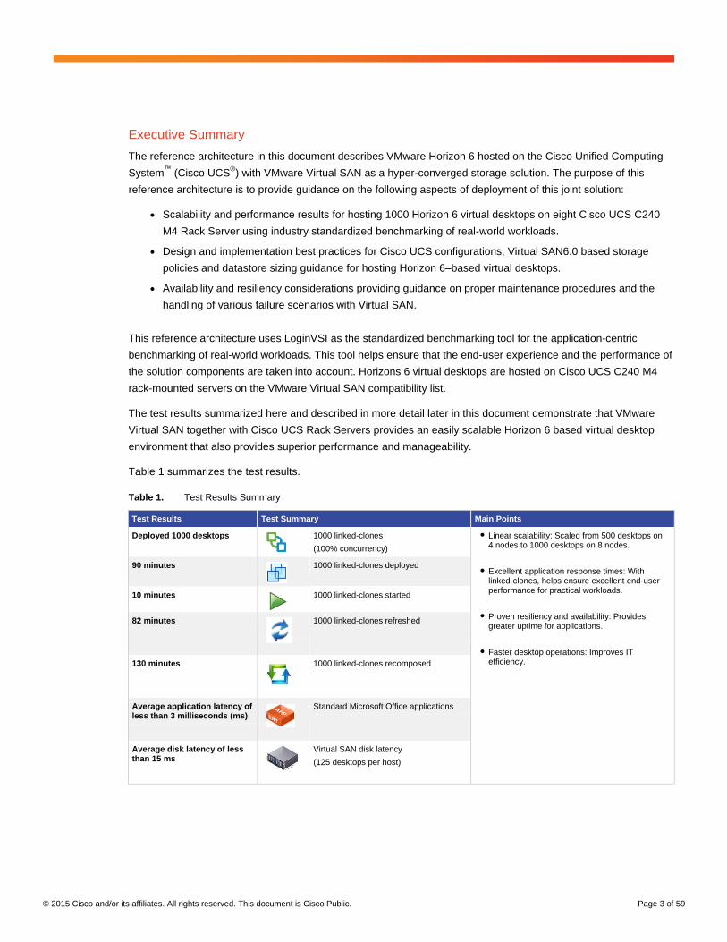
Table 1 summarizes the test results.
Table 1. Test Results Summary
Test Results Test Summary Main Points
Deployed 1000 desktops 1000 linked-clones
(100% concurrency)
● Linear scalability: Scaled from 500 desktops on 4 nodes to 1000 desktops on 8 nodes.
● Excellent application response times: With linked-clones, helps ensure excellent end-user performance for practical workloads.
● Proven resiliency and availability: Provides greater uptime for applications.
● Faster desktop operations: Improves IT efficiency.
90 minutes 1000 linked-clones deployed
10 minutes 1000 linked-clones started
82 minutes
1000 linked-clones refreshed
130 minutes
1000 linked-clones recomposed
Average application latency of less than 3 milliseconds (ms)
Standard Microsoft Office applications
Average disk latency of less than 15 ms
Virtual SAN disk latency
(125 desktops per host)
© 2015 Cisco and/or its affiliates. All rights reserved. This document is Cisco Public. Page 4 of 59
Solution Overview
The VMware Horizon 6 with View hosted on Cisco UCS with VMware Virtual SAN 6.0 reference architecture
supports and matches the Cisco UCS-based Virtual SAN Ready Nodes for View virtual desktops. This document
provides scalability and performance guidance for this solution. This section provides an overview of the individual
components used in this solution. For more information about each product, refer to the respective product
documentation.
Cisco Unified Computing System
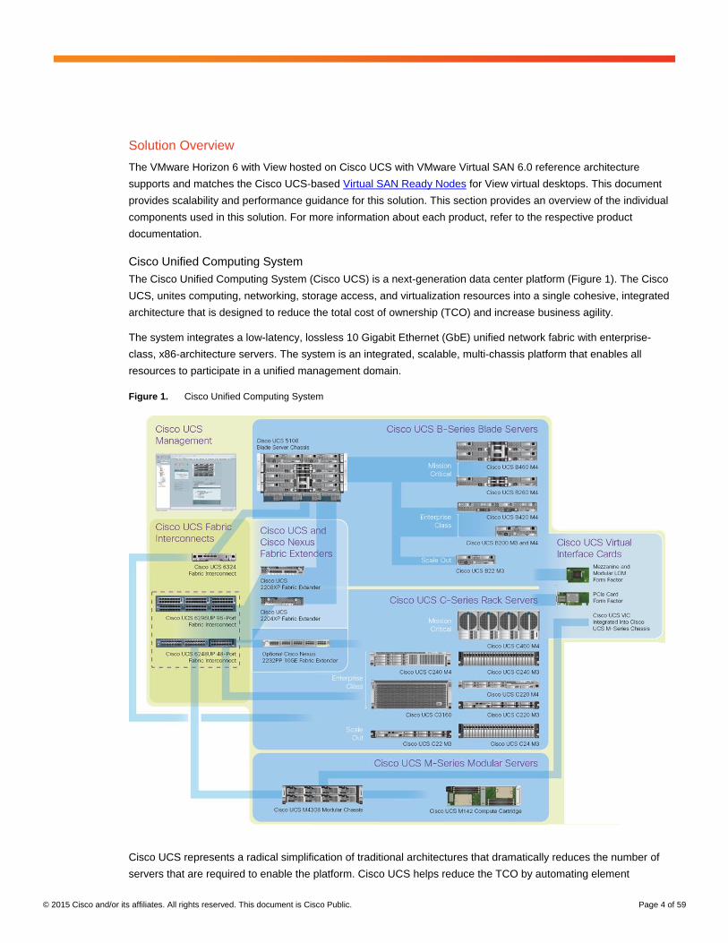
The Cisco Unified Computing System (Cisco UCS) is a next-generation data center platform (Figure 1). The Cisco
UCS, unites computing, networking, storage access, and virtualization resources into a single cohesive, integrated
architecture that is designed to reduce the total cost of ownership (TCO) and increase business agility.
The system integrates a low-latency, lossless 10 Gigabit Ethernet (GbE) unified network fabric with enterprise-
class, x86-architecture servers. The system is an integrated, scalable, multi-chassis platform that enables all
resources to participate in a unified management domain.
Figure 1. Cisco Unified Computing System
Cisco UCS represents a radical simplification of traditional architectures that dramatically reduces the number of
servers that are required to enable the platform. Cisco UCS helps reduce the TCO by automating element
© 2015 Cisco and/or its affiliates. All rights reserved. This document is Cisco Public. Page 5 of 59
management tasks through the use of service profiles that enable just-in-time provisioning. Service profiles
increase business agility by quickly aligning computing resources with rapidly changing business and workload
requirements.
In addition, Cisco UCS delivers end-to-end optimization for virtualized environments, while retaining the ability to
support traditional operating system and application stacks in physical environments.
Cisco UCS offers these main advantages:
● Less infrastructure and more intelligent servers: The Cisco UCS architecture enables end-to-end server
visibility, management, and control in both virtual and bare-metal environments. The Cisco UCS platform
facilitates the move to cloud computing and IT-as-a-service (ITaaS) platforms with fabric-based
Infrastructure.
● Resource consolidation with Cisco UCS servers: Cisco UCS servers simplify traditional architectures
and optimize virtualized environments across the entire system. With Cisco servers, bare-metal and
virtualized applications can be supported in the same environment.
● Faster server deployment: The smart, programmable infrastructure of Cisco UCS simplifies and
accelerates enterprise-class application and service deployment in bare-metal, virtualized, and cloud
computing environments. With unified model-based management, hundreds of servers can be configured
as quickly as just one server, resulting in lower cost of ownership and improved business continuity.
● Simplified management: Cisco UCS offers simplified and open management with a large partner
ecosystem. Cisco UCS Manager provides embedded management of all software and hardware
components in Cisco UCS. With Cisco UCS Central Software, management can be extended globally to
thousands of servers across multiple Cisco UCS domains and geographies. In addition, Cisco UCS Director
unifies management across computing, networking, and storage components in converged infrastructure
solutions.
For more information about the capabilities and features of Cisco UCS technologies, see the For More Information
section at the end of this document.
Cisco UCS C-Series Rack Servers
Cisco UCS C-Series Rack Servers deliver unified computing in an industry-standard form factor to reduce TCO
and increase agility. Each product addresses different workload challenges through a balance of processing,
memory, I/O, and internal storage resources.
Cisco UCS C-Series servers provide the following benefits:
● Form-factor independent entry point to Cisco UCS
● Simplified and fast deployment of applications
● Extension of unified computing innovations and benefits to rack servers
● Increased customer choice with unique benefits in a familiar rack package
● Reduced TCO and increased business agility
Several Cisco UCS C-Series server models are available, each optimized for particular types of deployments. For
VMware Virtual SAN deployments, disk density is an important factor in model selection. Computing power is also
an important consideration.
© 2015 Cisco and/or its affiliates. All rights reserved. This document is Cisco Public. Page 6 of 59
These servers can be managed by the built-in, standalone software provided by the Cisco Integrated Management
Controller (IMC), or by Cisco UCS Manager when connected through Cisco UCS 6200 Series Fabric Interconnects.
Cisco UCS Manager Supplies a totally integrated management process for both rack and blade servers through a
single tool. All Cisco UCS servers use industry-leading Intel® Xeon
® processors.
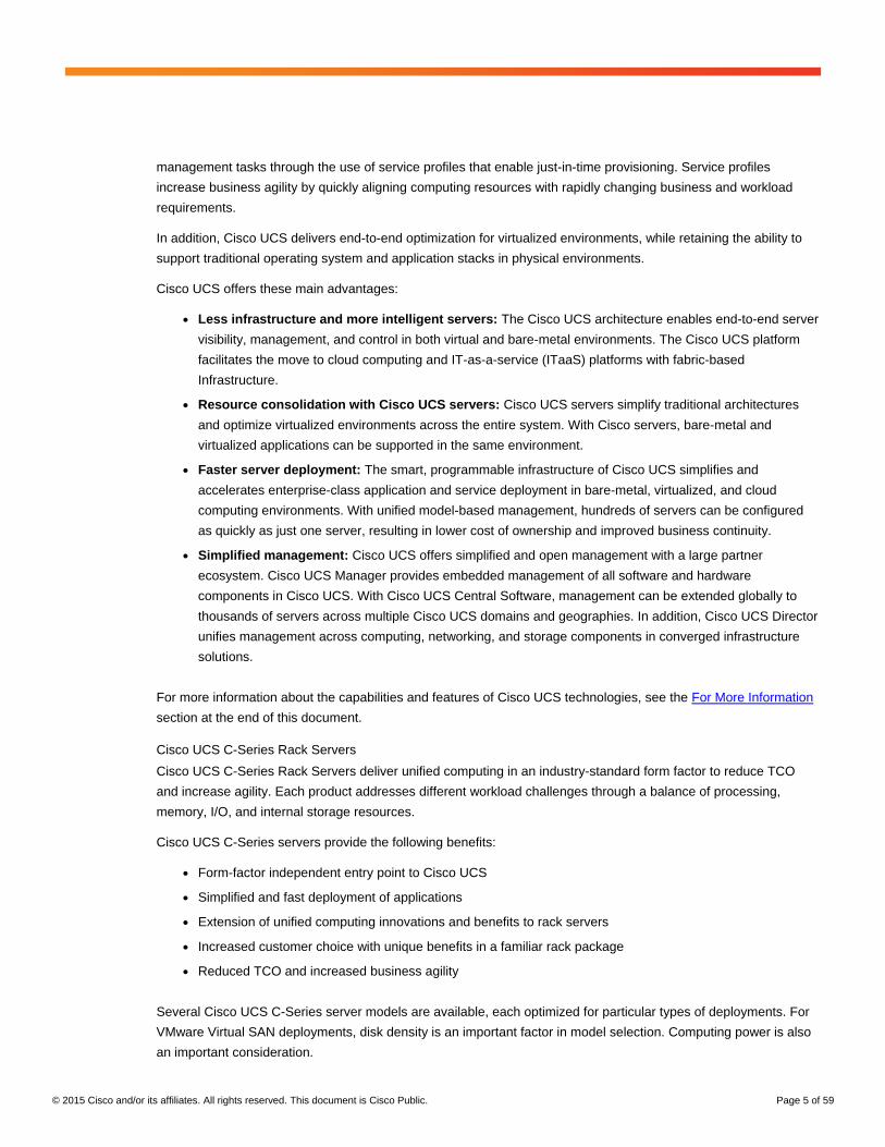
For Cisco UCS with VMware Virtual SAN, the Cisco UCS C240 M4 Rack Server (Figure 2) was considered the
optimal choice for the development of this solution. The Cisco UCS C240 M4 is a high-density, enterprise-class,
dual-socket, 2-rack-unit (2RU) rack server designed for computing, I/O, storage, and memory-intensive standalone
and virtualized applications. The addition of the Intel Xeon processor E5-2600 product family delivers an optimal
combination of performance, flexibility, and efficiency gains.
Figure 2. Cisco UCS C240 M4 Small Form-Factor (SFF) Rack Server
The Cisco UCS C240 M4 supports:
● Up to two Intel Xeon processor E5-2600v3 CPUs
● Up to 1.5 terabytes (TB) of RAM with 24 dual in-line memory module (DIMM) slots
● Capacity for up to 24 serial-attached SCSI (SAS), serial ATA (SATA), and solid-state disk (SSD) drives for
workloads that demand large amounts of internal storage
● Six PCI Express (PCIe) Generation 3 slots and two 1 Gigabit Ethernet LAN interfaces on the motherboard
● Trusted platform module (TPM) for authentication and tool-free access
The Cisco UCS C240 M4 2RU server comes in two varieties. It can support either large form-factor (3.5-inch) or
small form-factor (2.5-inch) hard drives. The VMware Virtual SAN technology uses SSD drives, so typically the
small form-factor variety is required.
Computing performance is important because the virtual machines that use the Virtual SAN data store reside on
the same hosts that contribute disk capacity to the data store.
The Cisco UCS C240 M4:
● Delivers outstanding internal memory and storage expandability and exceptional performance
● Is suitable for nearly all memory-intensive, storage-intensive, 2-socket applications
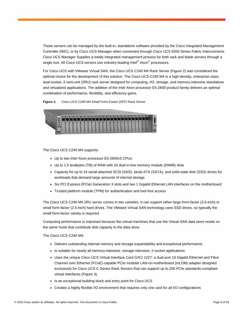
● Uses the unique Cisco UCS Virtual Interface Card (VIC) 1227: a dual-port 10 Gigabit Ethernet and Fibre
Channel over Ethernet (FCoE)-capable PCIe modular LAN-on-motherboard (mLOM) adapter designed
exclusively for Cisco UCS C-Series Rack Servers that can support up to 256 PCIe standards-compliant
virtual interfaces (Figure 3)
● Is an exceptional building block and entry point for Cisco UCS
● Creates a highly flexible I/O environment that requires only one card for all I/O configurations
© 2015 Cisco and/or its affiliates. All rights reserved. This document is Cisco Public. Page 7 of 59
● Supports continual innovation in Cisco server technology at all levels of Cisco UCS
Figure 3. Cisco UCS Virtual Interface Card 1227
For more information about the capabilities and features of Cisco UCS technologies, see the For More Information
section at the end of this document.
Service Profiles
In Cisco UCS, a service profile adds a layer of abstraction to the actual physical hardware. The server is defined in
a configuration file that is stored on the Cisco UCS 6200 Series Fabric Interconnects. It can be associated with the
physical hardware by using a simple operation from Cisco UCS Manager. When the service profile is applied, the
manager configures the server, adaptors, fabric extenders, and fabric interconnects to match the specified service
profile. The service profile makes the physical hardware transparent to the operating systems and virtual machines
running on it, enabling stateless computing and making the most of data center resources.
A number of parameters can be defined in the service profile, according to the environment requirements.
Administrators can create policies to define specific rules and operating characteristics. These policies can be
referenced in the service profiles to help ensure consistent configuration across many servers. Updates to a policy
can be propagated immediately to all servers that reference that policy in their service profile, or in the case of
firmware updates, they can be propagated at the next power-cycling event.
In addition, the advantages of the service profile can be extended when server-specific parameters, such as the
universal user ID (UUID), MAC address, and worldwide name (WWN), are themselves parameterized, and the
service profile is converted to a template. The template can be used to rapidly deploy new servers with consistent
general parameters and unique server-specific parameters.
When combined with templates, service profiles enable the rapid provisioning of servers with consistent operational
parameters and high availability. Service profiles can be configured in advance and used to move servers to a new
blade, chassis, or rack in the event of a failure.
© 2015 Cisco and/or its affiliates. All rights reserved. This document is Cisco Public. Page 8 of 59
VMware vSphere
VMware vSphere is the industry-leading virtualization platform for building cloud infrastructure. It enables users to
run business-critical applications with confidence and respond quickly to business needs. vSphere accelerates the
shift to cloud computing for existing data centers, and it enables compatible public cloud offerings, forming the
foundation for the industry’s best hybrid cloud model.
For more information about the capabilities and features of VMware vSphere, see the For More Information section
at the end of this document.
VMware Virtual SAN 6.0
VMware Virtual SAN is a hypervisor-converged storage solution that is fully integrated with VMware vSphere.
Virtual SAN combines storage and computing for virtual machines into a single device, with storage provided within
the hypervisor, instead of using a storage virtual machine that runs alongside the other virtual machines. Virtual
SAN aggregates locally attached disks in a vSphere cluster to create a storage solution, called a shared datastore
that can be rapidly provisioned from VMware vCenter Server during virtual machine provisioning operations.
Virtual SAN is an object-based storage system that is designed to provide virtual machine–centric storage services
and capabilities through a storage policy–based management (SPBM) platform. The SPBM platform and virtual
machine storage policies are designed to simplify virtual machine storage placement decisions for vSphere
administrators.
Virtual SAN is fully integrated with core vSphere enterprise features such as vSphere vMotion, vSphere High
Availability, and vSphere Distributed Resource Scheduler (DRS). Its goal is to provide both high availability and
scale-out storage capabilities. In the context of quality of service (QoS), virtual machine storage policies can be
created to define the level of performance and availability required on a per-virtual machine basis.
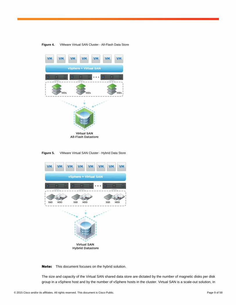
A Virtual SAN shared data store is constructed with a minimum of three vSphere ESXi hosts, each containing at
least one disk group with at least one SSD drive and one magnetic drive, as shown in Figure 4. It can also support
up to seven magnetic drives per disk group and up to five disk groups per host, or up to 35 drives per node. The
VMware virtual machine files are stored on the magnetic drive, and the SSD drive handles read caching and write
buffering. The disk group on each host is joined to a single network partition group, which is shared and controlled
by the hosts.
Virtual SAN 6.0 provides a new all-flash architecture on flash-memory devices that delivers high, predictable
performance and response times of less than a millisecond for some of the most demanding enterprise
applications.
Virtual SAN 6.0 supports double the scalability, with up to 64 nodes per cluster and up to 200 virtual machines per
host and up to 6400 virtual machines per Virtual SAN cluster, along with performance enhancements and highly
efficient snapshot and clone technology.
© 2015 Cisco and/or its affiliates. All rights reserved. This document is Cisco Public. Page 9 of 59
Figure 4. VMware Virtual SAN Cluster - All-Flash Data Store
Figure 5. VMware Virtual SAN Cluster - Hybrid Data Store
Note: This document focuses on the hybrid solution.
The size and capacity of the Virtual SAN shared data store are dictated by the number of magnetic disks per disk
group in a vSphere host and by the number of vSphere hosts in the cluster. Virtual SAN is a scale-out solution, in
© 2015 Cisco and/or its affiliates. All rights reserved. This document is Cisco Public. Page 10 of 59
which more capacity and performance can be obtained by adding more disks to a disk group, more disk groups to
a host, and more hosts to the cluster.
With Virtual SAN, the SPBM platform plays a major role in the way that administrators can use virtual machine
storage policies to specify a set of required storage capabilities for a virtual machine or, more specifically, to
specify a set of requirements for the application running in the virtual machine.
The following Virtual SAN datastore capabilities are available in vCenter Server, configurable under VM storage
policy:
● Number of failures to tolerate
● Number of disk stripes per object
● Flash read-cache reservation
● Object-space reservation
● Force provisioning
For more information about the capabilities and features of VMware Virtual SAN, see What’s New in VMware
Virtual SAN.
VMware Horizon 6 with View
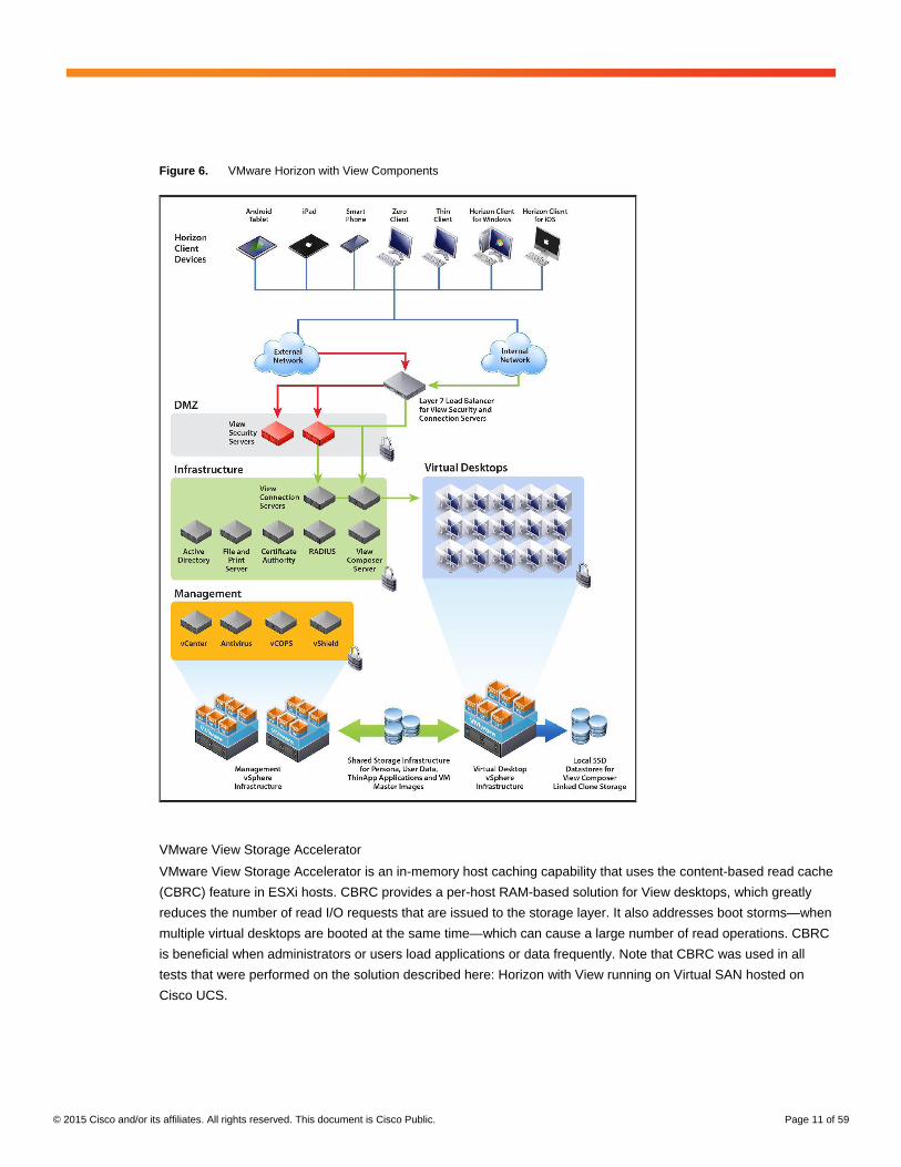
VMware Horizon with View brings the agility of cloud computing to the desktop by transforming desktops into highly
available and agile services delivered from the cloud (Figure 5). View delivers virtual sessions that follow end users
across devices and locations. It enables fast, secure access to corporate data across a wide range of devices,
including Microsoft Windows, Mac OS, and Linux desktop computers and iOS and Android tablets.
With vCenter Server, View can be used to create desktops from virtual machines that are running on ESXi hosts,
and to deploy these desktops to end users. After a desktop is created, authorized end-users can use web-based or
locally installed client software to connect securely to centralized virtual desktops, back-end physical systems, or
terminal servers. View uses the existing Microsoft Active Directory infrastructure for user authentication and
management.
© 2015 Cisco and/or its affiliates. All rights reserved. This document is Cisco Public. Page 11 of 59
Figure 6. VMware Horizon with View Components
VMware View Storage Accelerator
VMware View Storage Accelerator is an in-memory host caching capability that uses the content-based read cache
(CBRC) feature in ESXi hosts. CBRC provides a per-host RAM-based solution for View desktops, which greatly
reduces the number of read I/O requests that are issued to the storage layer. It also addresses boot storms—when
multiple virtual desktops are booted at the same time—which can cause a large number of read operations. CBRC
is beneficial when administrators or users load applications or data frequently. Note that CBRC was used in all
tests that were performed on the solution described here: Horizon with View running on Virtual SAN hosted on
Cisco UCS.
© 2015 Cisco and/or its affiliates. All rights reserved. This document is Cisco Public. Page 12 of 59
System Configuration: Design
This section describes the configuration of the components of the reference architecture for Horizon 6 with View
hosted on Cisco UCS with Virtual SAN.
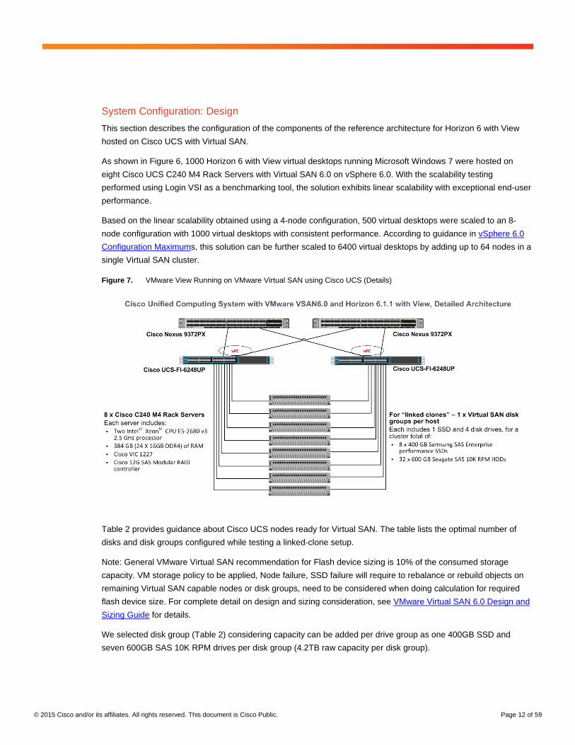
As shown in Figure 6, 1000 Horizon 6 with View virtual desktops running Microsoft Windows 7 were hosted on
eight Cisco UCS C240 M4 Rack Servers with Virtual SAN 6.0 on vSphere 6.0. With the scalability testing
performed using Login VSI as a benchmarking tool, the solution exhibits linear scalability with exceptional end-user
performance.
Based on the linear scalability obtained using a 4-node configuration, 500 virtual desktops were scaled to an 8-
node configuration with 1000 virtual desktops with consistent performance. According to guidance in vSphere 6.0
Configuration Maximums, this solution can be further scaled to 6400 virtual desktops by adding up to 64 nodes in a
single Virtual SAN cluster.
Figure 7. VMware View Running on VMware Virtual SAN using Cisco UCS (Details)
Table 2 provides guidance about Cisco UCS nodes ready for Virtual SAN. The table lists the optimal number of
disks and disk groups configured while testing a linked-clone setup.
Note: General VMware Virtual SAN recommendation for Flash device sizing is 10% of the consumed storage
capacity. VM storage policy to be applied, Node failure, SSD failure will require to rebalance or rebuild objects on
remaining Virtual SAN capable nodes or disk groups, need to be considered when doing calculation for required
flash device size. For complete detail on design and sizing consideration, see VMware Virtual SAN 6.0 Design and
Sizing Guide for details.
We selected disk group (Table 2) considering capacity can be added per drive group as one 400GB SSD and
seven 600GB SAS 10K RPM drives per disk group (4.2TB raw capacity per disk group).
© 2015 Cisco and/or its affiliates. All rights reserved. This document is Cisco Public. Page 13 of 59
Table 2. Virtual SAN Disk Group Configuration
Type of Virtual Desktop Number of Disk Groups per Host
SSD Drives and HDDs in Disk Groups Used and Total Capacity
500 linked-clones 1 1 SSD and 4 HDDs drives 1.76 TB used out of 8.71 TB
1000 linked-clones 1 1 SSD and 4 HDDs drives 4.47 TB used out of 17.43 TB
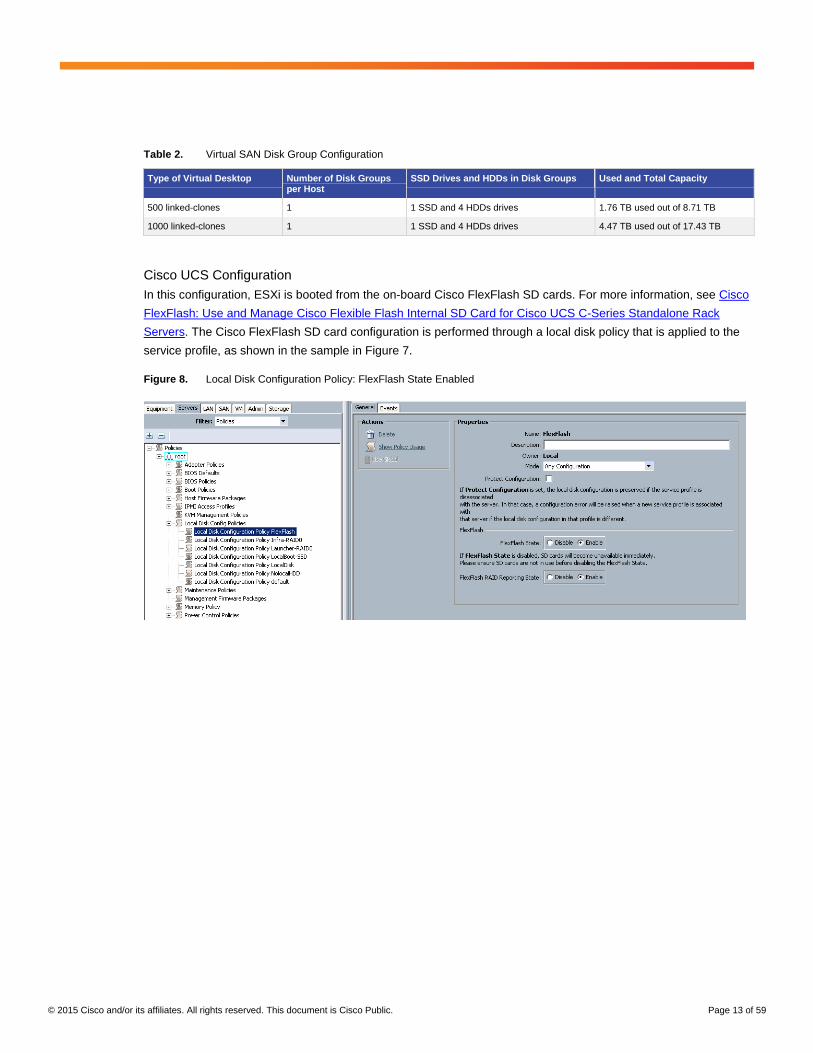
Cisco UCS Configuration
In this configuration, ESXi is booted from the on-board Cisco FlexFlash SD cards. For more information, see Cisco
FlexFlash: Use and Manage Cisco Flexible Flash Internal SD Card for Cisco UCS C-Series Standalone Rack
Servers. The Cisco FlexFlash SD card configuration is performed through a local disk policy that is applied to the
service profile, as shown in the sample in Figure 7.
Figure 8. Local Disk Configuration Policy: FlexFlash State Enabled
© 2015 Cisco and/or its affiliates. All rights reserved. This document is Cisco Public. Page 14 of 59
Service Profile Configuration
Table 3 summarizes the main configurable parameters of a Cisco UCS service profile.
Table 3. Service Profile Parameters
Parameter Type Parameter Description
Server hardware ● UUID ● Obtained from defined UUID pool
● MAC addresses ● Obtained from defined MAC address pool
● Worldwide port name (WWPN)
● Worldwide node name (WWNN)
● Obtained from defined WWPN and WWNN pools
● Boot policy ● Boot path and order
● Disk policy ● RAID configuration
Fabric ● LAN ● Virtual NICs (vNICs), VLANs, and maximum transmission unit (MTU)
● SAN ● Virtual host bus adapters (vHBAs) and Virtual SANs
● QoS policy ● Class of service (CoS) for Ethernet uplink traffic
Operation ● Firmware policy ● Current and backup versions
● BIOS policy ● BIOS version and settings
● Statistics policy ● System data collection
● Power-control policy ● Blade server power allotment
For Cisco UCS service profiles for hosts in a Virtual SAN cluster, the policy configuration shown here is
recommended. This configuration does not include all Cisco UCS service profile settings. The settings shown here
are configurations specific to an implementation of Cisco UCS with Virtual SAN for Horizon with View.
© 2015 Cisco and/or its affiliates. All rights reserved. This document is Cisco Public. Page 15 of 59
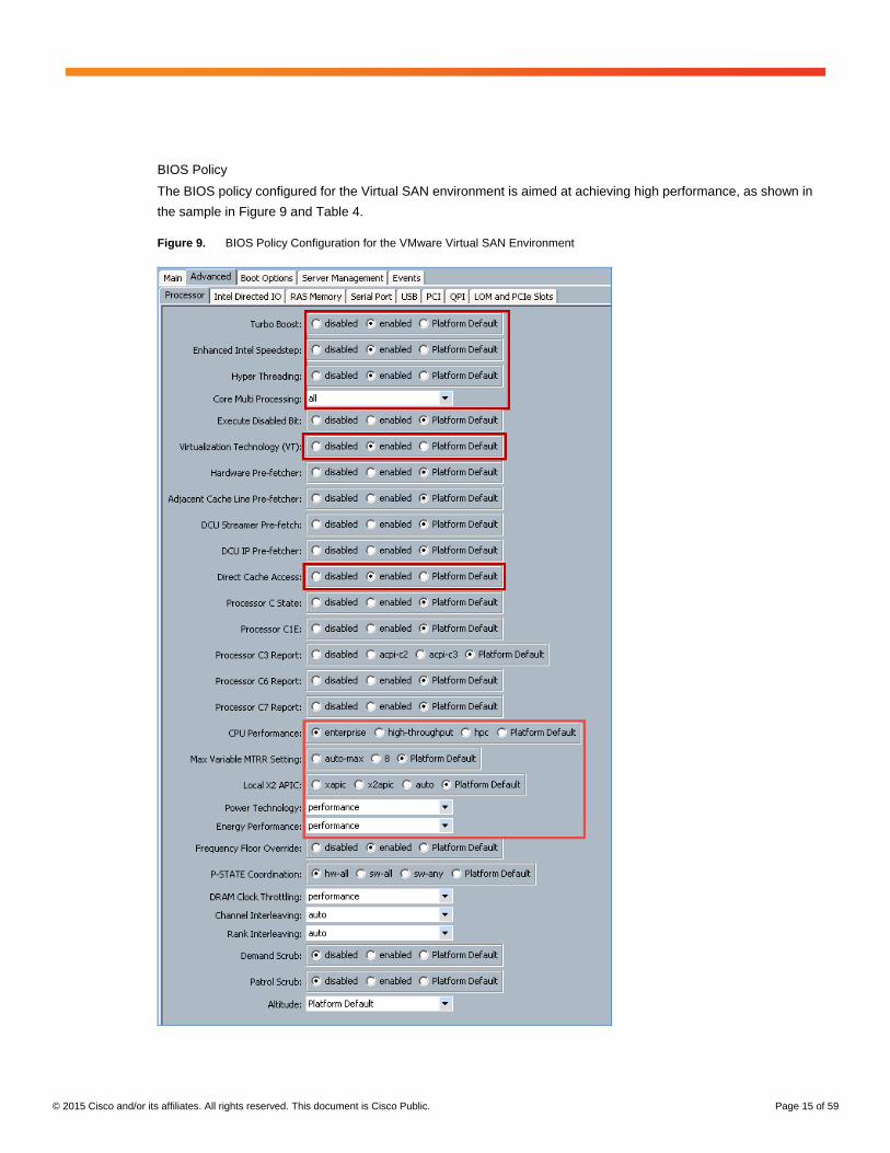
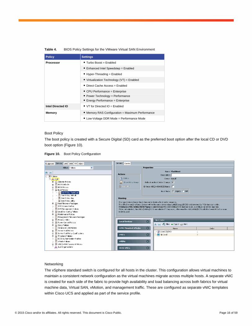
BIOS Policy
The BIOS policy configured for the Virtual SAN environment is aimed at achieving high performance, as shown in
the sample in Figure 9 and Table 4.
Figure 9. BIOS Policy Configuration for the VMware Virtual SAN Environment
© 2015 Cisco and/or its affiliates. All rights reserved. This document is Cisco Public. Page 16 of 59
Table 4. BIOS Policy Settings for the VMware Virtual SAN Environment
Policy Settings
Processor ● Turbo Boost = Enabled
● Enhanced Intel Speedstep = Enabled
● Hyper-Threading = Enabled
● Virtualization Technology (VT) = Enabled
● Direct Cache Access = Enabled
● CPU Performance = Enterprise
● Power Technology = Performance
● Energy Performance = Enterprise
Intel Directed IO ● VT for Directed IO = Enabled
Memory ● Memory RAS Configuration = Maximum Performance
● Low-Voltage DDR Mode = Performance Mode
Boot Policy
The boot policy is created with a Secure Digital (SD) card as the preferred boot option after the local CD or DVD
boot option (Figure 10).
Figure 10. Boot Policy Configuration
Networking
The vSphere standard switch is configured for all hosts in the cluster. This configuration allows virtual machines to
maintain a consistent network configuration as the virtual machines migrate across multiple hosts. A separate vNIC
is created for each side of the fabric to provide high availability and load balancing across both fabrics for virtual
machine data, Virtual SAN, vMotion, and management traffic. These are configured as separate vNIC templates
within Cisco UCS and applied as part of the service profile.
© 2015 Cisco and/or its affiliates. All rights reserved. This document is Cisco Public. Page 17 of 59
Two separate standard virtual switch (vSwitch) are created. The first vSwitch (vSwitch0) is configured with vNICs
defined for virtual machine data, management, and vMotion, and another vSwitch (vSwitch1) is configured with
vNICs defined for Virtual SAN traffic (Table 5).
Table 5. vNIC Template Configuration
vNIC Template Name Fabric ID Comments
Data-Fab-A Fabric A MTU = 1500; QoS Policy – Silver
Data-Fab-B Fabric B MTU = 1500; QoS Policy - Silver
Virtual SAN-A Fabric A MTU = 9000; QoS Policy - Platinum
Virtual SAN-B Fabric B MTU = 9000; QoS Policy - Platinum
The network control policy is set to Cisco Discovery Protocol enabled, and the dynamic vNIC connection policy is
applied as connection policy, not with an adapter policy of “VMware”.
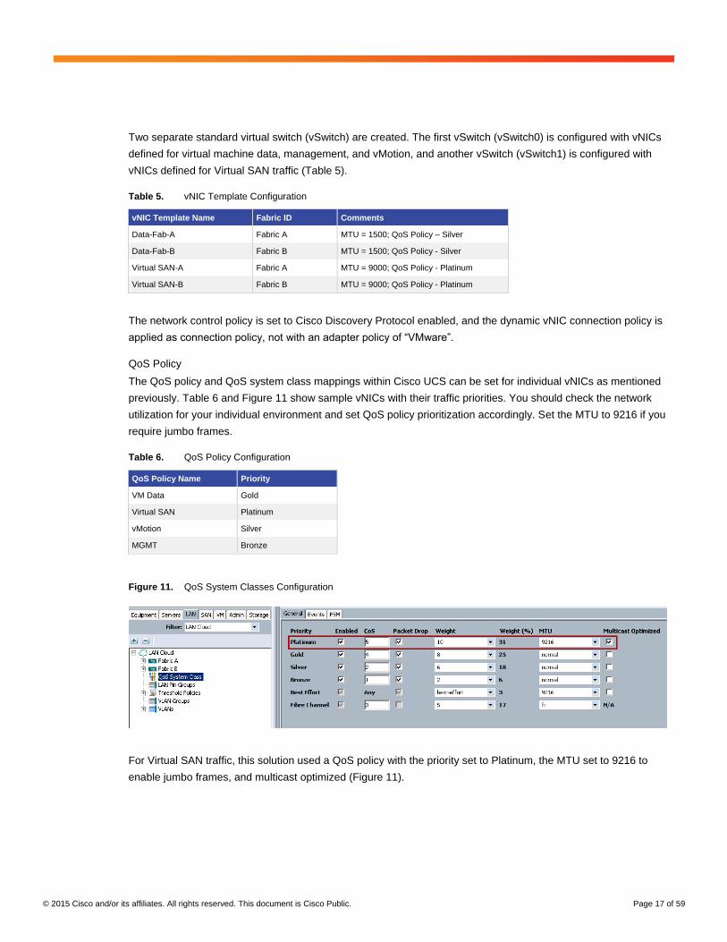
QoS Policy
The QoS policy and QoS system class mappings within Cisco UCS can be set for individual vNICs as mentioned
previously. Table 6 and Figure 11 show sample vNICs with their traffic priorities. You should check the network
utilization for your individual environment and set QoS policy prioritization accordingly. Set the MTU to 9216 if you
require jumbo frames.
Table 6. QoS Policy Configuration
QoS Policy Name Priority
VM Data Gold
Virtual SAN Platinum
vMotion Silver
MGMT Bronze
Figure 11. QoS System Classes Configuration
For Virtual SAN traffic, this solution used a QoS policy with the priority set to Platinum, the MTU set to 9216 to
enable jumbo frames, and multicast optimized (Figure 11).
© 2015 Cisco and/or its affiliates. All rights reserved. This document is Cisco Public. Page 18 of 59
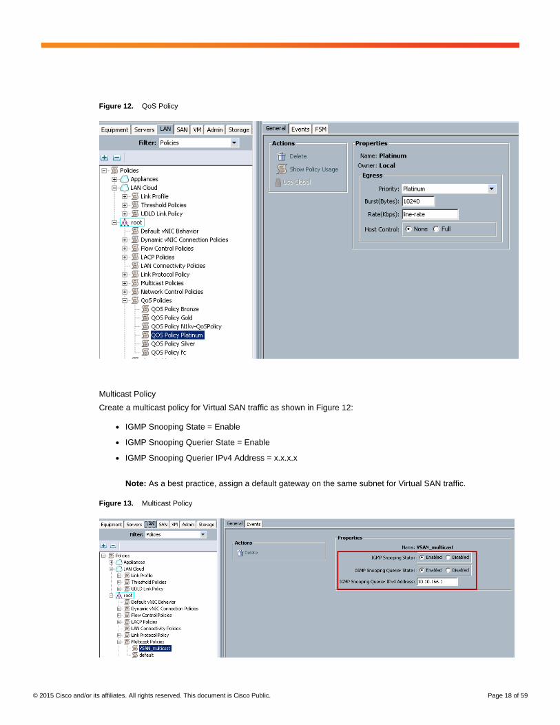
Figure 12. QoS Policy
Multicast Policy
Create a multicast policy for Virtual SAN traffic as shown in Figure 12:
● IGMP Snooping State = Enable
● IGMP Snooping Querier State = Enable
● IGMP Snooping Querier IPv4 Address = x.x.x.x
Note: As a best practice, assign a default gateway on the same subnet for Virtual SAN traffic.
Figure 13. Multicast Policy
© 2015 Cisco and/or its affiliates. All rights reserved. This document is Cisco Public. Page 19 of 59
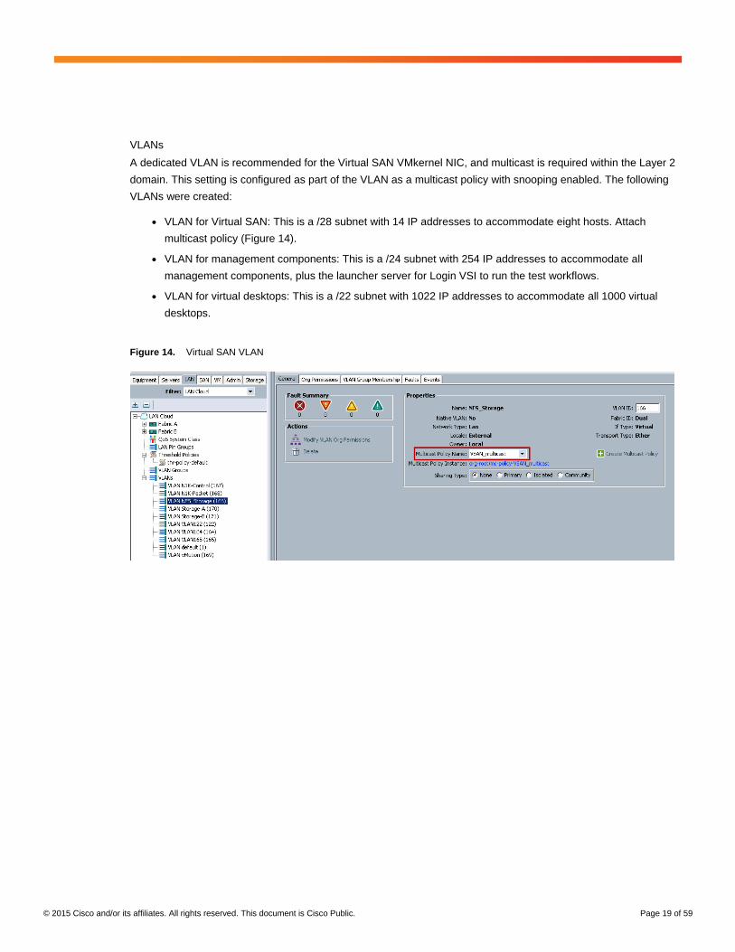
VLANs
A dedicated VLAN is recommended for the Virtual SAN VMkernel NIC, and multicast is required within the Layer 2
domain. This setting is configured as part of the VLAN as a multicast policy with snooping enabled. The following
VLANs were created:
● VLAN for Virtual SAN: This is a /28 subnet with 14 IP addresses to accommodate eight hosts. Attach
multicast policy (Figure 14).
● VLAN for management components: This is a /24 subnet with 254 IP addresses to accommodate all
management components, plus the launcher server for Login VSI to run the test workflows.
● VLAN for virtual desktops: This is a /22 subnet with 1022 IP addresses to accommodate all 1000 virtual
desktops.
Figure 14. Virtual SAN VLAN
© 2015 Cisco and/or its affiliates. All rights reserved. This document is Cisco Public. Page 20 of 59
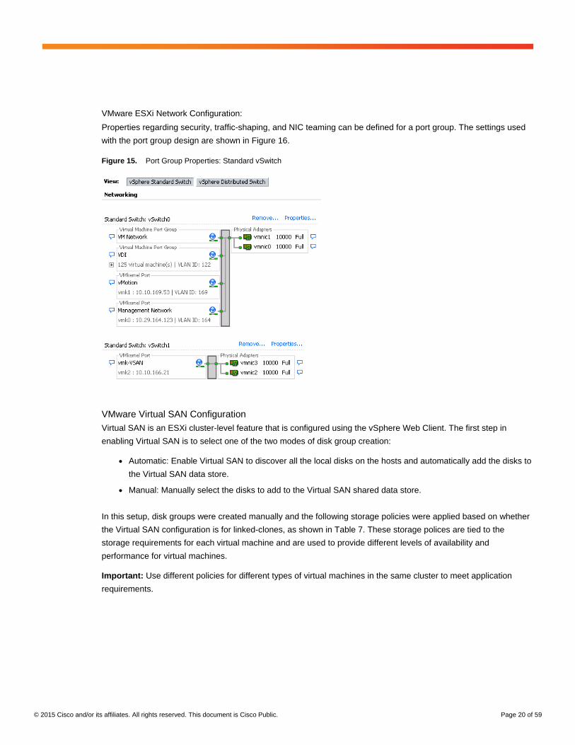
VMware ESXi Network Configuration:
Properties regarding security, traffic-shaping, and NIC teaming can be defined for a port group. The settings used
with the port group design are shown in Figure 16.
Figure 15. Port Group Properties: Standard vSwitch
VMware Virtual SAN Configuration
Virtual SAN is an ESXi cluster-level feature that is configured using the vSphere Web Client. The first step in
enabling Virtual SAN is to select one of the two modes of disk group creation:
● Automatic: Enable Virtual SAN to discover all the local disks on the hosts and automatically add the disks to
the Virtual SAN data store.
● Manual: Manually select the disks to add to the Virtual SAN shared data store.
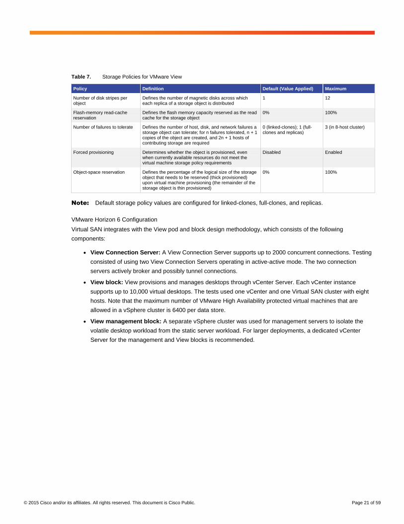
In this setup, disk groups were created manually and the following storage policies were applied based on whether
the Virtual SAN configuration is for linked-clones, as shown in Table 7. These storage polices are tied to the
storage requirements for each virtual machine and are used to provide different levels of availability and
performance for virtual machines.
Important: Use different policies for different types of virtual machines in the same cluster to meet application
requirements.
© 2015 Cisco and/or its affiliates. All rights reserved. This document is Cisco Public. Page 21 of 59
Table 7. Storage Policies for VMware View
Policy Definition Default (Value Applied) Maximum
Number of disk stripes per object
Defines the number of magnetic disks across which each replica of a storage object is distributed
1 12
Flash-memory read-cache reservation
Defines the flash memory capacity reserved as the read cache for the storage object
0% 100%
Number of failures to tolerate Defines the number of host, disk, and network failures a storage object can tolerate; for n failures tolerated, n + 1 copies of the object are created, and 2n + 1 hosts of contributing storage are required
0 (linked-clones); 1 (full-clones and replicas)
3 (in 8-host cluster)
Forced provisioning Determines whether the object is provisioned, even when currently available resources do not meet the virtual machine storage policy requirements
Disabled Enabled
Object-space reservation Defines the percentage of the logical size of the storage object that needs to be reserved (thick provisioned) upon virtual machine provisioning (the remainder of the storage object is thin provisioned)
0% 100%
Note: Default storage policy values are configured for linked-clones, full-clones, and replicas.
VMware Horizon 6 Configuration
Virtual SAN integrates with the View pod and block design methodology, which consists of the following
components:
● View Connection Server: A View Connection Server supports up to 2000 concurrent connections. Testing
consisted of using two View Connection Servers operating in active-active mode. The two connection
servers actively broker and possibly tunnel connections.
● View block: View provisions and manages desktops through vCenter Server. Each vCenter instance
supports up to 10,000 virtual desktops. The tests used one vCenter and one Virtual SAN cluster with eight
hosts. Note that the maximum number of VMware High Availability protected virtual machines that are
allowed in a vSphere cluster is 6400 per data store.
● View management block: A separate vSphere cluster was used for management servers to isolate the
volatile desktop workload from the static server workload. For larger deployments, a dedicated vCenter
Server for the management and View blocks is recommended.
© 2015 Cisco and/or its affiliates. All rights reserved. This document is Cisco Public. Page 22 of 59
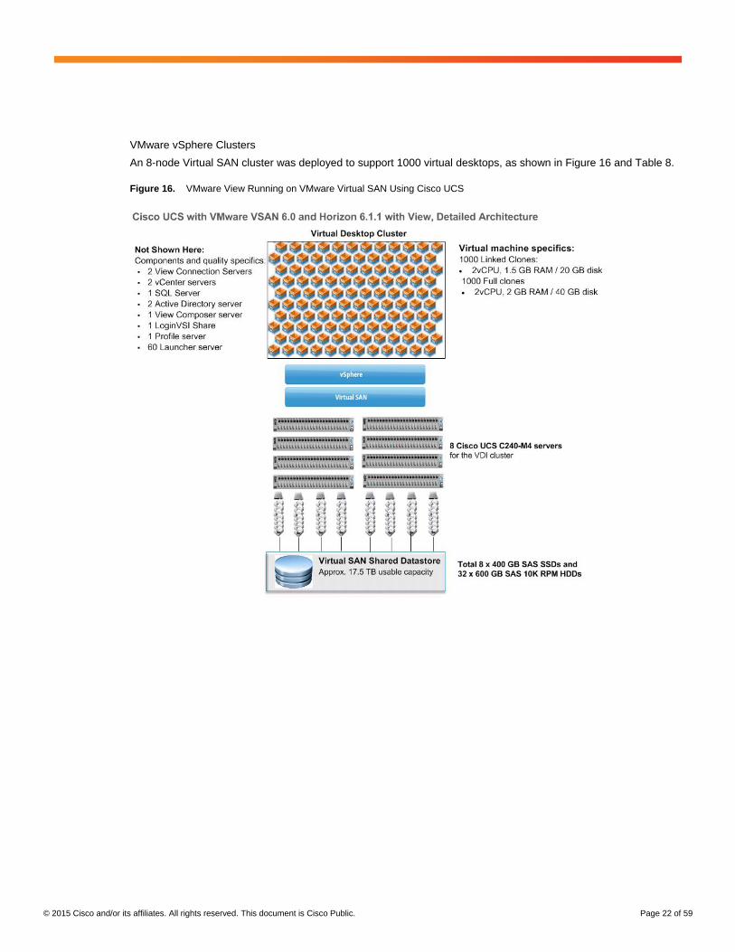
VMware vSphere Clusters
An 8-node Virtual SAN cluster was deployed to support 1000 virtual desktops, as shown in Figure 16 and Table 8.
Figure 16. VMware View Running on VMware Virtual SAN Using Cisco UCS
© 2015 Cisco and/or its affiliates. All rights reserved. This document is Cisco Public. Page 23 of 59
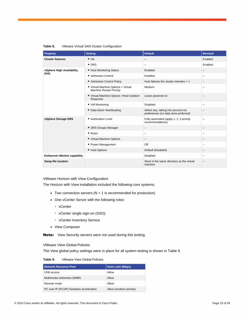
Table 8. VMware Virtual SAN Cluster Configuration
Property Setting Default Revised
Cluster features ● HA – Enabled
● DRS – Enabled
vSphere High Availability (HA)
● Host Monitoring Status Enabled –
● Admission Control Enabled –
● Admission Control Policy Host failures the cluster tolerates = 1 –
● Virtual Machine Options > Virtual Machine Restart Priority
Medium –
● Virtual Machine Options >Host Isolation Response
Leave powered on –
● VM Monitoring Disabled –
● Data-Store Heartbeating Select any, taking into account my preferences (no data store preferred)
–
vSphere Storage DRS ● Automation Level Fully automated (apply 1, 2, 3 priority recommendations)
–
● DRS Groups Manager – –
● Rules – –
● Virtual Machine Options – –
● Power Management Off –
● Host Options Default (Disabled) –
Enhanced vMotion capability Disabled –
Swap-file location Store in the same directory as the virtual machine
–
VMware Horizon with View Configuration
The Horizon with View installation included the following core systems.
● Two connection servers (N + 1 is recommended for production)
● One vCenter Server with the following roles:
◦ vCenter
◦ vCenter single sign-on (SSO)
◦ vCenter Inventory Service
● View Composer
Note: View Security servers were not used during this testing.
VMware View Global Policies
The View global policy settings were in place for all system testing is shown in Table 9.
Table 9. VMware View Global Policies
Network Resource Pool Host Limit (Mbps)
USB access Allow
Multimedia redirection (MMR) Allow
Remote mode Allow
PC over IP (PCoIP) hardware acceleration Allow (medium priority)
© 2015 Cisco and/or its affiliates. All rights reserved. This document is Cisco Public. Page 24 of 59
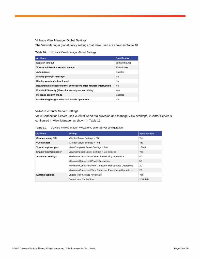
VMware View Manager Global Settings
The View Manager global policy settings that were used are shown in Table 10.
Table 10. VMware View Manager Global Settings
Attribute Specification
Session timeout 600 (10 hours)
View Administrator session timeout 120 minutes
Auto update Enabled
Display prelogin message No
Display warning before logout No
Reauthenticate secure tunnel connections after network interruption No
Enable IP Security (IPsec) for security server pairing Yes
Message security mode Enabled
Disable single sign-on for local-mode operations No
VMware vCenter Server Settings
View Connection Server uses vCenter Server to provision and manage View desktops. vCenter Server is
configured in View Manager as shown in Table 11.
Table 11. VMware View Manager: VMware vCenter Server configuration
Attribute Setting Specification
Connect using SSL vCenter Server Settings > SSL Yes
vCenter port vCenter Server Settings > Port 443
View Composer port View Composer Server Settings > Port 18443
Enable View Composer View Composer Server Settings > Co-Installed Yes
Advanced settings Maximum Concurrent vCenter Provisioning Operations 40
Maximum Concurrent Power Operations 50
Maximum Concurrent View Composer Maintenance Operations 20
Maximum Concurrent View Composer Provisioning Operations 20
Storage settings Enable View Storage Accelerator Yes
Default Host Cache Size 2048 MB
© 2015 Cisco and/or its affiliates. All rights reserved. This document is Cisco Public. Page 25 of 59
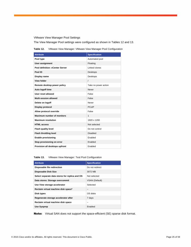
VMware View Manager Pool Settings
The View Manager Pool settings were configured as shown in Tables 12 and 13.
Table 12. VMware View Manager: VMware View Manager Pool Configuration
Attribute Specification
Pool type Automated pool
User assignment Floating
Pool definition: vCenter Server Linked clones
Pool ID Desktops
Display name Desktops
View folder /
Remote desktop power policy Take no power action
Auto logoff time Never
User reset allowed False
Multi-session allowed False
Delete on logoff Never
Display protocol PCoIP
Allow protocol override False
Maximum number of monitors 1
Maximum resolution 1920 x 1200
HTML access Not selected
Flash quality level Do not control
Flash throttling level Disabled
Enable provisioning Enabled
Stop provisioning on error Enabled
Provision all desktops upfront Enabled
Table 13. VMware View Manager: Test Pool Configuration
Attribute Specification
Disposable file redirection Do not redirect
Disposable Disk Size 3072 MB
Select separate data stores for replica and OS Not selected
Data stores: Storage overcommit VSAN (Default)
Use View storage accelerator Selected
Reclaim virtual machine disk space* –
Disk types OS disks
Regenerate storage accelerator after 7 days
Reclaim virtual machine disk space –
Use Sysprep Enabled
Note: Virtual SAN does not support the space-efficient (SE) sparse disk format.
© 2015 Cisco and/or its affiliates. All rights reserved. This document is Cisco Public. Page 26 of 59
Test Results
View running on Virtual SAN on the Cisco UCS reference architecture was tested based on real-world test
scenarios, user workloads, and infrastructure system configurations.
The tests performed included the following configuration:
● Test 1: 500 View linked clones on four Cisco UCS C240 M4 servers in a Virtual SAN cluster
● Test 2: 1000 View linked clones on eight Cisco UCS C240 M4 servers in a Virtual SAN cluster with one disk
group
● Test 3: 1000 View linked clones on eight Cisco UCS C240 M4 servers in a Virtual SAN cluster with two disk
groups
● Test 4: 1000 View linked clones on seven Cisco UCS C240 M4 servers in a Virtual SAN cluster (one node
failure)
● Test 5: Virtual SAN availability and manageability tests
These tests and the test results are summarized in the sections that follow.
Test Summary
LoginVSI is a desktop virtualization end-user experience measurement tool that uses a workload generator to
automate and measure a typical office user’s activity. The operations include opening a file, browsing the web,
modifying files, saving, closing, printing and more. Each LoginVSI operation runs in an iterative fashion. Each
iteration is a randomly sequenced workload of these applications and operations. The results of a run consist of
operational latencies collected for these applications and operations for all iterations.
For this testing, each test scenario discussed here was run multiple times with a knowledge worker workload in
benchmark mode to monitor the consistency and repeatability of the test results.
The testing monitored performance statistics during a virtual desktop boot storm, waited for the systems to settle
down. It tracked ramp-up, which is the login interval for all 500 or 1000 sessions, steady state, where all sessions
are logged on and active and then log off.
In addition to Login VSI Analyzer results, VMware Virtual SAN Observer and ESXTOP data captured from
individual test cycles were used as monitoring tools.
For more information about the applications used for this testing, see the section For More Information later in this
document.
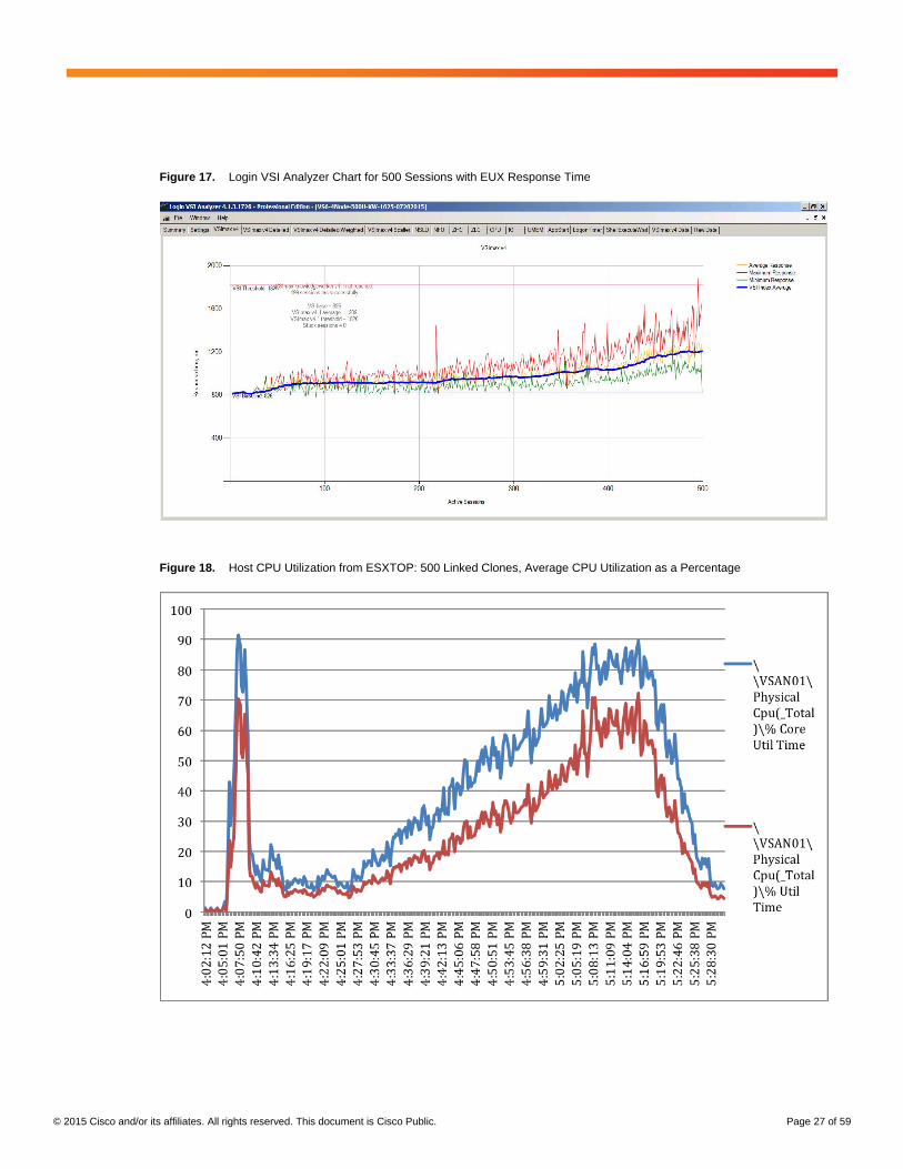
Test 1: 500 Linked Clone Desktop on Four Cisco UCS C240 M4 Servers in a VMware Virtual SAN Cluster
LoginVSI tests were run on 500 linked-clones hosted on four Cisco UCS C240 M4 servers with exceptional user
performance as represented by the LoginVSI Analyzer score and latency values (Figures 17 through 23).
Test result highlights include:
● Average CPU utilization of 85 percent
● Average of up to 196 GB of RAM used out of 384 GB available
● Average 29.04 MBps network used
● Average of 8.79 I/O latency per host
● Average of 859 I/O operations per second (IOPS) per host
© 2015 Cisco and/or its affiliates. All rights reserved. This document is Cisco Public. Page 27 of 59
Figure 17. Login VSI Analyzer Chart for 500 Sessions with EUX Response Time
Figure 18. Host CPU Utilization from ESXTOP: 500 Linked Clones, Average CPU Utilization as a Percentage
© 2015 Cisco and/or its affiliates. All rights reserved. This document is Cisco Public. Page 28 of 59
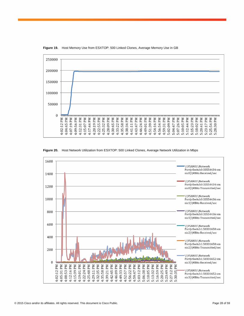
Figure 19. Host Memory Use from ESXTOP: 500 Linked Clones, Average Memory Use in GB
Figure 20. Host Network Utilization from ESXTOP: 500 Linked Clones, Average Network Utilization in Mbps
© 2015 Cisco and/or its affiliates. All rights reserved. This document is Cisco Public. Page 29 of 59
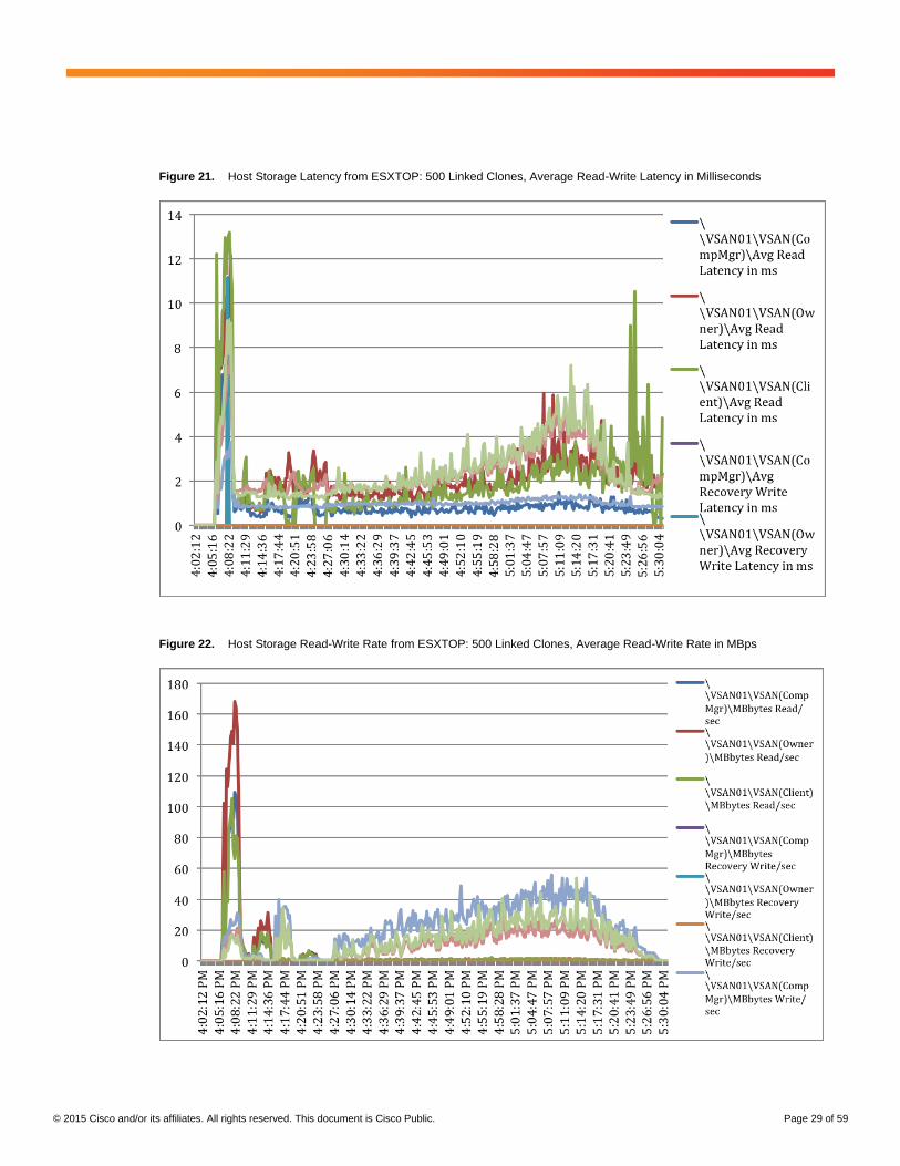
Figure 21. Host Storage Latency from ESXTOP: 500 Linked Clones, Average Read-Write Latency in Milliseconds
Figure 22. Host Storage Read-Write Rate from ESXTOP: 500 Linked Clones, Average Read-Write Rate in MBps
© 2015 Cisco and/or its affiliates. All rights reserved. This document is Cisco Public. Page 30 of 59
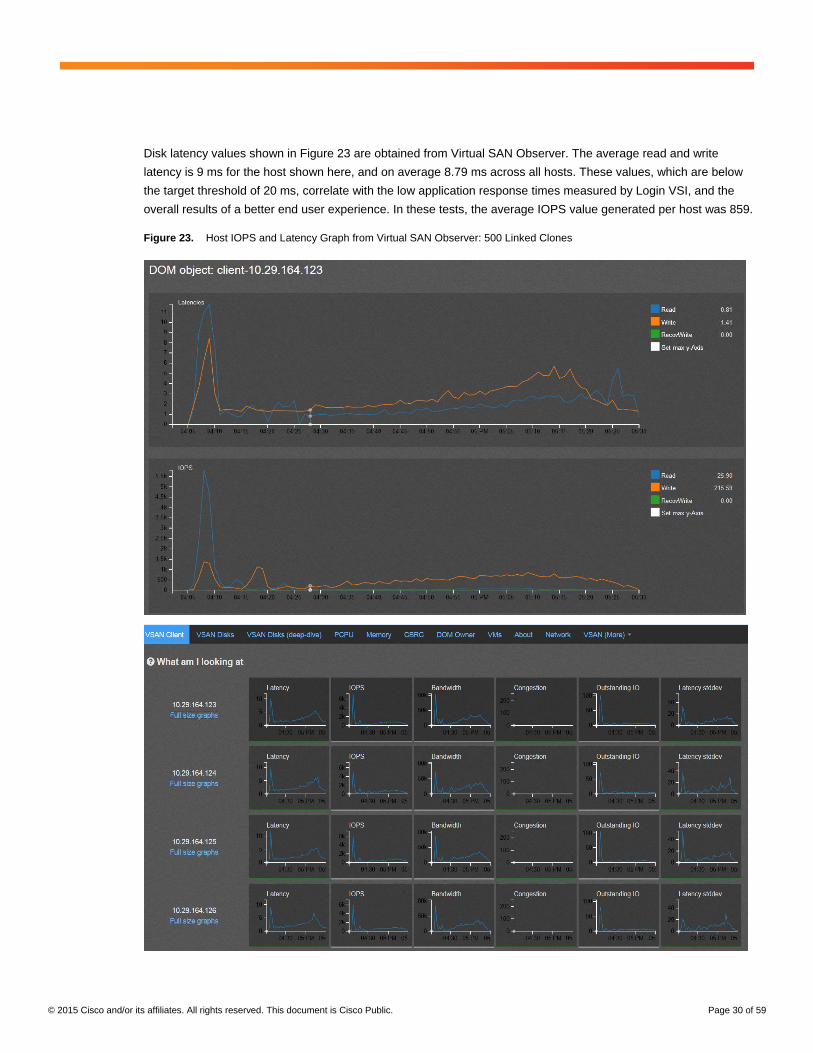
Disk latency values shown in Figure 23 are obtained from Virtual SAN Observer. The average read and write
latency is 9 ms for the host shown here, and on average 8.79 ms across all hosts. These values, which are below
the target threshold of 20 ms, correlate with the low application response times measured by Login VSI, and the
overall results of a better end user experience. In these tests, the average IOPS value generated per host was 859.
Figure 23. Host IOPS and Latency Graph from Virtual SAN Observer: 500 Linked Clones
© 2015 Cisco and/or its affiliates. All rights reserved. This document is Cisco Public. Page 31 of 59
Test 2: 1000 Linked Clone Desktop on Eight Cisco UCS C240 M4 Servers in a VMware Virtual SAN Cluster with a
Single Disk Group
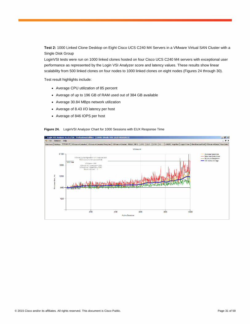
LoginVSI tests were run on 1000 linked clones hosted on four Cisco UCS C240 M4 servers with exceptional user
performance as represented by the Login VSI Analyzer score and latency values. These results show linear
scalability from 500 linked clones on four nodes to 1000 linked clones on eight nodes (Figures 24 through 30).
Test result highlights include:
● Average CPU utilization of 85 percent
● Average of up to 196 GB of RAM used out of 384 GB available
● Average 30.84 MBps network utilization
● Average of 8.43 I/O latency per host
● Average of 846 IOPS per host
Figure 24. LoginVSI Analyzer Chart for 1000 Sessions with EUX Response Time
© 2015 Cisco and/or its affiliates. All rights reserved. This document is Cisco Public. Page 32 of 59
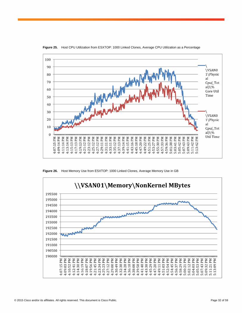
Figure 25. Host CPU Utilization from ESXTOP: 1000 Linked Clones, Average CPU Utilization as a Percentage
Figure 26. Host Memory Use from ESXTOP: 1000 Linked Clones, Average Memory Use in GB
© 2015 Cisco and/or its affiliates. All rights reserved. This document is Cisco Public. Page 33 of 59
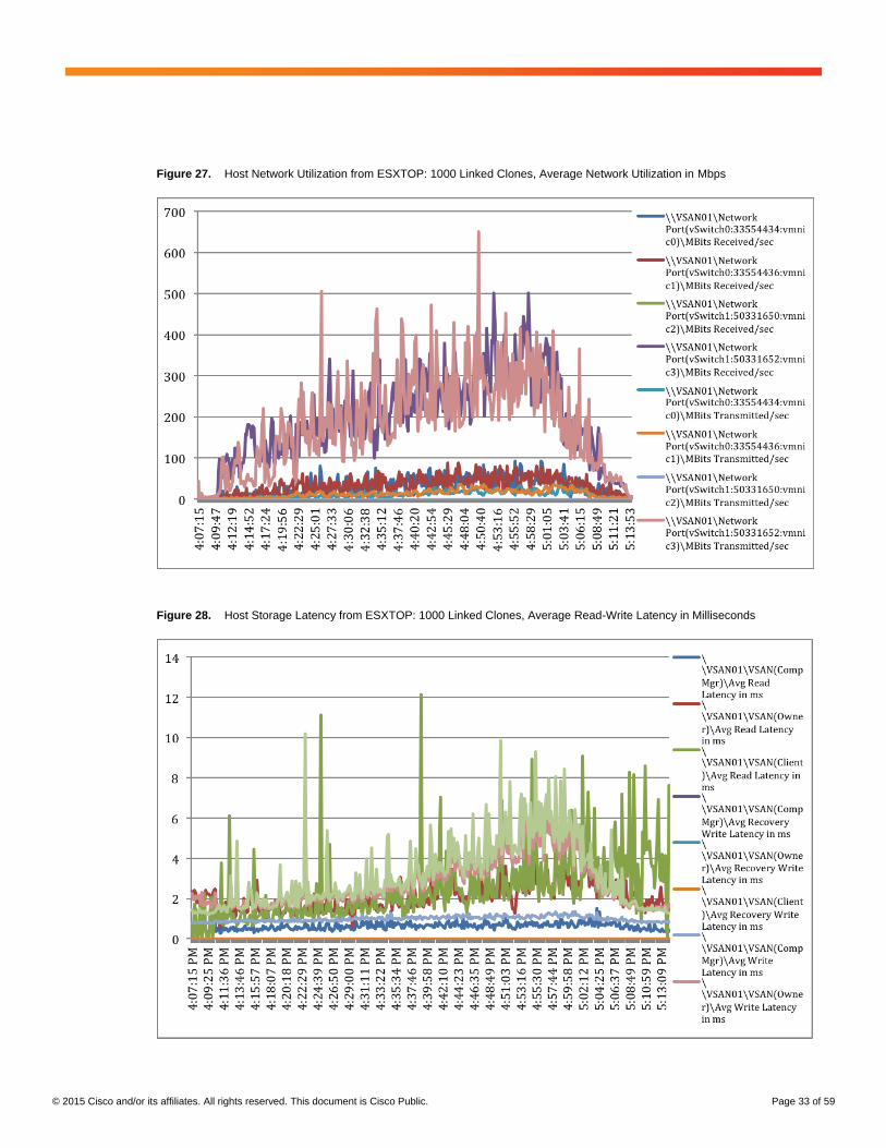
Figure 27. Host Network Utilization from ESXTOP: 1000 Linked Clones, Average Network Utilization in Mbps
Figure 28. Host Storage Latency from ESXTOP: 1000 Linked Clones, Average Read-Write Latency in Milliseconds
© 2015 Cisco and/or its affiliates. All rights reserved. This document is Cisco Public. Page 34 of 59
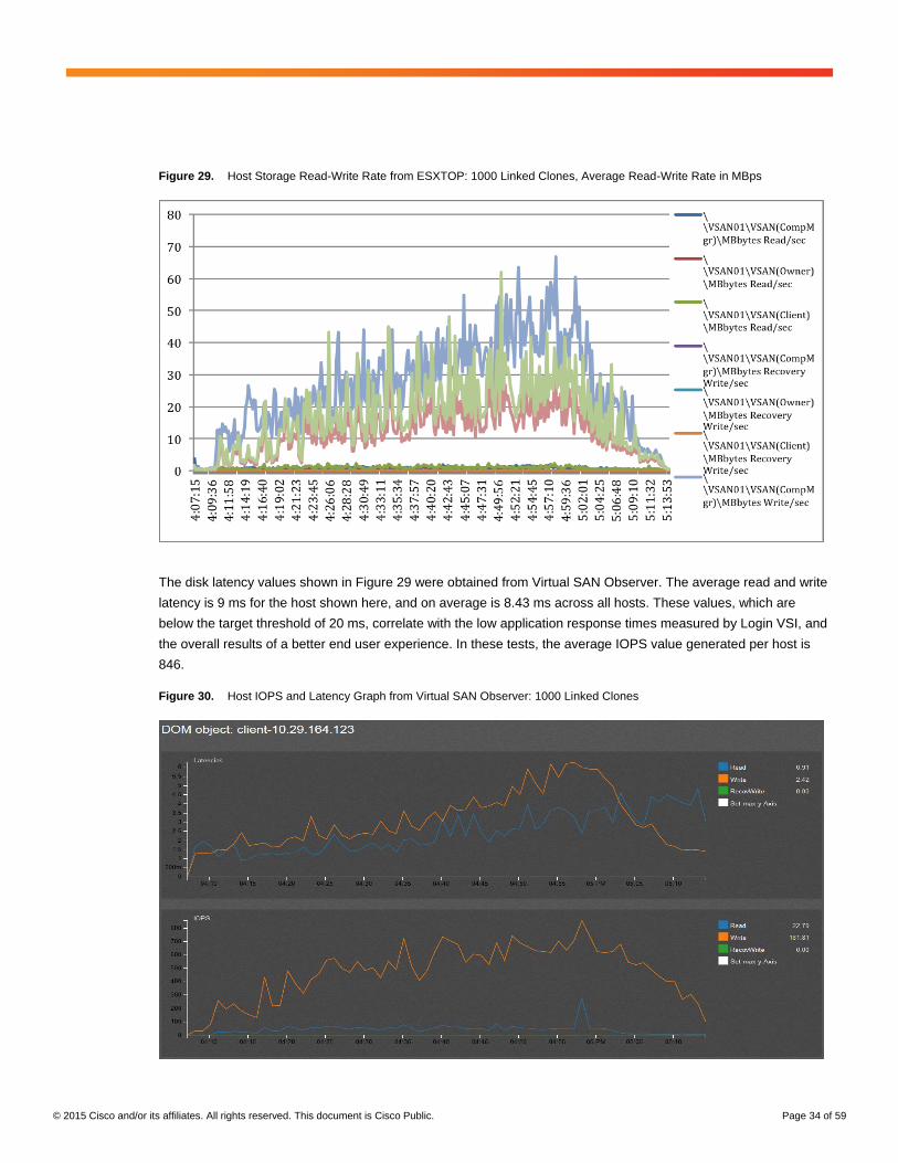
Figure 29. Host Storage Read-Write Rate from ESXTOP: 1000 Linked Clones, Average Read-Write Rate in MBps
The disk latency values shown in Figure 29 were obtained from Virtual SAN Observer. The average read and write
latency is 9 ms for the host shown here, and on average is 8.43 ms across all hosts. These values, which are
below the target threshold of 20 ms, correlate with the low application response times measured by Login VSI, and
the overall results of a better end user experience. In these tests, the average IOPS value generated per host is
846.
Figure 30. Host IOPS and Latency Graph from Virtual SAN Observer: 1000 Linked Clones
© 2015 Cisco and/or its affiliates. All rights reserved. This document is Cisco Public. Page 35 of 59
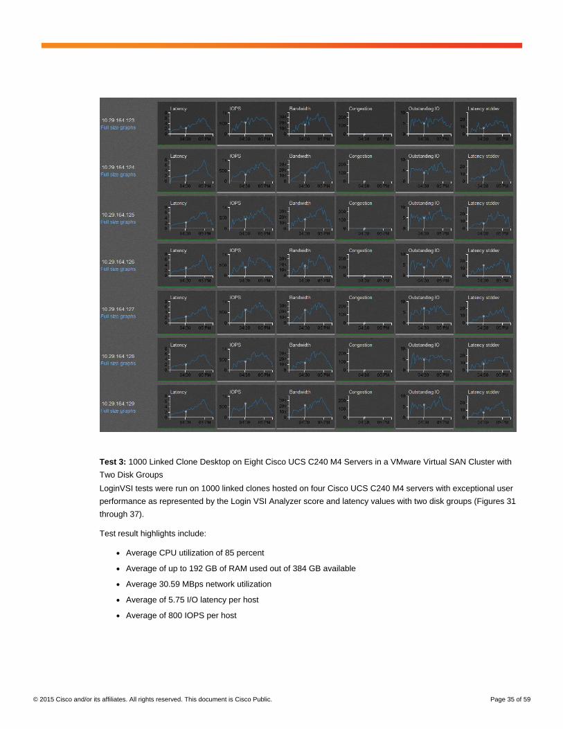
Test 3: 1000 Linked Clone Desktop on Eight Cisco UCS C240 M4 Servers in a VMware Virtual SAN Cluster with
Two Disk Groups
LoginVSI tests were run on 1000 linked clones hosted on four Cisco UCS C240 M4 servers with exceptional user
performance as represented by the Login VSI Analyzer score and latency values with two disk groups (Figures 31
through 37).
Test result highlights include:
● Average CPU utilization of 85 percent
● Average of up to 192 GB of RAM used out of 384 GB available
● Average 30.59 MBps network utilization
● Average of 5.75 I/O latency per host
● Average of 800 IOPS per host

© 2015 Cisco and/or its affiliates. All rights reserved. This document is Cisco Public. Page 36 of 59
Figure 31. LoginVSI Analyzer Chart for 1000 Sessions with EUX Response Time
Figure 32. Host CPU Utilization from ESXTOP: 1000 Linked Clones, Average CPU Utilization as a Percentage
© 2015 Cisco and/or its affiliates. All rights reserved. This document is Cisco Public. Page 37 of 59
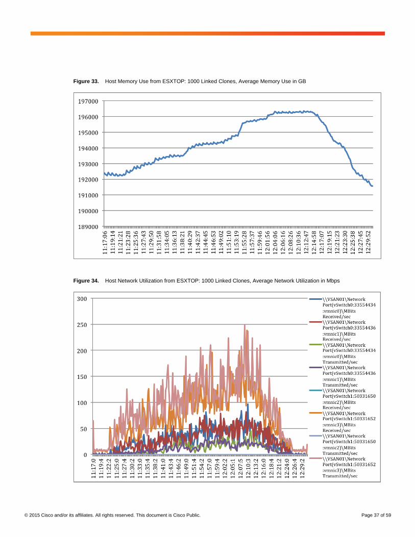
Figure 33. Host Memory Use from ESXTOP: 1000 Linked Clones, Average Memory Use in GB
Figure 34. Host Network Utilization from ESXTOP: 1000 Linked Clones, Average Network Utilization in Mbps
© 2015 Cisco and/or its affiliates. All rights reserved. This document is Cisco Public. Page 38 of 59
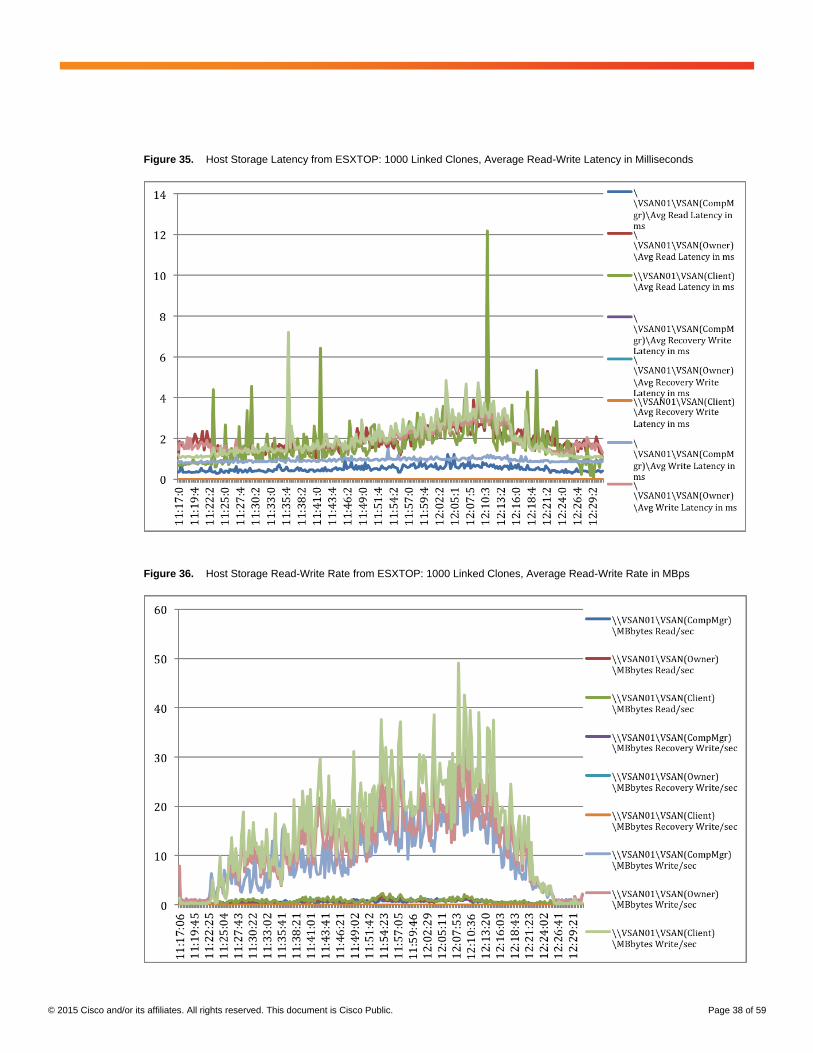
Figure 35. Host Storage Latency from ESXTOP: 1000 Linked Clones, Average Read-Write Latency in Milliseconds
Figure 36. Host Storage Read-Write Rate from ESXTOP: 1000 Linked Clones, Average Read-Write Rate in MBps
© 2015 Cisco and/or its affiliates. All rights reserved. This document is Cisco Public. Page 39 of 59
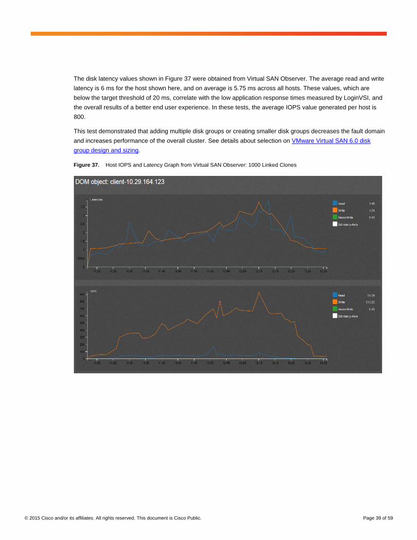
The disk latency values shown in Figure 37 were obtained from Virtual SAN Observer. The average read and write
latency is 6 ms for the host shown here, and on average is 5.75 ms across all hosts. These values, which are
below the target threshold of 20 ms, correlate with the low application response times measured by LoginVSI, and
the overall results of a better end user experience. In these tests, the average IOPS value generated per host is
800.
This test demonstrated that adding multiple disk groups or creating smaller disk groups decreases the fault domain
and increases performance of the overall cluster. See details about selection on VMware Virtual SAN 6.0 disk
group design and sizing.
Figure 37. Host IOPS and Latency Graph from Virtual SAN Observer: 1000 Linked Clones
© 2015 Cisco and/or its affiliates. All rights reserved. This document is Cisco Public. Page 40 of 59
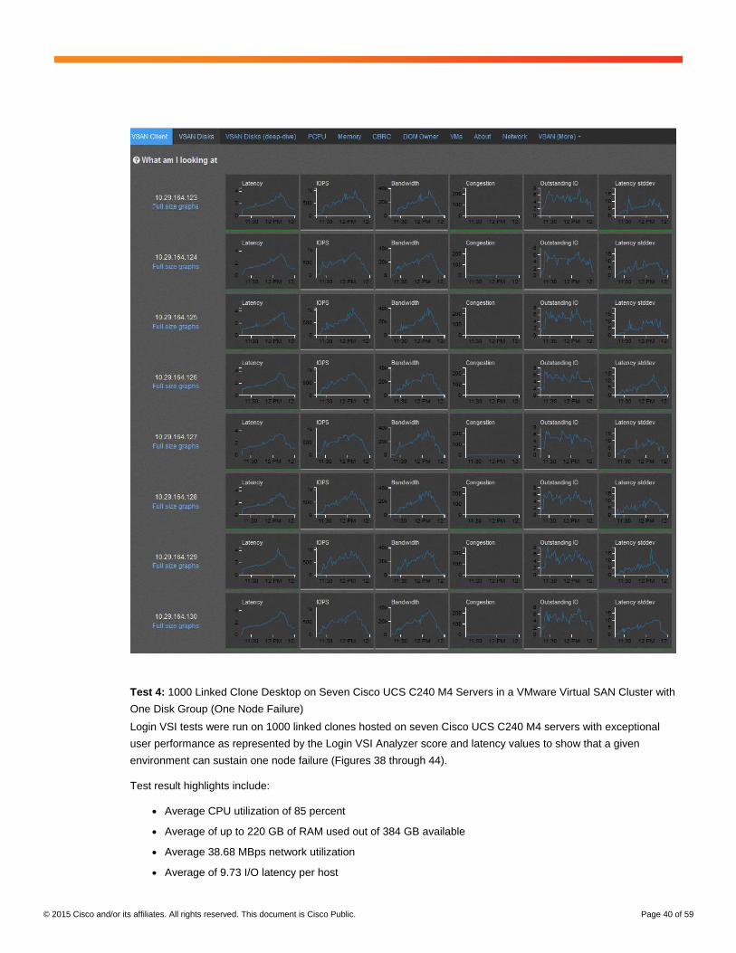
Test 4: 1000 Linked Clone Desktop on Seven Cisco UCS C240 M4 Servers in a VMware Virtual SAN Cluster with
One Disk Group (One Node Failure)
Login VSI tests were run on 1000 linked clones hosted on seven Cisco UCS C240 M4 servers with exceptional
user performance as represented by the Login VSI Analyzer score and latency values to show that a given
environment can sustain one node failure (Figures 38 through 44).
Test result highlights include:
● Average CPU utilization of 85 percent
● Average of up to 220 GB of RAM used out of 384 GB available
● Average 38.68 MBps network utilization
● Average of 9.73 I/O latency per host
© 2015 Cisco and/or its affiliates. All rights reserved. This document is Cisco Public. Page 41 of 59
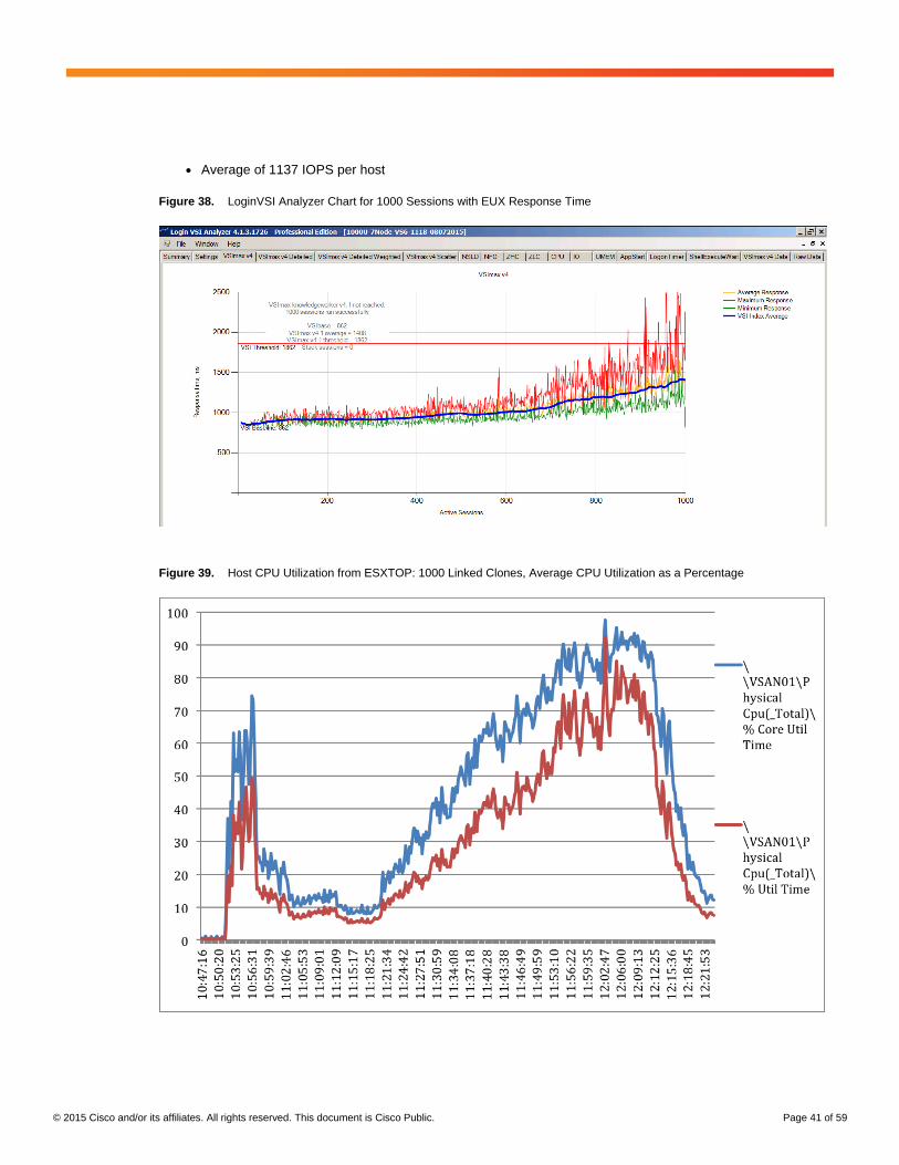
● Average of 1137 IOPS per host
Figure 38. LoginVSI Analyzer Chart for 1000 Sessions with EUX Response Time
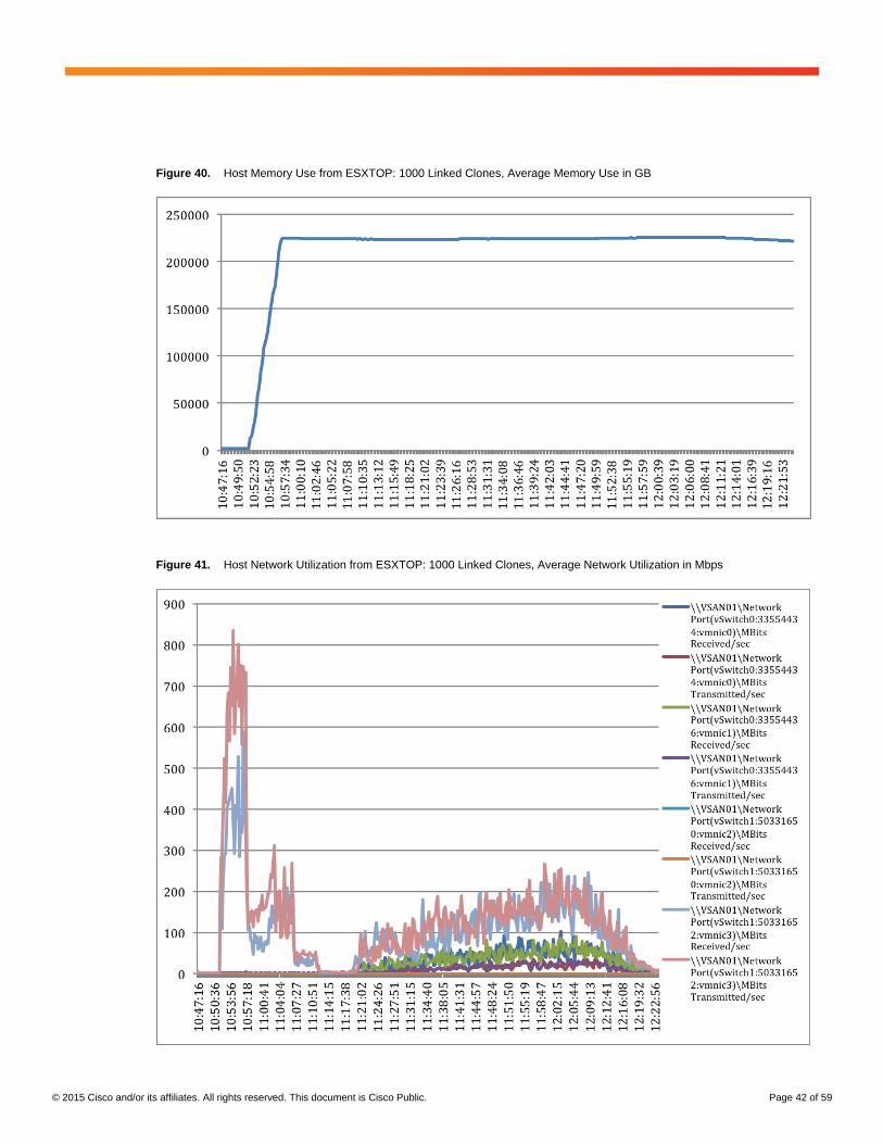
Figure 39. Host CPU Utilization from ESXTOP: 1000 Linked Clones, Average CPU Utilization as a Percentage
© 2015 Cisco and/or its affiliates. All rights reserved. This document is Cisco Public. Page 42 of 59
Figure 40. Host Memory Use from ESXTOP: 1000 Linked Clones, Average Memory Use in GB
Figure 41. Host Network Utilization from ESXTOP: 1000 Linked Clones, Average Network Utilization in Mbps
© 2015 Cisco and/or its affiliates. All rights reserved. This document is Cisco Public. Page 43 of 59
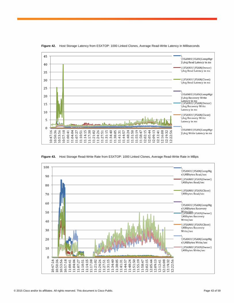
Figure 42. Host Storage Latency from ESXTOP: 1000 Linked Clones, Average Read-Write Latency in Milliseconds
Figure 43. Host Storage Read-Write Rate from ESXTOP: 1000 Linked Clones, Average Read-Write Rate in MBps
© 2015 Cisco and/or its affiliates. All rights reserved. This document is Cisco Public. Page 44 of 59
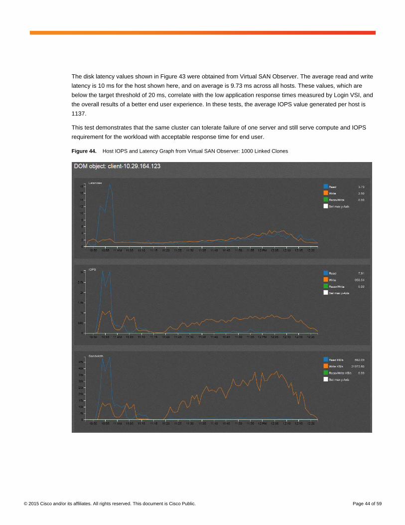
The disk latency values shown in Figure 43 were obtained from Virtual SAN Observer. The average read and write
latency is 10 ms for the host shown here, and on average is 9.73 ms across all hosts. These values, which are
below the target threshold of 20 ms, correlate with the low application response times measured by Login VSI, and
the overall results of a better end user experience. In these tests, the average IOPS value generated per host is
1137.
This test demonstrates that the same cluster can tolerate failure of one server and still serve compute and IOPS
requirement for the workload with acceptable response time for end user.
Figure 44. Host IOPS and Latency Graph from Virtual SAN Observer: 1000 Linked Clones
© 2015 Cisco and/or its affiliates. All rights reserved. This document is Cisco Public. Page 45 of 59
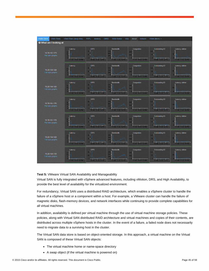
Test 5: VMware Virtual SAN Availability and Manageability
Virtual SAN is fully integrated with vSphere advanced features, including vMotion, DRS, and High Availability, to
provide the best level of availability for the virtualized environment.
For redundancy, Virtual SAN uses a distributed RAID architecture, which enables a vSphere cluster to handle the
failure of a vSphere host or a component within a host. For example, a VMware cluster can handle the failure of
magnetic disks, flash-memory devices, and network interfaces while continuing to provide complete capabilities for
all virtual machines.
In addition, availability is defined per virtual machine through the use of virtual machine storage policies. These
policies, along with Virtual SAN distributed RAID architecture and virtual machines and copies of their contents, are
distributed across multiple vSphere hosts in the cluster. In the event of a failure, a failed node does not necessarily
need to migrate data to a surviving host in the cluster.
The Virtual SAN data store is based on object-oriented storage. In this approach, a virtual machine on the Virtual
SAN is composed of these Virtual SAN objects:
● The virtual machine home or name-space directory
● A swap object (if the virtual machine is powered on)
© 2015 Cisco and/or its affiliates. All rights reserved. This document is Cisco Public. Page 46 of 59
● Virtual disks or virtual machine disks (VMDKs)
● Delta disks created for snapshots (each delta disk is an object)
The virtual machine name-space directory holds all the virtual machine files (VMware VMX files, log files, and so
on.). It excludes VMDKs, delta disks, and swap files, which are maintained as separate objects.
This approach is important because it determines the way in which objects and components are built and
distributed in the Virtual SAN. For instance, soft limitations exist, and exceeding those limitations can affect
performance.
In addition, witnesses are deployed to arbitrate between the remaining copies of data in the event of a failure within
the Virtual SAN cluster. The witness component helps ensure that split-brain scenarios do not occur.
Witness deployment is not predicated on any failures-to-tolerate (FTT) or stripe-width policy settings. Rather,
witness components are defined as primary, secondary, and tie-breaker and are deployed based on a defined set
of rules, as follows:
● Primary witnesses: Primary witnesses require at least (2 x FTT) + 1 nodes in a cluster to tolerate the FTT
number of node and disk failures. If the configuration does not have the required number of nodes after all
the data components have been placed, the primary witnesses are placed on exclusive nodes until the
configuration has (2 x FTT) + 1 nodes.
● Secondary witnesses: Secondary witnesses are created to help ensure that each node has equal voting
power toward a quorum. This capability is important because each node failure needs to affect the quorum
equally. Secondary witnesses are added to allow each node to receive an equal number of components,
including the nodes that hold only primary witnesses. The total count of data components, plus the number
of witnesses on each node, are equalized in this step.
● Tie-breaker witnesses: After primary witnesses and secondary witnesses have been added, if the
configuration has an even number of total components (data and witnesses), then one tie-breaker witness is
added to make the total component count an odd number.
The following sections describe the Virtual SAN data-store scenarios that provide resiliency and availability for
while day-to-day operations are performed.
Planned Maintenance
For planned operations, Virtual SAN provides three host maintenance mode options: Ensure Accessibility, Full
Data Migration, and No Data Migration. These options are described in the sections that follow.
Ensure Accessibility
The Ensure Accessibility option is the default host maintenance mode. With this option, Virtual SAN helps ensure
that all accessible virtual machines on the host remain accessible both when the host is powered off and when it is
removed from the cluster. In this case, Virtual SAN copies just enough data to other hosts in the cluster to help
ensure the continued operation of all virtual machines, even if this results in a situation that violates the FTT policy.
Use this option only used when the host is intended to remain in maintenance mode for only a short period of time.
During this time period, the system cannot guarantee resiliency against failures.
© 2015 Cisco and/or its affiliates. All rights reserved. This document is Cisco Public. Page 47 of 59
Typically, this option requires only partial data evacuation. Select Ensure Accessibility to remove the host from the
cluster temporarily, such as to install upgrades, and then to return the host to the same cluster. Do not use this
option to permanently remove the host from the cluster.
Full Data Migration
When you select the Full Data Migration option, Virtual SAN moves all of its data to other hosts in the cluster. Then
it maintains or fixes availability compliance for the affected components in the cluster. This option results in the
largest amount of data transfer, and this migration consumes the most time and resources.
Select the Full Data Migration option only when the host needs to be migrated permanently. When evacuating data
from the last host in the cluster, be sure to migrate the virtual machines to another data store and then put the host
in maintenance mode.
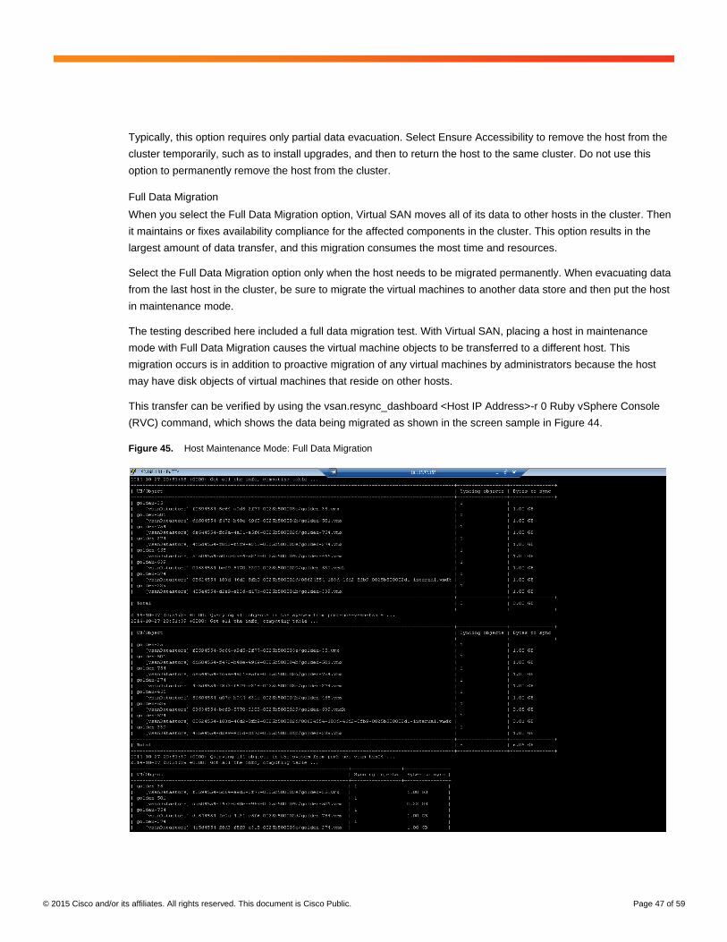
The testing described here included a full data migration test. With Virtual SAN, placing a host in maintenance
mode with Full Data Migration causes the virtual machine objects to be transferred to a different host. This
migration occurs is in addition to proactive migration of any virtual machines by administrators because the host
may have disk objects of virtual machines that reside on other hosts.
This transfer can be verified by using the vsan.resync_dashboard <Host IP Address>-r 0 Ruby vSphere Console
(RVC) command, which shows the data being migrated as shown in the screen sample in Figure 44.
Figure 45. Host Maintenance Mode: Full Data Migration
© 2015 Cisco and/or its affiliates. All rights reserved. This document is Cisco Public. Page 48 of 59
No Data Migration
When No Data Migration is selected, Virtual SAN does not evacuate any data from this host. If the host is powered
off or removed from the cluster, some virtual machines may become inaccessible.
VMware Virtual SAN Failure Simulations
In some cases, during ongoing operations in a Virtual SAN environment, either an individual disk failure or a host
failure may affect virtual machine availability depending on the storage policies applied. This section simulates
these failure scenarios to provide an understanding of how Virtual SAN maintains storage data that is highly
available under different conditions.
Magnetic Disk Failure Simulation
In a Virtual SAN environment, if a magnetic disk storing any component of any object fails, it is marked as
“Degraded” and Virtual SAN immediately begins to rebuild components from that disk onto other disks. This action
is usually triggered when a drive or controller reports some kind of physical hardware failure.
However, if a magnetic disk goes offline, it is marked “Absent.” In this case, Virtual SAN does not immediately
rebuild components. Instead, it waits a default time of 60 minutes for the drive to be replaced or restored. This
response is usually triggered by pulling a drive from its slot. During this time period, virtual machines continue to
run using replicas of their components that exist on other drives. The only virtual machines that cease functioning
are those that have a failure policy of FTT=0 and have the sole copy of their data stored on the offline drive.
If the drive is replaced within 60 minutes, Virtual SAN simply updates the data on that drive to synchronize it with
the live data from the rest of the cluster. When the drive has not been replaced after 60 minutes, Virtual SAN
changes the state of the drive to “Degraded” and then begins to rebuild the data on other drives.
Note that you can modify the Virtual SAN default 60-minute repair-delay time. For more information, see Changing
the Default Repair-Delay Time for a Host Failure in VMware Virtual SAN.
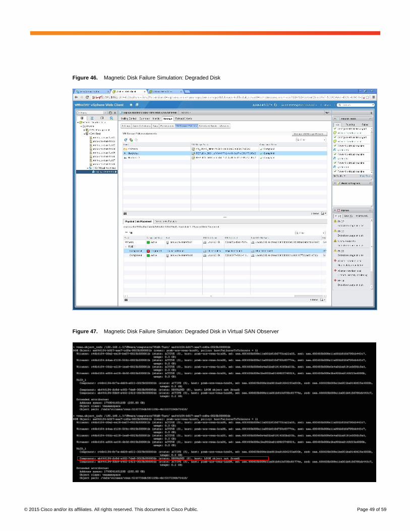
For this simulation, object placements for the replica virtual machine are configured with FTT=1 and use the default
storage policies. The magnetic disk is removed from the disk group as shown in the “Object not found” message in
Figure 45. After the default wait time has passed, the state of the drive changes from “Absent” to “Degraded.”
Another way to check the disk object information is by using the RVC command vsan.disk_object_info. In this case,
one of the disks is not found, as shown in the sample in Figure 46.
© 2015 Cisco and/or its affiliates. All rights reserved. This document is Cisco Public. Page 49 of 59
Figure 46. Magnetic Disk Failure Simulation: Degraded Disk
Figure 47. Magnetic Disk Failure Simulation: Degraded Disk in Virtual SAN Observer
© 2015 Cisco and/or its affiliates. All rights reserved. This document is Cisco Public. Page 50 of 59
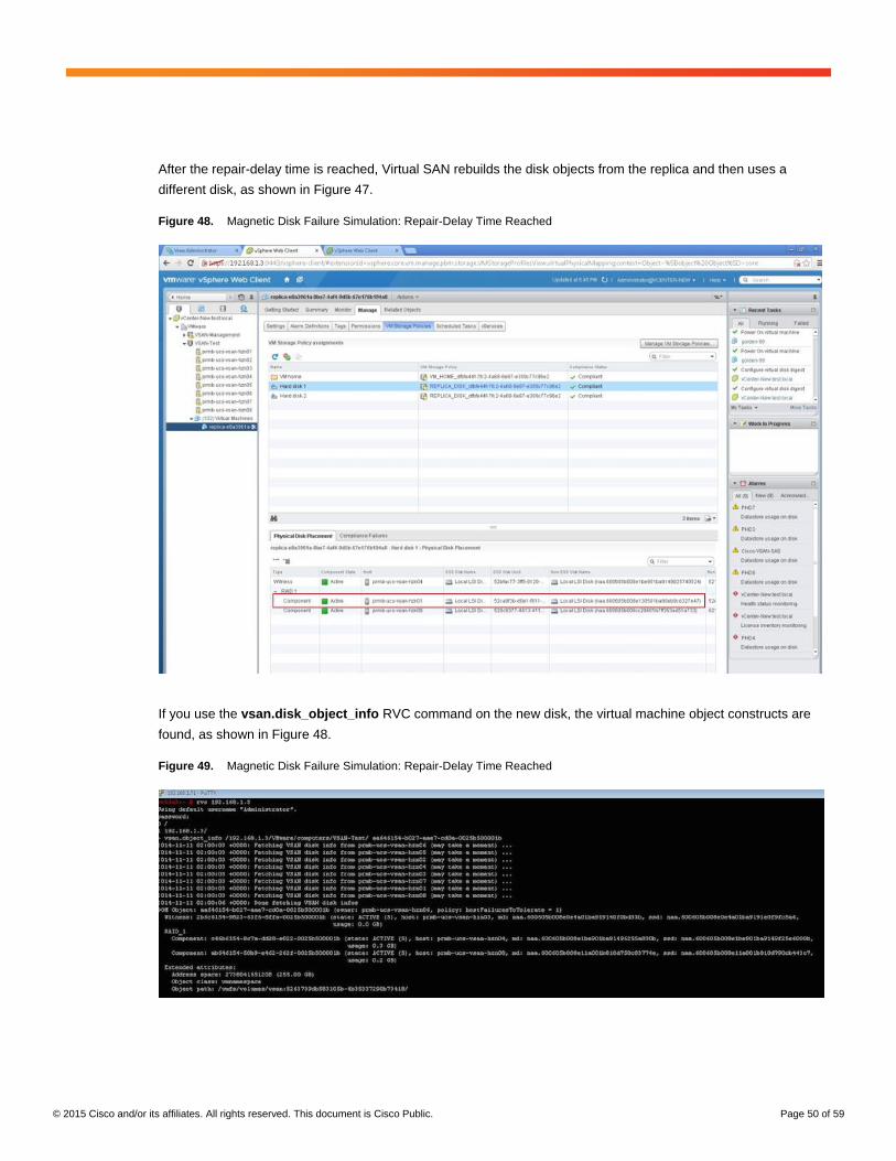
After the repair-delay time is reached, Virtual SAN rebuilds the disk objects from the replica and then uses a
different disk, as shown in Figure 47.
Figure 48. Magnetic Disk Failure Simulation: Repair-Delay Time Reached
If you use the vsan.disk_object_info RVC command on the new disk, the virtual machine object constructs are
found, as shown in Figure 48.
Figure 49. Magnetic Disk Failure Simulation: Repair-Delay Time Reached
© 2015 Cisco and/or its affiliates. All rights reserved. This document is Cisco Public. Page 51 of 59
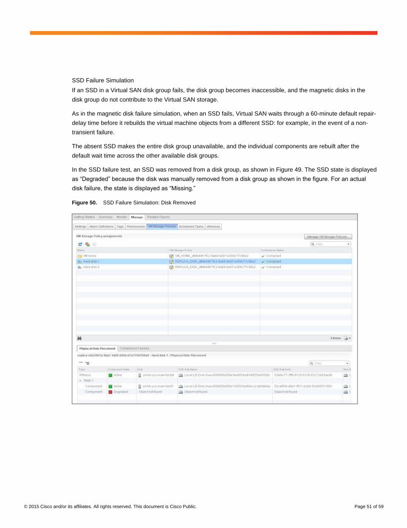
SSD Failure Simulation
If an SSD in a Virtual SAN disk group fails, the disk group becomes inaccessible, and the magnetic disks in the
disk group do not contribute to the Virtual SAN storage.
As in the magnetic disk failure simulation, when an SSD fails, Virtual SAN waits through a 60-minute default repair-
delay time before it rebuilds the virtual machine objects from a different SSD: for example, in the event of a non-
transient failure.
The absent SSD makes the entire disk group unavailable, and the individual components are rebuilt after the
default wait time across the other available disk groups.
In the SSD failure test, an SSD was removed from a disk group, as shown in Figure 49. The SSD state is displayed
as “Degraded” because the disk was manually removed from a disk group as shown in the figure. For an actual
disk failure, the state is displayed as “Missing.”
Figure 50. SSD Failure Simulation: Disk Removed
© 2015 Cisco and/or its affiliates. All rights reserved. This document is Cisco Public. Page 52 of 59
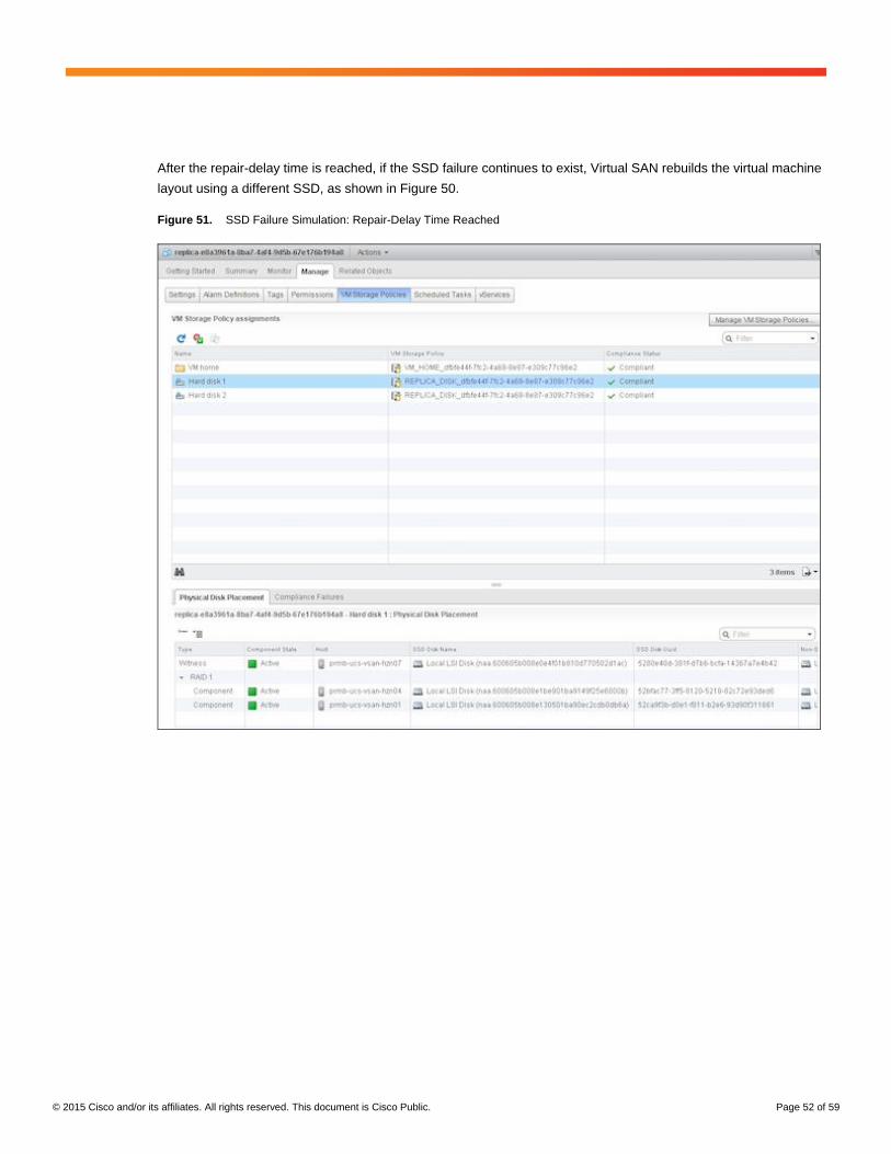
After the repair-delay time is reached, if the SSD failure continues to exist, Virtual SAN rebuilds the virtual machine
layout using a different SSD, as shown in Figure 50.
Figure 51. SSD Failure Simulation: Repair-Delay Time Reached

© 2015 Cisco and/or its affiliates. All rights reserved. This document is Cisco Public. Page 53 of 59
Network Failure Simulation
The Virtual SAN VMkernel network is configured with redundant virtual networks connected to Cisco UCS fabric
interconnects A and B.
To verify that the Virtual SAN traffic is not disrupted, the physical port was disabled from Cisco UCS Manager to
display a continuous VMkernel ping (vmkping) to the Virtual SAN IP address on the dedicated network, as shown
in Figures 51 and 52.
Figure 52. Network Failure Simulation
Figure 53. Network Failure Simulation: VMware Standard vSwitch
© 2015 Cisco and/or its affiliates. All rights reserved. This document is Cisco Public. Page 54 of 59
Similar redundancy for the management network in a Virtual SAN environment is also anticipated.
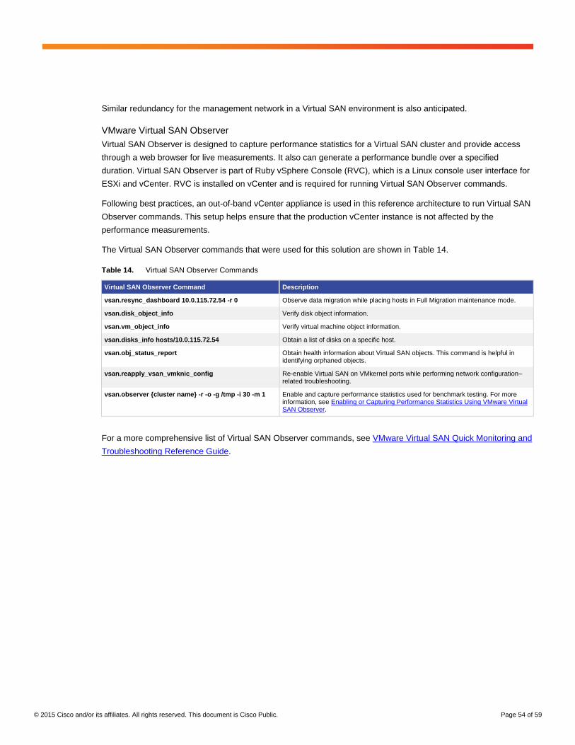
VMware Virtual SAN Observer
Virtual SAN Observer is designed to capture performance statistics for a Virtual SAN cluster and provide access
through a web browser for live measurements. It also can generate a performance bundle over a specified
duration. Virtual SAN Observer is part of Ruby vSphere Console (RVC), which is a Linux console user interface for
ESXi and vCenter. RVC is installed on vCenter and is required for running Virtual SAN Observer commands.
Following best practices, an out-of-band vCenter appliance is used in this reference architecture to run Virtual SAN
Observer commands. This setup helps ensure that the production vCenter instance is not affected by the
performance measurements.
The Virtual SAN Observer commands that were used for this solution are shown in Table 14.
Table 14. Virtual SAN Observer Commands
Virtual SAN Observer Command Description
vsan.resync_dashboard 10.0.115.72.54 -r 0 Observe data migration while placing hosts in Full Migration maintenance mode.
vsan.disk_object_info Verify disk object information.
vsan.vm_object_info Verify virtual machine object information.
vsan.disks_info hosts/10.0.115.72.54 Obtain a list of disks on a specific host.
vsan.obj_status_report Obtain health information about Virtual SAN objects. This command is helpful in identifying orphaned objects.
vsan.reapply_vsan_vmknic_config Re-enable Virtual SAN on VMkernel ports while performing network configuration–related troubleshooting.
vsan.observer {cluster name} -r -o -g /tmp -i 30 -m 1 Enable and capture performance statistics used for benchmark testing. For more information, see Enabling or Capturing Performance Statistics Using VMware Virtual SAN Observer.
For a more comprehensive list of Virtual SAN Observer commands, see VMware Virtual SAN Quick Monitoring and
Troubleshooting Reference Guide.
© 2015 Cisco and/or its affiliates. All rights reserved. This document is Cisco Public. Page 55 of 59
System Sizing
The reference architecture uses the sizing specifications described in this section.
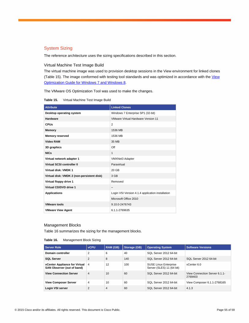
Virtual Machine Test Image Build
The virtual machine image was used to provision desktop sessions in the View environment for linked clones
(Table 15). The image conformed with testing tool standards and was optimized in accordance with the View
Optimization Guide for Windows 7 and Windows 8.
The VMware OS Optimization Tool was used to make the changes.
Table 15. Virtual Machine Test Image Build
Attribute Linked Clones
Desktop operating system Windows 7 Enterprise SP1 (32-bit)
Hardware VMware Virtual Hardware Version 11
CPUs 2
Memory 1536 MB
Memory reserved 1536 MB
Video RAM 35 MB
3D graphics Off
NICs 1
Virtual network adapter 1 VMXNet3 Adapter
Virtual SCSI controller 0 Paravirtual
Virtual disk: VMDK 1 20 GB
Virtual disk: VMDK 2 (non-persistent disk) 3 GB
Virtual floppy drive 1 Removed
Virtual CD/DVD drive 1 –
Applications Login VSI Version 4.1.4 application installation
Microsoft Office 2010
VMware tools 9.10.0-2476743
VMware View Agent 6.1.1-2769635
Management Blocks
Table 16 summarizes the sizing for the management blocks.
Table 16. Management Block Sizing
Server Role vCPU RAM (GB) Storage (GB) Operating System Software Versions
Domain controller 2 6 40 SQL Server 2012 64-bit
SQL Server 2 8 140 SQL Server 2012 64-bit SQL Server 2012 64-bit
vCenter Appliance for Virtual SAN Observer (out of band)
4 12 100 SUSE Linux Enterprise Server (SLES) 11 (64 bit)
vCenter 6.0
View Connection Server 4 10 60 SQL Server 2012 64-bit View Connection Server 6.1.1-2769403
View Composer Server 4 10 60 SQL Server 2012 64-bit View Composer 6.1.1-2768165
Login VSI server 2 4 60 SQL Server 2012 64-bit 4.1.3
© 2015 Cisco and/or its affiliates. All rights reserved. This document is Cisco Public. Page 56 of 59
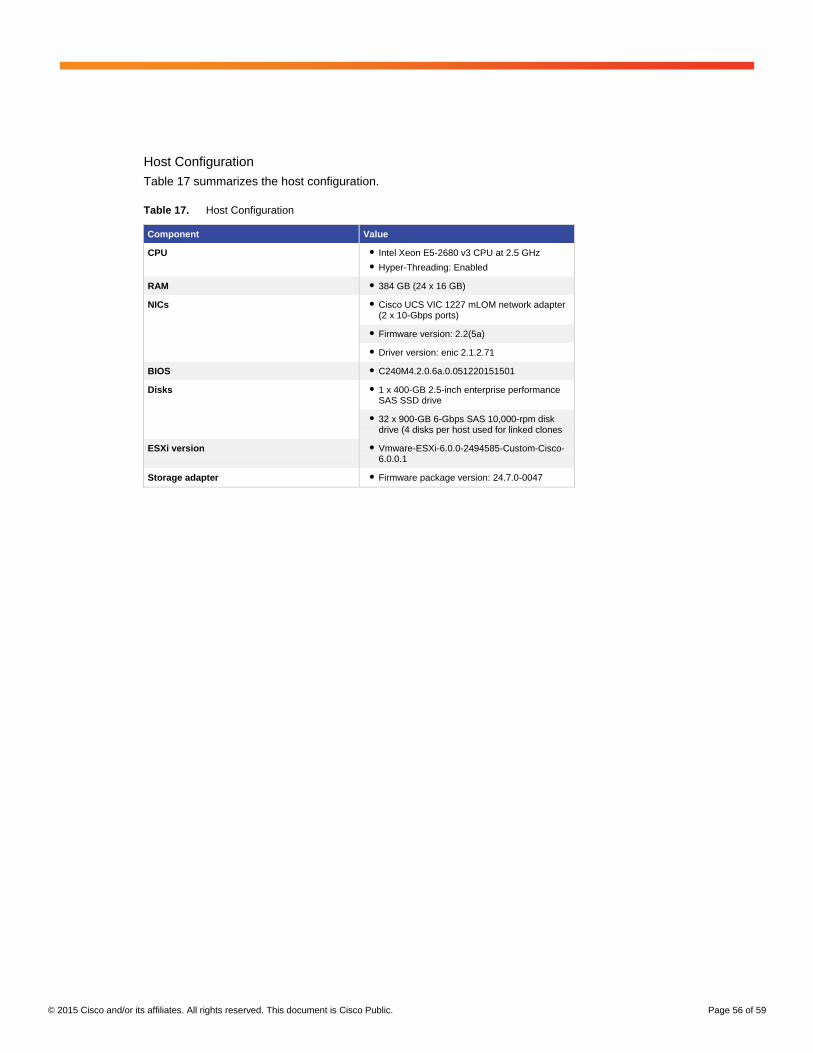
Host Configuration
Table 17 summarizes the host configuration.
Table 17. Host Configuration
Component Value
CPU ● Intel Xeon E5-2680 v3 CPU at 2.5 GHz
● Hyper-Threading: Enabled
RAM ● 384 GB (24 x 16 GB)
NICs ● Cisco UCS VIC 1227 mLOM network adapter (2 x 10-Gbps ports)
● Firmware version: 2.2(5a)
● Driver version: enic 2.1.2.71
BIOS ● C240M4.2.0.6a.0.051220151501
Disks ● 1 x 400-GB 2.5-inch enterprise performance SAS SSD drive
● 32 x 900-GB 6-Gbps SAS 10,000-rpm disk drive (4 disks per host used for linked clones
ESXi version ● Vmware-ESXi-6.0.0-2494585-Custom-Cisco-6.0.0.1
Storage adapter ● Firmware package version: 24.7.0-0047
© 2015 Cisco and/or its affiliates. All rights reserved. This document is Cisco Public. Page 57 of 59
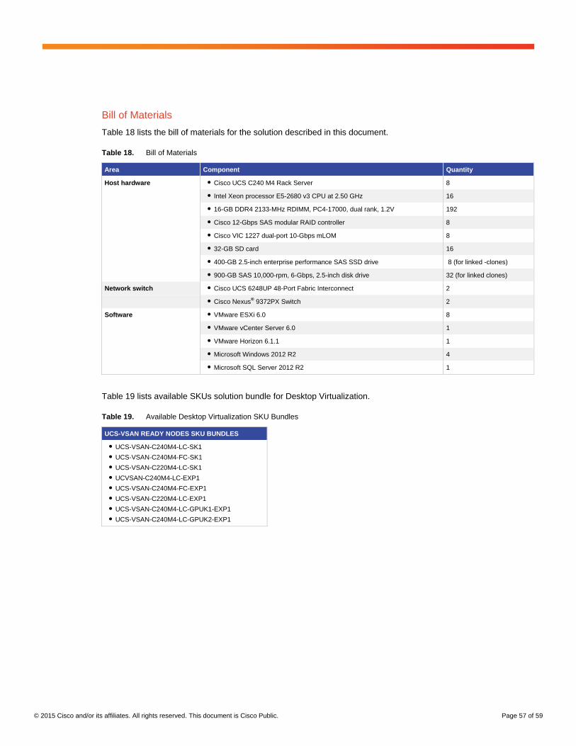
Bill of Materials
Table 18 lists the bill of materials for the solution described in this document.
Table 18. Bill of Materials
Area Component Quantity
Host hardware ● Cisco UCS C240 M4 Rack Server 8
● Intel Xeon processor E5-2680 v3 CPU at 2.50 GHz 16
● 16-GB DDR4 2133-MHz RDIMM, PC4-17000, dual rank, 1.2V 192
● Cisco 12-Gbps SAS modular RAID controller 8
● Cisco VIC 1227 dual-port 10-Gbps mLOM 8
● 32-GB SD card 16
● 400-GB 2.5-inch enterprise performance SAS SSD drive 8 (for linked -clones)
● 900-GB SAS 10,000-rpm, 6-Gbps, 2.5-inch disk drive 32 (for linked clones)
Network switch ● Cisco UCS 6248UP 48-Port Fabric Interconnect 2
● Cisco Nexus® 9372PX Switch 2
Software ● VMware ESXi 6.0 8
● VMware vCenter Server 6.0 1
● VMware Horizon 6.1.1 1
● Microsoft Windows 2012 R2 4
● Microsoft SQL Server 2012 R2 1
Table 19 lists available SKUs solution bundle for Desktop Virtualization.
Table 19. Available Desktop Virtualization SKU Bundles
UCS-VSAN READY NODES SKU BUNDLES
● UCS-VSAN-C240M4-LC-SK1
● UCS-VSAN-C240M4-FC-SK1
● UCS-VSAN-C220M4-LC-SK1
● UCVSAN-C240M4-LC-EXP1
● UCS-VSAN-C240M4-FC-EXP1
● UCS-VSAN-C220M4-LC-EXP1
● UCS-VSAN-C240M4-LC-GPUK1-EXP1
● UCS-VSAN-C240M4-LC-GPUK2-EXP1
© 2015 Cisco and/or its affiliates. All rights reserved. This document is Cisco Public. Page 58 of 59
Conclusion
A solution implementing VMware Virtual SAN 6.0 and Horizon 6 on Cisco UCS C240 M4 Rack Servers provides
linear scalability with exceptional end-user performance. A simpler management experience is achieved with Cisco
UCS Manager centrally managing the infrastructure. VMware Virtual SAN configuration, management, and
monitoring is integrated into VMware vSphere. This solution provides cost-effective scaling for virtual desktop
deployments of 3 to 64 nodes.
The reference architecture demonstrates following main capacities:
● Linear scalability is achieved with Virtual SAN as the storage solution on Cisco UCS for hosting VMware
View–based virtual desktops. The reference architecture successfully scaled from 500 desktops on four
Cisco UCS C240 M4 nodes to 1000 desktops on eight nodes, keeping all aspects of end-user performance
consistently acceptable with disk latency of less than 15 ms and application response times of faster than
3 ms.
● Optimal performance is achieved while performing all virtual desktop operations such as refresh,
recompose, deploy, power-on, and power-off operations. Times measured for these operations fall within
industry-measured benchmarks and provide a testimony of the joint solution’s scalability.
● To achieve better performance, future expandability and minimize failure domain in a Virtual SAN
environment disk group design is a critical factor. Multiple or smaller disk-group design reduces failure
domain compared to a single-disk-group design, although it adds cost and reduces the number of disk slots
available.
● Virtual SAN provides highly available and resilient storage for hosting View virtual desktops. Multiple
maintenance and failure scenarios tested demonstrate the resiliency of the joint solution.
© 2015 Cisco and/or its affiliates. All rights reserved. This document is Cisco Public. Page 59 of 59
For More Information
● Virtual SAN Ready Nodes for Cisco UCS
● Cisco UCS C240 M4 High-Density Rack Server (SFF Disk-Drive Model) specification sheet
● Cisco UCS C240 M3 with VMware Virtual SAN 5.5 and Horizon 6 with View
● What’s New in VMware Virtual SAN
● Cisco FlexFlash: Use and Manage Cisco Flexible Flash Internal SD Card for Cisco UCS C-Series
Standalone Rack Servers
● VMware Virtual SAN Compatibility Guide
● Changing the Default Repair-Delay Time for a Host Failure in VMware Virtual SAN
● I/O Analyzer
● Ruby vSphere Console (RVC)
● Enabling or Capturing Performance Statistics Using VMware Virtual SAN Observer
● View Optimization Guide for Windows 7 and Windows 8
● VMware Virtual SAN Quick Monitoring and Troubleshooting Reference Guide
● Working with VMware Virtual SAN
● VMware Virtual SAN Ready System Recommended Configurations
● Enabling or Capturing Statistics Using VMware Virtual SAN Observer for VMware Virtual SAN Resources
Printed in USA C11-735680-00 09/15
Related Documents