Installing Cisco TelePresence MX300 G2 - Floor Stand 78-101182-01A0 | JUNE 2017 | © 2017 Cisco Systems, Inc. All rights reserved. 1 This installation guide covers MX300 G2 with a floor stand. Dimensions Height: 1521 mm / 59.9 in. Width: 1278 mm / 50.4 in. Depth: 671 mm / 26.5 in. Weight total: 53 kg / 117 lb Weight monitor: 35 kg / 78 lb Manpower Two people working together are required to mount the monitor to the base module. Room setup Explore the Cisco Project Workplace website to find inspiration and guidelines when preparing your office or meeting room for video conferencing, http://www.cisco.com/go/projectworkplace Documentation Cisco Spark: Visit the Cisco Spark help site to find more information about Spark registered room systems, http://help.ciscospark.com Other services: Visit the Cisco web site to find user guides and compliance and safety information for the video system, http://www.cisco.com/go/mx-docs

Welcome message from author
This document is posted to help you gain knowledge. Please leave a comment to let me know what you think about it! Share it to your friends and learn new things together.
Transcript

Installing Cisco TelePresence MX300 G2 - Floor Stand
78-101182-01A0 | JUNE 2017 | © 2017 Cisco Systems, Inc. All rights reserved. 1
This installation guide covers MX300 G2 with a floor stand.
Dimensions
Height: 1521 mm / 59.9 in.Width: 1278 mm / 50.4 in.Depth: 671 mm / 26.5 in.Weight total: 53 kg / 117 lbWeight monitor: 35 kg / 78 lb
ManpowerTwo people working together are required to mount the monitor to the base module.
Room setup
Explore the Cisco Project Workplace website to find inspiration and guidelines when preparing your office or meeting room for video conferencing, http://www.cisco.com/go/projectworkplace
Documentation
Cisco Spark: Visit the Cisco Spark help site to find more information about Spark registered room systems, http://help.ciscospark.com
Other services: Visit the Cisco web site to find user guides and compliance and safety information for the video system, http://www.cisco.com/go/mx-docs
Installing Cisco TelePresence MX300 G2 - Floor Stand
78-101182-01A0 | JUNE 2017 | © 2017 Cisco Systems, Inc. All rights reserved. 2
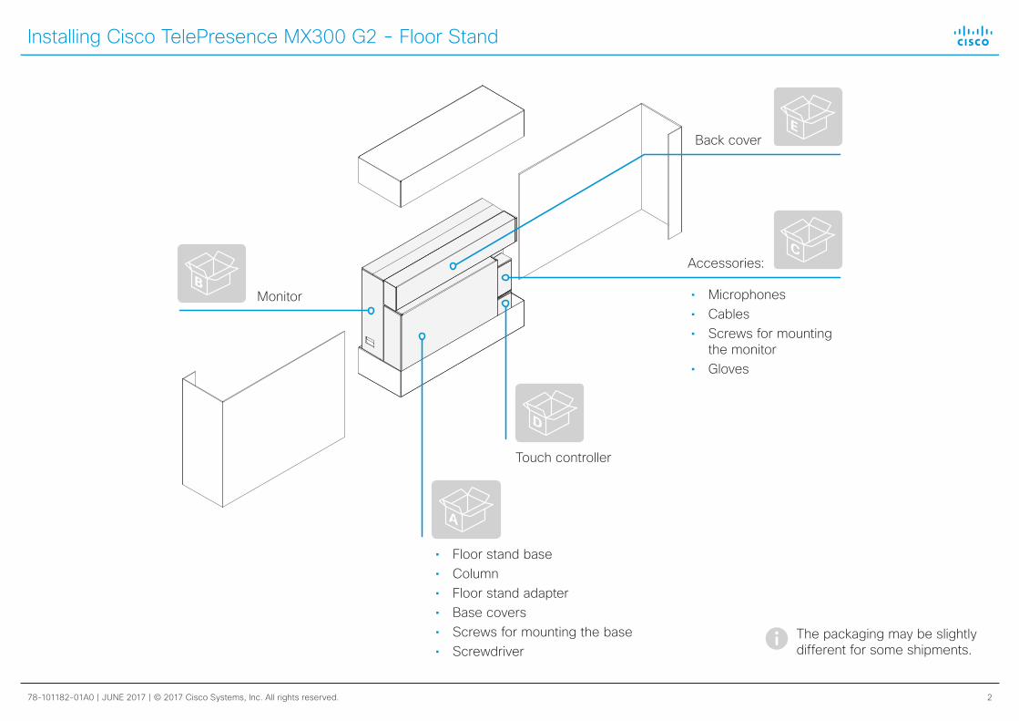
• Floor stand base• Column• Floor stand adapter• Base covers• Screws for mounting the base• Screwdriver
Back cover
Monitor
Accessories:
• Microphones• Cables• Screws for mounting
the monitor• Gloves
Touch controller
C
D
A
B
E
The packaging may be slightly different for some shipments.

Installing Cisco TelePresence MX300 G2 - Floor Stand
78-101182-01A0 | JUNE 2017 | © 2017 Cisco Systems, Inc. All rights reserved. 3
1 Mounting the floor stand
A
4 × M6x16
4 × M6x25
1
2

Installing Cisco TelePresence MX300 G2 - Floor Stand
78-101182-01A0 | JUNE 2017 | © 2017 Cisco Systems, Inc. All rights reserved. 4
2 Mounting the monitor
Use gloves when handling the monitor.
Remove the cable channel lid for now. You need it in step 4.
The monitor may be tilting slightly forward. If you gently pull it to a vertical position, the screws enter more easily.
Front
4 × M6x16B C

Installing Cisco TelePresence MX300 G2 - Floor Stand
78-101182-01A0 | JUNE 2017 | © 2017 Cisco Systems, Inc. All rights reserved. 5
3 Connecting the cables
For maintenance only
Reset to factory settings
Audio line output
Always use the provided power cable.
The wall socket outlet must be easily accessible after installation.
Power switch
Audio line input
LAN **
Video input (e.g. PC *)
Video output (e.g. 2nd display *)
Power (100-240 VAC, 50/60 Hz) Microphones
Touch controller **
USB, for future use
HDMI
DVI-I
* Optional
** Use the cable that is labeled with for the Touch controller;
use the cable that is labeled with for the LAN
C D

Installing Cisco TelePresence MX300 G2 - Floor Stand
78-101182-01A0 | JUNE 2017 | © 2017 Cisco Systems, Inc. All rights reserved. 6
5 Starting up the system
• Connect to power and LAN/Ethernet.
• Switch on the system. The power switch is next to the power connector at the rear side of the system.
Wait while the unit starts up. Normally this takes a few minutes. It may include automatic software upgrade and restart of the Touch controller.
• Follow the instructions on the Touch controller.
Cisco Spark: To find more information on how to get started with Spark registered systems, visit http://help.ciscospark.com and look for Getting Started articles for room systems.
Other services: For further information on set-up and configuration, download the Getting Started Guide from the Cisco web site, http://www.cisco.com/go/mx-docs
Never move the camera manually when power is switched on; always use the camera control function on the Touch controller to change the camera position.
4 Leading out the cables
Snap on the cable channel lid for strain relief.
Lead the cables in the cable slots. Lead them out at the front or back as appropriate.
Lead the cables around the cable slot several times if the cables are longer than you need.
Installing Cisco TelePresence MX300 G2 - Floor Stand
78-101182-01A0 | JUNE 2017 | © 2017 Cisco Systems, Inc. All rights reserved. 7
On our web site you will find an overview of the worldwide Cisco contacts.
Go to: http://www.cisco.com/go/offices
Corporate HeadquartersCisco Systems, Inc.
170 West Tasman Dr.San Jose, CA 95134 USA
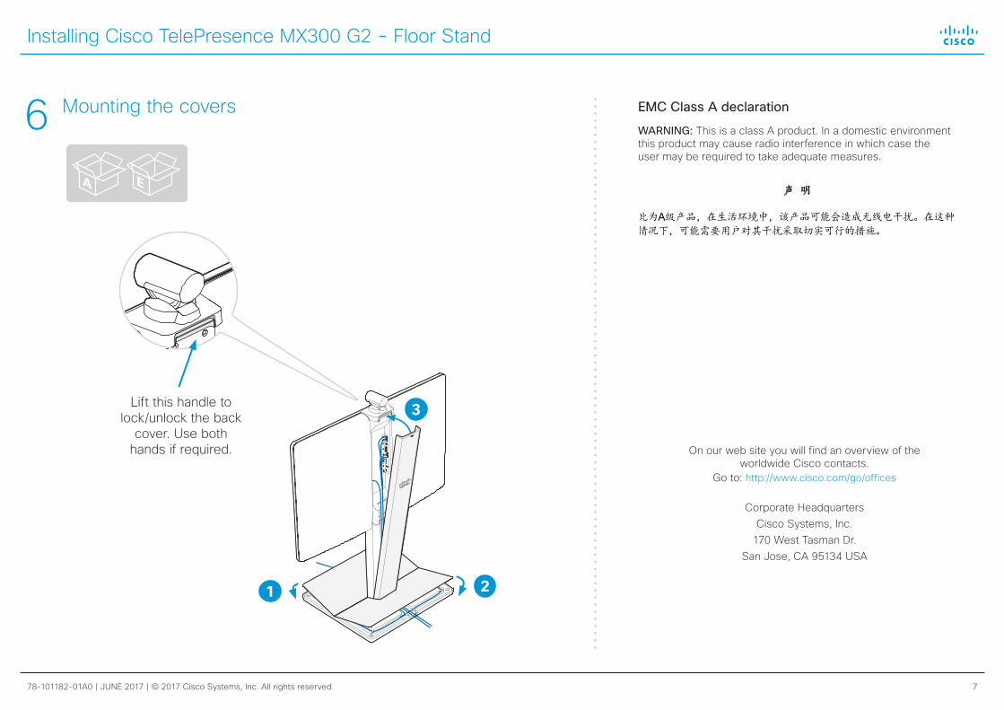
EMC Class A declaration
WARNING: This is a class A product. In a domestic environment this product may cause radio interference in which case the user may be required to take adequate measures.
声 明 此为A级产品,在生活环境中,该产品可能会造成无线电干扰。在这种情况下,可能需要用户对其干扰采取切实可行的措施。
WARNING: This is a class A product. In a domestic environment this product may cause radio interference in which case the user may be required to take adequate measures.
Lift this handle to lock/unlock the back
cover. Use both hands if required.
6 Mounting the covers
1 2
3
A E
Related Documents