Cisco Service Control Application for Broadband (Cisco SCA BB) User Guide First Published: February 18, 2015 Americas Headquarters Cisco Systems, Inc. 170 West Tasman Drive San Jose, CA 95134-1706 USA http://www.cisco.com Tel: 408 526-4000 800 553-NETS (6387) Fax: 408 527-0883

Welcome message from author
This document is posted to help you gain knowledge. Please leave a comment to let me know what you think about it! Share it to your friends and learn new things together.
Transcript
Cisco Service Control Application for Broadband (Cisco SCA BB)User GuideFirst Published: February 18, 2015
Americas HeadquartersCisco Systems, Inc.170 West Tasman DriveSan Jose, CA 95134-1706USAhttp://www.cisco.comTel: 408 526-4000 800 553-NETS (6387)Fax: 408 527-0883

© 2015-2016 Cisco Systems, Inc. All rights reserved.
C O N T E N T S
P r e f a c e Introduction xxi
Document Revision History xxii
Document Organization xxii
Related Publications xxiv
Obtaining Documentation and Submitting a Service Request xxiv
C H A P T E R 1 Cisco Service Control Solution Overview 1
Cisco Service Control Solution 1
Service Control for Broadband Service Providers 2
Cisco Service Control Capabilities 2
Cisco SCE Platform Description 3
Management and Collection 4
Network Management 5
Subscriber Management 5
Service Configuration Management 6
Data Collection 6
C H A P T E R 2 Cisco SCA BB System Overview 7
System Components 7
Subscribers and Subscriber Modes 9
Subscriberless Mode 10
Anonymous Subscriber Mode 10
Static Subscriber Mode 11
Subscriber-Aware Mode 11
Subscriber Modes--Summary 12
Service Configuration 13
The Cisco SCA BB Console 14
Cisco Service Control Application for Broadband (Cisco SCA BB) User Guide iii

The Service Configuration Utility 14
The Service Configuration API 14
C H A P T E R 3 Introduction to Traffic Processing 17
Routing Environment 17
Traffic Processing 18
Traffic Classification 18
Services 19
Service Elements 20
Examples of Services 21
Protocols 21
Easy Definition of Port-Based Protocols 21
Protocol Elements 22
Signatures 22
Initiating Side 23
Zones 23
Zone Items 24
Flavors 24
Flavor Items 24
DSCP ToS 25
Content Filtering 25
Flow Attributes to Services Mapping 26
Traffic Accounting and Reporting 26
Usage Accounting 26
The Service Hierarchy 27
The Package Hierarchy 27
Reporting 28
Raw Data Records (RDRs) 29
NetFlow 29
Traffic Control 29
Packages 30
Virtual Links Mode 30
Unknown Subscriber Traffic 30
Rules 30
Calendars 31
Cisco Service Control Application for Broadband (Cisco SCA BB) User Guideiv
Contents

Bandwidth Management 31
Global Bandwidth Control 31
Subscriber Bandwidth Control 32
Quota Management 34
Subscriber Notification 35
Service Security 35
Detecting Malicious Traffic 36
Responding to Malicious Traffic 36
Traffic Filters 37
DSCP ToS Marking 37
Traffic Forwarding to Value-Added Services Servers 37
Service Configurations 38
Defining Service Configurations in Practice 38
C H A P T E R 4 Getting Started with Cisco SCA BB Console 39
How to Install Cisco SCA BB 39
The Cisco SCA BB Installation Package 40
Installing Cisco SCA BB Application Components 40
Prerequisites 41
Verifying that the SCE Platform is Operational 41
Verifying that the SCE Platform is Running an Appropriate Version of the OS 41
Verifying that the Subscriber Manager is Correctly Installed 41
Verifying that an Appropriate Version of the Subscriber Manager is Running 41
How to Install Cisco SCA BB Front Ends 42
Cisco SCA BB Hardware Requirements 42
Cisco SCA BB Operating System Requirements 42
Installing the Java Runtime Environment 42
Installing the Cisco SCA BB Console 43
Installing the Cisco SCA BB Configuration Utilities 43
How to Upgrade Cisco SCA BB Components 44
Upgrading the SCE Using the SCE Software Upgrade Wizard 44
Working with Protocol Packs 55
Protocol Packs 55
Installing Protocol Packs 56
How to Install the Service Hierarchy Tree 57
Cisco Service Control Application for Broadband (Cisco SCA BB) User Guide v
Contents

Viewing and Installing the Service Hierarchy Tree 58
Removing the Service Hierarchy Tree 61
Verifying Version Compatibility for Protocol Packs 62
Verifying the Installation of a Protocol Pack 63
Causes for Protocol Pack Installation Failure and Remedies 63
Hitless Upgrade of the SLI 63
Hitless Upgrade CLI Commands 64
Description of Hitless Upgrade CLI Commands 65
Entering Line Interface Configuration Mode 66
Launching the Cisco SCA BB Console 66
How to Use the Cisco SCA BB Console 68
Cisco SCA BB Configuration Wizards 69
Using the Usage Analysis Wizard 70
Using the P2P Traffic Optimization Wizards 81
The Network Navigator Tool 95
Opening the Network Navigator Tool 96
Closing the Network Navigator Tool 96
The Service Configuration Editor Tool 97
Opening the Service Configuration Editor Tool 97
Closing the Service Configuration Editor Tool 99
The Signature Editor Tool 99
Opening the Signature Editor Tool 100
Closing the Signature Editor Tool 100
The Subscriber Manager GUI Tool 100
Opening the Subscriber Manager GUI Tool 101
Closing the Subscriber Manager GUI Tool 101
The Anonymous Group Manager Tool 101
Opening the Anonymous Group Manager Tool 102
Closing the Anonymous Group Manager Tool 102
Online Help 102
Accessing the Online Help 103
Searching Online Help 103
QuickStart with the Cisco SCA BB Console 104
Configuring the Console and Applying the Default Service Configuration 105
Cisco Service Control Application for Broadband (Cisco SCA BB) User Guidevi
Contents
C H A P T E R 5 The Network Navigator 107
The Network Navigator Tool 107
Introduction to Managing Sites 108
Adding a Site to the Site Manager 108
Introduction to Adding Devices to a Site 109
Adding Cisco SCE Devices to a Site 109
Adding Subscriber Manager Devices to a Site 110
Adding Collection Manager Devices to a Site 111
Deleting Devices 111
Deleting Sites 111
Introduction to Managing Devices 112
Password Management 112
Introduction to Managing Cisco SCE Devices 113
Configuring Cisco SCE and Collection Manager Devices Using a Wizard 113
Applying Zones and Flavors 121
Generating Tech Support Info Files for Cisco SCE Devices 123
Retrieving the Online Status of Cisco SCE Devices 125
Installing a Protocol Pack on a Single Cisco SCE Platform 126
Introduction to Applying Service Configurations to Cisco SCE Devices 127
Applying a Service Configuration to Multiple Cisco SCE Platforms 128
Applying a Service Configuration to a Single Cisco SCE Platform 128
Introduction to Retrieve Service Configurations from Cisco SCE Devices 129
Retrieving Service Configurations from Multiple Cisco SCE Platforms 129
Retrieving Service Configurations from a Single Cisco SCE Platform 130
Installing PQI Files on Cisco SCE Devices 130
Installing a Cisco SCE OS Software Package on Cisco SCE Devices 131
Introduction to Managing Subscriber Manager Devices 133
Generating Tech Support Info Files for Subscriber Manager Devices 133
Retrieving the Online Status of Subscriber Manager Devices 134
Connecting to Subscriber Manager Devices 134
Introduction to Managing Collection Manager Devices 135
Retrieving the Online Status of CM Devices 135
Working with Network Navigator Configuration Files 136
Exporting a Network Navigator Configuration 136
Cisco Service Control Application for Broadband (Cisco SCA BB) User Guide vii
Contents
Importing a Network Navigator Configuration 139
Network Settings Requirements 141
Firewall and NAT Requirements 141
User Authentication 141
Introduction to Disabling PRPC Authentication 142
Disabling PRPC Authentication on a Cisco SCE Platform 142
Disabling PRPC Authentication on a CM 143
Disabling PRPC Authentication on an Subscriber Manager 143
C H A P T E R 6 Using the Service Configuration Editor 145
Service Configurations 145
Managing Service Configurations 145
Opening the Service Configuration Editor Tool 146
Adding New Service Configurations 146
Opening Existing Service Configurations 148
How to Save the Current Service Configuration 149
Saving the Current Service Configuration to a Service Configuration File 149
Saving the Current Service Configuration to the File from Which it Was Loaded 150
Closing Service Configurations 150
Exporting Service Configuration Data 151
Importing Service Configuration Data 154
How to Apply and Retrieve Service Configurations 158
Validating the Current Service Configuration 158
Applying a Service Configuration to SCE Platforms 159
C H A P T E R 7 Traffic Classification Using Service Configuration Editor 161
Searching Traffic Classification Settings 161
Introduction to Managing Services 162
Service Parameters 163
How to Add and Define Services 164
Adding a Service to a Service Configuration 164
Defining Hierarchical Settings for a Service 165
Setting the Service Index 166
Viewing Services 167
Editing Services 169
Cisco Service Control Application for Broadband (Cisco SCA BB) User Guideviii
Contents

Deleting Services 170
Introduction to Managing Service Elements 171
Adding Service Elements 172
Duplicating Service Elements 176
Editing Service Elements 177
Deleting a Service Element 179
Moving Service Elements 180
Introduction to Managing Protocols 181
Viewing Protocols 182
Filtering a Protocols List 183
Adding Protocols to a Service Configuration 184
Editing Parameters of a Protocol 185
Deleting Protocols 186
Introduction to Managing Protocol Elements 187
Adding Protocol Elements 188
Editing Protocol Elements 191
Deleting Protocol Elements 192
Introduction to Managing Zones 193
BGP Autonomous System Dynamic Detection 193
Viewing Zones 193
Adding Zones 194
Editing Zones 197
Deleting Zones 197
Introduction to Managing Zone Items 198
Adding Zone Items 198
Editing Zone Items 199
Deleting Zone Items 200
BGP AS Dynamic Detection Workflow 200
Enabling BGP As Dynamic Detection 201
Collecting and Storing the BGP Autonomous System Details 201
Creating a New Zone with Select BGP AS Numbers and Prefixes 202
BGP AS Numbers and Prefixes Color Schema 203
Updating a Zone with Select BGP AS Numbers and Prefixes 204
Deleting IP Prefixes from a Zone 204
Introduction to Managing Protocol Signatures 204
Cisco Service Control Application for Broadband (Cisco SCA BB) User Guide ix
Contents
Viewing Protocol Signatures 204
Filtering the Protocol Signatures List 205
Dynamic Signatures 206
Dynamic Signature Script Files 207
Viewing Information About the Current Dynamic Signatures 207
Importing a Dynamic Signature Script into a Service Configuration 209
Removing Dynamic Protocol Signatures 210
The Default DSS File 211
Introduction to Setting and Clearing the Default DSS File 212
Setting a Protocol Pack as the Default DSS File 212
Clearing the Default DSS File 214
Introduction to Importing Dynamic Signatures from the Default DSS File 215
Importing the Default DSS File Automatically 215
Importing the Default DSS File Manually 215
Introduction to Managing Flavors 217
Flavor Types and Parameters 217
Viewing Flavors 225
Adding Flavors 227
Adding 2M URL support 229
Editing Flavors 231
Deleting Flavors 231
Introduction to Managing Flavor Items 232
Maximum Number of Flavor Items per Flavor Type 233
Adding Flavor Items 233
Editing Flavor Items 235
Deleting Flavor Items 236
Example on How to Import a List of URLs and Block Them 236
Introduction to Managing Content Filtering 237
Information About Content Filtering 237
The Cisco SCE Application 237
The Cisco CPA Client 238
The SurfControl CPA Server 238
The Content Filtering CLI 238
CPA Client CLI Commands 238
Description of CPA Client CLI Commands 238
Cisco Service Control Application for Broadband (Cisco SCA BB) User Guidex
Contents

Configuring the RDR Formatter 239
Entering Line Interface Configuration Mode 240
Managing Content Filtering Settings 240
Importing Content Filtering Categories 241
HTTP Content Category Flavors 242
HTTP Browsing with Categories Service Elements 243
Importing Content Filtering Categories Using the Import Dialog Box 243
Importing Content Filtering Categories Using the HTTP Content Filtering Settings
Dialog Box 247
Enabling Content Filtering 248
Viewing Content Filtering Settings 249
Configuring Content Filtering 250
Example for How to Configure Content Filtering for Web Based E-mail 250
Removing Content Filtering Settings 251
OS Fingerprinting Overview 252
Enabling OS Fingerprinting 253
Installing OS Fingerprinting Signatures 255
Viewing Subscriber OS Information 255
Disabling OS Fingerprinting 256
The OS Fingerprinting CLI 256
Configuring Policy for DNS Assisted Classification 256
C H A P T E R 8 Traffic Accounting and Reporting Using the Service Configuration Editor 261
Usage Counters 261
Raw Data Records 262
NetFlow Records 262
Managing RDR Settings 262
The RDR Settings Dialog Box 262
Managing Usage RDRs 263
Managing Transaction RDRs 266
Managing Quota RDRs 268
Managing Transaction Usage RDRs 270
Managing Log RDRs 272
Managing Real-Time Subscriber Usage RDRs 274
Managing Real-Time Signaling RDRs 276
Cisco Service Control Application for Broadband (Cisco SCA BB) User Guide xi
Contents
C H A P T E R 9 Traffic Control Using the Service Configuration Editor 279
Introduction to Managing Bandwidth 279
Managing Global Bandwidth Overview 280
Viewing Global Controller Settings 280
Filtering Global Controllers 282
Editing the Total Link Limits 283
Introduction to Defining Global Controllers 284
Setting Global Controller Bandwidth Limits Separately with a Different Rate Per
Link 285
Setting Global Controller Bandwidth Limits as the Sum of All Links with a Different
Rate Per Link 288
Setting Global Controller Bandwidth Limits as the Sum of All Links with an Equal
Rate Per Link 291
Setting Global Controller Bandwidth Limits with Equal Rate for All Links 294
Setting Global Controller Bandwidth for Virtual Links 297
Introduction to Managing Subscriber Bandwidth 301
Subscriber BWC Parameters 301
Editing Package Subscriber BWCs 302
A Practical Example of Managing Bandwidth 304
Configuring Total Bandwidth Control 305
Example for Limiting P2P and Streaming Traffic Using the Console 305
Configuring a Rule, Bandwidth Controller, and Global Controller Using the Wizard 310
Configuring the Upstream Configuration of the Global Bandwidth Controller for IPv6 313
Setting Bandwidth Management Prioritization Mode 314
Introduction to Managing Virtual Links 315
Collection Manager Virtual Links Names Utility 316
Enabling Virtual Links Mode 316
Viewing Virtual Links Global Controller Settings 318
Managing Virtual Links Global Controllers 320
Adding Global Controllers 320
Setting the Maximum Bandwidth of Global Controllers 323
Deleting Global Controllers 324
Configuring a Service Configuation in Virtual Links Mode 325
Editing the Virtual Links Total Link Limits 326
Cisco Service Control Application for Broadband (Cisco SCA BB) User Guidexii
Contents

Managing Virtual Links with CLI Commands 326
Description of Virtual Links CLI Commands 327
Entering Line Interface Configuration Mode 327
Introduction to Managing Packages 328
Package Parameters 328
Viewing Packages 329
Adding Packages 330
Setting Advanced Package Options 332
Duplicating Packages 334
Editing Packages 334
Deleting Packages 335
Introduction to Add-on Packages 336
Adding Add-on Groups 337
Adding Add-on Template 339
Package Combinations 340
Creating a Package Combination 340
Introduction to Managing Rules 341
The Default Service Rule 342
Rule Hierarchy 342
Viewing the Rules of a Package 342
Adding Rules to a Package 343
Defining Per-Flow Actions for a Rule 345
Editing Rules 347
Deleting Rules 349
Displaying the Services Affected by a Rule 349
Global Rules 350
Adding Global Rules 350
Editing a Global Rule 352
Adding Additional Global Rules for a Service 354
Deleting a Global Rule from a Service 356
Deleting All Additional Rules from a Service 356
Adding a Global Rule to a Package 357
Deleting a Global Rule from a Package 358
Displaying Packages Associated to a Global Rule 359
Time-Based Rules Overview 360
Cisco Service Control Application for Broadband (Cisco SCA BB) User Guide xiii
Contents
Adding Time-Based Rules to a Rule 360
Editing Time-Based Rules 362
Deleting Time-Based Rules 363
Managing Calendars Overview 363
Adding Calendars 364
Renaming the Time Frames 364
Viewing Calendars 365
Deleting Calendars 366
Configuring the Time Frames 367
How to Manage DSCP ToS Marker Values 368
Configuring DSCP ToS Marking 369
Quota Management 370
Adding Quota Profiles 370
Editing Quota Profiles 372
Deleting Quota Profiles 378
Editing Quota Management Settings for Packages 378
Quota Replenish Scatter 379
Selecting Quota Buckets for Rules 380
Editing Breach-Handling Parameters for a Rule 383
Breach-Handling Parameters 385
Example for Creating Tiered Subscriber Services 386
Unknown Subscriber Traffic 387
C H A P T E R 1 0 Service Configuration Editor: Additional Options 389
The Service Security Dashboard 389
Viewing the Service Security Dashboard 390
Introduction to Managing Worm Detection 390
Viewing Supported Worm Signatures 390
Adding New Worm Signatures to a Service Configuration 391
Managing Anomaly Detection Overview 391
Anomaly Detection 391
Anomaly Detection Parameters 392
Viewing Anomaly Detection Settings 394
Adding Anomaly Detectors 396
Editing Anomaly Detectors 400
Cisco Service Control Application for Broadband (Cisco SCA BB) User Guidexiv
Contents
Editing Detector Parameters 401
Editing Anomaly Types 401
Adding an Anomaly Type 402
Deleting an Anomaly Type 403
Changing the Order in which Detectors are Checked 403
Deleting Anomaly Detectors 404
Managing Spam Detection Overview 404
Configuring Spam Detection Settings 405
Configuring Outgoing Spam Mitigation Settings per Package from Subscriber Policies 407
Malicious Traffic Reports Overview 408
Malicious Traffic Reports 408
Viewing a Service Security Report 409
Traffic Flow Filtering 409
Information About Traffic Filtering 410
The Cisco SCA BB Filtered Traffic Mechanism 410
Filter Rule Actions 412
Filter Rules and Service Rules 412
Automatic Quick Forwarding of Media Flows 412
Filtering L2TP Traffic 412
Viewing Filter Rules for a Package 413
Setting Flexible Configuration of Port based Filters 414
Adding Filter Rules 415
Adding Filter Rules for IPv6 Configuration 421
Editing Filter Rules 427
Deleting Filter Rules 428
Activating and Deactivating Filter Rules 429
Managing Subscriber Notifications Overview 429
Subscriber Notification Parameters 429
Network Attack Notification 431
Network Attack Notification Parameters 432
Example of URL with Description Tail 433
Adding a Notification Redirect Profile 433
Managing Subscriber Redirection Overview 437
Subscriber Redirect Parameters 437
Adding a Redirect Profile 439
Cisco Service Control Application for Broadband (Cisco SCA BB) User Guide xv
Contents
Deleting a Redirection Profile 442
Adding a Set of Redirection URLs 443
Deleting a Set of Redirection URLs 446
Managing the System Settings Overview 447
System Operational Mode 447
Setting the Operational and Topological Modes of the System 447
Asymmetric Routing Classification Mode 449
Asymmetric Routing Classification Mode with Flavors 450
Advanced Service Configuration Options 451
The Advanced Service Configuration Properties 451
Editing Advanced Service Configuration Options 460
Managing VAS Settings Overview 461
Enabling VAS Traffic Forwarding 462
Enabling VAS Traffic Mirroring 463
Renaming VAS Server Groups 464
Configuring VAS Traffic-Mirroring 466
Viewing VAS Traffic-Forwarding Tables 467
Deleting VAS Traffic-Forwarding Tables 468
Adding VAS Traffic-Forwarding Tables 468
Managing VAS Table Parameters Overview 470
Adding VAS Table Parameters 470
Editing VAS Table Parameters 471
Deleting VAS Table Parameters 472
Managing the Protected URL Database 473
C H A P T E R 1 1 Subscriber Manager GUI Tool 475
Subscriber Manager GUI Tool Overview 475
Connecting to a Cisco Service Control Subscriber Manager Overview 476
Connecting to a Cisco Service Control Subscriber Manager from the Network Navigator
476
Connecting to a Cisco Service Control Subscriber Manager from the Console 477
Disconnecting from the Current Cisco Service Control Subscriber Manager 478
Subscriber CSV Files Overview 479
Importing Subscriber Information from a CSV File 479
Exporting Subscriber Information to a CSV File 480
Cisco Service Control Application for Broadband (Cisco SCA BB) User Guidexvi
Contents

Subscriber Management Overview 480
Subscriber Information 481
Overview of How to Find and Select Subscribers 485
Finding a Subscriber or Group of Subscribers 486
Selecting Subscribers 487
Selecting a Range of Subscribers 487
Selecting a Number of Noncontiguous Subscribers 487
Adding a Subscriber 487
Editing Subscriber Details 489
Deleting a Subscriber from the Database 490
Monitoring SM Online Status 491
C H A P T E R 1 2 Anonymous Group Manager GUI Tool 493
Using the Anonymous Group Manager GUI Tool 493
Introduction to Managing Anonymous Groups 494
Anonymous Group Manager Information 494
Finding and Selecting Subscribers Overview 495
Selecting Subscribers Overview 497
Selecting a Range of Subscribers 497
Selecting a Number of Noncontiguous Subscribers 497
Adding a Cisco SCE to the Anonymous Group Manager GUI Tool 498
Adding a New Anonymous Group in a Cisco SCE Device 498
Adding a New IPv6 Anonymous Group in a Cisco SCE Device 499
Viewing the Configuration of a Specific Anonymous Group 500
Deleting An Anonymous Groups in a Cisco SCE 501
Deleting All Anonymous Groups in a Cisco SCE 501
Viewing Subscribers in a Specific Anonymous Group 502
Viewing the Online Status of a Subscriber 503
Editing the Subscriber Properties 504
Removing Subscribers from an Anonymous Group in a Cisco SCE 504
Working with Anonymous Groups CSV Files 504
Exporting Anonymous Groups to a CSV File 507
Exporting Information on Subscribers of an Anonymous Group to CSV File 509
C H A P T E R 1 3 The Signature Editor Overview 511
Cisco Service Control Application for Broadband (Cisco SCA BB) User Guide xvii
Contents

The Signature Editor Console 511
Managing DSS Files Overview 511
The DSS File Components 512
The DSS File 512
DSS Protocol List 512
Information About DSS Protocols 512
DSS Protocol Name and ID 513
DSS Buddy Protocol 514
DSS Signatures 514
DSS String Match Signature 514
DSS Payload Length Signature 516
DSS HTTP User Agent Signature 518
DSS HTTP x-Header Signature 519
DSS Deep Inspection Clauses 519
DSS Deep Inspection Conditions 520
Creating DSS Files 522
Editing DSS Files 524
Importing DSS Files 525
C H A P T E R 1 4 Additional Management Tools and Interfaces 529
The Cisco SCA BB Service Configuration Utility 529
servconf Syntax 529
servconf Examples 532
The Cisco SCA BB Real-Time Monitoring Configuration Utility 533
rtmcmd Syntax 533
rtmcmd Examples 535
The rtmcmd User Configuration File 535
An rtmcmd User Configuration File Example 536
The Cisco SCA BB Signature Configuration Utility 537
sigconf Syntax 537
sigconf Examples 537
Overview of SNMP, MIB, and Traps 538
SNMP 538
MIB 538
Traps 539
Cisco Service Control Application for Broadband (Cisco SCA BB) User Guidexviii
Contents
Installing a Cisco SCA BB PQI File on a Cisco SCE Platform 539
Entering Line Interface Configuration Mode 539
Overview on Managing Subscribers via Other System Components 540
Anonymous Subscriber Mode 540
Subscriber-Aware Mode 541
The Cisco SCE Platform Subscriber CLI 541
The SM Subscriber Management CLU 542
Selecting Subscribers for Real-Time Usage Monitoring 543
Managing Subscriber Monitoring via the SM 543
Enabling Subscriber Monitoring for a Subscriber via the SM 543
Disabling Subscriber Monitoring for a Subscriber via the SM 544
Enabling Subscriber Monitoring for Multiple Subscribers 544
Verifying that Subscriber Monitoring is Enabled for a Subscriber via the SM 544
Managing Subscriber Monitoring via the Cisco SCE Platform Overview 544
Enabling Subscriber Monitoring for a Subscriber 544
Disabling Subscriber Monitoring for a Subscriber 545
Enabling Subscriber Monitoring for Multiple Subscribers 545
Verifying that Subscriber Monitoring is Enabled for a Subscriber 545
Managing Subscriber CSV Files 546
Importing Subscriber CSV Files 546
Exporting Subscriber CSV Files 546
Filtering and Exporting Subscribers Example 546
Cisco Service Control Application for Broadband (Cisco SCA BB) User Guide xix
Contents

Cisco Service Control Application for Broadband (Cisco SCA BB) User Guidexx
Contents

Introduction
This chapter describes who should read Cisco Service Control Application for Broadband User Guide, howit is organized, its document conventions, and how to obtain documentation and technical assistance.
This guide assumes a basic familiarity with the concept of the Service Control solution, the Cisco ServiceControl Engine (Cisco SCE) platforms, and related components.
• Document Revision History, page xxii
• Document Organization, page xxii
• Related Publications, page xxiv
• Obtaining Documentation and Submitting a Service Request, page xxiv
Cisco Service Control Application for Broadband (Cisco SCA BB) User Guide xxi
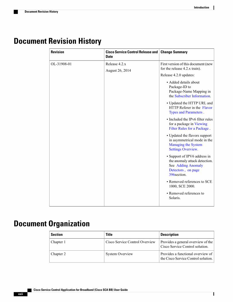
Document Revision HistoryChange SummaryCisco Service Control Release and
DateRevision
First version of this document (newfor the release 4.2.x train).
Release 4.2.0 updates:
• Added details aboutPackage-ID toPackage-Name Mapping inthe Subscriber Information.
• Updated the HTTP URL andHTTP Referer in the FlavorTypes and Parameters .
• Included the IPv6 filter rulesfor a package in ViewingFilter Rules for a Package .
• Updated the flavors supportin asymmetrical mode in theManaging the SystemSettings Overview.
• Support of IPV6 address inthe anomaly attack detection.See Adding AnomalyDetectors , on page396section.
• Removed references to SCE1000, SCE 2000.
• Removed references toSolaris.
Release 4.2.x
August 26, 2014
OL-31908-01
Document OrganizationDescriptionTitleSection
Provides a general overview of theCisco Service Control solution.
Cisco Service Control OverviewChapter 1
Provides a functional overview ofthe Cisco Service Control solution.
System OverviewChapter 2
Cisco Service Control Application for Broadband (Cisco SCA BB) User Guidexxii
IntroductionDocument Revision History
DescriptionTitleSection
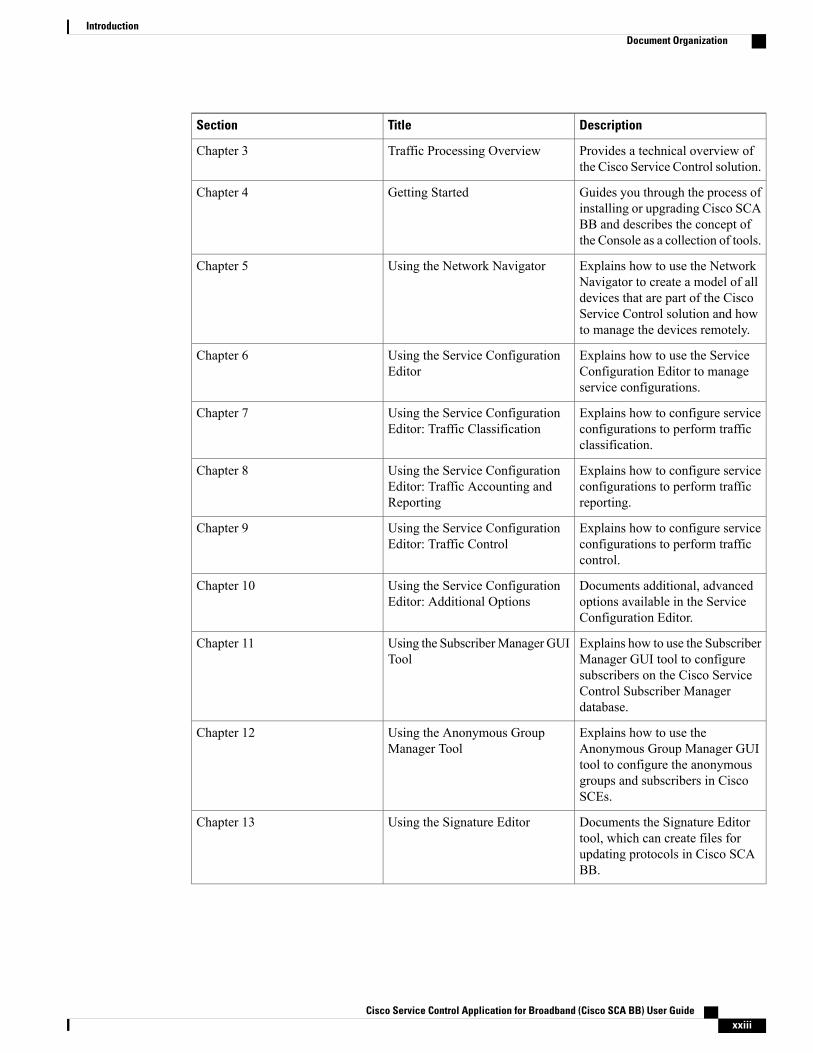
Provides a technical overview ofthe Cisco Service Control solution.
Traffic Processing OverviewChapter 3
Guides you through the process ofinstalling or upgrading Cisco SCABB and describes the concept ofthe Console as a collection of tools.
Getting StartedChapter 4
Explains how to use the NetworkNavigator to create a model of alldevices that are part of the CiscoService Control solution and howto manage the devices remotely.
Using the Network NavigatorChapter 5
Explains how to use the ServiceConfiguration Editor to manageservice configurations.
Using the Service ConfigurationEditor
Chapter 6
Explains how to configure serviceconfigurations to perform trafficclassification.
Using the Service ConfigurationEditor: Traffic Classification
Chapter 7
Explains how to configure serviceconfigurations to perform trafficreporting.
Using the Service ConfigurationEditor: Traffic Accounting andReporting
Chapter 8
Explains how to configure serviceconfigurations to perform trafficcontrol.
Using the Service ConfigurationEditor: Traffic Control
Chapter 9
Documents additional, advancedoptions available in the ServiceConfiguration Editor.
Using the Service ConfigurationEditor: Additional Options
Chapter 10
Explains how to use the SubscriberManager GUI tool to configuresubscribers on the Cisco ServiceControl Subscriber Managerdatabase.
Using the SubscriberManager GUITool
Chapter 11
Explains how to use theAnonymous Group Manager GUItool to configure the anonymousgroups and subscribers in CiscoSCEs.
Using the Anonymous GroupManager Tool
Chapter 12
Documents the Signature Editortool, which can create files forupdating protocols in Cisco SCABB.
Using the Signature EditorChapter 13
Cisco Service Control Application for Broadband (Cisco SCA BB) User Guide xxiii
IntroductionDocument Organization
DescriptionTitleSection
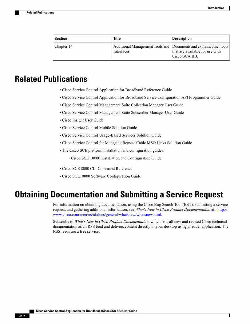
Documents and explains other toolsthat are available for use withCisco SCA BB.
AdditionalManagement Tools andInterfaces
Chapter 14
Related Publications• Cisco Service Control Application for Broadband Reference Guide
• Cisco Service Control Application for Broadband Service Configuration API Programmer Guide
• Cisco Service Control Management Suite Collection Manager User Guide
• Cisco Service Control Management Suite Subscriber Manager User Guide
• Cisco Insight User Guide
• Cisco Service Control Mobile Solution Guide
• Cisco Service Control Usage-Based Services Solution Guide
• Cisco Service Control for Managing Remote Cable MSO Links Solution Guide
• The Cisco SCE platform installation and configuration guides:
◦Cisco SCE 10000 Installation and Configuration Guide
• Cisco SCE 8000 CLI Command Reference
• Cisco SCE10000 Software Configuration Guide
Obtaining Documentation and Submitting a Service RequestFor information on obtaining documentation, using the Cisco Bug Search Tool (BST), submitting a servicerequest, and gathering additional information, seeWhat's New in Cisco Product Documentation, at: http://www.cisco.com/c/en/us/td/docs/general/whatsnew/whatsnew.html.
Subscribe toWhat's New in Cisco Product Documentation, which lists all new and revised Cisco technicaldocumentation as an RSS feed and delivers content directly to your desktop using a reader application. TheRSS feeds are a free service.
Cisco Service Control Application for Broadband (Cisco SCA BB) User Guidexxiv
IntroductionRelated Publications
C H A P T E R 1Cisco Service Control Solution Overview
This chapter provides a general overview of the Cisco Service Control solution. It introduces the Ciscoservice control concept and capabilities.
It also briefly describes the hardware capabilities of the Cisco Service Control Engine (Cisco SCE) platformand the Cisco-specific applications that together compose the Cisco service control solution.
• Cisco Service Control Solution, page 1
• Cisco Service Control Capabilities, page 2
• Cisco SCE Platform Description, page 3
• Management and Collection , page 4
Cisco Service Control SolutionThe Cisco service control solution is delivered through a combination of hardware and specific softwaresolutions that address various service control challenges. Service providers can use the Cisco SCE platformto support classification, analysis, and control of Internet and IP traffic.
Service control enables service providers to:
• Capitalize on existing infrastructure.
• Analyze, charge for, and control IP network traffic at multigigabit wire line speeds.
• Identify and target high-margin content-based services and enable their delivery.
As the downturn in the telecommunications industry has shown, the business models of the IP Service Providersrequire rework to make them profitable. Having spent billions of dollars to build ever larger data links,providers have incurred massive debts and faced rising costs. At the same time, access and bandwidth havebecome commodities where prices continually fall and profits disappear. Service providers have realized thatthey must offer value-added services to derive more revenue from the traffic and services running on theirnetworks.
Cisco service control solutions allow IP Service Providers to capture profits from IP Services through detailedmonitoring, precise, real-time control, and awareness of services as they are delivered.
Cisco Service Control Application for Broadband (Cisco SCA BB) User Guide 1
Service Control for Broadband Service ProvidersService providers of any access technology (DSL, cable, mobile, and so on) targeting residential and businessconsumersmust find newways to get maximum leverage from their existing infrastructure, while differentiatingtheir offerings with enhanced IP Services.
The Cisco service control application for broadband adds a layer of service intelligence and control to existingnetworks that can:
• Report and analyze network traffic at subscriber and aggregate level for capacity planning
• Provide customer-intuitive tiered application services and guarantee application service level agreements(SLAs)
• Implement different service levels for different types of customers, content, or applications
• Identify network abusers who are violating the acceptable use policy (AUP)
• Identify and manage peer-to-peer traffic, NNTP (news) traffic, and spam abusers
• Enforce the AUP
• Integrate Service Control solutions easily with existing network elements and business support systems(BSS) and operational support systems (OSS)
Cisco Service Control CapabilitiesThe core of the Cisco service control solution is the network hardware device: the Cisco Service ControlEngine (Cisco SCE). The core capabilities of the Cisco SCE platform, which support a wide range ofapplications for delivering service control solutions, include:
• Subscriber and application awareness—Application-level drilling into IP traffic for real-time understandingand controlling of usage and content at the granularity of a specific subscriber.
◦Subscriber awareness—The ability to map between IP flows and a specific subscriber to maintainthe state of each subscriber transmitting traffic through the Cisco SCE platform and to enforce anappropriate policy on this subscriber’s traffic.Subscriber awareness is achieved either through dedicated integrations with subscriber managementrepositories, such as a DHCP or a RADIUS server, or through sniffing of RADIUS or DHCPtraffic.
◦Application awareness—The ability to understand and analyze traffic up to the application protocollayer (Layer 7).For application protocols implemented using bundled flows (such as FTP, which is implementedusing Control and Data flows), the Cisco SCE platform understands the bundling connectionbetween the flows and treats them accordingly.
• Application-layer, stateful, real-time traffic control—The ability to perform advanced control functions,including granular bandwidth (BW) metering and shaping, quota management, and redirection, usingapplication-layer, stateful, real-time traffic transaction processing. This feature requires highly adaptiveprotocol and application-level intelligence.
Cisco Service Control Application for Broadband (Cisco SCA BB) User Guide2
Cisco Service Control Solution OverviewService Control for Broadband Service Providers
• Programmability—The ability to add new protocols quickly and adapt to new services and applicationsin the service provider environment. Programmability is achieved using the Cisco Service ModelingLanguage (SML).Programmability allows new services to be deployed quickly and provides an easy upgrade path fornetwork, application, or service growth.
• Robust and flexible back-office integration—The ability to integrate with existing third-party systemsat the service provider, including provisioning systems, subscriber repositories, billing systems, andOSS systems. The Cisco SCE provides a set of open and well-documented APIs that allows a quickintegration process.
• Scalable high-performance service engines—The ability to perform all of these operations at wire speed.
Cisco SCE Platform DescriptionThe Cisco SCE family of programmable network devices performs application-layer stateful-flow inspectionof IP traffic, and controls the traffic based on configurable rules. The Cisco SCE platform devices use ASICcomponents and reduced instruction set computer (RISC) processors to exceed beyond packet counting andexpand into the contents of network traffic.
The Cisco SCE platform devices:
• Are programmable.
• Provide stateful inspection of bidirectional traffic flows, and mapping these flows with user ownership.
• Provide real-time classification of network use. The classification provides the basis of the Cisco SCEplatform advanced traffic-control and bandwidth-shaping functionality.
Where most bandwidth shaper functionality ends, the Cisco SCE platform provides further control and shapingoptions, including:
• Layer 7 stateful wire-speed packet inspection and classification
• Robust support for more than 600 protocols and applications, including:
◦General—HTTP, HTTPS, FTP, Telnet, Network News Transfer Protocol (NNTP), Simple MailTransfer Protocol (SMTP), Post Office Protocol 3 (POP3), Internet Message Access Protocol(IMAP), Wireless Application Protocol (WAP), and others
◦Peer-to-Peer (P2P) file sharing—FastTrack-KazaA, Gnutella, BitTorrent,Winny, Hotline, eDonkey,DirectConnect, Piolet, and others
◦P2P VoIP—Skype, Skinny, DingoTel, and others
◦Streaming and Multimedia—Real Time Streaming Protocol (RTSP), Session Initiation Protocol(SIP), HTTP streaming, Real Time Protocol (RTP) and Real Time Control Protocol (RTCP), andothers
• Programmable system core for flexible reporting and bandwidth control
• Transparent network and BSS and OSS integration into existing networks
Cisco Service Control Application for Broadband (Cisco SCA BB) User Guide 3
Cisco Service Control Solution OverviewCisco SCE Platform Description
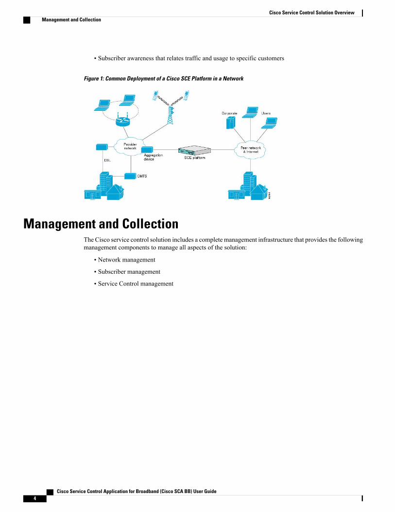
• Subscriber awareness that relates traffic and usage to specific customers
Figure 1: Common Deployment of a Cisco SCE Platform in a Network
Management and CollectionThe Cisco service control solution includes a complete management infrastructure that provides the followingmanagement components to manage all aspects of the solution:
• Network management
• Subscriber management
• Service Control management
Cisco Service Control Application for Broadband (Cisco SCA BB) User Guide4
Cisco Service Control Solution OverviewManagement and Collection

These management interfaces are designed to comply with common management standards and to integrateeasily with existing OSS infrastructure.
Figure 2: Service Control Management Infrastructure
Network ManagementThe Cisco service control solution provides complete network Fault, Configuration, Accounting, Performance,Security (FCAPS) Management.
Two interfaces provide network management:
• Command-line interface (CLI)—Accessible through the Console port or through a Telnet connection,the CLI is used for configuration and security functions.
• SNMP—Provides fault management (through SNMP traps) and performance-monitoring functionality.
Subscriber ManagementWhere the Cisco service control application for broadband (Cisco SCA BB) enforces policies on differentsubscribers and tracks usage on an individual subscriber basis, the Cisco Service Control Subscriber Managermay be used as middleware software for bridging between OSS and Cisco SCE platforms. Subscriberinformation is stored in the Subscriber Manager database and can be distributed between multiple platformsaccording to actual subscriber placement.
The Subscriber Manager provides subscriber awareness by mapping network IDs to subscriber IDs. It canobtain subscriber information using dedicated integration modules that integrate with AAA devices, such asRADIUS or DHCP servers.
Subscriber information may be obtained in one of two ways:
Cisco Service Control Application for Broadband (Cisco SCA BB) User Guide 5
Cisco Service Control Solution OverviewNetwork Management
• Push Mode—The Subscriber Manager pushes subscriber information to the Cisco SCE platformautomatically upon logon of a subscriber.
• PullMode—The SubscriberManager sends subscriber information to the Cisco SCE platform in responseto a query from the Cisco SCE platform.
Service Configuration ManagementService configuration management is the ability to configure the general service definitions of a service controlapplication. A service configuration file containing settings for traffic classification, accounting and reporting,and control is created and applied to a Cisco SCE platform. The Cisco SCA BB application provides tools toautomate the distribution of these configuration files to Cisco SCE platforms. This standards-based approachmakes it easy to manage multiple devices in a large network.
Service Control provides a GUI to edit and create these files and a complete set of APIs to automate theircreation.
Data CollectionData collection occurs as follows:
1 Cisco SCE Platform analyzes and process the data passing through it and generates Raw Data Records(RDRs).
2 Cisco SCE Platform then forwards these RDRs to Cisco service control management suite collectionmanager using a simple TCP-based protocol (RDR-Protocol).The collection manager software is an implementation of a collection system that receives RDRs fromone or more Cisco SCE platforms.
3 The collection manager collects these records and processes them in one of its adapters. Each adapterperforms a specific action on the RDR.RDRs contain various information and statistics, depending on the configuration of the system. The maincategories of RDRs include:
• Transaction RDRs—Records generated for each transaction , where a transaction is a single eventdetected in network traffic. The identification of a transaction depends on the particular applicationand protocol.
• Subscriber Usage RDRs—Records generated per subscriber, describing the traffic generated by thatsubscriber for a defined interval.
• Link RDRs—Records generated per link, describing the traffic carried on the link for a definedinterval.
• Zone RDRs—Records generated per zone, describing the traffic carried on the zone for a definedinterval.
Cisco Service Control Application for Broadband (Cisco SCA BB) User Guide6
Cisco Service Control Solution OverviewService Configuration Management
C H A P T E R 2Cisco SCA BB System Overview
The Cisco Service Control Application for Broadband (Cisco SCABB) is the Cisco Service Control solutionthat allows broadband service providers to gain network-traffic visibility, to control the distribution of networkresources, and to optimize traffic in accordance with their business strategies. It enables service providersto reduce network costs, improve network performance and customer experience, and create new serviceofferings and packages. This chapter contains the following sections:
• System Components, page 7
• Subscribers and Subscriber Modes , page 9
• Service Configuration , page 13
System ComponentsThe Cisco Service Control solution consists of four main components:
• The Cisco Service Control Engine (Cisco SCE) platform—A flexible and powerful dedicatednetwork-usage monitor that is purpose-built to analyze and report on network transactions at theapplication level.For more information about the installation and operation of the Cisco SCE platform, see the CiscoSCE Platform Installation and Configuration Guides .
• The Cisco Service Control Subscriber Manager—Amiddleware software component that is used wheredynamic binding of subscriber information and policies are required. The Subscriber Manager managessubscriber information and provisions it in real time to multiple Cisco SCE platforms. The SubscriberManager can store subscriber policy information internally, and act as a stateful bridge between theAAA system (such as RADIUS and DHCP) and the Cisco SCE platforms.For more information about the installation and operation of the Subscriber Manager, see the CiscoService Control Management Suite Subscriber Manager User Guide.
The Quota Manager (QM) is an optional component of the Subscriber Manager. It enables ServiceControl solution providers to manage subscriber quota across subscriber sessions with a high degree offlexibility.
For more information about the installation and operation of the QM, see the Cisco Service ControlManagement Suite Quota Manager User Guide.
Cisco Service Control Application for Broadband (Cisco SCA BB) User Guide 7
• The Cisco Service Control Collection Manager (CM)—An implementation of a collection system thatreceives RawData Records (RDRs) from one or more Cisco SCE platforms. It collects usage informationand statistics, and stores them in a database. The CM also converts subscriber usage information andstatistics into simple text-based files for further processing and collection by external systems.For more information about the installation and operation of the CM, see the Cisco Service ControlManagement Suite Collection Manager User Guide.
• The Service Control Application (SCA) Reporter—A software component that processes data stored bythe CM and provides a set of insightful reports from this data. The SCAReporter can run as a standaloneor as an integrated part of the Console.For more information about the installation and operation of the Reporter, see the Cisco Service ControlApplication Reporter User Guide.
Together, the Cisco SCE platform, the Cisco Service Control Collection Manager, the Cisco Service ControlSubscriberManager, and the SCAReporter are designed to support detailed classification, analysis, reporting,and control of IP network traffic. The Cisco Service Control Collection Manager, the SCA Reporter, and theCisco Service Control Subscriber Manager are optional components; not all deployments of the Cisco ServiceControl solution require them. Sites that employ third-party collection and reporting applications, those thatdo not require dynamic subscriber-aware processing, and those that use a RADIUS or DHCP sniffing optionmay not require all of these components.
The following figure illustrates the flow of information in the Cisco Service Control solution.
• Horizontal flow—Represents traffic between subscribers and an IP network.The Cisco SCE platform monitors traffic flow.
• Vertical flow—Represents transmission of the Raw Data Records (RDRs) from the Cisco SCE platformto the CM.
Cisco Service Control Application for Broadband (Cisco SCA BB) User Guide8
Cisco SCA BB System OverviewSystem Components
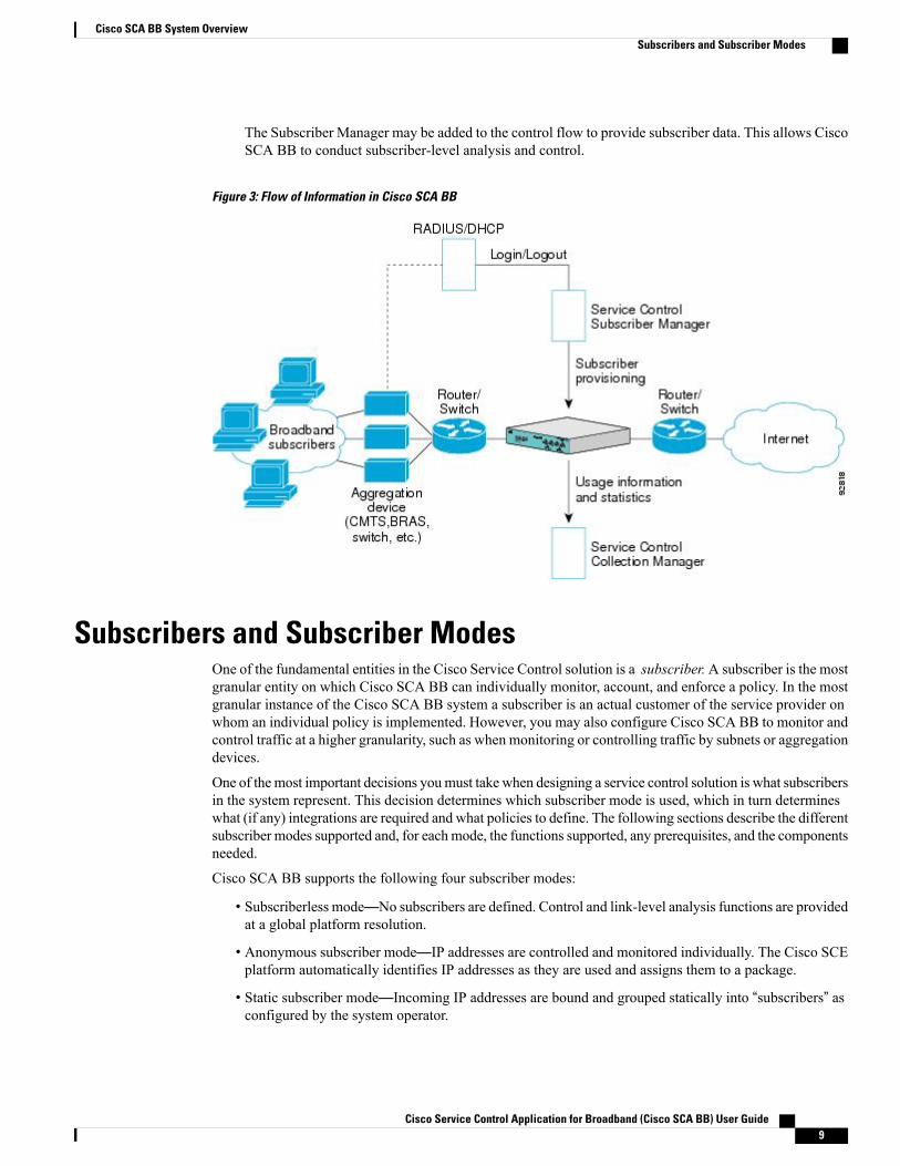
The Subscriber Manager may be added to the control flow to provide subscriber data. This allows CiscoSCA BB to conduct subscriber-level analysis and control.
Figure 3: Flow of Information in Cisco SCA BB
Subscribers and Subscriber ModesOne of the fundamental entities in the Cisco Service Control solution is a subscriber.A subscriber is the mostgranular entity on which Cisco SCA BB can individually monitor, account, and enforce a policy. In the mostgranular instance of the Cisco SCA BB system a subscriber is an actual customer of the service provider onwhom an individual policy is implemented. However, you may also configure Cisco SCA BB to monitor andcontrol traffic at a higher granularity, such as when monitoring or controlling traffic by subnets or aggregationdevices.
One of themost important decisions youmust take when designing a service control solution is what subscribersin the system represent. This decision determines which subscriber mode is used, which in turn determineswhat (if any) integrations are required and what policies to define. The following sections describe the differentsubscriber modes supported and, for eachmode, the functions supported, any prerequisites, and the componentsneeded.
Cisco SCA BB supports the following four subscriber modes:
• Subscriberless mode—No subscribers are defined. Control and link-level analysis functions are providedat a global platform resolution.
• Anonymous subscriber mode—IP addresses are controlled and monitored individually. The Cisco SCEplatform automatically identifies IP addresses as they are used and assigns them to a package.
• Static subscriber mode—Incoming IP addresses are bound and grouped statically into “subscribers” asconfigured by the system operator.
Cisco Service Control Application for Broadband (Cisco SCA BB) User Guide 9
Cisco SCA BB System OverviewSubscribers and Subscriber Modes
• Subscriber-aware mode—Subscriber information is dynamically bound to the IP address currently inuse by the subscriber. Subscriber-aware mode can be achieved by integrating Cisco SCA BB with thesystem (RADIUS, DHCP) that assigns IP addresses to subscribers, or by sniffing this information. Policyinformation is either administered to Cisco SCABB directly or provisioned dynamically via an integration.
Subscriberless ModeSubscriberless mode is the choice for sites where control and analysis functions are required only at a globalplatform resolution. It can be used, for example, to monitor and control the total P2P traffic over the link.
Subscriberless mode requires no integration; hence, the Cisco Service Control Subscriber Manager is notrequired.
The number of subscribers or inbound IP addresses does not influence the Subscriberless mode. Hence,the total number of subscribers using the monitored link is unlimited from the point of view of the CiscoSCE platform.
Note
Anonymous Subscriber ModeAnonymous subscriber mode provides the means to analyze and control network traffic at subscriber-inboundIP address granularity.
Use this mode when:
• You do not require subscriber-differentiated control or subscriber-level quota tracking
• Analysis on an IP level is sufficient
•When offline IP-address/subscriber binding can be performed
For example, you can identify which subscribers generate the most P2P traffic by identifying the top IPaddresses and correlating them to individual subscribers using RADIUS or DHCP logs. The total bandwidthof P2P traffic allowed for each subscriber can also be limited.
Anonymous subscriber mode requires no integration or static configuration of the IP addresses used, so theCisco Service Control Subscriber Manager is not required.
In this mode, ranges of IP addresses are configured directly on the Cisco SCE platform. Cisco SCE Platformdynamically creates “anonymous” subscribers for these IP addresses, using the IP address as the subscribername.
The total number of concurrently active anonymous subscribers supported by the Cisco SCE platform isthe same as the total number of concurrently active subscribers.
Note
Cisco Service Control Application for Broadband (Cisco SCA BB) User Guide10
Cisco SCA BB System OverviewSubscriberless Mode

Static Subscriber ModeStatic subscriber mode binds incoming IP addresses together into groups, so that traffic from and to definedsubscribers can be controlled as a group. For example, you can define all traffic from and to a particularnetwork subnet (used by multiple subscribers concurrently) as a (virtual) “subscriber” and controlled or viewedas a group.
Static subscriber mode supports cases in which the entity controlled by the Cisco Service Control solutionuses a constant IP address or address range that does not change dynamically, such as:
• Environments where the subscriber IP addresses do not change dynamically via, for example, DHCPor RADIUS
• Deployments in which a group of subscribers using a common pool of IP addresses (such as all thoseserved by a particular aggregation device) are managed together to provide a shared bandwidth to theentire group
The system supports the definition of static subscribers directly on a Cisco SCE platform; it does not requireexternal management software (such as the Cisco Service Control Subscriber Manager). Use the Cisco SCEplatform CLI to define the list of subscribers, their IP addresses, and the associated package.
Subscriber-Aware ModeIn subscriber-aware mode, the subscriber information (OSS ID and policy) that is dynamically bound to the(IP) address currently in use by the subscribers are populated on the Cisco SCE.
The subscriber information is populated regardless of the IP address in use and provides differentiated anddynamic control per subscriber and subscriber-level analysis. Use this mode to control and analyze traffic ona subscriber level, to monitor subscriber usage, and to assign and enforce different control policies (packages)for different subscribers.
In this mode, the Cisco Service Control Subscriber Manager may provision the Cisco SCE platform withsubscriber information.
Cisco Service Control Application for Broadband (Cisco SCA BB) User Guide 11
Cisco SCA BB System OverviewStatic Subscriber Mode
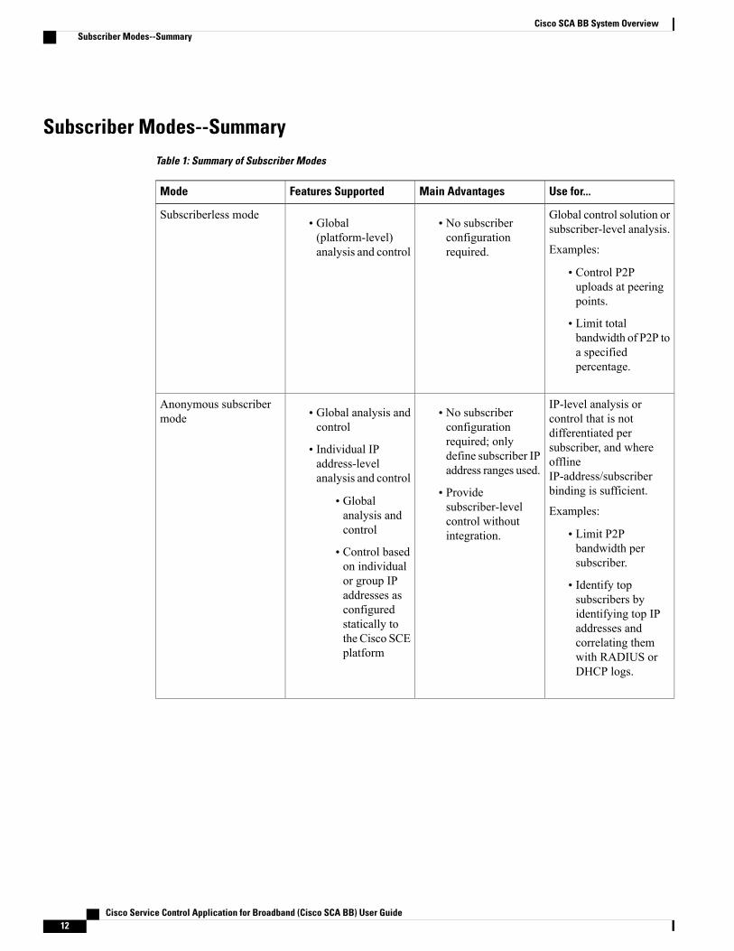
Subscriber Modes--SummaryTable 1: Summary of Subscriber Modes
Use for...Main AdvantagesFeatures SupportedMode
Global control solution orsubscriber-level analysis.
Examples:
• Control P2Puploads at peeringpoints.
• Limit totalbandwidth of P2P toa specifiedpercentage.
• No subscriberconfigurationrequired.
• Global(platform-level)analysis and control
Subscriberless mode
IP-level analysis orcontrol that is notdifferentiated persubscriber, and whereofflineIP-address/subscriberbinding is sufficient.
Examples:
• Limit P2Pbandwidth persubscriber.
• Identify topsubscribers byidentifying top IPaddresses andcorrelating themwith RADIUS orDHCP logs.
• No subscriberconfigurationrequired; onlydefine subscriber IPaddress ranges used.
• Providesubscriber-levelcontrol withoutintegration.
• Global analysis andcontrol
• Individual IPaddress-levelanalysis and control
• Globalanalysis andcontrol
• Control basedon individualor group IPaddresses asconfiguredstatically tothe Cisco SCEplatform
Anonymous subscribermode
Cisco Service Control Application for Broadband (Cisco SCA BB) User Guide12
Cisco SCA BB System OverviewSubscriber Modes--Summary
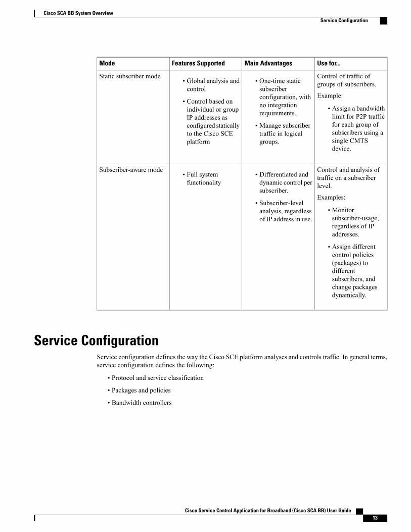
Use for...Main AdvantagesFeatures SupportedMode
Control of traffic ofgroups of subscribers.
Example:
• Assign a bandwidthlimit for P2P trafficfor each group ofsubscribers using asingle CMTSdevice.
• One-time staticsubscriberconfiguration, withno integrationrequirements.
• Manage subscribertraffic in logicalgroups.
• Global analysis andcontrol
• Control based onindividual or groupIP addresses asconfigured staticallyto the Cisco SCEplatform
Static subscriber mode
Control and analysis oftraffic on a subscriberlevel.
Examples:
• Monitorsubscriber-usage,regardless of IPaddresses.
• Assign differentcontrol policies(packages) todifferentsubscribers, andchange packagesdynamically.
• Differentiated anddynamic control persubscriber.
• Subscriber-levelanalysis, regardlessof IP address in use.
• Full systemfunctionality
Subscriber-aware mode
Service ConfigurationService configuration defines the way the Cisco SCE platform analyses and controls traffic. In general terms,service configuration defines the following:
• Protocol and service classification
• Packages and policies
• Bandwidth controllers
Cisco Service Control Application for Broadband (Cisco SCA BB) User Guide 13
Cisco SCA BB System OverviewService Configuration
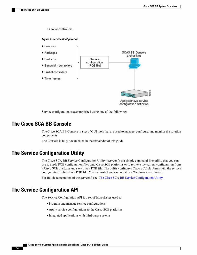
• Global controllers
Figure 4: Service Configuration
Service configuration is accomplished using one of the following:
The Cisco SCA BB ConsoleThe Cisco SCA BB Console is a set of GUI tools that are used to manage, configure, and monitor the solutioncomponents.
The Console is fully documented in the remainder of this guide.
The Service Configuration UtilityThe Cisco SCA BB Service Configuration Utility (servconf) is a simple command-line utility that you canuse to apply PQB configuration files onto Cisco SCE platforms or to retrieve the current configuration froma Cisco SCE platform and save it as a PQB file. The utility configures Cisco SCE platforms with the serviceconfiguration defined in a PQB file. You can install and execute it in a Windows environment.
For full documentation of the servconf, see The Cisco SCA BB Service Configuration Utility .
The Service Configuration APIThe Service Configuration API is a set of Java classes used to:
• Program and manage service configurations
• Apply service configurations to the Cisco SCE platforms
• Integrated applications with third-party systems
Cisco Service Control Application for Broadband (Cisco SCA BB) User Guide14
Cisco SCA BB System OverviewThe Cisco SCA BB Console

The service configuration API allows service providers to automate and simplifymanagement and operationaltasks.
The Service Configuration API is documented in Cisco Service Control Application for Broadband ServiceConfiguration API Programmer Guide.
Cisco Service Control Application for Broadband (Cisco SCA BB) User Guide 15
Cisco SCA BB System OverviewThe Service Configuration API

Cisco Service Control Application for Broadband (Cisco SCA BB) User Guide16
Cisco SCA BB System OverviewThe Service Configuration API

C H A P T E R 3Introduction to Traffic Processing
This chapter describes how the Cisco SCA BB installed on a Cisco Service Control Engine (Cisco SCE)platform processes traffic.
The chapter also describes the main elements (service configuration entities) of the Cisco SCA BB systemand explains how they relate to each other.
This chapter consists of these sections:
• Routing Environment , page 17
• Traffic Processing , page 18
• Traffic Classification , page 18
• Traffic Accounting and Reporting , page 26
• Traffic Control , page 29
• Service Security , page 35
• Traffic Filters , page 37
• Traffic Forwarding to Value-Added Services Servers , page 37
• Service Configurations , page 38
Routing EnvironmentTraffic processing depends on the routing environment. The Cisco Service Control solution can operate intwo typical routing schemes:
• Symmetric (Normal)—For most flows the inbound and outbound traffic is routed through one CiscoSCE platform. For a marginal number of flows, only one direction goes through this Cisco SCE platform.
• Asymmetric—For a significant number of flows, only one direction (inbound or outbound) is routedthrough the Cisco SCE platform. For other flows, both directions go through this Cisco SCE platform.
A flow is bidirectional when the inbound and outbound traffic of the flow passes through the same Cisco SCEplatform. A unidirectional flow is one where only one of the inbound traffic and the outbound traffic gothrough the Cisco SCE platform.
Cisco Service Control Application for Broadband (Cisco SCA BB) User Guide 17
The Cisco Service Control solution can handle both unidirectional and bidirectional flows. The Cisco SCEplatform can be configured to operate in either a symmetric or an asymmetric routing environment. The trafficprocessing capabilities of the Cisco SCE platform in the asymmetric environment are a subset of its capabilitiesin the symmetric environment.
When the Cisco Service Control solution is deployed in an asymmetric routing environment, and unidirectionalclassification is enabled, the Cisco SCE platform classification is better tuned to identify traffic based on asingle direction. The Cisco SCE platform handles unidirectional flows independently, with no synchronizationwith other Cisco SCE platforms that might handle the opposite direction of the flow.
Traffic ProcessingThere are three stages of traffic processing:
• Traffic classification—Cisco SCA BB analyses traffic flows and determines their type (for example,browsing, e-mail, file sharing, or voice).
• Traffic accounting and reporting—Cisco SCA BB performs bookkeeping and generates Raw DataRecords (RDRs) that let you analyze and monitor the network.
• Traffic control—Cisco SCA BB limits and prioritizes traffic flows according to their service,subscriber-package, subscriber quota state, and so on.
You can control how classification, reporting, and control perform by editing the service configurations andby applying these configurations to the Cisco SCE platform.
The three stages are described in these sections:
Traffic ClassificationTraffic processing starts with traffic classification, which categorizes network sessions into services.
For each commercial service that a provider offers to its subscribers, a corresponding service is defined in theCisco Service Control solution. You can use this service to classify and identify the traffic, report on its usage,and control it.
Cisco SCE internal architecture has two concepts that aid traffic classification:
• Hardware flow—created entirely in hardware, with a maximum limit of 32 million flows on Cisco SCE8000.
• Software flow—created in software, with a maximum limit of 16 million flows on Cisco SCE 8000.
• Hardware flow—created entirely in hardware, with a maximum limit of 32 million flows on Cisco SCE10000.
• Software flow—created in software, with a maximum limit of 16 million flows on Cisco SCE 10000.
Each flow context is unidirectional. Flows are opened based on the following logic:
• If the flow is on filter list or traffic rule with ignore , it is ignored and bypassed
• If the packet is Non-IP, it is ignored and bypassed
• If the packet is larger than 1600 bytes, it is ignored and bypassed
Cisco Service Control Application for Broadband (Cisco SCA BB) User Guide18
Introduction to Traffic ProcessingTraffic Processing
• If the packet is a TCP-retransmit packet or has a wrong checksum, it is ignored and bypassed
• If the packet matches any of the active attack filters, it is ignored and bypassed
• If the packet is TCP and the flow is in half-open state (3 way handshake), hardware flow is created foreach direction
• If the packet is TCP and is in established state, software flows (2 unidirectional) are created for the firstpayload packet
• If the packet is UDP, hardware flows are created for first packet in each direction.
• If the packet is UDP, software flow is created for the 5th packet.
Creating flow on the fifth packet helps to avoid creation of software flows for port-scans, and thus, protectCisco SCE from DoS conditions. Port-scans are still detected because their flows are opened in hardwaretemporarily. Also, some flows are still opened on the first packet, based on SCA-BB GUI options (Advancedsettings).
• If the flow is non-TCP, non-UDP but still IP (for example, ICMP), hardware flow is opened for eachdirection on first packet
• If the flow is non-TCP, non-UDP but still IP (for example, ICMP), software flow is opened for eachdirection on second packet
User counters, Service Counters, and Protocol counters are updated, and RDRs are generated only for softwareflows.
ServicesIn the traffic classification process, Cisco SCA BB categorizes network sessions into services.
Services are the building blocks for:
• Service configurations (because Cisco SCA BB can enforce different rules on different services)
• Aggregated usage reporting
From the point of view of a provider, a service is a network product sold to a subscriber. The service is usuallya network application—such as browsing, e-mail, file sharing, or voice—that the subscriber uses. From atechnical point of view, a service consists of one or more service elements, each of which enables a decisionabout the service associated with a network traffic flow type.
A number of services are predefined in the default service configuration. You can modify these services andadd additional services to a service configuration. A service configuration can contain up to 500 services. Seethe Default Service Configuration Reference Tables chapter of the Cisco Service Control Application forBroadband Reference Guide for a list of services.
The classification process occurs when a session starts. The process examines the first few packets of thesession and decides to which service the session belongs. The session is then assigned a service ID that remainsthe same during the life cycle of a session.
Traffic is classified and mapped to services based on some or all of the following service elements:
• Protocol—The protocol used. This classification allows, for example, the mapping of browsing flowsand e-mail flows to separate services.
Cisco Service Control Application for Broadband (Cisco SCA BB) User Guide 19
Introduction to Traffic ProcessingServices
• Initiating side—Whether the subscriber side or the network side generated the flow. This classificationallows, for example, the mapping of subscriber-initiated and network-initiated peer-to-peer traffic toseparate services.
• Zone—Lists of IP addresses of the network-side host of the flow. This classification allows, for example,the mapping of all voice flows going to a specified server to a specific service.
• Flavor—Specific Layer 7 properties such as host names of the network-side host of the flow. Thisclassification allows, for example, the mapping of all HTTP flows where the URL matches a certainpattern to a specific service.
Flavors are not used for classification when unidirectional classification is enabled.Note
Cisco SCA BB uses these flow mappings to map each network connection passing through it to a service.You define rules for the different services to implement control policies. The classification rules can containLayer 3 and Layer 4 parameters (such as port numbers and IP addresses), and also Layer 7 parameters (suchas host name and user agent for HTTP connections).
Cisco SCA BB cannot achieve 100% classification of all P2P services, because some P2P applicationsare persistent in trying to connect. They use many alternate protocols and connection schemes. Their nativeprotocol is encrypted and this encryption tends to change whenever a new version is released. This meansthat if you try to block the P2P traffic, the client may eventually connect in some cases. A better approachmay be to limit bandwidth for this traffic to make it ineffective instead of trying for a complete block.
Note
Service ElementsA service consists of one or more service elements; different network traffic flow types are mapped to differentservice elements.
A service element maps a specific protocol, initiating side, zone, and flavor to the selected service. Some orall of these parameters can take wild-card values.
When unidirectional classification is enabled, the flavor of a service element is always the wild-card value.Note
A traffic flow is mapped to a specific service if it meets all four of the following criteria:
• The flow uses the specified protocol of the service element.
• The flow matches the initiating side specified for the service element.
• The destination of the flow is an address that belongs to the specified zone of the service element.
• The flow matches the specified flavor of the service element.
If a flow matches two service elements and one is more specific than the other, the flow is mapped to the morespecific of the two. For example, Service A is defined for browsing and Service B is defined for browsing toa specific list of URLs. A browsing flow to a URL on the list of Service B matches both services, but ismapped to Service B.
Cisco Service Control Application for Broadband (Cisco SCA BB) User Guide20
Introduction to Traffic ProcessingServices
If a flow matches one parameter of one service element and a different parameter of another service element,precedence is given first to matching flavors, then to protocols, then to zones, and finally to the initiating side.For example, Service A is defined for e-mail and Service B is defined for all traffic to a specific network zone.An e-mail flow to the specific network zone matches both services, but is mapped to Service A.
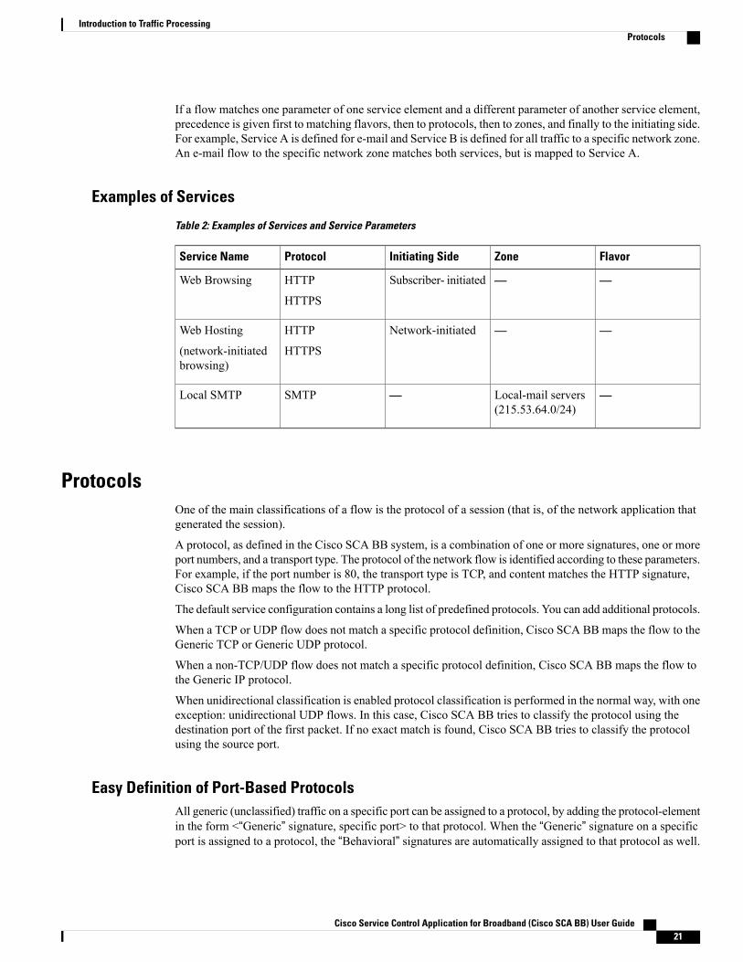
Examples of Services
Table 2: Examples of Services and Service Parameters
FlavorZoneInitiating SideProtocolService Name
——Subscriber- initiatedHTTP
HTTPS
Web Browsing
——Network-initiatedHTTP
HTTPS
Web Hosting
(network-initiatedbrowsing)
—Local-mail servers(215.53.64.0/24)
—SMTPLocal SMTP
ProtocolsOne of the main classifications of a flow is the protocol of a session (that is, of the network application thatgenerated the session).
A protocol, as defined in the Cisco SCA BB system, is a combination of one or more signatures, one or moreport numbers, and a transport type. The protocol of the network flow is identified according to these parameters.For example, if the port number is 80, the transport type is TCP, and content matches the HTTP signature,Cisco SCA BB maps the flow to the HTTP protocol.
The default service configuration contains a long list of predefined protocols. You can add additional protocols.
When a TCP or UDP flow does not match a specific protocol definition, Cisco SCA BB maps the flow to theGeneric TCP or Generic UDP protocol.
When a non-TCP/UDP flow does not match a specific protocol definition, Cisco SCA BB maps the flow tothe Generic IP protocol.
When unidirectional classification is enabled protocol classification is performed in the normal way, with oneexception: unidirectional UDP flows. In this case, Cisco SCA BB tries to classify the protocol using thedestination port of the first packet. If no exact match is found, Cisco SCA BB tries to classify the protocolusing the source port.
Easy Definition of Port-Based ProtocolsAll generic (unclassified) traffic on a specific port can be assigned to a protocol, by adding the protocol-elementin the form <“Generic” signature, specific port> to that protocol. When the “Generic” signature on a specificport is assigned to a protocol, the “Behavioral” signatures are automatically assigned to that protocol as well.
Cisco Service Control Application for Broadband (Cisco SCA BB) User Guide 21
Introduction to Traffic ProcessingProtocols
For example, in the default configuration, the “Generic” signature on port 555 is assigned to the H20 protocol,and therefore the “Behavioral Upload/Download” signature on port 555 is also automatically assigned to theH20 protocol.
This assignment is done automatically, so you do not need to do the assignment manually. Theseprotocol-elements that are added automatically are not displayed in the GUI. If, on the other hand, you wantto assign the “Behavioral Upload/Download” signature on a specific port to a different protocol, you can doit by creating an appropriate protocol-element and assigning it to the other protocol.
In the default configuration, the HTTP protocol definition accepts not just the HTTP signature, but alsoall other generic (unclassified) traffic on port 80, by including the protocol-element <“Generic” signature,port 80>. As described previously, when a protocol-element in this form, <“Generic” signature, specificport>, is used in a certain protocol definition, the Cisco SCE maps both the generic and the behavioralsignatures, on the specified port, to that protocol. For HTTP traffic, this means that traffic on port 80,which is classified as “Behavioral Upload/Download” signature, would also be assigned to the HTTPprotocol. As described earlier, the purpose of this behavior is to allow easy definition of port-basedprotocols. Nevertheless, this behavior can be avoided, by adding the protocol-element <“Behavioral”signature, specific port> to a different protocol.
Note
Protocol ElementsA protocol is a collection of protocol elements.
A protocol element maps a specific signature, IP protocol, and port range to the selected protocol. Some orall of these parameters can take wild-card values; port numbers can take range values.
If a traffic flow meets all the following criteria, it is mapped to a specific protocol:
• The flow matches the specified signature of the protocol element.
• The flow protocol matches the IP Protocol of the protocol element.
• The flow matches the specified port range of the protocol element.
If a flow matches two protocol elements and one is more specific than the other, the flow is mapped to themore specific of the two.
For example, Protocol A is defined for flows that match the FTP signature and Protocol B is defined for flowsthat match the FTP signature on TCP port 21. An FTP flow on port 21 matches both protocols, but is mappedto Protocol B.
If a flow matches the signature of one protocol element and the port of another protocol element; it is mappedto the matching signature.
For example, Protocol A is defined for flows that match the FTP signature and Protocol B is defined for flowson TCP port 21. An FTP flow on port 21 matches both protocols, but is mapped to Protocol A.
SignaturesCisco SCABB examines traffic flows using the deep-packet-inspection capabilities of the Cisco SCE platform,and compares each flow with an installed set of protocol signatures to identify the network application thatgenerated the flow.
Cisco Service Control Application for Broadband (Cisco SCA BB) User Guide22
Introduction to Traffic ProcessingProtocols

Cisco SCA BB comes with a set of predefined signatures for common network applications and protocols,such as browsing, e-mail, file sharing, and VoIP.
When unidirectional classification is enabled and a unidirectional flow (inbound or outbound) passes throughthe Cisco SCE platform, the flow is matched against a special set of unidirectional protocol signatures. Whena bidirectional flow passes through the Cisco SCE platform, the protocol library tries to match it to one of itsstandard (bidirectional) protocol signatures.
Cisco periodically publishes protocol packs containing new signatures and updates to existing signatures.You can use these protocol packs to update the set of signatures installed on Cisco SCA BB, enhancing itsclassification capabilities.
Dynamic Signatures
Most signatures used by Cisco SCA BB are predefined and hard-coded. Cisco SCA BB also allows you toadd dynamic signatures, which can be user-defined.
You can create and edit dynamic signatures in the Signature Editor tool. The Dynamic Signature Script (DSS)engine in Cisco SCA BB carries out the classification using these user-defined signatures in addition to thepredefined signatures.
Initiating SideThe Cisco SCE platform is usually located between the subscribers of the provider and the network. Basedon the initiating side, flows are called Subscriber-initiated flows and network-initiated flows. Flows initiatedby the subscriber towards the network are called subscriber-initiated flow, while the flows initiated from thenetwork towards the subscriber are called network-initiated flows.
You can limit some flow-types to one initiating side. For example, with HTTP you can restrict the directionof the flow to subscriber-initiated, because HTTP is always subscriber-initiated when the subscriber venturesoutward to surf the Internet. A network-initiated HTTP-flow means, that probably a web server is open onthe local machine of the subscriber for receiving incoming HTTP traffic. The provider can blocknetwork-initiated HTTP.
ZonesA zone is a collection of network-side IP addresses.
You configure zones by arranging IP addresses in groups connected by a common purpose. A network flowof the subscriber mapped to a service may be applied to a zone. In practice, zones often define geographicalareas.
Zones are used to classify network sessions; each network session can be assigned to a service element basedon its destination IP address.
Examples of Zones:
• A “walled garden”—A range of IP addresses of a server farm with premium video content, for whichthe provider would like to limit access to specific subscribers and to assure traffic priority.
• A zone to differentiate between off-net and on-net flows.
Example of Assigning a Zone to a Session:
Cisco Service Control Application for Broadband (Cisco SCA BB) User Guide 23
Introduction to Traffic ProcessingInitiating Side
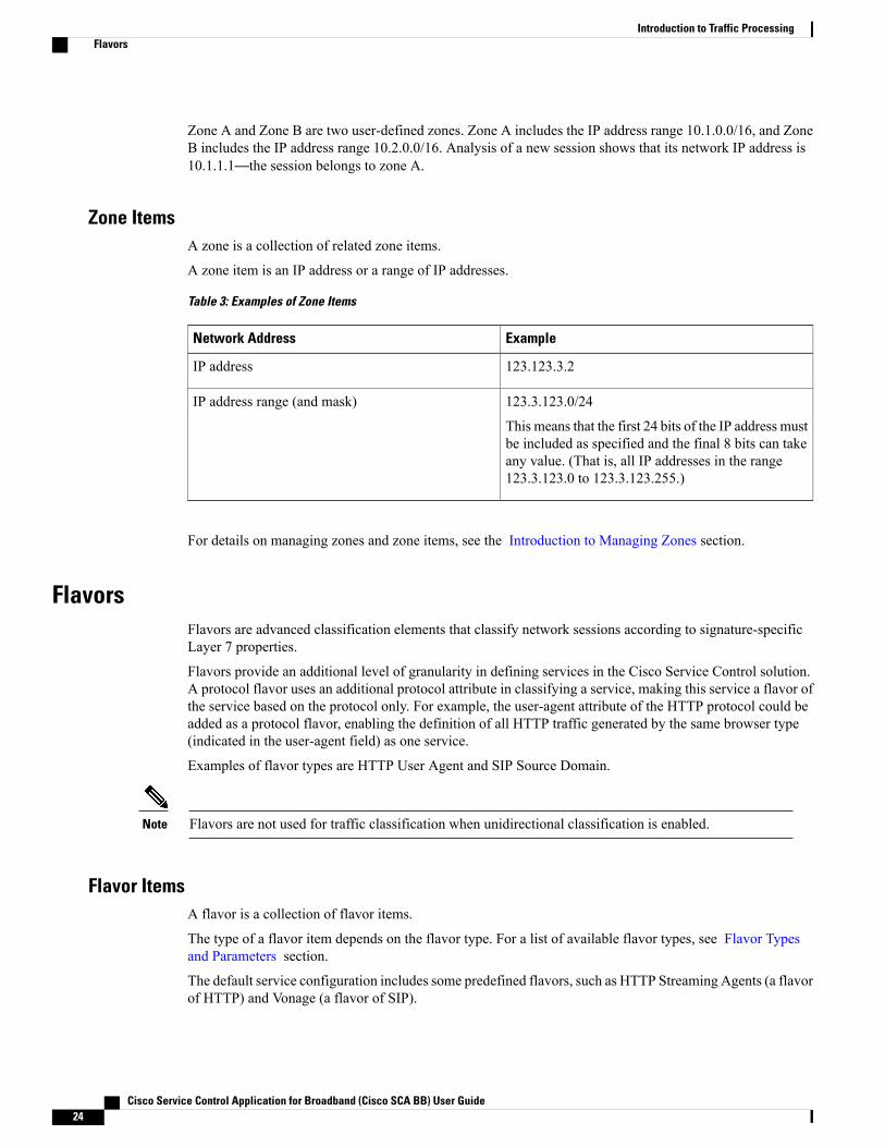
Zone A and Zone B are two user-defined zones. Zone A includes the IP address range 10.1.0.0/16, and ZoneB includes the IP address range 10.2.0.0/16. Analysis of a new session shows that its network IP address is10.1.1.1—the session belongs to zone A.
Zone ItemsA zone is a collection of related zone items.
A zone item is an IP address or a range of IP addresses.
Table 3: Examples of Zone Items
ExampleNetwork Address
123.123.3.2IP address
123.3.123.0/24
This means that the first 24 bits of the IP address mustbe included as specified and the final 8 bits can takeany value. (That is, all IP addresses in the range123.3.123.0 to 123.3.123.255.)
IP address range (and mask)
For details on managing zones and zone items, see the Introduction to Managing Zones section.
FlavorsFlavors are advanced classification elements that classify network sessions according to signature-specificLayer 7 properties.
Flavors provide an additional level of granularity in defining services in the Cisco Service Control solution.A protocol flavor uses an additional protocol attribute in classifying a service, making this service a flavor ofthe service based on the protocol only. For example, the user-agent attribute of the HTTP protocol could beadded as a protocol flavor, enabling the definition of all HTTP traffic generated by the same browser type(indicated in the user-agent field) as one service.
Examples of flavor types are HTTP User Agent and SIP Source Domain.
Flavors are not used for traffic classification when unidirectional classification is enabled.Note
Flavor ItemsA flavor is a collection of flavor items.
The type of a flavor item depends on the flavor type. For a list of available flavor types, see Flavor Typesand Parameters section.
The default service configuration includes some predefined flavors, such as HTTP Streaming Agents (a flavorof HTTP) and Vonage (a flavor of SIP).
Cisco Service Control Application for Broadband (Cisco SCA BB) User Guide24
Introduction to Traffic ProcessingFlavors
DSCP ToSOne flavor type is TOS. This allows DSCP ToS to be used as a classification criterion so that a packet carryinga specific marking can be assigned to a predefined service with, for example, unlimited bandwidth or reported.The DSCP ToS classification process takes precedence over other classificationmechanisms to allow externaldevices, such as a voice gateway, to dictate how the flow is treated. DSCP ToS-based classification is anexcellent way of marking proprietary managed services where Cisco SCA BB does not recognize theapplications but identifies them via the DSCP ToS field.
Content FilteringContent filtering involves classification and control of HTTP flows according to the requested URL. Theclassification of the URL is performed by accessing an external database.
Service providers require effective Web filtering for their subscribers, for various purposes such as avoidinglitigation and providing parental control. The problem is that the Web is huge and constantly growing, andCisco SCA BB and the Cisco SCE platform are not designed to track and maintain the huge database of URLsrequired for effective filtering.
Cisco SCA BB provides content filtering by integrating with SurfControl Content Portal Authority (CPA).SurfControl’s technology enhances Cisco SCA BB URL classification capabilities by eliminating the needfor a network administrator to manage a URL database or interact with the server, while creating a powerfulfiltering solution. It provides complete coverage of the web’s most trafficked sites and access to the mostaccurate and relevant database of URLs classified by risk category, such as sexually explicit, racist, hacker,and so on.
The integration of SurfControl’s CPA into Cisco SCA BB provides the required web-filtering solution. CiscoSCABB, running on the Cisco SCE platform, contacts a CPA server to categorize the website that a subscriberrequests. The returned category is then used to classify the HTTP flow. This classification is then used forthe normal Cisco SCA BB traffic control and reporting.
Cisco SCA BB includes an internal database of URLs used by the HTTP URL flavor classification. Whena URL is found in both the internal database and the external content filtering database, the URL is classifiedaccording to the internal database.
Note
Cisco Service Control Application for Broadband (Cisco SCA BB) User Guide 25
Introduction to Traffic ProcessingFlavors
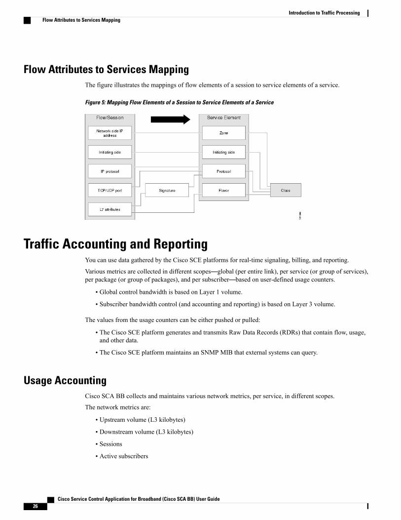
Flow Attributes to Services MappingThe figure illustrates the mappings of flow elements of a session to service elements of a service.
Figure 5: Mapping Flow Elements of a Session to Service Elements of a Service
Traffic Accounting and ReportingYou can use data gathered by the Cisco SCE platforms for real-time signaling, billing, and reporting.
Various metrics are collected in different scopes—global (per entire link), per service (or group of services),per package (or group of packages), and per subscriber—based on user-defined usage counters.
• Global control bandwidth is based on Layer 1 volume.
• Subscriber bandwidth control (and accounting and reporting) is based on Layer 3 volume.
The values from the usage counters can be either pushed or pulled:
• The Cisco SCE platform generates and transmits Raw Data Records (RDRs) that contain flow, usage,and other data.
• The Cisco SCE platform maintains an SNMP MIB that external systems can query.
Usage AccountingCisco SCA BB collects and maintains various network metrics, per service, in different scopes.
The network metrics are:
• Upstream volume (L3 kilobytes)
• Downstream volume (L3 kilobytes)
• Sessions
• Active subscribers
Cisco Service Control Application for Broadband (Cisco SCA BB) User Guide26
Introduction to Traffic ProcessingFlow Attributes to Services Mapping

• Concurrent sessions
• Session duration
For VoIP services, such as SIP and MGCP, the concurrent sessions usage counter counts concurrent voicecalls, and the session duration usage counter measures voice call duration.
Note
Per service accounting takes place in the following scopes:
• Per subscriber
• Per group of subscribers (package)
• Per link (global)
Several services may share the same service usage counter. For example, in the default service configuration,the SMTP service and the POP3 service share the E-Mail Counter. The service hierarchy determines how toassign services to usage counters, as explained in the following section. Similarly, several packages may sharethe same package usage counter, and the package hierarchy determines how to assign packages to usagecounters. For details, see The Package Hierarchy section .
The Service HierarchyServices are arranged in a hierarchal tree. A single default service is at the root, and you can place each newservice anywhere in the tree. For more information see, Services section.
Services inherit the rule of their parents. When a rule is defined for a particular service (in a specific package),unless explicitly specified, the same rule of the parent package controls all the child services.
Service Usage Counters
The service hierarchy provides a way to share usage counters and to organize services according to theirsemantics. Services are accounted in groups, as defined in the service hierarchy. Each service is assignedusage counters.
There are two categories of usage counters for services:
• Global—Used for Link Usage and Package Usage RDRs and reports
• Subscriber—Used for Real-Time Subscriber Usage RDRs and reports
A global usage counter and a subscriber usage counter are assigned to each service. The use of a service canbe accounted either exclusively for traffic classified to it or with the traffic of its parent service. For example,if a service called Premium Video Content is defined as a child of Streaming, the operator can either definea special usage counter for PremiumVideo Content or configure it to use the same usage counter as Streaming.
The global usage counter and the subscriber usage counter are independent. For the same service, one usagecounter may be the same for parent and child, whereas the other is exclusive to the child.
The Package HierarchyPackages are arranged in a hierarchal tree. A single default package is the root of the tree, and you can placenew packages anywhere in the tree. For more information see Packages section.
Package Usage Counters
Cisco Service Control Application for Broadband (Cisco SCA BB) User Guide 27
Introduction to Traffic ProcessingUsage Accounting

The package hierarchy allows you to organize packages according to their semantics and provides for sharingpackage usage counters. You can define a maximum of 1024 different exclusive package usage counters perservice configuration, one of which is used for the Unknown Subscriber Traffic package.
Usage reporting at a package level is grouped as follows:
• Package assigned an exclusive package usage counter—All traffic associated with this package isaccounted separately in the assigned counter, along with any children that are not assigned exclusivecounters.
• Package not assigned an exclusive package usage counter—All traffic associated with this package isaccounted together with its parent package.
In the figure Example Package Tree, if the Mail & Web Baseline package is allocated an exclusive counter,but neither child package is assigned an exclusive counter, then all Package Usage RDRs and derived reports(such as “Package Bandwidth per Service”) would group usage of subscribers assigned to all three packages.However, if theMail &Web Boost package also had an exclusive counter, the traffic forMain&Web Baselineand Mail & Web Captive HTTP would be accounted together, but traffic for Mail & Web Boost would beaccounted separately. (In general, this is not an efficient configuration. You should use the hierarchical structureto group packages that can share the same counter.)
Figure 6: Example Package Tree
ReportingCisco SCE platforms running Cisco SCA BB generate and transmit Raw Data Records (RDRs) that containinformation relevant to the service provider.
RDRs contain a wide variety of information and statistics, depending on the configuration of the system.
RDRs are transmitted using a Cisco proprietary protocol. To use RDRs, you require the Cisco Service ControlCollection Manager (CM) or to develop software to process the RDRs.
Cisco Service Control Application for Broadband (Cisco SCA BB) User Guide28
Introduction to Traffic ProcessingReporting

The data in some RDRs can also be exported using the NetFlow reporting protocol, which has become anindustry standard. NetFlow reporting allows the Cisco SCA BB solution to be more easily integrated withyour existing data collectors.
This section contains these topics:
Raw Data Records (RDRs)The following are the main categories of RDRs:
• Usage RDRs—Generated periodically. These RDRs contain the state of the usage counters, per serviceand per accounting scope. There are four types of usage RDRs:
◦Link Usage RDRs—Global usage per service, for the entire link.
◦Package Usage RDRs—Usage per group of subscribers, per service.
◦Subscriber Usage RDRs—Usage per subscriber, per service. These RDRs are generated for allsubscribers. The Cisco Service Control Collection Manager (CM) and Cisco Service ControlApplication (SCA) Reporter use these RDRs to generate top-subscriber reports and aggregatedusage billing records.
◦Real-Time Subscriber Usage RDRs—Generated for selected subscribers only. The Cisco ServiceControl Collection Manager and SCA Reporter use these RDRs by to generate detailed subscriberactivity reports.
• Transaction RDRs—Generated for a sample of the flows. These RDRs are used to create statisticalhistograms such as Top TCP Ports.
• Transaction Usage RDRs—Generated for every flow according to user-defined filters. These RDRscontain detailed Layer 7 information for browsing, streaming, and voice flows. They are used forflow-based billing.
• Real-Time Signaling RDRs—Generated to indicate specific network events such as flow start or end.These RDRs are used to signal external systems to allow real-time actions across the network.
• Malicious Traffic RDRs—Generated to indicate that the Cisco SCE platform has detected a trafficanomaly, such as a DDoS attack. These RDRs are used to detect attacks and attackers to mitigate them.
NetFlowThe following information can be exported using the NetFlow protocol
• Usage—Generated periodically. These RDRs contain the state of the usage counters, per service andper accounting scope.
• Malicious Traffic—Generated to indicate that the Cisco SCE platform has detected a traffic anomaly,such as a DDoS attack.
Traffic ControlTraffic Control provides means to block, limit, or prioritize traffic flows according to service, subscriberpackage, subscriber quota state, and so on.
Cisco Service Control Application for Broadband (Cisco SCA BB) User Guide 29
Introduction to Traffic ProcessingTraffic Control
PackagesA package is a collection of rules describing subscriber policy. The package defines the group of servicesdelivered to a specific group of subscribers and the behavior of the system for each service. It may containrestrictions on network flows, guidelines for prioritization of the flows, and instructions about how to reportflows.
Each subscriber in the network is provided with a reference to a package to which that subscriber belongs.The following list describes how the system references each subscriber in the network:
1 Maps each network flow to a service by matching the flow with a service element2 Identifies the subscriber to whom the flow pertains, according to the network ID of the subscriber (usually
the IP address of the subscriber)3 Identifies the package to which the subscriber belongs4 Applies the correct rule to the service of the network flow of the subscriber
Another scheme is described in the following section:
Virtual Links ModeIn normal mode, you define bandwidth controllers for each package (see BandwidthManagement ). In VirtualLinks mode, you define template bandwidth controllers. The actual bandwidth parameters are assigned to asubscriber when the subscriber enters the system. These parameters depend on the package of the subscriberand the direction of the virtual link.
For more information, see Quota Management.
Unknown Subscriber TrafficThe Cisco SCE platform tries to identify the subscriber responsible for every traffic flow that it processes.The platform looks at the IP address or VLAN tag of the traffic flow, and checks its internal database for asubscriber identified by this IP Address or VLAN tag. If such a subscriber is not found in the database, thetraffic flow is mapped to the Unknown Subscriber Traffic category.
RulesA rule is a set of instructions that tell the Cisco SCE platform how to treat network flows of a specific service.A rule can:
• Specify that a flow should:
◦be blocked
◦be granted a certain amount of bandwidth
◦have the DSCP ToS of its packets marked with a given value (see DSCP ToS Marking )
◦Define an aggregate volume or session limit, after which a set of different restrictions are enforcedon the flow
◦Specify how a flow is reported for billing or analysis purposes
Cisco Service Control Application for Broadband (Cisco SCA BB) User Guide30
Introduction to Traffic ProcessingPackages
CalendarsYou can use calendars to divide the hours of the week into four time frames.
After you have configured a calendar, you can add Time-Based Rules to a package that uses the calendar.
Time-Based Rules
A time-based rule is a rule that applies to only one time frame. Time-based rules allow you to set rule parametersthat are only applied at specific times. Youmight, for example, want to define different rules for peak, off-peak,nighttime, and weekend usage.
You can add time-based rules to any rule. If a time-based rule is not defined for a time frame, the parent ruleis enforced.
Often, you need rules for different time frames to be similar. When you add a time-based rule, the settings ofthe parent rule are copied to the new time-based rule; you can make any needed changes. Subsequent changesto the parent rule do not affect the time-based rule.
Related Topics
Global Bandwidth Control , on page 31
Bandwidth ManagementThe physical link bandwidth is an absolute limit on the bandwidth that can pass through the system. You canlimit the total bandwidth passing through the Cisco SCE platform to a value lower than the physical linkbandwidth. For example, if another device connected to the Cisco SCE platform on the IP stream has limitedBW capacity, you can limit the bandwidth passing through the Cisco SCE platform to match the capacity ofthe other device.
Bandwidth control in Cisco SCA BB is accomplished in two stages:
• Global control— based on Layer 1 volume.
• Subscriber bandwidth control—and accounting and reporting is based on Layer 3 volume.
Global Bandwidth ControlGlobal controllers control the total bandwidth use. Global controllers are virtual queues in Cisco SCE platforms.You configure them for the entire system, rather than for individual subscribers.
Global controllers provide constraints for large, global volumes of traffic, such as “Total Gold SubscriberTraffic”, or “Total P2P Traffic”. Each global controller defines the maximum percentage of total availablebandwidth allocated to all traffic of a particular type. Using a global controller, you can limit total traffic ofservices such as P2P in the system to any bandwidth between 16 kb/s and 1000 Mb/s. In this way, you keepthe total bandwidth consumed by this traffic under control.
The upstream and downstream interfaces are each assigned one default global controller that, by default,controls 100 percent of the link traffic. You can add up to 1023 more global controllers for each interface onCisco SCE Gigabit Ethernet hardware and up to 4095 more global controllers on Cisco SCE 10 GigabitEthernet hardware and you can assign a maximum percentage of the total link limit to each global controllerseparately.
Cisco Service Control Application for Broadband (Cisco SCA BB) User Guide 31
Introduction to Traffic ProcessingBandwidth Management

For each global controller, you can define separate values for the maximum percentage of total availablebandwidth separately for each time frame.
In dual-link systems, you can define different bandwidth values for each link. You can also set a limit on theaggregated bandwidth passing on the two links.
Virtual Links mode uses template global controllers. Template global controllers are templates of virtualqueues; they are applied to as many separate physical links as exist in the system. For each physical link,actual bandwidth parameters depend on the link. (For more information, see Quota Management.)
Related Topics
Calendars , on page 31
Quota Management, on page 370
Subscriber Bandwidth ControlSubscriber BW Controllers (BWCs) controls the bandwidth used by individual subscribers.
Each BWC controls available bandwidth for selected services. Services controlled by a particular BWC aredefined per package, but bandwidth control is per service.
The following parameters specify a BWC:
• Committed Information Rate (CIR)—The minimum bandwidth that must be granted to the services thata BWC control.
• Peak Information Rate (PIR)—The maximum bandwidth that can be allocated to the services that aBWC control.
• Global Controller—The global controller to which this BWC links
• Assurance Level (AL)—The rate of change of available bandwidth under conditions of traffic congestion
The Bandwidth Control Levels figure illustrates the maximum available bandwidth (Admitted InformationRate [AIR]) ranges between the CIR and the PIR. The actual consumed bandwidth is always less than theAIR.
The BWC has a third parameter that controls how the AIR is determined at different congestion conditions.When the network is not congested the system allows the PIR and when the network is highly congested thesystem provides the CIR. In between these two extremes, a third parameter—Assurance Level (AL)—determinesthe AIR. The AL controls how fast the AIR would decrease from the PIR to the CIR as congestion builds, orincrease from the CIR to the PIR as congestion decreases. A higher AL ensures a higher AIR compared to asimilar BWC with a lower AL.
Cisco Service Control Application for Broadband (Cisco SCA BB) User Guide32
Introduction to Traffic ProcessingBandwidth Management

The BWC ensures that even when the network is congested (PIR-congestion) at least the CIR is granted.Similarly, the BWC ensures that even when there is little traffic associated with a BWC the PIR is not exceeded.
Figure 7: Bandwidth Control Levels
Bandwidth may be thought of in terms of a virtual pipe of adjustable width. The PIR is the maximum allowedwidth of the virtual pipe. The CIR is the minimumwidth to which the pipe can contract. The actual pipe widthis the AIR. During Network congestion, the system contracts each pipe differently to differentiate betweensubscribers and between their services.
Primary and Internal Bandwidth Control
In Cisco SCA BB each subscriber has an independent set of BWCs, consisting of a single Primary (Total)BWC (tBWC) that controls the total bandwidth available to the subscriber and several Internal BWCs (iBWCs)that control the available bandwidth of some services of that subscriber, as illustrated in Figure. For example,one BWCmay control the Streaming Service; another may control the Download and E-mail Services together.
Cisco Service Control Application for Broadband (Cisco SCA BB) User Guide 33
Introduction to Traffic ProcessingBandwidth Management
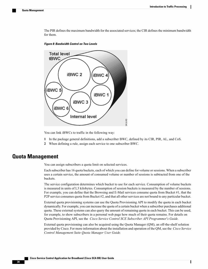
The PIR defines the maximum bandwidth for the associated services; the CIR defines the minimum bandwidthfor them.
Figure 8: Bandwidth Control on Two Levels
You can link iBWCs to traffic in the following way:
1 In the package general definitions, add a subscriber BWC, defined by its CIR, PIR, AL, and CoS.2 When defining a rule, assign each service to one subscriber BWC.
Quota ManagementYou can assign subscribers a quota limit on selected services.
Each subscriber has 16 quota buckets, each of which you can define for volume or sessions.When a subscriberuses a certain service, the amount of consumed volume or number of sessions is subtracted from one of thebuckets.
The service configuration determines which bucket to use for each service. Consumption of volume bucketsis measured in units of L3 kilobytes. Consumption of session buckets is measured by the number of sessions.For example, you can define that the Browsing and E-Mail services consume quota from Bucket #1, that theP2P service consumes quota fromBucket #2, and that all other services are not bound to any particular bucket.
External quota provisioning systems can use the Quota Provisioning API to modify the quota in each bucketdynamically. For example, you can increase the quota of a certain bucket when a subscriber purchases additionalquota. These external systems can also query the amount of remaining quota in each bucket. This can be used,for example, to show subscribers in a personal web page how much of their quota remains. For details onQuota Provisioning API, see the Cisco Service Control SCE Subscriber API Programmer’s Guide.External quota provisioning can also be acquired using the Quota Manager (QM), an off-the-shelf solutionprovided by Cisco. For more information about the installation and operation of the QM, see the Cisco ServiceControl Management Suite Quota Manager User Guide.
Cisco Service Control Application for Broadband (Cisco SCA BB) User Guide34
Introduction to Traffic ProcessingQuota Management
External quota provisioning can also be acquired using the Gy quota model and Gx quota model. For moreinformation, see the Cisco Service Control Mobile Solution Guide .
External quota provisioning is not supported when unidirectional classification is enabled.Note
The internal Cisco SCA BB quota provisioning system replenishes each quota bucket by a fixed amount atfixed intervals.
Subscribers can be notified when they breach the quota in any bucket.
Subscriber NotificationThe subscriber notification feature lets you push web-based messages (such as notifications of quota depletion)to a subscriber by redirecting the subscriber HTTP traffic to relevant web pages. HTTP redirection starts whenthe subscriber notification is activated and ceases when the notification is dismissed.
Subscriber notification is not supported when unidirectional classification is enabled.Note
Service SecurityCisco SCA BB includes service security functionality to help protect network operators and their subscribersfrom attacks and malicious traffic:
• DoS attacks
• DDoS attacks
• VoIP threats
•Worms
• Hacker activity
• Malicious takeover of subscriber computers:
◦Spam zombies
◦E-mail based viruses
Although it is never possible to provide complete protection from network threats, the Cisco Service Controlsolution provides insight into malicious activity in a network, and can mitigate large-scale eruptions ofmalicious activity that compromise overall network performance.
Networks operators can use Cisco SCA BB to:
• Monitor network traffic for suspicious activity
• Block malicious traffic
• Notify subscribers that are creating or have been affected by malicious traffic
Cisco Service Control Application for Broadband (Cisco SCA BB) User Guide 35
Introduction to Traffic ProcessingService Security
Detecting Malicious TrafficCisco SCA BB uses four threat detection mechanisms:
• Anomaly Detection—This set of mechanisms monitors the rate of connections (both successful andunsuccessful) to and from each host IP address. High connection rates or a low ratio between successfuland unsuccessful connections indicate malicious activity.Anomaly detection characteristics can indicate the following categories of malicious activity:
◦IP sweep—Scanning multiple IP addresses, all on the same port (a behavior typical of worms)
◦Port scan—Scanning all ports at one IP address (a behavior typical of hackers)
◦DoS attack—An attack (on a single IP address) from a single IP address
◦DDoS attack—An attack (on a single IP address) from multiple IP addresses
Cisco SCA BB identifies a DoS attack with spoofing (using many fake IP addressesinstead of one real address) as a DDoS attack.
Note
The anomaly detection mechanism is effective in addressing new threats as they appear. It does not needknowledge about their exact nature and Layer 7 signatures, but is based on the characteristics of theirnetwork activity.
• Massmailing activity detection—This mechanismmonitors SMTP session rates for individual subscribers(using Cisco SCE platform subscriber-awareness; it canwork in subscriber-aware or anonymous subscribermode). A high rate of SMTP sessions from an individual subscriber is usually an indicator of maliciousactivity that involves sending e-mail (either mail-based viruses or spam-zombie activity).
• Signature-based detection—The stateful Layer 7 capabilities of the Cisco SCE platform are used todetect malicious activity that is not easily detectable by the other mechanisms. Operators can addsignatures for such threats, achieving a quick response time in addressing new threats.
• RFC compliance detection—This mechanism monitors the SMTP traffic for RFC compliance.Non-compliant traffic is marked as spam.
Responding to Malicious TrafficYou can define the following actions when configuring the detection mechanisms described in the precedingsection:
• Monitor the network for malicious activity detected by each of these mechanisms.You can display graphs in the Console based on data collected for malicious activity analysis.
• Automatically block malicious activity detected by the Cisco SCE platform to avoid threat propagationand adverse effects to the network.
• Notify subscribers that are involved in malicious activity by redirecting their web sessions to a captiveportal.
Cisco SCA BB provides a high level of flexibility in tuning the detection methods to define malicious activityand in configuring the actions to be taken when malicious activity is detected.
Cisco Service Control Application for Broadband (Cisco SCA BB) User Guide36
Introduction to Traffic ProcessingDetecting Malicious Traffic
Traffic FiltersFilter rules are part of service configurations. Filter rules allow you to instruct the Cisco SCE platform toignore some types of flow (based on the Layer 3 and Layer 4 properties of the flow) and to transmit the flowsunchanged.
When a traffic flow enters the Cisco SCE platform, the platform checks whether a filter rule applies to theflow. If a filter rule applies to this traffic flow, the Cisco SCE platform performs one of the following actions:
• Bypass—The Cisco SCE platform passes the traffic flow to its transmit queues without generating anyRDRs (the flow does not appear in records generated for analysis purposes) and without enforcing anyservice configuration rules.
• Quick forward—A flow filter rule action whose aim is to ensure low latency for delay sensitive flows.The packets of quick-forwarded flows are duplicated and sent through different paths: one copy goesdirectly to the transmit queue and thus suffers only a minimal delay, the other copy goes through thenormal packet path.
A filter rule can also set the DSCP ToS value of the filtered traffic.
It is recommended that you add filter rules for OSS protocols (such as DHCP) and routing protocols (such asBGP) that might traverse the Cisco SCE platform. These protocols usually should not be affected by policyenforcement, and their low volume makes them insignificant for reporting.
A number of filter rules are included in the default service configuration.
Effective with Cisco SCA BB Release 4.0.0, there are 64 flow filter rules for both IPv4 and IPv6 addresseson the Cisco SCE 8000 devices. You can add from 0 to 60 flow filter rules using the Cisco SCA BB consoleand the other three flow filter rules are reserved.
There are 64 flow filter rules for both IPv4 and IPv6 addresses on the Cisco SCE 10000 devices. You can addfrom 0 to 60 flow filter rules using the Cisco SCABB console and the other three flow filter rules are reserved.
Flows of certain protocols can also be filtered according to the Layer 7 characteristics of the flow.
DSCP ToS MarkingDSCP ToS marking is used in IP networks to signal the type and priority of a flow between network elements.Typically, those elements that have an insight on how to treat the traffic throughout the network performs theDSCP ToS marking. Such an element can be the element generating traffic—a voice gateway, for example.Cisco SCABB, being application aware, can, for example, allocate bandwidth resources based on the businessmodel and the specific needs of latency sensitive applications. ToS marking is enabled per direction. You canconfigure seven DSCP ToS values as an action of the Package rules or for Flow Filter rules. The range is anyinteger from 0 to 63.
Traffic Forwarding to Value-Added Services ServersTraffic forwarding to Value Added Services (VAS) servers allows the Cisco Service Control solution to usean external expert system (VAS server) for additional traffic processing. The Cisco SCE reroutes traffic tothe preconfigured location of the VAS server. After processing, the traffic is sent back to the Cisco SCE,which then sends it to its original destination.
Cisco Service Control Application for Broadband (Cisco SCA BB) User Guide 37
Introduction to Traffic ProcessingTraffic Filters
VAS traffic forwarding is not supported when unidirectional classification is enabled.Note
Service ConfigurationsA service configuration implements and enforces the business strategy and vision of the provider.
A service configuration can take effect only after it is propagated to the appropriate Cisco SCE platform.Cisco SCA BB enforces the service configuration by analyzing the network traffic passing through them.
A service configuration consists of:
• Traffic classification settings—Services, such as web browsing, file sharing, and VoIP. Each serviceconsists of elements that define how network traffic is mapped to the service. The configuration buildingblocks of services are protocols, zones, flavors, and signatures.
• Traffic accounting and reporting settings—Settings that determine how traffic flows and network usageaccounting are reported.
• Traffic control settings—Packages, which consist of a set of rules (such as bandwidth rate limit andquota limits) defined for different services. The main configuration building blocks of packages arerules, quota buckets, subscriber BWCs, and global controllers.
Defining Service Configurations in PracticeIn practice, defining service configurations is an iterative process. It is recommended that you use the followingsequence of steps:
Procedure
Step 1 Set up the system.Step 2 Apply the default service configuration.Step 3 Gather data.Step 4 Analyze.Step 5 Do one or both of the following:
• Continue traffic discovery by partitioning the traffic into (additional) services.
• Create rules to limit and prioritize traffic according to services and subscriber packages.
Cisco Service Control Application for Broadband (Cisco SCA BB) User Guide38
Introduction to Traffic ProcessingService Configurations
C H A P T E R 4Getting Started with Cisco SCA BB Console
The module guides you through the process of installing or upgrading the Cisco SCA BB:
• Describes the concept of the Console as a collection of tools, presents each tool and its role. This modulealso describes how to launch the tools and navigate between these tools.
• Explains how to install Protocol Packs, which contain new and updated protocol signatures
• Concludes with a QuickStart that describes how to apply your first service configuration and generateyour first report
This section consists of the following sections:
• How to Install Cisco SCA BB , page 39
• How to Upgrade Cisco SCA BB Components, page 44
• Working with Protocol Packs , page 55
• Launching the Cisco SCA BB Console , page 66
• How to Use the Cisco SCA BB Console , page 68
• QuickStart with the Cisco SCA BB Console , page 104
How to Install Cisco SCA BB
On aWindows XP machine, the Cisco SCA BB application can only be installed in the administrator usergroup. During installation the Cisco SCA BB application changes registry entries, therefore installationin normal user groups is not allowed. The installer must have administrator privileges assigned.
Note
You install Cisco SCA BB in two stages:
1 Install the Cisco SCA BB front ends:
• The Cisco SCA BB Console
• The Cisco SCABB Service Configuration Utility, the Cisco SCABB Signature Configuration Utility,and the Cisco SCA BB Real-Time Monitoring Configuration Utility
Cisco Service Control Application for Broadband (Cisco SCA BB) User Guide 39
2 Install the Cisco SCA BB application components:
• The Cisco SCA BB Service Modeling Language Loadable Image (SLI) and the Cisco SCA BBService Control Engine (Cisco SCE) applicative management plug-in
• The Cisco SCA BB Subscriber Manager applicative management plug-in (for systems with a CiscoService Control Subscriber Manager)
If you are upgrading an existing installation of Cisco SCA BB, see the Upgrading the SCE Using the SCESoftware Upgrade Wizard, on page 44 section or the Working with Protocol Packs section.
The Cisco SCA BB Installation PackageThe Cisco SCA BB installation package is a ZIP file located in the CCO.
The installation package consists of the following files:
• The installer for the Console: scas-bb-console-<version>-<build>.exe.
• A Cisco installation application package file (PQI file) for each type of Cisco SCE platform. Each PQIfile is located in a subfolder whose name is the platform name.
• The file scas_bb_util.tgz, which contains the files for the Cisco SCA BB Service Configuration Utility( servconf) , the Cisco SCA BB Signature Configuration Utility ( sigconf) , the Cisco SCA BBReal-Time Monitoring Configuration Utility ( rtmcmd) (together with real-time monitoring reporttemplates), and the BGPAutonomous SystemDynamic Detection scripts and files ( routerInfo.properties, asFetch.bat , asFetch.sh ).
• The file PCubeEngageMib.mib, which defines the SCAS BB MIB, located in the SNMP subfolder.
• The Cisco SCA BB Service Configuration Java API distribution file: serviceconfig-java-api-dist.tgz.
• The file surfcontrol.xml, which lists the content categories for content filtering using SurfControl ContentPort Authority, located in the URL Filtering subfolder.
Installing Cisco SCA BB Application ComponentsCisco SCA BB has two software components that reside on the Cisco SCE platform:
• The Cisco SCA BB SLI, which performs traffic processing
• The Cisco SCA BB SCE applicative management plug-in, which performs some service configurationoperations
Cisco SCA BB also has one software component that resides on the Subscriber Manager device:
• The Cisco SCA BB Subscriber Manager applicative management plug-in, which performs someapplication-specific subscriber management operations
To install these components from the Console, see the Installing PQI Files on Cisco SCE Devices andIntroduction to Managing Collection Manager Devices sections.
To install these components from a command line, see the Installing a Cisco SCA BB PQI File on a CiscoSCE Platform section.
Cisco Service Control Application for Broadband (Cisco SCA BB) User Guide40
Getting Started with Cisco SCA BB ConsoleThe Cisco SCA BB Installation Package
PrerequisitesBefore installing Cisco SCABB, verify that the SCE platform and, if used, the Cisco Service Control SubscriberManager are operational and are running appropriate versions of their software.
Verifying that the SCE Platform is Operational
Procedure
Verify that the status LED on the SCE flashes green. (Orange—booting up; flashing orange—warning;red—failure.)
Verifying that the SCE Platform is Running an Appropriate Version of the OS
Procedure
Step 1 At the SCE platform CLI prompt (SCE#), type show version .Step 2 Press Enter .
The response shows the version of the OS running on the SCE platform.
Verifying that the Subscriber Manager is Correctly Installed
Procedure
Step 1 Open a Telnet session to the Subscriber Manager.Step 2 Go to the Subscriber Manager bin directory and type p3sm --sm-status.Step 3 Press Enter .
Displays the operational status of the Cisco Service Control Subscriber Manager.
Verifying that an Appropriate Version of the Subscriber Manager is Running
Procedure
Step 1 Open a Telnet session to the Subscriber Manager.Step 2 Go to the Subscriber Manager bin directory and type p3sm version .Step 3 Press Enter .
Cisco Service Control Application for Broadband (Cisco SCA BB) User Guide 41
Getting Started with Cisco SCA BB ConsolePrerequisites
Displays the Subscriber Manager version.
How to Install Cisco SCA BB Front EndsYou should install the following Cisco SCA BB front ends:
• The Console
• The Cisco SCA BB Service Configuration Utility ( servconf) , the Cisco SCA BB SignatureConfiguration Utility ( sigconf) , and the Cisco SCA BB Real-Time Monitoring Configuration tool (rtmcmd) (together with associated real-time monitoring report templates).
◦servconf requires access to the Java Runtime Environment (JRE) (see Installing the Java RuntimeEnvironment ).
Cisco SCA BB Hardware Requirements• At least 1024-MB RAM is required to run the Console.
• The minimal supported screen resolution for the Console is 1024x768 pixels.
Cisco SCA BB Operating System RequirementsThe SCA Reporter GUI front end can be installed on any computer running Windows 2000, Windows XP,Windows Vista, or Windows 7.
Installing the Java Runtime EnvironmentThe Cisco SCA BB Service Configuration Utility, servconf, requires access to JRE version 1.6 update 43.
Procedure
Step 1 Verify the version of the JRE installed on the system.From the command prompt, run java -version . The Java version should start with 1.6.
Step 2 (Optional) Configure the JAVA_HOME environment.If a different version of JRE is also installed on the workstation, configure the JAVA_HOME environmentvariable in the servconf file to point to the JRE 1.6 installation directory.
Example:JAVA_HOME=C:\Program Files\Java\jre1.6.0_43
Cisco Service Control Application for Broadband (Cisco SCA BB) User Guide42
Getting Started with Cisco SCA BB ConsoleHow to Install Cisco SCA BB Front Ends

Installing the Cisco SCA BB Console
Procedure
Step 1 Navigate to the Console installation file on your local machine, sca-bb-console-4.1.x.exe, and double-clickit.The Welcome page of the Cisco SCA BB Console 4.1.x Setup wizard appears.
Step 2 Click Next .The Install Location page of the Setup wizard opens.
Step 3 (Optional) Click Browse and choose a different destination folder.Step 4 Click Next .
The Start Menu Folder page of the Setup wizard opens.Step 5 (Optional) Enter a different Start Menu folder in the Start Menu Folder field.Step 6 (Optional) Check the Do not create shortcuts check box.Step 7 Click Install .
The Installing page of the Setup wizard opens.Step 8 Wait until the installation is complete.
The Next button is enabled.Step 9 Click Next .
The Installation Complete page of the Setup wizard opens.Step 10 To launch the Console, check the Run SCA BB Console after installation check box.Step 11 Click Finish .
The Cisco SCA BB Console 4.1.x Setup wizard closes. The Console is now installed on the machine. Ashortcut is added to the Start menu.
Installing the Cisco SCA BB Configuration Utilities
Procedure
Step 1 From the Cisco SCA BB installation package, extract the scas_bb_util.tgz file, and copy it to a work stationhaving Windows or Linux operating system.
Step 2 Unpack the file to a new folder. The Cisco SCA BB Service Configuration Utility ( servconf) , the CiscoSCABBReal-TimeMonitoring Configuration Utility ( rtmcmd) (and associated real-timemonitoring reporttemplates), the Cisco SCABB Signature Configuration Utility ( sigconf ), and the BGPAutonomous SystemDynamic Detection scripts and files ( routerInfo.properties , asFetch.bat , asFetch.sh ) are located in the binfolder. This folder also stores the BGPRouter<number>.csv file generated by the asFetch.bat script afterfetching the BGP AS information from the router.
Cisco Service Control Application for Broadband (Cisco SCA BB) User Guide 43
Getting Started with Cisco SCA BB ConsoleHow to Install Cisco SCA BB Front Ends

How to Upgrade Cisco SCA BB ComponentsUpgrading Cisco SCA BB includes upgrading each of these software components:
• SCE Firmware
• The SCE PQI file
• Protocol Pack SPQI file
• Policy file
This section describes the upgrade of Cisco SCA BB application components only. For a full descriptionof the entire Cisco solution upgrade procedure, consult the solution upgrade document accompanying theformal release.
Note
•When you upgrade old PQB files, some protocol IDs are changed automatically. Messages such as thefollowing may be displayed to indicate the change:
◦Protocol ID of PPLive changed from 81 to 44
◦Protocol ID of BaiBao changed from 80 to 43
•When you upgrade a device with a new SPQI or PQI file, all other devices that are not upgraded mayfail.
• New Cisco SCA BB releases do not use the default Dynamic Signature Script (DSS) file (see that it wasinstalled for a previous Cisco SCA BB release).
• If a protocol pack for the new release is available, install it after the product installation is complete. Donot install an old protocol pack on top of a new product installation.
Upgrading the SCE Using the SCE Software Upgrade WizardYou can upgrade the SCE using the Network Navigator Tool via the SCE Software Upgrade wizard.
Procedure
Step 1 Open the Network Navigator.Step 2 Choose one or more devices in the Site Manager tree.Step 3 Right-click one of the selected devices.Step 4 From the popup menu that appears, choose SCE Software Upgrade wizard.
Cisco Service Control Application for Broadband (Cisco SCA BB) User Guide44
Getting Started with Cisco SCA BB ConsoleHow to Upgrade Cisco SCA BB Components

The SCE Software Upgrade wizard appears.
Figure 9: SCE Software Upgrade
Step 5 Click Next .
Cisco Service Control Application for Broadband (Cisco SCA BB) User Guide 45
Getting Started with Cisco SCA BB ConsoleUpgrading the SCE Using the SCE Software Upgrade Wizard
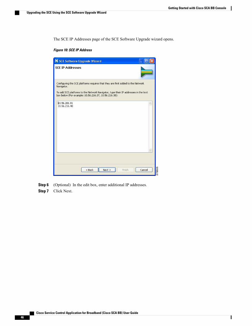
The SCE IP Addresses page of the SCE Software Upgrade wizard opens.
Figure 10: SCE IP Address
Step 6 (Optional) In the edit box, enter additional IP addresses.Step 7 Click Next.
Cisco Service Control Application for Broadband (Cisco SCA BB) User Guide46
Getting Started with Cisco SCA BB ConsoleUpgrading the SCE Using the SCE Software Upgrade Wizard

The SCE Usernames and Passwords page of the SCE Software Upgrade wizard opens.
Figure 11: SCE Usernames and Passwords
Step 8 Enter the usernames and passwords for the SCE devices.Do one of the following:
• To use the same username and password for all the SCE devices that you are adding, enter the usernamein the Username field and the password in the Password field.
• To provide a different username and password pair for each SCE device, click the Use separate usernamesand passwords for each SCE platform radio button, and, for each SCE device, enter the username andpassword in the appropriate cell of the table.
Step 9 Click Next.
Cisco Service Control Application for Broadband (Cisco SCA BB) User Guide 47
Getting Started with Cisco SCA BB ConsoleUpgrading the SCE Using the SCE Software Upgrade Wizard
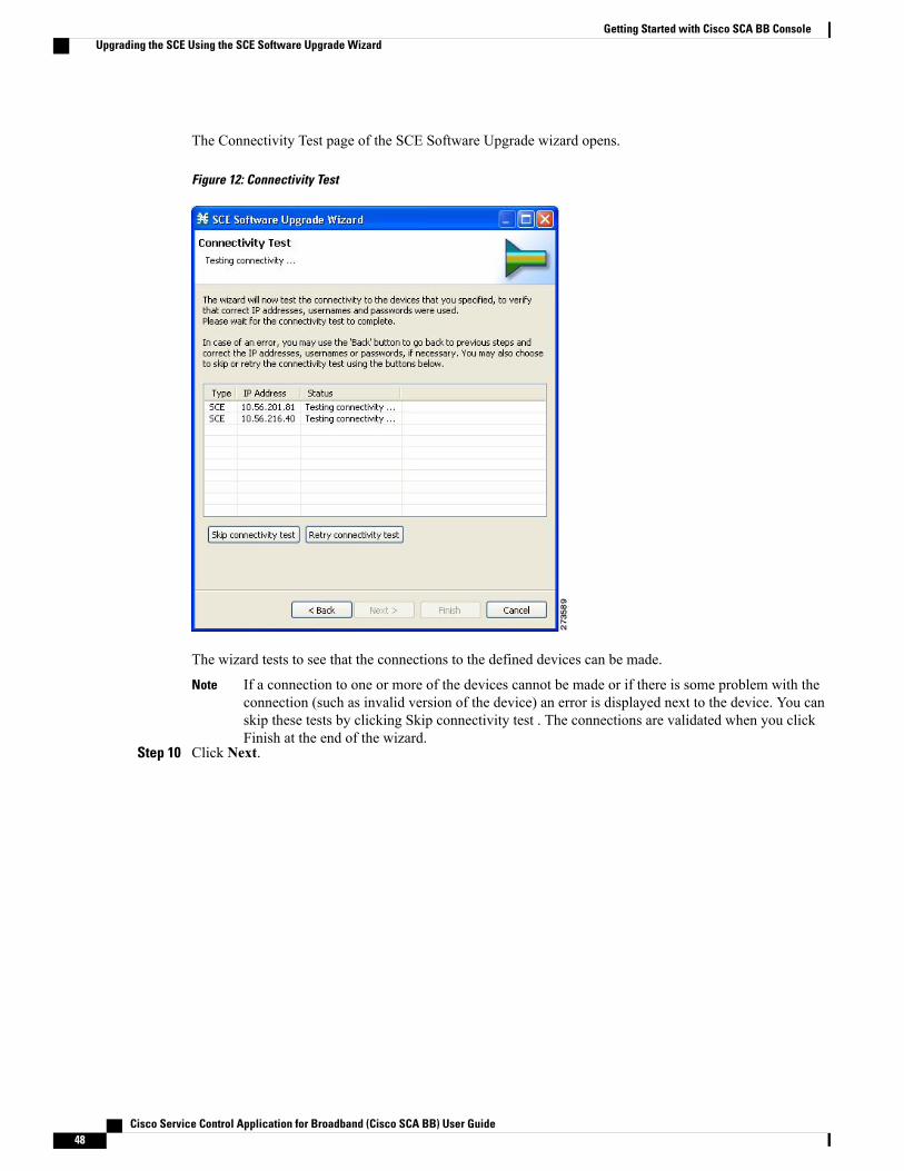
The Connectivity Test page of the SCE Software Upgrade wizard opens.
Figure 12: Connectivity Test
The wizard tests to see that the connections to the defined devices can be made.
If a connection to one or more of the devices cannot be made or if there is some problem with theconnection (such as invalid version of the device) an error is displayed next to the device. You canskip these tests by clicking Skip connectivity test . The connections are validated when you clickFinish at the end of the wizard.
Note
Step 10 Click Next.
Cisco Service Control Application for Broadband (Cisco SCA BB) User Guide48
Getting Started with Cisco SCA BB ConsoleUpgrading the SCE Using the SCE Software Upgrade Wizard
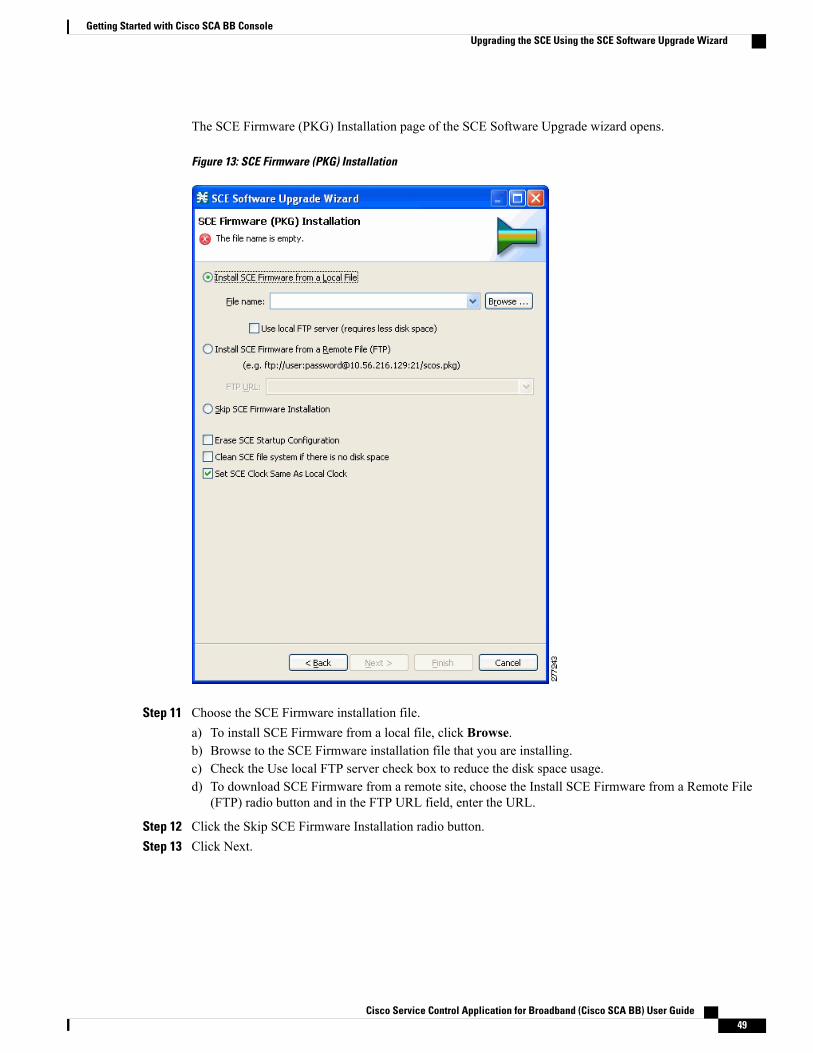
The SCE Firmware (PKG) Installation page of the SCE Software Upgrade wizard opens.
Figure 13: SCE Firmware (PKG) Installation
Step 11 Choose the SCE Firmware installation file.a) To install SCE Firmware from a local file, click Browse.b) Browse to the SCE Firmware installation file that you are installing.c) Check the Use local FTP server check box to reduce the disk space usage.d) To download SCE Firmware from a remote site, choose the Install SCE Firmware from a Remote File
(FTP) radio button and in the FTP URL field, enter the URL.
Step 12 Click the Skip SCE Firmware Installation radio button.Step 13 Click Next.
Cisco Service Control Application for Broadband (Cisco SCA BB) User Guide 49
Getting Started with Cisco SCA BB ConsoleUpgrading the SCE Using the SCE Software Upgrade Wizard
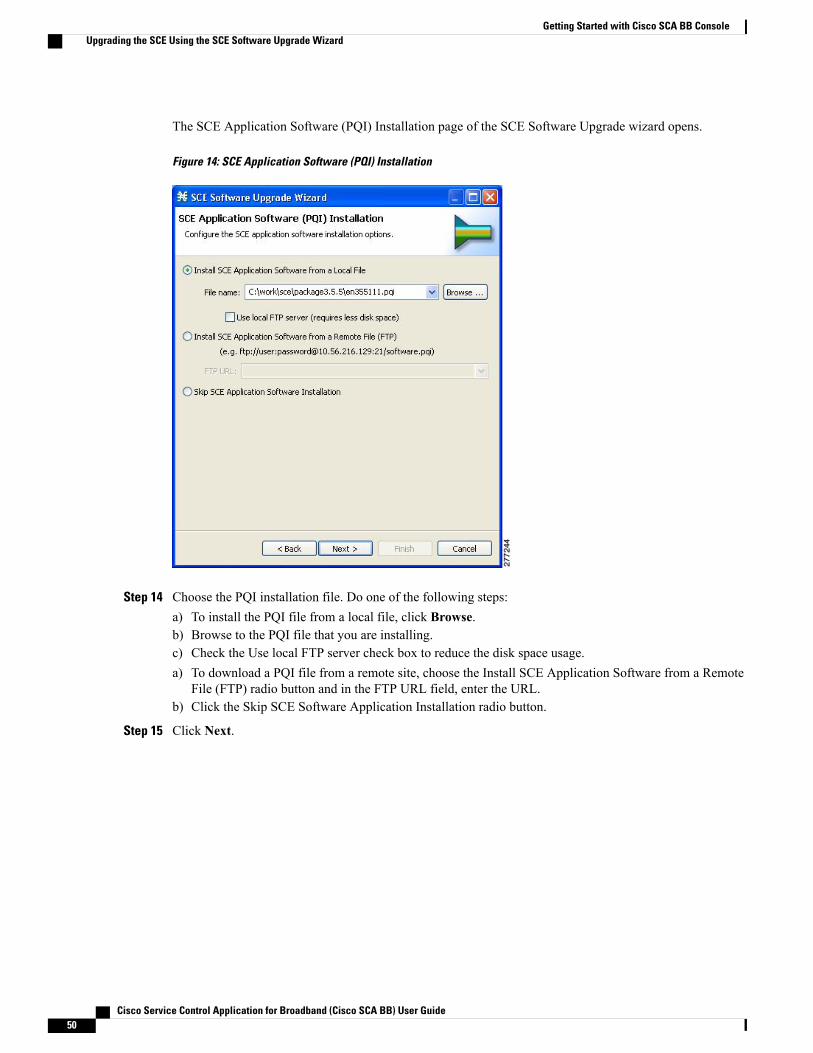
The SCE Application Software (PQI) Installation page of the SCE Software Upgrade wizard opens.
Figure 14: SCE Application Software (PQI) Installation
Step 14 Choose the PQI installation file. Do one of the following steps:a) To install the PQI file from a local file, click Browse.b) Browse to the PQI file that you are installing.c) Check the Use local FTP server check box to reduce the disk space usage.a) To download a PQI file from a remote site, choose the Install SCE Application Software from a Remote
File (FTP) radio button and in the FTP URL field, enter the URL.b) Click the Skip SCE Software Application Installation radio button.
Step 15 Click Next.
Cisco Service Control Application for Broadband (Cisco SCA BB) User Guide50
Getting Started with Cisco SCA BB ConsoleUpgrading the SCE Using the SCE Software Upgrade Wizard

The Protocol Pack (SPQI) Update page of the SCE Software Upgrade wizard opens.
Figure 15: Protocol Pack (SPQI) Update
Step 16 Update the protocol pack.Do one of the following:
• To update the SPQI file from a local file, click Browse. A Select file dialog box appears. Browse to theSPQI file that you are updating.
• Click the Skip Protocol Pack Update radio button.
Step 17 Click Next .
Cisco Service Control Application for Broadband (Cisco SCA BB) User Guide 51
Getting Started with Cisco SCA BB ConsoleUpgrading the SCE Using the SCE Software Upgrade Wizard
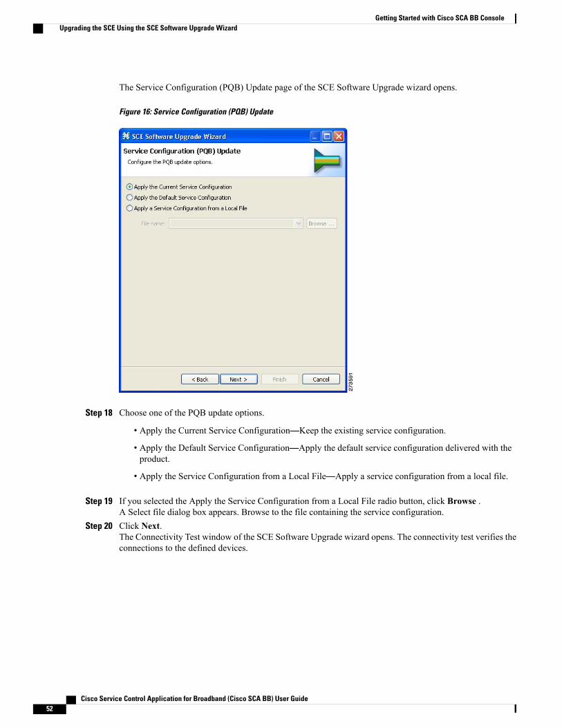
The Service Configuration (PQB) Update page of the SCE Software Upgrade wizard opens.
Figure 16: Service Configuration (PQB) Update
Step 18 Choose one of the PQB update options.
• Apply the Current Service Configuration—Keep the existing service configuration.
• Apply the Default Service Configuration—Apply the default service configuration delivered with theproduct.
• Apply the Service Configuration from a Local File—Apply a service configuration from a local file.
Step 19 If you selected the Apply the Service Configuration from a Local File radio button, click Browse .A Select file dialog box appears. Browse to the file containing the service configuration.
Step 20 Click Next.The Connectivity Test window of the SCE Software Upgrade wizard opens. The connectivity test verifies theconnections to the defined devices.
Cisco Service Control Application for Broadband (Cisco SCA BB) User Guide52
Getting Started with Cisco SCA BB ConsoleUpgrading the SCE Using the SCE Software Upgrade Wizard

If a connection to one or more of the devices cannot be made or if there is some problem with theconnection (such as invalid version of the device), an error is displayed next to the device. You canskip these tests by clicking Skip connectivity test . The connections are validated when you clickFinish at the end of the wizard.
Note
Figure 17: Connectivity Test
Step 21 Click Next .
Cisco Service Control Application for Broadband (Cisco SCA BB) User Guide 53
Getting Started with Cisco SCA BB ConsoleUpgrading the SCE Using the SCE Software Upgrade Wizard
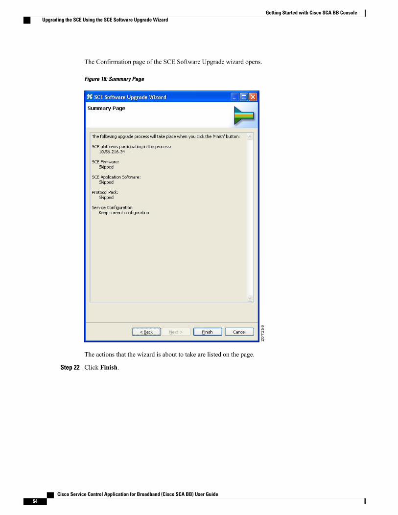
The Confirmation page of the SCE Software Upgrade wizard opens.
Figure 18: Summary Page
The actions that the wizard is about to take are listed on the page.
Step 22 Click Finish.
Cisco Service Control Application for Broadband (Cisco SCA BB) User Guide54
Getting Started with Cisco SCA BB ConsoleUpgrading the SCE Using the SCE Software Upgrade Wizard
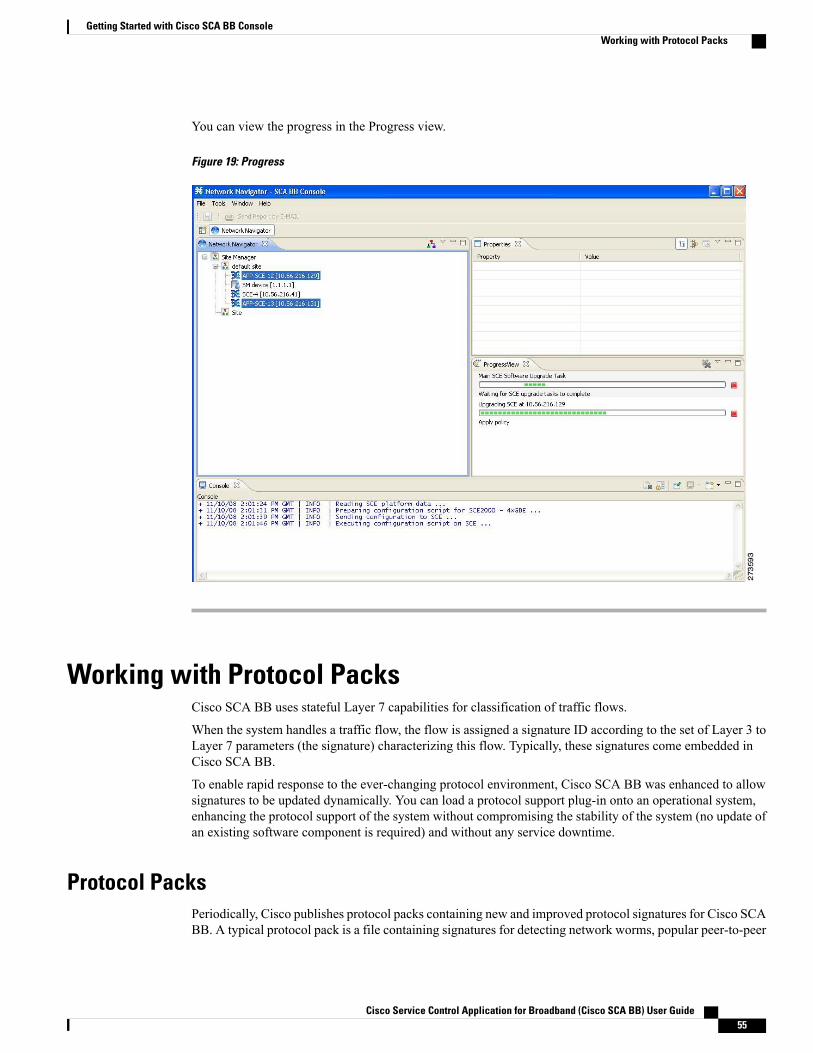
You can view the progress in the Progress view.
Figure 19: Progress
Working with Protocol PacksCisco SCA BB uses stateful Layer 7 capabilities for classification of traffic flows.
When the system handles a traffic flow, the flow is assigned a signature ID according to the set of Layer 3 toLayer 7 parameters (the signature) characterizing this flow. Typically, these signatures come embedded inCisco SCA BB.
To enable rapid response to the ever-changing protocol environment, Cisco SCA BB was enhanced to allowsignatures to be updated dynamically. You can load a protocol support plug-in onto an operational system,enhancing the protocol support of the system without compromising the stability of the system (no update ofan existing software component is required) and without any service downtime.
Protocol PacksPeriodically, Cisco publishes protocol packs containing new and improved protocol signatures for Cisco SCABB. A typical protocol pack is a file containing signatures for detecting network worms, popular peer-to-peer
Cisco Service Control Application for Broadband (Cisco SCA BB) User Guide 55
Getting Started with Cisco SCA BB ConsoleWorking with Protocol Packs
applications, and other relevant protocols. When loaded into SCE platforms, these signatures improve CiscoSCA BB classification abilities.
You can install a protocol pack on an SCE platform only if a PQI is already installed on the platform.Note
A protocol pack for Cisco SCA BB may be either a DSS file or an SPQI file:
• Loading a DSS file to the SCE platform requires no downtime of Cisco SCA BB or the platform.
• Loading an SPQI file to the SCE platform entails updating the SCE application:
◦If hitless upgrade (see Hitless Upgrade of the SLI section ) is enabled, there is no downtime ofthe SCE platform when loading the SPQI file.
◦If hitless upgrade is not enabled, loading an SPQI file requires a short downtime (up to one minute)of the SCE platform. During that time, network traffic bypasses the platform and is neither controllednor reported.
If hitless upgrade is disabled, SPQI installation can cause the loss of the following subscriber data fromall subscribers: package ID, real-timemonitoring flag, and quota settings. Subscribers are assigned defaultvalues for these properties.
Note
Installing Protocol PacksYou install a protocol pack on an SCE platform using one of the following:
• The Cisco SCA BB Service Configuration Utility (see the The Cisco SCA BB Service ConfigurationUtility section)
• The Network Navigator tool (see the Installing a Protocol Pack on a Single Cisco SCE Platform section)
If the protocol pack is an SPQI file you can enable and configure the hitless upgrade option using HitlessUpgrade CLI commands. (See the Hitless Upgrade of the SLI section.)
Note
The tool or utility performs the following steps: Retrieves the current service configuration from the SCEplatform and (optionally) stores a backup copy in a folder that you specify.
Cisco SCE does not support direct downgrade of higher PP versions to a lower PP version. Whiledowngrading the protocol pack from a higher version to a lower version, the Cisco SCA BB consoledisplays an error message and prevents you from applying the policy on the Cisco SCE.
Note
Cisco Service Control Application for Broadband (Cisco SCA BB) User Guide56
Getting Started with Cisco SCA BB ConsoleInstalling Protocol Packs

Procedure
Step 1 Retrieves the current service configuration from the SCE platform and (optionally) stores a backup copy ina folder that you specify.
Step 2 Imports the signatures that are in the DSS or SPQI file into the service configuration. This action overwritesany DSS that was previously imported into the service configuration.
Step 3 For each new signature that includes a Buddy Protocol attribute (an attribute that points to an existing protocol)(see DSS Buddy Protocol section)—Adds the new signature to all services that include the buddy protocol.
Step 4 If the protocol pack is an SPQI file—Replaces the SCE application. This action causes a short (up to oneminute) downtime in SCE platform service.
Step 5 Applies the new service configuration to the SCE platform.If the protocol pack is an SPQI file and the hitless upgrade option is enabled, you can monitor the progressof the upgrade using the hitless upgrade CLI commands (see the Hitless Upgrade CLI Commands section.)
How to Install the Service Hierarchy TreeOpening a PQB using the Client (GUI) exposes its service hierarchy tree (signatures, flavors, protocols, andso on). The client defines the Service Configuration Hierarchy.
When loading a PQB file from the SCE, the PQB Hierarchy Tree must be of the same version as the one inthe client. In other words, the PQB must be the same version as the Client, otherwise the PQB doe not open.
Because the client can be connected with different SCE with different versions, and each PQB can havedifferent Service Hierarchy Tree definition, you must install the relevant Service Hierarchy Tree in the Client(GUI) before opening a PQB.
The client can install the service hierarchy tree according to the SCE version. The GUI installation comeswith a fixed set of service hierarchy elements which are placed in a specific version-related jar file. You canselect between different jar files related to different versions.
The SCE service hierarchy tree is different than the client version. When installing a service hierarchy treefor a SCE:
• Always back up user PQB before upgrade to PPXY and keep a copy since the PQB is changed.
• Remove/Reinstall Service Tree Protocol.
Cisco Service Control Application for Broadband (Cisco SCA BB) User Guide 57
Getting Started with Cisco SCA BB ConsoleHow to Install the Service Hierarchy Tree
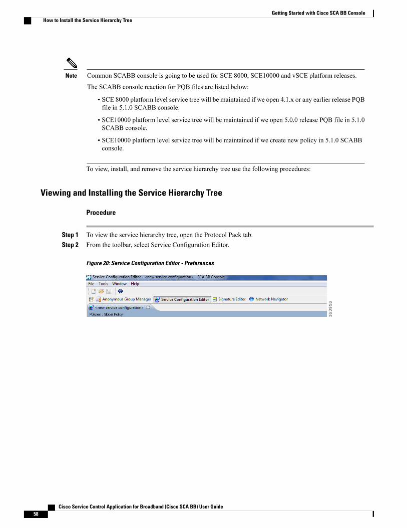
Common SCABB console is going to be used for SCE 8000, SCE10000 and vSCE platform releases.
The SCABB console reaction for PQB files are listed below:
Note
• SCE 8000 platform level service tree will be maintained if we open 4.1.x or any earlier release PQBfile in 5.1.0 SCABB console.
• SCE10000 platform level service tree will be maintained if we open 5.0.0 release PQB file in 5.1.0SCABB console.
• SCE10000 platform level service tree will be maintained if we create new policy in 5.1.0 SCABBconsole.
To view, install, and remove the service hierarchy tree use the following procedures:
Viewing and Installing the Service Hierarchy Tree
Procedure
Step 1 To view the service hierarchy tree, open the Protocol Pack tab.Step 2 From the toolbar, select Service Configuration Editor.
Figure 20: Service Configuration Editor - Preferences
Cisco Service Control Application for Broadband (Cisco SCA BB) User Guide58
Getting Started with Cisco SCA BB ConsoleHow to Install the Service Hierarchy Tree
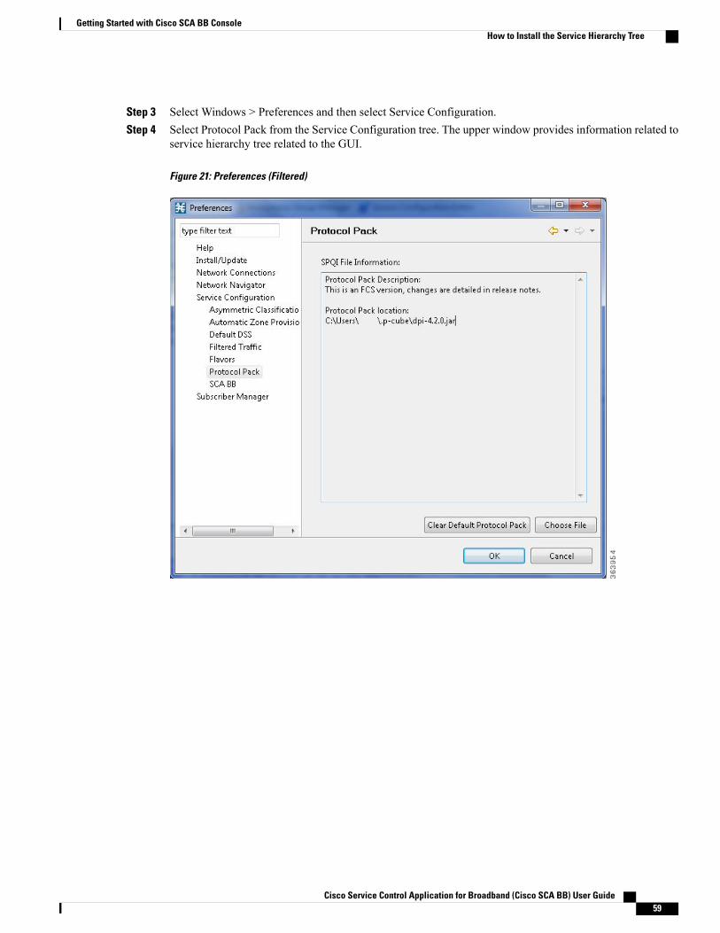
Step 3 Select Windows > Preferences and then select Service Configuration.Step 4 Select Protocol Pack from the Service Configuration tree. The upper window provides information related to
service hierarchy tree related to the GUI.
Figure 21: Preferences (Filtered)
Cisco Service Control Application for Broadband (Cisco SCA BB) User Guide 59
Getting Started with Cisco SCA BB ConsoleHow to Install the Service Hierarchy Tree

Step 5 To install a new service hierarchy tree, click the Choose File button and select either a jar file or an SPQI file.
Figure 22: Select Protocol Pack
Step 6 Click Open, and approve the warning message by clicking OK .
Figure 23: Protocol Pack Selection Warning Message
Step 7 To back up the current protocol pack and install the new service hierarchy tree, approve the backup messageby clicking OK.
Figure 24: Protocol Pack Selection Backup Message
Cisco Service Control Application for Broadband (Cisco SCA BB) User Guide60
Getting Started with Cisco SCA BB ConsoleHow to Install the Service Hierarchy Tree
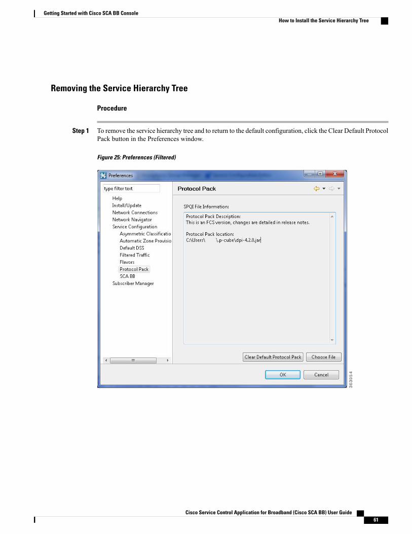
Removing the Service Hierarchy Tree
Procedure
Step 1 To remove the service hierarchy tree and to return to the default configuration, click the Clear Default ProtocolPack button in the Preferences window.
Figure 25: Preferences (Filtered)
Cisco Service Control Application for Broadband (Cisco SCA BB) User Guide 61
Getting Started with Cisco SCA BB ConsoleHow to Install the Service Hierarchy Tree

Step 2 Accept the operation by clicking OK on the Protocol Pack Removal message screen.
Figure 26: Protocol Pack Removal Message
The service hierarchy tree is removed from the system, and when a new PQB is opened, the client installs thedefault service classifications.
Verifying Version Compatibility for Protocol PacksA protocol pack is compatible only with specific versions of the SCE application.When working with protocolpacks, verify that the protocol pack version matches the SCE application version. For example, only use aprotocol pack for 4.0.0 on SCE application version 4.0.0.
The version compatibility information for each protocol pack is included in the release notes of the protocolpack.
Procedure
Step 1 Verify that the correct version of servconf is installed and running correctly.
• From the command prompt, type servconf --version .
• Press Enter .
The version of the utility should match that of the protocol pack.
Step 2 Verify that the correct version of the SCE application is installed.
• At the SCE platform CLI prompt (SCE#), type show version .
• Press Enter .
The application version should match that of the protocol pack.
Step 3 Verify that a service configuration (PQB) is applied to the SCE platform.
• In the Console, retrieve and view the current PQB.
Cisco Service Control Application for Broadband (Cisco SCA BB) User Guide62
Getting Started with Cisco SCA BB ConsoleVerifying Version Compatibility for Protocol Packs

Verifying the Installation of a Protocol Pack
Procedure
Step 1 At the SCE platform CLI prompt (SCE#), type show version .Step 2 Press Enter .
The response shows the version of the OS running on the SCE platform. This response includes informationabout the installed protocol pack version.
Step 3 Retrieve the PQB from the SCE platform and view it using the Console.Step 4 Verify that the new protocols from the protocol pack were added to the service configuration.
Causes for Protocol Pack Installation Failure and RemediesThe problems that may cause the installation of a protocol pack to fail and their remedies include:
• Missing or incorrect version of the JRE—Install the correct version of the JRE (see “Installing the JavaRuntime Environment” section ).
• Incorrect or missing SCE application version on the SCE platform—Verify that the correct version ofthe SCE application is installed (see “How to Verify Version Compatibility for Protocol Packs” section).
• No service configuration (PQB) is applied to the SCE platform—Create a new PQB and apply it usingthe Console.
• servconf failed to import the new signatures into the PQB—Use the --force-signature update signatureoption when running servconf (see “servconf Syntax” section).
When reporting problems to Cisco, include the servconf log file, located at <user.home>\.p-cube\servconf.log.With Windows, this usually maps to C:\Documents and Settings\<username>\.p-cube\servconf.log orC:\Users\<username>\.p-cube\servconf.log.
Hitless Upgrade of the SLIHitless upgrade is the Cisco SCA BB method of upgrading the software components that reside on the SCEplatform without incurring any service downtime.
• Hitless upgrade of Protocol Packs is available on SCE 8000.
• Hitless upgrade of Protocol Packs is available on SCE 10000.
If hitless upgrade is enabled, classification, reporting, and control continue uninterrupted when you install anSPQI file (see Working with Protocol Packs section ). You can install SPQI files using either the Consoleor servconf, the Cisco SCA BB Service Configuration Utility. An SPQI file is a package that includes therequired (SLI) files.
Cisco Service Control Application for Broadband (Cisco SCA BB) User Guide 63
Getting Started with Cisco SCA BB ConsoleVerifying the Installation of a Protocol Pack

When you apply a new policy or during Protocol Pack upgrade, there is a delay of 30 seconds before therules are applied to the new flows.
Note
After the new application is loaded on the SCE platform:
• The new application services all new flows and bundles.
• The old application continues to service existing flows (and new flows that belong to bundles of existingflows).
• Both applications share available memory.
Until all old flows die or are killed, the hitless upgrade is considered to be in progress. To make the hitlessupgrade process bounded, you can set criteria that triggers the explicit killing of all flows still executing onthe old application. Two such criteria exist:
•When a specified amount of time has passed since the process started.
•When the number of old flows goes below a specified threshold.
The default value for the first criterion is 60 (minutes); the default value for the second is zero (flows). Thismeans that the replace operation is guaranteed to complete after no more than one hour (sooner, if all oldflows die naturally). But the application does not kill any old flow before one hour completes.
These criteria are configurable by CLI commands.
You can initiate the explicit killing of all old flows using a manual command.
Hitless Upgrade CLI CommandsYou can configure, monitor, and control hitless upgrade using the SCE platform Command-Line Interface(CLI). For more information about the SCE platform CLI, see the Cisco SCE 8000 CLI Command Reference.Cisco SCE 10000 CLI Command Reference.
Use the following CLI commands to configure the criteria for completing a hitless upgrade:
replace completion time <minutes>
no replace completion time
default replace completion time
replace completion num-flows <num>
no replace completion num-flows
default replace completion num-flows
These commands are line interface configuration commands. To run these commands you must enter lineinterface configuration mode and see the SCE(config if)# prompt displayed. For details on interfaceconfiguration mode, see Entering Line Interface Configuration Mode section.
The following two CLI commands are EXEC mode commands.
Use the following CLI command to monitor the progress of a hitless upgrade:
show applications slot <num> replace
Use the following CLI command to force immediate completion of a hitless upgrade:
Cisco Service Control Application for Broadband (Cisco SCA BB) User Guide64
Getting Started with Cisco SCA BB ConsoleHitless Upgrade of the SLI
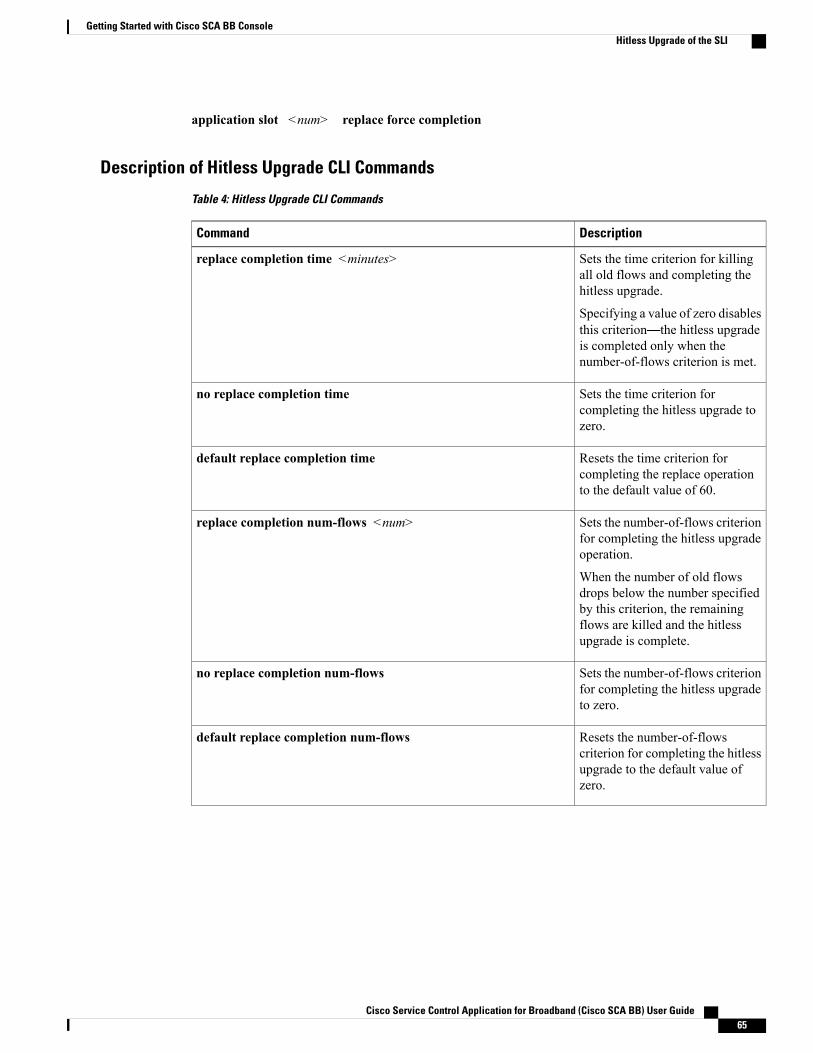
application slot <num> replace force completion
Description of Hitless Upgrade CLI Commands
Table 4: Hitless Upgrade CLI Commands
DescriptionCommand
Sets the time criterion for killingall old flows and completing thehitless upgrade.
Specifying a value of zero disablesthis criterion—the hitless upgradeis completed only when thenumber-of-flows criterion is met.
replace completion time <minutes>
Sets the time criterion forcompleting the hitless upgrade tozero.
no replace completion time
Resets the time criterion forcompleting the replace operationto the default value of 60.
default replace completion time
Sets the number-of-flows criterionfor completing the hitless upgradeoperation.
When the number of old flowsdrops below the number specifiedby this criterion, the remainingflows are killed and the hitlessupgrade is complete.
replace completion num-flows <num>
Sets the number-of-flows criterionfor completing the hitless upgradeto zero.
no replace completion num-flows
Resets the number-of-flowscriterion for completing the hitlessupgrade to the default value ofzero.
default replace completion num-flows
Cisco Service Control Application for Broadband (Cisco SCA BB) User Guide 65
Getting Started with Cisco SCA BB ConsoleHitless Upgrade of the SLI

DescriptionCommand
Shows the current hitless upgradestate:
• Current replace stage
• Current completion criteria
• Current completion status(elapsed time and number offlows on each trafficprocessor)
•Whether this task is anupgrade or a downgrade
• Values for spare memory
show applications slot <num> replace
Forces the current hitless upgradeprocess to complete (killing all oldflows).
application slot <num> replace force completion
Entering Line Interface Configuration ModeTo run line interface configuration commands, enter the line interface configuration mode and see theSCE(config if)# prompt displayed.
Procedure
Step 1 At the SCE platform CLI prompt SCE#, type configure .Step 2 Press Enter .
The SCE(config)# prompt appears.Step 3 Type interface LineCard 0 .Step 4 Press Enter .
The SCE(config if)# prompt appears.
Launching the Cisco SCA BB ConsoleProcedure
Step 1 Choose Start > All Programs > Cisco SCA > SCA BB Console 5.1.x > SCA BB Console 5.1.x.
Cisco Service Control Application for Broadband (Cisco SCA BB) User Guide66
Getting Started with Cisco SCA BB ConsoleLaunching the Cisco SCA BB Console

The Cisco SCA BB Console splash screen appears. After the Console has loaded, the main window of theConsole appears. The first time that you launch the Console, the Welcome view is open in the main window.
Figure 27: Welcome - Introducing Cisco Service Control
Step 2 Close the Welcome view and click Go to the console .
Cisco Service Control Application for Broadband (Cisco SCA BB) User Guide 67
Getting Started with Cisco SCA BB ConsoleLaunching the Cisco SCA BB Console

The Welcome view closes. The Network Navigator tool is open in the Console.
Figure 28: Network Navigator
When you close the Console, it remembers which tools are open, which is the active tool, and whetherthe Welcome view is displayed. The Console then applies this view the next time you launch theConsole.
Note
How to Use the Cisco SCA BB ConsoleThe Console is the front end of Cisco SCA BB. You use it to configure the services that the SP offers to you.
The Console consists of the following tools:
• Network Navigator tool
• Service Configuration Editor tool
• Signature Editor tool
• Subscriber Manager GUI tool
• Anonymous Groups Manager GUI tool
Cisco Service Control Application for Broadband (Cisco SCA BB) User Guide68
Getting Started with Cisco SCA BB ConsoleHow to Use the Cisco SCA BB Console
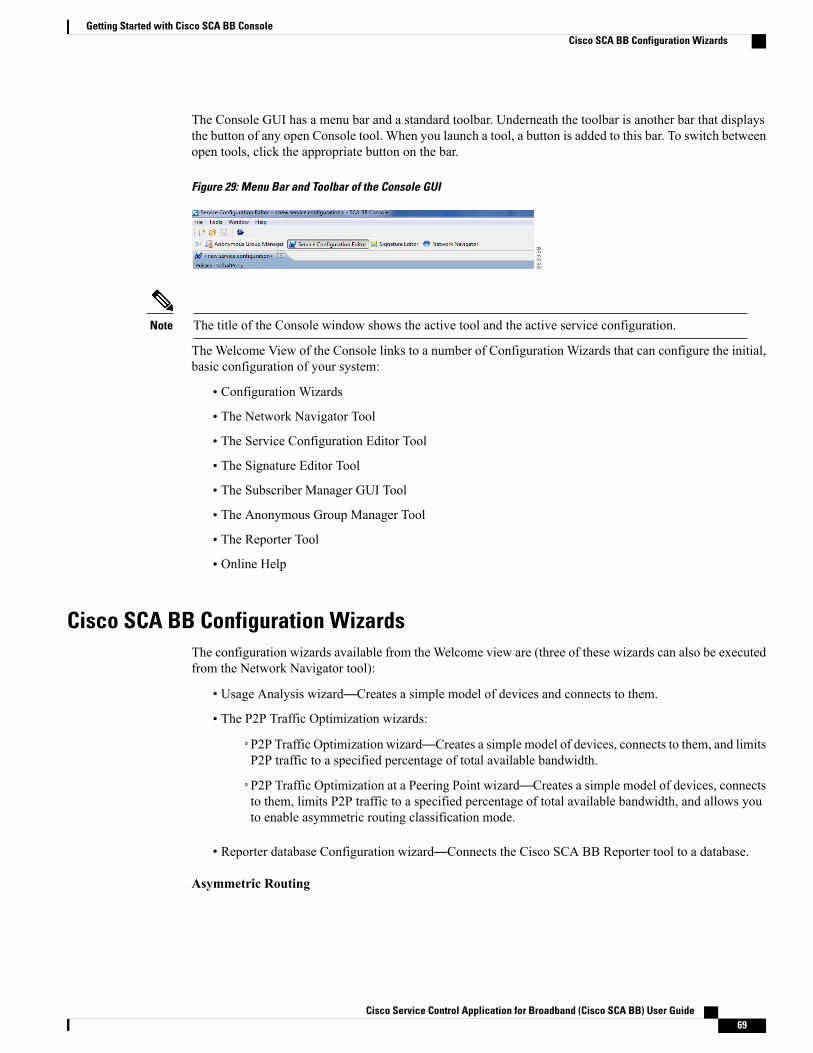
The Console GUI has a menu bar and a standard toolbar. Underneath the toolbar is another bar that displaysthe button of any open Console tool. When you launch a tool, a button is added to this bar. To switch betweenopen tools, click the appropriate button on the bar.
Figure 29: Menu Bar and Toolbar of the Console GUI
The title of the Console window shows the active tool and the active service configuration.Note
The Welcome View of the Console links to a number of Configuration Wizards that can configure the initial,basic configuration of your system:
• Configuration Wizards
• The Network Navigator Tool
• The Service Configuration Editor Tool
• The Signature Editor Tool
• The Subscriber Manager GUI Tool
• The Anonymous Group Manager Tool
• The Reporter Tool
• Online Help
Cisco SCA BB Configuration WizardsThe configuration wizards available from the Welcome view are (three of these wizards can also be executedfrom the Network Navigator tool):
• Usage Analysis wizard—Creates a simple model of devices and connects to them.
• The P2P Traffic Optimization wizards:
◦P2P Traffic Optimization wizard—Creates a simple model of devices, connects to them, and limitsP2P traffic to a specified percentage of total available bandwidth.
◦P2P Traffic Optimization at a Peering Point wizard—Creates a simple model of devices, connectsto them, limits P2P traffic to a specified percentage of total available bandwidth, and allows youto enable asymmetric routing classification mode.
• Reporter database Configuration wizard—Connects the Cisco SCA BB Reporter tool to a database.
Asymmetric Routing
Cisco Service Control Application for Broadband (Cisco SCA BB) User Guide 69
Getting Started with Cisco SCA BB ConsoleCisco SCA BB Configuration Wizards
Traffic processing depends on the routing environment. The Cisco Service Control solution can operate intwo typical routing schemes: symmetric and asymmetric. In asymmetric routing, for a significant number offlows, only one direction (inbound or outbound) is routed through the SCE platform.
Anonymous Subscriber Mode
Anonymous subscriber mode is a mode in which entities defined as IP addresses are treated as subscribers.
Using the Usage Analysis WizardThe Usage Analysis wizard allows you to create a simple model of devices and connect to them.
If they do not exist, devices defined in the wizard are added to the default site in the Site Manager tree.Note
Procedure
Step 1 From the Console main menu, choose Help > Welcome .
Cisco Service Control Application for Broadband (Cisco SCA BB) User Guide70
Getting Started with Cisco SCA BB ConsoleCisco SCA BB Configuration Wizards
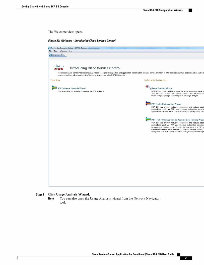
The Welcome view opens.
Figure 30: Welcome - Introducing Cisco Service Control
Step 2 Click Usage Analysis Wizard.You can also open the Usage Analysis wizard from the Network Navigatortool:
Note
Cisco Service Control Application for Broadband (Cisco SCA BB) User Guide 71
Getting Started with Cisco SCA BB ConsoleCisco SCA BB Configuration Wizards
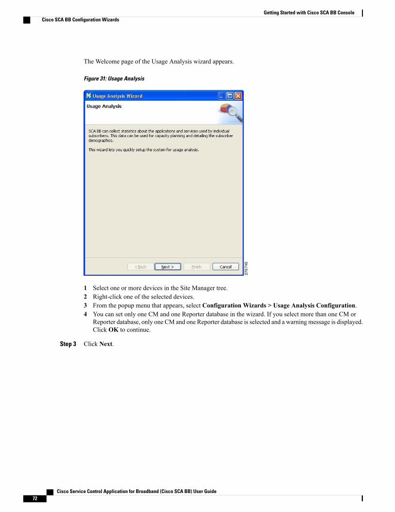
The Welcome page of the Usage Analysis wizard appears.
Figure 31: Usage Analysis
1 Select one or more devices in the Site Manager tree.2 Right-click one of the selected devices.3 From the popup menu that appears, select Configuration Wizards > Usage Analysis Configuration.4 You can set only one CM and one Reporter database in the wizard. If you select more than one CM or
Reporter database, only one CM and one Reporter database is selected and a warning message is displayed.Click OK to continue.
Step 3 Click Next.
Cisco Service Control Application for Broadband (Cisco SCA BB) User Guide72
Getting Started with Cisco SCA BB ConsoleCisco SCA BB Configuration Wizards
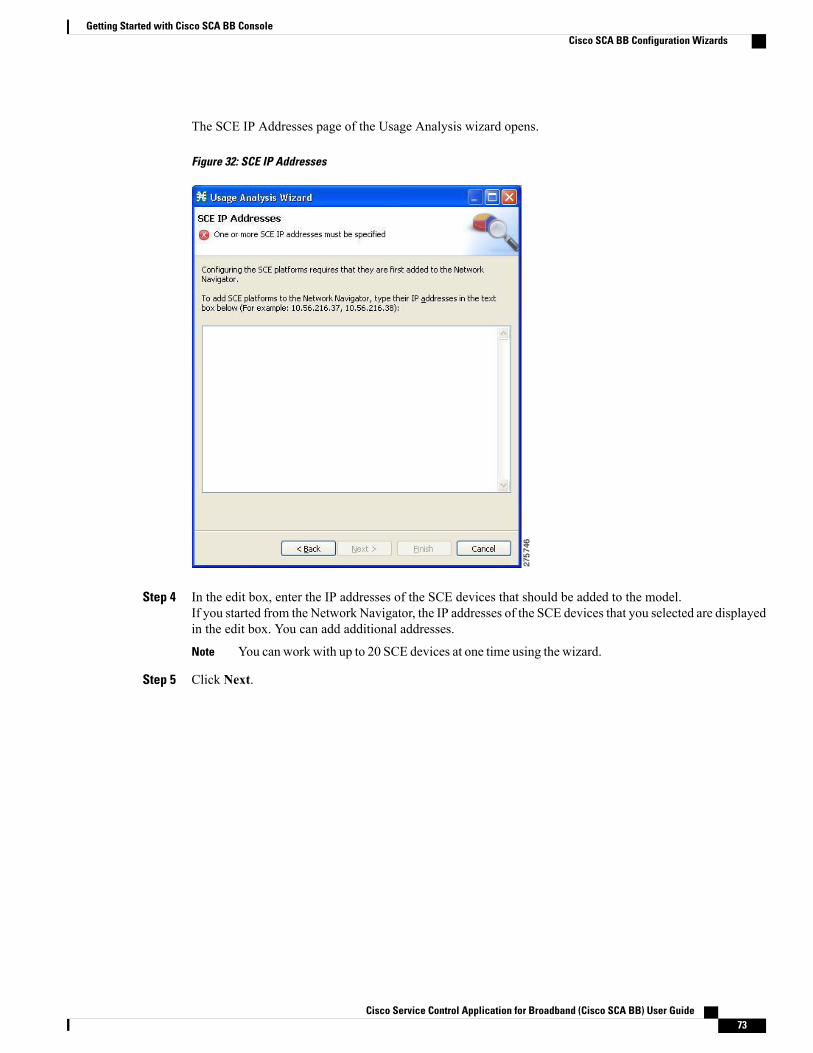
The SCE IP Addresses page of the Usage Analysis wizard opens.
Figure 32: SCE IP Addresses
Step 4 In the edit box, enter the IP addresses of the SCE devices that should be added to the model.If you started from the Network Navigator, the IP addresses of the SCE devices that you selected are displayedin the edit box. You can add additional addresses.
You can work with up to 20 SCE devices at one time using the wizard.Note
Step 5 Click Next.
Cisco Service Control Application for Broadband (Cisco SCA BB) User Guide 73
Getting Started with Cisco SCA BB ConsoleCisco SCA BB Configuration Wizards
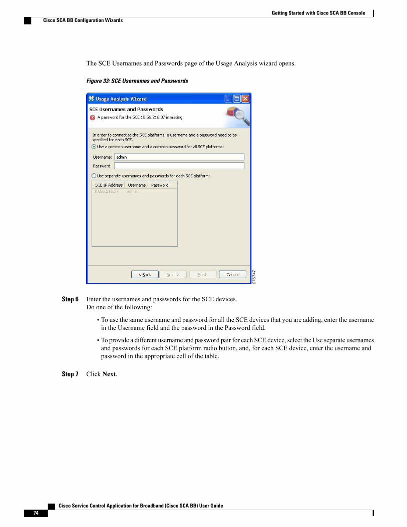
The SCE Usernames and Passwords page of the Usage Analysis wizard opens.
Figure 33: SCE Usernames and Passwords
Step 6 Enter the usernames and passwords for the SCE devices.Do one of the following:
• To use the same username and password for all the SCE devices that you are adding, enter the usernamein the Username field and the password in the Password field.
• To provide a different username and password pair for each SCE device, select the Use separate usernamesand passwords for each SCE platform radio button, and, for each SCE device, enter the username andpassword in the appropriate cell of the table.
Step 7 Click Next.
Cisco Service Control Application for Broadband (Cisco SCA BB) User Guide74
Getting Started with Cisco SCA BB ConsoleCisco SCA BB Configuration Wizards

The CM Setup page of the Usage Analysis wizard opens.
Figure 34: CM Setup
Step 8 Define the SCSM Collection Manager (CM) to use with this configuration.Do one of the following:
• Enter the IP address, username, and password of the CM device in the appropriate fields.
If you started from the Network Navigator, this information is retrieved and displayed. You can modify theseparameters.
• Check the Skip this step check box.
Step 9 Click Next.
Cisco Service Control Application for Broadband (Cisco SCA BB) User Guide 75
Getting Started with Cisco SCA BB ConsoleCisco SCA BB Configuration Wizards
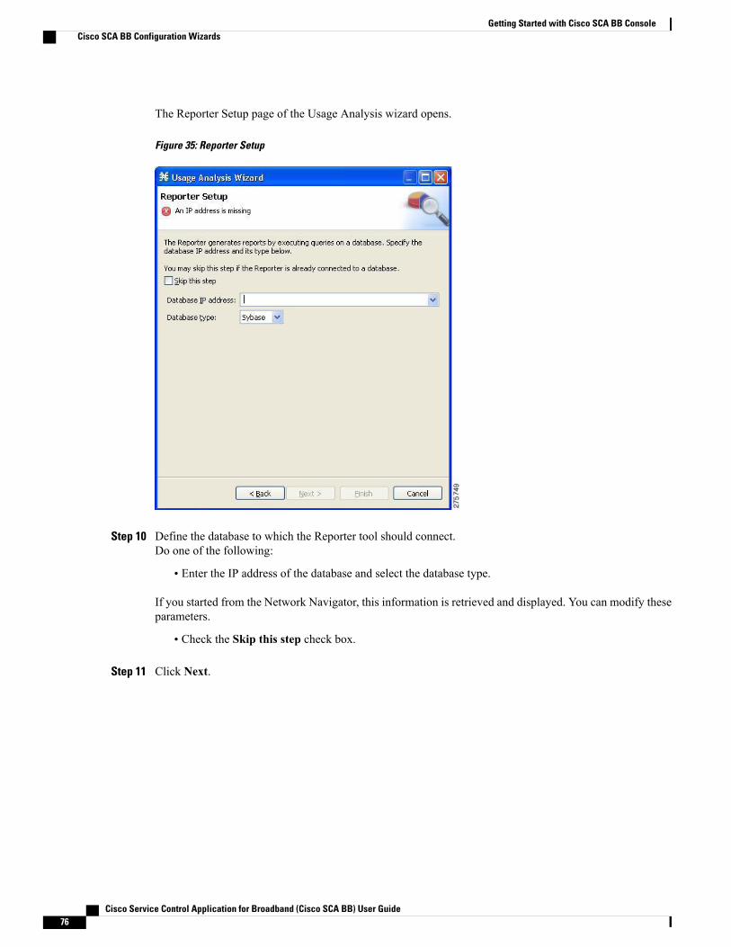
The Reporter Setup page of the Usage Analysis wizard opens.
Figure 35: Reporter Setup
Step 10 Define the database to which the Reporter tool should connect.Do one of the following:
• Enter the IP address of the database and select the database type.
If you started from the Network Navigator, this information is retrieved and displayed. You can modify theseparameters.
• Check the Skip this step check box.
Step 11 Click Next.
Cisco Service Control Application for Broadband (Cisco SCA BB) User Guide76
Getting Started with Cisco SCA BB ConsoleCisco SCA BB Configuration Wizards
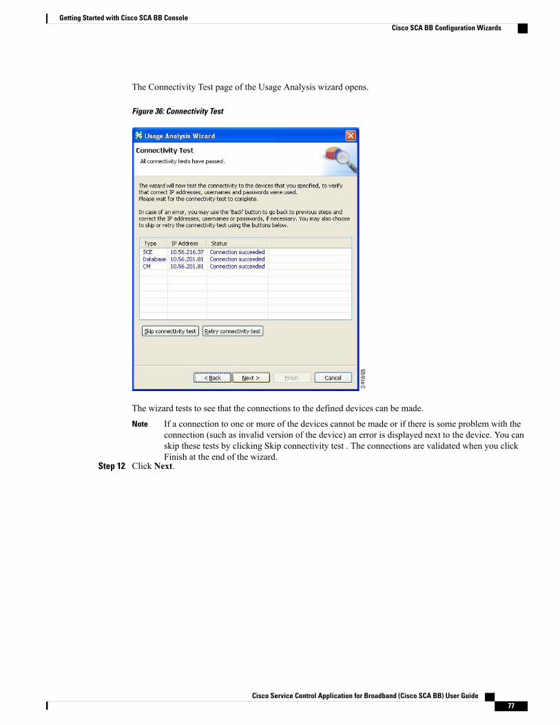
The Connectivity Test page of the Usage Analysis wizard opens.
Figure 36: Connectivity Test
The wizard tests to see that the connections to the defined devices can be made.
If a connection to one or more of the devices cannot be made or if there is some problem with theconnection (such as invalid version of the device) an error is displayed next to the device. You canskip these tests by clicking Skip connectivity test . The connections are validated when you clickFinish at the end of the wizard.
Note
Step 12 Click Next.
Cisco Service Control Application for Broadband (Cisco SCA BB) User Guide 77
Getting Started with Cisco SCA BB ConsoleCisco SCA BB Configuration Wizards
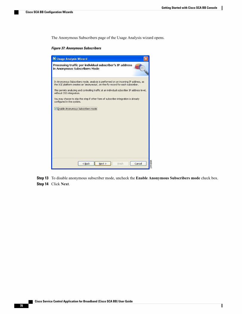
The Anonymous Subscribers page of the Usage Analysis wizard opens.
Figure 37: Anonymous Subscribers
Step 13 To disable anonymous subscriber mode, uncheck the Enable Anonymous Subscribers mode check box.Step 14 Click Next.
Cisco Service Control Application for Broadband (Cisco SCA BB) User Guide78
Getting Started with Cisco SCA BB ConsoleCisco SCA BB Configuration Wizards
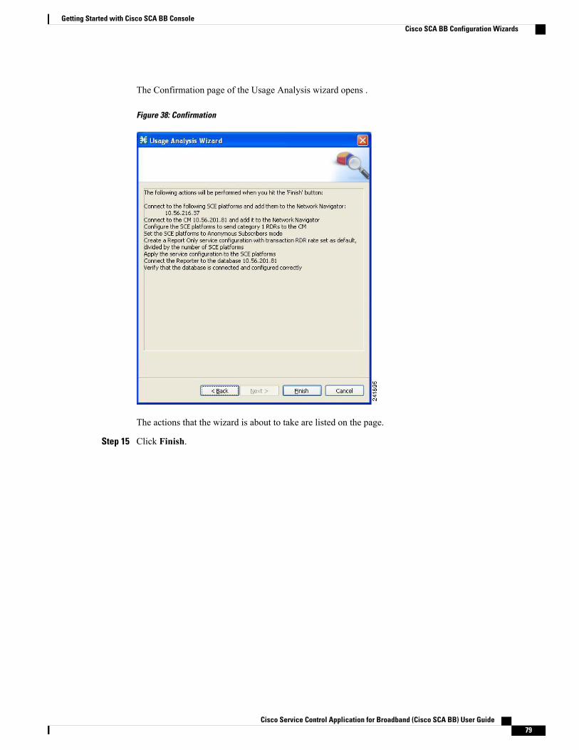
The Confirmation page of the Usage Analysis wizard opens .
Figure 38: Confirmation
The actions that the wizard is about to take are listed on the page.
Step 15 Click Finish.
Cisco Service Control Application for Broadband (Cisco SCA BB) User Guide 79
Getting Started with Cisco SCA BB ConsoleCisco SCA BB Configuration Wizards

The Configuration Output page of the Usage Analysis wizard opens.
Figure 39: Configuration Output
New devices are added to the default site of the Site Manager tree in the Network Navigator.
Figure 40: Site Manager Tree
The wizard attempts to connect to all devices that you defined. The operation fails if:
• The wizard cannot connect to any of the SCE devices that you listed in Step 4.
• You defined a CM in Step 8, but the wizard cannot connect to it.
• You defined a database in Step 10, but the wizard cannot connect to it.
If you defined a CM in Step 8, the SCE devices are configured so that the only category 1 RDR destinationis the CM.
Cisco Service Control Application for Broadband (Cisco SCA BB) User Guide80
Getting Started with Cisco SCA BB ConsoleCisco SCA BB Configuration Wizards

RDR categories are themechanism bywhich different types of RDRs can be sent to different collectors.For more information about RDR categories, see either the “RawData Formatting: The RDRFormatterand NetFlow Exporting” chapter of Cisco SCE8000 10GBE Software Configuration Guide or the"Raw Data Formatting: The RDR Formatter and NetFlow Exporting” chapter of Cisco SCE8000GBE Software Configuration Guide.
Note
RDR categories are themechanism bywhich different types of RDRs can be sent to different collectors.For more information about RDR categories, see the “Raw Data Formatting: The RDR Formatter”chapter of Cisco SCE10000 Software Configuration Guide.
Note
A new service configuration named Usage Analysis is created, and opens in the Service Configuration Editor.
Figure 41: Service Configuration Editor
The service configuration has the following characteristics:
• Report Only mode.
• The maximum Transaction RDR rate is set as the default value (250) divided by the number of SCEdevices. To configure the Transaction RDR see “How toManage Transaction RDRs” section. The contentand structure is listed in the “Transaction RDR” section in the “Raw Data Records: Formats and FieldContents” chapter of Cisco Service Control Application for Broadband Reference Guide.
The service configuration is applied to the SCE devices.
If you defined a database in Step 10:
• The Cisco SCA BB Reporter tool is connected to the selected database.
• The first SCE platform entered in Step 4 is selected as the source of service configuration data.
• The Next button is enabled.
Step 16 If you did not define a database in Step 10, click Close.The Usage Analysis wizard closes.
Report instances of each of the four report types open in the Report View of the Reporter tool.
Using the P2P Traffic Optimization WizardsThere are two wizards for optimizing P2P traffic:
Cisco Service Control Application for Broadband (Cisco SCA BB) User Guide 81
Getting Started with Cisco SCA BB ConsoleCisco SCA BB Configuration Wizards
• The P2P Traffic Optimization wizard allows you to create a simple model of devices, connect to them,and limit P2P traffic to a specified percentage of total available bandwidth.
• The P2P Traffic Optimization at a Peering Point wizard allows you to create a simple model of devices,connect to them, limit P2P traffic to a specified percentage of total available bandwidth, and enableasymmetric routing classification mode.
If they do not exist, devices defined in the wizard are added to the default site in the Site Manager tree.Note
Procedure
Step 1 From the Console main menu, choose Help > Welcome .
Cisco Service Control Application for Broadband (Cisco SCA BB) User Guide82
Getting Started with Cisco SCA BB ConsoleCisco SCA BB Configuration Wizards

The Welcome view opens.
Figure 42: Welcome - Introducing Cisco Service Control
Step 2 Click P2P Traffic Optimization Wizard or P2P Traffic Optimization for Asymmetrical Routing Wizard .
Cisco Service Control Application for Broadband (Cisco SCA BB) User Guide 83
Getting Started with Cisco SCA BB ConsoleCisco SCA BB Configuration Wizards

The Welcome page of the selected wizard appears.
Figure 43: P2P Traffic Optimization
Figure 44: P2P Traffic Optimization for Asymmetrical Routing
You can also execute the P2P Traffic Optimization wizard from the Network Navigatortool.
Note
1 Select one or more devices in the Site Manager tree.2 Right-click one of the selected devices.3 From the popup menu that appears, choose Configuration Wizards > P2P Traffic Optimization Wizard or
Configuration Wizards > P2P Traffic Optimization for Asymmetrical Routing Wizard .
You can set only one CM and one Reporter database in the wizard. If you select more than one CMor Reporter database, only one CM and one Reporter database is selected and a warning message isdisplayed. Click OK to continue.
Note
Step 3 Click Next .
Cisco Service Control Application for Broadband (Cisco SCA BB) User Guide84
Getting Started with Cisco SCA BB ConsoleCisco SCA BB Configuration Wizards

The SCE IP Addresses page of the P2P Traffic Optimization wizard opens
Figure 45: SCE IP Addresses
Step 4 In the edit box, enter the IP addresses of the SCE devices that should be added to the model.If you started from the Network Navigator, the IP addresses of the SCE devices that you selected are displayedin the edit box. You can add additional addresses.
You can work with up to 20 SCE devices at one time using the wizard.Note
Step 5 Click Next .
Cisco Service Control Application for Broadband (Cisco SCA BB) User Guide 85
Getting Started with Cisco SCA BB ConsoleCisco SCA BB Configuration Wizards
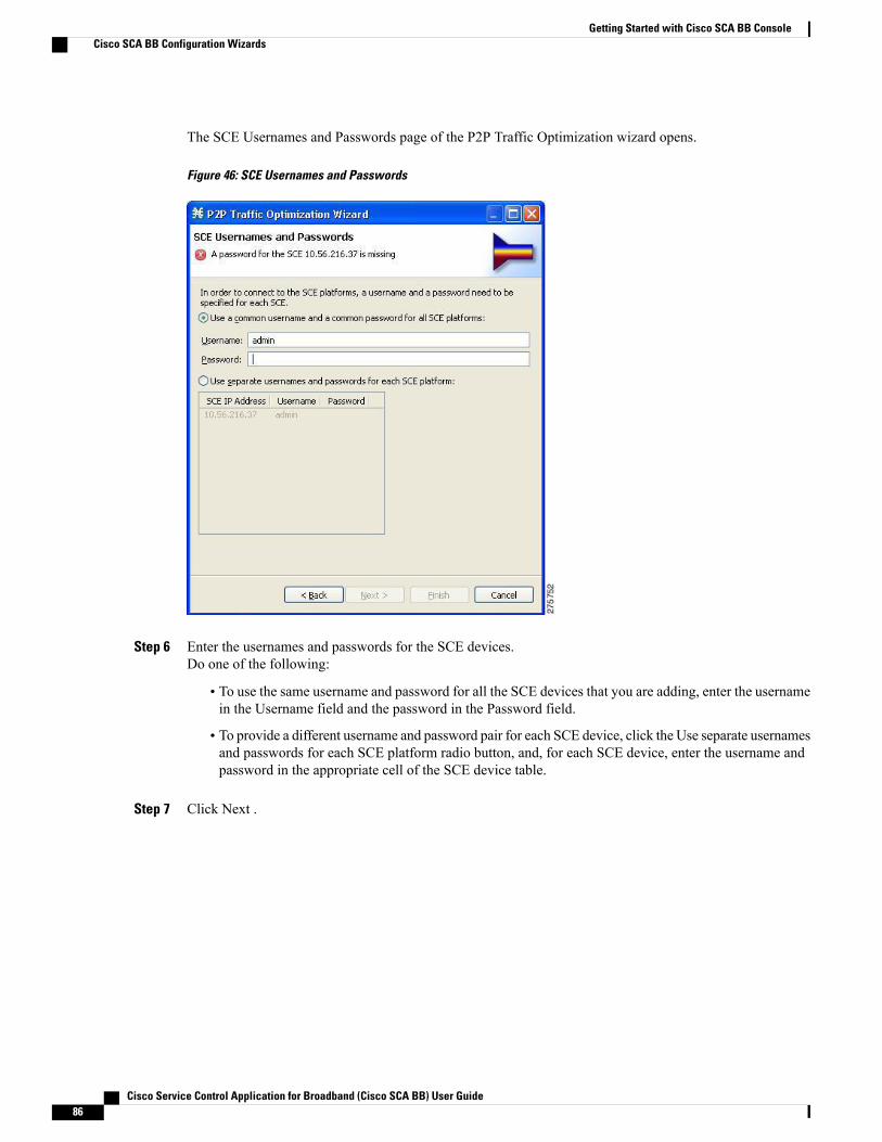
The SCE Usernames and Passwords page of the P2P Traffic Optimization wizard opens.
Figure 46: SCE Usernames and Passwords
Step 6 Enter the usernames and passwords for the SCE devices.Do one of the following:
• To use the same username and password for all the SCE devices that you are adding, enter the usernamein the Username field and the password in the Password field.
• To provide a different username and password pair for each SCE device, click the Use separate usernamesand passwords for each SCE platform radio button, and, for each SCE device, enter the username andpassword in the appropriate cell of the SCE device table.
Step 7 Click Next .
Cisco Service Control Application for Broadband (Cisco SCA BB) User Guide86
Getting Started with Cisco SCA BB ConsoleCisco SCA BB Configuration Wizards

The CM Setup page of the P2P Traffic Optimization wizard opens.
Figure 47: CM Setup
Step 8 Define the Cisco Service Control Collection Manager (CM) to use with this configuration.Do one of the following:
• Enter the IP address, username, and password of the CM device in the appropriate fields.
If you started from the Network Navigator, this information is retrieved and displayed. You can modify theseparameters.
• Check the Skip this step check box.
Step 9 Click Next.
Cisco Service Control Application for Broadband (Cisco SCA BB) User Guide 87
Getting Started with Cisco SCA BB ConsoleCisco SCA BB Configuration Wizards
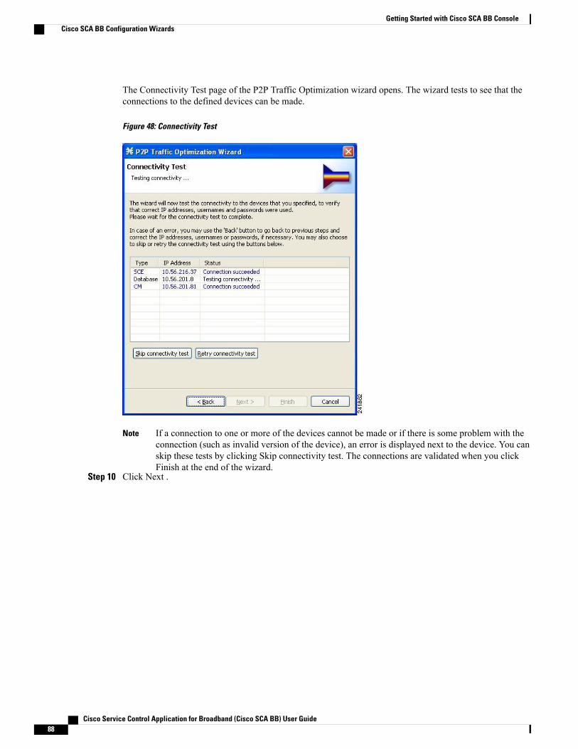
The Connectivity Test page of the P2P Traffic Optimization wizard opens. The wizard tests to see that theconnections to the defined devices can be made.
Figure 48: Connectivity Test
If a connection to one or more of the devices cannot be made or if there is some problem with theconnection (such as invalid version of the device), an error is displayed next to the device. You canskip these tests by clicking Skip connectivity test. The connections are validated when you clickFinish at the end of the wizard.
Note
Step 10 Click Next .
Cisco Service Control Application for Broadband (Cisco SCA BB) User Guide88
Getting Started with Cisco SCA BB ConsoleCisco SCA BB Configuration Wizards
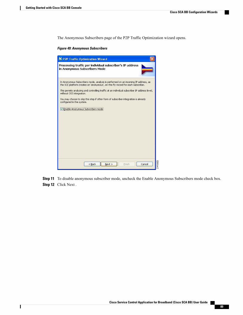
The Anonymous Subscribers page of the P2P Traffic Optimization wizard opens.
Figure 49: Anonymous Subscribers
Step 11 To disable anonymous subscriber mode, uncheck the Enable Anonymous Subscribers mode check box.Step 12 Click Next .
Cisco Service Control Application for Broadband (Cisco SCA BB) User Guide 89
Getting Started with Cisco SCA BB ConsoleCisco SCA BB Configuration Wizards
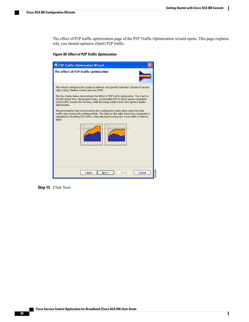
The effect of P2P traffic optimization page of the P2P Traffic Optimization wizard opens. This page explainswhy you should optimize (limit) P2P traffic.
Figure 50: Effect of P2P Traffic Optimization
Step 13 Click Next .
Cisco Service Control Application for Broadband (Cisco SCA BB) User Guide90
Getting Started with Cisco SCA BB ConsoleCisco SCA BB Configuration Wizards

The Link Rate Limits for P2P Traffic Optimization page of the P2P Traffic Optimization wizard opens.
Figure 51: Link Rate Limits
Step 14 Use the sliders to configure the upstream and downstream link rate limits.The scale of each slider is the percentage of the aggregated bandwidth of both links.
Step 15 If you are running the P2P Traffic Optimization wizard, go to Step 20.If you are running the P2P Traffic Optimization for Asymmetrical Routing wizard, continue at the next step.
Step 16 Click Next .
Cisco Service Control Application for Broadband (Cisco SCA BB) User Guide 91
Getting Started with Cisco SCA BB ConsoleCisco SCA BB Configuration Wizards
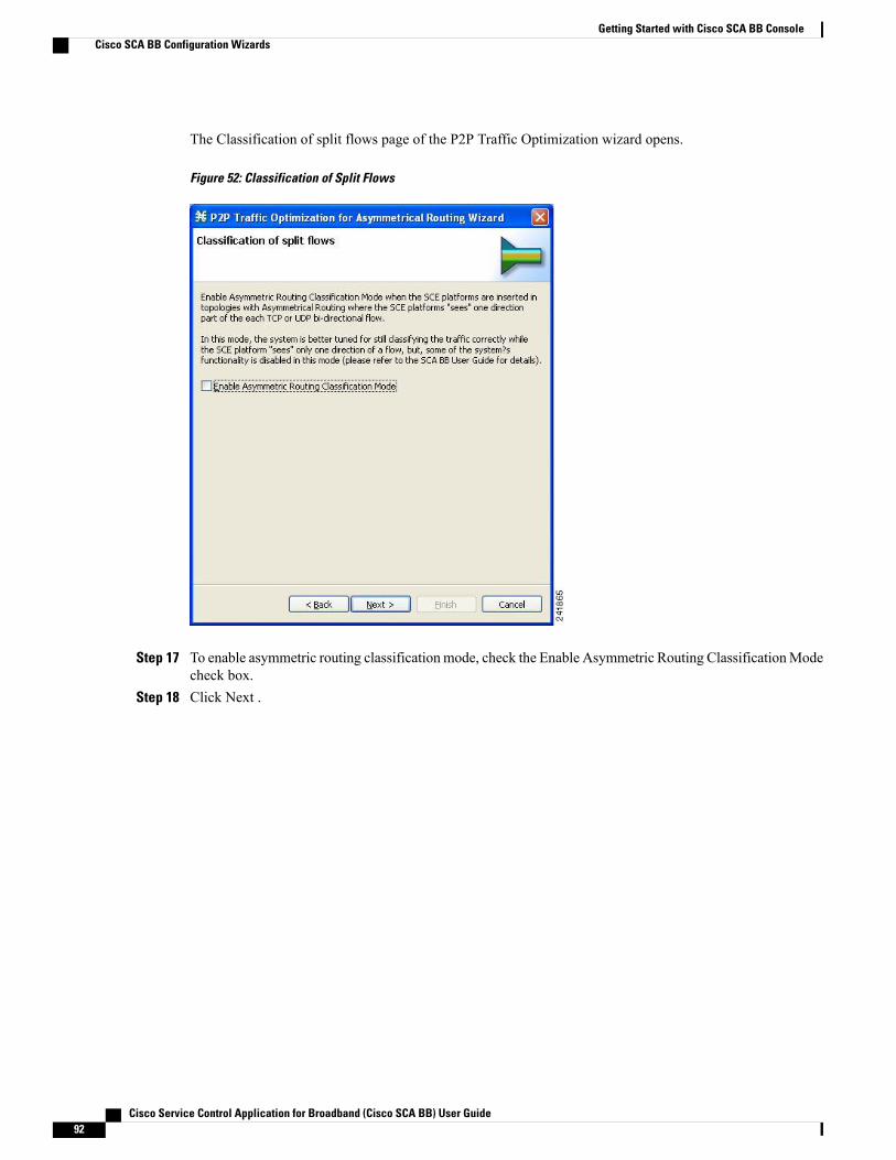
The Classification of split flows page of the P2P Traffic Optimization wizard opens.
Figure 52: Classification of Split Flows
Step 17 To enable asymmetric routing classificationmode, check the Enable Asymmetric Routing ClassificationModecheck box.
Step 18 Click Next .
Cisco Service Control Application for Broadband (Cisco SCA BB) User Guide92
Getting Started with Cisco SCA BB ConsoleCisco SCA BB Configuration Wizards
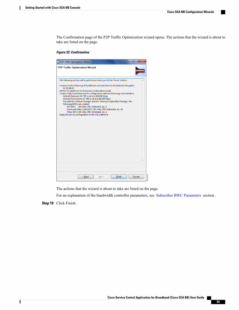
The Confirmation page of the P2P Traffic Optimization wizard opens. The actions that the wizard is about totake are listed on the page.
Figure 53: Confirmation
The actions that the wizard is about to take are listed on the page.
For an explanation of the bandwidth controller parameters, see Subscriber BWC Parameters section .
Step 19 Click Finish .
Cisco Service Control Application for Broadband (Cisco SCA BB) User Guide 93
Getting Started with Cisco SCA BB ConsoleCisco SCA BB Configuration Wizards
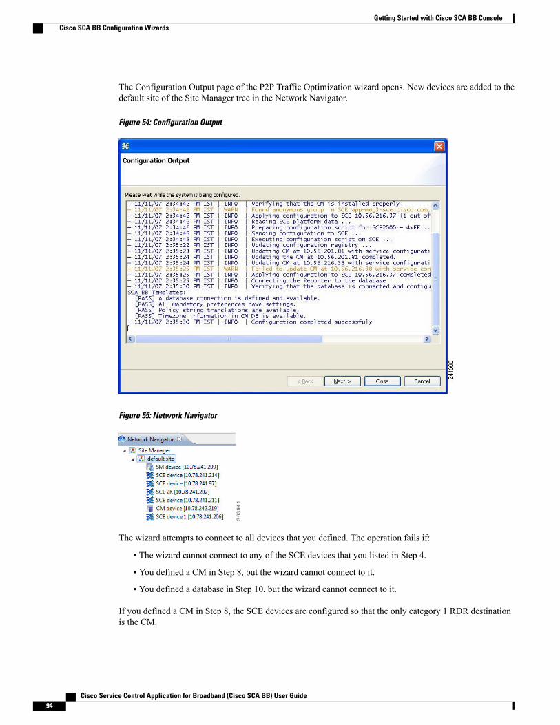
The Configuration Output page of the P2P Traffic Optimization wizard opens. New devices are added to thedefault site of the Site Manager tree in the Network Navigator.
Figure 54: Configuration Output
Figure 55: Network Navigator
The wizard attempts to connect to all devices that you defined. The operation fails if:
• The wizard cannot connect to any of the SCE devices that you listed in Step 4.
• You defined a CM in Step 8, but the wizard cannot connect to it.
• You defined a database in Step 10, but the wizard cannot connect to it.
If you defined a CM in Step 8, the SCE devices are configured so that the only category 1 RDR destinationis the CM.
Cisco Service Control Application for Broadband (Cisco SCA BB) User Guide94
Getting Started with Cisco SCA BB ConsoleCisco SCA BB Configuration Wizards
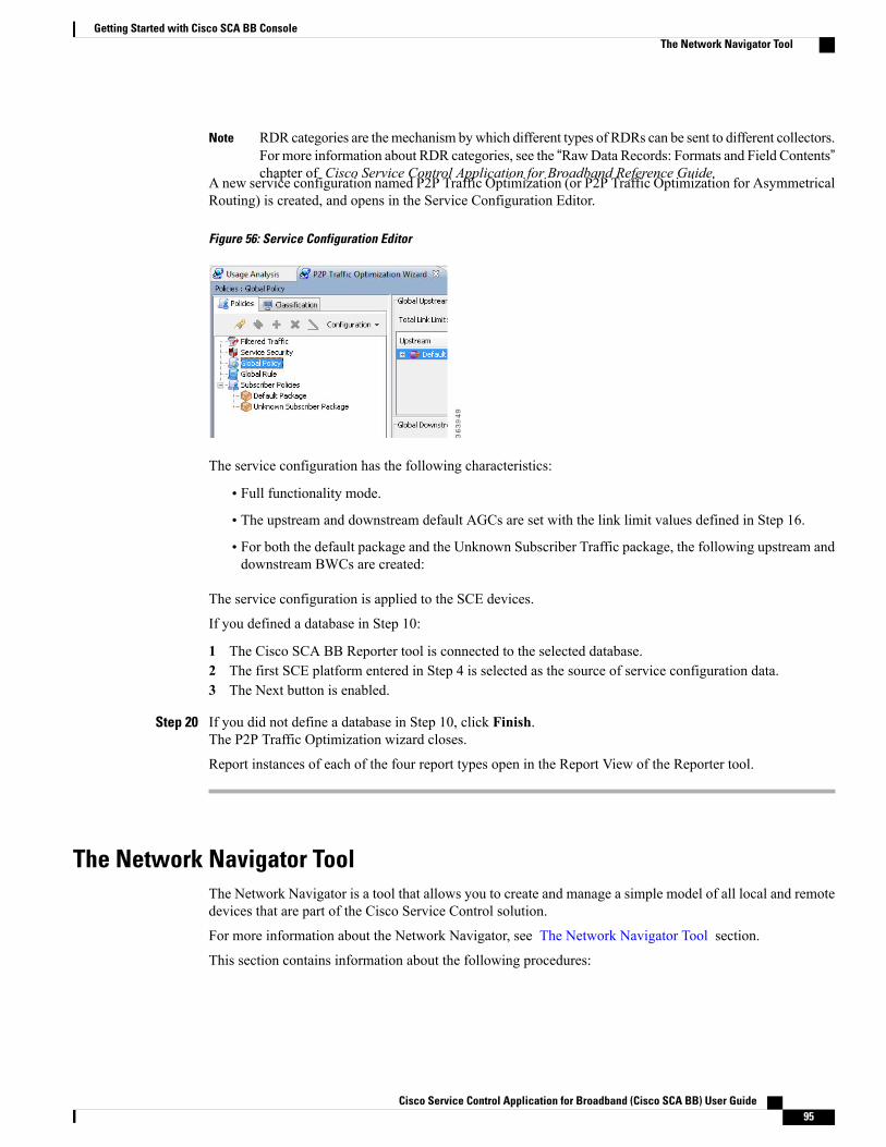
RDR categories are themechanism bywhich different types of RDRs can be sent to different collectors.For more information about RDR categories, see the “RawData Records: Formats and Field Contents”chapter of Cisco Service Control Application for Broadband Reference Guide.
Note
A new service configuration named P2P Traffic Optimization (or P2P Traffic Optimization for AsymmetricalRouting) is created, and opens in the Service Configuration Editor.
Figure 56: Service Configuration Editor
The service configuration has the following characteristics:
• Full functionality mode.
• The upstream and downstream default AGCs are set with the link limit values defined in Step 16.
• For both the default package and the Unknown Subscriber Traffic package, the following upstream anddownstream BWCs are created:
The service configuration is applied to the SCE devices.
If you defined a database in Step 10:
1 The Cisco SCA BB Reporter tool is connected to the selected database.2 The first SCE platform entered in Step 4 is selected as the source of service configuration data.3 The Next button is enabled.
Step 20 If you did not define a database in Step 10, click Finish.The P2P Traffic Optimization wizard closes.
Report instances of each of the four report types open in the Report View of the Reporter tool.
The Network Navigator ToolThe Network Navigator is a tool that allows you to create and manage a simple model of all local and remotedevices that are part of the Cisco Service Control solution.
For more information about the Network Navigator, see The Network Navigator Tool section.
This section contains information about the following procedures:
Cisco Service Control Application for Broadband (Cisco SCA BB) User Guide 95
Getting Started with Cisco SCA BB ConsoleThe Network Navigator Tool
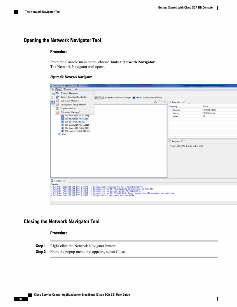
Opening the Network Navigator Tool
Procedure
From the Console main menu, choose Tools > Network Navigator .The Network Navigator tool opens.
Figure 57: Network Navigator
Closing the Network Navigator Tool
Procedure
Step 1 Right-click the Network Navigator button.Step 2 From the popup menu that appears, select Close .
Cisco Service Control Application for Broadband (Cisco SCA BB) User Guide96
Getting Started with Cisco SCA BB ConsoleThe Network Navigator Tool
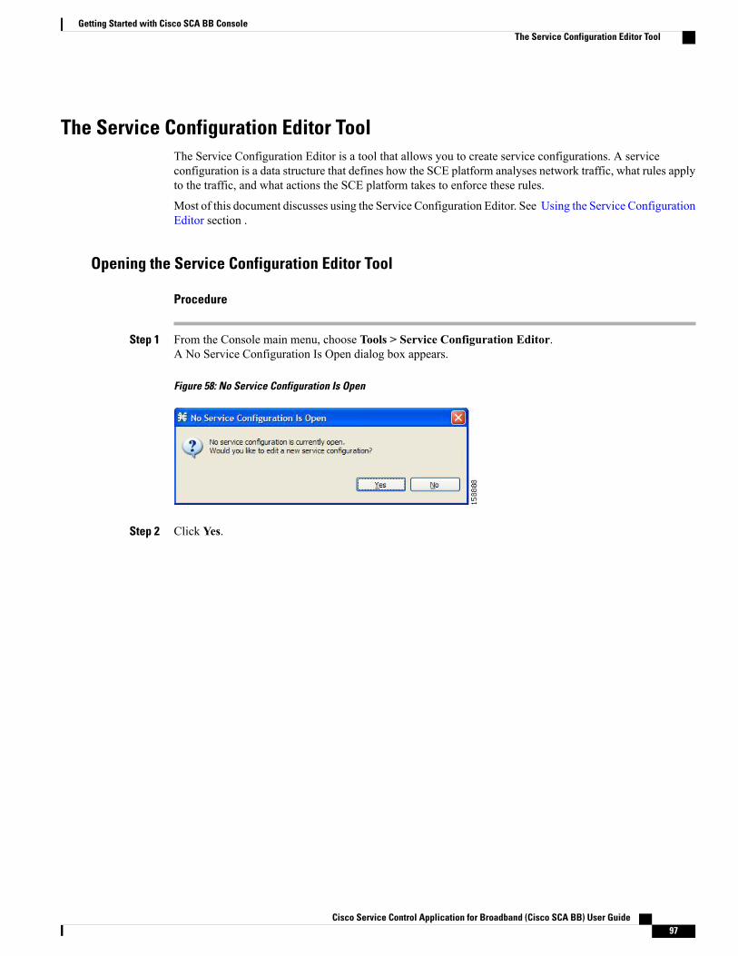
The Service Configuration Editor ToolThe Service Configuration Editor is a tool that allows you to create service configurations. A serviceconfiguration is a data structure that defines how the SCE platform analyses network traffic, what rules applyto the traffic, and what actions the SCE platform takes to enforce these rules.
Most of this document discusses using the Service Configuration Editor. See Using the Service ConfigurationEditor section .
Opening the Service Configuration Editor Tool
Procedure
Step 1 From the Console main menu, choose Tools > Service Configuration Editor.A No Service Configuration Is Open dialog box appears.
Figure 58: No Service Configuration Is Open
Step 2 Click Yes.
Cisco Service Control Application for Broadband (Cisco SCA BB) User Guide 97
Getting Started with Cisco SCA BB ConsoleThe Service Configuration Editor Tool
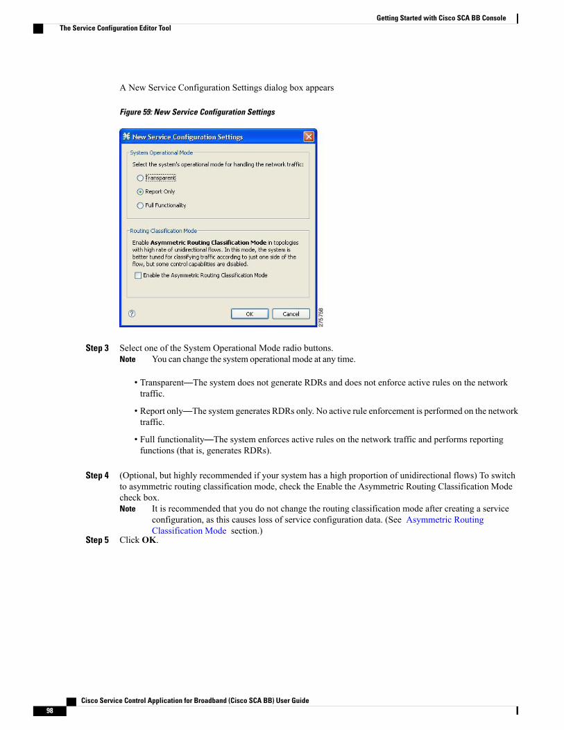
A New Service Configuration Settings dialog box appears
Figure 59: New Service Configuration Settings
Step 3 Select one of the System Operational Mode radio buttons.You can change the system operational mode at any time.Note
• Transparent—The system does not generate RDRs and does not enforce active rules on the networktraffic.
• Report only—The system generates RDRs only. No active rule enforcement is performed on the networktraffic.
• Full functionality—The system enforces active rules on the network traffic and performs reportingfunctions (that is, generates RDRs).
Step 4 (Optional, but highly recommended if your system has a high proportion of unidirectional flows) To switchto asymmetric routing classification mode, check the Enable the Asymmetric Routing Classification Modecheck box.
It is recommended that you do not change the routing classification mode after creating a serviceconfiguration, as this causes loss of service configuration data. (See Asymmetric RoutingClassification Mode section.)
Note
Step 5 Click OK.
Cisco Service Control Application for Broadband (Cisco SCA BB) User Guide98
Getting Started with Cisco SCA BB ConsoleThe Service Configuration Editor Tool
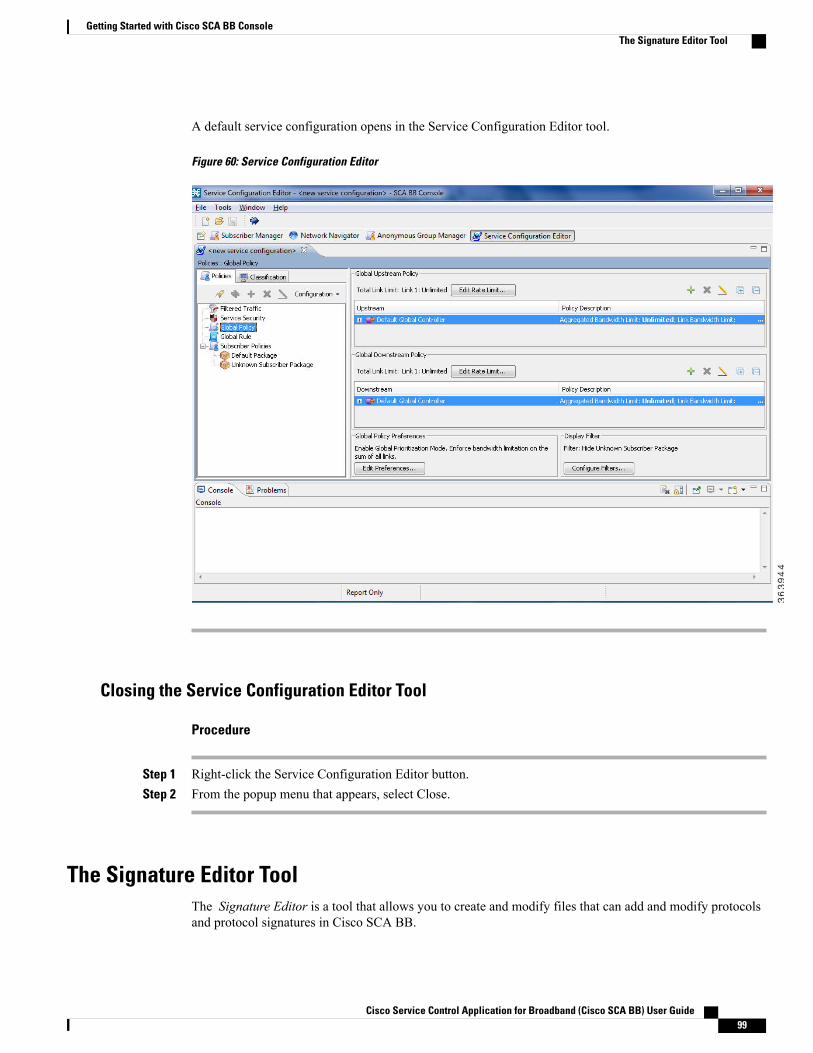
A default service configuration opens in the Service Configuration Editor tool.
Figure 60: Service Configuration Editor
Closing the Service Configuration Editor Tool
Procedure
Step 1 Right-click the Service Configuration Editor button.Step 2 From the popup menu that appears, select Close.
The Signature Editor ToolThe Signature Editor is a tool that allows you to create and modify files that can add and modify protocolsand protocol signatures in Cisco SCA BB.
Cisco Service Control Application for Broadband (Cisco SCA BB) User Guide 99
Getting Started with Cisco SCA BB ConsoleThe Signature Editor Tool
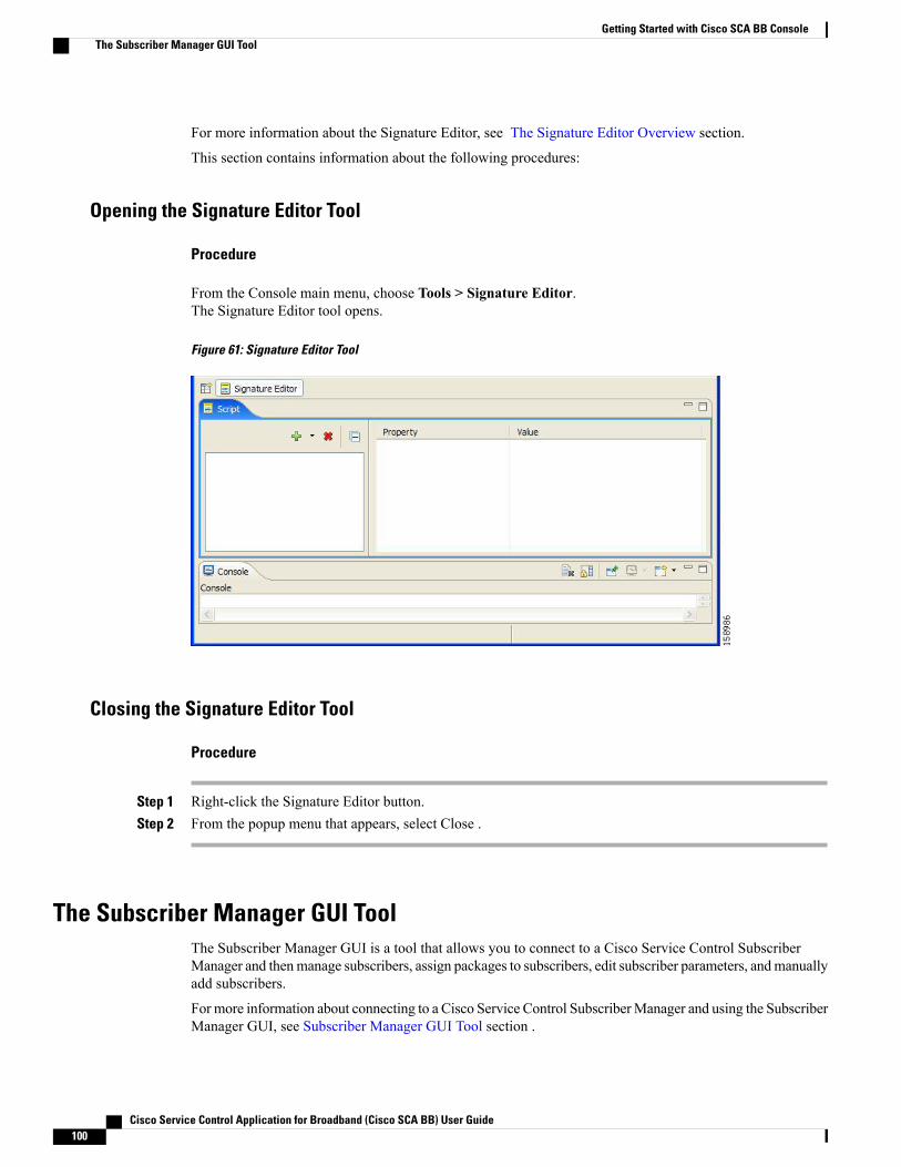
For more information about the Signature Editor, see The Signature Editor Overview section.
This section contains information about the following procedures:
Opening the Signature Editor Tool
Procedure
From the Console main menu, choose Tools > Signature Editor.The Signature Editor tool opens.
Figure 61: Signature Editor Tool
Closing the Signature Editor Tool
Procedure
Step 1 Right-click the Signature Editor button.Step 2 From the popup menu that appears, select Close .
The Subscriber Manager GUI ToolThe Subscriber Manager GUI is a tool that allows you to connect to a Cisco Service Control SubscriberManager and thenmanage subscribers, assign packages to subscribers, edit subscriber parameters, andmanuallyadd subscribers.
For more information about connecting to a Cisco Service Control SubscriberManager and using the SubscriberManager GUI, see Subscriber Manager GUI Tool section .
Cisco Service Control Application for Broadband (Cisco SCA BB) User Guide100
Getting Started with Cisco SCA BB ConsoleThe Subscriber Manager GUI Tool
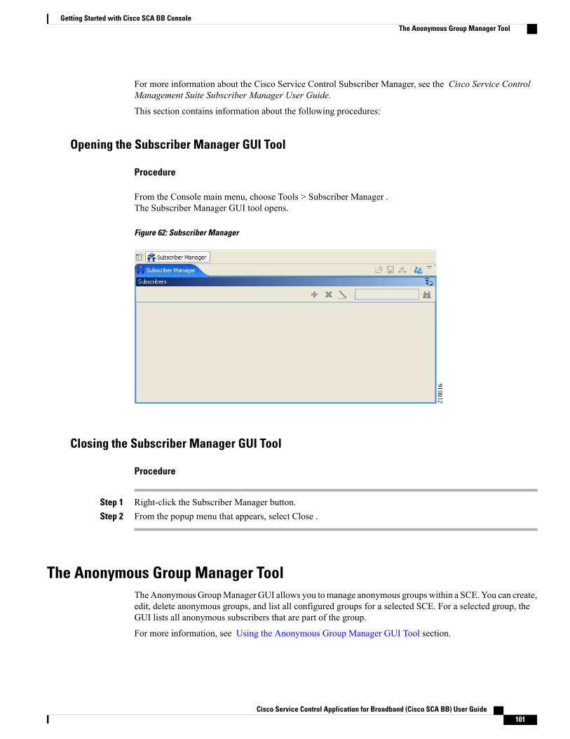
For more information about the Cisco Service Control Subscriber Manager, see the Cisco Service ControlManagement Suite Subscriber Manager User Guide.
This section contains information about the following procedures:
Opening the Subscriber Manager GUI Tool
Procedure
From the Console main menu, choose Tools > Subscriber Manager .The Subscriber Manager GUI tool opens.
Figure 62: Subscriber Manager
Closing the Subscriber Manager GUI Tool
Procedure
Step 1 Right-click the Subscriber Manager button.Step 2 From the popup menu that appears, select Close .
The Anonymous Group Manager ToolTheAnonymousGroupManager GUI allows you tomanage anonymous groups within a SCE. You can create,edit, delete anonymous groups, and list all configured groups for a selected SCE. For a selected group, theGUI lists all anonymous subscribers that are part of the group.
For more information, see Using the Anonymous Group Manager GUI Tool section.
Cisco Service Control Application for Broadband (Cisco SCA BB) User Guide 101
Getting Started with Cisco SCA BB ConsoleThe Anonymous Group Manager Tool
Opening the Anonymous Group Manager Tool
Procedure
From the Console main menu, choose Tools > Anonymous Group Manager .The Anonymous Group Manager tool opens.
Closing the Anonymous Group Manager Tool
Procedure
Step 1 Right-click the Anonymous Group Manager button.Step 2 From the popup menu that appears, select Close.
Online HelpYou can access relevant parts of this user guide from the Console. The following sections provide you withthe necessary details:
Cisco Service Control Application for Broadband (Cisco SCA BB) User Guide102
Getting Started with Cisco SCA BB ConsoleOnline Help

Accessing the Online Help
Procedure
From the Console main menu, choose Help > Help Contents .
Figure 63: Preferences - Help
Online help opens in a separate window.
Searching Online Help
Procedure
Step 1 From the Console main menu, choose Help > Search .
Cisco Service Control Application for Broadband (Cisco SCA BB) User Guide 103
Getting Started with Cisco SCA BB ConsoleOnline Help
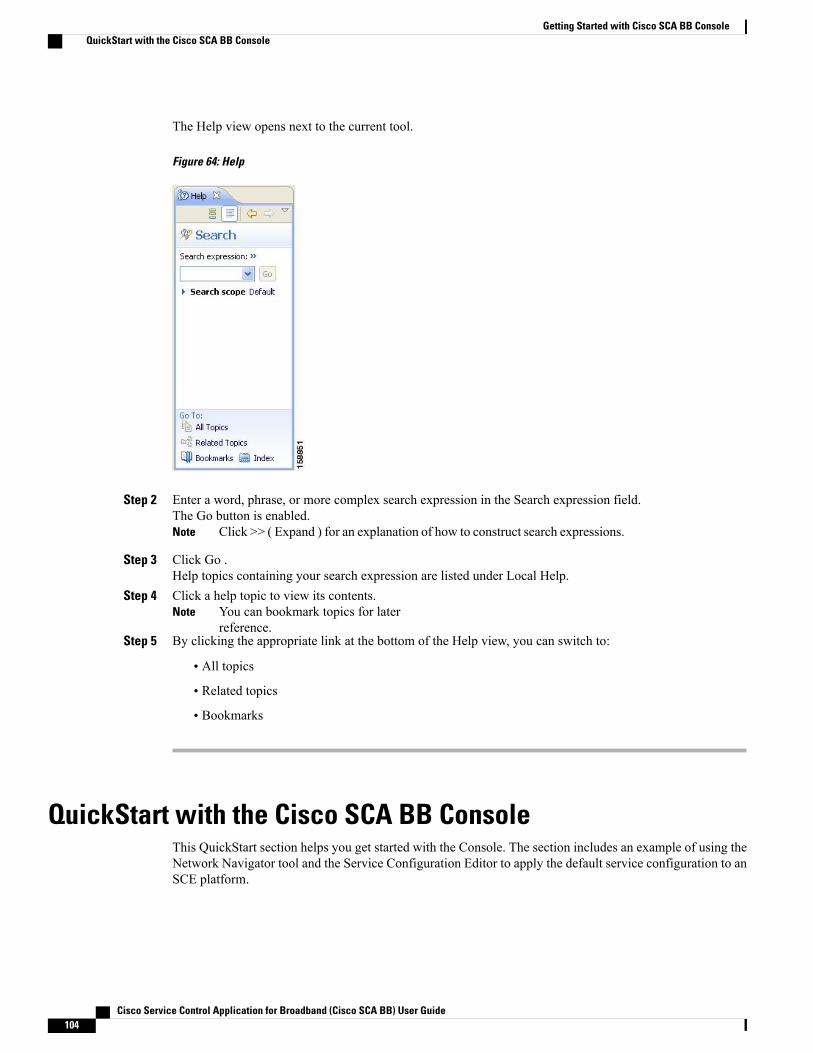
The Help view opens next to the current tool.
Figure 64: Help
Step 2 Enter a word, phrase, or more complex search expression in the Search expression field.The Go button is enabled.
Click >> ( Expand ) for an explanation of how to construct search expressions.Note
Step 3 Click Go .Help topics containing your search expression are listed under Local Help.
Step 4 Click a help topic to view its contents.You can bookmark topics for laterreference.
Note
Step 5 By clicking the appropriate link at the bottom of the Help view, you can switch to:
• All topics
• Related topics
• Bookmarks
QuickStart with the Cisco SCA BB ConsoleThis QuickStart section helps you get started with the Console. The section includes an example of using theNetwork Navigator tool and the Service Configuration Editor to apply the default service configuration to anSCE platform.
Cisco Service Control Application for Broadband (Cisco SCA BB) User Guide104
Getting Started with Cisco SCA BB ConsoleQuickStart with the Cisco SCA BB Console

Configuring the Console and Applying the Default Service ConfigurationIn this example, you add an SCE device to the default site and apply the default service configuration to theSCE.
Procedure
Step 1 Launch the Console.Choose Start > All Programs > Cisco SCA > SCA BB Console 5.1.x > SCA BB Console 5.1.x. Here xstands for the version within 5. For example, 5.1.0
Step 2 If necessary, close the Welcome view.Step 3 Open the Network Navigator.Step 4 From the Console main menu, choose Tools > Network Navigator.
This step sets up the Console for network device operations. You should now be able to see the default sitedisplayed in the Network Navigator view.
The Network Navigator tool is open the first time you launch the Console.Note
Step 5 Add a Cisco SCE device to the default site.a) Right-click the default site, and, from the popup menu that appears, select New > SCE.
The Create new SCE wizard appears.b) In the Address field, enter the actual IP address of an SCE platform.c) Click Finish.
The Create new SCE wizard closes. The new device is added to the site.
Step 6 Check the SCE platform version and operational state.a) Right-click the SCE device and, from the popup menu that appears, select Online Status.
A Password Management dialog box appears.b) Enter the username and password for managing the SCE.c) Enter the SNMP RO Community String.d) Click Extract.
The SCE online status is retrieved.e) Check that the system and application versions are correct, and that the operational state is Active.
Step 7 Open the Service Configuration Editor.a) From the Console main menu, choose Tools > Service Configuration Editor.
The Service Configuration Editor opens. A No Service Configuration Is Open dialog box appears.
Step 8 Create a new service configuration.a) From the Console main menu, choose Tools > Service Configuration Editor.
The Service Configuration Editor opens. A No Service Configuration Is Open dialog box appears.b) Click Yes in the No Editor Is Open dialog box.
A New Service Configuration Settings dialog box appears.c) Click OK.
A default service configuration opens in the Service Configuration Editor tool.
Step 9 Apply the service configuration to the SCE platform.a) From the toolbar, select the Apply Service Configuration to SCE Devices ( ) icon.
A Password Management dialog box appears.b) Enter the username and password for managing the SCE and click Apply.
Cisco Service Control Application for Broadband (Cisco SCA BB) User Guide 105
Getting Started with Cisco SCA BB ConsoleConfiguring the Console and Applying the Default Service Configuration
The service configuration is applied to the SCE platform.
Cisco Service Control Application for Broadband (Cisco SCA BB) User Guide106
Getting Started with Cisco SCA BB ConsoleConfiguring the Console and Applying the Default Service Configuration
C H A P T E R 5The Network Navigator
To manage a network entity—Cisco Service Control Engine (Cisco SCE) platform, Subscriber Manager(SM), or Collection Manager (CM)—from the Console, you must first define it as a device in the NetworkNavigator.
This chapter describes how to use the Network Navigator tool to create a model of all local and remote sitesand devices that are part of the Cisco Service Control solution, how to manage the devices remotely, andother functionality that is part of the Network Navigator tool.
The Usage Analysis wizard, which can be used to create a simple model of devices and connect to them, isalso described in this chapter.
This chapter consists of these sections:
• The Network Navigator Tool , page 107
• Introduction to Managing Sites, page 108
• Introduction to Managing Devices , page 112
• Working with Network Navigator Configuration Files , page 136
• Network Settings Requirements , page 141
The Network Navigator ToolThe Network Navigator tool contains four views:
• Network Navigator view—Displays all sites and devices that you have defined as part of your system,in the Site Manager tree.
• Properties view—Displays the editable properties of the node selected in the Site Manager tree in theNetwork Navigator view.
• Progress view—Displays a progress bar when you perform an operation on a site or device in the SiteManager tree.
Cisco Service Control Application for Broadband (Cisco SCA BB) User Guide 107
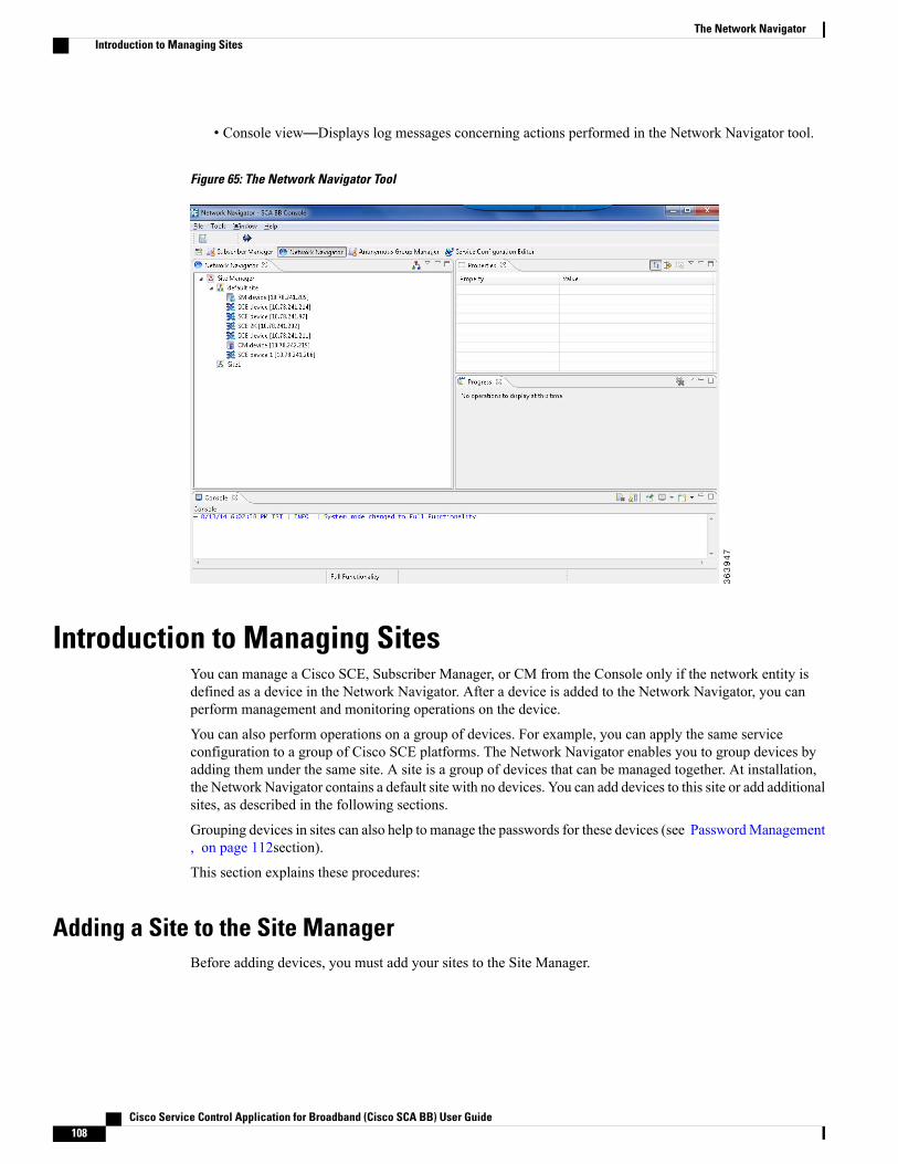
• Console view—Displays log messages concerning actions performed in the Network Navigator tool.
Figure 65: The Network Navigator Tool
Introduction to Managing SitesYou can manage a Cisco SCE, Subscriber Manager, or CM from the Console only if the network entity isdefined as a device in the Network Navigator. After a device is added to the Network Navigator, you canperform management and monitoring operations on the device.
You can also perform operations on a group of devices. For example, you can apply the same serviceconfiguration to a group of Cisco SCE platforms. The Network Navigator enables you to group devices byadding them under the same site. A site is a group of devices that can be managed together. At installation,the Network Navigator contains a default site with no devices. You can add devices to this site or add additionalsites, as described in the following sections.
Grouping devices in sites can also help to manage the passwords for these devices (see PasswordManagement, on page 112section).
This section explains these procedures:
Adding a Site to the Site ManagerBefore adding devices, you must add your sites to the Site Manager.
Cisco Service Control Application for Broadband (Cisco SCA BB) User Guide108
The Network NavigatorIntroduction to Managing Sites
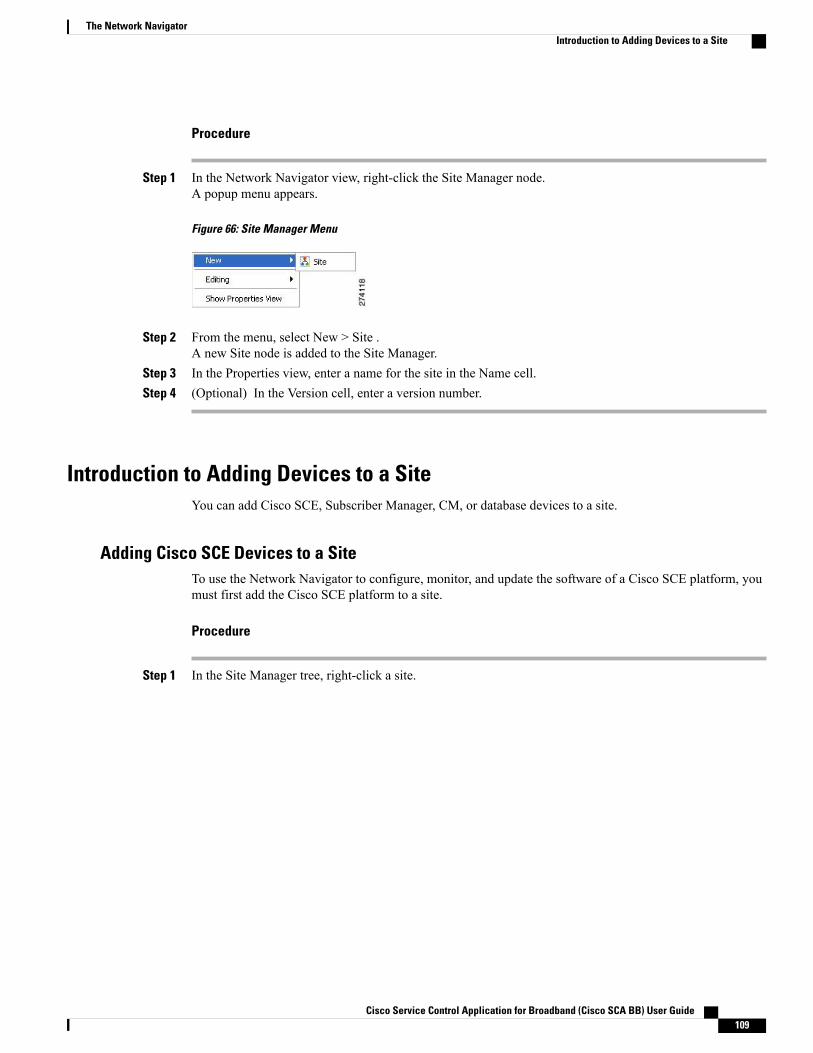
Procedure
Step 1 In the Network Navigator view, right-click the Site Manager node.A popup menu appears.
Figure 66: Site Manager Menu
Step 2 From the menu, select New > Site .A new Site node is added to the Site Manager.
Step 3 In the Properties view, enter a name for the site in the Name cell.Step 4 (Optional) In the Version cell, enter a version number.
Introduction to Adding Devices to a SiteYou can add Cisco SCE, Subscriber Manager, CM, or database devices to a site.
Adding Cisco SCE Devices to a SiteTo use the Network Navigator to configure, monitor, and update the software of a Cisco SCE platform, youmust first add the Cisco SCE platform to a site.
Procedure
Step 1 In the Site Manager tree, right-click a site.
Cisco Service Control Application for Broadband (Cisco SCA BB) User Guide 109
The Network NavigatorIntroduction to Adding Devices to a Site
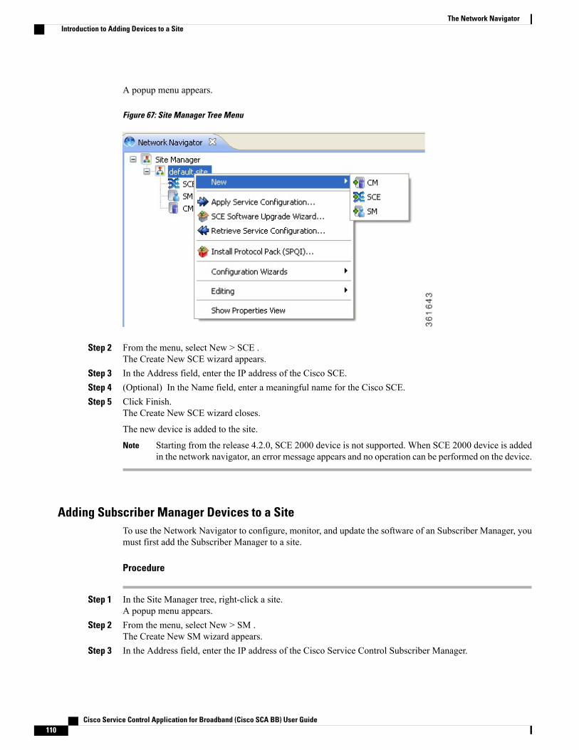
A popup menu appears.
Figure 67: Site Manager Tree Menu
Step 2 From the menu, select New > SCE .The Create New SCE wizard appears.
Step 3 In the Address field, enter the IP address of the Cisco SCE.Step 4 (Optional) In the Name field, enter a meaningful name for the Cisco SCE.Step 5 Click Finish.
The Create New SCE wizard closes.
The new device is added to the site.
Starting from the release 4.2.0, SCE 2000 device is not supported. When SCE 2000 device is addedin the network navigator, an error message appears and no operation can be performed on the device.
Note
Adding Subscriber Manager Devices to a SiteTo use the Network Navigator to configure, monitor, and update the software of an Subscriber Manager, youmust first add the Subscriber Manager to a site.
Procedure
Step 1 In the Site Manager tree, right-click a site.A popup menu appears.
Step 2 From the menu, select New > SM .The Create New SM wizard appears.
Step 3 In the Address field, enter the IP address of the Cisco Service Control Subscriber Manager.
Cisco Service Control Application for Broadband (Cisco SCA BB) User Guide110
The Network NavigatorIntroduction to Adding Devices to a Site
Step 4 (Optional) In the Name field, enter a meaningful name for the Subscriber Manager.Step 5 Click Finish.
The Create New SM wizard closes.
The new device is added to the site.
Adding Collection Manager Devices to a SiteTo use the Network Navigator to monitor a Collection Manager, you must first add the Collection Managerto a site.
Procedure
Step 1 In the Site Manager tree, right-click a site.A popup menu appears.
Step 2 From the menu, select New > CM.The Create New CM wizard appears.
Step 3 In the Address field, enter the IP address of the Collection Manager.Step 4 (Optional) In the Name field, enter a meaningful name for the Collection Manager.Step 5 Click Finish.
The Create New CM wizard closes.
The new device is added to the site.
Deleting Devices
Procedure
Step 1 In the Site Manager tree, right-click a device.A popup menu appears.
Step 2 From the menu, select Delete .The device is deleted and removed from the Site Manager tree.
Deleting Sites
Procedure
Step 1 In the Site Manager tree, right-click a site in the Site Manager tree.
Cisco Service Control Application for Broadband (Cisco SCA BB) User Guide 111
The Network NavigatorDeleting Sites

A popup menu appears.Step 2 If prompted, enter your password.Step 3 From the menu, select Delete .
The site and all its devices are deleted and the site is removed from the Site Manager tree.
Introduction to Managing DevicesThe Network Navigator enables you to manage Cisco SCE, Cisco Service Control Subscriber Manager, CiscoService Control Collection Manager, and database devices.
The Usage Analysis wizard enables you to create a simple model of devices and connect to those devicesto perform various tasks. (See Using the Usage Analysis Wizard , on page 70 section.)
Note
This section contains these topics:
Password ManagementNormally, before you can access a device (Cisco SCE, Cisco Service Control Subscriber Manager, CiscoService Control Collection Manager, or database), you must enter its password. When you try to perform anyoperation on a site device, the Network Navigator first asks for the device username and password. (Repeatingthe same operation on the same device does not always require a second entry of the password.)
When performing operations on multiple devices, password entry can become tedious. The Site MasterPassword can help you remember some or all usernames and passwords of your element by storing them aspart of the site data, and entering them for you automatically when you connect to an element.
Cisco Service Control Application for Broadband (Cisco SCA BB) User Guide112
The Network NavigatorIntroduction to Managing Devices

The Site Master Password protects saved usernames and passwords in the password manager. The PasswordManagement dialog box prompts you for the master password of the site when you wish to activate the sitepassword manager. If you have multiple sites, each site requires a separate master password.
Figure 68: The Password Management Dialog Box
For each site, when the Password Management dialog box appears, check the Enable Site Master Passwordcheck box.
Introduction to Managing Cisco SCE DevicesThis section explains the following procedures:
Configuring Cisco SCE and Collection Manager Devices Using a WizardTheNetworkNavigator Device wizard allows you to configure Cisco SCE and Cisco Service Control CollectionManager devices and connect to them.
If they do not exist, devices defined in the wizard are added to the default site in the Site Manager tree.Note
Procedure
Step 1In the Network Navigator view toolbar, click the Configure SCE and CM devices ( ) icon.
Cisco Service Control Application for Broadband (Cisco SCA BB) User Guide 113
The Network NavigatorIntroduction to Managing Cisco SCE Devices
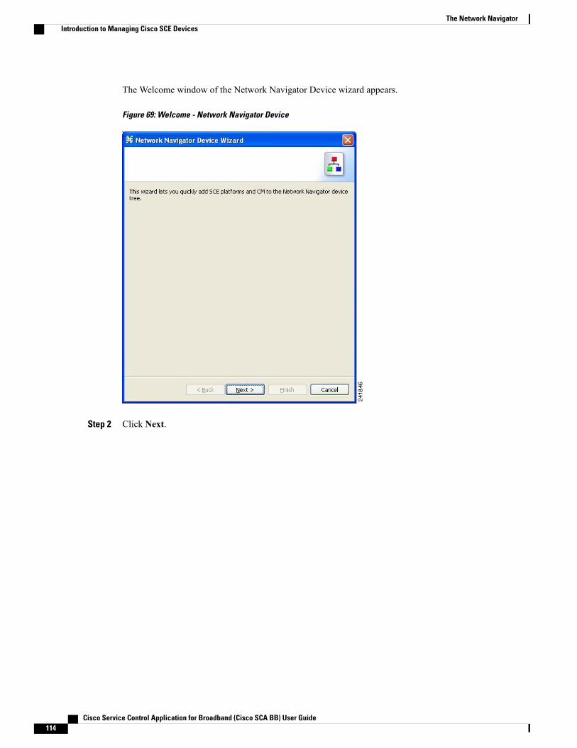
The Welcome window of the Network Navigator Device wizard appears.
Figure 69: Welcome - Network Navigator Device
Step 2 Click Next.
Cisco Service Control Application for Broadband (Cisco SCA BB) User Guide114
The Network NavigatorIntroduction to Managing Cisco SCE Devices
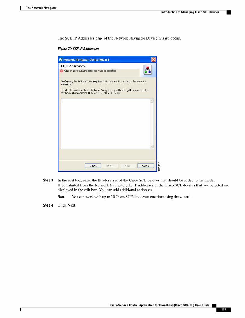
The SCE IP Addresses page of the Network Navigator Device wizard opens.
Figure 70: SCE IP Addresses
Step 3 In the edit box, enter the IP addresses of the Cisco SCE devices that should be added to the model.If you started from the Network Navigator, the IP addresses of the Cisco SCE devices that you selected aredisplayed in the edit box. You can add additional addresses.
You can work with up to 20 Cisco SCE devices at one time using the wizard.Note
Step 4 Click Next.
Cisco Service Control Application for Broadband (Cisco SCA BB) User Guide 115
The Network NavigatorIntroduction to Managing Cisco SCE Devices
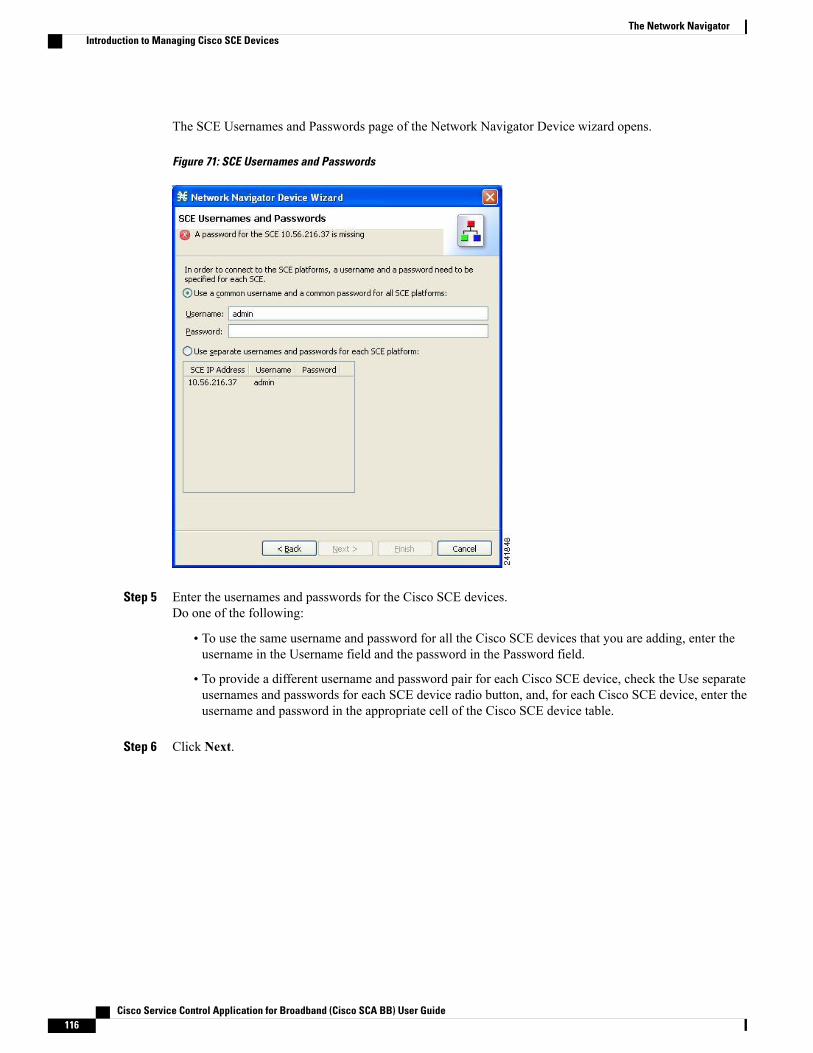
The SCE Usernames and Passwords page of the Network Navigator Device wizard opens.
Figure 71: SCE Usernames and Passwords
Step 5 Enter the usernames and passwords for the Cisco SCE devices.Do one of the following:
• To use the same username and password for all the Cisco SCE devices that you are adding, enter theusername in the Username field and the password in the Password field.
• To provide a different username and password pair for each Cisco SCE device, check the Use separateusernames and passwords for each SCE device radio button, and, for each Cisco SCE device, enter theusername and password in the appropriate cell of the Cisco SCE device table.
Step 6 Click Next.
Cisco Service Control Application for Broadband (Cisco SCA BB) User Guide116
The Network NavigatorIntroduction to Managing Cisco SCE Devices

The Cisco Service Control Collection Manager Setup page of the Network Navigator Device wizard opens.
Figure 72: Cisco Service Control Collection Manager Setup
Step 7 Define the Cisco Service Control Collection Manager to use with this configuration.Do one of the following:
• Enter the IP address, username, and password of the CM device in the appropriate fields.If you started from the Network Navigator, this information is retrieved and displayed. You can modifythese parameters.
• Check the Skip this step check box.
Step 8 Click Next.
Cisco Service Control Application for Broadband (Cisco SCA BB) User Guide 117
The Network NavigatorIntroduction to Managing Cisco SCE Devices

The Connectivity Test page of the Network Navigator Device wizard opens.
Figure 73: Connectivity Test
The wizard tests to see that the connections to the defined devices can be made.
If a connection to one or more of the devices cannot be made or if there is some problem with theconnection (such as invalid version of the device) an error is displayed next to the device. You canskip these tests by clicking Skip Connections . The connections are validated when you click Finishat the end of the wizard.
Note
Step 9 Click Next.
Cisco Service Control Application for Broadband (Cisco SCA BB) User Guide118
The Network NavigatorIntroduction to Managing Cisco SCE Devices

The Confirmation page of the Network Navigator Device wizard opens.
Figure 74: Confirmation
The actions that the wizard is about to take are listed on the page.
Step 10 Click Finish.
Cisco Service Control Application for Broadband (Cisco SCA BB) User Guide 119
The Network NavigatorIntroduction to Managing Cisco SCE Devices
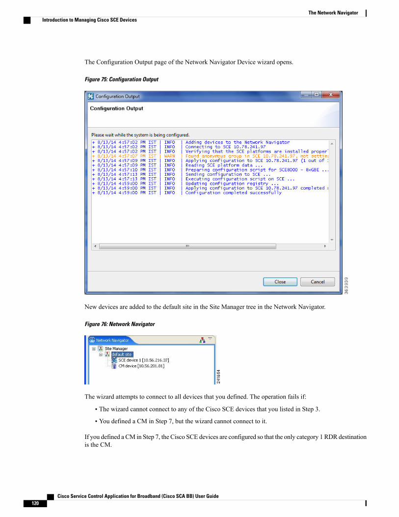
The Configuration Output page of the Network Navigator Device wizard opens.
Figure 75: Configuration Output
New devices are added to the default site in the Site Manager tree in the Network Navigator.
Figure 76: Network Navigator
The wizard attempts to connect to all devices that you defined. The operation fails if:
• The wizard cannot connect to any of the Cisco SCE devices that you listed in Step 3.
• You defined a CM in Step 7, but the wizard cannot connect to it.
If you defined a CM in Step 7, the Cisco SCE devices are configured so that the only category 1 RDR destinationis the CM.
Cisco Service Control Application for Broadband (Cisco SCA BB) User Guide120
The Network NavigatorIntroduction to Managing Cisco SCE Devices
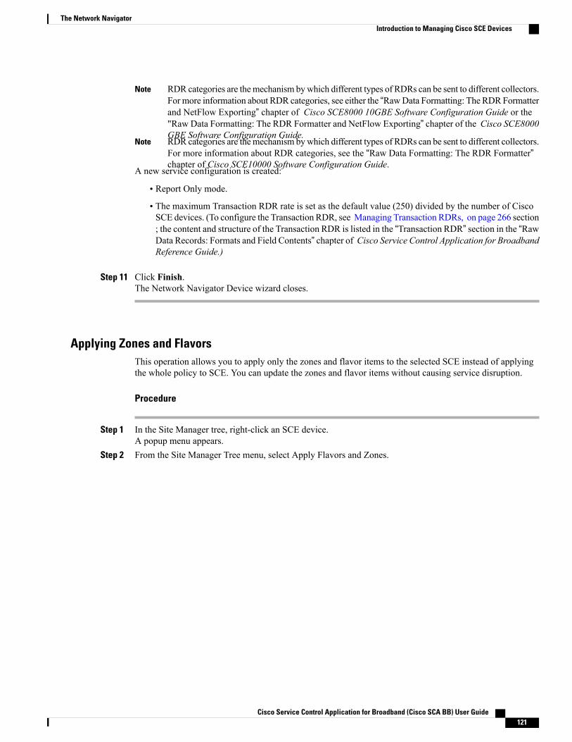
RDR categories are themechanism bywhich different types of RDRs can be sent to different collectors.For more information about RDR categories, see either the “RawData Formatting: The RDRFormatterand NetFlow Exporting” chapter of Cisco SCE8000 10GBE Software Configuration Guide or the"Raw Data Formatting: The RDR Formatter and NetFlow Exporting” chapter of the Cisco SCE8000GBE Software Configuration Guide.
Note
RDR categories are themechanism bywhich different types of RDRs can be sent to different collectors.For more information about RDR categories, see the “Raw Data Formatting: The RDR Formatter”chapter of Cisco SCE10000 Software Configuration Guide.
Note
A new service configuration is created:
• Report Only mode.
• The maximum Transaction RDR rate is set as the default value (250) divided by the number of CiscoSCE devices. (To configure the Transaction RDR, see Managing Transaction RDRs, on page 266 section; the content and structure of the Transaction RDR is listed in the “Transaction RDR” section in the “RawData Records: Formats and Field Contents” chapter of Cisco Service Control Application for BroadbandReference Guide.)
Step 11 Click Finish.The Network Navigator Device wizard closes.
Applying Zones and FlavorsThis operation allows you to apply only the zones and flavor items to the selected SCE instead of applyingthe whole policy to SCE. You can update the zones and flavor items without causing service disruption.
Procedure
Step 1 In the Site Manager tree, right-click an SCE device.A popup menu appears.
Step 2 From the Site Manager Tree menu, select Apply Flavors and Zones.
Cisco Service Control Application for Broadband (Cisco SCA BB) User Guide 121
The Network NavigatorIntroduction to Managing Cisco SCE Devices
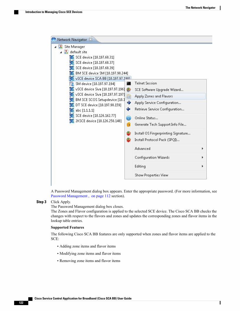
A Password Management dialog box appears. Enter the appropriate password. (For more information, seePassword Management , on page 112 section).
Step 3 Click Apply.The Password Management dialog box closes.The Zones and Flavor configuration is applied to the selected SCE device. The Cisco SCA BB checks thechanges with respect to the flavors and zones and updates the corresponding zones and flavor items in thelookup table entries.
Supported Features
The following Cisco SCA BB features are only supported when zones and flavor items are applied to theSCE:
• Adding zone items and flavor items
• Modifying zone items and flavor items
• Removing zone items and flavor items
Cisco Service Control Application for Broadband (Cisco SCA BB) User Guide122
The Network NavigatorIntroduction to Managing Cisco SCE Devices
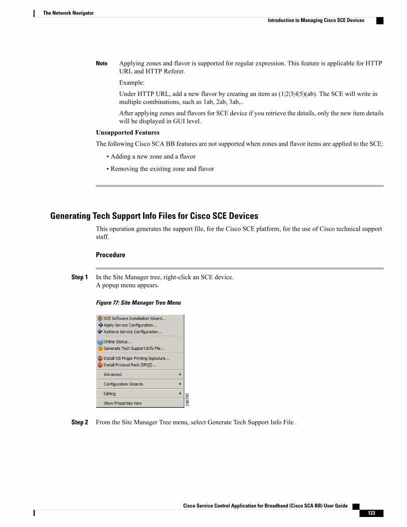
Applying zones and flavor is supported for regular expression. This feature is applicable for HTTPURL and HTTP Referer.
Example:
Under HTTP URL, add a new flavor by creating an item as (1|2|3|4|5)(ab). The SCE will write inmultiple combinations, such as 1ab, 2ab, 3ab,..
After applying zones and flavors for SCE device if you retrieve the details, only the new item detailswill be displayed in GUI level.
Note
Unsupported Features
The following Cisco SCA BB features are not supported when zones and flavor items are applied to the SCE:
• Adding a new zone and a flavor
• Removing the existing zone and flavor
Generating Tech Support Info Files for Cisco SCE DevicesThis operation generates the support file, for the Cisco SCE platform, for the use of Cisco technical supportstaff.
Procedure
Step 1 In the Site Manager tree, right-click an SCE device.A popup menu appears.
Figure 77: Site Manager Tree Menu
Step 2 From the Site Manager Tree menu, select Generate Tech Support Info File .
Cisco Service Control Application for Broadband (Cisco SCA BB) User Guide 123
The Network NavigatorIntroduction to Managing Cisco SCE Devices
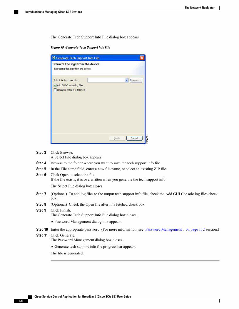
The Generate Tech Support Info File dialog box appears.
Figure 78: Generate Tech Support Info File
Step 3 Click Browse.A Select File dialog box appears.
Step 4 Browse to the folder where you want to save the tech support info file.Step 5 In the File name field, enter a new file name, or select an existing ZIP file.Step 6 Click Open to select the file.
If the file exists, it is overwritten when you generate the tech support info.
The Select File dialog box closes.
Step 7 (Optional) To add log files to the output tech support info file, check the Add GUI Console log files checkbox.
Step 8 (Optional) Check the Open file after it is fetched check box.Step 9 Click Finish.
The Generate Tech Support Info File dialog box closes.
A Password Management dialog box appears.
Step 10 Enter the appropriate password. (For more information, see Password Management , on page 112 section.)Step 11 Click Generate.
The Password Management dialog box closes.
A Generate tech support info file progress bar appears.
The file is generated.
Cisco Service Control Application for Broadband (Cisco SCA BB) User Guide124
The Network NavigatorIntroduction to Managing Cisco SCE Devices

Retrieving the Online Status of Cisco SCE DevicesThis operation provides information about the current software version and operational status of the CiscoSCE platform. The enhanced Cisco SCE online statuses are categorized as:
• System—displays the platform information
• Configuration—displays the Hostname
• Status—displays the operational mode and total traffic on the Cisco SCE
For more information on monitoring Cisco SCE online status, see the Cisco SCA BB Demo Kit Quick StartGuide.
Procedure
Step 1 In the Site Manager tree, right-click an SCE device.A popup menu appears.
Step 2 From the menu, select Online Status.A Password Management dialog box appears.
Step 3 Enter the appropriate password.For more information, see Password Management , on page 112 section.
Step 4 Enter the SNMP RO Community String.If SNMP is not already enabled on the Cisco SCE, it gets enabled.
If RO communities are not configured on the Cisco SCE or if only RW communities are configured on theCisco SCE, the SNMP RO community you provide here is added to the Cisco SCE.
If only RO communities are configured on the Cisco SCE, the SNMP RO community you provide here isvalidated first against the RO communities configured on Cisco SCE. If the RO community is valid, the onlinestatus window is launched. If the RO community is not valid, a validation message appears.
Step 5 Click Extract .The Password Management dialog box closes.
An Extracting info progress bar appears.
Cisco Service Control Application for Broadband (Cisco SCA BB) User Guide 125
The Network NavigatorIntroduction to Managing Cisco SCE Devices
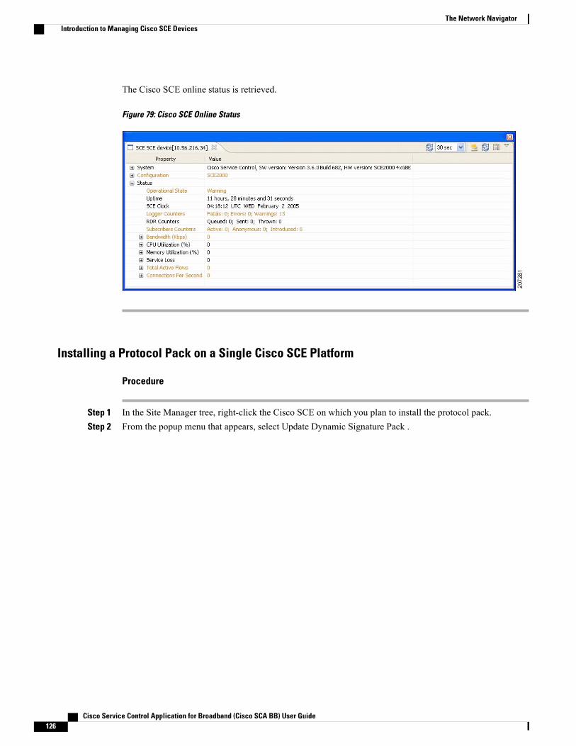
The Cisco SCE online status is retrieved.
Figure 79: Cisco SCE Online Status
Installing a Protocol Pack on a Single Cisco SCE Platform
Procedure
Step 1 In the Site Manager tree, right-click the Cisco SCE on which you plan to install the protocol pack.Step 2 From the popup menu that appears, select Update Dynamic Signature Pack .
Cisco Service Control Application for Broadband (Cisco SCA BB) User Guide126
The Network NavigatorIntroduction to Managing Cisco SCE Devices
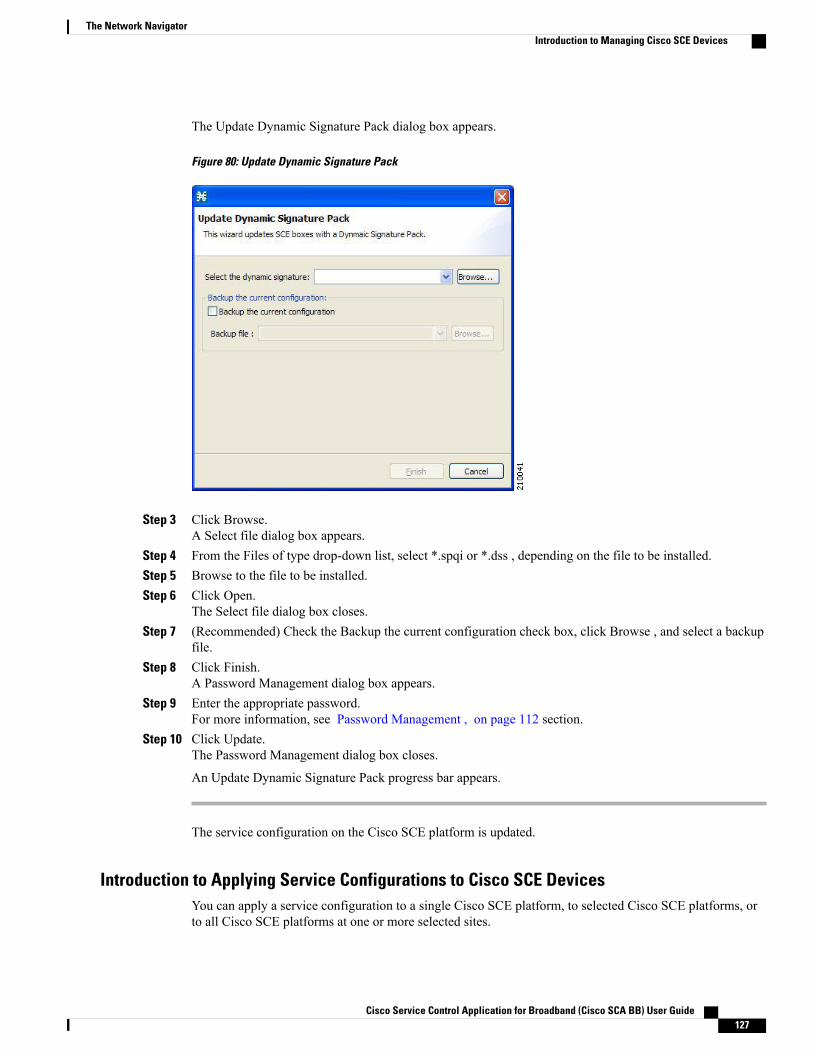
The Update Dynamic Signature Pack dialog box appears.
Figure 80: Update Dynamic Signature Pack
Step 3 Click Browse.A Select file dialog box appears.
Step 4 From the Files of type drop-down list, select *.spqi or *.dss , depending on the file to be installed.Step 5 Browse to the file to be installed.Step 6 Click Open.
The Select file dialog box closes.Step 7 (Recommended) Check the Backup the current configuration check box, click Browse , and select a backup
file.Step 8 Click Finish.
A Password Management dialog box appears.Step 9 Enter the appropriate password.
For more information, see Password Management , on page 112 section.Step 10 Click Update.
The Password Management dialog box closes.
An Update Dynamic Signature Pack progress bar appears.
The service configuration on the Cisco SCE platform is updated.
Introduction to Applying Service Configurations to Cisco SCE DevicesYou can apply a service configuration to a single Cisco SCE platform, to selected Cisco SCE platforms, orto all Cisco SCE platforms at one or more selected sites.
Cisco Service Control Application for Broadband (Cisco SCA BB) User Guide 127
The Network NavigatorIntroduction to Managing Cisco SCE Devices
The service configuration that you are applying must be open in the Service Configuration Editor.Note
If anomaly-based detection of malicious traffic is enabled, any access control list (ACL) that is configuredon the Cisco Service Control Engine (Cisco SCE) platform but is not applied to anything (for example,an interface, an access map, or an SNMP community string) might be deleted when a service configurationis applied to the platform. To workaround this issue, disable anomaly-based detection of malicious traffic.In the Network Traffic tab, select Service Security . In the Service Security Dashboard, clear the Enableanomaly detection check box.
Caution
Applying a Service Configuration to Multiple Cisco SCE Platforms
Procedure
Step 1 In the SiteManager tree, select sites or Cisco SCE devices to which you are applying the service configurationand right-click one of them.
Step 2 From the popup menu that appears, select Apply Service Configuration.The Choose Policy dialog box appears, listing all service configurations that are open in the ServiceConfiguration Editor.
If only one service configuration is open in the Service Configuration Editor, a PasswordManagementdialog box appears. Continue at Step 4. (If no service configurations are open in the ServiceConfiguration Editor, an error message is displayed.)
Note
Step 3 Select a service configuration from the list and click OK.A separate Password Management dialog box appears for each Cisco SCE device that you have selected.
Step 4 For each Cisco SCE device, enter the password and click Apply .The service configuration is applied to each selected Cisco SCE platform in turn.
Applying a Service Configuration to a Single Cisco SCE Platform
Procedure
Step 1 In the Site Manager tree, right-click a Cisco SCE device.A popup menu appears.
Step 2 From the menu, select Apply Service Configuration .The Choose Policy dialog box appears, listing all service configurations that are open in the ServiceConfiguration Editor.
Cisco Service Control Application for Broadband (Cisco SCA BB) User Guide128
The Network NavigatorIntroduction to Managing Cisco SCE Devices
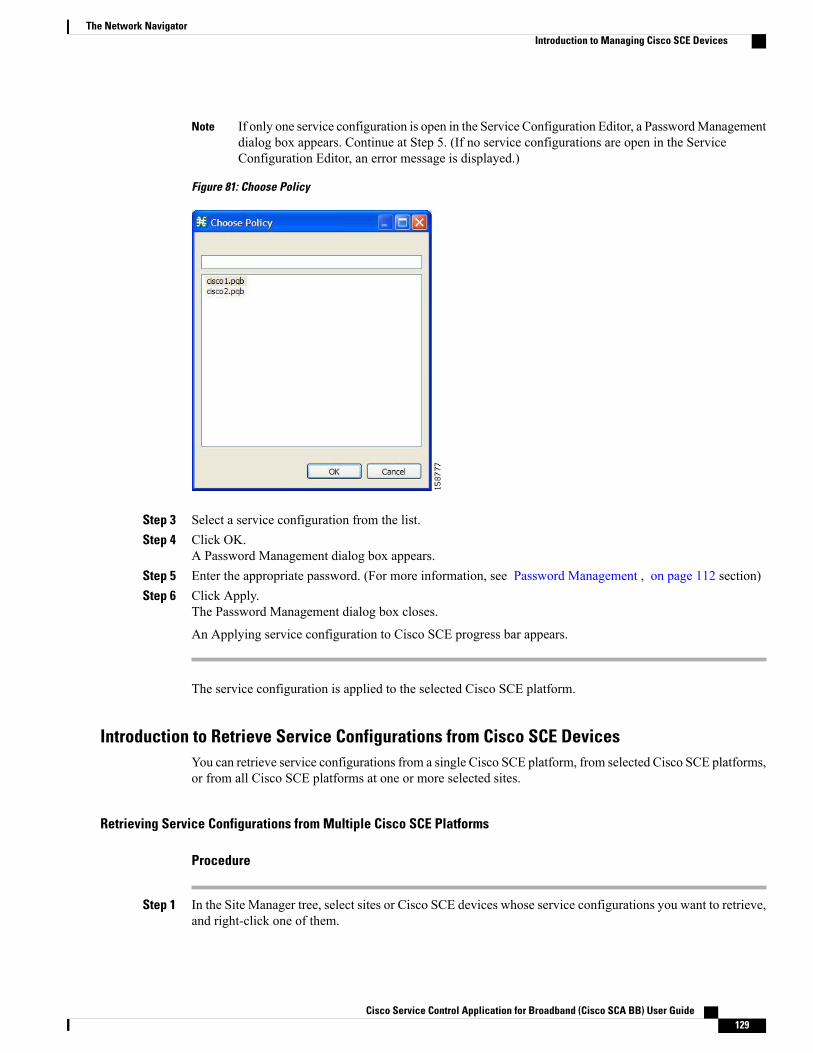
If only one service configuration is open in the Service Configuration Editor, a PasswordManagementdialog box appears. Continue at Step 5. (If no service configurations are open in the ServiceConfiguration Editor, an error message is displayed.)
Note
Figure 81: Choose Policy
Step 3 Select a service configuration from the list.Step 4 Click OK.
A Password Management dialog box appears.Step 5 Enter the appropriate password. (For more information, see Password Management , on page 112 section)Step 6 Click Apply.
The Password Management dialog box closes.
An Applying service configuration to Cisco SCE progress bar appears.
The service configuration is applied to the selected Cisco SCE platform.
Introduction to Retrieve Service Configurations from Cisco SCE DevicesYou can retrieve service configurations from a single Cisco SCE platform, from selected Cisco SCE platforms,or from all Cisco SCE platforms at one or more selected sites.
Retrieving Service Configurations from Multiple Cisco SCE Platforms
Procedure
Step 1 In the Site Manager tree, select sites or Cisco SCE devices whose service configurations you want to retrieve,and right-click one of them.
Cisco Service Control Application for Broadband (Cisco SCA BB) User Guide 129
The Network NavigatorIntroduction to Managing Cisco SCE Devices
Step 2 From the popup menu that appears, select Retrieve Service Configuration.A separate Password Management dialog box appears for each Cisco SCE device that you have selected.
Step 3 For each Cisco SCE device, enter the password and click Retrieve .The service configuration is retrieved from each Cisco SCE platform in turn, and is opened in the ServiceConfiguration Editor.
Retrieving Service Configurations from a Single Cisco SCE Platform
Procedure
Step 1 In the Site Manager tree, right-click a Cisco SCE device.A popup menu appears.
Step 2 Enter your password if prompted.Step 3 From the menu, select Retrieve Service Configuration .
A Password Management dialog box appears.Step 4 Enter the appropriate password.
For more information, see Password Management , on page 112 section.Step 5 Click Retrieve .
The Password Management dialog box closes.
A Retrieving from Cisco SCE progress bar appears.
The service configuration is retrieved from the Cisco SCE platform and opened in the Service ConfigurationEditor.
Installing PQI Files on Cisco SCE DevicesThis operation installs the Cisco SCA BB on the Cisco SCE platform.
It is recommended to use the SCE Software Upgrade wizard when installing a PQI file on multiple CiscoSCE devices. See Upgrading the SCE Using the SCE Software Upgrade Wizard, on page 44 section.
Note
Installing a PQI file usually takes a few minutes.Note
Procedure
Step 1 In the Site Manager tree, select a Cisco SCE device.Step 2 From the Console main menu, choose Network > Install Application Software (PQI).
Cisco Service Control Application for Broadband (Cisco SCA BB) User Guide130
The Network NavigatorIntroduction to Managing Cisco SCE Devices
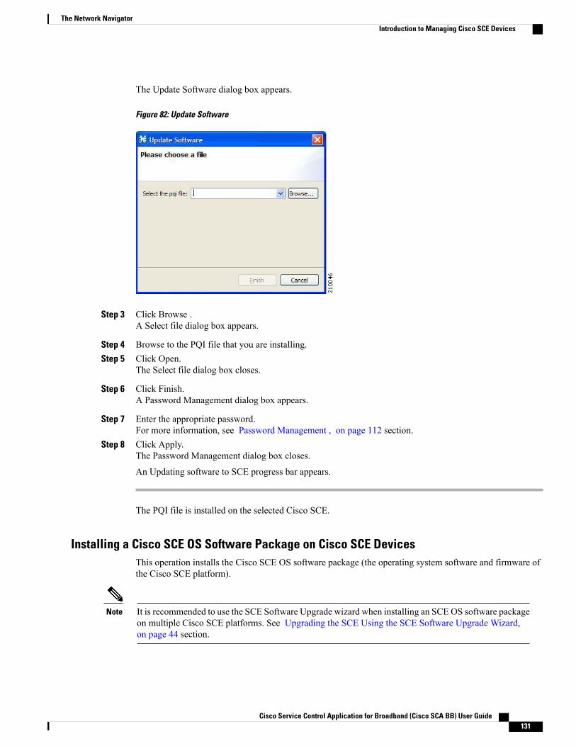
The Update Software dialog box appears.
Figure 82: Update Software
Step 3 Click Browse .A Select file dialog box appears.
Step 4 Browse to the PQI file that you are installing.Step 5 Click Open.
The Select file dialog box closes.
Step 6 Click Finish.A Password Management dialog box appears.
Step 7 Enter the appropriate password.For more information, see Password Management , on page 112 section.
Step 8 Click Apply.The Password Management dialog box closes.
An Updating software to SCE progress bar appears.
The PQI file is installed on the selected Cisco SCE.
Installing a Cisco SCE OS Software Package on Cisco SCE DevicesThis operation installs the Cisco SCE OS software package (the operating system software and firmware ofthe Cisco SCE platform).
It is recommended to use the SCE Software Upgrade wizard when installing an SCEOS software packageon multiple Cisco SCE platforms. See Upgrading the SCE Using the SCE Software Upgrade Wizard,on page 44 section.
Note
Cisco Service Control Application for Broadband (Cisco SCA BB) User Guide 131
The Network NavigatorIntroduction to Managing Cisco SCE Devices

Procedure
Step 1 In the Site Manager tree, select a Cisco SCE device.Step 2 From the Console main menu, choose Network > Upgrade SCE Platform Firmware (PKG) .
The Update OS dialog box appears.
Figure 83: Update OS
Step 3 Click Browse .A Select file dialog box appears.
Step 4 Browse to the PKG file containing the OS that you are installing.Step 5 Click Open.
The Select file dialog box closes.Step 6 Click Finish.
A Password Management dialog box appears.Step 7 Enter the appropriate password.
For more information, see Password Management , on page 112 section.Step 8 Click Apply.
The Password Management dialog box closes.
An Updating software to SCE progress bar appears.
The PQI file is installed on the selected Cisco SCE.
Cisco Service Control Application for Broadband (Cisco SCA BB) User Guide132
The Network NavigatorIntroduction to Managing Cisco SCE Devices
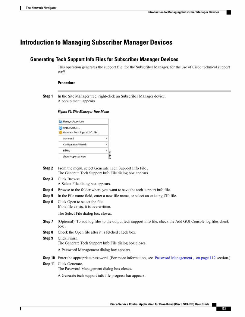
Introduction to Managing Subscriber Manager Devices
Generating Tech Support Info Files for Subscriber Manager DevicesThis operation generates the support file, for the Subscriber Manager, for the use of Cisco technical supportstaff.
Procedure
Step 1 In the Site Manager tree, right-click an Subscriber Manager device.A popup menu appears.
Figure 84: Site Manager Tree Menu
Step 2 From the menu, select Generate Tech Support Info File .The Generate Tech Support Info File dialog box appears.
Step 3 Click Browse.A Select File dialog box appears.
Step 4 Browse to the folder where you want to save the tech support info file.Step 5 In the File name field, enter a new file name, or select an existing ZIP file.Step 6 Click Open to select the file.
If the file exists, it is overwritten.
The Select File dialog box closes.
Step 7 (Optional) To add log files to the output tech support info file, check the Add GUI Console log files checkbox .
Step 8 Check the Open file after it is fetched check box.Step 9 Click Finish.
The Generate Tech Support Info File dialog box closes.
A Password Management dialog box appears.
Step 10 Enter the appropriate password. (For more information, see Password Management , on page 112 section.)Step 11 Click Generate.
The Password Management dialog box closes.
A Generate tech support info file progress bar appears.
Cisco Service Control Application for Broadband (Cisco SCA BB) User Guide 133
The Network NavigatorIntroduction to Managing Subscriber Manager Devices

The file is generated.
Retrieving the Online Status of Subscriber Manager DevicesThis operation provides information about the current software version and operational status of the SubscriberManager Device.
Procedure
Step 1 In the Site Manager tree, right-click an Subscriber Manager device.A popup menu appears.
Step 2 From the menu, select Online Status.A Password Management dialog box appears.
Step 3 Enter the appropriate password.For more information, see Password Management , on page 112 section
Step 4 Click Extract.The Password Management dialog box closes.
An Extracting info progress bar appears.
The Cisco Service Control Subscriber Manager online status is retrieved.
Figure 85: Cisco Service Control Subscriber Manager Online Status
Connecting to Subscriber Manager DevicesTo manage subscribers using the Subscriber Manager GUI tool, you must connect to an Subscriber Managerdevice.
Cisco Service Control Application for Broadband (Cisco SCA BB) User Guide134
The Network NavigatorIntroduction to Managing Subscriber Manager Devices

The Subscriber Manager GUI tool performs authentication on the Cisco Service Control SubscriberManager by opening a PRPC connection to port 14374 and attempting to log in using the username andpassword that you entered in the Password Management dialog box. If a PRPC server with this user is notrunning on the Cisco Service Control Subscriber Manager, authentication fails. If you have changed thePRPC port on the Cisco Service Control Subscriber Manager, see User Authentication , on page 141section.
Note
Procedure
Step 1 In the Site Manager tree, right-click an Subscriber Manager device.A popup menu appears.
Step 2 From the menu, select Manage Subscribers .A Password Management dialog box appears.
Step 3 Enter the appropriate password. (For more information, see Password Management , on page 112 section.)Step 4 Click Connecting.
The Password Management dialog box closes.
A Connecting to progress bar appears.
You connect to the Subscriber Manager, and the Console switches to the Subscriber Manager GUI tool.
What to Do Next
For an explanation of how to proceed, see Subscriber Manager GUI Tool, on page 475 section.
Introduction to Managing Collection Manager DevicesYou can configure Collection Manager devices using a wizard. See Configuring Cisco SCE and CollectionManager Devices Using a Wizard , on page 113 section.
Retrieving the Online Status of CM DevicesThis operation provides information about the current software version and operational status of the CollectionManager.
Procedure
Step 1 In the Site Manager tree, right-click a CM device.
Cisco Service Control Application for Broadband (Cisco SCA BB) User Guide 135
The Network NavigatorIntroduction to Managing Collection Manager Devices
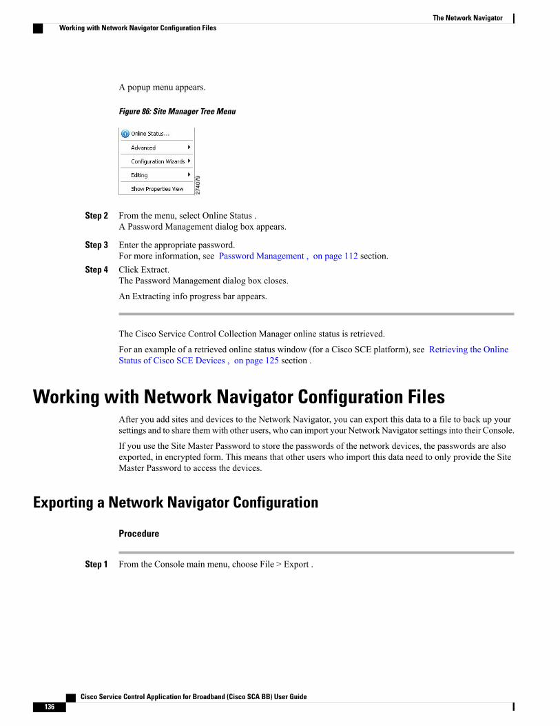
A popup menu appears.
Figure 86: Site Manager Tree Menu
Step 2 From the menu, select Online Status .A Password Management dialog box appears.
Step 3 Enter the appropriate password.For more information, see Password Management , on page 112 section.
Step 4 Click Extract.The Password Management dialog box closes.
An Extracting info progress bar appears.
The Cisco Service Control Collection Manager online status is retrieved.
For an example of a retrieved online status window (for a Cisco SCE platform), see Retrieving the OnlineStatus of Cisco SCE Devices , on page 125 section .
Working with Network Navigator Configuration FilesAfter you add sites and devices to the Network Navigator, you can export this data to a file to back up yoursettings and to share themwith other users, who can import your Network Navigator settings into their Console.
If you use the Site Master Password to store the passwords of the network devices, the passwords are alsoexported, in encrypted form. This means that other users who import this data need to only provide the SiteMaster Password to access the devices.
Exporting a Network Navigator Configuration
Procedure
Step 1 From the Console main menu, choose File > Export .
Cisco Service Control Application for Broadband (Cisco SCA BB) User Guide136
The Network NavigatorWorking with Network Navigator Configuration Files
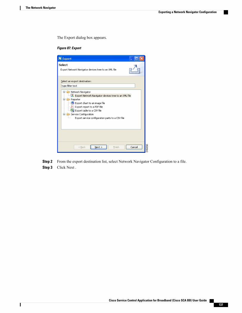
The Export dialog box appears.
Figure 87: Export
Step 2 From the export destination list, select Network Navigator Configuration to a file.Step 3 Click Next .
Cisco Service Control Application for Broadband (Cisco SCA BB) User Guide 137
The Network NavigatorExporting a Network Navigator Configuration
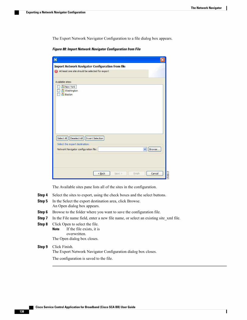
The Export Network Navigator Configuration to a file dialog box appears.
Figure 88: Import Network Navigator Configuration from File
The Available sites pane lists all of the sites in the configuration.
Step 4 Select the sites to export, using the check boxes and the select buttons.Step 5 In the Select the export destination area, click Browse.
An Open dialog box appears.Step 6 Browse to the folder where you want to save the configuration file.Step 7 In the File name field, enter a new file name, or select an existing site_xml file.Step 8 Click Open to select the file.
If the file exists, it isoverwritten.
Note
The Open dialog box closes.
Step 9 Click Finish.The Export Network Navigator Configuration dialog box closes.
The configuration is saved to the file.
Cisco Service Control Application for Broadband (Cisco SCA BB) User Guide138
The Network NavigatorExporting a Network Navigator Configuration
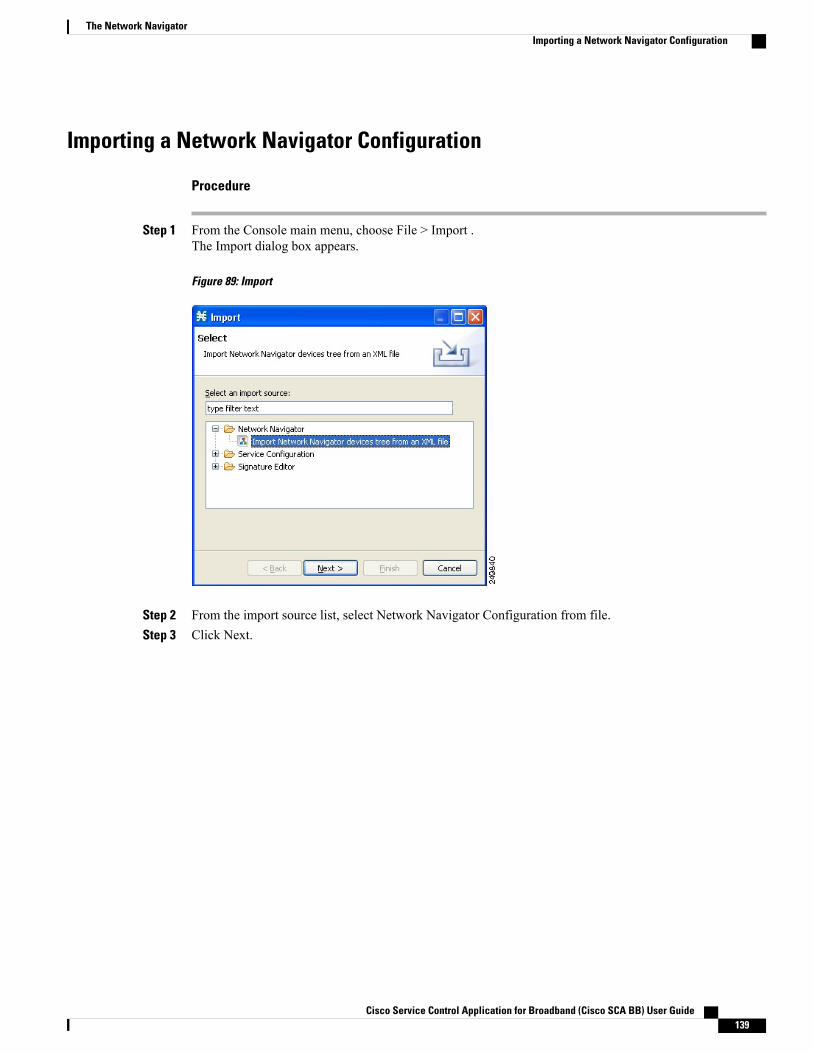
Importing a Network Navigator Configuration
Procedure
Step 1 From the Console main menu, choose File > Import .The Import dialog box appears.
Figure 89: Import
Step 2 From the import source list, select Network Navigator Configuration from file.Step 3 Click Next.
Cisco Service Control Application for Broadband (Cisco SCA BB) User Guide 139
The Network NavigatorImporting a Network Navigator Configuration

The Import Network Navigator Configuration from file dialog box appears.
Figure 90: Import Network Navigator Configuration from File
Step 4 Click Browse.An Open dialog box appears.
Step 5 Browse to the folder containing the file to import, and select a site_xml file.Step 6 Click Open to select the file.
The Open dialog box closes.Step 7 Click Finish .
The Import Network Navigator Configuration dialog box closes.
The configuration is imported from the file.
Cisco Service Control Application for Broadband (Cisco SCA BB) User Guide140
The Network NavigatorImporting a Network Navigator Configuration
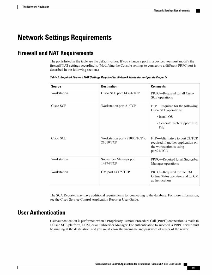
Network Settings Requirements
Firewall and NAT RequirementsThe ports listed in the table are the default values. If you change a port in a device, you must modify thefirewall/NAT settings accordingly. (Modifying the Console settings to connect to a different PRPC port isdescribed in the following section.)
Table 5: Required Firewall NAT Settings Required for Network Navigator to Operate Properly
CommentsDestinationSource
PRPC—Required for all CiscoSCE operations
Cisco SCE port 14374/TCPWorkstation
FTP—Required for the followingCisco SCE operations:
• Install OS
• Generate Tech Support InfoFile
Workstation port 21/TCPCisco SCE
FTP—Alternative to port 21/TCP,required if another application onthe workstation is usingport21/TCP.
Workstation ports 21000/TCP to21010/TCP
Cisco SCE
PRPC—Required for all SubscriberManager operations
Subscriber Manager port14374/TCP
Workstation
PRPC—Required for the CMOnline Status operation and for CMauthentication
CM port 14375/TCPWorkstation
The SCA Reporter may have additional requirements for connecting to the database. For more information,see the Cisco Service Control Application Reporter User Guide.
User AuthenticationUser authentication is performed when a Proprietary Remote Procedure Call (PRPC) connection is made toa Cisco SCE platform, a CM, or an Subscriber Manager. For authentication to succeed, a PRPC server mustbe running at the destination, and you must know the username and password of a user of the server.
Cisco Service Control Application for Broadband (Cisco SCA BB) User Guide 141
The Network NavigatorNetwork Settings Requirements
If you change a PRPC server port in a device (SM/CM/Cisco SCE), youmust add a line to the configurationfile engage.ini : <IP address of device>.rpc.port=<port number> For example: 10.56.216.37.rpc.port=222Add one line for each (non-default) port that you use. The file engage.ini is located in the folder Programfiles\Cisco SCA\SCA BB Console 5.1.x\plugins\policy.contribution_5.1.x\config\ .
Note
You define the username and password using the user/password mechanism in the Cisco SCE platform or acommand-line utility in the Subscriber Manager and CM.
For more information about defining users, see the following:
• Cisco SCE—See either the “TACACS+ Authentication, Authorization, and Accounting” section in the“Configuring the Management Interface and Security” chapter of or the “TACACS+ Authentication,Authorization, and Accounting” section in the “Configuring the Management Interface and Security”chapter of.
• Cisco SCE—See either the “TACACS+ Authentication, Authorization, and Accounting” section in the“Configuring the Management Interface and Security” chapter of .
• Collection Manager—“Managing Users” section in the “Managing the Collection Manager” chapter ofCisco Service Control Management Suite Collection Manager User Guide.
• Subscriber Manager—“Information About the p3rpc Utility” section in the “Command-Line Utilities”appendix of Cisco Service Control Management Suite Subscriber Manager User Guide.
PRPC authentication from the Cisco SCA BB Console to any CM/SM/Cisco SCE IP addresses other thanthe real IP address of the device is not supported. This is especially important when the CM/SubscriberManager/Cisco SCE resides on the inside interface of a NATing router or firewall Workaround : Redesignyour network so that the SCA BB Console is given the real IP address of the CM/SM/Cisco SCE. DisablePRPC authentication on the Cisco SCE/CM/Subscriber Manager as described in the following sections.
Note
Introduction to Disabling PRPC Authentication
Disabling PRPC Authentication on a Cisco SCE Platform
Procedure
Use the CLI to disable PRPC authentication.Run the ip rpc-adapter security-level none CLI in config mode.
Cisco Service Control Application for Broadband (Cisco SCA BB) User Guide142
The Network NavigatorIntroduction to Disabling PRPC Authentication
Disabling PRPC Authentication on a CM
Procedure
Step 1 Edit the CM configuration file.Edit the cm/um/config/p3cm.cfg configuration file:[RPC.Server] security_level=none
Step 2 Reload the CM process.
Disabling PRPC Authentication on an Subscriber Manager
Procedure
Step 1 Edit the Subscriber Manager configuration file.Edit the ~pcube/sm/server/root/config/p3sm.cfg configuration file:[RPC.Server] security_level= none
Step 2 Load the configuration.Run the following CLU: p3sm --load-config
Cisco Service Control Application for Broadband (Cisco SCA BB) User Guide 143
The Network NavigatorIntroduction to Disabling PRPC Authentication

Cisco Service Control Application for Broadband (Cisco SCA BB) User Guide144
The Network NavigatorIntroduction to Disabling PRPC Authentication

C H A P T E R 6Using the Service Configuration Editor
To configure a Cisco Service Control Engine (Cisco SCE) platform to handle traffic, you must define aservice configuration and apply it to the platform. Use the Service Configuration Editor tool to create, define,and manage service configurations.
This module describes how to use the Service Configuration Editor tool.
• Service Configurations , page 145
• Managing Service Configurations , page 145
Service ConfigurationsA service configuration is a data structure that defines how the Cisco SCE platform analyses network traffic,what rules apply to the traffic, and what actions the Cisco SCE platform takes to enforce these rules.
A service configuration consists of the following two main elements:
• Services—Define the categories to which transactions are classified
• Packages—Define how the Cisco SCE platform acts upon transactions from different services
Service configurations are stored as PQB files.
Managing Service ConfigurationsThis section explains how to:
• Manage service configurations
• Export and import service configuration data
• Apply service configurations to Cisco SCE platforms and retrieve them
Cisco Service Control Application for Broadband (Cisco SCA BB) User Guide 145
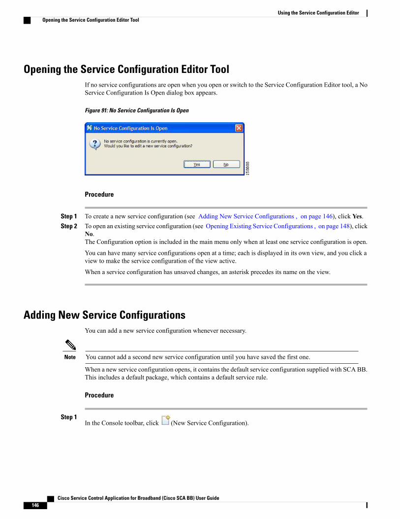
Opening the Service Configuration Editor ToolIf no service configurations are open when you open or switch to the Service Configuration Editor tool, a NoService Configuration Is Open dialog box appears.
Figure 91: No Service Configuration Is Open
Procedure
Step 1 To create a new service configuration (see Adding New Service Configurations , on page 146), click Yes.Step 2 To open an existing service configuration (see Opening Existing Service Configurations , on page 148), click
No.The Configuration option is included in the main menu only when at least one service configuration is open.
You can have many service configurations open at a time; each is displayed in its own view, and you click aview to make the service configuration of the view active.
When a service configuration has unsaved changes, an asterisk precedes its name on the view.
Adding New Service ConfigurationsYou can add a new service configuration whenever necessary.
You cannot add a second new service configuration until you have saved the first one.Note
When a new service configuration opens, it contains the default service configuration supplied with SCA BB.This includes a default package, which contains a default service rule.
Procedure
Step 1In the Console toolbar, click (New Service Configuration).
Cisco Service Control Application for Broadband (Cisco SCA BB) User Guide146
Using the Service Configuration EditorOpening the Service Configuration Editor Tool
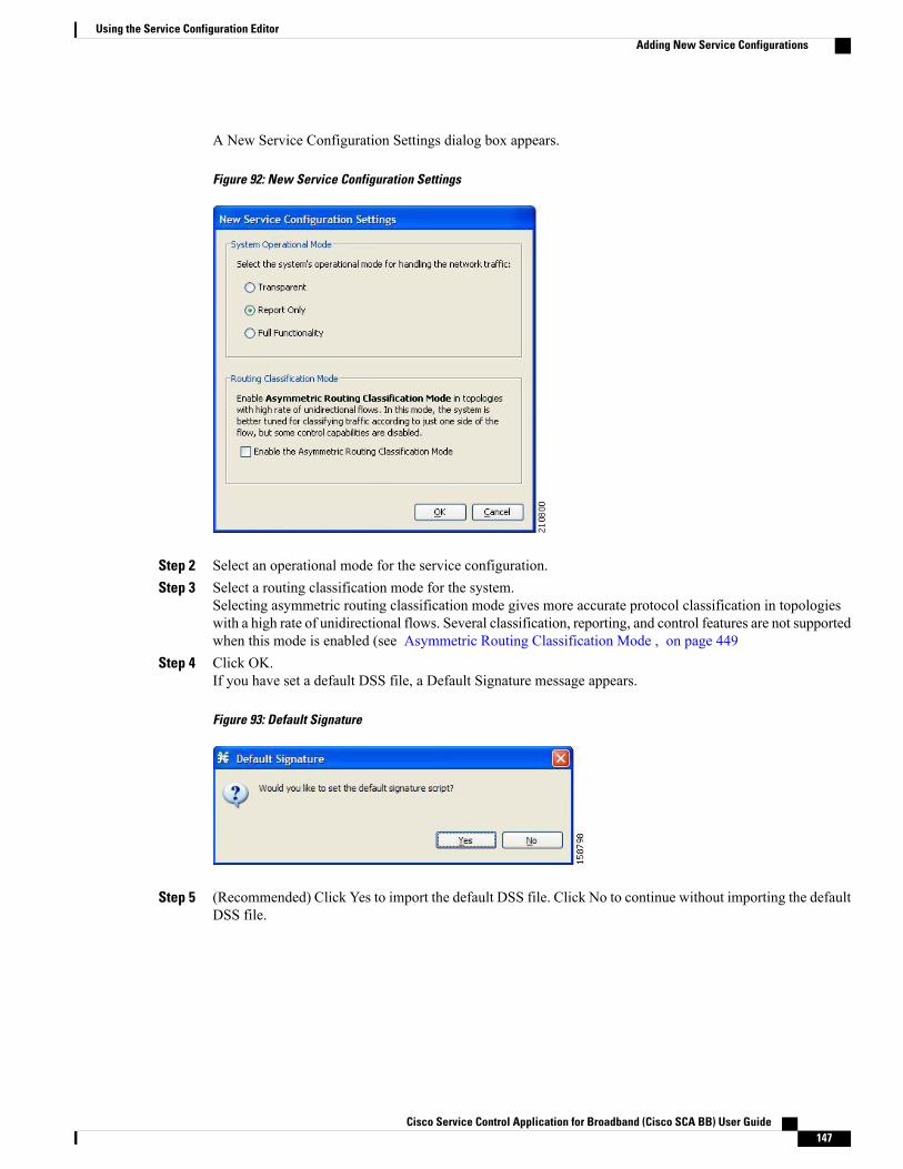
A New Service Configuration Settings dialog box appears.
Figure 92: New Service Configuration Settings
Step 2 Select an operational mode for the service configuration.Step 3 Select a routing classification mode for the system.
Selecting asymmetric routing classification mode gives more accurate protocol classification in topologieswith a high rate of unidirectional flows. Several classification, reporting, and control features are not supportedwhen this mode is enabled (see Asymmetric Routing Classification Mode , on page 449
Step 4 Click OK.If you have set a default DSS file, a Default Signature message appears.
Figure 93: Default Signature
Step 5 (Recommended) Click Yes to import the default DSS file. Click No to continue without importing the defaultDSS file.
Cisco Service Control Application for Broadband (Cisco SCA BB) User Guide 147
Using the Service Configuration EditorAdding New Service Configurations

The new service configuration is added to the Console window, open on the Network Traffic tab, and becomesthe active service configuration.
Figure 94: Service Configuration Editor
Opening Existing Service ConfigurationsYou can open a saved service configuration for viewing or for editing, or to apply it to a Cisco SCE platform.
Service configuration files have the extension PQB.
Procedure
Step 1In the Console toolbar, click the Open A Service Configuration File ( ) icon. Alternatively, you can chooseFile > Open Service Configuration from the Console main menu.An Open dialog box appears.
Step 2 Browse to a service configuration file.
Cisco Service Control Application for Broadband (Cisco SCA BB) User Guide148
Using the Service Configuration EditorOpening Existing Service Configurations
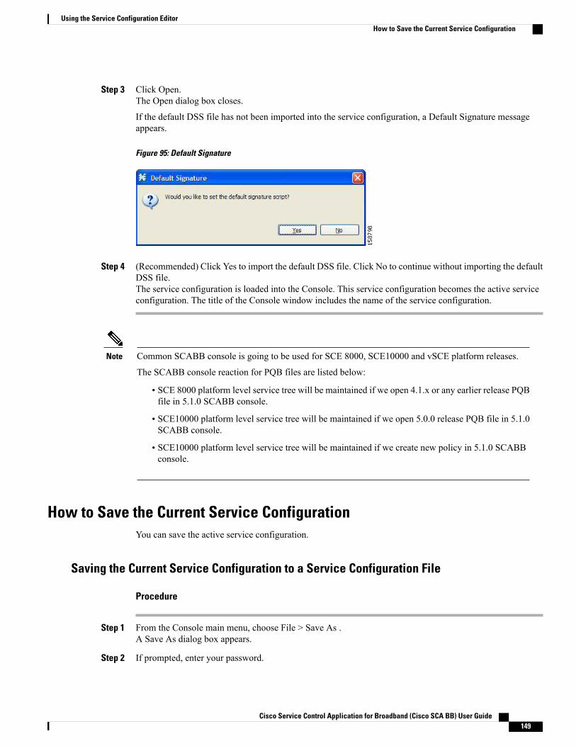
Step 3 Click Open.The Open dialog box closes.
If the default DSS file has not been imported into the service configuration, a Default Signature messageappears.
Figure 95: Default Signature
Step 4 (Recommended) Click Yes to import the default DSS file. Click No to continue without importing the defaultDSS file.The service configuration is loaded into the Console. This service configuration becomes the active serviceconfiguration. The title of the Console window includes the name of the service configuration.
Common SCABB console is going to be used for SCE 8000, SCE10000 and vSCE platform releases.
The SCABB console reaction for PQB files are listed below:
Note
• SCE 8000 platform level service tree will be maintained if we open 4.1.x or any earlier release PQBfile in 5.1.0 SCABB console.
• SCE10000 platform level service tree will be maintained if we open 5.0.0 release PQB file in 5.1.0SCABB console.
• SCE10000 platform level service tree will be maintained if we create new policy in 5.1.0 SCABBconsole.
How to Save the Current Service ConfigurationYou can save the active service configuration.
Saving the Current Service Configuration to a Service Configuration File
Procedure
Step 1 From the Console main menu, choose File > Save As .A Save As dialog box appears.
Step 2 If prompted, enter your password.
Cisco Service Control Application for Broadband (Cisco SCA BB) User Guide 149
Using the Service Configuration EditorHow to Save the Current Service Configuration
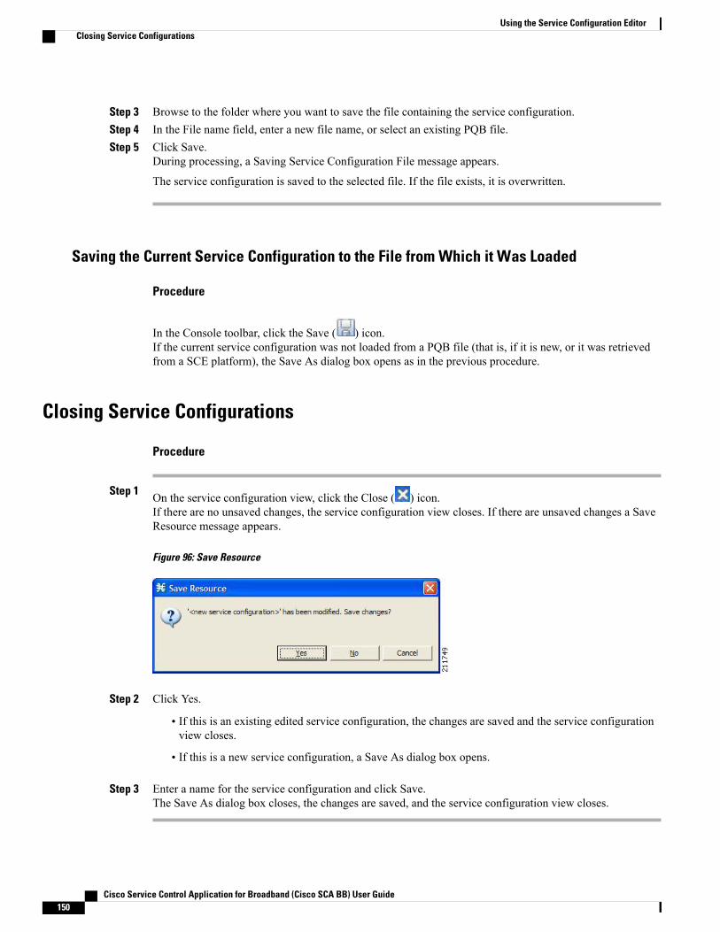
Step 3 Browse to the folder where you want to save the file containing the service configuration.Step 4 In the File name field, enter a new file name, or select an existing PQB file.Step 5 Click Save.
During processing, a Saving Service Configuration File message appears.
The service configuration is saved to the selected file. If the file exists, it is overwritten.
Saving the Current Service Configuration to the File from Which it Was Loaded
Procedure
In the Console toolbar, click the Save ( ) icon.If the current service configuration was not loaded from a PQB file (that is, if it is new, or it was retrievedfrom a SCE platform), the Save As dialog box opens as in the previous procedure.
Closing Service Configurations
Procedure
Step 1 On the service configuration view, click the Close ( ) icon.If there are no unsaved changes, the service configuration view closes. If there are unsaved changes a SaveResource message appears.
Figure 96: Save Resource
Step 2 Click Yes.
• If this is an existing edited service configuration, the changes are saved and the service configurationview closes.
• If this is a new service configuration, a Save As dialog box opens.
Step 3 Enter a name for the service configuration and click Save.The Save As dialog box closes, the changes are saved, and the service configuration view closes.
Cisco Service Control Application for Broadband (Cisco SCA BB) User Guide150
Using the Service Configuration EditorClosing Service Configurations

Exporting Service Configuration DataYou can export service configuration data from the current service configuration to CSV files. The CSV fileformats are described in the “CSV File Formats” chapter of Cisco Service Control Application Suit forBroadband Reference Guide.
Each type of service configuration element is exported to a separate file.
Procedure
Step 1 From the Console main menu, choose File > Export.The Export dialog box appears.
Figure 97: Export
Step 2 From the export destination list, select Export service configuration parts to CSV file .Step 3 Click Next.
Cisco Service Control Application for Broadband (Cisco SCA BB) User Guide 151
Using the Service Configuration EditorExporting Service Configuration Data
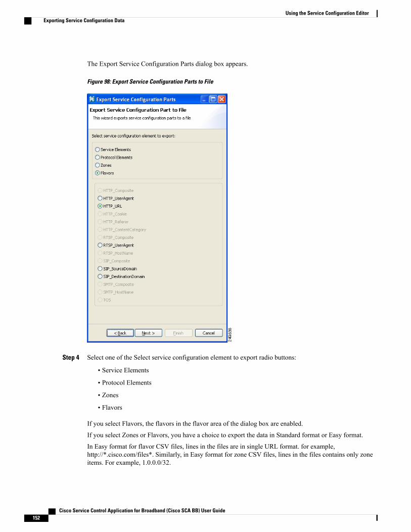
The Export Service Configuration Parts dialog box appears.
Figure 98: Export Service Configuration Parts to File
Step 4 Select one of the Select service configuration element to export radio buttons:
• Service Elements
• Protocol Elements
• Zones
• Flavors
If you select Flavors, the flavors in the flavor area of the dialog box are enabled.
If you select Zones or Flavors, you have a choice to export the data in Standard format or Easy format.
In Easy format for flavor CSV files, lines in the files are in single URL format. for example,http://*.cisco.com/files*. Similarly, in Easy format for zone CSV files, lines in the files contains only zoneitems. For example, 1.0.0.0/32.
Cisco Service Control Application for Broadband (Cisco SCA BB) User Guide152
Using the Service Configuration EditorExporting Service Configuration Data
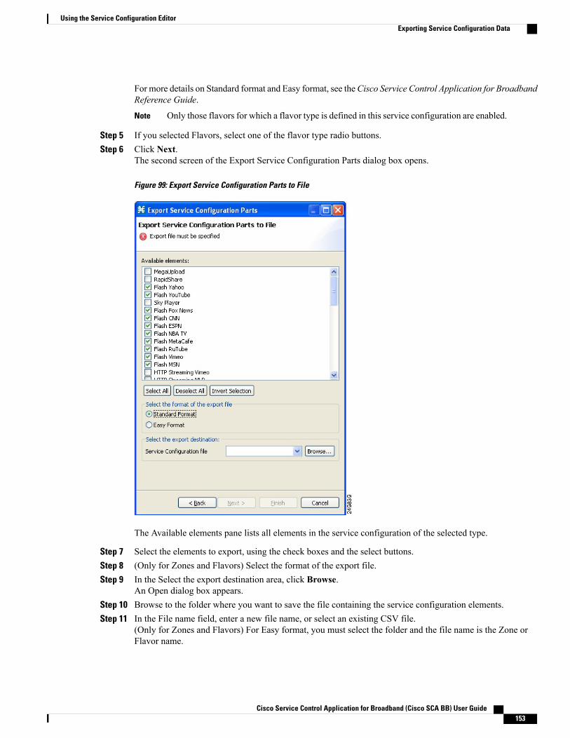
For more details on Standard format and Easy format, see theCisco Service Control Application for BroadbandReference Guide.
Only those flavors for which a flavor type is defined in this service configuration are enabled.Note
Step 5 If you selected Flavors, select one of the flavor type radio buttons.Step 6 Click Next.
The second screen of the Export Service Configuration Parts dialog box opens.
Figure 99: Export Service Configuration Parts to File
The Available elements pane lists all elements in the service configuration of the selected type.
Step 7 Select the elements to export, using the check boxes and the select buttons.Step 8 (Only for Zones and Flavors) Select the format of the export file.Step 9 In the Select the export destination area, click Browse.
An Open dialog box appears.Step 10 Browse to the folder where you want to save the file containing the service configuration elements.Step 11 In the File name field, enter a new file name, or select an existing CSV file.
(Only for Zones and Flavors) For Easy format, you must select the folder and the file name is the Zone orFlavor name.
Cisco Service Control Application for Broadband (Cisco SCA BB) User Guide 153
Using the Service Configuration EditorExporting Service Configuration Data
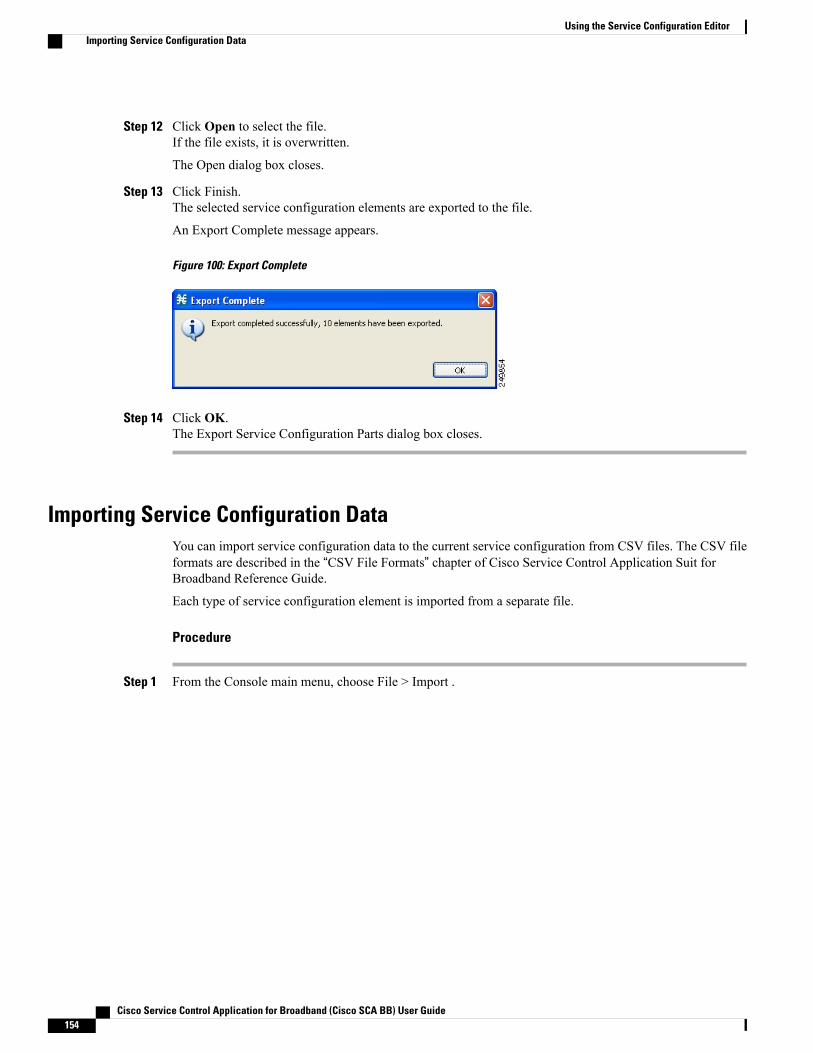
Step 12 Click Open to select the file.If the file exists, it is overwritten.
The Open dialog box closes.
Step 13 Click Finish.The selected service configuration elements are exported to the file.
An Export Complete message appears.
Figure 100: Export Complete
Step 14 Click OK.The Export Service Configuration Parts dialog box closes.
Importing Service Configuration DataYou can import service configuration data to the current service configuration from CSV files. The CSV fileformats are described in the “CSV File Formats” chapter of Cisco Service Control Application Suit forBroadband Reference Guide.
Each type of service configuration element is imported from a separate file.
Procedure
Step 1 From the Console main menu, choose File > Import .
Cisco Service Control Application for Broadband (Cisco SCA BB) User Guide154
Using the Service Configuration EditorImporting Service Configuration Data

The Import dialog box appears.
Figure 101: Import
Step 2 From the Select an import source list, select Import service configuration parts from CSV file .Step 3 Click Next.
Cisco Service Control Application for Broadband (Cisco SCA BB) User Guide 155
Using the Service Configuration EditorImporting Service Configuration Data
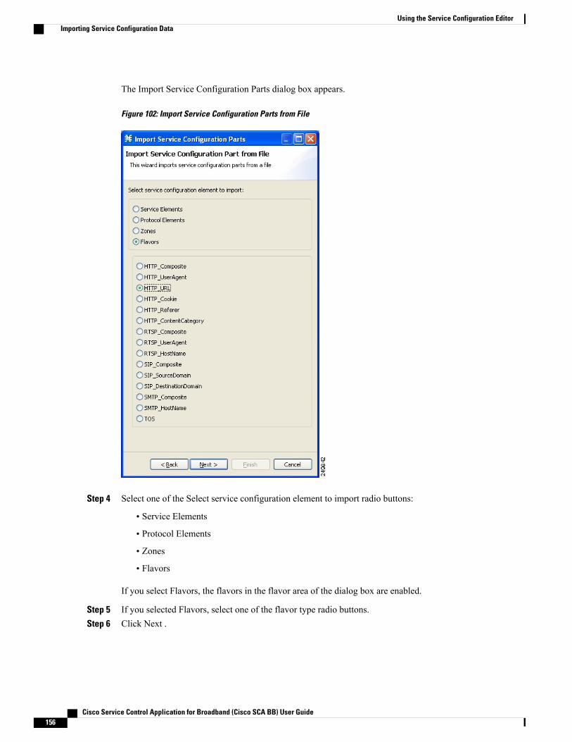
The Import Service Configuration Parts dialog box appears.
Figure 102: Import Service Configuration Parts from File
Step 4 Select one of the Select service configuration element to import radio buttons:
• Service Elements
• Protocol Elements
• Zones
• Flavors
If you select Flavors, the flavors in the flavor area of the dialog box are enabled.
Step 5 If you selected Flavors, select one of the flavor type radio buttons.Step 6 Click Next .
Cisco Service Control Application for Broadband (Cisco SCA BB) User Guide156
Using the Service Configuration EditorImporting Service Configuration Data
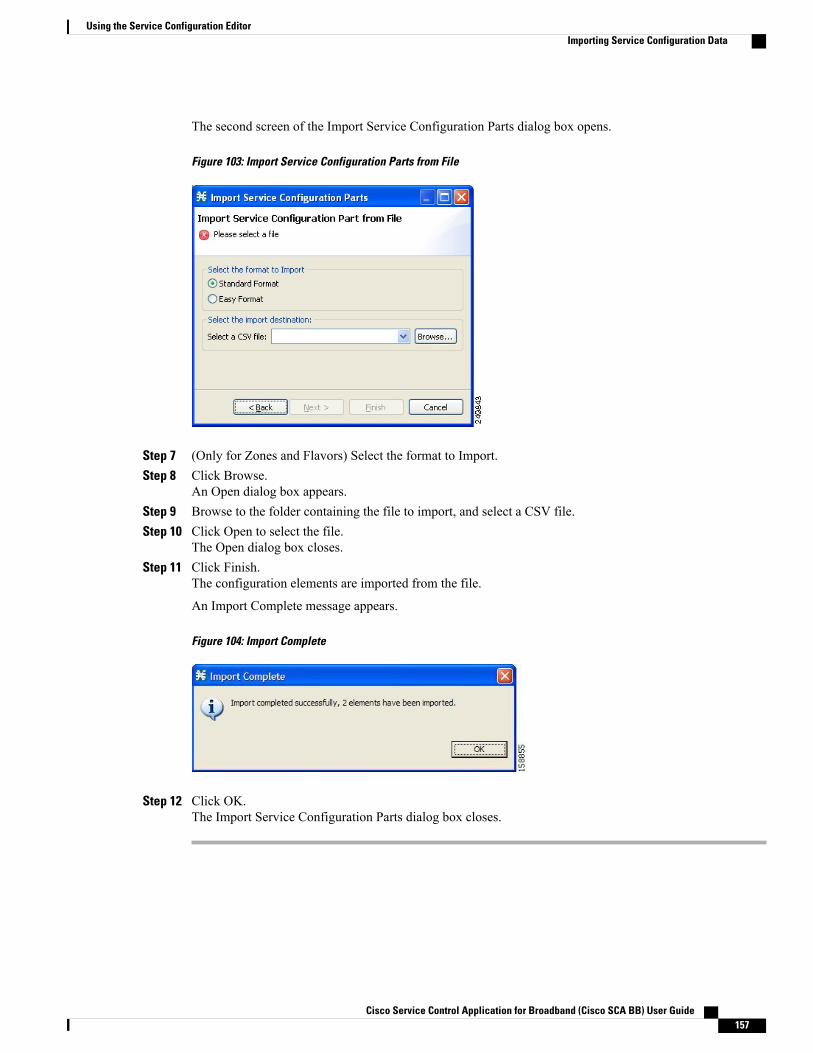
The second screen of the Import Service Configuration Parts dialog box opens.
Figure 103: Import Service Configuration Parts from File
Step 7 (Only for Zones and Flavors) Select the format to Import.Step 8 Click Browse.
An Open dialog box appears.Step 9 Browse to the folder containing the file to import, and select a CSV file.Step 10 Click Open to select the file.
The Open dialog box closes.Step 11 Click Finish.
The configuration elements are imported from the file.
An Import Complete message appears.
Figure 104: Import Complete
Step 12 Click OK.The Import Service Configuration Parts dialog box closes.
Cisco Service Control Application for Broadband (Cisco SCA BB) User Guide 157
Using the Service Configuration EditorImporting Service Configuration Data

How to Apply and Retrieve Service ConfigurationsFor a new or edited service configuration to take effect, you must apply it to the Cisco SCE platform. Untilyou do, the Cisco SCE platform continues to enforce the previous service configuration.
You can use the Service Configuration Editor to apply a service configuration to a Cisco SCE platform, butnot to retrieve a service configuration.
You can apply or retrieve a service configuration using:
• The Network Navigator Tool , on page 107
• servconf, the Cisco SCA BB Service Configuration Utility (see The Cisco SCA BB ServiceConfiguration Utility , on page 529)
Validating the Current Service ConfigurationUse the Validate option to validate the new or updated service configuration currently displayed. The validationprocess checks for overall service configuration coherence, and points out possible pitfalls in the serviceconfiguration.
The Validate process runs automatically when you select Apply Service Configuration to SCE devices. TheValidation Results dialog box appears only if the procedure found errors or issued warnings about the currentservice configuration.
Procedure
Step 1 From the Console main menu, choose File > Validate .The Validation Results dialog box appears.
Figure 105: Validation Results - Service Configuration is valid
Figure 106: Validation Results - Service Configuration has errors
Cisco Service Control Application for Broadband (Cisco SCA BB) User Guide158
Using the Service Configuration EditorHow to Apply and Retrieve Service Configurations
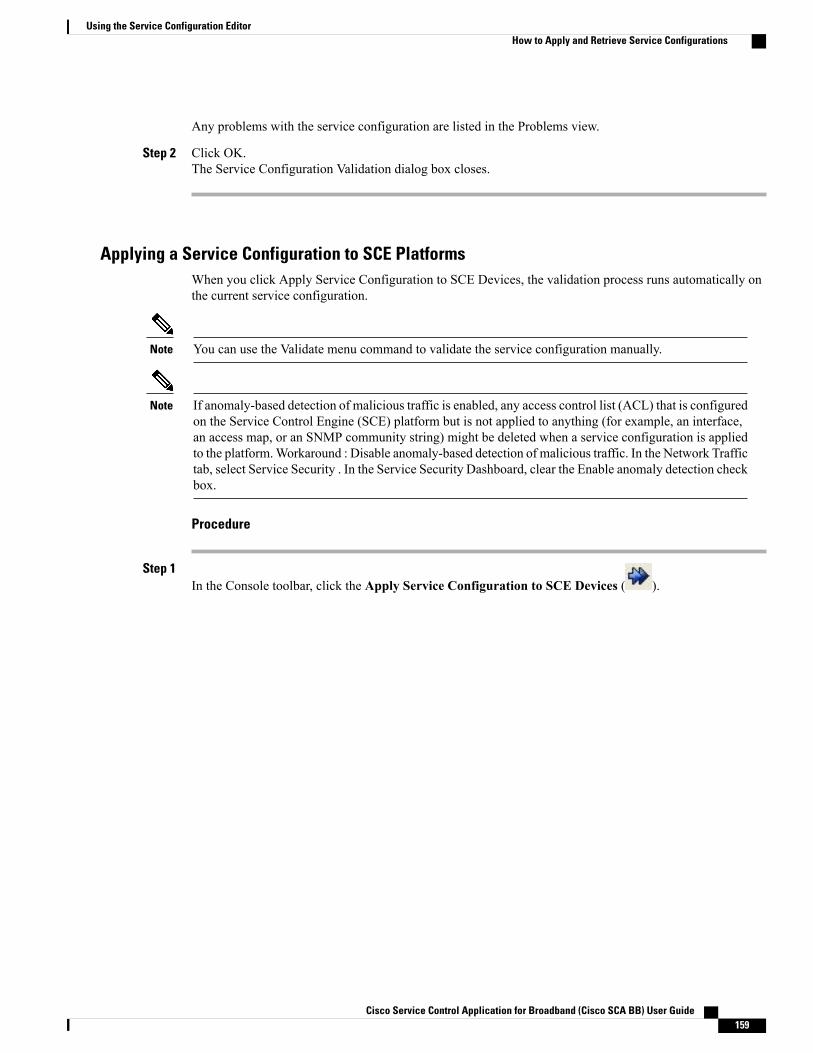
Any problems with the service configuration are listed in the Problems view.
Step 2 Click OK.The Service Configuration Validation dialog box closes.
Applying a Service Configuration to SCE PlatformsWhen you click Apply Service Configuration to SCE Devices, the validation process runs automatically onthe current service configuration.
You can use the Validate menu command to validate the service configuration manually.Note
If anomaly-based detection of malicious traffic is enabled, any access control list (ACL) that is configuredon the Service Control Engine (SCE) platform but is not applied to anything (for example, an interface,an access map, or an SNMP community string) might be deleted when a service configuration is appliedto the platform.Workaround : Disable anomaly-based detection of malicious traffic. In the Network Traffictab, select Service Security . In the Service Security Dashboard, clear the Enable anomaly detection checkbox.
Note
Procedure
Step 1In the Console toolbar, click the Apply Service Configuration to SCE Devices ( ).
Cisco Service Control Application for Broadband (Cisco SCA BB) User Guide 159
Using the Service Configuration EditorHow to Apply and Retrieve Service Configurations
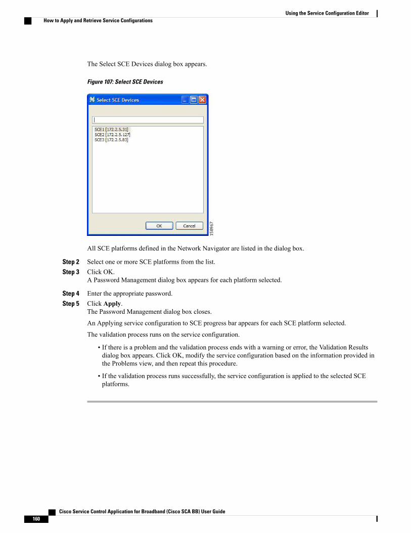
The Select SCE Devices dialog box appears.
Figure 107: Select SCE Devices
All SCE platforms defined in the Network Navigator are listed in the dialog box.
Step 2 Select one or more SCE platforms from the list.Step 3 Click OK.
A Password Management dialog box appears for each platform selected.
Step 4 Enter the appropriate password.Step 5 Click Apply.
The Password Management dialog box closes.
An Applying service configuration to SCE progress bar appears for each SCE platform selected.
The validation process runs on the service configuration.
• If there is a problem and the validation process ends with a warning or error, the Validation Resultsdialog box appears. Click OK, modify the service configuration based on the information provided inthe Problems view, and then repeat this procedure.
• If the validation process runs successfully, the service configuration is applied to the selected SCEplatforms.
Cisco Service Control Application for Broadband (Cisco SCA BB) User Guide160
Using the Service Configuration EditorHow to Apply and Retrieve Service Configurations
C H A P T E R 7Traffic Classification Using Service ConfigurationEditor
Traffic classification is the first step in creating a Cisco SCA BB service configuration. Traffic is classifiedaccording to services.
For each commercial service that providers offer to their subscribers, a corresponding service is defined inthe Cisco Service Control solution. You can use this service to classify and identify the traffic, report on itsusage, and control it.
This module explains how to work with services and their elements and subelements:
• Searching Traffic Classification Settings, page 161
• Introduction to Managing Services , page 162
• Introduction to Managing Protocols , page 181
• Introduction to Managing Zones, page 193
• Introduction to Managing Protocol Signatures , page 204
• Introduction to Managing Flavors , page 217
• Introduction to Managing Content Filtering, page 237
• OS Fingerprinting Overview, page 252
• Configuring Policy for DNS Assisted Classification, page 256
Searching Traffic Classification SettingsYou can search for any classification detail by name or numeric ID, such as services, protocols, port number,or counter assignments. You can also search for protocols or signatures that are not assigned to a service.
Procedure
Step 1In the Classification tab, click the Search Classification Settings ( ) icon.
Cisco Service Control Application for Broadband (Cisco SCA BB) User Guide 161
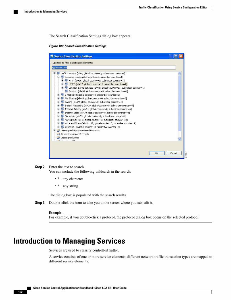
The Search Classification Settings dialog box appears.
Figure 108: Search Classification Settings
Step 2 Enter the text to search.You can include the following wildcards in the search:
• ?—any character
• *—any string
The dialog box is populated with the search results.
Step 3 Double-click the item to take you to the screen where you can edit it.
Example:For example, if you double-click a protocol, the protocol dialog box opens on the selected protocol.
Introduction to Managing ServicesServices are used to classify controlled traffic.
A service consists of one or more service elements; different network traffic transaction types are mapped todifferent service elements.
Cisco Service Control Application for Broadband (Cisco SCA BB) User Guide162
Traffic Classification Using Service Configuration EditorIntroduction to Managing Services

Traffic is classified based on some or all of the following:
• Protocol—The protocol used by the transaction, as identified by the Cisco Service Control Engine (CiscoSCE) platform
• Initiating side—Where the transaction was initiated
• Zone—IP address of the network-side host of the transaction
• Flavor—Specific Layer 7 properties of the transaction; for example, host names of the network-sidehost of the transaction
A service configuration can contain up to 500 services and 10,000 service elements. Every service elementin a service configuration must be unique.
Service ParametersA service is defined by the following parameters:
• General parameters:
◦Name—A unique name
◦Description—(Optional) A description of the service
• Hierarchy parameters:
◦Parent ServiceThe default service, which is the base of the service hierarchy, does not have a parent.
The parent service is important when services share usage counters (see next parameter).Note
◦Service Usage Counters—Used by the system to generate data about the total use of each service.A service can use either its own usage counters, or those of the parent service.Each usage counter has:
◦A name assigned by the system (based on the service name).
An asterisk is appended to a service usage counter name whenever the counter appliesto more than one service.
Note
◦A unique counter index—A default value of the counter index provided by the system. Donot modify this value.
• Advanced parameter:
◦Service Index—A unique number by which the system recognizes the service (changing the servicename does not affect Cisco SCE platform activity). The system provides a default value of theservice index. Do not modify this value.
Cisco Service Control Application for Broadband (Cisco SCA BB) User Guide 163
Traffic Classification Using Service Configuration EditorService Parameters
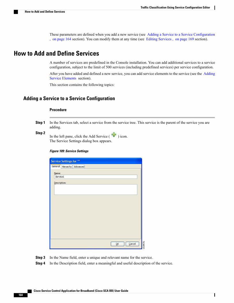
These parameters are defined when you add a new service (see Adding a Service to a Service Configuration, on page 164 section). You can modify them at any time (see Editing Services , on page 169 section).
How to Add and Define ServicesA number of services are predefined in the Console installation. You can add additional services to a serviceconfiguration, subject to the limit of 500 services (including predefined services) per service configuration.
After you have added and defined a new service, you can add service elements to the service (see the AddingService Elements section).
This section contains the following topics:
Adding a Service to a Service Configuration
Procedure
Step 1 In the Services tab, select a service from the service tree. This service is the parent of the service you areadding.
Step 2In the left pane, click the Add Service ( ) icon.The Service Settings dialog box appears.
Figure 109: Service Settings
Step 3 In the Name field, enter a unique and relevant name for the service.Step 4 In the Description field, enter a meaningful and useful description of the service.
Cisco Service Control Application for Broadband (Cisco SCA BB) User Guide164
Traffic Classification Using Service Configuration EditorHow to Add and Define Services
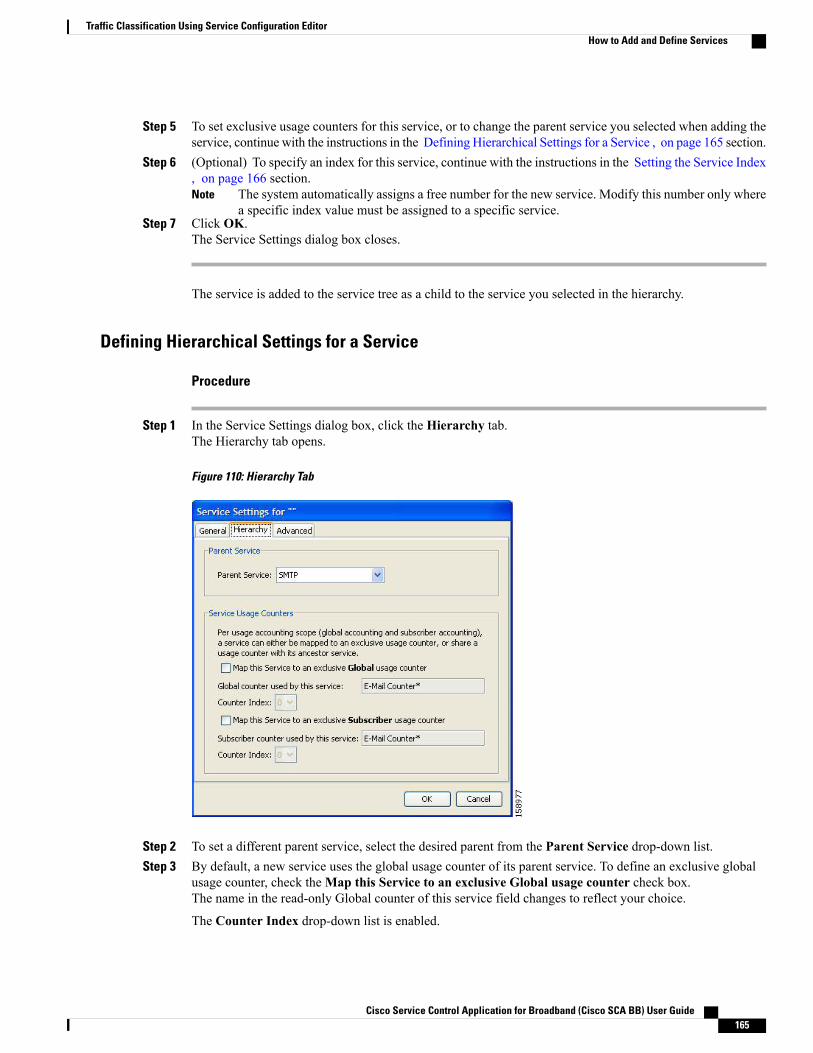
Step 5 To set exclusive usage counters for this service, or to change the parent service you selected when adding theservice, continue with the instructions in the Defining Hierarchical Settings for a Service , on page 165 section.
Step 6 (Optional) To specify an index for this service, continue with the instructions in the Setting the Service Index, on page 166 section.
The system automatically assigns a free number for the new service. Modify this number only wherea specific index value must be assigned to a specific service.
Note
Step 7 Click OK.The Service Settings dialog box closes.
The service is added to the service tree as a child to the service you selected in the hierarchy.
Defining Hierarchical Settings for a Service
Procedure
Step 1 In the Service Settings dialog box, click the Hierarchy tab.The Hierarchy tab opens.
Figure 110: Hierarchy Tab
Step 2 To set a different parent service, select the desired parent from the Parent Service drop-down list.Step 3 By default, a new service uses the global usage counter of its parent service. To define an exclusive global
usage counter, check theMap this Service to an exclusive Global usage counter check box.The name in the read-only Global counter of this service field changes to reflect your choice.
The Counter Index drop-down list is enabled.
Cisco Service Control Application for Broadband (Cisco SCA BB) User Guide 165
Traffic Classification Using Service Configuration EditorHow to Add and Define Services
(Optional) Select a value for the counter index from the Counter Index drop-down list. You can select upto192 counter index values.
The system provides a default value of the counter index. Do not modify this value.Note
Step 4 By default, a new service uses the subscriber usage counter of its parent service. To define an exclusivesubscriber usage counter, check theMap this Service to an exclusive Subscriber usage counter check box.The name in the read-only Subscriber counter of this service field changes to reflect your choice.
The Counter Index drop-down list is enabled.
(Optional) Select a value for the counter index from the Counter Index drop-down list. You can select upto48 counter index values.
The system provides a default value of the counter index. Do not modify this value.Note
Step 5 To specify an index for this service, continue with the instructions in the Setting the Service Index , on page166 section.
The system automatically assigns a free number for the new service. Modify this number only wherea specific index value must be assigned to a specific service.
Note
Step 6 Click OK.The Service Settings dialog box closes.
The service is added to the service tree as a child to the service selected in the Parent Service drop-down list.
Setting the Service Index
Procedure
Step 1 In the Service Settings dialog box, click the Advanced tab.
Cisco Service Control Application for Broadband (Cisco SCA BB) User Guide166
Traffic Classification Using Service Configuration EditorHow to Add and Define Services
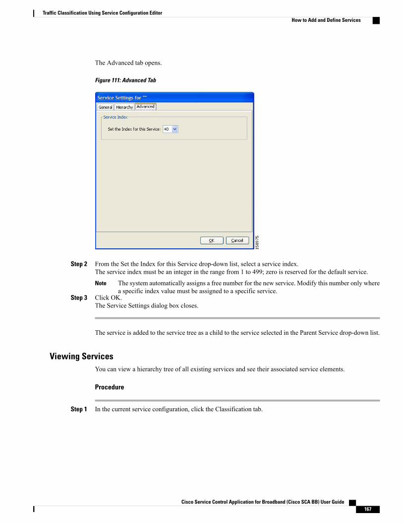
The Advanced tab opens.
Figure 111: Advanced Tab
Step 2 From the Set the Index for this Service drop-down list, select a service index.The service index must be an integer in the range from 1 to 499; zero is reserved for the default service.
The system automatically assigns a free number for the new service. Modify this number only wherea specific index value must be assigned to a specific service.
Note
Step 3 Click OK.The Service Settings dialog box closes.
The service is added to the service tree as a child to the service selected in the Parent Service drop-down list.
Viewing ServicesYou can view a hierarchy tree of all existing services and see their associated service elements.
Procedure
Step 1 In the current service configuration, click the Classification tab.
Cisco Service Control Application for Broadband (Cisco SCA BB) User Guide 167
Traffic Classification Using Service Configuration EditorHow to Add and Define Services

The Classification tab appears.
Figure 112: Classification Tab
A list of all services is displayed in the service tree (left pane).
Step 2 Click a service in the hierarchy to display its service elements.
Cisco Service Control Application for Broadband (Cisco SCA BB) User Guide168
Traffic Classification Using Service Configuration EditorHow to Add and Define Services

A list of all service elements defined for this service is displayed in the right (Service Elements) pane.
Figure 113: Service Elements
Step 3 To view more information about a service, select a service from the service tree and click the Edit Service
( ) icon.The Service Settings dialog box appears.
Step 4 Click OK.The Service Settings dialog box closes.
Editing ServicesYou can modify the parameters of a service, even those parameters included in the Console installation.
To add, modify, or delete service elements, see Introduction to Managing Service Elements , on page 171section.
Procedure
Step 1 In the Services tab, select a service from the service tree.Step 2
In the left pane, click the Edit Service ( ) icon.The Service Settings dialog box appears.
Step 3 (Optional) Give a new name to the service.Enter a new name in the Name field.
Step 4 (Optional) Give a new description for the service.
Cisco Service Control Application for Broadband (Cisco SCA BB) User Guide 169
Traffic Classification Using Service Configuration EditorEditing Services
Enter a new description in the Description field.
Step 5 To change hierarchical settings, click the Hierarchy tab.The Hierarchy tab opens.
Step 6 To set a different parent service, select the desired service from the Parent Service drop-down list.Step 7 To share a global usage counter with the parent service, uncheck the Map this Service to an exclusive Global
usage counter check box.The name of the parent service’s counter is displayed in the Global counter used by this service field.
Step 8 To define an exclusive global usage counter, check theMap this Service to an exclusive Global usagecounter check box.The name in the read-only Global counter of this service field changes to reflect your choice.
The Counter Index drop-down list is enabled.
The system provides a default value of the counter index. Do not modify this value.Note
Step 9 To share a subscriber usage counter with the parent service, uncheck theMap this Service to an exclusiveSubscriber usage counter check box.The name of the parent service’s counter is displayed in the Subscriber counter used by this service field.
Step 10 To define an exclusive subscriber usage counter, check the Map this Service to an exclusive Subscriber usagecounter check box.The name in the read-only Subscriber counter of this service field changes to reflect your choice.
The Counter Index drop-down list is enabled.
The system provides a default value of the counter index. Do not modify this value.Note
Step 11 Change the service index. To change the service index:a) In the Service Settings dialog box, click the Advanced tab.b) The Advanced tab opens.
Step 12 From the Set the Index for this Service drop-down list, select a service index.The service index must an integer in the range from 1 to 499; zero is reserved for the default service.
The system provides a default value of the service index. Do not modify this value.Note
Step 13 Click OK .The Service Settings dialog box closes.
The changes to the service are saved.
Deleting ServicesYou can delete all services, even those services in the Console installation, except for the default service.
Procedure
Step 1 In the Services tab, select a service from the service tree.
Cisco Service Control Application for Broadband (Cisco SCA BB) User Guide170
Traffic Classification Using Service Configuration EditorDeleting Services
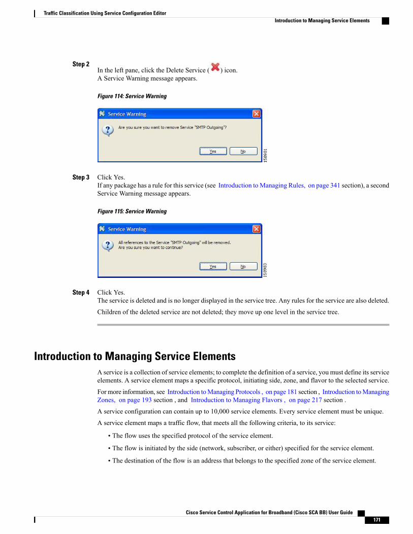
Step 2In the left pane, click the Delete Service ( ) icon.A Service Warning message appears.
Figure 114: Service Warning
Step 3 Click Yes.If any package has a rule for this service (see Introduction toManaging Rules, on page 341 section), a secondService Warning message appears.
Figure 115: Service Warning
Step 4 Click Yes.The service is deleted and is no longer displayed in the service tree. Any rules for the service are also deleted.
Children of the deleted service are not deleted; they move up one level in the service tree.
Introduction to Managing Service ElementsA service is a collection of service elements; to complete the definition of a service, you must define its serviceelements. A service element maps a specific protocol, initiating side, zone, and flavor to the selected service.
For more information, see Introduction toManaging Protocols , on page 181 section , Introduction toManagingZones, on page 193 section , and Introduction to Managing Flavors , on page 217 section .
A service configuration can contain up to 10,000 service elements. Every service element must be unique.
A service element maps a traffic flow, that meets all the following criteria, to its service:
• The flow uses the specified protocol of the service element.
• The flow is initiated by the side (network, subscriber, or either) specified for the service element.
• The destination of the flow is an address that belongs to the specified zone of the service element.
Cisco Service Control Application for Broadband (Cisco SCA BB) User Guide 171
Traffic Classification Using Service Configuration EditorIntroduction to Managing Service Elements

• The flow matches the specified flavor of the service element.
• The service element is the most specific service element satisfying the first four criteria.
Adding Service ElementsWhen necessary, you can add new service elements to a service. (The most useful service elements are includedin the Console installation.) A service may have any number of service elements (subject to the limit of 10,000service elements per service configuration).
Every service element must be unique. If, at any stage, the new service element is the same as an existingone, an error message is displayed in the dialog box, and the Finish button is dimmed. To proceed, modifythe value in at least one field.
Note
Procedure
Step 1 In the Services tab, select a service from the service tree.Step 2
In the right (Service Elements) pane, click the Add Service Element ( ).The New Service Element dialog box appears.
Figure 116: New Service Element
Step 3 To change the service to which this service element is assigned, click the Select button next to the Servicefield.
Cisco Service Control Application for Broadband (Cisco SCA BB) User Guide172
Traffic Classification Using Service Configuration EditorIntroduction to Managing Service Elements

The Select a Service dialog box appears, displaying a list of all services.
Figure 117: Select a Service
Step 4 Select a service from the list.Step 5 Click OK.
The Select a Service dialog box closes.
The selected service is displayed in the Service field of the New Service Element dialog box.
Step 6 Click the Select button next to the Protocol field.The default value (an asterisk, *) means that no protocol checking is performed when testing whethera flow maps to this service element.
Note
The Select a Protocol dialog box appears, displaying a list of all protocols.
Cisco Service Control Application for Broadband (Cisco SCA BB) User Guide 173
Traffic Classification Using Service Configuration EditorIntroduction to Managing Service Elements
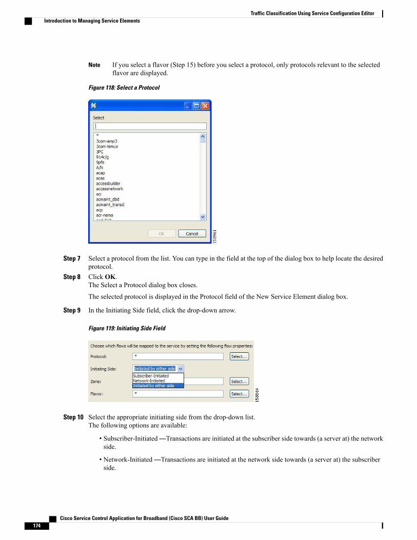
If you select a flavor (Step 15) before you select a protocol, only protocols relevant to the selectedflavor are displayed.
Note
Figure 118: Select a Protocol
Step 7 Select a protocol from the list. You can type in the field at the top of the dialog box to help locate the desiredprotocol.
Step 8 Click OK.The Select a Protocol dialog box closes.
The selected protocol is displayed in the Protocol field of the New Service Element dialog box.
Step 9 In the Initiating Side field, click the drop-down arrow.
Figure 119: Initiating Side Field
Step 10 Select the appropriate initiating side from the drop-down list.The following options are available:
• Subscriber-Initiated—Transactions are initiated at the subscriber side towards (a server at) the networkside.
• Network-Initiated—Transactions are initiated at the network side towards (a server at) the subscriberside.
Cisco Service Control Application for Broadband (Cisco SCA BB) User Guide174
Traffic Classification Using Service Configuration EditorIntroduction to Managing Service Elements
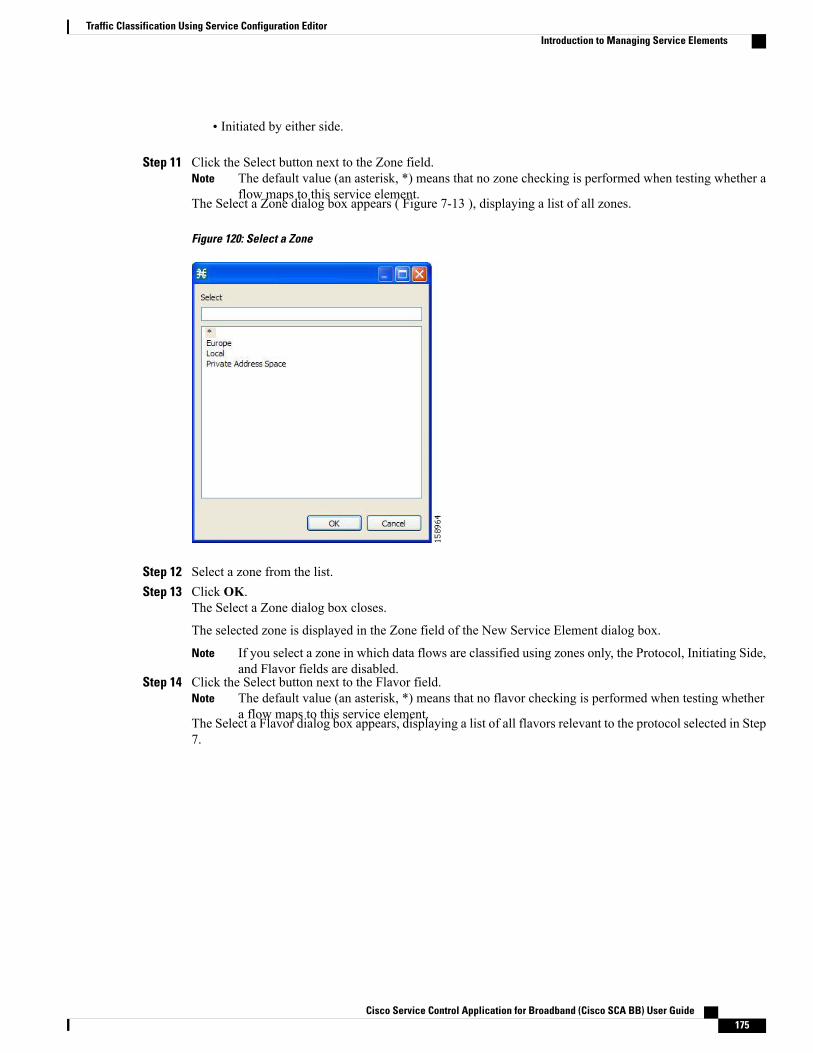
• Initiated by either side.
Step 11 Click the Select button next to the Zone field.The default value (an asterisk, *) means that no zone checking is performed when testing whether aflow maps to this service element.
Note
The Select a Zone dialog box appears ( Figure 7-13 ), displaying a list of all zones.
Figure 120: Select a Zone
Step 12 Select a zone from the list.Step 13 Click OK.
The Select a Zone dialog box closes.
The selected zone is displayed in the Zone field of the New Service Element dialog box.
If you select a zone in which data flows are classified using zones only, the Protocol, Initiating Side,and Flavor fields are disabled.
Note
Step 14 Click the Select button next to the Flavor field.The default value (an asterisk, *) means that no flavor checking is performed when testing whethera flow maps to this service element.
Note
The Select a Flavor dialog box appears, displaying a list of all flavors relevant to the protocol selected in Step7.
Cisco Service Control Application for Broadband (Cisco SCA BB) User Guide 175
Traffic Classification Using Service Configuration EditorIntroduction to Managing Service Elements
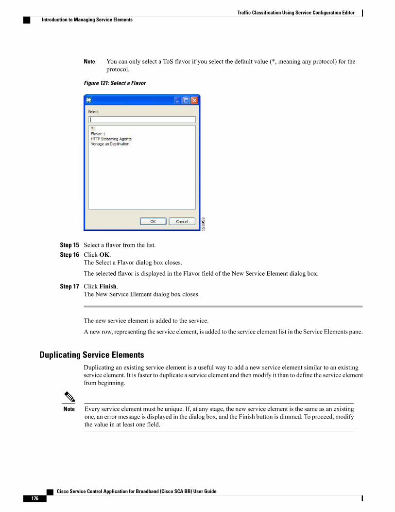
You can only select a ToS flavor if you select the default value (*, meaning any protocol) for theprotocol.
Note
Figure 121: Select a Flavor
Step 15 Select a flavor from the list.Step 16 Click OK.
The Select a Flavor dialog box closes.
The selected flavor is displayed in the Flavor field of the New Service Element dialog box.
Step 17 Click Finish.The New Service Element dialog box closes.
The new service element is added to the service.
A new row, representing the service element, is added to the service element list in the Service Elements pane.
Duplicating Service ElementsDuplicating an existing service element is a useful way to add a new service element similar to an existingservice element. It is faster to duplicate a service element and then modify it than to define the service elementfrom beginning.
Every service element must be unique. If, at any stage, the new service element is the same as an existingone, an error message is displayed in the dialog box, and the Finish button is dimmed. To proceed, modifythe value in at least one field.
Note
Cisco Service Control Application for Broadband (Cisco SCA BB) User Guide176
Traffic Classification Using Service Configuration EditorIntroduction to Managing Service Elements
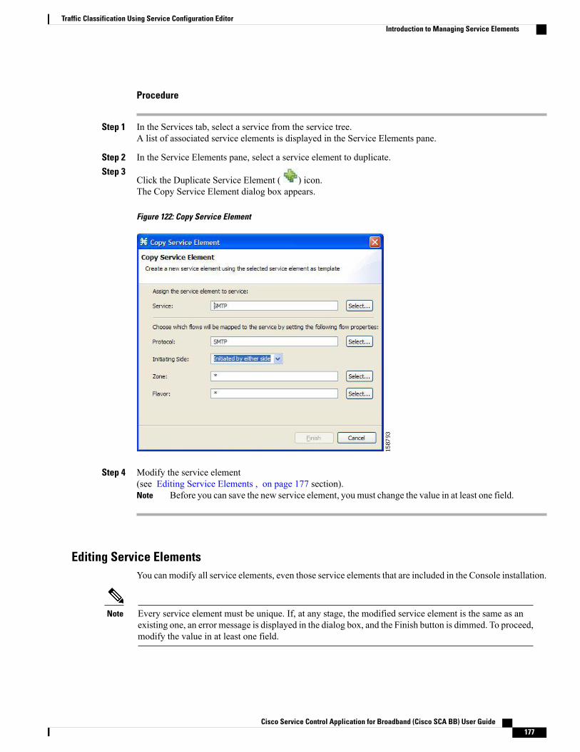
Procedure
Step 1 In the Services tab, select a service from the service tree.A list of associated service elements is displayed in the Service Elements pane.
Step 2 In the Service Elements pane, select a service element to duplicate.Step 3
Click the Duplicate Service Element ( ) icon.The Copy Service Element dialog box appears.
Figure 122: Copy Service Element
Step 4 Modify the service element(see Editing Service Elements , on page 177 section).
Before you can save the new service element, you must change the value in at least one field.Note
Editing Service ElementsYou can modify all service elements, even those service elements that are included in the Console installation.
Every service element must be unique. If, at any stage, the modified service element is the same as anexisting one, an error message is displayed in the dialog box, and the Finish button is dimmed. To proceed,modify the value in at least one field.
Note
Cisco Service Control Application for Broadband (Cisco SCA BB) User Guide 177
Traffic Classification Using Service Configuration EditorIntroduction to Managing Service Elements
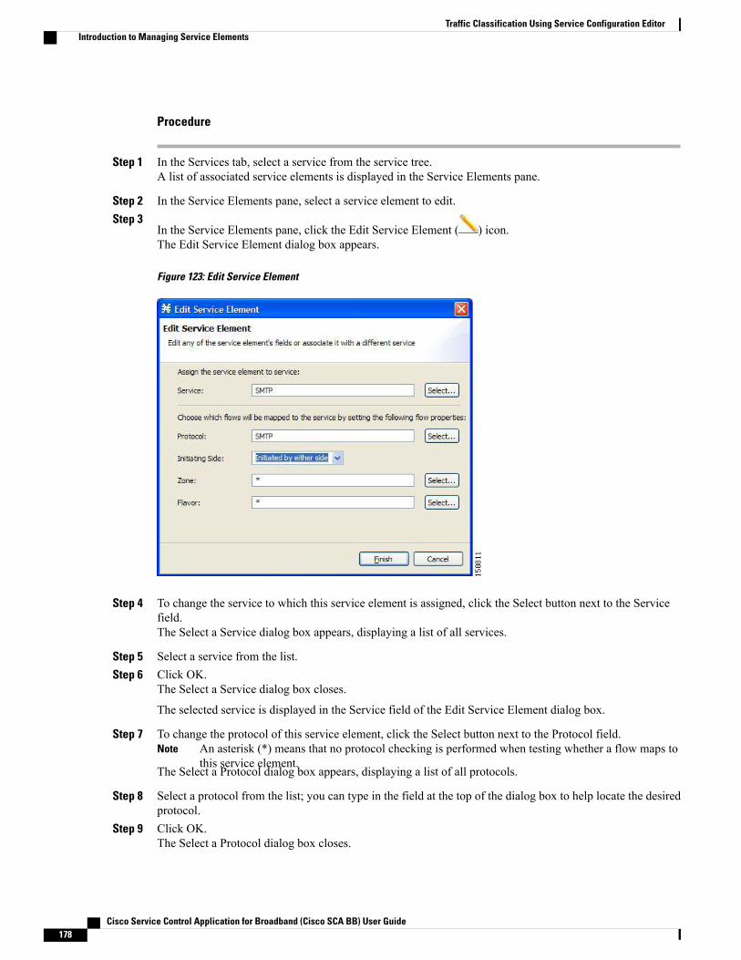
Procedure
Step 1 In the Services tab, select a service from the service tree.A list of associated service elements is displayed in the Service Elements pane.
Step 2 In the Service Elements pane, select a service element to edit.Step 3
In the Service Elements pane, click the Edit Service Element ( ) icon.The Edit Service Element dialog box appears.
Figure 123: Edit Service Element
Step 4 To change the service to which this service element is assigned, click the Select button next to the Servicefield.The Select a Service dialog box appears, displaying a list of all services.
Step 5 Select a service from the list.Step 6 Click OK.
The Select a Service dialog box closes.
The selected service is displayed in the Service field of the Edit Service Element dialog box.
Step 7 To change the protocol of this service element, click the Select button next to the Protocol field.An asterisk (*) means that no protocol checking is performed when testing whether a flow maps tothis service element.
Note
The Select a Protocol dialog box appears, displaying a list of all protocols.
Step 8 Select a protocol from the list; you can type in the field at the top of the dialog box to help locate the desiredprotocol.
Step 9 Click OK.The Select a Protocol dialog box closes.
Cisco Service Control Application for Broadband (Cisco SCA BB) User Guide178
Traffic Classification Using Service Configuration EditorIntroduction to Managing Service Elements
The selected protocol is displayed in the Protocol field of the Edit Service Element dialog box.
Step 10 To change the initiating side of this service element, click the drop-down arrow in the Initiating Side field.Step 11 Select the appropriate initiating side from the drop-down list.
• Subscriber-Initiated—Transactions are initiated at the subscriber side towards (a server at) the networkside.
• Network-Initiated—Transactions are initiated at the network side towards (a server at) the subscriberside.
• Initiated by either side
Step 12 To change the zone of this service element, click the Select button next to the Zone field.An asterisk (*) means that no zone checking is performed when testing whether a flow maps to thisservice element.
Note
The Select a Zone dialog box appears, displaying a list of all zones.
Step 13 Select a zone from the list.Step 14 Click OK.
The Select a Zone dialog box closes.
The selected zone is displayed in the Zone field of the Edit Service Element dialog box.
Step 15 To change the flavor of this service element, click the Select button next to the Flavor field.An asterisk (*) means that no flavor checking is performed when testing whether a flow maps to thisservice element.
Note
The Select a Flavor dialog box appears, displaying a list of all flavors.
Step 16 Select a flavor from the list.Step 17 Click OK.
The Select a Flavor dialog box closes.
The selected flavor is displayed in the Flavor field of the Edit Service Element dialog box.
Step 18 Click Finish.The Edit Service Element dialog box closes.
The changes to the service element are saved.
The changes to the service element appear in the service element list in the Service Elements pane.
Deleting a Service ElementYou can delete all service elements, even those service elements that are included in the Console installation.
Procedure
Step 1 In the Services tab, select a service from the service tree.A list of associated service elements is displayed in the Service Elements pane.
Step 2 In the Service Elements pane, select a service element to delete.
Cisco Service Control Application for Broadband (Cisco SCA BB) User Guide 179
Traffic Classification Using Service Configuration EditorIntroduction to Managing Service Elements
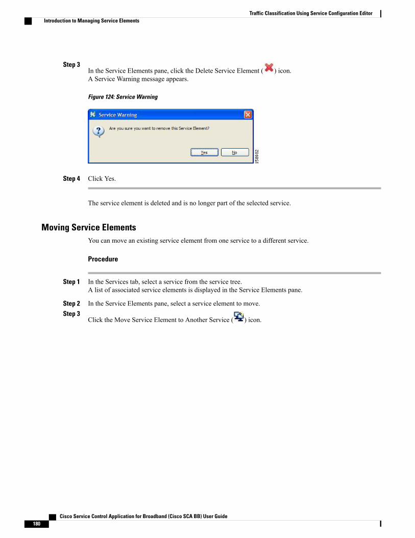
Step 3In the Service Elements pane, click the Delete Service Element ( ) icon.A Service Warning message appears.
Figure 124: Service Warning
Step 4 Click Yes.
The service element is deleted and is no longer part of the selected service.
Moving Service ElementsYou can move an existing service element from one service to a different service.
Procedure
Step 1 In the Services tab, select a service from the service tree.A list of associated service elements is displayed in the Service Elements pane.
Step 2 In the Service Elements pane, select a service element to move.Step 3
Click the Move Service Element to Another Service ( ) icon.
Cisco Service Control Application for Broadband (Cisco SCA BB) User Guide180
Traffic Classification Using Service Configuration EditorIntroduction to Managing Service Elements
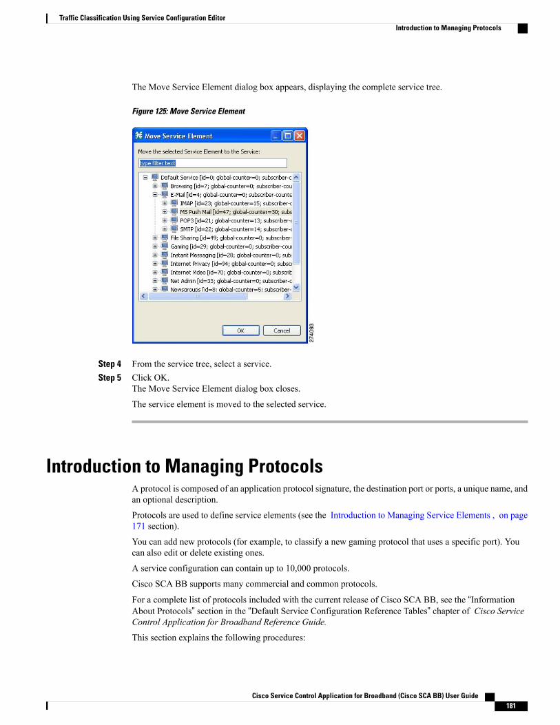
The Move Service Element dialog box appears, displaying the complete service tree.
Figure 125: Move Service Element
Step 4 From the service tree, select a service.Step 5 Click OK.
The Move Service Element dialog box closes.
The service element is moved to the selected service.
Introduction to Managing ProtocolsA protocol is composed of an application protocol signature, the destination port or ports, a unique name, andan optional description.
Protocols are used to define service elements (see the Introduction to Managing Service Elements , on page171 section).
You can add new protocols (for example, to classify a new gaming protocol that uses a specific port). Youcan also edit or delete existing ones.
A service configuration can contain up to 10,000 protocols.
Cisco SCA BB supports many commercial and common protocols.
For a complete list of protocols included with the current release of Cisco SCA BB, see the “InformationAbout Protocols” section in the “Default Service Configuration Reference Tables” chapter of Cisco ServiceControl Application for Broadband Reference Guide.
This section explains the following procedures:
Cisco Service Control Application for Broadband (Cisco SCA BB) User Guide 181
Traffic Classification Using Service Configuration EditorIntroduction to Managing Protocols
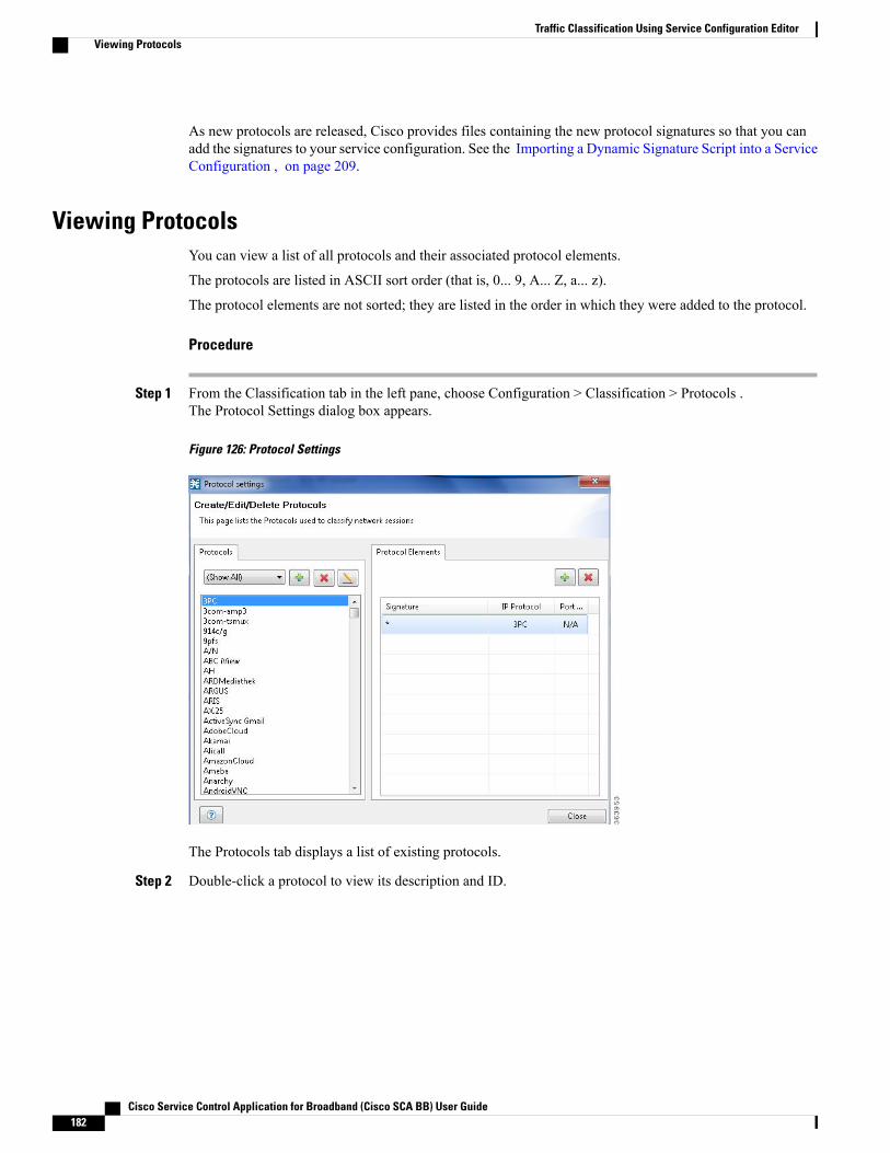
As new protocols are released, Cisco provides files containing the new protocol signatures so that you canadd the signatures to your service configuration. See the Importing a Dynamic Signature Script into a ServiceConfiguration , on page 209.
Viewing ProtocolsYou can view a list of all protocols and their associated protocol elements.
The protocols are listed in ASCII sort order (that is, 0... 9, A... Z, a... z).
The protocol elements are not sorted; they are listed in the order in which they were added to the protocol.
Procedure
Step 1 From the Classification tab in the left pane, choose Configuration > Classification > Protocols .The Protocol Settings dialog box appears.
Figure 126: Protocol Settings
The Protocols tab displays a list of existing protocols.
Step 2 Double-click a protocol to view its description and ID.
Cisco Service Control Application for Broadband (Cisco SCA BB) User Guide182
Traffic Classification Using Service Configuration EditorViewing Protocols

The Protocol Settings dialog box appears, displaying the protocol name, description, and ID.
Figure 127: Protocol Settings
Step 3 Click Cancel.The Protocol Settings dialog box closes.
Step 4 To view a list of protocol elements, select a protocol in the list in the Protocol Settings dialog box.Protocol elements are displayed in the Protocol Elements tab.
Step 5 Click Close .The Protocol Settings dialog box closes.
Filtering a Protocols ListYou can filter the protocols by type, so that the Protocols tab displays only the selected type of protocol.
The categories of protocols include:
• Generic Protocols—Generic IP, Generic TCP, and Generic UDP protocols, used for transactions thatare not specifically mapped to a protocol by any other protocol type.
• IP Protocols—Protocols (such as ICMP), other than TCP and UDP protocols, identified according tothe IP protocol number of the transaction.
• Port-Based Protocols—TCP and UDP protocols, classified according to their well-known ports. Thedefault service configuration includes more than 750 common port-based protocols.
• Signature-Based Protocols—Protocols classified according to a Layer 7 application signature. Includesthe most common protocols, such as HTTP and FTP, and a large group of popular P2P protocols.
• P2P Protocols—Peer-to-peer file-sharing application protocols, classified according to a Layer 7application signature.
• VoIP Protocols—Voice-over-IP application protocols, classified according to a Layer 7 applicationsignature.
Cisco Service Control Application for Broadband (Cisco SCA BB) User Guide 183
Traffic Classification Using Service Configuration EditorFiltering a Protocols List
• SIP Protocols—Protocols classified according to a Layer 7 application signature that is SIP or has SIPcharacteristics.
•Worm Protocols—Protocols classified according to a Layer 7 application signature that is based ontraffic patterns of internet worms.
• Packet Stream Pattern Based Protocols—Protocols classified according to a Layer 7 application signaturethat is based on the pattern of the packet stream (for example, the stream’s symmetry, average packetsize, and rate) rather than on the payload content of the packet.
• Unidirectionally Detected Protocols—Protocols having a unidirectional signature.
• Behavioral Protocols
• E-Mail and Newsgroup Protocols
• Gaming Protocols
• HTTP Protocols
• Instant Messaging Protocols
• Net Admin Protocols
• Video Protocols
• Tunneling Protocols
• ClickStream Protocols
Some protocols belong to more than one category. In particular, all predefined P2P, VoIP, SIP, Worm,and Packet Stream Pattern-Based Protocols are also defined as Signature-Based Protocols.
Note
Procedure
Step 1 From the Classification tab in the left pane, choose Configuration > Classification > Protocols .The Protocol Settings dialog box appears.
Step 2 From the drop-down list in the Protocols tab, select the type of protocol to display.The protocols of the selected type appear in the Protocols tab.
Step 3 Click Close.The Protocol Settings dialog box closes.
The setting in the drop-down list is not saved. The next time you open the Protocol Settings dialogbox, all protocols are displayed.
Note
Adding Protocols to a Service ConfigurationYou can add new protocols to a service configuration, subject to the limit of 10,000 protocols per serviceconfiguration.
Cisco Service Control Application for Broadband (Cisco SCA BB) User Guide184
Traffic Classification Using Service Configuration EditorAdding Protocols to a Service Configuration

Procedure
Step 1 From the Classification tab in the left pane, choose Configuration > Classification > Protocols .The Protocol Settings dialog box appears.
Step 2In the Protocols tab, click the Add Protocol ( ) icon.The Protocol Settings dialog box appears.
Figure 128: Protocol Settings
Step 3 In the Name field, enter a unique name for the new protocol.Step 4 (Optional) From the Protocol ID drop-down list, select an ID for the protocol.
The protocol ID must be an integer in the range from 5000 to 9998; lower values are reserved for protocolsprovided by Cisco SCA BB.
The system provides the value of the protocol ID. Do not modify this field.Note
Step 5 Click OK.The Protocol Settings dialog box closes.
The new protocol is displayed in the Protocols tab. You can now add protocol elements to it. See AddingProtocol Elements , on page 188 section.
Editing Parameters of a ProtocolYou can modify the parameters of a protocol, even those for those protocols that are included in the Consoleinstallation.
To add, modify, or delete protocol elements, see Introduction to Managing Protocol Elements , on page 187section.
Cisco Service Control Application for Broadband (Cisco SCA BB) User Guide 185
Traffic Classification Using Service Configuration EditorEditing Parameters of a Protocol

Procedure
Step 1 From the Classification tab in the left pane, choose Configuration > Classification > Protocols .The Protocol Settings dialog box appears.
Step 2 In the Protocols tab, double-click a protocol.A second Protocol Settings dialog box appears.
Figure 129: Protocol Settings
Step 3 Modify fields in the Protocol Settings dialog box.a) In the Name field, enter a new name for the protocol.b) From the Protocol ID drop-down list, select an ID for the protocol.
The protocol IDmust be an integer in the range from 5000 to 9998; lower values are reserved for protocolsprovided by Cisco SCA BB.
The system provides the protocol ID. Do not modify this field.Note
Step 4 Click OK.The Protocol Settings dialog box closes.
The new values of the protocol parameters are saved.
Step 5 Click Close.The Protocol Settings dialog box closes.
Deleting ProtocolsYou can delete all protocols, even those protocols that are included in the Console installation.
Cisco Service Control Application for Broadband (Cisco SCA BB) User Guide186
Traffic Classification Using Service Configuration EditorDeleting Protocols
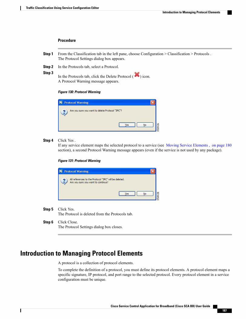
Procedure
Step 1 From the Classification tab in the left pane, choose Configuration > Classification > Protocols .The Protocol Settings dialog box appears.
Step 2 In the Protocols tab, select a Protocol.Step 3
In the Protocols tab, click the Delete Protocol ( ) icon.A Protocol Warning message appears.
Figure 130: Protocol Warning
Step 4 Click Yes .If any service element maps the selected protocol to a service (see Moving Service Elements , on page 180section), a second Protocol Warning message appears (even if the service is not used by any package).
Figure 131: Protocol Warning
Step 5 Click Yes.The Protocol is deleted from the Protocols tab.
Step 6 Click Close.The Protocol Settings dialog box closes.
Introduction to Managing Protocol ElementsA protocol is a collection of protocol elements.
To complete the definition of a protocol, you must define its protocol elements. A protocol element maps aspecific signature, IP protocol, and port range to the selected protocol. Every protocol element in a serviceconfiguration must be unique.
Cisco Service Control Application for Broadband (Cisco SCA BB) User Guide 187
Traffic Classification Using Service Configuration EditorIntroduction to Managing Protocol Elements

If a traffic flow meets all of the following four criteria, it is mapped to a specific protocol:
• The flow belongs to the specified signature of the protocol element.
• The flow protocol is the specified IP protocol of the protocol element.
• (If the IP protocol is TCP or UDP) The destination port is within the specified port range of the protocolelement.
• The protocol element is the most specific protocol element satisfying the first three criteria.
Adding Protocol ElementsYou can add any number of protocol elements to a protocol.
When you set the parameters of the protocol element, the values of the parameters are saved as you enterthem.
Note
Procedure
Step 1 From the Classification tab in the left pane, choose Configuration > Classification > Protocols .The Protocol Settings dialog box appears.
Step 2 In the Protocols tab, select a protocol.Step 3
In the Protocol Elements tab, click the Add Protocol Element ( ) icon.A protocol element is added to the protocol.
A new row, representing the protocol element, is added to the protocol element list in the Protocol Elementtab.
Step 4 Click in the Signature cell of the protocol element, and then click the Browse button that appears in the cell.The default value (an asterisk, *) means that no signature checking is performed when testing whethera flow maps to this protocol element.
Note
Cisco Service Control Application for Broadband (Cisco SCA BB) User Guide188
Traffic Classification Using Service Configuration EditorIntroduction to Managing Protocol Elements

The Select a Signature dialog box appears, displaying a list of all signatures.
Figure 132: Select a Signature
Step 5 Select a signature from the list.Select the Generic signature to allow a flow that has no matching signature in the protocol signaturedatabase to be mapped to this protocol element (if the flow also matches the IP protocol and portrange of the protocol element).
Note
Step 6 Click OK.The Select a Signature dialog box closes.
The selected signature is displayed in the Signature cell of the Protocol Settings dialog box.
Step 7 Click in the IP Protocol cell of the protocol element, and then click the Browse button that appears in the cell.The default value (an asterisk, *) means that no IP protocol checking is performed when testingwhether a flow maps to this protocol element.
Note
Cisco Service Control Application for Broadband (Cisco SCA BB) User Guide 189
Traffic Classification Using Service Configuration EditorIntroduction to Managing Protocol Elements
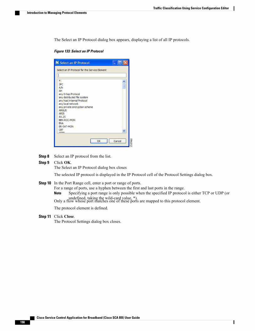
The Select an IP Protocol dialog box appears, displaying a list of all IP protocols.
Figure 133: Select an IP Protocol
Step 8 Select an IP protocol from the list.Step 9 Click OK.
The Select an IP Protocol dialog box closes
The selected IP protocol is displayed in the IP Protocol cell of the Protocol Settings dialog box.
Step 10 In the Port Range cell, enter a port or range of ports.For a range of ports, use a hyphen between the first and last ports in the range.
Specifying a port range is only possible when the specified IP protocol is either TCP or UDP (orundefined, taking the wild-card value, *).
Note
Only a flow whose port matches one of these ports are mapped to this protocol element.
The protocol element is defined.
Step 11 Click Close.The Protocol Settings dialog box closes.
Cisco Service Control Application for Broadband (Cisco SCA BB) User Guide190
Traffic Classification Using Service Configuration EditorIntroduction to Managing Protocol Elements
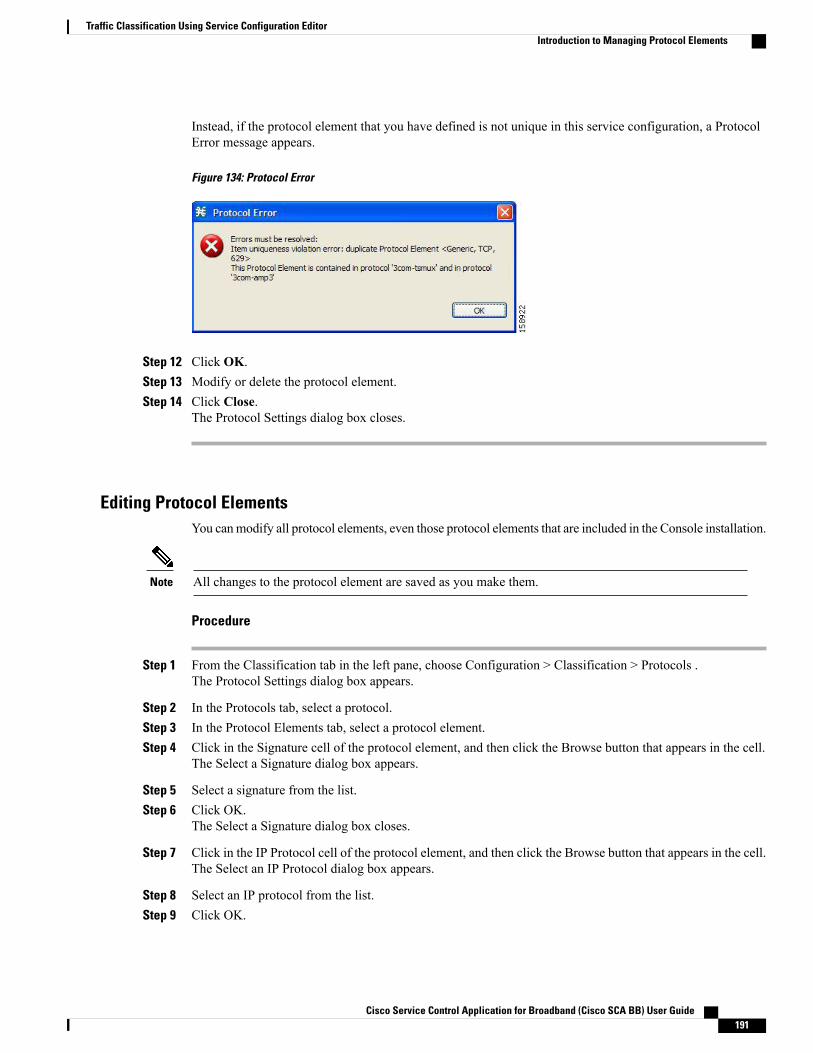
Instead, if the protocol element that you have defined is not unique in this service configuration, a ProtocolError message appears.
Figure 134: Protocol Error
Step 12 Click OK.Step 13 Modify or delete the protocol element.Step 14 Click Close.
The Protocol Settings dialog box closes.
Editing Protocol ElementsYou canmodify all protocol elements, even those protocol elements that are included in the Console installation.
All changes to the protocol element are saved as you make them.Note
Procedure
Step 1 From the Classification tab in the left pane, choose Configuration > Classification > Protocols .The Protocol Settings dialog box appears.
Step 2 In the Protocols tab, select a protocol.Step 3 In the Protocol Elements tab, select a protocol element.Step 4 Click in the Signature cell of the protocol element, and then click the Browse button that appears in the cell.
The Select a Signature dialog box appears.
Step 5 Select a signature from the list.Step 6 Click OK.
The Select a Signature dialog box closes.
Step 7 Click in the IP Protocol cell of the protocol element, and then click the Browse button that appears in the cell.The Select an IP Protocol dialog box appears.
Step 8 Select an IP protocol from the list.Step 9 Click OK.
Cisco Service Control Application for Broadband (Cisco SCA BB) User Guide 191
Traffic Classification Using Service Configuration EditorIntroduction to Managing Protocol Elements
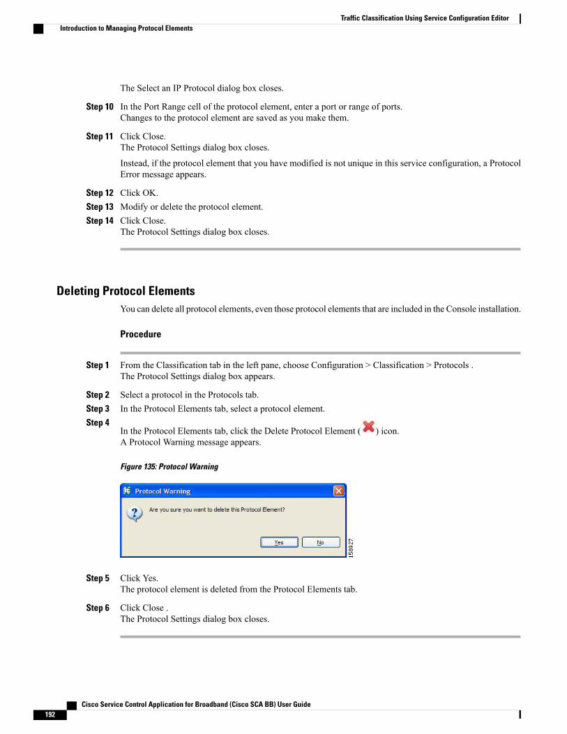
The Select an IP Protocol dialog box closes.
Step 10 In the Port Range cell of the protocol element, enter a port or range of ports.Changes to the protocol element are saved as you make them.
Step 11 Click Close.The Protocol Settings dialog box closes.
Instead, if the protocol element that you have modified is not unique in this service configuration, a ProtocolError message appears.
Step 12 Click OK.Step 13 Modify or delete the protocol element.Step 14 Click Close.
The Protocol Settings dialog box closes.
Deleting Protocol ElementsYou can delete all protocol elements, even those protocol elements that are included in the Console installation.
Procedure
Step 1 From the Classification tab in the left pane, choose Configuration > Classification > Protocols .The Protocol Settings dialog box appears.
Step 2 Select a protocol in the Protocols tab.Step 3 In the Protocol Elements tab, select a protocol element.Step 4
In the Protocol Elements tab, click the Delete Protocol Element ( ) icon.A Protocol Warning message appears.
Figure 135: Protocol Warning
Step 5 Click Yes.The protocol element is deleted from the Protocol Elements tab.
Step 6 Click Close .The Protocol Settings dialog box closes.
Cisco Service Control Application for Broadband (Cisco SCA BB) User Guide192
Traffic Classification Using Service Configuration EditorIntroduction to Managing Protocol Elements
Introduction to Managing ZonesA zone is a collection of destination IP addresses; usually the addresses in one zone are related in some way.
Zones are used to classify network sessions; each network session is assigned to a service element based onits destination IP address.
A service configuration can contain up to 40,000 zone items on Cisco SCE 8000 . Every zone item must beunique.
A service configuration can contain up to 40,000 zone items on Cisco SCE 10,000 device. The maximumallowed size for IPv4 is 32,000 and 8000 for IPv6. IPv4 and IPv6 are each addresses for individual uniqueports.
BGP Autonomous System Dynamic DetectionThe BGP Autonomous System (BGP AS) Dynamic Detection feature enables you to provision the BGPautonomous system as IP prefixes to the Cisco SCE zones.
With the BGP AS Dynamic Detection feature, you can:
• Add the complete AS number node and all the IP prefixes under it to a new zone.
• Add the IP Prefixes obtained from the AS number nodes to an existing zone.
• Add IP prefixes to a new zone.
• Delete IP prefixes from a zone.
For details, see the following sections:
• BGP AS Dynamic Detection Workflow, on page 200
• Enabling BGP As Dynamic Detection, on page 201
• Collecting and Storing the BGP Autonomous System Details, on page 201
• Creating a New Zone with Select BGP AS Numbers and Prefixes, on page 202
• BGP AS Numbers and Prefixes Color Schema, on page 203
• Updating a Zone with Select BGP AS Numbers and Prefixes, on page 204
• Deleting IP Prefixes from a Zone, on page 204
Viewing ZonesYou can view a list of all zones and their associated zone items.
Procedure
Step 1 From the Classification tab in the left pane, choose Configuration > Classification > Zones .The Zone Settings dialog box appears.
Cisco Service Control Application for Broadband (Cisco SCA BB) User Guide 193
Traffic Classification Using Service Configuration EditorIntroduction to Managing Zones

The Zones tab displays a list of all zones. The first zone in the list is selected, and its zone items are displayedin the Zone Items tab.
Figure 136: Zone Settings
Step 2 Click a zone in the list to display its zone items.The zone items of the selected zone are displayed in the Zone Items tab.
Step 3 Click Close .If you enable the automatic zone provisioning, an Advanced Import button will be available.Click the Advanced Import button to import the BGP AS numbers and prefixes to create Zones.See the Creating a New Zone with Select BGP AS Numbers and Prefixes, on page 202 section.
Timesaver
Adding Zones
Procedure
Step 1 From the Classification tab in the left pane, choose Configuration > Classification > Zones.The Zone Settings dialog box appears.
Step 2In the Zones tab, click the Add Zone ( ) icon.
Cisco Service Control Application for Broadband (Cisco SCA BB) User Guide194
Traffic Classification Using Service Configuration EditorAdding Zones
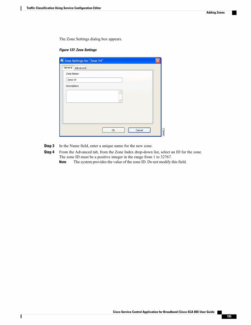
The Zone Settings dialog box appears.
Figure 137: Zone Settings
Step 3 In the Name field, enter a unique name for the new zone.Step 4 From the Advanced tab, from the Zone Index drop-down list, select an ID for the zone.
The zone ID must be a positive integer in the range from 1 to 32767.The system provides the value of the zone ID. Do not modify this field.Note
Cisco Service Control Application for Broadband (Cisco SCA BB) User Guide 195
Traffic Classification Using Service Configuration EditorAdding Zones
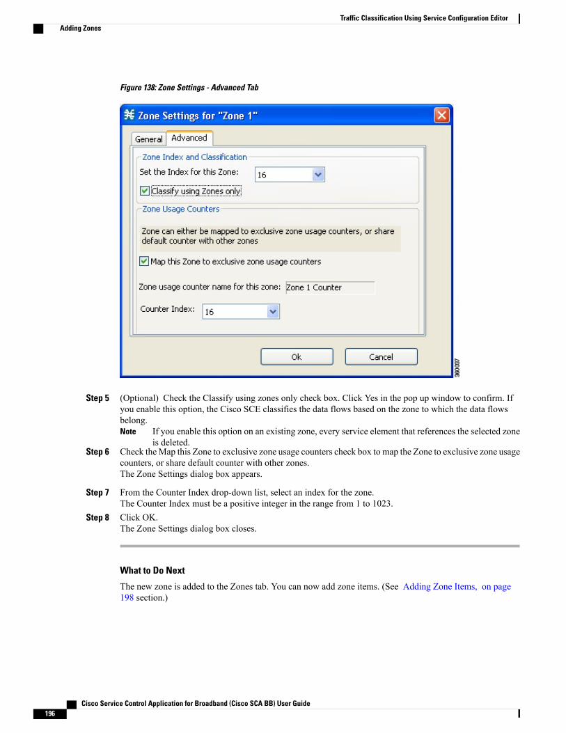
Figure 138: Zone Settings - Advanced Tab
Step 5 (Optional) Check the Classify using zones only check box. Click Yes in the pop up window to confirm. Ifyou enable this option, the Cisco SCE classifies the data flows based on the zone to which the data flowsbelong.
If you enable this option on an existing zone, every service element that references the selected zoneis deleted.
Note
Step 6 Check theMap this Zone to exclusive zone usage counters check box to map the Zone to exclusive zone usagecounters, or share default counter with other zones.The Zone Settings dialog box appears.
Step 7 From the Counter Index drop-down list, select an index for the zone.The Counter Index must be a positive integer in the range from 1 to 1023.
Step 8 Click OK.The Zone Settings dialog box closes.
What to Do Next
The new zone is added to the Zones tab. You can now add zone items. (See Adding Zone Items, on page198 section.)
Cisco Service Control Application for Broadband (Cisco SCA BB) User Guide196
Traffic Classification Using Service Configuration EditorAdding Zones
Editing ZonesYou can modify zone parameters at any time.
To add, modify, or delete zone items, see Introduction to Managing Zone Items , on page 198 section.
Procedure
Step 1 From the Classification tab in the left pane, choose Configuration > Classification > Zones.The Zone Settings dialog box appears.
Step 2 In the Zones tab, select a zone.Step 3
Click the Edit Zone ( ) icon.The Zone Settings dialog box appears.
Step 4 Modify fields in the dialog box.a) In the Name field, enter a new name for the zone.b) From the Zone Index drop-down list, select an ID for the zone.
The zone ID must be a positive integer in the range from 1 to 32767.
The system provides the value of the zone ID. Do not modify this field.Note
Step 5 Click OK.The Zone Settings dialog box closes.
The new values of the zone parameters are saved.
Step 6 Click Close.The Zone Settings dialog box closes.
Deleting ZonesYou can delete any or all zones.
Procedure
Step 1 From the Classification tab in the left pane, choose Configuration > Classification > Zones .The Zone Settings dialog box appears.
Step 2 In the Zones tab, select a zone.Step 3
In the Zones tab, click the Delete Zone ( ) icon.
Cisco Service Control Application for Broadband (Cisco SCA BB) User Guide 197
Traffic Classification Using Service Configuration EditorEditing Zones
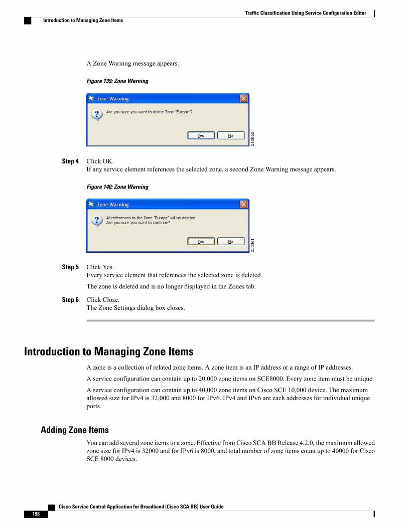
A Zone Warning message appears.
Figure 139: Zone Warning
Step 4 Click OK.If any service element references the selected zone, a second Zone Warning message appears.
Figure 140: Zone Warning
Step 5 Click Yes.Every service element that references the selected zone is deleted.
The zone is deleted and is no longer displayed in the Zones tab.
Step 6 Click Close.The Zone Settings dialog box closes.
Introduction to Managing Zone ItemsA zone is a collection of related zone items. A zone item is an IP address or a range of IP addresses.
A service configuration can contain up to 20,000 zone items on SCE8000. Every zone item must be unique.
A service configuration can contain up to 40,000 zone items on Cisco SCE 10,000 device. The maximumallowed size for IPv4 is 32,000 and 8000 for IPv6. IPv4 and IPv6 are each addresses for individual uniqueports.
Adding Zone ItemsYou can add several zone items to a zone. Effective from Cisco SCABBRelease 4.2.0, the maximum allowedzone size for IPv4 is 32000 and for IPv6 is 8000, and total number of zone items count up to 40000 for CiscoSCE 8000 devices.
Cisco Service Control Application for Broadband (Cisco SCA BB) User Guide198
Traffic Classification Using Service Configuration EditorIntroduction to Managing Zone Items
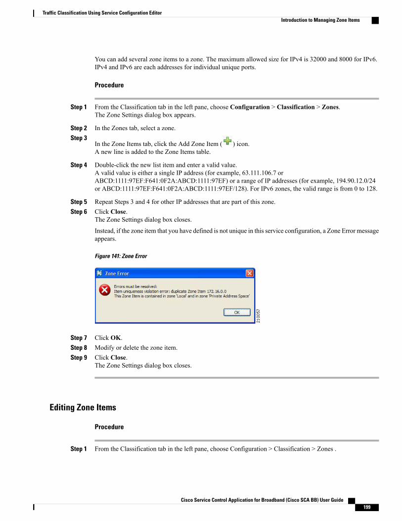
You can add several zone items to a zone. The maximum allowed size for IPv4 is 32000 and 8000 for IPv6.IPv4 and IPv6 are each addresses for individual unique ports.
Procedure
Step 1 From the Classification tab in the left pane, choose Configuration > Classification > Zones.The Zone Settings dialog box appears.
Step 2 In the Zones tab, select a zone.Step 3
In the Zone Items tab, click the Add Zone Item ( ) icon.A new line is added to the Zone Items table.
Step 4 Double-click the new list item and enter a valid value.A valid value is either a single IP address (for example, 63.111.106.7 orABCD:1111:97EF:F641:0F2A:ABCD:1111:97EF) or a range of IP addresses (for example, 194.90.12.0/24or ABCD:1111:97EF:F641:0F2A:ABCD:1111:97EF/128). For IPv6 zones, the valid range is from 0 to 128.
Step 5 Repeat Steps 3 and 4 for other IP addresses that are part of this zone.Step 6 Click Close.
The Zone Settings dialog box closes.
Instead, if the zone item that you have defined is not unique in this service configuration, a Zone Error messageappears.
Figure 141: Zone Error
Step 7 Click OK.Step 8 Modify or delete the zone item.Step 9 Click Close.
The Zone Settings dialog box closes.
Editing Zone Items
Procedure
Step 1 From the Classification tab in the left pane, choose Configuration > Classification > Zones .
Cisco Service Control Application for Broadband (Cisco SCA BB) User Guide 199
Traffic Classification Using Service Configuration EditorIntroduction to Managing Zone Items
The Zone Settings dialog box appears.
Step 2 In the Zones tab, select a zone.Step 3 In the Zone Items tab, double-click a zone item.Step 4 Enter a new value for the zone item.
A valid value is either a single IP address (for example, 63.111.106.7 orABCD:1111:97EF:F641:0F2A:ABCD:1111:97EF) or a range of IP addresses (for example, 194.90.12.0/24or ABCD:1111:97EF:F641:0F2A:ABCD:1111:97EF/128). For IPv6 zones, the valid range is from 0 to 128.
Step 5 Click Close.The Zone Settings dialog box closes.
Instead, if the zone item that you have modified is not unique in this service configuration, a Zone Errormessage appears.
Step 6 Click OK.Step 7 Modify or delete the zone item.Step 8 Click Close.
The Zone Settings dialog box closes.
Deleting Zone Items
Procedure
Step 1 From the Classification tab in the left pane, choose Configuration > Classification > Zones .The Zone Settings dialog box appears.
Step 2 In the Zones tab, select a zone.Step 3 In the Zone Items tab, select a zone item.Step 4
In the Zone Items tab, click the Delete Zone Item ( ) icon.The zone item is deleted.
Step 5 Click Close .The Zone Settings dialog box closes.
BGP AS Dynamic Detection WorkflowThis section provides details on the BGP AS Dynamic Detection workflow:
1 When you run the asFetch.bat script, the script downloads the AS number and IP prefixes from theconfigured BGP router using the SNMP MIBs
2 The script converts the prefixes to IP ranges and stores the details in a local file. If you configure a schedulerto run the script periodically, during each run, the IP file gets overwritten with a new one.
3 Cisco SCA BB:
Cisco Service Control Application for Broadband (Cisco SCA BB) User Guide200
Traffic Classification Using Service Configuration EditorIntroduction to Managing Zone Items
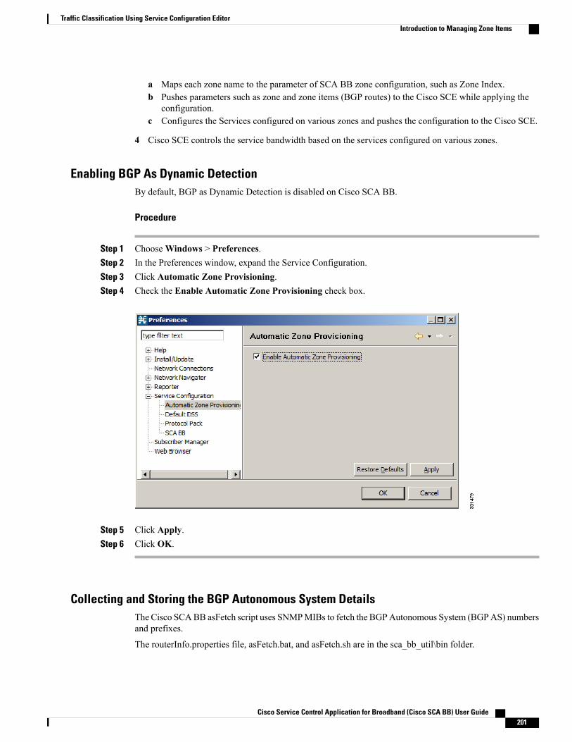
Maps each zone name to the parameter of SCA BB zone configuration, such as Zone Index.ab Pushes parameters such as zone and zone items (BGP routes) to the Cisco SCE while applying the
configuration.c Configures the Services configured on various zones and pushes the configuration to the Cisco SCE.
4 Cisco SCE controls the service bandwidth based on the services configured on various zones.
Enabling BGP As Dynamic DetectionBy default, BGP as Dynamic Detection is disabled on Cisco SCA BB.
Procedure
Step 1 ChooseWindows > Preferences.Step 2 In the Preferences window, expand the Service Configuration.Step 3 Click Automatic Zone Provisioning.Step 4 Check the Enable Automatic Zone Provisioning check box.
Step 5 Click Apply.Step 6 Click OK.
Collecting and Storing the BGP Autonomous System DetailsThe Cisco SCABB asFetch script uses SNMPMIBs to fetch the BGPAutonomous System (BGPAS) numbersand prefixes.
The routerInfo.properties file, asFetch.bat, and asFetch.sh are in the sca_bb_util\bin folder.
Cisco Service Control Application for Broadband (Cisco SCA BB) User Guide 201
Traffic Classification Using Service Configuration EditorIntroduction to Managing Zone Items
Procedure
Step 1 Enter the router IP and SNMP community string in the routerInfo.properties file.If AS numbers and IP prefixes have to be generated for more than one router IP, enter the router IP addressof the community string separated by a comma (,) in the routerInfo.properties file.
Step 2 Run the asFetch.bat script.You can run the script manually or use a scheduler to run the script periodically.
Run the asFetch.bat file to generate the BGPRouter<number>.csv files based on the number of IP addressesentered in the properties file. For example, if two IP addresses are specified in the properties file, TheBGPRouter1.csv and BGPRouter2.csv files get generated.These .csv files contain the AS number and IPprefix details. These files can be imported from the Zone settings window.
The script fetches the AS number and IP prefix details and saves them in the BGPRouter<number>.csv filethat is present in the same folder in which you have extracted the asFetch script.
Creating a New Zone with Select BGP AS Numbers and Prefixes
Before You Begin
Before attempting to add the BGP AS numbers and prefixes to zones, enable automatic zone provisioningand run the asFetch script to get the BGP AS details into the BGPRouter<number>.csv file.
Procedure
Step 1 From the Service Configuration Editor window, choose Configuration > Classification > Zones.Step 2 In the Zone Settings window, click Advanced Import.Step 3 Browse to the folder in which the BGPRouter<number>.csv file is saved, and select the
BGPRouter<number>.csv file.Step 4 Click Open.
The AS No & Prefixes dialog box appears.
Cisco Service Control Application for Broadband (Cisco SCA BB) User Guide202
Traffic Classification Using Service Configuration EditorIntroduction to Managing Zone Items

Step 5 Select the corresponding AS Number.Step 6 Click Add.Step 7 Enter a New Zone Name.Step 8 Click OK.Step 9 Click OK.
BGP AS Numbers and Prefixes Color SchemaThe AS Number and Prefixes dialog box uses various colors to indicate new prefixes, prefixes added to azone, or changes to the AS Number to which the prefix belongs.
Green color indicates a new prefix that does not belong to any zone. After you add the prefix to a zone, thecolor of the prefix in the prefix list and the zone changes to black. If you remove the prefix from the zone,the color of the prefix in the prefix list changes to green again.
Blue color indicates that the prefix has moved from one AS to another. This helps you decide whether to movethe prefix to another zone.
Red color indicates that the prefix is not a part of the AS Numbers and Prefixes list.
Cisco Service Control Application for Broadband (Cisco SCA BB) User Guide 203
Traffic Classification Using Service Configuration EditorIntroduction to Managing Zone Items
Updating a Zone with Select BGP AS Numbers and Prefixes
Procedure
Step 1 From the Service Configuration Editor window, choose Configuration > Classification > Zones .Step 2 In the Zone Settings window, click Advanced Import .Step 3 Browse to the folder in which the BGPRouter<number>.csv file is saved and select the
BGPRouter<number>.csv file.Step 4 Click Open.
The AS No & Prefixes dialog box appears.
Step 5 Select the corresponding AS Number.Step 6 Click Update.Step 7 Choose a zone from the drop-down list.Step 8 Click OK.Step 9 Click OK.
From the AS No & Prefixes dialog box, you can drag and drop the required AS numbers andIP prefixes to the required zones.
Timesaver
Deleting IP Prefixes from a ZoneYou can delete IP prefixes only from a zone and not from the AS Numbers and Prefixes list.
Procedure
Step 1 Select the prefixes you want to delete.Step 2 Click Delete .
Introduction to Managing Protocol SignaturesA protocol signature is a set of parameters that uniquely identify a protocol.
Viewing Protocol SignaturesYou can view a list of all signatures and the protocol to which each is assigned.
Procedure
Step 1 From the Classification tab in the left pane, choose Configuration > Classification > Signatures Settings .
Cisco Service Control Application for Broadband (Cisco SCA BB) User Guide204
Traffic Classification Using Service Configuration EditorIntroduction to Managing Protocol Signatures
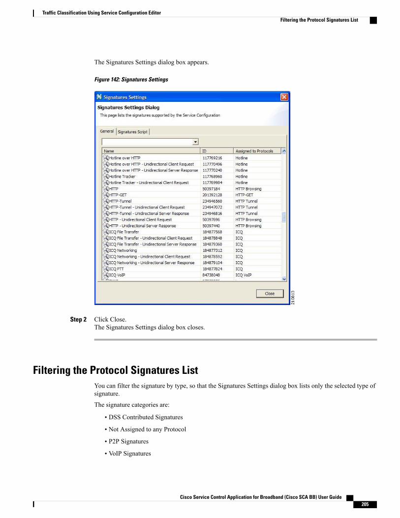
The Signatures Settings dialog box appears.
Figure 142: Signatures Settings
Step 2 Click Close.The Signatures Settings dialog box closes.
Filtering the Protocol Signatures ListYou can filter the signature by type, so that the Signatures Settings dialog box lists only the selected type ofsignature.
The signature categories are:
• DSS Contributed Signatures
• Not Assigned to any Protocol
• P2P Signatures
• VoIP Signatures
Cisco Service Control Application for Broadband (Cisco SCA BB) User Guide 205
Traffic Classification Using Service Configuration EditorFiltering the Protocol Signatures List

• SIP Signatures
•Worm Signatures
• Packet Stream Pattern Based Protocols Signatures
• Unidirectionally Detected Signatures
• Behavioral Signatures
• E-Mail and Newsgroups Signatures
• Gaming Signatures
• HTTP Signatures
• Instant Messaging Signatures
• Net Admin Signatures
• Video Signatures
• Tunneling Signatures
• ClickStream Signatures
Some signatures belong to more than one category.Note
Procedure
Step 1 From the Console main menu, choose Configuration > Classification > Signatures Settings .The Signatures Settings dialog box appears.
Step 2 From the drop-down list, select the type of signature to display.The signatures of the selected type appear in the dialog box.
Step 3 Click Close.The Signatures Settings dialog box closes.
Dynamic SignaturesNew protocols are being introduced all the time. Dynamic signatures is a mechanism that allows new protocolsto be added to the protocol list and, from there, to service configurations. Dynamic Signature is especiallyuseful for classifying the traffic of a new protocol (for example, a new P2P protocol in a P2P-Control solution).
• Installing new signatures to an active service configuration is described in Working with Protocol Packs, on page 55.
• Creating and modifying signatures is described in The Signature Editor Overview, on page 511.
• Using servconf , the Cisco SCA BB Server Configuration Utility, to apply signatures is described inThe Cisco SCA BB Service Configuration Utility , on page 529.
Cisco Service Control Application for Broadband (Cisco SCA BB) User Guide206
Traffic Classification Using Service Configuration EditorDynamic Signatures
The following sections describe working with dynamic signatures in the Service Configuration Editor:
Dynamic Signature Script FilesDynamic signatures are provided in special Dynamic Signatures Script (DSS) files that you can add to aservice configuration using either the Console or the Service Configuration API. After a DSS file is importedinto a service configuration, the new protocols it describes:
• Appear in the protocol list.
• May be added to services.
• Are used when viewing reports.
To simplify the configuration of new protocols added by a DSS, the DSS may specify a Buddy Protocol fora new protocol. If, when loading a DSS, the application encounters the Buddy Protocol, it automaticallyduplicates the set of service elements that use the Buddy Protocol, and replaces all references to the BuddyProtocol with references to the new protocol. The association of the new protocol to services matches that ofthe Buddy Protocol.
The following configuration actions are performed automatically when you import a DSS into a serviceconfiguration:
• Signatures are updated and new signatures are loaded.
• Protocol elements are created for new signatures of existing protocols.
• New protocols are added to the protocol list, and protocol elements are created for them.
• Service elements are created for new protocols according to the configuration of Buddy Protocols.
The import procedure preserves all service and protocol settings.
After importing a DSS, associate the newly added protocols with services.Note
Cisco or its partners releases DSS files periodically in accordance with customer requirements and marketneeds.
DSS files contain new protocols and signatures, and update previously defined signatures. Updating a serviceconfiguration with the new DSS is explained in Importing a Dynamic Signature Script into a ServiceConfiguration , on page 209.
You can create your own DSS files or modify the Cisco release DSS file using the Signature Editor tool(see Managing DSS Files Overview, on page 511 section).
Note
Viewing Information About the Current Dynamic Signatures
Procedure
Step 1 From the Classification tab in the left pane, choose Configuration > Classification > Signatures Settings .
Cisco Service Control Application for Broadband (Cisco SCA BB) User Guide 207
Traffic Classification Using Service Configuration EditorDynamic Signatures
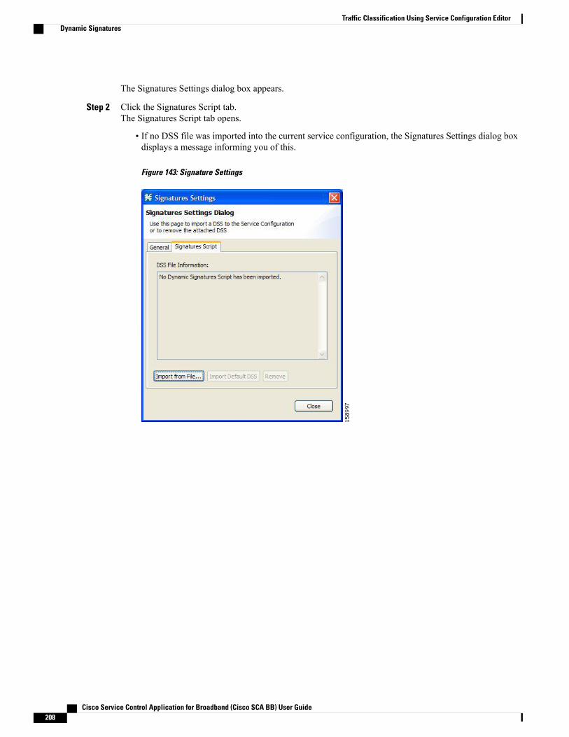
The Signatures Settings dialog box appears.
Step 2 Click the Signatures Script tab.The Signatures Script tab opens.
• If no DSS file was imported into the current service configuration, the Signatures Settings dialog boxdisplays a message informing you of this.
Figure 143: Signature Settings
Cisco Service Control Application for Broadband (Cisco SCA BB) User Guide208
Traffic Classification Using Service Configuration EditorDynamic Signatures
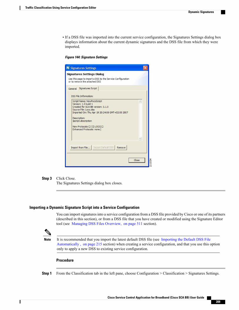
• If a DSS file was imported into the current service configuration, the Signatures Settings dialog boxdisplays information about the current dynamic signatures and the DSS file from which they wereimported.
Figure 144: Signature Settings
Step 3 Click Close.The Signatures Settings dialog box closes.
Importing a Dynamic Signature Script into a Service Configuration
You can import signatures into a service configuration from a DSS file provided by Cisco or one of its partners(described in this section), or from a DSS file that you have created or modified using the Signature Editortool (see Managing DSS Files Overview, on page 511 section).
It is recommended that you import the latest default DSS file (see Importing the Default DSS FileAutomatically , on page 215 section) when creating a service configuration, and that you use this optiononly to apply a new DSS to existing service configuration.
Note
Procedure
Step 1 From the Classification tab in the left pane, choose Configuration > Classification > Signatures Settings.
Cisco Service Control Application for Broadband (Cisco SCA BB) User Guide 209
Traffic Classification Using Service Configuration EditorDynamic Signatures
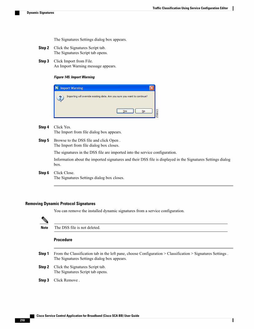
The Signatures Settings dialog box appears.
Step 2 Click the Signatures Script tab.The Signatures Script tab opens.
Step 3 Click Import from File.An Import Warning message appears.
Figure 145: Import Warning
Step 4 Click Yes.The Import from file dialog box appears.
Step 5 Browse to the DSS file and click Open .The Import from file dialog box closes.
The signatures in the DSS file are imported into the service configuration.
Information about the imported signatures and their DSS file is displayed in the Signatures Settings dialogbox.
Step 6 Click Close.The Signatures Settings dialog box closes.
Removing Dynamic Protocol Signatures
You can remove the installed dynamic signatures from a service configuration.
The DSS file is not deleted.Note
Procedure
Step 1 From the Classification tab in the left pane, choose Configuration > Classification > Signatures Settings .The Signatures Settings dialog box appears.
Step 2 Click the Signatures Script tab.The Signatures Script tab opens.
Step 3 Click Remove .
Cisco Service Control Application for Broadband (Cisco SCA BB) User Guide210
Traffic Classification Using Service Configuration EditorDynamic Signatures
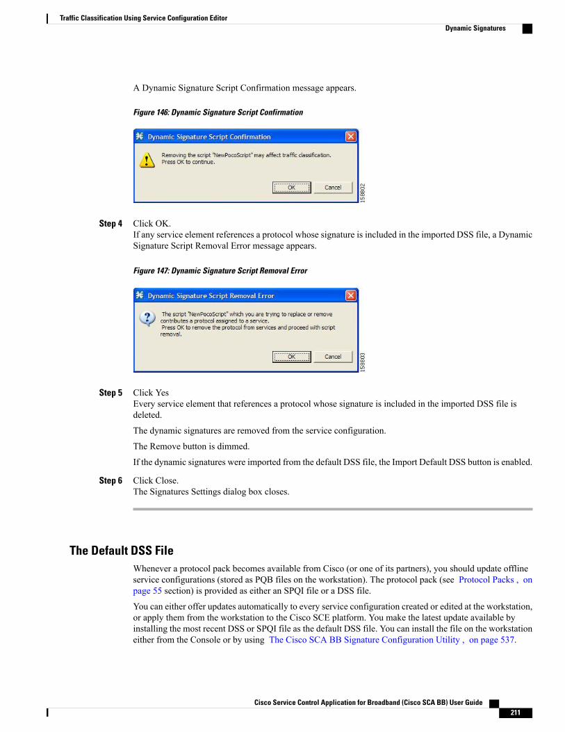
A Dynamic Signature Script Confirmation message appears.
Figure 146: Dynamic Signature Script Confirmation
Step 4 Click OK.If any service element references a protocol whose signature is included in the imported DSS file, a DynamicSignature Script Removal Error message appears.
Figure 147: Dynamic Signature Script Removal Error
Step 5 Click YesEvery service element that references a protocol whose signature is included in the imported DSS file isdeleted.
The dynamic signatures are removed from the service configuration.
The Remove button is dimmed.
If the dynamic signatures were imported from the default DSS file, the Import Default DSS button is enabled.
Step 6 Click Close.The Signatures Settings dialog box closes.
The Default DSS FileWhenever a protocol pack becomes available from Cisco (or one of its partners), you should update offlineservice configurations (stored as PQB files on the workstation). The protocol pack (see Protocol Packs , onpage 55 section) is provided as either an SPQI file or a DSS file.
You can either offer updates automatically to every service configuration created or edited at the workstation,or apply them from the workstation to the Cisco SCE platform. You make the latest update available byinstalling the most recent DSS or SPQI file as the default DSS file. You can install the file on the workstationeither from the Console or by using The Cisco SCA BB Signature Configuration Utility , on page 537.
Cisco Service Control Application for Broadband (Cisco SCA BB) User Guide 211
Traffic Classification Using Service Configuration EditorDynamic Signatures

• The default DSS file is automatically offered for import when you perform any service configurationoperation (such as creating a new service configuration or editing an existing one) from the Console ona service configuration that was not yet updated.
• The default DSS file is imported by default when any service configuration operation (such as applyingan existing service configuration) is performed using servconf, The Cisco SCA BB SignatureConfiguration Utility , on page 537. You can disable this option.
Users are expected to update the default DSS on their management workstation whenever they obtain anew protocol pack.
Note
Introduction to Setting and Clearing the Default DSS File
The default DSS file should normally be the latest protocol pack provided by Cisco (or one of its partners).If necessary, modify the protocol pack using the Signature Editor tool (see Editing DSS Files , on page 524section) to add signatures of new protocols until they become available from Cisco.
Whenever a new protocol pack becomes available, set it as the default DSS file. There is no need to clear thecurrent default DSS file; it is overwritten by the new protocol pack.
Setting a Protocol Pack as the Default DSS File
Procedure
Step 1 From the Console main menu, choose Window > Preferences .The Preferences dialog box appears.
Step 2 From the menu tree in the left pane of the dialog box, choose Service Configuration > Default DSS .
Cisco Service Control Application for Broadband (Cisco SCA BB) User Guide212
Traffic Classification Using Service Configuration EditorDynamic Signatures
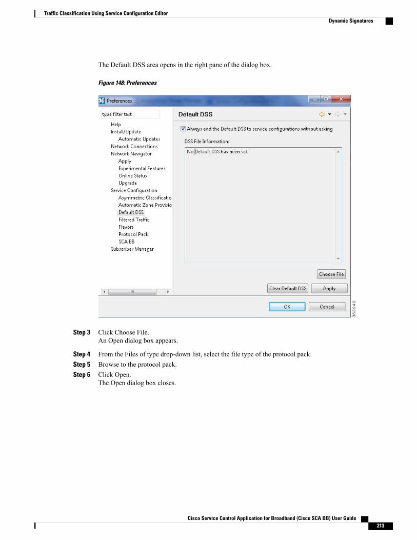
The Default DSS area opens in the right pane of the dialog box.
Figure 148: Preferences
Step 3 Click Choose File.An Open dialog box appears.
Step 4 From the Files of type drop-down list, select the file type of the protocol pack.Step 5 Browse to the protocol pack.Step 6 Click Open.
The Open dialog box closes.
Cisco Service Control Application for Broadband (Cisco SCA BB) User Guide 213
Traffic Classification Using Service Configuration EditorDynamic Signatures
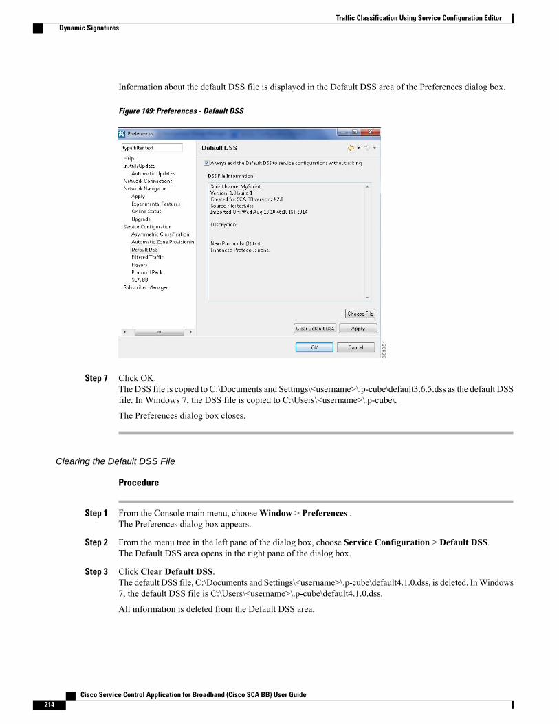
Information about the default DSS file is displayed in the Default DSS area of the Preferences dialog box.
Figure 149: Preferences - Default DSS
Step 7 Click OK.The DSS file is copied to C:\Documents and Settings\<username>\.p-cube\default3.6.5.dss as the default DSSfile. In Windows 7, the DSS file is copied to C:\Users\<username>\.p-cube\.
The Preferences dialog box closes.
Clearing the Default DSS File
Procedure
Step 1 From the Console main menu, chooseWindow > Preferences .The Preferences dialog box appears.
Step 2 From the menu tree in the left pane of the dialog box, choose Service Configuration > Default DSS.The Default DSS area opens in the right pane of the dialog box.
Step 3 Click Clear Default DSS.The default DSS file, C:\Documents and Settings\<username>\.p-cube\default4.1.0.dss, is deleted. InWindows7, the default DSS file is C:\Users\<username>\.p-cube\default4.1.0.dss.
All information is deleted from the Default DSS area.
Cisco Service Control Application for Broadband (Cisco SCA BB) User Guide214
Traffic Classification Using Service Configuration EditorDynamic Signatures

Deleting the default DSS file does not remove the imported dynamic signatures from the currentservice configuration.
Note
Step 4 Click OK.The Preferences dialog box closes.
Introduction to Importing Dynamic Signatures from the Default DSS File
If a default DSS file is installed, the application offers to import the dynamic signatures from the file whenyou create a new service configuration or when you open an existing service configuration that has not importedthe signatures. Alternatively, you can manually import the dynamic signatures.
Importing the Default DSS File Automatically
Procedure
Step 1 Open an existing service configuration or create a new one.A Default Signature message appears.
Figure 150: Default Signature
Step 2 Click Yes to import the default DSS file; click No to continue without importing the default DSS file.
Importing the Default DSS File Manually
Procedure
Step 1 From the Classification tab in the left pane, choose Configuration > Classification > Signatures Settings .The Signatures Settings dialog box appears.
Step 2 Click the Signatures Script tab.
Cisco Service Control Application for Broadband (Cisco SCA BB) User Guide 215
Traffic Classification Using Service Configuration EditorDynamic Signatures

The Signatures Script tab opens, with the Import Default DSS button enabled.
Figure 151: Signatures Settings
Step 3 Click Import Default DSS.An Import Warning message appears.
Figure 152: Import Warning
Step 4 Click Yes .The signatures in the default DSS file are imported into the service configuration.
The Import Default DSS button is dimmed.
Information about the imported signatures and the default DSS file is displayed in the Signatures Settingsdialog box.
Step 5 Click Close.The Signatures Settings dialog box closes.
Cisco Service Control Application for Broadband (Cisco SCA BB) User Guide216
Traffic Classification Using Service Configuration EditorDynamic Signatures

Introduction to Managing FlavorsFlavors are advanced classification elements that are used to classify network sessions.
Flavors are based on specific Layer 7 properties. For example, users can associate an HTTP flowwith a servicebased on different parts of the destination URL of the flow.
When you configure flavors, you cannot configure < and > symbols to be part of a URL.Note
Flavors are supported only for small number of protocols, and for each such protocol there are differentapplicable flavor types. Flavor types are listed in the table in the following section.
There is a maximum number of flavor items for each flavor type (see Maximum Number of Flavor Items perFlavor Type , on page 233 section). For each flavor type, every flavor item must be unique.
If unidirectional classification is enabled in the active service configuration, flavors are not used for trafficclassification.
Note
Flavor Types and ParametersFlavors are advanced classification elements that classify network sessions according to signature-specificLayer 7 properties.
When Layer 7 application properties are used as session parameters, such as with an HTTP User Agent, Theyare treated as character strings.
Layer 7 parameter-based flavor items may apply to the Layer 7 prefix (parameter beginning), Layer 7 suffix(parameter end), or a combination of Layer 7 prefixes and suffixes. A partial string must be followed by “*”in a prefix and preceded by “*” in a suffix.
Table 6: Cisco SCABB Flavors
Valid ValuesMatched Session ParametersFlavor Type
<HTTP User Agent flavor, HTTPURL flavor, HTTP Cookie flavor,HTTP Referer flavor>
• The flavors can be chosenusing flavor browsing.
HTTP User Agent, HTTP URL,HTTP Cookie and HTTP Refererflavors serve as session parameters.
HTTP Composite
Cisco Service Control Application for Broadband (Cisco SCA BB) User Guide 217
Traffic Classification Using Service Configuration EditorIntroduction to Managing Flavors
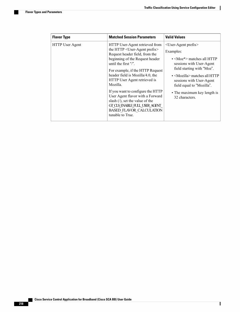
Valid ValuesMatched Session ParametersFlavor Type
<User-Agent prefix>
Examples:
• <Moz*> matches all HTTPsessions with User-Agentfield starting with “Moz”.
• <Mozilla>matches all HTTPsessions with User-Agentfield equal to “Mozilla”.
• The maximum key length is32 characters.
HTTP User-Agent retrieved fromthe HTTP <User-Agent prefix>Request header field, from thebeginning of the Request headeruntil the first “/”.For example, if the HTTP Requestheader field is Mozilla/4.0, theHTTP User Agent retrieved isMozilla.
If you want to configure the HTTPUser Agent flavor with a Forwardslash (/), set the value of theGT_CLS_ENABLE_FULL_USER_AGENT_BASED_FLAVOR_CALCULATIONtunable to True.
HTTP User Agent
Cisco Service Control Application for Broadband (Cisco SCA BB) User Guide218
Traffic Classification Using Service Configuration EditorFlavor Types and Parameters
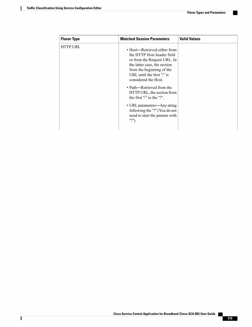
Valid ValuesMatched Session ParametersFlavor Type
• Host—Retrieved either fromthe HTTP Host header fieldor from the Request URL. Inthe latter case, the sectionfrom the beginning of theURL until the first “/” isconsidered the Host.
• Path—Retrieved from theHTTPURL, the section fromthe first “/” to the “?”.
• URLparameters—Any stringfollowing the “?” (You do notneed to start the params with“?”).
HTTP URL
Cisco Service Control Application for Broadband (Cisco SCA BB) User Guide 219
Traffic Classification Using Service Configuration EditorFlavor Types and Parameters
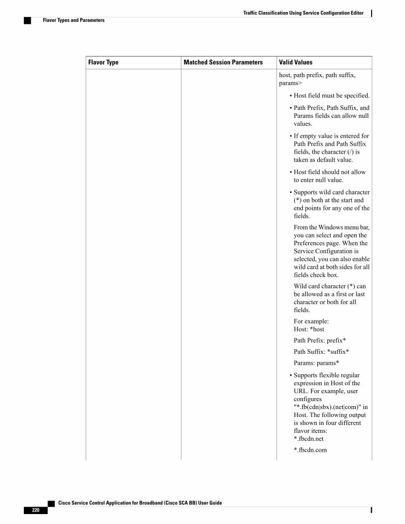
Valid ValuesMatched Session ParametersFlavor Type
host, path prefix, path suffix,params>
• Host field must be specified.
• Path Prefix, Path Suffix, andParams fields can allow nullvalues.
• If empty value is entered forPath Prefix and Path Suffixfields, the character (/) istaken as default value.
• Host field should not allowto enter null value.
• Supports wild card character(*) on both at the start andend points for any one of thefields.
From theWindowsmenu bar,you can select and open thePreferences page. When theService Configuration isselected, you can also enablewild card at both sides for allfields check box.
Wild card character (*) canbe allowed as a first or lastcharacter or both for allfields.
For example:Host: *host
Path Prefix: prefix*
Path Suffix: *suffix*
Params: params*
• Supports flexible regularexpression in Host of theURL. For example, userconfigures"*.fb(cdn|sbx).(net|com)" inHost. The following outputis shown in four differentflavor items:*.fbcdn.net
*.fbcdn.com
Cisco Service Control Application for Broadband (Cisco SCA BB) User Guide220
Traffic Classification Using Service Configuration EditorFlavor Types and Parameters

Valid ValuesMatched Session ParametersFlavor Type
*.fbsbx.net
*.fbsbx.com
• Supports the characters "()"and "|" in regular expression.Characters [a-z, A-Z, and0-9] are only allowed insidethe '()'.
• Host field regular expressioncan allow maximum twoinstances of '()' and fiveinstances of '|' inside each '()'.For example:
Host:google(1|2).(server1|server2).com
• Themaximum key length forall keys is 512 characters.
<key prefix, value prefix>
• For example: <act*,*>matches any Cookie pairwhere the Key begins with“act”, regardless of the Value.
• A flavor can be configuredso that the Value field isrequired to be empty. In thiscase, this field should be leftempty in the flavor item.
•White spaces are not allowed,“=” is not allowed, and “*” isonly allowed at the end of theKey or Value.
• The maximum key length is100 characters for both theKey and Value fields
Cookie “Key-Value” pairs that areretrieved from the HTTP Requestheader Cookie field.
A Cookie may consist of many“Key-Value” pairs; however, onlythe first three pairs are calculated.The Cookie flavor calculation stopswhen one of the “Key-Value” pairsmatches the specification, or whenit has exceeded the three pair limit.
HTTP Cookie
Cisco Service Control Application for Broadband (Cisco SCA BB) User Guide 221
Traffic Classification Using Service Configuration EditorFlavor Types and Parameters

Valid ValuesMatched Session ParametersFlavor Type
Similar to HTTP URL, but theparameters are retrieved from theReferer HTTP header field.
HTTP Referer
Cisco Service Control Application for Broadband (Cisco SCA BB) User Guide222
Traffic Classification Using Service Configuration EditorFlavor Types and Parameters
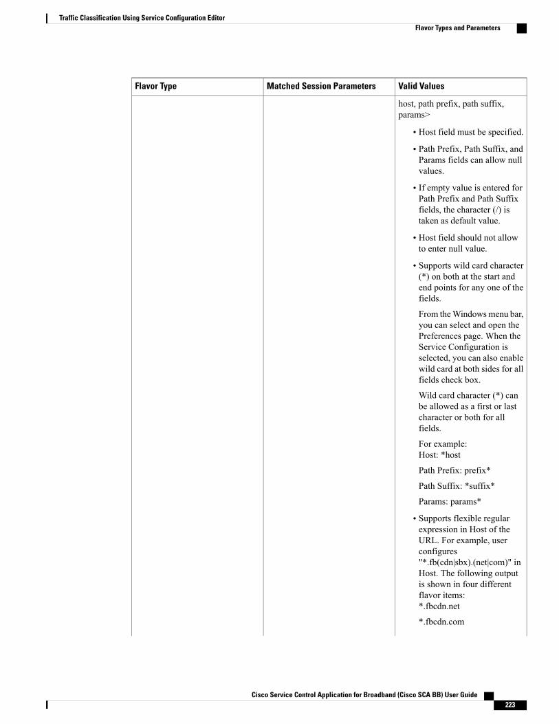
Valid ValuesMatched Session ParametersFlavor Type
host, path prefix, path suffix,params>
• Host field must be specified.
• Path Prefix, Path Suffix, andParams fields can allow nullvalues.
• If empty value is entered forPath Prefix and Path Suffixfields, the character (/) istaken as default value.
• Host field should not allowto enter null value.
• Supports wild card character(*) on both at the start andend points for any one of thefields.
From theWindowsmenu bar,you can select and open thePreferences page. When theService Configuration isselected, you can also enablewild card at both sides for allfields check box.
Wild card character (*) canbe allowed as a first or lastcharacter or both for allfields.
For example:Host: *host
Path Prefix: prefix*
Path Suffix: *suffix*
Params: params*
• Supports flexible regularexpression in Host of theURL. For example, userconfigures"*.fb(cdn|sbx).(net|com)" inHost. The following outputis shown in four differentflavor items:*.fbcdn.net
*.fbcdn.com
Cisco Service Control Application for Broadband (Cisco SCA BB) User Guide 223
Traffic Classification Using Service Configuration EditorFlavor Types and Parameters
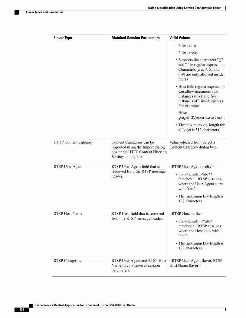
Valid ValuesMatched Session ParametersFlavor Type
*.fbsbx.net
*.fbsbx.com
• Supports the characters "()"and "|" in regular expression.Characters [a-z, A-Z, and0-9] are only allowed insidethe '()'.
• Host field regular expressioncan allow maximum twoinstances of '()' and fiveinstances of '|' inside each '()'.For example:
Host:google(1|2).(server1|server2).com
• Themaximum key length forall keys is 512 characters.
Value selected from Select aContent Category dialog box.
Content Categories can beimported using the Import dialogbox or the HTTP Content FilteringSettings dialog box.
HTTP Content Category
<RTSP User Agent prefix>
• For example: <abc*>matches all RTSP sessionswhere the User-Agent startswith “abc”.
• The maximum key length is128 characters
RTSP User-Agent field that isretrieved from the RTSP messageheader.
RTSP User Agent
<RTSP Host suffix>
• For example: <*abc>matches all RTSP sessionswhere the Host ends with“abc”.
• The maximum key length is128 characters
RTSP Host field that is retrievedfrom the RTSP message header.
RTSP Host Name
<RTSP User Agent flavor, RTSPHost Name flavor>
RTSP User Agent and RTSP HostName flavors serve as sessionparameters.
RTSP Composite
Cisco Service Control Application for Broadband (Cisco SCA BB) User Guide224
Traffic Classification Using Service Configuration EditorFlavor Types and Parameters
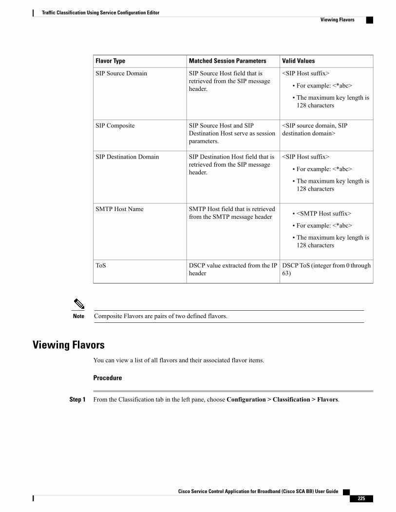
Valid ValuesMatched Session ParametersFlavor Type
<SIP Host suffix>
• For example: <*abc>
• The maximum key length is128 characters
SIP Source Host field that isretrieved from the SIP messageheader.
SIP Source Domain
<SIP source domain, SIPdestination domain>
SIP Source Host and SIPDestination Host serve as sessionparameters.
SIP Composite
<SIP Host suffix>
• For example: <*abc>
• The maximum key length is128 characters
SIP Destination Host field that isretrieved from the SIP messageheader.
SIP Destination Domain
• <SMTP Host suffix>
• For example: <*abc>
• The maximum key length is128 characters
SMTP Host field that is retrievedfrom the SMTP message header
SMTP Host Name
DSCP ToS (integer from 0 through63)
DSCP value extracted from the IPheader
ToS
Composite Flavors are pairs of two defined flavors.Note
Viewing FlavorsYou can view a list of all flavors and their associated flavor items.
Procedure
Step 1 From the Classification tab in the left pane, choose Configuration > Classification > Flavors.
Cisco Service Control Application for Broadband (Cisco SCA BB) User Guide 225
Traffic Classification Using Service Configuration EditorViewing Flavors
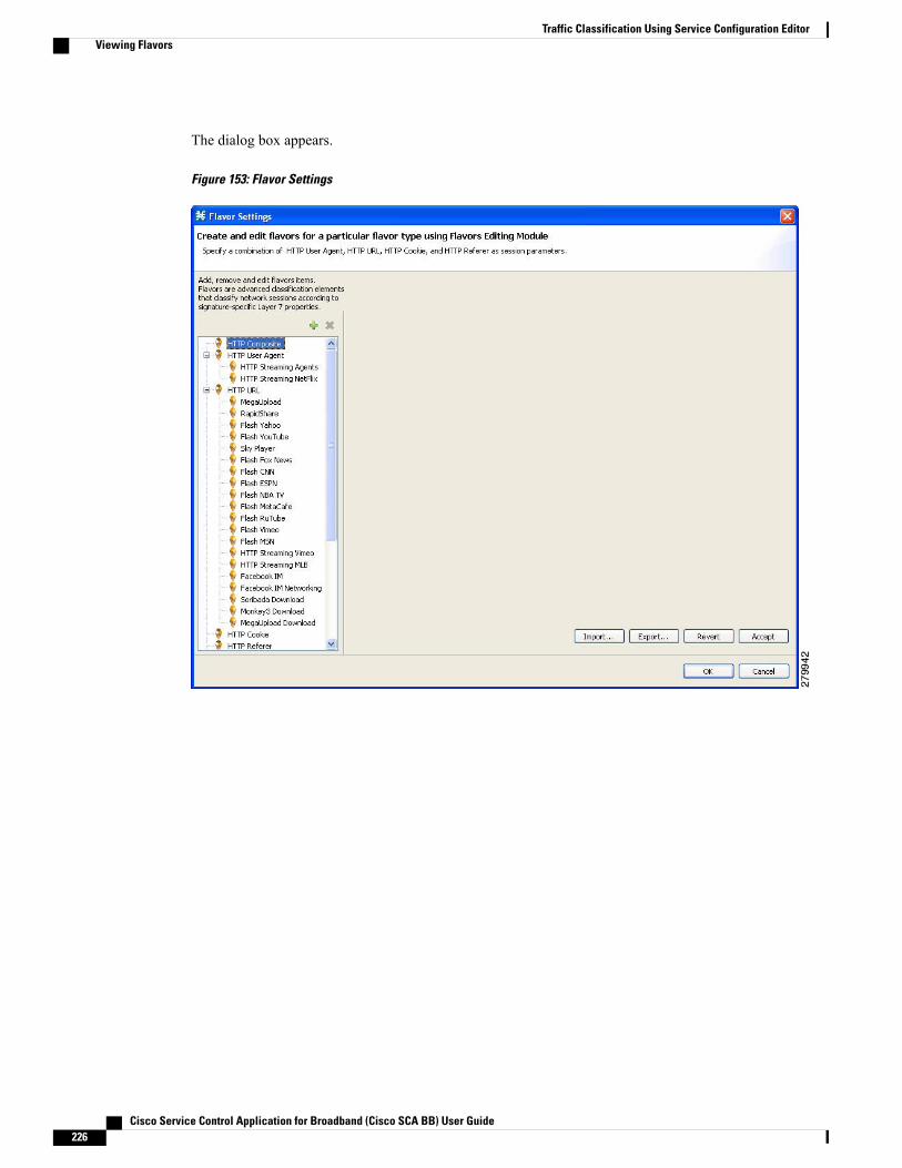
The dialog box appears.
Figure 153: Flavor Settings
Cisco Service Control Application for Broadband (Cisco SCA BB) User Guide226
Traffic Classification Using Service Configuration EditorViewing Flavors
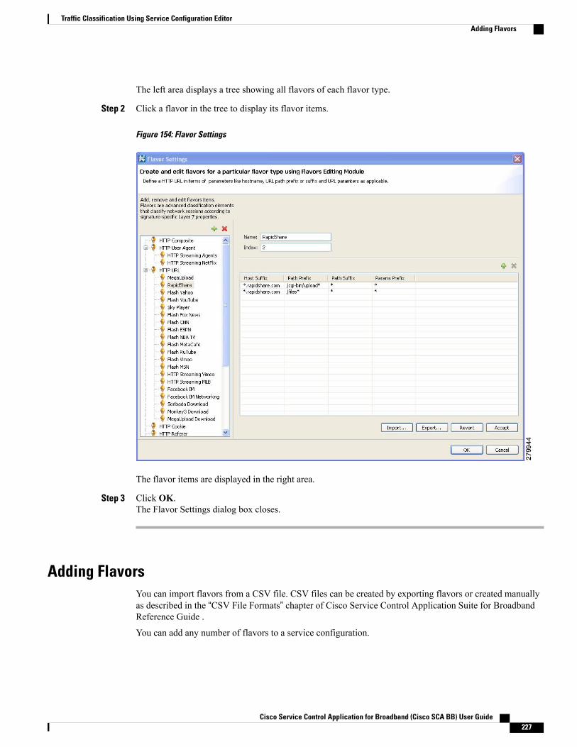
The left area displays a tree showing all flavors of each flavor type.
Step 2 Click a flavor in the tree to display its flavor items.
Figure 154: Flavor Settings
The flavor items are displayed in the right area.
Step 3 Click OK.The Flavor Settings dialog box closes.
Adding FlavorsYou can import flavors from a CSV file. CSV files can be created by exporting flavors or created manuallyas described in the “CSV File Formats” chapter of Cisco Service Control Application Suite for BroadbandReference Guide .
You can add any number of flavors to a service configuration.
Cisco Service Control Application for Broadband (Cisco SCA BB) User Guide 227
Traffic Classification Using Service Configuration EditorAdding Flavors
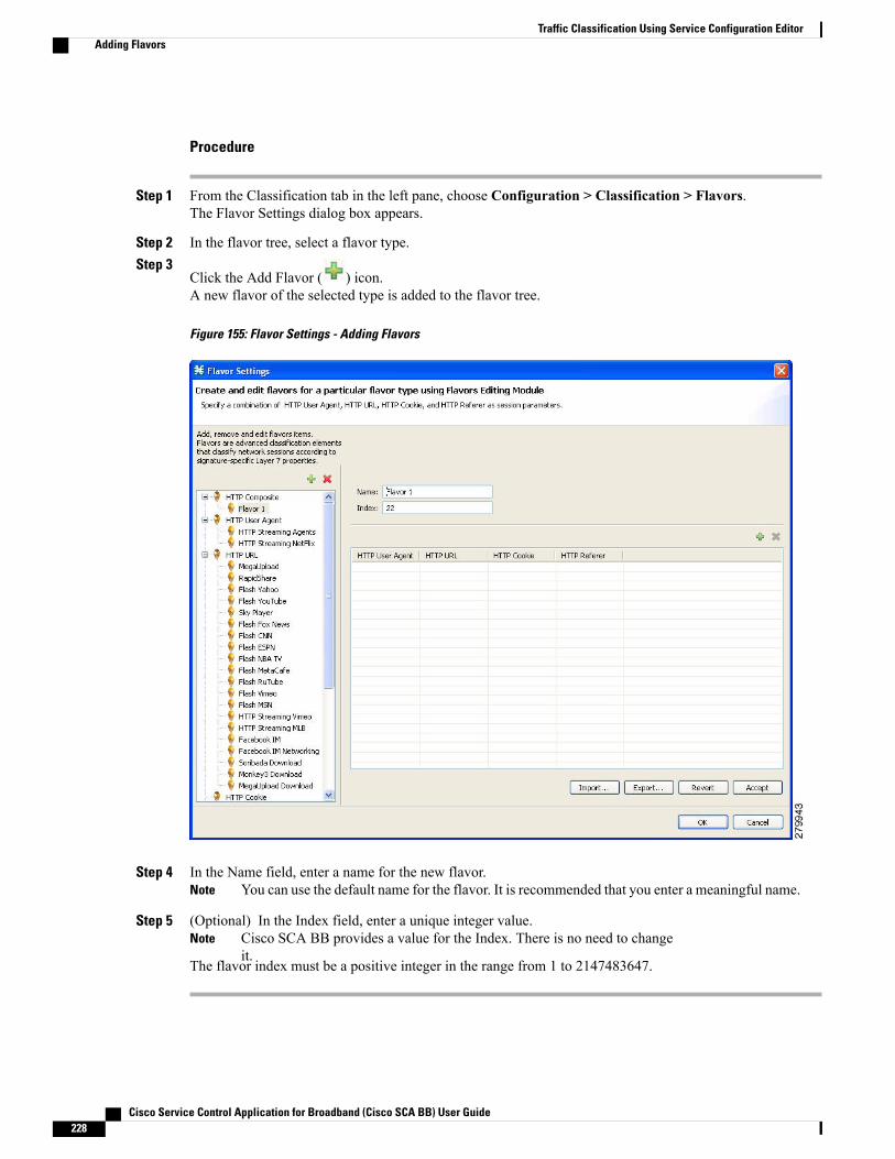
Procedure
Step 1 From the Classification tab in the left pane, choose Configuration > Classification > Flavors.The Flavor Settings dialog box appears.
Step 2 In the flavor tree, select a flavor type.Step 3
Click the Add Flavor ( ) icon.A new flavor of the selected type is added to the flavor tree.
Figure 155: Flavor Settings - Adding Flavors
Step 4 In the Name field, enter a name for the new flavor.You can use the default name for the flavor. It is recommended that you enter a meaningful name.Note
Step 5 (Optional) In the Index field, enter a unique integer value.Cisco SCA BB provides a value for the Index. There is no need to changeit.
Note
The flavor index must be a positive integer in the range from 1 to 2147483647.
Cisco Service Control Application for Broadband (Cisco SCA BB) User Guide228
Traffic Classification Using Service Configuration EditorAdding Flavors
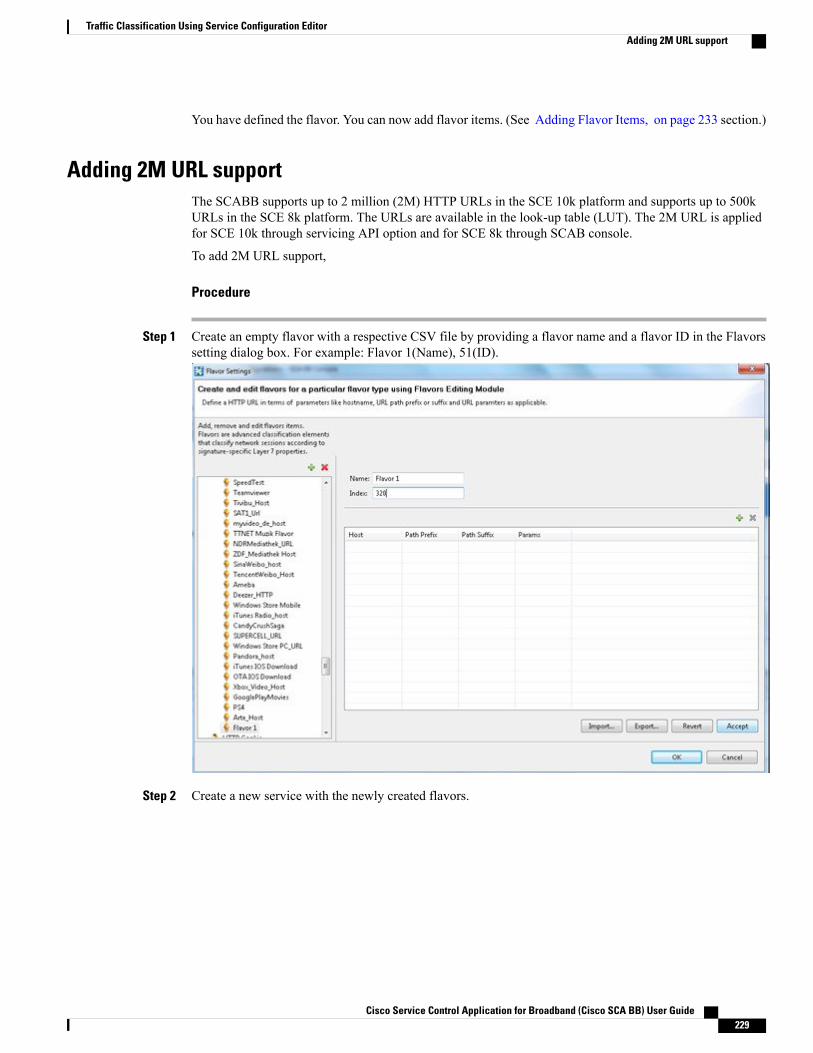
You have defined the flavor. You can now add flavor items. (See Adding Flavor Items, on page 233 section.)
Adding 2M URL supportThe SCABB supports up to 2 million (2M) HTTP URLs in the SCE 10k platform and supports up to 500kURLs in the SCE 8k platform. The URLs are available in the look-up table (LUT). The 2M URL is appliedfor SCE 10k through servicing API option and for SCE 8k through SCAB console.
To add 2M URL support,
Procedure
Step 1 Create an empty flavor with a respective CSV file by providing a flavor name and a flavor ID in the Flavorssetting dialog box. For example: Flavor 1(Name), 51(ID).
Step 2 Create a new service with the newly created flavors.
Cisco Service Control Application for Broadband (Cisco SCA BB) User Guide 229
Traffic Classification Using Service Configuration EditorAdding 2M URL support
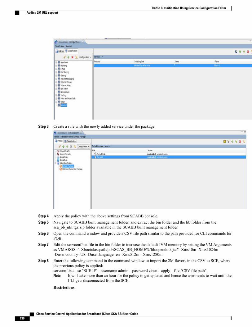
Step 3 Create a rule with the newly added service under the package.
Step 4 Apply the policy with the above settings from SCABB console.Step 5 Navigate to SCABB built management folder, and extract the bin folder and the lib folder from the
sca_bb_util.tgz zip folder available in the SCABB built management folder.Step 6 Open the command window and provide a CSV file path similar to the path provided for CLI commands for
PQB.Step 7 Edit the servconf.bat file in the bin folder to increase the default JVM memory by setting the VM Arguments
as VMARGS="-Xbootclasspath/p:%SCAS_BB_HOME%/lib/opendmk.jar" -Xms40m -Xmx1024m-Duser.country=US -Duser.language=en -Xms512m - Xmx1280m.
Step 8 Enter the following command in the command window to import the 2M flavors in the CSV to SCE, wherethe previous policy is applied:servconf.bat --se "SCE IP" --username admin --password cisco --apply --file "CSV file path".
It will take more than an hour for the policy to get updated and hence the user needs to wait until theCLI gets disconnected from the SCE.
Note
Restrictions:
Cisco Service Control Application for Broadband (Cisco SCA BB) User Guide230
Traffic Classification Using Service Configuration EditorAdding 2M URL support
• Easy format CSV files are not supported.
• Multiple CSV files are not supported. So the user is recommended to maintain a single 2M URL CSVfile.
• The CSV file corresponding to the policy that has been applied via API is not stored on the ServiceControl Engine (SCE). So, the user can view the policy applied only through SCABB.
• The user is recommended to apply policy through SCABB first and then through API, if it is done inreverse order all the 2M URLs in LUT will be overwritten. To retrieve the overwritten 2M URLs, theCLI has to be re-executed.
The above configuration can be done only after increasing the size of HTTP URL flavor LUT to2M.
Caution
Editing FlavorsYou can modify flavor parameters at any time.
To add, modify, or delete flavor items, see Introduction to Managing Flavor Items, on page 232 section .
Procedure
Step 1 From the Classification tab in the left pane, choose Configuration > Classification > Flavors .The Flavor Settings dialog box appears.
Step 2 In the flavor tree, select a flavor.The name and index of the flavor (and its flavor items) are displayed in the right area.
Step 3 Modify fields in the dialog box:a) In the Name field, enter a new name for the flavor.b) In the Index field, enter a new, unique index for the flavor.
The flavor index must be a positive integer in the range from 1 to 2147483647.
Step 4 Click OK.The Flavor Settings dialog box closes.
Deleting FlavorsYou can delete any or all flavors.
Cisco Service Control Application for Broadband (Cisco SCA BB) User Guide 231
Traffic Classification Using Service Configuration EditorEditing Flavors

Procedure
Step 1 From the Classification tab in the left pane, choose Configuration > Classification > Flavors .The Flavor Settings dialog box appears.
Step 2 In the flavor tree, right-click a flavor.A popup menu appears.
Step 3Click the Delete ( ) icon.A Confirm Delete message appears.
Figure 156: Confirm Delete
Step 4 Click OK.If any service element references the selected flavor, a Confirm References Delete message appears.
Figure 157: Confirm References Deletion
Step 5 Click Yes.Every service element that references the selected flavor is deleted.
The flavor is deleted and is no longer displayed in the flavor tree.
Step 6 Click Close.The Flavor Settings dialog box closes.
Introduction to Managing Flavor ItemsA flavor is a collection of related flavor items.
Cisco Service Control Application for Broadband (Cisco SCA BB) User Guide232
Traffic Classification Using Service Configuration EditorIntroduction to Managing Flavor Items
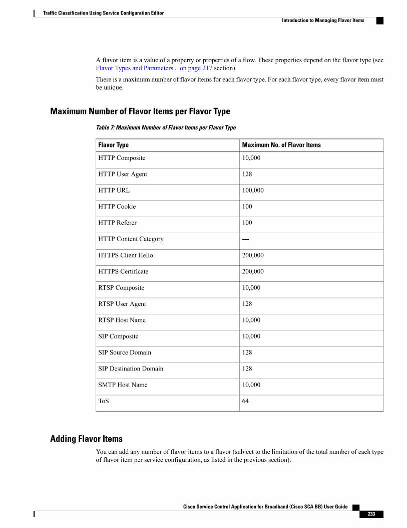
A flavor item is a value of a property or properties of a flow. These properties depend on the flavor type (seeFlavor Types and Parameters , on page 217 section).
There is a maximum number of flavor items for each flavor type. For each flavor type, every flavor item mustbe unique.
Maximum Number of Flavor Items per Flavor Type
Table 7: Maximum Number of Flavor Items per Flavor Type
Maximum No. of Flavor ItemsFlavor Type
10,000HTTP Composite
128HTTP User Agent
100,000HTTP URL
100HTTP Cookie
100HTTP Referer
—HTTP Content Category
200,000HTTPS Client Hello
200,000HTTPS Certificate
10,000RTSP Composite
128RTSP User Agent
10,000RTSP Host Name
10,000SIP Composite
128SIP Source Domain
128SIP Destination Domain
10,000SMTP Host Name
64ToS
Adding Flavor ItemsYou can add any number of flavor items to a flavor (subject to the limitation of the total number of each typeof flavor item per service configuration, as listed in the previous section).
Cisco Service Control Application for Broadband (Cisco SCA BB) User Guide 233
Traffic Classification Using Service Configuration EditorIntroduction to Managing Flavor Items
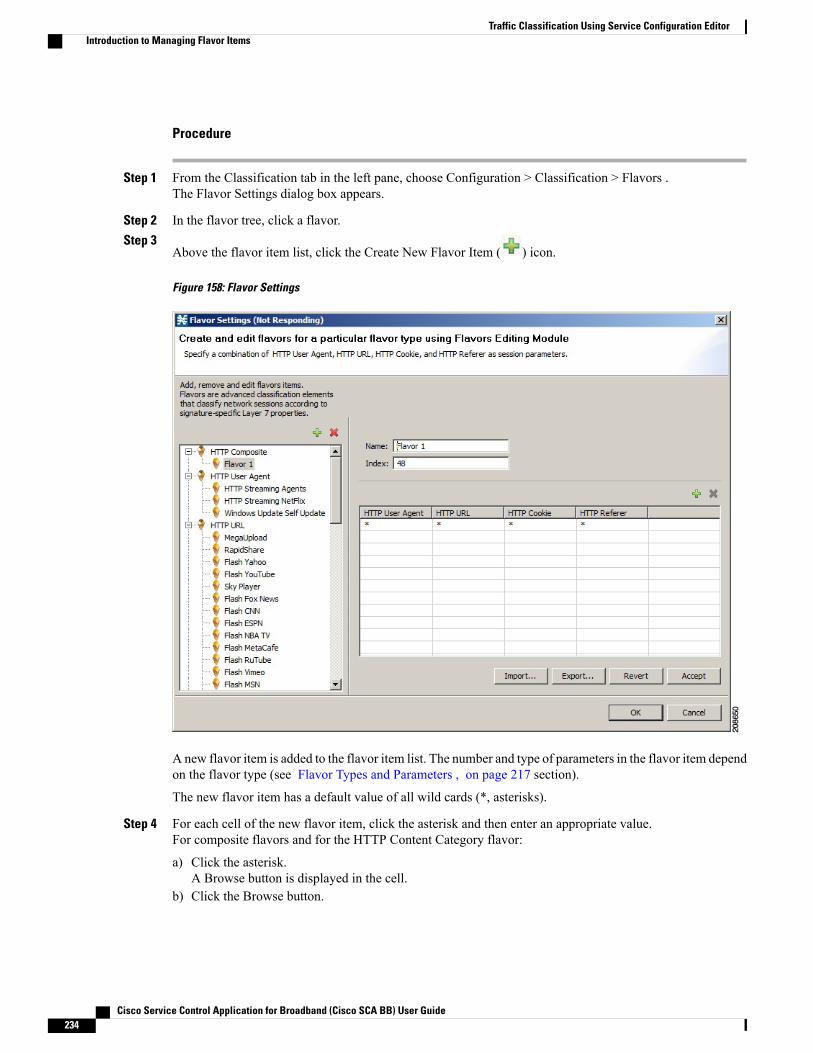
Procedure
Step 1 From the Classification tab in the left pane, choose Configuration > Classification > Flavors .The Flavor Settings dialog box appears.
Step 2 In the flavor tree, click a flavor.Step 3
Above the flavor item list, click the Create New Flavor Item ( ) icon.
Figure 158: Flavor Settings
A new flavor item is added to the flavor item list. The number and type of parameters in the flavor item dependon the flavor type (see Flavor Types and Parameters , on page 217 section).
The new flavor item has a default value of all wild cards (*, asterisks).
Step 4 For each cell of the new flavor item, click the asterisk and then enter an appropriate value.For composite flavors and for the HTTP Content Category flavor:
a) Click the asterisk.A Browse button is displayed in the cell.
b) Click the Browse button.
Cisco Service Control Application for Broadband (Cisco SCA BB) User Guide234
Traffic Classification Using Service Configuration EditorIntroduction to Managing Flavor Items
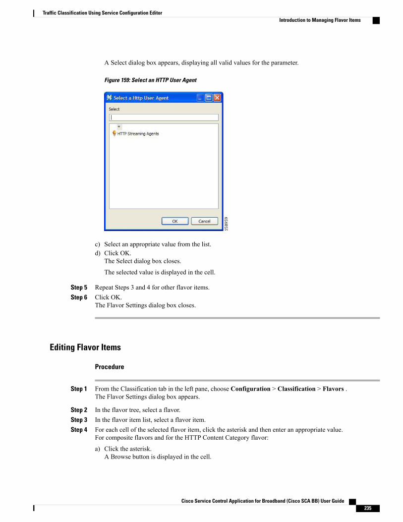
A Select dialog box appears, displaying all valid values for the parameter.
Figure 159: Select an HTTP User Agent
c) Select an appropriate value from the list.d) Click OK.
The Select dialog box closes.
The selected value is displayed in the cell.
Step 5 Repeat Steps 3 and 4 for other flavor items.Step 6 Click OK.
The Flavor Settings dialog box closes.
Editing Flavor Items
Procedure
Step 1 From the Classification tab in the left pane, choose Configuration > Classification > Flavors .The Flavor Settings dialog box appears.
Step 2 In the flavor tree, select a flavor.Step 3 In the flavor item list, select a flavor item.Step 4 For each cell of the selected flavor item, click the asterisk and then enter an appropriate value.
For composite flavors and for the HTTP Content Category flavor:
a) Click the asterisk.A Browse button is displayed in the cell.
Cisco Service Control Application for Broadband (Cisco SCA BB) User Guide 235
Traffic Classification Using Service Configuration EditorIntroduction to Managing Flavor Items
b) Click the Browse button.A Select dialog box appears, displaying all valid values for the parameter.
c) Select an appropriate value from the list.d) Click OK.
The Select dialog box closes.
The selected value is displayed in the cell.
Step 5 Click OK.The Flavor Settings dialog box closes.
Deleting Flavor Items
Procedure
Step 1 From the Classification tab in the left pane, choose Configuration > Classification > Flavors .The Flavor Settings dialog box appears.
Step 2 In the flavor tree, select a flavor.Step 3 In the flavor item list, right-click anywhere in a flavor item.
A popup menu appears.
Step 4Click the Delete ( ) icon.The flavor item is deleted and is no longer displayed in the flavor item list.
Step 5 Click Close .The Flavor Settings dialog box closes.
Example on How to Import a List of URLs and Block ThemThe following example shows how to import a URL file and configure the Cisco SCE to block these URLs
Procedure
Step 1 Create a new flavor under the HTTP URL flavor type.For details, see the Adding Flavors, on page 227 section.
Step 2 Import a CSV file containing the URLS you wish to block.For further information, see Importing Service Configuration Data , on page 154 section.
The CSV file formats are described in the “CSV File Formats” chapter of Cisco Service ControlApplication Suit for Broadband Reference Guide .
Note
Step 3 Define a Service.
Cisco Service Control Application for Broadband (Cisco SCA BB) User Guide236
Traffic Classification Using Service Configuration EditorExample on How to Import a List of URLs and Block Them
For further information, see Adding a Service to a Service Configuration , on page 164 section.
Step 4 Within the defined Service, add a service element that uses the new Flavor.For further information, see Adding Service Elements , on page 172 section.
Step 5 Add a rule to the package in which you want to block the URLs, and associate it with the new Service.For further information, see Adding Rules to a Package , on page 343 section.
Step 6 Configure the rule to block the flow.For further information, see Defining Per-Flow Actions for a Rule , on page 345 section.
Introduction to Managing Content FilteringContent filtering involves classification and control of HTTP flows according to the requested URL. Theclassification of the URL is performed by accessing an external database.
Cisco SCA BB provides content filtering by integrating with a SurfControl Content Portal Authority (CPA)server.
Content filtering is not supported when unidirectional classification is enabled.Note
Information About Content FilteringThe Cisco HTTP Content Filtering solution consists of:
• The Cisco SCE application
• The Cisco CPA client
• The SurfControl CPA server
The Cisco SCE application classifies each HTTP flow according to the category returned by the CPA server.This classification is then used for Cisco SCA BB traffic control and reporting. For example, you can definea rule to block browsing of the “Adult/Sexually Explicit” category or to generate reports on the volumeconsumed by browsing the “Kids” or “Shopping” categories.
The Cisco SCE ApplicationThe Cisco service control application runs on the Cisco SCE platform. It forwards HTTPURLs that it extractsfrom traffic to the CPA client and uses the categorization results to classify the original HTTP flow to a service.This classification is then used for normal Cisco SCA BB traffic control and reporting.
The Cisco SCE application communicates with the CPA client using Raw Data Records (RDRs). SeeConfiguring the RDR Formatter , on page 239 section.
Cisco Service Control Application for Broadband (Cisco SCA BB) User Guide 237
Traffic Classification Using Service Configuration EditorIntroduction to Managing Content Filtering
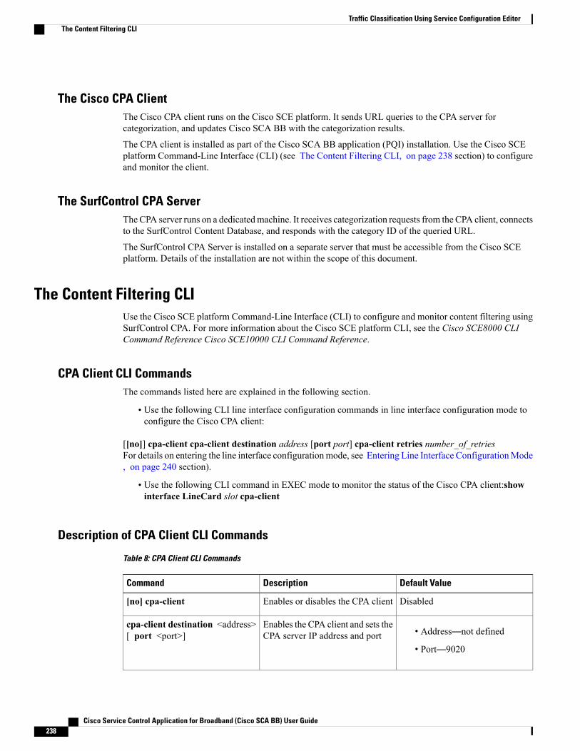
The Cisco CPA ClientThe Cisco CPA client runs on the Cisco SCE platform. It sends URL queries to the CPA server forcategorization, and updates Cisco SCA BB with the categorization results.
The CPA client is installed as part of the Cisco SCA BB application (PQI) installation. Use the Cisco SCEplatform Command-Line Interface (CLI) (see The Content Filtering CLI, on page 238 section) to configureand monitor the client.
The SurfControl CPA ServerThe CPA server runs on a dedicatedmachine. It receives categorization requests from the CPA client, connectsto the SurfControl Content Database, and responds with the category ID of the queried URL.
The SurfControl CPA Server is installed on a separate server that must be accessible from the Cisco SCEplatform. Details of the installation are not within the scope of this document.
The Content Filtering CLIUse the Cisco SCE platform Command-Line Interface (CLI) to configure and monitor content filtering usingSurfControl CPA. For more information about the Cisco SCE platform CLI, see the Cisco SCE8000 CLICommand Reference Cisco SCE10000 CLI Command Reference.
CPA Client CLI CommandsThe commands listed here are explained in the following section.
• Use the following CLI line interface configuration commands in line interface configuration mode toconfigure the Cisco CPA client:
[[no]] cpa-client cpa-client destination address [port port] cpa-client retries number_of_retriesFor details on entering the line interface configuration mode, see Entering Line Interface ConfigurationMode, on page 240 section).
• Use the following CLI command in EXEC mode to monitor the status of the Cisco CPA client:showinterface LineCard slot cpa-client
Description of CPA Client CLI Commands
Table 8: CPA Client CLI Commands
Default ValueDescriptionCommand
DisabledEnables or disables the CPA client[no] cpa-client
• Address—not defined
• Port—9020
Enables the CPA client and sets theCPA server IP address and port
cpa-client destination <address>[ port <port>]
Cisco Service Control Application for Broadband (Cisco SCA BB) User Guide238
Traffic Classification Using Service Configuration EditorThe Content Filtering CLI
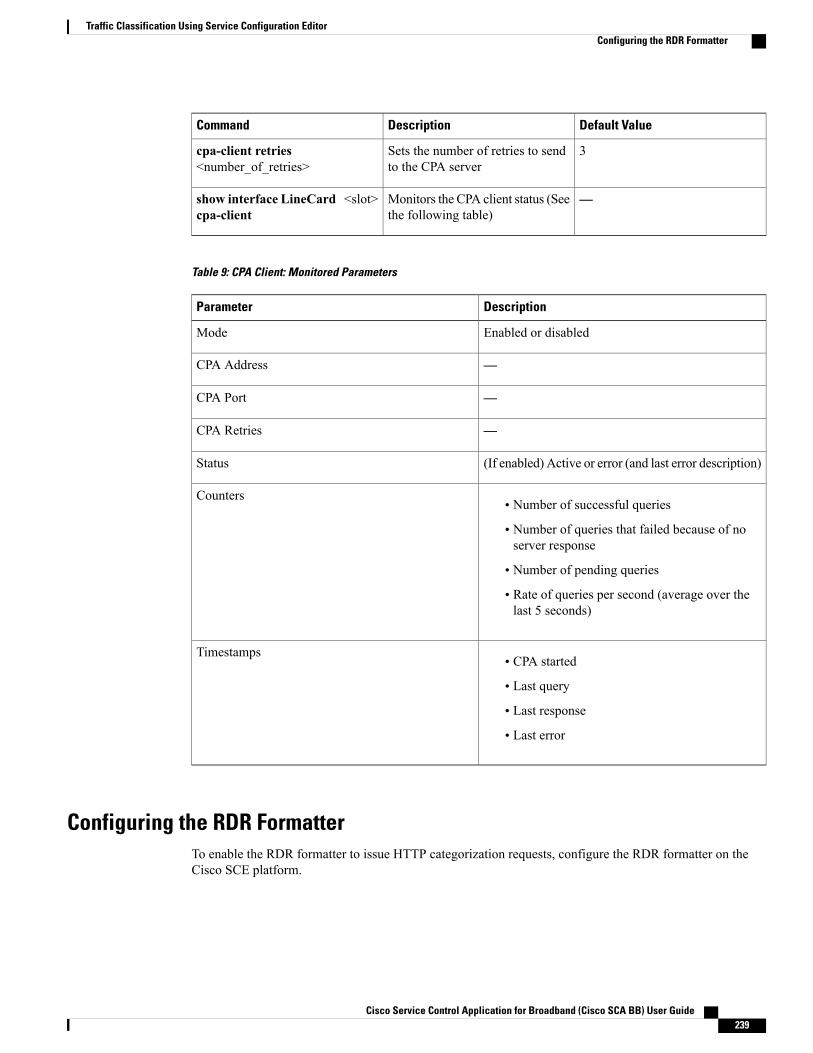
Default ValueDescriptionCommand
3Sets the number of retries to sendto the CPA server
cpa-client retries<number_of_retries>
—Monitors the CPA client status (Seethe following table)
show interface LineCard <slot>cpa-client
Table 9: CPA Client: Monitored Parameters
DescriptionParameter
Enabled or disabledMode
—CPA Address
—CPA Port
—CPA Retries
(If enabled) Active or error (and last error description)Status
• Number of successful queries
• Number of queries that failed because of noserver response
• Number of pending queries
• Rate of queries per second (average over thelast 5 seconds)
Counters
• CPA started
• Last query
• Last response
• Last error
Timestamps
Configuring the RDR FormatterTo enable the RDR formatter to issue HTTP categorization requests, configure the RDR formatter on theCisco SCE platform.
Cisco Service Control Application for Broadband (Cisco SCA BB) User Guide 239
Traffic Classification Using Service Configuration EditorConfiguring the RDR Formatter

Procedure
Step 1Step 2 Run the appropriate CLI commands on Cisco SCE platform.
Example:#>RDR-formatter destination 127.0.0.1 port 33001 category number 4 priority 100
What to Do Next
For more information about configuring the RDR formatter, see either the “Raw Data Formatting: The RDRFormatter and NetFlow Exporting” chapter of Cisco SCE8000 10GBE Software Configuration Guide or the“RawData Formatting: The RDR Formatter and NetFlow Exporting” chapter ofCisco SCE8000 GBE SoftwareConfiguration Guide.
For more information about configuring the RDR formatter, see either the “Raw Data Formatting: The RDRFormatter” chapter of Cisco SCE10000 Software Configuration Guide .
Entering Line Interface Configuration ModeTo run line interface configuration commands you must enter line interface configuration mode and see theSCE(config if)# prompt displayed.
Procedure
Step 1 At the Cisco SCE platform CLI prompt (SCE#), type configure .Step 2 Press Enter.
The SCE(config)# prompt appears.
Step 3 Type interface LineCard 0.Step 4 Press Enter.
The SCE(config if)# prompt appears.
Managing Content Filtering SettingsApplying HTTP URL content filtering requires the following steps in the Service Configuration Editor:
Procedure
Step 1 Import the content filtering configuration file into your service configuration.
Cisco Service Control Application for Broadband (Cisco SCA BB) User Guide240
Traffic Classification Using Service Configuration EditorEntering Line Interface Configuration Mode

By default, Cisco SCABB creates a separate flavor (of type HTTPContent Category) for each content categoryand a service element for each new flavor. A new top-level service, “HTTP Browsing with Categories”, iscreated, comprising these service elements.
Step 2 Create new services and map the new category flavors to them.Step 3 Create additional rule entries for ClickStream services for each flavor.Step 4 Configure ClickStream Services with the HTTP Browsing services for optimal HTTP content filtering.Step 5 Add content filtering rules to existing packages or create new packages that include content filtering rules.Step 6 Enable content filtering for selected packages.Step 7 Apply the service configuration.
What to Do Next
Importing Content Filtering CategoriesBefore you can control HTTP flows based on content, you must import an XML file provided with theinstallation.
You cannot import content filtering categories when unidirectional classification is enabled.Note
Procedure
Step 1 Unzip the installation package.Step 2 Open the URL Filtering subfolder.
Cisco Service Control Application for Broadband (Cisco SCA BB) User Guide 241
Traffic Classification Using Service Configuration EditorManaging Content Filtering Settings

What to Do Next
HTTP Content Category Flavors
By default, Cisco SCABB creates a separate flavor (of type HTTPContent Category) for each content categorywhen importing the XML file.
Figure 160: Flavor Settings
You can create additional HTTP Content Category Flavors that include two or more content categories. (SeeAdding Flavors, on page 227 section.)
Cisco Service Control Application for Broadband (Cisco SCA BB) User Guide242
Traffic Classification Using Service Configuration EditorManaging Content Filtering Settings
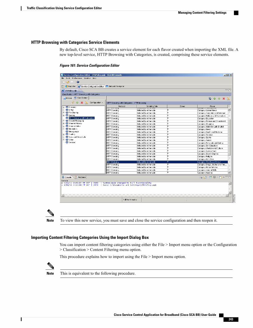
HTTP Browsing with Categories Service Elements
By default, Cisco SCA BB creates a service element for each flavor created when importing the XML file. Anew top-level service, HTTP Browsing with Categories, is created, comprising these service elements.
Figure 161: Service Configuration Editor
To view this new service, you must save and close the service configuration and then reopen it.Note
Importing Content Filtering Categories Using the Import Dialog Box
You can import content filtering categories using either the File > Import menu option or the Configuration> Classification > Content Filtering menu option.
This procedure explains how to import using the File > Import menu option.
This is equivalent to the following procedure.Note
Cisco Service Control Application for Broadband (Cisco SCA BB) User Guide 243
Traffic Classification Using Service Configuration EditorManaging Content Filtering Settings
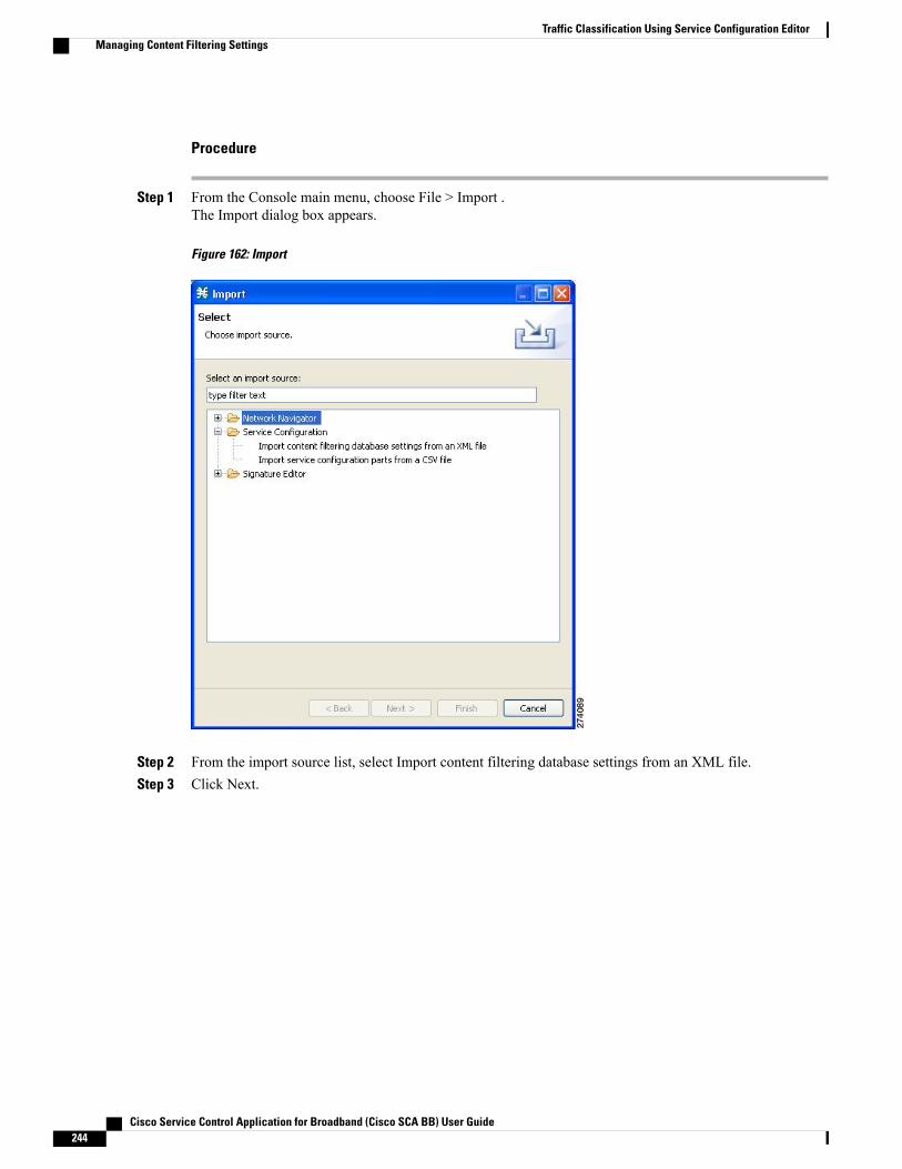
Procedure
Step 1 From the Console main menu, choose File > Import .The Import dialog box appears.
Figure 162: Import
Step 2 From the import source list, select Import content filtering database settings from an XML file.Step 3 Click Next.
Cisco Service Control Application for Broadband (Cisco SCA BB) User Guide244
Traffic Classification Using Service Configuration EditorManaging Content Filtering Settings

The Import Content Filtering Database Settings dialog box appears.
Figure 163: Import Content Filtering Database Settings
Step 4 Click the Browse button next to the Select an XML file field.An Open dialog box appears.
Step 5 Browse to the folder containing the file to import, and select it.For CPAof SurfControl, the file is named surfcontrol.xml.Note
Step 6 Click Open to select the file.The Open dialog box closes.
Information about the content of the XML file is displayed in the Database Settings pane of the Import ContentFiltering Database Settings dialog box.
By default, Cisco SCABB creates a separate flavor (of type HTTPContent Category) for each content categorywhen importing the XML file.
Cisco Service Control Application for Broadband (Cisco SCA BB) User Guide 245
Traffic Classification Using Service Configuration EditorManaging Content Filtering Settings

By default, Cisco SCA BB creates a service element for each flavor created in the previous Step. A newtop-level service, HTTP Browsing with Categories, is created, comprising these service elements.
Step 7 (Optional) To disable the default behavior of creating a separate flavor for each content category, uncheckthe Create a distinct Flavor for each Content Category check box.
It is recommended that you do not disable this option.Note
Step 8 (Optional) To disable the default behavior of creating service element for each flavor, uncheck the Create aService Element for each Content Category Flavor in Service ‘HTTP Browsing with Categories’ check box.
It is recommended that you do not disable this option.Note
Step 9 Click Finish.The Import Content Filtering Database Settings dialog box closes.
Information from the imported file is displayed in the Database Settings tab of the HTTP Content FilteringSettings dialog box.
Figure 164: HTTP Content Filtering Settings
Step 10 Click OK.The HTTP Content Filtering Settings dialog box closes.
Cisco Service Control Application for Broadband (Cisco SCA BB) User Guide246
Traffic Classification Using Service Configuration EditorManaging Content Filtering Settings

Importing Content Filtering Categories Using the HTTP Content Filtering Settings Dialog Box
You can import content filtering categories using either the File > Import menu option or the Configuration> Classification > Content Filtering menu option.
This procedure explains how to import using the Configuration > Classification > Content Filtering menuoption.
This is equivalent to the Importing Content Filtering Categories Using the Import Dialog Box, on page243 procedure.
Note
Procedure
Step 1 From the Classification tab in the left pane, choose Configuration > Classification > Content Filtering .The HTTP Content Filtering Settings dialog box appears.
Step 2 Click the Database Settings tab.The Database Settings tab opens.
Step 3 Click Import.The Import Content Filtering Database Settings dialog box appears.
Step 4 Click the Browse button next to the Select an XML file field.An Open dialog box appears.
Step 5 Browse to the folder containing the file to import, and select it.For the CPA of SurfControl, the file is named surfcontrol.xml.Note
Step 6 Click Open to select the file.The Open dialog box closes.
Information about the content of the XML file is displayed in the Database Settings pane of the Import ContentFiltering Database Settings dialog box.
By default, Cisco SCABB creates a separate flavor (of type HTTPContent Category) for each content categorywhen importing the XML file.
By default, Cisco SCA BB creates a service element for each flavor created in the previous Step. A newtop-level service, HTTP Browsing with Categories, is created, comprising these service elements.
Step 7 (Optional) To disable the default behavior of creating a separate flavor for each content category, uncheckthe Create a distinct Flavor for each Content Category check box.
It is recommended that you do not disable this option.Note
Step 8 (Optional) To disable the default behavior of creating a service element for each flavor, uncheck the Createa Service Element for each Content Category Flavor in Service ‘HTTP Browsing with Categories’ check box.
It is recommended that you do not disable this option.Note
Step 9 Click Finish.The Import Content Filtering Database Settings dialog box closes.
Cisco Service Control Application for Broadband (Cisco SCA BB) User Guide 247
Traffic Classification Using Service Configuration EditorManaging Content Filtering Settings
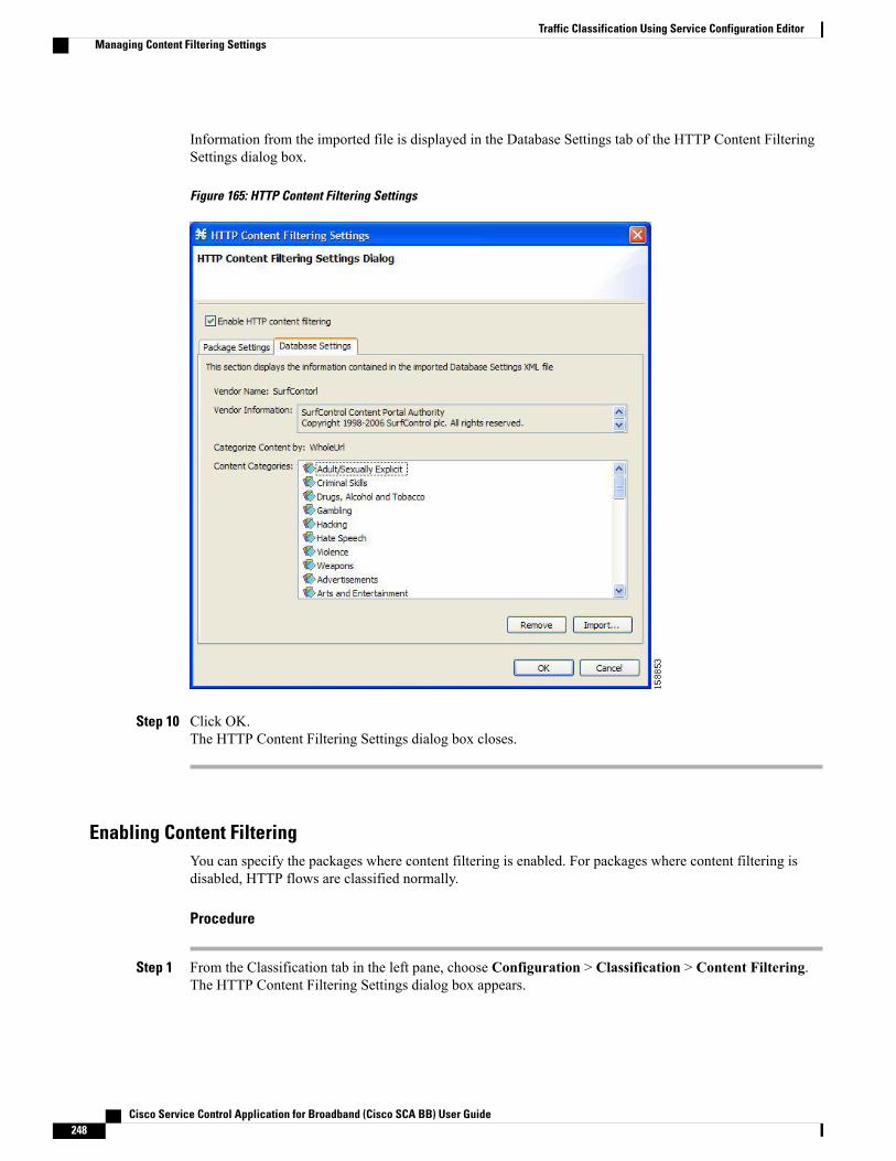
Information from the imported file is displayed in the Database Settings tab of the HTTP Content FilteringSettings dialog box.
Figure 165: HTTP Content Filtering Settings
Step 10 Click OK.The HTTP Content Filtering Settings dialog box closes.
Enabling Content FilteringYou can specify the packages where content filtering is enabled. For packages where content filtering isdisabled, HTTP flows are classified normally.
Procedure
Step 1 From the Classification tab in the left pane, choose Configuration > Classification > Content Filtering.The HTTP Content Filtering Settings dialog box appears.
Cisco Service Control Application for Broadband (Cisco SCA BB) User Guide248
Traffic Classification Using Service Configuration EditorManaging Content Filtering Settings

The Package Settings tab displays a list of all packages defined for the current service configuration.
Figure 166: HTTP Content Filtering Settings
Step 2 Check the Enable HTTP content filtering check box.Step 3 Check the check box next to each package for which content filtering is to be applied.Step 4 Click OK.
The HTTP Content Filtering Settings dialog box closes.
Viewing Content Filtering SettingsYou can view whether content filtering is enabled and to which packages content filtering is applied, andinformation about the content filtering vendor and the content categories of the vendor.
Procedure
Step 1 From the Classification tab in the left pane, choose Configuration > Classification > Content Filtering .The HTTP Content Filtering Settings dialog box appears.
Cisco Service Control Application for Broadband (Cisco SCA BB) User Guide 249
Traffic Classification Using Service Configuration EditorManaging Content Filtering Settings
The Package Settings tab displays a list of all packages defined for the current service configuration, andshows for which packages content filtering is enabled.
Step 2 Click the Database Settings tab.The Database Settings tab opens.
This tab displays information about the content filtering vendor and the content categories of the vendor.
Step 3 Click OK .The HTTP Content Filtering Settings dialog box closes.
Configuring Content FilteringWhile configuring Content Filtering, you must enter the ClickStream-New Page and ClickStream-New Siteservices along with HTTP Browsing protocol services for optimal HTTP content filtering.
The term ClickStream refers to all events generated by user clicks, including enter. If configured, Cisco SCEidentifies the HTTP transactions on the flows that were initialized due to direct user actions such as click ona link, enter a URL in the browser address bar and press enter.
Procedure
Step 1 Open Cisco SCA BB Service Configuration Editor with the default content filtering file (PQB).Step 2 Add a new service Service1.Step 3 Verify that you do not have duplicate service elements. Cisco SCA BB does not allow duplicate service
elements.Step 4 Move the desired service element from HTTP Browsing with Categories to Service1.Step 5 In Service1 , add a service element using protocol ClickStream–New Page and with the same Flavor selected
in Step 4.Step 6 In Service1, add a service element using protocol ClickStream–New Site and with the same Flavor selected
in Step 4.Step 7 Save the service configuration file (PQB).Step 8 Use the service to create rules in the desired package.
Example for How to Configure Content Filtering for Web Based E-mail
To configure content filtering for Web Based E-mail, complete the following steps:
Procedure
Step 1 Open Cisco SCA BB Service Configuration Editor with the default content filtering file (PQB).Step 2 Add a new service Service1.Step 3 Move the service element Category.Web-based E-mail from HTTP Browsing with Categories to Service1.
Cisco Service Control Application for Broadband (Cisco SCA BB) User Guide250
Traffic Classification Using Service Configuration EditorManaging Content Filtering Settings
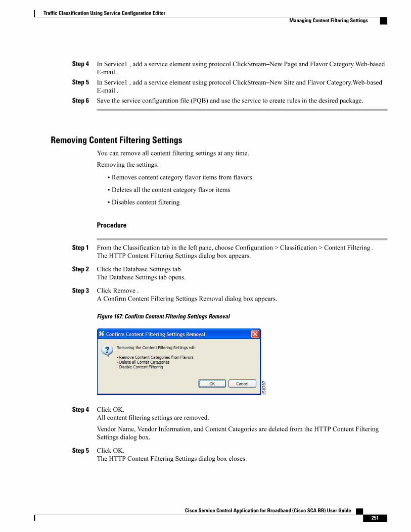
Step 4 In Service1 , add a service element using protocol ClickStream–New Page and Flavor Category.Web-basedE-mail .
Step 5 In Service1 , add a service element using protocol ClickStream–New Site and Flavor Category.Web-basedE-mail .
Step 6 Save the service configuration file (PQB) and use the service to create rules in the desired package.
Removing Content Filtering SettingsYou can remove all content filtering settings at any time.
Removing the settings:
• Removes content category flavor items from flavors
• Deletes all the content category flavor items
• Disables content filtering
Procedure
Step 1 From the Classification tab in the left pane, choose Configuration > Classification > Content Filtering .The HTTP Content Filtering Settings dialog box appears.
Step 2 Click the Database Settings tab.The Database Settings tab opens.
Step 3 Click Remove .A Confirm Content Filtering Settings Removal dialog box appears.
Figure 167: Confirm Content Filtering Settings Removal
Step 4 Click OK.All content filtering settings are removed.
Vendor Name, Vendor Information, and Content Categories are deleted from the HTTP Content FilteringSettings dialog box.
Step 5 Click OK.The HTTP Content Filtering Settings dialog box closes.
Cisco Service Control Application for Broadband (Cisco SCA BB) User Guide 251
Traffic Classification Using Service Configuration EditorManaging Content Filtering Settings
• Generic Protocols—Generic IP, Generic TCP, and Generic UDP protocols, used for transactions thatare not specifically mapped to a protocol by any other protocol type.
• IP Protocols—Protocols (such as ICMP), other than TCP and UDP protocols, identified according tothe IP protocol number of the transaction.
• Port-Based Protocols—TCP and UDP protocols, classified according to their well-known ports. Thedefault service configuration includes more than 750 common port-based protocols.
• Signature-Based Protocols—Protocols classified according to a Layer 7 application signature. Includesthe most common protocols, such as HTTP and FTP, and a large group of popular P2P protocols.
• P2P Protocols—Peer-to-peer file-sharing application protocols classified according to a Layer 7 applicationsignature.
• VoIP Protocols—Voice-over-IP application protocols classified according to a Layer 7 applicationsignature.
• SIP Protocols—Protocols classified according to a Layer 7 application signature that is SIP or has SIPcharacteristics.
•Worm Protocols—Protocols classified according to a Layer 7 application signature that is based ontraffic patterns of Internet worms.
• Packet Stream Pattern Based Protocols—Protocols classified according to a Layer 7 application signaturethat is based on the pattern of the packet stream (for example, the stream’s symmetry, average packetsize, and rate) rather than on the packet’s payload content.
• Unidirectionally Detected Protocols—Protocols having a unidirectional signature.
Some protocols belong to more than one category. In particular, all predefined P2P, VoIP, SIP, Worm,and Packet Stream Pattern-Based Protocols are also defined as Signature-Based Protocols.
Note
Step 6 From the Classification tab in the left pane, choose Configuration > Classification > Protocols .The Protocol Settings dialog box appears.
Step 7 From the drop-down list in the Protocols tab, select the type of protocol to display.The protocols of the selected type appear in the Protocols tab.
Step 8 Click Close .The Protocol Settings dialog box closes.
The setting in the drop-down list is not saved. The next time you open the Protocol Settings dialogbox, all protocols are displayed.
Note
OS Fingerprinting OverviewCisco SCE detects the operating system (OS) used by a subscriber by using the passive OS Fingerprinting.In passive OS fingerprinting, TCP and IP header received from target host is analyzed to identify the OS.
Cisco SCE uses OS fingerprinting signatures to identify the subscriber OS. By default, Cisco SCOS containsa signature file that contains a default set of OS. Details of unknown OS may be added to the signature filesusing the Cisco SCA BB Console.
Cisco Service Control Application for Broadband (Cisco SCA BB) User Guide252
Traffic Classification Using Service Configuration EditorOS Fingerprinting Overview
Cisco SCE also determines whether the subscriber is behind a NAT and whether the same subscriber isconnecting using multiple OS. If multiple OS is detected for the same subscriber, Cisco SCE considers thesubscriber as using a NAT.
From the Cisco SCA BB Console, you can also configure Cisco SCE to send the OS information of thesubscriber in Gx messages.
The OS Fingerprinting feature is supported only on Cisco SCE 8000 devices.Note
The OS Fingerprinting feature is supported only on Cisco SCE 10000 devices.Note
Limitations:
• OS information is available only for logged-in or active subscribers.
• The signature database is built based on the default settings used by various OS. If the user changes thedefault parameters like TCP window size through registries, it would not be possible or may lead towrong classification of the OS.
• If the subscriber has only one flow, then OS type is be detected. Subscribers that have only UDP flowsare not detected
• If all users behind a NAT use the same OS, it will not be possible to identify NAT.
• If a subscriber runs multiple OS using VMWare, it may be detected as NAT even though the subscriberis not in a NAT environment
• OS finger printing is not done continuously for any subscriber. So, if a subscriber changes OS or movesto a NAT environment during the time when he is not sampled, OS Information and NAT cannot bedetected.
Enabling OS Fingerprinting
Procedure
Step 1 In Service Configuration Editor, select Configuration > OS Finger Print... .The OS Fingerprinting Settings dialog box appears.
Step 2 Check the Enable OS Finger Printing check box.
Cisco Service Control Application for Broadband (Cisco SCA BB) User Guide 253
Traffic Classification Using Service Configuration EditorEnabling OS Fingerprinting
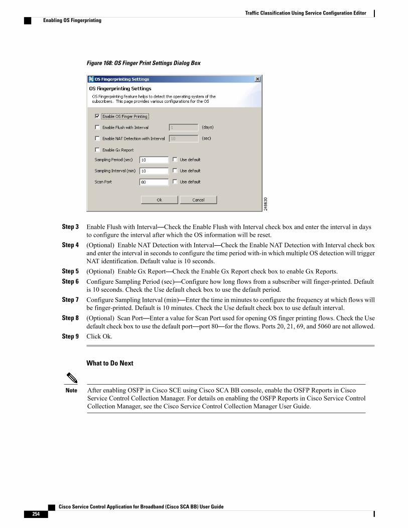
Figure 168: OS Finger Print Settings Dialog Box
Step 3 Enable Flush with Interval—Check the Enable Flush with Interval check box and enter the interval in daysto configure the interval after which the OS information will be reset.
Step 4 (Optional) Enable NAT Detection with Interval—Check the Enable NAT Detection with Interval check boxand enter the interval in seconds to configure the time period with-in which multiple OS detection will triggerNAT identification. Default value is 10 seconds.
Step 5 (Optional) Enable Gx Report—Check the Enable Gx Report check box to enable Gx Reports.Step 6 Configure Sampling Period (sec)—Configure how long flows from a subscriber will finger-printed. Default
is 10 seconds. Check the Use default check box to use the default period.Step 7 Configure Sampling Interval (min)—Enter the time in minutes to configure the frequency at which flows will
be finger-printed. Default is 10 minutes. Check the Use default check box to use default interval.Step 8 (Optional) Scan Port—Enter a value for Scan Port used for opening OS finger printing flows. Check the Use
default check box to use the default port—port 80—for the flows. Ports 20, 21, 69, and 5060 are not allowed.Step 9 Click Ok.
What to Do Next
After enabling OSFP in Cisco SCE using Cisco SCA BB console, enable the OSFP Reports in CiscoService Control Collection Manager. For details on enabling the OSFP Reports in Cisco Service ControlCollection Manager, see the Cisco Service Control Collection Manager User Guide.
Note
Cisco Service Control Application for Broadband (Cisco SCA BB) User Guide254
Traffic Classification Using Service Configuration EditorEnabling OS Fingerprinting
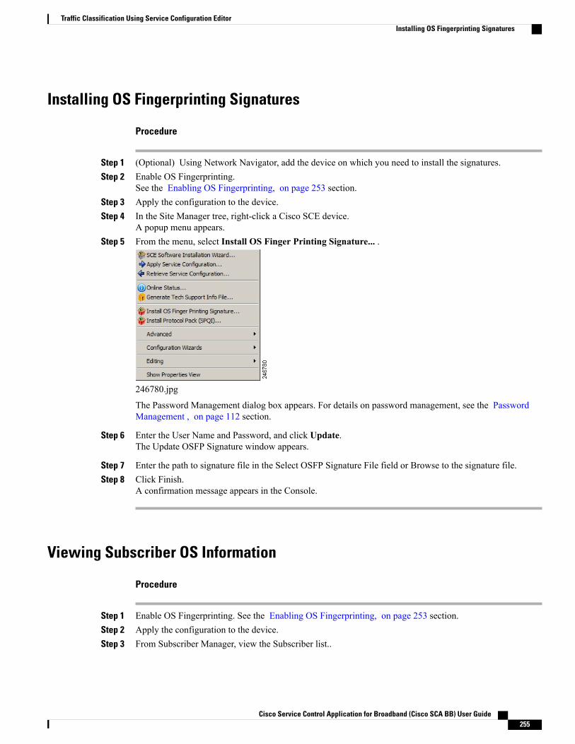
Installing OS Fingerprinting Signatures
Procedure
Step 1 (Optional) Using Network Navigator, add the device on which you need to install the signatures.Step 2 Enable OS Fingerprinting.
See the Enabling OS Fingerprinting, on page 253 section.Step 3 Apply the configuration to the device.Step 4 In the Site Manager tree, right-click a Cisco SCE device.
A popup menu appears.Step 5 From the menu, select Install OS Finger Printing Signature... .
246780.jpg
The Password Management dialog box appears. For details on password management, see the PasswordManagement , on page 112 section.
Step 6 Enter the User Name and Password, and click Update.The Update OSFP Signature window appears.
Step 7 Enter the path to signature file in the Select OSFP Signature File field or Browse to the signature file.Step 8 Click Finish.
A confirmation message appears in the Console.
Viewing Subscriber OS Information
Procedure
Step 1 Enable OS Fingerprinting. See the Enabling OS Fingerprinting, on page 253 section.Step 2 Apply the configuration to the device.Step 3 From Subscriber Manager, view the Subscriber list..
Cisco Service Control Application for Broadband (Cisco SCA BB) User Guide 255
Traffic Classification Using Service Configuration EditorInstalling OS Fingerprinting Signatures

Step 4 Right-click on the device, and select View Online Status .
The online status of the subscriber appears near the console panel with the OS information. The OSFingerprinting is available for Anonymous Groups through Anonymous Group Manager GUI Tool.
Disabling OS Fingerprinting
Procedure
Step 1 In the Service Configuration Editor, select Configuration > OS Finger Print... .The OS Finger Printing Settings dialog box appears.
Step 2 Uncheck the Enable OS Finger Printing check box.
The OS Fingerprinting CLIUse the following CLI command in EXEC mode to monitor the OS details of the subscriber:
show os-fingerprinting subscriber-nameIn this example, Cisco SCE has detected a NAT and behind the NAT two OS. One is iOS with an indexnumber 65 and another OS that is not known to Cisco SCE:SCE8000#> show os-fingerprinting subscriber-name 192.168.0.5@testofp
Subscriber 192.168.0.5@testofp OS-Info:IP Address:192.168.0.5OS-INFO:1. INDEX: 65 OS Name: iOSUNKNOWN OS FOUNDNAT DETECTED
SCE10000#> show os-fingerprinting subscriber-name 192.168.0.5@testofp
Subscriber 192.168.0.5@testofp OS-Info:IP Address:192.168.0.5OS-INFO:1. INDEX: 65 OS Name: iOSUNKNOWN OS FOUNDNAT DETECTED
Configuring Policy for DNS Assisted ClassificationBy default, the DNS traffic is bypassed via the default flow-filters configured in the policy. We need to disableDNS(to network) and DNS(to subscriber) flow-filters and enable first packet classification for DNS traffic,since the packets per DNS-flow are very less and in most of the cases there are only two packets; For example,Request and Response
To configure Policy for DNS Assisted Classification, follow the below procedure:
Cisco Service Control Application for Broadband (Cisco SCA BB) User Guide256
Traffic Classification Using Service Configuration EditorDisabling OS Fingerprinting

Procedure
Step 1 In the existing service configuration policy, select Policy tab and the select Filtered Traffic from the leftnavigation pane.
Step 2 Disable the DNS(to network) and DNS(to subscriber) check boxes in the active pane.
Step 3 Select Configuration > Policies > System Settings… from the Policies :Filtered Traffic window.The System Settings dialog box appears.
Cisco Service Control Application for Broadband (Cisco SCA BB) User Guide 257
Traffic Classification Using Service Configuration EditorConfiguring Policy for DNS Assisted Classification

Step 4 SelectAdvancedOptions tab and clickAdvanced Service ConfigurationOptions ... TheAdvanced ServiceConfiguration Options window appears.
Step 5 Under Classification properties, add a value 53 to the UDP ports for which flow should be opened on firstpacket option.
Cisco Service Control Application for Broadband (Cisco SCA BB) User Guide258
Traffic Classification Using Service Configuration EditorConfiguring Policy for DNS Assisted Classification
Step 6 Click Ok to close Advance Service Configuration Options window.Step 7 Click Ok to close System Settings dialog box.
Apply the Service configuration policy to the SCE.
Cisco Service Control Application for Broadband (Cisco SCA BB) User Guide 259
Traffic Classification Using Service Configuration EditorConfiguring Policy for DNS Assisted Classification

Cisco Service Control Application for Broadband (Cisco SCA BB) User Guide260
Traffic Classification Using Service Configuration EditorConfiguring Policy for DNS Assisted Classification
C H A P T E R 8Traffic Accounting and Reporting Using theService Configuration Editor
This chapter explains how to work with usage counters and Raw Data Records (RDRs).
Traffic Accounting and Reporting is the second step in creating a Cisco SCA BB service configuration. Thischapter consists of these sections:
• Usage Counters, page 261
• Raw Data Records, page 262
• NetFlow Records , page 262
• Managing RDR Settings, page 262
Usage CountersThe Cisco SCA BB collects and maintains various network metrics (such as volume and number of sessions)per service. This accounting takes place per subscriber, per group of subscribers (package or group of packages),and for the entire link.
Service Usage Counters
The system uses the service usage counters to generate data about the total use of each service. A service canuse either its own usage counters, or the usage counters of its parent service. For example, in the default serviceconfiguration the SMTP and POP3 services share the E-Mail service usage counters. Service hierarchydetermines the assignment of services to usage counters. For details on how to configure the service hierarchy,see Editing Services , on page 169 section.
Package Usage Counters
The Cisco SCA BB also collects and maintains various network metrics per package.
The system uses the package usage counters to generate data about the total use of each package. A packagecan use either its own usage counters, or the usage counters of its parent package. The package hierarchydetermines the assignment of packages to usage counters. For details on how to configure the package hierarchy,see Setting Advanced Package Options, on page 332 section.
Cisco Service Control Application for Broadband (Cisco SCA BB) User Guide 261
Raw Data RecordsCisco Service Control Engine (Cisco SCE) platforms generate and transmit Raw Data Records (RDRs) thatcontain information relevant to the service provider. These RDRs contain a wide variety of information andstatistics, depending on the configuration of the system.
• All RDR data is based on Layer 3 volume.
• RDRs are not generated for filtered traffic. For details, see Traffic Flow Filtering, on page 409 section.
The content and structure of each type of RDR is listed in the “RawData Records: Formats and Field Contents”chapter of Cisco Service Control Application for Broadband Reference Guide.
NetFlow Records• You enable and disable the export of NetFlow records using the CLI.
You can export records per supported RDR type. The data in the following RDR types can be exportedusing NetFlow:
◦Subscriber Usage RDR
◦Package Usage RDR
◦Link Usage RDR
◦Zone Usage RDR
• The NetFlow records can be sent to more than one collection device.
• NetFlow records can be generated concurrently with RDRs.
Managing RDR SettingsThis section explains how to configure the generation of the different types of RDRs.
The content and structure of each type of RDR is listed in the “RawData Records: Formats and Field Contents”chapter of Cisco Service Control Application for Broadband Reference Guide.
• RDRs are not generated for filtered traffic (see Traffic Flow Filtering, on page 409 section).
• All RDR data is based on Layer 3 volume.
The RDR Settings Dialog BoxThe RDR Settings dialog box allows you to control the generation of RDRs for an entire service configuration.This dialog box contains seven tabs:
• Usage RDRs tab—Allows you to enable the generation each type of Usage RDR, and define theirgeneration intervals
Cisco Service Control Application for Broadband (Cisco SCA BB) User Guide262
Traffic Accounting and Reporting Using the Service Configuration EditorRaw Data Records

• Transaction RDRs tab—Allows you to enable the generation of Transaction RDRs and define theirmaximum rate of generation
• Quota RDRs tab—Allows you to enable the generation of each type of Quota RDR, and define theirgeneration parameters
• Transaction Usage RDRs tab—Allows you to specify the packages and services for which TransactionUsage RDRs are generated
• Log RDRs tab—Allows you to specify the packages and services for which Log RDRs are generated
• Real-Time Subscriber RDRs tab—Allows you to enable the generation of Real-Time Subscriber UsageRDRs, and define their generation intervals and maximum rate of generation
• Real-Time Signaling RDRs tab—Allows you to specify the packages and services for which Real-TimeSignaling RDRs are generated
Media Flow RDRs and Malicious Traffic Periodic RDRs are enabled and configured in the AdvancedService Configuration Options, on page 451.
Note
Managing Usage RDRsThe five types of Usage RDRs contain data about total usage of all services included in a service usage counter:
• Link Usage RDRs—For the entire link
• Package Usage RDRs—For all subscribers to a particular package
• Subscriber Usage RDRs—For a particular subscriber
• Virtual Links Usage RDRs—For a particular group of virtual links
• Zone Usage RDRs—For the entire zone
You can enable or disable the generation of each type of Usage RDR, and set the generation interval for eachtype of Usage RDR. You can limit the generation rate of Subscriber Usage RDRs. This is advisable whenthere are a large number of subscribers.
By default, all four types of Usage RDRs are enabled. (Virtual Links Usage RDRs are enabled by default onlyif Virtual Links mode was enabled when you created the service configuration.)
Usage RDRs are not generated for blocked sessions. A session is blocked if the service to which the sessionis mapped is blocked for the package for this subscriber (see Defining Per-Flow Actions for a Rule , onpage 345 section), or if the subscriber has exceeded the allowed quota for this service (see QuotaManagement, on page 370“Managing Quotas” section on page 9-90 ).
Note
For detailed information regarding the RDR purpose, default destination, content, generation logic, tag, andfields, see the following sections in Cisco Service Control Application for Broadband Reference Guide :
• Link Usage RDR
• Package Usage RDR
Cisco Service Control Application for Broadband (Cisco SCA BB) User Guide 263
Traffic Accounting and Reporting Using the Service Configuration EditorManaging Usage RDRs
• Subscriber Usage RDR
• Virtual Link Usage RDR
• Zone Usage RDR
Procedure
Step 1 From the Classification tab in the left pane, choose Configuration > Classification > RDR Settings .
Cisco Service Control Application for Broadband (Cisco SCA BB) User Guide264
Traffic Accounting and Reporting Using the Service Configuration EditorManaging Usage RDRs
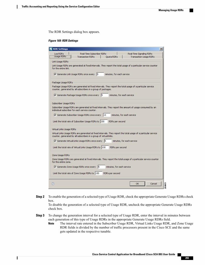
The RDR Settings dialog box appears.
Figure 169: RDR Settings
Step 2 To enable the generation of a selected type of Usage RDR, check the appropriate Generate Usage RDRs checkbox.To disable the generation of a selected type of Usage RDR, uncheck the appropriate Generate Usage RDRscheck box.
Step 3 To change the generation interval for a selected type of Usage RDR, enter the interval in minutes betweeneach generation of this type of Usage RDRs in the appropriate Generate Usage RDRs field.
The interval rate entered in the Subscriber Usage RDR, Virtual Links Usage RDR, and Zone UsageRDR fields is divided by the number of traffic processors present in the Cisco SCE and the samegets updated in the respective tunable.
Note
Cisco Service Control Application for Broadband (Cisco SCA BB) User Guide 265
Traffic Accounting and Reporting Using the Service Configuration EditorManaging Usage RDRs
Step 4 To limit the generation rate of Subscriber Usage RDRs, enter the maximum number of Subscriber UsageRDRs to be generated per second in the Limit the Total Rate of Subscriber Usage RDRs field.
Step 5 Click OK.The RDR Settings dialog box closes.
The new configuration for the generation of Usage RDRs is saved.
Managing Transaction RDRsEach Transaction RDRs contain data about a single network transaction. The Cisco SCE platform can generateTransaction RDRs for selected service types. You can use these RDRs, for example, to generate statisticalhistograms that help understand the traffic traversing the network.
You can enable or disable the generation of Transaction RDRs, set the maximum number of TransactionRDRs generated per second, and select for which services these RDRs are generated. You can also assign arelative weight to each service. The relative weight determines the relative number of Transaction RDRs thatare generated for this service, compared to other services.
By default, at most 100 Transaction RDRs are generated per second, and all services are given the sameweight.
For detailed information regarding the RDR purpose, default destination, content, generation logic, tag, andfields, see the “Transaction RDR” section in the Cisco Service Control Application for Broadband ReferenceGuide.
Procedure
Step 1 From the Classification tab in the left pane, choose Configuration > Classification > RDR Settings .The RDR Settings dialog box appears.
Step 2 Click the Transaction RDRs tab.
Cisco Service Control Application for Broadband (Cisco SCA BB) User Guide266
Traffic Accounting and Reporting Using the Service Configuration EditorManaging Transaction RDRs
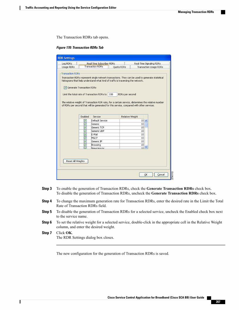
The Transaction RDRs tab opens.
Figure 170: Transaction RDRs Tab
Step 3 To enable the generation of Transaction RDRs, check the Generate Transaction RDRs check box.To disable the generation of Transaction RDRs, uncheck the Generate Transaction RDRs check box.
Step 4 To change the maximum generation rate for Transaction RDRs, enter the desired rate in the Limit the TotalRate of Transaction RDRs field.
Step 5 To disable the generation of Transaction RDRs for a selected service, uncheck the Enabled check box nextto the service name.
Step 6 To set the relative weight for a selected service, double-click in the appropriate cell in the Relative Weightcolumn, and enter the desired weight.
Step 7 Click OK.The RDR Settings dialog box closes.
The new configuration for the generation of Transaction RDRs is saved.
Cisco Service Control Application for Broadband (Cisco SCA BB) User Guide 267
Traffic Accounting and Reporting Using the Service Configuration EditorManaging Transaction RDRs

Managing Quota RDRsEach Quota RDR contains data for a single subscriber. There are four types of Quota RDRs:
• Quota Breach RDRs—Generated when a quota breach occurs, that is, when services that try to consumefrom a depleted quota bucket.A breached service is handled according to its breach-handling settings. For example, when the quotafor a service is consumed, you can block its flows.
• Remaining Quota RDRs—Generated as quota is consumed, but only if a bucket state has change sincethe last Remaining Quota RDR was generated.
• Quota Threshold Breach RDRs—Generated when the remaining quota in a bucket falls below a threshold.External systems can treat this RDR as a quota request and provision the subscriber with an additionalquota before the bucket is depleted.
• Quota State Restore RDRs—Generated when a subscriber is introduced. When a subscriber logs out,their remaining quota is stored in the Cisco Service Control Subscriber Manager (SM). When thesubscriber logs in again, this quota is restored from the SM.
You can enable or disable the generation each type of Quota RDR and define the rate of generation of theseRDRs.
• For Remaining Quota RDRs, you can set the generation interval, and limit the generation rate (advisablewhen there are a large number of subscribers).
• For Quota Threshold RDRs, you can configure the threshold.
By default, all Quota RDRs are disabled.
For detailed information regarding the RDR purpose, default destination, content, generation logic, tag, andfields, see the following sections in the Cisco Service Control Application for Broadband Reference Guide:
• Quota Breach RDR
• Remaining Quota RDR
• Quota Threshold Breach RDR
• Quota State Restore RDR
Procedure
Step 1 From the Classification tab in the left pane, choose Configuration > Classification > RDR Settings .The RDR Settings dialog box appears.
Step 2 Click the Quota RDRs tab.
Cisco Service Control Application for Broadband (Cisco SCA BB) User Guide268
Traffic Accounting and Reporting Using the Service Configuration EditorManaging Quota RDRs
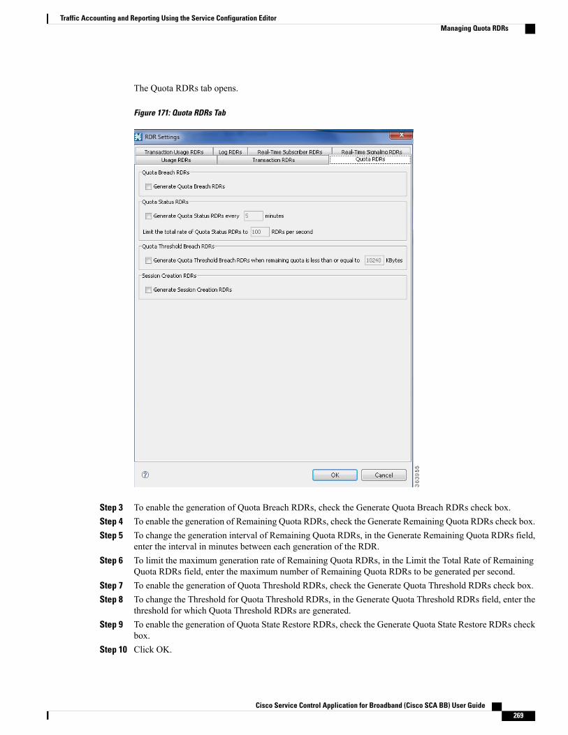
The Quota RDRs tab opens.
Figure 171: Quota RDRs Tab
Step 3 To enable the generation of Quota Breach RDRs, check the Generate Quota Breach RDRs check box.Step 4 To enable the generation of Remaining Quota RDRs, check the Generate Remaining Quota RDRs check box.Step 5 To change the generation interval of Remaining Quota RDRs, in the Generate Remaining Quota RDRs field,
enter the interval in minutes between each generation of the RDR.Step 6 To limit the maximum generation rate of Remaining Quota RDRs, in the Limit the Total Rate of Remaining
Quota RDRs field, enter the maximum number of Remaining Quota RDRs to be generated per second.Step 7 To enable the generation of Quota Threshold RDRs, check the Generate Quota Threshold RDRs check box.Step 8 To change the Threshold for Quota Threshold RDRs, in the Generate Quota Threshold RDRs field, enter the
threshold for which Quota Threshold RDRs are generated.Step 9 To enable the generation of Quota State Restore RDRs, check the Generate Quota State Restore RDRs check
box.Step 10 Click OK.
Cisco Service Control Application for Broadband (Cisco SCA BB) User Guide 269
Traffic Accounting and Reporting Using the Service Configuration EditorManaging Quota RDRs
The RDR Settings dialog box closes.
The new configuration for the generation of Quota RDRs is saved.
Managing Transaction Usage RDRsTransaction Usage RDRs are generated for all transactions of selected packages or for selected services perpackage. Each Transaction Usage RDR contains data about a single network transaction. You can use theseRDRs, for example, to build detailed usage logs for specific services and subscribers for transaction-basedbilling.
Generating and collecting an RDR for each transaction can compromise performance. Enable TransactionUsage RDR generation only for services and packages that must be monitored or controlled.
Caution
You can select the packages and services for which Transaction Usage RDRs are generated. The followingRDRs are also generated for these packages and services:
• HTTP Transaction Usage RDR
• RTSP Transaction Usage RDR
• VoIP Transaction Usage RDR
By default, no Transaction Usage RDRs are generated.
Media Flow RDRs are enabled using the Advance Service Configuration Options. When enabled, MediaFlow RDRs are generated at the end of every SIP and Skype media flow. You can use the Media FlowRDRs to distinguish between SIP voice and video calls. For details on enabling Media Flow RDRs, seeEditing Advanced Service Configuration Options , on page 460 section.
Note
For details on the RDR purpose, default destination, content, generation logic, tag, and fields, see the followingsections in the Cisco Service Control Application for Broadband Reference Guide :
• Transaction Usage RDR
• HTTP Transaction Usage RDR
• RTSP Transaction Usage RDR
• VoIP Transaction Usage RDR
Procedure
Step 1 From the Classification tab in the left pane of Service Configuration Editor window, choose Configuration >Classification > RDR Settings .The RDR Settings dialog box appears.
Step 2 Click the Transaction Usage RDRs tab.
Cisco Service Control Application for Broadband (Cisco SCA BB) User Guide270
Traffic Accounting and Reporting Using the Service Configuration EditorManaging Transaction Usage RDRs
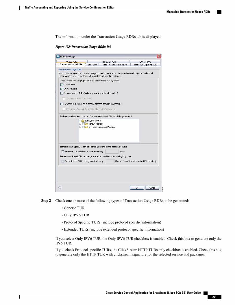
The information under the Transaction Usage RDRs tab is displayed.
Figure 172: Transaction Usage RDRs Tab
Step 3 Check one or more of the following types of Transaction Usage RDRs to be generated:
• Generic TUR
• Only IPV6 TUR
• Protocol Specific TURs (include protocol specific information)
• Extended TURs (include extended protocol specific information)
If you select Only IPV6 TUR, the Only IPV6 TUR checkbox is enabled. Check this box to generate only theIPv6 TUR.
If you check Protocol specific TURs, the ClickStream HTTP TURs only checkbox is enabled. Check this boxto generate only the HTTP TUR with clickstream signature for the selected service and packages.
Cisco Service Control Application for Broadband (Cisco SCA BB) User Guide 271
Traffic Accounting and Reporting Using the Service Configuration EditorManaging Transaction Usage RDRs
If you check Extended TURS, the Anonymize - Encrypt Personally Identifiable Information checkbox isenabled. Check this box to anonymize data.
Step 4 (Optional) To enable the generation of Transaction Usage RDRs for a selected package, check the check boxnext to the package name in the package tree.The package expands to show all component services of the package; all services are checked.
Step 5 Enable the generation of Transaction Usage RDRs for selected services of a package.Step 6 Expand the node of the desired package.Step 7 Check the check box next to the service name of each service for which a Transaction Usage RDR is to be
generated.Step 8 (Optional) Limit the generation of Transaction Usage RDRs by session size.Step 9 Check the Generate TUR only for sessions exceeding check box.
The Bytes field is enabled.
Step 10 Enter the minimum session size in bytes for which a Transaction Usage RDR should be generated for thesession.
Step 11 (Optional) Enable the generation of additional, interim Transaction Usage RDRs for long flows. (Usually, aTransaction Usage RDR is generated only when a flow closes.)
Step 12 Check the Enable Interim TUR to be generated every check box.The Minutes field is enabled.
Step 13 Enter the required time in minutes between each generation of a Transaction Usage RDR for each flow.Step 14 Click OK.
The RDR Settings dialog box closes.
The new configuration for the generation of Transaction Usage RDRs is saved.
Managing Log RDRsLog RDRs, which provide information about system events, are generated in response to specific actions orstate changes.
There are two types of Log RDRs:
• Blocking RDRs—Generated each time a transaction is blocked
• Breach RDRs—Generated each time a bucket exceeds the global threshold
You can set the maximum number of Log RDRs generated per second. You can select the packages andservices for which Blocking RDRs are generated.By default:
• Blocking RDRs are generated for all packages
• Breach RDRs are always generated
A maximum of 20 Log RDRs are generated for each second.Note
Cisco Service Control Application for Broadband (Cisco SCA BB) User Guide272
Traffic Accounting and Reporting Using the Service Configuration EditorManaging Log RDRs
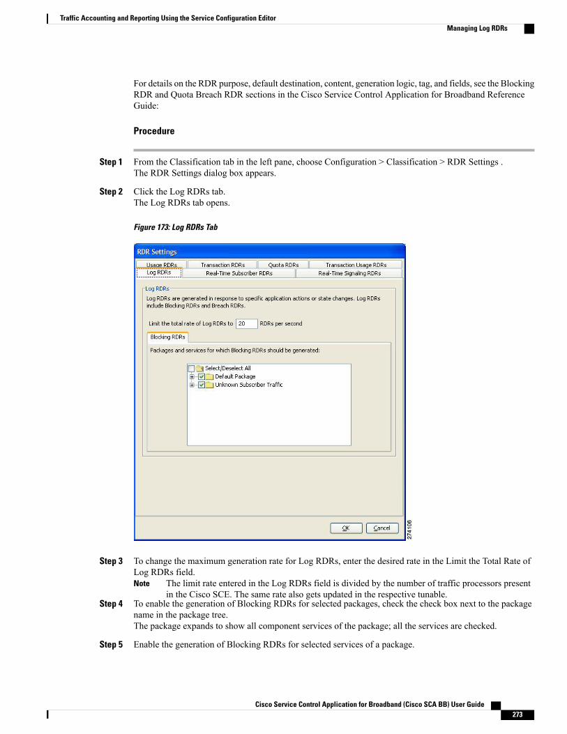
For details on the RDR purpose, default destination, content, generation logic, tag, and fields, see the BlockingRDR and Quota Breach RDR sections in the Cisco Service Control Application for Broadband ReferenceGuide:
Procedure
Step 1 From the Classification tab in the left pane, choose Configuration > Classification > RDR Settings .The RDR Settings dialog box appears.
Step 2 Click the Log RDRs tab.The Log RDRs tab opens.
Figure 173: Log RDRs Tab
Step 3 To change the maximum generation rate for Log RDRs, enter the desired rate in the Limit the Total Rate ofLog RDRs field.
The limit rate entered in the Log RDRs field is divided by the number of traffic processors presentin the Cisco SCE. The same rate also gets updated in the respective tunable.
Note
Step 4 To enable the generation of Blocking RDRs for selected packages, check the check box next to the packagename in the package tree.The package expands to show all component services of the package; all the services are checked.
Step 5 Enable the generation of Blocking RDRs for selected services of a package.
Cisco Service Control Application for Broadband (Cisco SCA BB) User Guide 273
Traffic Accounting and Reporting Using the Service Configuration EditorManaging Log RDRs
Expand the node of the desired package.a)b) Check the check box next to the service name of each desired service.
Step 6 Click OK.The RDR Settings dialog box closes.
The new configuration for the generation of Log RDRs is saved.
Managing Real-Time Subscriber Usage RDRsReal-Time Subscriber Usage RDRs, which report subscriber usage, are generated for each individual subscriberfor each service used, at specified intervals. These RDRs permit a more granular monitoring of selectedsubscribers when necessary.
For details on selecting the subscribers to be monitored, see Selecting Subscribers for Real-Time UsageMonitoring .
Generating and collecting Real-Time Subscriber Usage RDRs for many subscribers can compromiseperformance. Enable Real-Time Subscriber Usage RDR generation only for subscribers that must bemonitored.
Note
You can enable or disable the generation of Real-Time Subscriber Usage RDRs, set the generation intervalfor these RDRs, and set the maximum number generated per second.
By default, Real-Time Subscriber Usage RDRs:
• Are enabled (but only for selected subscribers)
• Are generated for each subscriber once every minute
• Are limited to 100 RDRs generated per second
For details on the RDR purpose, default destination, content, generation logic, tag, and fields, see the “Real-TimeSubscriber Usage RDR” section in the Cisco Service Control Application for Broadband Reference Guide.
Procedure
Step 1 From the Classification tab in the left pane, choose Configuration > Classification > RDR Settings .The RDR Settings dialog box appears.
Step 2 Click the Real-Time Subscriber RDRs tab.
Cisco Service Control Application for Broadband (Cisco SCA BB) User Guide274
Traffic Accounting and Reporting Using the Service Configuration EditorManaging Real-Time Subscriber Usage RDRs
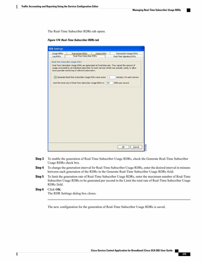
The Real-Time Subscriber RDRs tab opens.
Figure 174: Real-Time Subscriber RDRs tab
Step 3 To enable the generation of Real-Time Subscriber Usage RDRs, check the Generate Real-Time SubscriberUsage RDRs check box.
Step 4 To change the generation interval for Real-Time Subscriber Usage RDRs, enter the desired interval in minutesbetween each generation of the RDRs in the Generate Real-Time Subscriber Usage RDRs field.
Step 5 To limit the generation rate of Real-Time Subscriber Usage RDRs, enter the maximum number of Real-TimeSubscriber Usage RDRs to be generated per second in the Limit the total rate of Real-Time Subscriber UsageRDRs field.
Step 6 Click OK.The RDR Settings dialog box closes.
The new configuration for the generation of Real-Time Subscriber Usage RDRs is saved.
Cisco Service Control Application for Broadband (Cisco SCA BB) User Guide 275
Traffic Accounting and Reporting Using the Service Configuration EditorManaging Real-Time Subscriber Usage RDRs
Managing Real-Time Signaling RDRsReal-Time Signaling RDRs can be used to signal external systems concerning events detected by the CiscoSCE platform, allowing real-time actions to be taken across the network.
Real-Time Signaling RDRs, are generated at the beginning and end of a flow, at specified intervals after thebeginning of the flow, and at the beginning and end of a network attack.
There are two groups of Real-Time Signaling RDRs:
• Flow Signaling RDRs:
◦Flow Start Signaling RDRs
◦Flow Stop Signaling RDRs
◦Flow Interim Signaling RDRs
• Attack Signaling RDRs:
◦Attack Start Signaling RDRs
◦Attack Stop Signaling RDRs
You can enable or disable the generation of Flow Signaling RDRs for selected packages, or for selectedservices per package. You can set the generation interval for Flow Interim Signaling RDRs, which can begenerated only if Flow Start and Flow Stop Signaling RDRs are enabled.
You can enable or disable the generation of Attack Signaling RDRs for selected packages.
Malicious Traffic Periodic RDRs are enabled and configured in Editing Advanced Service ConfigurationOptions , on page 460.
Note
For detailed information regarding the RDR purpose, default destination, content, generation logic, tag, andfields, see the following sections in the Cisco Service Control Application for Broadband Reference Guide :
• Flow Start RDR
• Flow End RDR
• Ongoing Flow RDR
• Attack Start RDR
• Attack End RDR
By default, no Real-Time Signaling RDRs are generated.
Procedure
Step 1 From the Classification tab in the left pane, choose Configuration > Classification > RDR Settings .The RDR Settings dialog box appears.
Step 2 Click the Real-Time Signaling RDRs tab.
Cisco Service Control Application for Broadband (Cisco SCA BB) User Guide276
Traffic Accounting and Reporting Using the Service Configuration EditorManaging Real-Time Signaling RDRs

The Real-Time Signaling RDRs tab opens.
Figure 175: Real-Time Signaling RDRs Tab
Step 3 To enable the generation of Flow Start and Flow Stop Signaling RDRs, check the Enable Flow Start and FlowStop Signaling RDRs check box.
Generation of Flow Start and Flow Stop Signaling RDRs is not supported when unidirectionalclassification is enabled. If you try to check the Enable Flow Start and Flow Stop Signaling RDRscheck box when unidirectional classification is enabled, an RDR Settings Error message appears.Click OK , and continue at Step 8.
Note
The Enable Flow Interim Signaling RDRs check box is enabled.
Step 4 To enable the generation of Flow Interim Signaling RDRs, check the Enable Flow Interim Signaling RDRscheck box.The Enable Flow Interim Signaling RDRs field is enabled.
Step 5 To change the generation interval for Flow Interim Signaling RDRs, enter the interval in minutes betweeneach generation of the RDRs in the Enable Flow Interim Signaling RDRs field.
Step 6 To enable the generation of Flow Interim Signaling RDRs for selected packages, check the check box nextto the package name in the package tree.The package expands to show all component services of the package; all the services are checked.
Step 7 To enable the generation of Flow Interim Signaling RDRs for selected services of a package:a) Expand the node of the desired package.
Cisco Service Control Application for Broadband (Cisco SCA BB) User Guide 277
Traffic Accounting and Reporting Using the Service Configuration EditorManaging Real-Time Signaling RDRs

b) Check the check box next to the service name of each desired service.
Step 8 To enable the generation of Attack Signaling RDRs:a) In the body of the Real-Time Signaling RDRs tab, click the Attack Signaling tab.
Figure 176: Attack Signaling Tab
b) Check the Enable Attack Start and Attack Stop Signaling RDRs check box.
Step 9 To enable the generation of Attack Signaling RDRs for selected packages, check the check box next to thepackage name in the package list.
Step 10 Click OK .The RDR Settings dialog box closes.
The new configuration for the generation of Real-Time Signaling RDRs is saved.
Cisco Service Control Application for Broadband (Cisco SCA BB) User Guide278
Traffic Accounting and Reporting Using the Service Configuration EditorManaging Real-Time Signaling RDRs
C H A P T E R 9Traffic Control Using the Service ConfigurationEditor
The Traffic Control capabilities of the Service Control Engine (Service Control platform, and the CiscoService Control Application for Broadband) are used to limit and prioritize traffic flows. Control of trafficis based on parameters such as the service of the flow, the package of the subscriber, and the quota state ofthe subscriber. This chapter consists of these sections:
• Introduction to Managing Bandwidth, page 279
• Introduction to Managing Virtual Links, page 315
• Introduction to Managing Packages, page 328
• Introduction to Add-on Packages, page 336
• Introduction to Managing Rules, page 341
• Quota Management, page 370
• Unknown Subscriber Traffic , page 387
Introduction to Managing BandwidthThe upstream and downstream interfaces are each assigned one default global controller. You can add additionalglobal controllers.
The number of global controllers a service configuration can contain varies based on the Cisco SCE hardware.The maximum number of global controllers including the default global controllers are:
• Cisco SCE 8000 multi-Gigabit Ethernet—1024 upstream and 1024 downstream
• Cisco SCE 10000 10 Gigabit Ethernet—4096 upstream and 4096 downstream
After you have defined global controllers, you can add subscriber BW controllers (BWCs) to packages, andmap these subscriber BWCs to different global controllers.
Cisco Service Control Application for Broadband (Cisco SCA BB) User Guide 279
In release 3.7.5, the global bandwidth controller for IPv6 works in the subscriberless mode. The IPv6traffic is mapped to a default subscriber (N/A). Bandwidth control should be performed on the UnknownSubscriber Package. The maximum and the default package ID of the Unknown Subscriber value is 4999.
Note
If you enable or disable Virtual Links mode, all user-defined global controllers are deleted from the serviceconfiguration. A subscriber BWC that pointed to a user-defined global controller now points to the defaultglobal controller. (Other parameters of these subscriber BWCs remain unchanged.)
Note
Managing Global Bandwidth OverviewThe upstream and downstream interfaces are each assigned one default global controller that, by default,controls the total link traffic. Based on the Cisco SCE hardware, the number of global controllers you can addto a service configuration varies. For details, see the Introduction to Managing Bandwidth, on page 279section.
You can also define the bandwidth total link limit to be less than the physical capacity of the Cisco SCEplatform for each interface separately. When another device that has limited BW capacity is next to the CiscoSCE platform on the IP stream, you can have this limitation enforced in a policy-aware manner by the CiscoSCE platform, instead of having it enforced arbitrarily by the other device.
Viewing Global Controller Settings
Global controller bandwidth is based on Layer 1 volume. Accounting, reporting, and subscriber bandwidthcontrol in Cisco SCA BB is based on Layer 3 volume.
Note
Procedure
In the Policies tab, click Global Policy .
Cisco Service Control Application for Broadband (Cisco SCA BB) User Guide280
Traffic Control Using the Service Configuration EditorManaging Global Bandwidth Overview
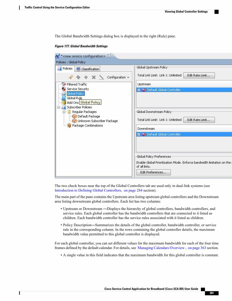
The Global Bandwidth Settings dialog box is displayed in the right (Rule) pane.
Figure 177: Global Bandwidth Settings
The two check boxes near the top of the Global Controllers tab are used only in dual-link systems (seeIntroduction to Defining Global Controllers, on page 284 section).
The main part of the pane contains the Upstream area listing upstream global controllers and the Downstreamarea listing downstream global controllers. Each list has two columns:
• Upstream or Downstream—Displays the hierarchy of global controllers, bandwidth controllers, andservice rules. Each global controller has the bandwidth controllers that are connected to it listed aschildren. Each bandwidth controller has the service rules associated with it listed as children.
• Policy Description—Summarizes the details of the global controller, bandwidth controller, or servicerule in the corresponding column. In the rows containing the global controller details, the maximumbandwidth value permitted to this global controller is displayed.
For each global controller, you can set different values for the maximum bandwidth for each of the four timeframes defined by the default calendar. For details, see Managing Calendars Overview , on page 363 section.
• A single value in this field indicates that the maximum bandwidth for this global controller is constant.
Cisco Service Control Application for Broadband (Cisco SCA BB) User Guide 281
Traffic Control Using the Service Configuration EditorViewing Global Controller Settings
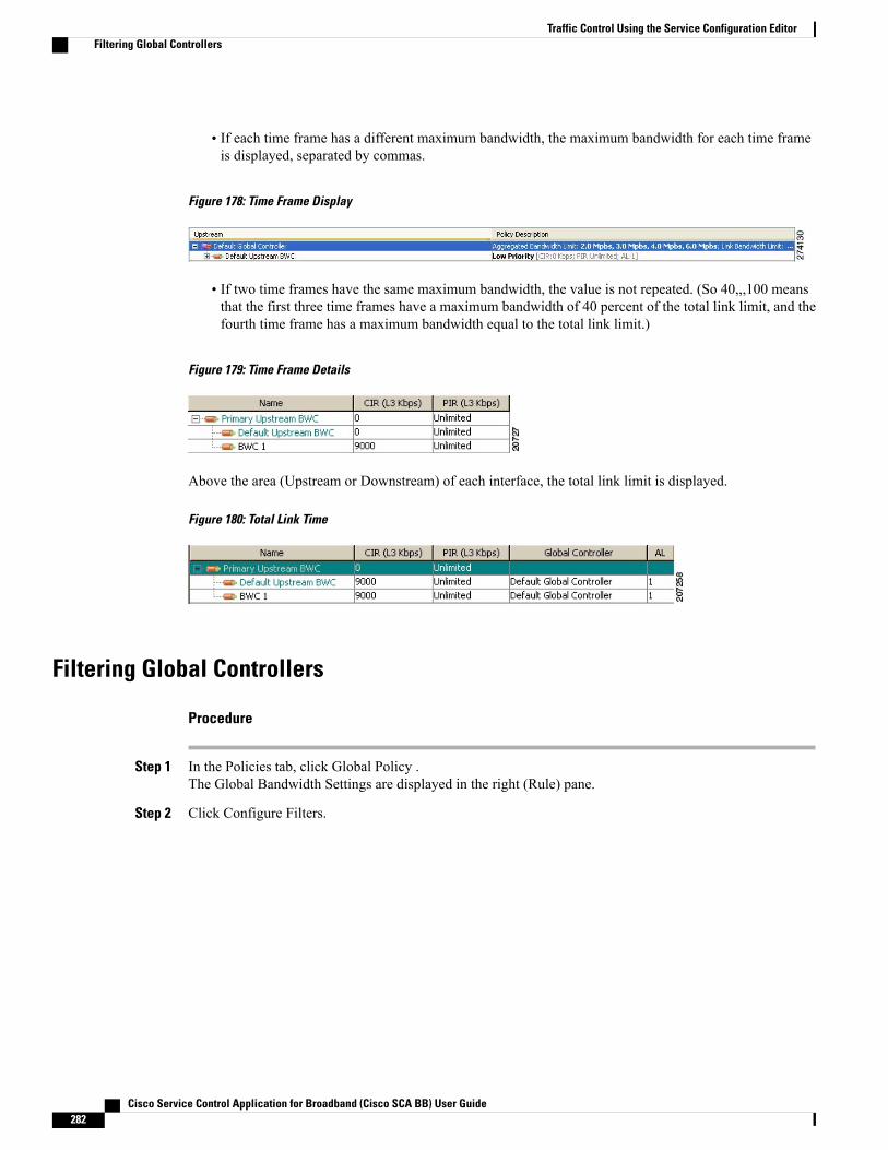
• If each time frame has a different maximum bandwidth, the maximum bandwidth for each time frameis displayed, separated by commas.
Figure 178: Time Frame Display
• If two time frames have the same maximum bandwidth, the value is not repeated. (So 40,,,100 meansthat the first three time frames have a maximum bandwidth of 40 percent of the total link limit, and thefourth time frame has a maximum bandwidth equal to the total link limit.)
Figure 179: Time Frame Details
Above the area (Upstream or Downstream) of each interface, the total link limit is displayed.
Figure 180: Total Link Time
Filtering Global Controllers
Procedure
Step 1 In the Policies tab, click Global Policy .The Global Bandwidth Settings are displayed in the right (Rule) pane.
Step 2 Click Configure Filters.
Cisco Service Control Application for Broadband (Cisco SCA BB) User Guide282
Traffic Control Using the Service Configuration EditorFiltering Global Controllers
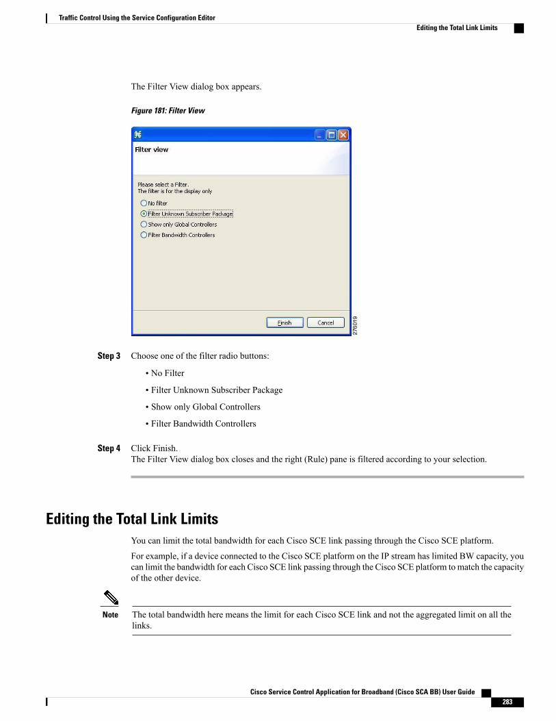
The Filter View dialog box appears.
Figure 181: Filter View
Step 3 Choose one of the filter radio buttons:
• No Filter
• Filter Unknown Subscriber Package
• Show only Global Controllers
• Filter Bandwidth Controllers
Step 4 Click Finish.The Filter View dialog box closes and the right (Rule) pane is filtered according to your selection.
Editing the Total Link LimitsYou can limit the total bandwidth for each Cisco SCE link passing through the Cisco SCE platform.
For example, if a device connected to the Cisco SCE platform on the IP stream has limited BW capacity, youcan limit the bandwidth for each Cisco SCE link passing through the Cisco SCE platform to match the capacityof the other device.
The total bandwidth here means the limit for each Cisco SCE link and not the aggregated limit on all thelinks.
Note
Cisco Service Control Application for Broadband (Cisco SCA BB) User Guide 283
Traffic Control Using the Service Configuration EditorEditing the Total Link Limits
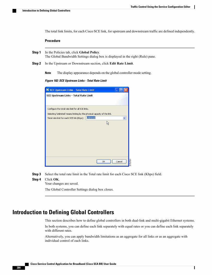
The total link limits, for each Cisco SCE link, for upstream and downstream traffic are defined independently.
Procedure
Step 1 In the Policies tab, click Global Policy.The Global Bandwidth Settings dialog box is displayed in the right (Rule) pane.
Step 2 In the Upstream or Downstream section, click Edit Rate Limit.
The display appearance depends on the global controller mode setting.Note
Figure 182: SCE Upstream Links - Total Rate Limit
Step 3 Select the total rate limit in the Total rate limit for each Cisco SCE link (Kbps) field.Step 4 Click OK.
Your changes are saved.
The Global Controller Settings dialog box closes.
Introduction to Defining Global ControllersThis section describes how to define global controllers in both dual-link and multi-gigabit Ethernet systems.
In both systems, you can define each link separately with equal rates or you can define each link separatelywith different rates.
Alternatively, you can apply bandwidth limitations as an aggregate for all links or as an aggregate withindividual control of each links.
Cisco Service Control Application for Broadband (Cisco SCA BB) User Guide284
Traffic Control Using the Service Configuration EditorIntroduction to Defining Global Controllers
You can:
1 Control each link separately with equal rate to all links.2 Control each link separately without with different rate per link.3 Control the links in aggregate and in addition maximum rate per-link, which is equal between all links.4 Control the links in aggregate and in addition maximum rate per-link, which is different between the links.5 Control the links in Virtual Link mode.
If Virtual Links mode is enabled, bandwidth limitations are applied to the sum of the all links.Note
Any attempt to change the global controller bandwidth for invalid link results in an error message duringapply policy, similar to the following: “Invalid value set on Link ID 6 for upstream GC ‘Default GlobalController’. Link ID 6 does not exist. Available Link IDs: 1, 2, 3, 4”
Note
To activate the respective edit dialog of the Global Controller settings:
• Double click on a global controller row in the global controller table view on the right main panel of theGlobal Policy setting.
• Click on the edit button that is located on the top right main panel of the Global Policy setting.
The behavior is the same whether you configure upstream or downstream GC.Note
Refer to the following sections for configuration details:
Setting Global Controller Bandwidth Limits Separately with a Different Rate Per LinkUse the following procedure to configure the global controller with a different rate per link.
Procedure
Step 1 In the Policies tab, click Global Policy.The Global Bandwidth Settings dialog box in the right (Rule) pane.
Step 2 Add global controllers, as described in Adding Global Controllers, on page 320.Step 3 Click Edit Preferences.
Cisco Service Control Application for Broadband (Cisco SCA BB) User Guide 285
Traffic Control Using the Service Configuration EditorIntroduction to Defining Global Controllers
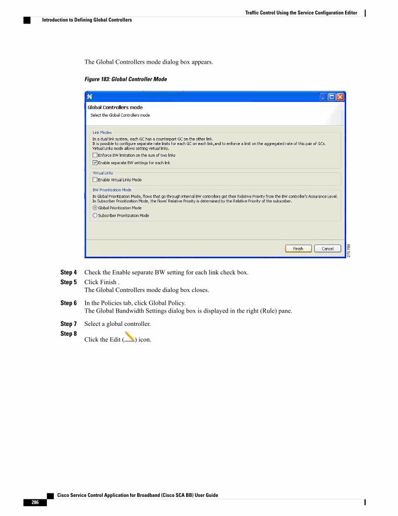
The Global Controllers mode dialog box appears.
Figure 183: Global Controller Mode
Step 4 Check the Enable separate BW setting for each link check box.Step 5 Click Finish .
The Global Controllers mode dialog box closes.
Step 6 In the Policies tab, click Global Policy.The Global Bandwidth Settings dialog box is displayed in the right (Rule) pane.
Step 7 Select a global controller.Step 8
Click the Edit ( ) icon.
Cisco Service Control Application for Broadband (Cisco SCA BB) User Guide286
Traffic Control Using the Service Configuration EditorIntroduction to Defining Global Controllers
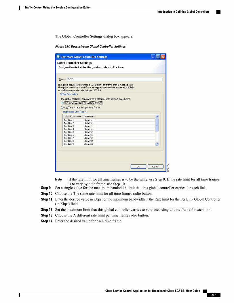
The Global Controller Settings dialog box appears.
Figure 184: Downstream Global Controller Settings
If the rate limit for all time frames is to be the same, use Step 9. If the rate limit for all time framesis to vary by time frame, use Step 10.
Note
Step 9 Set a single value for the maximum bandwidth limit that this global controller carries for each link.Step 10 Choose the The same rate limit for all time frames radio button.Step 11 Enter the desired value in Kbps for the maximum bandwidth in the Rate limit for the Per Link Global Controller
(in Kbps) field.Step 12 Set the maximum limit that this global controller carries to vary according to time frame for each link.Step 13 Choose the A different rate limit per time frame radio button.Step 14 Enter the desired value for each time frame.
Cisco Service Control Application for Broadband (Cisco SCA BB) User Guide 287
Traffic Control Using the Service Configuration EditorIntroduction to Defining Global Controllers
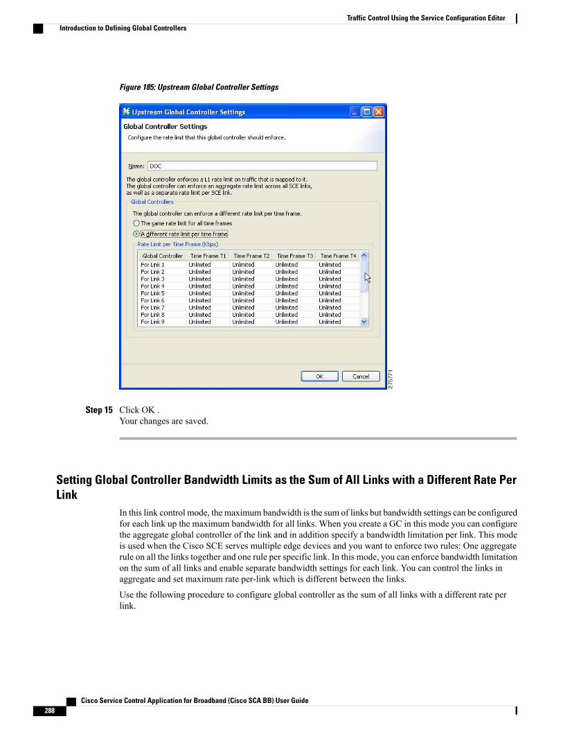
Figure 185: Upstream Global Controller Settings
Step 15 Click OK .Your changes are saved.
Setting Global Controller Bandwidth Limits as the Sum of All Links with a Different Rate PerLink
In this link control mode, the maximum bandwidth is the sum of links but bandwidth settings can be configuredfor each link up the maximum bandwidth for all links. When you create a GC in this mode you can configurethe aggregate global controller of the link and in addition specify a bandwidth limitation per link. This modeis used when the Cisco SCE serves multiple edge devices and you want to enforce two rules: One aggregaterule on all the links together and one rule per specific link. In this mode, you can enforce bandwidth limitationon the sum of all links and enable separate bandwidth settings for each link. You can control the links inaggregate and set maximum rate per-link which is different between the links.
Use the following procedure to configure global controller as the sum of all links with a different rate perlink.
Cisco Service Control Application for Broadband (Cisco SCA BB) User Guide288
Traffic Control Using the Service Configuration EditorIntroduction to Defining Global Controllers
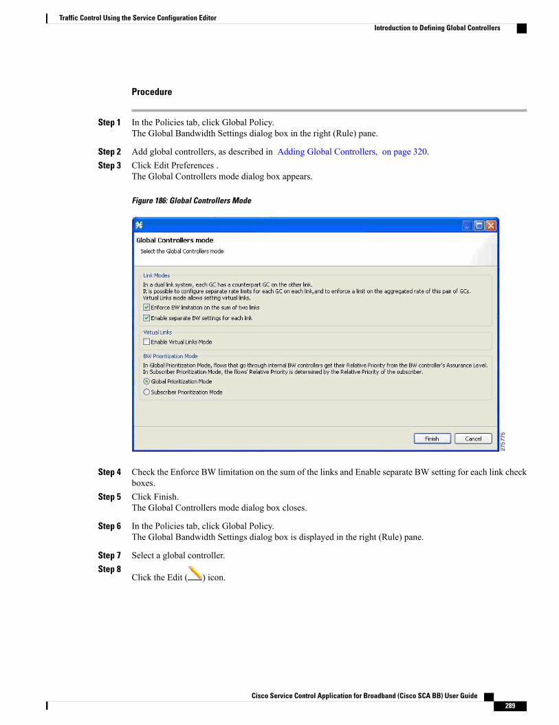
Procedure
Step 1 In the Policies tab, click Global Policy.The Global Bandwidth Settings dialog box in the right (Rule) pane.
Step 2 Add global controllers, as described in Adding Global Controllers, on page 320.Step 3 Click Edit Preferences .
The Global Controllers mode dialog box appears.
Figure 186: Global Controllers Mode
Step 4 Check the Enforce BW limitation on the sum of the links and Enable separate BW setting for each link checkboxes.
Step 5 Click Finish.The Global Controllers mode dialog box closes.
Step 6 In the Policies tab, click Global Policy.The Global Bandwidth Settings dialog box is displayed in the right (Rule) pane.
Step 7 Select a global controller.Step 8
Click the Edit ( ) icon.
Cisco Service Control Application for Broadband (Cisco SCA BB) User Guide 289
Traffic Control Using the Service Configuration EditorIntroduction to Defining Global Controllers
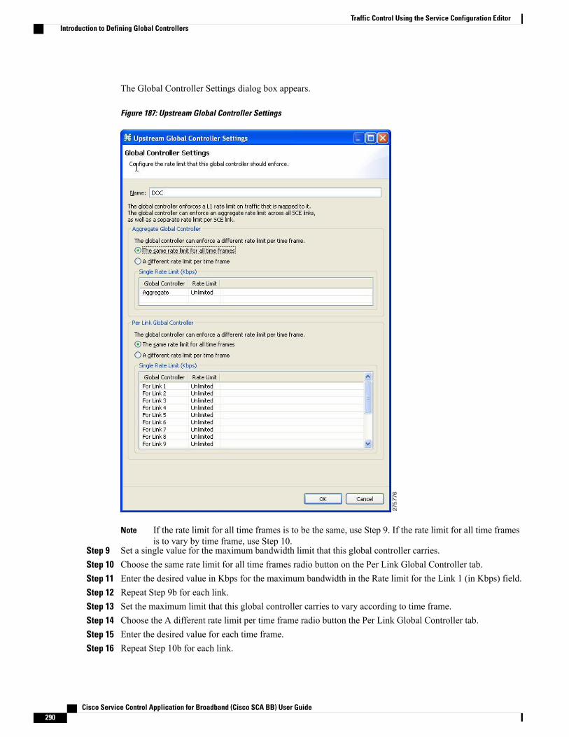
The Global Controller Settings dialog box appears.
Figure 187: Upstream Global Controller Settings
If the rate limit for all time frames is to be the same, use Step 9. If the rate limit for all time framesis to vary by time frame, use Step 10.
Note
Step 9 Set a single value for the maximum bandwidth limit that this global controller carries.Step 10 Choose the same rate limit for all time frames radio button on the Per Link Global Controller tab.Step 11 Enter the desired value in Kbps for the maximum bandwidth in the Rate limit for the Link 1 (in Kbps) field.Step 12 Repeat Step 9b for each link.Step 13 Set the maximum limit that this global controller carries to vary according to time frame.Step 14 Choose the A different rate limit per time frame radio button the Per Link Global Controller tab.Step 15 Enter the desired value for each time frame.Step 16 Repeat Step 10b for each link.
Cisco Service Control Application for Broadband (Cisco SCA BB) User Guide290
Traffic Control Using the Service Configuration EditorIntroduction to Defining Global Controllers
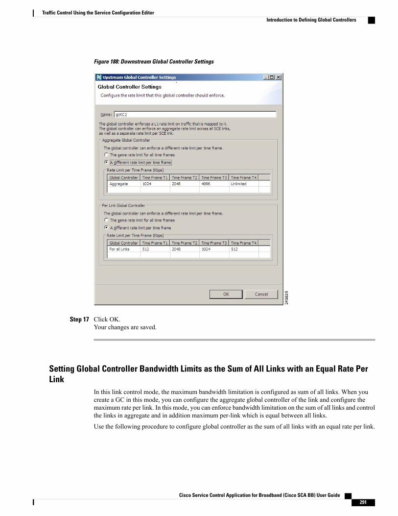
Figure 188: Downstream Global Controller Settings
Step 17 Click OK.Your changes are saved.
Setting Global Controller Bandwidth Limits as the Sum of All Links with an Equal Rate PerLink
In this link control mode, the maximum bandwidth limitation is configured as sum of all links. When youcreate a GC in this mode, you can configure the aggregate global controller of the link and configure themaximum rate per link. In this mode, you can enforce bandwidth limitation on the sum of all links and controlthe links in aggregate and in addition maximum per-link which is equal between all links.
Use the following procedure to configure global controller as the sum of all links with an equal rate per link.
Cisco Service Control Application for Broadband (Cisco SCA BB) User Guide 291
Traffic Control Using the Service Configuration EditorIntroduction to Defining Global Controllers

Procedure
Step 1 In the Policies tab, click Global Policy.The Global Bandwidth Settings dialog box in the right (Rule) pane.
Step 2 Add global controllers, as described in Adding Global Controllers, on page 320.Step 3 Click Edit Preferences .
The Global Controllers mode dialog box appears.
Figure 189: Global Controllers Mode
Step 4 Check the Enforce BW limitation on the sum of the links check box.Step 5 Click Finish .
The Global Controllers mode dialog box closes.
Step 6 In the Policies tab, click Global Policy.The Global Bandwidth Settings dialog box is displayed in the right (Rule) pane.
Step 7 Select a global controller.Step 8
Click the Edit ( ) icon.
Cisco Service Control Application for Broadband (Cisco SCA BB) User Guide292
Traffic Control Using the Service Configuration EditorIntroduction to Defining Global Controllers
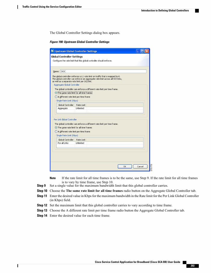
The Global Controller Settings dialog box appears.
Figure 190: Upstream Global Controller Settings
If the rate limit for all time frames is to be the same, use Step 9. If the rate limit for all time framesis to vary by time frame, use Step 10.
Note
Step 9 Set a single value for the maximum bandwidth limit that this global controller carries.Step 10 Choose the The same rate limit for all time frames radio button on the Aggregate Global Controller tab.Step 11 Enter the desired value in Kbps for the maximum bandwidth in the Rate limit for the Per Link Global Controller
(in Kbps) field.Step 12 Set the maximum limit that this global controller carries to vary according to time frame.Step 13 Choose the A different rate limit per time frame radio button the Aggregate Global Controller tab.Step 14 Enter the desired value for each time frame.
Cisco Service Control Application for Broadband (Cisco SCA BB) User Guide 293
Traffic Control Using the Service Configuration EditorIntroduction to Defining Global Controllers
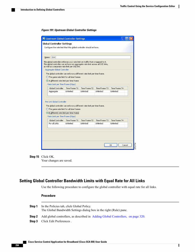
Figure 191: Upstream Global Controller Settings
Step 15 Click OK.Your changes are saved.
Setting Global Controller Bandwidth Limits with Equal Rate for All LinksUse the following procedure to configure the global controller with equal rate for all links.
Procedure
Step 1 In the Policies tab, click Global Policy.The Global Bandwidth Settings dialog box in the right (Rule) pane.
Step 2 Add global controllers, as described in Adding Global Controllers, on page 320.Step 3 Click Edit Preferences .
Cisco Service Control Application for Broadband (Cisco SCA BB) User Guide294
Traffic Control Using the Service Configuration EditorIntroduction to Defining Global Controllers

The Global Controllers mode dialog box appears.
Figure 192: Global Controllers Mode
Step 4 Verify that the Link Modes check boxes are unchecked.Step 5 Click Finish.
The Global Controllers mode dialog box closes.
Step 6 In the Policies tab, click Global Policy.The Global Bandwidth Settings dialog box is displayed in the right (Rule) pane.
Step 7 Select a global controller.Step 8
Click the Edit ( ) icon.
Cisco Service Control Application for Broadband (Cisco SCA BB) User Guide 295
Traffic Control Using the Service Configuration EditorIntroduction to Defining Global Controllers
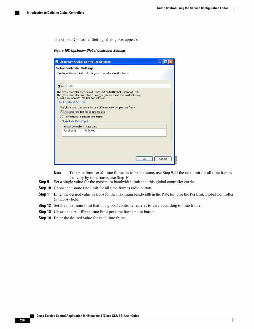
The Global Controller Settings dialog box appears.
Figure 193: Upstream Global Controller Settings
If the rate limit for all time frames is to be the same, use Step 9. If the rate limit for all time framesis to vary by time frame, use Step 10.
Note
Step 9 Set a single value for the maximum bandwidth limit that this global controller carries.Step 10 Choose the same rate limit for all time frames radio button.Step 11 Enter the desired value in Kbps for the maximum bandwidth in the Rate limit for the Per Link Global Controller
(in Kbps) field.Step 12 Set the maximum limit that this global controller carries to vary according to time frame.Step 13 Choose the A different rate limit per time frame radio button.Step 14 Enter the desired value for each time frame.
Cisco Service Control Application for Broadband (Cisco SCA BB) User Guide296
Traffic Control Using the Service Configuration EditorIntroduction to Defining Global Controllers
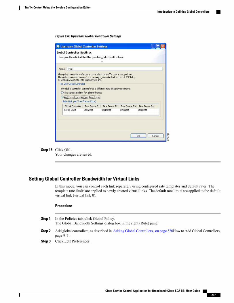
Figure 194: Upstream Global Controller Settings
Step 15 Click OK .Your changes are saved.
Setting Global Controller Bandwidth for Virtual LinksIn this mode, you can control each link separately using configured rate templates and default rates. Thetemplate rate limits are applied to newly created virtual links. The default rate limits are applied to the defaultvirtual link (virtual link 0).
Procedure
Step 1 In the Policies tab, click Global Policy.The Global Bandwidth Settings dialog box in the right (Rule) pane.
Step 2 Add global controllers, as described in AddingGlobal Controllers, on page 320How toAddGlobal Controllers,page 9-7 .
Step 3 Click Edit Preferences .
Cisco Service Control Application for Broadband (Cisco SCA BB) User Guide 297
Traffic Control Using the Service Configuration EditorIntroduction to Defining Global Controllers

The Global Controllers mode dialog box appears.
Figure 195: Global Controllers Mode
Step 4 Check the Enable Virtual Links Mode check box.Step 5 Click Finish.
The Global Controllers mode dialog box closes.
By default, the Virtual LinkMode works only in Subscriber PrioritizationMode.Note
Step 6 In the Policies tab, click Global Policy.The Global Bandwidth Settings dialog box is displayed in the right (Rule) pane.
Step 7 Select a global controller.Step 8
Click ( ) Edit.
Cisco Service Control Application for Broadband (Cisco SCA BB) User Guide298
Traffic Control Using the Service Configuration EditorIntroduction to Defining Global Controllers
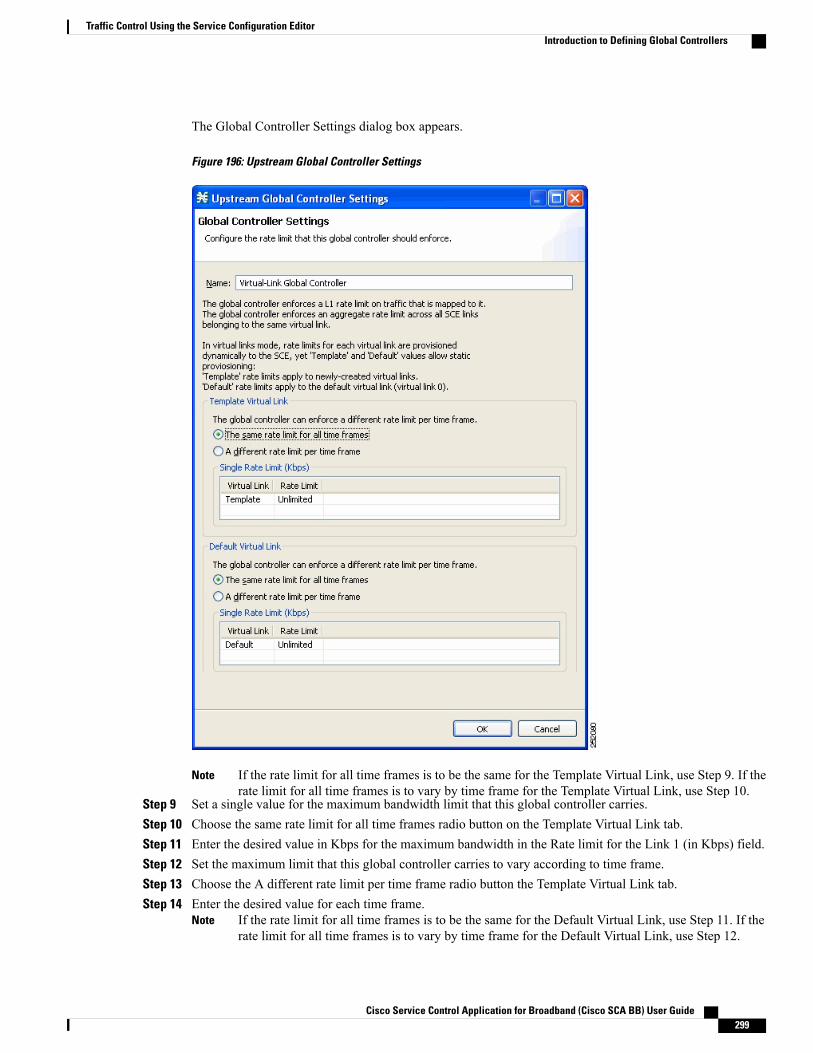
The Global Controller Settings dialog box appears.
Figure 196: Upstream Global Controller Settings
If the rate limit for all time frames is to be the same for the Template Virtual Link, use Step 9. If therate limit for all time frames is to vary by time frame for the Template Virtual Link, use Step 10.
Note
Step 9 Set a single value for the maximum bandwidth limit that this global controller carries.Step 10 Choose the same rate limit for all time frames radio button on the Template Virtual Link tab.Step 11 Enter the desired value in Kbps for the maximum bandwidth in the Rate limit for the Link 1 (in Kbps) field.Step 12 Set the maximum limit that this global controller carries to vary according to time frame.Step 13 Choose the A different rate limit per time frame radio button the Template Virtual Link tab.Step 14 Enter the desired value for each time frame.
If the rate limit for all time frames is to be the same for the Default Virtual Link, use Step 11. If therate limit for all time frames is to vary by time frame for the Default Virtual Link, use Step 12.
Note
Cisco Service Control Application for Broadband (Cisco SCA BB) User Guide 299
Traffic Control Using the Service Configuration EditorIntroduction to Defining Global Controllers
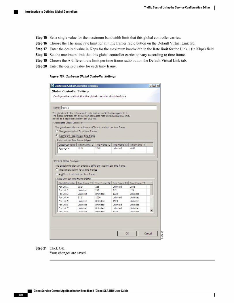
Step 15 Set a single value for the maximum bandwidth limit that this global controller carries.Step 16 Choose the The same rate limit for all time frames radio button on the Default Virtual Link tab.Step 17 Enter the desired value in Kbps for the maximum bandwidth in the Rate limit for the Link 1 (in Kbps) field.Step 18 Set the maximum limit that this global controller carries to vary according to time frame.Step 19 Choose the A different rate limit per time frame radio button the Default Virtual Link tab.Step 20 Enter the desired value for each time frame.
Figure 197: Upstream Global Controller Settings
Step 21 Click OK.Your changes are saved.
Cisco Service Control Application for Broadband (Cisco SCA BB) User Guide300
Traffic Control Using the Service Configuration EditorIntroduction to Defining Global Controllers
Introduction to Managing Subscriber BandwidthAfter you have defined global controllers, you can add subscriber BWCs to packages and map these subscriberBWCs to different global controllers.
A Subscriber BWC controls subscriber bandwidth consumption for upstream or downstream flows. It controlsand measures the bandwidth of an aggregation of traffic flows of a service or group of services.
Each package has its own set of BWCs that determine the bandwidth available per package subscriber foreach available service.
The two Primary BWCs, one for upstream traffic and one for downstream traffic, allocate bandwidth to specificsubscribers. Bandwidth is allocated based on the Committed Information Rate (CIR), the Peak InformationRate (PIR), and the Subscriber relative priority settings. You can configure these parameters, but the PrimaryBWCs cannot be deleted.
There are two default BWCs, one for upstream traffic and one for downstream traffic. By default, all servicesare mapped to one of these two BWCs. The BWCmechanism controls rate subpartitioning within the defaultBWC rate control, based on the CIR, PIR, and AL. You can configure these parameters, but the default BWCscannot be deleted.
You can add up to 32 user-defined BWCs per package:
• Subscriber BWCs operate at the service-per-subscriber level. They allocate bandwidth for services foreach subscriber, based upon the CIR, PIR, global controller, and Assurance Level (AL) set for the BWC.Each rule defines a link between the flow of the service and one of the BWCs (unless the flows are tobe blocked). See Defining Per-Flow Actions for a Rule , on page 345 section.
• Extra BWCs also operate at the subscriber level. Extra BWCs (based on the CIR, PIR, global controller,and AL) can be allocated for services that are not included in the Primary BWC. These are services thatare not often used but have strict bandwidth requirements, for example, video conference calls. TheExtra BWCs are BWCs that control a single service (or service group). BWCs cannot borrow bandwidthfrom Extra BWCs and vice versa.
Each user-defined BWC controls either downstream or upstream traffic.
If you enable or disable Virtual Links mode, all user-defined global controllers are deleted from the serviceconfiguration. A BWC that pointed to a user-defined global controller now points to the default globalcontroller. Other parameters of these BWCs remain unchanged.
Note
The Cisco SCE supports a maximum of 2000 BWCs. You cannot apply a PQB file to a Cisco SCE if the filecontains more than 2000 BWCs. But, the Subscriber BWCs with same values for GC Index, AL Level, PIR,and CIR are considered as a single BWC; even if the BWCs are mapped to different flows. So, in effect, CiscoSCA BB may support more than 2000 BWCs.
Subscriber BWC ParametersThe Subscriber BW Controllers tab of the Package Settings dialog box has the following configurationparameters:
• Name—A unique name for each BWC.
• CIR (L3 Kbps)—The minimum bandwidth that must be granted to traffic controlled by the BWC.
Cisco Service Control Application for Broadband (Cisco SCA BB) User Guide 301
Traffic Control Using the Service Configuration EditorIntroduction to Managing Subscriber Bandwidth
• PIR (L3 Kbps)—The maximum bandwidth allowed to traffic controlled by the BWC.
The minimum bandwidth for a subscriber BWC is 16 Kbps with a granularity of 1 Kbpsand the maximum bandwidth is 1000000 Kbps.
Note
• Global Controller—The global controller with which this BWC is associated. The global controllers arevirtual queues that are part of the bandwidth control mechanism. Direct traffic with similar bandwidthcontrol properties to the same global controller.
• Assurance Level—How fast bandwidth either decreases from the PIR to the CIR as congestion buildsor else increases from the CIR to the PIR as congestion decreases. A higher AL ensures a higher bandwidthcompared to a similar BWC with a lower AL. The lowest assurance value is 1, the highest is Persistent(10).Assurance Level 10 (persistent) never goes below the relevant CIR, unless the total line rate cannotsustain this value.
• Subscriber relative priority—Assurance Level given to the Primary BWC of the subscriber. It determinesthe assurance given to all the subscriber traffic when competing for bandwidth with subscribers to otherpackages. The lowest value is 1; the highest is 10.
Subscriber bandwidth control (and accounting and reporting) is based on Layer 3 volume. Global controllerbandwidth is based on Layer 1 volume.
Note
Editing Package Subscriber BWCs
Procedure
Step 1 In the Policies tab, click Global Policy.The Global Bandwidth Settings dialog box in the right (Rule) pane.
Step 2In the right (Rule) pane, select a BWC and click the Edit ( ) icon.The Package Settings dialog box appears.
Step 3 In the Package Settings dialog box, click the Subscriber BW Controllers tab.
Cisco Service Control Application for Broadband (Cisco SCA BB) User Guide302
Traffic Control Using the Service Configuration EditorIntroduction to Managing Subscriber Bandwidth
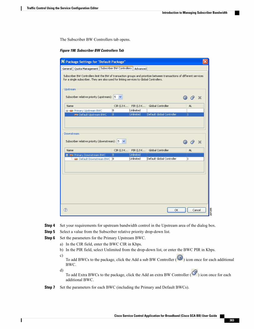
The Subscriber BW Controllers tab opens.
Figure 198: Subscriber BW Controllers Tab
Step 4 Set your requirements for upstream bandwidth control in the Upstream area of the dialog box.Step 5 Select a value from the Subscriber relative priority drop-down list.Step 6 Set the parameters for the Primary Upstream BWC.
a) In the CIR field, enter the BWC CIR in Kbps.b) In the PIR field, select Unlimited from the drop-down list, or enter the BWC PIR in Kbps.c)
To add BWCs to the package, click the Add a sub BW Controller ( ) icon once for each additionalBWC.
d)To add Extra BWCs to the package, click the Add an extra BW Controller ( ) icon once for eachadditional BWC.
Step 7 Set the parameters for each BWC (including the Primary and Default BWCs).
Cisco Service Control Application for Broadband (Cisco SCA BB) User Guide 303
Traffic Control Using the Service Configuration EditorIntroduction to Managing Subscriber Bandwidth
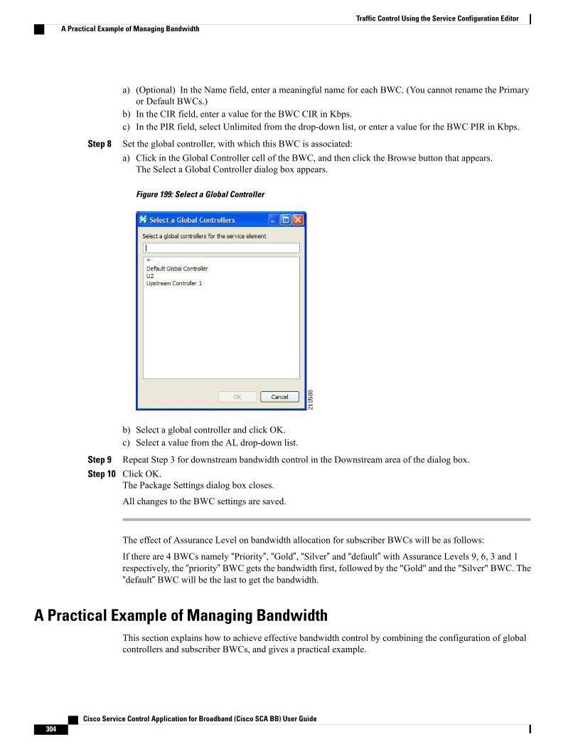
(Optional) In the Name field, enter a meaningful name for each BWC. (You cannot rename the Primaryor Default BWCs.)
a)
b) In the CIR field, enter a value for the BWC CIR in Kbps.c) In the PIR field, select Unlimited from the drop-down list, or enter a value for the BWC PIR in Kbps.
Step 8 Set the global controller, with which this BWC is associated:a) Click in the Global Controller cell of the BWC, and then click the Browse button that appears.
The Select a Global Controller dialog box appears.
Figure 199: Select a Global Controller
b) Select a global controller and click OK.c) Select a value from the AL drop-down list.
Step 9 Repeat Step 3 for downstream bandwidth control in the Downstream area of the dialog box.Step 10 Click OK.
The Package Settings dialog box closes.
All changes to the BWC settings are saved.
The effect of Assurance Level on bandwidth allocation for subscriber BWCs will be as follows:
If there are 4 BWCs namely “Priority”, “Gold”, “Silver” and “default” with Assurance Levels 9, 6, 3 and 1respectively, the “priority” BWC gets the bandwidth first, followed by the "Gold" and the "Silver" BWC. The“default” BWC will be the last to get the bandwidth.
A Practical Example of Managing BandwidthThis section explains how to achieve effective bandwidth control by combining the configuration of globalcontrollers and subscriber BWCs, and gives a practical example.
Cisco Service Control Application for Broadband (Cisco SCA BB) User Guide304
Traffic Control Using the Service Configuration EditorA Practical Example of Managing Bandwidth
Configuring Total Bandwidth Control
Procedure
Step 1 Configure the necessary global controllers.Ascertain which services are likely to be problematic, and what the maximum total bandwidth should be foreach. You do not need to configure services and packages that are unlikely to be problematic; you can includethem in the default global controllers.
Step 2 Configure the subscriber BWCs for the package.Step 3 Add a subscriber BWC for each type of upstream or downstream traffic that you want to limit, and configure
the CIR and the PIR accordingly.Step 4 Select an appropriate global controller for each subscriber BWC.Step 5 For each service that is to have its own BWC, create a rule and select appropriate upstream and downstream
BWCs.
Example for Limiting P2P and Streaming Traffic Using the Console
This example assumes that the traffic flow is bidirectional; you may decide that you only need upstreamcontrollers or downstream controllers.
Note
The P2P Traffic Optimization wizards allow you to create a simple model of devices, connect to them,and limit P2P traffic to a specified bandwidth. (See Using the P2P Traffic Optimization Wizards , onpage 81 section.)
Note
Procedure
Step 1 In the Policies tab, click Global Policy.
Cisco Service Control Application for Broadband (Cisco SCA BB) User Guide 305
Traffic Control Using the Service Configuration EditorA Practical Example of Managing Bandwidth

The Global Bandwidth Settings dialog box in the right (Rule) pane.
Step 2 Add two upstream global controllers and two downstream global controllers and assign the desired bandwidthto each global controller.
Figure 200: Global Bandwidth Settings
(Here, Upstream Controller 1 and Downstream Controller 1 is used for P2P traffic, and Upstream Controller2 and Downstream Controller 2 is used for streaming traffic.)
Cisco Service Control Application for Broadband (Cisco SCA BB) User Guide306
Traffic Control Using the Service Configuration EditorA Practical Example of Managing Bandwidth

Step 3 In a Package Settings dialog box, add two upstream BWCs and two downstream BWCs, map them to theappropriate global controllers, and set their parameters (CIR, PIR, AL).
Figure 201: Package Settings
(Here, BWC1 is for upstream P2P traffic and BWC3 is for downstream P2P traffic; BWC2 is for upstreamstreaming traffic and BWC4 is for downstream streaming traffic.)
Cisco Service Control Application for Broadband (Cisco SCA BB) User Guide 307
Traffic Control Using the Service Configuration EditorA Practical Example of Managing Bandwidth
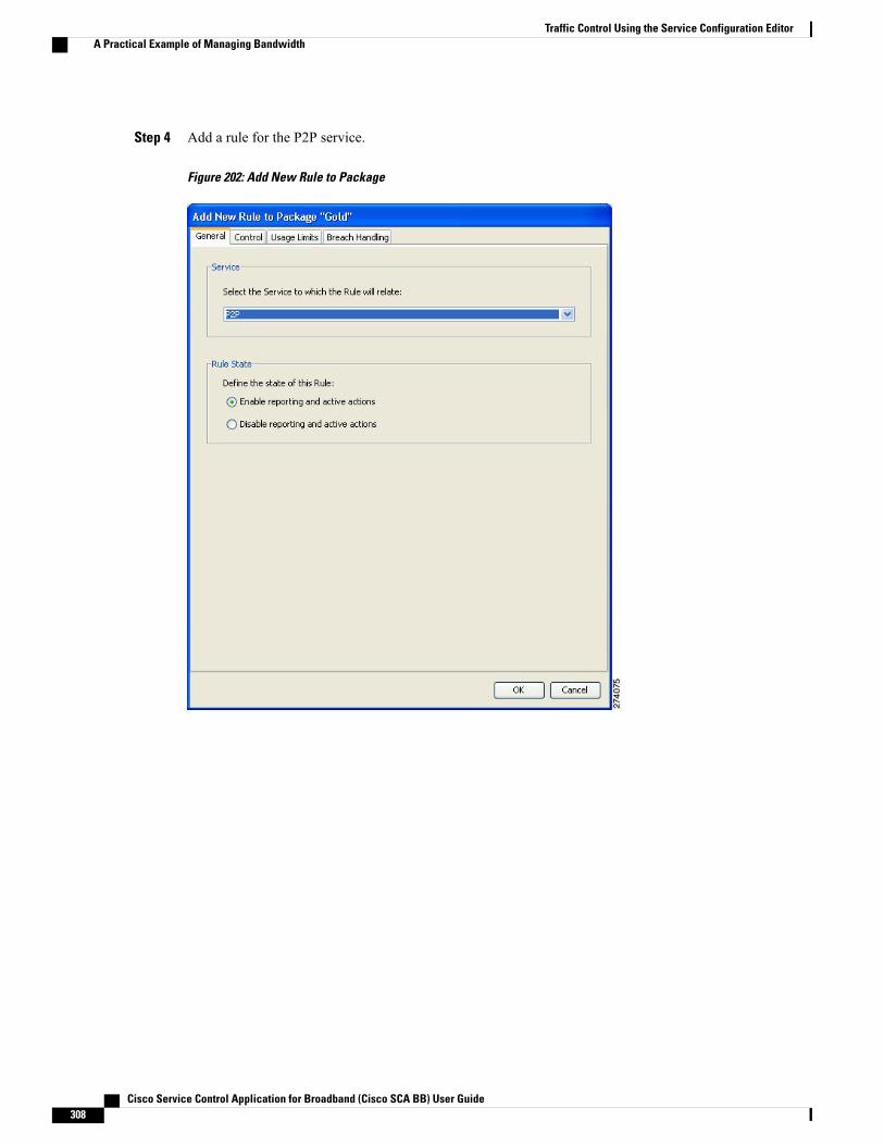
Step 4 Add a rule for the P2P service.
Figure 202: Add New Rule to Package
Cisco Service Control Application for Broadband (Cisco SCA BB) User Guide308
Traffic Control Using the Service Configuration EditorA Practical Example of Managing Bandwidth

Step 5 In the Control tab, assign BWC 1 as the upstream BWC and BWC 3 as the downstream BWC.
Figure 203: Control Tab
Step 6 Repeat Step 4 and Step 5 for the Streaming service, using BWC 2 as the upstream BWC and BWC 4 as thedownstream BWC.
Cisco Service Control Application for Broadband (Cisco SCA BB) User Guide 309
Traffic Control Using the Service Configuration EditorA Practical Example of Managing Bandwidth
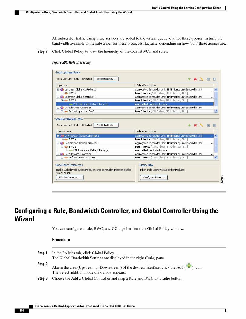
All subscriber traffic using these services are added to the virtual queue total for these queues. In turn, thebandwidth available to the subscriber for these protocols fluctuate, depending on how “full” these queues are.
Step 7 Click Global Policy to view the hierarchy of the GCs, BWCs, and rules.
Figure 204: Rule Hierarchy
Configuring a Rule, Bandwidth Controller, and Global Controller Using theWizard
You can configure a rule, BWC, and GC together from the Global Policy window.
Procedure
Step 1 In the Policies tab, click Global Policy .The Global Bandwidth Settings are displayed in the right (Rule) pane.
Step 2Above the area (Upstream or Downstream) of the desired interface, click the Add ( ) icon.The Select addition mode dialog box appears.
Step 3 Choose the Add a Global Controller and map a Rule and BWC to it radio button.
Cisco Service Control Application for Broadband (Cisco SCA BB) User Guide310
Traffic Control Using the Service Configuration EditorConfiguring a Rule, Bandwidth Controller, and Global Controller Using the Wizard
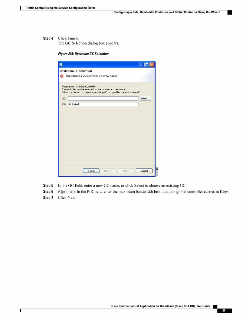
Step 4 Click Finish.The GC Selection dialog box appears.
Figure 205: Upstream GC Selection
Step 5 In the GC field, enter a new GC name, or click Select to choose an existing GC.Step 6 (Optional) In the PIR field, enter the maximum bandwidth limit that this global controller carries in Kbps.Step 7 Click Next.
Cisco Service Control Application for Broadband (Cisco SCA BB) User Guide 311
Traffic Control Using the Service Configuration EditorConfiguring a Rule, Bandwidth Controller, and Global Controller Using the Wizard
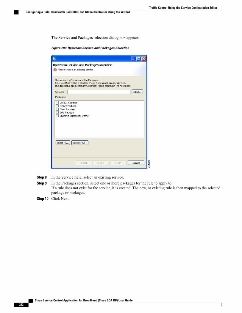
The Service and Packages selection dialog box appears.
Figure 206: Upstream Service and Packages Selection
Step 8 In the Service field, select an existing service.Step 9 In the Packages section, select one or more packages for the rule to apply to.
If a rule does not exist for the service, it is created. The new, or existing rule is then mapped to the selectedpackage or packages.
Step 10 Click Next.
Cisco Service Control Application for Broadband (Cisco SCA BB) User Guide312
Traffic Control Using the Service Configuration EditorConfiguring a Rule, Bandwidth Controller, and Global Controller Using the Wizard

The BWC selection dialog box appears.
Figure 207: Upstream BWC Selection
Step 11 Enter a new BWC name, or click Select to choose an existing BWC.Step 12 Click OK .
Configuring the Upstream Configuration of the Global Bandwidth Controllerfor IPv6
You can configure the upstream configuration of the global bandwidth controller for IPv6 from the GlobalPolicy window. For details on managing the bandwidth, see the Introduction to Managing Bandwidth, onpage 279“Managing Bandwidth” section.
Procedure
Step 1 In the Service Configuration Editor window, click the Policies tab.Step 2 Under the Policies tab, click Global Policy.
Cisco Service Control Application for Broadband (Cisco SCA BB) User Guide 313
Traffic Control Using the Service Configuration EditorConfiguring the Upstream Configuration of the Global Bandwidth Controller for IPv6
The Global Bandwidth Settings dialog box is displayed in the right (Rule) pane.
Step 3Above the area (Upstream or Downstream) of the corresponding interface, click the Add ( ) icon.The Select Addition mode dialog box is displayed.
Step 4 Click the Add a Global Controller and map a Rule and a BWC to it radio button to add a global controllerwith a rule mapped to it and a BWC added to it.
Step 5 Select an existing global controller by clicking the Select button or create a new global controller by typingthe name of a global controller.
Step 6 Enter the PIR value and click Next.Step 7 Select the service to control and check the Unknown Subscriber Package check box and Click Next.Step 8 Select an existing BWC by clicking the Select button or create a new BWC by typing the name of the BWC.
Click Next.Step 9 Double-click on the unknown subscriber package to verify the bandwidth controller and the global controller
association.
What to Do Next
Follow the same procedure for the downstream configuration of the global bandwidth controller for IPv6.
Setting Bandwidth Management Prioritization ModeRelative priority is the level of assurance that an internal BWC (iBWC) receives when competing againstother iBWCs for bandwidth.
The relative priority of one of the following modes determines the relative priority of the flow that goesthrough an iBWC:
• The iBWC—In Global Prioritization Mode
• The subscriber—In Subscriber Prioritization Mode
Procedure
Step 1 In the Policies tab, click Global Policy .The Global Bandwidth Settings are displayed in the right (Rule) pane.
Step 2 Click Edit Preferences .
Cisco Service Control Application for Broadband (Cisco SCA BB) User Guide314
Traffic Control Using the Service Configuration EditorSetting Bandwidth Management Prioritization Mode
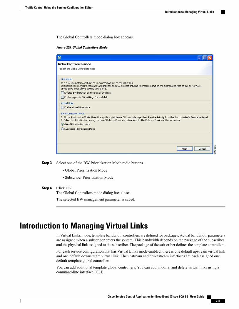
The Global Controllers mode dialog box appears.
Figure 208: Global Controllers Mode
Step 3 Select one of the BW Prioritization Mode radio buttons.
• Global Prioritization Mode
• Subscriber Prioritization Mode
Step 4 Click OK .The Global Controllers mode dialog box closes.
The selected BW management parameter is saved.
Introduction to Managing Virtual LinksIn Virtual Linksmode, template bandwidth controllers are defined for packages. Actual bandwidth parametersare assigned when a subscriber enters the system. This bandwidth depends on the package of the subscriberand the physical link assigned to the subscriber. The package of the subscriber defines the template controllers.
For each service configuration that has Virtual Links mode enabled, there is one default upstream virtual linkand one default downstream virtual link. The upstream and downstream interfaces are each assigned onedefault template global controller.
You can add additional template global controllers. You can add, modify, and delete virtual links using acommand-line interface (CLI).
Cisco Service Control Application for Broadband (Cisco SCA BB) User Guide 315
Traffic Control Using the Service Configuration EditorIntroduction to Managing Virtual Links
The number of directional template global controllers limits the maximum number of virtual links. The numberof template global controllers times the number of virtual links cannot exceed 1024 or 4096. Based on theCisco SCE hardware, the number of global controllers varies. For details, see the Introduction to ManagingBandwidth, on page 279section.
To support the DOCSIS 3.0 Downstream bonding, a two level virtual link hierarchy is created for the widebandchannels. The wideband channels are associated with the Aggregate Global Control (AGC) that provides aconstant output signal despite variations in input signal strength. Wideband channels are associated with threeAGCs in a two level hierarchy. At the lower level of the hierarchy, all the DOCSIS 3.0 modems for widebandare aggregated into one AGC and the other AGC contains both legacy and 3.0 modems. The AGC at the toplevel of the hierarchy is used to limit the aggregated bandwidth of the wideband channel.
For more information on the support for DOCSIS 3.0 solution, see the Cisco Service Control for ManagingRemote Cable MSO Links Solution Guide.
For more information onmanaging the virtual links global controllers, see the Managing Virtual Links GlobalControllers section.
If you enable or disable Virtual Links mode, all user-defined global controllers are deleted from the serviceconfiguration. A subscriber BWC that pointed to a user-defined global controller now points to the defaultglobal controller. (Other parameters of these subscriber BWCs remain unchanged.)
Note
While applying a policy in virtual link mode, if the new template includes a different number of globalcontrollers than the currently applied template, you must choose the Reset all Virtual Links to TemplateRate Limits. Otherwise, selecting apply results in en error message, similar to the following: “TemplateUpstream Virtual Link differ from the one in the SCE - cannot apply without the force template virtuallink option.”
Note
Collection Manager Virtual Links Names UtilityThe Cisco Service Control Collection Manager includes a command-line utility for managing the names ofvirtual links.
For more information about the Cisco Service Control Collection Manager Virtual Links Names Utility, seethe “Managing Virtual Links” section in the “Managing the Collection Manager” chapter of Cisco ServiceControl Management Suite Collection Manager User Guide .
Enabling Virtual Links ModeTo use virtual links, you must enable Virtual Links mode.
If you enable or disable Virtual Links mode, all user-defined global controllers are deleted from the serviceconfiguration.
Note
Cisco Service Control Application for Broadband (Cisco SCA BB) User Guide316
Traffic Control Using the Service Configuration EditorCollection Manager Virtual Links Names Utility
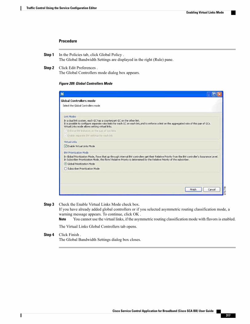
Procedure
Step 1 In the Policies tab, click Global Policy .The Global Bandwidth Settings are displayed in the right (Rule) pane.
Step 2 Click Edit Preferences .The Global Controllers mode dialog box appears.
Figure 209: Global Controllers Mode
Step 3 Check the Enable Virtual Links Mode check box.If you have already added global controllers or if you selected asymmetric routing classification mode, awarning message appears. To continue, click OK .
You cannot use the virtual links, if the asymmetric routing classification mode with flavors is enabled.Note
The Virtual Links Global Controllers tab opens.
Step 4 Click Finish .The Global Bandwidth Settings dialog box closes.
Cisco Service Control Application for Broadband (Cisco SCA BB) User Guide 317
Traffic Control Using the Service Configuration EditorEnabling Virtual Links Mode

Viewing Virtual Links Global Controller Settings
Global controller bandwidth is based on Layer 1 volume. (Accounting, reporting, and subscriber bandwidthcontrol in Cisco SCA BB is based on Layer 3 volume.)
Note
Procedure
Step 1 In the Policies tab, click Global Policy .The Global Bandwidth Settings are displayed in the right (Rule) pane.
The maximum amount of bandwidth that can be used by any global controller is displayed at the top of theGlobal Bandwidth Settings:
• Total Link Upstream Bandwidth Limit: Link 1
• Total Link Downstream Bandwidth Limit: Link 1
Step 2Select a global controller, and click the Edit ( ) icon.
Cisco Service Control Application for Broadband (Cisco SCA BB) User Guide318
Traffic Control Using the Service Configuration EditorViewing Virtual Links Global Controller Settings
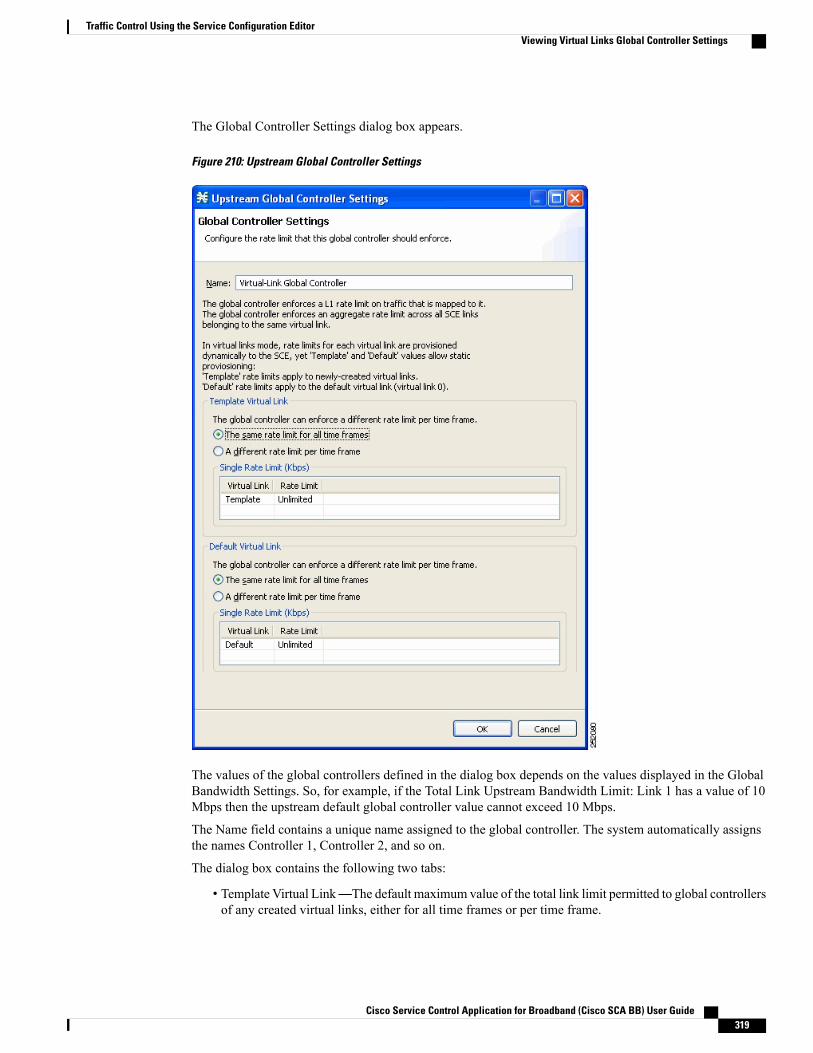
The Global Controller Settings dialog box appears.
Figure 210: Upstream Global Controller Settings
The values of the global controllers defined in the dialog box depends on the values displayed in the GlobalBandwidth Settings. So, for example, if the Total Link Upstream Bandwidth Limit: Link 1 has a value of 10Mbps then the upstream default global controller value cannot exceed 10 Mbps.
The Name field contains a unique name assigned to the global controller. The system automatically assignsthe names Controller 1, Controller 2, and so on.
The dialog box contains the following two tabs:
• Template Virtual Link—The default maximum value of the total link limit permitted to global controllersof any created virtual links, either for all time frames or per time frame.
Cisco Service Control Application for Broadband (Cisco SCA BB) User Guide 319
Traffic Control Using the Service Configuration EditorViewing Virtual Links Global Controller Settings
• Default Virtual Link—The maximum value of the total link limit permitted to global controllers of thedefault virtual link, either for all time frames or per time frame.
Step 3 Click OK.The Global Bandwidth Settings dialog box closes.
Managing Virtual Links Global ControllersVirtual link global controllers can be added edited and deleted in the same way as regular global controllers.For more information, see the following sections:
• Adding Global Controllers, on page 320
• Setting the Maximum Bandwidth of Global Controllers, on page 323
• Deleting Global Controllers, on page 324
• Introduction to Defining Global Controllers, on page 284
• Introduction to Managing Subscriber Bandwidth, on page 301
Adding Global ControllersBased on the Cisco SCE hardware, the number of global controllers you can add to a service configurationvaries. For details, see the Introduction to Managing Bandwidth, on page 279 section.
Procedure
Step 1 In the Policies tab, click Global Policy.The Global Bandwidth Settings dialog box is displayed in the right (Rule) pane.
Step 2Above the area (Upstream or Downstream) of the desired interface, click the Add ( ) icon.
Cisco Service Control Application for Broadband (Cisco SCA BB) User Guide320
Traffic Control Using the Service Configuration EditorManaging Virtual Links Global Controllers
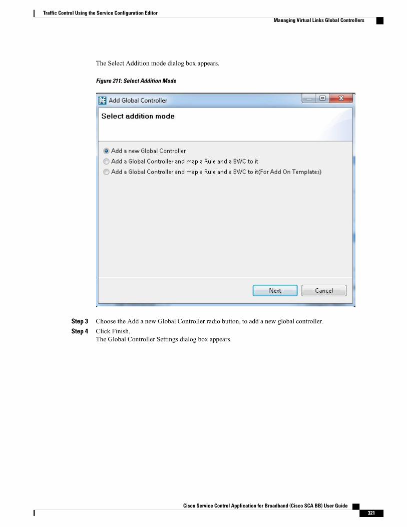
The Select Addition mode dialog box appears.
Figure 211: Select Addition Mode
Step 3 Choose the Add a new Global Controller radio button, to add a new global controller.Step 4 Click Finish.
The Global Controller Settings dialog box appears.
Cisco Service Control Application for Broadband (Cisco SCA BB) User Guide 321
Traffic Control Using the Service Configuration EditorManaging Virtual Links Global Controllers
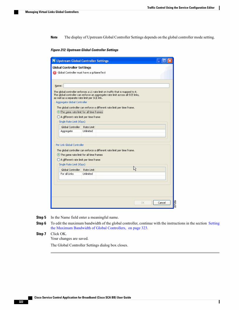
The display of UpstreamGlobal Controller Settings depends on the global controller mode setting.Note
Figure 212: Upstream Global Controller Settings
Step 5 In the Name field enter a meaningful name.Step 6 To edit the maximum bandwidth of the global controller, continue with the instructions in the section Setting
the Maximum Bandwidth of Global Controllers, on page 323.Step 7 Click OK.
Your changes are saved.
The Global Controller Settings dialog box closes.
Cisco Service Control Application for Broadband (Cisco SCA BB) User Guide322
Traffic Control Using the Service Configuration EditorManaging Virtual Links Global Controllers
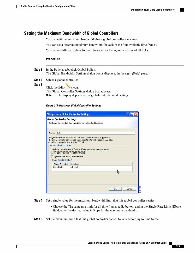
Setting the Maximum Bandwidth of Global ControllersYou can edit the maximum bandwidth that a global controller can carry.
You can set a different maximum bandwidth for each of the four available time frames.
You can set different values for each link and for the aggregated BW of all links.
Procedure
Step 1 In the Policies tab, click Global Policy.The Global Bandwidth Settings dialog box is displayed in the right (Rule) pane.
Step 2 Select a global controller.Step 3
Click the Edit ( ) icon.The Global Controller Settings dialog box appears.
The display depends on the global controller mode setting.Note
Figure 213: Upstream Global Controller Settings
Step 4 Set a single value for the maximum bandwidth limit that this global controller carries.
• Choose the The same rate limit for all time frames radio button, and in the Single Rate Limit (Kbps)field, enter the desired value in Kbps for the maximum bandwidth.
Step 5 Set the maximum limit that this global controller carries to vary according to time frame.
Cisco Service Control Application for Broadband (Cisco SCA BB) User Guide 323
Traffic Control Using the Service Configuration EditorManaging Virtual Links Global Controllers

Step 6 Choose the A different rate limit per time frame radio button, and enter the desired value for each time frame.The display depends on the global controller mode setting.Note
Figure 214: Upstream Global Controller Settings
These values are applied to the time frames of the default calendar.Note
Step 7 Click OK .Your changes are saved.
The value in the Policy Description column changes to reflect the new bandwidth limits.
Step 8 Repeat Step 2 through Step 6 for other global controllers.
Deleting Global ControllersYou can delete unused global controllers at any time. The default global controller and the Total Link Limitcannot be deleted.
Cisco Service Control Application for Broadband (Cisco SCA BB) User Guide324
Traffic Control Using the Service Configuration EditorManaging Virtual Links Global Controllers
Procedure
Step 1 In the Policies tab, click Global Policy.The Global Bandwidth Settings dialog box appears.
Step 2 Select a global controller.Step 3
Click the Delete ( ) icon.If a subscriber BWC is using the specified global controller (see Editing Package Subscriber BWCs,on page 302 section), a global controller cannot be removedmessage is displayed. The global controllercannot be deleted until you unassign it from all subscriber BWCs.
Note
The global controller is deleted.
Step 4 Click OK.Your changes are saved.
The Global Bandwidth Settings dialog box closes.
Configuring a Service Configuation in Virtual Links ModeThe following steps outline configuring a service configuration in Virtual Links mode. The procedure issimilar to that for configuring any service configuration, but virtual links must be added using the CLI.
Procedure
Step 1 Create a new service configuration.Step 2 Open the Global Bandwidth Settings dialog box and check the Enable Virtual Links Mode check box.Step 3 Create template global controllers.Step 4 Create packages.Step 5 Add subscriber BW controllers to the packages and associate them with appropriate global controllers.Step 6 Apply the service configuration.Step 7 The bandwidth values of the default global controllers are set; the values of all other global controllers are
not set – these global controllers are templates.Step 8 Add virtual links using the CLI.
Each virtual link gets a set of global controllers with the PIR values of the template global controllerconfiguration.
If necessary, you can use the CLI to change the PIR values of the global controller.
1 A subscriber is introduced to the Cisco SCE platform. Upstream and downstream virtual links are associatedwith the subscriber as well as a package.
2 Rule resolution for each flow of the subscriber is according to the package of the subscriber and the globalcontroller configuration of the virtual link.
Cisco Service Control Application for Broadband (Cisco SCA BB) User Guide 325
Traffic Control Using the Service Configuration EditorConfiguring a Service Configuation in Virtual Links Mode
Editing the Virtual Links Total Link LimitsYou can limit the total bandwidth passing through the physical link.
The total link limits for upstream and downstream traffic are defined independently.
In Virtual Links mode, bandwidth limitations are applied to the sum of all links.
Procedure
Step 1 In the Policies tab, click Global Policy.The Global Bandwidth Settings dialog box is displayed in the right (Rule) pane.
Step 2 In the Upstream or Downstream section, click Edit Rate Limit .The Total Rate Limit dialog box appears.
Step 3 In the Total Rate Limit for each SCE link (Kbps) field, enter the maximum bandwidth of the Cisco SCEplatform capacity that the platform carries, or enter Unlimited.
Step 4 Click OK.The Total Rate Limit dialog box closes.
The Total Link Bandwidth Limit: Link 1 field is updated.
Managing Virtual Links with CLI CommandsYou can configure, enable, and disable virtual links using the Cisco SCE platform Command-Line Interface(CLI). For more information about the Cisco SCE platform CLI, see the Cisco SCE8000 CLI CommandReference Cisco SCE10000 CLI Command Reference.
• Use the following CLI commands in line interface configuration mode to manage virtual links:
◦virtual-links index <index> direction [upstream | downstream]
◦virtual-links index <VL index> direction [upstream | downstream] gc <gc index> set-PIR value<PIR 1, PIR2, PIR3, PIR4>
◦virtual-links index <VL index> direction [upstream | downstream] gc <gc index> set-PIR value<PIR for all timeframes>
◦virtual-links index <VL index> direction [upstream | downstream] gc <gc index> reset-PIR
◦no virtual-links index <index> direction [upstream | downstream]
• Use the following CLI command in line interface configuration mode to set the virtual links index of asubscriber:
◦subscriber name <name> property name [vlUp | vlDown] value <vl index>
• Use the following CLI command in EXEC mode to monitor the status of virtual links:
◦Show interface LineCard 0 virtual-links [all | changed | different-from-template]
Cisco Service Control Application for Broadband (Cisco SCA BB) User Guide326
Traffic Control Using the Service Configuration EditorEditing the Virtual Links Total Link Limits
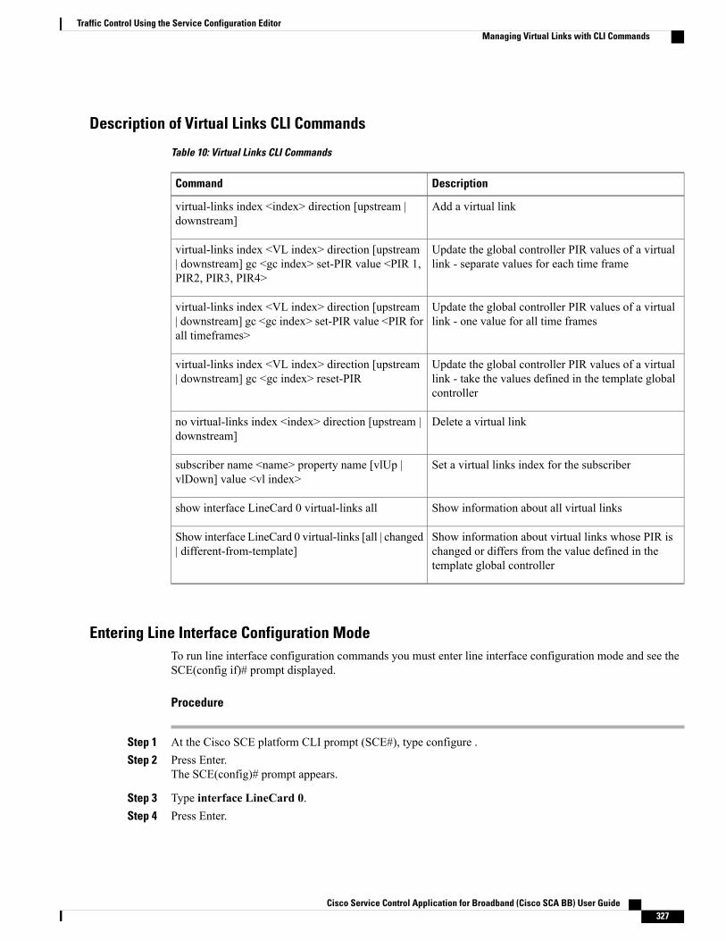
Description of Virtual Links CLI Commands
Table 10: Virtual Links CLI Commands
DescriptionCommand
Add a virtual linkvirtual-links index <index> direction [upstream |downstream]
Update the global controller PIR values of a virtuallink - separate values for each time frame
virtual-links index <VL index> direction [upstream| downstream] gc <gc index> set-PIR value <PIR 1,PIR2, PIR3, PIR4>
Update the global controller PIR values of a virtuallink - one value for all time frames
virtual-links index <VL index> direction [upstream| downstream] gc <gc index> set-PIR value <PIR forall timeframes>
Update the global controller PIR values of a virtuallink - take the values defined in the template globalcontroller
virtual-links index <VL index> direction [upstream| downstream] gc <gc index> reset-PIR
Delete a virtual linkno virtual-links index <index> direction [upstream |downstream]
Set a virtual links index for the subscribersubscriber name <name> property name [vlUp |vlDown] value <vl index>
Show information about all virtual linksshow interface LineCard 0 virtual-links all
Show information about virtual links whose PIR ischanged or differs from the value defined in thetemplate global controller
Show interface LineCard 0 virtual-links [all | changed| different-from-template]
Entering Line Interface Configuration ModeTo run line interface configuration commands you must enter line interface configuration mode and see theSCE(config if)# prompt displayed.
Procedure
Step 1 At the Cisco SCE platform CLI prompt (SCE#), type configure .Step 2 Press Enter.
The SCE(config)# prompt appears.
Step 3 Type interface LineCard 0.Step 4 Press Enter.
Cisco Service Control Application for Broadband (Cisco SCA BB) User Guide 327
Traffic Control Using the Service Configuration EditorManaging Virtual Links with CLI Commands

The SCE(config if)# prompt appears.
Introduction to Managing PackagesA package is a description of subscriber policy. It is a collection of rules that defines the reaction of the systemwhen it encounters flows that are mapped to the service to which the rule is related. It is recommended thatyou first define services (see Introduction to Managing Services , on page 162 section) and only then add anddefine packages.
Every Cisco SCABB service configuration contains a package, the default package, which is the root packageand cannot be deleted.
A subscriber is mapped to the default package in one of the following conditions:
• No other package is specifically assigned to the subscriber
• A nonexistent package is assigned to the subscriber.
A service configuration can contain up to 10000 packages.
For SCE 8K, it will be 5000 packages.
For SCE 10K, it will be 10000 packages.
Note
Package ParametersThe following parameters define a package:
• General parameters:
◦Package Name—A unique name for the package
◦Description—(Optional) A description of the package
• Quota Management parameters:
◦Quota Management Mode—Specifies how the subscriber quotas are managed—by external quotamanager or replenished periodically by Cisco SCA BB.
◦Aggregation Period Type—The quota aggregation period used when quotas are replenishedperiodically.
◦Quota Buckets—16 resource buckets used for quota management.
• Subscriber BW Controllers parameters:
◦Subscriber relative priority—The relative priority given to subscribers of the package at times ofNetwork congestion.Separate priorities are defined for upstream and downstream flows.
Cisco Service Control Application for Broadband (Cisco SCA BB) User Guide328
Traffic Control Using the Service Configuration EditorIntroduction to Managing Packages

◦Subscriber Bandwidth Controllers—A list of BW controllers (BWCs) that are available to servicesthat are part of the package. Various parameters are defined for each BWC, including a mappingto a global controller.Separate BWCs are defined for upstream and downstream flows.
• Advanced parameters:
◦Package Index—The unique number by which the system recognizes a package. Changing thepackage name does not affect Cisco SCE platform activity. The system provides a default valueof the package index. Do not modify this value.
◦Parent Package—The package one level higher in the package hierarchy. The parent package isimportant when packages share usage counters. The default package is the base of the packagehierarchy, and does not have a parent.
◦Package Usage Counter—Used by the system to generate data about the total use by each package.A package can use either an exclusive package usage counter or the package usage counter of theparent package.Each usage counter has:
◦A name assigned by the system (based on the package name).
An asterisk is appended to a package usage counter name whenever the counter appliesto more than one package.
Note
◦A unique counter index—The system provides a default value of the counter index. Do notmodify this value.
◦Calendar—The calendar used as the basis for the time-based rules of the package.
◦VAS Traffic Forwarding Table—The forwarding table used by the package.
These parameters are defined when you add a new package (see Adding Packages, on page 330 section). Youcan modify them at any time (see Editing Packages, on page 334 section).
Viewing PackagesYou can view a hierarchy tree of all existing packages, and you can see a list of services for which specificrules are defined for any selected package.
Procedure
Step 1 In the current service configuration, click the Policies tab.A list of all packages is displayed in the package tree.
To view more information about a package, open the Package Settings dialog box (see EditingPackages, on page 334 section).
Note
Step 2 Click a package in the hierarchy to display the rules of the package.
Cisco Service Control Application for Broadband (Cisco SCA BB) User Guide 329
Traffic Control Using the Service Configuration EditorViewing Packages
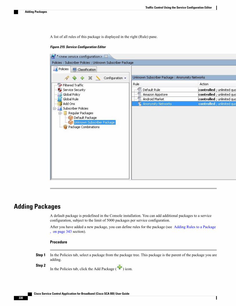
A list of all rules of this package is displayed in the right (Rule) pane.
Figure 215: Service Configuration Editor
Adding PackagesA default package is predefined in the Console installation. You can add additional packages to a serviceconfiguration, subject to the limit of 5000 packages per service configuration.
After you have added a new package, you can define rules for the package (see Adding Rules to a Package, on page 343 section).
Procedure
Step 1 In the Policies tab, select a package from the package tree. This package is the parent of the package you areadding.
Step 2In the Policies tab, click the Add Package ( ) icon.
Cisco Service Control Application for Broadband (Cisco SCA BB) User Guide330
Traffic Control Using the Service Configuration EditorAdding Packages
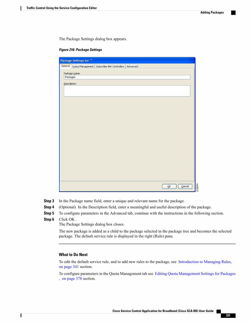
The Package Settings dialog box appears.
Figure 216: Package Settings
Step 3 In the Package name field, enter a unique and relevant name for the package.Step 4 (Optional) In the Description field, enter a meaningful and useful description of the package.Step 5 To configure parameters in the Advanced tab, continue with the instructions in the following section.Step 6 Click OK .
The Package Settings dialog box closes.
The new package is added as a child to the package selected in the package tree and becomes the selectedpackage. The default service rule is displayed in the right (Rule) pane.
What to Do Next
To edit the default service rule, and to add new rules to the package, see Introduction to Managing Rules,on page 341 section.
To configure parameters in the Quota Management tab see Editing Quota Management Settings for Packages, on page 378 section.
Cisco Service Control Application for Broadband (Cisco SCA BB) User Guide 331
Traffic Control Using the Service Configuration EditorAdding Packages

To configure parameters in the Subscriber BW Controllers tab, see Editing Package Subscriber BWCs, onpage 302 section.
Setting Advanced Package OptionsYou can change the index for the package, specify an exclusive usage counter, or select a calendar for thepackage in the Advanced tab.
Procedure
Step 1 In the Package Settings dialog box, click the Advanced tab.
Cisco Service Control Application for Broadband (Cisco SCA BB) User Guide332
Traffic Control Using the Service Configuration EditorSetting Advanced Package Options
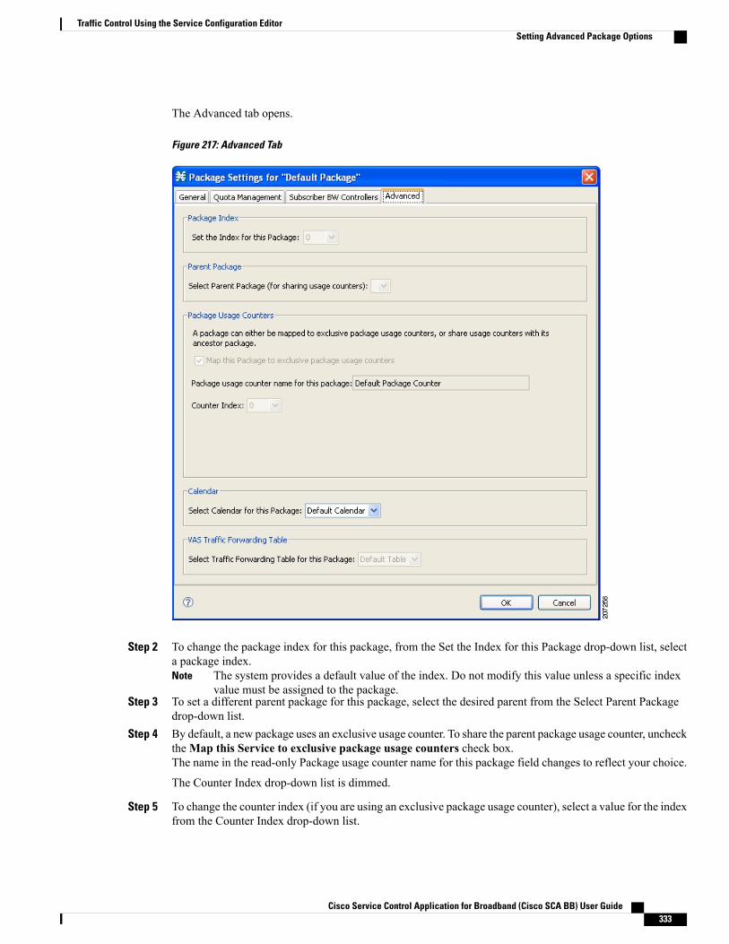
The Advanced tab opens.
Figure 217: Advanced Tab
Step 2 To change the package index for this package, from the Set the Index for this Package drop-down list, selecta package index.
The system provides a default value of the index. Do not modify this value unless a specific indexvalue must be assigned to the package.
Note
Step 3 To set a different parent package for this package, select the desired parent from the Select Parent Packagedrop-down list.
Step 4 By default, a new package uses an exclusive usage counter. To share the parent package usage counter, unchecktheMap this Service to exclusive package usage counters check box.The name in the read-only Package usage counter name for this package field changes to reflect your choice.
The Counter Index drop-down list is dimmed.
Step 5 To change the counter index (if you are using an exclusive package usage counter), select a value for the indexfrom the Counter Index drop-down list.
Cisco Service Control Application for Broadband (Cisco SCA BB) User Guide 333
Traffic Control Using the Service Configuration EditorSetting Advanced Package Options
The system provides a default value of the index. Do not modify this value.Note
Step 6 To set a calendar for this package (to use its time frames for time-based rules), select the desired calendarfrom the Select Calendar for this Package drop-down list.
Step 7 To set a VAS traffic-forwarding table for this package, select the desired traffic-forwarding table from theSelect Traffic Forwarding Table for this Package drop-down list.
If VAS traffic forwarding is disabled (the default), the drop-down list is dimmed. To enable VAStraffic forwarding, see Enabling VAS Traffic Forwarding, on page 462 section.
Note
Step 8 Click OK.The Package Settings dialog box closes.
The new package is added as a child to the selected parent package and becomes the selected package. Thedefault service rule is displayed in the right (Rule) pane.
What to Do Next
To edit the default service rule, and to add new rules to the package, see Introduction to Managing Rules,on page 341 section.
Duplicating PackagesDuplicating an existing package is a useful way to create a new package similar to an existing package. It isfaster to duplicate a package and then modify it than to define the package from beginning.
A duplicated package is added at the same level in the package tree as the original package.
Procedure
Step 1 In the Policies tab, select a package from the package tree.Step 2
In the Policies tab, click the Duplicate Package ( ) iconA duplicate package is created with all the same attributes as the original package. If the package is duplicatedseveral times, the name of the new package is the name of the selected package followed by “(1)”, “(2)”, andso on.
Step 3 Modify the package parameters (see Editing Packages, on page 334 section).
Editing PackagesYou can modify the parameters of a package (including the default package) at any time.
Procedure
Step 1 In the Policies tab, select a package from the package tree.
Cisco Service Control Application for Broadband (Cisco SCA BB) User Guide334
Traffic Control Using the Service Configuration EditorDuplicating Packages
Step 2In the Policies tab, click the Edit Package ( )icon.The Package Settings dialog box appears.
Step 3 In the Package name field, enter a new name for the package.Step 4 In the Description field, enter a new description of the package.Step 5 (Optional) Change quota management settings, see Editing Package Quota Management Settings (Using the
Quota Management Tab (Packages) Editing Quota Management Settings for Packages , on page 378 section.Step 6 (Optional) (Optional) Change bandwidth control settings, see Editing Package Subscriber BWCs, on page
302 section.Step 7 To change advanced settings, click the Advanced tab.
The Advanced tab opens.
Step 8 To change the package index for this package, from the Set the Index for this Package drop-down list, selecta Package Index.
The system provides a default value of the counter index. Do not modify this value unless a specificindex value must be assigned to the package.
Note
Step 9 To change the parent package of this package, select the desired parent from the Select Parent Packagedrop-down list.
Step 10 To share the parent package usage counter, uncheck the Map this Service to exclusive package usage counterscheck box.The name in the read-only Package usage counter name for this package field changes to reflect your choice.
The Counter Index drop-down list is dimmed.
Step 11 To use an exclusive package usage counter, check the Map this Service to exclusive package usage counterscheck box.The name in the read-only Package usage counter name for this package field changes to reflect your choice.
The Counter Index drop-down list is dimmed.
Step 12 To change the counter index if you are using the exclusive package usage counter, select a value for the indexfrom the Counter Index drop-down list.
The system provides a default value of the counter index. Do not modify this value.Note
Step 13 To change the calendar used by this package, select the desired calendar from the Select Calendar for thisPackage drop-down list.
Step 14 To change the VAS traffic-forwarding table for this package, select the desired traffic-forwarding table fromthe Select Traffic Forwarding Table for this Package drop-down list.
If VAS traffic forwarding is disabled (the default), the drop-down list is dimmed. To enable VAStraffic forwarding, see Enabling VAS Traffic Forwarding, on page 462 section.
Note
Step 15 Click OK.The Package Settings dialog box closes.
All changes to the package parameters are saved.
Deleting PackagesYou can delete user-defined packages. The default package cannot be deleted.
Cisco Service Control Application for Broadband (Cisco SCA BB) User Guide 335
Traffic Control Using the Service Configuration EditorDeleting Packages

Procedure
Step 1 In the Policies tab, select a package from the package tree.Step 2
In the Policies tab, click the Delete Package ( ) icon.A Package Warning message appears.
Figure 218: Package Warning
Step 3 Click Yes.The package is deleted and is no longer displayed in the package tree.
Introduction to Add-on PackagesThe Add-on Package has been added to Cisco SCABB 5.1 to reduce the complexity of maintaining largenumber of packages. The package enables you to create up to ten Add-on groups, and add up to 20 Add-ontemplates under each group.
The three node hierarchies of the Add-on Package are:
• Add-on Group, which groups similar templates under one category.
• Add-on Template, which is similar to the normal package with the minimal option.
Cisco Service Control Application for Broadband (Cisco SCA BB) User Guide336
Traffic Control Using the Service Configuration EditorIntroduction to Add-on Packages
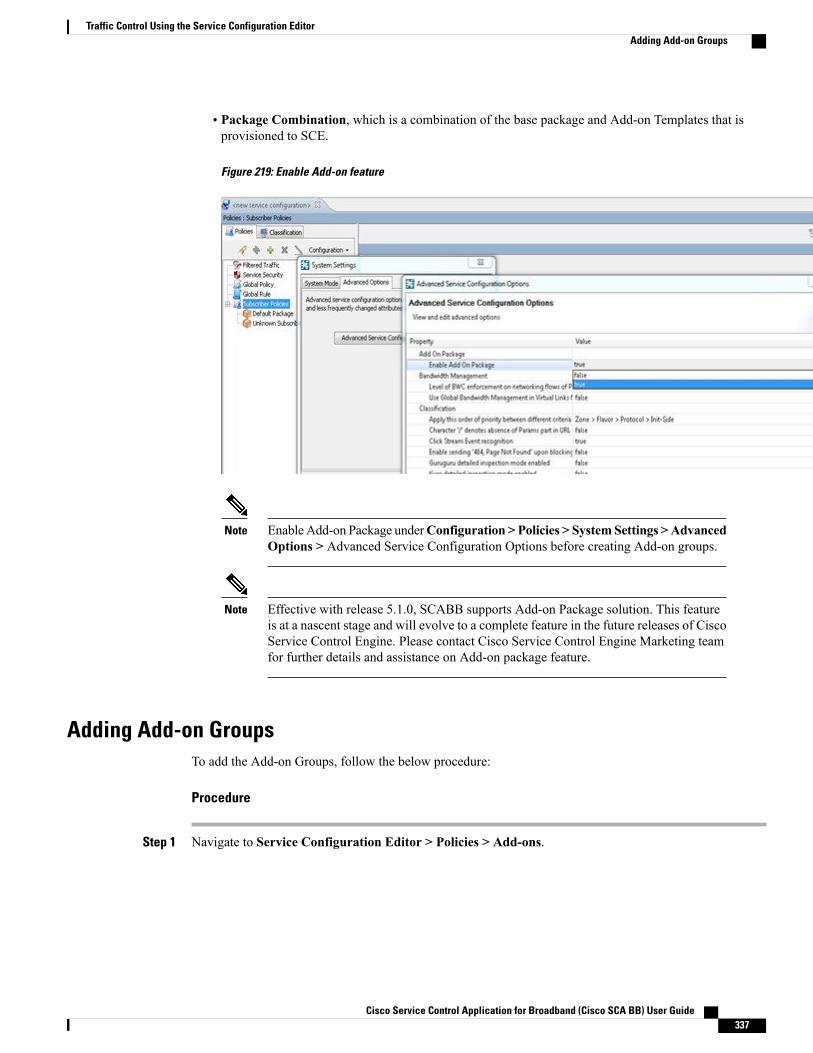
• Package Combination, which is a combination of the base package and Add-on Templates that isprovisioned to SCE.
Figure 219: Enable Add-on feature
Enable Add-on Package underConfiguration > Policies > SystemSettings >AdvancedOptions > Advanced Service Configuration Options before creating Add-on groups.
Note
Effective with release 5.1.0, SCABB supports Add-on Package solution. This featureis at a nascent stage and will evolve to a complete feature in the future releases of CiscoService Control Engine. Please contact Cisco Service Control Engine Marketing teamfor further details and assistance on Add-on package feature.
Note
Adding Add-on GroupsTo add the Add-on Groups, follow the below procedure:
Procedure
Step 1 Navigate to Service Configuration Editor > Policies > Add-ons.
Cisco Service Control Application for Broadband (Cisco SCA BB) User Guide 337
Traffic Control Using the Service Configuration EditorAdding Add-on Groups
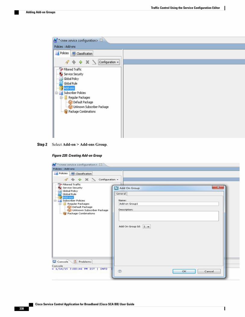
Step 2 Select Add-on > Add-ons Group.
Figure 220: Creating Add-on Group
Cisco Service Control Application for Broadband (Cisco SCA BB) User Guide338
Traffic Control Using the Service Configuration EditorAdding Add-on Groups

Step 3 In the Add-on Group dialog box, enter the name and the description of the group.Step 4 Select the Add-on Group Id from the drop down menu and click OK to create the Add-on Group dialog
box.You can create a maximum of ten Add-onGroups.
Note
Adding Add-on TemplateTo create an Add-on Template, follow the below procedure:
Procedure
Step 1 Navigate toService Configuration Editor > Policies > Add-ons.Step 2 Navigate to Add-on Group > Add-ons Group PackageStep 3 In the Add-on Template dialog box, enter the template name and description.
Figure 221: Creating Add-on template
Step 4 Click the Quota Management tab and select the appropriate Quota Profile and Quota Bucket.Step 5 Click the Subscriber BW Controllers tab and select the Subscriber relative priority for the upstream and
downstream BWC.The Subscriber BW Controllers control the bandwidth allotted for transaction groups. They alsoprioritize the transactions of a single subscriber.
Note
Step 6 Click on the Advanced Tab and assign the Index, Calendar and Traffic Forwarding Table for the Add-onTemplate.
Cisco Service Control Application for Broadband (Cisco SCA BB) User Guide 339
Traffic Control Using the Service Configuration EditorAdding Add-on Template
Package CombinationsYou can create package combinations using the regular package and Add-on templates under each group.Each package combination must have a base package. Package combinations cannot be repeated. You canfilter the Package Combinations based on the Base Package and Add-on Group.
While creating Package Combinations:
• The Package Combination has the Base Package rules. The Add-on Template rules are overwritten inthe Package Combination.
• The Package Combination displays the Add-on Template Calendar and VAS settings if the Overrideoption is selected while creating the Add-on template in Advanced tab.
• TheQuota Profile of the Add-on Template is overwritten for Package Combination. The Add-on Templatequota definition is set to No Override.
• The Bandwidth Controller defined in the Add-on Template is also overridden while creating PackageCombinations.
• The Transaction Usage RDR Settings for the Package Combination are based on the TUR option enabledfor Add-on template.
Creating a Package CombinationTo create a Package combination, follow the below procedure:
Procedure
Step 1 Navigate to Service Configuration Editor > Policies > Subscriber Policies > Package Combinations.Step 2 Click Add.
Cisco Service Control Application for Broadband (Cisco SCA BB) User Guide340
Traffic Control Using the Service Configuration EditorPackage Combinations
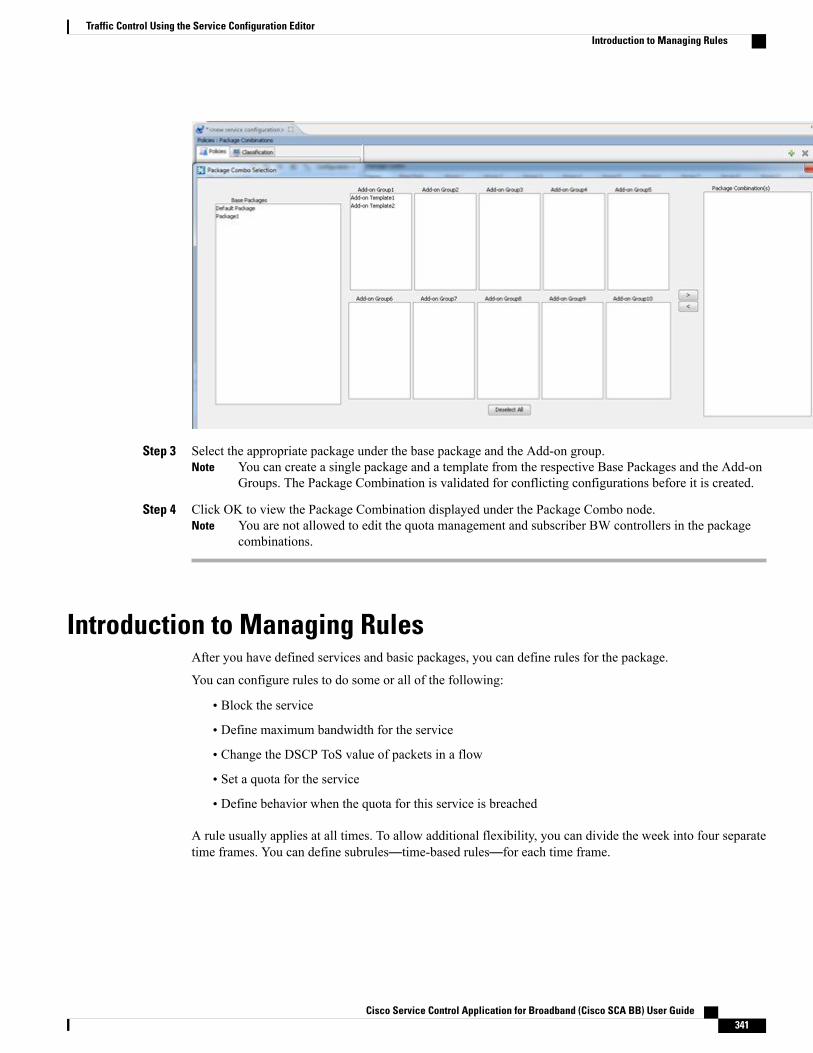
Step 3 Select the appropriate package under the base package and the Add-on group.You can create a single package and a template from the respective Base Packages and the Add-onGroups. The Package Combination is validated for conflicting configurations before it is created.
Note
Step 4 Click OK to view the Package Combination displayed under the Package Combo node.You are not allowed to edit the quota management and subscriber BW controllers in the packagecombinations.
Note
Introduction to Managing RulesAfter you have defined services and basic packages, you can define rules for the package.
You can configure rules to do some or all of the following:
• Block the service
• Define maximum bandwidth for the service
• Change the DSCP ToS value of packets in a flow
• Set a quota for the service
• Define behavior when the quota for this service is breached
A rule usually applies at all times. To allow additional flexibility, you can divide the week into four separatetime frames. You can define subrules—time-based rules—for each time frame.
Cisco Service Control Application for Broadband (Cisco SCA BB) User Guide 341
Traffic Control Using the Service Configuration EditorIntroduction to Managing Rules

In Cisco SCA BB, the maximum number of unique rules that can be applied is limited to 5000. If thenumber of unique rules exceeds the maximum limit, an error occurs. The number of unique rules areidentified from the Package ID, Service, and Timeframe fields.
Note
The Default Service RuleA default service rule is assigned to every package. It cannot be deleted or disabled.
The default values of this rule are:
• Admit (do not block) traffic.
• Map traffic to the default BWCs.
• Do not limit quotas for either upstream or downstream traffic.
Rule HierarchyThe Cisco SCE platform applies the most specific rule to any flow.
For example, if you define rules for E-Mail and POP3:
• Any flow mapped to the SMTP or IMAP service is handled according to the e-mail rule.
• Any flow mapped to the POP3 service is handled according to the POP3 rule
This means, for example, that POP3 can have its own usage limits, whereas SMTP and IMAP must shareusage limits.
If you add a rule for a child service, the settings for the parent rule are not copied to the new rule. All newrules start with default values.
Note
Indicates any rule that also applies to child services.
Indicates any rule that does not apply to any child services.
Indicates a global rule.
Time-based rules are shown as children of the relevant rule. The icon for a time-based rule also shows ifthe rule applies to child services ( or ).
See also “How to Display the Services Affected by a Rule” section.
Viewing the Rules of a PackageYou can view a list of the rules of a package.
Cisco Service Control Application for Broadband (Cisco SCA BB) User Guide342
Traffic Control Using the Service Configuration EditorThe Default Service Rule
The listing for each rule includes an icon, the name of the service or group of services to which the rule applies,whether the rule is enabled or disabled, and a brief description of the rule.
Procedure
In the Policies tab, select a package from the package tree.A list of all rules defined for this package is displayed in the right (Rule) pane.
Figure 222: Service Configuration Editor
What to Do Next
To see more information about a rule, open the Edit Rule for Service dialog box (see “How to Edit Rules”section).
To see more information about a time-based rule, open the Edit Time-Based Rule for Service dialog box (see“How to Edit Time-Based Rules” section).
Adding Rules to a PackageA default service rule is assigned to every package. You can add additional rules to a package.
Adding time-based rules is described in the section How to Add Time-Based Rules to a Rule.
Procedure
Step 1 In the Policies tab, select a package from the package tree.Step 2 In the right (Rule) pane, click the Add Rule icon.
Cisco Service Control Application for Broadband (Cisco SCA BB) User Guide 343
Traffic Control Using the Service Configuration EditorAdding Rules to a Package
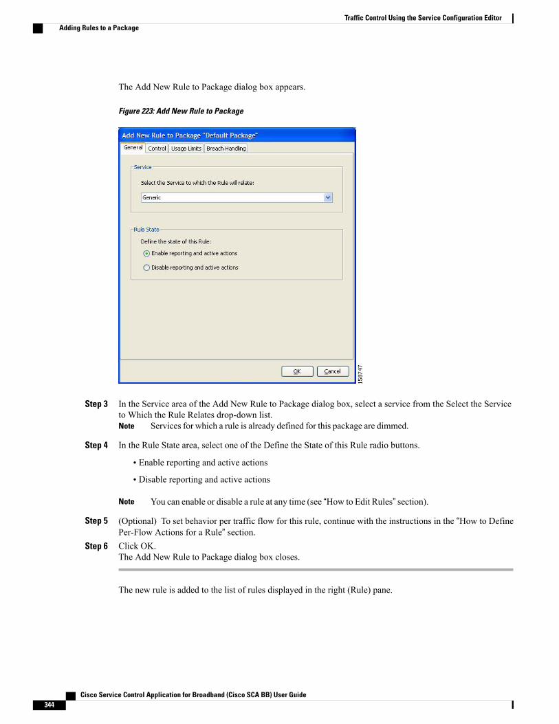
The Add New Rule to Package dialog box appears.
Figure 223: Add New Rule to Package
Step 3 In the Service area of the Add New Rule to Package dialog box, select a service from the Select the Serviceto Which the Rule Relates drop-down list.
Services for which a rule is already defined for this package are dimmed.Note
Step 4 In the Rule State area, select one of the Define the State of this Rule radio buttons.
• Enable reporting and active actions
• Disable reporting and active actions
You can enable or disable a rule at any time (see “How to Edit Rules” section).Note
Step 5 (Optional) To set behavior per traffic flow for this rule, continue with the instructions in the “How to DefinePer-Flow Actions for a Rule” section.
Step 6 Click OK.The Add New Rule to Package dialog box closes.
The new rule is added to the list of rules displayed in the right (Rule) pane.
Cisco Service Control Application for Broadband (Cisco SCA BB) User Guide344
Traffic Control Using the Service Configuration EditorAdding Rules to a Package

Defining Per-Flow Actions for a RuleThe Control tab of the Add New Rule to Package dialog box allows you to set behavior per traffic flow forsessions that are mapped to the current service.
Procedure
Step 1 In the Add New Rule to Package dialog box, click the Control tab.The Control tab opens.
Figure 224: Control Tab
To control flows that are mapped to the service of this rule, continue at Step 3.
Step 2 To block flows that are mapped to the service of this rule, select the Block the flow radio button and continueat Step 12.
Step 3 Select the Control the flow’s characteristics radio button.
Cisco Service Control Application for Broadband (Cisco SCA BB) User Guide 345
Traffic Control Using the Service Configuration EditorDefining Per-Flow Actions for a Rule
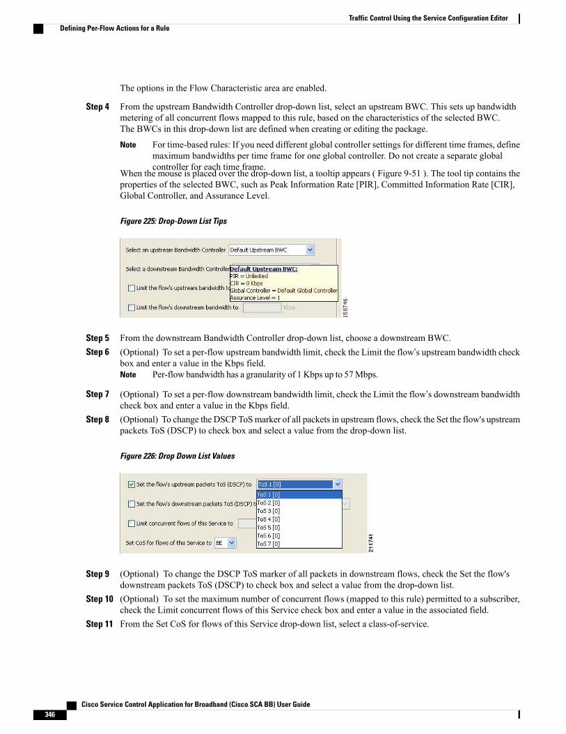
The options in the Flow Characteristic area are enabled.
Step 4 From the upstream Bandwidth Controller drop-down list, select an upstream BWC. This sets up bandwidthmetering of all concurrent flows mapped to this rule, based on the characteristics of the selected BWC.The BWCs in this drop-down list are defined when creating or editing the package.
For time-based rules: If you need different global controller settings for different time frames, definemaximum bandwidths per time frame for one global controller. Do not create a separate globalcontroller for each time frame.
Note
When the mouse is placed over the drop-down list, a tooltip appears ( Figure 9-51 ). The tool tip contains theproperties of the selected BWC, such as Peak Information Rate [PIR], Committed Information Rate [CIR],Global Controller, and Assurance Level.
Figure 225: Drop-Down List Tips
Step 5 From the downstream Bandwidth Controller drop-down list, choose a downstream BWC.Step 6 (Optional) To set a per-flow upstream bandwidth limit, check the Limit the flow’s upstream bandwidth check
box and enter a value in the Kbps field.Per-flow bandwidth has a granularity of 1 Kbps up to 57Mbps.Note
Step 7 (Optional) To set a per-flow downstream bandwidth limit, check the Limit the flow’s downstream bandwidthcheck box and enter a value in the Kbps field.
Step 8 (Optional) To change the DSCP ToSmarker of all packets in upstream flows, check the Set the flow's upstreampackets ToS (DSCP) to check box and select a value from the drop-down list.
Figure 226: Drop Down List Values
Step 9 (Optional) To change the DSCP ToS marker of all packets in downstream flows, check the Set the flow'sdownstream packets ToS (DSCP) to check box and select a value from the drop-down list.
Step 10 (Optional) To set the maximum number of concurrent flows (mapped to this rule) permitted to a subscriber,check the Limit concurrent flows of this Service check box and enter a value in the associated field.
Step 11 From the Set CoS for flows of this Service drop-down list, select a class-of-service.
Cisco Service Control Application for Broadband (Cisco SCA BB) User Guide346
Traffic Control Using the Service Configuration EditorDefining Per-Flow Actions for a Rule

Step 12 (Optional) To enable subscriber redirection, check the Redirect profile for this service check box and choosea redirect profile from the drop-down list.
Step 13 (Optional) To enable traffic mirroring, check the Mirror traffic to server group check box and choose a servergroup from the drop-down list.
The Mirror traffic to server group check box is only enabled when Traffic Mirroring is enabled inthe VAS Settings dialog box.
Note
Step 14 Click OK.The Add New Rule to Package dialog box closes.
The new rule is added to the list of rules displayed in the right (Rule) pane.
Editing RulesYou can edit any rule, including the default service rule.
You cannot disable the default service rule.Note
The tabs of the Edit Rule for Service dialog box are the same as the tabs of the Add New Rule to Packagedialog box, except for the General tab—you cannot change the service to which the rule applies.
Note
Procedure
Step 1 In the Policies tab, select a package from the package tree.Step 2 In the right (Rule) pane, select a rule.Step 3 Click Edit Rule.
Cisco Service Control Application for Broadband (Cisco SCA BB) User Guide 347
Traffic Control Using the Service Configuration EditorEditing Rules
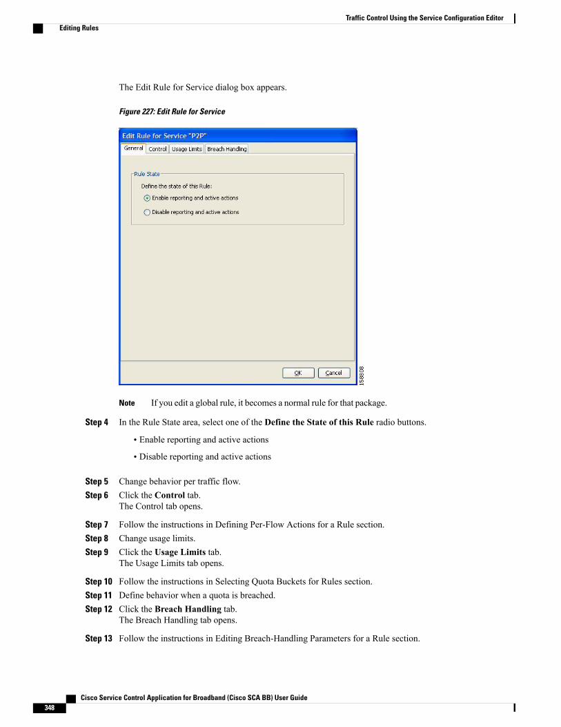
The Edit Rule for Service dialog box appears.
Figure 227: Edit Rule for Service
If you edit a global rule, it becomes a normal rule for that package.Note
Step 4 In the Rule State area, select one of the Define the State of this Rule radio buttons.
• Enable reporting and active actions
• Disable reporting and active actions
Step 5 Change behavior per traffic flow.Step 6 Click the Control tab.
The Control tab opens.
Step 7 Follow the instructions in Defining Per-Flow Actions for a Rule section.Step 8 Change usage limits.Step 9 Click the Usage Limits tab.
The Usage Limits tab opens.
Step 10 Follow the instructions in Selecting Quota Buckets for Rules section.Step 11 Define behavior when a quota is breached.Step 12 Click the Breach Handling tab.
The Breach Handling tab opens.
Step 13 Follow the instructions in Editing Breach-Handling Parameters for a Rule section.
Cisco Service Control Application for Broadband (Cisco SCA BB) User Guide348
Traffic Control Using the Service Configuration EditorEditing Rules

Step 14 Click OK.The Edit Rule for Service dialog box closes.
All changes to the rule are saved.
Deleting RulesYou can delete any user-defined rule. The default service rule cannot be deleted.
You can disable a rule without losing its profile. For details, see Step 4 of “How to Edit Rules” section.This feature allows you to enable the rule again later, without having to reset all its parameters. You cannotdisable the default service rule.
Note
Procedure
Step 1 In the Policies tab, select a package from the package tree.Step 2 In the right (Rule) pane, select a rule.Step 3 In the Rule pane, click the Delete Rule icon.
A Rule Warning message appears.Step 4 Click Yes.
The selected rule is deleted.
Displaying the Services Affected by a RuleYou can define a service as the child of another service (the parent service is a service group).
Until you define a separate rule for a child service, the rule of the parent service applies to the child service.A rule that affects any of child services of a service is indicated in the rules list by a different icon, as illustratedfor the P2P rule and the FTP rule in.
Figure 228: Rules
You can display all (child) services that are affected by a rule.
The default service rule applies to all services for which a specific rule is not defined.Note
Cisco Service Control Application for Broadband (Cisco SCA BB) User Guide 349
Traffic Control Using the Service Configuration EditorDeleting Rules
Procedure
Step 1 In the right (Rule) pane of the Policies tab, select a rule and click the Show All Services Affected By ThisRule.The Services Affected dialog box appears.
Step 2 Click OK.The Services Affected dialog box closes.
Global RulesEffective with Cisco SCE Release 4.1.0, you can define global rules. Using global rules, you can create a ruleand apply it to multiple packages. If you modify a global rule, the changes you make affects all its associatedpackages. You can create upto 10 rules definitions per service.
Adding Global RulesTo create a single service rule definition under a global rule, perform these steps:
Procedure
Step 1 Under the Policies tab, click Global Rule.Step 2
In the right (Rule) pane, click the Add Rule icon.
Cisco Service Control Application for Broadband (Cisco SCA BB) User Guide350
Traffic Control Using the Service Configuration EditorGlobal Rules

The Add New Rule to Package Global Rule dialog box appears.
Figure 229: Add New Rule to Package “Global Rule”
Step 3 In the Service area of the Add New Rule to Package Global Rule dialog box, select a service from the Selectthe Service to Which the Rule Relates drop-down list.
Services for which a rule is already defined are dimmed.Note
Step 4 In the Rule State area, select one of the Define the State of this Rule radio buttons.
• Enable reporting and active actions
• Disable reporting and active actions
Cisco Service Control Application for Broadband (Cisco SCA BB) User Guide 351
Traffic Control Using the Service Configuration EditorGlobal Rules
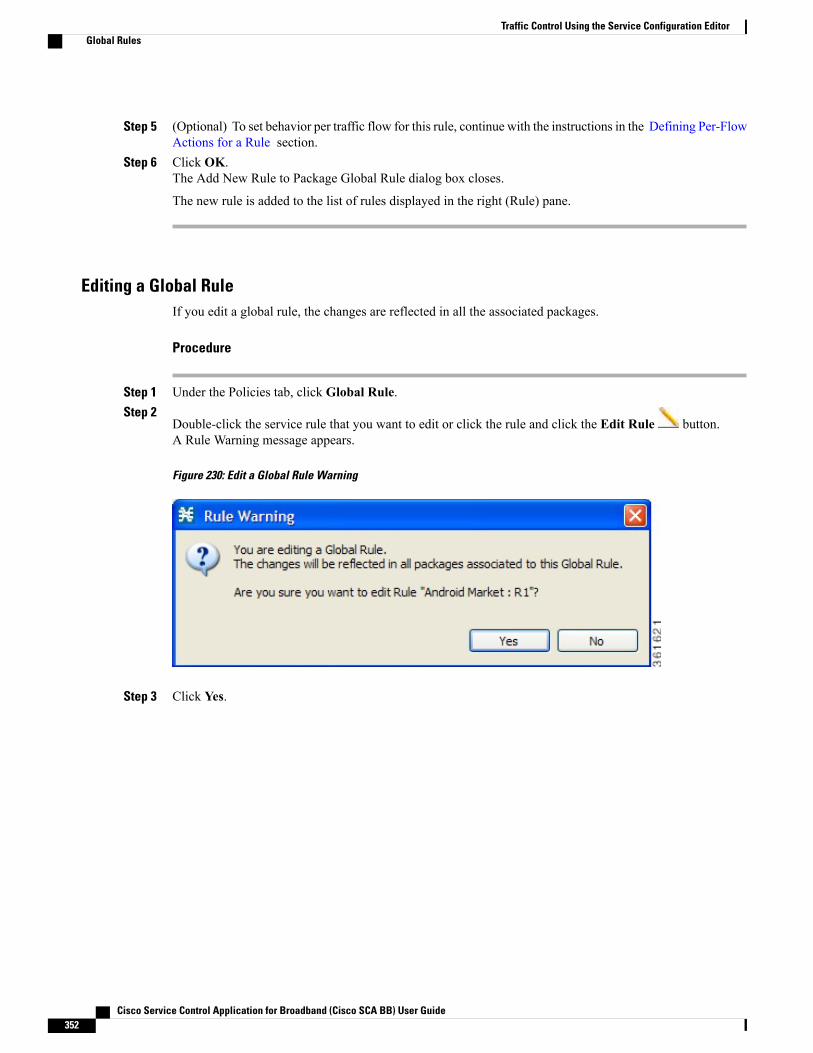
Step 5 (Optional) To set behavior per traffic flow for this rule, continue with the instructions in the Defining Per-FlowActions for a Rule section.
Step 6 Click OK.The Add New Rule to Package Global Rule dialog box closes.
The new rule is added to the list of rules displayed in the right (Rule) pane.
Editing a Global RuleIf you edit a global rule, the changes are reflected in all the associated packages.
Procedure
Step 1 Under the Policies tab, click Global Rule.Step 2
Double-click the service rule that you want to edit or click the rule and click the Edit Rule button.A Rule Warning message appears.
Figure 230: Edit a Global Rule Warning
Step 3 Click Yes.
Cisco Service Control Application for Broadband (Cisco SCA BB) User Guide352
Traffic Control Using the Service Configuration EditorGlobal Rules
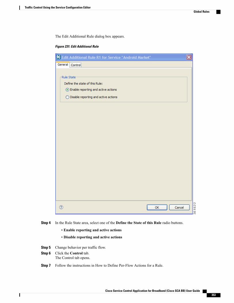
The Edit Additional Rule dialog box appears.
Figure 231: Edit Additional Rule
Step 4 In the Rule State area, select one of the Define the State of this Rule radio buttons.
• Enable reporting and active actions
• Disable reporting and active actions
Step 5 Change behavior per traffic flow.Step 6 Click the Control tab.
The Control tab opens.
Step 7 Follow the instructions in How to Define Per-Flow Actions for a Rule.
Cisco Service Control Application for Broadband (Cisco SCA BB) User Guide 353
Traffic Control Using the Service Configuration EditorGlobal Rules
Step 8 Click OK.The Edit Rule for Service dialog box closes.
All changes to the rule are saved.
Adding Additional Global Rules for a ServiceAfter creating a service rule definition under a global rule, you can optionally create more rule definitions fora service. To create more rule definitions for a service, perform these steps:
Procedure
Step 1 Under the Policies tab, click Global Rule.Step 2 Click the service rule to which you want to add additional rules.Step 3
Click the Add Additional Rule button.
Cisco Service Control Application for Broadband (Cisco SCA BB) User Guide354
Traffic Control Using the Service Configuration EditorGlobal Rules

The Add Additional Rule to Package “Global Rule” dialog box appears.Step 4 In the Additional Rule area, select an additional rule from the Select Additional rule for this service drop-down
list.
Figure 232: Add Additional Rule to Service
Rules that are already defined are dimmed. You can create upto 10 additional rules.Note
Step 5 In the Rule State area, select one of the Define the State of this Rule radio buttons.
• Enable reporting and active actions
• Disable reporting and active actions
Cisco Service Control Application for Broadband (Cisco SCA BB) User Guide 355
Traffic Control Using the Service Configuration EditorGlobal Rules

Step 6 (Optional) To set behavior per traffic flow for this rule, continue with the instructions in the Defining Per-FlowActions for a Rule section.
Step 7 Click OK.The Add Additional Rule to Package “Global Rule” dialog box closes.
The new additional rule is added to the list of rules displayed in the right (Rule) pane.
Deleting a Global Rule from a Service
Procedure
Step 1 In the Policies tab, click Global Rule.Step 2 In the right (Rule) pane, select a rule to delete.Step 3
In the Rule pane, click the Delete Rule icon.A Rule Warning message appears.
Figure 233:
Step 4 Click Yes.The selected rule is deleted.
Deleting All Additional Rules from a Service
Procedure
Step 1 In the Policies tab, click Global Rule.Step 2 In the right (Rule) pane, select a service to delete.Step 3
In the Rule pane, click the Delete Rule icon.
Cisco Service Control Application for Broadband (Cisco SCA BB) User Guide356
Traffic Control Using the Service Configuration EditorGlobal Rules
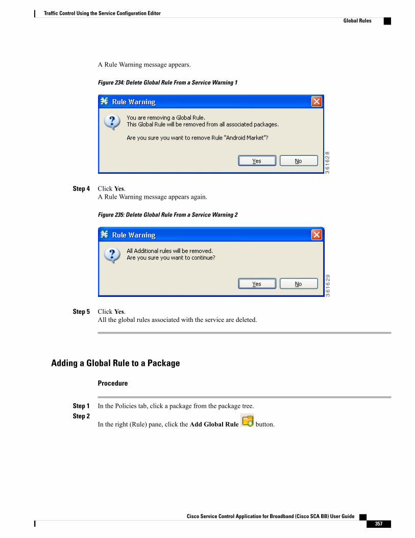
A Rule Warning message appears.
Figure 234: Delete Global Rule From a Service Warning 1
Step 4 Click Yes.A Rule Warning message appears again.
Figure 235: Delete Global Rule From a Service Warning 2
Step 5 Click Yes.All the global rules associated with the service are deleted.
Adding a Global Rule to a Package
Procedure
Step 1 In the Policies tab, click a package from the package tree.Step 2
In the right (Rule) pane, click the Add Global Rule button.
Cisco Service Control Application for Broadband (Cisco SCA BB) User Guide 357
Traffic Control Using the Service Configuration EditorGlobal Rules
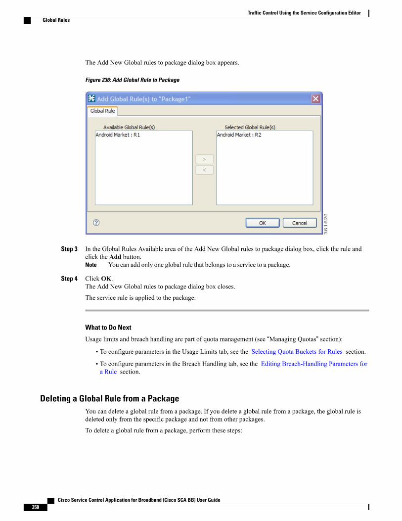
The Add New Global rules to package dialog box appears.
Figure 236: Add Global Rule to Package
Step 3 In the Global Rules Available area of the Add New Global rules to package dialog box, click the rule andclick the Add button.
You can add only one global rule that belongs to a service to a package.Note
Step 4 Click OK.The Add New Global rules to package dialog box closes.
The service rule is applied to the package.
What to Do Next
Usage limits and breach handling are part of quota management (see “Managing Quotas” section):
• To configure parameters in the Usage Limits tab, see the Selecting Quota Buckets for Rules section.
• To configure parameters in the Breach Handling tab, see the Editing Breach-Handling Parameters fora Rule section.
Deleting a Global Rule from a PackageYou can delete a global rule from a package. If you delete a global rule from a package, the global rule isdeleted only from the specific package and not from other packages.
To delete a global rule from a package, perform these steps:
Cisco Service Control Application for Broadband (Cisco SCA BB) User Guide358
Traffic Control Using the Service Configuration EditorGlobal Rules
Procedure
Step 1 In the Policies tab, click the package from which you want to delete a global rule.Step 2 In the right (Rule) pane, click a rule to delete.Step 3
Click the Delete Rule icon.A Rule Warning message appears.
Step 4 Click Yes.The selected rule is deleted from the package.
Displaying Packages Associated to a Global RuleYou can view all the packages associated to a global rule. To view the services affected by any global rule,perform these steps:
Procedure
Step 1 In the Policies tab, click Global Rule.Step 2 In the right (Rule) pane, select a global rule.Step 3
In the Rule pane, click the Show All Packages Associated With This Rule icon.
Cisco Service Control Application for Broadband (Cisco SCA BB) User Guide 359
Traffic Control Using the Service Configuration EditorGlobal Rules
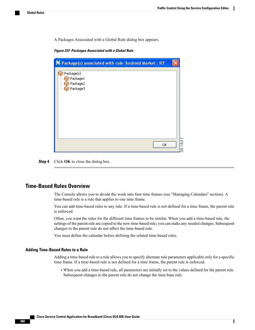
A Packages Associated with a Global Rule dialog box appears.
Figure 237: Packages Associated with a Global Rule
Step 4 Click OK to close the dialog box.
Time-Based Rules OverviewThe Console allows you to divide the week into four time frames (see “Managing Calendars” section). Atime-based rule is a rule that applies to one time frame.
You can add time-based rules to any rule. If a time-based rule is not defined for a time frame, the parent ruleis enforced.
Often, you want the rules for the different time frames to be similar. When you add a time-based rule, thesettings of the parent rule are copied to the new time-based rule; you canmake any needed changes. Subsequentchanges to the parent rule do not affect the time-based rule.
You must define the calendar before defining the related time-based rules.
Adding Time-Based Rules to a Rule
Adding a time-based rule to a rule allows you to specify alternate rule parameters applicable only for a specifictime frame. If a time-based rule is not defined for a time frame, the parent rule is enforced.
•When you add a time-based rule, all parameters are initially set to the values defined for the parent rule.Subsequent changes to the parent rule do not change the time-base rule.
Cisco Service Control Application for Broadband (Cisco SCA BB) User Guide360
Traffic Control Using the Service Configuration EditorGlobal Rules
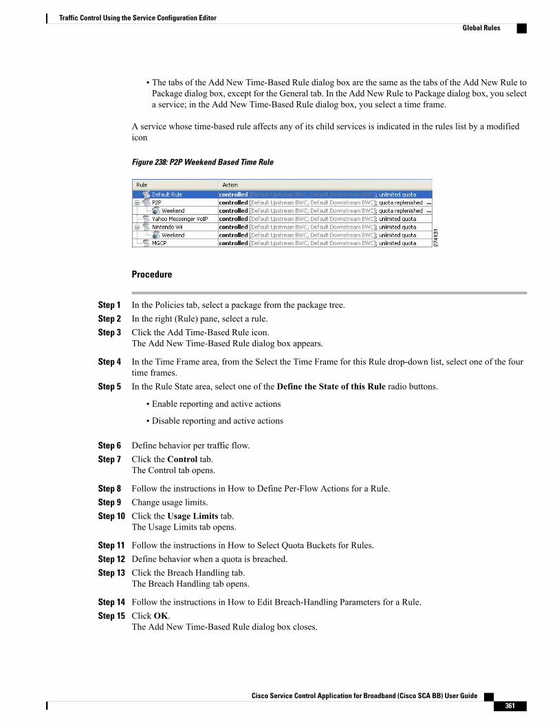
• The tabs of the Add New Time-Based Rule dialog box are the same as the tabs of the Add New Rule toPackage dialog box, except for the General tab. In the Add New Rule to Package dialog box, you selecta service; in the Add New Time-Based Rule dialog box, you select a time frame.
A service whose time-based rule affects any of its child services is indicated in the rules list by a modifiedicon
Figure 238: P2P Weekend Based Time Rule
Procedure
Step 1 In the Policies tab, select a package from the package tree.Step 2 In the right (Rule) pane, select a rule.Step 3 Click the Add Time-Based Rule icon.
The Add New Time-Based Rule dialog box appears.
Step 4 In the Time Frame area, from the Select the Time Frame for this Rule drop-down list, select one of the fourtime frames.
Step 5 In the Rule State area, select one of the Define the State of this Rule radio buttons.
• Enable reporting and active actions
• Disable reporting and active actions
Step 6 Define behavior per traffic flow.Step 7 Click the Control tab.
The Control tab opens.
Step 8 Follow the instructions in How to Define Per-Flow Actions for a Rule.Step 9 Change usage limits.Step 10 Click the Usage Limits tab.
The Usage Limits tab opens.
Step 11 Follow the instructions in How to Select Quota Buckets for Rules.Step 12 Define behavior when a quota is breached.Step 13 Click the Breach Handling tab.
The Breach Handling tab opens.
Step 14 Follow the instructions in How to Edit Breach-Handling Parameters for a Rule.Step 15 Click OK.
The Add New Time-Based Rule dialog box closes.
Cisco Service Control Application for Broadband (Cisco SCA BB) User Guide 361
Traffic Control Using the Service Configuration EditorGlobal Rules
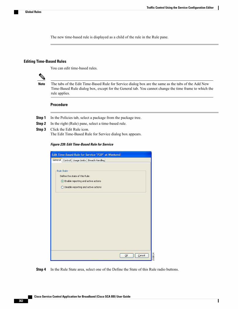
The new time-based rule is displayed as a child of the rule in the Rule pane.
Editing Time-Based Rules
You can edit time-based rules.
The tabs of the Edit Time-Based Rule for Service dialog box are the same as the tabs of the Add NewTime-Based Rule dialog box, except for the General tab. You cannot change the time frame to which therule applies.
Note
Procedure
Step 1 In the Policies tab, select a package from the package tree.Step 2 In the right (Rule) pane, select a time-based rule.Step 3 Click the Edit Rule icon.
The Edit Time-Based Rule for Service dialog box appears.
Figure 239: Edit Time-Based Rule for Service
Step 4 In the Rule State area, select one of the Define the State of this Rule radio buttons.
Cisco Service Control Application for Broadband (Cisco SCA BB) User Guide362
Traffic Control Using the Service Configuration EditorGlobal Rules

• Enable reporting and active actions
• Disable reporting and active actions
Step 5 Define behavior per traffic flow.Step 6 Click the Control tab.
The Control tab opens.Step 7 Follow the instructions in How to Define Per-Flow Actions for a Rule.Step 8 Change usage limits.Step 9 Click the Usage Limits tab.
The Usage Limits tab opens.
Step 10 Follow the instructions in How to Select Quota Buckets for Rules.Step 11 Define behavior when a quota is breached.Step 12 Click the Breach Handling tab.
The Breach Handling tab opens.
Step 13 Follow the instructions in How to Edit Breach-Handling Parameters for a Rule.Step 14 Click OK.
The Edit Time-Based Rule for Service dialog box closes.
All changes to the time-based rule are saved.
Deleting Time-Based Rules
You can delete any time-based rule.
You can disable a rule without losing its profile (see “How to Edit Time-Based Rules” section). Thisallows you to enable the rule again later, without having to reset all its parameters.
Note
Procedure
Step 1 In the Policies tab, select a package from the package tree.Step 2 In the right (Rule) pane, select a time-based rule.Step 3 In the Rule pane, click the Delete Rule icon.
A Rule Warning message appears.Step 4 Click Yes.
The selected rule is deleted.
Managing Calendars Overview
Calendars are used to divide the hours of the week into four time frames.
Cisco Service Control Application for Broadband (Cisco SCA BB) User Guide 363
Traffic Control Using the Service Configuration EditorGlobal Rules
After you have configured a calendar, you can add time-based rules to a package that uses the calendar. Atime-based rule is a rule that applies to only one time frame. Time-based rules allow you to set rule parametersthat apply only at specific times. You might, for example, want to define different rules for peak, off-peak,nighttime, and weekend usage.
Each service configuration includes one default calendar. You can add nine more calendars, each with adifferent time-frame configuration. You can use different calendars for different packages. You can also usedifferent calendars where a service provider has customers in more than one time zone by configuring calendarswith a one-hour offset from each other.
• How to View Calendars
• How to Add Calendars
• How to Rename the Time Frames
• How to Delete Calendars
• How to Configure the Time Frames
Adding CalendarsEach service configuration includes one default calendar. You can add up to nine more calendars.
Procedure
Step 1 From the Policies tab of the left pane, choose Configuration > Policies > Weekly Calendars.The Calendar Settings dialog box appears.
Step 2 In the Calendar tab, click the Add (158725.jpg) icon.A new calendar is added with the name Calendar (1).
Step 3 In the Calendar Parameters tab, click in the Calendar Name field and enter the name for this calendar.
Figure 240: Calendar Parameters Tab
Step 4 Click Close.The Calendar Settings dialog box closes, and the new calendar name is saved.
Renaming the Time FramesBy default, the time frames are named T1, T2, T3, and T4. You can change these names at any time; forexample, you may want to name the time frames Peak, Off Peak, Night, and Weekend.
Although you can configure the time frames differently in each calendar, the names of the time framesare the same in all of the calendars. If you change the name when configuring one calendar, the namesare also changed for all other calendars.
Note
Cisco Service Control Application for Broadband (Cisco SCA BB) User Guide364
Traffic Control Using the Service Configuration EditorGlobal Rules
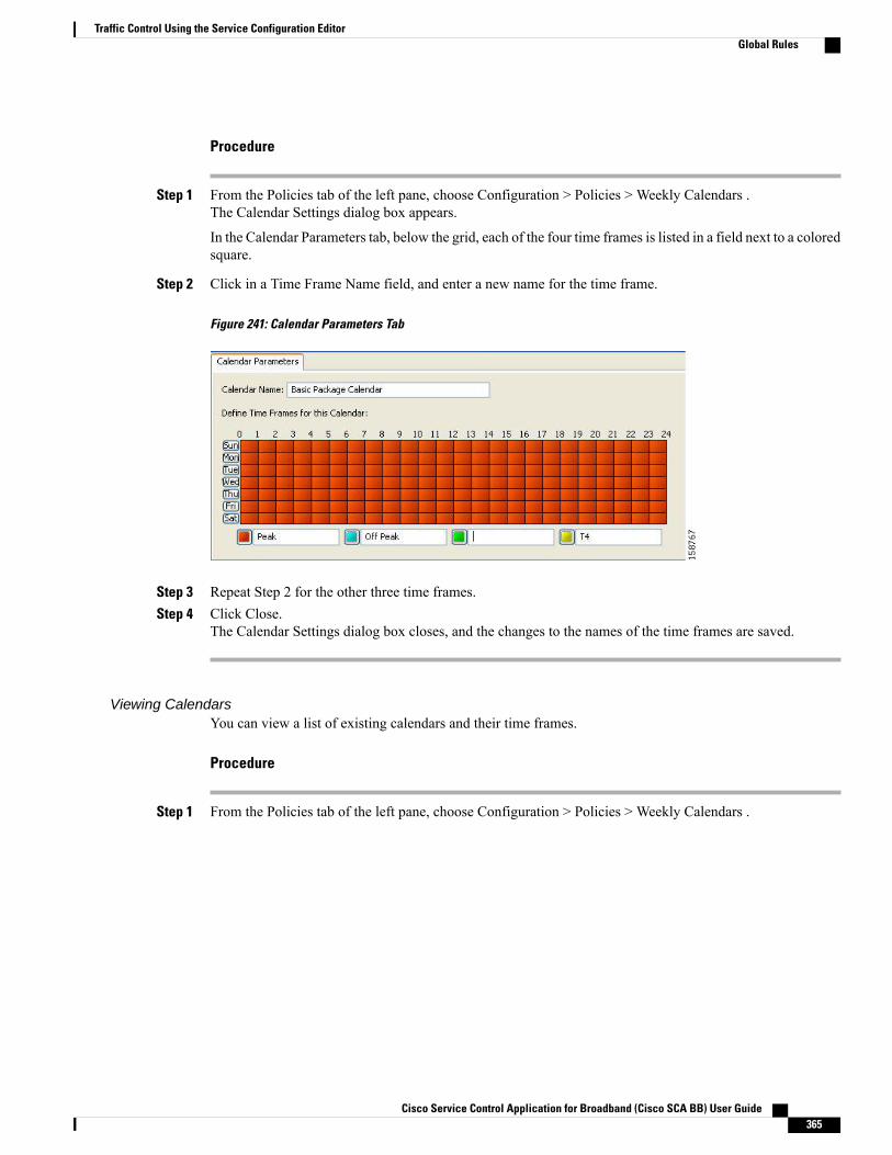
Procedure
Step 1 From the Policies tab of the left pane, choose Configuration > Policies > Weekly Calendars .The Calendar Settings dialog box appears.
In the Calendar Parameters tab, below the grid, each of the four time frames is listed in a field next to a coloredsquare.
Step 2 Click in a Time Frame Name field, and enter a new name for the time frame.
Figure 241: Calendar Parameters Tab
Step 3 Repeat Step 2 for the other three time frames.Step 4 Click Close.
The Calendar Settings dialog box closes, and the changes to the names of the time frames are saved.
Viewing CalendarsYou can view a list of existing calendars and their time frames.
Procedure
Step 1 From the Policies tab of the left pane, choose Configuration > Policies > Weekly Calendars .
Cisco Service Control Application for Broadband (Cisco SCA BB) User Guide 365
Traffic Control Using the Service Configuration EditorGlobal Rules

The Calendar Settings dialog box appears with a list of existing calendars.
Figure 242: Calendar Settings
Step 2 Click a calendar in the list to display its time-frame settings.The time frames for the selected calendar are displayed and configured in the Calendar Parameters tab.
Step 3 Click Close.The Calendar Settings dialog box closes.
Deleting CalendarsYou can delete any user-added calendar. The default calendar cannot be deleted.
A calendar used by a package cannot be deleted. (When you select the calendar, the Delete icon is dimmed.)To delete the calendar, you must first select a different calendar for each package using the calendar thatis deleted. See “How to Set Advanced Package Options” section for information about changing thecalendar associated with a package.
Note
Procedure
Step 1 From the Policies tab of the left pane, choose Configuration > Policies >Weekly Calendars.The Calendar Settings dialog box appears.
Step 2 In the Calendar tab, select a calendar and click the Delete icon.
Cisco Service Control Application for Broadband (Cisco SCA BB) User Guide366
Traffic Control Using the Service Configuration EditorGlobal Rules
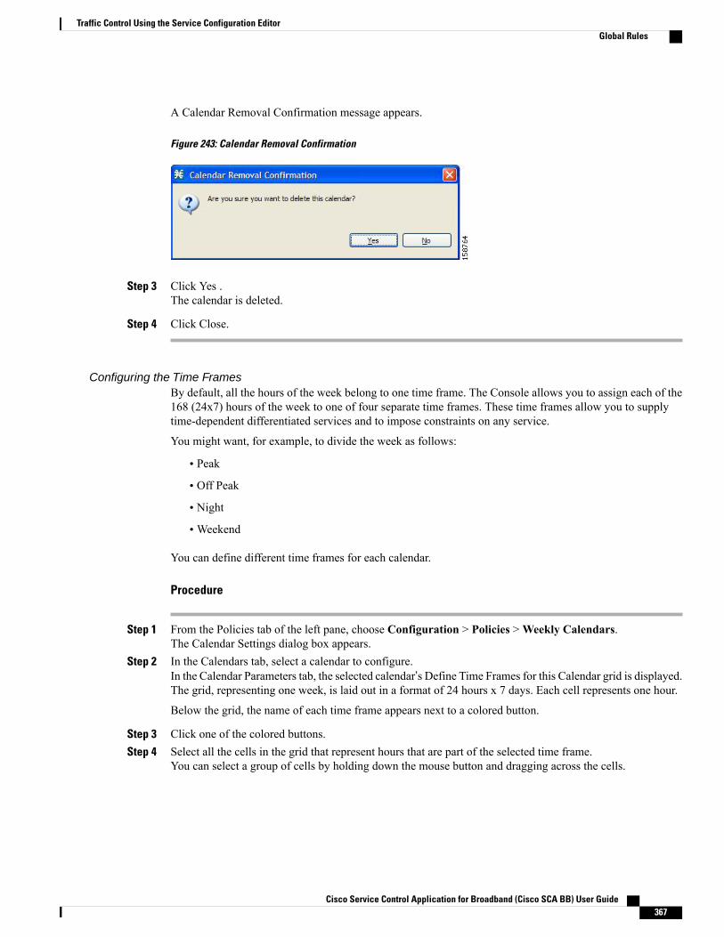
A Calendar Removal Confirmation message appears.
Figure 243: Calendar Removal Confirmation
Step 3 Click Yes .The calendar is deleted.
Step 4 Click Close.
Configuring the Time FramesBy default, all the hours of the week belong to one time frame. The Console allows you to assign each of the168 (24x7) hours of the week to one of four separate time frames. These time frames allow you to supplytime-dependent differentiated services and to impose constraints on any service.
You might want, for example, to divide the week as follows:
• Peak
• Off Peak
• Night
•Weekend
You can define different time frames for each calendar.
Procedure
Step 1 From the Policies tab of the left pane, choose Configuration > Policies >Weekly Calendars.The Calendar Settings dialog box appears.
Step 2 In the Calendars tab, select a calendar to configure.In the Calendar Parameters tab, the selected calendar’s Define Time Frames for this Calendar grid is displayed.The grid, representing one week, is laid out in a format of 24 hours x 7 days. Each cell represents one hour.
Below the grid, the name of each time frame appears next to a colored button.
Step 3 Click one of the colored buttons.Step 4 Select all the cells in the grid that represent hours that are part of the selected time frame.
You can select a group of cells by holding down the mouse button and dragging across the cells.
Cisco Service Control Application for Broadband (Cisco SCA BB) User Guide 367
Traffic Control Using the Service Configuration EditorGlobal Rules
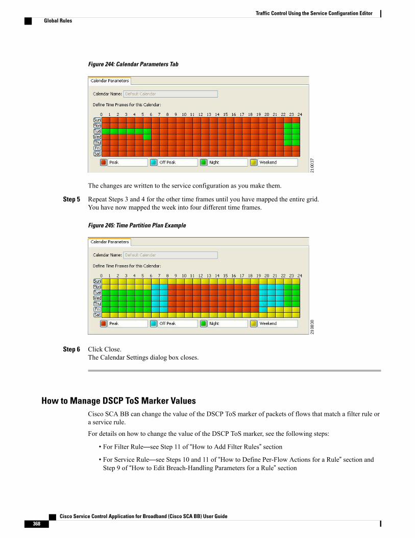
Figure 244: Calendar Parameters Tab
The changes are written to the service configuration as you make them.
Step 5 Repeat Steps 3 and 4 for the other time frames until you have mapped the entire grid.You have now mapped the week into four different time frames.
Figure 245: Time Partition Plan Example
Step 6 Click Close.The Calendar Settings dialog box closes.
How to Manage DSCP ToS Marker ValuesCisco SCA BB can change the value of the DSCP ToS marker of packets of flows that match a filter rule ora service rule.
For details on how to change the value of the DSCP ToS marker, see the following steps:
• For Filter Rule—see Step 11 of “How to Add Filter Rules” section
• For Service Rule—see Steps 10 and 11 of “How to Define Per-Flow Actions for a Rule” section andStep 9 of “How to Edit Breach-Handling Parameters for a Rule” section
Cisco Service Control Application for Broadband (Cisco SCA BB) User Guide368
Traffic Control Using the Service Configuration EditorGlobal Rules
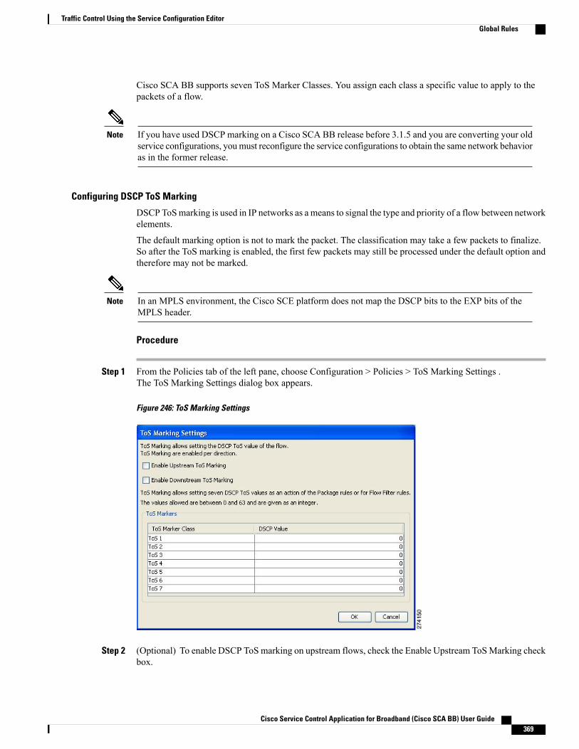
Cisco SCA BB supports seven ToS Marker Classes. You assign each class a specific value to apply to thepackets of a flow.
If you have used DSCP marking on a Cisco SCA BB release before 3.1.5 and you are converting your oldservice configurations, youmust reconfigure the service configurations to obtain the same network behavioras in the former release.
Note
Configuring DSCP ToS Marking
DSCP ToSmarking is used in IP networks as a means to signal the type and priority of a flow between networkelements.
The default marking option is not to mark the packet. The classification may take a few packets to finalize.So after the ToS marking is enabled, the first few packets may still be processed under the default option andtherefore may not be marked.
In an MPLS environment, the Cisco SCE platform does not map the DSCP bits to the EXP bits of theMPLS header.
Note
Procedure
Step 1 From the Policies tab of the left pane, choose Configuration > Policies > ToS Marking Settings .The ToS Marking Settings dialog box appears.
Figure 246: ToS Marking Settings
Step 2 (Optional) To enable DSCP ToS marking on upstream flows, check the Enable Upstream ToSMarking checkbox.
Cisco Service Control Application for Broadband (Cisco SCA BB) User Guide 369
Traffic Control Using the Service Configuration EditorGlobal Rules
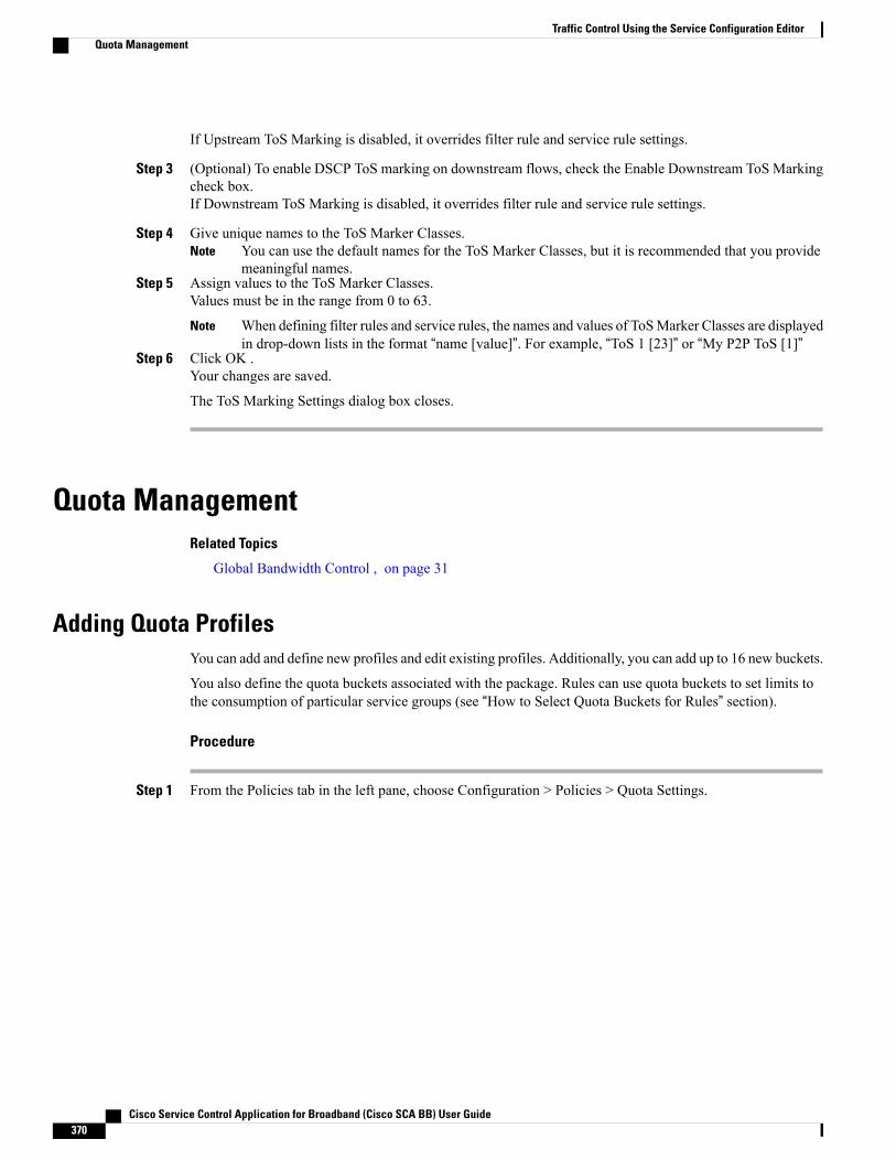
If Upstream ToS Marking is disabled, it overrides filter rule and service rule settings.
Step 3 (Optional) To enable DSCP ToS marking on downstream flows, check the Enable Downstream ToS Markingcheck box.If Downstream ToS Marking is disabled, it overrides filter rule and service rule settings.
Step 4 Give unique names to the ToS Marker Classes.You can use the default names for the ToS Marker Classes, but it is recommended that you providemeaningful names.
Note
Step 5 Assign values to the ToS Marker Classes.Values must be in the range from 0 to 63.
When defining filter rules and service rules, the names and values of ToSMarker Classes are displayedin drop-down lists in the format “name [value]”. For example, “ToS 1 [23]” or “My P2P ToS [1]”
Note
Step 6 Click OK .Your changes are saved.
The ToS Marking Settings dialog box closes.
Quota ManagementRelated Topics
Global Bandwidth Control , on page 31
Adding Quota ProfilesYou can add and define new profiles and edit existing profiles. Additionally, you can add up to 16 new buckets.
You also define the quota buckets associated with the package. Rules can use quota buckets to set limits tothe consumption of particular service groups (see “How to Select Quota Buckets for Rules” section).
Procedure
Step 1 From the Policies tab in the left pane, choose Configuration > Policies > Quota Settings.
Cisco Service Control Application for Broadband (Cisco SCA BB) User Guide370
Traffic Control Using the Service Configuration EditorQuota Management
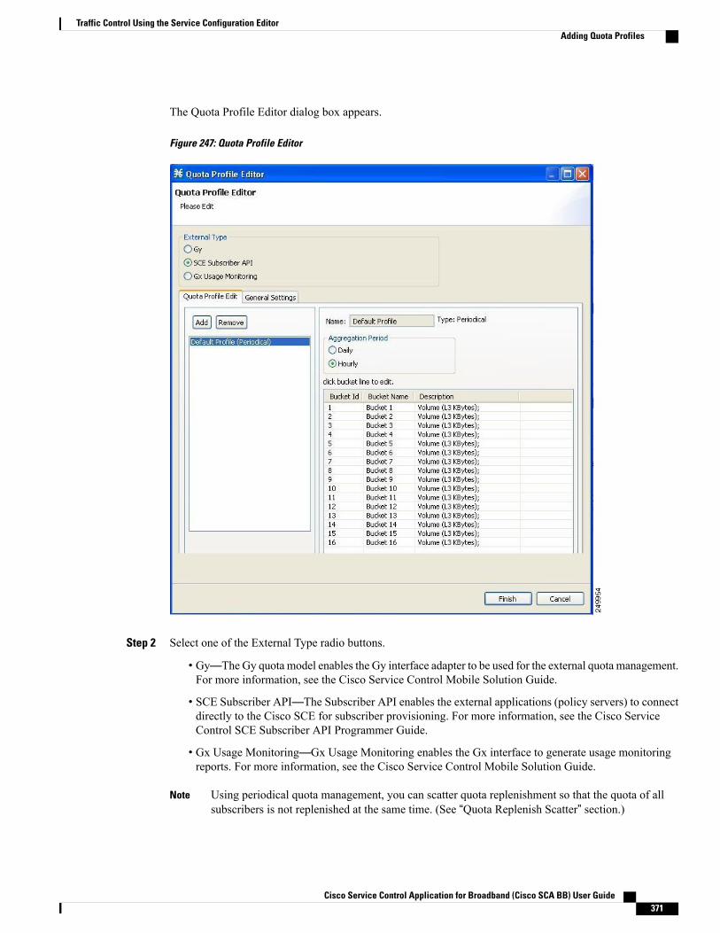
The Quota Profile Editor dialog box appears.
Figure 247: Quota Profile Editor
Step 2 Select one of the External Type radio buttons.
• Gy—The Gy quota model enables the Gy interface adapter to be used for the external quota management.For more information, see the Cisco Service Control Mobile Solution Guide.
• SCE Subscriber API—The Subscriber API enables the external applications (policy servers) to connectdirectly to the Cisco SCE for subscriber provisioning. For more information, see the Cisco ServiceControl SCE Subscriber API Programmer Guide.
• Gx Usage Monitoring—Gx Usage Monitoring enables the Gx interface to generate usage monitoringreports. For more information, see the Cisco Service Control Mobile Solution Guide.
Using periodical quota management, you can scatter quota replenishment so that the quota of allsubscribers is not replenished at the same time. (See “Quota Replenish Scatter” section.)
Note
Cisco Service Control Application for Broadband (Cisco SCA BB) User Guide 371
Traffic Control Using the Service Configuration EditorAdding Quota Profiles

Step 3 For Periodical quota profile, select one of the Aggregation Period radio buttons to specify when the quota isrenewed for the package:
• Hourly—Replenishes quota at each hour change
• Daily—Replenishes quota at midnight
Step 4 In the Quota Profile Edit tab, click Add.The Add Quota Profile dialog box appears.
Figure 248: Add Quota Profile
Step 5 In the Name field, enter a unique name for the new quota profile.Step 6 Select the Type from the drop-down list.
• Periodical
• Subscriber SCE API
Step 7 Click Finish.The Add Quota Profile window closes.
The new profile is added to the list of profiles displayed in the left (Quota Profile Edit) pane.
Editing Quota ProfilesYou can edit the profiles to update the bucket profile.
Cisco Service Control Application for Broadband (Cisco SCA BB) User Guide372
Traffic Control Using the Service Configuration EditorEditing Quota Profiles
You cannot edit or remove the default profile.Note
Procedure
Step 1 From the Policies tab in the left pane, choose Configuration > Policies > Quota Settings.The Quota Profile Editor dialog box appears.
Step 2 Select a quota profile from the profile tree.All the buckets defined for the selected profile are listed on the right pane.
Step 3 Double-click a bucket line in the right pane.
Cisco Service Control Application for Broadband (Cisco SCA BB) User Guide 373
Traffic Control Using the Service Configuration EditorEditing Quota Profiles
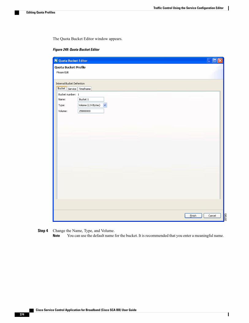
The Quota Bucket Editor window appears.
Figure 249: Quota Bucket Editor
Step 4 Change the Name, Type, and Volume.You can use the default name for the bucket. It is recommended that you enter a meaningful name.Note
Cisco Service Control Application for Broadband (Cisco SCA BB) User Guide374
Traffic Control Using the Service Configuration EditorEditing Quota Profiles

Step 5 Click on the Service tab, to associate the services to the quota profile.
Figure 250: Quota Bucket Editor - Service
Step 6 Select a service from the Non Attached Service pane and move it to the Attached Service pane on the right.
Cisco Service Control Application for Broadband (Cisco SCA BB) User Guide 375
Traffic Control Using the Service Configuration EditorEditing Quota Profiles
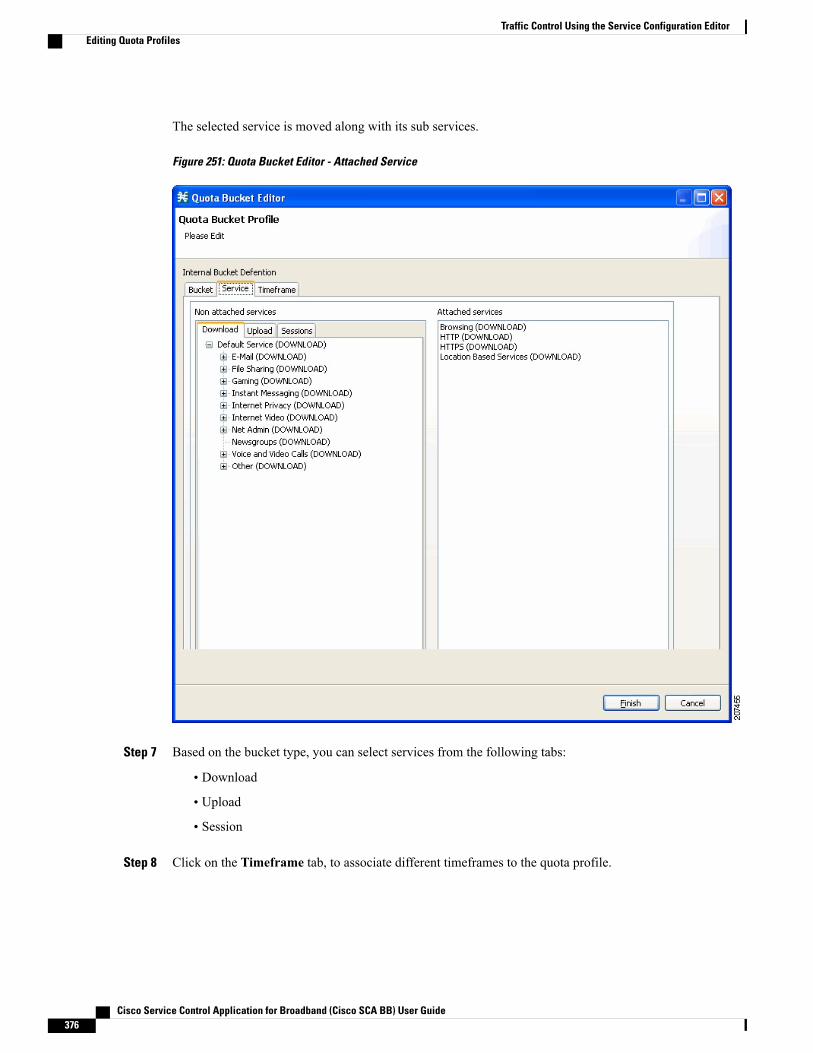
The selected service is moved along with its sub services.
Figure 251: Quota Bucket Editor - Attached Service
Step 7 Based on the bucket type, you can select services from the following tabs:
• Download
• Upload
• Session
Step 8 Click on the Timeframe tab, to associate different timeframes to the quota profile.
Cisco Service Control Application for Broadband (Cisco SCA BB) User Guide376
Traffic Control Using the Service Configuration EditorEditing Quota Profiles

Figure 252: Quota Bucket Editor - Timeframe
Step 9 Select a service from the Non Attached Service pane and move it to the Attached Service pane on the right.The selected service is moved along with its sub services.
Step 10 Based on the bucket type, you can select services from the following tabs:
• Download
• Upload
• Session
Step 11 Click Finish.The Quota Bucket Editor closes.
Step 12 Click Finish.
Cisco Service Control Application for Broadband (Cisco SCA BB) User Guide 377
Traffic Control Using the Service Configuration EditorEditing Quota Profiles
The Quota Profile Editor closes.
What to Do Next
To select a service to which the rule relates to, see “How to Add Rules to a Package” section.
Deleting Quota Profiles
The default profile cannot be deleted.Note
Procedure
Step 1 From the Policies tab in the left pane, choose Configuration > Policies > Quota Settings .The Quota Profile Editor dialog box appears.
Step 2 Select a quota profile from the profile tree.Step 3 Click Remove.Step 4 Click Finish.
The Quota Profile Editor dialog box closes.
Editing Quota Management Settings for PackagesYou can define whether an external quota manager or the Cisco SCA BB performs the quota managementfor a package.
Procedure
Step 1 In the Policies tab, select a package from the package tree, and click the Edit Package icon.The Package Settings dialog box appears.
Step 2 In the Package Settings dialog box, click the Quota Management tab.
Cisco Service Control Application for Broadband (Cisco SCA BB) User Guide378
Traffic Control Using the Service Configuration EditorDeleting Quota Profiles

The Quota Management tab opens.
Figure 253: Quota Management Tab
Step 3 Select the Select quota profile from the drop-down list.Step 4 Click OK.
The Package Settings dialog box closes.
All changes to the quota management settings are saved.
Quota Replenish ScatterBy default, if subscriber quota is replenished using periodical quota management, the quota of all subscribersis replenished at the same time. To smooth quota replenishment, you can scatter the time of quota replenishment.
Cisco Service Control Application for Broadband (Cisco SCA BB) User Guide 379
Traffic Control Using the Service Configuration EditorEditing Quota Management Settings for Packages
To activate this feature, enter a non-zero value for the Length of the time frame for quota replenish scatter(minutes) property of the Advanced Options tab of the Systems Settings dialog box (see “Managing AdvancedService Configuration Options” section). By default, this property has a value of zero, that is, all quota isreplenished at the same time.
Quota for each subscriber is replenished at a random time within the quota replenish scatter time frame, withreplenish events split evenly before and after the quota aggregation time.
Best results are obtained if the scatter time frame is the same length as the quota aggregation period, whichshould completely smooth replenish events. Do not enter a value larger than the quota replenish period.Therefore, for an hourly quota replenish period, set the scatter to 60 minutes.
The quota replenish scatter function is independent of all other quota management parameters.
Selecting Quota Buckets for RulesSelect the quota buckets that the flows mapped to a rule uses. The quota buckets are defined during packagesetup (see “How to Edit Quota Management Settings for Packages” section ). If no quota bucket is appropriatefor the rule, add a new quota bucket to the package or edit an existing bucket.
Procedure
Step 1 In the Network Traffic tab, select a package from the package tree.Step 2 In the right (Rule) pane, click the Add Rule icon.
Cisco Service Control Application for Broadband (Cisco SCA BB) User Guide380
Traffic Control Using the Service Configuration EditorSelecting Quota Buckets for Rules
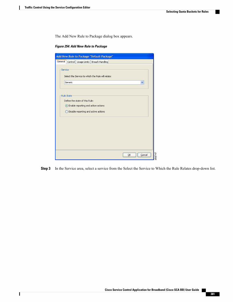
The Add New Rule to Package dialog box appears.
Figure 254: Add New Rule to Package
Step 3 In the Service area, select a service from the Select the Service to Which the Rule Relates drop-down list.
Cisco Service Control Application for Broadband (Cisco SCA BB) User Guide 381
Traffic Control Using the Service Configuration EditorSelecting Quota Buckets for Rules
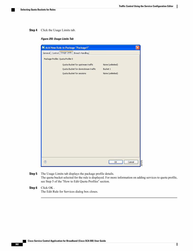
Step 4 Click the Usage Limits tab.
Figure 255: Usage Limits Tab
Step 5 The Usage Limits tab displays the package profile details.The quota bucket selected for the rule is displayed. For more information on adding services to quota profile,see Step 5 of the “How to Edit Quota Profiles” section.
Step 6 Click OK .The Edit Rule for Services dialog box closes.
Cisco Service Control Application for Broadband (Cisco SCA BB) User Guide382
Traffic Control Using the Service Configuration EditorSelecting Quota Buckets for Rules

Editing Breach-Handling Parameters for a RuleYou can define the Cisco SCE platform behavior when an aggregated volume limit or the totalnumber-of-sessions limit is exceeded. You can also notify subscribers when they exceed their quotas.
Procedure
Step 1 In the Policies tab, select a package from the package tree.Step 2 In the right (Rule) pane, select a rule.Step 3 Click the Edit Rule icon.
The Edit Rule for Service dialog box appears.
Step 4 Click the Breach Handling tab.
Cisco Service Control Application for Broadband (Cisco SCA BB) User Guide 383
Traffic Control Using the Service Configuration EditorEditing Breach-Handling Parameters for a Rule
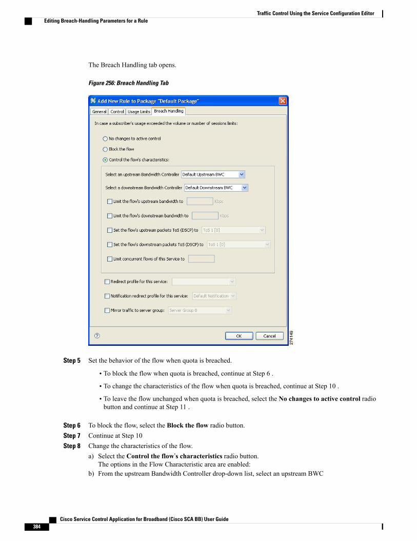
The Breach Handling tab opens.
Figure 256: Breach Handling Tab
Step 5 Set the behavior of the flow when quota is breached.
• To block the flow when quota is breached, continue at Step 6 .
• To change the characteristics of the flow when quota is breached, continue at Step 10 .
• To leave the flow unchanged when quota is breached, select the No changes to active control radiobutton and continue at Step 11 .
Step 6 To block the flow, select the Block the flow radio button.Step 7 Continue at Step 10Step 8 Change the characteristics of the flow.
a) Select the Control the flow’s characteristics radio button.The options in the Flow Characteristic area are enabled:
b) From the upstream Bandwidth Controller drop-down list, select an upstream BWC
Cisco Service Control Application for Broadband (Cisco SCA BB) User Guide384
Traffic Control Using the Service Configuration EditorEditing Breach-Handling Parameters for a Rule

The BWCs in this drop-down list are defined when creating or editing the package.
When the mouse is placed over the drop-down list, a tooltip appears. The tooltip contains the propertiesof the selected BWC, such as PIR, CIR, AL, and Global Controller.
c) From the downstream Bandwidth Controller drop-down list, select a downstream BWC.d) (Optional) Check the Limit the flow’s upstream bandwidth check box and enter a value in the Kbps
field.e) Check the Limit the flow’s downstream bandwidth check box and enter a value in the Kbps field.f) (Optional) Check the Set the flow's upstream packets ToS (DSCP) to check box and select a value
from the drop-down list.g) (Optional) Check the Set the flow's downstream packets ToS (DSCP) to check box and select a value
from the drop-down list.h) (Optional) Check the Limit concurrent flows of this Service check box and enter a value in the associated
field.
Step 9 (Optional) To enable subscriber redirect, check the check box, and select a redirect profile from the drop-downlist.
Step 10 (Optional) To enable subscriber notification, check the Notification redirect profile for this service check boxand select a notification redirect profile from the drop-down list.
A subscriber notification can be activated in addition to any of the three breach-handling options.Note
Subscriber notification is not supported when unidirectional classification is enabled. If you try tocheck the Activate a Subscriber Notification check box when unidirectional classification is enabled,a Rule Error message appears.
Note
Step 11 Click OK to continue.Step 12 (Optional) To enable mirror traffic to a server group, check Mirror traffic to server group and choose a server
group to send the mirror traffic to.The Mirror traffic to server group check box is only enabled when Traffic Mirroring is enabled inthe VAS Settings dialog box.
Note
Step 13 Click OK.The Edit Rule for Service dialog box closes.
All changes to the rule are saved.
Breach-Handling ParametersThe following are the configuration parameters in the Breach Handling tab of the Edit Rule for Service Settingsdialog box.
• You determine what happens to flows identified as belonging to this rule when a quota is breached:
◦No changes to active control—Flows mapped to this rule are not affected when quota is breached.Cisco SCA BB can generate Quota Breach RDRs even when this option is selected (see “How toManage Quota RDRs” section).
◦Block the flow—Flows mapped to this rule are blocked when quota is breached.
Redirect to—Redirect the flow to a specified, protocol-dependent URL, where a posted web page explainsthe reason for the redirection. URL redirection sets are defined in the System Settings dialog box. (See “How
Cisco Service Control Application for Broadband (Cisco SCA BB) User Guide 385
Traffic Control Using the Service Configuration EditorEditing Breach-Handling Parameters for a Rule

to Add a Set of Redirection URLs” section.) Only three protocol types support redirection: HTTP, HTTPStreaming, and RTSP. Redirection is not supported when unidirectional classification is enabled.
• Control the flow characteristics—The behaviors of flows mapped to this rule change when quota isbreached:
Select an upstream Bandwidth Controller—Map the traffic flow of this rule to a specific upstream BWcontroller (BWC). This sets up bandwidth metering of all concurrent flows mapped to this rule, based on thecharacteristics of the selected BWC.
Select a downstreamBandwidth Controller—The same functionality as the previous option, but for downstreamflow.
Limit the flow’s upstream bandwidth—Set a per-flow upstream bandwidth limit (for flows mapped to theservice of this rule).
Limit the flow’s downstream bandwidth—Set a per-flow downstream bandwidth limit.
Set the flow's upstream packets ToS—Set the DSCP ToS marker of all packets of upstream flows.
Set the flow's downstream packets ToS—Set the DSCP ToS marker of all packets of downstream flows.
Limit concurrent flows of this Service—Set the maximum number of concurrent flows (mapped to this rule)permitted to a subscriber.
• Activate a Subscriber Redirect—Activate a Subscriber Redirect when subscribers exceed their quotalimit.
• Activate a Subscriber Notification—Activate a Subscriber Notification when subscribers exceed theirquota limit. This notification can, for example, convey the quota breach situation to the subscriber andexplain how to obtain additional quota.
Subscriber notification is not supported when unidirectional classification is enabled.Note
To define Subscriber Notifications, see “Managing Subscriber Notifications” section.
• Activate Traffic Mirroring—Activate traffic mirroring when subscribers exceed their quota limit
Example for Creating Tiered Subscriber ServicesTiered subscriber services can be implemented using the Cisco SCA BB Console. Because the definition ofsuch services is open ended, this section describes how to define two of the tiers outlined in the value propositiondescription. The two tiers are defined as follows:
• Silver
◦Weekly bandwidth limited to 4.2 GB (corresponds to a daily limit of 600 MB)
◦Email and browsing services are limited to 256 kbps
◦Audio and video streaming services are limited to 64 kbps
◦P2P services are limited to 28 kbps
• Gold
Cisco Service Control Application for Broadband (Cisco SCA BB) User Guide386
Traffic Control Using the Service Configuration EditorExample for Creating Tiered Subscriber Services

Weekly bandwidth limited to 5.6 GB (corresponds to a daily limit of 800 MB)◦
◦Email and browsing services are not bandwidth limited
◦Audio and video streaming services are limited to 128 kbps
◦P2P services are limited to 28 kbps
The following steps are applicable to both the 'Silver' and 'Gold' packages.
Procedure
Step 1 Create a new package as described in “How to Add Packages” section.Step 2 Enable periodical (internal) quota management.Step 3 Set the aggregation period to DailyStep 4 Set the quota limit to the desired value and give the quota bucket a meaningful name
For further information, see “How to Edit Quota Management Settings for Packages” section.
Step 5 Add the bandwidth controllers for the required services and set the PIR to the desired rate.Each service that is bandwidth limited requires a sub bandwidth controller that is a child of the primarybandwidth controller, not an extra bandwidth controller.
Note
For further information, see “How to Edit Package Subscriber BWCs” section .
Step 6 Add a rule to the package for each bandwidth limited service.For further information, see “How to Add Rules to a Package” section .
Step 7 Configure the rule to control the characteristics of the flow with the bandwidth controller for the relevantservice.For further information, see “How to Define Per-Flow Actions for a Rule” section .
Step 8 Set the usage limit for the package to use the quota bucket defined in Step 2.For further information, see the “How to Select Quota Buckets for Rules” section section.
Unknown Subscriber TrafficCisco SCE platform processes a traffic flow that does not match any filter rule (see “Filtering the TrafficFlows” section on page 10-23 ). Cisco SCE platform tries to identify the subscriber responsible for the trafficflow. The platform checks its internal database for a subscriber identified by the IP address or VLAN tag ofthe traffic flow. If no such subscriber exists, the traffic flow is mapped to the Unknown Subscriber Trafficcategory.
The Unknown Subscriber Traffic category is included in the tree in the Network Traffic tab but is not part ofthe package hierarchy. The Unknown Subscriber Traffic category cannot be deleted.
Traffic of one unknown subscriber cannot be distinguished from traffic of other unknown subscribers.Therefore, you cannot set either per-subscriber usage limits or subscriber-level metering with subscriberBWCs. You can use subscriber BWCs only to link a selected service to a global controller.
Note
Cisco Service Control Application for Broadband (Cisco SCA BB) User Guide 387
Traffic Control Using the Service Configuration EditorUnknown Subscriber Traffic
The Unknown Subscriber Traffic category behaves like a package with the following parameters:
• Package Name = Unknown Subscriber Traffic
• Package Index = 4999
• One package usage counter:
◦Counter Name = Unknown Subscriber Traffic Counter
◦Counter Index = 1023
You can:
• Edit the Unknown Subscriber Traffic package settings:
◦Add extra BWCs (see “How to Edit Package Subscriber BWCs” section).
◦Select a calendar (see “How to Set Advanced Package Options” section).
• Edit the default service rule for the Unknown Subscriber Traffic category:
◦Change the Rule State (see “How to Edit Rules” section).
◦Change per-flow actions for the rule (see “How to Define Per-Flow Actions for a Rule” section).
• Add rules to the Unknown Subscriber Traffic package:
◦Add rules (see “How to Add Rules to a Package” section); edit (see “How to Edit Rules” section)and delete (see “How to Delete Rules” section) these rules.
◦Add time-based rules (see “How to Add Time-Based Rules to a Rule” section); edit (see “How toEdit Time-Based Rules” section) and delete (see “How to Delete Time-Based Rules” section) theserules.
Cisco Service Control Application for Broadband (Cisco SCA BB) User Guide388
Traffic Control Using the Service Configuration EditorUnknown Subscriber Traffic

C H A P T E R 10Service Configuration Editor: Additional Options
This chapter explains how to use additional, advanced functionality available in the Service ConfigurationEditor.
This chapter consists of these sections:
• The Service Security Dashboard , page 389
• Traffic Flow Filtering, page 409
• Managing Subscriber Notifications Overview, page 429
• Managing Subscriber Redirection Overview, page 437
• Managing the System Settings Overview, page 447
• Managing VAS Settings Overview, page 461
• Managing the Protected URL Database, page 473
The Service Security DashboardThe Service Security Dashboard allows you to view and control all Cisco SCA BB security functionality.
The Dashboard is a gateway to a set of features that help you protect your network from security threats suchas worms, DDoS attacks, and spam zombies. It allows configuration of the detectionmechanisms (for example,attack thresholds) and of the actions to be taken when an attack is detected.
The Dashboard also allows you to access malicious traffic reports in the Reporter tool.
If anomaly-based detection of malicious traffic is enabled, any access control list (ACL) that is configuredon the Cisco Service Control Engine (Cisco SCE) platform but is not applied to anything (for example,an interface, an access map, or an SNMP community string) might be deleted when a service configurationis applied to the platform. Workaround : Disable anomaly-based detection of malicious traffic. (Clear theEnable anomaly detection check box.)
Note
Cisco Service Control Application for Broadband (Cisco SCA BB) User Guide 389

Viewing the Service Security Dashboard
Procedure
In the Network Traffic tab, select Service Security .The Service Security Dashboard is displayed in the right pane.
Figure 257: Service Security Dashboard
Introduction to Managing Worm DetectionCisco SCA BB uses three mechanisms for detecting worms:
• Signature-based detection—The stateful Layer 7 capabilities of the Cisco SCE platform can detectmalicious activity that is not easily detectable by other mechanisms. You can add signatures for newworms.
• Anomaly-based detection—Overall traffic analysis can detect anomalies that might indicate wormactivity. See Managing Anomaly Detection Overview, on page 391 section.
• Mass-mailing based detection—E-mail traffic analysis can detect anomalies that might indicatee-mail-based worms. See Configuring Spam Detection Settings , on page 405 section.
For more information, see Introduction to Managing Protocol Signatures , on page 204 section.
Viewing Supported Worm Signatures
Procedure
Step 1 In the Service Security Dashboard, click View Signatures .
Cisco Service Control Application for Broadband (Cisco SCA BB) User Guide390
Service Configuration Editor: Additional OptionsViewing the Service Security Dashboard
The Signatures Settings dialog box appears, with Worm Signatures selected in the Signature Type drop-downlist.
All supported worm signatures are listed.
Step 2 Click Close.The Signatures Settings dialog box closes.
Adding New Worm Signatures to a Service ConfigurationEither import the latest DSS or SPQI file provided by Cisco or create a DSS file containing any worm signaturesthat you wish to add to the service configuration.
Managing Anomaly Detection OverviewThe most comprehensive threat detection method is anomaly detection.
Anomaly DetectionThe basic principle of anomaly detection is monitoring successful (correctly established for TCP, bidirectionalfor other protocols) and unsuccessful (not properly established for TCP, unidirectional for other protocols)connection rates both to and from any IP address viewed by the system, and triggering an anomaly detectioncondition based of one of the following criteria:
• The total connection rate exceeds a predefined threshold.
• The suspicious connection rate exceeds a predefined threshold and the ratio of suspicious to unsuspiciousconnections exceeds a predefined threshold.
The ratio metric is a robust indicator of malicious activity, and together with a rate qualifier it serves as areliable identifier for malicious activity.
Anomaly detection is divided into three categories based on the directional nature of the detected anomalycondition. The concepts used for the three categories are identical, but the nature of the detected maliciousactivity is different for each category.
• Scan/Sweep detector—Detects malicious activity based on an anomaly in connection rates from an IPaddress.
• DoS detector—Detects an anomaly in the connection rate between a pair of IP addresses: one of themis attacking the other. This can be either an isolated attack or part of a larger scale DDoS attack.
• DDoS detector—Detects an anomaly in the connection rate coming to an IP address, which means thatit is being attacked. The attack can be by either a single IP address (DoS) or multiple IP addresses.
When the IP address common to all flows of an attack is on the network side, the Cisco SCE may requiremore flows (than the configured threshold) to detect the attack.
Note
Cisco Service Control Application for Broadband (Cisco SCA BB) User Guide 391
Service Configuration Editor: Additional OptionsManaging Anomaly Detection Overview
For all kinds of anomaly detection conditions, maximum flexibility is provided by the ability to define detectionthresholds and the trigger actions to be taken for each:
• Flow direction
• Flow protocol
• (Optional) Port uniqueness for TCP and UDP
The GUI configuration described here replaces the CLI command set for configuring the Attack FilteringModule of the Cisco SCE platform, which was available in previous releases.
Note
Anomaly Detection ParametersFor each anomaly detector category (Scan/Sweep, DoS, DDoS) there is one default detector. You can addadditional detectors of each category. Detectors in each category are checked in order; the first match (accordingto the threshold settings of the detector) triggers detection. You set the order in which detectors are checked;the default detector is checked last.
Anomaly detectors can contain up to 12 anomaly types associated with malicious traffic:
• Network initiated—Malicious traffic initiated from the network side:
◦TCP—Aggregate TCP traffic on all ports
◦TCP Specific Ports—TCP traffic on any single port
◦UDP—Aggregate UDP traffic on all ports
◦UDP Specific Ports—UDP traffic on any single port
◦ICMP—Aggregate ICMP traffic on all ports
◦Other—Aggregate traffic using other protocol types on all ports
• Subscriber initiated—Malicious traffic initiated from the subscriber side:
◦TCP
◦TCP Specific Ports
◦UDP
◦UDP Specific Ports
◦ICMP
◦Other
ICMP and Other anomaly types are not available for DoS attack detectors.Note
Each anomaly type on a detector has the following attributes associated with it:
Cisco Service Control Application for Broadband (Cisco SCA BB) User Guide392
Service Configuration Editor: Additional OptionsManaging Anomaly Detection Overview
• Detection thresholds—There are two thresholds, crossing either of them means that an attack is definedto be in progress:
◦Session Rate threshold—The number of sessions (per second) over specified ports for a single IPaddress that trigger the anomaly detection condition.
◦Suspected sessions threshold—Suspected sessions are sessions that are not properly established(for TCP), or that are unidirectional sessions (for other protocols). Exceeding both the SuspectedSession Rate and the Suspected Session Ratio triggers the anomaly detection condition. (Arelatively high session rate with a low response rate typically indicates malicious activity.)
◦Suspected Session Rate—The number of suspected sessions (per second) over specified ports fora single IP address.
◦Suspected Session Ratio—The ratio (as a percentage) between the suspected session rate and thetotal session rate. A high ratio indicates that many sessions received no response, an indication ofmalicious activity.
• Actions—Zero or more of the following actions may be taken when an anomaly detection condition istriggered (by default, no action is enabled):
◦Alert User—Generate an SNMP trap indicating the beginning and end of an anomaly. For detailson SNMP traps, see the “SCA BB Proprietary MIB Reference” chapter of Cisco Service ControlApplication for Broadband Reference Guide for information about the Cisco proprietary MIB.
◦Notify Subscriber—Notify the relevant subscriber of the malicious activity by redirecting thebrowsing sessions to a captive portal. To configure network attack subscriber notification, seeManaging Subscriber Notifications Overview, on page 429 section.
◦Block Attack—Block the relevant sessions. Blocking is performed based on the specification ofthe malicious traffic that triggered the anomaly detection condition. If subscriber notification isenabled for the anomaly type, blocking is not applied to the port relevant for browsing (by default,this is TCP port 80; see Advanced Service Configuration Options, on page 451 section).
Logging of the anomaly to an on-device log file and generation of RDRs is notconfigurable per anomaly type.
Note
• User-defined detectors can also have one or more of the following attributes:
◦IP address list—Limit detection to the listed IP address ranges. This applies to the source IP whendetecting IP sweeps and port scans. It applies to the destination IP when detecting DoS and DDoSattacks.
◦TCP port list—Limit detection to the listed destination TCP ports. This list is applied to TCPSpecific Ports anomaly types only.
◦UDP port list—Limit detection to the listed destination UDP ports. This list is applied to UDPSpecific Ports anomaly types only.
Cisco Service Control Application for Broadband (Cisco SCA BB) User Guide 393
Service Configuration Editor: Additional OptionsManaging Anomaly Detection Overview

Viewing Anomaly Detection SettingsYou can view a list of all anomaly detectors. The anomaly detectors are displayed in a tree, grouped accordingto detector category (Scan/Sweep, DoS, or DDoS).
For each anomaly detector, you can view its associated parameters and see a list of all anomaly types includedin the detector, together with their parameters.
Procedure
Step 1 In the Service Security Dashboard, in the Anomaly Based Detection ofMalicious Traffic pane, click Configure.The Anomaly Detection Settings dialog box appears.
The detector tree is displayed in the left area of the dialog box; the right area is empty.
Figure 258: Detector Tree
Step 2 In the detector tree, select a detector.
Cisco Service Control Application for Broadband (Cisco SCA BB) User Guide394
Service Configuration Editor: Additional OptionsManaging Anomaly Detection Overview

The detector parameters are displayed in the upper right area of the dialog box.
Figure 259: Detector Parameters
The anomaly types defined for a detector are listed in the lower right area of the dialog box, together with thevalue of each parameter. The following screen capture shows the default parameter values for the Scan/Sweepdefault detector.
Figure 260: Detector Defined Anomaly Types
Cisco Service Control Application for Broadband (Cisco SCA BB) User Guide 395
Service Configuration Editor: Additional OptionsManaging Anomaly Detection Overview

If unidirectional classification is enabled, the Suspected Session Rate is set equal to the Session Rate, whicheffectively disables anomaly detection by the suspected session trigger.
Figure 261: Session Rate to Suspected Session Rate Comparison
Step 3 Click OK.The Anomaly Detection Settings dialog box closes.
Adding Anomaly DetectorsA service configuration can contain up to 100 anomaly detectors.
You define IP address ranges and TCP and UDP ports for the new detector, and one anomaly type.
After you have defined the detector, you can add other anomaly types (see Editing Anomaly Detectors ).
Procedure
Step 1 In the Service Security Dashboard, in the Anomaly BasedDetection ofMalicious Traffic pane, clickConfigure.The Anomaly Detection Settings dialog box appears.
Step 2 In the detector tree, select a detector category.Step 3
Click the Add icon.
Cisco Service Control Application for Broadband (Cisco SCA BB) User Guide396
Service Configuration Editor: Additional OptionsManaging Anomaly Detection Overview
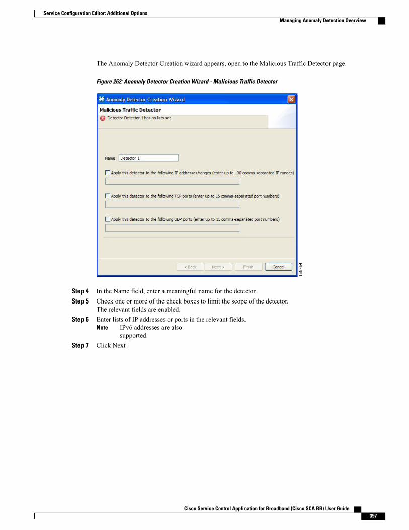
The Anomaly Detector Creation wizard appears, open to the Malicious Traffic Detector page.
Figure 262: Anomaly Detector Creation Wizard - Malicious Traffic Detector
Step 4 In the Name field, enter a meaningful name for the detector.Step 5 Check one or more of the check boxes to limit the scope of the detector.
The relevant fields are enabled.Step 6 Enter lists of IP addresses or ports in the relevant fields.
IPv6 addresses are alsosupported.
Note
Step 7 Click Next .
Cisco Service Control Application for Broadband (Cisco SCA BB) User Guide 397
Service Configuration Editor: Additional OptionsManaging Anomaly Detection Overview

The Malicious Traffic Characteristics for a WORM attack page of the Anomaly Detector Creation wizardopens.
Figure 263: Malicious Traffic Characteristics for a Worm Attack
Step 8 Depending on the detector type that you are defining, select the originating side or the target side.
• If you are defining a Scan/Sweep detector or a DoS detector, select the originating side for the anomalytype you are defining.
• If you are defining a DDoS detector, select the target side for the anomaly type you are defining.
Step 9 Select a transport type for the anomaly type that you are defining.Step 10 Click Next .
Cisco Service Control Application for Broadband (Cisco SCA BB) User Guide398
Service Configuration Editor: Additional OptionsManaging Anomaly Detection Overview
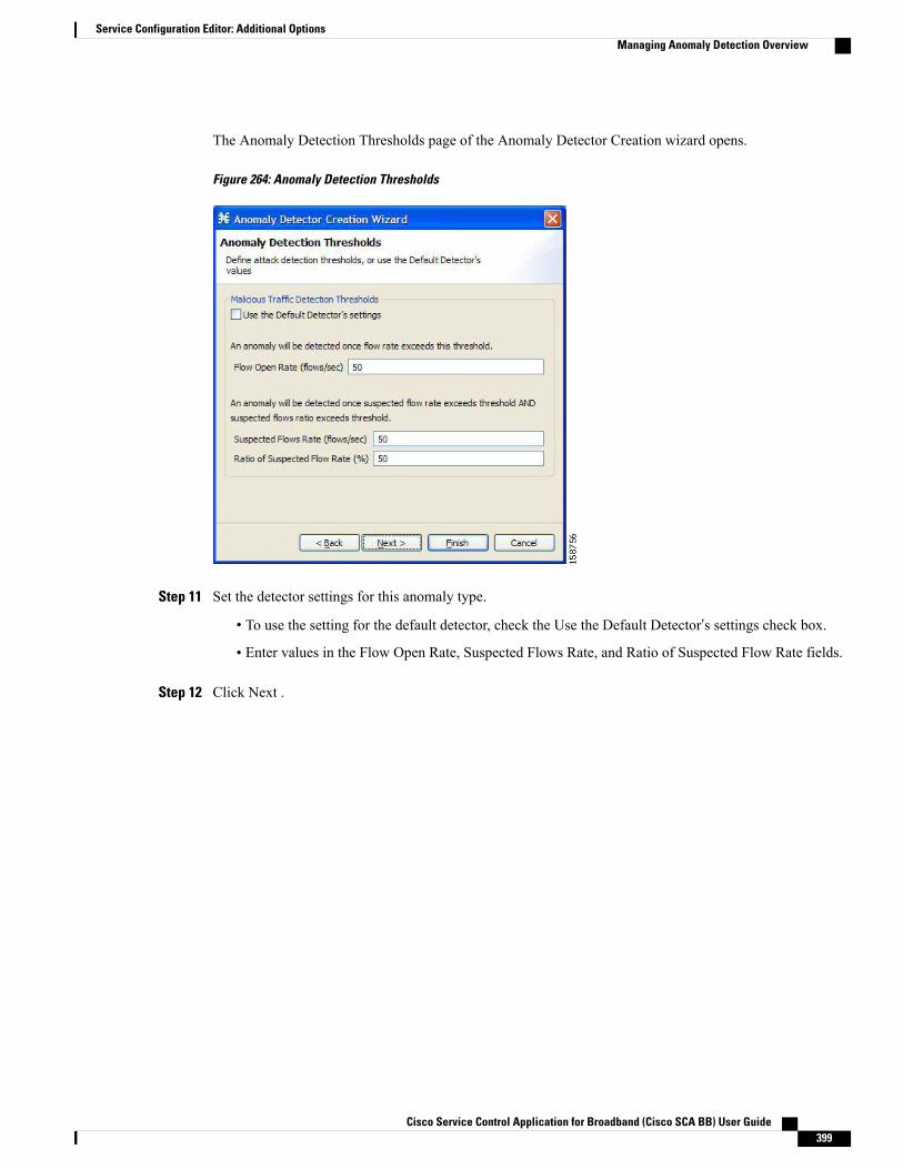
The Anomaly Detection Thresholds page of the Anomaly Detector Creation wizard opens.
Figure 264: Anomaly Detection Thresholds
Step 11 Set the detector settings for this anomaly type.
• To use the setting for the default detector, check the Use the Default Detector’s settings check box.
• Enter values in the Flow Open Rate, Suspected Flows Rate, and Ratio of Suspected Flow Rate fields.
Step 12 Click Next .
Cisco Service Control Application for Broadband (Cisco SCA BB) User Guide 399
Service Configuration Editor: Additional OptionsManaging Anomaly Detection Overview
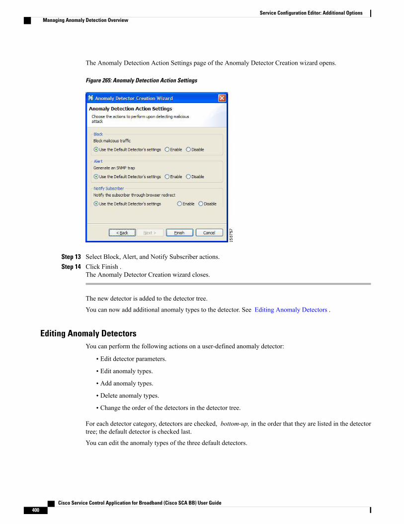
The Anomaly Detection Action Settings page of the Anomaly Detector Creation wizard opens.
Figure 265: Anomaly Detection Action Settings
Step 13 Select Block, Alert, and Notify Subscriber actions.Step 14 Click Finish .
The Anomaly Detector Creation wizard closes.
The new detector is added to the detector tree.
You can now add additional anomaly types to the detector. See Editing Anomaly Detectors .
Editing Anomaly DetectorsYou can perform the following actions on a user-defined anomaly detector:
• Edit detector parameters.
• Edit anomaly types.
• Add anomaly types.
• Delete anomaly types.
• Change the order of the detectors in the detector tree.
For each detector category, detectors are checked, bottom-up, in the order that they are listed in the detectortree; the default detector is checked last.
You can edit the anomaly types of the three default detectors.
Cisco Service Control Application for Broadband (Cisco SCA BB) User Guide400
Service Configuration Editor: Additional OptionsManaging Anomaly Detection Overview
Editing Detector Parameters
Procedure
Step 1 In the Service Security Dashboard, in the Anomaly Based Detection ofMalicious Traffic pane, click Configure.The Anomaly Detection Settings dialog box appears.
Step 2 In the detector tree, select a detector.The detector parameters are displayed in the upper right area of the dialog box.
Step 3 In the Name field, enter a new name for the detector.Step 4 Check or uncheck the IP address range and ports check boxes.Step 5 Enter or modify lists of IP addresses or ports in the relevant fields.Step 6 Click OK.
The Anomaly Detection Settings dialog box closes.
Your changes are saved.
Editing Anomaly Types
Procedure
Step 1 In the Service Security Dashboard, in the Anomaly Based Detection ofMalicious Traffic pane, click Configure.The Anomaly Detection Settings dialog box appears.
Step 2 In the detector tree, select a detector.Information about the anomaly types is displayed in the lower right area of the dialog box.
Step 3 Double-click an anomaly type.The Anomaly Detector Creation wizard appears, open to the Anomaly Detection Thresholds page (see Addingan Anomaly Type , on page 402 section).
Step 4 Set the detector settings for this anomaly type.Do one of the following:
• To use the setting of the default detector, check the Use the Default Detector’s settings check box.
• Change the values in the Flow Open Rate, Suspected Flows Rate, and Ratio of Suspected Flow Ratefields.
Step 5 Click Next.The Anomaly Detection Action Settings page of the Anomaly Detector Creation wizard opens.
Step 6 Change Block, Alert, and Notify Subscriber actions.Step 7 Click Finish .
The Anomaly Detector Creation wizard closes. The anomaly type is updated with your changes.Step 8 Repeat Steps 3 to 7 (or Steps 2 to 7) for other anomaly types.
Cisco Service Control Application for Broadband (Cisco SCA BB) User Guide 401
Service Configuration Editor: Additional OptionsManaging Anomaly Detection Overview
Step 9 Click OK.The Anomaly Detection Settings dialog box closes.
Adding an Anomaly Type
Procedure
Step 1 In the Service Security Dashboard, in the Anomaly Based Detection ofMalicious Traffic pane, click Configure.The Anomaly Detection Settings dialog box appears.
Step 2 In the detector tree, select a detector.The anomaly types are listed in the lower right area of the dialog box.
Step 3Click the Create New Detector Item Under Detector Items Feature icon.The Anomaly Detector Creation wizard appears, open to the Malicious Traffic Characteristics for a WORMattack page (see Adding Anomaly Detectors , on page 396 section).
Step 4 Select an origin for the anomaly type you are defining.Step 5 Select a transport type for the anomaly type you are defining.Step 6 Click Next .
The Anomaly Detection Thresholds page of the Anomaly Detector Creation wizard opens.Step 7 Set the detector settings for this anomaly type.
• To use the settings of the default detector, check the Use the Default Detector’s settings check box.
• Enter values in the Flow Open Rate, Suspected Flows Rate, and Ratio of Suspected Flow Rate fields.
Step 8 Click Next .The Anomaly Detection Action Settings page of the Anomaly Detector Creation wizard opens.
Step 9 Select Block, Alert, and Notify Subscriber actions.Step 10 Click Finish.
The Anomaly Detector Creation wizard closes.
The new anomaly type is added to the anomaly type list.
Step 11 Repeat Steps 3 to 10 (or Steps 2 to 10) for other anomaly types.Step 12 Click OK.
The Anomaly Detection Settings dialog box closes.
Cisco Service Control Application for Broadband (Cisco SCA BB) User Guide402
Service Configuration Editor: Additional OptionsManaging Anomaly Detection Overview
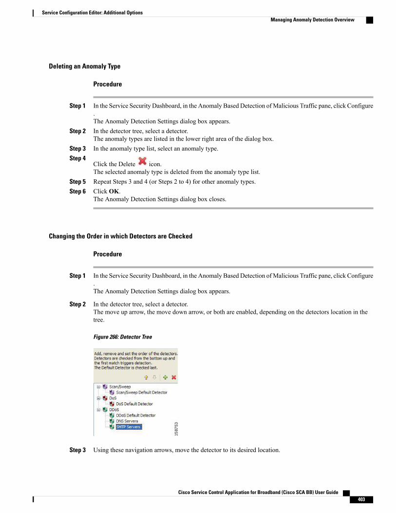
Deleting an Anomaly Type
Procedure
Step 1 In the Service Security Dashboard, in the Anomaly Based Detection ofMalicious Traffic pane, click Configure.The Anomaly Detection Settings dialog box appears.
Step 2 In the detector tree, select a detector.The anomaly types are listed in the lower right area of the dialog box.
Step 3 In the anomaly type list, select an anomaly type.Step 4
Click the Delete icon.The selected anomaly type is deleted from the anomaly type list.
Step 5 Repeat Steps 3 and 4 (or Steps 2 to 4) for other anomaly types.Step 6 Click OK.
The Anomaly Detection Settings dialog box closes.
Changing the Order in which Detectors are Checked
Procedure
Step 1 In the Service Security Dashboard, in the Anomaly Based Detection ofMalicious Traffic pane, click Configure.The Anomaly Detection Settings dialog box appears.
Step 2 In the detector tree, select a detector.The move up arrow, the move down arrow, or both are enabled, depending on the detectors location in thetree.
Figure 266: Detector Tree
Step 3 Using these navigation arrows, move the detector to its desired location.
Cisco Service Control Application for Broadband (Cisco SCA BB) User Guide 403
Service Configuration Editor: Additional OptionsManaging Anomaly Detection Overview
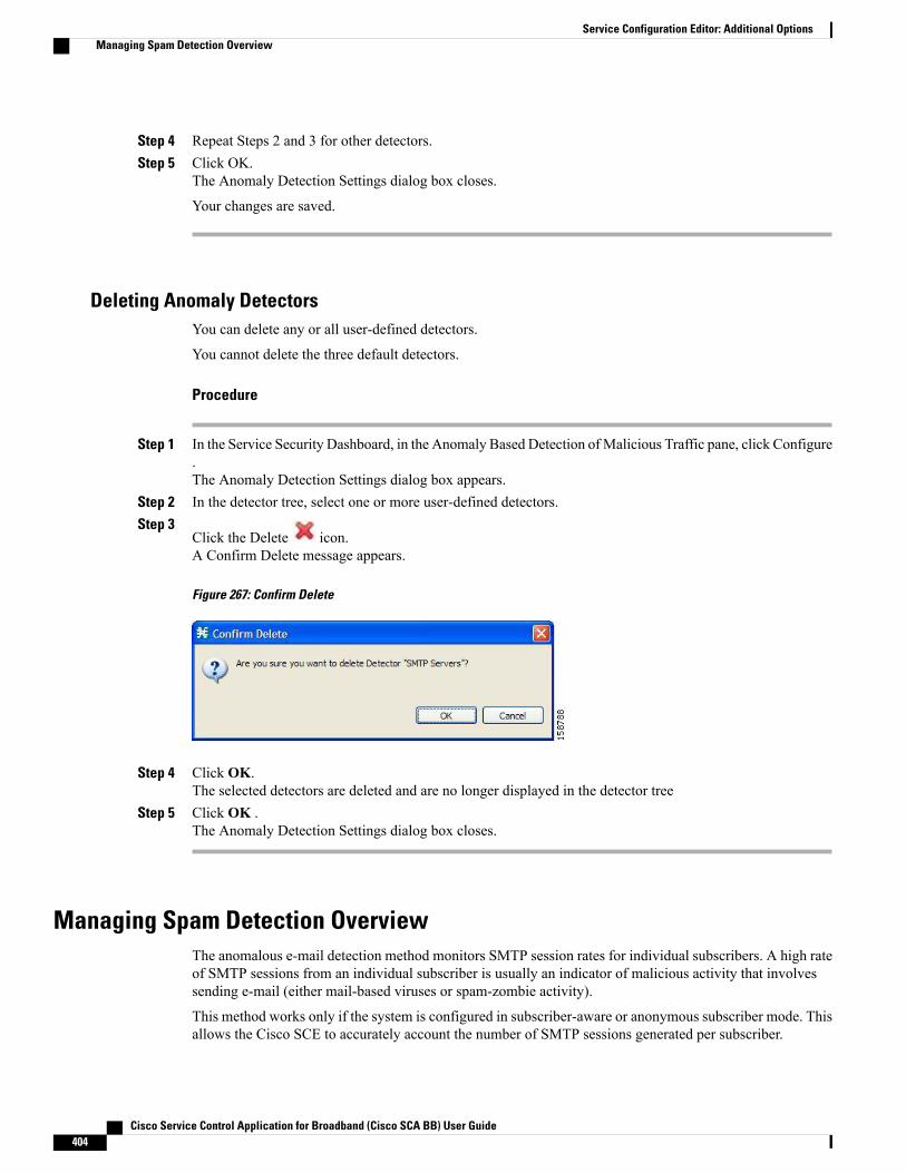
Step 4 Repeat Steps 2 and 3 for other detectors.Step 5 Click OK.
The Anomaly Detection Settings dialog box closes.
Your changes are saved.
Deleting Anomaly DetectorsYou can delete any or all user-defined detectors.
You cannot delete the three default detectors.
Procedure
Step 1 In the Service Security Dashboard, in the Anomaly Based Detection ofMalicious Traffic pane, click Configure.The Anomaly Detection Settings dialog box appears.
Step 2 In the detector tree, select one or more user-defined detectors.Step 3
Click the Delete icon.A Confirm Delete message appears.
Figure 267: Confirm Delete
Step 4 Click OK.The selected detectors are deleted and are no longer displayed in the detector tree
Step 5 Click OK .The Anomaly Detection Settings dialog box closes.
Managing Spam Detection OverviewThe anomalous e-mail detection method monitors SMTP session rates for individual subscribers. A high rateof SMTP sessions from an individual subscriber is usually an indicator of malicious activity that involvessending e-mail (either mail-based viruses or spam-zombie activity).
This method works only if the system is configured in subscriber-aware or anonymous subscriber mode. Thisallows the Cisco SCE to accurately account the number of SMTP sessions generated per subscriber.
Cisco Service Control Application for Broadband (Cisco SCA BB) User Guide404
Service Configuration Editor: Additional OptionsManaging Spam Detection Overview

The detection method is based on the following:
• Typical broadband subscribers generate few SMTP sessions (at most a single session each time theysend an e-mail message).
• Typical broadband subscribers normally use the SMTP server of the ISP (as configured in their mailclient) as their only mail relay, and do not communicate with off-net SMTP servers.
• Spam zombies create many SMTP sessions, mainly to off-net servers (the mail servers of the destinedrecipient of the messages).
When configuring spam detection, you select an appropriate service to monitor. By default, this is the built-inSMTP service.
Configuring Spam Detection Settings
Procedure
Step 1 In the Service Security Dashboard, in the Spam Zombies and Email Viruses Detection pane, click Configure.The Spam Detection and Mitigation settings dialog box appears.
Figure 268: Spam Detection and Mitigation Settings
Step 2 (Optional) To disable spam detection, uncheck the Enable Spam detection and mitigation check box. Allother fields are disabled. If you are disabling spam detection, continue at Step 6 .
Step 3 For each package, do the following:a) Define the quota to be used for indicating anomalous e-mail activity.
We recommend that the values for these fields should be based on some baseline monitoring of subscriberactivity.
b) Click in the Detection threshold column.A More (250619.jpg) button appears.
c) Click the More button.The Spam Detection Threshold window appears.
d) Define when to consider the subscriber as a spammer.
Cisco Service Control Application for Broadband (Cisco SCA BB) User Guide 405
Service Configuration Editor: Additional OptionsManaging Spam Detection Overview
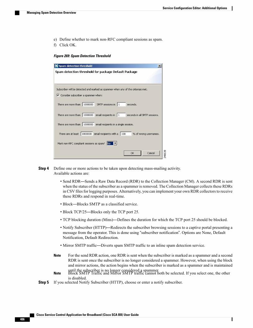
e) Define whether to mark non-RFC compliant sessions as spam.f) Click OK.
Figure 269: Spam Detection Threshold
Step 4 Define one or more actions to be taken upon detecting mass-mailing activity.Available actions are:
• Send RDR—Sends a Raw Data Record (RDR) to the Collection Manager (CM). A second RDR is sentwhen the status of the subscriber as a spammer is removed. The CollectionManager collects these RDRsin CSV files for logging purposes. Alternatively, you can implement your own RDR collectors to receivethese RDRs and respond in real-time.
• Block—Blocks SMTP as a classified service.
• Block TCP/25—Blocks only the TCP port 25.
• TCP blocking duration (Mins)—Defines the duration for which the TCP port 25 should be blocked.
• Notify Subscriber (HTTP)—Redirects the subscriber browsing sessions to a captive portal presenting amessage from the operator. This is done using “subscriber notification”. Options are None, DefaultNotification, Default Redirection.
• Mirror SMTP traffic—Diverts spam SMTP traffic to an inline spam detection service.
For the send RDR action, one RDR is sent when the subscriber is marked as a spammer and a secondRDR is sent once the subscriber is no longer considered a spammer. However, when using the blockand mirror actions, the action begins when the subscriber is marked as a spammer and is maintaineduntil the subscriber is no longer considered a spammer.
Note
Block SMTP Traffic and Mirror SMTP traffic cannot both be selected. If you select one, the otheris disabled.
Note
Step 5 If you selected Notify Subscriber (HTTP), choose or enter a notify subscriber.
Cisco Service Control Application for Broadband (Cisco SCA BB) User Guide406
Service Configuration Editor: Additional OptionsManaging Spam Detection Overview
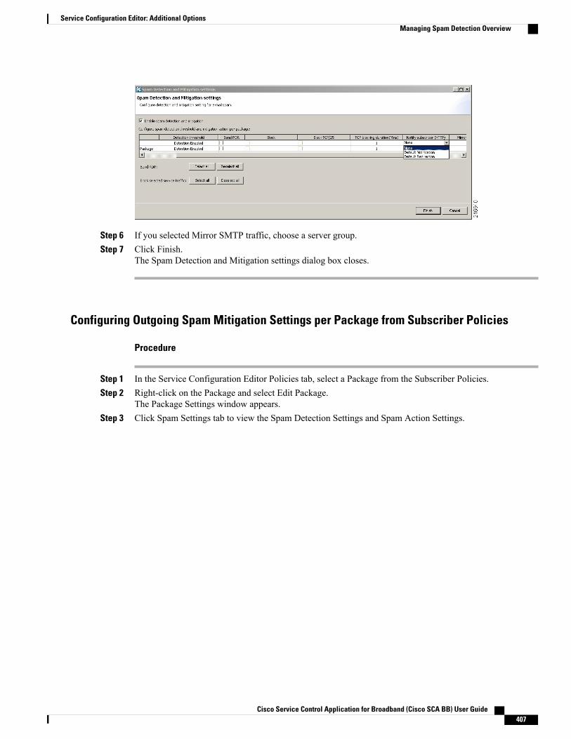
Step 6 If you selected Mirror SMTP traffic, choose a server group.Step 7 Click Finish.
The Spam Detection and Mitigation settings dialog box closes.
Configuring Outgoing Spam Mitigation Settings per Package from Subscriber Policies
Procedure
Step 1 In the Service Configuration Editor Policies tab, select a Package from the Subscriber Policies.Step 2 Right-click on the Package and select Edit Package.
The Package Settings window appears.Step 3 Click Spam Settings tab to view the Spam Detection Settings and Spam Action Settings.
Cisco Service Control Application for Broadband (Cisco SCA BB) User Guide 407
Service Configuration Editor: Additional OptionsManaging Spam Detection Overview
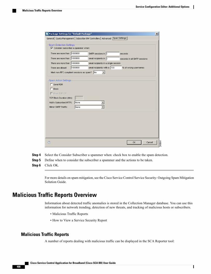
Step 4 Select the Consider Subscriber a spammer when: check box to enable the spam detection.Step 5 Define when to consider the subscriber a spammer and the actions to be taken.Step 6 Click OK.
For more details on spammitigation, see the Cisco Service Control Service Security: Outgoing SpamMitigationSolution Guide.
Malicious Traffic Reports OverviewInformation about detected traffic anomalies is stored in the Collection Manager database. You can use thisinformation for network trending, detection of new threats, and tracking of malicious hosts or subscribers.
• Malicious Traffic Reports
• How to View a Service Security Report
Malicious Traffic ReportsA number of reports dealing with malicious traffic can be displayed in the SCA Reporter tool:
Cisco Service Control Application for Broadband (Cisco SCA BB) User Guide408
Service Configuration Editor: Additional OptionsMalicious Traffic Reports Overview
• Global reports:
◦Global Scan or Attack Rate
◦Global DoS Rate
◦Infected Subscribers
◦Infected Subscribers versus Active Subscribers
◦DoS Attacked Subscribers
◦Top Scanned or Attacked ports
• Individual subscriber or hosts reports:
◦Top Scanning or Attacking hosts
◦Top DoS Attacked hosts
◦Top DoS Attacked Subscribers
◦Top Scanning or Attacking Subscribers
Viewing a Service Security Report
Procedure
Step 1 In the Service Security Dashboard, in the relevant pane, click View Report.A Choose a report dialog box appears, displaying a tree of relevant reports.
Step 2 Select a report from the report tree.Step 3 Click OK.
The Choose a report dialog box closes.
The Reporter tool opens in the Console, and displays the requested report.
For information about manipulating and saving the report, see the “Working with Reports” chapter of CiscoService Control Application Reporter User Guide.
Traffic Flow FilteringFilter rules are part of service configurations. They allow you to instruct the Cisco SCE platform, based on aflow’s Layer 3 and Layer 4 properties, to:
• Bypass—Ignore the flow and transmit it unchanged.
• Quick forward—Duplicate the flow and send one copy directly to the transmit queue to ensure minimaldelay. The second copy goes through the normal packet path.
Cisco Service Control Application for Broadband (Cisco SCA BB) User Guide 409
Service Configuration Editor: Additional OptionsTraffic Flow Filtering
When a traffic flow enters the Cisco SCE platform, the platform checks whether a filter rule applies to thisflow.
If a filter rule applies to this traffic flow, the Cisco SCE platform passes the traffic flow to its transmit queues.No RDR generation or service configuration enforcement is performed; these flows do not appear in anyrecords generated for analysis purposes and are not controlled by any rule belonging to the active serviceconfiguration.
It is recommended that you add filter rules for OSS protocols (such as DHCP) and routing protocols (such asBGP) that might traverse the Cisco SCE platform. These protocols usually should not be affected by policyenforcement, and their low volume makes them insignificant for reporting.
A number of predefined filter rules are included in every new service configuration.
By default, some, but not all, of the predefined filter rules are active.Note
Flows of certain protocols can also be filtered according to the Layer 7 characteristics of the flow (see AdvancedService Configuration Options, on page 451 section). Like other filtered flows, Layer 7 filtered flows are notcontrolled, but can be classified and reported. The flows of the protocols that can be filtered are typically shortand their overall volume is negligible. So filtering these protocols has little effect on network bandwidth andon the accuracy of the Cisco SCA BB reports.
Information About Traffic FilteringFor certain types of traffic, service providers may need to reduce the latency and jitter introduced by the CiscoSCE platform or even to bypass the Cisco SCE platform to avoid traffic control as well. Typically, suchdecisions are made for a portion of the traffic, to reduce latency for delay sensitive applications, such as voice,and to bypass mission-critical traffic, such as routing protocols. The Cisco SCABB Filtered Traffic mechanismis used to address this need.
To reduce latency, Cisco SCE platform automatically handles most voice traffic. For details, seeAutomaticQuick Forwarding of Media Flows, on page 412 section.
Note
The Cisco SCA BB Filtered Traffic MechanismThe Cisco SCA BB Filtered Traffic mechanism reduces latency or completely bypasses portions of the trafficby defining filter rules that match relevant flows and assign the correct action to them. A filter rule matchesa packet according to its Layer 3 and Layer 4 properties, such as IP address, port number, and DSCP ToS, aswell as the Cisco SCE platform interface (subscriber or network) from which the packet arrived. For packetsthat match a filter rule, the following actions can be applied:
• Bypass the current packet (to reduce latency and avoid traffic control).
When this action is applied, the current packet is directly transmitted from the Cisco SCE platform withoutgoing through any service configuration processing or reporting. You must map the bypassed packet to aClass of Service (CoS) to assign it to one of the transmit queues of the Cisco SCE platform.
Possible values for CoS are BE, AF1, AF2, AF3, AF4, and EF; where EF implies high processing priorityand the other classes imply normal processing priority.
Cisco Service Control Application for Broadband (Cisco SCA BB) User Guide410
Service Configuration Editor: Additional OptionsInformation About Traffic Filtering
• Quick forward the flow (to reduce latency).
When this action is applied, the current packet and all subsequent packets belonging to the same flow areduplicated and sent through two different paths: the original packet goes directly to the transmit queue, andthus has only a minimal delay, while a copy of the packet goes through the normal service configurationprocessing path for classification and reporting, and is then discarded.
• Assign the flow to the high priority processing input queue (to reduce latency).
Not all platforms support this option.Note
When this action is applied, the current packet and all subsequent packets belonging to the same flow enterthe high priority processing input queue. They go through the normal service configuration processing pathahead of other packets that arrive simultaneously. You should map the flow to the EF CoS to assign it to thehigh processing priority transmit queue of the Cisco SCE platform.
In an MPLS environment, the Cisco SCE platform does not map the DSCP bits to the EXP bits of theMPLS header.
Note
A filter rule can perform DSCP ToS marking (by changing the DSCP ToS field of the packet) of the matchedtraffic with any of the above actions.
DSCP ToS marking and the assignment to CoS only take place when the operational mode of the systemis Full Functionality (see System Operational Mode , on page 447 section).
Note
The Cisco SCE processes the traffic based on the Class of Service (CoS). Possible values for CoS are BE,AF1, AF2, AF3, AF4, and EF; where EF implies high processing priority and the other classes imply normalprocessing priority.
In SCE 8000SCE10000, if there are 4 output queues—EF, AF n ,AF1, and BE, this is how the queues areprioritized:
• EF—Gets the highest priority and strictly gets priority over all other queues.
• AF1 and AF n (AF2, AF3, AF4)—Gets the weighted priority on top of AF1. For each n packets of AFn , one packet is sent for AF1. The value of n can be configured from the FPGA. The default value is 3.
• BE—Gets lowest priority. BE packets are transmitted only if packets for transmission are not availablein other queues.
The Cisco SCE transmits only the received packet and do not generate the traffic internally; other than rarelytransmit inject for reset or redirect. So, there can never be a long time in which lower priority queues arestarved.
When there are only buckets—EF and the rest. In CoS other than EF (AF1,AF2,AF3,AF4,BE), the order ofpriority would be AF1 > AF2 > and so on. However, the bandwidth is allocated in the order EF > AF n > AF1> BE. Queues AF2, AF3, and AF4 would have the same weight.
Cisco Service Control Application for Broadband (Cisco SCA BB) User Guide 411
Service Configuration Editor: Additional OptionsInformation About Traffic Filtering

Filter Rule ActionsThe Bypass and Quick forward actions apply to different scopes of traffic:
• The Bypass action only bypasses the current packet; every subsequent packet of the same flow goesthrough the Filtered Traffic mechanism. This means, for example, that when traffic is to be bypassedbased on its destination port number, two rules should be created to match packets from both sides of abidirectional flow.For example, to bypass all traffic to destination port 23, two filter rules are needed, one for packetsarriving from the subscriber side addressed to network side port 23, and another for packets arrivingfrom the network side addressed to subscriber side port 23.
• The Quick forward action is applied to the entire flow; once identified, all subsequent packets do notgo through the filter rule mechanism, instead going through normal service configuration processing.A packet may match more than one filter rule. If both Bypass and Quick forward are matched, thepacket/flow is bypassed with minimum delay. Furthermore, if only Bypass is matched, the packet/flowis also be bypassed with minimum delay.
Filter Rules and Service RulesFilter rule actions to reduce latency allow the flow to be controlled by the Cisco SCE platform. This meansthat the flow can be blocked or given limited bandwidth if it matches a service rule. For example, if a filterrule is applied to reduce latency, but a service configuration rule is applied to block the same traffic, the trafficis blocked.
The Bypass action is designed to avoid service configuration processing; bypassed traffic is not affected byservice rules.
Automatic Quick Forwarding of Media FlowsThe Cisco SCE platform reduces the latency of delay-sensitive voice and video media flows by applying thequick-forwarding action to SIP, MGCP, H323, Skinny, and RTSP media flows during classification. Whena media flow is classified as being of one of these types, it is subjected to quick forwarding immediately.
The Cisco SCE platform does this automatically, regardless of filter rule configuration. These media flowsmight still be blocked or given limited bandwidth if they match a service rule.
Filtering L2TP TrafficIf you know the version of the L2TP tunnel that is being used, configure the relevant filters. If you do notknow the version, enable filter for both type of tunnels (L2TPv2 and L2TPv3).
The L2TPv3 data encapsulation is done directly over IP with protocol ID 115. Cisco SCA BB provides afilter for this type of traffic and you can enable it from Cisco SCA BB. However, L2TPv2 protocol dataencapsulation is done over UDP protocol at Layer 4 with default destination port 1701. Cisco SCA BBdoes not provide any filter for this type of traffic. To filter L2TPv2 traffic, create a new filter with thetransport type as UDP and destination UDP port value as 1701.
Note
Cisco Service Control Application for Broadband (Cisco SCA BB) User Guide412
Service Configuration Editor: Additional OptionsInformation About Traffic Filtering
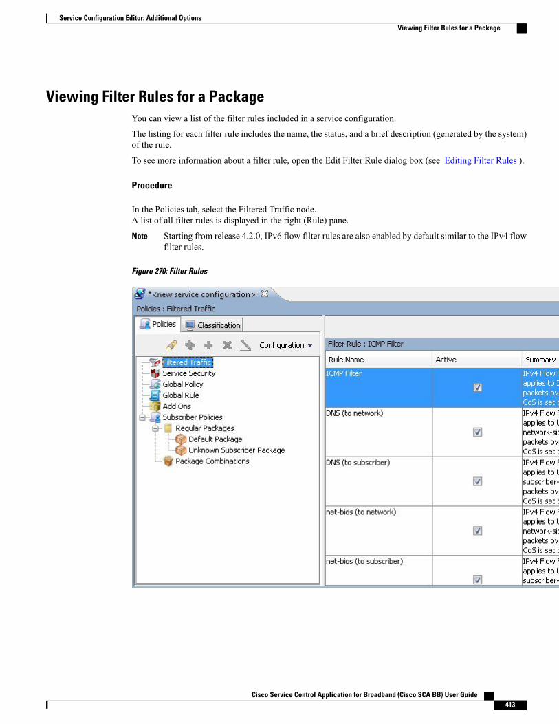
Viewing Filter Rules for a PackageYou can view a list of the filter rules included in a service configuration.
The listing for each filter rule includes the name, the status, and a brief description (generated by the system)of the rule.
To see more information about a filter rule, open the Edit Filter Rule dialog box (see Editing Filter Rules ).
Procedure
In the Policies tab, select the Filtered Traffic node.A list of all filter rules is displayed in the right (Rule) pane.
Starting from release 4.2.0, IPv6 flow filter rules are also enabled by default similar to the IPv4 flowfilter rules.
Note
Figure 270: Filter Rules
Cisco Service Control Application for Broadband (Cisco SCA BB) User Guide 413
Service Configuration Editor: Additional OptionsViewing Filter Rules for a Package
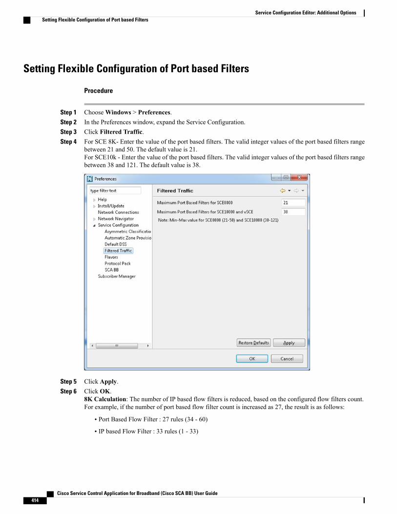
Setting Flexible Configuration of Port based Filters
Procedure
Step 1 ChooseWindows > Preferences.Step 2 In the Preferences window, expand the Service Configuration.Step 3 Click Filtered Traffic.Step 4 For SCE 8K- Enter the value of the port based filters. The valid integer values of the port based filters range
between 21 and 50. The default value is 21.For SCE10k - Enter the value of the port based filters. The valid integer values of the port based filters rangebetween 38 and 121. The default value is 38.
Step 5 Click Apply.Step 6 Click OK.
8K Calculation: The number of IP based flow filters is reduced, based on the configured flow filters count.For example, if the number of port based flow filter count is increased as 27, the result is as follows:
• Port Based Flow Filter : 27 rules (34 - 60)
• IP based Flow Filter : 33 rules (1 - 33)
Cisco Service Control Application for Broadband (Cisco SCA BB) User Guide414
Service Configuration Editor: Additional OptionsSetting Flexible Configuration of Port based Filters
10K Calculation: The number of IP based flow filters is reduced based on the configured flow filters count.For example, if the number of port based flow filter 10K count is increased as 40, the result is as follows:
• Port Based Flow Filter : 40 rules (179-257)
• IP based Flow Filter : 178 rules (1 - 178)
Adding Filter RulesThe Add Filter Rule wizard guides you through the process of adding a filter rule.
You can use a maximum of 39 IPv4 and IPv6 rules combined on the Cisco SCE 8000 devices. The CiscoSCA BB applies one internal rule automatically.
Note
IPv4 Rule Ranges:
IP Based: Out of 90 rules, 88 rules can be custom configured on the Cisco SCE10000 devices. One rulewill be allotted for default rule during the policy apply. This rule will be written to SCE only if the Systemmode is in either Transparent or report only mode. It will not be avail during full functionality mode andanother rule will be allotted during PQI Installation as default rule.
Port Based : 38 rules can be configured.
Note
IPv6 Rule Ranges:
IP Based: Out of 90 rules, 89 rules can be custom configured on the Cisco SCE 10000 devices. One defaultrule will be allotted during PQI Installation.
Port Based : All the 38 rules can be configured
There is no common rule behavior for port based filter configurations.
Note
Procedure
Step 1 In the Policies tab of Service Configuration Editor window, select the Filtered Traffic node.Step 2
Click (Add Rule) in the right (Rule) pane.
Cisco Service Control Application for Broadband (Cisco SCA BB) User Guide 415
Service Configuration Editor: Additional OptionsAdding Filter Rules
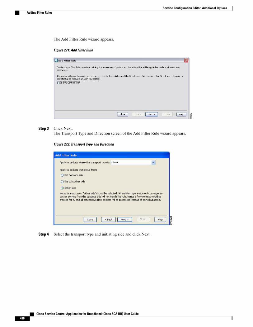
The Add Filter Rule wizard appears.
Figure 271: Add Filter Rule
Step 3 Click Next.The Transport Type and Direction screen of the Add Filter Rule wizard appears.
Figure 272: Transport Type and Direction
Step 4 Select the transport type and initiating side and click Next .
Cisco Service Control Application for Broadband (Cisco SCA BB) User Guide416
Service Configuration Editor: Additional OptionsAdding Filter Rules

The Subscriber-Side IP Address screen of the Add Filter Rule wizard appears.
Figure 273: Subscriber-Side IP Address
Step 5 Define the subscriber-side IP address and click Next.The Network-Side IP Address screen of the Add Filter Rule wizard appears.
Figure 274: Network-Side IP Address
Step 6 Define the network-side IP address and click Next.If the transport type selected in Step 4 was not TCP or UDP, the ToS screen of the Add Filter Rule wizard
appears. Go to Step 9.
Cisco Service Control Application for Broadband (Cisco SCA BB) User Guide 417
Service Configuration Editor: Additional OptionsAdding Filter Rules
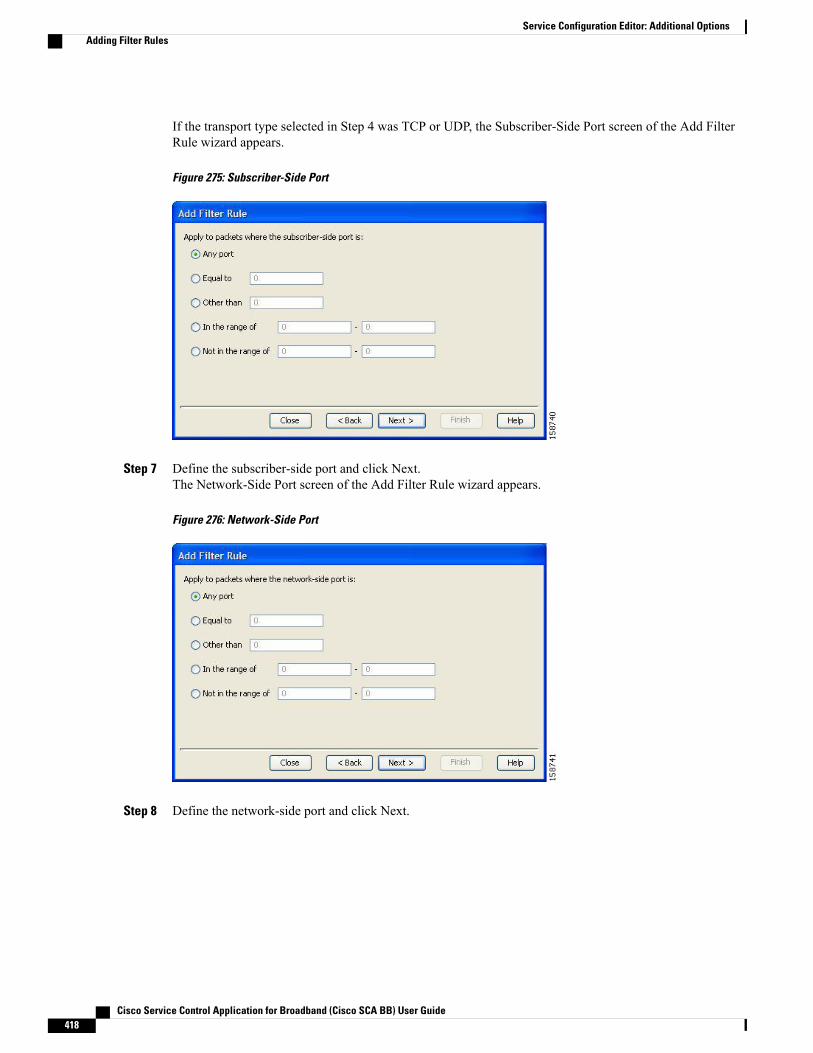
If the transport type selected in Step 4 was TCP or UDP, the Subscriber-Side Port screen of the Add FilterRule wizard appears.
Figure 275: Subscriber-Side Port
Step 7 Define the subscriber-side port and click Next.The Network-Side Port screen of the Add Filter Rule wizard appears.
Figure 276: Network-Side Port
Step 8 Define the network-side port and click Next.
Cisco Service Control Application for Broadband (Cisco SCA BB) User Guide418
Service Configuration Editor: Additional OptionsAdding Filter Rules
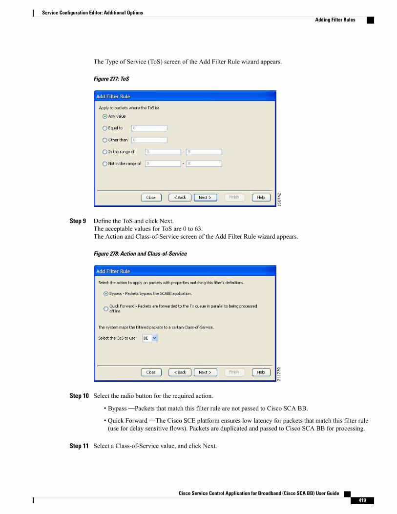
The Type of Service (ToS) screen of the Add Filter Rule wizard appears.
Figure 277: ToS
Step 9 Define the ToS and click Next.The acceptable values for ToS are 0 to 63.The Action and Class-of-Service screen of the Add Filter Rule wizard appears.
Figure 278: Action and Class-of-Service
Step 10 Select the radio button for the required action.
• Bypass—Packets that match this filter rule are not passed to Cisco SCA BB.
• Quick Forward—The Cisco SCE platform ensures low latency for packets that match this filter rule(use for delay sensitive flows). Packets are duplicated and passed to Cisco SCA BB for processing.
Step 11 Select a Class-of-Service value, and click Next.
Cisco Service Control Application for Broadband (Cisco SCA BB) User Guide 419
Service Configuration Editor: Additional OptionsAdding Filter Rules

The ToS Marking screen of the Add Filter Rule wizard appears.
Figure 279: ToS Marking
Step 12 (Optional) To change the DSCP ToS marker of packets in the filtered traffic, check the Remark UpstreamToS with ToS Marker and Remark Downstream ToS with ToS Marker check boxes, as required, select therequired ToS marker from the drop-down list, and click Next .
• Disabling directional DSCP ToS marking in the ToS Marking Settings dialog box (see How to ManageDSCP ToS Marker Values , on page 368 section) overrides DSCP ToS marking in that direction by afilter (that is, the DSCP ToS value are not changed). In this case, the Problems View displays aWarning.
• If you filter for a flow in one direction in Step 4 but select ToS marking in the other direction in thisStep, the filter rule is created, but no DSCP ToS remarking occurs. In this case, the Problems Viewdisplays a Warning.
• If you select Quick Forward in the previous Step, Cisco SCA BB receives the original package andprocesses it. That is, the application see the original DSCP ToS value regardless of the ToS markingaction selected in the filter rule.
Cisco Service Control Application for Broadband (Cisco SCA BB) User Guide420
Service Configuration Editor: Additional OptionsAdding Filter Rules

The Finish page of the Add Filter Rule wizard opens.
Figure 280: Finish
Step 13 In the Rule Name field, enter a unique name for the new filter rule.You can use the default name for the filter rule. It is recommended that you enter a meaningfulname.
Note
Step 14 (Optional) To activate the filter rule, check the Activate this rule check box. Traffic is filtered according tothe rule only when it is activated.
Step 15 Click Finish.The Add Filter Rule wizard closes.
The filter rule is added and is displayed in the Filter Rule table.
Adding Filter Rules for IPv6 ConfigurationThe Add Filter Rule wizard guides you through the process of adding a filter rule for IPv6 configuration.
Procedure
Step 1 In the Policies tab of Service Configuration Editor window, select the Filtered Traffic node.Step 2
Click Add Rule in the right (Rule) pane.
Cisco Service Control Application for Broadband (Cisco SCA BB) User Guide 421
Service Configuration Editor: Additional OptionsAdding Filter Rules for IPv6 Configuration
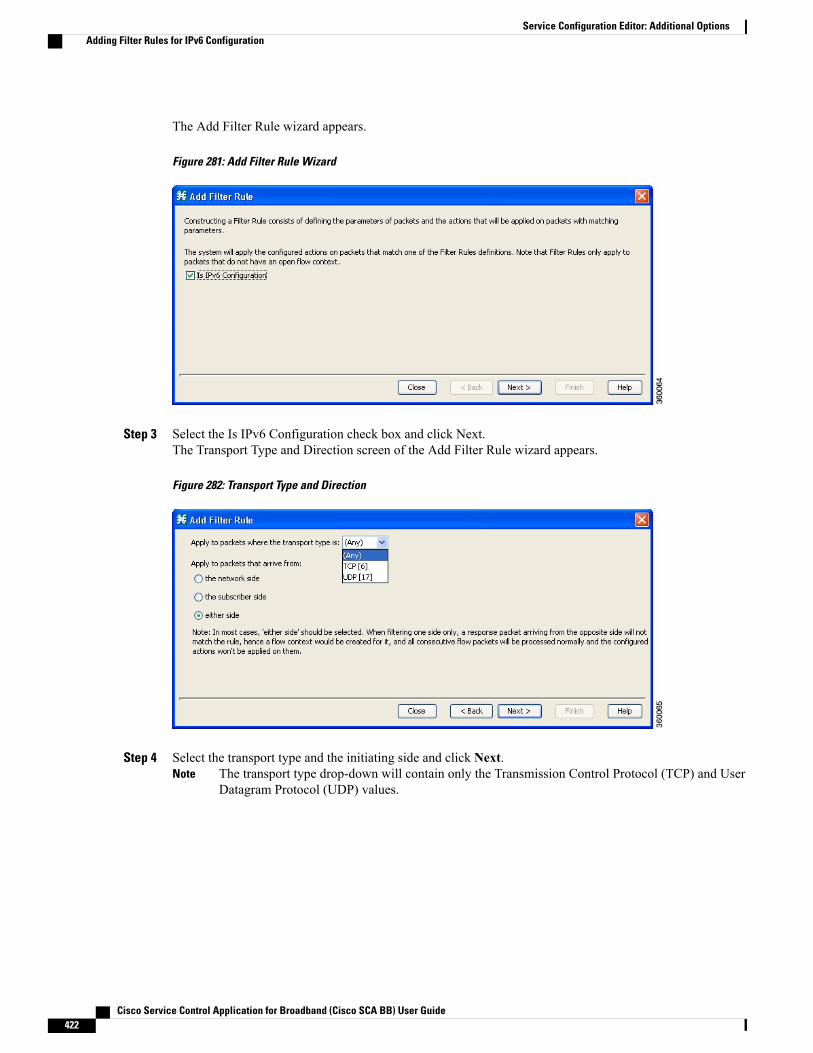
The Add Filter Rule wizard appears.
Figure 281: Add Filter Rule Wizard
Step 3 Select the Is IPv6 Configuration check box and click Next.The Transport Type and Direction screen of the Add Filter Rule wizard appears.
Figure 282: Transport Type and Direction
Step 4 Select the transport type and the initiating side and click Next.The transport type drop-down will contain only the Transmission Control Protocol (TCP) and UserDatagram Protocol (UDP) values.
Note
Cisco Service Control Application for Broadband (Cisco SCA BB) User Guide422
Service Configuration Editor: Additional OptionsAdding Filter Rules for IPv6 Configuration

The Subscriber-Side IP Address screen of the Add Filter Rule wizard appears.
Figure 283: Subscriber-Side IP Address
Step 5 Define the subscriber-side IP address and click Next .The Network-Side IP Address screen of the Add Filter Rule wizard appears.
Figure 284: Network-Side IP Address
Step 6 Define the network-side IP address and click Next .You can use 128-bit masks for the subscriber side IP addresses and the network side IP addresses.
If the transport type selected in Step 4 was not TCP or UDP, the ToS screen of the Add Filter Rule wizardappears. Go to Step 9.
Cisco Service Control Application for Broadband (Cisco SCA BB) User Guide 423
Service Configuration Editor: Additional OptionsAdding Filter Rules for IPv6 Configuration
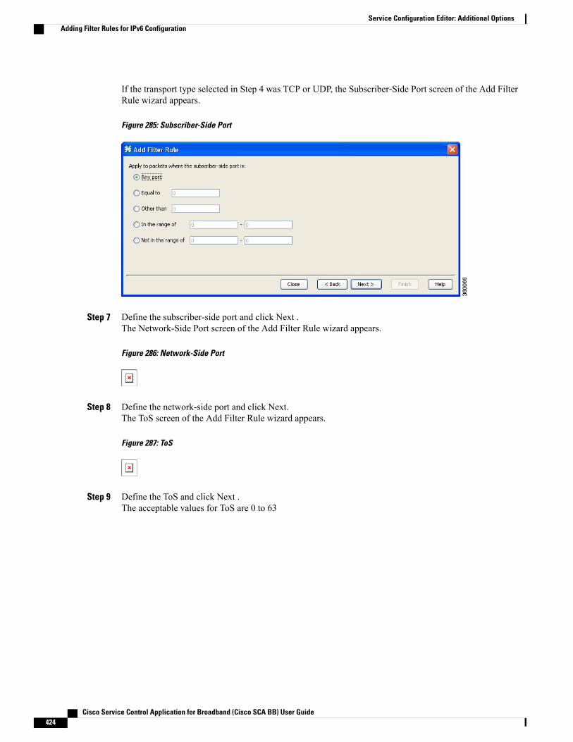
If the transport type selected in Step 4 was TCP or UDP, the Subscriber-Side Port screen of the Add FilterRule wizard appears.
Figure 285: Subscriber-Side Port
Step 7 Define the subscriber-side port and click Next .The Network-Side Port screen of the Add Filter Rule wizard appears.
Figure 286: Network-Side Port
Step 8 Define the network-side port and click Next.The ToS screen of the Add Filter Rule wizard appears.
Figure 287: ToS
Step 9 Define the ToS and click Next .The acceptable values for ToS are 0 to 63
Cisco Service Control Application for Broadband (Cisco SCA BB) User Guide424
Service Configuration Editor: Additional OptionsAdding Filter Rules for IPv6 Configuration
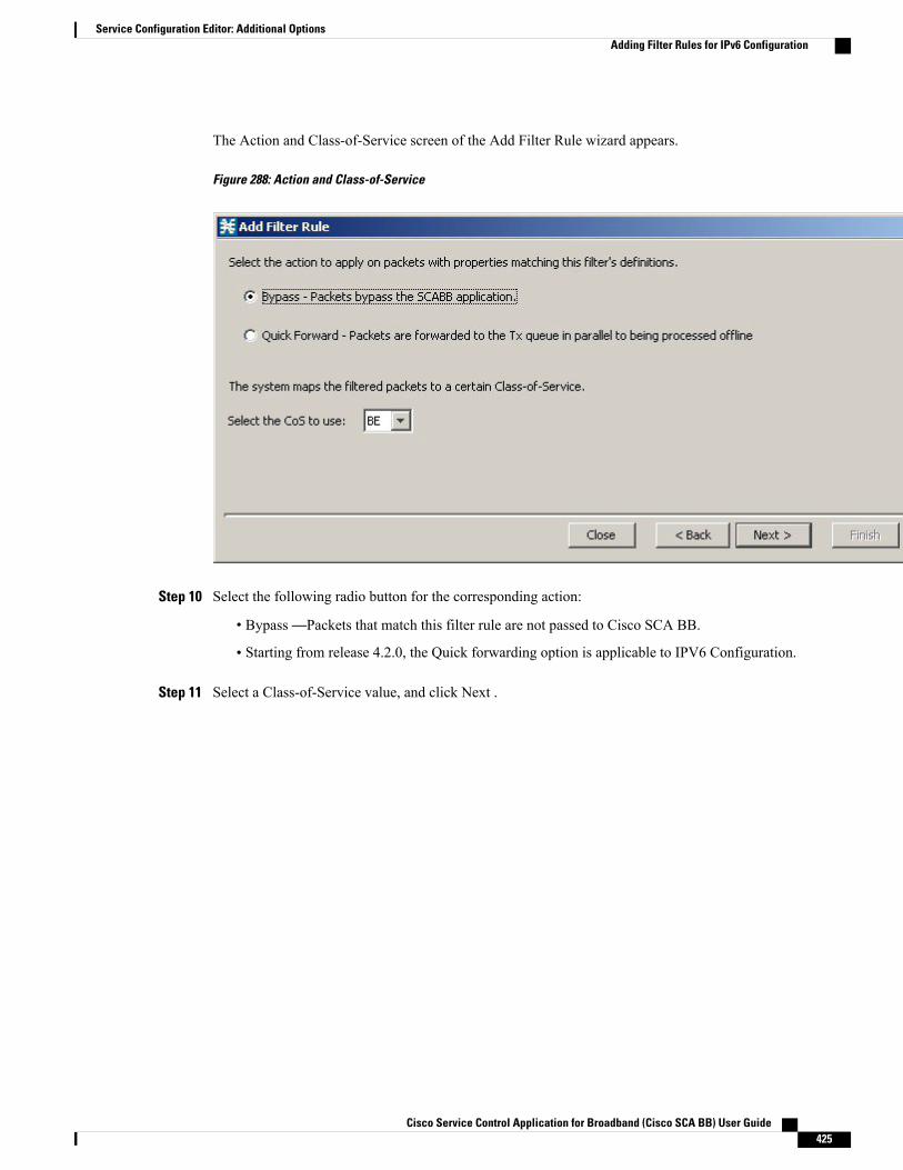
The Action and Class-of-Service screen of the Add Filter Rule wizard appears.
Figure 288: Action and Class-of-Service
Step 10 Select the following radio button for the corresponding action:
• Bypass—Packets that match this filter rule are not passed to Cisco SCA BB.
• Starting from release 4.2.0, the Quick forwarding option is applicable to IPV6 Configuration.
Step 11 Select a Class-of-Service value, and click Next .
Cisco Service Control Application for Broadband (Cisco SCA BB) User Guide 425
Service Configuration Editor: Additional OptionsAdding Filter Rules for IPv6 Configuration
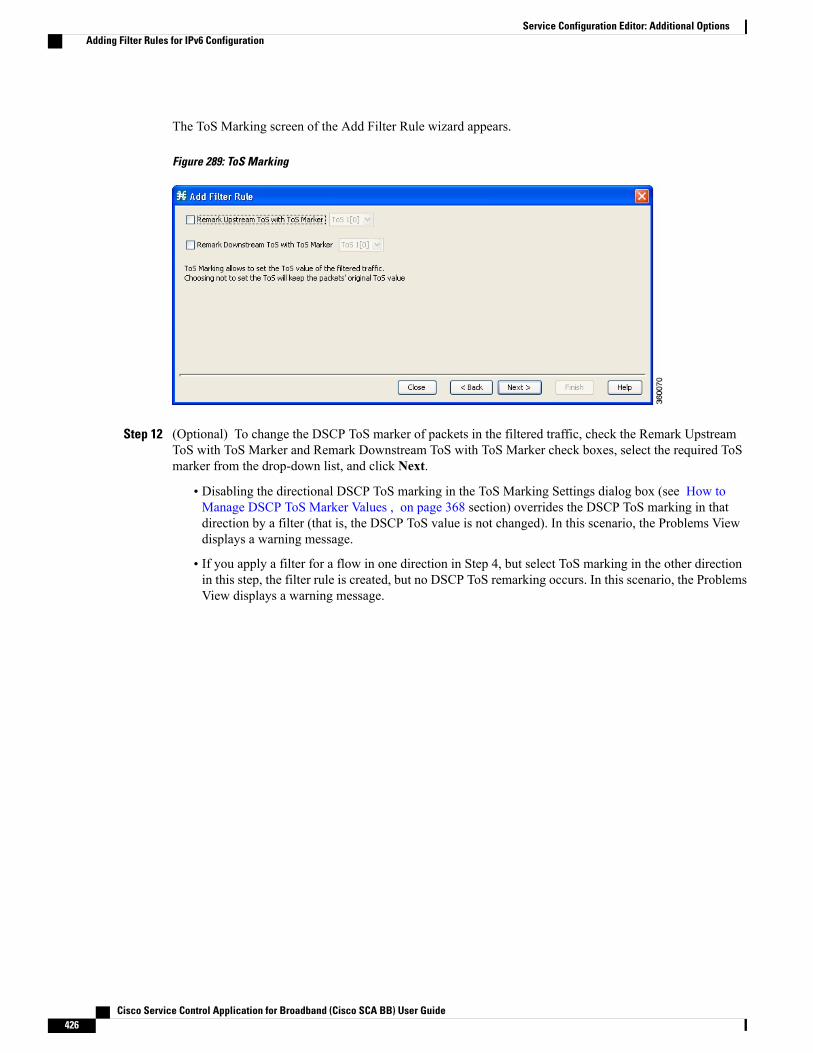
The ToS Marking screen of the Add Filter Rule wizard appears.
Figure 289: ToS Marking
Step 12 (Optional) To change the DSCP ToS marker of packets in the filtered traffic, check the Remark UpstreamToS with ToS Marker and Remark Downstream ToS with ToS Marker check boxes, select the required ToSmarker from the drop-down list, and click Next.
• Disabling the directional DSCP ToS marking in the ToS Marking Settings dialog box (see How toManage DSCP ToS Marker Values , on page 368 section) overrides the DSCP ToS marking in thatdirection by a filter (that is, the DSCP ToS value is not changed). In this scenario, the Problems Viewdisplays a warning message.
• If you apply a filter for a flow in one direction in Step 4, but select ToS marking in the other directionin this step, the filter rule is created, but no DSCP ToS remarking occurs. In this scenario, the ProblemsView displays a warning message.
Cisco Service Control Application for Broadband (Cisco SCA BB) User Guide426
Service Configuration Editor: Additional OptionsAdding Filter Rules for IPv6 Configuration
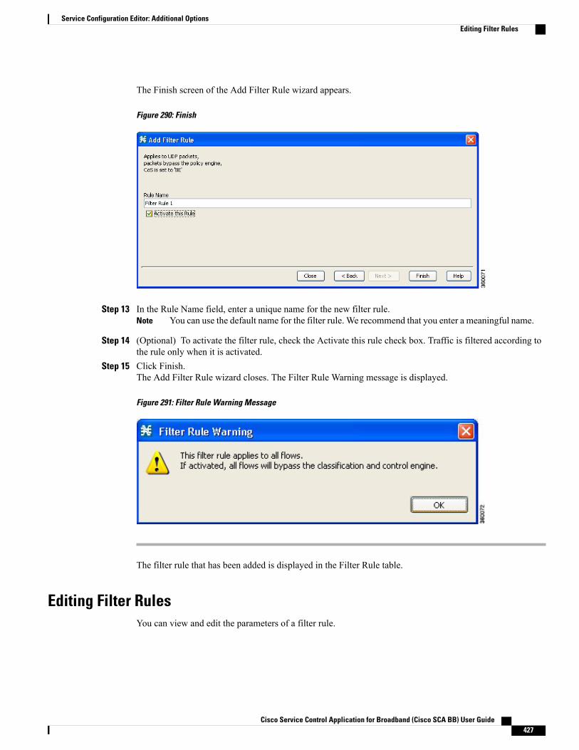
The Finish screen of the Add Filter Rule wizard appears.
Figure 290: Finish
Step 13 In the Rule Name field, enter a unique name for the new filter rule.You can use the default name for the filter rule. We recommend that you enter a meaningful name.Note
Step 14 (Optional) To activate the filter rule, check the Activate this rule check box. Traffic is filtered according tothe rule only when it is activated.
Step 15 Click Finish.The Add Filter Rule wizard closes. The Filter Rule Warning message is displayed.
Figure 291: Filter Rule Warning Message
The filter rule that has been added is displayed in the Filter Rule table.
Editing Filter RulesYou can view and edit the parameters of a filter rule.
Cisco Service Control Application for Broadband (Cisco SCA BB) User Guide 427
Service Configuration Editor: Additional OptionsEditing Filter Rules

Procedure
Step 1 In the Policies tab of Service Configuration Editor window, select the Filtered Traffic node.A list of all filter rules is displayed in the right (Rule) pane.
Step 2 Select a rule in the Filter Rule table.Step 3
Click the Edit Rule icon.The Introduction page of the Edit Filter Rule wizard appears.
The Edit Filter Rule wizard is the same as the Add Filter Rule wizard.
Step 4 Follow the instructions in the section Adding Filter Rules , on page 415, Steps 4 to 14.Step 5 Click Finish.
The filter rule is changed and the corresponding changes are displayed in the Filter Rule table.
Deleting Filter RulesYou can delete filter rules. This is useful, for example, when you want the system to resume handling the IPaddresses and their attributes according to the individual rules that were previously defined for each subscriberIP address.
Procedure
Step 1 In the Policies tab, select the Filtered Traffic node.A list of all filter rules is displayed in the right (Rule) pane.
Step 2 Select a rule in the Filter Rule table.Step 3
Click the Delete Rule (158940.jpg) icon.A Filter Rule Warning message is displayed.
Figure 292: Filter Rule Warning
Step 4 Click Yes.The filter rule is deleted and is no longer displayed in the Filter Rule table.
Cisco Service Control Application for Broadband (Cisco SCA BB) User Guide428
Service Configuration Editor: Additional OptionsDeleting Filter Rules
Activating and Deactivating Filter RulesYou can activate or deactivate filter rules at any time. Deactivating a filter rule has the same effect as deletingit, but the parameters are retained in the service configuration, and you can reactivate the filter rule at a laterdate.
Procedure
Step 1 In the Policies tab, select the Filtered Traffic node.A list of all filter rules is displayed in the right (Rule) pane.
Step 2 Select a rule in the Filter Rule table.Step 3 To activate the rule, check the Active check box.Step 4 To deactivate the rule, uncheck the Active check box.Step 5 Repeat Steps 3 and 4 for other rules.
Managing Subscriber Notifications OverviewThe subscriber notification feature pushes web-based messages to a subscriber by redirecting the subscriberHTTP traffic to relevant web pages. These web pages contain information relevant to the subscriber, such asnotifications of quota depletion. HTTP redirection starts when the subscriber notification is activated andceases when the notification is dismissed.
Subscriber notification is not supported when unidirectional classification is enabled.Note
Each set of subscriber redirection parameters comprises a notification redirect profile. The Cisco SCA BBsupports a maximum of 128 redirect profiles, including notification and redirect profiles. There are 3 defaultredirect profiles that cannot be deleted: Default Notification, Network Attack Notification, and DefaultRedirection. You configure which notification redirect profile to use when defining rules.
Subscriber Notification ParametersEach redirect profile of type notification contains the following subscriber notification parameters:
The Activation trigger configuration options are only available for redirect profile of type redirect.Note
• Name—Each profile must have a unique name.
You cannot change the name of the Default Notification or the Network Attack Notification.Note
Cisco Service Control Application for Broadband (Cisco SCA BB) User Guide 429
Service Configuration Editor: Additional OptionsActivating and Deactivating Filter Rules
• Redirect profile type—Each profile must be one of two types:
◦Notification
◦Redirect
• Set of Redirection URLs—A configurable set of destination URLs, to which the HTTP flows of thesubscriber are redirected after redirection is activated. This web page usually contains the message thatneeds to be conveyed to the subscriber. The redirection set can optionally include one, or severalparameters appended to the destination URL including the redirect reason and subscriber ID.
The destination web server can use these parameters to carry a more purposeful message to the subscriber.
• Activation frequency—Indicates when to activate the notification redirect. The activation frequency isone of the following:
The Periodically option is only available for redirect profile of type redirect.Note
• Only once—The subscriber is redirected to the notification only the first time the conditions are met.
For example, if a quota was exceeded, the subscriber browses to the destination URL that informs them ofthis fact, only once (even though the subscriber remains in a breach state).
• Always—The subscriber is redirected to the notification every time the conditions are met.
For example, if a quota was exceeded, the subscriber is continuously redirected to the notification until thesubscriber completes the procedure to refresh their quota.
• Until the subscriber browses to—Every time the conditions are met, the subscriber is redirected to thenotification, until the subscriber proceeds from the destination URL to a different, final URL.
For example, if a quota was exceeded, the web page at the destination URL may ask the subscriber to pressan Acknowledge button after reading the message. The acknowledge URL would be defined as the dismissalURL and would deactivate further notifications.
The dismissal URL is composed of the URL hostname and the URL path, separated by a colon, in the followingformat:
[*]<hostname>:<path>[*]
• < hostname >may optionally be preceded by a wildcard (*), to match all hostnames with the same suffix.
• The path element must always start with “/”.
• < path > may be followed by a wildcard (*), to match all paths with a common prefix.
For example, the entry *. some-isp.net:/redirect/ * matches all the following URLs:
• www.some-isp.net/redirect/index.html
• support.some-isp.net/redirect/info/warning.asp
• noquota.some-isp.net/redirect/acknowledge.aspx?ie=UTF-8
Cisco Service Control Application for Broadband (Cisco SCA BB) User Guide430
Service Configuration Editor: Additional OptionsSubscriber Notification Parameters
• List of Allowed URLs—A list of URLs that are not blocked and redirected even though redirection isactivated.
After redirection is activated, all HTTP flows, except flows to the destination URL and to the dismissal URL,are blocked and redirected to the destination URL. However, subscribers can be permitted to access anadditional set of URLs. This is useful, for example, to give subscribers access to additional support information.
Allowed URLs have the same format as the dismissal URL.
These parameters are defined when you add a new notification redirect profile (see Adding a Set of RedirectionURLs, on page 443 section). You can modify them at any time.
• Once in a day—The subscriber is redirected only the first time when the conditions are met and this alsohappens the first time every day.
• Once in a week—The subscriber is redirected only the first time when the conditions are met and thisalso happens the first time every week.
• Once in a Month—The subscriber is redirected only the first time when the conditions are met and thisalso happens the first time every month.
By default "Across login " support is enabled for the above three options . RedirectionHistory RDR will be generated every time , when the redirection condition is met . TheSubscriber manager processes those RDRs and shares the redirected profile informationon the next login The Redirection History RDR will be generated to reset the markedprofiles, once at the end of a Day, a Week and a Month . By this way we are achievingthe redirection only once in a Day , Week and Month .
Note
For more information, see "Subscriber Redirection" section in Cisco Subscriber Manger user guide.
For more information, see "Redirection History RDR" section in Cisco Service Control Application forBroadband reference guide and see "Configuring the Subscriber Redirection Across Login" section in CiscoSCE 10000 Software Configuration Guide
Network Attack NotificationSubscriber notification informs a subscriber in real-time about current attacks involving IP addresses mappedto that subscriber. (Enabling these notifications is described in “ The Service Security Dashboard .) CiscoSCA BB notifies the subscriber about the attack by redirecting HTTP flows originating from the subscriberto a server that supplies information about the attack.
One subscriber notification, Network Attack Notification, is dedicated to providing these notifications; itcannot be deleted. A Network Attack Notification is not dismissed at the end of an attack; subscribers mustrespond to it.
To allow redirection when blocking traffic, the system is configured to leave open one specified TCP port(by default, port 80). See “Advanced Service Configuration Options” section.
In earlier releases of Cisco SCA BB, configuring network attack notifications was performed using CLIcommands. CLI commands should no longer be used for this purpose.
Note
Cisco Service Control Application for Broadband (Cisco SCA BB) User Guide 431
Service Configuration Editor: Additional OptionsNetwork Attack Notification
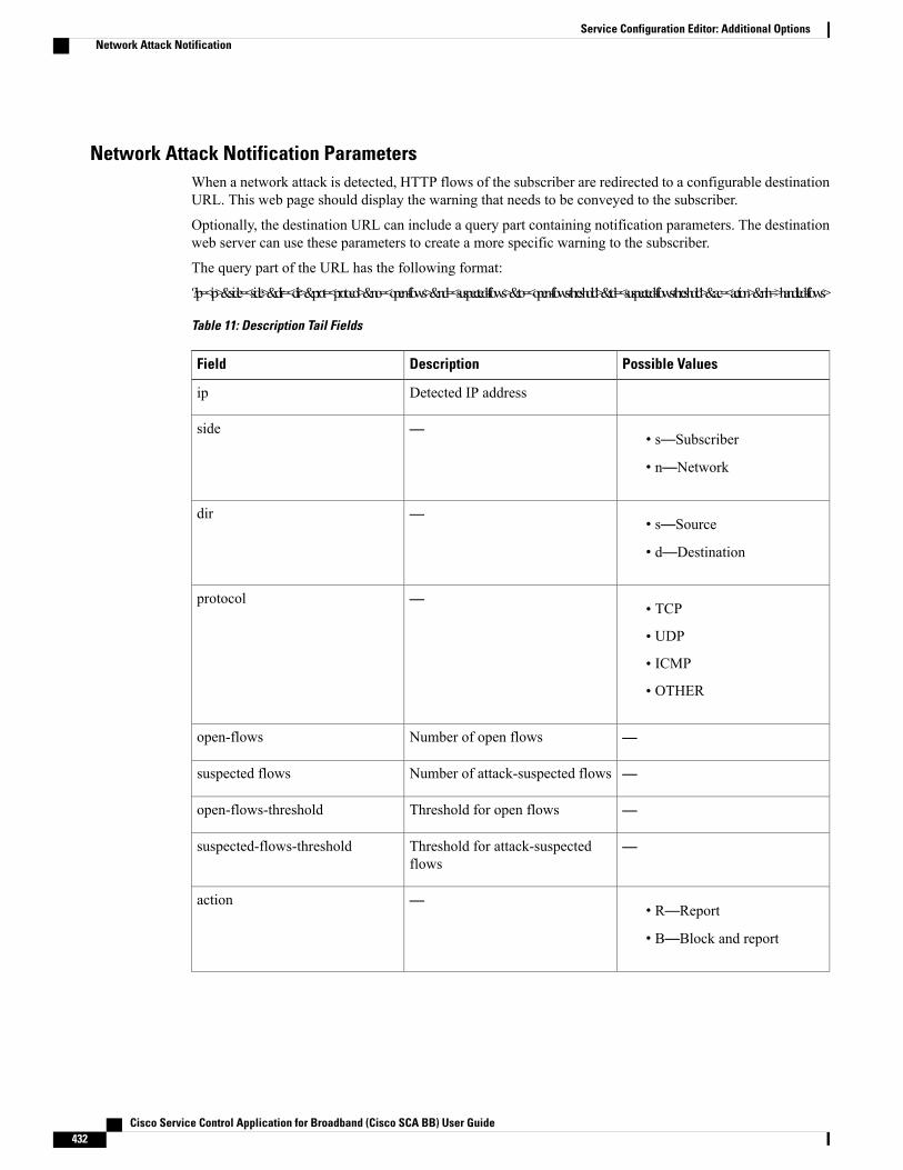
Network Attack Notification ParametersWhen a network attack is detected, HTTP flows of the subscriber are redirected to a configurable destinationURL. This web page should display the warning that needs to be conveyed to the subscriber.
Optionally, the destination URL can include a query part containing notification parameters. The destinationweb server can use these parameters to create a more specific warning to the subscriber.
The query part of the URL has the following format:
?ip=<ip>&side=<side>&dir=<dir>&prot=<protocol>&no=<open-flows>&nd=<suspected-flows>&to=<open-flows-threshold>&td=<suspected-flows-threshold>&ac=<action>&nh=>handled-flows>
Table 11: Description Tail Fields
Possible ValuesDescriptionField
Detected IP addressip
• s—Subscriber
• n—Network
—side
• s—Source
• d—Destination
—dir
• TCP
• UDP
• ICMP
• OTHER
—protocol
—Number of open flowsopen-flows
—Number of attack-suspected flowssuspected flows
—Threshold for open flowsopen-flows-threshold
—Threshold for attack-suspectedflows
suspected-flows-threshold
• R—Report
• B—Block and report
—action
Cisco Service Control Application for Broadband (Cisco SCA BB) User Guide432
Service Configuration Editor: Additional OptionsNetwork Attack Notification
Possible ValuesDescriptionField
—Number of flows handled since theattack began
(Non-zero only during and at theend of an attack)
handled-flows
Example of URL with Description Tailhttp://www.some-isp.net/warning?ip=80.178.113.222&side=s&proto=TCP&no=34&nd=4&to=34&td=10&ac=B&nh=100
Adding a Notification Redirect Profile
Creating a notification redirect profile does not activate the subscriber notification feature. After thenotification redirect profile is defined, it must be activated for a particular package
Note
Procedure
Step 1 From the Policies tab in the left pane, choose Configuration > Policies > Subscriber Redirection.
Cisco Service Control Application for Broadband (Cisco SCA BB) User Guide 433
Service Configuration Editor: Additional OptionsAdding a Notification Redirect Profile

The Redirect Actions Settings dialog box appears.
Figure 293: Redirect Action Settings - General Tab
Step 2 Click Add.A new redirection profile containing the default redirection URL set is added to the redirection profile list.
Step 3 In the Name field, enter a unique name for the new notification redirect profile.You can use the default name for the notification redirect profile. It is recommended that you enter a meaningfulname.
Step 4 In the Select redirection profile type field, select Notification.Do not skip this step or a redirect profile is created instead of a notification redirect profile.
Step 5 Choose a URL set.Step 6 Click the Activation tab.
Cisco Service Control Application for Broadband (Cisco SCA BB) User Guide434
Service Configuration Editor: Additional OptionsAdding a Notification Redirect Profile
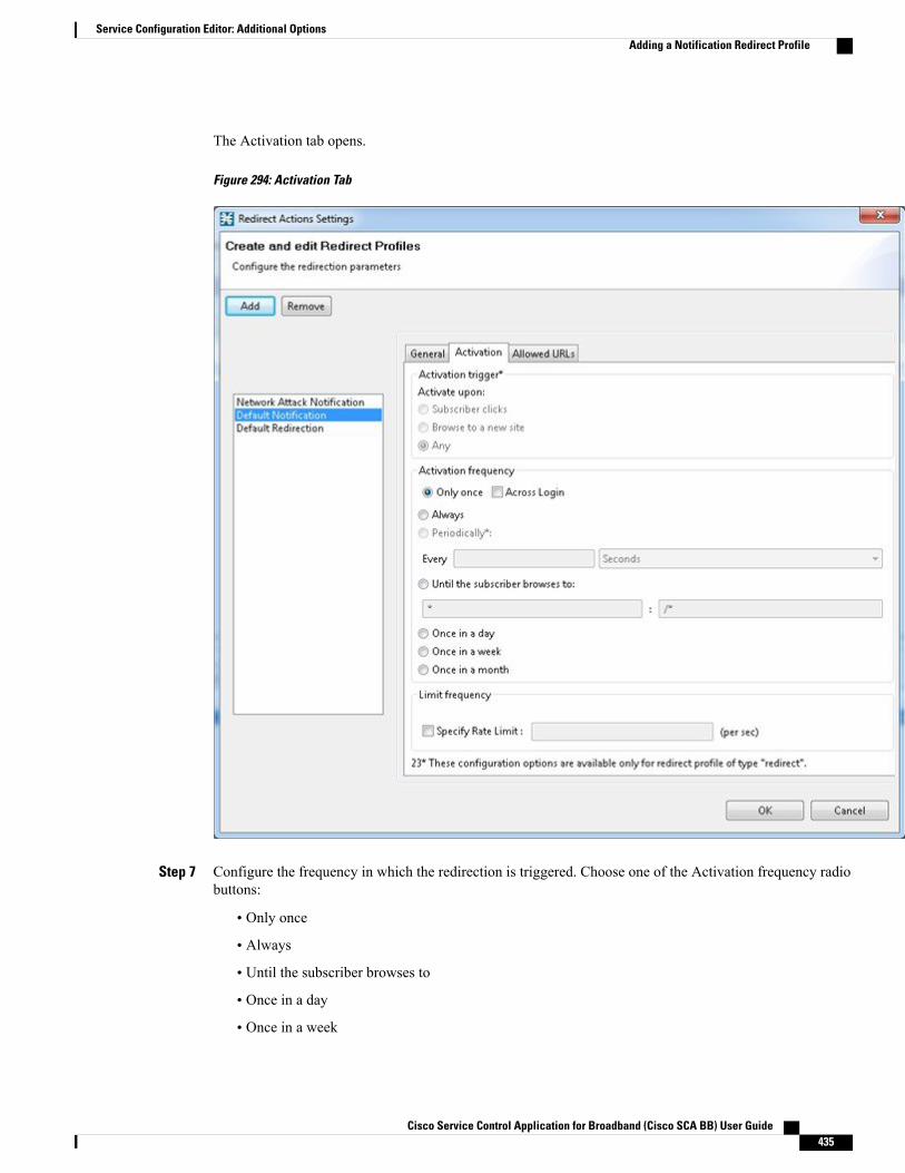
The Activation tab opens.
Figure 294: Activation Tab
Step 7 Configure the frequency in which the redirection is triggered. Choose one of the Activation frequency radiobuttons:
• Only once
• Always
• Until the subscriber browses to
• Once in a day
• Once in a week
Cisco Service Control Application for Broadband (Cisco SCA BB) User Guide 435
Service Configuration Editor: Additional OptionsAdding a Notification Redirect Profile
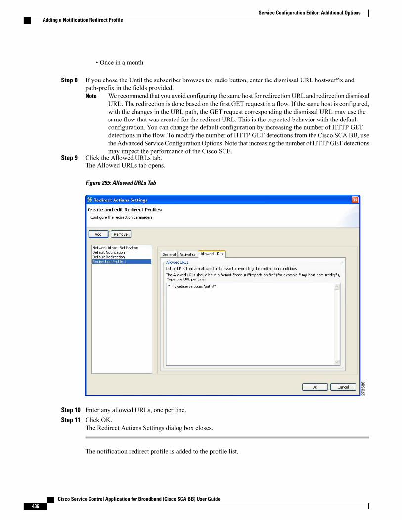
• Once in a month
Step 8 If you chose the Until the subscriber browses to: radio button, enter the dismissal URL host-suffix andpath-prefix in the fields provided.
We recommend that you avoid configuring the same host for redirection URL and redirection dismissalURL. The redirection is done based on the first GET request in a flow. If the same host is configured,with the changes in the URL path, the GET request corresponding the dismissal URL may use thesame flow that was created for the redirect URL. This is the expected behavior with the defaultconfiguration. You can change the default configuration by increasing the number of HTTP GETdetections in the flow. To modify the number of HTTP GET detections from the Cisco SCA BB, usetheAdvanced Service ConfigurationOptions. Note that increasing the number of HTTPGET detectionsmay impact the performance of the Cisco SCE.
Note
Step 9 Click the Allowed URLs tab.The Allowed URLs tab opens.
Figure 295: Allowed URLs Tab
Step 10 Enter any allowed URLs, one per line.Step 11 Click OK.
The Redirect Actions Settings dialog box closes.
The notification redirect profile is added to the profile list.
Cisco Service Control Application for Broadband (Cisco SCA BB) User Guide436
Service Configuration Editor: Additional OptionsAdding a Notification Redirect Profile
Managing Subscriber Redirection OverviewThe rules for a package may deny access to selected protocols. When a subscriber to the package tries toaccess a blocked protocol, the traffic flow can be redirected to a server where a posted web page explains thereason for the redirection. For example, a “Silver” subscriber trying to access a service available only to “Gold”subscribers. This web page can offer subscribers the opportunity to upgrade their packages. You configurewhich redirection profile to use when defining rules.
Redirection is not supported when unidirectional classification is enabled.Note
Each redirect profile consists of a set of redirect parameters. The Cisco SCA BB supports a maximum of 128redirect profiles, including notification redirect and redirect profiles.
Subscriber Redirect ParametersEach redirect profile of type redirect contains the following parameters:
• Name—Each profile must have a unique name.
You cannot change the name of the Default Redirection Profile.Note
• Redirect profile type—Each profile must be one of two types:
◦Notification
◦Redirect
• Set of Redirection URLs—A configurable set of destination URLs, to which the subscriber’s HTTPflows are redirected after redirection is activated. The redirection set can optionally include one, orseveral parameters appended to the destination URL including the redirect reason or subscriber ID.
• Activation trigger—The action that initiates the redirect. The activation trigger is one of the following:
◦Subscriber clicks—When the redirect is activated through a subscriber clicking a link.
◦Browse to a new site—When the redirect is activated through browsing.
◦Any—When the redirect is activated either via a link or browsing.
• Activation frequency—Indicates when to activate the redirect. The activation frequency is one of thefollowing:
◦Only once—The subscriber is redirected only the first time the conditions are met. Enable theGT_GLB_RedirectOnHomePage tunable to redirect from a home page.
◦Always—The subscriber is redirected every time the conditions are met.
◦Periodically—The redirection is based on a periodic counter and the counter is reset after theredirection is complete.
Cisco Service Control Application for Broadband (Cisco SCA BB) User Guide 437
Service Configuration Editor: Additional OptionsManaging Subscriber Redirection Overview
◦Triggering events
◦KBytes
◦Until the subscriber browses to—Every time the conditions are met, the subscriber is redirected,until the subscriber proceeds from the destination URL to a different, final URL.
The dismissal URL is composed of the URL hostname and the URL path, separated by a colon, in the followingformat:[*]<hostname>:<path>[*]
• < hostname >may optionally be preceded by a wildcard (*), to match all hostnames with the same suffix.
• The path element must always start with “/”.
• < path > may be followed by a wildcard (*), to match all paths with a common prefix.
For example, the entry *. some-isp.net:/redirect /* matches all the following URLs:
• www.some-isp.net/redirect/index.html• support.some-isp.net/redirect/info/warning.asp• noquota.some-isp.net/redirect/acknowledge.aspx?ie=UTF-8
• List of Allowed URLs—A list of URLs that are not blocked and redirected even though redirection isactivated.
After redirection is activated, all HTTP flows, except flows to the destination URL and to the dismissal URL,are blocked and redirected to the destination URL. However, subscribers can be permitted to access anadditional set of URLs. This is useful, for example, to give subscribers access to additional support information.
Allowed URLs have the same format as the dismissal URL. But, for Allowed URLs, you must specify theHTTP port and the port must be 80. If the URL contains any port other than 80, the URL is considered as anormal URL and is redirected.
These parameters are defined when you add a new notification redirect profile. You can modify them at anytime.
• Once in a day—The subscriber is redirected only the first time when the conditions are met andthis also happens the first time every day.
◦
◦Once in a week—The subscriber is redirected only the first time when the conditions are met andthis also happens the first time every week.
◦Once in a Month—The subscriber is redirected only the first time when the conditions are met andthis also happens the first time every month.
By default "Across login " support is enabled for the above three options . RedirectionHistory RDR will be generated every time , when the redirection condition is met . TheSubscriber manager processes those RDRs and shares the redirected profile informationon the next login The Redirection History RDR will be generated to reset the markedprofiles, once at the end of a Day, a Week and a Month . By this way we are achievingthe redirection only once in a Day , Week and Month .
Note
Cisco Service Control Application for Broadband (Cisco SCA BB) User Guide438
Service Configuration Editor: Additional OptionsSubscriber Redirect Parameters
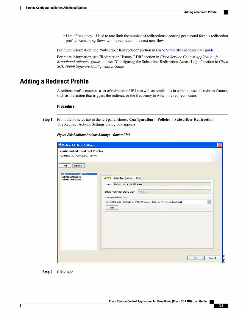
• Limit Frequency—Used to rate limit the number of redirections occuring per second for this redirectionprofile. Remaining flows will be redirect to the next new flow.
For more information, see "Subscriber Redirection" section in Cisco Subscriber Manger user guide.
For more information, see "Redirection History RDR" section in Cisco Service Control Application forBroadband reference guide and see "Configuring the Subscriber Redirection Across Login" section in CiscoSCE 10000 Software Configuration Guide
Adding a Redirect ProfileA redirect profile contains a set of redirection URLs as well as conditions in which to use the redirect feature,such as the action that triggers the redirect, or the frequency in which the redirect occurs.
Procedure
Step 1 From the Policies tab in the left pane, choose Configuration > Policies > Subscriber Redirection.The Redirect Actions Settings dialog box appears.
Figure 296: Redirect Actions Settings - General Tab
Step 2 Click Add.
Cisco Service Control Application for Broadband (Cisco SCA BB) User Guide 439
Service Configuration Editor: Additional OptionsAdding a Redirect Profile
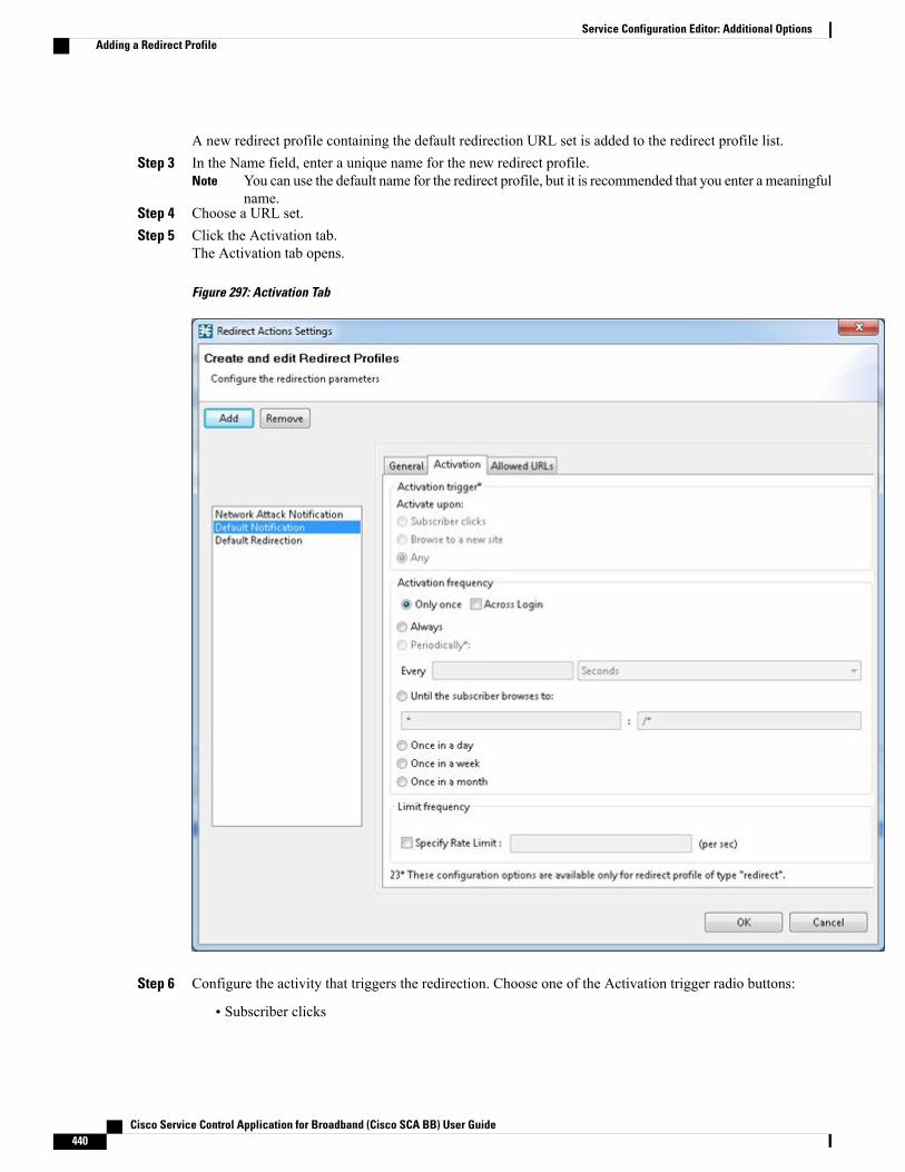
A new redirect profile containing the default redirection URL set is added to the redirect profile list.Step 3 In the Name field, enter a unique name for the new redirect profile.
You can use the default name for the redirect profile, but it is recommended that you enter a meaningfulname.
Note
Step 4 Choose a URL set.Step 5 Click the Activation tab.
The Activation tab opens.
Figure 297: Activation Tab
Step 6 Configure the activity that triggers the redirection. Choose one of the Activation trigger radio buttons:
• Subscriber clicks
Cisco Service Control Application for Broadband (Cisco SCA BB) User Guide440
Service Configuration Editor: Additional OptionsAdding a Redirect Profile
• Browse to a new site
• Any
Step 7 To configure the frequency in which the redirection is triggered, choose one of the following activationfrequency radio buttons:
• Only once
• Always
• Until the subscriber browses to
• Once in a day
• Once in a week
• Once in a month
Step 8 If you selected the Periodically radio button, enter a number and an increment in the Every fields, to specifythe frequency in which the redirection occurs.
Step 9 If you selected the Until the subscriber browses to: radio button, enter the dismissal URL in the fields provided.Step 10 Click the Allowed URLs tab.
Enter all configured redirection URLs to the Allowed URLs list to prevent a redirection loop.Note
Cisco Service Control Application for Broadband (Cisco SCA BB) User Guide 441
Service Configuration Editor: Additional OptionsAdding a Redirect Profile
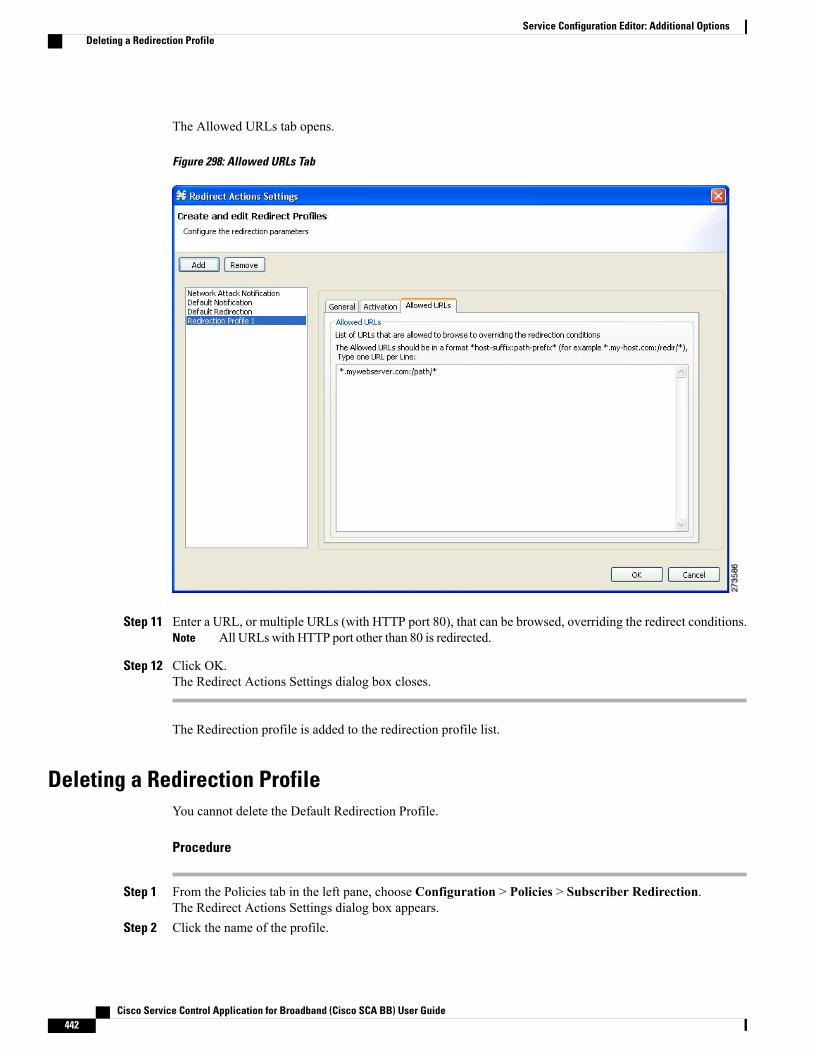
The Allowed URLs tab opens.
Figure 298: Allowed URLs Tab
Step 11 Enter a URL, or multiple URLs (with HTTP port 80), that can be browsed, overriding the redirect conditions.All URLswith HTTP port other than 80 is redirected.Note
Step 12 Click OK.The Redirect Actions Settings dialog box closes.
The Redirection profile is added to the redirection profile list.
Deleting a Redirection ProfileYou cannot delete the Default Redirection Profile.
Procedure
Step 1 From the Policies tab in the left pane, choose Configuration > Policies > Subscriber Redirection.The Redirect Actions Settings dialog box appears.
Step 2 Click the name of the profile.
Cisco Service Control Application for Broadband (Cisco SCA BB) User Guide442
Service Configuration Editor: Additional OptionsDeleting a Redirection Profile

Step 3 Click Remove.Step 4 Click OK.
The Redirect Actions Settings dialog box closes.
The Redirection settings are saved.
Adding a Set of Redirection URLsThe Console Redirection feature supports only three protocols:
• HTTP Browsing
• HTTP Streaming
• RTSP Streaming
Each redirection set contains one redirection option for each of these three protocols. The system provides adefault redirection set, which cannot be deleted. You can add up to 127 additional sets.
Each redirection URL includes the URL specified name, the Subscriber ID, and the Service ID in the followingformat:<URL>?n=<subscriber-ID>&s=<service-ID>
Optionally, the URL can contain one or multiple parameters appended to it.
Procedure
Step 1 From the Policies tab of the left pane, choose Configuration > Policies > Subscriber Redirection.The Redirect Actions Settings dialog box appears.
Step 2 In the General tab, click Edit.
Cisco Service Control Application for Broadband (Cisco SCA BB) User Guide 443
Service Configuration Editor: Additional OptionsAdding a Set of Redirection URLs
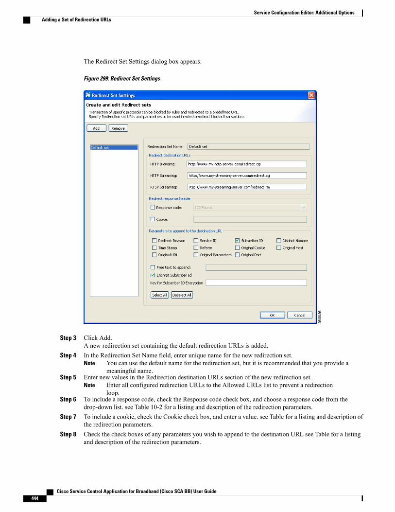
The Redirect Set Settings dialog box appears.
Figure 299: Redirect Set Settings
Step 3 Click Add.A new redirection set containing the default redirection URLs is added.
Step 4 In the Redirection Set Name field, enter unique name for the new redirection set.You can use the default name for the redirection set, but it is recommended that you provide ameaningful name.
Note
Step 5 Enter new values in the Redirection destination URLs section of the new redirection set.Enter all configured redirection URLs to the Allowed URLs list to prevent a redirectionloop.
Note
Step 6 To include a response code, check the Response code check box, and choose a response code from thedrop-down list. see Table 10-2 for a listing and description of the redirection parameters.
Step 7 To include a cookie, check the Cookie check box, and enter a value. see Table for a listing and description ofthe redirection parameters.
Step 8 Check the check boxes of any parameters you wish to append to the destination URL see Table for a listingand description of the redirection parameters.
Cisco Service Control Application for Broadband (Cisco SCA BB) User Guide444
Service Configuration Editor: Additional OptionsAdding a Set of Redirection URLs
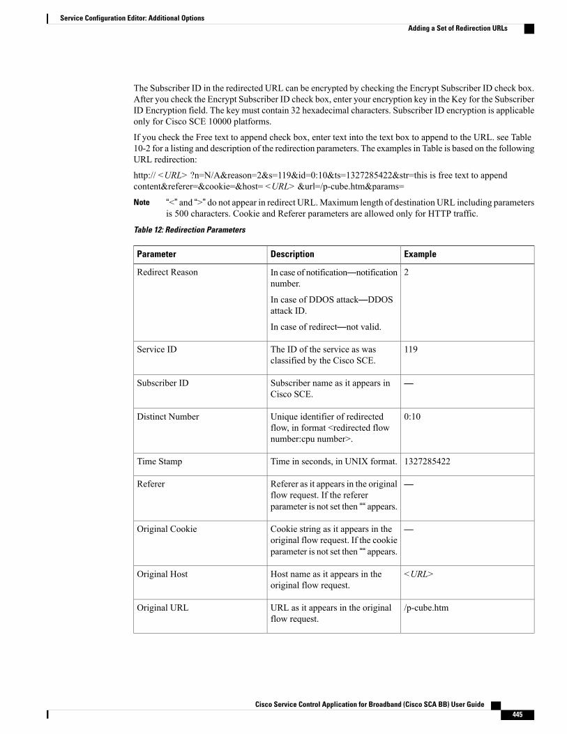
The Subscriber ID in the redirected URL can be encrypted by checking the Encrypt Subscriber ID check box.After you check the Encrypt Subscriber ID check box, enter your encryption key in the Key for the SubscriberID Encryption field. The key must contain 32 hexadecimal characters. Subscriber ID encryption is applicableonly for Cisco SCE 10000 platforms.
If you check the Free text to append check box, enter text into the text box to append to the URL. see Table10-2 for a listing and description of the redirection parameters. The examples in Table is based on the followingURL redirection:
http:// <URL> ?n=N/A&reason=2&s=119&id=0:10&ts=1327285422&str=this is free text to appendcontent&referer=&cookie=&host= <URL> &url=/p-cube.htm¶ms=
“<” and “>” do not appear in redirect URL.Maximum length of destination URL including parametersis 500 characters. Cookie and Referer parameters are allowed only for HTTP traffic.
Note
Table 12: Redirection Parameters
ExampleDescriptionParameter
2In case of notification—notificationnumber.
In case of DDOS attack—DDOSattack ID.
In case of redirect—not valid.
Redirect Reason
119The ID of the service as wasclassified by the Cisco SCE.
Service ID
—Subscriber name as it appears inCisco SCE.
Subscriber ID
0:10Unique identifier of redirectedflow, in format <redirected flownumber:cpu number>.
Distinct Number
1327285422Time in seconds, in UNIX format.Time Stamp
—Referer as it appears in the originalflow request. If the refererparameter is not set then ““ appears.
Referer
—Cookie string as it appears in theoriginal flow request. If the cookieparameter is not set then ““ appears.
Original Cookie
<URL>Host name as it appears in theoriginal flow request.
Original Host
/p-cube.htmURL as it appears in the originalflow request.
Original URL
Cisco Service Control Application for Broadband (Cisco SCA BB) User Guide 445
Service Configuration Editor: Additional OptionsAdding a Set of Redirection URLs
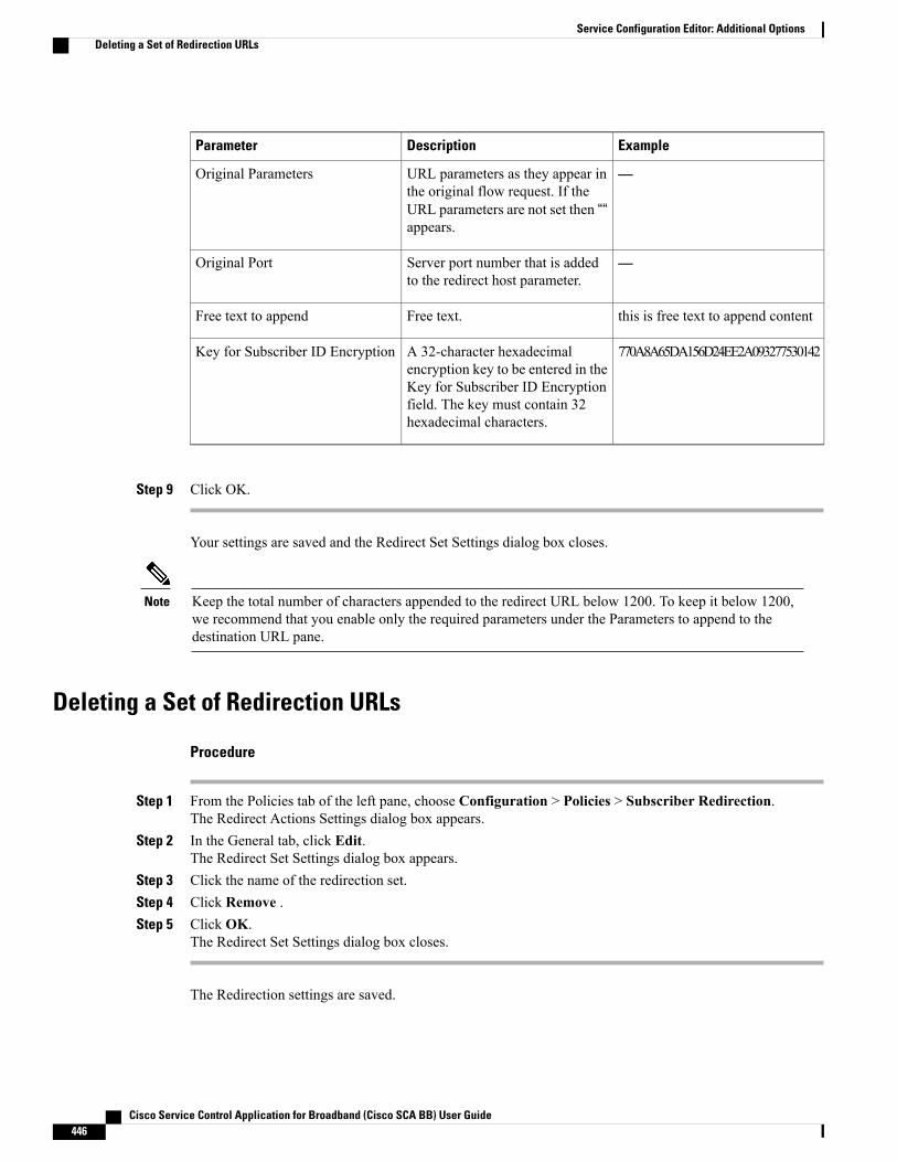
ExampleDescriptionParameter
—URL parameters as they appear inthe original flow request. If theURL parameters are not set then ““appears.
Original Parameters
—Server port number that is addedto the redirect host parameter.
Original Port
this is free text to append contentFree text.Free text to append
770A8A65DA156D24EE2A093277530142A 32-character hexadecimalencryption key to be entered in theKey for Subscriber ID Encryptionfield. The key must contain 32hexadecimal characters.
Key for Subscriber ID Encryption
Step 9 Click OK.
Your settings are saved and the Redirect Set Settings dialog box closes.
Keep the total number of characters appended to the redirect URL below 1200. To keep it below 1200,we recommend that you enable only the required parameters under the Parameters to append to thedestination URL pane.
Note
Deleting a Set of Redirection URLs
Procedure
Step 1 From the Policies tab of the left pane, choose Configuration > Policies > Subscriber Redirection.The Redirect Actions Settings dialog box appears.
Step 2 In the General tab, click Edit.The Redirect Set Settings dialog box appears.
Step 3 Click the name of the redirection set.Step 4 Click Remove .Step 5 Click OK.
The Redirect Set Settings dialog box closes.
The Redirection settings are saved.
Cisco Service Control Application for Broadband (Cisco SCA BB) User Guide446
Service Configuration Editor: Additional OptionsDeleting a Set of Redirection URLs
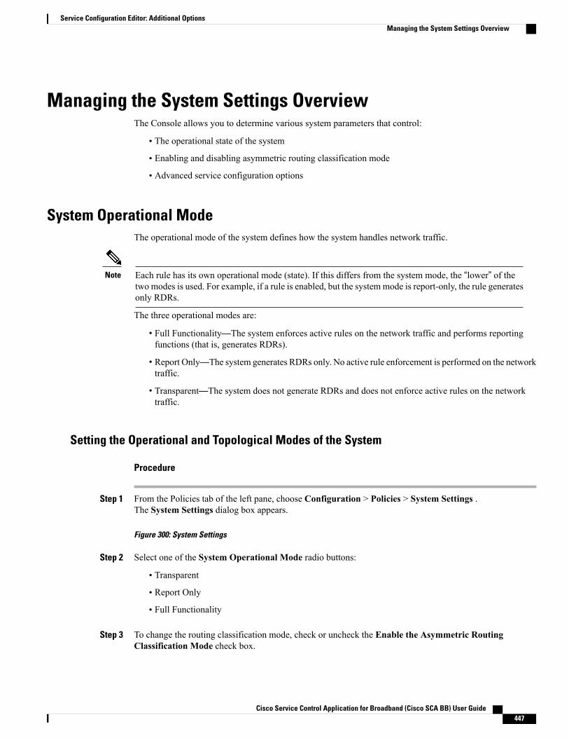
Managing the System Settings OverviewThe Console allows you to determine various system parameters that control:
• The operational state of the system
• Enabling and disabling asymmetric routing classification mode
• Advanced service configuration options
System Operational ModeThe operational mode of the system defines how the system handles network traffic.
Each rule has its own operational mode (state). If this differs from the system mode, the “lower” of thetwo modes is used. For example, if a rule is enabled, but the systemmode is report-only, the rule generatesonly RDRs.
Note
The three operational modes are:
• Full Functionality—The system enforces active rules on the network traffic and performs reportingfunctions (that is, generates RDRs).
• Report Only—The system generates RDRs only. No active rule enforcement is performed on the networktraffic.
• Transparent—The system does not generate RDRs and does not enforce active rules on the networktraffic.
Setting the Operational and Topological Modes of the System
Procedure
Step 1 From the Policies tab of the left pane, choose Configuration > Policies > System Settings .The System Settings dialog box appears.
Figure 300: System Settings
Step 2 Select one of the System Operational Mode radio buttons:
• Transparent
• Report Only
• Full Functionality
Step 3 To change the routing classification mode, check or uncheck the Enable the Asymmetric RoutingClassification Mode check box.
Cisco Service Control Application for Broadband (Cisco SCA BB) User Guide 447
Service Configuration Editor: Additional OptionsManaging the System Settings Overview
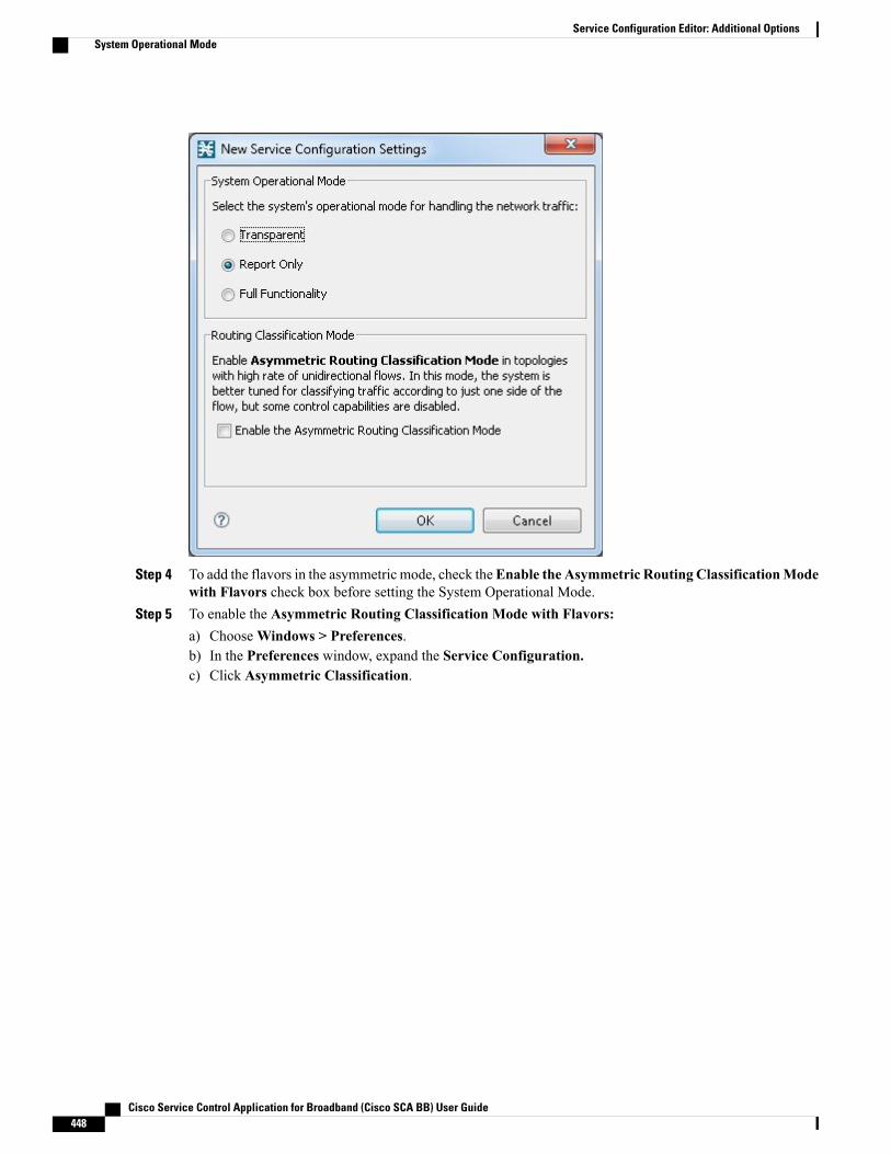
Step 4 To add the flavors in the asymmetric mode, check theEnable the Asymmetric Routing ClassificationModewith Flavors check box before setting the System Operational Mode.
Step 5 To enable the Asymmetric Routing Classification Mode with Flavors:a) ChooseWindows > Preferences.b) In the Preferences window, expand the Service Configuration.c) Click Asymmetric Classification.
Cisco Service Control Application for Broadband (Cisco SCA BB) User Guide448
Service Configuration Editor: Additional OptionsSystem Operational Mode

d) Click OK.
Figure 301: Asymmetric Classification - Preferences
Step 6 Click OK.The System Settings dialog box closes.
The new System Mode setting is saved.
Asymmetric Routing Classification Mode
Enabling unidirectional classification significantly improves classification accuracy when the Cisco SCEplatform is deployed in an environment with a high rate of unidirectional flows.
Unsupported Features
The following Cisco SCA BB features are not supported when unidirectional classification is enabled:
• Flavors
• External quota provisioning
• Subscriber notification
Cisco Service Control Application for Broadband (Cisco SCA BB) User Guide 449
Service Configuration Editor: Additional OptionsSystem Operational Mode

• Redirection
• Flow Signaling RDRs
• Content filtering
• VAS traffic forwarding
When unidirectional classification is enabled, the service configuration editor indicates (in the Problems View)if the service configuration is consistent with the features that are supported in this mode.
The following features, which are not part of the service configuration, are also affected when unidirectionalclassification is enabled:
• Subscriber-AwareMode (a mode in which subscriber information is dynamically bound to the IP addresscurrently in use by the subscriber) is not supported.
• Enhanced flow open mode must be enabled.
The system gives no indication if the state of the above features is consistent with the state of the routingclassification mode.
Protocol Classification
When unidirectional classification is enabled, protocol classification is performed in the normal way exceptfor unidirectional UDP flows. Because it is impossible to know the server side of a unidirectional UDP flow,Cisco SCA BB tries to classify the protocol using the destination port of the first packet; if no exact match isfound, Cisco SCA BB tries to classify the protocol using the source port.
Switching to Asymmetric Routing Classification Mode
If you create a service configuration in symmetric mode and switch to asymmetric routing classification mode:
• Flavors are not used for classification.
• Periodic quota management mode is used.
• Data is not lost when you switch to asymmetric routing classification mode, but you cannot apply theservice configuration to a Cisco SCE platform until all unsupported features are removed from the serviceconfiguration.
Switching from Asymmetric Routing Classification Mode
If you create a service configuration in asymmetric routing classification mode:
• The Suspected Session Rate is set equal to the Session Rate for all anomaly detectors.
• No flavors are created in the default service configuration, and no service elements have specified flavors.
• The quota management mode is periodic, with a daily aggregation period.
• Asymmetric routing classification mode limitations remain if you switch to symmetric mode. To changethem, you must edit the service configuration.
Asymmetric Routing Classification Mode with Flavors
Enabling unidirectional classification with flavors significantly associate the flavors to specific services andthose flavors are updated to respective lookup tables when applying the service configuration to a Cisco SCEplatform.
Cisco Service Control Application for Broadband (Cisco SCA BB) User Guide450
Service Configuration Editor: Additional OptionsSystem Operational Mode

Unsupported Features
The following Cisco SCA BB features are not supported when unidirectional classification with flavors isenabled:
• External quota provisioning
• Redirection
• Flow Signaling RDRs
• VAS traffic forwarding
Advanced Service Configuration OptionsAdvanced service configuration options control the more sophisticated and less frequently changed attributesof the system. It is recommended that you do not change these options.
The Advanced Service Configuration Properties
Table 13: Advanced Service Configuration Properties
DescriptionDefault ValueProperty
Add On Package
Enables addition of the Add On PackagesFALSEEnable Add On Package
Bandwidth Management
Specifies the level of BWC enforcementon networking flows of P2P and IMapplications.
SCE to use DefaultService BWCs.
Level of BWC enforcement on networkingflows of P2P and IM applications.
Specifies whether to use the GlobalBandwidth Management in Virtual LinksMode.
FALSEUse Global Bandwidth Management inVirtual Links Mode
Classification
Specifies the order of priority betweendifferent criteria for service classification.Values are:
• Flavor > Protocol > Zone > Init-Side
• Zone > Flavor > Protocol > Init-Side
Zone > Flavor >Protocol > Init-Side
Apply this order of priority betweendifferent criteria for service classification
Specifies that the character '/' is taken asdefault value when Params field is leftempty.
TRUECharacter '/' denotes absence of Paramspart in URL
Cisco Service Control Application for Broadband (Cisco SCA BB) User Guide 451
Service Configuration Editor: Additional OptionsSystem Operational Mode

DescriptionDefault ValueProperty
Specifies whether to recognizeClickStream Events.
TRUEClickStream Event recognition
Specifies whether to send ‘404, Page NotFound’ upon blocking.
FALSEEnable sending ‘404, Page Not Found’upon blocking
The Guruguru protocol is used by theGuruguru file-sharing application popularin Japan. Cisco SCA BB provides twoinspection modes for classification of thisprotocol:
• Default—Suitable for networkswhere little Guruguru traffic isexpected. This mode is usual in allcountries except Japan.
• Detailed—Suitable for networkswhere Guruguru traffic is expectedto be common. This mode is used inJapanese networks only.
FALSEGuruguru detailed inspection modeenabled
The Kuro protocol is used by the Kurofile-sharing application popular in Japan.Cisco SCA BB provides two inspectionmodes for classification of this protocol:
• Default—Suitable for networkswhere little Kuro traffic is expected.This is usual in all countries exceptJapan.
• Detailed—Suitable for networkswhere Kuro traffic is expected to becommon. This mode is used inJapanese networks only.
FALSEKuro detailed inspection mode enabled
Cisco Service Control Application for Broadband (Cisco SCA BB) User Guide452
Service Configuration Editor: Additional OptionsSystem Operational Mode
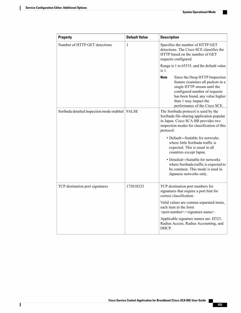
DescriptionDefault ValueProperty
Specifies the number of HTTP GETdetections. The Cisco SCE classifies theHTTP based on the number of GETrequests configured.
Range is 1 to 65535, and the default valueis 1.
Since the Deep HTTP Inspectionfeature examines all packets in asingle HTTP stream until theconfigured number of requestshas been found, any value higherthan 1 may impact theperformance of the Cisco SCE.
Note
1Number of HTTP GET detections
The Soribada protocol is used by theSoribada file-sharing application popularin Japan. Cisco SCA BB provides twoinspection modes for classification of thisprotocol:
• Default—Suitable for networkswhere little Soribada traffic isexpected. This is usual in allcountries except Japan.
• Detailed—Suitable for networkswhere Soribada traffic is expected tobe common. This mode is used inJapanese networks only.
FALSESoribada detailed inspectionmode enabled
TCP destination port numbers forsignatures that require a port hint forcorrect classification.
Valid values are comma-separated items,each item in the form<port-number>:<signature-name>.
Applicable signature names are: H323,Radius Access, Radius Accounting, andDHCP.
1720:H323TCP destination port signatures
Cisco Service Control Application for Broadband (Cisco SCA BB) User Guide 453
Service Configuration Editor: Additional OptionsSystem Operational Mode
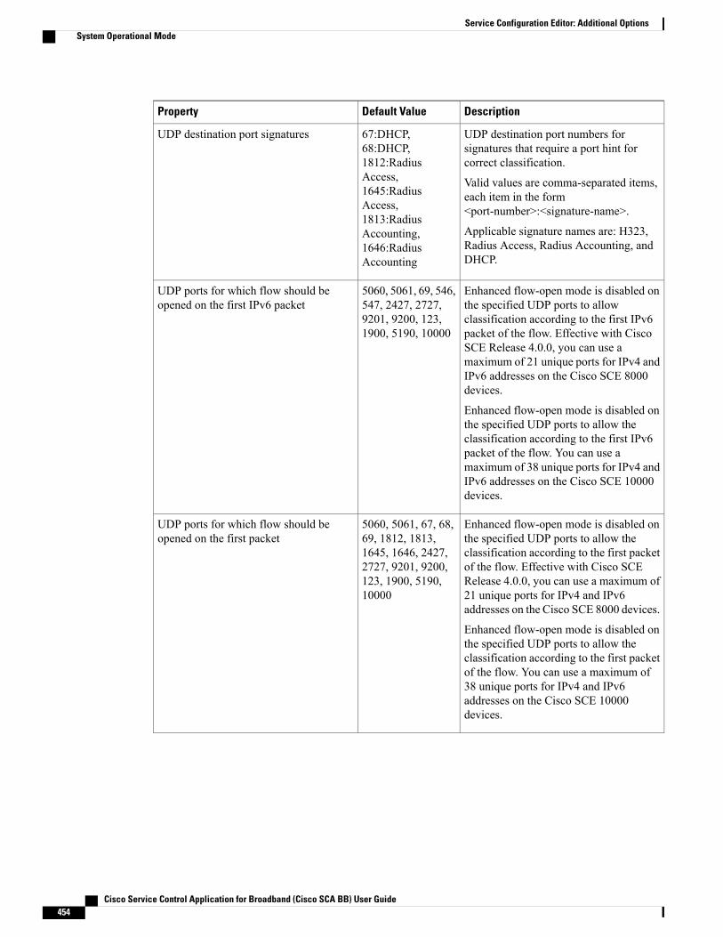
DescriptionDefault ValueProperty
UDP destination port numbers forsignatures that require a port hint forcorrect classification.
Valid values are comma-separated items,each item in the form<port-number>:<signature-name>.
Applicable signature names are: H323,Radius Access, Radius Accounting, andDHCP.
67:DHCP,68:DHCP,1812:RadiusAccess,1645:RadiusAccess,1813:RadiusAccounting,1646:RadiusAccounting
UDP destination port signatures
Enhanced flow-open mode is disabled onthe specified UDP ports to allowclassification according to the first IPv6packet of the flow. Effective with CiscoSCE Release 4.0.0, you can use amaximum of 21 unique ports for IPv4 andIPv6 addresses on the Cisco SCE 8000devices.
Enhanced flow-open mode is disabled onthe specified UDP ports to allow theclassification according to the first IPv6packet of the flow. You can use amaximum of 38 unique ports for IPv4 andIPv6 addresses on the Cisco SCE 10000devices.
5060, 5061, 69, 546,547, 2427, 2727,9201, 9200, 123,1900, 5190, 10000
UDP ports for which flow should beopened on the first IPv6 packet
Enhanced flow-open mode is disabled onthe specified UDP ports to allow theclassification according to the first packetof the flow. Effective with Cisco SCERelease 4.0.0, you can use a maximum of21 unique ports for IPv4 and IPv6addresses on the Cisco SCE 8000 devices.
Enhanced flow-open mode is disabled onthe specified UDP ports to allow theclassification according to the first packetof the flow. You can use a maximum of38 unique ports for IPv4 and IPv6addresses on the Cisco SCE 10000devices.
5060, 5061, 67, 68,69, 1812, 1813,1645, 1646, 2427,2727, 9201, 9200,123, 1900, 5190,10000
UDP ports for which flow should beopened on the first packet
Cisco Service Control Application for Broadband (Cisco SCA BB) User Guide454
Service Configuration Editor: Additional OptionsSystem Operational Mode

DescriptionDefault ValueProperty
UDP source port numbers for signaturesthat require a port hint for correctclassification.
Valid values are comma-separated items,each item in the form<port-number>:<signature-name>.
Applicable signature names are: H323,Radius Access, Radius Accounting, andDHCP.
1812:RadiusAccess,1645:RadiusAccess,1813:RadiusAccounting,1646:RadiusAccounting
UDP source port signatures
The V-Share protocol is used by theV-Share file-sharing application popularin Japan. Cisco SCA BB provides twoinspection modes for classification of thisprotocol:
• Default—Suitable for networkswhere little V-Share traffic isexpected. This mode is usual in allcountries except Japan.
• Detailed—Suitable for networkswhere V-Share traffic is expected tobe common. This mode is used inJapanese networks only.
FALSEV-Share detailed inspectionmode enabled
The Winny P2P protocol is used by theWinny file-sharing application popular inJapan. Cisco SCA BB provides twoinspection modes for classification of thisprotocol:
• Default—Suitable for networkswhere little Winny traffic isexpected. This is usual in allcountries except Japan.
• Detailed—Suitable for networkswhere Winny traffic is expected tobe common. This mode is used inJapanese networks only.
FALSEWinny detailed inspection mode enabled
—FALSEWinnyP aggressive classification enabled
—FALSEWinnyP classification enabled
Malicious Traffic
Cisco Service Control Application for Broadband (Cisco SCA BB) User Guide 455
Service Configuration Editor: Additional OptionsSystem Operational Mode
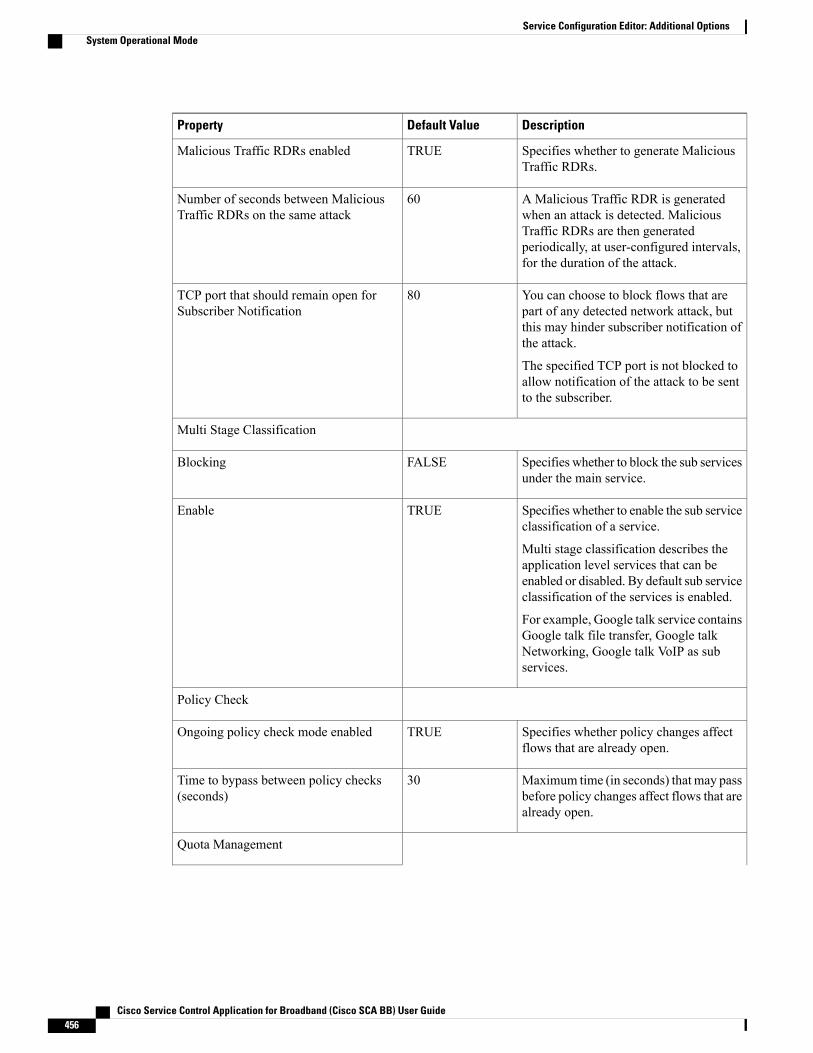
DescriptionDefault ValueProperty
Specifies whether to generate MaliciousTraffic RDRs.
TRUEMalicious Traffic RDRs enabled
A Malicious Traffic RDR is generatedwhen an attack is detected. MaliciousTraffic RDRs are then generatedperiodically, at user-configured intervals,for the duration of the attack.
60Number of seconds between MaliciousTraffic RDRs on the same attack
You can choose to block flows that arepart of any detected network attack, butthis may hinder subscriber notification ofthe attack.
The specified TCP port is not blocked toallow notification of the attack to be sentto the subscriber.
80TCP port that should remain open forSubscriber Notification
Multi Stage Classification
Specifies whether to block the sub servicesunder the main service.
FALSEBlocking
Specifies whether to enable the sub serviceclassification of a service.
Multi stage classification describes theapplication level services that can beenabled or disabled. By default sub serviceclassification of the services is enabled.
For example, Google talk service containsGoogle talk file transfer, Google talkNetworking, Google talk VoIP as subservices.
TRUEEnable
Policy Check
Specifies whether policy changes affectflows that are already open.
TRUEOngoing policy check mode enabled
Maximum time (in seconds) that may passbefore policy changes affect flows that arealready open.
30Time to bypass between policy checks(seconds)
Quota Management
Cisco Service Control Application for Broadband (Cisco SCA BB) User Guide456
Service Configuration Editor: Additional OptionsSystem Operational Mode

DescriptionDefault ValueProperty
The time (in seconds) to wait after a quotalimit is breached before the breach actionis performed.
Policy servers should use this period toprovision quota to a subscriber that justlogged in.
2Grace period before first breach (seconds)
The size of the window across which toscatter the periodic quota replenishmentrandomly.
0Length of the time frame for quotareplenish scatter (minutes)
Maximum time (in seconds) that may passbefore a quota breach affects flows thatare already open.
30Time to bypass between policy checks forquota limited flows
Maximum flow volume (in bytes) that maypass before a quota breach affects flowsthat are already open.
A value of zero means that unlimitedvolume may pass.
0Volume to bypass between policy checksfor quota limited flows
Redirection
Specifies whether to add the original hostto the redirection URL.
FALSEAdds original host to redirection URL
Specifies whether to add the original URLto the redirection URL.
FALSEAdds original URL to redirect URL
Specifies the maximum length of theredirect URL.
500Maximum redirect URL Length
Cisco Service Control Application for Broadband (Cisco SCA BB) User Guide 457
Service Configuration Editor: Additional OptionsSystem Operational Mode

DescriptionDefault ValueProperty
Specifies the redirect subscriber ID formatto be configured.
Valid Options are:
• Complete - n=<user>@<realm>(default)
• User only - n=<user>
• Realm only - r=<realm>
• Separately -n<user>&r=<realm>
If the subscriber name does not match theformat of <user>@<realm>, the fullsubscriber name is appended to the URL,regardless of the redirect subscriber formatconfigured.
Complete -n=<user>@<realm>
Redirect subscriber ID format
Reporting
Specifies whether to extract full user agentdetails.
FALSEExtract Full User Agent details
Specifies whether to generate FlowAccounting RDRs.
FALSEFlow Accounting RDRs enabled
Specifies the interval at which the FlowAccounting RDRs are generated for eachservice.
60Flow Accounting RDRs interval for eachService (in seconds)
Specifies the limit of Flow AccountingRDRs to be generated each second.
100Flow Accounting RDRs limit per second
Cisco Service Control Application for Broadband (Cisco SCA BB) User Guide458
Service Configuration Editor: Additional OptionsSystem Operational Mode
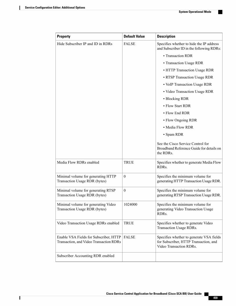
DescriptionDefault ValueProperty
Specifies whether to hide the IP addressand Subscriber ID in the following RDRs:
• Transaction RDR
• Transaction Usage RDR
• HTTP Transaction Usage RDR
• RTSP Transaction Usage RDR
• VoIP Transaction Usage RDR
• Video Transaction Usage RDR
• Blocking RDR
• Flow Start RDR
• Flow End RDR
• Flow Ongoing RDR
• Media Flow RDR
• Spam RDR
See the Cisco Service Control forBroadband Reference Guide for details onthe RDRs.
FALSEHide Subscriber IP and ID in RDRs
Specifies whether to generateMedia FlowRDRs.
TRUEMedia Flow RDRs enabled
Specifies the minimum volume forgeneratingHTTPTransactionUsageRDR.
0Minimal volume for generating HTTPTransaction Usage RDR (bytes)
Specifies the minimum volume forgenerating RTSP TransactionUsage RDR.
0Minimal volume for generating RTSPTransaction Usage RDR (bytes)
Specifies the minimum volume forgenerating Video Transaction UsageRDRs.
1024000Minimal volume for generating VideoTransaction Usage RDR (bytes)
Specifies whether to generate VideoTransaction Usage RDRs.
TRUEVideo Transaction Usage RDRs enabled
Specifies whether to generate VSA fieldsfor Subscriber, HTTP Transaction, andVideo Transaction RDRs.
FALSEEnable VSA Fields for Subscriber, HTTPTransaction, and Video Transaction RDRs
Subscriber Accounting RDR enabled
Cisco Service Control Application for Broadband (Cisco SCA BB) User Guide 459
Service Configuration Editor: Additional OptionsSystem Operational Mode
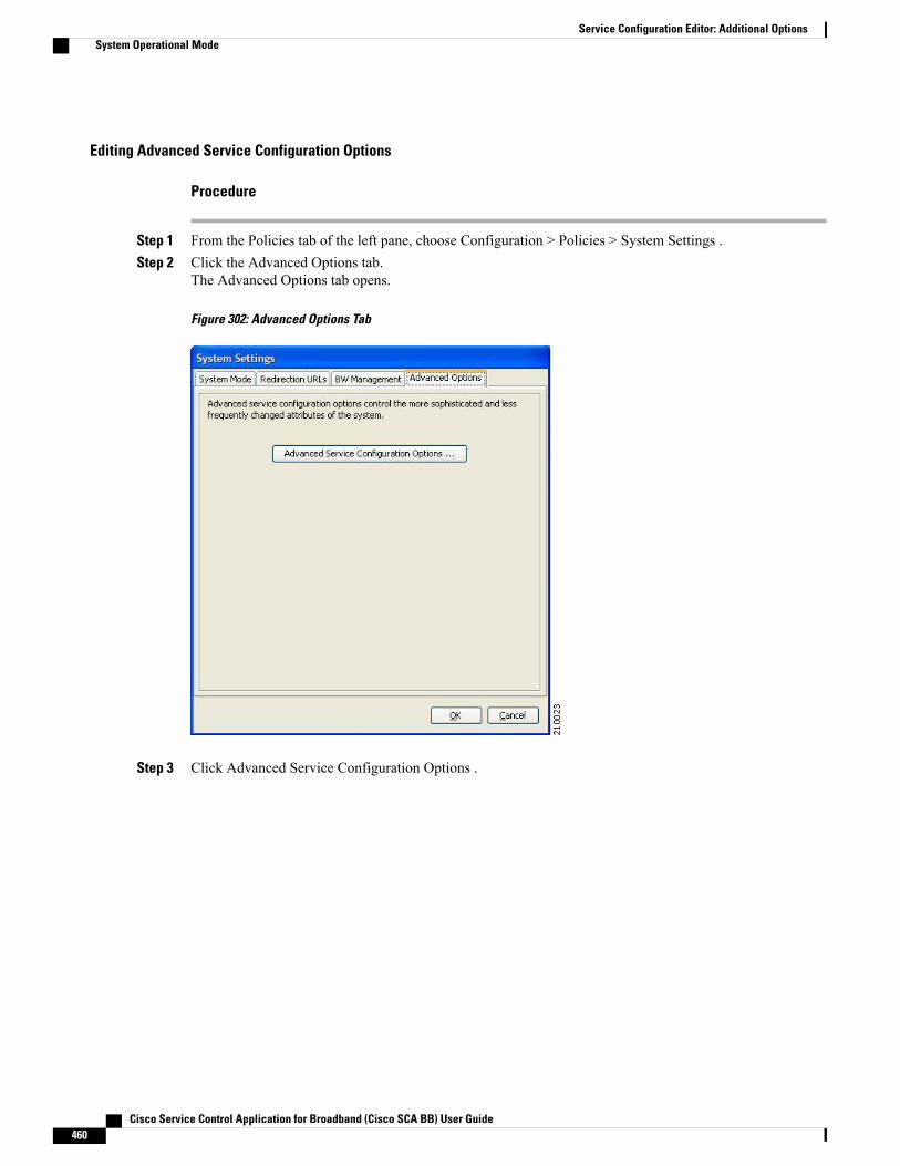
Editing Advanced Service Configuration Options
Procedure
Step 1 From the Policies tab of the left pane, choose Configuration > Policies > System Settings .Step 2 Click the Advanced Options tab.
The Advanced Options tab opens.
Figure 302: Advanced Options Tab
Step 3 Click Advanced Service Configuration Options .
Cisco Service Control Application for Broadband (Cisco SCA BB) User Guide460
Service Configuration Editor: Additional OptionsSystem Operational Mode
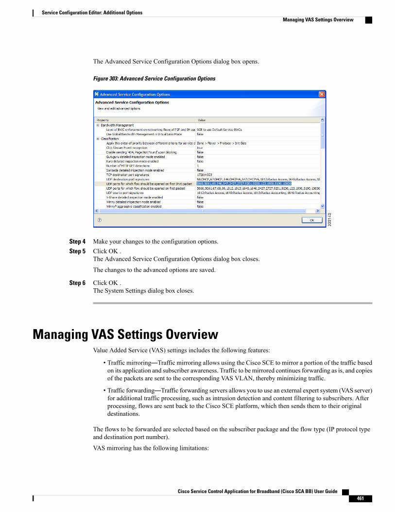
The Advanced Service Configuration Options dialog box opens.
Figure 303: Advanced Service Configuration Options
Step 4 Make your changes to the configuration options.Step 5 Click OK .
The Advanced Service Configuration Options dialog box closes.
The changes to the advanced options are saved.
Step 6 Click OK .The System Settings dialog box closes.
Managing VAS Settings OverviewValue Added Service (VAS) settings includes the following features:
• Traffic mirroring—Traffic mirroring allows using the Cisco SCE to mirror a portion of the traffic basedon its application and subscriber awareness. Traffic to be mirrored continues forwarding as is, and copiesof the packets are sent to the corresponding VAS VLAN, thereby minimizing traffic.
• Traffic forwarding—Traffic forwarding servers allows you to use an external expert system (VAS server)for additional traffic processing, such as intrusion detection and content filtering to subscribers. Afterprocessing, flows are sent back to the Cisco SCE platform, which then sends them to their originaldestinations.
The flows to be forwarded are selected based on the subscriber package and the flow type (IP protocol typeand destination port number).
VAS mirroring has the following limitations:
Cisco Service Control Application for Broadband (Cisco SCA BB) User Guide 461
Service Configuration Editor: Additional OptionsManaging VAS Settings Overview
• The Cisco SCE 8000Cisco SCE 10000 support traffic mirroring.
• Traffic mirroring is supported on any Cisco SCE platform that has at least 2 ports.
• A Cisco SCE 8000 can contain 64 distinct VLANs.
• A Cisco SCE 10000 can contain 64 distinct VLANs.
VAS forwarding has the following limitations:
• Only the Cisco SCE 8000 Cisco SCE 10000 platforms support VAS traffic forwarding.
• A single Cisco SCE platform can support up to eight VAS servers.
• A service configuration can contain up to 64 traffic-forwarding tables.
• A traffic-forwarding table can contain up to 64 table parameters.
• VAS traffic forwarding is not supported when unidirectional classification is enabled.
Because of the complexity of the VAS settings features, VAS flows are not subject to global bandwidthcontrol.
Note
To use VAS traffic forwarding:
• You must configure VAS services on the Cisco SCE platform.
• You must also assign the VAS traffic-forwarding tables to packages in the Advanced tab of the EditPackages dialog. VAS traffic-forwarding is based on per-package configuration of where to forwardwhat traffic.
Enabling VAS Traffic ForwardingBy default, VAS traffic forwarding is disabled. You can enable it at any time.
VAS traffic forwarding is not supported when unidirectional classification is enabled.Note
Procedure
Step 1 From the Policies tab of the left pane, choose Configuration > Policies > VAS Settings.
Cisco Service Control Application for Broadband (Cisco SCA BB) User Guide462
Service Configuration Editor: Additional OptionsEnabling VAS Traffic Forwarding
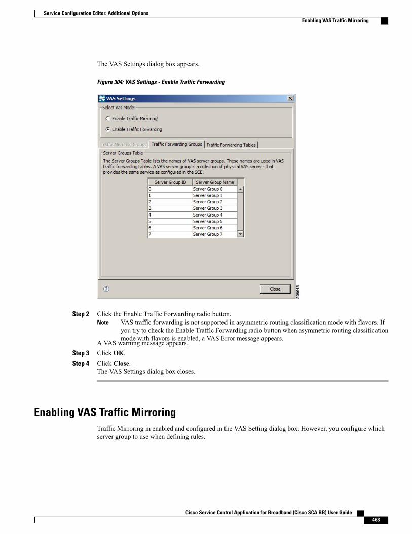
The VAS Settings dialog box appears.
Figure 304: VAS Settings - Enable Traffic Forwarding
Step 2 Click the Enable Traffic Forwarding radio button.VAS traffic forwarding is not supported in asymmetric routing classification mode with flavors. Ifyou try to check the Enable Traffic Forwarding radio button when asymmetric routing classificationmode with flavors is enabled, a VAS Error message appears.
Note
A VAS warning message appears.Step 3 Click OK.Step 4 Click Close.
The VAS Settings dialog box closes.
Enabling VAS Traffic MirroringTraffic Mirroring in enabled and configured in the VAS Setting dialog box. However, you configure whichserver group to use when defining rules.
Cisco Service Control Application for Broadband (Cisco SCA BB) User Guide 463
Service Configuration Editor: Additional OptionsEnabling VAS Traffic Mirroring
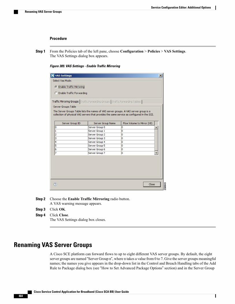
Procedure
Step 1 From the Policies tab of the left pane, choose Configuration > Policies > VAS Settings.The VAS Settings dialog box appears.
Figure 305: VAS Settings - Enable Traffic Mirroring
Step 2 Choose the Enable Traffic Mirroring radio button.A VAS warning message appears.
Step 3 Click OK.Step 4 Click Close.
The VAS Settings dialog box closes.
Renaming VAS Server GroupsA Cisco SCE platform can forward flows to up to eight different VAS server groups. By default, the eightserver groups are named “Server Group n”, where n takes a value from 0 to 7. Give the server groups meaningfulnames; the names you give appears in the drop-down list in the Control and Breach Handling tabs of the AddRule to Package dialog box (see “How to Set Advanced Package Options” section) and in the Server Group
Cisco Service Control Application for Broadband (Cisco SCA BB) User Guide464
Service Configuration Editor: Additional OptionsRenaming VAS Server Groups
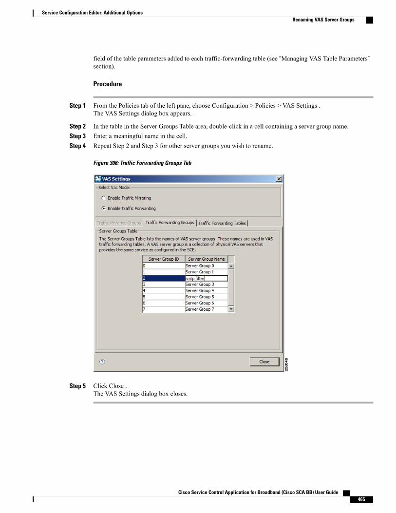
field of the table parameters added to each traffic-forwarding table (see “Managing VAS Table Parameters”section).
Procedure
Step 1 From the Policies tab of the left pane, choose Configuration > Policies > VAS Settings .The VAS Settings dialog box appears.
Step 2 In the table in the Server Groups Table area, double-click in a cell containing a server group name.Step 3 Enter a meaningful name in the cell.Step 4 Repeat Step 2 and Step 3 for other server groups you wish to rename.
Figure 306: Traffic Forwarding Groups Tab
Step 5 Click Close .The VAS Settings dialog box closes.
Cisco Service Control Application for Broadband (Cisco SCA BB) User Guide 465
Service Configuration Editor: Additional OptionsRenaming VAS Server Groups
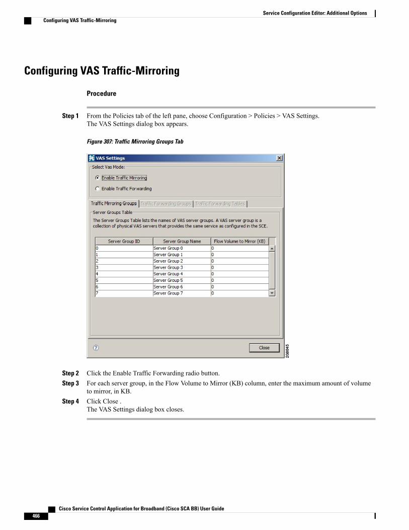
Configuring VAS Traffic-Mirroring
Procedure
Step 1 From the Policies tab of the left pane, choose Configuration > Policies > VAS Settings.The VAS Settings dialog box appears.
Figure 307: Traffic Mirroring Groups Tab
Step 2 Click the Enable Traffic Forwarding radio button.Step 3 For each server group, in the Flow Volume to Mirror (KB) column, enter the maximum amount of volume
to mirror, in KB.Step 4 Click Close .
The VAS Settings dialog box closes.
Cisco Service Control Application for Broadband (Cisco SCA BB) User Guide466
Service Configuration Editor: Additional OptionsConfiguring VAS Traffic-Mirroring

Viewing VAS Traffic-Forwarding TablesCisco SCA BB decides whether a flow passing through a Cisco SCE platform should be forwarded to a VASserver group based on a traffic-forwarding table. Each entry (table parameter) in a traffic-forwarding tabledefines to which VAS server group the specified flows should be forwarded.
Procedure
Step 1 From the Policies tab of the left pane, choose Configuration > Policies > VAS Settings.The VAS Settings dialog box appears.
Step 2 Click the Enable Traffic Forwarding radio button.Step 3 Click the Traffic Forwarding Tables tab.
The Traffic Forwarding Tables tab opens.
A list of all traffic-forwarding tables is displayed in the Traffic Forwarding Tables area.
Step 4 Click a table in the list of traffic-forwarding tables to display its table parameters.A list of all table parameters defined for this traffic-forwarding table opens in the Table Parameters tab.
Figure 308: Traffic Forwarding Tables Tab
Step 5 Click Close .
Cisco Service Control Application for Broadband (Cisco SCA BB) User Guide 467
Service Configuration Editor: Additional OptionsViewing VAS Traffic-Forwarding Tables
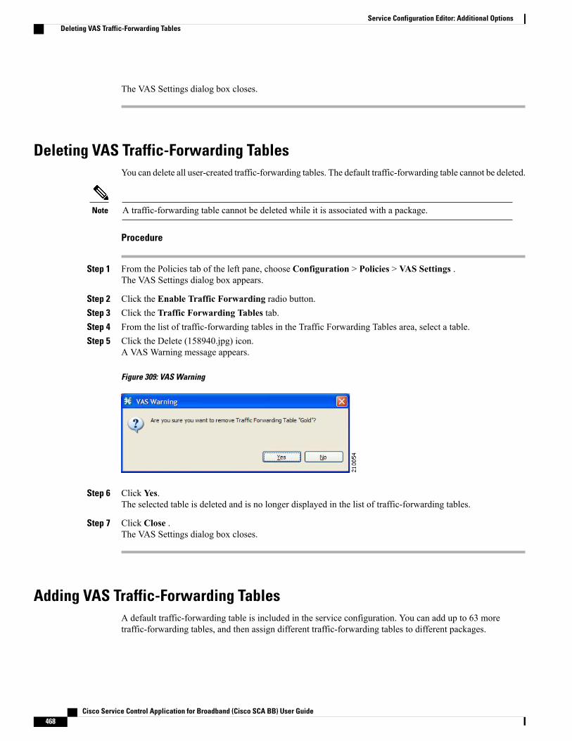
The VAS Settings dialog box closes.
Deleting VAS Traffic-Forwarding TablesYou can delete all user-created traffic-forwarding tables. The default traffic-forwarding table cannot be deleted.
A traffic-forwarding table cannot be deleted while it is associated with a package.Note
Procedure
Step 1 From the Policies tab of the left pane, choose Configuration > Policies > VAS Settings .The VAS Settings dialog box appears.
Step 2 Click the Enable Traffic Forwarding radio button.Step 3 Click the Traffic Forwarding Tables tab.Step 4 From the list of traffic-forwarding tables in the Traffic Forwarding Tables area, select a table.Step 5 Click the Delete (158940.jpg) icon.
A VAS Warning message appears.
Figure 309: VAS Warning
Step 6 Click Yes.The selected table is deleted and is no longer displayed in the list of traffic-forwarding tables.
Step 7 Click Close .The VAS Settings dialog box closes.
Adding VAS Traffic-Forwarding TablesA default traffic-forwarding table is included in the service configuration. You can add up to 63 moretraffic-forwarding tables, and then assign different traffic-forwarding tables to different packages.
Cisco Service Control Application for Broadband (Cisco SCA BB) User Guide468
Service Configuration Editor: Additional OptionsDeleting VAS Traffic-Forwarding Tables

Procedure
Step 1 From the Policies tab in the left pane, choose Configuration > Policies > VAS Settings.The VAS Settings dialog box appears.
Step 2 Click the Enable Traffic Forwarding radio button.Step 3 Click the Traffic Forwarding Tables tab.
The Traffic Forwarding Tables tab opens.
Figure 310: VAS Settings - Add VAS Traffic-Forwarding Tables
Step 4 In the Traffic Forwarding Tables area, click the Add (158725.jpg) icon.A new table named Table (n), where n is a value from 1 through 63, is added to the list of traffic-forwardingtables in the Traffic Forwarding Tables area.The table name is also displayed in the Item Name box in the Table Parameters tab.
Step 5 In the Item Name field, enter a unique and relevant name for the traffic-forwarding table.
You can now add table parameters to the new traffic-forwarding table, see “How to Add VAS Table Parameters”section.
Cisco Service Control Application for Broadband (Cisco SCA BB) User Guide 469
Service Configuration Editor: Additional OptionsAdding VAS Traffic-Forwarding Tables

Managing VAS Table Parameters OverviewA table parameter is an IP protocol type, an associated TCP/UDP port (where applicable), and a VAS servergroup or a range of IP addresses.
A traffic-forwarding table is a collection of related table parameters.
A traffic-forwarding table can contain up to 64 table parameters.
Adding VAS Table ParametersYou can add up to 64 table parameters to a traffic-forwarding table.
Procedure
Step 1 From the Policies tab in the left pane, choose Configuration > Policies > VAS Settings .The VAS Settings dialog box appears.
Step 2 Click the Enable Traffic Forwarding radio button.Step 3 Click the Traffic Forwarding Tables tab.
The Traffic Forwarding Tables tab opens.Step 4 From the list of traffic-forwarding tables in the Traffic Forwarding Tables area, select a table.Step 5 In the Traffic Parameters tab, click the Add (158725.jpg) icon.
A new table parameter is added to the list of table parameters in the Table Parameters tab.
Table 14: Table Parameter Default Values
Default valueParameter
IP Protocol
TCP Port
TCP/UDP Port Range
Default valueParameter
IP Protocol
TCP Port
TCP/UDP Port Range
You can now edit the new table parameter, as described in the following section.
Step 6 Click Close .The VAS Settings dialog box closes.
Cisco Service Control Application for Broadband (Cisco SCA BB) User Guide470
Service Configuration Editor: Additional OptionsManaging VAS Table Parameters Overview
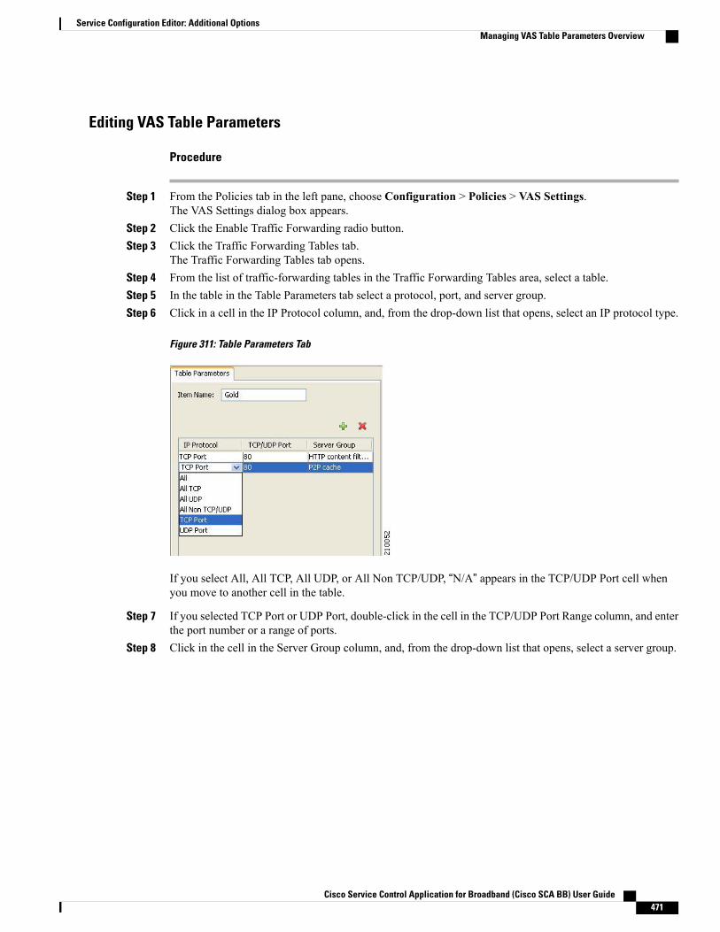
Editing VAS Table Parameters
Procedure
Step 1 From the Policies tab in the left pane, choose Configuration > Policies > VAS Settings.The VAS Settings dialog box appears.
Step 2 Click the Enable Traffic Forwarding radio button.Step 3 Click the Traffic Forwarding Tables tab.
The Traffic Forwarding Tables tab opens.Step 4 From the list of traffic-forwarding tables in the Traffic Forwarding Tables area, select a table.Step 5 In the table in the Table Parameters tab select a protocol, port, and server group.Step 6 Click in a cell in the IP Protocol column, and, from the drop-down list that opens, select an IP protocol type.
Figure 311: Table Parameters Tab
If you select All, All TCP, All UDP, or All Non TCP/UDP, “N/A” appears in the TCP/UDP Port cell whenyou move to another cell in the table.
Step 7 If you selected TCP Port or UDP Port, double-click in the cell in the TCP/UDP Port Range column, and enterthe port number or a range of ports.
Step 8 Click in the cell in the Server Group column, and, from the drop-down list that opens, select a server group.
Cisco Service Control Application for Broadband (Cisco SCA BB) User Guide 471
Service Configuration Editor: Additional OptionsManaging VAS Table Parameters Overview
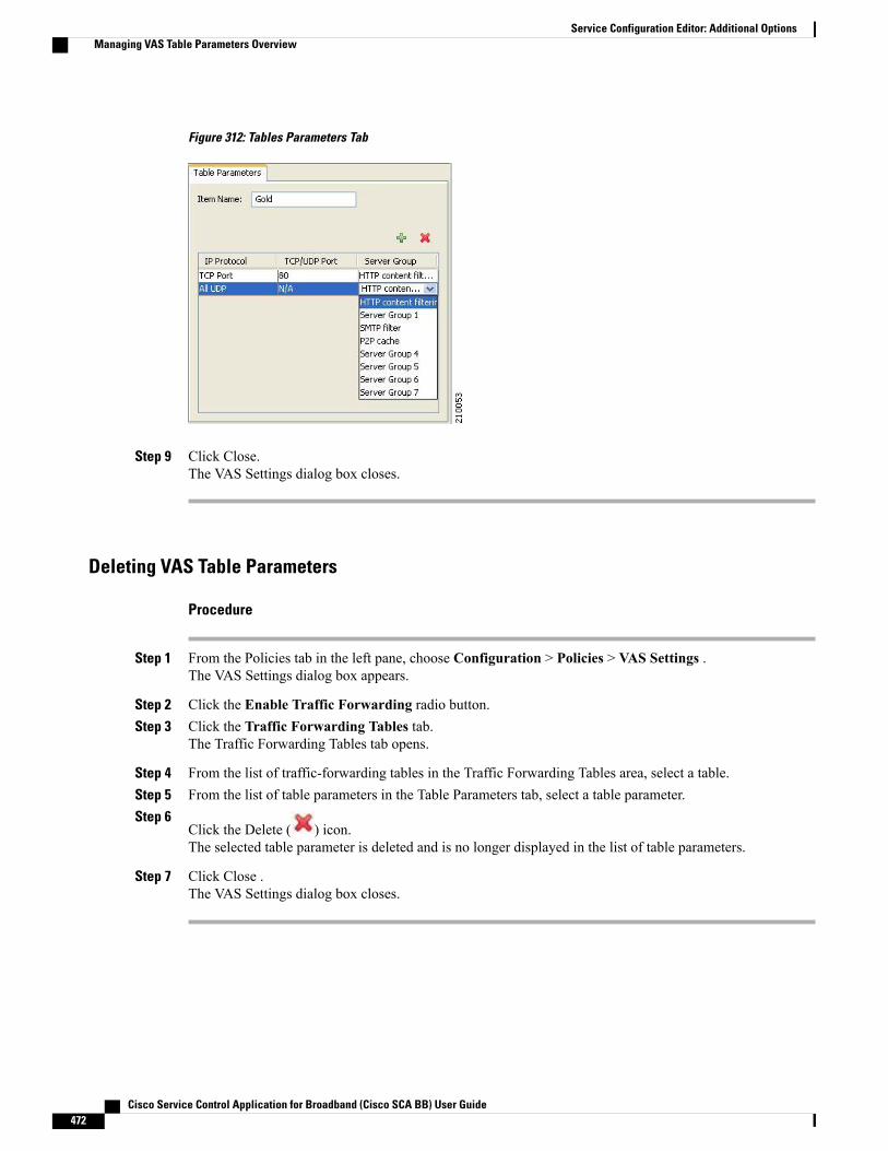
Figure 312: Tables Parameters Tab
Step 9 Click Close.The VAS Settings dialog box closes.
Deleting VAS Table Parameters
Procedure
Step 1 From the Policies tab in the left pane, choose Configuration > Policies > VAS Settings .The VAS Settings dialog box appears.
Step 2 Click the Enable Traffic Forwarding radio button.Step 3 Click the Traffic Forwarding Tables tab.
The Traffic Forwarding Tables tab opens.
Step 4 From the list of traffic-forwarding tables in the Traffic Forwarding Tables area, select a table.Step 5 From the list of table parameters in the Table Parameters tab, select a table parameter.Step 6
Click the Delete ( ) icon.The selected table parameter is deleted and is no longer displayed in the list of table parameters.
Step 7 Click Close .The VAS Settings dialog box closes.
Cisco Service Control Application for Broadband (Cisco SCA BB) User Guide472
Service Configuration Editor: Additional OptionsManaging VAS Table Parameters Overview
Managing the Protected URL DatabaseThe Cisco SCE Protected URL Database is a database that contains a blacklist, a list of websites that areconsidered off limits or dangerous. You can configure the Cisco SCE to apply a specific action, such asblocking a site, when a subscriber attempts to access a site listed on the blacklist.
The database is encrypted so that no one, including the operator, can view the blacklist. The blacklist ismanaged on the Cisco SCE and cannot be withdrawn to the management PC.
RDRs are created when a subscriber attempts to access a link included in the blacklist. However, the RDRsdo not contains the URL or Host information of the site.
To enable the blacklist feature:
Procedure
Step 1 Define an HTTP flavor.Step 2 Create a blacklist service.Step 3 Assign the HTTP flavor to the blacklist service.Step 4 Create a rule for the blacklist service.Step 5 Assign black list entries to the flavor, using the CLI.
What to Do Next
For more information about the Protected URL Database, see the Cisco Service Control URL BlacklistingSolution Guide .
Cisco Service Control Application for Broadband (Cisco SCA BB) User Guide 473
Service Configuration Editor: Additional OptionsManaging the Protected URL Database

Cisco Service Control Application for Broadband (Cisco SCA BB) User Guide474
Service Configuration Editor: Additional OptionsManaging the Protected URL Database

C H A P T E R 11Subscriber Manager GUI Tool
This chapter describes how to use the Subscriber Manager (SM) graphical user interface (GUI) tool toconfigure subscribers in the Cisco Service Control SM database.
The SM GUI tool is especially useful when the Cisco Service Control SM holds a static list of subscribers.It is not applicable when Cisco SCA BB is operating in subscriberless mode (a mode in which control andanalysis functions are available only at a global platform resolution) or in anonymous subscriber mode (amode in which entities defined as IP addresses or VLANs are treated as subscribers). This chapter consistsof these sections:
• Subscriber Manager GUI Tool Overview, page 475
• Connecting to a Cisco Service Control Subscriber Manager Overview, page 476
• Subscriber CSV Files Overview, page 479
• Subscriber Management Overview, page 480
• Monitoring SM Online Status, page 491
Subscriber Manager GUI Tool OverviewThis chapter describes how to use the SubscriberManager (SM) graphical user interface (GUI) tool to configuresubscribers in the Cisco Service Control SM database.
The SM GUI tool is especially useful when the Cisco Service Control SM holds a static list of subscribers. Itis not applicable when Cisco SCA BB is operating in subscriberless mode (a mode in which control andanalysis functions are available only at a global platform resolution) or in anonymous subscriber mode (amode in which entities defined as IP addresses or VLANs are treated as subscribers).
The SMGUI tool allows you to manage subscribers on a Cisco Service Control SM. The Cisco Service ControlSM functions as middleware software that bridges between the OSS and the Cisco Service Control Engine(Cisco SCE) platforms. Cisco SCE platforms use the subscriber information to provide subscriber-awarefunctionality, per-subscriber reporting, and policy enforcement. Subscriber information is stored in the CiscoService Control SM database and can be distributed between multiple platforms according to actual subscriberplacement.
You can use the SM GUI tool to import and export subscriber files, and to perform operations on individualsubscribers, such as:
Cisco Service Control Application for Broadband (Cisco SCA BB) User Guide 475
• Add and delete a subscriber
• Edit parameters and show data of an existing subscriber
• Add and remove subscriber mappings
• Import subscribers from a CSV file
• Export subscribers to a CSV file
• Find subscriber or subscribers in a certain domain (filter)
To access a Cisco Service Control SM from the SMGUI tool, you must first add the Cisco Service ControlSM to the SiteManager tree in the Network Navigator tool (see “How to Add SubscriberManager Devicesto a Site” section).
Note
The SM GUI tool provides only a subset of the functionality that the SM Command-Line Utility provides.For more information about the Cisco Service Control SM, see the Cisco Service Control Management SuiteSubscriber Manager User Guide.
Connecting to a Cisco Service Control Subscriber ManagerOverview
You can connect to a Cisco Service Control Subscriber Manager:
• From the Network Navigator tool
• From anywhere else in the Console
• From the Subscriber Manager GUI tool
The SM GUI tool performs authentication on the Cisco Service Control Subscriber Manager by openinga PRPC connection to port 14374 and attempting to log in using the username and password that youentered in the Password Management dialog box. If a PRPC server with this user is not running on theCisco Service Control Subscriber Manager, authentication fails. If you have changed the PRPC port onthe Cisco Service Control Subscriber Manager, see “User Authentication” section.
Note
Connecting to a Cisco Service Control Subscriber Manager from the NetworkNavigator
Procedure
Step 1 In the Site Manager tree in the Network Navigator tab, right-click an SM device.
Cisco Service Control Application for Broadband (Cisco SCA BB) User Guide476
Subscriber Manager GUI ToolConnecting to a Cisco Service Control Subscriber Manager Overview

A popup menu appears.
Figure 313: SM Device Popup Menu
Step 2 From the menu, selectManage Subscribers.A Password Management dialog box appears.
Step 3 Enter the appropriate password.For more information, see the “Password Management” section.
Step 4 Click Connecting.The Password Management dialog box closes. A Connecting to progress bar appears.
The system connects to the Cisco Service Control Subscriber Manager.
Connecting to a Cisco Service Control Subscriber Manager from the Console
If you are already in the Subscriber Manager GUI tool, start at Step 3.Note
Procedure
Step 1 From the Console main menu, chooseTools > Subscriber Manager.The Subscriber Manager GUI tool opens. A Subscriber Manager is not connected message appears.
Figure 314: Subscriber Manager is not Connected
Step 2 Click OK.
Cisco Service Control Application for Broadband (Cisco SCA BB) User Guide 477
Subscriber Manager GUI ToolConnecting to a Cisco Service Control Subscriber Manager from the Console
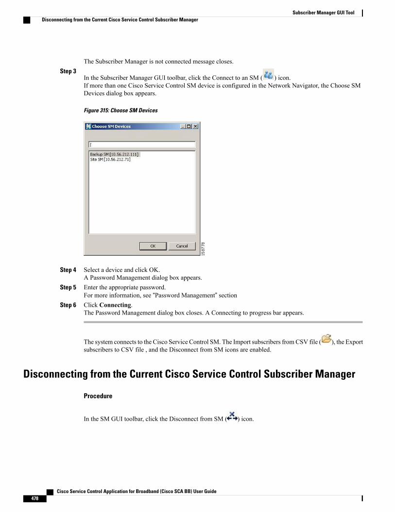
The Subscriber Manager is not connected message closes.Step 3
In the Subscriber Manager GUI toolbar, click the Connect to an SM ( ) icon.If more than one Cisco Service Control SM device is configured in the Network Navigator, the Choose SMDevices dialog box appears.
Figure 315: Choose SM Devices
Step 4 Select a device and click OK.A Password Management dialog box appears.
Step 5 Enter the appropriate password.For more information, see “Password Management” section
Step 6 Click Connecting.The Password Management dialog box closes. A Connecting to progress bar appears.
The system connects to the Cisco Service Control SM. The Import subscribers fromCSV file ( ), the Exportsubscribers to CSV file , and the Disconnect from SM icons are enabled.
Disconnecting from the Current Cisco Service Control Subscriber Manager
Procedure
In the SM GUI toolbar, click the Disconnect from SM ( ) icon.
Cisco Service Control Application for Broadband (Cisco SCA BB) User Guide478
Subscriber Manager GUI ToolDisconnecting from the Current Cisco Service Control Subscriber Manager
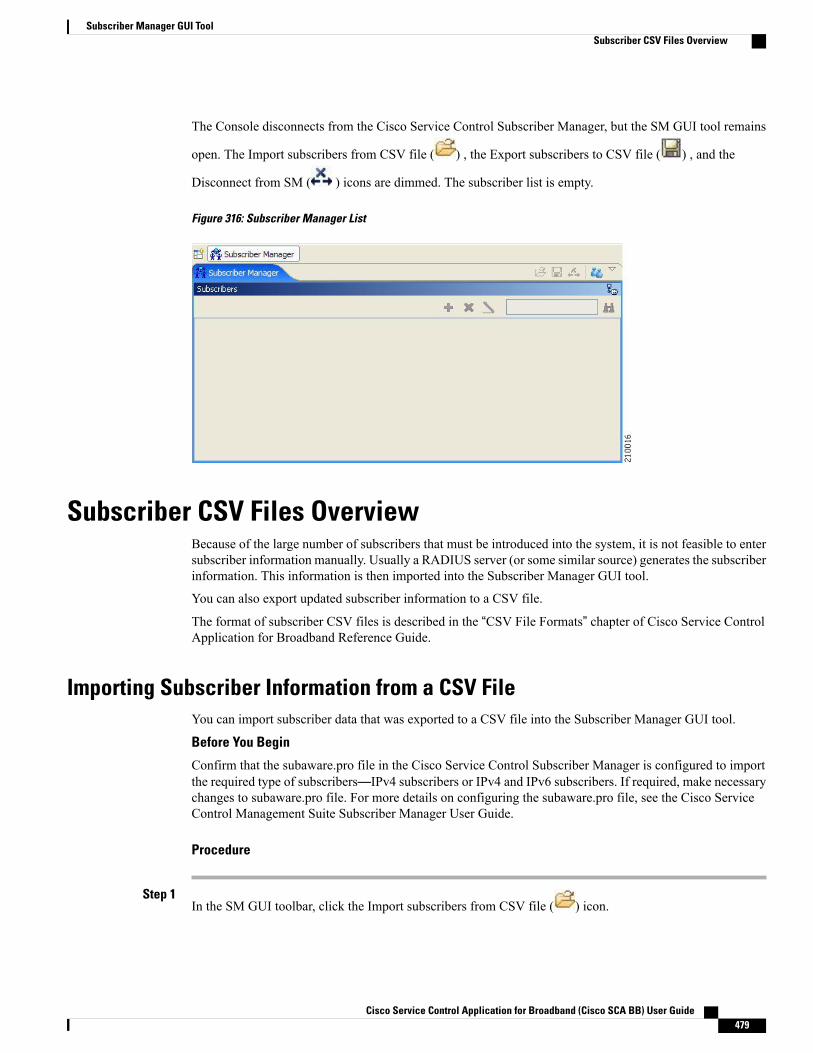
The Console disconnects from the Cisco Service Control Subscriber Manager, but the SM GUI tool remains
open. The Import subscribers from CSV file ( ) , the Export subscribers to CSV file ( ) , and the
Disconnect from SM ( ) icons are dimmed. The subscriber list is empty.
Figure 316: Subscriber Manager List
Subscriber CSV Files OverviewBecause of the large number of subscribers that must be introduced into the system, it is not feasible to entersubscriber information manually. Usually a RADIUS server (or some similar source) generates the subscriberinformation. This information is then imported into the Subscriber Manager GUI tool.
You can also export updated subscriber information to a CSV file.
The format of subscriber CSV files is described in the “CSV File Formats” chapter of Cisco Service ControlApplication for Broadband Reference Guide.
Importing Subscriber Information from a CSV FileYou can import subscriber data that was exported to a CSV file into the Subscriber Manager GUI tool.
Before You Begin
Confirm that the subaware.pro file in the Cisco Service Control Subscriber Manager is configured to importthe required type of subscribers—IPv4 subscribers or IPv4 and IPv6 subscribers. If required, make necessarychanges to subaware.pro file. For more details on configuring the subaware.pro file, see the Cisco ServiceControl Management Suite Subscriber Manager User Guide.
Procedure
Step 1In the SM GUI toolbar, click the Import subscribers from CSV file ( ) icon.
Cisco Service Control Application for Broadband (Cisco SCA BB) User Guide 479
Subscriber Manager GUI ToolSubscriber CSV Files Overview

An Import from File dialog box appears.Step 2 Browse to the file that is to be imported and click Open.
An Import Warning message appears.
Figure 317: Import Warning
Step 3 Click Yes.The Import from File dialog box closes.
The selected file is imported into the SM GUI tool; the imported subscribers are listed in the subscriber list.
Exporting Subscriber Information to a CSV FileYou can export subscriber information to a CSV file (for example, when data in the Cisco Service ControlSM database is updated).
Procedure
Step 1 Select the subscribers whose data you want to save.See the “Selecting Subscribers” section.
Step 2In the SM toolbar, click the Export subscribers to CSV file icon.An Export to File dialog box appears.
Step 3 Browse to the folder in which you want to save the exported file.Step 4 In the File name field, enter a file name.Step 5 Click Save.
The Export to File dialog box closes.
The selected subscribers are saved to the CSV file.
Subscriber Management OverviewAfter importing subscribers into the system, you can maintain and update the database.
You can perform the following operations:
Cisco Service Control Application for Broadband (Cisco SCA BB) User Guide480
Subscriber Manager GUI ToolExporting Subscriber Information to a CSV File
Subscriber InformationIn the SM GUI, you can see a list of all the subscribers currently introduced into Cisco SCA BB. Use this listto manage individual subscribers or groups of subscribers. Use the Find function to display a subset of thesubscribers (see Finding a Subscriber or Group of Subscribers ).
The SM GUI is composed of a console view at the bottom and a device view at the top. The console showsthe log messages. The device view has the following columns:
• Subscriber ID—Name of the subscriber in the system.
• Domain—Domain to which the subscriber is assigned. The names of the Cisco SCE platforms thatbelong to each domain appear in square brackets.
• Network Mappings—IP address, range of IP addresses, or VLAN tag mapped to the subscriber.
• Properties—Various properties assigned to the subscriber (Package ID, Monitor State, Up Vlink ID,Down Vlink ID).If you enable the Enable Package-ID to Package-Name Mapping check box in the Preferences page,the package name is displayed along with the package ID for the subscriber, based on the last policyupdated in the domain. For more information on enabling the Package-ID to Package-Name Mapping,see the Subscriber Manager GUI - Preferences Page .
Cisco Service Control Application for Broadband (Cisco SCA BB) User Guide 481
Subscriber Manager GUI ToolSubscriber Information
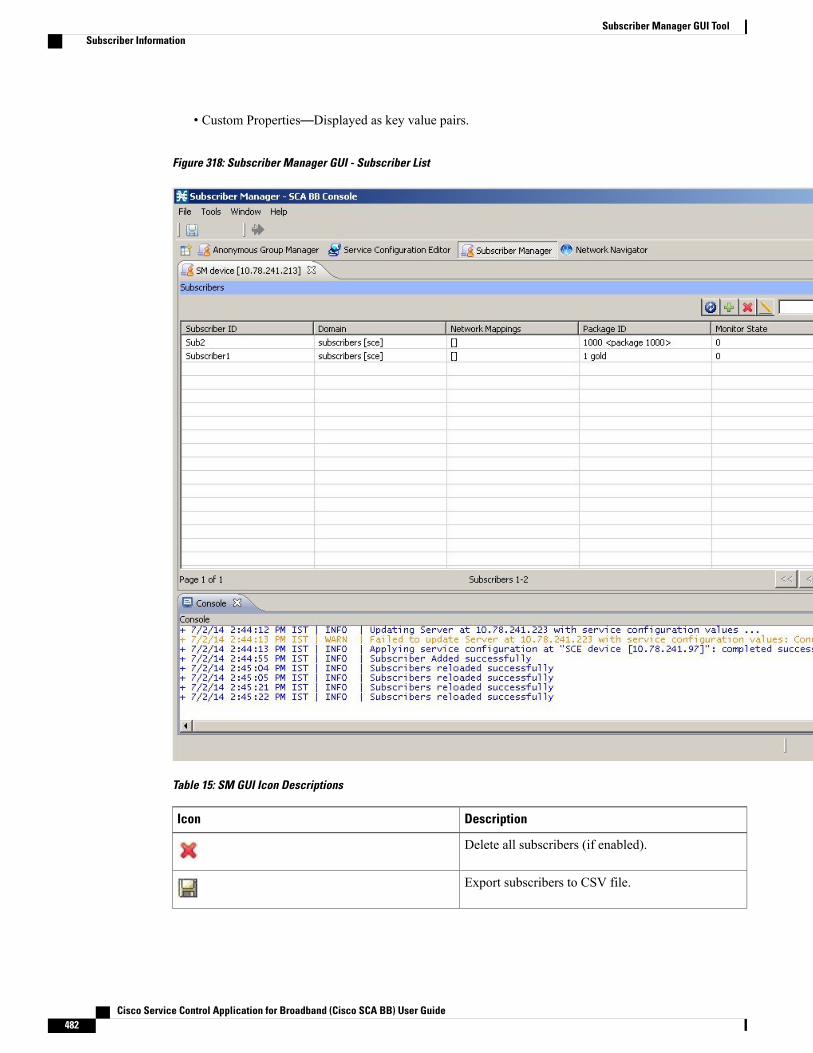
• Custom Properties—Displayed as key value pairs.
Figure 318: Subscriber Manager GUI - Subscriber List
Table 15: SM GUI Icon Descriptions
DescriptionIcon
Delete all subscribers (if enabled).
Export subscribers to CSV file.
Cisco Service Control Application for Broadband (Cisco SCA BB) User Guide482
Subscriber Manager GUI ToolSubscriber Information
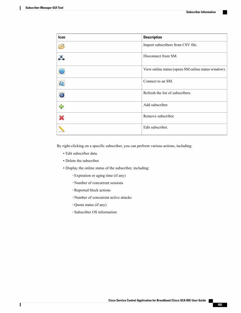
DescriptionIcon
Import subscribers from CSV file.
Disconnect from SM.
View online status (opens SM online status window).
Connect to an SM.
Refresh the list of subscribers.
Add subscriber.
Remove subscriber.
Edit subscriber.
By right-clicking on a specific subscriber, you can perform various actions, including:
• Edit subscriber data.
• Delete the subscriber.
• Display the online status of the subscriber, including:
◦Expiration or aging time (if any)
◦Number of concurrent sessions
◦Reported block actions
◦Number of concurrent active attacks
◦Quota status (if any)
◦Subscriber OS information
Cisco Service Control Application for Broadband (Cisco SCA BB) User Guide 483
Subscriber Manager GUI ToolSubscriber Information

• View information on multiple subscriber in multiple windows.
Figure 319: Subscriber Manager GUI - Subscriber Online Status
From the menu bar, you can select and open the Preferences page. When the Subscriber Manager is selectedin the left pane, you can do the following:
• Specify the number of subscriber records to be listed in the main display table.
• Enable or disable the “Remove All Subscribers” functionality.
• Enable or disable the enhanced subscriber data mode; if enabled, the Up Vlink ID and Down Vlink IDcolumns are displayed in the table.
Cisco Service Control Application for Broadband (Cisco SCA BB) User Guide484
Subscriber Manager GUI ToolSubscriber Information

• Enable or disable Package-ID to Package-Name Mapping; if enabled, the package name is displayedalong with the package ID for the subscriber.
Figure 320: Subscriber Manager GUI - Preferences Page
Overview of How to Find and Select SubscribersThe SM GUI tool retrieves subscribers in bulks of 1000 subscribers.
Cisco Service Control Application for Broadband (Cisco SCA BB) User Guide 485
Subscriber Manager GUI ToolOverview of How to Find and Select Subscribers

If the number of subscribers are more than that can be displayed in a standard view, then the information ispresented in multiple pages. You can navigate to the remaining groups of subscribers using the variouspagination buttons.
Figure 321: Subscriber Manager GUI - Pagination Buttons
• 1. Get previous bulk.
• 2. Get first page.
• 3. Get previous page.
• 4. Enter page number.
• 5. Get next page.
• 6. Get last page.
• 7. Get next bulk.
For ease of use, the SM GUI tool incorporates two standard features:
• Find—Search for a specific subscriber.
• Multiple Select—Select a range of subscribers or a number of individual subscribers.
Finding a Subscriber or Group of SubscribersUse the Find feature to find a specific subscriber or a group of subscribers according to a subscriber ID prefix.This feature is useful for editing the parameters of either a specific subscriber or a group of subscribers (see“Editing Subscriber Details” section.
Procedure
Step 1 In the Find field enter the prefix to be matched.
Figure 322: Find Field
Step 2Click the Find Subscribers ( ) icon.
Cisco Service Control Application for Broadband (Cisco SCA BB) User Guide486
Subscriber Manager GUI ToolOverview of How to Find and Select Subscribers
You see a list of only the subscribers that match the specified prefix.
The search criteria is selected in the drop-down list next to the Find field. Search by:
• Prefix
• Domain name
• Package ID
Selecting SubscribersYou can edit, export, or delete a group of subscribers at one time by selecting subscribers displayed in thesubscriber list. The group may be either of the following:
Selecting a Range of Subscribers
Procedure
Step 1 Select the first subscriber in the range.Step 2 Press the Shift key while clicking the last subscriber in the range.
You can combine this function with the search function; search for specific subscribers and then select theentire range.All subscribers within the range are selected.
Selecting a Number of Noncontiguous Subscribers
Procedure
Press the Ctrl key while selecting multiple subscribers.You can combine this function with selecting a range of subscribers; first, select the range of subscribers, andthen select additional subscribers.
Adding a SubscriberYou can add additional individual subscribers to the Cisco Service Control Subscriber Manager. To add largenumber of subscribers, export their information from a RADIUS (or DHCP) server to a CSV file, and thenimport the CSV file. For details on importing the CSV files, see “Working with Subscriber CSV Files” section.
Cisco Service Control Application for Broadband (Cisco SCA BB) User Guide 487
Subscriber Manager GUI ToolAdding a Subscriber
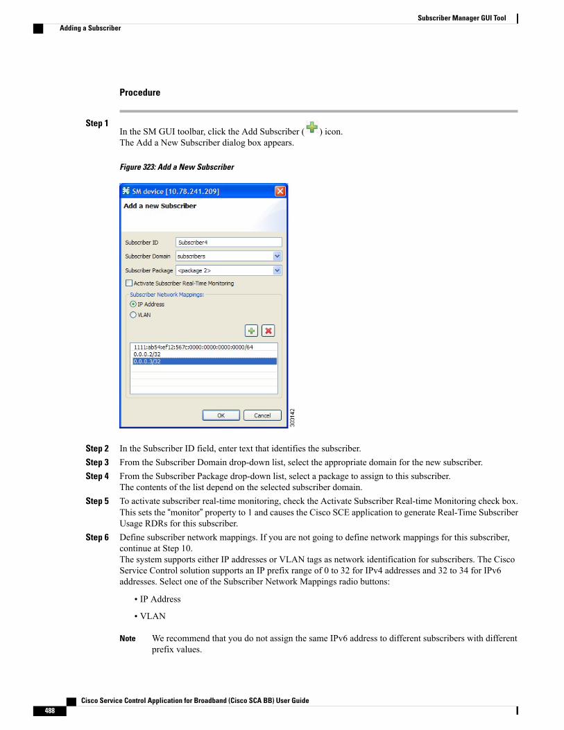
Procedure
Step 1In the SM GUI toolbar, click the Add Subscriber ( ) icon.The Add a New Subscriber dialog box appears.
Figure 323: Add a New Subscriber
Step 2 In the Subscriber ID field, enter text that identifies the subscriber.Step 3 From the Subscriber Domain drop-down list, select the appropriate domain for the new subscriber.Step 4 From the Subscriber Package drop-down list, select a package to assign to this subscriber.
The contents of the list depend on the selected subscriber domain.Step 5 To activate subscriber real-time monitoring, check the Activate Subscriber Real-time Monitoring check box.
This sets the “monitor” property to 1 and causes the Cisco SCE application to generate Real-Time SubscriberUsage RDRs for this subscriber.
Step 6 Define subscriber network mappings. If you are not going to define network mappings for this subscriber,continue at Step 10.The system supports either IP addresses or VLAN tags as network identification for subscribers. The CiscoService Control solution supports an IP prefix range of 0 to 32 for IPv4 addresses and 32 to 34 for IPv6addresses. Select one of the Subscriber Network Mappings radio buttons:
• IP Address
• VLAN
We recommend that you do not assign the same IPv6 address to different subscribers with differentprefix values.
Note
Cisco Service Control Application for Broadband (Cisco SCA BB) User Guide488
Subscriber Manager GUI ToolAdding a Subscriber
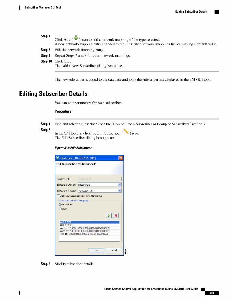
Step 7Click Add ( ) icon to add a network mapping of the type selected.A new network-mapping entry is added to the subscriber network mappings list, displaying a default value
Step 8 Edit the network-mapping entry.Step 9 Repeat Steps 7 and 8 for other network mappings.Step 10 Click OK .
The Add a New Subscriber dialog box closes.
The new subscriber is added to the database and joins the subscriber list displayed in the SM GUI tool.
Editing Subscriber DetailsYou can edit parameters for each subscriber.
Procedure
Step 1 Find and select a subscriber. (See the “How to Find a Subscriber or Group of Subscribers” section.)Step 2
In the SM toolbar, click the Edit Subscriber ( ) icon.The Edit Subscriber dialog box appears.
Figure 324: Edit Subscriber
Step 3 Modify subscriber details.
Cisco Service Control Application for Broadband (Cisco SCA BB) User Guide 489
Subscriber Manager GUI ToolEditing Subscriber Details
Edit the entry in the Subscriber ID field.a)b) From the Subscriber Domain drop-down list, select a subscriber domain.c) From the Subscriber Package drop-down list, select a package to assign to this subscriber.
The contents of the list depend on the selected subscriber domain.d) Check or uncheck the Activate Subscriber Real-time Monitoring check box.
If you are not editing the network mappings for this subscriber, continue at Step 5.
Step 4 Modify subscriber network mappings. The Cisco Service Control solution supports an IP prefix range of 0 to32 for IPv4 addresses and 32 to 34 for IPv6 addresses. To modify the Subscriber Network Mappings:
Step 5 Click one of the Subscriber Network Mappings radio buttons:
• IP Address
• VLAN
Step 6To add a new network mapping to the list, click the Add ( ) icon, and edit the network-mapping field thatis added to the Subscriber Network Mappings list.
Step 7 To delete a network mapping from the list, select an entry in the subscriber network mappings list and click
the Delete ( ) icon.Step 8 Click Apply.
The Edit Subscriber dialog box closes.
The modified subscriber information is saved to the database and displayed in the subscriber list in the SMGUI tool.
Deleting a Subscriber from the DatabaseYou can delete subscribers from the database.
Procedure
Step 1 Select a single subscriber or a group of subscribers.See the “Selecting Subscribers” section.
Step 2In the SM toolbar, click the Delete Subscriber ( ) icon.
Cisco Service Control Application for Broadband (Cisco SCA BB) User Guide490
Subscriber Manager GUI ToolDeleting a Subscriber from the Database

The system asks for confirmation before deleting the selected subscribers.
Figure 325: Subscriber Warning
Step 3 Click Yes to confirm.
The selected subscribers are deleted from the database and removed from the subscriber list displayed in theSM GUI tool.
Monitoring SM Online StatusThe SM online status window provides real-time status of the SM operation by displaying the main propertiesof the SM.
Figure 326: SM Online Status Window
Procedure
To open the SM Online Status window, click on the Open ( ) icon in the main GUI toolbar.The icons are grouped in the toolbar at the upper right corner of the SM Online Status window.
Cisco Service Control Application for Broadband (Cisco SCA BB) User Guide 491
Subscriber Manager GUI ToolMonitoring SM Online Status

Table 16: SM Online Status Window Icon Descriptions
DescriptionIcon
Autorefresh , the drop-down list shows selectabletime interval options (default 30 seconds)
Copy all properties and values to the clipboard (orright-click a single property to copy)
Always on top (enable or disable place status windowon top of other windows)
Cisco Service Control Application for Broadband (Cisco SCA BB) User Guide492
Subscriber Manager GUI ToolMonitoring SM Online Status

C H A P T E R 12Anonymous Group Manager GUI Tool
This chapter provides details on the Anonymous Group Manager GUI tool and how to manager AnonymousGroups using the Cisco SCABB. This chapter describes how to use the Anonymous GroupManager graphicaluser interface (GUI) tool to configure anonymous groups in a Cisco SCE. This chapter consists of thesesections:
• Using the Anonymous Group Manager GUI Tool, page 493
• Introduction to Managing Anonymous Groups, page 494
• Working with Anonymous Groups CSV Files , page 504
Using the Anonymous Group Manager GUI ToolYou can use the Anonymous Group Manager GUI tool to import and export subscriber files, and to performthese operations on anonymous groups:
• Add and delete an anonymous group
• View the subscribers in a specific anonymous group
• Delete all anonymous groups
• View the configuration of a specific anonymous group
• Filter subscribers
• View online status of the subscriber
• View OS information of the subscribers in anonymous group
• Edit subscriber properties
• Import anonymous groups from a CSV file
• Export anonymous groups to a CSV file
• Export subscribers of a certain group to CSV file
Software-based support for IPv6 subscribers is available on Cisco SCE 8000 devicesCisco SCE 10000 devices.
Cisco Service Control Application for Broadband (Cisco SCA BB) User Guide 493

For details on Anonymous Groups, Subscriber templates, and CSV file formats, see the Cisco SCE 10000Software Configuration Guide .
For more information about the Cisco Service Control Subscriber Manager, see the Cisco Service ControlManagement Suite Subscriber Manager User Guide.
Introduction to Managing Anonymous GroupsAfter importing subscribers into the system, you can maintain and update the database.
You can perform these tasks:
• Add and delete an anonymous group
• View the subscribers in a specific anonymous group
• View the configuration of a specific anonymous group
• Delete all anonymous groups in the Cisco SCE
• Filter subscribers
• View online status of the subscriber
• Edit subscriber properties
This section contains information on:
Anonymous Group Manager InformationIn the Anonymous Group Manager GUI, you can see a list of anonymous groups configured in a Cisco SCE.Use this list to manage individual anonymous group or multiple groups of subscriber tables stacked together,and the subscribers in each anonymous group.
The Anonymous Group Manager GUI is composed of a console view at the bottom and a device view at thetop. The console shows the logmessages. The anonymous group viewwithin the group folder has the followingcolumns in a subscriber table:
• Subscriber Name—Name of the subscriber in the system.
• Mappings—IP address, range of IP addresses, or VLAN tag mapped to the subscriber.
• Package ID
• Monitor State
• Up VLINK ID
• Down VLINK ID
Cisco Service Control Application for Broadband (Cisco SCA BB) User Guide494
Anonymous Group Manager GUI ToolIntroduction to Managing Anonymous Groups
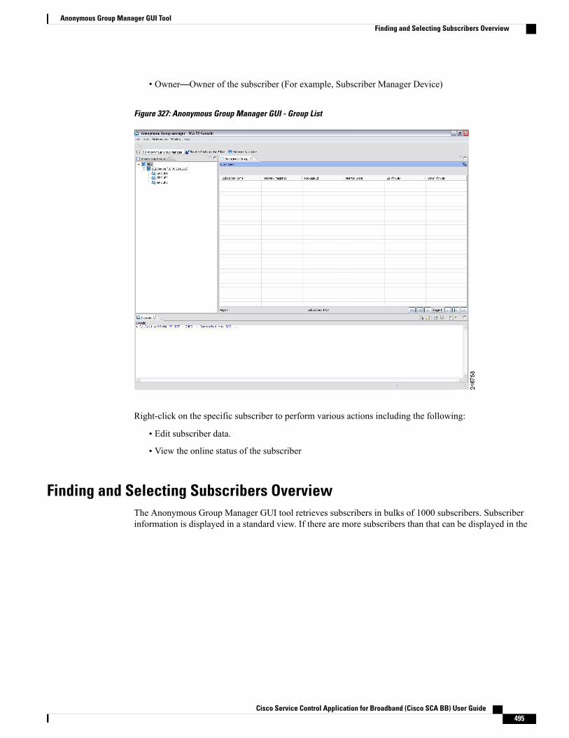
• Owner—Owner of the subscriber (For example, Subscriber Manager Device)
Figure 327: Anonymous Group Manager GUI - Group List
Right-click on the specific subscriber to perform various actions including the following:
• Edit subscriber data.
• View the online status of the subscriber
Finding and Selecting Subscribers OverviewThe Anonymous Group Manager GUI tool retrieves subscribers in bulks of 1000 subscribers. Subscriberinformation is displayed in a standard view. If there are more subscribers than that can be displayed in the
Cisco Service Control Application for Broadband (Cisco SCA BB) User Guide 495
Anonymous Group Manager GUI ToolFinding and Selecting Subscribers Overview
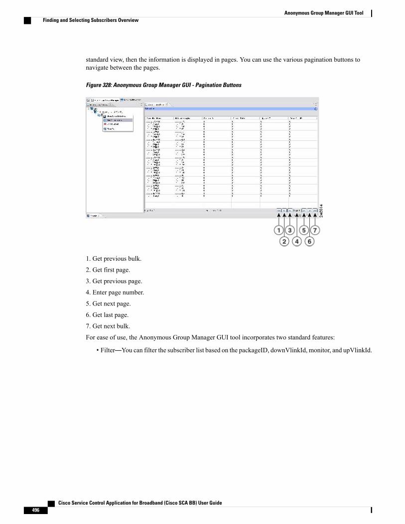
standard view, then the information is displayed in pages. You can use the various pagination buttons tonavigate between the pages.
Figure 328: Anonymous Group Manager GUI - Pagination Buttons
1. Get previous bulk.
2. Get first page.
3. Get previous page.
4. Enter page number.
5. Get next page.
6. Get last page.
7. Get next bulk.
For ease of use, the Anonymous Group Manager GUI tool incorporates two standard features:
• Filter—You can filter the subscriber list based on the packageID, downVlinkId, monitor, and upVlinkId.
Cisco Service Control Application for Broadband (Cisco SCA BB) User Guide496
Anonymous Group Manager GUI ToolFinding and Selecting Subscribers Overview
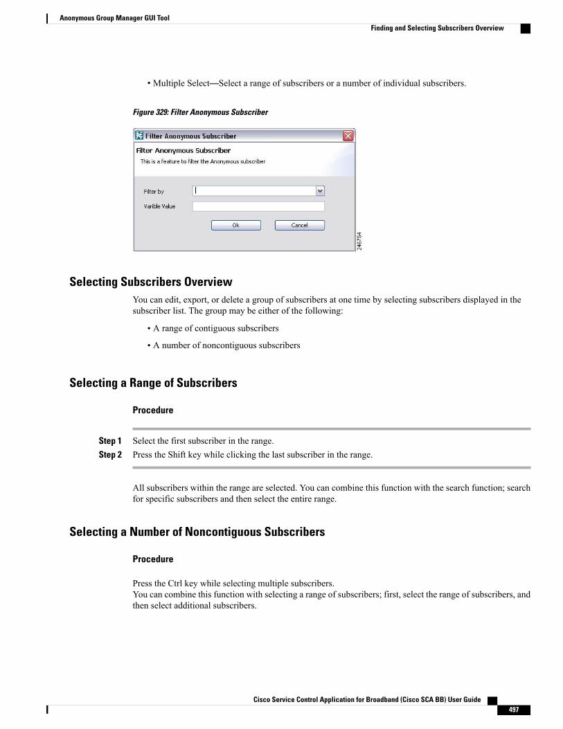
• Multiple Select—Select a range of subscribers or a number of individual subscribers.
Figure 329: Filter Anonymous Subscriber
Selecting Subscribers OverviewYou can edit, export, or delete a group of subscribers at one time by selecting subscribers displayed in thesubscriber list. The group may be either of the following:
• A range of contiguous subscribers
• A number of noncontiguous subscribers
Selecting a Range of Subscribers
Procedure
Step 1 Select the first subscriber in the range.Step 2 Press the Shift key while clicking the last subscriber in the range.
All subscribers within the range are selected. You can combine this function with the search function; searchfor specific subscribers and then select the entire range.
Selecting a Number of Noncontiguous Subscribers
Procedure
Press the Ctrl key while selecting multiple subscribers.You can combine this function with selecting a range of subscribers; first, select the range of subscribers, andthen select additional subscribers.
Cisco Service Control Application for Broadband (Cisco SCA BB) User Guide 497
Anonymous Group Manager GUI ToolFinding and Selecting Subscribers Overview
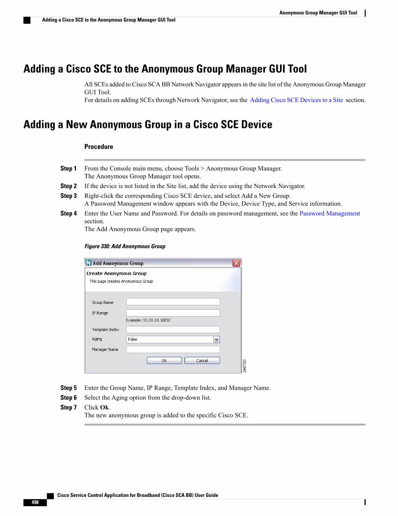
Adding a Cisco SCE to the Anonymous Group Manager GUI ToolAll SCEs added to Cisco SCABBNetwork Navigator appears in the site list of the Anonymous GroupManagerGUI Tool.For details on adding SCEs through Network Navigator, see the Adding Cisco SCEDevices to a Site section.
Adding a New Anonymous Group in a Cisco SCE Device
Procedure
Step 1 From the Console main menu, choose Tools > Anonymous Group Manager.The Anonymous Group Manager tool opens.
Step 2 If the device is not listed in the Site list, add the device using the Network Navigator.Step 3 Right-click the corresponding Cisco SCE device, and select Add a New Group.
A Password Management window appears with the Device, Device Type, and Service information.Step 4 Enter the User Name and Password. For details on password management, see the Password Management
section.The Add Anonymous Group page appears.
Figure 330: Add Anonymous Group
Step 5 Enter the Group Name, IP Range, Template Index, and Manager Name.Step 6 Select the Aging option from the drop-down list.Step 7 Click Ok.
The new anonymous group is added to the specific Cisco SCE.
Cisco Service Control Application for Broadband (Cisco SCA BB) User Guide498
Anonymous Group Manager GUI ToolAdding a Cisco SCE to the Anonymous Group Manager GUI Tool

Adding a New IPv6 Anonymous Group in a Cisco SCE Device
Procedure
Step 1 From the Console main menu, choose Tools > Anonymous Group Manager .The Anonymous Group Manager tool opens.
Step 2 If the device is not listed in the Site list, add the device using the Network Navigator.Step 3 Right-click on the Cisco SCE, and select Add a New Group .
A Password Management window appears with the Device, Device Type, and Service information.Step 4 Enter the User Name and Password. For details on password management, see the Password Management
section.The Add Anonymous Group page appears.
Figure 331: Add IPv6 Anonymous Group
Step 5 Enter the following details:
• Group Name
• IPv6 Range with a prefix value of 0 to 64
• Template Index
• Manager Name
Step 6 Select the Aging option from the drop-down list.Step 7 Click Ok .
The new anonymous group is added to the specific Cisco SCE device.
Cisco Service Control Application for Broadband (Cisco SCA BB) User Guide 499
Anonymous Group Manager GUI ToolAdding a New IPv6 Anonymous Group in a Cisco SCE Device
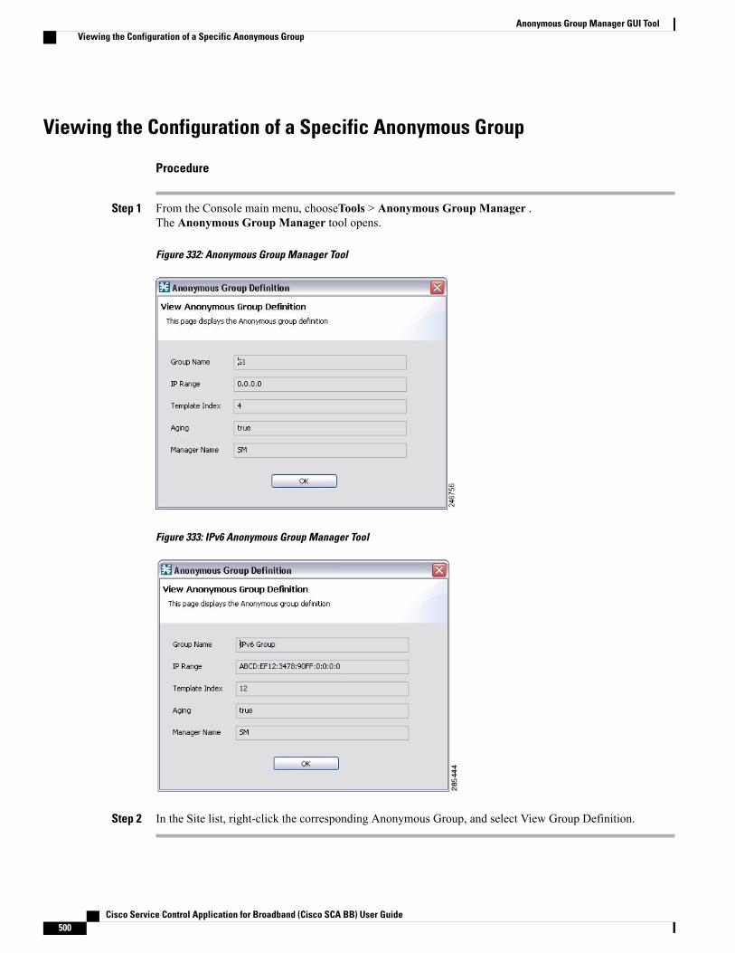
Viewing the Configuration of a Specific Anonymous Group
Procedure
Step 1 From the Console main menu, chooseTools > Anonymous Group Manager .The Anonymous Group Manager tool opens.
Figure 332: Anonymous Group Manager Tool
Figure 333: IPv6 Anonymous Group Manager Tool
Step 2 In the Site list, right-click the corresponding Anonymous Group, and select View Group Definition.
Cisco Service Control Application for Broadband (Cisco SCA BB) User Guide500
Anonymous Group Manager GUI ToolViewing the Configuration of a Specific Anonymous Group
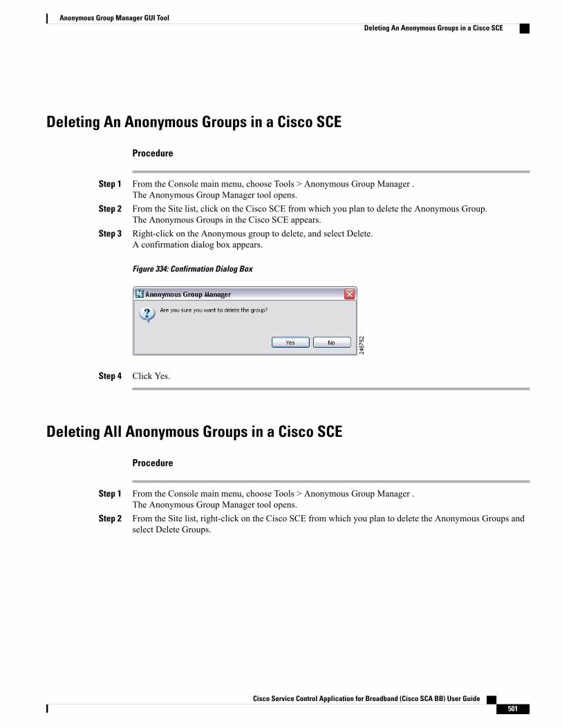
Deleting An Anonymous Groups in a Cisco SCE
Procedure
Step 1 From the Console main menu, choose Tools > Anonymous Group Manager .The Anonymous Group Manager tool opens.
Step 2 From the Site list, click on the Cisco SCE from which you plan to delete the Anonymous Group.The Anonymous Groups in the Cisco SCE appears.
Step 3 Right-click on the Anonymous group to delete, and select Delete.A confirmation dialog box appears.
Figure 334: Confirmation Dialog Box
Step 4 Click Yes.
Deleting All Anonymous Groups in a Cisco SCE
Procedure
Step 1 From the Console main menu, choose Tools > Anonymous Group Manager .The Anonymous Group Manager tool opens.
Step 2 From the Site list, right-click on the Cisco SCE from which you plan to delete the Anonymous Groups andselect Delete Groups.
Cisco Service Control Application for Broadband (Cisco SCA BB) User Guide 501
Anonymous Group Manager GUI ToolDeleting An Anonymous Groups in a Cisco SCE

A confirmation dialog box appears.
Figure 335: Confirmation Dialog Box
Step 3 Click Yes.
Viewing Subscribers in a Specific Anonymous Group
Procedure
Step 1 From the Console main menu, choose Tools > Anonymous Group Manager.
Cisco Service Control Application for Broadband (Cisco SCA BB) User Guide502
Anonymous Group Manager GUI ToolViewing Subscribers in a Specific Anonymous Group
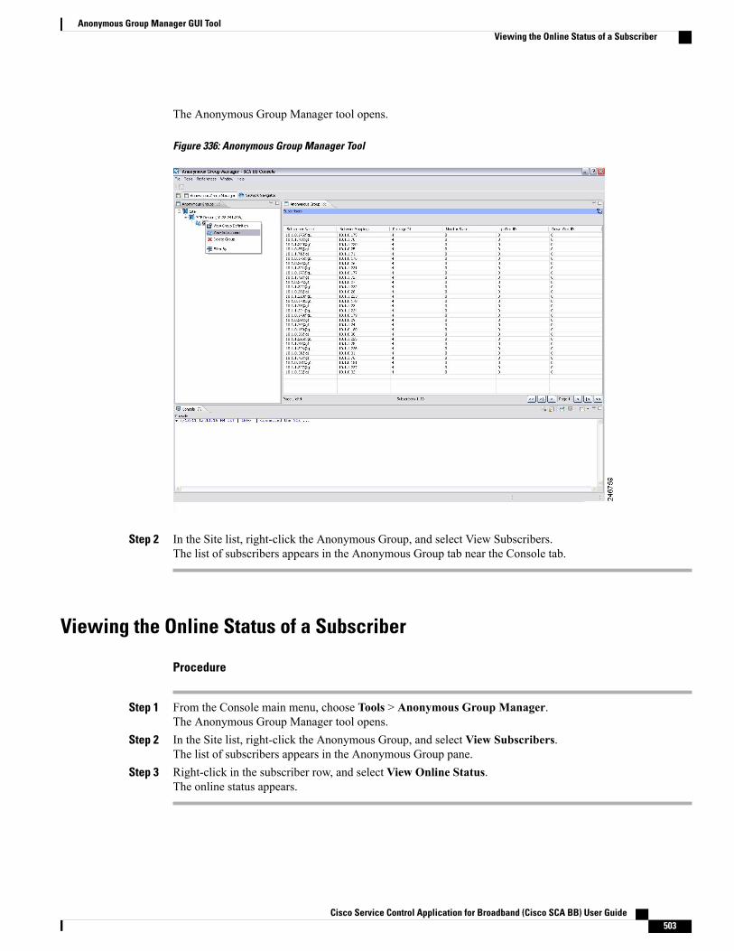
The Anonymous Group Manager tool opens.
Figure 336: Anonymous Group Manager Tool
Step 2 In the Site list, right-click the Anonymous Group, and select View Subscribers.The list of subscribers appears in the Anonymous Group tab near the Console tab.
Viewing the Online Status of a Subscriber
Procedure
Step 1 From the Console main menu, choose Tools > Anonymous Group Manager.The Anonymous Group Manager tool opens.
Step 2 In the Site list, right-click the Anonymous Group, and select View Subscribers.The list of subscribers appears in the Anonymous Group pane.
Step 3 Right-click in the subscriber row, and select View Online Status.The online status appears.
Cisco Service Control Application for Broadband (Cisco SCA BB) User Guide 503
Anonymous Group Manager GUI ToolViewing the Online Status of a Subscriber
Editing the Subscriber Properties
Procedure
Step 1 From the Console main menu, choose Tools > Anonymous Group Manager .The Anonymous Group Manager tool opens.
Step 2 In the Site list, right-click the Anonymous Group, and select View Subscribers.The list of subscribers appears in the Anonymous Group pane.
Step 3 Right-click in the subscriber row, and select Edit Subscriber .The Edit Subscriber dialog box appears.
Step 4 Modify the required fields from the following:
• Package ID
• Monitor State
• UpVlinkId
• DownVlinkId
Step 5 Click OK .
Removing Subscribers from an Anonymous Group in a Cisco SCE
Procedure
Step 1 From the Console main menu, choose Tools > Anonymous Group Manager.The Anonymous Group Manager tool opens.
Step 2 In the Site list, click the Anonymous Group, and select View Subscribers.The list of subscribers appears in the Anonymous Group pane.
Step 3 Right-click in the subscriber row, and select Remove the Subscriber.A confirmation dialog box appears.
Step 4 Click OK .
Working with Anonymous Groups CSV FilesWith Anonymous Group GUI tool, you can:
• Import anonymous groups from a CSV file
• Export anonymous groups to a CSV file
Cisco Service Control Application for Broadband (Cisco SCA BB) User Guide504
Anonymous Group Manager GUI ToolEditing the Subscriber Properties
• Export subscribers of a certain anonymous group to CSV file
The format of subscriber CSV files is described in the “CSV File Formats” chapter of Cisco Service ControlApplication for Broadband Reference Guide.
This section explains the following procedures:
• Importing Anonymous Groups from a CSV File
• Exporting Anonymous Groups to a CSV File
You can import subscriber data that was exported to a CSV file using the Anonymous Group Manager GUItool. This feature supports only one Cisco SCE at a time.
Importing Anonymous Groups from a CSV File
Procedure
Step 1 From the Console main menu, chooseTools > Anonymous Group Manager.Step 2 In the Site list in Anonymous Group Manager tool, click the Cisco SCE for which you want to import the
Anonymous Groups.Step 3 Select File > Import .
Cisco Service Control Application for Broadband (Cisco SCA BB) User Guide 505
Anonymous Group Manager GUI ToolWorking with Anonymous Groups CSV Files

Figure 337: Import Dialog Box
Step 4 Click Next.
Cisco Service Control Application for Broadband (Cisco SCA BB) User Guide506
Anonymous Group Manager GUI ToolWorking with Anonymous Groups CSV Files
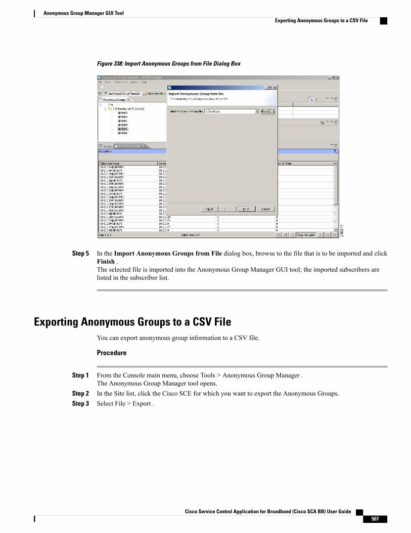
Figure 338: Import Anonymous Groups from File Dialog Box
Step 5 In the Import Anonymous Groups from File dialog box, browse to the file that is to be imported and clickFinish .The selected file is imported into the Anonymous Group Manager GUI tool; the imported subscribers arelisted in the subscriber list.
Exporting Anonymous Groups to a CSV FileYou can export anonymous group information to a CSV file.
Procedure
Step 1 From the Console main menu, choose Tools > Anonymous Group Manager .The Anonymous Group Manager tool opens.
Step 2 In the Site list, click the Cisco SCE for which you want to export the Anonymous Groups.Step 3 Select File > Export .
Cisco Service Control Application for Broadband (Cisco SCA BB) User Guide 507
Anonymous Group Manager GUI ToolExporting Anonymous Groups to a CSV File

The Export dialog box appears.
Figure 339: Export Dialog Box
Step 4 Click Next.
Cisco Service Control Application for Broadband (Cisco SCA BB) User Guide508
Anonymous Group Manager GUI ToolExporting Anonymous Groups to a CSV File
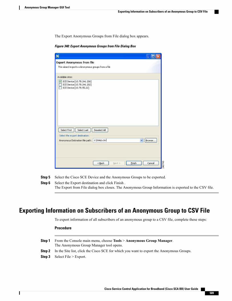
The Export Anonymous Groups from File dialog box appears.
Figure 340: Export Anonymous Groups from File Dialog Box
Step 5 Select the Cisco SCE Device and the Anonymous Groups to be exported.Step 6 Select the Export destination and click Finish .
The Export from File dialog box closes. The Anonymous Group Information is exported to the CSV file.
Exporting Information on Subscribers of an Anonymous Group to CSV FileTo export information of all subscribers of an anonymous group to a CSV file, complete these steps:
Procedure
Step 1 From the Console main menu, choose Tools > Anonymous Group Manager.The Anonymous Group Manager tool opens.
Step 2 In the Site list, click the Cisco SCE for which you want to export the Anonymous Groups.Step 3 Select File > Export.
Cisco Service Control Application for Broadband (Cisco SCA BB) User Guide 509
Anonymous Group Manager GUI ToolExporting Information on Subscribers of an Anonymous Group to CSV File
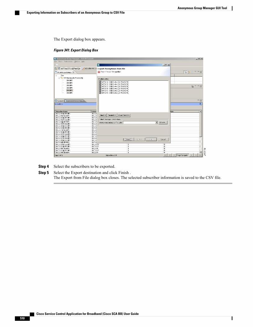
The Export dialog box appears.
Figure 341: Export Dialog Box
Step 4 Select the subscribers to be exported.Step 5 Select the Export destination and click Finish .
The Export from File dialog box closes. The selected subscriber information is saved to the CSV file.
Cisco Service Control Application for Broadband (Cisco SCA BB) User Guide510
Anonymous Group Manager GUI ToolExporting Information on Subscribers of an Anonymous Group to CSV File

C H A P T E R 13The Signature Editor Overview
This module describes the Signature Editor tool and how to use it to create and modify Dynamic SignatureScript (DSS) files.
The Signature Editor tool allows you to create and modify DSS files that can add and modify protocols andprotocol signatures in the Cisco SCA BB, based on your knowledge of new network protocols that CiscoSCA BB is yet to support.
This chapter consists of these sections:
• The Signature Editor Console , page 511
• Managing DSS Files Overview, page 511
• Creating DSS Files , page 522
• Editing DSS Files , page 524
• Importing DSS Files , page 525
The Signature Editor ConsoleThe Signature Editor writes log and error messages to the Signature Editor Console (in the Console view),when appropriate.
Managing DSS Files Overview• Installing new signatures to an active service configuration is described inWorking with Protocol Packs.
•Working with signatures in the Service Configuration Editor is described in Introduction to ManagingProtocol Signatures
• Using servconf, the Server Configuration Utility, to apply signatures is described in The Cisco SCABB Service Configuration Utility .
The DSS file components, and the creation and editing of DSS files, are explained in the following sections.
Cisco Service Control Application for Broadband (Cisco SCA BB) User Guide 511
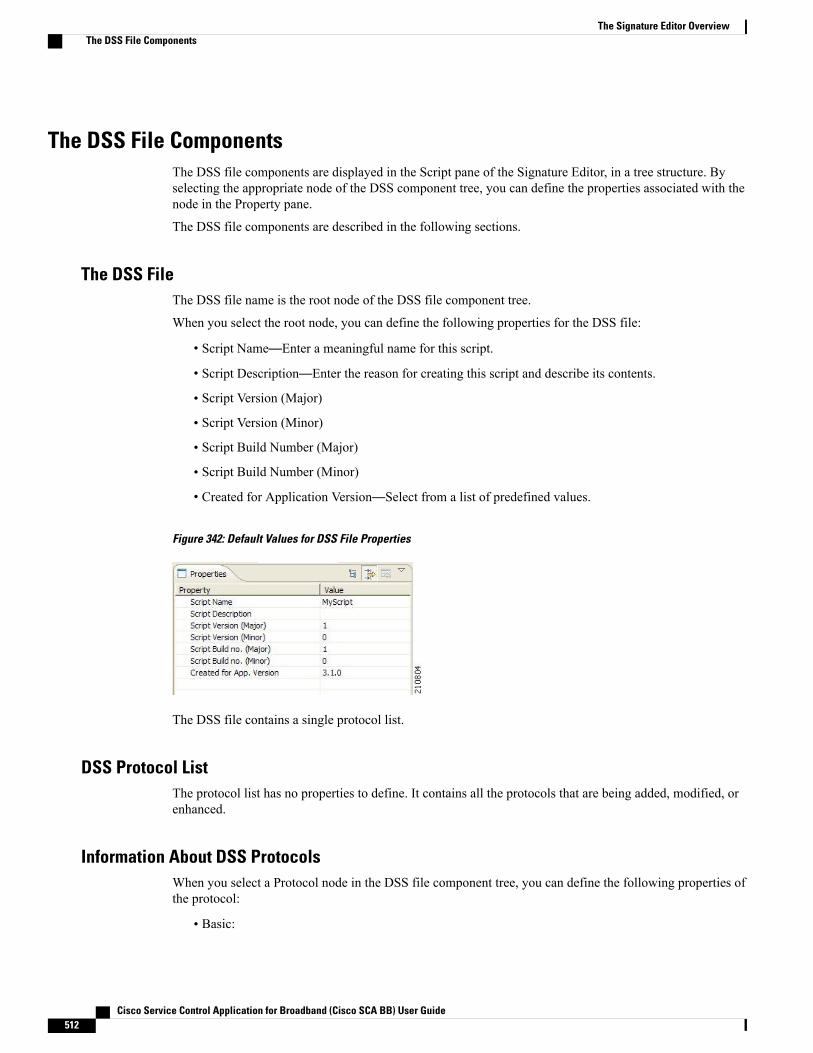
The DSS File ComponentsThe DSS file components are displayed in the Script pane of the Signature Editor, in a tree structure. Byselecting the appropriate node of the DSS component tree, you can define the properties associated with thenode in the Property pane.
The DSS file components are described in the following sections.
The DSS FileThe DSS file name is the root node of the DSS file component tree.
When you select the root node, you can define the following properties for the DSS file:
• Script Name—Enter a meaningful name for this script.
• Script Description—Enter the reason for creating this script and describe its contents.
• Script Version (Major)
• Script Version (Minor)
• Script Build Number (Major)
• Script Build Number (Minor)
• Created for Application Version—Select from a list of predefined values.
Figure 342: Default Values for DSS File Properties
The DSS file contains a single protocol list.
DSS Protocol ListThe protocol list has no properties to define. It contains all the protocols that are being added, modified, orenhanced.
Information About DSS ProtocolsWhen you select a Protocol node in the DSS file component tree, you can define the following properties ofthe protocol:
• Basic:
Cisco Service Control Application for Broadband (Cisco SCA BB) User Guide512
The Signature Editor OverviewThe DSS File Components

Protocol Name—See the “Setting Protocol Name and ID” section.◦
◦Protocol Description
◦Protocol ID—See the “Setting Protocol Name and ID” section.
• Protocol Category:
◦Buddy Protocol—See “The Buddy Protocol” section.
◦Protocol Families—Assign the protocol to one or more protocol families:
◦P2P
◦SIP
◦VOIP
◦Worm
Associating a protocol with a protocol family allows reports about the family to include the new protocol.
Figure 343: Default Values for the Protocol Properties
Protocols contain signatures.
DSS Protocol Name and ID
A DSS can include two types of protocols:
• A protocol new to Cisco SCA BB—The protocol is being defined in the DSS.
• A protocol that Cisco SCA BB already supports—The protocol identification is being enhanced ormodified in the DSS.
Selecting a name and ID is different for the two cases:
• For a protocol new to Cisco SCA BB, the name must not match any of the protocol names that CiscoSCA BB already supports. To see a list of supported-protocol names, open the Protocol Settings dialogbox in the Service Configuration Editor (see “How to View Protocols” section). Assign the protocol aunique ID in the range from 5000 to 9998.
• For an existing protocol, the protocol name and ID in the DSS must be identical to the protocol nameand ID in the service configuration. Locate the name and ID in the Protocol Settings dialog box in theService Configuration Editor (see “How to View Protocols” section).
Cisco Service Control Application for Broadband (Cisco SCA BB) User Guide 513
The Signature Editor OverviewThe DSS File Components

DSS Buddy Protocol
To simplify the configuration of new protocols added by a DSS, the DSS may specify a Buddy Protocol fora new protocol. If, when importing a DSS to a service configuration, the application encounters serviceelements referring to the Buddy Protocol, it automatically duplicates the set of service elements that use theBuddy Protocol and replaces all references to the Buddy Protocol with references to the new protocol. Theassociation of the new protocol to services matches that of the Buddy Protocol.
DSS SignaturesA protocol may contain as many different signatures as necessary.
Four different types of signatures may be added to a protocol:
• String Match Signatures
• Payload Length Signatures
• HTTP User Agent Signatures
• HTTP x-Header Signatures
Each of the four signature types tests different conditions against the first payload packet of the flows.
These signature types and their conditions are described in the following subsections.
String Match Signatures and Payload Length Signatures can contain deep inspection clauses. A signaturewhose first payload packet conditions are met accepts a flow if the conditions of any of its deep inspectionclauses are also met.
DSS String Match Signature
When you select a String Match Signature node in the DSS file component tree, you can define the followingproperties of the signature:
• Signature Name—A unique name
• Signature Description
• Signature ID—A value in the range from 0xC010000 to 0xC0100FF (decimal 201392128 to 201392383)
• First Payload Packet Conditions:
◦Fixed Size Byte String—(Display only) Shows the string formed by the next four fields:
◦[0]—Enter the ASCII code for the first byte of the string, or enter “*” to indicate that anyvalue is acceptable.
◦[1]—Enter the ASCII code for the second byte of the string, or enter “*” to indicate that anyvalue is acceptable.
◦[2]—Enter the ASCII code for the third byte of the string, or enter “*” to indicate that anyvalue is acceptable.
◦[3]—Enter the ASCII code for the fourth byte of the string, or enter “*” to indicate that anyvalue is acceptable.
Cisco Service Control Application for Broadband (Cisco SCA BB) User Guide514
The Signature Editor OverviewThe DSS File Components
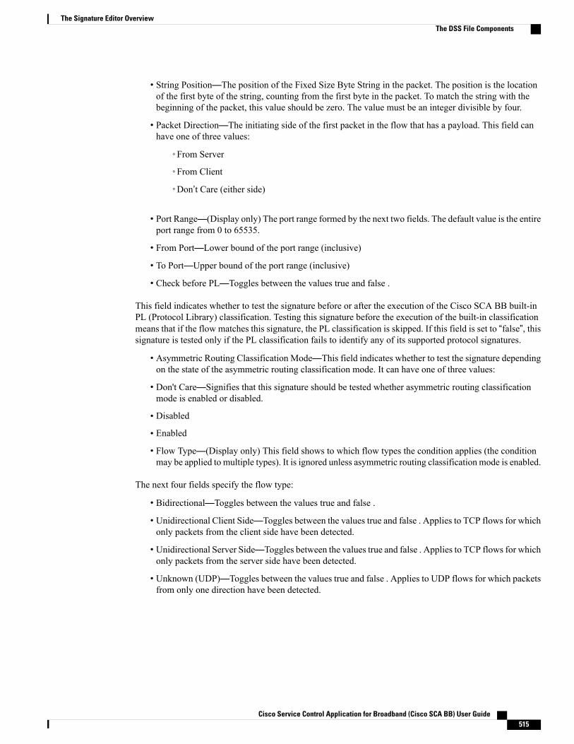
• String Position—The position of the Fixed Size Byte String in the packet. The position is the locationof the first byte of the string, counting from the first byte in the packet. To match the string with thebeginning of the packet, this value should be zero. The value must be an integer divisible by four.
• Packet Direction—The initiating side of the first packet in the flow that has a payload. This field canhave one of three values:
◦From Server
◦From Client
◦Don’t Care (either side)
• Port Range—(Display only) The port range formed by the next two fields. The default value is the entireport range from 0 to 65535.
• From Port—Lower bound of the port range (inclusive)
• To Port—Upper bound of the port range (inclusive)
• Check before PL—Toggles between the values true and false .
This field indicates whether to test the signature before or after the execution of the Cisco SCA BB built-inPL (Protocol Library) classification. Testing this signature before the execution of the built-in classificationmeans that if the flow matches this signature, the PL classification is skipped. If this field is set to “false”, thissignature is tested only if the PL classification fails to identify any of its supported protocol signatures.
• Asymmetric Routing Classification Mode—This field indicates whether to test the signature dependingon the state of the asymmetric routing classification mode. It can have one of three values:
• Don't Care—Signifies that this signature should be tested whether asymmetric routing classificationmode is enabled or disabled.
• Disabled
• Enabled
• Flow Type—(Display only) This field shows to which flow types the condition applies (the conditionmay be applied to multiple types). It is ignored unless asymmetric routing classification mode is enabled.
The next four fields specify the flow type:
• Bidirectional—Toggles between the values true and false .
• Unidirectional Client Side—Toggles between the values true and false . Applies to TCP flows for whichonly packets from the client side have been detected.
• Unidirectional Server Side—Toggles between the values true and false . Applies to TCP flows for whichonly packets from the server side have been detected.
• Unknown (UDP)—Toggles between the values true and false . Applies to UDP flows for which packetsfrom only one direction have been detected.
Cisco Service Control Application for Broadband (Cisco SCA BB) User Guide 515
The Signature Editor OverviewThe DSS File Components
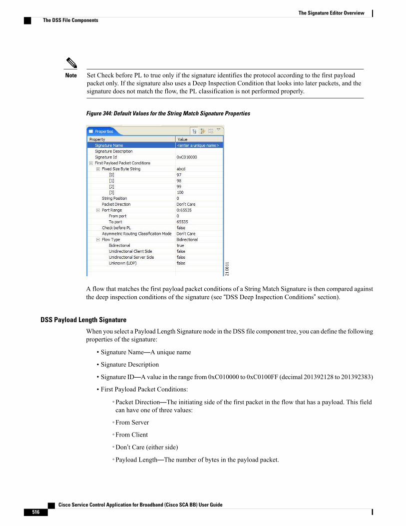
Set Check before PL to true only if the signature identifies the protocol according to the first payloadpacket only. If the signature also uses a Deep Inspection Condition that looks into later packets, and thesignature does not match the flow, the PL classification is not performed properly.
Note
Figure 344: Default Values for the String Match Signature Properties
A flow that matches the first payload packet conditions of a String Match Signature is then compared againstthe deep inspection conditions of the signature (see “DSS Deep Inspection Conditions” section).
DSS Payload Length Signature
When you select a Payload Length Signature node in the DSS file component tree, you can define the followingproperties of the signature:
• Signature Name—A unique name
• Signature Description
• Signature ID—A value in the range from 0xC010000 to 0xC0100FF (decimal 201392128 to 201392383)
• First Payload Packet Conditions:
◦Packet Direction—The initiating side of the first packet in the flow that has a payload. This fieldcan have one of three values:
◦From Server
◦From Client
◦Don’t Care (either side)
◦Payload Length—The number of bytes in the payload packet.
Cisco Service Control Application for Broadband (Cisco SCA BB) User Guide516
The Signature Editor OverviewThe DSS File Components
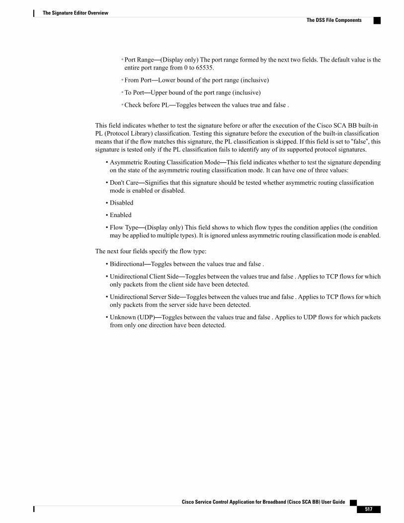
◦Port Range—(Display only) The port range formed by the next two fields. The default value is theentire port range from 0 to 65535.
◦From Port—Lower bound of the port range (inclusive)
◦To Port—Upper bound of the port range (inclusive)
◦Check before PL—Toggles between the values true and false .
This field indicates whether to test the signature before or after the execution of the Cisco SCA BB built-inPL (Protocol Library) classification. Testing this signature before the execution of the built-in classificationmeans that if the flow matches this signature, the PL classification is skipped. If this field is set to “false”, thissignature is tested only if the PL classification fails to identify any of its supported protocol signatures.
• Asymmetric Routing Classification Mode—This field indicates whether to test the signature dependingon the state of the asymmetric routing classification mode. It can have one of three values:
• Don't Care—Signifies that this signature should be tested whether asymmetric routing classificationmode is enabled or disabled.
• Disabled
• Enabled
• Flow Type—(Display only) This field shows to which flow types the condition applies (the conditionmay be applied to multiple types). It is ignored unless asymmetric routing classification mode is enabled.
The next four fields specify the flow type:
• Bidirectional—Toggles between the values true and false .
• Unidirectional Client Side—Toggles between the values true and false . Applies to TCP flows for whichonly packets from the client side have been detected.
• Unidirectional Server Side—Toggles between the values true and false . Applies to TCP flows for whichonly packets from the server side have been detected.
• Unknown (UDP)—Toggles between the values true and false . Applies to UDP flows for which packetsfrom only one direction have been detected.
Cisco Service Control Application for Broadband (Cisco SCA BB) User Guide 517
The Signature Editor OverviewThe DSS File Components

Set Check before PL to true only if the signature identifies the protocol according to the first payloadpacket only. If the signature also uses a Deep Inspection Condition that looks into later packets, and thesignature does not match the flow, the PL classification is not performed properly.
Note
Figure 345: Default Values for the Payload Length Signature Properties
A flow that matches the first payload packet conditions of a Payload Length Signature is then comparedagainst the deep inspection conditions of the signature (see “DSS Deep Inspection Conditions” section).
DSS HTTP User Agent Signature
When you select an HTTP User Agent Signature node in the DSS file component tree, you can define thefollowing properties of the signature:
• Signature Name—A unique name
• Signature Description
• Signature ID—A value in the range from 0xC010000 to 0xC0100FF (decimal 201392128 to 201392383)
• Conditions:
Cisco Service Control Application for Broadband (Cisco SCA BB) User Guide518
The Signature Editor OverviewThe DSS File Components
User Agent—The value of the User Agent field in the HTTP header◦
Figure 346: Default Values for the HTTP User Agent Signature Properties
DSS HTTP x-Header Signature
When you select an HTTP x-Header Signature node in the DSS file component tree, you can define thefollowing properties of the signature:
• Signature Name—A unique name
• Signature Description
• Signature ID—A value in the range from 0xC010000 to 0xC0100FF (decimal 201392128 to 201392383)
• Conditions:
◦x-Header Field Name—A name of a field in the x-Header of the HTTP header
Figure 347: Default Values for the DSS File Properties
DSS Deep Inspection ClausesA deep inspection clause is a conjunctive clause of deep inspection conditions—a signature accepts a flowonly if all conditions in a clause are met.
Cisco Service Control Application for Broadband (Cisco SCA BB) User Guide 519
The Signature Editor OverviewThe DSS File Components

If a signature has multiple deep inspection clauses, the clauses (and the deep inspection conditions makingup each clause) are tested in an order based on the value of the Packet Number property of the deepinspection conditions. After the first payload packet is accepted by the first payload packet conditions,the clause containing the condition with the lowest Packet Number is tested. The other conditions in thisclause are checked in ascending Packet Number order. Thus, the Packet Number of any condition in aclause cannot be less than the largest Packet Number in the clause it succeeds.
Note
DSS Deep Inspection ConditionsA deep inspection condition is a set of conditions that are checked against flows that pass the first payloadpacket conditions screening of String Match Signatures or Payload Length Signatures.
When you select a Deep Inspection Condition node in the DSS file component tree, you can define thefollowing properties of the deep inspection condition:
• Packet Direction—The initiating side of the first packet in the flow that has a payload. This field canhave one of three values:
◦From Server
◦From Client
◦Don’t Care (either side)
• Packet Number—The number of the packet in the flow. The payload packets are numbered from zero;packets are counted in both directions.
• Payload Length—The length of the packet in bytes. Enter zero to indicate that any value is acceptable.
• Printable Characters—Test if the inspected packet contains only printable characters. This field can haveone of three values:
◦Printable Characters Only
◦At Least One Non-Printable
◦Don’t Care
• Substring Search—Match a search string with a specific location in the packet. Leave the Search Stringfields empty if this condition is irrelevant.
◦Position Offset—The position from which to start searching for the search string in the packet.The offset is relative to the location specified in the Start Search From field.
◦Start Search From—This field can have one of two values:
◦Packet beginning
◦Last match
Last match means that the search for this search string starts where the last search match ended. The lastmatchmay be from a previous substring search or from the last string-based first payload packet condition.
• Searchable Range—Search in this number of bytes for the search string.
Cisco Service Control Application for Broadband (Cisco SCA BB) User Guide520
The Signature Editor OverviewThe DSS File Components

• Search Packets—This field can have one of two values:
• This packet only
• Multiple packets—Multiple Packets means that the search may span across packets, as long as the overall number of bytesis less than the number specified in the Searchable Range field.
• Search String—Enter the search string in one of the following three fields (the other two fields areupdated automatically):
◦ASCII Codes—Enter the ASCII codes for the characters of the search string. Separate each codeby a comma.
◦Byte String—Enter the actual search string.
◦Hex Values—Enter the hexadecimal values of the ASCII codes for the characters of the searchstring. Separate each code by a comma.
• Transport Protocol—This field can have one of three values:
◦TCP
◦UDP
◦Don’t Care (either TCP or UDP)
Figure 348: Default Values for the Deep Inspection Condition Properties
The structure of deep inspection conditions is the same for String Match Signatures and Payload LengthSignatures.
Cisco Service Control Application for Broadband (Cisco SCA BB) User Guide 521
The Signature Editor OverviewThe DSS File Components

Creating DSS Files
If you have a DSS file open in the Signature Editor, save it before you create a new DSS file. All unsavedchanges are lost.
Note
Procedure
Step 1From the toolbar, click the Create a New DSS File ( ) icon.A DSS component tree containing a DSS File node, a Protocol List node, and a Protocol node, is displayedin the Script view. The default properties of the new DSS file are displayed in the Properties view.
Figure 349: Properties Tab
Step 2 Edit the DSS file properties.For an explanation of the properties, see “The DSS File” section.
Step 3 Click the Protocol node.The protocol properties appear in the Properties view.
Step 4 Edit the protocol properties.
Cisco Service Control Application for Broadband (Cisco SCA BB) User Guide522
The Signature Editor OverviewCreating DSS Files

For an explanation of the properties, see “Information About DSS Protocols” section.Step 5
Click the drop-down arrow next to the Add ( ) icon.
Figure 350: Protocol Properties
Step 6 From the drop-down menu that appears, select a signature type.A Signature node is added under the Protocol node. If you selected a String Match Signature or a PayloadLength Signature, a Deep Inspection Clause node and a Deep Inspection Condition node are also added.
Figure 351: Protocol List Information
Step 7 Click the Signature node.The signature properties appear in the Properties view.
Step 8 Edit the signature properties.For an explanation of the properties, see “DSS Signatures” section.
Step 9 If you selected a String Match Signature or a Payload Length Signature, click the Deep Inspection Conditionnode to edit the deep inspection condition properties.For an explanation of the properties, see “DSS Deep Inspection Conditions” section.The deep inspection condition properties appear in the Properties view.
Step 10 Add additional deep inspection conditions, deep inspection clauses, signatures, and protocols as needed.Step 11
From the toolbar, click the Save ( ) icon.
Cisco Service Control Application for Broadband (Cisco SCA BB) User Guide 523
The Signature Editor OverviewCreating DSS Files

If there are duplicate protocol names or protocol IDs, a Validation Error message appears.
Figure 352: Validation Error
Step 12Click OK, remove the duplication, and then click the Save ( ) icon again.A Save As dialog box appears.
Step 13 Browse to the folder where you want to save the new DSS file.Step 14 In the File name field, enter an appropriate name for the DSS file.Step 15 Click Save.
The Save As dialog box closes. The DSS file is saved.
Editing DSS FilesYou can edit an existing DSS file, and add new protocols, or modify or delete existing protocols.
If you have a DSS file open in the Signature Editor, save it before you open a different DSS file. Allunsaved changes are lost.
Note
Procedure
Step 1From the toolbar, click the Open a DSS File ( ) icon.
Step 2 Browse to the DSS file that you want to edit.Step 3 Click Open.
The Open dialog box closes.
The DSS Component tree of the selected file is displayed in the Script view.
The DSS File node is selected, and the properties of the DSS file are displayed in the Properties view.
Step 4 Add, edit, or delete DSS file components.See the subsections of The DSS File Components section for an explanation of the properties of the differentcomponents.
Step 5 Save the modified DSS file.
Cisco Service Control Application for Broadband (Cisco SCA BB) User Guide524
The Signature Editor OverviewEditing DSS Files

Step 6To overwrite the current DSS file with the changes you have made, from the toolbar, click the Save ( )icon.
Step 7 To save the modified DSS file with a new name choose File > Save As.a) Browse to the folder where you want to save the new DSS file.b) In the File name field, enter an appropriate name for the DSS file.c) Click Save.
The modified DSS file is saved with the new name.
Importing DSS FilesYou can import DSS files into the file you are currently editing.
Importing signatures may create duplication of protocol names or protocol IDs.Note
Procedure
Step 1 From the Console main menu, choose File > Import.
Cisco Service Control Application for Broadband (Cisco SCA BB) User Guide 525
The Signature Editor OverviewImporting DSS Files
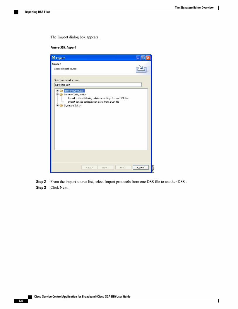
The Import dialog box appears.
Figure 353: Import
Step 2 From the import source list, select Import protocols from one DSS file to another DSS .Step 3 Click Next.
Cisco Service Control Application for Broadband (Cisco SCA BB) User Guide526
The Signature Editor OverviewImporting DSS Files
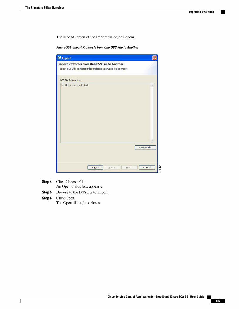
The second screen of the Import dialog box opens.
Figure 354: Import Protocols from One DSS File to Another
Step 4 Click Choose File.An Open dialog box appears.
Step 5 Browse to the DSS file to import.Step 6 Click Open.
The Open dialog box closes.
Cisco Service Control Application for Broadband (Cisco SCA BB) User Guide 527
The Signature Editor OverviewImporting DSS Files

Information about the DSS file that you have chosen is displayed in the DSS File Information area.
Figure 355: Import Protocols from One DSS File to Another
Step 7 Click Finish.The Import dialog box closes. The content of the selected DSS file is imported into the Signature Editor.
Cisco Service Control Application for Broadband (Cisco SCA BB) User Guide528
The Signature Editor OverviewImporting DSS Files

C H A P T E R 14Additional Management Tools and Interfaces
This chapter provides details on additional management tools and interfaces available in Cisco ServiceControl.
• The Cisco SCA BB Service Configuration Utility , page 529
• The Cisco SCA BB Real-Time Monitoring Configuration Utility , page 533
• The Cisco SCA BB Signature Configuration Utility , page 537
• Overview of SNMP, MIB, and Traps , page 538
• Installing a Cisco SCA BB PQI File on a Cisco SCE Platform , page 539
• Overview on Managing Subscribers via Other System Components , page 540
The Cisco SCA BB Service Configuration UtilityThe Cisco SCA BB Service Configuration Utility ( servconf) is a command-line utility (CLU) for applyingand retrieving service configurations. Use it in a scripting environment to automate service configuration taskson multiple Cisco Service Control Engine (Cisco SCE) platforms.
The Service Configuration Utility can run in Windows and Linux environments.
servconf SyntaxThe command-line syntax of servconf is: servconf<operation> [<option>] [<option>] ...
Table 17: servconf Operations
DescriptionAbbreviationOperation
Copies the specified serviceconfiguration file to the specifiedCisco SCE platforms and activatesit
-a--apply
Cisco Service Control Application for Broadband (Cisco SCA BB) User Guide 529

DescriptionAbbreviationOperation
Retrieves the current serviceconfiguration
-r--retrieve
Updates a Cisco Service ControlCollection Manager (CM) withservice configuration values
-u--update-dc
Shows the service configurationstatus on the Cisco SCE platform
—--status
Updates the Cisco SCE platformwith a new protocol pack
—--update-signature
Updates the Cisco SCE platformwith a new SPQI protocol pack
—--update-signature-pqi
Shows information about theDynamic Signature Script (DSS)file
-i--signature-info
Displays help, then exits—--help
Displays the program versionnumber, then exits
—--version
Table 18: servconf File Options
DescriptionAbbreviationFile Option
Specifies a service configurationfile or DSS file
-f--file= filename
Specifies the directory to which tosave the retrieved PQB file beforeapplying a new protocol pack
-b--backup-directory= directory
Cisco Service Control Application for Broadband (Cisco SCA BB) User Guide530
Additional Management Tools and Interfacesservconf Syntax

Table 19: servconf Connection Options
DescriptionAbbreviationFile Option
Specifies the IP address of thedestination Cisco SCE platform.
To specify multiple Cisco SCEplatforms, list the IP addressesseparated by semicolons (seeExample 1 in the followingsection).
When using a semicolon in a Unixcommand line, the command-lineargument must be enclosed inquotation marks.
-S--se= address
Specifies the IP address of thedestination Cisco Service ControlCollection Manager platform(required only for the --update-dcoperation).
-D--dc= address
Specifies the password forconnecting to the Cisco SCEplatform.
-P--password= password
Specifies the username forconnecting to the Cisco SCEplatform. If this option is notspecified, the following defaultvalues are used:
• SCE—admin
• CM—pcube
• SM—pcube
-U--username= username
Table 20: servconf Reference Cisco SCE Option
DescriptionFile Option
Specifies the IP address of the Cisco SCE platformto which the service configuration values refer(required only for --update-dc operation)
--refer-se= address
Cisco Service Control Application for Broadband (Cisco SCA BB) User Guide 531
Additional Management Tools and Interfacesservconf Syntax
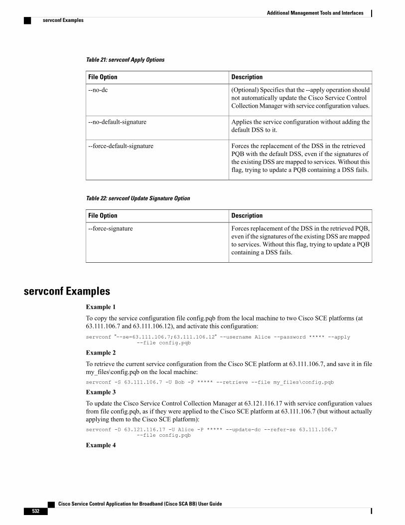
Table 21: servconf Apply Options
DescriptionFile Option
(Optional) Specifies that the --apply operation shouldnot automatically update the Cisco Service ControlCollectionManager with service configuration values.
--no-dc
Applies the service configuration without adding thedefault DSS to it.
--no-default-signature
Forces the replacement of the DSS in the retrievedPQB with the default DSS, even if the signatures ofthe existing DSS are mapped to services.Without thisflag, trying to update a PQB containing a DSS fails.
--force-default-signature
Table 22: servconf Update Signature Option
DescriptionFile Option
Forces replacement of the DSS in the retrieved PQB,even if the signatures of the existing DSS are mappedto services. Without this flag, trying to update a PQBcontaining a DSS fails.
--force-signature
servconf ExamplesExample 1
To copy the service configuration file config.pqb from the local machine to two Cisco SCE platforms (at63.111.106.7 and 63.111.106.12), and activate this configuration:servconf ”--se=63.111.106.7;63.111.106.12” --username Alice --password ***** --apply
--file config.pqb
Example 2
To retrieve the current service configuration from the Cisco SCE platform at 63.111.106.7, and save it in filemy_files\config.pqb on the local machine:servconf -S 63.111.106.7 -U Bob -P ***** --retrieve --file my_files\config.pqb
Example 3
To update the Cisco Service Control Collection Manager at 63.121.116.17 with service configuration valuesfrom file config.pqb, as if they were applied to the Cisco SCE platform at 63.111.106.7 (but without actuallyapplying them to the Cisco SCE platform):servconf -D 63.121.116.17 -U Alice -P ***** --update-dc --refer-se 63.111.106.7
--file config.pqb
Example 4
Cisco Service Control Application for Broadband (Cisco SCA BB) User Guide532
Additional Management Tools and Interfacesservconf Examples
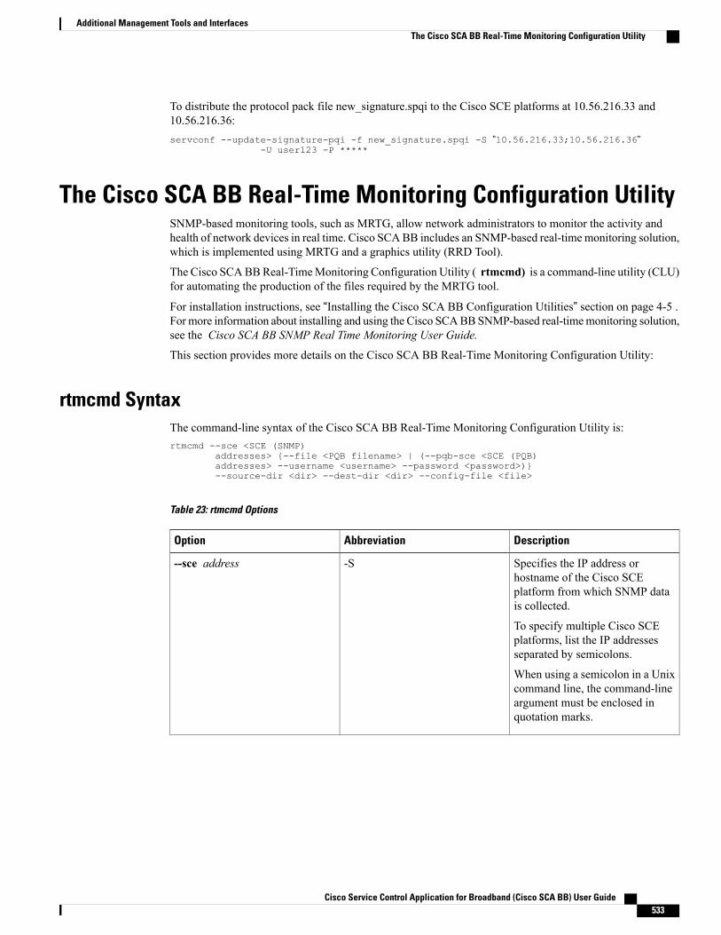
To distribute the protocol pack file new_signature.spqi to the Cisco SCE platforms at 10.56.216.33 and10.56.216.36:servconf --update-signature-pqi -f new_signature.spqi -S ”10.56.216.33;10.56.216.36”
-U user123 -P *****
The Cisco SCA BB Real-Time Monitoring Configuration UtilitySNMP-based monitoring tools, such as MRTG, allow network administrators to monitor the activity andhealth of network devices in real time. Cisco SCABB includes an SNMP-based real-timemonitoring solution,which is implemented using MRTG and a graphics utility (RRD Tool).
The Cisco SCABBReal-TimeMonitoring Configuration Utility ( rtmcmd) is a command-line utility (CLU)for automating the production of the files required by the MRTG tool.
For installation instructions, see “Installing the Cisco SCA BB Configuration Utilities” section on page 4-5 .For more information about installing and using the Cisco SCABBSNMP-based real-timemonitoring solution,see the Cisco SCA BB SNMP Real Time Monitoring User Guide.
This section provides more details on the Cisco SCA BB Real-Time Monitoring Configuration Utility:
rtmcmd SyntaxThe command-line syntax of the Cisco SCA BB Real-Time Monitoring Configuration Utility is:rtmcmd --sce <SCE (SNMP)
addresses> {--file <PQB filename> | (--pqb-sce <SCE (PQB)addresses> --username <username> --password <password>)}--source-dir <dir> --dest-dir <dir> --config-file <file>
Table 23: rtmcmd Options
DescriptionAbbreviationOption
Specifies the IP address orhostname of the Cisco SCEplatform from which SNMP datais collected.
To specify multiple Cisco SCEplatforms, list the IP addressesseparated by semicolons.
When using a semicolon in a Unixcommand line, the command-lineargument must be enclosed inquotation marks.
-S--sce address
Cisco Service Control Application for Broadband (Cisco SCA BB) User Guide 533
Additional Management Tools and InterfacesThe Cisco SCA BB Real-Time Monitoring Configuration Utility
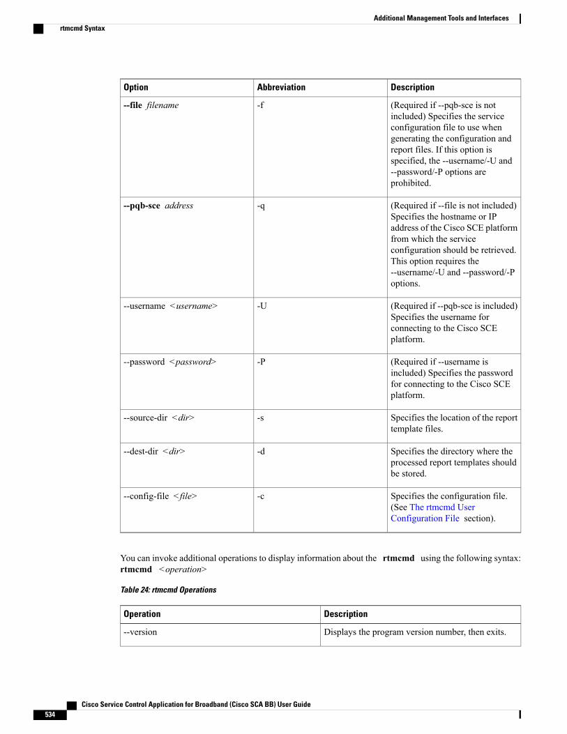
DescriptionAbbreviationOption
(Required if --pqb-sce is notincluded) Specifies the serviceconfiguration file to use whengenerating the configuration andreport files. If this option isspecified, the --username/-U and--password/-P options areprohibited.
-f--file filename
(Required if --file is not included)Specifies the hostname or IPaddress of the Cisco SCE platformfrom which the serviceconfiguration should be retrieved.This option requires the--username/-U and --password/-Poptions.
-q--pqb-sce address
(Required if --pqb-sce is included)Specifies the username forconnecting to the Cisco SCEplatform.
-U--username <username>
(Required if --username isincluded) Specifies the passwordfor connecting to the Cisco SCEplatform.
-P--password <password>
Specifies the location of the reporttemplate files.
-s--source-dir <dir>
Specifies the directory where theprocessed report templates shouldbe stored.
-d--dest-dir <dir>
Specifies the configuration file.(See The rtmcmd UserConfiguration File section).
-c--config-file <file>
You can invoke additional operations to display information about the rtmcmd using the following syntax:rtmcmd <operation>
Table 24: rtmcmd Operations
DescriptionOperation
Displays the program version number, then exits.--version
Cisco Service Control Application for Broadband (Cisco SCA BB) User Guide534
Additional Management Tools and Interfacesrtmcmd Syntax

DescriptionOperation
Displays help, then exits.--help
rtmcmd ExamplesExample 1
To use the service configuration file servicecfg.pqb to create configuration and report files for the collectingand reporting of SNMP information from two Cisco SCE platforms (at 63.111.106.7 and 63.111.106.12):
rtmcmd --sce="63.111.106.7;63.111.106.12" --file=servicecfg.pqb --source-dir=/rtm-templates--dest-dir=/rtm-output -c./rtmcmd.cfg
Example 2
To use the service configuration loaded on the Cisco SCE platform at 63.111.106.7 to create configurationand report files for the collecting and reporting of SNMP information from two Cisco SCE platforms (at63.111.106.7 and 63.111.106.12):
rtmcmd -S "63.111.106.7;63.111.106.12" -U user123 -P **** --pqb-sce=63.111.106.7--source-dir=/rtm-templates --dest-dir=/rtm-output -c./rtmcmd.cfg
The rtmcmd User Configuration FileThe user configuration file contains user-specific information required by the rtmcmd utility. The CiscoSCA BB utilities distribution package contains a sample configuration file, named rtmcmd.cfg. You shouldedit this file according to the details of your setup.
The table lists the configuration parameters that should be present in the user configuration file.
Table 25: rtmcmd User Configuration File Parameters
Required/ OptionalDefault ValueDescriptionParameter Description
Required—The absolute path to thedirectorywhere RRDTooland RRDCGI binary filesare installed.
rrdtool_bin_dir
Required—The absolute path to thedirectory where RRDarchives and CGI files arestored. This is under theweb server web directory.
rtm_dir
Cisco Service Control Application for Broadband (Cisco SCA BB) User Guide 535
Additional Management Tools and Interfacesrtmcmd Examples
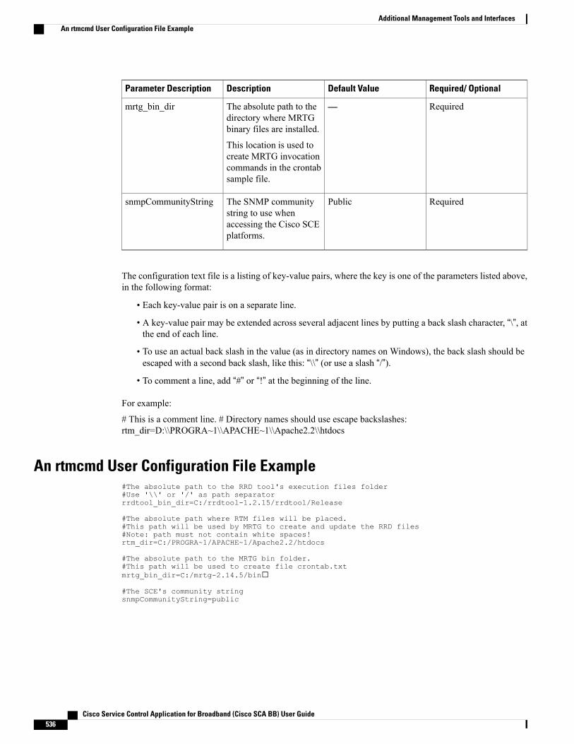
Required/ OptionalDefault ValueDescriptionParameter Description
Required—The absolute path to thedirectory where MRTGbinary files are installed.
This location is used tocreate MRTG invocationcommands in the crontabsample file.
mrtg_bin_dir
RequiredPublicThe SNMP communitystring to use whenaccessing the Cisco SCEplatforms.
snmpCommunityString
The configuration text file is a listing of key-value pairs, where the key is one of the parameters listed above,in the following format:
• Each key-value pair is on a separate line.
• A key-value pair may be extended across several adjacent lines by putting a back slash character, “\”, atthe end of each line.
• To use an actual back slash in the value (as in directory names on Windows), the back slash should beescaped with a second back slash, like this: “\\” (or use a slash “/”).
• To comment a line, add “#” or “!” at the beginning of the line.
For example:
# This is a comment line. # Directory names should use escape backslashes:rtm_dir=D:\\PROGRA~1\\APACHE~1\\Apache2.2\\htdocs
An rtmcmd User Configuration File Example#The absolute path to the RRD tool's execution files folder#Use '\\' or '/' as path separatorrrdtool_bin_dir=C:/rrdtool-1.2.15/rrdtool/Release
#The absolute path where RTM files will be placed.#This path will be used by MRTG to create and update the RRD files#Note: path must not contain white spaces!rtm_dir=C:/PROGRA~1/APACHE~1/Apache2.2/htdocs
#The absolute path to the MRTG bin folder.#This path will be used to create file crontab.txtmrtg_bin_dir=C:/mrtg-2.14.5/bin
#The SCE's community stringsnmpCommunityString=public
Cisco Service Control Application for Broadband (Cisco SCA BB) User Guide536
Additional Management Tools and InterfacesAn rtmcmd User Configuration File Example

The Cisco SCA BB Signature Configuration UtilityThe Cisco SCA BB Signature Configuration Utility ( sigconf) is a command-line utility for installing andmanaging the default DSS.
The Signature Configuration Utility can run in Windows and Linux environments.
For installation instructions, see Installing the Cisco SCA BB Configuration Utilities .
sigconf SyntaxThe command-line syntax of the Cisco SCABB Signature Configuration Utility is sigconf<operation> [--file<filename>]
Table 26: sigconf Operations
DescriptionAbbreviationOperation
Installs the default DSS on thisworkstation.
-d--set-default-dynamic-signature
Uninstalls the default DSS fromthis workstation.
—--remove-default-dynamic-signature
Fetches the default DSS installedon this workstation.
—--get-default-dynamic-signature
Displays help, then exits.—--help
Table 27: sigconf File Option
DescriptionAbbreviationFile Option
Specifies a DSS file-f--file filename
sigconf ExamplesExample 1
To install the file new_signature.dss as the default DSS:
sigconf --set-default-dynamic-signature --file new_signature.dss
Example 2
To retrieve the installed default DSS file, and save it as default_backup.dss:
sigconf --get-default-dynamic-signature --file default_backup.dss
Cisco Service Control Application for Broadband (Cisco SCA BB) User Guide 537
Additional Management Tools and InterfacesThe Cisco SCA BB Signature Configuration Utility
Overview of SNMP, MIB, and TrapsCisco provides complete network FCAPS (Fault, Configuration, Accounting, Performance, Security)management.
Two interfaces are provided for network management:
• Command-line interface (CLI)—Accessible through the console port on the front panel of the CiscoSCE platform or through a Telnet connection to the Cisco SCE platform, the CLI is used for configurationand security functions.
• SNMP (Simple Network Management Protocol)—Provides fault management (via SNMP traps) andperformance monitoring functionality.
SNMPSNMP is a set of protocols for managing complex networks. SNMP works by sending messages, calledprotocol data units (PDUs), to different parts of a network. SNMP-compliant devices, called agents, storedata about themselves inManagement Information Bases (MIBs) and return this data to the SNMP requesters.
The Cisco SCE platform operating system includes an SNMP agent. Configuring the SNMP agent parametersand enabling the SNMP interface is described in either the “Configuring the Management Interface andSecurity” chapter ofCisco SCE8000 10GBE Software ConfigurationGuide or the “Configuring theManagementInterface and Security” chapter of Cisco SCE8000 GBE Software Configuration Guide.The Cisco SCE platform operating system includes an SNMP agent. Configuring the SNMP agent parametersand enabling the SNMP interface is described in either the “Configuring the Management Interface andSecurity” chapter of Cisco SCE10000 Software Configuration Guide.
MIBManagement Information Bases (MIBs) are databases of objects that can be monitored by a networkmanagement system. SNMP uses standardized MIB formats that allow standard SNMP tools to monitor anydevice defined by a MIB.
The Cisco SCE platform supports the following MIBs:
• MIB-II—Defined in RFC 1213, (Management Information Base for Network Management ofTCP/IP-based Internets)
• Cisco Service Control Enterprise MIB—Described by a number of MIB files
The Cisco proprietary MIB allows external management systems to retrieve general information about theCisco SCE platform operating status and resource utilization, extract real-time measurements of bandwidthutilization and network statistics, and receive notifications of critical events and alarms.
The part of the Cisco proprietary MIB that provides configuration and runtime status for Cisco SCA BB isdocumented in the “SCA BB Proprietary MIB Reference” chapter of Cisco Service Control Application forBroadband Reference Guide . Other parts of the Cisco proprietaryMIB are documented in either the “ProprietaryMIB Reference” appendix of the Cisco SCE10000 Software Configuration Guide . These books also explainthe order in which the MIB must be loaded.
Cisco Service Control Application for Broadband (Cisco SCA BB) User Guide538
Additional Management Tools and InterfacesOverview of SNMP, MIB, and Traps
TrapsTraps are unsolicited messages generated by the SNMP agent that resides inside the Cisco SCE platform.Traps are generated when an event occurs.When the NetworkManagement System receives the trap message,it can take suitable actions, such as logging the occurrence or ignoring the signal.
The Cisco SCE platform supports two general categories of traps:
• Standard SNMP traps—As defined in RFC 1157 and using the conventions defined in RFC 1215
• Proprietary Cisco Service Control Enterprise traps—As defined in the Cisco proprietary MIB
For a description of the SNMP traps and an explanation of how to configure the SNMP trap managers, seethe “Configuring and Managing the SNMP Interface” section in the “Configuring the Management Interfaceand Security” chapter of Cisco SCE10000 Software Configuration Guide .
Installing a Cisco SCA BB PQI File on a Cisco SCE PlatformYou can install a Cisco SCA BB PQI file on a Cisco SCE platform using the Cisco SCE platformCommand-Line Interface (CLI).
Procedure
Step 1 Make sure that the PQI file is available.Do one of the following:
• Locate the PQI file on the Cisco SCE platform.
• Upload the appropriate PQI file to the Cisco SCE via FTP.
Step 2 Enter line interface configuration mode.Step 3 Type pqi install file engXXXXX.pqi .Step 4 Monitor the installation progress until it is completed.
After you install the Console, you can use the Network Navigator tool to install PQI files. See the InstallingPQI Files on Cisco SCE Devices , on page 130 section.
Entering Line Interface Configuration Mode
Procedure
Step 1 At the Cisco SCE platform CLI prompt (SCE#), type configure and press Enter.The SCE(config)# prompt appears.
Step 2 Type interface LineCard 0 .Step 3 Press Enter.
Cisco Service Control Application for Broadband (Cisco SCA BB) User Guide 539
Additional Management Tools and InterfacesTraps

The SCE(config if)# prompt appears.
Overview on Managing Subscribers via Other SystemComponents
Other components of the Cisco Service Control solution offer alternatives for subscriber management (asopposed to using the Subscriber Manager GUI tool in the Console):
• The Cisco Service Control SubscriberManager (SM) has options that are not available from the Console.
• The Cisco SCE platform has a wide range of subscriber-related functions.
For in-depth explanations, see the appropriate Service Control documentation.
This section gives an overview of these alternatives, with emphasis on the Cisco SCA BB-specific subscribermanagement options:
• Anonymous Subscriber Mode
• Subscriber-Aware Mode
• Selecting Subscribers for Real-Time Usage Monitoring
• Managing Subscriber CSV Files
Anonymous Subscriber ModeAn anonymous subscriber is one with a name generated automatically by the Cisco SCE platform accordingto an anonymous subscriber group specification. An anonymous subscriber is always mapped to a single IPaddress. The actual identity of the customer is unknown to the system.
An anonymous group is a specified IP range, possibly assigned a subscriber template. If an anonymous groupis configured, the Cisco SCE platform generates anonymous subscribers for that group when it detects trafficwith an IP address in the specified IP range. If a subscriber template is assigned to the group, the anonymoussubscribers generated have properties defined by that template. If no subscriber template is assigned, thedefault template is used, which cannot be changed by template import operations. Initially, 200 templates arepreconfigured, one for each package ID.
Anonymous subscriber groups and subscriber templates are managed using the Cisco SCE platformCommand-Line Interface (CLI). You can enter CLI commands via a Telnet session. For more information,see the Cisco SCE 8000 CLI Command Reference Guide Cisco SCE 10000 CLI Command Reference Guideor .
Use the following commands to import anonymous subscriber groups and subscriber templates from CSVfiles and to export subscriber data to these files:
• subscriber anonymous-group import csv-file
• subscriber anonymous-group export csv-file
• subscriber template import csv-file
Cisco Service Control Application for Broadband (Cisco SCA BB) User Guide540
Additional Management Tools and InterfacesOverview on Managing Subscribers via Other System Components

• subscriber template export csv-file
The preceding CLI commands are line interface configuration commands. You must enter line interfaceconfiguration mode (see Entering Line Interface Configuration Mode , on page 539 section) and see theSCE(config if)# prompt displayed before entering a command.
Note
Use the following commands to delete anonymous groups or subscriber templates from the system.
• no subscriber anonymous-group [all] [name <groupname>]
• clear subscriber anonymous
• default subscriber template all
The preceding CLI commands are line interface configuration commands. You must enter line interfaceconfiguration mode (see Entering Line Interface Configuration Mode , on page 539 section ) and see theSCE(config if)# prompt displayed before entering a command.
Note
Use the following commands to display anonymous subscriber information:
• show interface LineCard 0 subscriber templates [index]
• show interface LineCard 0 subscriber anonymous-group [all] [name <groupname>]
• show interface LineCard 0 subscriber amount anonymous [name <groupname>]
• show interface LineCard 0 subscriber anonymous [name <groupname>]
Subscriber-Aware ModeIn subscriber-aware mode, each subscriber is a specific customer with an externally generated name. Thisexternally generated name allows the subscriber to bemapped tomore than one IP address and still be identified.Each traffic session (single IP flow, or a group of related IP flows) processed by the Cisco SCE platform isassigned to a recognized subscriber on the basis of the configured subscriber mappings.
There are three options for introducing and managing these subscribers:
• The SM GUI tool (see Subscriber Manager GUI Tool Overview, on page 475 section)
The Cisco SCE Platform Subscriber CLIUse the following commands to import subscriber data from CSV files and to export subscriber data to thesefiles:
subscriber import csv-file
subscriber export csv-file
Cisco Service Control Application for Broadband (Cisco SCA BB) User Guide 541
Additional Management Tools and InterfacesSubscriber-Aware Mode

The preceding CLI commands are line interface configuration commands. You must enter line interfaceconfiguration mode (see Entering Line Interface Configuration Mode , on page 539 section) and see theSCE(config if)# prompt displayed before entering a command.
Note
Use the following command to remove subscribers from the system.
no subscriber [all] [name <subscriber-name>]
The preceding CLI command is a line interface configuration command. You must enter line interfaceconfigurationmode (see Entering Line Interface ConfigurationMode , on page 539 ) and see the SCE(configif)# prompt displayed before entering the command.
Note
Use the following commands to display subscribers meeting various criteria:
show interface LineCard 0 subscriber [amount] [prefix <prefix>] [property <propertyname> equals |greater-than | less-than <property-val>]
show interface LineCard 0 subscriber [amount] prefix <prefix>
show interface LineCard 0 subscriber [amount] suffix <suffix>
show interface LineCard 0 subscriber mapping IP <iprange>
show interface LineCard 0 subscriber [amount] mapping intersecting IP <iprange>
show interface LineCard 0 subscriber mapping VLANid <vlanid>
Use the following commands to display information about a specific subscriber:
show interface LineCard 0 subscriber properties
show interface LineCard 0 subscriber name <name>
show interface LineCard 0 subscriber name <name> mappings
show interface LineCard 0 subscriber name <name> counters
show interface LineCard 0 subscriber name <name> properties
The SM Subscriber Management CLUThe SM Subscriber Management Utility ( p3subs) is a CLU for managing subscribers. You can use it to addor remove subscribers. You can also manage subscriber properties and mappings with this utility.
For more information about p3subs, see the Cisco Service Control Management Suite Subscriber ManagerUser Guide.
p3subs Syntax
You run p3subs from the Solaris shell prompt. The command-line syntax of the utility is:
p3subs <operation> --subscriber=<Subscriber-Name> [--ip=<IP-address>][--property=<property-name=value>] [--domain=<domain-name>] [--overwrite]
The following table lists the p3subs operations relevant to managing subscribers.
Cisco Service Control Application for Broadband (Cisco SCA BB) User Guide542
Additional Management Tools and InterfacesSubscriber-Aware Mode
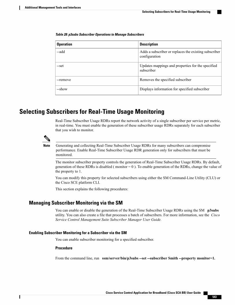
Table 28: p3subs Subscriber Operations to Manage Subscribers
DescriptionOperation
Adds a subscriber or replaces the existing subscriberconfiguration
--add
Updates mappings and properties for the specifiedsubscriber
--set
Removes the specified subscriber--remove
Displays information for specified subscriber--show
Selecting Subscribers for Real-Time Usage MonitoringReal-Time Subscriber Usage RDRs report the network activity of a single subscriber per service per metric,in real-time. You must enable the generation of these subscriber usage RDRs separately for each subscriberthat you wish to monitor.
Generating and collecting Real-Time Subscriber Usage RDRs for many subscribers can compromiseperformance. Enable Real-Time Subscriber Usage RDR generation only for subscribers that must bemonitored.
Note
The monitor subscriber property controls the generation of Real-Time Subscriber Usage RDRs. By default,generation of these RDRs is disabled ( monitor = 0 ). To enable generation of the RDRs, change the value ofthe property to 1.
You can modify this property for selected subscribers using either the SM Command-Line Utility (CLU) orthe Cisco SCE platform CLI.
This section explains the following procedures:
Managing Subscriber Monitoring via the SMYou can enable or disable the generation of the Real-Time Subscriber Usage RDRs using the SM p3subsutility. You can also create a file that processes a batch of subscribers. For more information, see the CiscoService Control Management Suite Subscriber Manager User Guide.
Enabling Subscriber Monitoring for a Subscriber via the SM
You can enable subscriber monitoring for a specified subscriber.
Procedure
From the command line, run ssm/server/bin/p3subs --set --subscriber Smith --property monitor=1.
Cisco Service Control Application for Broadband (Cisco SCA BB) User Guide 543
Additional Management Tools and InterfacesSelecting Subscribers for Real-Time Usage Monitoring
Disabling Subscriber Monitoring for a Subscriber via the SM
Procedure
From the command line, enter sm/server/bin/p3subs --set --subscriber Smith --property monitor=0.
Enabling Subscriber Monitoring for Multiple Subscribers
You can enable subscriber monitoring for multiple subscribers.
Procedure
Step 1 Create a text file (named monitor.txt in this example) containing the sequence of CLI invocations, includingthe commands to access the appropriate CLI mode.The file would look something like this:
configureinterface LineCard 0subscriber name Jerry property name monitor value 1subscriber name George property name monitor value 1subscriber name Elaine property name monitor value 1subscriber name Kramer property name monitor value 1subscriber name Newman property name monitor value 1
Step 2 From the Cisco SCE platform CLI prompt (SCE#), run script run monitor.txt
Verifying that Subscriber Monitoring is Enabled for a Subscriber via the SM
Procedure
From the command line, run sm/server/bin/p3subs --show-property --subscriber Smith --propertymonitor.
Managing Subscriber Monitoring via the Cisco SCE Platform OverviewYou can also enable or disable the generation of the Real-Time Subscriber Usage RDRs using the Cisco SCEplatform. For more information this, see the Cisco SCE8000 CLI Command Reference Guide. Cisco SCE10000CLI Command Reference Guide.
This section explains the following procedures:
Enabling Subscriber Monitoring for a Subscriber
You can enable subscriber monitoring for a specified subscriber.
Cisco Service Control Application for Broadband (Cisco SCA BB) User Guide544
Additional Management Tools and InterfacesSelecting Subscribers for Real-Time Usage Monitoring

Procedure
Step 1 Enter line interface configuration mode. (See " Entering Line Interface Configuration Mode " section.)Step 2 At the SCE(config if)# prompt, run subscriber name Smith property name monitor value 1.
Disabling Subscriber Monitoring for a Subscriber
Procedure
Step 1 Enter line interface configuration mode. (See " Entering Line Interface Configuration Mode " section.)Step 2 At the SCE(config if)# prompt, enter subscriber name Smith property name monitor value 0.
Enabling Subscriber Monitoring for Multiple Subscribers
You can enable subscriber monitoring for multiple subscribers.
Procedure
Step 1 Create a text file (named monitor.txt in this example) containing the sequence of CLI invocations, includingthe commands to access the appropriate CLI mode.The file would look something like this:
configureinterface LineCard 0subscriber name Jerry property name monitor value 1subscriber name George property name monitor value 1subscriber name Elaine property name monitor value 1subscriber name Kramer property name monitor value 1subscriber name Newman property name monitor value 1
Step 2 From the Cisco SCE platform CLI prompt (SCE#), run script run monitor.txt
Verifying that Subscriber Monitoring is Enabled for a Subscriber
Procedure
From the Cisco SCE platformCLI prompt (SCE#), run show interface LineCard 0 subscriber name Smithproperties.The properties are displayed; monitor is the relevant parameter.
Subscriber smith properties:subscriberPackage=0
Cisco Service Control Application for Broadband (Cisco SCA BB) User Guide 545
Additional Management Tools and InterfacesSelecting Subscribers for Real-Time Usage Monitoring
monitor=1Subscriber 'smith' read-only properties
Managing Subscriber CSV FilesUse the p3subsdb SM utility to import and export subscriber CSV files. You can import subscriberinformation for a group of subscribers from a CSV file into the SM database. You can also export subscriberinformation from the SM database to a CSV file.
For more information, see the Cisco Service Control Management Suite Subscriber Manager User Guide.
CSV file structure is described in the “CSV File Formats” chapter of Cisco Service Control Application forBroadband Reference Guide.
This section explains the following procedures:
Importing Subscriber CSV Files
Procedure
At the Solaris shell prompt, run p3subsdb --import <filename>.
Exporting Subscriber CSV Files
Procedure
At the Solaris shell prompt, run p3subsdb --export <filename> .
Filtering and Exporting Subscribers ExampleThe following example exports every subscriber whose name begins with ‘a’ to the file silverSubscriberFile.csvp3subsdb --export --prefix=a -–output=silverSubscriberFile.csv
Cisco Service Control Application for Broadband (Cisco SCA BB) User Guide546
Additional Management Tools and InterfacesManaging Subscriber CSV Files
Related Documents